WO2020045470A1 - Vibration actuator and electronic equipment - Google Patents
Vibration actuator and electronic equipment Download PDFInfo
- Publication number
- WO2020045470A1 WO2020045470A1 PCT/JP2019/033638 JP2019033638W WO2020045470A1 WO 2020045470 A1 WO2020045470 A1 WO 2020045470A1 JP 2019033638 W JP2019033638 W JP 2019033638W WO 2020045470 A1 WO2020045470 A1 WO 2020045470A1
- Authority
- WO
- WIPO (PCT)
- Prior art keywords
- movable body
- coil
- vibration
- vibration actuator
- magnet
- Prior art date
Links
Images


Classifications
-
- B—PERFORMING OPERATIONS; TRANSPORTING
- B06—GENERATING OR TRANSMITTING MECHANICAL VIBRATIONS IN GENERAL
- B06B—METHODS OR APPARATUS FOR GENERATING OR TRANSMITTING MECHANICAL VIBRATIONS OF INFRASONIC, SONIC, OR ULTRASONIC FREQUENCY, e.g. FOR PERFORMING MECHANICAL WORK IN GENERAL
- B06B1/00—Methods or apparatus for generating mechanical vibrations of infrasonic, sonic, or ultrasonic frequency
- B06B1/02—Methods or apparatus for generating mechanical vibrations of infrasonic, sonic, or ultrasonic frequency making use of electrical energy
- B06B1/04—Methods or apparatus for generating mechanical vibrations of infrasonic, sonic, or ultrasonic frequency making use of electrical energy operating with electromagnetism
- B06B1/045—Methods or apparatus for generating mechanical vibrations of infrasonic, sonic, or ultrasonic frequency making use of electrical energy operating with electromagnetism using vibrating magnet, armature or coil system
-
- H—ELECTRICITY
- H02—GENERATION; CONVERSION OR DISTRIBUTION OF ELECTRIC POWER
- H02K—DYNAMO-ELECTRIC MACHINES
- H02K33/00—Motors with reciprocating, oscillating or vibrating magnet, armature or coil system
- H02K33/16—Motors with reciprocating, oscillating or vibrating magnet, armature or coil system with polarised armatures moving in alternate directions by reversal or energisation of a single coil system
-
- H—ELECTRICITY
- H02—GENERATION; CONVERSION OR DISTRIBUTION OF ELECTRIC POWER
- H02K—DYNAMO-ELECTRIC MACHINES
- H02K33/00—Motors with reciprocating, oscillating or vibrating magnet, armature or coil system
- H02K33/02—Motors with reciprocating, oscillating or vibrating magnet, armature or coil system with armatures moved one way by energisation of a single coil system and returned by mechanical force, e.g. by springs
- H02K33/04—Motors with reciprocating, oscillating or vibrating magnet, armature or coil system with armatures moved one way by energisation of a single coil system and returned by mechanical force, e.g. by springs wherein the frequency of operation is determined by the frequency of uninterrupted AC energisation
- H02K33/06—Motors with reciprocating, oscillating or vibrating magnet, armature or coil system with armatures moved one way by energisation of a single coil system and returned by mechanical force, e.g. by springs wherein the frequency of operation is determined by the frequency of uninterrupted AC energisation with polarised armatures
-
- B—PERFORMING OPERATIONS; TRANSPORTING
- B06—GENERATING OR TRANSMITTING MECHANICAL VIBRATIONS IN GENERAL
- B06B—METHODS OR APPARATUS FOR GENERATING OR TRANSMITTING MECHANICAL VIBRATIONS OF INFRASONIC, SONIC, OR ULTRASONIC FREQUENCY, e.g. FOR PERFORMING MECHANICAL WORK IN GENERAL
- B06B1/00—Methods or apparatus for generating mechanical vibrations of infrasonic, sonic, or ultrasonic frequency
- B06B1/02—Methods or apparatus for generating mechanical vibrations of infrasonic, sonic, or ultrasonic frequency making use of electrical energy
- B06B1/04—Methods or apparatus for generating mechanical vibrations of infrasonic, sonic, or ultrasonic frequency making use of electrical energy operating with electromagnetism
-
- H—ELECTRICITY
- H02—GENERATION; CONVERSION OR DISTRIBUTION OF ELECTRIC POWER
- H02K—DYNAMO-ELECTRIC MACHINES
- H02K1/00—Details of the magnetic circuit
- H02K1/06—Details of the magnetic circuit characterised by the shape, form or construction
- H02K1/34—Reciprocating, oscillating or vibrating parts of the magnetic circuit
-
- H—ELECTRICITY
- H02—GENERATION; CONVERSION OR DISTRIBUTION OF ELECTRIC POWER
- H02K—DYNAMO-ELECTRIC MACHINES
- H02K33/00—Motors with reciprocating, oscillating or vibrating magnet, armature or coil system
- H02K33/02—Motors with reciprocating, oscillating or vibrating magnet, armature or coil system with armatures moved one way by energisation of a single coil system and returned by mechanical force, e.g. by springs
Definitions
- the present invention relates to a vibration actuator and an electronic device including the same.
- a vibration actuator is mounted as a vibration source on an electronic device having a vibration function.
- the electronic device can notify a user of an incoming call and improve the operational feeling and the realism by driving the vibration actuator to transmit the vibration to the user to experience the vibration.
- the electronic device is a portable game terminal, a controller (game pad) of a stationary game machine, a portable communication terminal such as a mobile phone or a smartphone, a portable information terminal such as a tablet PC, a wearable worn on clothes, arms, or the like. Including portable devices that can carry the terminal.
- a vibration actuator having a structure that can be miniaturized and mounted on a portable device for example, a vibration actuator used for a pager or the like is known as disclosed in Patent Document 1.
- a pair of plate-like elastic bodies are opposed to each other and supported by the opening edge of a cylindrical frame. Then, a yoke to which a magnet is attached is fixed to the raised central portion of one of the pair of plate-like elastic bodies in the spiral plate-like elastic body, and the yoke is supported in the frame.
- the yoke constitutes a magnetic field generator together with the magnet, and the coil is arranged in the magnetic field of the magnetic field generator with the coil attached to the other plate-like elastic body.
- the distance between the magnet and the coil and between the yoke and the coil is greater than the distance between the yoke and the inner peripheral wall of the frame.
- the pair of plate-like elastic bodies elastically supporting the movable body having the yoke may be damaged by an impact.
- Patent Document 1 discloses, as a second embodiment, a configuration in which a shaft, in which a movable body slides and moves in a vibration direction, is provided on a fixed body. Thus, even if an impact is received from the outside, the yoke, which is a movable body, does not move to the inner peripheral surface of the frame by the shaft, and collision with the frame is prevented.
- the movable body can move the shaft when driven. Sliding may cause sliding noise.
- the vibration actuator that vibrates as a vibrating body by driving the movable body outputs in a state where the vibration noise is not included and the amplitude is high, and the vibration is transmitted to the user to sufficiently experience the vibration. It is desired to output.
- An object of the present invention is to provide a vibration actuator and an electronic device that have impact resistance and generate suitable vibration with high output, as an example.
- One embodiment of the vibration actuator of the present invention is: A fixed body having a coil, A movable body having a magnet disposed radially inside the coil and relatively movable in a vibration direction orthogonal to the radial direction, A vibration actuator having an elastic supporting portion for movably supporting the movable body with respect to the fixed body, wherein the movable body vibrates with respect to the fixed body by cooperation of the coil and the magnet to which power is supplied; So, The fixed body is arranged to surround the movable body, and has a coil holding unit that holds the coil, The coil holding portion is disposed on the inner diameter side of the coil at an interval from the magnet, and has a coil protection wall portion that hinders contact between the magnet and the coil, The elastic support section has at least two or more leaf springs spanned between the coil holding section and the movable body so as to sandwich the movable body in the vibration direction, The leaf spring adopts a configuration in which the movable body is movably supported in a vibration direction so as not to contact the coil
- One embodiment of the electronic device of the present invention is A configuration in which the vibration actuator having the above configuration is mounted is adopted.
- a suitable vibration is generated at a high output while having impact resistance.
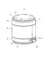
- FIG. 1 is an external perspective view illustrating a vibration actuator according to a first embodiment of the present invention.
- FIG. 2 is a longitudinal sectional view illustrating the vibration actuator according to the first embodiment of the present invention. It is an exploded perspective view of the same vibration actuator. It is a perspective view which shows the movable body and the elastic support part of the same vibration actuator.
- FIG. 5A and FIG. 5B are views showing a coupling state between the elastic support portion and the movable body.
- 6A and 6B are views showing a modification of the state of coupling between the elastic support portion and the movable body. It is a top view of the elastic support part provided with the damping part. It is a fragmentary sectional view of an elastic supporting part provided with a damping part.
- FIG. 6 is a longitudinal sectional view illustrating a vibration actuator according to a second embodiment of the present invention.
- FIG. 7 is an exploded perspective view of a vibration actuator according to Embodiment 2 of the present invention.
- FIG. 2 is a diagram illustrating an example of an electronic device on which the vibration actuator is mounted.
- FIG. 2 is a diagram illustrating an example of an electronic device on which the vibration actuator is mounted.
- FIG. 1 is an external perspective view showing a vibration actuator according to Embodiment 1 of the present invention
- FIG. 2 is a longitudinal sectional view showing a vibration actuator according to Embodiment 1 of the present invention
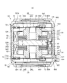
- FIG. It is an exploded perspective view of the same vibration actuator.
- FIG. 4 is a perspective view showing a movable body and an elastic support portion of the vibration actuator.
- the “upper” side and the “lower” side in the present embodiment are given for the sake of convenience for easy understanding, and mean one or the other of the vibration directions of the movable body 20 in the vibration actuator 10. That is, when the vibration actuator 10 is mounted on an electronic device (see FIGS. 16 and 17), it may be turned upside down or left and right.
- the vibration actuator 10 shown in FIGS. 1 to 4 is an electronic device, specifically, a portable game terminal device (for example, the game controller GC shown in FIG. 16), or a portable device such as a smartphone (for example, shown in FIG. 17). It is mounted as a vibration source on the portable terminal M) and realizes the vibration function of each device. Further, the vibration actuator 10 may have a function of generating sound by vibration. The vibration actuator 10 is driven, for example, when notifying a user of an incoming call or giving an operational feeling or a sense of reality.
- the vibration actuator 10 of the present embodiment accommodates a movable body 20 (see FIG. 2) in a cylindrical fixed body 50 so as to be able to vibrate in a cylindrical axial direction.
- the vibration actuator 10 itself becomes a vibration body.
- the vibration actuator 10 includes a movable body 20 having a magnet 30 and movable body cores 41 and 42, a fixed body 50 having coils 61 and 62, and a movable body 20 having a fixed body 50. And plate-like elastic support portions 81 and 82 for reciprocating support.
- the coils 61 and 62, the magnet 30, and the movable body cores 41 and 42 constitute a magnetic circuit that vibrates the movable body 20.
- the coils 61 and 62 are energized by power supply from a power supply unit (for example, the drive control unit 203 illustrated in FIGS. 16 and 17), the coils 61 and 62 and the magnet 30 cooperate. Accordingly, the movable body 20 reciprocates with respect to the fixed body 50 in the vibration direction.
- the movable body 20 reciprocates in the axial direction of the coils 61 and 62, that is, in the vibration direction, inside the coils 61 and 62 held by the coil holding unit 52.
- the movable body 20 can reciprocate inside an inner main body (coil protection wall) 522 disposed between the coils 61 and 62 and the movable body 20.
- the inner main body portion 522 is a part of the coil holding portion 52, and details of the coil holding portion 52 will be described later.
- the axial direction of the coils 61 and 62 is the vibration direction of the movable body 20, the magnetization direction of the magnet 30, or the axial direction of the coil holding unit 52.
- the movable body 20 is at the center of the length in the vibration direction of the fixed body 50 (specifically, the coil holding section 52) via the elastic support sections 81 and 82 when the movable body 20 is not moving and is not vibrating. And at predetermined intervals inside the fixed body 50 (more specifically, inside the main body part 522 of the coil holding part 52) in a direction orthogonal to the axial direction of the movable body 20. At this time, it is desirable that the movable body 20 is located at a position where the movable body 20 is balanced with the coils 61 and 62 so as not to contact the inner main body 522 of the coil holding section 52.
- the center of the length in the vibration direction of the magnet 30 and the movable body cores 41 and 42 is opposed to the center of the length in the vibration direction between the coils 61 and 62 in a direction orthogonal to the vibration direction. Preferably, they are arranged.
- the movable body 20 When movable (during vibration), the movable body 20 reciprocates in the vibration direction along the inner peripheral surface 522a of the inner main body 522. Note that a magnetic fluid may be interposed between the inner main body 522 and the movable body 20.
- the movable body 20 is located inside the cylindrical coil holding portion 52 of the fixed body 50 and along the inner peripheral surface 522 a of the inner main body portion 522 by the elastic support portions 81 and 82. It is supported so that it can reciprocate.
- the reciprocating direction is a direction in which a case (hereinafter, referred to as “upper case”) 54 and a case (hereinafter, referred to as “lower case”) 56 that cover the opening of the coil holding unit 52 face each other.
- the movable body 20 has a magnet 30, movable body cores 41 and 42, and spring stoppers 22 and 24.
- the movable body cores 41 and 42 and the spring stoppers 22 and 24 are continuously provided around the magnet 30 toward both sides in the vibration direction.
- the outer peripheral surfaces 20 a of the magnet 30 and the movable body cores 41 and 42 are opposed to each other at a predetermined interval inside the inner peripheral surface 522 a of the inner main body 522.
- the outer peripheral surface 20a reciprocates along the inner peripheral surface 522a without contact.
- the magnet 30 is disposed radially inside the coils 61 and 62 so as to be relatively movable in a vibration direction orthogonal to the radial directions of the coils 61 and 62.
- the magnet 30 is disposed so as to be spaced from the coils 61 and 62 radially inside the coils 61 and 62.
- the “radial direction” is a direction orthogonal to the axes of the coils 61 and 62, and is also a direction orthogonal to the vibration direction.
- the “interval” in the radial direction is an interval between the magnet 30 including the inner main body 522 and the coils 61 and 62, and is an interval that can move in the vibration direction of the movable body 20 without contacting each other.
- the distance between the coils 61 and 62 and the magnet 30 means the distance between the inner main body 522 on the side of the coils 61 and 62 and the magnet 30.
- the magnet 30 is disposed so as to face the center of the inner main body 522 on the radially outer side of the magnet 30.
- the magnet 30 may have a cylindrical shape, a plate shape, or the like as long as the magnet 30 is disposed inside the coils 61 and 62 with two magnetized surfaces directed in the direction in which the axes of the coils 61 and 62 extend.
- the shape may be other than a disk shape.
- the magnet 30 is a disk-shaped magnet, and the axial direction is the vibration direction and the magnetization direction is the magnetization direction. It is desirable that the center of the magnet 30 in the axial direction coincides with the center of the movable body 20 in the axial direction.
- the magnet 30 is magnetized in the vibration direction, and the front and back surfaces 30a and 30b separated in the vibration direction have different polarities.
- ⁇ ⁇ Movable body cores 41 and 42 are provided on the front and back surfaces 30a and 30b of the magnet 30, respectively.
- the movable body cores 41 and 42 are magnetic materials, and the magnet 30 and the coils 61 and 62 together constitute a magnetic circuit, and function as yokes.
- the movable body cores 41 and 42 concentrate the magnetic flux of the magnet 30 and flow it efficiently without leaking, and effectively distribute the magnetic flux flowing between the magnet 30 and the coils 61 and 62.
- the movable body cores 41 and 42 have a function as a body part of the movable body 20 and a function as a weight in the movable body 20 in addition to the function as a part of the magnetic circuit.
- the movable body cores 41 and 42 are formed in the shape of an annular plate, and are arranged so that the outer peripheral surface is flush with the outer peripheral surface of the magnet 30.
- the outer peripheral surface 20a is configured.
- the movable body cores 41 and 42 are laminated cores, for example, are formed by laminating silicon steel plates.
- the movable body cores 41 and 42 are the same members formed similarly, and are provided symmetrically about the magnet 30.
- the movable body cores 41 and 42 are attracted to the magnet 30 and fixed to the magnet 30 by a thermosetting adhesive such as an epoxy resin or an anaerobic adhesive.
- Openings 412, 422 formed in the respective central portions of the movable body cores 41, 42 indicate the axial position of the movable body 20, and are used as joints with the spring stoppers 22, 24.
- the movable body cores 41 and 42 are arranged inside the coils 61 and 62 (in the radial direction) and in a direction perpendicular to the axial direction of the coils 61 and 62. 61, 62.
- the movable body cores 41 and 42, together with the magnet 30, constitute a movable body side magnetic circuit portion in the magnetic circuit.
- the spring stoppers 22 and 24 have a function of fixing the movable body side magnetic circuit section to the elastic support sections 81 and 82. Further, the spring stoppers 22 and 24 are also weights, have a function as weights of the movable body 20, and increase the vibration output of the movable body 20.
- the spring stoppers 22 and 24 have joints 222 and 242 joined to the movable body cores 41 and 42, weight main bodies 224 and 244, and spring fixing parts 226 and 246.
- the spring stoppers 22 and 24 connect the joints 222 and 242, the weight main bodies 224 and 244, and the spring fixing parts 226 and 246 in the vibration direction, respectively, and open in the vibration direction. It is formed in a cylindrical shape having a through hole.
- a weight can be added in this through-hole, so that the through-hole can have a function as a weight adjusting portion together with the weight.
- the joining portions 222 and 242 are joined to the movable body cores 41 and 42, respectively. Specifically, the joints 222 and 242 are inserted into the openings 412 and 422 of the movable body cores 41 and 42, respectively, and are fitted therein. The joints 222 and 242 are fixed in the openings 412 and 422 by, for example, bonding using a thermosetting adhesive such as an epoxy resin or an anaerobic adhesive.
- the weight main bodies 224 and 244 are cylindrical bodies having larger outer diameters than the joining parts 222 and 242 and the spring fixing parts 226 and 246, and have a large mass.
- the weight body portions 224 and 244 are provided at both ends of the movable body 20 that are separated from each other in the vibration direction, and are not provided on the outer peripheral side of the movable body 20.
- the weight main bodies 224 and 244 do not limit the space in which the coils located on the outer peripheral side of the movable body 20 are arranged, and the efficiency of electromagnetic conversion does not decrease. Therefore, the weight of the movable body 20 can be suitably increased, and a high vibration output can be realized.
- the spring fixing portion 226 is located at one end of the movable body 20 in the vibration direction, that is, at the upper end of the movable body 20 and at the inner peripheral portion which is the inner diameter end of the upper leaf spring which is the elastic support portion 81. 802 (see FIG. 4).
- the spring fixing portion 246 is the other end in the vibration direction of the movable body, that is, the lower end of the movable body 20 and the inner end of the lower leaf spring that is the elastic support portion 82.
- the peripheral portion 802 (see FIG. 4) is joined. A detailed description of the elastic support portions 81 and 82 will be described later.
- the spring fixing portions 226 and 246 protrude in the vibration direction from the weight main body portions 224 and 244, respectively, and are joined to the inner peripheral portions 802 and 802 of the elastic support portions 81 and 82 at the tips. Therefore, the elastic support portions 81 and 82 protrude from the weight body portions 224 and 244, and are fixed at the tips of the spring fixing portions 226 and 246 having a step formed with respect to the weight body portions 224 and 244. Due to this step, a clearance as an elastic deformation region in the vibration direction of the elastic support portions 81 and 82 extending outward from the inner peripheral portions 802 and 802 in the outer peripheral direction is secured.
- the spring stoppers 22 and 24 can be fixed parts for fixing a weight or a spring. That is, since the spring stoppers 22 and 24 have a weight (weight) function and a spring fixing function of fixing the elastic support parts 81 and 82, it is not necessary to assemble members having the respective functions. By simply providing the spring stoppers 22 and 24 on the movable body side magnetic circuit unit, the upper leaf spring and the lower leaf spring, which are the elastic support parts 81 and 82, are attached to the movable body 20 having a weight function and a spring fixing function. It can be easily assembled, and the assemblability can be improved.
- the spring stoppers 22 and 24 may be made of a magnetic material, but are preferably made of a non-magnetic material. If the spring stoppers 22 and 24 are made of a non-magnetic material, the magnetic flux from the movable core 41 does not flow upward, and the magnetic flux from the movable core 42 does not flow downward. It can flow to the coils 61 and 62 located on the outer peripheral side of 41 and 42.
- the spring stoppers 22 and 24 may be formed of a material having a higher specific gravity (for example, a specific gravity of about 16 to 19) than a material such as a silicon steel plate (a specific gravity of the steel plate is 7.70 to 7.98). preferable.
- tungsten can be applied to the material of the spring stoppers 22 and 24.
- the fixed body 50 supports the movable body 20 movably in the vibration direction (the same direction as the coil axis direction and the magnetization direction) via the elastic support portions 81 and 82 inside the coils 61 and 62.
- the fixed body 50 in addition to the coils 61 and 62, includes a coil holding portion 52, an upper case (may be referred to as a "first case") 54, and a lower case (referred to as a "second case"). And an electromagnetic shield part 58.
- the coil holding section 52 holds the coils 61 and 62 arranged at a predetermined interval so as to surround the magnet 30 and guides the movement of the movable body 20.
- the coil holding portion 52 is a cylindrical body formed of resin or the like, is disposed radially inside the coils 61 and 62, and has an inner main body portion 522 interposed between the coils 61 and 62 and the magnet 30. Have.
- the inner main body portion 522 is arranged on the inner diameter side of the coils 61 and 62 at a distance from the magnet 30. The inner main body 522 obstructs contact between the magnet 30 and the coils 61 and 62.
- the coil holding portion 52 includes, in addition to the inner main body portion 522, an outer main body portion 524 which is a concentric tubular body arranged to surround and surround the outer peripheral side of the inner main body portion 522, and the inner main body portion 522 and the outer main body portion 524 and a central annular portion 526 that connects the central annular portion 526 with the central annular portion 526.
- an outer main body portion 524 which is a concentric tubular body arranged to surround and surround the outer peripheral side of the inner main body portion 522, and the inner main body portion 522 and the outer main body portion 524 and a central annular portion 526 that connects the central annular portion 526 with the central annular portion 526.
- the outer main body 524 is arranged so as to surround the coils 61 and 62 disposed on the outer peripheral surface of the inner main body 522, and the outer peripheral surface of the outer main body 524 is covered by a cylindrical electromagnetic shield 58.
- the outer body 524 is closed by the upper and lower cases 54 and 56 while sandwiching the outer peripheral portions 806 of the elastic support portions 81 and 82 together with the upper and lower cases 54 and 56 at both open ends (upper and lower ends). By closing both ends of the outer main body 524 with the upper and lower cases 54 and 56, respectively, a hollow vibration actuator housing is formed.
- the center annular portion 526 has a disk shape that is provided between the inner main body portion 522 and the outer main body portion 524 at the center position in the axial direction (the vibration direction). That is, the outer main body portion 524, the inner main body portion 522, and the central annular portion 526 form pockets (coil insertion portions) each having a concave cross section that open in a circular shape at both ends in the axial direction in the coil holding portion 52. I have.
- the central annular portion 526 forms the bottom of the pocket.
- the coils 61 and 62 are fixed in the concave pockets, respectively, while being accommodated therein.
- the inner body 522 is a cylindrical body, and the movable body 20 is arranged on the inner peripheral side so as to be able to reciprocate in the axial direction.
- the coils 61 and 62 are arranged in the axial direction (coil) so as to surround the outer peripheral surface of the inner body 522. (Axial direction).
- the inner peripheral surface 522a of the inner main body 522 is disposed facing the outer peripheral surface of the movable body 20 at a predetermined interval.
- the predetermined interval is an interval at which the movable body 20 can move in the axial direction, which is the vibration direction, without contacting the inner peripheral surface 522a when moving in the vibration direction.
- the movable body 20 moves along the inner peripheral surface 522a without contact.
- the thickness of the inner main body portion 522 is preferably smaller than the thickness of the outer main body portion 524. Even if the moving movable body 20 comes in contact with the outer main body portion 522, the inner main body portion 522 has a thickness that does not affect the outer peripheral coils 61 and 62 at all. is there. That is, the durability of the coil holding portion 52 that holds the coils 61 and 62 mainly depends on the radial thickness of the inner main body 522, the axial length of the central annular portion 526, and the diameter of the outer main body 524. Secure by thickness in the direction.
- the coil wire connecting the coils 61 and 62 held apart in the axial direction by the coil holding portion 52 is provided in the coil holding portion 52 and has a guide groove communicating between pockets (slits) having a concave cross section. (Not shown).
- the coils 61 and 62 are connected to the outside by turning a coil connection portion 521 below the coil holding portion 52.
- the coil connection portion 521 is located on the protrusion 564 of the lower case 56.
- the guide groove is provided, for example, on the outer peripheral portion of the central annular portion 526.
- the coils 61 and 62 are inserted into pockets (slits) having a concave cross section that are formed by the inner main body portion 522, the outer main body portion 524, and the central annular portion 526 and that open on both sides in the axial direction. It is fixed by bonding or sealing.
- the coils 61 and 62 are fixed to the inner main body 522, the outer main body 524, and the central annular part 526 by bonding. Therefore, the coils 61 and 62 can increase the bonding strength with the coil holding portion 52, and even when a large impact is applied, the coils 61 and 62 are damaged as compared with the configuration in which the movable body directly contacts the coil. None.
- the coils 61 and 62 generate the drive source of the vibration actuator 10 together with the magnet 30 and the movable body cores 41 and 42 in the vibration actuator 10 with the axial direction of the coils 61 and 62 (magnetization direction of the magnet 30) as the vibration direction. Used for The coils 61 and 62 are energized during driving and constitute a voice coil motor together with the magnet 30.
- the coils 61 and 62 are constituted by self-welding wire coils in the present embodiment. Accordingly, when the vibration actuator 10 is assembled to the coil holding portion 52, the cylindrical shape can be inserted and held in a pocket having a concave cross section, which is a slit, so that the coil wire is not unraveled and the assembling property of the vibration actuator 10 can be improved. Improvements are being made.
- the coil axes of the coils 61 and 62 are arranged coaxially with the axis of the coil holding portion 52 or the axis of the magnet 30.
- the center position of the length in the coil axis direction (vibration direction) is set to the center of the length in the vibration direction of the movable body 20 (specifically, the vibration direction of the magnet 30).
- the position is held so as to be substantially the same position (including the same position) in the vibration direction.
- the coils 61 and 62 according to the present embodiment are configured to be wound in opposite directions to each other, and configured to allow current to flow in the opposite direction when energized.
- Both ends of the coils 61 and 62 are connected to a power supply unit (for example, the drive control unit 203 shown in FIGS. 16 and 17).
- a power supply unit for example, the drive control unit 203 shown in FIGS. 16 and 17.
- both ends of the coils 61 and 62 are connected to an AC supply unit, and AC power (AC voltage) is supplied to the coils 61 and 62 from the AC supply unit.
- AC power AC voltage
- the magnet 30 is mounted such that the front surface 30a on one side (upper side in the present embodiment) of the magnetizing direction is an N pole, and the back surface 30b on the other side (lower side in the present embodiment) of the magnetizing direction is an S pole.
- a magnetic flux radiated from the movable core 41 on the front surface 30a side of the magnet 30 and incident on the movable core 42 on the back surface 30b side of the magnet 30 is formed.
- the light is emitted from the surface side of the magnet 30, radiated from the movable body core 41 on the upper side of the magnet 30 to the coil 61 side, passes through the electromagnetic shield part 58, and passes through the coil 62 through the lower side of the magnet 30.
- the flow of the magnetic flux entering the magnet 30 from the body core 42 is formed.
- the magnetic flux traverses the coils 61 and 62 in the radial direction with respect to any part of the coils 61 and 62 arranged so as to surround the magnet 30 and the movable body cores 41 and 42.
- Lorentz force acts in the same direction (for example, the ⁇ f direction shown in FIG. 11) along the magnetization direction.
- the upper case 54 and the lower case 56 are each formed in a cylindrical shape with a bottom, and the respective bottoms 541 and 561 constitute the top and bottom surfaces of the vibration actuator 10 in the present embodiment.
- the upper case 54 and the lower case 56 may be formed by forming a metal plate into a concave shape by drawing.
- the electromagnetic shield part 58 is a cylindrical magnetic body disposed so as to cover the outer periphery of the coil holding part 52.
- the electromagnetic shield part 58 functions as an electromagnetic shield and prevents leakage of magnetic flux to the outside of the vibration actuator 10.
- the electromagnetic shield portion 58 functions as a magnetic circuit together with the coils 61 and 62, the magnet 30, and the movable cores 41 and 42, the thrust constant can be increased and the electromagnetic conversion efficiency can be increased.
- the electromagnetic shield portion 58 has a function as a magnetic spring together with the magnet 30 by utilizing the magnetic attraction of the magnet 30.
- the magnet 30 is arranged inside the electromagnetic shield portion 58 such that the center of the magnet 30 in the vibration direction is located at the center of the length of the electromagnetic shield portion 58 in the vibration direction.
- the magnetic attraction force F1 acts between the magnet 30 and the electromagnetic shield portion 58, respectively.
- the magnetic attraction F2 is generated between the magnet 30 and the electromagnetic shield part 58, and the movable body 20 It returns to the original position by the force of the thrust F3.
- the total spring constant is the sum of the spring constants of the leaf springs serving as the elastic support portions 81 and 82 and the spring constant of the magnetic spring by the magnet 30 and the electromagnetic shield portion 58.
- the spring constant of the leaf spring can be reduced.
- the stress of the leaf spring is reduced, the adverse effect on the life is suppressed, and the reliability of the vibration actuator 10 can be increased.
- the bottom part 541 of the upper case 54 and the bottom part 561 of the lower case 56 are disk-shaped bodies, and the inside of the cylindrical peripheral wall parts 542 and 562 rising from the outer peripheral edge of each of the bottom parts 541 and 561 has an opening edge. Also, an annular step portion extending in the circumferential direction is provided at a position near the bottom portions 541 and 561 (see FIG. 2).
- the outer surfaces of the peripheral wall portions 542 and 562 are provided so as to be flush with the outer surface of the electromagnetic shield portion 58 surrounding the coils 61 and 62. Accordingly, the vibration actuator 10 is formed in a substantially cylindrical shape (barrel shape) having a flat outer peripheral surface and has a small and simple shape, so that the installation space can be configured with a simple cylindrical shape.
- the upper case 54 and the lower case 56 are fitted with both open ends of the coil holding portion 52 at the steps, respectively, and are fixed by sandwiching the outer peripheral portions 806 of the elastic support portions 81 and 82 with the open ends.
- the length from the bottoms 541 and 561 to the step can respectively define the movable range of the movable body 20.
- the movable range of the movable body 20 is configured so that the movable body 20 vibrates within the movable range due to deformation of the elastic support portions 81 and 82.
- the upper case 54 and the lower case 56 of the fixed body 50 are hard-stopped (movable range limited) via a movable body space having a length from the bottom parts 541 and 561 to the step part to which the elastic support parts 81 and 82 are fixed. It has a function as a movable range suppressing mechanism that becomes HS. That is, the movable body space is defined to have a length within a range in which the elastic support portions 81 and 82 are not plastically deformed. Accordingly, even when a force exceeding the movable range is applied to the movable body 20, the elastic support portions 81 and 82 come into contact with the fixed body 50 without being plastically deformed, so that the elastic support portions 81 and 82 are damaged. And reliability can be improved.
- the elastic support portions 81 and 82 are provided so as to sandwich the movable body 20 in the vibration direction of the movable body 20 and to be orthogonal to both the movable body 20 and the fixed body 50 in the vibration direction. Are supported on the fixed body 50 so as to be reciprocally movable in the vibration direction.
- the elastic support portions 81 and 82 are separated from each other at both ends of the movable body 20 that are separated in the vibration direction, and are connected to the fixed body 50.
- inner peripheral portions 802 are fitted respectively corresponding to both ends (spring fixing portions 226 and 246) of the movable body 20 which are separated in the axial direction (vibration direction), and The portion 806 is mounted so that the side thereof protrudes radially outward (radially).
- the elastic support portions 81 and 82 support the movable body 20 so as not to contact the fixed body 50 when the movable body 20 is not vibrating and when the movable body 20 is vibrating. In addition, even if the elastic support portions 81 and 82 come into contact with the inner peripheral surface 522a of the inner main body portion 522 of the movable body 20 during driving, the magnetic circuit, specifically, the coils 61 and 62 may not be damaged. Absent.
- the elastic support portions 81 and 82 may be configured as long as they elastically support the movable body 20 movably.
- the elastic support portions 81 and 82 may be a non-magnetic material or a magnetic material (specifically, a ferromagnetic material).
- the elastic support portions 81 and 82 may be configured using stainless steel plates such as SUS304 and SUS316 as long as they are nonmagnetic leaf springs. If the elastic supporting portions 81 and 82 are magnetic materials, a stainless steel plate such as SUS301 can be used.
- the elastic support portions 81 and 82 are arranged at positions in the vibration actuator that are hardly affected by the magnetic field of the magnetic circuit in the movable body 20, even if the material of the elastic support portions 81 and 82 is a non-magnetic material, Alternatively, it may be a magnetic material. Further, when the elastic support portions 81 and 82 are arranged at positions in the movable body 20 that are easily affected by the magnetic field of the magnetic circuit, the material of the elastic support portions 81 and 82 is a non-magnetic material. Is preferred.
- a magnetic material for example, SUS301
- a non-magnetic material for example, SUS304, SUS316
- the material of the elastic support portions 81 and 82 is, for example, A magnetic material (ferromagnetic material) such as SUS301 is used. Therefore, in the present embodiment, the elastic support portions 81 and 82 have high durability and are inexpensive as compared with the case where a nonmagnetic material is used, and can realize the vibration actuator 10 having excellent durability at low cost. I have.
- the elastic support portions 81 and 82 are a plurality of flat plate springs, respectively, as shown in FIG.
- the movable body 20 may have the plurality of elastic support portions 81 and 82 as three or more leaf springs. These leaf springs are attached along a direction orthogonal to the vibration direction.
- the elastic support portions 81 and 82 which are leaf springs, are joined by an arc-shaped deformation arm 804 in which an annular inner peripheral portion 802 as an inner spring end and an outer peripheral portion 806 as an outer spring end are elastically deformed.
- the shape has Due to the deformation of the deformable arm 804, the inner peripheral portion 802 and the outer peripheral portion 806 are relatively displaced in the axial direction.
- Outer peripheral portions 806 of the elastic support portions 81 and 82 are joined to the fixed body 50, and inner peripheral portions 802 are joined to the movable body 20.
- the leaf springs serving as the elastic support portions 81 and 82 are formed by sheet metal processing using a stainless steel plate, and more specifically, a thin flat disk-shaped spiral spring. Since the elastic support portions 81 and 82 have a flat plate shape, the positional accuracy, that is, the processing accuracy can be improved as compared with the conical spring.
- the plurality of elastic support portions 81 and 82 have the same spiral direction, and the outer peripheral portion 806, which is one end on the outer peripheral side, is fixed to the fixed body 50 and the inner peripheral side.
- a plurality of spiral leaf springs are used as the plurality of elastic support portions 81 and 82, and the leaf springs are attached to both ends of the movable body 20 that are separated in the vibration direction.
- the vibration actuator 10 when the movable body 20 is elastically supported with respect to the fixed body 50, if the moving amount of the movable body 20 is large, the movable body 20 is slightly rotated while rotating in the translation direction (here, in this case). , On a plane perpendicular to the vibration direction). If the directions of the vortices of the plurality of leaf springs are opposite to each other, the plurality of leaf springs will move in the buckling direction or the pulling direction, and smooth movement will be hindered.
- the elastic support portions 81 and 82 of the present embodiment are fixed to the movable body 20 so that the directions of the spirals are the same, even if the moving amount of the movable body 20 increases, the elastic support portions 81 and 82 move smoothly. , Can be deformed, have a larger amplitude, and increase the vibration output.
- the elastic support portions 81 and 82 are formed at the ends of the movable body 20 that are separated from each other in the vibration direction of the movable body 20 (the vertical direction in the present embodiment), and a step is formed in the outer peripheral portion from the weight main bodies 224 and 244. And fixed to the tips of the spring fixing portions 226 and 246 protruding. Since the elastic support portions 81 and 82 are arranged so as to extend from the tips of the spring fixing portions 226 and 246 in a direction orthogonal to the vibration direction, an elastic deformation region is secured by the steps. Therefore, the elastic supporting portion can be formed at low cost, and the reliability of the vibration actuator using the elastic supporting portion can be improved.
- the elastic support portions 81 and 82 and the movable body 20 are firmly joined via the fixed pins 26 and 28, respectively, so as not to come off due to the vibration of the movable body 20.
- the fixing pins 26 and 28 shown in FIGS. 2 to 4 have flanges 264 and 284 at the opening edges on one end side of the cylindrical pin bodies 262 and 282 which can be press-fitted into the spring fixing portions 226 and 246, respectively.
- FIG. 5A and FIG. 5B are views showing a connected state between the elastic support portions 81 and 82 and the movable body 20.
- FIG. 5A when fixing the plate-like elastic support portions 81 and 82 to the movable body 20, each inner peripheral portion 802 of the elastic support portions 81 and 82 is attached to the end of the movable body 20 in the vibration direction. Are superimposed on the spring fixing portions 226 and 246.
- the respective pin bodies 262, 282 of the fixing pins 26, 28 are inserted into the through holes opened by the spring fixing parts 226, 246 through the openings of the inner peripheral parts 802, 802 of the plate-like elastic support parts 81, 82. Press in.
- the flanges 264 and 284 hold the inner peripheral portions 802 of the elastic support portions 81 and 82 between the spring fixing portions 226 and 246 as shown in FIG. It is firmly joined to the parts 226, 246.
- the inner peripheral portions 802 of the elastic support portions 81 and 82 and the spring fixing portions 226 and 246 may be joined by welding, bonding, or caulking, or by combining welding, bonding, or caulking. Good.
- FIG. 6A and 6B are views showing a modification of the state of coupling between the elastic supporting portions 81 and 82 and the movable body 20.
- FIG. 6A and 6B the spring fixing portions 226 and 246 of the spring stoppers 22A and 24A, which are configured similarly to the spring stoppers 22 and 24, It has cylindrical caulking portions 228 and 248 protruding from the periphery of the through hole that opens on the direction side.
- the caulking portions 228 and 248 are inserted into the openings of the inner peripheral portions 802 of the elastic support portions 81 and 82, as shown in FIG. 6A.
- the outer periphery of the cylindrical caulking portions 228, 248 have a diameter that fits inside the inner peripheral portion 802 of the elastic support portions 81, 82.
- the length of the caulking portions 228 and 248 protruding from the surface on which the inner peripheral portion 802 is placed is longer than the thickness of the elastic support portions 81 and 82.
- the inner peripheral portions 802, 802 are inserted into the caulking portions 228, 248, and the caulking portions 228, 248 are crushed and caulked, so that the elastic support portions 81, 82 and the spring fixing portions are formed. 226 and 246 are firmly joined.
- This configuration can reduce the number of components, reduce the number of assembling steps, and facilitate manufacture, as compared with the configuration using the fixing pins 26 and 28 shown in FIG. Further, the joint between the elastic support portions 81 and 82 and the spring fixing portions 226 and 246 may be welded or bonded together with the caulking joint.
- the outer peripheral portion 806 of the elastic support portion 81 has an inner peripheral side portion (an inner peripheral side step portion) of the opening in the peripheral wall portion 542 of the upper case 54 on the radial outside.
- the coil holding portion 52 is fixed to the fixed body 50 by being sandwiched by the opening end of the outer main body portion 524.
- the outer peripheral portion 806 of the elastic support portion 82 is radially outside, and has an open end of the outer main body portion 524 in the coil holding portion 52 and a step portion inside the opening in the peripheral wall portion 562 of the lower case 56. And is fixed to the fixed body 50.
- the elastic support portions 81 and 82 are orthogonal to the vibration direction by the upper and lower opening ends of the outer main body portion 524 of the coil holding portion 52 and the upper and lower cases 54 and 56 that fit and close these opening ends. It is pinched while being arranged in the direction.
- the elastic support portions 81 and 82 are provided on the deformable arm 804 or the deformable arm 804 and the outer peripheral portion 806 with a damping portion (damper) 72 as damping means for damping vibration generated in the elastic support portions 81 and 82. Is attached.
- the damping means suppresses the resonance peak in the elastic support portions 81 and 82 and generates stable vibration over a wide range.
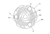
- FIG. 7 is a plan view of an elastic support portion 81 having a damping portion
- FIG. 8 is a partial cross-sectional view of the elastic support portion having a damping portion 72.
- the elastic support portion 82 also includes the damping portion 72, but is configured in the same manner as the elastic support portion 81, and a description thereof will be omitted.
- the damping portion 72 of the present embodiment has an H-shaped cross-section in which the central portions of a pair of flanges 722 arranged in parallel and opposed to each other are connected by ribs (pressing portions) 724.
- Elastic member such as an elastomer.
- the damping portion 72 is arranged while being in contact with both by inserting an elastomer into the bridge portion of the elastic support portion 81 which is a leaf spring, in this embodiment, between the outer peripheral portion 806 and the deformable arm 804.
- the plurality of damping portions 72 are attached to the elastic support portion 81 without being fixed.
- the damping section 72 as a damping means attenuates sharp spring resonance in the elastic support section 81, and prevents a large difference in vibration depending on the frequency due to a remarkable increase in the vibration near the resonance frequency. Accordingly, the movable body 20 vibrates so as not to contact the bottom portions 541 and 561 before the plastic deformation, and no abnormal noise is caused by the contact.
- the damping portion 72 may be formed of any shape, material, or the like as long as it prevents generation of sharp vibration in the elastic support portions 81 (82).
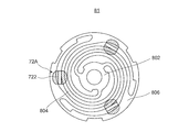
- FIG. 9 and FIG. 10 are a plan view and a partial cross-sectional view of an elastic support portion having a damping portion 72A as a modification.
- the damping portion 72A shown in FIGS. 9 and 10 is an elastomer having a T-shaped cross section, and has a plate-like flange 722 and a pushing portion 724A provided to protrude from the center of the flange 722.
- the damping portion 72A inserts the pushing portion 724A from one surface side of the elastic support portion 81 between the spring portions, specifically, between the outer peripheral portion 806 and the deformable arm 804, and connects the flange 722 between the spring portions. It is positioned over the bridge.
- the attachment portion 73 is a thermosetting resin or an adhesive that does not adhere to the elastic support portion 81, and has a shape such that the push portion 724A does not come off from the spring portion on the back side of the elastic support portion 81. Fixed. With this configuration, the damping portion 72A can reduce the component cost compared to the damping portion 72 having the H-shaped cross section, realize the same damping effect as the damping portion 72, suppress the resonance peak, and generate stable vibration over a wide range. it can.
- the movable body 20 is considered to correspond to a mass portion in a spring-mass system vibration model. Therefore, when the resonance is sharp (has a steep peak), the vibration is attenuated to thereby sharpen the vibration. Suppress peaks. By reducing the vibration, the resonance is no longer sharp, and the maximum amplitude value and the maximum movement amount of the movable body 20 at the time of resonance do not vary, and a vibration with a suitable stable maximum movement amount is output.
- the magnetic circuit shown in FIG. 11 is formed.
- the coils 61 and 62 are arranged such that the coil axes are orthogonal to the magnetic fluxes of the movable body cores 41 and 42 sandwiching the magnet 30 in the vibration direction. Therefore, when the coils 61 and 62 are energized as shown in FIG. 11, the interaction between the magnetic field of the magnet 30 and the current flowing through the coils 61 and 62 causes the coils 61 and 62 to move in the ⁇ f direction according to Fleming's left-hand rule. Lorentz force occurs.
- the Lorentz force in the -f direction is a direction orthogonal to the direction of the magnetic field and the direction of the current flowing through the coils 61 and 62. Since the coils 61 and 62 are fixed to the fixed body 50 (coil holding part 52), a force opposite to the Lorentz force in the ⁇ f direction is applied to the movable body 20 having the magnet 30 by the action-reaction law. It occurs as a thrust in the direction. As a result, the movable body 20 having the magnet 30 moves in the F direction, that is, toward the bottom 541 of the upper case 54.
- the vibration actuator 10 includes a fixed body 50 having coils 61 and 62, a movable body 20 magnetized in the axial direction of the coils 61 and 62 and having a magnet 30 disposed radially inside the coils 61 and 62, Plate-like elastic support portions 81 and 82 for elastically holding the movable member 20 in the vibration direction.
- an inner main body 522 is provided between the outer peripheral surface 30a of the movable body 20 and the coils 61, 62, and the elastic supporting portions 81, 82 allow the movable body 20 to move when the movable body 20 is not vibrated and when the movable body 20 vibrates. It is supported so that it does not touch sometimes.
- the movable body 20 is supported with respect to the fixed body 50 with a gap between the movable body 20 and the inner body 522 during non-vibration in a non-movable state and during movement, that is, during vibration. 20 does not come into contact with the fixed body 50 during the movement, that is, during the vibration.
- the movable body 20 contacts the inner main body 522 only when an impact is applied to the vibration actuator 10 itself, such as when the vibration actuator 10 is dropped. That is, only when there is an impact, the movable body 20 and the inner body 522 relatively move within the range between the outer peripheral surface 20a of the movable body 20 and the inner peripheral surface 522a of the inner body 522, and the movable body 20 Is in contact with the inner main body 522, and its movement is regulated.
- the vibration actuator 10 unlike the conventional vibration actuator, when the shock is applied to the vibration actuator 10, the movable body 20 is displaced and comes into contact with the inner wall of the fixed body, so that no shock is applied. That is, the coils 61 and 62 of the fixed body 50 are not damaged by the impact. Further, the movement of the movable body 20 is regulated by the inner main body 522 due to the impact, and the elastic supports 81 and 82 themselves are not deformed by the impact, and the movable body 20 caused by the deformation of the elastic supports 81 and 82 is movable. Inconveniences such as inability can be resolved. In addition, since the vibration actuator 10 has a structure in which the movable body 20 is reciprocated without sliding on the shaft, it is needless to say that no sliding noise occurs with the shaft when the movable body 20 moves.
- the vibration actuator 10 it is possible to output a suitable bodily sensation vibration having high impact expression and high vibration expression power.
- the vibration actuator 10 is driven by an AC wave input to the coils 61 and 62 from a power supply unit (for example, the drive control unit 203 illustrated in FIGS. 16 and 17). That is, the energizing direction of the coils 61 and 62 is periodically switched, and the thrust in the F direction on the bottom 541 side of the upper case 54 and the thrust in the ⁇ F direction on the bottom 561 side of the lower case 56 are alternately applied to the movable body 20. Works. Thereby, the movable body 20 vibrates in the vibration direction (the winding axis direction orthogonal to the radial direction of the coils 61 and 62 or the magnetization direction of the magnet 30).
- a power supply unit for example, the drive control unit 203 illustrated in FIGS. 16 and 17. That is, the energizing direction of the coils 61 and 62 is periodically switched, and the thrust in the F direction on the bottom 541 side of the upper case 54 and the thrust in the ⁇ F direction on the bottom 561 side of the
- the mass of the movable body 20 m [kg]
- the spring constant of the spring (elastic support portions 81, 82 is a spring) and K sp
- movable body 20 the fixed body With respect to 50, it vibrates at a resonance frequency fr [Hz] calculated by the following equation (1).
- the spring - it is considered to constitute the mass portion in the vibration model of the mass system, when an AC wave of frequency equal to the resonant frequency f r of the movable member 20 is input to the coil 61, the movable member 20 Is in a resonance state. That is, the coil 61 from the power supply unit, by inputting an AC wave of a frequency substantially equal to the resonance frequency f r of the movable member 20, thereby the movable member 20 efficiently vibrated.
- the equations of motion and the circuit equations showing the driving principle of the vibration actuator 10 are shown below.
- the vibration actuator 10 is driven based on a motion equation represented by the following equation (2) and a circuit equation represented by the following equation (3).
- the vibration actuator 10 the energization of the AC wave corresponding to the resonance frequency f r which is determined by the spring constant K sp of the elastic support portions 81, 82 is the mass m and the leaf spring of the movable member 20 to the coil 61, 62 Is performed, a large vibration output can be obtained efficiently.
- the vibration actuator 10 satisfies the equations (2) and (3) and is driven by a resonance phenomenon using a resonance frequency represented by the equation (1). Accordingly, in the vibration actuator 10, the power consumed in the steady state is only the loss due to the damping unit 72, and the vibration actuator 10 can be driven with low power consumption, that is, the movable body 20 can be linearly reciprocated with low power consumption.
- the plate-like elastic support portions 81 and 82 are arranged above and below (in the vibration direction) of the movable body 20, so that the movable body 20 is driven stably in the up and down direction, and The magnetic flux of the coils 61 and 62 can be efficiently distributed from the upper and lower elastic support portions 81 and 82.
- high-output vibration can be realized as the vibration motor.
- the fixed body 50 has a coil holding part 52 that also has a function of holding the coils 61 and 62 and a function of protecting the coils 61 and 62 against the movable body 20. Accordingly, even when the vibration actuator 10 receives an impact, the fixed body 50 withstands the impact and does not damage the elastic support portions 81 and 82 such as deformation. In addition, since impact is transmitted to the coils 61 and 62 via the resin-made inner main body 522, damage can be suppressed, and the vibration actuator 10 has high reliability.
- FIG. 14 is a longitudinal sectional view showing a vibration actuator according to Embodiment 2 of the present invention
- FIG. 15 is an exploded perspective view of the vibration actuator according to Embodiment 2 of the present invention.
- the vibration actuator 10A shown in FIG. 14 and FIG. 15 has the same basic configuration as the vibration actuator 10 corresponding to the first embodiment shown in FIG. 1 to FIG. Only the part 52A is changed.
- the vibration actuator 10 ⁇ / b> A has the same operation and effect as the configuration similar to the vibration actuator 10.
- the same components are denoted by the same reference numerals, and duplicate description will be omitted. That is, in the vibration actuator 10A shown in FIGS. 14 and 15, the movable body 20A is accommodated in the cylindrical fixed body 50A so as to be vibrated in the cylindrical axial direction. When the movable body 20A moves, the vibration actuator 10A itself becomes a vibration body.
- the vibration actuator 10A has a movable body 20A having the magnet 30 and the movable body cores 41 and 42, a fixed body 50A having the coils 61 and 62, and a plate-shaped member for supporting the movable body 20A reciprocally with respect to the fixed body 50A. And the elastic support portions 81 and 82.
- the vibration actuator 10A holds the coils 61 and 62 on the outer peripheral side of the coil holding section 52A in the cylindrical coil holding section 52A arranged to surround the outer circumference of the magnet 30.
- the coil holding portion 52A has a cylindrical shape, has a radially outward opening on the outer peripheral side, and has a concave coil mounting portion 522A on which the coils 61 and 62 are arranged.
- the coil mounting portion 522A is formed by ribs 528A, 528A, and 526A that protrude from the outer surface of the cylindrical portion at an interval in the axial direction.
- the coils 61 and 62 disposed in the coil mounting portion 522A are surrounded by an electromagnetic shield portion 58 surrounding the outer peripheral surface of the coil holding portion 52A, and are fixed in the coil mounting portion by adhesion or the like in a sealed state.
- the coil mounting portion 522A is formed in a concave shape that extends in the circumferential direction and opens radially outward on the outer periphery of the coil holding portion 52A, the coils 61 and 62 can be inserted from the radial outside. It also functions as a simple coil insertion part.
- the coils 61 and 62 are arranged by winding a coil wire from the outside of the coil holding unit 52A and winding the coil wire around the coil holding unit 52A. Therefore, in order to maintain the cylindrical coils 61 and 62, the coils 61 and 62 can be assembled without using a self-fusing wire, and the same operation and effect as those of the first embodiment can be obtained, and the cost of the coils 61 and 62 themselves can be reduced. Thus, the cost of the entire vibration actuator 10A can be reduced.
- FIG. 16 and 17 are diagrams illustrating an example of a mounting form of the vibration actuators 10 and 10A.
- FIG. 16 shows an example in which the vibration actuator 10 is mounted on a game controller GC
- FIG. 17 shows an example in which the vibration actuator 10 is mounted on a portable terminal M.
- the game controller GC is connected to the game machine body by wireless communication, for example, and is used when the user grips or grips it.
- the game controller GC has a rectangular plate shape, and the user grasps the left and right sides of the game controller GC with both hands to operate.
- the game controller GC notifies the user of a command from the game machine body by vibration.
- the game controller GC includes a function other than command notification, for example, an input operation unit for the game machine body.
- the mobile terminal M is, for example, a mobile communication terminal such as a mobile phone or a smartphone.
- the mobile terminal M notifies the user of an incoming call from an external communication device by vibration, and also realizes various functions of the mobile terminal M (for example, a function for giving a feeling of operation and a sense of presence).
- the game controller GC and the portable terminal M respectively include a communication unit 201, a processing unit 202, a drive control unit 203, and vibration actuators 10B and 10C that are vibration actuators 10 as drive units. 10D.
- a plurality of vibration actuators 10B and 10C are mounted.
- the vibration actuators 10B, 10C, and 10D are, for example, parallel to the main surface of the terminal and a plane orthogonal to the vibration direction of the vibration actuators 10B, 10C, and 10D, here, the bottom surface of the lower case 56. It is implemented so that The main surface of the terminal is a surface that comes into contact with the body surface of the user, and in the present embodiment, means a vibration transmission surface that transmits vibration by contacting the body surface of the user.
- the vibration actuators 10B, 10C are arranged such that the vibration direction is orthogonal to the surface where the user's fingertip, the pad of the finger, the palm of the hand touches, or the surface on which the operation unit is provided. Is implemented.
- the vibration actuator 10D is mounted such that the vibration direction is orthogonal to the display screen (touch panel surface). Thereby, the vibration in the direction perpendicular to the main surfaces of the game controller GC and the mobile terminal M is transmitted to the user.
- the communication unit 201 is connected to an external communication device by wireless communication, receives a signal from the communication device, and outputs the signal to the processing unit 202.
- the external communication device is a game machine main body as an information communication terminal, and performs communication in accordance with a short-range wireless communication standard such as Bluetooth (registered trademark).
- the external communication device is, for example, a base station, and performs communication according to the mobile communication standard.
- the processing unit 202 converts the input signal into a drive signal for driving the vibration actuators 10B, 10C, and 10D by a conversion circuit unit (not shown), and outputs the drive signal to the drive control unit 203. Note that, in the mobile terminal M, the processing unit 202 outputs a drive signal based on a signal input from various communication units (not shown, for example, an operation unit such as a touch panel) in addition to a signal input from the communication unit 201. Generate.
- the drive control unit 203 is connected to the vibration actuators 10B, 10C, and 10D, and has a circuit for driving the vibration actuators 10B, 10C, and 10D.
- the drive control unit 203 supplies a drive signal to the vibration actuators 10B, 10C, and 10D.
- the vibration actuators 10B, 10C, and 10D are driven according to a drive signal from the drive control unit 203. Specifically, in the vibration actuators 10B, 10C, and 10D, the movable body 20 vibrates in a direction orthogonal to the main surfaces of the game controller GC and the portable terminal M.
- the movable body 20 may contact the bottom 541 of the upper case 54 or the bottom 561 of the lower case 56 via a damper every time it vibrates.
- the impact on the bottom 541 of the upper case 54 or the bottom 561 of the lower case 56 due to the vibration of the movable body 20, that is, the impact on the housing is directly transmitted to the user as vibration.
- the plurality of vibration actuators 10B and 10C since the plurality of vibration actuators 10B and 10C are mounted, one or both of the plurality of vibration actuators 10B and 10C can be simultaneously driven in accordance with the input drive signal. it can.
- the bodily sensation vibration for the user can be applied by one or both of the vibration actuators 10B and 10C, and a highly expressive vibration such as selectively applying at least a strong or weak vibration can be applied.
- the vibration actuators 10 and 10A according to the present invention can be used by mobile devices other than the game controller GC and the mobile terminal M described in the embodiment (for example, a mobile information terminal such as a tablet PC, a mobile game terminal, and a user). It is suitable when applied to a wearable terminal that is worn and used.
- the vibration actuators 10 and 10A according to the present invention may be used as an exciter that is a vibration device that emits sound by vibration.
- the exciter is a vibrating speaker having a function of making sound by bringing a vibrating surface into contact with an object without using a cone, for example.
- the vibration actuators 10 and 10A according to the present invention may be an exciter that emits sound to cancel and reduce external noise, for example, road noise. Further, the vibration actuators 10 and 10A according to the present invention may be used as a vibration generator. Further, the vibration actuators 10 and 10A of the present embodiment can be used not only for the above-described portable device but also for an electric beauty appliance that requires vibration, such as a facial massage device.
- the vibration actuator according to the present invention has impact resistance, can output a suitable bodily sensation vibration, and is mounted on an electronic device such as a game machine terminal that imparts vibration to a user, an exciter as a vibration device that emits sound, or a portable terminal. It is useful as what is done.
Landscapes
- Engineering & Computer Science (AREA)
- Power Engineering (AREA)
- Physics & Mathematics (AREA)
- Electromagnetism (AREA)
- Mechanical Engineering (AREA)
- Apparatuses For Generation Of Mechanical Vibrations (AREA)
- Reciprocating, Oscillating Or Vibrating Motors (AREA)
- User Interface Of Digital Computer (AREA)
Abstract
This vibration actuator has: a stationary body having a coil; a movable body having a magnet disposed radially inside the coil; and an elastic support section for supporting the movable body so that the movable body can move relative to the stationary body, and the coil to which electric power is supplied and the magnet cooperate to vibrate the movable body relative to the stationary body. The stationary body is disposed so as to surround the movable body and has a coil holding section for holding the coil. The coil holding section has, on the inner diameter side of the coil, a coil protection wall section which prevents the contact between the magnet and the coil. The elastic support section has at least two or more plate springs bridged between the coil holding section and the movable body so as to sandwich the movable body in a vibration direction. In order that the movable body does not come into contact with the coil holding section when not vibrating and when vibrating, the plate springs support the movable body so that the movable body is movable in the vibration direction.
Description
本発明は、振動アクチュエータ及びこれを備える電子機器に関する。
The present invention relates to a vibration actuator and an electronic device including the same.
従来、振動機能を有する電子機器には、振動発生源として振動アクチュエータが実装されている。電子機器は、振動アクチュエータを駆動してユーザに振動を伝達して体感させることにより、着信を通知したり、操作感や臨場感を向上したりすることができる。ここで、電子機器は、携帯型ゲーム端末、据置型ゲーム機のコントローラー(ゲームパッド)、携帯電話やスマートフォンなどの携帯通信端末、タブレットPCなどの携帯情報端末、服や腕などに装着されるウェアラブル端末の携帯できる携帯機器を含む。
Conventionally, a vibration actuator is mounted as a vibration source on an electronic device having a vibration function. The electronic device can notify a user of an incoming call and improve the operational feeling and the realism by driving the vibration actuator to transmit the vibration to the user to experience the vibration. Here, the electronic device is a portable game terminal, a controller (game pad) of a stationary game machine, a portable communication terminal such as a mobile phone or a smartphone, a portable information terminal such as a tablet PC, a wearable worn on clothes, arms, or the like. Including portable devices that can carry the terminal.
携帯機器に実装される小型化可能な構造の振動アクチュエータとしては、例えば、特許文献1に示すように、ページャー等に用いられる振動アクチュエータが知られている。
As a vibration actuator having a structure that can be miniaturized and mounted on a portable device, for example, a vibration actuator used for a pager or the like is known as disclosed in Patent Document 1.
この振動アクチュエータは、一対の板状弾性体を相対向するようにして円筒状の枠体の開口縁部でそれぞれを支持させている。そして、一対の板状弾性体のうちの一方の渦巻型形状の板状弾性体における盛り上がった中央部分に、磁石を取り付けたヨークを固定して、ヨークが枠体内で支持されている。
ヨークは磁石とともに磁界発生体を構成し、この磁界発生体の磁界内に、コイルが他方の板状弾性体に取り付けた状態で配置されている。このコイルに発振回路を通じて周波数の異なる電流が切替えて付与されることにより一対の板状弾性体は選択的に共振されて振動を発生し、ヨークは枠体内で枠体の中心線方向で振動する。 In this vibration actuator, a pair of plate-like elastic bodies are opposed to each other and supported by the opening edge of a cylindrical frame. Then, a yoke to which a magnet is attached is fixed to the raised central portion of one of the pair of plate-like elastic bodies in the spiral plate-like elastic body, and the yoke is supported in the frame.
The yoke constitutes a magnetic field generator together with the magnet, and the coil is arranged in the magnetic field of the magnetic field generator with the coil attached to the other plate-like elastic body. When a current having a different frequency is switched and applied to this coil through an oscillation circuit, the pair of plate-like elastic members are selectively resonated to generate vibration, and the yoke vibrates in the frame in the direction of the center line of the frame. .
この振動アクチュエータでは、ヨークと枠体の内周壁との距離よりも磁石とコイル及びヨークとコイル間の距離を大きくしている。これにより、外部から衝撃を受けた場合、先にヨークが枠体の内周壁に衝突させることによりヨークや磁石がコイルに接触することがなく、コイルの破損を防止している。
In this vibration actuator, the distance between the magnet and the coil and between the yoke and the coil is greater than the distance between the yoke and the inner peripheral wall of the frame. Thus, when an external impact is applied, the yoke collides with the inner peripheral wall of the frame first, so that the yoke and the magnet do not contact the coil, thereby preventing the coil from being damaged.
しかしながら、実際には、磁石を有するヨークが枠体に衝突するので、ヨークを有する可動体を弾性支持する一対の板状弾性体は衝撃を受けて損傷する恐れがある。
However, actually, since the yoke having the magnet collides with the frame, the pair of plate-like elastic bodies elastically supporting the movable body having the yoke may be damaged by an impact.
このため、特許文献1では、第2の実施の形態として、可動体が振動方向に摺動して移動するシャフトを固定体に設けた構成が開示されている。これにより、外部から衝撃を受けても、可動体であるヨークは、シャフトにより枠体の内周面に移動することがなく、枠体への衝突が防止されている。
Therefore, Patent Document 1 discloses, as a second embodiment, a configuration in which a shaft, in which a movable body slides and moves in a vibration direction, is provided on a fixed body. Thus, even if an impact is received from the outside, the yoke, which is a movable body, does not move to the inner peripheral surface of the frame by the shaft, and collision with the frame is prevented.
しかしながら、可動体が摺動するシャフトを固定体に設けた従来の振動アクチュエータの構成では、シャフトにより可動体の動きを規制して耐衝撃性を高めることはできるものの、可動体が駆動時にシャフトを摺動して、摺動音が発生する恐れがある。
However, in the configuration of the conventional vibration actuator in which the shaft on which the movable body slides is provided on the fixed body, although the movement of the movable body can be regulated by the shaft to improve the shock resistance, the movable body can move the shaft when driven. Sliding may cause sliding noise.
振動音等のように、接触によるノイズの発生は、振動アクチュエータ自体の振幅を低下させる、という問題がある。これにより、可動体の駆動により、振動体として振動する振動アクチュエータは、振動ノイズを含まず振幅を高くした状態で出力し、ユーザに伝達して十分に振動を体感させる、つまり、好適な振動を出力することが望まれている。
接触 There is a problem that the occurrence of noise due to contact, such as vibration noise, reduces the amplitude of the vibration actuator itself. Thereby, the vibration actuator that vibrates as a vibrating body by driving the movable body outputs in a state where the vibration noise is not included and the amplitude is high, and the vibration is transmitted to the user to sufficiently experience the vibration. It is desired to output.
本発明の目的は、耐衝撃性を有するとともに、高い出力で好適な振動を発生する振動アクチュエータ及び電子機器を提供することを課題の一例とするものである。
An object of the present invention is to provide a vibration actuator and an electronic device that have impact resistance and generate suitable vibration with high output, as an example.
本発明の振動アクチュエータの一つの態様は、
コイルを有する固定体と、
前記コイルの径方向内側に、前記径方向と直交する振動方向に相対移動可能に配置されるマグネットを有する可動体と、
前記可動体を前記固定体に対して可動自在に支持する弾性支持部を有し、給電される前記コイルと前記マグネットの協働により、前記可動体が前記固定体に対して振動する振動アクチュエータであって、
前記固定体は、前記可動体を囲むように配置され、前記コイルを保持するコイル保持部を有し、
前記コイル保持部は、前記コイルの内径側に、前記マグネットから間隔をあけて配置され、前記マグネットと前記コイルとの接触を阻害するコイル保護壁部を有し、
前記弾性支持部は、前記可動体を前記振動方向で挟むように前記コイル保持部と前記可動体との間に架設された少なくとも2つ以上の板ばねを有し、
前記板ばねは、前記可動体が、前記可動体の非振動時及び振動時に、前記コイル保持部に接触しないよう、振動方向で移動自在に支持する構成を採る。 One embodiment of the vibration actuator of the present invention is:
A fixed body having a coil,
A movable body having a magnet disposed radially inside the coil and relatively movable in a vibration direction orthogonal to the radial direction,
A vibration actuator having an elastic supporting portion for movably supporting the movable body with respect to the fixed body, wherein the movable body vibrates with respect to the fixed body by cooperation of the coil and the magnet to which power is supplied; So,
The fixed body is arranged to surround the movable body, and has a coil holding unit that holds the coil,
The coil holding portion is disposed on the inner diameter side of the coil at an interval from the magnet, and has a coil protection wall portion that hinders contact between the magnet and the coil,
The elastic support section has at least two or more leaf springs spanned between the coil holding section and the movable body so as to sandwich the movable body in the vibration direction,
The leaf spring adopts a configuration in which the movable body is movably supported in a vibration direction so as not to contact the coil holding portion when the movable body does not vibrate or vibrates.
本発明の電子機器の一つの態様は、
上記構成の振動アクチュエータを実装した構成を採る。 One embodiment of the electronic device of the present invention is
A configuration in which the vibration actuator having the above configuration is mounted is adopted.
上記構成の振動アクチュエータを実装した構成を採る。 One embodiment of the electronic device of the present invention is
A configuration in which the vibration actuator having the above configuration is mounted is adopted.
本発明によれば、耐衝撃性を有するとともに、高い出力で好適な振動を発生する。
According to the present invention, a suitable vibration is generated at a high output while having impact resistance.
以下、本発明の実施の形態について、図面を参照して詳細に説明する。
Hereinafter, embodiments of the present invention will be described in detail with reference to the drawings.
(実施の形態1)
[振動アクチュエータの全体構成]
図1は、本発明の実施の形態1に係る振動アクチュエータを示す外観斜視図であり、図2は、本発明の実施の形態1に係る振動アクチュエータを示す縦断面図であり、図3は、同振動アクチュエータの分解斜視図である。また、図4は、同振動アクチュエータの可動体と弾性支持部とを示す斜視図である。なお、本実施の形態における「上」側、「下」側は、理解しやすくするために便宜上付与したものであり、振動アクチュエータ10における可動体20の振動方向の一方、他方を意味する。すなわち、振動アクチュエータ10が電子機器(図16及び図17参照)に搭載される際には上下が逆になっても左右になっても構わない。 (Embodiment 1)
[Overall configuration of vibration actuator]
FIG. 1 is an external perspective view showing a vibration actuator according to Embodiment 1 of the present invention, FIG. 2 is a longitudinal sectional view showing a vibration actuator according to Embodiment 1 of the present invention, and FIG. It is an exploded perspective view of the same vibration actuator. FIG. 4 is a perspective view showing a movable body and an elastic support portion of the vibration actuator. The “upper” side and the “lower” side in the present embodiment are given for the sake of convenience for easy understanding, and mean one or the other of the vibration directions of themovable body 20 in the vibration actuator 10. That is, when the vibration actuator 10 is mounted on an electronic device (see FIGS. 16 and 17), it may be turned upside down or left and right.
[振動アクチュエータの全体構成]
図1は、本発明の実施の形態1に係る振動アクチュエータを示す外観斜視図であり、図2は、本発明の実施の形態1に係る振動アクチュエータを示す縦断面図であり、図3は、同振動アクチュエータの分解斜視図である。また、図4は、同振動アクチュエータの可動体と弾性支持部とを示す斜視図である。なお、本実施の形態における「上」側、「下」側は、理解しやすくするために便宜上付与したものであり、振動アクチュエータ10における可動体20の振動方向の一方、他方を意味する。すなわち、振動アクチュエータ10が電子機器(図16及び図17参照)に搭載される際には上下が逆になっても左右になっても構わない。 (Embodiment 1)
[Overall configuration of vibration actuator]
FIG. 1 is an external perspective view showing a vibration actuator according to Embodiment 1 of the present invention, FIG. 2 is a longitudinal sectional view showing a vibration actuator according to Embodiment 1 of the present invention, and FIG. It is an exploded perspective view of the same vibration actuator. FIG. 4 is a perspective view showing a movable body and an elastic support portion of the vibration actuator. The “upper” side and the “lower” side in the present embodiment are given for the sake of convenience for easy understanding, and mean one or the other of the vibration directions of the
図1~図4に示す振動アクチュエータ10は、電子機器、具体的には、携帯型ゲーム端末機器(例えば、図16に示すゲームコントローラGC)、或いはスマートフォン等の携帯機器(例えば、図17に示す携帯端末M)に振動発生源として実装され、各機器の振動機能を実現する。また、振動アクチュエータ10は、振動により音を発生する機能を有してもよい。振動アクチュエータ10は、例えば、ユーザに対して着信を通知したり、操作感や臨場感を与えたりする場合に駆動される。
The vibration actuator 10 shown in FIGS. 1 to 4 is an electronic device, specifically, a portable game terminal device (for example, the game controller GC shown in FIG. 16), or a portable device such as a smartphone (for example, shown in FIG. 17). It is mounted as a vibration source on the portable terminal M) and realizes the vibration function of each device. Further, the vibration actuator 10 may have a function of generating sound by vibration. The vibration actuator 10 is driven, for example, when notifying a user of an incoming call or giving an operational feeling or a sense of reality.
本実施の形態の振動アクチュエータ10は、図1に示すように、円柱状の固定体50内に、可動体20(図2参照)を、円柱状の軸方向で振動可能に収容しており、可動体20が可動することに振動アクチュエータ10自体が振動体となる。
振動アクチュエータ10は、図2~図4に示すように、マグネット30及び可動体コア41、42を有する可動体20と、コイル61、62を有する固定体50と、可動体20を固定体50に対して往復動自在に支持させる板状の弾性支持部81、82と、を有する。 As shown in FIG. 1, thevibration actuator 10 of the present embodiment accommodates a movable body 20 (see FIG. 2) in a cylindrical fixed body 50 so as to be able to vibrate in a cylindrical axial direction. When the movable body 20 moves, the vibration actuator 10 itself becomes a vibration body.
As shown in FIGS. 2 to 4, thevibration actuator 10 includes a movable body 20 having a magnet 30 and movable body cores 41 and 42, a fixed body 50 having coils 61 and 62, and a movable body 20 having a fixed body 50. And plate-like elastic support portions 81 and 82 for reciprocating support.
振動アクチュエータ10は、図2~図4に示すように、マグネット30及び可動体コア41、42を有する可動体20と、コイル61、62を有する固定体50と、可動体20を固定体50に対して往復動自在に支持させる板状の弾性支持部81、82と、を有する。 As shown in FIG. 1, the
As shown in FIGS. 2 to 4, the
振動アクチュエータ10においてコイル61、62、マグネット30及び可動体コア41、42は、可動体20を振動させる磁気回路を構成する。振動アクチュエータ10では、電源供給部(例えば、図16及び図17に示す駆動制御部203)の給電によりコイル61、62が通電されることで、コイル61、62とマグネット30とが協働して、可動体20が固定体50に対して振動方向に往復振動する。
に お い て In the vibration actuator 10, the coils 61 and 62, the magnet 30, and the movable body cores 41 and 42 constitute a magnetic circuit that vibrates the movable body 20. In the vibration actuator 10, when the coils 61 and 62 are energized by power supply from a power supply unit (for example, the drive control unit 203 illustrated in FIGS. 16 and 17), the coils 61 and 62 and the magnet 30 cooperate. Accordingly, the movable body 20 reciprocates with respect to the fixed body 50 in the vibration direction.
本実施の形態の振動アクチュエータ10では、可動体20は、コイル保持部52に保持されたコイル61、62の内側で、コイル61、62の軸方向、つまり、振動方向で往復移動する。具体的には、可動体20は、コイル61、62と可動体20との間に配置される内側本体部(コイル保護壁部)522の内側で、往復移動可能である。内側本体部522はコイル保持部52の一部であり、コイル保持部52についての詳細は後述する。また、コイル61、62の軸方向は、可動体20の振動方向であるとともに、マグネット30の着磁方向或いは、コイル保持部52の軸方向でもある。
In the vibration actuator 10 according to the present embodiment, the movable body 20 reciprocates in the axial direction of the coils 61 and 62, that is, in the vibration direction, inside the coils 61 and 62 held by the coil holding unit 52. Specifically, the movable body 20 can reciprocate inside an inner main body (coil protection wall) 522 disposed between the coils 61 and 62 and the movable body 20. The inner main body portion 522 is a part of the coil holding portion 52, and details of the coil holding portion 52 will be described later. The axial direction of the coils 61 and 62 is the vibration direction of the movable body 20, the magnetization direction of the magnet 30, or the axial direction of the coil holding unit 52.
振動アクチュエータ10では、可動体20は、可動していない非振動時において、弾性支持部81、82を介して固定体50(具体的には、コイル保持部52)の振動方向の長さの中心で、且つ、可動体20の軸方向と直交する方向で、固定体50(より具体的には、コイル保持部52の内側本体部522)の内側で、所定間隔をあけて配置される。このとき、可動体20は、コイル保持部52の内側本体部522に接触しないように、コイル61、62との間で釣り合う位置に位置することが望ましい。具体的には、マグネット30および可動体コア41、42における振動方向の長さの中心が、コイル61、62間の振動方向の長さの中心と、振動方向と直交する方向で対向するように配置されることが好ましい。
In the vibration actuator 10, the movable body 20 is at the center of the length in the vibration direction of the fixed body 50 (specifically, the coil holding section 52) via the elastic support sections 81 and 82 when the movable body 20 is not moving and is not vibrating. And at predetermined intervals inside the fixed body 50 (more specifically, inside the main body part 522 of the coil holding part 52) in a direction orthogonal to the axial direction of the movable body 20. At this time, it is desirable that the movable body 20 is located at a position where the movable body 20 is balanced with the coils 61 and 62 so as not to contact the inner main body 522 of the coil holding section 52. Specifically, the center of the length in the vibration direction of the magnet 30 and the movable body cores 41 and 42 is opposed to the center of the length in the vibration direction between the coils 61 and 62 in a direction orthogonal to the vibration direction. Preferably, they are arranged.
可動時(振動時)において可動体20は、内側本体部522の内周面522aに沿って振動方向に往復移動する。なお、内側本体部522と可動体20の間に、磁性流体が介在するようにしてもよい。
When movable (during vibration), the movable body 20 reciprocates in the vibration direction along the inner peripheral surface 522a of the inner main body 522. Note that a magnetic fluid may be interposed between the inner main body 522 and the movable body 20.
<可動体20>
可動体20は、図2~図4に示すように、固定体50の筒状のコイル保持部52の内側で、且つ、弾性支持部81、82により内側本体部522の内周面522aに沿って往復移動可能に支持される。この往復移動可能な方向は、コイル保持部52の開口を塞ぐケース(便宜上、以下「上ケース」という)54及びケース(便宜上、以下「下ケース」という)56が対向する方向である。 <Movable body 20>
As shown in FIGS. 2 to 4, themovable body 20 is located inside the cylindrical coil holding portion 52 of the fixed body 50 and along the inner peripheral surface 522 a of the inner main body portion 522 by the elastic support portions 81 and 82. It is supported so that it can reciprocate. The reciprocating direction is a direction in which a case (hereinafter, referred to as “upper case”) 54 and a case (hereinafter, referred to as “lower case”) 56 that cover the opening of the coil holding unit 52 face each other.
可動体20は、図2~図4に示すように、固定体50の筒状のコイル保持部52の内側で、且つ、弾性支持部81、82により内側本体部522の内周面522aに沿って往復移動可能に支持される。この往復移動可能な方向は、コイル保持部52の開口を塞ぐケース(便宜上、以下「上ケース」という)54及びケース(便宜上、以下「下ケース」という)56が対向する方向である。 <
As shown in FIGS. 2 to 4, the
可動体20は、マグネット30、可動体コア41、42、及びばね止め部22、24を有する。本実施の形態では、マグネット30を中心に振動方向の両側に向かって可動体コア41、42,ばね止め部22,24が連設されている。可動体20では、マグネット30及び可動体コア41、42の外周面20aが内側本体部522の内周面522aの内側で所定間隔を空けて対向されている。
可動体20が振動方向に移動する際には、外周面20aが内周面522aに沿って接触することなく往復移動する。 Themovable body 20 has a magnet 30, movable body cores 41 and 42, and spring stoppers 22 and 24. In the present embodiment, the movable body cores 41 and 42 and the spring stoppers 22 and 24 are continuously provided around the magnet 30 toward both sides in the vibration direction. In the movable body 20, the outer peripheral surfaces 20 a of the magnet 30 and the movable body cores 41 and 42 are opposed to each other at a predetermined interval inside the inner peripheral surface 522 a of the inner main body 522.
When themovable body 20 moves in the vibration direction, the outer peripheral surface 20a reciprocates along the inner peripheral surface 522a without contact.
可動体20が振動方向に移動する際には、外周面20aが内周面522aに沿って接触することなく往復移動する。 The
When the
マグネット30は、コイル61、62の径方向内側に、コイル61、62の径方向と直交する振動方向に相対移動可能に配置される。マグネット30は、コイル61、62に対して、コイル61、62の径方向内側で間隔を空けて位置するように配置される。ここで、「径方向」とは、コイル61、62の軸に直交する方向であり、振動方向と直交する方向でもある。この径方向における「間隔」は、内側本体部522を含むマグネット30とコイル61,62との間の間隔であり、可動体20の振動方向に互いに接触することなく移動可能な間隔である。本実施の形態では、コイル61、62とマグネット30との間隔は、コイル61、62側の内側本体部522と、マグネット30との間隔を意味している。
The magnet 30 is disposed radially inside the coils 61 and 62 so as to be relatively movable in a vibration direction orthogonal to the radial directions of the coils 61 and 62. The magnet 30 is disposed so as to be spaced from the coils 61 and 62 radially inside the coils 61 and 62. Here, the “radial direction” is a direction orthogonal to the axes of the coils 61 and 62, and is also a direction orthogonal to the vibration direction. The “interval” in the radial direction is an interval between the magnet 30 including the inner main body 522 and the coils 61 and 62, and is an interval that can move in the vibration direction of the movable body 20 without contacting each other. In the present embodiment, the distance between the coils 61 and 62 and the magnet 30 means the distance between the inner main body 522 on the side of the coils 61 and 62 and the magnet 30.
また、マグネット30は、本実施の形態では、マグネット30の径方向外側で、内側本体部522の中心と、対向するように配置されている。なお、マグネット30は、コイル61、62の内側で、コイル61、62の軸の延在方向に2つの着磁面をそれぞれ向けて配置されるものであれば、筒状、板形状等のように円盤状以外の形状であってもよい。
In the present embodiment, the magnet 30 is disposed so as to face the center of the inner main body 522 on the radially outer side of the magnet 30. The magnet 30 may have a cylindrical shape, a plate shape, or the like as long as the magnet 30 is disposed inside the coils 61 and 62 with two magnetized surfaces directed in the direction in which the axes of the coils 61 and 62 extend. Alternatively, the shape may be other than a disk shape.
マグネット30は、本実施の形態では、円盤状のマグネットであり、軸方向が振動方向であるとともに、着磁方向である。マグネット30の軸方向の中心が、可動体20の軸方向の中心と一致することが望ましい。
In the present embodiment, the magnet 30 is a disk-shaped magnet, and the axial direction is the vibration direction and the magnetization direction is the magnetization direction. It is desirable that the center of the magnet 30 in the axial direction coincides with the center of the movable body 20 in the axial direction.
マグネット30は、振動方向に着磁され、振動方向で離間する表裏面30a、30bがそれぞれ異なる極性を有している。
The magnet 30 is magnetized in the vibration direction, and the front and back surfaces 30a and 30b separated in the vibration direction have different polarities.
マグネット30の表裏面30a、30bには、それぞれ可動体コア41、42が設けられている。
可 動 Movable body cores 41 and 42 are provided on the front and back surfaces 30a and 30b of the magnet 30, respectively.
可動体コア41、42は、磁性体であり、マグネット30、コイル61、62ともに磁気回路を構成するものであり、ヨークとして機能する。可動体コア41、42は、マグネット30の磁束を集中させて、漏らすことなく効率良く流し、マグネット30とコイル61、62間に流れる磁束を効果的に分布させる。
The movable body cores 41 and 42 are magnetic materials, and the magnet 30 and the coils 61 and 62 together constitute a magnetic circuit, and function as yokes. The movable body cores 41 and 42 concentrate the magnetic flux of the magnet 30 and flow it efficiently without leaking, and effectively distribute the magnetic flux flowing between the magnet 30 and the coils 61 and 62.
また、可動体コア41、42は、磁気回路の一部としての機能の他、可動体20において、可動体20の本体部分としての機能及びウェイトとしての機能を有する。
可動体コア41、42は、本実施の形態では、円環平板状に形成され、外周面をマグネット30の外周面と面一となるように配置され、マグネット30の外周面とともに可動体20の外周面20aを構成する。 In addition, the movable body cores 41 and 42 have a function as a body part of the movable body 20 and a function as a weight in the movable body 20 in addition to the function as a part of the magnetic circuit.
In the present embodiment, the movable body cores 41 and 42 are formed in the shape of an annular plate, and are arranged so that the outer peripheral surface is flush with the outer peripheral surface of the magnet 30. The outer peripheral surface 20a is configured.
可動体コア41、42は、本実施の形態では、円環平板状に形成され、外周面をマグネット30の外周面と面一となるように配置され、マグネット30の外周面とともに可動体20の外周面20aを構成する。 In addition, the
In the present embodiment, the
可動体コア41、42は、それぞれ積層コアであり、例えば、ケイ素鋼板を積層してなる。可動体コア41、42は、本実施の形態では同様に形成された同じ部材であり、マグネット30を中心に対称に設けられている。なお、可動体コア41、42は、マグネット30に吸引されるとともに、例えば、エポキシ樹脂等の熱硬化型接着剤もしくは嫌気性接着剤によりマグネット30に固定される。
The movable body cores 41 and 42 are laminated cores, for example, are formed by laminating silicon steel plates. In the present embodiment, the movable body cores 41 and 42 are the same members formed similarly, and are provided symmetrically about the magnet 30. The movable body cores 41 and 42 are attracted to the magnet 30 and fixed to the magnet 30 by a thermosetting adhesive such as an epoxy resin or an anaerobic adhesive.
可動体コア41、42のそれぞれの中央部に形成された開口部412、422は、可動体20の軸位置を示すとともに、ばね止め部22、24との接合部として用いられる。
本実施の形態では、可動体コア41、42は、可動体20の非振動時において、コイル61、62の内側(径方向内側)で、コイル61、62の軸方向と直交する方向で、コイル61、62に対向するように位置する。
なお、可動体コア41、42は、マグネット30とともに磁気回路における可動体側磁気回路部を構成している。 Openings 412, 422 formed in the respective central portions of the movable body cores 41, 42 indicate the axial position of the movable body 20, and are used as joints with the spring stoppers 22, 24.
In the present embodiment, when themovable body 20 is not vibrating, the movable body cores 41 and 42 are arranged inside the coils 61 and 62 (in the radial direction) and in a direction perpendicular to the axial direction of the coils 61 and 62. 61, 62.
The movable body cores 41 and 42, together with the magnet 30, constitute a movable body side magnetic circuit portion in the magnetic circuit.
本実施の形態では、可動体コア41、42は、可動体20の非振動時において、コイル61、62の内側(径方向内側)で、コイル61、62の軸方向と直交する方向で、コイル61、62に対向するように位置する。
なお、可動体コア41、42は、マグネット30とともに磁気回路における可動体側磁気回路部を構成している。
In the present embodiment, when the
The
ばね止め部22、24は、可動体側磁気回路部を弾性支持部81、82に固定する機能を有する。また、ばね止め部22、24は、錘部でもあり、可動体20のウェイトとしての機能を有し、可動体20の振動出力を増加させる。
The spring stoppers 22 and 24 have a function of fixing the movable body side magnetic circuit section to the elastic support sections 81 and 82. Further, the spring stoppers 22 and 24 are also weights, have a function as weights of the movable body 20, and increase the vibration output of the movable body 20.
ばね止め部22、24は、本実施の形態では、可動体コア41、42に接合する接合部222、242と、錘本体部224、244、ばね固定部226、246を有する。
In the present embodiment, the spring stoppers 22 and 24 have joints 222 and 242 joined to the movable body cores 41 and 42, weight main bodies 224 and 244, and spring fixing parts 226 and 246.
ばね止め部22、24は、本実施の形態では、接合部222、242と、錘本体部224、244及びばね固定部226、246を、それぞれ振動方向に連設し、且つ振動方向に開口する貫通孔を有した円筒形状に形成されている。なお、この貫通孔内には錘を追加することができ、これにより貫通孔は錘とともに重量調整部としての機能を有することができる。貫通孔内に錘を追加することにより可動体20を重くして、可動体20の振動出力を大きくすることができる。
In the present embodiment, the spring stoppers 22 and 24 connect the joints 222 and 242, the weight main bodies 224 and 244, and the spring fixing parts 226 and 246 in the vibration direction, respectively, and open in the vibration direction. It is formed in a cylindrical shape having a through hole. In addition, a weight can be added in this through-hole, so that the through-hole can have a function as a weight adjusting portion together with the weight. By adding a weight in the through-hole, the movable body 20 can be made heavy and the vibration output of the movable body 20 can be increased.
接合部222、242は、それぞれ可動体コア41、42に接合される。具体的には、接合部222、242は可動体コア41、42の開口部412、422にそれぞれ挿入されて内嵌する。接合部222、242は、開口部412、422内で、例えば、エポキシ樹脂等の熱硬化型接着剤や嫌気性接着剤を用いた接着により固定される。
錘本体部224、244は、接合部222、242及びばね固定部226、246よりも外径が大きい筒体であり質量も大きい。 The joining portions 222 and 242 are joined to the movable body cores 41 and 42, respectively. Specifically, the joints 222 and 242 are inserted into the openings 412 and 422 of the movable body cores 41 and 42, respectively, and are fitted therein. The joints 222 and 242 are fixed in the openings 412 and 422 by, for example, bonding using a thermosetting adhesive such as an epoxy resin or an anaerobic adhesive.
The weight main bodies 224 and 244 are cylindrical bodies having larger outer diameters than the joining parts 222 and 242 and the spring fixing parts 226 and 246, and have a large mass.
錘本体部224、244は、接合部222、242及びばね固定部226、246よりも外径が大きい筒体であり質量も大きい。 The joining
The weight
また、錘本体部224、244は、可動体20の振動方向で離間する両端部に設けられており、可動体20の外周側に設けられていない。これにより、錘本体部224、244が、可動体20の外周側に位置するコイルの配置スペースを限定することがなく、電磁変換の効率は低下しない。よって、好適に可動体20の重量を増加でき、高振動出力を実現できる。
The weight body portions 224 and 244 are provided at both ends of the movable body 20 that are separated from each other in the vibration direction, and are not provided on the outer peripheral side of the movable body 20. Thus, the weight main bodies 224 and 244 do not limit the space in which the coils located on the outer peripheral side of the movable body 20 are arranged, and the efficiency of electromagnetic conversion does not decrease. Therefore, the weight of the movable body 20 can be suitably increased, and a high vibration output can be realized.
ばね固定部226は、可動体20の振動方向の一方の端部、つまり、可動体20の上側の端部で、弾性支持部81である上側板ばねの内径側の端部である内周部802(図4参照)が接合されている。一方、ばね固定部246は、可動体の振動方向の他方の端部、つまり、可動体20の下側の端部で、弾性支持部82である下側板ばねの内径側の端部である内周部802(図4参照)が接合されている。なお、弾性支持部81、82についての詳細な説明は後述する。
The spring fixing portion 226 is located at one end of the movable body 20 in the vibration direction, that is, at the upper end of the movable body 20 and at the inner peripheral portion which is the inner diameter end of the upper leaf spring which is the elastic support portion 81. 802 (see FIG. 4). On the other hand, the spring fixing portion 246 is the other end in the vibration direction of the movable body, that is, the lower end of the movable body 20 and the inner end of the lower leaf spring that is the elastic support portion 82. The peripheral portion 802 (see FIG. 4) is joined. A detailed description of the elastic support portions 81 and 82 will be described later.
ばね固定部226、246は、それぞれ錘本体部224、244から振動方向に突出し、その先端で、弾性支持部81、82の内周部802、802にそれぞれ接合されている。よって、弾性支持部81、82は、錘本体部224、244から突出し、錘本体部224、244に対して段差が形成されたばね固定部226、246の先端で固定されることになる。この段差により、内周部802、802から外周方向外側に延出する弾性支持部81、82の振動方向への弾性変形領域としてのクリアランスが確保されている。
The spring fixing portions 226 and 246 protrude in the vibration direction from the weight main body portions 224 and 244, respectively, and are joined to the inner peripheral portions 802 and 802 of the elastic support portions 81 and 82 at the tips. Therefore, the elastic support portions 81 and 82 protrude from the weight body portions 224 and 244, and are fixed at the tips of the spring fixing portions 226 and 246 having a step formed with respect to the weight body portions 224 and 244. Due to this step, a clearance as an elastic deformation region in the vibration direction of the elastic support portions 81 and 82 extending outward from the inner peripheral portions 802 and 802 in the outer peripheral direction is secured.
ばね止め部22、24は、錘(ウエイト)又はばねを固定するための固定部になりえる。すなわち、ばね止め部22、24は、錘(ウェイト)機能と、弾性支持部81、82を固定する機能であるばね固定機能をそれぞれ有するので、それぞれの機能を有する部材を組み立てる必要が無い。ばね止め部22、24を可動体側磁気回路部に設けるだけで、弾性支持部81、82である上側板ばね、下側板ばねを、錘機能とばね固定機能を有した状態の可動体20に、容易に組み付けることができ、組立性を高めることができる。
The spring stoppers 22 and 24 can be fixed parts for fixing a weight or a spring. That is, since the spring stoppers 22 and 24 have a weight (weight) function and a spring fixing function of fixing the elastic support parts 81 and 82, it is not necessary to assemble members having the respective functions. By simply providing the spring stoppers 22 and 24 on the movable body side magnetic circuit unit, the upper leaf spring and the lower leaf spring, which are the elastic support parts 81 and 82, are attached to the movable body 20 having a weight function and a spring fixing function. It can be easily assembled, and the assemblability can be improved.
なお、ばね止め部22、24は、磁性材料により構成されてもよいが、非磁性材料により構成されることが望ましい。ばね止め部22、24が非磁性材料であれば、可動体コア41からの磁束が上方に流れることがないとともに、可動体コア42からの磁束が下方に流れることがなく、効率良く可動体コア41、42の外周側に位置するコイル61、62側に流すことができる。
The spring stoppers 22 and 24 may be made of a magnetic material, but are preferably made of a non-magnetic material. If the spring stoppers 22 and 24 are made of a non-magnetic material, the magnetic flux from the movable core 41 does not flow upward, and the magnetic flux from the movable core 42 does not flow downward. It can flow to the coils 61 and 62 located on the outer peripheral side of 41 and 42.
また、ばね止め部22、24は、ケイ素鋼板(鋼板の比重は7.70~7.98)等の材料よりも比重の高い材料(例えば、比重が16~19程度)により形成されるものが好ましい。ばね止め部22、24の材料には、例えば、タングステンを適用できる。これにより、設計等において可動体20の外形寸法が設定された場合でも、可動体20の質量を比較的容易に増加させることができ、ユーザに対する十分な体感振動となる所望の振動出力を実現することができる。
The spring stoppers 22 and 24 may be formed of a material having a higher specific gravity (for example, a specific gravity of about 16 to 19) than a material such as a silicon steel plate (a specific gravity of the steel plate is 7.70 to 7.98). preferable. For example, tungsten can be applied to the material of the spring stoppers 22 and 24. As a result, even when the outer dimensions of the movable body 20 are set in the design or the like, the mass of the movable body 20 can be relatively easily increased, and a desired vibration output that provides sufficient bodily sensation to the user is realized. be able to.
<固定体50>
固定体50は、コイル61、62の内側で、弾性支持部81、82を介して可動体20を振動方向(コイル軸方向、着磁方向と同方向)に移動自在に支持する。
固定体50は、本実施の形態では、コイル61、62の他、コイル保持部52、上ケース(「第1ケース」と称してもよい)54、下ケース(「第2ケース」と称してもよい)56及び電磁シールド部58を有する。 <Fixed body 50>
The fixedbody 50 supports the movable body 20 movably in the vibration direction (the same direction as the coil axis direction and the magnetization direction) via the elastic support portions 81 and 82 inside the coils 61 and 62.
In the present embodiment, in addition to the coils 61 and 62, the fixed body 50 includes a coil holding portion 52, an upper case (may be referred to as a "first case") 54, and a lower case (referred to as a "second case"). And an electromagnetic shield part 58.
固定体50は、コイル61、62の内側で、弾性支持部81、82を介して可動体20を振動方向(コイル軸方向、着磁方向と同方向)に移動自在に支持する。
固定体50は、本実施の形態では、コイル61、62の他、コイル保持部52、上ケース(「第1ケース」と称してもよい)54、下ケース(「第2ケース」と称してもよい)56及び電磁シールド部58を有する。 <
The fixed
In the present embodiment, in addition to the
コイル保持部52は、マグネット30を囲むように、所定間隔を空けて配置したコイル61、62を保持するとともに、可動体20の移動をガイドする。
コイル保持部52は、樹脂等により形成された筒状体であり、コイル61、62の径方向内側に配置され、コイル61、62とマグネット30との間に介設される内側本体部522を有する。内側本体部522は、コイル61、62の内径側でマグネット30から間隔をあけて、配置される。内側本体部522は、マグネット30とコイル61、62との接触を阻害する。 Thecoil holding section 52 holds the coils 61 and 62 arranged at a predetermined interval so as to surround the magnet 30 and guides the movement of the movable body 20.
Thecoil holding portion 52 is a cylindrical body formed of resin or the like, is disposed radially inside the coils 61 and 62, and has an inner main body portion 522 interposed between the coils 61 and 62 and the magnet 30. Have. The inner main body portion 522 is arranged on the inner diameter side of the coils 61 and 62 at a distance from the magnet 30. The inner main body 522 obstructs contact between the magnet 30 and the coils 61 and 62.
コイル保持部52は、樹脂等により形成された筒状体であり、コイル61、62の径方向内側に配置され、コイル61、62とマグネット30との間に介設される内側本体部522を有する。内側本体部522は、コイル61、62の内径側でマグネット30から間隔をあけて、配置される。内側本体部522は、マグネット30とコイル61、62との接触を阻害する。 The
The
コイル保持部52は、内側本体部522の他、内側本体部522の外周側に離間して囲むむように配置される同心の筒状体である外側本体部524と、内側本体部522と外側本体部524とを連結する中央円環部526とを有する。
The coil holding portion 52 includes, in addition to the inner main body portion 522, an outer main body portion 524 which is a concentric tubular body arranged to surround and surround the outer peripheral side of the inner main body portion 522, and the inner main body portion 522 and the outer main body portion 524 and a central annular portion 526 that connects the central annular portion 526 with the central annular portion 526.
外側本体部524は、内側本体部522の外周面に配置されたコイル61,62を囲むように配置され、外側本体部524の外周面は、筒状の電磁シールド部58により覆われている。外側本体部524では、開口する両端部(上下端部)で、上下ケース54、56とともに弾性支持部81、82の外周部806を挟持しつつ、上下ケース54、56によりそれぞれ閉塞されている。外側本体部524の両端を、上下ケース54、56によりそれぞれ閉塞することにより、中空の振動アクチュエータの筐体を構成している。
The outer main body 524 is arranged so as to surround the coils 61 and 62 disposed on the outer peripheral surface of the inner main body 522, and the outer peripheral surface of the outer main body 524 is covered by a cylindrical electromagnetic shield 58. The outer body 524 is closed by the upper and lower cases 54 and 56 while sandwiching the outer peripheral portions 806 of the elastic support portions 81 and 82 together with the upper and lower cases 54 and 56 at both open ends (upper and lower ends). By closing both ends of the outer main body 524 with the upper and lower cases 54 and 56, respectively, a hollow vibration actuator housing is formed.
中央円環部526は、内側本体部522と外側本体部524間に、軸方向(振動方向)の中心位置で架設された円盤状をなしている。
すなわち、外側本体部524、内側本体部522及び中央円環部526は、コイル保持部52において、軸方向の両端側でそれぞれ円状に開口する断面凹状のポケット(コイル挿入部)を形成している。中央円環部526はポケットの底部を構成する。この凹状のポケット内にコイル61、62が、それぞれ収容された状態で固定されている。 The centerannular portion 526 has a disk shape that is provided between the inner main body portion 522 and the outer main body portion 524 at the center position in the axial direction (the vibration direction).
That is, the outermain body portion 524, the inner main body portion 522, and the central annular portion 526 form pockets (coil insertion portions) each having a concave cross section that open in a circular shape at both ends in the axial direction in the coil holding portion 52. I have. The central annular portion 526 forms the bottom of the pocket. The coils 61 and 62 are fixed in the concave pockets, respectively, while being accommodated therein.
すなわち、外側本体部524、内側本体部522及び中央円環部526は、コイル保持部52において、軸方向の両端側でそれぞれ円状に開口する断面凹状のポケット(コイル挿入部)を形成している。中央円環部526はポケットの底部を構成する。この凹状のポケット内にコイル61、62が、それぞれ収容された状態で固定されている。 The center
That is, the outer
内側本体部522は筒状体であり、内周側で可動体20が軸方向に往復移動可能に配置され、内側本体部522の外周面を囲むようにコイル61、62が、軸方向(コイル軸方向)に並んで配置されている。
内側本体部522の内周面522aは、可動体20の外周面と所定間隔を空けて対向して配置されている。この所定間隔は、可動体20が、振動方向に移動する際に、内周面522aと接触することなく振動方向である軸方向に移動可能な間隔である。可動体20は、内周面522aに沿って接触することなく移動する。 Theinner body 522 is a cylindrical body, and the movable body 20 is arranged on the inner peripheral side so as to be able to reciprocate in the axial direction. The coils 61 and 62 are arranged in the axial direction (coil) so as to surround the outer peripheral surface of the inner body 522. (Axial direction).
The innerperipheral surface 522a of the inner main body 522 is disposed facing the outer peripheral surface of the movable body 20 at a predetermined interval. The predetermined interval is an interval at which the movable body 20 can move in the axial direction, which is the vibration direction, without contacting the inner peripheral surface 522a when moving in the vibration direction. The movable body 20 moves along the inner peripheral surface 522a without contact.
内側本体部522の内周面522aは、可動体20の外周面と所定間隔を空けて対向して配置されている。この所定間隔は、可動体20が、振動方向に移動する際に、内周面522aと接触することなく振動方向である軸方向に移動可能な間隔である。可動体20は、内周面522aに沿って接触することなく移動する。 The
The inner
内側本体部522の厚みは、外側本体部524の厚みよりも薄い方が好ましく、移動する可動体20が接触しても、外周側のコイル61、62に何ら影響を与えない強度をする厚みである。すなわち、コイル61,62を保持するコイル保持部52としての耐久性は主に、内側本体部522の径方向の厚みと、中央円環部526の軸方向の長さと、外側本体部524の径方向の厚みとにより確保する。
The thickness of the inner main body portion 522 is preferably smaller than the thickness of the outer main body portion 524. Even if the moving movable body 20 comes in contact with the outer main body portion 522, the inner main body portion 522 has a thickness that does not affect the outer peripheral coils 61 and 62 at all. is there. That is, the durability of the coil holding portion 52 that holds the coils 61 and 62 mainly depends on the radial thickness of the inner main body 522, the axial length of the central annular portion 526, and the diameter of the outer main body 524. Secure by thickness in the direction.
なお、コイル保持部52により、軸方向に離間して保持されるコイル61、62同士を連結するコイル線は、コイル保持部52に設けられ、断面凹状のポケット(スリット)間を連通させる案内溝(図示省略)により案内される。コイル61、62は、コイル保持部52の下部のコイル接続部521を回して外部と接続される。コイル接続部521は下ケース56の突起564上に位置する。なお、案内溝は、例えば中央円環部526の外周部に設けられる。
The coil wire connecting the coils 61 and 62 held apart in the axial direction by the coil holding portion 52 is provided in the coil holding portion 52 and has a guide groove communicating between pockets (slits) having a concave cross section. (Not shown). The coils 61 and 62 are connected to the outside by turning a coil connection portion 521 below the coil holding portion 52. The coil connection portion 521 is located on the protrusion 564 of the lower case 56. The guide groove is provided, for example, on the outer peripheral portion of the central annular portion 526.
コイル保持部52では、コイル61、62を、内側本体部522、外側本体部524及び中央円環部526とで形成され、軸方向の両側で開口する断面凹状のポケット(スリット)に挿入されて接着、或いは封止により、固定される。本実施の形態ではコイル61、62は、内側本体部522、外側本体部524及び中央円環部526の全てに接着により固定される。よって、コイル61、62はコイル保持部52との接合強度を大きくすることができ、大きな衝撃が加わる場合でも、可動体がコイルと直接接触する構成と比較して、コイル61、62が破損することがない。
In the coil holding portion 52, the coils 61 and 62 are inserted into pockets (slits) having a concave cross section that are formed by the inner main body portion 522, the outer main body portion 524, and the central annular portion 526 and that open on both sides in the axial direction. It is fixed by bonding or sealing. In the present embodiment, the coils 61 and 62 are fixed to the inner main body 522, the outer main body 524, and the central annular part 526 by bonding. Therefore, the coils 61 and 62 can increase the bonding strength with the coil holding portion 52, and even when a large impact is applied, the coils 61 and 62 are damaged as compared with the configuration in which the movable body directly contacts the coil. Nothing.
コイル61、62は、振動アクチュエータ10において、コイル61,62の軸方向(マグネット30の着磁方向)を振動方向として、マグネット30及び可動体コア41、42とともに、振動アクチュエータ10の駆動源の発生に用いられる。コイル61、62は、駆動時に通電され、マグネット30とともにボイスコイルモータを構成する。
The coils 61 and 62 generate the drive source of the vibration actuator 10 together with the magnet 30 and the movable body cores 41 and 42 in the vibration actuator 10 with the axial direction of the coils 61 and 62 (magnetization direction of the magnet 30) as the vibration direction. Used for The coils 61 and 62 are energized during driving and constitute a voice coil motor together with the magnet 30.
コイル61,62は、本実施の形態では自己融着線コイルにより構成されている。これにより、コイル保持部52に組み付ける際に、円筒状のまま、スリットである断面凹状のポケットに挿入して保持させることができるので、コイル線が解けることがなく、振動アクチュエータ10の組み立て性の向上が図られている。
The coils 61 and 62 are constituted by self-welding wire coils in the present embodiment. Accordingly, when the vibration actuator 10 is assembled to the coil holding portion 52, the cylindrical shape can be inserted and held in a pocket having a concave cross section, which is a slit, so that the coil wire is not unraveled and the assembling property of the vibration actuator 10 can be improved. Improvements are being made.
コイル61、62のコイル軸は、コイル保持部52の軸、或いは、マグネット30の軸と同軸上に配置されることが好ましい。
コ イ ル It is preferable that the coil axes of the coils 61 and 62 are arranged coaxially with the axis of the coil holding portion 52 or the axis of the magnet 30.
コイル61、62は、コイル保持部52に、コイル軸方向(振動方向)の長さの中心位置が、可動体20の振動方向(具体的には、マグネット30の振動方向)の長さの中心位置と、振動方向で略同じ位置(同じ位置も含む)となるように、保持されている。なお、本実施の形態のコイル61,62は、互いに逆方向に巻回されて構成され、通電時に逆方向に電流が流れるように構成されている。
In the coils 61 and 62, the center position of the length in the coil axis direction (vibration direction) is set to the center of the length in the vibration direction of the movable body 20 (specifically, the vibration direction of the magnet 30). The position is held so as to be substantially the same position (including the same position) in the vibration direction. The coils 61 and 62 according to the present embodiment are configured to be wound in opposite directions to each other, and configured to allow current to flow in the opposite direction when energized.
コイル61、62の両端部は、電源供給部(例えば、図16及び図17に示す駆動制御部203)に接続される。例えば、コイル61、62の両端部は、交流供給部に接続され、交流供給部からコイル61、62に交流電源(交流電圧)が供給される。これにより、コイル61、62は、マグネットとの間に、互いの軸方向で互いに接離方向に移動可能な推力を発生できる。
両 端 Both ends of the coils 61 and 62 are connected to a power supply unit (for example, the drive control unit 203 shown in FIGS. 16 and 17). For example, both ends of the coils 61 and 62 are connected to an AC supply unit, and AC power (AC voltage) is supplied to the coils 61 and 62 from the AC supply unit. Thus, the coils 61 and 62 can generate a thrust between the magnet and the magnet in the axial direction of each other and capable of moving in the direction of approaching and separating from each other.
マグネット30において着磁方向の一方側(本実施の形態では上側)の表面30a側がN極、着磁方向の他方側(本実施の形態では下側)の裏面30b側がS極となるように着磁されている場合、マグネット30の表面30a側の可動体コア41から放射されてマグネット30の裏面30b側の可動体コア42に入射する磁束が、形成される。具体的には、マグネット30の表面側から出射し、マグネット30の上側の可動体コア41からコイル61側に放射され、電磁シールド部58を通り、コイル62を介してマグネット30の下側の可動体コア42からマグネット30へ入射する磁束の流れが形成される。このように、マグネット30及び可動体コア41、42を囲むように配置されるコイル61、62のどの部分に対しても、コイル61、62を径方向で磁束が横切る。これにより、コイル61、62に通電したときに着磁方向に沿って同じ方向(例えば、図11で示す-f方向)にローレンツ力が作用する。
The magnet 30 is mounted such that the front surface 30a on one side (upper side in the present embodiment) of the magnetizing direction is an N pole, and the back surface 30b on the other side (lower side in the present embodiment) of the magnetizing direction is an S pole. When magnetized, a magnetic flux radiated from the movable core 41 on the front surface 30a side of the magnet 30 and incident on the movable core 42 on the back surface 30b side of the magnet 30 is formed. Specifically, the light is emitted from the surface side of the magnet 30, radiated from the movable body core 41 on the upper side of the magnet 30 to the coil 61 side, passes through the electromagnetic shield part 58, and passes through the coil 62 through the lower side of the magnet 30. The flow of the magnetic flux entering the magnet 30 from the body core 42 is formed. As described above, the magnetic flux traverses the coils 61 and 62 in the radial direction with respect to any part of the coils 61 and 62 arranged so as to surround the magnet 30 and the movable body cores 41 and 42. Thereby, when the coils 61 and 62 are energized, Lorentz force acts in the same direction (for example, the −f direction shown in FIG. 11) along the magnetization direction.
上ケース54及び下ケース56は、それぞれ有底筒状に形成され、それぞれの底部541、561は、本実施の形態における振動アクチュエータ10の天面、底面を構成する。なお、上ケース54、下ケース56は、絞り加工により金属板を凹状に成形されてもよい。
The upper case 54 and the lower case 56 are each formed in a cylindrical shape with a bottom, and the respective bottoms 541 and 561 constitute the top and bottom surfaces of the vibration actuator 10 in the present embodiment. The upper case 54 and the lower case 56 may be formed by forming a metal plate into a concave shape by drawing.
電磁シールド部58は、コイル保持部52の外周を覆うように配置される筒状の磁性体である。電磁シールド部58は、電磁シールドとして機能し、振動アクチュエータ10の外部への磁束漏れを防止する。この電磁シールド部58の電磁シールドの効果により、振動アクチュエータの外側への漏えい磁束の低減を図ることができる。
また、電磁シールド部58は、コイル61、62、マグネット30、可動体コア41,42とともに磁気回路としても機能するため、推力定数を大きくして電磁変換効率を高めることができる。電磁シールド部58は、マグネット30の磁気吸引力を利用して、マグネット30とともに磁気ばねとしての機能を有する。 Theelectromagnetic shield part 58 is a cylindrical magnetic body disposed so as to cover the outer periphery of the coil holding part 52. The electromagnetic shield part 58 functions as an electromagnetic shield and prevents leakage of magnetic flux to the outside of the vibration actuator 10. By the effect of the electromagnetic shield of the electromagnetic shield portion 58, it is possible to reduce the magnetic flux leaking to the outside of the vibration actuator.
In addition, since theelectromagnetic shield portion 58 functions as a magnetic circuit together with the coils 61 and 62, the magnet 30, and the movable cores 41 and 42, the thrust constant can be increased and the electromagnetic conversion efficiency can be increased. The electromagnetic shield portion 58 has a function as a magnetic spring together with the magnet 30 by utilizing the magnetic attraction of the magnet 30.
また、電磁シールド部58は、コイル61、62、マグネット30、可動体コア41,42とともに磁気回路としても機能するため、推力定数を大きくして電磁変換効率を高めることができる。電磁シールド部58は、マグネット30の磁気吸引力を利用して、マグネット30とともに磁気ばねとしての機能を有する。 The
In addition, since the
電磁シールド部58の内側には、電磁シールド部58の振動方向の長さの中心に、マグネット30の振動方向の中心が位置するように配置されている。これにより、図12に示すように、非駆動時においては、マグネット30と、電磁シールド部58との間に磁気吸引力F1がそれぞれ働く。これより、図13に示すように、可動体20が振動方向の一方に移動しすぎた場合でも、マグネット30と電磁シールド部58との間に磁気吸引力F2が発生し、可動体20は、推力F3の力により、元の位置に戻る。
The magnet 30 is arranged inside the electromagnetic shield portion 58 such that the center of the magnet 30 in the vibration direction is located at the center of the length of the electromagnetic shield portion 58 in the vibration direction. Thereby, as shown in FIG. 12, when not driven, the magnetic attraction force F1 acts between the magnet 30 and the electromagnetic shield portion 58, respectively. Accordingly, as shown in FIG. 13, even when the movable body 20 moves too much in one of the vibration directions, the magnetic attraction F2 is generated between the magnet 30 and the electromagnetic shield part 58, and the movable body 20 It returns to the original position by the force of the thrust F3.
全体のばね定数は、弾性支持部81、82としての板ばねのばね定数に加え、マグネット30と電磁シールド部58による磁気ばねのばね定数が合算される。これにより、板ばねのばね定数を下げることが可能となり、結果として、板ばねの応力が低下し寿命への悪影響が抑制され、振動アクチュエータ10としての信頼性を高めることができる。
The total spring constant is the sum of the spring constants of the leaf springs serving as the elastic support portions 81 and 82 and the spring constant of the magnetic spring by the magnet 30 and the electromagnetic shield portion 58. As a result, the spring constant of the leaf spring can be reduced. As a result, the stress of the leaf spring is reduced, the adverse effect on the life is suppressed, and the reliability of the vibration actuator 10 can be increased.
上ケース54の底部541及び下ケース56の底部561は、円盤状体であり、それぞれの底部541、561の外周縁部から立ちあがる筒状の周壁部542、562の内側には、開口縁部よりも底部541、561に近い位置で周方向に延在する環状の段差部が設けられている(図2参照)。
なお、本実施の形態では、周壁部542、562の外面は、コイル61、62を囲む電磁シールド部58の外面と面一となるように設けられている。これにより、振動アクチュエータ10は、フラットな外周面を有する略円柱状(樽状)に形成されており、小さく簡易な形状であるので、その設置のスペースを円柱状の簡易な形状で構成できる。 Thebottom part 541 of the upper case 54 and the bottom part 561 of the lower case 56 are disk-shaped bodies, and the inside of the cylindrical peripheral wall parts 542 and 562 rising from the outer peripheral edge of each of the bottom parts 541 and 561 has an opening edge. Also, an annular step portion extending in the circumferential direction is provided at a position near the bottom portions 541 and 561 (see FIG. 2).
In the present embodiment, the outer surfaces of the peripheral wall portions 542 and 562 are provided so as to be flush with the outer surface of the electromagnetic shield portion 58 surrounding the coils 61 and 62. Accordingly, the vibration actuator 10 is formed in a substantially cylindrical shape (barrel shape) having a flat outer peripheral surface and has a small and simple shape, so that the installation space can be configured with a simple cylindrical shape.
なお、本実施の形態では、周壁部542、562の外面は、コイル61、62を囲む電磁シールド部58の外面と面一となるように設けられている。これにより、振動アクチュエータ10は、フラットな外周面を有する略円柱状(樽状)に形成されており、小さく簡易な形状であるので、その設置のスペースを円柱状の簡易な形状で構成できる。 The
In the present embodiment, the outer surfaces of the
上ケース54及び下ケース56は、それぞれ段差部でコイル保持部52の両開口端部と嵌合するとともに、開口端部とで弾性支持部81、82の外周部806を挟持して固定する。この底部541、561から段差部までの長さは、それぞれ、可動体20の可動範囲を規定できる。この可動体20の可動範囲は、弾性支持部81、82の変形により、この可動範囲内で可動体20は振動するように構成されている。
The upper case 54 and the lower case 56 are fitted with both open ends of the coil holding portion 52 at the steps, respectively, and are fixed by sandwiching the outer peripheral portions 806 of the elastic support portions 81 and 82 with the open ends. The length from the bottoms 541 and 561 to the step can respectively define the movable range of the movable body 20. The movable range of the movable body 20 is configured so that the movable body 20 vibrates within the movable range due to deformation of the elastic support portions 81 and 82.
底部541、561から、弾性支持部81、82が固定される段差部までの長さの可動体空間を介して、固定体50の上ケース54及び下ケース56は、ハードストップ(可動範囲限定)HSとなる可動範囲抑制機構としての機能を有する。すなわち、可動体空間は、弾性支持部81、82が塑性変形しない範囲の長さに規定されている。これにより、可動体20に、可動範囲を超える力が加わる場合でも、弾性支持部81、82は、塑性変形することなく、固定体50に接触するので、弾性支持部81、82が破損することなく、信頼性が高めることができる。
The upper case 54 and the lower case 56 of the fixed body 50 are hard-stopped (movable range limited) via a movable body space having a length from the bottom parts 541 and 561 to the step part to which the elastic support parts 81 and 82 are fixed. It has a function as a movable range suppressing mechanism that becomes HS. That is, the movable body space is defined to have a length within a range in which the elastic support portions 81 and 82 are not plastically deformed. Accordingly, even when a force exceeding the movable range is applied to the movable body 20, the elastic support portions 81 and 82 come into contact with the fixed body 50 without being plastically deformed, so that the elastic support portions 81 and 82 are damaged. And reliability can be improved.
<弾性支持部81、82>
弾性支持部81、82は、可動体20の振動方向で、可動体20を挟み、且つ、可動体20と固定体50との双方に振動方向と直交するように架設されており、可動体20を固定体50に対して振動方向に往復移動自在に支持する。 < Elastic support parts 81 and 82>
The elastic support portions 81 and 82 are provided so as to sandwich the movable body 20 in the vibration direction of the movable body 20 and to be orthogonal to both the movable body 20 and the fixed body 50 in the vibration direction. Are supported on the fixed body 50 so as to be reciprocally movable in the vibration direction.
弾性支持部81、82は、可動体20の振動方向で、可動体20を挟み、且つ、可動体20と固定体50との双方に振動方向と直交するように架設されており、可動体20を固定体50に対して振動方向に往復移動自在に支持する。 <
The
弾性支持部81、82は、本実施の形態では、図2~図4に示すように、可動体20において振動方向で離間する両端部で互いに離間して固定体50と接続する。
弾性支持部81、82では、可動体20の軸方向(振動方向)で離れる両端部(ばね固定部226、246)にそれぞれ対応して内周部802が嵌合され、可動体20に、外周部806側が径方向外側(放射方向)に張り出すように取り付けられる。 In the present embodiment, as shown in FIGS. 2 to 4, the elastic support portions 81 and 82 are separated from each other at both ends of the movable body 20 that are separated in the vibration direction, and are connected to the fixed body 50.
In the elastic support portions 81 and 82, inner peripheral portions 802 are fitted respectively corresponding to both ends (spring fixing portions 226 and 246) of the movable body 20 which are separated in the axial direction (vibration direction), and The portion 806 is mounted so that the side thereof protrudes radially outward (radially).
弾性支持部81、82では、可動体20の軸方向(振動方向)で離れる両端部(ばね固定部226、246)にそれぞれ対応して内周部802が嵌合され、可動体20に、外周部806側が径方向外側(放射方向)に張り出すように取り付けられる。 In the present embodiment, as shown in FIGS. 2 to 4, the
In the
弾性支持部81、82は、可動体20を、可動体20の非振動時及び振動時において、固定体50に接触しないように支持する。なお、弾性支持部81、82は、駆動時において、可動体20の内側本体部522の内周面522aに接触しても、磁気回路、具体的には、コイル61、62が損傷することはない。弾性支持部81、82は、可動体20を可動自在に弾性支持するものであれば、どのようなもので構成されてもよい。
The elastic support portions 81 and 82 support the movable body 20 so as not to contact the fixed body 50 when the movable body 20 is not vibrating and when the movable body 20 is vibrating. In addition, even if the elastic support portions 81 and 82 come into contact with the inner peripheral surface 522a of the inner main body portion 522 of the movable body 20 during driving, the magnetic circuit, specifically, the coils 61 and 62 may not be damaged. Absent. The elastic support portions 81 and 82 may be configured as long as they elastically support the movable body 20 movably.
弾性支持部81、82は、非磁性体であってもよいし磁性体(具体的には、強磁性体)であってもよい。弾性支持部81、82は、非磁性体の板ばねであれば、SUS304、SUS316等のステンレス鋼板を用いて構成されてもよい。また、弾性支持部81、82が磁性体であれば、SUS301等のステンレス鋼板を適用可能である。
The elastic support portions 81 and 82 may be a non-magnetic material or a magnetic material (specifically, a ferromagnetic material). The elastic support portions 81 and 82 may be configured using stainless steel plates such as SUS304 and SUS316 as long as they are nonmagnetic leaf springs. If the elastic supporting portions 81 and 82 are magnetic materials, a stainless steel plate such as SUS301 can be used.
弾性支持部81、82が、振動アクチュエータにおいて、可動体20における磁気回路の磁界影響を受けにくい位置に配置されている場合では、弾性支持部81、82の材料は、非磁性材料であってもよく、磁性材料であってもよい。また、弾性支持部81、82が、可動体20における磁気回路の磁界影響を受けやすい位置に配置されている場合では、弾性支持部81、82の材料は非磁性材料であり、非磁性体とすることが好ましい。
弾性支持部81、82の材料としては、例えば、非磁性材料(例えばSUS304、SUS316)に比べて、磁性材料(例えば、SUS301)の方が、耐久性が高く、安価であることが知られている。 In a case where the elastic support portions 81 and 82 are arranged at positions in the vibration actuator that are hardly affected by the magnetic field of the magnetic circuit in the movable body 20, even if the material of the elastic support portions 81 and 82 is a non-magnetic material, Alternatively, it may be a magnetic material. Further, when the elastic support portions 81 and 82 are arranged at positions in the movable body 20 that are easily affected by the magnetic field of the magnetic circuit, the material of the elastic support portions 81 and 82 is a non-magnetic material. Is preferred.
As a material of the elastic support portions 81 and 82, for example, it is known that a magnetic material (for example, SUS301) has higher durability and is less expensive than a non-magnetic material (for example, SUS304, SUS316). I have.
弾性支持部81、82の材料としては、例えば、非磁性材料(例えばSUS304、SUS316)に比べて、磁性材料(例えば、SUS301)の方が、耐久性が高く、安価であることが知られている。 In a case where the
As a material of the
本実施の形態の振動アクチュエータ10では、可動体20における磁気回路の磁界影響を受けにくい位置に、弾性支持部81、82が配置されているため、弾性支持部81、82の材料は、例えば、SUS301等の磁性材料(強磁性材料)を使用している。よって、本実施の形態では、弾性支持部81、82は、非磁性材料を用いた場合と比べて、耐久性が高く安価であり、耐久性に優れた振動アクチュエータ10を低コストで実現可能としている。
In the vibration actuator 10 of the present embodiment, since the elastic support portions 81 and 82 are arranged at positions in the movable body 20 that are not easily affected by the magnetic field of the magnetic circuit, the material of the elastic support portions 81 and 82 is, for example, A magnetic material (ferromagnetic material) such as SUS301 is used. Therefore, in the present embodiment, the elastic support portions 81 and 82 have high durability and are inexpensive as compared with the case where a nonmagnetic material is used, and can realize the vibration actuator 10 having excellent durability at low cost. I have.
弾性支持部81、82は、図4に示すように、それぞれ平面状の複数の板ばねである。可動体20は、複数の弾性支持部81、82を3つ以上の板ばねとしてもよい。これら複数の板ばねは、振動方向と直交する方向に沿って取り付けられる。
The elastic support portions 81 and 82 are a plurality of flat plate springs, respectively, as shown in FIG. The movable body 20 may have the plurality of elastic support portions 81 and 82 as three or more leaf springs. These leaf springs are attached along a direction orthogonal to the vibration direction.
板ばねである弾性支持部81、82は、内側のばね端部である環状の内周部802と外側のばね端部である外周部806とが弾性変形する円弧状の変形アーム804により接合された形状を有する。変形アーム804の変形により、内周部802と外周部806とが、軸方向での相対的に変位する。
The elastic support portions 81 and 82, which are leaf springs, are joined by an arc-shaped deformation arm 804 in which an annular inner peripheral portion 802 as an inner spring end and an outer peripheral portion 806 as an outer spring end are elastically deformed. The shape has Due to the deformation of the deformable arm 804, the inner peripheral portion 802 and the outer peripheral portion 806 are relatively displaced in the axial direction.
弾性支持部81、82は、外周部806が固定体50に接合され、内周部802が可動体20に接合される。
弾性支持部81、82としての板ばねは、本実施の形態では、ステンレス鋼板を用いて板金加工により形成されており、より具体的には、薄い平板円盤状の渦巻型ばねとしている。弾性支持部81、82は平板状であるので、円錐状のばねよりも位置精度の向上、つまり加工精度の向上を図ることできる。 Outerperipheral portions 806 of the elastic support portions 81 and 82 are joined to the fixed body 50, and inner peripheral portions 802 are joined to the movable body 20.
In the present embodiment, the leaf springs serving as the elastic support portions 81 and 82 are formed by sheet metal processing using a stainless steel plate, and more specifically, a thin flat disk-shaped spiral spring. Since the elastic support portions 81 and 82 have a flat plate shape, the positional accuracy, that is, the processing accuracy can be improved as compared with the conical spring.
弾性支持部81、82としての板ばねは、本実施の形態では、ステンレス鋼板を用いて板金加工により形成されており、より具体的には、薄い平板円盤状の渦巻型ばねとしている。弾性支持部81、82は平板状であるので、円錐状のばねよりも位置精度の向上、つまり加工精度の向上を図ることできる。 Outer
In the present embodiment, the leaf springs serving as the
複数の弾性支持部81、82は、本実施の形態では、渦巻きの向きが同一となる向きで、それぞれ外周側の一端である外周部806が固定体50に固定されるとともに、内周側の他端である内周部802が可動体20に固定されている。
In the present embodiment, the plurality of elastic support portions 81 and 82 have the same spiral direction, and the outer peripheral portion 806, which is one end on the outer peripheral side, is fixed to the fixed body 50 and the inner peripheral side. The inner peripheral portion 802, which is the other end, is fixed to the movable body 20.
このように、本実施の形態では、複数の弾性支持部81、82として、渦巻き形状の板ばねを複数用いて、板ばねが、可動体20において振動方向で離間する両端部にそれぞれ取り付けられている。これにより、振動アクチュエータ10では、固定体50に対して可動体20を弾性支持する場合、可動体20の移動量が大きくなると、可動体20は、僅かではあるが回転しながら並進方向(ここでは、振動方向に対して垂直な面上の方向)に移動する。複数の板ばねの渦の方向が反対向きであれば、複数の板ばねは、互いに座屈方向ないし引っ張り方向に動くことになり、円滑な動きが妨げられることになる。
As described above, in the present embodiment, a plurality of spiral leaf springs are used as the plurality of elastic support portions 81 and 82, and the leaf springs are attached to both ends of the movable body 20 that are separated in the vibration direction. I have. Accordingly, in the vibration actuator 10, when the movable body 20 is elastically supported with respect to the fixed body 50, if the moving amount of the movable body 20 is large, the movable body 20 is slightly rotated while rotating in the translation direction (here, in this case). , On a plane perpendicular to the vibration direction). If the directions of the vortices of the plurality of leaf springs are opposite to each other, the plurality of leaf springs will move in the buckling direction or the pulling direction, and smooth movement will be hindered.
本実施の形態の弾性支持部81、82は、渦巻きの向きが同一となるように可動体20に固定されているので、可動体20の移動量が大きくなったとしても、円滑に動く、つまり、変形することができ、より大きな振幅となり、振動出力を高めることが可能である。
Since the elastic support portions 81 and 82 of the present embodiment are fixed to the movable body 20 so that the directions of the spirals are the same, even if the moving amount of the movable body 20 increases, the elastic support portions 81 and 82 move smoothly. , Can be deformed, have a larger amplitude, and increase the vibration output.
弾性支持部81、82は、可動体20において、可動体20の振動方向(本実施の形態では、上下方向)で離間する端部で、錘本体部224、244から外周部分に段差が形成されるように突出したばね固定部226、246の先端に固定されている。弾性支持部81、82は、ばね固定部226、246の先端から振動方向と直交する方向に延在するように配置されるので、段差により弾性変形領域が確保される。よって、弾性支持部として低コストで作成でき、これを用いる振動アクチュエータ自体の信頼性の向上を図ることができる。
The elastic support portions 81 and 82 are formed at the ends of the movable body 20 that are separated from each other in the vibration direction of the movable body 20 (the vertical direction in the present embodiment), and a step is formed in the outer peripheral portion from the weight main bodies 224 and 244. And fixed to the tips of the spring fixing portions 226 and 246 protruding. Since the elastic support portions 81 and 82 are arranged so as to extend from the tips of the spring fixing portions 226 and 246 in a direction orthogonal to the vibration direction, an elastic deformation region is secured by the steps. Therefore, the elastic supporting portion can be formed at low cost, and the reliability of the vibration actuator using the elastic supporting portion can be improved.
本実施の形態では、弾性支持部81、82と可動体20とは、可動体20の振動により外れないようにそれぞれ固定ピン26、28を介して強固に接合されている。
図2~図4に示す固定ピン26、28は、それぞれ、ばね固定部226、246に圧入可能な円筒状のピン本体262、282の一端側の開口縁部に、フランジ264、284を有する。 In the present embodiment, the elastic support portions 81 and 82 and the movable body 20 are firmly joined via the fixed pins 26 and 28, respectively, so as not to come off due to the vibration of the movable body 20.
The fixing pins 26 and 28 shown in FIGS. 2 to 4 have flanges 264 and 284 at the opening edges on one end side of the cylindrical pin bodies 262 and 282 which can be press-fitted into the spring fixing portions 226 and 246, respectively.
図2~図4に示す固定ピン26、28は、それぞれ、ばね固定部226、246に圧入可能な円筒状のピン本体262、282の一端側の開口縁部に、フランジ264、284を有する。 In the present embodiment, the
The fixing pins 26 and 28 shown in FIGS. 2 to 4 have
図5A、図5Bは、弾性支持部81、82と可動体20との結合状態を示す図である。
図5Aに示すように、板状の弾性支持部81、82を可動体20に固定する際に、弾性支持部81、82のそれぞれの内周部802を、可動体20の振動方向の端部を構成するばね固定部226、246に重ねる。次いで、固定ピン26、28のそれぞれのピン本体262、282を、板状の弾性支持部81、82の内周部802、802の開口を介してばね固定部226、246で開口する貫通孔に圧入する。 FIG. 5A and FIG. 5B are views showing a connected state between the elastic support portions 81 and 82 and the movable body 20.
As shown in FIG. 5A, when fixing the plate-like elastic support portions 81 and 82 to the movable body 20, each inner peripheral portion 802 of the elastic support portions 81 and 82 is attached to the end of the movable body 20 in the vibration direction. Are superimposed on the spring fixing portions 226 and 246. Next, the respective pin bodies 262, 282 of the fixing pins 26, 28 are inserted into the through holes opened by the spring fixing parts 226, 246 through the openings of the inner peripheral parts 802, 802 of the plate-like elastic support parts 81, 82. Press in.
図5Aに示すように、板状の弾性支持部81、82を可動体20に固定する際に、弾性支持部81、82のそれぞれの内周部802を、可動体20の振動方向の端部を構成するばね固定部226、246に重ねる。次いで、固定ピン26、28のそれぞれのピン本体262、282を、板状の弾性支持部81、82の内周部802、802の開口を介してばね固定部226、246で開口する貫通孔に圧入する。 FIG. 5A and FIG. 5B are views showing a connected state between the
As shown in FIG. 5A, when fixing the plate-like
これにより、フランジ264、284は、図5Bに示すように、弾性支持部81、82の内周部802を、ばね固定部226、246とで挟持して、弾性支持部81、82はばね固定部226、246に強固に接合する。
Thereby, the flanges 264 and 284 hold the inner peripheral portions 802 of the elastic support portions 81 and 82 between the spring fixing portions 226 and 246 as shown in FIG. It is firmly joined to the parts 226, 246.
可動体20の往復移動時において、ばね固定部226、246に大きな力が加わっても、外れることがない。また、例えば、接着のみでの固定した場合よりも、繰り返しの振動に耐えることができる。
に お い て When the movable body 20 reciprocates, even if a large force is applied to the spring fixing portions 226, 246, the movable body 20 does not come off. In addition, for example, it is possible to withstand repeated vibrations, as compared with the case of fixing only by bonding.
また、弾性支持部81、82の内周部802と、ばね固定部226、246とは、溶接、接着、または、カシメ等により、更には溶接、接着、または、カシメを組み合わせて接合されてもよい。
In addition, the inner peripheral portions 802 of the elastic support portions 81 and 82 and the spring fixing portions 226 and 246 may be joined by welding, bonding, or caulking, or by combining welding, bonding, or caulking. Good.
図6A、図6Bは、弾性支持部81、82と可動体20との結合状態の変形例を示す図である。
図6A、図6Bに示す可動体20は、可動体20の構成と比較して、ばね止め部22、24と同様に構成されるばね止め部22A、24Aのばね固定部226、246が、振動方向側に開口する貫通孔の周囲から突出する筒状のカシメ部228、248を有する。
カシメ部228、248は、図6Aに示すように、弾性支持部81、82の内周部802の開口内に挿入される。筒状のカシメ部228、248の外周は、弾性支持部81、82の内周部802に内嵌する径を有することが望ましい。また、カシメ部228、248の内周部802を載置する面からの突出長は、弾性支持部81、82の厚みより長い。 6A and 6B are views showing a modification of the state of coupling between the elastic supporting portions 81 and 82 and the movable body 20. FIG.
6A and 6B, the spring fixing portions 226 and 246 of the spring stoppers 22A and 24A, which are configured similarly to the spring stoppers 22 and 24, It has cylindrical caulking portions 228 and 248 protruding from the periphery of the through hole that opens on the direction side.
The caulking portions 228 and 248 are inserted into the openings of the inner peripheral portions 802 of the elastic support portions 81 and 82, as shown in FIG. 6A. It is desirable that the outer periphery of the cylindrical caulking portions 228, 248 have a diameter that fits inside the inner peripheral portion 802 of the elastic support portions 81, 82. The length of the caulking portions 228 and 248 protruding from the surface on which the inner peripheral portion 802 is placed is longer than the thickness of the elastic support portions 81 and 82.
図6A、図6Bに示す可動体20は、可動体20の構成と比較して、ばね止め部22、24と同様に構成されるばね止め部22A、24Aのばね固定部226、246が、振動方向側に開口する貫通孔の周囲から突出する筒状のカシメ部228、248を有する。
カシメ部228、248は、図6Aに示すように、弾性支持部81、82の内周部802の開口内に挿入される。筒状のカシメ部228、248の外周は、弾性支持部81、82の内周部802に内嵌する径を有することが望ましい。また、カシメ部228、248の内周部802を載置する面からの突出長は、弾性支持部81、82の厚みより長い。 6A and 6B are views showing a modification of the state of coupling between the elastic supporting
6A and 6B, the
The
図6Aに示すように、カシメ部228、248に、内周部802、802を挿入して、カシメ部228、248を潰す等してカシメることにより、弾性支持部81、82とばね固定部226、246とは強固に接合される。この構成は、図5に示す固定ピン26、28を用いる構成と比較して、部品点数を少なくでき,組み立て工数を減さすことができ、製作が容易になる。また、弾性支持部81、82とばね固定部226、246との接合は、カシメ接合ととともに溶接或いは接着してもよい。
As shown in FIG. 6A, the inner peripheral portions 802, 802 are inserted into the caulking portions 228, 248, and the caulking portions 228, 248 are crushed and caulked, so that the elastic support portions 81, 82 and the spring fixing portions are formed. 226 and 246 are firmly joined. This configuration can reduce the number of components, reduce the number of assembling steps, and facilitate manufacture, as compared with the configuration using the fixing pins 26 and 28 shown in FIG. Further, the joint between the elastic support portions 81 and 82 and the spring fixing portions 226 and 246 may be welded or bonded together with the caulking joint.
一方、弾性支持部81の外周部806は、図2で上述したように、径方向外側で、上ケース54の周壁部542における開口部の内周側部分(内周側の段差部)と、コイル保持部52における外側本体部524の開口端とにより挟持されて固定体50に固定されている。
弾性支持部82の外周部806は、図2に示すように、径方向外側で、コイル保持部52における外側本体部524の開口端と、下ケース56の周壁部562における開口部内側の段差部とに挟持されて固定体50に固定されている。 On the other hand, as described above with reference to FIG. 2, the outerperipheral portion 806 of the elastic support portion 81 has an inner peripheral side portion (an inner peripheral side step portion) of the opening in the peripheral wall portion 542 of the upper case 54 on the radial outside. The coil holding portion 52 is fixed to the fixed body 50 by being sandwiched by the opening end of the outer main body portion 524.
As shown in FIG. 2, the outerperipheral portion 806 of the elastic support portion 82 is radially outside, and has an open end of the outer main body portion 524 in the coil holding portion 52 and a step portion inside the opening in the peripheral wall portion 562 of the lower case 56. And is fixed to the fixed body 50.
弾性支持部82の外周部806は、図2に示すように、径方向外側で、コイル保持部52における外側本体部524の開口端と、下ケース56の周壁部562における開口部内側の段差部とに挟持されて固定体50に固定されている。 On the other hand, as described above with reference to FIG. 2, the outer
As shown in FIG. 2, the outer
このように弾性支持部81、82は、コイル保持部52の外側本体部524の上下の開口端と、これら開口端を嵌合して閉塞する上下ケース54、56とにより、振動方向と直交する方向に配置された状態で挟持されている。
As described above, the elastic support portions 81 and 82 are orthogonal to the vibration direction by the upper and lower opening ends of the outer main body portion 524 of the coil holding portion 52 and the upper and lower cases 54 and 56 that fit and close these opening ends. It is pinched while being arranged in the direction.
弾性支持部81、82は、本実施の形態では、変形アーム804或いは変形アーム804と外周部806に、弾性支持部81、82において発生する振動を減衰させる減衰手段としての減衰部(ダンパー)72が取り付けられている。減衰手段は、弾性支持部81、82において、共振峰を抑え、且つ、広範囲にわたる安定した振動を発生させる。
In the present embodiment, the elastic support portions 81 and 82 are provided on the deformable arm 804 or the deformable arm 804 and the outer peripheral portion 806 with a damping portion (damper) 72 as damping means for damping vibration generated in the elastic support portions 81 and 82. Is attached. The damping means suppresses the resonance peak in the elastic support portions 81 and 82 and generates stable vibration over a wide range.
図7は、減衰部を備えた弾性支持部81の平面図であり、図8は、減衰部72を備えた弾性支持部の部分断面図である。なお、弾性支持部82も減衰部72を備えているが、弾性支持部81と同様に構成されているので、説明は省略する。
FIG. 7 is a plan view of an elastic support portion 81 having a damping portion, and FIG. 8 is a partial cross-sectional view of the elastic support portion having a damping portion 72. The elastic support portion 82 also includes the damping portion 72, but is configured in the same manner as the elastic support portion 81, and a description thereof will be omitted.
本実施の形態の減衰部72は、図7及び図8に示すように、平行に対向して配置される一対のフランジ722の中央部同士をリブ(押し込み部)724で連結した断面H型形状のエラストマー等の弾性部材である。減衰部72は、エラストマーを板ばねである弾性支持部81のブリッジ部分、本実施の形態では、外周部806と変形アーム804との間に挿入することで双方に接触しつつ配置されている。減衰部72は、弾性支持部81に固着せずに複数取り付けられている。
As shown in FIGS. 7 and 8, the damping portion 72 of the present embodiment has an H-shaped cross-section in which the central portions of a pair of flanges 722 arranged in parallel and opposed to each other are connected by ribs (pressing portions) 724. Elastic member such as an elastomer. The damping portion 72 is arranged while being in contact with both by inserting an elastomer into the bridge portion of the elastic support portion 81 which is a leaf spring, in this embodiment, between the outer peripheral portion 806 and the deformable arm 804. The plurality of damping portions 72 are attached to the elastic support portion 81 without being fixed.
減衰手段としての減衰部72は、弾性支持部81における鋭いばね共振を減衰して、共振周波数付近での振動が著しく大きくなることで周波数による振動の差が大きくことを防止する。これにより、可動体20は、塑性変形する前に、底部541、561に接触しないように振動し、接触により異音が生じることがない。
減衰部72は、弾性支持部81(82)における鋭い振動の発生を防止するものであれば、どのような形状、材料等で形成されてもよい。 The dampingsection 72 as a damping means attenuates sharp spring resonance in the elastic support section 81, and prevents a large difference in vibration depending on the frequency due to a remarkable increase in the vibration near the resonance frequency. Accordingly, the movable body 20 vibrates so as not to contact the bottom portions 541 and 561 before the plastic deformation, and no abnormal noise is caused by the contact.
The dampingportion 72 may be formed of any shape, material, or the like as long as it prevents generation of sharp vibration in the elastic support portions 81 (82).
減衰部72は、弾性支持部81(82)における鋭い振動の発生を防止するものであれば、どのような形状、材料等で形成されてもよい。 The damping
The damping
図9及び図10は、変形例としての減衰部72Aを備えた弾性支持部の平面図と部分断面図である。
図9及び図10に示す減衰部72Aは、断面T型形状のエラストマーであり、板状のフランジ722と、フランジ722の中央部から突出して設けられた押し込み部724Aとを有する。 FIG. 9 and FIG. 10 are a plan view and a partial cross-sectional view of an elastic support portion having a dampingportion 72A as a modification.
The dampingportion 72A shown in FIGS. 9 and 10 is an elastomer having a T-shaped cross section, and has a plate-like flange 722 and a pushing portion 724A provided to protrude from the center of the flange 722.
図9及び図10に示す減衰部72Aは、断面T型形状のエラストマーであり、板状のフランジ722と、フランジ722の中央部から突出して設けられた押し込み部724Aとを有する。 FIG. 9 and FIG. 10 are a plan view and a partial cross-sectional view of an elastic support portion having a damping
The damping
減衰部72Aは、押し込み部724Aを弾性支持部81の一方の面側からばね部分間、具体的には外周部806と変形アーム804との間に挿入して、フランジ722を、ばね部分間に架け渡して位置させている。取付部73は、熱硬化樹脂或いは弾性支持部81に固着しない接着剤等であり、弾性支持部81の裏面側で、押し込み部724Aがばね部分間から外れないような形状で、押し込み部724Aに固定されている。
この構成により、減衰部72Aは、断面H型形状の減衰部72よりも部品コストを低減でき、減衰部72と同等の減衰効果を実現して、共振峰を抑え、広範囲にわたり安定した振動を発生できる。 The dampingportion 72A inserts the pushing portion 724A from one surface side of the elastic support portion 81 between the spring portions, specifically, between the outer peripheral portion 806 and the deformable arm 804, and connects the flange 722 between the spring portions. It is positioned over the bridge. The attachment portion 73 is a thermosetting resin or an adhesive that does not adhere to the elastic support portion 81, and has a shape such that the push portion 724A does not come off from the spring portion on the back side of the elastic support portion 81. Fixed.
With this configuration, the dampingportion 72A can reduce the component cost compared to the damping portion 72 having the H-shaped cross section, realize the same damping effect as the damping portion 72, suppress the resonance peak, and generate stable vibration over a wide range. it can.
この構成により、減衰部72Aは、断面H型形状の減衰部72よりも部品コストを低減でき、減衰部72と同等の減衰効果を実現して、共振峰を抑え、広範囲にわたり安定した振動を発生できる。 The damping
With this configuration, the damping
すなわち、振動アクチュエータ10では、可動体20は、ばね-マス系の振動モデルにおけるマス部に相当すると考えられるので、共振が鋭い(急峻なピークを有する)場合、振動を減衰することにより、急峻なピークを抑制する。振動を減数することにより共振が急峻では無くなり、共振時の可動体20の最大振幅値、最大移動量がばらつくことがなく、好適な安定した最大移動量による振動が出力される。
That is, in the vibration actuator 10, the movable body 20 is considered to correspond to a mass portion in a spring-mass system vibration model. Therefore, when the resonance is sharp (has a steep peak), the vibration is attenuated to thereby sharpen the vibration. Suppress peaks. By reducing the vibration, the resonance is no longer sharp, and the maximum amplitude value and the maximum movement amount of the movable body 20 at the time of resonance do not vary, and a vibration with a suitable stable maximum movement amount is output.
振動アクチュエータ10では、図11に示す磁気回路が形成される。また、振動アクチュエータ10において、コイル61、62は、コイル軸がマグネット30を振動方向で挟む可動体コア41、42らの磁束に直交するように、配置されている。したがって、図11に示すようにコイル61、62に通電が行われると、マグネット30の磁界とコイル61、62に流れる電流との相互作用により、フレミング左手の法則に従ってコイル61、62に-f方向のローレンツ力が生じる。
磁 気 In the vibration actuator 10, the magnetic circuit shown in FIG. 11 is formed. In the vibration actuator 10, the coils 61 and 62 are arranged such that the coil axes are orthogonal to the magnetic fluxes of the movable body cores 41 and 42 sandwiching the magnet 30 in the vibration direction. Therefore, when the coils 61 and 62 are energized as shown in FIG. 11, the interaction between the magnetic field of the magnet 30 and the current flowing through the coils 61 and 62 causes the coils 61 and 62 to move in the −f direction according to Fleming's left-hand rule. Lorentz force occurs.
-f方向のローレンツ力は、磁界の方向とコイル61、62に流れる電流の方向に直交する方向である。コイル61、62は固定体50(コイル保持部52)に固定されているので、作用反作用の法則に則り、この-f方向のローレンツ力と反対の力が、マグネット30を有する可動体20にF方向の推力として発生する。これにより、マグネット30を有する可動体20側がF方向、つまり上ケース54の底部541側に移動する。
The Lorentz force in the -f direction is a direction orthogonal to the direction of the magnetic field and the direction of the current flowing through the coils 61 and 62. Since the coils 61 and 62 are fixed to the fixed body 50 (coil holding part 52), a force opposite to the Lorentz force in the −f direction is applied to the movable body 20 having the magnet 30 by the action-reaction law. It occurs as a thrust in the direction. As a result, the movable body 20 having the magnet 30 moves in the F direction, that is, toward the bottom 541 of the upper case 54.
また、コイル61、62の通電方向が逆方向に切り替わり、コイル61、62に通電が行われると、逆向きのF方向のローレンツ力が生じる。このF方向のローレンツ力の発生により、作用反作用の法則に則り、このF方向のローレンツ力と反対の力が、可動体20に推力(-F方向の推力)として発生し、可動体20は、-F方向、つまり、固定体50の下ケース56の底部561側に移動する。
{Circle around (4)} When the direction of current supply to the coils 61 and 62 is switched to the opposite direction, and power is applied to the coils 61 and 62, a Lorentz force in the opposite direction F is generated. Due to the generation of the Lorentz force in the F direction, a force opposite to the Lorentz force in the F direction is generated as a thrust (thrust in the −F direction) on the movable body 20 in accordance with the law of action and reaction. Move in the −F direction, that is, toward the bottom 561 side of the lower case 56 of the fixed body 50.
振動アクチュエータ10は、コイル61、62を有する固定体50と、コイル61、62の軸方向に磁化され、コイル61、62の径方向内側に配置されるマグネット30を有する可動体20と、可動体20を振動方向に移動自在に弾性保持する平板状の弾性支持部81、82と、を備える。
The vibration actuator 10 includes a fixed body 50 having coils 61 and 62, a movable body 20 magnetized in the axial direction of the coils 61 and 62 and having a magnet 30 disposed radially inside the coils 61 and 62, Plate-like elastic support portions 81 and 82 for elastically holding the movable member 20 in the vibration direction.
また、可動体20の外周面30aとコイル61、62との間に内側本体部522が設けられており、弾性支持部81、82は、可動体20を、可動体20の非振動時及び振動時に接触しないように支持している。
Further, an inner main body 522 is provided between the outer peripheral surface 30a of the movable body 20 and the coils 61, 62, and the elastic supporting portions 81, 82 allow the movable body 20 to move when the movable body 20 is not vibrated and when the movable body 20 vibrates. It is supported so that it does not touch sometimes.
これにより、可動体20は、固定体50に対して、可動しない状態の非振動時と、可動中つまり振動時では、内側本体部522との間に隙間を空けて支持されるので、可動体20は可動中、つまり、振動中に、固定体50への接触が発生することがない。
As a result, the movable body 20 is supported with respect to the fixed body 50 with a gap between the movable body 20 and the inner body 522 during non-vibration in a non-movable state and during movement, that is, during vibration. 20 does not come into contact with the fixed body 50 during the movement, that is, during the vibration.
また、振動アクチュエータ10を落下した場合等、振動アクチュエータ10自体に衝撃が加わる場合にのみ、可動体20は、内側本体部522に接触する。すなわち、衝撃がある場合にのみ、可動体20と内側本体部522とは、可動体20の外周面20aと内側本体部522の内周面522aとの間の範囲で相対移動し、可動体20は、内側本体部522に接触して、その移動が規制される。
The movable body 20 contacts the inner main body 522 only when an impact is applied to the vibration actuator 10 itself, such as when the vibration actuator 10 is dropped. That is, only when there is an impact, the movable body 20 and the inner body 522 relatively move within the range between the outer peripheral surface 20a of the movable body 20 and the inner peripheral surface 522a of the inner body 522, and the movable body 20 Is in contact with the inner main body 522, and its movement is regulated.
このように、振動アクチュエータ10によれば、従来の振動アクチュエータと異なり、振動アクチュエータ10に衝撃が加わることで可動体20が変位して固定体の内壁に接触し、衝撃を与えることがない。つまり、衝撃により、固定体50のコイル61、62が破損することがない。また、衝撃に伴い内側本体部522により可動体20の移動が規制され、衝撃で弾性支持部81、82自体が変形することもなく、弾性支持部81、82の変形により生じる可動体20の可動不能等の不具合を解消できる。また、振動アクチュエータ10は、可動体20をシャフトに摺動させることなく往復移動させる構造であるので、可動体20の移動の際のシャフトとの摺動音は発生しないことは勿論である。
As described above, according to the vibration actuator 10, unlike the conventional vibration actuator, when the shock is applied to the vibration actuator 10, the movable body 20 is displaced and comes into contact with the inner wall of the fixed body, so that no shock is applied. That is, the coils 61 and 62 of the fixed body 50 are not damaged by the impact. Further, the movement of the movable body 20 is regulated by the inner main body 522 due to the impact, and the elastic supports 81 and 82 themselves are not deformed by the impact, and the movable body 20 caused by the deformation of the elastic supports 81 and 82 is movable. Inconveniences such as inability can be resolved. In addition, since the vibration actuator 10 has a structure in which the movable body 20 is reciprocated without sliding on the shaft, it is needless to say that no sliding noise occurs with the shaft when the movable body 20 moves.
このように振動アクチュエータ10によれば、耐衝撃性を有するとともに、振動表現力の高い好適な体感振動を出力できる。
Thus, according to the vibration actuator 10, it is possible to output a suitable bodily sensation vibration having high impact expression and high vibration expression power.
ここで、振動アクチュエータ10は、電源供給部(例えば、図16及び図17に示す駆動制御部203)からコイル61、62へ入力される交流波によって駆動される。つまり、コイル61、62の通電方向は周期的に切り替わり、可動体20には、上ケース54の底部541側のF方向の推力と下ケース56の底部561側の-F方向の推力が交互に作用する。これにより、可動体20は、振動方向(コイル61、62の径方向と直交する巻回軸方向、或いは、マグネット30の着磁方向)に振動する。
Here, the vibration actuator 10 is driven by an AC wave input to the coils 61 and 62 from a power supply unit (for example, the drive control unit 203 illustrated in FIGS. 16 and 17). That is, the energizing direction of the coils 61 and 62 is periodically switched, and the thrust in the F direction on the bottom 541 side of the upper case 54 and the thrust in the −F direction on the bottom 561 side of the lower case 56 are alternately applied to the movable body 20. Works. Thereby, the movable body 20 vibrates in the vibration direction (the winding axis direction orthogonal to the radial direction of the coils 61 and 62 or the magnetization direction of the magnet 30).
以下に、振動アクチュエータ10の駆動原理について簡単に説明する。本実施の形態の振動アクチュエータ10では、可動体20の質量をm[kg]、ばね(ばねである弾性支持部81、82)のばね定数をKspとした場合、可動体20は、固定体50に対して、下式(1)によって算出される共振周波数fr[Hz]で振動する。
Hereinafter, the driving principle of the vibration actuator 10 will be briefly described. In the vibration actuator 10 of this embodiment, the mass of the movable body 20 m [kg], when the spring constant of the spring ( elastic support portions 81, 82 is a spring) and K sp, movable body 20, the fixed body With respect to 50, it vibrates at a resonance frequency fr [Hz] calculated by the following equation (1).

可動体20は、ばね-マス系の振動モデルにおけるマス部を構成すると考えられるので、コイル61、62に可動体20の共振周波数frに等しい周波数の交流波が入力されると、可動体20は共振状態となる。すなわち、電源供給部からコイル61、62に対して、可動体20の共振周波数frと略等しい周波数の交流波を入力することにより、可動体20を効率良く振動させることができる。
Movable member 20, the spring - it is considered to constitute the mass portion in the vibration model of the mass system, when an AC wave of frequency equal to the resonant frequency f r of the movable member 20 is input to the coil 61, the movable member 20 Is in a resonance state. That is, the coil 61 from the power supply unit, by inputting an AC wave of a frequency substantially equal to the resonance frequency f r of the movable member 20, thereby the movable member 20 efficiently vibrated.
振動アクチュエータ10の駆動原理を示す運動方程式及び回路方程式を以下に示す。振動アクチュエータ10は、下式(2)で示す運動方程式及び下式(3)で示す回路方程式に基づいて駆動する。
The equations of motion and the circuit equations showing the driving principle of the vibration actuator 10 are shown below. The vibration actuator 10 is driven based on a motion equation represented by the following equation (2) and a circuit equation represented by the following equation (3).


すなわち、振動アクチュエータ10における質量m[kg]、変位x(t)[m]、推力定数Kf[N/A]、電流i(t)[A]、ばね定数Ksp[N/m]、減衰係数D[N/(m/s)]等は、式(2)を満たす範囲内で適宜変更できる。また、電圧e(t)[V]、抵抗R[Ω]、インダクタンスL[H]、逆起電力定数Ke[V/(rad/s)]は、式(3)を満たす範囲内で適宜変更できる。
That is, mass m [kg], displacement x (t) [m], thrust constant Kf [N / A], current i (t) [A], spring constant Ksp [N / m] in the vibration actuator 10, The damping coefficient D [N / (m / s)] and the like can be appropriately changed within a range satisfying Expression (2). The voltage e (t) [V], the resistance R [Ω], the inductance L [H], and the back electromotive force constant K e [V / (rad / s)] are appropriately set within a range satisfying the expression (3). Can be changed.
このように、振動アクチュエータ10では、可動体20の質量mと板ばねである弾性支持部81、82のばね定数Kspにより決まる共振周波数frに対応する交流波によりコイル61、62への通電を行った場合に、効率的に大きな振動出力を得ることができる。
Thus, the vibration actuator 10, the energization of the AC wave corresponding to the resonance frequency f r which is determined by the spring constant K sp of the elastic support portions 81, 82 is the mass m and the leaf spring of the movable member 20 to the coil 61, 62 Is performed, a large vibration output can be obtained efficiently.
また、振動アクチュエータ10は、式(2)、(3)を満たし、式(1)で示す共振周波数を用いた共振現象により駆動する。これにより、振動アクチュエータ10では、定常状態において消費される電力は減衰部72による損失だけとなり、低消費電力で駆動、つまり、可動体20を低消費電力で直線往復振動させることができる。
(4) The vibration actuator 10 satisfies the equations (2) and (3) and is driven by a resonance phenomenon using a resonance frequency represented by the equation (1). Accordingly, in the vibration actuator 10, the power consumed in the steady state is only the loss due to the damping unit 72, and the vibration actuator 10 can be driven with low power consumption, that is, the movable body 20 can be linearly reciprocated with low power consumption.
本実施の形態によれば、可動体20の上下(振動方向)に板状の弾性支持部81、82を配置しているので、可動体20を上下方向に安定して駆動すると同時に、マグネット30の上下の弾性支持部81、82から効率的にコイル61、62の磁束を分布できる。これにより、振動モータとして、高出力の振動を実現することができる。
According to the present embodiment, the plate-like elastic support portions 81 and 82 are arranged above and below (in the vibration direction) of the movable body 20, so that the movable body 20 is driven stably in the up and down direction, and The magnetic flux of the coils 61 and 62 can be efficiently distributed from the upper and lower elastic support portions 81 and 82. Thus, high-output vibration can be realized as the vibration motor.
また、固定体50は、コイル61、62の保持機能、可動体20に対するコイル61、62の保護機能を兼ねたコイル保持部52を有する。これにより、振動アクチュエータ10が衝撃を受けた場合でも、固定体50は、その衝撃に耐えるとともに、弾性支持部81、82に変形などのダメージを与えることがない。加えて、コイル61、62に対しても、樹脂製の内側本体部522を介して衝撃が伝わるため、ダメージを抑制することができ、信頼性の高い振動アクチュエータ10となっている。
The fixed body 50 has a coil holding part 52 that also has a function of holding the coils 61 and 62 and a function of protecting the coils 61 and 62 against the movable body 20. Accordingly, even when the vibration actuator 10 receives an impact, the fixed body 50 withstands the impact and does not damage the elastic support portions 81 and 82 such as deformation. In addition, since impact is transmitted to the coils 61 and 62 via the resin-made inner main body 522, damage can be suppressed, and the vibration actuator 10 has high reliability.
(実施の形態2)
図14は、本発明の実施の形態2に係る振動アクチュエータを示す縦断面図であり、図15は、本発明の実施の形態2に係る振動アクチュエータの分解斜視図である。 (Embodiment 2)
FIG. 14 is a longitudinal sectional view showing a vibration actuator according toEmbodiment 2 of the present invention, and FIG. 15 is an exploded perspective view of the vibration actuator according to Embodiment 2 of the present invention.
図14は、本発明の実施の形態2に係る振動アクチュエータを示す縦断面図であり、図15は、本発明の実施の形態2に係る振動アクチュエータの分解斜視図である。 (Embodiment 2)
FIG. 14 is a longitudinal sectional view showing a vibration actuator according to
図14及び図15に示す振動アクチュエータ10Aは、図1~図13に示す実施の形態1に対応する振動アクチュエータ10と同様の基本的構成を有しており、振動アクチュエータ10の構成において、コイル保持部52Aのみ変更したものである。振動アクチュエータ10Aは、振動アクチュエータ10と同様の構成については同様の作用効果を有する。以下では、同一の構成要素には同一の符号を付し、重複する説明は省略する。
すなわち、図14及び図15示す振動アクチュエータ10Aは、円柱状の固定体50A内に、可動体20Aを、円柱状の軸方向で振動可能に収容している。可動体20Aが可動することに振動アクチュエータ10A自体が振動体となる。 Thevibration actuator 10A shown in FIG. 14 and FIG. 15 has the same basic configuration as the vibration actuator 10 corresponding to the first embodiment shown in FIG. 1 to FIG. Only the part 52A is changed. The vibration actuator 10 </ b> A has the same operation and effect as the configuration similar to the vibration actuator 10. In the following, the same components are denoted by the same reference numerals, and duplicate description will be omitted.
That is, in thevibration actuator 10A shown in FIGS. 14 and 15, the movable body 20A is accommodated in the cylindrical fixed body 50A so as to be vibrated in the cylindrical axial direction. When the movable body 20A moves, the vibration actuator 10A itself becomes a vibration body.
すなわち、図14及び図15示す振動アクチュエータ10Aは、円柱状の固定体50A内に、可動体20Aを、円柱状の軸方向で振動可能に収容している。可動体20Aが可動することに振動アクチュエータ10A自体が振動体となる。 The
That is, in the
振動アクチュエータ10Aは、マグネット30及び可動体コア41、42を有する可動体20Aと、コイル61、62を有する固定体50Aと、可動体20Aを固定体50Aに対して往復動自在に支持させる板状の弾性支持部81、82と、を有する。
振動アクチュエータ10Aは、マグネット30の外周を囲むように配置される筒状のコイル保持部52Aにおいて、コイル61、62をコイル保持部52Aの外周側で保持させている。 Thevibration actuator 10A has a movable body 20A having the magnet 30 and the movable body cores 41 and 42, a fixed body 50A having the coils 61 and 62, and a plate-shaped member for supporting the movable body 20A reciprocally with respect to the fixed body 50A. And the elastic support portions 81 and 82.
Thevibration actuator 10A holds the coils 61 and 62 on the outer peripheral side of the coil holding section 52A in the cylindrical coil holding section 52A arranged to surround the outer circumference of the magnet 30.
振動アクチュエータ10Aは、マグネット30の外周を囲むように配置される筒状のコイル保持部52Aにおいて、コイル61、62をコイル保持部52Aの外周側で保持させている。 The
The
コイル保持部52Aは、筒状をなしており、外周側に径方向外方に開口し、且つ、コイル61、62を配置する凹状のコイル取付部522Aを有する。コイル取付部522Aは、筒状部の外面から軸方向で間隔を空けて突出するリブ528A、528A、526Aにより形成されている。コイル取付部522A内に配置されたコイル61、62は、コイル保持部52Aの外周面を囲む電磁シールド部58により囲まれ、封止された状態で、コイル取付部内に接着等により固定される。なお、コイル取付部522Aは、コイル保持部52Aの外周において、周方向に延在して径方向外方に開口する凹状に形成されているので、径方向外方からコイル61、62を挿入可能なコイル挿入部としても機能する。
The coil holding portion 52A has a cylindrical shape, has a radially outward opening on the outer peripheral side, and has a concave coil mounting portion 522A on which the coils 61 and 62 are arranged. The coil mounting portion 522A is formed by ribs 528A, 528A, and 526A that protrude from the outer surface of the cylindrical portion at an interval in the axial direction. The coils 61 and 62 disposed in the coil mounting portion 522A are surrounded by an electromagnetic shield portion 58 surrounding the outer peripheral surface of the coil holding portion 52A, and are fixed in the coil mounting portion by adhesion or the like in a sealed state. In addition, since the coil mounting portion 522A is formed in a concave shape that extends in the circumferential direction and opens radially outward on the outer periphery of the coil holding portion 52A, the coils 61 and 62 can be inserted from the radial outside. It also functions as a simple coil insertion part.
コイル61、62は、コイル保持部52Aの外側からコイル線を巻線して、コイル保持部52Aに巻き付けて配置されている。よって、円筒状のコイル61、62を維持するために、自己融着線を用いずに組み立てることができ、実施の形態1と同様の作用効果を奏するとともに、コイル61、62自体の低コスト化、ひいては、振動アクチュエータ10A全体を低コスト化できる。
The coils 61 and 62 are arranged by winding a coil wire from the outside of the coil holding unit 52A and winding the coil wire around the coil holding unit 52A. Therefore, in order to maintain the cylindrical coils 61 and 62, the coils 61 and 62 can be assembled without using a self-fusing wire, and the same operation and effect as those of the first embodiment can be obtained, and the cost of the coils 61 and 62 themselves can be reduced. Thus, the cost of the entire vibration actuator 10A can be reduced.
(電子機器例)
図16及び図17は、振動アクチュエータ10、10Aの実装形態の一例を示す図である。図16は、振動アクチュエータ10をゲームコントローラGCに実装した例を示し、図17は、振動アクチュエータ10を携帯端末Mに実装した例を示す。 (Example of electronic equipment)
16 and 17 are diagrams illustrating an example of a mounting form of the vibration actuators 10 and 10A. FIG. 16 shows an example in which the vibration actuator 10 is mounted on a game controller GC, and FIG. 17 shows an example in which the vibration actuator 10 is mounted on a portable terminal M.
図16及び図17は、振動アクチュエータ10、10Aの実装形態の一例を示す図である。図16は、振動アクチュエータ10をゲームコントローラGCに実装した例を示し、図17は、振動アクチュエータ10を携帯端末Mに実装した例を示す。 (Example of electronic equipment)
16 and 17 are diagrams illustrating an example of a mounting form of the
ゲームコントローラGCは、例えば、無線通信によりゲーム機本体に接続され、ユーザが握ったり把持したりすることにより使用される。ゲームコントローラGCは、ここでは矩形板状を有し、ユーザが両手でゲームコントローラGCの左右側を掴み操作するものとしている。
The game controller GC is connected to the game machine body by wireless communication, for example, and is used when the user grips or grips it. Here, the game controller GC has a rectangular plate shape, and the user grasps the left and right sides of the game controller GC with both hands to operate.
ゲームコントローラGCは、振動により、ゲーム機本体からの指令をユーザに通知する。なお、ゲームコントローラGCは、図示しないが、指令通知以外の機能、例えば、ゲーム機本体に対する入力操作部を備える。
The game controller GC notifies the user of a command from the game machine body by vibration. Although not shown, the game controller GC includes a function other than command notification, for example, an input operation unit for the game machine body.
携帯端末Mは、例えば、携帯電話やスマートフォン等の携帯通信端末である。携帯端末Mは、振動により、外部の通信装置からの着信をユーザに通知するとともに、携帯端末Mの各機能(例えば、操作感や臨場感を与える機能)を実現する。
The mobile terminal M is, for example, a mobile communication terminal such as a mobile phone or a smartphone. The mobile terminal M notifies the user of an incoming call from an external communication device by vibration, and also realizes various functions of the mobile terminal M (for example, a function for giving a feeling of operation and a sense of presence).
図16及び図17に示すように、ゲームコントローラGC及び携帯端末Mは、それぞれ、通信部201、処理部202、駆動制御部203、及び駆動部としての振動アクチュエータ10である振動アクチュエータ10B、10C、10Dを有する。なお、ゲームコントローラGCでは、複数の振動アクチュエータ10B、10Cが実装される。
As shown in FIGS. 16 and 17, the game controller GC and the portable terminal M respectively include a communication unit 201, a processing unit 202, a drive control unit 203, and vibration actuators 10B and 10C that are vibration actuators 10 as drive units. 10D. In the game controller GC, a plurality of vibration actuators 10B and 10C are mounted.
ゲームコントローラGC及び携帯端末Mにおいて、振動アクチュエータ10B、10C、10Dは、例えば、端末の主面と振動アクチュエータ10B、10C、10Dの振動方向と直交する面、ここでは下ケース56の底面とが平行となるように、実装される。端末の主面とは、ユーザの体表面に接触する面であり、本実施の形態では、ユーザの体表面に接触して振動を伝達する振動伝達面を意味する。
In the game controller GC and the portable terminal M, the vibration actuators 10B, 10C, and 10D are, for example, parallel to the main surface of the terminal and a plane orthogonal to the vibration direction of the vibration actuators 10B, 10C, and 10D, here, the bottom surface of the lower case 56. It is implemented so that The main surface of the terminal is a surface that comes into contact with the body surface of the user, and in the present embodiment, means a vibration transmission surface that transmits vibration by contacting the body surface of the user.
具体的には、ゲームコントローラGCでは、操作するユーザの指先、指の腹、手の平等が接触する面、或いは、操作部が設けられた面と、振動方向が直交するように振動アクチュエータ10B、10Cが実装される。また、携帯端末Mの場合は、表示画面(タッチパネル面)と振動方向が直交するように振動アクチュエータ10Dが実装される。これにより、ゲームコントローラGC及び携帯端末Mの主面に対して垂直な方向の振動が、ユーザに伝達される。
Specifically, in the game controller GC, the vibration actuators 10B, 10C are arranged such that the vibration direction is orthogonal to the surface where the user's fingertip, the pad of the finger, the palm of the hand touches, or the surface on which the operation unit is provided. Is implemented. In the case of the mobile terminal M, the vibration actuator 10D is mounted such that the vibration direction is orthogonal to the display screen (touch panel surface). Thereby, the vibration in the direction perpendicular to the main surfaces of the game controller GC and the mobile terminal M is transmitted to the user.
通信部201は、外部の通信装置と無線通信により接続され、通信装置からの信号を受信して処理部202に出力する。ゲームコントローラGCの場合、外部の通信装置は、情報通信端末としてのゲーム機本体であり、Bluetooth(登録商標)等の近距離無線通信規格に従って通信が行われる。携帯端末Mの場合、外部の通信装置は、例えば基地局であり、移動体通信規格に従って通信が行われる。
The communication unit 201 is connected to an external communication device by wireless communication, receives a signal from the communication device, and outputs the signal to the processing unit 202. In the case of the game controller GC, the external communication device is a game machine main body as an information communication terminal, and performs communication in accordance with a short-range wireless communication standard such as Bluetooth (registered trademark). In the case of the mobile terminal M, the external communication device is, for example, a base station, and performs communication according to the mobile communication standard.
処理部202は、入力された信号を、変換回路部(図示省略)により振動アクチュエータ10B、10C、10Dを駆動するための駆動信号に変換して駆動制御部203に出力する。なお、携帯端末Mにおいては、処理部202は、通信部201から入力される信号の他、各種機能部(図示略、例えばタッチパネル等の操作部)から入力される信号に基づいて、駆動信号を生成する。
The processing unit 202 converts the input signal into a drive signal for driving the vibration actuators 10B, 10C, and 10D by a conversion circuit unit (not shown), and outputs the drive signal to the drive control unit 203. Note that, in the mobile terminal M, the processing unit 202 outputs a drive signal based on a signal input from various communication units (not shown, for example, an operation unit such as a touch panel) in addition to a signal input from the communication unit 201. Generate.
駆動制御部203は、振動アクチュエータ10B、10C、10Dに接続されており、振動アクチュエータ10B、10C、10Dを駆動するための回路が実装されている。駆動制御部203は、振動アクチュエータ10B、10C、10Dに対して駆動信号を供給する。
The drive control unit 203 is connected to the vibration actuators 10B, 10C, and 10D, and has a circuit for driving the vibration actuators 10B, 10C, and 10D. The drive control unit 203 supplies a drive signal to the vibration actuators 10B, 10C, and 10D.
振動アクチュエータ10B、10C、10Dは、駆動制御部203からの駆動信号に従って駆動する。具体的には、振動アクチュエータ10B、10C、10Dにおいて、可動体20は、ゲームコントローラGC及び携帯端末Mの主面に直交する方向に振動する。
The vibration actuators 10B, 10C, and 10D are driven according to a drive signal from the drive control unit 203. Specifically, in the vibration actuators 10B, 10C, and 10D, the movable body 20 vibrates in a direction orthogonal to the main surfaces of the game controller GC and the portable terminal M.
可動体20は、振動する度に、上ケース54の底部541又は下ケース56の底部561にダンパーを介して接触するようにしてもよい。この場合、可動体20の振動に伴う上ケース54の底部541又は下ケース56の底部561への衝撃、つまり、筐体への衝撃が、ダイレクトにユーザに振動として伝達される。特に、ゲームコントローラGCでは、複数の振動アクチュエータ10B、10Cが実装されているため、入力される駆動信号に応じて、複数の振動アクチュエータ10B、10Cのうちの一方、または双方を同時に駆動させることができる。
The movable body 20 may contact the bottom 541 of the upper case 54 or the bottom 561 of the lower case 56 via a damper every time it vibrates. In this case, the impact on the bottom 541 of the upper case 54 or the bottom 561 of the lower case 56 due to the vibration of the movable body 20, that is, the impact on the housing is directly transmitted to the user as vibration. In particular, in the game controller GC, since the plurality of vibration actuators 10B and 10C are mounted, one or both of the plurality of vibration actuators 10B and 10C can be simultaneously driven in accordance with the input drive signal. it can.
ゲームコントローラGC又は携帯端末Mに接触するユーザの体表面には、体表面に垂直な方向の振動が伝達されるので、ユーザに対して十分な体感振動を与えることができる。ゲームコントローラGCでは、ユーザに対する体感振動を、振動アクチュエータ10B、10Cのうちの一方、または双方で付与でき、少なくとも強弱の振動を選択的に付与するといった表現力の高い振動を付与できる。
(4) Vibration in a direction perpendicular to the body surface is transmitted to the user's body surface that comes into contact with the game controller GC or the portable terminal M, so that a sufficient bodily sensation can be given to the user. In the game controller GC, the bodily sensation vibration for the user can be applied by one or both of the vibration actuators 10B and 10C, and a highly expressive vibration such as selectively applying at least a strong or weak vibration can be applied.
以上、本発明者によってなされた発明を実施の形態に基づいて具体的に説明したが、本発明は上記実施の形態に限定されるものではなく、その要旨を逸脱しない範囲で変更可能である。
Although the invention made by the inventor has been specifically described based on the embodiment, the invention is not limited to the above embodiment, and can be changed without departing from the gist of the invention.
また、例えば、本発明に係る振動アクチュエータ10、10Aは、実施の形態で示したゲームコントローラGC及び携帯端末M以外の携帯機器(例えば、タブレットPCなどの携帯情報端末、携帯型ゲーム端末、ユーザが身につけて使用するウェアラブル端末)に適用する場合に好適である。また、本発明に係る振動アクチュエータ10、10Aは、振動により音を出す振動デバイスであるエキサイタとして用いてもよい。エキサイタは、例えば、コーンを用いることなく、振動面を対象物に接触させて音を出す機能を有する振動スピーカーである。また、本発明に係る振動アクチュエータ10、10Aは、音を出すことで、外部のノイズ、例えば、ロードノイズを相殺して低減させるエキサイタとしてもよい。また、本発明に係る振動アクチュエータ10、10Aは、振動発生器として使用しても構わない。また、本実施の形態の振動アクチュエータ10、10Aは、上述した携帯機器の他、振動を必要とする美顔マッサージ器等の電動理美容器具にも用いることができる。
Further, for example, the vibration actuators 10 and 10A according to the present invention can be used by mobile devices other than the game controller GC and the mobile terminal M described in the embodiment (for example, a mobile information terminal such as a tablet PC, a mobile game terminal, and a user). It is suitable when applied to a wearable terminal that is worn and used. Further, the vibration actuators 10 and 10A according to the present invention may be used as an exciter that is a vibration device that emits sound by vibration. The exciter is a vibrating speaker having a function of making sound by bringing a vibrating surface into contact with an object without using a cone, for example. Further, the vibration actuators 10 and 10A according to the present invention may be an exciter that emits sound to cancel and reduce external noise, for example, road noise. Further, the vibration actuators 10 and 10A according to the present invention may be used as a vibration generator. Further, the vibration actuators 10 and 10A of the present embodiment can be used not only for the above-described portable device but also for an electric beauty appliance that requires vibration, such as a facial massage device.
2018年8月28日出願の特願2018-159790の日本出願に含まれる明細書、図面および要約書の開示内容は、すべて本願に援用される。
The disclosure of Japanese Patent Application No. 2018-159790 filed on Aug. 28, 2018, including the specification, drawings and abstract, is incorporated herein by reference in its entirety.
本発明に係る振動アクチュエータは、耐衝撃性を有するとともに、好適な体感振動を出力でき、ユーザに振動を付与するゲーム機端末、音を出す振動デバイスとしてのエキサイタ或いは携帯端末等の電子機器に搭載されるものとして有用である。
The vibration actuator according to the present invention has impact resistance, can output a suitable bodily sensation vibration, and is mounted on an electronic device such as a game machine terminal that imparts vibration to a user, an exciter as a vibration device that emits sound, or a portable terminal. It is useful as what is done.
10、10A、10B、10C、10D 振動アクチュエータ
20、20A 可動体
20a 外周面
22、22A、24、24A ばね止め部
30 マグネット
30a 表面
30b 裏面
41、42 可動体コア(ヨーク)
50、50A 固定体
52、52A コイル保持部
54 上ケース
56 下ケース
58 電磁シールド部
61、62 コイル
72、72A 減衰部
73 取付部
81、82 弾性支持部
201 通信部
202 処理部
203 駆動制御部
226、246 ばね固定部
522a 内周面
522 内側本体部(コイル保護壁部)
522A コイル取付部
524 外側本体部
526 中央円環部
541、561 底部
542、562 周壁部
722 フランジ
724 リブ(押し込み部)
802 内周部
804 変形アーム
806 外周部 10, 10A, 10B, 10C, 10D Vibration actuator 20, 20A Movable body 20a Outer peripheral surface 22, 22A, 24, 24A Spring stopper 30 Magnet 30a Front surface 30b Back surface 41, 42 Movable body core (yoke)
50, 50A Fixed body 52, 52A Coil holding part 54 Upper case 56 Lower case 58 Electromagnetic shield part 61, 62 Coil 72, 72A Attenuation part 73 Attachment part 81, 82 Elastic support part 201 Communication part 202 Processing part 203 Drive control part 226 , 246 Spring fixing part 522a Inner peripheral surface 522 Inner body part (coil protection wall part)
522ACoil mounting part 524 Outer body part 526 Central annular part 541, 561 Bottom part 542, 562 Peripheral wall part 722 Flange 724 Rib (pressed part)
802Inner circumference 804 Deformed arm 806 Outer circumference
20、20A 可動体
20a 外周面
22、22A、24、24A ばね止め部
30 マグネット
30a 表面
30b 裏面
41、42 可動体コア(ヨーク)
50、50A 固定体
52、52A コイル保持部
54 上ケース
56 下ケース
58 電磁シールド部
61、62 コイル
72、72A 減衰部
73 取付部
81、82 弾性支持部
201 通信部
202 処理部
203 駆動制御部
226、246 ばね固定部
522a 内周面
522 内側本体部(コイル保護壁部)
522A コイル取付部
524 外側本体部
526 中央円環部
541、561 底部
542、562 周壁部
722 フランジ
724 リブ(押し込み部)
802 内周部
804 変形アーム
806 外周部 10, 10A, 10B, 10C,
50, 50A Fixed
522A
802
Claims (14)
- コイルを有する固定体と、
前記コイルの径方向内側に、前記径方向と直交する振動方向に相対移動可能に配置されるマグネットを有する可動体と、
前記可動体を前記固定体に対して可動自在に支持する弾性支持部を有し、給電される前記コイルと前記マグネットの協働により、前記可動体が前記固定体に対して振動する振動アクチュエータであって、
前記固定体は、前記可動体を囲むように配置され、前記コイルを保持するコイル保持部を有し、
前記コイル保持部は、前記コイルの内径側に、前記マグネットから間隔をあけて配置され、前記マグネットと前記コイルとの接触を阻害するコイル保護壁部を有し、
前記弾性支持部は、前記可動体を前記振動方向で挟むように前記コイル保持部と前記可動体との間に架設された少なくとも2つ以上の板ばねを有し、
前記板ばねは、前記可動体が、前記可動体の非振動時及び振動時に、前記コイル保持部に接触しないよう、振動方向で移動自在に支持する、
振動アクチュエータ。 A fixed body having a coil,
A movable body having a magnet disposed radially inside the coil and relatively movable in a vibration direction orthogonal to the radial direction,
A vibration actuator having an elastic supporting portion for movably supporting the movable body with respect to the fixed body, wherein the movable body vibrates with respect to the fixed body by cooperation of the coil and the magnet to which power is supplied; So,
The fixed body is arranged to surround the movable body, and has a coil holding unit that holds the coil,
The coil holding portion is disposed on the inner diameter side of the coil at an interval from the magnet, and has a coil protection wall portion that hinders contact between the magnet and the coil,
The elastic support portion has at least two or more leaf springs spanned between the coil holding portion and the movable body so as to sandwich the movable body in the vibration direction,
The leaf spring supports the movable body movably in the vibration direction so as not to contact the coil holding portion when the movable body does not vibrate and when the movable body vibrates,
Vibration actuator. - 前記可動体は、前記マグネットに、前記可動体の振動方向にそれぞれに固定されるヨークを有し、
前記コイルは、前記マグネット及び2つの前記ヨークを囲むように、前記振動方向に沿って複数設けられている、
請求項1記載の振動アクチュエータ。 The movable body has a yoke fixed to the magnet in a vibration direction of the movable body,
A plurality of the coils are provided along the vibration direction so as to surround the magnet and the two yokes.
The vibration actuator according to claim 1. - 前記弾性支持部は、平面状の板ばねであり、前記可動体において振動方向で離間する両端部で突出する突部にそれぞれ取り付けられている、
請求項1または2記載の振動アクチュエータ。 The elastic support portion is a flat plate spring, and is attached to each of the protrusions protruding at both ends of the movable body separated in the vibration direction.
The vibration actuator according to claim 1. - 前記コイル保持部は、前記コイルが挿入され、前記マグネット側から前記コイルを前記コイル保護壁部により覆う挿入部を有する、
請求項1~3のいずれか一項に記載の振動アクチュエータ。 The coil holding portion has an insertion portion into which the coil is inserted and covers the coil from the magnet side with the coil protection wall portion.
The vibration actuator according to any one of claims 1 to 3. - 前記コイルは自己融着線コイルにて構成されたことを特徴とする、
請求項1記載の振動アクチュエータ。 The coil is constituted by a self-fusing wire coil,
The vibration actuator according to claim 1. - 前記コイルは、前記コイル保護壁部の外径側に配置され、前記コイル保護壁部に対して巻き付けられたコイルである、
請求項1記載の振動アクチュエータ。 The coil is a coil disposed on the outer diameter side of the coil protection wall portion and wound around the coil protection wall portion.
The vibration actuator according to claim 1. - 前記固定体には、前記可動体が可動する際の可動範囲を抑制する可動範囲抑制部を有する、
請求項1記載の振動アクチュエータ。 The fixed body has a movable range suppression unit that suppresses a movable range when the movable body moves.
The vibration actuator according to claim 1. - 前記固定体は、前記コイル保持部の外周を覆う磁性体からなる電磁シールド部を有する、
請求項1記載の振動アクチュエータ。 The fixed body has an electromagnetic shield portion made of a magnetic material that covers the outer periphery of the coil holding portion,
The vibration actuator according to claim 1. - 前記電磁シールド部は、前記可動体の前記マグネットとともに磁気ばねの機能を有する、
請求項8記載の振動アクチュエータ。 The electromagnetic shield portion has a function of a magnetic spring together with the magnet of the movable body,
The vibration actuator according to claim 8. - 前記弾性支持部と前記可動体とは、フランジ付きピンによる圧入又はカシメ部によるカシメにより固定されている、
請求項1記載の振動アクチュエータ。 The elastic support portion and the movable body are fixed by press-fitting with a flanged pin or by caulking with a caulking portion,
The vibration actuator according to claim 1. - 前記弾性支持部には、弾性変形による振動を減衰する減衰部が設けられている、
請求項1記載の振動アクチュエータ。 The elastic support portion is provided with a damping portion for damping vibration due to elastic deformation,
The vibration actuator according to claim 1. - 前記減衰部は、前記弾性支持部の板ばねの外周部と弾性アームとの間に挿入して挟持可能な断面H型形状のエラストマーである、
請求項11記載の振動アクチュエータ。 The damping portion is an elastomer having an H-shaped cross section that can be inserted and pinched between an outer peripheral portion of a leaf spring of the elastic support portion and an elastic arm.
The vibration actuator according to claim 11. - 前記減衰部は、前記弾性支持部の板ばねの外周部と弾性アームとの間に挿入して接着可能な断面T型形状のエラストマーである、
請求項11記載の振動アクチュエータ。 The damping portion is an elastomer having a T-shaped cross section that can be inserted and bonded between the outer peripheral portion of the leaf spring of the elastic support portion and the elastic arm.
The vibration actuator according to claim 11. - 請求項1から13のいずれか一項に記載の振動アクチュエータを実装した、
電子機器。 The vibration actuator according to any one of claims 1 to 13 is mounted,
Electronics.
Priority Applications (12)
| Application Number | Priority Date | Filing Date | Title |
|---|---|---|---|
| EP19854445.4A EP3846326A4 (en) | 2018-08-28 | 2019-08-28 | Vibration actuator and electronic equipment |
| CN201980056702.2A CN112640275A (en) | 2018-08-28 | 2019-08-28 | Vibration actuator and electronic device |
| CN202111601643.8A CN114337178A (en) | 2018-08-28 | 2019-08-28 | Vibration actuator and electronic device |
| CN202111601645.7A CN114337179A (en) | 2018-08-28 | 2019-08-28 | Vibration actuator and electronic device |
| KR1020217005721A KR20210046682A (en) | 2018-08-28 | 2019-08-28 | Vibration actuators and electronics |
| US17/271,614 US11848586B2 (en) | 2018-08-28 | 2019-08-28 | Vibration actuator with plate springs sandwiched between a coil holding part and cases |
| JP2020517611A JP6750825B2 (en) | 2018-08-28 | 2019-08-28 | Vibration actuator and electronic equipment |
| CN202111601638.7A CN114337177A (en) | 2018-08-28 | 2019-08-28 | Vibration actuator and electronic device |
| US17/561,956 US12003156B2 (en) | 2018-08-28 | 2021-12-26 | Vibration actuator with plate springs including planar, spiral deformation arms |
| US17/561,954 US11444524B2 (en) | 2018-08-28 | 2021-12-26 | Vibration actuator and electronic equipment |
| US17/561,953 US11418099B2 (en) | 2018-08-28 | 2021-12-26 | Vibration actuator and electronic equipment |
| US17/561,955 US11515775B2 (en) | 2018-08-28 | 2021-12-26 | Vibration actuator and electronic equipment |
Applications Claiming Priority (2)
| Application Number | Priority Date | Filing Date | Title |
|---|---|---|---|
| JP2018159790 | 2018-08-28 | ||
| JP2018-159790 | 2018-08-28 |
Related Child Applications (5)
| Application Number | Title | Priority Date | Filing Date |
|---|---|---|---|
| US17/271,614 A-371-Of-International US11848586B2 (en) | 2018-08-28 | 2019-08-28 | Vibration actuator with plate springs sandwiched between a coil holding part and cases |
| US17/561,956 Continuation US12003156B2 (en) | 2018-08-28 | 2021-12-26 | Vibration actuator with plate springs including planar, spiral deformation arms |
| US17/561,953 Continuation US11418099B2 (en) | 2018-08-28 | 2021-12-26 | Vibration actuator and electronic equipment |
| US17/561,954 Continuation US11444524B2 (en) | 2018-08-28 | 2021-12-26 | Vibration actuator and electronic equipment |
| US17/561,955 Continuation US11515775B2 (en) | 2018-08-28 | 2021-12-26 | Vibration actuator and electronic equipment |
Publications (1)
| Publication Number | Publication Date |
|---|---|
| WO2020045470A1 true WO2020045470A1 (en) | 2020-03-05 |
Family
ID=69643569
Family Applications (1)
| Application Number | Title | Priority Date | Filing Date |
|---|---|---|---|
| PCT/JP2019/033638 WO2020045470A1 (en) | 2018-08-28 | 2019-08-28 | Vibration actuator and electronic equipment |
Country Status (7)
| Country | Link |
|---|---|
| US (4) | US11848586B2 (en) |
| EP (1) | EP3846326A4 (en) |
| JP (12) | JP6750825B2 (en) |
| KR (1) | KR20210046682A (en) |
| CN (4) | CN114337178A (en) |
| TW (1) | TW202033283A (en) |
| WO (1) | WO2020045470A1 (en) |
Cited By (14)
| Publication number | Priority date | Publication date | Assignee | Title |
|---|---|---|---|---|
| KR102234342B1 (en) * | 2020-10-20 | 2021-03-31 | 에이유에스피코리아 주식회사 | Haptic actuator |
| JPWO2022003921A1 (en) * | 2020-07-02 | 2022-01-06 | ||
| US20220045591A1 (en) * | 2018-03-26 | 2022-02-10 | Mitsumi Electric Co., Ltd. | Vibration actuator and electronic equipment |
| WO2022027121A1 (en) * | 2020-08-03 | 2022-02-10 | Gilbert Bouchard | Gravitational multifrequency acoustic vibration generator (gmavg) with calibrated resonator and anti-transmission protection cylinder |
| EP3993239A1 (en) * | 2020-11-02 | 2022-05-04 | Continental Engineering Services GmbH | Actuator for exciting vibrations comprising a drive with improved damping |
| WO2022102259A1 (en) * | 2020-11-10 | 2022-05-19 | フォスター電機株式会社 | Oscillatory actuator |
| US11418099B2 (en) | 2018-08-28 | 2022-08-16 | Minebea Mitsumi Inc. | Vibration actuator and electronic equipment |
| EP4087101A1 (en) * | 2021-04-30 | 2022-11-09 | INS GmbH | Electrodynamic energy converter |
| GB2607085A (en) * | 2021-05-27 | 2022-11-30 | Tatsunosuke Inoue Nicholas | A transducer for producing vibrational movement |
| EP4094849A1 (en) * | 2021-05-27 | 2022-11-30 | Ask Industries Societa' per Azioni | Electromechanical transducer for generating vibrations to be transmitted to an external mounting wall |
| WO2024034597A1 (en) * | 2022-08-09 | 2024-02-15 | ミネベアミツミ株式会社 | Non-contact tactile sense presentation device and non-contact tactile sense presentation system |
| US11943599B2 (en) | 2019-04-11 | 2024-03-26 | Continental Engineering Services Gmbh | Vibration actuator for rigid structures for high-performance bass playback in automobiles |
| US11996752B2 (en) | 2019-11-29 | 2024-05-28 | Groundwave LTD | Transducer for producing vibrational movement |
| US12003156B2 (en) | 2018-08-28 | 2024-06-04 | Minebea Mitsumi Inc. | Vibration actuator with plate springs including planar, spiral deformation arms |
Families Citing this family (14)
| Publication number | Priority date | Publication date | Assignee | Title |
|---|---|---|---|---|
| GB2572350B (en) * | 2018-03-27 | 2023-01-25 | Hitachi Rail Ltd | An electromechanical generator for converting mechanical vibrational energy into electrical energy |
| GB2572349B (en) * | 2018-03-27 | 2021-08-11 | Perpetuum Ltd | An electromechanical generator for converting mechanical vibrational energy into electrical energy |
| JP7063691B2 (en) * | 2018-04-06 | 2022-05-09 | フォスター電機株式会社 | Vibration actuator |
| WO2021003602A1 (en) * | 2019-07-05 | 2021-01-14 | 瑞声声学科技(深圳)有限公司 | Actuator |
| US20210013786A1 (en) * | 2019-07-08 | 2021-01-14 | West Virginia University | High frequency resonant linear machines |
| CN113572333B (en) * | 2020-04-28 | 2024-03-29 | 日本电产三协株式会社 | Actuator with a spring |
| JP7410791B2 (en) * | 2020-04-28 | 2024-01-10 | ニデックインスツルメンツ株式会社 | actuator |
| JP2022049071A (en) * | 2020-09-16 | 2022-03-29 | 株式会社東芝 | Vibration generator |
| JP2022081272A (en) * | 2020-11-19 | 2022-05-31 | 株式会社ソニー・インタラクティブエンタテインメント | Device with movable mass body in housing |
| CN217388499U (en) * | 2021-05-06 | 2022-09-06 | 瑞声光电科技(常州)有限公司 | Linear vibration motor |
| KR20230000640A (en) * | 2021-06-25 | 2023-01-03 | 부전전자 주식회사 | Coil separating and mounting structure in coaxial exciter |
| CN114233785A (en) * | 2021-11-30 | 2022-03-25 | 沈阳航天新光集团有限公司 | Dynamic vibration absorber |
| JP7487446B2 (en) * | 2022-04-28 | 2024-05-21 | ミネベアミツミ株式会社 | Vibration actuator and contact-type input device |
| JP2023176492A (en) * | 2022-05-31 | 2023-12-13 | ミネベアミツミ株式会社 | Vibration actuator and electronic device |
Citations (10)
| Publication number | Priority date | Publication date | Assignee | Title |
|---|---|---|---|---|
| JPS59191427U (en) * | 1983-06-07 | 1984-12-19 | 中央発條株式会社 | Disc spring |
| JPH09117721A (en) * | 1994-09-28 | 1997-05-06 | Seiko Instr Inc | Vibration module |
| JPH11262234A (en) * | 1998-03-12 | 1999-09-24 | Daido Steel Co Ltd | Vibration power generator |
| JP2004293334A (en) * | 2003-03-25 | 2004-10-21 | Toei Denki Kk | Linear motor drive type compressor and refrigerator using it |
| JP3748637B2 (en) | 1996-10-14 | 2006-02-22 | 松下電器産業株式会社 | Vibration generator for portable devices |
| JP2006296127A (en) * | 2005-04-13 | 2006-10-26 | Alps Electric Co Ltd | Electromagnetic actuator |
| JP2009033864A (en) * | 2007-07-26 | 2009-02-12 | Mitsumi Electric Co Ltd | Vibration generator |
| JP2013126299A (en) * | 2011-12-14 | 2013-06-24 | Aisin Seiki Co Ltd | Linear actuator |
| JP2016013554A (en) * | 2015-09-24 | 2016-01-28 | 日本電産コパル株式会社 | Vibration actuator |
| JP2018159790A (en) | 2017-03-22 | 2018-10-11 | 富士ゼロックス株式会社 | Developer supply device and image forming apparatus |
Family Cites Families (114)
| Publication number | Priority date | Publication date | Assignee | Title |
|---|---|---|---|---|
| US3748637A (en) | 1971-10-22 | 1973-07-24 | C W S Ind Inc | Sonar transducer assembly |
| CA1122638A (en) | 1979-03-13 | 1982-04-27 | Cts Corporation | Linear electromagnetic actuator with permanent magnet armature |
| NL175856C (en) * | 1979-12-21 | 1987-12-16 | Terra Dynamics B V | TRANSMITTER FOR RECORDING MECHANICAL VIBRATIONS AND A SEIZE METER CONTAINED WITH SUCH A TRANSMITTER, IN ADDITION TO A SWITCH FOR SUB-GROUPING A NUMBER OF SUCH SEAMOMETERS. |
| JPS5831779Y2 (en) | 1980-11-25 | 1983-07-14 | 弘夫 杉田 | Wrapping double-sided container |
| JPS5831779A (en) | 1981-08-19 | 1983-02-24 | Nec Corp | Thermal head |
| JPS5831779U (en) * | 1981-08-21 | 1983-03-02 | 日立金属株式会社 | Reciprocating drive device |
| JPS59191427A (en) | 1983-04-12 | 1984-10-30 | 株式会社東芝 | Varying component detecting relay |
| JP3363792B2 (en) | 1998-07-06 | 2003-01-08 | 三洋電機株式会社 | Sound / vibration generator |
| US5973422A (en) * | 1998-07-24 | 1999-10-26 | The Guitammer Company | Low frequency vibrator |
| JP4899076B2 (en) * | 1999-04-16 | 2012-03-21 | 並木精密宝石株式会社 | Vibration actuator and power feeding mechanism thereof |
| US6501357B2 (en) * | 2000-03-16 | 2002-12-31 | Quizix, Inc. | Permanent magnet actuator mechanism |
| JP3591429B2 (en) * | 2000-06-22 | 2004-11-17 | オムロンヘルスケア株式会社 | Flow control valve and sphygmomanometer |
| JP2002021922A (en) | 2000-07-11 | 2002-01-23 | Delta Tooling Co Ltd | Vibration resistant mechanism using magnetic circuit |
| JP2002307012A (en) * | 2001-04-11 | 2002-10-22 | Citizen Electronics Co Ltd | Multifunctional acoustic apparatus |
| IL142779A0 (en) * | 2001-04-24 | 2002-03-10 | Mnde Technologies L L C | Electromagnetic device particularly useful as a vibrator for a fluid pump |
| US6936937B2 (en) * | 2002-06-14 | 2005-08-30 | Sunyen Co., Ltd. | Linear electric generator having an improved magnet and coil structure, and method of manufacture |
| AU2003301464A1 (en) * | 2002-10-16 | 2004-05-04 | Matsushita Refrigeration Company | Linear motor and liner compressor using the same |
| JP4273738B2 (en) | 2002-10-16 | 2009-06-03 | パナソニック株式会社 | Linear compressor |
| JP4065769B2 (en) | 2002-11-29 | 2008-03-26 | アルプス電気株式会社 | Vibration generator |
| JP4255124B2 (en) | 2004-04-05 | 2009-04-15 | 一登 背戸 | Dynamic vibration absorber |
| KR100541112B1 (en) * | 2004-07-01 | 2006-01-11 | 삼성전기주식회사 | A vertical vibrator of inner weight type |
| JP2006158135A (en) * | 2004-11-30 | 2006-06-15 | Nidec Sankyo Corp | Linear actuator and valve device using it |
| US7449803B2 (en) * | 2005-03-21 | 2008-11-11 | Sahyoun Joseph Y | Electromagnetic motor to create a desired low frequency vibration or to cancel an undesired low frequency vibration |
| US7576454B2 (en) * | 2005-05-23 | 2009-08-18 | Ciiis, Llc | Multiple magnet coil in gap generator |
| US7755227B2 (en) * | 2005-10-19 | 2010-07-13 | Alps Electric Co., Ltd. | Vibration generator |
| US7538463B2 (en) * | 2006-01-10 | 2009-05-26 | Citizen Electronics Co., Ltd. | Vibrator |
| GB2438255B (en) * | 2006-02-23 | 2009-10-21 | Citizen Electronics | Vibrator |
| JP2008225690A (en) * | 2007-03-09 | 2008-09-25 | Sony Corp | Vibration body, tactile sense function-equipped input device, and electronic equipment |
| GB2439411B (en) * | 2007-04-27 | 2008-07-23 | Perpetuum Ltd | An electromechanical generator for converting mechanical vibrational energy into electrical energy |
| GB2446685B (en) * | 2007-11-27 | 2009-04-01 | Perpetuum Ltd | An electromechanical generator for converting mechanical vibrational energy into electrical energy |
| US8115581B2 (en) * | 2008-04-04 | 2012-02-14 | Correlated Magnetics Research, Llc | Techniques for producing an electrical pulse |
| JP4535172B2 (en) | 2008-06-25 | 2010-09-01 | ミツミ電機株式会社 | Actuator and electric toothbrush using the same |
| US20110133577A1 (en) * | 2008-08-18 | 2011-06-09 | In Ho Lee | Horizontal linear vibration device |
| JP2010069356A (en) * | 2008-09-16 | 2010-04-02 | Sanyo Electric Co Ltd | Reciprocating vibrator |
| IT1391362B1 (en) * | 2008-10-06 | 2011-12-13 | Encrea S R L | MINIATURED GENERATOR WITH OSCILLANT MAGNETS FOR THE PRODUCTION OF ELECTRICAL ENERGY FROM VIBRATIONS |
| JP2010104864A (en) * | 2008-10-28 | 2010-05-13 | Sanyo Electric Co Ltd | Reciprocating vibration generator |
| US7948124B1 (en) * | 2009-01-28 | 2011-05-24 | The United States Of America As Represented By The Secretary Of The Navy | Electro-magnetic kinetic energy harvesting device using increased magnetic edge area |
| KR101018214B1 (en) * | 2009-03-16 | 2011-02-28 | 삼성전기주식회사 | Linear vibration motor |
| KR20100116335A (en) * | 2009-04-22 | 2010-11-01 | 엘지이노텍 주식회사 | Linear vibrator |
| KR101059599B1 (en) * | 2009-07-01 | 2011-08-25 | 삼성전기주식회사 | Linear vibration motor |
| KR101090428B1 (en) * | 2009-07-07 | 2011-12-07 | 삼성전기주식회사 | Linear vibrator |
| US20110020156A1 (en) * | 2009-07-22 | 2011-01-27 | Van Brunt Nicholas P | Gaseous fluid pump |
| KR101077374B1 (en) * | 2009-07-22 | 2011-10-26 | 삼성전기주식회사 | Horizontal Linear vibrator |
| KR101084860B1 (en) * | 2009-07-22 | 2011-11-21 | 삼성전기주식회사 | Horizontal Linear vibrator |
| JP2011067082A (en) * | 2009-08-19 | 2011-03-31 | Sanyo Electric Co Ltd | Flat vibration motor |
| GB2469347B (en) * | 2009-08-26 | 2011-10-05 | Perpetuum Ltd | An electromechanical generator for converting mechanical vibrational energy into electrical energy |
| KR101069997B1 (en) * | 2009-09-11 | 2011-10-04 | 삼성전기주식회사 | Linear vibration motor |
| KR101077446B1 (en) * | 2009-09-11 | 2011-10-26 | 삼성전기주식회사 | Horizontal linear vibrator |
| KR101079448B1 (en) * | 2009-09-24 | 2011-11-03 | 삼성전기주식회사 | horizontal linear vibrator |
| KR20110042745A (en) * | 2009-10-20 | 2011-04-27 | 삼성전기주식회사 | Linear vibration generator |
| KR101090426B1 (en) * | 2009-11-02 | 2011-12-07 | 삼성전기주식회사 | Linear Vibrator |
| JPWO2011074579A1 (en) * | 2009-12-15 | 2013-04-25 | 日本電気株式会社 | Actuator, piezoelectric actuator, electronic device, vibration damping and vibration direction changing method |
| US8704387B2 (en) * | 2010-01-06 | 2014-04-22 | Tremont Electric, Inc. | Electrical energy generator |
| KR101113561B1 (en) * | 2010-02-08 | 2012-02-24 | 삼성전기주식회사 | A vertical vibrator |
| JP5537984B2 (en) * | 2010-02-16 | 2014-07-02 | 日本電産セイミツ株式会社 | Reciprocating vibration generator |
| JP5659426B2 (en) * | 2010-02-16 | 2015-01-28 | 日本電産セイミツ株式会社 | Vibration generator |
| JP5327095B2 (en) * | 2010-02-22 | 2013-10-30 | ブラザー工業株式会社 | Vibration generator |
| JP5764929B2 (en) * | 2010-04-14 | 2015-08-19 | 株式会社安川電機 | Linear rotary actuator |
| KR101004879B1 (en) * | 2010-05-25 | 2010-12-28 | 삼성전기주식회사 | Linear vibrator |
| EP2577061A2 (en) * | 2010-06-07 | 2013-04-10 | Dynamic Energy Technologies, LLC | Rotational kinetic energy conversion system |
| KR101101506B1 (en) * | 2010-06-29 | 2012-01-03 | 삼성전기주식회사 | Horizontal linear vibrator |
| JP5496822B2 (en) * | 2010-08-20 | 2014-05-21 | 東海ゴム工業株式会社 | Active vibration damper and manufacturing method thereof |
| CN101944819B (en) | 2010-09-16 | 2012-01-11 | 中国科学院宁波材料技术与工程研究所 | Permanent magnet linear reciprocating mechanism |
| US8736129B2 (en) * | 2010-10-21 | 2014-05-27 | Emerson Electric Co. | End caps for stator segments of segmented stator assemblies |
| JP6085173B2 (en) * | 2010-11-30 | 2017-02-22 | セイコーインスツル株式会社 | Electromagnetic generator |
| US20120146557A1 (en) * | 2010-12-09 | 2012-06-14 | Korea Advanced Institute Of Science And Technology | Vibration generating module, actuator using the same, handheld device, method for generating vibration and recording medium thereof |
| KR101255914B1 (en) * | 2010-12-31 | 2013-04-23 | 삼성전기주식회사 | Linear Vibration Motor |
| JP2012151954A (en) | 2011-01-18 | 2012-08-09 | Toshiba Mach Co Ltd | Linear motor |
| US8736086B2 (en) * | 2011-03-25 | 2014-05-27 | Tai-Her Yang | Reciprocal vibration type power generator equipped with inner columnar and outer annular magnetic members, a power storage device, a rectifying circuit, and a charging circuit |
| KR101803809B1 (en) * | 2011-05-18 | 2017-12-04 | 주식회사 이엠텍 | Linear vibrator |
| KR101354773B1 (en) * | 2011-08-04 | 2014-01-23 | 삼성전기주식회사 | Linear Motor |
| KR101354744B1 (en) * | 2011-08-04 | 2014-01-23 | 삼성전기주식회사 | Linear vibration device |
| US20130099600A1 (en) * | 2011-10-24 | 2013-04-25 | Lg Innotek Co., Ltd. | Linear vibrator |
| KR20130068262A (en) | 2011-12-15 | 2013-06-26 | 삼성전기주식회사 | Vibrator |
| KR101388868B1 (en) * | 2012-09-06 | 2014-04-30 | 삼성전기주식회사 | vibratior |
| JP6036143B2 (en) * | 2012-10-11 | 2016-11-30 | ミツミ電機株式会社 | Power generator |
| KR101969438B1 (en) * | 2012-11-12 | 2019-04-16 | 주식회사 엠플러스 | Linear vibration motor |
| JP5889259B2 (en) * | 2013-02-18 | 2016-03-22 | 日本電産コパル株式会社 | Linear vibration actuator |
| KR102030597B1 (en) * | 2013-03-15 | 2019-11-08 | 주식회사 엠플러스 | Vibrator and electronic apparatus having thereof |
| JP5766748B2 (en) * | 2013-06-05 | 2015-08-19 | Thk株式会社 | Linear actuator |
| CN205753929U (en) * | 2013-11-07 | 2016-11-30 | 松下知识产权经营株式会社 | Trt |
| JP6023691B2 (en) * | 2013-11-18 | 2016-11-09 | 日本電産コパル株式会社 | Vibration actuator |
| US9660509B2 (en) * | 2014-01-08 | 2017-05-23 | Mplus Co., Ltd. | Linear vibration actuator |
| EP3236565A1 (en) | 2014-03-17 | 2017-10-25 | Nidec Sankyo Corporation | Linear actuator |
| DE102014211949A1 (en) | 2014-06-23 | 2015-12-24 | Contitech Vibration Control Gmbh | Linear actuator, hydraulic bearing and motor vehicle with such a hydraulic bearing or linear actuator |
| CN105518983B (en) * | 2014-07-18 | 2018-02-02 | 爱斯尼克电子有限公司 | Tactile actuator |
| JP6396129B2 (en) * | 2014-09-05 | 2018-09-26 | 日本電産コパル株式会社 | Manufacturing method of linear vibration motor |
| KR101670131B1 (en) * | 2014-09-23 | 2016-10-28 | 한국과학기술원 | Triboelectric energy harvester including coating electrification layer and manufacturing method thereof |
| JP6365190B2 (en) | 2014-09-30 | 2018-08-01 | ミツミ電機株式会社 | Linear actuator and electric brush, electric cutting machine and electric air pump |
| US10333430B2 (en) * | 2014-11-25 | 2019-06-25 | Georgia Tech Research Corporation | Robust triboelectric nanogenerator based on rolling electrification |
| CN204906155U (en) * | 2015-07-31 | 2015-12-23 | 瑞声光电科技(常州)有限公司 | Oscillating motor |
| CN205051551U (en) * | 2015-07-31 | 2016-02-24 | 瑞声光电科技(常州)有限公司 | Vibration motor |
| JP6746372B2 (en) | 2016-05-13 | 2020-08-26 | 住友理工株式会社 | Electromagnetic actuator, active vibration control system and active vibration control system |
| US10418890B2 (en) * | 2016-05-27 | 2019-09-17 | University Of Southern California | Energy harvester with magnets and self-assembled ferrofluid liquid bearing |
| JP6715101B2 (en) * | 2016-06-20 | 2020-07-01 | 株式会社東芝 | Vibration power generator, vibration power generation unit, vibration power generation module and electrical equipment |
| CN106130303B (en) * | 2016-07-21 | 2019-03-22 | 瑞声科技(新加坡)有限公司 | Linear vibration electric motor |
| CN206602446U (en) * | 2016-10-25 | 2017-10-31 | 瑞声科技(新加坡)有限公司 | Linear vibration electric motor |
| US11133736B2 (en) | 2016-12-20 | 2021-09-28 | Mitsumi Electric Co., Ltd. | Vibration actuator, wearable terminal, and device with incoming notification function |
| CN206834962U (en) * | 2017-04-14 | 2018-01-02 | 瑞声科技(新加坡)有限公司 | Linear vibration electric motor |
| CN206834955U (en) * | 2017-04-14 | 2018-01-02 | 瑞声科技(新加坡)有限公司 | Vibrating motor |
| CN206834963U (en) * | 2017-04-14 | 2018-01-02 | 瑞声科技(新加坡)有限公司 | Linear vibration electric motor |
| CN207251424U (en) * | 2017-04-14 | 2018-04-17 | 瑞声科技(新加坡)有限公司 | Vibrating motor |
| CN206834956U (en) * | 2017-04-14 | 2018-01-02 | 瑞声科技(新加坡)有限公司 | Linear vibration electric motor |
| US10622538B2 (en) * | 2017-07-18 | 2020-04-14 | Apple Inc. | Techniques for providing a haptic output and sensing a haptic input using a piezoelectric body |
| WO2019098249A1 (en) * | 2017-11-20 | 2019-05-23 | アルプスアルパイン株式会社 | Vibration generating device |
| JP7137046B2 (en) * | 2017-12-28 | 2022-09-14 | ミツミ電機株式会社 | Vibration actuators and portable devices |
| DE202018000352U1 (en) | 2018-01-15 | 2019-01-16 | Ralf Zablowski | vibrating machine |
| JP7081791B2 (en) * | 2018-02-28 | 2022-06-07 | ミネベアミツミ株式会社 | Vibration actuator |
| JP7157305B2 (en) | 2018-03-26 | 2022-10-20 | ミツミ電機株式会社 | Vibration actuators and electronics |
| GB2572350B (en) * | 2018-03-27 | 2023-01-25 | Hitachi Rail Ltd | An electromechanical generator for converting mechanical vibrational energy into electrical energy |
| GB2572348B (en) * | 2018-03-27 | 2020-08-19 | Perpetuum Ltd | An electromechanical generator for converting mechanical vibrational energy into electrical energy |
| GB2572351B (en) * | 2018-03-27 | 2020-08-26 | Perpetuum Ltd | An electromechanical generator for converting mechanical vibrational energy into electrical energy |
| CN114337178A (en) | 2018-08-28 | 2022-04-12 | 美蓓亚三美株式会社 | Vibration actuator and electronic device |
| US11646680B2 (en) * | 2021-09-08 | 2023-05-09 | Honeywell International Inc. | Autonomous wireless multivariant sensor node—AWSN |
-
2019
- 2019-08-28 CN CN202111601643.8A patent/CN114337178A/en active Pending
- 2019-08-28 CN CN201980056702.2A patent/CN112640275A/en active Pending
- 2019-08-28 KR KR1020217005721A patent/KR20210046682A/en unknown
- 2019-08-28 CN CN202111601638.7A patent/CN114337177A/en active Pending
- 2019-08-28 EP EP19854445.4A patent/EP3846326A4/en active Pending
- 2019-08-28 US US17/271,614 patent/US11848586B2/en active Active
- 2019-08-28 TW TW108130754A patent/TW202033283A/en unknown
- 2019-08-28 CN CN202111601645.7A patent/CN114337179A/en active Pending
- 2019-08-28 JP JP2020517611A patent/JP6750825B2/en active Active
- 2019-08-28 WO PCT/JP2019/033638 patent/WO2020045470A1/en unknown
-
2020
- 2020-03-31 JP JP2020064139A patent/JP6753571B2/en active Active
- 2020-03-31 JP JP2020064156A patent/JP6717478B1/en active Active
- 2020-07-13 JP JP2020120207A patent/JP6927539B2/en active Active
- 2020-07-13 JP JP2020120214A patent/JP6923279B2/en active Active
-
2021
- 2021-07-27 JP JP2021122809A patent/JP6978139B2/en active Active
- 2021-08-17 JP JP2021132808A patent/JP6993533B2/en active Active
- 2021-08-17 JP JP2021132804A patent/JP6978140B2/en active Active
- 2021-08-17 JP JP2021132805A patent/JP6993532B2/en active Active
- 2021-08-17 JP JP2021132809A patent/JP6993534B2/en active Active
- 2021-12-08 JP JP2021199221A patent/JP7225357B2/en active Active
- 2021-12-26 US US17/561,953 patent/US11418099B2/en active Active
- 2021-12-26 US US17/561,955 patent/US11515775B2/en active Active
- 2021-12-26 US US17/561,954 patent/US11444524B2/en active Active
-
2023
- 2023-02-07 JP JP2023016931A patent/JP2023052967A/en active Pending
Patent Citations (10)
| Publication number | Priority date | Publication date | Assignee | Title |
|---|---|---|---|---|
| JPS59191427U (en) * | 1983-06-07 | 1984-12-19 | 中央発條株式会社 | Disc spring |
| JPH09117721A (en) * | 1994-09-28 | 1997-05-06 | Seiko Instr Inc | Vibration module |
| JP3748637B2 (en) | 1996-10-14 | 2006-02-22 | 松下電器産業株式会社 | Vibration generator for portable devices |
| JPH11262234A (en) * | 1998-03-12 | 1999-09-24 | Daido Steel Co Ltd | Vibration power generator |
| JP2004293334A (en) * | 2003-03-25 | 2004-10-21 | Toei Denki Kk | Linear motor drive type compressor and refrigerator using it |
| JP2006296127A (en) * | 2005-04-13 | 2006-10-26 | Alps Electric Co Ltd | Electromagnetic actuator |
| JP2009033864A (en) * | 2007-07-26 | 2009-02-12 | Mitsumi Electric Co Ltd | Vibration generator |
| JP2013126299A (en) * | 2011-12-14 | 2013-06-24 | Aisin Seiki Co Ltd | Linear actuator |
| JP2016013554A (en) * | 2015-09-24 | 2016-01-28 | 日本電産コパル株式会社 | Vibration actuator |
| JP2018159790A (en) | 2017-03-22 | 2018-10-11 | 富士ゼロックス株式会社 | Developer supply device and image forming apparatus |
Cited By (24)
| Publication number | Priority date | Publication date | Assignee | Title |
|---|---|---|---|---|
| US20220045591A1 (en) * | 2018-03-26 | 2022-02-10 | Mitsumi Electric Co., Ltd. | Vibration actuator and electronic equipment |
| US11764659B2 (en) * | 2018-03-26 | 2023-09-19 | Mitsumi Electric Co., Ltd. | Vibration actuator and electronic equipment |
| US11848586B2 (en) | 2018-08-28 | 2023-12-19 | Minebea Mitsumi Inc. | Vibration actuator with plate springs sandwiched between a coil holding part and cases |
| US11418099B2 (en) | 2018-08-28 | 2022-08-16 | Minebea Mitsumi Inc. | Vibration actuator and electronic equipment |
| US11444524B2 (en) | 2018-08-28 | 2022-09-13 | Minebea Mitsumi Inc. | Vibration actuator and electronic equipment |
| US11515775B2 (en) | 2018-08-28 | 2022-11-29 | Minebea Mitsumi Inc. | Vibration actuator and electronic equipment |
| US12003156B2 (en) | 2018-08-28 | 2024-06-04 | Minebea Mitsumi Inc. | Vibration actuator with plate springs including planar, spiral deformation arms |
| US11943599B2 (en) | 2019-04-11 | 2024-03-26 | Continental Engineering Services Gmbh | Vibration actuator for rigid structures for high-performance bass playback in automobiles |
| US11996752B2 (en) | 2019-11-29 | 2024-05-28 | Groundwave LTD | Transducer for producing vibrational movement |
| JPWO2022003921A1 (en) * | 2020-07-02 | 2022-01-06 | ||
| WO2022003921A1 (en) * | 2020-07-02 | 2022-01-06 | フォスター電機株式会社 | Oscillatory actuator |
| JP7217810B2 (en) | 2020-07-02 | 2023-02-03 | フォスター電機株式会社 | vibration actuator |
| WO2022027121A1 (en) * | 2020-08-03 | 2022-02-10 | Gilbert Bouchard | Gravitational multifrequency acoustic vibration generator (gmavg) with calibrated resonator and anti-transmission protection cylinder |
| KR102234342B1 (en) * | 2020-10-20 | 2021-03-31 | 에이유에스피코리아 주식회사 | Haptic actuator |
| US11973389B2 (en) | 2020-11-02 | 2024-04-30 | Continental Engineering Services Gmbh | Actuator for exciting vibration having at least one electrically conductive ring |
| EP3993239A1 (en) * | 2020-11-02 | 2022-05-04 | Continental Engineering Services GmbH | Actuator for exciting vibrations comprising a drive with improved damping |
| WO2022102259A1 (en) * | 2020-11-10 | 2022-05-19 | フォスター電機株式会社 | Oscillatory actuator |
| EP4245430A4 (en) * | 2020-11-10 | 2024-04-17 | Foster Electric Co Ltd | Oscillatory actuator |
| EP4087101A1 (en) * | 2021-04-30 | 2022-11-09 | INS GmbH | Electrodynamic energy converter |
| EP4094849A1 (en) * | 2021-05-27 | 2022-11-30 | Ask Industries Societa' per Azioni | Electromechanical transducer for generating vibrations to be transmitted to an external mounting wall |
| GB2607085B (en) * | 2021-05-27 | 2023-11-08 | Groundwaves Ltd | A transducer for producing vibrational movement |
| WO2022248716A1 (en) * | 2021-05-27 | 2022-12-01 | Inoue Nicholas T | A transducer for producing vibrational movement |
| GB2607085A (en) * | 2021-05-27 | 2022-11-30 | Tatsunosuke Inoue Nicholas | A transducer for producing vibrational movement |
| WO2024034597A1 (en) * | 2022-08-09 | 2024-02-15 | ミネベアミツミ株式会社 | Non-contact tactile sense presentation device and non-contact tactile sense presentation system |
Also Published As
Similar Documents
| Publication | Publication Date | Title |
|---|---|---|
| JP6993532B2 (en) | Vibration actuators and electronic devices | |
| JP7157305B2 (en) | Vibration actuators and electronics | |
| JP7106777B2 (en) | Vibration actuators and electronics | |
| US12003156B2 (en) | Vibration actuator with plate springs including planar, spiral deformation arms | |
| JP2023176492A (en) | Vibration actuator and electronic device |
Legal Events
| Date | Code | Title | Description |
|---|---|---|---|
| ENP | Entry into the national phase |
Ref document number: 2020517611 Country of ref document: JP Kind code of ref document: A |
|
| 121 | Ep: the epo has been informed by wipo that ep was designated in this application |
Ref document number: 19854445 Country of ref document: EP Kind code of ref document: A1 |
|
| NENP | Non-entry into the national phase |
Ref country code: DE |
|
| ENP | Entry into the national phase |
Ref document number: 2019854445 Country of ref document: EP Effective date: 20210329 |