WO2020013251A1 - Motor control device - Google Patents
Motor control device Download PDFInfo
- Publication number
- WO2020013251A1 WO2020013251A1 PCT/JP2019/027417 JP2019027417W WO2020013251A1 WO 2020013251 A1 WO2020013251 A1 WO 2020013251A1 JP 2019027417 W JP2019027417 W JP 2019027417W WO 2020013251 A1 WO2020013251 A1 WO 2020013251A1
- Authority
- WO
- WIPO (PCT)
- Prior art keywords
- map
- torque
- motor
- battery
- unit
- Prior art date
Links
Images


Classifications
-
- B—PERFORMING OPERATIONS; TRANSPORTING
- B60—VEHICLES IN GENERAL
- B60W—CONJOINT CONTROL OF VEHICLE SUB-UNITS OF DIFFERENT TYPE OR DIFFERENT FUNCTION; CONTROL SYSTEMS SPECIALLY ADAPTED FOR HYBRID VEHICLES; ROAD VEHICLE DRIVE CONTROL SYSTEMS FOR PURPOSES NOT RELATED TO THE CONTROL OF A PARTICULAR SUB-UNIT
- B60W20/00—Control systems specially adapted for hybrid vehicles
- B60W20/10—Controlling the power contribution of each of the prime movers to meet required power demand
- B60W20/15—Control strategies specially adapted for achieving a particular effect
-
- B—PERFORMING OPERATIONS; TRANSPORTING
- B60—VEHICLES IN GENERAL
- B60K—ARRANGEMENT OR MOUNTING OF PROPULSION UNITS OR OF TRANSMISSIONS IN VEHICLES; ARRANGEMENT OR MOUNTING OF PLURAL DIVERSE PRIME-MOVERS IN VEHICLES; AUXILIARY DRIVES FOR VEHICLES; INSTRUMENTATION OR DASHBOARDS FOR VEHICLES; ARRANGEMENTS IN CONNECTION WITH COOLING, AIR INTAKE, GAS EXHAUST OR FUEL SUPPLY OF PROPULSION UNITS IN VEHICLES
- B60K6/00—Arrangement or mounting of plural diverse prime-movers for mutual or common propulsion, e.g. hybrid propulsion systems comprising electric motors and internal combustion engines ; Control systems therefor, i.e. systems controlling two or more prime movers, or controlling one of these prime movers and any of the transmission, drive or drive units Informative references: mechanical gearings with secondary electric drive F16H3/72; arrangements for handling mechanical energy structurally associated with the dynamo-electric machine H02K7/00; machines comprising structurally interrelated motor and generator parts H02K51/00; dynamo-electric machines not otherwise provided for in H02K see H02K99/00
- B60K6/20—Arrangement or mounting of plural diverse prime-movers for mutual or common propulsion, e.g. hybrid propulsion systems comprising electric motors and internal combustion engines ; Control systems therefor, i.e. systems controlling two or more prime movers, or controlling one of these prime movers and any of the transmission, drive or drive units Informative references: mechanical gearings with secondary electric drive F16H3/72; arrangements for handling mechanical energy structurally associated with the dynamo-electric machine H02K7/00; machines comprising structurally interrelated motor and generator parts H02K51/00; dynamo-electric machines not otherwise provided for in H02K see H02K99/00 the prime-movers consisting of electric motors and internal combustion engines, e.g. HEVs
- B60K6/22—Arrangement or mounting of plural diverse prime-movers for mutual or common propulsion, e.g. hybrid propulsion systems comprising electric motors and internal combustion engines ; Control systems therefor, i.e. systems controlling two or more prime movers, or controlling one of these prime movers and any of the transmission, drive or drive units Informative references: mechanical gearings with secondary electric drive F16H3/72; arrangements for handling mechanical energy structurally associated with the dynamo-electric machine H02K7/00; machines comprising structurally interrelated motor and generator parts H02K51/00; dynamo-electric machines not otherwise provided for in H02K see H02K99/00 the prime-movers consisting of electric motors and internal combustion engines, e.g. HEVs characterised by apparatus, components or means specially adapted for HEVs
- B60K6/28—Arrangement or mounting of plural diverse prime-movers for mutual or common propulsion, e.g. hybrid propulsion systems comprising electric motors and internal combustion engines ; Control systems therefor, i.e. systems controlling two or more prime movers, or controlling one of these prime movers and any of the transmission, drive or drive units Informative references: mechanical gearings with secondary electric drive F16H3/72; arrangements for handling mechanical energy structurally associated with the dynamo-electric machine H02K7/00; machines comprising structurally interrelated motor and generator parts H02K51/00; dynamo-electric machines not otherwise provided for in H02K see H02K99/00 the prime-movers consisting of electric motors and internal combustion engines, e.g. HEVs characterised by apparatus, components or means specially adapted for HEVs characterised by the electric energy storing means, e.g. batteries or capacitors
-
- B—PERFORMING OPERATIONS; TRANSPORTING
- B60—VEHICLES IN GENERAL
- B60K—ARRANGEMENT OR MOUNTING OF PROPULSION UNITS OR OF TRANSMISSIONS IN VEHICLES; ARRANGEMENT OR MOUNTING OF PLURAL DIVERSE PRIME-MOVERS IN VEHICLES; AUXILIARY DRIVES FOR VEHICLES; INSTRUMENTATION OR DASHBOARDS FOR VEHICLES; ARRANGEMENTS IN CONNECTION WITH COOLING, AIR INTAKE, GAS EXHAUST OR FUEL SUPPLY OF PROPULSION UNITS IN VEHICLES
- B60K6/00—Arrangement or mounting of plural diverse prime-movers for mutual or common propulsion, e.g. hybrid propulsion systems comprising electric motors and internal combustion engines ; Control systems therefor, i.e. systems controlling two or more prime movers, or controlling one of these prime movers and any of the transmission, drive or drive units Informative references: mechanical gearings with secondary electric drive F16H3/72; arrangements for handling mechanical energy structurally associated with the dynamo-electric machine H02K7/00; machines comprising structurally interrelated motor and generator parts H02K51/00; dynamo-electric machines not otherwise provided for in H02K see H02K99/00
- B60K6/20—Arrangement or mounting of plural diverse prime-movers for mutual or common propulsion, e.g. hybrid propulsion systems comprising electric motors and internal combustion engines ; Control systems therefor, i.e. systems controlling two or more prime movers, or controlling one of these prime movers and any of the transmission, drive or drive units Informative references: mechanical gearings with secondary electric drive F16H3/72; arrangements for handling mechanical energy structurally associated with the dynamo-electric machine H02K7/00; machines comprising structurally interrelated motor and generator parts H02K51/00; dynamo-electric machines not otherwise provided for in H02K see H02K99/00 the prime-movers consisting of electric motors and internal combustion engines, e.g. HEVs
- B60K6/22—Arrangement or mounting of plural diverse prime-movers for mutual or common propulsion, e.g. hybrid propulsion systems comprising electric motors and internal combustion engines ; Control systems therefor, i.e. systems controlling two or more prime movers, or controlling one of these prime movers and any of the transmission, drive or drive units Informative references: mechanical gearings with secondary electric drive F16H3/72; arrangements for handling mechanical energy structurally associated with the dynamo-electric machine H02K7/00; machines comprising structurally interrelated motor and generator parts H02K51/00; dynamo-electric machines not otherwise provided for in H02K see H02K99/00 the prime-movers consisting of electric motors and internal combustion engines, e.g. HEVs characterised by apparatus, components or means specially adapted for HEVs
- B60K6/38—Arrangement or mounting of plural diverse prime-movers for mutual or common propulsion, e.g. hybrid propulsion systems comprising electric motors and internal combustion engines ; Control systems therefor, i.e. systems controlling two or more prime movers, or controlling one of these prime movers and any of the transmission, drive or drive units Informative references: mechanical gearings with secondary electric drive F16H3/72; arrangements for handling mechanical energy structurally associated with the dynamo-electric machine H02K7/00; machines comprising structurally interrelated motor and generator parts H02K51/00; dynamo-electric machines not otherwise provided for in H02K see H02K99/00 the prime-movers consisting of electric motors and internal combustion engines, e.g. HEVs characterised by apparatus, components or means specially adapted for HEVs characterised by the driveline clutches
- B60K6/387—Actuated clutches, i.e. clutches engaged or disengaged by electric, hydraulic or mechanical actuating means
-
- B—PERFORMING OPERATIONS; TRANSPORTING
- B60—VEHICLES IN GENERAL
- B60K—ARRANGEMENT OR MOUNTING OF PROPULSION UNITS OR OF TRANSMISSIONS IN VEHICLES; ARRANGEMENT OR MOUNTING OF PLURAL DIVERSE PRIME-MOVERS IN VEHICLES; AUXILIARY DRIVES FOR VEHICLES; INSTRUMENTATION OR DASHBOARDS FOR VEHICLES; ARRANGEMENTS IN CONNECTION WITH COOLING, AIR INTAKE, GAS EXHAUST OR FUEL SUPPLY OF PROPULSION UNITS IN VEHICLES
- B60K6/00—Arrangement or mounting of plural diverse prime-movers for mutual or common propulsion, e.g. hybrid propulsion systems comprising electric motors and internal combustion engines ; Control systems therefor, i.e. systems controlling two or more prime movers, or controlling one of these prime movers and any of the transmission, drive or drive units Informative references: mechanical gearings with secondary electric drive F16H3/72; arrangements for handling mechanical energy structurally associated with the dynamo-electric machine H02K7/00; machines comprising structurally interrelated motor and generator parts H02K51/00; dynamo-electric machines not otherwise provided for in H02K see H02K99/00
- B60K6/20—Arrangement or mounting of plural diverse prime-movers for mutual or common propulsion, e.g. hybrid propulsion systems comprising electric motors and internal combustion engines ; Control systems therefor, i.e. systems controlling two or more prime movers, or controlling one of these prime movers and any of the transmission, drive or drive units Informative references: mechanical gearings with secondary electric drive F16H3/72; arrangements for handling mechanical energy structurally associated with the dynamo-electric machine H02K7/00; machines comprising structurally interrelated motor and generator parts H02K51/00; dynamo-electric machines not otherwise provided for in H02K see H02K99/00 the prime-movers consisting of electric motors and internal combustion engines, e.g. HEVs
- B60K6/42—Arrangement or mounting of plural diverse prime-movers for mutual or common propulsion, e.g. hybrid propulsion systems comprising electric motors and internal combustion engines ; Control systems therefor, i.e. systems controlling two or more prime movers, or controlling one of these prime movers and any of the transmission, drive or drive units Informative references: mechanical gearings with secondary electric drive F16H3/72; arrangements for handling mechanical energy structurally associated with the dynamo-electric machine H02K7/00; machines comprising structurally interrelated motor and generator parts H02K51/00; dynamo-electric machines not otherwise provided for in H02K see H02K99/00 the prime-movers consisting of electric motors and internal combustion engines, e.g. HEVs characterised by the architecture of the hybrid electric vehicle
- B60K6/48—Parallel type
-
- B—PERFORMING OPERATIONS; TRANSPORTING
- B60—VEHICLES IN GENERAL
- B60L—PROPULSION OF ELECTRICALLY-PROPELLED VEHICLES; SUPPLYING ELECTRIC POWER FOR AUXILIARY EQUIPMENT OF ELECTRICALLY-PROPELLED VEHICLES; ELECTRODYNAMIC BRAKE SYSTEMS FOR VEHICLES IN GENERAL; MAGNETIC SUSPENSION OR LEVITATION FOR VEHICLES; MONITORING OPERATING VARIABLES OF ELECTRICALLY-PROPELLED VEHICLES; ELECTRIC SAFETY DEVICES FOR ELECTRICALLY-PROPELLED VEHICLES
- B60L15/00—Methods, circuits, or devices for controlling the traction-motor speed of electrically-propelled vehicles
- B60L15/20—Methods, circuits, or devices for controlling the traction-motor speed of electrically-propelled vehicles for control of the vehicle or its driving motor to achieve a desired performance, e.g. speed, torque, programmed variation of speed
- B60L15/2045—Methods, circuits, or devices for controlling the traction-motor speed of electrically-propelled vehicles for control of the vehicle or its driving motor to achieve a desired performance, e.g. speed, torque, programmed variation of speed for optimising the use of energy
-
- B—PERFORMING OPERATIONS; TRANSPORTING
- B60—VEHICLES IN GENERAL
- B60L—PROPULSION OF ELECTRICALLY-PROPELLED VEHICLES; SUPPLYING ELECTRIC POWER FOR AUXILIARY EQUIPMENT OF ELECTRICALLY-PROPELLED VEHICLES; ELECTRODYNAMIC BRAKE SYSTEMS FOR VEHICLES IN GENERAL; MAGNETIC SUSPENSION OR LEVITATION FOR VEHICLES; MONITORING OPERATING VARIABLES OF ELECTRICALLY-PROPELLED VEHICLES; ELECTRIC SAFETY DEVICES FOR ELECTRICALLY-PROPELLED VEHICLES
- B60L50/00—Electric propulsion with power supplied within the vehicle
- B60L50/50—Electric propulsion with power supplied within the vehicle using propulsion power supplied by batteries or fuel cells
- B60L50/60—Electric propulsion with power supplied within the vehicle using propulsion power supplied by batteries or fuel cells using power supplied by batteries
- B60L50/61—Electric propulsion with power supplied within the vehicle using propulsion power supplied by batteries or fuel cells using power supplied by batteries by batteries charged by engine-driven generators, e.g. series hybrid electric vehicles
-
- B—PERFORMING OPERATIONS; TRANSPORTING
- B60—VEHICLES IN GENERAL
- B60L—PROPULSION OF ELECTRICALLY-PROPELLED VEHICLES; SUPPLYING ELECTRIC POWER FOR AUXILIARY EQUIPMENT OF ELECTRICALLY-PROPELLED VEHICLES; ELECTRODYNAMIC BRAKE SYSTEMS FOR VEHICLES IN GENERAL; MAGNETIC SUSPENSION OR LEVITATION FOR VEHICLES; MONITORING OPERATING VARIABLES OF ELECTRICALLY-PROPELLED VEHICLES; ELECTRIC SAFETY DEVICES FOR ELECTRICALLY-PROPELLED VEHICLES
- B60L58/00—Methods or circuit arrangements for monitoring or controlling batteries or fuel cells, specially adapted for electric vehicles
- B60L58/10—Methods or circuit arrangements for monitoring or controlling batteries or fuel cells, specially adapted for electric vehicles for monitoring or controlling batteries
- B60L58/12—Methods or circuit arrangements for monitoring or controlling batteries or fuel cells, specially adapted for electric vehicles for monitoring or controlling batteries responding to state of charge [SoC]
-
- B—PERFORMING OPERATIONS; TRANSPORTING
- B60—VEHICLES IN GENERAL
- B60L—PROPULSION OF ELECTRICALLY-PROPELLED VEHICLES; SUPPLYING ELECTRIC POWER FOR AUXILIARY EQUIPMENT OF ELECTRICALLY-PROPELLED VEHICLES; ELECTRODYNAMIC BRAKE SYSTEMS FOR VEHICLES IN GENERAL; MAGNETIC SUSPENSION OR LEVITATION FOR VEHICLES; MONITORING OPERATING VARIABLES OF ELECTRICALLY-PROPELLED VEHICLES; ELECTRIC SAFETY DEVICES FOR ELECTRICALLY-PROPELLED VEHICLES
- B60L58/00—Methods or circuit arrangements for monitoring or controlling batteries or fuel cells, specially adapted for electric vehicles
- B60L58/10—Methods or circuit arrangements for monitoring or controlling batteries or fuel cells, specially adapted for electric vehicles for monitoring or controlling batteries
- B60L58/24—Methods or circuit arrangements for monitoring or controlling batteries or fuel cells, specially adapted for electric vehicles for monitoring or controlling batteries for controlling the temperature of batteries
- B60L58/25—Methods or circuit arrangements for monitoring or controlling batteries or fuel cells, specially adapted for electric vehicles for monitoring or controlling batteries for controlling the temperature of batteries by controlling the electric load
-
- B—PERFORMING OPERATIONS; TRANSPORTING
- B60—VEHICLES IN GENERAL
- B60W—CONJOINT CONTROL OF VEHICLE SUB-UNITS OF DIFFERENT TYPE OR DIFFERENT FUNCTION; CONTROL SYSTEMS SPECIALLY ADAPTED FOR HYBRID VEHICLES; ROAD VEHICLE DRIVE CONTROL SYSTEMS FOR PURPOSES NOT RELATED TO THE CONTROL OF A PARTICULAR SUB-UNIT
- B60W10/00—Conjoint control of vehicle sub-units of different type or different function
- B60W10/04—Conjoint control of vehicle sub-units of different type or different function including control of propulsion units
- B60W10/08—Conjoint control of vehicle sub-units of different type or different function including control of propulsion units including control of electric propulsion units, e.g. motors or generators
-
- B—PERFORMING OPERATIONS; TRANSPORTING
- B60—VEHICLES IN GENERAL
- B60W—CONJOINT CONTROL OF VEHICLE SUB-UNITS OF DIFFERENT TYPE OR DIFFERENT FUNCTION; CONTROL SYSTEMS SPECIALLY ADAPTED FOR HYBRID VEHICLES; ROAD VEHICLE DRIVE CONTROL SYSTEMS FOR PURPOSES NOT RELATED TO THE CONTROL OF A PARTICULAR SUB-UNIT
- B60W10/00—Conjoint control of vehicle sub-units of different type or different function
- B60W10/24—Conjoint control of vehicle sub-units of different type or different function including control of energy storage means
- B60W10/26—Conjoint control of vehicle sub-units of different type or different function including control of energy storage means for electrical energy, e.g. batteries or capacitors
-
- B—PERFORMING OPERATIONS; TRANSPORTING
- B60—VEHICLES IN GENERAL
- B60W—CONJOINT CONTROL OF VEHICLE SUB-UNITS OF DIFFERENT TYPE OR DIFFERENT FUNCTION; CONTROL SYSTEMS SPECIALLY ADAPTED FOR HYBRID VEHICLES; ROAD VEHICLE DRIVE CONTROL SYSTEMS FOR PURPOSES NOT RELATED TO THE CONTROL OF A PARTICULAR SUB-UNIT
- B60W20/00—Control systems specially adapted for hybrid vehicles
- B60W20/10—Controlling the power contribution of each of the prime movers to meet required power demand
- B60W20/11—Controlling the power contribution of each of the prime movers to meet required power demand using model predictive control [MPC] strategies, i.e. control methods based on models predicting performance
-
- B—PERFORMING OPERATIONS; TRANSPORTING
- B60—VEHICLES IN GENERAL
- B60W—CONJOINT CONTROL OF VEHICLE SUB-UNITS OF DIFFERENT TYPE OR DIFFERENT FUNCTION; CONTROL SYSTEMS SPECIALLY ADAPTED FOR HYBRID VEHICLES; ROAD VEHICLE DRIVE CONTROL SYSTEMS FOR PURPOSES NOT RELATED TO THE CONTROL OF A PARTICULAR SUB-UNIT
- B60W20/00—Control systems specially adapted for hybrid vehicles
- B60W20/10—Controlling the power contribution of each of the prime movers to meet required power demand
- B60W20/13—Controlling the power contribution of each of the prime movers to meet required power demand in order to stay within battery power input or output limits; in order to prevent overcharging or battery depletion
-
- B—PERFORMING OPERATIONS; TRANSPORTING
- B60—VEHICLES IN GENERAL
- B60W—CONJOINT CONTROL OF VEHICLE SUB-UNITS OF DIFFERENT TYPE OR DIFFERENT FUNCTION; CONTROL SYSTEMS SPECIALLY ADAPTED FOR HYBRID VEHICLES; ROAD VEHICLE DRIVE CONTROL SYSTEMS FOR PURPOSES NOT RELATED TO THE CONTROL OF A PARTICULAR SUB-UNIT
- B60W50/00—Details of control systems for road vehicle drive control not related to the control of a particular sub-unit, e.g. process diagnostic or vehicle driver interfaces
- B60W50/04—Monitoring the functioning of the control system
- B60W50/045—Monitoring control system parameters
-
- H—ELECTRICITY
- H01—ELECTRIC ELEMENTS
- H01M—PROCESSES OR MEANS, e.g. BATTERIES, FOR THE DIRECT CONVERSION OF CHEMICAL ENERGY INTO ELECTRICAL ENERGY
- H01M10/00—Secondary cells; Manufacture thereof
- H01M10/42—Methods or arrangements for servicing or maintenance of secondary cells or secondary half-cells
- H01M10/425—Structural combination with electronic components, e.g. electronic circuits integrated to the outside of the casing
- H01M10/4257—Smart batteries, e.g. electronic circuits inside the housing of the cells or batteries
-
- H—ELECTRICITY
- H01—ELECTRIC ELEMENTS
- H01M—PROCESSES OR MEANS, e.g. BATTERIES, FOR THE DIRECT CONVERSION OF CHEMICAL ENERGY INTO ELECTRICAL ENERGY
- H01M10/00—Secondary cells; Manufacture thereof
- H01M10/42—Methods or arrangements for servicing or maintenance of secondary cells or secondary half-cells
- H01M10/46—Accumulators structurally combined with charging apparatus
-
- H—ELECTRICITY
- H01—ELECTRIC ELEMENTS
- H01M—PROCESSES OR MEANS, e.g. BATTERIES, FOR THE DIRECT CONVERSION OF CHEMICAL ENERGY INTO ELECTRICAL ENERGY
- H01M10/00—Secondary cells; Manufacture thereof
- H01M10/42—Methods or arrangements for servicing or maintenance of secondary cells or secondary half-cells
- H01M10/48—Accumulators combined with arrangements for measuring, testing or indicating the condition of cells, e.g. the level or density of the electrolyte
- H01M10/486—Accumulators combined with arrangements for measuring, testing or indicating the condition of cells, e.g. the level or density of the electrolyte for measuring temperature
-
- B—PERFORMING OPERATIONS; TRANSPORTING
- B60—VEHICLES IN GENERAL
- B60K—ARRANGEMENT OR MOUNTING OF PROPULSION UNITS OR OF TRANSMISSIONS IN VEHICLES; ARRANGEMENT OR MOUNTING OF PLURAL DIVERSE PRIME-MOVERS IN VEHICLES; AUXILIARY DRIVES FOR VEHICLES; INSTRUMENTATION OR DASHBOARDS FOR VEHICLES; ARRANGEMENTS IN CONNECTION WITH COOLING, AIR INTAKE, GAS EXHAUST OR FUEL SUPPLY OF PROPULSION UNITS IN VEHICLES
- B60K6/00—Arrangement or mounting of plural diverse prime-movers for mutual or common propulsion, e.g. hybrid propulsion systems comprising electric motors and internal combustion engines ; Control systems therefor, i.e. systems controlling two or more prime movers, or controlling one of these prime movers and any of the transmission, drive or drive units Informative references: mechanical gearings with secondary electric drive F16H3/72; arrangements for handling mechanical energy structurally associated with the dynamo-electric machine H02K7/00; machines comprising structurally interrelated motor and generator parts H02K51/00; dynamo-electric machines not otherwise provided for in H02K see H02K99/00
- B60K6/20—Arrangement or mounting of plural diverse prime-movers for mutual or common propulsion, e.g. hybrid propulsion systems comprising electric motors and internal combustion engines ; Control systems therefor, i.e. systems controlling two or more prime movers, or controlling one of these prime movers and any of the transmission, drive or drive units Informative references: mechanical gearings with secondary electric drive F16H3/72; arrangements for handling mechanical energy structurally associated with the dynamo-electric machine H02K7/00; machines comprising structurally interrelated motor and generator parts H02K51/00; dynamo-electric machines not otherwise provided for in H02K see H02K99/00 the prime-movers consisting of electric motors and internal combustion engines, e.g. HEVs
- B60K6/42—Arrangement or mounting of plural diverse prime-movers for mutual or common propulsion, e.g. hybrid propulsion systems comprising electric motors and internal combustion engines ; Control systems therefor, i.e. systems controlling two or more prime movers, or controlling one of these prime movers and any of the transmission, drive or drive units Informative references: mechanical gearings with secondary electric drive F16H3/72; arrangements for handling mechanical energy structurally associated with the dynamo-electric machine H02K7/00; machines comprising structurally interrelated motor and generator parts H02K51/00; dynamo-electric machines not otherwise provided for in H02K see H02K99/00 the prime-movers consisting of electric motors and internal combustion engines, e.g. HEVs characterised by the architecture of the hybrid electric vehicle
- B60K6/48—Parallel type
- B60K2006/4825—Electric machine connected or connectable to gearbox input shaft
-
- B—PERFORMING OPERATIONS; TRANSPORTING
- B60—VEHICLES IN GENERAL
- B60K—ARRANGEMENT OR MOUNTING OF PROPULSION UNITS OR OF TRANSMISSIONS IN VEHICLES; ARRANGEMENT OR MOUNTING OF PLURAL DIVERSE PRIME-MOVERS IN VEHICLES; AUXILIARY DRIVES FOR VEHICLES; INSTRUMENTATION OR DASHBOARDS FOR VEHICLES; ARRANGEMENTS IN CONNECTION WITH COOLING, AIR INTAKE, GAS EXHAUST OR FUEL SUPPLY OF PROPULSION UNITS IN VEHICLES
- B60K6/00—Arrangement or mounting of plural diverse prime-movers for mutual or common propulsion, e.g. hybrid propulsion systems comprising electric motors and internal combustion engines ; Control systems therefor, i.e. systems controlling two or more prime movers, or controlling one of these prime movers and any of the transmission, drive or drive units Informative references: mechanical gearings with secondary electric drive F16H3/72; arrangements for handling mechanical energy structurally associated with the dynamo-electric machine H02K7/00; machines comprising structurally interrelated motor and generator parts H02K51/00; dynamo-electric machines not otherwise provided for in H02K see H02K99/00
- B60K6/20—Arrangement or mounting of plural diverse prime-movers for mutual or common propulsion, e.g. hybrid propulsion systems comprising electric motors and internal combustion engines ; Control systems therefor, i.e. systems controlling two or more prime movers, or controlling one of these prime movers and any of the transmission, drive or drive units Informative references: mechanical gearings with secondary electric drive F16H3/72; arrangements for handling mechanical energy structurally associated with the dynamo-electric machine H02K7/00; machines comprising structurally interrelated motor and generator parts H02K51/00; dynamo-electric machines not otherwise provided for in H02K see H02K99/00 the prime-movers consisting of electric motors and internal combustion engines, e.g. HEVs
- B60K6/50—Architecture of the driveline characterised by arrangement or kind of transmission units
- B60K6/54—Transmission for changing ratio
- B60K6/547—Transmission for changing ratio the transmission being a stepped gearing
-
- B—PERFORMING OPERATIONS; TRANSPORTING
- B60—VEHICLES IN GENERAL
- B60L—PROPULSION OF ELECTRICALLY-PROPELLED VEHICLES; SUPPLYING ELECTRIC POWER FOR AUXILIARY EQUIPMENT OF ELECTRICALLY-PROPELLED VEHICLES; ELECTRODYNAMIC BRAKE SYSTEMS FOR VEHICLES IN GENERAL; MAGNETIC SUSPENSION OR LEVITATION FOR VEHICLES; MONITORING OPERATING VARIABLES OF ELECTRICALLY-PROPELLED VEHICLES; ELECTRIC SAFETY DEVICES FOR ELECTRICALLY-PROPELLED VEHICLES
- B60L2240/00—Control parameters of input or output; Target parameters
- B60L2240/40—Drive Train control parameters
- B60L2240/42—Drive Train control parameters related to electric machines
- B60L2240/423—Torque
-
- B—PERFORMING OPERATIONS; TRANSPORTING
- B60—VEHICLES IN GENERAL
- B60L—PROPULSION OF ELECTRICALLY-PROPELLED VEHICLES; SUPPLYING ELECTRIC POWER FOR AUXILIARY EQUIPMENT OF ELECTRICALLY-PROPELLED VEHICLES; ELECTRODYNAMIC BRAKE SYSTEMS FOR VEHICLES IN GENERAL; MAGNETIC SUSPENSION OR LEVITATION FOR VEHICLES; MONITORING OPERATING VARIABLES OF ELECTRICALLY-PROPELLED VEHICLES; ELECTRIC SAFETY DEVICES FOR ELECTRICALLY-PROPELLED VEHICLES
- B60L2240/00—Control parameters of input or output; Target parameters
- B60L2240/40—Drive Train control parameters
- B60L2240/44—Drive Train control parameters related to combustion engines
- B60L2240/441—Speed
-
- B—PERFORMING OPERATIONS; TRANSPORTING
- B60—VEHICLES IN GENERAL
- B60L—PROPULSION OF ELECTRICALLY-PROPELLED VEHICLES; SUPPLYING ELECTRIC POWER FOR AUXILIARY EQUIPMENT OF ELECTRICALLY-PROPELLED VEHICLES; ELECTRODYNAMIC BRAKE SYSTEMS FOR VEHICLES IN GENERAL; MAGNETIC SUSPENSION OR LEVITATION FOR VEHICLES; MONITORING OPERATING VARIABLES OF ELECTRICALLY-PROPELLED VEHICLES; ELECTRIC SAFETY DEVICES FOR ELECTRICALLY-PROPELLED VEHICLES
- B60L2240/00—Control parameters of input or output; Target parameters
- B60L2240/40—Drive Train control parameters
- B60L2240/44—Drive Train control parameters related to combustion engines
- B60L2240/443—Torque
-
- B—PERFORMING OPERATIONS; TRANSPORTING
- B60—VEHICLES IN GENERAL
- B60L—PROPULSION OF ELECTRICALLY-PROPELLED VEHICLES; SUPPLYING ELECTRIC POWER FOR AUXILIARY EQUIPMENT OF ELECTRICALLY-PROPELLED VEHICLES; ELECTRODYNAMIC BRAKE SYSTEMS FOR VEHICLES IN GENERAL; MAGNETIC SUSPENSION OR LEVITATION FOR VEHICLES; MONITORING OPERATING VARIABLES OF ELECTRICALLY-PROPELLED VEHICLES; ELECTRIC SAFETY DEVICES FOR ELECTRICALLY-PROPELLED VEHICLES
- B60L2240/00—Control parameters of input or output; Target parameters
- B60L2240/40—Drive Train control parameters
- B60L2240/54—Drive Train control parameters related to batteries
- B60L2240/545—Temperature
-
- B—PERFORMING OPERATIONS; TRANSPORTING
- B60—VEHICLES IN GENERAL
- B60L—PROPULSION OF ELECTRICALLY-PROPELLED VEHICLES; SUPPLYING ELECTRIC POWER FOR AUXILIARY EQUIPMENT OF ELECTRICALLY-PROPELLED VEHICLES; ELECTRODYNAMIC BRAKE SYSTEMS FOR VEHICLES IN GENERAL; MAGNETIC SUSPENSION OR LEVITATION FOR VEHICLES; MONITORING OPERATING VARIABLES OF ELECTRICALLY-PROPELLED VEHICLES; ELECTRIC SAFETY DEVICES FOR ELECTRICALLY-PROPELLED VEHICLES
- B60L2260/00—Operating Modes
- B60L2260/20—Drive modes; Transition between modes
- B60L2260/26—Transition between different drive modes
-
- B—PERFORMING OPERATIONS; TRANSPORTING
- B60—VEHICLES IN GENERAL
- B60L—PROPULSION OF ELECTRICALLY-PROPELLED VEHICLES; SUPPLYING ELECTRIC POWER FOR AUXILIARY EQUIPMENT OF ELECTRICALLY-PROPELLED VEHICLES; ELECTRODYNAMIC BRAKE SYSTEMS FOR VEHICLES IN GENERAL; MAGNETIC SUSPENSION OR LEVITATION FOR VEHICLES; MONITORING OPERATING VARIABLES OF ELECTRICALLY-PROPELLED VEHICLES; ELECTRIC SAFETY DEVICES FOR ELECTRICALLY-PROPELLED VEHICLES
- B60L2260/00—Operating Modes
- B60L2260/40—Control modes
- B60L2260/48—Control modes by fuzzy logic
-
- B—PERFORMING OPERATIONS; TRANSPORTING
- B60—VEHICLES IN GENERAL
- B60W—CONJOINT CONTROL OF VEHICLE SUB-UNITS OF DIFFERENT TYPE OR DIFFERENT FUNCTION; CONTROL SYSTEMS SPECIALLY ADAPTED FOR HYBRID VEHICLES; ROAD VEHICLE DRIVE CONTROL SYSTEMS FOR PURPOSES NOT RELATED TO THE CONTROL OF A PARTICULAR SUB-UNIT
- B60W50/00—Details of control systems for road vehicle drive control not related to the control of a particular sub-unit, e.g. process diagnostic or vehicle driver interfaces
- B60W2050/0001—Details of the control system
- B60W2050/0019—Control system elements or transfer functions
- B60W2050/0026—Lookup tables or parameter maps
-
- B—PERFORMING OPERATIONS; TRANSPORTING
- B60—VEHICLES IN GENERAL
- B60W—CONJOINT CONTROL OF VEHICLE SUB-UNITS OF DIFFERENT TYPE OR DIFFERENT FUNCTION; CONTROL SYSTEMS SPECIALLY ADAPTED FOR HYBRID VEHICLES; ROAD VEHICLE DRIVE CONTROL SYSTEMS FOR PURPOSES NOT RELATED TO THE CONTROL OF A PARTICULAR SUB-UNIT
- B60W50/00—Details of control systems for road vehicle drive control not related to the control of a particular sub-unit, e.g. process diagnostic or vehicle driver interfaces
- B60W2050/0062—Adapting control system settings
- B60W2050/0075—Automatic parameter input, automatic initialising or calibrating means
- B60W2050/0083—Setting, resetting, calibration
- B60W2050/0088—Adaptive recalibration
-
- B—PERFORMING OPERATIONS; TRANSPORTING
- B60—VEHICLES IN GENERAL
- B60W—CONJOINT CONTROL OF VEHICLE SUB-UNITS OF DIFFERENT TYPE OR DIFFERENT FUNCTION; CONTROL SYSTEMS SPECIALLY ADAPTED FOR HYBRID VEHICLES; ROAD VEHICLE DRIVE CONTROL SYSTEMS FOR PURPOSES NOT RELATED TO THE CONTROL OF A PARTICULAR SUB-UNIT
- B60W2510/00—Input parameters relating to a particular sub-units
- B60W2510/06—Combustion engines, Gas turbines
- B60W2510/0638—Engine speed
-
- B—PERFORMING OPERATIONS; TRANSPORTING
- B60—VEHICLES IN GENERAL
- B60W—CONJOINT CONTROL OF VEHICLE SUB-UNITS OF DIFFERENT TYPE OR DIFFERENT FUNCTION; CONTROL SYSTEMS SPECIALLY ADAPTED FOR HYBRID VEHICLES; ROAD VEHICLE DRIVE CONTROL SYSTEMS FOR PURPOSES NOT RELATED TO THE CONTROL OF A PARTICULAR SUB-UNIT
- B60W2510/00—Input parameters relating to a particular sub-units
- B60W2510/24—Energy storage means
- B60W2510/242—Energy storage means for electrical energy
- B60W2510/244—Charge state
-
- B—PERFORMING OPERATIONS; TRANSPORTING
- B60—VEHICLES IN GENERAL
- B60W—CONJOINT CONTROL OF VEHICLE SUB-UNITS OF DIFFERENT TYPE OR DIFFERENT FUNCTION; CONTROL SYSTEMS SPECIALLY ADAPTED FOR HYBRID VEHICLES; ROAD VEHICLE DRIVE CONTROL SYSTEMS FOR PURPOSES NOT RELATED TO THE CONTROL OF A PARTICULAR SUB-UNIT
- B60W2510/00—Input parameters relating to a particular sub-units
- B60W2510/24—Energy storage means
- B60W2510/242—Energy storage means for electrical energy
- B60W2510/246—Temperature
-
- B—PERFORMING OPERATIONS; TRANSPORTING
- B60—VEHICLES IN GENERAL
- B60W—CONJOINT CONTROL OF VEHICLE SUB-UNITS OF DIFFERENT TYPE OR DIFFERENT FUNCTION; CONTROL SYSTEMS SPECIALLY ADAPTED FOR HYBRID VEHICLES; ROAD VEHICLE DRIVE CONTROL SYSTEMS FOR PURPOSES NOT RELATED TO THE CONTROL OF A PARTICULAR SUB-UNIT
- B60W2520/00—Input parameters relating to overall vehicle dynamics
- B60W2520/10—Longitudinal speed
-
- B—PERFORMING OPERATIONS; TRANSPORTING
- B60—VEHICLES IN GENERAL
- B60W—CONJOINT CONTROL OF VEHICLE SUB-UNITS OF DIFFERENT TYPE OR DIFFERENT FUNCTION; CONTROL SYSTEMS SPECIALLY ADAPTED FOR HYBRID VEHICLES; ROAD VEHICLE DRIVE CONTROL SYSTEMS FOR PURPOSES NOT RELATED TO THE CONTROL OF A PARTICULAR SUB-UNIT
- B60W2540/00—Input parameters relating to occupants
- B60W2540/10—Accelerator pedal position
-
- B—PERFORMING OPERATIONS; TRANSPORTING
- B60—VEHICLES IN GENERAL
- B60W—CONJOINT CONTROL OF VEHICLE SUB-UNITS OF DIFFERENT TYPE OR DIFFERENT FUNCTION; CONTROL SYSTEMS SPECIALLY ADAPTED FOR HYBRID VEHICLES; ROAD VEHICLE DRIVE CONTROL SYSTEMS FOR PURPOSES NOT RELATED TO THE CONTROL OF A PARTICULAR SUB-UNIT
- B60W2710/00—Output or target parameters relating to a particular sub-units
- B60W2710/08—Electric propulsion units
- B60W2710/083—Torque
-
- H—ELECTRICITY
- H01—ELECTRIC ELEMENTS
- H01M—PROCESSES OR MEANS, e.g. BATTERIES, FOR THE DIRECT CONVERSION OF CHEMICAL ENERGY INTO ELECTRICAL ENERGY
- H01M2220/00—Batteries for particular applications
- H01M2220/20—Batteries in motive systems, e.g. vehicle, ship, plane
-
- Y—GENERAL TAGGING OF NEW TECHNOLOGICAL DEVELOPMENTS; GENERAL TAGGING OF CROSS-SECTIONAL TECHNOLOGIES SPANNING OVER SEVERAL SECTIONS OF THE IPC; TECHNICAL SUBJECTS COVERED BY FORMER USPC CROSS-REFERENCE ART COLLECTIONS [XRACs] AND DIGESTS
- Y02—TECHNOLOGIES OR APPLICATIONS FOR MITIGATION OR ADAPTATION AGAINST CLIMATE CHANGE
- Y02E—REDUCTION OF GREENHOUSE GAS [GHG] EMISSIONS, RELATED TO ENERGY GENERATION, TRANSMISSION OR DISTRIBUTION
- Y02E60/00—Enabling technologies; Technologies with a potential or indirect contribution to GHG emissions mitigation
- Y02E60/10—Energy storage using batteries
-
- Y—GENERAL TAGGING OF NEW TECHNOLOGICAL DEVELOPMENTS; GENERAL TAGGING OF CROSS-SECTIONAL TECHNOLOGIES SPANNING OVER SEVERAL SECTIONS OF THE IPC; TECHNICAL SUBJECTS COVERED BY FORMER USPC CROSS-REFERENCE ART COLLECTIONS [XRACs] AND DIGESTS
- Y02—TECHNOLOGIES OR APPLICATIONS FOR MITIGATION OR ADAPTATION AGAINST CLIMATE CHANGE
- Y02T—CLIMATE CHANGE MITIGATION TECHNOLOGIES RELATED TO TRANSPORTATION
- Y02T10/00—Road transport of goods or passengers
- Y02T10/60—Other road transportation technologies with climate change mitigation effect
- Y02T10/64—Electric machine technologies in electromobility
Definitions
- the present disclosure relates to a motor control device that controls a motor mounted on a hybrid vehicle.
- Patent Document 1 discloses a technique for suppressing an excessive rise in the battery temperature by limiting the power supplied to the motor when the battery temperature is equal to or higher than a predetermined limit temperature, that is, by limiting the output of the motor. Is disclosed.
- the present disclosure has an object to provide a motor control device capable of improving fuel efficiency while suppressing an excessive rise in battery temperature.
- a motor control device configured to control a motor.
- the motor is configured to be powered by a battery and assist the engine.
- the motor control device a battery temperature that is the temperature of the battery, a required torque that is a torque required by a driver, and an acquisition unit configured to acquire an engine speed that is the engine speed,
- a torque control unit configured to control a motor torque output by the motor by selectively using one of a first map and a second map, wherein each of the first map and the second map includes: A torque control unit that regulates the motor torque according to the required torque and the engine speed, wherein the torque control unit sets the motor torque below a switching temperature lower than a limit start temperature at which the motor torque is limited.
- the motor torque is controlled using the first map, and the limit start temperature is equal to or higher than the switching temperature.
- the first map and the second map each include the required torque, the engine speed,
- the assist area of the second map is larger than the assist area of the first map, and the maximum torque defined in the assist area of the second map is equal to the second torque. It is smaller than the maximum torque defined in the assist area of one map.
- FIG. 1 is a functional block diagram schematically showing a schematic configuration of a hybrid vehicle equipped with a motor control device according to one embodiment.
- FIG. 2 is a functional block diagram showing an example of a configuration relating to control of motor torque in a hybrid ECU.
- 9 is a flowchart illustrating an example of a procedure of a control mode selection process.
- the figure which shows an example of a 1st map typically.
- the figure which shows an example of a 2nd map typically.
- FIG. 3A is a functional block diagram illustrating an example of a first map generator
- FIG. 3B is a functional block diagram illustrating an example of a second map generator.
- FIG. The figure which shows an example of a structure of a 1st neural network part typically.
- (A) is a diagram showing an example of a relationship between a required torque pattern and motor power in a first control mode
- (b) is a diagram showing an example of a relationship between a required torque pattern and motor power in a second control mode
- (C) is a diagram showing an example of the relationship between the required torque pattern and the motor power in the restriction mode.
- a vehicle 10 that is a hybrid vehicle includes an engine 11 as a power source and a motor generator (hereinafter, referred to as M / G) 12.
- M / G motor generator
- the rotating shaft 13 of the engine 11 and the rotating shaft 14 of the M / G 12 are connected to each other by a clutch 15 so as to be connectable and disconnectable.
- the rotating shaft 14 of the M / G 12 is connected to driving wheels 18 via a transmission 16 and a driving shaft 17.
- the engine 11 is, for example, a diesel engine having a plurality of cylinders, and generates torque for rotating the rotating shaft 13 by burning fuel in each cylinder.
- the torque generated by the engine 11 is transmitted to the drive wheels 18 via the rotating shaft 14 of the M / G 12, the transmission 16, and the drive shaft 17 when the clutch 15 is in the engaged state.
- the M / G 12 is electrically connected to the battery 20 via the inverter 21.
- the battery 20 is a chargeable / dischargeable secondary battery, and includes a plurality of cells electrically connected to each other.
- the M / G 12 functions as a motor that assists the engine 11 by rotating the rotating shaft 14 by supplying the power stored in the battery 20 via the inverter 21.
- Motor torque Tm generated when M / G 12 functions as a motor is transmitted to drive wheels 18 via transmission 16 and drive shaft 17.
- the M / G 12 functions as a generator that stores the power generated using the rotation of the rotating shaft 14 when the accelerator is off in the battery 20 via the inverter 21, for example.
- the regenerative torque Tr which is a braking torque generated when the M / G 12 functions as a generator, can be controlled in a range equal to or less than a maximum regenerative torque Trmax set for each motor rotation speed Nm.
- the transmission 16 changes the torque of the rotating shaft 14 of the M / G 12 and transmits the changed torque to the driving wheels 18 via the driving shaft 17.
- the transmission 16 is configured so that a plurality of speed ratios Rt can be set.
- the inverter 21 converts a DC voltage from the battery 20 into an AC voltage and supplies power to the M / G 12.
- the inverter 21 converts an AC voltage from the M / G 12 into a DC voltage, supplies the DC voltage to the battery 20, and charges the battery 20.
- the vehicle 10 includes the M / G 12, the inverter 21, and the high-voltage electric circuit 25 having the battery 20, which are high-voltage components.
- a current flowing through the battery 20 when power is supplied from the inverter 21 to the M / G 12 is referred to as a discharge current, and a current flowing through the battery 20 when power is supplied from the inverter 21 to the battery 20 is charged. It is called current.
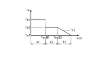
- the range of the battery temperature TmpB which is the temperature of the battery 20, is classified into three regions where the maximum value of the motor torque Tm is different.
- the first region A1 is a region in which the battery temperature TmpB is lower than the switching temperature TmpB1, and in which the first maximum torque Tm1 is defined as the maximum value of the motor torque Tm.
- the second region A2 is a region in which the battery temperature TmpB is equal to or higher than the switching temperature TmpB1 and lower than the limit start temperature TmpB2, and in which the second maximum torque Tm2 smaller than the first maximum torque Tm1 is defined as the maximum value of the motor torque Tm. is there.
- the restriction region A3 is a region where the battery temperature TmpB is equal to or higher than the restriction start temperature TmpB2.
- a temperature equal to or higher than the limit start temperature TmpB2 may be referred to as a limit temperature.
- the restriction region A3 is a region in which a restriction torque Tm3 that is smaller than the second maximum torque Tm2 as the battery temperature TmpB becomes higher than the restriction start temperature TmpB2 is defined.
- the minimum value of the limit torque Tm3 is the minimum limit torque Tm4.
- the engine 11, the clutch 15, the inverter 21, the transmission 16, and the like are controlled by a control device 30 that controls the vehicle 10.
- the control device 30 includes a hybrid ECU 31, an engine ECU 32, an inverter ECU 33, a battery ECU 34, a transmission ECU 35, an information ECU 37, and the like.
- the ECUs 31 to 37 are connected to each other via, for example, a CAN (Control Area Network). .
- the ECUs 31 to 37 are mainly configured by a microcontroller in which a processor, a memory, an input interface, an output interface, and the like are connected to each other via a bus. Each of the ECUs 31 to 37 acquires status information that is information relating to the status of the vehicle 10 via an input interface, and performs various processing based on the acquired status information, a control program and various data stored in a memory. Execute
- the hybrid ECU 31 acquires various state information output from the ECUs 32 to 37 via the input interface. For example, based on a signal from the engine ECU 32, the hybrid ECU 31 acquires the required torque Tdrv, which is the torque required by the driver, and acquires the engine speed Ne, which is the rotation speed of the rotating shaft 13 of the engine 11. That is, the hybrid ECU 31 corresponds to a required torque acquisition unit and a rotation speed acquisition unit.
- the hybrid ECU 31 Based on a signal from the inverter ECU 33, the hybrid ECU 31 calculates a motor rotation speed Nm, which is the rotation speed of the rotating shaft 14 of the M / G 12, a motor temperature TmpM, which is the temperature of the M / G 12, and an inverter temperature, which is the temperature of the inverter 21. Get TmpI. That is, the hybrid ECU 31 corresponds to a temperature acquisition unit. The hybrid ECU 31 acquires the state of charge SOC of the battery 20 in addition to the battery voltage based on the signal from the battery ECU 34 and acquires the battery temperature TmpB, which is the temperature of the battery 20. That is, the hybrid ECU 31 corresponds to a charging rate acquisition unit and a temperature acquisition unit.
- the hybrid ECU 31 acquires the connection / disconnection state of the clutch 15, the gear ratio Rt of the transmission 16, and the like based on a signal from the transmission ECU 35.
- the hybrid ECU 31 acquires the vehicle speed v based on a signal from the information ECU 37. That is, the hybrid ECU 31 corresponds to a vehicle speed acquisition unit.
- the hybrid ECU 31 generates various control signals based on the acquired information, and outputs the generated control signals to the ECUs 32 to 37 via the output interface.
- the hybrid ECU 31 calculates an engine command torque Teref, which is a command torque to the engine 11, and outputs a control signal indicating the calculated engine command torque Teref to the engine ECU 32.
- the hybrid ECU 31 calculates a motor command torque Tmref, which is a command torque for the M / G 12, and outputs a control signal indicating the calculated motor command torque Tmref to the inverter ECU 33.
- the hybrid ECU 31 outputs to the transmission ECU 35 a control signal for instructing connection / disconnection of the clutch 15 and a control signal for instructing the transmission gear ratio Rt in the transmission 16.
- the engine ECU 32 obtains the engine speed Ne and the accelerator operation amount ACC of the accelerator pedal 51, and controls the fuel injection amount and the injection amount so that the torque corresponding to the engine instruction torque Teref input from the hybrid ECU 31 acts on the rotating shaft 13. Control timing, etc.
- the engine ECU 32 calculates the required torque Tdrv based on the accelerator operation amount ACC and the engine speed Ne, and outputs the calculated required torque Tdrv to the hybrid ECU 31.
- the inverter ECU 33 acquires the motor rotation speed Nm, the motor temperature TmpM, and the inverter temperature TmpI, and controls the inverter 21 so that the torque corresponding to the motor instruction torque Tmref input from the hybrid ECU 31 acts on the rotating shaft 14. I do.
- the inverter ECU 33 acquires detection values of a plurality of motor temperature sensors attached to the M / G 12. The highest temperature among the acquired detection values is the motor temperature TmpM.
- the inverter ECU 33 acquires detection values of a plurality of inverter temperature sensors attached to the inverter 21. The highest temperature among the acquired detection values is the inverter temperature TmpI.
- Inverter ECU 33 outputs inverter temperature TmpI to hybrid ECU 31.
- the battery ECU 34 monitors the charge / discharge current of the battery 20 and calculates the state of charge SOC of the battery 20 based on the integrated value of the charge / discharge current.
- the battery ECU 34 acquires the battery voltage and the battery temperature TmpB in addition to the charge / discharge current I of the battery 20.
- the battery ECU 34 acquires detection values of a plurality of battery temperature sensors attached to the battery 20, and outputs the highest temperature among the acquired detection values to the hybrid ECU 31 as the battery temperature TmpB.
- the transmission ECU 35 controls connection and disconnection of the clutch 15 in response to a request for connection and disconnection of the clutch 15 from the hybrid ECU 31. Further, the transmission ECU 35 controls the speed ratio Rt of the transmission 16 based on a control signal indicating the speed ratio Rt from the hybrid ECU 31.
- the information ECU 37 acquires various information based on signals from various sensors which are components of the information acquisition unit 53, and outputs the acquired information to the hybrid ECU 31. For example, the information ECU 37 acquires the vehicle speed v of the vehicle 10 based on a signal from the vehicle speed sensor, and outputs the acquired vehicle speed v to the hybrid ECU 31.
- the hybrid ECU 31 analyzes the state information acquired in the set period T1, and generates a map used for controlling the motor torque Tm in the set period T2 based on the analysis result. Further, the hybrid ECU 31 analyzes the state information acquired in the set period T2, and generates a map used for controlling the motor torque Tm in the set period T3 based on the analyzed result. As described above, when k is an integer equal to or greater than 1, the hybrid ECU 31 generates a map based on the analysis result of the state information acquired in the set period Tk, and uses the generated map to set the map for the set period T (k + 1). The control of the motor torque Tm is performed.
- the setting period Tk can be set according to the use condition of the vehicle and the road environment.
- the set period Tk for a vehicle mainly traveling on a highway such as a large truck used for long-distance transportation may be about several minutes due to a small variation in road environment.
- the set period Tk for a vehicle mainly traveling in an urban area, such as a small truck may be about several tens of seconds due to a large variation in road environment.
- the set period Tk may be a predetermined time or a time that is changed based on an actual traveling state.
- the setting period Tk may be changed so as to be short when the variation in the road environment is large and the change in the accelerator operation amount is large, and to be long when the variation in the road environment is small and the change in the accelerator operation amount is small.
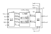
- the hybrid ECU 31 has various functional units that function by executing a program. That is, the hybrid ECU 31 includes a data analysis unit 61, a map update unit 62, and a torque control unit 63.
- the data analysis unit 61 calculates a plurality of feature amounts in the set period Tk based on the state information of the analysis target acquired at a plurality of times in the set period Tk, and outputs analysis result information including the calculated plurality of feature amounts. Output to the map update unit 62.
- the data analysis unit 61 acquires state information to be analyzed, including the required torque Tdrv, the engine speed Ne, the charging current Ic, the state of charge SOC of the battery 20, and the vehicle speed v.
- the data analysis unit 61 calculates the required torque average value Tdave and the required torque variance value Tdvar, which are characteristic amounts, based on the required torque Tdrv, the engine speed Ne, and the vehicle speed v acquired at a plurality of times during the set period Tk. Is calculated.
- the data analysis unit 61 calculates the engine speed average value Neave and the engine speed distribution The value Nevar is calculated.
- the data analysis unit 61 is an amount of power that can be supplied to the battery 20 during the set period T (k + 1) based on the charging current Ic and the state of charge SOC acquired at a plurality of times during the set period Tk. Is calculated.
- the data analysis unit 61 maps the analysis result information including the required torque average value Tdave, the required torque dispersion value Tdvar, the engine speed average value Neave, the engine speed dispersion value Nevar, and the suppliable power amount Pb to the map updating unit 62.
- the map update unit 62 generates a map in which the motor torque Tm is defined according to the required torque Tdrv and the engine speed Ne based on the analysis result information of the data analysis unit 61.
- the map update unit 62 has a first map generation unit 67 that generates a first map M1 (see FIG. 6) that is a map used when the battery temperature TmpB is in the first area A1.
- the map updating unit 62 includes a second map generating unit 69 that generates a second map M2 (see FIG. 7) that is a map used when the battery temperature TmpB is in the second area A2.
- the detailed description of the first map generator 67 and the second map generator 69 will be described later.
- the map updating section 62 outputs the first map M1 generated by the first map generating section 67 and the second map M2 generated by the second map generating section 69 to the torque control section 63.
- the map updating unit 62 updates the first map M1 and the second map M2 by outputting the first map M1 and the second map M2 to the torque control unit 63 for each set period Tk.
- the torque control unit 63 controls the motor torque Tm based on the required torque Tdrv, the battery temperature TmpB, and the first and second maps M1 and M2 generated by the map updating unit 62 for each set period Tk.
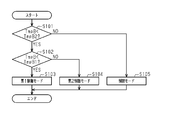
- the torque control unit 63 repeatedly executes a mode selection process for selecting a control mode for controlling the motor torque Tm. Then, the torque control unit 63 calculates the motor torque Tm based on the required torque Tdrv, the engine speed Ne, and the control mode selected in the mode selection processing.
- the torque control unit 63 acquires the battery temperature TmpB, and determines whether or not the acquired battery temperature TmpB is lower than the limit start temperature TmpB2 (step S101). . If the battery temperature TmpB is lower than the limit start temperature TmpB2 (step S101: YES), the torque controller 63 determines whether the battery temperature TmpB is lower than the switching temperature TmpB1 (step S102).
- the torque control unit 63 uses the first map M1 to The first control mode in which the torque Tm is controlled is selected (step S103), and a series of processes is temporarily ended.
- the first control mode is a fuel efficiency priority mode in which the motor torque Tm is controlled with the priority on improving the fuel efficiency regardless of the battery temperature TmpB.
- the torque control unit 63 uses the second map M2 to The second control mode in which the torque Tm is controlled is selected (Step S104), and a series of processes is temporarily ended.
- the second control mode is a balance mode in which the motor torque Tm is controlled so as to improve fuel efficiency while suppressing an increase in the battery temperature TmpB.
- the torque control unit 63 uses the map used for controlling the motor torque Tm based on the switching temperature TmpB1 as the first map M1 and the second map. It is configured to switch to the map M2.
- the limit mode is a temperature priority mode in which the motor torque Tm is controlled with the priority given to suppressing a rise in the battery temperature TmpB.
- the first map M1 corresponding to the first control mode includes, for each position corresponding to the required torque Tdrv equal to or less than the maximum required torque TdrvX and the engine speed Ne equal to or less than the maximum engine speed NeX.
- 5 is a map in which a motor torque Tm equal to or less than a first maximum torque Tm1 is defined.
- an area where a motor torque Tm greater than 0 is defined is an assist area.
- 0 is defined as the motor torque Tm in an area other than the assist area (an area where the engine speed Ne is low and high, and an area where the required torque Tdrv is low and high).
- the engine 11 can be assisted with a high motor torque Tm when the engine 11 is in a state of low combustion efficiency, particularly in an acceleration state.
- the engine 11 can be assisted by the M / G 12 to improve fuel efficiency.
- a relatively high motor torque Tm for example, a motor torque larger than the average value of the motor torque Tm in the assist region, is set in an acceleration region in which the engine 11 is in an acceleration state in the assist region of the first map M1.
- Tm is defined.
- the average value of the motor torque Tm is a value obtained by averaging the motor torque Tm greater than 0. That is, the first map M1 is a map in which the assist area is small and the assist frequency by the M / G 12 is low.
- the torque control unit 63 controls the motor torque Tm to a torque selected from the first map M1 according to the required torque Tdrv and the engine speed Ne.
- the second map M2 corresponding to the second control mode includes, for each position corresponding to the required torque Tdrv equal to or less than the maximum required torque TdrvX and the engine speed Ne equal to or less than the maximum engine speed NeX.
- 4 is a map in which a motor torque Tm equal to or less than a second maximum torque Tm2 smaller than the first maximum torque Tm1 is defined.
- the second map M2 is a map in which the assist area is larger than the first map M1 and the frequency of assist by the M / G 12 is higher.
- the average value and the variance value of the motor torque Tm defined in the acceleration region in the second map M2 are smaller than the average value and the variance value of the motor torque Tm defined in the acceleration region of the first map M1, respectively.
- the second map M2 is a map in which the maximum value of the motor torque Tm is smaller and the assist frequency is higher than the first map M1.
- the torque control unit 63 controls the motor torque Tm to a torque selected from the second map M2 according to the required torque Tdrv and the engine speed Ne.
- the torque control unit 63 controls the motor torque Tm such that the maximum value of the motor torque Tm becomes the limit torque Tm3 according to the battery temperature TmpB.
- the limit torque Tm3 becomes smaller than the second maximum torque Tm2 toward the minimum limit torque Tm4 as the battery temperature TmpB increases.
- the torque control unit 63 controls the motor torque Tm to the limit torque Tm3 when the required torque Tdrv is larger than the limit torque Tm3, and when the required torque Tdrv is equal to or less than the limit torque Tm3, the motor torque is reduced to the required torque Tdrv itself. Control Tm.
- the torque control unit 63 sets the motor torque Tm obtained based on the battery temperature TmpB to the motor instruction torque Tmref, and outputs the motor instruction torque Tmref to the inverter ECU 33. Further, the torque control unit 63 sets the torque obtained by subtracting the motor torque Tm from the required torque Tdrv as the engine instruction torque Teref, and outputs the engine instruction torque Teref to the engine ECU 32.
- the first map generation unit 67 and the second map generation unit 69 will be described with reference to FIGS.
- the first map generation unit 67 has various functional units that function by executing a program. That is, the first map generation unit 67 includes the first ANN unit 71 and the first map construction unit 72.
- the second map generating unit 69 has various functional units that function by executing a program. That is, the second map generation unit 69 has a second ANN unit 73 and a second map construction unit 74.
- the first map generation unit 67 and the second map generation unit 69 have the same basic structure except for the conditions when constructing an ANN (Artificial Neural Network). Therefore, the first map generator 67 will be described in detail, and the detailed description of the second map generator 69 will be omitted.
- ANN Artificial Neural Network
- the first ANN unit 71 and the second ANN unit 73 are constructed based on the result of a preliminary simulation performed before the hybrid ECU 31 is mounted.
- the preliminary simulation is performed by inputting into the simulation device 75 several hundred simulation patterns # 111 to # 1ij (i and j are integers of 1 or more) in which various conditions are set in addition to various constraint conditions.
- the constraint condition is a condition regarding the minimum engine torque of the engine 11, the maximum motor torque of the M / G 12, and the like.
- the simulation patterns # 111 to # 1ij are the torque patterns Tdrv # 1 to Tdrv # i of the required torque Tdrv during the set period Tk, the suppliable power amounts Pb # 1 to Pb # j during the set period Tk, and the maximum of the motor power Pm. Consists of a value.
- the simulation device 75 performs a simulation for each of the simulation patterns # 111 to # 1ij by a dynamic programming method for a vehicle type on which the hybrid ECU 31 is mounted. Then, the simulation device 75 obtains an optimization map that minimizes the fuel consumption for each of the simulation patterns # 111 to # 1ij.
- the optimization map is a map in which the motor torque Tm is defined for each position according to the required torque Tdrv and the engine speed Ne.
- the simulation device 75 is configured such that the maximum value of the motor power Pm is the first maximum power Pm1 and the fuel consumption amount is related to the first ANN unit 71 which is the first neural network unit.
- the simulation is performed under the condition of the minimum without considering the battery temperature TmpB.
- the simulation device 75 generates the first optimization maps M # 111 to M # 1ij for each of the simulation patterns # 111 to # 1ij through such a simulation.
- the motor torque Tm defined in the first optimization maps M # 111 to M # 1ij is equal to or less than the first maximum torque Tm1.
- the feature amounts (the required torque average value Tdave and the required torque variance Tdvar) of the simulation patterns # 111 to # 1ij are obtained.
- the engine speed average value Neave, the engine speed dispersion value Nevar, and the suppliable power amount) are set as inputs, and the first optimization maps M # 111 to M # 1ij are set as outputs, and the first ANN unit 71 is set. Let them learn.
- each node constituting the input layer has an activation function in which the feature amount of the set period Tk is a variable.
- Each node constituting the intermediate layer and the output layer includes an activation function in which a plurality of operation values at a plurality of nodes of a previous layer and a plurality of weight values set at a plurality of connection edges are variables.
- the plurality of nodes constituting the output layer correspond to the first optimization maps M # 111 to M # 1ij, respectively.
- the first optimization maps M # 111 to M # 1ij corresponding to the feature amounts in the simulation patterns # 111 to # 1ij are input to the first ANN unit 71 so that the corresponding nodes are output.
- the activation function and the weight of each connection edge are set.
- the first map builder 72 holds the first optimization maps M # 111 to M # 1ij generated by the simulation device 75. Then, based on the plurality of output values of the first ANN unit 71, the first map construction unit 72 generates a plurality of first optimization maps M # 111 to M # 1ij in which the motor power Pm is allowed to reach the first maximum power Pm1. Is interpolated or extrapolated to construct a first map M1.
- the first map M1 is used to drive the M / G 12 with the motor power Pm equal to or less than the first maximum power Pm1, that is, the motor torque Tm equal to or less than the first maximum torque Tm1.
- the simulation device 75 determines that the maximum value of the motor power Pm The simulation of the plurality of simulation patterns # 111 to # 1ij is performed under the condition of the second maximum power Pm2 smaller than the first maximum power Pm1. Then, the simulation device 75 obtains the second optimization maps M # 211 to M # 2ij for each of the simulation patterns # 111 to # 1ij. In this simulation, for example, a condition for a temperature rise value of the battery temperature TmpB may be provided.
- Examples of such conditions include a condition that the temperature rise value is equal to or less than the difference between the switching temperature TmpB1 and the limit start temperature TmpB2, a condition that the temperature rise value is 30 ° C. or less, and the like. By providing such a condition, an excessive increase in the battery temperature TmpB can be suppressed more reliably.
- the activation function of each node and the second optimization map M # 211 to M # 2ij are output when the feature amounts of the simulation patterns # 111 to # 1ij are input to the second ANN unit 73.
- the weight of each connection edge is set.
- the simulation device 75 sets the first optimization map and the second optimization map such that the assist amount (work amount) by the M / G 12 is the same for the simulation pattern in which the torque pattern and the suppliable electric energy are the same. And can be configured.
- the motor torque Tm in the second optimization maps M # 211 to M # 2ij obtained under the second maximum power Pm2 ( ⁇ Pm1) is equal to or less than the second maximum torque Tm2 smaller than the first maximum torque Tm1. .
- the second optimization maps M # 211 to M # 2ij have a minimum fuel consumption under the condition that the maximum value of the motor power Pm is smaller than the first optimization maps M # 111 to M # 1ij. Map. Therefore, the second optimization maps M # 211 to M # 2ij have a lower degree of freedom in the output of the M / G12 than the first optimization maps M # 111 to M # 1ij, and thus the first optimization map M # 111 This is a map in which the assist frequency is higher than that of M # 1ij.
- the second map construction unit 74 holds the second optimization maps M # 211 to M # 2ij generated by the simulation device 75. Then, based on the plurality of output values of the second ANN unit 73, the second map construction unit 74 generates the second optimization maps M # 211 to M # 211 obtained from the simulation in which the motor power Pm is limited to the second maximum power Pm2.
- a second map M2 is constructed by interpolating or extrapolating M # 2ij.
- the second map M2 drives the M / G 12 with a motor power Pm less than the second maximum power Pm2 smaller than the first maximum power Pm1, that is, a motor torque Tm less than the second maximum torque Tm2 smaller than the first maximum torque Tm1. Used to make The second map M2 is a map that drives the M / G 12 more frequently than the first map M1.
- hybrid ECU 31 having the above-described configuration will be described by taking as an example a case where vehicle 10 travels in the first control mode, the second control mode, and the limit mode during a certain set period Tk. explain.
- the amount of assist output by the M / G 12 per unit time is proportional to the amount of power supplied by the battery 20 to the M / G 12 during the unit time, that is, the current value flowing through the battery 20.
- the heat value of the battery 20 is proportional to the square of the value of the current flowing through the battery 20. Therefore, for example, even if the same amount of power is supplied from the battery 20 to the M / G 12 in the set period Tk, the smaller the proportion of the power supply period in the set period Tk, that is, the motor in the set period Tk.
- the larger the variance of the power Pm the greater the amount of heat generated by the M / G 12 during the set period Tk.
- the first control mode is a control mode in which improvement in fuel efficiency is given top priority, and is performed when the battery temperature TmpB belongs to the first area A1, which is a low temperature area (TmpB ⁇ TmpB1). Selected.
- the hybrid ECU 31 controls the motor torque Tm using the first map M1 with a low assist frequency in which the motor power Pm is allowed to reach the first maximum power Pm1. Therefore, the motor power Pm increases intensively during a period in which the condition that the combustion efficiency of the engine 11 is low is satisfied. That is, the first control mode is a control mode in which the heat generated by the battery 20 is large because the current flowing through the battery 20 during the assist is large, but the M / G 12 can assist the engine 11 most efficiently. .
- the second control mode is a control mode in which fuel efficiency is improved while suppressing an increase in the battery temperature TmpB, and the battery temperature TmpB belongs to the second region A2 which is a medium temperature region.
- the hybrid ECU 31 controls the motor torque Tm using the second map M2 with a high assist frequency in which the motor power Pm is limited to the second maximum power Pm2 ( ⁇ Pm1). Therefore, in the second control mode, the engine 11 is continuously assisted with the motor power Pm equal to or less than the second maximum power Pm2 for a longer period than in the first control mode, and the first control mode shown in FIG.
- the engine 11 is assisted by an amount of work substantially equal to.
- the current flowing through the battery 20 at the time of assist is smaller than in the first control mode, so that the increase in the battery temperature TmpB is suppressed.
- This is a control mode similar to the first control mode.
- the limit mode is a control mode in which the engine 11 is assisted with the priority given to suppressing an increase in the battery temperature TmpB.
- the battery temperature TmpB belongs to the limit region A3 which is a high temperature region. (TmpB2 ⁇ TmpB) is selected.
- the limit mode when the required torque Tdrv is equal to or less than the limited torque Tm3 corresponding to the battery temperature TmpB, the motor power Pm at which the motor torque Tm of the M / G 12 becomes the required torque Tdrv is set.
- the limit mode is a control mode in which the motor torque Tm is limited to the limit torque Tm3 to continuously assist the engine 11 and suppress the rise in the battery temperature TmpB more effectively than in the second control mode.
- the hybrid ECU 31 sets the motor torque Tm in the second control mode in which the maximum value of the motor torque Tm is smaller and the assist frequency is higher than in the first control mode.
- the M / G 12 is driven by the first map M1 based on the result of the simulation in which the motor power Pm is allowed to reach the first maximum power Pm1.
- the M / G 12 is driven by the second map M2 based on the result of the simulation in which the motor power Pm is limited to the second maximum power Pm2 ( ⁇ Pm1) or less.
- the hybrid ECU 31 controls the motor torque Tm in the first control mode in which the fuel efficiency is prioritized when the battery temperature TmpB is in the first region A1, and controls the battery temperature TmpB when the battery temperature TmpB is in the second region A2.
- the motor torque Tm is controlled in the second control mode in which the rise is suppressed and the fuel efficiency is balanced.
- the battery temperature TmpB is easily maintained in a state in which the battery temperature TmpB is lower than the limit start temperature TmpB2, that is, a state in which the motor torque Tm can be controlled to a motor torque Tm corresponding to the running state at that time.
- the motor torque Tm can be controlled to a motor torque Tm corresponding to the running state at that time.
- the service life of the battery 20 can be extended by suppressing an excessive increase in the battery temperature TmpB.
- the torque control unit 63 controls the motor torque Tm to the limit torque Tm3.
- the motor torque Tm can be controlled so as to assist the engine 11 while giving priority to a decrease in the battery temperature TmpB. As a result, it is possible to improve fuel efficiency while more reliably suppressing an excessive increase in the battery temperature TmpB.
- the first map generation unit 67 causes the first map construction unit 72 to perform interpolation or extrapolation of the first optimization maps M # 111 to M # 1ij based on the output value of the first ANN unit 71.
- a first map M1 which is an optimization map based on the feature amounts in the set period Tk immediately before the update is constructed.
- the first map generation unit 67 can generate the first map M1 that is the optimum map according to the feature amount in the setting period Tk immediately before the update. That is, the motor torque Tm can be controlled in the next set period using the first map M1 suitable for the running state in the latest set period. Thereby, it is possible to effectively improve the fuel efficiency in a state where the battery temperature TmpB is lower than the switching temperature TmpB1.
- the first map generation unit 67 uses the hundreds of first optimization maps M # 111 to M # 1ij obtained based on the result of the preliminary simulation to optimize maps corresponding to each of the huge feature amount patterns. Can be generated. Therefore, the first map generation unit 67 only needs to hold the hundreds of these first optimization maps M # 111 to M # 1ij, and holds the optimization maps corresponding to each of the huge feature amount patterns. No need. Therefore, the capacity required for the first map generation unit 67 can be suppressed while enabling generation of optimization maps for various patterns. It is to be noted that such an operation and effect is the same for the second map generation unit 69.
- the hybrid ECU 31 is configured to be able to acquire the motor temperature TmpM and the inverter temperature TmpI in addition to the battery temperature TmpB. In such a configuration, the hybrid ECU 31 controls the motor torque Tm based on the second map M2 even when the motor temperature TmpM exceeds the proper motor temperature or when the inverter temperature TmpI exceeds the proper inverter temperature. Is also good.
- a determination is made on the motor temperature TmpM and the inverter temperature TmpI in addition to the battery temperature TmpB.
- the fuel consumption can be improved while suppressing the excessive rise in the temperature of the M / G 12 and the inverter 21.
- the hybrid ECU 31 may be configured to stop the assist of the engine 11 by the M / G 12 when the battery temperature TmpB is equal to or higher than the limit start temperature TmpB2.
- the hybrid ECU 31 may be configured to switch between the first map M1 and the second map M2 based on the switching temperature TmpB1. Therefore, the hybrid ECU 31 may be configured to hold one or more of each of the first map M1 and the second map M2.
Landscapes
- Engineering & Computer Science (AREA)
- Transportation (AREA)
- Mechanical Engineering (AREA)
- Chemical & Material Sciences (AREA)
- Combustion & Propulsion (AREA)
- Automation & Control Theory (AREA)
- General Chemical & Material Sciences (AREA)
- Manufacturing & Machinery (AREA)
- Electrochemistry (AREA)
- Chemical Kinetics & Catalysis (AREA)
- Power Engineering (AREA)
- Sustainable Energy (AREA)
- Life Sciences & Earth Sciences (AREA)
- Sustainable Development (AREA)
- Human Computer Interaction (AREA)
- Microelectronics & Electronic Packaging (AREA)
- Electric Propulsion And Braking For Vehicles (AREA)
- Hybrid Electric Vehicles (AREA)
- Secondary Cells (AREA)
- Artificial Intelligence (AREA)
- Evolutionary Computation (AREA)
- Physics & Mathematics (AREA)
- Mathematical Physics (AREA)
Abstract
A motor control device that comprises an acquisition part and a torque control part. The torque control part selectively uses one of a first map and a second map to control motor torque. The first map and the second map each prescribe motor torque in accordance with requested torque and engine speed. When a battery temperature is lower than a switching temperature that is lower than a restriction start temperature at which motor torque is restricted, the torque control part uses the first map to control the motor torque. When the battery temperature is at or above the switching temperature but below the restriction start temperature, the torque control part uses the second map to control the motor torque. An assist region of the second map is larger than an assist region of the first map, and the maximum torque prescribed in the assist region of the second map is lower than the maximum torque prescribed in the assist region of the first map.
Description
本開示は、ハイブリッド自動車に搭載されるモーターを制御するモーター制御装置に関する。
The present disclosure relates to a motor control device that controls a motor mounted on a hybrid vehicle.
動力源であるエンジンとモーターとを有するハイブリッド自動車が知られている。ハイブリッド自動車は、発進時といったエンジンの燃焼効率が低いときにモーターを駆動してエンジンをアシストすることにより燃費向上を図ることができる。こうしたモーターに電力を供給するバッテリーは、その温度であるバッテリー温度が過度に高くなると熱劣化が進行しやすくなる。そのため、例えば特許文献1には、バッテリー温度が所定の制限温度以上にあるときにモーターへの供給電力を制限することにより、すなわちモーターの出力を制限することによりバッテリー温度の過度な上昇を抑える技術が開示されている。
A hybrid vehicle having an engine and a motor as power sources is known. In a hybrid vehicle, when the combustion efficiency of the engine is low, such as when starting, the motor is driven to assist the engine to improve fuel efficiency. In a battery that supplies power to such a motor, if the battery temperature, which is the temperature of the battery, becomes excessively high, thermal deterioration tends to proceed. Therefore, for example, Patent Document 1 discloses a technique for suppressing an excessive rise in the battery temperature by limiting the power supplied to the motor when the battery temperature is equal to or higher than a predetermined limit temperature, that is, by limiting the output of the motor. Is disclosed.
特許文献1に記載された技術においては、バッテリー温度の過度な上昇を抑えることができるものの、例えば長い上り坂など、バッテリー温度が放電制限温度に到達しやすくなる状況下における燃費の向上を図るうえで改善の余地が残されている。
In the technique described in Patent Document 1, although an excessive rise in the battery temperature can be suppressed, the fuel efficiency is improved in a situation where the battery temperature easily reaches the discharge limit temperature such as a long uphill. There is still room for improvement.
本開示は、バッテリー温度の過度な上昇を抑えつつ燃費の向上を図ることのできるモーター制御装置を提供することを目的とする。
The present disclosure has an object to provide a motor control device capable of improving fuel efficiency while suppressing an excessive rise in battery temperature.
本開示の一態様によれば、モーターを制御するように構成されたモーター制御装置が提供される。前記モーターは、バッテリーから電力を供給されて、エンジンをアシストするように構成される。前記モーター制御装置は、前記バッテリーの温度であるバッテリー温度、ドライバーから要求されるトルクである要求トルク、および、前記エンジンの回転数であるエンジン回転数を取得するように構成された取得部と、第1マップおよび第2マップの一方を選択的に用いて前記モーターの出力するモータートルクを制御するように構成されたトルク制御部であって、前記第1マップおよび前記第2マップの各々は、前記モータートルクを前記要求トルクと前記エンジン回転数とに応じて規定する、トルク制御部とを備え、前記トルク制御部は、前記モータートルクが制限される制限開始温度よりも低い切替温度未満に前記バッテリー温度がある場合に前記第1マップを用いて前記モータートルクを制御し、前記切替温度以上前記制限開始温度未満に前記バッテリー温度がある場合に前記第2マップを用いて前記モータートルクを制御する、ように構成され、前記第1マップおよび前記第2マップの各々は、前記要求トルクと前記エンジン回転数とに基づいて定まるアシスト領域を有し、前記第2マップの前記アシスト領域は前記第1マップの前記アシスト領域よりも大きく、かつ、前記第2マップの前記アシスト領域に規定された最大トルクが前記第1マップの前記アシスト領域に規定された最大トルクよりも小さい。
According to one embodiment of the present disclosure, there is provided a motor control device configured to control a motor. The motor is configured to be powered by a battery and assist the engine. The motor control device, a battery temperature that is the temperature of the battery, a required torque that is a torque required by a driver, and an acquisition unit configured to acquire an engine speed that is the engine speed, A torque control unit configured to control a motor torque output by the motor by selectively using one of a first map and a second map, wherein each of the first map and the second map includes: A torque control unit that regulates the motor torque according to the required torque and the engine speed, wherein the torque control unit sets the motor torque below a switching temperature lower than a limit start temperature at which the motor torque is limited. When there is a battery temperature, the motor torque is controlled using the first map, and the limit start temperature is equal to or higher than the switching temperature. And controlling the motor torque using the second map when the battery temperature is less than or equal to, the first map and the second map each include the required torque, the engine speed, The assist area of the second map is larger than the assist area of the first map, and the maximum torque defined in the assist area of the second map is equal to the second torque. It is smaller than the maximum torque defined in the assist area of one map.
図面を参照して、一実施形態に係るモーター制御装置について説明する。
図1に示すように、ハイブリッド自動車である車両10は、動力源であるエンジン11とモータージェネレーター(以下、M/Gという)12とを備えている。エンジン11の回転軸13とM/G12の回転軸14とは、クラッチ15で断接可能に接続されている。M/G12の回転軸14は、トランスミッション16および駆動軸17などを介して駆動輪18に接続されている。 A motor control device according to one embodiment will be described with reference to the drawings.
As shown in FIG. 1, avehicle 10 that is a hybrid vehicle includes an engine 11 as a power source and a motor generator (hereinafter, referred to as M / G) 12. The rotating shaft 13 of the engine 11 and the rotating shaft 14 of the M / G 12 are connected to each other by a clutch 15 so as to be connectable and disconnectable. The rotating shaft 14 of the M / G 12 is connected to driving wheels 18 via a transmission 16 and a driving shaft 17.
図1に示すように、ハイブリッド自動車である車両10は、動力源であるエンジン11とモータージェネレーター(以下、M/Gという)12とを備えている。エンジン11の回転軸13とM/G12の回転軸14とは、クラッチ15で断接可能に接続されている。M/G12の回転軸14は、トランスミッション16および駆動軸17などを介して駆動輪18に接続されている。 A motor control device according to one embodiment will be described with reference to the drawings.
As shown in FIG. 1, a
エンジン11は、例えば複数の気筒を有するディーゼルエンジンであり、各気筒において燃料が燃焼することにより回転軸13を回転させるトルクを発生させる。エンジン11が発生させたトルクは、クラッチ15が接続状態にあるときに、M/G12の回転軸14、トランスミッション16、および、駆動軸17を介して駆動輪18に伝達される。
The engine 11 is, for example, a diesel engine having a plurality of cylinders, and generates torque for rotating the rotating shaft 13 by burning fuel in each cylinder. The torque generated by the engine 11 is transmitted to the drive wheels 18 via the rotating shaft 14 of the M / G 12, the transmission 16, and the drive shaft 17 when the clutch 15 is in the engaged state.
M/G12は、インバーター21を介してバッテリー20に電気的に接続されている。バッテリー20は、充放電可能な二次電池であり、互いに電気的に接続された複数のセルで構成されている。M/G12は、バッテリー20に蓄電された電力がインバーター21を介して供給されることにより、回転軸14を回転させてエンジン11をアシストするモーターとして機能する。M/G12がモーターとして機能する際に発生させるモータートルクTmは、トランスミッション16および駆動軸17を介して駆動輪18に伝達される。また、M/G12は、例えばアクセルオフ時における回転軸14の回転を利用して発電した電力をインバーター21を介してバッテリー20に蓄電するジェネレーターとして機能する。M/G12がジェネレーターとして機能する際に発生させる制動トルクである回生トルクTrは、モーター回転数Nmごとに設定された最大回生トルクTrmax以下の範囲において制御可能である。
The M / G 12 is electrically connected to the battery 20 via the inverter 21. The battery 20 is a chargeable / dischargeable secondary battery, and includes a plurality of cells electrically connected to each other. The M / G 12 functions as a motor that assists the engine 11 by rotating the rotating shaft 14 by supplying the power stored in the battery 20 via the inverter 21. Motor torque Tm generated when M / G 12 functions as a motor is transmitted to drive wheels 18 via transmission 16 and drive shaft 17. Further, the M / G 12 functions as a generator that stores the power generated using the rotation of the rotating shaft 14 when the accelerator is off in the battery 20 via the inverter 21, for example. The regenerative torque Tr, which is a braking torque generated when the M / G 12 functions as a generator, can be controlled in a range equal to or less than a maximum regenerative torque Trmax set for each motor rotation speed Nm.
トランスミッション16は、M/G12の回転軸14が有するトルクを変速し、その変速したトルクを駆動軸17を介して駆動輪18に伝達する。トランスミッション16は、複数の変速比Rtを設定可能に構成されている。
The transmission 16 changes the torque of the rotating shaft 14 of the M / G 12 and transmits the changed torque to the driving wheels 18 via the driving shaft 17. The transmission 16 is configured so that a plurality of speed ratios Rt can be set.
インバーター21は、M/G12をモーターとして機能させる場合、バッテリー20からの直流電圧を交流電圧に変換してM/G12に電力を供給する。また、インバーター21は、M/G12をジェネレーターとして機能させる場合、M/G12からの交流電圧を直流電圧に変換してバッテリー20に供給し、バッテリー20を充電する。
When the M / G 12 functions as a motor, the inverter 21 converts a DC voltage from the battery 20 into an AC voltage and supplies power to the M / G 12. When the M / G 12 functions as a generator, the inverter 21 converts an AC voltage from the M / G 12 into a DC voltage, supplies the DC voltage to the battery 20, and charges the battery 20.
車両10は、高圧系部品である、これらM/G12、インバーター21、および、バッテリー20を有する高圧電気回路25を含む。以下では、インバーター21からM/G12に電力が供給されているときにバッテリー20に流れる電流を放電電流といい、インバーター21からバッテリー20に電力が供給されているときにバッテリー20に流れる電流を充電電流という。
The vehicle 10 includes the M / G 12, the inverter 21, and the high-voltage electric circuit 25 having the battery 20, which are high-voltage components. Hereinafter, a current flowing through the battery 20 when power is supplied from the inverter 21 to the M / G 12 is referred to as a discharge current, and a current flowing through the battery 20 when power is supplied from the inverter 21 to the battery 20 is charged. It is called current.
また、図2に示すように、バッテリー20は、その温度であるバッテリー温度TmpBの範囲は、モータートルクTmの最大値が異なる3つの領域に分類される。第1領域A1は、バッテリー温度TmpBが切替温度TmpB1未満の領域であり、モータートルクTmの最大値として第1最大トルクTm1が規定される領域である。第2領域A2は、バッテリー温度TmpBが切替温度TmpB1以上制限開始温度TmpB2未満の領域であり、モータートルクTmの最大値として第1最大トルクTm1よりも小さい第2最大トルクTm2が規定される領域である。制限領域A3は、バッテリー温度TmpBが制限開始温度TmpB2以上の領域である。制限開始温度TmpB2以上の温度は、制限温度と称され得る。制限領域A3は、制限開始温度TmpB2よりもバッテリー温度TmpBが高くなるほど第2最大トルクTm2よりも小さくなる制限トルクTm3が規定される領域である。制限トルクTm3の最小値は、最低制限トルクTm4である。
As shown in FIG. 2, the range of the battery temperature TmpB, which is the temperature of the battery 20, is classified into three regions where the maximum value of the motor torque Tm is different. The first region A1 is a region in which the battery temperature TmpB is lower than the switching temperature TmpB1, and in which the first maximum torque Tm1 is defined as the maximum value of the motor torque Tm. The second region A2 is a region in which the battery temperature TmpB is equal to or higher than the switching temperature TmpB1 and lower than the limit start temperature TmpB2, and in which the second maximum torque Tm2 smaller than the first maximum torque Tm1 is defined as the maximum value of the motor torque Tm. is there. The restriction region A3 is a region where the battery temperature TmpB is equal to or higher than the restriction start temperature TmpB2. A temperature equal to or higher than the limit start temperature TmpB2 may be referred to as a limit temperature. The restriction region A3 is a region in which a restriction torque Tm3 that is smaller than the second maximum torque Tm2 as the battery temperature TmpB becomes higher than the restriction start temperature TmpB2 is defined. The minimum value of the limit torque Tm3 is the minimum limit torque Tm4.
上述したエンジン11、クラッチ15、インバーター21、および、トランスミッション16などは、車両10を統括制御する制御装置30によって制御される。
制御装置30は、ハイブリッドECU31、エンジンECU32、インバーターECU33、バッテリーECU34、トランスミッションECU35、情報ECU37などで構成されており、各ECU31~37は、例えばCAN(Control Area Network)を介して互いに接続されている。 Theengine 11, the clutch 15, the inverter 21, the transmission 16, and the like are controlled by a control device 30 that controls the vehicle 10.
Thecontrol device 30 includes a hybrid ECU 31, an engine ECU 32, an inverter ECU 33, a battery ECU 34, a transmission ECU 35, an information ECU 37, and the like. The ECUs 31 to 37 are connected to each other via, for example, a CAN (Control Area Network). .
制御装置30は、ハイブリッドECU31、エンジンECU32、インバーターECU33、バッテリーECU34、トランスミッションECU35、情報ECU37などで構成されており、各ECU31~37は、例えばCAN(Control Area Network)を介して互いに接続されている。 The
The
各ECU(Electronic Control Unit)31~37は、プロセッサ、メモリ、入力インターフェース、および、出力インターフェース等がバスを介して互いに接続されたマイクロコントローラーを中心に構成されている。各ECU31~37は、車両10の状態に関する情報である状態情報を入力インターフェースを介して取得し、その取得した状態情報、および、メモリに格納された制御プログラムや各種のデータに基づいて各種の処理を実行する。
The ECUs (Electronic Control Units) 31 to 37 are mainly configured by a microcontroller in which a processor, a memory, an input interface, an output interface, and the like are connected to each other via a bus. Each of the ECUs 31 to 37 acquires status information that is information relating to the status of the vehicle 10 via an input interface, and performs various processing based on the acquired status information, a control program and various data stored in a memory. Execute
ハイブリッドECU31は、各ECU32~37が出力した各種の状態情報を入力インターフェースを介して取得する。例えば、ハイブリッドECU31は、エンジンECU32からの信号に基づき、ドライバーから要求されるトルクである要求トルクTdrvを取得するとともにエンジン11の回転軸13の回転数であるエンジン回転数Neを取得する。すなわち、ハイブリッドECU31は、要求トルク取得部および回転数取得部に相当する。ハイブリッドECU31は、インバーターECU33からの信号に基づき、M/G12の回転軸14の回転数であるモーター回転数Nmのほか、M/G12の温度であるモーター温度TmpMおよびインバーター21の温度であるインバーター温度TmpIを取得する。すなわち、ハイブリッドECU31は、温度取得部に相当する。ハイブリッドECU31は、バッテリーECU34からの信号に基づき、バッテリー電圧のほか、バッテリー20の充電率SOCを取得するとともにバッテリー20の温度であるバッテリー温度TmpBを取得する。すなわち、ハイブリッドECU31は、充電率取得部および温度取得部に相当する。ハイブリッドECU31は、トランスミッションECU35からの信号に基づき、クラッチ15の断接状態、トランスミッション16における変速比Rtなどを取得する。ハイブリッドECU31は、情報ECU37からの信号に基づき、車速vを取得する。すなわち、ハイブリッドECU31は、車速取得部に相当する。
The hybrid ECU 31 acquires various state information output from the ECUs 32 to 37 via the input interface. For example, based on a signal from the engine ECU 32, the hybrid ECU 31 acquires the required torque Tdrv, which is the torque required by the driver, and acquires the engine speed Ne, which is the rotation speed of the rotating shaft 13 of the engine 11. That is, the hybrid ECU 31 corresponds to a required torque acquisition unit and a rotation speed acquisition unit. Based on a signal from the inverter ECU 33, the hybrid ECU 31 calculates a motor rotation speed Nm, which is the rotation speed of the rotating shaft 14 of the M / G 12, a motor temperature TmpM, which is the temperature of the M / G 12, and an inverter temperature, which is the temperature of the inverter 21. Get TmpI. That is, the hybrid ECU 31 corresponds to a temperature acquisition unit. The hybrid ECU 31 acquires the state of charge SOC of the battery 20 in addition to the battery voltage based on the signal from the battery ECU 34 and acquires the battery temperature TmpB, which is the temperature of the battery 20. That is, the hybrid ECU 31 corresponds to a charging rate acquisition unit and a temperature acquisition unit. The hybrid ECU 31 acquires the connection / disconnection state of the clutch 15, the gear ratio Rt of the transmission 16, and the like based on a signal from the transmission ECU 35. The hybrid ECU 31 acquires the vehicle speed v based on a signal from the information ECU 37. That is, the hybrid ECU 31 corresponds to a vehicle speed acquisition unit.
ハイブリッドECU31は、取得した情報に基づいて各種制御信号を生成し、その生成した制御信号を出力インターフェースを介して各ECU32~37に出力する。ハイブリッドECU31は、エンジン11への指示トルクであるエンジン指示トルクTerefを演算し、その演算したエンジン指示トルクTerefを示す制御信号をエンジンECU32に出力する。ハイブリッドECU31は、M/G12に対する指示トルクであるモーター指示トルクTmrefを演算し、その演算したモーター指示トルクTmrefを示す制御信号をインバーターECU33に出力する。ハイブリッドECU31は、クラッチ15の断接を指示する制御信号、および、トランスミッション16における変速比Rtを指示する制御信号をトランスミッションECU35に出力する。
The hybrid ECU 31 generates various control signals based on the acquired information, and outputs the generated control signals to the ECUs 32 to 37 via the output interface. The hybrid ECU 31 calculates an engine command torque Teref, which is a command torque to the engine 11, and outputs a control signal indicating the calculated engine command torque Teref to the engine ECU 32. The hybrid ECU 31 calculates a motor command torque Tmref, which is a command torque for the M / G 12, and outputs a control signal indicating the calculated motor command torque Tmref to the inverter ECU 33. The hybrid ECU 31 outputs to the transmission ECU 35 a control signal for instructing connection / disconnection of the clutch 15 and a control signal for instructing the transmission gear ratio Rt in the transmission 16.
エンジンECU32は、エンジン回転数Neおよびアクセルペダル51のアクセル操作量ACCを取得するとともに、ハイブリッドECU31から入力されたエンジン指示トルクTerefの分のトルクが回転軸13に作用するように燃料噴射量や噴射タイミングなどを制御する。エンジンECU32は、アクセル操作量ACCおよびエンジン回転数Neなどに基づいて要求トルクTdrvを演算し、その演算した要求トルクTdrvをハイブリッドECU31に出力する。
The engine ECU 32 obtains the engine speed Ne and the accelerator operation amount ACC of the accelerator pedal 51, and controls the fuel injection amount and the injection amount so that the torque corresponding to the engine instruction torque Teref input from the hybrid ECU 31 acts on the rotating shaft 13. Control timing, etc. The engine ECU 32 calculates the required torque Tdrv based on the accelerator operation amount ACC and the engine speed Ne, and outputs the calculated required torque Tdrv to the hybrid ECU 31.
インバーターECU33は、モーター回転数Nm、モーター温度TmpM、および、インバーター温度TmpIを取得するとともに、ハイブリッドECU31から入力されたモーター指示トルクTmrefの分のトルクが回転軸14に作用するようにインバーター21を制御する。インバーターECU33は、M/G12に取り付けられた複数のモーター温度センサーの検出値を取得する。その取得した検出値のうちで最も高い温度がモーター温度TmpMである。インバーターECU33は、インバーター21に取り付けられた複数のインバーター温度センサーの検出値を取得する。その取得した検出値のうちで最も高い温度がインバーター温度TmpIである。インバーターECU33は、インバーター温度TmpIをハイブリッドECU31に出力する。
The inverter ECU 33 acquires the motor rotation speed Nm, the motor temperature TmpM, and the inverter temperature TmpI, and controls the inverter 21 so that the torque corresponding to the motor instruction torque Tmref input from the hybrid ECU 31 acts on the rotating shaft 14. I do. The inverter ECU 33 acquires detection values of a plurality of motor temperature sensors attached to the M / G 12. The highest temperature among the acquired detection values is the motor temperature TmpM. The inverter ECU 33 acquires detection values of a plurality of inverter temperature sensors attached to the inverter 21. The highest temperature among the acquired detection values is the inverter temperature TmpI. Inverter ECU 33 outputs inverter temperature TmpI to hybrid ECU 31.
バッテリーECU34は、バッテリー20の充放電電流を監視し、該充放電電流の積算値に基づいてバッテリー20の充電率SOCを演算する。バッテリーECU34は、バッテリー20の充放電電流Iのほか、バッテリー電圧やバッテリー温度TmpBを取得する。バッテリーECU34は、バッテリー20に取り付けられた複数のバッテリー温度センサーの検出値を取得し、その取得した検出値のうちで最も高い温度をバッテリー温度TmpBとしてハイブリッドECU31に出力する。
The battery ECU 34 monitors the charge / discharge current of the battery 20 and calculates the state of charge SOC of the battery 20 based on the integrated value of the charge / discharge current. The battery ECU 34 acquires the battery voltage and the battery temperature TmpB in addition to the charge / discharge current I of the battery 20. The battery ECU 34 acquires detection values of a plurality of battery temperature sensors attached to the battery 20, and outputs the highest temperature among the acquired detection values to the hybrid ECU 31 as the battery temperature TmpB.
トランスミッションECU35は、ハイブリッドECU31からのクラッチ15の断接要求に応じてクラッチ15の断接を制御する。また、トランスミッションECU35は、ハイブリッドECU31からの変速比Rtを示す制御信号に基づいてトランスミッション16の変速比Rtを制御する。
The transmission ECU 35 controls connection and disconnection of the clutch 15 in response to a request for connection and disconnection of the clutch 15 from the hybrid ECU 31. Further, the transmission ECU 35 controls the speed ratio Rt of the transmission 16 based on a control signal indicating the speed ratio Rt from the hybrid ECU 31.
情報ECU37は、情報取得部53の構成要素である各種センサーからの信号に基づいて各種情報を取得し、その取得した情報をハイブリッドECU31に出力する。例えば、情報ECU37は、車速センサーからの信号に基づく車両10の車速vを取得し、その取得した車速vをハイブリッドECU31に出力する。
The information ECU 37 acquires various information based on signals from various sensors which are components of the information acquisition unit 53, and outputs the acquired information to the hybrid ECU 31. For example, the information ECU 37 acquires the vehicle speed v of the vehicle 10 based on a signal from the vehicle speed sensor, and outputs the acquired vehicle speed v to the hybrid ECU 31.
図3~図4を参照して、ハイブリッドECU31によるモータートルクTmの制御態様の概要について説明する。まず、図3を参照して、ハイブリッドECU31が実行するモータートルクTmの制御に関する基本的な概念について説明する。
With reference to FIGS. 3 and 4, an outline of a control mode of the motor torque Tm by the hybrid ECU 31 will be described. First, with reference to FIG. 3, a basic concept regarding control of motor torque Tm executed by hybrid ECU 31 will be described.
図3に示すように、ハイブリッドECU31は、設定期間T1にて取得した状態情報を解析し、その解析結果に基づいて設定期間T2でのモータートルクTmの制御に用いるマップを生成する。また、ハイブリッドECU31は、設定期間T2にて取得した状態情報を解析し、その解析した結果に基づいて設定期間T3でのモータートルクTmの制御に用いるマップを生成する。このようにハイブリッドECU31は、kを1以上の整数とするとき、設定期間Tkにて取得した状態情報の解析結果に基づいてマップを生成し、その生成したマップを用いて設定期間T(k+1)でのモータートルクTmの制御を行う。
As shown in FIG. 3, the hybrid ECU 31 analyzes the state information acquired in the set period T1, and generates a map used for controlling the motor torque Tm in the set period T2 based on the analysis result. Further, the hybrid ECU 31 analyzes the state information acquired in the set period T2, and generates a map used for controlling the motor torque Tm in the set period T3 based on the analyzed result. As described above, when k is an integer equal to or greater than 1, the hybrid ECU 31 generates a map based on the analysis result of the state information acquired in the set period Tk, and uses the generated map to set the map for the set period T (k + 1). The control of the motor torque Tm is performed.
なお、この設定期間Tkは、車両の使用状況および道路の環境に応じて設定され得る。例えば、長距離輸送に用いられる大型の貨物自動車など、高速道路を主に走行する車両についての設定期間Tkは、道路環境のばらつきが小さいため数分程度であってもよい。また例えば、小型の貨物自動車など、市街地を主に走行する車両についての設定期間Tkは、道路環境のばらつきが大きいため数十秒程度であってもよい。また、設定期間Tkは、予め定めた時間であってもよいし、実際の走行状態に基づいて変更される時間であってもよい。例えば、設定期間Tkは、道路環境のばらつきが大きくアクセル操作量の変化が大きい場合は短く、道路環境のばらつきが小さくアクセル操作量の変化が小さい場合は長くなるように変更されてもよい。
The setting period Tk can be set according to the use condition of the vehicle and the road environment. For example, the set period Tk for a vehicle mainly traveling on a highway such as a large truck used for long-distance transportation may be about several minutes due to a small variation in road environment. Further, for example, the set period Tk for a vehicle mainly traveling in an urban area, such as a small truck, may be about several tens of seconds due to a large variation in road environment. Further, the set period Tk may be a predetermined time or a time that is changed based on an actual traveling state. For example, the setting period Tk may be changed so as to be short when the variation in the road environment is large and the change in the accelerator operation amount is large, and to be long when the variation in the road environment is small and the change in the accelerator operation amount is small.
図4に示すように、モータートルクTmの制御に関し、ハイブリッドECU31は、プログラムの実行により機能する各種機能部を有する。すなわち、ハイブリッドECU31は、データ解析部61、マップ更新部62、および、トルク制御部63を有している。
As shown in FIG. 4, regarding the control of the motor torque Tm, the hybrid ECU 31 has various functional units that function by executing a program. That is, the hybrid ECU 31 includes a data analysis unit 61, a map update unit 62, and a torque control unit 63.
データ解析部61は、設定期間Tkにおける複数の時刻に取得した解析対象の状態情報に基づいて当該設定期間Tkにおける複数の特徴量を演算し、その演算した複数の特徴量を含む解析結果情報をマップ更新部62に出力する。
The data analysis unit 61 calculates a plurality of feature amounts in the set period Tk based on the state information of the analysis target acquired at a plurality of times in the set period Tk, and outputs analysis result information including the calculated plurality of feature amounts. Output to the map update unit 62.
データ解析部61は、要求トルクTdrv、エンジン回転数Ne、充電電流Ic、バッテリー20の充電率SOC、および、車速vを含む、解析対象の状態情報を取得する。データ解析部61は、設定期間Tkにおける複数の時刻にて取得した要求トルクTdrv、エンジン回転数Ne、および、車速vに基づいて、特徴量である、要求トルク平均値Tdaveと要求トルク分散値Tdvarとを演算する。データ解析部61は、設定期間Tkにおける複数の時刻にて取得したエンジン回転数Ne、要求トルクTdrv、および、車速vに基づいて、特徴量である、エンジン回転数平均値Neaveとエンジン回転数分散値Nevarとを演算する。データ解析部61は、設定期間Tkにおける複数の時刻にて取得した充電電流Icと充電率SOCとに基づいて、設定期間T(k+1)にてバッテリー20に供給可能な電力量であり、特徴量である、供給可能電力量Pbを演算する。データ解析部61は、これら要求トルク平均値Tdave、要求トルク分散値Tdvar、エンジン回転数平均値Neave、エンジン回転数分散値Nevar、および、供給可能電力量Pbを含む解析結果情報をマップ更新部62に出力する。
The data analysis unit 61 acquires state information to be analyzed, including the required torque Tdrv, the engine speed Ne, the charging current Ic, the state of charge SOC of the battery 20, and the vehicle speed v. The data analysis unit 61 calculates the required torque average value Tdave and the required torque variance value Tdvar, which are characteristic amounts, based on the required torque Tdrv, the engine speed Ne, and the vehicle speed v acquired at a plurality of times during the set period Tk. Is calculated. Based on the engine speed Ne, the required torque Tdrv, and the vehicle speed v acquired at a plurality of times during the set period Tk, the data analysis unit 61 calculates the engine speed average value Neave and the engine speed distribution The value Nevar is calculated. The data analysis unit 61 is an amount of power that can be supplied to the battery 20 during the set period T (k + 1) based on the charging current Ic and the state of charge SOC acquired at a plurality of times during the set period Tk. Is calculated. The data analysis unit 61 maps the analysis result information including the required torque average value Tdave, the required torque dispersion value Tdvar, the engine speed average value Neave, the engine speed dispersion value Nevar, and the suppliable power amount Pb to the map updating unit 62. Output to
マップ更新部62は、データ解析部61の解析結果情報に基づき、要求トルクTdrvとエンジン回転数Neとに応じてモータートルクTmが規定されるマップを生成する。
マップ更新部62は、バッテリー温度TmpBが第1領域A1にあるときに使用されるマップである第1マップM1(図6参照)を生成する第1マップ生成部67を有している。また、マップ更新部62は、バッテリー温度TmpBが第2領域A2にあるときに使用されるマップである第2マップM2(図7参照)を生成する第2マップ生成部69を有している。第1マップ生成部67および第2マップ生成部69についての詳しい説明は後述する。マップ更新部62は、第1マップ生成部67が生成した第1マップM1と第2マップ生成部69が生成した第2マップM2とをトルク制御部63に出力する。マップ更新部62は、こうした第1マップM1および第2マップM2を設定期間Tkごとにトルク制御部63に出力することにより第1マップM1および第2マップM2を更新する。 Themap update unit 62 generates a map in which the motor torque Tm is defined according to the required torque Tdrv and the engine speed Ne based on the analysis result information of the data analysis unit 61.
Themap update unit 62 has a first map generation unit 67 that generates a first map M1 (see FIG. 6) that is a map used when the battery temperature TmpB is in the first area A1. In addition, the map updating unit 62 includes a second map generating unit 69 that generates a second map M2 (see FIG. 7) that is a map used when the battery temperature TmpB is in the second area A2. The detailed description of the first map generator 67 and the second map generator 69 will be described later. The map updating section 62 outputs the first map M1 generated by the first map generating section 67 and the second map M2 generated by the second map generating section 69 to the torque control section 63. The map updating unit 62 updates the first map M1 and the second map M2 by outputting the first map M1 and the second map M2 to the torque control unit 63 for each set period Tk.
マップ更新部62は、バッテリー温度TmpBが第1領域A1にあるときに使用されるマップである第1マップM1(図6参照)を生成する第1マップ生成部67を有している。また、マップ更新部62は、バッテリー温度TmpBが第2領域A2にあるときに使用されるマップである第2マップM2(図7参照)を生成する第2マップ生成部69を有している。第1マップ生成部67および第2マップ生成部69についての詳しい説明は後述する。マップ更新部62は、第1マップ生成部67が生成した第1マップM1と第2マップ生成部69が生成した第2マップM2とをトルク制御部63に出力する。マップ更新部62は、こうした第1マップM1および第2マップM2を設定期間Tkごとにトルク制御部63に出力することにより第1マップM1および第2マップM2を更新する。 The
The
トルク制御部63は、要求トルクTdrv、バッテリー温度TmpB、ならびに、設定期間Tkごとにマップ更新部62が生成した第1および第2マップM1,M2などに基づいてモータートルクTmを制御する。
The torque control unit 63 controls the motor torque Tm based on the required torque Tdrv, the battery temperature TmpB, and the first and second maps M1 and M2 generated by the map updating unit 62 for each set period Tk.
図5~図7を参照して、トルク制御部63によるモータートルクTmの制御態様について説明する。トルク制御部63は、モータートルクTmを制御する制御モードを選択するモード選択処理を繰り返し実行する。そしてトルク制御部63は、要求トルクTdrv、エンジン回転数Ne、および、モード選択処理で選択した制御モードに基づいてモータートルクTmを演算する。
With reference to FIGS. 5 to 7, a description will be given of a control mode of the motor torque Tm by the torque control unit 63. The torque control unit 63 repeatedly executes a mode selection process for selecting a control mode for controlling the motor torque Tm. Then, the torque control unit 63 calculates the motor torque Tm based on the required torque Tdrv, the engine speed Ne, and the control mode selected in the mode selection processing.
図5に示すように、制御モード選択処理にてトルク制御部63は、バッテリー温度TmpBを取得し、その取得したバッテリー温度TmpBが制限開始温度TmpB2未満であるか否かを判断する(ステップS101)。バッテリー温度TmpBが制限開始温度TmpB2未満である場合(ステップS101:YES)、トルク制御部63は、バッテリー温度TmpBが切替温度TmpB1未満であるか否かを判断する(ステップS102)。
As shown in FIG. 5, in the control mode selection process, the torque control unit 63 acquires the battery temperature TmpB, and determines whether or not the acquired battery temperature TmpB is lower than the limit start temperature TmpB2 (step S101). . If the battery temperature TmpB is lower than the limit start temperature TmpB2 (step S101: YES), the torque controller 63 determines whether the battery temperature TmpB is lower than the switching temperature TmpB1 (step S102).
バッテリー温度TmpBが切替温度TmpB1未満である場合(ステップS102:YES)、すなわちバッテリー温度TmpBが第1領域A1(図2参照)に属する場合、トルク制御部63は、第1マップM1を用いてモータートルクTmが制御される第1制御モードを選択して(ステップS103)一連の処理を一旦終了する。第1制御モードは、バッテリー温度TmpBにかかわらず燃費の向上を最優先にしてモータートルクTmが制御される燃費優先モードである。
When the battery temperature TmpB is lower than the switching temperature TmpB1 (step S102: YES), that is, when the battery temperature TmpB belongs to the first area A1 (see FIG. 2), the torque control unit 63 uses the first map M1 to The first control mode in which the torque Tm is controlled is selected (step S103), and a series of processes is temporarily ended. The first control mode is a fuel efficiency priority mode in which the motor torque Tm is controlled with the priority on improving the fuel efficiency regardless of the battery temperature TmpB.
バッテリー温度TmpBが切替温度TmpB1以上である場合(ステップS102:NO)、すなわちバッテリー温度TmpBが第2領域A2(図2参照)に属する場合、トルク制御部63は、第2マップM2を用いてモータートルクTmが制御される第2制御モードを選択して(ステップS104)一連の処理を一旦終了する。第2制御モードは、バッテリー温度TmpBの上昇を抑えつつも燃費の向上が図られるようにモータートルクTmが制御されるバランスモードである。このようにトルク制御部63は、バッテリー温度TmpBが制限開始温度TmpB2未満である場合(ステップS101:YES)、切替温度TmpB1を基準としてモータートルクTmの制御に用いるマップを第1マップM1と第2マップM2とに切り替えるように構成されている。
When the battery temperature TmpB is equal to or higher than the switching temperature TmpB1 (step S102: NO), that is, when the battery temperature TmpB belongs to the second region A2 (see FIG. 2), the torque control unit 63 uses the second map M2 to The second control mode in which the torque Tm is controlled is selected (Step S104), and a series of processes is temporarily ended. The second control mode is a balance mode in which the motor torque Tm is controlled so as to improve fuel efficiency while suppressing an increase in the battery temperature TmpB. As described above, when the battery temperature TmpB is lower than the limit start temperature TmpB2 (step S101: YES), the torque control unit 63 uses the map used for controlling the motor torque Tm based on the switching temperature TmpB1 as the first map M1 and the second map. It is configured to switch to the map M2.
バッテリー温度TmpBが制限開始温度TmpB2以上である場合(ステップS101:NO)、すなわちバッテリー温度TmpBが制限領域A3(図2参照)に属する場合、ハイブリッドECU31は、制限モードを選択して(ステップS105)一連の処理を一旦終了する。制限モードは、バッテリー温度TmpBの上昇を抑えることを最優先としてモータートルクTmが制御される温度優先モードである。
If the battery temperature TmpB is equal to or higher than the restriction start temperature TmpB2 (step S101: NO), that is, if the battery temperature TmpB belongs to the restriction area A3 (see FIG. 2), the hybrid ECU 31 selects the restriction mode (step S105). A series of processing is once ended. The limit mode is a temperature priority mode in which the motor torque Tm is controlled with the priority given to suppressing a rise in the battery temperature TmpB.
図6に示すように、第1制御モードに対応する第1マップM1は、最大要求トルクTdrvX以下の要求トルクTdrvと最大エンジン回転数NeX以下のエンジン回転数Neとに応じた各位置に対して第1最大トルクTm1以下のモータートルクTmが規定されるマップである。第1マップM1において、0よりも大きいモータートルクTmが規定された領域がアシスト領域である。第1マップM1は、アシスト領域以外の領域(エンジン回転数Neが低い領域および高い領域、ならびに、要求トルクTdrvが低い領域および高い領域)にモータートルクTmとして0が規定される。また、エンジン11が燃焼効率の低い状態、とくに加速状態にあるときに高いモータートルクTmでエンジン11がアシストされ得る。これによって、エンジン11をM/G12でアシストして燃費を向上させ得る。燃費を向上させるべく、第1マップM1のアシスト領域のうちでエンジン11が加速状態にある加速領域には、比較的高いモータートルクTm、例えばアシスト領域におけるモータートルクTmの平均値よりも大きいモータートルクTmが規定される。モータートルクTmの平均値は、0よりも大きいモータートルクTmを平均した値である。すなわち第1マップM1は、アシスト領域が小さくM/G12によるアシスト頻度の低いマップである。トルク制御部63は、要求トルクTdrvとエンジン回転数Neとに応じて第1マップM1から選択したトルクにモータートルクTmを制御する。
As shown in FIG. 6, the first map M1 corresponding to the first control mode includes, for each position corresponding to the required torque Tdrv equal to or less than the maximum required torque TdrvX and the engine speed Ne equal to or less than the maximum engine speed NeX. 5 is a map in which a motor torque Tm equal to or less than a first maximum torque Tm1 is defined. In the first map M1, an area where a motor torque Tm greater than 0 is defined is an assist area. In the first map M1, 0 is defined as the motor torque Tm in an area other than the assist area (an area where the engine speed Ne is low and high, and an area where the required torque Tdrv is low and high). Further, the engine 11 can be assisted with a high motor torque Tm when the engine 11 is in a state of low combustion efficiency, particularly in an acceleration state. Thus, the engine 11 can be assisted by the M / G 12 to improve fuel efficiency. In order to improve fuel efficiency, a relatively high motor torque Tm, for example, a motor torque larger than the average value of the motor torque Tm in the assist region, is set in an acceleration region in which the engine 11 is in an acceleration state in the assist region of the first map M1. Tm is defined. The average value of the motor torque Tm is a value obtained by averaging the motor torque Tm greater than 0. That is, the first map M1 is a map in which the assist area is small and the assist frequency by the M / G 12 is low. The torque control unit 63 controls the motor torque Tm to a torque selected from the first map M1 according to the required torque Tdrv and the engine speed Ne.
図7に示すように、第2制御モードに対応する第2マップM2は、最大要求トルクTdrvX以下の要求トルクTdrvと最大エンジン回転数NeX以下のエンジン回転数Neとに応じた各位置に対して第1最大トルクTm1よりも小さい第2最大トルクTm2以下のモータートルクTmが規定されるマップである。第2マップM2は、第1マップM1よりもアシスト領域が大きくM/G12によるアシスト頻度の高いマップである。また、第2マップM2における加速領域に規定されたモータートルクTmの平均値および分散値は、それぞれ、第1マップM1の加速領域に規定されたモータートルクTmの平均値および分散値よりも小さい。このように第2マップM2は、第1マップM1よりもモータートルクTmの最大値が小さくアシスト頻度が高いマップである。トルク制御部63は、要求トルクTdrvとエンジン回転数Neとに応じて第2マップM2から選択したトルクにモータートルクTmを制御する。
As shown in FIG. 7, the second map M2 corresponding to the second control mode includes, for each position corresponding to the required torque Tdrv equal to or less than the maximum required torque TdrvX and the engine speed Ne equal to or less than the maximum engine speed NeX. 4 is a map in which a motor torque Tm equal to or less than a second maximum torque Tm2 smaller than the first maximum torque Tm1 is defined. The second map M2 is a map in which the assist area is larger than the first map M1 and the frequency of assist by the M / G 12 is higher. Further, the average value and the variance value of the motor torque Tm defined in the acceleration region in the second map M2 are smaller than the average value and the variance value of the motor torque Tm defined in the acceleration region of the first map M1, respectively. Thus, the second map M2 is a map in which the maximum value of the motor torque Tm is smaller and the assist frequency is higher than the first map M1. The torque control unit 63 controls the motor torque Tm to a torque selected from the second map M2 according to the required torque Tdrv and the engine speed Ne.
制限モードにおいて、トルク制御部63は、モータートルクTmの最大値が、バッテリー温度TmpBに応じた制限トルクTm3となるように、モータートルクTmを制御する。バッテリー温度TmpBが制限開始温度TmpB2よりも高い場合、制限トルクTm3は、バッテリー温度TmpBが高くなるほど最低制限トルクTm4に向けて第2最大トルクTm2よりも小さくなる。トルク制御部63は、要求トルクTdrvが制限トルクTm3よりも大きい場合にはモータートルクTmを制限トルクTm3に制御し、要求トルクTdrvが制限トルクTm3以下である場合には要求トルクTdrvそのものにモータートルクTmを制御する。
In the limit mode, the torque control unit 63 controls the motor torque Tm such that the maximum value of the motor torque Tm becomes the limit torque Tm3 according to the battery temperature TmpB. When the battery temperature TmpB is higher than the limit start temperature TmpB2, the limit torque Tm3 becomes smaller than the second maximum torque Tm2 toward the minimum limit torque Tm4 as the battery temperature TmpB increases. The torque control unit 63 controls the motor torque Tm to the limit torque Tm3 when the required torque Tdrv is larger than the limit torque Tm3, and when the required torque Tdrv is equal to or less than the limit torque Tm3, the motor torque is reduced to the required torque Tdrv itself. Control Tm.
各制御モードにおいて、トルク制御部63は、バッテリー温度TmpBに基づいて得られるモータートルクTmをモーター指示トルクTmrefに設定し、モーター指示トルクTmrefをインバーターECU33に出力する。また、トルク制御部63は、要求トルクTdrvからモータートルクTmを差し引いた分のトルクをエンジン指示トルクTerefに設定し、エンジン指示トルクTerefをエンジンECU32に出力する。
In each control mode, the torque control unit 63 sets the motor torque Tm obtained based on the battery temperature TmpB to the motor instruction torque Tmref, and outputs the motor instruction torque Tmref to the inverter ECU 33. Further, the torque control unit 63 sets the torque obtained by subtracting the motor torque Tm from the required torque Tdrv as the engine instruction torque Teref, and outputs the engine instruction torque Teref to the engine ECU 32.
次に、図8~図10を参照して、第1マップ生成部67および第2マップ生成部69について説明する。
図8(a)に示すように、第1マップ生成部67は、プログラムの実行により機能する各種機能部を有する。すなわち、第1マップ生成部67は、第1ANN部71と第1マップ構築部72とを有している。また図8(b)に示すように、第2マップ生成部69は、プログラムの実行により機能する各種機能部を有する。すなわち、第2マップ生成部69は、第2ANN部73と第2マップ構築部74とを有している。なお、第1マップ生成部67および第2マップ生成部69は、ANN(Artificial Neural Network:人工ニューラルネットワーク)を構築する際の条件が異なるだけで基本的な構造は同じである。そのため、第1マップ生成部67について詳しく説明し、第2マップ生成部69についての詳しい説明は省略する。 Next, the firstmap generation unit 67 and the second map generation unit 69 will be described with reference to FIGS.
As shown in FIG. 8A, the firstmap generation unit 67 has various functional units that function by executing a program. That is, the first map generation unit 67 includes the first ANN unit 71 and the first map construction unit 72. Further, as shown in FIG. 8B, the second map generating unit 69 has various functional units that function by executing a program. That is, the second map generation unit 69 has a second ANN unit 73 and a second map construction unit 74. The first map generation unit 67 and the second map generation unit 69 have the same basic structure except for the conditions when constructing an ANN (Artificial Neural Network). Therefore, the first map generator 67 will be described in detail, and the detailed description of the second map generator 69 will be omitted.
図8(a)に示すように、第1マップ生成部67は、プログラムの実行により機能する各種機能部を有する。すなわち、第1マップ生成部67は、第1ANN部71と第1マップ構築部72とを有している。また図8(b)に示すように、第2マップ生成部69は、プログラムの実行により機能する各種機能部を有する。すなわち、第2マップ生成部69は、第2ANN部73と第2マップ構築部74とを有している。なお、第1マップ生成部67および第2マップ生成部69は、ANN(Artificial Neural Network:人工ニューラルネットワーク)を構築する際の条件が異なるだけで基本的な構造は同じである。そのため、第1マップ生成部67について詳しく説明し、第2マップ生成部69についての詳しい説明は省略する。 Next, the first
As shown in FIG. 8A, the first
図9(a)に示すように、第1ANN部71および第2ANN部73は、ハイブリッドECU31に実装されるまえに実施された事前シミュレーションの結果に基づき構築される。事前シミュレーションは、各種制約条件のほか、各種条件が設定された数百程度のシミュレーションパターン#111~#1ij(i,jは、1以上の整数)をシミュレーション装置75に入力することにより実施される。制約条件は、エンジン11の最小エンジントルクやM/G12の最大モータートルクなどに関する条件である。シミュレーションパターン#111~#1ijは、設定期間Tkにおける要求トルクTdrvのトルクパターンTdrv#1~Tdrv#i、設定期間Tkにおける供給可能電力量Pb#1~Pb#j、および、モーターパワーPmの最大値で構成されている。シミュレーション装置75は、ハイブリッドECU31が搭載される車種に対するダイナミックプログラミング手法により各シミュレーションパターン#111~#1ijについてシミュレーションを実施する。そしてシミュレーション装置75は、燃料消費量が最小となる最適化マップを各シミュレーションパターン#111~#1ijごとに得る。最適化マップは、要求トルクTdrvとエンジン回転数Neとに応じた各位置に対してモータートルクTmが規定されたマップである。
As shown in FIG. 9A, the first ANN unit 71 and the second ANN unit 73 are constructed based on the result of a preliminary simulation performed before the hybrid ECU 31 is mounted. The preliminary simulation is performed by inputting into the simulation device 75 several hundred simulation patterns # 111 to # 1ij (i and j are integers of 1 or more) in which various conditions are set in addition to various constraint conditions. . The constraint condition is a condition regarding the minimum engine torque of the engine 11, the maximum motor torque of the M / G 12, and the like. The simulation patterns # 111 to # 1ij are the torque patterns Tdrv # 1 to Tdrv # i of the required torque Tdrv during the set period Tk, the suppliable power amounts Pb # 1 to Pb # j during the set period Tk, and the maximum of the motor power Pm. Consists of a value. The simulation device 75 performs a simulation for each of the simulation patterns # 111 to # 1ij by a dynamic programming method for a vehicle type on which the hybrid ECU 31 is mounted. Then, the simulation device 75 obtains an optimization map that minimizes the fuel consumption for each of the simulation patterns # 111 to # 1ij. The optimization map is a map in which the motor torque Tm is defined for each position according to the required torque Tdrv and the engine speed Ne.
図9(b)に示すように、シミュレーション装置75は、第1ニューラルネットワーク部である第1ANN部71に関連して、モーターパワーPmの最大値が第1最大パワーPm1、および、燃料消費量が最小という条件のもとバッテリー温度TmpBを考慮することなくシミュレーションを行う。シミュレーション装置75は、こうしたシミュレーションを通じて第1最適化マップM#111~M#1ijをシミュレーションパターン#111~#1ijごとに生成する。第1最適化マップM#111~M#1ijに規定されるモータートルクTmは第1最大トルクTm1以下である。
As shown in FIG. 9B, the simulation device 75 is configured such that the maximum value of the motor power Pm is the first maximum power Pm1 and the fuel consumption amount is related to the first ANN unit 71 which is the first neural network unit. The simulation is performed under the condition of the minimum without considering the battery temperature TmpB. The simulation device 75 generates the first optimization maps M # 111 to M # 1ij for each of the simulation patterns # 111 to # 1ij through such a simulation. The motor torque Tm defined in the first optimization maps M # 111 to M # 1ij is equal to or less than the first maximum torque Tm1.
図9(c)に示すように、第1最適化マップM#111~M#1ijが得られると、各シミュレーションパターン#111~#1ijの特徴量(要求トルク平均値Tdave、要求トルク分散値Tdvar、エンジン回転数平均値Neave、エンジン回転数分散値Nevar、および、供給可能電力量)を入力に設定し、第1最適化マップM#111~M#1ijを出力に設定して第1ANN部71に学習させる。
As shown in FIG. 9C, when the first optimization maps M # 111 to M # 1ij are obtained, the feature amounts (the required torque average value Tdave and the required torque variance Tdvar) of the simulation patterns # 111 to # 1ij are obtained. , The engine speed average value Neave, the engine speed dispersion value Nevar, and the suppliable power amount) are set as inputs, and the first optimization maps M # 111 to M # 1ij are set as outputs, and the first ANN unit 71 is set. Let them learn.
図10に示すように、学習後の第1ANN部71において、入力層を構成する各ノードは、設定期間Tkの特徴量が変数である活性化関数を有している。中間層および出力層を構成する各ノードは、1つまえの層の複数のノードにおける複数の演算値と、複数の接続エッジに設定された複数の重みの値とが変数である活性化関数を有している。出力層を構成する複数のノードは、それぞれ第1最適化マップM#111~M#1ijに対応している。上記学習を通じて、各シミュレーションパターン#111~#1ijにおける特徴量が第1ANN部71に入力されたときに対応する第1最適化マップM#111~M#1ijが出力されるように、各ノードの活性化関数および各接続エッジの重みが設定される。
As shown in FIG. 10, in the first ANN unit 71 after learning, each node constituting the input layer has an activation function in which the feature amount of the set period Tk is a variable. Each node constituting the intermediate layer and the output layer includes an activation function in which a plurality of operation values at a plurality of nodes of a previous layer and a plurality of weight values set at a plurality of connection edges are variables. Have. The plurality of nodes constituting the output layer correspond to the first optimization maps M # 111 to M # 1ij, respectively. Through the above-described learning, the first optimization maps M # 111 to M # 1ij corresponding to the feature amounts in the simulation patterns # 111 to # 1ij are input to the first ANN unit 71 so that the corresponding nodes are output. The activation function and the weight of each connection edge are set.
図8(a)に示すように、第1マップ構築部72は、シミュレーション装置75によって生成された第1最適化マップM#111~M#1ijを保持している。そして、第1マップ構築部72は、第1ANN部71の複数の出力値に基づいて、モーターパワーPmが第1最大パワーPm1まで許容された複数の第1最適化マップM#111~M#1ijを内挿補間あるいは外挿補間することによって第1マップM1を構築する。第1マップM1は第1最大パワーPm1以下のモーターパワーPm、すなわち第1最大トルクTm1以下のモータートルクTmでM/G12を駆動させるために用いられる。
8 (a), the first map builder 72 holds the first optimization maps M # 111 to M # 1ij generated by the simulation device 75. Then, based on the plurality of output values of the first ANN unit 71, the first map construction unit 72 generates a plurality of first optimization maps M # 111 to M # 1ij in which the motor power Pm is allowed to reach the first maximum power Pm1. Is interpolated or extrapolated to construct a first map M1. The first map M1 is used to drive the M / G 12 with the motor power Pm equal to or less than the first maximum power Pm1, that is, the motor torque Tm equal to or less than the first maximum torque Tm1.
図8(b)に示すように、第2マップ生成部69の有する第2ニューラルネットワーク部である第2ANN部73について、シミュレーション装置75は、燃費に関する条件に加えて、モーターパワーPmの最大値が第1最大パワーPm1よりも小さい第2最大パワーPm2という条件のもとで複数のシミュレーションパターン#111~#1ijのシミュレーションを実施する。そしてシミュレーション装置75は、第2最適化マップM#211~M#2ijをシミュレーションパターン#111~#1ijごとに得る。このシミュレーションにおいては、例えば、バッテリー温度TmpBの温度上昇値についての条件が設けられてもよい。こうした条件としては、例えば、温度上昇値が切替温度TmpB1と制限開始温度TmpB2との差以下であるという条件や温度上昇値が30℃以下であるという条件などが挙げられる。こうした条件が設けられることにより、バッテリー温度TmpBの過度な上昇をより確実に抑えることができる。
As shown in FIG. 8B, for the second ANN unit 73, which is the second neural network unit included in the second map generation unit 69, the simulation device 75 determines that the maximum value of the motor power Pm The simulation of the plurality of simulation patterns # 111 to # 1ij is performed under the condition of the second maximum power Pm2 smaller than the first maximum power Pm1. Then, the simulation device 75 obtains the second optimization maps M # 211 to M # 2ij for each of the simulation patterns # 111 to # 1ij. In this simulation, for example, a condition for a temperature rise value of the battery temperature TmpB may be provided. Examples of such conditions include a condition that the temperature rise value is equal to or less than the difference between the switching temperature TmpB1 and the limit start temperature TmpB2, a condition that the temperature rise value is 30 ° C. or less, and the like. By providing such a condition, an excessive increase in the battery temperature TmpB can be suppressed more reliably.
各シミュレーションパターン#111~#1ijの特徴量が第2ANN部73に入力されたときに対応する第2最適化マップM#211~M#2ijが出力されるように、各ノードの活性化関数および各接続エッジの重みが設定される。また、シミュレーション装置75は、トルクパターンおよび供給可能電力量が同じであるシミュレーションパターンについては、M/G12によるアシスト量(仕事量)が同じとなるように第1最適化マップと第2最適化マップとを構成し得る。第2最大パワーPm2(<Pm1)のもとで得られた第2最適化マップM#211~M#2ijにおけるモータートルクTmは、第1最大トルクTm1よりも小さい第2最大トルクTm2以下である。また、第2最適化マップM#211~M#2ijは、第1最適化マップM#111~M#1ijよりもモーターパワーPmの最大値が小さいという条件のもとで燃料消費量が最小となるマップである。そのため、第2最適化マップM#211~M#2ijは、第1最適化マップM#111~M#1ijよりもM/G12の出力に自由度が少ないため、第1最適化マップM#111~M#1ijよりもアシスト頻度が多くなるマップである。
The activation function of each node and the second optimization map M # 211 to M # 2ij are output when the feature amounts of the simulation patterns # 111 to # 1ij are input to the second ANN unit 73. The weight of each connection edge is set. Further, the simulation device 75 sets the first optimization map and the second optimization map such that the assist amount (work amount) by the M / G 12 is the same for the simulation pattern in which the torque pattern and the suppliable electric energy are the same. And can be configured. The motor torque Tm in the second optimization maps M # 211 to M # 2ij obtained under the second maximum power Pm2 (<Pm1) is equal to or less than the second maximum torque Tm2 smaller than the first maximum torque Tm1. . Further, the second optimization maps M # 211 to M # 2ij have a minimum fuel consumption under the condition that the maximum value of the motor power Pm is smaller than the first optimization maps M # 111 to M # 1ij. Map. Therefore, the second optimization maps M # 211 to M # 2ij have a lower degree of freedom in the output of the M / G12 than the first optimization maps M # 111 to M # 1ij, and thus the first optimization map M # 111 This is a map in which the assist frequency is higher than that of M # 1ij.
第2マップ構築部74は、シミュレーション装置75によって生成された第2最適化マップM#211~M#2ijを保持している。そして、第2マップ構築部74は、第2ANN部73の複数の出力値に基づいて、モーターパワーPmが第2最大パワーPm2に制限されたシミュレーションから得られた第2最適化マップM#211~M#2ijを内挿補間あるいは外挿補間することによって第2マップM2を構築する。第2マップM2は、第1最大パワーPm1よりも小さい第2最大パワーPm2以下のモーターパワーPm、すなわち第1最大トルクTm1よりも小さい第2最大トルクTm2以下のモータートルクTmでM/G12を駆動させるために用いられる。また第2マップM2は、第1マップM1よりもM/G12を駆動する頻度の高いマップである。
The second map construction unit 74 holds the second optimization maps M # 211 to M # 2ij generated by the simulation device 75. Then, based on the plurality of output values of the second ANN unit 73, the second map construction unit 74 generates the second optimization maps M # 211 to M # 211 obtained from the simulation in which the motor power Pm is limited to the second maximum power Pm2. A second map M2 is constructed by interpolating or extrapolating M # 2ij. The second map M2 drives the M / G 12 with a motor power Pm less than the second maximum power Pm2 smaller than the first maximum power Pm1, that is, a motor torque Tm less than the second maximum torque Tm2 smaller than the first maximum torque Tm1. Used to make The second map M2 is a map that drives the M / G 12 more frequently than the first map M1.
図11を参照して、上述した構成のハイブリッドECU31の作用について、ある設定期間Tkにおけるトルクパターンを第1制御モード、第2制御モード、および、制限モードで車両10を走行させた場合を例にとって説明する。
Referring to FIG. 11, the operation of hybrid ECU 31 having the above-described configuration will be described by taking as an example a case where vehicle 10 travels in the first control mode, the second control mode, and the limit mode during a certain set period Tk. explain.
なお、単位時間におけるM/G12によって出力されるアシスト量は、その単位時間にバッテリー20がM/G12に供給した電力量、すなわちバッテリー20を流れる電流値に比例する。また、バッテリー20の発熱量は、バッテリー20を流れる電流値の自乗に比例する。そのため、例えば、設定期間Tkにおいてバッテリー20からM/G12に対して同じ電力量が供給されたとしても、その設定期間Tkのうちで電力供給期間が占める割合が小さいほど、すなわち設定期間TkにおけるモーターパワーPmの分散値が大きいほど当該設定期間TkにおけるM/G12の発熱量は大きくなる。
The amount of assist output by the M / G 12 per unit time is proportional to the amount of power supplied by the battery 20 to the M / G 12 during the unit time, that is, the current value flowing through the battery 20. The heat value of the battery 20 is proportional to the square of the value of the current flowing through the battery 20. Therefore, for example, even if the same amount of power is supplied from the battery 20 to the M / G 12 in the set period Tk, the smaller the proportion of the power supply period in the set period Tk, that is, the motor in the set period Tk. The larger the variance of the power Pm, the greater the amount of heat generated by the M / G 12 during the set period Tk.
図11(a)に示すように、第1制御モードは、燃費の向上を最優先とする制御モードであり、低温領域である第1領域A1にバッテリー温度TmpBが属する場合(TmpB<TmpB1)に選択される。第1制御モードにおいて、ハイブリッドECU31は、モーターパワーPmが第1最大パワーPm1まで許容されたアシスト頻度の低い第1マップM1を用いてモータートルクTmを制御する。そのため、エンジン11の燃焼効率が低い条件が満たされる期間においてモーターパワーPmが集中的に高くなる。すなわち、第1制御モードは、アシスト時にバッテリー20を流れる電流が大きいためにバッテリー20の発熱量が大きい一方で、M/G12によるエンジン11のアシストを最も効率よく実行することができる制御モードである。
As shown in FIG. 11A, the first control mode is a control mode in which improvement in fuel efficiency is given top priority, and is performed when the battery temperature TmpB belongs to the first area A1, which is a low temperature area (TmpB <TmpB1). Selected. In the first control mode, the hybrid ECU 31 controls the motor torque Tm using the first map M1 with a low assist frequency in which the motor power Pm is allowed to reach the first maximum power Pm1. Therefore, the motor power Pm increases intensively during a period in which the condition that the combustion efficiency of the engine 11 is low is satisfied. That is, the first control mode is a control mode in which the heat generated by the battery 20 is large because the current flowing through the battery 20 during the assist is large, but the M / G 12 can assist the engine 11 most efficiently. .
図11(b)に示すように、第2制御モードは、バッテリー温度TmpBの上昇を抑えつつも燃費の向上が図られる制御モードであり、中温領域である第2領域A2にバッテリー温度TmpBが属する場合(TmpB1≦TmpB<TmpB2)に選択される。第2制御モードにおいて、ハイブリッドECU31は、モーターパワーPmが第2最大パワーPm2(<Pm1)に制限されたアシスト頻度の高い第2マップM2を用いてモータートルクTmを制御する。そのため、第2制御モードは、第2最大パワーPm2以下のモーターパワーPmでエンジン11を第1制御モードよりも長期間で連続的にアシストするとともに、図11(a)に示した第1制御モードと略等しい仕事量の分だけエンジン11をアシストする。このように第2制御モードは、アシスト時にバッテリー20を流れる電流が第1制御モードよりも小さいことでバッテリー温度TmpBの上昇を抑えつつ、連続的なエンジン11のアシストによりM/G12の仕事量が第1制御モードと同程度となる制御モードである。
As shown in FIG. 11B, the second control mode is a control mode in which fuel efficiency is improved while suppressing an increase in the battery temperature TmpB, and the battery temperature TmpB belongs to the second region A2 which is a medium temperature region. In this case, (TmpB1 ≦ TmpB <TmpB2) is selected. In the second control mode, the hybrid ECU 31 controls the motor torque Tm using the second map M2 with a high assist frequency in which the motor power Pm is limited to the second maximum power Pm2 (<Pm1). Therefore, in the second control mode, the engine 11 is continuously assisted with the motor power Pm equal to or less than the second maximum power Pm2 for a longer period than in the first control mode, and the first control mode shown in FIG. The engine 11 is assisted by an amount of work substantially equal to. Thus, in the second control mode, the current flowing through the battery 20 at the time of assist is smaller than in the first control mode, so that the increase in the battery temperature TmpB is suppressed. This is a control mode similar to the first control mode.
図11(c)に示すように、制限モードは、バッテリー温度TmpBの上昇を抑えることを最優先にエンジン11をアシストする制御モードであり、高温領域である制限領域A3にバッテリー温度TmpBが属する場合(TmpB2<TmpB)に選択される。制限モードにおいて、要求トルクTdrvがバッテリー温度TmpBに応じた制限トルクTm3以下の場合には、M/G12のモータートルクTmが要求トルクTdrvとなるモーターパワーPmが設定される。一方、要求トルクTdrvがバッテリー温度TmpBに応じた制限トルクTm3を上回る場合には、M/G12のモータートルクTmが制限トルクTm3となるモーターパワーPm3が設定される。制限モードは、モータートルクTmを制限トルクTm3に制限することでエンジン11を連続的にアシストしつつ、バッテリー温度TmpBの上昇を第2制御モードよりも効果的に抑えることができる制御モードである。
As shown in FIG. 11C, the limit mode is a control mode in which the engine 11 is assisted with the priority given to suppressing an increase in the battery temperature TmpB. When the battery temperature TmpB belongs to the limit region A3 which is a high temperature region. (TmpB2 <TmpB) is selected. In the limit mode, when the required torque Tdrv is equal to or less than the limited torque Tm3 corresponding to the battery temperature TmpB, the motor power Pm at which the motor torque Tm of the M / G 12 becomes the required torque Tdrv is set. On the other hand, when the required torque Tdrv exceeds the limit torque Tm3 corresponding to the battery temperature TmpB, the motor power Pm3 at which the motor torque Tm of the M / G 12 becomes the limit torque Tm3 is set. The limit mode is a control mode in which the motor torque Tm is limited to the limit torque Tm3 to continuously assist the engine 11 and suppress the rise in the battery temperature TmpB more effectively than in the second control mode.
本実施形態の作用及び効果について説明する。
(1)ハイブリッドECU31は、バッテリー温度TmpBが切替温度TmpB1以上制限開始温度TmpB2未満にあるとき、第1制御モードよりもモータートルクTmの最大値が小さくアシスト頻度の高い第2制御モードでモータートルクTmを制御する。第1制御モードにおいては、モーターパワーPmが第1最大パワーPm1まで許容されたシミュレーションの結果に基づく第1マップM1でM/G12が駆動される。第2制御モードにおいては、モーターパワーPmが第2最大パワーPm2(<Pm1)以下に制限されたシミュレーションの結果に基づく第2マップM2でM/G12が駆動される。こうしたシミュレーションの結果に基づくマップでモータートルクTmが制御されることにより、第2制御モードにおいては、第1制御モードよりもバッテリー20での発熱量が小さくなりM/G12によってエンジン11がアシストされる時間が増えることとなる。すなわち、ハイブリッドECU31は、バッテリー温度TmpBが第1領域A1にあるときは燃費を優先する第1制御モードでモータートルクTmを制御し、バッテリー温度TmpBが第2領域A2にあるときはバッテリー温度TmpBの上昇抑制および燃費についてのバランスがとれた第2制御モードでモータートルクTmを制御する。これにより、モーターでエンジン11をアシストしつつも、バッテリー温度TmpBが制限開始温度TmpB2未満にある状態、すなわちその時々の走行状態に応じたモータートルクTmに制御可能な状態に維持されやすくなる。その結果、バッテリー温度TmpBの過度な上昇を抑えつつ燃費の向上を図ることができる。 The operation and effect of the present embodiment will be described.
(1) When the battery temperature TmpB is equal to or higher than the switching temperature TmpB1 and lower than the limit start temperature TmpB2, thehybrid ECU 31 sets the motor torque Tm in the second control mode in which the maximum value of the motor torque Tm is smaller and the assist frequency is higher than in the first control mode. Control. In the first control mode, the M / G 12 is driven by the first map M1 based on the result of the simulation in which the motor power Pm is allowed to reach the first maximum power Pm1. In the second control mode, the M / G 12 is driven by the second map M2 based on the result of the simulation in which the motor power Pm is limited to the second maximum power Pm2 (<Pm1) or less. By controlling the motor torque Tm with a map based on the result of such a simulation, the amount of heat generated in the battery 20 is smaller in the second control mode than in the first control mode, and the engine 11 is assisted by the M / G 12. Time will increase. That is, the hybrid ECU 31 controls the motor torque Tm in the first control mode in which the fuel efficiency is prioritized when the battery temperature TmpB is in the first region A1, and controls the battery temperature TmpB when the battery temperature TmpB is in the second region A2. The motor torque Tm is controlled in the second control mode in which the rise is suppressed and the fuel efficiency is balanced. Thus, while the engine 11 is assisted by the motor, the battery temperature TmpB is easily maintained in a state in which the battery temperature TmpB is lower than the limit start temperature TmpB2, that is, a state in which the motor torque Tm can be controlled to a motor torque Tm corresponding to the running state at that time. As a result, it is possible to improve fuel efficiency while suppressing an excessive increase in the battery temperature TmpB.
(1)ハイブリッドECU31は、バッテリー温度TmpBが切替温度TmpB1以上制限開始温度TmpB2未満にあるとき、第1制御モードよりもモータートルクTmの最大値が小さくアシスト頻度の高い第2制御モードでモータートルクTmを制御する。第1制御モードにおいては、モーターパワーPmが第1最大パワーPm1まで許容されたシミュレーションの結果に基づく第1マップM1でM/G12が駆動される。第2制御モードにおいては、モーターパワーPmが第2最大パワーPm2(<Pm1)以下に制限されたシミュレーションの結果に基づく第2マップM2でM/G12が駆動される。こうしたシミュレーションの結果に基づくマップでモータートルクTmが制御されることにより、第2制御モードにおいては、第1制御モードよりもバッテリー20での発熱量が小さくなりM/G12によってエンジン11がアシストされる時間が増えることとなる。すなわち、ハイブリッドECU31は、バッテリー温度TmpBが第1領域A1にあるときは燃費を優先する第1制御モードでモータートルクTmを制御し、バッテリー温度TmpBが第2領域A2にあるときはバッテリー温度TmpBの上昇抑制および燃費についてのバランスがとれた第2制御モードでモータートルクTmを制御する。これにより、モーターでエンジン11をアシストしつつも、バッテリー温度TmpBが制限開始温度TmpB2未満にある状態、すなわちその時々の走行状態に応じたモータートルクTmに制御可能な状態に維持されやすくなる。その結果、バッテリー温度TmpBの過度な上昇を抑えつつ燃費の向上を図ることができる。 The operation and effect of the present embodiment will be described.
(1) When the battery temperature TmpB is equal to or higher than the switching temperature TmpB1 and lower than the limit start temperature TmpB2, the
(2)バッテリー温度TmpBの過度な上昇が抑えられることでバッテリー20の長寿命化を図ることもできる。
(3)バッテリー温度TmpBが制限開始温度TmpB2未満である時間が多くなることでバッテリー温度TmpBに起因してバッテリー20の充電電流が制限される頻度も少なくすることができる。その結果、回生による充電効率を高めることができ、結果として燃費の向上につなげることができる。 (2) The service life of thebattery 20 can be extended by suppressing an excessive increase in the battery temperature TmpB.
(3) By increasing the time during which the battery temperature TmpB is lower than the limit start temperature TmpB2, the frequency at which the charging current of thebattery 20 is limited due to the battery temperature TmpB can be reduced. As a result, the charging efficiency by regeneration can be increased, and as a result, the fuel efficiency can be improved.
(3)バッテリー温度TmpBが制限開始温度TmpB2未満である時間が多くなることでバッテリー温度TmpBに起因してバッテリー20の充電電流が制限される頻度も少なくすることができる。その結果、回生による充電効率を高めることができ、結果として燃費の向上につなげることができる。 (2) The service life of the
(3) By increasing the time during which the battery temperature TmpB is lower than the limit start temperature TmpB2, the frequency at which the charging current of the
(4)トルク制御部63は、バッテリー温度TmpBが制限開始温度TmpB2以上である場合には、モータートルクTmを制限トルクTm3に制御する。こうした構成によれば、バッテリー温度TmpBが制限開始温度TmpB2を超えた場合にバッテリー温度TmpBの低下を優先させつつエンジン11をアシストするようにモータートルクTmを制御することができる。その結果、バッテリー温度TmpBの過度な上昇をより確実に抑えつつ、燃費の向上を図ることができる。
(4) When the battery temperature TmpB is equal to or higher than the limit start temperature TmpB2, the torque control unit 63 controls the motor torque Tm to the limit torque Tm3. According to such a configuration, when the battery temperature TmpB exceeds the limit start temperature TmpB2, the motor torque Tm can be controlled so as to assist the engine 11 while giving priority to a decrease in the battery temperature TmpB. As a result, it is possible to improve fuel efficiency while more reliably suppressing an excessive increase in the battery temperature TmpB.
(5)第1マップ生成部67は、第1ANN部71の出力値に基づいて第1マップ構築部72が第1最適化マップM#111~M#1ijを内挿補間あるいは外挿補間することにより、更新直前の設定期間Tkでの特徴量に基づく最適化マップである第1マップM1を構築する。これにより、第1マップ生成部67は、更新直前の設定期間Tkにおける特徴量に応じた最適なマップである第1マップM1を生成することができる。すなわち、直近の設定期間の走行状態に適した第1マップM1を用いて次の設定期間でモータートルクTmを制御することができる。これにより、バッテリー温度TmpBが切替温度TmpB1未満である状態での燃費の向上を効果的に図ることができる。また、第1マップ生成部67は、事前シミュレーションの結果に基づいて得られた数百程度の第1最適化マップM#111~M#1ijから膨大な特徴量パターンの各々に応じた最適化マップを生成することができる。そのため、第1マップ生成部67は、これら数百程度の第1最適化マップM#111~M#1ijを保持するだけでよく、膨大な特徴量パターンの各々に応じた最適化マップを保持する必要がない。そのため、様々なパターンについての最適化マップの生成を可能にしつつ、第1マップ生成部67に必要となる容量を抑えることができる。なお、こうした作用効果は第2マップ生成部69についても同様である。
(5) The first map generation unit 67 causes the first map construction unit 72 to perform interpolation or extrapolation of the first optimization maps M # 111 to M # 1ij based on the output value of the first ANN unit 71. Thus, a first map M1 which is an optimization map based on the feature amounts in the set period Tk immediately before the update is constructed. Thereby, the first map generation unit 67 can generate the first map M1 that is the optimum map according to the feature amount in the setting period Tk immediately before the update. That is, the motor torque Tm can be controlled in the next set period using the first map M1 suitable for the running state in the latest set period. Thereby, it is possible to effectively improve the fuel efficiency in a state where the battery temperature TmpB is lower than the switching temperature TmpB1. Further, the first map generation unit 67 uses the hundreds of first optimization maps M # 111 to M # 1ij obtained based on the result of the preliminary simulation to optimize maps corresponding to each of the huge feature amount patterns. Can be generated. Therefore, the first map generation unit 67 only needs to hold the hundreds of these first optimization maps M # 111 to M # 1ij, and holds the optimization maps corresponding to each of the huge feature amount patterns. No need. Therefore, the capacity required for the first map generation unit 67 can be suppressed while enabling generation of optimization maps for various patterns. It is to be noted that such an operation and effect is the same for the second map generation unit 69.
本実施形態は、以下のように変更して実施することができる。本実施形態及び以下の変更例は、技術的に矛盾しない範囲で互いに組み合わせて実施することができる。
・ハイブリッドECU31は、バッテリー温度TmpBに加えて、モーター温度TmpMおよびインバーター温度TmpIを取得可能に構成されている。こうした構成においてハイブリッドECU31は、モーター温度TmpMがモーター適正温度を超えている場合、または、インバーター温度TmpIがインバーター適正温度を超えている場合にも第2マップM2に基づいてモータートルクTmを制御してもよい。この場合、図5に示したフローチャートのステップS101の処理においては、バッテリー温度TmpBに加えてモーター温度TmpMやインバーター温度TmpIについても判断がなされる。これにより、バッテリー温度TmpBの過度な上昇に加えて、M/G12やインバーター21の過度な温度上昇を抑えつつ燃費の向上を図ることができる。 This embodiment can be implemented with the following modifications. The present embodiment and the following modifications can be implemented in combination with each other within a technically consistent range.
Thehybrid ECU 31 is configured to be able to acquire the motor temperature TmpM and the inverter temperature TmpI in addition to the battery temperature TmpB. In such a configuration, the hybrid ECU 31 controls the motor torque Tm based on the second map M2 even when the motor temperature TmpM exceeds the proper motor temperature or when the inverter temperature TmpI exceeds the proper inverter temperature. Is also good. In this case, in the process of step S101 in the flowchart shown in FIG. 5, a determination is made on the motor temperature TmpM and the inverter temperature TmpI in addition to the battery temperature TmpB. As a result, in addition to the excessive rise in the battery temperature TmpB, the fuel consumption can be improved while suppressing the excessive rise in the temperature of the M / G 12 and the inverter 21.
・ハイブリッドECU31は、バッテリー温度TmpBに加えて、モーター温度TmpMおよびインバーター温度TmpIを取得可能に構成されている。こうした構成においてハイブリッドECU31は、モーター温度TmpMがモーター適正温度を超えている場合、または、インバーター温度TmpIがインバーター適正温度を超えている場合にも第2マップM2に基づいてモータートルクTmを制御してもよい。この場合、図5に示したフローチャートのステップS101の処理においては、バッテリー温度TmpBに加えてモーター温度TmpMやインバーター温度TmpIについても判断がなされる。これにより、バッテリー温度TmpBの過度な上昇に加えて、M/G12やインバーター21の過度な温度上昇を抑えつつ燃費の向上を図ることができる。 This embodiment can be implemented with the following modifications. The present embodiment and the following modifications can be implemented in combination with each other within a technically consistent range.
The
・マップ更新部62は、例えば、データ解析部61の解析結果に基づいて第1最適化マップM#111~M#1ijのなかから適切なマップを選択することにより第1マップM1を更新する構成であってもよい。また、マップ更新部62は、第1マップM1のみを更新する構成であってもよい。
The configuration in which the map update unit 62 updates the first map M1 by selecting an appropriate map from among the first optimization maps M # 111 to M # 1ij based on the analysis result of the data analysis unit 61, for example. It may be. Further, the map updating unit 62 may be configured to update only the first map M1.
・マップ更新部62は、例えば、データ解析部61の解析結果に基づいて第2最適化マップM#211~M#2ijのなかから適切なマップを選択することにより第2マップM2を更新する構成であってもよい。また、マップ更新部62は、第2マップM2のみを更新する構成であってもよい。
The configuration in which the map update unit 62 updates the second map M2 by selecting an appropriate map from among the second optimization maps M # 211 to M # 2ij based on the analysis result of the data analysis unit 61, for example. It may be. Further, the map updating unit 62 may be configured to update only the second map M2.
・ハイブリッドECU31は、バッテリー温度TmpBが制限開始温度TmpB2以上であるときにM/G12によるエンジン11のアシストが停止する構成であってもよい。
・ハイブリッドECU31は、切替温度TmpB1を基準に第1マップM1と第2マップM2とが切り替えられる構成であればよい。そのため、ハイブリッドECU31は、第1マップM1および第2マップM2の各々を1以上保持している構成であってもよい。 Thehybrid ECU 31 may be configured to stop the assist of the engine 11 by the M / G 12 when the battery temperature TmpB is equal to or higher than the limit start temperature TmpB2.
Thehybrid ECU 31 may be configured to switch between the first map M1 and the second map M2 based on the switching temperature TmpB1. Therefore, the hybrid ECU 31 may be configured to hold one or more of each of the first map M1 and the second map M2.
・ハイブリッドECU31は、切替温度TmpB1を基準に第1マップM1と第2マップM2とが切り替えられる構成であればよい。そのため、ハイブリッドECU31は、第1マップM1および第2マップM2の各々を1以上保持している構成であってもよい。 The
The
Claims (4)
- モーターを制御するように構成されたモーター制御装置であって、前記モーターは、バッテリーから電力を供給されて、エンジンをアシストするように構成され、前記モーター制御装置は、
前記バッテリーの温度であるバッテリー温度、ドライバーから要求されるトルクである要求トルク、および、前記エンジンの回転数であるエンジン回転数を取得するように構成された取得部と、
第1マップおよび第2マップの一方を選択的に用いて前記モーターの出力するモータートルクを制御するように構成されたトルク制御部であって、前記第1マップおよび前記第2マップの各々は、前記モータートルクを前記要求トルクと前記エンジン回転数とに応じて規定する、トルク制御部とを備え、
前記トルク制御部は、
前記モータートルクが制限される制限開始温度よりも低い切替温度未満に前記バッテリー温度がある場合に前記第1マップを用いて前記モータートルクを制御し、
前記切替温度以上前記制限開始温度未満に前記バッテリー温度がある場合に前記第2マップを用いて前記モータートルクを制御する、ように構成され、
前記第1マップおよび前記第2マップの各々は、前記要求トルクと前記エンジン回転数とに基づいて定まるアシスト領域を有し、前記第2マップの前記アシスト領域は前記第1マップの前記アシスト領域よりも大きく、かつ、前記第2マップの前記アシスト領域に規定された最大トルクが前記第1マップの前記アシスト領域に規定された最大トルクよりも小さい
モーター制御装置。 A motor controller configured to control a motor, wherein the motor is powered by a battery and configured to assist an engine, the motor controller comprising:
An acquisition unit configured to acquire a battery temperature that is the temperature of the battery, a required torque that is a torque required by a driver, and an engine speed that is the engine speed,
A torque control unit configured to control a motor torque output by the motor by selectively using one of a first map and a second map, wherein each of the first map and the second map includes: A torque control unit that defines the motor torque according to the required torque and the engine speed,
The torque control unit includes:
Controlling the motor torque using the first map when the battery temperature is below the switching temperature lower than the limit start temperature at which the motor torque is limited,
Controlling the motor torque using the second map when the battery temperature is equal to or higher than the switching temperature and lower than the limit start temperature,
Each of the first map and the second map has an assist area determined based on the required torque and the engine speed, and the assist area of the second map is smaller than the assist area of the first map. And a maximum torque defined in the assist area of the second map is smaller than a maximum torque defined in the assist area of the first map. - 前記トルク制御部は、前記バッテリー温度が前記制限開始温度以上の場合、前記バッテリー温度が高くなるほど前記第2マップの前記アシスト領域に規定された前記最大トルクよりも小さくなる制限トルクに前記モータートルクを制御するように構成されている
請求項1に記載のモーター制御装置。 When the battery temperature is equal to or higher than the limit start temperature, the torque control unit adjusts the motor torque to a limit torque that is smaller than the maximum torque defined in the assist area of the second map as the battery temperature increases. The motor control device according to claim 1, wherein the motor control device is configured to control. - 前記取得部は、前記バッテリーを流れる充電電流、前記バッテリーの充電率、および、車両の速度である車速を取得するようにさらに構成され、
前記モーター制御装置は、
設定期間の経過ごとに前記第1マップを生成するように構成された第1マップ生成部を有するマップ更新部と、
更新直前の設定期間に取得した前記要求トルク、前記エンジン回転数、前記車速、および、前記充電電流、ならびに、更新時における前記充電率に基づいて、前記更新直前の設定期間における要求トルク平均値、要求トルク分散値、エンジン回転数平均値、エンジン回転数分散値、および、更新直後の設定期間において前記モーターへ供給可能な電力量を演算するように構成されたデータ解析部とを備え、
前記第1マップ生成部は、
前記データ解析部によって演算された結果を入力とするように構成された第1ニューラルネットワーク部と、
第1マップ構築部とを有し、該第1マップ構築部は、複数のシミュレーションパターンについてそれぞれ対応する複数の第1最適化マップを保持し、該複数の第1最適化マップの各々は、対応するシミュレーションパターンに基づいて事前シミュレーションを行うことによって得られており、
前記第1マップ構築部は、前記第1ニューラルネットワーク部の複数の出力値に基づいて前記複数の第1最適化マップを補間することにより新たな第1マップを構築するように構成されている
請求項1または2に記載のモーター制御装置。 The obtaining unit is further configured to obtain a charging current flowing through the battery, a charging rate of the battery, and a vehicle speed that is a speed of the vehicle,
The motor control device includes:
A map updating unit having a first map generating unit configured to generate the first map every time a set period elapses;
The required torque obtained in the set period immediately before the update, the engine speed, the vehicle speed, and the charging current, and, based on the charging rate at the time of the update, the required torque average value in the set period immediately before the update, A required torque variance value, an engine speed average value, an engine speed variance value, and a data analysis unit configured to calculate an amount of power that can be supplied to the motor in a set period immediately after updating,
The first map generation unit includes:
A first neural network unit configured to receive the result calculated by the data analysis unit as an input;
A first map builder, wherein the first map builder holds a plurality of first optimization maps respectively corresponding to the plurality of simulation patterns, and each of the plurality of first optimization maps It is obtained by performing a preliminary simulation based on the simulation pattern to be
The first map construction unit is configured to construct a new first map by interpolating the plurality of first optimization maps based on a plurality of output values of the first neural network unit. Item 3. The motor control device according to item 1 or 2. - 前記マップ更新部は、
前記設定期間の経過ごとに前記第2マップを生成する第2マップ生成部を有し、
前記第2マップ生成部は、
前記データ解析部によって演算された結果を入力とするように構成された第2ニューラルネットワーク部と、
第2マップ構築部とを有し、該第2マップ構築部は、複数のシミュレーションパターンについてそれぞれ対応する複数の第2最適化マップを保持し、該複数の第2最適化マップの各々は、対応するシミュレーションパターンに基づいて事前シミュレーションを行うことによって得られており、
前記第2マップ構築部は、前記第2ニューラルネットワーク部の複数の出力値に基づいて前記複数の第2最適化マップを補間することにより新たな第2マップを構築するように構成されている
請求項3に記載のモーター制御装置。 The map updating unit,
A second map generation unit that generates the second map every time the set period elapses,
The second map generation unit includes:
A second neural network unit configured to receive a result calculated by the data analysis unit as an input;
A second map builder, wherein the second map builder holds a plurality of second optimization maps respectively corresponding to the plurality of simulation patterns, and each of the plurality of second optimization maps It is obtained by performing a preliminary simulation based on the simulation pattern to be
The second map construction unit is configured to construct a new second map by interpolating the plurality of second optimization maps based on a plurality of output values of the second neural network unit. Item 4. The motor control device according to item 3.
Priority Applications (3)
| Application Number | Priority Date | Filing Date | Title |
|---|---|---|---|
| CN201980008264.2A CN111683849B (en) | 2018-07-13 | 2019-07-10 | Motor control device |
| US16/962,008 US11827209B2 (en) | 2018-07-13 | 2019-07-10 | Motor control device |
| EP19834888.0A EP3722167B1 (en) | 2018-07-13 | 2019-07-10 | Motor control device |
Applications Claiming Priority (2)
| Application Number | Priority Date | Filing Date | Title |
|---|---|---|---|
| JP2018133014A JP7122186B2 (en) | 2018-07-13 | 2018-07-13 | motor controller |
| JP2018-133014 | 2018-07-13 |
Publications (1)
| Publication Number | Publication Date |
|---|---|
| WO2020013251A1 true WO2020013251A1 (en) | 2020-01-16 |
Family
ID=69142439
Family Applications (1)
| Application Number | Title | Priority Date | Filing Date |
|---|---|---|---|
| PCT/JP2019/027417 WO2020013251A1 (en) | 2018-07-13 | 2019-07-10 | Motor control device |
Country Status (5)
| Country | Link |
|---|---|
| US (1) | US11827209B2 (en) |
| EP (1) | EP3722167B1 (en) |
| JP (1) | JP7122186B2 (en) |
| CN (1) | CN111683849B (en) |
| WO (1) | WO2020013251A1 (en) |
Families Citing this family (3)
| Publication number | Priority date | Publication date | Assignee | Title |
|---|---|---|---|---|
| DE102020208886A1 (en) | 2020-07-16 | 2022-01-20 | Robert Bosch Gesellschaft mit beschränkter Haftung | Method of operating a vehicle |
| CN112428881B (en) * | 2020-12-04 | 2022-06-14 | 浙江吉利控股集团有限公司 | Battery heating method and heating system for hybrid vehicle |
| EP4137376A1 (en) * | 2021-08-20 | 2023-02-22 | Ningbo Geely Automobile Research & Development Co., Ltd. | A method for adaptative real-time optimization of a power or torque split in a vehicle |
Citations (5)
| Publication number | Priority date | Publication date | Assignee | Title |
|---|---|---|---|---|
| JPH09191582A (en) * | 1996-01-11 | 1997-07-22 | Nissan Motor Co Ltd | Electric vehicle controller |
| JP2009090735A (en) * | 2007-10-04 | 2009-04-30 | Honda Motor Co Ltd | Control device for hybrid vehicle |
| JP2015033154A (en) | 2013-07-31 | 2015-02-16 | 三菱自動車工業株式会社 | Battery charge/discharge control device |
| JP2017100473A (en) * | 2015-11-30 | 2017-06-08 | スズキ株式会社 | Motor assist control device of hybrid vehicle |
| WO2017104033A1 (en) * | 2015-12-16 | 2017-06-22 | ボルボ トラック コーポレーション | Device and method for controlling hybrid system |
Family Cites Families (19)
| Publication number | Priority date | Publication date | Assignee | Title |
|---|---|---|---|---|
| JP3926518B2 (en) | 1999-08-27 | 2007-06-06 | 本田技研工業株式会社 | Battery control device for hybrid vehicle |
| JP3904192B2 (en) * | 2001-11-05 | 2007-04-11 | 本田技研工業株式会社 | Vehicle drive device |
| JP4538418B2 (en) * | 2006-02-15 | 2010-09-08 | トヨタ自動車株式会社 | Secondary battery charge / discharge controller |
| DE102007011410A1 (en) * | 2006-03-14 | 2007-11-08 | Mitsubishi Fuso Truck and Bus Corp., Kawasaki | Control unit for a hybrid electric vehicle |
| US7797089B2 (en) * | 2006-03-30 | 2010-09-14 | Ford Global Technologies, Llc | System and method for managing a power source in a vehicle |
| JP4379432B2 (en) * | 2006-05-10 | 2009-12-09 | トヨタ自動車株式会社 | Power output device, vehicle equipped with the same, and secondary battery setting method |
| JP4297948B2 (en) * | 2007-04-13 | 2009-07-15 | トヨタ自動車株式会社 | Hybrid drive apparatus and control method thereof |
| FR2964612B1 (en) * | 2010-09-09 | 2014-08-15 | Renault Sa | METHOD AND DEVICE FOR THERMAL PROTECTION OF AN ELECTRICAL COMPONENT OF A MOTOR VEHICLE |
| FR2966991B1 (en) * | 2010-10-28 | 2018-11-02 | Psa Automobiles Sa. | METHOD FOR LIMITING THE MAXIMUM TORQUE WHICH MAY BE DELIVERED OR RECEIVED BY A BATTERY POWERED ELECTRIC MACHINE AND TRACTION CHAIN FOR A HYBRID VEHICLE USING THE METHOD |
| JP5920473B2 (en) * | 2012-09-05 | 2016-05-18 | トヨタ自動車株式会社 | Hybrid vehicle drive device |
| JP5772809B2 (en) * | 2012-12-26 | 2015-09-02 | トヨタ自動車株式会社 | Vehicle control device |
| KR101963945B1 (en) * | 2013-12-27 | 2019-07-31 | 혼다 기켄 고교 가부시키가이샤 | Vehicle, and vehicle control method |
| JP6332172B2 (en) * | 2015-07-06 | 2018-05-30 | トヨタ自動車株式会社 | Hybrid car |
| JP6260595B2 (en) * | 2015-09-03 | 2018-01-17 | トヨタ自動車株式会社 | Hybrid car |
| JP6380304B2 (en) * | 2015-09-03 | 2018-08-29 | トヨタ自動車株式会社 | Hybrid car |
| US10974584B2 (en) * | 2015-12-11 | 2021-04-13 | Volvo Truck Corporation | Device and method for controlling hybrid system |
| US10696290B2 (en) * | 2018-02-27 | 2020-06-30 | Ford Global Technologies, Llc | Hybrid vehicle and powertrain |
| KR20210069137A (en) * | 2019-12-02 | 2021-06-11 | 현대자동차주식회사 | Method for controlling connection of engine clutch in hybrid electric vehicle |
| US11794588B2 (en) * | 2021-02-04 | 2023-10-24 | Ford Global Technologies, Llc | Feedforward torque limit for electrified powertrain |
-
2018
- 2018-07-13 JP JP2018133014A patent/JP7122186B2/en active Active
-
2019
- 2019-07-10 WO PCT/JP2019/027417 patent/WO2020013251A1/en unknown
- 2019-07-10 CN CN201980008264.2A patent/CN111683849B/en active Active
- 2019-07-10 EP EP19834888.0A patent/EP3722167B1/en active Active
- 2019-07-10 US US16/962,008 patent/US11827209B2/en active Active
Patent Citations (5)
| Publication number | Priority date | Publication date | Assignee | Title |
|---|---|---|---|---|
| JPH09191582A (en) * | 1996-01-11 | 1997-07-22 | Nissan Motor Co Ltd | Electric vehicle controller |
| JP2009090735A (en) * | 2007-10-04 | 2009-04-30 | Honda Motor Co Ltd | Control device for hybrid vehicle |
| JP2015033154A (en) | 2013-07-31 | 2015-02-16 | 三菱自動車工業株式会社 | Battery charge/discharge control device |
| JP2017100473A (en) * | 2015-11-30 | 2017-06-08 | スズキ株式会社 | Motor assist control device of hybrid vehicle |
| WO2017104033A1 (en) * | 2015-12-16 | 2017-06-22 | ボルボ トラック コーポレーション | Device and method for controlling hybrid system |
Also Published As
| Publication number | Publication date |
|---|---|
| US20210053554A1 (en) | 2021-02-25 |
| JP7122186B2 (en) | 2022-08-19 |
| EP3722167A4 (en) | 2021-04-28 |
| EP3722167B1 (en) | 2022-10-12 |
| US11827209B2 (en) | 2023-11-28 |
| JP2020011530A (en) | 2020-01-23 |
| CN111683849A (en) | 2020-09-18 |
| EP3722167A1 (en) | 2020-10-14 |
| CN111683849B (en) | 2023-08-15 |
Similar Documents
| Publication | Publication Date | Title |
|---|---|---|
| CN102666234B (en) | Control device for a hybrid vehicle | |
| CN106240569B (en) | For controlling the method and apparatus of the operation of the internal combustion engine of multi-mode power drive system | |
| KR100904258B1 (en) | Power Output Apparatus, Vehicle Equipped with Power Output Apparatus, and Control Method of Power Output Apparatus | |
| JP4306746B2 (en) | Vehicle power supply | |
| WO2020013251A1 (en) | Motor control device | |
| CN103619625A (en) | Internal combustion engine control apparatus and internal combustion engine control method | |
| CN106627561B (en) | The method and apparatus that energy storage device on vehicle is recharged | |
| JP2021020563A (en) | Vehicle energy management system and vehicle energy management method | |
| WO2023020083A1 (en) | A method for adaptative real-time optimization of a power or torque split in a vehicle | |
| KR102359578B1 (en) | Method for determining optimal operating point for hybrid electric vehicle | |
| JP6156166B2 (en) | Vehicle control device | |
| JP2013151247A (en) | Control device of hybrid vehicle | |
| CN109131308A (en) | The method and apparatus for controlling hybrid power system | |
| Hofman et al. | Rule-based energy management strategies for hybrid vehicle drivetrains: A fundamental approach in reducing computation time | |
| JP5545309B2 (en) | Energy management system | |
| US11820358B2 (en) | Charging/discharging control device | |
| JP5089334B2 (en) | Hybrid car | |
| JP2006341708A (en) | Controller for hybrid vehicle | |
| Liu et al. | Real-time control for a parallel hybrid electric vehicle based on Pontryagin's minimum principle | |
| JP2020184857A (en) | Vehicle control device | |
| JP6505267B1 (en) | Control device for hybrid vehicle | |
| JP6773547B2 (en) | Hybrid vehicle control device | |
| JP7234875B2 (en) | Vehicle drive control device | |
| JP6775637B1 (en) | Vehicle control device and vehicle control method | |
| JP7456867B2 (en) | Hybrid vehicle control device |
Legal Events
| Date | Code | Title | Description |
|---|---|---|---|
| 121 | Ep: the epo has been informed by wipo that ep was designated in this application |
Ref document number: 19834888 Country of ref document: EP Kind code of ref document: A1 |
|
| ENP | Entry into the national phase |
Ref document number: 2019834888 Country of ref document: EP Effective date: 20200707 |
|
| NENP | Non-entry into the national phase |
Ref country code: DE |