WO2020003914A1 - Electronic device, mobile body, program, and control method - Google Patents
Electronic device, mobile body, program, and control method Download PDFInfo
- Publication number
- WO2020003914A1 WO2020003914A1 PCT/JP2019/022027 JP2019022027W WO2020003914A1 WO 2020003914 A1 WO2020003914 A1 WO 2020003914A1 JP 2019022027 W JP2019022027 W JP 2019022027W WO 2020003914 A1 WO2020003914 A1 WO 2020003914A1
- Authority
- WO
- WIPO (PCT)
- Prior art keywords
- driver
- controller
- gesture
- screen
- display
- Prior art date
Links
Images


Classifications
-
- G—PHYSICS
- G01—MEASURING; TESTING
- G01C—MEASURING DISTANCES, LEVELS OR BEARINGS; SURVEYING; NAVIGATION; GYROSCOPIC INSTRUMENTS; PHOTOGRAMMETRY OR VIDEOGRAMMETRY
- G01C21/00—Navigation; Navigational instruments not provided for in groups G01C1/00 - G01C19/00
- G01C21/26—Navigation; Navigational instruments not provided for in groups G01C1/00 - G01C19/00 specially adapted for navigation in a road network
- G01C21/34—Route searching; Route guidance
- G01C21/36—Input/output arrangements for on-board computers
- G01C21/3664—Details of the user input interface, e.g. buttons, knobs or sliders, including those provided on a touch screen; remote controllers; input using gestures
-
- G—PHYSICS
- G06—COMPUTING; CALCULATING OR COUNTING
- G06F—ELECTRIC DIGITAL DATA PROCESSING
- G06F3/00—Input arrangements for transferring data to be processed into a form capable of being handled by the computer; Output arrangements for transferring data from processing unit to output unit, e.g. interface arrangements
- G06F3/01—Input arrangements or combined input and output arrangements for interaction between user and computer
- G06F3/048—Interaction techniques based on graphical user interfaces [GUI]
- G06F3/0487—Interaction techniques based on graphical user interfaces [GUI] using specific features provided by the input device, e.g. functions controlled by the rotation of a mouse with dual sensing arrangements, or of the nature of the input device, e.g. tap gestures based on pressure sensed by a digitiser
- G06F3/0488—Interaction techniques based on graphical user interfaces [GUI] using specific features provided by the input device, e.g. functions controlled by the rotation of a mouse with dual sensing arrangements, or of the nature of the input device, e.g. tap gestures based on pressure sensed by a digitiser using a touch-screen or digitiser, e.g. input of commands through traced gestures
- G06F3/04883—Interaction techniques based on graphical user interfaces [GUI] using specific features provided by the input device, e.g. functions controlled by the rotation of a mouse with dual sensing arrangements, or of the nature of the input device, e.g. tap gestures based on pressure sensed by a digitiser using a touch-screen or digitiser, e.g. input of commands through traced gestures for inputting data by handwriting, e.g. gesture or text
-
- G—PHYSICS
- G06—COMPUTING; CALCULATING OR COUNTING
- G06F—ELECTRIC DIGITAL DATA PROCESSING
- G06F3/00—Input arrangements for transferring data to be processed into a form capable of being handled by the computer; Output arrangements for transferring data from processing unit to output unit, e.g. interface arrangements
- G06F3/01—Input arrangements or combined input and output arrangements for interaction between user and computer
- G06F3/017—Gesture based interaction, e.g. based on a set of recognized hand gestures
-
- G—PHYSICS
- G06—COMPUTING; CALCULATING OR COUNTING
- G06F—ELECTRIC DIGITAL DATA PROCESSING
- G06F3/00—Input arrangements for transferring data to be processed into a form capable of being handled by the computer; Output arrangements for transferring data from processing unit to output unit, e.g. interface arrangements
- G06F3/01—Input arrangements or combined input and output arrangements for interaction between user and computer
- G06F3/03—Arrangements for converting the position or the displacement of a member into a coded form
- G06F3/041—Digitisers, e.g. for touch screens or touch pads, characterised by the transducing means
- G06F3/0412—Digitisers structurally integrated in a display
-
- G—PHYSICS
- G06—COMPUTING; CALCULATING OR COUNTING
- G06F—ELECTRIC DIGITAL DATA PROCESSING
- G06F3/00—Input arrangements for transferring data to be processed into a form capable of being handled by the computer; Output arrangements for transferring data from processing unit to output unit, e.g. interface arrangements
- G06F3/14—Digital output to display device ; Cooperation and interconnection of the display device with other functional units
- G06F3/147—Digital output to display device ; Cooperation and interconnection of the display device with other functional units using display panels
-
- G—PHYSICS
- G09—EDUCATION; CRYPTOGRAPHY; DISPLAY; ADVERTISING; SEALS
- G09G—ARRANGEMENTS OR CIRCUITS FOR CONTROL OF INDICATING DEVICES USING STATIC MEANS TO PRESENT VARIABLE INFORMATION
- G09G5/00—Control arrangements or circuits for visual indicators common to cathode-ray tube indicators and other visual indicators
- G09G5/14—Display of multiple viewports
-
- G—PHYSICS
- G06—COMPUTING; CALCULATING OR COUNTING
- G06F—ELECTRIC DIGITAL DATA PROCESSING
- G06F2203/00—Indexing scheme relating to G06F3/00 - G06F3/048
- G06F2203/048—Indexing scheme relating to G06F3/048
- G06F2203/04803—Split screen, i.e. subdividing the display area or the window area into separate subareas
-
- G—PHYSICS
- G09—EDUCATION; CRYPTOGRAPHY; DISPLAY; ADVERTISING; SEALS
- G09G—ARRANGEMENTS OR CIRCUITS FOR CONTROL OF INDICATING DEVICES USING STATIC MEANS TO PRESENT VARIABLE INFORMATION
- G09G2320/00—Control of display operating conditions
- G09G2320/02—Improving the quality of display appearance
- G09G2320/0261—Improving the quality of display appearance in the context of movement of objects on the screen or movement of the observer relative to the screen
-
- G—PHYSICS
- G09—EDUCATION; CRYPTOGRAPHY; DISPLAY; ADVERTISING; SEALS
- G09G—ARRANGEMENTS OR CIRCUITS FOR CONTROL OF INDICATING DEVICES USING STATIC MEANS TO PRESENT VARIABLE INFORMATION
- G09G2340/00—Aspects of display data processing
- G09G2340/04—Changes in size, position or resolution of an image
- G09G2340/0464—Positioning
-
- G—PHYSICS
- G09—EDUCATION; CRYPTOGRAPHY; DISPLAY; ADVERTISING; SEALS
- G09G—ARRANGEMENTS OR CIRCUITS FOR CONTROL OF INDICATING DEVICES USING STATIC MEANS TO PRESENT VARIABLE INFORMATION
- G09G2354/00—Aspects of interface with display user
-
- G—PHYSICS
- G09—EDUCATION; CRYPTOGRAPHY; DISPLAY; ADVERTISING; SEALS
- G09G—ARRANGEMENTS OR CIRCUITS FOR CONTROL OF INDICATING DEVICES USING STATIC MEANS TO PRESENT VARIABLE INFORMATION
- G09G2380/00—Specific applications
- G09G2380/10—Automotive applications
Definitions
- the present disclosure relates to an electronic device, a moving object, a program, and a control method.
- Patent Literature 1 discloses a car navigation system mounted on a vehicle.
- the car navigation system disclosed in Patent Literature 1 supports driving of a vehicle by displaying, for example, information on a moving route to a destination on a display.
- An electronic device includes a sensor that detects a gesture that does not touch the device, and does not touch the device when the first screen and the second screen are displayed on a display screen of a display.
- a controller that, when a gesture is detected, specifies a driver's position according to the direction of the gesture first detected, and changes the display screen to a display screen corresponding to the driver's position. .
- a sensor that detects a gesture that does not touch the device itself, and when an icon is displayed on the display screen of the display, when a gesture that does not touch the device is detected by the sensor,
- a controller that identifies the position of the driver according to the direction of the gesture detected first, and moves the icon to a position closer to the driver.
- a moving object includes the above electronic device.
- the moving object according to one embodiment is communicably connected to the electronic device.
- a program is a program for controlling an electronic device including a sensor that detects a gesture that does not touch the own device and a controller, wherein the controller includes a first screen and a second screen on a display screen of a display.
- the controller includes a first screen and a second screen on a display screen of a display.
- a program is a program that controls an electronic device including a sensor that detects a gesture that does not touch the device and a controller, and the controller displays an icon on a display screen of a display.
- a gesture that does not touch the own device is detected by the sensor, a step of specifying a driver's position in accordance with the direction of the gesture first detected, and a step of identifying the icon in a position closer to the driver And moving.
- a control method is a control method of an electronic device including a sensor that detects a gesture that does not touch the own device, and a controller, wherein the controller displays a first screen and a second screen on a display screen of a display.
- a gesture that does not touch the own device is detected by the sensor while the screen is displayed, a step of specifying a position of a driver according to a direction of the gesture detected first; and Changing the screen to a display screen according to the position of the driver.
- a control method is a control method of an electronic device including a sensor that detects a gesture that does not touch the own device and a controller, wherein the controller displays an icon on a display screen of a display.
- a gesture that does not touch the own device is detected by the sensor, a step of specifying a driver's position in accordance with the direction of the gesture first detected, and a step of identifying the icon in a position closer to the driver Moving.
- FIG. 9 is a diagram illustrating a state in which the user operates the electronic device by a gesture. It is a schematic structure figure of a proximity sensor.
- FIG. 5 is a diagram showing a transition of a detection value detected by each infrared photodiode.
- FIG. 5 is a diagram illustrating a situation in which an electronic device is operated by a gesture.
- FIG. 3 is a diagram illustrating a display screen of the electronic device. It is a figure for explaining a direction of a gesture. It is a figure showing an example of arrangement of a seat in a car. It is a figure which illustrates a setting screen.
- FIG. 11 is a diagram illustrating another example of a change in a display screen including two or more screens. It is a figure showing the example of a change of the display screen containing an icon.
- FIG. 14 is a diagram illustrating a display example of an icon group including a plurality of icons.
- FIG. 11 is a diagram illustrating still another example of a change in a display screen including two or more screens. It is a figure showing the example of a change of a single screen.
- 9 is a flowchart illustrating an example of a process executed by a controller of the electronic device. It is a figure which shows a ranging sensor typically.
- FIG. 11 is a diagram illustrating another example of a change in a display screen including two or more screens. It is a figure showing the example of a change of the display screen containing an icon.
- FIG. 14 is a diagram illustrating a display example of an icon group including a plurality of icons.
- FIG. 11 is a diagram illustrating still another example of
- FIG. 18 is a diagram schematically illustrating an example of an arrangement of light receiving elements in the light receiving unit illustrated in FIG. 17. It is a figure which shows typically the transition of the distance to the target object detected by each light receiving element. It is a figure showing another example of arrangement of a proximity sensor. It is a figure showing another example of a display of an icon group. It is a figure showing another example of a display of an icon group. It is a figure showing another example of a display of an icon group. It is a figure showing another example of a display of an icon group. It is a figure showing another example of a display of an icon group.
- Patent Document 1 A user of the car navigation system disclosed in Patent Document 1 performs a touch input on a display when performing an input operation. However, from the viewpoint of safe driving of the vehicle, it is preferable that the driver avoid touch input during driving.
- An object of the present disclosure that has been made in view of such circumstances is to provide an electronic device, a moving body, a program, and a control method that can improve driving safety of the moving body. According to one embodiment, it is possible to provide an electronic device, a moving object, a program, and a control method that can improve the safety of driving the moving object.
- the electronic device 1 includes a timer 12, a camera 13, a display 14, a microphone 15, a storage 16, a communication unit 17, a speaker 25, and a proximity sensor 18 (gesture sensor). ) And a controller 11.
- the electronic device 1 further includes a UV sensor 19, an illuminance sensor 20, an acceleration sensor 21, a geomagnetic sensor 22, a barometric pressure sensor 23, and a gyro sensor 24.
- FIG. 1 is an example.
- the electronic device 1 may not include some of the components illustrated in FIG. Further, the electronic device 1 may include components other than those illustrated in FIG.
- the electronic device 1 may be realized as various devices used in driving or maneuvering a moving object.
- the moving object may be constituted by any movable device.
- the mobile may be capable of being boarded by a user.
- the moving object may include, for example, a vehicle, a ship, an aircraft, and the like.
- the vehicles may include, for example, electric vehicles, hybrid electric vehicles, gasoline vehicles, motorcycles, motorcycles, welfare vehicles, and the like.
- the vehicle may include, for example, a railway vehicle.
- the mobile may be driven or steered by a user. At least a part of the user operation related to driving or maneuvering the moving object may be automated.
- the moving object may be autonomously movable without depending on the user operation.
- a description will be given assuming that the moving object is an automobile driven by the user.
- the electronic device 1 may be realized as an in-vehicle device such as a car navigation system mounted on the automobile.
- the electronic device 1 may be realized as, for example, a mobile phone terminal, a phablet, a tablet PC (Personal Computer), a smartphone, a feature phone, or the like.
- the electronic device 1 may be communicably connected by wire or wirelessly to a system mounted on an automobile driven by the user.
- the electronic device 1 may be realized as a smartphone, and may be communicably connected to a system mounted on a vehicle by Bluetooth (registered trademark).
- the electronic device 1 is not limited to these examples, and may be realized as any device used in driving or maneuvering a moving body.
- the electronic device 1 may be realized by, for example, a PDA (Personal Digital Assistant), a remote control terminal, a portable music player, a game machine, an electronic book reader, a home appliance, or an industrial device (FA device).
- PDA Personal Digital Assistant
- FA device industrial device
- the electronic device 1 will be described as being realized as a car navigation system mounted on an automobile.
- the timer 12 receives a timer operation instruction from the controller 11 and outputs a signal to that effect to the controller 11 when a predetermined time has elapsed.
- the timer 12 may be provided independently of the controller 11 as shown in FIG. 1, or may have a configuration built in the controller 11.
- the camera 13 captures an image of a subject around the electronic device 1.
- the camera 13 is provided on a surface of the electronic device 1 on which the display 14 is provided.
- the display 14 displays a screen.
- the screen includes, for example, at least one of characters, images, symbols, figures, and the like.
- the display 14 may be a liquid crystal display (Liquid Crystal Display), an organic EL panel (Organic Electro-Luminescence Panel), an inorganic EL panel (Inorganic Electro-Luminescence Panel), or the like.
- the display 14 is a touch panel display (touch screen display).
- the touch panel display detects contact with a finger or a stylus pen or the like, and specifies the contact position.
- the display 14 can simultaneously detect a plurality of positions touched by a finger, a stylus pen, or the like.
- the microphone 15 detects sounds around the electronic device 1 including a voice uttered by a person.
- the storage 16 stores programs and data as a storage unit.
- the storage 16 temporarily stores the processing result of the controller 11.
- the storage 16 may include any storage device such as a semiconductor storage device and a magnetic storage device.
- the storage 16 may include a plurality of types of storage devices.
- the storage 16 may include a combination of a portable storage medium such as a memory card and a storage medium reading device.
- the programs stored in the storage 16 include applications executed in the foreground or background, and control programs that support the operations of the applications.
- the application causes the controller 11 to execute a process corresponding to the gesture, for example.
- the control program is, for example, an OS (Operating System).
- the application and the control program may be installed in the storage 16 via communication by the communication unit 17 or via a storage medium.
- the communication unit 17 is an interface for performing wired or wireless communication.
- the communication method performed by the communication unit 17 of the embodiment is a wireless communication standard.
- wireless communication standards include cellular phone communication standards such as 2G, 3G and 4G.
- cellular phone communication standards include LTE (Long Term Evolution), W-CDMA (Wideband Code Division Multiple Access), CDMA2000, PDC (Personal Digital Cellular), GSM (registered trademark) (Global System for Mobile communications) and PHS (PHS). Personal ⁇ Handy-phone ⁇ System).
- wireless communication standards include WiMAX (Worldwide Interoperability for Microwave Access), IEEE 802.11, Bluetooth (registered trademark), IrDA (Infrared Data Association), NFC (Near Field Communication), and the like.
- the communication unit 17 can support one or more of the above communication standards.
- the speaker 25 outputs sound.
- the speaker 25 outputs, for example, a voice for guiding the inputted route to the destination of the car.
- the electronic device 1 is realized as a device capable of talking, for example, the other party's voice is output from the speaker 25 during a call. Further, for example, when reading out a news or weather forecast, the content is output from the speaker 25 as sound.
- the proximity sensor 18 detects the relative distance of the electronic device 1 from the surrounding object and the moving direction of the object without contact.
- the proximity sensor 18 includes one infrared LED for light source (Light Emitting Diode) and four infrared photodiodes.
- the proximity sensor 18 emits infrared light from a light source infrared LED toward an object.
- the proximity sensor 18 uses light reflected from the object as incident light of the infrared photodiode. Then, the proximity sensor 18 can measure the relative distance to the object based on the output current of the infrared photodiode.
- the proximity sensor 18 detects the moving direction of the object based on the time difference at which the reflected light from the object enters each of the infrared photodiodes. Therefore, the proximity sensor 18 can detect an operation using an air gesture (hereinafter, simply referred to as “gesture”) performed by the user of the electronic device 1 without touching the electronic device 1.
- the proximity sensor 18 may include a visible light photodiode.
- the controller 11 is a processor such as a CPU (Central Processing Unit).
- the controller 11 may be an integrated circuit such as a SoC (System-on-a-Chip) into which other components are integrated.
- SoC System-on-a-Chip
- the controller 11 may be configured by combining a plurality of integrated circuits.
- the controller 11 controls the overall operation of the electronic device 1 to realize various functions.
- the controller 11 included in the electronic device 1 may be configured by, for example, an ECU (Electric Control Unit or Engine Control Unit) included in the vehicle.
- ECU Electronic Control Unit or Engine Control Unit
- the controller 11 refers to the data stored in the storage 16 as necessary.
- the controller 11 implements various functions by executing instructions included in a program stored in the storage 16 and controlling other functional units such as the display 14. For example, the controller 11 acquires information on a user's gesture detected by the proximity sensor 18. For example, when the automobile is stopped and the electronic device 1 is operable by the touch panel, the controller 11 acquires the data of the contact by the user from the touch panel. Further, for example, the controller 11 acquires information detected by a sensor other than the proximity sensor 18.
- the controller 11 has a function as a display driver for controlling display on the display 14. That is, in the present embodiment, the controller 11 can directly control the display 14 to display an image.
- the display driver may be provided independently of the controller 11. In this case, the controller 11 may cause the display 14 to display an image via the display driver.
- the UV sensor 19 can measure the amount of ultraviolet (Ultraviolet) contained in sunlight or the like.
- the illuminance sensor 20 detects the illuminance of ambient light incident on the illuminance sensor 20.
- the acceleration sensor 21 detects the direction and magnitude of the acceleration acting on the electronic device 1.
- the acceleration sensor 21 is, for example, a three-axis (three-dimensional) type that detects acceleration in the x-axis direction, the y-axis direction, and the z-axis direction.
- the acceleration sensor 21 may be, for example, a piezoresistive type or a capacitive type.
- the geomagnetic sensor 22 detects the direction of the geomagnetism and enables the direction of the electronic device 1 to be measured.
- the atmospheric pressure sensor 23 detects the atmospheric pressure (atmospheric pressure) outside the electronic device 1.
- the gyro sensor 24 detects the angular velocity of the electronic device 1.
- the controller 11 can measure a change in the direction of the electronic device 1 by time-integrating the angular velocity acquired by the gyro sensor 24.
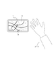
- FIG. 2 shows a state in which the user operates the electronic device 1 by a gesture.
- the electronic device 1 is mounted on an automobile such that, for example, the display 14 is installed on a console panel. Alternatively, the electronic device 1 may be supported by a support provided in the vehicle for supporting the electronic device 1.
- the controller 11 performs a process based on the detected gesture.
- the processing based on the gesture is, for example, adjustment of the volume of the sound output from the speaker 25.
- the volume increases in conjunction with the movement of the hand of the user.
- the volume decreases in conjunction with the movement of the user's hand.
- the processing based on the gesture is not limited to adjusting the volume.
- the process based on the gesture may be another process that can be executed based on the detected gesture.
- the processing based on the gesture may include enlargement or reduction of information displayed on the display 14, adjustment of the brightness of the display on the display 14, start of reading of predetermined information by voice, stop of voice by voice, and the like.
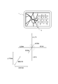
- FIG. 3 is a diagram illustrating a configuration example of the proximity sensor 18 when the electronic device 1 is viewed from the front.
- the proximity sensor 18 includes a light source infrared LED 180 and four infrared photodiodes SU, SR, SD, and SL.
- the four infrared photodiodes SU, SR, SD, and SL detect reflected light from the detection target via the lens 181.
- the four infrared photodiodes SU, SR, SD and SL are symmetrically arranged when viewed from the center of the lens 181.
- the infrared photodiode SU and the infrared photodiode SD are arranged apart from each other on the virtual line D1 in FIG. Then, in the direction of the virtual line D1 in FIG. 3, the infrared photodiodes SR and SL are disposed between the infrared photodiode SU and the infrared photodiode SD.
- FIG. 4 shows the transition of the detection value when the detection target (for example, a user's hand) of the four infrared photodiodes SU, SR, SD, and SL moves along the direction of the virtual line D1 in FIG.
- the detection target for example, a user's hand
- the infrared photodiode SU and the infrared photodiode SD are farthest apart. Therefore, as shown in FIG. 4, the time difference between the change (for example, rise) of the detection value (broken line) of the infrared photodiode SU and the same change (for example, rise) of the detection value (thin solid line) of the infrared photodiode SD. Is the largest.
- the controller 11 can determine the moving direction of the detection target by knowing the time difference between the predetermined changes of the detection values of the photodiodes SU, SR, SD, and SL.
- the controller 11 acquires the detection values of the photodiodes SU, SR, SD, and SL from the proximity sensor 18. Then, the controller 11 integrates a value obtained by subtracting the detection value of the photodiode SU from the detection value of the photodiode SD for a predetermined time, for example, in order to grasp the movement of the detection target in the direction of the virtual line D1. Good.
- the integral value is a non-zero value in the regions R41 and R42.
- the controller 11 can grasp the movement of the detection target in the direction of the virtual line D1 from the change of the integral value (for example, the change of the positive value, the zero value, and the negative value).
- the controller 11 may integrate a value obtained by subtracting the detection value of the photodiode SR from the detection value of the photodiode SL over a predetermined time.
- the controller 11 can grasp the movement of the detection target in the direction orthogonal to the virtual line D1 from the change in the integral value (for example, the change in the positive value, the zero value, and the negative value).
- the controller 11 may perform the calculation using all the detected values of the photodiodes SU, SR, SD and SL. That is, the controller 11 may grasp the moving direction of the detection target object without separating and calculating the components in the direction of the virtual line D1 and in the direction orthogonal to the virtual line D1.
- Gestures detected include, for example, left and right gestures, up and down gestures, oblique gestures, gestures that draw a circle clockwise, and gestures that draw a circle counterclockwise.
- the gesture to the left and right is a gesture performed in a direction substantially parallel to the longitudinal direction of the electronic device 1.
- the upper and lower gestures are gestures performed in a direction substantially parallel to the lateral direction of the electronic device 1.
- the oblique gesture is a gesture performed on a plane substantially parallel to the electronic device 1 in a direction that is not parallel to either the longitudinal direction or the short direction of the electronic device 1.
- the photodiodes SU, SR, SD, and SL receive the reflected light of the infrared light emitted from the light source infrared LED 180 on the object to be detected, and output a detection value having a size corresponding to the amount of received light. I can do it.
- the controller 11 can also determine whether the detection target approaches the proximity sensor 18 or moves away. First, the controller 11 can determine that the detection target is present when at least one of the detection values of the photodiodes SU, SR, SD, and SL is equal to or greater than a certain threshold (for example, a value other than zero).
- the controller 11 determines that the detection target is present, the detection target approaches the electronic device 1 by at least one of the detection values of the photodiodes SU, SR, SD, and SL becoming relatively large. Can be determined. In addition, after the controller 11 determines that the detection target is present, the detection target moves away from the electronic device 1 when at least one of the detection values of the photodiodes SU, SR, SD, and SL becomes relatively small. Can be determined. At this time, the controller 11 performs a gesture in which the user approaches the hand toward the electronic device 1, a gesture in which the user moves away from the hand, and a gesture in which these gestures are combined with the other gestures described above (for example, left and right gestures). It can be determined.
- FIG. 5 shows an example of a situation where the user operates the electronic device 1 by a gesture.
- the electronic device 1 is arranged such that the display 14 is located at the center of the console panel of the automobile.
- the user gets on the car on which the electronic device 1 is mounted while referring to the displayed route while the route to the destination is displayed on the display 14 of the electronic device 1.
- the proximity sensor 18 is in a state capable of detecting a gesture of the user.
- the controller 11 performs a process based on the gesture detected by the proximity sensor 18.
- the controller 11 can perform a process of adjusting the volume of the sound output from the electronic device 1 in accordance with a specific gesture (for example, a gesture in which the user moves the hand up and down).
- the electronic device 1 can receive a touch input from a user on a touch screen display.
- the user may shift his / her eyes to the display 14 for a long time to check the distance to the touch screen display and the contact position.
- the user does not perform touch input.
- the electronic device 1 can accept an input operation by a gesture as in the present embodiment, a user can perform an input operation without touching the electronic device 1. Thereby, even when the user performs an input operation during driving, driving safety can be easily ensured.
- the electronic device 1 may have a plurality of modes.
- the mode refers to an operation mode (operation state or operation state) that restricts the entire operation of the electronic device 1. Only one mode can be selected at a time.
- the mode of the electronic device 1 includes a first mode and a second mode.
- the first mode is a normal operation mode (normal mode) suitable for use in situations other than driving, for example.
- Conditions other than driving include, for example, a state in which the car engine is not running, a state in which the shift lever is in a predetermined range (for example, a parking range), a state in which the brake is being depressed, and a state in which the route to the destination is Any of the states where the display is not performed may be included.
- the second mode is an operation mode (car mode) of the electronic device 1 suitable for driving a car by displaying the route to the destination on the display 14 of the electronic device 1.
- car mode an operation mode of the electronic device 1 suitable for driving a car by displaying the route to the destination on the display 14 of the electronic device 1.
- the input by the gesture is possible. That is, when the mode of the electronic device 1 is switched to the second mode, it is preferable that the proximity sensor 18 be operated in conjunction with the electronic device 1 to detect the gesture.
- the electronic device 1 may switch the mode of the electronic device 1 based on, for example, a predetermined input operation on the electronic device 1 or a predetermined input operation on a vehicle by a user.
- FIG. 6 is an example of a display on the display 14 of the electronic device 1.
- the first screen 140 is, for example, a map screen, and includes a road, a mark 141 indicating the current position and direction of the car, and a mark 142 indicating an interchange (IC) or a building.
- the second screen 150 is, for example, a road information screen showing information on an expressway, and includes detailed information 151 of an interchange near the current position.
- the detailed information 151 includes an interchange name (for example, XX, ⁇ , and XX). Further, the detailed information 151 includes information on whether or not there is a service area (SA) or a junction (JCT) near an interchange (IC). The example of FIG. 6 shows that there is a service area near the interchange XX. Further, the detailed information 151 includes a distance from the current position to each interchange. In the example of FIG. 6, it is shown that it is 5 km to the interchange ⁇ .
- a display screen displayed on the entire display area of the display 14 is generally fixed.
- a first screen 140 for example, a map screen
- a second screen 150 for example, road information screen
- right-hand drive vehicles and left-hand drive vehicles as types of vehicles.
- the controller 11 of the electronic device 1 can improve the driving safety of the moving body by a gesture operation while realizing a screen arrangement that is easy to operate in the driver's seat by executing the processing described below.
- the device 1 can be provided.
- the processing described below is executed when the electronic device 1 is in the above-described car mode.
- the direction detected as a gesture may be predetermined.
- directions detected as gestures may be determined in a vertical direction, a horizontal direction, and a front-back direction.
- the directions detected as gestures are determined in the vertical direction, the horizontal direction, and the front-back direction. That is, hereinafter, a gesture in an oblique direction and a gesture of drawing a predetermined shape such as a circle are not illustrated.
- the electronic device 1 may detect, for example, a gesture in an oblique direction in the same manner as described below.
- a rectangular coordinate system is set, and the x-axis is associated with the left-right direction, the y-axis is associated with the up-down direction, and the z-axis is associated with the front-back direction.
- the front-back direction is a direction approaching the proximity sensor 18 of the electronic device 1 and a direction away from the proximity sensor 18.
- the positive direction and the negative direction of the x-axis correspond to the right direction and the left direction, respectively.
- the positive direction and the negative direction of the y-axis are associated with the upward direction and the downward direction, respectively.
- the positive direction and the negative direction of the z-axis are associated with the rearward direction and the forward direction, respectively.
- the controller 11 determines the position of the driver's seat in an automobile on which the electronic device 1 is mounted. For example, as shown in FIG. 8 as an example, it is assumed that the automobile 30 has two seats in the front row and the rear row in the traveling direction, and has two seats in each of the right side and the left side. That is, the automobile 30 includes the seat 31, the seat 32, the seat 33, and the seat 34 on the front row right side, the front row left side, the rear row right side, and the rear row left side, respectively.
- the display 14 and the proximity sensor 18 are arranged at the center on the front side of the front row.
- the driver's seat refers to a seat where a user who drives the automobile 30 sits.
- the driver's seat is the seat in front of the position where the steering is arranged.
- the steering can be, for example, a steering wheel, lever or bar.
- the steering wheel of the automobile 30 is arranged in front of any seat in the front row. Therefore, the controller 11 determines the right seat 31 in the front row or the left seat 32 in the front row as the position of the driver's seat.
- the controller 11 determines the position of the driver's seat based on the direction in which the gesture was first detected.
- the gesture detected first may be the first gesture detected after power is supplied to the electronic device 1.
- the first detected gesture may be the first gesture detected after the electronic device 1 has shown at least one of a predetermined character, image, and sound to the user.
- the predetermined characters and image may be a message displayed on the display 14 such as “Please reach from the driver's seat to the passenger seat” and an image indicating the content of the message.
- the predetermined sound may be a sound that is output from the speaker 25 and says, “Please reach from the driver's seat to the passenger seat side”.
- the user After the power is supplied to the electronic device 1, the user approaches his / her hand to use the electronic device 1.
- the user's hand extends from the direction of the seat where the user is sitting. That is, if the user is sitting on the right side in the traveling direction, the user's hand extends from the right side of the proximity sensor 18 in the traveling direction. Conversely, if the user is sitting on the left side in the traveling direction, the user's hand extends from the left side of the proximity sensor 18 in the traveling direction. Therefore, the electronic device 1 can specify the position of the user according to the direction of the gesture first detected by the proximity sensor 18.
- the controller 11 can specify the position of the driver's seat according to the direction in which the gesture is first detected.
- the controller 11 After specifying the position of the driver's seat (that is, the position of the driver), the controller 11 changes the display screen of the display to a display screen corresponding to the position of the driver.
- the controller 11 changes the original display screen to a display screen corresponding to the position of the driver according to display settings of the electronic device 1 described later.
- “change” of the display screen includes a case where the original display screen is invariable even according to the display settings of the electronic device 1, that is, a case where the content of the display screen does not change as a result.
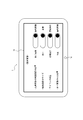
- FIG. 9 shows an example of the setting screen.
- the user can specify “position of a highway map screen”, “size of multiple images”, “icon position”, and “center position of a single screen”.
- the setting screen does not need to include some of these items.
- the setting screen may further include other items other than these items.
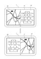
- FIG. 10 shows a display screen including two or more screens displayed while the automobile is traveling on a highway.
- the display screen includes a map screen as first screen 140 and a road information screen as second screen 150.
- the display screen includes two or more screens, it is preferable to set a priority on the screen and display a screen having a higher priority near the driver. In other words, it is preferable that a screen with a higher priority, which is more necessary information for the driver, is displayed closer so that the driver can easily see the screen.
- “Position of map screen on expressway” in the setting screen of FIG. 9 is an item for setting the priority of the map screen.
- the position on the map screen of the expressway is set to “driver's seat side”. That is, the priority of the map screen (first screen 140) is set higher than that of the road information screen (second screen 150).
- the controller 11 When determining that the position of the driver's seat is on the right side (seat 31 in the example of FIG. 8), the controller 11 displays a high-priority map screen on the right side close to the driver as shown in the lower diagram of FIG. I do. Then, the controller 11 displays the low-priority road information screen at a position (passenger seat side) farther from the driver than the map screen. That is, the controller 11 changes the display so that the high-priority screen is displayed at a position close to the driver when the high-priority screen is located far from the driver (upper diagram in FIG. 10) (FIG. 10 below).
- the controller 11 interchanges (rearranges) the positions of the low-priority screens and the high-priority screens, and continues to display the low-priority screens.
- the controller 11 can execute the rearrangement of the display positions based on the priority of the screen.
- the priority of the map screen first screen 140
- the road information screen second screen 150
- the display screen in FIG. 11 includes a map screen as the first screen 140 and a road information screen as the second screen 150, as in FIG.
- a high-priority screen displayed near the driver is displayed larger than a low-priority screen.
- a high-priority screen which is more necessary information for the driver, be displayed in a large size so as to be more easily viewed.
- Size of multiple images in the setting screen of FIG. 9 is an item for adjusting the sizes of the multiple screens included in the display screen. In the example of FIG. 9, the sizes of the plurality of images are set to “change”. That is, the size of the screen displayed near the driver is adjusted to be larger than the other screens.
- the controller 11 determines that the position of the driver's seat is on the right side, the controller 11 increases the display screen area (size) of the map screen close to the driver.
- the controller 11 makes the size of the map screen closer to the driver larger than at least the size of the road information screen farther from the driver than the map screen.
- a specific size of the screen close to the driver for example, a size of 70% of the display area of the display 14
- a ratio between a size of a screen close to the driver and a size of another screen far from the driver may be settable.
- the controller 11 also continues to display a screen far from the driver. As shown in FIG.
- the size of the screen far from the driver may be adjusted so that only a part is displayed.
- the controller 11 increases the display screen area of the screen closer to the driver than the display screen area of the screen far from the driver.
- the sizes of the plurality of images are set to “the same” on the setting screen of FIG. 9, the sizes of the plurality of screens included in the display screen are the same.
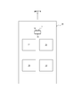
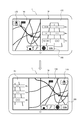
- the display screen of FIG. 12 includes an icon group 160 and an icon 170.
- the icon group 160 and the icon 170 may be displayed by detecting a gesture (for example, left and right gestures) in a non-display state. After the icon group 160 and the icon 170 are displayed, the icon group 160 and the icon 170 may be set to the non-display state again when a certain time has elapsed without any operation by the driver.
- the icon group 160 is a set of a plurality of icons 160A, 160B, 160C and 160D. The user can perform an associated function by selecting an icon 160A, 160B, 160C, 160D or 170 by gesture.
- Icon 160A is associated with a function of displaying a home on the map screen.
- Icon 160B is associated with a function for registering the current position or a specified position on the map screen.
- Icon 160C is associated with a function for displaying a list of setting menus. For example, the setting screen of FIG. 9 can be displayed by selecting from a list of a setting menu.
- Icon 160D is associated with a function for designating the scale of the map screen.
- the icon 170 is associated with a function for designating the display mode of the map screen. The icon 170 is used, for example, to switch between displaying a map in which the upward direction is north and displaying a map in which the upward direction is the traveling direction of the vehicle.
- icon position on the setting screen in FIG. 9 is an item for adjusting the position of an icon included in the display screen.
- the position of the icon is set to be “driver's seat side”.
- the controller 11 determines that the position of the driver's seat is on the right side
- the controller 11 displays the icon group 160 and the icon 170 on the right side close to the driver as shown in the lower diagram of FIG.
- the controller 11 moves the icon group 160 and the icon 170 located far from the driver's seat in parallel in one direction (left-right direction) to approach the driver's seat.
- the controller 11 moves the icon to a position closer to the driver.
- the position of the icon is set to the “initial position” on the setting screen of FIG. 9, the icon is displayed at the initial position without moving.
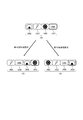
- FIG. 13 is a diagram showing a state of rotation of the icon group 160. As shown in FIG. 13, when the first gesture is detected, the controller 11 executes rotation of the icons 160A, 160B, 160C, and 160D. In the example of FIG. 13, the icon located closest to the driver's seat changes in the order of the icon 160D, the icon 160C, the icon 160B, and the icon 160A.
- the controller 11 can make it easier for the user to select the icons included in the icon group 160.
- the controller 11 may determine that the icon 170 has been selected when a gesture that is neither the first gesture nor the second gesture (for example, a back and forth gesture) is detected. Then, when the second gesture is detected in a state where the icon 170 is selected, the controller 11 may execute the function of the icon 170 (switching the display of the map).
- the controller 11 may execute a rotation that sequentially changes the selected icon, including the icon 160A, 160B, 160C, and 160D, and the icon 170.
- the controller 11 also employs the same method on the setting screen of FIG.
- the controller 11 sequentially selects “the position of the highway map screen”, “the size of a plurality of images”, “the position of the icon”, and “the center position of a single screen”. I do. Then, when the second gesture is detected, the controller 11 switches the setting of the selected item (for example, changes the passenger seat side to the driver seat side).
- the controller 11 can change the display screen according to a plurality of display settings. For example, when the position of the map screen on the highway is set to “driver's seat side”, the size of the plurality of images is set to “change”, and the position of the icon is set to “driver's seat side”, the controller 11 returns to FIG. Change the display screen as shown in. That is, the controller 11 switches the first screen 140 and the second screen 150 according to the priority, increases the size of the first screen 140 close to the driver, and changes the icon group 160 and the icon 170 to the driver's. View nearby.
- the controller 11 may change the plurality of display screens according to the plurality of display settings specified by the user in order or at once.
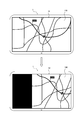
- the display screen of FIG. 15 can be one screen (single screen).
- the display indicating the current position of the car is often located near the center of the display 14. If the current position of the car is displayed at a position (closer) that is easy for the driver to see, the driver can perform the checking work more quickly.
- “Center position of single screen” in the setting screen of FIG. 9 is an item for adjusting the position of the center of the single screen included in the display screen. In the example of FIG. 9, the center position of the single screen is set to “driver's seat side”. That is, the screen is shifted (shifted) to the driver's seat side and displayed.
- the controller 11 When the controller 11 determines that the position of the driver's seat is on the right side, the controller 11 shifts and displays the center position of the single screen to the driver's seat side.
- the shift amount (the size of the shift) may be settable on the setting screen. As shown in FIG. 15, by shifting the single screen, an area where the screen is not displayed may be displayed in a specific color (for example, black).
- the controller 11 may display the center position of the single screen shifted to the driver side.
- the center position of the single screen is set to “center” in the setting screen of FIG. 9, the screen is not shifted.
- FIG. 16 is a flowchart illustrating an example of a process executed by the controller 11 of the electronic device 1.
- the controller 11 determines the position of the driver's seat in the vehicle by the method described above (step S1).
- step S3 the controller 11 adjusts and displays the screen position. For example, when the position of the map screen of the expressway is set to the driver's seat side in the setting screen of FIG. 9, the controller 11 displays a map screen having a high priority at a position close to the driver.
- step S3 After step S3, or when there is no setting of the screen display position according to the priority (No in step S2), the controller 11 proceeds to the processing in step S4.
- step S5 the controller 11 adjusts and displays the screen area (step S5). For example, when the size of a plurality of images is set to change in the setting screen of FIG. 9, the controller 11 displays the size of the screen displayed near the driver larger than other screens.
- step S5 After step S5 or when there is no setting for adjusting the screen area (No in step S4), the controller 11 proceeds to the processing in step S6.
- step S6 the controller 11 adjusts the position of the icon and displays it (step S7). For example, when the position of the icon is set to the driver's seat side in the setting screen of FIG. 9, the controller 11 moves and displays the icon to a position closer to the driver.
- step S7 or when there is no setting of the icon display position (No in step S6), the controller 11 ends the series of processing.
- the electronic device 1 specifies the position of the driver's seat according to the direction of the gesture detected first, and changes the display screen of the display 14 to a display screen corresponding to the position of the driver. Change to Therefore, the electronic device 1 realizes a screen layout that is easy to operate in the driver's seat. Since the electronic device 1 can perform an input operation by a gesture, the electronic device 1 can be operated without moving the line of sight to the display 14 as compared with, for example, a contact operation. Therefore, the user can continue checking the situation around the vehicle while driving, and driving safety is improved.
- the gesture is described as being detected by the proximity sensor 18, but the gesture is not necessarily detected by the proximity sensor 18.
- the gesture may be detected by any sensor capable of detecting the gesture of the user without touching the device.
- An example of such a sensor includes, for example, the camera 13 and the like.
- the sensor capable of detecting the gesture of the user without touching the own device may include, for example, a distance measuring sensor.
- the electronic device 1 may include a distance measurement sensor instead of or in addition to the proximity sensor 18, and may detect a gesture with the distance measurement sensor.
- a distance measurement sensor is a sensor that can measure the distance to an object.
- the distance measuring sensor may be constituted by, for example, a ToF (Time @ Flight) sensor.
- a ranging sensor configured as a ToF sensor emits a sine wave modulated light (infrared laser light) toward an object, and receives reflected light of the irradiated infrared laser light from the object.
- a light receiving unit has, for example, an image sensor in which a plurality of light receiving elements are arranged.
- the ToF sensor measures the time (flight time) from the irradiation of the infrared laser light to the reception of the reflected light by each light receiving element.
- the ToF sensor can measure the time of flight based on the phase difference between the emitted infrared laser light and the received reflected light.
- the ToF sensor can measure a distance to an object reflecting the irradiated infrared laser light based on the measured flight time.
- the ToF sensor can detect the moving direction of the target based on the time difference at which the reflected light from the target enters each of the plurality of light receiving elements. Accordingly, the ToF sensor can also detect a gesture performed by the user based on the same principle as that described for the proximity sensor 18.
- the distance measurement sensor may be arranged on the same surface of the electronic device 1 as the surface on which the proximity sensor 18 is arranged, for example.
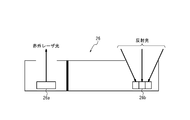
- FIG. 17 is a diagram schematically showing the distance measuring sensor 26.
- FIG. 17 shows the distance measuring sensor 26 in a side view.
- the distance measuring sensor 26 includes a light emitting unit 26a and a light receiving unit 26b.
- the light emitting unit 26a irradiates the target with the infrared laser light.
- the light receiving unit 26b receives reflected light of the irradiated infrared light from the object.
- the light receiving section 26b may include a plurality of light receiving elements.
- the light receiving section 26b may include nine light receiving elements arranged in 3 rows ⁇ 3 columns. Each of the nine light receiving elements receives the reflected light from the object.
- three light receiving elements of Ch11, Ch12, and Ch13 are arranged in order from the left in the upper stage.
- three light receiving elements of Ch21, Ch22 and Ch23 are arranged in order from the left in the middle stage.
- three light receiving elements of Ch31, Ch32 and Ch33 are arranged in the lower row in order from the left.
- the distance measuring sensor 26 calculates the distance from each of the nine light receiving elements to the target object based on the phase difference between the infrared laser light emitted by the light emitting part 26a and the reflected light respectively received by the nine light receiving elements of the light receiving part 26b. Can be measured.
- the distance measurement sensor 26 can detect a gesture based on the distance from each of the nine light receiving elements to the object and a change in the distance over time.
- FIG. 19 is a diagram schematically showing a transition of a distance to an object detected by each light receiving element.
- a hand as an object first approaches the light receiving element Ch21 arranged on the left side, so that the distance D21 of the object detected by the light receiving element Ch21 becomes short.
- the distance D22 of the object detected by the light receiving element Ch22 becomes short.
- the distance D23 of the object detected by the light receiving element Ch23 arranged on the right becomes short.
- the order in which the hands approaching the light receiving elements Ch21, Ch22, and Ch23 also move away is in the order of Ch21, Ch22, and Ch23. Therefore, the distances D21, D22, and D23 increase in this order (return to the initial value).
- Gestures in the up-down direction can be detected based on the same principle using, for example, the light receiving elements Ch12, Ch22, and Ch32.
- the distance measurement sensor 26 can detect a gesture based on the distance from each of the nine light receiving elements to the target object and the change in the distance over time.
- the light receiving section 26b has been described as including nine light receiving elements, but the number of light receiving elements included in the light receiving section 26b is not limited to this.
- the arrangement of the plurality of light receiving elements is not limited to the arrangement shown in FIG.
- the number and arrangement of the light receiving elements included in the light receiving unit 26b may be appropriately determined according to the type of the gesture to be detected.
- the light emitting unit 26a of the distance measuring sensor 26 may include a plurality of light emitting elements.
- the distance from each of the nine light emitting elements to the object can be measured based on the phase difference between the infrared laser light emitted from each light emitting element and the reflected light received by the light receiving unit 26b.
- the distance measurement sensor 26 can detect a gesture by applying the above-described principle based on the distance from each of the nine light-emitting elements to the object and the change in distance over time. it can.
- the controller 11 determines that the position of the driver's seat is determined based on the direction in which the gesture is first detected, but the present invention is not limited to this method.
- the controller 11 may determine the position of the driver's seat by at least one of the methods described below, instead of, or in combination with, the direction in which the gesture was initially detected.
- the controller 11 may determine the position of the driver's seat based on information stored in the storage 16 in advance. For example, when the electronic device 1 is provided in the vehicle 30 in advance, the storage 16 may store information on the position of the driver's seat. Alternatively, when the user performs an input operation on the electronic device 1 to input information regarding the position of the driver's seat, the storage 16 may store information regarding the position of the driver's seat. In this case, the controller 11 can determine the position of the driver's seat based on the information on the position of the driver's seat stored in the storage 16.
- the controller 11 may determine the position of the driver's seat based on the image captured by the camera 13. Specifically, the controller 11 activates the camera 13 when performing control based on a gesture (for example, when the electronic device 1 is in the first operation mode).
- the camera 13 captures an image of the front side of the display 14, that is, the inside of the automobile 30.
- the controller 11 may analyze the image captured by the camera 13 and determine the position of the seat in front of the steering as the position of the driver's seat.
- the controller 11 may analyze an image captured by the camera 13 and determine the position of the seat as the position of the driver's seat when the user is reflected in a seat in front of the steering wheel.
- the controller 11 may stop the operation of the camera 13. Thereby, the controller 11 can suppress power consumption by the camera 13.
- the controller 11 may determine the position of the driver's seat based on the output of the pressure sensor.
- the pressure sensor may be provided, for example, in each of the seats 31 to 34 below a seat surface to which a load is applied when a user sits.
- the pressure sensor detects the pressure applied to the seat surface of each of the seats 31 to 34.
- the controller 11 can specify the seat on which the user is sitting based on the output from the pressure sensor arranged on the seat.
- the controller 11 may determine the position of the seat where the user sits as the position of the driver's seat. This method can be used, for example, when a user gets into a car by himself.
- the controller 11 may determine the position of the driver's seat based on the output of the human sensor.
- the human sensor may be, for example, a sensor that detects whether or not the user is sitting in the seats 31 to 34 by sensing a change in ambient temperature using infrared rays.
- the controller 11 can identify the seat on which the user is sitting based on the output from the human sensor disposed in front of the seat.
- the controller 11 may determine the position of the seat where the user sits as the position of the driver's seat. This method can be used, for example, when a user gets into a car by himself.
- the controller 11 may determine the position of the driver's seat based on the opening and closing of the door of the automobile 30.
- the automobile 30 has one door near each of the seats 31 to 34.
- the automobile 30 includes one door on each of the right side of the front row right seat 31, the left side of the front row left seat 32, the right side of the rear row right seat 33, and the left side of the rear row left seat 34. I do.
- each door is provided with a sensor for detecting opening and closing.
- the controller 11 can determine that the user is sitting on the seat closest to the door that has been opened and closed. This is because the user would normally enter the car 30 from the door closest to the seat to be seated.
- the controller 11 may determine the position of the seat determined to be seated by the user as the position of the driver's seat. This method can be used, for example, when a user gets into a car by himself.
- the controller 11 may determine the position of the driver's seat based on the position where the door of the automobile 30 is unlocked. When a plurality of doors are provided in the automobile 30 as described above, the controller 11 can determine that the user sits on the seat closest to the door on which the unlocking operation has been performed. This is because the user normally unlocks the door closest to the seat to be seated and gets into the automobile 30 from the door. The controller 11 may determine the position of the seat determined to be seated by the user as the position of the driver's seat. This method can be used, for example, when a user gets into a car by himself.
- the controller 11 may determine the position of the driver's seat based on the hand that has operated the touch screen display.
- the user stores fingerprint data of the left and right fingers in the storage 16 of the electronic device 1 in advance.
- the user can perform an input operation for registering fingerprint data, for example, and store the fingerprint data in the storage 16 of the electronic device 1.
- the controller 11 reads the fingerprint of the finger touching the touch screen display when the user touches the touch screen display in a state where power is supplied to the electronic device 1 when driving the automobile 30. It is determined whether the finger is the right finger or the left finger of the user.
- the controller 11 determines that the seat on the opposite side to the determined hand direction (that is, right hand or left hand) is the seat where the user is sitting.
- the controller 11 determines that the user is sitting on the right seat.
- the controller 11 determines that the user is sitting on the left seat.
- the controller 11 determines that the user is sitting on the left seat.
- the controller 11 may determine the position of the seat determined to be sitting by the user as the position of the driver's seat.
- the controller 11 may determine the position of the driver's seat based on the sound detected by the microphone 15. For example, for the sound detected by the microphone 15, the controller 11 determines the direction in which the sound is generated. The controller 11 can determine that the direction in which the determined sound is generated is the direction in which the user exists. Therefore, the controller 11 may determine the position of the seat in the direction in which the sound is generated as the position of the driver's seat.
- the controller 11 may change the gesture detection range of the proximity sensor 18 according to the determined position of the driver's seat.
- the gesture detection range may include a direction that can be detected by the proximity sensor 18.
- the controller 11 may control the proximity sensor 18 to point in the direction of the determined driver's seat. That is, for example, when the controller 11 determines that the driver's seat is on the right side in the traveling direction, the controller 11 may turn the proximity sensor 18 to the right in the traveling direction. Similarly, when the controller 11 determines that the driver's seat is on the left side in the traveling direction, the controller 11 may turn the proximity sensor 18 to the left side in the traveling direction.
- the proximity sensor 18 has a limited viewing angle at which a gesture can be detected. Therefore, even if the user makes a gesture, if the user is out of the detectable range of the proximity sensor 18, the user's gesture is not detected. However, by changing the detection range of the proximity sensor 18 and, for example, directing the detection range of the proximity sensor 18 in the direction of the driver's seat where the user is sitting, the proximity sensor 18 can more easily detect the gesture of the user. . Since the proximity sensor 18 makes it easier to detect a gesture of the user, the input by the gesture is less likely to be overlooked by the user, so that it is easier to concentrate on driving. Therefore, driving safety is improved.
- the electronic device 1 includes one proximity sensor 18.
- the electronic device 1 may include a plurality of proximity sensors 18.
- the proximity sensor 18 is located at the center of the side of the display 14 in the left-right direction (x-axis direction) and below the display 14 in the up-down direction (y-axis direction). It is provided on the body part.
- the electronic device 1 may include the proximity sensor 18 at a position different from that of the above embodiment. That is, the number and position of the proximity sensors 18 included in the electronic device 1 are not limited.
- FIG. 20 is a diagram showing an example of the arrangement of the proximity sensors 18, 118a, 118b, and 118c in another embodiment.
- the electronic device 1 includes a plurality of four proximity sensors 18, 118a, 118b, and 118c.
- the controller 11 can determine the gesture more accurately by statistically processing (for example, calculating an average value or the like) the detection values of the four proximity sensors 18, 118a, 118b, and 118c, for example. . Further, for example, even if some of the proximity sensors 18, 118a, 118b, and 118c cannot output a detection value due to a failure or the like, the controller 11 continues to determine the gesture using the detection values from other sensors. can do.
- the proximity sensors 118b and 118c are electronic devices located at the center of the side of the display 14 in the vertical direction (y-axis direction) and outside (left and right) of the display 14 in the left-right direction (x-axis direction). It is provided in one housing part. One of the proximity sensors 118b and 118c is closer to the driver's seat than the other sensors, so that it is possible to detect a driver's gesture with higher sensitivity.
- the electronic device 1 may include a part of the proximity sensors 18, 118a, 118b, and 118c of FIG.
- the electronic device 1 may include two proximity sensors 18 and 118a.
- the electronic device 1 may include two proximity sensors 118b and 118c.
- the electronic device 1 may include one proximity sensor at the position of the proximity sensor 118a, 118b or 118c shown in FIG.
- at least a portion of the proximity sensors 18, 118a, 118b, and 118c need not be located at the center of the side of the display 14.
- the proximity sensors 18, 118a, 118b and 118c may be located outside the four corners of the display 14.
- the controller 11 rotates and displays the icon group 160.
- the controller 11 may display a high-priority icon near the driver instead of the rotation.
- the driver may be able to specify the priority of the icons included in the icon group 160 on the setting screen.
- FIG. 21 illustrates an example in which the controller 11 displays an icon with a high priority near the driver.
- the controller 11 sets the icon group 160 as shown in the lower left diagram of FIG. indicate.
- the position of the driver's seat is on the right side.
- the controller 11 sets the icon as shown in the lower right diagram of FIG. The group 160 is displayed.
- the controller 11 displays an icon that the driver wants to operate near the driver. This prevents the driver from accidentally selecting another icon. That is, erroneous operation of the driver is prevented.
- the icon group 160 is along one side in the longitudinal direction of the display 14 (lower side in the horizontal direction).
- an icon group 185 along the short direction (vertical direction) of the display 14 may be displayed.
- the icon group 185 is a set of a plurality of icons 185A, 185B and 185C.
- Icon 185A is associated with a function for designating the display mode of the map screen.
- Icon 185B is associated with a function for designating the scale of the map screen.
- Icon 185C is associated with a function of displaying a home on the map screen.
- the icon group 185 is displayed at a position along the left side of the display 14.
- the controller 11 When determining that the position of the driver's seat is on the right side, the controller 11 displays the icon group 185 along the right side close to the driver as shown in the lower diagram of FIG.
- the upper diagram of FIG. 23 illustrates a case where the icon group 185 is displayed at a position along the right side of the display 14 on the first screen.
- the controller 11 displays the icon group 185 along the left side near the driver, as shown in the lower diagram of FIG.
- icon groups 185 and 190 along the short direction may be displayed on the left and right sides of the display 14.
- the icon group 190 is a set of a plurality of icons 190A and 190B.
- Icon 190A is associated with the function of selecting the next song in car audio.
- Icon 190B is associated with the function of adjusting the volume with car audio.
- the icon group 185 related to the operation of the map screen has a higher priority than the icon group 190 related to the operation of the car audio.
- the controller 11 displays the icon group 185 along the right side close to the driver as shown in the lower diagram of FIG. Display along the far left side.
- the controller 11 displays an icon group having a higher priority for the driver near the driver. Therefore, erroneous operation is prevented, and the driver can easily operate.
- the icon group 185 may be displayed along the left side or the right side of the display 14 near the driver.
- the controller 11 displays the icon group 185 along the side closer to the driver (FIG. 22, (See the lower diagram of FIG. 23).
- the gesture for displaying the icon group 185 may be, for example, a left and right gesture.
- the gesture for displaying the icon group 185 may be the gesture detected first.
- the controller 11 determines the position of the driver's seat and displays the icon group 185 along the side near the driver.
- the icon group 185 may be set to the non-display state again when a certain time has elapsed without an operation from the driver.
- the icon group 185 may be displayed again when a gesture is detected in the non-display state.
- the display position of the high-priority icon group is always near the driver, so that the driver can easily operate.
- the computer system and other hardware include, for example, a general-purpose computer, a PC (personal computer), a special-purpose computer, a workstation, a PCS (Personal Communications System), a mobile (cellular) telephone, and a data processing function. Includes mobile phones, RFID receivers, game consoles, electronic notepads, laptop computers, GPS (Global Positioning System) receivers or other programmable data processing devices.
- the various operations or control methods may be performed by dedicated circuitry (eg, discrete logic gates interconnected to perform a particular function) implemented with program instructions (software), by one or more processors.
- the one or more processors that execute logic blocks and / or program modules include, for example, one or more microprocessors, CPUs (Central Processing Units), ASICs (Application Specific Integrated Circuits), DSPs (Digital Signal Processors), and PLDs. (Programmable Logic Device), FPGA (Field Programmable Gate Array), processor, controller, microcontroller, microprocessor, electronics, other devices designed to perform the functions described herein and / or any combination thereof Is included.
- the embodiments described herein are implemented, for example, by hardware, software, firmware, middleware, microcode, or any combination thereof. Instructions may be program code or code segments for performing the necessary tasks.
- a code segment may represent a procedure, a function, a subprogram, a program, a routine, a subroutine, a module, a software package, a class, or any combination of any of instructions, data structures, or program statements.
- a code segment transmits and / or receives information, data arguments, variables or storage contents to or from other code segments or hardware circuits, thereby connecting the code segment to other code segments or hardware circuits. .
- the storage 16 used here can be further configured as a tangible computer-readable carrier (medium) composed of a solid state memory, a magnetic disk, and an optical disk.
- a tangible computer-readable carrier composed of a solid state memory, a magnetic disk, and an optical disk.
- Such media stores an appropriate set of computer instructions or data structures, such as program modules, for causing a processor to execute the techniques disclosed herein.
- Computer readable media includes electrical connections with one or more wires, magnetic disk storage media, magnetic cassettes, magnetic tape, and other magnetic and optical storage devices (eg, CDs (Compact Disks), laser disks ( Registered trademark), DVD (registered trademark) (Digital Versatile Disc), floppy (registered trademark) disk and Blu-ray Disc (registered trademark)), portable computer disk, RAM (Random Access Memory), ROM (Read-Only Memory), Rewritable and programmable ROM such as EPROM (Erasable Programmable Read-Only Memory), EEPROM (Electrically Erasable Programmable Read-Only Memory) or flash memory, or other tangible storage medium capable of storing information, or a combination of any of these Is included.
- CDs Compact Disks
- laser disks Registered trademark
- DVD registered trademark
- floppy registered trademark
- Blu-ray Disc registered trademark
- portable computer disk Portable computer disk
- RAM Random Access Memory
- ROM Read-Only Memory
- the memory may be provided inside and / or outside the processor or the processing unit.
- the term “memory” refers to any type of long-term storage, short-term storage, volatile, non-volatile or other memory. That is, “memory” is not limited to a particular type and / or number. Further, the type of the medium in which the storage is stored is not limited.
Abstract
This electronic device comprises: a sensor (proximity sensor) that detects a gesture that does not contact the device; and a controller that, if the gesture that does not contact the device is detected by the sensor while a first screen and a second screen are displayed on a display screen of a display, specifies the position of a driver in accordance with the direction of the first detected gesture and changes the display screen to a display screen that accommodates the position of the driver.
Description
本出願は、2018年6月26日に日本国に特許出願された特願2018-121297および特願2018-121298の優先権を主張するものであり、これらの先の出願の開示全体を、ここに参照のために取り込む。
This application claims the priority of Japanese Patent Application No. 2018-112297 and Japanese Patent Application No. 2018-112298 filed on June 26, 2018, the disclosure of which is hereby incorporated by reference. Capture for reference.
本開示は、電子機器、移動体、プログラムおよび制御方法に関する。
The present disclosure relates to an electronic device, a moving object, a program, and a control method.
従来、ユーザによる車両の運転を支援する装置が知られている。例えば、特許文献1には、車両に搭載されるカーナビゲーションシステムが開示されている。特許文献1に開示されたカーナビゲーションシステムは、例えば目的地までの移動経路等に関する情報をディスプレイに表示することにより、車両の運転を支援する。
装置 Conventionally, a device that assists a user in driving a vehicle is known. For example, Patent Literature 1 discloses a car navigation system mounted on a vehicle. The car navigation system disclosed in Patent Literature 1 supports driving of a vehicle by displaying, for example, information on a moving route to a destination on a display.
一実施形態に係る電子機器は、自機器に触れないジェスチャを検出するセンサと、ディスプレイの表示画面に第1画面と第2画面とが表示されているときに、前記センサによって自機器に触れないジェスチャが検出されると、最初に検出された前記ジェスチャの方向に応じて、運転者の位置を特定し、前記表示画面を前記運転者の位置に応じた表示画面に変更するコントローラと、を備える。
An electronic device according to an embodiment includes a sensor that detects a gesture that does not touch the device, and does not touch the device when the first screen and the second screen are displayed on a display screen of a display. A controller that, when a gesture is detected, specifies a driver's position according to the direction of the gesture first detected, and changes the display screen to a display screen corresponding to the driver's position. .
一実施形態に係る電子機器は、自機器に触れないジェスチャを検出するセンサと、ディスプレイの表示画面にアイコンが表示されているときに、前記センサによって自機器に触れないジェスチャが検出されると、最初に検出された前記ジェスチャの方向に応じて、運転者の位置を特定し、前記運転者により近い位置に前記アイコンを移動するコントローラと、を備える。
Electronic device according to one embodiment, a sensor that detects a gesture that does not touch the device itself, and when an icon is displayed on the display screen of the display, when a gesture that does not touch the device is detected by the sensor, A controller that identifies the position of the driver according to the direction of the gesture detected first, and moves the icon to a position closer to the driver.
一実施形態に係る移動体は、上記電子機器を備える。
移動 A moving object according to one embodiment includes the above electronic device.
一実施形態に係る移動体は、上記電子機器と通信可能に接続される。
移動 The moving object according to one embodiment is communicably connected to the electronic device.
一実施形態に係るプログラムは、自機器に触れないジェスチャを検出するセンサと、コントローラと、を備える電子機器を制御するプログラムであって、前記コントローラに、ディスプレイの表示画面に第1画面と第2画面とが表示されているときに、前記センサによって自機器に触れないジェスチャが検出されると、最初に検出された前記ジェスチャの方向に応じて、運転者の位置を特定するステップと、前記表示画面を前記運転者の位置に応じた表示画面に変更するステップと、を実行させる。
A program according to an embodiment is a program for controlling an electronic device including a sensor that detects a gesture that does not touch the own device and a controller, wherein the controller includes a first screen and a second screen on a display screen of a display. When a gesture that does not touch the own device is detected by the sensor while the screen is displayed, a step of specifying a position of a driver according to a direction of the gesture detected first; and Changing the screen to a display screen corresponding to the position of the driver.
一実施形態に係るプログラムは、自機器に触れないジェスチャを検出するセンサと、コントローラと、を備える電子機器を制御するプログラムであって、前記コントローラに、ディスプレイの表示画面にアイコンが表示されているときに、前記センサによって自機器に触れないジェスチャが検出されると、最初に検出された前記ジェスチャの方向に応じて、運転者の位置を特定するステップと、前記運転者により近い位置に前記アイコンを移動するステップと、を実行させる。
A program according to an embodiment is a program that controls an electronic device including a sensor that detects a gesture that does not touch the device and a controller, and the controller displays an icon on a display screen of a display. When a gesture that does not touch the own device is detected by the sensor, a step of specifying a driver's position in accordance with the direction of the gesture first detected, and a step of identifying the icon in a position closer to the driver And moving.
一実施形態に係る制御方法は、自機器に触れないジェスチャを検出するセンサと、コントローラと、を備える電子機器の制御方法であって、前記コントローラが、ディスプレイの表示画面に第1画面と第2画面とが表示されているときに、前記センサによって自機器に触れないジェスチャが検出されると、最初に検出された前記ジェスチャの方向に応じて、運転者の位置を特定するステップと、前記表示画面を前記運転者の位置に応じた表示画面に変更するステップと、を含む。
A control method according to an embodiment is a control method of an electronic device including a sensor that detects a gesture that does not touch the own device, and a controller, wherein the controller displays a first screen and a second screen on a display screen of a display. When a gesture that does not touch the own device is detected by the sensor while the screen is displayed, a step of specifying a position of a driver according to a direction of the gesture detected first; and Changing the screen to a display screen according to the position of the driver.
一実施形態に係る制御方法は、自機器に触れないジェスチャを検出するセンサと、コントローラと、を備える電子機器の制御方法であって、前記コントローラが、ディスプレイの表示画面にアイコンが表示されているときに、前記センサによって自機器に触れないジェスチャが検出されると、最初に検出された前記ジェスチャの方向に応じて、運転者の位置を特定するステップと、前記運転者により近い位置に前記アイコンを移動するステップと、を含む。
A control method according to one embodiment is a control method of an electronic device including a sensor that detects a gesture that does not touch the own device and a controller, wherein the controller displays an icon on a display screen of a display. When a gesture that does not touch the own device is detected by the sensor, a step of specifying a driver's position in accordance with the direction of the gesture first detected, and a step of identifying the icon in a position closer to the driver Moving.
特許文献1に開示されたカーナビゲーションシステムのユーザは、入力操作を行う際、ディスプレイにタッチ入力を行う。しかしながら、車両の安全運転の観点から、運転者は運転中のタッチ入力を避けることが好ましい。かかる事情に鑑みてなされた本開示の目的は、移動体の運転の安全性を向上可能な電子機器、移動体、プログラムおよび制御方法を提供することにある。一実施形態によれば、移動体の運転の安全性を向上可能な電子機器、移動体、プログラムおよび制御方法を提供することができる。
ユ ー ザ A user of the car navigation system disclosed in Patent Document 1 performs a touch input on a display when performing an input operation. However, from the viewpoint of safe driving of the vehicle, it is preferable that the driver avoid touch input during driving. An object of the present disclosure that has been made in view of such circumstances is to provide an electronic device, a moving body, a program, and a control method that can improve driving safety of the moving body. According to one embodiment, it is possible to provide an electronic device, a moving object, a program, and a control method that can improve the safety of driving the moving object.
(電子機器の構成)
図1に示すように一実施形態の電子機器1は、タイマー12と、カメラ13と、ディスプレイ14と、マイク15と、ストレージ16と、通信ユニット17と、スピーカー25と、近接センサ18(ジェスチャセンサ)と、コントローラ11と、を備える。電子機器1は、さらにUVセンサ19と、照度センサ20と、加速度センサ21と、地磁気センサ22と、気圧センサ23と、ジャイロセンサ24と、を備える。図1は例示である。電子機器1は図1に示す構成要素の一部を備えなくてよい。また、電子機器1は図1に示す以外の構成要素を備えていてよい。 (Configuration of electronic equipment)
As shown in FIG. 1, theelectronic device 1 according to one embodiment includes a timer 12, a camera 13, a display 14, a microphone 15, a storage 16, a communication unit 17, a speaker 25, and a proximity sensor 18 (gesture sensor). ) And a controller 11. The electronic device 1 further includes a UV sensor 19, an illuminance sensor 20, an acceleration sensor 21, a geomagnetic sensor 22, a barometric pressure sensor 23, and a gyro sensor 24. FIG. 1 is an example. The electronic device 1 may not include some of the components illustrated in FIG. Further, the electronic device 1 may include components other than those illustrated in FIG.
図1に示すように一実施形態の電子機器1は、タイマー12と、カメラ13と、ディスプレイ14と、マイク15と、ストレージ16と、通信ユニット17と、スピーカー25と、近接センサ18(ジェスチャセンサ)と、コントローラ11と、を備える。電子機器1は、さらにUVセンサ19と、照度センサ20と、加速度センサ21と、地磁気センサ22と、気圧センサ23と、ジャイロセンサ24と、を備える。図1は例示である。電子機器1は図1に示す構成要素の一部を備えなくてよい。また、電子機器1は図1に示す以外の構成要素を備えていてよい。 (Configuration of electronic equipment)
As shown in FIG. 1, the
電子機器1は、移動体の運転または操縦において用いられる種々の機器として実現されてよい。移動体は、移動可能な任意の装置により構成されていてよい。移動体は、ユーザが乗り込むことが可能であってよい。移動体は、例えば、車両、船舶および航空機等を含んでよい。車両は、例えば、電気自動車、ハイブリッド電気自動車、ガソリン自動車、バイク、二輪車、および福祉車両等を含んでよい。車両は、例えば鉄道車両を含んでよい。移動体は、ユーザによって運転または操縦されてよい。移動体の運転または操縦に関するユーザ操作の少なくとも一部が自動化されていてよい。移動体は、ユーザ操作によらず、自律して移動可能であってよい。以下において、移動体は、ユーザが運転する自動車であるとして説明する。
The electronic device 1 may be realized as various devices used in driving or maneuvering a moving object. The moving object may be constituted by any movable device. The mobile may be capable of being boarded by a user. The moving object may include, for example, a vehicle, a ship, an aircraft, and the like. The vehicles may include, for example, electric vehicles, hybrid electric vehicles, gasoline vehicles, motorcycles, motorcycles, welfare vehicles, and the like. The vehicle may include, for example, a railway vehicle. The mobile may be driven or steered by a user. At least a part of the user operation related to driving or maneuvering the moving object may be automated. The moving object may be autonomously movable without depending on the user operation. Hereinafter, a description will be given assuming that the moving object is an automobile driven by the user.
移動体が自動車である場合、電子機器1は、例えば自動車に搭載されたカーナビゲーションシステム等の車載機器として実現されてよい。電子機器1は、例えば携帯電話端末、ファブレット、タブレットPC(Personal Computer)、スマートフォンまたはフィーチャーフォン等として実現されてよい。この場合、電子機器1は、ユーザが運転する自動車に搭載されたシステムと、有線または無線により通信可能に接続されてよい。例えば、電子機器1は、スマートフォンとして実現され、Bluetooth(登録商標)により自動車に搭載されたシステムと通信可能に接続されてよい。電子機器1は、これらの例に限られず、移動体の運転または操縦において用いられる任意の機器として実現されてよい。電子機器1は、例えば、PDA(Personal Digital Assistant)、リモコン端末、携帯音楽プレイヤ、ゲーム機、電子書籍リーダ、家電製品または産業用機器(FA機器)等により実現されてよい。ここでは、電子機器1が、自動車に搭載されたカーナビゲーションシステムとして実現されるものとして、説明する。
場合 When the moving object is an automobile, the electronic device 1 may be realized as an in-vehicle device such as a car navigation system mounted on the automobile. The electronic device 1 may be realized as, for example, a mobile phone terminal, a phablet, a tablet PC (Personal Computer), a smartphone, a feature phone, or the like. In this case, the electronic device 1 may be communicably connected by wire or wirelessly to a system mounted on an automobile driven by the user. For example, the electronic device 1 may be realized as a smartphone, and may be communicably connected to a system mounted on a vehicle by Bluetooth (registered trademark). The electronic device 1 is not limited to these examples, and may be realized as any device used in driving or maneuvering a moving body. The electronic device 1 may be realized by, for example, a PDA (Personal Digital Assistant), a remote control terminal, a portable music player, a game machine, an electronic book reader, a home appliance, or an industrial device (FA device). Here, the electronic device 1 will be described as being realized as a car navigation system mounted on an automobile.
タイマー12はコントローラ11からタイマー動作の指示を受け、所定時間経過した時点で、その旨を示す信号をコントローラ11に出力する。タイマー12は、図1に示すようにコントローラ11とは独立して設けられていてよいし、コントローラ11が内蔵する構成であってよい。
The timer 12 receives a timer operation instruction from the controller 11 and outputs a signal to that effect to the controller 11 when a predetermined time has elapsed. The timer 12 may be provided independently of the controller 11 as shown in FIG. 1, or may have a configuration built in the controller 11.
カメラ13は、電子機器1の周囲の被写体を撮像する。カメラ13は一例として、電子機器1のディスプレイ14が設けられる面に設けられる。
The camera 13 captures an image of a subject around the electronic device 1. As an example, the camera 13 is provided on a surface of the electronic device 1 on which the display 14 is provided.
ディスプレイ14は画面を表示する。画面は、例えば文字、画像、記号および図形等の少なくとも一つを含む。ディスプレイ14は、液晶ディスプレイ(Liquid Crystal Display)、有機ELパネル(Organic Electro-Luminescence Panel)または無機ELパネル(Inorganic Electro-Luminescence Panel)等であってよい。本実施形態において、ディスプレイ14はタッチパネルディスプレイ(タッチスクリーンディスプレイ)である。タッチパネルディスプレイは、指またはスタイラスペン等の接触を検出して、その接触位置を特定する。ディスプレイ14は、指またはスタイラスペン等が接触した位置を同時に複数検出することができる。
The display 14 displays a screen. The screen includes, for example, at least one of characters, images, symbols, figures, and the like. The display 14 may be a liquid crystal display (Liquid Crystal Display), an organic EL panel (Organic Electro-Luminescence Panel), an inorganic EL panel (Inorganic Electro-Luminescence Panel), or the like. In the present embodiment, the display 14 is a touch panel display (touch screen display). The touch panel display detects contact with a finger or a stylus pen or the like, and specifies the contact position. The display 14 can simultaneously detect a plurality of positions touched by a finger, a stylus pen, or the like.
マイク15は、人が発する声を含む、電子機器1の周囲の音を検出する。
The microphone 15 detects sounds around the electronic device 1 including a voice uttered by a person.
ストレージ16は記憶部としてプログラムおよびデータを記憶する。ストレージ16は、コントローラ11の処理結果を一時的に記憶する。ストレージ16は、半導体記憶デバイスおよび磁気記憶デバイス等の任意の記憶デバイスを含んでよい。ストレージ16は、複数の種類の記憶デバイスを含んでよい。ストレージ16は、メモリカード等の可搬の記憶媒体と、記憶媒体の読み取り装置との組み合わせを含んでよい。
The storage 16 stores programs and data as a storage unit. The storage 16 temporarily stores the processing result of the controller 11. The storage 16 may include any storage device such as a semiconductor storage device and a magnetic storage device. The storage 16 may include a plurality of types of storage devices. The storage 16 may include a combination of a portable storage medium such as a memory card and a storage medium reading device.
ストレージ16に記憶されるプログラムには、フォアグランドまたはバックグランドで実行されるアプリケーションと、アプリケーションの動作を支援する制御プログラムとを含む。アプリケーションは、例えば、ジェスチャに応じた処理をコントローラ11に実行させる。制御プログラムは、例えば、OS(Operating System)である。アプリケーションおよび制御プログラムは、通信ユニット17による通信または記憶媒体を介してストレージ16にインストールされてよい。
The programs stored in the storage 16 include applications executed in the foreground or background, and control programs that support the operations of the applications. The application causes the controller 11 to execute a process corresponding to the gesture, for example. The control program is, for example, an OS (Operating System). The application and the control program may be installed in the storage 16 via communication by the communication unit 17 or via a storage medium.
通信ユニット17は、有線または無線により通信するためのインタフェースである。一実施形態の通信ユニット17によって行われる通信方式は無線通信規格である。例えば、無線通信規格は2G、3Gおよび4G等のセルラーフォンの通信規格を含む。例えばセルラーフォンの通信規格は、LTE(Long Term Evolution)、W-CDMA(Wideband Code Division Multiple Access)、CDMA2000、PDC(Personal Digital Cellular)、GSM(登録商標)(Global System for Mobile communications)およびPHS(Personal Handy-phone System)等を含む。例えば、無線通信規格は、WiMAX(Worldwide Interoperability for Microwave Access)、IEEE802.11、Bluetooth(登録商標)、IrDA(Infrared Data Association)およびNFC(Near Field Communication)等を含む。通信ユニット17は、上記の通信規格の1つまたは複数をサポートすることができる。
The communication unit 17 is an interface for performing wired or wireless communication. The communication method performed by the communication unit 17 of the embodiment is a wireless communication standard. For example, wireless communication standards include cellular phone communication standards such as 2G, 3G and 4G. For example, cellular phone communication standards include LTE (Long Term Evolution), W-CDMA (Wideband Code Division Multiple Access), CDMA2000, PDC (Personal Digital Cellular), GSM (registered trademark) (Global System for Mobile communications) and PHS (PHS). Personal \ Handy-phone \ System). For example, wireless communication standards include WiMAX (Worldwide Interoperability for Microwave Access), IEEE 802.11, Bluetooth (registered trademark), IrDA (Infrared Data Association), NFC (Near Field Communication), and the like. The communication unit 17 can support one or more of the above communication standards.
スピーカー25は音を出力する。スピーカー25は、例えば入力された自動車の目的地までの経路を案内する音声を出力する。電子機器1が通話可能な機器として実現されている場合には、例えば通話の際に、相手の声がスピーカー25から出力される。また、例えばニュースまたは天気予報等の読み上げの際に、その内容がスピーカー25から音で出力される。
The speaker 25 outputs sound. The speaker 25 outputs, for example, a voice for guiding the inputted route to the destination of the car. When the electronic device 1 is realized as a device capable of talking, for example, the other party's voice is output from the speaker 25 during a call. Further, for example, when reading out a news or weather forecast, the content is output from the speaker 25 as sound.
近接センサ18は、電子機器1の周囲の対象物との相対距離および対象物の移動方向等を非接触で検出する。本実施形態において、近接センサ18は1つの光源用赤外LED(Light Emitting Diode)と4つの赤外フォトダイオードとを有する。近接センサ18は、光源用赤外LEDから赤外光を対象物に向けて照射する。近接センサ18は、対象物からの反射光を赤外フォトダイオードの入射光とする。そして、近接センサ18は赤外フォトダイオードの出力電流に基づいて対象物との相対距離を測定することができる。また、近接センサ18は、対象物からの反射光がそれぞれの赤外フォトダイオードに入射する時間差により対象物の移動方向を検出する。したがって、近接センサ18は、電子機器1のユーザが電子機器1に触れずに行うエアジェスチャ(以下単に「ジェスチャ」という)を用いた操作を検出することができる。ここで、近接センサ18は可視光フォトダイオードを有していてよい。
The proximity sensor 18 detects the relative distance of the electronic device 1 from the surrounding object and the moving direction of the object without contact. In the present embodiment, the proximity sensor 18 includes one infrared LED for light source (Light Emitting Diode) and four infrared photodiodes. The proximity sensor 18 emits infrared light from a light source infrared LED toward an object. The proximity sensor 18 uses light reflected from the object as incident light of the infrared photodiode. Then, the proximity sensor 18 can measure the relative distance to the object based on the output current of the infrared photodiode. In addition, the proximity sensor 18 detects the moving direction of the object based on the time difference at which the reflected light from the object enters each of the infrared photodiodes. Therefore, the proximity sensor 18 can detect an operation using an air gesture (hereinafter, simply referred to as “gesture”) performed by the user of the electronic device 1 without touching the electronic device 1. Here, the proximity sensor 18 may include a visible light photodiode.
コントローラ11は、例えばCPU(Central Processing Unit)等のプロセッサである。コントローラ11は、他の構成要素が統合されたSoC(System-on-a-Chip)等の集積回路であってよい。コントローラ11は、複数の集積回路を組み合わせて構成されてよい。コントローラ11は、電子機器1の動作を統括的に制御して各種の機能を実現する。
The controller 11 is a processor such as a CPU (Central Processing Unit). The controller 11 may be an integrated circuit such as a SoC (System-on-a-Chip) into which other components are integrated. The controller 11 may be configured by combining a plurality of integrated circuits. The controller 11 controls the overall operation of the electronic device 1 to realize various functions.
電子機器1が自動車に搭載されたカーナビゲーションシステムとして実現される場合、電子機器1が備えるコントローラ11は、例えば、自動車が備えるECU(Electric Control UnitまたはEngine Control Unit)により構成されていてよい。
When the electronic device 1 is realized as a car navigation system mounted on a vehicle, the controller 11 included in the electronic device 1 may be configured by, for example, an ECU (Electric Control Unit or Engine Control Unit) included in the vehicle.
コントローラ11は、ストレージ16に記憶されているデータを必要に応じて参照する。コントローラ11は、ストレージ16に記憶されているプログラムに含まれる命令を実行してディスプレイ14等の他の機能部を制御することによって各種機能を実現する。例えばコントローラ11は、近接センサ18が検出したユーザのジェスチャに関する情報を取得する。コントローラ11は、例えば自動車が停止中であって電子機器1がタッチパネルによって操作可能である場合に、ユーザによる接触のデータをタッチパネルから取得する。また、例えばコントローラ11は、近接センサ18以外のセンサが検出した情報を取得する。
(4) The controller 11 refers to the data stored in the storage 16 as necessary. The controller 11 implements various functions by executing instructions included in a program stored in the storage 16 and controlling other functional units such as the display 14. For example, the controller 11 acquires information on a user's gesture detected by the proximity sensor 18. For example, when the automobile is stopped and the electronic device 1 is operable by the touch panel, the controller 11 acquires the data of the contact by the user from the touch panel. Further, for example, the controller 11 acquires information detected by a sensor other than the proximity sensor 18.
また、本実施形態において、コントローラ11は、ディスプレイ14の表示を制御するディスプレイドライバとしての機能を有する。すなわち、本実施形態において、コントローラ11は、直接的にディスプレイ14の制御を行って、画像を表示することが可能である。別の実施形態として、ディスプレイドライバは、コントローラ11から独立して設けられていてよい。この場合に、コントローラ11は、ディスプレイドライバを介して、ディスプレイ14に画像を表示させてよい。
In addition, in the present embodiment, the controller 11 has a function as a display driver for controlling display on the display 14. That is, in the present embodiment, the controller 11 can directly control the display 14 to display an image. In another embodiment, the display driver may be provided independently of the controller 11. In this case, the controller 11 may cause the display 14 to display an image via the display driver.
UVセンサ19は、太陽光等に含まれる紫外線(Ultraviolet)量を測定することができる。
The UV sensor 19 can measure the amount of ultraviolet (Ultraviolet) contained in sunlight or the like.
照度センサ20は、当該照度センサ20に入射する周囲光の照度を検出する。
The illuminance sensor 20 detects the illuminance of ambient light incident on the illuminance sensor 20.
加速度センサ21は、電子機器1に働く加速度の方向および大きさを検出する。加速度センサ21は、例えばx軸方向、y軸方向およびz軸方向の加速度を検出する3軸(3次元)タイプである。加速度センサ21は、例えばピエゾ抵抗型であってよいし、静電容量型であってよい。
The acceleration sensor 21 detects the direction and magnitude of the acceleration acting on the electronic device 1. The acceleration sensor 21 is, for example, a three-axis (three-dimensional) type that detects acceleration in the x-axis direction, the y-axis direction, and the z-axis direction. The acceleration sensor 21 may be, for example, a piezoresistive type or a capacitive type.
地磁気センサ22は地磁気の向きを検出して、電子機器1の向きを測定可能にする。
(4) The geomagnetic sensor 22 detects the direction of the geomagnetism and enables the direction of the electronic device 1 to be measured.
気圧センサ23は、電子機器1の外側の気圧(大気圧)を検出する。
The atmospheric pressure sensor 23 detects the atmospheric pressure (atmospheric pressure) outside the electronic device 1.
ジャイロセンサ24は、電子機器1の角速度を検出する。コントローラ11は、ジャイロセンサ24により取得された角速度を時間積分することにより、電子機器1の向きの変化を測定することができる。
The gyro sensor 24 detects the angular velocity of the electronic device 1. The controller 11 can measure a change in the direction of the electronic device 1 by time-integrating the angular velocity acquired by the gyro sensor 24.
(ジェスチャによる電子機器の操作)
図2は、ユーザがジェスチャにより電子機器1を操作する様子を示す。電子機器1は、一例として、ディスプレイ14がコンソールパネルに設置されるように、自動車に搭載されている。代替例として、電子機器1は、自動車内に設けられた、電子機器1を支持するための支持具に支持されてよい。近接センサ18がユーザのジェスチャを検出すると、コントローラ11は検出されたジェスチャに基づく処理を行う。図2の例では、ジェスチャに基づく処理は、例えばスピーカー25から出力されている音の音量の調整である。例えば、ユーザが電子機器1の上方へと手を動かすジェスチャを行うと、ユーザの手の動きに連動して音量が大きくなる。また、例えば、ユーザが電子機器1の下方へと手を動かすジェスチャを行うと、ユーザの手の動きに連動して音量が小さくなる。 (Operation of electronic devices by gesture)
FIG. 2 shows a state in which the user operates theelectronic device 1 by a gesture. The electronic device 1 is mounted on an automobile such that, for example, the display 14 is installed on a console panel. Alternatively, the electronic device 1 may be supported by a support provided in the vehicle for supporting the electronic device 1. When the proximity sensor 18 detects a gesture of the user, the controller 11 performs a process based on the detected gesture. In the example of FIG. 2, the processing based on the gesture is, for example, adjustment of the volume of the sound output from the speaker 25. For example, when the user performs a gesture of moving his / her hand above the electronic device 1, the volume increases in conjunction with the movement of the hand of the user. In addition, for example, when the user performs a gesture of moving his / her hand below the electronic device 1, the volume decreases in conjunction with the movement of the user's hand.
図2は、ユーザがジェスチャにより電子機器1を操作する様子を示す。電子機器1は、一例として、ディスプレイ14がコンソールパネルに設置されるように、自動車に搭載されている。代替例として、電子機器1は、自動車内に設けられた、電子機器1を支持するための支持具に支持されてよい。近接センサ18がユーザのジェスチャを検出すると、コントローラ11は検出されたジェスチャに基づく処理を行う。図2の例では、ジェスチャに基づく処理は、例えばスピーカー25から出力されている音の音量の調整である。例えば、ユーザが電子機器1の上方へと手を動かすジェスチャを行うと、ユーザの手の動きに連動して音量が大きくなる。また、例えば、ユーザが電子機器1の下方へと手を動かすジェスチャを行うと、ユーザの手の動きに連動して音量が小さくなる。 (Operation of electronic devices by gesture)
FIG. 2 shows a state in which the user operates the
ジェスチャに基づく処理は、音量の調整に限られない。ジェスチャに基づく処理は、検出したジェスチャに基づいて実行可能な他の処理であってよい。例えば、ジェスチャに基づく処理は、ディスプレイ14に表示された情報の拡大または縮小、ディスプレイ14の表示の明るさの調整、所定の情報の音声による読み上げ開始、音声による読み上げの停止等を含んでよい。
処理 The processing based on the gesture is not limited to adjusting the volume. The process based on the gesture may be another process that can be executed based on the detected gesture. For example, the processing based on the gesture may include enlargement or reduction of information displayed on the display 14, adjustment of the brightness of the display on the display 14, start of reading of predetermined information by voice, stop of voice by voice, and the like.
(ジェスチャを検出する方法)
ここで、図3および図4を参照しながら、コントローラ11が近接センサ18の出力に基づいてユーザのジェスチャを検出する方法を説明する。図3は、電子機器1を正面から見たときの近接センサ18の構成例を示す図である。近接センサ18は、光源用赤外LED180と、4つの赤外フォトダイオードSU,SR,SDおよびSLと、を有する。4つの赤外フォトダイオードSU,SR,SDおよびSLは、レンズ181を介して検出対象物からの反射光を検出する。4つの赤外フォトダイオードSU,SR,SDおよびSLは、レンズ181の中心から見て対称的に配置されている。ここで、図3の仮想線D1上に、赤外フォトダイオードSUと赤外フォトダイオードSDとが離れて配置されている。そして、図3の仮想線D1の方向において、赤外フォトダイオードSRおよびSLは、赤外フォトダイオードSUと赤外フォトダイオードSDとの間に配置されている。 (How to detect gestures)
Here, a method in which thecontroller 11 detects a user's gesture based on the output of the proximity sensor 18 will be described with reference to FIGS. 3 and 4. FIG. 3 is a diagram illustrating a configuration example of the proximity sensor 18 when the electronic device 1 is viewed from the front. The proximity sensor 18 includes a light source infrared LED 180 and four infrared photodiodes SU, SR, SD, and SL. The four infrared photodiodes SU, SR, SD, and SL detect reflected light from the detection target via the lens 181. The four infrared photodiodes SU, SR, SD and SL are symmetrically arranged when viewed from the center of the lens 181. Here, the infrared photodiode SU and the infrared photodiode SD are arranged apart from each other on the virtual line D1 in FIG. Then, in the direction of the virtual line D1 in FIG. 3, the infrared photodiodes SR and SL are disposed between the infrared photodiode SU and the infrared photodiode SD.
ここで、図3および図4を参照しながら、コントローラ11が近接センサ18の出力に基づいてユーザのジェスチャを検出する方法を説明する。図3は、電子機器1を正面から見たときの近接センサ18の構成例を示す図である。近接センサ18は、光源用赤外LED180と、4つの赤外フォトダイオードSU,SR,SDおよびSLと、を有する。4つの赤外フォトダイオードSU,SR,SDおよびSLは、レンズ181を介して検出対象物からの反射光を検出する。4つの赤外フォトダイオードSU,SR,SDおよびSLは、レンズ181の中心から見て対称的に配置されている。ここで、図3の仮想線D1上に、赤外フォトダイオードSUと赤外フォトダイオードSDとが離れて配置されている。そして、図3の仮想線D1の方向において、赤外フォトダイオードSRおよびSLは、赤外フォトダイオードSUと赤外フォトダイオードSDとの間に配置されている。 (How to detect gestures)
Here, a method in which the
図4は、4つの赤外フォトダイオードSU,SR,SDおよびSLの検出対象物(例えばユーザの手等)が、図3の仮想線D1の方向に沿って移動したときの検出値の推移を例示する。ここで、仮想線D1の方向において、赤外フォトダイオードSUと赤外フォトダイオードSDとが最も離れている。そのため、図4に示すように、赤外フォトダイオードSUの検出値(破線)の変化(例えば上昇)と、赤外フォトダイオードSDの検出値(細い実線)の同じ変化(例えば上昇)との時間差が最も大きい。コントローラ11は、フォトダイオードSU,SR,SDおよびSLの検出値の所定の変化の時間差を把握することによって、検出対象物の移動方向を判定できる。
FIG. 4 shows the transition of the detection value when the detection target (for example, a user's hand) of the four infrared photodiodes SU, SR, SD, and SL moves along the direction of the virtual line D1 in FIG. For example. Here, in the direction of the virtual line D1, the infrared photodiode SU and the infrared photodiode SD are farthest apart. Therefore, as shown in FIG. 4, the time difference between the change (for example, rise) of the detection value (broken line) of the infrared photodiode SU and the same change (for example, rise) of the detection value (thin solid line) of the infrared photodiode SD. Is the largest. The controller 11 can determine the moving direction of the detection target by knowing the time difference between the predetermined changes of the detection values of the photodiodes SU, SR, SD, and SL.
コントローラ11は、近接センサ18からフォトダイオードSU,SR,SDおよびSLの検出値を取得する。そして、コントローラ11は、例えば検出対象物の仮想線D1の方向への移動を把握するために、フォトダイオードSDの検出値からフォトダイオードSUの検出値を減算した値を所定の時間で積分してよい。図4の例では、領域R41およびR42において積分値は非ゼロの値となる。この積分値の変化(例えば正値、ゼロ、負値の変化)から、コントローラ11は、仮想線D1の方向における検出対象物の移動を把握できる。
(4) The controller 11 acquires the detection values of the photodiodes SU, SR, SD, and SL from the proximity sensor 18. Then, the controller 11 integrates a value obtained by subtracting the detection value of the photodiode SU from the detection value of the photodiode SD for a predetermined time, for example, in order to grasp the movement of the detection target in the direction of the virtual line D1. Good. In the example of FIG. 4, the integral value is a non-zero value in the regions R41 and R42. The controller 11 can grasp the movement of the detection target in the direction of the virtual line D1 from the change of the integral value (for example, the change of the positive value, the zero value, and the negative value).
また、コントローラ11は、フォトダイオードSLの検出値からフォトダイオードSRの検出値を減算した値を所定の時間で積分してよい。この積分値の変化(例えば正値、ゼロ、負値の変化)から、コントローラ11は、仮想線D1に直交する方向における検出対象物の移動を把握できる。
{Circle around (4)} The controller 11 may integrate a value obtained by subtracting the detection value of the photodiode SR from the detection value of the photodiode SL over a predetermined time. The controller 11 can grasp the movement of the detection target in the direction orthogonal to the virtual line D1 from the change in the integral value (for example, the change in the positive value, the zero value, and the negative value).
代替例として、コントローラ11はフォトダイオードSU,SR,SDおよびSLの全ての検出値を用いて演算を行ってよい。すなわち、コントローラ11は検出対象物の移動方向を、仮想線D1の方向および直交する方向の成分に分離して演算することなく把握してよい。
As an alternative, the controller 11 may perform the calculation using all the detected values of the photodiodes SU, SR, SD and SL. That is, the controller 11 may grasp the moving direction of the detection target object without separating and calculating the components in the direction of the virtual line D1 and in the direction orthogonal to the virtual line D1.
検出されるジェスチャは例えば、左右のジェスチャ、上下のジェスチャ、斜めのジェスチャ、時計回りで円を描くジェスチャ、および反時計回りで円を描くジェスチャ等である。例えば左右へのジェスチャとは、電子機器1の長手方向と略平行な方向に行われるジェスチャである。上下のジェスチャとは、電子機器1の短手方向と略平行な方向に行われるジェスチャである。斜めのジェスチャとは、電子機器1と略平行な平面において、電子機器1の長手方向と短手方向とのいずれとも平行でない方向に行われるジェスチャである。
Gestures detected include, for example, left and right gestures, up and down gestures, oblique gestures, gestures that draw a circle clockwise, and gestures that draw a circle counterclockwise. For example, the gesture to the left and right is a gesture performed in a direction substantially parallel to the longitudinal direction of the electronic device 1. The upper and lower gestures are gestures performed in a direction substantially parallel to the lateral direction of the electronic device 1. The oblique gesture is a gesture performed on a plane substantially parallel to the electronic device 1 in a direction that is not parallel to either the longitudinal direction or the short direction of the electronic device 1.
ここで、フォトダイオードSU,SR,SDおよびSLは、光源用赤外LED180から照射された赤外光の検出対象物での反射光を受光し、受光量に応じた大きさの検出値を出力し得る。このとき、コントローラ11は、検出対象物が近接センサ18に近付くこと、および、遠ざかることも判定可能である。まず、コントローラ11は、フォトダイオードSU,SR,SDおよびSLの少なくとも1つの検出値がある閾値(例えばゼロでない値)以上であることによって、検出対象物が存在すると判定可能である。そして、コントローラ11は、検出対象物が存在すると判定した後に、フォトダイオードSU,SR,SDおよびSLの少なくとも1つの検出値が相対的に大きくなることによって、検出対象物が電子機器1に近付いていると判定できる。また、コントローラ11は、検出対象物が存在すると判定した後に、フォトダイオードSU,SR,SDおよびSLの少なくとも1つの検出値が相対的に小さくなることによって、検出対象物が電子機器1から遠ざかっていると判定できる。このとき、コントローラ11は、ユーザが電子機器1に向かって、手を近付けるジェスチャ、手を遠ざけるジェスチャ、および、これらのジェスチャと上記の別のジェスチャ(例えば左右のジェスチャ等)とを組み合わせたジェスチャを判別可能である。
Here, the photodiodes SU, SR, SD, and SL receive the reflected light of the infrared light emitted from the light source infrared LED 180 on the object to be detected, and output a detection value having a size corresponding to the amount of received light. I can do it. At this time, the controller 11 can also determine whether the detection target approaches the proximity sensor 18 or moves away. First, the controller 11 can determine that the detection target is present when at least one of the detection values of the photodiodes SU, SR, SD, and SL is equal to or greater than a certain threshold (for example, a value other than zero). After the controller 11 determines that the detection target is present, the detection target approaches the electronic device 1 by at least one of the detection values of the photodiodes SU, SR, SD, and SL becoming relatively large. Can be determined. In addition, after the controller 11 determines that the detection target is present, the detection target moves away from the electronic device 1 when at least one of the detection values of the photodiodes SU, SR, SD, and SL becomes relatively small. Can be determined. At this time, the controller 11 performs a gesture in which the user approaches the hand toward the electronic device 1, a gesture in which the user moves away from the hand, and a gesture in which these gestures are combined with the other gestures described above (for example, left and right gestures). It can be determined.
(カーモード)
図5は、ユーザがジェスチャにより電子機器1を操作する状況の一例を示す。図5に示すように、例えば電子機器1は、ディスプレイ14が自動車のコンソールパネルにおいて中央に位置するように、配置される。図5の例で、ユーザは、目的地までの経路を電子機器1のディスプレイ14に表示させた状態で、表示された経路を参照しながら、電子機器1が搭載された自動車に乗り込んで、当該自動車を運転している。このとき、近接センサ18はユーザのジェスチャを検出可能な状態である。コントローラ11は近接センサ18が検出したジェスチャに基づく処理を行う。 (Car mode)
FIG. 5 shows an example of a situation where the user operates theelectronic device 1 by a gesture. As shown in FIG. 5, for example, the electronic device 1 is arranged such that the display 14 is located at the center of the console panel of the automobile. In the example of FIG. 5, the user gets on the car on which the electronic device 1 is mounted while referring to the displayed route while the route to the destination is displayed on the display 14 of the electronic device 1. I am driving a car. At this time, the proximity sensor 18 is in a state capable of detecting a gesture of the user. The controller 11 performs a process based on the gesture detected by the proximity sensor 18.
図5は、ユーザがジェスチャにより電子機器1を操作する状況の一例を示す。図5に示すように、例えば電子機器1は、ディスプレイ14が自動車のコンソールパネルにおいて中央に位置するように、配置される。図5の例で、ユーザは、目的地までの経路を電子機器1のディスプレイ14に表示させた状態で、表示された経路を参照しながら、電子機器1が搭載された自動車に乗り込んで、当該自動車を運転している。このとき、近接センサ18はユーザのジェスチャを検出可能な状態である。コントローラ11は近接センサ18が検出したジェスチャに基づく処理を行う。 (Car mode)
FIG. 5 shows an example of a situation where the user operates the
例えば、コントローラ11は特定のジェスチャ(例えばユーザが手を上下に動かすジェスチャ)に応じて電子機器1から出力させている音の音量を調整する処理が可能である。電子機器1は、タッチスクリーンディスプレイにおいて、ユーザからのタッチ入力を受け付け可能である。しかし、運転中にタッチ入力を行おうとすると、タッチスクリーンディスプレイまでの距離および接触位置を確認するために、ユーザがディスプレイ14に長く視線を移す可能性がある。仮に運転に関するユーザ操作の少なくとも一部が自動化されているとしても、車両の安全運転の観点から、ユーザは運転中に自動車の周囲の状況確認し続けることが好ましい。つまり、ユーザはタッチ入力を行わないことが好ましい。本実施形態のように電子機器1がジェスチャによる入力操作を受付可能な場合には、ユーザは電子機器1に触れることなく入力操作を行うことができる。これにより、ユーザが運転中に入力操作を行う場合であっても、運転の安全性を確保しやすくなる。
For example, the controller 11 can perform a process of adjusting the volume of the sound output from the electronic device 1 in accordance with a specific gesture (for example, a gesture in which the user moves the hand up and down). The electronic device 1 can receive a touch input from a user on a touch screen display. However, if an attempt is made to perform a touch input while driving, the user may shift his / her eyes to the display 14 for a long time to check the distance to the touch screen display and the contact position. Even if at least a part of the user operation related to driving is automated, it is preferable that the user continue to check the situation around the vehicle during driving from the viewpoint of safe driving of the vehicle. That is, it is preferable that the user does not perform touch input. When the electronic device 1 can accept an input operation by a gesture as in the present embodiment, a user can perform an input operation without touching the electronic device 1. Thereby, even when the user performs an input operation during driving, driving safety can be easily ensured.
ここで、電子機器1はモードを複数有してよい。モードとは電子機器1の全体の動作について制限等を与える動作モード(動作状態または動作状況)を意味する。モードは同時に1つだけ選択可能である。本実施形態において、電子機器1のモードは第1モードおよび第2モードを含む。第1モードは、例えば運転以外の状況での使用に適している通常の動作モード(通常モード)である。運転以外の状況は、例えば、自動車のエンジンがかかっていない状態、シフトレバーが所定のレンジ(例えばパーキングレンジ)になっている状態、ブレーキが踏まれている状態、および、目的地までの経路の表示が行われていない状態のいずれかを含んでよい。第2モードは、目的地までの経路を電子機器1のディスプレイ14に表示させて自動車を運転するのに適した電子機器1の動作モード(カーモード)である。上記で説明したように、第2モードの場合には、ジェスチャによる入力が可能であることが好ましい。つまり、電子機器1のモードが第2モードに切り替わる場合には、連動して近接センサ18を動作させてジェスチャを検出可能にすることが好ましい。電子機器1は、例えばユーザによる電子機器1に対する所定の入力操作または自動車に対する所定の入力操作に基づいて、電子機器1のモードを切り替えてよい。
Here, the electronic device 1 may have a plurality of modes. The mode refers to an operation mode (operation state or operation state) that restricts the entire operation of the electronic device 1. Only one mode can be selected at a time. In the present embodiment, the mode of the electronic device 1 includes a first mode and a second mode. The first mode is a normal operation mode (normal mode) suitable for use in situations other than driving, for example. Conditions other than driving include, for example, a state in which the car engine is not running, a state in which the shift lever is in a predetermined range (for example, a parking range), a state in which the brake is being depressed, and a state in which the route to the destination is Any of the states where the display is not performed may be included. The second mode is an operation mode (car mode) of the electronic device 1 suitable for driving a car by displaying the route to the destination on the display 14 of the electronic device 1. As described above, in the case of the second mode, it is preferable that the input by the gesture is possible. That is, when the mode of the electronic device 1 is switched to the second mode, it is preferable that the proximity sensor 18 be operated in conjunction with the electronic device 1 to detect the gesture. The electronic device 1 may switch the mode of the electronic device 1 based on, for example, a predetermined input operation on the electronic device 1 or a predetermined input operation on a vehicle by a user.
ここで、図6は、電子機器1のディスプレイ14の表示の一例である。第1画面140は、例えば地図画面であって、道路と、自動車の現在の位置および向きを示すマーク141と、インターチェンジ(IC:interchange)または建造物等を示すマーク142と、を含む。また、第2画面150は、例えば高速道路の情報を示す道路情報画面であって、現在位置から近いインターチェンジの詳細情報151を含む。詳細情報151は、インターチェンジ名(例えば○○、△△および××)を含む。また、詳細情報151は、インタ
ーチェンジ(IC)付近に、サービスエリア(SA)またはジャンクション(JCT)があるか否かの情報を含む。図6の例では、インターチェンジである××の付近にサービスエリアがあることが示されている。また、詳細情報151は、現在の位置から各インターチェンジまでの距離を含む。図6の例では、インターチェンジである△△まで5kmであることが示されている。 Here, FIG. 6 is an example of a display on thedisplay 14 of the electronic device 1. The first screen 140 is, for example, a map screen, and includes a road, a mark 141 indicating the current position and direction of the car, and a mark 142 indicating an interchange (IC) or a building. The second screen 150 is, for example, a road information screen showing information on an expressway, and includes detailed information 151 of an interchange near the current position. The detailed information 151 includes an interchange name (for example, XX, Δ, and XX). Further, the detailed information 151 includes information on whether or not there is a service area (SA) or a junction (JCT) near an interchange (IC). The example of FIG. 6 shows that there is a service area near the interchange XX. Further, the detailed information 151 includes a distance from the current position to each interchange. In the example of FIG. 6, it is shown that it is 5 km to the interchange △△.
ーチェンジ(IC)付近に、サービスエリア(SA)またはジャンクション(JCT)があるか否かの情報を含む。図6の例では、インターチェンジである××の付近にサービスエリアがあることが示されている。また、詳細情報151は、現在の位置から各インターチェンジまでの距離を含む。図6の例では、インターチェンジである△△まで5kmであることが示されている。 Here, FIG. 6 is an example of a display on the
特に車載機器である電子機器1において、ディスプレイ14の表示領域の全体に表示される画面(以下、表示画面という)の構成は一般に固定的である。例えば、搭載される自動車に関係なく、図6のように表示画面の左半分に第1画面140(例えば地図画面)が表示されて、右半分に第2画面150(例えば道路情報画面)が表示される。しかし、自動車の種類として、右ハンドル車と左ハンドル車がある。固定的な表示画面の電子機器1を操作する場合に、右ハンドル車の運転者と左ハンドル車の運転者とでは使い勝手が大きく異なる。そのため、一方(例えば右ハンドル車)の運転者が操作しやすい表示画面であっても、他方(例えば左ハンドル車)の運転者にとって操作しやすいとは限らなかった。また、例えば運転者の好みを反映できる、柔軟な画面配置が可能な電子機器1が求められていた。本実施形態において、電子機器1のコントローラ11は、以下に説明する処理の実行によって、運転席で操作しやすい画面配置を実現しながら、ジェスチャ操作によって移動体の運転の安全性を向上可能な電子機器1を提供できる。ここで、以下に説明する処理は、電子機器1が上記のカーモードである場合に実行される。
In particular, in the electronic device 1 which is a vehicle-mounted device, the configuration of a screen (hereinafter, referred to as a display screen) displayed on the entire display area of the display 14 is generally fixed. For example, a first screen 140 (for example, a map screen) is displayed on the left half of the display screen and a second screen 150 (for example, road information screen) is displayed on the right half, as shown in FIG. Is done. However, there are right-hand drive vehicles and left-hand drive vehicles as types of vehicles. When operating the electronic device 1 having a fixed display screen, the driver of a right-hand drive vehicle and the driver of a left-hand drive vehicle have greatly different usability. Therefore, even if the display screen is easy for one driver (for example, a right-hand drive vehicle) to operate, it is not always easy for the other (for example, a left-hand drive vehicle) driver to operate. Further, there has been a demand for an electronic device 1 that can reflect a driver's preference and that can flexibly arrange screens. In the present embodiment, the controller 11 of the electronic device 1 can improve the driving safety of the moving body by a gesture operation while realizing a screen arrangement that is easy to operate in the driver's seat by executing the processing described below. The device 1 can be provided. Here, the processing described below is executed when the electronic device 1 is in the above-described car mode.
(運転席の位置の決定方法)
ここで、電子機器1において、ジェスチャとして検出される方向は、予め定められていてよい。例えば図7に示すように、ジェスチャとして検出される方向は、上下方向、左右方向および前後方向に定められていてよい。以下において、説明を簡潔にするため、ジェスチャとして検出される方向が、上下方向および左右方向および前後方向に定められているとして、以下説明する。すなわち、以下、斜め方向のジェスチャおよび例えば円等の所定の形状を描くジェスチャについては例示しない。ただし、これは本開示に係る電子機器1においてジェスチャとして検出される方向を限定するものではない。従って、電子機器1は、以下の説明と同様の方法で、例えば斜め方向のジェスチャ等の検出を行ってよい。 (How to determine the driver's seat position)
Here, in theelectronic device 1, the direction detected as a gesture may be predetermined. For example, as shown in FIG. 7, directions detected as gestures may be determined in a vertical direction, a horizontal direction, and a front-back direction. Hereinafter, for the sake of simplicity, the following description will be made assuming that the directions detected as gestures are determined in the vertical direction, the horizontal direction, and the front-back direction. That is, hereinafter, a gesture in an oblique direction and a gesture of drawing a predetermined shape such as a circle are not illustrated. However, this does not limit the direction detected as a gesture in the electronic device 1 according to the present disclosure. Therefore, the electronic device 1 may detect, for example, a gesture in an oblique direction in the same manner as described below.
ここで、電子機器1において、ジェスチャとして検出される方向は、予め定められていてよい。例えば図7に示すように、ジェスチャとして検出される方向は、上下方向、左右方向および前後方向に定められていてよい。以下において、説明を簡潔にするため、ジェスチャとして検出される方向が、上下方向および左右方向および前後方向に定められているとして、以下説明する。すなわち、以下、斜め方向のジェスチャおよび例えば円等の所定の形状を描くジェスチャについては例示しない。ただし、これは本開示に係る電子機器1においてジェスチャとして検出される方向を限定するものではない。従って、電子機器1は、以下の説明と同様の方法で、例えば斜め方向のジェスチャ等の検出を行ってよい。 (How to determine the driver's seat position)
Here, in the
図7では、直交座標系が設定されており、x軸が左右方向、y軸が上下方向、z軸が前後方向にそれぞれ対応付けられている。前後方向は、電子機器1の近接センサ18に近付く方向、および、遠ざかる方向である。詳細には、x軸の正方向、負方向がそれぞれ右方向、左方向に対応付けられている。また、y軸の正方向、負方向がそれぞれ上方向、下方向に対応付けられている。z軸の正方向、負方向がそれぞれ後方向、前方向に対応付けられている。
In FIG. 7, a rectangular coordinate system is set, and the x-axis is associated with the left-right direction, the y-axis is associated with the up-down direction, and the z-axis is associated with the front-back direction. The front-back direction is a direction approaching the proximity sensor 18 of the electronic device 1 and a direction away from the proximity sensor 18. Specifically, the positive direction and the negative direction of the x-axis correspond to the right direction and the left direction, respectively. Further, the positive direction and the negative direction of the y-axis are associated with the upward direction and the downward direction, respectively. The positive direction and the negative direction of the z-axis are associated with the rearward direction and the forward direction, respectively.
コントローラ11は、電子機器1が搭載された自動車において、運転席の位置を決定する。例えば、一例として図8に示すように、自動車30は、進行方向に向かって、前列および後列にそれぞれ2つの座席を備え、右側および左側にそれぞれ2つの座席を備えるとする。すなわち、自動車30は、前列右側、前列左側、後列右側、および後列左側に、それぞれ座席31、座席32、座席33、および座席34を備える。また、自動車30には、前列の前方側の中央に、ディスプレイ14および近接センサ18が配置されている。
(4) The controller 11 determines the position of the driver's seat in an automobile on which the electronic device 1 is mounted. For example, as shown in FIG. 8 as an example, it is assumed that the automobile 30 has two seats in the front row and the rear row in the traveling direction, and has two seats in each of the right side and the left side. That is, the automobile 30 includes the seat 31, the seat 32, the seat 33, and the seat 34 on the front row right side, the front row left side, the rear row right side, and the rear row left side, respectively. In the vehicle 30, the display 14 and the proximity sensor 18 are arranged at the center on the front side of the front row.
ここで、運転席は、自動車30の運転を行うユーザが座る座席をいう。自動車30がステアリング(操舵装置)を備え、ユーザがステアリングを操作して運転を行う場合、運転席はステアリングが配置された位置の正面の座席である。ステアリングは例えばハンドル、レバーまたはバー等であり得る。通常、自動車30のステアリングは前列のいずれかの座席の正面に配置される。そのため、コントローラ11は、前列右側の座席31または前列左側の座席32を運転席の位置として決定する。
運 転 Here, the driver's seat refers to a seat where a user who drives the automobile 30 sits. When the vehicle 30 is equipped with a steering (steering device) and the user operates the steering to drive, the driver's seat is the seat in front of the position where the steering is arranged. The steering can be, for example, a steering wheel, lever or bar. Usually, the steering wheel of the automobile 30 is arranged in front of any seat in the front row. Therefore, the controller 11 determines the right seat 31 in the front row or the left seat 32 in the front row as the position of the driver's seat.
本実施形態において、コントローラ11は、最初にジェスチャが検出された方向に基づいて、運転席の位置を決定する。最初に検出されたジェスチャは、電子機器1に電源が供給された後に検出された1番目のジェスチャであってよい。別の例として、最初に検出されたジェスチャは、電子機器1がユーザに対して所定の文字、画像および音の少なくとも1つを示した後で検出された1番目のジェスチャであってよい。例えば所定の文字および画像は、ディスプレイ14に表示される「運転席から助手席側に手を伸ばしてください」といったメッセージ、および、当該メッセージの内容を示す画像であってよい。また、例えば所定の音は、スピーカー25から発せられる「運転席から助手席側に手を伸ばしてください」という音声であってよい。
In the present embodiment, the controller 11 determines the position of the driver's seat based on the direction in which the gesture was first detected. The gesture detected first may be the first gesture detected after power is supplied to the electronic device 1. As another example, the first detected gesture may be the first gesture detected after the electronic device 1 has shown at least one of a predetermined character, image, and sound to the user. For example, the predetermined characters and image may be a message displayed on the display 14 such as “Please reach from the driver's seat to the passenger seat” and an image indicating the content of the message. Further, for example, the predetermined sound may be a sound that is output from the speaker 25 and says, “Please reach from the driver's seat to the passenger seat side”.
ユーザは、電子機器1に電源が供給された後で、電子機器1を使用するために手を近づける。この場合、ユーザの手は、ユーザが座っている座席の方向から伸びてくる。つまり、ユーザが進行方向に向かって右側に座っていれば、ユーザの手は、進行方向に向かって近接センサ18の右側から伸びてくる。反対に、ユーザが進行方向に向かって左側に座っていれば、ユーザの手は、進行方向に向かって近接センサ18の左側から伸びてくる。そこで、電子機器1は、近接センサ18によって最初に検出されたジェスチャの方向に応じて、ユーザの位置を特定することができる。自動車30を運転するに際して、電子機器1の操作を行おうとするユーザは、通常、当該自動車30を運転するユーザであると考えられる。そのため、コントローラ11は、最初にジェスチャを検出した方向に応じて、運転席の位置を特定することができる。
After the power is supplied to the electronic device 1, the user approaches his / her hand to use the electronic device 1. In this case, the user's hand extends from the direction of the seat where the user is sitting. That is, if the user is sitting on the right side in the traveling direction, the user's hand extends from the right side of the proximity sensor 18 in the traveling direction. Conversely, if the user is sitting on the left side in the traveling direction, the user's hand extends from the left side of the proximity sensor 18 in the traveling direction. Therefore, the electronic device 1 can specify the position of the user according to the direction of the gesture first detected by the proximity sensor 18. When driving the automobile 30, a user who intends to operate the electronic device 1 is generally considered to be a user who drives the automobile 30. Therefore, the controller 11 can specify the position of the driver's seat according to the direction in which the gesture is first detected.
(表示設定)
コントローラ11は、運転席の位置(つまり、運転者の位置)を特定した後に、ディスプレイの表示画面を運転者の位置に応じた表示画面に変更する。コントローラ11は、後述する電子機器1の表示設定に従って、もとの表示画面を、運転者の位置に応じた表示画面に変更する。ここで、表示画面の「変更」は、もとの表示画面が電子機器1の表示設定に従っても不変である場合、すなわち、結果的に表示画面の内容が変わらない場合を含む。 (Display settings)
After specifying the position of the driver's seat (that is, the position of the driver), thecontroller 11 changes the display screen of the display to a display screen corresponding to the position of the driver. The controller 11 changes the original display screen to a display screen corresponding to the position of the driver according to display settings of the electronic device 1 described later. Here, “change” of the display screen includes a case where the original display screen is invariable even according to the display settings of the electronic device 1, that is, a case where the content of the display screen does not change as a result.
コントローラ11は、運転席の位置(つまり、運転者の位置)を特定した後に、ディスプレイの表示画面を運転者の位置に応じた表示画面に変更する。コントローラ11は、後述する電子機器1の表示設定に従って、もとの表示画面を、運転者の位置に応じた表示画面に変更する。ここで、表示画面の「変更」は、もとの表示画面が電子機器1の表示設定に従っても不変である場合、すなわち、結果的に表示画面の内容が変わらない場合を含む。 (Display settings)
After specifying the position of the driver's seat (that is, the position of the driver), the
ユーザは、電子機器1の設定画面で、表示設定を指定できる。図9は設定画面の一例を示す。図9の例において、ユーザは「高速道路の地図画面の位置」、「複数画像のサイズ」、「アイコンの位置」および「単一画面の中心位置」について指定が可能である。ここで、設定画面は、これらの項目の一部を含まなくてよい。また、設定画面は、これらの項目以外の別の項目を更に含んでよい。
The user can specify display settings on the setting screen of the electronic device 1. FIG. 9 shows an example of the setting screen. In the example of FIG. 9, the user can specify “position of a highway map screen”, “size of multiple images”, “icon position”, and “center position of a single screen”. Here, the setting screen does not need to include some of these items. Further, the setting screen may further include other items other than these items.
(優先度に応じた表示位置)
図10は、自動車が高速道路を走行中に表示される、2以上の画面を含む表示画面を示す。図10の例において、表示画面は、第1画面140である地図画面と、第2画面150である道路情報画面と、を含む。ここで、表示画面が2以上の画面を含む場合に、画面に優先度を設定して、優先度の高い画面を運転者の近くに表示することが好ましい。つまり、運転者にとってより必要な情報である優先度の高い画面が、見やすいように、より近くに表示されることが好ましい。図9の設定画面における「高速道路の地図画面の位置」は、地図画面の優先度を設定するための項目である。図9の例では、高速道路の地図画面の位置が「運転席側」に設定されている。つまり、地図画面(第1画面140)の優先度は、道路情報画面(第2画面150)よりも高く設定される。 (Display position according to priority)
FIG. 10 shows a display screen including two or more screens displayed while the automobile is traveling on a highway. In the example of FIG. 10, the display screen includes a map screen asfirst screen 140 and a road information screen as second screen 150. Here, when the display screen includes two or more screens, it is preferable to set a priority on the screen and display a screen having a higher priority near the driver. In other words, it is preferable that a screen with a higher priority, which is more necessary information for the driver, is displayed closer so that the driver can easily see the screen. “Position of map screen on expressway” in the setting screen of FIG. 9 is an item for setting the priority of the map screen. In the example of FIG. 9, the position on the map screen of the expressway is set to “driver's seat side”. That is, the priority of the map screen (first screen 140) is set higher than that of the road information screen (second screen 150).
図10は、自動車が高速道路を走行中に表示される、2以上の画面を含む表示画面を示す。図10の例において、表示画面は、第1画面140である地図画面と、第2画面150である道路情報画面と、を含む。ここで、表示画面が2以上の画面を含む場合に、画面に優先度を設定して、優先度の高い画面を運転者の近くに表示することが好ましい。つまり、運転者にとってより必要な情報である優先度の高い画面が、見やすいように、より近くに表示されることが好ましい。図9の設定画面における「高速道路の地図画面の位置」は、地図画面の優先度を設定するための項目である。図9の例では、高速道路の地図画面の位置が「運転席側」に設定されている。つまり、地図画面(第1画面140)の優先度は、道路情報画面(第2画面150)よりも高く設定される。 (Display position according to priority)
FIG. 10 shows a display screen including two or more screens displayed while the automobile is traveling on a highway. In the example of FIG. 10, the display screen includes a map screen as
コントローラ11は、運転席の位置が右側(図8の例では座席31)であると決定した場合に、図10の下図に示すように、優先度の高い地図画面を運転者に近い右側に表示する。そして、コントローラ11は、優先度の低い道路情報画面を、地図画面よりも運転者から遠い位置(助手席側)に表示する。つまり、コントローラ11は、優先度の高い画面が運転者から遠い位置にある場合に(図10の上図)、優先度の高い画面が運転者に近い位置に表示されるように変更する(図10の下図)。このとき、コントローラ11は、優先度の低い画面の位置と優先度の高い画面の位置とを入れ替えて(並べ替えて)、優先度の低い画面の表示も継続する。このように、コントローラ11は、表示画面が2以上の画面を含む場合に、画面の優先度に基づいて、表示位置の並べ替えを実行できる。ここで、図9の設定画面において地図画面が助手席側に設定された場合、上記と反対に、地図画面(第1画面140)の優先度は、道路情報画面(第2画面150)よりも低く設定される。
When determining that the position of the driver's seat is on the right side (seat 31 in the example of FIG. 8), the controller 11 displays a high-priority map screen on the right side close to the driver as shown in the lower diagram of FIG. I do. Then, the controller 11 displays the low-priority road information screen at a position (passenger seat side) farther from the driver than the map screen. That is, the controller 11 changes the display so that the high-priority screen is displayed at a position close to the driver when the high-priority screen is located far from the driver (upper diagram in FIG. 10) (FIG. 10 below). At this time, the controller 11 interchanges (rearranges) the positions of the low-priority screens and the high-priority screens, and continues to display the low-priority screens. Thus, when the display screen includes two or more screens, the controller 11 can execute the rearrangement of the display positions based on the priority of the screen. Here, when the map screen is set to the passenger seat side in the setting screen of FIG. 9, on the contrary, the priority of the map screen (first screen 140) is higher than that of the road information screen (second screen 150). Set lower.
(表示画面領域の変更)
図11の表示画面は、図10と同じく、第1画面140である地図画面と、第2画面150である道路情報画面と、を含む。ここで、運転者の近くに表示された優先度の高い画面は、優先度の低い画面よりも大きく表示されることが好ましい。つまり、運転者にとってより必要な情報である優先度の高い画面が、さらに見やすいように、大きく表示されることが好ましい。図9の設定画面における「複数画像のサイズ」は、表示画面に含まれる複数の画面のサイズを調整するための項目である。図9の例では、複数画像のサイズが「変更」に設定されている。つまり、運転者の近くに表示される画面のサイズは、他の画面よりも大きくなるように調整される。 (Change of display screen area)
The display screen in FIG. 11 includes a map screen as thefirst screen 140 and a road information screen as the second screen 150, as in FIG. Here, it is preferable that a high-priority screen displayed near the driver is displayed larger than a low-priority screen. In other words, it is preferable that a high-priority screen, which is more necessary information for the driver, be displayed in a large size so as to be more easily viewed. “Size of multiple images” in the setting screen of FIG. 9 is an item for adjusting the sizes of the multiple screens included in the display screen. In the example of FIG. 9, the sizes of the plurality of images are set to “change”. That is, the size of the screen displayed near the driver is adjusted to be larger than the other screens.
図11の表示画面は、図10と同じく、第1画面140である地図画面と、第2画面150である道路情報画面と、を含む。ここで、運転者の近くに表示された優先度の高い画面は、優先度の低い画面よりも大きく表示されることが好ましい。つまり、運転者にとってより必要な情報である優先度の高い画面が、さらに見やすいように、大きく表示されることが好ましい。図9の設定画面における「複数画像のサイズ」は、表示画面に含まれる複数の画面のサイズを調整するための項目である。図9の例では、複数画像のサイズが「変更」に設定されている。つまり、運転者の近くに表示される画面のサイズは、他の画面よりも大きくなるように調整される。 (Change of display screen area)
The display screen in FIG. 11 includes a map screen as the
コントローラ11は、運転席の位置が右側であると決定した場合に、運転者に近い地図画面の表示画面領域(サイズ)を大きくする。コントローラ11は、運転者に近い地図画面のサイズを、少なくとも地図画面より運転者から遠い道路情報画面のサイズよりも大きくする。ここで、設定画面において、運転者に近い画面の具体的なサイズ(例えばディスプレイ14の表示領域の70%のサイズ)が設定可能であってよい。また、例えば設定画面において、運転者に近い画面のサイズと、運転者から遠い他の画面のサイズとの比率が設定可能であってよい。ここで、コントローラ11は運転者から遠い画面の表示も継続する。図11に示すように、運転者から遠い画面は、一部だけが表示されるようにサイズが調整されてよい。このように、コントローラ11は、表示画面が2以上の画面を含む場合に、運転者に近い画面の表示画面領域を、運転者から遠い画面の表示画面領域よりも大きくする。ここで、図9の設定画面において複数画像のサイズが「同一」に設定された場合、表示画面に含まれる複数の画面のサイズは同じである。
When the controller 11 determines that the position of the driver's seat is on the right side, the controller 11 increases the display screen area (size) of the map screen close to the driver. The controller 11 makes the size of the map screen closer to the driver larger than at least the size of the road information screen farther from the driver than the map screen. Here, on the setting screen, a specific size of the screen close to the driver (for example, a size of 70% of the display area of the display 14) may be settable. Further, for example, in the setting screen, a ratio between a size of a screen close to the driver and a size of another screen far from the driver may be settable. Here, the controller 11 also continues to display a screen far from the driver. As shown in FIG. 11, the size of the screen far from the driver may be adjusted so that only a part is displayed. Thus, when the display screen includes two or more screens, the controller 11 increases the display screen area of the screen closer to the driver than the display screen area of the screen far from the driver. Here, when the sizes of the plurality of images are set to “the same” on the setting screen of FIG. 9, the sizes of the plurality of screens included in the display screen are the same.
(アイコンの表示位置)
図12の表示画面は、アイコングループ160およびアイコン170を含む。アイコングループ160およびアイコン170は、例えば非表示状態でジェスチャ(一例として左右のジェスチャ)が検出されることによって表示されてよい。また、アイコングループ160およびアイコン170は、表示された後で、運転者からの操作がないまま一定の時間が経過した場合に再び非表示状態になってよい。アイコングループ160は、複数のアイコン160A、160B、160Cおよび160Dの集合である。ユーザは、アイコン160A、160B、160C、160Dまたは170をジェスチャによって選択することによって、関連付けられた機能を実行させることができる。アイコン160Aは、地図画面において自宅を表示させる機能に関連付けられている。アイコン160Bは、地図画面において現在の位置または指定した位置を登録する機能に関連付けられている。アイコン160Cは、設定メニューの一覧を表示させる機能に関連付けられている。例えば図9の設定画面は、設定メニューの一覧から選択されることによって表示され得る。アイコン160Dは、地図画面の縮尺を指定する機能に関連付けられている。アイコン170は、地図画面の表示態様を指定する機能に関連付けられている。アイコン170は、例えば上方向を北とする地図の表示と、上方向を自動車の進行方向とする地図の表示とを切り替えるために用いられる。 (Icon display position)
The display screen of FIG. 12 includes anicon group 160 and an icon 170. The icon group 160 and the icon 170 may be displayed by detecting a gesture (for example, left and right gestures) in a non-display state. After the icon group 160 and the icon 170 are displayed, the icon group 160 and the icon 170 may be set to the non-display state again when a certain time has elapsed without any operation by the driver. The icon group 160 is a set of a plurality of icons 160A, 160B, 160C and 160D. The user can perform an associated function by selecting an icon 160A, 160B, 160C, 160D or 170 by gesture. Icon 160A is associated with a function of displaying a home on the map screen. Icon 160B is associated with a function for registering the current position or a specified position on the map screen. Icon 160C is associated with a function for displaying a list of setting menus. For example, the setting screen of FIG. 9 can be displayed by selecting from a list of a setting menu. Icon 160D is associated with a function for designating the scale of the map screen. The icon 170 is associated with a function for designating the display mode of the map screen. The icon 170 is used, for example, to switch between displaying a map in which the upward direction is north and displaying a map in which the upward direction is the traveling direction of the vehicle.
図12の表示画面は、アイコングループ160およびアイコン170を含む。アイコングループ160およびアイコン170は、例えば非表示状態でジェスチャ(一例として左右のジェスチャ)が検出されることによって表示されてよい。また、アイコングループ160およびアイコン170は、表示された後で、運転者からの操作がないまま一定の時間が経過した場合に再び非表示状態になってよい。アイコングループ160は、複数のアイコン160A、160B、160Cおよび160Dの集合である。ユーザは、アイコン160A、160B、160C、160Dまたは170をジェスチャによって選択することによって、関連付けられた機能を実行させることができる。アイコン160Aは、地図画面において自宅を表示させる機能に関連付けられている。アイコン160Bは、地図画面において現在の位置または指定した位置を登録する機能に関連付けられている。アイコン160Cは、設定メニューの一覧を表示させる機能に関連付けられている。例えば図9の設定画面は、設定メニューの一覧から選択されることによって表示され得る。アイコン160Dは、地図画面の縮尺を指定する機能に関連付けられている。アイコン170は、地図画面の表示態様を指定する機能に関連付けられている。アイコン170は、例えば上方向を北とする地図の表示と、上方向を自動車の進行方向とする地図の表示とを切り替えるために用いられる。 (Icon display position)
The display screen of FIG. 12 includes an
ここで、アイコングループ160およびアイコン170は、ジェスチャによる選択等の操作がしやすいように、運転者の近くに表示されることが好ましい。図9の設定画面における「アイコンの位置」は、表示画面に含まれるアイコンの位置を調整するための項目である。図9の例では、アイコンの位置が「運転席側」であるように設定されている。
Here, it is preferable that the icon group 160 and the icon 170 are displayed near the driver so that operations such as selection by gesture can be easily performed. “Icon position” on the setting screen in FIG. 9 is an item for adjusting the position of an icon included in the display screen. In the example of FIG. 9, the position of the icon is set to be “driver's seat side”.
コントローラ11は、運転席の位置が右側であると決定した場合に、図12の下図に示すように、アイコングループ160およびアイコン170を運転者に近い右側に表示する。つまり、コントローラ11は、運転席から遠い位置にあったアイコングループ160およびアイコン170を、一方向(左右方向)に平行移動させて運転席に近付ける。このように、コントローラ11は、表示画面がアイコンを含む場合に、運転者により近い位置にアイコンを移動する。ここで、図9の設定画面においてアイコンの位置が「初期位置」に設定された場合、アイコンは移動せずに最初の位置に表示される。
When the controller 11 determines that the position of the driver's seat is on the right side, the controller 11 displays the icon group 160 and the icon 170 on the right side close to the driver as shown in the lower diagram of FIG. In other words, the controller 11 moves the icon group 160 and the icon 170 located far from the driver's seat in parallel in one direction (left-right direction) to approach the driver's seat. In this way, when the display screen includes the icon, the controller 11 moves the icon to a position closer to the driver. Here, when the position of the icon is set to the “initial position” on the setting screen of FIG. 9, the icon is displayed at the initial position without moving.
また、コントローラ11は、近接センサ18によって第1のジェスチャ(例えば左右のジェスチャ)が検出されると、アイコングループ160に含まれるアイコン160A、160B、160C、160Dをローテーションして表示してよい。そして、コントローラ11は、近接センサ18によって第2のジェスチャ(例えば上下のジェスチャ)が検出されると、最も運転席側に表示されているアイコンの機能を実行してよい。図13は、アイコングループ160のローテーションの様子を示す図である。図13に示すように、コントローラ11は、第1のジェスチャが検出されると、アイコン160A、160B、160C、160Dのローテーションを実行する。図13の例では、アイコン160D、アイコン160C、アイコン160B、アイコン160Aの順に、最も運転席側に位置するアイコンが変化する。コントローラ11は、このようなローテーションによって、アイコングループ160に含まれるアイコンをユーザが選択しやすいようにすることができる。また、コントローラ11は、第1のジェスチャでなく、第2のジェスチャでもないジェスチャ(例えば前後のジェスチャ)が検出されると、アイコン170が選択されたと判定してよい。そして、コントローラ11は、アイコン170が選択された状態で第2のジェスチャが検出されると、アイコン170の機能(地図の表示の切り替え)を実行してよい。別の実施形態として、コントローラ11は、アイコン160A、160B、160C、160Dに、更にアイコン170を含めて、選択されるアイコンを順に変更するローテーションを実行してよい。ここで、コントローラ11は、図9の設定画面においても、同じ手法を採用する。つまり、コントローラ11は、第1のジェスチャが検出されると、「高速道路の地図画面の位置」、「複数画像のサイズ」、「アイコンの位置」および「単一画面の中心位置」を順に選択する。そして、コントローラ11は、第2のジェスチャが検出されると、選択された項目の設定を切り替える(例えば、助手席側を運転席側に変更する)。
In addition, when the first gesture (for example, left and right gesture) is detected by the proximity sensor 18, the controller 11 may rotate and display the icons 160A, 160B, 160C, and 160D included in the icon group 160. Then, when the proximity sensor 18 detects the second gesture (for example, the upper and lower gesture), the controller 11 may execute the function of the icon displayed closest to the driver's seat. FIG. 13 is a diagram showing a state of rotation of the icon group 160. As shown in FIG. 13, when the first gesture is detected, the controller 11 executes rotation of the icons 160A, 160B, 160C, and 160D. In the example of FIG. 13, the icon located closest to the driver's seat changes in the order of the icon 160D, the icon 160C, the icon 160B, and the icon 160A. By such a rotation, the controller 11 can make it easier for the user to select the icons included in the icon group 160. In addition, the controller 11 may determine that the icon 170 has been selected when a gesture that is neither the first gesture nor the second gesture (for example, a back and forth gesture) is detected. Then, when the second gesture is detected in a state where the icon 170 is selected, the controller 11 may execute the function of the icon 170 (switching the display of the map). As another embodiment, the controller 11 may execute a rotation that sequentially changes the selected icon, including the icon 160A, 160B, 160C, and 160D, and the icon 170. Here, the controller 11 also employs the same method on the setting screen of FIG. That is, when the first gesture is detected, the controller 11 sequentially selects “the position of the highway map screen”, “the size of a plurality of images”, “the position of the icon”, and “the center position of a single screen”. I do. Then, when the second gesture is detected, the controller 11 switches the setting of the selected item (for example, changes the passenger seat side to the driver seat side).
上記では表示設定の項目について個別に説明したが、コントローラ11は、複数の表示設定に従って表示画面を変更することが可能である。例えば高速道路の地図画面の位置が「運転席側」に、複数画像のサイズが「変更」に、および、アイコンの位置が「運転席側」に設定された場合に、コントローラ11は、図14に示すように表示画面を変更する。つまり、コントローラ11は、優先度に応じて第1画面140と第2画面150とを入れ替えて、運転者に近い第1画面140のサイズを大きくして、アイコングループ160およびアイコン170を運転者の近くに表示する。コントローラ11は、ユーザによって指定された複数の表示設定に応じた複数の表示画面の変更を、順番に、または一度に実行してよい。
(4) Although the items of the display setting have been described individually, the controller 11 can change the display screen according to a plurality of display settings. For example, when the position of the map screen on the highway is set to “driver's seat side”, the size of the plurality of images is set to “change”, and the position of the icon is set to “driver's seat side”, the controller 11 returns to FIG. Change the display screen as shown in. That is, the controller 11 switches the first screen 140 and the second screen 150 according to the priority, increases the size of the first screen 140 close to the driver, and changes the icon group 160 and the icon 170 to the driver's. View nearby. The controller 11 may change the plurality of display screens according to the plurality of display settings specified by the user in order or at once.
(単一画面の表示調整)
図15の表示画面は、1つの画面(単一画面)であり得る。ここで、例えば1つの地図画面が表示されている場合に、自動車の現在位置を示す表示はディスプレイ14の中心付近にあることが多い。自動車の現在位置が運転者にとって見やすい位置(より近く)に表示されるならば、運転者はより早く確認作業を行うことが可能になる。図9の設定画面における「単一画面の中心位置」は、表示画面に含まれる単一画面の中心の位置を調整するための項目である。図9の例では、単一画面の中心位置が「運転席側」に設定されている。つまり、画面が運転席側にずれて(シフトして)表示される。 (Single screen display adjustment)
The display screen of FIG. 15 can be one screen (single screen). Here, for example, when one map screen is displayed, the display indicating the current position of the car is often located near the center of thedisplay 14. If the current position of the car is displayed at a position (closer) that is easy for the driver to see, the driver can perform the checking work more quickly. “Center position of single screen” in the setting screen of FIG. 9 is an item for adjusting the position of the center of the single screen included in the display screen. In the example of FIG. 9, the center position of the single screen is set to “driver's seat side”. That is, the screen is shifted (shifted) to the driver's seat side and displayed.
図15の表示画面は、1つの画面(単一画面)であり得る。ここで、例えば1つの地図画面が表示されている場合に、自動車の現在位置を示す表示はディスプレイ14の中心付近にあることが多い。自動車の現在位置が運転者にとって見やすい位置(より近く)に表示されるならば、運転者はより早く確認作業を行うことが可能になる。図9の設定画面における「単一画面の中心位置」は、表示画面に含まれる単一画面の中心の位置を調整するための項目である。図9の例では、単一画面の中心位置が「運転席側」に設定されている。つまり、画面が運転席側にずれて(シフトして)表示される。 (Single screen display adjustment)
The display screen of FIG. 15 can be one screen (single screen). Here, for example, when one map screen is displayed, the display indicating the current position of the car is often located near the center of the
コントローラ11は、運転席の位置が右側であると決定した場合に、単一画面の中心位置を運転席側にシフトして表示する。ここで、設定画面において、シフト量(ずれの大きさ)が設定可能であってよい。図15に示すように、単一画面をシフトすることで、画面が表示されなくなった領域は特定の色(例えば黒色)で表示されてよい。このように、コントローラ11は、表示画面が単一画面である場合に、単一画面の中心位置を運転者側にずらして表示してよい。ここで、図9の設定画面において単一画面の中心位置が「中央」に設定された場合、画面のシフトは実行されない。
When the controller 11 determines that the position of the driver's seat is on the right side, the controller 11 shifts and displays the center position of the single screen to the driver's seat side. Here, the shift amount (the size of the shift) may be settable on the setting screen. As shown in FIG. 15, by shifting the single screen, an area where the screen is not displayed may be displayed in a specific color (for example, black). As described above, when the display screen is a single screen, the controller 11 may display the center position of the single screen shifted to the driver side. Here, when the center position of the single screen is set to “center” in the setting screen of FIG. 9, the screen is not shifted.
(コントローラが実行する処理のフロー)
図16は、電子機器1のコントローラ11が実行する処理の一例を示すフローチャートである。 (Process flow executed by the controller)
FIG. 16 is a flowchart illustrating an example of a process executed by thecontroller 11 of the electronic device 1.
図16は、電子機器1のコントローラ11が実行する処理の一例を示すフローチャートである。 (Process flow executed by the controller)
FIG. 16 is a flowchart illustrating an example of a process executed by the
コントローラ11は、上記説明した方法により、自動車における運転席の位置を決定する(ステップS1)。
(4) The controller 11 determines the position of the driver's seat in the vehicle by the method described above (step S1).
コントローラ11は、優先度に応じた画面表示位置の設定がある場合に(ステップS2のYes)、画面の位置を調整して表示する(ステップS3)。例えば、コントローラ11は、図9の設定画面において高速道路の地図画面の位置が運転席側に設定された場合に、優先度が高い地図画面を運転者に近い位置に表示する。
If the screen display position is set according to the priority (Yes in step S2), the controller 11 adjusts and displays the screen position (step S3). For example, when the position of the map screen of the expressway is set to the driver's seat side in the setting screen of FIG. 9, the controller 11 displays a map screen having a high priority at a position close to the driver.
コントローラ11は、ステップS3の後で、または、優先度に応じた画面表示位置の設定がない場合に(ステップS2のNo)、ステップS4の処理に進む。
(4) After step S3, or when there is no setting of the screen display position according to the priority (No in step S2), the controller 11 proceeds to the processing in step S4.
コントローラ11は、画面の領域調整の設定がある場合に(ステップS4のYes)、画面の領域を調整して表示する(ステップS5)。例えば、コントローラ11は、図9の設定画面において複数画像のサイズが変更に設定された場合に、運転者の近くに表示される画面のサイズを他の画面よりも大きくして表示する。
If there is a setting for screen area adjustment (Yes in step S4), the controller 11 adjusts and displays the screen area (step S5). For example, when the size of a plurality of images is set to change in the setting screen of FIG. 9, the controller 11 displays the size of the screen displayed near the driver larger than other screens.
コントローラ11は、ステップS5の後で、または、画面の領域調整の設定がない場合に(ステップS4のNo)、ステップS6の処理に進む。
(4) After step S5 or when there is no setting for adjusting the screen area (No in step S4), the controller 11 proceeds to the processing in step S6.
コントローラ11は、アイコンの表示位置の設定がある場合に(ステップS6のYes)、アイコンの位置を調整して表示する(ステップS7)。例えば、コントローラ11は、図9の設定画面においてアイコンの位置が運転席側に設定された場合に、運転者により近い位置にアイコンを移動して表示する。
If the display position of the icon is set (Yes in step S6), the controller 11 adjusts the position of the icon and displays it (step S7). For example, when the position of the icon is set to the driver's seat side in the setting screen of FIG. 9, the controller 11 moves and displays the icon to a position closer to the driver.
コントローラ11は、ステップS7の後で、または、アイコンの表示位置の設定がない場合に(ステップS6のNo)、一連の処理を終了する。
(4) After step S7 or when there is no setting of the icon display position (No in step S6), the controller 11 ends the series of processing.
以上説明したように、本実施形態に係る電子機器1は、最初に検出されたジェスチャの方向に応じて運転席の位置を特定し、ディスプレイ14の表示画面を運転者の位置に応じた表示画面に変更する。そのため、電子機器1は、運転席で操作しやすい画面配置を実現する。そして、電子機器1は、ジェスチャによる入力操作が可能であるため、例えば接触操作の場合に比べて、ディスプレイ14に視線を移さずに操作が可能になる。そのため、ユーザは運転中に自動車の周囲の状況確認し続けることができ、運転の安全性が向上する。
As described above, the electronic device 1 according to the present embodiment specifies the position of the driver's seat according to the direction of the gesture detected first, and changes the display screen of the display 14 to a display screen corresponding to the position of the driver. Change to Therefore, the electronic device 1 realizes a screen layout that is easy to operate in the driver's seat. Since the electronic device 1 can perform an input operation by a gesture, the electronic device 1 can be operated without moving the line of sight to the display 14 as compared with, for example, a contact operation. Therefore, the user can continue checking the situation around the vehicle while driving, and driving safety is improved.
(その他の実施形態)
本開示を図面および実施形態に基づき説明してきたが、当業者であれば本開示に基づき種々の変形および修正を行うことが容易であることに注意されたい。したがって、これらの変形および修正は本開示の範囲に含まれることに留意されたい。例えば、各手段または各ステップ等に含まれる機能等は論理的に矛盾しないように再配置可能であり、複数の手段またはステップ等を1つに組み合わせたり、或いは分割したりすることが可能である。 (Other embodiments)
Although the present disclosure has been described based on the drawings and the embodiments, it should be noted that those skilled in the art can easily make various changes and modifications based on the present disclosure. Therefore, it should be noted that these variations and modifications are included in the scope of the present disclosure. For example, functions and the like included in each means or each step and the like can be rearranged so as not to be logically inconsistent, and a plurality of means or steps and the like can be combined into one or divided. .
上記の実施形態では、ジェスチャは、近接センサ18により検出されると説明したが、必ずしも近接センサ18により検出されなくてよい。ジェスチャは、自機器に触れずにユーザのジェスチャを検出可能な任意のセンサにより検出されてよい。このようなセンサの一例は、例えば、カメラ13等を含む。
In the above embodiment, the gesture is described as being detected by the proximity sensor 18, but the gesture is not necessarily detected by the proximity sensor 18. The gesture may be detected by any sensor capable of detecting the gesture of the user without touching the device. An example of such a sensor includes, for example, the camera 13 and the like.
自機器に触れずにユーザのジェスチャを検出可能なセンサは、例えば測距センサを含んでよい。例えば、電子機器1は、近接センサ18に代えて、または近接センサ18とともに、測距センサを含み、測距センサにより、ジェスチャを検出してよい。
セ ン サ The sensor capable of detecting the gesture of the user without touching the own device may include, for example, a distance measuring sensor. For example, the electronic device 1 may include a distance measurement sensor instead of or in addition to the proximity sensor 18, and may detect a gesture with the distance measurement sensor.
測距センサは、対象物との距離を測定可能なセンサである。測距センサは、例えばToF(Time of Flight)センサにより構成されていてよい。ToFセンサとして構成される測距センサは、正弦波変調光(赤外レーザ光)を対象物に向けて照射する発光部と、照射された赤外レーザ光の対象物からの反射光を受光する受光部とを備える。受光部は、例えば複数の受光素子を配置したイメージセンサを有する。ToFセンサは、赤外レーザ光を照射してから、各受光素子で反射光を受光するまでの時間(飛行時間)を測定する。ToFセンサは、照射した赤外レーザ光と、受光した反射光との位相差に基づき、飛行時間を測定できる。ToFセンサは、測定した飛行時間に基づき、照射した赤外レーザ光を反射した対象物までの距離を測定できる。ToFセンサは、対象物からの反射光が複数の受光素子それぞれに入射する時間差により対象物の移動方向を検出することができる。これにより、ToFセンサも、近接センサ18で説明した原理と同様の原理で、ユーザが行うジェスチャを検出することができる。測距センサは、電子機器1において、例えば近接センサ18が配置された面と同じ面に配置されてよい。
距 A distance measurement sensor is a sensor that can measure the distance to an object. The distance measuring sensor may be constituted by, for example, a ToF (Time @ Flight) sensor. A ranging sensor configured as a ToF sensor emits a sine wave modulated light (infrared laser light) toward an object, and receives reflected light of the irradiated infrared laser light from the object. A light receiving unit. The light receiving section has, for example, an image sensor in which a plurality of light receiving elements are arranged. The ToF sensor measures the time (flight time) from the irradiation of the infrared laser light to the reception of the reflected light by each light receiving element. The ToF sensor can measure the time of flight based on the phase difference between the emitted infrared laser light and the received reflected light. The ToF sensor can measure a distance to an object reflecting the irradiated infrared laser light based on the measured flight time. The ToF sensor can detect the moving direction of the target based on the time difference at which the reflected light from the target enters each of the plurality of light receiving elements. Accordingly, the ToF sensor can also detect a gesture performed by the user based on the same principle as that described for the proximity sensor 18. The distance measurement sensor may be arranged on the same surface of the electronic device 1 as the surface on which the proximity sensor 18 is arranged, for example.
ここで、図17から図19を参照しながら、コントローラ11が測距センサの出力に基づいてユーザのジェスチャを検出する方法を説明する。図17は、測距センサ26を模式的に示す図である。図17は、側面視における測距センサ26を示している。測距センサ26は、発光部26aと受光部26bとを備える。発光部26aは、赤外レーザ光を対象物に向けて照射する。受光部26bは、照射された赤外光の対象物からの反射光を受光する。
Here, a method in which the controller 11 detects a user's gesture based on the output of the distance measurement sensor will be described with reference to FIGS. FIG. 17 is a diagram schematically showing the distance measuring sensor 26. FIG. 17 shows the distance measuring sensor 26 in a side view. The distance measuring sensor 26 includes a light emitting unit 26a and a light receiving unit 26b. The light emitting unit 26a irradiates the target with the infrared laser light. The light receiving unit 26b receives reflected light of the irradiated infrared light from the object.
受光部26bは、複数の受光素子を備えていてよい。例えば、受光部26bは、図18に示すように、3行×3列に配置された9つの受光素子を備えていてよい。9つの受光素子は、それぞれ対象物からの反射光を受光する。受光部26bにおいて、上段には、左から順にCh11、Ch12およびCh13の3つの受光素子が配置されている。受光部26bにおいて、中段には、左から順にCh21、Ch22およびCh23の3つの受光素子が配置されている。受光部26bにおいて、下段には、左から順にCh31、Ch32およびCh33の3つの受光素子が配置されている。
(4) The light receiving section 26b may include a plurality of light receiving elements. For example, as shown in FIG. 18, the light receiving section 26b may include nine light receiving elements arranged in 3 rows × 3 columns. Each of the nine light receiving elements receives the reflected light from the object. In the light receiving unit 26b, three light receiving elements of Ch11, Ch12, and Ch13 are arranged in order from the left in the upper stage. In the light receiving section 26b, three light receiving elements of Ch21, Ch22 and Ch23 are arranged in order from the left in the middle stage. In the light receiving section 26b, three light receiving elements of Ch31, Ch32 and Ch33 are arranged in the lower row in order from the left.
測距センサ26は、発光部26aが照射した赤外レーザ光と、受光部26bの9つの受光素子がそれぞれ受光した反射光との位相差に基づき、9つの受光素子それぞれから対象物までの距離を測定できる。測距センサ26は、9つの受光素子それぞれから対象物までの距離と、時間経過に伴う距離の変化に基づいて、ジェスチャを検出することができる。
The distance measuring sensor 26 calculates the distance from each of the nine light receiving elements to the target object based on the phase difference between the infrared laser light emitted by the light emitting part 26a and the reflected light respectively received by the nine light receiving elements of the light receiving part 26b. Can be measured. The distance measurement sensor 26 can detect a gesture based on the distance from each of the nine light receiving elements to the object and a change in the distance over time.
例えば、ユーザが手を左から右に動かすジェスチャを行ったとする。このとき、例えば中段の受光素子Ch21、Ch22およびCh23により検出される、対象物までの距離をそれぞれD21、D22およびD23とする。図19は、各受光素子により検出される対象物までの距離の推移を模式的に示す図である。例えば図19に模式的に示すように、まず、対象物である手が最初に左側に配置された受光素子Ch21に近づくため、受光素子Ch21により検出される対象物の距離D21が近くなる。その後、対象物である手が中央に配置された受光素子Ch22に近づくと、受光素子Ch22により検出される対象物の距離D22が近くなる。最後に、対象物である手が右側に移動すると、右側に配置された受光素子Ch23により検出される対象物の距離D23が近くなる。各受光素子Ch21、Ch22およびCh23に近づいた手が遠ざかる順序も、Ch21、Ch22、Ch23の順である。そのため、距離D21、D22およびD23は、この順序で大きくなる(初期値に戻る)。上下方向のジェスチャも、同様の原理により、例えば受光素子Ch12、Ch22およびCh32を用いて検出することができる。このように、測距センサ26は、9つの受光素子それぞれから対象物までの距離と、時間経過に伴う距離の変化に基づいて、ジェスチャを検出することができる。
For example, suppose that the user made a gesture of moving his hand from left to right. At this time, the distances to the object detected by the light receiving elements Ch21, Ch22, and Ch23 in the middle stage are D21, D22, and D23, respectively. FIG. 19 is a diagram schematically showing a transition of a distance to an object detected by each light receiving element. For example, as schematically shown in FIG. 19, first, a hand as an object first approaches the light receiving element Ch21 arranged on the left side, so that the distance D21 of the object detected by the light receiving element Ch21 becomes short. Thereafter, when the hand as the object approaches the light receiving element Ch22 arranged at the center, the distance D22 of the object detected by the light receiving element Ch22 becomes short. Finally, when the hand as the object moves to the right, the distance D23 of the object detected by the light receiving element Ch23 arranged on the right becomes short. The order in which the hands approaching the light receiving elements Ch21, Ch22, and Ch23 also move away is in the order of Ch21, Ch22, and Ch23. Therefore, the distances D21, D22, and D23 increase in this order (return to the initial value). Gestures in the up-down direction can be detected based on the same principle using, for example, the light receiving elements Ch12, Ch22, and Ch32. As described above, the distance measurement sensor 26 can detect a gesture based on the distance from each of the nine light receiving elements to the target object and the change in the distance over time.
ここでは、受光部26bが9つの受光素子を備えるとして説明したが、受光部26bが備える受光素子の数量はこれに限られない。複数の受光素子の配置も図18に示す配置に限られない。受光部26bが備える受光素子の数量およびその配置は、検出するジェスチャの種類に応じて、適宜定められてよい。
Here, the light receiving section 26b has been described as including nine light receiving elements, but the number of light receiving elements included in the light receiving section 26b is not limited to this. The arrangement of the plurality of light receiving elements is not limited to the arrangement shown in FIG. The number and arrangement of the light receiving elements included in the light receiving unit 26b may be appropriately determined according to the type of the gesture to be detected.
また、測距センサ26の発光部26aは、複数の発光素子を備えていてよい。この場合、各発光素子から発光される赤外レーザ光と、受光部26bが受光する反射光との位相差に基づき、9つの発光素子それぞれから対象物までの距離を測定できる。この場合においても、測距センサ26は、9つの発光素子それぞれから対象物までの距離と、時間経過に伴う距離の変化に基づいて、上記の原理を応用することにより、ジェスチャを検出することができる。
The light emitting unit 26a of the distance measuring sensor 26 may include a plurality of light emitting elements. In this case, the distance from each of the nine light emitting elements to the object can be measured based on the phase difference between the infrared laser light emitted from each light emitting element and the reflected light received by the light receiving unit 26b. Also in this case, the distance measurement sensor 26 can detect a gesture by applying the above-described principle based on the distance from each of the nine light-emitting elements to the object and the change in distance over time. it can.
また、上記の実施形態では、コントローラ11は、最初にジェスチャを検出した方向によって運転席の位置を決定すると説明したが、この手法に限定されない。コントローラ11は、最初にジェスチャを検出した方向に代えて、または、最初にジェスチャを検出した方向と組み合わせて、以下に説明する方法の少なくとも1つによって、運転席の位置を決定してよい。
Also, in the above embodiment, the controller 11 determines that the position of the driver's seat is determined based on the direction in which the gesture is first detected, but the present invention is not limited to this method. The controller 11 may determine the position of the driver's seat by at least one of the methods described below, instead of, or in combination with, the direction in which the gesture was initially detected.
例えば、コントローラ11は、予めストレージ16に記憶された情報に基づいて、運転席の位置を決定してよい。例えば、電子機器1が予め自動車30に備え付けられている場合、ストレージ16には、運転席の位置に関する情報が記憶されていてよい。あるいは、ユーザが電子機器1に対して入力操作を行うことにより、運転席の位置に関する情報を入力した場合、ストレージ16には、運転席の位置に関する情報が記憶されていてよい。この場合、コントローラ11は、ストレージ16に記憶された運転席の位置に関する情報に基づいて、運転席の位置を決定できる。
For example, the controller 11 may determine the position of the driver's seat based on information stored in the storage 16 in advance. For example, when the electronic device 1 is provided in the vehicle 30 in advance, the storage 16 may store information on the position of the driver's seat. Alternatively, when the user performs an input operation on the electronic device 1 to input information regarding the position of the driver's seat, the storage 16 may store information regarding the position of the driver's seat. In this case, the controller 11 can determine the position of the driver's seat based on the information on the position of the driver's seat stored in the storage 16.
例えば、コントローラ11は、カメラ13で撮像した画像に基づいて、運転席の位置を決定してよい。具体的には、コントローラ11は、ジェスチャに基づく制御を実行する場合(例えば電子機器1が第1の動作モードである場合)に、カメラ13を起動する。カメラ13は、ディスプレイ14の正面側、つまり自動車30の内部を撮像する。コントローラ11は、カメラ13が撮像した画像を解析して、ステアリングの正面の座席の位置を、運転席の位置と決定してよい。コントローラ11は、カメラ13が撮像した画像を解析して、ステアリングの正面の座席にユーザが映り込んでいる場合に、当該座席の位置を、運転席の位置と決定してよい。コントローラ11は、運転席の位置を決定した場合、カメラ13の動作を停止してよい。これにより、コントローラ11は、カメラ13による消費電力を抑えることができる。
For example, the controller 11 may determine the position of the driver's seat based on the image captured by the camera 13. Specifically, the controller 11 activates the camera 13 when performing control based on a gesture (for example, when the electronic device 1 is in the first operation mode). The camera 13 captures an image of the front side of the display 14, that is, the inside of the automobile 30. The controller 11 may analyze the image captured by the camera 13 and determine the position of the seat in front of the steering as the position of the driver's seat. The controller 11 may analyze an image captured by the camera 13 and determine the position of the seat as the position of the driver's seat when the user is reflected in a seat in front of the steering wheel. When determining the position of the driver's seat, the controller 11 may stop the operation of the camera 13. Thereby, the controller 11 can suppress power consumption by the camera 13.
例えば、コントローラ11は、各座席31ないし34に圧力センサが設けられている場合、圧力センサの出力に基づいて、運転席の位置を決定してよい。圧力センサは、例えば、各座席31ないし34において、ユーザが座ったときに荷重がかかる座面の下に設けられていてよい。圧力センサは、各座席31ないし34の座面にかかる圧力を検出する。コントローラ11は、ユーザが自動車に乗り込んで座席に座ったときに、当該座席に配置された圧力センサからの出力に基づいて、ユーザが座った座席を特定することができる。コントローラ11は、ユーザが座った座席の位置を、運転席の位置と決定してよい。この方法は、例えば、自動車にユーザが1人で乗り込む場合に用いることができる。
For example, when a pressure sensor is provided in each of the seats 31 to 34, the controller 11 may determine the position of the driver's seat based on the output of the pressure sensor. The pressure sensor may be provided, for example, in each of the seats 31 to 34 below a seat surface to which a load is applied when a user sits. The pressure sensor detects the pressure applied to the seat surface of each of the seats 31 to 34. When the user gets into the car and sits on the seat, the controller 11 can specify the seat on which the user is sitting based on the output from the pressure sensor arranged on the seat. The controller 11 may determine the position of the seat where the user sits as the position of the driver's seat. This method can be used, for example, when a user gets into a car by himself.
例えば、コントローラ11は、各座席31ないし34の正面に人感センサが設けられている場合、人感センサの出力に基づいて、運転席の位置を決定してよい。人感センサは、例えば、赤外線を利用して周囲の温度変化を感知することにより、座席31ないし34にユーザが座ったか否かを検出するものであってよい。コントローラ11は、ユーザが自動車に乗り込んで座席に座ったときに、当該座席の正面に配置された人感センサからの出力に基づいて、ユーザが座った座席を特定することができる。コントローラ11は、ユーザが座った座席の位置を、運転席の位置と決定してよい。この方法は、例えば、自動車にユーザが1人で乗り込む場合に用いることができる。
For example, when a human sensor is provided in front of each of the seats 31 to 34, the controller 11 may determine the position of the driver's seat based on the output of the human sensor. The human sensor may be, for example, a sensor that detects whether or not the user is sitting in the seats 31 to 34 by sensing a change in ambient temperature using infrared rays. When the user gets into the car and sits on the seat, the controller 11 can identify the seat on which the user is sitting based on the output from the human sensor disposed in front of the seat. The controller 11 may determine the position of the seat where the user sits as the position of the driver's seat. This method can be used, for example, when a user gets into a car by himself.
例えば、コントローラ11は、自動車30のドアの開閉に基づいて、運転席の位置を決定してよい。例えば、自動車30は、各座席31ないし34の近くに、それぞれ1つずつドアを備えるとする。具体的には、自動車30は、前列右側の座席31の右側、前列左側の座席32の左側、後列右側の座席33の右側、および後列左側の座席34の左側に、それぞれ1つのドアを備えるとする。また、各ドアには、開閉を検出するセンサが設けられているとする。コントローラ11は、開閉が行われたドアの最も近くの座席に、ユーザが座ると判定することができる。ユーザは、通常、座ろうとする座席の最も近くのドアから自動車30に乗り込むと考えられるためである。コントローラ11は、ユーザが座ると判定した座席の位置を、運転席の位置と決定してよい。この方法は、例えば、自動車にユーザが1人で乗り込む場合に用いることができる。
For example, the controller 11 may determine the position of the driver's seat based on the opening and closing of the door of the automobile 30. For example, it is assumed that the automobile 30 has one door near each of the seats 31 to 34. Specifically, the automobile 30 includes one door on each of the right side of the front row right seat 31, the left side of the front row left seat 32, the right side of the rear row right seat 33, and the left side of the rear row left seat 34. I do. Further, it is assumed that each door is provided with a sensor for detecting opening and closing. The controller 11 can determine that the user is sitting on the seat closest to the door that has been opened and closed. This is because the user would normally enter the car 30 from the door closest to the seat to be seated. The controller 11 may determine the position of the seat determined to be seated by the user as the position of the driver's seat. This method can be used, for example, when a user gets into a car by himself.
例えば、コントローラ11は、自動車30のドアのロックを解除した位置に基づいて、運転席の位置を決定してよい。上記のように自動車30に複数のドアが設けられている場合、コントローラ11は、ロックの解除操作が行われたドアの最も近くの座席に、ユーザが座ると判定することができる。ユーザは、通常、座ろうとする座席の最も近くのドアにおいてロックを解除し、当該ドアから自動車30に乗り込むと考えられるためである。コントローラ11は、ユーザが座ると判定した座席の位置を、運転席の位置と決定してよい。この方法は、例えば、自動車にユーザが1人で乗り込む場合に用いることができる。
For example, the controller 11 may determine the position of the driver's seat based on the position where the door of the automobile 30 is unlocked. When a plurality of doors are provided in the automobile 30 as described above, the controller 11 can determine that the user sits on the seat closest to the door on which the unlocking operation has been performed. This is because the user normally unlocks the door closest to the seat to be seated and gets into the automobile 30 from the door. The controller 11 may determine the position of the seat determined to be seated by the user as the position of the driver's seat. This method can be used, for example, when a user gets into a car by himself.
例えば、コントローラ11は、タッチスクリーンディスプレイを操作した手に基づいて、運転席の位置を決定してよい。例えば、ユーザは、左右の指の指紋のデータを予め電子機器1のストレージ16に記憶させる。ユーザは、例えば、指紋のデータを登録するための入力操作を行って、指紋のデータを電子機器1のストレージ16に記憶させることができる。そして、コントローラ11は、自動車30の運転を行うに際して電子機器1に電源が供給された状態で、タッチスクリーンディスプレイにユーザの指が触れたときに、当該タッチスクリーンディスプレイに触れた指の指紋を読み取り、当該指がユーザの右手の指であるか、左手の指であるかを判定する。コントローラ11は、決定した手の方向(つまり右手であるか左手であるか)と反対側の座席が、ユーザが座っている座席であると判定する。例えば、ユーザが右側の座席に座っている場合には、ユーザは、中央に配置されたタッチスクリーンディスプレイに対して、左手でタッチ入力を行うことが想定される。そこで、コントローラ11は、タッチスクリーンディスプレイに触れた指がユーザの左手であると判定した場合、ユーザが右側の座席に座っていると判定する。反対に、ユーザが左側の座席に座っている場合には、ユーザは、中央に配置されたタッチスクリーンディスプレイに対して、右手でタッチ入力を行うことが想定される。そこで、コントローラ11は、タッチスクリーンディスプレイに触れた指がユーザの右手であると判定した場合、ユーザが左側の座席に座っていると判定する。コントローラ11は、ユーザが座っていると判定した座席の位置を、運転席の位置と決定してよい。
For example, the controller 11 may determine the position of the driver's seat based on the hand that has operated the touch screen display. For example, the user stores fingerprint data of the left and right fingers in the storage 16 of the electronic device 1 in advance. The user can perform an input operation for registering fingerprint data, for example, and store the fingerprint data in the storage 16 of the electronic device 1. The controller 11 reads the fingerprint of the finger touching the touch screen display when the user touches the touch screen display in a state where power is supplied to the electronic device 1 when driving the automobile 30. It is determined whether the finger is the right finger or the left finger of the user. The controller 11 determines that the seat on the opposite side to the determined hand direction (that is, right hand or left hand) is the seat where the user is sitting. For example, when the user is sitting on the right seat, it is assumed that the user performs a touch input with the left hand on the touch screen display arranged in the center. Therefore, when determining that the finger touching the touch screen display is the left hand of the user, the controller 11 determines that the user is sitting on the right seat. Conversely, when the user is sitting on the left seat, it is assumed that the user performs a touch input with the right hand on the touch screen display arranged in the center. Therefore, when determining that the finger touching the touch screen display is the right hand of the user, the controller 11 determines that the user is sitting on the left seat. The controller 11 may determine the position of the seat determined to be sitting by the user as the position of the driver's seat.
例えば、コントローラ11は、マイク15が検出した音に基づいて、運転席の位置を決定してよい。例えば、コントローラ11は、マイク15が検出した音について、音が発生した方向を決定する。コントローラ11は、決定した音が発生した方向が、ユーザが存在する方向であると判定できる。そこで、コントローラ11は、音が発生した方向にある座席の位置を、運転席の位置と決定してよい。
For example, the controller 11 may determine the position of the driver's seat based on the sound detected by the microphone 15. For example, for the sound detected by the microphone 15, the controller 11 determines the direction in which the sound is generated. The controller 11 can determine that the direction in which the determined sound is generated is the direction in which the user exists. Therefore, the controller 11 may determine the position of the seat in the direction in which the sound is generated as the position of the driver's seat.
また、上記実施形態において、コントローラ11は、決定した運転席の位置に応じて、近接センサ18によるジェスチャの検出範囲を変更してよい。ジェスチャの検出範囲は、近接センサ18により検出可能な方向を含んでよい。例えば、コンソールパネルにおいて近接センサ18が左右方向に可動に設けられているとする。コントローラ11は、決定した運転席の方向に、近接センサ18を向けるように制御してよい。つまり、例えば、コントローラ11は、運転席が進行方向に向かって右側であると判定した場合、近接センサ18を進行方向に向かって右側に向けてよい。同様に、コントローラ11は、運転席が進行方向に向かって左側であると判定した場合、近接センサ18を進行方向に向かって左側に向けてよい。近接センサ18は、ジェスチャを検出可能な視野角が限られている。そのため、ユーザがジェスチャを行っても、近接センサ18の検出可能範囲外である場合には、ユーザのジェスチャは検出されない。しかしながら、近接センサ18の検出範囲を変更し、例えば、ユーザが座っている運転席の方向に近接センサ18の検出範囲を向けることにより、近接センサ18は、ユーザのジェスチャを、より検出しやすくなる。近接センサ18がユーザのジェスチャを検出しやすくなることによって、ユーザにとってはジェスチャによる入力が見落とされにくくなるため、より運転に集中しやすくなる。そのため、運転の安全性が向上する。
In addition, in the above embodiment, the controller 11 may change the gesture detection range of the proximity sensor 18 according to the determined position of the driver's seat. The gesture detection range may include a direction that can be detected by the proximity sensor 18. For example, it is assumed that the proximity sensor 18 is provided movably in the left-right direction on the console panel. The controller 11 may control the proximity sensor 18 to point in the direction of the determined driver's seat. That is, for example, when the controller 11 determines that the driver's seat is on the right side in the traveling direction, the controller 11 may turn the proximity sensor 18 to the right in the traveling direction. Similarly, when the controller 11 determines that the driver's seat is on the left side in the traveling direction, the controller 11 may turn the proximity sensor 18 to the left side in the traveling direction. The proximity sensor 18 has a limited viewing angle at which a gesture can be detected. Therefore, even if the user makes a gesture, if the user is out of the detectable range of the proximity sensor 18, the user's gesture is not detected. However, by changing the detection range of the proximity sensor 18 and, for example, directing the detection range of the proximity sensor 18 in the direction of the driver's seat where the user is sitting, the proximity sensor 18 can more easily detect the gesture of the user. . Since the proximity sensor 18 makes it easier to detect a gesture of the user, the input by the gesture is less likely to be overlooked by the user, so that it is easier to concentrate on driving. Therefore, driving safety is improved.
上記実施形態において、電子機器1は1つの近接センサ18を備える。ここで、電子機器1は複数の近接センサ18を備えてよい。上記実施形態において、近接センサ18は、ディスプレイ14の左右方向(x軸方向)の辺の中央であって、上下方向(y軸方向)においてディスプレイ14よりも下側に位置する電子機器1の筐体部分に設けられている。ここで、電子機器1は、上記実施形態と異なる位置に近接センサ18を備えてよい。つまり、電子機器1が備える近接センサ18の数および位置は限定されない。
In the above embodiment, the electronic device 1 includes one proximity sensor 18. Here, the electronic device 1 may include a plurality of proximity sensors 18. In the above-described embodiment, the proximity sensor 18 is located at the center of the side of the display 14 in the left-right direction (x-axis direction) and below the display 14 in the up-down direction (y-axis direction). It is provided on the body part. Here, the electronic device 1 may include the proximity sensor 18 at a position different from that of the above embodiment. That is, the number and position of the proximity sensors 18 included in the electronic device 1 are not limited.
図20は、別の実施形態における、近接センサ18、118a、118bおよび118cの配置例を示す図である。図20の例において、電子機器1は複数の4つの近接センサ18、118a、118bおよび118cを備える。コントローラ11は、例えば4つの近接センサ18、118a、118bおよび118cの検出値を統計的に処理すること(例えば平均値等を算出すること)によって、ジェスチャをより正確に判別することが可能になる。また、例えば近接センサ18、118a、118bおよび118cの一部が故障等によって検出値の出力が不可能になっても、コントローラ11は他のセンサからの検出値を用いて、ジェスチャの判別を継続することができる。また、近接センサ118bおよび118cは、ディスプレイ14の上下方向(y軸方向)の辺の中央であって、左右方向(x軸方向)においてディスプレイ14よりも外側(左側および右側)に位置する電子機器1の筐体部分に設けられている。近接センサ118bおよび118cの一方は、他のセンサより運転席に近いため、より高い感度で運転者のジェスチャを検出することが可能である。さらに別の実施形態として、電子機器1は、図20の近接センサ18、118a、118bおよび118cのうちの一部を備えてよい。例えば、電子機器1は、2つの近接センサ18および118aを備えてよい。また、例えば、電子機器1は、2つの近接センサ118bおよび118cを備えてよい。また、さらに別の実施形態として、電子機器1は、図20に示される近接センサ118a、118bまたは118cの位置に、1つの近接センサを備えてよい。また、さらに別の実施形態として、近接センサ18、118a、118bおよび118cの少なくとも一部は、ディスプレイ14の辺の中央に位置しなくてよい。例えば、近接センサ18、118a、118bおよび118cは、ディスプレイ14の四隅の外側に配置されてよい。
FIG. 20 is a diagram showing an example of the arrangement of the proximity sensors 18, 118a, 118b, and 118c in another embodiment. In the example of FIG. 20, the electronic device 1 includes a plurality of four proximity sensors 18, 118a, 118b, and 118c. The controller 11 can determine the gesture more accurately by statistically processing (for example, calculating an average value or the like) the detection values of the four proximity sensors 18, 118a, 118b, and 118c, for example. . Further, for example, even if some of the proximity sensors 18, 118a, 118b, and 118c cannot output a detection value due to a failure or the like, the controller 11 continues to determine the gesture using the detection values from other sensors. can do. The proximity sensors 118b and 118c are electronic devices located at the center of the side of the display 14 in the vertical direction (y-axis direction) and outside (left and right) of the display 14 in the left-right direction (x-axis direction). It is provided in one housing part. One of the proximity sensors 118b and 118c is closer to the driver's seat than the other sensors, so that it is possible to detect a driver's gesture with higher sensitivity. As yet another embodiment, the electronic device 1 may include a part of the proximity sensors 18, 118a, 118b, and 118c of FIG. For example, the electronic device 1 may include two proximity sensors 18 and 118a. Further, for example, the electronic device 1 may include two proximity sensors 118b and 118c. In still another embodiment, the electronic device 1 may include one proximity sensor at the position of the proximity sensor 118a, 118b or 118c shown in FIG. In yet another embodiment, at least a portion of the proximity sensors 18, 118a, 118b, and 118c need not be located at the center of the side of the display 14. For example, the proximity sensors 18, 118a, 118b and 118c may be located outside the four corners of the display 14.
また、上記実施形態において、コントローラ11は、近接センサ18によって第1のジェスチャ(例えば左右のジェスチャ)が検出されると、アイコングループ160をローテーションして表示した。ここで、コントローラ11は、ローテーションでなく、優先度の高いアイコンを運転者の近くに表示してよい。このとき、運転者は、設定画面においてアイコングループ160が含むアイコンの優先度を指定可能であってよい。図21は、コントローラ11が優先度の高いアイコンを運転者の近くに表示する例を示す。例えば、運転者が第1の優先度設定として、アイコン160C、160A、160D、160Bの順に優先度が高いように指定した場合に、コントローラ11は図21の左下の図のようにアイコングループ160を表示する。ここで、運転席の位置は右側である。また、例えば、運転者が第2の優先度設定として、アイコン160A、160D、160B、160Cの順に優先度が高いように指定した場合に、コントローラ11は図21の右下の図のようにアイコングループ160を表示する。コントローラ11は、運転者が操作したいアイコンを、運転者の近くに表示する。このことによって、運転者は誤って他のアイコンを選択することがなくなる。つまり、運転者の誤操作が防止される。
In addition, in the above-described embodiment, when the first gesture (for example, left and right gestures) is detected by the proximity sensor 18, the controller 11 rotates and displays the icon group 160. Here, the controller 11 may display a high-priority icon near the driver instead of the rotation. At this time, the driver may be able to specify the priority of the icons included in the icon group 160 on the setting screen. FIG. 21 illustrates an example in which the controller 11 displays an icon with a high priority near the driver. For example, when the driver designates the icons 160C, 160A, 160D, and 160B in the order of higher priority as the first priority setting, the controller 11 sets the icon group 160 as shown in the lower left diagram of FIG. indicate. Here, the position of the driver's seat is on the right side. For example, when the driver designates the icons 160A, 160D, 160B, and 160C in the order of higher priority as the second priority setting, the controller 11 sets the icon as shown in the lower right diagram of FIG. The group 160 is displayed. The controller 11 displays an icon that the driver wants to operate near the driver. This prevents the driver from accidentally selecting another icon. That is, erroneous operation of the driver is prevented.
また、上記実施形態において、アイコングループ160はディスプレイ14の長手方向の一辺(横方向の下辺)に沿ったものであった。ここで、ディスプレイ14の短手方向(縦方向)に沿ったアイコングループ185が表示されてよい。図22に示すように、アイコングループ185は、複数のアイコン185A、185Bおよび185Cの集合である。アイコン185Aは、地図画面の表示態様を指定する機能に関連付けられている。アイコン185Bは、地図画面の縮尺を指定する機能に関連付けられている。アイコン185Cは、地図画面において自宅を表示させる機能に関連付けられている。図22の上図に示すように、最初の画面において、アイコングループ185はディスプレイ14の左辺に沿った位置に表示されている。コントローラ11は、運転席の位置が右側であると決定した場合に、図22の下図に示すように、アイコングループ185を運転者に近い右辺に沿って表示する。ここで、図23の上図は、最初の画面において、アイコングループ185がディスプレイ14の右辺に沿った位置に表示されている場合を示す。このとき、コントローラ11は、運転席の位置が左側であると決定した場合に、図23の下図に示すように、アイコングループ185を運転者に近い左辺に沿って表示する。
In addition, in the above embodiment, the icon group 160 is along one side in the longitudinal direction of the display 14 (lower side in the horizontal direction). Here, an icon group 185 along the short direction (vertical direction) of the display 14 may be displayed. As shown in FIG. 22, the icon group 185 is a set of a plurality of icons 185A, 185B and 185C. Icon 185A is associated with a function for designating the display mode of the map screen. Icon 185B is associated with a function for designating the scale of the map screen. Icon 185C is associated with a function of displaying a home on the map screen. As shown in the upper diagram of FIG. 22, on the first screen, the icon group 185 is displayed at a position along the left side of the display 14. When determining that the position of the driver's seat is on the right side, the controller 11 displays the icon group 185 along the right side close to the driver as shown in the lower diagram of FIG. Here, the upper diagram of FIG. 23 illustrates a case where the icon group 185 is displayed at a position along the right side of the display 14 on the first screen. At this time, when determining that the position of the driver's seat is on the left side, the controller 11 displays the icon group 185 along the left side near the driver, as shown in the lower diagram of FIG.
ここで、ディスプレイ14の左辺および右辺に、短手方向(縦方向)に沿ったアイコングループ185および190が表示されてよい。図24に示すように、アイコングループ190は、複数のアイコン190Aおよび190Bの集合である。アイコン190Aは、カーオーディオで次の曲を選択する機能に関連付けられている。アイコン190Bは、カーオーディオで音量を調整する機能に関連付けられている。ここで、地図画面の操作に関連するアイコングループ185は、カーオーディオの操作に関連するアイコングループ190より優先度が高い。コントローラ11は、運転席の位置が右側であると決定した場合に、図24の下図に示すように、アイコングループ185を運転者に近い右辺に沿って表示して、アイコングループ190を運転者から遠い左辺に沿って表示する。図22~図24の例のいずれにおいても、コントローラ11は、運転者にとって優先度の高いアイコングループを、運転者の近くに表示する。そのため、誤操作が防止されて、運転者にとって操作がしやすくなる。ここで、さらに別の例として、アイコングループ185は、非表示状態でジェスチャが検出された場合に、運転者に近いディスプレイ14の左辺または右辺に沿って表示されてよい。例えば、コントローラ11は、アイコングループ185の非表示状態(図10の上図参照)でジェスチャが検出された場合に、アイコングループ185を運転者に近い方の辺に沿って表示する(図22、図23の下図参照)。このとき、アイコングループ185を表示させるジェスチャは、例えば左右のジェスチャでよい。また、アイコングループ185を表示させるジェスチャは、上記の最初に検出されるジェスチャであってよい。コントローラ11は、アイコングループ185の非表示状態で最初のジェスチャが検出された場合に、運転席の位置を決定するとともに、アイコングループ185を運転者に近い辺に沿って表示する。アイコングループ185は、表示された後で、運転者からの操作がないまま一定の時間が経過した場合に再び非表示状態になってよい。そして、アイコングループ185は、非表示状態でジェスチャが検出された場合に、再び表示されてよい。この例では、優先度の高いアイコングループの表示位置は常に運転者の近くであり、運転者にとって操作がしやすくなる。
Here, icon groups 185 and 190 along the short direction (vertical direction) may be displayed on the left and right sides of the display 14. As shown in FIG. 24, the icon group 190 is a set of a plurality of icons 190A and 190B. Icon 190A is associated with the function of selecting the next song in car audio. Icon 190B is associated with the function of adjusting the volume with car audio. Here, the icon group 185 related to the operation of the map screen has a higher priority than the icon group 190 related to the operation of the car audio. When it is determined that the position of the driver's seat is on the right side, the controller 11 displays the icon group 185 along the right side close to the driver as shown in the lower diagram of FIG. Display along the far left side. In any of the examples of FIGS. 22 to 24, the controller 11 displays an icon group having a higher priority for the driver near the driver. Therefore, erroneous operation is prevented, and the driver can easily operate. Here, as still another example, when a gesture is detected in a non-display state, the icon group 185 may be displayed along the left side or the right side of the display 14 near the driver. For example, when a gesture is detected in the non-display state of the icon group 185 (see the upper diagram of FIG. 10), the controller 11 displays the icon group 185 along the side closer to the driver (FIG. 22, (See the lower diagram of FIG. 23). At this time, the gesture for displaying the icon group 185 may be, for example, a left and right gesture. The gesture for displaying the icon group 185 may be the gesture detected first. When the first gesture is detected in the non-display state of the icon group 185, the controller 11 determines the position of the driver's seat and displays the icon group 185 along the side near the driver. After the icon group 185 is displayed, the icon group 185 may be set to the non-display state again when a certain time has elapsed without an operation from the driver. The icon group 185 may be displayed again when a gesture is detected in the non-display state. In this example, the display position of the high-priority icon group is always near the driver, so that the driver can easily operate.
本開示内容の多くの側面は、プログラム命令を実行可能なコンピュータシステムその他のハードウェアにより実行される、一連の動作として示される。コンピュータシステムその他のハードウェアには、例えば、汎用コンピュータ、PC(パーソナルコンピュータ)、専用コンピュータ、ワークステーション、PCS(Personal Communications System、パーソナル移動通信システム)、移動(セルラー)電話機、データ処理機能を備えた移動電話機、RFID受信機、ゲーム機、電子ノートパッド、ラップトップコンピュータ、GPS(Global Positioning System)受信機またはその他のプログラム可能なデータ処理装置が含まれる。各実施形態では、種々の動作または制御方法は、プログラム命令(ソフトウェア)で実装された専用回路(例えば、特定機能を実行するために相互接続された個別の論理ゲート)、一以上のプロセッサにより実行される論理ブロックおよび/またはプログラムモジュール等により実行されることに留意されたい。論理ブロックおよび/またはプログラムモジュール等を実行する一以上のプロセッサには、例えば、一以上のマイクロプロセッサ、CPU(中央演算処理ユニット)、ASIC(Application Specific Integrated Circuit)、DSP(Digital Signal Processor)、PLD(Programmable Logic Device)、FPGA(Field Programmable Gate Array)、プロセッサ、コントローラ、マイクロコントローラ、マイクロプロセッサ、電子機器、ここに記載する機能を実行可能に設計されたその他の装置および/またはこれらいずれかの組合せが含まれる。ここに示す実施形態は、例えば、ハードウェア、ソフトウェア、ファームウェア、ミドルウェア、マイクロコードまたはこれらいずれかの組合せにより実装される。命令は、必要なタスクを実行するためのプログラムコードまたはコードセグメントであってよい。そして、命令は、機械読取り可能な非一時的記憶媒体その他の媒体に格納することができる。コードセグメントは、手順、関数、サブプログラム、プログラム、ルーチン、サブルーチン、モジュール、ソフトウェアパッケージ、クラスまたは命令、データ構造もしくはプログラムステートメントのいずれかの任意の組合せを示すものであってよい。コードセグメントは、他のコードセグメントまたはハードウェア回路と、情報、データ引数、変数または記憶内容の送信および/または受信を行い、これにより、コードセグメントが他のコードセグメントまたはハードウェア回路と接続される。
Many aspects of the present disclosure are presented as a series of acts performed by a computer system or other hardware capable of executing program instructions. The computer system and other hardware include, for example, a general-purpose computer, a PC (personal computer), a special-purpose computer, a workstation, a PCS (Personal Communications System), a mobile (cellular) telephone, and a data processing function. Includes mobile phones, RFID receivers, game consoles, electronic notepads, laptop computers, GPS (Global Positioning System) receivers or other programmable data processing devices. In each embodiment, the various operations or control methods may be performed by dedicated circuitry (eg, discrete logic gates interconnected to perform a particular function) implemented with program instructions (software), by one or more processors. Note that the execution is performed by a logic block and / or a program module. The one or more processors that execute logic blocks and / or program modules include, for example, one or more microprocessors, CPUs (Central Processing Units), ASICs (Application Specific Integrated Circuits), DSPs (Digital Signal Processors), and PLDs. (Programmable Logic Device), FPGA (Field Programmable Gate Array), processor, controller, microcontroller, microprocessor, electronics, other devices designed to perform the functions described herein and / or any combination thereof Is included. The embodiments described herein are implemented, for example, by hardware, software, firmware, middleware, microcode, or any combination thereof. Instructions may be program code or code segments for performing the necessary tasks. The instructions may then be stored on a machine readable non-transitory storage medium or other medium. A code segment may represent a procedure, a function, a subprogram, a program, a routine, a subroutine, a module, a software package, a class, or any combination of any of instructions, data structures, or program statements. A code segment transmits and / or receives information, data arguments, variables or storage contents to or from other code segments or hardware circuits, thereby connecting the code segment to other code segments or hardware circuits. .
ここで用いられるストレージ16は、さらに、ソリッドステートメモリ、磁気ディスクおよび光学ディスクの範疇で構成されるコンピュータ読取り可能な有形のキャリア(媒体)として構成することができる。かかる媒体には、ここに開示する技術をプロセッサに実行させるためのプログラムモジュール等のコンピュータ命令の適宜なセットまたはデータ構造が格納される。コンピュータ読取り可能な媒体には、一つ以上の配線を備えた電気的接続、磁気ディスク記憶媒体、磁気カセット、磁気テープ、その他の磁気および光学記憶装置(例えば、CD(Compact Disk)、レーザーディスク(登録商標)、DVD(登録商標)(Digital Versatile Disc)、フロッピー(登録商標)ディスクおよびブルーレイディスク(登録商標))、可搬型コンピュータディスク、RAM(Random Access Memory)、ROM(Read-Only Memory)、EPROM(Erasable Programmable Read-Only Memory)、EEPROM(Electrically Erasable Programmable Read-Only Memory)もしくはフラッシュメモリ等の書換え可能でプログラム可能なROMもしくは情報を格納可能な他の有形の記憶媒体またはこれらいずれかの組合せが含まれる。メモリは、プロセッサまたはプロセッシングユニットの内部および/または外部に設けることができる。ここで用いられるように、「メモリ」という語は、あらゆる種類の長期記憶用、短期記憶用、揮発性、不揮発性またはその他のメモリを意味する。つまり、「メモリ」は特定の種類および/または数に限定されない。また、記憶が格納される媒体の種類も限定されない。
The storage 16 used here can be further configured as a tangible computer-readable carrier (medium) composed of a solid state memory, a magnetic disk, and an optical disk. Such media stores an appropriate set of computer instructions or data structures, such as program modules, for causing a processor to execute the techniques disclosed herein. Computer readable media includes electrical connections with one or more wires, magnetic disk storage media, magnetic cassettes, magnetic tape, and other magnetic and optical storage devices (eg, CDs (Compact Disks), laser disks ( Registered trademark), DVD (registered trademark) (Digital Versatile Disc), floppy (registered trademark) disk and Blu-ray Disc (registered trademark)), portable computer disk, RAM (Random Access Memory), ROM (Read-Only Memory), Rewritable and programmable ROM such as EPROM (Erasable Programmable Read-Only Memory), EEPROM (Electrically Erasable Programmable Read-Only Memory) or flash memory, or other tangible storage medium capable of storing information, or a combination of any of these Is included. The memory may be provided inside and / or outside the processor or the processing unit. As used herein, the term "memory" refers to any type of long-term storage, short-term storage, volatile, non-volatile or other memory. That is, "memory" is not limited to a particular type and / or number. Further, the type of the medium in which the storage is stored is not limited.
1 電子機器
11 コントローラ
12 タイマー
13 カメラ
14 ディスプレイ
15 マイク
16 ストレージ
17 通信ユニット
18 近接センサ
19 UVセンサ
20 照度センサ
21 加速度センサ
22 地磁気センサ
23 気圧センサ
24 ジャイロセンサ
25 スピーカー
26 測距センサ
26a 発光部
26b 受光部
30 自動車
31、32、33、34 座席
118a,118b,118c 近接センサ
140 第1画面
150 第2画面
160 アイコングループ
170 アイコン
180 光源用赤外LED
181 レンズ
SU,SR,SD,SL フォトダイオード
DESCRIPTION OFSYMBOLS 1 Electronic device 11 Controller 12 Timer 13 Camera 14 Display 15 Microphone 16 Storage 17 Communication unit 18 Proximity sensor 19 UV sensor 20 Illuminance sensor 21 Acceleration sensor 22 Geomagnetic sensor 23 Barometric pressure sensor 24 Gyro sensor 25 Speaker 26 Distance sensor 26a Light emitting unit 26b Part 30 Cars 31, 32, 33, 34 Seats 118a, 118b, 118c Proximity sensor 140 First screen 150 Second screen 160 Icon group 170 Icon 180 Infrared LED for light source
181 Lens SU, SR, SD, SL Photodiode
11 コントローラ
12 タイマー
13 カメラ
14 ディスプレイ
15 マイク
16 ストレージ
17 通信ユニット
18 近接センサ
19 UVセンサ
20 照度センサ
21 加速度センサ
22 地磁気センサ
23 気圧センサ
24 ジャイロセンサ
25 スピーカー
26 測距センサ
26a 発光部
26b 受光部
30 自動車
31、32、33、34 座席
118a,118b,118c 近接センサ
140 第1画面
150 第2画面
160 アイコングループ
170 アイコン
180 光源用赤外LED
181 レンズ
SU,SR,SD,SL フォトダイオード
DESCRIPTION OF
181 Lens SU, SR, SD, SL Photodiode
Claims (13)
- 自機器に触れないジェスチャを検出するセンサと、
ディスプレイの表示画面に第1画面と第2画面とが表示されているときに、前記センサによって自機器に触れないジェスチャが検出されると、最初に検出された前記ジェスチャの方向に応じて、運転者の位置を特定し、前記表示画面を前記運転者の位置に応じた表示画面に変更するコントローラと、
を備える電子機器。 A sensor that detects gestures that do not touch the device,
When the first sensor and the second sensor are displayed on the display screen of the display and a gesture that does not touch the device is detected by the sensor, driving is performed in accordance with the direction of the gesture detected first. A controller that specifies the position of the driver and changes the display screen to a display screen corresponding to the position of the driver;
Electronic equipment provided with. - 前記コントローラは、
優先度が高い前記第1画面を前記運転者に近い位置に表示し、前記優先度が低い前記第2画面を前記第1画面より前記運転者から遠い位置に表示する、請求項1に記載の電子機器。 The controller is
2. The method according to claim 1, wherein the first screen having a higher priority is displayed at a position closer to the driver, and the second screen having a lower priority is displayed at a position farther from the driver than the first screen. 3. Electronics. - 前記コントローラは、
前記運転者に近い前記第1画面の表示画面領域を、前記第1画面より前記運転者から遠い前記第2画面の表示画面領域よりも大きくする、請求項1または2に記載の電子機器。 The controller is
The electronic device according to claim 1, wherein a display screen area of the first screen closer to the driver is larger than a display screen area of the second screen farther from the driver than the first screen. - 自機器に触れないジェスチャを検出するセンサと、
ディスプレイの表示画面にアイコンが表示されているときに、前記センサによって自機器に触れないジェスチャが検出されると、最初に検出された前記ジェスチャの方向に応じて、運転者の位置を特定し、前記運転者により近い位置に前記アイコンを移動するコントローラと、
を備える電子機器。 A sensor that detects gestures that do not touch the device,
When an icon is displayed on the display screen of the display, when a gesture that does not touch the own device is detected by the sensor, the position of the driver is identified according to the direction of the gesture that was detected first, A controller for moving the icon to a position closer to the driver;
Electronic equipment provided with. - 前記コントローラは、
前記アイコンを一方向に平行移動する、請求項4に記載の電子機器。 The controller is
The electronic device according to claim 4, wherein the icon is translated in one direction. - 前記コントローラは、
前記アイコンを前記表示画面の辺のうち前記運転者により近い位置の辺に沿うように移動する、請求項4または5に記載の電子機器。 The controller is
The electronic device according to claim 4, wherein the icon is moved along a side of the side of the display screen closer to the driver. - 前記電子機器は、車載機器であって、
前記運転者の位置は、運転席である、請求項1から6のいずれか一項に記載の電子機器。 The electronic device is a vehicle-mounted device,
The electronic device according to claim 1, wherein the driver's position is a driver's seat. - 請求項1から7のいずれか一項に記載の電子機器を備える、移動体。 移動 A mobile body comprising the electronic device according to any one of claims 1 to 7.
- 請求項1から7のいずれか一項に記載の電子機器と通信可能に接続された、移動体。 A mobile object communicably connected to the electronic device according to any one of claims 1 to 7.
- 自機器に触れないジェスチャを検出するセンサと、コントローラと、を備える電子機器を制御するプログラムであって、
前記コントローラに、
ディスプレイの表示画面に第1画面と第2画面とが表示されているときに、前記センサによって自機器に触れないジェスチャが検出されると、最初に検出された前記ジェスチャの方向に応じて、運転者の位置を特定するステップと、
前記表示画面を前記運転者の位置に応じた表示画面に変更するステップと、
を実行させるプログラム。 A program for controlling an electronic device including a sensor that detects a gesture that does not touch the own device and a controller,
In the controller,
When the first sensor and the second sensor are displayed on the display screen of the display and a gesture that does not touch the device is detected by the sensor, driving is performed in accordance with the direction of the gesture detected first. Locating the person;
Changing the display screen to a display screen according to the position of the driver;
A program that executes - 自機器に触れないジェスチャを検出するセンサと、コントローラと、を備える電子機器を制御するプログラムであって、
前記コントローラに、
ディスプレイの表示画面にアイコンが表示されているときに、前記センサによって自機器に触れないジェスチャが検出されると、最初に検出された前記ジェスチャの方向に応じて、運転者の位置を特定するステップと、
前記運転者により近い位置に前記アイコンを移動するステップと、
を実行させるプログラム。 A program for controlling an electronic device including a sensor that detects a gesture that does not touch the own device and a controller,
In the controller,
When an icon is displayed on the display screen of the display, when a gesture that does not touch the own device is detected by the sensor, a position of a driver is specified according to a direction of the gesture detected first. When,
Moving the icon to a position closer to the driver;
A program that executes - 自機器に触れないジェスチャを検出するセンサと、コントローラと、を備える電子機器の制御方法であって、
前記コントローラが、
ディスプレイの表示画面に第1画面と第2画面とが表示されているときに、前記センサによって自機器に触れないジェスチャが検出されると、最初に検出された前記ジェスチャの方向に応じて、運転者の位置を特定するステップと、
前記表示画面を前記運転者の位置に応じた表示画面に変更するステップと、
を含む制御方法。 A sensor for detecting a gesture that does not touch the own device, and a controller, a control method of an electronic device including:
The controller is
When the first sensor and the second sensor are displayed on the display screen of the display and a gesture that does not touch the device is detected by the sensor, driving is performed in accordance with the direction of the gesture detected first. Locating the person;
Changing the display screen to a display screen according to the position of the driver;
Control method including: - 自機器に触れないジェスチャを検出するセンサと、コントローラと、を備える電子機器の制御方法であって、
前記コントローラが、
ディスプレイの表示画面にアイコンが表示されているときに、前記センサによって自機器に触れないジェスチャが検出されると、最初に検出された前記ジェスチャの方向に応じて、運転者の位置を特定するステップと、
前記運転者により近い位置に前記アイコンを移動するステップと、
を含む制御方法。
A sensor for detecting a gesture that does not touch the own device, and a controller, a control method of an electronic device including:
The controller is
When an icon is displayed on the display screen of the display, when a gesture that does not touch the own device is detected by the sensor, a position of a driver is specified according to a direction of the gesture detected first. When,
Moving the icon to a position closer to the driver;
Control method including:
Priority Applications (2)
| Application Number | Priority Date | Filing Date | Title |
|---|---|---|---|
| US17/251,466 US20210255764A1 (en) | 2018-06-26 | 2019-06-03 | Electronic apparatus, mobile body, program, and control method |
| EP19827081.1A EP3816584A4 (en) | 2018-06-26 | 2019-06-03 | Electronic device, mobile body, program, and control method |
Applications Claiming Priority (4)
| Application Number | Priority Date | Filing Date | Title |
|---|---|---|---|
| JP2018121298A JP6557385B1 (en) | 2018-06-26 | 2018-06-26 | ELECTRONIC DEVICE, MOBILE BODY, PROGRAM, AND CONTROL METHOD |
| JP2018-121297 | 2018-06-26 | ||
| JP2018-121298 | 2018-06-26 | ||
| JP2018121297A JP6557384B1 (en) | 2018-06-26 | 2018-06-26 | ELECTRONIC DEVICE, MOBILE BODY, PROGRAM, AND CONTROL METHOD |
Publications (1)
| Publication Number | Publication Date |
|---|---|
| WO2020003914A1 true WO2020003914A1 (en) | 2020-01-02 |
Family
ID=68986454
Family Applications (1)
| Application Number | Title | Priority Date | Filing Date |
|---|---|---|---|
| PCT/JP2019/022027 WO2020003914A1 (en) | 2018-06-26 | 2019-06-03 | Electronic device, mobile body, program, and control method |
Country Status (3)
| Country | Link |
|---|---|
| US (1) | US20210255764A1 (en) |
| EP (1) | EP3816584A4 (en) |
| WO (1) | WO2020003914A1 (en) |
Cited By (2)
| Publication number | Priority date | Publication date | Assignee | Title |
|---|---|---|---|---|
| EP3859391A1 (en) * | 2020-01-29 | 2021-08-04 | Alpine Electronics, Inc. | Proximity detection device |
| EP3926444A1 (en) * | 2020-03-03 | 2021-12-22 | Alpine Electronics, Inc. | Proximity detection device and information processing system |
Families Citing this family (3)
| Publication number | Priority date | Publication date | Assignee | Title |
|---|---|---|---|---|
| JP2019139633A (en) * | 2018-02-14 | 2019-08-22 | 京セラ株式会社 | Electronic device, mobile vehicle, program, and control method |
| DE102021120856B3 (en) * | 2021-08-11 | 2022-08-18 | Audi Aktiengesellschaft | Method for operating a display device of a motor vehicle, motor vehicle and control device |
| US20230252117A1 (en) * | 2022-02-07 | 2023-08-10 | Ford Global Technologies, Llc | Vehicle control panel with passenger detection for function enablement |
Citations (5)
| Publication number | Priority date | Publication date | Assignee | Title |
|---|---|---|---|---|
| JP2001216069A (en) * | 2000-02-01 | 2001-08-10 | Toshiba Corp | Operation inputting device and direction detecting method |
| JP2002122441A (en) * | 2000-10-17 | 2002-04-26 | Kenwood Corp | Navigation device and display method of navigation screen |
| JP2011169860A (en) | 2010-02-22 | 2011-09-01 | Toyota Motor Corp | Car navigation system |
| US20130076615A1 (en) * | 2010-11-18 | 2013-03-28 | Mike Iao | Interface method and apparatus for inputting information with air finger gesture |
| JP2014119339A (en) * | 2012-12-17 | 2014-06-30 | Alpine Electronics Inc | Navigation device, screen display method, and screen display program |
Family Cites Families (7)
| Publication number | Priority date | Publication date | Assignee | Title |
|---|---|---|---|---|
| JP2003252127A (en) * | 2001-12-28 | 2003-09-10 | Pioneer Electronic Corp | Drive control device and drive control method |
| DE102006037156A1 (en) * | 2006-03-22 | 2007-09-27 | Volkswagen Ag | Interactive operating device and method for operating the interactive operating device |
| JP2009286175A (en) * | 2008-05-27 | 2009-12-10 | Pioneer Electronic Corp | Display device for vehicle |
| JP2011193040A (en) * | 2010-03-11 | 2011-09-29 | Toyota Motor Corp | Input device for vehicle, and pointer display method |
| JP5916566B2 (en) * | 2012-08-29 | 2016-05-11 | アルパイン株式会社 | Information system |
| EP3018568A4 (en) * | 2013-07-05 | 2017-04-19 | Clarion Co., Ltd. | Information processing device |
| US9615391B2 (en) * | 2014-02-19 | 2017-04-04 | Ford Global Technologies, Llc | Systems and methods of gesture-based detection of driver mobile device |
-
2019
- 2019-06-03 US US17/251,466 patent/US20210255764A1/en not_active Abandoned
- 2019-06-03 WO PCT/JP2019/022027 patent/WO2020003914A1/en unknown
- 2019-06-03 EP EP19827081.1A patent/EP3816584A4/en active Pending
Patent Citations (5)
| Publication number | Priority date | Publication date | Assignee | Title |
|---|---|---|---|---|
| JP2001216069A (en) * | 2000-02-01 | 2001-08-10 | Toshiba Corp | Operation inputting device and direction detecting method |
| JP2002122441A (en) * | 2000-10-17 | 2002-04-26 | Kenwood Corp | Navigation device and display method of navigation screen |
| JP2011169860A (en) | 2010-02-22 | 2011-09-01 | Toyota Motor Corp | Car navigation system |
| US20130076615A1 (en) * | 2010-11-18 | 2013-03-28 | Mike Iao | Interface method and apparatus for inputting information with air finger gesture |
| JP2014119339A (en) * | 2012-12-17 | 2014-06-30 | Alpine Electronics Inc | Navigation device, screen display method, and screen display program |
Non-Patent Citations (1)
| Title |
|---|
| See also references of EP3816584A4 |
Cited By (4)
| Publication number | Priority date | Publication date | Assignee | Title |
|---|---|---|---|---|
| EP3859391A1 (en) * | 2020-01-29 | 2021-08-04 | Alpine Electronics, Inc. | Proximity detection device |
| US11960678B2 (en) | 2020-01-29 | 2024-04-16 | Alpine Electronics, Inc. | Proximity detection device to detect a user's approach to a display surface comprising a sensitivity setting unit |
| EP3926444A1 (en) * | 2020-03-03 | 2021-12-22 | Alpine Electronics, Inc. | Proximity detection device and information processing system |
| US11619999B2 (en) | 2020-03-03 | 2023-04-04 | Alpine Electronics, Inc. | Proximity detection device and information processing system |
Also Published As
| Publication number | Publication date |
|---|---|
| EP3816584A4 (en) | 2022-04-06 |
| US20210255764A1 (en) | 2021-08-19 |
| EP3816584A1 (en) | 2021-05-05 |
Similar Documents
| Publication | Publication Date | Title |
|---|---|---|
| WO2020003914A1 (en) | Electronic device, mobile body, program, and control method | |
| TWI578021B (en) | Augmented reality interactive system and dynamic information interactive and display method thereof | |
| US11307669B2 (en) | Electronic device, moving body, program and control method | |
| US7239947B2 (en) | Operation equipment for vehicle | |
| JP6851482B2 (en) | Operation support device and operation support method | |
| WO2019021418A1 (en) | Display control device and display control method | |
| JP2019144955A (en) | Electronic device, control method and program | |
| US11354030B2 (en) | Electronic device, control method, and program | |
| KR102585564B1 (en) | Avn head unit and vehicle comprising the same, vehicle control search method of the avn head unit | |
| JP6541910B1 (en) | Electronic device, control method, and program | |
| JP2019145094A (en) | Electronic device, control method, and program | |
| JP6557384B1 (en) | ELECTRONIC DEVICE, MOBILE BODY, PROGRAM, AND CONTROL METHOD | |
| JP6557385B1 (en) | ELECTRONIC DEVICE, MOBILE BODY, PROGRAM, AND CONTROL METHOD | |
| JP2020003474A (en) | Electronic apparatus, mobile body, program, and method for control | |
| JP6568331B1 (en) | Electronic device, control method, and program | |
| JP2007132678A (en) | Navigation device | |
| JP6471261B1 (en) | Electronic device, control method and program | |
| JP6417062B1 (en) | Electronic device, control method and program | |
| JP2019139738A (en) | Electronic device, mobile vehicle, program, and control method | |
| US9848387B2 (en) | Electronic device and display control method thereof | |
| JP2014191818A (en) | Operation support system, operation support method and computer program |
Legal Events
| Date | Code | Title | Description |
|---|---|---|---|
| 121 | Ep: the epo has been informed by wipo that ep was designated in this application |
Ref document number: 19827081 Country of ref document: EP Kind code of ref document: A1 |
|
| NENP | Non-entry into the national phase |
Ref country code: DE |
|
| ENP | Entry into the national phase |
Ref document number: 2019827081 Country of ref document: EP Effective date: 20210126 |