WO2020002964A1 - Travel assistance method and travel assistance device - Google Patents
Travel assistance method and travel assistance device Download PDFInfo
- Publication number
- WO2020002964A1 WO2020002964A1 PCT/IB2018/000890 IB2018000890W WO2020002964A1 WO 2020002964 A1 WO2020002964 A1 WO 2020002964A1 IB 2018000890 W IB2018000890 W IB 2018000890W WO 2020002964 A1 WO2020002964 A1 WO 2020002964A1
- Authority
- WO
- WIPO (PCT)
- Prior art keywords
- reliability
- vehicle
- preceding vehicle
- route
- calculated
- Prior art date
Links
- 238000000034 method Methods 0.000 title claims abstract description 45
- 230000010354 integration Effects 0.000 claims abstract description 43
- 238000001514 detection method Methods 0.000 claims description 34
- 230000007423 decrease Effects 0.000 claims description 13
- 230000000052 comparative effect Effects 0.000 claims description 4
- 230000006870 function Effects 0.000 description 19
- 238000012545 processing Methods 0.000 description 15
- 238000010586 diagram Methods 0.000 description 11
- 238000004891 communication Methods 0.000 description 7
- 238000011156 evaluation Methods 0.000 description 3
- 238000005259 measurement Methods 0.000 description 3
- 230000033228 biological regulation Effects 0.000 description 1
- 238000010276 construction Methods 0.000 description 1
- 239000006185 dispersion Substances 0.000 description 1
- 238000005516 engineering process Methods 0.000 description 1
- 230000002093 peripheral effect Effects 0.000 description 1
Images


Classifications
-
- G—PHYSICS
- G08—SIGNALLING
- G08G—TRAFFIC CONTROL SYSTEMS
- G08G1/00—Traffic control systems for road vehicles
- G08G1/22—Platooning, i.e. convoy of communicating vehicles
-
- B—PERFORMING OPERATIONS; TRANSPORTING
- B60—VEHICLES IN GENERAL
- B60R—VEHICLES, VEHICLE FITTINGS, OR VEHICLE PARTS, NOT OTHERWISE PROVIDED FOR
- B60R21/00—Arrangements or fittings on vehicles for protecting or preventing injuries to occupants or pedestrians in case of accidents or other traffic risks
-
- B—PERFORMING OPERATIONS; TRANSPORTING
- B60—VEHICLES IN GENERAL
- B60W—CONJOINT CONTROL OF VEHICLE SUB-UNITS OF DIFFERENT TYPE OR DIFFERENT FUNCTION; CONTROL SYSTEMS SPECIALLY ADAPTED FOR HYBRID VEHICLES; ROAD VEHICLE DRIVE CONTROL SYSTEMS FOR PURPOSES NOT RELATED TO THE CONTROL OF A PARTICULAR SUB-UNIT
- B60W30/00—Purposes of road vehicle drive control systems not related to the control of a particular sub-unit, e.g. of systems using conjoint control of vehicle sub-units
- B60W30/08—Active safety systems predicting or avoiding probable or impending collision or attempting to minimise its consequences
- B60W30/095—Predicting travel path or likelihood of collision
- B60W30/0956—Predicting travel path or likelihood of collision the prediction being responsive to traffic or environmental parameters
-
- B—PERFORMING OPERATIONS; TRANSPORTING
- B60—VEHICLES IN GENERAL
- B60W—CONJOINT CONTROL OF VEHICLE SUB-UNITS OF DIFFERENT TYPE OR DIFFERENT FUNCTION; CONTROL SYSTEMS SPECIALLY ADAPTED FOR HYBRID VEHICLES; ROAD VEHICLE DRIVE CONTROL SYSTEMS FOR PURPOSES NOT RELATED TO THE CONTROL OF A PARTICULAR SUB-UNIT
- B60W30/00—Purposes of road vehicle drive control systems not related to the control of a particular sub-unit, e.g. of systems using conjoint control of vehicle sub-units
- B60W30/10—Path keeping
- B60W30/12—Lane keeping
-
- B—PERFORMING OPERATIONS; TRANSPORTING
- B60—VEHICLES IN GENERAL
- B60W—CONJOINT CONTROL OF VEHICLE SUB-UNITS OF DIFFERENT TYPE OR DIFFERENT FUNCTION; CONTROL SYSTEMS SPECIALLY ADAPTED FOR HYBRID VEHICLES; ROAD VEHICLE DRIVE CONTROL SYSTEMS FOR PURPOSES NOT RELATED TO THE CONTROL OF A PARTICULAR SUB-UNIT
- B60W30/00—Purposes of road vehicle drive control systems not related to the control of a particular sub-unit, e.g. of systems using conjoint control of vehicle sub-units
- B60W30/14—Adaptive cruise control
- B60W30/16—Control of distance between vehicles, e.g. keeping a distance to preceding vehicle
- B60W30/165—Automatically following the path of a preceding lead vehicle, e.g. "electronic tow-bar"
-
- B—PERFORMING OPERATIONS; TRANSPORTING
- B60—VEHICLES IN GENERAL
- B60W—CONJOINT CONTROL OF VEHICLE SUB-UNITS OF DIFFERENT TYPE OR DIFFERENT FUNCTION; CONTROL SYSTEMS SPECIALLY ADAPTED FOR HYBRID VEHICLES; ROAD VEHICLE DRIVE CONTROL SYSTEMS FOR PURPOSES NOT RELATED TO THE CONTROL OF A PARTICULAR SUB-UNIT
- B60W40/00—Estimation or calculation of non-directly measurable driving parameters for road vehicle drive control systems not related to the control of a particular sub unit, e.g. by using mathematical models
- B60W40/10—Estimation or calculation of non-directly measurable driving parameters for road vehicle drive control systems not related to the control of a particular sub unit, e.g. by using mathematical models related to vehicle motion
- B60W40/105—Speed
-
- B—PERFORMING OPERATIONS; TRANSPORTING
- B60—VEHICLES IN GENERAL
- B60W—CONJOINT CONTROL OF VEHICLE SUB-UNITS OF DIFFERENT TYPE OR DIFFERENT FUNCTION; CONTROL SYSTEMS SPECIALLY ADAPTED FOR HYBRID VEHICLES; ROAD VEHICLE DRIVE CONTROL SYSTEMS FOR PURPOSES NOT RELATED TO THE CONTROL OF A PARTICULAR SUB-UNIT
- B60W60/00—Drive control systems specially adapted for autonomous road vehicles
- B60W60/001—Planning or execution of driving tasks
- B60W60/0027—Planning or execution of driving tasks using trajectory prediction for other traffic participants
-
- G—PHYSICS
- G08—SIGNALLING
- G08G—TRAFFIC CONTROL SYSTEMS
- G08G1/00—Traffic control systems for road vehicles
- G08G1/16—Anti-collision systems
-
- B—PERFORMING OPERATIONS; TRANSPORTING
- B60—VEHICLES IN GENERAL
- B60W—CONJOINT CONTROL OF VEHICLE SUB-UNITS OF DIFFERENT TYPE OR DIFFERENT FUNCTION; CONTROL SYSTEMS SPECIALLY ADAPTED FOR HYBRID VEHICLES; ROAD VEHICLE DRIVE CONTROL SYSTEMS FOR PURPOSES NOT RELATED TO THE CONTROL OF A PARTICULAR SUB-UNIT
- B60W2520/00—Input parameters relating to overall vehicle dynamics
- B60W2520/14—Yaw
-
- B—PERFORMING OPERATIONS; TRANSPORTING
- B60—VEHICLES IN GENERAL
- B60W—CONJOINT CONTROL OF VEHICLE SUB-UNITS OF DIFFERENT TYPE OR DIFFERENT FUNCTION; CONTROL SYSTEMS SPECIALLY ADAPTED FOR HYBRID VEHICLES; ROAD VEHICLE DRIVE CONTROL SYSTEMS FOR PURPOSES NOT RELATED TO THE CONTROL OF A PARTICULAR SUB-UNIT
- B60W2552/00—Input parameters relating to infrastructure
- B60W2552/30—Road curve radius
-
- B—PERFORMING OPERATIONS; TRANSPORTING
- B60—VEHICLES IN GENERAL
- B60W—CONJOINT CONTROL OF VEHICLE SUB-UNITS OF DIFFERENT TYPE OR DIFFERENT FUNCTION; CONTROL SYSTEMS SPECIALLY ADAPTED FOR HYBRID VEHICLES; ROAD VEHICLE DRIVE CONTROL SYSTEMS FOR PURPOSES NOT RELATED TO THE CONTROL OF A PARTICULAR SUB-UNIT
- B60W2552/00—Input parameters relating to infrastructure
- B60W2552/53—Road markings, e.g. lane marker or crosswalk
-
- B—PERFORMING OPERATIONS; TRANSPORTING
- B60—VEHICLES IN GENERAL
- B60W—CONJOINT CONTROL OF VEHICLE SUB-UNITS OF DIFFERENT TYPE OR DIFFERENT FUNCTION; CONTROL SYSTEMS SPECIALLY ADAPTED FOR HYBRID VEHICLES; ROAD VEHICLE DRIVE CONTROL SYSTEMS FOR PURPOSES NOT RELATED TO THE CONTROL OF A PARTICULAR SUB-UNIT
- B60W2554/00—Input parameters relating to objects
- B60W2554/40—Dynamic objects, e.g. animals, windblown objects
- B60W2554/404—Characteristics
- B60W2554/4041—Position
-
- B—PERFORMING OPERATIONS; TRANSPORTING
- B60—VEHICLES IN GENERAL
- B60W—CONJOINT CONTROL OF VEHICLE SUB-UNITS OF DIFFERENT TYPE OR DIFFERENT FUNCTION; CONTROL SYSTEMS SPECIALLY ADAPTED FOR HYBRID VEHICLES; ROAD VEHICLE DRIVE CONTROL SYSTEMS FOR PURPOSES NOT RELATED TO THE CONTROL OF A PARTICULAR SUB-UNIT
- B60W2554/00—Input parameters relating to objects
- B60W2554/40—Dynamic objects, e.g. animals, windblown objects
- B60W2554/404—Characteristics
- B60W2554/4044—Direction of movement, e.g. backwards
-
- B—PERFORMING OPERATIONS; TRANSPORTING
- B60—VEHICLES IN GENERAL
- B60W—CONJOINT CONTROL OF VEHICLE SUB-UNITS OF DIFFERENT TYPE OR DIFFERENT FUNCTION; CONTROL SYSTEMS SPECIALLY ADAPTED FOR HYBRID VEHICLES; ROAD VEHICLE DRIVE CONTROL SYSTEMS FOR PURPOSES NOT RELATED TO THE CONTROL OF A PARTICULAR SUB-UNIT
- B60W2554/00—Input parameters relating to objects
- B60W2554/80—Spatial relation or speed relative to objects
- B60W2554/801—Lateral distance
-
- B—PERFORMING OPERATIONS; TRANSPORTING
- B60—VEHICLES IN GENERAL
- B60W—CONJOINT CONTROL OF VEHICLE SUB-UNITS OF DIFFERENT TYPE OR DIFFERENT FUNCTION; CONTROL SYSTEMS SPECIALLY ADAPTED FOR HYBRID VEHICLES; ROAD VEHICLE DRIVE CONTROL SYSTEMS FOR PURPOSES NOT RELATED TO THE CONTROL OF A PARTICULAR SUB-UNIT
- B60W2556/00—Input parameters relating to data
- B60W2556/20—Data confidence level
-
- B—PERFORMING OPERATIONS; TRANSPORTING
- B60—VEHICLES IN GENERAL
- B60W—CONJOINT CONTROL OF VEHICLE SUB-UNITS OF DIFFERENT TYPE OR DIFFERENT FUNCTION; CONTROL SYSTEMS SPECIALLY ADAPTED FOR HYBRID VEHICLES; ROAD VEHICLE DRIVE CONTROL SYSTEMS FOR PURPOSES NOT RELATED TO THE CONTROL OF A PARTICULAR SUB-UNIT
- B60W2556/00—Input parameters relating to data
- B60W2556/40—High definition maps
-
- B—PERFORMING OPERATIONS; TRANSPORTING
- B60—VEHICLES IN GENERAL
- B60W—CONJOINT CONTROL OF VEHICLE SUB-UNITS OF DIFFERENT TYPE OR DIFFERENT FUNCTION; CONTROL SYSTEMS SPECIALLY ADAPTED FOR HYBRID VEHICLES; ROAD VEHICLE DRIVE CONTROL SYSTEMS FOR PURPOSES NOT RELATED TO THE CONTROL OF A PARTICULAR SUB-UNIT
- B60W2556/00—Input parameters relating to data
- B60W2556/45—External transmission of data to or from the vehicle
- B60W2556/50—External transmission of data to or from the vehicle of positioning data, e.g. GPS [Global Positioning System] data
Definitions
- the present invention relates to a driving support method and a driving support device for controlling driving of a vehicle.
- a traveling region of the preceding vehicle is set as a center, a preceding vehicle traveling region in which the width increases as the likelihood of recognition of the preceding vehicle decreases, and the traveling region in which the own vehicle travels and the preceding vehicle traveling region are set.
- Patent Document 1 An apparatus that generates a traveling route of a host vehicle passing through an overlapping range.
- the problem to be solved by the present invention is to provide a driving support method and a driving support device that can suppress the fluctuation of the host vehicle.
- the present invention generates an own vehicle travel route based on the estimated position of the own vehicle and map information, calculates a first reliability indicating the reliability of the own vehicle travel route, and detects a preceding vehicle using an on-vehicle sensor. Then, a preceding vehicle traveling route is generated, a second reliability indicating the reliability of the preceding vehicle traveling route is calculated based on the shape of the preceding vehicle traveling route, and the own vehicle traveling based on the first reliability and the second reliability.
- an integration ratio for integrating the route and the preceding vehicle travel route and integrating the own vehicle travel route and the preceding vehicle travel route with the integration ratio, the target travel route of the own vehicle is calculated, and the target travel route is calculated. The above problem is solved by controlling the own vehicle based on the vehicle.
- the difference between the traveling route of the preceding vehicle and the traveling route of the own vehicle can be recognized, and the fluctuation of the own vehicle due to following the preceding vehicle can be suppressed.
- FIG. 1 is a block diagram illustrating a driving support device according to an embodiment of the present invention.
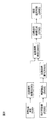
- FIG. 2 is a block diagram for explaining a flowchart of a driving support process in the control device of FIG. 1.
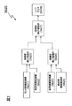
- FIG. 3 is a block diagram for explaining a flowchart of a control process (step S600) of FIG.
- FIG. 4 is a block diagram illustrating a flowchart of a control process (step S610) in FIG. 3.
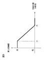
- 5 is a graph showing a relationship between a variance value of a vehicle position and a first reliability. It is a graph which shows the relationship between map accuracy and 1st reliability.
- FIG. 4 is a block diagram for explaining a flowchart of a control process (step S620) of FIG.
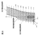
- FIG. 4 is a diagram for explaining a traveling route after integration calculated by the control process (step S600) of FIG. 2. It is a table
- FIG. 1 is a diagram showing a configuration of a vehicle driving support device 100 according to an embodiment of the present invention.
- the driving support device 100 includes a vehicle position detecting device 110, a map database 120, a vehicle speed sensor 130, a distance measuring sensor 140, a camera 150, a driving mechanism 170, , A control device 180, and a yaw rate sensor 190.
- These devices are connected to each other by a CAN (Controller Area Network) or other in-vehicle LAN in order to exchange information with each other.
- CAN Controller Area Network
- the own-vehicle position detecting device 110 includes a GPS unit, detects radio waves transmitted from a plurality of satellite communications with a locator (GPS antenna), periodically acquires position information of the own vehicle, and acquires the acquired self-vehicle information.
- the current position of the vehicle is detected based on the position information of the vehicle, the angle change information acquired from the gyro sensor, and the vehicle speed acquired from the vehicle speed sensor. Further, the own vehicle position detecting device 110 can also detect the position of the own vehicle using a well-known map matching technique.
- the map database 120 stores map information.
- the map information stored in the map database 120 includes information on the road shape at each map coordinate, for example, attributes related to a curve, a sloping road, an intersection, an interchange, a narrow road, a straight road, a roadside structure, and a merging point are associated with the map coordinates. Recorded.
- the map information is a high-precision map used for automatic driving control of the vehicle.
- the vehicle speed sensor 130 measures the rotational speed of a drive system such as a drive shaft, and detects the traveling speed (hereinafter, also referred to as vehicle speed) of the host vehicle based on the measured rotational speed.
- the vehicle speed information of the own vehicle detected by the vehicle speed sensor 130 is output to the control device 180.
- the yaw rate sensor 190 is mounted at an appropriate place such as a vehicle interior, detects the yaw rate of the own vehicle (the speed of change of the rotation angle in the turning direction), and outputs the detected yaw rate information of the own vehicle to the control device 180. .
- the distance measuring sensor 140 detects an object existing around the own vehicle. Further, the distance measurement sensor 140 calculates a relative distance and a relative speed between the vehicle and the target object. Information on the target object detected by the distance measuring sensor 140 is transmitted to the control device 180.
- a laser radar, a millimeter wave radar, or the like can be used as the distance measuring sensor 140.
- the camera 150 captures images of roads and objects around the own vehicle. In the present embodiment, the camera 150 captures an image of the front of the host vehicle. Image information captured by the camera 150 is transmitted to the control device 180.
- the camera 150 is a camera that images the front of the host vehicle and / or a camera that images the side of the host vehicle.
- the input device 160 is an operation member that can be operated by a driver.
- the driver can turn on / off the automatic driving control by operating the input device 160.
- the automatic driving control of the vehicle when a preceding vehicle exists in front of the own vehicle, the inter-vehicle distance between the own vehicle and the preceding vehicle is maintained at the inter-vehicle distance set by the driver.
- Inter-vehicle distance control (preceding vehicle following control) is performed to drive the own vehicle so that the vehicle follows the preceding vehicle. If there is no preceding vehicle ahead of the own vehicle, the own vehicle is driven at the vehicle speed set by the driver. Is controlled.
- the driver operates the input device 160 to set the vehicle speed (for example, a specific speed value) of the own vehicle in the speed control and the set inter-vehicle distance (for example, short, medium, Three stages of length) can be set.
- the drive mechanism 170 includes an engine and / or a motor (power system), a brake (braking system), a steering actuator (steering system), and the like for automatically driving the vehicle.
- the operation of the drive mechanism 170 is controlled by the control device 180 when the automatic operation control described later is performed.
- the control device 180 is a computer having a processor, a ROM (Read Only Memory) storing a program for controlling traveling of the own vehicle, and a CPU (Central Processing Unit) executing the program stored in the ROM. ) And a RAM (Random Access Memory) functioning as an accessible storage device.
- a CPU Central Processing Unit
- MPU Micro Processing Unit
- DSP Digital Signal Processor
- ASIC Application ⁇ Can be used as an operation circuit.
- the control device 180 executes the program stored in the ROM by the CPU, thereby generating a traveling route of the own vehicle, a preceding vehicle traveling route generating function of generating a traveling route of the preceding vehicle, and An integrated function for integrating a vehicle traveling route and a preceding vehicle traveling route, and a traveling control function (including an automatic following function) for controlling traveling of the own vehicle are realized.
- each function of the control device 180 will be described.
- Control device 180 has other functions in addition to the functions described below, such as a function of detecting and estimating the position of the vehicle.
- the control device 180 calculates the own vehicle traveling route based on the own vehicle position and the map information by the own vehicle traveling route generation function.
- the traveling route of the own vehicle is represented by a traveling locus of the own vehicle, a lane boundary, and / or a traveling area.
- the control device 180 estimates the position of the vehicle on the map based on the position information of the vehicle detected by the vehicle position detection device 110 and the map information.
- the control device 180 generates a traveling locus of the own vehicle from a point sequence of points (coordinate positions) indicating the estimated position of the own vehicle.
- the control device 180 may calculate the own vehicle traveling route using the image captured by the camera 150. For example, the control device 180 detects a lane from captured images on the side and / or the front of the own vehicle.
- the control device 180 may generate the own-vehicle traveling route by specifying the detected lane boundary as a lane boundary.
- the control device 180 generates the preceding vehicle traveling route by the preceding vehicle traveling route generating function.
- the preceding vehicle traveling locus is represented by a traveling locus of a preceding vehicle, a lane boundary, and / or a traveling area.
- the control device 180 detects a preceding vehicle traveling in front of the host vehicle using the captured image of the camera 150 and / or detection data of the distance measurement sensor 140.
- Control device 180 estimates the position of the detected preceding vehicle, and generates a traveling locus of the preceding vehicle from the point sequence of the estimated position. Further, control device 180 specifies the shape of the generated preceding vehicle traveling locus.
- the control device 180 generates the target travel route by integrating the own vehicle travel route and the preceding vehicle travel locus by the integration function.
- the target travel route is a route that is a target when the host vehicle travels under the automatic driving control.
- the target travel route is represented by a target travel locus, a target travel path boundary, and a target travel area.
- the control device 180 calculates the reliability of the own vehicle traveling route and the reliability of the preceding vehicle traveling route.
- the reliability of the own vehicle traveling route is a value indicating the accuracy of the generated own vehicle traveling route. For example, when the accuracy of the map information used for generating the own vehicle traveling route is low, the reliability of the own vehicle traveling route generated by the arithmetic processing using the map information becomes low.
- the reliability of the own-vehicle travel route corresponds to the degree of coincidence of the travel route obtained by calculation with the actual travel route.
- the reliability of the preceding vehicle traveling route represents a difference between the own vehicle traveling route and the preceding vehicle traveling route in addition to the accuracy of the generated preceding vehicle traveling route itself. For example, when the accuracy of the camera is low and the recognition accuracy of the preceding vehicle is low, the calculation accuracy of the preceding vehicle traveling locus generated based on the detection data of the camera is low. Such a decrease in accuracy affects the accuracy of the preceding vehicle traveling route itself. Further, for example, when the own vehicle is running following the preceding vehicle by the automatic driving control and the preceding vehicle changes lanes, the running route of the preceding vehicle deviates from the running route of the own vehicle.
- the control device 180 specifies the difference between the own vehicle traveling route and the preceding vehicle traveling route from the shape of the preceding vehicle traveling route. For example, if the preceding vehicle turns left or right or changes lanes while the own vehicle is traveling in a straight lane, the traveling route of the preceding vehicle does not have a straight shape. That is, the control device 180 calculates the reliability of the preceding vehicle traveling route based on the shape of the preceding vehicle traveling route. The method of calculating the reliability of the own vehicle traveling route and the reliability of the preceding vehicle traveling route will be described later. In the following description, the reliability of the own vehicle traveling route is also referred to as “first reliability”, and the reliability of the preceding vehicle traveling route is also referred to as “second reliability”.
- the control device 180 calculates an integration ratio for integrating the own vehicle traveling route and the preceding vehicle traveling route based on the first reliability and the second reliability.
- the integration ratio is a value indicating which of the own vehicle travel route and the preceding vehicle travel route is weighted in calculating the target travel route.
- the integration ratio corresponds to the weighting of the own vehicle traveling route and the preceding vehicle traveling route.
- control device 180 calculates the target travel route of the own vehicle by integrating the own vehicle travel route and the preceding vehicle travel route at the calculated integration ratio.
- the control device 180 controls the drive mechanism 170 by the travel control function, and executes automatic driving control for automatically performing all or a part of the travel of the own vehicle so that the own vehicle travels on the target travel route.
- the traveling control function controls the operation of a drive mechanism 170 such as an engine and a brake when the preceding vehicle exists in front of the own vehicle, thereby controlling the inter-vehicle distance set by the inter-vehicle distance setting function.
- An inter-vehicle distance control is performed to cause the own vehicle to travel a distance away from the preceding vehicle.
- control device 180 controls the operation of the drive mechanism 170 such as the engine, the brake, and the steering actuator when the preceding vehicle is present in front of the own vehicle, so that the inter-vehicle distance between the own vehicle and the preceding vehicle can be calculated.
- the automatic following control is performed to cause the own vehicle to travel so that the own vehicle follows the traveling locus of the preceding vehicle with the following distance set by the following distance setting function.
- control device 180 controls the operation of drive mechanism 170 such as an engine or a brake to drive the own vehicle at a predetermined speed set by the driver.
- the speed running control to be performed is executed.
- the automatic driving control by the driving control function is performed in compliance with the traffic regulations of each country.
- FIG. 2 is a block diagram illustrating a flow of a control process according to the present embodiment.
- the traveling control processing described below is executed by the control device 180.
- the traveling control process described below is started when the ignition switch or the power switch is turned on, and is repeatedly executed at a predetermined cycle (for example, every 10 milliseconds) until the ignition switch or the power switch is turned off. Is done.
- the automatic driving control is input (ON) by the driver
- the driver sets the automatic driving control to ON via the input device 160, and when a preceding vehicle is present ahead of the own vehicle, the driver is separated from the preceding vehicle by the set inter-vehicle distance set by the driver. Then, the automatic following control for following the own vehicle is executed.
- control device 180 acquires the position information of the own vehicle detected by own vehicle position detecting device 110, and acquires the map information from map database 120. Control device 180 estimates the position of the vehicle on the map based on the governor information and the map information.
- control device 180 acquires the own-vehicle road boundary by specifying the travel route on which the own vehicle is currently traveling, based on the estimated position of the own vehicle and the map information.
- the own-vehicle running road boundary corresponds to the left and right boundary lines (lane boundary lines) of the lane in which the own vehicle is currently traveling.
- the control device 180 may obtain the lane boundary from the map database 120. If the high-precision map does not include the information on the lane boundary, the control device 180 may acquire the lane boundary by performing image processing on the image captured by the camera 150.
- control device 180 acquires information on the preceding vehicle by performing image processing on the image captured by camera 150. Further, control device 180 estimates the position of the preceding vehicle based on the information of the preceding vehicle. The control device 180 may acquire the preceding vehicle from the detection data of the distance measurement sensor 140.
- control device 180 calculates the traveling locus of the preceding vehicle based on the acquired information on the preceding vehicle.
- control device 180 acquires a preceding vehicle traveling road boundary by generating a traveling route on which the preceding vehicle is currently traveling based on the map information and the estimated position and map information of the preceding vehicle.
- control device 180 determines the reliability (first reliability) of the own vehicle traveling route (own vehicle traveling road boundary) and the reliability (second reliability) of the preceding vehicle traveling route (preceding vehicle traveling road boundary). Each is calculated, an integration ratio is calculated based on the calculated reliability, and the own vehicle traveling route and the preceding vehicle traveling route are integrated at the calculated integration ratio.
- a lane boundary included in the traveling route will be described as an example, but a lane center line may be used instead of the lane boundary.
- FIG. 3 is a block diagram for explaining the flow of the control process in step S600.
- control device 180 calculates the first reliability based on the lane boundary of the vehicle.
- control device 180 calculates the second reliability based on the lane boundary of the preceding vehicle.
- control device 180 integrates the own-vehicle lane boundary and the preceding-vehicle lane boundary based on the lane boundary of the own vehicle, the lane boundary of the preceding vehicle, the first reliability, and the second reliability.
- the control processing in each of the steps S610 to S630 will be described.
- FIG. 4 is a block diagram illustrating the flow of the control process in step S610.
- the control device 180 calculates the reliability of the high-accuracy map in the control processing in step S610.
- the high-precision map contains information used to execute the automatic driving control. Since the position of a feature such as a lane boundary line shown on a high-accuracy map may be different from the actual position of the feature, the accuracy of the map may change depending on the location on the map.
- the control device 180 calculates the reliability of the map alone according to the following control flow.
- control device 180 calculates a variance value of the position of the host vehicle based on the position of the host vehicle and the posture of the host vehicle estimated within a predetermined cycle.
- the control device 180 estimates the position of the host vehicle at a constant cycle.
- the detection accuracy of the own-vehicle position detecting device 110 is high, the estimated own-vehicle positions are arranged along the traveling locus of the own vehicle.
- the detection accuracy of the own-vehicle position detecting device 110 is low, the estimated own-vehicle position spreads with respect to the traveling locus.
- the control device 180 calculates this spread as a variance value of the own vehicle position.
- control device 180 detects the attitude of the host vehicle using the detection data of yaw rate sensor 190. For example, when the own vehicle fluctuates, the estimated own vehicle position is dispersed. Therefore, control device 180 corrects the variance value of the vehicle position according to the attitude of the vehicle in order to increase the correlation between the detection accuracy of vehicle position detection device 110 and the variance value of the vehicle position.
- the control device 180 refers to a map indicating the correlation between the variance of the position of the vehicle and the first reliability, and calculates the first reliability corresponding to the calculated variance.
- FIG. 5 is a graph showing the relationship between the variance value of the vehicle position and the first reliability. As shown in FIG. 5, there is a correlation between the degree of dispersion of the vehicle position and the first reliability. The larger the variance value of the own vehicle position, the lower the first reliability of the own vehicle position.
- the control device 180 calculates the map accuracy based on the detection value of the on-board sensor such as the camera 150 and the map information.
- the control device 180 specifies the map shape of the peripheral portion of the vehicle from the map information.
- the map shape is specified from, for example, a road shape or the like.
- the control device 180 specifies an object corresponding to the map shape from the image captured by the camera 150.
- the control device 180 specifies a road shape by detecting a lane, a guardrail, a white line indicating an intersection, and the like from the captured image. For example, in places where boundaries are not specified, such as inside an intersection, the accuracy of the high-accuracy map is low.
- control device 180 calculates the degree of coincidence between the road shape specified from the detection data of the vehicle-mounted sensor and the map shape specified from the map information. Then, control device 180 calculates the map accuracy such that the higher the degree of coincidence, the higher the value indicating the map accuracy.
- the control device 180 refers to the map indicating the correlation between the map accuracy and the first reliability, and calculates the first reliability corresponding to the calculated map accuracy.
- FIG. 6 is a graph showing the relationship between the map accuracy and the first reliability. As shown in FIG. 6, there is a correlation between the map accuracy and the first reliability. The lower the map accuracy, the lower the first reliability of the vehicle position.
- control device 180 selects the lower first reliability from the first reliability calculated based on the variance value of the vehicle position and the first reliability calculated based on the map accuracy. Yes (select low).
- control device 180 performs a rate limiter process on the selected first reliability.
- the upper limit value of the change amount is set in the control device 180 in advance.
- Control device 180 calculates the amount of change between the first reliability value calculated in the previous cycle and the first reliability value calculated in the current cycle.
- Control device 180 compares the calculated change amount with the upper limit value of the change amount. If the calculated change amount is equal to or more than the upper limit value, a value obtained by limiting the change amount to the upper limit value (a value obtained by adding the upper limit value of the change amount to the first reliability calculated in the previous cycle) is used as the first reliability value. Degree.
- the control device 180 outputs the first reliability value selected in the control processing of step S613 as it is.
- control device 180 calculates the reliability of the generated preceding vehicle lane boundary itself (hereinafter, also referred to as single unit reliability) by comparing the own vehicle lane boundary and the preceding vehicle lane boundary.
- the reliability (hereinafter, also referred to as comparison reliability) is calculated.
- the control device 180 calculates the second reliability based on the unit reliability and the comparative reliability.
- the unit reliability is represented by the sensor reliability and the trajectory reliability
- the comparison reliability is represented by the curvature reliability and the lateral position reliability.
- the unit reliability may include at least one of the sensor reliability and the trajectory reliability
- the comparison reliability may include at least one of the curvature reliability and the lateral position reliability.
- step S621 the control device 180 calculates the sensor reliability based on the detection data of the in-vehicle sensor such as a camera.
- the sensor reliability corresponds to the stability of detection of the sensor. For example, if the preceding vehicle cannot be detected from the image captured by the camera due to the input of disturbance, the sensor reliability decreases.
- control device 180 calculates the locus reliability of the preceding vehicle traveling locus.
- the trajectory reliability is an evaluation value indicating whether or not the preceding vehicle lane boundary computed in the computation processing of steps S400 and S500 is a path suitable for computation of the target lane boundary, and is the length of the preceding vehicle traveling locus. Determined by For example, when the preceding vehicle enters the front of the own vehicle with a cut-in and exits from the front of the own vehicle in a short time, the running locus of the preceding vehicle becomes short. In such a case, the trajectory reliability decreases. Control device 180 calculates the trajectory reliability such that the shorter the length of the preceding vehicle traveling trajectory, the lower the trajectory reliability.
- control device 180 selects the lower one of the sensor reliability and the trajectory reliability. The selected reliability becomes the unit reliability.
- control device 180 calculates a curvature difference between the curvature of the own vehicle travel locus and the curvature of the preceding vehicle travel locus, and calculates the curvature reliability based on the curvature difference.
- the curvature reliability is an evaluation value obtained by evaluating the difference between the traveling locus of the preceding vehicle and the traveling locus of the own vehicle using the curvature.
- the controller 180 calculates the curvature reliability such that the larger the difference in curvature, the lower the curvature reliability.
- the curvature reliability is lowered so that the target route of the host vehicle does not become the travel route of the preceding vehicle that changes lanes.
- the control device 180 refers to a map indicating the correlation between the curvature difference and the curvature reliability, and calculates the curvature reliability corresponding to the calculated curvature difference.
- FIG. 8 is a graph showing the correlation between the curvature difference and the curvature reliability. As shown in FIG. 8, there is a correlation between the curvature difference and the curvature reliability. The greater the curvature difference, the lower the curvature reliability.
- the control device 180 refers to the map and calculates the curvature reliability corresponding to the curvature difference according to the vehicle speed of the own vehicle.
- the solid line graph shows the characteristics when the vehicle speed is low.
- the dotted-line graph shows the identification when the vehicle speed is high.
- the correlation between the curvature difference and the curvature reliability is such that, when the curvature difference is the same, the curvature reliability decreases as the vehicle speed increases. For example, when the preceding vehicle changes lanes while the vehicle speed of the preceding vehicle is high, the curvature of the traveling locus of the preceding vehicle decreases. On the other hand, when the preceding vehicle changes lanes while the vehicle speed of the preceding vehicle is low, the curvature of the traveling locus of the preceding vehicle increases.
- the correlation between the curvature difference and the curvature reliability is changed according to the vehicle speed, so that the comparison reliability is appropriately calculated in accordance with the vehicle speed of the preceding vehicle.
- control device 180 calculates a deviation between the position of the host vehicle in the lateral direction on the boundary of the host vehicle and the position of the preceding vehicle in the lateral direction on the boundary of the preceding vehicle.
- the lateral direction is the width direction of the vehicle.
- the position of the vehicle may be on the boundary of the traveling route and / or on the center line of the traveling route.
- the position of the vehicle may be on any one of the left and right lane boundaries.
- the controller 180 decreases the lateral position reliability as the deviation in the lateral direction increases.
- the lateral position reliability is an evaluation value obtained by evaluating the difference between the boundary of the preceding vehicle lane and the boundary of the own vehicle lane by the position in the lateral direction.
- the controller 180 calculates the lateral reliability so that the greater the deviation of the lateral position, the lower the lateral position reliability.
- the controller 180 refers to a map indicating the correlation between the lateral position deviation (hereinafter, also referred to as the lateral position deviation) and the lateral position reliability, and calculates the lateral position reliability corresponding to the calculated lateral position deviation. Calculate.
- FIG. 9 is a graph showing the correlation between the lateral position deviation and the lateral position reliability. As shown in FIG. 9, there is a correlation between the lateral position deviation and the lateral position reliability. The greater the lateral position deviation, the lower the lateral position reliability.
- the control device 180 calculates the lateral position reliability corresponding to the lateral position deviation with reference to the map according to the vehicle speed of the own vehicle.
- the solid line graph shows the characteristics when the vehicle speed is low.
- the dotted-line graph shows the identification when the vehicle speed is high.
- the correlation between the lateral position deviation and the lateral position reliability is such that, when the lateral position deviation is the same, the lateral position reliability decreases as the vehicle speed increases. For example, when the preceding vehicle changes lanes in a state where the speed of the preceding vehicle is high, the amount of change in the traveling locus of the preceding vehicle in the lateral direction becomes small. On the other hand, when the preceding vehicle changes lanes while the speed of the preceding vehicle is low, the amount of change in the traveling locus of the preceding vehicle in the lateral direction increases.
- the correlation between the lateral position deviation and the lateral position reliability is changed according to the vehicle speed, so that the comparison reliability is appropriately calculated in accordance with the vehicle speed of the preceding vehicle.
- control device 180 selects the lower one of the curvature reliability and the lateral position reliability.
- the selected reliability is the comparison reliability.
- control device 180 selects the lower one of the unit reliability and the comparison reliability.
- the selected reliability is the second reliability.
- control device 180 performs a rate limiter process on the selected second reliability.
- the upper limit value of the change amount is set in the control device 180 in advance.
- Control device 180 calculates the amount of change between the second reliability value calculated in the previous cycle and the second reliability value calculated in the current cycle.
- Control device 180 compares the calculated change amount with the upper limit value of the change amount. If the calculated change amount is equal to or larger than the upper limit value, the value obtained by limiting the change amount to the upper limit value (the value obtained by adding the upper limit value of the change amount to the second reliability calculated in the previous cycle) is used as the second trust value. Degree. On the other hand, if the calculated change amount is less than the upper limit value, the control device 180 outputs the second reliability value selected in the control processing of step S627 as it is.
- control device 180 executes the control process of step S600 and then executes the control process of step S700 shown in FIG.
- control device 180 In step S700, control device 180 generates a target travel route based on the first reliability and the second reliability. The control process of the target traveling route will be described with reference to FIG.
- the control device 180 calculates the integration ratio based on the first reliability and the second reliability.
- the integration ratio is represented by the ratio of the first reliability to the total reliability obtained by adding the first reliability and the second reliability, and the ratio of the second reliability to the total reliability.
- the control device 180 corrects the lateral coordinates of the own vehicle lane boundary and the lateral coordinates of the preceding vehicle lane boundary by the corresponding integration ratio, and calculates the integrated lane boundary.
- the control device 180 calculates the lateral coordinates of the lane boundary after integration using the following equation (1).
- the traveling direction of the host vehicle is defined as the x-axis
- the vehicle width direction is defined as the y-axis.
- y i, j denotes the y coordinate on the lane boundary after integration
- y a_i, j represents the y coordinate on the vehicle lane boundary
- y b_i, j denotes a y-coordinate on the preceding vehicle lane boundary.
- Ra_i, j indicates the first reliability
- Rb_i, j indicates the second reliability.
- i indicates a detection order
- j indicates left and right.
- the first reliability and the second reliability are normalized between 0 and 1.
- the coefficient multiplied by the y coordinate ( ya_i, j ) and the y coordinate ( yb_i, j ) corresponds to the integration ratio.
- the first reliability and the second reliability are 0.5
- the y-coordinate of the lane boundary after integration is between the y-coordinate of the own vehicle lane boundary and the y-coordinate of the preceding lane boundary.
- the first reliability and the second reliability are compared, and when the first reliability is higher than the second reliability, the y-coordinate of the lane boundary after integration is more than the y-coordinate of the lane of the preceding vehicle. , Closer to the y-coordinate of the own-vehicle running road boundary.
- the y-coordinate (y i, j ) of the lane boundary after integration matches the y-coordinate ( ya_i, j ) of the own vehicle lane boundary.
- the control device 180 may calculate the integration ratio so that the first reliability is weighted more than the second reliability.
- the first reliability is weighted more than the second reliability.
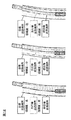
- FIGS. 11 and 12 a description will be given of the relationship between the weighting in the calculation processing of the integration ratio and the own vehicle lane boundary, the preceding vehicle lane boundary, and the integrated lane boundary.
- An upper reliability threshold and a lower reliability threshold are set for the first reliability and the second reliability, respectively.
- the upper reliability threshold is set to a value higher than the lower reliability threshold.
- a state in which the first reliability is higher than the upper reliability threshold is “high”
- a state in which the first reliability is lower than the upper reliability and higher than the lower reliability is “medium”
- the first reliability is higher.
- a state lower than the lower reliability is defined as “low”.
- the integration ratio is set assuming that the utilization ratio of the own vehicle lane boundary is 100%.
- the utilization ratio of the preceding vehicle lane boundary is set to 0%.
- the integration ratio is defined as the utilization ratio of the own vehicle lane boundary being 100% and the use of the preceding vehicle lane boundary. Set the ratio to 0%. That is, when the first reliability is higher than the upper reliability threshold and the second reliability is higher than the lower reliability threshold, the control device 180 sets the ratio of the first reliability higher than the second reliability. , Calculate the integration ratio.
- FIG. 12A The lane boundary when the first reliability is “high” and the second reliability is “high” is shown in FIG. 12A.
- the lane boundary after integration coincides with the own vehicle lane boundary.
- the reliability of the own vehicle traveling route is high, the utilization rate of the own vehicle traveling route is increased regardless of the degree of reliability of the preceding vehicle traveling route. Thereby, the own vehicle can run stably in the lane of the own vehicle without following the fluctuation in the lane of the preceding vehicle or the steady positional deviation.
- the integration ratio is set to 50% of the utilization ratio of the own vehicle traveling road boundary.
- the utilization ratio of the boundary of the preceding vehicle lane is set to 50%.
- the integration ratio is defined as the utilization ratio of the preceding vehicle lane boundary with the utilization ratio of the vehicle lane boundary being 100%. Set the ratio to 0%. That is, when the first reliability is equal to or more than the lower reliability threshold, the control device 180 calculates the integration ratio so as to include the first reliability.
- FIG. 12B The lane boundary when the first reliability is “high” and the second reliability is “medium” is shown in FIG. 12B.
- the lane boundary after the integration slightly deviates from the position of the lane boundary of the own vehicle to the lane boundary of the preceding vehicle lane. That is, when the first reliability is equal to or greater than the lower reliability threshold, the vehicle can travel stably in the lane of the vehicle by utilizing the vehicle traveling route.
- the integration ratio is set to 0% based on the utilization ratio of the own vehicle lane boundary. , The utilization rate of the boundary of the preceding vehicle lane is set to 100%.
- the integration ratio is set to 0% using the own vehicle lane boundary and utilizing the preceding vehicle lane boundary. Set the ratio to 0%. That is, when the first reliability is less than the lower reliability threshold and the second reliability is equal to or more than the upper reliability, the control device 180 causes the ratio of the second reliability to be larger than the first reliability. Then, the integration ratio is calculated.
- FIG. 12C The lane boundary when the first reliability is “low” and the second reliability is “high” is shown in FIG. 12C.
- the lane boundary after integration coincides with the preceding vehicle lane boundary.
- the reliability of the own vehicle traveling route is low, the utilization ratio of the preceding vehicle traveling route is increased when the reliability of the preceding vehicle traveling route is high. As a result, the vehicle can travel stably in the lane.
- control device 180 generates a target traveling route by calculating a target traveling route boundary based on the map information and the integrated traveling road boundary.
- control device 180 controls the operation of drive mechanism 170 such that the vehicle travels on the target traveling route.
- the own vehicle travel route is generated based on the estimated position of the own vehicle and the map information, the first reliability indicating the reliability of the own vehicle travel route is calculated, and the preceding vehicle is detected. Then, a preceding vehicle traveling route is generated, and a second reliability indicating the reliability of the preceding vehicle traveling route is calculated based on the shape of the preceding vehicle traveling route. Then, based on the first reliability and the second reliability, an integration ratio for integrating the own vehicle traveling route and the preceding vehicle traveling route is calculated, and the own vehicle traveling route and the preceding vehicle traveling route are integrated based on the integration ratio. By doing so, the target traveling route of the own vehicle is calculated, and the own vehicle is controlled based on the target traveling route. As a result, for example, when the detection accuracy of the preceding vehicle is low, or when the traveling route of the preceding vehicle is different from the traveling route, the own vehicle follows the trajectory of the preceding vehicle and the subject vehicle fluctuates. Can be suppressed.
- the lower the estimation accuracy of the position of the host vehicle the lower the first reliability. If the position estimation accuracy is reduced, there is a possibility that a steady deviation occurs in the lateral position of the host vehicle or the attitude angle of the host vehicle. In the present embodiment, when the estimation accuracy of the position of the host vehicle is low, the first reliability is lowered, so that the steady deviation can be suppressed and the fluctuation of the host vehicle can be prevented.
- the lower the map accuracy of the map represented by the map information the lower the first reliability.
- the map accuracy is low. In the present embodiment, it is possible to suppress the fluctuation of the host vehicle caused by a decrease in map accuracy.
- the estimation accuracy of the position of the host vehicle and the map accuracy are calculated, and the first reliability is calculated based on the lower one of the detection accuracy and the map accuracy.
- the reliability of the preceding vehicle traveling route is calculated using the detection data of the preceding vehicle detected by the sensor, and the relative reliability is calculated by comparing the own vehicle traveling route with the preceding vehicle traveling route.
- the second reliability is calculated based on the single reliability and the comparison reliability. Accordingly, by using both the detection state of the preceding vehicle and the shape of the traveling route for the calculation of the second reliability, when the detection accuracy of the preceding vehicle is low, or when the traveling route of the own vehicle and the traveling route of the preceding vehicle are different If different, it is possible to prevent the host vehicle from following the preceding vehicle and wobbling.
- the reliability of the sensor is calculated by evaluating the stability of the detection of the sensor, and the preceding vehicle traveling locus included in the preceding vehicle traveling route is generated using the detection data of the sensor, and the traveling of the preceding vehicle is performed.
- the trajectory reliability determined by the trajectory length is calculated, and the unit reliability is calculated based on the sensor reliability and the trajectory reliability.
- the second reliability is calculated based on the trajectory reliability. By following the trajectory, the vehicle can be prevented from wobbling.
- the shorter the length of the preceding vehicle traveling locus the lower the locus reliability. Accordingly, when the path of the preceding vehicle is short and the path of the preceding vehicle cannot be correctly recognized, it is possible to prevent the own vehicle from following the path change of the preceding vehicle and wandering.
- the unit reliability is calculated based on the lower one of the sensor reliability and the trajectory reliability.
- the vehicle can be prevented from wandering when the detection accuracy of the preceding vehicle is low or when the traveling locus of the preceding vehicle is short.
- the curvature difference between the curvature of the own vehicle traveling route and the curvature of the preceding vehicle traveling route is calculated, and the larger the curvature difference, the lower the comparison reliability.
- the comparison reliability is calculated based on the vehicle speed and the curvature difference of the own vehicle using a correlation in which the higher the vehicle speed of the own vehicle, the lower the comparison reliability.
- the calculation reference of the reliability of the preceding vehicle traveling route can be changed according to the vehicle speed.
- the deviation between the position of the host vehicle in the lateral direction on the host vehicle traveling route and the position of the preceding vehicle in the lateral direction on the preceding vehicle traveling route is calculated. make low.
- the lateral positional deviation between the preceding vehicle traveling route and the own vehicle traveling route is large, it is possible to prevent the own vehicle from following the preceding vehicle and fluctuating.
- the curvature difference between the curvature of the own vehicle traveling route and the curvature of the preceding vehicle traveling route is calculated, and the curvature reliability is calculated based on the correlation between the curvature difference and the reliability of the preceding vehicle traveling route, Calculates the deviation between the position of the host vehicle in the lateral direction on the own vehicle traveling route and the position of the preceding vehicle in the lateral direction on the preceding vehicle traveling route, and based on the correlation between the deviation and the reliability of the preceding vehicle traveling route.
- the horizontal reliability is calculated, and the second reliability is calculated based on the lower one of the curvature reliability and the horizontal reliability.
- the second reliability is calculated based on the lower one of the unit reliability and the comparison reliability. This can prevent the subject vehicle from wandering when either the detection accuracy of the preceding vehicle decreases or the traveling route of the preceding vehicle changes.
- the coordinates of the host vehicle in the lateral direction on the own vehicle traveling route and the coordinates of the preceding vehicle in the lateral direction on the preceding vehicle traveling route are estimated, and the coordinates of the own vehicle and the The target travel route is calculated by integrating the coordinates.
- the target travel route is switched by selecting the own vehicle travel route and the preceding vehicle travel route, the behavior of the own vehicle may change suddenly.
- the target travel route changes continuously, it is possible to prevent the behavior of the own vehicle from changing suddenly.
- the target travel route is calculated such that the ratio of the own vehicle travel route to the preceding vehicle travel route is larger.
- the ratio of the own vehicle traveling route is larger than the preceding vehicle traveling route. Calculate the target travel route.
- the vehicle can stably travel in the own lane by utilizing the own lane traveling route.
- the ratio of the preceding vehicle traveling route becomes larger than the own vehicle traveling route.
- the target travel route is calculated. Accordingly, when the reliability of the traveling path of the preceding vehicle is high and the reliability of the traveling path of the own vehicle is low, the vehicle can travel stably in the own lane by utilizing the traveling path of the preceding vehicle.
- the reliability when calculating the first reliability, the reliability is calculated based on different factors such as the variance of the position of the vehicle, the map accuracy, and the like. Thus, the first reliability is calculated, but it is not always necessary to take the select low. For example, an average value of various degrees of reliability calculated with different elements may be calculated as the first reliability. Similarly, for the second reliability, it is not necessary to take the select rows of various reliability calculated with different elements, and it may be an average value.
- all or some of the reliability values may be extracted from the various reliability values calculated using different elements, and the integration ratio may be calculated based on the extracted reliability values.
- the integration ratio may be calculated by calculating the ratio of each reliability with respect to the extracted total reliability.
- the travel locus used for the control for causing the vehicle to travel in a stepwise manner may be calculated so as to calculate the target travel locus of the own vehicle.
- the travel locus of the own vehicle can be calculated after calculating the area in which the own vehicle can travel using the information of the preceding vehicle, so that it is possible to suppress fluctuations following the preceding vehicle.
- control device 180 For example, the control device 180 generates a preceding vehicle traveling route by a preceding vehicle traveling route generating function. Then, control device 180 sets a route along the generated preceding vehicle travel route as a target travel route of the own vehicle, and calculates a target travel route boundary or a target travel area from the set target travel route. The control device 180 calculates a target travel locus based on the calculated target lane boundary or target travel area, and controls the own vehicle so as to follow the calculated target travel locus. As a result, it is possible to calculate a target traveling locus along the actual road environment in the traveling road boundary or the traveling area.
- a trajectory can be arbitrarily drawn in a road boundary or a traveling area, it is possible to calculate a traveling trajectory that suppresses a sense of discomfort given to an occupant while suppressing a stagger caused by a preceding vehicle. become able to.
- the detection data of the on-vehicle sensor such as a camera is used when calculating the traveling route of the preceding vehicle.
- the information of the preceding vehicle is acquired using the vehicle-to-vehicle communication or the road-to-vehicle communication. Based on the acquired information, the traveling speed of the preceding vehicle may be calculated.
- the own vehicle traveling route may be calculated based on data obtained using inter-vehicle communication or road-to-vehicle communication.
- the preceding vehicle is not limited to the vehicle immediately before the own vehicle, but may be a preceding vehicle that is two or more vehicles ahead of the own vehicle. If the information of the preceding vehicle that is two or more vehicles ahead cannot be acquired by the on-vehicle sensor, the necessary data may be acquired using inter-vehicle communication or road-to-vehicle communication.
- REFERENCE SIGNS LIST 100 driving support device 110 own vehicle position detecting device 120 map database 130 vehicle speed sensor 140 ranging sensor 150 camera 160 input device 170 driving mechanism 180 control device 190 yaw rate sensor
Landscapes
- Engineering & Computer Science (AREA)
- Mechanical Engineering (AREA)
- Automation & Control Theory (AREA)
- Transportation (AREA)
- Physics & Mathematics (AREA)
- Human Computer Interaction (AREA)
- General Physics & Mathematics (AREA)
- Mathematical Physics (AREA)
- Traffic Control Systems (AREA)
- Control Of Driving Devices And Active Controlling Of Vehicle (AREA)
Abstract
Description

目標走行経路が連続的に変わるため、自車両の挙動が急変することを防止できる。 Further, in the present embodiment, the coordinates of the host vehicle in the lateral direction on the own vehicle traveling route and the coordinates of the preceding vehicle in the lateral direction on the preceding vehicle traveling route are estimated, and the coordinates of the own vehicle and the The target travel route is calculated by integrating the coordinates. When the target travel route is switched by selecting the own vehicle travel route and the preceding vehicle travel route, the behavior of the own vehicle may change suddenly. In the present embodiment,
Since the target travel route changes continuously, it is possible to prevent the behavior of the own vehicle from changing suddenly.
110…自車位置検出装置
120…地図データベース
130…車速センサ
140…測距センサ
150…カメラ
160…入力装置
170…駆動機構
180…制御装置
190…ヨーレートセンサ REFERENCE SIGNS
Claims (20)
- プロセッサに実行にさせる、車両の走行支援方法であって、
自車両の位置を推定し、
データベースから地図情報を取得し、
推定された前記自車両の位置及び前記地図情報に基づき、前記自車両が走行する自車走行経路を生成し、
前記自車走行経路の信頼度を示す第1信頼度を演算し、
前記自車両の前方を走行する先行車を検出し、
前記先行車両が走行する先行車走行経路を生成し、
前記先行車走行経路の形状に基づき、前記先行車走行経路の信頼度を示す第2信頼度を演算し、
前記第1信頼度と前記第2信頼度に基づき、前記自車走行経路と前記先行車走行経路とを統合するための統合割合を演算し、
演算された前記統合割合で前記自車走行経路と前記先行車走行経路とを統合することで、前記自車両の目標走行経路を演算し、
前記目標走行経路に基づいて前記自車両を制御する走行支援方法。 A driving support method for a vehicle, which is executed by a processor,
Estimate the position of your vehicle,
Get map information from the database,
Based on the estimated position of the host vehicle and the map information, generate a host vehicle traveling route on which the host vehicle travels,
Calculating a first reliability indicating the reliability of the own vehicle traveling route;
Detecting a preceding vehicle traveling in front of the host vehicle,
Generating a preceding vehicle traveling route on which the preceding vehicle travels,
Based on the shape of the preceding vehicle traveling route, a second reliability indicating the reliability of the preceding vehicle traveling route is calculated,
Based on the first reliability and the second reliability, an integration ratio for integrating the own vehicle traveling route and the preceding vehicle traveling route is calculated,
By integrating the own vehicle travel route and the preceding vehicle travel route at the calculated integration ratio, a target travel route of the own vehicle is calculated,
A driving support method for controlling the own vehicle based on the target driving route. - 前記自車両の位置の推定精度が低いほど、前記第1信頼度を低くする請求項1に記載の走行支援方法。 The driving support method according to claim 1, wherein the lower the estimation accuracy of the position of the host vehicle is, the lower the first reliability is.
- 前記地図情報で表される地図の地図精度が低いほど、前記第1信頼度を低くする請求項1又は2に記載の走行支援方法。 The driving support method according to claim 1 or 2, wherein the lower the map accuracy of the map represented by the map information is, the lower the first reliability is.
- 前記自車両の位置の推定精度、及び、前記地図情報で表される地図の地図精度をそれぞれ演算し、
前記推定精度と前記地図精度のうち、いずれか低い方の精度に基づき前記第1信頼度を演算する請求項1記載の走行支援方法。 The estimation accuracy of the position of the vehicle, and the map accuracy of the map represented by the map information is calculated,
The driving support method according to claim 1, wherein the first reliability is calculated based on a lower one of the estimation accuracy and the map accuracy. - センサにより検出される前記先行車の検出データを用いて、前記先行車走行経路の単体信頼度を演算し、
前記自車走行経路と前記先行車走行経路とを比較して、前記先行車走行経路の比較信頼度を演算し、
前記単体信頼度と前記比較信頼度に基づき、前記第2信頼度を演算する請求項1~4のいずれか一項に記載の走行支援方法。 Using the detection data of the preceding vehicle detected by a sensor, calculate the unit reliability of the preceding vehicle traveling route,
Comparing the own vehicle travel route and the preceding vehicle travel route, and calculating the comparative reliability of the preceding vehicle travel route,
The driving support method according to any one of claims 1 to 4, wherein the second reliability is calculated based on the single reliability and the comparison reliability. - 前記センサの検出の安定性を評価することで、前記センサの信頼度を示すセンサ信頼度を演算し、
前記センサの検出データを用いて、前記先行車走行経路に含まれる先行車走行軌跡を生成し、
前記先行車走行軌跡の長さで決まる、軌跡信頼度を演算し、
前記センサ信頼度及び前記軌跡信頼度に基づき、前記単体信頼度を演算する請求項5記載の走行支援方法。 By evaluating the stability of the detection of the sensor, to calculate the sensor reliability indicating the reliability of the sensor,
Using the detection data of the sensor, generate a preceding vehicle traveling locus included in the preceding vehicle traveling route,
Calculate the locus reliability, which is determined by the length of the preceding vehicle running locus,
The driving support method according to claim 5, wherein the single unit reliability is calculated based on the sensor reliability and the trajectory reliability. - 前記先行車走行軌跡の長さが短いほど、前記軌跡信頼度を低くする請求項6記載の走行支援方法。 7. The driving support method according to claim 6, wherein the shorter the length of the preceding vehicle traveling locus, the lower the locus reliability.
- 前記センサ信頼度と前記軌跡信頼度のうち、いずれか低い方の信頼度に基づき前記単体信頼度を演算する請求項6又は7記載の走行支援方法。 8. The driving support method according to claim 6, wherein the single unit reliability is calculated based on a lower one of the sensor reliability and the trajectory reliability.
- 前記自車走行経路の曲率と前記先行車走行経路の曲率との曲率差を演算し、前記曲率差が大きいほど前記比較信頼度を低くする請求項5~8のいずれか一項に記載の走行支援方法。 The travel according to any one of claims 5 to 8, wherein a curvature difference between a curvature of the own vehicle travel route and a curvature of the preceding vehicle travel route is calculated, and the comparative reliability is reduced as the curvature difference increases. How to help.
- 前記曲率差が同じ場合に、前記自車両の車速が大きいほど前記比較信頼度が低くなる相関関係を用いて、前記自車両の車速及び前記曲率差に基づき、前記比較信頼度を演算する請求項9記載の走行支援方法。 When the curvature difference is the same, the comparison reliability is calculated based on the vehicle speed of the own vehicle and the curvature difference, using a correlation in which the comparison reliability decreases as the vehicle speed of the own vehicle increases. 9. The driving support method according to 9.
- 前記自車走行経路上における横方向の前記自車両の位置と、前記先行車走行経路上における横方向の前記先行車の位置との偏差を演算し、前記偏差が大きいほど前記比較信頼度を低くする請求項5~10のいずれか一項に記載の走行支援方法。 A deviation between the position of the host vehicle in the lateral direction on the host vehicle traveling route and the position of the preceding vehicle in the lateral direction on the preceding vehicle traveling route is calculated, and the larger the deviation is, the lower the comparison reliability is. The driving support method according to any one of claims 5 to 10.
- 前記自車走行経路の曲率と前記先行車走行経路の曲率との曲率差を演算し、前記曲率差と前記先行車走行経路の信頼度との相関性に基づき、前記第2信頼度を示す値を曲率信頼度として演算し、
前記自車走行経路上における横方向の前記自車両の位置と、前記先行車走行経路上における横方向の前記先行車の位置との偏差を演算し、前記偏差と前記先行車走行経路の信頼度との相関性に基づき、前記第2信頼度を示す値を横方向信頼度として演算し、
前記曲率信頼度及び前記横方向信頼度のうち、いずれか低い方の信頼度に基づき前記第2信頼度を演算する請求項5~8のいずれか一項に記載の走行支援方法。 Calculating a curvature difference between the curvature of the own vehicle travel route and the curvature of the preceding vehicle travel route; and a value indicating the second reliability based on a correlation between the curvature difference and the reliability of the preceding vehicle travel route. Is calculated as the curvature reliability,
Calculating the deviation between the position of the host vehicle in the lateral direction on the host vehicle traveling route and the position of the preceding vehicle in the lateral direction on the preceding vehicle traveling route; and calculating the deviation and the reliability of the preceding vehicle traveling route. The value indicating the second reliability is calculated as the horizontal reliability based on the correlation with
9. The driving support method according to claim 5, wherein the second reliability is calculated based on a lower one of the curvature reliability and the lateral reliability. - 前記単体信頼度及び前記比較信頼度のうち、いずれか低い方の信頼度に基づき前記第2信頼度を演算する請求項5~8のいずれか一項に記載の走行支援方法。 The driving support method according to any one of claims 5 to 8, wherein the second reliability is calculated based on a lower one of the single reliability and the comparative reliability.
- 前記自車走行経路上における横方向の前記自車両の座標と、前記先行車走行経路上における横方向の前記先行車の座標をそれぞれ推定し、
前記統合割合で前記自車両の座標及び前記先行車の座標を統合させることで前記目標走行経路を演算する請求項1~13のいずれか一項に記載の走行支援方法。 Estimating the coordinates of the host vehicle in the lateral direction on the host vehicle traveling route and the coordinates of the preceding vehicle in the lateral direction on the preceding vehicle driving route,
14. The travel support method according to claim 1, wherein the target travel route is calculated by integrating the coordinates of the host vehicle and the coordinates of the preceding vehicle at the integration ratio. - 前記第1信頼度及び前記第2信頼度が所定の信頼度閾値より高い場合には、前記先行車走行経路より前記自車走行経路の割合が大きくなるように前記目標走行経路を演算する請求項1~14のいずれか一項に記載の走行支援方法。 The target travel route is calculated such that, when the first reliability and the second reliability are higher than a predetermined reliability threshold, the ratio of the own vehicle travel route is larger than the preceding vehicle travel route. 15. The driving support method according to any one of 1 to 14.
- 前記第1信頼度が所定の信頼度閾値より高く、前記第2信頼度が前記所定の信頼度より低い場合には、前記先行車走行経路より前記自車走行経路の割合が大きくなるように前記目標走行経路を演算する請求項1~14のいずれか一項に記載の走行支援方法。 When the first reliability is higher than a predetermined reliability threshold and the second reliability is lower than the predetermined reliability, the ratio of the own vehicle traveling route is larger than that of the preceding vehicle traveling route. 15. The driving support method according to claim 1, wherein a target driving route is calculated.
- 前記第1信頼度が所定の信頼度閾値より低く、前記第2信頼度が前記所定の信頼度閾値より高い場合には、前記自車走行経路より前記先行車走行経路の割合が大きくなるように前記目標走行経路を演算する請求項1~14のいずれか一項に記載の走行支援方法。 When the first reliability is lower than a predetermined reliability threshold and the second reliability is higher than the predetermined reliability threshold, the ratio of the preceding vehicle traveling route is larger than the own vehicle traveling route. 15. The driving support method according to claim 1, wherein the target driving route is calculated.
- 前記自車両の目標走行経路を目標走路境界として演算し、
前記目標走路境界に基づいて目標走行軌跡を演算し、自車両の前記自車両を制御する請求項1~15のいずれか一項に記載の走行支援方法。 Calculate the target travel route of the vehicle as a target travel boundary,
16. The driving support method according to any one of claims 1 to 15, wherein a target traveling locus is calculated based on the target lane boundary, and the own vehicle is controlled. - 前記自車両の目標走行経路を目標走行領域として演算し、
前記目標走行領域に基づいて目標走行軌跡を演算し、自車両の前記自車両を制御する請求項1~15のいずれか一項に記載の走行支援方法。 The target travel route of the vehicle is calculated as a target travel area,
16. The driving support method according to claim 1, wherein a target traveling locus is calculated based on the target traveling region, and the own vehicle is controlled. - プロセッサを有する走行支援装置であって、
前記プロセッサは、
自車両の位置を推定し、
データベースから地図情報を取得し、
推定された前記自車両の位置及び前記地図情報に基づき、前記自車両が走行する自車走行経路を生成し、
前記自車走行経路の信頼度を示す第1信頼度を演算し、
前記自車両の前方を走行する先行車を検出し、
前記先行車両が走行する先行車走行経路を生成し、
前記先行車走行経路の形状に基づき、前記先行車走行経路の信頼度を示す第2信頼度を演算し、
前記第1信頼度と前記第2信頼度に基づき、前記自車走行経路と前記先行車走行経路とを統合するための統合割合を演算し、
演算された前記統合割合で前記自車走行経路と前記先行車走行経路とを統合することで、前記自車両の目標走行経路を演算し、
前記目標走行経路に基づいて前記自車両を制御する走行支援装置。 A driving assistance device having a processor,
The processor comprises:
Estimate the position of your vehicle,
Get map information from the database,
Based on the estimated position of the host vehicle and the map information, generate a host vehicle traveling route on which the host vehicle travels,
Calculating a first reliability indicating the reliability of the own vehicle traveling route;
Detecting a preceding vehicle traveling in front of the host vehicle,
Generating a preceding vehicle traveling route on which the preceding vehicle travels,
Based on the shape of the preceding vehicle traveling route, a second reliability indicating the reliability of the preceding vehicle traveling route is calculated,
Based on the first reliability and the second reliability, an integration ratio for integrating the own vehicle traveling route and the preceding vehicle traveling route is calculated,
By integrating the own vehicle travel route and the preceding vehicle travel route at the calculated integration ratio, a target travel route of the own vehicle is calculated,
A driving support device that controls the host vehicle based on the target driving route.
Priority Applications (6)
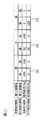
| Application Number | Priority Date | Filing Date | Title |
|---|---|---|---|
| CN201880094929.1A CN112352270B (en) | 2018-06-29 | 2018-06-29 | Driving assistance method and driving assistance device |
| EP18924837.0A EP3816965A4 (en) | 2018-06-29 | 2018-06-29 | Travel assistance method and travel assistance device |
| JP2020526707A JP6962469B2 (en) | 2018-06-29 | 2018-06-29 | Driving support method and driving support device |
| US17/254,950 US11845471B2 (en) | 2018-06-29 | 2018-06-29 | Travel assistance method and travel assistance device |
| PCT/IB2018/000890 WO2020002964A1 (en) | 2018-06-29 | 2018-06-29 | Travel assistance method and travel assistance device |
| RU2020142786A RU2758225C1 (en) | 2018-06-29 | 2018-06-29 | Driving assistance method and driving assistance device |
Applications Claiming Priority (1)
| Application Number | Priority Date | Filing Date | Title |
|---|---|---|---|
| PCT/IB2018/000890 WO2020002964A1 (en) | 2018-06-29 | 2018-06-29 | Travel assistance method and travel assistance device |
Publications (1)
| Publication Number | Publication Date |
|---|---|
| WO2020002964A1 true WO2020002964A1 (en) | 2020-01-02 |
Family
ID=68986009
Family Applications (1)
| Application Number | Title | Priority Date | Filing Date |
|---|---|---|---|
| PCT/IB2018/000890 WO2020002964A1 (en) | 2018-06-29 | 2018-06-29 | Travel assistance method and travel assistance device |
Country Status (6)
| Country | Link |
|---|---|
| US (1) | US11845471B2 (en) |
| EP (1) | EP3816965A4 (en) |
| JP (1) | JP6962469B2 (en) |
| CN (1) | CN112352270B (en) |
| RU (1) | RU2758225C1 (en) |
| WO (1) | WO2020002964A1 (en) |
Families Citing this family (6)
| Publication number | Priority date | Publication date | Assignee | Title |
|---|---|---|---|---|
| US11538287B2 (en) * | 2019-09-20 | 2022-12-27 | Sonatus, Inc. | System, method, and apparatus for managing vehicle data collection |
| CN114651427A (en) | 2019-09-20 | 2022-06-21 | 桑纳特斯公司 | System, method and apparatus for supporting hybrid network communications on a vehicle |
| US20230158975A1 (en) * | 2020-03-06 | 2023-05-25 | Sonatus, Inc. | System, method, and apparatus for managing vehicle automation |
| US11772583B2 (en) | 2020-03-06 | 2023-10-03 | Sonatus, Inc. | System, method, and apparatus for managing vehicle automation |
| JP7363621B2 (en) * | 2020-03-17 | 2023-10-18 | トヨタ自動車株式会社 | Information processing device, information processing method, and program |
| CN112990087B (en) * | 2021-04-08 | 2022-08-19 | 济南博观智能科技有限公司 | Lane line detection method, device, equipment and readable storage medium |
Citations (7)
| Publication number | Priority date | Publication date | Assignee | Title |
|---|---|---|---|---|
| JP2007249407A (en) * | 2006-03-14 | 2007-09-27 | Omron Corp | Vehicle detector |
| JP2015191553A (en) | 2014-03-28 | 2015-11-02 | 株式会社日本自動車部品総合研究所 | Travel route generation apparatus |
| JP2016218737A (en) * | 2015-05-20 | 2016-12-22 | 株式会社豊田中央研究所 | Preceding vehicle estimation device and program |
| JP2017016403A (en) * | 2015-07-01 | 2017-01-19 | 株式会社デンソー | Intra-lane travel control device, and method for controlling intra-lane travel |
| JP2017054296A (en) * | 2015-09-09 | 2017-03-16 | 株式会社デンソー | Travel supporting device and travel supporting method |
| JP2018024345A (en) * | 2016-08-10 | 2018-02-15 | 株式会社Subaru | Travelling control device of vehicle |
| JP2018079848A (en) * | 2016-11-17 | 2018-05-24 | 株式会社デンソー | Travel control device |
Family Cites Families (11)
| Publication number | Priority date | Publication date | Assignee | Title |
|---|---|---|---|---|
| JP2010235062A (en) * | 2009-03-31 | 2010-10-21 | Equos Research Co Ltd | Vehicle control device, vehicle and vehicle control program |
| RU2624373C1 (en) * | 2013-07-19 | 2017-07-03 | Ниссан Мотор Ко., Лтд. | Driving assistance device for vehicle and method for driving assistance for vehicle |
| JP5991340B2 (en) * | 2014-04-28 | 2016-09-14 | トヨタ自動車株式会社 | Driving assistance device |
| JP5982034B1 (en) * | 2015-03-30 | 2016-08-31 | 富士重工業株式会社 | Vehicle driving support system |
| JP6432468B2 (en) | 2015-08-28 | 2018-12-05 | 株式会社デンソー | VEHICLE CONTROL DEVICE AND TRAVEL ESTIMATION METHOD |
| JP6561704B2 (en) * | 2015-09-09 | 2019-08-21 | 株式会社デンソー | Driving support device and driving support method |
| JP2017182521A (en) | 2016-03-31 | 2017-10-05 | 日立オートモティブシステムズ株式会社 | Travel control device for vehicle |
| JP6583252B2 (en) * | 2016-12-27 | 2019-10-02 | トヨタ自動車株式会社 | Driving assistance device |
| JP6438516B2 (en) * | 2017-03-31 | 2018-12-12 | 株式会社Subaru | Vehicle travel control device |
| CN110998691B (en) * | 2017-08-02 | 2022-07-01 | 日产自动车株式会社 | Driving assistance method and driving assistance device |
| JP6430087B1 (en) * | 2018-03-23 | 2018-11-28 | 三菱電機株式会社 | Route generating apparatus and vehicle control system |
-
2018
- 2018-06-29 JP JP2020526707A patent/JP6962469B2/en active Active
- 2018-06-29 EP EP18924837.0A patent/EP3816965A4/en active Pending
- 2018-06-29 US US17/254,950 patent/US11845471B2/en active Active
- 2018-06-29 WO PCT/IB2018/000890 patent/WO2020002964A1/en active Application Filing
- 2018-06-29 RU RU2020142786A patent/RU2758225C1/en active
- 2018-06-29 CN CN201880094929.1A patent/CN112352270B/en active Active
Patent Citations (7)
| Publication number | Priority date | Publication date | Assignee | Title |
|---|---|---|---|---|
| JP2007249407A (en) * | 2006-03-14 | 2007-09-27 | Omron Corp | Vehicle detector |
| JP2015191553A (en) | 2014-03-28 | 2015-11-02 | 株式会社日本自動車部品総合研究所 | Travel route generation apparatus |
| JP2016218737A (en) * | 2015-05-20 | 2016-12-22 | 株式会社豊田中央研究所 | Preceding vehicle estimation device and program |
| JP2017016403A (en) * | 2015-07-01 | 2017-01-19 | 株式会社デンソー | Intra-lane travel control device, and method for controlling intra-lane travel |
| JP2017054296A (en) * | 2015-09-09 | 2017-03-16 | 株式会社デンソー | Travel supporting device and travel supporting method |
| JP2018024345A (en) * | 2016-08-10 | 2018-02-15 | 株式会社Subaru | Travelling control device of vehicle |
| JP2018079848A (en) * | 2016-11-17 | 2018-05-24 | 株式会社デンソー | Travel control device |
Non-Patent Citations (1)
| Title |
|---|
| See also references of EP3816965A4 |
Also Published As
| Publication number | Publication date |
|---|---|
| US11845471B2 (en) | 2023-12-19 |
| JPWO2020002964A1 (en) | 2021-07-15 |
| US20210155267A1 (en) | 2021-05-27 |
| CN112352270B (en) | 2023-03-28 |
| JP6962469B2 (en) | 2021-11-05 |
| EP3816965A4 (en) | 2022-02-09 |
| CN112352270A (en) | 2021-02-09 |
| RU2758225C1 (en) | 2021-10-26 |
| EP3816965A1 (en) | 2021-05-05 |
Similar Documents
| Publication | Publication Date | Title |
|---|---|---|
| WO2020002964A1 (en) | Travel assistance method and travel assistance device | |
| EP3309640B1 (en) | Group driving style learning framework for autonomous vehicles | |
| EP3423787B1 (en) | Method and system for updating maps based on control feedbacks of autonomous driving vehicles | |
| US10452074B2 (en) | Method and system for controlling autonomous driving vehicle reentering autonomous driving mode | |
| US11332141B2 (en) | Path estimation device and path estimation method | |
| CN108891417B (en) | Method for operating an autonomous vehicle and data processing system | |
| EP3405374B1 (en) | Deceleration curb-based direction checking and lane keeping system for autonomous driving vehicles | |
| EP3627470A1 (en) | Movement prediction method for travel assistance device and movement prediction device | |
| WO2019051834A1 (en) | Driving scenario based lane guidelines for path planning of autonomous driving vehicles | |
| WO2019200563A1 (en) | Map-less and localization-less lane following method for autonomous driving of autonomous driving vehicles on highway | |
| US11631257B2 (en) | Surroundings recognition device, and surroundings recognition method | |
| WO2020025991A1 (en) | Traveling trajectory correction method, traveling control method, and traveling trajectory correction device | |
| EP3659889B1 (en) | Predetermined calibration table-based vehicle throttle/brake assist system for level 2 autonomous vehicle | |
| EP3659884B1 (en) | Predetermined calibration table-based method for operating an autonomous driving vehicle | |
| EP4134288B1 (en) | Vehicle behavior estimation method, vehicle control method, and vehicle behavior estimation device | |
| EP3698228B1 (en) | Optimal planner switch method for three point turn of autonomous driving vehicles | |
| EP3659886B1 (en) | Method to determine vehicle load of autonomous driving vehicle using predetermined load calibration tables | |
| EP3697659B1 (en) | Method and system for generating reference lines for autonomous driving vehicles | |
| JP7233299B2 (en) | Driving behavior control method and driving behavior control device | |
| JP7313240B2 (en) | Traveling trajectory estimation method, vehicle control method, and traveling trajectory estimation device | |
| JP2019196941A (en) | Own vehicle position estimating device | |
| JP2020192942A (en) | Traveling support method and traveling support device |
Legal Events
| Date | Code | Title | Description |
|---|---|---|---|
| 121 | Ep: the epo has been informed by wipo that ep was designated in this application |
Ref document number: 18924837 Country of ref document: EP Kind code of ref document: A1 |
|
| ENP | Entry into the national phase |
Ref document number: 2020526707 Country of ref document: JP Kind code of ref document: A |
|
| NENP | Non-entry into the national phase |
Ref country code: DE |
|
| WWE | Wipo information: entry into national phase |
Ref document number: 2018924837 Country of ref document: EP Ref document number: 2020142786 Country of ref document: RU |