WO2019239466A1 - Image display device - Google Patents
Image display device Download PDFInfo
- Publication number
- WO2019239466A1 WO2019239466A1 PCT/JP2018/022270 JP2018022270W WO2019239466A1 WO 2019239466 A1 WO2019239466 A1 WO 2019239466A1 JP 2018022270 W JP2018022270 W JP 2018022270W WO 2019239466 A1 WO2019239466 A1 WO 2019239466A1
- Authority
- WO
- WIPO (PCT)
- Prior art keywords
- substrate
- image
- light
- light guide
- display device
- Prior art date
Links
Images

Classifications
-
- G—PHYSICS
- G02—OPTICS
- G02B—OPTICAL ELEMENTS, SYSTEMS OR APPARATUS
- G02B27/00—Optical systems or apparatus not provided for by any of the groups G02B1/00 - G02B26/00, G02B30/00
- G02B27/10—Beam splitting or combining systems
- G02B27/106—Beam splitting or combining systems for splitting or combining a plurality of identical beams or images, e.g. image replication
-
- G—PHYSICS
- G02—OPTICS
- G02B—OPTICAL ELEMENTS, SYSTEMS OR APPARATUS
- G02B27/00—Optical systems or apparatus not provided for by any of the groups G02B1/00 - G02B26/00, G02B30/00
- G02B27/01—Head-up displays
- G02B27/0101—Head-up displays characterised by optical features
-
- G—PHYSICS
- G02—OPTICS
- G02B—OPTICAL ELEMENTS, SYSTEMS OR APPARATUS
- G02B27/00—Optical systems or apparatus not provided for by any of the groups G02B1/00 - G02B26/00, G02B30/00
- G02B27/10—Beam splitting or combining systems
- G02B27/108—Beam splitting or combining systems for sampling a portion of a beam or combining a small beam in a larger one, e.g. wherein the area ratio or power ratio of the divided beams significantly differs from unity, without spectral selectivity
-
- G—PHYSICS
- G02—OPTICS
- G02B—OPTICAL ELEMENTS, SYSTEMS OR APPARATUS
- G02B27/00—Optical systems or apparatus not provided for by any of the groups G02B1/00 - G02B26/00, G02B30/00
- G02B27/10—Beam splitting or combining systems
- G02B27/14—Beam splitting or combining systems operating by reflection only
-
- G—PHYSICS
- G02—OPTICS
- G02B—OPTICAL ELEMENTS, SYSTEMS OR APPARATUS
- G02B6/00—Light guides; Structural details of arrangements comprising light guides and other optical elements, e.g. couplings
- G02B6/0001—Light guides; Structural details of arrangements comprising light guides and other optical elements, e.g. couplings specially adapted for lighting devices or systems
- G02B6/0011—Light guides; Structural details of arrangements comprising light guides and other optical elements, e.g. couplings specially adapted for lighting devices or systems the light guides being planar or of plate-like form
- G02B6/0033—Means for improving the coupling-out of light from the light guide
- G02B6/005—Means for improving the coupling-out of light from the light guide provided by one optical element, or plurality thereof, placed on the light output side of the light guide
- G02B6/0055—Reflecting element, sheet or layer
Definitions
- the present invention relates to an image display device that displays image information as a virtual image in front of a user's eyes.
- the image display device according to the present invention is suitable for an image display device such as a helmet-mounted display, a head-up display, or a glasses-type display (so-called smart glass).
- a head that forms a display image with a virtual image in front of the driver's eyes by projecting an image displayed on a display element such as a liquid crystal display (LCD) onto a windshield or combiner and reflecting the image on the driver's side Up display is used.
- a helmet-mounted display that projects images onto a combiner provided in a helmet worn by the pilot on the head and forms a display image as a virtual image in front of the pilot is used by a similar mechanism.
- eyeglass-type or head-mounted head-mounted displays called smart glasses have begun to spread.
- FIG. 2 is a schematic diagram showing an optical path configuration in an example of a conventional image display device using a light guide, which is disclosed in Patent Documents 1 and 2 and the like.
- x, y, and z axes orthogonal to each other are defined as shown in the figure.
- the image display device includes a light source unit 1, a display element 2, a collimating optical system 3, and a light guide 20.
- the display element 2 is a transmissive liquid crystal display element
- the light source unit 1 is a backlight light source for a so-called transmissive liquid crystal display element.
- the light emitted from the light source unit 1 illuminates the display element 2 from the back side, and light including information formed on the display surface of the display element 2 as information (hereinafter referred to as “image light”) is emitted from the display element 2.
- image light information formed on the display surface of the display element 2 as information (hereinafter referred to as “image light”) is emitted from the display element 2.
- the collimating optical system 3 introduces image light emitted from each point (pixel) on the display surface of the display element 2 into the light guide 20 as a substantially parallel light beam. Accordingly, the light introduced from the collimating optical system 3 into the light guide 20 includes information on different parts of the image formed on the display surface of the display element
- the light guide 20 is both parallel to the yz plane and opposed to the first surface 21a and the second surface 21b facing away from each other in the x-axis direction, and is both parallel to the xy plane and separated from each other in the z-axis direction.
- a transparent substrate 21 having a flat cubic shape having a third surface and a fourth surface (not shown). Inside the substrate 21, one incident-side reflecting surface 22 and a plurality of (in this example, five) exit-side reflecting surfaces 23a to 23e are formed inside the substrate 21, one incident-side reflecting surface 22 and a plurality of (in this example, five) exit-side reflecting surfaces 23a to 23e are formed.
- the incident-side reflection surface 22 is perpendicular to the third surface and the fourth surface of the substrate 21, and is inclined with respect to the first surface 21a and the second surface 21b.
- the plurality of exit-side reflecting surfaces 23a to 23e are perpendicular to the third surface and the fourth surface, are inclined with respect to the first surface 21a and the second surface 21b, and are parallel to each other.
- the incident-side reflecting surface 22 is a reflecting surface by a mirror or the like
- the exit-side reflecting surfaces 23a to 23e are partially reflecting surfaces, that is, a beam splitter or a half that reflects a part of irradiated light and transmits the remaining light. It is a mirror.
- image light including information on different parts of the image formed on the display surface of the display element 2 is incident on the substrate 21 of the light guide 20 at different angles as a parallel light flux, and is reflected by the incident-side reflection surface 22.
- the luminous flux of the image light propagates through the substrate 21 while being repeatedly reflected by the first surface 21 a and the second surface 21 b of the substrate 21, and reaches the exit-side reflecting surface 23 a that is closest to the incident-side reflecting surface 22. .
- the exit-side reflecting surface 23a reflects a part of the reached image light and transmits the rest according to the transmittance.
- the transmitted image light reaches the next exit-side reflecting surface 23b, a part of the light is reflected, and the rest is transmitted.
- exit-side reflecting surfaces 23c to 23e part of the image light that has propagated inside the substrate 21 of the light guide 20 is reflected by the plurality of exit-side reflecting surfaces 23a to 23e, and passes through the second surface 21b of the substrate 21 and exits to the outside.
- the image light reflected by the exit-side reflecting surfaces 23a to 23e is incident on the user's eye E at a predetermined angle.
- this image display device the image formed on the display surface of the display element 2 is displayed as a virtual image in front of the user's eyes. Further, since the substrate 21 of the light guide 20 is transparent and the exit-side reflecting surfaces 23a to 23e are partially reflecting surfaces, the user can also visually recognize the scenery in front through the substrate 21 of the light guide 20. That is, this image display device is a see-through type image display device, and can display an arbitrary virtual image superimposed on a landscape.
- the image light propagates while being substantially totally reflected by the first surface 21a and the second surface 21b of the substrate 21 of the light guide 20, but oil and fat such as fingerprints, water droplets, and the like are transmitted to the substrate 21.
- the image light is not totally reflected at that portion, but a part leaks to the outside. Therefore, there is a possibility that the image quality may be deteriorated such that the amount of image light is reduced and the displayed image becomes dark, a part of the image is lost, or stray light is generated due to irregular reflection.
- the light guide substrate faces the surface facing the user (second surface 21b in FIG. 2) and is visible light.
- a protective plate made of a transparent or translucent material is arranged.
- the protective plate Since the protective plate is placed in front of the light guide board as seen from the user, it can be attached to the surface of the board by finger contact with oil and fat such as fingerprints and raindrops when used outdoors. Image quality deterioration due to such deposits can be prevented.
- an image display apparatus has the following problems.
- the distance between the surface of the light guide substrate and the protective plate is considered to avoid the leakage of light from the substrate and to avoid the enlargement of the apparatus.
- the range is 700 nm to 1 mm.
- the protective plate is made of a synthetic resin, but such a protective plate cannot be ignored due to temperature or external stress.
- the protective plate in an image display device of a type that is worn on the body by a user such as a helmet-mounted display or a glasses-type display, the user often touches the protective plate when the device is worn or removed. If the user strongly presses the protective plate with a finger at that time, the protective plate bent by the force may contact the light guide and the light guide may be damaged or broken.
- the present invention has been made to solve the above-mentioned problems, and its purpose is to prevent damage and breakage of the light guide even when the handling is inadequate as described above. It is to provide an image display device that can do this.
- the present invention made to solve the above problems is an image display device that displays a virtual image in front of the user's eyes, a) an image emitting unit that includes a display unit that forms two-dimensional image information, and forms parallel light beams having different angles at each part on the image to be incident on a light guide as image light, b) a transparent substrate having a first surface and a second surface opposed in parallel to each other; and an incident portion for guiding the image light to the inside of the substrate so as to be reflected by the first surface and the second surface; A part of the image light that has been guided inside the substrate by the incident portion and reflected in the first surface and the second surface while traveling through the substrate is reflected, and passes through the first surface or the second surface.
- a light guide having a plurality of partially reflecting surfaces formed inside the substrate, the light guide being emitted to the outside of the substrate; c) Transparent or semi-transparent on the substrate of the light guide and arranged parallel to the first surface or the second surface from which image light is emitted to the outside, spaced apart by a distance that is greater than 1 mm and less than or equal to 20 mm
- a flat plate member It is characterized by having.
- the wavelength region of the image light is usually a visible light region.
- the flat plate member is usually made of a synthetic resin in consideration of assemblability and the like.
- polycarbonate which is excellent in impact resistance and heat resistance, as a material for the flat plate member.
- the inventors of the present invention experimentally investigated the bending characteristics of a 2 mm-thick polycarbonate plate used in protective glasses (goggles) commonly used by aircraft operators.
- an image display device used as a helmet mount display if the distance between the light guide and the flat plate member is 1 mm or less, the force when the user attaches or removes the device is flat. It has been found that the bent flat plate member may come into contact with the light guide when added to the member. In other words, by making the distance between the light guide and the flat plate member larger than 1 mm, contact between the flat plate member and the light guide can be substantially avoided even if a certain amount of force is applied to the flat plate member. . Therefore, in the image display device according to the present invention, the distance between the light guide and the flat plate member is set to be larger than 1 mm.
- the larger the distance between the light guide and the flat plate member the more reliably the contact between the flat plate member and the light guide can be avoided, but the device becomes large and impractical.
- the flat plate member has the effect of preventing the shards scattered by the ride guide from being damaged in the event of an accident, etc., but reaching the user's eyes. If the distance from the member is too wide, the fragments are likely to scatter around. For this reason, in the image display device according to the present invention, the distance between the flat plate member and the light guide is set to 20 mm or less assuming use in a helmet mount display.
- the distance between the surface from which the image light is emitted from the substrate of the light guide and the flat plate member is determined to be in a range of more than 1 mm and 20 mm or less. Even when the member is pressed with a finger, the flat plate member does not contact the substrate of the light guide, and damage or breakage of the substrate can be avoided. Thereby, the reliability of the apparatus according to the present invention is improved, and the cost unnecessary for the user is suppressed and the cost is reduced.
- the flat plate member is effective to prevent oils and fats such as fingerprints and water droplets from adhering to the substrate of the light guide and to protect the eyes of the user when the substrate of the light guide is damaged.
- FIG. 1 is a schematic configuration diagram of an optical system in an image display apparatus that is an embodiment of the present invention. 1 is a schematic configuration diagram of an optical system in an example of a conventional image display device.
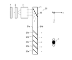
- FIG. 1 is a schematic configuration diagram of an optical system in the image display apparatus of the present embodiment.
- the image display apparatus includes a light source unit 1, a display element 2, a collimating optical system 3, a light guide 10, and a protective plate 15.
- the light source unit 1, the display element 2, and the collimating optical system 3 correspond to an image emitting unit in the present invention, and the same light source unit 1, display element 2, and collimating optical system 3 in the conventional image display device can be used.
- the transmissive liquid crystal display element a reflective liquid crystal display element, an organic EL display, a DMD (digital macro mirror device), a MEMS mirror, a projector, or the like can be used as the display element 2.
- the light source unit 1 is used to illuminate the liquid crystal display element or DMD from the front side.
- a self-luminous display element such as an organic EL display
- the light source unit 1 is built in the display element 2.
- a MEMS mirror whose angle is scanned is used as the display element 2
- a laser light source that irradiates a thin laser beam toward the MEMS mirror is used as the light source unit 1
- the collimating optical system 3 is omitted.
- the collimating optical system 3 may be used for the purpose of finely adjusting the parallel light.
- the light source unit 1 can be regarded as a projector and the display element 2 can be regarded as a projector screen.
- the light guide 10 is both parallel to the yz plane and opposed to the first surface 11a and the second surface 11b facing away from each other in the x-axis direction, and is both parallel to the xy plane and separated from the z-axis direction.
- a substrate 11 having a flat cubic shape having a third surface and a fourth surface (not shown) facing each other is provided.
- the substrate 11 is typically a transparent body such as quartz glass or glass.
- one incident-side reflecting surface 12 and a plurality of (in this example, five) exit-side reflecting surfaces 13a to 13e are formed inside the substrate 11.
- the incident-side reflection surface 12 is perpendicular to the third surface and the fourth surface, and is inclined at a predetermined angle with respect to the first surface 11a and the second surface 11b.
- the plurality of exit-side reflection surfaces 13a to 13e are perpendicular to the third surface and the fourth surface, respectively, and are inclined at a predetermined angle with respect to the first surface 11a and the second surface 11b.
- the incident side reflection surface 12 is a reflection surface by a mirror or the like, and the emission side reflection surfaces 13a to 13e are partial reflection surfaces having predetermined reflectance characteristics (transmittance characteristics).
- the second surface 11 b of the substrate 11 of the light guide 10 is an emission surface of image light from the light guide 10.
- the protection plate 15 is disposed in parallel with a predetermined distance d from the second surface 11b which is the emission surface.
- the protective plate 15 is a transparent or translucent (preferably transparent) flat plate member, and is typically made of a synthetic resin having high impact resistance such as polycarbonate.
- image light is formed by the display element 2 in response to illumination light from the light source unit 1.
- the illumination light at this time is light in a wavelength band centered on the visible region (400 to 750 nm).
- the image light emitted from the display screen of the display element 2 is made substantially parallel by the collimating optical system 3 and introduced into the substrate 11 of the light guide 10 through the first surface 11a.
- the image light introduced from the collimating optical system 3 into the light guide 10 includes information on different parts of the two-dimensional image formed on the display surface of the display element 2 and is incident on the light guide 10 at different angles. Is a set of parallel luminous fluxes.
- the image light is reflected by the incident-side reflecting surface 12 and then travels through the substrate 11 while being reflected by the first surface 11 a and the second surface 11 b one or more times, and is positioned closest to the incident-side reflecting surface 12. It reaches a certain exit side reflecting surface 13a.
- the exit-side reflecting surface 13a reflects a part of the reached light beam and transmits the rest.
- the transmitted light reaches the next exit-side reflecting surface 13b, a part of the light beam is reflected, and the rest is transmitted.
- the light beam propagating through the inside of the substrate 11 of the light guide 10 is reflected little by little by the plurality of exit-side reflecting surfaces 13a to 13e, and is emitted outside through the second surface 11b of the substrate 11.
- the light beam introduced into the substrate 11 of the light guide 10 is expanded and emitted from the substrate 11.
- the image light emitted from the substrate 11 passes through the protection plate 15 and reaches the user's eye E. That is, an image formed on the display surface of the display element 2 is displayed as an enlarged virtual image in front of the user's eye E.
- the distance d between the second surface 11b of the substrate 11 and the protective plate 15 is appropriately determined within a range of 1 mm ⁇ d ⁇ 20 mm. When importance is attached to compactness, the distance d should be a value close to 1 mm, for example, about 1.5 to 2 mm.
- the distance d is set to about 2 mm, so that even if the user presses the vicinity of the center of the protective plate 15 to some extent, it bends. The protective plate 15 does not contact the substrate 11 of the light guide 10. Thereby, damage and breakage of the substrate 11 due to contact of the protective plate 15 can be prevented.
- the second surface 11b of the substrate 11 is finely scratched, a part of the image light hitting the scratched portion of the second surface 11b at a large incident angle while traveling inside the substrate 11 is not totally reflected. Leaks outside or diffuse reflection occurs. That is, it contributes to a decrease in image quality such as a decrease in light use efficiency or generation of stray light.
- the second surface 11b of the substrate 11 is not easily damaged, so that the light use efficiency can be kept good and stray light can be prevented from being generated.
- the substrate 11 will be damaged if the protective plate 15 contacts the substrate 11 violently, but such damage can also be prevented.
- the protective plate 15 is disposed between the second surface 11b of the substrate 11 of the light guide 10 and the user, oils and water droplets such as a user's fingerprint are less likely to adhere to the second surface 11b.
- a similar protective plate may be provided outside the first surface 11a of the substrate 11 of the light guide 10, or the light guide is surrounded by connecting the protective plates on both sides. May be.
- the protective plate provided outside the first surface 11a of the substrate 11 of the light guide 10 also needs to be transparent.
- the distance d between the second surface 11b of the substrate 11 and the protective plate 15 is 20 mm or close thereto. It is good.
- the image display device of the above embodiment can be appropriately modified.
- the number of exit-side reflecting surfaces can be arbitrarily determined as long as it is plural.
- a reflection volume hologram is used as an incident portion that guides image light into the substrate 11 of the light guide 10 and an emission portion that emits image light from the substrate 11.
- a hologram surface such as a grating may be used.
- the third surface and the fourth surface of the substrate 11 are parallel to each other, but the third surface and the fourth surface do not need to be parallel to the xy plane. That is, the first surface 11a, the second surface 11b, the incident-side reflecting surface 12, and the exit-side reflecting surfaces 13a to 13e need not be perpendicular to the third surface and the fourth surface.
- the shapes of the third and fourth surfaces can be arbitrarily determined.
Abstract
Image light emitted from an image emitting unit including a light source unit (1) and the like is introduced into a light guide (10), reflected by an incident-side reflection surface (12), and guided to the inside of a substrate (11). The image light travels while being reflected by a first surface (11a) and a second surface (11b) of the substrate (11), and is partially reflected by each of the outgoing-side reflection surfaces (13a-13e) which are half mirrors, and emitted from the substrate (11). A protective plate (15) made of a transparent synthetic resin is disposed at a distance d of 1 mm < d ≤ 20 mm from the second surface (11b) of the substrate (11). The protective plate (15) prevents oils and fats such as fingerprints and water droplets from adhering to the surface of the substrate (11) and prevents shards from flying to the user side when the light guide (10) is damaged. In addition, since the distance d between the substrate (11) and the protective plate (15) is appropriately determined, even when the user strongly presses the protective plate (15) on attaching or detaching the apparatus, the bent protective plate (15) does not contact the light guide (10), and the light guide (10) avoids being damaged.
Description
本発明は、画像情報を虚像として使用者の眼前に表示する画像表示装置に関する。本発明に係る画像表示装置は、ヘルメットマウントディスプレイ、ヘッドアップディスプレイ、眼鏡型ディスプレイ(いわゆるスマートグラス)などの画像表示装置に好適である。
The present invention relates to an image display device that displays image information as a virtual image in front of a user's eyes. The image display device according to the present invention is suitable for an image display device such as a helmet-mounted display, a head-up display, or a glasses-type display (so-called smart glass).
自動車や電車では、液晶ディスプレイ(LCD)などの表示素子に表示された画像をフロントガラスやコンバイナに投影して運転者側に反射させることにより、運転者の眼前に虚像による表示画像を形成するヘッドアップディスプレイが使用されている。また、航空機では、同様の仕組みにより、操縦者が頭部に着用するヘルメットに設けられたコンバイナに画像を投影し、操縦者の眼前に虚像による表示画像を形成するヘルメットマウントディスプレイが使用されている。また最近では、スマートグラス等と呼ばれる眼鏡型、或いは頭部装着型のヘッドマウントディスプレイも普及し始めている。
In automobiles and trains, a head that forms a display image with a virtual image in front of the driver's eyes by projecting an image displayed on a display element such as a liquid crystal display (LCD) onto a windshield or combiner and reflecting the image on the driver's side Up display is used. Also, in aircraft, a helmet-mounted display that projects images onto a combiner provided in a helmet worn by the pilot on the head and forms a display image as a virtual image in front of the pilot is used by a similar mechanism. . Recently, eyeglass-type or head-mounted head-mounted displays called smart glasses have begun to spread.
こうした画像表示装置には使用者の眼前に虚像を表示する光学系として様々な方式のものが知られているが、その一つとして、ライトガイド(導光板)を用いた方式がある。
図2は特許文献1、2等に開示されている、ライトガイドを用いた従来の画像表示装置の一例における光路構成を示す概略図である。説明の便宜上、図中に示すように互いに直交するx、y、z軸を定めている。 As such an image display apparatus, various types of optical systems for displaying a virtual image in front of the user's eyes are known. One of them is a system using a light guide (light guide plate).
FIG. 2 is a schematic diagram showing an optical path configuration in an example of a conventional image display device using a light guide, which is disclosed in Patent Documents 1 and 2 and the like. For convenience of explanation, x, y, and z axes orthogonal to each other are defined as shown in the figure.
図2は特許文献1、2等に開示されている、ライトガイドを用いた従来の画像表示装置の一例における光路構成を示す概略図である。説明の便宜上、図中に示すように互いに直交するx、y、z軸を定めている。 As such an image display apparatus, various types of optical systems for displaying a virtual image in front of the user's eyes are known. One of them is a system using a light guide (light guide plate).
FIG. 2 is a schematic diagram showing an optical path configuration in an example of a conventional image display device using a light guide, which is disclosed in
画像表示装置は、光源部1、表示素子2、コリメート光学系3、及びライトガイド20を備える。ここでは表示素子2は透過型液晶表示素子であり、光源部1はいわゆる透過型液晶表示素子に対するバックライト光源である。光源部1から出射した光は表示素子2を背面側から照明し、表示素子2の表示面上に形成された画像を情報として含む光(以下「画像光」という)が該表示素子2から射出される。コリメート光学系3は、表示素子2の表示面の各点(画素)から射出された画像光をそれぞれ略平行な光束としてライトガイド20に導入する。したがって、コリメート光学系3からライトガイド20に導入される光は、それぞれが表示素子2の表示面上に形成される画像の異なる部位の情報を含み、異なる角度でライトガイド20に入射する平行光束の集合である。
The image display device includes a light source unit 1, a display element 2, a collimating optical system 3, and a light guide 20. Here, the display element 2 is a transmissive liquid crystal display element, and the light source unit 1 is a backlight light source for a so-called transmissive liquid crystal display element. The light emitted from the light source unit 1 illuminates the display element 2 from the back side, and light including information formed on the display surface of the display element 2 as information (hereinafter referred to as “image light”) is emitted from the display element 2. Is done. The collimating optical system 3 introduces image light emitted from each point (pixel) on the display surface of the display element 2 into the light guide 20 as a substantially parallel light beam. Accordingly, the light introduced from the collimating optical system 3 into the light guide 20 includes information on different parts of the image formed on the display surface of the display element 2 and enters the light guide 20 at different angles. Is a set of
ライトガイド20は、共にy-z平面に平行でx軸方向に離れて対向している第一面21a及び第二面21bと、共にx-y平面に平行でz軸方向に離れて対向している、図示しない第三面及び第四面と、を有する偏平立方体形状である透明な基板21を備える。基板21の内部に一つの入射側反射面22と複数(この例では5枚)の射出側反射面23a~23eが形成されている。入射側反射面22は基板21の第三面及び第四面に垂直であり、第一面21a及び第二面21bに対して傾斜している。複数の射出側反射面23a~23eは同様に第三面及び第四面に垂直であり、第一面21a及び第二面21bに対して傾斜しており、且つそれらは互いに平行である。ここでは、入射側反射面22はミラー等による反射面であり、射出側反射面23a~23eは部分反射面、つまりは照射された光の一部を反射させ、残りを透過させるビームスプリッタ又はハーフミラーである。
The light guide 20 is both parallel to the yz plane and opposed to the first surface 21a and the second surface 21b facing away from each other in the x-axis direction, and is both parallel to the xy plane and separated from each other in the z-axis direction. And a transparent substrate 21 having a flat cubic shape having a third surface and a fourth surface (not shown). Inside the substrate 21, one incident-side reflecting surface 22 and a plurality of (in this example, five) exit-side reflecting surfaces 23a to 23e are formed. The incident-side reflection surface 22 is perpendicular to the third surface and the fourth surface of the substrate 21, and is inclined with respect to the first surface 21a and the second surface 21b. Similarly, the plurality of exit-side reflecting surfaces 23a to 23e are perpendicular to the third surface and the fourth surface, are inclined with respect to the first surface 21a and the second surface 21b, and are parallel to each other. Here, the incident-side reflecting surface 22 is a reflecting surface by a mirror or the like, and the exit-side reflecting surfaces 23a to 23e are partially reflecting surfaces, that is, a beam splitter or a half that reflects a part of irradiated light and transmits the remaining light. It is a mirror.
上述したように表示素子2の表示面上に形成される画像の異なる部位の情報を含む画像光は平行光束として異なる角度でライトガイド20の基板21に入射し、入射側反射面22で反射される。この画像光の光束が基板21の第一面21aと第二面21bとで繰り返し反射されつつ基板21の内部を伝播し、入射側反射面22に最も近い位置にある射出側反射面23aに達する。射出側反射面23aはその透過率に応じて、到達した画像光の一部を反射させ、残りを透過させる。透過した画像光は次の射出側反射面23bに到達し、その光の一部は反射され、残りは透過する。残りの射出側反射面23c~23eも同様である。したがって、ライトガイド20の基板21の内部を伝播してきた画像光の一部は複数の射出側反射面23a~23eでそれぞれ反射され、基板21の第二面21bを透過して外部に射出する。各射出側反射面23a~23eで反射された画像光はそれぞれ所定の角度で使用者の眼Eに入射する。
As described above, image light including information on different parts of the image formed on the display surface of the display element 2 is incident on the substrate 21 of the light guide 20 at different angles as a parallel light flux, and is reflected by the incident-side reflection surface 22. The The luminous flux of the image light propagates through the substrate 21 while being repeatedly reflected by the first surface 21 a and the second surface 21 b of the substrate 21, and reaches the exit-side reflecting surface 23 a that is closest to the incident-side reflecting surface 22. . The exit-side reflecting surface 23a reflects a part of the reached image light and transmits the rest according to the transmittance. The transmitted image light reaches the next exit-side reflecting surface 23b, a part of the light is reflected, and the rest is transmitted. The same applies to the remaining exit-side reflecting surfaces 23c to 23e. Accordingly, part of the image light that has propagated inside the substrate 21 of the light guide 20 is reflected by the plurality of exit-side reflecting surfaces 23a to 23e, and passes through the second surface 21b of the substrate 21 and exits to the outside. The image light reflected by the exit-side reflecting surfaces 23a to 23e is incident on the user's eye E at a predetermined angle.
このようにして上記画像表示装置では、表示素子2の表示面に形成された画像が虚像として使用者の眼前に表示される。また、ライトガイド20の基板21は透明であり、射出側反射面23a~23eは部分反射面であるため、使用者はライトガイド20の基板21を通して前方の風景を視認することもできる。即ち、この画像表示装置はシースルー型の画像表示装置であり、風景に任意の虚像を重畳して表示することができる。
In this way, in the above image display device, the image formed on the display surface of the display element 2 is displayed as a virtual image in front of the user's eyes. Further, since the substrate 21 of the light guide 20 is transparent and the exit-side reflecting surfaces 23a to 23e are partially reflecting surfaces, the user can also visually recognize the scenery in front through the substrate 21 of the light guide 20. That is, this image display device is a see-through type image display device, and can display an arbitrary virtual image superimposed on a landscape.
上述したように、上記画像表示装置ではライトガイド20の基板21の第一面21aと第二面21bとで画像光がほぼ全反射しながら伝播するが、指紋等の油脂や水滴等が基板21の第一面21aや第二面21bに付着すると、その部分で画像光が全反射されずに一部が外部に漏れ出す。そのため、画像光の光量が減って表示される画像が暗くなったり、画像の一部が欠損したり、乱反射により迷光が発生したりする、といった画質の低下が生じるおそれがある。こうした問題を解決するために特許文献3に記載の画像表示装置では、ライトガイドの基板にあって使用者に向いた側の面(図2では第二面21b)に対向して、可視光に対して透明又は半透明な材料から成る保護板を配置している。
As described above, in the image display device, the image light propagates while being substantially totally reflected by the first surface 21a and the second surface 21b of the substrate 21 of the light guide 20, but oil and fat such as fingerprints, water droplets, and the like are transmitted to the substrate 21. When adhering to the first surface 21a or the second surface 21b, the image light is not totally reflected at that portion, but a part leaks to the outside. Therefore, there is a possibility that the image quality may be deteriorated such that the amount of image light is reduced and the displayed image becomes dark, a part of the image is lost, or stray light is generated due to irregular reflection. In order to solve such a problem, in the image display device described in Patent Document 3, the light guide substrate faces the surface facing the user (second surface 21b in FIG. 2) and is visible light. On the other hand, a protective plate made of a transparent or translucent material is arranged.
使用者から見て保護板がライトガイドの基板の手前に配置されているので、該基板の表面に指が接触することによる指紋等の油脂の付着や、屋外での使用時の雨滴等の付着を防止し、そうした付着物に起因する画質低下を防止することができる。しかしながら、こうした画像表示装置では次のような問題がある。
Since the protective plate is placed in front of the light guide board as seen from the user, it can be attached to the surface of the board by finger contact with oil and fat such as fingerprints and raindrops when used outdoors. Image quality deterioration due to such deposits can be prevented. However, such an image display apparatus has the following problems.
特許文献3の記載によれば、ライトガイドの基板の表面と保護板との間隔は、基板からの光の染み出しを回避すること、及び、装置の大形化を回避すること、を考慮して700nm以上1mm以下の範囲に定められている。一般に、上記保護板は合成樹脂により形成されるが、こうした保護板は温度や外部応力による撓みが無視できない。例えばヘルメットマウントディスプレイや眼鏡型ディスプレイのように使用者自身が身体に装着するタイプの画像表示装置では、該装置を装着したり取り外したりする際に使用者が保護板に触れる機会が多い。その際に使用者が保護板を指で強く押してしまうと、その力で撓んだ保護板がライトガイドに接触してライトガイドが損傷したり破損したりするおそれがある。
According to the description of Patent Document 3, the distance between the surface of the light guide substrate and the protective plate is considered to avoid the leakage of light from the substrate and to avoid the enlargement of the apparatus. The range is 700 nm to 1 mm. In general, the protective plate is made of a synthetic resin, but such a protective plate cannot be ignored due to temperature or external stress. For example, in an image display device of a type that is worn on the body by a user such as a helmet-mounted display or a glasses-type display, the user often touches the protective plate when the device is worn or removed. If the user strongly presses the protective plate with a finger at that time, the protective plate bent by the force may contact the light guide and the light guide may be damaged or broken.
本発明は上記課題を解決するために成されたものであり、その目的とするところは、上記のように取り扱いが不用意であったような場合であってもライトガイドの損傷や破損を防止することができる画像表示装置を提供することである。
The present invention has been made to solve the above-mentioned problems, and its purpose is to prevent damage and breakage of the light guide even when the handling is inadequate as described above. It is to provide an image display device that can do this.
上記課題を解決するために成された本発明は、使用者の眼前に虚像を表示する画像表示装置であって、
a)二次元的な画像情報を形成する表示部を含み、該画像上の各部位で角度が異なる平行光束を形成して画像光として後記ライトガイドに入射させる画像出射部と、
b)互いに平行に対向する第一面及び第二面を有する透明な基板と、前記画像光を前記第一面及び第二面で反射されるように該基板の内部に案内する入射部と、該入射部により該基板の内部に案内され前記第一面及び第二面で反射されつつ該基板内を進行して来た画像光の一部を反射させ、前記第一面又は第二面を通して該基板の外部に射出させる、該基板の内部に形成された複数の部分反射面と、を有するライトガイドと、
c)前記ライトガイドの基板にあって画像光が外部に射出される第一面又は第二面から1mmよりも大きく20mm以下の範囲である間隔だけ離して平行に配置された、透明又は半透明である平板部材と、
を備えることを特徴としている。 The present invention made to solve the above problems is an image display device that displays a virtual image in front of the user's eyes,
a) an image emitting unit that includes a display unit that forms two-dimensional image information, and forms parallel light beams having different angles at each part on the image to be incident on a light guide as image light,
b) a transparent substrate having a first surface and a second surface opposed in parallel to each other; and an incident portion for guiding the image light to the inside of the substrate so as to be reflected by the first surface and the second surface; A part of the image light that has been guided inside the substrate by the incident portion and reflected in the first surface and the second surface while traveling through the substrate is reflected, and passes through the first surface or the second surface. A light guide having a plurality of partially reflecting surfaces formed inside the substrate, the light guide being emitted to the outside of the substrate;
c) Transparent or semi-transparent on the substrate of the light guide and arranged parallel to the first surface or the second surface from which image light is emitted to the outside, spaced apart by a distance that is greater than 1 mm and less than or equal to 20 mm A flat plate member,
It is characterized by having.
本発明に係る画像表示装置では、使用者が肉眼で視認可能な画像を表示するために、通常、画像光の波長領域は可視光領域である。
In the image display device according to the present invention, in order to display an image that can be visually recognized by the user, the wavelength region of the image light is usually a visible light region.
また、上記平板部材は組立性等を考慮して、通常、合成樹脂から成るものとされる。特に、耐衝撃性や耐熱性に優れるポリカーボネートを平板部材の材料として用いることが好ましい。
In addition, the flat plate member is usually made of a synthetic resin in consideration of assemblability and the like. In particular, it is preferable to use polycarbonate, which is excellent in impact resistance and heat resistance, as a material for the flat plate member.
本発明者らは、航空機の操縦者が一般に使用する保護眼鏡(ゴーグル)で用いられているポリカーボネートの2mm厚の板材の撓み特性を実験的に調べた。その結果、ヘルメットマウントディスプレイとして利用される画像表示装置を想定した場合、ライトガイドと平板部材との間隔が1mm以下であると、使用者が当該装置を装着したり取り外したりする際の力が平板部材に加わったときに、撓んだ該平板部材がライトガイドに接触する可能性があることが判明した。換言すれば、ライトガイドと平板部材との間隔を1mmよりも大きくしておくことで、或る程度大きな力が平板部材に加わっても平板部材とライトガイドとの接触をほぼ回避することができる。そこで、本発明に係る画像表示装置では、ライトガイドと平板部材との間隔を1mmよりも大きい状態に定めている。
The inventors of the present invention experimentally investigated the bending characteristics of a 2 mm-thick polycarbonate plate used in protective glasses (goggles) commonly used by aircraft operators. As a result, assuming an image display device used as a helmet mount display, if the distance between the light guide and the flat plate member is 1 mm or less, the force when the user attaches or removes the device is flat. It has been found that the bent flat plate member may come into contact with the light guide when added to the member. In other words, by making the distance between the light guide and the flat plate member larger than 1 mm, contact between the flat plate member and the light guide can be substantially avoided even if a certain amount of force is applied to the flat plate member. . Therefore, in the image display device according to the present invention, the distance between the light guide and the flat plate member is set to be larger than 1 mm.
一方、ライトガイドと平板部材との間隔を大きくすればするほど平板部材とライトガイドとの接触を確実に回避できるようになるものの、装置が大形化し実用的でなくなる。また、航空機の操縦者用ヘルメットマウントディスプレイでは、平板部材は、事故等の際にライドガイドが破損して飛び散った破片が使用者の眼に達するのを防止する作用もあるが、ライトガイドと平板部材との間隔が広すぎると破片が周囲に飛び散りやすくなる。こうしたことから本発明に係る画像表示装置では、ヘルメットマウントディスプレイでの利用を想定して平板部材とライトガイドとの間隔を20mm以下に定めている。
On the other hand, the larger the distance between the light guide and the flat plate member, the more reliably the contact between the flat plate member and the light guide can be avoided, but the device becomes large and impractical. In addition, in the helmet mount display for aircraft operators, the flat plate member has the effect of preventing the shards scattered by the ride guide from being damaged in the event of an accident, etc., but reaching the user's eyes. If the distance from the member is too wide, the fragments are likely to scatter around. For this reason, in the image display device according to the present invention, the distance between the flat plate member and the light guide is set to 20 mm or less assuming use in a helmet mount display.
本発明に係る画像表示装置によれば、ライトガイドの基板から画像光が射出する面と平板部材との間隔を1mmより大きく且つ20mm以下の範囲に定めているため、使用者が不用意に平板部材を指で押さえたような場合でも該平板部材がライトガイドの基板に接触せず、該基板の損傷や破損を回避することができる。それにより、本発明に係る装置の信頼性が向上し、ユーザにとっては不要な出費を抑えてコスト削減に繋がる。もちろん、平板部材は、指紋等の油脂や水滴等がライトガイドの基板に付着するのを防止するとともに、該ライトガイドの基板の破損時等に使用者の眼を保護するのに有効である。
According to the image display device of the present invention, the distance between the surface from which the image light is emitted from the substrate of the light guide and the flat plate member is determined to be in a range of more than 1 mm and 20 mm or less. Even when the member is pressed with a finger, the flat plate member does not contact the substrate of the light guide, and damage or breakage of the substrate can be avoided. Thereby, the reliability of the apparatus according to the present invention is improved, and the cost unnecessary for the user is suppressed and the cost is reduced. Of course, the flat plate member is effective to prevent oils and fats such as fingerprints and water droplets from adhering to the substrate of the light guide and to protect the eyes of the user when the substrate of the light guide is damaged.
本発明の一実施例である画像表示装置について、添付図面を参照して説明する。
図1は本実施例の画像表示装置における光学系の概略構成図である。 An image display apparatus according to an embodiment of the present invention will be described with reference to the accompanying drawings.
FIG. 1 is a schematic configuration diagram of an optical system in the image display apparatus of the present embodiment.
図1は本実施例の画像表示装置における光学系の概略構成図である。 An image display apparatus according to an embodiment of the present invention will be described with reference to the accompanying drawings.
FIG. 1 is a schematic configuration diagram of an optical system in the image display apparatus of the present embodiment.
本実施例の画像表示装置は、光源部1、表示素子2、コリメート光学系3、ライトガイド10、及び、保護板15、を備える。光源部1、表示素子2及びコリメート光学系3は本発明における画像出射部に相当し、従来の画像表示装置における光源部1、表示素子2、及びコリメート光学系3と同じものを用いることができるが、これに限るものではない。例えば表示素子2としては、透過型液晶表示素子に代えて、反射型液晶表示素子や有機ELディスプレイ、或いは、DMD(デジタルマクロミラーデバイス)、MEMSミラー、プロジェクタなどを用いることもできる。
The image display apparatus according to the present embodiment includes a light source unit 1, a display element 2, a collimating optical system 3, a light guide 10, and a protective plate 15. The light source unit 1, the display element 2, and the collimating optical system 3 correspond to an image emitting unit in the present invention, and the same light source unit 1, display element 2, and collimating optical system 3 in the conventional image display device can be used. However, it is not limited to this. For example, instead of the transmissive liquid crystal display element, a reflective liquid crystal display element, an organic EL display, a DMD (digital macro mirror device), a MEMS mirror, a projector, or the like can be used as the display element 2.
表示素子2として反射型液晶表示素子やDMDが使用される場合には、光源部1は該液晶表示素子やDMDを前面側から照明するものを用いる。また表示素子2として有機ELディスプレイなどの自己発光型の表示素子が使用される場合には、該表示素子2に光源部1が内蔵されているとみなすことができる。また表示素子2として角度が走査されるMEMSミラーが使用される場合には、光源部1として該MEMSミラーに向けて細いレーザ光を照射するレーザ光源を用い、コリメート光学系3は省略するか、或いは平行光を微調整する目的でコリメート光学系3を用いればよい。また、画像形成のためにプロジェクタを用いる場合には、光源部1がプロジェクタ、表示素子2がプロジェクタスクリーンとみなすことができる。
When a reflective liquid crystal display element or DMD is used as the display element 2, the light source unit 1 is used to illuminate the liquid crystal display element or DMD from the front side. When a self-luminous display element such as an organic EL display is used as the display element 2, it can be regarded that the light source unit 1 is built in the display element 2. When a MEMS mirror whose angle is scanned is used as the display element 2, a laser light source that irradiates a thin laser beam toward the MEMS mirror is used as the light source unit 1, and the collimating optical system 3 is omitted. Alternatively, the collimating optical system 3 may be used for the purpose of finely adjusting the parallel light. When a projector is used for image formation, the light source unit 1 can be regarded as a projector and the display element 2 can be regarded as a projector screen.
ライトガイド10は、共にy-z平面に平行であってx軸方向に離れて対向する第一面11a及び第二面11bと、共にx-y平面に平行であってz軸方向に離れて対向する図示しない第三面及び第四面とを有する偏平立方体形状である基板11を備える。基板11は典型的には石英ガラス、ガラスなどの透明体である。この基板11の内部に一つの入射側反射面12と複数(本例では5枚)の射出側反射面13a~13eが形成されている。
The light guide 10 is both parallel to the yz plane and opposed to the first surface 11a and the second surface 11b facing away from each other in the x-axis direction, and is both parallel to the xy plane and separated from the z-axis direction. A substrate 11 having a flat cubic shape having a third surface and a fourth surface (not shown) facing each other is provided. The substrate 11 is typically a transparent body such as quartz glass or glass. Inside the substrate 11, one incident-side reflecting surface 12 and a plurality of (in this example, five) exit-side reflecting surfaces 13a to 13e are formed.
入射側反射面12は第三面及び第四面に垂直であり、第一面11a及び第二面11bに対し所定角度で傾斜している。また、複数の射出側反射面13a~13eも同様に、それぞれ第三面及び第四面に垂直であり、第一面11a及び第二面11bに対して所定角度で傾斜している。入射側反射面12はミラー等による反射面であり、射出側反射面13a~13eは所定の反射率特性(透過率特性)を有する部分反射面である。
The incident-side reflection surface 12 is perpendicular to the third surface and the fourth surface, and is inclined at a predetermined angle with respect to the first surface 11a and the second surface 11b. Similarly, the plurality of exit-side reflection surfaces 13a to 13e are perpendicular to the third surface and the fourth surface, respectively, and are inclined at a predetermined angle with respect to the first surface 11a and the second surface 11b. The incident side reflection surface 12 is a reflection surface by a mirror or the like, and the emission side reflection surfaces 13a to 13e are partial reflection surfaces having predetermined reflectance characteristics (transmittance characteristics).
ここでは、ライトガイド10の基板11の第二面11bが該ライトガイド10からの画像光の射出面である。保護板15は、この射出面である第二面11bから所定の距離dだけ離して平行に配設されている。保護板15は透明又は半透明(好ましくは透明)な平板部材であり、典型的にはポリカーボネート等の耐衝撃性が高い合成樹脂から成るものとするとよい。
Here, the second surface 11 b of the substrate 11 of the light guide 10 is an emission surface of image light from the light guide 10. The protection plate 15 is disposed in parallel with a predetermined distance d from the second surface 11b which is the emission surface. The protective plate 15 is a transparent or translucent (preferably transparent) flat plate member, and is typically made of a synthetic resin having high impact resistance such as polycarbonate.
本実施例の画像表示装置では、光源部1からの照明光を受けて表示素子2で画像光が形成される。このときの照明光は可視領域(400~750nm)を中心とする波長帯域の光である。表示素子2の表示画面から発せられた画像光は、コリメート光学系3によって略平行光化され第一面11aを通してライトガイド10の基板11の内部に導入される。コリメート光学系3からライトガイド10に導入される画像光は、それぞれが表示素子2の表示面上に形成される二次元的な画像の異なる部位の情報を含み、異なる角度でライトガイド10に入射する平行光束の集合である。
In the image display device of the present embodiment, image light is formed by the display element 2 in response to illumination light from the light source unit 1. The illumination light at this time is light in a wavelength band centered on the visible region (400 to 750 nm). The image light emitted from the display screen of the display element 2 is made substantially parallel by the collimating optical system 3 and introduced into the substrate 11 of the light guide 10 through the first surface 11a. The image light introduced from the collimating optical system 3 into the light guide 10 includes information on different parts of the two-dimensional image formed on the display surface of the display element 2 and is incident on the light guide 10 at different angles. Is a set of parallel luminous fluxes.
この画像光は入射側反射面12で反射されたあと第一面11aと第二面11bとで一又は複数回反射されながら基板11の内部を進行し、入射側反射面12に最も近い位置にある射出側反射面13aに達する。射出側反射面13aは到達した光束の一部を反射させ、残りを透過させる。透過した光は次の射出側反射面13bに到達し、その光束の一部は反射され、残りは透過する。他の射出側反射面13c~13eも同様である。したがって、ライトガイド10の基板11の内部を伝播してきた光束は複数の射出側反射面13a~13eでそれぞれ少しずつ反射され、基板11の第二面11bを通過して外部に射出される。これにより、ライトガイド10の基板11に導入された光束は拡大されて該基板11から射出される。基板11から射出された画像光は保護板15を透過し、使用者の眼Eに到達する。即ち、使用者の眼Eの前には表示素子2の表示面上に形成された画像が拡大された虚像として表示される。
The image light is reflected by the incident-side reflecting surface 12 and then travels through the substrate 11 while being reflected by the first surface 11 a and the second surface 11 b one or more times, and is positioned closest to the incident-side reflecting surface 12. It reaches a certain exit side reflecting surface 13a. The exit-side reflecting surface 13a reflects a part of the reached light beam and transmits the rest. The transmitted light reaches the next exit-side reflecting surface 13b, a part of the light beam is reflected, and the rest is transmitted. The same applies to the other exit-side reflecting surfaces 13c to 13e. Therefore, the light beam propagating through the inside of the substrate 11 of the light guide 10 is reflected little by little by the plurality of exit-side reflecting surfaces 13a to 13e, and is emitted outside through the second surface 11b of the substrate 11. Thereby, the light beam introduced into the substrate 11 of the light guide 10 is expanded and emitted from the substrate 11. The image light emitted from the substrate 11 passes through the protection plate 15 and reaches the user's eye E. That is, an image formed on the display surface of the display element 2 is displayed as an enlarged virtual image in front of the user's eye E.
基板11の第二面11bと保護板15との距離dは1mm<d≦20mmの範囲で適宜に定められる。コンパクト性を重視する場合には、距離dは1mmに近い値であるほうがよく、例えば1.5~2mm程度に定めておくとよい。保護板15がポリカーボネートから成り、その板厚が2mm程度である場合、距離dを2mm程度にしておくことで、使用者が保護板15の中央付近を或る程度強く押したとしても、撓んだ保護板15がライトガイド10の基板11に接触することはない。それにより、保護板15が接触することによる基板11の損傷や破損を防止することができる。
The distance d between the second surface 11b of the substrate 11 and the protective plate 15 is appropriately determined within a range of 1 mm <d ≦ 20 mm. When importance is attached to compactness, the distance d should be a value close to 1 mm, for example, about 1.5 to 2 mm. When the protective plate 15 is made of polycarbonate and has a thickness of about 2 mm, the distance d is set to about 2 mm, so that even if the user presses the vicinity of the center of the protective plate 15 to some extent, it bends. The protective plate 15 does not contact the substrate 11 of the light guide 10. Thereby, damage and breakage of the substrate 11 due to contact of the protective plate 15 can be prevented.
基板11の第二面11bに細かい傷が付くと、基板11内部で進行しながら大きな入射角で以て第二面11bのその傷の部位に当たった画像光の一部は全反射せずに外側に漏れ出したり乱反射が生じたりする。即ち、光の利用効率が下がる、或いは迷光が発生するといった画質低下の一因となる。これに対し、本実施例の画像表示装置では、基板11の第二面11bに傷が付きにくいので、光の利用効率を良好に保ち、迷光の発生を防止することができる。もちろん、保護板15が基板11に激しく接触すると基板11が破損する可能性があるが、そうした破損も防止することができる。
If the second surface 11b of the substrate 11 is finely scratched, a part of the image light hitting the scratched portion of the second surface 11b at a large incident angle while traveling inside the substrate 11 is not totally reflected. Leaks outside or diffuse reflection occurs. That is, it contributes to a decrease in image quality such as a decrease in light use efficiency or generation of stray light. On the other hand, in the image display apparatus of the present embodiment, the second surface 11b of the substrate 11 is not easily damaged, so that the light use efficiency can be kept good and stray light can be prevented from being generated. Of course, there is a possibility that the substrate 11 will be damaged if the protective plate 15 contacts the substrate 11 violently, but such damage can also be prevented.
また、保護板15がライトガイド10の基板11の第二面11bと使用者との間に配置されることで、使用者の指紋などの油脂や水滴などがその第二面11bに付着しにくい。なお、図1では記載していないが、ライトガイド10の基板11の第一面11aの外側にも同様の保護板を設けるようにしてもよいし、両面の保護板を繋いでライトガイドを囲ってもよい。シースルー型の画像表示装置では、ライトガイド10の基板11の第一面11aの外側に設ける保護板も透明である必要がある。
Further, since the protective plate 15 is disposed between the second surface 11b of the substrate 11 of the light guide 10 and the user, oils and water droplets such as a user's fingerprint are less likely to adhere to the second surface 11b. . Although not shown in FIG. 1, a similar protective plate may be provided outside the first surface 11a of the substrate 11 of the light guide 10, or the light guide is surrounded by connecting the protective plates on both sides. May be. In the see-through type image display device, the protective plate provided outside the first surface 11a of the substrate 11 of the light guide 10 also needs to be transparent.
また、装置のコンパクト性はあまり重視しない場合や、保護板15の板厚が薄い等撓みが大きい場合には、基板11の第二面11bと保護板15との距離dを20mm又はそれに近い状態としてもよい。
In addition, when the compactness of the apparatus is not so important, or when the thickness of the protective plate 15 is small and the deflection is large, the distance d between the second surface 11b of the substrate 11 and the protective plate 15 is 20 mm or close thereto. It is good.
また上記実施例の画像表示装置は適宜に変形可能である。例えば、射出側反射面の枚数は複数であれば任意に定めることができる。
Further, the image display device of the above embodiment can be appropriately modified. For example, the number of exit-side reflecting surfaces can be arbitrarily determined as long as it is plural.
またライトガイド10の基板11内部に画像光を案内する入射部や基板11から画像光を射出する射出部として、基板11の内部に形成した反射面や部分反射面に代えて、反射型体積ホログラムグレーティング等のホログラム面を用いてもよい。また、ライトガイド10の基板11の第一面11aの一部を第二面11bに対し非平行とすることで、その非平行である面(基板11と外界との界面)で画像光を反射させる反射面としてもよい。
In addition, instead of a reflection surface or a partial reflection surface formed inside the substrate 11, a reflection volume hologram is used as an incident portion that guides image light into the substrate 11 of the light guide 10 and an emission portion that emits image light from the substrate 11. A hologram surface such as a grating may be used. Further, by making a part of the first surface 11a of the substrate 11 of the light guide 10 non-parallel to the second surface 11b, the image light is reflected by the non-parallel surface (interface between the substrate 11 and the outside world). It is good also as a reflective surface to make.
また上記実施例の画像表示装置では、基板11の第三面と第四面とが互いに平行となっているが、第三面及び第四面はx-y平面に平行である必要はない。即ち、第一面11a、第二面11b、入射側反射面12、及び、射出側反射面13a~13eと第三面及び第四面とは垂直である必要はなく、それらの間の角度や第三面及び第四面の面の形状は任意に定めることができる。
In the image display device of the above embodiment, the third surface and the fourth surface of the substrate 11 are parallel to each other, but the third surface and the fourth surface do not need to be parallel to the xy plane. That is, the first surface 11a, the second surface 11b, the incident-side reflecting surface 12, and the exit-side reflecting surfaces 13a to 13e need not be perpendicular to the third surface and the fourth surface. The shapes of the third and fourth surfaces can be arbitrarily determined.
また、上記実施例はあくまでも本発明の一例にすぎず、本発明の趣旨の範囲で適宜、変更や修正、追加を行っても本願特許請求の範囲に包含されることは当然である。
Further, the above-described embodiment is merely an example of the present invention, and it is natural that even if changes, modifications, and additions are appropriately made within the scope of the present invention, they are included in the scope of the claims of the present application.
1…光源部
2…表示素子
3…コリメート光学系
10…ライトガイド
11…基板
11a…第一面
11b…第二面
12…入射側反射面
13a~13e…射出側反射面
15…保護板 DESCRIPTION OFSYMBOLS 1 ... Light source part 2 ... Display element 3 ... Collimating optical system 10 ... Light guide 11 ... Substrate 11a ... First surface 11b ... Second surface 12 ... Incident side reflective surfaces 13a-13e ... Emission side reflective surface 15 ... Protection plate
2…表示素子
3…コリメート光学系
10…ライトガイド
11…基板
11a…第一面
11b…第二面
12…入射側反射面
13a~13e…射出側反射面
15…保護板 DESCRIPTION OF
Claims (4)
- 使用者の眼前に虚像を表示する画像表示装置であって、
a)二次元的な画像情報を形成する表示部を含み、該画像上の各部位で角度が異なる平行光束を形成して画像光として後記ライトガイドに入射させる画像出射部と、
b)互いに平行に対向する第一面及び第二面を有する透明な基板と、前記画像光を前記第一面及び第二面で反射されるように該基板の内部に案内する入射部と、該入射部により該基板の内部に案内され前記第一面及び第二面で反射されつつ該基板内を進行して来た画像光の一部を反射させ、前記第一面又は第二面を通して該基板の外部に射出させる、該基板の内部に形成された複数の部分反射面と、を有するライトガイドと、
c)前記ライトガイドの基板にあって画像光が外部に射出される第一面又は第二面から1mmよりも大きく20mm以下の範囲である間隔だけ離して平行に配置された、透明又は半透明である平板部材と、
を備えることを特徴とする画像表示装置。 An image display device that displays a virtual image in front of a user's eyes,
a) an image emitting unit that includes a display unit that forms two-dimensional image information, and forms parallel light beams having different angles at each part on the image to be incident on a light guide as image light,
b) a transparent substrate having a first surface and a second surface opposed in parallel to each other; and an incident portion for guiding the image light to the inside of the substrate so as to be reflected by the first surface and the second surface; A part of the image light that has been guided inside the substrate by the incident portion and reflected in the first surface and the second surface while traveling through the substrate is reflected, and passes through the first surface or the second surface. A light guide having a plurality of partially reflecting surfaces formed inside the substrate, the light guide being emitted to the outside of the substrate;
c) Transparent or semi-transparent on the substrate of the light guide and arranged parallel to the first surface or the second surface from which image light is emitted to the outside, spaced apart by a distance that is greater than 1 mm and less than or equal to 20 mm A flat plate member,
An image display device comprising: - 請求項1に記載の画像表示装置であって、
前記画像光の波長領域は可視光領域であることを特徴とする画像表示装置。 The image display device according to claim 1,
An image display device characterized in that the wavelength region of the image light is a visible light region. - 請求項1に記載の画像表示装置であって、
前記平板部材は合成樹脂から成ることを特徴とする画像表示装置。 The image display device according to claim 1,
The image display device, wherein the flat plate member is made of a synthetic resin. - 請求項3に記載の画像表示装置であって、
前記平板部材はポリカーボネートから成ることを特徴とする画像表示装置。 The image display device according to claim 3,
The image display device, wherein the flat plate member is made of polycarbonate.
Priority Applications (4)
| Application Number | Priority Date | Filing Date | Title |
|---|---|---|---|
| EP18922856.2A EP3805846A4 (en) | 2018-06-11 | 2018-06-11 | Image display device |
| US17/059,387 US20210239975A1 (en) | 2018-06-11 | 2018-06-11 | Image display device |
| PCT/JP2018/022270 WO2019239466A1 (en) | 2018-06-11 | 2018-06-11 | Image display device |
| JP2020524967A JPWO2019239466A1 (en) | 2018-06-11 | 2018-06-11 | Image display device |
Applications Claiming Priority (1)
| Application Number | Priority Date | Filing Date | Title |
|---|---|---|---|
| PCT/JP2018/022270 WO2019239466A1 (en) | 2018-06-11 | 2018-06-11 | Image display device |
Publications (1)
| Publication Number | Publication Date |
|---|---|
| WO2019239466A1 true WO2019239466A1 (en) | 2019-12-19 |
Family
ID=68842756
Family Applications (1)
| Application Number | Title | Priority Date | Filing Date |
|---|---|---|---|
| PCT/JP2018/022270 WO2019239466A1 (en) | 2018-06-11 | 2018-06-11 | Image display device |
Country Status (4)
| Country | Link |
|---|---|
| US (1) | US20210239975A1 (en) |
| EP (1) | EP3805846A4 (en) |
| JP (1) | JPWO2019239466A1 (en) |
| WO (1) | WO2019239466A1 (en) |
Citations (8)
| Publication number | Priority date | Publication date | Assignee | Title |
|---|---|---|---|---|
| JP2000227575A (en) * | 1999-02-08 | 2000-08-15 | Canon Inc | Observation optical system and image display device |
| JP2009145513A (en) * | 2007-12-13 | 2009-07-02 | Konica Minolta Holdings Inc | Video display apparatus and head mount display |
| JP4508655B2 (en) | 2002-03-21 | 2010-07-21 | ラマス リミテッド | Light guide optical device |
| US8830588B1 (en) * | 2012-03-28 | 2014-09-09 | Rockwell Collins, Inc. | Reflector and cover glass for substrate guided HUD |
| JP5698297B2 (en) | 2000-06-05 | 2015-04-08 | ラマス リミテッド | Substrate guided optical beam expander |
| JP2015172713A (en) | 2014-03-12 | 2015-10-01 | オリンパス株式会社 | display device |
| JP2015184560A (en) * | 2014-03-25 | 2015-10-22 | ソニー株式会社 | Light guide device, image display device, and display device |
| JP2016126134A (en) * | 2014-12-26 | 2016-07-11 | シャープ株式会社 | Display device and wearable device |
Family Cites Families (1)
| Publication number | Priority date | Publication date | Assignee | Title |
|---|---|---|---|---|
| US8638498B2 (en) * | 2012-01-04 | 2014-01-28 | David D. Bohn | Eyebox adjustment for interpupillary distance |
-
2018
- 2018-06-11 EP EP18922856.2A patent/EP3805846A4/en not_active Withdrawn
- 2018-06-11 JP JP2020524967A patent/JPWO2019239466A1/en active Pending
- 2018-06-11 US US17/059,387 patent/US20210239975A1/en not_active Abandoned
- 2018-06-11 WO PCT/JP2018/022270 patent/WO2019239466A1/en unknown
Patent Citations (8)
| Publication number | Priority date | Publication date | Assignee | Title |
|---|---|---|---|---|
| JP2000227575A (en) * | 1999-02-08 | 2000-08-15 | Canon Inc | Observation optical system and image display device |
| JP5698297B2 (en) | 2000-06-05 | 2015-04-08 | ラマス リミテッド | Substrate guided optical beam expander |
| JP4508655B2 (en) | 2002-03-21 | 2010-07-21 | ラマス リミテッド | Light guide optical device |
| JP2009145513A (en) * | 2007-12-13 | 2009-07-02 | Konica Minolta Holdings Inc | Video display apparatus and head mount display |
| US8830588B1 (en) * | 2012-03-28 | 2014-09-09 | Rockwell Collins, Inc. | Reflector and cover glass for substrate guided HUD |
| JP2015172713A (en) | 2014-03-12 | 2015-10-01 | オリンパス株式会社 | display device |
| JP2015184560A (en) * | 2014-03-25 | 2015-10-22 | ソニー株式会社 | Light guide device, image display device, and display device |
| JP2016126134A (en) * | 2014-12-26 | 2016-07-11 | シャープ株式会社 | Display device and wearable device |
Non-Patent Citations (1)
| Title |
|---|
| See also references of EP3805846A4 * |
Also Published As
| Publication number | Publication date |
|---|---|
| US20210239975A1 (en) | 2021-08-05 |
| EP3805846A4 (en) | 2021-06-09 |
| EP3805846A1 (en) | 2021-04-14 |
| JPWO2019239466A1 (en) | 2021-04-01 |
Similar Documents
| Publication | Publication Date | Title |
|---|---|---|
| CN113439230B (en) | Transparent light guide for viewing a scene and near-eye display | |
| US20210033774A1 (en) | Image display device | |
| JP6994940B2 (en) | Head-mounted imaging device using optical coupling | |
| CN111158079B (en) | Light guide with multiple in-coupling holograms for head wearable displays | |
| US8743464B1 (en) | Waveguide with embedded mirrors | |
| US9507150B1 (en) | Head up display (HUD) using a bent waveguide assembly | |
| US8760762B1 (en) | Image waveguide utilizing two mirrored or polarized surfaces | |
| US11143872B2 (en) | Waveguide and video image display device | |
| CN110058410B (en) | Waveguide assembly and near-to-eye display device | |
| JP2010122478A (en) | Image display device and head mount display | |
| CN110036235B (en) | Waveguide with peripheral side geometry for recycling light | |
| US11698532B2 (en) | Image display device | |
| CN111742254A (en) | Image light guide with circular polarizer | |
| JP6565496B2 (en) | Light guide device and virtual image display device | |
| WO2019239466A1 (en) | Image display device | |
| CN116209941A (en) | Compensating diffraction waveguide for off-axis in-coupling and viewing | |
| CN115004080A (en) | Light guide body and virtual image display device | |
| CN114424109A (en) | Optical element of display | |
| WO2019171450A1 (en) | Image display device | |
| JP7380240B2 (en) | Light guide member and virtual image display device | |
| US20240142707A1 (en) | Virtual image display device and optical unit | |
| US20240069350A1 (en) | Image light guide with flexible substrate | |
| JP6977865B2 (en) | Image display device | |
| WO2019176071A1 (en) | Image display device | |
| WO2023235402A2 (en) | Waveguide stack architecture with high red efficiency |
Legal Events
| Date | Code | Title | Description |
|---|---|---|---|
| 121 | Ep: the epo has been informed by wipo that ep was designated in this application |
Ref document number: 18922856 Country of ref document: EP Kind code of ref document: A1 |
|
| ENP | Entry into the national phase |
Ref document number: 2020524967 Country of ref document: JP Kind code of ref document: A |
|
| NENP | Non-entry into the national phase |
Ref country code: DE |
|
| ENP | Entry into the national phase |
Ref document number: 2018922856 Country of ref document: EP Effective date: 20210111 |