WO2019216392A1 - User equipment (ue) - Google Patents
User equipment (ue) Download PDFInfo
- Publication number
- WO2019216392A1 WO2019216392A1 PCT/JP2019/018646 JP2019018646W WO2019216392A1 WO 2019216392 A1 WO2019216392 A1 WO 2019216392A1 JP 2019018646 W JP2019018646 W JP 2019018646W WO 2019216392 A1 WO2019216392 A1 WO 2019216392A1
- Authority
- WO
- WIPO (PCT)
- Prior art keywords
- identification information
- utran
- network
- ran
- procedure
- Prior art date
Links
- 238000000034 method Methods 0.000 claims abstract description 269
- 230000005540 biological transmission Effects 0.000 claims abstract description 32
- 230000007704 transition Effects 0.000 claims description 13
- 230000008859 change Effects 0.000 claims description 3
- 230000000977 initiatory effect Effects 0.000 claims description 3
- 238000010295 mobile communication Methods 0.000 abstract description 25
- 230000006870 function Effects 0.000 description 96
- 238000004891 communication Methods 0.000 description 54
- 238000007726 management method Methods 0.000 description 44
- 230000008569 process Effects 0.000 description 29
- 230000002159 abnormal effect Effects 0.000 description 19
- 238000012545 processing Methods 0.000 description 17
- 238000005516 engineering process Methods 0.000 description 11
- 238000012546 transfer Methods 0.000 description 9
- 239000004338 Dichlorodifluoromethane Substances 0.000 description 8
- 239000004065 semiconductor Substances 0.000 description 8
- 230000011664 signaling Effects 0.000 description 7
- 239000013256 coordination polymer Substances 0.000 description 6
- 230000000737 periodic effect Effects 0.000 description 6
- 239000004201 L-cysteine Substances 0.000 description 4
- 238000010586 diagram Methods 0.000 description 4
- 238000013475 authorization Methods 0.000 description 3
- 238000013523 data management Methods 0.000 description 3
- 239000004205 dimethyl polysiloxane Substances 0.000 description 3
- 230000004044 response Effects 0.000 description 3
- 230000001413 cellular effect Effects 0.000 description 2
- 238000013500 data storage Methods 0.000 description 2
- 230000000694 effects Effects 0.000 description 2
- 102100038254 Cyclin-F Human genes 0.000 description 1
- 101000884183 Homo sapiens Cyclin-F Proteins 0.000 description 1
- 238000004378 air conditioning Methods 0.000 description 1
- 238000003491 array Methods 0.000 description 1
- 230000008901 benefit Effects 0.000 description 1
- 230000002457 bidirectional effect Effects 0.000 description 1
- 230000003139 buffering effect Effects 0.000 description 1
- 239000000969 carrier Substances 0.000 description 1
- 238000004140 cleaning Methods 0.000 description 1
- 238000009795 derivation Methods 0.000 description 1
- 238000013461 design Methods 0.000 description 1
- 239000000284 extract Substances 0.000 description 1
- 230000007774 longterm Effects 0.000 description 1
- 238000012986 modification Methods 0.000 description 1
- 230000004048 modification Effects 0.000 description 1
- 230000003287 optical effect Effects 0.000 description 1
- 238000005457 optimization Methods 0.000 description 1
- 230000002093 peripheral effect Effects 0.000 description 1
- 238000011084 recovery Methods 0.000 description 1
- 239000007787 solid Substances 0.000 description 1
- 230000001360 synchronised effect Effects 0.000 description 1
- 238000012384 transportation and delivery Methods 0.000 description 1
- 238000012795 verification Methods 0.000 description 1
- 238000005406 washing Methods 0.000 description 1
Images


Classifications
-
- H—ELECTRICITY
- H04—ELECTRIC COMMUNICATION TECHNIQUE
- H04W—WIRELESS COMMUNICATION NETWORKS
- H04W36/00—Hand-off or reselection arrangements
- H04W36/0005—Control or signalling for completing the hand-off
- H04W36/0011—Control or signalling for completing the hand-off for data sessions of end-to-end connection
- H04W36/0022—Control or signalling for completing the hand-off for data sessions of end-to-end connection for transferring data sessions between adjacent core network technologies
-
- H—ELECTRICITY
- H04—ELECTRIC COMMUNICATION TECHNIQUE
- H04W—WIRELESS COMMUNICATION NETWORKS
- H04W8/00—Network data management
- H04W8/22—Processing or transfer of terminal data, e.g. status or physical capabilities
- H04W8/24—Transfer of terminal data
-
- H—ELECTRICITY
- H04—ELECTRIC COMMUNICATION TECHNIQUE
- H04W—WIRELESS COMMUNICATION NETWORKS
- H04W36/00—Hand-off or reselection arrangements
- H04W36/0005—Control or signalling for completing the hand-off
- H04W36/0011—Control or signalling for completing the hand-off for data sessions of end-to-end connection
- H04W36/0022—Control or signalling for completing the hand-off for data sessions of end-to-end connection for transferring data sessions between adjacent core network technologies
- H04W36/00224—Control or signalling for completing the hand-off for data sessions of end-to-end connection for transferring data sessions between adjacent core network technologies between packet switched [PS] and circuit switched [CS] network technologies, e.g. circuit switched fallback [CSFB]
-
- H—ELECTRICITY
- H04—ELECTRIC COMMUNICATION TECHNIQUE
- H04L—TRANSMISSION OF DIGITAL INFORMATION, e.g. TELEGRAPHIC COMMUNICATION
- H04L65/00—Network arrangements, protocols or services for supporting real-time applications in data packet communication
- H04L65/10—Architectures or entities
- H04L65/1016—IP multimedia subsystem [IMS]
-
- H—ELECTRICITY
- H04—ELECTRIC COMMUNICATION TECHNIQUE
- H04W—WIRELESS COMMUNICATION NETWORKS
- H04W60/00—Affiliation to network, e.g. registration; Terminating affiliation with the network, e.g. de-registration
Definitions
- 3GPP 3rd Generation Partnership Project
- SAE System Architecture Evolution
- LTE Long Term Evolution
- 3GPP has specified EPS (Evolved Packet System) as a communication system for realizing all IP (Internet Protocol).
- EPC Evolved Packet Core
- E-UTRAN Evolved Universal Terrestrial Radio Access Network
- IMS IP Multimedia Subsystem
- 5G Next-generation mobile communication system
- 5G System
- 5GS 5G System
- IMS IP Multimedia Subsystem
- CS network circuit switched network
- PS network packet switched network
- EPS Evolved Packet System
- SRVCC Single Radio Voice Call Continuity
- vSRVCC Single Radio Video Call Continuity
- the present invention has been made in view of such circumstances, and the purpose thereof is based on the capability information of the user device transmitted by the user device in the registration procedure to the 5G core network, and the voice call or video call in the 5G network. To provide means for enabling continuation of a voice call or video call service even when switching to a circuit switched network during execution.
- the UE is at least mobile when the UE supports SRVCC (Single Radio Voice Voice Call Continuity) from NG-RAN (Next Generation Radio Radio Access Network) to UTRAN (Universal Terrestrial Radio Access Network).
- a control unit that includes first identification information in a registration request message and a transmission / reception unit that transmits the registration request message including the first identification information to a core network when changing the station Classmark 2 and / or supported codec
- the first identification information is UTRAN (Universal Terrestrial Radio Access Network), HSPA (High Speed Packet Access), E-UTRAN (Evolved UTRAN), or 2G wireless access from the NG-RAN. It is functional information indicating that SRVCC to the network or the UTRAN is supported.
- the present invention it is possible to provide a mobile communication service that allows a terminal that is performing a voice call or a video call with 5GS to continue a voice call or a video call even when the connected network is switched to the CS network. it can.
- FIG. 2 is a diagram illustrating an example of a configuration of a core network and an access network in a mobile communication system. It is a figure which shows the connection outline of IMS for voice call service and / or video call service, and a core network. It is a figure which shows the abnormal system 2 of a 2nd procedure. It is a figure which shows the apparatus structure of UE. It is a figure which shows the structure of an access network apparatus. It is a figure which shows the apparatus structure of MME / AMF. It is a figure which shows the apparatus structure of SMF / PGW / UPF. It is a figure which shows the apparatus structure of CSCF. It is a figure which shows the various procedures for each embodiment. It is a figure which shows a registration procedure. It is a figure which shows the normal system and abnormal system 1 of a 2nd procedure.
- FIG. 1 is a diagram describing an outline of the mobile communication system 1.
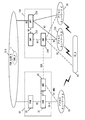
- FIG. 2 is a diagram describing an example of the configuration of an access network and a core network in the mobile communication system of FIG.
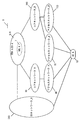
- FIG. 3 is a diagram illustrating an example of a connection configuration of an IP multimedia subsystem (IMS) and a core network mainly in the mobile communication system of FIG.
- IMS IP multimedia subsystem
- the mobile communication system 1 in this embodiment includes a UE (User Equipment) _A10 (also referred to as a user device, a terminal device, or a mobile terminal device), a CN (Circuit Switched) network_A290 (circuit switching). Network)), access network (AN; Access Network) _A80, access network_A'81, access network_B120, core network (CN; CNCore Network) _B190, core network_A90, data network (DN; Data Network) _A5, packet data network (PDN; Packet Data Network) _B6, and IMS_A7.
- UE User Equipment
- AN Access Network
- CN Core Network
- the core network_A and / or the core network B and / or CS network_A or a combination thereof may be referred to as a core network
- the access network_A80 and / or the access network_A '81 and / or access network_B and / or CS network_A or a combination thereof may also be referred to as access network or radio access network
- DN_A5 PDN_A6 or a combination thereof
- the CS network_A may be referred to as a circuit switched network or a CS network.
- the core network_A, and / or the core network_B, and / or the CS network_A, and / or one or more devices / functions included in these core networks are referred to as a core network or a core network device. There is a case.
- the core network and / or the core network device transmits / receives a message and / or executes a procedure
- One or more devices / functions included in these core networks may mean sending / receiving messages and / or executing procedures.
- EPS Evolved Packet System
- 4G system includes UE, access network_A, and core network_A, but may further include PDN.
- 5GS which is a 5G system, includes UE, access network_B, access network_A ', and core network_B, and may further include DN.
- the base station ⁇ ⁇ ⁇ ⁇ (eNB and / or ng-eNB) ⁇ ⁇ ⁇ ⁇ of the access network_A ′ and the base station (gNB) ⁇ of the access network_B may or may not be connected to each other, for example, by an Xn interface. May be.
- 3G the old system, is composed of UMTS (Universal Mobile Telecommunications System) and UTRAN (UMTS Terrestrial Radio Access Network).
- 2G which is an old system, is composed of GSM (registered trademark) (global system for mobile communications), and includes GERAN (GSM (registered trademark), EDGE, Radio Access, Network).
- GSM registered trademark
- EDGE Radio Access, Network
- the wireless access provided by the old system of UMTS and GSM (registered trademark) may be referred to as 2G / 3G.
- Core network_A corresponds to EPCE (EvolvedvolvePacket Core).
- EPC EvolvedvolvePacket Core
- MME Mobility Management Entity
- SGW Serving Gateway
- PGW Packet Gateway
- PCRF Policy and Charging Rules, Function
- HSS Home Subscriber Server
- Core network_B corresponds to 5GC (5G Core Network).
- 5GC 5G Core Network
- AMF Access Management Function
- UPF User Plane Function
- SMF Serving Mobility Management Function
- PCF Policy Control Function
- UDM Unified Data Management
- the CS network_A290 is a 2G / 3G system network, a 2G / 3G system radio access network, and / or a 2G / 3G core network, and / or a voice call service and / or video call described later.
- a device for service may be included.
- the connection (access) of the UE to the CS network_A may be that the UE connects to a circuit switched network (CS network) via the UTRAN.
- UE_A10 can be connected to a network service via 3GPP access (also referred to as 3GPP access or 3GPP access access network) and / or non-3GPP access (also referred to as non-3GPP access or non-3GPP access access network). It may be a simple device.
- the UE_A 10 may include a UICC (UniversalUniversIntegrated Circuit Card) and an eUICC (Embedded UICC).
- UE_A10 may be a wirelessly connectable terminal device, and may be a ME (Mobile Equipment), MS (Mobile Station), CIoT (Cellular Internet of Things) terminal (CIoT UE), or the like.
- UE_A 10 can be connected to an access network and / or a core network. Moreover, UE_A10 can be connected with DN_A5 and / or PDN_A6 via an access network and / or a core network. UE_A10 transmits / receives user data to / from DN_A5 and / or PDN_A6 using PDU (Protocol Data Unit or Packet Data Unit) session and / or PDN connection (PDN connection; Packet Data Data Network (PDN) Connection) (connect. Further, user data communication is not limited to IP (Internet Protocol) communication but may be non-IP communication.
- PDU Protocol Data Unit or Packet Data Unit
- PDN connection Packet Data Data Network (PDN) Connection
- IP communication is data communication using IP, and is data communication realized by transmission / reception of an IP packet provided with an IP header.
- the payload part which comprises an IP packet may contain the user data which UE_A10 transmits / receives.
- the non-IP communication is data communication that does not use IP, and is data communication that is realized by transmission / reception of data without an IP header.
- non-IP communication may be data communication realized by transmission / reception of application data to which an IP header is not added, or another header such as a MAC (Media Access Control) header or an Ethernet (registered trademark) frame header. You may transmit / receive the user data which UE_A10 gives and transmits.
- the PDU session or PDN connection is connectivity established between UE_A10 and DN_A5 and / or PDN_A6 in order to provide a PDU connection service. More specifically, the PDU session or PDN connection may be connectivity established between UE_A 10 and the external gateway.
- the external gateway may be UPF, PGW (Packet Data Data Network Gateway), SCEF (Service Capacity Capability Function), or the like.
- the PDU session or PDN connection may be a communication path established for transmitting / receiving user data between the UE_A 10 and the core network and / or DN, or may be a communication path for transmitting / receiving PDUs.
- the PDU session or PDN connection may be a session established between UE_A10 and the core network and / or DN, and is a transfer path such as one or more flows or bearers between each device in the mobile communication system 1. It may be a logical communication path configured. More specifically, the PDU session or the PDN connection may be a connection established by the UE_A 10 between the core network and / or the external gateway, or may be a connection established between the UE_A 10 and the UPF_A 235 or PGW_A 30.
- the PDN connection may be a connection and / or connection between UE_A10 and PGW_A30 via eNB (evolvedvolveNode B; eNodeB) _A45 and / or SGW (Serving Gateway) _A35, and may be eNB_A45 and / or MME (Mobility Management Entity) _A40 may be the connectivity and / or connection between UE_A10 and SCEF.
- the PDU session may be connectivity and / or connection between UE_A10 and UPF_A235 via gNB_A122 or eNB_B145.
- the PDN connection may be identified by a PDN connection ID
- the PDU session may be identified by a PDU session ID.
- the PDN connection and the PDU session may be identified by an EPS bearer ID.
- the PDU session and / or the PDN connection may be referred to as a PDU session.
- UE_A 10 can execute transmission / reception of user data using a PDU session or a PDN connection with a device such as an application server arranged in DN_A 5 and / or PDN_A 6.
- the PDU session or the PDN connection can transfer user data transmitted and received between the UE_A 10 and a device such as an application server arranged in the DN_A5 and / or the PDN_A6.
- each device UE_A10, a device in the access network, and / or a device in the core network
- identification information includes APN (Access Point Name), TFT (Traffic Flow Template), session type, application identification information, DN_A5 and / or PDN_A6 identification information, NSI (Network Slice Instance) identification information, and DCN. At least one of (Dedicated Core Core Network) identification information and access network identification information may be included, or other information may be further included. Further, when a plurality of PDU sessions are established, the identification information associated with the PDU session or the PDN connection may have the same contents or different contents. Further, the NSI identification information is information for identifying the NSI, and may be NSI ID or Slice Instance ID hereinafter.
- E-UTRAN Evolved Universal Terrestrial Radio Access Network
- UTRAN_A20, GERAN_A25, WLAN ANb75, WLAN ANa70, NG-RAN_A120 Any of WLAN ANc125 may be used.
- E-UTRAN_A80 and / or NG-RAN_A120 and / or UTRAN_A20 and / or GERAN_A25 may also be called a 3GPP access network
- WLAN ANb75 and / or WLAN Ana70 and / or WLAN ANc125 may be called a non-3GPP access network.
- Each radio access network includes devices (for example, base station devices and access points) to which UE_A 10 is actually connected. In the present specification, the devices constituting the wireless access network are also referred to as a wireless access system.
- E-UTRAN_A80 is an LTE access network and includes one or more eNB_A45.
- eNB_A45 is a radio base station to which UE_A10 is connected by E-UTRA (Evolved Universal Terrestrial Radio Access).
- E-UTRA Evolved Universal Terrestrial Radio Access
- the eNBs may be connected to each other.
- NG-RAN_A120 is a 5G access network and includes one or more gNB (NR B) _A122.
- gNB_A122 is a radio base station to which UE_A10 is connected by 5G radio access (5G Radio Access).
- 5G Radio Access 5G Radio Access
- each gNB_A122 may be connected to each other.
- gNB may also be referred to as NR node (New Radio Access Technology node; NR-node).
- the NG-RAN_A 120 may be an access network configured by E-UTRA and / or 5G Radio Access.
- eNB_A45 and / or gNB_A122 and / or eNB_B145 may be included in NG-RAN_A120.
- eNB_A45 and gNB_A122 may be similar devices. Therefore, gNB_A122 can be replaced with eNB_A45 and / or eNB_B145.
- the eNB connected to the core network_A is also referred to as eNB_A
- the eNB connected to the core network_B is also referred to as eNB_B145 or Ng-eNB, and connected to the core network_A.
- GNB may be referred to as en-gNB.
- a radio access network including a gNB connected to the 5G network is also referred to as a first radio access system or access network_A ′
- a radio access network including the eNB_B connected to the 5G network is also referred to as a second radio access system. .
- the access network_B connected to the core network_B is the first access network
- the access network_A 'connected to the core network_B is the second access network
- the access is connected to the core network_A.
- Network_A is also referred to as a third access network.
- the access network and the core network connection form in this specification include an access network connected to the core network_B_B (NR (New Radio) connected to 5GC, and / or connected to the core network_B.
- Access network_A '(E-UTRA connected to 5GC) and / or access network _A (E-UTRA connected ⁇ ⁇ to EPC) and / or CS network for simplicity, The access network and the core network may be expressed as one network), and the CS network is composed of the 2G / 3G system radio access network and / or the 2G / 3G core network as described above. May be.
- an interface for communication between access network devices may be provided, and an interface between access network devices connected to the core network_A may be referred to as an X2 interface and connected to the core network_B.
- An interface between access network devices may be referred to as an Xn interface.
- an Xn interface may be used for communication between a plurality of gNBs connected to the core network_B and / or between a plurality of Ng-eNBs and / or between a plurality of gNBs and Ng-eNBs.
- the X2 interface may be used for communication between a plurality of gNBs connected to the network_A and / or between a plurality of Ng-eNBs and / or between a plurality of gNBs and Ng-eNBs.
- the communication between the access network devices may be transmission / reception of control information, may be transfer of user data between the UE_A 10 and the network, and is not limited thereto.
- UE_A10 being connected to each radio access network means being connected to a base station device or an access point included in each radio access network. In other words, it goes through a base station device or an access point.
- the control message transmitted and received between UE_A10 and core network_B190 may be the same control message regardless of the type of access network. Therefore, UE_A10 and core network_B190 transmitting / receiving a message via gNB_A122 may be the same as UE_A10 and core network_B190 transmitting a message via eNB_A45 and / or eNB_B145.
- the access network is a wireless network connected to UE_A10 and / or the core network.
- the access network may be a 3GPP access network or a non-3GPP access network.
- the 3GPP access network may be UTRAN_A20 and / or GERAN and / or E-UTRAN_A80 and / or NG-RAN (Radio Access Network) _A120, and the non-3GPP access network may be WLAN ANb75 and / or WLAN ANa72 and / or Or it may be WLAN125ANc125.
- the UE_A 10 may be connected to the access network in order to connect to the core network, or may be connected to the core network via the access network.
- DN_A5 and / or PDN_A6 is a data network (Data Network) or packet data network (Packet Data Network) that provides communication services to UE_A10, and may be configured as a packet data service network or configured for each service. May be.
- DN_A5 and / or PDN_A6 may include a device for providing an IMS service.
- DN_A5 and / or PDN_A6 may be configured as IMS_A7
- DN_A5 and / or PDN_A6 may include IMS_A7
- IMS_A7 provides UE_A10 with voice and / or video call services.
- a normal call connection service and / or an emergency call connection service for a normal call connection service and / or an emergency call connection service and / or a text message service may be provided.
- DN_A5 and / or PDN_A6 may include a connected communication terminal. Therefore, the connection with DN_A5 and / or PDN_A6 may be a connection with a communication terminal or server device arranged in DN_A5 and / or PDN_A6.
- transmitting / receiving user data to / from DN_A5 and / or PDN_A6 may be transmitting / receiving user data to / from a communication terminal or server device arranged in DN_A5 and / or PDN_A6.
- DN_A5 and / or PDN_A6 are outside the core network in FIG. 1, but may be inside the core network.
- the core network_A90 and / or the core network_B190 and / or the CS network_A290 may be configured as one or more core network devices.
- the core network device may be a device that executes part or all of the processing or function of each device included in the core network_A90 and / or the core network_B190 and / or the CS network_A290.
- the core network is an IP mobile communication network operated by a mobile communication operator (MNO: Mobile Network Operator) connected to an access network and / or a DN.
- the core network may be a core network for mobile communication operators that operate and manage the mobile communication system 1, or virtual mobile communication operators such as MVNO (Mobile Virtual Network Operator) and MVNE (Mobile Virtual Network Enabler) It may be a core network for a mobile communication service provider.
- the core network_A90 may be an EPC (Evolved Packet Core) that constitutes EPS (Evolved Packet System), and the core network_B190 may be 5GC (5G Core Core Network) that constitutes 5GS.
- the EPC may be the core network_A90
- the 5GC may be the core network_B190.
- the core network_B190 may be a core network of a system that provides a 5G communication service.
- the core network_A90 and / or the core network_B190 and / or the CS network_A290 are not limited to this, and may be a network for providing a mobile communication service.
- 5GS may be referred to as a first network system
- EPS may be referred to as a second network system.
- 5GC may be referred to as a first core network
- EPC may be referred to as a second core network.
- the first radio access system and / or the second radio access system and / or the first network system and / or the second network system are collectively referred to simply as a network.
- the core network may be a core network_A90, a core network_B190, a CS network_A290, or a combination thereof.
- Core network_A90 includes HSS (Home Subscriber Server) _A50, AAA (Authentication Authorization Authorization), PCRF (Policy and Charging Rules), PGW_A30, ePDG, SGW_A35, MME (Mobility Management Entity) _A40, SGSN (Serving GPRS Support Node) and SCEF may be included. These may be configured as NF (Network Function). The NF may refer to a processing function configured in the network.
- the core network_A90 can be connected to a plurality of radio access networks (UTRAN_A20, GERAN_A25, E-UTRAN_A80, WLAN ⁇ ANb75, WLAN ANa70).
- UE_A10 is also referred to as UE, HSS_A50 as HSS, PGW_A30 as PGW, SGW_A35 as SGW, MME_A40 as MME, and DN_A5 and / or PDN_A6 as DN.
- the interface connecting the devices is indicated by a solid line or a dotted line.
- the solid line is the interface for U-Plane
- the dotted line is the interface for C-Plane.
- PGW_A30 is a relay device that is connected to DN, SGW_A35, ePDG, WLAN ANa70, PCRF, and AAA, and transfers user data as a gateway between DN (DN_A5 and / or PDN_A6) and core network_A90.
- the PGW_A30 may be a gateway for IP communication and / or non-IP communication.
- PGW_A30 may have a function of transferring IP communication, or may have a function of converting non-IP communication and IP communication.
- a plurality of such gateways may be arranged in the core network_A90. Further, the plurality of gateways may be gateways that connect the core network_A90 and a single DN.
- U-Plane (User Plane; UP) may be a communication path for transmitting and receiving user data, and may be configured by a plurality of bearers.
- C-Plane (Control Plane; CP) may be a communication path for transmitting and receiving control messages, and may be configured by a plurality of bearers.
- PGW_A30 may be connected to UPF (User Plane Function) and SMF (Session Management Function), or may be connected to UE_A10 via U-Plane. Furthermore, PGW_A30 may be configured together with UPF_A235 and / or SMF_A230.
- UPF User Plane Function
- SMF Session Management Function
- SGW_A35 is connected to PGW_A30, MME_A40, E-UTRAN_A80, SGSN, and UTRAN_A20. Device.
- MME_A40 is connected to SGW_A35, the access network, HSS_A50, and SCEF, and is a control device that performs location information management including UE_A10 mobility management and access control via the access network. Further, the MME_A 40 may include a function as a session management device that manages a session established by the UE_A 10. Further, a plurality of such control devices may be arranged in the core network_A90. For example, a location management device different from the MME_A40 may be configured. A location management device different from MME_A40 may be connected to SGW_A35, an access network, SCEF, and HSS_A50, similarly to MME_A40.
- the MMEs may be connected to each other. Thereby, transmission / reception of the context of UE_A10 may be performed between MMEs.
- the MME_A 40 is a management device that transmits and receives control information related to mobility management and session management with the UE_A 10, and in other words, may be a control device of a control plane (Control Plane; C-Plane; CP).
- the MME_A40 may be a management device configured in one or more core networks or DCN or NSI, or one or more core networks or A management device connected to DCN or NSI may be used.
- a plurality of DCNs or NSIs may be operated by a single communication carrier, or may be operated by different communication carriers.
- the MME_A40 may be a relay device that transfers user data as a gateway between the core network_A90 and the access network. Note that the user data transmitted / received using the MME_A 40 as a gateway may be small data.
- MME_A40 may be an NF that plays a role of mobility management such as UE_A10, or may be an NF that manages one or a plurality of NSIs.
- the MME_A 40 may be an NF that plays one or more of these roles.
- the NF may be one or more devices arranged in the core network_A90, and may be a CP function for control information and / or control messages (hereinafter referred to as CPF (Control Plane Function) or Control Plane Network Function). Or a shared CP function shared among a plurality of network slices.
- CPF Control Plane Function
- Control Plane Network Function Control Plane Network Function
- NF is a processing function configured in the network. That is, the NF may be a functional device such as MME, SGW, PGW, CPF, AMF, SMF, or UPF, or may be function or capability capability information such as MM (Mobility Management) or SM (Session Management).
- the NF may be a functional device for realizing a single function or a functional device for realizing a plurality of functions.
- the NF for realizing the MM function and the NF for realizing the SM function may exist separately, and the NF for realizing both the MM function and the SM function exists. May be.
- HSS_A50 is connected to MME_A40, AAA, and SCEF, and is a management node that manages subscriber information.
- the subscriber information of HSS_A50 is referred to at the time of access control of MME_A40, for example.
- the HSS_A50 may be connected to a location management device different from the MME_A40.
- HSS_A50 may be connected to CPF_A140.
- HSS_A50 may be configured as a different device and / or NF
- UDM (Unified Data Management) _A245 may be configured as the same device and / or NF.
- AAA is connected to PGW30, HSS_A50, PCRF, and WLAN ANa70, and performs access control for UE_A10 connected via WLAN ANa70.
- PCRF is connected to PGW_A30, WLAN ANa75, AAA, DN_A5 and / or PDN_A6, and performs QoS management for data delivery. For example, the QoS of the communication path between UE_A10 and DN_A5 and / or PDN_A6 is managed.
- the PCRF may be a device that creates and / or manages a PCC (Policy and Charging Control) rule and / or a routing rule used when each device transmits and receives user data.
- PCC Policy and Charging Control
- the PCRF may be a PCF that creates and / or manages policies. More specifically, the PCRF may be connected to UPF_A235.
- EPDG is connected to PGW30 and WLAN ANb75, and delivers user data as a gateway between core network_A90 and WLAN ANb75.
- SGSN is connected to UTRAN_A20, GERAN, and SGW_A35, and is a control device for location management between 3G / 2G access network (UTRAN / GERAN) and LTE access network (E-UTRAN). Further, the SGSN has a PGW and SGW selection function, a UE_A10 time zone management function, and an MME_A40 selection function at the time of handover to E-UTRAN.
- SCEF is a relay device that is connected to DN_A5 and / or PDN_A6, MME_A40, and HSS_A50, and transfers user data as a gateway that connects DN_A5 and / or PDN_A6 and core network_A90.
- SCEF may be a gateway for non-IP communication. Further, the SCEF may have a function of converting non-IP communication and IP communication.
- a plurality of such gateways may be arranged in the core network_A90. Further, a plurality of gateways connecting the core network_A90 and a single DN_A5 and / or PDN_A6 and / or DN may be arranged.
- the SCEF may be configured outside the core network or may be configured inside.
- the core network _B190 includes AUSF (Authentication Server Function), AMF (Access and Mobility Management Function) _A240, SDSF (Structured Data Storage network function), UDSF (Unstructured Data Storage Network function), NEF (Network Exposure Function). ), NRF (NF Repository Function), PCF (Policy Control Function), SMF (Session Management Function) _A230, SMF (Session Management Function) _B232, UDM (Unified Data Management) _A245, UPF (User Plane Function) _A235, UPF ( User Plane Function) _B237, AF (Application Function), N3IWF (Non-3GPP InterWorking Function) may be included.
- AUSF Authentication Server Function
- AMF Access and Mobility Management Function
- SDSF Structured Data Storage network function
- UDSF Unstructured Data Storage Network function
- NEF Network Exposure Function
- NRF Network Exposure Function
- PCF Policy Control Function
- SMF Session
- the NF may refer to a processing function configured in the network.
- the core network_B190 can be connected to a plurality of radio access networks (E-UTRAN_A80, NG-RAN_A120, WLAN).
- the radio access network may be configured to be connected to a plurality of different access networks, or may be configured to be connected to any one access network.
- UE_A10 is also referred to as UE, AMF_A240 as AMF, SMF_A230 as SMF, UPF_A235 as UPF, and DN_A5 and / or PDN_A6 as DN.
- FIG. 2 shows an N1 interface (hereinafter also referred to as a reference point), an N2 interface, an N3 interface, an N4 interface, an N6 interface, an N11 interface, and an N26 interface.
- N1 interface is an interface between UE and AMF
- N2 interface is an interface between (R) AN (access network) and AMF
- N3 interface is (R) AN (access network).
- the interface between UPF, N4 interface is the interface between SMF and UPF
- N6 interface is the interface between UPF and DN
- N11 interface is the interface between AMF and SMF
- N26 interface is an interface between the AMF in the core network_B190 and the MME in the core network_A90.
- each device can communicate.
- the interface connecting the apparatuses is indicated by a solid line or a dotted line.
- the solid line is the interface for U-Plane
- the dotted line is the interface for C-Plane.
- AMF_A240 is connected to other AMF, SMF_A230, access network (that is, E-UTRAN_A80, NG-RAN_A120, WLAN-ANc125, WLAN-ANa70, and WLAN-ANb75), UDM_A245, AUSF, PCF.
- AMF_A240 is registration management, connection management, reachability management, mobility management such as UE_A10, and SM (Session Management) message transfer between UE and SMF.
- AMF_A240 may be arranged in the core network_B190.
- AMF_A240 may be an NF that manages one or more NSIs (Network Slice Instance).
- AMF_A240 may be a shared CP function (CCNF; “Common CPNF (Control Plane Network Function)) shared between a plurality of NSIs.
- the RM state includes, for example, a non-registered state (RM-DEREGISTERED state) and a registered state (RM-REGISTERED state).
- RM-DEREGISTERED state since the UE is not registered in the network, the AMF cannot reach the UE because the UE context in the AMF does not have valid location information or routing information for the UE. is there.
- RM-REGISTERED state since the UE is registered in the network, the UE can receive a service that needs to be registered with the network.
- the CM state includes, for example, a non-connection state (CM-IDLE state) and a connection state (CM-CONNECTED state).
- CM-IDLE state the UE is in the RM-REGISTERED state, but does not have a NAS signaling connection (NAS signaling connection) established with the AMF via the N1 interface.
- NAS signaling connection NAS signaling connection
- the CM-IDLE state the UE does not have an N2 interface connection (N2 connection) and an N3 interface connection (N3 connection).
- the CM-CONNECTED state has a NAS signaling connection (NAS ⁇ ⁇ signaling connection) established with the AMF via the N1 interface.
- the CM-CONNECTED state the UE may have an N2 interface connection (N2Nconnection) and / or an N3 interface connection (N3 connection).
- SMF_A230 is connected to AMF_A240, UPF_A235, UDM_A245, and PCF.
- SMF_A230 is a session management (Session Management) such as PDU session, IP address allocation to UE (IP address allocation), UPF selection and control, UPF setting to route traffic to appropriate destination, downlink data A function to notify the arrival of data (Downlink Data Notification), the identifier of SM information (for each AN) transmitted to the AN via the N2 interface via the AMF, and the SSC mode (Session and Service Continuity mode), roaming function, etc.
- Session Management Session Management
- PDU session IP address allocation to UE (IP address allocation)
- UPF selection and control UPF setting to route traffic to appropriate destination
- downlink data A function to notify the arrival of data Downlink Data Notification
- the identifier of SM information for each AN transmitted to the AN via the N2 interface via the AMF
- SSC mode Session and Service Contin
- UPF_A235 is connected to DN_A5, SMF_A230, other UPFs, and access networks (that is, E-UTRAN_A80, NG-RAN_A120, WLAN-ANc125, WLAN-ANa70, and WLAN-ANb75).
- UPF_A235 is an anchor for intra-RAT mobility or inter-RAT mobility, packet routing and forwarding (Packet routing & forwarding), UL CL (Uplink Classifier) function that supports the routing of multiple traffic flows for one DN, Branching point function that supports multi-homed PDU session, QoS processing for User Plane, uplink traffic verification, downlink packet buffering, downlink data notification (Downlink Data Notification) It may play a role such as a trigger function.
- Packet routing & forwarding Packet routing & forwarding
- UL CL Uplink Classifier
- the UPF_A235 may be a relay device that transfers user data as a gateway between the DN_A5 and the core network_B190.
- the UPF_A235 may be a gateway for IP communication and / or non-IP communication.
- UPF_A235 may have a function of transferring IP communication, or may have a function of converting non-IP communication and IP communication.
- the plurality of gateways may be gateways connecting the core network_B190 and a single DN.
- the UPF_A235 may have connectivity with other NFs and may be connected to each device via other NFs.
- AUSF is connected to UDM_A245 and AMF_A240. AUSF functions as an authentication server.
- SDSF provides functions for NEF to store and retrieve information as structured data.
- UDSF provides a function for all NFs to store and retrieve information as unstructured data.
- NEF provides a means to securely provide services and capabilities provided by 3GPP networks. Stores information received from other NFs as structured data (structured data).
- an NRF When an NRF receives an NF discovery request (NF Discovery Request) from an NF instance, the NRF provides information on the discovered NF instance to the NF, information on available NF instances, and information on services supported by the instances. Or hold.
- NF Discovery Request NF Discovery Request
- ⁇ PCF is connected to SMF_A230, AF and AMF_A240. Provides policy rules, etc.
- UDM_A245 is connected to AMF_A240, SMF_A230, AUSF, and PCF.
- UDM_A245 includes UDM FE (application front end) and UDR (User Data Repository).
- UDM FE performs processing such as authentication information (credentials), location management (location management), and subscriber management (subscription management).
- UDR stores data required for UDM FE and policy ⁇ ⁇ ⁇ ⁇ profiles required by PCF.
- AF is connected to PCF. AF affects traffic routing and participates in policy control.
- N3IWF establishes an IPsec tunnel with UE, relays NAS (N1) signaling between UE and AMF, processes N2 signaling sent from SMF and relayed by AMF, establishes IPsec Security Association (IPsec SA) Provides functions such as relaying of user plane packets between UE and UPF, AMF selection, etc.
- IPsec SA IPsec Security Association
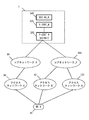
- IMS_A7 includes P-CSCF (Proxy Call Session Control Function; Proxy Proxy CSCF) _A300, I-CSCF (Interrogating Call Session Control Function; Interrogating CSCS), S-CSCF (Serving Call Session Control Function; Serving-CSCF ) _A320 and SCC AS (Service Centralization and Continuity Application Server) _A340 may include at least one of them. These may be configured as NF (Network Function). The NF may refer to a processing function configured in the network.
- CSCF Call Session Control Function
- P-CSCF and / or S-CSCF and / or I for processing a SIP (Session Initiation Protocol) signal packet in IMS (IP Multimedia subsystem).
- IMS IP Multimedia subsystem
- P-CSCF_A300 is also referred to as P-CSCF
- S-CSCF_A320 is also referred to as S-CSCF
- SCCSCAS_A340 is also referred to as SCC AS.
- P-CSCF is connected to Core Network_A and / or Core Network_B and / or UPF and / or PWG and / or S-CSCF.
- P-CSCF is a SIP proxy server when UE_A10 connects to IMS_A7.
- P-CSCF is a device of IMS_A7 to which UE_A10 first connects, and is assigned to UE_A10 in a registration procedure described later, and UE_A10 may acquire the destination address of P-CSCF during the procedure.
- the P-CSCF may execute the normal call connection processing and the emergency call connection processing for the voice call service and / or video call service requested by the UE_A10 with different devices and / or NFs, or the same It may be executed by the device and / or NF.
- S-CSCF is connected to HSS_A50 and / or UDM_A245 and / or P-CSCF and / or I-CSCF and / or SCC AS.
- the S-CSCF is a SIP server that performs IMS session control and / or user authentication related to UE_A10.
- SCC AS may be connected to S-CSCF and / or I-CSCF and / or CS network_A290.
- SCC / AS is an AS (Application / Server) that provides a switching function between VoLTE and circuit switching in SRVCC (Single Radio / Voice / Call / Continuity).
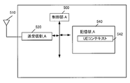
- UE_A10 includes a control unit_A500, a transmission / reception unit_A520, and a storage unit_A540.
- the transmission / reception unit_A520 and the storage unit_A540 are connected to the control unit_A500 via a bus.
- an external antenna 510 is connected to the transmission / reception unit_A520.
- the storage unit_A540 stores the UE context 442.
- the control unit_A500 is a functional unit for controlling the entire UE_A10, and implements various processes of the entire UE_A10 by reading and executing various information and programs stored in the storage unit_A540.
- the transmission / reception unit_A520 is a functional unit for the UE_A10 to connect to a base station (E-UTRAN_A80 and NG-RAN_A120) and / or an access point (WLAN ANc125) in the access network and connect to the access network.
- the UE_A 10 can be connected to a base station and / or an access point in the access network via the external antenna 510 connected to the transmission / reception unit_A 520.
- UE_A10 transmits / receives user data and / or control information to / from a base station and / or access point in the access network via external antenna 510 connected to transmission / reception unit_A520. Can do.
- the storage unit_A540 is a functional unit that stores programs and data necessary for each operation of the UE_A10, and includes, for example, a semiconductor memory, HDD (Hard Disk Drive), SSD (Solid State Drive), and the like.
- the storage unit_A540 stores identification information, control information, flags, parameters, and the like included in control messages that are transmitted and received within a communication procedure described later.
- the UE context stored in the storage unit_A540 may include, for example, a UE context used when connecting to the access network_B120 and a UE context used when connecting to the core network_B190.
- the UE context 442 may include a UE context stored for each UE, a UE context stored for each PDU session, and a UE context stored for each bearer.
- the UE context stored for each UE may include IMSI, EMMIState, GUTI, and ME Identity.
- the UE context stored for each PDU session may include APN in Use, Assigned Session Type, IP Address (es), and Default Bearer.
- the UE context stored for each bearer may include EPS Bearer ID, TI, and TFT.
- FIG. 6 shows a configuration example of the access network device.
- the access network device may include eNB_A45 and / or eNB_B and / or gNB_A122 and / or WAG_A126, for example, but is not limited thereto.
- the access network apparatus includes a control unit_B600, a network connection unit_B620, a transmission / reception unit_B630, and a storage unit_B640.
- the network connection unit_B620, the transmission / reception unit_B630, and the storage unit_B640 are connected to the control unit_B600 via a bus. Further, an external antenna 610 is connected to the transmission / reception unit_B630.
- the control unit _B600 is a functional unit for controlling the entire access network device, and by reading and executing various information and programs stored in the storage unit _B640, the eNB_A45, gNB_A122, and WAG_A126 as a whole Various processes are realized.
- the network connection unit_B620 is a functional unit for the access network device to connect to the AMF_A240 and UPF_A235 in the core network.
- the access network device can be connected to the AMF_A240 and UPF_A235 in the core network via the network connection unit_B620.
- the access network apparatus can transmit / receive user data and / or control information to / from AMF_A240 and / or UPF_A235 via the network connection unit_B620.
- the transmission / reception unit_B630 is a functional unit for the access network device to connect to the UE_A10.
- the access network apparatus can transmit / receive user data and / or control information to / from UE_A10 via the transmission / reception unit_B630.
- Storage unit_B640 is a functional unit that stores programs and data necessary for each operation of the access network device.
- the storage unit_B640 is configured by, for example, a semiconductor memory, HDD, SSD, or the like.
- the storage unit_B640 stores identification information, control information, flags, parameters, and the like included in control messages that are transmitted and received within a communication procedure described later.
- the storage unit_B640 may store these pieces of information as contexts for each UE_A10.
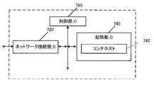
- FIG. 7 shows a device configuration example of MME_A40 and / or AMF_A240.
- the MME_A 40 and / or AMF_A 240 includes a control unit_C700, a network connection unit_C720, and a storage unit_C740.
- the network connection unit _C720 and the storage unit _C740 are connected to the control unit _C700 via a bus.
- the storage unit_C740 stores a context 742.
- the control unit _C700 is a functional unit for controlling the entire MME_A40 and / or AMF_A240, and by reading and executing various information and programs stored in the storage unit_C740, the MME_A40 and / or AMF_A240 Implements the entire process.
- Network connection unit _C720 MME_A40 and / or AMF_A240, other AMF_240, SMF_A230, base station (E-UTRAN_A80 and NG-RAN_A120) and / or access point (WLAN ANc125), UDM_A245, AUSF, PCF It is a functional part for connecting with.
- the MME_A40 and / or AMF_A240 transmits and receives user data and / or control information to and from the base station and / or access point, UDM_A245, AUSF, and PCF in the access network via the network connection unit_C720. can do.
- Storage unit_C740 is a functional unit that stores programs and data necessary for each operation of MME_A40 and / or AMF_A240.
- the storage unit_C740 is configured by, for example, a semiconductor memory, HDD, SSD, or the like.
- the storage unit_C740 stores identification information, control information, flags, parameters, and the like included in control messages that are transmitted and received in a communication procedure described later.
- the context 742 stored in the storage unit _C740 may include a context stored for each UE, a context stored for each PDU session, and a context stored for each bearer.
- Contexts stored for each UE include IMSI, MSISDN, MM State, GUTI, ME Identity, UE Radio Access Capability, UE Network Capability, MS Network Capability, Access Restriction, MME F-TEID, SGW F-TEID, eNB Address , MME UE1S1AP ID, eNB UE S1AP ID, gNB Address, gNB ID, WAG Address, and WAG ⁇ ⁇ ID.
- the context stored for each PDU session may include APN in Use, Assigned Session Type, IP Address (es), PGW F-TEID, SCEF ID, and Default bearer.
- the context stored for each bearer includes EPS Bearer ID, TI, TFT, SGW F-TEID, PGW F-TEID, MME F-TEID, eNB Address, gNB Address, WAG Address, eNB ID, gNB ID, WAG ID may be included.
- FIG. 8 shows a device configuration example of SMF_A230.
- the SMF_A 230 includes a control unit_D800, a network connection unit_D820, and a storage unit_D840, respectively.
- the network connection unit _D820 and the storage unit _D840 are connected to the control unit _D800 via a bus.
- the storage unit_D840 stores a context 842.
- the control unit _D800 of SMF_A230 is a functional unit for controlling the entire SMF_A230. By reading and executing various information and programs stored in the storage unit _D840, various processes of the entire SMF_A230 are realized. To do.
- the network connection unit_D820 of the SMF_A230 is a functional unit for the SMF_A230 to connect with the AMF_A240, UPF_A235, UDM_A245, and PCF.
- the SMF_A 230 can transmit / receive user data and / or control information to / from the AMF_A 240, UPF_A 235, UDM_A 245, and PCF via the network connection unit_D820.
- the storage unit_D840 of the SMF_A230 is a functional unit that stores programs and data necessary for each operation of the SMF_A230.
- the storage unit_D840 of the SMF_A230 is configured by, for example, a semiconductor memory, HDD, SSD, or the like.
- the storage unit_D840 of the SMF_A230 stores identification information, control information, flags, parameters, and the like included in control messages that are transmitted and received within a communication procedure that will be described later.
- the context 842 stored in the storage unit _D840 of the SMF_A230 is stored for each bearer, the context stored for each UE, the context stored for each APN, the context stored for each PDU session, and the bearer. There may be contexts.
- the context stored for each UE may include IMSI, ME Identity, MSISDN, and RAT type.
- the context stored for each APN may include APN in use. Note that the context stored for each APN may be stored for each Data ⁇ ⁇ Network Identifier.
- the context stored for each PDU session may include Assigned Session Type, IP Address (es), SGW F-TEID, PGW F-TEID, and Default Bearer.
- the context stored for each bearer may include EPS Bearer ID, TFT, SGW F-TEID, PGW F-TEID.
- FIG. 8 shows an example of the device configuration of PGW_A30 and / or UPF_A235.
- PGW_A30 and / or UPF_A235 are configured by a control unit_D800, a network connection unit_D820, and a storage unit_D840, respectively.
- the network connection unit _D820 and the storage unit _D840 are connected to the control unit _D800 via a bus.
- the storage unit_D840 stores a context 842.
- the control unit _D800 of the PGW_A30 and / or UPF_A235 is a functional unit for controlling the entire UPF_A235, and by reading and executing various information and programs stored in the storage unit_D840, the PGW_A30 and / or UPF_A235 Alternatively, various processing of the entire UPF_A235 is realized.
- the network connection unit _D820 of the PGW_A30 and / or UPF_A235 is configured such that the PGW_A30 and / or UPF_A235 is a DN (i.e., DN_A5 and / or PDN_A6), SMF_A230, other PGW_A30 and / or UPF_A235, and an access network (i.e. E-UTRAN_A80, NG-RAN_A120, WLAN ANc125, WLAN ANa70 and WLAN ANb75).
- DN i.e., DN_A5 and / or PDN_A6
- SMF_A230 i.e., other PGW_A30 and / or UPF_A235
- an access network i.e. E-UTRAN_A80, NG-RAN_A120, WLAN ANc125, WLAN ANa70 and WLAN ANb75.
- UPF_A235 is connected to DN (i.e., DN_A5 and / or PDN_A6), SMF_A230, other UPF_A235, and access network (i.e., E-UTRAN_A80, NG-RAN_A120, and WLAN ANc125 via network connection _D820).
- DN i.e., DN_A5 and / or PDN_A6
- SMF_A230 i.e., SMF_A230
- other UPF_A235 i.e., DN_A5 and / or PDN_A6
- access network i.e., E-UTRAN_A80, NG-RAN_A120, and WLAN ANc125 via network connection _D820.
- User data and / or control information can be transmitted / received between WLAN ANa 70 and WLAN ANb 75).
- the storage unit_D840 of the PGW_A30 and / or UPF_A235 is a functional unit that stores programs, data, and the like necessary for each operation of the PGW_A30 and / or UPF_A235.
- the storage unit_D840 of the PGW_A30 and / or UPF_A235 is configured by, for example, a semiconductor memory, HDD, SSD, or the like.
- the storage unit_D840 of the PGW_A30 and / or UPF_A235 stores identification information, control information, flags, parameters, and the like included in control messages that are transmitted and received within a communication procedure described later.
- the context 842 stored in the storage unit_D840 of the PGW_A30 and / or UPF_A235 includes a context stored for each UE, a context stored for each APN, a context stored for each PDU session, a bearer There may be a context stored for each.
- the context stored for each UE may include IMSI, ME Identity, MSISDN, and RAT type.
- the context stored for each APN may include APN in use. Note that the context stored for each APN may be stored for each Data ⁇ ⁇ Network Identifier.
- the context stored for each PDU session may include Assigned Session Type, IP Address (es), SGW F-TEID, PGW F-TEID, and Default Bearer.
- the context stored for each bearer may include EPS Bearer ID, TFT, SGW F-TEID, PGW F-TEID.
- FIG. 9 shows a configuration example of the CSCF.
- the CSCF includes a control unit_E900, a network connection unit_E920, and a storage unit_E940, respectively.
- the network connection unit_E920 and the storage unit_E940 are connected to the control unit_E900 via a bus.
- the storage unit_E940 stores a context 942.
- CSCF control unit _E900 is a functional unit for controlling the entire CSCF, and various types of information and programs stored in the storage unit _E940 are read and executed to implement various processes for the entire CSCF. To do.
- CSCF network connection part_E920 is a functional part for CSCF to connect with other CSCFs, UPF_A235, PGW_A30, HSS_A50, UDM_A245.
- the CSCF can transmit / receive user data and / or control information to / from other CSCFs, UPF_A235, PGW_A30, HSS_A50, and UDM_A245 via the network connection unit_E920.
- CSCF storage unit_E940 is a functional unit that stores programs and data necessary for each operation of CSCF.
- the storage unit_E940 is configured by, for example, a semiconductor memory, HDD, SSD, or the like.
- the storage unit_E940 stores identification information, control information, flags, parameters, and the like included in control messages that are transmitted and received in a communication procedure described later.
- As the context 942 stored in the storage unit _E940 there may be a context stored for each UE, IMSI, MSISDN, UE Address, Public User ID (s), Private User ID (s), access network May include type, session state (session state information).
- IMSI International Mobile Subscriber Identity
- SUPI Subscriber Permanent Identifier
- UE_A10 and MME_A40 / CPF_A140 / AMF_A2400 and SGW_A35 may be equal to the IMSI and / or SUPI stored in HSS_A50 and / or UDM_A245.
- SUPI may include IMSI.
- EMM State / MM State indicates the mobility management state of UE_A10 or MME_A40 / CPF_A140 / AMF_A240.
- the EMM State / MM State may be an EMM-REGISTERED state (registered state) in which UE_A10 is registered in the network and / or an EMM-DEREGISTERD state (unregistered state) in which UE_A10 is not registered in the network.
- EMM State / MM State may be an ECM-CONNECTED state in which the connection between the UE_A 10 and the core network is maintained and / or an ECM-IDLE state in which the connection is released.
- the EMM State / MM State may be information that can distinguish the state in which the UE_A 10 is registered in the EPC and the state in which the UE_A 10 is registered in the NGC or 5GC.
- GUTI Globally Unique Temporary Identity
- MME_A40 / CPF_A140 / AMF_A240 GUMMEI (Globally Unique MME Identifier)
- M-TMSI M-Temporary Mobile Subscriber Identity
- ME Identity is the ID of UE_A10 or ME, and may be, for example, IMEI (International Mobile Equipment Identity) or IMEISV (IMEI Software Version).
- MSISDN represents the basic telephone number of UE_A10.
- the MSISDN stored in MME_A40 / CPF_A140 / AMF_A240 may be information indicated by the storage unit of HSS_A50.
- the GUTI may include information for identifying CPF_140.
- MME F-TEID is information for identifying MME_A40 / CPF_A140 / AMF_A240.
- the MME F-TEID may contain the IP address of MME_A40 / CPF_A140 / AMF_A240, the TEID (Tunnel Endpoint Identifier) of MME_A40 / CPF_A140 / AMF_A240, or both of them. Also good. Further, the IP address of MME_A40 / CPF_A140 / AMF_A240 and the TEID of MME_A40 / CPF_A140 / AMF_A240 may be stored independently. Further, the MME F-TEID may be identification information for user data or identification information for control information.
- SGW F-TEID is information that identifies SGW_A35.
- the SGW F-TEID may include the IP address of SGW_A35, may include the TEID of SGW_A35, or may include both of them. Further, the IP address of SGW_A35 and the TEID of SGW_A35 may be stored independently. Further, the SGWTEF-TEID may be identification information for user data or identification information for control information.
- PGW F-TEID is information for identifying PGW_A30 / UPGW_A130 / SMF_A230 / UPF_A235.
- the PGW F-TEID may include the IP address of PGW_A30 / UPGW_A130 / SMF_A230 / UPF_A235, the TEGW of PGW_A30 / UPGW_A130 / SMF_A230 / UPF_A235, or both. Good.
- the IP address of PGW_A30 / UPGW_A130 / SMF_A230 / UPF_A235 and the TEID of PGW_A30 / UPGW_A130 / SMF_A230 / UPF_A235 may be stored independently.
- the PGW F-TEID may be identification information for user data or identification information for control information.
- ENB F-TEID is information that identifies eNB_A45.
- the eNB F-TEID may include the IP address of eNB_A45, may include the TEID of eNB_A45, or may include both. Further, the IP address of eNB_A45 and the TEID of SGW_A35 may be stored independently. Further, the eNB F-TEID may be identification information for user data or identification information for control information.
- the APN may be identification information that identifies the core network and an external network such as a DN. Furthermore, the APN can also be used as information for selecting a gateway such as PGW_A30 / UPGW_A130 / UPF_A235 that connects the core network_A90.
- the APN may be DNN (Data Network Name). Therefore, APN may be expressed as DNN, or DNN may be expressed as APN.
- the APN may be identification information for identifying such a gateway, or identification information for identifying an external network such as a DN.
- identification information for identifying such a gateway or identification information for identifying an external network such as a DN.
- UE Radio Access Capability is identification information indicating the radio access capability of UE_A10.
- UE Network Capability includes security algorithms and key derivation functions supported by UE_A10.
- MS Network Capability is information including one or more pieces of information necessary for SGSN for UE_A 10 having the GERAN_A 25 and / or UTRAN_A 20 functions.
- Access Restriction is registration information of access restriction.
- eNB Address is the IP address of eNB_A45.
- MME UE S1AP ID is information for identifying UE_A10 in MME_A40 / CPF_A140 / AMF_A240.
- eNB UE S1AP ID is information for identifying UE_A10 in eNB_A45.
- APNAPin Use is a recently used APN.
- APN in Use can be Data Network Identifier. This APN may be composed of network identification information and default operator identification information. Further, APN in Use may be information for identifying the DN of the establishment destination of the PDU session.
- Assigned Session Type is information indicating the type of PDU session. Assigned Session Type may be Assigned PDN Type. The type of PDU session may be IP or non-IP. Furthermore, when the type of the PDU session is IP, information indicating the type of PDN allocated from the network may be further included. The Assigned Session Type may be IPv4, IPv6, or IPv4v6.
- IP Address is an IP address assigned to the UE.
- the IP address may be an IPv4 address, an IPv6 address, or an IPv6 prefix.
- Assigned Session Type indicates non-IP, the IP Address element need not be included.
- DN ID is identification information that identifies the core network_B190 and an external network such as DN. Further, the DN ID can also be used as information for selecting a gateway such as UPGW_A130 or PF_A235 that connects the core network_B190.
- the DN ID may be identification information for identifying such a gateway, or identification information for identifying an external network such as a DN.
- a plurality of gateways that connect the core network_B190 and the DN there may be a plurality of gateways that can be selected by the DN ID. Further, one gateway may be selected from the plurality of gateways by another method using identification information other than the DN ID.
- the DN ID may be the same information as the APN, or may be information different from the APN. If the DN ID and APN are different information, each device may manage information indicating the correspondence between the DN ID and APN, or perform a procedure for inquiring the APN using the DN ID. Alternatively, a procedure for inquiring about the DN ID using the APN may be performed.
- the SCEF IV ID is the SCEF IP address used in the PDU session.
- Default Bearer is information acquired and / or generated when a PDU session is established, and is EPS bearer identification information for identifying a default bearer associated with a PDU session.
- EPS Bearer ID is the EPS bearer identification information.
- the EPS Bearer ID may be identification information for identifying SRB (Signalling Radio Bearer) and / or CRB (Control-plane-Radio Bearer), or may be identification information for identifying DRB (Data Radio Bearer).
- TI Transaction Identifier
- the EPS Bearer ID may be EPS bearer identification information for identifying a dedicated bearer. Therefore, identification information for identifying an EPS bearer different from the default bearer may be used.
- TFT indicates all packet filters associated with the EPS bearer.
- the TFT is information for identifying a part of user data to be transmitted / received, and the UE_A 10 transmits / receives the user data identified by the TFT using an EPS bearer associated with the TFT.
- UE_A 10 transmits and receives user data identified by the TFT using an RB (RadioRadBearer) associated with the TFT.
- the TFT may associate user data such as application data to be transmitted / received with an appropriate transfer path, or may be identification information for identifying application data.
- UE_A10 may transmit / receive user data that cannot be identified by TFT using a default bearer.
- UE_A10 may memorize
- Default Bearer is EPS bearer identification information that identifies the default bearer associated with the PDN connection / PDU session.
- the EPS bearer may be a logical communication path established between UE_A10 and PGW_A30 / UPGW_A130 / UPF_A235, or may be a communication path constituting a PDN connection / PDU session. Further, the EPS bearer may be a default bearer or a dedicated bearer. Furthermore, the EPS bearer may be configured to include an RB established between the UE_A 10 and a base station and / or access point in the access network. Furthermore, RBs and EPS bearers may be associated one-to-one.
- the RB identification information may be associated with the EPS bearer identification information on a one-to-one basis, or may be the same identification information.
- RB may be SRB and / or CRB or DRB.
- Default Bearer may be information that UE_A10 and / or SGW_A35 and / or PGW_A30 / UPGW_A130 / SMF_A230 / UPF_A235 acquire from the core network when a PDU session is established.
- the default bearer is an EPS bearer that is first established in a PDN connection / PDU session, and is an EPS bearer that can be established only in one PDN connection / PDU session.
- the default bearer may be an EPS bearer that can be used for communication of user data not associated with the TFT.
- a dedicated bearer is an EPS bearer that is established after a default bearer is established in a PDN connection / PDU session, and a plurality of EPS bearers that can be established in one PDN connection / PDU session. is there.
- a dedicated bearer is an EPS bearer that can be used for communication of user data associated with a TFT.
- User Identity is information for identifying a subscriber.
- User Identity may be IMSI or MSISDN. Further, the user identity may be identification information other than IMSI or MSISDN.
- Serving Node Information is information for identifying MME_A40 / CPF_A140 / AMF_A240 used in the PDU session, and may be the IP address of MME_A40 / CPF_A140 / AMF_A240.
- ENB Address is the IP address of eNB_A45.
- the eNB ID is information for identifying the UE in the eNB_A45.
- MME Address is the IP address of MME_A40 / CPF_A140 / AMF_A240.
- the MME ID is information for identifying MME_A40 / CPF_A140 / AMF_A240.
- gNB Address is the IP address of gNB_A122.
- gNB ID is information for identifying gNB_A122.
- WAG Address is the IP address of WAG_A126.
- WAG ID is information for identifying WAG_A126.
- SRVCC Single Radio Voice Call Continuity
- IMS Interoperability Management Function
- PS Packet Control Function
- SRVCC may be a technology in which the UE switches the access to be used between VoLTE (Voice over LTE) and circuit switching to continue the voice call.
- vSRVCC Single Radio Video Video Call Continuity
- vSRVCC Single Radio Video Video Call Continuity
- UTRAN may be UTRAN-CS.
- Video call (Video ⁇ Call) is a technology that provides two-way voice calls and synchronized real-time video sessions for IMS via E-UTRAN or NG-RAN.
- video calling is a technology that provides CS multimedia calls for UTRAN.
- 3GPP SRVCC UE is SRVCC capability information between E-UTRAN and UTRAN, or SRVCC capability information between E-UTRAN and GERAN, or SRVCC capability between UTRAN (HSPA) and UTRAN and GERAN. This is a UE whose IMS service continuity is extended by the UE or the UE capability information to which SRVCC capability information between NG-RAN and UTRAN is added.
- UTRAN may be expressed as 3GPP UTRAN
- GERAN may be expressed as 3GPP UTRAN.
- SCC AS Service Centralization and Continuity Application Server
- AS Application Server
- Mobile Station Class Mark 2 (Mobile Station Class Mark 2) is an information element provided to the network including information on the priority (including both high priority and low priority) of the mobile terminal device (UE).
- the mobile station class mark 2 may be information that affects the handling of the mobile terminal device in the network.
- the mobile station class mark 2 may be information indicating characteristics of a general mobile terminal device. Therefore, the mobile station class mark 2 may be information independent of the frequency band of the transmitted channel, except for the explicitly indicated fields.
- Mobile Station Class Mark 3 (Mobile Station Class Mark 3) is an information element provided to the network including information related to the mobile terminal device (UE).
- the content of the mobile station class mark 3 may be information that affects the handling of the mobile terminal device in the network.
- the mobile station class mark 3 may be information indicating characteristics of a general mobile terminal device. Therefore, the mobile station class mark 3 may be information independent of the frequency band of the transmitted channel, except for the fields explicitly indicated.
- Supported codecs are one or more audio codecs supported in CS voice calls.
- the first state is a state in which UE_A 10 and each device complete the registration procedure, and UE_A 10 is registered in core network_B (RM-REGISTERED state and / or 5GMM-REGISTERED state). Further, the first state may be a state in which the AMF stores context information about the UE, or a state in which the UE_A 10 stores the context information of the network acquired during the registration procedure.
- the second state is a state in which UE_A has completed the PDU connection establishment procedure for IMS via core network_B.
- UE_A in the second state may be in a state in which a PDU session for voice service or video service provided by IMS is established.
- UE_A in the second state may be in the CM-CONNECTED state, or may be in a state in which the UE and each device have completed the IMS registration procedure.
- the tracking area is a single or a plurality of ranges that can be represented by UE_A10 location information managed by the core network.
- the tracking area may be composed of a plurality of cells. Further, the tracking area may be a range where a control message such as paging is broadcast, or a range where UE_A 10 can move without performing a handover procedure. Furthermore, the tracking area may be a routing area, a location area, or the like. Hereinafter, the tracking area may be TA (Tracking Area).
- the TA list is a list that includes one or more TAs assigned to UE_A10 by the network. Note that UE_A10 may be able to move without executing the tracking area update procedure while moving in one or more TAs included in the TA list. In other words, UE_A10 may be an information group in which the TA list indicates an area where UE_A10 can move without executing the tracking area update procedure.
- SUPI Subscriber Permanent Identifier
- the SUPI may be IMSI (International Mobile Subscriber Identity) or NAI (Network Access Identifier).
- DNN Data Network Name
- DN Data Network
- the DNN may be APN (Access Point) Name).
- N1 mode is a UE mode in which UE can access 5GC via 5G access network. Further, the N1 mode may be a UE mode capable of transmitting and receiving messages using the N1 interface.
- the N1 interface may be composed of an Xn interface that connects the N1 interface and the radio base station.
- the UE in N1 mode can access, for example, 5GC via ng-eNB that provides the E-UTRA function and 5GC via gNB that provides the NR function.
- access to 5GC via ng-eNB providing the E-UTRA function and access to 5GC via gNB providing the NR function are N1 modes, they may be configured as different modes. .
- the Iu mode is a UE mode in which the UE can access the CS network_A.
- VoLTE is used in P-CSCF and / or S-CSCF and / or SRVCC that execute the call control function of IMS.
- a message may be transmitted to the SCC-AS, which is an application server that provides a circuit switching function.
- circuit switching is performed with VoLTE in P-CSCF and / or S-CSCF and / or SRVCC that execute the call control function of IMS. It is possible to receive a message from SCC-AS, which is an application server that provides a switching function.
- SRVCC from NG-RAN to UTRAN and SRVCC from N1 mode to Iu mode used in the description in this embodiment represent the same meaning, and each description in this embodiment is read as the other. It's okay.
- vSRVCC from NG-RAN to UTRAN and the vSRVCC from N1 mode to Iu mode used for the description in the present embodiment represent the same meaning, and each description in the present embodiment refers to the other. You may replace it.
- the first identification information in this embodiment is UE capability information indicating that SRTRAN is supported from UTRAN HSPA (High Speed Packet Access) or E-UTRAN or NG-RAN to GERAN or UTRAN (GERAN / UTRAN). is there.
- UTRAN HSPA High Speed Packet Access
- E-UTRAN or NG-RAN to GERAN or UTRAN (GERAN / UTRAN).
- UE_A10 has SRVCC capability information to GERAN / UTRAN when UE_A10 supports SRVCC function to GERAN / UTRAN and / or UE_A10 supports SRVCC function from NG-RAN to UTRAN.
- This identification information may be set and transmitted for SRVCC (to GERAN / UTRAN (capability (bit)).
- UE_A may transmit SRVCC capability information to GERAN / UTRAN in an MS (Mobile Station) network capability information element.
- the second identification information in this embodiment is UE capability information indicating that SRVCC from NG-RAN to UTRAN is supported.
- UE_A10 sets this identification information for SRVCC capability information (SRVCCSRto GERAN / UTRAN capability bit) to GERAN / UTRAN when UE_A10 supports SRVCC function from NG-RAN to UTRAN. May be. Further, UE_A may transmit SRVCC capability information to GERAN / UTRAN in an MS (Mobile Station) network capability information element.
- SRVCC capability information SRVCCSRto GERAN / UTRAN capability bit
- MS Mobile Station
- UE_A10 when UE_A10 supports the SRVCC function from NG-RAN to UTRAN, UE_A uses this identification information for SRVCC capability information (SRVCC-from ⁇ ⁇ NG-RAN to UTRAN capability bit) from NG-RAN to UTRAN. You may set and transmit. Furthermore, UE_A may transmit SRVCC capability information from NG-RAN to UTRAN in an MS (Mobile Station) network capability information element.
- MS Mobile Station
- the third identification information in the present embodiment supports H.245, can use a predefined code, and further executes H.245 codec negotiation after SRVCC handover if necessary.
- UE capability information indicating that it can be performed.
- UE_A has information indicating the ability to execute H.245 after handover when supporting vSRVCC from S1 mode to IuImode and / or supporting vSRVCC from N1 mode to Iu mode (H .245 ⁇ after handover bit) may be set to this identification information. Further, UE_A may transmit information indicating the ability to execute H.245 after handover in the UE network capability information element.
- UE_A may transmit the first identification information or the second identification information in addition to the main identification information.
- UE_A may set and transmit the first identification information with respect to SRVCC capability information (SRVCC-to-GERAN / UTRAN-capability-bit) to GERAN / UTRAN. Further, UE_A may transmit SRVCC capability information to GERAN / UTRAN in an MS (Mobile Station) network capability information element.
- SRVCC capability information SRVCC-to-GERAN / UTRAN-capability-bit
- UE_A may set the second identification information for SRVCC capability information (SRVCC-to-GERAN / UTRAN-capability-bit) to GERAN / UTRAN and transmit it. Further, UE_A may transmit SRVCC capability information to GERAN / UTRAN in an MS (Mobile Station) network capability information element.
- SRVCC capability information SRVCC-to-GERAN / UTRAN-capability-bit
- UE_A may transmit the second identification information by setting this identification information with respect to SRVCC capability information from NG-RAN to UTRAN (SRVCC from NG-RAN to UTRAN capability bit). Furthermore, UE_A may transmit SRVCC capability information from NG-RAN to UTRAN in an MS (Mobile Station) network capability information element.
- MS Mobile Station
- the fourth identification information in the present embodiment supports H.245, can use a predefined code, and further, if necessary, performs H.245 codec negotiation from NG-RAN to UTRAN.
- UE capability information indicating that it can be executed after SRVCC handover.
- UE_A may set this identification information in information (H.245.after handover bit) indicating the ability to execute H.245 after handover when supporting vSRVCC from N1 mode to Iu mode . Further, UE_A may transmit information indicating the ability to execute H.245 after handover in the UE network capability information element. In this case, UE_A may transmit the first identification information or the second identification information in addition to the main identification information.
- UE_A may set and transmit the first identification information with respect to SRVCC capability information (SRVCC-to-GERAN / UTRAN-capability-bit) to GERAN / UTRAN. Further, UE_A may transmit SRVCC capability information to GERAN / UTRAN in an MS (Mobile Station) network capability information element.
- SRVCC capability information SRVCC-to-GERAN / UTRAN-capability-bit
- UE_A may set the second identification information for SRVCC capability information (SRVCC-to-GERAN / UTRAN-capability-bit) to GERAN / UTRAN and transmit it. Further, UE_A may transmit SRVCC capability information to GERAN / UTRAN in an MS (Mobile Station) network capability information element.
- SRVCC capability information SRVCC-to-GERAN / UTRAN-capability-bit
- UE_A may transmit the second identification information by setting this identification information with respect to SRVCC capability information from NG-RAN to UTRAN (SRVCC from NG-RAN to UTRAN capability bit). Furthermore, UE_A may transmit SRVCC capability information from NG-RAN to UTRAN in an MS (Mobile Station) network capability information element.
- MS Mobile Station
- the fifth identification information may be information indicating a mobile station class mark 2 (Mobile Station Class Mark 2).
- the fifth identification information is transmitted when the UE supports SRVCC handover to UTRAN or GERAN and / or when the UE supports vSRVCC handover to UTRAN or GERAN. It may be information. In other words, the network may recognize the UE's support for handover to UTRAN based on the fifth information.
- the sixth identification information may be information indicating codecs (Supported codecs) that the UE supports in CS voice call.
- the seventh identification information is information indicating that the SRVCC handover has been canceled and / or information indicating that the IMS session needs to be re-established.
- UE_A10 starts a registration procedure to the core network (S1020).
- the UE_A 10 and each device exchange capability information of the UE_A 10 and the core network and / or the access network by executing a registration procedure with the core network.
- the UE_A 10 and each device transition to the first state (S1030).
- the UE_A 10 and each device may transition to a state where the UE_A 10 is registered in the network (RM-REGISTERED state) by executing a registration procedure for the core network.
- UE_A10 in the first state starts a PDU session establishment procedure for IMS (S1040).
- the UE_A 10 and each device in the first state establish a PDU session between the UE_A 10 and the IMS by executing a PDU session establishment procedure for the IMS.
- UE_A 10 and each device transition to the second state (S1050).
- the PDU session established between the UE_A 10 and the IMS may be a PDU session established via the access network and the core network.
- the UE_A 10 and each device in the second state execute the second procedure.
- the UE_A 10 and each device in the second state perform handover from the NG-RAN_A 120 to the UTRAN_A 20 using the SRVCC function by executing the second procedure.
- the UE_A 10 and each device may exchange and / or acquire various capability information and / or various request information of each device in the registration procedure to the core network.
- each device involved in this procedure transmits / receives each control message described in this procedure, thereby transmitting / receiving one or more pieces of identification information included in each control message, and storing each transmitted / received identification information as a context. Also good.
- This procedure is led by UE_A10 to register with the network (access network and / or core network_B190, and / or DN (DN_A5 and / or PDN_A6).
- UE_A10 registers with the network. If not, this procedure can be executed at any timing such as when the power is turned on, etc. In other words, UE_A10 can execute this procedure at any timing if it is in the unregistered state (RM-DEREGISTERED state).
- each device may transition to a registration state (RM-REGISTERED state) based on the completion of the registration procedure.
- this procedure updates the location registration information of UE_A10 in the network and / or periodically notifies UE_A10 of the status of UE_A10 from the UE_A10 and / or updates specific parameters related to UE_A10 in the network. It may be a procedure.
- UE_A10 may start this procedure when performing mobility across TAs. In other words, the UE_A 10 may start this procedure when moving to a TA that is different from the TA indicated in the held TA list. Furthermore, UE_A10 may start this procedure when the running timer expires. Further, UE_A 10 may start this procedure when the context of each device needs to be updated due to disconnection or invalidation of the PDU session. Furthermore, UE_A10 may start this procedure, when the capability information regarding a PDU session establishment of UE_A10 and / or a preference change arise. Furthermore, UE_A10 may start this procedure periodically. The UE_A 10 is not limited to these, and can execute this procedure at an arbitrary timing as long as the PDU session is established.
- each device may transition to the first state, and each device in the first state executes the subsequent processes and procedures described in FIG. 10 described above. May be.
- UE_A10 starts a registration procedure by transmitting a registration request (Registration Request) message to AMF_A240 via gNB_A122 or eNB_B145 (S1100) (S1102) (S1104). Further, UE_A10 transmits an SM message (for example, a PDU session establishment request message) together with the registration request message by transmitting an SM (Session Management) message (for example, a PDU session establishment request message) in the registration request message. By doing so, the SM procedure such as the PDU session establishment procedure may be started during the registration procedure.
- SM Session Management
- UE_A10 transmits an RRC message including a registration request message to gNB_A122 or eNB_B145 (S1100).
- the gNB_A122 or eNB_B145 receives the RRC message including the registration request message
- the gNB_A122 or eNB_B145 selects AMF_A240 as the NF or shared CP function of the routing destination of the registration request message (S1102).
- the gNB_A122 or eNB_B145 extracts the registration request message from the received RRC message, and transmits or forwards the registration request message to the selected AMF_A240 (S1104).
- gNB_A122 or eNB_B145 may select AMF_A240 based on information included in the RRC message.
- the registration request message may be a NAS (Non-Access-Stratum) message transmitted / received on the N1 interface.
- the RRC message may be a control message transmitted / received between UE_A10 and gNB_A122 or eNB_B145.
- the NAS message is processed in the NAS layer, the RRC message is processed in the RRC layer, and the NAS layer may be a higher layer than the RRC layer.
- UE_A10 may transmit a registration request message for each NSI, or may transmit a plurality of registration request messages included in one or more RRC messages. Good.
- the plurality of registration request messages may be transmitted as one registration request message included in one or more RRC messages.
- UE_A10 may include one or more of the first to sixth identification information in the registration request message, and by including this identification information, SRVCC handover support from NG-RAN_A120 to UTRAN_A20 Or vSRVCC handover support from NG-RAN_A 120 to UTRAN_A 20 may be indicated.
- UE_A10 transmits the first identification information and / or the fifth identification information and / or the sixth identification information included in the registration request message, so that NG-RAN_A120 to UTRAN_A20. May support support for SRVCC handover.
- the UE_A10 transmits the second identification information and / or the fifth identification information and / or the sixth identification information included in the registration request message, so that the SRVCC hand from the NG-RAN_A120 to the UTRAN_A20. Over support may be indicated.
- UE_A10 transmits the first identification information and / or the fifth identification information and / or the sixth identification information to AMF_A240 via NG-RAN_A120, so that NG-RAN_A120 to UTRAN_A20 SRVCC handover support may be indicated.
- UE_A10 transmits the second identification information and / or the fifth identification information and / or the sixth identification information to AMF_A240 via NG-RAN_A120, so that NG-RAN_A120 to UTRAN_A20 SRVCC handover support may be indicated.
- UE_A10 includes the registration request message to transmit the first identification information, and / or the third identification information, and / or the fifth identification information, and / or the sixth identification information, Support for vSRVCC handover from NG-RAN_A120 to UTRAN_A20 may be indicated.
- UE_A10 includes the registration request message and transmits the second identification information, and / or the third identification information, and / or the fifth identification information, and / or the sixth identification information, Support for vSRVCC handover from NG-RAN_A120 to UTRAN_A20 may be indicated.
- UE_A10 includes the registration request message and transmits the first identification information, and / or the fourth identification information, and / or the fifth identification information, and / or the sixth identification information, Support for vSRVCC handover from NG-RAN_A120 to UTRAN_A20 may be indicated.
- UE_A10 includes the registration request message and transmits the second identification information, and / or the fourth identification information, and / or the fifth identification information, and / or the sixth identification information, Support for vSRVCC handover from NG-RAN_A120 to UTRAN_A20 may be indicated.
- UE_A10 may indicate support for vSRVCC handover from NG-RAN_A120 to UTRAN_A20 by transmitting the third identification information included in the registration request message.
- UE_A10 may indicate support for vSRVCC handover from NG-RAN_A120 to UTRAN_A20 by transmitting the fourth identification information included in the registration request message.
- UE_A10 transmits the first identification information and / or the third identification information and / or the fifth identification information and / or the sixth identification information to AMF_A240 via NG-RAN_A120. May indicate support for vSRVCC handover from NG-RAN_A120 to UTRAN_A20.
- UE_A10 transmits the second identification information and / or the third identification information and / or the fifth identification information and / or the sixth identification information to AMF_A240 via NG-RAN_A120. May indicate support for vSRVCC handover from NG-RAN_A120 to UTRAN_A20.
- UE_A10 transmits the first identification information and / or the fourth identification information and / or the fifth identification information and / or the sixth identification information to AMF_A240 via NG-RAN_A120. May indicate support for vSRVCC handover from NG-RAN_A120 to UTRAN_A20.
- UE_A10 transmits the second identification information and / or the fourth identification information and / or the fifth identification information and / or the sixth identification information to AMF_A240 via NG-RAN_A120. May indicate support for vSRVCC handover from NG-RAN_A120 to UTRAN_A20.
- UE_A10 may transmit the fifth identification information and / or the sixth identification information when supporting SRVCC handover from NG-RAN_A120 to UTRAN_A20.
- UE_A10 may transmit the fifth identification information and / or the sixth identification information when vSRVCC handover from NG-RAN_A120 to UTRAN_A20 is supported.
- UE_A10 is the first identification information or the second identification information when this procedure is an initial registration procedure (initial registration procedure), and UE_A10 supports SRVCC handover from NG-RAN_A120 to UTRAN_A20.
- the identification information may be transmitted.
- UE_A10 transmits the third identification information or the fourth identification information when this procedure is an initial registration procedure and UE_A10 supports vSRVCC handover from NG-RAN_A120 to UTRAN_A20. May be.
- UE_A10 is a registration update procedure other than the procedure that is started when the periodic registration update timer (periodic periodregistration update timer) expires, and UE_A10 supports SRVCC handover from NG-RAN_A120 to UTRAN_A20.
- the first identification information or the second identification information may be transmitted.
- the UE_A10 changes the information indicated by the fifth identification information and / or the sixth identification information from the previously transmitted information in addition to the above condition, the first identification information, or The second identification information may be transmitted.
- UE_A10 is a registration renewal procedure other than the one started when the periodic renewal timer expires, and UE_A10 supports the vSRVCC handover from NG-RAN_A120 to UTRAN_A20.
- the third identification information or the fourth identification information may be transmitted.
- the UE_A10 changes the information indicated by the fifth identification information and / or the sixth identification information from the previously transmitted information in addition to the above condition, the third identification information, or The fourth identification information may be transmitted.
- the initial registration procedure may be a registration procedure executed when UE_A10 is not registered in the network.
- the registration procedure may be a registration procedure that is executed when the location registration information of UE_A10 in the network is updated and / or that is periodically executed when the UE_A10 notifies the network of the UE_A10 status.
- the registration update procedure may be expressed as mobility and periodic registration update procedure (mobility and periodic registration update procedure).
- the periodic registration update timer may be a timer for managing the interval of the registration update procedure that is periodically executed.
- the regular registration update timer may be T3512.
- the AMF_A240 receives the registration request message and / or a control message different from the registration request message, and executes the first condition determination.
- the first condition determination is for determining whether or not the network accepts the UE_A10 request.
- the AMF_A 240 starts the procedure (A) in the procedure when the first condition determination is true, and starts the procedure (B) in the procedure when the first condition determination is false.
- the AMF_A240 may recognize the type of function supported by the UE_A10 in the first condition determination. Specifically, the AMF_A240 performs SRVCC handover from the NG-RAN_A120 to the UTRAN_A20 by receiving the first identification information and / or the fifth identification information and / or the sixth identification information from the UE_A10. It may be recognized that UE_A10 supports. Further, the AMF_A240 receives the first identification information and / or the fifth identification information and / or the sixth identification information included in the registration request message, so that the SRVCC from the NG-RAN_A120 to the UTRAN_A20. You may recognize that UE_A10 supports the handover.
- the AMF_A240 receives the first identification information and / or the fifth identification information and / or the sixth identification information via the NG-RAN_A120, so that the SRVCC hand from the NG-RAN_A120 to the UTRAN_A20. It may be recognized that UE_A10 supports over. Further, UE_A10 supports SRVCC handover from NG-RAN_A120 to UTRAN_A20 by receiving second identification information and / or fifth identification information and / or sixth identification information. You may recognize that.
- the AMF_A240 receives the second identification information and / or the fifth identification information and / or the sixth identification information included in the registration request message, so that the SRVCC from the NG-RAN_A120 to the UTRAN_A20. You may recognize that UE_A10 supports the handover. Furthermore, the AMF_A240 receives the second identification information and / or the fifth identification information and / or the sixth identification information via the NG-RAN_A120, thereby allowing the SRVCC hand from the NG-RAN_A120 to the UTRAN_A20. It may be recognized that UE_A10 supports over.
- the AMF_A240 receives the first information, and / or the third identification information, and / or the fifth identification information, and / or the sixth identification information, so that the vSRVCC from the NG-RAN_A120 to the UTRAN_A20 You may recognize that UE_A10 supports the handover. Further, the AMF_A240 receives the first information and / or the third identification information and / or the fifth identification information and / or the sixth identification information included in the registration request message, It may be recognized that UE_A10 supports vSRVCC handover from NG-RAN_A120 to UTRAN_A20.
- the AMF_A240 receives the first information and / or the third identification information and / or the fifth identification information and / or the sixth identification information via the NG-RAN_A120. -You may recognize that UE_A10 supports vSRVCC handover from RAN_A120 to UTRAN_A20. Further, the AMF_A240 receives the second information, and / or the third identification information, and / or the fifth identification information, and / or the sixth identification information, so that the vSRVCC from the NG-RAN_A120 to the UTRAN_A20 You may recognize that UE_A10 supports the handover.
- AMF_A240 receives the second information and / or the third identification information and / or the fifth identification information and / or the sixth identification information included in the registration request message, It may be recognized that UE_A10 supports vSRVCC handover from NG-RAN_A120 to UTRAN_A20. Further, the AMF_A240 receives the second information and / or the third identification information and / or the fifth identification information and / or the sixth identification information via the NG-RAN_A120. -You may recognize that UE_A10 supports vSRVCC handover from RAN_A120 to UTRAN_A20.
- the AMF_A240 receives the first information, and / or the fourth identification information, and / or the fifth identification information, and / or the sixth identification information, so that the vSRVCC from the NG-RAN_A120 to the UTRAN_A20 You may recognize that UE_A10 supports the handover. Further, AMF_A240 receives the first information and / or the fourth identification information and / or the fifth identification information and / or the sixth identification information included in the registration request message, It may be recognized that UE_A10 supports vSRVCC handover from NG-RAN_A120 to UTRAN_A20.
- the AMF_A240 receives the first information and / or the fourth identification information and / or the fifth identification information and / or the sixth identification information via the NG-RAN_A120. -You may recognize that UE_A10 supports vSRVCC handover from RAN_A120 to UTRAN_A20. Further, the AMF_A240 receives the second information, and / or the fourth identification information, and / or the fifth identification information, and / or the sixth identification information, so that the vSRVCC from the NG-RAN_A120 to the UTRAN_A20 You may recognize that UE_A10 supports the handover.
- AMF_A240 receives the second information and / or the fourth identification information and / or the fifth identification information and / or the sixth identification information included in the registration request message, It may be recognized that UE_A10 supports vSRVCC handover from NG-RAN_A120 to UTRAN_A20. Further, the AMF_A240 receives the second information and / or the fourth identification information and / or the fifth identification information and / or the sixth identification information via the NG-RAN_A120. -You may recognize that UE_A10 supports vSRVCC handover from RAN_A120 to UTRAN_A20.
- UE_A 10 does not have to include mobile station class mark 3 (Mobile Station Class Mark 3) information in the registration request message. Further, UE_A10 does not have to transmit mobile station class mark 3 to AMF_A240 via NG-RAN_A120.
- mobile station class mark 3 Mobile Station Class Mark 3
- AMF_A240 executes the fourth condition determination and starts the procedure (A) in this procedure.
- the fourth condition determination is for determining whether or not the AMF_A 240 performs transmission / reception of an SM message with the SMF_A 230.
- AMF_A240 executes selection of SMF_A230 and transmission / reception of SM messages to / from the selected SMF_A230 when the fourth condition determination is true, and omits them when the fourth condition determination is false. (S1106).
- AMF_A240 transmits a registration acceptance (Registration Accept) message to UE_A10 via gNB_A122 or eNB_B145 based on reception of a registration request message from UE_A10 and / or completion of transmission / reception of an SM message with SMF_A230. (S1108).
- the registration acceptance message may be transmitted and received by being included in an N2 interface control message and an RRC message.
- the registration acceptance message may be a NAS message transmitted / received on the N1 interface.
- the registration acceptance message may be a response message to the registration request message.
- AMF_A240 may stop the procedure (A) in this procedure and start the procedure (B) in this procedure.
- the AMF_A240 transmits an SM message (for example, a PDU session establishment acceptance message) such as a PDU session establishment acceptance message in the registration acceptance message, or a registration acceptance message.
- an SM message (for example, a PDU session establishment acceptance message) such as a PDU session establishment acceptance message may be transmitted.
- This transmission method may be executed when an SM message (for example, a PDU session establishment request message) is included in the registration request message and the fourth condition determination is true. Further, this transmission method may be executed when an SM message (for example, a PDU session establishment request message) is included together with the registration request message and the fourth condition determination is true.
- AMF_A240 may indicate that the procedure for SM has been accepted by performing such a transmission method.
- AMF_A240 may include each identification information in the registration acceptance message, and by including these identification information and / or transmitting the registration acceptance message, the request of UE_A10 is accepted, and the wireless access It may indicate capability information indicating whether the system and / or core network supports a PDU session function for a voice call service and / or a video call service, or the same or another network within the same PLMN (The capability information may indicate whether the access network and / or core network) supports a voice call service and / or a video call service.
- AMF_A240 determines whether to enter each identification information in a registration acceptance message and / or whether to send a registration acceptance message, the received identification information, and / or network capability information, and / or operator policy, It may also be determined based on the network status and / or user registration information.
- UE_A10 receives the registration acceptance message via gNB_A122 or eNB_B145 (S1108).
- the UE_A 10 recognizes the contents of various types of identification information included in the registration acceptance message by receiving the registration acceptance message.
- the UE_A10 may recognize that the radio access system and / or the core network attempting registration by this procedure is voiced when each identification information is included in the registration acceptance message and / or when the registration acceptance message is received. It may recognize whether or not it supports PDU session function for call service and / or video call service, and the same or network (access network and / or core network) in the same PLMN is voice Either a call service and / or a video call service may be recognized. Furthermore, UE_A10 may memorize
- UE_A10 may further send a Registration Complete message to AMF_A240 (S1110).
- the UE_A10 may transmit an SM message such as a PDU session establishment completion message in the registration completion message.
- the registration completion message may be a NAS message transmitted / received on the N1 interface.
- the registration completion message may be a response message to the registration acceptance message.
- the registration completion message may be transmitted and received by being included in the RRC message and the control message of the N2 interface.
- AMF_A240 receives the registration completion message (S1110). Also, each device completes the procedure (A) in this procedure based on transmission / reception of a registration acceptance message and / or a registration completion message.
- the AMF_A 240 transmits a registration rejection (Registration Reject) message to the UE_A 10 via the gNB_A 122 or the eNB_B 145 (S1112), thereby starting the procedure (B) in this procedure. Furthermore, UE_A10 recognizes that the request of UE_A10 has been rejected by receiving a registration rejection message or by not receiving a registration acceptance message. Each device completes the procedure (B) in this procedure based on the transmission / reception of the registration rejection message.
- the AMF_A240 may transmit a registration rejection message including an SM message indicating rejection such as a PDU session establishment rejection message, or an SM message indicating rejection. Inclusion may indicate that the procedure for the SM has been rejected. In that case, UE_A 10 may further receive an SM message indicating rejection such as a PDU session establishment rejection message, or may recognize that the procedure for SM has been rejected.
- an SM message indicating rejection such as a PDU session establishment rejection message
- the registration rejection message may be a NAS message transmitted / received on the N1 interface.
- the registration rejection message may be a response message to the registration request message.
- the registration rejection message transmitted by AMF_A240 is not limited to this as long as it is a message rejecting the request of UE_A10. Further, the registration rejection message may be transmitted and received by being included in the N2 interface control message and the RRC message.
- UE_A10 recognizes the contents of various types of identification information included in the registration rejection message by receiving the registration rejection message.
- Each device completes the registration procedure to the core network based on the completion of the procedure (A) or (B) in the registration procedure shown in FIG.
- Each device may transition to a state in which the UE is registered in the core network (RM_REGISTERED state) based on the completion of the procedure in FIG. 11A, or the procedure in FIG. Based on the completion, a state where the UE is not registered in the core network (RM_DEREGISTERED state) may be maintained, or a transition may be made to a state where the UE is not registered in the core network.
- each device may perform processing based on information transmitted and received in the registration procedure based on completion of the registration procedure. For example, each device may transition to the first state based on the completion of the procedure (A) during the registration procedure, or the first device based on the completion of the procedure (B) during the registration procedure. There is no need to transition to a state.
- AMF_A240 may recognize that UE_A10 supports SRVCC handover from NG-RAN_A120 to UTRAN_A20 based on completion of registration procedure, or support vSRVCC handover from NG-RAN_A120 to UTRAN_A20 You may recognize that you are doing.
- the first condition determination may be performed based on identification information and / or subscriber information and / or operator policy included in the registration request message. For example, the first condition determination may be true when the network permits the UE_A10 request. Further, the first condition determination may be false when the network does not permit the request of UE_A10. Furthermore, the first condition determination is true if the UE_A10 registration destination network and / or a device in the network supports the function requested by the UE_A10, and false otherwise. Good. Note that the condition for determining the authenticity of the first condition determination is not limited to the above-described condition.
- the fourth condition determination may be performed based on whether the AMF_A 240 has received the SM, or may be performed based on whether the SM message is included in the registration request message. For example, the fourth condition determination may be true if the AMF_A240 receives the SM and / or if the registration request message includes an SM message, the AMF_A240 does not receive the SM, and If the SM message is not included in the registration request message, it may be false. Note that the condition for determining the authenticity of the fourth condition determination is not limited to the above-described condition.
- This procedure is a procedure for establishing a PDU session led by UE_A10.
- the PDU session established by this procedure may be a PDU session established between the UE_A 10 and the IMS. Further, the PDU session established by this procedure may be a PDU session established via the access network and the core network.
- UE_A 10 can start this procedure at an arbitrary timing if each device is in the first state.
- the UE_A 10 and / or each device in the network may execute this procedure based on the completion of the registration procedure to the core network described above or based on the transition to the first state. May be.
- each device may establish a PDU session based on the completion of this procedure.
- each device may establish a plurality of PDU sessions by executing this procedure a plurality of times.
- this procedure may include a procedure for registration to IMS led by UE_A10.
- UE_A 10 may execute a procedure for registering with IMS based on establishment of a PDU session.
- each device may establish a PDU session between UE_A 10 and IMS based on the completion of this procedure, or may transition to the second state.
- each device based on completion of this procedure, registers with the UE's network (access network, core network, CS network, PDN, DN) and / or session establishment and / or bearer establishment. Any or a combination of these may be completed.
- This procedure is for SRVCC handover from NG-RAN_A120 to UTRAN_A20.
- This procedure may be a procedure led and executed by NG-RAN_A 120, or may be a procedure executed for UE_A 10 in the second state. Further, this procedure may be a procedure for vSRVCC handover from NG-RAN_A 120 to UTRAN_A 20.
- SRVCC handover from NG-RAN_A120 to UTRAN_A20 may mean a handover from NG-RAN_A120 to UTRAN_A20 using the SRVCC function, or it may be expressed as SRVCC from NG-RAN_A120 to UTRAN_A20.
- vSRVCC handover from NG-RAN_A120 to UTRAN_A20 may mean a handover from NG-RAN_A120 to UTRAN_A20 using the vSRVCC function, or may be expressed as vSRVCC from NG-RAN_A120 to UTRAN_A20.
- NG-RAN_A 120 can start this procedure at an arbitrary timing if each device is in the second state.
- each device may execute this procedure at an arbitrary timing after the registration procedure to the core network is completed, or an arbitrary timing after the PDU session establishment procedure for the IMS is completed. You may execute this procedure.
- UE_A10 can switch to the target UTRAN_A20 cell based on the completion of this procedure. Further, when this procedure is unsuccessful, UE_A 10 can switch to the cell of NG-RAN_A 120 that has been in the area based on the completion of this procedure.
- the procedure may include a normal system of the second procedure, an abnormal system 1 of the second procedure, and an abnormal system 2 of the second procedure.
- a normal system of the second procedure an abnormal system 1 of the second procedure
- an abnormal system 2 of the second procedure an abnormal system 2 of the second procedure.
- AMF_A240 transmits a handover command (Handover Command) message to gNB_A122 or eNB_B145 (S1610), and gNB_A122 or eNB_B145 that has received the handover command message performs handover to UE_A10.
- a step of transmitting a command message (S1620) and a step of performing a first process (S1630) are included.
- AMF_A240 transmits a handover command message to gNB_A122 or eNB_B145 (S1610).
- gNB_A122 or eNB_B145 transmits a handover command to UE_A10 based on reception of the handover command message from AMF_A (S1620).
- the handover command message transmitted from gNB_A122 or eNB_B145 to UE_A10 may be expressed as a handover command (Handover (from NG-RAN Command) message from NG-RAN.
- UE_A10 receives the handover command message from gNB_A122 or eNB_B145. Furthermore, UE_A10 performs the first process based on the reception of the handover command (S1630). Further, UE_A10 switches the access network to be connected from NG-RAN_A120 to UTRAN_A20 based on the first process.
- the first process may be a process in which UE_A10 detects an SRVCC handover from NG-RAN_A120 to UTRAN_A20.
- Each device completes the normal procedure of the second procedure and completes this procedure normally.
- Each device may perform appropriate processing based on the completion of the normal system of the second procedure. For example, UE_A10 may perform handover from NG-RAN_A120 to UTRAN_A20 using the SRVCC function based on the completion of the normal system of the second procedure. Furthermore, UE_A10 may continue the voice call or video call that was being executed before the handover.
- AMF_A240 transmits a handover command (Handover Command) message to the gNB_A122 or eNB_B145 (S1610), and the gNB_A122 or eNB_B145 that has received the handover command message hands to the UE_A10.
- a step of transmitting an overcommand message (S1620), a step of performing a first process (S1630), and a step of UE_A10 transmitting a re-invite message (Re-INVITE) to IMS are included (S1640).
- AMF_A240 transmits a handover command message to gNB_A122 or eNB_B145 (S1610).
- gNB_A122 or eNB_B145 transmits a handover command message to UE_A10 based on reception of the handover command message from AMF_A (S1620).
- the handover command message transmitted from gNB_A122 or eNB_B145 to UE_A10 may be expressed as a handover command (Handover (fromNGNG-RAN Command) message from NG-RAN.
- UE_A10 receives the handover command message from gNB_A122 or eNB_B145. Further, UE_A10 performs the first process based on the reception of the handover command message (S1630). Furthermore, UE_A10 attempts to switch the access network to be connected from NG-RAN_A120 to UTRAN_A20 based on the first process.
- the first process may be a process in which UE_A10 detects an SRVCC handover from NG-RAN_A120 to UTRAN_A20. Further, the first process may be a process of detecting a failure although UE_A10 attempts SRVCC handover from NG-RAN_A120 to UTRAN_A20.
- UE_A10 cannot switch the access network to be connected from NG-RAN_A120 to UTRAN_A20.
- the UE_A 10 may attempt to return to the connection via the NG-RAN_A 120 by sending a Re-INVITE message to the IMS.
- UE_A10 may initiate the IMS session re-establishment procedure by sending a re-invite message to IMS.
- the IMS session re-establishment procedure may be a procedure for each device to re-establish an IMS session via NG-RAN_A120 and / or AMF_A240.
- Each device completes abnormal system 1 of the second procedure as described above, and the second procedure does not complete normally and ends in failure.
- Each device may perform appropriate processing based on the completion of the abnormal system 1 of the second procedure. For example, the UE_A 10 may reconnect to the cell of the NG-RAN_A 120 that has been located based on the completion of the abnormal system 1 of the second procedure. Further, each device may re-establish an IMS session via NG-RAN_A 120 and / or AMF_A 240.
- the abnormal system 2 of the second procedure will be described with reference to FIG.
- the step (S1710) in which the AMF_A240 transmits a notification (Notification) message (notification information) to the UE_A10 the step in which the UE_A performs the second process (S1720)
- UE_A is a step for re-establishing a session
- UE_A 10 sends a re-invite message to IMS (S1730) and / or executes a IMS session re-establishment procedure (S1740) Is included.
- AMF_A240 transmits a notification message to UE_A10 (S1710).
- AMF_A240 may transmit a notification message to UE_A10 via gNB_A122 or eNB_B145.
- AMF_A240 may send a notification message to UE_A10 or send a notification message to UE_A10 when it receives a notification indicating that the session move procedure is in progress from the server device of CS network_A290. By doing so, the start of the IMS session re-establishment procedure may be notified.
- AMF_A240 may include the seventh identification information in the notification message, and by including this identification information, it may indicate that the SRVCC handover from NG-RAN_A120 to UTRAN_A20 has been canceled. Furthermore, AMF_A240 may return the state of AMF_A240 to the state before starting the procedure for the SRVCC handover from NG-RAN_A120 to UTRAN_A20. In other words, if NG-RAN_A120 decides to stop the procedure for SRVCC handover from NG-RAN_A120 to UTRAN_A20 before completion, AMF_A240 changes the state of AMF_A240 from NG-RAN_A120 to UTRAN_A20. You may return to the state before starting the procedure for SRVCC handover. Note that the notification message transmitted from AMF_A 240 to UE_A 10 may be expressed as a session re-establishment trigger notification message.
- UE_A10 receives a notification message from AMF_A240.
- the UE_A 10 performs the second process based on the reception of the notification message (S1720).
- the second process may be a process in which UE_A10 authenticates that the SRVCC handover from NG-RAN_A120 to UTRAN_A20 has been canceled.
- the second process may be a process performed based on the seventh identification information.
- the second process may be a process in which UE_A 10 provides a notification indicator (notification indicator) to an upper layer (upper layer).
- 5GSM (5G Session Management) protocol entity in UE_A may be a process of providing a notification indicator to an upper layer.
- the upper layer may be, for example, an application layer, a layer for processing an IMS function, or a layer higher than the 5GSM protocol.
- the notification indicator may be information indicating that SRVCC handover from NG-RAN_A120 to UTRAN_A20 has been canceled, or information indicating that it is necessary to execute a procedure for re-establishing an IMS session. It may be.
- UE_A10 starts an IMS session re-establishment procedure based on the second process (S1740). Specifically, UE_A10 sends a re-INVITE message to IMS (S1730) and attempts to restore the connection via NG-RAN_A120 to start the IMS session re-establishment procedure. Good (S1740). In addition, transmission of the re-invite message (Re-INVITE) to the IMS (S1730) may be executed as included in the IMS session re-establishment procedure (S1740).
- Re-INVITE re-invite message
- the IMS session re-establishment procedure may be a procedure for each device to re-establish an IMS session via NG-RAN_A120 and / or AMF_A240.
- the IMS session re-establishment procedure may be expressed as a recovery procedure.
- the IMS session re-establishment procedure may be a procedure that is started when UE_A 10 transmits a re-invite message.
- the session move request in the session move procedure described above may be rejected from the IMS.
- Each device completes abnormal system 2 of the second procedure as described above, and the second procedure does not complete normally and ends in failure.
- Each device may perform appropriate processing based on the completion of the abnormal system 2 of the second procedure. For example, UE_A10 may reconnect to the cell of NG-RAN_A120 that has been located based on the completion of abnormal system 2 of the second procedure. Further, each device may re-establish an IMS session via NG-RAN_A 120 and / or AMF_A 240.
- the program that operates in the apparatus related to the present invention may be a program that controls the central processing unit (CPU) and the like to function the computer so as to realize the functions of the embodiments related to the present invention.
- a program or information handled by the program is temporarily stored in a volatile memory such as a random access memory (RAM), a nonvolatile memory such as a flash memory, a hard disk drive (HDD), or another storage system.
- RAM random access memory
- HDD hard disk drive
- a program for realizing the functions of the embodiments according to the present invention may be recorded on a computer-readable recording medium.
- the “computer system” here is a computer system built in the apparatus, and includes hardware such as an operating system and peripheral devices.
- the “computer-readable recording medium” refers to a semiconductor recording medium, an optical recording medium, a magnetic recording medium, a medium that dynamically holds a program for a short time, or other recording medium that can be read by a computer. Also good.
- each functional block or various features of the apparatus used in the above-described embodiments can be implemented or executed by an electric circuit, for example, an integrated circuit or a plurality of integrated circuits.
- Electrical circuits designed to perform the functions described herein can be general purpose processors, digital signal processors (DSPs), application specific integrated circuits (ASICs), field programmable gate arrays (FPGAs), or other Programmable logic devices, discrete gate or transistor logic, discrete hardware components, or a combination thereof.
- a general purpose processor may be a microprocessor or a conventional processor, controller, microcontroller, or state machine.
- the electric circuit described above may be configured by a digital circuit or an analog circuit.
- one or more aspects of the present invention can use a new integrated circuit based on the technology.
- the present invention is not limited to the above-described embodiment.
- one example of the apparatus has been described.
- the present invention is not limited to this, and a stationary or non-movable electronic device that is installed indoors or outdoors, such as an AV device or a kitchen device. It can be applied to terminal devices or communication devices such as cleaning / washing equipment, air conditioning equipment, office equipment, vending machines, and other daily equipment.
Landscapes
- Engineering & Computer Science (AREA)
- Computer Networks & Wireless Communication (AREA)
- Signal Processing (AREA)
- Databases & Information Systems (AREA)
- Mobile Radio Communication Systems (AREA)
Abstract
This user equipment (UE) comprises: a control unit that, when the UE supports single radio voice call continuity (SRVCC) from a next generation radio access network (NG-RAN) to a universal terrestrial radio access network (UTRAN), includes first identification information in a registration request message at least when changing a mobile station classmark 2 and/or a supporting codec; and a transmission/reception unit that transmits the registration request message including the first identification information to a core network. The first identification information is function information indicating that SRVCC is supported from a UTRAN, high speed packet access (HSPA), an evolved UTRAN (E-UTRAN), or the NG-RAN to a 2G wireless access network or to the aforementioned UTRAN. As a result, the present invention provides a control method to be performed by a user device, an access network device, a core network, and an IMS device so that a voice call or a video call can be made to continue even when the network used by a user device is switched between different mobile communication systems including a next generation mobile communication system, namely, 5G (5th generation).
Description
本出願は、UE(User Equipment)に関する。本出願は、2018年5月11日に日本国において出願された特願2018-092184に対して、優先権の利益を主張するものであり、それを参照することにより、その内容の全てが本出願に含まれるものである。
This application relates to UE (User Equipment). This application claims the benefit of priority to Japanese Patent Application No. 2018-092184 filed in Japan on May 11, 2018. By referring to it, the entire contents of this application are It is included in the application.
近年の移動通信システムの標準化活動を行う3GPP(3rd Generation Partnership Project)は、LTE(Long Term Evolution)のシステムアーキテクチャであるSAE(System Architecture Evolution)の検討を行っている。3GPPは、オールIP(Internet Protocol)化を実現する通信システムとしてEPS(Evolved Packet System)の仕様化を行っている。尚、EPSを構成するコアネットワークはEPC(Evolved Packet Core)と呼ばれ、EPSを構成するアクセスネットワークは、E-UTRAN (Evolved Universal Terrestrial Radio Access Network) と呼ばれている。
3GPP (3rd Generation Partnership Project), which conducts standardization activities for mobile communication systems in recent years, is studying SAE (System Architecture Evolution), which is an LTE (Long Term Evolution) system architecture. 3GPP has specified EPS (Evolved Packet System) as a communication system for realizing all IP (Internet Protocol). The core network that configures EPS is called EPC (Evolved Packet Core), and the access network that configures EPS is called E-UTRAN (Evolved Universal Terrestrial Radio Access Network).
また、オールIPネットワーク上で音声通話サービス及び/又はビデオ通話サービスを提供するには、IMS (IP Multimedia Subsystem) と呼ばれるシステムをサポートする必要がある。
Also, in order to provide a voice call service and / or a video call service on an all-IP network, it is necessary to support a system called IMS (IP Multimedia Subsystem).
また、近年3GPPでは、次世代移動通信システムである5G(5th Generation) 移動通信システムの次世代通信技術やシステムアーキテクチャの検討も行っており、特に、5G移動通信システムを実現するシステムとして、5GS(5G System)の仕様化を行っている(非特許文献1、及び非特許文献2参照)。5GSでは、多種多様な端末をセルラーネットワークに接続する為の技術課題を抽出し、解決策を仕様化している。
In recent years, 3GPP is also studying next-generation communication technology and system architecture of 5G (5th Generation) mobile communication system, which is the next-generation mobile communication system. 5G (System) is being specified (see Non-Patent Document 1 and Non-Patent Document 2). In 5GS, technical issues for connecting a wide variety of terminals to cellular networks are extracted, and solutions are specified.
例えば、音声通話又はビデオ通話を実行中の端末が、接続するネットワークが切替わった場合でも、音声通話又はビデオ通話を継続させる為のコアネットワーク、アクセスネットワーク、及びIMSの最適化等の仕様検討が行われている。
For example, specifications of core network, access network, and IMS optimization for continuing voice call or video call even when the network to which a terminal that is executing a voice call or video call is connected is switched. Has been done.
5GS(5G System)では、移動通信音声呼サービスをサポートする為に従来のIMS(IP Multimedia Subsystem)を5GSに適用する検討が行われている。具体的には、端末 (UE; User Equipment)、アクセスネットワーク及び/又はコアネットワーク装置間の音声通話サービス及び/又はビデオ通話サービスにおける各種能力情報交換等を行うことで、UEやネットワーク装置に適した移動通信における音声通話サービス及び/又はビデオ通話サービスを提供するための仕様化検討が行われている。
In 5GS (5G System), in order to support mobile communication voice call service, application of conventional IMS (IP Multimedia Subsystem) to 5GS is being studied. Specifically, it is suitable for UEs and network devices by exchanging various capability information in voice call service and / or video call service between terminal (UE; User Equipment), access network and / or core network device. A specification study for providing a voice call service and / or a video call service in mobile communication is underway.
一方、従来は例えば、UEが例えばEPS(Evolved Packet System)のようなパケット交換ネットワーク(PSネットワーク)を介して音声通話又はビデオ通話中に回線交換網(CSネットワーク)に切替わった場合でも音声通話又はビデオ通話を継続させる為の技術としてSRVCC (Single Radio Voice Call Continuity)やvSRVCC (Single Radio Video Call Continuity)等が仕様化されている。しかし、5GSからCSネットワークにハンドオーバーする際に音声通話又はビデオ通話の継続を可能にするための解決策が開示されていない。
On the other hand, conventionally, for example, when a UE switches to a circuit switched network (CS network) during a voice call or video call via a packet switched network (PS network) such as EPS (Evolved Packet System), the voice call Alternatively, SRVCC (Single Radio Voice Call Continuity), vSRVCC (Single Radio Video Call Continuity), etc. are specified as techniques for continuing a video call. However, no solution is disclosed for enabling continuation of voice or video calls when handing over from 5GS to CS network.
本発明は、このような事情を鑑みてなされたもので、その目的は、ユーザ装置が、5Gコアネットワークへの登録手続きで送信したユーザ装置の能力情報基づき、5Gネットワークで音声通話又はビデオ通話の実行中に回線交換ネットワークに切替わった場合でも、音声通話又はビデオ通話サービスの継続を可能にするための手段を提供することである。
The present invention has been made in view of such circumstances, and the purpose thereof is based on the capability information of the user device transmitted by the user device in the registration procedure to the 5G core network, and the voice call or video call in the 5G network. To provide means for enabling continuation of a voice call or video call service even when switching to a circuit switched network during execution.
本発明の一実施形態のUEは、前記UEがNG-RAN(Next Generation Radio Access Network)からUTRAN(Universal Terrestrial Radio Access Network)へのSRVCC(Single Radio Voice Call Continuity)をサポートする場合、少なくとも、Mobile Station Classmark2及び/又はサポートするコーデックを変更する際に、第1の識別情報を登録要求メッセージに含める制御部と、前記第1の識別情報を含めた前記登録要求メッセージをコアネットワークに送信する送受信部とを有し、前記第1の識別情報は、UTRAN(Universal Terrestrial Radio Access Network)、又はHSPA(High Speed Packet Access)、又はE-UTRAN(Evolved UTRAN)、又は前記NG-RANから、2G無線アクセスネットワーク又は前記UTRANへのSRVCCをサポートすることを示す機能情報である、ことを特徴とする。
The UE according to an embodiment of the present invention is at least mobile when the UE supports SRVCC (Single Radio Voice Voice Call Continuity) from NG-RAN (Next Generation Radio Radio Access Network) to UTRAN (Universal Terrestrial Radio Access Network). A control unit that includes first identification information in a registration request message and a transmission / reception unit that transmits the registration request message including the first identification information to a core network when changing the station Classmark 2 and / or supported codec The first identification information is UTRAN (Universal Terrestrial Radio Access Network), HSPA (High Speed Packet Access), E-UTRAN (Evolved UTRAN), or 2G wireless access from the NG-RAN. It is functional information indicating that SRVCC to the network or the UTRAN is supported.
本発明によれば、5GSで音声通話又はビデオ通話を実行中の端末が、接続するネットワークがCSネットワークに切替わった場合でも、音声通話又はビデオ通話を継続可能な移動通信サービスを提供することができる。
According to the present invention, it is possible to provide a mobile communication service that allows a terminal that is performing a voice call or a video call with 5GS to continue a voice call or a video call even when the connected network is switched to the CS network. it can.
以下、図面を参照して本発明を実施する為に最良の形態について説明する。尚、本実施形態では1例として、本発明を適用した場合の移動通信システムの実施形態について説明する。
Hereinafter, the best mode for carrying out the present invention will be described with reference to the drawings. In the present embodiment, as an example, an embodiment of a mobile communication system when the present invention is applied will be described.
[1.システム概要]
本実施形態における移動通信システムについて、図1、図2、図3を用いて説明する。 [1. System overview]
The mobile communication system according to the present embodiment will be described with reference to FIG. 1, FIG. 2, and FIG.
本実施形態における移動通信システムについて、図1、図2、図3を用いて説明する。 [1. System overview]
The mobile communication system according to the present embodiment will be described with reference to FIG. 1, FIG. 2, and FIG.
図1は、移動通信システム1の概略を記載した図である。図2は、図1の移動通信システムにおけるアクセスネットワークとコアネットワークの構成の1例を記載した図である。図3は、図1の移動通信システムのうち、主にIPマルチメディアサブシステム(IMS; IP Multimedia Subsystem)とコアネットワークの接続構成の1例を記載した図である。
FIG. 1 is a diagram describing an outline of the mobile communication system 1. FIG. 2 is a diagram describing an example of the configuration of an access network and a core network in the mobile communication system of FIG. FIG. 3 is a diagram illustrating an example of a connection configuration of an IP multimedia subsystem (IMS) and a core network mainly in the mobile communication system of FIG.
図1に示すように、本実施形態における移動通信システム1は、UE(User Equipment)_A10(ユーザ装置又は、端末装置又は、移動端末装置とも称する)、CN(Circuit Switched)ネットワーク_A290(回線交換ネットワークとも称する)、アクセスネットワーク(AN; Access Network)_A80、アクセスネットワーク_A’81、アクセスネットワーク_B120、コアネットワーク(CN; Core Network)_B190、コアネットワーク_A90、データネットワーク(DN; Data Network)_A5、パケットデータネットワーク(PDN; Packet Data Network)_B6、及びIMS_A7により構成されている。尚、簡単化のため、コアネットワーク_A、及び/又はコアネットワークB及び/又はCSネットワーク_A又はこれらの組み合わせをコアネットワークとも称することがあり、アクセスネットワーク_A80、及び/又はアクセスネットワーク_A’81、及び/又はアクセスネットワーク_B、及び/又はCSネットワーク_A又はこれらの組み合わせをアクセスネットワーク又は無線アクセスネットワークとも称することがあり、DN_A5、PDN_A6又はこれらの組み合わせをDNとも称することがあり、特にCSネットワーク_Aを回線交換ネットワーク又はCSネットワークと称することがある。
As shown in FIG. 1, the mobile communication system 1 in this embodiment includes a UE (User Equipment) _A10 (also referred to as a user device, a terminal device, or a mobile terminal device), a CN (Circuit Switched) network_A290 (circuit switching). Network)), access network (AN; Access Network) _A80, access network_A'81, access network_B120, core network (CN; CNCore Network) _B190, core network_A90, data network (DN; Data Network) _A5, packet data network (PDN; Packet Data Network) _B6, and IMS_A7. For the sake of simplicity, the core network_A and / or the core network B and / or CS network_A or a combination thereof may be referred to as a core network, and the access network_A80 and / or the access network_A '81 and / or access network_B and / or CS network_A or a combination thereof may also be referred to as access network or radio access network, DN_A5, PDN_A6 or a combination thereof may also be referred to as DN, In particular, the CS network_A may be referred to as a circuit switched network or a CS network.
また、コアネットワーク_A、及び/又はコアネットワーク_B、及び/又はCSネットワーク_A、及び/又はこれらのコアネットワークに含まれる1以上の装置・機能は、コアネットワーク、又はコアネットワーク装置と呼称する場合がある。
In addition, the core network_A, and / or the core network_B, and / or the CS network_A, and / or one or more devices / functions included in these core networks are referred to as a core network or a core network device. There is a case.
つまり、コアネットワーク及び/又はコアネットワーク装置が、メッセージを送受信する、及び/又は手続きを実行するということは、コアネットワーク_A、及び/又はコアネットワーク_B、及び/又はCSネットワーク_A、及び/又はこれらのコアネットワークに含まれる1以上の装置・機能が、メッセージを送受信する、及び/又は手続きを実行することを意味してもよい。
That is, when the core network and / or the core network device transmits / receives a message and / or executes a procedure, the core network_A and / or the core network_B and / or the CS network_A, and One or more devices / functions included in these core networks may mean sending / receiving messages and / or executing procedures.
また、4GシステムであるEPS(Evolved Packet System)は、UE及びアクセスネットワーク_A及びコアネットワーク_Aを含んで構成されるが、さらにPDNが含まれても良い。
Also, EPS (Evolved Packet System), which is a 4G system, includes UE, access network_A, and core network_A, but may further include PDN.
また、5Gシステムである5GSは、UE及びアクセスネットワーク_B及びアクセスネットワーク_A'及びコアネットワーク_Bを含んで構成され、さらにDNが含まれてもよい。また、アクセスネットワーク_A'の基地局 (eNB及び/又はng-eNB) とアクセスネットワーク_Bの基地局 (gNB) は、例えばXnインターフェースにより、互いに接続されていてもよいし、接続されていなくてもよい。
Also, 5GS, which is a 5G system, includes UE, access network_B, access network_A ', and core network_B, and may further include DN. Also, the base station ア ク セ ス (eNB and / or ng-eNB) ア ク セ ス of the access network_A ′ and the base station (gNB) の of the access network_B may or may not be connected to each other, for example, by an Xn interface. May be.
また、旧システムである3Gは、UMTS (Universal Mobile Telecommunications System) で構成され、UTRAN (UMTS Terrestrial Radio Access Network) が含まれる。また、旧システムである2Gは、GSM (登録商標)(global system for mobile communications) で構成され、GERAN (GSM(登録商標) EDGE Radio Access Network) が含まれる。尚、UMTS及びGSM(登録商標)の旧システムが提供する無線アクセスを2G/3Gと呼称する場合がある。
Also, 3G, the old system, is composed of UMTS (Universal Mobile Telecommunications System) and UTRAN (UMTS Terrestrial Radio Access Network). 2G, which is an old system, is composed of GSM (registered trademark) (global system for mobile communications), and includes GERAN (GSM (registered trademark), EDGE, Radio Access, Network). The wireless access provided by the old system of UMTS and GSM (registered trademark) may be referred to as 2G / 3G.
また、コアネットワーク_Aは、EPC (Evolved Packet Core) に対応する。EPCには、例えば、MME、SGW、PGW、PCRF (Policy and Charging Rules Function)、HSS (Home Subscriber Server) 等が配置される。
Core network_A corresponds to EPCE (EvolvedvolvePacket Core). In the EPC, for example, MME, SGW, PGW, PCRF (Policy and Charging Rules, Function), HSS (Home Subscriber Server), etc. are arranged.
また、コアネットワーク_Bは、5GC (5G Core Network) に対応する。5GCには、例えば、AMF、UPF、SMF、PCF (Policy Control Function)、UDM (Unified Data Management) 等が配置される。
Core network_B corresponds to 5GC (5G Core Network). In 5GC, for example, AMF, UPF, SMF, PCF (Policy Control Function), UDM (Unified Data Management), etc. are arranged.
また、CSネットワーク_A290は、2G/3Gシステムのネットワークであり、2G/3Gシステムの無線アクセスネットワーク、及び/又は、2G/3Gのコアネットワーク、及び/又は後述の音声通話サービス及び/又はビデオ通話サービスのための装置を含んでいてもよい。尚、UEのCSネットワーク_Aへの接続(アクセス)は、UEがUTRANを介して回線交換網(CSネットワーク)に接続することであってよい。
The CS network_A290 is a 2G / 3G system network, a 2G / 3G system radio access network, and / or a 2G / 3G core network, and / or a voice call service and / or video call described later. A device for service may be included. Note that the connection (access) of the UE to the CS network_A may be that the UE connects to a circuit switched network (CS network) via the UTRAN.
ここで、UE_A10は、3GPPアクセス(3GPP access又は3GPP access networkとも称する)及び/又はnon-3GPPアクセス(non-3GPP access又はnon-3GPP access networkとも称する)を介して、ネットワークサービスに対して接続可能な装置であってよい。また、UE_A10は、UICC(Universal Integrated Circuit Card)やeUICC(Embedded UICC)を備えてもよい。また、UE_A10は無線接続可能な端末装置であってもよく、ME(Mobile Equipment)、MS(Mobile Station)、又はCIoT(Cellular Internet of Things)端末(CIoT UE)等であってもよい。
Here, UE_A10 can be connected to a network service via 3GPP access (also referred to as 3GPP access or 3GPP access access network) and / or non-3GPP access (also referred to as non-3GPP access or non-3GPP access access network). It may be a simple device. The UE_A 10 may include a UICC (UniversalUniversIntegrated Circuit Card) and an eUICC (Embedded UICC). UE_A10 may be a wirelessly connectable terminal device, and may be a ME (Mobile Equipment), MS (Mobile Station), CIoT (Cellular Internet of Things) terminal (CIoT UE), or the like.
また、UE_A10は、アクセスネットワーク及び/又はコアネットワークと接続することができる。また、UE_A10は、アクセスネットワーク及び/又はコアネットワークを介して、DN_A5及び/又はPDN_A6と接続することができる。UE_A10は、DN_A5及び/又はPDN_A6との間で、PDU(Protocol Data Unit又はPacket Data Unit)セッション及び/又は、PDNコネクション(PDN接続; Packet Data Network(PDN) Connection)を用いて、ユーザデータを送受信(通信)する。さらに、ユーザデータの通信は、IP(Internet Protocol)通信に限らず、non-IP通信であってもよい。
Also, UE_A 10 can be connected to an access network and / or a core network. Moreover, UE_A10 can be connected with DN_A5 and / or PDN_A6 via an access network and / or a core network. UE_A10 transmits / receives user data to / from DN_A5 and / or PDN_A6 using PDU (Protocol Data Unit or Packet Data Unit) session and / or PDN connection (PDN connection; Packet Data Data Network (PDN) Connection) (connect. Further, user data communication is not limited to IP (Internet Protocol) communication but may be non-IP communication.
ここで、IP通信とは、IPを用いたデータの通信のことであり、IPヘッダが付与されたIPパケットの送受信によって実現されるデータ通信のことである。尚、IPパケットを構成するペイロード部にはUE_A10が送受信するユーザデータが含まれてよい。また、non-IP通信とは、IPを用いないデータの通信のことであり、IPヘッダが付与されていないデータの送受信によって実現されるデータ通信のことである。例えば、non-IP通信は、IPヘッダが付与されていないアプリケーションデータの送受信によって実現されるデータ通信でもよいし、MAC(Media Access Control)ヘッダやEthernet(登録商標)フレームヘッダ等の別のヘッダを付与してUE_A10が送受信するユーザデータを送受信してもよい。
Here, IP communication is data communication using IP, and is data communication realized by transmission / reception of an IP packet provided with an IP header. In addition, the payload part which comprises an IP packet may contain the user data which UE_A10 transmits / receives. The non-IP communication is data communication that does not use IP, and is data communication that is realized by transmission / reception of data without an IP header. For example, non-IP communication may be data communication realized by transmission / reception of application data to which an IP header is not added, or another header such as a MAC (Media Access Control) header or an Ethernet (registered trademark) frame header. You may transmit / receive the user data which UE_A10 gives and transmits.
また、PDUセッション又はPDN接続とは、PDU接続サービスを提供する為に、UE_A10とDN_A5及び/又はPDN_A6との間で確立される接続性である。より具体的には、PDUセッション又はPDN接続は、UE_A10と外部ゲートウェイとの間で確立する接続性でよい。ここで、外部ゲートウェイは、UPFやPGW(Packet Data Network Gateway)やSCEF(Service Capability Exposure Function)等であってもよい。また、PDUセッション又はPDN接続は、UE_A10と、コアネットワーク及び/又はDNとの間でユーザデータを送受信する為に確立される通信路でもよく、PDUを送受信する為の通信路でもよい。さらに、PDUセッション又はPDN接続は、UE_A10と、コアネットワーク及び/又はDNとの間で確立されるセッションでもよく、移動通信システム1内の各装置間の1以上のフロー又はベアラ等の転送路で構成される論理的な通信路でもよい。より具体的には、PDUセッション又はPDN接続は、UE_A10が、コアネットワーク及び/又は外部ゲートウェイとの間に確立するコネクションでもよく、UE_A10とUPF_A235又はPGW_A30との間に確立するコネクションでもよい。尚、PDN接続は、eNB(evolved Node B; eNodeB)_A45及び/又はSGW(Serving Gateway)_A35を介したUE_A10とPGW_A30との間の接続及び/又はコネクションでもよいし、eNB_A45及び/又はMME(Mobility Management Entity)_A40を介したUE_A10とSCEFとの間の接続性及び/又はコネクションでもよい。さらに、PDUセッションは、gNB_A122又はeNB_B145を介したUE_A10とUPF_A235との間の接続性及び/又はコネクションでもよい。さらに、PDNコネクションはPDNコネクションIDで識別されてよく、PDUセッションはPDUセッションIDで識別されてもよい。さらに、PDNコネクション及びPDUセッションは、EPSベアラIDで識別されてもよい。尚、簡単化のため、PDUセッション及び/又はPDNコネクションをPDUセッションと称することがある。
Also, the PDU session or PDN connection is connectivity established between UE_A10 and DN_A5 and / or PDN_A6 in order to provide a PDU connection service. More specifically, the PDU session or PDN connection may be connectivity established between UE_A 10 and the external gateway. Here, the external gateway may be UPF, PGW (Packet Data Data Network Gateway), SCEF (Service Capacity Capability Function), or the like. The PDU session or PDN connection may be a communication path established for transmitting / receiving user data between the UE_A 10 and the core network and / or DN, or may be a communication path for transmitting / receiving PDUs. Further, the PDU session or PDN connection may be a session established between UE_A10 and the core network and / or DN, and is a transfer path such as one or more flows or bearers between each device in the mobile communication system 1. It may be a logical communication path configured. More specifically, the PDU session or the PDN connection may be a connection established by the UE_A 10 between the core network and / or the external gateway, or may be a connection established between the UE_A 10 and the UPF_A 235 or PGW_A 30. The PDN connection may be a connection and / or connection between UE_A10 and PGW_A30 via eNB (evolvedvolveNode B; eNodeB) _A45 and / or SGW (Serving Gateway) _A35, and may be eNB_A45 and / or MME (Mobility Management Entity) _A40 may be the connectivity and / or connection between UE_A10 and SCEF. Further, the PDU session may be connectivity and / or connection between UE_A10 and UPF_A235 via gNB_A122 or eNB_B145. Further, the PDN connection may be identified by a PDN connection ID, and the PDU session may be identified by a PDU session ID. Furthermore, the PDN connection and the PDU session may be identified by an EPS bearer ID. For simplicity, the PDU session and / or the PDN connection may be referred to as a PDU session.
尚、UE_A10は、DN_A5及び/又はPDN_A6に配置するアプリケーションサーバー等の装置と、PDUセッション又はPDN接続を用いてユーザデータの送受信を実行することができる。言い換えると、PDUセッション又はPDN接続は、UE_A10とDN_A5及び/又はPDN_A6に配置するアプリケーションサーバー等の装置との間で送受信されるユーザデータを転送することができる。さらに、各装置(UE_A10、アクセスネットワーク内の装置、及び/又はコアネットワーク内の装置)は、PDUセッション又はPDN接続に対して、1以上の識別情報を対応づけて管理してもよい。尚、これらの識別情報には、APN(Access Point Name)、TFT(Traffic Flow Template)、セッションタイプ、アプリケーション識別情報、DN_A5及び/又はPDN_A6の識別情報、NSI(Network Slice Instance)識別情報、及びDCN(Dedicated Core Network)識別情報、及びアクセスネットワークの識別情報のうち、少なくとも1つが含まれてもよいし、その他の情報がさらに含まれてもよい。さらに、PDUセッションを複数確立する場合には、PDUセッション又はPDN接続に対応づけられる各識別情報は、同じ内容でもよいし、異なる内容でもよい。さらに、NSI識別情報は、NSIを識別する情報であり、以下NSI ID又はSlice Instance IDであってもよい。
Note that UE_A 10 can execute transmission / reception of user data using a PDU session or a PDN connection with a device such as an application server arranged in DN_A 5 and / or PDN_A 6. In other words, the PDU session or the PDN connection can transfer user data transmitted and received between the UE_A 10 and a device such as an application server arranged in the DN_A5 and / or the PDN_A6. Furthermore, each device (UE_A10, a device in the access network, and / or a device in the core network) may manage one or more pieces of identification information in association with the PDU session or the PDN connection. These identification information includes APN (Access Point Name), TFT (Traffic Flow Template), session type, application identification information, DN_A5 and / or PDN_A6 identification information, NSI (Network Slice Instance) identification information, and DCN. At least one of (Dedicated Core Core Network) identification information and access network identification information may be included, or other information may be further included. Further, when a plurality of PDU sessions are established, the identification information associated with the PDU session or the PDN connection may have the same contents or different contents. Further, the NSI identification information is information for identifying the NSI, and may be NSI ID or Slice Instance ID hereinafter.
また、アクセスネットワーク_A及び/又はアクセスネットワーク_A'及び/又はアクセスネットワーク_Bとしては、E-UTRAN(Evolved Universal Terrestrial Radio Access Network)_A80、UTRAN_A20、GERAN_A25、WLAN ANb75、WLAN ANa70、NG-RAN_A120、WLAN ANc125のいずれであってもよい。尚、E-UTRAN_A80及び/又はNG-RAN_A120及び/又はUTRAN_A20及び/又はGERAN_A25は3GPPアクセスネットワークとも呼び、WLAN ANb75及び/又はWLAN Ana70及び/又はWLAN ANc125はnon-3GPPアクセスネットワークと呼んでもよい。各無線アクセスネットワークには、UE_A10が実際に接続する装置(例えば、基地局装置やアクセスポイント)等が含まれている。尚、本明細書では、無線アクセスネットワークと構成する装置をあわせて、無線アクセスシステムとも称する。
Further, as access network_A and / or access network_A 'and / or access network_B, E-UTRAN (Evolved Universal Terrestrial Radio Access Network) _A80, UTRAN_A20, GERAN_A25, WLAN ANb75, WLAN ANa70, NG-RAN_A120 Any of WLAN ANc125 may be used. Note that E-UTRAN_A80 and / or NG-RAN_A120 and / or UTRAN_A20 and / or GERAN_A25 may also be called a 3GPP access network, and WLAN ANb75 and / or WLAN Ana70 and / or WLAN ANc125 may be called a non-3GPP access network. Each radio access network includes devices (for example, base station devices and access points) to which UE_A 10 is actually connected. In the present specification, the devices constituting the wireless access network are also referred to as a wireless access system.
例えば、E-UTRAN_A80は、LTEのアクセスネットワークであり、1以上のeNB_A45を含んで構成される。eNB_A45はE-UTRA(Evolved Universal Terrestrial Radio Access)でUE_A10が接続する無線基地局である。また、E-UTRAN_A80内に複数のeNBがある場合、各eNBは互いに接続してよい。
For example, E-UTRAN_A80 is an LTE access network and includes one or more eNB_A45. eNB_A45 is a radio base station to which UE_A10 is connected by E-UTRA (Evolved Universal Terrestrial Radio Access). Moreover, when there are a plurality of eNBs in the E-UTRAN_A80, the eNBs may be connected to each other.
また、NG-RAN_A120は、5Gのアクセスネットワークであり、1以上のgNB(NR NodeB)_A122を含んで構成される。gNB_A122は5Gの無線アクセス(5G Radio Access)でUE_A10が接続する無線基地局である。また、NG-RAN_A120内に複数のgNB_A122がある場合、各gNB_A122は互いに接続してよい。尚、gNBは、NR node(New Radio Access Technology node; NR-node)とも称することがある。
NG-RAN_A120 is a 5G access network and includes one or more gNB (NR B) _A122. gNB_A122 is a radio base station to which UE_A10 is connected by 5G radio access (5G Radio Access). Moreover, when there are a plurality of gNB_A122 in NG-RAN_A120, each gNB_A122 may be connected to each other. Note that gNB may also be referred to as NR node (New Radio Access Technology node; NR-node).
尚、NG-RAN_A120は、E-UTRA及び/又は5G Radio Accessで構成されるアクセスネットワークであってもよい。言い換えると、NG-RAN_A120には、eNB_A45及び/又はgNB_A122及び/又はeNB_B145が含まれていてもよい。この場合、eNB_A45とgNB_A122とは同様の装置であってもよい。従って、gNB_A122は、eNB_A45及び又はeNB_B145と置き換えことができる。
The NG-RAN_A 120 may be an access network configured by E-UTRA and / or 5G Radio Access. In other words, eNB_A45 and / or gNB_A122 and / or eNB_B145 may be included in NG-RAN_A120. In this case, eNB_A45 and gNB_A122 may be similar devices. Therefore, gNB_A122 can be replaced with eNB_A45 and / or eNB_B145.
尚、本明細書では、コアネットワーク_Aに接続されているeNBをeNB_Aとも称し、コアネットワーク_Bに接続されているeNBを、eNB_B145またはNg-eNBとも称し、コアネットワーク_Aに接続しているgNBをen-gNBと称することがある。さらに、5Gネットワークに接続されるgNBを含む無線アクセスネットワークを第1の無線アクセスシステム又はアクセスネットワーク_A'と、5Gネットワークに接続されるeNB_Bを含む無線アクセスネットワークを第2の無線アクセスシステムとも称する。さらに、コアネットワーク_Bに接続されるアクセスネットワーク_Bを第1のアクセスネットワーク、コアネットワーク_Bに接続されるアクセスネットワーク_A'を第2のアクセスネットワーク、コアネットワーク_Aに接続されるアクセスネットワーク_Aを第3のアクセスネットワークとも称する。
In this specification, the eNB connected to the core network_A is also referred to as eNB_A, the eNB connected to the core network_B is also referred to as eNB_B145 or Ng-eNB, and connected to the core network_A. GNB may be referred to as en-gNB. Further, a radio access network including a gNB connected to the 5G network is also referred to as a first radio access system or access network_A ′, and a radio access network including the eNB_B connected to the 5G network is also referred to as a second radio access system. . Furthermore, the access network_B connected to the core network_B is the first access network, the access network_A 'connected to the core network_B is the second access network, and the access is connected to the core network_A. Network_A is also referred to as a third access network.
さらに、本明細書におけるアクセスネットワークとコアネットワーク接続形態には、コアネットワーク_Bに接続されたアクセスネットワーク_B (NR(New Radio) connected to 5GC、及び/又は、コアネットワーク_Bに接続されたアクセスネットワーク_A'(E-UTRA connected to 5GC)、及び/又は、コアネットワーク_Aに接続されたアクセスネットワーク_A(E-UTRA connected to EPC)、及び/又は、CSネットワーク(簡単のため、アクセスネットワーク及びコアネットワークを1つのネットワークとして表現する)があってよい。尚、CSネットワークは、前述のように2G/3Gシステムの無線アクセスネットワーク、及び/又は2G/3Gのコアネットワークで構成されていてもよい。
Furthermore, the access network and the core network connection form in this specification include an access network connected to the core network_B_B (NR (New Radio) connected to 5GC, and / or connected to the core network_B. Access network_A '(E-UTRA connected to 5GC) and / or access network _A (E-UTRA connected 接 続 to EPC) and / or CS network (for simplicity, The access network and the core network may be expressed as one network), and the CS network is composed of the 2G / 3G system radio access network and / or the 2G / 3G core network as described above. May be.
また、アクセスネットワーク装置間の通信のためのインターフェースが備えられていてよく、コアネットワーク_Aに接続されているアクセスネットワーク装置間のインターフェースをX2インターフェースと称してもよく、コアネットワーク_Bに接続されているアクセスネットワーク装置間のインターフェースをXnインターフェースと称してもよい。言い換えると、例えば、コアネットワーク_Bに接続している複数のgNB間及び/又は複数のNg-eNB間及び/又は複数のgNBとNg-eNB間の通信にXnインターフェースを用いてもよく、コアネットワーク_Aに接続している複数のgNB間及び/又は複数のNg-eNB間及び/又は複数のgNBとNg-eNB間の通信にX2インターフェースを用いていてもよい。ここで、アクセスネットワーク装置間の通信は、制御情報の送受信であってもよく、UE_A10とネットワーク間のユーザデータの転送であってもよく、これらに限らない。
In addition, an interface for communication between access network devices may be provided, and an interface between access network devices connected to the core network_A may be referred to as an X2 interface and connected to the core network_B. An interface between access network devices may be referred to as an Xn interface. In other words, for example, an Xn interface may be used for communication between a plurality of gNBs connected to the core network_B and / or between a plurality of Ng-eNBs and / or between a plurality of gNBs and Ng-eNBs. The X2 interface may be used for communication between a plurality of gNBs connected to the network_A and / or between a plurality of Ng-eNBs and / or between a plurality of gNBs and Ng-eNBs. Here, the communication between the access network devices may be transmission / reception of control information, may be transfer of user data between the UE_A 10 and the network, and is not limited thereto.
尚、本明細書において、UE_A10が各無線アクセスネットワークに接続されるということは、各無線アクセスネットワークに含まれる基地局装置やアクセスポイント等に接続されることであり、送受信されるデータや信号等も、基地局装置やアクセスポイントを経由するということである。尚、UE_A10とコアネットワーク_B190間で送受信する制御メッセージは、アクセスネットワークの種類によらず、同じ制御メッセージでもよい。従って、UE_A10とコアネットワーク_B190とがgNB_A122を介してメッセージを送受信するということは、UE_A10とコアネットワーク_B190とがeNB_A45及び又はeNB_B145を介してメッセージを送信することと同じであってよい。
In addition, in this specification, UE_A10 being connected to each radio access network means being connected to a base station device or an access point included in each radio access network. In other words, it goes through a base station device or an access point. Note that the control message transmitted and received between UE_A10 and core network_B190 may be the same control message regardless of the type of access network. Therefore, UE_A10 and core network_B190 transmitting / receiving a message via gNB_A122 may be the same as UE_A10 and core network_B190 transmitting a message via eNB_A45 and / or eNB_B145.
さらに、アクセスネットワークは、UE_A10及び/又はコアネットワークと接続した無線ネットワークのことである。アクセスネットワークは、3GPPアクセスネットワークでもよく、non-3GPPアクセスネットワークでもよい。尚、3GPPアクセスネットワークは、UTRAN_A20及び/又はGERAN及び/又はE-UTRAN_A80及び/又はNG-RAN(Radio Access Network)_A120でもよく、non-3GPPアクセスネットワークは、WLAN ANb75及び/又は、WLAN ANa72及び/又はWLAN ANc125でもよい。尚、UE_A10はコアネットワークに接続する為に、アクセスネットワークに接続してもよく、アクセスネットワークを介してコアネットワークに接続してもよい。
Furthermore, the access network is a wireless network connected to UE_A10 and / or the core network. The access network may be a 3GPP access network or a non-3GPP access network. The 3GPP access network may be UTRAN_A20 and / or GERAN and / or E-UTRAN_A80 and / or NG-RAN (Radio Access Network) _A120, and the non-3GPP access network may be WLAN ANb75 and / or WLAN ANa72 and / or Or it may be WLAN125ANc125. The UE_A 10 may be connected to the access network in order to connect to the core network, or may be connected to the core network via the access network.
またDN_A5及び/又はPDN_A6は、UE_A10に通信サービスを提供するデータネットワーク(Data Network)又はパケットデータネットワーク(Packet Data Network)であり、パケットデータサービス網として構成されてもよいし、サービス毎に構成されてもよい。例えば、IMSサービスを提供するDN_A5及び/又はPDN_A6があってもよいし、DN_A5及び/又はPDN_A6がIMSサービスを提供するための装置を含んでいてもよい。言い換えると、DN_A5及び/又はPDN_A6がIMS_A7として構成されていてもよいし、DN_A5及び/又はPDN_A6がIMS_A7を含んでいてもよく、IMS_A7が、UE_A10に音声通話サービス及び/又はビデオ通話サービスのための通常呼接続サービス及び/又は緊急呼接続サービス、及び/又はテキストメッセージサービスのための通常呼接続サービス及び/又は緊急呼接続サービスを提供してもよい。
DN_A5 and / or PDN_A6 is a data network (Data Network) or packet data network (Packet Data Network) that provides communication services to UE_A10, and may be configured as a packet data service network or configured for each service. May be. For example, there may be DN_A5 and / or PDN_A6 that provides an IMS service, and DN_A5 and / or PDN_A6 may include a device for providing an IMS service. In other words, DN_A5 and / or PDN_A6 may be configured as IMS_A7, DN_A5 and / or PDN_A6 may include IMS_A7, and IMS_A7 provides UE_A10 with voice and / or video call services. A normal call connection service and / or an emergency call connection service for a normal call connection service and / or an emergency call connection service and / or a text message service may be provided.
尚、以下、音声通話サービスのための通常呼接続サービス及び/又は緊急呼接続サービスについてのみ述べているが、テキストメッセージサービス及び/又はビデオ通話サービスのための通常呼接続サービス及び/又は緊急呼接続サービスも同様に実行されてよい。さらに、DN_A5及び/又はPDN_A6は、接続された通信端末を含んでもよい。従って、DN_A5及び/又はPDN_A6と接続することは、DN_A5及び/又はPDN_A6に配置された通信端末やサーバ装置と接続することであってもよい。さらに、DN_A5及び/又はPDN_A6との間でユーザデータを送受信することは、DN_A5及び/又はPDN_A6に配置された通信端末やサーバ装置とユーザデータを送受信することであってもよい。また、DN_A5及び/又はPDN_A6は、図1ではコアネットワークの外にあるが、コアネットワーク内にあってもよい。
In the following, only the normal call connection service and / or emergency call connection service for the voice call service is described, but the normal call connection service and / or emergency call connection for the text message service and / or video call service are described. Services may be performed as well. Furthermore, DN_A5 and / or PDN_A6 may include a connected communication terminal. Therefore, the connection with DN_A5 and / or PDN_A6 may be a connection with a communication terminal or server device arranged in DN_A5 and / or PDN_A6. Further, transmitting / receiving user data to / from DN_A5 and / or PDN_A6 may be transmitting / receiving user data to / from a communication terminal or server device arranged in DN_A5 and / or PDN_A6. DN_A5 and / or PDN_A6 are outside the core network in FIG. 1, but may be inside the core network.
また、コアネットワーク_A90及び/又はコアネットワーク_B190及び/又はCSネットワーク_A290は、1以上のコアネットワーク装置として構成されてもよい。ここで、コアネットワーク装置は、コアネットワーク_A90及び/又はコアネットワーク_B190及び/又はCSネットワーク_A290に含まれる各装置の処理又は機能の一部又は全てを実行する装置であってよい。
Also, the core network_A90 and / or the core network_B190 and / or the CS network_A290 may be configured as one or more core network devices. Here, the core network device may be a device that executes part or all of the processing or function of each device included in the core network_A90 and / or the core network_B190 and / or the CS network_A290.
さらに、コアネットワークは、アクセスネットワーク及び/又はDNと接続した移動体通信事業者(MNO; Mobile Network Operator)が運用するIP移動通信ネットワークのことである。コアネットワークは、移動通信システム1を運用、管理する移動通信事業者の為のコアネットワークでもよいし、MVNO(Mobile Virtual Network Operator)、MVNE(Mobile Virtual Network Enabler)等の仮想移動通信事業者や仮想移動体通信サービス提供者の為のコアネットワークでもよい。尚、コアネットワーク_A90は、EPS(Evolved Packet System)を構成するEPC(Evolved Packet Core)でもよく、コアネットワーク_B190は、5GSを構成する5GC(5G Core Network)でもよい。逆に、EPCはコアネットワーク_A90であってもよく、5GCはコアネットワーク_B190であってもよい。さらに、コアネットワーク_B190は、5G通信サービスを提供するシステムのコアネットワークでもよい。尚、コアネットワーク_A90及び/又はコアネットワーク_B190及び/又はCSネットワーク_A290は、これに限らず、モバイル通信サービスを提供するためのネットワークでもよい。以下、本明細書では、5GSを第1のネットワークシステム、EPSを第2のネットワークシステムとも称することがある。さらに、5GCを第1のコアネットワーク、EPCを第2のコアネットワークとも称することがある。さらに、前述の第1の無線アクセスシステム及び/又は第2の無線アクセスシステム及び/又は第1のネットワークシステム及び/又は第2のネットワークシステムを総称して、単にネットワークとも称する。
Furthermore, the core network is an IP mobile communication network operated by a mobile communication operator (MNO: Mobile Network Operator) connected to an access network and / or a DN. The core network may be a core network for mobile communication operators that operate and manage the mobile communication system 1, or virtual mobile communication operators such as MVNO (Mobile Virtual Network Operator) and MVNE (Mobile Virtual Network Enabler) It may be a core network for a mobile communication service provider. The core network_A90 may be an EPC (Evolved Packet Core) that constitutes EPS (Evolved Packet System), and the core network_B190 may be 5GC (5G Core Core Network) that constitutes 5GS. Conversely, the EPC may be the core network_A90, and the 5GC may be the core network_B190. Furthermore, the core network_B190 may be a core network of a system that provides a 5G communication service. The core network_A90 and / or the core network_B190 and / or the CS network_A290 are not limited to this, and may be a network for providing a mobile communication service. Hereinafter, in this specification, 5GS may be referred to as a first network system, and EPS may be referred to as a second network system. Furthermore, 5GC may be referred to as a first core network and EPC may be referred to as a second core network. Furthermore, the first radio access system and / or the second radio access system and / or the first network system and / or the second network system are collectively referred to simply as a network.
次に、コアネットワークについて説明する。本実施形態ではコアネットワーク_A90及びコアネットワーク_B190の構成例を説明する。尚、コアネットワークは、コアネットワーク_A90、コアネットワーク_B190、CSネットワーク_A290、又はこれらの組み合わせでもよい。
Next, the core network will be described. In this embodiment, configuration examples of the core network_A90 and the core network_B190 will be described. The core network may be a core network_A90, a core network_B190, a CS network_A290, or a combination thereof.
コアネットワーク_A90には、HSS(Home Subscriber Server)_A50、AAA(Authentication Authorization Accounting)、PCRF(Policy and Charging Rules Function)、PGW_A30、ePDG、SGW_A35、MME(Mobility Management Entity)_A40、SGSN(Serving GPRS Support Node)、SCEFのうち、少なくとも1つが含まれてよい。そして、これらはNF(Network Function)として構成されてもよい。NFとは、ネットワーク内に構成される処理機能を指してもよい。また、コアネットワーク_A90は、複数の無線アクセスネットワーク(UTRAN_A20、GERAN_A25、E-UTRAN_A80、WLAN ANb75、WLAN ANa70)に接続することができる。
Core network_A90 includes HSS (Home Subscriber Server) _A50, AAA (Authentication Authorization Authorization), PCRF (Policy and Charging Rules), PGW_A30, ePDG, SGW_A35, MME (Mobility Management Entity) _A40, SGSN (Serving GPRS Support Node) and SCEF may be included. These may be configured as NF (Network Function). The NF may refer to a processing function configured in the network. The core network_A90 can be connected to a plurality of radio access networks (UTRAN_A20, GERAN_A25, E-UTRAN_A80, WLAN 、 ANb75, WLAN ANa70).
図2には、簡単化のために、これらのうち、PGW(PGW_A30)、SGW(SGW_A35)及びMME(MME_A40)についてのみ記載されているが、これら以外の装置及び/又はNFが含まれないということを意味するものではない。尚、簡単化のため、UE_A10はUEと、HSS_A50はHSSと、PGW_A30はPGWと、SGW_A35はSGWと、MME_A40はMMEと、DN_A5及び/又はPDN_A6はDNとも称する。
In FIG. 2, for simplification, only PGW (PGW_A30), SGW (SGW_A35) and MME (MME_A40) are described, but other devices and / or NF are not included. It doesn't mean that. For simplification, UE_A10 is also referred to as UE, HSS_A50 as HSS, PGW_A30 as PGW, SGW_A35 as SGW, MME_A40 as MME, and DN_A5 and / or PDN_A6 as DN.
また、図2には、装置間を結ぶインターフェースとして、実線又は点線で記載されている。ここで、実線はU-Planeの為のインターフェースであり、点線はC-Planeの為のインターフェースである。
Also, in FIG. 2, the interface connecting the devices is indicated by a solid line or a dotted line. Here, the solid line is the interface for U-Plane, and the dotted line is the interface for C-Plane.
まず、コアネットワーク_A90内に含まれる各装置の簡単な説明をする。
First, a brief description of each device included in the core network_A90 will be given.
PGW_A30は、DNとSGW_A35とePDGとWLAN ANa70とPCRFとAAAとに接続されており、DN(DN_A5及び/又はPDN_A6)とコアネットワーク_A90とのゲートウェイとしてユーザデータの転送を行う中継装置である。尚、PGW_A30は、IP通信及び/又はnon-IP通信の為のゲートウェイでもよい。さらに、PGW_A30は、IP通信を転送する機能を持っていてもよく、non-IP通信とIP通信を変換する機能を持っていてもよい。尚、こうしたゲートウェイはコアネットワーク_A90に複数配置されてよい。さらに複数配置されるゲートウェイは、コアネットワーク_A90と単一のDNを接続するゲートウェイでもよい。
PGW_A30 is a relay device that is connected to DN, SGW_A35, ePDG, WLAN ANa70, PCRF, and AAA, and transfers user data as a gateway between DN (DN_A5 and / or PDN_A6) and core network_A90. The PGW_A30 may be a gateway for IP communication and / or non-IP communication. Furthermore, PGW_A30 may have a function of transferring IP communication, or may have a function of converting non-IP communication and IP communication. A plurality of such gateways may be arranged in the core network_A90. Further, the plurality of gateways may be gateways that connect the core network_A90 and a single DN.
尚、U-Plane(User Plane; UP)とは、ユーザデータを送受信する為の通信路でもよく、複数のベアラで構成されてもよい。さらに、C-Plane(Control Plane; CP)とは、制御メッセージを送受信する為の通信路でもよく、複数のベアラで構成されてもよい。
U-Plane (User Plane; UP) may be a communication path for transmitting and receiving user data, and may be configured by a plurality of bearers. Furthermore, C-Plane (Control Plane; CP) may be a communication path for transmitting and receiving control messages, and may be configured by a plurality of bearers.
さらに、PGW_A30は、UPF (User Plane Function)とSMF(Session Management Function)と接続されてもよいし、U-Planeを介してUE_A10と接続されてもよい。さらに、PGW_A30は、UPF_A235及び/又はSMF_A230と一緒に構成されてもよい。
Furthermore, PGW_A30 may be connected to UPF (User Plane Function) and SMF (Session Management Function), or may be connected to UE_A10 via U-Plane. Furthermore, PGW_A30 may be configured together with UPF_A235 and / or SMF_A230.
SGW_A35は、PGW_A30とMME_A40とE-UTRAN_A80とSGSNとUTRAN_A20とに接続されており、コアネットワーク_A90と3GPPのアクセスネットワーク(UTRAN_A20、GERAN_A25、E-UTRAN_A80)とのゲートウェイとしてユーザデータの転送を行う中継装置である。
SGW_A35 is connected to PGW_A30, MME_A40, E-UTRAN_A80, SGSN, and UTRAN_A20. Device.
MME_A40は、SGW_A35とアクセスネットワークとHSS_A50とSCEFとに接続されており、アクセスネットワークを経由してUE_A10のモビリティ管理を含む位置情報管理と、アクセス制御を行う制御装置である。さらに、MME_A40は、UE_A10が確立するセッションを管理するセッション管理装置としての機能を含んでもよい。また、コアネットワーク_A90には、こうした制御装置を複数配置してもよく、例えば、MME_A40とは異なる位置管理装置が構成されてもよい。MME_A40とは異なる位置管理装置は、MME_A40と同様に、SGW_A35とアクセスネットワークとSCEFとHSS_A50と接続されてよい。
MME_A40 is connected to SGW_A35, the access network, HSS_A50, and SCEF, and is a control device that performs location information management including UE_A10 mobility management and access control via the access network. Further, the MME_A 40 may include a function as a session management device that manages a session established by the UE_A 10. Further, a plurality of such control devices may be arranged in the core network_A90. For example, a location management device different from the MME_A40 may be configured. A location management device different from MME_A40 may be connected to SGW_A35, an access network, SCEF, and HSS_A50, similarly to MME_A40.
また、コアネットワーク_A90内に複数のMMEが含まれている場合、MME同士が接続されてもよい。これにより、MME間で、UE_A10のコンテキストの送受信が行われてもよい。このように、MME_A40は、UE_A10とモビリティ管理やセッション管理に関連する制御情報を送受信する管理装置であり、言い換えるとコントロールプレーン(Control Plane; C-Plane; CP)の制御装置であればよい。
In addition, when a plurality of MMEs are included in the core network_A90, the MMEs may be connected to each other. Thereby, transmission / reception of the context of UE_A10 may be performed between MMEs. As described above, the MME_A 40 is a management device that transmits and receives control information related to mobility management and session management with the UE_A 10, and in other words, may be a control device of a control plane (Control Plane; C-Plane; CP).
さらに、MME_A40はコアネットワーク_A90に含まれて構成される例を説明したが、MME_A40は1又は複数のコアネットワーク又はDCN又はNSIに構成される管理装置でもよいし、1又は複数のコアネットワーク又はDCN又はNSIに接続される管理装置でもよい。ここで、複数のDCN又はNSIは単一の通信事業者によって運用されてもよいし、それぞれ異なる通信事業者によって運用されてもよい。
Furthermore, although the example in which MME_A40 is included in the core network_A90 has been described, the MME_A40 may be a management device configured in one or more core networks or DCN or NSI, or one or more core networks or A management device connected to DCN or NSI may be used. Here, a plurality of DCNs or NSIs may be operated by a single communication carrier, or may be operated by different communication carriers.
また、MME_A40は、コアネットワーク_A90とアクセスネットワークとの間のゲートウェイとしてユーザデータの転送を行う中継装置でもよい。尚、MME_A40がゲートウェイとなって送受信されるユーザデータは、スモールデータでもよい。
Also, the MME_A40 may be a relay device that transfers user data as a gateway between the core network_A90 and the access network. Note that the user data transmitted / received using the MME_A 40 as a gateway may be small data.
さらに、MME_A40は、UE_A10等のモビリティ管理の役割を担うNFでもよく、1又は複数のNSIを管理するNFでもよい。また、MME_A40は、これらの1又は複数の役割を担うNFでよい。尚、NFは、コアネットワーク_A90内に1又は複数配置される装置でもよく、制御情報及び/又は制御メッセージの為のCPファンクション(以下、CPF(Control Plane Function)、又はControl Plane Network Functionとしても称される)でもよく、複数のネットワークスライス間で共有される共有CPファンクションでもよい。
Furthermore, MME_A40 may be an NF that plays a role of mobility management such as UE_A10, or may be an NF that manages one or a plurality of NSIs. The MME_A 40 may be an NF that plays one or more of these roles. The NF may be one or more devices arranged in the core network_A90, and may be a CP function for control information and / or control messages (hereinafter referred to as CPF (Control Plane Function) or Control Plane Network Function). Or a shared CP function shared among a plurality of network slices.
ここで、NFとは、ネットワーク内に構成される処理機能である。つまり、NFは、MMEやSGWやPGWやCPFやAMFやSMFやUPF等の機能装置でもよいし、MM(Mobility Management)やSM(Session Management)等の機能や能力capability情報でもよい。また、NFは、単一の機能を実現する為の機能装置でもよいし、複数の機能を実現する為の機能装置でもよい。例えば、MM機能を実現する為のNFと、SM機能を実現する為のNFとが別々に存在してもよいし、MM機能とSM機能との両方の機能を実現する為のNFが存在してもよい。
Here, NF is a processing function configured in the network. That is, the NF may be a functional device such as MME, SGW, PGW, CPF, AMF, SMF, or UPF, or may be function or capability capability information such as MM (Mobility Management) or SM (Session Management). The NF may be a functional device for realizing a single function or a functional device for realizing a plurality of functions. For example, the NF for realizing the MM function and the NF for realizing the SM function may exist separately, and the NF for realizing both the MM function and the SM function exists. May be.
HSS_A50は、MME_A40とAAAとSCEFとに接続されており、加入者情報の管理を行う管理ノードである。HSS_A50の加入者情報は、例えばMME_A40のアクセス制御の際に参照される。さらに、HSS_A50は、MME_A40とは異なる位置管理装置と接続されていてもよい。例えば、HSS_A50は、CPF_A140と接続されていてもよい。
HSS_A50 is connected to MME_A40, AAA, and SCEF, and is a management node that manages subscriber information. The subscriber information of HSS_A50 is referred to at the time of access control of MME_A40, for example. Further, the HSS_A50 may be connected to a location management device different from the MME_A40. For example, HSS_A50 may be connected to CPF_A140.
さらに、HSS_A50は、UDM(Unified Data Management)_A245は、異なる装置及び/又はNFとして構成されていてもよいし、同じ装置及び/又はNFとして構成されていてもよい。
Furthermore, HSS_A50 may be configured as a different device and / or NF, and UDM (Unified Data Management) _A245 may be configured as the same device and / or NF.
AAAは、PGW30とHSS_A50とPCRFとWLAN ANa70とに接続されており、WLAN ANa70を経由して接続するUE_A10のアクセス制御を行う。
AAA is connected to PGW30, HSS_A50, PCRF, and WLAN ANa70, and performs access control for UE_A10 connected via WLAN ANa70.
PCRFは、PGW_A30とWLAN ANa75とAAAとDN_A5及び/又はPDN_A6とに接続されており、データ配送に対するQoS管理を行う。例えば、UE_A10とDN_A5及び/又はPDN_A6間の通信路のQoSの管理を行う。さらに、PCRFは、各装置がユーザデータを送受信する際に用いるPCC(Policy and Charging Control)ルール、及び/又はルーティングルールを作成、及び/又は管理する装置でもよい。
PCRF is connected to PGW_A30, WLAN ANa75, AAA, DN_A5 and / or PDN_A6, and performs QoS management for data delivery. For example, the QoS of the communication path between UE_A10 and DN_A5 and / or PDN_A6 is managed. Furthermore, the PCRF may be a device that creates and / or manages a PCC (Policy and Charging Control) rule and / or a routing rule used when each device transmits and receives user data.
また、PCRFは、ポリシーを作成及び/又は管理するPCFでもよい。より詳細には、PCRFは、UPF_A235に接続されていてもよい。
Also, the PCRF may be a PCF that creates and / or manages policies. More specifically, the PCRF may be connected to UPF_A235.
ePDGは、PGW30とWLAN ANb75とに接続されており、コアネットワーク_A90とWLAN ANb75とのゲートウェイとしてユーザデータの配送を行う。
EPDG is connected to PGW30 and WLAN ANb75, and delivers user data as a gateway between core network_A90 and WLAN ANb75.
SGSNは、UTRAN_A20とGERANとSGW_A35とに接続されており、3G/2Gのアクセスネットワーク(UTRAN/GERAN)とLTEのアクセスネットワーク(E-UTRAN)との間の位置管理の為の制御装置である。さらに、SGSNは、PGW及びSGWの選択機能、UE_A10のタイムゾーンの管理機能、及びE-UTRANへのハンドオーバー時のMME_A40の選択機能を持つ。
SGSN is connected to UTRAN_A20, GERAN, and SGW_A35, and is a control device for location management between 3G / 2G access network (UTRAN / GERAN) and LTE access network (E-UTRAN). Further, the SGSN has a PGW and SGW selection function, a UE_A10 time zone management function, and an MME_A40 selection function at the time of handover to E-UTRAN.
SCEFは、DN_A5及び/又はPDN_A6とMME_A40とHSS_A50とに接続されており、DN_A5及び/又はPDN_A6とコアネットワーク_A90とを繋ぐゲートウェイとしてユーザデータの転送を行う中継装置である。尚、SCEFは、non-IP通信の為のゲートウェイでもよい。さらに、SCEFは、non-IP通信とIP通信を変換する機能を持っていてもよい。また、こうしたゲートウェイはコアネットワーク_A90に複数配置されてよい。さらに、コアネットワーク_A90と単一のDN_A5及び/又はPDN_A6及び/又はDNを接続するゲートウェイも複数配置されてよい。尚、SCEFはコアネットワークの外側に構成されてもよいし、内側に構成されてもよい。
SCEF is a relay device that is connected to DN_A5 and / or PDN_A6, MME_A40, and HSS_A50, and transfers user data as a gateway that connects DN_A5 and / or PDN_A6 and core network_A90. SCEF may be a gateway for non-IP communication. Further, the SCEF may have a function of converting non-IP communication and IP communication. A plurality of such gateways may be arranged in the core network_A90. Further, a plurality of gateways connecting the core network_A90 and a single DN_A5 and / or PDN_A6 and / or DN may be arranged. The SCEF may be configured outside the core network or may be configured inside.
次に、コアネットワーク_B190には、AUSF(Authentication Server Function)、AMF(Access and Mobility Management Function)_A240、SDSF(Structured Data Storage network function)、UDSF(Unstructured Data Storage network function)、NEF(Network Exposure Function)、NRF(NF Repository Function)、PCF(Policy Control Function)、SMF(Session Management Function)_A230、SMF(Session Management Function)_B232、UDM(Unified Data Management)_A245、UPF(User Plane Function)_A235、UPF(User Plane Function)_B237、AF(Application Function)、N3IWF(Non-3GPP InterWorking Function)のうち、少なくとも1つが含まれてよい。そして、これらはNF(Network Function)として構成されてもよい。NFとは、ネットワーク内に構成される処理機能を指してもよい。また、コアネットワーク_B190は、複数の無線アクセスネットワーク(E-UTRAN_A80、NG-RAN_A120、WLAN)に接続することができる。無線アクセスネットワークは、複数の異なるアクセスネットワークに接続した構成でもよいし、いずれか1つのアクセスネットワークに接続した構成でもよい。
Next, the core network _B190 includes AUSF (Authentication Server Function), AMF (Access and Mobility Management Function) _A240, SDSF (Structured Data Storage network function), UDSF (Unstructured Data Storage Network function), NEF (Network Exposure Function). ), NRF (NF Repository Function), PCF (Policy Control Function), SMF (Session Management Function) _A230, SMF (Session Management Function) _B232, UDM (Unified Data Management) _A245, UPF (User Plane Function) _A235, UPF ( User Plane Function) _B237, AF (Application Function), N3IWF (Non-3GPP InterWorking Function) may be included. These may be configured as NF (Network Function). The NF may refer to a processing function configured in the network. The core network_B190 can be connected to a plurality of radio access networks (E-UTRAN_A80, NG-RAN_A120, WLAN). The radio access network may be configured to be connected to a plurality of different access networks, or may be configured to be connected to any one access network.
図2には、簡単化のために、これらのうち、AMF_A240、SMF_A230、及びUPF_A235についてのみ記載されているが、これら以外のもの(装置及び/又はNF)が含まれないということを意味するものではない。尚、簡単化のため、UE_A10はUEと、AMF_A240はAMFと、SMF_A230はSMFと、UPF_A235はUPFと、DN_A5及び/又はPDN_A6はDNとも称する。
In FIG. 2, for simplicity, only AMF_A240, SMF_A230, and UPF_A235 are described, but this means that nothing else (device and / or NF) is included. is not. For simplification, UE_A10 is also referred to as UE, AMF_A240 as AMF, SMF_A230 as SMF, UPF_A235 as UPF, and DN_A5 and / or PDN_A6 as DN.
また、図2には、N1インターフェース(以下、参照点、reference pointとも称する)、N2インターフェース、N3インターフェース、N4インターフェース、N6インターフェース、N11インターフェース、N26インターフェースが記載されている。ここで、N1インターフェースはUEとAMFとの間のインターフェースであり、N2インターフェースは(R)AN(アクセスネットワーク)とAMFとの間のインターフェースであり、N3インターフェースは(R)AN(アクセスネットワーク)とUPFとの間のインターフェースであり、N4インターフェースはSMFとUPFとの間のインターフェースであり、N6インターフェースはUPFとDNとの間のインターフェースであり、N11インターフェースはAMFとSMFとの間のインターフェースであり、N26インターフェースは、コアネットワーク_B190内のAMFとコアネットワーク_A90内のMMEの間のインターフェースである。これらのインターフェースを利用して、各装置間は通信を行うことができる。さらに、図2には、装置間を結ぶインターフェースとして、実線又は点線で記載されている。ここで、実線はU-Planeの為のインターフェースであり、点線はC-Planeの為のインターフェースである。
FIG. 2 shows an N1 interface (hereinafter also referred to as a reference point), an N2 interface, an N3 interface, an N4 interface, an N6 interface, an N11 interface, and an N26 interface. Here, N1 interface is an interface between UE and AMF, N2 interface is an interface between (R) AN (access network) and AMF, and N3 interface is (R) AN (access network). The interface between UPF, N4 interface is the interface between SMF and UPF, N6 interface is the interface between UPF and DN, and N11 interface is the interface between AMF and SMF. , N26 interface is an interface between the AMF in the core network_B190 and the MME in the core network_A90. Using these interfaces, each device can communicate. Further, in FIG. 2, the interface connecting the apparatuses is indicated by a solid line or a dotted line. Here, the solid line is the interface for U-Plane, and the dotted line is the interface for C-Plane.
次に、コアネットワーク_B190内に含まれる各装置の簡単な説明をする。
Next, a brief description of each device included in the core network_B190 will be given.
まず、AMF_A240は、他のAMF、SMF_A230、アクセスネットワーク(つまり、E-UTRAN_A80とNG-RAN_A120とWLAN ANc125とWLAN ANa70とWLAN ANb75)、UDM_A245、AUSF、PCFに接続される。AMF_A240は、登録管理(Registration management)、接続管理(Connection management)、到達可能性管理(Reachability management)、UE_A10等の移動性管理(Mobility management)、UEとSMF間のSM(Session Management)メッセージの転送、アクセス認証(Access Authentication、Access Authorization)、セキュリティアンカー機能(SEA; Security Anchor Function)、セキュリティコンテキスト管理(SCM; Security Context Management)、N3IWFに対するN2インターフェースのサポート、N3IWFを介したUEとのNAS信号の送受信のサポート、N3IWFを介して接続するUEの認証、RM状態(Registration Management states)の管理、CM状態(Connection Management states)の管理等の役割を担ってもよい。また、AMF_A240は、コアネットワーク_B190内に1以上配置されてもよい。また、AMF_A240は、1以上のNSI(Network Slice Instance)を管理するNFでもよい。また、AMF_A240は、複数のNSI間で共有される共有CPファンクション(CCNF; Common CPNF(Control Plane Network Function))でもよい。
First, AMF_A240 is connected to other AMF, SMF_A230, access network (that is, E-UTRAN_A80, NG-RAN_A120, WLAN-ANc125, WLAN-ANa70, and WLAN-ANb75), UDM_A245, AUSF, PCF. AMF_A240 is registration management, connection management, reachability management, mobility management such as UE_A10, and SM (Session Management) message transfer between UE and SMF. , Access authentication (Access Authentication, Access Authorization), security anchor function (SEA; Security Anchor Function), security context management (SCM; Security Context Management), N2 interface support for N3IWF, NAS signal to UE via N3IWF It may play a role such as support of transmission / reception, authentication of UE connected via N3IWF, management of RM state (Registration Management State), management of CM state (Connection Management State), and the like. One or more AMF_A240 may be arranged in the core network_B190. AMF_A240 may be an NF that manages one or more NSIs (Network Slice Instance). AMF_A240 may be a shared CP function (CCNF; “Common CPNF (Control Plane Network Function)) shared between a plurality of NSIs.
また、RM状態としては、例えば、非登録状態(RM-DEREGISTERED state)と、登録状態(RM-REGISTERED state)がある。RM-DEREGISTERED状態では、UEはネットワークに登録されていないため、AMFにおけるUEコンテキストが、そのUEに対して有効な場所の情報やルーティングの情報を持っていない為、AMFはUEに到達できない状態である。また、RM-REGISTERED状態では、UEはネットワークに登録されているため、UEはネットワークとの登録が必要なサービスを受信することができる。
Also, the RM state includes, for example, a non-registered state (RM-DEREGISTERED state) and a registered state (RM-REGISTERED state). In the RM-DEREGISTERED state, since the UE is not registered in the network, the AMF cannot reach the UE because the UE context in the AMF does not have valid location information or routing information for the UE. is there. In the RM-REGISTERED state, since the UE is registered in the network, the UE can receive a service that needs to be registered with the network.
また、CM状態としては、例えば、非接続状態(CM-IDLE state)と、接続状態(CM-CONNECTED state)がある。CM-IDLE状態では、UEはRM-REGISTERED状態にあるが、N1インターフェースを介したAMFとの間で確立されるNASシグナリング接続(NAS signaling connection)を持っていない。また、CM-IDLE状態では、UEはN2インターフェースの接続(N2 connection)、及びN3インターフェースの接続(N3 connection)を持っていない。一方、CM-CONNECTED状態では、N1インターフェースを介したAMFとの間で確立されるNASシグナリング接続(NAS signaling connection)を持っている。また、CM-CONNECTED状態では、UEはN2インターフェースの接続(N2 connection)、及び/又はN3インターフェースの接続(N3 connection)を持っていてもよい。
Also, the CM state includes, for example, a non-connection state (CM-IDLE state) and a connection state (CM-CONNECTED state). In the CM-IDLE state, the UE is in the RM-REGISTERED state, but does not have a NAS signaling connection (NAS signaling connection) established with the AMF via the N1 interface. In the CM-IDLE state, the UE does not have an N2 interface connection (N2 connection) and an N3 interface connection (N3 connection). On the other hand, the CM-CONNECTED state has a NAS signaling connection (NAS 接 続 signaling connection) established with the AMF via the N1 interface. In the CM-CONNECTED state, the UE may have an N2 interface connection (N2Nconnection) and / or an N3 interface connection (N3 connection).
また、SMF_A230は、AMF_A240、UPF_A235、UDM_A245、PCFに接続される。SMF_A230は、PDUセッション等のセッション管理(Session Management)、UEに対するIPアドレス割り当て(IP address allocation)、UPFの選択と制御、適切な目的地へトラフィックをルーティングする為のUPFの設定、下りリンクのデータが到着したことを通知する機能(Downlink Data Notification)、AMFを介してANに対してN2インターフェースを介して送信される、AN特有の(ANごとの)SM情報の識別子、セッションに対するSSCモード(Session and Service Continuity mode)の決定、ローミング機能等の役割を担ってもよい。
Also, SMF_A230 is connected to AMF_A240, UPF_A235, UDM_A245, and PCF. SMF_A230 is a session management (Session Management) such as PDU session, IP address allocation to UE (IP address allocation), UPF selection and control, UPF setting to route traffic to appropriate destination, downlink data A function to notify the arrival of data (Downlink Data Notification), the identifier of SM information (for each AN) transmitted to the AN via the N2 interface via the AMF, and the SSC mode (Session and Service Continuity mode), roaming function, etc.
また、UPF_A235は、DN_A5、SMF_A230、他のUPF、及び、アクセスネットワーク(つまり、E-UTRAN_A80とNG-RAN_A120とWLAN ANc125とWLAN ANa70とWLAN ANb75)に接続される。UPF_A235は、intra-RAT mobility又はinter-RAT mobilityに対するアンカー、パケットのルーティングと転送(Packet routing & forwarding)、1つのDNに対して複数のトラフィックフローのルーティングをサポートするUL CL(Uplink Classifier)機能、マルチホームPDUセッション(multi-homed PDU session)をサポートするBranching point機能、User Planeに対するQoS処理、上りリンクトラフィックの検証(verification)、下りリンクパケットのバッファリング、下りリンクデータ通知(Downlink Data Notification)のトリガ機能等の役割を担ってもよい。また、UPF_A235は、DN_A5とコアネットワーク_B190との間のゲートウェイとして、ユーザデータの転送を行う中継装置でもよい。尚、UPF_A235は、IP通信及び/又はnon-IP通信の為のゲートウェイでもよい。さらに、UPF_A235は、IP通信を転送する機能を持っていてもよく、non-IP通信とIP通信を変換する機能を持っていてもよい。さらに複数配置されるゲートウェイは、コアネットワーク_B190と単一のDNを接続するゲートウェイでもよい。尚、UPF_A235は、他のNFとの接続性を備えてもよく、他のNFを介して各装置に接続してもよい。
Also, UPF_A235 is connected to DN_A5, SMF_A230, other UPFs, and access networks (that is, E-UTRAN_A80, NG-RAN_A120, WLAN-ANc125, WLAN-ANa70, and WLAN-ANb75). UPF_A235 is an anchor for intra-RAT mobility or inter-RAT mobility, packet routing and forwarding (Packet routing & forwarding), UL CL (Uplink Classifier) function that supports the routing of multiple traffic flows for one DN, Branching point function that supports multi-homed PDU session, QoS processing for User Plane, uplink traffic verification, downlink packet buffering, downlink data notification (Downlink Data Notification) It may play a role such as a trigger function. The UPF_A235 may be a relay device that transfers user data as a gateway between the DN_A5 and the core network_B190. The UPF_A235 may be a gateway for IP communication and / or non-IP communication. Furthermore, UPF_A235 may have a function of transferring IP communication, or may have a function of converting non-IP communication and IP communication. Further, the plurality of gateways may be gateways connecting the core network_B190 and a single DN. The UPF_A235 may have connectivity with other NFs and may be connected to each device via other NFs.
また、AUSFは、UDM_A245、AMF_A240に接続されている。AUSFは、認証サーバとして機能する。
Also, AUSF is connected to UDM_A245 and AMF_A240. AUSF functions as an authentication server.
SDSFは、NEFが、構造化されたデータ(structured data)として、情報を保存したり、取得したりするための機能を提供する。
SDSF provides functions for NEF to store and retrieve information as structured data.
UDSFは、全てのNFが、構造化されていないデータ(unstructured data)として、情報を保存したり、取得したりするための機能を提供する。
UDSF provides a function for all NFs to store and retrieve information as unstructured data.
NEFは、3GPPネットワークによって提供されるサービス・能力を安全に提供する手段を提供する。他のNFから受信した情報を、構造化されたデータ(structured data)として保存する。
NEF provides a means to securely provide services and capabilities provided by 3GPP networks. Stores information received from other NFs as structured data (structured data).
NRFは、NFインスタンスからNF発見要求(NF Discovery Request)を受信すると、そのNFに対して、発見したNFインスタンスの情報を提供したり、利用可能なNFインスタンスや、そのインスタンスがサポートするサービスの情報を保持したりする。
When an NRF receives an NF discovery request (NF Discovery Request) from an NF instance, the NRF provides information on the discovered NF instance to the NF, information on available NF instances, and information on services supported by the instances. Or hold.
PCFは、SMF_A230、AF、AMF_A240に接続されている。ポリシールール(policy rule)等を提供する。
∙ PCF is connected to SMF_A230, AF and AMF_A240. Provides policy rules, etc.
UDM_A245は、AMF_A240、SMF_A230、AUSF、PCFに接続される。UDM_A245は、UDM FE(application front end)とUDR(User Data Repository)を含む。UDM FEは、認証情報(credentials)、場所管理(location management)、加入者管理(subscription management)等の処理を行う。UDRは、UDM FEが提供するために必要なデータと、PCFが必要とするポリシープロファイル(policy profiles)を保存する。
UDM_A245 is connected to AMF_A240, SMF_A230, AUSF, and PCF. UDM_A245 includes UDM FE (application front end) and UDR (User Data Repository). UDM FE performs processing such as authentication information (credentials), location management (location management), and subscriber management (subscription management). UDR stores data required for UDM FE and policy ポ リ シ ー profiles required by PCF.
AFは、PCFに接続される。AFは、トラフィックルーティングに対して影響を与えたり、ポリシー制御に関与したりする。
AF is connected to PCF. AF affects traffic routing and participates in policy control.
N3IWFは、UEとのIPsecトンネルの確立、UEとAMF間のNAS(N1)シグナリングの中継(relaying)、SMFから送信されAMFによってリレーされたN2シグナリングの処理、IPsec Security Association(IPsec SA)の確立、UEとUPF間のUser Planeパケットの中継(relaying)、AMF選択等の機能を提供する。
N3IWF establishes an IPsec tunnel with UE, relays NAS (N1) signaling between UE and AMF, processes N2 signaling sent from SMF and relayed by AMF, establishes IPsec Security Association (IPsec SA) Provides functions such as relaying of user plane packets between UE and UPF, AMF selection, etc.
次にIMS_A7には、P-CSCF(Proxy Call Session Control Function; Proxy-CSCF)_A300、I-CSCF(Interrogating Call Session Control Function; Interrogating-CSCF)、S-CSCF(Serving Call Session Control Function; Serving-CSCF)_A320、SCC AS(Service Centralization and Continuity Application Server)_A340のうち、すくなくとも1つが含まれていてよい。これらはNF(Network Function)として構成されてもよい。NFとは、ネットワーク内に構成される処理機能を指してもよい。ここで、CSCF(Call Session Control Function)は、IMS(IP Multimedia subsystem)において、SIP(Session Initiation Protocol)の信号パケットを処理するための、例えば、P-CSCF及び/又はS-CSCF及び/又はI-CSCFのような、サーバ及び/又はプロキシの役割を担う、装置及び/又はNFの総称である。
Next, IMS_A7 includes P-CSCF (Proxy Call Session Control Function; Proxy Proxy CSCF) _A300, I-CSCF (Interrogating Call Session Control Function; Interrogating CSCS), S-CSCF (Serving Call Session Control Function; Serving-CSCF ) _A320 and SCC AS (Service Centralization and Continuity Application Server) _A340 may include at least one of them. These may be configured as NF (Network Function). The NF may refer to a processing function configured in the network. Here, CSCF (Call Session Control Function) is, for example, P-CSCF and / or S-CSCF and / or I for processing a SIP (Session Initiation Protocol) signal packet in IMS (IP Multimedia subsystem). -A generic term for devices and / or NFs that act as servers and / or proxies, such as CSCF.
図3には、簡単化のため、P-CSCF_A300、S-CSCF_A320、SCC AS_A340についてのみ記載されているが、これら以外のもの(装置及び/又はNF)が含まれないということを意味するものではない。尚、簡単化のためP-CSCF_A300をP-CSCFと、S-CSCF_A320をS-CSCFと、SCC AS_A340をSCC ASとも称する。
In FIG. 3, for simplicity, only P-CSCF_A300, S-CSCF_A320, and SCC340AS_A340 are described, but this does not mean that nothing else (device and / or NF) is included. Absent. For simplicity, P-CSCF_A300 is also referred to as P-CSCF, S-CSCF_A320 is also referred to as S-CSCF, and SCCSCAS_A340 is also referred to as SCC AS.
次にIMS_A7内に含まれる各装置の簡単な説明をする。
Next, a brief description of each device included in IMS_A7 will be given.
まず、P-CSCFは、コアネットワーク_A及び/又はコアネットワーク_B及び/又はUPF及び/又はPWG及び/又はS-CSCF等に接続される。P-CSCFは、UE_A10がIMS_A7に接続する際のSIPプロキシサーバである。P-CSCFはUE_A10が最初に接続するIMS_A7の装置であり、後述する登録手続きにてUE_A10に割り当てられ、UE_A10は当該手続き中にP-CSCFの宛先アドレスを取得してもよい。さらにP-CSCFは、UE_A10が要求する、音声通話サービス及び/又はビデオ通話サービスのための通常呼接続の処理と緊急呼接続の処理を異なる装置及び/又はNFで実行してもよいし、同じ装置及び/又はNFで実行してもよい。
First, P-CSCF is connected to Core Network_A and / or Core Network_B and / or UPF and / or PWG and / or S-CSCF. P-CSCF is a SIP proxy server when UE_A10 connects to IMS_A7. P-CSCF is a device of IMS_A7 to which UE_A10 first connects, and is assigned to UE_A10 in a registration procedure described later, and UE_A10 may acquire the destination address of P-CSCF during the procedure. Furthermore, the P-CSCF may execute the normal call connection processing and the emergency call connection processing for the voice call service and / or video call service requested by the UE_A10 with different devices and / or NFs, or the same It may be executed by the device and / or NF.
また、S-CSCFは、HSS_A50及び又はUDM_A245及び又はP-CSCF及び/又はI-CSCF及び/又はSCC AS等に接続される。S-CSCFは、UE_A10にかかわるIMSのセッション制御及び/又はユーザ認証を行うSIPサーバである。
Also, S-CSCF is connected to HSS_A50 and / or UDM_A245 and / or P-CSCF and / or I-CSCF and / or SCC AS. The S-CSCF is a SIP server that performs IMS session control and / or user authentication related to UE_A10.
また、SCC ASは、S-CSCF及び/又はI-CSCF及び/又はCSネットワーク_A290と接続されていてよい。SCC ASは、SRVCC(Single Radio Voice Call Continuity)においてVoLTEと回線交換間の切替え機能を提供するAS(Application Server)である。
Also, SCC AS may be connected to S-CSCF and / or I-CSCF and / or CS network_A290. SCC / AS is an AS (Application / Server) that provides a switching function between VoLTE and circuit switching in SRVCC (Single Radio / Voice / Call / Continuity).
[2.各装置の構成]
以下、各装置の構成について説明する。尚、下記各装置及び各装置の各部の機能の一部又は全部は、物理的なハードウェア上で動作するものでもよいし、汎用的なハードウェア上に仮想的に構成された論理的なハードウェア上で動作するものでもよい。 [2. Configuration of each device]
Hereinafter, the configuration of each apparatus will be described. Note that some or all of the functions of the following devices and each part of each device may operate on physical hardware, or logical hardware configured virtually on general-purpose hardware. It may operate on hardware.
[2.1.UEの構成]
まず、UE_A10の装置構成例を、図5に示す。図5に示すように、UE_A10は、制御部_A500、送受信部_A520、記憶部_A540で構成される。送受信部_A520及び記憶部_A540は、制御部_A500とバスを介して接続されている。また、送受信部_A520には、外部アンテナ510が接続されている。また、記憶部_A540は、UEコンテキスト442を記憶している。 [2.1. Configuration of UE]
First, an example of the device configuration of UE_A10 is shown in FIG. As illustrated in FIG. 5, UE_A10 includes a control unit_A500, a transmission / reception unit_A520, and a storage unit_A540. The transmission / reception unit_A520 and the storage unit_A540 are connected to the control unit_A500 via a bus. In addition, anexternal antenna 510 is connected to the transmission / reception unit_A520. Further, the storage unit_A540 stores the UE context 442.
まず、UE_A10の装置構成例を、図5に示す。図5に示すように、UE_A10は、制御部_A500、送受信部_A520、記憶部_A540で構成される。送受信部_A520及び記憶部_A540は、制御部_A500とバスを介して接続されている。また、送受信部_A520には、外部アンテナ510が接続されている。また、記憶部_A540は、UEコンテキスト442を記憶している。 [2.1. Configuration of UE]
First, an example of the device configuration of UE_A10 is shown in FIG. As illustrated in FIG. 5, UE_A10 includes a control unit_A500, a transmission / reception unit_A520, and a storage unit_A540. The transmission / reception unit_A520 and the storage unit_A540 are connected to the control unit_A500 via a bus. In addition, an
制御部_A500は、UE_A10全体を制御する為の機能部であり、記憶部_A540に記憶されている各種の情報やプログラムを読みだして実行することにより、UE_A10全体の各種処理を実現する。
The control unit_A500 is a functional unit for controlling the entire UE_A10, and implements various processes of the entire UE_A10 by reading and executing various information and programs stored in the storage unit_A540.
送受信部_A520は、UE_A10がアクセスネットワーク内の基地局(E-UTRAN_A80とNG-RAN_A120)及び/又はアクセスポイント(WLAN ANc125)に接続し、アクセスネットワークへ接続する為の機能部である。言い換えると、UE_A10は、送受信部_A520に接続された外部アンテナ510を介して、アクセスネットワーク内の基地局及び/又はアクセスポイントと接続することができる。具体的には、UE_A10は、送受信部_A520に接続された外部アンテナ510を介して、アクセスネットワーク内の基地局及び/又はアクセスポイントとの間で、ユーザデータ及び/又は制御情報を送受信することができる。
The transmission / reception unit_A520 is a functional unit for the UE_A10 to connect to a base station (E-UTRAN_A80 and NG-RAN_A120) and / or an access point (WLAN ANc125) in the access network and connect to the access network. In other words, the UE_A 10 can be connected to a base station and / or an access point in the access network via the external antenna 510 connected to the transmission / reception unit_A 520. Specifically, UE_A10 transmits / receives user data and / or control information to / from a base station and / or access point in the access network via external antenna 510 connected to transmission / reception unit_A520. Can do.
記憶部_A540は、UE_A10の各動作に必要なプログラムやデータ等を記憶する機能部であり、例えば、半導体メモリ、HDD(Hard Disk Drive)、SSD(Solid State Drive)等により構成されている。記憶部_A540は、後述する通信手続き内で送受信する制御メッセージに含まれる識別情報、制御情報、フラグ、パラメータ等を記憶している。記憶部_A540で記憶されるUEコンテキストとしては、例えば、アクセスネットワーク_B120に接続する際に用いるUEコンテキストと、コアネットワーク_B190に接続する際に用いるUEコンテキストとがあってもよい。また、UEコンテキスト442としては、UEごとに記憶されるUEコンテキスト、PDUセッションごとに記憶されるUEコンテキスト、ベアラごとに記憶されるUEコンテキストがあってもよい。UEごとに記憶されるUEコンテキストとしては、IMSI、EMM State、GUTI、ME Identityを含んでもよい。また、PDUセッションごとに記憶されるUEコンテキストとしては、APN in Use、Assigned Session Type、IP Address(es)、Default Bearerを含んでもよい。また、ベアラごとに記憶されるUEコンテキストとしては、EPS Bearer ID、TI、TFTを含んでもよい。
The storage unit_A540 is a functional unit that stores programs and data necessary for each operation of the UE_A10, and includes, for example, a semiconductor memory, HDD (Hard Disk Drive), SSD (Solid State Drive), and the like. The storage unit_A540 stores identification information, control information, flags, parameters, and the like included in control messages that are transmitted and received within a communication procedure described later. The UE context stored in the storage unit_A540 may include, for example, a UE context used when connecting to the access network_B120 and a UE context used when connecting to the core network_B190. Further, the UE context 442 may include a UE context stored for each UE, a UE context stored for each PDU session, and a UE context stored for each bearer. The UE context stored for each UE may include IMSI, EMMIState, GUTI, and ME Identity. In addition, the UE context stored for each PDU session may include APN in Use, Assigned Session Type, IP Address (es), and Default Bearer. Further, the UE context stored for each bearer may include EPS Bearer ID, TI, and TFT.
[2.2. アクセスネットワーク装置の構成]
次に、アクセスネットワーク装置の構成例を、図6に示す。アクセスネットワーク装置には、例えば、eNB_A45及び/又はeNB_B及び/又はgNB_A122及び/又はWAG_A126が含まれていてよく、これらに限らない。図6に示すように、アクセスネットワーク装置は、制御部_B600、ネットワーク接続部_B620、送受信部_B630、記憶部_B640で構成されている。ネットワーク接続部_B620、送受信部_B630及び記憶部_B640は、制御部_B600とバスを介して接続されている。また、送受信部_B630には、外部アンテナ610が接続されている。 [2.2. Configuration of access network device]
Next, FIG. 6 shows a configuration example of the access network device. The access network device may include eNB_A45 and / or eNB_B and / or gNB_A122 and / or WAG_A126, for example, but is not limited thereto. As shown in FIG. 6, the access network apparatus includes a control unit_B600, a network connection unit_B620, a transmission / reception unit_B630, and a storage unit_B640. The network connection unit_B620, the transmission / reception unit_B630, and the storage unit_B640 are connected to the control unit_B600 via a bus. Further, anexternal antenna 610 is connected to the transmission / reception unit_B630.
次に、アクセスネットワーク装置の構成例を、図6に示す。アクセスネットワーク装置には、例えば、eNB_A45及び/又はeNB_B及び/又はgNB_A122及び/又はWAG_A126が含まれていてよく、これらに限らない。図6に示すように、アクセスネットワーク装置は、制御部_B600、ネットワーク接続部_B620、送受信部_B630、記憶部_B640で構成されている。ネットワーク接続部_B620、送受信部_B630及び記憶部_B640は、制御部_B600とバスを介して接続されている。また、送受信部_B630には、外部アンテナ610が接続されている。 [2.2. Configuration of access network device]
Next, FIG. 6 shows a configuration example of the access network device. The access network device may include eNB_A45 and / or eNB_B and / or gNB_A122 and / or WAG_A126, for example, but is not limited thereto. As shown in FIG. 6, the access network apparatus includes a control unit_B600, a network connection unit_B620, a transmission / reception unit_B630, and a storage unit_B640. The network connection unit_B620, the transmission / reception unit_B630, and the storage unit_B640 are connected to the control unit_B600 via a bus. Further, an
制御部_B600は、アクセスネットワーク装置全体を制御する為の機能部であり、記憶部_B640に記憶されている各種の情報やプログラムを読みだして実行することにより、eNB_A45、gNB_A122、及びWAG_A126全体の各種処理を実現する。
The control unit _B600 is a functional unit for controlling the entire access network device, and by reading and executing various information and programs stored in the storage unit _B640, the eNB_A45, gNB_A122, and WAG_A126 as a whole Various processes are realized.
ネットワーク接続部_B620は、アクセスネットワーク装置が、コアネットワーク内のAMF_A240やUPF_A235と接続する為の機能部である。言い換えると、アクセスネットワーク装置は、ネットワーク接続部_B620を介して、コアネットワーク内のAMF_A240やUPF_A235と接続することができる。具体的には、アクセスネットワーク装置は、ネットワーク接続部_B620を介して、AMF_A240及び/又はUPF_A235との間で、ユーザデータ及び/又は制御情報を送受信することができる。
The network connection unit_B620 is a functional unit for the access network device to connect to the AMF_A240 and UPF_A235 in the core network. In other words, the access network device can be connected to the AMF_A240 and UPF_A235 in the core network via the network connection unit_B620. Specifically, the access network apparatus can transmit / receive user data and / or control information to / from AMF_A240 and / or UPF_A235 via the network connection unit_B620.
送受信部_B630は、アクセスネットワーク装置が、UE_A10と接続する為の機能部である。言い換えると、アクセスネットワーク装置は、送受信部_B630を介して、UE_A10との間で、ユーザデータ及び/又は制御情報を送受信することができる。
The transmission / reception unit_B630 is a functional unit for the access network device to connect to the UE_A10. In other words, the access network apparatus can transmit / receive user data and / or control information to / from UE_A10 via the transmission / reception unit_B630.
記憶部_B640は、アクセスネットワーク装置の各動作に必要なプログラムやデータ等を記憶する機能部である。記憶部_B640は、例えば、半導体メモリや、HDD、SSD等により構成されている。記憶部_B640は、後述する通信手続き内で送受信する制御メッセージに含まれる識別情報、制御情報、フラグ、パラメータ等を記憶している。記憶部_B640は、これらの情報をコンテキストとしてUE_A10毎に記憶してもよい。
Storage unit_B640 is a functional unit that stores programs and data necessary for each operation of the access network device. The storage unit_B640 is configured by, for example, a semiconductor memory, HDD, SSD, or the like. The storage unit_B640 stores identification information, control information, flags, parameters, and the like included in control messages that are transmitted and received within a communication procedure described later. The storage unit_B640 may store these pieces of information as contexts for each UE_A10.
[2.3.MME/AMFの構成]
次に、MME_A40及び/又はAMF_A240の装置構成例を、図7に示す。図7に示すように、MME_A40及び/又はAMF_A240は、制御部_C700、ネットワーク接続部_C720、記憶部_C740で構成されている。ネットワーク接続部_C720及び記憶部_C740は、制御部_C700とバスを介して接続されている。また、記憶部_C740は、コンテキスト742を記憶している。 [2.3 Configuration of MME / AMF]
Next, FIG. 7 shows a device configuration example of MME_A40 and / or AMF_A240. As shown in FIG. 7, theMME_A 40 and / or AMF_A 240 includes a control unit_C700, a network connection unit_C720, and a storage unit_C740. The network connection unit _C720 and the storage unit _C740 are connected to the control unit _C700 via a bus. In addition, the storage unit_C740 stores a context 742.
次に、MME_A40及び/又はAMF_A240の装置構成例を、図7に示す。図7に示すように、MME_A40及び/又はAMF_A240は、制御部_C700、ネットワーク接続部_C720、記憶部_C740で構成されている。ネットワーク接続部_C720及び記憶部_C740は、制御部_C700とバスを介して接続されている。また、記憶部_C740は、コンテキスト742を記憶している。 [2.3 Configuration of MME / AMF]
Next, FIG. 7 shows a device configuration example of MME_A40 and / or AMF_A240. As shown in FIG. 7, the
制御部_C700は、MME_A40及び/又はAMF_A240全体を制御する為の機能部であり、記憶部_C740に記憶されている各種の情報やプログラムを読みだして実行することにより、MME_A40及び/又はAMF_A240全体の各種処理を実現する。
The control unit _C700 is a functional unit for controlling the entire MME_A40 and / or AMF_A240, and by reading and executing various information and programs stored in the storage unit_C740, the MME_A40 and / or AMF_A240 Implements the entire process.
ネットワーク接続部_C720は、MME_A40及び/又はAMF_A240が、他のAMF_240、SMF_A230、アクセスネットワーク内の基地局(E-UTRAN_A80とNG-RAN_A120)及び/又はアクセスポイント(WLAN ANc125)、UDM_A245、AUSF、PCFと接続する為の機能部である。言い換えると、MME_A40及び/又はAMF_A240は、ネットワーク接続部_C720を介して、アクセスネットワーク内の基地局及び/又はアクセスポイント、UDM_A245、AUSF、PCFとの間で、ユーザデータ及び/又は制御情報を送受信することができる。
Network connection unit _C720, MME_A40 and / or AMF_A240, other AMF_240, SMF_A230, base station (E-UTRAN_A80 and NG-RAN_A120) and / or access point (WLAN ANc125), UDM_A245, AUSF, PCF It is a functional part for connecting with. In other words, the MME_A40 and / or AMF_A240 transmits and receives user data and / or control information to and from the base station and / or access point, UDM_A245, AUSF, and PCF in the access network via the network connection unit_C720. can do.
記憶部_C740は、MME_A40及び/又はAMF_A240の各動作に必要なプログラムやデータ等を記憶する機能部である。記憶部_C740は、例えば、半導体メモリや、HDD、SSD等により構成されている。記憶部_C740は、後述する通信手続き内で送受信する制御メッセージに含まれる識別情報、制御情報、フラグ、パラメータ等を記憶している。記憶部_C740に記憶されているコンテキスト742としては、UEごとに記憶されるコンテキスト、PDUセッションごとに記憶されるコンテキスト、ベアラごとに記憶されるコンテキストがあってもよい。UEごとに記憶されるコンテキストとしては、IMSI、MSISDN、MM State、GUTI、ME Identity、UE Radio Access Capability、UE Network Capability、MS Network Capability、Access Restriction、MME F-TEID、SGW F-TEID、eNB Address、MME UE S1AP ID、eNB UE S1AP ID、gNB Address、gNB ID、WAG Address、WAG IDを含んでもよい。また、PDUセッションごとに記憶されるコンテキストとしては、APN in Use、Assigned Session Type、IP Address(es)、PGW F-TEID、SCEF ID、Default bearerを含んでもよい。また、ベアラごとに記憶されるコンテキストとしては、EPS Bearer ID、TI、TFT、SGW F-TEID、PGW F-TEID、MME F-TEID、eNB Address、gNB Address、WAG Address、eNB ID、gNB ID、WAG IDを含んでもよい。
Storage unit_C740 is a functional unit that stores programs and data necessary for each operation of MME_A40 and / or AMF_A240. The storage unit_C740 is configured by, for example, a semiconductor memory, HDD, SSD, or the like. The storage unit_C740 stores identification information, control information, flags, parameters, and the like included in control messages that are transmitted and received in a communication procedure described later. The context 742 stored in the storage unit _C740 may include a context stored for each UE, a context stored for each PDU session, and a context stored for each bearer. Contexts stored for each UE include IMSI, MSISDN, MM State, GUTI, ME Identity, UE Radio Access Capability, UE Network Capability, MS Network Capability, Access Restriction, MME F-TEID, SGW F-TEID, eNB Address , MME UE1S1AP ID, eNB UE S1AP ID, gNB Address, gNB ID, WAG Address, and WAG よ い ID. In addition, the context stored for each PDU session may include APN in Use, Assigned Session Type, IP Address (es), PGW F-TEID, SCEF ID, and Default bearer. Also, the context stored for each bearer includes EPS Bearer ID, TI, TFT, SGW F-TEID, PGW F-TEID, MME F-TEID, eNB Address, gNB Address, WAG Address, eNB ID, gNB ID, WAG ID may be included.
[2.4.SMFの構成]
次に、SMF_A230の装置構成例を、図8に示す。図8に示すように、SMF_A230は、それぞれ、制御部_D800、ネットワーク接続部_D820、記憶部_D840で構成されている。ネットワーク接続部_D820及び記憶部_D840は、制御部_D800とバスを介して接続されている。また、記憶部_D840は、コンテキスト842を記憶している。 [2.4. SMF configuration]
Next, FIG. 8 shows a device configuration example of SMF_A230. As shown in FIG. 8, theSMF_A 230 includes a control unit_D800, a network connection unit_D820, and a storage unit_D840, respectively. The network connection unit _D820 and the storage unit _D840 are connected to the control unit _D800 via a bus. In addition, the storage unit_D840 stores a context 842.
次に、SMF_A230の装置構成例を、図8に示す。図8に示すように、SMF_A230は、それぞれ、制御部_D800、ネットワーク接続部_D820、記憶部_D840で構成されている。ネットワーク接続部_D820及び記憶部_D840は、制御部_D800とバスを介して接続されている。また、記憶部_D840は、コンテキスト842を記憶している。 [2.4. SMF configuration]
Next, FIG. 8 shows a device configuration example of SMF_A230. As shown in FIG. 8, the
SMF_A230の制御部_D800は、SMF_A230全体を制御する為の機能部であり、記憶部_D840に記憶されている各種の情報やプログラムを読みだして実行することにより、SMF_A230全体の各種処理を実現する。
The control unit _D800 of SMF_A230 is a functional unit for controlling the entire SMF_A230. By reading and executing various information and programs stored in the storage unit _D840, various processes of the entire SMF_A230 are realized. To do.
また、SMF_A230のネットワーク接続部_D820は、SMF_A230が、AMF_A240、UPF_A235、UDM_A245、PCFと接続する為の機能部である。言い換えると、SMF_A230は、ネットワーク接続部_D820を介して、AMF_A240、UPF_A235、UDM_A245、PCFとの間で、ユーザデータ及び/又は制御情報を送受信することができる。
Also, the network connection unit_D820 of the SMF_A230 is a functional unit for the SMF_A230 to connect with the AMF_A240, UPF_A235, UDM_A245, and PCF. In other words, the SMF_A 230 can transmit / receive user data and / or control information to / from the AMF_A 240, UPF_A 235, UDM_A 245, and PCF via the network connection unit_D820.
また、SMF_A230の記憶部_D840は、SMF_A230の各動作に必要なプログラムやデータ等を記憶する機能部である。SMF_A230の記憶部_D840は、例えば、半導体メモリや、HDD、SSD等により構成されている。SMF_A230の記憶部_D840は、後述する通信手続き内で送受信する制御メッセージに含まれる識別情報、制御情報、フラグ、パラメータ等を記憶している。また、SMF_A230の記憶部_D840で記憶されるコンテキスト842としては、UEごとに記憶されるコンテキストと、APNごとに記憶されるコンテキストと、PDUセッションごとに記憶されるコンテキストと、ベアラごとに記憶されるコンテキストがあってよい。UEごとに記憶されるコンテキストは、IMSI、ME Identity、MSISDN、RAT typeを含んでもよい。APNごとに記憶されるコンテキストは、APN in useを含んでもよい。尚、APNごとに記憶されるコンテキストは、Data Network Identifierごとに記憶されてもよい。PDUセッションごとに記憶されるコンテキストは、Assigned Session Type、IP Address(es)、SGW F-TEID、PGW F-TEID、Default Bearerを含んでもよい。ベアラごとに記憶されるコンテキストは、EPS Bearer ID、TFT、SGW F-TEID、PGW F-TEIDを含んでもよい。
In addition, the storage unit_D840 of the SMF_A230 is a functional unit that stores programs and data necessary for each operation of the SMF_A230. The storage unit_D840 of the SMF_A230 is configured by, for example, a semiconductor memory, HDD, SSD, or the like. The storage unit_D840 of the SMF_A230 stores identification information, control information, flags, parameters, and the like included in control messages that are transmitted and received within a communication procedure that will be described later. In addition, the context 842 stored in the storage unit _D840 of the SMF_A230 is stored for each bearer, the context stored for each UE, the context stored for each APN, the context stored for each PDU session, and the bearer. There may be contexts. The context stored for each UE may include IMSI, ME Identity, MSISDN, and RAT type. The context stored for each APN may include APN in use. Note that the context stored for each APN may be stored for each Data よ い Network Identifier. The context stored for each PDU session may include Assigned Session Type, IP Address (es), SGW F-TEID, PGW F-TEID, and Default Bearer. The context stored for each bearer may include EPS Bearer ID, TFT, SGW F-TEID, PGW F-TEID.
[2.5.PGW/UPFの構成]
次に、PGW_A30及び/又はUPF_A235の装置構成例を、図8に示す。図8に示すように、PGW_A30及び/又はUPF_A235は、それぞれ、制御部_D800、ネットワーク接続部_D820、記憶部_D840で構成されている。ネットワーク接続部_D820及び記憶部_D840は、制御部_D800とバスを介して接続されている。また、記憶部_D840は、コンテキスト842を記憶している。 [2.5.PGW / UPF configuration]
Next, FIG. 8 shows an example of the device configuration of PGW_A30 and / or UPF_A235. As shown in FIG. 8, PGW_A30 and / or UPF_A235 are configured by a control unit_D800, a network connection unit_D820, and a storage unit_D840, respectively. The network connection unit _D820 and the storage unit _D840 are connected to the control unit _D800 via a bus. In addition, the storage unit_D840 stores acontext 842.
次に、PGW_A30及び/又はUPF_A235の装置構成例を、図8に示す。図8に示すように、PGW_A30及び/又はUPF_A235は、それぞれ、制御部_D800、ネットワーク接続部_D820、記憶部_D840で構成されている。ネットワーク接続部_D820及び記憶部_D840は、制御部_D800とバスを介して接続されている。また、記憶部_D840は、コンテキスト842を記憶している。 [2.5.PGW / UPF configuration]
Next, FIG. 8 shows an example of the device configuration of PGW_A30 and / or UPF_A235. As shown in FIG. 8, PGW_A30 and / or UPF_A235 are configured by a control unit_D800, a network connection unit_D820, and a storage unit_D840, respectively. The network connection unit _D820 and the storage unit _D840 are connected to the control unit _D800 via a bus. In addition, the storage unit_D840 stores a
PGW_A30及び/又はUPF_A235の制御部_D800は、UPF_A235全体を制御する為の機能部であり、記憶部_D840に記憶されている各種の情報やプログラムを読みだして実行することにより、PGW_A30及び/又はUPF_A235全体の各種処理を実現する。
The control unit _D800 of the PGW_A30 and / or UPF_A235 is a functional unit for controlling the entire UPF_A235, and by reading and executing various information and programs stored in the storage unit_D840, the PGW_A30 and / or UPF_A235 Alternatively, various processing of the entire UPF_A235 is realized.
また、PGW_A30及び/又はUPF_A235のネットワーク接続部_D820は、PGW_A30及び/又はUPF_A235が、DN(つまり、DN_A5及び/又はPDN_A6)、SMF_A230、他のPGW_A30及び/又はUPF_A235、及び、アクセスネットワーク(つまり、E-UTRAN_A80とNG-RAN_A120とWLAN ANc125とWLAN ANa70とWLAN ANb75)と接続する為の機能部である。言い換えると、UPF_A235は、ネットワーク接続部_D820を介して、DN(つまり、DN_A5及び/又はPDN_A6)、SMF_A230、他のUPF_A235、及び、アクセスネットワーク(つまり、E-UTRAN_A80とNG-RAN_A120とWLAN ANc125とWLAN ANa70とWLAN ANb75)との間で、ユーザデータ及び/又は制御情報を送受信することができる。
Further, the network connection unit _D820 of the PGW_A30 and / or UPF_A235 is configured such that the PGW_A30 and / or UPF_A235 is a DN (i.e., DN_A5 and / or PDN_A6), SMF_A230, other PGW_A30 and / or UPF_A235, and an access network (i.e. E-UTRAN_A80, NG-RAN_A120, WLAN ANc125, WLAN ANa70 and WLAN ANb75). In other words, UPF_A235 is connected to DN (i.e., DN_A5 and / or PDN_A6), SMF_A230, other UPF_A235, and access network (i.e., E-UTRAN_A80, NG-RAN_A120, and WLAN ANc125 via network connection _D820). User data and / or control information can be transmitted / received between WLAN ANa 70 and WLAN ANb 75).
また、PGW_A30及び/又はUPF_A235の記憶部_D840は、PGW_A30及び/又はUPF_A235の各動作に必要なプログラムやデータ等を記憶する機能部である。PGW_A30及び/又はUPF_A235の記憶部_D840は、例えば、半導体メモリや、HDD、SSD等により構成されている。PGW_A30及び/又はUPF_A235の記憶部_D840は、後述する通信手続き内で送受信する制御メッセージに含まれる識別情報、制御情報、フラグ、パラメータ等を記憶している。また、PGW_A30及び/又はUPF_A235の記憶部_D840で記憶されるコンテキスト842としては、UEごとに記憶されるコンテキストと、APNごとに記憶されるコンテキストと、PDUセッションごとに記憶されるコンテキストと、ベアラごとに記憶されるコンテキストがあってよい。UEごとに記憶されるコンテキストは、IMSI、ME Identity、MSISDN、RAT typeを含んでもよい。APNごとに記憶されるコンテキストは、APN in useを含んでもよい。尚、APNごとに記憶されるコンテキストは、Data Network Identifierごとに記憶されてもよい。PDUセッションごとに記憶されるコンテキストは、Assigned Session Type、IP Address(es)、SGW F-TEID、PGW F-TEID、Default Bearerを含んでもよい。ベアラごとに記憶されるコンテキストは、EPS Bearer ID、TFT、SGW F-TEID、PGW F-TEIDを含んでもよい。
Further, the storage unit_D840 of the PGW_A30 and / or UPF_A235 is a functional unit that stores programs, data, and the like necessary for each operation of the PGW_A30 and / or UPF_A235. The storage unit_D840 of the PGW_A30 and / or UPF_A235 is configured by, for example, a semiconductor memory, HDD, SSD, or the like. The storage unit_D840 of the PGW_A30 and / or UPF_A235 stores identification information, control information, flags, parameters, and the like included in control messages that are transmitted and received within a communication procedure described later. Further, the context 842 stored in the storage unit_D840 of the PGW_A30 and / or UPF_A235 includes a context stored for each UE, a context stored for each APN, a context stored for each PDU session, a bearer There may be a context stored for each. The context stored for each UE may include IMSI, ME Identity, MSISDN, and RAT type. The context stored for each APN may include APN in use. Note that the context stored for each APN may be stored for each Data よ い Network Identifier. The context stored for each PDU session may include Assigned Session Type, IP Address (es), SGW F-TEID, PGW F-TEID, and Default Bearer. The context stored for each bearer may include EPS Bearer ID, TFT, SGW F-TEID, PGW F-TEID.
[2.6.CSCFの構成]
次に、CSCFの構成例を、図9に示す。図9に示すように、CSCFは、それぞれ、制御部_E900、ネットワーク接続部_E920、記憶部_E940で構成されている。ネットワーク接続部_E920及び記憶部_E940は、制御部_E900とバスを介して接続されている。また、記憶部_E940は、コンテキスト942を記憶している。 [2.6 CSCF configuration]
Next, FIG. 9 shows a configuration example of the CSCF. As shown in FIG. 9, the CSCF includes a control unit_E900, a network connection unit_E920, and a storage unit_E940, respectively. The network connection unit_E920 and the storage unit_E940 are connected to the control unit_E900 via a bus. In addition, the storage unit_E940 stores acontext 942.
次に、CSCFの構成例を、図9に示す。図9に示すように、CSCFは、それぞれ、制御部_E900、ネットワーク接続部_E920、記憶部_E940で構成されている。ネットワーク接続部_E920及び記憶部_E940は、制御部_E900とバスを介して接続されている。また、記憶部_E940は、コンテキスト942を記憶している。 [2.6 CSCF configuration]
Next, FIG. 9 shows a configuration example of the CSCF. As shown in FIG. 9, the CSCF includes a control unit_E900, a network connection unit_E920, and a storage unit_E940, respectively. The network connection unit_E920 and the storage unit_E940 are connected to the control unit_E900 via a bus. In addition, the storage unit_E940 stores a
CSCFの制御部_E900は、CSCF全体を制御する為の機能部であり、記憶部_E940に記憶されている各種の情報やプログラムを読みだして実行することにより、CSCF全体の各種処理を実現する。
CSCF control unit _E900 is a functional unit for controlling the entire CSCF, and various types of information and programs stored in the storage unit _E940 are read and executed to implement various processes for the entire CSCF. To do.
また、CSCFのネットワーク接続部_E920は、CSCFが、他のCSCF、UPF_A235、PGW_A30、HSS_A50、UDM_A245と接続する為の機能部である。言い換えると、CSCFは、ネットワーク接続部_E920を介して、他のCSCF、UPF_A235、PGW_A30、HSS_A50、UDM_A245との間で、ユーザデータ及び/又は制御情報を送受信することができる。
Also, CSCF network connection part_E920 is a functional part for CSCF to connect with other CSCFs, UPF_A235, PGW_A30, HSS_A50, UDM_A245. In other words, the CSCF can transmit / receive user data and / or control information to / from other CSCFs, UPF_A235, PGW_A30, HSS_A50, and UDM_A245 via the network connection unit_E920.
また、CSCFの記憶部_E940は、CSCFの各動作に必要なプログラムやデータ等を記憶する機能部である。記憶部_E940は、例えば、半導体メモリや、HDD、SSD等により構成されている。記憶部_E940は、後述する通信手続き内で送受信する制御メッセージに含まれる識別情報、制御情報、フラグ、パラメータ等を記憶している。記憶部_E940に記憶されているコンテキスト942としては、UEごとに記憶されるコンテキストがあってもよく、IMSI、MSISDN、UE Address、Public User ID(s)、Private User ID(s)、アクセスネットワークタイプ、セッションの状態(session state information)を含んでもよい。
Also, CSCF storage unit_E940 is a functional unit that stores programs and data necessary for each operation of CSCF. The storage unit_E940 is configured by, for example, a semiconductor memory, HDD, SSD, or the like. The storage unit_E940 stores identification information, control information, flags, parameters, and the like included in control messages that are transmitted and received in a communication procedure described later. As the context 942 stored in the storage unit _E940, there may be a context stored for each UE, IMSI, MSISDN, UE Address, Public User ID (s), Private User ID (s), access network May include type, session state (session state information).
[2.7.各装置の記憶部に記憶される情報]
次に、上記各装置の記憶部で記憶される各情報について、説明する。 [2.7. Information stored in the storage unit of each device]
Next, each information memorize | stored in the memory | storage part of each said apparatus is demonstrated.
次に、上記各装置の記憶部で記憶される各情報について、説明する。 [2.7. Information stored in the storage unit of each device]
Next, each information memorize | stored in the memory | storage part of each said apparatus is demonstrated.
IMSI(International Mobile Subscriber Identity)及び/又はSUPI(Subscriber Permanent Identifier)は、加入者(ユーザ)の永久的な識別情報であり、UEを使用するユーザに割り当てられる識別情報である。UE_A10及びMME_A40/CPF_A140/AMF_A2400及びSGW_A35が記憶するIMSI及び/又はSUPIは、HSS_A50及び/又はUDM_A245が記憶するIMSI及び/又はSUPIと等しくてよい。ここで、SUPIは、IMSIを含んでいてもよい。
IMSI (International Mobile Subscriber Identity) and / or SUPI (Subscriber Permanent Identifier) is permanent identification information of a subscriber (user) and is identification information assigned to a user who uses the UE. The IMSI and / or SUPI stored in UE_A10 and MME_A40 / CPF_A140 / AMF_A2400 and SGW_A35 may be equal to the IMSI and / or SUPI stored in HSS_A50 and / or UDM_A245. Here, SUPI may include IMSI.
EMM State/MM Stateは、UE_A10又はMME_A40/CPF_A140/AMF_A240の移動管理(Mobility management)状態を示す。例えば、EMM State/MM Stateは、UE_A10がネットワークに登録されているEMM-REGISTERED状態(登録状態)、及び/又はUE_A10がネットワークに登録されていないEMM-DEREGISTERD状態(非登録状態)でもよい。また、EMM State/MM Stateは、UE_A10とコアネットワーク間の接続が維持されているECM-CONNECTED状態、及び/又は接続が解放されているECM-IDLE状態でもよい。尚、EMM State/MM Stateは、UE_A10がEPCに登録されている状態と、NGC又は5GCに登録されている状態とを、区別できる情報であってもよい。
EMM State / MM State indicates the mobility management state of UE_A10 or MME_A40 / CPF_A140 / AMF_A240. For example, the EMM State / MM State may be an EMM-REGISTERED state (registered state) in which UE_A10 is registered in the network and / or an EMM-DEREGISTERD state (unregistered state) in which UE_A10 is not registered in the network. Further, EMM State / MM State may be an ECM-CONNECTED state in which the connection between the UE_A 10 and the core network is maintained and / or an ECM-IDLE state in which the connection is released. The EMM State / MM State may be information that can distinguish the state in which the UE_A 10 is registered in the EPC and the state in which the UE_A 10 is registered in the NGC or 5GC.
GUTI(Globally Unique Temporary Identity)は、UE_A10の一時的な識別情報である。GUTIは、MME_A40/CPF_A140/AMF_A240の識別情報(GUMMEI(Globally Unique MME Identifier))と特定MME_A40/CPF_A140/AMF_A240内でのUE_A10の識別情報(M-TMSI(M-Temporary Mobile Subscriber Identity))とにより構成される。ME Identityは、UE_A10又はMEのIDであり、例えば、IMEI(International Mobile Equipment Identity)やIMEISV(IMEI Software Version)でもよい。MSISDNは、UE_A10の基本的な電話番号を表す。MME_A40/CPF_A140/AMF_A240が記憶するMSISDNはHSS_A50の記憶部により示された情報でよい。尚、GUTIには、CPF_140を識別する情報が含まれてもよい。
GUTI (Globally Unique Temporary Identity) is temporary identification information of UE_A10. GUTI has identification information of MME_A40 / CPF_A140 / AMF_A240 (GUMMEI (Globally Unique MME Identifier)) and identification information of UE_A10 in specific MME_A40 / CPF_A140 / AMF_A240 (composed of M-TMSI (M-Temporary Mobile Subscriber Identity)). Is done. ME Identity is the ID of UE_A10 or ME, and may be, for example, IMEI (International Mobile Equipment Identity) or IMEISV (IMEI Software Version). MSISDN represents the basic telephone number of UE_A10. The MSISDN stored in MME_A40 / CPF_A140 / AMF_A240 may be information indicated by the storage unit of HSS_A50. The GUTI may include information for identifying CPF_140.
MME F-TEIDは、MME_A40/CPF_A140/AMF_A240を識別する情報である。MME F-TEIDには、MME_A40/CPF_A140/AMF_A240のIPアドレスが含まれてもよいし、MME_A40/CPF_A140/AMF_A240のTEID(Tunnel Endpoint Identifier)が含まれてもよいし、これらの両方が含まれてもよい。また、MME_A40/CPF_A140/AMF_A240のIPアドレスとMME_A40/CPF_A140/AMF_A240のTEIDは独立して記憶されてもよい。また、MME F-TEIDは、ユーザデータ用の識別情報でもよいし、制御情報用の識別情報でもよい。
MME F-TEID is information for identifying MME_A40 / CPF_A140 / AMF_A240. The MME F-TEID may contain the IP address of MME_A40 / CPF_A140 / AMF_A240, the TEID (Tunnel Endpoint Identifier) of MME_A40 / CPF_A140 / AMF_A240, or both of them. Also good. Further, the IP address of MME_A40 / CPF_A140 / AMF_A240 and the TEID of MME_A40 / CPF_A140 / AMF_A240 may be stored independently. Further, the MME F-TEID may be identification information for user data or identification information for control information.
SGW F-TEIDは、SGW_A35を識別する情報である。SGW F-TEIDには、SGW_A35のIPアドレスが含まれてもよいし、SGW_A35のTEIDが含まれてもよいし、これら両方が含まれてもよい。また、SGW_A35のIPアドレスとSGW_A35のTEIDとは、独立して記憶されてもよい。また、SGW F-TEIDは、ユーザデータ用の識別情報でもよいし、制御情報用の識別情報でもよい。
SGW F-TEID is information that identifies SGW_A35. The SGW F-TEID may include the IP address of SGW_A35, may include the TEID of SGW_A35, or may include both of them. Further, the IP address of SGW_A35 and the TEID of SGW_A35 may be stored independently. Further, the SGWTEF-TEID may be identification information for user data or identification information for control information.
PGW F-TEIDは、PGW_A30/UPGW_A130/SMF_A230/UPF_A235を識別する情報である。PGW F-TEIDには、PGW_A30/UPGW_A130/SMF_A230/UPF_A235のIPアドレスが含まれてもよいし、PGW_A30/UPGW_A130/SMF_A230/UPF_A235のTEIDが含まれてもよいし、これらの両方が含まれてもよい。また、PGW_A30/UPGW_A130/SMF_A230/UPF_A235のIPアドレスとPGW_A30/UPGW_A130/SMF_A230/UPF_A235のTEIDは独立して記憶されてもよい。また、PGW F-TEIDは、ユーザデータ用の識別情報でもよいし、制御情報用の識別情報でもよい。
PGW F-TEID is information for identifying PGW_A30 / UPGW_A130 / SMF_A230 / UPF_A235. The PGW F-TEID may include the IP address of PGW_A30 / UPGW_A130 / SMF_A230 / UPF_A235, the TEGW of PGW_A30 / UPGW_A130 / SMF_A230 / UPF_A235, or both. Good. Also, the IP address of PGW_A30 / UPGW_A130 / SMF_A230 / UPF_A235 and the TEID of PGW_A30 / UPGW_A130 / SMF_A230 / UPF_A235 may be stored independently. Also, the PGW F-TEID may be identification information for user data or identification information for control information.
eNB F-TEIDはeNB_A45を識別する情報である。eNB F-TEIDには、eNB_A45のIPアドレスが含まれてもよいし、eNB_A45のTEIDが含まれてもよいし、これら両方が含まれてもよい。また、eNB_A45のIPアドレスとSGW_A35のTEIDとは、独立して記憶されてもよい。また、eNB F-TEIDは、ユーザデータ用の識別情報でもよいし、制御情報用の識別情報でもよい。
ENB F-TEID is information that identifies eNB_A45. The eNB F-TEID may include the IP address of eNB_A45, may include the TEID of eNB_A45, or may include both. Further, the IP address of eNB_A45 and the TEID of SGW_A35 may be stored independently. Further, the eNB F-TEID may be identification information for user data or identification information for control information.
また、APNは、コアネットワークとDN等の外部ネットワークとを識別する識別情報でよい。さらに、APNは、コアネットワーク_A90を接続するPGW_A30/UPGW_A130/UPF_A235等のゲートウェイを選択する情報として用いることもできる。尚、APNは、DNN(Data Network Name)であってもよい。従って、APNのことをDNNと表現してもよいし、DNNのことをAPNと表現してもよい。
Also, the APN may be identification information that identifies the core network and an external network such as a DN. Furthermore, the APN can also be used as information for selecting a gateway such as PGW_A30 / UPGW_A130 / UPF_A235 that connects the core network_A90. The APN may be DNN (Data Network Name). Therefore, APN may be expressed as DNN, or DNN may be expressed as APN.
尚、APNは、こうしたゲートウェイを識別する識別情報でもよいし、DN等の外部ネットワークを識別する識別情報でもよい。尚、コアネットワークとDNとを接続するゲートウェイが複数配置される場合には、APNによって選択可能なゲートウェイは複数あってもよい。さらに、APN以外の識別情報を用いた別の手法によって、こうした複数のゲートウェイの中から1つのゲートウェイを選択してもよい。
The APN may be identification information for identifying such a gateway, or identification information for identifying an external network such as a DN. When a plurality of gateways connecting the core network and the DN are arranged, there may be a plurality of gateways that can be selected by the APN. Further, one gateway may be selected from among the plurality of gateways by another method using identification information other than APN.
UE Radio Access Capabilityは、UE_A10の無線アクセス能力を示す識別情報である。UE Network Capabilityは、UE_A10にサポートされるセキュリティーのアルゴリズムと鍵派生関数を含める。MS Network Capabilityは、GERAN_A25及び/又はUTRAN_A20機能をもつUE_A10に対して、SGSNに必要な1以上の情報を含める情報である。Access Restrictionは、アクセス制限の登録情報である。eNB Addressは、eNB_A45のIPアドレスである。MME UE S1AP IDは、MME_A40/CPF_A140/AMF_A240内でUE_A10を識別する情報である。eNB UE S1AP IDは、eNB_A45内でUE_A10を識別する情報である。
UE Radio Access Capability is identification information indicating the radio access capability of UE_A10. UE Network Capability includes security algorithms and key derivation functions supported by UE_A10. MS Network Capability is information including one or more pieces of information necessary for SGSN for UE_A 10 having the GERAN_A 25 and / or UTRAN_A 20 functions. Access Restriction is registration information of access restriction. eNB Address is the IP address of eNB_A45. MME UE S1AP ID is information for identifying UE_A10 in MME_A40 / CPF_A140 / AMF_A240. eNB UE S1AP ID is information for identifying UE_A10 in eNB_A45.
APN in Useは、最近使用されたAPNである。APN in UseはData Network Identifierでもよい。このAPNは、ネットワークの識別情報と、デフォルトのオペレータの識別情報とで構成されてよい。さらに、APN in Useは、PDUセッションの確立先のDNを識別する情報でもよい。
APNAPin Use is a recently used APN. APN in Use can be Data Network Identifier. This APN may be composed of network identification information and default operator identification information. Further, APN in Use may be information for identifying the DN of the establishment destination of the PDU session.
Assigned Session Typeは、PDUセッションのタイプを示す情報である。Assigned Session TypeはAssigned PDN Typeでもよい。PDUセッションのタイプは、IPでもよいし、non-IPでもよい。さらに、PDUセッションのタイプがIPである場合、ネットワークから割り当てられたPDNのタイプを示す情報をさらに含んでもよい。尚、Assigned Session Typeは、IPv4、IPv6、又はIPv4v6でよい。
“Assigned Session Type” is information indicating the type of PDU session. Assigned Session Type may be Assigned PDN Type. The type of PDU session may be IP or non-IP. Furthermore, when the type of the PDU session is IP, information indicating the type of PDN allocated from the network may be further included. The Assigned Session Type may be IPv4, IPv6, or IPv4v6.
また、特に記載がない場合には、IP Addressは、UEに割り当てられたIPアドレスである。IPアドレスは、IPv4アドレスでもよいし、IPv6アドレスでもよいし、IPv6プレフィックスでもよい。尚、Assigned Session Typeがnon-IPを示す場合、IP Addressの要素を含まなくてもよい。
Also, unless otherwise specified, IP Address is an IP address assigned to the UE. The IP address may be an IPv4 address, an IPv6 address, or an IPv6 prefix. When Assigned Session Type indicates non-IP, the IP Address element need not be included.
DN IDは、コアネットワーク_B190とDN等の外部ネットワークとを識別する識別情報である。さらに、DN IDは、コアネットワーク_B190を接続するUPGW_A130又はPF_A235等のゲートウェイを選択する情報として用いることもできる。
DN ID is identification information that identifies the core network_B190 and an external network such as DN. Further, the DN ID can also be used as information for selecting a gateway such as UPGW_A130 or PF_A235 that connects the core network_B190.
尚、DN IDは、こうしたゲートウェイを識別する識別情報でもよいし、DN等の外部ネットワークを識別する識別情報でもよい。尚、コアネットワーク_B190とDNとを接続するゲートウェイが複数配置される場合には、DN IDによって選択可能なゲートウェイは複数あってもよい。さらに、DN ID以外の識別情報を用いた別の手法によって、こうした複数のゲートウェイの中から1つのゲートウェイを選択してもよい。
The DN ID may be identification information for identifying such a gateway, or identification information for identifying an external network such as a DN. When a plurality of gateways that connect the core network_B190 and the DN are arranged, there may be a plurality of gateways that can be selected by the DN ID. Further, one gateway may be selected from the plurality of gateways by another method using identification information other than the DN ID.
さらに、DN IDは、APNと等しい情報でもよいし、APNとは異なる情報でもよい。尚、DN IDとAPNが異なる情報である場合、各装置は、DN IDとAPNとの対応関係を示す情報を管理してもよいし、DN IDを用いてAPNを問い合わせる手続きを実施してもよいし、APNを用いてDN IDを問い合わせる手続きを実施してもよい。
Furthermore, the DN ID may be the same information as the APN, or may be information different from the APN. If the DN ID and APN are different information, each device may manage information indicating the correspondence between the DN ID and APN, or perform a procedure for inquiring the APN using the DN ID. Alternatively, a procedure for inquiring about the DN ID using the APN may be performed.
SCEF IDは、PDUセッションで用いられているSCEFのIPアドレスである。Default Bearerは、PDUセッション確立時に取得及び/又は生成する情報であり、PDUセッションに対応づけられたデフォルトベアラ(default bearer)を識別する為のEPSベアラ識別情報である。
The SCEF IV ID is the SCEF IP address used in the PDU session. Default Bearer is information acquired and / or generated when a PDU session is established, and is EPS bearer identification information for identifying a default bearer associated with a PDU session.
EPS Bearer IDは、EPSベアラの識別情報である。また、EPS Bearer IDは、SRB(Signalling Radio Bearer)及び/又はCRB(Control-plane Radio Bearer)を識別する識別情報でもよいし、DRB(Data Radio Bearer)を識別する識別情報でもよい。TI(Transaction Identifier)は、双方向のメッセージフロー(Transaction)を識別する識別情報である。尚、EPS Bearer IDは、デディケイテッドベアラ(dedicated bearer)を識別するEPSベアラ識別情報でよい。したがって、デフォルトベアラとは異なるEPSベアラを識別する識別情報でよい。TFTは、EPSベアラと関連づけられた全てのパケットフィルターを示す。TFTは送受信するユーザデータの一部を識別する情報であり、UE_A10は、TFTによって識別されたユーザデータを、TFTに関連付けたEPSベアラを用いて送受信する。さらに言い換えると、UE_A10は、TFTによって識別されたユーザデータを、TFTに関連づけたRB(Radio Bearer)を用いて送受信する。また、TFTは、送受信するアプリケーションデータ等のユーザデータを適切な転送路に対応づけるものでもよく、アプリケーションデータを識別する識別情報でもよい。また、UE_A10は、TFTで識別できないユーザデータを、デフォルトベアラを用いて送受信してもよい。また、UE_A10は、デフォルトベアラに関連付けられたTFTを予め記憶しておいてもよい。
EPS Bearer ID is the EPS bearer identification information. The EPS Bearer ID may be identification information for identifying SRB (Signalling Radio Bearer) and / or CRB (Control-plane-Radio Bearer), or may be identification information for identifying DRB (Data Radio Bearer). TI (Transaction Identifier) is identification information for identifying a bidirectional message flow (Transaction). The EPS Bearer ID may be EPS bearer identification information for identifying a dedicated bearer. Therefore, identification information for identifying an EPS bearer different from the default bearer may be used. TFT indicates all packet filters associated with the EPS bearer. The TFT is information for identifying a part of user data to be transmitted / received, and the UE_A 10 transmits / receives the user data identified by the TFT using an EPS bearer associated with the TFT. In other words, UE_A 10 transmits and receives user data identified by the TFT using an RB (RadioRadBearer) associated with the TFT. In addition, the TFT may associate user data such as application data to be transmitted / received with an appropriate transfer path, or may be identification information for identifying application data. Moreover, UE_A10 may transmit / receive user data that cannot be identified by TFT using a default bearer. Moreover, UE_A10 may memorize | store the TFT linked | related with the default bearer previously.
Default Bearerは、PDNコネクション/PDUセッションに対応づけられたデフォルトベアラを識別するEPSベアラ識別情報である。尚、EPSベアラとは、UE_A10とPGW_A30/UPGW_A130/UPF_A235との間で確立する論理的な通信路でもよく、PDNコネクション/PDUセッションを構成する通信路でもよい。さらに、EPSベアラは、デフォルトベアラでもよく、デディケイテッドベアラでもよい。さらに、EPSベアラは、UE_A10とアクセスネットワーク内の基地局及び/又はアクセスポイントとの間で確立するRBを含んで構成されてよい。さらに、RBとEPSベアラとは1対1に対応づけられてよい。その為、RBの識別情報は、EPSベアラの識別情報と1対1に対応づけられてもよいし、同じ識別情報でもよい。尚、RBは、SRB及び/又はCRBでもよいし、DRBでもよい。また、Default Bearerは、PDUセッション確立時にUE_A10及び/又はSGW_A35及び/又はPGW_A30/UPGW_A130/SMF_A230/UPF_A235がコアネットワークから取得する情報でよい。尚、デフォルトベアラとは、PDNコネクション/PDUセッション中で最初に確立されるEPSベアラであり、1つのPDNコネクション/PDUセッション中に、1つしか確立することができないEPSベアラである。デフォルトベアラは、TFTに対応付けられていないユーザデータの通信に用いることができるEPSベアラであってもよい。また、デディケイテッドベアラとは、PDNコネクション/PDUセッション中でデフォルトベアラが確立された後に確立されるEPSベアラであり、1つのPDNコネクション/PDUセッション中に、複数確立することができるEPSベアラである。デディケイテッドベアラは、TFTに対応付けられたユーザデータの通信に用いることができるEPSベアラである。
Default Bearer is EPS bearer identification information that identifies the default bearer associated with the PDN connection / PDU session. The EPS bearer may be a logical communication path established between UE_A10 and PGW_A30 / UPGW_A130 / UPF_A235, or may be a communication path constituting a PDN connection / PDU session. Further, the EPS bearer may be a default bearer or a dedicated bearer. Furthermore, the EPS bearer may be configured to include an RB established between the UE_A 10 and a base station and / or access point in the access network. Furthermore, RBs and EPS bearers may be associated one-to-one. Therefore, the RB identification information may be associated with the EPS bearer identification information on a one-to-one basis, or may be the same identification information. Note that RB may be SRB and / or CRB or DRB. Further, Default Bearer may be information that UE_A10 and / or SGW_A35 and / or PGW_A30 / UPGW_A130 / SMF_A230 / UPF_A235 acquire from the core network when a PDU session is established. The default bearer is an EPS bearer that is first established in a PDN connection / PDU session, and is an EPS bearer that can be established only in one PDN connection / PDU session. The default bearer may be an EPS bearer that can be used for communication of user data not associated with the TFT. A dedicated bearer is an EPS bearer that is established after a default bearer is established in a PDN connection / PDU session, and a plurality of EPS bearers that can be established in one PDN connection / PDU session. is there. A dedicated bearer is an EPS bearer that can be used for communication of user data associated with a TFT.
User Identityは、加入者を識別する情報である。User Identityは、IMSIでもよいし、MSISDNでもよい。さらに、User Identityは、IMSI、MSISDN以外の識別情報でもよい。Serving Node Informationは、PDUセッションで用いられているMME_A40/CPF_A140/AMF_A240を識別する情報であり、MME_A40/CPF_A140/AMF_A240のIPアドレスでよい。
“User Identity” is information for identifying a subscriber. User Identity may be IMSI or MSISDN. Further, the user identity may be identification information other than IMSI or MSISDN. Serving Node Information is information for identifying MME_A40 / CPF_A140 / AMF_A240 used in the PDU session, and may be the IP address of MME_A40 / CPF_A140 / AMF_A240.
eNB Addressは、eNB_A45のIPアドレスである。eNB IDは、eNB_A45内でUEを識別する情報である。MME Addressは、MME_A40/CPF_A140/AMF_A240のIPアドレスである。MME IDは、MME_A40/CPF_A140/AMF_A240を識別する情報である。gNB Addressは、gNB_A122のIPアドレスである。gNB IDは、gNB_A122を識別する情報である。WAG Addressは、WAG_A126のIPアドレスである。WAG IDは、WAG_A126を識別する情報である。
ENB Address is the IP address of eNB_A45. The eNB ID is information for identifying the UE in the eNB_A45. MME Address is the IP address of MME_A40 / CPF_A140 / AMF_A240. The MME ID is information for identifying MME_A40 / CPF_A140 / AMF_A240. gNB Address is the IP address of gNB_A122. gNB ID is information for identifying gNB_A122. WAG Address is the IP address of WAG_A126. WAG ID is information for identifying WAG_A126.
[3. 各実施形態で用いられる用語・識別情報、手続きの説明]
各実施形態で、少なくとも1つは用いられる用語・識別情報、手続きを予め説明する。 [3. Explanation of terms / identification information and procedures used in each embodiment]
In each embodiment, at least one of the terminology / identification information and procedure to be used will be described in advance.
各実施形態で、少なくとも1つは用いられる用語・識別情報、手続きを予め説明する。 [3. Explanation of terms / identification information and procedures used in each embodiment]
In each embodiment, at least one of the terminology / identification information and procedure to be used will be described in advance.
[3.1.各実施形態における各種手続きにおける用語・識別情報の説明]
次に、本実施形態における各実施形態における各種手続きの詳細手順を説明する前に、重複説明を避ける為、本実施形態で特有の用語や、各手続きに用いる主要な識別情報を予め説明する。 [3.1. Explanation of terminology / identification information in various procedures in each embodiment]
Next, before explaining the detailed procedures of various procedures in each embodiment in this embodiment, in order to avoid duplication, specific terms used in this embodiment and main identification information used for each procedure will be described in advance.
SRVCC (Single Radio Voice Call Continuity)は、UEが、ある時点において、複数のアクセスの内の1つのアクセス上でデータの送受信可能な場合に、IMSをアンカーにして、PSアクセスを介したIMSと、CS (Circuit Switched) アクセスとの間で、音声通話を継続させる技術である。言い換えると、SRVCCは、UEがVoLTE(Voice over LTE)と回線交換間との間で、使用するアクセスを切替えて音声通話を継続させる技術であってよい。
SRVCC (Single Radio Voice Call Continuity), when the UE can send and receive data on one access among a plurality of accesses at a certain time, IMS as an anchor, IMS via PS access, This is a technology that continues voice calls with CS (Circuit Switched) access. In other words, SRVCC may be a technology in which the UE switches the access to be used between VoLTE (Voice over LTE) and circuit switching to continue the voice call.
vSRVCC (Single Radio Video Call Continuity)は、UEが、ある時点において、複数のアクセスの内の1つのアクセス上で、データの送受信可能な場合に、複数のアクセスの内の1つのアクセス上でデータの送受信可能な場合に、IMSをアンカーにして、E-UTRAN又はNG-RANからUTRANに、ビデオ通話を継続させる技術である。言い換えると、vSRVCCは、UEがVoLTE(Voice over LTE)と回線交換間との間で、使用するアクセスを切替えてビデオ通話を継続させる技術であってよい。尚、vSRVCCは、SRVCCと区別されるために導入された用語であってよい。尚、UTRANは、UTRAN-CSであってもよい。
vSRVCC (Single Radio Video Video Call Continuity) is used when the UE can send and receive data on one access of multiple accesses at a certain point in time. This is a technology for continuing video calls from E-UTRAN or NG-RAN to UTRAN using IMS as an anchor when transmission and reception are possible. In other words, vSRVCC may be a technology in which the UE switches the access to be used between VoLTE (Voice over LTE) and circuit switching to continue the video call. Note that vSRVCC may be a term introduced to distinguish it from SRVCC. UTRAN may be UTRAN-CS.
ビデオ通話(Video Call)は、E-UTRAN又はNG-RANを介したIMSに向けに、双方向の音声通話と、同期されたリアルタイムビデオを用いたセッションを提供する技術である。さらに、ビデオ通話は、UTRANに向けに、CSマルチメディア通話を提供する技術である。
Video call (Video 技術 Call) is a technology that provides two-way voice calls and synchronized real-time video sessions for IMS via E-UTRAN or NG-RAN. In addition, video calling is a technology that provides CS multimedia calls for UTRAN.
3GPP SRVCC UEは、E-UTRANとUTRANとの間のSRVCCの能力情報、又はE-UTRANとGERANとの間のSRVCCの能力情報、又はUTRAN (HSPA)とUTRANとGERANとの間のSRVCCの能力情報、又はNG-RANとUTRANとの間のSRVCCの能力情報が追加されたUEの能力情報によって、IMSサービス継続性が拡張されたUEである。尚、UTRANは、3GPP UTRANと表現されてもよく、GERANは、3GPP UTRANと表現されてもよい。
3GPP SRVCC UE is SRVCC capability information between E-UTRAN and UTRAN, or SRVCC capability information between E-UTRAN and GERAN, or SRVCC capability between UTRAN (HSPA) and UTRAN and GERAN. This is a UE whose IMS service continuity is extended by the UE or the UE capability information to which SRVCC capability information between NG-RAN and UTRAN is added. UTRAN may be expressed as 3GPP UTRAN, and GERAN may be expressed as 3GPP UTRAN.
SCC AS(Service Centralization and Continuity Application Server)は、SRVCCにおいてVoLTEと回線交換間の切替え機能を提供するAS(Application Server)である。
SCC AS (Service Centralization and Continuity Application Server) is an AS (Application Server) that provides a switching function between VoLTE and circuit switching in SRVCC.
モバイルステーションクラスマーク2 (Mobile Station Classmark 2)は、移動端末装置(UE)の優先度(高優先度、低優先度の両方を含む)に関する情報を含む、ネットワークに提供される情報要素である。モバイルステーションクラスマーク2は、ネットワークにおける移動端末装置の扱いに影響を与える情報であってもよい。
Mobile Station Class Mark 2 (Mobile Station Class Mark 2) is an information element provided to the network including information on the priority (including both high priority and low priority) of the mobile terminal device (UE). The mobile station class mark 2 may be information that affects the handling of the mobile terminal device in the network.
さらに、モバイルステーションクラスマーク2は、一般的な移動端末装置の特徴を示す情報であってもよい。それ故に、モバイルステーションクラスマーク2は、明示的に示されたフィールドを除いて、送信されるチャンネルの周波数帯域とは、独立した情報であってよい。
Furthermore, the mobile station class mark 2 may be information indicating characteristics of a general mobile terminal device. Therefore, the mobile station class mark 2 may be information independent of the frequency band of the transmitted channel, except for the explicitly indicated fields.
モバイルステーションクラスマーク3 (Mobile Station Classmark 3)は、移動端末装置(UE)に関する情報を含む、ネットワークに提供される情報要素である。モバイルステーションクラスマーク3の内容は、ネットワークにおける移動端末装置の扱いに影響を与える情報であってもよい。
Mobile Station Class Mark 3 (Mobile Station Class Mark 3) is an information element provided to the network including information related to the mobile terminal device (UE). The content of the mobile station class mark 3 may be information that affects the handling of the mobile terminal device in the network.
さらに、モバイルステーションクラスマーク3は、一般的な移動端末装置の特徴を示す情報であってもよい。それ故に、モバイルステーションクラスマーク3は、明示的に示されたフィールドを除いて、送信されるチャンネルの周波数帯域とは、独立した情報であってよい。
Furthermore, the mobile station class mark 3 may be information indicating characteristics of a general mobile terminal device. Therefore, the mobile station class mark 3 may be information independent of the frequency band of the transmitted channel, except for the fields explicitly indicated.
サポートされたコーデック(Supported codecs)は、CS音声通話において、サポートされた一又複数の音声コーデックである。
* Supported codecs are one or more audio codecs supported in CS voice calls.
第1の状態は、UE_A10及び各装置が登録手続きを完了し、UE_A10がコアネットワーク_Bに登録された状態(RM-REGISTERED状態及び/又は5GMM-REGISTERED状態)である。さらに、第1の状態は、AMFがUEに関するコンテキスト情報を記憶している状態であってよく、UE_A10が登録手続き中に取得したネットワークのコンテキスト情報を記憶している状態であってもよい。
The first state is a state in which UE_A 10 and each device complete the registration procedure, and UE_A 10 is registered in core network_B (RM-REGISTERED state and / or 5GMM-REGISTERED state). Further, the first state may be a state in which the AMF stores context information about the UE, or a state in which the UE_A 10 stores the context information of the network acquired during the registration procedure.
第2の状態は、UE_Aがコアネットワーク_Bを介したIMSに対するPDU接続確立手続きを完了した状態である。言いかえると、第2の状態のUE_Aは、IMSにより提供される音声サービス又はビデオサービスの為のPDUセッションを確立した状態であってよい。第2の状態のUE_AはCM-CONNECTED状態であってもよいし、UE及び各装置がIMS登録手続きを完了した状態であってもよい。
The second state is a state in which UE_A has completed the PDU connection establishment procedure for IMS via core network_B. In other words, UE_A in the second state may be in a state in which a PDU session for voice service or video service provided by IMS is established. UE_A in the second state may be in the CM-CONNECTED state, or may be in a state in which the UE and each device have completed the IMS registration procedure.
トラッキングエリアは、コアネットワークが管理する、UE_A10の位置情報で表すことが可能な単数又は複数の範囲である。トラッキングエリアは、複数のセルで構成されもよい。さらに、トラッキングエリアは、ページング等の制御メッセージがブロードキャストされる範囲でもよいし、UE_A10がハンドオーバー手続きをせずに移動できる範囲でもよい。さらに、トラッキングエリアは、ルーティングエリアでもよいし、ロケーションエリアでもよいし、これらと同様のものであればよい。以下、トラッキングエリアはTA(Tracking Area)であってもよい。
The tracking area is a single or a plurality of ranges that can be represented by UE_A10 location information managed by the core network. The tracking area may be composed of a plurality of cells. Further, the tracking area may be a range where a control message such as paging is broadcast, or a range where UE_A 10 can move without performing a handover procedure. Furthermore, the tracking area may be a routing area, a location area, or the like. Hereinafter, the tracking area may be TA (Tracking Area).
TAリストは、ネットワークがUE_A10に割り当てた一又は複数のTAが含まれるリストである。なお、UE_A10は、TAリストに含まれる一又は複数のTA内を移動している間は、トラッキングエリア更新手続きを実行することなく移動することができてよい。言い換えると、UE_A10は、TAリストは、UE_A10がトラッキングエリア更新手続きを実行することなく移動できるエリアを示す情報群であってよい。
The TA list is a list that includes one or more TAs assigned to UE_A10 by the network. Note that UE_A10 may be able to move without executing the tracking area update procedure while moving in one or more TAs included in the TA list. In other words, UE_A10 may be an information group in which the TA list indicates an area where UE_A10 can move without executing the tracking area update procedure.
SUPI(Subscriber Permanent Identifier)は、登録者に割り当てられる識別情報である。SUPIは、IMSI(International Mobile Subscriber Identity)であってもよいし、NAI(Network Access Identifier)であってもよい。
SUPI (Subscriber Permanent Identifier) is identification information assigned to the registrant. The SUPI may be IMSI (International Mobile Subscriber Identity) or NAI (Network Access Identifier).
DNN(Data Network Name)は、DN(Data Network)を識別する情報である。DNNはAPN(Access Point Name)であってもよい。
DNN (Data Network Name) is information that identifies DN (Data Network). The DNN may be APN (Access Point) Name).
N1モードは、UEが、5Gアクセスネットワークを介した5GCへのアクセスができるUEモードである。また、N1モードは、N1インターフェースを用いたメッセージの送受信が可能なUEモードであってもよい。尚、N1インターフェースは、N1インターフェース及び無線基地局間を接続するXnインターフェースで構成されて良い。
N1 mode is a UE mode in which UE can access 5GC via 5G access network. Further, the N1 mode may be a UE mode capable of transmitting and receiving messages using the N1 interface. The N1 interface may be composed of an Xn interface that connects the N1 interface and the radio base station.
N1モードのUEは、例えば、E-UTRA機能を提供するng-eNB経由の5GCへのアクセスや、NR機能を提供するgNB経由の5GCへのアクセスが可能である。
The UE in N1 mode can access, for example, 5GC via ng-eNB that provides the E-UTRA function and 5GC via gNB that provides the NR function.
尚、E-UTRA機能を提供するng-eNB経由の5GCへのアクセスとNR機能を提供するgNB経由の5GCへのアクセスをN1モードとしているが、それぞれ個別の異なるモードとして構成されていてもよい。
In addition, although access to 5GC via ng-eNB providing the E-UTRA function and access to 5GC via gNB providing the NR function are N1 modes, they may be configured as different modes. .
Iuモードは、UEが、CSネットワーク_AにアクセスできるUEモードである。
The Iu mode is a UE mode in which the UE can access the CS network_A.
尚、本実施形態において説明に用いる表現として、IMSへ送信する、と記載した場合には、IMSの呼制御機能を実行するP-CSCF、及び/又はS-CSCF、及び/又はSRVCCにおいてVoLTEと回線交換の切り替え機能を提供するアプリケーションサーバーであるSCC-ASへメッセージを送信することであってよい。
In this embodiment, as an expression used in the description, when it is described as being transmitted to IMS, VoLTE is used in P-CSCF and / or S-CSCF and / or SRVCC that execute the call control function of IMS. A message may be transmitted to the SCC-AS, which is an application server that provides a circuit switching function.
また、本実施形態において説明に用いる表現として、IMSから受信すると記載した場合には、IMSの呼制御機能を実行するP-CSCF、及び/又はS-CSCF、及び/又はSRVCCにおいてVoLTEと回線交換の切り替え機能を提供するアプリケーションサーバーであるSCC-ASからメッセージを受信することであってよい。
In addition, as an expression used for explanation in the present embodiment, when it is described that it is received from IMS, circuit switching is performed with VoLTE in P-CSCF and / or S-CSCF and / or SRVCC that execute the call control function of IMS. It is possible to receive a message from SCC-AS, which is an application server that provides a switching function.
尚、本実施形態において説明に用いる、NG-RANからUTRANへのSRVCCと、N1 modeからIuモードのSRVCCは同一の意味を表しており、本実施形態にある各記載は、それぞれを他方に読み替えてよい。
In addition, SRVCC from NG-RAN to UTRAN and SRVCC from N1 mode to Iu mode used in the description in this embodiment represent the same meaning, and each description in this embodiment is read as the other. It's okay.
さらに、本実施形態にいて説明に用いる、NG-RANからUTRANへのvSRVCCと、N1 modeからIuモードのvSRVCCは同一の意味を表しており、本実施形態にある各記載は、それぞれを他方に読み替えてよい。
Further, the vSRVCC from NG-RAN to UTRAN and the vSRVCC from N1 mode to Iu mode used for the description in the present embodiment represent the same meaning, and each description in the present embodiment refers to the other. You may replace it.
次に、本実施形態における識別情報について説明する。
Next, the identification information in this embodiment will be described.
本実施形態における第1の識別情報は、UTRAN HSPA(High Speed Packet Access)又はE-UTRAN又はNG-RANからGERAN若しくはUTRAN(GERAN/UTRAN)へのSRVCCをサポートすることを示すUEの能力情報である。
The first identification information in this embodiment is UE capability information indicating that SRTRAN is supported from UTRAN HSPA (High Speed Packet Access) or E-UTRAN or NG-RAN to GERAN or UTRAN (GERAN / UTRAN). is there.
なお、UE_A10は、UE_A10がGERAN/UTRANへのSRVCCの機能をサポートする場合、及び/又は、UE_A10がNG-RANからUTRANへのSRVCCの機能をサポートする場合、GERAN/UTRANへのSRVCC能力情報(SRVCC to GERAN/UTRAN capability bit) に対して本識別情報をセットして送信してもよい。さらに、UE_Aは、GERAN/UTRANへのSRVCC能力情報を、MS(Mobile Station)ネットワークケーパビリティインフォメーションエレメントに含めて送信してもよい。
Note that UE_A10 has SRVCC capability information to GERAN / UTRAN when UE_A10 supports SRVCC function to GERAN / UTRAN and / or UE_A10 supports SRVCC function from NG-RAN to UTRAN. This identification information may be set and transmitted for SRVCC (to GERAN / UTRAN (capability (bit)). Further, UE_A may transmit SRVCC capability information to GERAN / UTRAN in an MS (Mobile Station) network capability information element.
本実施形態における第2の識別情報は、NG-RANからUTRANへのSRVCCをサポートすることを示すUEの能力情報である。
The second identification information in this embodiment is UE capability information indicating that SRVCC from NG-RAN to UTRAN is supported.
なお、UE_A10は、UE_A10がNG-RANからUTRANへのSRVCCの機能をサポートする場合、GERAN/UTRANへのSRVCC能力情報(SRVCC to GERAN/UTRAN capability bit)に対して本識別情報をセットして送信してもよい。さらに、UE_Aは、GERAN/UTRANへのSRVCC能力情報を、MS(Mobile Station)ネットワークケーパビリティインフォメーションエレメントに含めて送信してもよい。
UE_A10 sets this identification information for SRVCC capability information (SRVCCSRto GERAN / UTRAN capability bit) to GERAN / UTRAN when UE_A10 supports SRVCC function from NG-RAN to UTRAN. May be. Further, UE_A may transmit SRVCC capability information to GERAN / UTRAN in an MS (Mobile Station) network capability information element.
あるいは、UE_Aは、UE_A10がNG-RANからUTRANへのSRVCCの機能をサポートする場合、NG-RANからUTRANへのSRVCC能力情報(SRVCC from NG-RAN to UTRAN capability bit)に対して本識別情報をセットして送信してもよい。さらに、UE_Aは、NG-RANからUTRANへのSRVCC能力情報をMS(Mobile Station)ネットワークケーパビリティインフォメーションエレメントに含めて送信してもよい。
Alternatively, when UE_A10 supports the SRVCC function from NG-RAN to UTRAN, UE_A uses this identification information for SRVCC capability information (SRVCC-from か ら NG-RAN to UTRAN capability bit) from NG-RAN to UTRAN. You may set and transmit. Furthermore, UE_A may transmit SRVCC capability information from NG-RAN to UTRAN in an MS (Mobile Station) network capability information element.
本実施形態における第3の識別情報は、H.245をサポートすること、予め定義されたコードを使用することができること、さらに必要に応じてH.245のコーデックネゴシエーションをSRVCCのハンドオーバーの後実行することができることを示すUEの能力情報である。
The third identification information in the present embodiment supports H.245, can use a predefined code, and further executes H.245 codec negotiation after SRVCC handover if necessary. UE capability information indicating that it can be performed.
なお、UE_Aは、S1モードからIu modeへのvSRVCCをサポートする場合、及び/又はN1モードからIu modeへのvSRVCCをサポートする場合、ハンドオーバーの後H.245を実行する能力を示す情報(H.245 after handover bit)に本識別情報をセットしてもよい。さらに、UE_Aは、ハンドオーバーの後H.245を実行する能力を示す情報を、UEネットワークケーパビリティインフォメーションエレメントに含めて送信してもよい。
Note that UE_A has information indicating the ability to execute H.245 after handover when supporting vSRVCC from S1 mode to IuImode and / or supporting vSRVCC from N1 mode to Iu mode (H .245 情報 after handover bit) may be set to this identification information. Further, UE_A may transmit information indicating the ability to execute H.245 after handover in the UE network capability information element.
この場合、UE_Aは、本識別情報に加え、第1の識別情報又は第2の識別情報を送信してもよい。
In this case, UE_A may transmit the first identification information or the second identification information in addition to the main identification information.
なお、UE_Aは、第1の識別情報を、GERAN/UTRANへのSRVCC能力情報(SRVCC to GERAN/UTRAN capability bit) に対してセットして送信してもよい。さらに、UE_Aは、GERAN/UTRANへのSRVCC能力情報を、MS(Mobile Station)ネットワークケーパビリティインフォメーションエレメントに含めて送信してもよい。
Note that UE_A may set and transmit the first identification information with respect to SRVCC capability information (SRVCC-to-GERAN / UTRAN-capability-bit) to GERAN / UTRAN. Further, UE_A may transmit SRVCC capability information to GERAN / UTRAN in an MS (Mobile Station) network capability information element.
また、UE_Aは、第2の識別情報を、GERAN/UTRANへのSRVCC能力情報(SRVCC to GERAN/UTRAN capability bit)に対してセットして送信してもよい。さらに、UE_Aは、GERAN/UTRANへのSRVCC能力情報を、MS(Mobile Station)ネットワークケーパビリティインフォメーションエレメントに含めて送信してもよい。
Also, UE_A may set the second identification information for SRVCC capability information (SRVCC-to-GERAN / UTRAN-capability-bit) to GERAN / UTRAN and transmit it. Further, UE_A may transmit SRVCC capability information to GERAN / UTRAN in an MS (Mobile Station) network capability information element.
或は、UE_Aは、第2の識別情報を、NG-RANからUTRANへのSRVCC能力情報(SRVCC from NG-RAN to UTRAN capability bit)に対して本識別情報をセットして送信してもよい。さらに、UE_Aは、NG-RANからUTRANへのSRVCC能力情報をMS(Mobile Station)ネットワークケーパビリティインフォメーションエレメントに含めて送信してもよい。
Alternatively, UE_A may transmit the second identification information by setting this identification information with respect to SRVCC capability information from NG-RAN to UTRAN (SRVCC from NG-RAN to UTRAN capability bit). Furthermore, UE_A may transmit SRVCC capability information from NG-RAN to UTRAN in an MS (Mobile Station) network capability information element.
本実施形態における第4の識別情報は、H.245をサポートすること、予め定義されたコードを使用することができること、さらに必要に応じてH.245のコーデックネゴシエーションをNG-RANからUTRANへのSRVCCのハンドオーバーの後実行することができることを示すUEの能力情報である。
The fourth identification information in the present embodiment supports H.245, can use a predefined code, and further, if necessary, performs H.245 codec negotiation from NG-RAN to UTRAN. UE capability information indicating that it can be executed after SRVCC handover.
なお、UE_Aは、N1モードからIu modeへのvSRVCCをサポートする場合、ハンドオーバーの後H.245を実行する能力を示す情報(H.245 after handover bit)に本識別情報をセットしてもよい。さらに、UE_Aは、ハンドオーバーの後H.245を実行する能力を示す情報を、UEネットワークケーパビリティインフォメーションエレメントに含めて送信してもよい。この場合、UE_Aは、本識別情報に加え、第1の識別情報又は第2の識別情報を送信してもよい。
UE_A may set this identification information in information (H.245.after handover bit) indicating the ability to execute H.245 after handover when supporting vSRVCC from N1 mode to Iu mode . Further, UE_A may transmit information indicating the ability to execute H.245 after handover in the UE network capability information element. In this case, UE_A may transmit the first identification information or the second identification information in addition to the main identification information.
なお、UE_Aは、第1の識別情報を、GERAN/UTRANへのSRVCC能力情報(SRVCC to GERAN/UTRAN capability bit) に対してセットして送信してもよい。さらに、UE_Aは、GERAN/UTRANへのSRVCC能力情報を、MS(Mobile Station)ネットワークケーパビリティインフォメーションエレメントに含めて送信してもよい。
Note that UE_A may set and transmit the first identification information with respect to SRVCC capability information (SRVCC-to-GERAN / UTRAN-capability-bit) to GERAN / UTRAN. Further, UE_A may transmit SRVCC capability information to GERAN / UTRAN in an MS (Mobile Station) network capability information element.
また、UE_Aは、第2の識別情報を、GERAN/UTRANへのSRVCC能力情報(SRVCC to GERAN/UTRAN capability bit)に対してセットして送信してもよい。さらに、UE_Aは、GERAN/UTRANへのSRVCC能力情報を、MS(Mobile Station)ネットワークケーパビリティインフォメーションエレメントに含めて送信してもよい。
Also, UE_A may set the second identification information for SRVCC capability information (SRVCC-to-GERAN / UTRAN-capability-bit) to GERAN / UTRAN and transmit it. Further, UE_A may transmit SRVCC capability information to GERAN / UTRAN in an MS (Mobile Station) network capability information element.
或は、UE_Aは、第2の識別情報を、NG-RANからUTRANへのSRVCC能力情報(SRVCC from NG-RAN to UTRAN capability bit)に対して本識別情報をセットして送信してもよい。さらに、UE_Aは、NG-RANからUTRANへのSRVCC能力情報をMS(Mobile Station)ネットワークケーパビリティインフォメーションエレメントに含めて送信してもよい。
Alternatively, UE_A may transmit the second identification information by setting this identification information with respect to SRVCC capability information from NG-RAN to UTRAN (SRVCC from NG-RAN to UTRAN capability bit). Furthermore, UE_A may transmit SRVCC capability information from NG-RAN to UTRAN in an MS (Mobile Station) network capability information element.
第5の識別情報は、モバイルステーションクラスマーク2(Mobile Station Classmark 2)を示す情報であってよい。
The fifth identification information may be information indicating a mobile station class mark 2 (Mobile Station Class Mark 2).
更に第5の識別情報は、UEがUTRAN又はGERANへのSRVCCのハンドオーバーをサポートしている場合、及び/又はUEがUTRAN又はGERANへのvSRVCCのハンドオーバーをサポートしている場合に送信される情報であってよい。言いかえると、ネットワークは、第5の情報に基づいて、UEのUTRANへのハンドオーバーサポートを認識してもよい。
Furthermore, the fifth identification information is transmitted when the UE supports SRVCC handover to UTRAN or GERAN and / or when the UE supports vSRVCC handover to UTRAN or GERAN. It may be information. In other words, the network may recognize the UE's support for handover to UTRAN based on the fifth information.
第6の識別情報は、UEがCS音声通話においてサポートするコーデック(Supported codecs)を示す情報であってよい。
The sixth identification information may be information indicating codecs (Supported codecs) that the UE supports in CS voice call.
第7の識別情報は、SRVCCハンドオーバーがキャンセルされたことを示す情報、及び/又は、IMSセッションの再確立が必要であることを示す情報である。
The seventh identification information is information indicating that the SRVCC handover has been canceled and / or information indicating that the IMS session needs to be re-established.
より詳細には、NG-RANからUTRANへのSRVCCハンドオーバーがキャンセルされたことを示す情報、及び/又は、NG-RANを介してIMSセッションの再確立が必要であることを示す情報である。
More specifically, it is information indicating that SRVCC handover from NG-RAN to UTRAN has been canceled and / or information indicating that an IMS session needs to be re-established via NG-RAN.
[3.2.各実施形態で用いられる手続きの説明]
次に、各実施形態における各種手続きを、図10を用いて説明する。以下、各実施形態における各種手続きは本手続きとも称し、本手続きには、コアネットワークへの登録手続き(Registration procedure)(S1020)、IMSに対するPDUセッション確立手続き(PDU session establishment procedure)(S1040)、第2の手続き(S1060)が含まれる。 [3.2. Description of procedures used in each embodiment]
Next, various procedures in each embodiment will be described with reference to FIG. Hereinafter, the various procedures in each embodiment are also referred to as this procedure, which includes a registration procedure (S1020) in the core network, a PDU session establishment procedure (S1040) for IMS, 2 procedures (S1060) are included.
具体的には、本手続きは、まずUE_A10がコアネットワークへの登録手続きを開始する(S1020)。UE_A10及び各装置は、コアネットワークへの登録手続きを実行することにより、UE_A10及び、コアネットワーク及び/又はアクセスネットワークの能力情報を交換する。さらに、コアネットワークへの登録手続きの完了に基づき、UE_A10及び各装置は第1の状態に遷移する(S1030)。ここで、UE_A10及び各装置は、コアネットワークへの登録手続きを実行することにより、UE_A10がネットワークに登録された状態(RM-REGISTERED状態)に遷移してもよい。
Specifically, in this procedure, first, UE_A10 starts a registration procedure to the core network (S1020). The UE_A 10 and each device exchange capability information of the UE_A 10 and the core network and / or the access network by executing a registration procedure with the core network. Furthermore, based on the completion of the registration procedure to the core network, the UE_A 10 and each device transition to the first state (S1030). Here, the UE_A 10 and each device may transition to a state where the UE_A 10 is registered in the network (RM-REGISTERED state) by executing a registration procedure for the core network.
次に、第1の状態のUE_A10は、IMSに対するPDUセッション確立手続きを開始する(S1040)。第1の状態のUE_A10及び各装置は、IMSに対するPDUセッション確立手続きを実行することにより、UE_A10とIMSとの間でPDUセッションを確立する。さらに、IMSに対するPDUセッション確立手続きの完了に基づき、UE_A10及び各装置は第2の状態に遷移する(S1050)。尚、UE_A10とIMSとの間で確立されるPDUセッションは、アクセスネットワーク、及びコアネットワークを介して確立されるPDUセッションであってよい。
Next, UE_A10 in the first state starts a PDU session establishment procedure for IMS (S1040). The UE_A 10 and each device in the first state establish a PDU session between the UE_A 10 and the IMS by executing a PDU session establishment procedure for the IMS. Furthermore, based on the completion of the PDU session establishment procedure for IMS, UE_A 10 and each device transition to the second state (S1050). Note that the PDU session established between the UE_A 10 and the IMS may be a PDU session established via the access network and the core network.
次に、第2の状態のUE_A10及び各装置は、第2の手続きを実行する。第2の状態のUE_A10及び各装置は、第2の手続きを実行することにより、SRVCC機能を用いてNG-RAN_A120からUTRAN_A20へハンドオーバーする。
Next, the UE_A 10 and each device in the second state execute the second procedure. The UE_A 10 and each device in the second state perform handover from the NG-RAN_A 120 to the UTRAN_A 20 using the SRVCC function by executing the second procedure.
以上により本手続きは完了する。尚、UE_A10及び各装置は、コアネットワークへの登録手続きにおいて、各装置の各種能力情報及び/又は各種要求情報を交換及び/又は取得してもよい。
This completes the procedure. The UE_A 10 and each device may exchange and / or acquire various capability information and / or various request information of each device in the registration procedure to the core network.
また、本手続きに関わる各装置は、本手続きで説明する各制御メッセージを送受信することにより、各制御メッセージに含まれる1以上の識別情報を送受信し、送受信した各識別情報をコンテキストとして記憶してもよい。
In addition, each device involved in this procedure transmits / receives each control message described in this procedure, thereby transmitting / receiving one or more pieces of identification information included in each control message, and storing each transmitted / received identification information as a context. Also good.
[3.3.コアネットワークへの登録手続き例]
次に、コアネットワークへの登録手続きについて、図10及び図11を用いて説明する。以下、登録確立手続きは、本手続きとも称する。尚、本手続きは、前述の図10に記載のコアネットワークへの登録手続き(S1020)に対応する手続きである。 [3.3. Sample registration procedure for core network]
Next, the registration procedure to the core network will be described with reference to FIGS. Hereinafter, the registration establishment procedure is also referred to as this procedure. This procedure is a procedure corresponding to the registration procedure (S1020) to the core network described in FIG.
本手続きは、UE_A10が主導して、ネットワーク(アクセスネットワーク、及び/又はコアネットワーク_B190、及び/又はDN(DN_A5及び/又はPDN_A6)へ登録する為の手続きである。UE_A10は、ネットワークに登録していない状態であれば、電源投入時等の任意のタイミングで本手続きを実行することができる。言い換えると、UE_A10は、非登録状態(RM-DEREGISTERED state)であれば任意のタイミングで本手続きを開始してもよい。また、各装置は、登録手続きの完了に基づいて、登録状態(RM-REGISTERED state)に遷移してもよい。
This procedure is led by UE_A10 to register with the network (access network and / or core network_B190, and / or DN (DN_A5 and / or PDN_A6). UE_A10 registers with the network. If not, this procedure can be executed at any timing such as when the power is turned on, etc. In other words, UE_A10 can execute this procedure at any timing if it is in the unregistered state (RM-DEREGISTERED state). In addition, each device may transition to a registration state (RM-REGISTERED state) based on the completion of the registration procedure.
さらに、本手続きは、ネットワークにおけるUE_A10の位置登録情報を更新する、及び/又は、UE_A10からネットワークへ定期的にUE_A10の状態を通知する、及び/又は、ネットワークにおけるUE_A10に関する特定のパラメータを更新する為の手続きであってもよい。
Furthermore, this procedure updates the location registration information of UE_A10 in the network and / or periodically notifies UE_A10 of the status of UE_A10 from the UE_A10 and / or updates specific parameters related to UE_A10 in the network. It may be a procedure.
UE_A10は、TAを跨ぐモビリティをした際に、本手続きを開始してもよい。言い換えると、UE_A10は、保持しているTAリストで示されるTAとは異なるTAに移動した際に、本手続きを開始してもよい。さらに、UE_A10は、実行しているタイマーが満了した際に本手続きを開始してもよい。さらに、UE_A10は、PDUセッションの切断や無効化が原因で各装置のコンテキストの更新が必要な際に本手続きを開始してもよい。さらに、UE_A10は、UE_A10のPDUセッション確立に関する、能力情報、及び/又はプリファレンスに変化が生じた場合、本手続きを開始してもよい。さらに、UE_A10は、定期的に本手続きを開始してもよい。尚、UE_A10は、これらに限らず、PDUセッションが確立された状態であれば、任意のタイミングで本手続きを実行することができる。
UE_A10 may start this procedure when performing mobility across TAs. In other words, the UE_A 10 may start this procedure when moving to a TA that is different from the TA indicated in the held TA list. Furthermore, UE_A10 may start this procedure when the running timer expires. Further, UE_A 10 may start this procedure when the context of each device needs to be updated due to disconnection or invalidation of the PDU session. Furthermore, UE_A10 may start this procedure, when the capability information regarding a PDU session establishment of UE_A10 and / or a preference change arise. Furthermore, UE_A10 may start this procedure periodically. The UE_A 10 is not limited to these, and can execute this procedure at an arbitrary timing as long as the PDU session is established.
さらに、コアネットワークへの登録手続きの完了後に、各装置は、第1の状態に遷移してもよく、第1の状態の各装置は、前述の図10に記載の以降の処理及び手続きを実行してもよい。
Further, after the registration procedure to the core network is completed, each device may transition to the first state, and each device in the first state executes the subsequent processes and procedures described in FIG. 10 described above. May be.
以下、本手続きの各ステップについて説明する。まず、UE_A10は、gNB_A122又はeNB_B145を介して、AMF_A240に登録要求(Registration Request)メッセージを送信することにより(S1100)(S1102)(S1104)、登録手続きを開始する。また、UE_A10は、登録要求メッセージにSM(Session Management)メッセージ(例えば、PDUセッション確立要求メッセージ)を含めて送信することで、又は登録要求メッセージとともにSMメッセージ(例えば、PDUセッション確立要求メッセージ)を送信することで、登録手続き中にPDUセッション確立手続き等のSMのための手続きを開始してもよい。
The following explains each step of this procedure. First, UE_A10 starts a registration procedure by transmitting a registration request (Registration Request) message to AMF_A240 via gNB_A122 or eNB_B145 (S1100) (S1102) (S1104). Further, UE_A10 transmits an SM message (for example, a PDU session establishment request message) together with the registration request message by transmitting an SM (Session Management) message (for example, a PDU session establishment request message) in the registration request message. By doing so, the SM procedure such as the PDU session establishment procedure may be started during the registration procedure.
具体的には、UE_A10は、登録要求メッセージを含むRRCメッセージを、gNB_A122又はeNB_B145に送信する(S1100)。gNB_A122又はeNB_B145は、登録要求メッセージを含むRRCメッセージを受信すると、登録要求メッセージのルーティング先のNF又は共有CPファンクションとして、AMF_A240を選択する(S1102)。gNB_A122又はeNB_B145は、受信したRRCメッセージの中から登録要求メッセージを取り出し、選択したAMF_A240に、登録要求メッセージを送信又は転送する(S1104)。ここで、gNB_A122又はeNB_B145は、RRCメッセージに含まれる情報に基づき、AMF_A240を選択してもよい。また、登録要求メッセージは、N1インターフェース上で送受信されるNAS(Non-Access-Stratum)メッセージであってよい。また、RRCメッセージは、UE_A10とgNB_A122又はeNB_B145との間で送受信される制御メッセージであってよい。また、NASメッセージはNASレイヤで処理され、RRCメッセージはRRCレイヤで処理され、NASレイヤはRRCレイヤよりも上位のレイヤであってよい。
Specifically, UE_A10 transmits an RRC message including a registration request message to gNB_A122 or eNB_B145 (S1100). When the gNB_A122 or eNB_B145 receives the RRC message including the registration request message, the gNB_A122 or eNB_B145 selects AMF_A240 as the NF or shared CP function of the routing destination of the registration request message (S1102). The gNB_A122 or eNB_B145 extracts the registration request message from the received RRC message, and transmits or forwards the registration request message to the selected AMF_A240 (S1104). Here, gNB_A122 or eNB_B145 may select AMF_A240 based on information included in the RRC message. The registration request message may be a NAS (Non-Access-Stratum) message transmitted / received on the N1 interface. Also, the RRC message may be a control message transmitted / received between UE_A10 and gNB_A122 or eNB_B145. Further, the NAS message is processed in the NAS layer, the RRC message is processed in the RRC layer, and the NAS layer may be a higher layer than the RRC layer.
また、UE_A10は、登録を要求するNSIが複数存在する場合は、そのNSIごとに登録要求メッセージを送信してもよく、複数の登録要求メッセージを、1以上のRRCメッセージに含めて送信してもよい。また、上記の複数の登録要求メッセージを1つの登録要求メッセージとして、1以上のRRCメッセージに含めて送信してもよい。
Further, when there are a plurality of NSIs requesting registration, UE_A10 may transmit a registration request message for each NSI, or may transmit a plurality of registration request messages included in one or more RRC messages. Good. The plurality of registration request messages may be transmitted as one registration request message included in one or more RRC messages.
UE_A10は、登録要求メッセージに、第1から6の識別情報の内、1つ以上の識別情報を含めてもよく、この識別情報を含めることで、NG-RAN_A120からUTRAN_A20へのSRVCCハンドオーバーのサポートを示してもよいし、NG-RAN_A120からUTRAN_A20へのvSRVCCハンドオーバーのサポートを示してもよい。
UE_A10 may include one or more of the first to sixth identification information in the registration request message, and by including this identification information, SRVCC handover support from NG-RAN_A120 to UTRAN_A20 Or vSRVCC handover support from NG-RAN_A 120 to UTRAN_A 20 may be indicated.
具体的には、UE_A10は、登録要求メッセージに含めて、第1の識別情報、及び/又は第5の識別情報、及び/又は第6の識別情報を送信することで、NG-RAN_A120からUTRAN_A20へのSRVCCハンドオーバーのサポートを示してもよい。又は、UE_A10は、登録要求メッセージに含めて、第2の識別情報、及び/又は第5の識別情報、及び/又は第6の識別情報を送信することで、NG-RAN_A120からUTRAN_A20へのSRVCCハンドオーバーのサポートを示してもよい。さらに、UE_A10は、NG-RAN_A120を介してAMF_A240に、第1の識別情報、及び/又は第5の識別情報、及び/又は第6の識別情報を送信することで、NG-RAN_A120からUTRAN_A20へのSRVCCハンドオーバーのサポートを示してもよい。又は、UE_A10は、NG-RAN_A120を介してAMF_A240に、第2の識別情報、及び/又は第5の識別情報、及び/又は第6の識別情報を送信することで、NG-RAN_A120からUTRAN_A20へのSRVCCハンドオーバーのサポートを示してもよい。
Specifically, UE_A10 transmits the first identification information and / or the fifth identification information and / or the sixth identification information included in the registration request message, so that NG-RAN_A120 to UTRAN_A20. May support support for SRVCC handover. Alternatively, the UE_A10 transmits the second identification information and / or the fifth identification information and / or the sixth identification information included in the registration request message, so that the SRVCC hand from the NG-RAN_A120 to the UTRAN_A20. Over support may be indicated. Furthermore, UE_A10 transmits the first identification information and / or the fifth identification information and / or the sixth identification information to AMF_A240 via NG-RAN_A120, so that NG-RAN_A120 to UTRAN_A20 SRVCC handover support may be indicated. Alternatively, UE_A10 transmits the second identification information and / or the fifth identification information and / or the sixth identification information to AMF_A240 via NG-RAN_A120, so that NG-RAN_A120 to UTRAN_A20 SRVCC handover support may be indicated.
また、UE_A10は、登録要求メッセージに含めて、第1の識別情報、及び/又は第3の識別情報、及び/又は第5の識別情報、及び/又は第6の識別情報を送信することで、NG-RAN_A120からUTRAN_A20へのvSRVCCハンドオーバーのサポートを示してもよい。又は、UE_A10は、登録要求メッセージに含めて、第2の識別情報、及び/又は第3の識別情報、及び/又は第5の識別情報、及び/又は第6の識別情報を送信することで、NG-RAN_A120からUTRAN_A20へのvSRVCCハンドオーバーのサポートを示してもよい。又は、UE_A10は、登録要求メッセージに含めて、第1の識別情報、及び/又は第4の識別情報、及び/又は第5の識別情報、及び/又は第6の識別情報を送信することで、NG-RAN_A120からUTRAN_A20へのvSRVCCハンドオーバーのサポートを示してもよい。又は、UE_A10は、登録要求メッセージに含めて、第2の識別情報、及び/又は第4の識別情報、及び/又は第5の識別情報、及び/又は第6の識別情報を送信することで、NG-RAN_A120からUTRAN_A20へのvSRVCCハンドオーバーのサポートを示してもよい。又は、UE_A10は、登録要求メッセージに含めて、第3の識別情報を送信することで、NG-RAN_A120からUTRAN_A20へのvSRVCCハンドオーバーのサポートを示してもよい。又は、UE_A10は、登録要求メッセージに含めて、第4の識別情報を送信することで、NG-RAN_A120からUTRAN_A20へのvSRVCCハンドオーバーのサポートを示してもよい。さらに、UE_A10は、NG-RAN_A120を介してAMF_A240に、第1の識別情報、及び/又は第3の識別情報、及び/又は第5の識別情報、及び/又は第6の識別情報を送信することで、NG-RAN_A120からUTRAN_A20へのvSRVCCハンドオーバーのサポートを示してもよい。又は、UE_A10は、NG-RAN_A120を介してAMF_A240に、第2の識別情報、及び/又は第3の識別情報、及び/又は第5の識別情報、及び/又は第6の識別情報を送信することで、NG-RAN_A120からUTRAN_A20へのvSRVCCハンドオーバーのサポートを示してもよい。又は、UE_A10は、NG-RAN_A120を介してAMF_A240に、第1の識別情報、及び/又は第4の識別情報、及び/又は第5の識別情報、及び/又は第6の識別情報を送信することで、NG-RAN_A120からUTRAN_A20へのvSRVCCハンドオーバーのサポートを示してもよい。又は、UE_A10は、NG-RAN_A120を介してAMF_A240に、第2の識別情報、及び/又は第4の識別情報、及び/又は第5の識別情報、及び/又は第6の識別情報を送信することで、NG-RAN_A120からUTRAN_A20へのvSRVCCハンドオーバーのサポートを示してもよい。
In addition, UE_A10 includes the registration request message to transmit the first identification information, and / or the third identification information, and / or the fifth identification information, and / or the sixth identification information, Support for vSRVCC handover from NG-RAN_A120 to UTRAN_A20 may be indicated. Or, UE_A10 includes the registration request message and transmits the second identification information, and / or the third identification information, and / or the fifth identification information, and / or the sixth identification information, Support for vSRVCC handover from NG-RAN_A120 to UTRAN_A20 may be indicated. Or, UE_A10 includes the registration request message and transmits the first identification information, and / or the fourth identification information, and / or the fifth identification information, and / or the sixth identification information, Support for vSRVCC handover from NG-RAN_A120 to UTRAN_A20 may be indicated. Or, UE_A10 includes the registration request message and transmits the second identification information, and / or the fourth identification information, and / or the fifth identification information, and / or the sixth identification information, Support for vSRVCC handover from NG-RAN_A120 to UTRAN_A20 may be indicated. Alternatively, UE_A10 may indicate support for vSRVCC handover from NG-RAN_A120 to UTRAN_A20 by transmitting the third identification information included in the registration request message. Alternatively, UE_A10 may indicate support for vSRVCC handover from NG-RAN_A120 to UTRAN_A20 by transmitting the fourth identification information included in the registration request message. Further, UE_A10 transmits the first identification information and / or the third identification information and / or the fifth identification information and / or the sixth identification information to AMF_A240 via NG-RAN_A120. May indicate support for vSRVCC handover from NG-RAN_A120 to UTRAN_A20. Alternatively, UE_A10 transmits the second identification information and / or the third identification information and / or the fifth identification information and / or the sixth identification information to AMF_A240 via NG-RAN_A120. May indicate support for vSRVCC handover from NG-RAN_A120 to UTRAN_A20. Alternatively, UE_A10 transmits the first identification information and / or the fourth identification information and / or the fifth identification information and / or the sixth identification information to AMF_A240 via NG-RAN_A120. May indicate support for vSRVCC handover from NG-RAN_A120 to UTRAN_A20. Alternatively, UE_A10 transmits the second identification information and / or the fourth identification information and / or the fifth identification information and / or the sixth identification information to AMF_A240 via NG-RAN_A120. May indicate support for vSRVCC handover from NG-RAN_A120 to UTRAN_A20.
ここで、UE_A10は、NG-RAN_A120からUTRAN_A20へのSRVCCハンドオーバーをサポートしている場合に、第5の識別情報、及び/又は第6の識別情報を送信してもよい。また、UE_A10は、NG-RAN_A120からUTRAN_A20へのvSRVCCハンドオーバーをサポートしている場合に、第5の識別情報、及び/又は第6の識別情報を送信してもよい。
Here, UE_A10 may transmit the fifth identification information and / or the sixth identification information when supporting SRVCC handover from NG-RAN_A120 to UTRAN_A20. In addition, UE_A10 may transmit the fifth identification information and / or the sixth identification information when vSRVCC handover from NG-RAN_A120 to UTRAN_A20 is supported.
また、UE_A10は、本手続きが初期登録手続き(initial registration procedure)であり、さらに、UE_A10がNG-RAN_A120からUTRAN_A20へのSRVCCハンドオーバーをサポートしている場合に、第1の識別情報、又は第2の識別情報を送信してもよい。また、UE_A10は、本手続きが初期登録手続きで、さらに、UE_A10がNG-RAN_A120からUTRAN_A20へのvSRVCCハンドオーバーをサポートしている場合に、第3の識別情報、又は第4の識別情報を送信してもよい。
Also, UE_A10 is the first identification information or the second identification information when this procedure is an initial registration procedure (initial registration procedure), and UE_A10 supports SRVCC handover from NG-RAN_A120 to UTRAN_A20. The identification information may be transmitted. Further, UE_A10 transmits the third identification information or the fourth identification information when this procedure is an initial registration procedure and UE_A10 supports vSRVCC handover from NG-RAN_A120 to UTRAN_A20. May be.
また、UE_A10は、本手続きが定期登録更新タイマー(periodic registration update timer)の満了によって開始される手続き以外の登録更新手続きであり、さらに、UE_A10がNG-RAN_A120からUTRAN_A20へのSRVCCハンドオーバーをサポートしている場合に、第1の識別情報、又は第2の識別情報を送信してもよい。さらに、UE_A10は、前記条件に加えて、第5の識別情報、及び/又は第6の識別情報が示す情報を、以前に送信した情報から変更する場合に、さらに、第1の識別情報、又は第2の識別情報を送信してもよい。
UE_A10 is a registration update procedure other than the procedure that is started when the periodic registration update timer (periodic periodregistration update timer) expires, and UE_A10 supports SRVCC handover from NG-RAN_A120 to UTRAN_A20. In this case, the first identification information or the second identification information may be transmitted. Furthermore, when the UE_A10 changes the information indicated by the fifth identification information and / or the sixth identification information from the previously transmitted information in addition to the above condition, the first identification information, or The second identification information may be transmitted.
また、UE_A10は、本手続きが定期登録更新タイマーの満了によって開始される手続き以外の登録更新手続きであり、さらに、UE_A10がNG-RAN_A120からUTRAN_A20へのvSRVCCハンドオーバーをサポートしている場合に、第3の識別情報、又は第4の識別情報を送信してもよい。さらに、UE_A10は、前記条件に加えて、第5の識別情報、及び/又は第6の識別情報が示す情報を、以前に送信した情報から変更する場合に、さらに、第3の識別情報、又は第4の識別情報を送信してもよい。
UE_A10 is a registration renewal procedure other than the one started when the periodic renewal timer expires, and UE_A10 supports the vSRVCC handover from NG-RAN_A120 to UTRAN_A20. The third identification information or the fourth identification information may be transmitted. Furthermore, when the UE_A10 changes the information indicated by the fifth identification information and / or the sixth identification information from the previously transmitted information in addition to the above condition, the third identification information, or The fourth identification information may be transmitted.
尚、初期登録手続きは、UE_A10がネットワークに登録していない状態で実行する登録手続きであってよい。さらに、登録手続きは、ネットワークにおけるUE_A10の位置登録情報を更新する際に実行する、及び/又は、UE_A10からネットワークへ定期的にUE_A10の状態を通知する際に実行する登録手続きであってよい。さらに、登録更新手続きは、モビリティと定期的な登録更新手続き(mobility and periodic registration update procedure)と表現されてもよい。さらに、定期登録更新タイマーは、定期的に実行される登録更新手続きの間隔を管理するためのタイマーであってよい。さらに、定期登録更新タイマーは、T3512であってもよい。
Note that the initial registration procedure may be a registration procedure executed when UE_A10 is not registered in the network. Further, the registration procedure may be a registration procedure that is executed when the location registration information of UE_A10 in the network is updated and / or that is periodically executed when the UE_A10 notifies the network of the UE_A10 status. Further, the registration update procedure may be expressed as mobility and periodic registration update procedure (mobility and periodic registration update procedure). Furthermore, the periodic registration update timer may be a timer for managing the interval of the registration update procedure that is periodically executed. Further, the regular registration update timer may be T3512.
AMF_A240は、登録要求メッセージ及び/又は登録要求メッセージとは異なる制御メッセージを受信し、第1の条件判別を実行する。第1の条件判別は、ネットワークがUE_A10の要求を受諾するか否かを判別するためのものである。AMF_A240は、第1の条件判別が真の場合、本手続き中の(A)の手続きを開始し、第1の条件判別が偽の場合、本手続き中の(B)の手続きを開始する。
The AMF_A240 receives the registration request message and / or a control message different from the registration request message, and executes the first condition determination. The first condition determination is for determining whether or not the network accepts the UE_A10 request. The AMF_A 240 starts the procedure (A) in the procedure when the first condition determination is true, and starts the procedure (B) in the procedure when the first condition determination is false.
尚、AMF_A240は、第1の条件判別において、UE_A10がサポートしている機能の種類を認識してもよい。具体的には、AMF_A240は、UE_A10から第1の識別情報、及び/又は第5の識別情報、及び/又は第6の識別情報を受信することで、NG-RAN_A120からUTRAN_A20へのSRVCCハンドオーバーを、UE_A10がサポートしていることを認識してもよい。さらに、AMF_A240は、登録要求メッセージに含まれた、第1の識別情報、及び/又は第5の識別情報、及び/又は第6の識別情報を受信することで、NG-RAN_A120からUTRAN_A20へのSRVCCハンドオーバーを、UE_A10がサポートしていることを認識してもよい。さらに、AMF_A240は、NG-RAN_A120を介して、第1の識別情報、及び/又は第5の識別情報、及び/又は第6の識別情報を受信することで、NG-RAN_A120からUTRAN_A20へのSRVCCハンドオーバーを、UE_A10がサポートしていることを認識してもよい。さらに、AMF_A240は、第2の識別情報、及び/又は第5の識別情報、及び/又は第6の識別情報を受信することで、NG-RAN_A120からUTRAN_A20へのSRVCCハンドオーバーを、UE_A10がサポートしていることを認識してもよい。さらに、AMF_A240は、登録要求メッセージに含まれた、第2の識別情報、及び/又は第5の識別情報、及び/又は第6の識別情報を受信することで、NG-RAN_A120からUTRAN_A20へのSRVCCハンドオーバーを、UE_A10がサポートしていることを認識してもよい。さらに、AMF_A240は、NG-RAN_A120を介して、第2の識別情報、及び/又は第5の識別情報、及び/又は第6の識別情報を受信することで、NG-RAN_A120からUTRAN_A20へのSRVCCハンドオーバーを、UE_A10がサポートしていることを認識してもよい。
Note that the AMF_A240 may recognize the type of function supported by the UE_A10 in the first condition determination. Specifically, the AMF_A240 performs SRVCC handover from the NG-RAN_A120 to the UTRAN_A20 by receiving the first identification information and / or the fifth identification information and / or the sixth identification information from the UE_A10. It may be recognized that UE_A10 supports. Further, the AMF_A240 receives the first identification information and / or the fifth identification information and / or the sixth identification information included in the registration request message, so that the SRVCC from the NG-RAN_A120 to the UTRAN_A20. You may recognize that UE_A10 supports the handover. Furthermore, the AMF_A240 receives the first identification information and / or the fifth identification information and / or the sixth identification information via the NG-RAN_A120, so that the SRVCC hand from the NG-RAN_A120 to the UTRAN_A20. It may be recognized that UE_A10 supports over. Further, UE_A10 supports SRVCC handover from NG-RAN_A120 to UTRAN_A20 by receiving second identification information and / or fifth identification information and / or sixth identification information. You may recognize that. Further, the AMF_A240 receives the second identification information and / or the fifth identification information and / or the sixth identification information included in the registration request message, so that the SRVCC from the NG-RAN_A120 to the UTRAN_A20. You may recognize that UE_A10 supports the handover. Furthermore, the AMF_A240 receives the second identification information and / or the fifth identification information and / or the sixth identification information via the NG-RAN_A120, thereby allowing the SRVCC hand from the NG-RAN_A120 to the UTRAN_A20. It may be recognized that UE_A10 supports over.
さらに、AMF_A240は、第1の情報、及び/又は第3の識別情報、及び/又は第5の識別情報、及び/又は第6の識別情報を受信することで、NG-RAN_A120からUTRAN_A20へのvSRVCCハンドオーバーを、UE_A10がサポートしていることを認識してもよい。さらに、AMF_A240は、登録要求メッセージに含まれた、第1の情報、及び/又は第3の識別情報、及び/又は第5の識別情報、及び/又は第6の識別情報を受信することで、NG-RAN_A120からUTRAN_A20へのvSRVCCハンドオーバーを、UE_A10がサポートしていることを認識してもよい。さらに、AMF_A240は、NG-RAN_A120を介して、第1の情報、及び/又は第3の識別情報、及び/又は第5の識別情報、及び/又は第6の識別情報を受信することで、NG-RAN_A120からUTRAN_A20へのvSRVCCハンドオーバーを、UE_A10がサポートしていることを認識してもよい。さらに、AMF_A240は、第2の情報、及び/又は第3の識別情報、及び/又は第5の識別情報、及び/又は第6の識別情報を受信することで、NG-RAN_A120からUTRAN_A20へのvSRVCCハンドオーバーを、UE_A10がサポートしていることを認識してもよい。さらに、AMF_A240は、登録要求メッセージに含まれた、第2の情報、及び/又は第3の識別情報、及び/又は第5の識別情報、及び/又は第6の識別情報を受信することで、NG-RAN_A120からUTRAN_A20へのvSRVCCハンドオーバーを、UE_A10がサポートしていることを認識してもよい。さらに、AMF_A240は、NG-RAN_A120を介して、第2の情報、及び/又は第3の識別情報、及び/又は第5の識別情報、及び/又は第6の識別情報を受信することで、NG-RAN_A120からUTRAN_A20へのvSRVCCハンドオーバーを、UE_A10がサポートしていることを認識してもよい。さらに、AMF_A240は、第1の情報、及び/又は第4の識別情報、及び/又は第5の識別情報、及び/又は第6の識別情報を受信することで、NG-RAN_A120からUTRAN_A20へのvSRVCCハンドオーバーを、UE_A10がサポートしていることを認識してもよい。さらに、AMF_A240は、登録要求メッセージに含まれた、第1の情報、及び/又は第4の識別情報、及び/又は第5の識別情報、及び/又は第6の識別情報を受信することで、NG-RAN_A120からUTRAN_A20へのvSRVCCハンドオーバーを、UE_A10がサポートしていることを認識してもよい。さらに、AMF_A240は、NG-RAN_A120を介して、第1の情報、及び/又は第4の識別情報、及び/又は第5の識別情報、及び/又は第6の識別情報を受信することで、NG-RAN_A120からUTRAN_A20へのvSRVCCハンドオーバーを、UE_A10がサポートしていることを認識してもよい。さらに、AMF_A240は、第2の情報、及び/又は第4の識別情報、及び/又は第5の識別情報、及び/又は第6の識別情報を受信することで、NG-RAN_A120からUTRAN_A20へのvSRVCCハンドオーバーを、UE_A10がサポートしていることを認識してもよい。さらに、AMF_A240は、登録要求メッセージに含まれた、第2の情報、及び/又は第4の識別情報、及び/又は第5の識別情報、及び/又は第6の識別情報を受信することで、NG-RAN_A120からUTRAN_A20へのvSRVCCハンドオーバーを、UE_A10がサポートしていることを認識してもよい。さらに、AMF_A240は、NG-RAN_A120を介して、第2の情報、及び/又は第4の識別情報、及び/又は第5の識別情報、及び/又は第6の識別情報を受信することで、NG-RAN_A120からUTRAN_A20へのvSRVCCハンドオーバーを、UE_A10がサポートしていることを認識してもよい。
Further, the AMF_A240 receives the first information, and / or the third identification information, and / or the fifth identification information, and / or the sixth identification information, so that the vSRVCC from the NG-RAN_A120 to the UTRAN_A20 You may recognize that UE_A10 supports the handover. Further, the AMF_A240 receives the first information and / or the third identification information and / or the fifth identification information and / or the sixth identification information included in the registration request message, It may be recognized that UE_A10 supports vSRVCC handover from NG-RAN_A120 to UTRAN_A20. Further, the AMF_A240 receives the first information and / or the third identification information and / or the fifth identification information and / or the sixth identification information via the NG-RAN_A120. -You may recognize that UE_A10 supports vSRVCC handover from RAN_A120 to UTRAN_A20. Further, the AMF_A240 receives the second information, and / or the third identification information, and / or the fifth identification information, and / or the sixth identification information, so that the vSRVCC from the NG-RAN_A120 to the UTRAN_A20 You may recognize that UE_A10 supports the handover. Further, AMF_A240 receives the second information and / or the third identification information and / or the fifth identification information and / or the sixth identification information included in the registration request message, It may be recognized that UE_A10 supports vSRVCC handover from NG-RAN_A120 to UTRAN_A20. Further, the AMF_A240 receives the second information and / or the third identification information and / or the fifth identification information and / or the sixth identification information via the NG-RAN_A120. -You may recognize that UE_A10 supports vSRVCC handover from RAN_A120 to UTRAN_A20. Further, the AMF_A240 receives the first information, and / or the fourth identification information, and / or the fifth identification information, and / or the sixth identification information, so that the vSRVCC from the NG-RAN_A120 to the UTRAN_A20 You may recognize that UE_A10 supports the handover. Further, AMF_A240 receives the first information and / or the fourth identification information and / or the fifth identification information and / or the sixth identification information included in the registration request message, It may be recognized that UE_A10 supports vSRVCC handover from NG-RAN_A120 to UTRAN_A20. Further, the AMF_A240 receives the first information and / or the fourth identification information and / or the fifth identification information and / or the sixth identification information via the NG-RAN_A120. -You may recognize that UE_A10 supports vSRVCC handover from RAN_A120 to UTRAN_A20. Further, the AMF_A240 receives the second information, and / or the fourth identification information, and / or the fifth identification information, and / or the sixth identification information, so that the vSRVCC from the NG-RAN_A120 to the UTRAN_A20 You may recognize that UE_A10 supports the handover. Further, AMF_A240 receives the second information and / or the fourth identification information and / or the fifth identification information and / or the sixth identification information included in the registration request message, It may be recognized that UE_A10 supports vSRVCC handover from NG-RAN_A120 to UTRAN_A20. Further, the AMF_A240 receives the second information and / or the fourth identification information and / or the fifth identification information and / or the sixth identification information via the NG-RAN_A120. -You may recognize that UE_A10 supports vSRVCC handover from RAN_A120 to UTRAN_A20.
尚、本手続きにおいて、上述の条件に加え、UE_A10は登録要求メッセージに、モバイルステーションクラスマーク3(Mobile Station Classmark 3)情報を含めなくてもよい。また、UE_A10は、モバイルステーションクラスマーク3をNG-RAN_A120を介してAMF_A240に送信しなくてもよい。
In this procedure, in addition to the above-described conditions, UE_A 10 does not have to include mobile station class mark 3 (Mobile Station Class Mark 3) information in the registration request message. Further, UE_A10 does not have to transmit mobile station class mark 3 to AMF_A240 via NG-RAN_A120.
以下、本手続き中の(A)の手続きの各ステップを説明する。AMF_A240は、第4の条件判別を実行し、本手続き中の(A)の手続きを開始する。第4の条件判別は、AMF_A240がSMF_A230との間でSMメッセージの送受信を実施するか否かを判別するためのものである。AMF_A240は、第4の条件判別が真の場合には、SMF_A230の選択、及び選択したSMF_A230との間でSMメッセージの送受信を実行し、第4の条件判別が偽の場合には、それらを省略する(S1106)。
The following describes each step of the procedure (A) in this procedure. AMF_A240 executes the fourth condition determination and starts the procedure (A) in this procedure. The fourth condition determination is for determining whether or not the AMF_A 240 performs transmission / reception of an SM message with the SMF_A 230. AMF_A240 executes selection of SMF_A230 and transmission / reception of SM messages to / from the selected SMF_A230 when the fourth condition determination is true, and omits them when the fourth condition determination is false. (S1106).
さらに、AMF_A240は、UE_A10からの登録要求メッセージの受信、及び/又はSMF_A230との間のSMメッセージの送受信の完了に基づいて、gNB_A122又はeNB_B145を介して、UE_A10に登録受諾(Registration Accept)メッセージを送信する(S1108)。ここで、登録受諾メッセージは、N2インターフェースの制御メッセージ及びRRCメッセージに含まれて送受信されてもよい。さらに、登録受諾メッセージはN1インターフェース上で送受信されるNASメッセージであってよい。また、登録受諾メッセージは、登録要求メッセージに対する応答メッセージであってよい。
Furthermore, AMF_A240 transmits a registration acceptance (Registration Accept) message to UE_A10 via gNB_A122 or eNB_B145 based on reception of a registration request message from UE_A10 and / or completion of transmission / reception of an SM message with SMF_A230. (S1108). Here, the registration acceptance message may be transmitted and received by being included in an N2 interface control message and an RRC message. Further, the registration acceptance message may be a NAS message transmitted / received on the N1 interface. The registration acceptance message may be a response message to the registration request message.
尚、AMF_A240は、SMF_A230から拒絶を示すSMメッセージを受信した場合は、本手続き中の(A)の手続きを中止し、本手続き中の(B)の手続きを開始してもよい。
When AMF_A240 receives an SM message indicating rejection from SMF_A230, AMF_A240 may stop the procedure (A) in this procedure and start the procedure (B) in this procedure.
さらに、第4の条件判別が真の場合、AMF_A240は、登録受諾メッセージに、PDUセッション確立受諾メッセージ等のSMメッセージ(例えば、PDUセッション確立受諾メッセージ)を含めて送信するか、又は、登録受諾メッセージとともにPDUセッション確立受諾メッセージ等のSMメッセージ(例えば、PDUセッション確立受諾メッセージ)を送信してもよい。また、この送信方法は、登録要求メッセージの中にSMメッセージ(例えば、PDUセッション確立要求メッセージ)が含められており、かつ、第4の条件判別が真の場合に、実行されてもよい。また、この送信方法は、登録要求メッセージとともにSMメッセージ(例えば、PDUセッション確立要求メッセージ)を含められており、かつ、第4の条件判別が真の場合に、実行されてもよい。AMF_A240は、このような送信方法を行うことにより、SMのための手続きが受諾されたことを示してもよい。
Further, if the fourth condition determination is true, the AMF_A240 transmits an SM message (for example, a PDU session establishment acceptance message) such as a PDU session establishment acceptance message in the registration acceptance message, or a registration acceptance message. In addition, an SM message (for example, a PDU session establishment acceptance message) such as a PDU session establishment acceptance message may be transmitted. This transmission method may be executed when an SM message (for example, a PDU session establishment request message) is included in the registration request message and the fourth condition determination is true. Further, this transmission method may be executed when an SM message (for example, a PDU session establishment request message) is included together with the registration request message and the fourth condition determination is true. AMF_A240 may indicate that the procedure for SM has been accepted by performing such a transmission method.
また、AMF_A240は、登録受諾メッセージに、各識別情報を含めてもよいし、これらの識別情報を含めること、及び/又は登録受諾メッセージ送信することで、UE_A10の要求が受諾され、かつ、無線アクセスシステム及び/又はコアネットワークが音声通話サービス及び/又はビデオ通話サービスのためのPDUセッション機能をサポートしているか否かを示す能力情報を示してもよいし、同一PLMN内の同じ又は別のネットワーク(アクセスネットワーク及び/又はコアネットワーク)が音声通話サービス及び/又はビデオ通話サービスをサポートしているか否かを示す能力情報を示してもよい。
Further, AMF_A240 may include each identification information in the registration acceptance message, and by including these identification information and / or transmitting the registration acceptance message, the request of UE_A10 is accepted, and the wireless access It may indicate capability information indicating whether the system and / or core network supports a PDU session function for a voice call service and / or a video call service, or the same or another network within the same PLMN ( The capability information may indicate whether the access network and / or core network) supports a voice call service and / or a video call service.
尚、AMF_A240は、各識別情報を登録受諾メッセージに入れるか否か、及び/又は登録受諾メッセージ送信するか否かを、受信した識別情報、及び/又はネットワークの能力情報、及び/又はオペレータポリシー、及び/又はネットワークの状態、及び/又はユーザの登録情報(user subscription)等に基づいて決定してもよい。
Note that AMF_A240 determines whether to enter each identification information in a registration acceptance message and / or whether to send a registration acceptance message, the received identification information, and / or network capability information, and / or operator policy, It may also be determined based on the network status and / or user registration information.
UE_A10は、gNB_A122又はeNB_B145介して、登録受諾メッセージを受信する(S1108)。UE_A10は、登録受諾メッセージを受信することで、登録受諾メッセージに含まれる各種の識別情報の内容を認識する。
UE_A10 receives the registration acceptance message via gNB_A122 or eNB_B145 (S1108). The UE_A 10 recognizes the contents of various types of identification information included in the registration acceptance message by receiving the registration acceptance message.
さらに、UE_A10は、登録受諾メッセージに各識別情報が含まれていることにより、及び/又は登録受諾メッセージを受信したことにより、本手続きにより登録を試みている無線アクセスシステム及び/又はコアネットワークが音声通話サービス及び/又はビデオ通話サービスのためのPDUセッション機能をサポートしているか否かのいずれかを認識してもよいし、同一PLMN内の同じ又はネットワーク(アクセスネットワーク及び/又はコアネットワーク)が音声通話サービス及び/又はビデオ通話サービスをサポートしているか否かのいずれかを認識してもよい。さらに、UE_A10は、保持しているコンテキスト中にこれらの情報を記憶してしてもよい。
Furthermore, the UE_A10 may recognize that the radio access system and / or the core network attempting registration by this procedure is voiced when each identification information is included in the registration acceptance message and / or when the registration acceptance message is received. It may recognize whether or not it supports PDU session function for call service and / or video call service, and the same or network (access network and / or core network) in the same PLMN is voice Either a call service and / or a video call service may be recognized. Furthermore, UE_A10 may memorize | store such information in the hold | maintained context.
UE_A10は、さらに、登録完了(Registration Complete)メッセージを、AMF_A240に送信してもよい(S1110)。尚、UE_A10は、PDUセッション確立受諾メッセージ等のSMメッセージを受信した場合は、登録完了メッセージに、PDUセッション確立完了メッセージ等のSMメッセージを含めて送信してもよいし、SMメッセージを含めることで、SMのための手続きを完了することを示してもよい。ここで、登録完了メッセージはN1インターフェース上で送受信されるNASメッセージであってよい。また、登録完了メッセージは、登録受諾メッセージに対する応答メッセージであってよい。さらに、登録完了メッセージは、RRCメッセージ及びN2インターフェースの制御メッセージに含まれて送受信されてもよい。
UE_A10 may further send a Registration Complete message to AMF_A240 (S1110). In addition, when the UE_A10 receives an SM message such as a PDU session establishment acceptance message, the UE_A10 may transmit an SM message such as a PDU session establishment completion message in the registration completion message. , May indicate to complete the procedure for SM. Here, the registration completion message may be a NAS message transmitted / received on the N1 interface. Further, the registration completion message may be a response message to the registration acceptance message. Further, the registration completion message may be transmitted and received by being included in the RRC message and the control message of the N2 interface.
AMF_A240は、登録完了メッセージを受信する(S1110)。また、各装置は、登録受諾メッセージ、及び/又は登録完了メッセージの送受信に基づき、本手続き中の(A)の手続きを完了する。
AMF_A240 receives the registration completion message (S1110). Also, each device completes the procedure (A) in this procedure based on transmission / reception of a registration acceptance message and / or a registration completion message.
次に、本手続き中の(B)の手続きの各ステップを説明する。AMF_A240は、gNB_A122又はeNB_B145を介して、UE_A10に登録拒絶(Registration Reject)メッセージを送信することにより(S1112)、本手続き中の(B)の手続きを開始する。さらに、UE_A10は、登録拒絶メッセージを受信することにより、あるいは、登録受諾メッセージを受信しないことにより、UE_A10の要求が拒絶されたことを認識する。各装置は、登録拒絶メッセージの送受信に基づき、本手続き中の(B)の手続きを完了する。
Next, each step of the procedure (B) in this procedure will be explained. The AMF_A 240 transmits a registration rejection (Registration Reject) message to the UE_A 10 via the gNB_A 122 or the eNB_B 145 (S1112), thereby starting the procedure (B) in this procedure. Furthermore, UE_A10 recognizes that the request of UE_A10 has been rejected by receiving a registration rejection message or by not receiving a registration acceptance message. Each device completes the procedure (B) in this procedure based on the transmission / reception of the registration rejection message.
尚、第4の条件判別が真の場合、AMF_A240は、登録拒絶メッセージに、PDUセッション確立拒絶メッセージ等の拒絶を意味するSMメッセージを含めて送信してもよいし、拒絶を意味するSMメッセージを含めることで、SMのための手続きが拒絶されたことを示してもよい。その場合、UE_A10は、さらに、PDUセッション確立拒絶メッセージ等の拒絶を意味するSMメッセージを受信してもよいし、SMのための手続きが拒絶されたことを認識してもよい。
If the fourth condition determination is true, the AMF_A240 may transmit a registration rejection message including an SM message indicating rejection such as a PDU session establishment rejection message, or an SM message indicating rejection. Inclusion may indicate that the procedure for the SM has been rejected. In that case, UE_A 10 may further receive an SM message indicating rejection such as a PDU session establishment rejection message, or may recognize that the procedure for SM has been rejected.
さらに、登録拒絶メッセージは、N1インターフェース上で送受信されるNASメッセージであってよい。また、登録拒絶メッセージは、登録要求メッセージに対する応答メッセージであればよい。また、AMF_A240が送信する登録拒絶メッセージは、UE_A10の要求を拒絶するメッセージであれば、これに限らない。さらに、登録拒絶メッセージは、N2インターフェースの制御メッセージ及びRRCメッセージに含まれて送受信されてもよい。
Furthermore, the registration rejection message may be a NAS message transmitted / received on the N1 interface. The registration rejection message may be a response message to the registration request message. Further, the registration rejection message transmitted by AMF_A240 is not limited to this as long as it is a message rejecting the request of UE_A10. Further, the registration rejection message may be transmitted and received by being included in the N2 interface control message and the RRC message.
UE_A10は、登録拒絶メッセージを受信することで、登録拒絶メッセージに含まれる各種の識別情報の内容を認識する。
UE_A10 recognizes the contents of various types of identification information included in the registration rejection message by receiving the registration rejection message.
各装置は、図11に記載の登録手続き中の(A)又は(B)の手続きの完了に基づいて、コアネットワークへの登録手続きを完了する。尚、各装置は、図11の(A)の手続きの完了に基づいて、UEがコアネットワークに登録された状態(RM_REGISTERED state)に遷移してもよいし、図11の(B)の手続きの完了に基づいて、UEがコアネットワークに登録されていない状態(RM_DEREGISTERED state)を維持してもよいし、UEがコアネットワークに登録されていない状態へ遷移してもよい。
Each device completes the registration procedure to the core network based on the completion of the procedure (A) or (B) in the registration procedure shown in FIG. Each device may transition to a state in which the UE is registered in the core network (RM_REGISTERED state) based on the completion of the procedure in FIG. 11A, or the procedure in FIG. Based on the completion, a state where the UE is not registered in the core network (RM_DEREGISTERED state) may be maintained, or a transition may be made to a state where the UE is not registered in the core network.
さらに、各装置は、登録手続きの完了に基づいて、登録手続きで送受信した情報に基づいた処理を実施してもよい。例えば、各装置は、登録手続き中の(A)の手続きの完了に基づいて、第1の状態へ遷移してもよいし、登録手続き中の(B)の手続きの完了に基づいて第1の状態へ遷移しなくてもよい。AMF_A240は、登録手続きの完了に基づいて、UE_A10が、NG-RAN_A120からUTRAN_A20へのSRVCCハンドオーバーをサポートしていることを認識してもよいし、NG-RAN_A120からUTRAN_A20へのvSRVCCハンドオーバーをサポートしていることを認識してもよい。
Furthermore, each device may perform processing based on information transmitted and received in the registration procedure based on completion of the registration procedure. For example, each device may transition to the first state based on the completion of the procedure (A) during the registration procedure, or the first device based on the completion of the procedure (B) during the registration procedure. There is no need to transition to a state. AMF_A240 may recognize that UE_A10 supports SRVCC handover from NG-RAN_A120 to UTRAN_A20 based on completion of registration procedure, or support vSRVCC handover from NG-RAN_A120 to UTRAN_A20 You may recognize that you are doing.
また、第1の条件判別は、登録要求メッセージに含まれる識別情報、及び/又は加入者情報、及び/又はオペレータポリシーに基づいて実行されてもよい。例えば、第1の条件判別は、UE_A10の要求をネットワークが許可する場合、真でよい。また、第1の条件判別は、UE_A10の要求をネットワークが許可しない場合、偽でよい。さらに、第1の条件判別は、UE_A10の登録先のネットワーク、及び/又はネットワーク内の装置が、UE_A10が要求する機能を、サポートしている場合は真でよく、サポートしていない場合は偽でよい。尚、第1の条件判別の真偽が決まる条件は前述した条件に限らなくてもよい。
In addition, the first condition determination may be performed based on identification information and / or subscriber information and / or operator policy included in the registration request message. For example, the first condition determination may be true when the network permits the UE_A10 request. Further, the first condition determination may be false when the network does not permit the request of UE_A10. Furthermore, the first condition determination is true if the UE_A10 registration destination network and / or a device in the network supports the function requested by the UE_A10, and false otherwise. Good. Note that the condition for determining the authenticity of the first condition determination is not limited to the above-described condition.
また、第4の条件判別は、AMF_A240がSMを受信したか否かに基づいて実行されてよく、登録要求メッセージにSMメッセージが含まれているかに基づいて実行されてもよい。例えば、第4の条件判別は、AMF_A240がSMを受信した場合、及び/又は登録要求メッセージにSMメッセージが含まれていた場合は真であってよく、AMF_A240がSMを受信しなかった場合、及び/又は登録要求メッセージにSMメッセージが含まれていなかった場合は偽であってよい。尚、第4の条件判別の真偽が決まる条件は前述した条件に限らなくてもよい。
Further, the fourth condition determination may be performed based on whether the AMF_A 240 has received the SM, or may be performed based on whether the SM message is included in the registration request message. For example, the fourth condition determination may be true if the AMF_A240 receives the SM and / or if the registration request message includes an SM message, the AMF_A240 does not receive the SM, and If the SM message is not included in the registration request message, it may be false. Note that the condition for determining the authenticity of the fourth condition determination is not limited to the above-described condition.
[3.4.IMSに対するPDUセッション確立手続き]
次に、IMSに対するPDUセッションを確立するために行うPDUセッション確立手続きについて説明する。以下、PDUセッション確立手続きは、本手続きとも称する。尚、本手続きは、前述の図10に記載のIMSに対するPDUセッション確立手続き(S1040)に対応する手続きである。 [3.4. Procedure for establishing a PDU session for IMS]
Next, a PDU session establishment procedure performed to establish a PDU session for IMS will be described. Hereinafter, the PDU session establishment procedure is also referred to as this procedure. This procedure corresponds to the PDU session establishment procedure (S1040) for the IMS described in FIG.
本手続きは、UE_A10が主導して、PDUセッションを確立する為の手続きである。尚、本手続きで確立されるPDUセッションは、UE_A10とIMSとの間で確立されるPDUセッションであってよい。さらに、本手続きで確立されるPDUセッションは、アクセスネットワーク、及びコアネットワークを介して確立されるPDUセッションであってよい。
本 This procedure is a procedure for establishing a PDU session led by UE_A10. Note that the PDU session established by this procedure may be a PDU session established between the UE_A 10 and the IMS. Further, the PDU session established by this procedure may be a PDU session established via the access network and the core network.
ここで、UE_A10は、各装置が第1の状態の状態であれば、任意のタイミングで本手続きを開始することができる。言い換えると、UE_A10及び/又はネットワーク内の各装置は、本手続きを、前述のコアネットワークへの登録手続きの完了に基づいて実行してもよいし、第1の状態への遷移に基づいて実行してもよい。また、各装置は、本手続きの完了に基づいて、PDUセッションを確立してもよい。さらに、各装置は、本手続きを複数回実行することで、複数のPDUセッションを確立してもよい。
Here, UE_A 10 can start this procedure at an arbitrary timing if each device is in the first state. In other words, the UE_A 10 and / or each device in the network may execute this procedure based on the completion of the registration procedure to the core network described above or based on the transition to the first state. May be. In addition, each device may establish a PDU session based on the completion of this procedure. Furthermore, each device may establish a plurality of PDU sessions by executing this procedure a plurality of times.
さらに、本手続きは、UE_A10が主導してIMSへ登録する為の手続きを含んでいてもよい。具体的には、UE_A10は、PDUセッションの確立に基づいて、IMSへ登録する為の手続きを実行してもよい。この場合、各装置は、本手続きの完了に基づいて、UE_A10とIMSとの間でPDUセッションを確立してもよいし、第2の状態へ遷移してもよい。より詳細には、各装置は、本手続きの完了に基づいて、UEのネットワーク(アクセスネットワーク、コアネットワーク、CSネットワーク、PDN、DN)への登録、及び/又はセッション確立、及び/又はベアラ確立のいずれか又はこれらの組み合わせが完了した状態であってよい。
Furthermore, this procedure may include a procedure for registration to IMS led by UE_A10. Specifically, UE_A 10 may execute a procedure for registering with IMS based on establishment of a PDU session. In this case, each device may establish a PDU session between UE_A 10 and IMS based on the completion of this procedure, or may transition to the second state. In more detail, each device, based on completion of this procedure, registers with the UE's network (access network, core network, CS network, PDN, DN) and / or session establishment and / or bearer establishment. Any or a combination of these may be completed.
[3.5.第2の手続きの概要]
次に、第2の手続きについて説明する。以下、UE設定更新手続きは本手続きとも称する。尚、本手続きは、前述の図10に記載の第2の手続き(S1060)に対応する。 [3.5 Outline of the second procedure]
Next, the second procedure will be described. Hereinafter, the UE setting update procedure is also referred to as this procedure. This procedure corresponds to the second procedure (S1060) described in FIG.
本手続きは、NG-RAN_A120からUTRAN_A20へのSRVCCハンドオーバーのための手続きである。本手続きは、NG-RAN_A120が主導して実行する手続きであってよく、第2の状態のUE_A10に対して実行される手続きであってよい。さらに、本手続きは、NG-RAN_A120からUTRAN_A20へのvSRVCCハンドオーバーのための手続きであってもよい。
This procedure is for SRVCC handover from NG-RAN_A120 to UTRAN_A20. This procedure may be a procedure led and executed by NG-RAN_A 120, or may be a procedure executed for UE_A 10 in the second state. Further, this procedure may be a procedure for vSRVCC handover from NG-RAN_A 120 to UTRAN_A 20.
ここで、NG-RAN_A120からUTRAN_A20へのSRVCCハンドオーバーは、SRVCC機能を用いたNG-RAN_A120からUTRAN_A20へのハンドオーバーを意味してもよいし、NG-RAN_A120からUTRAN_A20へのSRVCCと表現されてもよい。さらに、NG-RAN_A120からUTRAN_A20へのvSRVCCハンドオーバーは、vSRVCC機能を用いたNG-RAN_A120からUTRAN_A20へのハンドオーバーを意味してもよいし、NG-RAN_A120からUTRAN_A20へのvSRVCCと表現されてもよい。
Here, SRVCC handover from NG-RAN_A120 to UTRAN_A20 may mean a handover from NG-RAN_A120 to UTRAN_A20 using the SRVCC function, or it may be expressed as SRVCC from NG-RAN_A120 to UTRAN_A20. Good. Furthermore, vSRVCC handover from NG-RAN_A120 to UTRAN_A20 may mean a handover from NG-RAN_A120 to UTRAN_A20 using the vSRVCC function, or may be expressed as vSRVCC from NG-RAN_A120 to UTRAN_A20. .
以下、本手続きが、NG-RAN_A120からUTRAN_A20へのSRVCCハンドオーバーのための手続きである場合についてのみ説明する。尚、本手続きが、NG-RAN_A120からUTRAN_A20へのvSRVCCハンドオーバーのための手続きである場合は、以降の説明におけるSRVCCをvSRVCCと置き換えたものとなる。
Hereinafter, only the case where this procedure is for SRVCC handover from NG-RAN_A120 to UTRAN_A20 will be described. If this procedure is for vSRVCC handover from NG-RAN_A120 to UTRAN_A20, SRVCC in the following description is replaced with vSRVCC.
ここで、NG-RAN_A120は、各装置が第2の状態であれば、任意のタイミングで本手続きを開始することができる。言い換えると、各装置は、本手続きを、コアネットワークへの登録手続きが完了した後の任意のタイミングで本手続きを実行してもよいし、IMSに対するPDUセッション確立手続きが完了した後の任意のタイミングで本手続きを実行してもよい。
Here, NG-RAN_A 120 can start this procedure at an arbitrary timing if each device is in the second state. In other words, each device may execute this procedure at an arbitrary timing after the registration procedure to the core network is completed, or an arbitrary timing after the PDU session establishment procedure for the IMS is completed. You may execute this procedure.
さらに、UE_A10は、本手続きが正常に完了した場合、本手続きの完了に基づいて、ターゲットのUTRAN_A20のセルに切り替えることができる。また、UE_A10は、本手続きが失敗に終わった場合、本手続きの完了に基づいて、在圏していたNG-RAN_A120のセルに切り替えることができる。
Furthermore, when this procedure is completed normally, UE_A10 can switch to the target UTRAN_A20 cell based on the completion of this procedure. Further, when this procedure is unsuccessful, UE_A 10 can switch to the cell of NG-RAN_A 120 that has been in the area based on the completion of this procedure.
尚、本手続きには、第2の手続きの正常系と、第2の手続きの異常系1と、第2の手続きの異常系2とがあってよい。以下、本手続きにおける第2の手続きの正常系、第2の手続きの異常系1、及び第2の手続きの異常系2の各ステップについて説明する。
The procedure may include a normal system of the second procedure, an abnormal system 1 of the second procedure, and an abnormal system 2 of the second procedure. Hereinafter, each step of the normal system of the second procedure, the abnormal system 1 of the second procedure, and the abnormal system 2 of the second procedure in this procedure will be described.
[3.5.1.第2の手続きの正常系]
第2の手続きの正常系を、図12を用いて説明する。第2の手続きの正常系には、少なくとも、AMF_A240がgNB_A122又はeNB_B145にハンドオーバーコマンド(Handover Command)メッセージを送信するステップ(S1610)と、ハンドオーバーコマンドメッセージを受信したgNB_A122又はeNB_B145がUE_A10にハンドオーバーコマンドメッセージを送信するステップ(S1620)と、第1の処理を実施するステップ(S1630)とが含まれる。 [3.5.1. Normal system of the second procedure]
The normal system of the second procedure will be described with reference to FIG. In the normal system of the second procedure, at least AMF_A240 transmits a handover command (Handover Command) message to gNB_A122 or eNB_B145 (S1610), and gNB_A122 or eNB_B145 that has received the handover command message performs handover to UE_A10. A step of transmitting a command message (S1620) and a step of performing a first process (S1630) are included.
具体的には、AMF_A240は、gNB_A122又はeNB_B145にハンドオーバーコマンドメッセージを送信する(S1610)。
Specifically, AMF_A240 transmits a handover command message to gNB_A122 or eNB_B145 (S1610).
続いて、gNB_A122又はeNB_B145は、AMF_Aからのハンドオーバーコマンドメッセージの受信に基づいて、UE_A10にハンドオーバーコマンドを送信する(S1620)。ここで、gNB_A122又はeNB_B145からUE_A10に対して送信されるハンドオーバーコマンドメッセージは、NG-RANからのハンドオーバーコマンド(Handover from NG-RAN Command)メッセージと表現されてもよい。
Subsequently, gNB_A122 or eNB_B145 transmits a handover command to UE_A10 based on reception of the handover command message from AMF_A (S1620). Here, the handover command message transmitted from gNB_A122 or eNB_B145 to UE_A10 may be expressed as a handover command (Handover (from NG-RAN Command) message from NG-RAN.
次にUE_A10は、gNB_A122又はeNB_B145からハンドオーバーコマンドメッセージを受信する。さらに、UE_A10は、ハンドオーバーコマンドの受信に基づいて、第1の処理を実施する(S1630)。さらに、UE_A10は、第1の処理に基づいて、NG-RAN_A120からUTRAN_A20に、接続先のアクセスネットワークを切り替える。ここで、第1の処理は、UE_A10が、NG-RAN_A120からUTRAN_A20へのSRVCCハンドオーバーを検出する処理であってもよい。
Next, UE_A10 receives the handover command message from gNB_A122 or eNB_B145. Furthermore, UE_A10 performs the first process based on the reception of the handover command (S1630). Further, UE_A10 switches the access network to be connected from NG-RAN_A120 to UTRAN_A20 based on the first process. Here, the first process may be a process in which UE_A10 detects an SRVCC handover from NG-RAN_A120 to UTRAN_A20.
各装置は、以上により第2の手続きの正常系を完了し、本手続きを正常に完了する。各装置は、第2の手続きの正常系の完了に基づいて、適切な処理を実施してもよい。例えば、UE_A10は、第2の手続きの正常系の完了に基づいて、SRVCC機能を用いてNG-RAN_A120からUTRAN_A20へハンドオーバーしてもよい。さらに、UE_A10は、ハンドオーバー前に実行していた音声通話又はビデオ通話を継続してもよい。
Each device completes the normal procedure of the second procedure and completes this procedure normally. Each device may perform appropriate processing based on the completion of the normal system of the second procedure. For example, UE_A10 may perform handover from NG-RAN_A120 to UTRAN_A20 using the SRVCC function based on the completion of the normal system of the second procedure. Furthermore, UE_A10 may continue the voice call or video call that was being executed before the handover.
[3.5.2.第2の手続きの異常系1]
第2の手続きの異常系1を、図12を用いて説明する。第2の手続きの異常系1には、少なくとも、AMF_A240がgNB_A122又はeNB_B145にハンドオーバーコマンド(Handover Command)メッセージを送信するステップ(S1610)と、ハンドオーバーコマンドメッセージを受信したgNB_A122又はeNB_B145がUE_A10にハンドオーバーコマンドメッセージを送信するステップ(S1620)と、第1の処理を実施するステップ(S1630)と、UE_A10が再インバイト(Re-INVITE)メッセージをIMSに送信するステップ(S1640)とが含まれる。 [3.5.2.Abnormal system 1 of the second procedure]
Theabnormal system 1 of the second procedure will be described with reference to FIG. In the abnormal system 1 of the second procedure, at least the step AMF_A240 transmits a handover command (Handover Command) message to the gNB_A122 or eNB_B145 (S1610), and the gNB_A122 or eNB_B145 that has received the handover command message hands to the UE_A10. A step of transmitting an overcommand message (S1620), a step of performing a first process (S1630), and a step of UE_A10 transmitting a re-invite message (Re-INVITE) to IMS are included (S1640).
第2の手続きの異常系1を、図12を用いて説明する。第2の手続きの異常系1には、少なくとも、AMF_A240がgNB_A122又はeNB_B145にハンドオーバーコマンド(Handover Command)メッセージを送信するステップ(S1610)と、ハンドオーバーコマンドメッセージを受信したgNB_A122又はeNB_B145がUE_A10にハンドオーバーコマンドメッセージを送信するステップ(S1620)と、第1の処理を実施するステップ(S1630)と、UE_A10が再インバイト(Re-INVITE)メッセージをIMSに送信するステップ(S1640)とが含まれる。 [3.5.2.
The
具体的には、AMF_A240は、gNB_A122又はeNB_B145にハンドオーバーコマンドメッセージを送信する(S1610)。
Specifically, AMF_A240 transmits a handover command message to gNB_A122 or eNB_B145 (S1610).
続いて、gNB_A122又はeNB_B145は、AMF_Aからのハンドオーバーコマンドメッセージの受信に基づいて、UE_A10にハンドオーバーコマンドメッセージを送信する(S1620)。ここで、gNB_A122又はeNB_B145からUE_A10に対して送信される、ハンドオーバーコマンドメッセージは、NG-RANからのハンドオーバーコマンド(Handover from NG-RAN Command)メッセージと表現されてもよい。
Subsequently, gNB_A122 or eNB_B145 transmits a handover command message to UE_A10 based on reception of the handover command message from AMF_A (S1620). Here, the handover command message transmitted from gNB_A122 or eNB_B145 to UE_A10 may be expressed as a handover command (Handover (fromNGNG-RAN Command) message from NG-RAN.
次にUE_A10は、gNB_A122又はeNB_B145からハンドオーバーコマンドメッセージを受信する。さらに、UE_A10は、ハンドオーバーコマンドメッセージの受信に基づいて、第1の処理を実施する(S1630)。さらに、UE_A10は、第1の処理に基づいて、NG-RAN_A120からUTRAN_A20への接続先のアクセスネットワークの切り替えを試みる。ここで、第1の処理は、UE_A10が、NG-RAN_A120からUTRAN_A20へのSRVCCハンドオーバーを検出する処理であってもよい。さらに、第1の処理は、UE_A10がNG-RAN_A120からUTRAN_A20へのSRVCCハンドオーバーを試みるが、失敗を検知する処理であってもよい。
Next, UE_A10 receives the handover command message from gNB_A122 or eNB_B145. Further, UE_A10 performs the first process based on the reception of the handover command message (S1630). Furthermore, UE_A10 attempts to switch the access network to be connected from NG-RAN_A120 to UTRAN_A20 based on the first process. Here, the first process may be a process in which UE_A10 detects an SRVCC handover from NG-RAN_A120 to UTRAN_A20. Further, the first process may be a process of detecting a failure although UE_A10 attempts SRVCC handover from NG-RAN_A120 to UTRAN_A20.
尚、第2の手続きの異常系1の場合、UE_A10は、NG-RAN_A120からUTRAN_A20に、接続先のアクセスネットワークを切り替えることができない。この場合、UE_A10は、再インバイト(Re-INVITE)メッセージをIMSに送信することで、NG-RAN_A120を介した接続への復帰を試みてもよい。
In the case of abnormal system 1 in the second procedure, UE_A10 cannot switch the access network to be connected from NG-RAN_A120 to UTRAN_A20. In this case, the UE_A 10 may attempt to return to the connection via the NG-RAN_A 120 by sending a Re-INVITE message to the IMS.
言い換えると、UE_A10が、ハンドオーバーコマンドメッセージを受信した後に、無線レベルの失敗に遭遇し、UTRAN RATへ正常に移行できない場合、UE_A10は、再インバイトメッセージをIMSに送信することで、NG-RAN_A120を介した接続への復帰を試みてもよい。さらに、UE_A10は、再インバイトメッセージをIMSに送信することで、IMSセッションの再確立手続きを開始してもよい。尚、IMSセッションの再確立手続きとは、各装置が、NG-RAN_A120、及び/又はAMF_A240を介したIMSセッションを再確立するための手続きであってよい。
In other words, if UE_A10 encounters a radio-level failure after receiving a handover command message and cannot successfully transition to UTRAN RAT, UE_A10 sends a re-invite message to IMS, and NG-RAN_A120 You may attempt to return to the connection via. Further, UE_A 10 may initiate the IMS session re-establishment procedure by sending a re-invite message to IMS. The IMS session re-establishment procedure may be a procedure for each device to re-establish an IMS session via NG-RAN_A120 and / or AMF_A240.
各装置は、以上により第2の手続きの異常系1を完了し、第2の手続きは正常に完了せずに、失敗に終わる。各装置は、第2の手続きの異常系1の完了に基づいて、適切な処理を実施してもよい。例えば、UE_A10は、第2の手続きの異常系1の完了に基づいて、在圏していたNG-RAN_A120のセルに、再接続してもよい。さらに、各装置は、NG-RAN_A120、及び/又はAMF_A240を介したIMSセッションを再確立してもよい。
Each device completes abnormal system 1 of the second procedure as described above, and the second procedure does not complete normally and ends in failure. Each device may perform appropriate processing based on the completion of the abnormal system 1 of the second procedure. For example, the UE_A 10 may reconnect to the cell of the NG-RAN_A 120 that has been located based on the completion of the abnormal system 1 of the second procedure. Further, each device may re-establish an IMS session via NG-RAN_A 120 and / or AMF_A 240.
[3.6.2.第2の手続きの異常系2]
第2の手続きの異常系2を、図4を用いて説明する。第2の手続きの異常系2には、少なくとも、AMF_A240がUE_A10に通知(Notification)メッセージ(通知情報)を送信するステップ(S1710)と、UE_Aが第2の処理を実施するステップ(S1720)と、UE_Aがセッションを再確立するためのステップである、UE_A10が再インバイト(Re-INVITE)メッセージをIMSに送信するステップ(S1730)及び/又はIMSセッションの再確立手続きを実行するステップ(S1740)とが含まれる。 [3.6.2. Abnormal system 2 of the second procedure]
The abnormal system 2 of the second procedure will be described with reference to FIG. In the abnormal system 2 of the second procedure, at least the step (S1710) in which the AMF_A240 transmits a notification (Notification) message (notification information) to the UE_A10, the step in which the UE_A performs the second process (S1720) UE_A is a step for re-establishing a session,UE_A 10 sends a re-invite message to IMS (S1730) and / or executes a IMS session re-establishment procedure (S1740) Is included.
第2の手続きの異常系2を、図4を用いて説明する。第2の手続きの異常系2には、少なくとも、AMF_A240がUE_A10に通知(Notification)メッセージ(通知情報)を送信するステップ(S1710)と、UE_Aが第2の処理を実施するステップ(S1720)と、UE_Aがセッションを再確立するためのステップである、UE_A10が再インバイト(Re-INVITE)メッセージをIMSに送信するステップ(S1730)及び/又はIMSセッションの再確立手続きを実行するステップ(S1740)とが含まれる。 [3.6.2. Abnormal system 2 of the second procedure]
The abnormal system 2 of the second procedure will be described with reference to FIG. In the abnormal system 2 of the second procedure, at least the step (S1710) in which the AMF_A240 transmits a notification (Notification) message (notification information) to the UE_A10, the step in which the UE_A performs the second process (S1720) UE_A is a step for re-establishing a session,
具体的には、AMF_A240は、UE_A10に通知メッセージを送信する(S1710)。AMF_A240は、gNB_A122又はeNB_B145を介して、UE_A10に通知メッセージを送信してもよい。
Specifically, AMF_A240 transmits a notification message to UE_A10 (S1710). AMF_A240 may transmit a notification message to UE_A10 via gNB_A122 or eNB_B145.
尚、AMF_A240は、CSネットワーク_A290のサーバ装置から、セッション移動手続きが進行中であることを示す通知を受信した場合に、UE_A10に通知メッセージを送信してもよいし、UE_A10に通知メッセージを送信することで、IMSセッションの再確立手続きの開始を通知してもよい。
AMF_A240 may send a notification message to UE_A10 or send a notification message to UE_A10 when it receives a notification indicating that the session move procedure is in progress from the server device of CS network_A290. By doing so, the start of the IMS session re-establishment procedure may be notified.
ここで、AMF_A240は、通知メッセージに、第7の識別情報を含めてもよく、この識別情報を含めることで、NG-RAN_A120からUTRAN_A20へのSRVCCハンドオーバーがキャンセルされたことを示してもよい。さらに、AMF_A240は、AMF_A240の状態を、NG-RAN_A120からUTRAN_A20へのSRVCCハンドオーバーのための手続きを開始する前の状態に戻してもよい。言い換えると、NG-RAN_A120が、NG-RAN_A120からUTRAN_A20へのSRVCCハンドオーバーのための手続きを、完了前に停止することを決めた場合に、AMF_A240は、AMF_A240の状態を、NG-RAN_A120からUTRAN_A20へのSRVCCハンドオーバーのための手続きを開始する前の状態に戻してもよい。尚、AMF_A240からUE_A10に対して送信される、通知メッセージは、セッション再確立トリガ通知(Session reestablishment trigger notification)メッセージと表現されてもよい。
Here, AMF_A240 may include the seventh identification information in the notification message, and by including this identification information, it may indicate that the SRVCC handover from NG-RAN_A120 to UTRAN_A20 has been canceled. Furthermore, AMF_A240 may return the state of AMF_A240 to the state before starting the procedure for the SRVCC handover from NG-RAN_A120 to UTRAN_A20. In other words, if NG-RAN_A120 decides to stop the procedure for SRVCC handover from NG-RAN_A120 to UTRAN_A20 before completion, AMF_A240 changes the state of AMF_A240 from NG-RAN_A120 to UTRAN_A20. You may return to the state before starting the procedure for SRVCC handover. Note that the notification message transmitted from AMF_A 240 to UE_A 10 may be expressed as a session re-establishment trigger notification message.
次にUE_A10は、AMF_A240から通知メッセージを受信する。UE_A10は、通知メッセージの受信に基づいて、第2の処理を実施する(S1720)。ここで、第2の処理は、UE_A10がNG-RAN_A120からUTRAN_A20へのSRVCCハンドオーバーがキャンセルされたこと認証する処理であってよい。さらに、第2の処理は、第7の識別情報に基づいて実施される処理であってよい。さらに、第2の処理は、UE_A10が、通知インジケーター(notification indicator)を、上位層(上位レイヤ)に提供する処理であってよい。詳細には、UEが通知メッセージを受信したとき、UE_A内の5GSM(5G Session Management) protocol entityが上位層に通知インジケーターを提供する処理であってよい。ここで、上位層は、例えばアプリケーション層であってもよいし、IMS機能を処理するための層であってよいし、5GSMプロトコルより上位の層であってよい。
Next, UE_A10 receives a notification message from AMF_A240. The UE_A 10 performs the second process based on the reception of the notification message (S1720). Here, the second process may be a process in which UE_A10 authenticates that the SRVCC handover from NG-RAN_A120 to UTRAN_A20 has been canceled. Further, the second process may be a process performed based on the seventh identification information. Furthermore, the second process may be a process in which UE_A 10 provides a notification indicator (notification indicator) to an upper layer (upper layer). Specifically, when the UE receives a notification message, 5GSM (5G Session Management) protocol entity in UE_A may be a process of providing a notification indicator to an upper layer. Here, the upper layer may be, for example, an application layer, a layer for processing an IMS function, or a layer higher than the 5GSM protocol.
尚、通知インジケーターは、NG-RAN_A120からUTRAN_A20へのSRVCCハンドオーバーがキャンセルされたことを示す情報であってもよいし、IMSセッションを再確立するための手続きの実行が必要であることを示す情報であってもよい。
The notification indicator may be information indicating that SRVCC handover from NG-RAN_A120 to UTRAN_A20 has been canceled, or information indicating that it is necessary to execute a procedure for re-establishing an IMS session. It may be.
次にUE_A10は、第2の処理に基づいて、IMSセッションの再確立手続きを開始する(S1740)。具体的には、UE_A10は、再インバイト(Re-INVITE)メッセージをIMSに送信し(S1730)、NG-RAN_A120を介した接続の復帰を試みることで、IMSセッションの再確立手続きを開始してもよい(S1740)。また、再インバイト(Re-INVITE)メッセージのIMSへの送信(S1730)は、IMSセッションの再確立手続き(S1740)に含まれて実行されてもよい。
Next, UE_A10 starts an IMS session re-establishment procedure based on the second process (S1740). Specifically, UE_A10 sends a re-INVITE message to IMS (S1730) and attempts to restore the connection via NG-RAN_A120 to start the IMS session re-establishment procedure. Good (S1740). In addition, transmission of the re-invite message (Re-INVITE) to the IMS (S1730) may be executed as included in the IMS session re-establishment procedure (S1740).
尚、IMSセッションの再確立手続きとは、各装置が、NG-RAN_A120、及び/又はAMF_A240を介したIMSセッションを再確立するための手続きであってよい。IMSセッションの再確立手続きは、リカバリー手続きと表現されてもよい。さらに、IMSセッションの再確立手続きは、UE_A10が再インバイトメッセージを送信することで、開始される手続きであってよい。また、IMSセッション再確立において、再確立を試みるIMSセッションが有効でない場合、前述のセッション移動手続きにおけるセッション移動要求がIMSから拒絶されてもよい。
The IMS session re-establishment procedure may be a procedure for each device to re-establish an IMS session via NG-RAN_A120 and / or AMF_A240. The IMS session re-establishment procedure may be expressed as a recovery procedure. Further, the IMS session re-establishment procedure may be a procedure that is started when UE_A 10 transmits a re-invite message. Further, in the IMS session re-establishment, when the IMS session to be re-established is not valid, the session move request in the session move procedure described above may be rejected from the IMS.
各装置は、以上により第2の手続きの異常系2を完了し、第2の手続きは正常に完了せずに、失敗に終わる。各装置は、第2の手続きの異常系2の完了に基づいて、適切な処理を実施してもよい。例えば、UE_A10は、第2の手続きの異常系2の完了に基づいて、在圏していたNG-RAN_A120のセルに再接続してもよい。さらに、各装置は、NG-RAN_A120、及び/又はAMF_A240を介したIMSセッションを再確立してもよい。
Each device completes abnormal system 2 of the second procedure as described above, and the second procedure does not complete normally and ends in failure. Each device may perform appropriate processing based on the completion of the abnormal system 2 of the second procedure. For example, UE_A10 may reconnect to the cell of NG-RAN_A120 that has been located based on the completion of abnormal system 2 of the second procedure. Further, each device may re-establish an IMS session via NG-RAN_A 120 and / or AMF_A 240.
[4.変形例]
本発明に関わる装置で動作するプログラムは、本発明に関わる実施形態の機能を実現するように、Central Processing Unit(CPU)等を制御してコンピュータを機能させるプログラムであってもよい。プログラムあるいはプログラムによって取り扱われる情報は、一時的にRandom Access Memory(RAM)等の揮発性メモリあるいはフラッシュメモリ等の不揮発性メモリやHard Disk Drive(HDD)、あるいはその他の記憶装置システムに格納される。 [4. Modifications]
The program that operates in the apparatus related to the present invention may be a program that controls the central processing unit (CPU) and the like to function the computer so as to realize the functions of the embodiments related to the present invention. A program or information handled by the program is temporarily stored in a volatile memory such as a random access memory (RAM), a nonvolatile memory such as a flash memory, a hard disk drive (HDD), or another storage system.
尚、本発明に関わる実施形態の機能を実現する為のプログラムをコンピュータが読み取り可能な記録媒体に記録してもよい。この記録媒体に記録されたプログラムをコンピュータシステムに読み込ませ、実行することによって実現してもよい。ここでいう「コンピュータシステム」とは、装置に内蔵されたコンピュータシステムであって、オペレーティングシステムや周辺機器等のハードウェアを含むものとする。また、「コンピュータが読み取り可能な記録媒体」とは、半導体記録媒体、光記録媒体、磁気記録媒体、短時間動的にプログラムを保持する媒体、あるいはコンピュータが読み取り可能なその他の記録媒体であってもよい。
Note that a program for realizing the functions of the embodiments according to the present invention may be recorded on a computer-readable recording medium. You may implement | achieve by making a computer system read and run the program recorded on this recording medium. The “computer system” here is a computer system built in the apparatus, and includes hardware such as an operating system and peripheral devices. The “computer-readable recording medium” refers to a semiconductor recording medium, an optical recording medium, a magnetic recording medium, a medium that dynamically holds a program for a short time, or other recording medium that can be read by a computer. Also good.
また、上述した実施形態に用いた装置の各機能ブロック、または諸特徴は、電気回路、たとえば、集積回路あるいは複数の集積回路で実装または実行され得る。本明細書で述べられた機能を実行するように設計された電気回路は、汎用用途プロセッサ、デジタルシグナルプロセッサ(DSP)、特定用途向け集積回路(ASIC)、フィールドプログラマブルゲートアレイ(FPGA)、またはその他のプログラマブル論理デバイス、ディスクリートゲートまたはトランジスタロジック、ディスクリートハードウェア部品、またはこれらを組み合わせたものを含んでよい。汎用用途プロセッサは、マイクロプロセッサでもよいし、従来型のプロセッサ、コントローラ、マイクロコントローラ、またはステートマシンであってもよい。前述した電気回路は、デジタル回路で構成されていてもよいし、アナログ回路で構成されていてもよい。また、半導体技術の進歩により現在の集積回路に代替する集積回路化の技術が出現した場合、本発明の一以上の態様は当該技術による新たな集積回路を用いることも可能である。
In addition, each functional block or various features of the apparatus used in the above-described embodiments can be implemented or executed by an electric circuit, for example, an integrated circuit or a plurality of integrated circuits. Electrical circuits designed to perform the functions described herein can be general purpose processors, digital signal processors (DSPs), application specific integrated circuits (ASICs), field programmable gate arrays (FPGAs), or other Programmable logic devices, discrete gate or transistor logic, discrete hardware components, or a combination thereof. A general purpose processor may be a microprocessor or a conventional processor, controller, microcontroller, or state machine. The electric circuit described above may be configured by a digital circuit or an analog circuit. In addition, in the case where an integrated circuit technology that replaces the current integrated circuit appears due to progress in semiconductor technology, one or more aspects of the present invention can use a new integrated circuit based on the technology.
尚、本願発明は上述の実施形態に限定されるものではない。実施形態では、装置の1例を記載したが、本願発明は、これに限定されるものではなく、屋内外に設置される据え置き型、または非可動型の電子機器、たとえば、AV機器、キッチン機器、掃除・洗濯機器、空調機器、オフィス機器、自動販売機、その他生活機器等の端末装置もしくは通信装置に適用出来る。
Note that the present invention is not limited to the above-described embodiment. In the embodiment, one example of the apparatus has been described. However, the present invention is not limited to this, and a stationary or non-movable electronic device that is installed indoors or outdoors, such as an AV device or a kitchen device. It can be applied to terminal devices or communication devices such as cleaning / washing equipment, air conditioning equipment, office equipment, vending machines, and other daily equipment.
以上、この発明の実施形態に関して図面を参照して詳述してきたが、具体的な構成はこの実施形態に限られるものではなく、この発明の要旨を逸脱しない範囲の設計変更等も含まれる。また、本発明は、請求項に示した範囲で種々の変更が可能であり、異なる実施形態にそれぞれ開示された技術的手段を適宜組み合わせて得られる実施形態についても本発明の技術的範囲に含まれる。また、上記各実施形態に記載された要素であり、同様の効果を奏する要素同士を置換した構成も含まれる。
As described above, the embodiment of the present invention has been described in detail with reference to the drawings. However, the specific configuration is not limited to this embodiment, and includes design changes and the like without departing from the gist of the present invention. The present invention can be modified in various ways within the scope of the claims, and embodiments obtained by appropriately combining technical means disclosed in different embodiments are also included in the technical scope of the present invention. It is. Moreover, it is the element described in each said embodiment, and the structure which substituted the element which has the same effect is also contained.
1 移動通信システム
5 DN_A
6 PDN_A
7 IMS_A
10 UE_A
30 PGW_A
35 SGW_A
45 eNB_A
40 MME_A
50 HSS_A
80 アクセスネットワーク_A
81 アクセスネットワーク_A'
90 コアネットワーク_A
120 アクセスネットワーク_B
122 gNB_A
145 eNB_B
190 コアネットワーク_B
230 SMF_A
235 UPF_A
240 AMF_A
245 UDM_A
290 CSネットワーク_A
300 P-CSCF_A
320 S-CSCF_A
340 SCC AS_A 1 Mobile communication system
5 DN_A
6 PDN_A
7 IMS_A
10 UE_A
30 PGW_A
35 SGW_A
45 eNB_A
40 MME_A
50 HSS_A
80 Access network_A
81 Access network_A '
90 Core network_A
120 access network_B
122 gNB_A
145 eNB_B
190 Core Network_B
230 SMF_A
235 UPF_A
240 AMF_A
245 UDM_A
290 CS network_A
300 P-CSCF_A
320 S-CSCF_A
340 SCC AS_A
5 DN_A
6 PDN_A
7 IMS_A
10 UE_A
30 PGW_A
35 SGW_A
45 eNB_A
40 MME_A
50 HSS_A
80 アクセスネットワーク_A
81 アクセスネットワーク_A'
90 コアネットワーク_A
120 アクセスネットワーク_B
122 gNB_A
145 eNB_B
190 コアネットワーク_B
230 SMF_A
235 UPF_A
240 AMF_A
245 UDM_A
290 CSネットワーク_A
300 P-CSCF_A
320 S-CSCF_A
340 SCC AS_A 1 Mobile communication system
5 DN_A
6 PDN_A
7 IMS_A
10 UE_A
30 PGW_A
35 SGW_A
45 eNB_A
40 MME_A
50 HSS_A
80 Access network_A
81 Access network_A '
90 Core network_A
120 access network_B
122 gNB_A
145 eNB_B
190 Core Network_B
230 SMF_A
235 UPF_A
240 AMF_A
245 UDM_A
290 CS network_A
300 P-CSCF_A
320 S-CSCF_A
340 SCC AS_A
Claims (6)
- UE(User Equipment)であって、
前記UEがNG-RAN(Next Generation Radio Access Network)からUTRAN(Universal Terrestrial Radio Access Network)へのSRVCC(Single Radio Voice Call Continuity)をサポートする場合、少なくとも、Mobile Station Classmark2及び/又はサポートするコーデックを変更する際に、第1の識別情報を登録要求メッセージに含める制御部と、
前記第1の識別情報を含めた前記登録要求メッセージをコアネットワークに送信する送受信部とを有し、
前記第1の識別情報は、UTRAN(Universal Terrestrial Radio Access Network)、又はHSPA(High Speed Packet Access)、又はE-UTRAN(Evolved UTRAN)、又は前記NG-RANから、2G(Second Generation)無線アクセスネットワーク又は前記UTRANへのSRVCCをサポートすることを示す機能情報である、
ことを特徴とするUE。 UE (User Equipment)
If the UE supports SRVCC (Single Radio Voice Call Continuity) from NG-RAN (Next Generation Radio Access Network) to UTRAN (Universal Terrestrial Radio Access Network), change at least Mobile Station Classmark 2 and / or supported codec A control unit that includes the first identification information in the registration request message,
A transmission / reception unit that transmits the registration request message including the first identification information to a core network;
The first identification information is from UTRAN (Universal Terrestrial Radio Access Network), HSPA (High Speed Packet Access), E-UTRAN (Evolved UTRAN), or NG-RAN, 2G (Second Generation) radio access network Or function information indicating that SRVCC is supported to the UTRAN.
UE characterized by that. - UE(User Equipment)であって、
前記UEがNG-RAN(Next Generation Radio Access Network)からUTRAN(Universal Terrestrial Radio Access Network)へのSRVCC(Single Radio Voice Call Continuity)をサポートする場合、少なくとも、Mobile Station Classmark2及び/又はサポートするコーデックを変更する際に、第1の識別情報を登録要求メッセージに含める制御部と、
前記第1の識別情報を含めた前記登録要求メッセージをコアネットワークに送信する送受信部とを有し、
前記第1の識別情報は、前記NG-RANから前記UTRANへのSRVCCをサポートすることを示す機能情報である、
ことを特徴とするUE。 UE (User Equipment)
If the UE supports SRVCC (Single Radio Voice Call Continuity) from NG-RAN (Next Generation Radio Access Network) to UTRAN (Universal Terrestrial Radio Access Network), change at least Mobile Station Classmark 2 and / or supported codec A control unit that includes the first identification information in the registration request message,
A transmission / reception unit that transmits the registration request message including the first identification information to a core network;
The first identification information is functional information indicating that SRVCC is supported from the NG-RAN to the UTRAN.
UE characterized by that. - 前記UEがN1モードからIuモードへのvSRVCC(Single Radio Video Call Continuity) をサポートする場合、第4の識別情報、又は第5の識別情報を前記登録要求メッセージに含める制御部を有し、
前記第4の識別情報は、SRVCCハンドオーバーの後、H.245に基づく手続きをサポートすることを示す能力情報であり、
前記第5の識別情報は、前記NG-RANから前記UTRANへのSRVCCハンドオーバーの後、H.245に基づく手続きをサポートすることを示す能力情報である、
ことを特徴とする請求項1又は2に記載のUE。 When the UE supports vSRVCC (Single Radio Video Call Continuity) from N1 mode to Iu mode, the UE includes a control unit that includes fourth identification information or fifth identification information in the registration request message,
The fourth identification information is capability information indicating that a procedure based on H.245 is supported after SRVCC handover,
The fifth identification information is capability information indicating that a procedure based on H.245 is supported after an SRVCC handover from the NG-RAN to the UTRAN.
The UE according to claim 1, wherein the UE. - 前記NG-RANから前記UTRANのSRVCCハンドオーバー手続きにおいて、
前記送受信部は、
SRVCCハンドオーバーがキャンセルされたことを示し、且つIMS(IP Multimedia Subsystem)セッションの再確立が必要であることを示す情報を含む通知情報を受信し、
前記通知情報の受信に基づいて、前記UEのセッション管理プロトコルエンティティは、上位レイヤに対して前記通知情報を提供する、
ことを特徴とする請求項1から3に記載のUE。 In the SRVCC handover procedure from the NG-RAN to the UTRAN,
The transceiver unit is
Receive notification information including information indicating that the SRVCC handover has been canceled and that the IMS (IP Multimedia Subsystem) session needs to be re-established.
Based on the reception of the notification information, the UE session management protocol entity provides the notification information to an upper layer,
The UE according to claim 1, wherein: - 前記NG-RANから前記UTRANのSRVCCハンドオーバー手続きにおいて、
前記送受信部は、
SRVCCハンドオーバーがキャンセルされたことを示し、且つIMS(IP Multimedia Subsystem)セッションの再確立が必要であることを示す情報を含む通知情報を受信し、
前記制御部は、
前記通知情報の受信に基づいて、再インバイトメッセージを送信することにより、前記NG-RANへもどるためにIMSセッションの再確立手続きを開始する、
ことを特徴とする請求項1から3に記載のUE。 In the SRVCC handover procedure from the NG-RAN to the UTRAN,
The transceiver unit is
Receive notification information including information indicating that the SRVCC handover has been canceled and that the IMS (IP Multimedia Subsystem) session needs to be re-established.
The controller is
Initiating an IMS session re-establishment procedure to return to the NG-RAN by sending a re-invite message based on receipt of the notification information;
The UE according to claim 1, wherein: - 前記NG-RANから前記UTRANのSRVCCハンドオーバー手続きにおいて、
前記送受信部は、
前記NG-RANからハンドオーバーコマンドを受信し、
前記制御部は、
前記ハンドオーバーコマンドを受信した後、無線レベルの失敗を検出し、前記UTRANへの遷移ができない場合、通知メッセージの受信に基づいて、前記NG-RANへ戻るために再インバイトメッセージを送信する、
ことを特徴とする請求項1から3に記載のUE。 In the SRVCC handover procedure from the NG-RAN to the UTRAN,
The transceiver unit is
Receiving a handover command from the NG-RAN,
The controller is
After receiving the handover command, if a radio level failure is detected and transition to the UTRAN is not possible, a re-invite message is sent to return to the NG-RAN based on reception of the notification message.
The UE according to claim 1, wherein:
Priority Applications (4)
| Application Number | Priority Date | Filing Date | Title |
|---|---|---|---|
| EP19799882.6A EP3793231B1 (en) | 2018-05-11 | 2019-05-09 | User equipment supporting srvcc |
| CN201980030900.1A CN112119650B (en) | 2018-05-11 | 2019-05-09 | User equipment and communication method thereof |
| AU2019268020A AU2019268020B2 (en) | 2018-05-11 | 2019-05-09 | User equipment (UE) |
| US17/054,361 US20210195471A1 (en) | 2018-05-11 | 2019-05-09 | User equipment (ue) |
Applications Claiming Priority (2)
| Application Number | Priority Date | Filing Date | Title |
|---|---|---|---|
| JP2018-092184 | 2018-05-11 | ||
| JP2018092184A JP6918742B2 (en) | 2018-05-11 | 2018-05-11 | UE (User Equipment) |
Publications (1)
| Publication Number | Publication Date |
|---|---|
| WO2019216392A1 true WO2019216392A1 (en) | 2019-11-14 |
Family
ID=68467004
Family Applications (1)
| Application Number | Title | Priority Date | Filing Date |
|---|---|---|---|
| PCT/JP2019/018646 WO2019216392A1 (en) | 2018-05-11 | 2019-05-09 | User equipment (ue) |
Country Status (6)
| Country | Link |
|---|---|
| US (1) | US20210195471A1 (en) |
| EP (1) | EP3793231B1 (en) |
| JP (1) | JP6918742B2 (en) |
| CN (1) | CN112119650B (en) |
| AU (1) | AU2019268020B2 (en) |
| WO (1) | WO2019216392A1 (en) |
Cited By (1)
| Publication number | Priority date | Publication date | Assignee | Title |
|---|---|---|---|---|
| WO2022148571A1 (en) * | 2021-01-11 | 2022-07-14 | Telefonaktiebolaget Lm Ericsson (Publ) | Methods and apparatuses for handover between different rats |
Families Citing this family (4)
| Publication number | Priority date | Publication date | Assignee | Title |
|---|---|---|---|---|
| CN110351804B (en) * | 2019-06-17 | 2021-11-12 | 腾讯科技(深圳)有限公司 | Communication method, communication device, computer readable medium and electronic equipment |
| KR20210123141A (en) * | 2020-04-02 | 2021-10-13 | 삼성전자주식회사 | Electronic device and method for keeping a call function in electronic device |
| US11627641B2 (en) | 2021-06-02 | 2023-04-11 | Cisco Technology, Inc. | Interworking function to connect a device within a 2G or 3G network to a 5G network |
| US11974176B2 (en) * | 2021-12-03 | 2024-04-30 | Qualcomm Incorporated | Inter-radio access technology handoff procedure |
Citations (1)
| Publication number | Priority date | Publication date | Assignee | Title |
|---|---|---|---|---|
| JP2018092184A (en) | 2018-02-14 | 2018-06-14 | 株式会社ニコン | Optical system, optical instrument and optical system manufacturing method |
Family Cites Families (8)
| Publication number | Priority date | Publication date | Assignee | Title |
|---|---|---|---|---|
| US6512924B2 (en) * | 1997-10-01 | 2003-01-28 | Ntt Mobile Communications Network Inc. | Mobile communications system |
| CN101472316B (en) * | 2007-12-29 | 2012-06-06 | 华为技术有限公司 | Method for implementing voice call succession, interconnection functional entity |
| GB2482919B (en) * | 2010-08-20 | 2014-05-07 | Samsung Electronics Co Ltd | Retrieval of user equipment capabilities by application server |
| CN104254111B (en) * | 2010-08-30 | 2018-08-14 | 华为技术有限公司 | Processing method, equipment and the system of reverse single wireless voice calling continuity |
| US9402212B2 (en) * | 2010-11-08 | 2016-07-26 | Nokia Solutions And Networks Oy | Method for SRVCC solution |
| EP2764739B1 (en) * | 2011-10-04 | 2018-07-04 | Nokia Solutions and Networks Oy | Minimal access transfer control function requirements for single radio voice call continuity handover |
| EP2648450B1 (en) * | 2012-04-03 | 2015-08-19 | Alcatel Lucent | Handover enhancement for user equipment application layer traffic carried over a mobile network |
| US10595355B2 (en) * | 2017-07-10 | 2020-03-17 | Lg Electronics Inc. | Method and apparatus for establishing a connection in a wireless communication system |
-
2018
- 2018-05-11 JP JP2018092184A patent/JP6918742B2/en active Active
-
2019
- 2019-05-09 CN CN201980030900.1A patent/CN112119650B/en active Active
- 2019-05-09 AU AU2019268020A patent/AU2019268020B2/en active Active
- 2019-05-09 WO PCT/JP2019/018646 patent/WO2019216392A1/en active Application Filing
- 2019-05-09 US US17/054,361 patent/US20210195471A1/en active Pending
- 2019-05-09 EP EP19799882.6A patent/EP3793231B1/en active Active
Patent Citations (1)
| Publication number | Priority date | Publication date | Assignee | Title |
|---|---|---|---|---|
| JP2018092184A (en) | 2018-02-14 | 2018-06-14 | 株式会社ニコン | Optical system, optical instrument and optical system manufacturing method |
Non-Patent Citations (15)
Cited By (1)
| Publication number | Priority date | Publication date | Assignee | Title |
|---|---|---|---|---|
| WO2022148571A1 (en) * | 2021-01-11 | 2022-07-14 | Telefonaktiebolaget Lm Ericsson (Publ) | Methods and apparatuses for handover between different rats |
Also Published As
| Publication number | Publication date |
|---|---|
| JP2019198037A (en) | 2019-11-14 |
| CN112119650A (en) | 2020-12-22 |
| EP3793231A1 (en) | 2021-03-17 |
| JP6918742B2 (en) | 2021-08-11 |
| AU2019268020B2 (en) | 2024-05-23 |
| US20210195471A1 (en) | 2021-06-24 |
| EP3793231A4 (en) | 2022-02-09 |
| AU2019268020A1 (en) | 2020-11-26 |
| EP3793231B1 (en) | 2023-11-15 |
| CN112119650B (en) | 2024-04-02 |
Similar Documents
| Publication | Publication Date | Title |
|---|---|---|
| WO2019198717A1 (en) | Ue and communication method thereof | |
| WO2019216392A1 (en) | User equipment (ue) | |
| WO2019029883A1 (en) | Service gap control for a wireless device | |
| WO2018207837A1 (en) | User device | |
| US11930549B2 (en) | UE and communication method for same | |
| US11190995B2 (en) | User equipment, AMF, core network apparatus, P-CSCF, and communication control method | |
| CN111034341B (en) | Terminal device, device in core network, and communication control method | |
| WO2019031433A1 (en) | Terminal device, device in core network, and communication control method | |
| JP2020025213A (en) | UE and core network device | |
| JP2020025212A (en) | UE and core network device | |
| JP2019062443A (en) | Terminal device and communication control method | |
| US20240114587A1 (en) | User equipment (ue) | |
| WO2022138731A1 (en) | User equipment (ue) |
Legal Events
| Date | Code | Title | Description |
|---|---|---|---|
| 121 | Ep: the epo has been informed by wipo that ep was designated in this application |
Ref document number: 19799882 Country of ref document: EP Kind code of ref document: A1 |
|
| NENP | Non-entry into the national phase |
Ref country code: DE |
|
| ENP | Entry into the national phase |
Ref document number: 2019268020 Country of ref document: AU Date of ref document: 20190509 Kind code of ref document: A |
|
| WWE | Wipo information: entry into national phase |
Ref document number: 2019799882 Country of ref document: EP |