WO2019211941A1 - Electronic device and fingerprint authentication device mounted therewith - Google Patents
Electronic device and fingerprint authentication device mounted therewith Download PDFInfo
- Publication number
- WO2019211941A1 WO2019211941A1 PCT/JP2019/007780 JP2019007780W WO2019211941A1 WO 2019211941 A1 WO2019211941 A1 WO 2019211941A1 JP 2019007780 W JP2019007780 W JP 2019007780W WO 2019211941 A1 WO2019211941 A1 WO 2019211941A1
- Authority
- WO
- WIPO (PCT)
- Prior art keywords
- electronic device
- substrate
- mold layer
- disposed
- wiring pattern
- Prior art date
Links
Images


Classifications
-
- G—PHYSICS
- G06—COMPUTING; CALCULATING OR COUNTING
- G06V—IMAGE OR VIDEO RECOGNITION OR UNDERSTANDING
- G06V40/00—Recognition of biometric, human-related or animal-related patterns in image or video data
- G06V40/10—Human or animal bodies, e.g. vehicle occupants or pedestrians; Body parts, e.g. hands
- G06V40/12—Fingerprints or palmprints
- G06V40/13—Sensors therefor
- G06V40/1306—Sensors therefor non-optical, e.g. ultrasonic or capacitive sensing
-
- H—ELECTRICITY
- H01—ELECTRIC ELEMENTS
- H01L—SEMICONDUCTOR DEVICES NOT COVERED BY CLASS H10
- H01L23/00—Details of semiconductor or other solid state devices
- H01L23/58—Structural electrical arrangements for semiconductor devices not otherwise provided for, e.g. in combination with batteries
- H01L23/64—Impedance arrangements
- H01L23/642—Capacitive arrangements
-
- A—HUMAN NECESSITIES
- A61—MEDICAL OR VETERINARY SCIENCE; HYGIENE
- A61B—DIAGNOSIS; SURGERY; IDENTIFICATION
- A61B5/00—Measuring for diagnostic purposes; Identification of persons
- A61B5/117—Identification of persons
- A61B5/1171—Identification of persons based on the shapes or appearances of their bodies or parts thereof
- A61B5/1172—Identification of persons based on the shapes or appearances of their bodies or parts thereof using fingerprinting
-
- G—PHYSICS
- G06—COMPUTING; CALCULATING OR COUNTING
- G06T—IMAGE DATA PROCESSING OR GENERATION, IN GENERAL
- G06T1/00—General purpose image data processing
-
- G—PHYSICS
- G06—COMPUTING; CALCULATING OR COUNTING
- G06V—IMAGE OR VIDEO RECOGNITION OR UNDERSTANDING
- G06V40/00—Recognition of biometric, human-related or animal-related patterns in image or video data
- G06V40/10—Human or animal bodies, e.g. vehicle occupants or pedestrians; Body parts, e.g. hands
- G06V40/12—Fingerprints or palmprints
- G06V40/13—Sensors therefor
- G06V40/1318—Sensors therefor using electro-optical elements or layers, e.g. electroluminescent sensing
-
- G—PHYSICS
- G06—COMPUTING; CALCULATING OR COUNTING
- G06V—IMAGE OR VIDEO RECOGNITION OR UNDERSTANDING
- G06V40/00—Recognition of biometric, human-related or animal-related patterns in image or video data
- G06V40/10—Human or animal bodies, e.g. vehicle occupants or pedestrians; Body parts, e.g. hands
- G06V40/12—Fingerprints or palmprints
- G06V40/13—Sensors therefor
- G06V40/1329—Protecting the fingerprint sensor against damage caused by the finger
-
- H—ELECTRICITY
- H01—ELECTRIC ELEMENTS
- H01L—SEMICONDUCTOR DEVICES NOT COVERED BY CLASS H10
- H01L23/00—Details of semiconductor or other solid state devices
- H01L23/48—Arrangements for conducting electric current to or from the solid state body in operation, e.g. leads, terminal arrangements ; Selection of materials therefor
- H01L23/482—Arrangements for conducting electric current to or from the solid state body in operation, e.g. leads, terminal arrangements ; Selection of materials therefor consisting of lead-in layers inseparably applied to the semiconductor body
- H01L23/485—Arrangements for conducting electric current to or from the solid state body in operation, e.g. leads, terminal arrangements ; Selection of materials therefor consisting of lead-in layers inseparably applied to the semiconductor body consisting of layered constructions comprising conductive layers and insulating layers, e.g. planar contacts
-
- H—ELECTRICITY
- H01—ELECTRIC ELEMENTS
- H01L—SEMICONDUCTOR DEVICES NOT COVERED BY CLASS H10
- H01L23/00—Details of semiconductor or other solid state devices
- H01L23/52—Arrangements for conducting electric current within the device in operation from one component to another, i.e. interconnections, e.g. wires, lead frames
- H01L23/522—Arrangements for conducting electric current within the device in operation from one component to another, i.e. interconnections, e.g. wires, lead frames including external interconnections consisting of a multilayer structure of conductive and insulating layers inseparably formed on the semiconductor body
- H01L23/5222—Capacitive arrangements or effects of, or between wiring layers
- H01L23/5225—Shielding layers formed together with wiring layers
-
- H—ELECTRICITY
- H01—ELECTRIC ELEMENTS
- H01L—SEMICONDUCTOR DEVICES NOT COVERED BY CLASS H10
- H01L23/00—Details of semiconductor or other solid state devices
- H01L23/52—Arrangements for conducting electric current within the device in operation from one component to another, i.e. interconnections, e.g. wires, lead frames
- H01L23/538—Arrangements for conducting electric current within the device in operation from one component to another, i.e. interconnections, e.g. wires, lead frames the interconnection structure between a plurality of semiconductor chips being formed on, or in, insulating substrates
- H01L23/5383—Multilayer substrates
-
- H—ELECTRICITY
- H01—ELECTRIC ELEMENTS
- H01L—SEMICONDUCTOR DEVICES NOT COVERED BY CLASS H10
- H01L23/00—Details of semiconductor or other solid state devices
- H01L23/52—Arrangements for conducting electric current within the device in operation from one component to another, i.e. interconnections, e.g. wires, lead frames
- H01L23/538—Arrangements for conducting electric current within the device in operation from one component to another, i.e. interconnections, e.g. wires, lead frames the interconnection structure between a plurality of semiconductor chips being formed on, or in, insulating substrates
- H01L23/5387—Flexible insulating substrates
-
- H—ELECTRICITY
- H01—ELECTRIC ELEMENTS
- H01L—SEMICONDUCTOR DEVICES NOT COVERED BY CLASS H10
- H01L23/00—Details of semiconductor or other solid state devices
- H01L23/28—Encapsulations, e.g. encapsulating layers, coatings, e.g. for protection
- H01L23/31—Encapsulations, e.g. encapsulating layers, coatings, e.g. for protection characterised by the arrangement or shape
- H01L23/3107—Encapsulations, e.g. encapsulating layers, coatings, e.g. for protection characterised by the arrangement or shape the device being completely enclosed
- H01L23/3121—Encapsulations, e.g. encapsulating layers, coatings, e.g. for protection characterised by the arrangement or shape the device being completely enclosed a substrate forming part of the encapsulation
Definitions
- the present disclosure relates to an electronic device and a fingerprint authentication apparatus equipped with the electronic device, and more particularly, to a technique for reducing the height of an electronic device constituting a sensor portion for the fingerprint authentication apparatus.
- fingerprint authentication devices for personal authentication are becoming popular for security enhancement.
- Such fingerprint authentication devices are used in various applications such as electronic keys provided at the entrance of buildings, ATMs (Automatic Telling Machines) such as banks, and portable electronic devices such as mobile phones and smartphones. .
- Patent Document 1 JP-T-2017-511162 discloses an electronic device used for a fingerprint authentication apparatus.
- the electronic device disclosed in Patent Document 1 includes a sensor electrode for sensing a fingerprint, an integrated circuit electrically connected to the sensor electrode, and a sensor electrode provided on the integrated circuit.
- the fingerprint authentication device In the use of portable electronic devices, there is a great need for downsizing and thinning of devices, and when a fingerprint authentication device is mounted for such use, the fingerprint authentication device itself should be reduced in size and thickness. Is needed.
- the electronic device for a fingerprint authentication device disclosed in Patent Document 1 has a configuration in which the second circuit board is disposed below the integrated circuit.
- the substrate and the integrated circuit can interfere with each other. That is, the characteristic configuration of the electronic device for the fingerprint authentication device disclosed in Patent Document 1 can be a limitation on the reduction in the height of the device.
- the present disclosure has been made to solve the above-described problem, and an object thereof is to reduce the height of an electronic device used in a fingerprint authentication apparatus.
- An electronic device is opposite to a first substrate having a wiring pattern formed therein, a first electronic device disposed on a first surface of the first substrate, and a first surface of the first substrate.
- a second electronic device disposed on the second surface of the first electronic device and electrically connected to the first electronic device by a wiring pattern, a mold layer for molding the first electronic device, a second substrate on which external terminals are formed, and a mold
- a conductive portion disposed in the layer and electrically connecting the first substrate and the second substrate;
- a step portion is formed at the end of the mold layer, and the conductive portion is exposed at the step portion.
- the second substrate is disposed on the step portion. The distance in the thickness direction between the second substrate and the first substrate is shorter than the distance between the first surface of the first substrate and the surface opposite to the first substrate in the first electronic device.
- a fingerprint authentication device is a fingerprint authentication device equipped with the electronic device described above.
- the second substrate is arranged at the step portion formed at the end of the mold layer, and the distance in the thickness direction between the first substrate and the second substrate is the first substrate. And the distance between the surface of the first electronic device opposite to the first substrate is shorter.
- FIG. 10 is a cross-sectional view of an electronic device according to Modification 1.
- FIG. 10 is a cross-sectional view of an electronic device according to Modification 2.
- FIG. 14 is a cross-sectional view of an electronic device according to Modification 3.
- FIG. It is a figure for demonstrating the subject in arrangement
- FIG. 1 is a diagram illustrating a cross-sectional view of a portion of an electronic device 100 in a fingerprint authentication apparatus 10 in which the electronic device 100 according to an embodiment is incorporated.
- the fingerprint authentication device 10 is provided, for example, in a part of a portable electronic device such as a smartphone.
- an electronic device 100 includes a sensor substrate 110 on which a sensor for fingerprint detection is formed, a wiring substrate 120, an integrated circuit 141 for driving a sensor, a capacitor 142, a conductive portion 150, a mold. A layer 130 and a terminal substrate 160 are provided. The electronic device 100 is attached so that the sensor substrate 110 is exposed from the housing 20 of the portable electronic device.
- an ultrasonic sensor is formed on the sensor substrate 110.
- an electrical signal corresponding to the unevenness of the fingerprint is generated.
- the electrical signal generated by the sensor substrate 110 is transmitted to other devices through a wiring pattern (not shown) formed in the wiring substrate 120, the conductive portion 150, and the terminal substrate 160.
- an integrated circuit 141 for driving a sensor and a capacitor 142 for removing noise are arranged on the first surface 121 of the wiring substrate 120.
- the sensor substrate 110 is disposed on the second surface 122 of the wiring substrate 120.
- the wiring board 120 has a multilayer structure, and a wiring pattern is formed inside.
- the integrated circuit 141 and the capacitor 142 are electrically connected to the sensor substrate 110 by a wiring pattern formed in the wiring substrate 120.
- the mold layer 130 is formed of, for example, an insulating resin, and molds the integrated circuit 141 and the capacitor 142 on the first surface 121 of the wiring board 120.
- a stepped portion 170 in which the resin is thinned is formed at the end of the mold layer 130.
- a portion where the thickness of the mold layer 130 is thick is referred to as “thick portion 131”, and a portion where the thickness of the mold layer 130 where the stepped portion 170 is formed is also referred to as “thin portion 132”.
- the thin portion 132 has a conductive portion 150 that penetrates the mold layer 130 and is electrically connected to the wiring board 120.
- the conductive part 150 is a columnar member made of a conductive metal such as copper, silver, gold, or aluminum. The conductive portion 150 is exposed from the mold layer 130 at the stepped portion 170.
- the integrated circuit 141 and the capacitor 142 are collectively referred to as “built-in device 140”.
- the terminal board 160 is a connector for transmitting an electrical signal generated by the sensor board 110 to another device (not shown).
- the terminal board 160 is preferably a flexible board formed of a flexible material.
- the dielectric of the terminal substrate 160 is made of a resin such as epoxy or polyimide, for example.
- the dielectric of the terminal substrate 160 may be formed using a liquid crystal polymer (LCP) or a fluorine resin having a lower dielectric constant.
- Terminal board 160 may be formed of a rigid board having thermoplasticity, for example.
- the terminal substrate 160 includes a terminal 161 exposed on one surface, an external terminal 163 exposed on the other surface, and a wiring pattern 162 that is formed inside the substrate and electrically connects the terminal 161 and the external terminal 163. Including.
- the terminal substrate 160 is disposed on the stepped portion 170 of the mold layer 130, and the terminal 161 is electrically connected to the conductive portion 150.
- the thickness H2 of the thin wall portion 132 where the stepped portion 170 is formed is the wiring board in the first surface 121 of the wiring board 120 and the built-in device 140. It is made thinner than the minimum value H1 of the distance to the surface opposite to 120. As a result, the entire terminal substrate 160 is suppressed from protruding from the mold layer 130, so that the total thickness of the electronic device 100 is suppressed by the terminal substrate 160, and as a result, the height of the electronic device 100 is reduced. realizable.
- FIG. 2 is a plan view of the electronic device 100 as viewed from the first surface 121 side of the wiring board 120.
- the resin of the mold layer 130 is omitted, and a state in which the built-in device 140 and the conductive portion 150 arranged on the wiring board 120 are exposed is shown.
- the sensor substrate 110 disposed on the second surface 122 of the wiring substrate 120 and the terminal substrate 160 to be provided on the stepped portion 170 of the mold layer 130 are drawn by broken lines.
- the sensor substrate 110 is disposed at a position that does not overlap the stepped portion 170.
- the sensor substrate 110 and the terminal substrate 160 do not overlap when viewed from the normal direction of the electronic device 100.
- a force is applied in the thickness direction of the sensor substrate 110.
- FIG. 3 is a diagram illustrating an example of a manufacturing process of the electronic device 100.
- built-in devices 140 such as integrated circuit 141 and capacitor 142 and conductive portion 150 are arranged on support 50 using a mounter (FIG. 3A). Thereafter, the built-in device 140 and the conductive portion 150 are molded using an insulating sealing resin and cured to form the mold layer 130 (FIG. 3B).
- the sealing resin material it is preferable to use a material having low hygroscopicity such as an epoxy resin.
- a resin material having low hygroscopicity corrosion of the wiring portion of the molded mounting component, deterioration of the insulating film, and the like can be suppressed, so that good reliability can be obtained.
- a material having a linear expansion coefficient close to that of the built-in device molded in the mold layer 130 as the sealing resin material By using a material having a similar linear expansion coefficient, thermal stress caused by a difference in linear expansion coefficient with a temperature change is reduced. Therefore, it is possible to prevent the electronic device 100 from being damaged by distortion or cracks.
- the support 50 is removed (FIG. 3C).
- the wiring substrate 120 is formed by alternately laminating the wiring metal layer and the insulating layer on which the wiring pattern is formed on the back surface 135 of the mold layer 130 where the built-in device is exposed (FIG. 3D).
- the wiring metal layer is formed by, for example, a semi-additive method.
- the insulating layer is formed using a photosensitive organic film.
- the sensor board 110 is placed on the wiring board 120. Accordingly, the built-in device 140 in the mold layer 30 and the sensor substrate 110 are electrically connected via the wiring pattern in the wiring substrate 120.
- the end portion of the mold layer 130 is scraped off by half dicing to form a stepped portion 170, and the conductive portion 150 is exposed from the sealing resin material (FIG. 3E).
- the height of the exposed surface 173 where the conductive portion 150 is exposed in the stepped portion 170 is a built-in device arranged on the wiring substrate 120.
- the mold layer 130 is scraped off so as to be lower than the height of 140.
- the stepped portion 170 is formed so that the entire conductive portion 150 exists in the thin portion 132 of the mold layer 130. Therefore, the corner portion 172 in the stepped portion 170 is integrally formed with the sealing resin of the mold layer 130. Although stress concentration is likely to occur in the corner portion 172, the thick portion 131 and the thin portion 132 are formed as a single body with a structure of the same material, so that the thick portion 131 and the thin portion 132 are separate parts. It is hard to break compared with the case where it is formed as. Further, by molding the periphery of the conductive portion 150 with a resin, the wiring substrate 120 formed of a thin film laminate can be reinforced.
- FIG. 3F is a diagram in which the electronic device 100 in FIG. 1 is inverted upside down.
- FIG. 5 is a cross-sectional view of the electronic device 100A of the first modification.
- the conductive portion 150A that electrically connects the wiring substrate 120 and the terminal substrate 160 is disposed across the boundary portion 145 including the boundary between the thick portion 131 and the thin portion 132 of the mold layer 130. It has a configuration.
- the metal material of the conductive portion 150A is exposed at the corner portion 172 by cutting a part of the conductive portion 150A.
- the metal material for example, copper, silver, gold, aluminum, etc.
- used for the conductive portion 150A generally has a higher strength than the resin material of the mold layer 130, and has a ductility specific to the metal. Therefore, durability higher than that of the sealing resin material can be realized against stress acting on the corner portion 172.
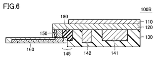
- FIG. 6 is a cross-sectional view of the electronic device 100B of the second modification.
- the electronic device 100B has a configuration in which the periphery of the conductive portion 150 and the boundary portion 145 of the mold layer 130 are covered with a resin 180 having a higher elastic modulus than the sealing resin material of the mold layer 130.
- the resin 180 is exposed at the portion 172. That is, since the resin 180 has higher rigidity than the sealing resin material of the mold layer 130, higher durability can be realized against stress acting on the corner portion 172.
- an inorganic filler mixed resin in which an inorganic filler such as silica or alumina is mixed can be used.
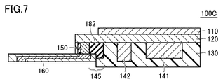
- FIG. 7 is a cross-sectional view of the electronic device 100 ⁇ / b> C of the third modification.
- electronic device 100C contrary to Modification 2, the periphery of conductive portion 150 and the boundary portion 145 of mold layer 130 are covered with resin 182 having a lower elastic modulus than the sealing resin material of mold layer 130.
- the resin 180 is exposed at the corner portion 172. That is, the resin 182 has higher flexibility than the sealing resin material of the mold layer 130 and is easily elastically deformed. Therefore, even when a stress is applied to the corner portion 172, the resin 182 is elastically deformed to absorb the stress like a cushion, so that the corner portion 172 is prevented from being damaged. Therefore, durability higher than that of the sealing resin material can be realized against stress acting on the corner portion 172.
- low elastic material for example, polyimide, bismaleimide, polyamide, polyamideimide, polybenzoxazole, benzocyclobutene, aramid resin, silicone resin, liquid crystal polymer and the like can be used.
- Modifications 2 and 3 are the same as those in FIG. 3B of the manufacturing process illustrated in FIG. 3, in which the resin 180 (or the resin 182) is formed before the mold layer 130 is formed of the sealing resin material. It can be formed by partially molding only the periphery of the conductive part 150 and then molding the whole with a sealing resin material.
- the wiring pattern formed of a metal material such as copper and the insulating layer formed of a resin have different elastic modulus or density, and also have different ultrasonic reflectivity. As shown in FIG. 8, when the wiring pattern is arranged on the second surface 122 of the wiring board 120, that is, immediately below the sensor board 110, when the user touches the sensor board 110 with a finger, A force is applied in the direction of AR1.
- the density is different between the portion where the wiring pattern 125 is disposed and the resin portion where the wiring pattern 125 is not present. Will be added.
- the sensor substrate 110 itself is partially distorted, and the ultrasonic attenuation state may be nonuniform on the detection surface of the sensor substrate 110.
- the wiring pattern 125 when the wiring pattern 125 is disposed immediately below the sensor substrate 110, ultrasonic waves are generated between a portion where the sensor substrate 110 and the wiring pattern 125 are in contact with each other and a portion where the sensor substrate 110 and the resin are in contact with each other.
- the reflection state can be non-uniform.
- the reflection state of the ultrasonic wave differs depending on the presence or absence of the wiring pattern 125, the image of the wiring pattern 125 may be reflected in the detected fingerprint image.
- the wiring pattern 125 is not disposed in the portion (second surface 122) immediately below the sensor board 110, and the sensor board 110 and the wiring pattern 125 are not in contact with each other. It is preferable to do.
- the wiring pattern 125 is formed in the inner layer of the wiring substrate 120, and at least one insulating layer is formed between the sensor substrate 110 and the wiring pattern 125.
- an intermediate layer 127 of metal or other insulating material is disposed in a layer between the sensor substrate 110 and the wiring pattern 125 so as to block the wiring pattern 125. You may make it make the reflection of an ultrasonic wave uniform.
- the wiring pattern 125 When it is necessary to form the wiring pattern 125 on the second surface 122 of the wiring board 120, the wiring pattern 125 is covered with an intermediate layer 128 of metal or other insulating material as shown in FIG.
- the sensor substrate 110 may be disposed on the intermediate layer 128.
- 10 fingerprint authentication device 20 housing, 50 support, 100, 100A to 100C electronic device, 110 sensor substrate, 120 wiring substrate, 121 first surface, 122 second surface, 125, 162 wiring pattern, 127, 128 intermediate layer , 130 mold layer, 131 thick part, 132 thin part, 135 back surface, 140 built-in equipment, 141 integrated circuit, 142 capacitor, 145 boundary part, 150, 150A conductive part, 160 terminal board, 161, 163 terminal, 170 step part , 172 corner, 173 exposed surface, 180,182 resin.
Landscapes
- Engineering & Computer Science (AREA)
- Physics & Mathematics (AREA)
- General Physics & Mathematics (AREA)
- Microelectronics & Electronic Packaging (AREA)
- Condensed Matter Physics & Semiconductors (AREA)
- Power Engineering (AREA)
- Computer Hardware Design (AREA)
- Theoretical Computer Science (AREA)
- Health & Medical Sciences (AREA)
- Life Sciences & Earth Sciences (AREA)
- Multimedia (AREA)
- Human Computer Interaction (AREA)
- Biophysics (AREA)
- Medical Informatics (AREA)
- General Health & Medical Sciences (AREA)
- Public Health (AREA)
- Veterinary Medicine (AREA)
- Surgery (AREA)
- Molecular Biology (AREA)
- Animal Behavior & Ethology (AREA)
- Heart & Thoracic Surgery (AREA)
- Biomedical Technology (AREA)
- Pathology (AREA)
- Image Input (AREA)
- Measurement Of The Respiration, Hearing Ability, Form, And Blood Characteristics Of Living Organisms (AREA)
- Measurement Of Length, Angles, Or The Like Using Electric Or Magnetic Means (AREA)
- Structure Of Printed Boards (AREA)
Abstract
This electronic device (100) is provided with: a first substrate (120) which has a wiring pattern formed therein; a second substrate (160) which has an external terminal formed thereon; first electronic equipment (141) which is disposed on a first surface of the first substrate; second electronic equipment (110) which is disposed on a second surface of the first substrate; a mold layer (130) for molding the first electronic equipment; and a conductive part (150) which is disposed inside the mold layer. The second electronic equipment is electrically connected to the first electronic equipment. The conductive part electrically connects the first substrate and the second substrate. The mold layer has, formed at an end thereof, a stepped part (170) where the conductive part is exposed. The second substrate is disposed at the stepped part. The distance in the thickness direction between the second substrate and the first substrate is shorter than the distance between the first surface of the first substrate and a surface of the first electronic equipment on the side opposite to the first substrate.
Description
本開示は、電子デバイスおよびそれを搭載した指紋認証装置に関し、より特定的には、指紋認証装置用のセンサ部分を構成する電子デバイスを低背化する技術に関する。
The present disclosure relates to an electronic device and a fingerprint authentication apparatus equipped with the electronic device, and more particularly, to a technique for reducing the height of an electronic device constituting a sensor portion for the fingerprint authentication apparatus.
近年、セキュリティの強化のために、個人認証用の指紋認証装置が普及しつつある。このような指紋認証装置は、たとえば、建物の入口等に設けられる電子キー、銀行などのATM(Automatic Telling Machine)、携帯電話やスマートフォンなどの携帯電子機器のような様々な用途で用いられている。
In recent years, fingerprint authentication devices for personal authentication are becoming popular for security enhancement. Such fingerprint authentication devices are used in various applications such as electronic keys provided at the entrance of buildings, ATMs (Automatic Telling Machines) such as banks, and portable electronic devices such as mobile phones and smartphones. .
特表2017-511162号公報(特許文献1)には、指紋認証装置に用いられる電子機器が開示されている。特許文献1に開示されている電子機器には、指紋を感知するためのセンサ電極と、当該センサ電極に電気的に接続される集積回路と、集積回路の上部に位置しセンサ電極が設けられる第1回路基板と、第1回路基板と電気的に接続され上記集積回路の下部に位置する第2回路基板と、集積回路を保護するモールディング層と、モールディング層、第1および第2回路基板を電気的に接続する連結部とが備えられている。
JP-T-2017-511162 (Patent Document 1) discloses an electronic device used for a fingerprint authentication apparatus. The electronic device disclosed in Patent Document 1 includes a sensor electrode for sensing a fingerprint, an integrated circuit electrically connected to the sensor electrode, and a sensor electrode provided on the integrated circuit. 1 circuit board, a second circuit board electrically connected to the first circuit board and positioned below the integrated circuit, a molding layer for protecting the integrated circuit, the molding layer, the first and second circuit boards are electrically connected And a connecting portion to be connected to each other.
携帯電子機器の用途においては、機器の小型化および薄型化のニーズが高く、このような用途に指紋認証装置が搭載される場合には、指紋認証装置自体についても小型化および薄型化を行なうことが必要とされる。
In the use of portable electronic devices, there is a great need for downsizing and thinning of devices, and when a fingerprint authentication device is mounted for such use, the fingerprint authentication device itself should be reduced in size and thickness. Is needed.
しかしながら、特許文献1に開示された指紋認証装置用の電子機器においては、第2回路基板が集積回路の下部に配置される構成となっており、機器の低背化を図る場合、第2回路基板と集積回路とが干渉し得る。すなわち、特許文献1に開示された指紋認証装置用の電子機器の特徴的な構成が、機器の低背化に対して制限となり得る。
However, the electronic device for a fingerprint authentication device disclosed in Patent Document 1 has a configuration in which the second circuit board is disposed below the integrated circuit. The substrate and the integrated circuit can interfere with each other. That is, the characteristic configuration of the electronic device for the fingerprint authentication device disclosed in Patent Document 1 can be a limitation on the reduction in the height of the device.
本開示は、上記の課題を解決するためになされたものであって、その目的は、指紋認証装置に用いられる電子デバイスの低背化を行なうことである。
The present disclosure has been made to solve the above-described problem, and an object thereof is to reduce the height of an electronic device used in a fingerprint authentication apparatus.
本開示のある局面に従う電子デバイスは、内部に配線パターンが形成された第1基板と、第1基板の第1面に配置された第1電子機器と、第1基板の第1面とは反対の第2面に配置され配線パターンによって第1電子機器と電気的に接続された第2電子機器と、第1電子機器をモールドするモールド層と、外部端子が形成された第2基板と、モールド層内に配置され第1基板と第2基板とを電気的に接続する導電部とを備える。モールド層の端部には段差部が形成されており、段差部には導電部が露出している。第2基板は段差部に配置されている。第2基板と第1基板との間の厚み方向の距離は、第1基板の第1面と、第1電子機器における第1基板とは反対側の面との間の距離よりも短い。
An electronic device according to an aspect of the present disclosure is opposite to a first substrate having a wiring pattern formed therein, a first electronic device disposed on a first surface of the first substrate, and a first surface of the first substrate. A second electronic device disposed on the second surface of the first electronic device and electrically connected to the first electronic device by a wiring pattern, a mold layer for molding the first electronic device, a second substrate on which external terminals are formed, and a mold A conductive portion disposed in the layer and electrically connecting the first substrate and the second substrate; A step portion is formed at the end of the mold layer, and the conductive portion is exposed at the step portion. The second substrate is disposed on the step portion. The distance in the thickness direction between the second substrate and the first substrate is shorter than the distance between the first surface of the first substrate and the surface opposite to the first substrate in the first electronic device.
本開示の他の局面に従う指紋認証装置は、上記の電子デバイスを搭載した指紋認証装置である。
A fingerprint authentication device according to another aspect of the present disclosure is a fingerprint authentication device equipped with the electronic device described above.
本開示による電子デバイスによれば、モールド層の端部に形成された段差部に第2基板が配置されており、第1基板と第2基板との間の厚み方向の距離が、第1基板と第1電子機器における第1基板とは反対側の面との間の距離よりも短くなるように構成されている。このような構成によって、第2基板の全体がモールド層から突出することが抑制されるので、第2基板によって電子デバイスのトータルの厚みが厚くなることが抑制される。したがって、電子デバイスを低背化することが可能となる。
According to the electronic device according to the present disclosure, the second substrate is arranged at the step portion formed at the end of the mold layer, and the distance in the thickness direction between the first substrate and the second substrate is the first substrate. And the distance between the surface of the first electronic device opposite to the first substrate is shorter. With such a configuration, since the entire second substrate is suppressed from protruding from the mold layer, the total thickness of the electronic device is suppressed from being increased by the second substrate. Therefore, it is possible to reduce the height of the electronic device.
以下、本開示の実施の形態について、図面を参照しながら詳細に説明する。なお、図中同一または相当部分には同一符号を付してその説明は繰り返さない。
Hereinafter, embodiments of the present disclosure will be described in detail with reference to the drawings. In the drawings, the same or corresponding parts are denoted by the same reference numerals and description thereof will not be repeated.
(電子デバイスの構成)
図1は、実施の形態に係る電子デバイス100が組み込まれた指紋認証装置10における、電子デバイス100の部分の断面図を示す図である。指紋認証装置10は、たとえば、スマートフォンなどの携帯電子機器の一部に設けられる。 (Configuration of electronic device)
FIG. 1 is a diagram illustrating a cross-sectional view of a portion of anelectronic device 100 in a fingerprint authentication apparatus 10 in which the electronic device 100 according to an embodiment is incorporated. The fingerprint authentication device 10 is provided, for example, in a part of a portable electronic device such as a smartphone.
図1は、実施の形態に係る電子デバイス100が組み込まれた指紋認証装置10における、電子デバイス100の部分の断面図を示す図である。指紋認証装置10は、たとえば、スマートフォンなどの携帯電子機器の一部に設けられる。 (Configuration of electronic device)
FIG. 1 is a diagram illustrating a cross-sectional view of a portion of an
図1を参照して、電子デバイス100は、指紋検出用のセンサが形成されたセンサ基板110と、配線基板120と、センサ駆動用の集積回路141と、キャパシタ142と、導電部150と、モールド層130と、端子基板160とを備える。電子デバイス100は、携帯電子機器の筐体20からセンサ基板110が露出するように取付けられる。
Referring to FIG. 1, an electronic device 100 includes a sensor substrate 110 on which a sensor for fingerprint detection is formed, a wiring substrate 120, an integrated circuit 141 for driving a sensor, a capacitor 142, a conductive portion 150, a mold. A layer 130 and a terminal substrate 160 are provided. The electronic device 100 is attached so that the sensor substrate 110 is exposed from the housing 20 of the portable electronic device.
センサ基板110には、たとえば超音波センサが形成されており、センサ基板110の表面にユーザの指が載せられると、指紋の凹凸に応じた電気信号が生成される。センサ基板110で生成された電気信号は、配線基板120内に形成された配線パターン(図示せず)、導電部150、および端子基板160を通して他の機器に伝達される。
For example, an ultrasonic sensor is formed on the sensor substrate 110. When a user's finger is placed on the surface of the sensor substrate 110, an electrical signal corresponding to the unevenness of the fingerprint is generated. The electrical signal generated by the sensor substrate 110 is transmitted to other devices through a wiring pattern (not shown) formed in the wiring substrate 120, the conductive portion 150, and the terminal substrate 160.
配線基板120の第1面121には、センサ駆動用の集積回路141およびノイズ除去用のキャパシタ142が配置される。センサ基板110は、配線基板120の第2面122に配置される。配線基板120は多層構造を有しており、内部に配線パターンが形成されている。集積回路141およびキャパシタ142は、配線基板120内に形成された配線パターンによって、センサ基板110と電気的に接続される。
On the first surface 121 of the wiring substrate 120, an integrated circuit 141 for driving a sensor and a capacitor 142 for removing noise are arranged. The sensor substrate 110 is disposed on the second surface 122 of the wiring substrate 120. The wiring board 120 has a multilayer structure, and a wiring pattern is formed inside. The integrated circuit 141 and the capacitor 142 are electrically connected to the sensor substrate 110 by a wiring pattern formed in the wiring substrate 120.
モールド層130は、たとえば絶縁性の樹脂で形成されており、配線基板120の第1面121において集積回路141およびキャパシタ142をモールドする。モールド層130の端部には、樹脂が薄くされた段差部170が形成される。なお、モールド層130の厚みが厚い部分を「厚肉部131」と称し、段差部170が形成されたモールド層130の厚みが薄い部分を「薄肉部132」とも称する。薄肉部132は、モールド層130を貫通し、配線基板120に電気的に接続された導電部150が配置される。導電部150は、たとえば、銅,銀,金,アルミのような導電性金属で形成された柱状部材である。導電部150は、段差部170においてモールド層130から露出している。なお、以下の説明においては、集積回路141とキャパシタ142とを包括して「内蔵機器140」とも称する。
The mold layer 130 is formed of, for example, an insulating resin, and molds the integrated circuit 141 and the capacitor 142 on the first surface 121 of the wiring board 120. A stepped portion 170 in which the resin is thinned is formed at the end of the mold layer 130. A portion where the thickness of the mold layer 130 is thick is referred to as “thick portion 131”, and a portion where the thickness of the mold layer 130 where the stepped portion 170 is formed is also referred to as “thin portion 132”. The thin portion 132 has a conductive portion 150 that penetrates the mold layer 130 and is electrically connected to the wiring board 120. The conductive part 150 is a columnar member made of a conductive metal such as copper, silver, gold, or aluminum. The conductive portion 150 is exposed from the mold layer 130 at the stepped portion 170. In the following description, the integrated circuit 141 and the capacitor 142 are collectively referred to as “built-in device 140”.
端子基板160は、センサ基板110で生成された電気信号を図示しない他の機器へ伝達するためのコネクタである。端子基板160は、好ましくは柔軟性を有する材料で形成されたフレキシブル基板である。端子基板160の誘電体は、たとえば、エポキシ、ポリイミドなどの樹脂で形成される。あるいは端子基板160の誘電体は、より低い誘電率を有する液晶ポリマー(Liquid Crystal Polymer:LCP)あるいはフッ素系樹脂を用いて形成されてもよい。なお、端子基板160は、たとえば熱可塑性を有するリジッド基板で形成されてもよい。
The terminal board 160 is a connector for transmitting an electrical signal generated by the sensor board 110 to another device (not shown). The terminal board 160 is preferably a flexible board formed of a flexible material. The dielectric of the terminal substrate 160 is made of a resin such as epoxy or polyimide, for example. Alternatively, the dielectric of the terminal substrate 160 may be formed using a liquid crystal polymer (LCP) or a fluorine resin having a lower dielectric constant. Terminal board 160 may be formed of a rigid board having thermoplasticity, for example.
端子基板160は、一方の表面に露出した端子161と、他方の表面に露出した外部端子163と、基板内部に形成され、端子161と外部端子163とを電気的に接続する配線パターン162とを含む。端子基板160は、モールド層130の段差部170に配置され、端子161が導電部150と電気的に接続される。
The terminal substrate 160 includes a terminal 161 exposed on one surface, an external terminal 163 exposed on the other surface, and a wiring pattern 162 that is formed inside the substrate and electrically connects the terminal 161 and the external terminal 163. Including. The terminal substrate 160 is disposed on the stepped portion 170 of the mold layer 130, and the terminal 161 is electrically connected to the conductive portion 150.
段差部170が形成されている薄肉部132の厚みH2(すなわち、配線基板120と端子基板160との間の厚み方向の距離)は、配線基板120の第1面121と内蔵機器140における配線基板120とは反対の面との距離の最小値H1よりも薄くされている。これにより、端子基板160全体がモールド層130から突出することが抑制されるので、端子基板160によって電子デバイス100のトータルの厚みが厚くなることが抑制され、結果として電子デバイス100の低背化が実現できる。
The thickness H2 of the thin wall portion 132 where the stepped portion 170 is formed (that is, the distance in the thickness direction between the wiring board 120 and the terminal board 160) is the wiring board in the first surface 121 of the wiring board 120 and the built-in device 140. It is made thinner than the minimum value H1 of the distance to the surface opposite to 120. As a result, the entire terminal substrate 160 is suppressed from protruding from the mold layer 130, so that the total thickness of the electronic device 100 is suppressed by the terminal substrate 160, and as a result, the height of the electronic device 100 is reduced. realizable.
図2は、電子デバイス100を、配線基板120の第1面121側から見たときの平面図である。なお、図2においては、モールド層130の樹脂については省略されており、配線基板120に配置された内蔵機器140および導電部150が露出した状態が示されている。また、図2においては、配線基板120の第2面122に配置されたセンサ基板110、および、モールド層130の段差部170に設けられるべき端子基板160が破線で描かれている。
FIG. 2 is a plan view of the electronic device 100 as viewed from the first surface 121 side of the wiring board 120. In FIG. 2, the resin of the mold layer 130 is omitted, and a state in which the built-in device 140 and the conductive portion 150 arranged on the wiring board 120 are exposed is shown. In FIG. 2, the sensor substrate 110 disposed on the second surface 122 of the wiring substrate 120 and the terminal substrate 160 to be provided on the stepped portion 170 of the mold layer 130 are drawn by broken lines.
図2に示されるように、センサ基板110は、段差部170とは重ならない位置に配置されている。言い換えれば、電子デバイス100の法線方向から平面視した場合に、センサ基板110と端子基板160とは重なっていない。上述のように、指紋認証装置10においては、センサ基板110上にユーザの指が載せられるため、センサ基板110の厚み方向に力が加わる。センサ基板110と端子基板160とを互いに重ならない位置に配置することによって、センサ基板110に加えられた力が端子基板160に伝達されることが抑制される。
As shown in FIG. 2, the sensor substrate 110 is disposed at a position that does not overlap the stepped portion 170. In other words, the sensor substrate 110 and the terminal substrate 160 do not overlap when viewed from the normal direction of the electronic device 100. As described above, in the fingerprint authentication device 10, since a user's finger is placed on the sensor substrate 110, a force is applied in the thickness direction of the sensor substrate 110. By disposing the sensor board 110 and the terminal board 160 at positions that do not overlap each other, the force applied to the sensor board 110 is suppressed from being transmitted to the terminal board 160.
(製造プロセス)
図3は、電子デバイス100の製造プロセスの一例を示す図である。図3を参照して、まず、支持体50上に、マウンタを用いて、集積回路141およびキャパシタ142等の内蔵機器140と、導電部150とが配列される(図3(a))。その後、絶縁性の封止樹脂を用いて、内蔵機器140および導電部150をモールドし、硬化させることによってモールド層130が形成される(図3(b))。 (Manufacturing process)
FIG. 3 is a diagram illustrating an example of a manufacturing process of theelectronic device 100. Referring to FIG. 3, first, built-in devices 140 such as integrated circuit 141 and capacitor 142 and conductive portion 150 are arranged on support 50 using a mounter (FIG. 3A). Thereafter, the built-in device 140 and the conductive portion 150 are molded using an insulating sealing resin and cured to form the mold layer 130 (FIG. 3B).
図3は、電子デバイス100の製造プロセスの一例を示す図である。図3を参照して、まず、支持体50上に、マウンタを用いて、集積回路141およびキャパシタ142等の内蔵機器140と、導電部150とが配列される(図3(a))。その後、絶縁性の封止樹脂を用いて、内蔵機器140および導電部150をモールドし、硬化させることによってモールド層130が形成される(図3(b))。 (Manufacturing process)
FIG. 3 is a diagram illustrating an example of a manufacturing process of the
ここで、封止樹脂材料としては、エポキシ系の樹脂のような吸湿性が低い材料を用いることが好ましい。吸湿性が低い樹脂材料を用いることにより、モールドされた搭載部品の配線部の腐食や絶縁膜の劣化などを抑制できるため、良好な信頼性を得ることができる。また、封止樹脂材料として、モールド層130内にモールドされる内蔵機器と線膨張率の近い材料を用いることが好ましい。線膨張率の近い材料を用いることによって、温度変化に伴って線膨張率の違いにより生じる熱応力が低減される。したがって、歪みやクラックによって電子デバイス100が破損することを防止できる。
Here, as the sealing resin material, it is preferable to use a material having low hygroscopicity such as an epoxy resin. By using a resin material having low hygroscopicity, corrosion of the wiring portion of the molded mounting component, deterioration of the insulating film, and the like can be suppressed, so that good reliability can be obtained. Moreover, it is preferable to use a material having a linear expansion coefficient close to that of the built-in device molded in the mold layer 130 as the sealing resin material. By using a material having a similar linear expansion coefficient, thermal stress caused by a difference in linear expansion coefficient with a temperature change is reduced. Therefore, it is possible to prevent the electronic device 100 from being damaged by distortion or cracks.
モールド層130が形成されると、支持体50が除去される(図3(c))。そして、内蔵機器が露出しているモールド層130の裏面135に、配線パターンが形成された配線金属層と絶縁層とを交互に積層させて配線基板120を形成する(図3(d))。配線金属層は、たとえばセミアディティブ法により形成される。また、絶縁層は感光性有機膜を用いて形成される。配線金属層および絶縁層の各層を数μm程度の厚みで積層して配線基板120を形成することによって、配線基板120を低背化することができる。なお、配線基板120において、異なる配線金属層に形成された配線パターンは、絶縁層に形成されたビアによって電気的に接続される。
When the mold layer 130 is formed, the support 50 is removed (FIG. 3C). Then, the wiring substrate 120 is formed by alternately laminating the wiring metal layer and the insulating layer on which the wiring pattern is formed on the back surface 135 of the mold layer 130 where the built-in device is exposed (FIG. 3D). The wiring metal layer is formed by, for example, a semi-additive method. The insulating layer is formed using a photosensitive organic film. By forming the wiring board 120 by laminating each layer of the wiring metal layer and the insulating layer with a thickness of about several μm, the wiring board 120 can be reduced in height. In the wiring board 120, wiring patterns formed in different wiring metal layers are electrically connected by vias formed in the insulating layer.
配線基板120の形成後、センサ基板110が配線基板120に配置される。これにより、配線基板120内の配線パターンを介して、モールド層30内の内蔵機器140とセンサ基板110とが電気的に接続される。
After forming the wiring board 120, the sensor board 110 is placed on the wiring board 120. Accordingly, the built-in device 140 in the mold layer 30 and the sensor substrate 110 are electrically connected via the wiring pattern in the wiring substrate 120.
次に、モールド層130の端部をハーフダイシングにより削り取って段差部170が形成され、導電部150が封止樹脂材料から露出される(図3(e))。このとき、段差部170において導電部150が露出する露出面173の高さ(すなわち、配線基板120と露出面173との間の厚み方向の距離)が、配線基板120上に配置された内蔵機器140の高さよりも低くなるように、モールド層130が削り取られる。
Next, the end portion of the mold layer 130 is scraped off by half dicing to form a stepped portion 170, and the conductive portion 150 is exposed from the sealing resin material (FIG. 3E). At this time, the height of the exposed surface 173 where the conductive portion 150 is exposed in the stepped portion 170 (that is, the distance in the thickness direction between the wiring substrate 120 and the exposed surface 173) is a built-in device arranged on the wiring substrate 120. The mold layer 130 is scraped off so as to be lower than the height of 140.
図3においては、導電部150の全体が、モールド層130の薄肉部132に存在するように段差部170が形成されている。そのため、段差部170におけるコーナー部172は、モールド層130の封止樹脂で一体的に形成されている。コーナー部172には応力集中が生じやすいが、厚肉部131と薄肉部132とを同じ材料の構造体で一体物として形成されているため、厚肉部131と薄肉部132とが別の部品として形成されている場合に比べて破損しづらくなっている。また、導電部150の周囲を樹脂でモールドすることによって、薄膜の積層体で形成された配線基板120を補強することができる。
In FIG. 3, the stepped portion 170 is formed so that the entire conductive portion 150 exists in the thin portion 132 of the mold layer 130. Therefore, the corner portion 172 in the stepped portion 170 is integrally formed with the sealing resin of the mold layer 130. Although stress concentration is likely to occur in the corner portion 172, the thick portion 131 and the thin portion 132 are formed as a single body with a structure of the same material, so that the thick portion 131 and the thin portion 132 are separate parts. It is hard to break compared with the case where it is formed as. Further, by molding the periphery of the conductive portion 150 with a resin, the wiring substrate 120 formed of a thin film laminate can be reinforced.
その後、端子基板160を段差部170の部分に配置して、電子デバイス100が形成される(図3(f))。なお、図3(f)は、図1における電子デバイス100の上下が反転された図となっている。
After that, the terminal board 160 is disposed on the stepped portion 170 to form the electronic device 100 (FIG. 3F). FIG. 3F is a diagram in which the electronic device 100 in FIG. 1 is inverted upside down.
応力集中が生じやすいコーナー部172については、図4に示されるように、厚肉部131と薄肉部132との境目を含む境界部145において、モールド層130および端子基板160に曲率半径Rの曲面加工を施して、応力集中を緩和するようにしてもよい。
As for the corner portion 172 where stress concentration is likely to occur, as shown in FIG. 4, a curved surface having a curvature radius R on the mold layer 130 and the terminal substrate 160 at the boundary portion 145 including the boundary between the thick portion 131 and the thin portion 132. Processing may be performed to relieve stress concentration.
なお、応力集中によるコーナー部172の破損を抑制する構成として、他の構成を採用することも可能である。以下の変形例1~3においては、コーナー部172を封止樹脂材料とは異なる材料で形成する例について説明する。
In addition, it is also possible to employ | adopt another structure as a structure which suppresses the damage of the corner part 172 by stress concentration. In the following modifications 1 to 3, an example in which the corner portion 172 is formed of a material different from the sealing resin material will be described.
(変形例1)
図5は、変形例1の電子デバイス100Aの断面図である。電子デバイス100Aにおいては、配線基板120と端子基板160とを電気的に接続する導電部150Aが、モールド層130の厚肉部131および薄肉部132の境目を含む境界部145に亘って配置された構成となっている。そして、段差部170の形成において、導電部150Aの一部を削り込むことによって、コーナー部172に導電部150Aの金属材料が露出した状態となっている。導電部150Aに用いられる金属材料(たとえば、銅,銀,金,アルミなど)は、一般的にモールド層130の樹脂材料よりも高い強度を有し、さらに金属特有の延性を有している。そのため、コーナー部172に作用する応力に対して、封止樹脂材料よりも高い耐久性が実現できる。 (Modification 1)
FIG. 5 is a cross-sectional view of theelectronic device 100A of the first modification. In the electronic device 100A, the conductive portion 150A that electrically connects the wiring substrate 120 and the terminal substrate 160 is disposed across the boundary portion 145 including the boundary between the thick portion 131 and the thin portion 132 of the mold layer 130. It has a configuration. Then, in the formation of the stepped portion 170, the metal material of the conductive portion 150A is exposed at the corner portion 172 by cutting a part of the conductive portion 150A. The metal material (for example, copper, silver, gold, aluminum, etc.) used for the conductive portion 150A generally has a higher strength than the resin material of the mold layer 130, and has a ductility specific to the metal. Therefore, durability higher than that of the sealing resin material can be realized against stress acting on the corner portion 172.
図5は、変形例1の電子デバイス100Aの断面図である。電子デバイス100Aにおいては、配線基板120と端子基板160とを電気的に接続する導電部150Aが、モールド層130の厚肉部131および薄肉部132の境目を含む境界部145に亘って配置された構成となっている。そして、段差部170の形成において、導電部150Aの一部を削り込むことによって、コーナー部172に導電部150Aの金属材料が露出した状態となっている。導電部150Aに用いられる金属材料(たとえば、銅,銀,金,アルミなど)は、一般的にモールド層130の樹脂材料よりも高い強度を有し、さらに金属特有の延性を有している。そのため、コーナー部172に作用する応力に対して、封止樹脂材料よりも高い耐久性が実現できる。 (Modification 1)
FIG. 5 is a cross-sectional view of the
(変形例2)
図6は、変形例2の電子デバイス100Bの断面図である。電子デバイス100Bにおいては、導電部150の周囲、およびモールド層130の境界部145が、モールド層130の封止樹脂材料よりも高い弾性率を有する樹脂180で覆われた構成となっており、コーナー部172に樹脂180が露出した状態となっている。すなわち、樹脂180は、モールド層130の封止樹脂材料よりも高い剛性を有しているため、コーナー部172に作用する応力に対して、より高い耐久性を実現することができる。 (Modification 2)
FIG. 6 is a cross-sectional view of theelectronic device 100B of the second modification. The electronic device 100B has a configuration in which the periphery of the conductive portion 150 and the boundary portion 145 of the mold layer 130 are covered with a resin 180 having a higher elastic modulus than the sealing resin material of the mold layer 130. The resin 180 is exposed at the portion 172. That is, since the resin 180 has higher rigidity than the sealing resin material of the mold layer 130, higher durability can be realized against stress acting on the corner portion 172.
図6は、変形例2の電子デバイス100Bの断面図である。電子デバイス100Bにおいては、導電部150の周囲、およびモールド層130の境界部145が、モールド層130の封止樹脂材料よりも高い弾性率を有する樹脂180で覆われた構成となっており、コーナー部172に樹脂180が露出した状態となっている。すなわち、樹脂180は、モールド層130の封止樹脂材料よりも高い剛性を有しているため、コーナー部172に作用する応力に対して、より高い耐久性を実現することができる。 (Modification 2)
FIG. 6 is a cross-sectional view of the
なお、高弾性率材料としては、たとえば、シリカあるいはアルミナなどの無機フィラーを混合した無機フィラー混合樹脂を用いることができる。
In addition, as a high elastic modulus material, for example, an inorganic filler mixed resin in which an inorganic filler such as silica or alumina is mixed can be used.
(変形例3)
図7は、変形例3の電子デバイス100Cの断面図である。電子デバイス100Cにおいては、変形例2とは逆に、導電部150の周囲、およびモールド層130の境界部145が、モールド層130の封止樹脂材料よりも低い弾性率を有する樹脂182で覆われた構成となっており、コーナー部172に樹脂180が露出した状態となっている。すなわち、樹脂182は、モールド層130の封止樹脂材料に比べて柔軟性が高く弾性変形しやすい。そのため、コーナー部172に応力が作用した場合でも、当該樹脂182が弾性変形することによってクッションのように応力が吸収されるので、コーナー部172の破損が抑制される。したがって、コーナー部172に作用する応力に対して、封止樹脂材料よりも高い耐久性が実現できる。 (Modification 3)
FIG. 7 is a cross-sectional view of theelectronic device 100 </ b> C of the third modification. In electronic device 100C, contrary to Modification 2, the periphery of conductive portion 150 and the boundary portion 145 of mold layer 130 are covered with resin 182 having a lower elastic modulus than the sealing resin material of mold layer 130. The resin 180 is exposed at the corner portion 172. That is, the resin 182 has higher flexibility than the sealing resin material of the mold layer 130 and is easily elastically deformed. Therefore, even when a stress is applied to the corner portion 172, the resin 182 is elastically deformed to absorb the stress like a cushion, so that the corner portion 172 is prevented from being damaged. Therefore, durability higher than that of the sealing resin material can be realized against stress acting on the corner portion 172.
図7は、変形例3の電子デバイス100Cの断面図である。電子デバイス100Cにおいては、変形例2とは逆に、導電部150の周囲、およびモールド層130の境界部145が、モールド層130の封止樹脂材料よりも低い弾性率を有する樹脂182で覆われた構成となっており、コーナー部172に樹脂180が露出した状態となっている。すなわち、樹脂182は、モールド層130の封止樹脂材料に比べて柔軟性が高く弾性変形しやすい。そのため、コーナー部172に応力が作用した場合でも、当該樹脂182が弾性変形することによってクッションのように応力が吸収されるので、コーナー部172の破損が抑制される。したがって、コーナー部172に作用する応力に対して、封止樹脂材料よりも高い耐久性が実現できる。 (Modification 3)
FIG. 7 is a cross-sectional view of the
低弾性材料としては、たとえば、ポリイミド、ビスマレイミド、ポリアミド、ポリアミドイミド、ポリベンゾオキサゾール、ベンゾシクロブテン、アラミド樹脂、シリコーン系樹脂、液晶ポリマーなどを用いることができる。
As the low elastic material, for example, polyimide, bismaleimide, polyamide, polyamideimide, polybenzoxazole, benzocyclobutene, aramid resin, silicone resin, liquid crystal polymer and the like can be used.
なお、変形例2および変形例3の構成は、図3に示した製造プロセスの図3(b)において、封止樹脂材料でモールド層130を形成する前に、樹脂180(あるいは樹脂182)を用いて導電部150の周囲のみを部分的にモールドし、その後封止樹脂材料により全体をモールドすることによって形成することができる。
Note that the configurations of Modifications 2 and 3 are the same as those in FIG. 3B of the manufacturing process illustrated in FIG. 3, in which the resin 180 (or the resin 182) is formed before the mold layer 130 is formed of the sealing resin material. It can be formed by partially molding only the periphery of the conductive part 150 and then molding the whole with a sealing resin material.
(配線基板内の配線パターンの配置)
指紋認証用のセンサとして超音波センサが用いられる場合には、センサ基板110が配置される配線基板120内の配線パターンの配置が、センサの検出精度に影響を与え得る。 (Layout of wiring patterns in the wiring board)
When an ultrasonic sensor is used as a sensor for fingerprint authentication, the arrangement of the wiring pattern in thewiring board 120 on which the sensor board 110 is arranged can affect the detection accuracy of the sensor.
指紋認証用のセンサとして超音波センサが用いられる場合には、センサ基板110が配置される配線基板120内の配線パターンの配置が、センサの検出精度に影響を与え得る。 (Layout of wiring patterns in the wiring board)
When an ultrasonic sensor is used as a sensor for fingerprint authentication, the arrangement of the wiring pattern in the
銅などの金属材料で形成される配線パターンと樹脂で形成される絶縁層とは、弾性率あるいは密度が異なり、さらに超音波の反射率も異なる。図8のように、配線基板120の第2面122、すなわちセンサ基板110の直下に配線パターンが配置された場合において、ユーザが指でセンサ基板110に触れると、センサ基板に110に対して矢印AR1の方向に力が加えられる。
The wiring pattern formed of a metal material such as copper and the insulating layer formed of a resin have different elastic modulus or density, and also have different ultrasonic reflectivity. As shown in FIG. 8, when the wiring pattern is arranged on the second surface 122 of the wiring board 120, that is, immediately below the sensor board 110, when the user touches the sensor board 110 with a finger, A force is applied in the direction of AR1.
このとき、センサ基板110と配線基板120との接触面において、配線パターン125が配置された部分と、配線パターン125のない樹脂の部分とでは、密度が異なるため、センサ基板110に不均一な荷重が加わる。これによって、センサ基板110自体が部分的に歪んだ状態となり、センサ基板110の検出面において超音波の減衰状態が不均一となり得る。
At this time, on the contact surface between the sensor substrate 110 and the wiring substrate 120, the density is different between the portion where the wiring pattern 125 is disposed and the resin portion where the wiring pattern 125 is not present. Will be added. As a result, the sensor substrate 110 itself is partially distorted, and the ultrasonic attenuation state may be nonuniform on the detection surface of the sensor substrate 110.
また、センサ基板110の直下に配線パターン125が配置されていると、センサ基板110と配線パターン125とが接触している部分と、センサ基板110と樹脂とが接触している部分とでは超音波の反射状態が不均一となり得る。
In addition, when the wiring pattern 125 is disposed immediately below the sensor substrate 110, ultrasonic waves are generated between a portion where the sensor substrate 110 and the wiring pattern 125 are in contact with each other and a portion where the sensor substrate 110 and the resin are in contact with each other. The reflection state can be non-uniform.
このように、配線パターン125の有無によって、超音波の反射状態が異なると、検出した指紋の画像中に、配線パターン125の画像が映り込んでしまうことになり得る。
Thus, if the reflection state of the ultrasonic wave differs depending on the presence or absence of the wiring pattern 125, the image of the wiring pattern 125 may be reflected in the detected fingerprint image.
そのため、配線基板120においては、基本的にはセンサ基板110の直下の部分(第2面122)には、配線パターン125を配置しないようにし、センサ基板110と配線パターン125とが接触しないようにすることが好ましい。言い換えれば、図9のように、配線パターン125を配線基板120の内層に形成し、センサ基板110と配線パターン125との間に少なくとも1つの絶縁層が形成されるようにする。このような構成とすることによって、センサ基板110と配線基板120との接触面において、超音波の反射状態が均一となるため、超音波センサで検出された検出画像における配線パターン125の影響を低減することができる。
Therefore, in the wiring board 120, basically, the wiring pattern 125 is not disposed in the portion (second surface 122) immediately below the sensor board 110, and the sensor board 110 and the wiring pattern 125 are not in contact with each other. It is preferable to do. In other words, as shown in FIG. 9, the wiring pattern 125 is formed in the inner layer of the wiring substrate 120, and at least one insulating layer is formed between the sensor substrate 110 and the wiring pattern 125. By adopting such a configuration, since the reflected state of the ultrasonic wave becomes uniform on the contact surface between the sensor substrate 110 and the wiring substrate 120, the influence of the wiring pattern 125 on the detection image detected by the ultrasonic sensor is reduced. can do.
なお、絶縁層に用いられる樹脂の種類によっては、配線パターン125を配線基板120の内層に形成したとしても、配線パターン125からの反射の影響を少なからず受ける場合もあり得る。そのような場合には、図10のように、センサ基板110と配線パターン125との間の層に、配線パターン125を遮るように金属あるいは他の絶縁材料の中間層127を配置することによって、超音波の反射を均一化するようにしてもよい。
Depending on the type of resin used for the insulating layer, even if the wiring pattern 125 is formed in the inner layer of the wiring substrate 120, there may be a considerable influence of the reflection from the wiring pattern 125. In such a case, as shown in FIG. 10, an intermediate layer 127 of metal or other insulating material is disposed in a layer between the sensor substrate 110 and the wiring pattern 125 so as to block the wiring pattern 125. You may make it make the reflection of an ultrasonic wave uniform.
また、配線基板120の第2面122に配線パターン125を形成することが必要である場合には、図11に示されるように、配線パターン125を金属あるいは他の絶縁材料の中間層128で覆い、その中間層128の上にセンサ基板110を配置するようにしてもよい。これによって、配線パターン125よる超音波の不均一な反射を防止することができるので、超音波センサの検出画像をより鮮明にすることが可能となる。
When it is necessary to form the wiring pattern 125 on the second surface 122 of the wiring board 120, the wiring pattern 125 is covered with an intermediate layer 128 of metal or other insulating material as shown in FIG. The sensor substrate 110 may be disposed on the intermediate layer 128. As a result, non-uniform reflection of ultrasonic waves by the wiring pattern 125 can be prevented, so that the detection image of the ultrasonic sensor can be made clearer.
今回開示された実施の形態は、すべての点で例示であって制限的なものではないと考えられるべきである。本開示の範囲は、上記した実施の形態の説明ではなくて請求の範囲によって示され、請求の範囲と均等の意味および範囲内でのすべての変更が含まれることが意図される。
The embodiment disclosed this time should be considered as illustrative in all points and not restrictive. The scope of the present disclosure is shown not by the above description of the embodiments but by the scope of claims, and is intended to include meanings equivalent to the scope of claims and all modifications within the scope.
10 指紋認証装置、20 筐体、50 支持体、100,100A~100C 電子デバイス、110 センサ基板、120 配線基板、121 第1面、122 第2面、125,162 配線パターン、127,128 中間層、130 モールド層、131 厚肉部、132 薄肉部、135 裏面、140 内蔵機器、141 集積回路、142 キャパシタ、145 境界部、150,150A 導電部、160 端子基板、161,163 端子、170 段差部、172 コーナー部、173 露出面、180,182 樹脂。
10 fingerprint authentication device, 20 housing, 50 support, 100, 100A to 100C electronic device, 110 sensor substrate, 120 wiring substrate, 121 first surface, 122 second surface, 125, 162 wiring pattern, 127, 128 intermediate layer , 130 mold layer, 131 thick part, 132 thin part, 135 back surface, 140 built-in equipment, 141 integrated circuit, 142 capacitor, 145 boundary part, 150, 150A conductive part, 160 terminal board, 161, 163 terminal, 170 step part , 172 corner, 173 exposed surface, 180,182 resin.
Claims (13)
- 内部に配線パターンが形成された第1基板と、
前記第1基板の第1面に配置された第1電子機器と、
前記第1基板の前記第1面とは反対の第2面に配置され、前記配線パターンによって前記第1電子機器と電気的に接続された第2電子機器と、
前記第1電子機器をモールドするモールド層と、
外部端子が形成された第2基板と、
前記モールド層内に配置され、前記第1基板と前記第2基板とを電気的に接続する導電部とを備え、
前記モールド層の端部には、前記導電部が露出した段差部が形成されており、
前記第2基板は前記段差部に配置されており、
前記第2基板と前記第1基板との間の厚み方向の距離は、前記第1基板の前記第1面と、前記第1電子機器における前記第1基板とは反対側の面との間の距離よりも短い、電子デバイス。 A first substrate having a wiring pattern formed therein;
A first electronic device disposed on a first surface of the first substrate;
A second electronic device disposed on a second surface opposite to the first surface of the first substrate and electrically connected to the first electronic device by the wiring pattern;
A mold layer for molding the first electronic device;
A second substrate on which external terminals are formed;
A conductive portion disposed in the mold layer and electrically connecting the first substrate and the second substrate;
At the end of the mold layer, a stepped portion where the conductive portion is exposed is formed,
The second substrate is disposed on the stepped portion;
The distance in the thickness direction between the second substrate and the first substrate is the distance between the first surface of the first substrate and the surface of the first electronic device opposite to the first substrate. An electronic device that is shorter than the distance. - 前記電子デバイスの法線方向から平面視すると、前記第2基板と前記第1電子機器とは重ならない、請求項1に記載の電子デバイス。 The electronic device according to claim 1, wherein the second substrate and the first electronic device do not overlap when viewed in a plan view from a normal direction of the electronic device.
- 前記モールド層は、前記段差部が形成される薄肉部と、前記段差部が形成されていない厚肉部とを有し、
前記薄肉部と前記厚肉部との間の境界部を含む領域は、前記モールド層の材料で一体的に形成されている、請求項1または2に記載の電子デバイス。 The mold layer has a thin portion where the step portion is formed, and a thick portion where the step portion is not formed,
3. The electronic device according to claim 1, wherein a region including a boundary portion between the thin portion and the thick portion is integrally formed of the material of the mold layer. - 前記モールド層は、前記段差部が形成される薄肉部と、前記段差部が形成されていない厚肉部とを有し、
前記薄肉部と前記厚肉部との間の境界部を含む領域には、前記導電部が露出している、請求項1または2に記載の電子デバイス。 The mold layer has a thin portion where the step portion is formed, and a thick portion where the step portion is not formed,
The electronic device according to claim 1, wherein the conductive portion is exposed in a region including a boundary portion between the thin portion and the thick portion. - 前記モールド層は、前記段差部が形成される薄肉部と、前記段差部が形成されていない厚肉部とを有し、
前記薄肉部と前記厚肉部との間の境界部を含む領域には、前記モールド層の材料よりも高い弾性率の材料で形成された部材が配置される、請求項1または2に記載の電子デバイス。 The mold layer has a thin portion where the step portion is formed, and a thick portion where the step portion is not formed,
The member formed of a material having a higher modulus of elasticity than the material of the mold layer is disposed in a region including a boundary portion between the thin portion and the thick portion. Electronic devices. - 前記モールド層は、前記段差部が形成される薄肉部と、前記段差部が形成されていない厚肉部とを有し、
前記薄肉部と前記厚肉部との間の境界部を含む領域には、前記モールド層の材料よりも低い弾性率の材料で形成された部材が配置される、請求項1または2に記載の電子デバイス。 The mold layer has a thin portion where the step portion is formed, and a thick portion where the step portion is not formed,
The member formed of a material having an elastic modulus lower than that of the material of the mold layer is arranged in a region including a boundary portion between the thin portion and the thick portion. Electronic devices. - 前記境界部は、所定の曲率半径に形成されている、請求項3~6のいずれか1項に記載の電子デバイス。 The electronic device according to any one of claims 3 to 6, wherein the boundary portion is formed to have a predetermined radius of curvature.
- 前記モールド層は、前記段差部が形成される薄肉部と、前記段差部が形成されていない厚肉部とを有し、
前記電子デバイスの法線方向から平面視すると、前記第2電子機器は、前記厚肉部の範囲内に配置されている、請求項1に記載の電子デバイス。 The mold layer has a thin portion where the step portion is formed, and a thick portion where the step portion is not formed,
2. The electronic device according to claim 1, wherein the second electronic device is disposed within a range of the thick portion when viewed in plan from the normal direction of the electronic device. - 前記第2電子機器は、超音波センサであり、
前記第2電子機器と前記第1基板の前記配線パターンとは接触していない、請求項1~8のいずれか1項に記載の電子デバイス。 The second electronic device is an ultrasonic sensor;
The electronic device according to any one of claims 1 to 8, wherein the second electronic device and the wiring pattern of the first substrate are not in contact with each other. - 前記第1基板は複数の絶縁層が積層された多層構造を有しており、
前記第2電子機器と前記配線パターンとの間には、前記複数の絶縁層のうちの少なくとも一層が形成されている、請求項9に記載の電子デバイス。 The first substrate has a multilayer structure in which a plurality of insulating layers are laminated,
The electronic device according to claim 9, wherein at least one of the plurality of insulating layers is formed between the second electronic device and the wiring pattern. - 前記第2電子機器と前記第1基板との間には、少なくとも一層の絶縁層または金属層が形成される、請求項9に記載の電子デバイス。 10. The electronic device according to claim 9, wherein at least one insulating layer or metal layer is formed between the second electronic device and the first substrate.
- 前記第2基板は、柔軟性を有する材料で形成されたフレキシブル基板である、請求項1~11のいずれか1項に記載の電子デバイス。 The electronic device according to any one of claims 1 to 11, wherein the second substrate is a flexible substrate formed of a flexible material.
- 請求項1~12のいずれか1項に記載の電子デバイスを搭載した指紋認証装置。 A fingerprint authentication device equipped with the electronic device according to any one of claims 1 to 12.
Priority Applications (3)
| Application Number | Priority Date | Filing Date | Title |
|---|---|---|---|
| JP2020517025A JP6784342B2 (en) | 2018-05-01 | 2019-02-28 | Electronic device and fingerprint authentication device equipped with it |
| CN201980019503.4A CN111886623B (en) | 2018-05-01 | 2019-02-28 | Electronic device and fingerprint authentication device equipped with same |
| US17/062,864 US10997389B2 (en) | 2018-05-01 | 2020-10-05 | Electronic device with exposed conductive member at step in mold and fingerprint recognition apparatus equipped with the same |
Applications Claiming Priority (2)
| Application Number | Priority Date | Filing Date | Title |
|---|---|---|---|
| JP2018088117 | 2018-05-01 | ||
| JP2018-088117 | 2018-05-01 |
Related Child Applications (1)
| Application Number | Title | Priority Date | Filing Date |
|---|---|---|---|
| US17/062,864 Continuation US10997389B2 (en) | 2018-05-01 | 2020-10-05 | Electronic device with exposed conductive member at step in mold and fingerprint recognition apparatus equipped with the same |
Publications (1)
| Publication Number | Publication Date |
|---|---|
| WO2019211941A1 true WO2019211941A1 (en) | 2019-11-07 |
Family
ID=68386524
Family Applications (1)
| Application Number | Title | Priority Date | Filing Date |
|---|---|---|---|
| PCT/JP2019/007780 WO2019211941A1 (en) | 2018-05-01 | 2019-02-28 | Electronic device and fingerprint authentication device mounted therewith |
Country Status (4)
| Country | Link |
|---|---|
| US (1) | US10997389B2 (en) |
| JP (1) | JP6784342B2 (en) |
| CN (1) | CN111886623B (en) |
| WO (1) | WO2019211941A1 (en) |
Citations (5)
| Publication number | Priority date | Publication date | Assignee | Title |
|---|---|---|---|---|
| JP2003235830A (en) * | 2002-02-20 | 2003-08-26 | Fujitsu Ltd | Fingerprint sensor arrangement and production method therefor |
| JP2005242841A (en) * | 2004-02-27 | 2005-09-08 | Casio Comput Co Ltd | Electronic device |
| JP2013534008A (en) * | 2010-06-18 | 2013-08-29 | オーセンテック,インコーポレイテッド | Finger sensor having sealing layer on sensing area and associated method |
| JP2013541773A (en) * | 2010-10-08 | 2013-11-14 | アップル インコーポレイテッド | Finger detection device including differential measurement circuit and associated method |
| JP2017511162A (en) * | 2014-01-29 | 2017-04-20 | サムスン エレクトロニクス カンパニー リミテッド | Fingerprint recognition device, manufacturing method thereof, and electronic apparatus |
Family Cites Families (31)
| Publication number | Priority date | Publication date | Assignee | Title |
|---|---|---|---|---|
| US6551248B2 (en) | 2001-07-31 | 2003-04-22 | Koninklijke Philips Electronics N.V. | System for attaching an acoustic element to an integrated circuit |
| JP3612312B2 (en) | 2002-07-19 | 2005-01-19 | アロカ株式会社 | Ultrasonic probe and manufacturing method thereof |
| US7205621B2 (en) * | 2003-02-17 | 2007-04-17 | Nippon Telegraph And Telephone Corporation | Surface shape recognition sensor |
| WO2007047816A1 (en) * | 2005-10-18 | 2007-04-26 | Authentec, Inc. | Finger sensor including flexible circuit and associated methods |
| JP2009061112A (en) | 2007-09-06 | 2009-03-26 | Ge Medical Systems Global Technology Co Llc | Ultrasonic probe and ultrasonic imaging apparatus |
| JP2011044452A (en) * | 2009-08-19 | 2011-03-03 | Denso Corp | Electronic device and method of manufacturing the same |
| CN106067511A (en) * | 2010-03-30 | 2016-11-02 | 大日本印刷株式会社 | Resin lead frame, semiconductor device and manufacture method thereof |
| US9001040B2 (en) * | 2010-06-02 | 2015-04-07 | Synaptics Incorporated | Integrated fingerprint sensor and navigation device |
| US9065358B2 (en) * | 2011-07-11 | 2015-06-23 | Taiwan Semiconductor Manufacturing Company, Ltd. | MEMS structure and method of forming same |
| CN204808363U (en) * | 2012-11-20 | 2015-11-25 | 韩国科泰高科株式会社 | Fingerprint sensor module, has this portable electronic equipment |
| WO2014185194A1 (en) | 2013-05-13 | 2014-11-20 | 株式会社村田製作所 | Flexible circuit board, and flexible-circuit-board production method |
| JP2015005263A (en) * | 2013-05-20 | 2015-01-08 | 日東電工株式会社 | Sensor substrate |
| KR20150018350A (en) * | 2013-08-08 | 2015-02-23 | 삼성전자주식회사 | Fingerprint Recognizing Apparatus And Manufacturing Method Thereof And Electronic Device |
| JP2016048723A (en) | 2014-08-27 | 2016-04-07 | イビデン株式会社 | Flex rigid wiring board |
| WO2016067969A1 (en) * | 2014-10-31 | 2016-05-06 | 株式会社村田製作所 | Antenna module and circuit module |
| JP5997796B2 (en) | 2015-02-27 | 2016-09-28 | 株式会社日立製作所 | Ultrasonic transducer unit |
| CN207529410U (en) * | 2015-02-27 | 2018-06-22 | 株式会社村田制作所 | Rfic equipment |
| US10134966B2 (en) * | 2015-02-27 | 2018-11-20 | Nichia Corporation | Light emitting device |
| WO2016204208A1 (en) * | 2015-06-19 | 2016-12-22 | 株式会社村田製作所 | Module and method for manufacturing same |
| US10055631B1 (en) * | 2015-11-03 | 2018-08-21 | Synaptics Incorporated | Semiconductor package for sensor applications |
| WO2017189367A1 (en) * | 2016-04-29 | 2017-11-02 | Uniqarta, Inc. | Connecting electronic components to substrates |
| US10354114B2 (en) * | 2016-06-13 | 2019-07-16 | Taiwan Semiconductor Manufacturing Company, Ltd. | Fingerprint sensor in InFO structure and formation method |
| US9691708B1 (en) * | 2016-07-20 | 2017-06-27 | Taiwan Semiconductor Manufacturing Co., Ltd. | Semiconductor package and manufacturing method thereof |
| KR102279735B1 (en) * | 2016-10-10 | 2021-07-20 | 삼성전자주식회사 | Electronic device and manufacturing method of the same |
| JP6815159B2 (en) * | 2016-10-14 | 2021-01-20 | 株式会社ジャパンディスプレイ | Display device |
| US10978403B2 (en) * | 2019-01-30 | 2021-04-13 | Delta Electronics, Inc. | Package structure and method for fabricating the same |
| JP6724851B2 (en) * | 2017-04-14 | 2020-07-15 | 株式会社デンソー | Base material, mold package using the same, base material manufacturing method, and mold package manufacturing method |
| JP7028254B2 (en) * | 2017-11-20 | 2022-03-02 | 株式会社村田製作所 | High frequency module |
| WO2019133016A1 (en) * | 2017-12-30 | 2019-07-04 | Intel Corporation | Zero-misalignment two-via structures using photoimageable dielectric, buildup film, and electrolytic plating |
| KR102478310B1 (en) * | 2018-12-05 | 2022-12-16 | 삼성전자주식회사 | An electronic device comprising a hinge housing having a conductive pattern formed therein |
| TWI732228B (en) * | 2019-02-19 | 2021-07-01 | 美律實業股份有限公司 | Microphone package structure |
-
2019
- 2019-02-28 JP JP2020517025A patent/JP6784342B2/en active Active
- 2019-02-28 WO PCT/JP2019/007780 patent/WO2019211941A1/en active Application Filing
- 2019-02-28 CN CN201980019503.4A patent/CN111886623B/en active Active
-
2020
- 2020-10-05 US US17/062,864 patent/US10997389B2/en active Active
Patent Citations (5)
| Publication number | Priority date | Publication date | Assignee | Title |
|---|---|---|---|---|
| JP2003235830A (en) * | 2002-02-20 | 2003-08-26 | Fujitsu Ltd | Fingerprint sensor arrangement and production method therefor |
| JP2005242841A (en) * | 2004-02-27 | 2005-09-08 | Casio Comput Co Ltd | Electronic device |
| JP2013534008A (en) * | 2010-06-18 | 2013-08-29 | オーセンテック,インコーポレイテッド | Finger sensor having sealing layer on sensing area and associated method |
| JP2013541773A (en) * | 2010-10-08 | 2013-11-14 | アップル インコーポレイテッド | Finger detection device including differential measurement circuit and associated method |
| JP2017511162A (en) * | 2014-01-29 | 2017-04-20 | サムスン エレクトロニクス カンパニー リミテッド | Fingerprint recognition device, manufacturing method thereof, and electronic apparatus |
Also Published As
| Publication number | Publication date |
|---|---|
| CN111886623A (en) | 2020-11-03 |
| US20210019490A1 (en) | 2021-01-21 |
| JP6784342B2 (en) | 2020-11-11 |
| CN111886623B (en) | 2024-05-07 |
| US10997389B2 (en) | 2021-05-04 |
| JPWO2019211941A1 (en) | 2020-12-10 |
Similar Documents
| Publication | Publication Date | Title |
|---|---|---|
| US20210373709A1 (en) | Fingerprint sensor and button combinations and methods of making same | |
| US9960512B2 (en) | Flexible circuit board and device | |
| US10242242B2 (en) | Semiconductor fingerprint identification sensor and manufacturing method thereof | |
| US8149001B2 (en) | Low cost fingerprint sensor system | |
| CN109427731B (en) | Circuit board | |
| US20140353014A1 (en) | Combined circuit board and method of manufacturing the same | |
| CN109429431B (en) | Circuit board | |
| JPWO2014002860A1 (en) | Camera module and electronic equipment | |
| TWI755555B (en) | Printed circuit board and electronic device having the same | |
| WO2019211941A1 (en) | Electronic device and fingerprint authentication device mounted therewith | |
| JP2012182274A (en) | Module component, manufacturing method of the module component, semiconductor package where the module component is mounted, electronic module, and electronic apparatus | |
| JP2008153478A (en) | Printed wiring board, manufacturing method thereof and electronic apparatus | |
| JP5427476B2 (en) | Semiconductor sensor device | |
| WO2014123556A1 (en) | Ultrasound device | |
| US20060129839A1 (en) | Flexchip-mounted fingerprint sensor | |
| JP4907328B2 (en) | Printed wiring board, manufacturing method thereof, and electronic device | |
| KR20190089406A (en) | Fingerprint sensing module and lectronic device comprising the same | |
| KR102561936B1 (en) | Printed circuit board | |
| US20070230146A1 (en) | Printed-wiring board with built-in component, manufacturing method of printed-wiring board with built-in component, and electronic device | |
| US11439011B2 (en) | Electronic device module and method of manufacturing electronic device module | |
| KR101008479B1 (en) | Rigid-flexible printed circuit board and method for manufacturing thereof | |
| KR101969643B1 (en) | Rigid flexible circuit board manufacturing method | |
| US20220201839A1 (en) | Dielectric material change to optimize electrical and mechanical properties of flex circuit | |
| US20090109642A1 (en) | Semiconductor modules and electronic devices using the same | |
| KR20160084143A (en) | Substrate with electronic device embedded therein and manufacturing method thereof |
Legal Events
| Date | Code | Title | Description |
|---|---|---|---|
| 121 | Ep: the epo has been informed by wipo that ep was designated in this application |
Ref document number: 19796608 Country of ref document: EP Kind code of ref document: A1 |
|
| ENP | Entry into the national phase |
Ref document number: 2020517025 Country of ref document: JP Kind code of ref document: A |
|
| NENP | Non-entry into the national phase |
Ref country code: DE |
|
| 122 | Ep: pct application non-entry in european phase |
Ref document number: 19796608 Country of ref document: EP Kind code of ref document: A1 |