WO2019203335A1 - Automatic steering device for vessels - Google Patents
Automatic steering device for vessels Download PDFInfo
- Publication number
- WO2019203335A1 WO2019203335A1 PCT/JP2019/016747 JP2019016747W WO2019203335A1 WO 2019203335 A1 WO2019203335 A1 WO 2019203335A1 JP 2019016747 W JP2019016747 W JP 2019016747W WO 2019203335 A1 WO2019203335 A1 WO 2019203335A1
- Authority
- WO
- WIPO (PCT)
- Prior art keywords
- route
- hull
- control system
- geodesic
- error
- Prior art date
Links
- 238000004364 calculation method Methods 0.000 claims abstract description 16
- 238000004088 simulation Methods 0.000 description 13
- 238000010586 diagram Methods 0.000 description 11
- 238000000034 method Methods 0.000 description 7
- 238000005516 engineering process Methods 0.000 description 6
- 238000012937 correction Methods 0.000 description 5
- 230000004044 response Effects 0.000 description 5
- 230000008859 change Effects 0.000 description 3
- 239000011159 matrix material Substances 0.000 description 3
- 238000012795 verification Methods 0.000 description 3
- 230000001133 acceleration Effects 0.000 description 2
- 230000005484 gravity Effects 0.000 description 2
- 238000012423 maintenance Methods 0.000 description 2
- 238000012546 transfer Methods 0.000 description 2
- 230000003044 adaptive effect Effects 0.000 description 1
- 238000004458 analytical method Methods 0.000 description 1
- 238000013459 approach Methods 0.000 description 1
- 238000006243 chemical reaction Methods 0.000 description 1
- 238000013461 design Methods 0.000 description 1
- 230000000694 effects Effects 0.000 description 1
- 239000000446 fuel Substances 0.000 description 1
- 238000012986 modification Methods 0.000 description 1
- 230000004048 modification Effects 0.000 description 1
- 230000009466 transformation Effects 0.000 description 1
- 230000007704 transition Effects 0.000 description 1
Images


Classifications
-
- B—PERFORMING OPERATIONS; TRANSPORTING
- B63—SHIPS OR OTHER WATERBORNE VESSELS; RELATED EQUIPMENT
- B63H—MARINE PROPULSION OR STEERING
- B63H25/00—Steering; Slowing-down otherwise than by use of propulsive elements; Dynamic anchoring, i.e. positioning vessels by means of main or auxiliary propulsive elements
- B63H25/02—Initiating means for steering, for slowing down, otherwise than by use of propulsive elements, or for dynamic anchoring
- B63H25/04—Initiating means for steering, for slowing down, otherwise than by use of propulsive elements, or for dynamic anchoring automatic, e.g. reacting to compass
-
- G—PHYSICS
- G05—CONTROLLING; REGULATING
- G05D—SYSTEMS FOR CONTROLLING OR REGULATING NON-ELECTRIC VARIABLES
- G05D1/00—Control of position, course, altitude or attitude of land, water, air or space vehicles, e.g. using automatic pilots
Definitions
- the present invention relates to an automatic steering device for a ship.
- the ocean voyage is less affected by other ships and targets than the coastal area, so the effect of autopilot technology is expected.
- the great circle route has a feature that the longer the distance is, the shorter the route length is compared to the equiangular route (constant azimuth).
- the setting of this great circle route can be easily performed on an electronic chart display device (Electronic Chart Display and Information System: ECDIS).
- ECDIS appropriately divides the Greater Route and creates a straight and circular planned route and sends the information to the autopilot.
- the autopilot controls the rudder to make the hull follow the planned route.
- the control system is called a track control system (TCS), and has a ship maneuvering mode corresponding to straight and circular routes.
- the direction control system feedback gain unit that constitutes the direction control loop As a technology related to the route control system by the present inventor, the direction control system feedback gain unit that constitutes the direction control loop, the route control system feedback gain unit that constitutes the route control loop including the direction control loop, the direction error, the route
- an automatic steering apparatus for a ship having a feedback control unit that estimates an error and a tidal current and has an estimator that inputs a correction amount based on a tidal current estimation error in a sway direction to a bearing control system feedback gain unit. (See Patent Document 1).
- the two ship maneuvering modes are factors that increase management work in the labor saving of the ship, specifically, in the management of the ship from the land base.
- the present invention has been made to solve the above-described problems, and an object of the present invention is to provide a marine vessel automatic steering apparatus that can cope with ocean voyage by one marine vessel maneuvering mode.
- the marine vessel automatic steering apparatus is a marine vessel automatic steering apparatus that outputs a command rudder angle to cause the hull to follow the great circle route, and
- the geodesic line as the great circle route is calculated based on the arrival position, and on the geodesic line intersecting with the line passing through the hull position and perpendicular to the geodesic line based on the hull position and the heading detected by the sensor.
- a geodetic calculation unit that outputs a starting course at the intersection of the vehicle as a reference direction, and outputs a length from the hull position to the intersection as a navigation error, and a direction that constitutes a direction control loop that causes the bow direction to follow the reference direction
- FIG. 1 is a block diagram showing a system including a marine vessel automatic steering apparatus and a control target.
- FIG. 2 is a block diagram illustrating a configuration of the feedback control unit.
- the marine vessel automatic steering device 1 is a device that controls a rudder so that the hull orientation ⁇ and the hull position (x, y) follow the great circle route.
- the unit 12, the subtractor 13, and a known identifier not shown for identifying each parameter are provided.
- the sensors 3 of the hull 2 include a speed log for detecting the surge speed u of the hull 2, a gyrocompass for detecting the heading ⁇ of the hull 2, and a hull position (x, y) from a satellite positioning system (GNSS) such as GPS.
- GNSS sensor for detecting
- the geodetic calculation unit 11 calculates a geodesic line as a great circle route based on the starting position and arrival position in the ocean voyage given as an initial setting, and the hull position (x, y) detected by the sensors 3 It calculates and outputs the reference direction [psi R and route error y e based on.
- the geodesic line calculation by the geodetic calculation unit 11 may use any known technique. For example, as a technique using a normal vector, Position calculations-simple and exact solutions-by means of n-vector, [ online], [Search February 2, 2016] Search Date February 2, 2016, Internet ⁇ http://www.navlab.net/nvector/>.
- the feedback control unit 12 outputs a command steering angle ⁇ c to the steering machine of the hull 2 based on the reference bearing ⁇ R and the route error y e output by the geodetic calculation unit 11, as shown in FIG.
- an azimuth control system feedback gain unit 121 that performs state feedback
- an estimator 122 a route control system feedback gain unit 123 that performs PI control
- a filter 124 is provided. The feedback control unit 12 will be described in detail later.
- the identifier is based on the time series data of the heading azimuth ⁇ detected by the sensors 3, the hull position (x, y), the surge speed u, and the command steering angle ⁇ c output from the feedback control unit 12.
- the parameters of the hull model and the wave model are identified by a known method.
- parameter identification of the hull model refer to Fuyu Hane, “Comprehensive identification method of hull motion parameters”, Japanese Society of Marine Science and Technology, December 2014, 20: 27-38.
- For the parameter identification of the wave model see Fuyu Hane, “Identification Method of Wave Disturbance Parameters for Autopilot”, Proceedings of the Japan Society of Marine Science and Technology, 2016, (23): 461-465. I want to be.
- FIG. 3 is a diagram illustrating the great circle route.
- FIG. 4 is a diagram showing a route that approximates the great circle route.
- FIG. 5 is a diagram illustrating trajectory following by the marine vessel automatic steering apparatus.
- the great circle route treats the earth as a sphere with a constant radius
- point A is the departure position
- point B is the arrival position
- point H is the position on the route
- ⁇ A is the departure course
- ⁇ B it is Chakutachi course
- ⁇ H is Okoshihodo course.
- the position is given by latitude and longitude coordinates, and the course is calculated by the coordinates with the meridian. In other words, when two points of the start position and the arrival position are given to the great circle route, the position on the route and its course are determined.
- the geodetic calculation for the great circle route uses the method using the normal vector. Its feature is a simple configuration and no repeated calculation.
- the approximate great circle route shown in FIG. 4 is obtained by approximating the great circle route by ECDIS.
- the approximate great circle route is divided at an appropriate distance, and is represented by a straight line and a point indicated by a solid line in FIG. It is comprised by the circular arc shown. It is assumed that when the position of the point is enlarged, a circular arc line (Circular arc line) is obtained.
- the straight route is called a route line (Rhumb line) where the set direction is constant.
- Rhumb line route line
- the turning angle of the arc is small, a marine vessel maneuvering mode for turning is required.
- the hull position is at the point P, and the vehicle navigates at the forward speed u and the heading direction ⁇ .
- the point of the perpendicular is lowered from the point P onto the great circle route, and the point is set to H. That is, the point H is a point where the line passing through the point P and the great circle route are orthogonal to each other.
- the length of this Shideashi i.e. the distance from the point P to the point H is the route error y e, also referred to as cross-track error (Cross Track Error).
- Marine autopilot 1 replaces Okoshihodo course [psi H point H to the reference azimuth [psi R. Therefore, the control system using the marine vessel automatic steering apparatus 1 constitutes the trajectory tracking control for causing the azimuth and position of the hull 2 to follow the respective target values.
- FIG. 6 is an explanatory diagram showing a coordinate system used in the route control system.
- the fixed earth coordinate system is a coordinate system in which the X axis is northward, the Y axis is westward, and the Z axis is downward, and is hereinafter referred to as earth coordinates.
- Hull fixing coordinate system the origin O B fixed to the center of gravity G of the hull, at the bow direction (surge) the X B axis, the Y B axis on the starboard direction (sway), the Z B-axis direction of gravity (heave)
- This coordinate system is hereinafter referred to as hull coordinates.
- plane coordinates are used for the positional information of the coordinate system for convenience. Also, the Z axis and Z B axis are omitted because they are not used.
- the channel error y e is obtained from geodetic calculation and corresponds to the length of the droop from the hull position to the great circle channel. Azimuth error is
- the controlled object consists of a hull model and a disturbance model. Referring to FIG. 6, the hull model is based on the response model with a constant speed u.
- s is a Laplace operator
- R (s) r is a turning angular velocity (yaw angular velocity)
- V (s) v is a transverse flow velocity (sway velocity)
- ⁇ c (s) ⁇ c is a command steering angle
- K r is a turning force gain
- K v is a transverse flow gain
- T r , T r3 , T v are time constants
- P (s) is a transfer function
- subscripts r , v mean yaw and sway movements, respectively.
- ⁇ ro and ⁇ vo are obtained by converting the angular velocity acting around the azimuth axis induced by wind and hull characteristics, etc., and the velocity acting in the sway direction into steering angles, respectively.
- ⁇ w is a directional conversion of the output of the narrow band filter to which the white noise ⁇ is input, and generates an invalid rudder in ⁇ c .
- u c and v c generate a route error. Therefore, the disturbance model
- the subscript w is a wave component
- ⁇ w and ⁇ w are attenuation coefficients
- natural frequencies and ⁇ w are constants representing the strength of the waves, respectively.
- u, v respectively forward speed, crossflow velocity
- u n, v n are each north velocity, east velocity, u c, v c respectively northward tidal velocity, east tidal velocity
- U c is tidal Velocity
- ⁇ c is tidal direction
- subscript n , c is hull velocity
- M coordinate transformation matrix
- the Earth coordinate speed is the sum of the hull motion component and the tidal component
- the speed error component in the reference route is as follows.
- u R and v R are velocity components of the reference channel
- the route error model is, from equation (14), u e is negligible, v e only becomes the target.
- the marine vessel automatic steering device 1 does not control the position and speed in the forward direction, but controls the position in the lateral direction.
- FIG. 7 is a diagram illustrating an error model of the closed loop control system.
- FIG. 8 is a table showing servo characteristics with an integrator.
- the error model is as shown in FIG. However, for simplicity, the wave component of the disturbance model is excluded because the average value is zero, and the estimator 122 and the filter 124 are excluded because they do not affect the steady value.
- s represents a Laplace operator
- subscripts h 1 and t represent heading control and route control, respectively
- u 0 is a constant value of the forward speed.
- F h (s) and F t (s) are feedback gains, respectively.
- gamma (s) is the correction term
- the K p is a proportional gain
- K d is the derivative gain
- f y is route gain
- f i is an integral gain.
- D h (s) and D t (s) correspond to characteristic polynomials of the heading control loop and the route control loop, respectively.
- the subscript (0) indicates the initial value
- rR (0) indicates the angular velocity of the reference direction
- a cR (0) indicates the acceleration component of the tidal component.
- the closed-loop control system has the following error characteristics.
- r R (0) 1 deg / h
- K v ⁇ K r ⁇ 70 m / s
- v o (0) 0.
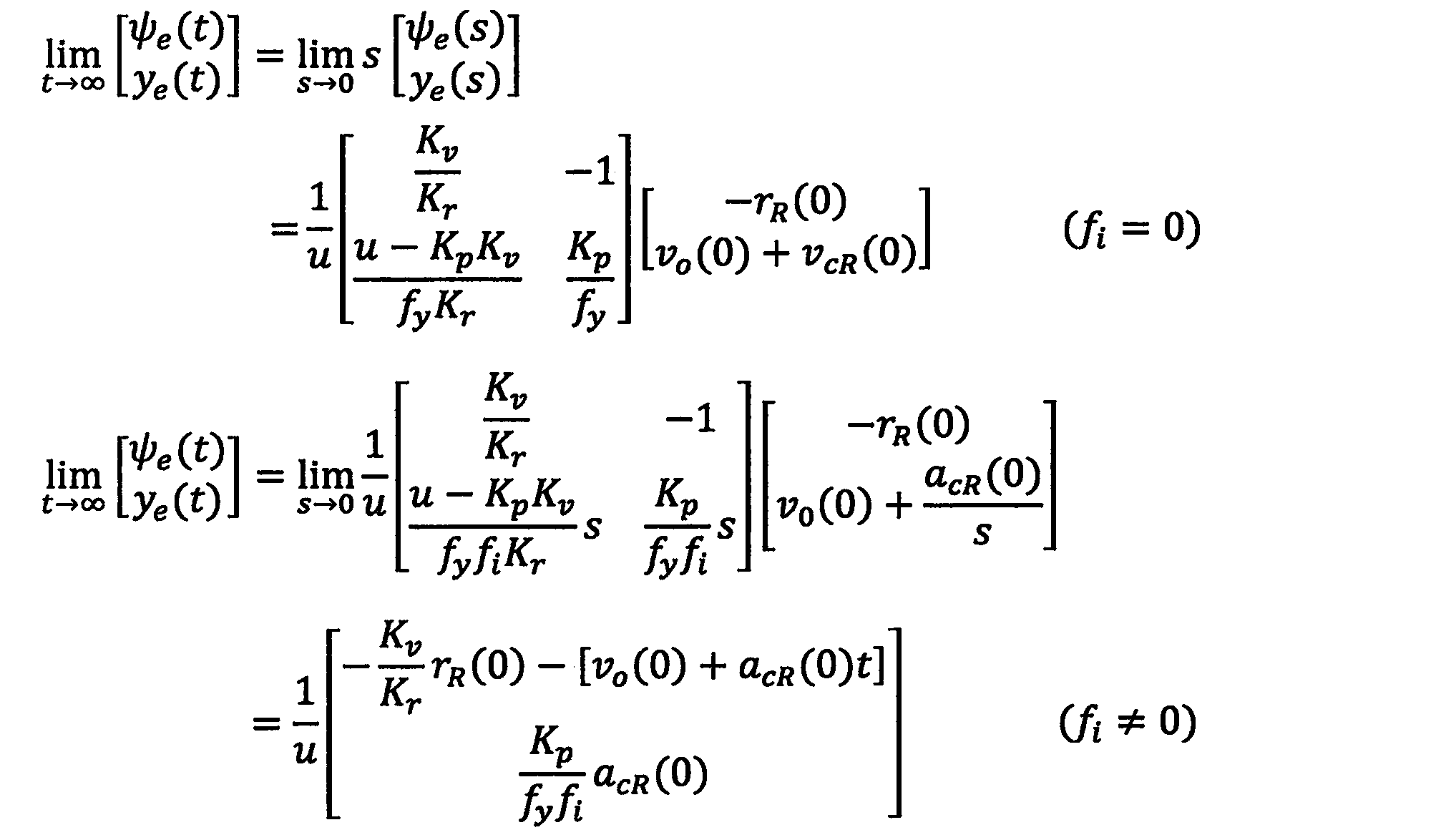
- Azimuth error is not affected by the presence or absence of an integrator, and a skew angle is generated mainly by the tidal component perpendicular to the channel, and is given by the following equation.
- VcR (0) acR (0) ⁇ . ⁇ is time. Therefore, the tidal component v cR (0) becomes dominant.
- the route control system feedback gain unit 123 employs a control system having an integrator.
- the feedback control unit 12 is obtained by adding an estimator 122 and a filter 124 to the direction control system feedback gain unit 121 and the route control system feedback gain unit 123, as shown in FIG.
- x h ⁇ [x r ⁇ x w ⁇ ⁇ ro ⁇ ] T
- x r ⁇ [ ⁇ e ⁇ r x ⁇ ] T
- K h are estimated gains of 5 rows and 1 column
- F h is 1 row 5 columns of feedback gains
- T y is a filter time constant
- F t is 1 row 2 columns of feedback gain
- subscript - is a detected value
- the feedback control unit 12 is an adaptive type in which the parameters of the hull, wave, and specification are set from the parameters of the hull model and wave model identified based on the time series data by the identifier, and the control gain is known. Is required. For this method, refer to Fuyu Hane, “Design by Analytical Method Based on Needle Holding Control for Route Maintenance System”, Japanese Society of Marine Science and Technology, June 2016, 23:33. I want. In the present embodiment, feedback gains F h and F t , an estimated gain K h , and a filter time constant T y are obtained as control gains.
- the calculation point is that the departure position is Yokohama (latitude 35.5 deg, longitude 139.6 deg), the arrival position is Seattle (longitude 47.6 deg, latitude -122.3 deg), and 360 degrees is added to the longitude.
- the section distance is 4470M for the route line route and 4168.2M for the great circle route. These differences are 302M, and the distance of the great circle route is reduced to -6.8% compared to the distance of the route line.
- FIG. 9 is a graph showing the latitude and longitude of the great circle route in the simulation.
- FIG. 10 is a graph showing the starting course of the great circle route in the simulation.
- FIG. 11 is a graph showing the turning angular velocity of the great circle route in the simulation.
- the horizontal axis is the range
- the initial course is 45.5 degrees
- the arrival course is 120.4 degrees
- the amount of change between them is 74.9 degrees. is there.
- the angle inclination is large near the center.
- FIG. 11 showing the turning angular velocity of the great circle route, the influence is proportional when the ship speed is changed.
- the boat speed is 20 kn, 0.52 ⁇ 1.0 deg / h.
- FIG. 12 is a diagram illustrating a section range of the great circle route that is a target in the simulation.
- FIG. 13 is a diagram illustrating a response of the marine vessel automatic steering apparatus by simulation.
- the initial value of the channel error is 50 m
- the magnitude of the tidal component has a time series of zero, trapezoid, and sine as shown in the uppermost stage. This figure shows the following.
- ⁇ Directional error is proportional to the tidal current, and the channel error is offset by the tilt angle.
- the navigation error is proportional to the derivative of the heading error and becomes zero when the heading error is constant.
- -The command rudder angle has an offset of a correction amount ⁇ .
- the estimated value ⁇ e ⁇ is consistent with ⁇ e .
- the parameters of the orientation control system are appropriate.
- the autopilot for the great circle route is realized in one control mode by combining the geodetic calculation and the route holding system.
- the range is longer than that of the Greater Route, and the transition distance is extended by switching the control mode. According to the pilot, such an extension of the navigation distance does not occur.
- the starting course is replaced with the reference direction, and in the route maintenance system, an integrator is introduced in the route control loop. According to the verification by the simulation described above, the performance designed in the marine vessel automatic steering apparatus 1 according to the present embodiment can be confirmed.
Landscapes
- Engineering & Computer Science (AREA)
- Radar, Positioning & Navigation (AREA)
- Combustion & Propulsion (AREA)
- Mechanical Engineering (AREA)
- Ocean & Marine Engineering (AREA)
- Aviation & Aerospace Engineering (AREA)
- Chemical & Material Sciences (AREA)
- Remote Sensing (AREA)
- Physics & Mathematics (AREA)
- General Physics & Mathematics (AREA)
- Automation & Control Theory (AREA)
- Control Of Position, Course, Altitude, Or Attitude Of Moving Bodies (AREA)
- Navigation (AREA)
- Traffic Control Systems (AREA)
Abstract
This invention is provided with a geodesic calculation unit 11 and a feedback control unit 12. The geodesic calculation unit 11: calculates, on the basis of a departure position and an arrival position of a hull, a geodesic serving as a great circle route; outputs, on the basis of a hull position (x, y) and heading ψ detected by a sensor 3, an initial course at the point of intersection of the geodesic intersecting with a line that passes through the hull position (x, y) and that is orthogonal to the geodesic, as a reference direction ψR; and outputs the length from the hull position to the intersection as a route error ye. The feedback control unit 12 has a direction control system feedback gain unit constituting a direction control loop in which the heading ψ is made to track the reference direction ψR, and a route control system feedback gain unit constituting a route control loop in which the hull position (x, y) is made to track the geodesic so as to reduce the route error ye. The feedback control unit 12 adds an output from the direction control system feedback gain unit and an output from the route control system feedback gain unit and outputs the result as a command rudder angle δc.
Description
本発明は、船舶用自動操舵装置に関する。
The present invention relates to an automatic steering device for a ship.
近年、船舶の運航において、乗船員の不足を補い、安全航海をより推進し、さらに操船者による燃料消費の変動を抑制することなどを目的として、船舶が自律的に運行することによる船舶の省人化が求められている。この船舶の省人化には、IT技術により陸上基地からの船舶の一元的な管理と、オートパイロットによる航海とが前提となる。
In recent years, ship operations have been reduced due to autonomous operation of ships in order to make up for the shortage of crew members, promote safe navigation, and reduce fluctuations in fuel consumption by ship operators. Humanization is required. The labor saving of this ship is premised on the unified management of the ship from the land base by IT technology and the voyage by the autopilot.
大洋航海は沿岸付近に比べ、他船や物標の影響が少ないため、オートパイロット技術の効果が期待される。大圏航路はその距離が長くなるほど、等角航路(方位角一定)に比べて航路長が短くなる特徴をもつ。現在では、この大圏航路の設定は、電子海図表示装置(Electronic Chart Display and Information System:ECDIS)上で容易に行うことができる。
The ocean voyage is less affected by other ships and targets than the coastal area, so the effect of autopilot technology is expected. The great circle route has a feature that the longer the distance is, the shorter the route length is compared to the equiangular route (constant azimuth). At present, the setting of this great circle route can be easily performed on an electronic chart display device (Electronic Chart Display and Information System: ECDIS).
ECDISは、大圏航路を適当に分割して直線と円弧の計画航路を作成しオートパイロットにその情報を送る。オートパイロットはその計画航路に船体を追従させるため、舵を制御する。その制御システムは航路制御システム(Track Control System:TCS)と呼ばれ、直線と円弧の航路に対応する操船モードをもつ。
ECDIS appropriately divides the Greater Route and creates a straight and circular planned route and sends the information to the autopilot. The autopilot controls the rudder to make the hull follow the planned route. The control system is called a track control system (TCS), and has a ship maneuvering mode corresponding to straight and circular routes.
なお、本発明者による航路制御システムに関する技術として、方位制御ループを構成する方位制御系フィードバックゲイン器と、方位制御ループを含む航路制御ループを構成する航路制御系フィードバックゲイン器と、方位誤差、航路誤差及び潮流の推定を行うとともに、方位制御系フィードバックゲイン器へsway方向の潮流推定誤差に基づく修正量を入力する推定器とを有するフィードバック制御部を備えた船舶用自動操舵装置、が知られている(特許文献1参照)。
As a technology related to the route control system by the present inventor, the direction control system feedback gain unit that constitutes the direction control loop, the route control system feedback gain unit that constitutes the route control loop including the direction control loop, the direction error, the route There is known an automatic steering apparatus for a ship having a feedback control unit that estimates an error and a tidal current and has an estimator that inputs a correction amount based on a tidal current estimation error in a sway direction to a bearing control system feedback gain unit. (See Patent Document 1).
しかしながら、従来の航路制御システムによる大圏航海において、操船モードが2つあることは船舶の省人化、具体的には、陸上基地からの船舶の管理において、管理作業を増大させる要因となる。操船は単純なものほど、使いやすく保守しやすいため、大洋航海において1つの操船モードで対応できることが要求される。
However, in the large-area voyage by the conventional route control system, the two ship maneuvering modes are factors that increase management work in the labor saving of the ship, specifically, in the management of the ship from the land base. The simpler the maneuvering is, the easier it is to use and maintain, and therefore it is required to be able to support one maneuvering mode in ocean voyages.
本発明は、上述した問題点を解決するためになされたものであり、1つの操船モードにより大洋航海に対応することができる船舶用自動操舵装置を提供することをその目的とする。
The present invention has been made to solve the above-described problems, and an object of the present invention is to provide a marine vessel automatic steering apparatus that can cope with ocean voyage by one marine vessel maneuvering mode.
上述した課題を解決するため、本実施形態に係る船舶用自動操舵装置は、船体を大圏航路に追従させるべく命令舵角を出力する船舶用自動操舵装置であって、前記船体の出発位置と着達位置とに基づいて前記大圏航路としての測地線を算出し、センサにより検出された船体位置及び船首方位に基づいて、該船体位置を通り前記測地線に直交する線と交わる前記測地線上の交点における起程針路を参照方位として出力し、前記船体位置から前記交点までの長さを航路誤差として出力する測地計算部と、前記船首方位を前記参照方位に追従させる方位制御ループを構成する方位制御系フィードバックゲイン器と、前記航路誤差を低減するように前記船体位置を前記測地線に追従させる航路制御ループを構成する航路制御系フィードバックゲイン器とを有し、前記方位制御系フィードバックゲイン器からの出力と前記航路制御系フィードバックゲイン器からの出力とを加算して前記命令舵角として出力するフィードバック制御部とを備える。
In order to solve the above-described problems, the marine vessel automatic steering apparatus according to the present embodiment is a marine vessel automatic steering apparatus that outputs a command rudder angle to cause the hull to follow the great circle route, and The geodesic line as the great circle route is calculated based on the arrival position, and on the geodesic line intersecting with the line passing through the hull position and perpendicular to the geodesic line based on the hull position and the heading detected by the sensor. A geodetic calculation unit that outputs a starting course at the intersection of the vehicle as a reference direction, and outputs a length from the hull position to the intersection as a navigation error, and a direction that constitutes a direction control loop that causes the bow direction to follow the reference direction A control system feedback gain unit, and a route control system feedback gain constituting a route control loop for causing the hull position to follow the geodesic line so as to reduce the route error It has the door, and a feedback controller for outputting as the command steering angle by adding the output from the route control system feedback gain unit and an output from said orientation control system feedback gain units.
本発明によれば、1つの操船モードにより大洋航海に対応することができる。
According to the present invention, it is possible to respond to ocean voyage by one ship maneuvering mode.
以下、図面を参照しながら、本発明の実施形態について説明する。
Hereinafter, embodiments of the present invention will be described with reference to the drawings.
1. 船舶用航行支援装置の構成
本実施形態に係る船舶用自動操舵装置を含むシステムについて説明する。図1は、船舶用自動操舵装置と制御対象とを含むシステムを示すブロック図である。図2は、フィードバック制御部の構成を示すブロック図である。 1. Configuration of Ship Navigation Support Device A system including a boat automatic steering device according to the present embodiment will be described. FIG. 1 is a block diagram showing a system including a marine vessel automatic steering apparatus and a control target. FIG. 2 is a block diagram illustrating a configuration of the feedback control unit.
本実施形態に係る船舶用自動操舵装置を含むシステムについて説明する。図1は、船舶用自動操舵装置と制御対象とを含むシステムを示すブロック図である。図2は、フィードバック制御部の構成を示すブロック図である。 1. Configuration of Ship Navigation Support Device A system including a boat automatic steering device according to the present embodiment will be described. FIG. 1 is a block diagram showing a system including a marine vessel automatic steering apparatus and a control target. FIG. 2 is a block diagram illustrating a configuration of the feedback control unit.
船舶用自動操舵装置1は、大圏航路に船体方位ψ及び船体位置(x,y)を追従させるために舵を制御する装置であり、図1に示すように、測地計算部11、フィードバック制御部12、減算器13及び各パラメータを同定する図示しない公知の同定器を備えている。船体2のセンサ類3は、船体2のsurge速度uを検出するスピードログ、船体2の船首方位ψを検出するジャイロコンパス、GPS等の衛星測位システム(GNSS)からの船体位置(x,y)を検出するGNSSセンサを含む。
The marine vessel automatic steering device 1 is a device that controls a rudder so that the hull orientation ψ and the hull position (x, y) follow the great circle route. As shown in FIG. 1, as shown in FIG. The unit 12, the subtractor 13, and a known identifier not shown for identifying each parameter are provided. The sensors 3 of the hull 2 include a speed log for detecting the surge speed u of the hull 2, a gyrocompass for detecting the heading ψ of the hull 2, and a hull position (x, y) from a satellite positioning system (GNSS) such as GPS. GNSS sensor for detecting
測地計算部11は、初期設定として与えられた大洋航海における出発位置及び着達位置に基づいて大圏航路としての測地線を算出するとともに、センサ類3により検出された船体位置(x,y)に基づいて参照方位ψRと航路誤差yeとを算出して出力する。なお、測地計算部11による測地線の算出は、既知のいかなる手法を用いても良く、例えば、法線ベクトルを用いた手法として、Position calculations - simple and exact solutions - by means of n-vector、[online]、[平成28年2月2日検索]検索日 2016年2月2日、インターネット<http://www.navlab.net/nvector/>が挙げられる。
The geodetic calculation unit 11 calculates a geodesic line as a great circle route based on the starting position and arrival position in the ocean voyage given as an initial setting, and the hull position (x, y) detected by the sensors 3 It calculates and outputs the reference direction [psi R and route error y e based on. Note that the geodesic line calculation by the geodetic calculation unit 11 may use any known technique. For example, as a technique using a normal vector, Position calculations-simple and exact solutions-by means of n-vector, [ online], [Search February 2, 2016] Search Date February 2, 2016, Internet <http://www.navlab.net/nvector/>.
フィードバック制御部12は、測地計算部11により出力された参照方位ψRと航路誤差yeとに基づいて船体2の操舵機に命令舵角δcを出力するものであり、図2に示すように、状態フィードバックを行う方位制御系フィードバックゲイン器121と、推定器122と、PI制御を行う航路制御系フィードバックゲイン器123と、フィルタ124とを備える。なお、フィードバック制御部12については後に詳述する。
The feedback control unit 12 outputs a command steering angle δ c to the steering machine of the hull 2 based on the reference bearing ψ R and the route error y e output by the geodetic calculation unit 11, as shown in FIG. In addition, an azimuth control system feedback gain unit 121 that performs state feedback, an estimator 122, a route control system feedback gain unit 123 that performs PI control, and a filter 124 are provided. The feedback control unit 12 will be described in detail later.
なお、同定器は、センサ類3により検出された船首方位ψ、船体位置(x,y)、surge速度u、フィードバック制御部12より出力された命令舵角δcの時系列データに基づいて、船体モデル、波浪モデルそれぞれのパラメータを公知の手法により同定する。なお、船体モデルのパラメータ同定については、羽根冬希著、「船体運動パラメータの包括的同定手法」、日本船舶海洋工学会論文集、2014年12月、20:27-38を参照されたい。また、波浪モデルのパラメータ同定については、羽根冬希著、「オートパイロット用の波浪外乱パラメータの同定手法」、日本船舶海洋工学会講演会論文集、2016年、(23):461-465を参照されたい。
The identifier is based on the time series data of the heading azimuth ψ detected by the sensors 3, the hull position (x, y), the surge speed u, and the command steering angle δ c output from the feedback control unit 12. The parameters of the hull model and the wave model are identified by a known method. For parameter identification of the hull model, refer to Fuyu Hane, “Comprehensive identification method of hull motion parameters”, Japanese Society of Marine Science and Technology, December 2014, 20: 27-38. For the parameter identification of the wave model, see Fuyu Hane, “Identification Method of Wave Disturbance Parameters for Autopilot”, Proceedings of the Japan Society of Marine Science and Technology, 2016, (23): 461-465. I want to be.
2.船舶用自動操舵装置の動作原理
船舶用自動操舵装置の動作原理について説明する。図3は、大圏航路を示す図である。図4は、大圏航路を近似した航路を示す図である。図5は、船舶用自動操舵装置による軌道追従を示す図である。 2. Operating Principle of Marine Automatic Steering Device The operational principle of the marine automatic steering device will be described. FIG. 3 is a diagram illustrating the great circle route. FIG. 4 is a diagram showing a route that approximates the great circle route. FIG. 5 is a diagram illustrating trajectory following by the marine vessel automatic steering apparatus.
船舶用自動操舵装置の動作原理について説明する。図3は、大圏航路を示す図である。図4は、大圏航路を近似した航路を示す図である。図5は、船舶用自動操舵装置による軌道追従を示す図である。 2. Operating Principle of Marine Automatic Steering Device The operational principle of the marine automatic steering device will be described. FIG. 3 is a diagram illustrating the great circle route. FIG. 4 is a diagram showing a route that approximates the great circle route. FIG. 5 is a diagram illustrating trajectory following by the marine vessel automatic steering apparatus.
図3に示すように、大圏航路は、地球を半径一定の球体と扱い、A点は出発位置、B点は着達位置、H点は航路上の位置、ψAは出発針路,ψBは着達針路、ψHは起程針路である。位置は緯度・経度の座標によって与えられ、針路は子午線との角度でその座標によって計算される。つまり、大圏航路は出発位置と着達位置の2点が与えられると、航路上の位置とその針路が決定される。大圏航路に関する測地計算は、上述したように法線ベクトルを用いた方法を利用する。その特徴は単純な構成で、繰り返し計算がないことである。
As shown in FIG. 3, the great circle route treats the earth as a sphere with a constant radius, point A is the departure position, point B is the arrival position, point H is the position on the route, ψ A is the departure course, ψ B it is Chakutachi course, ψ H is Okoshihodo course. The position is given by latitude and longitude coordinates, and the course is calculated by the coordinates with the meridian. In other words, when two points of the start position and the arrival position are given to the great circle route, the position on the route and its course are determined. As described above, the geodetic calculation for the great circle route uses the method using the normal vector. Its feature is a simple configuration and no repeated calculation.
図4に示される近似大圏航路は、ECDISにより大圏航路を近似したものであり、ここで、近似大圏航路は適当な距離ごとに分割され、図4において実線により示される直線と点により示される円弧とにより構成される。点の位置を拡大すると円弧線(Circular arc line)となっているものとする。直線航路は設定方位が一定になる航程線(Rhumb line)と呼ばれる。円弧の変針角は小さいが、旋回するための操船モードが必要になる。
The approximate great circle route shown in FIG. 4 is obtained by approximating the great circle route by ECDIS. Here, the approximate great circle route is divided at an appropriate distance, and is represented by a straight line and a point indicated by a solid line in FIG. It is comprised by the circular arc shown. It is assumed that when the position of the point is enlarged, a circular arc line (Circular arc line) is obtained. The straight route is called a route line (Rhumb line) where the set direction is constant. Although the turning angle of the arc is small, a marine vessel maneuvering mode for turning is required.
一方、船舶用自動操舵装置1による軌道追従によれば、図5に示すように、船体位置はP点にあり、前進速度u、船首方位ψで航行する。P点から大圏航路上に垂線の足を下ろし、その点をHとする。即ち、H点は、P点を通る線と大圏航路とが直交する点である。この垂足の長さ、即ちP点からH点までの距離がクロストラックエラー(Cross Track Error)とも呼ばれる航路誤差yeとなる。船舶用自動操舵装置1は、H点の起程針路ψHを参照方位ψRに置き換える。よって、船舶用自動操舵装置1による制御システムは船体2の方位と位置をそれぞれの目標値に追従させる軌道追従制御を構成することになる。この軌道追従制御は、方位制御系フィードバックゲイン器121と推定器122とを含む方位制御系と、航路制御系フィードバックゲイン器123とフィルタ124とを含む航路制御系とにより構成され、方位制御系によれば、ψ=ψRになり、船体航跡は大圏航路とyeを保持して並進する。また、航路制御系によれば、yeがゼロに漸近して、船体航跡は大圏航路上を追従するようになる。
On the other hand, according to the trajectory tracking by the marine vessel automatic steering apparatus 1, as shown in FIG. 5, the hull position is at the point P, and the vehicle navigates at the forward speed u and the heading direction ψ. The point of the perpendicular is lowered from the point P onto the great circle route, and the point is set to H. That is, the point H is a point where the line passing through the point P and the great circle route are orthogonal to each other. The length of this Shideashi, i.e. the distance from the point P to the point H is the route error y e, also referred to as cross-track error (Cross Track Error). Marine autopilot 1 replaces Okoshihodo course [psi H point H to the reference azimuth [psi R. Therefore, the control system using the marine vessel automatic steering apparatus 1 constitutes the trajectory tracking control for causing the azimuth and position of the hull 2 to follow the respective target values. This trajectory tracking control includes an azimuth control system including an azimuth control system feedback gain unit 121 and an estimator 122, and a route control system including a channel control system feedback gain unit 123 and a filter 124. According, become [psi = [psi R, the hull wake can translate holds great circle route and y e. Further, according to the route control system, y e asymptotically approaches zero, and the hull track follows the great circle route.
3.航路誤差と制御対象
航路誤差と制御対象について説明する。図6は、航路制御システムで用いる座標系を示す説明図である。 3. Route error and controlled object The route error and controlled object are explained. FIG. 6 is an explanatory diagram showing a coordinate system used in the route control system.
航路誤差と制御対象について説明する。図6は、航路制御システムで用いる座標系を示す説明図である。 3. Route error and controlled object The route error and controlled object are explained. FIG. 6 is an explanatory diagram showing a coordinate system used in the route control system.
図6に示すように、座標系は、右手・直交三軸において、地球固定座標系と船体固定座標系との2つを定める。地球固定座標系は、X軸を北向きに、Y軸を西向きに、Z軸を下向きとする座標系であり、以降は地球座標と呼称する。船体固定座標系は、原点OBを船体の重心Gに固定し、XB軸を船首方向(surge)に、YB軸を右舷方向(sway)に,ZB軸を重力方向(heave)とする座標系であり、以降は船体座標と呼称する。
As shown in FIG. 6, two coordinate systems are defined for the right-handed / three orthogonal axes, the earth fixed coordinate system and the ship fixed coordinate system. The fixed earth coordinate system is a coordinate system in which the X axis is northward, the Y axis is westward, and the Z axis is downward, and is hereinafter referred to as earth coordinates. Hull fixing coordinate system, the origin O B fixed to the center of gravity G of the hull, at the bow direction (surge) the X B axis, the Y B axis on the starboard direction (sway), the Z B-axis direction of gravity (heave) This coordinate system is hereinafter referred to as hull coordinates.
なお、座標系の位置情報は便宜上平面座標を用いる。また、Z軸とZB軸は利用しないので省く。航路誤差yeは測地計算から求まり、船体位置から大圏航路までの垂足の長さに相当する。方位誤差は、
Note that plane coordinates are used for the positional information of the coordinate system for convenience. Also, the Z axis and Z B axis are omitted because they are not used. The channel error y e is obtained from geodetic calculation and corresponds to the length of the droop from the hull position to the great circle channel. Azimuth error is


外乱モデルは、舵角オフセットδro,δvo、波浪成分ψw及び図6に示す潮流成分uc、vcとする。ここで、δro,δvoは、それぞれ、風や船体特性などに誘起された方位軸周りに作用する角速度、sway方向に作用する速度を舵角換算したものであり、それぞれ、方位誤差、航路誤差を発生させる。ψwは、白色ノイズνが入力した狭帯域フィルタ出力を方位変換したものでδcに無効舵を発生させる。uc、vcは、航路誤差を発生させる。よって、外乱モデルを
Disturbance model, the steering angle offset [delta] ro, [delta] vo, wave component [psi w and tidal component u c shown in FIG. 6, and v c. Here, δ ro and δ vo are obtained by converting the angular velocity acting around the azimuth axis induced by wind and hull characteristics, etc., and the velocity acting in the sway direction into steering angles, respectively. Generate an error. ψ w is a directional conversion of the output of the narrow band filter to which the white noise ν is input, and generates an invalid rudder in δ c . u c and v c generate a route error. Therefore, the disturbance model


とし、ここで、添字wは波浪成分、ζw、ωwはそれぞれ減衰係数、固有周波数、σwは波浪の強さを表す定数を示す。
Here, the subscript w is a wave component, ζ w and ω w are attenuation coefficients, natural frequencies, and σ w are constants representing the strength of the waves, respectively.
4.速度誤差成分
速度誤差成分について説明する。 4). Speed error component The speed error component will be described.
速度誤差成分について説明する。 4). Speed error component The speed error component will be described.
船体運動と潮流成分を図6に示すように地球座標の成分に変換すると、
When the hull motion and tidal current components are converted into the components of the earth coordinates as shown in Fig. 6,


参照航路における速度誤差成分は次式になる。
The speed error component in the reference route is as follows.


5.制御誤差特性
閉ループ制御システムの誤差の特性について説明する。図7は、閉ループ制御システムの誤差モデルを示す図である。図8は、積分器ありのサーボ特性を示す表である。 5). Control Error Characteristics The error characteristics of the closed loop control system will be described. FIG. 7 is a diagram illustrating an error model of the closed loop control system. FIG. 8 is a table showing servo characteristics with an integrator.
閉ループ制御システムの誤差の特性について説明する。図7は、閉ループ制御システムの誤差モデルを示す図である。図8は、積分器ありのサーボ特性を示す表である。 5). Control Error Characteristics The error characteristics of the closed loop control system will be described. FIG. 7 is a diagram illustrating an error model of the closed loop control system. FIG. 8 is a table showing servo characteristics with an integrator.
船舶用自動操舵装置1における閉ループ制御システムの誤差を解析する。その誤差モデルは図7に示すようになり、次式になる。ただし、簡単化のため、外乱モデルの波浪成分は平均値がゼロのため除き、推定器122とフィルタ124は定常値に影響しないために除くものとする。
Analyzes the error of the closed-loop control system in the ship automatic steering system 1. The error model is as shown in FIG. However, for simplicity, the wave component of the disturbance model is excluded because the average value is zero, and the estimator 122 and the filter 124 are excluded because they do not affect the steady value.


よって、方位誤差と航路誤差の伝達特性は、(18)~(21)式を用いて、
Therefore, the transfer characteristics of heading error and route error are expressed by using equations (18) to (21).


上式から、閉ループ制御システムは次のような誤差特性をもつ。ただし、rR(0)=1deg/h、Kv÷Kr=-70m/s、vo(0)=0とする。
From the above equation, the closed-loop control system has the following error characteristics. However, r R (0) = 1 deg / h, K v ÷ K r = −70 m / s, and v o (0) = 0.
方位誤差は、積分器の有無による影響を受けず、主に航路に直角方向の潮流成分により斜航角を生じ、次式になる。
Azimuth error is not affected by the presence or absence of an integrator, and a skew angle is generated mainly by the tidal component perpendicular to the channel, and is given by the following equation.

航路誤差は、航路制御系フィードバックゲイン器123における積分器の有無による差が表れる。積分器なしの場合では、潮流成分vcR(0)が支配的になり、航路誤差
The difference in the channel error due to the presence or absence of an integrator in the channel control system feedback gain unit 123 appears. In the case without an integrator, the tidal component v cR (0) becomes dominant and the channel error


フィードバック制御部12は、図2に示すように、方位制御系フィードバックゲイン器121、航路制御系フィードバックゲイン器123に推定器122、フィルタ124を追加したものであり、
The feedback control unit 12 is obtained by adding an estimator 122 and a filter 124 to the direction control system feedback gain unit 121 and the route control system feedback gain unit 123, as shown in FIG.


フィードバック制御部12は適応型であり、同定器により時系列データに基づいて同定された船体モデル、波浪モデルそれぞれのパラメータから、船体、波浪、仕様の各パラメータを設定して制御ゲインが公知の方法により求められる。なお、この方法については、羽根冬希著、「航路保持システムのための保針制御に基づく解析的方法による設計」、日本船舶海洋工学会論文集、2016年6月、23:33を参照されたい。本実施形態においては、制御ゲインとして、フィードバックゲインFh,Ft、推定ゲインKh、フィルタ時定数Tyが求められる。
The feedback control unit 12 is an adaptive type in which the parameters of the hull, wave, and specification are set from the parameters of the hull model and wave model identified based on the time series data by the identifier, and the control gain is known. Is required. For this method, refer to Fuyu Hane, “Design by Analytical Method Based on Needle Holding Control for Route Maintenance System”, Japanese Society of Marine Science and Technology, June 2016, 23:33. I want. In the present embodiment, feedback gains F h and F t , an estimated gain K h , and a filter time constant T y are obtained as control gains.
6 検証
6.1 条件
本実施形態に係る船舶用自動操舵装置1の有効性をシミュレーションによって検証する。このシミュレーションにおいては、1海里Mは1852m、地球半径は6371×103m、初期船速はu0=20knを条件として用いる。船体運動モデルはyawとswayの連成運動に非線形項を加えたものとし、潮流成分の大きさUcは最大5kn、方向ψcは北向き、波浪成分は無しとする。 6 Verification 6.1 Conditions The effectiveness of the marine vesselautomatic steering apparatus 1 according to this embodiment is verified by simulation. In this simulation, 1 nautical mile M is 1852 m, the earth radius is 6371 × 10 3 m, and the initial ship speed is u 0 = 20 kn. In the ship motion model, a nonlinear term is added to the coupled motion of yaw and sway, the tidal current component size U c is 5 kn at maximum, the direction ψ c is north, and the wave component is absent.
6.1 条件
本実施形態に係る船舶用自動操舵装置1の有効性をシミュレーションによって検証する。このシミュレーションにおいては、1海里Mは1852m、地球半径は6371×103m、初期船速はu0=20knを条件として用いる。船体運動モデルはyawとswayの連成運動に非線形項を加えたものとし、潮流成分の大きさUcは最大5kn、方向ψcは北向き、波浪成分は無しとする。 6 Verification 6.1 Conditions The effectiveness of the marine vessel
船体パラメータは同定値であり、Kr=0.132 1/s,Tr=29.5s,Tr3=0.03s,Kv=-8.18m/s,波浪パラメータは初期値で、周期10s,減衰係数0.1とする。また、制御ゲインは、Kp=1.0,Kd=13.6s,fy=0.00134 1/m,fi=0.00688 1/m/s,Ty=2.54s,Kh=[-1.31 -0.272 1.32 -0.206 -0.458]Tとする。
The hull parameters are the identification values, K r = 0.132 1 / s, T r = 29.5 s, T r3 = 0.03 s, K v = −8.18 m / s, the wave parameters are the initial values, and the period 10s, attenuation coefficient 0.1. Further, the control gains are K p = 1.0, K d = 13.6 s, f y = 0.00134 1 / m, f i = 0.00688 1 / m / s, T y = 2.54 s, K h = [− 1.31 −0.272 1.32 −0.206 −0.458] T
計算地点は、出発位置を横浜(緯度35.5deg、経度139.6deg)とし、到達位置はシアトル(経度47.6deg、緯度-122.3deg)とし、経度に360度を加えている。その区間距離は、航程線航路で4470M、大圏航路で4168.2Mとなり、これらの差異は302Mになり、大圏航路の距離は航程線の距離と比較して-6.8%に短縮される。
The calculation point is that the departure position is Yokohama (latitude 35.5 deg, longitude 139.6 deg), the arrival position is Seattle (longitude 47.6 deg, latitude -122.3 deg), and 360 degrees is added to the longitude. The section distance is 4470M for the route line route and 4168.2M for the great circle route. These differences are 302M, and the distance of the great circle route is reduced to -6.8% compared to the distance of the route line. The
6.2 大圏航路の特性
大圏航路の特性について説明する。図9は、シミュ―レーションにおける大圏航路の緯度経度を示すグラフである。図10は、シミュ―レーションにおける大圏航路の起程針路を示すグラフである。図11は、シミュ―レーションにおける大圏航路の旋回角速度を示すグラフである。 6.2 Characteristics of Greater Area Route The characteristics of the Greater Area Route will be explained. FIG. 9 is a graph showing the latitude and longitude of the great circle route in the simulation. FIG. 10 is a graph showing the starting course of the great circle route in the simulation. FIG. 11 is a graph showing the turning angular velocity of the great circle route in the simulation.
大圏航路の特性について説明する。図9は、シミュ―レーションにおける大圏航路の緯度経度を示すグラフである。図10は、シミュ―レーションにおける大圏航路の起程針路を示すグラフである。図11は、シミュ―レーションにおける大圏航路の旋回角速度を示すグラフである。 6.2 Characteristics of Greater Area Route The characteristics of the Greater Area Route will be explained. FIG. 9 is a graph showing the latitude and longitude of the great circle route in the simulation. FIG. 10 is a graph showing the starting course of the great circle route in the simulation. FIG. 11 is a graph showing the turning angular velocity of the great circle route in the simulation.
大圏航路の緯度経度を示す図9において、経度を0度から360度とし、7点は1000km毎に1000~7000kmの航程距離を示し、この航程距離の頂点は、緯度54.5度、経度198.9度になる。
In FIG. 9 showing the latitude and longitude of the great circle route, the longitude is changed from 0 to 360 degrees, 7 points indicate a distance of 1000 to 7000 km every 1000 km, and the vertex of this distance is 54.5 degrees latitude and longitude It becomes 198.9 degrees.
また、大圏航路の方位角を示す図10において、横軸を航程距離とし、初期針路は、45.5度、到達針路は120.4度になり、両者の変化量は74.9度である。角度傾斜は中央付近で大きくなっている。
Further, in FIG. 10 showing the azimuth angle of the great circle route, the horizontal axis is the range, the initial course is 45.5 degrees, the arrival course is 120.4 degrees, and the amount of change between them is 74.9 degrees. is there. The angle inclination is large near the center.
また、大圏航路の旋回角速度を示す図11おいて、船速を変化させると、その影響が比例している。船速20knの場合、0.52<1.0deg/hになる。
Also, in FIG. 11 showing the turning angular velocity of the great circle route, the influence is proportional when the ship speed is changed. When the boat speed is 20 kn, 0.52 <1.0 deg / h.
6.3 制御システムの検証
船舶用自動操舵装置による制御システムを検証する。図12は、シミュレーションにおいて対象とする大圏航路の区画範囲を示す図である。図13は、シミュレーションによる船舶用自動操舵装置の応答を示す図である。 6.3 Verification of control system The control system by the automatic steering system for ships is verified. FIG. 12 is a diagram illustrating a section range of the great circle route that is a target in the simulation. FIG. 13 is a diagram illustrating a response of the marine vessel automatic steering apparatus by simulation.
船舶用自動操舵装置による制御システムを検証する。図12は、シミュレーションにおいて対象とする大圏航路の区画範囲を示す図である。図13は、シミュレーションによる船舶用自動操舵装置の応答を示す図である。 6.3 Verification of control system The control system by the automatic steering system for ships is verified. FIG. 12 is a diagram illustrating a section range of the great circle route that is a target in the simulation. FIG. 13 is a diagram illustrating a response of the marine vessel automatic steering apparatus by simulation.
図11において角速度がピークを迎える4000から5000km内を大圏航路の区間に選ぶと、図12に示すようになる。この図においてGCRはGreat Circle Routeを意味し、計算時間は6h、移動距離は222km、参照方位はほぼ西向きである。図12の速度成分から、前進速度u(一定値u0を差し引く)は変動が少なく、横流れ速度vは船体運動モデルの特性からオフセット0.02m/sをもっていることがわかる。参照方位に対する潮流成分はucR=0,vcR=-2.5m/sになり,そのランプ入力の時間は600sである。ただし、ψR=0degとする。
In FIG. 11, when the angular velocity within 4000 to 5000 km is peaked, the section of the great circle route is as shown in FIG. In this figure, GCR means Great Circle Route, the calculation time is 6 h, the movement distance is 222 km, and the reference direction is almost west. From the speed components of FIG. 12, (subtracting the constant value u 0) forward speed u is less change, transverse flow velocity v is found to be have an offset 0.02 m / s from the characteristics of the ship motion model. The tidal current component with respect to the reference orientation is u cR = 0, v cR = −2.5 m / s, and the lamp input time is 600 s. However, ψ R = 0 deg.
制御性能を示す図13において、航路誤差の初期値は50mであり、潮流成分の大きさは最上段に示すように、ゼロ、台形、サインの時系列をもつ。この図から以下のことがわかる。
In FIG. 13 showing the control performance, the initial value of the channel error is 50 m, and the magnitude of the tidal component has a time series of zero, trapezoid, and sine as shown in the uppermost stage. This figure shows the following.
・方位誤差は、潮流の大きさに比例し、その斜航角によって航路誤差を相殺する。
・航路誤差は、方位誤差の微分に比例し、方位誤差が一定のときゼロになる。ランプ入力時の航路誤差は、(33)式からye=-46.9mになり、図13に示される計算値は正しいことが確認できる。
・命令舵角は、修正量γのオフセットをもつ。
・推定値ψe^はψeと一致している。方位制御システムのパラメータは適切である。 ・ Directional error is proportional to the tidal current, and the channel error is offset by the tilt angle.
・ The navigation error is proportional to the derivative of the heading error and becomes zero when the heading error is constant. The route error at the time of ramp input is ye = −46.9 m from the equation (33), and it can be confirmed that the calculated value shown in FIG. 13 is correct.
-The command rudder angle has an offset of a correction amount γ.
The estimated value ψ e ^ is consistent with ψ e . The parameters of the orientation control system are appropriate.
7. まとめ
以上に説明したように、本実施形態に係る船舶用自動操舵装置1によれば、測地計算と航路保持システムを組み合わせることによって、大圏航路用オートパイロットがひとつの制御モードで実現される。また、大圏航路を近似した計画航路によれば、大圏航路に比べて航程距離が長くなり、更に制御モードの切り換えにより過渡現象が生じて航行距離が延長されるが、大圏航路用オートパイロットによれば、このような航行距離の延長が生じない。 7). Summary As described above, according to the marine vesselautomatic steering apparatus 1 according to this embodiment, the autopilot for the great circle route is realized in one control mode by combining the geodetic calculation and the route holding system. In addition, according to the planned route that approximates the Greater Route, the range is longer than that of the Greater Route, and the transition distance is extended by switching the control mode. According to the pilot, such an extension of the navigation distance does not occur.
以上に説明したように、本実施形態に係る船舶用自動操舵装置1によれば、測地計算と航路保持システムを組み合わせることによって、大圏航路用オートパイロットがひとつの制御モードで実現される。また、大圏航路を近似した計画航路によれば、大圏航路に比べて航程距離が長くなり、更に制御モードの切り換えにより過渡現象が生じて航行距離が延長されるが、大圏航路用オートパイロットによれば、このような航行距離の延長が生じない。 7). Summary As described above, according to the marine vessel
測地計算においては起程針路の参照方位への置き換えがなされ、航路保持システムにおいては航路制御ループに積分器が導入される。上述のシミュレーションによる検証によれば、本実施形態に係る船舶用自動操舵装置1において設計した性能を確認できた。
In the geodetic calculation, the starting course is replaced with the reference direction, and in the route maintenance system, an integrator is introduced in the route control loop. According to the verification by the simulation described above, the performance designed in the marine vessel automatic steering apparatus 1 according to the present embodiment can be confirmed.
本発明の実施形態は、例として提示したものであり、発明の範囲を限定することは意図していない。この新規な実施形態は、その他の様々な形態で実施されることが可能であり、発明の要旨を逸脱しない範囲で、種々の省略、置き換え、変更を行うことができる。この実施形態やその変形は、発明の範囲や要旨に含まれるとともに、特許請求の範囲に記載された発明とその均等の範囲に含まれる。
The embodiment of the present invention is presented as an example, and is not intended to limit the scope of the invention. The novel embodiment can be implemented in various other forms, and various omissions, replacements, and changes can be made without departing from the scope of the invention. This embodiment and its modifications are included in the scope and gist of the invention, and are included in the invention described in the claims and the equivalents thereof.
1 船舶用自動操舵装置
2 船体
3 センサ類
11 測地計算部
12 フィードバック制御部
121 方位制御系フィードバックゲイン器
123 航路制御系フィードバックゲイン器 DESCRIPTION OFSYMBOLS 1 Automatic ship steering device 2 Hull 3 Sensors 11 Geodetic calculation part 12 Feedback control part 121 Direction control system feedback gain unit 123 Route control system feedback gain unit
2 船体
3 センサ類
11 測地計算部
12 フィードバック制御部
121 方位制御系フィードバックゲイン器
123 航路制御系フィードバックゲイン器 DESCRIPTION OF
Claims (2)
- 船体を大圏航路に追従させるべく命令舵角を出力する船舶用自動操舵装置であって、
前記船体の出発位置と着達位置とに基づいて前記大圏航路としての測地線を算出し、センサにより検出された船体位置及び船首方位に基づいて、該船体位置を通り前記測地線に直交する線と交わる前記測地線上の交点における起程針路を参照方位として出力し、前記船体位置から前記交点までの長さを航路誤差として出力する測地計算部と、
前記船首方位を前記参照方位に追従させる方位制御ループを構成する方位制御系フィードバックゲイン器と、前記航路誤差を低減するように前記船体位置を前記測地線に追従させる航路制御ループを構成する航路制御系フィードバックゲイン器とを有し、前記方位制御系フィードバックゲイン器からの出力と前記航路制御系フィードバックゲイン器からの出力とを加算して前記命令舵角として出力するフィードバック制御部と
を備える船舶用自動操舵装置。 An automatic steering device for a ship that outputs a command rudder angle to cause the hull to follow a great circle route,
A geodesic line as the great circle route is calculated based on the start position and arrival position of the hull, and passes through the hull position and is orthogonal to the geodesic line based on the hull position and heading detected by the sensor. A geodesic calculation unit that outputs a starting course at an intersection on the geodesic line that intersects with a line as a reference direction, and outputs a length from the hull position to the intersection as a navigation error;
An azimuth control system feedback gain device that constitutes an azimuth control loop that causes the bow azimuth to follow the reference azimuth, and a route control loop that constitutes a route control loop that causes the hull position to follow the geodesic line so as to reduce the lane error. And a feedback control unit that adds the output from the bearing control system feedback gain device and the output from the route control system feedback gain device and outputs the command steering angle. Automatic steering device. - 前記航路制御系フィードバックゲイン器は積分器を有することを特徴とする請求項1に記載の船舶用自動操舵装置。 The marine vessel automatic steering device according to claim 1, wherein the route control system feedback gain unit includes an integrator.
Priority Applications (1)
| Application Number | Priority Date | Filing Date | Title |
|---|---|---|---|
| JP2020514454A JP6781861B2 (en) | 2018-04-20 | 2019-04-19 | Automatic steering device for ships |
Applications Claiming Priority (2)
| Application Number | Priority Date | Filing Date | Title |
|---|---|---|---|
| JP2018-081521 | 2018-04-20 | ||
| JP2018081521 | 2018-04-20 |
Publications (1)
| Publication Number | Publication Date |
|---|---|
| WO2019203335A1 true WO2019203335A1 (en) | 2019-10-24 |
Family
ID=68239682
Family Applications (1)
| Application Number | Title | Priority Date | Filing Date |
|---|---|---|---|
| PCT/JP2019/016747 WO2019203335A1 (en) | 2018-04-20 | 2019-04-19 | Automatic steering device for vessels |
Country Status (2)
| Country | Link |
|---|---|
| JP (1) | JP6781861B2 (en) |
| WO (1) | WO2019203335A1 (en) |
Citations (6)
| Publication number | Priority date | Publication date | Assignee | Title |
|---|---|---|---|---|
| JP2002316697A (en) * | 2001-04-20 | 2002-10-29 | Tech Res & Dev Inst Of Japan Def Agency | Ship route keeping control method and device, and ship |
| JP2009286230A (en) * | 2008-05-28 | 2009-12-10 | Mitsui Eng & Shipbuild Co Ltd | Operation support system of marine vessel and operation support method of marine vessel |
| CN203005731U (en) * | 2012-12-11 | 2013-06-19 | 南宁睿洋自动化科技有限公司 | Automatic steering control system used for ships |
| JP2013226905A (en) * | 2012-04-25 | 2013-11-07 | Universal Tokki Kk | Ship course keeping control device and ship |
| JP2016008038A (en) * | 2014-06-26 | 2016-01-18 | 東京計器株式会社 | Automatic steering device for ship |
| JP2016159695A (en) * | 2015-02-27 | 2016-09-05 | 東京計器株式会社 | Automatic steering gear for vessel |
Family Cites Families (2)
| Publication number | Priority date | Publication date | Assignee | Title |
|---|---|---|---|---|
| JP5993125B2 (en) * | 2011-10-21 | 2016-09-14 | 東京計器株式会社 | Ship automatic steering system |
| JP6487264B2 (en) * | 2015-04-23 | 2019-03-20 | 東京計器株式会社 | Waypoint generator |
-
2019
- 2019-04-19 WO PCT/JP2019/016747 patent/WO2019203335A1/en active Application Filing
- 2019-04-19 JP JP2020514454A patent/JP6781861B2/en active Active
Patent Citations (6)
| Publication number | Priority date | Publication date | Assignee | Title |
|---|---|---|---|---|
| JP2002316697A (en) * | 2001-04-20 | 2002-10-29 | Tech Res & Dev Inst Of Japan Def Agency | Ship route keeping control method and device, and ship |
| JP2009286230A (en) * | 2008-05-28 | 2009-12-10 | Mitsui Eng & Shipbuild Co Ltd | Operation support system of marine vessel and operation support method of marine vessel |
| JP2013226905A (en) * | 2012-04-25 | 2013-11-07 | Universal Tokki Kk | Ship course keeping control device and ship |
| CN203005731U (en) * | 2012-12-11 | 2013-06-19 | 南宁睿洋自动化科技有限公司 | Automatic steering control system used for ships |
| JP2016008038A (en) * | 2014-06-26 | 2016-01-18 | 東京計器株式会社 | Automatic steering device for ship |
| JP2016159695A (en) * | 2015-02-27 | 2016-09-05 | 東京計器株式会社 | Automatic steering gear for vessel |
Also Published As
| Publication number | Publication date |
|---|---|
| JP6781861B2 (en) | 2020-11-04 |
| JPWO2019203335A1 (en) | 2020-09-17 |
Similar Documents
| Publication | Publication Date | Title |
|---|---|---|
| US10996676B2 (en) | Proactive directional control systems and methods | |
| JP2021181301A (en) | Automatic guidance method for vessel, automatic guidance program for vessel, automatic guidance system for vessel, and vessel | |
| CN111487966A (en) | Self-adaptive path tracking control method for unmanned surface vehicle based on waypoints | |
| JP2009248897A (en) | Automatic ship steering device | |
| CN111580518B (en) | Unmanned ship layered obstacle avoidance method based on improved drosophila optimization and dynamic window method | |
| Yang et al. | An improved stanley guidance law for large curvature path following of unmanned surface vehicle | |
| Liu et al. | Model predictive controller design with disturbance observer for path following of unmanned surface vessel | |
| CN112650257A (en) | Unmanned ship area maintaining control method and device | |
| WO2016109601A1 (en) | Proactive directional control systems and methods | |
| CN113341953A (en) | Pod type unmanned ship course control method | |
| CN117707162A (en) | Unmanned sailing boat dynamic event triggering control method based on improved LVS guidance | |
| Zhu et al. | Straight path following of unmanned surface vehicle under flow disturbance | |
| JP7170019B2 (en) | Tracking controller | |
| CN113359737A (en) | Ship formation self-adaptive event trigger control method considering formation expansion | |
| CN113126492A (en) | Automatic path tracking method for dynamic positioning ship | |
| JP6487264B2 (en) | Waypoint generator | |
| WO2019203335A1 (en) | Automatic steering device for vessels | |
| CN113296505B (en) | Unmanned ship multi-mode path tracking control method based on speed change LOS | |
| Miller | Model predictive ship trajectory tracking system based on line of sight method | |
| JP3999976B2 (en) | Maneuvering method and apparatus | |
| Kang et al. | Autonomous sailboat local route planning | |
| JP2021167132A (en) | Ship's hull position holding apparatus | |
| Alvarez et al. | Nonlinear control of an unmanned amphibious vehicle | |
| WO2023089843A1 (en) | Automatic steering device for vessels | |
| Tomera | Dynamic positioning system design for “Blue Lady”. Simulation tests |
Legal Events
| Date | Code | Title | Description |
|---|---|---|---|
| 121 | Ep: the epo has been informed by wipo that ep was designated in this application |
Ref document number: 19787783 Country of ref document: EP Kind code of ref document: A1 |
|
| ENP | Entry into the national phase |
Ref document number: 2020514454 Country of ref document: JP Kind code of ref document: A |
|
| NENP | Non-entry into the national phase |
Ref country code: DE |
|
| 122 | Ep: pct application non-entry in european phase |
Ref document number: 19787783 Country of ref document: EP Kind code of ref document: A1 |