WO2019203160A1 - Driving assistance system and method - Google Patents
Driving assistance system and method Download PDFInfo
- Publication number
- WO2019203160A1 WO2019203160A1 PCT/JP2019/016022 JP2019016022W WO2019203160A1 WO 2019203160 A1 WO2019203160 A1 WO 2019203160A1 JP 2019016022 W JP2019016022 W JP 2019016022W WO 2019203160 A1 WO2019203160 A1 WO 2019203160A1
- Authority
- WO
- WIPO (PCT)
- Prior art keywords
- driving support
- host vehicle
- support system
- communication unit
- detection sensor
- Prior art date
Links
- 238000000034 method Methods 0.000 title claims description 13
- 238000004891 communication Methods 0.000 claims abstract description 83
- 238000001514 detection method Methods 0.000 claims abstract description 63
- 230000009467 reduction Effects 0.000 description 13
- 238000010586 diagram Methods 0.000 description 6
- 238000004364 calculation method Methods 0.000 description 5
- 230000008859 change Effects 0.000 description 5
- 238000012545 processing Methods 0.000 description 5
- 239000013598 vector Substances 0.000 description 5
- 239000012530 fluid Substances 0.000 description 4
- 230000008569 process Effects 0.000 description 3
- 238000004590 computer program Methods 0.000 description 2
- 238000005259 measurement Methods 0.000 description 2
- 230000007246 mechanism Effects 0.000 description 2
- 238000012544 monitoring process Methods 0.000 description 2
- 230000002093 peripheral effect Effects 0.000 description 2
- 238000012935 Averaging Methods 0.000 description 1
- 230000003044 adaptive effect Effects 0.000 description 1
- 230000003247 decreasing effect Effects 0.000 description 1
- 230000000694 effects Effects 0.000 description 1
- 238000005516 engineering process Methods 0.000 description 1
- 230000006870 function Effects 0.000 description 1
- 238000010295 mobile communication Methods 0.000 description 1
- 230000002265 prevention Effects 0.000 description 1
Images


Classifications
-
- G—PHYSICS
- G08—SIGNALLING
- G08G—TRAFFIC CONTROL SYSTEMS
- G08G1/00—Traffic control systems for road vehicles
- G08G1/16—Anti-collision systems
- G08G1/166—Anti-collision systems for active traffic, e.g. moving vehicles, pedestrians, bikes
-
- B—PERFORMING OPERATIONS; TRANSPORTING
- B60—VEHICLES IN GENERAL
- B60W—CONJOINT CONTROL OF VEHICLE SUB-UNITS OF DIFFERENT TYPE OR DIFFERENT FUNCTION; CONTROL SYSTEMS SPECIALLY ADAPTED FOR HYBRID VEHICLES; ROAD VEHICLE DRIVE CONTROL SYSTEMS FOR PURPOSES NOT RELATED TO THE CONTROL OF A PARTICULAR SUB-UNIT
- B60W30/00—Purposes of road vehicle drive control systems not related to the control of a particular sub-unit, e.g. of systems using conjoint control of vehicle sub-units
- B60W30/08—Active safety systems predicting or avoiding probable or impending collision or attempting to minimise its consequences
- B60W30/095—Predicting travel path or likelihood of collision
- B60W30/0956—Predicting travel path or likelihood of collision the prediction being responsive to traffic or environmental parameters
-
- G—PHYSICS
- G06—COMPUTING; CALCULATING OR COUNTING
- G06V—IMAGE OR VIDEO RECOGNITION OR UNDERSTANDING
- G06V20/00—Scenes; Scene-specific elements
- G06V20/50—Context or environment of the image
- G06V20/56—Context or environment of the image exterior to a vehicle by using sensors mounted on the vehicle
- G06V20/58—Recognition of moving objects or obstacles, e.g. vehicles or pedestrians; Recognition of traffic objects, e.g. traffic signs, traffic lights or roads
-
- G—PHYSICS
- G08—SIGNALLING
- G08G—TRAFFIC CONTROL SYSTEMS
- G08G1/00—Traffic control systems for road vehicles
- G08G1/16—Anti-collision systems
- G08G1/161—Decentralised systems, e.g. inter-vehicle communication
- G08G1/163—Decentralised systems, e.g. inter-vehicle communication involving continuous checking
-
- H—ELECTRICITY
- H04—ELECTRIC COMMUNICATION TECHNIQUE
- H04W—WIRELESS COMMUNICATION NETWORKS
- H04W4/00—Services specially adapted for wireless communication networks; Facilities therefor
- H04W4/30—Services specially adapted for particular environments, situations or purposes
- H04W4/40—Services specially adapted for particular environments, situations or purposes for vehicles, e.g. vehicle-to-pedestrians [V2P]
- H04W4/44—Services specially adapted for particular environments, situations or purposes for vehicles, e.g. vehicle-to-pedestrians [V2P] for communication between vehicles and infrastructures, e.g. vehicle-to-cloud [V2C] or vehicle-to-home [V2H]
-
- B—PERFORMING OPERATIONS; TRANSPORTING
- B60—VEHICLES IN GENERAL
- B60W—CONJOINT CONTROL OF VEHICLE SUB-UNITS OF DIFFERENT TYPE OR DIFFERENT FUNCTION; CONTROL SYSTEMS SPECIALLY ADAPTED FOR HYBRID VEHICLES; ROAD VEHICLE DRIVE CONTROL SYSTEMS FOR PURPOSES NOT RELATED TO THE CONTROL OF A PARTICULAR SUB-UNIT
- B60W2420/00—Indexing codes relating to the type of sensors based on the principle of their operation
- B60W2420/40—Photo, light or radio wave sensitive means, e.g. infrared sensors
- B60W2420/403—Image sensing, e.g. optical camera
-
- B—PERFORMING OPERATIONS; TRANSPORTING
- B60—VEHICLES IN GENERAL
- B60W—CONJOINT CONTROL OF VEHICLE SUB-UNITS OF DIFFERENT TYPE OR DIFFERENT FUNCTION; CONTROL SYSTEMS SPECIALLY ADAPTED FOR HYBRID VEHICLES; ROAD VEHICLE DRIVE CONTROL SYSTEMS FOR PURPOSES NOT RELATED TO THE CONTROL OF A PARTICULAR SUB-UNIT
- B60W2520/00—Input parameters relating to overall vehicle dynamics
- B60W2520/06—Direction of travel
-
- B—PERFORMING OPERATIONS; TRANSPORTING
- B60—VEHICLES IN GENERAL
- B60W—CONJOINT CONTROL OF VEHICLE SUB-UNITS OF DIFFERENT TYPE OR DIFFERENT FUNCTION; CONTROL SYSTEMS SPECIALLY ADAPTED FOR HYBRID VEHICLES; ROAD VEHICLE DRIVE CONTROL SYSTEMS FOR PURPOSES NOT RELATED TO THE CONTROL OF A PARTICULAR SUB-UNIT
- B60W2554/00—Input parameters relating to objects
- B60W2554/40—Dynamic objects, e.g. animals, windblown objects
- B60W2554/404—Characteristics
- B60W2554/4041—Position
-
- B—PERFORMING OPERATIONS; TRANSPORTING
- B60—VEHICLES IN GENERAL
- B60W—CONJOINT CONTROL OF VEHICLE SUB-UNITS OF DIFFERENT TYPE OR DIFFERENT FUNCTION; CONTROL SYSTEMS SPECIALLY ADAPTED FOR HYBRID VEHICLES; ROAD VEHICLE DRIVE CONTROL SYSTEMS FOR PURPOSES NOT RELATED TO THE CONTROL OF A PARTICULAR SUB-UNIT
- B60W2556/00—Input parameters relating to data
- B60W2556/45—External transmission of data to or from the vehicle
- B60W2556/65—Data transmitted between vehicles
-
- H—ELECTRICITY
- H04—ELECTRIC COMMUNICATION TECHNIQUE
- H04L—TRANSMISSION OF DIGITAL INFORMATION, e.g. TELEGRAPHIC COMMUNICATION
- H04L67/00—Network arrangements or protocols for supporting network services or applications
- H04L67/01—Protocols
- H04L67/12—Protocols specially adapted for proprietary or special-purpose networking environments, e.g. medical networks, sensor networks, networks in vehicles or remote metering networks
-
- H—ELECTRICITY
- H04—ELECTRIC COMMUNICATION TECHNIQUE
- H04W—WIRELESS COMMUNICATION NETWORKS
- H04W4/00—Services specially adapted for wireless communication networks; Facilities therefor
- H04W4/30—Services specially adapted for particular environments, situations or purposes
- H04W4/40—Services specially adapted for particular environments, situations or purposes for vehicles, e.g. vehicle-to-pedestrians [V2P]
Definitions
- This disclosure relates to a driving support system.
- a first vector indicating the amount and direction of movement of the preceding vehicle detected by the surrounding monitoring means constituted by a camera or a radar, and inter-vehicle communication The degree of coincidence between the preceding vehicle detected by the surrounding monitoring means and the other vehicle that communicated by inter-vehicle communication based on the degree of overlap with the second vector indicating the movement amount and the moving direction of the other vehicle acquired by Deciding. Then, another vehicle having a high degree of coincidence is selected, and follow-up traveling is performed on the other vehicle using inter-vehicle communication.
- a driving support system mounted on the host vehicle includes an object detection sensor capable of detecting a first object existing in front of the host vehicle, a communication unit capable of communicating with a second object existing around the host vehicle, and the object detection sensor. Whether or not the detected first direction from the host vehicle to the first object and the second direction from the host vehicle to the second object communicated by the communication unit are the same direction.
- the object detection sensor and The identity determination unit that is determined based on the information acquired by the communication unit, and when the first object and the second object are determined to be the same object, the first object and the second object Information acquired from a predetermined object And a driving support unit that performs driving support based on.
- the present disclosure can be realized in various forms other than the driving support system.
- the present invention can be realized in the form of a method executed by the driving support system, a computer program for realizing the method, a non-temporary tangible recording medium storing the computer program, and the like.
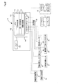
- FIG. 1 is an explanatory diagram showing the configuration of the driving support system
- FIG. 2 is a block diagram of the driving support device
- FIG. 3 is a flowchart of the driving support process.
- FIG. 4 is a diagram illustrating the orientation of the first object detected by the object detection sensor
- FIG. 5 is a diagram illustrating the orientation of the second object detected by the communication unit
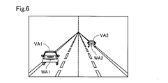
- FIG. 6 is a diagram showing the angular width of the first object detected by the object detection sensor
- FIG. 7 is a diagram illustrating the angular width of the second object detected by the communication unit.
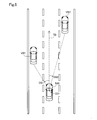
- the driving support system 10 is mounted on a vehicle 500.
- the driving support system 10 includes a driving support device 100, a radar ECU (Electronic Control Unit) 21, a camera ECU 22, a rotation angle sensor 23, a wheel speed sensor 24, a yaw rate sensor 25, a positioning sensor 26, a direction indicator sensor 27, and a communication unit 28.
- a braking support device 31 and a steering support device 32 are provided.
- the driving support system 10 supports driving of the vehicle by the driver using these various devices.
- the vehicle 500 is referred to as the own vehicle 500, and vehicles other than the own vehicle 500 are referred to as other vehicles.
- the driving support apparatus 100 includes a CPU 101, a memory 102, an input / output interface 103, and a bus 104.
- the CPU 101, the memory 102 and the input / output interface 103 are connected to each other via a bus 104.
- the input / output interface 103 includes a radar ECU 21, a camera ECU 22, a rotation angle sensor 23, a wheel speed sensor 24, a yaw rate sensor 25, a positioning sensor 26, a direction indicator sensor 27, a communication unit 28, a braking support device 31, and a steering support device 32.
- a radar ECU 21 includes a radar ECU 21, a camera ECU 22, a rotation angle sensor 23, a wheel speed sensor 24, a yaw rate sensor 25, a positioning sensor 26, a direction indicator sensor 27, a communication unit 28, a braking support device 31, and a steering support device 32.
- Each of these devices is configured to be able to exchange signals with the CPU 101 through the input / output interface 103 and the bus 104.
- the radar ECU 21 is connected to a laser radar 211 that emits laser light and detects the distance to the target based on the light reception time of the reflected light from the target.
- the laser radar 211 is disposed at the center of the front bumper 520.
- a signal output from the laser radar 211 is processed in the radar ECU 21 and input to the driving support apparatus 100 as a distance value.
- Laser radar 211 may be installed on the ceiling of vehicle 500.
- the camera ECU 22 is connected to the front camera 221 and detects an object captured in the image by a known image recognition technique from the image acquired by the front camera 221.
- the front camera 221 is configured as a monocular camera. However, as the front camera 221, a stereo camera or a multi camera configured by two or more cameras may be used.
- the front camera 221 is disposed at the upper center of the windshield 510.
- the camera ECU 22 and the front camera 221 are referred to as an “object detection sensor 20”.
- the object detection sensor 20 can detect the first object existing in front of the host vehicle 500 by the camera ECU 22 and the front camera 221.
- Braking device 502 is provided on each wheel 501.
- Each braking device 502 is, for example, a disc brake or a drum brake, and brakes each wheel 501 with a braking force according to the brake fluid pressure supplied via the braking line 503 according to the driver's braking pedal operation.
- the brake line 503 includes a brake piston and a brake fluid line that generate a brake fluid pressure according to a brake pedal operation.
- the brake line 503 may be a control signal line instead of the brake fluid line, and a configuration in which an actuator provided in each brake device 502 is operated may be employed.
- the steering wheel 504 is connected to the front wheel 501 via a steering device 42 including a steering rod, a steering mechanism, and a steered shaft.
- the rotation angle sensor 23 is a torque sensor that detects a torsion amount generated in the steering rod by steering of the steering wheel 504, that is, a steering torque, and detects a steering angle of the steering wheel 504.
- the rotation angle sensor 23 is provided on a steering rod that connects the steering wheel 504 and the steering mechanism.
- the detection signal output from the rotation angle sensor 23 is a voltage value proportional to the amount of twist.
- the wheel speed sensor 24 is a sensor that detects the rotational speed of the wheel 501 and is provided in each wheel 501.
- the detection signal output from the wheel speed sensor 24 is a pulse value indicating a voltage value proportional to the wheel speed or an interval corresponding to the wheel speed.
- the CPU 101 can obtain information such as the vehicle speed and the travel distance of the vehicle by using the detection signal from the wheel speed sensor 24.
- the yaw rate sensor 25 is a sensor that detects the rotational angular velocity of the vehicle 500.
- the yaw rate sensor 25 is disposed, for example, at the center of the vehicle.
- the detection signal output from the yaw rate sensor 25 is a voltage value proportional to the rotation direction and the angular velocity, and a voltage value indicating lane change or right / left turn in the vehicle 500 can be detected.
- the positioning sensor 26 is a sensor for receiving a signal from a satellite or a base station, such as a global navigation satellite system (GNSS) receiver or a mobile communication transceiver, and measuring the position of the host vehicle 500.
- GNSS global navigation satellite system
- the position of the host vehicle 500 is treated as current position information of the host vehicle.
- the direction indicator sensor 27 detects the operation of the direction indicator by the driver, that is, the right turn, left turn, and lane change operation.
- the direction indicator sensor 27 may be provided in the direction indicator.
- the communication unit 28 is a device that receives or transmits information with the outside of the vehicle 500 by radio or light.
- the communication unit 28 is configured to be able to communicate with a second object existing around the host vehicle 500.
- the communication unit 28 performs, for example, vehicle-to-vehicle communication with other vehicles and road-to-vehicle communication with a traffic information service provider provided on the road.
- the communication unit 28 can acquire information representing a traveling state such as the position, speed, and steering angle of the other vehicle and vehicle information such as the vehicle width, the total length, the total height, and the vehicle number of the other vehicle by inter-vehicle communication.
- the communication part 28 can acquire the various information regarding roads, such as road regulation information, road shape, and intersection information, by road-to-vehicle communication.
- the braking assist device 31 is an actuator for realizing braking by the braking device 502 regardless of the brake pedal operation by the driver.
- a driver that controls the operation of the actuator based on a control signal from the CPU 101 is mounted on the braking support device 31.
- the braking assistance device 31 is provided in the braking line 503, and the detection result by the front camera 221 and the laser radar 211 is obtained by increasing or decreasing the hydraulic pressure in the braking line 503 according to the control signal from the driving assistance device 100. Braking assistance and vehicle speed reduction according to the vehicle speed are realized.
- the braking assist device 31 is constituted by a module including, for example, an electric motor and a hydraulic piston driven by the electric motor.
- a braking control actuator that has already been introduced as a skid prevention device or an antilock brake system may be used as the braking assist device 31.
- the steering assist device 32 is an actuator for realizing steering by the steering device 42 regardless of the operation of the steering wheel 504 by the driver.
- a driver that controls the operation of the actuator based on a control signal that instructs the steering angle from the CPU 101 is mounted on the steering assist device 32.
- the steering assist device 32 is provided on the steered shaft, and drives the steered shaft in the left-right direction according to a control signal from the driving assist device 100 to change the steered angle of the front wheel 501.
- steering assistance according to the detection results of the front camera 221 and the laser radar 211 is realized.
- the steering assist device 32 is constituted by, for example, a module including an electric motor and a pinion gear driven by the electric motor, and the steered shaft is operated by driving the rack gear provided on the steered shaft. .
- the steering assist device 32 can also be used as a steering force assisting device that assists the steering force input from the steering wheel 504. Further, the steering assist device 32 may have a configuration in which a motor is arranged coaxially with the steered shaft, or may be provided integrally with the steering device 42.
- the alarm device 40 is a device that informs the passenger of the host vehicle 500 of the possibility of contact or collision between another vehicle ahead and the host vehicle, for example.
- the alarm device 40 includes, for example, a display screen for warning and a speaker for warning.
- the CPU 101 functions as an orientation determination unit 110, an identity determination unit 111, and a driving support unit 112 by executing a control program stored in the memory 102.
- the direction determination unit 110 includes a first direction from the host vehicle 500 to the first object detected by the object detection sensor 20, and a second direction from the host vehicle 500 to the second object communicated by the communication unit 28. It is determined whether or not they are in the same direction.
- the identity determination unit 111 determines that the first object and the second object are the same object based on the information acquired by the object detection sensor 20 and the communication unit 28. Judge whether there is.
- the driving support unit 112 drives based on information acquired from a predetermined object of the first object and the second object. Provide support. The processing contents realized by these functional units will be described in detail below.
- the driving support processing executed by the driving support device 100 will be described with reference to FIG.
- the processing routine shown in FIG. 3 is repeatedly executed at a predetermined control timing from when the start switch of the host vehicle 500 is turned on until the start switch is turned off.
- the driving support device 100 detects the first object using the object detection sensor 20 (step S10). Subsequently, the driving support device 100 detects the second object by performing communication by using the communication unit 28 and the object existing in the vicinity by the inter-vehicle communication (step S20).
- the communication unit 28 acquires information indicating the current position and the vehicle width of the second object from the second object by inter-vehicle communication. When such information is acquired, the communication unit 28 has detected the second object.
- the order in which step S10 and step S20 are executed may be reversed or simultaneous. In step S10 and step S20, the first object and the second object may not be detected, respectively.
- the direction determination unit 110 of the driving support device 100 detects objects (first object and second object) by both the object detection sensor 20 and the communication unit 28, and the direction from the own vehicle 500 to these objects is the same. Is determined (step S30).
- FIG. 4 shows the directions DA1 and DA2 of the first objects VA1 and VA2 detected by the object detection sensor 20.
- the object detection sensor 20 is configured by a monocular front camera 221. Therefore, the direction determination unit 110 determines the directions DA1 and DA2 based on the positions of the first objects VA1 and VA2 in the image captured by the front camera 221. Specifically, the azimuth determination unit 110 in the image captured by the front camera 221 is from the center line CL of the image along the traveling direction of the host vehicle 500 to the center of the first objects VA1 and VA2 in the image. The distance and direction (right or left) are calculated as the orientations DA1 and DA2 of the first objects VA1 and VA2.
- the direction represents the angle and direction (right or left) from the traveling direction of the host vehicle 500.
- the first object is mainly another vehicle.
- the first object may also include a two-wheeled vehicle, a bicycle, a tricycle (trike), a pedestrian, and the like.
- FIG. 5 shows the orientations DB1 and DB2 of the second objects VB1 and VB2 detected by the communication unit 28.
- the communication unit 28 acquires the current position from the second objects VB1 and VB2. Therefore, the direction determination unit 110 determines the second object with respect to the traveling direction TD of the host vehicle 500 from the current position of the host vehicle 500 measured by the positioning sensor 26 of the host vehicle 500 and the current positions of the second objects VB1 and VB2.
- the azimuth (angle) is calculated. Similar to the first object, the second object is mainly another vehicle.
- the second object may include a two-wheeled vehicle, a bicycle, a tricycle (trike), a pedestrian, or the like that has or possesses a communication device that can transmit position information of the second object to the communication unit 28.
- the direction determination unit 110 determines the position of the front camera 221 as a reference position based on the current position of the host vehicle 500, and the reference position and the second object It is preferable to calculate the azimuth based on the position of the center of the rear end of the second object calculated from the current position. This is to accurately compare the orientation (FIG. 4) of the first object detected using the front camera 221 (object detection sensor 20).
- the azimuth determining unit 110 obtains an azimuth difference by calculating a difference between the first azimuth DA1 and DA2 shown in FIG. 4 and the second azimuth DB1 and DB2 shown in FIG. Is within a predetermined threshold (for example, 3 degrees), it is determined that the first orientation and the second orientation are the same orientation.
- a predetermined threshold for example, 3 degrees
- the direction determination unit 110 detects the objects having close directions (for example, the first object VA1 in FIG. 4 and the second object in FIG. 5). It is determined whether or not the object VB1 and the first object VA2 in FIG. 4 and the second object VB2 in FIG. 5 have the same orientation.
- step S30 it is determined that the objects (first object and second object) are detected by both the object detection sensor 20 and the communication unit 28, and the directions from the own vehicle 500 to these objects are the same. If not (step S30: No), the driving support apparatus 100 uses the object detection sensor 20 and the communication unit 28 to acquire information from all objects that can be detected by the object detection sensor 20 and the communication unit 28 (step S30). In step S40, the driving support unit 112 performs driving support based on the information (step S80). In the present embodiment, the driving support unit 112 controls the collision damage reduction brake (PCS: pre-crash safety system) using the braking support device 31 according to the distance to another vehicle as driving support.
- PCS collision damage reduction brake
- the driving support unit 112 calculates a time margin for collision (TTC: Time To Collation) from the distance to the other vehicle and the relative speed of the other vehicle, and performs braking according to the calculation result.
- TTC Time To Collation
- the braking device 502 is controlled using the support device 31.
- step S30 it is determined that the objects (first object and second object) are detected by both the object detection sensor 20 and the communication unit 28, and the directions from the own vehicle 500 to these objects are the same.
- Step S30: Yes the identity determination unit 111 of the driving support device 100 determines that the first object detected by the object detection sensor 20 and the second object detected by the communication unit 28 are the same object. Is determined (step S50). In this embodiment, when the difference between the angular width of the first object and the angular width of the second object viewed from the host vehicle 500 is smaller than a predetermined reference, it is determined that they are the same object.
- the angle width in the present embodiment refers to the current position of the host vehicle 500 as the first vertex, the left end of the object viewed from the host vehicle 500 as the second vertex, and the right end of the object from the host vehicle 500 as the third vertex. This is the inner angle at the first vertex of the triangle.
- FIG. 6 shows the angular widths WA1 and WA2 of the first objects VA1 and VA2 detected by the object detection sensor 20.
- the object detection sensor 20 is configured by a monocular front camera 221. Therefore, the identity determination unit 111 acquires an image captured by the front camera 221, and the horizontal width of the first objects VA1 and VA2 in the image is the angular width AW1 of the first objects VA1 and VA2 viewed from the host vehicle 500. , AW2 is simply calculated.
- FIG. 7 shows the angular widths WB1 and WB2 of the second objects VB1 and VB2 detected by the communication unit 28.
- the communication unit 28 acquires the position and the vehicle width of the second object from the second object. Therefore, the identity determination unit 111 determines the three sides of the triangle described above from the current position measured by the positioning sensor 26 of the host vehicle 500 and the positions and vehicle widths of the second objects VB1 and VB2 acquired by the communication unit 28. The length is calculated, and the angular widths WB1 and WB2 of the second objects VB1 and VB2 viewed from the host vehicle 500 are calculated based on the cosine theorem. As shown in FIG.
- the identity determination unit 111 determines the position of the front camera 221 as a reference position based on the current position of the host vehicle 500, the reference position, It is preferable to calculate the angle width based on the vehicle width of the rear end portion of the second object calculated from the current position of the two objects. This is to accurately compare the orientation (FIG. 6) of the first object detected using the front camera 221 (object detection sensor 20).
- step S50 the identity determination unit 111 obtains a difference between the angular widths WA1 and WA2 shown in FIG. 6 and the angular widths WB1 and WB2 shown in FIG. 7, and the difference is a predetermined reference value ( For example, when it is smaller than 3 degrees, it is determined that the first object and the second object are the same object.
- the identity determination unit 111 determines that the objects having close azimuths (for example, the first object VA1 in FIG. 6 and the first object VA1 in FIG. 7). Two objects VB1, and first object VA2 in FIG. 6 and second object VB2 in FIG.
- step S50 when the identity determination unit 111 determines that the first object and the second object are the same object (step S50: Yes), the driving support unit 112 uses the communication unit 28 to check the distance between vehicles. Information necessary for driving support by the driving support unit 112 is acquired from the second object (other vehicle) by communication (step S60). On the other hand, when the identity determination unit 111 determines in step S50 that the first object and the second object are not the same object (step S50: No), the driving support unit 112 determines that the first object and the second object Information necessary for driving support by the driving support unit 112 is acquired from an object having a higher possibility of collision with the host vehicle 500 among the objects (step S70).
- the driving support unit 112 is calculated based on the distance (Euclidean distance) from the vehicle 500 to the first object measured using the object detection sensor 20 and information acquired by the communication unit 28.
- the distance from the own vehicle 500 to the second object (Euclidean distance) is compared, and the object with the shorter distance is determined as the object with the higher possibility of collision.
- the driving support unit 112 performs driving support based on the information acquired in step S60, the information acquired in step S70, or the information acquired in step S40 (step S80).
- the driving assistance unit 112 controls the collision damage reduction brake using the braking assistance device 31. Therefore, when the azimuths of the first object and the second object are the same and they are the same object, the driving support unit 112 determines the information on the second object, that is, the information (position) acquired by the communication unit 28. The distance to the other vehicle or the relative speed is obtained based on the vehicle speed and the speed, and the collision damage reduction brake is controlled based on the distance or the relative speed.
- the driving support unit 112 determines whether the first object and the second object are based on information acquired from an object having a short distance. Control the collision damage reduction brake.
- the driving support unit 112 controls the collision damage reduction brake using information (distance or relative speed) calculated using the object detection sensor 20, and the second object
- the collision damage reduction brake is controlled using information (distance or relative speed) calculated using the communication unit 28.
- the driving support unit 112 controls the collision damage reduction brake based on the information acquired from each object.
- the orientation of the first object detected by the object detection sensor 20 (first orientation) and the orientation of the second object communicated by the communication unit 28 (second orientation).
- the information acquisition destination used for driving assistance is specified. Therefore, appropriate driving assistance can be performed.
- a monocular camera front camera 221 is used as the object detection sensor 20, and in the image coordinate system of the monocular camera, the depth per pixel is larger at the center of the image than at the end. Become.
- the distance error is different between the side closer to the host vehicle 500 and the side farther from the host vehicle 500, and it is difficult to calculate an accurate distance even if an attempt is made to calculate the distance from the height direction of the image to the other vehicle. Therefore, in the present embodiment, when it is determined that the azimuth difference of the object detected using the object detection sensor 20 and the communication unit 28 matches, and further the object also matches, it is based on vehicle-to-vehicle communication instead of an image. The distance to the other vehicle is calculated from the acquired position information. As a result, the distance to the other vehicle can be calculated more accurately than the distance is calculated based on the image, so that driving assistance can be performed with high accuracy.
- the first object and the second object have the same orientation. However, if they are not the same, the first object and the second object, It is determined that an object having a shorter distance is an object having a high collision risk, and driving assistance is performed based on information acquired from the object. Therefore, even when an object closer to the host vehicle 500 does not have inter-vehicle communication means, the collision damage reduction brake can be controlled so as to avoid a collision with the object. Therefore, driving assistance can be performed more appropriately.
- the identity between the first object and the second object is determined based on the angle width of the first object and the angle width of the second object, it is possible to easily determine the identity of these objects. Can do.
- a monocular camera is used as the object detection sensor 20, and it is difficult for the monocular camera to measure an accurate distance to the first object as described above. Therefore, in the present embodiment, the angular width is obtained by directly measuring the lateral width of the first object in the image. Therefore, the identity of the first object and the second object can be accurately determined by simple calculation.
- the object detection sensor 20 is configured by the camera ECU 22 and the front camera 221.
- the object detection sensor 20 may be configured by the radar ECU 21 and the laser radar 211.
- the object detection sensor 20 may be configured by a millimeter wave radar that emits radio waves and detects a reflected wave from a target, and an ECU that controls the millimeter wave radar.
- the object detection sensor 20 may be configured as a hybrid type sensor including at least two of the front camera 221, the laser radar 211, and the millimeter wave radar.
- Each sensor (front camera 221, laser radar 211, millimeter wave radar) and ECU that controls the sensors may be configured as independent devices or may be configured as an integrated device.
- the driving support device 100 specifies the angle at which the first object exists and its range in the radial scan range that is the horizontal scan range of the laser, for example. By doing so, the azimuth
- the driving support device 100 receives the received power based on the relationship between the phase difference and the direction of the received power received by the plurality of receiving antennas arranged on the front bumper 520, for example. By specifying an azimuth with a certain value or more, the azimuth and angular width of the first object can be obtained.
- the driving assistance device 100 When calculating the azimuth and angular width of the first object, the driving assistance device 100 combines two or more calculation results of the front camera 221, the laser radar 211, and the millimeter wave radar to obtain the final azimuth and angular width. May be calculated.
- the final azimuth and angle width may be obtained by averaging the calculation results calculated using these sensors.
- a weight may be given to the calculation result of each sensor, and the final azimuth and angle width may be obtained by a weighted average.
- the driving support device 100 uses the information acquired by the inter-vehicle communication as the second information based on the mounting position of the laser radar 211. It is preferable to determine the orientation and angular width of the object. Further, when calculating the azimuth and angular width of the first object using the millimeter wave radar, the driving support device 100 uses the second information from the information acquired by the inter-vehicle communication based on the mounting position of the millimeter wave radar. It is preferable to determine the orientation and angular width of the object. By doing so, it is possible to accurately compare the azimuth and angular width of the second object calculated based on inter-vehicle communication with the azimuth and angular width of the first object detected using the sensors.
- the communication unit 28 acquires information from an object by inter-vehicle communication.
- the information acquisition method is not limited to inter-vehicle communication.
- information may be acquired from an object by road-to-vehicle communication, wireless LAN, communication via a smartphone, or the like.
- the orientation determination unit 110 calculates the distance and orientation from the center line CL of the image to the center of the first object as the orientation of the first object. ing. However, the orientation determination unit 110 may calculate the distance and orientation from the center line CL of the image to the right end or the left end of the first object as the orientation of the first object. Further, the azimuth determination unit 110 is based on the azimuth based on the distance and direction from the center line CL to the center of the first object, the azimuth based on the distance and direction from the center line CL to the right end of the first object, and the center line CL. If at least one of the azimuth differences calculated based on the distance and direction to the left end of the first object is within a threshold, it may be determined that the azimuth matches the second object.
- the threshold value of the azimuth difference that serves as a criterion for determining whether the azimuths of the first object and the second object coincide with each other depends on the area on the image where the first object is detected. It may be changed. For example, due to the characteristics of the lens of the front camera 221, there is a possibility that the azimuth accuracy is lower in the peripheral portion (wide-angle region) of the image than in the central portion of the image. Therefore, for the object detected from the peripheral part of the image, the azimuth difference threshold value may be set larger than that of the object detected from the central part of the image.
- the direction difference threshold may be larger than the initial threshold. By doing so, it is possible to improve the robustness against an instantaneous misalignment.
- the threshold value may be varied based on the frequency at which the first object and the second object are determined to be the same. For example, when the frequency determined to be the same is low, the threshold value may be set small, and when the frequency is determined to be the same and the frequency is high, the threshold value may be set large. By doing this also, the robustness against instantaneous azimuth deviation can be improved.
- the identity determination unit 111 determines the identity based on the angular widths of the first object and the second object.
- the method for determining identity is not limited to this.
- the identity determination unit 111 may determine the identity based on the height, color, shape, and number (vehicle number) of the object.
- the identity may be determined by combining a plurality of these elements.
- the reference value of the difference in angle width used by the identity determination unit 111 to determine the identity of objects may not be a fixed value.
- the identity determination unit 111 may determine the identity using a reference value that changes linearly or nonlinearly according to the angular width.
- the identity determination unit 111 may store an allowable lateral width difference and obtain the reference value by converting the lateral width difference into an angular width difference.
- the reference value may be varied based on the frequency at which the first object and the second object are determined to be the same.
- step S80 the driving support unit 112 uses not only the information acquired by the vehicle-to-vehicle communication in step S60 but also the information acquired using the object detection sensor 20 (for example, the color and shape of the object). May be performed. Further, for example, when the information acquisition cycle is shorter when the information is acquired using the object detection sensor 20 than when the information is acquired using the communication unit 28, the information is acquired using the object detection sensor 20. Then, driving assistance may be provided.
- the driving assistance unit 112 controls the collision damage reduction brake using the braking assistance device 31 according to the distance to the other vehicle.
- the driving support unit 112 may perform driving support other than the collision damage reduction brake as driving support.
- the driving support unit 112 may perform constant speed traveling / inter-vehicle distance control (ACC: adaptive cruise control) according to the distance to the other vehicle, or notify according to the distance to the other vehicle. You may perform the warning of the danger of a collision using the container 40.
- FIG. the driving support unit 112 determines a destination from which information is acquired when it is determined that the first object and the second object are the same from the first object and the second object according to the content of the driving support. You may choose.
- information may be acquired from the first object detected by the object detection sensor 20, and in the constant speed traveling / inter-vehicle distance control, the second object detected by the communication unit 28. Information may be obtained from
- the driving support unit 112 may change the weight of information used for driving support. For example, as the frequency at which the driving support unit 112 is determined to be the same object increases, the weight of the information on the second object acquired using the communication unit 28 is used as the information on the first object acquired using the object detection sensor 20. It may be larger than the weight of.
- the driving support unit 112 may change the weight of information used for driving support in accordance with the difference between the angle widths calculated by the identity determination unit 111 and the difference between the reference values. For example, as the difference between the angle width and the reference value is smaller, the weight of the information on the second object acquired using the communication unit 28 is greater than the weight of the information on the first object acquired using the object detection sensor 20. May be larger.
- the driving support unit 112 displays information on the object having the shorter distance from the first object and the second object to the host vehicle 500. Have acquired.
- the driving support unit 112 may select an object for which information is to be acquired based on whether the distance difference is not less than a certain value, rather than the distance length. For example, when the distance measured using the object detection sensor 20 is 10 m or more and shorter than the distance measured using the communication unit 28, the driving support unit 112 uses the object detection sensor 20 to obtain information on the first object. You may get it.
- the value to be compared with the difference in distance may not be a fixed value, and may be varied according to, for example, the frequency determined to be the same in the past or the measured distance. Further, the value contrasted with the difference in distance may be varied according to the content of driving assistance.
- the Euclidean distance is calculated as the distance between the host vehicle 500 and the first object or the second object.
- the distance along the traveling direction TD of the vehicle 500 is calculated as these distances. May be.
- the distance along the traveling direction TD of the vehicle 500 is an interval in the Y direction between the vehicle 500 and the first object or the second object when the traveling direction of the vehicle 500 is the + Y direction in the XY coordinate system.
- the driving support unit 112 determines that an object with a short distance to the host vehicle 500 is highly likely to collide in step S70 shown in FIG. On the other hand, the driving support unit 112 calculates the relative speed between the host vehicle 500 and the object and the collision margin time, not the distance to the host vehicle 500, and determines the possibility of collision based on these. Good. For example, when using the collision allowance time, the driving support unit 112 determines that an object having a short collision allowance time has a high possibility of collision.
- the present disclosure is not limited to the above-described embodiment, and can be realized with various configurations without departing from the spirit of the present disclosure.
- the technical features in the above embodiments are appropriately replaced or combined in order to solve part or all of the above-described problems or to achieve part or all of the above-described effects. It is possible. Further, if the technical feature is not described as essential in the present specification, it can be deleted as appropriate.
Landscapes
- Engineering & Computer Science (AREA)
- Physics & Mathematics (AREA)
- General Physics & Mathematics (AREA)
- Automation & Control Theory (AREA)
- Transportation (AREA)
- Mechanical Engineering (AREA)
- Multimedia (AREA)
- Theoretical Computer Science (AREA)
- Computer Networks & Wireless Communication (AREA)
- Signal Processing (AREA)
- Traffic Control Systems (AREA)
Abstract
A driving assistance system (10) mounted in a host vehicle (500) comprises: an object detection sensor (20) that can detect a first object present ahead of the host vehicle; a communication unit (28) that can communicate with a second object present around the host vehicle; an orientation determination unit (110) that determines whether a first orientation from the host vehicle to the first object detected by the object detection sensor and a second orientation from the host vehicle to the second object communicated with by the communication unit are the same orientation; an identity determination unit (111) that, when the first orientation and the second orientation are the same, determines, on the basis of information acquired by the object detection sensor and the communication unit, whether the first object and the second object are the same object; and a driving assistance unit (112) that, when the first object and the second object are determined to be the same object, performs driving assistance on the basis of information acquired from a predetermined object that is the first object or the second object.
Description
本出願は、2018年4月17日に出願された日本出願番号2018-78918号に基づくもので、ここにその記載内容を援用する。
This application is based on Japanese Patent Application No. 2018-78918 filed on April 17, 2018, the contents of which are incorporated herein by reference.
本開示は、運転支援システムに関する。
This disclosure relates to a driving support system.
運転支援システムに関し、例えば、特許文献1に記載された技術では、カメラやレーダによって構成された周辺監視手段によって検出された先行車両の移動量および移動方向を示す第1のベクトルと、車車間通信により取得された他車両の移動量および移動方向を示す第2のベクトルとの重なり度合いに基づき、周辺監視手段によって検出された先行車両と車車間通信により通信を行った他車両との一致度を判断している。そして、一致度の高い他車両を選定し、その他車両に対して車車間通信を用いて追従走行を行っている。
With regard to the driving support system, for example, in the technique described in Patent Document 1, a first vector indicating the amount and direction of movement of the preceding vehicle detected by the surrounding monitoring means constituted by a camera or a radar, and inter-vehicle communication The degree of coincidence between the preceding vehicle detected by the surrounding monitoring means and the other vehicle that communicated by inter-vehicle communication based on the degree of overlap with the second vector indicating the movement amount and the moving direction of the other vehicle acquired by Deciding. Then, another vehicle having a high degree of coincidence is selected, and follow-up traveling is performed on the other vehicle using inter-vehicle communication.
特許文献1に記載された技術では、第1のベクトルと第2のベクトルとの重なり度合いに基づき一致度を判断しているため、一致度の判定対象となる車両が異なる車両であっても、ベクトルの重なりが生じていれば、同一の車両として判断される可能性がある。この結果、例えば、近くの車両よりも遠くの車両に対して車車間通信を用いた追従走行が行われる可能性があり、適切な運転支援を行うことができない場合が想定され得る。そのため、より適切に運転支援を行うことのできる技術が求められている。
In the technique described in Patent Document 1, since the degree of coincidence is determined based on the degree of overlap between the first vector and the second vector, even if the vehicle for which the degree of coincidence is determined is different, If vectors overlap, there is a possibility that they are determined as the same vehicle. As a result, for example, there is a possibility that follow-up traveling using inter-vehicle communication may be performed on a vehicle farther than a nearby vehicle, and it may be assumed that appropriate driving assistance cannot be performed. Therefore, there is a need for a technology that can provide driving assistance more appropriately.
本開示は、以下の形態として実現することが可能である。
This disclosure can be realized as the following forms.
本開示の一形態によれば、自車両に搭載される運転支援システムが提供される。この運転支援システムは、前記自車両の前方に存在する第1物体を検出可能な物体検出センサと、前記自車両の周囲に存在する第2物体と通信可能な通信部と、前記物体検出センサによって検出された前記第1物体への前記自車両からの第1方位と、前記通信部によって通信した前記第2物体への前記自車両からの第2方位とが、同じ方位であるか否かを判定する方位判定部と、前記第1方位と前記第2方位とが同じ方位である場合、前記第1物体と前記第2物体とが同一の物体であるか否かを、前記物体検出センサおよび前記通信部によって取得された情報に基づき判定する同一性判定部と、前記第1物体と前記第2物体とが同一の物体と判定された場合、前記第1物体と前記第2物体とのうち、予め定められた方の物体から取得された情報に基づき運転支援を行う運転支援部と、を備える。
According to one form of the present disclosure, a driving support system mounted on the host vehicle is provided. The driving support system includes an object detection sensor capable of detecting a first object existing in front of the host vehicle, a communication unit capable of communicating with a second object existing around the host vehicle, and the object detection sensor. Whether or not the detected first direction from the host vehicle to the first object and the second direction from the host vehicle to the second object communicated by the communication unit are the same direction. When the azimuth determination unit for determining and the first azimuth and the second azimuth are the same azimuth, whether the first object and the second object are the same object, the object detection sensor and The identity determination unit that is determined based on the information acquired by the communication unit, and when the first object and the second object are determined to be the same object, the first object and the second object Information acquired from a predetermined object And a driving support unit that performs driving support based on.
このような形態の運転支援システムであれば、物体検出センサによって検出された第1物体の方位と通信部によって通信した第2物体の方位との一致性だけではなく、第1物体と第2物体との同一性をも判定することによって、運転支援を行う際に用いる情報の取得先を特定することができるので、適切な運転支援を行うことができる。
In the case of such a driving support system, not only the coincidence between the orientation of the first object detected by the object detection sensor and the orientation of the second object communicated by the communication unit, but also the first object and the second object Therefore, it is possible to specify an acquisition destination of information used when driving support is performed, so that appropriate driving support can be performed.
本開示は、運転支援システム以外の種々の形態で実現することも可能である。例えば、運転支援システムが実行する方法、その方法を実現するためのコンピュータプログラム、そのコンピュータプログラムを記憶した一時的でない有形の記録媒体等の形態で実現できる。
The present disclosure can be realized in various forms other than the driving support system. For example, the present invention can be realized in the form of a method executed by the driving support system, a computer program for realizing the method, a non-temporary tangible recording medium storing the computer program, and the like.
本開示についての上記目的およびその他の目的、特徴や利点は、添付の図面を参照しながら下記の詳細な記述により、より明確になる。その図面は、
図1は、運転支援システムの構成を示す説明図であり、
図2は、運転支援装置のブロック図であり、
図3は、運転支援処理のフローチャートであり、
図4は、物体検出センサによって検出された第1物体の方位を示す図であり、
図5は、通信部によって検出された第2物体の方位を示す図であり、
図6は、物体検出センサによって検出された第1物体の角度幅を示す図であり、
図7は、通信部よって検出された第2物体の角度幅を示す図である。
The above and other objects, features and advantages of the present disclosure will become more apparent from the following detailed description with reference to the accompanying drawings. The drawing
FIG. 1 is an explanatory diagram showing the configuration of the driving support system, FIG. 2 is a block diagram of the driving support device, FIG. 3 is a flowchart of the driving support process. FIG. 4 is a diagram illustrating the orientation of the first object detected by the object detection sensor, FIG. 5 is a diagram illustrating the orientation of the second object detected by the communication unit, FIG. 6 is a diagram showing the angular width of the first object detected by the object detection sensor, FIG. 7 is a diagram illustrating the angular width of the second object detected by the communication unit.
A.第1実施形態:
図1に示すように、本開示の一実施形態に係る運転支援システム10は、車両500に搭載されている。運転支援システム10は、運転支援装置100、レーダECU(Electronic Control Unit)21、カメラECU22、回転角センサ23、車輪速度センサ24、ヨーレートセンサ25、測位センサ26、方向指示器センサ27、通信部28、制動支援装置31、操舵支援装置32を備えている。運転支援システム10は、これら各種の装置によって、運転者による車両の運転を支援する。なお、以下では、車両500のことを自車両500といい、自車両500以外の車両のことを、他車両という。 A. First embodiment:
As shown in FIG. 1, thedriving support system 10 according to an embodiment of the present disclosure is mounted on a vehicle 500. The driving support system 10 includes a driving support device 100, a radar ECU (Electronic Control Unit) 21, a camera ECU 22, a rotation angle sensor 23, a wheel speed sensor 24, a yaw rate sensor 25, a positioning sensor 26, a direction indicator sensor 27, and a communication unit 28. , A braking support device 31 and a steering support device 32 are provided. The driving support system 10 supports driving of the vehicle by the driver using these various devices. Hereinafter, the vehicle 500 is referred to as the own vehicle 500, and vehicles other than the own vehicle 500 are referred to as other vehicles.
図1に示すように、本開示の一実施形態に係る運転支援システム10は、車両500に搭載されている。運転支援システム10は、運転支援装置100、レーダECU(Electronic Control Unit)21、カメラECU22、回転角センサ23、車輪速度センサ24、ヨーレートセンサ25、測位センサ26、方向指示器センサ27、通信部28、制動支援装置31、操舵支援装置32を備えている。運転支援システム10は、これら各種の装置によって、運転者による車両の運転を支援する。なお、以下では、車両500のことを自車両500といい、自車両500以外の車両のことを、他車両という。 A. First embodiment:
As shown in FIG. 1, the
図2に示すように、運転支援装置100は、CPU101、メモリ102、入出力インタフェース103、および、バス104を備えている。CPU101、メモリ102および入出力インタフェース103はバス104を介して相互に接続されている。
As shown in FIG. 2, the driving support apparatus 100 includes a CPU 101, a memory 102, an input / output interface 103, and a bus 104. The CPU 101, the memory 102 and the input / output interface 103 are connected to each other via a bus 104.
入出力インタフェース103には、レーダECU21、カメラECU22、回転角センサ23、車輪速度センサ24、ヨーレートセンサ25、測位センサ26、方向指示器センサ27、通信部28、制動支援装置31、操舵支援装置32が、それぞれ接続されている。これらの各装置は、入出力インタフェース103およびバス104を通じてCPU101と信号の授受が可能なように構成されている。
The input / output interface 103 includes a radar ECU 21, a camera ECU 22, a rotation angle sensor 23, a wheel speed sensor 24, a yaw rate sensor 25, a positioning sensor 26, a direction indicator sensor 27, a communication unit 28, a braking support device 31, and a steering support device 32. Are connected to each other. Each of these devices is configured to be able to exchange signals with the CPU 101 through the input / output interface 103 and the bus 104.
レーダECU21は、レーザ光を射出し物標からの反射光の受光時間に基づき物標までの距離を検出するレーザレーダ211に接続されている。レーザレーダ211は、フロントバンパ520の中央に配置されている。レーザレーダ211から出力される信号は、レーダECU21において処理され、距離値として運転支援装置100に入力される。なお、レーザレーダ211は、車両500の天井部に設置されてもよい。
The radar ECU 21 is connected to a laser radar 211 that emits laser light and detects the distance to the target based on the light reception time of the reflected light from the target. The laser radar 211 is disposed at the center of the front bumper 520. A signal output from the laser radar 211 is processed in the radar ECU 21 and input to the driving support apparatus 100 as a distance value. Laser radar 211 may be installed on the ceiling of vehicle 500.
カメラECU22は、前方カメラ221と接続されており、前方カメラ221によって取得された画像から、周知の画像認識技術によって画像中に撮像された物体を検出する。本実施形態では、前方カメラ221は単眼カメラとして構成されている。ただし、前方カメラ221としては、2以上のカメラによって構成されるステレオカメラやマルチカメラが用いられても良い。本実施形態では、前方カメラ221はフロントガラス510の上部中央に配置されている。本実施形態では、カメラECU22および前方カメラ221のことを、「物体検出センサ20」という。物体検出センサ20は、カメラECU22および前方カメラ221によって、自車両500の前方に存在する第1物体を検出可能である。
The camera ECU 22 is connected to the front camera 221 and detects an object captured in the image by a known image recognition technique from the image acquired by the front camera 221. In the present embodiment, the front camera 221 is configured as a monocular camera. However, as the front camera 221, a stereo camera or a multi camera configured by two or more cameras may be used. In the present embodiment, the front camera 221 is disposed at the upper center of the windshield 510. In the present embodiment, the camera ECU 22 and the front camera 221 are referred to as an “object detection sensor 20”. The object detection sensor 20 can detect the first object existing in front of the host vehicle 500 by the camera ECU 22 and the front camera 221.
制動装置502は、各車輪501に備えられている。各制動装置502は、例えば、ディスクブレーキ、あるいは、ドラムブレーキであり、運転者の制動ペダル操作に応じて制動ライン503を介して供給されるブレーキ液圧に応じた制動力で各車輪501を制動し、車両500の制動を実現する。制動ライン503には制動ペダル操作に応じたブレーキ液圧を発生させるブレーキピストンおよびブレーキ液ラインが含まれる。なお、制動ライン503としては、ブレーキ液ラインに代えて、制御信号線とし、各制動装置502に備えられているアクチュエータを作動させる構成が採用されても良い。
Braking device 502 is provided on each wheel 501. Each braking device 502 is, for example, a disc brake or a drum brake, and brakes each wheel 501 with a braking force according to the brake fluid pressure supplied via the braking line 503 according to the driver's braking pedal operation. Thus, braking of the vehicle 500 is realized. The brake line 503 includes a brake piston and a brake fluid line that generate a brake fluid pressure according to a brake pedal operation. The brake line 503 may be a control signal line instead of the brake fluid line, and a configuration in which an actuator provided in each brake device 502 is operated may be employed.
ステアリングホイール504は、ステアリングロッド、操舵機構および転舵軸を含む操舵装置42を介して前側の車輪501と接続されている。
The steering wheel 504 is connected to the front wheel 501 via a steering device 42 including a steering rod, a steering mechanism, and a steered shaft.
回転角センサ23は、ステアリングホイール504の操舵によりステアリングロッドに生じるねじれ量、すなわち、操舵トルク、を検出するトルクセンサであり、ステアリングホイール504の操舵角を検出する。本実施形態において、回転角センサ23は、ステアリングホイール504と操舵機構とを接続するステアリングロッドに備えられている。回転角センサ23から出力される検出信号は、ねじれ量に比例する電圧値である。
The rotation angle sensor 23 is a torque sensor that detects a torsion amount generated in the steering rod by steering of the steering wheel 504, that is, a steering torque, and detects a steering angle of the steering wheel 504. In the present embodiment, the rotation angle sensor 23 is provided on a steering rod that connects the steering wheel 504 and the steering mechanism. The detection signal output from the rotation angle sensor 23 is a voltage value proportional to the amount of twist.
車輪速度センサ24は、車輪501の回転速度を検出するセンサであり、各車輪501に備えられている。車輪速度センサ24から出力される検出信号は、車輪速度に比例する電圧値または車輪速度に応じた間隔を示すパルス波である。CPU101は、車輪速度センサ24からの検出信号を用いることによって、車両速度、車両の走行距離等の情報を得ることができる。
The wheel speed sensor 24 is a sensor that detects the rotational speed of the wheel 501 and is provided in each wheel 501. The detection signal output from the wheel speed sensor 24 is a pulse value indicating a voltage value proportional to the wheel speed or an interval corresponding to the wheel speed. The CPU 101 can obtain information such as the vehicle speed and the travel distance of the vehicle by using the detection signal from the wheel speed sensor 24.
ヨーレートセンサ25は、車両500の回転角速度を検出するセンサである。ヨーレートセンサ25は、例えば、車両の中央部に配置されている。ヨーレートセンサ25から出力される検出信号は、回転方向と角速度に比例する電圧値であり、車両500において車線変更や右左折を示す電圧値が検出され得る。
The yaw rate sensor 25 is a sensor that detects the rotational angular velocity of the vehicle 500. The yaw rate sensor 25 is disposed, for example, at the center of the vehicle. The detection signal output from the yaw rate sensor 25 is a voltage value proportional to the rotation direction and the angular velocity, and a voltage value indicating lane change or right / left turn in the vehicle 500 can be detected.
測位センサ26は、例えば、全地球航法衛星システム(GNSS)受信機、移動体通信送受信機といった、衛星や基地局からの信号を受信し、自車両500の位置を測位するためのセンサである。自車両500の位置は、自車両の現在位置情報として扱われる。
The positioning sensor 26 is a sensor for receiving a signal from a satellite or a base station, such as a global navigation satellite system (GNSS) receiver or a mobile communication transceiver, and measuring the position of the host vehicle 500. The position of the host vehicle 500 is treated as current position information of the host vehicle.
方向指示器センサ27は、運転者による方向指示器の操作、すなわち、右折、左折、レーンチェンジの操作を検出する。方向指示器センサ27は、方向指示器に備えられていて良い。
The direction indicator sensor 27 detects the operation of the direction indicator by the driver, that is, the right turn, left turn, and lane change operation. The direction indicator sensor 27 may be provided in the direction indicator.
通信部28は、無線または光により車両500の外部と情報を受信または送信する装置である。通信部28は、自車両500の周囲に存在する第2物体と通信可能に構成されている。通信部28によって、例えば、他車両との車車間通信や、道路に備えられている交通情報サービス提供器との路車間通信が実行される。通信部28は、車車間通信によって、他車両の位置、速度、操舵角といった走行状態を表す情報や、他車両の車幅、全長、全高、車番といった車両情報を取得可能である。また、通信部28は、路車間通信によって、道路規制情報、道路形状、交差点情報といった道路に関する種々の情報を取得可能である。
The communication unit 28 is a device that receives or transmits information with the outside of the vehicle 500 by radio or light. The communication unit 28 is configured to be able to communicate with a second object existing around the host vehicle 500. The communication unit 28 performs, for example, vehicle-to-vehicle communication with other vehicles and road-to-vehicle communication with a traffic information service provider provided on the road. The communication unit 28 can acquire information representing a traveling state such as the position, speed, and steering angle of the other vehicle and vehicle information such as the vehicle width, the total length, the total height, and the vehicle number of the other vehicle by inter-vehicle communication. Moreover, the communication part 28 can acquire the various information regarding roads, such as road regulation information, road shape, and intersection information, by road-to-vehicle communication.
制動支援装置31は、運転者による制動ペダル操作とは無関係に制動装置502による制動を実現するためのアクチュエータである。制動支援装置31には、CPU101からの制御信号に基づきアクチュエータの動作を制御するドライバが実装されている。本実施形態において、制動支援装置31は、制動ライン503に備えられており、運転支援装置100からの制御信号に従って制動ライン503における油圧を増減させることによって、前方カメラ221およびレーザレーダ211による検出結果に応じた制動支援および車速の減速が実現される。制動支援装置31は、例えば、電動モータと電動モータにより駆動される油圧ピストンとを備えるモジュールから構成されている。あるいは、制動支援装置31として、横滑り防止装置、アンチロックブレーキシステムとして既に導入されている制動制御アクチュエータが用いられても良い。
The braking assist device 31 is an actuator for realizing braking by the braking device 502 regardless of the brake pedal operation by the driver. A driver that controls the operation of the actuator based on a control signal from the CPU 101 is mounted on the braking support device 31. In the present embodiment, the braking assistance device 31 is provided in the braking line 503, and the detection result by the front camera 221 and the laser radar 211 is obtained by increasing or decreasing the hydraulic pressure in the braking line 503 according to the control signal from the driving assistance device 100. Braking assistance and vehicle speed reduction according to the vehicle speed are realized. The braking assist device 31 is constituted by a module including, for example, an electric motor and a hydraulic piston driven by the electric motor. Alternatively, a braking control actuator that has already been introduced as a skid prevention device or an antilock brake system may be used as the braking assist device 31.
操舵支援装置32は、運転者によるステアリングホイール504の操作とは無関係に操舵装置42による操舵を実現するためのアクチュエータである。操舵支援装置32には、CPU101からの操舵角を指示する制御信号に基づきアクチュエータの動作を制御するドライバが実装されている。本実施形態において、操舵支援装置32は、転舵軸に備えられており、運転支援装置100からの制御信号に従って転舵軸を左右方向に駆動して、前側の車輪501の転舵角を変えることにより、前方カメラ221およびレーザレーダ211による検出結果に応じた操舵支援が実現される。操舵支援装置32は、例えば、電動モータと電動モータにより駆動されるピニオンギヤとを備えるモジュールから構成されており、ピニオンギヤが転舵軸に備えられているラックギヤを駆動することによって転舵軸が作動する。なお、操舵支援装置32は、ステアリングホイール504から入力される操舵力を補助する操舵力補助装置としても用いられ得る。また、操舵支援装置32は、転舵軸と同軸上にモータが配置される構成を備えていても良く、操舵装置42と一体に備えられていても良い。
The steering assist device 32 is an actuator for realizing steering by the steering device 42 regardless of the operation of the steering wheel 504 by the driver. A driver that controls the operation of the actuator based on a control signal that instructs the steering angle from the CPU 101 is mounted on the steering assist device 32. In the present embodiment, the steering assist device 32 is provided on the steered shaft, and drives the steered shaft in the left-right direction according to a control signal from the driving assist device 100 to change the steered angle of the front wheel 501. As a result, steering assistance according to the detection results of the front camera 221 and the laser radar 211 is realized. The steering assist device 32 is constituted by, for example, a module including an electric motor and a pinion gear driven by the electric motor, and the steered shaft is operated by driving the rack gear provided on the steered shaft. . The steering assist device 32 can also be used as a steering force assisting device that assists the steering force input from the steering wheel 504. Further, the steering assist device 32 may have a configuration in which a motor is arranged coaxially with the steered shaft, or may be provided integrally with the steering device 42.
報知器40は、例えば、前方の他車両と自車両との接触または衝突の可能性を自車両500の乗員に知らせる装置である。報知器40は、例えば、警告を行うための表示画面や警報を行うためのスピーカを含む。
The alarm device 40 is a device that informs the passenger of the host vehicle 500 of the possibility of contact or collision between another vehicle ahead and the host vehicle, for example. The alarm device 40 includes, for example, a display screen for warning and a speaker for warning.
CPU101は、メモリ102に記憶された制御プログラムを実行することにより、方位判定部110、同一性判定部111、運転支援部112として機能する。方位判定部110は、物体検出センサ20によって検出された第1物体への自車両500からの第1方位と、通信部28によって通信した第2物体への自車両500からの第2方位とが、同じ方位であるか否かを判定する。同一性判定部111は、第1方位と第2方位とが同じ方位である場合、物体検出センサ20および通信部28によって取得された情報に基づき第1物体と第2物体とが同一の物体であるか否か判定する。運転支援部112は、第1物体と第2物体とが同一の物体と判定された場合、第1物体と第2物体とのうち、予め定められた方の物体から取得された情報に基づき運転支援を行う。これらの機能部によって実現される処理内容について以下、詳細に説明する。
The CPU 101 functions as an orientation determination unit 110, an identity determination unit 111, and a driving support unit 112 by executing a control program stored in the memory 102. The direction determination unit 110 includes a first direction from the host vehicle 500 to the first object detected by the object detection sensor 20, and a second direction from the host vehicle 500 to the second object communicated by the communication unit 28. It is determined whether or not they are in the same direction. When the first orientation and the second orientation are the same orientation, the identity determination unit 111 determines that the first object and the second object are the same object based on the information acquired by the object detection sensor 20 and the communication unit 28. Judge whether there is. When it is determined that the first object and the second object are the same object, the driving support unit 112 drives based on information acquired from a predetermined object of the first object and the second object. Provide support. The processing contents realized by these functional units will be described in detail below.
図3を用いて、運転支援装置100が実行する運転支援処理について説明する。図3に示した処理ルーチンは、自車両500のスタートスイッチがオンにされてから、スタートスイッチがオフにされるまで、予め定められた制御タイミングにて繰り返し実行される。
The driving support processing executed by the driving support device 100 will be described with reference to FIG. The processing routine shown in FIG. 3 is repeatedly executed at a predetermined control timing from when the start switch of the host vehicle 500 is turned on until the start switch is turned off.
まず、運転支援装置100は、物体検出センサ20を用いて、第1物体の検出を行う(ステップS10)。続いて、運転支援装置100は、通信部28を用いて、周囲に存在する物体と車車間通信による通信を行うことにより第2物体の検出を行う(ステップS20)。通信部28は、車車間通信により、第2物体から第2物体の現在位置および車幅を表す情報を取得する。これらの情報が取得された場合に、通信部28は、第2物体を検出したことになる。ステップS10とステップS20が実行される順序は逆であってもよいし、同時であってもよい。ステップS10およびステップS20では、第1物体および第2物体が、それぞれ検出されない場合もあり得る。
First, the driving support device 100 detects the first object using the object detection sensor 20 (step S10). Subsequently, the driving support device 100 detects the second object by performing communication by using the communication unit 28 and the object existing in the vicinity by the inter-vehicle communication (step S20). The communication unit 28 acquires information indicating the current position and the vehicle width of the second object from the second object by inter-vehicle communication. When such information is acquired, the communication unit 28 has detected the second object. The order in which step S10 and step S20 are executed may be reversed or simultaneous. In step S10 and step S20, the first object and the second object may not be detected, respectively.
運転支援装置100の方位判定部110は、物体検出センサ20と通信部28の両方によって物体(第1物体および第2物体)が検出され、かつ、自車両500からそれらの物体への方位が同じであるか否かを判断する(ステップS30)。
The direction determination unit 110 of the driving support device 100 detects objects (first object and second object) by both the object detection sensor 20 and the communication unit 28, and the direction from the own vehicle 500 to these objects is the same. Is determined (step S30).
図4には、物体検出センサ20によって検出された第1物体VA1,VA2の方位DA1,DA2を示している。本実施形態では、物体検出センサ20は、単眼の前方カメラ221によって構成されている。そのため、方位判定部110は、前方カメラ221によって撮像された画像中の第1物体VA1,VA2の位置に基づき、方位DA1,DA2を判断する。具体的には、方位判定部110は、前方カメラ221によって撮像された画像において、自車両500の進行方向に沿った画像の中心線CLから、画像中の第1物体VA1,VA2の中心までの距離および向き(右または左)を、第1物体VA1,VA2の方位DA1,DA2として算出する。本実施形態において、方位とは、自車両500の進行方向からの角度および向き(右または左)を表す。本実施形態において、第1物体は、主に、他車両である。第1物体には、二輪車、自転車、三輪車(トライク)、歩行者なども含まれ得る。
FIG. 4 shows the directions DA1 and DA2 of the first objects VA1 and VA2 detected by the object detection sensor 20. In the present embodiment, the object detection sensor 20 is configured by a monocular front camera 221. Therefore, the direction determination unit 110 determines the directions DA1 and DA2 based on the positions of the first objects VA1 and VA2 in the image captured by the front camera 221. Specifically, the azimuth determination unit 110 in the image captured by the front camera 221 is from the center line CL of the image along the traveling direction of the host vehicle 500 to the center of the first objects VA1 and VA2 in the image. The distance and direction (right or left) are calculated as the orientations DA1 and DA2 of the first objects VA1 and VA2. In the present embodiment, the direction represents the angle and direction (right or left) from the traveling direction of the host vehicle 500. In the present embodiment, the first object is mainly another vehicle. The first object may also include a two-wheeled vehicle, a bicycle, a tricycle (trike), a pedestrian, and the like.
図5には、通信部28によって検出された第2物体VB1,VB2の方位DB1,DB2を示している。上記のように、本実施形態における車車間通信では、通信部28は第2物体VB1,VB2から現在位置を取得する。そのため、方位判定部110は、自車両500の測位センサ26によって測位した自車両500の現在位置と、第2物体VB1,VB2の現在位置とから、自車両500の進行方向TDに対する第2物体の方位(角度)を算出する。第2物体は、第1物体と同様に、主に、他車両である。第2物体には、第2物体の位置情報を通信部28に送信可能な通信装置を有する又は所持する、二輪車、自転車、三輪車(トライク)、歩行者などが含まれ得る。図5に示すように、方位判定部110は、第2物体の方位を求める際に、自車両500の現在位置に基づき前方カメラ221の位置を基準位置として求め、その基準位置と、第2物体の現在位置から算出される第2物体の後端中央の位置とに基づき方位を算出することが好ましい。前方カメラ221(物体検出センサ20)を用いて検出した第1物体の方位(図4)と精度良く対比を行うためである。
FIG. 5 shows the orientations DB1 and DB2 of the second objects VB1 and VB2 detected by the communication unit 28. As described above, in the vehicle-to-vehicle communication in the present embodiment, the communication unit 28 acquires the current position from the second objects VB1 and VB2. Therefore, the direction determination unit 110 determines the second object with respect to the traveling direction TD of the host vehicle 500 from the current position of the host vehicle 500 measured by the positioning sensor 26 of the host vehicle 500 and the current positions of the second objects VB1 and VB2. The azimuth (angle) is calculated. Similar to the first object, the second object is mainly another vehicle. The second object may include a two-wheeled vehicle, a bicycle, a tricycle (trike), a pedestrian, or the like that has or possesses a communication device that can transmit position information of the second object to the communication unit 28. As shown in FIG. 5, when determining the direction of the second object, the direction determination unit 110 determines the position of the front camera 221 as a reference position based on the current position of the host vehicle 500, and the reference position and the second object It is preferable to calculate the azimuth based on the position of the center of the rear end of the second object calculated from the current position. This is to accurately compare the orientation (FIG. 4) of the first object detected using the front camera 221 (object detection sensor 20).
上記ステップS30では、方位判定部110は、図4に示した第1方位DA1,DA2と図5に示した第2方位DB1,DB2との差を算出することによって方位差を求め、その方位差が、予め定められた閾値(例えば、3度)以内である場合に、第1方位と第2方位とが同じ方位であると判断する。物体検出センサ20および通信部28において、それぞれ、複数の物体が検出された場合には、方位判定部110は、方位の近い物体同士(例えば、図4の第1物体VA1と図5の第2物体VB1、および、図4の第1物体VA2と図5の第2物体VB2)で、それぞれ、同じ方位であるか否かを判断する。
In step S30, the azimuth determining unit 110 obtains an azimuth difference by calculating a difference between the first azimuth DA1 and DA2 shown in FIG. 4 and the second azimuth DB1 and DB2 shown in FIG. Is within a predetermined threshold (for example, 3 degrees), it is determined that the first orientation and the second orientation are the same orientation. When a plurality of objects are detected in the object detection sensor 20 and the communication unit 28, the direction determination unit 110 detects the objects having close directions (for example, the first object VA1 in FIG. 4 and the second object in FIG. 5). It is determined whether or not the object VB1 and the first object VA2 in FIG. 4 and the second object VB2 in FIG. 5 have the same orientation.
上記ステップS30において、物体検出センサ20と通信部28の両方によって物体(第1物体および第2物体)が検出され、かつ、自車両500からそれらの物体への方位が同じである、と判断されなかった場合(ステップS30:No)、運転支援装置100は、物体検出センサ20および通信部28を用いて、物体検出センサ20および通信部28によって検出可能な全ての物体から情報を取得し(ステップS40)、運転支援部112は、それらの情報に基づき、運転支援を行う(ステップS80)。本実施形態では、運転支援部112は、運転支援として、他車両までの距離に応じて、制動支援装置31を用いた衝突被害軽減ブレーキ(PCS:プリクラッシュセーフティシステム)の制御を行う。衝突被害軽減ブレーキの制御では、運転支援部112は、他車両までの距離と他車両の相対速度とから、衝突余裕時間(TTC:Time To Collision)を算出し、その算出結果に応じて、制動支援装置31を用いて制動装置502を制御する。
In step S30, it is determined that the objects (first object and second object) are detected by both the object detection sensor 20 and the communication unit 28, and the directions from the own vehicle 500 to these objects are the same. If not (step S30: No), the driving support apparatus 100 uses the object detection sensor 20 and the communication unit 28 to acquire information from all objects that can be detected by the object detection sensor 20 and the communication unit 28 (step S30). In step S40, the driving support unit 112 performs driving support based on the information (step S80). In the present embodiment, the driving support unit 112 controls the collision damage reduction brake (PCS: pre-crash safety system) using the braking support device 31 according to the distance to another vehicle as driving support. In the control of the collision damage reduction brake, the driving support unit 112 calculates a time margin for collision (TTC: Time To Collation) from the distance to the other vehicle and the relative speed of the other vehicle, and performs braking according to the calculation result. The braking device 502 is controlled using the support device 31.
上記ステップS30において、物体検出センサ20と通信部28の両方によって物体(第1物体および第2物体)が検出され、かつ、自車両500からそれらの物体への方位が同じである、と判断された場合(ステップS30:Yes)、運転支援装置100の同一性判定部111は、物体検出センサ20によって検出された第1物体と、通信部28により検出された第2物体とが、同一の物体であるか否かを判断する(ステップS50)。本実施形態では、自車両500から見た第1物体の角度幅と第2物体の角度幅との差が、予め定められた基準よりも小さい場合に、同一の物体であると判断する。本実施形態における角度幅とは、自車両500の現在位置を第1の頂点とし、自車両500から見た物体の左端を第2の頂点とし、自車両500から物体の右端を第3の頂点とした三角形において、第1の頂点における内角の角度のことをいう。
In step S30, it is determined that the objects (first object and second object) are detected by both the object detection sensor 20 and the communication unit 28, and the directions from the own vehicle 500 to these objects are the same. (Step S30: Yes), the identity determination unit 111 of the driving support device 100 determines that the first object detected by the object detection sensor 20 and the second object detected by the communication unit 28 are the same object. Is determined (step S50). In this embodiment, when the difference between the angular width of the first object and the angular width of the second object viewed from the host vehicle 500 is smaller than a predetermined reference, it is determined that they are the same object. The angle width in the present embodiment refers to the current position of the host vehicle 500 as the first vertex, the left end of the object viewed from the host vehicle 500 as the second vertex, and the right end of the object from the host vehicle 500 as the third vertex. This is the inner angle at the first vertex of the triangle.
図6には、物体検出センサ20によって検出された第1物体VA1,VA2の角度幅WA1,WA2を示している。本実施形態では、物体検出センサ20は、単眼の前方カメラ221によって構成されている。そのため、同一性判定部111は、前方カメラ221によって撮像された画像を取得し、その画像における第1物体VA1,VA2の横幅を、自車両500から見た第1物体VA1,VA2の角度幅AW1,AW2として簡易的に算出する。
FIG. 6 shows the angular widths WA1 and WA2 of the first objects VA1 and VA2 detected by the object detection sensor 20. In the present embodiment, the object detection sensor 20 is configured by a monocular front camera 221. Therefore, the identity determination unit 111 acquires an image captured by the front camera 221, and the horizontal width of the first objects VA1 and VA2 in the image is the angular width AW1 of the first objects VA1 and VA2 viewed from the host vehicle 500. , AW2 is simply calculated.
図7には、通信部28によって検出された第2物体VB1,VB2の角度幅WB1,WB2を示している。上記のように、本実施形態における車車間通信では、通信部28は、第2物体から第2物体の位置と車幅とを取得する。そのため、同一性判定部111は、自車両500の測位センサ26によって測位した現在位置と、通信部28によって取得した第2物体VB1,VB2の位置および車幅とから、上述した三角形の3辺の長さを算出し、余弦定理に基づき、自車両500から見た第2物体VB1,VB2の角度幅WB1,WB2を算出する。図7に示すように、同一性判定部111は、第2物体の角度幅を求める際に、自車両500の現在位置に基づき前方カメラ221の位置を基準位置として求め、その基準位置と、第2物体の現在位置から算出される第2物体の後端部の車幅と、に基づき角度幅を算出することが好ましい。前方カメラ221(物体検出センサ20)を用いて検出した第1物体の方位(図6)と精度良く対比を行うためである。
FIG. 7 shows the angular widths WB1 and WB2 of the second objects VB1 and VB2 detected by the communication unit 28. As described above, in the vehicle-to-vehicle communication according to the present embodiment, the communication unit 28 acquires the position and the vehicle width of the second object from the second object. Therefore, the identity determination unit 111 determines the three sides of the triangle described above from the current position measured by the positioning sensor 26 of the host vehicle 500 and the positions and vehicle widths of the second objects VB1 and VB2 acquired by the communication unit 28. The length is calculated, and the angular widths WB1 and WB2 of the second objects VB1 and VB2 viewed from the host vehicle 500 are calculated based on the cosine theorem. As shown in FIG. 7, when determining the angular width of the second object, the identity determination unit 111 determines the position of the front camera 221 as a reference position based on the current position of the host vehicle 500, the reference position, It is preferable to calculate the angle width based on the vehicle width of the rear end portion of the second object calculated from the current position of the two objects. This is to accurately compare the orientation (FIG. 6) of the first object detected using the front camera 221 (object detection sensor 20).
上記ステップS50では、同一性判定部111は、図6に示した角度幅WA1,WA2と図7に示した角度幅WB1,WB2との差を求め、その差が、予め定められた基準値(例えば、3度)よりも小さい場合に、第1物体と第2物体とが同一の物体であると判断する。物体検出センサ20および通信部28において、それぞれ、複数の物体が検出された場合には、同一性判定部111は、方位の近い物体同士(例えば、図6の第1物体VA1と図7の第2物体VB1、および、図6の第1物体VA2と図7の第2物体VB2)で、それぞれ、同一性を判断する。
In step S50, the identity determination unit 111 obtains a difference between the angular widths WA1 and WA2 shown in FIG. 6 and the angular widths WB1 and WB2 shown in FIG. 7, and the difference is a predetermined reference value ( For example, when it is smaller than 3 degrees, it is determined that the first object and the second object are the same object. When the object detection sensor 20 and the communication unit 28 respectively detect a plurality of objects, the identity determination unit 111 determines that the objects having close azimuths (for example, the first object VA1 in FIG. 6 and the first object VA1 in FIG. 7). Two objects VB1, and first object VA2 in FIG. 6 and second object VB2 in FIG.
ステップS50において、同一性判定部111によって第1物体と第2物体とが同一の物体であると判断された場合(ステップS50:Yes)、運転支援部112は、通信部28を用いて車車間通信により、第2物体(他車両)から運転支援部112による運転支援に必要な情報を取得する(ステップS60)。一方、ステップS50において、同一性判定部111によって第1物体と第2物体とが同一の物体ではないと判断された場合(ステップS50:No)、運転支援部112は、第1物体と第2物体とのうち、自車両500に対して衝突可能性の高い方の物体から、運転支援部112による運転支援に必要な情報を取得する(ステップS70)。本実施形態では、運転支援部112は、物体検出センサ20を用いて測定された自車両500から第1物体までの距離(ユークリッド距離)と、通信部28によって取得された情報に基づいて算出された自車両500から第2物体までの距離(ユークリッド距離)とを比較し、距離が短い方の物体を、衝突可能性が高い方の物体であると判断する。
In step S50, when the identity determination unit 111 determines that the first object and the second object are the same object (step S50: Yes), the driving support unit 112 uses the communication unit 28 to check the distance between vehicles. Information necessary for driving support by the driving support unit 112 is acquired from the second object (other vehicle) by communication (step S60). On the other hand, when the identity determination unit 111 determines in step S50 that the first object and the second object are not the same object (step S50: No), the driving support unit 112 determines that the first object and the second object Information necessary for driving support by the driving support unit 112 is acquired from an object having a higher possibility of collision with the host vehicle 500 among the objects (step S70). In the present embodiment, the driving support unit 112 is calculated based on the distance (Euclidean distance) from the vehicle 500 to the first object measured using the object detection sensor 20 and information acquired by the communication unit 28. The distance from the own vehicle 500 to the second object (Euclidean distance) is compared, and the object with the shorter distance is determined as the object with the higher possibility of collision.
運転支援部112は、ステップS60において取得された情報、ステップS70において取得された情報、または、ステップS40において取得された情報に基づき、運転支援を行う(ステップS80)。上記のとおり、本実施形態では、運転支援部112は、制動支援装置31を用いた衝突被害軽減ブレーキの制御を行う。そのため、第1物体と第2物体との方位が同じで、これらが同一の物体である場合には、運転支援部112は、第2物体の情報、すなわち、通信部28によって取得した情報(位置や速度)に基づき、他車両までの距離あるいは相対速度を求め、それらに基づき、衝突被害軽減ブレーキの制御を行う。また、第1物体と第2物体との方位は同一であるが、これらが同一の物体ではない場合には、運転支援部112は、これらのうち、距離の短い物体から取得された情報に基づき、衝突被害軽減ブレーキの制御を行う。運転支援部112は、第1物体の方の距離が短い場合、物体検出センサ20を用いて算出された情報(距離あるいは相対速度)を用いて衝突被害軽減ブレーキの制御を行い、第2物体の方の距離が短い場合には、通信部28を用いて算出された情報(距離あるいは相対速度)を用いて衝突被害軽減ブレーキの制御を行う。第1物体および第2物体の方位が異なる場合には、運転支援部112は、それぞれの物体から取得された情報に基づき、衝突被害軽減ブレーキの制御を行う。
The driving support unit 112 performs driving support based on the information acquired in step S60, the information acquired in step S70, or the information acquired in step S40 (step S80). As described above, in the present embodiment, the driving assistance unit 112 controls the collision damage reduction brake using the braking assistance device 31. Therefore, when the azimuths of the first object and the second object are the same and they are the same object, the driving support unit 112 determines the information on the second object, that is, the information (position) acquired by the communication unit 28. The distance to the other vehicle or the relative speed is obtained based on the vehicle speed and the speed, and the collision damage reduction brake is controlled based on the distance or the relative speed. In addition, when the first object and the second object have the same azimuth, but they are not the same object, the driving support unit 112 determines whether the first object and the second object are based on information acquired from an object having a short distance. Control the collision damage reduction brake. When the distance to the first object is shorter, the driving support unit 112 controls the collision damage reduction brake using information (distance or relative speed) calculated using the object detection sensor 20, and the second object When the distance is shorter, the collision damage reduction brake is controlled using information (distance or relative speed) calculated using the communication unit 28. When the directions of the first object and the second object are different, the driving support unit 112 controls the collision damage reduction brake based on the information acquired from each object.
以上で説明した本実施形態の運転支援装置100によれば、物体検出センサ20によって検出された第1物体の方位(第1方位)と通信部28によって通信した第2物体の方位(第2方位)との一致性だけではなく、第1物体と第2物体自体の同一性をも判定することによって、運転支援を行う際に用いる情報の取得先を特定する。そのため、適切な運転支援を行うことができる。特に、本実施形態では、物体検出センサ20として、単眼カメラ(前方カメラ221)を用いており、単眼カメラの画像座標系では、画像の中央部の方が端部よりもピクセルあたりの奥行きが大きくなる。そのため、自車両500に近い側と遠い側とで距離の誤差が異なり、画像の高さ方向から他車両までの距離を算出しようとしても正確な距離を算出することが困難である。そこで、本実施形態では、物体検出センサ20と通信部28とを用いて検出された物体の方位差が一致し、更に、物体も一致すると判断された場合には、画像ではなく車車間通信によって取得する位置情報から他車両までの距離を算出する。この結果、画像に基づき距離を算出するよりも正確に他車両までの距離を算出することができるので、運転支援を精度良く行うことができる。
According to the driving support device 100 of the present embodiment described above, the orientation of the first object detected by the object detection sensor 20 (first orientation) and the orientation of the second object communicated by the communication unit 28 (second orientation). ) As well as the identity of the first object and the second object itself, the information acquisition destination used for driving assistance is specified. Therefore, appropriate driving assistance can be performed. In particular, in this embodiment, a monocular camera (front camera 221) is used as the object detection sensor 20, and in the image coordinate system of the monocular camera, the depth per pixel is larger at the center of the image than at the end. Become. Therefore, the distance error is different between the side closer to the host vehicle 500 and the side farther from the host vehicle 500, and it is difficult to calculate an accurate distance even if an attempt is made to calculate the distance from the height direction of the image to the other vehicle. Therefore, in the present embodiment, when it is determined that the azimuth difference of the object detected using the object detection sensor 20 and the communication unit 28 matches, and further the object also matches, it is based on vehicle-to-vehicle communication instead of an image. The distance to the other vehicle is calculated from the acquired position information. As a result, the distance to the other vehicle can be calculated more accurately than the distance is calculated based on the image, so that driving assistance can be performed with high accuracy.
また、本実施形態では、第1物体と第2物体との方位は同じであるものの、これらが同一のものではない場合には、第1物体と第2物体とのうち、自車両500との距離が近い方の物体を、衝突危険性が高い物体であると判断し、その物体から取得した情報に基づき運転支援を行う。そのため、自車両500との距離が近い方の物体が車車間通信手段を持たない場合であっても、その物体への衝突を避けるように衝突被害軽減ブレーキの制御を行うことができる。そのため、より適切に運転支援を行うことができる。
In the present embodiment, the first object and the second object have the same orientation. However, if they are not the same, the first object and the second object, It is determined that an object having a shorter distance is an object having a high collision risk, and driving assistance is performed based on information acquired from the object. Therefore, even when an object closer to the host vehicle 500 does not have inter-vehicle communication means, the collision damage reduction brake can be controlled so as to avoid a collision with the object. Therefore, driving assistance can be performed more appropriately.
また、本実施形態では、第1物体の角度幅と第2物体の角度幅とに基づき、第1物体と第2物体との同一性を判断するので、容易にこれらの同一性を判断することができる。特に本実施形態では、物体検出センサ20として単眼カメラを用いており、単眼カメラでは、前述のとおり、第1物体までの正確な距離の測定が困難である。そこで、本実施形態では、画像において第1物体の横幅を直接測定することにより角度幅を求める。従って、簡易的な演算によって精度よく第1物体と第2物体の同一性を判定することができる。
In the present embodiment, since the identity between the first object and the second object is determined based on the angle width of the first object and the angle width of the second object, it is possible to easily determine the identity of these objects. Can do. In particular, in the present embodiment, a monocular camera is used as the object detection sensor 20, and it is difficult for the monocular camera to measure an accurate distance to the first object as described above. Therefore, in the present embodiment, the angular width is obtained by directly measuring the lateral width of the first object in the image. Therefore, the identity of the first object and the second object can be accurately determined by simple calculation.
B.他の実施形態:
(B-1)上記実施形態では、物体検出センサ20は、カメラECU22および前方カメラ221によって構成されるものとした。しかし、物体検出センサ20は、レーダECU21およびレーザレーダ211によって構成されてもよい。また、物体検出センサ20は、電波を射出し物標からの反射波を検出するミリ波レーダと、ミリ波レーダを制御するECUによって構成されてもよい。また、物体検出センサ20は、前方カメラ221、レーザレーダ211、ミリ波レーダのうち、少なくとも2つを備えるハイブリッドタイプのセンサとして構成されてもよい。各センサ(前方カメラ221、レーザレーダ211、ミリ波レーダ)とそれを制御するECUとは、それぞれ独立の装置として構成されていてもよいし、一体型の装置として構成されてもよい。 B. Other embodiments:
(B-1) In the above embodiment, theobject detection sensor 20 is configured by the camera ECU 22 and the front camera 221. However, the object detection sensor 20 may be configured by the radar ECU 21 and the laser radar 211. The object detection sensor 20 may be configured by a millimeter wave radar that emits radio waves and detects a reflected wave from a target, and an ECU that controls the millimeter wave radar. Further, the object detection sensor 20 may be configured as a hybrid type sensor including at least two of the front camera 221, the laser radar 211, and the millimeter wave radar. Each sensor (front camera 221, laser radar 211, millimeter wave radar) and ECU that controls the sensors may be configured as independent devices or may be configured as an integrated device.
(B-1)上記実施形態では、物体検出センサ20は、カメラECU22および前方カメラ221によって構成されるものとした。しかし、物体検出センサ20は、レーダECU21およびレーザレーダ211によって構成されてもよい。また、物体検出センサ20は、電波を射出し物標からの反射波を検出するミリ波レーダと、ミリ波レーダを制御するECUによって構成されてもよい。また、物体検出センサ20は、前方カメラ221、レーザレーダ211、ミリ波レーダのうち、少なくとも2つを備えるハイブリッドタイプのセンサとして構成されてもよい。各センサ(前方カメラ221、レーザレーダ211、ミリ波レーダ)とそれを制御するECUとは、それぞれ独立の装置として構成されていてもよいし、一体型の装置として構成されてもよい。 B. Other embodiments:
(B-1) In the above embodiment, the
物体検出センサ20としてレーザレーダ211を用いた場合、運転支援装置100は、例えば、レーザの水平方向のスキャン範囲である放射状のスキャン範囲の中で、第1物体が存在する角度およびその範囲を特定することで、第1物体の方位および角度幅を求めることができる。物体検出センサ20としてミリ波レーダを用いた場合、運転支援装置100は、例えば、フロントバンパ520に配置された複数の受信アンテナによって受信する受信電力の位相差と方位との関係に基づき、受信電力が一定以上の方位を特定することで、第1物体の方位および角度幅を求めることができる。
When the laser radar 211 is used as the object detection sensor 20, the driving support device 100 specifies the angle at which the first object exists and its range in the radial scan range that is the horizontal scan range of the laser, for example. By doing so, the azimuth | direction and angle width of a 1st object can be calculated | required. When the millimeter wave radar is used as the object detection sensor 20, the driving support device 100 receives the received power based on the relationship between the phase difference and the direction of the received power received by the plurality of receiving antennas arranged on the front bumper 520, for example. By specifying an azimuth with a certain value or more, the azimuth and angular width of the first object can be obtained.
運転支援装置100は、第1物体の方位および角度幅を算出する際に、前方カメラ221、レーザレーダ211、ミリ波レーダのうちの2以上の算出結果を組み合わせて、最終的な方位および角度幅を算出してもよい。例えば、これらのセンサを用いて算出された算出結果を平均化することにより、最終的な方位および角度幅を求めてもよい。また、各センサの算出結果に重みを与え、加重平均によって最終的な方位および角度幅を求めてもよい。この場合、例えば、重みの比を、「前方カメラ221:レーザレーダ211:ミリ波レーダ=3:2:1」のように設定することができる。この比は、各センサの測定精度に基づいて定めることが可能であり、測定精度の高いセンサほど、重みを大きくすることで、最終的に算出される方位および角度幅の精度を向上させることが可能である。
When calculating the azimuth and angular width of the first object, the driving assistance device 100 combines two or more calculation results of the front camera 221, the laser radar 211, and the millimeter wave radar to obtain the final azimuth and angular width. May be calculated. For example, the final azimuth and angle width may be obtained by averaging the calculation results calculated using these sensors. Moreover, a weight may be given to the calculation result of each sensor, and the final azimuth and angle width may be obtained by a weighted average. In this case, for example, the weight ratio can be set as “front camera 221: laser radar 211: millimeter wave radar = 3: 2: 1”. This ratio can be determined based on the measurement accuracy of each sensor. By increasing the weight of a sensor with higher measurement accuracy, the accuracy of the finally calculated azimuth and angular width can be improved. Is possible.
なお、レーザレーダ211を用いて第1物体の方位および角度幅を算出する場合には、運転支援装置100は、レーザレーダ211の取り付け位置を基準に、車車間通信によって取得された情報から第2物体の方位および角度幅を求めることが好ましい。また、ミリ波レーダを用いて第1物体の方位および角度幅を算出する場合には、運転支援装置100は、ミリ波レーダの取り付け位置を基準に、車車間通信によって取得された情報から第2物体の方位および角度幅を求めることが好ましい。このようにすることで、車車間通信に基づき算出した第2物体の方位および角度幅と、各センサを用いて検出した第1物体の方位および角度幅を、精度良く対比させることができる。
When calculating the azimuth and the angular width of the first object using the laser radar 211, the driving support device 100 uses the information acquired by the inter-vehicle communication as the second information based on the mounting position of the laser radar 211. It is preferable to determine the orientation and angular width of the object. Further, when calculating the azimuth and angular width of the first object using the millimeter wave radar, the driving support device 100 uses the second information from the information acquired by the inter-vehicle communication based on the mounting position of the millimeter wave radar. It is preferable to determine the orientation and angular width of the object. By doing so, it is possible to accurately compare the azimuth and angular width of the second object calculated based on inter-vehicle communication with the azimuth and angular width of the first object detected using the sensors.
(B-2)上記実施形態では、通信部28は、車車間通信によって物体から情報を取得している。しかし、情報の取得方法は車車間通信に限られない。例えば、路車間通信や、無線LAN、スマートフォンを介した通信などによって物体から情報を取得してもよい。
(B-2) In the above embodiment, the communication unit 28 acquires information from an object by inter-vehicle communication. However, the information acquisition method is not limited to inter-vehicle communication. For example, information may be acquired from an object by road-to-vehicle communication, wireless LAN, communication via a smartphone, or the like.
(B-3)上記実施形態では、図4に示したように、方位判定部110は、画像の中心線CLから第1物体の中心までの距離および向きを、第1物体の方位として算出している。しかし、方位判定部110は、第1物体の方位として、画像の中心線CLから第1物体の右端または左端までの距離および向きを算出してもよい。また、方位判定部110は、中心線CLから第1物体の中心までの距離および向きに基づく方位と、中心線CLから第1物体の右端までの距離および向きに基づく方位と、中心線CLから第1物体の左端までの距離および向きに基づく方位と、に基づいて算出された方位差のうち、少なくとも1つが閾値以内であれば、第2物体と方位が一致すると判断してもよい。
(B-3) In the above embodiment, as shown in FIG. 4, the orientation determination unit 110 calculates the distance and orientation from the center line CL of the image to the center of the first object as the orientation of the first object. ing. However, the orientation determination unit 110 may calculate the distance and orientation from the center line CL of the image to the right end or the left end of the first object as the orientation of the first object. Further, the azimuth determination unit 110 is based on the azimuth based on the distance and direction from the center line CL to the center of the first object, the azimuth based on the distance and direction from the center line CL to the right end of the first object, and the center line CL. If at least one of the azimuth differences calculated based on the distance and direction to the left end of the first object is within a threshold, it may be determined that the azimuth matches the second object.
(B-4)上記実施形態において、第1物体と第2物体の方位が一致するか否かの判断基準となる方位差の閾値は、第1物体が検出された画像上のエリアに応じて変更してもよい。例えば、前方カメラ221のレンズの特性上、画像の中央部よりも画像の周辺部(広角領域)の方が方位の精度が低くなる可能性がある。そのため、画像の周辺部から検出された物体については、画像の中央部から検出された物体よりも、方位差の閾値を大きくしてもよい。
(B-4) In the above embodiment, the threshold value of the azimuth difference that serves as a criterion for determining whether the azimuths of the first object and the second object coincide with each other depends on the area on the image where the first object is detected. It may be changed. For example, due to the characteristics of the lens of the front camera 221, there is a possibility that the azimuth accuracy is lower in the peripheral portion (wide-angle region) of the image than in the central portion of the image. Therefore, for the object detected from the peripheral part of the image, the azimuth difference threshold value may be set larger than that of the object detected from the central part of the image.
(B-5)上記実施形態において、図3に示した処理を繰り返し実行している場合に、同一性判定部111によって一旦、同一と判定された第1物体および第2物体同士に適用される方位差の閾値は、当初の閾値よりも大きくしてもよい。こうすることにより、瞬間的な方位ずれに対するロバスト性を向上させることができる。また、第1物体および第2物体同士が同一と判定された頻度に基づいて、閾値を可変させてもよい。例えば、同一と判定された頻度が低い場合は、閾値を小さく設定し、同一と判定され頻度が高い場合は、閾値を大きく設定してもよい。こうすることによっても、瞬間的な方位ずれに対するロバスト性を向上させることができる。
(B-5) In the above embodiment, when the process shown in FIG. 3 is repeatedly executed, the process is applied to the first object and the second object that are once determined to be the same by the identity determination unit 111. The direction difference threshold may be larger than the initial threshold. By doing so, it is possible to improve the robustness against an instantaneous misalignment. Further, the threshold value may be varied based on the frequency at which the first object and the second object are determined to be the same. For example, when the frequency determined to be the same is low, the threshold value may be set small, and when the frequency is determined to be the same and the frequency is high, the threshold value may be set large. By doing this also, the robustness against instantaneous azimuth deviation can be improved.
(B-6)上記実施形態では、同一性判定部111は、第1物体および第2物体の角度幅に基づいて、これらの同一性を判断している。しかし、同一性の判断手法はこれに限られない。例えば、同一性判定部111は、物体の高さ、色、形状、ナンバー(車番)に基づいて、同一性を判断してもよい。もちろん、これらの要素を複数組み合わせて同一性を判断してもよい。
(B-6) In the above embodiment, the identity determination unit 111 determines the identity based on the angular widths of the first object and the second object. However, the method for determining identity is not limited to this. For example, the identity determination unit 111 may determine the identity based on the height, color, shape, and number (vehicle number) of the object. Of course, the identity may be determined by combining a plurality of these elements.
(B-7)上記実施形態において、同一性判定部111が物体同士の同一性を判断するために用いる角度幅の差の基準値は、固定値でなくてもよい。例えば、同一性判定部111は、角度幅に応じて線形もしくは非線形に変化する基準値を用いて同一性を判断してもよい。また、例えば、同一性判定部111は、許容可能な横幅の差を記憶しておき、その横幅の差を角度幅の差に換算することによって基準値を求めてもよい。また、第1物体および第2物体同士が同一と判定された頻度に基づいて、基準値を可変させてもよい。
(B-7) In the above embodiment, the reference value of the difference in angle width used by the identity determination unit 111 to determine the identity of objects may not be a fixed value. For example, the identity determination unit 111 may determine the identity using a reference value that changes linearly or nonlinearly according to the angular width. Further, for example, the identity determination unit 111 may store an allowable lateral width difference and obtain the reference value by converting the lateral width difference into an angular width difference. Further, the reference value may be varied based on the frequency at which the first object and the second object are determined to be the same.
(B-8)上記実施形態において、図3に示した処理フローのステップS50において、同一性判定部111が、第1物体と第2物体とが同一であると判断した場合であっても、ステップS80において、運転支援部112は、ステップS60において車車間通信によって取得した情報だけに限らず、物体検出センサ20を用いて取得した情報(例えば、物体の色や形状等)も用いて運転支援を行ってもよい。また、例えば、通信部28を用いて情報を取得するよりも、物体検出センサ20を用いて情報を取得する方が、情報の取得周期が短い場合、物体検出センサ20を用いてその情報を取得し、運転支援を行ってもよい。
(B-8) In the above embodiment, even when the identity determination unit 111 determines that the first object and the second object are the same in step S50 of the processing flow shown in FIG. In step S80, the driving support unit 112 uses not only the information acquired by the vehicle-to-vehicle communication in step S60 but also the information acquired using the object detection sensor 20 (for example, the color and shape of the object). May be performed. Further, for example, when the information acquisition cycle is shorter when the information is acquired using the object detection sensor 20 than when the information is acquired using the communication unit 28, the information is acquired using the object detection sensor 20. Then, driving assistance may be provided.
(B-9)上記実施形態では、運転支援部112は、他車両までの距離に応じて、制動支援装置31を用いた衝突被害軽減ブレーキの制御を行う。これに対して、運転支援部112は、運転支援として、衝突被害軽減ブレーキ以外の運転支援を行ってもよい。例えば、運転支援部112は、他車両までの距離に応じて、定速走行・車間距離制御(ACC:アダプティブ・クルーズ・コントロール)を行ってもよいし、他車両までの距離に応じて、報知器40を用いた衝突危険性の警告を行ってもよい。また、運転支援部112は、第1物体と第2物体とが同一であると判定された場合に情報を取得する先を、運転支援の内容に応じて、第1物体と第2物体とから選択してもよい。例えば、衝突被害軽減ブレーキの制御では、物体検出センサ20によって検出された第1物体から情報を取得してもよいし、定速走行・車間距離制御では、通信部28によって検出された第2物体から情報を取得してもよい。
(B-9) In the above embodiment, the driving assistance unit 112 controls the collision damage reduction brake using the braking assistance device 31 according to the distance to the other vehicle. On the other hand, the driving support unit 112 may perform driving support other than the collision damage reduction brake as driving support. For example, the driving support unit 112 may perform constant speed traveling / inter-vehicle distance control (ACC: adaptive cruise control) according to the distance to the other vehicle, or notify according to the distance to the other vehicle. You may perform the warning of the danger of a collision using the container 40. FIG. In addition, the driving support unit 112 determines a destination from which information is acquired when it is determined that the first object and the second object are the same from the first object and the second object according to the content of the driving support. You may choose. For example, in the collision damage reduction brake control, information may be acquired from the first object detected by the object detection sensor 20, and in the constant speed traveling / inter-vehicle distance control, the second object detected by the communication unit 28. Information may be obtained from
(B-10)上記実施形態において、図3に示した処理を繰り返し実行している場合に、同一性判定部111によって、第1物体および第2物体が同一と判定された頻度に基づいて、運転支援部112は、運転支援に利用する情報の重みを変更してもよい。例えば、運転支援部112は、同一物体と判定された頻度が多いほど、通信部28を用いて取得した第2物体の情報の重みを、物体検出センサ20を用いて取得した第1物体の情報の重みよりも大きくしてもよい。また、同一性判定部111によって算出された角度幅の差と基準値の乖離度に応じて、運転支援部112は、運転支援に利用する情報の重みを変更してもよい。例えば、角度幅の差と基準値との差が小さいほど、通信部28を用いて取得した第2物体の情報の重みを、物体検出センサ20を用いて取得した第1物体の情報の重みよりも大きくしてもよい。
(B-10) In the above embodiment, when the processing shown in FIG. 3 is repeatedly executed, based on the frequency with which the first and second objects are determined to be the same by the identity determination unit 111, The driving support unit 112 may change the weight of information used for driving support. For example, as the frequency at which the driving support unit 112 is determined to be the same object increases, the weight of the information on the second object acquired using the communication unit 28 is used as the information on the first object acquired using the object detection sensor 20. It may be larger than the weight of. In addition, the driving support unit 112 may change the weight of information used for driving support in accordance with the difference between the angle widths calculated by the identity determination unit 111 and the difference between the reference values. For example, as the difference between the angle width and the reference value is smaller, the weight of the information on the second object acquired using the communication unit 28 is greater than the weight of the information on the first object acquired using the object detection sensor 20. May be larger.
(B-11)上記実施形態では、図3に示したステップS70において、運転支援部112は、第1物体と第2物体とのうち、自車両500までの距離が短い方の物体の情報を取得している。これに対して、運転支援部112は、距離の長短ではなく、これらの距離の差が一定値以上か否かに基づき、情報を取得する対象の物体を選択してもよい。例えば、物体検出センサ20を用いて測定した距離が10m以上、通信部28を用いて測定した距離よりも短い場合は、運転支援部112は、物体検出センサ20を用いて第1物体の情報を取得してもよい。この場合、距離の差と対比する値は、固定値でなくてもよく、例えば、過去に同一と判定された頻度や、測定された距離に応じて可変させてもよい。また、距離の差と対比する値は、運転支援の内容に応じて可変させてもよい。なお、上記実施形態では、自車両500と第1物体あるいは第2物体との距離として、ユークリッド距離を算出しているが、これらの距離として、車両500の進行方向TDに沿った距離を算出してもよい。車両500の進行方向TDに沿った距離とは、XY座標系において車両500の進行方向が+Y方向である場合において、車両500と第1物体あるいは第2物体とのY方向における間隔である。
(B-11) In the above embodiment, in step S70 shown in FIG. 3, the driving support unit 112 displays information on the object having the shorter distance from the first object and the second object to the host vehicle 500. Have acquired. On the other hand, the driving support unit 112 may select an object for which information is to be acquired based on whether the distance difference is not less than a certain value, rather than the distance length. For example, when the distance measured using the object detection sensor 20 is 10 m or more and shorter than the distance measured using the communication unit 28, the driving support unit 112 uses the object detection sensor 20 to obtain information on the first object. You may get it. In this case, the value to be compared with the difference in distance may not be a fixed value, and may be varied according to, for example, the frequency determined to be the same in the past or the measured distance. Further, the value contrasted with the difference in distance may be varied according to the content of driving assistance. In the above embodiment, the Euclidean distance is calculated as the distance between the host vehicle 500 and the first object or the second object. However, the distance along the traveling direction TD of the vehicle 500 is calculated as these distances. May be. The distance along the traveling direction TD of the vehicle 500 is an interval in the Y direction between the vehicle 500 and the first object or the second object when the traveling direction of the vehicle 500 is the + Y direction in the XY coordinate system.
(B-12)上記実施形態では、運転支援部112は、図3に示したステップS70において、自車両500までの距離が近い物体を衝突可能性が高いと判断している。これに対して、運転支援部112は、自車両500までの距離ではなく、自車両500と物体との相対速度や衝突余裕時間を算出し、これらに基づいて、衝突可能性を判断してもよい。例えば、衝突余裕時間を用いる場合、運転支援部112は、衝突余裕時間が短い物体を、衝突可能性が高いと判断する。
(B-12) In the above embodiment, the driving support unit 112 determines that an object with a short distance to the host vehicle 500 is highly likely to collide in step S70 shown in FIG. On the other hand, the driving support unit 112 calculates the relative speed between the host vehicle 500 and the object and the collision margin time, not the distance to the host vehicle 500, and determines the possibility of collision based on these. Good. For example, when using the collision allowance time, the driving support unit 112 determines that an object having a short collision allowance time has a high possibility of collision.
本開示は、上述の実施形態に限られるものではなく、その趣旨を逸脱しない範囲において種々の構成で実現することができる。例えば、上記実施形態中の技術的特徴は、上述の課題の一部又は全部を解決するために、あるいは、上述の効果の一部又は全部を達成するために、適宜、差し替えや、組み合わせを行うことが可能である。また、その技術的特徴が本明細書中に必須なものとして説明されていなければ、適宜、削除することが可能である。
The present disclosure is not limited to the above-described embodiment, and can be realized with various configurations without departing from the spirit of the present disclosure. For example, the technical features in the above embodiments are appropriately replaced or combined in order to solve part or all of the above-described problems or to achieve part or all of the above-described effects. It is possible. Further, if the technical feature is not described as essential in the present specification, it can be deleted as appropriate.
Claims (10)
- 自車両(500)に搭載される運転支援システム(10)であって、
前記自車両の前方に存在する第1物体を検出可能な物体検出センサ(20)と、
前記自車両の周囲に存在する第2物体と通信可能な通信部(28)と、
前記物体検出センサによって検出された前記第1物体への前記自車両からの第1方位と、前記通信部によって通信した前記第2物体への前記自車両からの第2方位とが、同じ方位であるか否かを判定する方位判定部(110)と、
前記第1方位と前記第2方位とが同じ方位である場合、前記第1物体と前記第2物体とが同一の物体であるか否かを、前記物体検出センサおよび前記通信部によって取得された情報に基づき判定する同一性判定部(111)と、
前記第1物体と前記第2物体とが同一の物体と判定された場合、前記第1物体と前記第2物体とのうち、予め定められた方の物体から取得された情報に基づき運転支援を行う運転支援部(112)と、
を備える運転支援システム。 A driving support system (10) mounted on the host vehicle (500),
An object detection sensor (20) capable of detecting a first object present in front of the host vehicle;
A communication unit (28) capable of communicating with a second object existing around the host vehicle;
The first direction from the host vehicle to the first object detected by the object detection sensor and the second direction from the host vehicle to the second object communicated by the communication unit are the same direction. An orientation determination unit (110) for determining whether or not there is,
When the first azimuth and the second azimuth are the same azimuth, whether the first object and the second object are the same object is acquired by the object detection sensor and the communication unit An identity determination unit (111) for determination based on the information;
When it is determined that the first object and the second object are the same object, driving assistance is provided based on information acquired from a predetermined object of the first object and the second object. A driving support unit (112) to perform;
A driving support system comprising: - 請求項1に記載の運転支援システムであって、
前記運転支援部は、前記第1物体と前記第2物体とが同一の物体ではないと判定された場合、前記第1物体と前記第2物体とのうち、前記自車両に対して衝突可能性の高い方の物体から取得された情報に基づき前記運転支援を行う、運転支援システム。 The driving support system according to claim 1,
When it is determined that the first object and the second object are not the same object, the driving support unit may collide with the host vehicle among the first object and the second object. The driving assistance system which performs the said driving assistance based on the information acquired from the higher object. - 請求項2に記載の運転支援システムであって、
前記運転支援部は、前記第1物体と前記第2物体とのうち、前記自車両との距離が近い方の物体を、衝突危険性が高い方の物体であると判断する、運転支援システム。 The driving support system according to claim 2,
The said driving assistance part is a driving assistance system which judges the object with a nearer distance with the said own vehicle among the said 1st object and the said 2nd object as an object with a higher collision risk. - 請求項1から請求項3までのいずれか一項に記載の運転支援システムであって、
前記運転支援部は、前記第1物体と前記第2物体とが同一の物体と判定された場合、前記第2物体から前記通信部を用いて取得された情報に基づき前記運転支援を行う、運転支援システム。 The driving support system according to any one of claims 1 to 3, wherein
The driving support unit performs the driving support based on information acquired from the second object using the communication unit when the first object and the second object are determined to be the same object. Support system. - 請求項1から請求項4までのいずれか一項に記載の運転支援システムであって、
前記同一性判定部は、前記自車両から見た前記第1物体の角度幅を前記物体検出センサを用いて求め、前記自車両から見た前記第2物体の角度幅を前記通信部により取得された情報を用いて求め、前記第1物体の角度幅と前記第2物体の角度幅とに基づき、前記第1物体と前記第2物体とが同一の物体であるか否かを判定する、運転支援システム。 The driving support system according to any one of claims 1 to 4, wherein
The identity determination unit obtains the angular width of the first object viewed from the host vehicle using the object detection sensor, and the angular width of the second object viewed from the host vehicle is acquired by the communication unit. And determining whether or not the first object and the second object are the same object based on the angular width of the first object and the angular width of the second object. Support system. - 請求項1から請求項5までのいずれか一項に記載の運転支援システムであって、
前記物体検出センサは、カメラを含み、
前記方位判定部は、前記カメラによって撮像された画像中の前記第1物体の位置に基づき、前記第1方位を求める、運転支援システム。 The driving support system according to any one of claims 1 to 5, wherein
The object detection sensor includes a camera,
The azimuth determining unit is a driving support system that obtains the first azimuth based on a position of the first object in an image captured by the camera. - 請求項1から請求項6までのいずれか一項に記載の運転支援システムであって、
前記物体検出センサは、カメラを含み、
前記同一性判定部は、前記カメラによって撮像された画像中の前記第1物体の幅である第1幅を用いて、前記第1物体と前記第2物体とが同一の物体であるか否かを判定する、運転支援システム。 The driving support system according to any one of claims 1 to 6,
The object detection sensor includes a camera,
The identity determination unit uses the first width that is the width of the first object in the image captured by the camera to determine whether the first object and the second object are the same object. A driving support system for determining - 請求項1から請求項7までのいずれか一項に記載の運転支援システムであって、
前記方位判定部は、前記自車両の位置と、前記通信部によって取得された前記第2物体の位置を表す情報とに基づき、前記第2方位を求める、運転支援システム。 The driving support system according to any one of claims 1 to 7,
The azimuth determining unit is a driving support system that obtains the second azimuth based on the position of the host vehicle and information indicating the position of the second object acquired by the communication unit. - 請求項1から請求項8までのいずれか一項に記載の運転支援システムであって、
前記同一性判定部は、前記自車両の位置と、前記通信部によって取得された前記第2物体の位置を表す情報と、前記通信部によって取得された前記第2物体の幅を表す情報とを用いて、前記自車両から見た前記第2物体の幅である第2幅を算出し、前記第2幅を用いて、前記第1物体と前記第2物体とが同一の物体であるか否かを判定する、運転支援システム。 The driving support system according to any one of claims 1 to 8,
The identity determination unit includes a position of the host vehicle, information indicating the position of the second object acquired by the communication unit, and information indicating a width of the second object acquired by the communication unit. And calculating a second width that is the width of the second object as seen from the host vehicle, and using the second width, whether the first object and the second object are the same object or not. A driving support system that determines whether - 自車両に搭載される運転支援システムが実行する方法であって、
前記自車両の前方に存在する第1物体を、物体検出センサを用いて検出し、
前記自車両の周囲に存在する第2物体と、通信部によって通信し、
前記物体検出センサによって検出された前記第1物体への前記自車両からの第1方位と、前記通信部によって通信した前記第2物体への前記自車両からの第2方位とが、同じ方位であるか否かを判定し、
前記第1方位と前記第2方位とが同じ方位である場合、前記第1物体と前記第2物体とが同一の物体であるか否かを、前記物体検出センサおよび前記通信部によって取得された情報に基づき判定し、
前記第1物体と前記第2物体とが同一の物体と判定された場合、前記第1物体と前記第2物体とのうち、予め定められた方の物体から取得された情報に基づき運転支援を行う、
方法。 A method executed by a driving support system mounted on the host vehicle,
Detecting a first object existing in front of the host vehicle using an object detection sensor;
Communicates with a second object existing around the host vehicle by a communication unit,
The first direction from the host vehicle to the first object detected by the object detection sensor and the second direction from the host vehicle to the second object communicated by the communication unit are the same direction. Determine if there is,
When the first azimuth and the second azimuth are the same azimuth, whether the first object and the second object are the same object is acquired by the object detection sensor and the communication unit Judgment based on information,
When it is determined that the first object and the second object are the same object, driving assistance is provided based on information acquired from a predetermined object of the first object and the second object. Do,
Method.
Priority Applications (1)
| Application Number | Priority Date | Filing Date | Title |
|---|---|---|---|
| US17/072,387 US11713039B2 (en) | 2018-04-17 | 2020-10-16 | Driving support system and method |
Applications Claiming Priority (2)
| Application Number | Priority Date | Filing Date | Title |
|---|---|---|---|
| JP2018078918A JP6927132B2 (en) | 2018-04-17 | 2018-04-17 | Driver assistance systems and methods |
| JP2018-078918 | 2018-04-17 |
Related Child Applications (1)
| Application Number | Title | Priority Date | Filing Date |
|---|---|---|---|
| US17/072,387 Continuation US11713039B2 (en) | 2018-04-17 | 2020-10-16 | Driving support system and method |
Publications (1)
| Publication Number | Publication Date |
|---|---|
| WO2019203160A1 true WO2019203160A1 (en) | 2019-10-24 |
Family
ID=68239147
Family Applications (1)
| Application Number | Title | Priority Date | Filing Date |
|---|---|---|---|
| PCT/JP2019/016022 WO2019203160A1 (en) | 2018-04-17 | 2019-04-12 | Driving assistance system and method |
Country Status (3)
| Country | Link |
|---|---|
| US (1) | US11713039B2 (en) |
| JP (1) | JP6927132B2 (en) |
| WO (1) | WO2019203160A1 (en) |
Families Citing this family (2)
| Publication number | Priority date | Publication date | Assignee | Title |
|---|---|---|---|---|
| JP7243227B2 (en) * | 2019-01-29 | 2023-03-22 | トヨタ自動車株式会社 | vehicle controller |
| US11875611B2 (en) * | 2021-08-03 | 2024-01-16 | GM Global Technology Operations LLC | Remote observation and reporting of vehicle operating condition via V2X communication |
Citations (5)
| Publication number | Priority date | Publication date | Assignee | Title |
|---|---|---|---|---|
| JP2006154967A (en) * | 2004-11-25 | 2006-06-15 | Nissan Motor Co Ltd | Risk minimum locus generating device, and dangerous situation warning device using it |
| WO2012059973A1 (en) * | 2010-11-01 | 2012-05-10 | 株式会社日立製作所 | Onboard device and control method |
| JP2013168019A (en) * | 2012-02-15 | 2013-08-29 | Denso Corp | Vehicle-mounted device and vehicle mounted system |
| JP2014160419A (en) * | 2013-02-20 | 2014-09-04 | Denso Corp | Peripheral vehicle identification system, feature quantity transmitter and peripheral vehicle identification device |
| WO2016194297A1 (en) * | 2015-06-03 | 2016-12-08 | 株式会社デンソー | On-board device |
Family Cites Families (6)
| Publication number | Priority date | Publication date | Assignee | Title |
|---|---|---|---|---|
| JP4918807B2 (en) | 2006-04-06 | 2012-04-18 | トヨタ自動車株式会社 | Vehicle position calculation device, vehicle selection method |
| US8504233B1 (en) * | 2012-04-27 | 2013-08-06 | Google Inc. | Safely navigating on roads through maintaining safe distance from other vehicles |
| JP6677513B2 (en) * | 2016-01-07 | 2020-04-08 | シャープ株式会社 | Autonomous traveling device |
| JP6867184B2 (en) * | 2017-02-13 | 2021-04-28 | トヨタ自動車株式会社 | Driving support device |
| JP6766783B2 (en) * | 2017-08-31 | 2020-10-14 | トヨタ自動車株式会社 | Vehicle control device |
| KR20170124979A (en) * | 2017-10-10 | 2017-11-13 | 현대자동차주식회사 | Vehicle, communicating method thereof and wireless communication apparatus therein |
-
2018
- 2018-04-17 JP JP2018078918A patent/JP6927132B2/en active Active
-
2019
- 2019-04-12 WO PCT/JP2019/016022 patent/WO2019203160A1/en active Application Filing
-
2020
- 2020-10-16 US US17/072,387 patent/US11713039B2/en active Active
Patent Citations (5)
| Publication number | Priority date | Publication date | Assignee | Title |
|---|---|---|---|---|
| JP2006154967A (en) * | 2004-11-25 | 2006-06-15 | Nissan Motor Co Ltd | Risk minimum locus generating device, and dangerous situation warning device using it |
| WO2012059973A1 (en) * | 2010-11-01 | 2012-05-10 | 株式会社日立製作所 | Onboard device and control method |
| JP2013168019A (en) * | 2012-02-15 | 2013-08-29 | Denso Corp | Vehicle-mounted device and vehicle mounted system |
| JP2014160419A (en) * | 2013-02-20 | 2014-09-04 | Denso Corp | Peripheral vehicle identification system, feature quantity transmitter and peripheral vehicle identification device |
| WO2016194297A1 (en) * | 2015-06-03 | 2016-12-08 | 株式会社デンソー | On-board device |
Also Published As
| Publication number | Publication date |
|---|---|
| JP6927132B2 (en) | 2021-08-25 |
| JP2019185640A (en) | 2019-10-24 |
| US11713039B2 (en) | 2023-08-01 |
| US20210031763A1 (en) | 2021-02-04 |
Similar Documents
| Publication | Publication Date | Title |
|---|---|---|
| US10919525B2 (en) | Advanced driver assistance system, vehicle having the same, and method of controlling the vehicle | |
| US11454525B2 (en) | Vehicle sensor field calibration utilizing other vehicles | |
| US9914463B2 (en) | Autonomous driving device | |
| US11745735B2 (en) | Advanced driver assistance system, vehicle having the same, and method of controlling vehicle | |
| US11772655B2 (en) | Advanced driver assistance system, vehicle having the same, and method of controlling vehicle | |
| JP6344275B2 (en) | Vehicle control device | |
| US9150223B2 (en) | Collision mitigation apparatus | |
| JP6269606B2 (en) | Vehicle control device | |
| US9896098B2 (en) | Vehicle travel control device | |
| JP2016517106A (en) | Automobile navigation system | |
| US20190073540A1 (en) | Vehicle control device, vehicle control method, and storage medium | |
| US20190071071A1 (en) | Vehicle control device, vehicle control method, and storage medium | |
| US11548441B2 (en) | Out-of-vehicle notification device | |
| WO2018225347A1 (en) | Driving-obstacle detecting device and vehicle navigation system | |
| KR20200139443A (en) | Apparatus and method for driver assistance | |
| US10406977B2 (en) | Vehicle driving assistance apparatus and vehicle driving assistance method | |
| JP2019002691A (en) | Target information acquisition device | |
| US11713039B2 (en) | Driving support system and method | |
| US20180158336A1 (en) | Method and device for operating a vehicle | |
| KR20220119229A (en) | Advanced Driver Assistance System, and Vehicle having the same | |
| JP6558261B2 (en) | Automatic driving device | |
| KR20210114689A (en) | Vehicle and method of controlling the same | |
| US20190315349A1 (en) | Collision determination apparatus and method | |
| US11548504B2 (en) | Driver assistance system and control method thereof | |
| US11798287B2 (en) | Driver assistance apparatus and method of controlling the same |
Legal Events
| Date | Code | Title | Description |
|---|---|---|---|
| 121 | Ep: the epo has been informed by wipo that ep was designated in this application |
Ref document number: 19788961 Country of ref document: EP Kind code of ref document: A1 |
|
| NENP | Non-entry into the national phase |
Ref country code: DE |
|
| 122 | Ep: pct application non-entry in european phase |
Ref document number: 19788961 Country of ref document: EP Kind code of ref document: A1 |