WO2019189306A1 - 外部刺激付与システム、外部刺激条件決定システム、外部刺激条件決定支援サーバ、およびデータ構造 - Google Patents
外部刺激付与システム、外部刺激条件決定システム、外部刺激条件決定支援サーバ、およびデータ構造 Download PDFInfo
- Publication number
- WO2019189306A1 WO2019189306A1 PCT/JP2019/013088 JP2019013088W WO2019189306A1 WO 2019189306 A1 WO2019189306 A1 WO 2019189306A1 JP 2019013088 W JP2019013088 W JP 2019013088W WO 2019189306 A1 WO2019189306 A1 WO 2019189306A1
- Authority
- WO
- WIPO (PCT)
- Prior art keywords
- external stimulus
- external
- user
- information
- unit
- Prior art date
Links
- 238000001514 detection method Methods 0.000 claims abstract description 138
- 230000009471 action Effects 0.000 claims abstract description 31
- 230000000638 stimulation Effects 0.000 claims description 248
- 210000003205 muscle Anatomy 0.000 claims description 103
- 210000000689 upper leg Anatomy 0.000 claims description 26
- 230000003183 myoelectrical effect Effects 0.000 claims description 20
- 230000001133 acceleration Effects 0.000 claims description 14
- 230000008859 change Effects 0.000 claims description 10
- 210000001217 buttock Anatomy 0.000 claims description 8
- 230000004044 response Effects 0.000 claims description 8
- 238000012545 processing Methods 0.000 claims description 7
- 210000004003 subcutaneous fat Anatomy 0.000 claims description 6
- 230000003252 repetitive effect Effects 0.000 claims description 4
- 210000003141 lower extremity Anatomy 0.000 claims description 3
- 230000001225 therapeutic effect Effects 0.000 claims 1
- 230000033001 locomotion Effects 0.000 description 49
- 238000010586 diagram Methods 0.000 description 38
- 238000004891 communication Methods 0.000 description 32
- 230000005540 biological transmission Effects 0.000 description 23
- 210000003127 knee Anatomy 0.000 description 21
- 210000002683 foot Anatomy 0.000 description 18
- 230000000694 effects Effects 0.000 description 15
- 239000000463 material Substances 0.000 description 15
- 210000001699 lower leg Anatomy 0.000 description 13
- 238000009408 flooring Methods 0.000 description 12
- 238000000034 method Methods 0.000 description 11
- 230000007246 mechanism Effects 0.000 description 8
- 238000011084 recovery Methods 0.000 description 8
- 230000008569 process Effects 0.000 description 6
- 210000002027 skeletal muscle Anatomy 0.000 description 6
- 208000027418 Wounds and injury Diseases 0.000 description 5
- 230000000052 comparative effect Effects 0.000 description 5
- 230000006378 damage Effects 0.000 description 5
- 208000014674 injury Diseases 0.000 description 5
- 210000000629 knee joint Anatomy 0.000 description 5
- 210000002414 leg Anatomy 0.000 description 5
- 210000003314 quadriceps muscle Anatomy 0.000 description 5
- 208000024891 symptom Diseases 0.000 description 5
- 210000003423 ankle Anatomy 0.000 description 4
- 210000000245 forearm Anatomy 0.000 description 4
- 229910052751 metal Inorganic materials 0.000 description 4
- 239000002184 metal Substances 0.000 description 4
- 230000004048 modification Effects 0.000 description 4
- 238000012986 modification Methods 0.000 description 4
- 238000001356 surgical procedure Methods 0.000 description 4
- 210000001264 anterior cruciate ligament Anatomy 0.000 description 3
- 238000005452 bending Methods 0.000 description 3
- 210000002310 elbow joint Anatomy 0.000 description 3
- 238000001914 filtration Methods 0.000 description 3
- 239000007769 metal material Substances 0.000 description 3
- 210000002976 pectoralis muscle Anatomy 0.000 description 3
- 238000012549 training Methods 0.000 description 3
- XEEYBQQBJWHFJM-UHFFFAOYSA-N Iron Chemical compound [Fe] XEEYBQQBJWHFJM-UHFFFAOYSA-N 0.000 description 2
- 239000004698 Polyethylene Substances 0.000 description 2
- 239000004743 Polypropylene Substances 0.000 description 2
- 230000003187 abdominal effect Effects 0.000 description 2
- 210000003489 abdominal muscle Anatomy 0.000 description 2
- 230000036772 blood pressure Effects 0.000 description 2
- 230000036760 body temperature Effects 0.000 description 2
- 201000010099 disease Diseases 0.000 description 2
- 208000037265 diseases, disorders, signs and symptoms Diseases 0.000 description 2
- 238000006073 displacement reaction Methods 0.000 description 2
- 230000006870 function Effects 0.000 description 2
- 238000002955 isolation Methods 0.000 description 2
- 238000005259 measurement Methods 0.000 description 2
- -1 polyethylene Polymers 0.000 description 2
- 229920000573 polyethylene Polymers 0.000 description 2
- 229920000098 polyolefin Polymers 0.000 description 2
- 229920001155 polypropylene Polymers 0.000 description 2
- 229920002635 polyurethane Polymers 0.000 description 2
- 239000004814 polyurethane Substances 0.000 description 2
- 230000002980 postoperative effect Effects 0.000 description 2
- 230000004936 stimulating effect Effects 0.000 description 2
- 229920003002 synthetic resin Polymers 0.000 description 2
- 239000000057 synthetic resin Substances 0.000 description 2
- 229910000838 Al alloy Inorganic materials 0.000 description 1
- 0 C1OC1*1CCCC1 Chemical compound C1OC1*1CCCC1 0.000 description 1
- 229920000742 Cotton Polymers 0.000 description 1
- 244000043261 Hevea brasiliensis Species 0.000 description 1
- 125000002066 L-histidyl group Chemical group [H]N1C([H])=NC(C([H])([H])[C@](C(=O)[*])([H])N([H])[H])=C1[H] 0.000 description 1
- 206010052904 Musculoskeletal stiffness Diseases 0.000 description 1
- 239000004677 Nylon Substances 0.000 description 1
- RTAQQCXQSZGOHL-UHFFFAOYSA-N Titanium Chemical compound [Ti] RTAQQCXQSZGOHL-UHFFFAOYSA-N 0.000 description 1
- 230000004308 accommodation Effects 0.000 description 1
- 239000004676 acrylonitrile butadiene styrene Substances 0.000 description 1
- 239000000853 adhesive Substances 0.000 description 1
- 230000001070 adhesive effect Effects 0.000 description 1
- 239000012790 adhesive layer Substances 0.000 description 1
- 229910045601 alloy Inorganic materials 0.000 description 1
- 239000000956 alloy Substances 0.000 description 1
- 206010003246 arthritis Diseases 0.000 description 1
- 230000037396 body weight Effects 0.000 description 1
- 230000009194 climbing Effects 0.000 description 1
- 229920001577 copolymer Polymers 0.000 description 1
- 230000003111 delayed effect Effects 0.000 description 1
- 238000003745 diagnosis Methods 0.000 description 1
- 229940079593 drug Drugs 0.000 description 1
- 239000003814 drug Substances 0.000 description 1
- 239000013013 elastic material Substances 0.000 description 1
- 229920001971 elastomer Polymers 0.000 description 1
- 239000000806 elastomer Substances 0.000 description 1
- 230000005611 electricity Effects 0.000 description 1
- 230000005484 gravity Effects 0.000 description 1
- 230000035876 healing Effects 0.000 description 1
- 230000036541 health Effects 0.000 description 1
- 230000000968 intestinal effect Effects 0.000 description 1
- 229910052742 iron Inorganic materials 0.000 description 1
- 230000007794 irritation Effects 0.000 description 1
- 230000003387 muscular Effects 0.000 description 1
- 229920003052 natural elastomer Polymers 0.000 description 1
- 229920001194 natural rubber Polymers 0.000 description 1
- 229920001778 nylon Polymers 0.000 description 1
- 230000002093 peripheral effect Effects 0.000 description 1
- 230000035699 permeability Effects 0.000 description 1
- 229920000728 polyester Polymers 0.000 description 1
- 229920001296 polysiloxane Polymers 0.000 description 1
- 210000002097 psoas muscle Anatomy 0.000 description 1
- 210000001139 rectus abdominis Anatomy 0.000 description 1
- 239000010936 titanium Substances 0.000 description 1
- 229910052719 titanium Inorganic materials 0.000 description 1
- 230000007704 transition Effects 0.000 description 1
- 210000001364 upper extremity Anatomy 0.000 description 1
- 238000009941 weaving Methods 0.000 description 1
Images


Classifications
-
- A—HUMAN NECESSITIES
- A61—MEDICAL OR VETERINARY SCIENCE; HYGIENE
- A61B—DIAGNOSIS; SURGERY; IDENTIFICATION
- A61B5/00—Measuring for diagnostic purposes; Identification of persons
- A61B5/103—Detecting, measuring or recording devices for testing the shape, pattern, colour, size or movement of the body or parts thereof, for diagnostic purposes
- A61B5/11—Measuring movement of the entire body or parts thereof, e.g. head or hand tremor, mobility of a limb
- A61B5/1123—Discriminating type of movement, e.g. walking or running
-
- A—HUMAN NECESSITIES
- A61—MEDICAL OR VETERINARY SCIENCE; HYGIENE
- A61B—DIAGNOSIS; SURGERY; IDENTIFICATION
- A61B5/00—Measuring for diagnostic purposes; Identification of persons
- A61B5/02—Detecting, measuring or recording pulse, heart rate, blood pressure or blood flow; Combined pulse/heart-rate/blood pressure determination; Evaluating a cardiovascular condition not otherwise provided for, e.g. using combinations of techniques provided for in this group with electrocardiography or electroauscultation; Heart catheters for measuring blood pressure
- A61B5/0205—Simultaneously evaluating both cardiovascular conditions and different types of body conditions, e.g. heart and respiratory condition
- A61B5/02055—Simultaneously evaluating both cardiovascular condition and temperature
-
- A—HUMAN NECESSITIES
- A61—MEDICAL OR VETERINARY SCIENCE; HYGIENE
- A61B—DIAGNOSIS; SURGERY; IDENTIFICATION
- A61B5/00—Measuring for diagnostic purposes; Identification of persons
- A61B5/103—Detecting, measuring or recording devices for testing the shape, pattern, colour, size or movement of the body or parts thereof, for diagnostic purposes
- A61B5/11—Measuring movement of the entire body or parts thereof, e.g. head or hand tremor, mobility of a limb
- A61B5/112—Gait analysis
-
- A—HUMAN NECESSITIES
- A61—MEDICAL OR VETERINARY SCIENCE; HYGIENE
- A61B—DIAGNOSIS; SURGERY; IDENTIFICATION
- A61B5/00—Measuring for diagnostic purposes; Identification of persons
- A61B5/48—Other medical applications
- A61B5/4869—Determining body composition
- A61B5/4872—Body fat
-
- A—HUMAN NECESSITIES
- A61—MEDICAL OR VETERINARY SCIENCE; HYGIENE
- A61B—DIAGNOSIS; SURGERY; IDENTIFICATION
- A61B5/00—Measuring for diagnostic purposes; Identification of persons
- A61B5/68—Arrangements of detecting, measuring or recording means, e.g. sensors, in relation to patient
- A61B5/6801—Arrangements of detecting, measuring or recording means, e.g. sensors, in relation to patient specially adapted to be attached to or worn on the body surface
- A61B5/6813—Specially adapted to be attached to a specific body part
- A61B5/6828—Leg
-
- A—HUMAN NECESSITIES
- A61—MEDICAL OR VETERINARY SCIENCE; HYGIENE
- A61B—DIAGNOSIS; SURGERY; IDENTIFICATION
- A61B5/00—Measuring for diagnostic purposes; Identification of persons
- A61B5/74—Details of notification to user or communication with user or patient ; user input means
- A61B5/7455—Details of notification to user or communication with user or patient ; user input means characterised by tactile indication, e.g. vibration or electrical stimulation
-
- A—HUMAN NECESSITIES
- A61—MEDICAL OR VETERINARY SCIENCE; HYGIENE
- A61N—ELECTROTHERAPY; MAGNETOTHERAPY; RADIATION THERAPY; ULTRASOUND THERAPY
- A61N1/00—Electrotherapy; Circuits therefor
- A61N1/02—Details
- A61N1/04—Electrodes
- A61N1/0404—Electrodes for external use
- A61N1/0408—Use-related aspects
- A61N1/0452—Specially adapted for transcutaneous muscle stimulation [TMS]
-
- A—HUMAN NECESSITIES
- A61—MEDICAL OR VETERINARY SCIENCE; HYGIENE
- A61N—ELECTROTHERAPY; MAGNETOTHERAPY; RADIATION THERAPY; ULTRASOUND THERAPY
- A61N1/00—Electrotherapy; Circuits therefor
- A61N1/18—Applying electric currents by contact electrodes
- A61N1/32—Applying electric currents by contact electrodes alternating or intermittent currents
- A61N1/36—Applying electric currents by contact electrodes alternating or intermittent currents for stimulation
- A61N1/36003—Applying electric currents by contact electrodes alternating or intermittent currents for stimulation of motor muscles, e.g. for walking assistance
-
- G—PHYSICS
- G16—INFORMATION AND COMMUNICATION TECHNOLOGY [ICT] SPECIALLY ADAPTED FOR SPECIFIC APPLICATION FIELDS
- G16H—HEALTHCARE INFORMATICS, i.e. INFORMATION AND COMMUNICATION TECHNOLOGY [ICT] SPECIALLY ADAPTED FOR THE HANDLING OR PROCESSING OF MEDICAL OR HEALTHCARE DATA
- G16H20/00—ICT specially adapted for therapies or health-improving plans, e.g. for handling prescriptions, for steering therapy or for monitoring patient compliance
- G16H20/30—ICT specially adapted for therapies or health-improving plans, e.g. for handling prescriptions, for steering therapy or for monitoring patient compliance relating to physical therapies or activities, e.g. physiotherapy, acupressure or exercising
-
- G—PHYSICS
- G16—INFORMATION AND COMMUNICATION TECHNOLOGY [ICT] SPECIALLY ADAPTED FOR SPECIFIC APPLICATION FIELDS
- G16H—HEALTHCARE INFORMATICS, i.e. INFORMATION AND COMMUNICATION TECHNOLOGY [ICT] SPECIALLY ADAPTED FOR THE HANDLING OR PROCESSING OF MEDICAL OR HEALTHCARE DATA
- G16H20/00—ICT specially adapted for therapies or health-improving plans, e.g. for handling prescriptions, for steering therapy or for monitoring patient compliance
- G16H20/40—ICT specially adapted for therapies or health-improving plans, e.g. for handling prescriptions, for steering therapy or for monitoring patient compliance relating to mechanical, radiation or invasive therapies, e.g. surgery, laser therapy, dialysis or acupuncture
-
- G—PHYSICS
- G16—INFORMATION AND COMMUNICATION TECHNOLOGY [ICT] SPECIALLY ADAPTED FOR SPECIFIC APPLICATION FIELDS
- G16H—HEALTHCARE INFORMATICS, i.e. INFORMATION AND COMMUNICATION TECHNOLOGY [ICT] SPECIALLY ADAPTED FOR THE HANDLING OR PROCESSING OF MEDICAL OR HEALTHCARE DATA
- G16H40/00—ICT specially adapted for the management or administration of healthcare resources or facilities; ICT specially adapted for the management or operation of medical equipment or devices
- G16H40/60—ICT specially adapted for the management or administration of healthcare resources or facilities; ICT specially adapted for the management or operation of medical equipment or devices for the operation of medical equipment or devices
- G16H40/63—ICT specially adapted for the management or administration of healthcare resources or facilities; ICT specially adapted for the management or operation of medical equipment or devices for the operation of medical equipment or devices for local operation
-
- A—HUMAN NECESSITIES
- A61—MEDICAL OR VETERINARY SCIENCE; HYGIENE
- A61B—DIAGNOSIS; SURGERY; IDENTIFICATION
- A61B2505/00—Evaluating, monitoring or diagnosing in the context of a particular type of medical care
- A61B2505/09—Rehabilitation or training
-
- A—HUMAN NECESSITIES
- A61—MEDICAL OR VETERINARY SCIENCE; HYGIENE
- A61B—DIAGNOSIS; SURGERY; IDENTIFICATION
- A61B2562/00—Details of sensors; Constructional details of sensor housings or probes; Accessories for sensors
- A61B2562/02—Details of sensors specially adapted for in-vivo measurements
- A61B2562/0219—Inertial sensors, e.g. accelerometers, gyroscopes, tilt switches
-
- A—HUMAN NECESSITIES
- A61—MEDICAL OR VETERINARY SCIENCE; HYGIENE
- A61H—PHYSICAL THERAPY APPARATUS, e.g. DEVICES FOR LOCATING OR STIMULATING REFLEX POINTS IN THE BODY; ARTIFICIAL RESPIRATION; MASSAGE; BATHING DEVICES FOR SPECIAL THERAPEUTIC OR HYGIENIC PURPOSES OR SPECIFIC PARTS OF THE BODY
- A61H2201/00—Characteristics of apparatus not provided for in the preceding codes
- A61H2201/12—Driving means
- A61H2201/1207—Driving means with electric or magnetic drive
- A61H2201/1215—Rotary drive
-
- A—HUMAN NECESSITIES
- A61—MEDICAL OR VETERINARY SCIENCE; HYGIENE
- A61H—PHYSICAL THERAPY APPARATUS, e.g. DEVICES FOR LOCATING OR STIMULATING REFLEX POINTS IN THE BODY; ARTIFICIAL RESPIRATION; MASSAGE; BATHING DEVICES FOR SPECIAL THERAPEUTIC OR HYGIENIC PURPOSES OR SPECIFIC PARTS OF THE BODY
- A61H2201/00—Characteristics of apparatus not provided for in the preceding codes
- A61H2201/16—Physical interface with patient
- A61H2201/1602—Physical interface with patient kind of interface, e.g. head rest, knee support or lumbar support
- A61H2201/164—Feet or leg, e.g. pedal
-
- A—HUMAN NECESSITIES
- A61—MEDICAL OR VETERINARY SCIENCE; HYGIENE
- A61H—PHYSICAL THERAPY APPARATUS, e.g. DEVICES FOR LOCATING OR STIMULATING REFLEX POINTS IN THE BODY; ARTIFICIAL RESPIRATION; MASSAGE; BATHING DEVICES FOR SPECIAL THERAPEUTIC OR HYGIENIC PURPOSES OR SPECIFIC PARTS OF THE BODY
- A61H2201/00—Characteristics of apparatus not provided for in the preceding codes
- A61H2201/16—Physical interface with patient
- A61H2201/1602—Physical interface with patient kind of interface, e.g. head rest, knee support or lumbar support
- A61H2201/165—Wearable interfaces
-
- A—HUMAN NECESSITIES
- A61—MEDICAL OR VETERINARY SCIENCE; HYGIENE
- A61H—PHYSICAL THERAPY APPARATUS, e.g. DEVICES FOR LOCATING OR STIMULATING REFLEX POINTS IN THE BODY; ARTIFICIAL RESPIRATION; MASSAGE; BATHING DEVICES FOR SPECIAL THERAPEUTIC OR HYGIENIC PURPOSES OR SPECIFIC PARTS OF THE BODY
- A61H2201/00—Characteristics of apparatus not provided for in the preceding codes
- A61H2201/50—Control means thereof
- A61H2201/5007—Control means thereof computer controlled
- A61H2201/501—Control means thereof computer controlled connected to external computer devices or networks
- A61H2201/5012—Control means thereof computer controlled connected to external computer devices or networks using the internet
-
- A—HUMAN NECESSITIES
- A61—MEDICAL OR VETERINARY SCIENCE; HYGIENE
- A61H—PHYSICAL THERAPY APPARATUS, e.g. DEVICES FOR LOCATING OR STIMULATING REFLEX POINTS IN THE BODY; ARTIFICIAL RESPIRATION; MASSAGE; BATHING DEVICES FOR SPECIAL THERAPEUTIC OR HYGIENIC PURPOSES OR SPECIFIC PARTS OF THE BODY
- A61H2201/00—Characteristics of apparatus not provided for in the preceding codes
- A61H2201/50—Control means thereof
- A61H2201/5058—Sensors or detectors
- A61H2201/5069—Angle sensors
-
- A—HUMAN NECESSITIES
- A61—MEDICAL OR VETERINARY SCIENCE; HYGIENE
- A61H—PHYSICAL THERAPY APPARATUS, e.g. DEVICES FOR LOCATING OR STIMULATING REFLEX POINTS IN THE BODY; ARTIFICIAL RESPIRATION; MASSAGE; BATHING DEVICES FOR SPECIAL THERAPEUTIC OR HYGIENIC PURPOSES OR SPECIFIC PARTS OF THE BODY
- A61H2201/00—Characteristics of apparatus not provided for in the preceding codes
- A61H2201/50—Control means thereof
- A61H2201/5058—Sensors or detectors
- A61H2201/5084—Acceleration sensors
-
- A—HUMAN NECESSITIES
- A61—MEDICAL OR VETERINARY SCIENCE; HYGIENE
- A61H—PHYSICAL THERAPY APPARATUS, e.g. DEVICES FOR LOCATING OR STIMULATING REFLEX POINTS IN THE BODY; ARTIFICIAL RESPIRATION; MASSAGE; BATHING DEVICES FOR SPECIAL THERAPEUTIC OR HYGIENIC PURPOSES OR SPECIFIC PARTS OF THE BODY
- A61H2201/00—Characteristics of apparatus not provided for in the preceding codes
- A61H2201/50—Control means thereof
- A61H2201/5097—Control means thereof wireless
-
- A—HUMAN NECESSITIES
- A61—MEDICAL OR VETERINARY SCIENCE; HYGIENE
- A61H—PHYSICAL THERAPY APPARATUS, e.g. DEVICES FOR LOCATING OR STIMULATING REFLEX POINTS IN THE BODY; ARTIFICIAL RESPIRATION; MASSAGE; BATHING DEVICES FOR SPECIAL THERAPEUTIC OR HYGIENIC PURPOSES OR SPECIFIC PARTS OF THE BODY
- A61H2205/00—Devices for specific parts of the body
- A61H2205/10—Leg
- A61H2205/102—Knee
-
- A—HUMAN NECESSITIES
- A61—MEDICAL OR VETERINARY SCIENCE; HYGIENE
- A61H—PHYSICAL THERAPY APPARATUS, e.g. DEVICES FOR LOCATING OR STIMULATING REFLEX POINTS IN THE BODY; ARTIFICIAL RESPIRATION; MASSAGE; BATHING DEVICES FOR SPECIAL THERAPEUTIC OR HYGIENIC PURPOSES OR SPECIFIC PARTS OF THE BODY
- A61H2230/00—Measuring physical parameters of the user
- A61H2230/60—Muscle strain, i.e. measured on the user, e.g. Electromyography [EMG]
- A61H2230/605—Muscle strain, i.e. measured on the user, e.g. Electromyography [EMG] used as a control parameter for the apparatus
-
- A—HUMAN NECESSITIES
- A61—MEDICAL OR VETERINARY SCIENCE; HYGIENE
- A61N—ELECTROTHERAPY; MAGNETOTHERAPY; RADIATION THERAPY; ULTRASOUND THERAPY
- A61N1/00—Electrotherapy; Circuits therefor
- A61N1/18—Applying electric currents by contact electrodes
- A61N1/32—Applying electric currents by contact electrodes alternating or intermittent currents
- A61N1/36—Applying electric currents by contact electrodes alternating or intermittent currents for stimulation
- A61N1/36014—External stimulators, e.g. with patch electrodes
- A61N1/3603—Control systems
- A61N1/36031—Control systems using physiological parameters for adjustment
Definitions
- the present invention relates to an external stimulus application system, an external stimulus condition determination system, an external stimulus condition determination support server, and a data structure.
- external stimuli such as vibration stimulation and electrical stimulation are applied to the target part of the user's body in order to alleviate symptoms, promote healing, improve treatment efficiency, or strengthen muscles in injury and postoperative rehabilitation.
- the device which gives is used.
- Patent Document 1 discloses an apparatus for applying a vibration stimulus to a target site of a user for the purpose of improving symptoms such as arthritis and muscle stiffness.
- Patent Document 2 discloses an apparatus for applying electrical stimulation to a target site of a user for the purpose of muscle enhancement.
- the vibrator and the electrode unit are intermittently stimulated by vibrations and electricity on the target site in the user's body. Gives irritation.
- such devices disclosed in Patent Literature 1 and Patent Literature 2 cannot store information related to vibration stimulation and electrical stimulation applied to the user.
- An object of the present invention is to provide an external stimulation condition determination system, an external stimulation condition determination support server, and a data structure as well as an external stimulation application system capable of storing a detection value of a detection unit.
- An external stimulus applying system detects an external stimulus unit for applying an external stimulus to a target part in a user's body, and first information that is information relating to a change in a detected part in the user's body during the operation of the user. And a control unit that generates a stimulus in the external stimulation unit when the first information satisfies a predetermined condition, and a storage unit that stores a detection value of the detection unit.
- the external stimulation condition determination system determines an external stimulation condition of an external stimulation applying device that applies an external stimulation to a target site of a user.
- Such an external stimulus condition determination system is configured such that when a storage unit in which external stimulus conditions related to an external stimulus are stored in advance, user information related to the user, and information related to an operation performed by the user are input, the user information and the operation input.
- An external stimulus condition acquisition unit that acquires an external stimulus condition corresponding to the information related to the information from the storage unit, and an output unit that sends the external stimulus condition acquired by the external stimulus condition acquisition unit to the external stimulus application device.
- the external stimulus condition determination support server is communicably connected to an external stimulus application device that applies an external stimulus to a user's target site.
- Such an external stimulus condition determination support server relates to user information related to the user and operations performed by the user from a storage unit that stores external stimulus conditions related to the external stimulus in advance and a terminal that is communicably connected to the external stimulus condition determination support server.
- the external stimulus condition acquisition unit that receives the information and receives the external stimulus condition corresponding to the received user information and information related to the operation from the storage unit, and the external stimulus condition acquired by the external stimulus condition acquisition unit to the external stimulus application device And an output unit for sending out.
- the data structure according to the present invention is used in an external stimulus condition determination support server that is communicably connected to an external stimulus applying device that applies an external stimulus to a target site of a user.
- a data structure includes an external stimulus condition associated with the user information of the user and information regarding the operation performed by the user.
- the external stimulus condition determination support server receives the user information and information related to the action, acquires the external stimulus condition corresponding to the received user information and information related to the action, and obtains the acquired external stimulus condition. Used for processing to be sent to an external stimulus applying device.
- an external stimulus condition determination system it is possible to provide an external stimulus condition determination system, an external stimulus condition determination support server, and a data structure, as well as an external stimulus application system capable of storing the detection value of the detection unit.
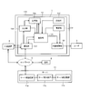
- FIG. 1 is a block diagram of an external stimulus applying apparatus according to Embodiment 1 of the present invention.
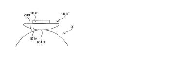
- FIG. 2 is a schematic diagram showing a state in which the user wears the external stimulus applying device.
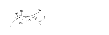
- FIG. 3A is a schematic diagram illustrating a first example of an external stimulation unit.
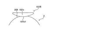
- FIG. 3B is a schematic diagram illustrating a second example of the external stimulation unit.
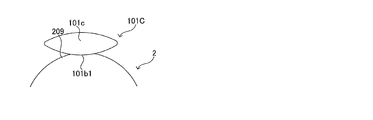
- FIG. 3C is a schematic diagram illustrating a third example of the external stimulation unit.
- FIG. 3D is a schematic diagram illustrating a fourth example of the external stimulation unit.
- FIG. 3E is a schematic diagram illustrating a fifth example of the external stimulation unit.
- FIG. 3F is a schematic diagram illustrating a sixth example of the external stimulation unit.
- FIG. 3A is a schematic diagram illustrating a first example of an external stimulation unit.
- FIG. 3B is a schematic diagram illustrating a second example of the external stimulation unit.
- FIG. 3C is a schematic diagram illustrating a third example of
- 3G is a schematic diagram illustrating a seventh example of the external stimulation unit.
- 4A is a A 1 arrow view of FIG. 3A showing a first example of the external stimulus imparting surface.
- Figure 4B is a A 2 arrow view of FIG 4A.
- 4C is a A 2 arrow view of FIG. 4A showing the first modification of the first example of an external stimulus imparting surface.
- Figure 4D is a A 2 arrow view of FIG. 4A showing a modified example 2 of the first example of an external stimulus imparting surface.
- 5A is a A 1 arrow view of FIG. 3A showing a second example of the external stimulus imparting surface.
- 5B is a A 1 arrow view of FIG. 3A showing a third example of the external stimulus imparting surface.
- FIG. 5C is a A 1 arrow view of FIG. 3A showing a fourth example of the external stimulus imparting surface.
- 5D is a A 1 arrow view of FIG. 3A showing a fifth example of the external stimulus imparting surface.
- Figure 5E is a A 1 arrow view of FIG. 3A showing a sixth example of the external stimulus imparting surface.
- FIG. 6 is a schematic diagram showing the relationship between the walking motion and the myoelectric potential of each muscle during the walking motion.
- FIG. 7 is a schematic diagram showing changes in the myoelectric potential of each muscle during the standing / sitting operation from the chair.
- FIG. 8 is a flowchart for explaining the operation of the external stimulus applying apparatus.
- FIG. 9A is a diagram illustrating an example of a diagram generated from chart data.
- FIG. 9A is a diagram illustrating an example of a diagram generated from chart data.
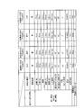
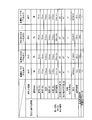
- FIG. 9B is a diagram illustrating an example of a table generated from the chart data.
- FIG. 10A is a diagram illustrating a display example 1 on the display unit of the external device.
- FIG. 10B is a diagram illustrating a display example 2 on the display unit of the external device.
- FIG. 10C is a diagram illustrating a display example 3 on the display unit of the external device.
- FIG. 10D is a diagram illustrating a display example 4 on the display unit of the external device.
- FIG. 10E is a diagram illustrating a first modification of the display example 1 illustrated in FIG. 10A.
- FIG. 11A is a diagram conceptually illustrating a data structure included in the server-side storage unit.
- FIG. 11B is a diagram conceptually illustrating a data structure included in the server-side storage unit.
- FIG. 11C is a diagram conceptually illustrating the data structure of the server-side storage unit.
- FIG. 11D is a diagram conceptually illustrating a data structure included in the server-side storage unit.
- FIG. 12 is a diagram illustrating an external stimulus applying system according to Embodiment 2 of the present invention.
- FIG. 1 is a block diagram illustrating an external stimulus applying system 1 according to the first embodiment.
- the external stimulus application system 1 includes an external stimulus application device 10 and a server 11.
- the external stimulus applying apparatus 10 applies an external stimulus to a target part (for example, the inner vastus muscle 203, see FIG. 2) of the body of the user 2 during the operation of the user 2 (see FIGS. 2, 6).
- the external stimulus applying system 1 includes an external stimulus applying device 10 that applies a vibration stimulus as an external stimulus.
- the external stimulus application system 1 is an alternative to an electrical stimulus application device (electric stimulation unit) or an electrode unit (not shown) that contracts muscles by applying electrical stimulation as an external stimulus to a target part of the body of the user 2. Or it can additionally have.
- the external stimulus applying device 10 may be read as a vibration stimulus applying device.
- the external stimulus application device 10 can be appropriately read as an electrical stimulus application device or an electrode unit.
- the external stimulus can be appropriately read as a vibration stimulus or an electrical stimulus.
- Such an external stimulus applying device 10 includes an external stimulus unit 101, a detection unit 102, a control unit 103, a communication unit 104, a storage unit 105, an input unit 106, a power supply unit 107, and a mounting unit 108.
- the external stimulation unit 101 gives external stimulation to the target part of the body of the user 2 under the control of the control unit 103 described later.
- the external stimulation unit 101 is held by a mounting unit 108 described later.
- the external stimulation unit 101 is arranged in direct or indirect contact with the surface of the target site of the user 2 (hereinafter referred to as “external stimulus applying surface”).
- FIGS. 3A to 3G are diagrams showing specific examples of the external stimulation unit.
- the external stimulation units 101A to 101G shown in FIGS. 3A to 3G will be described in order.
- FIG. 3A is a schematic diagram illustrating a first example of an external stimulation unit.
- An external stimulation unit 101A shown in FIG. 3A includes a housing 101a having a shape along the external stimulus application surface 209 of the user 2.
- An eccentric motor (not shown) is accommodated in the housing 101a. Therefore, in this example, the external stimulus is a vibration stimulus.
- the first example of the external stimulation unit of this example may be regarded as the first example of the vibration stimulation unit.
- external stimulation can also be made into electrical stimulation by providing an electrode part, employ
- Such a housing 101a has an external stimulus applying surface 101a1 on one side surface (in other words, a surface facing the external stimulus applying surface 209).
- the external stimulus application surface 101a1 is a concave curved surface along the external stimulus application surface 209.
- the shape of the external stimulus applying surface 101a1 is not limited to the illustrated case.
- the size, curvature, and the like of the external stimulus application surface 101a1 may be appropriately determined according to the shape of the external stimulus application surface 209.
- the other side surface of the housing 101a (in other words, the surface facing the external stimulus application surface 101a1) is a convex curved surface having the same curvature as the external stimulus application surface 101a1.
- the shape of the other side surface of the housing 101a is not limited to the case of this example.
- FIG. 3B is a schematic diagram illustrating a second example of the external stimulation unit.
- the external stimulation unit 101B illustrated in FIG. 3B includes a housing 101b.
- An eccentric motor (not shown) is accommodated in the housing 101b.
- the housing 101b has an external stimulus applying surface 101b1 on one side surface (in other words, a surface facing the external stimulus applying surface 209).
- the external stimulus application surface 101b1 is a convex curved surface that is convex toward the external stimulus application surface 209.
- the shape of the external stimulus applying surface 101b1 is not limited to the illustrated case. The size, curvature, and the like of the external stimulus application surface 101b1 may be appropriately determined according to the shape of the external stimulus application surface 209.
- the other side surface of the housing 101b (in other words, the surface facing the external stimulus applying surface 101b1) is a flat surface.
- the shape of the other side surface of the housing 101b is not limited to this example.
- FIG. 3C is a schematic diagram illustrating a third example of the external stimulation unit.
- the external stimulation unit 101C shown in FIG. 3C is different from the external stimulation unit 101B shown in FIG. 3B in the shape of the other side surface of the housing 101c (in other words, the surface facing the external stimulation application surface 101b1).
- the external stimulus applying surface 101b1 is a convex curved surface, the external stimulus can be accurately transmitted to the target site.
- FIG. 3D is a schematic diagram illustrating a fourth example of the external stimulation unit.
- the external stimulation unit 101D illustrated in FIG. 3D includes a housing 101d.
- the housing 101d has a first housing element 1011d, a second housing element 1012d, and a third housing element 1013d.
- the first housing element 1011d is disposed at the center of the housing 101d.
- the first housing element 1011d has a substantially rectangular box shape.
- Such a first housing element 1011d has an external stimulus applying surface 101d1 on one side surface (a surface facing the external stimulus applying surface 209).
- the external stimulus applying surface 101d1 is a flat surface.
- the shape of the external stimulus applying surface 101d1 is not limited to the illustrated case.
- the external stimulus application surface 101d1 may be a concave curved surface that extends along the external stimulus application surface 209 or a convex curved surface that is convex toward the external stimulus application surface 209.
- the other side surface of the first housing element 1011d (in other words, the surface facing the external stimulus applying surface 101d1) is a flat surface.
- the shape of the other side surface of the external stimulus imparting surface 101d1 is not limited to the illustrated case.
- the second housing element 1012d and the third housing element 1013d each have a substantially rectangular box shape.
- the second housing element 1012d and the third housing element 1013d are arranged with the first housing element 1011d interposed therebetween.
- Each of the second housing element 1012d and the third housing element 1013d has an external stimulus applying surface 101d2 and an external stimulus applying surface 101d3 on one side surface (a surface facing the external stimulus applying surface 209).
- the external stimulus applying surface 101d2 and the external stimulus applying surface 101d3 are flat surfaces.
- the shapes of the external stimulus applying surface 101d2 and the external stimulus applying surface 101d3 are not limited to the illustrated case.
- the external stimulus imparting surface 101d2 and the external stimulus imparting surface 101d3 may be concave curved surfaces along the external stimulus imparting surface 209 or convex curved surfaces that are convex toward the external stimulus imparting surface 209.
- the other side surfaces of the second housing element 1012d and the third housing element 1013d are flat surfaces.
- the shape of the other side surface of the second housing element 1012d and the third housing element 1013d is not limited to the illustrated case.
- the first housing element 1011d and the second housing element 1012d are connected by a first joint portion 1014d that enables relative swinging between the first housing element 1011d and the second housing element 1012d.
- the first housing element 1011d and the third housing element 1013d are connected by a second joint portion 1015d that enables relative swinging between the first housing element 1011d and the third housing element 1013d.
- An eccentric motor (not shown) is housed in each of the first housing element 1011d, the second housing element 1012d, and the third housing element 1013d.
- the external stimulus is adjusted in accordance with the shape of the external stimulus application surface 209.
- the shape of the part 101C can be adjusted.
- FIG. 3E is a schematic diagram illustrating a fifth example of the external stimulation unit.
- An external stimulation unit 101E shown in FIG. 3E includes a housing 101e and an external stimulation transmission member 101m.
- Such a housing 101e is flat on one side and the other side.
- the shape of the housing 101e is not limited to the illustrated case.
- An eccentric motor (not shown) is accommodated in the housing 101e.
- the external stimulus transmission member 101m is disposed between the housing 101e and the external stimulus applying surface 209 of the user 2, and transmits the external stimulus of the housing 101e to the external stimulus applying surface 209.
- Such an external stimulus transmission member 101m has a shape along the external stimulus application surface 209.
- the external stimulus transmission member 101m has an external stimulus application surface 101e1 on one side surface (in other words, the surface facing the external stimulus application surface 209).
- the external stimulus application surface 101e1 is a concave curved surface along the external stimulus application surface 209.
- the shape of the external stimulus applying surface 101e1 is not limited to the illustrated case.
- the size, curvature, and the like of the external stimulus application surface 101e1 may be appropriately determined according to the shape of the external stimulus application surface 209.
- the other side surface of the external stimulus transmission member 101m (in other words, the surface facing the external stimulus application surface 101e1) is a convex curved surface having the same curvature as the external stimulus application surface 101e1.
- a housing 101e is fixed to the other side surface of the external stimulus transmission member 101m.
- the method for fixing the housing 101e and the external stimulus transmission member 101m is not particularly limited.
- the housing 101e and the external stimulus transmission member 101m may be fixed by various methods such as a fitting type, a screwing type, and a button type. If the external stimulus of the housing 101e can be transmitted to the external stimulus transmission member 101m in a state where the housing 101e and the external stimulus transmission member 101m are held by the mounting portion 108 (see FIG. 2), the housing 101e and the external stimulus transmission member 101m The stimulus transmission member 101m may not be fixed.
- the external stimulus transmission member 101m may be provided in the mounting portion 108.
- the external stimulus transmission member 101m shown in FIG. 3E may be provided in a holding portion (for example, a pocket) of the mounting portion 108 for holding the housing 101e.
- the external stimulus application surface 101e1 is provided on the inner surface of the holding unit of the mounting unit 108 (the surface facing the external stimulus application surface 209).
- the surface pressure on the external stimulus applying surface 101e1 can be lowered. Therefore, the user 2 can use comfortably without feeling uncomfortable.
- FIG. 3F is a schematic diagram illustrating a sixth example of the external stimulation unit.
- An external stimulation unit 101F illustrated in FIG. 3F includes a housing 101f and an external stimulation transmission member 101n.
- An eccentric motor (not shown) is accommodated in the housing 101f.
- the housing 101f is the same as in the case of the fifth example described above.
- the external stimulus transmission member 101n is disposed between the housing 101f and the external stimulus applying surface 209 of the user 2, and transmits the external stimulus of the housing 101f to the external stimulus applying surface 209.
- the external stimulus transmission member 101n has an external stimulus application surface 101f1 on one side surface (in other words, the surface facing the external stimulus application surface 209).
- the external stimulus applying surface 101f1 is a convex curved surface that is convex toward the external stimulus applying surface 209.
- the shape of the external stimulus applying surface 101f1 is not limited to the illustrated case. The size, curvature, and the like of the external stimulus application surface 101f1 may be appropriately determined according to the shape of the external stimulus application surface 209.
- the other side surface of the external stimulus transmission member 101n (in other words, the surface facing the external stimulus application surface 101f1) is a flat surface.
- the shape of the other side surface of the external stimulus transmission member 101n is not limited to this example.
- the external stimulus applying surface 101f1 is a convex curved surface, the external stimulus can be accurately transmitted to the target site.
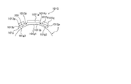
- FIG. 3G is a schematic diagram illustrating a seventh example of the external stimulation unit.
- An external stimulation unit 101G illustrated in FIG. 3G includes a housing 101g and an external stimulation transmission member 101p.
- the housing 101g has a first housing element 1011g, a second housing element 1012g, and a third housing element 1013g.
- the first housing element 1011g, the second housing element 1012g, and the third housing element 1013g each have a substantially rectangular box shape.
- One side surface and the other side surface of the first housing element 1011g, the second housing element 1012g, and the third housing element 1013g are flat surfaces.
- An eccentric motor (not shown) is accommodated in each of the first housing element 1011g, the second housing element 1012g, and the third housing element 1013g.
- the shapes of the first housing element 1011g, the second housing element 1012g, and the third housing element 1013g are not limited to the illustrated case.
- the external stimulus transmission member 101p has a first element 1011p, a second element 1012p, and a third element 1013p.
- the first element 1011p is arranged at the center of the external stimulus transmission member 101p.
- the first element 1011P has a substantially rectangular plate shape.
- Such a first element 1011p has an external stimulus application surface 101g1 on one side surface (a surface facing the external stimulus application surface 209).
- the external stimulus imparting surface 101g1 is a flat surface.
- the shape of the external stimulus applying surface 101g1 is not limited to the illustrated case.
- the external stimulus applying surface 101g1 may be a concave curved surface that extends along the external stimulus applying surface 209 or a convex curved surface that is convex toward the external stimulus applying surface 209.
- the other side of the first element 1011p (in other words, the surface facing the external stimulus applying surface 101g1) is a flat surface.
- a first housing element 1011g is fixed to the other side surface of the first element 1011p.
- the shape of the other side surface of the external stimulus applying surface 101g1 is not limited to the illustrated case.
- Each of the second element 1012p and the third element 1013p has a substantially rectangular box shape.
- the 2nd element 1012p and the 3rd element 1013p are arrange
- Each of the second element 1012p and the third element 1013p has an external stimulus applying surface 101g2 and an external stimulus applying surface 101g3 on one side surface (the surface facing the external stimulus applying surface 209).
- the external stimulus applying surface 101g2 and the external stimulus applying surface 101g3 are flat surfaces.
- the shapes of the external stimulus applying surface 101g2 and the external stimulus applying surface 101g3 are not limited to the illustrated case.
- the external stimulus imparting surface 101g2 and the external stimulus imparting surface 101g3 may be concave curved surfaces along the external stimulus imparting surface 209 or convex curved surfaces that are convex toward the external stimulus imparting surface 209.
- the other side surfaces of the second element 1012p and the third element 1013p are flat surfaces.
- a second housing element 1012g and a third housing element 1013g are fixed to the other sides of the second element 1012p and the third element 1013p, respectively.
- the shape of the other side surface of the external stimulus applying surface 101g2 and the external stimulus applying surface 101g3 is not limited to the illustrated case.
- the first element 1011p and the second element 1012p are connected by a first joint portion 1014p that enables relative swinging between the first element 1011p and the second element 1012p.
- the first element 1011p and the third element 1013p are connected by a second joint portion 1015p that enables relative swinging between the first element 1011p and the third element 1013p.
- the second element 1012p and the third element 1013p are supported so as to be swingable with respect to the first element 1011p, according to the shape of the external stimulus application surface 209, The shape can be adjusted.
- the external stimulation unit 101 has an external stimulus application surface that faces the external stimulus application surface in use.
- the external stimulus application surface may be configured by a part of the external stimulus unit 101.
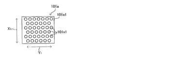
- FIGS. 4A to 4D and FIGS. 5A to 5E are diagrams showing some examples of the external stimulus applying surface 101a1. Note that the configuration of the external stimulus applying surface 101a1 shown in FIGS. 4A to 4D and FIGS. 5A to 5E can be applied to each of the external stimulus units 101 and 101A to 101G described above.
- FIG. 4A is a A 1 arrow view of FIG. 3A.
- Figure 4B is a A 2 arrow view of FIG 4A.
- the external stimulus applying surface 101a1 of the housing 101a has a rectangular shape in the state shown in FIG. 4A.
- the external stimulus applying surface 101a1 has a plurality of convex portions 101x1.
- the convex portion 101x1, the first direction (direction of arrow X 1 in FIG. 4A), and, in a second direction perpendicular to the first direction (the direction of arrow Y 1 in FIG. 4A), at regular intervals Has been placed.
- the housing 101a may be curved as in Modification 1 and Modification 2 shown in FIGS. 4C and 4D.
- FIG. 5A corresponds to FIG. 4A.
- the convex portions 101x1 are staggered over the entire surface of the external stimulus application surface 101a1.
- FIG. 5B corresponds to FIG. 4A.
- the convex portions 101x1 are staggered.
- a predetermined range including the central portion in the (vertical arrow X 1 in FIG. 5B) a first direction are provided with a flat surface portion 101y1 where the convex portion 101x1 is not formed.
- FIG. 5C corresponds to FIG. 4A.
- the convex portions 101x1 are staggered.
- the second direction by a predetermined range (a range of about 1/3 of the total length of the second direction) including a central portion in the (direction of arrow Y 1 in FIG. 5C)
- the flat surface portion 101y2 is not formed with the convex portion 101x1.
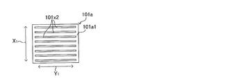
- FIG. 5D corresponds to FIG. 4A.
- protrusions 101x2 is a convex extending in the second direction (direction of arrow Y 1 in FIG. 5D).
- Such protrusions 101x2 are arranged at equal intervals in a first direction (direction of arrow X 1 in FIG. 5D).
- the first direction is a direction in which the external stimulus application surface 101a1 is likely to be displaced with respect to the external stimulus application surface 209 (for example, the vertical direction in the use state).
- FIG. 5E corresponds to FIG. 4A.
- the convex portion 101x3 is, (in other words, zigzag) zigzag shape extending in a second direction (direction of arrow Y 1 in FIG. 5E) which is convex in .
- Such protrusions 101x3 are arranged at equal intervals in a first direction (direction of arrow X 11 in FIG. 5E).
- the first direction is a direction in which the external stimulus applying surface 101a1 is likely to be displaced with respect to the external stimulus applying surface 209 (for example, the vertical direction in the use state).
- the shape of the convex portion provided on the external stimulus application surface is not limited to the case of the first to sixth examples.
- the structure in which the convex portion is provided on the external stimulus applying surface 101a1 as described above can selectively apply the external stimulus to the external stimulus applying surface 209, and the external stimulus applying surface 101a1 and the external stimulus applying surface 209.
- the air permeability between can be improved.
- the external stimulation unit 101 as described above is disposed at a position including the central portion of the external stimulus application surface.
- the number of external stimulating units 101 may be singular or plural.
- the external stimulation units 101 may be distributed and arranged on the external stimulus application surface of one target site.
- each external stimulation unit 101 may be arranged on an external stimulus application surface of a different target part.
- each external stimulation unit 101 is preferably arranged at a position where the external stimulations do not weaken each other. Further, when there are a plurality of external stimulation units 101, it is preferable that each external stimulation unit 101 is arranged at a position where external stimulations (for example, vibrations) strengthen each other.
- each external stimulation unit 101 is disposed at a position where external stimulations (for example, vibrations) of each other strengthen each other in the target site. More preferably, each external stimulation unit 101 is preferably disposed at a position where external stimulations (for example, vibrations) mutually strengthen at the center of the target site.
- Such a configuration can amplify an external stimulus (for example, vibration) at the target site while keeping the stimulus to the external stimulus application surface (that is, the skin surface) small.
- the external stimulation units 101 are arranged at positions where external stimulations (for example, vibrations) mutually strengthen at the center of the target site.
- the external stimulation unit 101 may be held by the mounting unit 108 in a state where the external stimulation unit 101 can be adjusted. Further, the external stimulation unit 101 may be removable from the mounting unit 108.
- the external stimulation unit 101 may not be held by the mounting unit 108.
- the connection between the external stimulation unit 101 and the control unit 103 may be wired or wireless.
- the external stimulation unit 101 has an external stimulus application surface that faces the external stimulus application surface in use.
- the external stimulus application surface may be configured by a part of the external stimulus unit 101.
- the external stimulus application surface may be configured by a surface of another member fixed to the external stimulus unit 101.
- the other member is a member capable of transmitting the external stimulus generated by the external stimulus unit 101 to the external stimulus application surface.
- the external stimulus application surface may be a curved surface, for example.
- the external stimulus application surface may be a curved surface that is convex toward the external stimulus application surface.
- Such a configuration makes it easier for external stimuli to be transmitted to the user 2 during use.
- Such a configuration is also effective in reducing the discomfort of the user 2 during use.
- the external stimulus application surface may be a curved surface along the external stimulus application surface.
- the contact area between the external stimulus application surface and the external stimulus application surface increases.
- external stimuli are transmitted from the external stimulating unit 101 to the external stimulus imparting surface in a multifaceted manner.
- the external stimulus imparting surface may be a flat surface or an uneven surface having a concave portion and a convex portion. Regardless of the shape described above, it is preferable that the external stimulus imparting surface does not have a pointed portion (in other words, a corner) on the outer peripheral edge. Such a configuration is effective in reducing discomfort of the user 2 during use.
- the external stimulation unit 101 as described above is a vibrator and includes, for example, a housing (see FIGS. 3A to 3G) and an eccentric motor (not shown).
- the housing has, for example, the accommodation space and the external stimulus application surface described above in a part of the outer surface.
- the housing is a rectangular parallelepiped box-shaped member.
- the housing may be a disk-shaped box-shaped member.
- the housing may have the above-described external stimulus application surface.
- it is good also as a structure which fixes an external stimulus provision surface to a housing so that replacement
- the material of the housing is preferably a material that does not absorb vibration generated by an eccentric motor, for example. Further, the material of the housing is preferably a material that is difficult to dissipate by converting vibration energy into heat energy.
- the housing material include synthetic resins such as polyolefins such as acrylonitrile-butadiene-styrene (ABS) copolymer, polyethylene (PE), and polypropylene (PP).
- ABS acrylonitrile-butadiene-styrene
- PE polyethylene
- PP polypropylene
- the material of the housing is not limited to the above materials.
- the material of the housing may be a metal.
- the metal material is preferably a metal with excellent biocompatibility.
- examples of the metal material include various metal materials other than titanium (such as iron-based alloys and aluminum alloys).
- the eccentric motor is composed of, for example, a DC motor and a weight having a bias in the center of gravity.
- the weight is fixed to the rotating shaft of the DC motor.
- the operation of such a DC motor is controlled by the control unit 103 described later.
- the external stimulation unit 101 can employ various types of conventionally known vibrators.
- the size of the external stimulation unit 101 (specifically, the housing) is not particularly limited.
- the size of the external stimulation unit 101 is preferably a size that does not hinder the operation of the user 2.
- the size of the external stimulation unit 101 is appropriately determined according to the size of the target part (in other words, the area of the external stimulus application surface).
- the electrode part is provided with an electrode base material (not shown) formed by weaving metal yarns, a gel-like adhesive layer provided on the surface of the electrode base material and capable of being energized,
- the electrode unit is not limited to the above-described configuration, and may be any configuration that can apply electrical stimulation to muscles.
- the shape of the external stimulation unit 101 is, for example, a rectangular parallelepiped having a vertical dimension of 40 mm, a horizontal dimension of 60 mm, and a height dimension of 30 mm.
- the external stimulation unit 101 has an external stimulus application surface on the surface that contacts the user 2 during use.
- the target part of the body of the user 2 will be described.
- Examples of the target part of the user 2's body include the chest muscles, abdominal muscles, back muscles, shoulder muscles, arm muscles, leg muscles, and buttocks muscles of the user 2.
- the pectoral muscle is an example of the chest muscle.
- abdominal muscles include rectus abdominis, external abdominal oblique muscle, internal abdominal oblique muscle, and intestinal psoas muscle.
- Back muscles include, for example, the spine upright, latissimus dorsi, great circular, small circular, and subspinous.
- shoulder muscles include deltoid and trapezius.
- Examples of arm muscles include biceps and triceps.
- Examples of leg muscles include quadriceps femoris (stratus thigh, middle vastus, medial vastus, lateral vastus), and hamstrings (biceps femoris, semitendonoid, semimembranous).
- Examples of the gluteal muscle include the small gluteal muscle, the middle gluteal muscle, and the greater gluteal muscle.
- the detection unit 102 detects a change in the body of the user 2 during the operation of the user 2. For example, during the operation of the user 2, the detection unit 102 detects a change in a part (for example, knee) that changes in correspondence with a target part of the user 2 (for example, the inner vastus muscle 203, see FIG. 2). Detect as. Then, the detection unit 102 sends the detected physical quantity to the control unit 103 described later. The detection unit 102 detects the physical quantity at a predetermined interval and sends the detected physical quantity to the control unit 103.
- a part for example, knee
- a target part of the user 2 for example, the inner vastus muscle 203, see FIG. 2
- Examples of the physical quantity described above include displacement, time, angle, angular velocity, speed, acceleration, current, voltage (for example, myoelectric potential), and pressure.
- Such a physical quantity is detected by a sensor corresponding to the physical quantity to be detected.
- Such a detection value of the detection unit 102 is information used to determine the timing at which the control unit 103 controls the external stimulation unit 101 (that is, switches on / off the vibration of the external stimulation unit 101) (hereinafter, “First information during operation").
- the detection unit 102 may detect information related to the user 2 other than the first information during operation (hereinafter referred to as “second information during operation”).
- second information during operation information on the body temperature, blood pressure, heart rate, fat mass, and muscle mass during the operation of the user 2 can be mentioned.
- the second information during the operation includes information corresponding to the operation of the user 2 (that is, the type of exercise).
- the information corresponding to the motion when the motion of the user 2 is walking including running
- the number of steps, the step length, the walking cycle, the walking speed, the acceleration in other words, the rate of change of the walking speed
- the knee extension angle Information on knee adduction angle (twist angle) and leg muscle strength information related to the user 2 other than the first information during operation.
- the second information may include a wearing time during which the user 2 is wearing the external stimulus applying device 10.
- the first information during operation and the second information during operation may be used in common.
- the angles, angular velocities, speeds, accelerations, voltages, and the like exemplified in the first information during operation can be used as indices (such as the degree of knee bending (angle) or walking speed) when measuring the rehabilitation effect.
- the right stride, walking cycle, acceleration, extension angle, etc. of the left and right feet may differ due to the injury, so each left and right foot has a detection unit 102. May be.
- the detection unit 102 may detect a bending or extension angle of a joint such as a knee (maximum movable range of the joint) as the second information based on the control of the control unit 103 or based on an operation by the user 2. Such detection by the detection unit 102 may be performed once a day or once before and after rehabilitation, for example. Such detection by the detection unit 102 is performed in a state where the detection unit 102 has not detected the first information during operation.
- the detection unit 102 may detect the muscular strength of the target site of the user 2 (for example, the inner vastus muscle) as the second information based on the control of the control unit 103 or based on the operation by the user 2. Such detection by the detection unit 102 may be performed once a day or once before and after rehabilitation, for example. Such detection by the detection unit 102 is performed in a state where the detection unit 102 has not detected the first information during operation.
- the detection unit 102 may detect information around the user 2 (hereinafter referred to as “third information during operation”) during the operation of the user 2.
- the third information during operation includes, for example, temperature, humidity, atmospheric pressure, altitude, position information (GPS: Grobal Positioning System).
- Such a detection unit 102 is, for example, a sensor such as an angle sensor, an angular velocity sensor, an acceleration sensor, or a myoelectric potential sensor.
- the detection unit 102 is not limited to the above-described sensors.
- the detection unit 102 may include a sensor for detecting the second information during the operation described above.
- a sensor is, for example, a body temperature sensor, a blood pressure sensor, a heart rate sensor, or a step number sensor.
- the detection unit 102 may include a sensor for detecting the third information during the above-described operation.
- a sensor is, for example, an air temperature sensor, an atmospheric pressure sensor, a GPS sensor, or the like.
- Examples of the timing for detecting the first information, the second information, or the third information during movement by the various sensors described above include, for example, each movement during walking, that is, the timing of landing, the timing when the knee is fully extended, Can be arbitrarily detected according to the purpose, such as the timing at which the vehicle leaves the ground, the intermediate timing of the time until the vehicle leaves the ground, or the timing after 0.1 second from the landing.
- a timing for detecting various types of information may be set at the same timing as the above-described walking motion.
- the detection unit 102 may transmit and store all data to the server 11 described later, or transmit an average value for an arbitrarily set period to the server 11. And save it.
- the detection unit 102 may transmit and store data for each unit time such as every minute or every hour to the server. With respect to these acquired data, all or a part of the acquired data is stored in a storage unit inside the external stimulus applying device 10 or an external storage device (such as a server).
- the measurement frequency of fat mass or muscle mass may be low.
- the measurement frequency of acceleration and change in angle be as high as minutes.
- the data may be acquired and stored in minutes, hours, or days, depending on the purpose of use.
- Data obtained in this way can be used, for example, to verify the effects of rehabilitation and treatment, and to provide indicators for rehabilitation, indicators for doctor visits, indicators for medication, or sports It can be used as an index of the effect of strength training.
- the acquired data can also be used as an index when adjusting, producing, or selecting a device such as an insole or a joint supporter.
- the detection unit 102 is connected to the control unit 103.
- the connection between the detection unit 102 and the control unit 103 may be wired or wireless.
- the detection unit 102 is held by a mounting unit 108 described later.
- the detection unit 102 is arranged in a part of the body of the user 2 (hereinafter referred to as “detected part”) that changes in correspondence with the target part during the operation of the user 2.
- the detected part may be the same part as the target part in the user 2 or may be a different part.
- the detection unit 102 When the detection unit 102 is affected by an external stimulus (for example, vibration) generated by the external stimulation unit 101 in the wearing state, the detection unit 102 is preferably arranged at a position that is not easily affected.
- the detection unit 102 when the target site is the inner vastus muscle 203 (see FIG. 2) of the user 2, the detection unit 102 is at least 90 degrees to 180 degrees from the inner vastus muscle in the direction along the outer periphery of the knee of the user 2. It is preferably arranged at a position shifted by 120 to 180 degrees.
- the detection unit 102 may be arranged on the lower leg of the user 2.
- the position of the detection unit 102 is a part that changes (in other words, activates) in accordance with the movement of the target part, and is hardly affected by an external stimulus (for example, vibration) generated by the external stimulus part 101. It is preferable to arrange it at a position.
- the detection unit 102 when the target part is the lower leg of the user 2, the detection unit 102 is preferably arranged on the thigh of the user 2. In addition, when the target site is the muscle of the upper arm portion of the user 2, the detection unit 102 is preferably disposed on the forearm portion of the user 2. In addition, when the target site is the muscle of the back of the user 2, the detection unit 102 is preferably disposed on the thigh of the user 2. In addition, when the target site is the muscle of the buttocks of the user 2, the detection unit 102 is preferably arranged on the thigh of the user 2. Further, when the target site is the muscle of the shoulder portion of the user 2, it is preferable that the detection unit 102 is disposed on the upper arm portion of the user 2.
- the detection unit 102 may be covered with a vibration proof member having a vibration proof property. Each of such configurations is effective in reducing erroneous detection in the detection unit 102.
- the detection unit 102 detects the amount of joint displacement due to joint extension, bending, rotation, or the like.
- FIG. 2 shows the external stimulus applying device 10 when the detected part is the knee of the user 2 and the target part is the inner vastus muscle 203 of the leg of the user 2.
- the knee joint and a portion around the knee joint may be included.
- the detection unit 102 includes a first sensor 102a and a second sensor 102b.
- the first sensor 102a is, for example, an acceleration sensor, and is disposed on the thigh 204 of the user 2 in the wearing state.
- the external stimulus is a vibration stimulus
- the first sensor 102a is preferably held by the mounting portion 108 in a state of being covered with the vibration isolating member 12.
- the reason for providing the vibration isolation member 12 is that both the external stimulation unit 101 and the first sensor 102a are disposed on the thigh 204.
- the anti-vibration member 12 makes it difficult to transmit the vibration of the external stimulation unit 101 to the first sensor 102a when the external stimulation is a vibration stimulation. This configuration is effective in improving the detection accuracy of the first sensor 102a. Note that the vibration isolation member 12 may be omitted.
- the second sensor 102b is an acceleration sensor, and is disposed on the lower leg 205 of the user 2 in the wearing state.
- the second sensor 102b is not covered with a vibration isolating member. This is because the external sensor 101 is disposed on the thigh 204 while the second sensor 102b is disposed on the crus 205. Note that the second sensor 102b may be held by the mounting portion 108 in a state of being covered with the vibration isolating member.
- the first sensor 102a and the second sensor 102b detect accelerations in a predetermined direction in the thigh 204 and the crus 205, respectively, while the user 2 is moving.
- the predetermined directions are, for example, three directions (X direction, Y direction, and Z direction orthogonal to each other) (see FIG. 2).
- the X direction coincides with the front-rear direction (the left-right direction in FIG. 2) of the user 2.
- the Y direction coincides with the left / right direction of the user 2 (perpendicular to the plane of FIG. 2).
- the Z direction coincides with the vertical direction (vertical direction in FIG. 2).
- One side in each of the above directions (for example, the front side, the right side, and the upper side) is defined as a positive direction.
- the other side in each of the above directions (for example, the rear side, the left side, and the lower side) is defined as a negative direction.
- the foot 20 of the user 2 shown in FIG. 2 is the right foot of the user 2.
- the detection unit 102 may include, for example, a third sensor 102c that is an angle sensor together with the first sensor 102a and the second sensor 102b.
- the third sensor 102 c is arranged so as to be bridged from the thigh 204 of the user 2 to the crus 205.
- the third sensor 102c detects the angle of the knee joint of the user 2 (that is, the angle formed by the thigh 204 and the crus 205) during the operation of the user 2.
- the detection unit 102 may include a third sensor 102c that is an angle sensor together with the first sensor 102a and the second sensor 102b.
- the third sensor 102c is arranged so as to be bridged from the upper arm part of the user 2 to the forearm part.
- part is the muscle of the user's 2 arm.
- the control unit 103 includes a central processing unit (CPU), a read only memory (ROM), a random access memory (RAM), an input port, and an output port.
- CPU central processing unit
- ROM read only memory
- RAM random access memory
- the control unit 103 can turn on / off external stimulation (for example, vibration) of the external stimulation unit 101 under specific conditions. Specifically, when the external stimulus is a vibration stimulus, when the detection value (physical quantity) received from the detection unit 102 satisfies a predetermined condition, the external stimulus unit 101 is vibrated under a predetermined vibration condition. More specifically, the control unit 103 compares the detection value received from the detection unit 102 with a predetermined threshold, and when the comparison result satisfies the vibration start condition (that is, the predetermined condition), The external stimulation unit 101 is vibrated.
- the control part 103 can turn ON / OFF the output of the electric current by an electrical stimulation part on predetermined conditions.
- the control unit 103 controls the output of the pulse current supplied from the power supply unit (not shown) to the pulse generation unit (electrode unit, not shown).
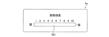
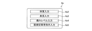
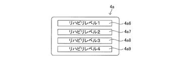
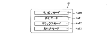
- the display unit 4a displays information indicating muscles to which electrical stimulation is applied, the intensity of electrical stimulation, or pulses (frequency, amplitude, waveform, stimulation application pattern, etc.).
- Such a control part 103 and the display part 4a receive supply of electric power from the said power supply part.
- the storage unit 105 stores a program for controlling the current output mode of the electrode unit.
- the pulse generation unit (electrode unit) outputs a low frequency signal of 2 Hz to 100 Hz, preferably 2 to 40 Hz, to the control device. Moreover, ON / OFF of the power supply of a control part may be switched by the switch of an operation part.
- Such an operation unit may include a switch and a dial for performing various settings. It may be possible to select a plurality of electrical stimulation modes by operating the operation unit.
- control unit 103 determines that the external stimulus start condition is satisfied when the detection value of the detection unit 102 is equal to or greater than a predetermined threshold. On the other hand, the control unit 103 determines that the external stimulus start condition is not satisfied when the detection value of the detection unit 102 is smaller than a predetermined threshold value.
- the control unit 103 may set the stimulation time of the external stimulation unit 101 (for example, the duration of vibration and the duration of current flowing through the electrode). In this case, the control unit 103 stops the operation of the external stimulation unit 101 when the stimulation time has elapsed.
- the predetermined threshold value a value corresponding to the target part, the part to be detected, and the physical quantity detected by the detection unit 102 is stored in advance in the ROM of the control unit 103 or the like.
- the control unit 103 compares the received detection value with a stored predetermined threshold value.
- the predetermined threshold when the target part is the muscle of the user 2 will be described.
- the threshold value in this case is a value with which the control unit 103 can determine the contracted state of the target part.
- the contracted state of the target part is also a state in which myoelectricity is exhibited in the target part.
- the predetermined threshold may be a value that allows the control unit 103 to determine a state that is a predetermined time before myoelectricity is exerted in the target region.
- the control unit 103 When the user's action (for example, walking or running action) is a repetitive action in which the predetermined action is repeated, the control unit 103 operates (for example, vibrates) the external stimulator 101 in the previous predetermined action in the repetitive action.
- E) Timing may be stored.
- the control unit 103 may store the timing in the storage unit 105. And the control part 103 may determine the timing which operates the external stimulation part 101 based on the said timing.
- the control unit 103 sets the threshold by specifying the timing at which the user's 2 foot touches the ground from the change in the detected value of the acceleration sensor during walking. And based on this threshold value, the control part 103 determines the moment of landing in the walking motion of the user 2, immediately before landing, and immediately after landing.
- control unit 103 sets a threshold value by specifying the timing when the user's 2 foot touches the ground from the previous walking motion. Thereby, the control unit 103 can determine a more accurate landing moment, immediately before landing, and immediately after landing in the walking motion of the user 2.
- control unit 103 When the control unit 103 receives detection values from a plurality of detection units (for example, an acceleration sensor and an angle sensor), the control unit 103 operates the external stimulation unit 101 when at least one detection value satisfies the external stimulus start condition. (For example, vibration) may be used.
- a plurality of detection units for example, an acceleration sensor and an angle sensor
- control unit 103 when the control unit 103 receives detection values from a plurality of detection units, the control unit 103 externally only when all the detection values satisfy the external stimulus start condition.
- the stimulation unit 101 may be operated (for example, vibrated).
- the control unit 103 compares the detection value received from the detection unit 102 with a predetermined threshold value, and stops the operation of the external stimulation unit 101 when the comparison result satisfies the end condition.
- the control unit 103 may remove a signal based on an external stimulus (for example, vibration) generated by the external stimulus unit 101 from the detection value received from the detection unit 102 when performing each determination described above.
- an external stimulus for example, vibration
- a method of removing such a signal for example, a method of performing filtering processing on a detection value received from the detection unit 102 by a filter (for example, a bandpass filter) that removes a predetermined frequency (cutoff frequency) can be given. It is done.
- the frequency of the external stimulus (for example, vibration) generated by the external stimulus unit 101 is set by the control unit 103 and thus known.
- the control unit 103 may set the same frequency as the external stimulation frequency set in the external stimulation unit 101 as the cutoff frequency of the filter. At this time, the control unit 103 may consider the time until an external stimulus (for example, vibration) generated by the external stimulation unit 101 is detected by the detection unit 102 as a delay time in the above filtering process.
- the control unit 103 sets an external stimulation condition in the external stimulation unit 101.
- the external stimulus condition may include, for example, at least one of vibration time, amplitude, vibration frequency, and vibration pattern.
- the control unit 103 acquires an external stimulus condition from the storage unit 105, the server 11, or the external device 4.
- the amplitude under the external stimulus condition is, for example, 0.05 mm to 5 mm.
- the amplitude is 0.1 mm to 1 mm.
- the vibration frequency is, for example, 0.5 Hz to 1000 Hz. Such a vibration stimulus having an amplitude and a vibration frequency can improve the rehabilitation effect.
- the frequency in the external stimulus condition is, for example, 2 Hz to 100 Hz, preferably 2 Hz to 40 Hz.
- the electrical stimulation may be a pulse wave or a burst wave having an electrical signal divided into a plurality.
- control unit 103 receives information (for example, information on vibration intensity or vibration mode) input from the display unit 4a of the external device 4 from the external device 4.
- the control unit 103 sets the information received from the external device 4 in the external stimulation unit 101.
- the control unit 103 acquires external stimulus conditions (for example, vibration conditions) corresponding to these pieces of information from the storage unit 105 when user information and information related to user actions are input from the input unit 106 described later.
- the control unit 103 sets the acquired external stimulation condition in the external stimulation unit 101.
- Information on the user's motion includes information on the type of exercise performed by the user or the intensity of the exercise.
- control unit 103 may acquire an external stimulus condition (for example, a vibration condition) corresponding to the user information input from the input unit 106 and the information related to the user's operation from the server 11. Then, the control unit 103 sets the acquired external stimulation condition in the external stimulation unit 101.
- an external stimulus condition for example, a vibration condition
- the control unit 103 sends the user information, information about the user's operation, and external stimulation conditions of the external stimulation given to the target site of the user by the external stimulation unit 101 to the storage unit 105 for each user.
- the control unit 103 generates, for example, chart data (see FIGS. 9A and 9B) for confirming the rehabilitation effect and the treatment effect based on the information received from the detection unit 102 (for example, the second information during operation). May be.
- the control unit 103 may send the generated chart data to the external device 4.
- the external device 4 may display the received chart data on the display unit 4a. The user can check the rehabilitation effect and his / her state during operation by visually checking the chart data displayed on the display unit 4a.
- control unit 103 may send the information received from the detection unit 102 to the storage unit 105. Further, the control unit 103 may send the information received from the detection unit 102 to the server 11. The server 11 stores the received information in a server-side storage unit 11b described later.
- the control unit 103 executes the above-described control for each external stimulation unit 101.
- the control unit 103 may operate (for example, vibrate) each external stimulation unit 101 at the same timing.
- the control unit 103 may vibrate each external stimulation unit 101 at different timings.
- the external stimulation unit 101 is an electrical stimulation unit (not shown)
- the control unit 103 may cause the electrical stimulation unit to output a current at the same timing as the timing of operating the external stimulation unit 101 described above. .
- the timing of external stimulus application described in operation examples 1 to 5 to be described later may be replaced with the timing of application of vibration stimulation and the timing of application of electrical stimulation (timing for outputting current to the electrical stimulation unit).
- FIG. 6 shows the walking action of the user 2 and the myoelectric potentials of the muscles of the user 2 corresponding to the walking action (the medial vastus muscle 203, the medial hamstring 206, the biceps long head 207, and the gastrocnemius muscle outer head 208).
- FIG. 6 shows the walking action of the user 2 and the myoelectric potentials of the muscles of the user 2 corresponding to the walking action (the medial vastus muscle 203, the medial hamstring 206, the biceps long head 207, and the gastrocnemius muscle outer head 208).
- the walking motion of the user 2 consists of a floor contact period (also referred to as a stance period) and a bed leaving period (also referred to as a swing leg period).
- a floor contact period also referred to as a stance period
- a bed leaving period also referred to as a swing leg period.
- One cycle of walking is from a state in which the heel 202 of one foot 20 of the user 2 is in contact with the ground 3 (the state of the user 2a), and then in a state in which the heel 202 of one foot 20 is in contact with the ground 3 again (the user). 2f state).
- the floor contact period is a period in which the foot 20 of the user 2 is in contact with the ground 3 in one cycle of the walking motion (a period from the user 2a to the user 2c).
- the bed leaving period is a period (a period from the user 2d to the user 2f) in which the foot 20 of the user 2 is away from the ground 3 in one cycle of the walking motion.
- the user 2a and the user 2f are in the same state.
- the starting point of the flooring period (hereinafter referred to as “the flooring period starting point”) is separated from the ground 3 (in other words, in the state of leaving the floor), the heel 202 of the foot 2 of the user 2 is This is the moment when the user touches the ground 3 (that is, the state of the users 2a and 2f).
- the flooring period end point is in contact with the ground 3 (in other words, in the flooring state), the toe 201 of the foot 20 of the user 2 is on the ground 3. This is the moment of leaving (ie, the state of the user 2c).
- the start point of the bed leaving period (hereinafter referred to as “bed bed start point”) is the moment when the toe 201 of the foot 20 of the user 2 in the floor contact state leaves the ground 3 (that is, the state of the user 2d).
- the end point of the bed leaving period (hereinafter referred to as “the bed leaving end point”) is the moment when the heel 202 of the foot 20 of the user 2 in the bed leaving state contacts the ground 3 (that is, the state of the user 2f). That is, the floor contact period start point overlaps the bed leaving period end point. On the other hand, the end point of the bed contact period overlaps with the start point of the bed leaving period.
- the inner vastus muscle 203 of the user 2 exerts myoelectricity at the floor contact period start point (which is also the bed leaving period end point) and the floor contact period end point (which is also the bed leaving period start point).
- control unit 103 controls the external stimulation unit 101 so as to apply external stimulation (for example, vibration stimulation or electrical stimulation) to the inner vastus muscle 203 of the user 2 in the floor contact period of the walking motion. To do.
- external stimulation for example, vibration stimulation or electrical stimulation
- control unit 103 compares the detection value (first information during operation) received from the detection unit 102 with a predetermined threshold value. Then, the control unit 103 determines whether or not the walking motion of the user 2 is in the floor contact period. As a result of the determination, when the walking motion of the user 2 is in the floor contact period, the control unit 103 operates the external stimulation unit 101 under a predetermined external stimulation condition. That is, when the walking motion of the user 2 is in the floor contact period, the above-described external stimulus start condition is satisfied.
- the control unit 103 may determine whether or not the walking motion of the user 2 is immediately before the start of the floor contact period (for example, 0.5 s before). Then, as a result of the determination, when it is determined that the walking motion of the user 2 is immediately before the start of the flooring period, the control unit 103 operates the external stimulation unit 101 under predetermined external stimulation conditions. That is, the above-described external stimulus start condition is satisfied when the walking motion is immediately before the start of the flooring period.
- the external stimulation of the external stimulation unit 101 is efficiently applied to the inner vastus muscle 203 of the user 2 at the start point of the flooring period where the myoelectricity of the inner vastus muscle 203 is exhibited.
- the control unit 103 may determine whether or not the walking motion of the user 2 is immediately before the end of the floor contact period (for example, 0.5 s before). Then, as a result of the determination, when it is determined that the walking motion of the user 2 is immediately before the end point of the flooring period, the control unit 103 controls the external stimulation unit 101 to generate a stimulus under a predetermined external stimulation condition. . That is, the above-described external stimulus start condition is satisfied when the walking motion of the user 2 is immediately before the end of the flooring period.
- the external stimulation of the external stimulation unit 101 is efficiently applied to the target site of the user 2 at the end point of the bed contact stage where the myoelectricity of the inner vastus muscle 203 is exhibited.
- the control unit 103 may operate the external stimulation unit 101 for a predetermined time when the external stimulation start condition is satisfied.
- the predetermined time may be set so as to include both the bed leaving period start point and the bed contacting period end point.
- the predetermined time may be set so as to include at least one of the bed leaving period start point and the bed contacting period end point.
- the control unit 103 may stop the operation of the external stimulation unit 101 between the bed departure period start point and the bed contact period end point.
- the external stimulus at the start point of the bed leaving period and the external stimulus at the end point of the bed contact period are discontinuous.
- the detection value (physical quantity) detected by the detection unit 102 is the angle of the knee joint of the user 2
- the predetermined threshold value is 180 °, it can be detected that the walking state of the user 2 is the floor contact period.
- the control unit 103 determines that the walking motion of the user 2 is in the floor contact period when the detection value of the detection unit 102 is 180 °, and operates the external stimulation unit 101. And the control part 103 sets the external stimulation time of the external stimulation part 101 to 5 second, for example. Or the control part 102 compares the stop threshold value (for example, 170 degrees) for stopping the operation
- the stop threshold value for example, 170 degrees
- the detection unit 102 may detect second information during operation and third information during operation in addition to the first information during operation.
- the control unit 103 may send the information received from the detection unit 102 among the first information, the second information, and the third information in operation to the storage unit 105 or the server 11.
- the control unit 103 may send the information received from the detection unit 102 in real time, or may send the information collectively later.
- control unit 103 may generate chart data (see FIGS. 9A and 9B) based on the information received from the detection unit 102, and send the generated chart data to the external device 4.
- the chart data shown in FIG. 9A or 9B may be provided by the server 11 to the external device 4 or the terminal 6 described later.
- control unit 103 controls the external stimulation unit 101 so as to apply an external stimulation to the inner vastus muscle 203 of the user 2 in the floor contact period of the walking motion.
- the detection unit 102 detects the myoelectric potential of the inner vastus muscle 203 of the user 2.
- the first sensor 102 a is a myoelectric sensor for measuring the myoelectric potential of the inner vastus muscle 203.
- control unit 103 compares the detection value (myoelectric potential of the medial vastus muscle 203) received from the detection unit 102 with a predetermined threshold value.
- the detection value myoelectric potential of the medial vastus muscle 203
- the inner vastus muscle 203 of the user 2 is a muscle larger than the other states at the floor contact period start point (the end of the bed leaving period of the user 2a and 2f in FIG. 2) of the walking motion. Indicates potential.
- the control unit 103 compares the detected value with a predetermined threshold value and operates the external stimulation unit 101 under predetermined external stimulation conditions when it is determined that the walking motion of the user 2 is in the floor contact period.
- the control unit 102 may perform filtering processing on the detected value to remove noise and incidental and minute muscle activity that is not caused by the walking motion of the user 2 before performing the above determination. .
- control unit 103 controls the external stimulation unit 101 so as to apply an external stimulation to the inner vastus muscle 203 of the user 2 in the floor contact period of the walking motion.
- the detection unit 102 detects a myoelectric potential at a site where the myoelectric potential changes corresponding to the inner vastus muscle 203 during the walking motion of the user 2.
- the detection unit 102 includes, for example, a fourth sensor 102d (see FIG. 2) for detecting a myoelectric potential of the medial hamstring 206 or the biceps long head 207.
- the inner hamstring 206 immediately before the floor contact period start point (the end of the bed leaving period of FIG. 2 users 2a and 2f) of the walking motion in which the inner vastus muscle 203 exerts myoelectricity. And the biceps long head 207 exhibits higher myoelectricity than other states.
- control unit 103 compares the detection value received from the detection unit 102 (fourth sensor 102d) (that is, the myoelectric potential of the medial hamstring 206 and the biceps long head 207) with a predetermined threshold value. Therefore, it can be determined that the walking motion of the user 2 is immediately before the flooring period.
- control unit 103 compares the detected value with a predetermined threshold value and operates the external stimulation unit 101 under predetermined external stimulation conditions when it is determined that the walking motion of the user 2 is immediately before the flooring period. .
- the inner vastus muscle 203 since the state immediately before the myoelectricity of the inner vastus muscle 203 is exerted can be detected, the inner vastus muscle 203 is efficient even when there is a delay between the detection of myoelectricity and the application of an external stimulus. Can give external stimuli well.
- the control unit 103 may perform the above-described determination based on myoelectric potentials at a plurality of sites where myoelectric potential changes corresponding to the inner vastus muscle 203 during the walking motion of the user 2.
- control unit 103 controls the external stimulation unit 101 so as to apply an external stimulation to the inner vastus muscle 203 of the user 2 in the step of getting out of walking.
- the detection unit 102 detects the myoelectric potential at the site where the myoelectric potential changes corresponding to the inner vastus muscle 203 during the walking motion of the user 2.
- the detection unit 102 includes, for example, a fifth sensor 102e for detecting the myoelectric potential of the gastrocnemius outer head 208.
- the gastrocnemius lateral head 208 is EMG is higher than other states.
- control unit 103 compares the detection value received from the detection unit 102 (fifth sensor 102e) (that is, the myoelectric potential of the gastrocnemius lateral head) with a predetermined threshold value, so that the walking motion of the user 2 can be It can be determined that it is immediately before.
- control unit 103 compares the detection value with a predetermined threshold value and operates the external stimulation unit 101 under predetermined external stimulation conditions when it is determined that the walking motion of the user 2 is immediately before the bed leaving period.
- the inner vastus muscle 203 since the state immediately before the myoelectricity of the inner vastus muscle 203 is exerted can be detected, the inner vastus muscle 203 is efficient even when there is a delay between the detection of myoelectricity and the application of an external stimulus. Can give external stimuli well.
- standing / sitting movement the movement of the user 2 is standing / sitting with respect to the chair (hereinafter referred to as “standing / sitting movement”), and the target site is the back muscle (back), the roughly straight muscle (thigh), An operation example 5 of the control unit 103 in the case of the anterior tibial muscle (crus) will be described.
- Standing and seating movements are whole body exercises not limited to the lower limbs, and the particularly active back muscle (back), rectus femoris (thigh), and anterior tibial muscle (crus) can be targeted.
- the anterior tibial muscle exerts myoelectricity in a state where the ankle angle of the user 2 is less than 90 degrees.
- the state where the angle of the ankle of the user 2 is less than 90 degrees is a state where the buttocks of the user 2 are separated from the chair in FIG. 7 (the state of the user 2b in FIG. 7).
- the rectus femoris muscle exhibits myoelectricity when the thigh rotates around the knee of the user 2 and lifts the body.
- the state in which the thigh rotates around the knee of the user 2 and lifts the body in FIG. 7 refers to the standing position (the user 2b in FIG. 7) from the state where the buttocks are separated from the chair (the user 2b in FIG. 7). 2c state).
- the back muscles exert myoelectricity when reestablishing the state in which the trunk of the user 2 is tilted after being seated (the state of the user 2e in FIG. 7).
- the anterior tibial muscle exerts myoelectricity in a state where the angle of the ankle of the user 2 is less than 90 degrees.
- the state where the angle of the ankle is less than 90 degrees is a state immediately before the buttock is attached to the chair (a state immediately before the user 2e in FIG. 7).
- the rectus femoris muscles exert myoelectricity in a state where the thigh rotates around the knee of the user 2 and the body descends.
- the state in which the thigh rotates around the knee of the user 2 and the body descends is a state from the state where the user 2 starts the seating operation (the state of the user 2d in FIG. 7) to the time when the buttocks are attached to the chair ( The state of the user 2e in FIG.
- a sensor (not shown) constituting the detection unit 102 is arranged at a position where the myoelectricity of each target part (back muscle, anterior tibial metal, and rectus femoris) can be detected.
- the control part 103 compares the detection value received from each of these sensors with a predetermined threshold value, and determines whether each object part is active. As a result of the determination, when it is determined that the muscles of each target region are active, the control unit 103 operates the external stimulation unit 101 under a predetermined external stimulation condition.
- the external stimulation of the external stimulation unit 101 is efficiently applied to the target part of the user 2.
- the operation using the upper limbs includes “lifting luggage”.
- the target site is the biceps brachii.
- the main activity timing of the biceps is during the forearm rotation around the elbow.
- the communication unit 104 communicates with an external device 4 described later.
- the communication unit 104 is connected to an external device by wireless communication such as WiFi (registered trademark, Wireless Fidelity), Bluetooth (registered trademark), wireless LAN, NFC (Near Field Communication).
- the communication unit 104 may be connected to an external device via a network 5 such as the Internet.
- the communication unit 104 performs mutual communication between the external stimulus applying device 10 attached to the right foot of the user 2 and the external stimulus applying device 10 attached to the left foot to synchronize the timing of applying the external stimulus. May be.
- the storage unit 105 stores information about the user (hereinafter referred to as “user information”).
- the user information includes the user's age information, gender information, exercise history information, and body information about the user's height, weight, muscle mass for each part of the body, muscle density, and subcutaneous fat.
- the user information may include information related to the pain level at the target site of the user 2. Further, the user information may include information related to instructions from the medical staff.
- the storage unit 105 stores information related to user operations.
- the storage unit 105 stores information on user actions performed in the past for each user 2 in association with the user information. Information on the type of exercise and the intensity of exercise is given as information on user actions performed in the past.
- the storage unit 105 stores external stimulation conditions.
- the external stimulus conditions include the vibration amplitude, vibration frequency, vibration pattern, vibration mode, and the like of the external stimulus unit 101.
- the storage unit 105 stores external stimulus conditions of external stimuli that have been given to the user in the past in association with user information and information about the user's actions when the external stimulus is given.
- the storage unit 105 stores an electrical stimulus application condition.
- the electrical stimulation application conditions include the intensity of electrical stimulation (the magnitude of the current output by the electrical stimulation unit), pulse, frequency, amplitude, waveform (including burst wave), electrical stimulation application pattern, and electrical stimulation application mode. is there.
- the vibration pattern is not limited to the vibration in which the frequency, the amplitude, the vibration time, and the like are not changed, but includes a vibration in which at least one of the frequency, the amplitude, and the vibration time is changed.
- the vibration mode is a vibration pattern provided for purposes such as muscle training, rehabilitation, and pain relief.
- the vibration mode may be configured by a combination of a plurality of vibration patterns. When the vibration mode includes a plurality of vibration patterns, the vibration patterns are switched at appropriate timing.
- the electrical stimulus application pattern is not limited to an electrical stimulus in which the pulse, frequency, amplitude, waveform, electrical stimulus application time, etc. do not change, but at least the frequency, amplitude, and electrical stimulus application time. Includes electrical stimulation that changes one.
- the electrical stimulation application mode is an electrical stimulation application pattern provided for purposes such as muscle training, rehabilitation, or pain relief.
- the electrical stimulation application mode may be configured by a combination of a plurality of electrical stimulation application patterns. When the electrical stimulus application mode includes a plurality of electrical stimulus application patterns, the electrical stimulus application patterns are switched at appropriate timing.
- a stimulus application mode in which a weak external stimulus is applied for a certain period after the operation starts and the intensity of the external stimulus is gradually increased as time elapses may be used.
- the stimulation applying mode may be such that the frequency of the burst wave increases stepwise from 2 Hz to 20 Hz.
- This mode first increases the frequency continuously or stepwise from a first frequency to a second frequency that is higher than the first frequency.
- the electrical stimulation by the burst wave of the second frequency for example, 20 Hz
- a predetermined time for example, 20 minutes.
- the frequency of the burst wave is gradually reduced from 20 Hz to 2 Hz, and the stimulus application is completed.
- the storage unit 105 sets the vibration condition and / or the electrical stimulus application condition, including information on the user's action including the type of exercise and the intensity of the exercise, and items included in the user information (user's age, sex, height, or weight). Etc.) and stored.
- the storage unit 105 includes, for example, a vibration condition table (not shown) in which vibration conditions are stored in association with information related to user actions and items included in the user information.
- the input unit 106 acquires input information necessary for the operation of the external stimulus applying device 10.
- the input unit 106 receives input information from the external device 4 such as a smartphone via the communication unit 104, for example. Then, the input unit 106 sends the received input information to the control unit 103. Note that the input unit 106 may acquire input information necessary for the operation of the electrical stimulation unit (not shown).
- the input information is, for example, information related to ON / OFF switching of the power supply of the external stimulus applying apparatus 10, information related to switching of the vibration frequency, and information related to switching of the vibration pattern.
- the input information includes various information that the user 2 can input from the external device 4.
- the input information includes information regarding vibration intensity, user weight, user height, user pain level, and instructions from a healthcare professional, which are input from the external device 4 by the user 2.
- the input unit 106 may receive information on the above-described vibration condition (for example, vibration intensity) from the external device 4 such as a smartphone via the communication unit 104.
- the input unit 106 sends the received information to the control unit 103.
- the input unit 106 may send the received information to the storage unit 105.
- the storage unit 105 stores information received from the input unit 106.
- the user 2 can input the above-described operation information and information on the vibration condition using an application installed in the external device 4.
- the input information includes, for example, information related to ON / OFF switching of the power source of the external stimulus applying device 10, information related to switching of the frequency of the electrical stimulus, and information related to switching of the pattern of the electrical stimulus. Good. Other input information is the same as in the case of vibration stimulation.
- the power supply unit 107 supplies power to each unit constituting the external stimulus applying device 10.
- the power supply unit 107 is held by a mounting unit 108 described later.
- the power supply unit 107 is, for example, a rechargeable battery or a dry battery.
- the charging method may be a contact type or a non-contact type.
- the mounting unit 108 is mounted around the target site in the user 2 's body. In the wearing state, the wearing unit 108 holds the external stimulation unit 101 at an appropriate position with respect to the external stimulus application surface. Further, in the mounted state, the mounting unit 108 holds the detection unit 102 at an appropriate position with respect to the detected site.
- the external stimulation unit 101 held by the mounting unit 108 may be a vibration stimulation unit or an electrical stimulation unit.
- Such a mounting portion 108 has a shape like a supporter, for example.
- the material of the mounting portion 108 is preferably an elastic material. Specific examples include polyurethane, polyolefin-based elastomer, natural rubber, or silicone.
- the mounting portion 108 may be a band shape such as a bandage or a band.
- the material of the mounting part 108 is selected from various materials used for general supporters. Specific examples include nylon, polyester, polyurethane, and cotton.
- the mounting portion 108 may be an adhesive member. Note that the material of the mounting portion 108 is not limited to the above case.
- the mounting unit 108 may have a position adjustment mechanism (for example, a slide mechanism) for adjusting the position of the external stimulation unit 101.
- a position adjustment mechanism for example, a slide mechanism
- the mounting unit 108 may hold the external stimulation unit 101 so as to be removable.
- the wearing unit 108 may have more holding units (not shown) that hold the external stimulation unit 101 than the number of external stimulation units 101.
- the user 2 selects a holding unit that holds the external stimulation unit 101 from a plurality of holding units.
- the mounting portion 108 has a substantially cylindrical supporter shape that is mounted from the thigh 204 to the crus 205 of the foot 2 of the user 2.
- the mounting part 108 has a first holding part 108a and a second holding part 108b.
- the first holding unit 108 a holds the external stimulation unit 101.
- the first holding unit 108a faces the surface of the inner vastus muscle 203 of the user 2 in the mounted state.
- the first holding unit 108a may have a position adjustment mechanism (not shown) that can adjust the position of the external stimulation unit 101.
- the position adjustment mechanism is, for example, a slide mechanism.
- the first holding unit 108a may hold the external stimulation unit 101 so as to be removable.
- the second holding unit 108b holds the detection unit 102.
- the second holding unit 108b includes a holding unit element 108c and a holding unit element 108d.
- the holding element 108c is disposed on the surface of the thigh 204 of the user 2 in the mounted state.
- the holding unit element 108 c holds the first sensor 102 a of the detection unit 102.
- the holding element 108d is disposed on the surface of the lower leg 205 of the user 2 in the mounted state.
- the holding element 108d holds the second sensor 102b of the detection unit 102.
- the mounting portion 108 may have a tightening adjustment mechanism that adjusts the tightening force in the mounted state.
- the tightening adjustment mechanism is a belt-type adjustment mechanism.
- the external stimulus applying apparatus 10 may include a tightening determination unit that determines whether or not the tightening force is appropriate in the mounted state.
- the tightening determination means can be constituted by a pressure sensor (not shown) and the control unit 103.
- the pressure sensor is held by the mounting portion 108.
- the pressure sensor detects information related to the pressure between the mounting unit 108 and the user 2. Then, the pressure sensor sends information regarding the detected pressure to the control unit 103.
- the control unit 103 determines whether or not the tightening force is appropriate based on the information regarding the pressure received from the pressure sensor.
- the external stimulus application device 10 may include a display unit (not shown) that displays information related to the state of the external stimulus application device 10.
- the display unit displays, for example, external stimulation conditions.
- the display unit may display an electrical stimulus application condition or the like.
- the server 11 (see FIG. 1) is an external server, and is connected to the external stimulus applying device 10 via a network 5 such as the Internet, for example.
- a server 11 is also an external stimulation condition determination system and an external stimulation condition determination device that return external stimulation conditions in response to a request from the external stimulation applying device 10.
- the server 11 may be regarded as a vibration stimulus condition determination system and a vibration stimulus condition determination device that return a vibration stimulus condition in response to a request from the external stimulus application device 10.
- the server 11 is an electrical stimulus application condition determination system and an electrical stimulus application condition determination device that return the electrical stimulus application condition in response to a request from an electrical stimulus application device (not shown). You may think that.
- the server 11 returns an external stimulus applying condition in response to a request from an external stimulus applying device (not shown). It is also a determination system and an external stimulus application condition determination device.
- the external stimulus applying device 10 will be described as an example, but “external stimulus” may be appropriately replaced with “vibration stimulus” or “electric stimulus” and replaced.
- the server 11 includes a server-side communication unit 11a, a server-side storage unit 11b, and a server-side control unit 11c.
- the server-side communication unit 11a is an interface connected to a communication device (not shown) such as an antenna or a router connected to the network 5 such as a communication line (for example, the Internet) or a telephone line.
- a communication device such as an antenna or a router connected to the network 5 such as a communication line (for example, the Internet) or a telephone line.
- the server-side communication unit 11 a has a function of performing communication control between the server 11 and the external stimulus applying device 10.
- the server side communication unit 11 a has a function of performing communication control between the server 11 and the external device 4.
- the server-side communication unit 11a sends the request information received from the external stimulus applying device 10 or the external device 4 to the server-side control unit 11c.
- the server side communication unit 11a sends the response information received from the server side control unit 11c to the terminal (external stimulus applying device 10 or external device 4) that has sent the request information.
- the server-side storage unit 11b stores information related to the user 2 (hereinafter referred to as “user information”).
- the user information includes the user's age information, gender information, exercise history information, and body information regarding muscle mass, muscle density, and subcutaneous fat for each part of the user's body.
- the user information may include information related to the pain level at the target site of the user 2. Further, the user information may include information related to instructions from the medical staff.
- the user information stored in the server-side storage unit 11b is almost the same as that of the storage unit 105 described above.
- the server-side storage unit 11b stores information related to user operations for each user 2.
- the server-side storage unit 11b stores information related to user actions performed in the past for each user 2 in association with the user information. Information on the type of exercise and the intensity of exercise is given as information on user actions performed in the past.
- the information related to the user's operation stored in the server-side storage unit 11b is almost the same as that of the storage unit 105 described above.
- the server-side storage unit 11b stores a vibration condition related to the vibration stimulus.
- the vibration conditions include the vibration amplitude, vibration frequency, vibration pattern, vibration mode, and the like of the vibration stimulation unit 101. Further, the server-side storage unit 11b stores the vibration conditions of the vibration stimulus given to the user in the past in association with the user information and information related to the user's action performed in the past.
- the vibration conditions stored in the server-side storage unit 11b are substantially the same as those of the storage unit 105 described above.
- the server-side storage unit 11b stores information detected by the detection unit 102. Specifically, the server-side storage unit 11b stores the first information during operation, the second information during operation, and the third information during operation detected by the detection unit 102.
- the server-side storage unit 11b stores parameters input by a server user such as a doctor via the terminal 6. As shown in FIG. 11B, for example, the server-side storage unit 11b sets parameters in association with user information, vibration conditions, first information during operation, second information during operation, third information during operation, and the like. I remember it. The parameters will be described later.
- the server-side storage unit 11b sets external stimulation conditions (for example, vibration conditions) as items relating to user actions including types of exercise and intensity of exercise and items included in user information (user age, gender, height, Or the weight and the like.
- the server-side storage unit 11b stores an external stimulus condition table (for example, a vibration condition table) in which an external stimulus condition (for example, a vibration condition) is stored in association with information related to user actions and items included in the user information. , Not shown).
- an external stimulus condition table is the same as that of the storage unit 105 described above.
- the server-side storage unit 11b has a data structure including external stimulus conditions associated with user information and information related to actions.
- a data structure is used in processing executed by the server 11 that is communicably connected to the external stimulus applying device 10.
- the processing executed by the server 11 includes a step of receiving user information and information related to an action, a step of acquiring external stimulus conditions corresponding to the received user information and information related to the action, and an external stimulus condition acquired as an external stimulus. Delivering to the applicator device.
- Such a data structure is stored in a recording medium such as the server-side storage unit 11b.
- Such a data structure may be provided by being stored in a recording medium such as a DVD or a USB memory.
- FIG. 11A is a diagram conceptually illustrating an example of a data structure D included in the server storage unit 11b when the external stimulus is a vibration stimulus.
- the data structure D includes user information (specifically, age and gender), information related to movement (specifically, type of exercise and intensity of exercise), vibration conditions (specifically, vibration frequency), and Have.
- the vibration condition is associated with user information and information related to the operation. That is, when age, sex, type of exercise, and intensity of exercise are specified in the data structure D, vibration conditions are determined.
- the configuration of the data structure is not limited to the case of FIG. 11A.
- the user condition item, the operation item, and the vibration condition item in the data structure D are not limited to the case of FIG. 11A.
- FIG. 11B is a diagram conceptually illustrating an example of this data structure when the external stimulus is a vibration stimulus.
- FIG. 11C is a diagram corresponding to FIG. 11A when the external stimulus is an electrical stimulus.
- FIG. 11D is a diagram corresponding to FIG. 11B when the external stimulus is an electrical stimulus.
- the server-side control unit 11c receives request information from the external stimulus applying device 10 or the external device 4 from the server-side communication unit 11a.
- the request information includes user information and information related to user operations.
- the server-side control unit 11c acquires an external stimulus condition (for example, a vibration condition) corresponding to the item included in the received user information and the item included in the information related to the user's operation from the server-side storage unit 11b. Specifically, the server-side control unit 11c uses the items included in the received user information and the items included in the information related to the user's operation as parameters, and sets the external stimulus conditions corresponding to the parameters to the outside of the server-side storage unit 11b. Obtain from the stimulation condition table. And the server side control part 11c sends the acquired external stimulus conditions to the server side communication part 11a.
- the server-side control unit 11c may be regarded as an external stimulus condition acquisition unit.
- the server-side control unit 11c stores information on the detection unit 102 stored in the server-side storage unit 11b (for example, operating Chart data (see FIGS. 9A and 9B) may be generated based on the second information.
- the server-side control unit 11c sends the generated chart data to the user terminal used by the server user (the external stimulus applying device 10, the external device 4, or the terminal 6 that is communicably connected to the server 11).
- the chart data is displayed on the display unit of the user terminal (for example, the display unit 4a of the external device 4).
- the server user can visually recognize the chart data displayed on the display unit.
- the server user accesses the server 11 from the terminal 6, for example. And the medical worker can confirm the rehabilitation effect from the chart data displayed on the display part (not shown) of the terminal 6, and can make an appropriate rehabilitation plan.
- the external device 4 is a computer, a smart phone, a wearable terminal, a server, etc., for example. Such an external device 4 is connected to the communication unit 104 of the external stimulus applying device 10.
- the external device 4 is connected to the communication unit 104 by wireless communication such as WiFi, Bluetooth, wireless LAN, or NFC.
- the communication unit 104 may be connected to an external device via a network 5 such as the Internet.
- the external device 4 may be connected to the server 11 via a network 5 such as the Internet.
- the external device 4 is a terminal that is communicably connected to the server 11.
- the external device 4 may send user information and information related to user operations to the server 11 as request information.
- the user information and the information related to the operation may be input by the user 2 via an input unit (for example, a touch screen) of the external device 4.
- the user information and the information related to the operation may be acquired from the storage unit (not shown) of the external device 4 or the storage unit 105 of the external stimulus applying device 10.
- the external device 4 receives an external stimulus condition (vibration condition or electrical stimulus application condition) corresponding to the request information from the server 11. Then, the external device 4 sends the received external stimulus condition to the external stimulus applying device 10.
- the control unit 103 of the external stimulation unit 10 sets the external stimulation condition received from the external device 4 in the external stimulation unit 101.
- the external device 4 is also a controller of the external stimulus applying device 10.
- the external device 4 may include a display unit 4a.
- FIG. 10A shows an example of an image displayed on the display unit 4a of the external device 4 when the external stimulus is a vibration stimulus.
- a strength setting bar 4a1 for setting the vibration strength is displayed on the display unit 4a of the external device 4.
- the user 2 can set the vibration intensity by clicking the intensity setting bar 4a1.
- FIG. 10E shows an example of an image displayed on the display unit 4b of the external device 4 when the external stimulus is an electrical stimulus.
- an intensity setting bar 4b1 for setting the electrical stimulation intensity (Hz) is displayed on the display unit 4b.
- the user 2 can set the electrical stimulation intensity by clicking the intensity setting bar 4b1.
- electrical stimulation of 4 Hz to 8 Hz is preferable when the intensity of exercise is low.
- electrical stimulation of 16 Hz or more and 20 Hz or less is preferable when the intensity of exercise is high.
- the external device 4 sends information related to the external stimulus strength (vibration stimulus strength or electrical stimulus strength) set by the strength setting bars 4a1 and 4b1 to the external stimulus applying device 10.
- input icons 4a2 to 4a5 as shown in FIG. 10B are displayed on the display unit 4a of the external device 4.
- the input icon 4a2 is an icon for inputting the user's weight.
- the external device 4 sends the input information regarding the weight of the user 2 to the external stimulus applying device 10 or the server 11.
- the input icon 4a3 is an icon for inputting the user's height.
- the external device 4 sends the input information related to the height of the user 2 to the external stimulus applying device 10 or the server 11.
- the input icon 4a4 is an icon for inputting the user's pain level.
- the external device 4 sends the input information regarding the pain level of the user 2 to the external stimulus applying device 10 or the server 11.
- the input icon 4a5 is an icon for inputting a medical worker's instruction. For example, when the user 2 clicks the input icon 4a5 in order to input an instruction from the medical staff, selection icons 4a6 to 4a9 as shown in FIG. 10C are displayed.
- the selection icons 4a6 to 4a9 are icons for selecting a rehabilitation level.
- the user 2 selects the rehabilitation level instructed by the medical staff from the selection icons 4a6 to 4a9.
- the external device 4 sends the input information regarding the instructions of the medical staff to the external stimulus applying device 10 or the server 11.
- selection icons 4a10 to 4a13 as shown in FIG. 10D are displayed on the display unit 4a of the external device 4.
- the selection icons 4a10 to 4a13 are icons for selecting a vibration mode.
- the selection icons 4a10 to 4a13 may be displayed when the user 2 clicks the input icon 4a5 shown in FIG. 10B.
- User 2 selects a preferred vibration mode from selection icons 4a10 to 4a13 or a vibration mode instructed by a medical worker.
- the external device 4 sends information related to the vibration mode selected by the user 2 to the external stimulus applying device 10.
- the user 2 can input various input information necessary for the operation of the external stimulus applying device 10 from the external device 4.
- a server user such as a medical worker can access the server 11 via the terminal 6.
- a terminal 6 is, for example, a computer, a smartphone, or a wearable terminal.
- Such a terminal 6 may be connected to the server 11 via the network 5 such as the Internet.
- the medical worker diagnoses the symptom of the user 2 (patient) based on information (first information, second information, third information, and the like) of the user 2 stored in the server 11 and diagnoses it.
- a parameter corresponding to the result is input from the terminal 6 to the server 11.
- the parameter may be a stepwise parameter such as -2, -1, 0, +1, +2, for example.
- the parameters are not limited to this case.
- the parameters input by the medical staff will be described as an example when the patient has damaged the anterior cruciate ligament of the right knee.
- the patient When undergoing reconstruction surgery for the anterior cruciate ligament, the patient performs appropriate rehabilitation before surgery. The patient recovers until daily life and light exercise are possible (usually about 2 to 4 weeks after the injury), and then undergoes surgery. This is known to improve post-operative recovery.
- FIG. 11B is an example of data stored in the server-side storage unit 11b when a patient who has damaged the anterior cruciate ligament of the right knee uses the external stimulus applying system 1 according to the present embodiment.
- the data shown in FIG. 11B is data when the external stimulus is a vibration stimulus. Such data may be data that can be used only by the patient and medical personnel.
- the doctor diagnoses the patient's symptom based on the information (first information, second information, third information, etc.) of the patient stored in the server 11 and inputs parameters corresponding to the diagnosis result. To do. Such parameters may be input for each rehabilitation, or may be input after a predetermined number of days. In the case of the data structure shown in FIG. 11B, the parameters are input every week from the first day after the injury by the medical staff (doctor).
- a doctor compares a patient's recovery status with statistical data on the number of days postoperatively and recovery status in the same case (hereinafter referred to as “comparative case”), and the degree of recovery of the patient is If the time is far behind, set “ ⁇ 2” as a parameter. Further, the doctor sets “ ⁇ 1” as a parameter when the degree of recovery of the patient is slightly delayed as compared with the comparative case. Further, the doctor sets “0” as a parameter when the degree of recovery of the patient is equivalent to that of the comparative case. In addition, the doctor sets “+1” as a parameter when the degree of recovery of the patient is slightly advanced compared to the comparative case.
- the doctor sets “+2” as a parameter when the degree of recovery of the user 2 is greatly advanced compared to the comparative case.
- the vibration strength is set to be 10% weaker than the vibration strength when the parameter “0” is set.
- the vibration condition can be changed and set by setting the vibration frequency of the vibration condition to a vibration frequency lower by 10%.
- the doctor may set parameters based on the patient's body condition (specifically, muscle mass). Also in this case, the doctor sets parameters of ⁇ 2 to +2 for each patient based on the patient's body condition. For example, the doctor sets “ ⁇ 1” as a parameter when the muscle strength of the patient is originally weak (the muscle mass is small).
- the doctor may set the parameters based on the number of days that the patient takes to recover. Also in this case, the doctor sets parameters of ⁇ 2 to +2 for each patient based on the patient's body condition. For example, when the doctor determines that the patient needs more days than usual to recover, the doctor sets “ ⁇ 1” as a parameter.
- the doctor sets “ ⁇ 2” as a parameter when the patient is a patient having some kind of disease.
- the doctor may set the parameters in stages according to the disease state of the patient.
- the doctor may set parameters based on how often the patient plays sports. Also in this case, the doctor sets parameters of ⁇ 2 to +2 for each patient based on the frequency with which the patient plays sports. For example, the doctor sets “+1” as a parameter when the patient is a patient who regularly plays sports (such as an athlete).
- the medical staff may comprehensively determine the above items and set parameters.
- the health care professional Based on the patient's operational information stored in the server 11 (first information, second information, and third information, etc.) and the parameters described above, the health care professional recovers the knee after the patient's injury. We can judge the timing of surgery by judging the degree.
- the medical staff is more appropriate based on the information (first information, second information, third information, etc.) during the operation of the patient stored in the server 11 and the above parameters.
- a rehabilitation menu can be provided to the user 2.
- the medical staff can determine the appropriate timing of the operation, and can support the patient's daily life and early return to competition.
- FIG. 11D is data when the external stimulus is an electrical stimulus.
- the doctor's response is the same as in FIG. 11B described above.
- FIG. 8 is a flowchart for explaining operations of the external stimulus applying system 1 and the external stimulus applying device 10 according to the present embodiment.
- the following operations of the external stimulus applying system 1 and the external stimulus applying device 10 are the operations of the vibration stimulus applying system and the vibration stimulus applying device, and the electric stimulus applying system and the electric stimulus applying device (both not shown). It can be read as appropriate.
- step S ⁇ b> 101 the detection unit 102 detects a change in the detected part of the user 2 while the user 2 is operating. Then, the detection value (physical quantity) is sent to the control unit 103. The detection unit 102 detects a change in the detected part at a predetermined time interval, and sends a detection value to the control unit 103.
- step S102 the control unit 103 compares the physical quantity received from the detection unit 102 with a predetermined threshold value. In step S102, the control unit 103 determines whether the comparison result satisfies the external stimulus start condition. For example, the control unit 103 determines that the external stimulus start condition is satisfied when the walking motion of the user 2 is in the above-mentioned bed contact period.
- step S102 When it is determined in step S102 that the external stimulus start condition is not satisfied (“NO” in step S102), the control process shown in FIG. 8 ends. Note that the control process shown in FIG. 8 is repeatedly executed at predetermined time intervals.
- step S102 determines whether the external stimulus start condition is satisfied (“YES” in step S102).
- step S103 the control unit 103 determines an external stimulus condition.
- the control unit 103 acquires the stored external stimulus condition from the storage unit 105 or the server 11, for example.
- step 103 the control unit 103 sends request information including user information input from the input unit 106 and information related to the user's operation to the server 11, and acquires external stimulus conditions corresponding to these pieces of information from the server 11. May be.
- Such a step is effective when the user uses the external stimulus applying apparatus 10 for the first time, or when the exercise performed by the user is the first exercise.
- Such a step is also effective when user information (for example, body weight, muscle mass, or subcutaneous fat) has changed significantly from past user information.
- the control process proceeds to step S104.
- step S104 the control unit 103 operates the external stimulation unit 101 based on the external stimulation condition determined in step S103. Thereby, an external stimulus is applied to the target site of the user 2. Then, the control process ends.
- the external stimulus imparting system 1A according to the second embodiment of the present embodiment will be described.
- the external stimulus applying system 1A is different from the external stimulus applying system 1 according to the first embodiment described above in the structure of the external stimulus applying device 10A.
- the external stimulus applying system 1 ⁇ / b> A will be described focusing on the structure of parts different from the external stimulus applying system 1.
- the external stimulus application device 10A includes an external stimulus unit 101A, a detection unit 102, a control unit 103, a communication unit 104, a storage unit 105, an input unit 106, a power supply unit 107, and a mounting unit 108.
- the external stimulation unit 101A has a plurality (six in the case of this embodiment) of external stimulation unit elements 101A1.
- the external stimulation unit element 101A1 is disposed on the thigh 204 of the user 2 while being held by the mounting unit 108.
- the detection unit 102 includes a first sensor 102a and a second sensor 102b.
- the first sensor 102a is, for example, an acceleration sensor, and is disposed on the thigh 204 of the user 2 in the mounted state.
- the second sensor 102b is an acceleration sensor, and is disposed on the lower leg 205 of the user 2 in the wearing state.
- the configuration of such a detection unit 102 is the same as that of the first embodiment.
- the control unit 103, the communication unit 104, the storage unit 105, the input unit 106, and the power supply unit 107 are held by a hinge unit 108e included in the mounting unit 108.
- the configurations of the control unit 103, the communication unit 104, the storage unit 105, the input unit 106, and the power supply unit 107 are the same as those in the first embodiment.
- the mounting part 108 has a shape like a supporter that can be mounted on the knee of the user 2.
- the configuration of the mounting portion 108 is also almost the same as that of the first embodiment.
- Other configurations, operations, and effects of the external stimulus applying device 10A are the same as those of the first embodiment.
- the external stimulus applying apparatus according to the present invention can be applied to user actions other than walking, user target parts other than the medial vastus muscles, and user detected parts other than knees.
- External stimulus provision apparatus 101 101A-101G External stimulus part 101a-101g Housing 1011d, 1011g First housing element 1012d, 1012g Second housing element 1013d, 1013g Third housing element 1014d First joint part 1015d First Two joint parts 101m, 101n, 101p External stimulus transmission member 1011p First element 1012p Second element 1013p Third element 1014p First joint part 1015p Second joint part 101a1, 101b1, 101d1, 101d2, 101d3 External stimulus applying surface 101e1, 101f1 , 101g1, 101g2, 101g3 External stimulus applying surface 101x1, 101x2, 101x3 Convex portion 101y1, 101y2 Flat surface portion 02 detection unit 102a first sensor 102b second sensor 102c third sensor 102d fourth sensor 102e fifth sensor 103 control unit 104 communication unit 105 storage unit 106 input unit 107 power supply unit 108 mounting unit 108a first holding unit 108b second holding Part 108c Holding part element 108d
Abstract
外部刺激付与システムを、ユーザの体における対象部位に外部刺激を付与する外部刺激部と、ユーザの動作中、ユーザの体における被検出部位の変化を検出する検出部と、検出部が検出した検出値が、所定条件を満たす場合に外部刺激部において刺激を発生させる制御部と、検出値を記憶する記憶部と、を備えるように構成する。
Description
本発明は、外部刺激付与システム、外部刺激条件決定システム、外部刺激条件決定支援サーバ、およびデータ構造に関する。
従来から、怪我や術後のリハビリにおいて、症状の緩和、治癒の促進、治療の効率化、または筋肉の増強などを図るために、ユーザの体における対象部位に振動刺激や電気刺激等の外部刺激を付与する装置が使用されている。
特許文献1には、関節炎、筋肉の硬直などの症状の改善を目的として、ユーザの対象部位に振動刺激を付与する装置が開示されている。また、特許文献2には、筋肉増強を目的として、ユーザの対象部位に電気刺激を付与する装置が開示されている。
上述のような特許文献1および特許文献2に開示された装置の場合、上述の症状の改善を図るために、振動子や電極部が、ユーザの体における対象部位に断続的な振動刺激や電気刺激を付与する。ただし、このような特許文献1および特許文献2に開示された装置は、ユーザに付与した振動刺激や電気刺激に関する情報を記憶しておくことはできない。
本発明の目的は、検出部の検出値を記憶できる外部刺激付与システムとともに、外部刺激条件決定システム、外部刺激条件決定支援サーバ、およびデータ構造を提供することである。
本発明に係る外部刺激付与システムは、ユーザの体における対象部位に外部刺激を付与する外部刺激部と、ユーザの動作中、ユーザの体における被検出部位の変化に関する情報である第一情報を検出する検出部と、第一情報が、所定条件を満たす場合に外部刺激部において刺激を発生させる制御部と、検出部の検出値を記憶する記憶部と、を備える。
本発明に係る外部刺激条件決定システムは、ユーザの対象部位に外部刺激を付与する外部刺激付与装置の外部刺激条件を決定する。このような外部刺激条件決定システムは、外部刺激に関する外部刺激条件が予め記憶された記憶部と、ユーザに関するユーザ情報およびユーザが行う動作に関する情報が入力された場合に、入力されたユーザ情報および動作に関する情報に対応する外部刺激条件を記憶部から取得する外部刺激条件取得部と、外部刺激条件取得部が取得した外部刺激条件を、外部刺激付与装置に送り出す出力部と、を備える。
本発明に係る外部刺激条件決定支援サーバは、ユーザの対象部位に外部刺激を付与する外部刺激付与装置に通信可能に接続される。このような外部刺激条件決定支援サーバは、外部刺激に関する外部刺激条件を予め記憶する記憶部と、外部刺激条件決定支援サーバに通信可能に接続された端末からユーザに関するユーザ情報およびユーザが行う動作に関する情報を受け取り、受け取ったユーザ情報および動作に関する情報に対応する外部刺激条件を、記憶部から取得する外部刺激条件取得部と、外部刺激条件取得部が取得した外部刺激条件を、外部刺激付与装置に送り出す出力部と、を備える。
本発明に係るデータ構造は、ユーザの対象部位に外部刺激を付与する外部刺激付与装置に通信可能に接続された外部刺激条件決定支援サーバで用いられる。このようなデータ構造は、ユーザのユーザ情報とユーザが行う動作に関する情報とに対応付けられた外部刺激条件、を含む。そして、このようなデータ構造は、外部刺激条件決定支援サーバが、ユーザ情報および動作に関する情報を受け取り、受け取ったユーザ情報および動作に関する情報に対応する外部刺激条件を取得し、取得した外部刺激条件を、外部刺激付与装置に送り出す、処理に用いられる。
本発明によれば、検出部の検出値を記憶できる外部刺激付与システムとともに、外部刺激条件決定システム、外部刺激条件決定支援サーバ、およびデータ構造を提供できる。
以下、本発明の実施形態について、図面を用いて詳細に説明する。
[実施形態1]
図1は、実施形態1に係る外部刺激付与システム1を示すブロック図である。
図1は、実施形態1に係る外部刺激付与システム1を示すブロック図である。
<外部刺激付与システムについて>
以下、図1を参照して本実施形態に係る外部刺激付与システム1について説明する。外部刺激付与システム1は、外部刺激付与装置10およびサーバ11を有する。
以下、図1を参照して本実施形態に係る外部刺激付与システム1について説明する。外部刺激付与システム1は、外部刺激付与装置10およびサーバ11を有する。
<外部刺激付与装置について>
まず、外部刺激付与装置10について説明する。本実施形態に係る外部刺激付与装置10は、ユーザ2(図2、図6参照)の動作中、ユーザ2の体の対象部位(たとえば、内側広筋203、図2参照)に外部刺激を付与する。なお、一例として、本実施形態に係る外部刺激付与システム1は、外部刺激として振動刺激を付与する外部刺激付与装置10を有する。ただし、外部刺激付与システム1は、外部刺激として電気刺激をユーザ2の体の対象部位に付与して筋肉を収縮させる電気刺激付与装置(電気刺激部)または電極部(図示せず)を代替的または追加的に有することもできる。また、本明細書において、外部刺激付与装置10は、振動刺激付与装置と読み替えられてもよい。また、本明細書において、外部刺激付与装置10は、電気刺激付与装置または電極部と適宜読み替えることができる。さらに、本明細書において、外部刺激は、振動刺激または電気刺激と適宜読み替えることができる。
まず、外部刺激付与装置10について説明する。本実施形態に係る外部刺激付与装置10は、ユーザ2(図2、図6参照)の動作中、ユーザ2の体の対象部位(たとえば、内側広筋203、図2参照)に外部刺激を付与する。なお、一例として、本実施形態に係る外部刺激付与システム1は、外部刺激として振動刺激を付与する外部刺激付与装置10を有する。ただし、外部刺激付与システム1は、外部刺激として電気刺激をユーザ2の体の対象部位に付与して筋肉を収縮させる電気刺激付与装置(電気刺激部)または電極部(図示せず)を代替的または追加的に有することもできる。また、本明細書において、外部刺激付与装置10は、振動刺激付与装置と読み替えられてもよい。また、本明細書において、外部刺激付与装置10は、電気刺激付与装置または電極部と適宜読み替えることができる。さらに、本明細書において、外部刺激は、振動刺激または電気刺激と適宜読み替えることができる。
このような外部刺激付与装置10は、外部刺激部101、検出部102、制御部103、通信部104、記憶部105、入力部106、電源部107、および装着部108を有する。
<外部刺激部について>
外部刺激部101は、後述する制御部103の制御下で、ユーザ2の体の対象部位に外部刺激を付与する。外部刺激部101は、後述する装着部108により保持される。使用時において、外部刺激部101は、ユーザ2の対象部位の表面(以下、「被外部刺激付与面」という。)に直接的または間接的に当接した状態で配置される。
外部刺激部101は、後述する制御部103の制御下で、ユーザ2の体の対象部位に外部刺激を付与する。外部刺激部101は、後述する装着部108により保持される。使用時において、外部刺激部101は、ユーザ2の対象部位の表面(以下、「被外部刺激付与面」という。)に直接的または間接的に当接した状態で配置される。
図3A~図3Gは、外部刺激部の具体例を示す図である。以下、図3A~図3Gに示される外部刺激部101A~101Gについて、順に説明する。
<外部刺激部の第1例>
図3Aは、外部刺激部の第1例を示す模式図である。図3Aに示される外部刺激部101Aは、ユーザ2の被外部刺激付与面209に沿う形状のハウジング101aを有する。ハウジング101aには、偏心モータ(不図示)が収納されている。従って、本例の場合、外部刺激は、振動刺激である。本例の外部刺激部の第1例は、振動刺激部の第1例と捉えてもよい。なお、本例のハウジング101aの構成を採用しつつ、電極部を設けることにより、外部刺激を電気刺激にすることもできる。この場合には、本例の外部刺激部の第1例は、電気刺激部の第1例と捉えてよい。後述の外部刺激部の第2例~第7例についても同様である。
図3Aは、外部刺激部の第1例を示す模式図である。図3Aに示される外部刺激部101Aは、ユーザ2の被外部刺激付与面209に沿う形状のハウジング101aを有する。ハウジング101aには、偏心モータ(不図示)が収納されている。従って、本例の場合、外部刺激は、振動刺激である。本例の外部刺激部の第1例は、振動刺激部の第1例と捉えてもよい。なお、本例のハウジング101aの構成を採用しつつ、電極部を設けることにより、外部刺激を電気刺激にすることもできる。この場合には、本例の外部刺激部の第1例は、電気刺激部の第1例と捉えてよい。後述の外部刺激部の第2例~第7例についても同様である。
このようなハウジング101aは、一側面(換言すれば、被外部刺激付与面209と対向する面)に、外部刺激付与面101a1を有する。外部刺激付与面101a1は、被外部刺激付与面209に沿う凹曲面である。なお、外部刺激付与面101a1の形状は、図示の場合に限定されない。外部刺激付与面101a1の大きさ、曲率などは、被外部刺激付与面209の形状に合わせて適宜決定されてよい。
本例の場合、ハウジング101aの他側面(換言すれば、外部刺激付与面101a1と対向する面)は、外部刺激付与面101a1と同じ曲率の凸曲面である。ただし、ハウジング101aの他側面の形状は、本例の場合に限定されない。
本例の場合、外部刺激付与面101a1の面積を大きく確保できるため、外部刺激付与面101a1とユーザ2との当接部における面圧を低くできる。
<外部刺激部の第2例>
図3Bは、外部刺激部の第2例を示す模式図である。図3Bに示される外部刺激部101Bは、ハウジング101bを有する。ハウジング101bには、偏心モータ(不図示)が収納されている。
図3Bは、外部刺激部の第2例を示す模式図である。図3Bに示される外部刺激部101Bは、ハウジング101bを有する。ハウジング101bには、偏心モータ(不図示)が収納されている。
ハウジング101bは、一側面(換言すれば、被外部刺激付与面209に対向する面)に、外部刺激付与面101b1を有する。外部刺激付与面101b1は、被外部刺激付与面209に向かって凸となる凸曲面である。なお、外部刺激付与面101b1の形状は、図示の場合に限定されない。外部刺激付与面101b1の大きさ、曲率などは、被外部刺激付与面209の形状に合わせて適宜決定されてよい。
また、ハウジング101bの他側面(換言すれば、外部刺激付与面101b1と対向する面)は、平坦面である。ただし、ハウジング101bの他側面の形状は、本例の場合に限定されない。
<外部刺激部の第3例>
なお、図3Cは、外部刺激部の第3例を示す模式図である。図3Cに示される外部刺激部101Cは、ハウジング101cの他側面(換言すれば、外部刺激付与面101b1と対向する面)の形状が、図3Bに示される外部刺激部101Bと異なる。
なお、図3Cは、外部刺激部の第3例を示す模式図である。図3Cに示される外部刺激部101Cは、ハウジング101cの他側面(換言すれば、外部刺激付与面101b1と対向する面)の形状が、図3Bに示される外部刺激部101Bと異なる。
本例の場合、外部刺激付与面101b1が凸曲面であるため、対象部位に外部刺激を的確に伝えることができる。
<外部刺激部の第4例>
図3Dは、外部刺激部の第4例を示す模式図である。図3Dに示される外部刺激部101Dは、ハウジング101dを有する。ハウジング101dは、第一ハウジング要素1011d、第二ハウジング要素1012d、および第三ハウジング要素1013dを有する。
図3Dは、外部刺激部の第4例を示す模式図である。図3Dに示される外部刺激部101Dは、ハウジング101dを有する。ハウジング101dは、第一ハウジング要素1011d、第二ハウジング要素1012d、および第三ハウジング要素1013dを有する。
第一ハウジング要素1011dは、ハウジング101dの中央に配置されている。第一ハウジング要素1011dは、略矩形の箱状である。このような第一ハウジング要素1011dは、一側面(被外部刺激付与面209に対向する面)に外部刺激付与面101d1を有する。外部刺激付与面101d1は、平坦面である。ただし、外部刺激付与面101d1の形状は、図示の場合に限定されない。たとえば、外部刺激付与面101d1は、被外部刺激付与面209に沿うような凹曲面でもよいし、被外部刺激付与面209に向かって凸となる凸曲面でもよい。
また、本例の場合、第一ハウジング要素1011dの他側面(換言すれば、外部刺激付与面101d1と対向する面)は、平坦面である。ただし、外部刺激付与面101d1の他側面の形状も、図示の場合に限定されない。
第二ハウジング要素1012dおよび第三ハウジング要素1013dはそれぞれ、略矩形の箱状である。第二ハウジング要素1012dと第三ハウジング要素1013dとは、第一ハウジング要素1011dを挟んで配置される。
第二ハウジング要素1012dおよび第三ハウジング要素1013dはそれぞれ、一側面(被外部刺激付与面209に対向する面)に外部刺激付与面101d2および外部刺激付与面101d3を有する。外部刺激付与面101d2および外部刺激付与面101d3は、平坦面である。ただし、外部刺激付与面101d2および外部刺激付与面101d3の形状は、図示の場合に限定されない。たとえば、外部刺激付与面101d2および外部刺激付与面101d3は、被外部刺激付与面209に沿うような凹曲面でもよいし、被外部刺激付与面209に向かって凸となる凸曲面でもよい。
また、本例の場合、第二ハウジング要素1012dおよび第三ハウジング要素1013dの他側面(換言すれば、外部刺激付与面101d2および外部刺激付与面101d3と対向する面)は、平坦面である。ただし、第二ハウジング要素1012dおよび第三ハウジング要素1013dの他側面の形状は、図示の場合に限定されない。
第一ハウジング要素1011dと第二ハウジング要素1012dとは、第一ハウジング要素1011dと第二ハウジング要素1012dとの相対的な揺動を可能にする第一ジョイント部1014dにより接続されている。
第一ハウジング要素1011dと第三ハウジング要素1013dとは、第一ハウジング要素1011dと第三ハウジング要素1013dとの相対的な揺動を可能にする第二ジョイント部1015dにより接続されている。
第一ハウジング要素1011d、第二ハウジング要素1012d、および第三ハウジング要素1013dにはそれぞれ、偏心モータ(不図示)が収納されている。
本例の場合、第二ハウジング要素1012dおよび第三ハウジング要素1013dが、第一ハウジング要素1011dに対して揺動可能に支持されているため、被外部刺激付与面209の形状に合わせて、外部刺激部101Cの形状を調整可能である。
<外部刺激部の第5例>
図3Eは、外部刺激部の第5例を示す模式図である。図3Eに示される外部刺激部101Eは、ハウジング101eおよび外部刺激伝達部材101mを有する。
図3Eは、外部刺激部の第5例を示す模式図である。図3Eに示される外部刺激部101Eは、ハウジング101eおよび外部刺激伝達部材101mを有する。
このようなハウジング101eは、一側面および他側面が平坦面である。ただし、ハウジング101eの形状は、図示の場合に限定されない。ハウジング101eには、偏心モータ(不図示)が収容されている。
また、外部刺激伝達部材101mは、ハウジング101eとユーザ2の被外部刺激付与面209との間に配置されて、ハウジング101eの外部刺激を、被外部刺激付与面209に伝達する。このような外部刺激伝達部材101mは、被外部刺激付与面209に沿う形状を有する。
外部刺激伝達部材101mは、一側面(換言すれば、被外部刺激付与面209と対向する面)に、外部刺激付与面101e1を有する。外部刺激付与面101e1は、被外部刺激付与面209に沿う凹曲面である。なお、外部刺激付与面101e1の形状は、図示の場合に限定されない。外部刺激付与面101e1の大きさ、曲率などは、被外部刺激付与面209の形状に合わせて適宜決定されてよい。
また、外部刺激伝達部材101mの他側面(換言すれば、外部刺激付与面101e1と対向する面)は、外部刺激付与面101e1と同じ曲率の凸曲面である。外部刺激伝達部材101mの他側面には、ハウジング101eが固定されている。なお、ハウジング101eと外部刺激伝達部材101mとの固定方法は特に限定されない。ハウジング101eと外部刺激伝達部材101mとは、嵌合式、ねじ止め式、ボタン式などの種々の方法により固定されてよい。また、ハウジング101eと外部刺激伝達部材101mとが、装着部108(図2参照)に保持された状態で、ハウジング101eの外部刺激が外部刺激伝達部材101mに伝達可能であれば、ハウジング101eと外部刺激伝達部材101mとは、固定されていなくてもよい。
また、外部刺激伝達部材101mは、装着部108に設けられていてもよい。たとえば、図3Eに示される外部刺激伝達部材101mが、ハウジング101eを保持するための装着部108の保持部(たとえば、ポケット)に設けられていてもよい。この場合には、外部刺激付与面101e1は、装着部108の保持部の内面(被外部刺激付与面209と対向する面)に設けられる。
本例の場合、外部刺激付与面101e1の面積を大きく確保できるため、外部刺激付与面101e1における面圧を低くできる。よって、ユーザ2は、違和感を感じることなく快適に使用できる。
<外部刺激部の第6例>
図3Fは、外部刺激部の第6例を示す模式図である。図3Fに示される外部刺激部101Fは、ハウジング101fおよび外部刺激伝達部材101nを有する。ハウジング101fには、偏心モータ(不図示)が収納されている。
図3Fは、外部刺激部の第6例を示す模式図である。図3Fに示される外部刺激部101Fは、ハウジング101fおよび外部刺激伝達部材101nを有する。ハウジング101fには、偏心モータ(不図示)が収納されている。
ハウジング101fは、前述した第5例の場合と同様である。
また、外部刺激伝達部材101nは、ハウジング101fとユーザ2の被外部刺激付与面209との間に配置されて、ハウジング101fの外部刺激を、被外部刺激付与面209に伝達する。
外部刺激伝達部材101nは、一側面(換言すれば、被外部刺激付与面209と対向する面)に、外部刺激付与面101f1を有する。外部刺激付与面101f1は、被外部刺激付与面209に向かって凸となる凸曲面である。なお、外部刺激付与面101f1の形状は、図示の場合に限定されない。外部刺激付与面101f1の大きさ、曲率などは、被外部刺激付与面209の形状に合わせて適宜決定されてよい。
また、外部刺激伝達部材101nの他側面(換言すれば、外部刺激付与面101f1と対向する面)は、平坦面である。ただし、外部刺激伝達部材101nの他側面の形状は、本例の場合に限定されない。
本例の場合、外部刺激付与面101f1が凸曲面であるため、対象部位に外部刺激を的確に伝えることができる。
<外部刺激部の第7例>
図3Gは、外部刺激部の第7例を示す模式図である。図3Gに示される外部刺激部101Gは、ハウジング101gおよび外部刺激伝達部材101pを有する。
図3Gは、外部刺激部の第7例を示す模式図である。図3Gに示される外部刺激部101Gは、ハウジング101gおよび外部刺激伝達部材101pを有する。
ハウジング101gは、第一ハウジング要素1011g、第二ハウジング要素1012g、および第三ハウジング要素1013gを有する。
第一ハウジング要素1011g、第二ハウジング要素1012g、および第三ハウジング要素1013gはそれぞれ、略矩形の箱状である。第一ハウジング要素1011g、第二ハウジング要素1012g、および第三ハウジング要素1013gの一側面および他側面は、平坦面である。
第一ハウジング要素1011g、第二ハウジング要素1012g、および第三ハウジング要素1013gにはそれぞれ、偏心モータ(不図示)が収容されている。なお、第一ハウジング要素1011g、第二ハウジング要素1012g、および第三ハウジング要素1013gの形状は、図示の場合に限定されない。
外部刺激伝達部材101pは、第一要素1011p、第二要素1012p、および第三要素1013pを有する。
第一要素1011pは、外部刺激伝達部材101pの中央に配置されている。第一要素1011Pは、略矩形の板状である。このような第一要素1011pは、一側面(被外部刺激付与面209に対向する面)に外部刺激付与面101g1を有する。外部刺激付与面101g1は、平坦面である。ただし、外部刺激付与面101g1の形状は、図示の場合に限定されない。たとえば、外部刺激付与面101g1は、被外部刺激付与面209に沿うような凹曲面でもよいし、被外部刺激付与面209に向かって凸となる凸曲面でもよい。
また、本例の場合、第一要素1011pの他側面(換言すれば、外部刺激付与面101g1と対向する面)は、平坦面である。第一要素1011pの他側面には、第一ハウジング要素1011gが固定されている。なお、外部刺激付与面101g1の他側面の形状は、図示の場合に限定されない。
第二要素1012pおよび第三要素1013pはそれぞれ、略矩形の箱状である。第二要素1012pと第三要素1013pとは、第一要素1011pを挟んで配置される。
第二要素1012pおよび第三要素1013pはそれぞれ、一側面(被外部刺激付与面209に対向する面)に外部刺激付与面101g2および外部刺激付与面101g3を有する。外部刺激付与面101g2および外部刺激付与面101g3は、平坦面である。ただし、外部刺激付与面101g2および外部刺激付与面101g3の形状は、図示の場合に限定されない。たとえば、外部刺激付与面101g2および外部刺激付与面101g3は、被外部刺激付与面209に沿うような凹曲面でもよいし、被外部刺激付与面209に向かって凸となる凸曲面でもよい。
また、本例の場合、第二要素1012pおよび第三要素1013pの他側面(換言すれば、外部刺激付与面101g2および外部刺激付与面101g3と対向する面)は、平坦面である。第二要素1012pおよび第三要素1013pの他側面にはそれぞれ、第二ハウジング要素1012gおよび第三ハウジング要素1013gが固定されている。なお、外部刺激付与面101g2および外部刺激付与面101g3の他側面の形状は、図示の場合に限定されない。
第一要素1011pと第二要素1012pとは、第一要素1011pと第二要素1012pとの相対的な揺動を可能にする第一ジョイント部1014pにより接続されている。
第一要素1011pと第三要素1013pとは、第一要素1011pと第三要素1013pとの相対的な揺動を可能にする第二ジョイント部1015pにより接続されている。
本例の場合、第二要素1012pおよび第三要素1013pが、第一要素1011pに対して揺動可能に支持されているため、被外部刺激付与面209の形状に合わせて、外部刺激部101Gの形状を調整可能である。
<外部刺激付与面>
外部刺激部101は、使用時において、被外部刺激付与面と対向する外部刺激付与面を有する。外部刺激付与面は、外部刺激部101の一部の面により構成されてよい。
外部刺激部101は、使用時において、被外部刺激付与面と対向する外部刺激付与面を有する。外部刺激付与面は、外部刺激部101の一部の面により構成されてよい。
図4A~図4Dおよび図5A~図5Eは、外部刺激付与面101a1のいくつかの例を示す図である。なお、図4A~図4Dおよび図5A~図5Eに示される外部刺激付与面101a1の構成は、前述した各外部刺激部101、101A~101Gに適用できる。
<外部刺激付与面の第1例>
図4Aは、図3AのA1矢視図である。図4Bは、図4AのA2矢視図である。
図4Aは、図3AのA1矢視図である。図4Bは、図4AのA2矢視図である。
ハウジング101aの外部刺激付与面101a1は、図4Aに示す状態において矩形状である。また、外部刺激付与面101a1は、複数の凸部101x1を有する。本例の場合、凸部101x1は、第一方向(図4Aの矢印X1の方向)、および、第一方向に直交する第二方向(図4Aの矢印Y1の方向)において、等間隔に配置されている。なお、ハウジング101aは、図4Cおよび図4Dに示す変形例1および変形例2のように、湾曲していてもよい。
<外部刺激付与面の第2例>
つぎに、図5Aを参照して、外部刺激付与面の第2例について説明する。図5Aは、図4Aに対応する図である。図5Aに示される外部刺激付与面101a1の場合、凸部101x1が、外部刺激付与面101a1の全面にわたり千鳥配置されている。
つぎに、図5Aを参照して、外部刺激付与面の第2例について説明する。図5Aは、図4Aに対応する図である。図5Aに示される外部刺激付与面101a1の場合、凸部101x1が、外部刺激付与面101a1の全面にわたり千鳥配置されている。
<外部刺激付与面の第3例>
つぎに、図5Bを参照して、外部刺激付与面の第3例について説明する。図5Bは、図4Aに対応する図である。図5Bに示される外部刺激付与面101a1の場合も、凸部101x1が、千鳥配置されている。ただし、図5Bに示される外部刺激付与面101a1の場合、第一方向(図5Bの矢印X1の上下方向)における中央部を含む所定範囲(第一方向の全長に対する約1/3の範囲)に、凸部101x1が形成されいない平坦面部101y1を有する。
つぎに、図5Bを参照して、外部刺激付与面の第3例について説明する。図5Bは、図4Aに対応する図である。図5Bに示される外部刺激付与面101a1の場合も、凸部101x1が、千鳥配置されている。ただし、図5Bに示される外部刺激付与面101a1の場合、第一方向(図5Bの矢印X1の上下方向)における中央部を含む所定範囲(第一方向の全長に対する約1/3の範囲)に、凸部101x1が形成されいない平坦面部101y1を有する。
<外部刺激付与面の第4例>
つぎに、図5Cを参照して、外部刺激付与面の第4例について説明する。図5Cは、図4Aに対応する図である。図5Cに示される外部刺激付与面101a1の場合も、凸部101x1が、千鳥配置されている。ただし、図5Cに示される外部刺激付与面101a1の場合、第二方向(図5Cの矢印Y1の方向)における中央部を含む所定範囲(第二方向の全長に対する約1/3の範囲)に、凸部101x1が形成されいない平坦面部101y2を有する。
つぎに、図5Cを参照して、外部刺激付与面の第4例について説明する。図5Cは、図4Aに対応する図である。図5Cに示される外部刺激付与面101a1の場合も、凸部101x1が、千鳥配置されている。ただし、図5Cに示される外部刺激付与面101a1の場合、第二方向(図5Cの矢印Y1の方向)における中央部を含む所定範囲(第二方向の全長に対する約1/3の範囲)に、凸部101x1が形成されいない平坦面部101y2を有する。
<外部刺激付与面の第5例>
つぎに、図5Dを参照して、外部刺激付与面の第5例について説明する。図5Dは、図4Aに対応する図である。図5Dに示される外部刺激付与面101a1の場合、凸部101x2が、第二方向(図5Dの矢印Y1の方向)に延在する凸条である。このような凸部101x2は、第一方向(図5Dの矢印X1の方向)において等間隔に配置されている。このような構成の場合、第一方向が、被外部刺激付与面209に対して外部刺激付与面101a1がずれ落ち易い方向(たとえば、使用状態における天地方向)であると好ましい。
つぎに、図5Dを参照して、外部刺激付与面の第5例について説明する。図5Dは、図4Aに対応する図である。図5Dに示される外部刺激付与面101a1の場合、凸部101x2が、第二方向(図5Dの矢印Y1の方向)に延在する凸条である。このような凸部101x2は、第一方向(図5Dの矢印X1の方向)において等間隔に配置されている。このような構成の場合、第一方向が、被外部刺激付与面209に対して外部刺激付与面101a1がずれ落ち易い方向(たとえば、使用状態における天地方向)であると好ましい。
<外部刺激付与面の第6例>
つぎに、図5Eを参照して、外部刺激付与面の第6例について説明する。図5Eは、図4Aに対応する図である。図5Eに示される外部刺激付与面101a1の場合、凸部101x3が、第二方向(図5Eの矢印Y1の方向)に延在するジグザグ状(換言すれば、つづら折り状)の凸条である。このような凸部101x3は、第一方向(図5Eの矢印X11の方向)において等間隔に配置されている。このような構成の場合も、第一方向が、被外部刺激付与面209に対して外部刺激付与面101a1がずれ落ち易い方向(たとえば、使用状態における天地方向)であると好ましい。なお、外部刺激付与面に設けられる凸部の形状は、上述の第1例~第6例の場合に限定されない。
つぎに、図5Eを参照して、外部刺激付与面の第6例について説明する。図5Eは、図4Aに対応する図である。図5Eに示される外部刺激付与面101a1の場合、凸部101x3が、第二方向(図5Eの矢印Y1の方向)に延在するジグザグ状(換言すれば、つづら折り状)の凸条である。このような凸部101x3は、第一方向(図5Eの矢印X11の方向)において等間隔に配置されている。このような構成の場合も、第一方向が、被外部刺激付与面209に対して外部刺激付与面101a1がずれ落ち易い方向(たとえば、使用状態における天地方向)であると好ましい。なお、外部刺激付与面に設けられる凸部の形状は、上述の第1例~第6例の場合に限定されない。
上述のような外部刺激付与面101a1に凸部が設けられている構造は、外部刺激を被外部刺激付与面209に選択的に付与できるとともに、外部刺激付与面101a1と被外部刺激付与面209との間の通気性を向上できる。
以上のような外部刺激部101(以下、外部刺激部101A~101Gについても同様)は、被外部刺激付与面の中央部を含む位置に配置されるのが好ましい。外部刺激部101の数は、単数でもよいし、複数でもよい。外部刺激部101が複数の場合には、各外部刺激部101は、一つの対象部位の被外部刺激付与面に分散して配置されてもよい。あるいは、外部刺激部101が複数の場合には、各外部刺激部101はそれぞれ、異なる対象部位の被外部刺激付与面に配置されてもよい。
外部刺激部101が複数の場合には、各外部刺激部101は、互いの外部刺激が弱め合わない位置に配置されるのが好ましい。また、外部刺激部101が複数の場合には、各外部刺激部101は、互いの外部刺激(たとえば、振動)が強め合う位置に配置されるのが好ましい。
また、外部刺激部101が複数の場合には、各外部刺激部101は、互いの外部刺激(たとえば、振動)が、対象部位において強め合う位置に配置されるのが好ましい。より好ましくは、各外部刺激部101は、互いの外部刺激(たとえば、振動)が、対象部位の中央部で強め合う位置に配置されるのが好ましい。このような構成は、被外部刺激付与面(つまり、皮膚表面)に対する刺激を小さく保ったまま、対象部位における外部刺激(たとえば、振動)を増幅できる。
また、各外部刺激部101は、互いの外部刺激(たとえば、振動)が、対象部位の中央部で強め合う位置に配置されるのが好ましい。
外部刺激部101は、自身の位置を調節可能な状態で、装着部108に保持されてもよい。また、外部刺激部101は、装着部108に対して、取外し可能であってもよい。
外部刺激部101は、制御部103に接続されていれば、装着部108に保持されていなくてもよい。なお、外部刺激部101と制御部103との接続は、有線であってもよいし、無線であってもよい。
また、外部刺激部101は、使用時において、被外部刺激付与面と対向する外部刺激付与面を有する。外部刺激付与面は、外部刺激部101の一部の面により構成されてよい。あるいは、外部刺激付与面は、外部刺激部101に固定された他の部材が有する面により構成されてもよい。この場合には、他の部材は、外部刺激部101が発生する外部刺激を被外部刺激付与面に伝達可能な部材である。
外部刺激付与面は、たとえば、曲面であってもよい。この場合に、外部刺激付与面は、被外部刺激付与面に向かって凸となるような曲面であってもよい。このような構成は、使用時において、外部刺激が、ユーザ2に伝わり易くなる。また、このような構成は、使用時におけるユーザ2の不快感の低減にも効果的である。
あるいは、外部刺激付与面は、被外部刺激付与面に沿うような曲面であってもよい。このような外部刺激付与面を採用することにより、外部刺激付与面と被外部刺激付与面との接触面積が大きくなる。また、外部刺激が、外部刺激部101から被外部刺激付与面に多面的に伝わる。
なお、外部刺激付与面は、平坦面、または、凹部と凸部とを有する凹凸面であってもよい。上述した何れの形状であっても、外部刺激付与面は、外周縁に、尖った部分(換言すれば、角部)を有していないのが好ましい。このような構成は、使用時において、ユーザ2の不快感の低減に効果的である。
以上のような外部刺激部101は、振動子であって、たとえば、ハウジング(図3A~図3G参照)および偏心モータ(図示省略)を有する。
ハウジングは、たとえば、収容空間、および、外面の一部に上述した外部刺激付与面を有する。具体的には、ハウジングは、直方体の箱状部材である。ハウジングは、円板型の箱状部材であってもよい。また、ハウジングが上述した外部刺激付与面を有してもよい。なお、ハウジングが外部刺激付与面を有する場合は、外部刺激付与面をハウジングに交換可能に固定する構成としてもよい。
ハウジングの材料は、たとえば、偏心モータが発生する振動を吸収しない材料が好ましい。また、ハウジングの材料は、振動エネルギーを熱エネルギーに変換して散逸させにくい材料が好ましい。
そのようなハウジングの材料として、たとえば、合成樹脂が挙げられる。具体的には、ハウジングの材料として、たとえば、アクリロニトリル-ブタジエン-スチレン(ABS)共重合体、ポリエチレン(PE)、ポリプロピレン(PP)などのポリオレフィンなどの合成樹脂が挙げられる。
なお、ハウジングの材料は、上述の材料に限定されない。たとえば、ハウジングの材料は、金属であってもよい。ハウジングがユーザの皮膚に直接接触する場合には、金属材料としては、生体親和性に優れた金属が好ましい。なお、ハウジングがユーザの皮膚に直接接触しない場合には、金属材料として、チタン以外の種々の金属材料(鉄系合金、アルミニウム合金など)が挙げられる。
偏心モータは、たとえば、DCモータと、重心に偏りを有する錘とにより構成される。錘は、DCモータの回転軸に固定される。このようなDCモータの動作は、後述する制御部103により制御される。なお、外部刺激部101は、従来から知られている各種の振動子を採用できる。
外部刺激部101(具体的には、ハウジング)の大きさは、特に限定されない。外部刺激部101の大きさは、ユーザ2の動作を阻害しない大きさが好ましい。外部刺激部101の大きさは、対象部位の大きさ(換言すれば、被外部刺激付与面の面積)に応じて、適宜決定される。
なお、外部刺激が電気刺激の場合、電極部は、金属糸を織り込んで形成された電極基材(不図示)と、電極基材の表面に設けられ、通電可能なゲル状の粘着層と、を有する。電極部は、上述の構成に限定されず、筋肉に電気刺激を与えることができる構成であれば良い。
対象部位がユーザ2の内側広筋の場合には、外部刺激部101の形状は、たとえば、縦寸法が40mm、横寸法が60mm、高さ寸法が30mmの直方体である。この場合に、外部刺激部101は、使用時においてユーザ2に当接する側の面に外部刺激付与面を有する。
以下、ユーザ2の体の対象部位について説明する。ユーザ2の体の対象部位として、たとえば、ユーザ2の胸部の筋肉、腹部の筋肉、背部の筋肉、肩部の筋肉、腕部の筋肉、足部の筋肉、および臀部の筋肉が挙げられる。
胸部の筋肉として、たとえば、大胸筋が挙げられる。腹部の筋肉として、たとえば、腹直筋、外腹斜筋、内腹斜筋、および腸腰筋が挙げられる。背部の筋肉として、たとえば、脊柱起立筋、広背筋、大円筋、小円筋、および棘下筋が挙げられる。肩部の筋肉として、たとえば、三角筋および僧帽筋が挙げられる。
腕部の筋肉として、たとえば、上腕二頭筋および上腕三頭筋が挙げられる。足部の筋肉として、たとえば、大腿四頭筋(大腿直筋、中間広筋、内側広筋、外側広筋)、およびハムストリングス(大腿二頭筋、半腱様筋、半膜様筋)が挙げられる。臀部の筋肉として、たとえば、小臀筋、中臀筋、および大臀筋が挙げられる。
<検出部について>
検出部102は、ユーザ2の動作中、ユーザ2の体の変化を検出する。検出部102は、たとえば、ユーザ2の動作中、ユーザ2の対象部位(たとえば、内側広筋203、図2参照)と対応して変化する部位(たとえば、膝)の変化を物理量(変化量)として検出する。そして、検出部102は、検出した物理量を後述する制御部103に送る。検出部102は、所定間隔で上記物理量を検出し、検出した物理量を制御部103に送る。
検出部102は、ユーザ2の動作中、ユーザ2の体の変化を検出する。検出部102は、たとえば、ユーザ2の動作中、ユーザ2の対象部位(たとえば、内側広筋203、図2参照)と対応して変化する部位(たとえば、膝)の変化を物理量(変化量)として検出する。そして、検出部102は、検出した物理量を後述する制御部103に送る。検出部102は、所定間隔で上記物理量を検出し、検出した物理量を制御部103に送る。
上述の物理量として、たとえば、変位量、時間、角度、角速度、速度、加速度、電流、電圧(たとえば、筋電位)、圧力が挙げられる。このような物理量は、検出する物理量に対応するセンサにより検出される。このような検出部102の検出値は、制御部103において、外部刺激部101を制御する(つまり、外部刺激部101の振動のON/OFFを切り換える)タイミングの決定に用いられる情報(以下、「動作中の第一情報」という。)である。
また、検出部102は、ユーザ2の動作中、動作中の第一情報以外のユーザ2に関する情報(以下、「動作中の第二情報」という。)を検出してもよい。動作中の第二情報として、ユーザ2の動作中における、体温、血圧、心拍、脂肪量、および筋肉量に関する情報が挙げられる。また、動作中の第二情報は、ユーザ2の動作(つまり、運動の種類)に対応する情報を含む。ユーザ2の動作が歩行(走行も含む)である場合の、動作に対応する情報として、歩数、歩幅、歩行周期、歩行速度、加速度(換言すれば、歩行速度の変化率)、膝の伸展角度、膝の内転角度(ねじれ角度)、および脚の筋力に関する情報が挙げられる。また、第二情報は、ユーザ2が、外部刺激付与装置10を装着している装着時間を含んでもよい。なお、動作中の第一情報と動作中の第二情報とは、共通して用いられる場合もある。たとえば、動作中の第一情報で例示した角度、角速度、速度、加速度、および電圧などは、リハビリ効果を測る場合の指標(膝の曲がり度合い(角度)または歩行速度など)として用いることができる。また、一方の膝を負傷した場合などにおいては、負傷により左右の足の各々の歩幅や歩行周期、加速度、伸展角度などが異なることがあるため、左右の足のそれぞれに検出部102を有しても良い。
検出部102は、制御部103の制御下またはユーザ2による操作に基づいて、第二情報として、膝などの関節の曲げまたは伸ばし角度(関節の最大可動域)を検出してもよい。このような検出部102による検出は、たとえば、1日に1回、または、リハビリの前後に1回ずつ行われてよい。このような検出部102による検出は、検出部102が動作中の第一情報の検出を行っていない状況で行われる。
また、検出部102は、制御部103の制御下またはユーザ2による操作に基づいて、第二情報として、ユーザ2の対象部位(たとえば、内側広筋)の筋力を検出してもよい。このような検出部102による検出は、たとえば、1日に1回、または、リハビリの前後に1回ずつ行われてよい。このような検出部102による検出は、検出部102が動作中の第一情報の検出を行っていない状況で行われる。
また、検出部102は、ユーザ2の動作中、ユーザ2の周囲の情報(以下、「動作中の第三情報」という。)を検出してもよい。動作中の第三情報として、たとえば、気温、湿度、気圧、高度、位置情報(GPS:Grobal Positioning System)などである。
このような検出部102は、たとえば、角度センサ、角速度センサ、加速度センサ、筋電位センサなどのセンサである。ただし、検出部102は、上述の各センサに限定されない。
検出部102は、上述の動作中の第二情報を検出するためのセンサを有してもよい。このようなセンサは、たとえば、体温センサ、血圧センサ、心拍センサ、または歩数センサなどである。また、検出部102は、上述の動作中の第三情報を検出するためのセンサを有してもよい。このようなセンサは、たとえば、気温センサ、気圧センサ、GPSセンサなどである。
上述の各種センサにより、動作中の第一情報、第二情報、または第三情報を検出するタイミングとしては、たとえば、歩行時の各動作、すなわち、着地のタイミング、膝が伸びきったタイミング、足が地面から離れるタイミング、着地から離れるまでの時間の中間のタイミング、または着地から0.1秒後のタイミングなど、目的に応じて任意に検出できる。その他にも、たとえば、走行や階段昇降などの運動においても、上述の歩行動作と同様のタイミングで各種情報を検出するタイミングを設定してよい。
また、検出および取得した各種情報については、検出部102は、たとえば、全てのデータを後述のサーバ11に送信して保存してもよいし、任意に設定した期間における平均値をサーバ11に送信して保存してもよい。
また、検出部102は、毎分や毎時などの単位時間ごとのデータをサーバに送信して保存してもよい。これらの取得データについては、取得した全部または一部のデータを外部刺激付与装置10内部の記憶部または外部の記憶装置(サーバなど)に記憶させる。
たとえば、リハビリの効果を検証するに際して、脂肪量または筋肉量の測定頻度は、低くてもよい。一方、リハビリの効果を検証するに際して、加速度や角度の変化の測定頻度は、たとえば、分単位のように高いと好ましい。平均値としてデータを加工して保存する場合にも、データは、その利用目的に応じて、分単位、時単位、または日単位などで取得し保存されてもよい。
このようにして取得したデータは、たとえば、リハビリや治療の効果を検証して、リハビリのための通院の指標、医師による診療・診察のための通院の指標、投薬のための指標、またはスポーツにおける筋力トレーニングの効果の指標とすることができる。また、取得したデータは、インソールまたは関節用サポータなどの装具の調整、作製、または選択の際の指標とすることもできる。
検出部102は、制御部103に接続される。検出部102と制御部103との接続は、有線であってもよいし、無線であってもよい。本実施形態の場合、検出部102は、後述する装着部108に保持される。
検出部102は、ユーザ2の動作中、上記対象部位と対応して変化する、ユーザ2の体の部位(以下、「被検出部位」という。)に配置される。なお、被検出部位は、ユーザ2において対象部位と同じ部位であってもよいし、異なる部位であってもよい。
検出部102は、装着状態において、検出値が、外部刺激部101が発生する外部刺激(たとえば、振動)の影響を受ける場合には、影響を受けにくい位置に配置されると好ましい。たとえば、対象部位がユーザ2の内側広筋203(図2参照)の場合には、検出部102は、ユーザ2の膝の外周に沿う方向において、内側広筋から、少なくとも90度~180度、好ましくは120度~180度ずれた位置に配置されるのが好ましい。
また、対象部位がユーザ2の大腿部の筋肉(たとえば、内側広筋、外側広筋)の場合には、検出部102は、ユーザ2の下腿部に配置されてもよい。検出部102の位置は、対象部位の運動に対応して変化する(換言すれば、活動する)部位であり、かつ、外部刺激部101が発生する外部刺激(たとえば、振動)の影響を受けにくい位置に配置されると好ましい。
対象部位と検出部102との配置に関する一例として、対象部位がユーザ2の下腿部である場合には、検出部102は、ユーザ2の大腿部に配置されると好ましい。また、対象部位が、ユーザ2の上腕部の筋肉である場合には、検出部102は、ユーザ2の前腕部に配置されると好ましい。また、対象部位が、ユーザ2の背部の筋肉である場合には、検出部102は、ユーザ2の大腿部に配置されると好ましい。また、対象部位が、ユーザ2の臀部の筋肉である場合には、検出部102は、ユーザ2の大腿部に配置されると好ましい。さらに、対象部位が、ユーザ2の肩部の筋肉である場合には、検出部102は、ユーザ2の上腕部に配置されると好ましい。
また、検出部102は、防振性を有する防振部材により覆われてもよい。このような各構成は、検出部102における誤検出の低減に効果的である。
たとえば、被検出部位が、ユーザ2の関節である場合には、検出部102は、関節の伸展、屈曲、回旋などによる関節の変位量を検出する。
図2は、被検出部位が、ユーザ2の膝であり、対象部位が、ユーザ2の足の内側広筋203である場合の、外部刺激付与装置10を示している。なお、ユーザ2の膝といった場合には、膝関節、および膝関節の周囲の部位(大腿部または下腿部の一部)を含んでもよい。
このような外部刺激付与装置10の場合、検出部102は、第一センサ102aおよび第二センサ102bを有する。第一センサ102aは、たとえば、加速度センサであって、装着状態において、ユーザ2の大腿部204に配置される。外部刺激が振動刺激の場合、第一センサ102aは、防振部材12に覆われた状態で装着部108に保持されると好ましい。
防振部材12を設ける理由は、外部刺激部101と第一センサ102aとが、ともに大腿部204に配置されるからである。防振部材12は、外部刺激が振動刺激の場合に、外部刺激部101の振動を、第一センサ102aに伝わりにくくする。この構成は、第一センサ102aの検出精度の向上に効果的である。なお、防振部材12は省略されてもよい。
第二センサ102bは、加速度センサであって、装着状態において、ユーザ2の下腿部205に配置される。本実施形態の場合、第二センサ102bは、防振部材により覆われていない。この理由は、外部刺激部101が大腿部204に配置されるのに対して、第二センサ102bは、下腿部205に配置されるからである。なお、第二センサ102bは、防振部材により覆われた状態で装着部108に保持されてもよい。
第一センサ102aおよび第二センサ102bはそれぞれ、ユーザ2の動作中、大腿部204および下腿部205における所定方向の加速度を検出する。所定方向は、たとえば、互いに直交するX方向、Y方向、およびZ方向の3方向(図2参照)である。
X方向は、ユーザ2の前後方向(図2の左右方向)に一致する。Y方向は、ユーザ2の左右方向(図2の紙面に垂直方向)に一致する。Z方向は、天地方向(図2の上下方向)に一致する。上記各方向における一方側(たとえば、前側、右側、および上側)を正方向とする。一方、上記各方向における他方側(たとえば、後側、左側、および下側)を負方向とする。なお、図2に示されるユーザ2の足20は、ユーザ2の右足である。
検出部102は、第一センサ102aおよび第二センサ102bとともに、たとえば、角度センサである第三センサ102cを有してもよい。被検出部位がユーザ2の膝である場合には、第三センサ102cは、ユーザ2の大腿部204から下腿部205に架け渡すように配置される。第三センサ102cは、ユーザ2の動作中、ユーザ2の膝関節の角度(つまり、大腿部204と下腿部205とがなす角度)を検出する。
なお、被検出部位がユーザ2の肘関節である場合には、装着状態において、第一センサ102aは、ユーザ2の上腕部に、第二センサ102bは、ユーザ2の前腕部に、それぞれ配置される。この場合に、検出部102は、第一センサ102aおよび第二センサ102bとともに、角度センサである第三センサ102cを有してもよい。
被検出部位がユーザ2の肘関節である場合には、第三センサ102cは、ユーザ2の上腕部から前腕部に架け渡すように配置される。なお、被検出部位がユーザ2の肘関節である場合には、対象部位は、ユーザ2の腕の筋肉である。
<制御部について>
制御部103(図1参照)は、CPU(Central Processing Unit)、ROM(Read Only Memory)、RAM(Random Access Memory)、入力ポート、および出力ポートなどを備える。
制御部103(図1参照)は、CPU(Central Processing Unit)、ROM(Read Only Memory)、RAM(Random Access Memory)、入力ポート、および出力ポートなどを備える。
制御部103は、特定の条件で外部刺激部101の外部刺激(たとえば、振動)をON/OFFさせることができる。具体的には、外部刺激が振動刺激の場合、検出部102から受け取った検出値(物理量)が所定条件を満たす場合に、所定の振動条件で外部刺激部101を振動させる。より具体的には、制御部103は、検出部102から受け取った検出値と所定の閾値とを比較し、比較結果が振動開始条件(つまり、所定条件)を満たす場合に、所定の振動条件で外部刺激部101を振動させる。
なお、振動刺激部101に代えて電気刺激部(不図示)を有する場合は、制御部103は、所定の条件で電気刺激部による電流の出力をON/OFFさせることができる。この場合、制御部103は、電源部(不図示)からパルス発生部(電極部、不図示)に供給されるパルス電流の出力を制御する。たとえば、表示部4aは、電気刺激を付与している筋肉、電気刺激の強さ、あるいはパルス(周波数、振幅、波形、または刺激付与パターンなど)を示す情報などを表示する。このような制御部103および表示部4aは、上記電源部から電力の供給を受ける。記憶部105は、電極部の電流の出力態様を制御するためのプログラムが記憶されている。パルス発生部(電極部)は、2Hz~100Hz、好ましくは2~40Hzの低周波の信号を制御装置に出力する。また、制御部の電源のON/OFFは、操作部のスイッチにより切り換えられてよい。このような操作部は、各種の設定を行うためのスイッチおよびダイヤルを有してよい。操作部を操作することにより、複数の電気刺激モードの選択が可能であってよい。
たとえば、制御部103は、検出部102の検出値が所定の閾値以上の場合に、外部刺激開始条件を満たすと判定する。一方、制御部103は、検出部102の検出値が所定の閾値より小さい場合に、外部刺激開始条件を満たさないと判定する。
制御部103は、外部刺激部101の刺激時間(たとえば、振動の継続時間、電極を流れる電流の継続時間)を設定してもよい。この場合には、制御部103は、上記刺激時間が経過した時点で、外部刺激部101の動作を停止させる。
上記所定の閾値として、対象部位、被検出部位および検出部102が検出する物理量の種類に対応した値が、予め制御部103のROMなどに記憶される。制御部103は、検出部102から検出値を受け取ると、受け取った検出値と記憶している所定の閾値とを比較する。
対象部位がユーザ2の筋肉である場合の、所定の閾値について説明する。この場合の閾値は、制御部103が、対象部位の収縮状態を判定できる値である。対象部位の収縮状態とは、対象部位において筋電が発揮される状態でもある。
所定の閾値は、制御部103が、対象部位において筋電が発揮されるよりも所定時間だけ前の状態を判定できる値でもよい。
制御部103は、ユーザの動作(たとえば、歩行または走行動作)が、所定動作が繰り返される繰り返し動作の場合に、繰り返し動作における従前の所定動作において外部刺激部101を動作させた(たとえば、振動させた)タイミングを記憶してもよい。制御部103は、当該タイミングを記憶部105に記憶してもよい。そして、制御部103は、上記タイミングに基づいて、外部刺激部101を動作させるタイミングを決定してもよい。
また、歩行時における、所定の閾値について説明する。制御部103は、歩行時における加速度センサの検出値の変化からユーザ2の足が地面に接するタイミングを特定して閾値を設定する。そして、この閾値に基づいて、制御部103は、ユーザ2の歩行動作における着地の瞬間、着地直前、および着地直後を判定する。
好ましくは、制御部103は、ひとつ前の歩行動作からユーザ2の足が地面に接するタイミングを特定して閾値を設定する。これにより、制御部103は、ユーザ2の歩行動作において、より正確な着地の瞬間、着地直前、着地直後を判定できる。
制御部103は、複数の検出部(たとえば、加速度センサと角度センサ)から検出値を受け取った場合には、少なくとも一つの検出値が外部刺激開始条件を満たした場合に、外部刺激部101を動作(たとえば、振動)させてもよい。
外部刺激付与のタイミングの精度を高める観点から、制御部103は、複数の検出部から検出値を受け取った場合には、総ての検出値が、外部刺激開始条件を満たした場合にのみ、外部刺激部101を動作(たとえば、振動)させるとよい。
制御部103は、検出部102から受け取った検出値と所定の閾値とを比較し、比較結果が終了条件を満たす場合に、外部刺激部101の動作を停止する。
制御部103は、上述の各判定を行う際、検出部102から受け取った検出値から、外部刺激部101が発生している外部刺激(たとえば、振動)に基づく信号を除去してもよい。このような信号を除去する方法として、たとえば、検出部102から受け取った検出値に対して、所定の周波数(遮断周波数)を除去するフィルタ(たとえば、バンドパスフィルタ)によるフィルタリング処理を施す方法が挙げられる。
なお、外部刺激部101が発生している外部刺激(たとえば、振動)の周波数は、制御部103により設定されるため、既知である。制御部103は、外部刺激部101に設定している外部刺激の周波数と同じ周波数を、フィルタの遮断周波数として設定してもよい。この際、制御部103は、外部刺激部101が発生した外部刺激(たとえば、振動)が検出部102で検出されるまでの時間を、遅延時間として、上述のフィルタリング処理に考慮してもよい。
制御部103は、外部刺激部101に外部刺激条件を設定する。外部刺激が振動刺激の場合、外部刺激条件には、たとえば、振動時間、振幅、振動周波数、および振動パターンのうちの少なくとも一つが含まれてよい。制御部103は、記憶部105、サーバ11または外部装置4から外部刺激条件を取得する。
外部刺激が振動刺激の場合、外部刺激条件(振動条件)における振幅は、たとえば、0.05mm~5mmである。好ましくは、振幅は、0.1mm~1mmである。振動周波数は、たとえば、0.5Hz~1000Hzである。このような振幅および振動周波数の振動刺激は、リハビリ効果を向上できる。
外部刺激が電気刺激の場合、外部刺激条件(電気刺激条件)における周波数は、たとえば、2Hz~100Hz、好ましくは、2Hz~40Hzである。なお、電気刺激は、パルス波、または、複数に分断された電気信号を有するバースト波であってもよい。
後述するように、制御部103は、外部装置4の表示部4aから入力された情報(たとえば、振動強度または振動モードに関する情報)を、外部装置4から受け取る。制御部103は、外部装置4から受け取った情報を外部刺激部101に設定する。
制御部103は、後述する入力部106からユーザ情報およびユーザの動作に関する情報が入力された場合に、これら各情報に対応する外部刺激条件(たとえば、振動条件)を記憶部105から取得する。制御部103は、取得した外部刺激条件を、外部刺激部101に設定する。ユーザの動作に関する情報として、ユーザが行う運動の種類または運動の強度に関する情報が挙げられる。
また、制御部103は、入力部106から入力されたユーザ情報およびユーザの動作に関する情報に対応する外部刺激条件(たとえば、振動条件)をサーバ11から取得してもよい。そして、制御部103は、取得した外部刺激条件を、外部刺激部101に設定する。
制御部103は、ユーザ情報、ユーザの動作に関する情報、および、外部刺激部101がユーザの対象部位に付与した外部刺激の外部刺激条件を、ユーザ毎に記憶部105に送る。
制御部103は、検出部102から受け取った情報(たとえば、動作中の第二情報)に基づいて、たとえば、リハビリ効果や治療効果を確認するための図表データ(図9Aおよび図9B参照)を生成してもよい。制御部103は、生成した図表データを、外部装置4に送ってもよい。外部装置4は、受け取った図表データを表示部4aに表示してもよい。ユーザは、表示部4aに表示された図表データを視認することにより、リハビリ効果や動作中における自身の状態を確認できる。
また、制御部103は、検出部102から受け取った情報を記憶部105に送ってもよい。さらに、制御部103は、検出部102から受け取った情報をサーバ11に送ってもよい。サーバ11は、受け取った情報を、後述するサーバ側記憶部11bに記憶する。
外部刺激部101が複数の場合には、制御部103は、それぞれの外部刺激部101に対して上述の制御を実行する。外部刺激部101が複数の場合には、制御部103は、各外部刺激部101を同じタイミングで動作(たとえば、振動)させてもよい。あるいは、外部刺激部101が複数の場合には、制御部103は、各外部刺激部101を異なるタイミングで振動させてもよい。なお、外部刺激部101が電気刺激部(不図示)である場合は、制御部103は、前述の外部刺激部101を動作させるタイミングと同様のタイミングで電気刺激部に電流を出力させてもよい。後述の動作例1~5において説明する外部刺激付与のタイミングは、振動刺激付与のタイミングおよび電気刺激付与のタイミング(電気刺激部に電流を出力させるタイミング)に置き換えてよい。
<動作例1>
以下、図6を参照しつつ、ユーザ2の動作が歩行動作であり、被検出部位がユーザ2の膝であり、対象部位が内側広筋203である場合における、制御部103の動作例1について説明する。図6は、ユーザ2の歩行動作と、歩行動作に対応するユーザ2の各筋肉(内側広筋203、内側ハムストリング206、および大腿二頭筋長頭207、および腓腹筋外側頭208)の筋電位を示す図である。
以下、図6を参照しつつ、ユーザ2の動作が歩行動作であり、被検出部位がユーザ2の膝であり、対象部位が内側広筋203である場合における、制御部103の動作例1について説明する。図6は、ユーザ2の歩行動作と、歩行動作に対応するユーザ2の各筋肉(内側広筋203、内側ハムストリング206、および大腿二頭筋長頭207、および腓腹筋外側頭208)の筋電位を示す図である。
ユーザ2の歩行動作は、接床期(立脚期ともいう。)と離床期(遊脚期ともいう。)とからなる。歩行の一周期は、ユーザ2の一方の足20の踵202が地面3に接地した状態(ユーザ2aの状態)から、次に一方の足20の踵202が再度地面3に接地した状態(ユーザ2fの状態)までの期間をいう。
接床期とは、歩行動作の一周期においてユーザ2の足20が地面3に接している期間(ユーザ2a~ユーザ2cの状態までの期間)である。一方、離床期とは、歩行動作の一周期においてユーザ2の足20が地面3から離れている期間(ユーザ2d~ユーザ2fの状態までの期間)である。なお、図6において、ユーザ2aとユーザ2fとは、同じ状態である。
具体的には、接床期の始点(以下、「接床期始点」という。)は、地面3から離れている(換言すれば、離床状態にある)ユーザ2の足20の踵202が、地面3に接地した瞬間(つまり、ユーザ2a、2fの状態)である。
一方、接床期の終点(以下、「接床期終点」という。)は、地面3に接地している(換言すれば、接床状態にある)ユーザ2の足20のつま先201が地面3から離れる瞬間(つまり、ユーザ2cの状態)である。
離床期の始点(以下、「離床期始点」という。)は、接床状態にあるユーザ2の足20のつま先201が地面3から離れる瞬間(つまり、ユーザ2dの状態)である。
一方、離床期の終点(以下、「離床期終点」という。)は、離床状態にあるユーザ2の足20の踵202が、地面3に接地した瞬間(つまり、ユーザ2fの状態)である。つまり、接床期始点は、離床期終点と重なる。一方、接床期終点は、離床期始点と重なる。
図6に示されるように、ユーザ2の内側広筋203は、接床期始点(離床期終点でもある。)および接床期終点(離床期始点でもある。)において、筋電を発揮する。
本実施形態の場合、制御部103は、歩行動作の接床期において、ユーザ2の内側広筋203に外部刺激(たとえば、振動刺激または電気刺激)を付与するように、外部刺激部101を制御する。
具体的には、制御部103は、検出部102から受け取った検出値(動作中の第一情報)と所定の閾値とを比較する。そして、制御部103は、ユーザ2の歩行動作が接床期であるか否かを判定する。判定の結果、ユーザ2の歩行動作が接床期である場合に、制御部103は、所定の外部刺激条件で外部刺激部101を動作させる。つまり、ユーザ2の歩行動作が接床期である場合に、上述の外部刺激開始条件が満たされる。
制御部103は、ユーザ2の歩行動作が接床期始点の直前(たとえば、0.5s前)であるか否かを判定してもよい。そして、判定の結果、ユーザ2の歩行動作が接床期始点の直前であると判定した場合に、制御部103は、所定の外部刺激条件で外部刺激部101を動作させる。つまり、歩行動作が接床期始点の直前である場合に、上述の外部刺激開始条件が満たされる。
このような構成によれば、内側広筋203の筋電が発揮される接床期始点において、外部刺激部101の外部刺激が、ユーザ2の内側広筋203に効率よく付与される。
制御部103は、ユーザ2の歩行動作が接床期終点の直前(たとえば、0.5s前)であるか否かを判定してもよい。そして、判定の結果、ユーザ2の歩行動作が接床期終点の直前であると判定した場合に、制御部103は、所定の外部刺激条件で刺激を発生するように外部刺激部101を制御する。つまり、ユーザ2の歩行動作が接床期終点の直前である場合に、上述の外部刺激開始条件が満たされる。
このような構成によれば、内側広筋203の筋電が発揮される接床期終点において、外部刺激部101の外部刺激が、ユーザ2の対象部位に効率よく付与される。
制御部103は、外部刺激開始条件が満たされた場合に、所定時間だけ外部刺激部101を動作させてもよい。この場合に、所定時間は、離床期始点および接床期終点の両方を含むように設定されるとよい。所定時間は、離床期始点および接床期終点の少なくとも一方を含むように設定されてもよい。
制御部103は、離床期始点と接床期終点との間で、外部刺激部101の動作を停止してもよい。この場合には、離床期始点における外部刺激と、接床期終点における外部刺激とが、不連続となる。
なお、たとえば、検出部102が検出する検出値(物理量)がユーザ2の膝関節の角度の場合、所定の閾値を180°とすると、ユーザ2の歩行状態が接床期であることを検出できる。
この理由は、ユーザ2の歩行動作において、ユーザ2の踵202が接地する直前(つまり、図6のユーザ2aの状態)、および、ユーザ2の踵202が離床する前後(つまり、図6のユーザ2b~ユーザ2cの状態)ではともに、膝関節角度が180°となるからである。
制御部103は、検出部102の検出値が180°となった場合に、ユーザ2の歩行動作が接床期であると判定し、外部刺激部101を動作させる。そして、制御部103は、たとえば、外部刺激部101の外部刺激時間を5秒に設定する。あるいは、制御部102は、予め設定された外部刺激部101の動作を停止するための停止閾値(たとえば、170°)と、検出部102の検出値とを比較して、検出値が停止閾値になった場合に、外部刺激部101の動作を停止する。
上述のような動作例1において、検出部102は、動作中の第一情報以外にも、動作中の第二情報および動作中の第三情報を検出してもよい。制御部103は、動作中の第一情報、第二情報、および第三情報のうち、検出部102から受け取った情報を記憶部105またはサーバ11に送ってもよい。制御部103は、検出部102から受け取った情報をリアルタイムで送ってもよいし、後でまとめて送ってもよい。
また、制御部103は、検出部102から受け取った情報に基づいて図表データ(図9A、図9B参照)を生成し、生成した図表データを外部装置4に送ってもよい。なお、図9Aまたは図9Bに示される図表データは、サーバ11により、外部装置4または後述する端末6に提供されてもよい。
<動作例2>
つぎに、図6を参照して、ユーザ2の動作が歩行動作であり、対象部位が内側広筋203である場合における、制御部103の動作例2について説明する
つぎに、図6を参照して、ユーザ2の動作が歩行動作であり、対象部位が内側広筋203である場合における、制御部103の動作例2について説明する
本例の場合も、制御部103は、歩行動作の接床期において、ユーザ2の内側広筋203に外部刺激を付与するように、外部刺激部101を制御する。
本例の場合、検出部102は、ユーザ2の内側広筋203の筋電位を検出する。このために、本例の場合、第一センサ102aは、内側広筋203の筋電位を測定するための筋電センサである。
具体的には、制御部103は、検出部102から受け取った検出値(内側広筋203の筋電位)と所定の閾値とを比較する。図6に示されるように、ユーザ2の内側広筋203は、歩行動作の接床期始点(離床期終点でもある。図2のユーザ2a、2fの状態)において、他の状態よりも大きい筋電位を示す。
制御部103は、検出値と所定の閾値とを比較して、ユーザ2の歩行動作が接床期であると判定した場合に、所定の外部刺激条件で外部刺激部101を動作させる。なお、制御部102は、上記判定を行う前に、検出値に対して、ノイズ、および、ユーザ2の歩行動作に起因しない偶発的かつ微少な筋活動を除くためのフィルタリング処理を施してもよい。
<動作例3>
つぎに、図6を参照して、ユーザ2の動作が歩行動作であり、対象部位が内側広筋203である場合における、制御部103の動作例3について説明する。
つぎに、図6を参照して、ユーザ2の動作が歩行動作であり、対象部位が内側広筋203である場合における、制御部103の動作例3について説明する。
本例の場合も、制御部103は、歩行動作の接床期において、ユーザ2の内側広筋203に外部刺激を付与するように、外部刺激部101を制御する。
本例の場合、検出部102は、ユーザ2の歩行動作中、内側広筋203と対応して筋電位が変化する部位における筋電位を検出する。このために、検出部102は、たとえば、内側ハムストリング206または大腿二頭筋長頭207の筋電位を検出するための第四センサ102d(図2参照)を有する。
図6に示されるように、内側広筋203が筋電を発揮する歩行動作の接床期始点(離床期終点でもある。図2のユーザ2a、2fの状態)の直前に、内側ハムストリング206および大腿二頭筋長頭207が、他の状態よりも高い筋電を発揮している。
したがって、制御部103は、検出部102(第四センサ102d)から受け取った検出値(つまり、内側ハムストリング206および大腿二頭筋長頭207の筋電位)と所定の閾値とを比較することにより、ユーザ2の歩行動作が接床期直前であることを判定できる。
そして、制御部103は、検出値と所定の閾値とを比較して、ユーザ2の歩行動作が接床期直前であると判定した場合に、所定の外部刺激条件で外部刺激部101を動作させる。
以上の構成によれば、内側広筋203の筋電が発揮される直前の状態を検出できるため、筋電を検出してから外部刺激付与までに遅延が生じる場合でも、内側広筋203に効率よく外部刺激を付与できる。
なお、制御部103は、ユーザ2の歩行動作中、内側広筋203と対応して筋電位が変化する複数の部位における筋電位に基づいて、上述の判定を行ってもよい。
<動作例4>
つぎに、図6を参照して、ユーザ2の動作が歩行動作であり、対象部位が内側広筋203である場合における、制御部103の動作例4について説明する。
つぎに、図6を参照して、ユーザ2の動作が歩行動作であり、対象部位が内側広筋203である場合における、制御部103の動作例4について説明する。
本例の場合も、制御部103は、歩行動作の離床期において、ユーザ2の内側広筋203に外部刺激を付与するように、外部刺激部101を制御する。
本例の場合も、上述の動作例3と同様に、検出部102は、ユーザ2の歩行動作中、内側広筋203と対応して筋電位が変化する部位における筋電位を検出する。このために、検出部102は、たとえば、腓腹筋外側頭208の筋電位を検出するための第五センサ102eを有する。
図6に示されるように、内側広筋203が筋電を発揮する歩行動作の離床期始点(接床期終点でもある。図2のユーザ2dの状態)の直前に、腓腹筋外側頭208が、他の状態よりも高い筋電を発揮している。
したがって、制御部103は、検出部102(第五センサ102e)から受け取った検出値(つまり、腓腹筋外側頭の筋電位)と所定の閾値とを比較することにより、ユーザ2の歩行動作が離床期直前であることを判定できる。
そして、制御部103は、検出値と所定の閾値とを比較して、ユーザ2の歩行動作が離床期直前であると判定した場合に、所定の外部刺激条件で外部刺激部101を動作させる。
以上の構成によれば、内側広筋203の筋電が発揮される直前の状態を検出できるため、筋電を検出してから外部刺激付与までに遅延が生じる場合でも、内側広筋203に効率よく外部刺激を付与できる。
<動作例5>
つぎに、図7を参照して、ユーザ2の動作が椅子に対する起立・着席(以下、「起立・着席動作」という。)であり、対象部位が背筋(背中)、大体直筋(大腿)、前脛骨筋(下腿)である場合における、制御部103の動作例5について説明する。起立・着席動作は下肢に限らない全身運動であり、特に活動の激しい背筋(背中)、大腿直筋(大腿)、前脛骨筋(下腿)を対象部位とすることができる。
つぎに、図7を参照して、ユーザ2の動作が椅子に対する起立・着席(以下、「起立・着席動作」という。)であり、対象部位が背筋(背中)、大体直筋(大腿)、前脛骨筋(下腿)である場合における、制御部103の動作例5について説明する。起立・着席動作は下肢に限らない全身運動であり、特に活動の激しい背筋(背中)、大腿直筋(大腿)、前脛骨筋(下腿)を対象部位とすることができる。
図7に示されるように、起立時(図7においてユーザ2bからユーザ2cに状態遷移する時)、ユーザ2の背筋は、臀部が椅子より離れて立位状態(図7のユーザ2c参照)に至るまでの間、筋電を発揮する。
また、前脛骨筋は、ユーザ2の足首の角度が90度を下回る状態で筋電を発揮する。なお、ユーザ2の足首の角度が90度を下回る状態は、図7において、ユーザ2の臀部が椅子より離れた状態(図7のユーザ2bの状態)である。
大腿直筋は、ユーザ2の膝を中心に大腿部が回転し体を持ち上げる状態において、筋電を発揮する。なお、ユーザ2の膝を中心に大腿部が回転し体を持ち上げる状態とは、図7において、臀部が椅子より離れた状態(図7のユーザ2bの状態)から立位(図7のユーザ2cの状態)に至るまでの状態である。
一方、着席動作において、背筋は、着席後であってユーザ2の体幹が傾いている状態(図7のユーザ2eの状態)を立て直す際に筋電を発揮する。
また、着席動作において、前脛骨筋は、ユーザ2の足首の角度が90度を下回る状態で筋電を発揮する。なお、足首の角度が90度を下回る状態は、臀部が椅子につく直前の状態(図7のユーザ2eの直前の状態)である。
また、着席動作において、大腿直筋は、ユーザ2の膝を中心に大腿部が回転し体が降下する状態で、筋電を発揮する。なお、ユーザ2の膝を中心に大腿部が回転し体が降下する状態は、ユーザ2が着席動作を開始した状態(図7のユーザ2dの状態)から臀部が椅子につくまでの状態(図7のユーザ2eの状態)である。
本例の場合、それぞれの対象部位(背筋、前脛骨金、および大腿直筋)の筋電を検出できる位置に、検出部102を構成するセンサ(不図示)が配置される。そして、制御部103は、これら各センサから受け取った検出値と、所定の閾値とを比較し、各対象部位が活動中であるか否かを判定する。そして、判定の結果、各対象部位の筋肉が活動中であると判定した場合に、制御部103は、所定の外部刺激条件で外部刺激部101を動作させる。
このような構成によれば、対象部位の筋電が発揮される際、外部刺激部101の外部刺激が、ユーザ2の対象部位に効率よく付与される。
その他、日常的な動作のうち、上肢を用いる動作としては、「荷物の持ち上げ」などが挙げられる。この場合、対象部位は上腕二頭筋である。また、上腕二頭筋の主な活動タイミングは、肘を中心に前腕を回転させている間である。
<通信部について>
通信部104は、後述する外部装置4との間で通信を行う。通信部104は、外部装置と、WiFi(登録商標、Wireless Fidelity)、Bluetooth(登録商標)、無線LAN、NFC(Near Field Communication)などの無線通信により接続される。なお、通信部104は、外部装置とインターネットなどのネットワーク5を介して接続されてもよい。
通信部104は、後述する外部装置4との間で通信を行う。通信部104は、外部装置と、WiFi(登録商標、Wireless Fidelity)、Bluetooth(登録商標)、無線LAN、NFC(Near Field Communication)などの無線通信により接続される。なお、通信部104は、外部装置とインターネットなどのネットワーク5を介して接続されてもよい。
通信部104は、ユーザ2の右足に装着された外部刺激付与装置10と、左足に装着された外部刺激付与装置10との間で、外部刺激付与のタイミングに関する同調を図るための相互通信を行ってもよい。
<記憶部について>
記憶部105は、ユーザに関する情報(以下、「ユーザ情報」という。)を記憶している。ユーザ情報は、ユーザの年齢情報、性別情報、運動歴情報、ならびに、前記ユーザの身長、体重、身体の部位毎の筋肉量、筋肉密度、および皮下脂肪に関する身体情報を含む。ユーザ情報には、ユーザ2の対象部位における痛みレベルに関する情報が含まれてもよい。また、ユーザ情報には、医療従事者の指示に関する情報が含まれてもよい。
記憶部105は、ユーザに関する情報(以下、「ユーザ情報」という。)を記憶している。ユーザ情報は、ユーザの年齢情報、性別情報、運動歴情報、ならびに、前記ユーザの身長、体重、身体の部位毎の筋肉量、筋肉密度、および皮下脂肪に関する身体情報を含む。ユーザ情報には、ユーザ2の対象部位における痛みレベルに関する情報が含まれてもよい。また、ユーザ情報には、医療従事者の指示に関する情報が含まれてもよい。
また、記憶部105は、ユーザの動作に関する情報を記憶している。また、記憶部105は、過去に行われたユーザの動作に関する情報を、ユーザ情報と対応付けて、ユーザ2毎に記憶している。過去に行われたユーザの動作に関する情報として、運動の種類および運動の強度に関する情報が挙げられる。
記憶部105は、外部刺激条件を記憶している。外部刺激が振動刺激の場合、外部刺激条件は、外部刺激部101の振動の振幅、振動周波数、振動パターン、および振動モードなどである。また、記憶部105は、ユーザに過去に付与された外部刺激の外部刺激条件を、ユーザ情報および外部刺激を付与した際のユーザの動作に関する情報と対応付けて記憶している。
なお、外部刺激が電気刺激の場合は、記憶部105は、電気刺激付与条件を記憶している。電気刺激付与条件は、電気刺激の強さ(電気刺激部が出力する電流の大きさ)、パルス、周波数、振幅、波形(バースト波を含む)、電気刺激付与パターン、および電気刺激付与モードなどである。
外部刺激が振動刺激の場合、振動パターンは、周波数、振幅、および振動時間などが変化しない振動に限らず、周波数、振幅、および振動時間の少なくとも一つが変化するような振動を含む。振動モードとは、筋肉トレーニング、リハビリテーション、疼痛緩和などの目的に応じて設けられた振動パターンである。振動モードは、複数の振動パターンの組み合わせにより構成されてもよい。振動モードが複数の振動パターンを含む場合には、振動パターン同士は、適宜のタイミングで切り換えられる。
また、外部刺激が電気刺激の場合、電気刺激付与パターンは、パルス、周波数、振幅、波形、および電気刺激付与時間などが変化しない電気刺激に限らず、周波数、振幅、および電気刺激付与時間の少なくとも一つが変化するような電気刺激を含む。電気刺激付与モードとは、筋肉トレーニング、リハビリテーション、または疼痛緩和などの目的に応じて設けられた電気刺激付与パターンである。電気刺激付与モードは、複数の電気刺激付与パターンの組み合わせにより構成されてもよい。電気刺激付与モードが複数の電気刺激付与パターンを含む場合には、電気刺激付与パターン同士は、適宜のタイミングで切り換えられる。
たとえば、動作開始後一定期間は弱い外部刺激を付与し、時間が経過するに伴い、徐々に外部刺激の強度を上げていく刺激付与モードであってもよい。例えば、バースト波による電気刺激を付与する場合に、バースト波の周波数が2Hz~20Hzに段階的に高くなるような刺激付与モードであってよい。
さらに、刺激付与モードの一例として、次のようなモードであってもよい。このモードは、まず、第一周波数からこの第一周波数よりも高い周波数である第二周波数まで、周波数を連続的または段階的に上げる。つぎに、所定時間(たとえば、20分間)の間、第二周波数(たとえば、20Hz)のバースト波による電気刺激を継続する。そして、上記所定時間が経過した後、バースト波の周波数を20Hzから2Hzまで段階的に下げ、刺激付与を終了する。
また、記憶部105は、振動条件および/または電気刺激付与条件を、運動の種類および運動の強度を含むユーザの動作に関する情報およびユーザ情報に含まれる項目(ユーザの年齢、性別、身長、または体重など)に対応付けて記憶する。記憶部105は、たとえば、振動条件が、ユーザの動作に関する情報およびユーザ情報に含まれる項目に対応付けて記憶された振動条件テーブル(不図示)を有する。
<入力部について>
入力部106は、外部刺激付与装置10の動作に必要な入力情報を取得する。入力部106は、入力情報を、たとえば、スマートフォンなどの外部装置4から通信部104を介して受け取る。そして、入力部106は、受け取った入力情報を制御部103に送る。なお、入力部106は、電気刺激部(不図示)の動作に必要な入力情報を取得してもよい。
入力部106は、外部刺激付与装置10の動作に必要な入力情報を取得する。入力部106は、入力情報を、たとえば、スマートフォンなどの外部装置4から通信部104を介して受け取る。そして、入力部106は、受け取った入力情報を制御部103に送る。なお、入力部106は、電気刺激部(不図示)の動作に必要な入力情報を取得してもよい。
外部刺激が振動刺激の場合、入力情報は、たとえば、外部刺激付与装置10の電源のON/OFFの切り替えに関する情報、振動の周波数の切り替えに関する情報、振動のパターンの切り替えに関する情報である。また、入力情報には、ユーザ2が外部装置4から入力可能な種々の情報を含む。たとえば、入力情報には、ユーザ2が外部装置4から入力した、振動強度、ユーザの体重、ユーザの身長、ユーザの痛みレベル、および医療従事者からの指示に関する情報が含まれる。
また、入力部106は、スマートフォンなどの外部装置4から通信部104を介して、上述の振動条件(たとえば、振動強度)に関する情報を受け取ってもよい。入力部106は、受け取った情報を、制御部103に送る。また、入力部106は、受け取った情報を記憶部105に送ってもよい。記憶部105は、入力部106から受け取った情報を記憶する。
ユーザ2は、外部装置4にインストールされたアプリケーションを使って、上述の操作情報、および、振動条件に関する情報を入力できる。
外部刺激が電気刺激の場合、入力情報は、たとえば、外部刺激付与装置10の電源のON/OFFの切り替えに関する情報、電気刺激の周波数の切り替えに関する情報、電気刺激のパターンの切り替えに関する情報を含んでよい。その他の入力情報は、振動刺激の場合と同様である。
<電源部について>
電源部107は、外部刺激付与装置10を構成する各部に電力を供給する。電源部107は、後述する装着部108に保持される。電源部107は、たとえば、充電式バッテリー、乾電池などである。電源部107が充電式の場合には、充電方式は、接触式でもよいし、非接触式でもよい。
電源部107は、外部刺激付与装置10を構成する各部に電力を供給する。電源部107は、後述する装着部108に保持される。電源部107は、たとえば、充電式バッテリー、乾電池などである。電源部107が充電式の場合には、充電方式は、接触式でもよいし、非接触式でもよい。
<装着部について>
装着部108は、ユーザ2の体における対象部位の周囲に装着される。装着状態において、装着部108は、被外部刺激付与面に対する適切な位置に外部刺激部101を保持する。また、装着状態において、装着部108は、被検出部位に対する適切な位置に検出部102を保持する。なお、装着部108が保持する外部刺激部101は、振動刺激部であってもよいし、電気刺激部であってもよい。
装着部108は、ユーザ2の体における対象部位の周囲に装着される。装着状態において、装着部108は、被外部刺激付与面に対する適切な位置に外部刺激部101を保持する。また、装着状態において、装着部108は、被検出部位に対する適切な位置に検出部102を保持する。なお、装着部108が保持する外部刺激部101は、振動刺激部であってもよいし、電気刺激部であってもよい。
このような装着部108は、たとえば、サポータのような形状をしている。装着部108がスリーブ状である場合には、装着部108の材料は、弾性を有する材料だと好ましい。具体的には、ポリウレタン、ポリオレフィン系エラストマー、天然ゴム、またはシリコーンなどが挙げられる。また、装着部108は、包帯、バンドなどの帯状であってもよい。装着部108が帯状の場合には、装着部108の材料は、一般的なサポータに用いられる種々の材料から選択される。具体的には、ナイロン、ポリエステル、ポリウレタン、または綿などが挙げられる。また、装着部108は、粘着性を有する部材であってもよい。なお、装着部108の材料は、上述の場合に限定されない。
装着部108は、外部刺激部101の位置を調節するための位置調節機構(たとえば、スライド機構)を有してもよい。
また、装着部108は、外部刺激部101を取外し可能に保持してもよい。この場合に、装着部108は、外部刺激部101を保持する保持部(図示省略)を、外部刺激部101の数よりも多く有してもよい。この場合には、ユーザ2は、外部刺激部101を保持する保持部を、複数の保持部から選択する。
以下、再び図2を参照して、対象部位が、ユーザ2の内側広筋203の場合の装着部108の構造の一例について説明する。装着部108は、ユーザ2の足20における大腿部204から下腿部205にかけて装着される、略筒状のサポータ形状である。
装着部108は、第一保持部108aおよび第二保持部108bを有する。第一保持部108aは、外部刺激部101を保持する。第一保持部108aは、装着状態において、ユーザ2の内側広筋203の表面に対面する。
第一保持部108aは、外部刺激部101の位置を調節可能な位置調節機構(図示省略)を有してもよい。位置調節機構は、たとえばスライド機構である。第一保持部108aは、外部刺激部101を取外し可能に保持してもよい。
一方、第二保持部108bは、検出部102を保持する。具体的には、第二保持部108bは、保持部要素108cおよび保持部要素108dを有する。保持部要素108cは、装着状態において、ユーザ2の大腿部204の表面に配置される。保持部要素108cは、検出部102の第一センサ102aを保持する。
一方、保持部要素108dは、装着状態において、ユーザ2の下腿部205の表面に配置される。保持部要素108dは、検出部102の第二センサ102bを保持する。
装着部108は、装着状態における、締め付け力を調節する締付調節機構を有してもよい。たとえば、締付調節機構は、ベルト式の調節機構である。この場合に、外部刺激付与装置10は、装着状態における、締め付け力が適切であるか否かを判定する締付判定手段を有してもよい。
締付判定手段は、圧力センサ(図示省略)と、制御部103とにより構成できる。圧力センサは、装着部108に保持される。圧力センサは、装着部108とユーザ2との間の圧力に関する情報を検出する。そして、圧力センサは、検出した圧力に関する情報を制御部103に送る。
制御部103は、圧力センサから受け取った圧力に関する情報に基づいて、締め付け力が適切であるか否かを判定する。
<表示部について>
外部刺激付与装置10は、外部刺激付与装置10の状態に関する情報を表示する表示部(図示省略)を有してもよい。表示部は、たとえば、外部刺激条件などを表示する。なお、表示部は、たとえば、外部刺激付与装置10が電気刺激部を有する場合には、電気刺激付与条件などを表示してよい。
外部刺激付与装置10は、外部刺激付与装置10の状態に関する情報を表示する表示部(図示省略)を有してもよい。表示部は、たとえば、外部刺激条件などを表示する。なお、表示部は、たとえば、外部刺激付与装置10が電気刺激部を有する場合には、電気刺激付与条件などを表示してよい。
<サーバについて>
サーバ11(図1参照)は、外部サーバであって、たとえば、外部刺激付与装置10とインターネットなどのネットワーク5を介して接続されている。このようなサーバ11は、外部刺激付与装置10からの要求に応じて外部刺激条件を返送する外部刺激条件決定システムおよび外部刺激条件決定装置でもある。
サーバ11(図1参照)は、外部サーバであって、たとえば、外部刺激付与装置10とインターネットなどのネットワーク5を介して接続されている。このようなサーバ11は、外部刺激付与装置10からの要求に応じて外部刺激条件を返送する外部刺激条件決定システムおよび外部刺激条件決定装置でもある。
なお、外部刺激が振動刺激の場合、サーバ11は、外部刺激付与装置10からの要求に応じて振動刺激条件を返送する振動刺激条件決定システムおよび振動刺激条件決定装置と捉えてよい。また、外部刺激が電気刺激の場合、サーバ11は、電気刺激付与装置(図示しない)からの要求に応じて電気刺激付与条件を返送する電気刺激付与条件決定システムおよび電気刺激付与条件決定装置であると捉えてよい。振動刺激付与装置と電気刺激付与装置が混在する外部刺激付与システムである場合は、サーバ11は、外部刺激付与装置(不図示)からの要求に応じて外部刺激付与条件を返送する外部刺激付与条件決定システムおよび外部刺激付与条件決定装置でもある。以下では、外部刺激付与装置10を例に説明するが、「外部刺激」を適宜「振動刺激」又は「電気刺激」に読み替え、置換してもよい。
サーバ11は、サーバ側通信部11aと、サーバ側記憶部11bと、サーバ側制御部11cと、を有する。
<サーバ側通信部について>
サーバ側通信部11aは、通信回線(たとえば、インターネット)や電話回線などのネットワーク5に接続されるアンテナやルータなどの通信装置(図示せず)に接続されるインターフェースである。
サーバ側通信部11aは、通信回線(たとえば、インターネット)や電話回線などのネットワーク5に接続されるアンテナやルータなどの通信装置(図示せず)に接続されるインターフェースである。
サーバ側通信部11aは、サーバ11と外部刺激付与装置10との間における通信制御を行う機能を有する。また、サーバ側通信部11aは、サーバ11と外部装置4との間における通信制御を行う機能を有する。サーバ側通信部11aは、外部刺激付与装置10または外部装置4から受け取った要求情報を、サーバ側制御部11cに送る。
また、サーバ側通信部11aは、サーバ側制御部11cから受け取った応答情報を、要求情報を送ってきた端末(外部刺激付与装置10または外部装置4)に送る。
<サーバ側記憶部について>
サーバ側記憶部11bは、ユーザ2に関する情報(以下、「ユーザ情報」という。)を記憶している。ユーザ情報は、ユーザの年齢情報、性別情報、運動歴情報、ならびに、ユーザの身体の部位毎の筋肉量、筋肉密度、および皮下脂肪に関する身体情報を含む。ユーザ情報には、ユーザ2の対象部位における痛みレベルに関する情報が含まれてもよい。また、ユーザ情報には、医療従事者の指示に関する情報が含まれてもよい。このようなサーバ側記憶部11bが記憶するユーザ情報は、上述の記憶部105とほぼ同様である。
サーバ側記憶部11bは、ユーザ2に関する情報(以下、「ユーザ情報」という。)を記憶している。ユーザ情報は、ユーザの年齢情報、性別情報、運動歴情報、ならびに、ユーザの身体の部位毎の筋肉量、筋肉密度、および皮下脂肪に関する身体情報を含む。ユーザ情報には、ユーザ2の対象部位における痛みレベルに関する情報が含まれてもよい。また、ユーザ情報には、医療従事者の指示に関する情報が含まれてもよい。このようなサーバ側記憶部11bが記憶するユーザ情報は、上述の記憶部105とほぼ同様である。
また、サーバ側記憶部11bは、ユーザの動作に関する情報を、ユーザ2毎に記憶している。また、サーバ側記憶部11bは、過去に行われたユーザの動作に関する情報を、ユーザ情報と対応付けて、ユーザ2毎に記憶している。過去に行われたユーザの動作に関する情報として、運動の種類および運動の強度に関する情報が挙げられる。サーバ側記憶部11bが記憶するユーザの動作に関する情報については、上述の記憶部105とほぼ同様である。
外部刺激が振動刺激の場合、サーバ側記憶部11bは、振動刺激に関する振動条件を記憶している。振動条件は、振動刺激部101の振動の振幅、振動周波数、振動パターン、および振動モードなどである。また、サーバ側記憶部11bは、ユーザに過去に付与された振動刺激の振動条件を、ユーザ情報および過去に行われたユーザの動作に関する情報と対応付けて記憶している。サーバ側記憶部11bが記憶する振動条件は、上述の記憶部105とほぼ同様である。
サーバ側記憶部11bは、検出部102が検出した情報を記憶している。具体的には、サーバ側記憶部11bは、検出部102が検出した動作中の第一情報、動作中の第二情報、および動作中の第三情報を記憶している。
サーバ側記憶部11bは、医師などのサーバユーザが端末6を介して入力したパラメータを記憶している。サーバ側記憶部11bは、たとえば、図11Bに示されるようにユーザ情報、振動条件、動作中の第一情報、動作中の第二情報、および動作中の第三情報などと対応付けてパラメータを記憶している。なお、パラメータについては後述する。
また、サーバ側記憶部11bは、外部刺激条件(たとえば、振動条件)を、運動の種類および運動の強度を含むユーザの動作に関する情報およびユーザ情報に含まれる項目(ユーザの年齢、性別、身長、または体重など)に対応付けて記憶する。サーバ側記憶部11bは、たとえば、外部刺激条件(たとえば、振動条件)が、ユーザの動作に関する情報およびユーザ情報に含まれる項目に対応付けられて記憶された外部刺激条件テーブル(たとえば、振動条件テーブル、不図示)を有する。このような外部刺激条件テーブルについても、上述の記憶部105と同様である。
つまり、サーバ側記憶部11bは、ユーザ情報と動作に関する情報とに対応付けられた外部刺激条件を含むデータ構造を有する。このようなデータ構造は、外部刺激付与装置10に通信可能に接続されたサーバ11で実行される処理で用いられる。サーバ11で実行される処理は、ユーザ情報および動作に関する情報を受け取るステップと、受け取ったユーザ情報および上記動作に関する情報に対応する外部刺激条件を取得するステップと、取得した外部刺激条件を、外部刺激付与装置に送り出すステップと、含む。このようなデータ構造は、サーバ側記憶部11bなどの記録媒体に格納されている。なお、このようなデータ構造は、DVDまたはUSBメモリなどの記録媒体に格納されて提供されても良い。
図11Aは、外部刺激が振動刺激の場合に、サーバ記憶部11bが有するデータ構造Dの一例を概念的に示す図である。データ構造Dは、ユーザ情報(具体的には、年齢および性別)と、動作に関する情報(具体的には、運動の種類および運動の強度)と、振動条件(具体的には、振動周波数)と、を有する。
データ構造Dにおいて、振動条件は、ユーザ情報と動作に関する情報とに対応付けられている。つまり、データ構造Dにおいて、年齢、性別、運動の種類、および運動の強度が指定されると、振動条件が決まる。なお、データ構造の構成は、図11Aの場合に限定されない。データ構造Dにおけるユーザ条件の項目、動作に関する項目、および振動条件に関する項目も、図11Aの場合に限定されない。
また、サーバ側記憶部11bは、ユーザ毎に、検出部102から取得したユーザ2の動作中の情報(第一情報、第二情報、および第三情報など)と、医療従事者により入力されたパラメータとを、対応付けたデータ構造を有する。図11Bは、外部刺激が振動刺激の場合の、このデータ構造の一例を概念的に示す図である。
なお、図11Cは、外部刺激が電気刺激の場合の、図11Aに相当する図である。また、図11Dは、外部刺激が電気刺激の場合の、図11Bに相当する図である。
<サーバ側制御部について>
サーバ側制御部11cは、サーバ側通信部11aから、外部刺激付与装置10または外部装置4からの要求情報を受け取る。要求情報には、ユーザ情報およびユーザの動作に関する情報が含まれる。
サーバ側制御部11cは、サーバ側通信部11aから、外部刺激付与装置10または外部装置4からの要求情報を受け取る。要求情報には、ユーザ情報およびユーザの動作に関する情報が含まれる。
サーバ側制御部11cは、受け取ったユーザ情報に含まれる項目およびユーザの動作に関する情報に含まれる項目に対応する外部刺激条件(たとえば、振動条件)をサーバ側記憶部11bから取得する。具体的には、サーバ側制御部11cは、受け取ったユーザ情報に含まれる項目およびユーザの動作に関する情報に含まれる項目をパラメータとして、このパラメータに対応する外部刺激条件をサーバ側記憶部11bの外部刺激条件テーブルから取得する。そして、サーバ側制御部11cは、取得した外部刺激条件を、サーバ側通信部11aに送る。サーバ側制御部11cは、外部刺激条件取得部として捉えてもよい。
サーバ側制御部11cは、ユーザ2またはサーバ11にアクセス可能な医療従事者などのサーバユーザからの要求に応じて、サーバ側記憶部11bに記憶された検出部102の情報(たとえば、動作中の第二情報)に基づいて、図表データ(図9Aおよび図9B参照)を生成してもよい。
サーバ側制御部11cは、生成した図表データを、サーバユーザが使用しているユーザ端末(外部刺激付与装置10、外部装置4、またはサーバ11に通信可能に接続された端末6)に送る。図表データは、ユーザ端末の表示部(たとえば、外部装置4の表示部4a)に表示される。サーバユーザは、上記表示部に表示された図表データを視認できる。サーバユーザが医療従事者である場合には、医療従事者は、たとえば、端末6からサーバ11にアクセスする。そして、医療従事者は、端末6の表示部(不図示)に表示された図表データからリハビリ効果を確認し、適切なリハビリ計画を立てることができる。
<外部装置について>
外部装置4は、たとえば、コンピュータ、スマートフォン、ウェアラブル端末、サーバなどである。このような外部装置4は、外部刺激付与装置10の通信部104に接続されている。外部装置4は、通信部104と、WiFi、Bluetooth、無線LAN、NFCなどの無線通信により接続される。なお、通信部104は、外部装置とインターネットなどのネットワーク5を介して接続されてもよい。
外部装置4は、たとえば、コンピュータ、スマートフォン、ウェアラブル端末、サーバなどである。このような外部装置4は、外部刺激付与装置10の通信部104に接続されている。外部装置4は、通信部104と、WiFi、Bluetooth、無線LAN、NFCなどの無線通信により接続される。なお、通信部104は、外部装置とインターネットなどのネットワーク5を介して接続されてもよい。
また、外部装置4は、インターネットなどのネットワーク5を介してサーバ11に接続されてもよい。この場合に、外部装置4は、サーバ11に通信可能に接続された端末である。
外部装置4は、サーバ11にユーザ情報およびユーザの動作に関する情報を要求情報として送ってもよい。ユーザ情報および動作に関する情報は、外部装置4の入力部(たとえば、タッチスクリーンなど)を介して、ユーザ2により入力されてもよい。あるいは、ユーザ情報および動作に関する情報は、外部装置4の記憶部(図示省略)または外部刺激付与装置10の記憶部105から取得されてもよい。
外部装置4は、要求情報に対応する外部刺激条件(振動条件または電気刺激付与条件)を、サーバ11から受け取る。そして、外部装置4は、受け取った外部刺激条件を、外部刺激付与装置10に送る。外部刺激部10の制御部103は、外部装置4から受け取った外部刺激条件を、外部刺激部101に設定する。
外部装置4は、外部刺激付与装置10のコントローラでもある。外部装置4は、表示部4aを有してもよい。
図10Aは、外部刺激が振動刺激の場合に、外部装置4の表示部4aに表示される画像の一例を示す。図10Aに示すように、外部装置4の表示部4aには、たとえば、振動強度を設定するための強度設定バー4a1が表示される。ユーザ2は、たとえば、強度設定バー4a1をクリックすることにより、振動強度を設定できる。なお、図10Eは、外部刺激が電気刺激の場合に、外部装置4の表示部4bに表示される画像の一例を示す。図10Eに示すように、表示部4bには、電気刺激強度(Hz)を設定するための強度設定バー4b1が表示される。ユーザ2は、たとえば、強度設定バー4b1をクリックすることにより、電気刺激強度を設定できる。図10Eにおいて、4Hz以上8Hz以下の電気刺激は、運動の強度が低い場合に好ましい。一方、図10Eにおいて、16Hz以上20Hz以下の電気刺激は、運動の強度が高い場合に好ましい。
外部装置4は、強度設定バー4a1、4b1で設定された外部刺激強度(振動刺激強度または電気刺激強度)に関する情報を外部刺激付与装置10に送る。
また、外部装置4の表示部4aには、たとえば、図10Bに示されるような入力用アイコン4a2~4a5が表示される。
入力用アイコン4a2は、ユーザの体重を入力するためのアイコンである。外部装置4は、入力されたユーザ2の体重に関する情報を外部刺激付与装置10またはサーバ11に送る。
入力用アイコン4a3は、ユーザの身長を入力するためのアイコンである。外部装置4は、入力されたユーザ2の身長に関する情報を外部刺激付与装置10またはサーバ11に送る。
入力用アイコン4a4は、ユーザの痛みレベルを入力するためのアイコンである。外部装置4は、入力されたユーザ2の痛みレベルに関する情報を外部刺激付与装置10またはサーバ11に送る。
入力用アイコン4a5は、医療従事者の指示を入力するためのアイコンである。たとえば、ユーザ2は、医療従事者からの指示を入力するために入力用アイコン4a5をクリックすると、図10Cに示されるような選択用アイコン4a6~4a9が表示される。
選択用アイコン4a6~4a9はそれぞれ、リハビリレベルを選択するためのアイコンである。ユーザ2は、選択用アイコン4a6~4a9から、医療従事者から指示されたリハビリレベルを選択する。外部装置4は、入力された医療従事者の指示に関する情報を外部刺激付与装置10またはサーバ11に送る。
また、外部刺激が振動刺激の場合、外部装置4の表示部4aには、たとえば、図10Dに示されるような選択用アイコン4a10~4a13が表示される。選択用アイコン4a10~4a13は、振動モードを選択するためのアイコンである。選択用アイコン4a10~4a13は、ユーザ2が、図10Bに示される入力用アイコン4a5をクリックした場合に表示されてもよい。
ユーザ2は、選択用アイコン4a10~4a13から好みの振動モード、あるいは、医療従事者から指示された振動モードを選択する。外部装置4は、ユーザ2が選択した振動モードに関する情報を、外部刺激付与装置10に送る。
なお、アイコンの種類は、上述の場合に限定されない。ユーザ2は、外部装置4から、外部刺激付与装置10の動作に必要な種々の入力情報を入力できる。
<端末について>
医療従事者などのサーバユーザは、端末6を介して、サーバ11にアクセスできる。このような端末6は、たとえば、コンピュータ、スマートフォン、またはウェアラブル端末などである。このような端末6は、インターネットなどのネットワーク5を介してサーバ11に接続されてもよい。
医療従事者などのサーバユーザは、端末6を介して、サーバ11にアクセスできる。このような端末6は、たとえば、コンピュータ、スマートフォン、またはウェアラブル端末などである。このような端末6は、インターネットなどのネットワーク5を介してサーバ11に接続されてもよい。
医療従事者は、サーバ11に保存されているユーザ2の動作中の情報(第一情報、第二情報、および第三情報など)に基づいて、ユーザ2(患者)の症状を診断し、診断結果に対応するパラメータを端末6からサーバ11に入力する。
パラメータは、たとえば、-2、-1、0、+1、+2などの段階的なパラメータであってよい。ただし、パラメータは、この場合に限定されない。
以下、医療従事者が入力するパラメータについて、患者が、右膝の前十字靭帯を損傷した場合を例に説明する。膝前十字靭帯の再建手術を受ける場合、患者は、手術前に適切なリハビリテーションを行う。そして、患者は、日常生活や軽い運動ができるまで回復した後(通常、負傷後2~4週間程度)、手術を受ける。これにより、術後の回復が良好になることが知られている。
図11Bは、右膝の前十字靭帯を損傷した患者が、本実施形態に係る外部刺激付与システム1を使用した場合の、サーバ側記憶部11bに記憶されているデータの一例である。図11Bに示すデータは、外部刺激が振動刺激の場合のデータである。このようなデータは、患者本人と医療従事者のみが利用できるデータであってよい。
医師は、サーバ11に保存されている患者の動作中の情報(第一情報、第二情報、および第三情報など)に基づいて、患者の症状を診断し、診断結果に対応するパラメータを入力する。このようなパラメータは、リハビリ毎に入力されてもよいし、所定の日数を空けて入力されてもよい。図11Bに示されるデータ構造の場合、パラメータは、医療従事者(医師)により、負傷後1日目から一週間毎に入力されている。
たとえば、医師は、患者の回復状況と、同一の症例における術後の経過日数および回復状況に関する統計データ(以下、「比較症例」という。)とを比較し、患者の回復の程度が、比較症例と比べて大きく遅れている場合はパラメータとして「-2」を設定する。また、医師は、患者の回復の程度が、比較症例と比べて僅かに遅れている場合はパラメータとして「-1」を設定する。また、医師は、患者の回復の程度が比較症例と同等の場合には、パラメータとして「0」を設定する。また、医師は、患者の回復の程度が、比較症例と比べて僅かに進んでいる場合はパラメータとして「+1」を設定する。また、医師は、ユーザ2の回復の程度が、比較症例と比べて大きく進んでいる場合はパラメータとして「+2」を設定する。なお、設定されたパラメータに基づいて、たとえば、「-1」のパラメータが設定された場合は、「0」のパラメータが設定された場合の振動強度と比較して10%弱い振動強度に設定したり、振動条件のうちの振動周波数を10%低い振動周波数に設定したりして、振動条件などを変更および設定することもできる。
また、医師は、患者の体の状態(具体的には、筋肉量)に基づいて、パラメータを設定してもよい。この場合にも、医師は、患者の体の状態に基づいて、患者毎に-2~+2のパラメータを設定する。たとえば、医師は、患者の筋力がもともと弱い(筋肉量が少ない)場合には、パラメータとして「-1」を設定する。
また、医師は、患者が、回復までに要する日数に基づいて、パラメータを設定してもよい。この場合にも、医師は、患者の体の状態に基づいて、患者毎に-2~+2のパラメータを設定する。たとえば、医師は、患者が、通常よりも多い日数を回復に要すると判断した場合は、パラメータとして「-1」を設定する。
また、医師は、患者が、何らかの疾患を持っている患者である場合は、パラメータとして「-2」を設定する。この場合に、医師は、患者の疾患の状態に応じて、パラメータを段階的に設定してもよい。
また、医師は、患者が、スポーツを行う頻度に基づいて、パラメータを設定してもよい。この場合にも、医師は、患者がスポーツを行う頻度に基づいて、患者毎に-2~+2のパラメータを設定する。たとえば、医師は、患者が、日常的にスポーツをしている患者(運動選手など)である場合は、パラメータとして「+1」を設定する。なお、医療従事者は、上述の各項目を総合的に判断し、パラメータを設定してもよい。
医療従事者は、サーバ11に保存されている患者の動作中の情報(第一情報、第二情報、および第三情報など)、および上述のパラメータに基づいて、患者の負傷後の膝の回復程度を見極めて、手術のタイミングを判断できる。
以上のように、医療従事者は、サーバ11に保存されている患者の動作中の情報(第一情報、第二情報、および第三情報など)、および上述のパラメータに基づいて、より適切なリハビリメニューをユーザ2に提供できる。この結果、医療従事者は、適切な手術のタイミングを判断し、患者の日常生活や競技への早期復帰を支援できる。なお、図11Dに示すデータは、外部刺激が電気刺激の場合のデータである。医師の対応については、上述した図11Bの場合と同様である。
<外部刺激付与システム1の動作について>
以下、図8を参照して、外部刺激付与システム1および外部刺激付与装置10の動作について説明する。図8は、本実施形態に係る外部刺激付与システム1および外部刺激付与装置10の動作を説明するためのフローチャートである。なお、以下の外部刺激付与システム1および外部刺激付与装置10の動作は、振動刺激付与システムおよび振動刺激付与装置、ならびに、電気刺激付与システムおよび電気刺激付与装置(いずれも図示せず)の動作として適宜読み替えることができる。
以下、図8を参照して、外部刺激付与システム1および外部刺激付与装置10の動作について説明する。図8は、本実施形態に係る外部刺激付与システム1および外部刺激付与装置10の動作を説明するためのフローチャートである。なお、以下の外部刺激付与システム1および外部刺激付与装置10の動作は、振動刺激付与システムおよび振動刺激付与装置、ならびに、電気刺激付与システムおよび電気刺激付与装置(いずれも図示せず)の動作として適宜読み替えることができる。
以下の説明において、外部刺激付与システム1を構成する各装置に関する説明と重複する内容については、説明を省略する。
ステップS101において、検出部102は、ユーザ2の動作中、ユーザ2の被検出部位の変化を検出する。そして、検出値(物理量)を制御部103に送る。検出部102は、所定の時間間隔で被検出部位の変化を検出し、検出値を制御部103に送る。
ステップS102において、制御部103は、検出部102から受け取った物理量と所定の閾値とを比較する。そして、ステップS102において、制御部103は、比較結果が外部刺激開始条件を満たすか否かを判定する。たとえば、制御部103は、ユーザ2の歩行動作が上述の接床期である場合に、外部刺激開始条件を満たすと判定する。
ステップS102において、外部刺激開始条件を満たさないと判定された場合(ステップS102において“NO”)には、図8に示す制御処理は終了する。なお、図8に示す制御処理は、所定の時間間隔で繰り返し実行される。
一方、ステップS102において、外部刺激開始条件を満たすと判定された場合(ステップS102において“YES”)には、制御処理はステップS103に移行する。
ステップS103において、制御部103は、外部刺激条件を決定する。制御部103は、たとえば、記憶部105またはサーバ11から、記憶された外部刺激条件を取得する。
あるいは、ステップ103において、制御部103は、入力部106から入力されたユーザ情報およびユーザの動作に関する情報からなる要求情報をサーバ11に送り、これら各情報に対応する外部刺激条件をサーバ11から取得してもよい。このようなステップは、ユーザが初めて外部刺激付与装置10を使用する場合や、ユーザが行う運動が初めての運動である場合に、有効である。また、このようなステップは、ユーザ情報(たとえば、体重、筋肉量、または皮下脂肪など)が、過去のユーザ情報から大きく変わった場合にも有効である。そして、制御処理は、ステップS104に移行する。
ステップS104において、制御部103は、ステップS103で決定した外部刺激条件に基づいて外部刺激部101を動作させる。これにより外部刺激が、ユーザ2の対象部位に付与される。そして、制御処理は、終了する。
<本実施形態の作用・効果について>
以上のような構成を有する本実施形態によれば、動作中のユーザに対して適切なタイミングで外部刺激を付与できる。また、リハビリ効果を確認するための情報を検出し記憶できるため、ユーザおよび医療従事者は、リハビリの進行状況に応じた治療計画を立てることができる。
以上のような構成を有する本実施形態によれば、動作中のユーザに対して適切なタイミングで外部刺激を付与できる。また、リハビリ効果を確認するための情報を検出し記憶できるため、ユーザおよび医療従事者は、リハビリの進行状況に応じた治療計画を立てることができる。
[実施形態2]
図12を参照して、本実施形態の実施形態2に係る外部刺激付与システム1Aについて説明する。外部刺激付与システム1Aは、外部刺激付与装置10Aの構造が前述した実施形態1に係る外部刺激付与システム1と異なる。以下、外部刺激付与システム1Aについて、外部刺激付与システム1と異なる部分の構造を中心に説明する。
図12を参照して、本実施形態の実施形態2に係る外部刺激付与システム1Aについて説明する。外部刺激付与システム1Aは、外部刺激付与装置10Aの構造が前述した実施形態1に係る外部刺激付与システム1と異なる。以下、外部刺激付与システム1Aについて、外部刺激付与システム1と異なる部分の構造を中心に説明する。
外部刺激付与装置10Aは、外部刺激部101A、検出部102、制御部103、通信部104、記憶部105、入力部106、電源部107、および装着部108を有する。
外部刺激部101Aは、複数の(本実施形態の場合6個)の外部刺激部要素101A1を有する。外部刺激部要素101A1は、装着部108に保持された状態で、ユーザ2の大腿部204に配置されている。
検出部102は、第一センサ102aおよび第二センサ102bを有する。第一センサ102aは、たとえば、加速度センサであって、装着状態において、ユーザ2の大腿部204に配置されている。第二センサ102bは、加速度センサであって、装着状態において、ユーザ2の下腿部205に配置される。このような検出部102の構成は、前述の実施形態1と同様である。
制御部103、通信部104、記憶部105、入力部106、および電源部107は、装着部108が有するヒンジ部108eに保持されている。なお、制御部103、通信部104、記憶部105、入力部106、および電源部107の構成は、前述の実施形態1と同様である。
装着部108は、ユーザ2の膝に装着可能なサポータのような形状をしている。このような装着部108の構成も、前述の実施形態1とほぼ同様である。その他の外部刺激付与装置10Aの構成および作用・効果は、前述の実施形態1と同様である。
2018年3月30日出願の特願2018-068923の日本出願に含まれる明細書、図面及び要約書の開示内容は、すべて本願に援用される。
本発明に係る外部刺激付与装置は、歩行以外のユーザの動作、内側広筋以外のユーザの対象部位、膝以外のユーザの被検出部位に適用できる。
1 外部刺激付与システム
10 外部刺激付与装置
101、101A~101G 外部刺激部
101a~101g ハウジング
1011d、1011g 第一ハウジング要素
1012d、1012g 第二ハウジング要素
1013d、1013g 第三ハウジング要素
1014d 第一ジョイント部
1015d 第二ジョイント部
101m、101n、101p 外部刺激伝達部材
1011p 第一要素
1012p 第二要素
1013p 第三要素
1014p 第一ジョイント部
1015p 第二ジョイント部
101a1、101b1、101d1、101d2、101d3 外部刺激付与面
101e1、101f1、101g1、101g2、101g3 外部刺激付与面
101x1、101x2、101x3 凸部
101y1、101y2 平坦面部
102 検出部
102a 第一センサ
102b 第二センサ
102c 第三センサ
102d 第四センサ
102e 第五センサ
103 制御部
104 通信部
105 記憶部
106 入力部
107 電源部
108 装着部
108a 第一保持部
108b 第二保持部
108c 保持部要素
108d 保持部要素
11 サーバ
12 防振部材
2、2a~2f ユーザ
20 足
201 つま先
202 踵
203 内側広筋
204 大腿部
205 下腿部
206 内側ハムストリング
207 大腿二頭筋長頭
208 腓腹筋外側頭
209 被外部刺激付与面
3 地面
4 外部装置
4a、4b 表示部
4a1、4b1 強度設定バー
4a2~4a5 入力用アイコン
5 ネットワーク
6 端末
D データ構造
Claims (27)
- ユーザの体における対象部位に外部刺激を付与する外部刺激部と、
前記ユーザの動作中、前記ユーザの体における被検出部位の変化に関する情報である第一情報を検出する検出部と、
前記第一情報が、所定条件を満たす場合に前記外部刺激部において刺激を発生させる制御部と、
前記検出部の検出値を記憶する記憶部と、を備える、
外部刺激付与システム。 - 前記検出部は、前記第一情報とともに、前記第一情報以外の動作中の前記ユーザに関する情報である第二情報を検出する、請求項1に記載の外部刺激付与システム。
- 前記第二情報は、前記ユーザの歩行中または走行中の歩数、歩幅、歩行周期、および歩行速度に関する情報のうちの少なくとも一つの情報を含む、請求項2に記載の外部刺激付与システム。
- 前記制御部は、前記第一情報が前記所定条件を満たすか否かを、前記第一情報と所定の閾値との比較結果に基づいて判定する、請求項1~3の何れか一項に記載の外部刺激付与システム。
- 前記ユーザの動作が、所定動作が繰り返される繰り返し動作の場合に、
前記制御部は、前記繰り返し動作における従前の所定動作において前記外部刺激部において発生させた刺激のタイミングを記憶し、記憶した前記タイミングに基づいて、前記外部刺激部において刺激を発生させるタイミングを決定する、請求項1~4の何れか一項に記載の外部刺激付与システム。 - 前記制御部は、前記検出値から、前記外部刺激部において発生させた刺激に基づく信号を除去する、請求項1~5の何れか一項に記載の外部刺激付与システム。
- 前記記憶部は、前記制御部に通信可能に接続された外部サーバを含み、
前記外部サーバは、前記ユーザに関するユーザ情報および前記ユーザが行う動作に関する情報に対応付けられた外部刺激条件を記憶する、請求項1~6の何れか一項に記載の外部刺激付与システム。 - 前記外部刺激部を制御する外部装置を、さらに備え、
前記外部装置は、前記ユーザ情報および前記動作に関する情報に対応する外部刺激条件を前記外部サーバから受け取り、受け取った外部刺激条件を前記外部刺激部に設定する、請求項7に記載の外部刺激付与システム。 - 前記外部サーバは、前記外部サーバに通信可能に接続された端末からアクセス可能である、請求項7または8に記載の外部刺激付与システム。
- 前記外部サーバは、前記端末からの要求に応じて、前記検出値に基づいて生成した治療効果を確認可能な情報を前記端末に送る、請求項7~9の何れか一項に記載の外部刺激付与システム。
- 前記ユーザの動作が、歩行または走行である、請求項1~10の何れか一項に記載の外部刺激付与システム。
- 前記外部刺激部を複数有する、請求項1~11の何れか一項に記載の外部刺激付与システム。
- 前記検出値は、前記被検出部位の加速度、角度、および筋電位のうちの少なくとも一つに関する情報を含む、請求項1~12の何れか一項に記載の外部刺激付与システム。
- 前記被検出部位は、前記ユーザの下肢である、請求項13に記載の外部刺激付与システム。
- 前記下肢は、前記ユーザの大腿部である、請求項14に記載の外部刺激付与システム。
- 前記対象部位は、前記ユーザの筋肉である、請求項1~15の何れか一項に記載の外部刺激付与システム。
- 前記筋肉は、前記ユーザの大腿部の筋肉である、請求項16に記載の外部刺激付与システム。
- 前記対象部位は、前記ユーザの背部の筋肉である、請求項13に記載の外部刺激付与システム。
- 前記対象部位は、前記ユーザの臀部の筋肉である、請求項13に記載の外部刺激付与システム。
- 前記外部刺激は、振動刺激である、請求項1~19の何れか一項に記載の外部刺激付与システム。
- 前記外部刺激は、電気刺激である、請求項1~19の何れか一項に記載の外部刺激付与システム。
- ユーザの対象部位に外部刺激を付与する外部刺激付与装置の外部刺激条件を決定する外部刺激条件決定システムであって、
前記外部刺激に関する外部刺激条件が予め記憶された記憶部と、
前記ユーザに関するユーザ情報および前記ユーザが行う動作に関する情報が入力された場合に、入力された前記ユーザ情報および前記動作に関する情報に対応する前記外部刺激条件を前記記憶部から取得する外部刺激条件取得部と、
前記外部刺激条件取得部が取得した前記外部刺激条件を、前記外部刺激付与装置に送り出す出力部と、を備える、
外部刺激条件決定システム。 - 前記ユーザ情報は、前記ユーザの年齢情報、性別情報、運動歴情報、ならびに、前記ユーザの身体の部位毎の筋肉量、筋肉密度、および皮下脂肪率に関する身体情報のうちの少なくとも一つの情報を含み、
前記外部刺激条件は、前記外部刺激の振幅、周波数、付与時間、および付与タイミングのうちの少なくとも一つの条件を含む、請求項22に記載の外部刺激条件決定システム。 - ユーザの対象部位に外部刺激を付与する外部刺激付与装置に通信可能に接続される外部刺激条件決定支援サーバであって、
前記外部刺激に関する外部刺激条件を予め記憶する記憶部と、
前記外部刺激条件決定支援サーバに通信可能に接続された端末から前記ユーザに関するユーザ情報および前記ユーザが行う動作に関する情報を受け取り、受け取った前記ユーザ情報および前記動作に関する情報に対応する前記外部刺激条件を、前記記憶部から取得する外部刺激条件取得部と、
前記外部刺激条件取得部が取得した前記外部刺激条件を、前記外部刺激付与装置に送り出す出力部と、を備える、
外部刺激条件決定支援サーバ。 - 前記ユーザ情報は、前記ユーザの年齢情報、性別情報、運動歴情報、ならびに、前記ユーザの身体の部位毎の筋肉量、筋肉密度、および皮下脂肪率に関する身体情報のうちの少なくとも一つの情報を含み、
前記外部刺激条件は、前記外部刺激の振幅、周波数、付与時間、および付与タイミングのうちの少なくとも一つの条件を含む、請求項24に記載の外部刺激条件決定支援サーバ。 - ユーザの対象部位に外部刺激を付与する外部刺激付与装置に通信可能に接続された外部刺激条件決定支援サーバで用いられるデータ構造であって、
前記ユーザのユーザ情報と前記ユーザが行う動作に関する情報とに対応付けられた外部刺激条件、を含み、
前記外部刺激条件決定支援サーバが、
前記ユーザ情報および前記動作に関する情報を受け取り、
受け取った前記ユーザ情報および前記動作に関する情報に対応する外部刺激条件を取得し、
取得した前記外部刺激条件を、前記外部刺激付与装置に送り出す、
処理に用いられる、
データ構造。 - 前記ユーザ情報は、前記ユーザの年齢、性別、運動歴、ならびに、前記ユーザの身体の部位毎の筋肉量、筋肉密度、および皮下脂肪率のうちの少なくとも一つを含み、
前記外部刺激条件は、前記外部刺激の振幅、周波数、付与時間、および付与タイミングのうちの少なくとも一つの条件を含む、請求項26に記載のデータ構造。
Priority Applications (3)
| Application Number | Priority Date | Filing Date | Title |
|---|---|---|---|
| EP19777425.0A EP3777812A4 (en) | 2018-03-30 | 2019-03-27 | EXTERNAL IRRITATION DELIVERY SYSTEM, EXTERNAL IRRITATION STATE DETERMINATION SYSTEM, SERVER TO SUPPORT THE DETERMINATION OF AN EXTERNAL IRRITATION STATE AND DATA STRUCTURE |
| US17/043,757 US11957906B2 (en) | 2018-03-30 | 2019-03-27 | External stimulus application system, external stimulus condition determination system, and external stimulus condition determination support server |
| JP2020509159A JP6886559B2 (ja) | 2018-03-30 | 2019-03-27 | 振動刺激付与システム |
Applications Claiming Priority (2)
| Application Number | Priority Date | Filing Date | Title |
|---|---|---|---|
| JP2018-068923 | 2018-03-30 | ||
| JP2018068923 | 2018-03-30 |
Publications (1)
| Publication Number | Publication Date |
|---|---|
| WO2019189306A1 true WO2019189306A1 (ja) | 2019-10-03 |
Family
ID=68060121
Family Applications (1)
| Application Number | Title | Priority Date | Filing Date |
|---|---|---|---|
| PCT/JP2019/013088 WO2019189306A1 (ja) | 2018-03-30 | 2019-03-27 | 外部刺激付与システム、外部刺激条件決定システム、外部刺激条件決定支援サーバ、およびデータ構造 |
Country Status (4)
| Country | Link |
|---|---|
| US (1) | US11957906B2 (ja) |
| EP (1) | EP3777812A4 (ja) |
| JP (2) | JP6886559B2 (ja) |
| WO (1) | WO2019189306A1 (ja) |
Cited By (2)
| Publication number | Priority date | Publication date | Assignee | Title |
|---|---|---|---|---|
| WO2022181384A1 (ja) * | 2021-02-26 | 2022-09-01 | 株式会社資生堂 | 皮膚刺激装置および皮膚刺激方法 |
| WO2024029400A1 (ja) * | 2022-08-01 | 2024-02-08 | 株式会社村田製作所 | 触力覚提示装置の振動体の制御装置、及び触力覚提示装置 |
Families Citing this family (4)
| Publication number | Priority date | Publication date | Assignee | Title |
|---|---|---|---|---|
| US11803241B2 (en) * | 2019-06-21 | 2023-10-31 | Rehabilitation Institute Of Chicago | Wearable joint tracking device with muscle activity and methods thereof |
| EP4248984A1 (en) | 2020-10-24 | 2023-09-27 | Osaka University | Muscular function improving agent for skeletal muscle of which function is degraded due to aging |
| CN113261952A (zh) * | 2021-05-19 | 2021-08-17 | 北京工业大学 | 一种基于多传感器的人体下肢姿态采集及足底振动康复系统 |
| FR3128366A1 (fr) * | 2021-10-21 | 2023-04-28 | Digitsole | Procede et systeme de validation d’une correction orthopedique pour un individu |
Citations (9)
| Publication number | Priority date | Publication date | Assignee | Title |
|---|---|---|---|---|
| JPH0722264U (ja) | 1993-08-26 | 1995-04-21 | 三菱重工業株式会社 | 伝熱管の支持装置 |
| JP2002331007A (ja) * | 2001-05-08 | 2002-11-19 | Keio Gijuku | 運動補助装置 |
| JP2004081676A (ja) * | 2002-08-28 | 2004-03-18 | Yaskawa Electric Corp | バイオフィードバック装置及び方法 |
| JP2012011102A (ja) * | 2010-07-02 | 2012-01-19 | Panasonic Electric Works Co Ltd | 電気刺激装置 |
| JP2014509919A (ja) * | 2011-04-08 | 2014-04-24 | ヨンセイ ユニヴァーシティ ウォンジュ インダストリー−アカデミック コオぺレイション ファウンデイション | 能動的ロボティック歩行訓練システム及び方法 |
| US20160007885A1 (en) * | 2007-10-15 | 2016-01-14 | Alterg, Inc. | Method of gait evaluation and training with differential pressure system |
| JP2017153822A (ja) * | 2016-03-03 | 2017-09-07 | パナソニックIpマネジメント株式会社 | 電気刺激装置及びそれを備える動作アシストシステム |
| JP2018068923A (ja) | 2016-11-04 | 2018-05-10 | 章仁 久保木 | 鼻内洗浄装置 |
| KR20180089127A (ko) * | 2017-01-31 | 2018-08-08 | 주식회사 셀루메드 | 근전도 측정센서를 포함하는 무릎관절 재활장치 및 이를 운용하는 방법 |
Family Cites Families (7)
| Publication number | Priority date | Publication date | Assignee | Title |
|---|---|---|---|---|
| US20080208288A1 (en) * | 2003-10-24 | 2008-08-28 | Lockheed Martin Corporation | Systems and methods for treating movement disorders |
| JP4911738B2 (ja) * | 2006-11-22 | 2012-04-04 | 学校法人早稲田大学 | 歩行リハビリ支援装置 |
| US9272139B2 (en) * | 2010-07-01 | 2016-03-01 | Marilyn J. Hamilton | Universal closed-loop electrical stimulation system |
| AU2012327234A1 (en) * | 2011-11-11 | 2013-05-30 | Victor Reggie EDGERTON | Non invasive neuromodulation device for enabling recovery of motor, sensory, autonomic, sexual, vasomotor and cognitive function |
| US9867985B2 (en) * | 2014-03-24 | 2018-01-16 | Bioness Inc. | Systems and apparatus for gait modulation and methods of use |
| WO2016007885A1 (en) | 2014-07-11 | 2016-01-14 | A&P Technology, Inc. | Stabilized braided biaxial structure and method of manufacture of the same |
| JP2016163663A (ja) | 2015-03-06 | 2016-09-08 | 株式会社 Mtg | 筋肉電気刺激装置 |
-
2019
- 2019-03-27 US US17/043,757 patent/US11957906B2/en active Active
- 2019-03-27 EP EP19777425.0A patent/EP3777812A4/en active Pending
- 2019-03-27 WO PCT/JP2019/013088 patent/WO2019189306A1/ja active Application Filing
- 2019-03-27 JP JP2020509159A patent/JP6886559B2/ja active Active
-
2021
- 2021-02-25 JP JP2021028947A patent/JP2021079188A/ja active Pending
Patent Citations (9)
| Publication number | Priority date | Publication date | Assignee | Title |
|---|---|---|---|---|
| JPH0722264U (ja) | 1993-08-26 | 1995-04-21 | 三菱重工業株式会社 | 伝熱管の支持装置 |
| JP2002331007A (ja) * | 2001-05-08 | 2002-11-19 | Keio Gijuku | 運動補助装置 |
| JP2004081676A (ja) * | 2002-08-28 | 2004-03-18 | Yaskawa Electric Corp | バイオフィードバック装置及び方法 |
| US20160007885A1 (en) * | 2007-10-15 | 2016-01-14 | Alterg, Inc. | Method of gait evaluation and training with differential pressure system |
| JP2012011102A (ja) * | 2010-07-02 | 2012-01-19 | Panasonic Electric Works Co Ltd | 電気刺激装置 |
| JP2014509919A (ja) * | 2011-04-08 | 2014-04-24 | ヨンセイ ユニヴァーシティ ウォンジュ インダストリー−アカデミック コオぺレイション ファウンデイション | 能動的ロボティック歩行訓練システム及び方法 |
| JP2017153822A (ja) * | 2016-03-03 | 2017-09-07 | パナソニックIpマネジメント株式会社 | 電気刺激装置及びそれを備える動作アシストシステム |
| JP2018068923A (ja) | 2016-11-04 | 2018-05-10 | 章仁 久保木 | 鼻内洗浄装置 |
| KR20180089127A (ko) * | 2017-01-31 | 2018-08-08 | 주식회사 셀루메드 | 근전도 측정센서를 포함하는 무릎관절 재활장치 및 이를 운용하는 방법 |
Non-Patent Citations (1)
| Title |
|---|
| See also references of EP3777812A4 |
Cited By (2)
| Publication number | Priority date | Publication date | Assignee | Title |
|---|---|---|---|---|
| WO2022181384A1 (ja) * | 2021-02-26 | 2022-09-01 | 株式会社資生堂 | 皮膚刺激装置および皮膚刺激方法 |
| WO2024029400A1 (ja) * | 2022-08-01 | 2024-02-08 | 株式会社村田製作所 | 触力覚提示装置の振動体の制御装置、及び触力覚提示装置 |
Also Published As
| Publication number | Publication date |
|---|---|
| EP3777812A1 (en) | 2021-02-17 |
| JP6886559B2 (ja) | 2021-06-16 |
| EP3777812A4 (en) | 2021-12-15 |
| US11957906B2 (en) | 2024-04-16 |
| US20210138240A1 (en) | 2021-05-13 |
| JP2021079188A (ja) | 2021-05-27 |
| JPWO2019189306A1 (ja) | 2020-07-16 |
Similar Documents
| Publication | Publication Date | Title |
|---|---|---|
| US11071672B2 (en) | Method and apparatus for improving human balance and gait and preventing foot injury | |
| WO2019189306A1 (ja) | 外部刺激付与システム、外部刺激条件決定システム、外部刺激条件決定支援サーバ、およびデータ構造 | |
| US20210146120A1 (en) | Topical Neurological Stimulation | |
| JP7296315B2 (ja) | 末梢神経機能を改善するための方法および装置 | |
| CN108135537B (zh) | 用于治疗骨关节炎的系统、装置和方法 | |
| JP2004141384A (ja) | 整復装置および衣類ならびにそれらを用いた整復方法 | |
| CN107998643A (zh) | 一种用于帕金森病人步态运动改善和训练监测的智能脚环 | |
| US20160140866A1 (en) | Tactile Input for Improving Physical Movement | |
| WO2019189735A1 (ja) | 振動付与装置、振動付与システム、および振動付与方法 | |
| JP2022154476A (ja) | 振動刺激付与装置 | |
| KR102095645B1 (ko) | 사용자의 움직임에 기반한 고유 수용성 감각 자극 장치 | |
| JP2021027850A (ja) | 振動付与装置、振動付与システム、および振動付与方法 | |
| JPWO2019189735A1 (ja) | 振動付与装置、振動付与システム、および振動付与方法 | |
| AU2022207355A1 (en) | Devices, systems and methods using flexible circuitry for stimulating a body of a subject to cause a desired movement |
Legal Events
| Date | Code | Title | Description |
|---|---|---|---|
| 121 | Ep: the epo has been informed by wipo that ep was designated in this application |
Ref document number: 19777425 Country of ref document: EP Kind code of ref document: A1 |
|
| ENP | Entry into the national phase |
Ref document number: 2020509159 Country of ref document: JP Kind code of ref document: A |
|
| WWE | Wipo information: entry into national phase |
Ref document number: 2019777425 Country of ref document: EP |