WO2019187883A1 - Obstacle detection system for work vehicle - Google Patents
Obstacle detection system for work vehicle Download PDFInfo
- Publication number
- WO2019187883A1 WO2019187883A1 PCT/JP2019/007166 JP2019007166W WO2019187883A1 WO 2019187883 A1 WO2019187883 A1 WO 2019187883A1 JP 2019007166 W JP2019007166 W JP 2019007166W WO 2019187883 A1 WO2019187883 A1 WO 2019187883A1
- Authority
- WO
- WIPO (PCT)
- Prior art keywords
- control unit
- measurement range
- tractor
- ultrasonic sensor
- sensor
- Prior art date
Links
- 238000001514 detection method Methods 0.000 title claims abstract description 58
- 238000005259 measurement Methods 0.000 claims abstract description 184
- 238000006073 displacement reaction Methods 0.000 claims abstract description 39
- 238000000034 method Methods 0.000 claims description 56
- 238000012545 processing Methods 0.000 abstract description 17
- 230000005540 biological transmission Effects 0.000 description 15
- 238000010295 mobile communication Methods 0.000 description 13
- 238000013459 approach Methods 0.000 description 9
- 238000004891 communication Methods 0.000 description 7
- 230000002093 peripheral effect Effects 0.000 description 5
- 238000003971 tillage Methods 0.000 description 5
- 241000209094 Oryza Species 0.000 description 2
- 235000007164 Oryza sativa Nutrition 0.000 description 2
- 230000001133 acceleration Effects 0.000 description 2
- 238000010586 diagram Methods 0.000 description 2
- 238000003384 imaging method Methods 0.000 description 2
- 235000009566 rice Nutrition 0.000 description 2
- 238000012546 transfer Methods 0.000 description 2
- 244000025254 Cannabis sativa Species 0.000 description 1
- 230000006870 function Effects 0.000 description 1
- 230000002706 hydrostatic effect Effects 0.000 description 1
- 239000004973 liquid crystal related substance Substances 0.000 description 1
- 238000010899 nucleation Methods 0.000 description 1
- 230000001681 protective effect Effects 0.000 description 1
- 239000002689 soil Substances 0.000 description 1
- 238000005507 spraying Methods 0.000 description 1
Images


Classifications
-
- G—PHYSICS
- G01—MEASURING; TESTING
- G01S—RADIO DIRECTION-FINDING; RADIO NAVIGATION; DETERMINING DISTANCE OR VELOCITY BY USE OF RADIO WAVES; LOCATING OR PRESENCE-DETECTING BY USE OF THE REFLECTION OR RERADIATION OF RADIO WAVES; ANALOGOUS ARRANGEMENTS USING OTHER WAVES
- G01S15/00—Systems using the reflection or reradiation of acoustic waves, e.g. sonar systems
- G01S15/88—Sonar systems specially adapted for specific applications
- G01S15/93—Sonar systems specially adapted for specific applications for anti-collision purposes
- G01S15/931—Sonar systems specially adapted for specific applications for anti-collision purposes of land vehicles
-
- A—HUMAN NECESSITIES
- A01—AGRICULTURE; FORESTRY; ANIMAL HUSBANDRY; HUNTING; TRAPPING; FISHING
- A01B—SOIL WORKING IN AGRICULTURE OR FORESTRY; PARTS, DETAILS, OR ACCESSORIES OF AGRICULTURAL MACHINES OR IMPLEMENTS, IN GENERAL
- A01B69/00—Steering of agricultural machines or implements; Guiding agricultural machines or implements on a desired track
-
- G—PHYSICS
- G01—MEASURING; TESTING
- G01S—RADIO DIRECTION-FINDING; RADIO NAVIGATION; DETERMINING DISTANCE OR VELOCITY BY USE OF RADIO WAVES; LOCATING OR PRESENCE-DETECTING BY USE OF THE REFLECTION OR RERADIATION OF RADIO WAVES; ANALOGOUS ARRANGEMENTS USING OTHER WAVES
- G01S15/00—Systems using the reflection or reradiation of acoustic waves, e.g. sonar systems
- G01S15/02—Systems using the reflection or reradiation of acoustic waves, e.g. sonar systems using reflection of acoustic waves
- G01S15/06—Systems determining the position data of a target
- G01S15/46—Indirect determination of position data
-
- G—PHYSICS
- G01—MEASURING; TESTING
- G01S—RADIO DIRECTION-FINDING; RADIO NAVIGATION; DETERMINING DISTANCE OR VELOCITY BY USE OF RADIO WAVES; LOCATING OR PRESENCE-DETECTING BY USE OF THE REFLECTION OR RERADIATION OF RADIO WAVES; ANALOGOUS ARRANGEMENTS USING OTHER WAVES
- G01S15/00—Systems using the reflection or reradiation of acoustic waves, e.g. sonar systems
- G01S15/02—Systems using the reflection or reradiation of acoustic waves, e.g. sonar systems using reflection of acoustic waves
- G01S15/50—Systems of measurement, based on relative movement of the target
- G01S15/58—Velocity or trajectory determination systems; Sense-of-movement determination systems
- G01S15/62—Sense-of-movement determination
-
- G—PHYSICS
- G01—MEASURING; TESTING
- G01S—RADIO DIRECTION-FINDING; RADIO NAVIGATION; DETERMINING DISTANCE OR VELOCITY BY USE OF RADIO WAVES; LOCATING OR PRESENCE-DETECTING BY USE OF THE REFLECTION OR RERADIATION OF RADIO WAVES; ANALOGOUS ARRANGEMENTS USING OTHER WAVES
- G01S15/00—Systems using the reflection or reradiation of acoustic waves, e.g. sonar systems
- G01S15/86—Combinations of sonar systems with lidar systems; Combinations of sonar systems with systems not using wave reflection
-
- G—PHYSICS
- G01—MEASURING; TESTING
- G01S—RADIO DIRECTION-FINDING; RADIO NAVIGATION; DETERMINING DISTANCE OR VELOCITY BY USE OF RADIO WAVES; LOCATING OR PRESENCE-DETECTING BY USE OF THE REFLECTION OR RERADIATION OF RADIO WAVES; ANALOGOUS ARRANGEMENTS USING OTHER WAVES
- G01S15/00—Systems using the reflection or reradiation of acoustic waves, e.g. sonar systems
- G01S15/87—Combinations of sonar systems
-
- G—PHYSICS
- G01—MEASURING; TESTING
- G01S—RADIO DIRECTION-FINDING; RADIO NAVIGATION; DETERMINING DISTANCE OR VELOCITY BY USE OF RADIO WAVES; LOCATING OR PRESENCE-DETECTING BY USE OF THE REFLECTION OR RERADIATION OF RADIO WAVES; ANALOGOUS ARRANGEMENTS USING OTHER WAVES
- G01S15/00—Systems using the reflection or reradiation of acoustic waves, e.g. sonar systems
- G01S15/88—Sonar systems specially adapted for specific applications
- G01S15/93—Sonar systems specially adapted for specific applications for anti-collision purposes
-
- G—PHYSICS
- G01—MEASURING; TESTING
- G01S—RADIO DIRECTION-FINDING; RADIO NAVIGATION; DETERMINING DISTANCE OR VELOCITY BY USE OF RADIO WAVES; LOCATING OR PRESENCE-DETECTING BY USE OF THE REFLECTION OR RERADIATION OF RADIO WAVES; ANALOGOUS ARRANGEMENTS USING OTHER WAVES
- G01S17/00—Systems using the reflection or reradiation of electromagnetic waves other than radio waves, e.g. lidar systems
- G01S17/88—Lidar systems specially adapted for specific applications
- G01S17/89—Lidar systems specially adapted for specific applications for mapping or imaging
- G01S17/894—3D imaging with simultaneous measurement of time-of-flight at a 2D array of receiver pixels, e.g. time-of-flight cameras or flash lidar
-
- G—PHYSICS
- G01—MEASURING; TESTING
- G01S—RADIO DIRECTION-FINDING; RADIO NAVIGATION; DETERMINING DISTANCE OR VELOCITY BY USE OF RADIO WAVES; LOCATING OR PRESENCE-DETECTING BY USE OF THE REFLECTION OR RERADIATION OF RADIO WAVES; ANALOGOUS ARRANGEMENTS USING OTHER WAVES
- G01S7/00—Details of systems according to groups G01S13/00, G01S15/00, G01S17/00
- G01S7/52—Details of systems according to groups G01S13/00, G01S15/00, G01S17/00 of systems according to group G01S15/00
- G01S7/521—Constructional features
Definitions
- the present invention relates to an obstacle detection system for a work vehicle that prevents a work vehicle such as a tractor from colliding with an obstacle present in a work site.
- a front of the work vehicle has a stereo camera (stereo camera device) that captures the front of the work vehicle, and measures the front of the work vehicle.
- a stereo camera is used to detect obstacles in the traveling direction of the work vehicle and to detect the distance and size to the obstacles.
- an ultrasonic sonar device for distance measurement with an obstacle in a blind spot where cannot be captured (see, for example, Patent Document 1).
- a stereo camera suitable for detecting the position of an obstacle with respect to the vehicle body and the like and an area near the work vehicle that becomes a blind spot of the stereo camera enter the front part of the work vehicle.
- a pair of left and right ultrasonic sonar devices that measure the distance to the obstacle are provided. Then, when these stereo cameras or ultrasonic sonar devices catch an obstacle existing in the traveling direction (front) of the work vehicle, the work vehicle is prevented from colliding with an obstacle in the traveling direction (front). Like to do.
- an ultrasonic sonar along with an expensive stereo camera is provided on each of the front, rear, left and right sides of the work vehicle. It is necessary to arrange the device. Further, when detecting an obstacle with a stereo camera, it is necessary to perform a learning process in which the shapes of many obstacles to be detected are learned in advance. As a result, in constructing an obstacle detection system that prevents the work vehicle from colliding with an obstacle, the cost increases and the labor required for the preliminary work such as learning processing increases.
- the main problem of the present invention is to provide an obstacle detection system for a work vehicle that can reduce costs and labor required for preliminary work.
- a first characteristic configuration of the present invention is an obstacle detection system for a work vehicle.
- a sensor unit having three or more ultrasonic sensors and arranged on one side of the front, rear, left and right of the work vehicle;
- a distance measuring control unit that measures the distance of an object that has entered the measurement range of the ultrasonic sensor based on the distance measuring operation of the ultrasonic sensor;
- Each of the ultrasonic sensors is disposed on the one side part in a positional relationship in which the measurement range of at least two of the ultrasonic sensors is continuous in a direction along the one side part,
- the control unit is configured to detect a position of the object with respect to the vehicle in a direction along the one side based on a distance measuring operation of the ultrasonic sensor in which the measurement range is continuous, and the measurement range is
- a displacement detection process for detecting a displacement of the object in a direction along the one side is performed based on a distance measuring operation sequence of the continuous ultrasonic sensors.
- the sensor unit when the sensor unit is arranged on the right side of the work vehicle, at least two ultrasonic sensors are arranged side by side in the vehicle body front-rear direction on the right side of the work vehicle. .
- the ultrasonic wave transmitted from the first ultrasonic sensor hits the object and 1 Rebounds to the ultrasonic sensor.
- the first ultrasonic sensor performs a distance measuring operation for receiving the reflected wave in addition to the transmission of the ultrasonic wave.
- the control unit detects the presence of an object in the front region on the right outer side of the vehicle body, which is the measurement range of the first ultrasonic sensor that has performed the distance measurement, by the position detection process described above, and the first ultrasonic sensor.
- the distance from the first ultrasonic sensor to the object is measured based on the required time from the transmission to the reception of the ultrasonic wave.
- the control unit detects that an object exists at a position away from the first ultrasonic sensor in the front region on the right outer side of the vehicle body by the measurement distance based on the distance measuring operation of the first ultrasonic sensor. Can do.
- the second ultrasonic sensor when the object enters the measurement range of the second ultrasonic sensor whose measurement range is the rear region on the right outside of the vehicle body, the second ultrasonic sensor performs a distance measurement operation. Based on the distance measuring operation of the second ultrasonic sensor, it can be detected that an object is present at a position away from the second ultrasonic sensor in the rear region on the right outer side of the vehicle body by the measurement distance. Further, for example, when the object enters the measurement range of the second ultrasonic sensor after entering the measurement range of the first ultrasonic sensor, the second ultrasonic sensor performs the ranging operation after the first ultrasonic sensor performs the distance measuring operation.
- the control unit can detect that the object has been displaced from the front region on the right side of the vehicle body to the rear region by the above-described displacement detection process.
- the first ultrasonic sensor after the second ultrasonic sensor performs the distance measuring operation. Since the distance measuring operation is performed, the control unit can detect that the object is displaced from the rear region on the right side of the vehicle body to the front region by the above-described displacement detection processing.
- each ultrasonic sensor does not perform the ranging operation, so that the control unit may detect that the object no longer exists in the measurement range of the sensor unit. it can.
- the control unit measures the distance of the object based on the distance measuring operation of the first ultrasonic sensor or the second ultrasonic sensor, so that the first ultrasonic sensor or the second ultrasonic sensor
- the control unit detects the displacement of the object in the perspective direction with respect to the right side of the vehicle body based on the measurement distance that changes accordingly. be able to.
- the control unit determines the right side of the vehicle body based on the difference in the measurement distance obtained accordingly. The displacement of the object in the perspective direction with respect to the part can be detected.
- a sensor unit having a plurality of ultrasonic sensors that are cheaper than a stereo camera or a rider sensor that is substituted for a stereo camera is disposed at least on one side of the work vehicle in the front, rear, left, and right sides, and near the one side. The position of the object relative to the vehicle body and the displacement in the direction along the one side near the one side and the perspective direction relative to the one side can be detected without providing a stereo camera or a rider sensor.
- the second characteristic configuration of the present invention is:
- the sensor unit has four or more ultrasonic sensors, Each of the ultrasonic sensors is arranged on the one side portion so as to be aligned vertically and horizontally in a positional relationship in which the measurement range is continuous in both the direction along the one side portion and the perspective direction.
- the control unit detects a position of the object with respect to the vehicle in the measurement range of the sensor unit based on a distance measurement operation of the ultrasonic sensor in which the measurement range is continuous, and the displacement
- the displacement of the object in the measurement range of the sensor unit is detected based on the distance measurement operation sequence of the ultrasonic sensor in which the measurement range is continuous.
- the ultrasonic sensor is arranged at a relatively high position in the vehicle body in this way, in order to reduce the blind angle of the ultrasonic sensor near the vehicle body, the depression angle of the ultrasonic sensor is increased as the ultrasonic sensor is arranged higher. There is a need to. When the depression angle is increased, it is necessary to limit the measurement range of the ultrasonic sensor so that the ultrasonic sensor detects the ground as an object and does not measure the distance. Therefore, the measurement range of the ultrasonic sensor is limited to a short distance from the work vehicle.
- the ultrasonic sensors are described above on the right side of the work vehicle. They will be arranged vertically and horizontally due to the positional relationship.
- the ultrasonic wave transmitted from the first ultrasonic sensor is It hits the object and bounces back to the first ultrasonic sensor.
- the first ultrasonic sensor performs a distance measuring operation for receiving the reflected wave in addition to the transmission of the ultrasonic wave.
- the control unit detects the presence of an object in the front outside region on the right outer side of the vehicle body, which is the measurement range of the first ultrasonic sensor that has performed the distance measurement, by the position detection process described above, and the first ultrasonic wave
- the distance from the first ultrasonic sensor to the object is measured based on the required time from the transmission to reception of the ultrasonic wave in the sensor.
- the control unit detects that an object is present at a position away from the first ultrasonic sensor in the front outer region on the right outer side of the vehicle body by the measurement distance based on the distance measuring operation of the first ultrasonic sensor. be able to.
- the second ultrasonic sensor when the object enters the measurement range of the second ultrasonic sensor whose measurement range is the rear outer region on the right outer side of the vehicle body, the second ultrasonic sensor performs a ranging operation. Based on the distance measuring operation of the second ultrasonic sensor, it can be detected that an object is present at a position away from the second ultrasonic sensor in the rear outer region on the right outer side of the vehicle body by the measurement distance. Similarly, for example, when the object enters the measurement range of the third ultrasonic sensor whose measurement range is the front inner area on the right outer side of the vehicle body, the third ultrasonic sensor performs a distance measuring operation.
- the third ultrasonic sensor Based on the distance measuring operation of the third ultrasonic sensor, it can be detected that an object is present at a position away from the third ultrasonic sensor in the front inner region on the right outer side of the vehicle body by the measurement distance.
- the fourth ultrasonic sensor performs a distance measuring operation. Based on the distance measuring operation of the fourth ultrasonic sensor, it can be detected that an object is present at a position away from the fourth ultrasonic sensor in the rear inner region on the right outer side of the vehicle body by the measurement distance.
- the control unit can detect that the object has been displaced from the front outer region on the right outer side of the vehicle body to the rear outer region by the above-described displacement detection processing. That is, when an object enters the measurement range of one of the ultrasonic sensors and then enters the measurement range of another ultrasonic sensor, the control unit moves the object to the measurement range of the movement source by the displacement detection process described above.
- each ultrasonic sensor does not perform the ranging operation, so that the control unit may detect that the object no longer exists in the measurement range of the sensor unit. it can.
- the control unit measures the distance of the object based on the distance measuring operation of any of the ultrasonic sensors, the object located in the measurement range of any of the ultrasonic sensors is measured.
- the control unit can detect the displacement of the object in the perspective direction with respect to the right side of the vehicle body based on the measurement distance that changes accordingly.
- the control unit detects that the object is displaced between any two predetermined regions on the right outside of the vehicle body by the above-described displacement detection process, the control unit detects the displacement of the right side of the vehicle body due to the difference in the measurement distance obtained accordingly. The displacement of the object in the perspective direction can be detected.
- each ultrasonic sensor is arranged at a high position where mud can be prevented from adhering to the ultrasonic sensor, and the ultrasonic sensor can measure the distance from the ground without causing a problem. Can be widened in the perspective direction with respect to the work vehicle in a state where the blind spot in the vicinity of the vehicle body is reduced. Then, the control unit can satisfactorily detect the position and displacement of the object with respect to the vehicle in a wider area outside one side of the work vehicle.
- the third characteristic configuration of the present invention is: A collision avoidance control unit that performs collision avoidance control for avoiding a collision between the work vehicle and the object based on information from the control unit;
- the collision avoidance control unit is configured to control traveling of the work vehicle in the collision avoidance control.
- the control unit is based on the distance measuring operation of the ultrasonic sensor whose measurement range is a region far from the work vehicle.
- the collision avoidance control when the presence of an object in the far side area is detected, a deceleration process for causing the work vehicle to travel at a speed lower than the set speed is performed based on the detection information.
- the collision avoidance control when the presence of an object in the near side area is detected based on the distance measuring operation of the ultrasonic sensor whose area is close to the work vehicle, based on the detection information If stop processing for stopping the work vehicle is performed, the work vehicle can be prevented from colliding with an object.
- the control unit responds to the measurement range of the sensor unit by not performing the ranging operation of each ultrasonic sensor.
- the collision avoidance control if the acceleration process for increasing the vehicle speed of the work vehicle to the set speed is performed based on the detection information, the work vehicle It is possible to avoid a decrease in work efficiency due to continuing low-speed traveling in a state where there is no possibility of collision with an object.
- an obstacle detection system for a work vehicle that can avoid collision with an object of the work vehicle, a decrease in work efficiency, etc., while reducing costs and labor required for prior work is constructed. be able to.
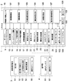
- the figure which shows schematic structure of an automatic traveling system Block diagram showing schematic configuration of automatic driving system A figure showing an example of the target travel route
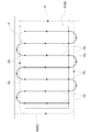
- the figure which shows the measurement range of each rider sensor in the side view, and the measurement range of each ultrasonic sensor The figure which shows the measurement range of each rider sensor in planar view, and the measurement range of each ultrasonic sensor
- the top view which shows another embodiment which has arrange
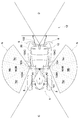
- Front view showing another embodiment in which four ultrasonic sensors are arranged vertically and horizontally so that the measurement range is aligned vertically and horizontally in plan view
- the obstacle detection system for a work vehicle according to the present invention includes, for example, a riding mower, a riding rice transplanter, a combiner, a transporter, a snowplow, a wheel loader, etc., and an unmanned mower other than a tractor. It can be applied to unmanned work vehicles such as.
- the tractor 1 exemplified in the present embodiment is configured to automatically travel on a farm field S (see FIG. 3), which is an example of a work site, by an automatic travel system for a work vehicle.
- the automatic traveling system includes an automatic traveling unit 2 mounted on the tractor 1 and a mobile communication terminal 3 that is set to be communicable with the automatic traveling unit 2.
- the mobile communication terminal 3 can employ a tablet personal computer, a smartphone, or the like having a display unit 51 (for example, a liquid crystal panel) that can be touch-operated.
- the tractor 1 is provided with a traveling machine body 7 having left and right front wheels 5 functioning as drivable steering wheels and drivable left and right rear wheels 6.
- a front frame 27 and a bonnet 8 are disposed on the front side of the traveling machine body 7, and an electronically controlled diesel engine (hereinafter referred to as an engine) 9 having a common rail system is provided inside the bonnet 8. It has been.
- an engine 9 having a common rail system is provided inside the bonnet 8. It has been.
- a rotary plowing device which is an example of the work device 12, is connected to the rear portion of the traveling machine body 7 via a three-point link mechanism 11 so that the rotary tiller can be raised and lowered.
- the tractor 1 is comprised by the rotary tillage specification.
- a working device 12 such as a plow, a seeding device, or a spraying device can be connected to the rear portion of the tractor 1 instead of the rotary tiller.
- the tractor 1 includes an electronically controlled transmission 13 that shifts the power from the engine 9, an all-hydraulic power steering mechanism 14 that steers the left and right front wheels 5, and the left and right rear wheels 6.
- Left and right side brakes (not shown) for braking, an electronically controlled brake operating mechanism 15 that enables hydraulic operation of the left and right side brakes, and a work clutch that intermittently transmits power to the work device 12 such as a rotary tiller (see FIG. (Not shown)
- an electronically controlled clutch operating mechanism 16 that enables hydraulic operation of the work clutch
- an electrohydraulic control type lifting drive mechanism 17 that drives the working device 12 such as a rotary tiller, etc., automatic travel of the tractor 1, etc.
- An in-vehicle electronic control unit 18 having various control programs, a vehicle speed sensor 19 for detecting the vehicle speed of the tractor 1, and a steering angle sensor for detecting the steering angle of the front wheels 5. Sa 20, and the positioning unit 21 and the like for measuring the current position and current heading of the tractor 1 is provided.
- the engine 9 may be an electronically controlled gasoline engine equipped with an electronic governor.
- a hydraulic mechanical continuously variable transmission (HMT), a hydrostatic continuously variable transmission (HST), a belt-type continuously variable transmission, or the like can be employed.
- the power steering mechanism 14 may be an electric power steering mechanism 14 provided with an electric motor.
- the cabin 10 includes a steering wheel 38 that enables manual steering of the left and right front wheels 5 via the power steering mechanism 14 (see FIG. 2), and a driver's seat for passengers. 39, a touch panel type display unit, various operation tools, and the like.
- boarding steps 41 and 42 serving as boarding / alighting parts for the cabin 10 (driver's seat 39) are provided.
- the on-vehicle electronic control unit 18 includes a shift control unit 181 that controls the operation of the transmission 13, a brake control unit 182 that controls the operation of the left and right side brakes, and a work device 12 such as a rotary tillage device.
- a non-volatile in-vehicle storage unit 185 and the like for storing the route P (for example, see FIG. 3) and the like are included.
- the positioning unit 21 includes a satellite that measures the current position and current direction of the tractor 1 using GPS (Global Positioning System), which is an example of a satellite positioning system (NSS).
- GPS Global Positioning System
- a navigation device 22, an inertial measurement device (IMU) 23 that measures the attitude, orientation, and the like of the tractor 1 by including a three-axis gyroscope and a three-direction acceleration sensor are provided.
- GPS Global Positioning System
- IMU inertial measurement device
- Examples of positioning methods using GPS include DGPS (Differential GPS) and RTK-GPS (Real Time Kinematic GPS).
- RTK-GPS suitable for positioning of a moving body is employed. Therefore, as shown in FIGS. 1 and 2, a reference station 4 that enables positioning by RTK-GPS is installed at a known position around the field.
- Each of the tractor 1 and the reference station 4 includes, as shown in FIG. 2, GPS antennas 24 and 61 that receive radio waves transmitted from the GPS satellite 71 (see FIG. 1), and between the tractor 1 and the reference station 4.
- Communication modules 25, 62 and the like that enable wireless communication of various data including positioning data in are provided.
- the satellite navigation device 22 receives the positioning data obtained by the GPS antenna 24 on the tractor side receiving the radio wave from the GPS satellite 71, and the GPS antenna 61 on the base station side receives the radio wave from the GPS satellite 71. Based on the obtained positioning data, the current position and the current direction of the tractor 1 can be measured with high accuracy.
- the positioning unit 21 includes the satellite navigation device 22 and the inertial measurement device 23, thereby measuring the current position, current azimuth, and attitude angle (yaw angle, roll angle, pitch angle) of the tractor 1 with high accuracy. Can do.
- the GPS antenna 24, communication module 25, and inertial measurement device 23 provided in the tractor 1 are housed in an antenna unit 80 as shown in FIG.
- the antenna unit 80 is disposed at an upper position on the front side of the cabin 10.
- the mobile communication terminal 3 includes positioning data between the terminal electronic control unit 52 having various control programs for controlling the operation of the display unit 51 and the like, and the communication module 25 on the tractor side. Including a communication module 55 that enables wireless communication of various data including the.
- the terminal electronic control unit 52 includes a travel route generation unit 53 that generates a target travel route P for travel guidance (for example, see FIG. 3) for automatically traveling the tractor 1, various input data input by the user,
- a non-volatile terminal storage unit 54 that stores the target travel route P and the like generated by the travel route generation unit 53 is included.
- the travel route generation unit 53 When the travel route generation unit 53 generates the target travel route P, a user including a driver and an administrator can work on the work vehicle according to the input guidance for target travel route setting displayed on the display unit 51 of the mobile communication terminal 3.
- the vehicle body data such as the type and model of the work device 12 is input, and the input vehicle body data is stored in the terminal storage unit 54.
- a travel region R (see FIG. 3) that is a target for generating the target travel route P is set as a work region in the field S, and the terminal electronic control unit 52 of the mobile communication terminal 3 acquires field data including the shape and position of the field. And stored in the terminal storage unit 54.
- the terminal electronic control unit 52 determines the shape and position of the field from the current position of the tractor 1 acquired by the positioning unit 21. It is possible to acquire position information for specifying The terminal electronic control unit 52 specifies the shape and position of the field from the acquired position information, and acquires field data including the travel region R specified from the specified shape and position of the field.
- FIG. 3 shows an example in which a rectangular travel region R is specified.
- the travel route generation unit 53 uses the field data and the vehicle body data stored in the terminal storage unit 54 to perform the target travel. A path P is generated.
- the travel route generation unit 53 sets the travel region R into a central region R1 and an outer peripheral region R2.
- the central region R1 is set at the center of the traveling region R, and is a reciprocating work region in which a predetermined operation (for example, work such as tillage) is performed by automatically traveling the tractor 1 in the reciprocating direction in advance.
- the outer peripheral region R2 is set around the central region R1, and is a circular work region in which the tractor 1 automatically travels in the circular direction following the central region R1 and performs a predetermined operation.
- the travel route generation unit 53 uses a turning radius required for turning the tractor 1 at the edge of the field based on the turning radius, the front-rear length and the left-right width of the tractor 1 included in the vehicle data. Etc.
- the traveling route generation unit 53 divides the traveling region R into a central region R1 and an outer peripheral region R2 so as to ensure the space obtained on the outer periphery of the central region R1.
- the travel route generation unit 53 generates a target travel route P using vehicle body data, farm field data, and the like.
- the target travel route P includes a plurality of work routes P1 that are arranged in parallel at regular intervals corresponding to the work width and have the same rectilinear distance in the central region R1, and end and start ends of adjacent work routes P1.
- a plurality of non-working turning paths P2 that are connected in the traveling order, and a circulation path P3 (shown by a dotted line in the drawing) formed in the outer peripheral region R2.
- the plurality of work paths P1 are paths for the tractor 1 to perform a predetermined work while traveling straight ahead.
- the turning path P2 is a U-turn path for changing the traveling direction of the tractor 1 by 180 degrees without the tractor 1 performing a predetermined work, and the start end of the next work path P1 adjacent to the end of the work path P1.
- the circulation path P3 is a path for the tractor 1 to perform a predetermined work while traveling around in the outer peripheral region R2.
- the route portions located at the four corners of the travel region R are route portions for changing the traveling direction of the tractor 1 by 90 degrees while appropriately performing the forward traveling and the backward traveling.
- the target travel route P shown in FIG. 3 is merely an example, and what target travel route is generated can be changed according to vehicle body data, farm field data, or the like.
- the target travel route P generated by the travel route generation unit 53 can be displayed on the display unit 51 and is stored in the terminal storage unit 54 as route data associated with vehicle body data, farm field data, and the like.
- the route data includes an azimuth angle of the target travel route P, a set engine rotational speed, a target travel speed, and the like set according to the travel mode of the tractor 1 on the target travel route P, and the like.
- the terminal electronic control unit 52 transfers the route data from the mobile communication terminal 3 to the tractor 1, whereby the in-vehicle electronic control unit 18 of the tractor 1.
- route data can be acquired.
- the in-vehicle electronic control unit 18 automatically causes the tractor 1 to travel along the target travel route P while acquiring its current position (current position of the tractor 1) by the positioning unit 21 based on the acquired route data. Can do.
- the current position of the tractor 1 acquired by the positioning unit 21 is transmitted from the tractor 1 to the mobile communication terminal 3 in real time (for example, every several seconds), and the mobile communication terminal 3 recognizes the current position of the tractor 1. Yes.
- the entire route data can be transferred from the terminal electronic control unit 52 to the in-vehicle electronic control unit 18 at a time before the tractor 1 starts the automatic travel.
- the route data including the target travel route P can be divided into a plurality of route portions for each predetermined distance with a small data amount.
- only the initial route portion of the route data is transferred from the terminal electronic control unit 52 to the in-vehicle electronic control unit 18 before the tractor 1 starts automatic traveling.
- route data of only the subsequent route portion corresponding to the point is transmitted from the terminal electronic control unit 52 to the on-vehicle electronic control. It may be transferred to the unit 18.
- the mobile communication terminal 3 When starting automatic traveling of the tractor 1, for example, when various automatic traveling start conditions are satisfied after the user or the like has moved the tractor 1 to the start point, the mobile communication terminal 3 displays a display unit. The mobile communication terminal 3 transmits an instruction to start automatic traveling to the tractor 1 by operating 51 to instruct the start of automatic traveling. As a result, in the tractor 1, the in-vehicle electronic control unit 18 receives an instruction to start automatic traveling, and the positioning unit 21 obtains its current position (current position of the tractor 1) while obtaining the target traveling route P. The automatic traveling control for automatically traveling the tractor 1 is started.
- the automatic travel control includes automatic shift control for automatically controlling the operation of the transmission 13, automatic braking control for automatically controlling the operation of the brake operating mechanism 15, automatic steering control for automatically steering the left and right front wheels 5, and a rotary tillage device.
- An automatic work control for automatically controlling the operation of the working device 12 is included.
- the shift control unit 181 determines whether the tractor 1 on the target travel route P is based on the route data of the target travel route P including the target travel speed, the output of the positioning unit 21, and the output of the vehicle speed sensor 19.
- the operation of the transmission 13 is automatically controlled so that the target travel speed set according to the travel mode and the like is obtained as the vehicle speed of the tractor 1.
- the braking control unit 182 causes the left and right side brakes to move rearward in the braking area included in the route data of the target traveling route P based on the target traveling route P and the output of the positioning unit 21.
- the operation of the brake operation mechanism 15 is automatically controlled so as to properly brake the wheel 6.
- the steering angle setting unit 184 determines the target of the left and right front wheels 5 based on the route data of the target travel route P and the output of the positioning unit 21 so that the tractor 1 automatically travels on the target travel route P.
- the steering angle is obtained and set, and the set target steering angle is output to the power steering mechanism 14.
- the power steering mechanism 14 Based on the target steering angle and the output of the steering angle sensor 20, the power steering mechanism 14 automatically steers the left and right front wheels 5 so that the target steering angle is obtained as the steering angle of the left and right front wheels 5.
- the work device control unit 183 operates the tractor 1 at the start of the work route P1 (for example, see FIG. 3) based on the route data of the target travel route P and the output of the positioning unit 21.
- a predetermined work for example, tillage work
- the tractor 1 reaches the work end point such as the end of the work path P1 (for example, see FIG. 3).
- the operations of the clutch operation mechanism 16 and the lifting drive mechanism 17 are automatically controlled so that the predetermined work by the work device 12 is stopped.
- the automatic traveling unit 2 is configured by the unit 21, the communication module 25, and the like.
- the tractor 1 can also automatically run while the user or the like gets on the cabin 10. Accordingly, not only the user or the like does not board the cabin 10 but also the tractor 1 can automatically travel along the target travel route P by the automatic traveling control by the in-vehicle electronic control unit 18, and the user or the like can board the cabin 10. Even in this case, the tractor 1 can be automatically driven along the target travel route P by the automatic travel control by the in-vehicle electronic control unit 18.
- the tractor travels based on an automatic travel state in which the in-vehicle electronic control unit 18 automatically travels the tractor 1 and the operation of the user or the like. It can be switched to the manual running state. Therefore, while the tractor is automatically traveling on the target travel route P in the automatic travel state, the travel state of the tractor can be switched from the automatic travel state to the manual travel state. On the contrary, while the tractor is traveling in the manual travel state, the travel state of the tractor can be switched from the manual travel state to the automatic travel state.
- a switching operation unit for enabling switching between the automatic travel state and the manual travel state can be provided in the vicinity of the driver's seat 39, and the switching is performed.
- the operation unit can be displayed on the display unit 51 of the mobile communication terminal 3. Further, when the user operates the steering wheel 38 during the automatic traveling control by the in-vehicle electronic control unit 18, the traveling state of the tractor can be switched from the automatic traveling state to the manual traveling state.
- the tractor 1 detects the presence or absence of an obstacle around the tractor 1 (running vehicle body 7), and detects the presence of an obstacle when the presence of the obstacle is detected.
- An obstacle detection system 100 for avoiding a collision is provided.
- the obstacle detection system 100 includes two lidar sensors (LiDAR Sensor: Light Detection and Ranging Sensor) 101 and 102 that generate a three-dimensional image by measuring a distance to an object to be measured in three dimensions using a laser. , A sonar system 106 that measures the distance to the measurement object using ultrasonic waves, and collision avoidance control that performs obstacle determination control, collision avoidance control, and the like based on information from each of the rider sensors 101 and 102 and the sonar system 106 Part 107.
- LiDAR Sensor Light Detection and Ranging Sensor
- the collision avoidance control unit 107 determines that the measurement object is an obstacle in the obstacle determination control
- the collision avoidance control unit 107 activates a notification device 26 such as a notification buzzer or a notification lamp provided in the tractor 1 in the collision avoidance control.
- a deceleration process for reducing the vehicle speed of the tractor 1 and a stop process for stopping the tractor 1 are appropriately performed according to the distance from the obstacle.
- measurement objects measured by the rider sensors 101 and 102 and the sonar system 106 include a person such as a worker who works on a farm field (working place), another work vehicle, an existing utility pole or tree on the farm field, and work. Objects such as existing fences and fences are included around the ground.
- Each of the rider sensors 101 and 102 measures TOF (Time Of) Flight) that measures the distance from the round trip time until the laser beam (for example, pulsed near-infrared laser beam) bounces off the measurement object and bounces back.
- the distance to the measurement object is measured by the method.
- Each rider sensor 101 and 102 measures the distance to the measurement object in three dimensions by scanning the laser beam at high speed in the vertical and horizontal directions and measuring the distance to the measurement object at each scanning angle sequentially. To do.
- Each rider sensor 101, 102 repeatedly measures the distance to the measurement object within the measurement range in real time.
- Each rider sensor 101, 102 generates a three-dimensional image from the measurement result and outputs it to the in-vehicle electronic control unit 18.
- the three-dimensional images from the rider sensors 101 and 102 can be displayed on a display device such as the display unit of the tractor 1 or the display unit 51 of the mobile communication terminal 3.
- the situation and the situation on the rear side can be visually recognized.
- the distance in the perspective direction can be shown using color or the like.
- the front rider sensor 101 obliquely places the front side of the tractor 1 on the left and right central portion of the front end portion of the roof 35 of the cabin 10. It is arranged in a forward-downward attitude looking down from above.
- the front rider sensor 101 is set so that the front side of the tractor 1 is in the measurement range C.
- the rear rider sensor 102 is disposed in a laterally lowered posture in which the rear side of the tractor 1 is looked down obliquely from the upper side at the central portion of the rear end of the roof 35 of the cabin 10.
- the rear rider sensor 102 is set so that the rear side of the tractor 1 is in the measurement range D.
- a cut process may be performed to limit the range in the left-right direction to a set range corresponding to the work width of the work device 12.
- the sonar system 106 is disposed on the right side of the tractor 1 (the traveling machine body 7) and the right sensor unit 103 disposed on the right side of the tractor 1 (the traveling machine body 7).
- the left sensor unit 104 and a ranging electronic control unit 105 as a ranging control unit for measuring the distance of an object entering the measurement range N of each of the sensor units 103 and 104 are provided.
- the right sensor unit 103 has a right downward posture having a small depression angle on the bottom surface of the upper step portion 41A of the upper and lower step portions 41A in the right getting on / off step 41 (see FIG. 5) disposed on the lower right side of the cabin 10. It is attached with.
- the right sensor unit 103 is disposed at a relatively high position between the right front wheel 5 and the right rear wheel 6 in a state where the right outer side of the tractor 1 is set to be the measurement range N. Yes.
- the measurement range N of the right sensor unit 103 is set to a wide range in the front-rear direction including the measurement ranges Na-Nc of the three ultrasonic sensors 103A-103C arranged in the front-rear direction.
- the left sensor unit 104 has a small depression angle on the bottom surface of the upper step portion 42A among the upper and lower step portions 42A and 42B in the left and right step 42 that is arranged on the lower left side of the cabin 10. It is attached in a left-down position.
- the left sensor unit 104 is disposed at a relatively high position between the left front wheel 5 and the left rear wheel 6 in a state where the left outer side of the tractor 1 is set to be the measurement range N. Yes.
- the measurement range N of the left sensor unit 104 is set to a wide range in the front-rear direction including the measurement ranges Na-Nc of the three ultrasonic sensors 104A-104C arranged in the front-rear direction.
- Each of the ultrasonic sensors 103A to 103C, 104A to 104C is measured by a TOF (Time Of Flight) method that measures the distance from the round-trip time until the transmitted ultrasonic wave bounces off the measurement object and bounces back. Measure the distance to the object.
- TOF Time Of Flight
- the ranging electronic control unit 105 detects the objects that have entered the measurement ranges Na to Nc of the ultrasonic sensors 103A to 103C and 104A to 104C based on the ranging operation of the ultrasonic sensors 103A to 103C and 104A to 104C. Measure distance.
- the left and right sensor units 103 and 104 are configured to be able to adjust the depression angle and the attachment angle in the front-rear direction of the ultrasonic sensors 103A to 103C and 104A to 104C. Thereby, the measurement range N of each sensor unit 103,104 can be set appropriately.
- the collision avoidance control unit 107 is provided in the in-vehicle electronic control unit 18.
- the in-vehicle electronic control unit 18 is communicably connected to the engine electronic control unit included in the common rail system, the rider sensors 101 and 102, the sonar system 106, and the like via a CAN (Controller Area Network). .
- CAN Controller Area Network
- the tractor 1 includes a front camera 108 whose imaging range is the front side of the traveling aircraft body 7 and a rear camera 109 whose imaging range is the rear side of the traveling aircraft body 7.
- the front camera 108 is disposed in a front-down posture in which the front side of the tractor 1 is looked down obliquely from the upper side at the center of the front end of the roof 35 of the cabin 10.
- the rear camera 109 is disposed in a rearward lowered posture in which the rear side of the tractor 1 is looked down obliquely from the upper side at the left and right central portions of the rear end portion of the roof 35 of the cabin 10.
- the captured images of the front camera 108 and the rear camera 109 can be displayed on a display device such as the display unit of the tractor 1 or the display unit 51 of the mobile communication terminal 3. It can be visually recognized.
- the right ultrasonic sensors 103A to 103C and the left ultrasonic sensors 104A to 104C have their measurement ranges Na to Nc along the left and right sides of the tractor 1 (front-rear direction). Are arranged on both the left and right sides of the tractor 1 in a continuous positional relationship.
- the ranging electronic control unit 105 performs the tractor 1 based on the ranging operation of the right ultrasonic sensors 103A to 103C or the ranging operation of the left ultrasonic sensors 104A to 104C in which the measurement ranges Na to Nc are continuous.
- a displacement detection process for detecting the displacement of the object in the direction along the left and right sides of the tractor 1 (front-rear direction) is performed.
- the ultrasonic wave transmitted from the first ultrasonic sensor 103A is And bounces back to the first ultrasonic sensor 103A.
- the first ultrasonic sensor 103A performs a distance measuring operation for receiving the reflected wave in addition to the transmission of the ultrasonic wave.
- the distance measurement electronic control unit 105 detects the presence of an object in the front region on the right outer side of the vehicle body that is the measurement range Na of the first ultrasonic sensor 103A that has performed the distance measurement by the position detection process described above.
- the distance from the first ultrasonic sensor 103A to the object is measured based on the required time from transmission to reception of the ultrasonic wave in the first ultrasonic sensor 103A.
- the electronic control unit for distance measurement 105 detects that the object is located at a position away from the first ultrasonic sensor 103A in the front region on the right outside of the vehicle body by the measurement distance based on the distance measurement operation of the first ultrasonic sensor 103A. The presence can be detected.
- the second ultrasonic sensor 103B performs a distance measuring operation.
- the electronic control unit for distance measurement 105 detects that the object is located at a position away from the second ultrasonic sensor 103B by a measurement distance in the front-rear center side region on the right outer side of the vehicle body based on the distance measurement operation of the second ultrasonic sensor 103B. The presence can be detected. Similarly, for example, when the object enters the measurement range Nc of the third ultrasonic sensor 103C whose measurement range is the rear region on the right outside of the vehicle body, the third ultrasonic sensor 103C performs a distance measurement operation.
- the ranging electronic control unit 105 has an object at a position away from the third ultrasonic sensor 103C in the rear region on the right outside of the vehicle body by the measuring distance based on the distance measuring operation of the third ultrasonic sensor 103C. Can be detected.
- the first ultrasonic sensor 103A performs the distance measuring operation and then 2 Since the ultrasonic sensor 103B performs a ranging operation, the ranging electronic control unit 105 detects that the object has been displaced from the front region on the right side of the vehicle body to the front / rear center region by the above-described displacement detection processing. can do.
- the second ultrasonic sensor 103B performs a distance measuring operation.
- the ranging electronic control unit 105 Since the third ultrasonic sensor 103C performs a ranging operation, the ranging electronic control unit 105 has detected that the object has been displaced from the front-rear center region to the rear region on the right outer side of the vehicle body by the above-described displacement detection process. Can be detected. Similarly, for example, when the object enters the measurement range Nb of the second ultrasonic sensor 103B after entering the measurement range Nc of the third ultrasonic sensor 103C, the third ultrasonic sensor 103B performs the distance measuring operation.
- the ranging electronic control unit 105 Since the second ultrasonic sensor 103B performs a ranging operation, the ranging electronic control unit 105 has detected that the object has been displaced from the rear region on the right side of the vehicle body to the front / rear center region by the displacement detection process described above. Can be detected. Similarly, for example, when the object enters the measurement range Na of the first ultrasonic sensor 103A after entering the measurement range Nb of the second ultrasonic sensor 103B, the second ultrasonic sensor 103B performs the distance measuring operation. Since the first ultrasonic sensor 103A performs a ranging operation, the ranging electronic control unit 105 determines that the object has been displaced from the front / rear center side region on the right outer side of the vehicle body to the front region by the displacement detection process described above.
- each of the ultrasonic sensors 103A to 103C on the right side does not perform the distance measuring operation. It can be detected that an object no longer exists in the measurement range N.
- the ranging electronic control unit 105 measures the distance of the object based on the ranging operation of any of the ultrasonic sensors 103A to 103C and 104A to 104C.
- the ranging electronic control unit 105 changes accordingly. The displacement of the object in the perspective direction relative to the right side of the vehicle body can be detected based on the measurement distance.
- the distance measuring electronic control unit 105 detects that the object is displaced between the two regions adjacent in the front-rear direction on the right outer side of the vehicle body by the above-described displacement detection processing, the measurement distance obtained along with it is detected. Due to the difference, the displacement of the object in the perspective direction with respect to the right side of the vehicle body can be detected.
- the ranging electronic control unit 105 detects the position of the object with respect to the vehicle body and the displacement based on the ranging operation and the ranging operation sequence of the ultrasonic sensors 103A to 103C on the right side as described above. This can be performed based on the ranging operation and the ranging operation order of the acoustic wave sensors 104A to 104C.
- the tractor 1 is provided with a sonar system 106 having six ultrasonic sensors 103A to 103C, 104A to 104C, which are cheaper than a stereo camera or a rider sensor substituted for a stereo camera, and the ranging electronic control unit 105.
- a sonar system 106 having six ultrasonic sensors 103A to 103C, 104A to 104C, which are cheaper than a stereo camera or a rider sensor substituted for a stereo camera, and the ranging electronic control unit 105.
- the obstacle detection system 100 for a tractor, it is possible to reduce the cost by reducing the number of expensive stereo cameras, rider sensors, and the like, and the labor required for preliminary work.
- the ranging electronic control unit 105 performs a first ranging operation determination process for determining whether or not there is a ranging operation in any of the ultrasonic sensors 103A to 103C and 104A to 104C (step # 1).
- the ranging electronic control unit 105 waits until the ranging operation is performed if there is no ranging operation in step # 1, and the ranging processing for measuring the distance of the object when the ranging operation is performed.
- the ranging electronic control unit 105 performs a distance measurement operation continuation determination process for determining whether or not the ultrasonic sensors 103A to 103C and 104A to 104C that have performed the distance measurement continue the distance measurement operation (Step S1). # 4). If the distance measurement electronic control unit 105 continues the distance measurement operation in step # 4, the distance measurement electronic control unit 105 performs the distance measurement process described above, and the object distance obtained in the current distance measurement process and the previous distance measurement process.
- step # 5 the displacement detection process for detecting the displacement of the object in the perspective direction (left and right direction) with respect to the left and right sides of the tractor 1 is performed (steps # 5 and # 6), and then step # Return to 4.
- the distance measurement electronic control unit 105 does not continue the distance measurement operation in step # 4, the ultrasonic sensors 103A to 103C, 104A to 104C having the distance measurement operation in step # 1 and the measurement ranges Na to A second distance measuring operation determination process is performed to determine the presence or absence of a distance measuring operation in any of the ultrasonic sensors 103A to 103C and 104A to 104C in which Nc continues (step # 7).
- step # 7 the distance measuring electronic control unit 105 performs the distance measuring process described above and the position detecting process described above to thereby perform the direction along the left and right sides of the tractor 1 (
- the position of the object in the front-rear direction is specified (steps # 8 and # 9), and the displacement detection process described above is performed from the difference between the position of the object specified this time and the position of the object specified last time.
- the near / far direction displacement detection process (steps # 10 and # 11), and then returns to step # 4.
- step # 7 the distance measuring electronic control unit 105 determines that the object is out of the measurement ranges Na to Nc of the ultrasonic sensors 103A to 103C, 104A to 104C, and step # 1. Return to.
- the collision avoidance control unit 107 detects an object that has entered the measurement range N of the left or right sensor unit 103 or 104.
- the object is determined as an obstacle.
- the collision avoidance control unit 107 controls the travel of the tractor 1 in the collision avoidance control based on information from the sonar system 106.
- the collision avoidance control unit 107 determines the position of the obstacle with respect to the vehicle based on information from the ranging electronic control unit 105 (steps # 20 to # 22).
- the collision avoidance control unit 107 lowers the tractor 1 below the work setting speed when the position of the obstacle relative to the vehicle body is the left or right front region (measurement range Na) far from the work device 12 of the tractor 1.
- the first low-speed traveling process is performed to travel at the first speed (step # 23), and then the approaching direction of the near-near direction (measurement range Na) in which the position of the obstacle with respect to the vehicle is on the left or right side (measurement range Na) (
- An approach determination process is performed to determine whether or not the vehicle has been displaced in the left-right direction (step # 24).
- a stop process for stopping the tractor 1 is performed and the collision avoidance control is terminated (step # 25). If not displaced in the approaching direction, the process returns to step # 20.
- the collision avoidance control unit 107 is configured so that the position of the obstacle with respect to the vehicle body is in the front-rear center side region (measurement range Nb) closer to the work device 12 of the tractor 1 than the left and right front regions (measurement range Na). Performs a second low-speed traveling process for causing the tractor 1 to travel at a second speed lower than the first speed (step # 26), and then performs the approach determination process described above (step # 24). In this approach determination process, when the position of the obstacle relative to the vehicle body is displaced in the approach direction, the stop process described above is performed and the collision avoidance control is terminated (step # 25). If not displaced in the approaching direction, the process returns to step # 20.
- the collision avoidance control unit 107 is the left or right rear region (measurement range Nc) where the position of the obstacle relative to the vehicle body is closer to the work device 12 of the tractor 1 than the left and right front and rear center regions (measurement range Nb).
- stop processing for stopping the tractor 1 is performed and the collision avoidance control is ended (step # 25).
- the tractor 1 is set at the work set speed.
- a set speed running process for running is performed (step # 27), and then the process returns to step # 20.
- the collision avoidance control unit 107 performs such a control operation, whereby the traveling of the tractor 1 can be appropriately controlled based on the position of the obstacle with respect to the vehicle body. As a result, it is possible to avoid the possibility that the tractor 1 will collide with the obstacle, and to avoid the reduction in work efficiency due to the continued low-speed traveling in a state where the tractor 1 does not collide with the obstacle. it can.
- the position of the obstacle with respect to the vehicle body is the front region (measurement range Na), the front / rear center region (measurement range Nb), and the rear region (measurement range Nc). It is preferable that a notification process for operating the notification device 26 is added. Further, it is more preferable that the operation of the notification device 26 is made different as the position of the obstacle relative to the vehicle body approaches the tractor 1 (for example, the notification sound is increased). Further, in the approach determination process described above, when the position of the obstacle relative to the vehicle body is displaced in the approach direction, the collision avoidance control unit 107 steers the left and right front wheels 5 away from the obstacle instead of the stop process. A steering process for collision avoidance may be performed.
- the collision avoidance control unit 107 includes map data stored in the in-vehicle storage unit 185, position information of the object acquired by the sonar system 106, and ultrasonic sensors 103A to 103C, 104A that detect the object included in the vehicle body data.
- -104C position information (such as the positions of the ultrasonic sensors 103A-103C, 104A-104C attached to the tractor 1) and the position information of the tractor 1 included in the positioning information from the positioning unit 21 It is possible to perform a map data update process in which the position of an object (obstacle) is specified and written to the map data.
- the tractor 1 when the tractor 1 is run along the periphery of the work place in a work place such as a farm field, the positions of the fences and fences existing around the work place (the farm field), the entrance to the work place, etc. You can specify the location and add it to the map data. Further, when storing the tractor 1 in the barn, the position of the doorway to the barn or the position of an object such as a pillar or farm equipment existing in the barn can be specified and written to the map data.
- the work vehicle 1 may be configured in a semi-crawler specification including left and right crawlers instead of the left and right rear wheels 6.
- the work vehicle 1 may be configured in a full crawler specification including left and right crawlers instead of the left and right front wheels 5 and the left and right rear wheels 6.
- the work vehicle 1 may be configured to have an electric specification including an electric motor instead of the engine 9.
- the work vehicle 1 may be configured in a hybrid specification including an engine 9 and an electric motor.
- the work vehicle 1 may be configured to have a rear wheel steering specification in which the left and right rear wheels 6 function as steering wheels.
- the work vehicle 1 may be configured to perform work by running a plurality of work vehicles 1 together using an automatic travel system.
- the work vehicle 1 may have a configuration in which the work device 12 is connected to only one of the front and rear sides thereof.
- the work vehicle 1 may be configured to include a protective frame that extends from the traveling machine body 7 to above the boarding space instead of the cabin 10.
- the left and right sensor units 103 and 104 may be provided at the lower ends of the left and right sides of the cabin 10.
- the sensor units 103 and 104 may be provided on both front and rear sides of the work vehicle 1 such as the front end portion of the bonnet 8 and the rear surface portion of the cabin 10. It may be provided.
- the number and arrangement of the ultrasonic sensors 103A to 103C and 104A to 104C in the sensor units 103 and 104 can be variously changed.
- the ranging control unit (ranging electronic control unit) 105 performs the above-described position detection processing and displacement detection processing based on the five measurement ranges Na, Nab, Nb, Nbc, and Nc. it can.
- the ranging control unit (ranging electronic control unit) 105 performs the above-described position detection processing and displacement detection processing in four measurement ranges Na, Nb, Nc, This can be done based on Nd. For example, as shown in FIG.
- three ultrasonic sensors 103A to 103C and 104A to 104C are arranged in directions in which their measurement ranges Na to Nc are along the left and right sides (front and rear).
- the left and right sides of the bonnet 8, the left and right getting-on / off steps 41 and 42, and the left and right rear fenders 28 may be dispersed so as to be continuous while being positioned at equal intervals.
- the obstacle detection system for a work vehicle includes, for example, a tractor, a riding mower, a riding rice transplanter, a combine, a transport vehicle, a snowplow, a wheeled loader, and other unmanned grass mowers. It can be applied to work vehicles.
Landscapes
- Engineering & Computer Science (AREA)
- Radar, Positioning & Navigation (AREA)
- Remote Sensing (AREA)
- Physics & Mathematics (AREA)
- General Physics & Mathematics (AREA)
- Computer Networks & Wireless Communication (AREA)
- Acoustics & Sound (AREA)
- Life Sciences & Earth Sciences (AREA)
- Mechanical Engineering (AREA)
- Soil Sciences (AREA)
- Environmental Sciences (AREA)
- Electromagnetism (AREA)
- Guiding Agricultural Machines (AREA)
- Control Of Position, Course, Altitude, Or Attitude Of Moving Bodies (AREA)
- Aviation & Aerospace Engineering (AREA)
- Automation & Control Theory (AREA)
- Measurement Of Velocity Or Position Using Acoustic Or Ultrasonic Waves (AREA)
Abstract
Provided is an obstacle detection system for a work vehicle, with which the reduction of costs or labor required for preparatory work can be achieved. In an obstacle detection system for a work vehicle, three left-side and three right-side ultrasonic sensors 103A-103C, 104A-104C are disposed on the left and right sides of a work vehicle 1, respectively, and the measurement ranges Na-Nc thereof are continuous in the front and rear direction. In addition, a control unit 105 for distance measurement performs: position detection processing for detecting the position of an object with respect to the vehicle in the front and rear direction on the basis of a distance measurement operation of the ultrasonic sensors 103A-103C, 104A-104C having the continuous measurement ranges Na-Nc; and displacement detection processing for detecting the movement of the object in the front and rear direction on the basis of the distance measurement operation sequence of the ultrasonic sensors 103A-103C, 104A-104C having the continuous measurement ranges Na-Nc.
Description
本発明は、トラクタ等の作業車両が作業地に存在する障害物と衝突することを回避する作業車両用の障害物検知システムに関する。
The present invention relates to an obstacle detection system for a work vehicle that prevents a work vehicle such as a tractor from colliding with an obstacle present in a work site.
農業機械等の作業車両に備える障害物検知システムとしては、例えば、作業車両(農業機械)の前部に、作業車両の前方を撮影するステレオカメラ(ステレオカメラ装置)と、作業車両の前方を測定範囲とする左右一組の超音波ソナー装置とを備えて、作業車両の進行方向にある障害物の検知、及び、障害物までの距離や大きさの検知にはステレオカメラを使用し、ステレオカメラが捉えられない死角における障害物との距離計測に超音波ソナー装置を使用するように構成されたものがある(例えば特許文献1参照)。
As an obstacle detection system provided in a work vehicle such as an agricultural machine, for example, a front of the work vehicle (agricultural machine) has a stereo camera (stereo camera device) that captures the front of the work vehicle, and measures the front of the work vehicle. A stereo camera is used to detect obstacles in the traveling direction of the work vehicle and to detect the distance and size to the obstacles. There is one that is configured to use an ultrasonic sonar device for distance measurement with an obstacle in a blind spot where cannot be captured (see, for example, Patent Document 1).
つまり、特許文献1に記載の発明では、作業車両の前部に、障害物の対車体位置等を検知するのに適したステレオカメラと、ステレオカメラの死角となる作業車両の近傍領域に入り込んだ障害物との距離を測定する左右一組の超音波ソナー装置とを備えている。そして、これらのステレオカメラ又は超音波ソナー装置が作業車両の進行方向(前方)に存在する障害物を捉えた場合に、作業車両がその進行方向(前方)にある障害物と衝突することを回避するようにしている。そのため、特許文献1に記載の発明において、作業車両における前後左右の各側部に対する障害物の衝突を回避するためには、作業車両における前後左右の各側部に高価なステレオカメラとともに超音波ソナー装置を配置する必要がある。又、ステレオカメラで障害物を検知する上においては、事前に検知対象となる多数の障害物の形状を学習させておく学習処理を行う必要がある。その結果、作業車両が障害物と衝突することを回避する障害物検知システムを構築する上において、コストが嵩むとともに、学習処理等の事前作業に要する手間が増大することになる。
In other words, in the invention described in Patent Document 1, a stereo camera suitable for detecting the position of an obstacle with respect to the vehicle body and the like and an area near the work vehicle that becomes a blind spot of the stereo camera enter the front part of the work vehicle. A pair of left and right ultrasonic sonar devices that measure the distance to the obstacle are provided. Then, when these stereo cameras or ultrasonic sonar devices catch an obstacle existing in the traveling direction (front) of the work vehicle, the work vehicle is prevented from colliding with an obstacle in the traveling direction (front). Like to do. Therefore, in the invention described in Patent Document 1, in order to avoid an obstacle collision with each of the front, rear, left and right sides of the work vehicle, an ultrasonic sonar along with an expensive stereo camera is provided on each of the front, rear, left and right sides of the work vehicle. It is necessary to arrange the device. Further, when detecting an obstacle with a stereo camera, it is necessary to perform a learning process in which the shapes of many obstacles to be detected are learned in advance. As a result, in constructing an obstacle detection system that prevents the work vehicle from colliding with an obstacle, the cost increases and the labor required for the preliminary work such as learning processing increases.
この実情に鑑み、本発明の主たる課題は、コストの削減や事前作業に要する手間の軽減を図れる作業車両用の障害物検知システムを提供する点にある。
In view of this situation, the main problem of the present invention is to provide an obstacle detection system for a work vehicle that can reduce costs and labor required for preliminary work.
本発明の第1特徴構成は、作業車両用の障害物検知システムにおいて、
3個以上の超音波センサを有して作業車両における前後左右の一側部に配置されるセンサユニットと、
前記超音波センサの測距動作に基づいて前記超音波センサの測定範囲に入り込んだ物体の距離を測定する測距用の制御部とを備え、
前記超音波センサの夫々は、少なくとも2個の前記超音波センサの前記測定範囲が前記一側部に沿う方向で連続する位置関係で前記一側部に配置され、
前記制御部は、前記測定範囲が連続する前記超音波センサの測距動作に基づいて、前記一側部に沿う方向での前記物体の対車体位置を検知する位置検知処理と、前記測定範囲が連続する前記超音波センサの測距動作順序に基づいて、前記一側部に沿う方向での前記物体の変位を検知する変位検知処理とを行う点にある。 A first characteristic configuration of the present invention is an obstacle detection system for a work vehicle.
A sensor unit having three or more ultrasonic sensors and arranged on one side of the front, rear, left and right of the work vehicle;
A distance measuring control unit that measures the distance of an object that has entered the measurement range of the ultrasonic sensor based on the distance measuring operation of the ultrasonic sensor;
Each of the ultrasonic sensors is disposed on the one side part in a positional relationship in which the measurement range of at least two of the ultrasonic sensors is continuous in a direction along the one side part,
The control unit is configured to detect a position of the object with respect to the vehicle in a direction along the one side based on a distance measuring operation of the ultrasonic sensor in which the measurement range is continuous, and the measurement range is A displacement detection process for detecting a displacement of the object in a direction along the one side is performed based on a distance measuring operation sequence of the continuous ultrasonic sensors.
本構成によれば、例えば、センサユニットが作業車両の右側部に配置された場合には、少なくとも2個の超音波センサが、作業車両の右側部において車体前後方向に並べて配置されることになる。
このような場合において、例えば、物体が車体右外方の前側領域を測定範囲とする第1超音波センサの測定範囲に入り込んだときには、第1超音波センサから発信された超音波が物体に当たって第1超音波センサに跳ね返ってくる。これにより、第1超音波センサは、超音波の発信に加えて反射波を受信する測距動作を行うことになる。そして、制御部は、前述した位置検知処理により、測距動作した第1超音波センサの測定範囲である車体右外方の前側領域に物体が存在することを検知するとともに、第1超音波センサにおける超音波の発信から受信までの所要時間に基づいて、第1超音波センサから物体までの距離を測定する。その結果、制御部は、第1超音波センサの測距動作に基づいて、車体右外方の前側領域における第1超音波センサから測定距離だけ離れた位置に物体が存在することを検知することができる。
同様に、例えば、物体が車体右外方の後側領域を測定範囲とする第2超音波センサの測定範囲に入り込んだときには、第2超音波センサが測距動作を行うことから、制御部は、第2超音波センサの測距動作に基づいて、車体右外方の後側領域における第2超音波センサから測定距離だけ離れた位置に物体が存在することを検知することができる。
又、例えば、物体が第1超音波センサの測定範囲に入り込んだ後に第2超音波センサの測定範囲に入り込んだときには、第1超音波センサが測距動作を行った後に第2超音波センサが測距動作を行うことから、制御部は、前述した変位検知処理により、物体が車体右外方の前側領域から後側領域に変位したことを検知することができる。
同様に、例えば、物体が第2超音波センサの測定範囲に入り込んだ後に第1超音波センサの測定範囲に入り込んだときには、第2超音波センサが測距動作を行った後に第1超音波センサが測距動作を行うことから、制御部は、前述した変位検知処理により、物体が車体右外方の後側領域から前側領域に変位したことを検知することができる。
一方、物体がセンサユニットの測定範囲から外れたときには、各超音波センサが測距動作を行わなくなることから、制御部は、センサユニットの測定範囲に物体が存在しなくなったことを検知することができる。 According to this configuration, for example, when the sensor unit is arranged on the right side of the work vehicle, at least two ultrasonic sensors are arranged side by side in the vehicle body front-rear direction on the right side of the work vehicle. .
In such a case, for example, when an object enters the measurement range of the first ultrasonic sensor whose measurement range is the front region on the right outside of the vehicle body, the ultrasonic wave transmitted from the first ultrasonic sensor hits the object and 1 Rebounds to the ultrasonic sensor. Thereby, the first ultrasonic sensor performs a distance measuring operation for receiving the reflected wave in addition to the transmission of the ultrasonic wave. The control unit detects the presence of an object in the front region on the right outer side of the vehicle body, which is the measurement range of the first ultrasonic sensor that has performed the distance measurement, by the position detection process described above, and the first ultrasonic sensor. The distance from the first ultrasonic sensor to the object is measured based on the required time from the transmission to the reception of the ultrasonic wave. As a result, the control unit detects that an object exists at a position away from the first ultrasonic sensor in the front region on the right outer side of the vehicle body by the measurement distance based on the distance measuring operation of the first ultrasonic sensor. Can do.
Similarly, for example, when the object enters the measurement range of the second ultrasonic sensor whose measurement range is the rear region on the right outside of the vehicle body, the second ultrasonic sensor performs a distance measurement operation. Based on the distance measuring operation of the second ultrasonic sensor, it can be detected that an object is present at a position away from the second ultrasonic sensor in the rear region on the right outer side of the vehicle body by the measurement distance.
Further, for example, when the object enters the measurement range of the second ultrasonic sensor after entering the measurement range of the first ultrasonic sensor, the second ultrasonic sensor performs the ranging operation after the first ultrasonic sensor performs the distance measuring operation. Since the distance measuring operation is performed, the control unit can detect that the object has been displaced from the front region on the right side of the vehicle body to the rear region by the above-described displacement detection process.
Similarly, for example, when the object enters the measurement range of the first ultrasonic sensor after entering the measurement range of the second ultrasonic sensor, the first ultrasonic sensor after the second ultrasonic sensor performs the distance measuring operation. Since the distance measuring operation is performed, the control unit can detect that the object is displaced from the rear region on the right side of the vehicle body to the front region by the above-described displacement detection processing.
On the other hand, when the object is out of the measurement range of the sensor unit, each ultrasonic sensor does not perform the ranging operation, so that the control unit may detect that the object no longer exists in the measurement range of the sensor unit. it can.
そして、当然のことながら、制御部は、第1超音波センサ又は第2超音波センサの測距動作に基づいて物体の距離を測定することから、第1超音波センサ又は第2超音波センサの測定範囲に位置する物体が、その測定範囲において車体右側部に対する遠近方向で変位したときには、制御部は、それに伴って変化する測定距離により、車体右側部に対する遠近方向での物体の変位を検知することができる。
又、制御部は、前述した変位検知処理によって物体が車体右外方の前側領域と後側領域との間で変位したことを検知したときには、それに伴って得られる測定距離の差により、車体右側部に対する遠近方向での物体の変位を検知することができる。 As a matter of course, the control unit measures the distance of the object based on the distance measuring operation of the first ultrasonic sensor or the second ultrasonic sensor, so that the first ultrasonic sensor or the second ultrasonic sensor When an object located in the measurement range is displaced in the perspective direction with respect to the right side of the vehicle body in the measurement range, the control unit detects the displacement of the object in the perspective direction with respect to the right side of the vehicle body based on the measurement distance that changes accordingly. be able to.
Further, when the control unit detects that the object is displaced between the front region and the rear region on the right outer side of the vehicle body by the above-described displacement detection process, the control unit determines the right side of the vehicle body based on the difference in the measurement distance obtained accordingly. The displacement of the object in the perspective direction with respect to the part can be detected.
つまり、ステレオカメラやステレオカメラに代用されるライダーセンサ等よりも安価な複数の超音波センサを有するセンサユニットを、少なくとも作業車両における前後左右の一側部に配置することにより、その一側部付近を撮影するステレオカメラやライダーセンサ等を備えることなく、その一側部付近における一側部に沿う方向や一側部に対する遠近方向での物体の対車体位置や変位を検知することができる。
In other words, a sensor unit having a plurality of ultrasonic sensors that are cheaper than a stereo camera or a rider sensor that is substituted for a stereo camera is disposed at least on one side of the work vehicle in the front, rear, left, and right sides, and near the one side. The position of the object relative to the vehicle body and the displacement in the direction along the one side near the one side and the perspective direction relative to the one side can be detected without providing a stereo camera or a rider sensor.
その結果、作業車両用の障害物検知システムを構築する上において、高価なステレオカメラやライダーセンサ等の設置台数を削減することによるコストの削減や事前作業に要する手間の軽減を図ることができる。
As a result, in constructing an obstacle detection system for work vehicles, it is possible to reduce costs and reduce labor required for preliminary work by reducing the number of expensive stereo cameras and rider sensors installed.
本発明の第2特徴構成は、
前記センサユニットは4個以上の前記超音波センサを有し、
前記超音波センサの夫々は、前記一側部において、前記測定範囲が前記一側部に沿う方向と前記遠近方向との双方で連続する位置関係で縦横に整列して配置され、
前記制御部は、前記位置検知処理においては、前記測定範囲が連続する前記超音波センサの測距動作に基づいて、前記センサユニットの測定範囲での前記物体の対車体位置を検知し、前記変位検知処理においては、前記測定範囲が連続する前記超音波センサの測距動作順序に基づいて、前記センサユニットの測定範囲での前記物体の変位を検知する点にある。 The second characteristic configuration of the present invention is:
The sensor unit has four or more ultrasonic sensors,
Each of the ultrasonic sensors is arranged on the one side portion so as to be aligned vertically and horizontally in a positional relationship in which the measurement range is continuous in both the direction along the one side portion and the perspective direction.
In the position detection process, the control unit detects a position of the object with respect to the vehicle in the measurement range of the sensor unit based on a distance measurement operation of the ultrasonic sensor in which the measurement range is continuous, and the displacement In the detection process, the displacement of the object in the measurement range of the sensor unit is detected based on the distance measurement operation sequence of the ultrasonic sensor in which the measurement range is continuous.
ところで、作業車両に超音波センサを備える場合、特に土壌が泥土化している圃場を走行することが多い農作業機等の作業車両においては、超音波センサに対する泥の付着等を防止するために、車体の比較的高い位置に超音波センサを配置する必要がある。このように超音波センサを車体の比較的高い位置に配置する場合には、車体近傍での超音波センサの死角を少なくするために、超音波センサの配置が高いほど超音波センサの俯角を大きくする必要がある。そして、その俯角を大きくすると、超音波センサが地面を物体として検知してその距離を測定しないように超音波センサの測定範囲を制限する必要がある。そのため、超音波センサの測定範囲が作業車両からの近距離に制限されることになる。
By the way, when a work vehicle is equipped with an ultrasonic sensor, especially in a work vehicle such as an agricultural machine that often travels in a field where the soil is muddy, in order to prevent mud from adhering to the ultrasonic sensor, It is necessary to arrange the ultrasonic sensor at a relatively high position. When the ultrasonic sensor is arranged at a relatively high position in the vehicle body in this way, in order to reduce the blind angle of the ultrasonic sensor near the vehicle body, the depression angle of the ultrasonic sensor is increased as the ultrasonic sensor is arranged higher. There is a need to. When the depression angle is increased, it is necessary to limit the measurement range of the ultrasonic sensor so that the ultrasonic sensor detects the ground as an object and does not measure the distance. Therefore, the measurement range of the ultrasonic sensor is limited to a short distance from the work vehicle.
このような実情に鑑みて得た本構成によれば、例えば、センサユニットが作業車両の右側部に配置された場合には、少なくとも4個の超音波センサが、作業車両の右側部において前述した位置関係で縦横に整列して配置されることになる。
そして、このような場合において、例えば、物体が車体右外方の前外側領域を測定範囲とする第1超音波センサの測定範囲に入り込んだときには、第1超音波センサから発信された超音波が物体に当たって第1超音波センサに跳ね返ってくる。これにより、第1超音波センサは、超音波の発信に加えて反射波を受信する測距動作を行うことになる。そして、制御部は、前述した位置検知処理により、測距動作した第1超音波センサの測定範囲である車体右外方の前外側領域に物体が存在することを検知するとともに、第1超音波センサにおける超音波の発信から受信までの所要時間に基づいて、第1超音波センサから物体までの距離を測定する。その結果、制御部は、第1超音波センサの測距動作に基づいて、車体右外方の前外側領域における第1超音波センサから測定距離だけ離れた位置に物体が存在することを検知することができる。
同様に、例えば、物体が車体右外方の後外側領域を測定範囲とする第2超音波センサの測定範囲に入り込んだときには、第2超音波センサが測距動作を行うことから、制御部は、第2超音波センサの測距動作に基づいて、車体右外方の後外側領域における第2超音波センサから測定距離だけ離れた位置に物体が存在することを検知することができる。
同様に、例えば、物体が車体右外方の前内側領域を測定範囲とする第3超音波センサの測定範囲に入り込んだときには、第3超音波センサが測距動作を行うことから、制御部は、第3超音波センサの測距動作に基づいて、車体右外方の前内側領域における第3超音波センサから測定距離だけ離れた位置に物体が存在することを検知することができる。
同様に、例えば、物体が車体右外方の後内側領域を測定範囲とする第4超音波センサの測定範囲に入り込んだときには、第4超音波センサが測距動作を行うことから、制御部は、第4超音波センサの測距動作に基づいて、車体右外方の後内側領域における第4超音波センサから測定距離だけ離れた位置に物体が存在することを検知することができる。 According to the present configuration obtained in view of such circumstances, for example, when the sensor unit is arranged on the right side of the work vehicle, at least four ultrasonic sensors are described above on the right side of the work vehicle. They will be arranged vertically and horizontally due to the positional relationship.
In such a case, for example, when an object enters the measurement range of the first ultrasonic sensor whose measurement range is the front outer region on the right outside of the vehicle body, the ultrasonic wave transmitted from the first ultrasonic sensor is It hits the object and bounces back to the first ultrasonic sensor. Thereby, the first ultrasonic sensor performs a distance measuring operation for receiving the reflected wave in addition to the transmission of the ultrasonic wave. Then, the control unit detects the presence of an object in the front outside region on the right outer side of the vehicle body, which is the measurement range of the first ultrasonic sensor that has performed the distance measurement, by the position detection process described above, and the first ultrasonic wave The distance from the first ultrasonic sensor to the object is measured based on the required time from the transmission to reception of the ultrasonic wave in the sensor. As a result, the control unit detects that an object is present at a position away from the first ultrasonic sensor in the front outer region on the right outer side of the vehicle body by the measurement distance based on the distance measuring operation of the first ultrasonic sensor. be able to.
Similarly, for example, when the object enters the measurement range of the second ultrasonic sensor whose measurement range is the rear outer region on the right outer side of the vehicle body, the second ultrasonic sensor performs a ranging operation. Based on the distance measuring operation of the second ultrasonic sensor, it can be detected that an object is present at a position away from the second ultrasonic sensor in the rear outer region on the right outer side of the vehicle body by the measurement distance.
Similarly, for example, when the object enters the measurement range of the third ultrasonic sensor whose measurement range is the front inner area on the right outer side of the vehicle body, the third ultrasonic sensor performs a distance measuring operation. Based on the distance measuring operation of the third ultrasonic sensor, it can be detected that an object is present at a position away from the third ultrasonic sensor in the front inner region on the right outer side of the vehicle body by the measurement distance.
Similarly, for example, when the object enters the measurement range of the fourth ultrasonic sensor whose measurement range is the rear inner region on the right outer side of the vehicle body, the fourth ultrasonic sensor performs a distance measuring operation. Based on the distance measuring operation of the fourth ultrasonic sensor, it can be detected that an object is present at a position away from the fourth ultrasonic sensor in the rear inner region on the right outer side of the vehicle body by the measurement distance.
又、例えば、物体が第1超音波センサの測定範囲に入り込んだ後に第2超音波センサの測定範囲に入り込んだときには、第1超音波センサが測距動作を行った後に第2超音波センサが測距動作を行うことから、制御部は、前述した変位検知処理により、物体が車体右外方の前外側領域から後外側領域に変位したことを検知することができる。
つまり、物体がいずれかの超音波センサの測定範囲に入り込んだ後に他の超音波センサの測定範囲に入り込んだときには、制御部は、前述した変位検知処理により、物体が、移動元の測定範囲に対応する車体右外方の所定領域から移動後の測定範囲に対応する車体右外方の所定領域に変位したことを検知することができる。
一方、物体がセンサユニットの測定範囲から外れたときには、各超音波センサが測距動作を行わなくなることから、制御部は、センサユニットの測定範囲に物体が存在しなくなったことを検知することができる。 Further, for example, when the object enters the measurement range of the second ultrasonic sensor after entering the measurement range of the first ultrasonic sensor, the second ultrasonic sensor performs the ranging operation after the first ultrasonic sensor performs the distance measuring operation. Since the distance measuring operation is performed, the control unit can detect that the object has been displaced from the front outer region on the right outer side of the vehicle body to the rear outer region by the above-described displacement detection processing.
That is, when an object enters the measurement range of one of the ultrasonic sensors and then enters the measurement range of another ultrasonic sensor, the control unit moves the object to the measurement range of the movement source by the displacement detection process described above. It can be detected that the vehicle body has been displaced from a predetermined area on the right outside of the vehicle body to a predetermined area on the right outside of the vehicle body corresponding to the measurement range after movement.
On the other hand, when the object is out of the measurement range of the sensor unit, each ultrasonic sensor does not perform the ranging operation, so that the control unit may detect that the object no longer exists in the measurement range of the sensor unit. it can.
そして、当然のことながら、制御部は、いずれかの超音波センサの測距動作に基づいて物体の距離を測定することから、いずれかの超音波センサの測定範囲に位置する物体が、その測定範囲において車体右側部に対する遠近方向で変位したときには、制御部は、それに伴って変化する測定距離により、車体右側部に対する遠近方向での物体の変位を検知することができる。
又、制御部は、前述した変位検知処理によって物体が車体右外方のいずれか2つの所定領域間で変位したことを検知したときには、それに伴って得られる測定距離の差により、車体右側部に対する遠近方向での物体の変位を検知することができる。 As a matter of course, since the control unit measures the distance of the object based on the distance measuring operation of any of the ultrasonic sensors, the object located in the measurement range of any of the ultrasonic sensors is measured. When the range is displaced in the perspective direction with respect to the right side of the vehicle body, the control unit can detect the displacement of the object in the perspective direction with respect to the right side of the vehicle body based on the measurement distance that changes accordingly.
In addition, when the control unit detects that the object is displaced between any two predetermined regions on the right outside of the vehicle body by the above-described displacement detection process, the control unit detects the displacement of the right side of the vehicle body due to the difference in the measurement distance obtained accordingly. The displacement of the object in the perspective direction can be detected.
これにより、各超音波センサを、それらに対する泥の付着等を防止することができる高い位置に配置しながらも、各超音波センサが地面との距離を測定する不具合を招くことなく、センサユニットとしての測定範囲を、車体近傍での死角を少なくした状態で作業車両に対する遠近方向で広くすることができる。そして、制御部は、作業車両の一側部外方におけるより広い領域において、物体の対車体位置や変位を良好に検知することができる。
As a result, each ultrasonic sensor is arranged at a high position where mud can be prevented from adhering to the ultrasonic sensor, and the ultrasonic sensor can measure the distance from the ground without causing a problem. Can be widened in the perspective direction with respect to the work vehicle in a state where the blind spot in the vicinity of the vehicle body is reduced. Then, the control unit can satisfactorily detect the position and displacement of the object with respect to the vehicle in a wider area outside one side of the work vehicle.
その結果、コストの削減や事前作業に要する手間の軽減等を図りながらも、作業車両用の障害物検知システムとして好適な広い測定範囲を確保することができるとともに物体の検知を良好に行うことができる。
As a result, it is possible to secure a wide measurement range suitable as an obstacle detection system for work vehicles and to detect objects satisfactorily while reducing costs and labor required for preliminary work. it can.
本発明の第3特徴構成は、
前記制御部からの情報に基づいて、前記作業車両と前記物体との衝突を回避する衝突回避制御を行う衝突回避制御部を備え、
前記衝突回避制御部は、前記衝突回避制御において前記作業車両の走行を制御する点にある。 The third characteristic configuration of the present invention is:
A collision avoidance control unit that performs collision avoidance control for avoiding a collision between the work vehicle and the object based on information from the control unit;
The collision avoidance control unit is configured to control traveling of the work vehicle in the collision avoidance control.
本構成によれば、例えば、作業車両が作業用の設定速度で走行しているときに、制御部が、作業車両から遠い側の領域を測定範囲とする超音波センサの測距動作に基づいて遠い側の領域での物体の存在を検知した場合に、衝突回避制御においては、その検知情報に基づいて作業車両を設定速度よりも低い速度で走行させる減速処理が行われ、その後、制御部が、作業車両から近い側の領域を測定範囲とする超音波センサの測距動作に基づいて近い側の領域での物体の存在を検知した場合に、衝突回避制御においては、その検知情報に基づいて作業車両を停止させる停止処理が行われるようにすれば、作業車両が物体に衝突することを回避することができる。
又、例えば、前述した減速処理によって作業車両が設定速度よりも低い速度で走行しているときに、制御部が、各超音波センサが測距動作を行わないことでセンサユニットの測定範囲に対応する領域での物体の存在を検知しなくなった場合に、衝突回避制御においては、その検知情報に基づいて作業車両の車速を設定速度まで上昇させる増速処理が行われるようにすれば、作業車両が物体に衝突する虞のない状態において低速走行を継続することによる作業効率の低下を回避することができる。 According to this configuration, for example, when the work vehicle is traveling at a set speed for work, the control unit is based on the distance measuring operation of the ultrasonic sensor whose measurement range is a region far from the work vehicle. In the collision avoidance control, when the presence of an object in the far side area is detected, a deceleration process for causing the work vehicle to travel at a speed lower than the set speed is performed based on the detection information. In the collision avoidance control, when the presence of an object in the near side area is detected based on the distance measuring operation of the ultrasonic sensor whose area is close to the work vehicle, based on the detection information If stop processing for stopping the work vehicle is performed, the work vehicle can be prevented from colliding with an object.
In addition, for example, when the work vehicle is traveling at a speed lower than the set speed by the deceleration process described above, the control unit responds to the measurement range of the sensor unit by not performing the ranging operation of each ultrasonic sensor. When the presence of an object in the area to be detected is no longer detected, in the collision avoidance control, if the acceleration process for increasing the vehicle speed of the work vehicle to the set speed is performed based on the detection information, the work vehicle It is possible to avoid a decrease in work efficiency due to continuing low-speed traveling in a state where there is no possibility of collision with an object.
その結果、コストの削減や事前作業に要する手間の軽減等を図りながらも、作業車両の物体との衝突や作業効率の低下等を回避することができる作業車両用の障害物検知システムを構築することができる。
As a result, an obstacle detection system for a work vehicle that can avoid collision with an object of the work vehicle, a decrease in work efficiency, etc., while reducing costs and labor required for prior work is constructed. be able to.
以下、本発明を実施するための形態の一例として、本発明に係る作業車両用の障害物検知システムを、作業車両の一例であるトラクタに適用した実施形態を図面に基づいて説明する。
尚、本発明に係る作業車両用の障害物検知システムは、トラクタ以外の、例えば乗用草刈機、乗用田植機、コンバイン、運搬車、除雪車、ホイールローダ等の乗用作業車両、及び、無人草刈機などの無人作業車両に適用することができる。 Hereinafter, an embodiment in which an obstacle detection system for a work vehicle according to the present invention is applied to a tractor that is an example of a work vehicle will be described with reference to the drawings as an example of an embodiment for carrying out the present invention.
The obstacle detection system for a work vehicle according to the present invention includes, for example, a riding mower, a riding rice transplanter, a combiner, a transporter, a snowplow, a wheel loader, etc., and an unmanned mower other than a tractor. It can be applied to unmanned work vehicles such as.
図1及び図2に示すように、本実施形態で例示するトラクタ1は、作業車両用の自動走行システムによって作業地の一例である圃場S(図3参照)等において自動走行するように構成されている。この自動走行システムは、トラクタ1に搭載された自動走行ユニット2、及び、自動走行ユニット2と通信可能に通信設定された携帯通信端末3を備えている。携帯通信端末3には、タッチ操作可能な表示部51(例えば、液晶パネル)等を有するタブレット型のパーソナルコンピュータやスマートフォン等を採用することができる。
As shown in FIGS. 1 and 2, the tractor 1 exemplified in the present embodiment is configured to automatically travel on a farm field S (see FIG. 3), which is an example of a work site, by an automatic travel system for a work vehicle. ing. The automatic traveling system includes an automatic traveling unit 2 mounted on the tractor 1 and a mobile communication terminal 3 that is set to be communicable with the automatic traveling unit 2. The mobile communication terminal 3 can employ a tablet personal computer, a smartphone, or the like having a display unit 51 (for example, a liquid crystal panel) that can be touch-operated.
トラクタ1は、駆動可能な操舵輪として機能する左右の前輪5、及び、駆動可能な左右の後輪6を有する走行機体7が備えられている。走行機体7の前部側には、前部フレーム27とボンネット8とが配置され、ボンネット8の内部には、コモンレールシステムを備えた電子制御式のディーゼルエンジン(以下、エンジンと称する)9が備えられている。走行機体7のボンネット8よりも後部側には、搭乗式の運転部を形成するキャビン10と左右のリアフェンダ28が備えられている。
The tractor 1 is provided with a traveling machine body 7 having left and right front wheels 5 functioning as drivable steering wheels and drivable left and right rear wheels 6. A front frame 27 and a bonnet 8 are disposed on the front side of the traveling machine body 7, and an electronically controlled diesel engine (hereinafter referred to as an engine) 9 having a common rail system is provided inside the bonnet 8. It has been. On the rear side of the hood 8 of the traveling machine body 7, a cabin 10 and a left and right rear fender 28 that form a boarding type driving unit are provided.
走行機体7の後部には、3点リンク機構11を介して、作業装置12の一例であるロータリ耕耘装置が昇降可能かつローリング可能に連結されている。これにより、トラクタ1はロータリ耕耘仕様に構成されている。トラクタ1の後部には、ロータリ耕耘装置に代えて、プラウ、播種装置、散布装置等の作業装置12を連結することができる。
A rotary plowing device, which is an example of the work device 12, is connected to the rear portion of the traveling machine body 7 via a three-point link mechanism 11 so that the rotary tiller can be raised and lowered. Thereby, the tractor 1 is comprised by the rotary tillage specification. A working device 12 such as a plow, a seeding device, or a spraying device can be connected to the rear portion of the tractor 1 instead of the rotary tiller.
トラクタ1には、図2に示すように、エンジン9からの動力を変速する電子制御式の変速装置13、左右の前輪5を操舵する全油圧式のパワーステアリング機構14、左右の後輪6を制動する左右のサイドブレーキ(図示せず)、左右のサイドブレーキの油圧操作を可能にする電子制御式のブレーキ操作機構15、ロータリ耕耘装置等の作業装置12への伝動を断続する作業クラッチ(図示せず)、作業クラッチの油圧操作を可能にする電子制御式のクラッチ操作機構16、ロータリ耕耘装置等の作業装置12を昇降駆動する電子油圧制御式の昇降駆動機構17、トラクタ1の自動走行等に関する各種の制御プログラム等を有する車載電子制御ユニット18、トラクタ1の車速を検出する車速センサ19、前輪5の操舵角を検出する舵角センサ20、及び、トラクタ1の現在位置及び現在方位を測定する測位ユニット21等が備えられている。
As shown in FIG. 2, the tractor 1 includes an electronically controlled transmission 13 that shifts the power from the engine 9, an all-hydraulic power steering mechanism 14 that steers the left and right front wheels 5, and the left and right rear wheels 6. Left and right side brakes (not shown) for braking, an electronically controlled brake operating mechanism 15 that enables hydraulic operation of the left and right side brakes, and a work clutch that intermittently transmits power to the work device 12 such as a rotary tiller (see FIG. (Not shown), an electronically controlled clutch operating mechanism 16 that enables hydraulic operation of the work clutch, an electrohydraulic control type lifting drive mechanism 17 that drives the working device 12 such as a rotary tiller, etc., automatic travel of the tractor 1, etc. An in-vehicle electronic control unit 18 having various control programs, a vehicle speed sensor 19 for detecting the vehicle speed of the tractor 1, and a steering angle sensor for detecting the steering angle of the front wheels 5. Sa 20, and the positioning unit 21 and the like for measuring the current position and current heading of the tractor 1 is provided.
尚、エンジン9には、電子ガバナを備えた電子制御式のガソリンエンジンを採用してもよい。変速装置13には、油圧機械式無段変速装置(HMT)、静油圧式無段変速装置(HST)、又は、ベルト式無段変速装置等を採用することができる。パワーステアリング機構14には、電動モータを備えた電動式のパワーステアリング機構14等を採用してもよい。
The engine 9 may be an electronically controlled gasoline engine equipped with an electronic governor. As the transmission 13, a hydraulic mechanical continuously variable transmission (HMT), a hydrostatic continuously variable transmission (HST), a belt-type continuously variable transmission, or the like can be employed. The power steering mechanism 14 may be an electric power steering mechanism 14 provided with an electric motor.
キャビン10の内部には、図1及び図4に示すように、パワーステアリング機構14(図2参照)を介した左右の前輪5の手動操舵を可能にするステアリングホイール38、搭乗者用の運転席39、タッチパネル式の表示部、及び、各種の操作具等が備えられている。キャビン10の前方側部位の両横側部には、キャビン10(運転席39)に対する乗降部となる乗降ステップ41,42が備えられている。
As shown in FIGS. 1 and 4, the cabin 10 includes a steering wheel 38 that enables manual steering of the left and right front wheels 5 via the power steering mechanism 14 (see FIG. 2), and a driver's seat for passengers. 39, a touch panel type display unit, various operation tools, and the like. On both lateral sides of the front portion of the cabin 10, boarding steps 41 and 42 serving as boarding / alighting parts for the cabin 10 (driver's seat 39) are provided.
図2に示すように、車載電子制御ユニット18は、変速装置13の作動を制御する変速制御部181、左右のサイドブレーキの作動を制御する制動制御部182、ロータリ耕耘装置等の作業装置12の作動を制御する作業装置制御部183、自動走行時に左右の前輪5の目標操舵角を設定してパワーステアリング機構14に出力する操舵角設定部184、及び、予め設定された自動走行用の目標走行経路P(例えば、図3参照)等を記憶する不揮発性の車載記憶部185等を有している。
As shown in FIG. 2, the on-vehicle electronic control unit 18 includes a shift control unit 181 that controls the operation of the transmission 13, a brake control unit 182 that controls the operation of the left and right side brakes, and a work device 12 such as a rotary tillage device. A work device control unit 183 that controls the operation, a steering angle setting unit 184 that sets the target steering angle of the left and right front wheels 5 during automatic traveling and outputs the target steering angle to the power steering mechanism 14, and a preset target traveling for automatic traveling A non-volatile in-vehicle storage unit 185 and the like for storing the route P (for example, see FIG. 3) and the like are included.
図2に示すように、測位ユニット21には、衛星測位システム(NSS:Navigation Satellite System)の一例であるGPS(Global Positioning System)を利用してトラクタ1の現在位置と現在方位とを測定する衛星航法装置22、及び、3軸のジャイロスコープ及び3方向の加速度センサ等を有してトラクタ1の姿勢や方位等を測定する慣性計測装置(IMU:Inertial Measurement Unit)23等が備えられている。GPSを利用した測位方法には、DGPS(Differential GPS:相対測位方式)やRTK-GPS(Real Time Kinematic GPS:干渉測位方式)等がある。本実施形態においては、移動体の測位に適したRTK-GPSが採用されている。そのため、圃場周辺の既知位置には、図1及び図2に示すように、RTK-GPSによる測位を可能にする基準局4が設置されている。
As shown in FIG. 2, the positioning unit 21 includes a satellite that measures the current position and current direction of the tractor 1 using GPS (Global Positioning System), which is an example of a satellite positioning system (NSS). A navigation device 22, an inertial measurement device (IMU) 23 that measures the attitude, orientation, and the like of the tractor 1 by including a three-axis gyroscope and a three-direction acceleration sensor are provided. Examples of positioning methods using GPS include DGPS (Differential GPS) and RTK-GPS (Real Time Kinematic GPS). In the present embodiment, RTK-GPS suitable for positioning of a moving body is employed. Therefore, as shown in FIGS. 1 and 2, a reference station 4 that enables positioning by RTK-GPS is installed at a known position around the field.
トラクタ1と基準局4との夫々には、図2に示すように、GPS衛星71(図1参照)から送信された電波を受信するGPSアンテナ24,61、及び、トラクタ1と基準局4との間における測位データを含む各種データの無線通信を可能にする通信モジュール25,62等が備えられている。これにより、衛星航法装置22は、トラクタ側のGPSアンテナ24がGPS衛星71からの電波を受信して得た測位データと、基地局側のGPSアンテナ61がGPS衛星71からの電波を受信して得た測位データとに基づいて、トラクタ1の現在位置及び現在方位を高い精度で測定することができる。又、測位ユニット21は、衛星航法装置22と慣性計測装置23とを備えることにより、トラクタ1の現在位置、現在方位、姿勢角(ヨー角、ロール角、ピッチ角)を高精度に測定することができる。
Each of the tractor 1 and the reference station 4 includes, as shown in FIG. 2, GPS antennas 24 and 61 that receive radio waves transmitted from the GPS satellite 71 (see FIG. 1), and between the tractor 1 and the reference station 4. Communication modules 25, 62 and the like that enable wireless communication of various data including positioning data in are provided. Thereby, the satellite navigation device 22 receives the positioning data obtained by the GPS antenna 24 on the tractor side receiving the radio wave from the GPS satellite 71, and the GPS antenna 61 on the base station side receives the radio wave from the GPS satellite 71. Based on the obtained positioning data, the current position and the current direction of the tractor 1 can be measured with high accuracy. In addition, the positioning unit 21 includes the satellite navigation device 22 and the inertial measurement device 23, thereby measuring the current position, current azimuth, and attitude angle (yaw angle, roll angle, pitch angle) of the tractor 1 with high accuracy. Can do.
トラクタ1に備えられるGPSアンテナ24、通信モジュール25、及び、慣性計測装置23は、図1に示すように、アンテナユニット80に収納されている。アンテナユニット80は、キャビン10の前面側の上部位置に配置されている。
The GPS antenna 24, communication module 25, and inertial measurement device 23 provided in the tractor 1 are housed in an antenna unit 80 as shown in FIG. The antenna unit 80 is disposed at an upper position on the front side of the cabin 10.
図2に示すように、携帯通信端末3には、表示部51等の作動を制御する各種の制御プログラム等を有する端末電子制御ユニット52、及び、トラクタ側の通信モジュール25との間における測位データを含む各種データの無線通信を可能にする通信モジュール55等が備えられている。端末電子制御ユニット52は、トラクタ1を自動走行させるための走行案内用の目標走行経路P(例えば、図3参照)を生成する走行経路生成部53、及び、ユーザが入力した各種の入力データや走行経路生成部53が生成した目標走行経路P等を記憶する不揮発性の端末記憶部54等を有している。
As shown in FIG. 2, the mobile communication terminal 3 includes positioning data between the terminal electronic control unit 52 having various control programs for controlling the operation of the display unit 51 and the like, and the communication module 25 on the tractor side. Including a communication module 55 that enables wireless communication of various data including the. The terminal electronic control unit 52 includes a travel route generation unit 53 that generates a target travel route P for travel guidance (for example, see FIG. 3) for automatically traveling the tractor 1, various input data input by the user, A non-volatile terminal storage unit 54 that stores the target travel route P and the like generated by the travel route generation unit 53 is included.
走行経路生成部53が目標走行経路Pを生成するに当たり、携帯通信端末3の表示部51に表示された目標走行経路設定用の入力案内に従って、運転者や管理者を含むユーザ等が、作業車両や作業装置12の種類及び機種等の車体データを入力しており、入力された車体データが端末記憶部54に記憶されている。目標走行経路Pの生成対象となる走行領域R(図3参照)を圃場Sでの作業領域としており、携帯通信端末3の端末電子制御ユニット52は、圃場の形状や位置を含む圃場データを取得して端末記憶部54に記憶している。
When the travel route generation unit 53 generates the target travel route P, a user including a driver and an administrator can work on the work vehicle according to the input guidance for target travel route setting displayed on the display unit 51 of the mobile communication terminal 3. The vehicle body data such as the type and model of the work device 12 is input, and the input vehicle body data is stored in the terminal storage unit 54. A travel region R (see FIG. 3) that is a target for generating the target travel route P is set as a work region in the field S, and the terminal electronic control unit 52 of the mobile communication terminal 3 acquires field data including the shape and position of the field. And stored in the terminal storage unit 54.
圃場データの取得について説明すると、ユーザ等が運転してトラクタ1を実際に走行させることで、端末電子制御ユニット52は、測位ユニット21が取得するトラクタ1の現在位置等から圃場の形状や位置等を特定するための位置情報を取得することができる。端末電子制御ユニット52は、取得した位置情報から圃場の形状及び位置を特定し、その特定した圃場の形状及び位置から特定した走行領域Rを含む圃場データを取得している。図3では、矩形状の走行領域Rが特定された例を示している。
The acquisition of the field data will be described. When the user or the like drives and actually travels the tractor 1, the terminal electronic control unit 52 determines the shape and position of the field from the current position of the tractor 1 acquired by the positioning unit 21. It is possible to acquire position information for specifying The terminal electronic control unit 52 specifies the shape and position of the field from the acquired position information, and acquires field data including the travel region R specified from the specified shape and position of the field. FIG. 3 shows an example in which a rectangular travel region R is specified.
特定された圃場の形状や位置等を含む圃場データが端末記憶部54に記憶されると、走行経路生成部53は、端末記憶部54に記憶されている圃場データや車体データを用いて目標走行経路Pを生成する。
When the field data including the specified shape and position of the field is stored in the terminal storage unit 54, the travel route generation unit 53 uses the field data and the vehicle body data stored in the terminal storage unit 54 to perform the target travel. A path P is generated.
図3に示すように、走行経路生成部53は、走行領域Rを中央領域R1と外周領域R2とに区分け設定している。中央領域R1は、走行領域Rの中央部に設定されており、先行してトラクタ1を往復方向に自動走行させて所定の作業(例えば、耕耘等の作業)を行う往復作業領域となっている。外周領域R2は、中央領域R1の周囲に設定されており、中央領域R1に後続してトラクタ1を周回方向に自動走行させて所定の作業を行う周回作業領域となっている。走行経路生成部53は、例えば、車体データに含まれる旋回半径やトラクタ1の前後長さ及び左右幅等から、トラクタ1を圃場の畦際で旋回走行させるために必要となる旋回走行用のスペース等を求めている。走行経路生成部53は、中央領域R1の外周に求めたスペース等を確保するように、走行領域Rを中央領域R1と外周領域R2とに区分けしている。
As shown in FIG. 3, the travel route generation unit 53 sets the travel region R into a central region R1 and an outer peripheral region R2. The central region R1 is set at the center of the traveling region R, and is a reciprocating work region in which a predetermined operation (for example, work such as tillage) is performed by automatically traveling the tractor 1 in the reciprocating direction in advance. . The outer peripheral region R2 is set around the central region R1, and is a circular work region in which the tractor 1 automatically travels in the circular direction following the central region R1 and performs a predetermined operation. For example, the travel route generation unit 53 uses a turning radius required for turning the tractor 1 at the edge of the field based on the turning radius, the front-rear length and the left-right width of the tractor 1 included in the vehicle data. Etc. The traveling route generation unit 53 divides the traveling region R into a central region R1 and an outer peripheral region R2 so as to ensure the space obtained on the outer periphery of the central region R1.
走行経路生成部53は、図3に示すように、車体データや圃場データ等を用いて目標走行経路Pを生成している。例えば、目標走行経路Pは、中央領域R1において同じ直進距離を有して作業幅に対応する一定間隔で平行に配置設定された複数の作業経路P1と、隣接する作業経路P1の終端と始端とを走行順に接続する非作業用の複数の旋回経路P2と、外周領域R2に形成される周回経路P3(図中点線にて示している)とを有している。複数の作業経路P1は、トラクタ1が直進走行しながら所定の作業を行うための経路である。旋回経路P2は、トラクタ1が所定の作業を行わずに、トラクタ1の走行方向を180度転換するためのUターン経路であり、作業経路P1の終端と隣接する次の作業経路P1の始端とを連結している。周回経路P3は、外周領域R2にてトラクタ1が周回走行しながら所定の作業を行うための経路である。周回経路P3において、走行領域Rの四隅に位置する経路部は、トラクタ1が前進走行と後進走行とを適宜行いながら、トラクタ1の走行方向を90度転換するための経路部である。ちなみに、図3に示す目標走行経路Pは、あくまで一例であり、どのような目標走行経路を生成するかは、車体データや圃場データ等に応じて変更可能である。
As shown in FIG. 3, the travel route generation unit 53 generates a target travel route P using vehicle body data, farm field data, and the like. For example, the target travel route P includes a plurality of work routes P1 that are arranged in parallel at regular intervals corresponding to the work width and have the same rectilinear distance in the central region R1, and end and start ends of adjacent work routes P1. And a plurality of non-working turning paths P2 that are connected in the traveling order, and a circulation path P3 (shown by a dotted line in the drawing) formed in the outer peripheral region R2. The plurality of work paths P1 are paths for the tractor 1 to perform a predetermined work while traveling straight ahead. The turning path P2 is a U-turn path for changing the traveling direction of the tractor 1 by 180 degrees without the tractor 1 performing a predetermined work, and the start end of the next work path P1 adjacent to the end of the work path P1. Are connected. The circulation path P3 is a path for the tractor 1 to perform a predetermined work while traveling around in the outer peripheral region R2. In the circulation route P3, the route portions located at the four corners of the travel region R are route portions for changing the traveling direction of the tractor 1 by 90 degrees while appropriately performing the forward traveling and the backward traveling. Incidentally, the target travel route P shown in FIG. 3 is merely an example, and what target travel route is generated can be changed according to vehicle body data, farm field data, or the like.
走行経路生成部53にて生成された目標走行経路Pは、表示部51に表示可能であり、車体データ及び圃場データ等と関連付けた経路データとして端末記憶部54に記憶されている。経路データには、目標走行経路Pの方位角、及び、目標走行経路Pでのトラクタ1の走行形態等に応じて設定された設定エンジン回転速度や目標走行速度等が含まれている。
The target travel route P generated by the travel route generation unit 53 can be displayed on the display unit 51 and is stored in the terminal storage unit 54 as route data associated with vehicle body data, farm field data, and the like. The route data includes an azimuth angle of the target travel route P, a set engine rotational speed, a target travel speed, and the like set according to the travel mode of the tractor 1 on the target travel route P, and the like.
このようにして、走行経路生成部53が目標走行経路Pを生成すると、端末電子制御ユニット52が、携帯通信端末3からトラクタ1に経路データを転送することで、トラクタ1の車載電子制御ユニット18が、経路データを取得することができる。車載電子制御ユニット18は、取得した経路データに基づいて、測位ユニット21にて自己の現在位置(トラクタ1の現在位置)を取得しながら、目標走行経路Pに沿ってトラクタ1を自動走行させることができる。測位ユニット21が取得するトラクタ1の現在位置については、リアルタイム(例えば、数秒周期)でトラクタ1から携帯通信端末3に送信されており、携帯通信端末3にてトラクタ1の現在位置が把握されている。
In this way, when the travel route generation unit 53 generates the target travel route P, the terminal electronic control unit 52 transfers the route data from the mobile communication terminal 3 to the tractor 1, whereby the in-vehicle electronic control unit 18 of the tractor 1. However, route data can be acquired. The in-vehicle electronic control unit 18 automatically causes the tractor 1 to travel along the target travel route P while acquiring its current position (current position of the tractor 1) by the positioning unit 21 based on the acquired route data. Can do. The current position of the tractor 1 acquired by the positioning unit 21 is transmitted from the tractor 1 to the mobile communication terminal 3 in real time (for example, every several seconds), and the mobile communication terminal 3 recognizes the current position of the tractor 1. Yes.
経路データの転送に関しては、トラクタ1が自動走行を開始する前の段階において、経路データの全体を端末電子制御ユニット52から車載電子制御ユニット18に一挙に転送することができる。又、例えば、目標走行経路Pを含む経路データを、データ量の少ない所定距離ごとの複数の経路部分に分割することもできる。この場合には、トラクタ1が自動走行を開始する前の段階においては、経路データの初期経路部分のみが端末電子制御ユニット52から車載電子制御ユニット18に転送される。自動走行の開始後は、トラクタ1がデータ量等に応じて設定された経路取得地点に達するごとに、その地点に対応する以後の経路部分のみの経路データが端末電子制御ユニット52から車載電子制御ユニット18に転送されるようにしてもよい。
Regarding the transfer of route data, the entire route data can be transferred from the terminal electronic control unit 52 to the in-vehicle electronic control unit 18 at a time before the tractor 1 starts the automatic travel. Further, for example, the route data including the target travel route P can be divided into a plurality of route portions for each predetermined distance with a small data amount. In this case, only the initial route portion of the route data is transferred from the terminal electronic control unit 52 to the in-vehicle electronic control unit 18 before the tractor 1 starts automatic traveling. After the start of automatic driving, every time the tractor 1 reaches a route acquisition point set according to the data amount or the like, route data of only the subsequent route portion corresponding to the point is transmitted from the terminal electronic control unit 52 to the on-vehicle electronic control. It may be transferred to the unit 18.
トラクタ1の自動走行を開始する場合には、例えば、ユーザ等がスタート地点にトラクタ1を移動させた後に、各種の自動走行開始条件が満たされると、携帯通信端末3にて、ユーザが表示部51を操作して自動走行の開始を指示することで、携帯通信端末3は、自動走行の開始指示をトラクタ1に送信する。これにより、トラクタ1では、車載電子制御ユニット18が、自動走行の開始指示を受けることで、測位ユニット21にて自己の現在位置(トラクタ1の現在位置)を取得しながら、目標走行経路Pに沿ってトラクタ1を自動走行させる自動走行制御を開始する。
When starting automatic traveling of the tractor 1, for example, when various automatic traveling start conditions are satisfied after the user or the like has moved the tractor 1 to the start point, the mobile communication terminal 3 displays a display unit. The mobile communication terminal 3 transmits an instruction to start automatic traveling to the tractor 1 by operating 51 to instruct the start of automatic traveling. As a result, in the tractor 1, the in-vehicle electronic control unit 18 receives an instruction to start automatic traveling, and the positioning unit 21 obtains its current position (current position of the tractor 1) while obtaining the target traveling route P. The automatic traveling control for automatically traveling the tractor 1 is started.
自動走行制御には、変速装置13の作動を自動制御する自動変速制御、ブレーキ操作機構15の作動を自動制御する自動制動制御、左右の前輪5を自動操舵する自動操舵制御、及び、ロータリ耕耘装置等の作業装置12の作動を自動制御する作業用自動制御等が含まれている。
The automatic travel control includes automatic shift control for automatically controlling the operation of the transmission 13, automatic braking control for automatically controlling the operation of the brake operating mechanism 15, automatic steering control for automatically steering the left and right front wheels 5, and a rotary tillage device. An automatic work control for automatically controlling the operation of the working device 12 is included.
自動変速制御においては、変速制御部181が、目標走行速度を含む目標走行経路Pの経路データと測位ユニット21の出力と車速センサ19の出力とに基づいて、目標走行経路Pでのトラクタ1の走行形態等に応じて設定された目標走行速度がトラクタ1の車速として得られるように変速装置13の作動を自動制御する。
In the automatic shift control, the shift control unit 181 determines whether the tractor 1 on the target travel route P is based on the route data of the target travel route P including the target travel speed, the output of the positioning unit 21, and the output of the vehicle speed sensor 19. The operation of the transmission 13 is automatically controlled so that the target travel speed set according to the travel mode and the like is obtained as the vehicle speed of the tractor 1.
自動制動制御においては、制動制御部182が、目標走行経路Pと測位ユニット21の出力とに基づいて、目標走行経路Pの経路データに含まれている制動領域において左右のサイドブレーキが左右の後輪6を適正に制動するようにブレーキ操作機構15の作動を自動制御する。
In the automatic braking control, the braking control unit 182 causes the left and right side brakes to move rearward in the braking area included in the route data of the target traveling route P based on the target traveling route P and the output of the positioning unit 21. The operation of the brake operation mechanism 15 is automatically controlled so as to properly brake the wheel 6.
自動操舵制御においては、トラクタ1が目標走行経路Pを自動走行するように、操舵角設定部184が、目標走行経路Pの経路データと測位ユニット21の出力とに基づいて左右の前輪5の目標操舵角を求めて設定し、設定した目標操舵角をパワーステアリング機構14に出力する。パワーステアリング機構14が、目標操舵角と舵角センサ20の出力とに基づいて、目標操舵角が左右の前輪5の操舵角として得られるように左右の前輪5を自動操舵する。
In the automatic steering control, the steering angle setting unit 184 determines the target of the left and right front wheels 5 based on the route data of the target travel route P and the output of the positioning unit 21 so that the tractor 1 automatically travels on the target travel route P. The steering angle is obtained and set, and the set target steering angle is output to the power steering mechanism 14. Based on the target steering angle and the output of the steering angle sensor 20, the power steering mechanism 14 automatically steers the left and right front wheels 5 so that the target steering angle is obtained as the steering angle of the left and right front wheels 5.
作業用自動制御においては、作業装置制御部183が、目標走行経路Pの経路データと測位ユニット21の出力とに基づいて、トラクタ1が作業経路P1(例えば、図3参照)の始端等の作業開始地点に達するのに伴って作業装置12による所定の作業(例えば耕耘作業)が開始され、かつ、トラクタ1が作業経路P1(例えば、図3参照)の終端等の作業終了地点に達するのに伴って作業装置12による所定の作業が停止されるように、クラッチ操作機構16及び昇降駆動機構17の作動を自動制御する。
In the automatic work control, the work device control unit 183 operates the tractor 1 at the start of the work route P1 (for example, see FIG. 3) based on the route data of the target travel route P and the output of the positioning unit 21. As the start point is reached, a predetermined work (for example, tillage work) by the work device 12 is started, and the tractor 1 reaches the work end point such as the end of the work path P1 (for example, see FIG. 3). Along with this, the operations of the clutch operation mechanism 16 and the lifting drive mechanism 17 are automatically controlled so that the predetermined work by the work device 12 is stopped.
このようにして、トラクタ1においては、変速装置13、パワーステアリング機構14、ブレーキ操作機構15、クラッチ操作機構16、昇降駆動機構17、車載電子制御ユニット18、車速センサ19、舵角センサ20、測位ユニット21、及び、通信モジュール25等によって自動走行ユニット2が構成されている。
Thus, in the tractor 1, the transmission 13, the power steering mechanism 14, the brake operation mechanism 15, the clutch operation mechanism 16, the lift drive mechanism 17, the on-vehicle electronic control unit 18, the vehicle speed sensor 19, the steering angle sensor 20, positioning. The automatic traveling unit 2 is configured by the unit 21, the communication module 25, and the like.
この実施形態では、キャビン10にユーザ等が搭乗せずにトラクタ1を自動走行させるだけでなく、キャビン10にユーザ等が搭乗した状態でトラクタ1を自動走行させることも可能となっている。よって、キャビン10にユーザ等が搭乗せずに、車載電子制御ユニット18による自動走行制御により、トラクタ1を目標走行経路Pに沿って自動走行させることができるだけでなく、キャビン10にユーザ等が搭乗している場合でも、車載電子制御ユニット18による自動走行制御により、トラクタ1を目標走行経路Pに沿って自動走行させることができる。
In this embodiment, not only the user or the like does not get on the cabin 10 but also the tractor 1 automatically runs, and the tractor 1 can also automatically run while the user or the like gets on the cabin 10. Accordingly, not only the user or the like does not board the cabin 10 but also the tractor 1 can automatically travel along the target travel route P by the automatic traveling control by the in-vehicle electronic control unit 18, and the user or the like can board the cabin 10. Even in this case, the tractor 1 can be automatically driven along the target travel route P by the automatic travel control by the in-vehicle electronic control unit 18.
キャビン10にユーザ等が搭乗している場合には、トラクタの走行状態を、車載電子制御ユニット18にてトラクタ1を自動走行させる自動走行状態と、ユーザ等の運転に基づいてトラクタ1を走行させる手動走行状態とに切り替えることができる。よって、トラクタが自動走行状態にて目標走行経路Pを自動走行している途中において、トラクタの走行状態を自動走行状態から手動走行状態に切り替えることができる。逆に、トラクタが手動走行状態にて走行している途中において、トラクタの走行状態を手動走行状態から自動走行状態に切り替えることができる。手動走行状態と自動走行状態との切り替えについては、例えば、運転席39の近傍に、自動走行状態と手動走行状態との切り替えを可能にするための切替操作部を備えることができるとともに、その切替操作部を携帯通信端末3の表示部51に表示させることもできる。又、車載電子制御ユニット18による自動走行制御中に、ユーザがステアリングホイール38を操作すると、トラクタの走行状態が自動走行状態から手動走行状態に切り替わるようにすることもできる。
When a user or the like is in the cabin 10, the tractor travels based on an automatic travel state in which the in-vehicle electronic control unit 18 automatically travels the tractor 1 and the operation of the user or the like. It can be switched to the manual running state. Therefore, while the tractor is automatically traveling on the target travel route P in the automatic travel state, the travel state of the tractor can be switched from the automatic travel state to the manual travel state. On the contrary, while the tractor is traveling in the manual travel state, the travel state of the tractor can be switched from the manual travel state to the automatic travel state. For switching between the manual travel state and the automatic travel state, for example, a switching operation unit for enabling switching between the automatic travel state and the manual travel state can be provided in the vicinity of the driver's seat 39, and the switching is performed. The operation unit can be displayed on the display unit 51 of the mobile communication terminal 3. Further, when the user operates the steering wheel 38 during the automatic traveling control by the in-vehicle electronic control unit 18, the traveling state of the tractor can be switched from the automatic traveling state to the manual traveling state.
図1、図2及び図4~6に示すように、トラクタ1は、トラクタ1(走行機体7)の周囲における障害物の存否を検知し、障害物の存在を検知した場合に障害物との衝突を回避する障害物検知システム100を備えている。障害物検知システム100は、レーザを用いて測定対象物までの距離を3次元で測定して3次元画像を生成する前後2台のライダーセンサ(LiDAR Sensor:Light Detection and Ranging Sensor)101,102と、超音波を用いて測定対象物までの距離を測定するソナーシステム106と、各ライダーセンサ101,102及びソナーシステム106からの情報に基づいて障害物判定制御や衝突回避制御等を行う衝突回避制御部107とを有している。衝突回避制御部107は、障害物判定制御において測定対象物を障害物と判定した場合に、衝突回避制御において、トラクタ1に備えられた報知ブザーや報知ランプ等の報知装置26を作動させる報知処理、トラクタ1の車速を低下させる減速処理、トラクタ1を停止させる停止処理等を、障害物との距離等に応じて適宜行うように構成されている。ここで、各ライダーセンサ101,102及びソナーシステム106が測定する測定対象物には、圃場(作業地)で作業する作業者等の人物や他の作業車両、圃場に既存の電柱や樹木及び作業地の周囲に既存の畦や柵等の物体が含まれている。
As shown in FIGS. 1, 2 and 4 to 6, the tractor 1 detects the presence or absence of an obstacle around the tractor 1 (running vehicle body 7), and detects the presence of an obstacle when the presence of the obstacle is detected. An obstacle detection system 100 for avoiding a collision is provided. The obstacle detection system 100 includes two lidar sensors (LiDAR Sensor: Light Detection and Ranging Sensor) 101 and 102 that generate a three-dimensional image by measuring a distance to an object to be measured in three dimensions using a laser. , A sonar system 106 that measures the distance to the measurement object using ultrasonic waves, and collision avoidance control that performs obstacle determination control, collision avoidance control, and the like based on information from each of the rider sensors 101 and 102 and the sonar system 106 Part 107. When the collision avoidance control unit 107 determines that the measurement object is an obstacle in the obstacle determination control, the collision avoidance control unit 107 activates a notification device 26 such as a notification buzzer or a notification lamp provided in the tractor 1 in the collision avoidance control. A deceleration process for reducing the vehicle speed of the tractor 1 and a stop process for stopping the tractor 1 are appropriately performed according to the distance from the obstacle. Here, measurement objects measured by the rider sensors 101 and 102 and the sonar system 106 include a person such as a worker who works on a farm field (working place), another work vehicle, an existing utility pole or tree on the farm field, and work. Objects such as existing fences and fences are included around the ground.
各ライダーセンサ101,102は、レーザ光(例えば、パルス状の近赤外レーザ光)が測定対象物に当たって跳ね返ってくるまでの往復時間から測定対象物までの距離を測定するTOF(Time Of Flight)方式により、測定対象物までの距離を測定する。各ライダーセンサ101,102は、レーザ光を上下方向及び左右方向に高速で走査し、各走査角における測定対象物までの距離を順次測定することで、測定対象物までの距離を3次元で測定する。各ライダーセンサ101,102は、測定範囲内における測定対象物までの距離をリアルタイムで繰り返し測定する。各ライダーセンサ101,102は、測定結果から3次元画像を生成して車載電子制御ユニット18に出力する。各ライダーセンサ101,102からの3次元画像は、トラクタ1の表示部や携帯通信端末3の表示部51等の表示装置に表示させることができ、これにより、ユーザ等にトラクタ1の前方側の状況と後方側の状況とを視認させることができる。ちなみに、3次元画像では、例えば、色等を用いて遠近方向での距離を示すことができる。
Each of the rider sensors 101 and 102 measures TOF (Time Of) Flight) that measures the distance from the round trip time until the laser beam (for example, pulsed near-infrared laser beam) bounces off the measurement object and bounces back. The distance to the measurement object is measured by the method. Each rider sensor 101 and 102 measures the distance to the measurement object in three dimensions by scanning the laser beam at high speed in the vertical and horizontal directions and measuring the distance to the measurement object at each scanning angle sequentially. To do. Each rider sensor 101, 102 repeatedly measures the distance to the measurement object within the measurement range in real time. Each rider sensor 101, 102 generates a three-dimensional image from the measurement result and outputs it to the in-vehicle electronic control unit 18. The three-dimensional images from the rider sensors 101 and 102 can be displayed on a display device such as the display unit of the tractor 1 or the display unit 51 of the mobile communication terminal 3. The situation and the situation on the rear side can be visually recognized. By the way, in the three-dimensional image, for example, the distance in the perspective direction can be shown using color or the like.
図1、図4及び図5に示すように、前後のライダーセンサ101,102のうち、前ライダーセンサ101は、キャビン10のルーフ35における前端部の左右中央部位に、トラクタ1の前方側を斜め上方側から見下ろす前下がり姿勢で配置されている。これにより、前ライダーセンサ101は、トラクタ1の前方側が測定範囲Cとなるように設定されている。後ライダーセンサ102は、キャビン10のルーフ35における後端部の左右中央部位に、トラクタ1の後方側を斜め上方側から見下ろす後下がり姿勢で配置されている。これにより、後ライダーセンサ102は、トラクタ1の後方側が測定範囲Dとなるように設定されている。
ちなみに、各ライダーセンサ101,102の測定範囲C,Dに関しては、それらの左右方向の範囲を作業装置12の作業幅に応じた設定範囲に制限するカット処理を施すようにしてもよい。 As shown in FIGS. 1, 4, and 5, among the front and rear rider sensors 101, 102, the front rider sensor 101 obliquely places the front side of the tractor 1 on the left and right central portion of the front end portion of the roof 35 of the cabin 10. It is arranged in a forward-downward attitude looking down from above. Thus, the front rider sensor 101 is set so that the front side of the tractor 1 is in the measurement range C. The rear rider sensor 102 is disposed in a laterally lowered posture in which the rear side of the tractor 1 is looked down obliquely from the upper side at the central portion of the rear end of the roof 35 of the cabin 10. Thus, the rear rider sensor 102 is set so that the rear side of the tractor 1 is in the measurement range D.
Incidentally, with respect to the measurement ranges C and D of the rider sensors 101 and 102, a cut process may be performed to limit the range in the left-right direction to a set range corresponding to the work width of the work device 12.
ちなみに、各ライダーセンサ101,102の測定範囲C,Dに関しては、それらの左右方向の範囲を作業装置12の作業幅に応じた設定範囲に制限するカット処理を施すようにしてもよい。 As shown in FIGS. 1, 4, and 5, among the front and
Incidentally, with respect to the measurement ranges C and D of the
図1及び図4~7に示すように、ソナーシステム106は、トラクタ1(走行機体7)の右側部に配置された右センサユニット103と、トラクタ1(走行機体7)の左側部に配置された左センサユニット104と、各センサユニット103,104の測定範囲Nに入り込んだ物体の距離を測定する測距用の制御部としての測距用電子制御ユニット105とを備えている。右センサユニット103は、キャビン10の右側下方に配置された右乗降ステップ41(図5参照)における上下2段のステップ部41Aのうちの上ステップ部41Aの底面に、小さい俯角を有する右下向き姿勢で取り付けられている。これにより、右センサユニット103は、トラクタ1の右外方側が測定範囲Nとなるように設定された状態で右側の前輪5と右側の後輪6との間の比較的高い位置に配置されている。右センサユニット103の測定範囲Nは、図5に示すように、前後方向に並ぶ3つの超音波センサ103A~103Cの測定範囲Na~Ncを含む前後方向に広い範囲に設定されている。左センサユニット104は、図7に示すように、キャビン10の左側下方に配置された左乗降ステップ42における上下2段のステップ部42A,42Bのうちの上ステップ部42Aの底面に、小さい俯角を有する左下向き姿勢で取り付けられている。これにより、左センサユニット104は、トラクタ1の左外方側が測定範囲Nとなるように設定された状態で左側の前輪5と左側の後輪6との間の比較的高い位置に配置されている。左センサユニット104の測定範囲Nは、図5に示すように、前後方向に並ぶ3つの超音波センサ104A~104Cの測定範囲Na~Ncを含む前後方向に広い範囲に設定されている。各超音波センサ103A~103C,104A~104Cは、発信した超音波が測定対象物に当たって跳ね返ってくるまでの往復時間から測定対象物までの距離を測定するTOF(Time Of Flight)方式により、測定対象物までの距離を測定する。測距用電子制御ユニット105は、各超音波センサ103A~103C,104A~104Cの測距動作に基づいて、各超音波センサ103A~103C,104A~104Cの測定範囲Na~Ncに入り込んだ物体の距離を測定する。
尚、左右のセンサユニット103,104は、各超音波センサ103A~103C,104A~104Cの俯角や前後方向の取り付け角度等の調整が可能に構成されている。これにより、各センサユニット103,104の測定範囲Nを適正に設定することができる。 As shown in FIG. 1 and FIGS. 4 to 7, thesonar system 106 is disposed on the right side of the tractor 1 (the traveling machine body 7) and the right sensor unit 103 disposed on the right side of the tractor 1 (the traveling machine body 7). The left sensor unit 104 and a ranging electronic control unit 105 as a ranging control unit for measuring the distance of an object entering the measurement range N of each of the sensor units 103 and 104 are provided. The right sensor unit 103 has a right downward posture having a small depression angle on the bottom surface of the upper step portion 41A of the upper and lower step portions 41A in the right getting on / off step 41 (see FIG. 5) disposed on the lower right side of the cabin 10. It is attached with. Accordingly, the right sensor unit 103 is disposed at a relatively high position between the right front wheel 5 and the right rear wheel 6 in a state where the right outer side of the tractor 1 is set to be the measurement range N. Yes. As shown in FIG. 5, the measurement range N of the right sensor unit 103 is set to a wide range in the front-rear direction including the measurement ranges Na-Nc of the three ultrasonic sensors 103A-103C arranged in the front-rear direction. As shown in FIG. 7, the left sensor unit 104 has a small depression angle on the bottom surface of the upper step portion 42A among the upper and lower step portions 42A and 42B in the left and right step 42 that is arranged on the lower left side of the cabin 10. It is attached in a left-down position. Accordingly, the left sensor unit 104 is disposed at a relatively high position between the left front wheel 5 and the left rear wheel 6 in a state where the left outer side of the tractor 1 is set to be the measurement range N. Yes. As shown in FIG. 5, the measurement range N of the left sensor unit 104 is set to a wide range in the front-rear direction including the measurement ranges Na-Nc of the three ultrasonic sensors 104A-104C arranged in the front-rear direction. Each of the ultrasonic sensors 103A to 103C, 104A to 104C is measured by a TOF (Time Of Flight) method that measures the distance from the round-trip time until the transmitted ultrasonic wave bounces off the measurement object and bounces back. Measure the distance to the object. The ranging electronic control unit 105 detects the objects that have entered the measurement ranges Na to Nc of the ultrasonic sensors 103A to 103C and 104A to 104C based on the ranging operation of the ultrasonic sensors 103A to 103C and 104A to 104C. Measure distance.
Note that the left and right sensor units 103 and 104 are configured to be able to adjust the depression angle and the attachment angle in the front-rear direction of the ultrasonic sensors 103A to 103C and 104A to 104C. Thereby, the measurement range N of each sensor unit 103,104 can be set appropriately.
尚、左右のセンサユニット103,104は、各超音波センサ103A~103C,104A~104Cの俯角や前後方向の取り付け角度等の調整が可能に構成されている。これにより、各センサユニット103,104の測定範囲Nを適正に設定することができる。 As shown in FIG. 1 and FIGS. 4 to 7, the
Note that the left and
図2に示すように、衝突回避制御部107は、車載電子制御ユニット18に備えられている。車載電子制御ユニット18は、コモンレールシステムに含まれたエンジン用の電子制御ユニット、各ライダーセンサ101,102、及び、ソナーシステム106等にCAN(Controller Area Network)を介して通信可能に接続されている。
As shown in FIG. 2, the collision avoidance control unit 107 is provided in the in-vehicle electronic control unit 18. The in-vehicle electronic control unit 18 is communicably connected to the engine electronic control unit included in the common rail system, the rider sensors 101 and 102, the sonar system 106, and the like via a CAN (Controller Area Network). .
トラクタ1には、図1、図2及び図4に示すように、走行機体7の前方側を撮像範囲とする前カメラ108と、走行機体7の後方側を撮像範囲とする後カメラ109とが備えられている。前カメラ108は、前ライダーセンサ101と同様に、キャビン10のルーフ35における前端部の左右中央部位に、トラクタ1の前方側を斜め上方側から見下ろす前下がり姿勢で配置されている。後カメラ109は、後ライダーセンサ102と同様に、キャビン10のルーフ35における後端部の左右中央部位に、トラクタ1の後方側を斜め上方側から見下ろす後下がり姿勢で配置されている。前カメラ108及び後カメラ109の撮像画像は、トラクタ1の表示部や携帯通信端末3の表示部51等の表示装置に表示させることができ、これにより、ユーザ等にトラクタ1の周囲の状況を視認させることができる。
As shown in FIGS. 1, 2, and 4, the tractor 1 includes a front camera 108 whose imaging range is the front side of the traveling aircraft body 7 and a rear camera 109 whose imaging range is the rear side of the traveling aircraft body 7. Is provided. Similar to the front rider sensor 101, the front camera 108 is disposed in a front-down posture in which the front side of the tractor 1 is looked down obliquely from the upper side at the center of the front end of the roof 35 of the cabin 10. Similar to the rear rider sensor 102, the rear camera 109 is disposed in a rearward lowered posture in which the rear side of the tractor 1 is looked down obliquely from the upper side at the left and right central portions of the rear end portion of the roof 35 of the cabin 10. The captured images of the front camera 108 and the rear camera 109 can be displayed on a display device such as the display unit of the tractor 1 or the display unit 51 of the mobile communication terminal 3. It can be visually recognized.
図5及び図6に示すように、右側の超音波センサ103A~103C及び左側の超音波センサ104A~104Cは、それらの測定範囲Na~Ncがトラクタ1の左右両側部に沿う方向(前後方向)で連続する位置関係でトラクタ1の左右両側部に配置されている。測距用電子制御ユニット105は、測定範囲Na~Ncが連続する右側の各超音波センサ103A~103Cの測距動作又は左側の各超音波センサ104A~104Cの測距動作に基づいて、トラクタ1の左右両側部に沿う方向(前後方向)での物体の対車体位置を検知する位置検知処理と、測定範囲Na~Ncが連続する右側の各超音波センサ103A~103Cの測距動作順序又は左側の各超音波センサ104A~104Cの測距動作順序に基づいて、トラクタ1の左右両側部に沿う方向(前後方向)での物体の変位を検知する変位検知処理とを行う。
As shown in FIGS. 5 and 6, the right ultrasonic sensors 103A to 103C and the left ultrasonic sensors 104A to 104C have their measurement ranges Na to Nc along the left and right sides of the tractor 1 (front-rear direction). Are arranged on both the left and right sides of the tractor 1 in a continuous positional relationship. The ranging electronic control unit 105 performs the tractor 1 based on the ranging operation of the right ultrasonic sensors 103A to 103C or the ranging operation of the left ultrasonic sensors 104A to 104C in which the measurement ranges Na to Nc are continuous. Detection processing for detecting the position of the object with respect to the vehicle body in the direction along the left and right sides (front-rear direction), and the distance measurement operation sequence of the ultrasonic sensors 103A to 103C on the right side where the measurement ranges Na to Nc continue or the left side Based on the ranging operation order of each of the ultrasonic sensors 104A to 104C, a displacement detection process for detecting the displacement of the object in the direction along the left and right sides of the tractor 1 (front-rear direction) is performed.
上記の構成により、例えば、物体が車体右外方の前側領域を測定範囲とする第1超音波センサ103Aの測定範囲Naに入り込んだときには、第1超音波センサ103Aから発信された超音波が物体に当たって第1超音波センサ103Aに跳ね返ってくる。これにより、第1超音波センサ103Aは、超音波の発信に加えて反射波を受信する測距動作を行うことになる。そして、測距用電子制御ユニット105は、前述した位置検知処理により、測距動作した第1超音波センサ103Aの測定範囲Naである車体右外方の前側領域に物体が存在することを検知するとともに、第1超音波センサ103Aにおける超音波の発信から受信までの所要時間に基づいて、第1超音波センサ103Aから物体までの距離を測定する。その結果、測距用電子制御ユニット105は、第1超音波センサ103Aの測距動作に基づいて、車体右外方の前側領域における第1超音波センサ103Aから測定距離だけ離れた位置に物体が存在することを検知することができる。
同様に、例えば、物体が車体右外方の前後中央側領域を測定範囲とする第2超音波センサ103Bの測定範囲Nbに入り込んだときには、第2超音波センサ103Bが測距動作を行うことから、測距用電子制御ユニット105は、第2超音波センサ103Bの測距動作に基づいて、車体右外方の前後中央側領域における第2超音波センサ103Bから測定距離だけ離れた位置に物体が存在することを検知することができる。
同様に、例えば、物体が車体右外方の後側領域を測定範囲とする第3超音波センサ103Cの測定範囲Ncに入り込んだときには、第3超音波センサ103Cが測距動作を行うことから、測距用電子制御ユニット105は、第3超音波センサ103Cの測距動作に基づいて、車体右外方の後側領域における第3超音波センサ103Cから測定距離だけ離れた位置に物体が存在することを検知することができる。 With the above configuration, for example, when an object enters the measurement range Na of the firstultrasonic sensor 103A whose measurement range is the front region on the right outside of the vehicle body, the ultrasonic wave transmitted from the first ultrasonic sensor 103A is And bounces back to the first ultrasonic sensor 103A. As a result, the first ultrasonic sensor 103A performs a distance measuring operation for receiving the reflected wave in addition to the transmission of the ultrasonic wave. Then, the distance measurement electronic control unit 105 detects the presence of an object in the front region on the right outer side of the vehicle body that is the measurement range Na of the first ultrasonic sensor 103A that has performed the distance measurement by the position detection process described above. At the same time, the distance from the first ultrasonic sensor 103A to the object is measured based on the required time from transmission to reception of the ultrasonic wave in the first ultrasonic sensor 103A. As a result, the electronic control unit for distance measurement 105 detects that the object is located at a position away from the first ultrasonic sensor 103A in the front region on the right outside of the vehicle body by the measurement distance based on the distance measurement operation of the first ultrasonic sensor 103A. The presence can be detected.
Similarly, for example, when the object enters the measurement range Nb of the secondultrasonic sensor 103B whose measurement range is the front-rear center side region on the right outer side of the vehicle body, the second ultrasonic sensor 103B performs a distance measuring operation. The electronic control unit for distance measurement 105 detects that the object is located at a position away from the second ultrasonic sensor 103B by a measurement distance in the front-rear center side region on the right outer side of the vehicle body based on the distance measurement operation of the second ultrasonic sensor 103B. The presence can be detected.
Similarly, for example, when the object enters the measurement range Nc of the thirdultrasonic sensor 103C whose measurement range is the rear region on the right outside of the vehicle body, the third ultrasonic sensor 103C performs a distance measurement operation. The ranging electronic control unit 105 has an object at a position away from the third ultrasonic sensor 103C in the rear region on the right outside of the vehicle body by the measuring distance based on the distance measuring operation of the third ultrasonic sensor 103C. Can be detected.
同様に、例えば、物体が車体右外方の前後中央側領域を測定範囲とする第2超音波センサ103Bの測定範囲Nbに入り込んだときには、第2超音波センサ103Bが測距動作を行うことから、測距用電子制御ユニット105は、第2超音波センサ103Bの測距動作に基づいて、車体右外方の前後中央側領域における第2超音波センサ103Bから測定距離だけ離れた位置に物体が存在することを検知することができる。
同様に、例えば、物体が車体右外方の後側領域を測定範囲とする第3超音波センサ103Cの測定範囲Ncに入り込んだときには、第3超音波センサ103Cが測距動作を行うことから、測距用電子制御ユニット105は、第3超音波センサ103Cの測距動作に基づいて、車体右外方の後側領域における第3超音波センサ103Cから測定距離だけ離れた位置に物体が存在することを検知することができる。 With the above configuration, for example, when an object enters the measurement range Na of the first
Similarly, for example, when the object enters the measurement range Nb of the second
Similarly, for example, when the object enters the measurement range Nc of the third
又、例えば、物体が第1超音波センサ103Aの測定範囲Naに入り込んだ後に第2超音波センサ103Bの測定範囲Nbに入り込んだときには、第1超音波センサ103Aが測距動作を行った後に第2超音波センサ103Bが測距動作を行うことから、測距用電子制御ユニット105は、前述した変位検知処理により、物体が車体右外方の前側領域から前後中央側領域に変位したことを検知することができる。
同様に、例えば、物体が第2超音波センサ103Bの測定範囲Nbに入り込んだ後に第3超音波センサ103Cの測定範囲Ncに入り込んだときには、第2超音波センサ103Bが測距動作を行った後に第3超音波センサ103Cが測距動作を行うことから、測距用電子制御ユニット105は、前述した変位検知処理により、物体が車体右外方の前後中央側領域から後側領域に変位したことを検知することができる。
同様に、例えば、物体が第3超音波センサ103Cの測定範囲Ncに入り込んだ後に第2超音波センサ103Bの測定範囲Nbに入り込んだときには、第3超音波センサ103Bが測距動作を行った後に第2超音波センサ103Bが測距動作を行うことから、測距用電子制御ユニット105は、前述した変位検知処理により、物体が車体右外方の後側領域から前後中央側領域に変位したことを検知することができる。
同様に、例えば、物体が第2超音波センサ103Bの測定範囲Nbに入り込んだ後に第1超音波センサ103Aの測定範囲Naに入り込んだときには、第2超音波センサ103Bが測距動作を行った後に第1超音波センサ103Aが測距動作を行うことから、測距用電子制御ユニット105は、前述した変位検知処理により、物体が車体右外方の前後中央側領域から前側領域に変位したことを検知することができる。
一方、物体が右センサユニット103の測定範囲Nから外れたときには、右側の各超音波センサ103A~103Cが測距動作を行わなくなることから、測距用電子制御ユニット105は、右センサユニット103の測定範囲Nに物体が存在しなくなったことを検知することができる。 For example, when an object enters the measurement range Nb of the secondultrasonic sensor 103B after entering the measurement range Na of the first ultrasonic sensor 103A, the first ultrasonic sensor 103A performs the distance measuring operation and then 2 Since the ultrasonic sensor 103B performs a ranging operation, the ranging electronic control unit 105 detects that the object has been displaced from the front region on the right side of the vehicle body to the front / rear center region by the above-described displacement detection processing. can do.
Similarly, for example, when an object enters the measurement range Nc of the thirdultrasonic sensor 103C after entering the measurement range Nb of the second ultrasonic sensor 103B, the second ultrasonic sensor 103B performs a distance measuring operation. Since the third ultrasonic sensor 103C performs a ranging operation, the ranging electronic control unit 105 has detected that the object has been displaced from the front-rear center region to the rear region on the right outer side of the vehicle body by the above-described displacement detection process. Can be detected.
Similarly, for example, when the object enters the measurement range Nb of the secondultrasonic sensor 103B after entering the measurement range Nc of the third ultrasonic sensor 103C, the third ultrasonic sensor 103B performs the distance measuring operation. Since the second ultrasonic sensor 103B performs a ranging operation, the ranging electronic control unit 105 has detected that the object has been displaced from the rear region on the right side of the vehicle body to the front / rear center region by the displacement detection process described above. Can be detected.
Similarly, for example, when the object enters the measurement range Na of the firstultrasonic sensor 103A after entering the measurement range Nb of the second ultrasonic sensor 103B, the second ultrasonic sensor 103B performs the distance measuring operation. Since the first ultrasonic sensor 103A performs a ranging operation, the ranging electronic control unit 105 determines that the object has been displaced from the front / rear center side region on the right outer side of the vehicle body to the front region by the displacement detection process described above. Can be detected.
On the other hand, when the object is out of the measurement range N of theright sensor unit 103, each of the ultrasonic sensors 103A to 103C on the right side does not perform the distance measuring operation. It can be detected that an object no longer exists in the measurement range N.
同様に、例えば、物体が第2超音波センサ103Bの測定範囲Nbに入り込んだ後に第3超音波センサ103Cの測定範囲Ncに入り込んだときには、第2超音波センサ103Bが測距動作を行った後に第3超音波センサ103Cが測距動作を行うことから、測距用電子制御ユニット105は、前述した変位検知処理により、物体が車体右外方の前後中央側領域から後側領域に変位したことを検知することができる。
同様に、例えば、物体が第3超音波センサ103Cの測定範囲Ncに入り込んだ後に第2超音波センサ103Bの測定範囲Nbに入り込んだときには、第3超音波センサ103Bが測距動作を行った後に第2超音波センサ103Bが測距動作を行うことから、測距用電子制御ユニット105は、前述した変位検知処理により、物体が車体右外方の後側領域から前後中央側領域に変位したことを検知することができる。
同様に、例えば、物体が第2超音波センサ103Bの測定範囲Nbに入り込んだ後に第1超音波センサ103Aの測定範囲Naに入り込んだときには、第2超音波センサ103Bが測距動作を行った後に第1超音波センサ103Aが測距動作を行うことから、測距用電子制御ユニット105は、前述した変位検知処理により、物体が車体右外方の前後中央側領域から前側領域に変位したことを検知することができる。
一方、物体が右センサユニット103の測定範囲Nから外れたときには、右側の各超音波センサ103A~103Cが測距動作を行わなくなることから、測距用電子制御ユニット105は、右センサユニット103の測定範囲Nに物体が存在しなくなったことを検知することができる。 For example, when an object enters the measurement range Nb of the second
Similarly, for example, when an object enters the measurement range Nc of the third
Similarly, for example, when the object enters the measurement range Nb of the second
Similarly, for example, when the object enters the measurement range Na of the first
On the other hand, when the object is out of the measurement range N of the
そして、当然のことながら、測距用電子制御ユニット105は、いずれかの超音波センサ103A~103C,104A~104Cの測距動作に基づいて物体の距離を測定することから、右側のいずれかの超音波センサ103A~103Cの測定範囲Na~Ncに位置する物体が、その測定範囲Na~Ncにおいて車体右側部に対する遠近方向で変位したときには、測距用電子制御ユニット105は、それに伴って変化する測定距離により、車体右側部に対する遠近方向での物体の変位を検知することができる。
又、測距用電子制御ユニット105は、前述した変位検知処理によって物体が車体右外方において前後方向に隣接する2つの領域間で変位したことを検知したときには、それに伴って得られる測定距離の差により、車体右側部に対する遠近方向での物体の変位を検知することができる。 Naturally, the rangingelectronic control unit 105 measures the distance of the object based on the ranging operation of any of the ultrasonic sensors 103A to 103C and 104A to 104C. When an object located in the measurement ranges Na to Nc of the ultrasonic sensors 103A to 103C is displaced in the perspective direction with respect to the right side of the vehicle body in the measurement ranges Na to Nc, the ranging electronic control unit 105 changes accordingly. The displacement of the object in the perspective direction relative to the right side of the vehicle body can be detected based on the measurement distance.
Further, when the distance measuringelectronic control unit 105 detects that the object is displaced between the two regions adjacent in the front-rear direction on the right outer side of the vehicle body by the above-described displacement detection processing, the measurement distance obtained along with it is detected. Due to the difference, the displacement of the object in the perspective direction with respect to the right side of the vehicle body can be detected.
又、測距用電子制御ユニット105は、前述した変位検知処理によって物体が車体右外方において前後方向に隣接する2つの領域間で変位したことを検知したときには、それに伴って得られる測定距離の差により、車体右側部に対する遠近方向での物体の変位を検知することができる。 Naturally, the ranging
Further, when the distance measuring
そして、測距用電子制御ユニット105は、上記のような右側の各超音波センサ103A~103Cの測距動作及び測距動作順序に基づく物体の対車体位置や変位の検知を、左側の各超音波センサ104A~104Cの測距動作及び測距動作順序に基づいて行うことができる。
Then, the ranging electronic control unit 105 detects the position of the object with respect to the vehicle body and the displacement based on the ranging operation and the ranging operation sequence of the ultrasonic sensors 103A to 103C on the right side as described above. This can be performed based on the ranging operation and the ranging operation order of the acoustic wave sensors 104A to 104C.
つまり、ステレオカメラやステレオカメラに代用されるライダーセンサ等よりも安価な6つの超音波センサ103A~103C,104A~104Cと測距用電子制御ユニット105とを有するソナーシステム106をトラクタ1に備えることにより、トラクタ1の左右両側部付近を撮影する左右のステレオカメラや左右のライダーセンサ等を備えることなく、トラクタ1の左右両側部付近における左右両側部に沿う方向(前後方向)や左右両側部に対する遠近方向(左右方向)での物体の対車体位置や変位を検知することができる。
That is, the tractor 1 is provided with a sonar system 106 having six ultrasonic sensors 103A to 103C, 104A to 104C, which are cheaper than a stereo camera or a rider sensor substituted for a stereo camera, and the ranging electronic control unit 105. Thus, without providing left and right stereo cameras and left and right rider sensors for photographing the vicinity of the left and right sides of the tractor 1, the direction along the left and right sides (front and rear direction) and the left and right sides of the tractor 1 are determined. It is possible to detect the position and displacement of the object in the perspective direction (left-right direction).
その結果、トラクタ用の障害物検知システム100を構築する上において、高価なステレオカメラやライダーセンサ等の設置台数を削減することによるコストの削減や事前作業に要する手間の軽減を図ることができる。
As a result, in constructing the obstacle detection system 100 for a tractor, it is possible to reduce the cost by reducing the number of expensive stereo cameras, rider sensors, and the like, and the labor required for preliminary work.
図8に示すフローチャートに基づいて、上記の位置・変位検知処理での測距用電子制御ユニット105の制御作動について説明する。
測距用電子制御ユニット105は、いずれかの超音波センサ103A~103C,104A~104Cにおける測距動作の有無を判定する第1測距動作判定処理を行う(ステップ#1)。
測距用電子制御ユニット105は、ステップ#1において測距動作が無かった場合は測距動作が有るまで待機し、測距動作が有った場合は、物体の距離を測定する測距処理と前述した位置検知処理とを行うことで、トラクタ1の左右両側部に沿う方向(前後方向)での物体の対車体位置を特定する(ステップ#2,#3)。
次に、測距用電子制御ユニット105は、測距動作した超音波センサ103A~103C,104A~104Cが測距動作を継続しているか否かを判定する測距動作継続判定処理を行う(ステップ#4)。
測距用電子制御ユニット105は、ステップ#4において測距動作を継続している場合は、前述した測距処理を行うとともに、今回の測距処理で得た物体の距離と前回の測距処理で得た物体の距離との差からトラクタ1の左右両側部に対する遠近方向(左右方向)での物体の変位を検知する遠近方向変位検知処理を行い(ステップ#5,#6)、その後ステップ#4に戻る。
測距用電子制御ユニット105は、ステップ#4において測距動作を継続していない場合は、ステップ#1において測距動作が有った超音波センサ103A~103C,104A~104Cと測定範囲Na~Ncが連続するいずれかの超音波センサ103A~103C,104A~104Cにおける測距動作の有無を判定する第2測距動作判定処理を行う(ステップ#7)。
測距用電子制御ユニット105は、ステップ#7において測距動作が有った場合は、前述した測距処理と前述した位置検知処理とを行うことで、トラクタ1の左右両側部に沿う方向(前後方向)での物体の対車体位置を特定し(ステップ#8,#9)、且つ、今回特定した物体の対車体位置と前回特定した物体の対車体位置との差から前述した変位検知処理と遠近方向変位検知処理とを行い(ステップ#10,#11)、その後ステップ#4に戻る。
測距用電子制御ユニット105は、ステップ#7において測距動作が無かった場合は、物体が各超音波センサ103A~103C,104A~104Cの測定範囲Na~Ncから外れたと判断してステップ#1に戻る。 Based on the flowchart shown in FIG. 8, the control operation of the distance measuringelectronic control unit 105 in the position / displacement detection processing will be described.
The rangingelectronic control unit 105 performs a first ranging operation determination process for determining whether or not there is a ranging operation in any of the ultrasonic sensors 103A to 103C and 104A to 104C (step # 1).
The rangingelectronic control unit 105 waits until the ranging operation is performed if there is no ranging operation in step # 1, and the ranging processing for measuring the distance of the object when the ranging operation is performed. By performing the position detection process described above, the position of the object with respect to the vehicle in the direction along the left and right sides of the tractor 1 (front-rear direction) is specified (steps # 2 and # 3).
Next, the rangingelectronic control unit 105 performs a distance measurement operation continuation determination process for determining whether or not the ultrasonic sensors 103A to 103C and 104A to 104C that have performed the distance measurement continue the distance measurement operation (Step S1). # 4).
If the distance measurementelectronic control unit 105 continues the distance measurement operation in step # 4, the distance measurement electronic control unit 105 performs the distance measurement process described above, and the object distance obtained in the current distance measurement process and the previous distance measurement process. From the difference with the distance of the object obtained in step 5, the displacement detection process for detecting the displacement of the object in the perspective direction (left and right direction) with respect to the left and right sides of the tractor 1 is performed (steps # 5 and # 6), and then step # Return to 4.
If the distance measurementelectronic control unit 105 does not continue the distance measurement operation in step # 4, the ultrasonic sensors 103A to 103C, 104A to 104C having the distance measurement operation in step # 1 and the measurement ranges Na to A second distance measuring operation determination process is performed to determine the presence or absence of a distance measuring operation in any of the ultrasonic sensors 103A to 103C and 104A to 104C in which Nc continues (step # 7).
If there is a distance measuring operation instep # 7, the distance measuring electronic control unit 105 performs the distance measuring process described above and the position detecting process described above to thereby perform the direction along the left and right sides of the tractor 1 ( The position of the object in the front-rear direction is specified (steps # 8 and # 9), and the displacement detection process described above is performed from the difference between the position of the object specified this time and the position of the object specified last time. And the near / far direction displacement detection process (steps # 10 and # 11), and then returns to step # 4.
If there is no distance measuring operation instep # 7, the distance measuring electronic control unit 105 determines that the object is out of the measurement ranges Na to Nc of the ultrasonic sensors 103A to 103C, 104A to 104C, and step # 1. Return to.
測距用電子制御ユニット105は、いずれかの超音波センサ103A~103C,104A~104Cにおける測距動作の有無を判定する第1測距動作判定処理を行う(ステップ#1)。
測距用電子制御ユニット105は、ステップ#1において測距動作が無かった場合は測距動作が有るまで待機し、測距動作が有った場合は、物体の距離を測定する測距処理と前述した位置検知処理とを行うことで、トラクタ1の左右両側部に沿う方向(前後方向)での物体の対車体位置を特定する(ステップ#2,#3)。
次に、測距用電子制御ユニット105は、測距動作した超音波センサ103A~103C,104A~104Cが測距動作を継続しているか否かを判定する測距動作継続判定処理を行う(ステップ#4)。
測距用電子制御ユニット105は、ステップ#4において測距動作を継続している場合は、前述した測距処理を行うとともに、今回の測距処理で得た物体の距離と前回の測距処理で得た物体の距離との差からトラクタ1の左右両側部に対する遠近方向(左右方向)での物体の変位を検知する遠近方向変位検知処理を行い(ステップ#5,#6)、その後ステップ#4に戻る。
測距用電子制御ユニット105は、ステップ#4において測距動作を継続していない場合は、ステップ#1において測距動作が有った超音波センサ103A~103C,104A~104Cと測定範囲Na~Ncが連続するいずれかの超音波センサ103A~103C,104A~104Cにおける測距動作の有無を判定する第2測距動作判定処理を行う(ステップ#7)。
測距用電子制御ユニット105は、ステップ#7において測距動作が有った場合は、前述した測距処理と前述した位置検知処理とを行うことで、トラクタ1の左右両側部に沿う方向(前後方向)での物体の対車体位置を特定し(ステップ#8,#9)、且つ、今回特定した物体の対車体位置と前回特定した物体の対車体位置との差から前述した変位検知処理と遠近方向変位検知処理とを行い(ステップ#10,#11)、その後ステップ#4に戻る。
測距用電子制御ユニット105は、ステップ#7において測距動作が無かった場合は、物体が各超音波センサ103A~103C,104A~104Cの測定範囲Na~Ncから外れたと判断してステップ#1に戻る。 Based on the flowchart shown in FIG. 8, the control operation of the distance measuring
The ranging
The ranging
Next, the ranging
If the distance measurement
If the distance measurement
If there is a distance measuring operation in
If there is no distance measuring operation in
図5及び図6に示すように、衝突回避制御部107は、ソナーシステム106からの情報に基づく障害物判定制御においては、左右いずれかのセンサユニット103,104の測定範囲Nに入り込んだ物体をいずれかの超音波センサ103A~103C,104A~104Cが検知したときに、その物体を障害物として判定する。衝突回避制御部107は、ソナーシステム106からの情報に基づく衝突回避制御においてはトラクタ1の走行を制御する。
As shown in FIGS. 5 and 6, in the obstacle determination control based on information from the sonar system 106, the collision avoidance control unit 107 detects an object that has entered the measurement range N of the left or right sensor unit 103 or 104. When any of the ultrasonic sensors 103A to 103C, 104A to 104C detects, the object is determined as an obstacle. The collision avoidance control unit 107 controls the travel of the tractor 1 in the collision avoidance control based on information from the sonar system 106.
図9に示すフローチャートに基づいて、ソナーシステム106からの情報に基づく衝突回避制御での衝突回避制御部107の制御作動について説明する。
先ず、衝突回避制御部107は、測距用電子制御ユニット105からの情報に基づいて障害物の対車体位置を判別する(ステップ#20~22)。
衝突回避制御部107は、障害物の対車体位置がトラクタ1の作業装置12から遠い左右いずれか一方の前側領域(測定範囲Na)である場合は、トラクタ1を作業用の設定速度よりも低速の第1速度で走行させる第1低速走行処理を行い(ステップ#23)、その後、障害物の対車体位置が左右いずれか一方の前側領域(測定範囲Na)において遠近方向のうちの接近方向(左右方向のうちの車体方向)に変位したか否かを判定する接近判定処理を行う(ステップ#24)。そして、この接近判定処理おいて、障害物の対車体位置が接近方向に変位した場合はトラクタ1を停止させる停止処理を行って衝突回避制御を終了する(ステップ#25)。接近方向に変位していない場合はステップ#20に戻る。
衝突回避制御部107は、障害物の対車体位置が左右の前側領域(測定範囲Na)よりもトラクタ1の作業装置12に近い左右いずれか一方の前後中央側領域(測定範囲Nb)である場合は、トラクタ1を第1速度よりも低速の第2速度で走行させる第2低速走行処理を行い(ステップ#26)、その後前述した接近判定処理を行う(ステップ#24)。そして、この接近判定処理おいて、障害物の対車体位置が接近方向に変位した場合は前述した停止処理を行って衝突回避制御を終了する(ステップ#25)。接近方向に変位していない場合はステップ#20に戻る。
衝突回避制御部107は、障害物の対車体位置が左右の前後中央側領域(測定範囲Nb)よりもトラクタ1の作業装置12に近い左右いずれか一方の後側領域(測定範囲Nc)である場合は、作業装置12が障害物に衝突するのを回避するために、トラクタ1を停止させる停止処理を行って衝突回避制御を終了する(ステップ#25)。障害物の対車体位置が前側領域(測定範囲Na)と前後中央側領域(測定範囲Nb)と後側領域(測定範囲Nc)とのいずれでもない場合は、トラクタ1を作業用の設定速度で走行させる設定速度走行処理を行い(ステップ#27)、その後ステップ#20に戻る。 Based on the flowchart shown in FIG. 9, the control operation of the collisionavoidance control unit 107 in the collision avoidance control based on the information from the sonar system 106 will be described.
First, the collisionavoidance control unit 107 determines the position of the obstacle with respect to the vehicle based on information from the ranging electronic control unit 105 (steps # 20 to # 22).
The collisionavoidance control unit 107 lowers the tractor 1 below the work setting speed when the position of the obstacle relative to the vehicle body is the left or right front region (measurement range Na) far from the work device 12 of the tractor 1. The first low-speed traveling process is performed to travel at the first speed (step # 23), and then the approaching direction of the near-near direction (measurement range Na) in which the position of the obstacle with respect to the vehicle is on the left or right side (measurement range Na) ( An approach determination process is performed to determine whether or not the vehicle has been displaced in the left-right direction (step # 24). In the approach determination process, when the position of the obstacle relative to the vehicle body is displaced in the approach direction, a stop process for stopping the tractor 1 is performed and the collision avoidance control is terminated (step # 25). If not displaced in the approaching direction, the process returns to step # 20.
The collisionavoidance control unit 107 is configured so that the position of the obstacle with respect to the vehicle body is in the front-rear center side region (measurement range Nb) closer to the work device 12 of the tractor 1 than the left and right front regions (measurement range Na). Performs a second low-speed traveling process for causing the tractor 1 to travel at a second speed lower than the first speed (step # 26), and then performs the approach determination process described above (step # 24). In this approach determination process, when the position of the obstacle relative to the vehicle body is displaced in the approach direction, the stop process described above is performed and the collision avoidance control is terminated (step # 25). If not displaced in the approaching direction, the process returns to step # 20.
The collisionavoidance control unit 107 is the left or right rear region (measurement range Nc) where the position of the obstacle relative to the vehicle body is closer to the work device 12 of the tractor 1 than the left and right front and rear center regions (measurement range Nb). In this case, in order to avoid the work device 12 from colliding with an obstacle, stop processing for stopping the tractor 1 is performed and the collision avoidance control is ended (step # 25). If the position of the obstacle with respect to the vehicle is not one of the front region (measurement range Na), the front / rear center region (measurement range Nb), and the rear region (measurement range Nc), the tractor 1 is set at the work set speed. A set speed running process for running is performed (step # 27), and then the process returns to step # 20.
先ず、衝突回避制御部107は、測距用電子制御ユニット105からの情報に基づいて障害物の対車体位置を判別する(ステップ#20~22)。
衝突回避制御部107は、障害物の対車体位置がトラクタ1の作業装置12から遠い左右いずれか一方の前側領域(測定範囲Na)である場合は、トラクタ1を作業用の設定速度よりも低速の第1速度で走行させる第1低速走行処理を行い(ステップ#23)、その後、障害物の対車体位置が左右いずれか一方の前側領域(測定範囲Na)において遠近方向のうちの接近方向(左右方向のうちの車体方向)に変位したか否かを判定する接近判定処理を行う(ステップ#24)。そして、この接近判定処理おいて、障害物の対車体位置が接近方向に変位した場合はトラクタ1を停止させる停止処理を行って衝突回避制御を終了する(ステップ#25)。接近方向に変位していない場合はステップ#20に戻る。
衝突回避制御部107は、障害物の対車体位置が左右の前側領域(測定範囲Na)よりもトラクタ1の作業装置12に近い左右いずれか一方の前後中央側領域(測定範囲Nb)である場合は、トラクタ1を第1速度よりも低速の第2速度で走行させる第2低速走行処理を行い(ステップ#26)、その後前述した接近判定処理を行う(ステップ#24)。そして、この接近判定処理おいて、障害物の対車体位置が接近方向に変位した場合は前述した停止処理を行って衝突回避制御を終了する(ステップ#25)。接近方向に変位していない場合はステップ#20に戻る。
衝突回避制御部107は、障害物の対車体位置が左右の前後中央側領域(測定範囲Nb)よりもトラクタ1の作業装置12に近い左右いずれか一方の後側領域(測定範囲Nc)である場合は、作業装置12が障害物に衝突するのを回避するために、トラクタ1を停止させる停止処理を行って衝突回避制御を終了する(ステップ#25)。障害物の対車体位置が前側領域(測定範囲Na)と前後中央側領域(測定範囲Nb)と後側領域(測定範囲Nc)とのいずれでもない場合は、トラクタ1を作業用の設定速度で走行させる設定速度走行処理を行い(ステップ#27)、その後ステップ#20に戻る。 Based on the flowchart shown in FIG. 9, the control operation of the collision
First, the collision
The collision
The collision
The collision
このような制御作動を衝突回避制御部107が行うことにより、障害物の対車体位置に基づいてトラクタ1の走行を適切に制御することができる。その結果、トラクタ1が障害物に衝突する虞を回避することができるとともに、トラクタ1が障害物に衝突する虞のない状態において低速走行が継続されることによる作業効率の低下を回避することができる。
The collision avoidance control unit 107 performs such a control operation, whereby the traveling of the tractor 1 can be appropriately controlled based on the position of the obstacle with respect to the vehicle body. As a result, it is possible to avoid the possibility that the tractor 1 will collide with the obstacle, and to avoid the reduction in work efficiency due to the continued low-speed traveling in a state where the tractor 1 does not collide with the obstacle. it can.
ちなみに、衝突回避制御での衝突回避制御部107の制御作動として、障害物の対車体位置が前側領域(測定範囲Na)と前後中央側領域(測定範囲Nb)と後側領域(測定範囲Nc)とのいずれかである場合に報知装置26を作動させる報知処理を加えるようにすると好適である。又、障害物の対車体位置がトラクタ1に近づくに連れて報知装置26の作動を異ならせる(例えば報知音を大きくする等)ようにすると更に好適である。
又、前述した接近判定処理おいて、障害物の対車体位置が接近方向に変位した場合に、衝突回避制御部107が、停止処理に代えて左右の前輪5を障害物から離れる方向に操舵する衝突回避用の操舵処理を行うようにしてもよい。 Incidentally, as a control operation of the collisionavoidance control unit 107 in the collision avoidance control, the position of the obstacle with respect to the vehicle body is the front region (measurement range Na), the front / rear center region (measurement range Nb), and the rear region (measurement range Nc). It is preferable that a notification process for operating the notification device 26 is added. Further, it is more preferable that the operation of the notification device 26 is made different as the position of the obstacle relative to the vehicle body approaches the tractor 1 (for example, the notification sound is increased).
Further, in the approach determination process described above, when the position of the obstacle relative to the vehicle body is displaced in the approach direction, the collisionavoidance control unit 107 steers the left and right front wheels 5 away from the obstacle instead of the stop process. A steering process for collision avoidance may be performed.
又、前述した接近判定処理おいて、障害物の対車体位置が接近方向に変位した場合に、衝突回避制御部107が、停止処理に代えて左右の前輪5を障害物から離れる方向に操舵する衝突回避用の操舵処理を行うようにしてもよい。 Incidentally, as a control operation of the collision
Further, in the approach determination process described above, when the position of the obstacle relative to the vehicle body is displaced in the approach direction, the collision
衝突回避制御部107は、車載記憶部185に記憶された地図データと、ソナーシステム106が取得する物体の位置情報と、車体データに含まれている物体を検知した超音波センサ103A~103C,104A~104Cの位置情報(トラクタ1に対する超音波センサ103A~103C,104A~104Cの取り付け位置等)と、測位ユニット21からの測位情報に含まれているトラクタ1の位置情報とに基づいて、作業地等における物体(障害物)の位置を特定して地図データに書き加える地図データ更新処理を行うことができる。
これにより、圃場等の作業地においてトラクタ1を作業地の周囲に沿って走行させた場合には、作業地(圃場)の周囲に存在する柵や畦の位置、あるいは、作業地に対する出入り口等の位置を特定して地図データに書き加えることができる。
又、トラクタ1を納屋に格納する場合等においては、納屋に対する出入り口の位置、あるいは、納屋の内部に存在する柱や農機具等の物体の位置を特定して地図データに書き加えることができる。 The collisionavoidance control unit 107 includes map data stored in the in-vehicle storage unit 185, position information of the object acquired by the sonar system 106, and ultrasonic sensors 103A to 103C, 104A that detect the object included in the vehicle body data. -104C position information (such as the positions of the ultrasonic sensors 103A-103C, 104A-104C attached to the tractor 1) and the position information of the tractor 1 included in the positioning information from the positioning unit 21 It is possible to perform a map data update process in which the position of an object (obstacle) is specified and written to the map data.
As a result, when thetractor 1 is run along the periphery of the work place in a work place such as a farm field, the positions of the fences and fences existing around the work place (the farm field), the entrance to the work place, etc. You can specify the location and add it to the map data.
Further, when storing thetractor 1 in the barn, the position of the doorway to the barn or the position of an object such as a pillar or farm equipment existing in the barn can be specified and written to the map data.
これにより、圃場等の作業地においてトラクタ1を作業地の周囲に沿って走行させた場合には、作業地(圃場)の周囲に存在する柵や畦の位置、あるいは、作業地に対する出入り口等の位置を特定して地図データに書き加えることができる。
又、トラクタ1を納屋に格納する場合等においては、納屋に対する出入り口の位置、あるいは、納屋の内部に存在する柱や農機具等の物体の位置を特定して地図データに書き加えることができる。 The collision
As a result, when the
Further, when storing the
〔別実施形態〕
本発明の他の実施形態について説明する。
尚、以下に説明する各実施形態の構成は、それぞれ単独で適用することに限らず、他の実施形態の構成と組み合わせて適用することも可能である。 [Another embodiment]
Another embodiment of the present invention will be described.
Note that the configuration of each embodiment described below is not limited to being applied alone, but may be applied in combination with the configuration of another embodiment.
(1)作業車両1の構成に関する代表的な別実施形態は以下の通りである。
例えば、作業車両1は、左右の後輪6に代えて左右のクローラを備えるセミクローラ仕様に構成されていてもよい。
例えば、作業車両1は、左右の前輪5及び左右の後輪6に代えて左右のクローラを備えるフルクローラ仕様に構成されていてもよい。
例えば、作業車両1は、エンジン9の代わりに電動モータを備える電動仕様に構成されていてもよい。
例えば、作業車両1は、エンジン9と電動モータとを備えるハイブリッド仕様に構成されていてもよい。
例えば、作業車両1は、左右の後輪6が操舵輪として機能する後輪ステアリング仕様に構成されていてもよい。
例えば、作業車両1は、自動走行システムを利用して複数の作業車両1を併走させて作業を行うように構成されていてもよい。
例えば、作業車両1は、その前後いずれか一方のみに作業装置12が連結された構成であってもよい。
例えば、作業車両1は、キャビン10に代えて、走行機体7から搭乗空間の上方に延びる保護フレームを備えるように構成されていてもよい。 (1) Another typical embodiment regarding the configuration of thework vehicle 1 is as follows.
For example, thework vehicle 1 may be configured in a semi-crawler specification including left and right crawlers instead of the left and right rear wheels 6.
For example, thework vehicle 1 may be configured in a full crawler specification including left and right crawlers instead of the left and right front wheels 5 and the left and right rear wheels 6.
For example, thework vehicle 1 may be configured to have an electric specification including an electric motor instead of the engine 9.
For example, thework vehicle 1 may be configured in a hybrid specification including an engine 9 and an electric motor.
For example, thework vehicle 1 may be configured to have a rear wheel steering specification in which the left and right rear wheels 6 function as steering wheels.
For example, thework vehicle 1 may be configured to perform work by running a plurality of work vehicles 1 together using an automatic travel system.
For example, thework vehicle 1 may have a configuration in which the work device 12 is connected to only one of the front and rear sides thereof.
For example, thework vehicle 1 may be configured to include a protective frame that extends from the traveling machine body 7 to above the boarding space instead of the cabin 10.
例えば、作業車両1は、左右の後輪6に代えて左右のクローラを備えるセミクローラ仕様に構成されていてもよい。
例えば、作業車両1は、左右の前輪5及び左右の後輪6に代えて左右のクローラを備えるフルクローラ仕様に構成されていてもよい。
例えば、作業車両1は、エンジン9の代わりに電動モータを備える電動仕様に構成されていてもよい。
例えば、作業車両1は、エンジン9と電動モータとを備えるハイブリッド仕様に構成されていてもよい。
例えば、作業車両1は、左右の後輪6が操舵輪として機能する後輪ステアリング仕様に構成されていてもよい。
例えば、作業車両1は、自動走行システムを利用して複数の作業車両1を併走させて作業を行うように構成されていてもよい。
例えば、作業車両1は、その前後いずれか一方のみに作業装置12が連結された構成であってもよい。
例えば、作業車両1は、キャビン10に代えて、走行機体7から搭乗空間の上方に延びる保護フレームを備えるように構成されていてもよい。 (1) Another typical embodiment regarding the configuration of the
For example, the
For example, the
For example, the
For example, the
For example, the
For example, the
For example, the
For example, the
(2)センサユニット103,104の装備数量及び配置等は種々の変更が可能である。
例えば、左右のセンサユニット103,104は、キャビン10のおける左右両側部の下端部等に備えられていてもよい。
例えば、センサユニット103,104は、ボンネット8の前端部やキャビン10の背面部等の作業車両1における前後の両側部に備えられていてもよく、又、作業車両1における前後の一側部に備えられていてもよい。 (2) Various changes can be made to the number and arrangement of the sensor units 103 and 104.
For example, the left and right sensor units 103 and 104 may be provided at the lower ends of the left and right sides of the cabin 10.
For example, the sensor units 103 and 104 may be provided on both front and rear sides of the work vehicle 1 such as the front end portion of the bonnet 8 and the rear surface portion of the cabin 10. It may be provided.
例えば、左右のセンサユニット103,104は、キャビン10のおける左右両側部の下端部等に備えられていてもよい。
例えば、センサユニット103,104は、ボンネット8の前端部やキャビン10の背面部等の作業車両1における前後の両側部に備えられていてもよく、又、作業車両1における前後の一側部に備えられていてもよい。 (2) Various changes can be made to the number and arrangement of the
For example, the left and
For example, the
(3)センサユニット103,104における超音波センサ103A~103C,104A~104Cの装備数量及び配置等は種々の変更が可能である。
例えば、図10に示すように、左右のセンサユニット103,104において、夫々、3つの超音波センサ103A~103C,104A~104Cを、それらの測定範囲Na~Ncが前後方向で重なり合う測定範囲Nab,Nbcを有するように配置してもよい。この場合、測距用の制御部(測距用電子制御ユニット)105は、前述した位置検知処理及び変位検知処理を、5つの測定範囲Na,Nab,Nb,Nbc,Ncに基づいて行うことができる。
例えば、図11~13に示すように、左右のセンサユニット103,104において、夫々、4つの超音波センサ103A~103D,104A~104Dを、それらの測定範囲Na~Ndが左右両側部に沿う方向(前後方向)と左右両側部に対する遠近方向(左右方向)との双方で連続する位置関係となるように、縦横に整列して配置してもよい。この場合、測距用の制御部(測距用電子制御ユニット)105は、前述した位置検知処理及び変位検知処理を、平面視で縦横に整列配置された4つの測定範囲Na,Nb,Nc,Ndに基づいて行うことができる。
例えば、図14に示すように、左右のセンサユニット103,104において、夫々、3つの超音波センサ103A~103C,104A~104Cを、それらの測定範囲Na~Ncが左右両側部に沿う方向(前後方向)に等間隔で位置しながら連続するように、ボンネット8の左右両側部と左右の乗降ステップ41,42と左右のリアフェンダ28とに分散して配置してもよい。 (3) The number and arrangement of theultrasonic sensors 103A to 103C and 104A to 104C in the sensor units 103 and 104 can be variously changed.
For example, as shown in FIG. 10, in the left and right sensor units 103 and 104, three ultrasonic sensors 103A to 103C and 104A to 104C are respectively connected to measurement ranges Nab, You may arrange | position so that it may have Nbc. In this case, the ranging control unit (ranging electronic control unit) 105 performs the above-described position detection processing and displacement detection processing based on the five measurement ranges Na, Nab, Nb, Nbc, and Nc. it can.
For example, as shown in FIGS. 11 to 13, in the left and right sensor units 103 and 104, four ultrasonic sensors 103A to 103D and 104A to 104D are arranged in directions in which their measurement ranges Na to Nd are along the left and right sides. They may be arranged vertically and horizontally so as to have a continuous positional relationship in both the (front-rear direction) and the perspective direction (left-right direction) with respect to the left and right sides. In this case, the ranging control unit (ranging electronic control unit) 105 performs the above-described position detection processing and displacement detection processing in four measurement ranges Na, Nb, Nc, This can be done based on Nd.
For example, as shown in FIG. 14, in the left and right sensor units 103 and 104, three ultrasonic sensors 103A to 103C and 104A to 104C are arranged in directions in which their measurement ranges Na to Nc are along the left and right sides (front and rear). The left and right sides of the bonnet 8, the left and right getting-on / off steps 41 and 42, and the left and right rear fenders 28 may be dispersed so as to be continuous while being positioned at equal intervals.
例えば、図10に示すように、左右のセンサユニット103,104において、夫々、3つの超音波センサ103A~103C,104A~104Cを、それらの測定範囲Na~Ncが前後方向で重なり合う測定範囲Nab,Nbcを有するように配置してもよい。この場合、測距用の制御部(測距用電子制御ユニット)105は、前述した位置検知処理及び変位検知処理を、5つの測定範囲Na,Nab,Nb,Nbc,Ncに基づいて行うことができる。
例えば、図11~13に示すように、左右のセンサユニット103,104において、夫々、4つの超音波センサ103A~103D,104A~104Dを、それらの測定範囲Na~Ndが左右両側部に沿う方向(前後方向)と左右両側部に対する遠近方向(左右方向)との双方で連続する位置関係となるように、縦横に整列して配置してもよい。この場合、測距用の制御部(測距用電子制御ユニット)105は、前述した位置検知処理及び変位検知処理を、平面視で縦横に整列配置された4つの測定範囲Na,Nb,Nc,Ndに基づいて行うことができる。
例えば、図14に示すように、左右のセンサユニット103,104において、夫々、3つの超音波センサ103A~103C,104A~104Cを、それらの測定範囲Na~Ncが左右両側部に沿う方向(前後方向)に等間隔で位置しながら連続するように、ボンネット8の左右両側部と左右の乗降ステップ41,42と左右のリアフェンダ28とに分散して配置してもよい。 (3) The number and arrangement of the
For example, as shown in FIG. 10, in the left and
For example, as shown in FIGS. 11 to 13, in the left and
For example, as shown in FIG. 14, in the left and
本発明に係る作業車両用の障害物検知システムは、例えば、トラクタ、乗用草刈機、乗用田植機、コンバイン、運搬車、除雪車、ホイールローダ等の乗用作業車両、及び、無人草刈機などの無人作業車両に適用することができる。
The obstacle detection system for a work vehicle according to the present invention includes, for example, a tractor, a riding mower, a riding rice transplanter, a combine, a transport vehicle, a snowplow, a wheeled loader, and other unmanned grass mowers. It can be applied to work vehicles.
1 作業車両
103 センサユニット(右センサユニット)
103A 第1超音波センサ
103B 第2超音波センサ
103C 第3超音波センサ
104 センサユニット(左センサユニット)
104A 第1超音波センサ
104B 第2超音波センサ
104C 第3超音波センサ
105 測距用の制御部(測距用電子制御ユニット)
107 衝突回避制御部
Na 測定範囲
Nb 測定範囲
Nc 測定範囲
1 Workingvehicle 103 Sensor unit (right sensor unit)
103A Firstultrasonic sensor 103B Second ultrasonic sensor 103C Third ultrasonic sensor 104 Sensor unit (left sensor unit)
104A 1stultrasonic sensor 104B 2nd ultrasonic sensor 104C 3rd ultrasonic sensor 105 Control part for ranging (electronic control unit for ranging)
107 Collision Avoidance Control Unit Na Measurement range Nb Measurement range Nc Measurement range
103 センサユニット(右センサユニット)
103A 第1超音波センサ
103B 第2超音波センサ
103C 第3超音波センサ
104 センサユニット(左センサユニット)
104A 第1超音波センサ
104B 第2超音波センサ
104C 第3超音波センサ
105 測距用の制御部(測距用電子制御ユニット)
107 衝突回避制御部
Na 測定範囲
Nb 測定範囲
Nc 測定範囲
1 Working
103A First
104A 1st
107 Collision Avoidance Control Unit Na Measurement range Nb Measurement range Nc Measurement range
Claims (3)
- 3個以上の超音波センサを有して作業車両における前後左右の一側部に配置されるセンサユニットと、
前記超音波センサの測距動作に基づいて前記超音波センサの測定範囲に入り込んだ物体の距離を測定する測距用の制御部とを備え、
前記超音波センサの夫々は、少なくとも2個の前記超音波センサの前記測定範囲が前記一側部に沿う方向で連続する位置関係で前記一側部に配置され、
前記制御部は、前記測定範囲が連続する前記超音波センサの測距動作に基づいて、前記一側部に沿う方向での前記物体の対車体位置を検知する位置検知処理と、前記測定範囲が連続する前記超音波センサの測距動作順序に基づいて、前記一側部に沿う方向での前記物体の移動を検知する変位検知処理とを行う作業車両用の障害物検知システム。 A sensor unit having three or more ultrasonic sensors and arranged on one side of the front, rear, left and right of the work vehicle;
A distance measuring control unit that measures the distance of an object that has entered the measurement range of the ultrasonic sensor based on the distance measuring operation of the ultrasonic sensor;
Each of the ultrasonic sensors is disposed on the one side part in a positional relationship in which the measurement range of at least two of the ultrasonic sensors is continuous in a direction along the one side part,
The control unit is configured to detect a position of the object with respect to the vehicle in a direction along the one side based on a distance measuring operation of the ultrasonic sensor in which the measurement range is continuous, and the measurement range is An obstacle detection system for a work vehicle that performs a displacement detection process for detecting movement of the object in a direction along the one side portion based on a distance measuring operation sequence of the continuous ultrasonic sensors. - 前記センサユニットは4個以上の前記超音波センサを有し、
前記超音波センサの夫々は、前記一側部において、前記測定範囲が前記一側部に沿う方向と前記遠近方向との双方で連続する位置関係で縦横に整列して配置され、
前記制御部は、前記位置検知処理においては、前記測定範囲が連続する前記超音波センサの測距動作に基づいて、前記センサユニットの測定範囲での前記物体の対車体位置を検知し、前記変位検知処理においては、前記測定範囲が連続する前記超音波センサの測距動作順序に基づいて、前記センサユニットの測定範囲での前記物体の移動を検知する請求項1に記載の作業車両用の障害物検知システム。 The sensor unit has four or more ultrasonic sensors,
Each of the ultrasonic sensors is arranged on the one side portion so as to be aligned vertically and horizontally in a positional relationship in which the measurement range is continuous in both the direction along the one side portion and the perspective direction.
In the position detection process, the control unit detects a position of the object with respect to the vehicle in the measurement range of the sensor unit based on a distance measurement operation of the ultrasonic sensor in which the measurement range is continuous, and the displacement 2. The obstacle for a work vehicle according to claim 1, wherein in the detection process, the movement of the object in the measurement range of the sensor unit is detected based on a distance measurement operation sequence of the ultrasonic sensor in which the measurement range is continuous. Object detection system. - 前記制御部からの情報に基づいて、前記作業車両と前記物体との衝突を回避する衝突回避制御を行う衝突回避制御部を備え、
前記衝突回避制御部は、前記衝突回避制御において前記作業車両の走行を制御する請求項1又は2に記載の作業車両用の障害物検知システム。 A collision avoidance control unit that performs collision avoidance control for avoiding a collision between the work vehicle and the object based on information from the control unit;
The obstacle detection system for a work vehicle according to claim 1, wherein the collision avoidance control unit controls traveling of the work vehicle in the collision avoidance control.
Priority Applications (4)
| Application Number | Priority Date | Filing Date | Title |
|---|---|---|---|
| EP19778110.7A EP3779509A4 (en) | 2018-03-29 | 2019-02-26 | Obstacle detection system for work vehicle |
| US17/042,139 US20210018617A1 (en) | 2018-03-29 | 2019-02-26 | Obstacle Detection System for Work Vehicle |
| CN201980006926.2A CN111886516A (en) | 2018-03-29 | 2019-02-26 | Obstacle detection system for work vehicle |
| KR1020207010917A KR20200139126A (en) | 2018-03-29 | 2019-02-26 | Obstacle detection system for work vehicles |
Applications Claiming Priority (2)
| Application Number | Priority Date | Filing Date | Title |
|---|---|---|---|
| JP2018064514A JP2019174344A (en) | 2018-03-29 | 2018-03-29 | Working vehicle-purpose obstacle detection system |
| JP2018-064514 | 2018-03-29 |
Publications (1)
| Publication Number | Publication Date |
|---|---|
| WO2019187883A1 true WO2019187883A1 (en) | 2019-10-03 |
Family
ID=68061238
Family Applications (1)
| Application Number | Title | Priority Date | Filing Date |
|---|---|---|---|
| PCT/JP2019/007166 WO2019187883A1 (en) | 2018-03-29 | 2019-02-26 | Obstacle detection system for work vehicle |
Country Status (6)
| Country | Link |
|---|---|
| US (1) | US20210018617A1 (en) |
| EP (1) | EP3779509A4 (en) |
| JP (1) | JP2019174344A (en) |
| KR (1) | KR20200139126A (en) |
| CN (1) | CN111886516A (en) |
| WO (1) | WO2019187883A1 (en) |
Cited By (2)
| Publication number | Priority date | Publication date | Assignee | Title |
|---|---|---|---|---|
| CN111352123A (en) * | 2019-10-30 | 2020-06-30 | 清华大学 | Robot and method for vehicle inspection, method for determining centerline of vehicle chassis |
| EP3816968B1 (en) * | 2019-10-29 | 2024-05-01 | Deere & Company | Method for monitoring an environment of a vehicle and system for monitoring an environment of a vehicle |
Families Citing this family (3)
| Publication number | Priority date | Publication date | Assignee | Title |
|---|---|---|---|---|
| JP7233950B2 (en) * | 2019-02-14 | 2023-03-07 | 株式会社クボタ | Agricultural machines |
| US11338860B2 (en) * | 2020-03-10 | 2022-05-24 | Caterpillar Paving Products Inc. | Multi-function modular cover for a roof assembly |
| CN113348830A (en) * | 2021-06-29 | 2021-09-07 | 中国农业大学 | Information feedback-based unmanned control system and control method for rice transplanter |
Citations (5)
| Publication number | Priority date | Publication date | Assignee | Title |
|---|---|---|---|---|
| JPH0277685U (en) * | 1988-12-02 | 1990-06-14 | ||
| WO2011145141A1 (en) * | 2010-05-19 | 2011-11-24 | 三菱電機株式会社 | Vehicle rear-view observation device |
| JP2015191441A (en) * | 2014-03-28 | 2015-11-02 | 三菱電機株式会社 | Collision determination apparatus |
| WO2016009688A1 (en) | 2014-07-16 | 2016-01-21 | 株式会社リコー | System, machine, control method, and program |
| KR20160103254A (en) * | 2015-02-24 | 2016-09-01 | 한밭대학교 산학협력단 | Object recognition device |
Family Cites Families (3)
| Publication number | Priority date | Publication date | Assignee | Title |
|---|---|---|---|---|
| FR2610428B1 (en) * | 1986-12-09 | 1997-01-03 | Kubota Ltd | CONTROL SYSTEM FOR A SELF-PROPELLED OPERATING VEHICLE, PARTICULARLY FOR THE SPRAYING OF CHEMICALS INTENDED FOR AGRICULTURAL PROCESSING |
| DE19901953B4 (en) * | 1999-01-20 | 2014-02-06 | Robert Bosch Gmbh | Device and method for stabilizing a vehicle combination |
| DE102009041557A1 (en) * | 2009-09-15 | 2010-06-17 | Daimler Ag | Vehicle i.e. passenger car, has lighting device for lighting vehicle environment i.e. dead angle area, where lighting device is automatically switched on, if detecting devices detect objects in vehicle environment |
-
2018
- 2018-03-29 JP JP2018064514A patent/JP2019174344A/en active Pending
-
2019
- 2019-02-26 US US17/042,139 patent/US20210018617A1/en not_active Abandoned
- 2019-02-26 CN CN201980006926.2A patent/CN111886516A/en active Pending
- 2019-02-26 EP EP19778110.7A patent/EP3779509A4/en not_active Withdrawn
- 2019-02-26 WO PCT/JP2019/007166 patent/WO2019187883A1/en active Application Filing
- 2019-02-26 KR KR1020207010917A patent/KR20200139126A/en active Search and Examination
Patent Citations (5)
| Publication number | Priority date | Publication date | Assignee | Title |
|---|---|---|---|---|
| JPH0277685U (en) * | 1988-12-02 | 1990-06-14 | ||
| WO2011145141A1 (en) * | 2010-05-19 | 2011-11-24 | 三菱電機株式会社 | Vehicle rear-view observation device |
| JP2015191441A (en) * | 2014-03-28 | 2015-11-02 | 三菱電機株式会社 | Collision determination apparatus |
| WO2016009688A1 (en) | 2014-07-16 | 2016-01-21 | 株式会社リコー | System, machine, control method, and program |
| KR20160103254A (en) * | 2015-02-24 | 2016-09-01 | 한밭대학교 산학협력단 | Object recognition device |
Non-Patent Citations (1)
| Title |
|---|
| See also references of EP3779509A4 |
Cited By (2)
| Publication number | Priority date | Publication date | Assignee | Title |
|---|---|---|---|---|
| EP3816968B1 (en) * | 2019-10-29 | 2024-05-01 | Deere & Company | Method for monitoring an environment of a vehicle and system for monitoring an environment of a vehicle |
| CN111352123A (en) * | 2019-10-30 | 2020-06-30 | 清华大学 | Robot and method for vehicle inspection, method for determining centerline of vehicle chassis |
Also Published As
| Publication number | Publication date |
|---|---|
| JP2019174344A (en) | 2019-10-10 |
| US20210018617A1 (en) | 2021-01-21 |
| EP3779509A1 (en) | 2021-02-17 |
| CN111886516A (en) | 2020-11-03 |
| KR20200139126A (en) | 2020-12-11 |
| EP3779509A4 (en) | 2021-12-15 |
Similar Documents
| Publication | Publication Date | Title |
|---|---|---|
| WO2019187883A1 (en) | Obstacle detection system for work vehicle | |
| JP6926020B2 (en) | Obstacle detection system | |
| JP7356829B2 (en) | automatic driving system | |
| WO2019187937A1 (en) | Obstacle detection system and work vehicle | |
| JP2019170312A (en) | Automatic traveling system for work vehicle | |
| WO2019187884A1 (en) | Work vehicle autonomous travel device | |
| WO2020044802A1 (en) | Obstacle sensing system | |
| JP2019169059A (en) | Travel area shape specification device | |
| JP2019175261A (en) | Travel area shape specification device | |
| JP6942664B2 (en) | Travel control system for work vehicles | |
| JP7122845B2 (en) | Automatic traveling device for work vehicle | |
| WO2021010297A1 (en) | Automatic traveling system | |
| JP2019168888A (en) | Obstacle detection system | |
| JP7016747B2 (en) | Collaborative work system | |
| JP6937263B2 (en) | Travel control system for work vehicles | |
| JP2020068693A (en) | Display device and automatic travelling system | |
| JP2019174348A (en) | Work vehicle | |
| JP2019170309A (en) | Work vehicle | |
| JP2019175049A (en) | Automatic travel device of work vehicle | |
| JP6942666B2 (en) | Work vehicle | |
| WO2020044805A1 (en) | Work vehicle autonomous travel system | |
| JP2019170310A (en) | Obstacle detection system | |
| JP7247240B2 (en) | Automated driving system for work vehicles | |
| JP7094832B2 (en) | Collaborative work system | |
| WO2020044801A1 (en) | Obstacle detection system |
Legal Events
| Date | Code | Title | Description |
|---|---|---|---|
| 121 | Ep: the epo has been informed by wipo that ep was designated in this application |
Ref document number: 19778110 Country of ref document: EP Kind code of ref document: A1 |
|
| NENP | Non-entry into the national phase |
Ref country code: DE |
|
| WWE | Wipo information: entry into national phase |
Ref document number: 2019778110 Country of ref document: EP |
|
| ENP | Entry into the national phase |
Ref document number: 2019778110 Country of ref document: EP Effective date: 20201029 |