WO2019187660A1 - Remote operation system for working machine - Google Patents
Remote operation system for working machine Download PDFInfo
- Publication number
- WO2019187660A1 WO2019187660A1 PCT/JP2019/004151 JP2019004151W WO2019187660A1 WO 2019187660 A1 WO2019187660 A1 WO 2019187660A1 JP 2019004151 W JP2019004151 W JP 2019004151W WO 2019187660 A1 WO2019187660 A1 WO 2019187660A1
- Authority
- WO
- WIPO (PCT)
- Prior art keywords
- operator
- work machine
- intention
- lever
- remote control
- Prior art date
Links
Images

Classifications
-
- G—PHYSICS
- G08—SIGNALLING
- G08C—TRANSMISSION SYSTEMS FOR MEASURED VALUES, CONTROL OR SIMILAR SIGNALS
- G08C17/00—Arrangements for transmitting signals characterised by the use of a wireless electrical link
-
- E—FIXED CONSTRUCTIONS
- E02—HYDRAULIC ENGINEERING; FOUNDATIONS; SOIL SHIFTING
- E02F—DREDGING; SOIL-SHIFTING
- E02F9/00—Component parts of dredgers or soil-shifting machines, not restricted to one of the kinds covered by groups E02F3/00 - E02F7/00
- E02F9/20—Drives; Control devices
- E02F9/2025—Particular purposes of control systems not otherwise provided for
- E02F9/205—Remotely operated machines, e.g. unmanned vehicles
-
- E—FIXED CONSTRUCTIONS
- E02—HYDRAULIC ENGINEERING; FOUNDATIONS; SOIL SHIFTING
- E02F—DREDGING; SOIL-SHIFTING
- E02F9/00—Component parts of dredgers or soil-shifting machines, not restricted to one of the kinds covered by groups E02F3/00 - E02F7/00
- E02F9/26—Indicating devices
- E02F9/261—Surveying the work-site to be treated
-
- G—PHYSICS
- G02—OPTICS
- G02B—OPTICAL ELEMENTS, SYSTEMS OR APPARATUS
- G02B27/00—Optical systems or apparatus not provided for by any of the groups G02B1/00 - G02B26/00, G02B30/00
- G02B27/01—Head-up displays
- G02B27/017—Head mounted
-
- G—PHYSICS
- G05—CONTROLLING; REGULATING
- G05B—CONTROL OR REGULATING SYSTEMS IN GENERAL; FUNCTIONAL ELEMENTS OF SUCH SYSTEMS; MONITORING OR TESTING ARRANGEMENTS FOR SUCH SYSTEMS OR ELEMENTS
- G05B13/00—Adaptive control systems, i.e. systems automatically adjusting themselves to have a performance which is optimum according to some preassigned criterion
- G05B13/02—Adaptive control systems, i.e. systems automatically adjusting themselves to have a performance which is optimum according to some preassigned criterion electric
- G05B13/0265—Adaptive control systems, i.e. systems automatically adjusting themselves to have a performance which is optimum according to some preassigned criterion electric the criterion being a learning criterion
-
- G—PHYSICS
- G06—COMPUTING; CALCULATING OR COUNTING
- G06F—ELECTRIC DIGITAL DATA PROCESSING
- G06F3/00—Input arrangements for transferring data to be processed into a form capable of being handled by the computer; Output arrangements for transferring data from processing unit to output unit, e.g. interface arrangements
- G06F3/14—Digital output to display device ; Cooperation and interconnection of the display device with other functional units
- G06F3/147—Digital output to display device ; Cooperation and interconnection of the display device with other functional units using display panels
-
- H—ELECTRICITY
- H04—ELECTRIC COMMUNICATION TECHNIQUE
- H04N—PICTORIAL COMMUNICATION, e.g. TELEVISION
- H04N7/00—Television systems
- H04N7/18—Closed-circuit television [CCTV] systems, i.e. systems in which the video signal is not broadcast
- H04N7/183—Closed-circuit television [CCTV] systems, i.e. systems in which the video signal is not broadcast for receiving images from a single remote source
Definitions
- the control device includes: an operation intention determination unit that determines presence / absence of the operation intention based on content of the determination information acquired by the at least one determination information acquisition device; and the operation intention determination unit sends the operation to the operator
- the operation type determination unit determines that the operator does not have the operation intention while causing the wearable display to display the work area image in the specific display area Stops the display of the work area video in at least a part of the specific display area and switches the at least part of the area to a perimeter-viewable area that allows the operator to view the surroundings of the operator A display video switching unit.
- the communication unit 11 is composed of a communication device corresponding to the communication method adopted for the communication path 100.
- the communication unit 11 receives a signal transmitted from the master 20, for example, the operation information and the gate lever command.
- the communication unit 11 transmits to the master 20 an image captured by the work area photographing camera 32.
- the operation intention determination unit configured as described above considers not only the presence / absence of the gripping operation but also the operation posture of the operator, specifically the presence / absence of the operator's seating, so that the operator can The presence / absence of an intention to operate can be determined more accurately.
Landscapes
- Engineering & Computer Science (AREA)
- Physics & Mathematics (AREA)
- General Engineering & Computer Science (AREA)
- General Physics & Mathematics (AREA)
- Mining & Mineral Resources (AREA)
- Civil Engineering (AREA)
- Structural Engineering (AREA)
- Theoretical Computer Science (AREA)
- Artificial Intelligence (AREA)
- Human Computer Interaction (AREA)
- Signal Processing (AREA)
- Multimedia (AREA)
- Optics & Photonics (AREA)
- Software Systems (AREA)
- Evolutionary Computation (AREA)
- Medical Informatics (AREA)
- Computer Vision & Pattern Recognition (AREA)
- Automation & Control Theory (AREA)
- Health & Medical Sciences (AREA)
- Computer Networks & Wireless Communication (AREA)
- Component Parts Of Construction Machinery (AREA)
- Operation Control Of Excavators (AREA)
- Selective Calling Equipment (AREA)
- Closed-Circuit Television Systems (AREA)
- Controls And Circuits For Display Device (AREA)
Abstract
This remote operation system for a working machine is provided with a control device that enables an operator wearing a wearable display to ascertain the situation around him. The control device comprises: an operation intention determination unit that determines, on the basis of the content of acquired determination information, the presence or absence of the operator's intention of operating a remote operation lever; and a display image switching unit. When it is determined that the intention of operating is present, the display image switching unit causes a working area image captured by a working area imaging camera to be displayed in a particular display area of the wearable display. When it is determined that the intention of operating is absent, the display image switching unit stops the display of the working area image in at least a partial area of the particular display area, and switches the at least partial area to a surroundings visible area that allows the operator to visually recognize the surroundings.
Description
本発明は、作業機械の遠隔操作システムに関する。
The present invention relates to a remote control system for work machines.
従来、油圧ショベル等の作業機械が知られている。作業機械は、オペレータが着座する運転席と、当該運転席に着座しているオペレータが操作可能な操作レバーとを備えているのが一般的である。このような作業機械は、運転席に着座しているオペレータが操作レバーを操作することによって稼働される。
Conventionally, work machines such as hydraulic excavators are known. The work machine generally includes a driver's seat on which an operator is seated and an operation lever that can be operated by the operator seated on the driver's seat. Such a working machine is operated by an operator sitting on a driver's seat operating an operation lever.
また、近年では、上記のように運転席に着座しているオペレータによって稼働される作業機械の他に、作業機械から離れた位置に存在するオペレータによって遠隔操作されることで稼働される作業機械が提案されている。
Further, in recent years, in addition to the working machine operated by the operator seated in the driver's seat as described above, there are working machines operated by being remotely operated by an operator present at a position away from the working machine. Proposed.
下記特許文献1は、作業機械を遠隔操作する際に用いられる遠隔操作支援用画像システムを開示する。当該遠隔操作支援用画像システムは、作業機械に設けられて施工対象を撮影する撮像機と、作業機械から離れた位置に設けられた遠隔操作室内の操作員により装着されるゴーグルとを含む。ゴーグルは左右一対の液晶パネルを有し、これらに前記撮像機が撮影した施工対象の画像が表示される。操作員は当該画像を見ながら、遠隔操作室内の遠隔操作手段を操作することにより、作業機械を遠隔操作することができる。
The following Patent Document 1 discloses a remote operation support image system used when remotely operating a work machine. The remote operation support image system includes an imaging device that is provided in a work machine and photographs a construction target, and goggles that are attached by an operator in a remote operation room provided at a position away from the work machine. The goggles have a pair of left and right liquid crystal panels, on which an image of the construction object photographed by the image pickup device is displayed. The operator can remotely operate the work machine by operating the remote operation means in the remote operation room while viewing the image.
しかし、特許文献1に記載される技術では、ゴーグルの装着中に操作員の視野が妨げられてしまう不都合がある。具体的には、当該ゴーグルを装着した操作員は、実質上、前記左右一対の液晶パネルに表示される画像しか見ることができず、操作員自身の周囲の状況を把握することが難しい。このことは遠隔操作手段の誤操作等の不都合を招くおそれがある。
However, the technique described in Patent Document 1 has a disadvantage that the visual field of the operator is obstructed while wearing the goggles. Specifically, the operator wearing the goggles can substantially see only the images displayed on the pair of left and right liquid crystal panels, and it is difficult to grasp the situation around the operator. This may cause inconveniences such as erroneous operation of the remote control means.
本発明の目的は、作業機械のオペレータに装着された状態で当該オペレータに対して作業機の周囲の映像を表示可能な装着型ディスプレイと、当該装着型ディスプレイを装着したオペレータによる操作を受けることができる遠隔操作レバーとを備える作業機械の遠隔操作システムであって、上記装着型ディスプレイを装着したオペレータが自身の周囲の状況を把握することを可能にする作業機械の遠隔操作システムを提供することである。
An object of the present invention is to provide a wearable display capable of displaying an image around the work implement with respect to the operator while being worn by an operator of the work machine, and receiving an operation by the operator wearing the wearable display. A remote control system for a work machine including a remote control lever capable of enabling the operator wearing the wearable display to grasp the situation around him. is there.
提供されるのは、作業機械を遠隔操作するためのシステムであって、前記作業機械から離れた位置に配置され、前記作業機械のオペレータによって把持された状態で前記オペレータによる操作を受けることができる遠隔操作レバーと、前記オペレータが前記遠隔操作レバーに対して操作を与える意思である操作意思の有無を判定するための判定情報を取得可能な少なくとも1つの判定情報取得装置と、前記作業機械に配置され、前記作業機械の周囲の映像である作業領域映像を撮影可能な作業領域撮影カメラと、前記オペレータに装着された状態で当該オペレータに対して映像を表示可能なディスプレイであって、前記作業領域映像を表示可能な特定表示領域を有する装着型ディスプレイと、前記少なくとも1つの判定情報取得装置が取得した前記判定情報の内容に応じて前記装着型ディスプレイに前記特定表示領域での前記作業領域映像の表示を行わせる制御装置と、を備える。前記制御装置は、前記少なくとも1つの判定情報取得装置により取得された前記判定情報の内容に基づいて前記操作意思の有無を判定する操作意思判定部と、前記操作意思判定部が前記オペレータに前記操作意思があると判定した場合には前記装着型ディスプレイに前記特定表示領域での前記作業領域映像の表示を行わせる一方、前記操作意思判定部が前記オペレータに前記操作意思がないと判定した場合には前記特定表示領域の少なくとも一部の領域における前記作業領域映像の表示を中止させかつ当該少なくとも一部の領域を前記オペレータが当該オペレータの周囲を視認することを可能にする周囲視認可能領域に切り替える表示映像切替部と、を含む。
What is provided is a system for remotely operating a work machine, which is disposed at a position away from the work machine and can be operated by the operator while being gripped by the operator of the work machine. Arranged on the work machine, a remote control lever, at least one determination information acquisition device capable of acquiring determination information for determining whether or not the operator has an intention to operate the remote control lever A work area photographing camera capable of photographing a work area image that is an image around the work machine, and a display capable of displaying an image to the operator in a state of being attached to the operator, the work area Acquired by a wearable display having a specific display area capable of displaying video and the at least one determination information acquisition device And and a control unit for causing a display of the workspace image in said specific display area on the mounted display according to the contents of the determination information. The control device includes: an operation intention determination unit that determines presence / absence of the operation intention based on content of the determination information acquired by the at least one determination information acquisition device; and the operation intention determination unit sends the operation to the operator When it is determined that there is an intention, the operation type determination unit determines that the operator does not have the operation intention while causing the wearable display to display the work area image in the specific display area Stops the display of the work area video in at least a part of the specific display area and switches the at least part of the area to a perimeter-viewable area that allows the operator to view the surroundings of the operator A display video switching unit.
以下、添付図面を参照しながら、本発明の実施の形態について詳述する。
Hereinafter, embodiments of the present invention will be described in detail with reference to the accompanying drawings.
図1を参照しながら、本発明の実施の形態による作業機械の遠隔操作システム(以下、単に遠隔操作システムと称する)について説明する。図1は、遠隔操作システムの全体構成を示すブロック図である。
Referring to FIG. 1, a remote control system for work machines (hereinafter simply referred to as a remote control system) according to an embodiment of the present invention will be described. FIG. 1 is a block diagram showing the overall configuration of the remote control system.
図2は、本発明の実施の形態に係る遠隔操作システムが適用される作業機械30の外観を示す側面図である。
FIG. 2 is a side view showing an appearance of the work machine 30 to which the remote control system according to the embodiment of the present invention is applied.
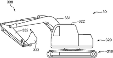
前記作業機械30は、油圧ショベルである。前記作業機械30は、例えば、クローラ式の下部走行体310と、下部走行体310上に旋回可能に設けられた上部旋回体320と、上部旋回体320に取り付けられた作業装置330とを備える。作業装置330は、例えば、上部旋回体320に対して起伏可能に取り付けられたブーム331と、ブーム331の先端部に対して揺動可能に取り付けられたアーム332と、アーム332の先端部に対して揺動可能に取り付けられたアタッチメント333とを備える。前記上部旋回体320は、運転室322を有し、当該運転室322内に図1に示すような複数の実機操作レバー31が配置されている。また、前記作業機械30には、前記複数の実機操作レバー31の他、図1に示されるような作業領域撮影カメラ32、ゲートレバー33及びこれを駆動するための駆動機構34が搭載されている。これらについては後に詳述する。
The work machine 30 is a hydraulic excavator. The work machine 30 includes, for example, a crawler-type lower traveling body 310, an upper revolving body 320 that is turnable on the lower traveling body 310, and a work device 330 attached to the upper revolving body 320. The working device 330 includes, for example, a boom 331 attached to the upper swing body 320 so as to be raised and lowered, an arm 332 attached so as to be swingable with respect to the distal end portion of the boom 331, and the distal end portion of the arm 332. And an attachment 333 attached to be swingable. The upper swing body 320 has a cab 322, and a plurality of actual machine operation levers 31 as shown in FIG. In addition to the plurality of actual machine operation levers 31, the work machine 30 is equipped with a work area photographing camera 32, a gate lever 33, and a drive mechanism 34 for driving the same as shown in FIG. . These will be described in detail later.
なお、本実施の形態に係る遠隔操作システムによって遠隔操作される作業機械は前記のような油圧ショベルに限定されない。
Note that the work machine remotely operated by the remote operation system according to the present embodiment is not limited to the hydraulic excavator as described above.
図1は、前記遠隔操作システムの全体構成を示す。当該遠隔操作システムは、スレーブ10とマスター20を備える。以下、これらについて説明する。
FIG. 1 shows the overall configuration of the remote control system. The remote operation system includes a slave 10 and a master 20. Hereinafter, these will be described.
前記スレーブ10は、前記作業機械30の操縦席に配置され、前記マスター20に与えられた操作の内容(操作量及び操作方向)に基づいて前記作業機械30の前記複数の実機操作レバー31を直接操作する従操作装置である。スレーブ10は、いわばオペレータのダミーとなって作業機械30を操作する機械である。
The slave 10 is arranged at the cockpit of the work machine 30 and directly controls the plurality of actual machine operation levers 31 of the work machine 30 based on the operation content (operation amount and operation direction) given to the master 20. It is a slave operating device to be operated. The slave 10 is a machine that operates the work machine 30 as an operator's dummy.
前記マスター20は、前記作業機械30から離れた位置に配置され、作業機械30を動かすためのオペレータによる操作が直接与えられる主操作装置である。前記マスター20は、前記作業機械30の運転席を模擬した構成を有する。
The master 20 is a main operation device that is arranged at a position away from the work machine 30 and is directly given an operation by an operator for moving the work machine 30. The master 20 has a configuration simulating a driver's seat of the work machine 30.
前記スレーブ10及び前記マスター20は、通信路100を介して相互に通信可能に接続されている。前記通信路100としては、例えば、特定省電力無線及びブルーツース(登録商標)といった、前記スレーブ10と前記マスター20を数十m~数百m程度の距離で無線通信させる通信路が採用される。但し、これは一例であり、通信路100としては、携帯電話通信網及びインターネット通信網等を含む公衆通信回線が採用されてもよい。この場合、マスター20とスレーブ10は長距離通信が可能となる。
The slave 10 and the master 20 are connected to each other via a communication path 100 so that they can communicate with each other. As the communication path 100, for example, a communication path for wireless communication between the slave 10 and the master 20 at a distance of about several tens to several hundreds of meters, such as specific power-saving radio and Bluetooth (registered trademark), is adopted. However, this is only an example, and the communication path 100 may be a public communication line including a mobile phone communication network and an Internet communication network. In this case, the master 20 and the slave 10 can perform long-distance communication.
マスター20は、通信部21と、マスター制御装置22と、オペレータによる操作を直接受ける複数の遠隔操作レバー23と、オペレータが着座する操縦席としてのシート24と、オペレータに装着される装着型ディスプレイ25と、オペレータの周囲を撮影する周囲撮影カメラ26と、オペレータが前記複数の遠隔操作レバー23のそれぞれに対して操作を与える意思である操作意思の有無を判定するための判定情報を取得する複数の判定情報取得装置と、を備える。以下、これらについて説明する。
The master 20 includes a communication unit 21, a master control device 22, a plurality of remote control levers 23 that are directly operated by an operator, a seat 24 as a cockpit on which the operator is seated, and a wearable display 25 that is mounted on the operator. And a plurality of surrounding information cameras 26 for photographing the surroundings of the operator, and a plurality of pieces of determination information for determining whether or not the operator intends to operate each of the plurality of remote control levers 23. A determination information acquisition device. Hereinafter, these will be described.
前記通信部21は、前記通信路100に採用される前記通信方式に対応する通信装置で構成されている。前記通信部21は、前記マスター20の前記複数の遠隔操作レバー23にそれぞれ与えられた操作についての操作情報、つまり操作量及び操作方向についての情報、を前記スレーブ10に送信する。前記通信部21は、前記スレーブ10から送られてくる映像(後に詳述される前記作業領域カメラ32が撮影している映像)を受信する。
The communication unit 21 is composed of a communication device corresponding to the communication method adopted for the communication path 100. The communication unit 21 transmits, to the slave 10, operation information about operations given to the plurality of remote control levers 23 of the master 20, that is, information about an operation amount and an operation direction. The communication unit 21 receives a video sent from the slave 10 (a video taken by the work area camera 32 described in detail later).
前記マスター制御装置22は、CPU、ASIC等のプロセッサとROM及びRAMといった記憶装置とを含むコンピュータで構成されている。前記マスター制御装置22は、各種の情報(例えば前記操作情報や、後に詳述される前記ゲートレバー33の位置を指示するゲートレバー指令を通信部21に送信させる。前記マスター制御装置22は、装着型ディスプレイ25に表示される映像を切り替える。当該マスター制御装置22の詳細については、後述する。
The master control device 22 is constituted by a computer including a processor such as a CPU and an ASIC and a storage device such as a ROM and a RAM. The master control device 22 transmits various information (for example, the operation information and a gate lever command indicating the position of the gate lever 33 described in detail later) to the communication unit 21. The master control device 22 is mounted. The image displayed on the mold display 25 is switched, and details of the master control device 22 will be described later.
前記複数の遠隔操作レバー23のそれぞれは、前記作業機械30から離れた位置に配置され、当該作業機械30のオペレータによって把持された状態で当該オペレータによる操作を受ける。前記複数の遠隔操作レバー23は、前記作業機械30の前記複数の実機操作レバー31とそれぞれ同様の構成を有する。前記複数の遠隔操作レバー23は、ATT(アタッチメント)レバー231と走行レバー232とを含む。
Each of the plurality of remote control levers 23 is disposed at a position away from the work machine 30 and is operated by the operator while being gripped by the operator of the work machine 30. The plurality of remote operation levers 23 have the same configuration as the plurality of actual machine operation levers 31 of the work machine 30. The plurality of remote control levers 23 include an ATT (attachment) lever 231 and a travel lever 232.
前記ATTレバー231は、前後左右の4方向に傾倒可能な操作レバーで構成され、前記作業機械30の作業装置(例えば、アタッチメント333及びブーム331)を動かすためのオペレータによる操作を受けることが可能である。具体的に、前記ATTレバー231は、ブーム倒伏操作と、ブーム起立操作と、アタッチメント引き操作と、アタッチメント押し操作と、を受けることが可能である。前記ブーム倒伏操作は、前記ブーム331を倒伏させるために前記ATTレバー231を前方に傾倒させる操作である。前記ブーム起立操作は、前記ブーム331を起立させるために前記ATTレバー231を後方に傾倒させる操作である。前記アタッチメント引き操作は、前記アタッチメント333を前記運転室332に近づく向きに揺動させるために前記ATTレバー231を左方に傾倒させる操作である。前記アタッチメント押し操作は、前記アタッチメント333を前記運転席から離れる向きに揺動させるために前記ATTレバー231を右方に傾倒させる操作である。
The ATT lever 231 is configured by an operation lever that can tilt in four directions, front, rear, left, and right, and can be operated by an operator for moving a work device (for example, the attachment 333 and the boom 331) of the work machine 30. is there. Specifically, the ATT lever 231 can receive a boom overturning operation, a boom standing up operation, an attachment pulling operation, and an attachment pushing operation. The boom overturning operation is an operation of tilting the ATT lever 231 forward in order to make the boom 331 fall down. The boom raising operation is an operation of tilting the ATT lever 231 backward in order to raise the boom 331. The attachment pulling operation is an operation of tilting the ATT lever 231 to the left in order to swing the attachment 333 in a direction approaching the cab 332. The attachment pressing operation is an operation of tilting the ATT lever 231 to the right in order to swing the attachment 333 away from the driver's seat.
前記走行レバー232は、前方向及び後方向に傾倒可能な操作レバーで構成され、前記作業機械30を前進及び後進させるためのオペレータによる前進操作及び後進操作を受けることが可能である。前記前進操作は、前記作業機械30を前進させるために前記走行レバー232を前方に傾倒させる操作であり、前記後進操作は、前記作業機械30を後進させるために前記走行レバー232を後方に傾倒させる操作である。
The travel lever 232 is composed of an operation lever that can be tilted forward and backward, and can receive forward operation and reverse operation by an operator for moving the work machine 30 forward and backward. The forward operation is an operation of tilting the traveling lever 232 forward to advance the work machine 30, and the backward operation is an operation of tilting the traveling lever 232 backward to reverse the work machine 30. It is an operation.
図1に示す前記複数の遠隔操作レバー23は、前記ATTレバー231と前記走行レバー232とを含むが、本発明に係る遠隔操作レバーはこれに限定されない。例えば、前記作業機械30が、前記作業装置330を動かすための前後方向の操作と前記上部旋回体320を動かすための左右方向の操作とを受けることが可能な4方向の実機操作レバーを備えている場合、その実機操作レバーと同じ構成を有する遠隔操作レバーを前記マスター20が含んでいてもよい。このように、本発明に係る遠隔操作レバーは、作業機械に搭載された各種の実機操作レバーにそれぞれ対応するものであることが、好ましい。
The plurality of remote control levers 23 shown in FIG. 1 include the ATT lever 231 and the travel lever 232, but the remote control lever according to the present invention is not limited thereto. For example, the work machine 30 includes a four-direction actual machine operation lever capable of receiving a front-back operation for moving the work device 330 and a left-right operation for moving the upper swing body 320. If so, the master 20 may include a remote control lever having the same configuration as the actual machine control lever. Thus, it is preferable that the remote control lever according to the present invention correspond to each of various actual machine control levers mounted on the work machine.
前記シート24は、当該シート24に着座しているオペレータが前記複数の遠隔操作レバー23をそれぞれ把持できるように、当該複数の遠隔操作レバー23の近傍に配置される。
The seat 24 is disposed in the vicinity of the plurality of remote control levers 23 so that an operator sitting on the seat 24 can grip the plurality of remote control levers 23, respectively.
前記装着型ディスプレイ25は、オペレータに装着された状態で当該オペレータに対して映像を表示することが可能なディスプレイである。前記装着型ディスプレイ25は、例えば、オペレータの頭部に装着された状態で使用されるへッドマウントディスプレイである。
The wearable display 25 is a display capable of displaying an image to the operator while being worn by the operator. The wearable display 25 is, for example, a head mounted display that is used while being worn on the operator's head.
装着型ディスプレイ25がオペレータの頭部に装着され且つ映像を表示していない状態では、オペレータの視界が装着型ディスプレイ25によって遮られる。つまり、この状態では、オペレータは自身の周囲を直接視認することが極めて困難である。
When the wearable display 25 is mounted on the operator's head and no image is displayed, the operator's field of view is blocked by the wearable display 25. That is, in this state, it is extremely difficult for the operator to visually recognize his / her surroundings directly.
装着型ディスプレイ25は、前記作業領域撮影カメラ32によって撮影される作業領域映像が表示されることが可能な特定表示領域251を有する。前記特定表示領域251は、例えば、装着型ディスプレイ25を装着しているオペレータが視認可能な視認可能領域の全体に亘って設定されていてもよいし、当該視認可能領域の一部の領域に設定されていてもよい。前記特定表示領域251は、例えば、前記装着型ディスプレイ25を装着しているオペレータの両目のそれぞれに設定されている。
The wearable display 25 has a specific display area 251 in which a work area image photographed by the work area photographing camera 32 can be displayed. For example, the specific display area 251 may be set over the entire visible area that can be visually recognized by the operator wearing the wearable display 25, or may be set to a part of the visible area. May be. For example, the specific display area 251 is set in each of the eyes of the operator wearing the wearable display 25.
前記周囲撮影カメラ26は、前記作業機械30から離れた位置に配置され、オペレータの周囲の映像である周囲映像を撮影する。前記周囲撮影カメラ26は、前記装着型ディスプレイ25と一体に動くように当該装着型ディスプレイ25に配置されて、当該装着側ディスプレイ25を装着するオペレータの前方を撮影する。従って、前記周囲撮影カメラ26の撮影範囲は、前記オペレータの顔の向きに応じて変化する。
The ambient shooting camera 26 is disposed at a position away from the work machine 30 and captures a surrounding image that is a surrounding image of the operator. The surrounding photographing camera 26 is disposed on the wearable display 25 so as to move integrally with the wearable display 25 and photographs the front of the operator who wears the wearable display 25. Accordingly, the shooting range of the surrounding camera 26 changes according to the orientation of the operator's face.
前記複数の判定情報取得装置のそれぞれは、前記操作意思、すなわちオペレータが前記遠隔操作レバー23に操作を与える意思、の有無を判定するための判定情報を取得する。当該複数の判定情報取得装置は、把持情報取得装置271、272と、着座情報取得装置273とを含む。
Each of the plurality of determination information acquisition devices acquires determination information for determining the presence or absence of the operation intention, that is, the intention of the operator to operate the remote control lever 23. The plurality of determination information acquisition devices include grip information acquisition devices 271 and 272 and a seating information acquisition device 273.
前記把持情報取得装置271は、オペレータによる前記ATTレバー231の把持動作の有無についての把持情報を前記判定情報として取得する。前記把持情報取得装置271は、例えば、前記ATTレバー231のうちオペレータが把持する部分に配置される。前記把持情報取得装置271は、例えば、把持センサを含む。当該把持センサは、オペレータによるATTレバー231の把持動作を検出できるものであればよい。把持センサは、例えば、ATTレバー231に配置されたセンサ電極と、当該センサ電極と人体(オペレータ)との間の静電容量の値を測定する測定部と、当該測定部が測定した静電容量値に基づいて前記把持動作の有無についての情報である把持情報を取得する取得部とを含むものであってもよい。あるいは、前記把持センサは、前記ATTレバー231に及ぼされるオペレータの把持力(圧力)を測定する測定部と、当該測定部が測定した把持力(圧力)に基づいて前記把持動作の有無についての把持情報を取得する取得部と、を含むものであってもよい。
The grip information acquisition device 271 acquires grip information about whether or not the ATT lever 231 is gripped by an operator as the determination information. The grip information acquisition device 271 is disposed, for example, at a portion of the ATT lever 231 that is gripped by an operator. The grip information acquisition device 271 includes, for example, a grip sensor. The grip sensor may be any sensor that can detect the gripping operation of the ATT lever 231 by the operator. The grip sensor includes, for example, a sensor electrode disposed on the ATT lever 231, a measurement unit that measures a capacitance value between the sensor electrode and a human body (operator), and a capacitance measured by the measurement unit. And an acquisition unit that acquires gripping information that is information about the presence or absence of the gripping operation based on the value. Alternatively, the grip sensor measures a gripping force (pressure) of an operator exerted on the ATT lever 231 and grips the presence or absence of the gripping operation based on the gripping force (pressure) measured by the measuring unit. And an acquisition unit that acquires information.
前記把持情報取得装置272は、オペレータによる前記走行レバー232の把持動作の有無についての情報である把持情報を前記判定情報として取得する。前記把持情報取得装置272は、例えば、前記走行レバー232のうちオペレータが把持する部分に配置される。前記把持情報取得装置272は、例えば、把持センサを含む。当該把持センサは、オペレータによる走行レバー232の把持動作を検出できるものであればよい。当該把持センサとしては、例えば、前記ATTレバー231に採用されるものと同様なものが採用される。
The grip information acquisition device 272 acquires grip information, which is information about the presence or absence of a gripping operation of the travel lever 232 by an operator, as the determination information. The grip information acquisition device 272 is disposed, for example, at a portion of the travel lever 232 that is gripped by an operator. The grip information acquisition device 272 includes a grip sensor, for example. The grip sensor may be any sensor that can detect the grip operation of the travel lever 232 by the operator. As the grip sensor, for example, a sensor similar to that used for the ATT lever 231 is used.
前記着座情報取得装置273は、オペレータの前記シート24への着座の有無についての情報である着座情報を判定情報として取得する。着座情報取得装置273は、例えば、前記シート24のうちオペレータが着座する部分に配置される。前記着座情報取得装置273は、例えば、着座センサによって実現される。当該着座センサは、オペレータの前記シート24への着座を検出できるものであればよい。前記着座センサとしては、例えば、超音波センサや赤外線センサ、近接センサ、重量センサ(例えば、歪ゲージ)等が採用される。
The seating information acquisition device 273 acquires seating information, which is information about whether an operator is seated on the seat 24, as determination information. The seating information acquisition device 273 is disposed, for example, at a portion of the seat 24 where an operator is seated. The seating information acquisition device 273 is realized by a seating sensor, for example. The seating sensor may be any sensor that can detect the seating of the operator on the seat 24. As the seating sensor, for example, an ultrasonic sensor, an infrared sensor, a proximity sensor, a weight sensor (for example, a strain gauge) or the like is employed.
前記スレーブ10は、通信部11と、スレーブ制御装置12と、前記作業機械30の前記複数の実機操作レバー31をそれぞれ操作する複数の操作機構14と、を備える。以下、これらについて説明する。
The slave 10 includes a communication unit 11, a slave control device 12, and a plurality of operation mechanisms 14 that respectively operate the plurality of actual machine operation levers 31 of the work machine 30. Hereinafter, these will be described.
前記通信部11は、前記通信路100に採用される通信方式に対応する通信装置で構成されている。前記通信部11は、前記マスター20から送信されてきた信号、例えば、前記操作情報及び前記ゲートレバー指令を受信する。前記通信部11は、マスター20に対して、前記作業領域撮影カメラ32が撮影している映像を送信する。
The communication unit 11 is composed of a communication device corresponding to the communication method adopted for the communication path 100. The communication unit 11 receives a signal transmitted from the master 20, for example, the operation information and the gate lever command. The communication unit 11 transmits to the master 20 an image captured by the work area photographing camera 32.
前記スレーブ制御装置12は、CPU、ASIC等のプロセッサとROM及びRAMといった記憶装置とを含むコンピュータで構成されている。前記スレーブ制御装置12は、前記作業領域撮影カメラ32が撮影した映像を前記通信部11に送信させる。前記スレーブ制御装置12は、前記マスター20から送られてくる信号に基づいて前記操作機構14の動作を制御する。
The slave control device 12 is composed of a computer including a processor such as a CPU and an ASIC and a storage device such as a ROM and a RAM. The slave control device 12 causes the communication unit 11 to transmit an image captured by the work area imaging camera 32. The slave control device 12 controls the operation of the operation mechanism 14 based on a signal sent from the master 20.
前記複数の操作機構14は、アクチュエータで構成され、マスター20から送られてくる操作内容(操作量及び操作方向)に応じた操作力を発生させ、当該操作力を前記複数の実機操作レバー31のうち対応するものに付与する。図1に示す例では、前記複数の実機操作レバー31が前記ATTレバー311と前記走行レバー312とを含むので、前記複数の操作機構14は、前記ATTレバー311に対応する操作機構14Aと、走行レバー312に対応する操作機構14Bと、を含む。前記ATTレバー311は「前後」方向及び「左右」方向に操作可能であるため、前記操作機構14Aは前記ATTレバー311を「前後」方向に動かすためのアクチュエータと前記ATTレバー31を「左右」方向に動かすアクチュエータとを含む。前記走行レバー312は「前後」方向に操作可能であるため、前記操作機構14Bは前記走行レバー312を「前後」方向に動かすアクチュエータを含む。
The plurality of operation mechanisms 14 are composed of actuators, generate an operation force corresponding to the operation content (operation amount and operation direction) sent from the master 20, and the operation force is applied to the plurality of actual machine operation levers 31. It is given to the corresponding one. In the example shown in FIG. 1, since the plurality of actual machine operation levers 31 include the ATT lever 311 and the traveling lever 312, the plurality of operation mechanisms 14 includes an operation mechanism 14 </ b> A corresponding to the ATT lever 311, and traveling And an operation mechanism 14B corresponding to the lever 312. Since the ATT lever 311 can be operated in the “front-rear” direction and the “left-right” direction, the operating mechanism 14A moves the actuator for moving the ATT lever 311 in the “front-rear” direction and the ATT lever 31 in the “left-right” direction. And an actuator to be moved. Since the traveling lever 312 can be operated in the “front-rear” direction, the operation mechanism 14B includes an actuator that moves the traveling lever 312 in the “front-rear” direction.
前記スレーブ制御装置12は、前記通信部11が前記ATTレバー231についての操作情報(操作量及び操作内容についての情報)を受信した場合、その操作情報に応じた制御信号を生成して操作機構14Aに入力する。前記スレーブ制御装置12は、前記通信部11が前記走行レバー232についての操作情報(操作量及び操作内容についての情報)を受信した場合、その操作情報に応じた制御信号を生成して操作機構14Bに入力する。これにより、スレーブ10はマスター20を操作するオペレータのダミーとして作業機械30に直接操作を与える。
When the communication unit 11 receives operation information about the ATT lever 231 (information about the operation amount and operation details), the slave control device 12 generates a control signal according to the operation information and operates the operation mechanism 14A. To enter. When the communication unit 11 receives operation information about the travel lever 232 (information about the operation amount and the operation content), the slave control device 12 generates a control signal according to the operation information and operates the operation mechanism 14B. To enter. As a result, the slave 10 gives an operation directly to the work machine 30 as a dummy of an operator who operates the master 20.
次に、前記作業機械30に搭載されている、前記実機操作レバー31、前記作業領域撮影カメラ32、前記ゲートレバー33、及び前記駆動機構34について説明する。
Next, the actual machine operation lever 31, the work area photographing camera 32, the gate lever 33, and the drive mechanism 34 mounted on the work machine 30 will be described.
前記複数の実機操作レバー31は、前記作業機械30の前記運転室322内に設けられ、前記スレーブ10から付与される操作力の方向に傾倒する。前記複数の実機操作レバー31のうち、前記ATTレバー311は、前記ATTレバー231と同様、前後左右の4方向に傾倒可能な操作レバーで構成され、前記走行レバー312は、前記走行レバー232と同様、前方向及び後方向に傾倒可能な操作レバーで構成されている。前記ATTレバー311にこれを前方又は後方に傾倒させる操作が与えられることにより前記ブーム331が倒伏又は起伏する。前記ATTレバー31にこれを左右方向に傾倒させる操作が与えられることにより、前記アタッチメント333が揺動する。前記走行レバー322にこれを前方に傾倒させる操作が与えられることにより前記下部走行体310が前進し、前記走行レバー322にこれを後方に傾倒させる操作が与えられることにより前記下部走行体310が後進する。
The plurality of actual machine operation levers 31 are provided in the cab 322 of the work machine 30 and tilt in the direction of the operation force applied from the slave 10. Of the plurality of actual machine operating levers 31, the ATT lever 311 is configured by an operating lever that can tilt in four directions, front, rear, left and right, similar to the ATT lever 231, and the traveling lever 312 is similar to the traveling lever 232. The operation lever can be tilted forward and backward. When the ATT lever 311 is operated to tilt it forward or backward, the boom 331 falls or rises and falls. When the ATT lever 31 is tilted in the left-right direction, the attachment 333 is swung. The lower traveling body 310 moves forward by giving the traveling lever 322 an operation of tilting it forward, and the lower traveling body 310 moves backward by giving the operation of tilting the traveling lever 322 backward. To do.
前記作業領域撮影カメラ32は、前記作業機械30の周囲の作業領域についての映像である作業領域映像を撮影する。前記作業領域撮影カメラ32は、例えば、前記運転室322に設けられて当該運転室322よりも前側の領域を撮影する。
The work area photographing camera 32 photographs a work area image that is an image of a work area around the work machine 30. For example, the work area imaging camera 32 is provided in the operator cab 322 and shoots an area in front of the operator cab 322.
前記ゲートレバー33は、前記運転室322において運転席に通じる乗降口を開閉するように配置される。当該ゲートレバー33は、前記乗降口を開く開位置において、第三者(例えば、作業機械30の周囲に存在する作業者)が前記運転席に乗り込むのを許容する。前記ゲートレバー33は、前記乗降口を閉じる閉位置において、第三者が前記運転席に乗り込むのを阻止する。
The gate lever 33 is disposed so as to open and close the entrance / exit leading to the driver's seat in the driver's cab 322. The gate lever 33 allows a third party (for example, an operator present around the work machine 30) to get into the driver's seat at the open position where the entrance is opened. The gate lever 33 prevents a third party from getting into the driver's seat in the closed position where the entrance / exit is closed.
前記駆動機構34は、前記乗降口を開閉する方向に前記ゲートレバー33を駆動する。すなわち、前記ゲートレバー33を前記開位置と前記閉位置との間で移動させる。駆動機構34は、例えばアクチュエータを含み、前記マスター20から送られてくるゲートレバー指令に応じて駆動力を発生させ、当該駆動力を前記ゲートレバー33に付与する。
The drive mechanism 34 drives the gate lever 33 in a direction to open and close the entrance / exit. That is, the gate lever 33 is moved between the open position and the closed position. The drive mechanism 34 includes, for example, an actuator, generates a driving force in accordance with a gate lever command sent from the master 20, and applies the driving force to the gate lever 33.
続いて、図3を参照しながら、前記マスター制御装置22についてさらに説明する。図3は、当該マスター制御装置22を示す機能ブロック図である。
Subsequently, the master controller 22 will be further described with reference to FIG. FIG. 3 is a functional block diagram showing the master control device 22.
前記マスター制御装置22は、前記複数の判定情報取得装置、この実施の形態では前記把持情報取得装置271,272及び前記着座情報取得装置273、が取得した判定情報の内容に応じて作業領域映像を装着型ディスプレイ25の特定表示領域251に表示させる。
The master control device 22 displays a work area image according to the contents of the determination information acquired by the plurality of determination information acquisition devices, in this embodiment, the grip information acquisition devices 271, 272 and the seating information acquisition device 273. It is displayed in the specific display area 251 of the wearable display 25.
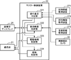
前記マスター制御装置22は、操作意思判定部221と、表示映像切替部222と、駆動機構制御部223と、稼働制御部224とを含む。以下、これらについて説明する。
The master control device 22 includes an operation intention determination unit 221, a display video switching unit 222, a drive mechanism control unit 223, and an operation control unit 224. Hereinafter, these will be described.
前記操作意思判定部221は、前記複数の判定情報取得装置、この実施の形態では前記把持情報取得装置271,272及び前記着座情報取得装置273、により取得された判定情報の内容に基づいて前記複数の遠隔操作レバー23のいずれかに対するオペレータの操作意思の有無を判定する。操作意思判定部221は、前記把持情報取得装置271、272により取得されることが可能な前記把持情報と前記着座情報取得装置273により取得されることが可能な前記着座情報とに基づいて、前記複数の遠隔操作レバー23のいずれかに対するオペレータの操作意思があるか否か、この実施の形態では予め設定された操作意思判定条件が満たされているか否か、を判定する。前記操作意思判定条件は、この実施の形態では、前記複数の遠隔操作レバー23である前記ATTレバー231及び前記走行レバー232のうちの少なくとも一方に対するオペレータの把持動作があり且つ前記シート24への当該オペレータの着座があることである。
The operation intention determination unit 221 includes the plurality of determination information acquisition devices, which are based on the content of determination information acquired by the grip information acquisition devices 271, 272 and the seating information acquisition device 273 in this embodiment. The operator's intention to operate the remote control lever 23 is determined. The operation intention determination unit 221 is based on the grip information that can be acquired by the grip information acquisition devices 271 and 272 and the seating information that can be acquired by the seating information acquisition device 273. In this embodiment, it is determined whether or not there is an operator's intention to operate any of the plurality of remote control levers 23, and whether or not a predetermined operation intention determination condition is satisfied. In this embodiment, the operation intention determination condition includes an operator's gripping operation with respect to at least one of the ATT lever 231 and the travel lever 232 that are the plurality of remote control levers 23, and the operation to the seat 24. There is an operator seating.
前記表示映像切替部222は、前記操作意思の有無についての前記操作意思判定部221による判定の結果に応じて、装着型ディスプレイ25に表示する映像を切り替える。具体的には、前記表示映像切替部222は、前記操作意思があると前記操作意思判定部221が判定した場合には前記装着型ディスプレイ25に前記特定表示領域251での作業領域映像の表示を行わせる一方、前記操作意思がないと前記操作意思判定部221が判定した場合には前記特定表示領域251における前記作業領域映像の表示を中止させて当該特定表示領域251に周囲映像を表示させる。つまり、前記表示映像切替部222は、前記操作意思がないと判定された場合には前記特定表示領域251において前記作業領域映像の代わりに前記周囲映像の表示を前記装着型ディスプレイ25に行わせる。従って、本実施の形態では、前記特定表示領域251の全体が周囲視認可能領域として機能する。
The display video switching unit 222 switches the video to be displayed on the wearable display 25 according to the determination result by the operation intention determination unit 221 regarding the presence or absence of the operation intention. Specifically, the display image switching unit 222 displays the work area image in the specific display area 251 on the wearable display 25 when the operation intention determination unit 221 determines that the operation intention is present. On the other hand, when the operation intention determination unit 221 determines that there is no intention to operate, the display of the work area video in the specific display area 251 is stopped and the surrounding video is displayed in the specific display area 251. That is, the display video switching unit 222 causes the wearable display 25 to display the surrounding video instead of the work area video in the specific display area 251 when it is determined that there is no intention to operate. Therefore, in the present embodiment, the entire specific display area 251 functions as a peripheral viewable area.
前記駆動機構制御部223は、前記操作意思があると前記操作意思判定部221が判定した場合には、前記ゲートレバー33を前記閉位置に移動させるように前記駆動機構34を作動させるためのゲートレバー指令を生成する一方、前記操作意思がない場合と前記操作意思判定部221が判定した場合には前記ゲートレバー33を開位置に移動させるように前記駆動機構34を作動させるためのゲートレバー指令を生成する。前記駆動機構制御部223は、さらに、前記ゲートレバー指令を前記通信部21に送信させる。当該ゲートレバー指令を前記スレーブ10の通信部11が受信すると、当該スレーブ10のスレーブ制御装置12はその受信した前記ゲートレバー指令に基づいて前記ゲートレバー33を前記閉位置または前記開位置に移動させるように前記駆動機構34の動作を制御する。
The drive mechanism control unit 223 is a gate for operating the drive mechanism 34 to move the gate lever 33 to the closed position when the operation intention determination unit 221 determines that there is the operation intention. While generating a lever command, a gate lever command for operating the drive mechanism 34 to move the gate lever 33 to an open position when the operation intention determination unit 221 determines that there is no operation intention. Is generated. The drive mechanism control unit 223 further causes the communication unit 21 to transmit the gate lever command. When the communication unit 11 of the slave 10 receives the gate lever command, the slave control device 12 of the slave 10 moves the gate lever 33 to the closed position or the open position based on the received gate lever command. Thus, the operation of the drive mechanism 34 is controlled.
前記稼働制御部224は、前記操作意思があると前記操作意思判定部221が判定した場合には前記複数の遠隔操作レバー23のいずれかに与えられる操作に基づく前記作業機械30の稼働を許容する一方、前記操作意思がないと前記操作意思判定部221が判定した場合には前記操作に基づく前記作業機械30の稼働を禁止する。具体的に、前記稼働制御部224は、前記複数の遠隔操作レバー23のいずれかに与えられる前記操作に基づく前記作業機械30の稼働を許容するか否かについての指令である稼働許容指令または稼働禁止指令を前記通信部21に送信させる。当該稼働許容指令または当該稼働禁止指令を前記スレーブ10の通信部11が受信すると、当該スレーブ10のスレーブ制御装置12はその受信した稼働許否指令に応じて前記操作機構14A、14Bの動作を制御する。具体的に、前記稼働許容指令が受信された場合、前記スレーブ制御装置12は、オペレータによって前記遠隔操作レバー23に与えられた操作に対応する操作を前記実機操作レバー31に与えるように前記操作機構14A,14Bを作動させる。逆に、前記稼働禁止指令が受信された場合、前記スレーブ制御装置12は、オペレータによって前記遠隔操作レバー23に与えられた操作にかかわらず、前記操作機構14A,14Bが前記実機操作レバー31に操作を与える動作を禁止する。
The operation control unit 224 allows the operation of the work machine 30 based on an operation given to one of the plurality of remote operation levers 23 when the operation intention determination unit 221 determines that there is the operation intention. On the other hand, when the operation intention determination unit 221 determines that there is no operation intention, the operation of the work machine 30 based on the operation is prohibited. Specifically, the operation control unit 224 is an operation permission command or operation that is a command as to whether or not to permit the operation of the work machine 30 based on the operation given to any of the plurality of remote control levers 23. A prohibition command is transmitted to the communication unit 21. When the communication unit 11 of the slave 10 receives the operation permission command or the operation prohibition command, the slave control device 12 of the slave 10 controls the operation of the operation mechanisms 14A and 14B according to the received operation permission / inhibition command. . Specifically, when the operation permission command is received, the slave control device 12 gives the operation mechanism 31 an operation corresponding to an operation given to the remote operation lever 23 by an operator to the actual machine operation lever 31. 14A and 14B are operated. On the contrary, when the operation prohibition command is received, the slave control device 12 causes the operation mechanism 14A, 14B to operate the actual machine operation lever 31 regardless of the operation given to the remote operation lever 23 by the operator. Is prohibited.
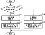
続いて、図4を参照しながら、前記マスター制御装置22により実行される映像切替処理について説明する。図4は、当該映像切替処理を示すフローチャートである。
Subsequently, the video switching process executed by the master control device 22 will be described with reference to FIG. FIG. 4 is a flowchart showing the video switching process.
先ず、前記マスター制御装置22の前記操作意思判定部221は、ステップS11において、前記複数の遠隔操作レバー23のいずれかに対するオペレータの操作意思の有無を判定する。
First, in step S11, the operation intention determination unit 221 of the master control device 22 determines whether or not there is an operator's operation intention with respect to any of the plurality of remote operation levers 23.
前記操作意思があると前記操作意思判定部221が判定した場合(ステップS11でYES)、前記マスター制御装置22は、ステップS12において、作業機械30を稼働可能な状態にする。具体的には、前記マスター制御装置22の前記稼働制御部224が前記複数の遠隔操作レバー23に与えられる操作に基づく前記作業機械30の稼働を許容する旨の稼働許容指令を前記通信部21に送信させるとともに、前記駆動機構制御部223が前記ゲートレバー33を閉位置に移動させる旨のゲートレバー指令を前記通信部21に送信させる。
When the operation intention determination unit 221 determines that there is the operation intention (YES in step S11), the master control device 22 sets the work machine 30 in an operable state in step S12. Specifically, an operation permission command for permitting the operation of the work machine 30 based on an operation given to the plurality of remote control levers 23 by the operation control unit 224 of the master control device 22 is sent to the communication unit 21. The transmission mechanism control unit 223 causes the communication unit 21 to transmit a gate lever command for moving the gate lever 33 to the closed position.
続いて、前記マスター制御装置22の前記表示映像切替部222は、ステップS13において、前記装着型ディスプレイ25にその特定表示領域251での作業領域映像、つまり前記作業領域撮影カメラ32が撮影している映像、の表示を行わせる。
Subsequently, in step S13, the display image switching unit 222 of the master control device 22 captures the work area image in the specific display area 251 on the wearable display 25, that is, the work area photographing camera 32 takes an image. Display video.
前記操作意思がないと前記操作意思判定部221が判定した場合(ステップS11でNO)、前記マスター制御装置22は、ステップS14において、前記作業機械30を稼働不可の状態にする。具体的には、当該マスター制御装置22の前記稼働制御部224が、前記複数の遠隔操作レバー23に与えられる操作に基づく前記作業機械30の稼働を禁止する旨の稼働禁止指令を前記通信部21に送信させるとともに、前記駆動機構制御部223が前記ゲートレバー33を開位置に移動させる旨のゲートレバー指令を前記通信部21に送信させる。
When the operation intention determination unit 221 determines that there is no operation intention (NO in step S11), the master control device 22 puts the work machine 30 into an inoperable state in step S14. Specifically, the operation control unit 224 of the master control device 22 issues an operation prohibition command to prohibit the operation of the work machine 30 based on an operation given to the plurality of remote control levers 23. And the drive mechanism control unit 223 causes the communication unit 21 to transmit a gate lever command for moving the gate lever 33 to the open position.
続いて、前記マスター制御装置22の前記表示映像切替部222は、ステップS15において、装着型ディスプレイ25にその特定表示領域251での周囲映像、すなわち前記周囲撮影カメラ26が撮影している映像、の表示を行わせる。
Subsequently, in step S15, the display image switching unit 222 of the master control device 22 displays a surrounding image in the specific display area 251 on the wearable display 25, that is, an image captured by the surrounding photographing camera 26. Make a display.
このような遠隔操作システムにおいては、オペレータが前記操作意思、すなわち前記複数の遠隔操作レバー23のいずれかに対して操作を与える意思、を有していると判定された場合、前記作業領域撮影カメラ32によって撮影される作業領域映像が前記装着型ディスプレイ25の前記特定表示領域251に表示される。この表示は、オペレータが前記装着型ディスプレイ25を通じて前記作業機械30の周囲を視認することを可能にする。つまり、オペレータが前記操作意思を有している場合には、オペレータに対して主に前記作業機械30の周囲の状況を認識できるような環境を提供することができる。このことは、オペレータが前記作業機械30の遠隔操作を的確に行うことを可能にする。
In such a remote operation system, when it is determined that the operator has the operation intention, that is, the intention to give an operation to any of the plurality of remote operation levers 23, the work area photographing camera A work area image captured by the display 32 is displayed in the specific display area 251 of the wearable display 25. This display allows the operator to visually recognize the surroundings of the work machine 30 through the wearable display 25. That is, when the operator has the operation intention, it is possible to provide an environment in which the operator can mainly recognize the situation around the work machine 30. This enables an operator to accurately perform remote operation of the work machine 30.
一方、オペレータが前記操作意思を有していない場合、前記特定表示領域251において作業領域映像の表示が中止されるとともに当該特定表示領域251に周囲映像(周囲撮影カメラ26によって撮影される映像)が表示される。この表示は、オペレータが前記装着型ディスプレイ25を装着したまま当該オペレータ自身の周囲の状況を把握することを可能にする。つまり、オペレータが前記操作意思を有していない場合には、オペレータに対して主に自身の周囲の状況を認識できるような環境を提供することができる。このことは、オペレータが前記複数の遠隔操作レバー23に対する前記操作意思を有していないにもかかわらず誤って当該操作レバー23に操作を与えてしまうことを防ぐ。
On the other hand, when the operator does not have the intention to operate, the display of the work area video is stopped in the specific display area 251 and the surrounding video (video shot by the ambient camera 26) is displayed in the specific display area 251. Is displayed. This display makes it possible for the operator to grasp the situation around the operator while wearing the wearable display 25. That is, when the operator does not have the intention to operate, it is possible to provide an environment in which the operator can mainly recognize the situation around him / her. This prevents an operator from giving an operation to the operation lever 23 by mistake even though the operator does not have the intention to operate the plurality of remote operation levers 23.
上述の遠隔操作システムにおいては、作業機械30の遠隔操作に必要な遠隔操作レバー23の把持動作だけでなくオペレータの操作姿勢(具体的には、シート24への着座)も考慮することにより、オペレータの前記遠隔操作レバー23に対する操作意思の有無をより的確に判定することができる。
In the above-described remote operation system, not only the gripping operation of the remote operation lever 23 necessary for the remote operation of the work machine 30 but also the operator's operation posture (specifically, sitting on the seat 24) is taken into consideration. It is possible to more accurately determine whether or not there is an intention to operate the remote control lever 23.
上述の遠隔操作システムにおいては、前記装着型ディスプレイ25の前記特定表示領域251における前記周囲映像の表示が、当該装着型ディスプレイ25の透過性の有無にかかわらずオペレータが前記装着型ディスプレイ25を装着したまま自身の周囲の状況を把握することを可能にする。
In the remote operation system described above, the operator wears the wearable display 25 regardless of whether or not the display of the surrounding image in the specific display area 251 of the wearable display 25 is permeable to the wearable display 25. It is possible to keep track of the situation around you.
上述の遠隔操作システムの前記周囲撮影カメラ26は、オペレータの頭部に装着される前記装着型ディスプレイ25と一体に動きかつ前記オペレータの前方を撮影するように前記装着型ディスプレイ25に配置されるので、オペレータの顔の向きに応じて当該周囲撮影カメラ26自身の向きを変化させて常にオペレータの前方の映像を撮影することができる。このことは、オペレータの顔の向きに関わらず当該オペレータが自身の周囲の状況を的確に把握することを可能にする。
The ambient camera 26 of the above-described remote operation system is arranged on the wearable display 25 so as to move integrally with the wearable display 25 mounted on the operator's head and to photograph the front of the operator. By changing the direction of the surrounding photographing camera 26 itself according to the orientation of the operator's face, it is possible to always take a picture in front of the operator. This makes it possible for the operator to accurately grasp the surrounding situation regardless of the face orientation of the operator.
上述の遠隔操作システムにおいては、オペレータの前記遠隔操作レバー23に対する操作意思に応じて作業機械30の運転席に通じる乗降口をゲートレバー33が開閉するので、オペレータによる作業機械30の遠隔操作が行われているときに第三者(例えば、作業機械30の周囲に存在する作業者等)が作業機械30の運転席に乗り込むのを防ぐことができる。
In the above-described remote operation system, the gate lever 33 opens and closes the entrance / exit that leads to the driver's seat of the work machine 30 according to the operator's intention to operate the remote control lever 23, so that the operator can remotely operate the work machine 30. It is possible to prevent a third party (for example, an operator or the like existing around the work machine 30) from getting into the driver's seat of the work machine 30 when he / she is sitting.
また、前記遠隔操作システムは、前記複数の操作レバー23に対するオペレータの前記操作意思に応じて作業機械30の稼働の許否を切換えることにより、さらに高い安全性を確保することができる。例えば、オペレータが前記複数の操作レバー23に対する前記操作意思を有していないにもかかわらず誤って当該複数の操作レバー23のいずれかに操作を与えたとしても、その誤った操作に基づく作業機械30の稼働を防ぐことができる。つまり、作業機械30がオペレータの意思に反して稼働するのを防ぐことができる。
Further, the remote operation system can ensure higher safety by switching permission / inhibition of operation of the work machine 30 in accordance with the operation intention of the operator with respect to the plurality of operation levers 23. For example, even if an operator does not have the intention to operate the plurality of operation levers 23 and erroneously gives an operation to any of the plurality of operation levers 23, the work machine based on the erroneous operation The operation of 30 can be prevented. That is, it is possible to prevent the work machine 30 from operating against the operator's intention.
以上、本発明の実施の形態について詳述してきたが、これらはあくまでも例示であって、本発明は、上述の実施の形態によって、何等、限定されない。
Although the embodiments of the present invention have been described in detail above, these are merely examples, and the present invention is not limited to the above-described embodiments.
図1に示す遠隔操作システムは、前記マスター20における前記複数の遠隔操作レバー23に与えられるオペレータの操作に対応して、前記作業機械30の運転席に配置された前記スレーブ10が前記作業機械30における前記複数の実機操作レバー31のうち前記操作に対応するものに実機操作を与えるものであるが、本発明に係る遠隔操作システムは、図1に示す態様に限定されない。本発明は、例えば、前記スレーブ10のない態様や前記作業機械30が前記実機操作レバー31を有しない態様も包含する。また、本発明に係る遠隔操作レバーは単数であってもよい。
In the remote control system shown in FIG. 1, the slave 10 disposed in the driver's seat of the work machine 30 corresponds to the operation of the operator given to the plurality of remote control levers 23 in the master 20. Although the real machine operation is given to the one corresponding to the operation among the plurality of real machine operation levers 31 in FIG. 1, the remote operation system according to the present invention is not limited to the mode shown in FIG. The present invention includes, for example, an aspect without the slave 10 and an aspect in which the work machine 30 does not have the actual machine operation lever 31. Further, a single remote control lever according to the present invention may be provided.
本発明における判定情報取得装置は、上記実施の形態にて説明した把持情報取得装置271,272や着座情報取得装置273のように作業機械を遠隔操作するオペレータの体の一部が常時接触する部分に配置されるものに、限定されない。例えば、オペレータが押圧操作可能なスイッチによって判定情報取得装置を実現してもよい。このようなスイッチは、例えば、遠隔操作レバーの周囲に配置されるのが好ましい。
The determination information acquisition device according to the present invention is a portion where a part of the body of an operator who remotely operates the work machine is always in contact, such as the grip information acquisition devices 271 and 272 and the seating information acquisition device 273 described in the above embodiment. It is not limited to what is arrange | positioned. For example, the determination information acquisition device may be realized by a switch that can be pressed by the operator. Such a switch is preferably arranged, for example, around a remote control lever.
本発明に係る遠隔操作システムは、単数の判定情報取得装置のみを備えてもよいし、複数の判定情報取得装置を備えてもよい。複数の判定情報取得装置を備える遠隔操作システムでは、前記複数の判定情報取得装置の各々によって取得された判定情報の全てがオペレータの操作意思があることを示すものである場合にのみ当該オペレータの操作意思があると判定するように操作意思判定部が構成されてもよい。例えば、上記実施の形態に係る操作意思判定部221は、2つの前記把持情報取得装置271、272の各々によって取得された把持情報が何れも把持動作を示すものであって且つ着座情報取得装置273によって取得された着座情報がオペレータのシート24への着座を示すものである場合に限り前記操作意思があると判定するように構成されていてもよい。或いは、本発明に係る操作意思判定部は、複数の判定情報取得装置の各々によって取得された判定情報の少なくとも一つがオペレータの操作意思があることを示す場合にオペレータの操作意思があると判定してもよい。例えば、上記実施の形態において前記着座情報取得装置273が省略された態様において、前記操作意思判定部221は、残りの2つの把持情報取得装置271、272の何れかによって取得された把持情報がオペレータの操作意思があることを示すものであればオペレータの操作意思があると判定するように構成されていてもよい。単一の判定情報取得装置の例としては、上記のようにオペレータが押圧操作可能なスイッチが挙げられる。
The remote operation system according to the present invention may include only a single determination information acquisition device or a plurality of determination information acquisition devices. In a remote operation system including a plurality of determination information acquisition devices, the operator's operation is performed only when all of the determination information acquired by each of the plurality of determination information acquisition devices indicates an operator's intention to operate. The operation intention determination unit may be configured to determine that there is an intention. For example, in the operation intention determination unit 221 according to the above-described embodiment, the grip information acquired by each of the two grip information acquisition devices 271 and 272 indicates a grip operation, and the seating information acquisition device 273 is used. It may be configured to determine that the user has the intention to operate only when the seating information obtained by the above indicates the seating of the operator on the seat 24. Alternatively, the operation intention determination unit according to the present invention determines that there is an operator's operation intention when at least one of the determination information acquired by each of the plurality of determination information acquisition devices indicates the operator's operation intention. May be. For example, in the aspect in which the seating information acquisition device 273 is omitted in the above embodiment, the operation intention determination unit 221 determines that the grip information acquired by one of the remaining two grip information acquisition devices 271 and 272 is an operator. It may be configured to determine that there is an operator's operation intention as long as it indicates that there is an operation intention. As an example of a single determination information acquisition device, there is a switch that can be pressed by an operator as described above.
本発明に係る表示映像切換部は、前記実施の形態のように装着型ディスプレイに特定表示領域の全体に亘る周囲映像の表示を行わせるものに限定されない。例えば、前記周囲映像を前記特定表示領域の一部にのみ表示させるものでもよい。つまり、本発明に係る周囲視認可能領域は前記特定表示領域の一部であってもよい。また、本発明は周囲視認可能領域に周囲映像を表示させる態様に限定されない。例えば、本発明に係る周囲視認可能領域は、当該周囲視認可能領域を透過してオペレータの周囲を視認することを許容する透過性をもった領域すなわち透過領域であってもよい。当該透過領域は前記オペレータが当該透過領域を通じて自身の周囲を視認することを可能にする。また、前記周囲視認画像領域が前記特定表示領域の一部である場合、オペレータは、作業領域映像を見ながら当該オペレータ自身の周囲を視認することができる。
The display video switching unit according to the present invention is not limited to the one that causes the wearable display to display the surrounding video over the entire specific display area as in the above embodiment. For example, the surrounding image may be displayed only on a part of the specific display area. In other words, the peripheral viewable area according to the present invention may be a part of the specific display area. In addition, the present invention is not limited to an aspect in which a surrounding video is displayed in a surrounding visible region. For example, the perimeter-viewable area according to the present invention may be a transmissive area that transmits the perimeter-viewable area and allows the operator to see the perimeter of the operator, that is, a transmissive area. The transmissive area allows the operator to view his surroundings through the transmissive area. Further, when the peripheral visual image area is a part of the specific display area, the operator can visually recognize the surroundings of the operator while viewing the work area video.
本発明に係る前記周囲撮影カメラは、前記装着型ディスプレイに設けられるものに限定されない。例えば、オペレータが着座する操縦席の上方に本発明に係る周囲撮影カメラを設けてもよい。
The ambient shooting camera according to the present invention is not limited to that provided in the wearable display. For example, an ambient camera according to the present invention may be provided above a cockpit where an operator is seated.
本発明において、前記周囲撮影カメラは必須ではない。例えば、装着型ディスプレイにおいて特定表示領域の周辺にオペレータの周囲を透過可能な透過領域が設けられている場合、オペレータは当該透過領域を通じて自身の周囲を常時視認できるため、前記周囲撮影カメラは必ずしも要しない。
In the present invention, the surrounding camera is not essential. For example, in the case where a wearable display has a transmission area that can be transmitted through the operator around the specific display area, the operator can always visually recognize the surrounding area through the transmission area. do not do.
以上のように、作業機械のオペレータに装着された状態で当該オペレータに対して作業機の周囲の映像を表示可能な装着型ディスプレイと、当該装着型ディスプレイを装着したオペレータによる操作を受けることができる遠隔操作レバーとを備える作業機械の遠隔操作システムであって、上記装着型ディスプレイを装着したオペレータが自身の周囲の状況を把握することを可能にする作業機械の遠隔操作システムが、提供される。
As described above, the wearable display capable of displaying an image around the work implement with respect to the operator while being worn by the operator of the work machine, and the operation by the operator wearing the wearable display can be received. There is provided a remote operation system for a work machine including a remote control lever, which enables an operator wearing the wearable display to grasp a situation around the work machine.
提供されるのは、作業機械を遠隔操作するためのシステムであって、前記作業機械から離れた位置に配置され、前記作業機械のオペレータによって把持された状態で前記オペレータによる操作を受けることができる遠隔操作レバーと、前記オペレータが前記遠隔操作レバーに対して操作を与える意思である操作意思の有無を判定するための判定情報を取得可能な少なくとも1つの判定情報取得装置と、前記作業機械に配置され、前記作業機械の周囲の映像である作業領域映像を撮影可能な作業領域撮影カメラと、前記オペレータに装着された状態で当該オペレータに対して映像を表示可能なディスプレイであって、前記作業領域映像を表示可能な特定表示領域を有する装着型ディスプレイと、前記少なくとも1つの判定情報取得装置が取得した前記判定情報の内容に応じて前記作業領域映像を前記特定表示領域に表示させる制御装置とを備える。前記制御装置は、前記少なくとも1つの判定情報取得装置により取得された前記判定情報の内容に基づいて前記操作意思の有無を判定する操作意思判定部と、前記操作意思判定部が前記オペレータに前記操作意思があると判定した場合には前記装着型ディスプレイに前記特定表示領域での前記作業領域映像の表示を行わせる一方、前記操作意思判定部が前記オペレータに前記操作意思がないと判定した場合には前記特定表示領域の少なくとも一部の領域における前記作業領域映像の表示を中止させかつ当該少なくとも一部の領域を前記オペレータが当該オペレータの周囲を視認することを可能にする周囲視認可能領域に切り替える表示映像切替部と、を含む。
What is provided is a system for remotely operating a work machine, which is disposed at a position away from the work machine and can be operated by the operator while being gripped by the operator of the work machine. Arranged on the work machine, a remote control lever, at least one determination information acquisition device capable of acquiring determination information for determining whether or not the operator has an intention to operate the remote control lever A work area photographing camera capable of photographing a work area image that is an image around the work machine, and a display capable of displaying an image to the operator in a state of being attached to the operator, the work area Acquired by a wearable display having a specific display area capable of displaying video and the at least one determination information acquisition device And a control unit for displaying the workspace image according to the contents of the determination information in the specific display area. The control device includes: an operation intention determination unit that determines presence / absence of the operation intention based on content of the determination information acquired by the at least one determination information acquisition device; and the operation intention determination unit sends the operation to the operator When it is determined that there is an intention, the operation type determination unit determines that the operator does not have the operation intention while causing the wearable display to display the work area image in the specific display area Stops the display of the work area video in at least a part of the specific display area and switches the at least part of the area to a perimeter-viewable area that allows the operator to view the surroundings of the operator A display video switching unit.
上記作業機械の遠隔操作システムにおいては、オペレータが前記遠隔操作レバーに対する前記操作意思を有していると前記操作意思判定部が判定した場合、前記表示映像切替部は、前記装着型ディスプレイにその特定表示領域において前記作業領域映像を表示させることにより、オペレータが当該装着型ディスプレイを通じて前記作業機械の周囲を視認することを可能にする。従って、前記遠隔操作システムは、オペレータが前記遠隔操作レバーに対する前記操作意思を有している場合には、当該オペレータに対して主に作業機械の周囲の状況を認識できるような環境を提供することができる。このことは、当該オペレータが作業機械の遠隔操作を的確に行うことを可能にする。
In the work machine remote operation system, when the operation intention determination unit determines that an operator has the operation intention with respect to the remote operation lever, the display video switching unit is specified on the wearable display. By displaying the work area image in the display area, the operator can visually recognize the periphery of the work machine through the wearable display. Therefore, when the operator has the intention to operate the remote control lever, the remote operation system provides an environment in which the operator can mainly recognize the situation around the work machine. Can do. This allows the operator to accurately perform remote operation of the work machine.
一方、オペレータが前記遠隔操作レバーに対する前記操作意思を有していないと操作意思判定部が判定した場合、前記表示映像切替部は、前記装着型ディスプレイによる前記特定表示領域の少なくとも一部の領域での前記作業領域映像の表示を中止させるとともに当該少なくとも一部の領域がオペレータが自身の周囲の視認を可能にする状態に切換える。これにより、オペレータは、装着型ディスプレイを装着したまま自身の周囲の状況を把握することができる。このように、前記遠隔操作システムは、オペレータが前記遠隔操作レバーに対する前記操作意思を有していない場合には当該オペレータに対して主に当該オペレータ自身の周囲の状況を認識できるような環境を提供することができる。このことは、前記遠隔操作レバーに対する前記操作意思を有していないオペレータが誤って当該遠隔操作レバーを操作してしまう事態を防ぐことを可能にする。
On the other hand, when the operation intention determination unit determines that the operator does not have the operation intention with respect to the remote control lever, the display image switching unit is in at least a part of the specific display region by the wearable display. The display of the work area video is stopped, and at least a part of the area is switched to a state in which the operator can visually recognize his / her surroundings. Thereby, the operator can grasp | ascertain the surrounding condition of the own with the mounting | wearing type display mounted | worn. As described above, the remote operation system provides an environment in which the operator can mainly recognize the situation around the operator when the operator does not have the intention to operate the remote control lever. can do. This makes it possible to prevent a situation where an operator who does not have the intention to operate the remote control lever accidentally operates the remote control lever.
好ましくは、前記少なくとも1つの判定情報取得装置は、前記オペレータが前記遠隔操作レバーを把持する動作である把持動作の有無についての情報である把持情報を前記判定情報として取得可能な把持情報取得装置を含み、前記操作意思判定部は、前記前記把持動作があるという把持情報が取得された場合に前記操作意思があると判定するように構成される。
Preferably, the at least one determination information acquisition device is a gripping information acquisition device capable of acquiring gripping information, which is information about the presence or absence of a gripping operation, which is an operation in which the operator grips the remote control lever, as the determination information. And the operation intention determination unit is configured to determine that the operation intention is present when gripping information indicating that the gripping operation is performed is acquired.
このように構成された前記操作意思判定部は、作業機械の遠隔操作に必要な前記遠隔操作レバーに対する前記把持動作の有無に基づき、前記操作意思の有無を的確に判定することができる。
The operation intention determination unit configured as described above can accurately determine the presence or absence of the operation intention based on the presence or absence of the gripping operation with respect to the remote operation lever necessary for the remote operation of the work machine.
好ましくは、前記少なくとも1つの判定情報取得装置は、オペレータが前記遠隔操作レバーを把持しながら着座可能な位置に設けられた操縦席への前記オペレータの着座の有無についての情報である着座情報を前記判定情報として取得可能な着座情報取得装置をさらに含み、前記操作意思判定部は、前記把持動作があるという前記把持情報が取得され且つ前記着座があるという前記着座情報が取得されるという判定条件が満たされる場合にのみ前記操作意思がある場合と判定するように構成されている。
Preferably, the at least one determination information acquisition device receives seating information, which is information about whether or not the operator is seated in a cockpit provided at a position where an operator can sit while gripping the remote control lever. It further includes a seating information acquisition device that can be acquired as determination information, and the operation intention determination unit has a determination condition that the gripping information that the gripping operation is performed is acquired and the seating information that the seating is present is acquired. Only when it is satisfied, it is configured to determine that there is an intention to operate.
このように構成された前記操作意思判定部は、前記把持動作の有無だけでなくオペレータの操作姿勢、具体的にはオペレータの着座の有無、も考慮することにより、オペレータの前記遠隔操作レバーに対する前記操作意思の有無をより的確に判定することができる。
The operation intention determination unit configured as described above considers not only the presence / absence of the gripping operation but also the operation posture of the operator, specifically the presence / absence of the operator's seating, so that the operator can The presence / absence of an intention to operate can be determined more accurately.
前記遠隔操作システムは、好ましくは、前記作業機械から離れた位置に配置され、前記オペレータの周囲の映像である周囲映像を撮影する周囲撮影カメラをさらに備え、前記表示映像切替部は、前記操作意思がないと前記操作意思判定部が判定した場合に前記周囲視認可能領域に前記周囲映像を表示させるように構成される。
Preferably, the remote operation system further includes a surrounding photographing camera that is disposed at a position away from the work machine and photographs a surrounding image that is a surrounding image of the operator, and the display image switching unit includes the operation intention. When the operation intention determination unit determines that there is no image, the surrounding image is displayed in the surrounding viewable area.
このように構成された前記表示映像切替部は、前記装着型ディスプレイの透過性の有無にかかわらず、オペレータが装着型ディスプレイを装着したまま自身の周囲の状況を把握することを可能にする。
The display image switching unit configured in this manner enables an operator to grasp the situation of his / her surroundings while wearing the wearable display regardless of whether the wearable display has transparency.
好ましくは、前記装着型ディスプレイは、前記オペレータの頭部に装着された状態で使用され、前記周囲撮影カメラは、前記装着型ディスプレイと一体に動きかつ前記オペレータの前方を撮影するように前記装着型ディスプレイに配置される。
Preferably, the wearable display is used in a state of being worn on the operator's head, and the surrounding photographing camera moves together with the wearable display and photographs the front of the operator. Arranged on the display.
このように配置された前記周囲撮影カメラは、オペレータの顔の向きにかかわらず当該オペレータの前方を撮影することができ、これにより、オペレータの顔の向きにかかわらず当該オペレータが自身の周囲の状況を的確に把握することを可能にする。
The surrounding photographing camera arranged in this way can photograph the front of the operator regardless of the orientation of the operator's face, so that the operator can monitor the surrounding situation regardless of the orientation of the operator's face. Can be accurately grasped.
前記遠隔操作システムは、好ましくは、前記作業機械に設けられた運転席に通じる乗降口を閉じる閉位置と当該乗降口を開く開位置との間で移動可能なゲートレバーと、前記ゲートレバーを前記閉位置と前記開位置との間で移動させるように当該ゲートレバーを駆動する駆動機構と、をさらに備え、前記制御装置は、前記操作意思があると前記操作意思判定部が判定した場合には前記ゲートレバーを前記閉位置に移動させ、前記操作意思がないと前記操作意思判定部が判定した場合には前記ゲートレバーを前記開位置に移動させるように前記駆動機構を制御する駆動機構制御部をさらに含む。
The remote control system preferably includes a gate lever that is movable between a closed position that closes an entrance / exit leading to a driver's seat provided in the work machine and an open position that opens the entrance / exit, and the gate lever includes the gate lever. A drive mechanism that drives the gate lever to move between the closed position and the open position, and the control device determines that the operation intention determination unit determines that there is the operation intention. A drive mechanism control unit that moves the gate lever to the closed position and controls the drive mechanism to move the gate lever to the open position when the operation intention determination unit determines that there is no operation intention. Further included.
前記駆動機構及び前記駆動機構制御部は、前記操作意思の有無に応じて前記乗降口を開閉するように前記ゲートレバーの位置を切換えることにより、オペレータによる前記作業機械の遠隔操作が行われているときに第三者(例えば、当該作業機械の周囲に存在する作業者等)が当該作業機械の運転席に乗り込むのを防ぐことができる。
The drive mechanism and the drive mechanism control unit are operated remotely by the operator by switching the position of the gate lever so as to open and close the entrance according to the presence or absence of the operation intention. Sometimes it is possible to prevent a third party (for example, a worker or the like present around the work machine) from getting into the driver's seat of the work machine.
好ましくは、前記制御装置は、前記操作意思があると前記操作意思判定部が判定した場合には前記遠隔操作レバーに与えられる操作に基づく前記作業機械の稼働を許容する一方、前記操作意思がないと前記操作意思判定部が判定した場合には前記遠隔操作レバーに与えられる前記操作に基づく前記作業機械の稼働を禁止する稼働制御部をさらに含む。
Preferably, the control device allows the operation of the work machine based on an operation given to the remote control lever when the operation intention determination unit determines that there is the operation intention, but does not have the operation intention. And an operation control unit for prohibiting the operation of the work machine based on the operation given to the remote control lever.
このように、前記遠隔操作レバーに対するオペレータの前記操作意思の有無に基づいて作業機械の稼働を制御する前記稼働制御部は、前記遠隔操作レバーに対する前記操作意思を有していないオペレータが誤って当該遠隔操作レバーに操作を与えることにより前記作業機械が前記オペレータの意思に反して稼働するのを、防ぐことができる。
As described above, the operation control unit that controls the operation of the work machine based on the presence or absence of the operator's intention to operate the remote operation lever is such that an operator who does not have the operation intention to the remote operation lever erroneously By giving an operation to the remote control lever, it is possible to prevent the work machine from operating against the intention of the operator.
Claims (7)
- 作業機械を遠隔操作するためのシステムであって、
前記作業機械から離れた位置に配置され、前記作業機械のオペレータによって把持された状態で前記オペレータによる操作を受けることができる遠隔操作レバーと、
オペレータが前記遠隔操作レバーに対して操作を与える意思である操作意思の有無を判定するための判定情報を取得可能な少なくとも1つの判定情報取得装置と、
前記作業機械に配置され、前記作業機械の周囲の映像である作業領域映像を撮影可能な作業領域撮影カメラと、
前記オペレータに装着された状態で当該オペレータに対して映像を表示可能なディスプレイであって、前記作業領域映像を表示可能な特定表示領域を有する装着型ディスプレイと、
前記少なくとも1つの判定情報取得装置が取得した前記判定情報の内容に応じて前記特定表示領域での前記作業領域映像の表示を前記装着型ディスプレイに行わせる制御装置と、を備え、
前記制御装置は、前記少なくとも1つの判定情報取得装置により取得された前記判定情報の内容に基づいて前記操作意思の有無を判定する操作意思判定部と、前記操作意思があると前記操作意思判定部が判定した場合には前記装着型ディスプレイに前記特定表示領域での前記作業領域映像の表示を行わせ、前記操作意思がないと前記操作意思判定部が判定した場合には前記特定表示領域の少なくとも一部の領域における前記作業領域映像の表示を中止させて当該少なくとも一部の領域を前記オペレータが当該オペレータの周囲を視認することを可能にする周囲視認可能領域に切り替える表示映像切替部と、を含む、作業機械の遠隔操作システム。 A system for remotely operating a work machine,
A remote control lever that is disposed at a position away from the work machine and can be operated by the operator while being gripped by the operator of the work machine;
At least one determination information acquisition device capable of acquiring determination information for determining the presence or absence of an operation intention, which is an operator's intention to give an operation to the remote control lever;
A work area photographing camera arranged on the work machine and capable of photographing a work area image that is an image around the work machine;
A display capable of displaying an image to the operator in a state of being mounted on the operator, and having a specific display area capable of displaying the work area image;
A control device that causes the wearable display to display the work area video in the specific display area according to the content of the determination information acquired by the at least one determination information acquisition apparatus,
The control device includes an operation intention determination unit that determines presence or absence of the operation intention based on the content of the determination information acquired by the at least one determination information acquisition device, and the operation intention determination unit when there is the operation intention. Is determined to cause the wearable display to display the work area video in the specific display area, and when the operation intention determination unit determines that there is no operation intention, at least the specific display area A display video switching unit that stops the display of the work area video in a part of the area and switches the at least part of the area to a surrounding visually recognizable area that allows the operator to visually recognize the periphery of the operator; Including remote control system for work machines. - 請求項1に記載の作業機械の遠隔操作システムであって、前記少なくとも1つの判定情報取得装置は、前記オペレータが前記遠隔操作レバーを把持する動作である把持動作の有無についての情報である把持情報を前記判定情報として取得可能な把持情報取得装置を含み、前記操作意思判定部は、前記把持動作があるという前記把持情報が取得された場合に前記操作意思があると判定するように構成されている、作業機械の遠隔操作システム。 2. The work machine remote operation system according to claim 1, wherein the at least one determination information acquisition device is information about presence / absence of a gripping operation in which the operator grips the remote control lever. The operation intention determination unit is configured to determine that there is the operation intention when the grip information indicating that there is the gripping operation is acquired. A remote control system for work machines.
- 請求項2に記載の作業機械の遠隔操作システムであって、前記少なくとも1つの判定情報取得装置は、オペレータが前記操作レバーを把持しながら着座可能な位置に設けられた操縦席への前記オペレータの着座の有無についての情報である着座情報を前記判定情報として取得可能な着座情報取得装置をさらに含み、前記操作意思判定部は、前記把持動作があるという前記把持情報が取得され且つ前記着座があるという前記着座情報が取得されるという判定条件が満たされた場合にのみ前記操作意思があると判定するように構成されている、作業機械の遠隔操作システム。 The remote control system for a work machine according to claim 2, wherein the at least one determination information acquisition device is configured to allow the operator to move to a cockpit provided at a position where the operator can sit while gripping the operation lever. It further includes a seating information acquisition device capable of acquiring seating information, which is information about the presence or absence of seating, as the determination information, and the operation intention determination unit acquires the gripping information indicating that the gripping operation is performed and has the seating A work machine remote control system configured to determine that there is an intention to operate only when a determination condition that the seating information is acquired is satisfied.
- 請求項1~3の何れか1項に記載の作業機械の遠隔操作システムであって、前記作業機械から離れた位置に配置され、前記オペレータの周囲の映像である周囲映像を撮影する周囲撮影カメラをさらに備え、前記表示映像切替部は、前記操作意思がないと前記操作意思判定部が判定した場合には前記周囲視認可能領域に前記周囲映像を表示させる、作業機械の遠隔操作システム。 The remote control system for a work machine according to any one of claims 1 to 3, wherein the camera is a remote control system for shooting a surrounding image that is an image surrounding the operator and is disposed at a position away from the work machine. The display image switching unit further displays the surrounding image in the surrounding viewable area when the operation intention determining unit determines that there is no intention to operate.
- 請求項4に記載の作業機械の遠隔操作システムであって、前記装着型ディスプレイは、前記オペレータの頭部に装着された状態で使用され、前記周囲撮影カメラは、前記装着型ディスプレイと一体に動きかつ前記オペレータの前方を撮影するように前記装着型ディスプレイに配置されている、作業機械の遠隔操作システム。 5. The remote control system for a work machine according to claim 4, wherein the wearable display is used in a state of being worn on the head of the operator, and the surrounding photographing camera moves integrally with the wearable display. A work machine remote control system arranged on the wearable display so as to photograph the front of the operator.
- 請求項1~5の何れか1項に記載の作業機械の遠隔操作システムであって、前記作業機械に設けられた運転席に通じる乗降口を閉じる閉位置と当該乗降口を開く開位置との間で移動可能なゲートレバーと、前記ゲートレバーを前記閉位置と前記開位置との間で移動させるように当該ゲートレバーを駆動する駆動機構と、をさらに備え、前記制御装置は、前記操作意思があると前記操作意思判定部が判定した場合には前記ゲートレバーを前記閉位置に移動させ、前記操作意思がないと前記操作意思判定部が判定した場合には前記ゲートレバーを前記開位置に移動させるように前記駆動機構を制御する駆動機構制御部をさらに含む、作業機械の遠隔操作システム。 The remote control system for a work machine according to any one of claims 1 to 5, wherein a closed position that closes a boarding gate that leads to a driver's seat provided in the work machine and an open position that opens the boarding gate. And a drive mechanism that drives the gate lever so as to move the gate lever between the closed position and the open position, and the control device includes the operation intention When the operation intention determination unit determines that there is, the gate lever is moved to the closed position, and when the operation intention determination unit determines that there is no operation intention, the gate lever is moved to the open position. A work machine remote control system further comprising: a drive mechanism control unit configured to control the drive mechanism so as to be moved.
- 請求項1~6の何れか1項に記載の作業機械の遠隔操作システムであって、前記制御装置は、前記操作意思があると前記操作意思判定部が判定した場合には前記遠隔操作レバーに与えられる操作に基づく前記作業機械の稼働を許容する一方、前記操作意思がないと前記操作意思判定部が判定した場合には前記遠隔操作レバーに与えられる操作に基づく前記作業機械の稼働を禁止する稼働制御部をさらに含む、作業機械の遠隔操作システム。 The remote control system for a work machine according to any one of claims 1 to 6, wherein when the operation intention determination unit determines that there is the operation intention, the control device causes the remote operation lever to While allowing the operation of the work machine based on a given operation, the operation intention determination unit determines that there is no intention to operate, and prohibits the operation of the work machine based on an operation given to the remote control lever. A work machine remote control system further including an operation control unit.
Priority Applications (3)
| Application Number | Priority Date | Filing Date | Title |
|---|---|---|---|
| US16/980,551 US11821170B2 (en) | 2018-03-29 | 2019-02-06 | Remote operation system for working machine |
| EP19776060.6A EP3745716B1 (en) | 2018-03-29 | 2019-02-06 | Remote operation system for working machine |
| CN201980016148.5A CN111837382B (en) | 2018-03-29 | 2019-02-06 | Remote operation system for construction machine |
Applications Claiming Priority (2)
| Application Number | Priority Date | Filing Date | Title |
|---|---|---|---|
| JP2018064897A JP7014007B2 (en) | 2018-03-29 | 2018-03-29 | Remote control system for work machines |
| JP2018-064897 | 2018-03-29 |
Publications (1)
| Publication Number | Publication Date |
|---|---|
| WO2019187660A1 true WO2019187660A1 (en) | 2019-10-03 |
Family
ID=68058767
Family Applications (1)
| Application Number | Title | Priority Date | Filing Date |
|---|---|---|---|
| PCT/JP2019/004151 WO2019187660A1 (en) | 2018-03-29 | 2019-02-06 | Remote operation system for working machine |
Country Status (5)
| Country | Link |
|---|---|
| US (1) | US11821170B2 (en) |
| EP (1) | EP3745716B1 (en) |
| JP (1) | JP7014007B2 (en) |
| CN (1) | CN111837382B (en) |
| WO (1) | WO2019187660A1 (en) |
Cited By (1)
| Publication number | Priority date | Publication date | Assignee | Title |
|---|---|---|---|---|
| WO2021161692A1 (en) * | 2020-02-15 | 2021-08-19 | コベルコ建機株式会社 | Remote operation assistance system for work machine |
Families Citing this family (7)
| Publication number | Priority date | Publication date | Assignee | Title |
|---|---|---|---|---|
| JP7291645B2 (en) * | 2020-01-31 | 2023-06-15 | 株式会社小松製作所 | SYSTEM, CONTROL METHOD AND EXCAVATOR FOR PREVENTING ERROR OPERATION OF WORK MACHINE |
| JP7363627B2 (en) * | 2020-03-23 | 2023-10-18 | コベルコ建機株式会社 | Remote operation support server, remote operation support system, and remote operation support method |
| JP7472578B2 (en) | 2020-03-23 | 2024-04-23 | コベルコ建機株式会社 | REMOTE OPERATION SUPPORT SERVER, REMOTE OPERATION SUPPORT SYSTEM, AND REMOTE OPERATION SUPPORT METHOD |
| JP2022121138A (en) * | 2021-02-08 | 2022-08-19 | コベルコ建機株式会社 | Remote operation support system, remote operation support method, and remote operation support composite system |
| JP2022152338A (en) | 2021-03-29 | 2022-10-12 | コベルコ建機株式会社 | Work support system and work support complex system |
| JP2022154873A (en) | 2021-03-30 | 2022-10-13 | コベルコ建機株式会社 | Work support system and work support composite system |
| CN117336337A (en) * | 2021-04-15 | 2024-01-02 | 本田技研工业株式会社 | Remote operation system and method and storage medium |
Citations (8)
| Publication number | Priority date | Publication date | Assignee | Title |
|---|---|---|---|---|
| JPH0662438A (en) * | 1992-08-14 | 1994-03-04 | Olympus Optical Co Ltd | Stereoscopic image observation system |
| JPH0678247A (en) * | 1992-08-24 | 1994-03-18 | Olympus Optical Co Ltd | Head-mounted type display device |
| JPH08234275A (en) | 1995-03-01 | 1996-09-13 | Kajima Corp | Image system for supporting remote operation |
| JPH08322064A (en) * | 1995-05-26 | 1996-12-03 | Hitachi Ltd | Head mount display device |
| JPH10126711A (en) * | 1996-10-17 | 1998-05-15 | Olympus Optical Co Ltd | Head mounted image display device |
| JP2015226094A (en) * | 2014-05-26 | 2015-12-14 | 住友建機株式会社 | Remote control system for work machine |
| JP2016189120A (en) * | 2015-03-30 | 2016-11-04 | ソニー株式会社 | Information processing device, information processing system, and head-mounted display |
| JP2018121195A (en) * | 2017-01-25 | 2018-08-02 | 大成建設株式会社 | Remote control system |
Family Cites Families (7)
| Publication number | Priority date | Publication date | Assignee | Title |
|---|---|---|---|---|
| US5621424A (en) * | 1992-08-24 | 1997-04-15 | Olympus Optical Co., Ltd. | Head mount display apparatus allowing easy switching operation from electronic image to external field image |
| JP2008111269A (en) | 2006-10-30 | 2008-05-15 | Komatsu Ltd | Image display system |
| JP5646232B2 (en) | 2010-07-16 | 2014-12-24 | 株式会社小松製作所 | Construction machinery |
| JP5269026B2 (en) | 2010-09-29 | 2013-08-21 | 日立建機株式会社 | Work machine ambient monitoring device |
| US10019057B2 (en) * | 2013-06-07 | 2018-07-10 | Sony Interactive Entertainment Inc. | Switching mode of operation in a head mounted display |
| CN111754750B (en) * | 2014-11-17 | 2022-03-01 | 洋马动力科技有限公司 | Display device for remote control working machine, display system, and working machine |
| JP6522441B2 (en) * | 2015-06-29 | 2019-05-29 | 日立建機株式会社 | Work support system for work machine |
-
2018
- 2018-03-29 JP JP2018064897A patent/JP7014007B2/en active Active
-
2019
- 2019-02-06 US US16/980,551 patent/US11821170B2/en active Active
- 2019-02-06 WO PCT/JP2019/004151 patent/WO2019187660A1/en unknown
- 2019-02-06 EP EP19776060.6A patent/EP3745716B1/en active Active
- 2019-02-06 CN CN201980016148.5A patent/CN111837382B/en active Active
Patent Citations (8)
| Publication number | Priority date | Publication date | Assignee | Title |
|---|---|---|---|---|
| JPH0662438A (en) * | 1992-08-14 | 1994-03-04 | Olympus Optical Co Ltd | Stereoscopic image observation system |
| JPH0678247A (en) * | 1992-08-24 | 1994-03-18 | Olympus Optical Co Ltd | Head-mounted type display device |
| JPH08234275A (en) | 1995-03-01 | 1996-09-13 | Kajima Corp | Image system for supporting remote operation |
| JPH08322064A (en) * | 1995-05-26 | 1996-12-03 | Hitachi Ltd | Head mount display device |
| JPH10126711A (en) * | 1996-10-17 | 1998-05-15 | Olympus Optical Co Ltd | Head mounted image display device |
| JP2015226094A (en) * | 2014-05-26 | 2015-12-14 | 住友建機株式会社 | Remote control system for work machine |
| JP2016189120A (en) * | 2015-03-30 | 2016-11-04 | ソニー株式会社 | Information processing device, information processing system, and head-mounted display |
| JP2018121195A (en) * | 2017-01-25 | 2018-08-02 | 大成建設株式会社 | Remote control system |
Non-Patent Citations (1)
| Title |
|---|
| See also references of EP3745716A4 |
Cited By (2)
| Publication number | Priority date | Publication date | Assignee | Title |
|---|---|---|---|---|
| WO2021161692A1 (en) * | 2020-02-15 | 2021-08-19 | コベルコ建機株式会社 | Remote operation assistance system for work machine |
| JP7476558B2 (en) | 2020-02-15 | 2024-05-01 | コベルコ建機株式会社 | Remote operation support system for work machines |
Also Published As
| Publication number | Publication date |
|---|---|
| US20210002860A1 (en) | 2021-01-07 |
| CN111837382A (en) | 2020-10-27 |
| EP3745716B1 (en) | 2021-11-24 |
| EP3745716A4 (en) | 2020-12-02 |
| JP7014007B2 (en) | 2022-02-01 |
| EP3745716A1 (en) | 2020-12-02 |
| CN111837382B (en) | 2022-06-10 |
| US11821170B2 (en) | 2023-11-21 |
| JP2019176401A (en) | 2019-10-10 |
Similar Documents
| Publication | Publication Date | Title |
|---|---|---|
| WO2019187660A1 (en) | Remote operation system for working machine | |
| KR101482171B1 (en) | Control method for around view stop mode | |
| JP5775283B2 (en) | Work machine monitoring device | |
| CN111868335B (en) | Remote operation system and main operation device | |
| JP4115236B2 (en) | Display device for aerial dismantling machine | |
| CN114729522A (en) | Shovel management system, shovel mobile terminal, and program for shovel mobile terminal | |
| US11732440B2 (en) | Remote operation system and remote operation server | |
| EP3923594B1 (en) | Remote operation system | |
| JP2022186719A (en) | Dismantling system | |
| KR102570492B1 (en) | shovel | |
| JP2017210729A (en) | Shovel | |
| JP2016211149A (en) | Construction machine | |
| JP7021502B2 (en) | Visual expansion system for construction machinery | |
| KR100200933B1 (en) | Remote control system of excavator | |
| US11993922B2 (en) | Remote operation system | |
| WO2022176654A1 (en) | Work machine display system | |
| JP6548235B1 (en) | Industrial vehicles and driving support systems | |
| WO2023026568A1 (en) | Remote operation system and remote operation composite system | |
| JP2023032998A (en) | Work support system and work support composite system | |
| JP2021075883A (en) | Work machine periphery monitoring device |
Legal Events
| Date | Code | Title | Description |
|---|---|---|---|
| 121 | Ep: the epo has been informed by wipo that ep was designated in this application |
Ref document number: 19776060 Country of ref document: EP Kind code of ref document: A1 |
|
| ENP | Entry into the national phase |
Ref document number: 2019776060 Country of ref document: EP Effective date: 20200825 |
|
| ENP | Entry into the national phase |
Ref document number: 2019776060 Country of ref document: EP Effective date: 20200825 |
|
| NENP | Non-entry into the national phase |
Ref country code: DE |