WO2019181406A1 - Vehicle input device - Google Patents
Vehicle input device Download PDFInfo
- Publication number
- WO2019181406A1 WO2019181406A1 PCT/JP2019/007585 JP2019007585W WO2019181406A1 WO 2019181406 A1 WO2019181406 A1 WO 2019181406A1 JP 2019007585 W JP2019007585 W JP 2019007585W WO 2019181406 A1 WO2019181406 A1 WO 2019181406A1
- Authority
- WO
- WIPO (PCT)
- Prior art keywords
- user
- touch sensor
- gripping
- hand
- finger
- Prior art date
Links
- 210000003811 finger Anatomy 0.000 claims abstract description 29
- 210000003813 thumb Anatomy 0.000 claims abstract description 15
- 238000001514 detection method Methods 0.000 claims abstract description 12
- 238000010801 machine learning Methods 0.000 claims description 5
- 210000005224 forefinger Anatomy 0.000 abstract description 4
- 238000000034 method Methods 0.000 description 16
- 238000010586 diagram Methods 0.000 description 7
- 210000004247 hand Anatomy 0.000 description 4
- 230000008569 process Effects 0.000 description 4
- 230000000694 effects Effects 0.000 description 3
- 125000002066 L-histidyl group Chemical group [H]N1C([H])=NC(C([H])([H])[C@](C(=O)[*])([H])N([H])[H])=C1[H] 0.000 description 2
- 238000012986 modification Methods 0.000 description 2
- 230000004048 modification Effects 0.000 description 2
- 230000008859 change Effects 0.000 description 1
- 238000006243 chemical reaction Methods 0.000 description 1
- 230000006870 function Effects 0.000 description 1
- 238000010079 rubber tapping Methods 0.000 description 1
Images


Classifications
-
- B—PERFORMING OPERATIONS; TRANSPORTING
- B62—LAND VEHICLES FOR TRAVELLING OTHERWISE THAN ON RAILS
- B62D—MOTOR VEHICLES; TRAILERS
- B62D1/00—Steering controls, i.e. means for initiating a change of direction of the vehicle
- B62D1/02—Steering controls, i.e. means for initiating a change of direction of the vehicle vehicle-mounted
- B62D1/04—Hand wheels
- B62D1/046—Adaptations on rotatable parts of the steering wheel for accommodation of switches
-
- B—PERFORMING OPERATIONS; TRANSPORTING
- B60—VEHICLES IN GENERAL
- B60K—ARRANGEMENT OR MOUNTING OF PROPULSION UNITS OR OF TRANSMISSIONS IN VEHICLES; ARRANGEMENT OR MOUNTING OF PLURAL DIVERSE PRIME-MOVERS IN VEHICLES; AUXILIARY DRIVES FOR VEHICLES; INSTRUMENTATION OR DASHBOARDS FOR VEHICLES; ARRANGEMENTS IN CONNECTION WITH COOLING, AIR INTAKE, GAS EXHAUST OR FUEL SUPPLY OF PROPULSION UNITS IN VEHICLES
- B60K35/00—Instruments specially adapted for vehicles; Arrangement of instruments in or on vehicles
- B60K35/10—Input arrangements, i.e. from user to vehicle, associated with vehicle functions or specially adapted therefor
-
- B—PERFORMING OPERATIONS; TRANSPORTING
- B60—VEHICLES IN GENERAL
- B60K—ARRANGEMENT OR MOUNTING OF PROPULSION UNITS OR OF TRANSMISSIONS IN VEHICLES; ARRANGEMENT OR MOUNTING OF PLURAL DIVERSE PRIME-MOVERS IN VEHICLES; AUXILIARY DRIVES FOR VEHICLES; INSTRUMENTATION OR DASHBOARDS FOR VEHICLES; ARRANGEMENTS IN CONNECTION WITH COOLING, AIR INTAKE, GAS EXHAUST OR FUEL SUPPLY OF PROPULSION UNITS IN VEHICLES
- B60K35/00—Instruments specially adapted for vehicles; Arrangement of instruments in or on vehicles
- B60K35/20—Output arrangements, i.e. from vehicle to user, associated with vehicle functions or specially adapted therefor
- B60K35/29—Instruments characterised by the way in which information is handled, e.g. showing information on plural displays or prioritising information according to driving conditions
-
- B—PERFORMING OPERATIONS; TRANSPORTING
- B60—VEHICLES IN GENERAL
- B60K—ARRANGEMENT OR MOUNTING OF PROPULSION UNITS OR OF TRANSMISSIONS IN VEHICLES; ARRANGEMENT OR MOUNTING OF PLURAL DIVERSE PRIME-MOVERS IN VEHICLES; AUXILIARY DRIVES FOR VEHICLES; INSTRUMENTATION OR DASHBOARDS FOR VEHICLES; ARRANGEMENTS IN CONNECTION WITH COOLING, AIR INTAKE, GAS EXHAUST OR FUEL SUPPLY OF PROPULSION UNITS IN VEHICLES
- B60K35/00—Instruments specially adapted for vehicles; Arrangement of instruments in or on vehicles
- B60K35/60—Instruments characterised by their location or relative disposition in or on vehicles
-
- B—PERFORMING OPERATIONS; TRANSPORTING
- B60—VEHICLES IN GENERAL
- B60K—ARRANGEMENT OR MOUNTING OF PROPULSION UNITS OR OF TRANSMISSIONS IN VEHICLES; ARRANGEMENT OR MOUNTING OF PLURAL DIVERSE PRIME-MOVERS IN VEHICLES; AUXILIARY DRIVES FOR VEHICLES; INSTRUMENTATION OR DASHBOARDS FOR VEHICLES; ARRANGEMENTS IN CONNECTION WITH COOLING, AIR INTAKE, GAS EXHAUST OR FUEL SUPPLY OF PROPULSION UNITS IN VEHICLES
- B60K35/00—Instruments specially adapted for vehicles; Arrangement of instruments in or on vehicles
- B60K35/65—Instruments specially adapted for specific vehicle types or users, e.g. for left- or right-hand drive
- B60K35/654—Instruments specially adapted for specific vehicle types or users, e.g. for left- or right-hand drive the user being the driver
-
- B—PERFORMING OPERATIONS; TRANSPORTING
- B60—VEHICLES IN GENERAL
- B60R—VEHICLES, VEHICLE FITTINGS, OR VEHICLE PARTS, NOT OTHERWISE PROVIDED FOR
- B60R16/00—Electric or fluid circuits specially adapted for vehicles and not otherwise provided for; Arrangement of elements of electric or fluid circuits specially adapted for vehicles and not otherwise provided for
- B60R16/02—Electric or fluid circuits specially adapted for vehicles and not otherwise provided for; Arrangement of elements of electric or fluid circuits specially adapted for vehicles and not otherwise provided for electric constitutive elements
- B60R16/023—Electric or fluid circuits specially adapted for vehicles and not otherwise provided for; Arrangement of elements of electric or fluid circuits specially adapted for vehicles and not otherwise provided for electric constitutive elements for transmission of signals between vehicle parts or subsystems
- B60R16/027—Electric or fluid circuits specially adapted for vehicles and not otherwise provided for; Arrangement of elements of electric or fluid circuits specially adapted for vehicles and not otherwise provided for electric constitutive elements for transmission of signals between vehicle parts or subsystems between relatively movable parts of the vehicle, e.g. between steering wheel and column
-
- G—PHYSICS
- G06—COMPUTING; CALCULATING OR COUNTING
- G06F—ELECTRIC DIGITAL DATA PROCESSING
- G06F3/00—Input arrangements for transferring data to be processed into a form capable of being handled by the computer; Output arrangements for transferring data from processing unit to output unit, e.g. interface arrangements
- G06F3/01—Input arrangements or combined input and output arrangements for interaction between user and computer
- G06F3/03—Arrangements for converting the position or the displacement of a member into a coded form
- G06F3/033—Pointing devices displaced or positioned by the user, e.g. mice, trackballs, pens or joysticks; Accessories therefor
- G06F3/0354—Pointing devices displaced or positioned by the user, e.g. mice, trackballs, pens or joysticks; Accessories therefor with detection of 2D relative movements between the device, or an operating part thereof, and a plane or surface, e.g. 2D mice, trackballs, pens or pucks
-
- B—PERFORMING OPERATIONS; TRANSPORTING
- B60—VEHICLES IN GENERAL
- B60K—ARRANGEMENT OR MOUNTING OF PROPULSION UNITS OR OF TRANSMISSIONS IN VEHICLES; ARRANGEMENT OR MOUNTING OF PLURAL DIVERSE PRIME-MOVERS IN VEHICLES; AUXILIARY DRIVES FOR VEHICLES; INSTRUMENTATION OR DASHBOARDS FOR VEHICLES; ARRANGEMENTS IN CONNECTION WITH COOLING, AIR INTAKE, GAS EXHAUST OR FUEL SUPPLY OF PROPULSION UNITS IN VEHICLES
- B60K2360/00—Indexing scheme associated with groups B60K35/00 or B60K37/00 relating to details of instruments or dashboards
- B60K2360/143—Touch sensitive instrument input devices
-
- B—PERFORMING OPERATIONS; TRANSPORTING
- B60—VEHICLES IN GENERAL
- B60K—ARRANGEMENT OR MOUNTING OF PROPULSION UNITS OR OF TRANSMISSIONS IN VEHICLES; ARRANGEMENT OR MOUNTING OF PLURAL DIVERSE PRIME-MOVERS IN VEHICLES; AUXILIARY DRIVES FOR VEHICLES; INSTRUMENTATION OR DASHBOARDS FOR VEHICLES; ARRANGEMENTS IN CONNECTION WITH COOLING, AIR INTAKE, GAS EXHAUST OR FUEL SUPPLY OF PROPULSION UNITS IN VEHICLES
- B60K2360/00—Indexing scheme associated with groups B60K35/00 or B60K37/00 relating to details of instruments or dashboards
- B60K2360/18—Information management
- B60K2360/197—Blocking or enabling of input functions
-
- B—PERFORMING OPERATIONS; TRANSPORTING
- B60—VEHICLES IN GENERAL
- B60K—ARRANGEMENT OR MOUNTING OF PROPULSION UNITS OR OF TRANSMISSIONS IN VEHICLES; ARRANGEMENT OR MOUNTING OF PLURAL DIVERSE PRIME-MOVERS IN VEHICLES; AUXILIARY DRIVES FOR VEHICLES; INSTRUMENTATION OR DASHBOARDS FOR VEHICLES; ARRANGEMENTS IN CONNECTION WITH COOLING, AIR INTAKE, GAS EXHAUST OR FUEL SUPPLY OF PROPULSION UNITS IN VEHICLES
- B60K2360/00—Indexing scheme associated with groups B60K35/00 or B60K37/00 relating to details of instruments or dashboards
- B60K2360/18—Information management
- B60K2360/199—Information management for avoiding maloperation
-
- B—PERFORMING OPERATIONS; TRANSPORTING
- B60—VEHICLES IN GENERAL
- B60K—ARRANGEMENT OR MOUNTING OF PROPULSION UNITS OR OF TRANSMISSIONS IN VEHICLES; ARRANGEMENT OR MOUNTING OF PLURAL DIVERSE PRIME-MOVERS IN VEHICLES; AUXILIARY DRIVES FOR VEHICLES; INSTRUMENTATION OR DASHBOARDS FOR VEHICLES; ARRANGEMENTS IN CONNECTION WITH COOLING, AIR INTAKE, GAS EXHAUST OR FUEL SUPPLY OF PROPULSION UNITS IN VEHICLES
- B60K2360/00—Indexing scheme associated with groups B60K35/00 or B60K37/00 relating to details of instruments or dashboards
- B60K2360/77—Instrument locations other than the dashboard
- B60K2360/782—Instrument locations other than the dashboard on the steering wheel
-
- G—PHYSICS
- G06—COMPUTING; CALCULATING OR COUNTING
- G06N—COMPUTING ARRANGEMENTS BASED ON SPECIFIC COMPUTATIONAL MODELS
- G06N20/00—Machine learning
Definitions
- the present disclosure relates to a vehicle input device mounted on a vehicle such as an automobile.
- a touch sensor provided on a rim portion of a steering wheel is considered (for example, see Patent Document 1).
- the touch sensor includes a grip detection area for detecting that the driver grips with a palm, and an operation detection area for detecting an operation (drag or tap) with the thumb or index finger, with an operation invalid area interposed therebetween.
- an operation drag or tap
- it is provided as a separate area. Thereby, it is possible to distinguish whether the driver simply holds the steering wheel with his palm, or performs a drag operation or a tap operation. The driver can safely perform an input operation on the in-vehicle device while holding the steering wheel, and can prevent an erroneous operation.
- the size of the hand is different depending on the user, that is, the position where the finger reaches is different.
- the gripping position varies depending on the user's heel, such as gripping the upper part of the steering wheel, gripping the middle part, or gripping the lower part.
- the gripping method is different for each user, such as gripping with a reverse hand or gripping with only one hand.
- This disclosure is intended to provide an input device for a vehicle that can be easily used for various users while preventing erroneous operation in a configuration in which a touch sensor is incorporated in a steering wheel.
- the vehicular input device includes a touch sensor provided in a grip portion of a steering wheel, a user gripping the grip portion based on an input signal of the touch sensor, and a grip A grip position determination unit that determines a position; an operation range setting unit that sets an operable range of the touch sensor in the vicinity of the thumb and forefinger of the user's hand from the grip position; and a user for the operable range of the touch sensor And an operation detection unit that detects an operation by a finger.
- the grip position determination unit determines that the user is gripping the grip portion and the grip position based on the input signal of the touch sensor. At this time, as the gripping position, the size of the user's hand, the gripping position, and the gripping method can be determined. Then, the operable range of the touch sensor is set in the vicinity of the thumb and index finger of the user's hand from the gripping position by the operation range setting unit.
- the operable range set by the operation range setting unit is a range that allows the user to surely reach the finger by natural operation without being aware of the operation invalid area and to be operated easily. Therefore, the operation detection unit can reliably detect an operation by the user's finger with respect to the operable range of the touch sensor. As a result, the touch sensor built into the steering wheel is easy to use for various users with different hand sizes, gripping positions, and finger positions depending on how they are gripped while preventing misoperation. It is possible to obtain an excellent effect of being able to.
- FIG. 1 shows an embodiment and is a block diagram schematically showing a main configuration of an input device for a vehicle.
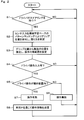
- FIG. 2 is a flowchart showing a processing procedure relating to operation input executed by the control unit
- FIG. 3A is a diagram showing an example (part 1) of a grip method different from FIG. 1 with respect to the grip portion of the steering wheel
- FIG. 3B is a diagram illustrating an example (part 2) of a grip method different from that in FIG. 1 with respect to the grip portion of the steering wheel
- FIG. 3C is a diagram showing an example (part 3) of a grip method different from FIG.
- FIG. 3D is a diagram showing an example (part 4) of a grip method different from FIG. 1 with respect to the grip portion of the steering wheel;
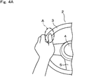
- FIG. 4A is a diagram illustrating an example of an operable range when the size of the user's hand is relatively large;
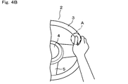
- FIG. 4B is a diagram illustrating an example of an operable range when the size of the user's hand is relatively small.
- FIG. 1 schematically shows a configuration of a vehicle input device 1 according to the present embodiment.
- a steering wheel 2 is provided in the driver's seat of the vehicle (automobile).
- the steering wheel 2 includes a ring-shaped grip portion (rim portion) 3 that is gripped and operated by a user.
- the steering wheel 2 includes a boss portion 4 that is located at the center and connected to the steering shaft, and a spoke portion 5 that connects the grip portion 3 and the boss portion 4 at a plurality of locations, for example, at the left and right and lower portions of the boss portion 4. Configured.
- the vehicle input device 1 includes a touch sensor 6 provided on the steering wheel 2 and a control unit 7 connected to the touch sensor 6.
- the touch sensor 6 is composed of, for example, a capacitive touch sensor, and is provided on the entire surface portion of the grip portion 3 of the steering wheel 2.
- the touch sensor 6 divides the entire region of the surface of the grip portion 3 into a bitmap format, and outputs a position (region) where the user's (driver) hand or finger is in contact as a detection signal.
- the control unit 7 is mainly configured by a computer including a CPU, a storage device, and the like, and processes an input signal from the touch sensor 6 to generate operation information. And it connects to networks, such as CAN and in-vehicle LAN, via vehicle IF8, and transmits operation information to HMI control ECU10 via vehicle IF9 from a network.
- the HMI control ECU 10 performs input control of on-vehicle equipment, and controls, for example, the start and end of a hands-free call of a mobile phone (car phone). In addition, it can be configured to perform input control of various in-vehicle devices such as car navigation, automatic driving device, cruise control device, car air conditioner, car audio, and display device screen switching.
- the control unit 7 includes an AD conversion unit 11 that converts an analog signal from the touch sensor 6 into a digital signal.
- the control unit 7 has functions as a gripping position determination unit 12, an operation range setting unit 13, and an operation detection unit 14 depending on its software configuration and hardware configuration. ing.
- the gripping position determination unit 12 determines that the user is gripping the gripping part 3 of the steering wheel 2 and the gripping position based on the input signal of the touch sensor 6.
- the operation range setting unit 13 can operate the touch sensor 6 within the operable range A (FIGS. 3A to 3D, 4A, 4A, and 4B) from the gripping position determined by the gripping position determination unit 12 to the vicinity of the thumb and index finger of the user's hand. 4B) is automatically set.
- the operation detection unit 14 detects a gesture such as an operation by a user's finger, such as a thumb or an index finger, for example, a tap operation or a flick operation with respect to the operable range A of the touch sensor 6.
- the gripping position determination unit 12 determines the size of each user's hand, the position of gripping the gripping part 3, and the position of the finger associated with the gripping method. More specifically, the gripping position determination unit 12 determines the size of each user's hand and the position of the finger holding the gripping unit 3, particularly the positions of the thumb and the index finger, by machine learning-based pattern matching. Then, the operation range setting unit 13 sets the operable range A of the touch sensor 6 from the size of the user's hand holding the grip unit 3, the grip position, and the finger position associated with the grip.
- the user sets the operable range A of the touch sensor 6 based on the input signal from the touch sensor 6. And if the operation detection part 14 detects that there was user operation with respect to the operation possible range A, the operation information according to the gesture at that time will be transmitted to HMI control ECU10.
- the HMI control ECU 10 outputs a control signal to the in-vehicle device accordingly.
- operation information of the tap operation is transmitted to the HMI control ECU 10, and the HMI control ECU 10 instructs the start (incoming) of the hands-free call.
- operation information on the flick operation is transmitted to the HMI control ECU 10, and the HMI control ECU 10 instructs the end of the hands-free call.
- the user can perform a hands-free call start (incoming) operation by tapping the surface of the grip portion 3 with the thumb or forefinger while holding the grip portion 3 of the steering wheel 2. It becomes. Thereafter, by performing a flick operation on the surface of the grip portion 3 with the thumb or forefinger, the hands-free call can be terminated.
- the present invention is applicable not only to hands-free calling but also to various operations of various on-vehicle devices as described above.
- step S ⁇ b> 1 it is determined based on an input signal from the touch sensor 6 whether or not the user (driver) has gripped the grip portion 3 of the steering wheel 2. If it is determined that the holding unit 3 is held (Yes in step S1), the process proceeds to the next step S2.
- step S2 from the input signal of the touch sensor 6, the size of the user's hand, the gripping position of the gripping part 3 by the user, and the gripping position of the thumb index finger are determined by machine learning-based pattern matching.
- FIG. 1 shows a state in which the user seems to be most general, and is gripping the left and right vertical middle portions of the grip portion 3 of the steering wheel 2 with left and right hands.
- the user grips the middle part in the vertical direction on the left side of the grip 3 of the steering wheel 2 with only the left hand, and the right hand is separated from the steering wheel 2.
- the user is holding the upper part of the grip part 3 of the steering wheel 2 with the left and right hands.
- the user is holding the lower part of the grip portion 3 of the steering wheel 2 with his / her left and right hands.
- the user is gripping the lower part of the grip portion 3 of the steering wheel 2 with his / her left and right hands.
- such different gripping positions and gripping methods for each user are determined based on machine learning-based pattern matching.
- the operable range A of the touch sensor 6 on the grip portion 3 is set from the size of the user's hand obtained in step S2, the grip position and the grip method, particularly the position of the thumb.
- the operable range A is set in a circle or ellipse range where the thumb can reach.
- the operable range A varies depending on the size of the user's hand. As shown only in the left hand side in FIG. 4A, when the user has a relatively large hand, the operable range A is set to be relatively large. As shown in FIG. 4B only on the right hand side, when the user is a relatively small hand, the operable range A is set to be relatively small.
- step S4 it is determined by the user whether there is an operation input of the touch sensor 6, that is, whether there is a change in input. If there is no user operation input (No in step S4), the process returns to step S1. On the other hand, when there is an operation input of the touch sensor 6 by the user, for example, a tap operation or a flick operation with the thumb (Yes in step S4), the operation is performed in step S5. It is determined whether or not it was within A. If it is out of the operable range A (No in step S5), the operation is invalidated in step S6, and the process returns to step S1.
- step S5 when it is determined that there has been an operation input within the operable range A (Yes in step S5), the operation is validated in step S7. And in step S8, the operation information according to a user's operation is transmitted to HMI control ECU10 through vehicle IF8. Thereafter, the processing from step S2 is repeated.
- the user can perform a manipulation input for starting and ending a hands-free call, for example, by performing a tap operation and a flick operation with the thumb while holding the grip portion 3 of the steering wheel 2. it can.
- the operable range A set by the operation range setting unit 13 of the control unit 7 allows the user to surely reach the finger with natural operation without being aware of the operation invalid area, and easy to operate. Range. Therefore, the operation detection unit 14 of the control unit 7 can reliably detect an operation by the user's finger on the operable range A of the touch sensor 6.
- the vehicle input device 1 of the present embodiment the following effects can be obtained when the touch sensor 6 is incorporated in the steering wheel 2. That is, it is possible to make it easy to use for various users with different hand sizes, gripping positions, and finger positions depending on how to grip, while preventing erroneous operations.
- the operable range A can be appropriately set by the gripping position determination unit 12 based on the size of the user's hand and the position of the finger. Furthermore, the size of the hand and the position of the finger for each user can be more reliably determined by machine learning-based pattern matching.
- the case where a hands-free call operation of a mobile phone (car phone) as an in-vehicle device is performed by the vehicle input device 1 is described as a specific example, but there are various other uses and types.
- the present invention can be applied to a vehicle input device.
- the operable region A may be set in a range where the user can operate the touch sensor 6 with the index finger of the hand.
- various changes can be made in the hardware configuration of each part of the vehicle input device, such as a touch sensor may be used.
Landscapes
- Engineering & Computer Science (AREA)
- Mechanical Engineering (AREA)
- Chemical & Material Sciences (AREA)
- Transportation (AREA)
- Combustion & Propulsion (AREA)
- Theoretical Computer Science (AREA)
- General Engineering & Computer Science (AREA)
- Software Systems (AREA)
- General Physics & Mathematics (AREA)
- Physics & Mathematics (AREA)
- Medical Informatics (AREA)
- Computer Vision & Pattern Recognition (AREA)
- Data Mining & Analysis (AREA)
- Evolutionary Computation (AREA)
- Artificial Intelligence (AREA)
- Computing Systems (AREA)
- Mathematical Physics (AREA)
- Human Computer Interaction (AREA)
- Steering Controls (AREA)
- Position Input By Displaying (AREA)
- User Interface Of Digital Computer (AREA)
Abstract
This vehicle input device (1) comprises: a touch sensor (6) which is provided on a grip portion (3) of a steering wheel (2); a gripped site identification unit (12) which uses input signals of the touch sensor (6) to make a determination about whether a user is gripping the grip portion (3) and the site that is being gripped; a manipulation range setting unit (13) that sets a manipulable range for the touch sensor (6) in the vicinity of the thumb and forefinger of the user on the basis of the position of the gripped site; and a manipulation detection unit (14) that detects manipulations by the user's fingers on the manipulable range on the touch sensor (6).
Description
本出願は、2018年3月23日に出願された日本出願番号2018-056251号に基づくもので、ここにその記載内容を援用する。
This application is based on Japanese Patent Application No. 2018-056251 filed on March 23, 2018, the contents of which are incorporated herein by reference.
本開示は、例えば自動車等の車両に搭載される車両用入力装置に関する。
The present disclosure relates to a vehicle input device mounted on a vehicle such as an automobile.
自動車のドライバが、車載機器を操作するための車両用入力装置として、ステアリングホイールのリム部にタッチセンサを設けるようにしたものが考えられている(例えば、特許文献1参照)。このものでは、タッチセンサに、ドライバが掌で握ったことを検出するグリップ検出エリアと、親指又は人差し指での操作(ドラッグやタップ)を検出する操作検出エリアとを、操作無効領域を間に挟むようにして別領域として設けている。これにより、ドライバが掌でステアリングホイールを単に握ったのか、或いはドラッグ操作やタップ操作を行ったのかの区別を可能としている。ドライバは、ステアリングホイールを握ったままで、車載機器に対する入力操作を安全に行うことが可能となり、また誤操作を防止することができる。
As a vehicle input device for an automobile driver to operate an in-vehicle device, a touch sensor provided on a rim portion of a steering wheel is considered (for example, see Patent Document 1). In this case, the touch sensor includes a grip detection area for detecting that the driver grips with a palm, and an operation detection area for detecting an operation (drag or tap) with the thumb or index finger, with an operation invalid area interposed therebetween. Thus, it is provided as a separate area. Thereby, it is possible to distinguish whether the driver simply holds the steering wheel with his palm, or performs a drag operation or a tap operation. The driver can safely perform an input operation on the in-vehicle device while holding the steering wheel, and can prevent an erroneous operation.
ところで、ドライバ(ユーザ)がステアリングホイールを握る場合、ユーザによって、手の大きさが異なる、つまり指の届く位置が異なってくる。また、ユーザの癖などにより、ステアリングホイールの上部を握る、中間部を握る、下部を握る等、把持する位置も異なってくる。更には、逆手で握ったり、片手のみで握ったりする等、ユーザ毎に握り方も異なる場合がある。上記特許文献1の入力装置では、そのようなユーザ毎の手の大きさや持ち方などに応じたきめ細やかな対処はできなかった。そのため、例えば手の小さい女性ドライバの場合、操作検出エリアまで大きく指を伸ばして操作しなければならなくなる等、ユーザによっては必ずしも使いやすいものとなっていなかった。
By the way, when the driver (user) holds the steering wheel, the size of the hand is different depending on the user, that is, the position where the finger reaches is different. Also, the gripping position varies depending on the user's heel, such as gripping the upper part of the steering wheel, gripping the middle part, or gripping the lower part. Furthermore, there are cases where the gripping method is different for each user, such as gripping with a reverse hand or gripping with only one hand. In the input device of the above-mentioned patent document 1, it is not possible to deal with the details according to the size of the hand or the way of holding for each user. For this reason, for example, in the case of a female driver with a small hand, it is not always easy for some users to use, such as having to operate with a finger greatly extended to the operation detection area.
本開示は、ステアリングホイールにタッチセンサを組込んで構成されるものにおいて、誤操作を防止しながら、様々なユーザに関して使いやすいものとすることができる車両用入力装置を提供することを目的とする。
This disclosure is intended to provide an input device for a vehicle that can be easily used for various users while preventing erroneous operation in a configuration in which a touch sensor is incorporated in a steering wheel.
本開示の第一の態様において、車両用入力装置は、ステアリングホイールの把持部に設けられたタッチセンサと、前記タッチセンサの入力信号に基づいてユーザが前記把持部を把持していること及び把持位置を判定する把持位置判定部と、前記把持位置からユーザの手の親指及び人差し指の近傍に前記タッチセンサの操作可能範囲を設定する操作範囲設定部と、前記タッチセンサの前記操作可能範囲に対するユーザの指による操作を検出する操作検出部とを備えている。
In the first aspect of the present disclosure, the vehicular input device includes a touch sensor provided in a grip portion of a steering wheel, a user gripping the grip portion based on an input signal of the touch sensor, and a grip A grip position determination unit that determines a position; an operation range setting unit that sets an operable range of the touch sensor in the vicinity of the thumb and forefinger of the user's hand from the grip position; and a user for the operable range of the touch sensor And an operation detection unit that detects an operation by a finger.
これによれば、ユーザがステアリングホイールの把持部を握ると、タッチセンサの入力信号に基づいて、把持位置判定部により、ユーザが前記把持部を把持していること及び把持位置が判定される。このとき、把持位置として、ユーザの手の大きさや握る位置、握り方を判定することができる。そして、その把持位置から、操作範囲設定部により、ユーザの手の親指及び人差し指の近傍にタッチセンサの操作可能範囲が設定される。
According to this, when the user grips the grip portion of the steering wheel, the grip position determination unit determines that the user is gripping the grip portion and the grip position based on the input signal of the touch sensor. At this time, as the gripping position, the size of the user's hand, the gripping position, and the gripping method can be determined. Then, the operable range of the touch sensor is set in the vicinity of the thumb and index finger of the user's hand from the gripping position by the operation range setting unit.
操作範囲設定部により設定される操作可能範囲は、ユーザにとって、操作無効領域を意識することもなく、自然な操作で確実に指が届き、操作が容易な範囲とされる。従って、操作検出部により、タッチセンサの前記操作可能範囲に対するユーザの指による操作を確実に検出することができる。この結果、ステアリングホイールにタッチセンサを組込んで構成されるものにおいて、誤操作を防止しながら、手の大きさや、握る位置及び握り方に応じた指の位置の異なる様々なユーザに関して、使いやすいものとすることができるという優れた効果を得ることができる。
The operable range set by the operation range setting unit is a range that allows the user to surely reach the finger by natural operation without being aware of the operation invalid area and to be operated easily. Therefore, the operation detection unit can reliably detect an operation by the user's finger with respect to the operable range of the touch sensor. As a result, the touch sensor built into the steering wheel is easy to use for various users with different hand sizes, gripping positions, and finger positions depending on how they are gripped while preventing misoperation. It is possible to obtain an excellent effect of being able to.
本開示についての上記目的およびその他の目的、特徴や利点は、添付の図面を参照しながら下記の詳細な記述により、より明確になる。その図面は、
図1は、一実施形態を示すもので、車両用入力装置の要部構成を概略的に示すブロック図であり、
図2は、制御ユニットが実行する操作入力に関する処理手順を示すフローチャートであり、
図3Aは、ステアリングホイールの握り部に対する図1とは別の握り方の例(その1)を示す図であり、
図3Bは、ステアリングホイールの握り部に対する図1とは別の握り方の例(その2)を示す図であり、
図3Cは、ステアリングホイールの握り部に対する図1とは別の握り方の例(その3)を示す図であり、
図3Dは、ステアリングホイールの握り部に対する図1とは別の握り方の例(その4)を示す図であり、
図4Aは、ユーザの手の大きさが比較的大きい場合の操作可能範囲の例を示す図であり、
図4Bは、ユーザの手の大きさが比較的小さい場合の操作可能範囲の例を示す図である。
The above and other objects, features and advantages of the present disclosure will become more apparent from the following detailed description with reference to the accompanying drawings. The drawing
FIG. 1 shows an embodiment and is a block diagram schematically showing a main configuration of an input device for a vehicle. FIG. 2 is a flowchart showing a processing procedure relating to operation input executed by the control unit, FIG. 3A is a diagram showing an example (part 1) of a grip method different from FIG. 1 with respect to the grip portion of the steering wheel; FIG. 3B is a diagram illustrating an example (part 2) of a grip method different from that in FIG. 1 with respect to the grip portion of the steering wheel; FIG. 3C is a diagram showing an example (part 3) of a grip method different from FIG. 1 with respect to the grip portion of the steering wheel; FIG. 3D is a diagram showing an example (part 4) of a grip method different from FIG. 1 with respect to the grip portion of the steering wheel; FIG. 4A is a diagram illustrating an example of an operable range when the size of the user's hand is relatively large; FIG. 4B is a diagram illustrating an example of an operable range when the size of the user's hand is relatively small.
以下、一実施形態について、図面を参照しながら説明する。図1は、本実施形態に係る車両用入力装置1の構成を概略的に示している。ここで、図3A~図3D、図4A、図4Bにも示すように、車両(自動車)の運転席には、ステアリングホイール2が設けられている。周知のように、ステアリングホイール2は、ユーザが握って操作するリング状の把持部(リム部)3を備えている。更に、ステアリングホイール2は、中央部に位置しステアリングシャフトに連結されるボス部4、把持部3とボス部4とを複数個所、例えばボス部4の左右及び下部でつなぐスポーク部5等を備えて構成されている。
Hereinafter, an embodiment will be described with reference to the drawings. FIG. 1 schematically shows a configuration of a vehicle input device 1 according to the present embodiment. Here, as shown in FIGS. 3A to 3D, FIGS. 4A, and 4B, a steering wheel 2 is provided in the driver's seat of the vehicle (automobile). As is well known, the steering wheel 2 includes a ring-shaped grip portion (rim portion) 3 that is gripped and operated by a user. Further, the steering wheel 2 includes a boss portion 4 that is located at the center and connected to the steering shaft, and a spoke portion 5 that connects the grip portion 3 and the boss portion 4 at a plurality of locations, for example, at the left and right and lower portions of the boss portion 4. Configured.
図1に示すように、本実施形態に係る車両用入力装置1は、前記ステアリングホイール2に設けられたタッチセンサ6と、このタッチセンサ6に接続された制御ユニット7とを備えている。前記タッチセンサ6は、例えば静電容量式のタッチセンサからなり、ステアリングホイール2の把持部3の全体の表面部に設けられている。この場合、タッチセンサ6は、把持部3の表面の全体の領域をビットマップ形式に区画し、ユーザ(ドライバ)の手や指が接触した位置(領域)を検出信号として出力する。
As shown in FIG. 1, the vehicle input device 1 according to the present embodiment includes a touch sensor 6 provided on the steering wheel 2 and a control unit 7 connected to the touch sensor 6. The touch sensor 6 is composed of, for example, a capacitive touch sensor, and is provided on the entire surface portion of the grip portion 3 of the steering wheel 2. In this case, the touch sensor 6 divides the entire region of the surface of the grip portion 3 into a bitmap format, and outputs a position (region) where the user's (driver) hand or finger is in contact as a detection signal.
そして、前記制御ユニット7は、CPUや記憶装置等からなるコンピュータを主体として構成され、タッチセンサ6からの入力信号を処理し、操作情報を生成する。そして、車両IF8を介してCANや車内LAN等のネットワークに接続され、ネットワークから車両IF9を介してHMI制御ECU10に操作情報を送信する。尚、HMI制御ECU10は、車載機器の入力制御を行うもので、例えば、携帯電話(自動車電話)のハンズフリー通話の開始、終了を制御する。それ以外にも、カーナビゲーション、自動運転装置、クルーズコントロール装置、カーエアコン、カーオーディオ、表示装置の画面切替等の、各種車載機器の入力制御を行う構成とすることができる。
The control unit 7 is mainly configured by a computer including a CPU, a storage device, and the like, and processes an input signal from the touch sensor 6 to generate operation information. And it connects to networks, such as CAN and in-vehicle LAN, via vehicle IF8, and transmits operation information to HMI control ECU10 via vehicle IF9 from a network. The HMI control ECU 10 performs input control of on-vehicle equipment, and controls, for example, the start and end of a hands-free call of a mobile phone (car phone). In addition, it can be configured to perform input control of various in-vehicle devices such as car navigation, automatic driving device, cruise control device, car air conditioner, car audio, and display device screen switching.
さて、図1に示すように、前記制御ユニット7は、タッチセンサ6からのアナログ信号をデジタル信号に変換するAD変換部11を備える。これと共に、詳しくは後の作用説明で述べるように、制御ユニット7は、そのソフトウエア構成及びハードウエア構成により、把持位置判定部12、操作範囲設定部13、操作検出部14としての機能を備えている。そのうち把持位置判定部12は、前記タッチセンサ6の入力信号に基づいてユーザがステアリングホイール2の把持部3を把持していること及び把持位置を判定する。
As shown in FIG. 1, the control unit 7 includes an AD conversion unit 11 that converts an analog signal from the touch sensor 6 into a digital signal. Along with this, as will be described in detail later, the control unit 7 has functions as a gripping position determination unit 12, an operation range setting unit 13, and an operation detection unit 14 depending on its software configuration and hardware configuration. ing. Among them, the gripping position determination unit 12 determines that the user is gripping the gripping part 3 of the steering wheel 2 and the gripping position based on the input signal of the touch sensor 6.
また、前記操作範囲設定部13は、把持位置判定部12が判定した把持位置から、ユーザの手の親指及び人差し指の近傍にタッチセンサ6の操作可能範囲A(図3A~図3D、図4A、図4B参照)を自動で設定する。前記操作検出部14は、タッチセンサ6の前記操作可能範囲Aに対するユーザの指例えば親指又は人差し指による操作、例えばタップ操作やフリック操作などのジェスチャを検出する。
In addition, the operation range setting unit 13 can operate the touch sensor 6 within the operable range A (FIGS. 3A to 3D, 4A, 4A, and 4B) from the gripping position determined by the gripping position determination unit 12 to the vicinity of the thumb and index finger of the user's hand. 4B) is automatically set. The operation detection unit 14 detects a gesture such as an operation by a user's finger, such as a thumb or an index finger, for example, a tap operation or a flick operation with respect to the operable range A of the touch sensor 6.
このとき、本実施形態では、前記把持位置判定部12は、個々のユーザの手の大きさ、並びに、把持部3を握る位置及び握り方に伴う指の位置を判定する。より具体的には、把持位置判定部12は、機械学習ベースのパターンマッチングにより、個々のユーザの手の大きさ及び把持部3を握る指の位置、特に親指と人差し指の位置を判定する。そして、前記操作範囲設定部13は、把持部3を握るユーザの手の大きさ、並びに、握る位置及び握り方に伴う指の位置から、タッチセンサ6の操作可能範囲Aを設定する。
At this time, in the present embodiment, the gripping position determination unit 12 determines the size of each user's hand, the position of gripping the gripping part 3, and the position of the finger associated with the gripping method. More specifically, the gripping position determination unit 12 determines the size of each user's hand and the position of the finger holding the gripping unit 3, particularly the positions of the thumb and the index finger, by machine learning-based pattern matching. Then, the operation range setting unit 13 sets the operable range A of the touch sensor 6 from the size of the user's hand holding the grip unit 3, the grip position, and the finger position associated with the grip.
以上の構成により、制御ユニット7においては、ユーザ(ドライバ)がタッチセンサ6からの入力信号に基づいて、タッチセンサ6の操作可能範囲Aを設定する。そして、操作検出部14は、その操作可能範囲Aに対するユーザの操作があったことを検出すると、その際のジェスチャに応じた操作情報を、HMI制御ECU10に送信する。HMI制御ECU10は、それに応じて車載機器に対し、制御信号の出力を行う。
With the above configuration, in the control unit 7, the user (driver) sets the operable range A of the touch sensor 6 based on the input signal from the touch sensor 6. And if the operation detection part 14 detects that there was user operation with respect to the operation possible range A, the operation information according to the gesture at that time will be transmitted to HMI control ECU10. The HMI control ECU 10 outputs a control signal to the in-vehicle device accordingly.
例えば、タッチセンサ6の操作可能範囲Aに対するタップ操作があった場合には、タップ操作の操作情報がHMI制御ECU10に送信され、HMI制御ECU10は、ハンズフリー通話の開始(着信)を指示する。その後、タッチセンサ6の操作可能範囲Aに対するフリック操作があった場合には、フリック操作の操作情報がHMI制御ECU10に送信され、HMI制御ECU10は、ハンズフリー通話の終了を指示する。
For example, when there is a tap operation on the operable range A of the touch sensor 6, operation information of the tap operation is transmitted to the HMI control ECU 10, and the HMI control ECU 10 instructs the start (incoming) of the hands-free call. Thereafter, when a flick operation is performed on the operable range A of the touch sensor 6, operation information on the flick operation is transmitted to the HMI control ECU 10, and the HMI control ECU 10 instructs the end of the hands-free call.
従って、ユーザは、ステアリングホイール2の把持部3を握ったままで、親指或いは人差し指で把持部3の表面に対してタップ操作をすることにより、ハンズフリー通話の開始(着信)操作を行うことが可能となる。その後、親指或いは人差し指で把持部3の表面に対してフリック操作することにより、ハンズフリー通話を終了することができる。尚、ハンズフリー通話に限らず、上記したような各種の車載機器の様々な操作に適用できることは勿論である。
Therefore, the user can perform a hands-free call start (incoming) operation by tapping the surface of the grip portion 3 with the thumb or forefinger while holding the grip portion 3 of the steering wheel 2. It becomes. Thereafter, by performing a flick operation on the surface of the grip portion 3 with the thumb or forefinger, the hands-free call can be terminated. Needless to say, the present invention is applicable not only to hands-free calling but also to various operations of various on-vehicle devices as described above.
次に、上記のように構成された車両用入力装置1の作用・効果について、図2~図4Bも参照しながら述べる。図2のフローチャートは、制御ユニット7が実行する操作入力に関する制御の処理手順を示している。即ち、まず、ステップS1では、タッチセンサ6から入力信号に基づき、ユーザ(ドライバ)がステアリングホイール2の把持部3を握ったかどうかが判定される。把持部3を持っていると判断された場合には(ステップS1にてYes)、次のステップS2に進む。
Next, operations and effects of the vehicle input device 1 configured as described above will be described with reference to FIGS. 2 to 4B. The flowchart of FIG. 2 shows a control processing procedure related to operation input executed by the control unit 7. That is, first, in step S <b> 1, it is determined based on an input signal from the touch sensor 6 whether or not the user (driver) has gripped the grip portion 3 of the steering wheel 2. If it is determined that the holding unit 3 is held (Yes in step S1), the process proceeds to the next step S2.
ステップS2では、タッチセンサ6の入力信号から、機械学習ベースのパターンマッチングにより、ユーザの手の大きさ、並びに、ユーザによる把持部3の把持位置及び握り方ひいては親指人差し指の位置が判定される。ここで、図1は、最も一般的と思われる、ユーザが、左右の手でステアリングホイール2の把持部3の左右の上下方向中間部を握っている様子を示している。他にも、4種類を図3A~図3Dに例示するように、把持部3の把持位置及び握り方には、いくつかの別のパターンがある。
In step S2, from the input signal of the touch sensor 6, the size of the user's hand, the gripping position of the gripping part 3 by the user, and the gripping position of the thumb index finger are determined by machine learning-based pattern matching. Here, FIG. 1 shows a state in which the user seems to be most general, and is gripping the left and right vertical middle portions of the grip portion 3 of the steering wheel 2 with left and right hands. In addition, there are several other patterns in the gripping position and the gripping method of the grip portion 3, as illustrated in FIGS. 3A to 3D.
図3Aの例では、ユーザは、左手のみでステアリングホイール2の把持部3の左側の上下方向中間部を握り、右手はステアリングホイール2から離している。図3Bの例では、ユーザは、左右の手でステアリングホイール2の把持部3の上部を握っている。図3Cの例では、ユーザは、左右の手でステアリングホイール2の把持部3の下部を逆手で握っている。図3Dの例では、ユーザは、左右の手でステアリングホイール2の把持部3の下部を順手で握っている。本実施形態では、そのようなユーザ毎に異なる把持位置や握り方が、機械学習ベースのパターンマッチングに基づいて判定される。
In the example of FIG. 3A, the user grips the middle part in the vertical direction on the left side of the grip 3 of the steering wheel 2 with only the left hand, and the right hand is separated from the steering wheel 2. In the example of FIG. 3B, the user is holding the upper part of the grip part 3 of the steering wheel 2 with the left and right hands. In the example of FIG. 3C, the user is holding the lower part of the grip portion 3 of the steering wheel 2 with his / her left and right hands. In the example of FIG. 3D, the user is gripping the lower part of the grip portion 3 of the steering wheel 2 with his / her left and right hands. In the present embodiment, such different gripping positions and gripping methods for each user are determined based on machine learning-based pattern matching.
次のステップS3では、ステップS2で求められたユーザの手の大きさ、把持位置及び握り方、特に親指の位置から、把持部3上のタッチセンサ6の操作可能範囲Aが設定される。本実施形態では、図1、図3A~図3D、図4A、図4Bに示すように、例えば、親指の位置の周囲部分の、親指が届く円又は楕円の範囲に操作可能範囲Aが設定される。またこのとき、図4A、図4Bに例示するように、ユーザの手の大きさによっても、操作可能範囲Aが変動する。図4Aに左手側のみ図示するように、手が比較的大きいユーザであった場合には、操作可能範囲Aが比較的大きく設定される。図4Bに右手側のみ図示するように、手が比較的小さいユーザであった場合には、操作可能範囲Aが比較的小さく設定される。
In the next step S3, the operable range A of the touch sensor 6 on the grip portion 3 is set from the size of the user's hand obtained in step S2, the grip position and the grip method, particularly the position of the thumb. In this embodiment, as shown in FIG. 1, FIG. 3A to FIG. 3D, FIG. 4A, and FIG. 4B, for example, the operable range A is set in a circle or ellipse range where the thumb can reach. The At this time, as illustrated in FIGS. 4A and 4B, the operable range A varies depending on the size of the user's hand. As shown only in the left hand side in FIG. 4A, when the user has a relatively large hand, the operable range A is set to be relatively large. As shown in FIG. 4B only on the right hand side, when the user is a relatively small hand, the operable range A is set to be relatively small.
ステップS4では、ユーザによりタッチセンサ6の操作入力、つまり入力の変動があるかどうかが判断される。ユーザの操作入力がない場合には(ステップS4にてNo)、ステップS1に戻る。これに対し、ユーザによりタッチセンサ6の操作入力、例えば親指でのタップ操作やフリック操作があった場合には(ステップS4にてYes)、ステップS5にて、操作があったのは操作可能範囲A内であったかどうかが判断される。操作可能範囲A内から外れていた場合には(ステップS5にてNo)、ステップS6にて操作が無効とされた上で、ステップS1に戻る。
In step S4, it is determined by the user whether there is an operation input of the touch sensor 6, that is, whether there is a change in input. If there is no user operation input (No in step S4), the process returns to step S1. On the other hand, when there is an operation input of the touch sensor 6 by the user, for example, a tap operation or a flick operation with the thumb (Yes in step S4), the operation is performed in step S5. It is determined whether or not it was within A. If it is out of the operable range A (No in step S5), the operation is invalidated in step S6, and the process returns to step S1.
一方、操作可能範囲A内における操作入力があったと判断された場合には(ステップS5にてYes)、ステップS7にて、操作が有効とされる。そして、ステップS8にて、ユーザの操作に応じた操作情報が、車両IF8を通じてHMI制御ECU10に送信される。この後、ステップS2からの処理が繰返される。これにより、上記したように、ユーザは、ステアリングホイール2の把持部3を握ったままで、親指でタップ操作、フリック操作を行うことにより、例えばハンズフリー通話の開始、終了の操作入力を行うことができる。
On the other hand, when it is determined that there has been an operation input within the operable range A (Yes in step S5), the operation is validated in step S7. And in step S8, the operation information according to a user's operation is transmitted to HMI control ECU10 through vehicle IF8. Thereafter, the processing from step S2 is repeated. Thus, as described above, the user can perform a manipulation input for starting and ending a hands-free call, for example, by performing a tap operation and a flick operation with the thumb while holding the grip portion 3 of the steering wheel 2. it can.
上記構成においては、制御ユニット7の操作範囲設定部13により設定される操作可能範囲Aは、ユーザにとって、操作無効領域を意識することもなく、自然な操作で確実に指が届き、操作が容易な範囲とされる。従って、制御ユニット7の操作検出部14により、タッチセンサ6の操作可能範囲Aに対するユーザの指による操作を確実に検出することができる。
In the above-described configuration, the operable range A set by the operation range setting unit 13 of the control unit 7 allows the user to surely reach the finger with natural operation without being aware of the operation invalid area, and easy to operate. Range. Therefore, the operation detection unit 14 of the control unit 7 can reliably detect an operation by the user's finger on the operable range A of the touch sensor 6.
この結果、本実施形態の車両用入力装置1によれば、ステアリングホイール2にタッチセンサ6を組込んで構成されるものにおいて、次の効果を得ることができる。即ち、誤操作を防止しながら、手の大きさや、握る位置及び握り方に応じた指の位置の異なる様々なユーザに関して、使いやすいものとすることができる。特に本実施形態では、把持位置判定部12により、ユーザの手の大きさ及び指の位置に基づいて、操作可能範囲Aを適切に設定することができる。更には、機械学習ベースのパターンマッチングにより、個々のユーザ毎の手の大きさ及び指の位置を、より確実に判定することができる。
As a result, according to the vehicle input device 1 of the present embodiment, the following effects can be obtained when the touch sensor 6 is incorporated in the steering wheel 2. That is, it is possible to make it easy to use for various users with different hand sizes, gripping positions, and finger positions depending on how to grip, while preventing erroneous operations. In particular, in the present embodiment, the operable range A can be appropriately set by the gripping position determination unit 12 based on the size of the user's hand and the position of the finger. Furthermore, the size of the hand and the position of the finger for each user can be more reliably determined by machine learning-based pattern matching.
尚、上記実施形態では、車両用入力装置1により、車載機器としての携帯電話(自動車電話)のハンズフリー通話の操作を行う場合を具体例として挙げたが、他にも様々な用途、種類の車両用入力装置に適用することが可能である。また、上記実施形態では説明しなかったが、操作可能領域Aとしては、ユーザが手の人差し指でタッチセンサ6を操作することが可能な範囲に設定するようにしても良い。その他、タッチセンサとしては抵抗膜方式のもの等を採用しても良い等、車両用入力装置の各部のハードウエア構成としても、様々な変更が可能である。
In the above-described embodiment, the case where a hands-free call operation of a mobile phone (car phone) as an in-vehicle device is performed by the vehicle input device 1 is described as a specific example, but there are various other uses and types. The present invention can be applied to a vehicle input device. Although not described in the above embodiment, the operable region A may be set in a range where the user can operate the touch sensor 6 with the index finger of the hand. In addition, various changes can be made in the hardware configuration of each part of the vehicle input device, such as a touch sensor may be used.
本開示は、実施例に準拠して記述されたが、本開示は当該実施例や構造に限定されるものではないと理解される。本開示は、様々な変形例や均等範囲内の変形をも包含する。加えて、様々な組み合わせや形態、さらには、それらに一要素のみ、それ以上、あるいはそれ以下、を含む他の組み合わせや形態をも、本開示の範疇や思想範囲に入るものである。
Although the present disclosure has been described based on the embodiments, it is understood that the present disclosure is not limited to the embodiments and structures. The present disclosure includes various modifications and modifications within the equivalent range. In addition, various combinations and forms, as well as other combinations and forms including only one element, more or less, are within the scope and spirit of the present disclosure.
Claims (3)
- ステアリングホイール(2)の把持部(3)に設けられたタッチセンサ(6)と、
前記タッチセンサ(6)の入力信号に基づいてユーザが前記把持部(3)を把持していること及び把持位置を判定する把持位置判定部(12)と、
前記把持位置からユーザの手の親指及び人差し指の近傍に前記タッチセンサ(6)の操作可能範囲を設定する操作範囲設定部(13)と、
前記タッチセンサ(6)の前記操作可能範囲に対するユーザの指による操作を検出する操作検出部(14)とを備える車両用入力装置。 A touch sensor (6) provided on the grip (3) of the steering wheel (2);
A gripping position determination unit (12) for determining that the user is gripping the gripping part (3) and determining a gripping position based on an input signal of the touch sensor (6);
An operation range setting unit (13) for setting an operable range of the touch sensor (6) in the vicinity of the thumb and index finger of the user's hand from the gripping position;
An input device for vehicles provided with an operation detection part (14) which detects operation by a user's finger to the above-mentioned operable range of said touch sensor (6). - 前記把持位置判定部(12)は、個々のユーザの手の大きさ及び指の位置を判定し、
前記操作範囲設定部(13)は、前記ユーザの手の大きさ及び指の位置から前記タッチセンサ(6)の操作可能範囲を設定する請求項1記載の車両用入力装置。 The gripping position determination unit (12) determines the hand size and finger position of each user,
The vehicle input device according to claim 1, wherein the operation range setting unit (13) sets an operable range of the touch sensor (6) from a size of the user's hand and a position of a finger. - 前記把持位置判定部(12)は、機械学習ベースのパターンマッチングにより、個々のユーザの手の大きさ及び指の位置を判定する請求項2記載の車両用入力装置。 The vehicle input device according to claim 2, wherein the gripping position determination unit (12) determines the size of each user's hand and the position of the finger by machine learning-based pattern matching.
Priority Applications (1)
| Application Number | Priority Date | Filing Date | Title |
|---|---|---|---|
| US17/026,806 US20210001914A1 (en) | 2018-03-23 | 2020-09-21 | Vehicle input device |
Applications Claiming Priority (2)
| Application Number | Priority Date | Filing Date | Title |
|---|---|---|---|
| JP2018-056251 | 2018-03-23 | ||
| JP2018056251A JP6881368B2 (en) | 2018-03-23 | 2018-03-23 | Vehicle input device |
Related Child Applications (1)
| Application Number | Title | Priority Date | Filing Date |
|---|---|---|---|
| US17/026,806 Continuation US20210001914A1 (en) | 2018-03-23 | 2020-09-21 | Vehicle input device |
Publications (1)
| Publication Number | Publication Date |
|---|---|
| WO2019181406A1 true WO2019181406A1 (en) | 2019-09-26 |
Family
ID=67987722
Family Applications (1)
| Application Number | Title | Priority Date | Filing Date |
|---|---|---|---|
| PCT/JP2019/007585 WO2019181406A1 (en) | 2018-03-23 | 2019-02-27 | Vehicle input device |
Country Status (3)
| Country | Link |
|---|---|
| US (1) | US20210001914A1 (en) |
| JP (1) | JP6881368B2 (en) |
| WO (1) | WO2019181406A1 (en) |
Families Citing this family (1)
| Publication number | Priority date | Publication date | Assignee | Title |
|---|---|---|---|---|
| JP2022073761A (en) * | 2020-11-02 | 2022-05-17 | 株式会社Subaru | Vehicle driving system |
Citations (5)
| Publication number | Priority date | Publication date | Assignee | Title |
|---|---|---|---|---|
| JP2006341729A (en) * | 2005-06-09 | 2006-12-21 | Nissan Motor Co Ltd | Input device for vehicle and operation detection method thereof |
| US20120179328A1 (en) * | 2011-01-12 | 2012-07-12 | GM Global Technology Operations LLC | Steering wheel system |
| JP2013082423A (en) * | 2011-09-28 | 2013-05-09 | Jvc Kenwood Corp | Device and method for controlling device to be operated in vehicle |
| JP2016049956A (en) * | 2014-09-02 | 2016-04-11 | トヨタ自動車株式会社 | Grip-state determination device, grip-state determination method, input apparatus, and input acquisition method |
| WO2016125304A1 (en) * | 2015-02-06 | 2016-08-11 | 三菱電機株式会社 | In-vehicle apparatus operating device and in-vehicle apparatus operating system |
Family Cites Families (4)
| Publication number | Priority date | Publication date | Assignee | Title |
|---|---|---|---|---|
| US7295904B2 (en) * | 2004-08-31 | 2007-11-13 | International Business Machines Corporation | Touch gesture based interface for motor vehicle |
| JP4814594B2 (en) * | 2005-09-14 | 2011-11-16 | 日立オートモティブシステムズ株式会社 | In-vehicle equipment operation device |
| US9278705B2 (en) * | 2009-12-08 | 2016-03-08 | Nec Corporation | Information presentation device using tactile stimulus with vibrator |
| US9358887B2 (en) * | 2013-12-09 | 2016-06-07 | Harman Becker Automotive Systems Gmbh | User interface |
-
2018
- 2018-03-23 JP JP2018056251A patent/JP6881368B2/en active Active
-
2019
- 2019-02-27 WO PCT/JP2019/007585 patent/WO2019181406A1/en active Application Filing
-
2020
- 2020-09-21 US US17/026,806 patent/US20210001914A1/en not_active Abandoned
Patent Citations (5)
| Publication number | Priority date | Publication date | Assignee | Title |
|---|---|---|---|---|
| JP2006341729A (en) * | 2005-06-09 | 2006-12-21 | Nissan Motor Co Ltd | Input device for vehicle and operation detection method thereof |
| US20120179328A1 (en) * | 2011-01-12 | 2012-07-12 | GM Global Technology Operations LLC | Steering wheel system |
| JP2013082423A (en) * | 2011-09-28 | 2013-05-09 | Jvc Kenwood Corp | Device and method for controlling device to be operated in vehicle |
| JP2016049956A (en) * | 2014-09-02 | 2016-04-11 | トヨタ自動車株式会社 | Grip-state determination device, grip-state determination method, input apparatus, and input acquisition method |
| WO2016125304A1 (en) * | 2015-02-06 | 2016-08-11 | 三菱電機株式会社 | In-vehicle apparatus operating device and in-vehicle apparatus operating system |
Also Published As
| Publication number | Publication date |
|---|---|
| JP2019166977A (en) | 2019-10-03 |
| US20210001914A1 (en) | 2021-01-07 |
| JP6881368B2 (en) | 2021-06-02 |
Similar Documents
| Publication | Publication Date | Title |
|---|---|---|
| CN109475079B (en) | Haptic driving guidance system | |
| JP5884742B2 (en) | User interface device and input acquisition method | |
| JP5798160B2 (en) | Vehicle control device | |
| JP4687257B2 (en) | VEHICLE INPUT DEVICE AND METHOD FOR DETECTING OPERATION OF VEHICLE INPUT DEVICE | |
| US10486531B2 (en) | Vehicle display system | |
| JP2006298241A (en) | Display device for vehicle | |
| JP6233248B2 (en) | Gripping state determination device, gripping state determination method, input device, input acquisition method | |
| EP3040252B1 (en) | Steering wheel control system | |
| US11433937B2 (en) | Vehicle and steering unit | |
| JPWO2012144217A1 (en) | VEHICLE INPUT DEVICE AND VEHICLE INPUT METHOD | |
| CN110968184B (en) | Equipment control device | |
| JP2011201497A (en) | Operation accepting device, method and program | |
| JP2014019355A (en) | Contact detection steering wheel and contact detection method for steering wheel | |
| JP2004362429A (en) | Command input device using touch panel display | |
| WO2019181406A1 (en) | Vehicle input device | |
| WO2016031152A1 (en) | Input interface for vehicle | |
| JP2006312346A (en) | Command input device | |
| JP2022151123A (en) | Operation input device, operation input method and operation input program | |
| WO2020144967A1 (en) | Control device | |
| CN108473053B (en) | Touch surface on a vehicle steering wheel | |
| KR101922454B1 (en) | System and method for gesture recognition using transition of quantity of electric charge | |
| WO2023153267A1 (en) | Occupant state detection device and computer program | |
| JP2001175397A (en) | On-vehicle equipment and its control method | |
| JP2017095066A (en) | Vehicle and method for controlling vehicle | |
| JP2016124322A (en) | Onboard equipment operating system |
Legal Events
| Date | Code | Title | Description |
|---|---|---|---|
| 121 | Ep: the epo has been informed by wipo that ep was designated in this application |
Ref document number: 19770897 Country of ref document: EP Kind code of ref document: A1 |
|
| NENP | Non-entry into the national phase |
Ref country code: DE |
|
| 122 | Ep: pct application non-entry in european phase |
Ref document number: 19770897 Country of ref document: EP Kind code of ref document: A1 |