WO2019160133A1 - Information management device, information management method, and information management program - Google Patents
Information management device, information management method, and information management program Download PDFInfo
- Publication number
- WO2019160133A1 WO2019160133A1 PCT/JP2019/005769 JP2019005769W WO2019160133A1 WO 2019160133 A1 WO2019160133 A1 WO 2019160133A1 JP 2019005769 W JP2019005769 W JP 2019005769W WO 2019160133 A1 WO2019160133 A1 WO 2019160133A1
- Authority
- WO
- WIPO (PCT)
- Prior art keywords
- bit string
- unit
- key
- search
- value
- Prior art date
Links
Images


Classifications
-
- G—PHYSICS
- G06—COMPUTING; CALCULATING OR COUNTING
- G06F—ELECTRIC DIGITAL DATA PROCESSING
- G06F16/00—Information retrieval; Database structures therefor; File system structures therefor
- G06F16/90—Details of database functions independent of the retrieved data types
- G06F16/95—Retrieval from the web
- G06F16/953—Querying, e.g. by the use of web search engines
- G06F16/9537—Spatial or temporal dependent retrieval, e.g. spatiotemporal queries
-
- G—PHYSICS
- G06—COMPUTING; CALCULATING OR COUNTING
- G06F—ELECTRIC DIGITAL DATA PROCESSING
- G06F16/00—Information retrieval; Database structures therefor; File system structures therefor
- G06F16/20—Information retrieval; Database structures therefor; File system structures therefor of structured data, e.g. relational data
- G06F16/24—Querying
- G06F16/245—Query processing
- G06F16/2455—Query execution
-
- G—PHYSICS
- G06—COMPUTING; CALCULATING OR COUNTING
- G06F—ELECTRIC DIGITAL DATA PROCESSING
- G06F12/00—Accessing, addressing or allocating within memory systems or architectures
-
- G—PHYSICS
- G06—COMPUTING; CALCULATING OR COUNTING
- G06F—ELECTRIC DIGITAL DATA PROCESSING
- G06F16/00—Information retrieval; Database structures therefor; File system structures therefor
-
- G—PHYSICS
- G06—COMPUTING; CALCULATING OR COUNTING
- G06F—ELECTRIC DIGITAL DATA PROCESSING
- G06F16/00—Information retrieval; Database structures therefor; File system structures therefor
- G06F16/20—Information retrieval; Database structures therefor; File system structures therefor of structured data, e.g. relational data
- G06F16/22—Indexing; Data structures therefor; Storage structures
- G06F16/2228—Indexing structures
- G06F16/2255—Hash tables
-
- G—PHYSICS
- G06—COMPUTING; CALCULATING OR COUNTING
- G06F—ELECTRIC DIGITAL DATA PROCESSING
- G06F16/00—Information retrieval; Database structures therefor; File system structures therefor
- G06F16/20—Information retrieval; Database structures therefor; File system structures therefor of structured data, e.g. relational data
- G06F16/22—Indexing; Data structures therefor; Storage structures
- G06F16/2228—Indexing structures
- G06F16/2264—Multidimensional index structures
-
- G—PHYSICS
- G06—COMPUTING; CALCULATING OR COUNTING
- G06F—ELECTRIC DIGITAL DATA PROCESSING
- G06F16/00—Information retrieval; Database structures therefor; File system structures therefor
- G06F16/20—Information retrieval; Database structures therefor; File system structures therefor of structured data, e.g. relational data
- G06F16/23—Updating
-
- G—PHYSICS
- G06—COMPUTING; CALCULATING OR COUNTING
- G06F—ELECTRIC DIGITAL DATA PROCESSING
- G06F16/00—Information retrieval; Database structures therefor; File system structures therefor
- G06F16/20—Information retrieval; Database structures therefor; File system structures therefor of structured data, e.g. relational data
- G06F16/28—Databases characterised by their database models, e.g. relational or object models
- G06F16/284—Relational databases
Definitions
- the present invention relates to an information management apparatus, an information management method, and an information management program.
- IoT Internet of Things
- data acquired by IoT devices are used in a variety of ways via networks.
- this IoT device is a mobile device such as a vehicle, a drone, or a smartphone
- time information and position information are associated with actual acquired data, resulting in an enormous amount of data.
- a database that can store a huge amount of data appropriately from business operators handling IoT device data, and can efficiently and quickly search for data using spatio-temporal information from these data.
- a system was sought.
- RDBMS relational database management system
- Non-Patent Document 2 As another database technology, a distributed key-value store has been proposed in which a large amount of data is distributed and stored in a plurality of nodes and can be searched at a high speed according to limited search conditions (see Non-Patent Document 2). . And in order to ease the restriction
- the processing load may be biased among the nodes constituting the data store, and the performance may be significantly reduced.
- the present invention has been made in view of the above, and is an information management capable of appropriately distributing and storing a large amount of data including spatiotemporal information and efficiently and rapidly searching for data using spatiotemporal information.
- An object is to provide an apparatus, an information management method, and an information management program.
- the information management apparatus uses a key-value store to store temporal and spatial information including time information and position information and corresponding data corresponding to the temporal and spatial information.
- An information management device that distributes and manages to a plurality of nodes, converts spatiotemporal information of information to be stored into a one-dimensional bit string, divides the converted one-dimensional bit string into a front bit string and a rear bit string, and at least The divided front bit string is stored in the key, and the storage unit that stores the divided rear bit string and the corresponding data in the storage node in the key value, and the range condition of the space-time information to be searched is converted into a one-dimensional bit string Then, the converted one-dimensional bit string is divided into a front bit string and a rear bit string, and a key is detected using at least the divided front bits from the search destination node. And, from the value of the search key, searches the value corresponding to the divided rear bit string, and having a
- a large amount of data including spatiotemporal information can be appropriately distributed and stored, and data can be retrieved efficiently and quickly using spatiotemporal information.
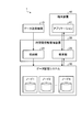
- FIG. 1 is a diagram illustrating an example of the configuration of the information management system according to the first embodiment.
- FIG. 2 is a diagram illustrating an example of a data configuration of acquired data transmitted by the data transmission device illustrated in FIG.
- FIG. 3 is a diagram illustrating an example of a data configuration of data stored in the node illustrated in FIG. 1.
- FIG. 4 is a diagram illustrating an example of a data configuration of a search request transmitted by the terminal device illustrated in FIG.
- FIG. 5 is a diagram illustrating an example of a data configuration of a search result output by the spatiotemporal information management apparatus illustrated in FIG.
- FIG. 6 is a diagram illustrating an example of the configuration of the spatiotemporal information management device illustrated in FIG. 1.
- FIG. 1 is a diagram illustrating an example of the configuration of the information management system according to the first embodiment.
- FIG. 2 is a diagram illustrating an example of a data configuration of acquired data transmitted by the data transmission device illustrated in FIG.
- FIG. 3 is a diagram illustrating
- FIG. 7 is a diagram for explaining the flow of processing of the storage unit shown in FIG.
- FIG. 8 is a diagram for explaining a data holding format in the data storage system shown in FIG.
- FIG. 9 is a diagram for explaining the flow of processing of the search unit shown in FIG.
- FIG. 10 is a diagram for explaining a data holding format in the data storage system shown in FIG.
- FIG. 11 is a flowchart showing a processing procedure of information storage processing by the spatiotemporal information management apparatus shown in FIG.
- FIG. 12 is a flowchart showing a processing procedure of information search processing by the spatiotemporal information management apparatus shown in FIG.
- FIG. 13 is a diagram for explaining data distribution in a conventional database system.
- FIG. 14 is a diagram for explaining data distribution performed by the spatiotemporal information management apparatus according to the first embodiment.
- FIG. 15 is a diagram for explaining data distribution in a conventional database system.
- FIG. 16 is a diagram for explaining data distribution performed by the spatiotemporal information management apparatus according to the first embodiment.
- FIG. 17 is a diagram illustrating an example of a configuration of a spatiotemporal information management apparatus according to a modification of the first embodiment.
- FIG. 18 is a diagram illustrating an example of a data configuration of the distribution destination node combination information.
- FIG. 19 is a flowchart showing a processing procedure of information storage processing by the spatiotemporal information management apparatus shown in FIG.
- FIG. 20 is a flowchart showing a processing procedure of information search processing by the spatiotemporal information management apparatus shown in FIG.
- FIG. 21 is a diagram showing combinations of nodes that can be selected by the spatiotemporal information management apparatus shown in FIG.
- FIG. 22 is a diagram illustrating an example of the configuration of the information management system according to the second embodiment.
- FIG. 23 is a diagram showing an example of the data configuration of data stored in the data storage system shown in FIG.
- FIG. 24 is a diagram showing an example of the configuration of the spatiotemporal information management device shown in FIG.
- FIG. 25 is a diagram for explaining the processing flow of the storage unit shown in FIG.
- FIG. 26 is a diagram for explaining a data holding format in the data storage system shown in FIG.
- FIG. 27 is a diagram for explaining the flow of processing of the search unit shown in FIG. FIG.
- FIG. 28 is a diagram for explaining a data holding format in the data storage system shown in FIG.
- FIG. 29 is a flowchart showing a processing procedure of information storage processing by the spatiotemporal information management apparatus shown in FIG.
- FIG. 30 is a flowchart showing a processing procedure of information search processing by the spatiotemporal information management apparatus shown in FIG.
- FIG. 31 is a diagram illustrating an example of a computer that realizes a spatiotemporal information management apparatus by executing a program.
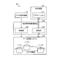
- FIG. 1 is a diagram illustrating an example of the configuration of the information management system according to the first embodiment.
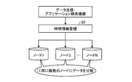
- the information management system 1 includes a data transmission device 10, a spatiotemporal information management device 20 (information management device), a data storage system 30, and a terminal device 40.
- the spatiotemporal information management device 20 is connected to the data transmission device 10, the data storage system 30, and the terminal device 40 via a network or the like.
- the data transmission device 10 is an IoT device.
- the data transmission device 10 is, for example, a mobile device such as a vehicle, a drone, or a smartphone.
- the data transmission device 10 transmits the data acquired while moving to the spatiotemporal information management device 20.
- the data transmission device 10 transmits acquisition data in which the spatiotemporal information including the time information and the position information is associated with the corresponding data corresponding to the spatiotemporal information to the spatiotemporal information management device 20.
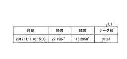
- FIG. 2 is a diagram illustrating an example of a data configuration of acquired data transmitted by the data transmission device 10 illustrated in FIG.
- the data acquired by the data transmission device 10 includes various data (data portion) acquired by the data transmission device 10 in time information indicating data acquisition time and position information indicating longitude and latitude. Are associated with each other.
- the data transmission device 10 obtains “data1” acquired at the position of longitude “27.1984 °” and latitude “-15.2958 °” at time “2017/1/1 10:15:30”, time information and position information.
- time information and position information are transmitted to the spatiotemporal information management device 20 in association with
- the spatio-temporal information management device 20 manages the acquired data transmitted by the data transmitting device 10 by distributing and storing the acquired data in a plurality of nodes 1 to N that are key-value stores. In addition, the spatiotemporal information management device 20 outputs corresponding data corresponding to the range condition of the spatiotemporal information to be searched from the data stored in the nodes 1 to N as a search result.
- the spatio-temporal information management device 20 includes a storage unit 24 and a search unit 25 as main parts.
- the space-time information management device 20 may be configured to be incorporated in the data transmission device 10 or the application 41.
- the storage unit 24 stores the acquired data distributed to the nodes 1 to N.
- the storage unit 24 converts the spatio-temporal information of the information to be stored into a one-dimensional bit string, and divides the converted one-dimensional bit string into a front bit string and a rear bit string.
- the storage unit 24 stores the divided forward bit string in the key, and stores the divided backward bit string and the corresponding data in the storage destination node in the value of the key.
- the storage unit 24 can set different nodes as storage destinations for each data, and thus the storage destinations can be distributed. it can.
- the search unit 25 outputs corresponding data corresponding to the range condition of the spatiotemporal information to be searched as a search result.
- the search unit 25 converts the range condition of the spatio-temporal information to be searched into a one-dimensional bit string, and divides the converted one-dimensional bit string into a front bit string and a rear bit string. Then, the search unit 25 searches the search destination node for the key using the divided front bits, searches the value of the searched key for the value corresponding to the divided backward bit string, and includes the value in the searched value. Corresponding data is output as a search result.
- the search unit 25 performs the search by narrowing down the number of search destination nodes, the search load can be reduced without the search being concentrated on one node, and all the nodes can be reduced. Therefore, the search process can be speeded up.
- the data storage system 30 has a plurality of nodes 1 to N that are key-value stores.
- the nodes 1 to N are, for example, servers that have storage and execute data input / output to / from the storage, and each server performs operations related to data input / output in conjunction with each other.
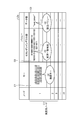
- FIG. 3 is a diagram showing an example of the data configuration of data stored in the nodes 1 to N shown in FIG. As shown in the list L2 in FIG. 3, the data structure of the data stored in the nodes 1 to N is assumed to be a key-value type having a secondary index part.
- the nodes 1 to N store data in a configuration having items of node identification information, key, and value as in the list L2.
- the value is provided with a secondary index part and a data part in which the corresponding data is stored.
- the key stores a forward bit string when the space-time information is converted into a bit string.
- the secondary index of the value stores a backward bit string when the space-time information is bit string converted.
- the terminal device 40 is a smartphone or the like owned by the user, and has an application 41.
- the application 41 has a function of requesting the space-time information management device 20 to perform a search for route guidance or failure point notification.
- the terminal device 40 transmits a search request to the spatiotemporal information management device 20 using the range condition of the spatiotemporal information to be searched as a search condition.
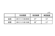
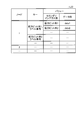
- FIG. 4 is a diagram illustrating an example of a data configuration of a search request transmitted by the terminal device 40 illustrated in FIG.
- the search request data has a data configuration in which a data string indicating the start end of the spatiotemporal information to be searched is associated with a data string serving as the end.
- time, longitude, and latitude are indicated for each of the start end and the end end indicating the range of the spatiotemporal information to be searched.
- the terminal device 40 has a time in the range of “2017/1/1 09:00:00” to “2017/1/1 09:15:00”, and the longitude “27 °” to “ A range of “28 °” and a latitude of “ ⁇ 16 °” to “ ⁇ 15 °” is requested as a range condition of the spatio-temporal information to be searched.
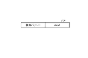
- FIG. 5 is a diagram showing an example of a data structure of a search result output from the spatiotemporal information management device 20 shown in FIG.
- the spatiotemporal information management device 20 searches the data of the nodes 1 to N based on the search condition shown in FIG. Then, the spatiotemporal information management device 20 returns the list L4 shown in FIG. 5 to the terminal device 40 as a search result, for example. As shown in the list L4, the spatiotemporal information management device 20 returns “data1” as the corresponding value corresponding to the search condition.
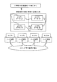
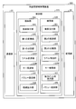
- FIG. 6 is a diagram showing an example of the configuration of the spatiotemporal information management device 20 shown in FIG.
- the spatiotemporal information management device 20 includes a communication unit 21, a storage unit 22, and a control unit 23.
- the spatiotemporal information management device 20 may be a physical server or a virtual server deployed on the physical server.
- the communication unit 21 is a communication interface that transmits and receives various types of information to and from other devices connected via the network 2 or the like.
- the communication unit 21 is realized by a NIC (Network Interface Card) or the like, and performs communication between another device and a control unit 23 (described later) via a telecommunication line such as a LAN (Local Area Network) or the Internet.
- the storage unit 22 is a storage device such as an HDD (Hard Disk Drive), an SSD (Solid State Drive), or an optical disk.
- the storage unit 22 may be a semiconductor memory capable of rewriting data such as a RAM (Random Access Memory), a flash memory, and a NVSRAM (Non Volatile Static Random Access Memory).
- the storage unit 22 stores an OS (Operating System) executed by the spatiotemporal information management device 20 and various programs. Furthermore, the storage unit 22 stores various information used in executing the program.
- the control unit 23 controls the entire spatiotemporal information management device 20.
- the control unit 23 is, for example, an electronic circuit such as a CPU (Central Processing Unit) or MPU (Micro Processing Unit), or an integrated circuit such as an ASIC (Application Specific Integrated Circuit) or FPGA (Field Programmable Gate Array).
- the control unit 23 has an internal memory for storing programs and control data that define various processing procedures, and executes each process using the internal memory.
- the control unit 23 functions as various processing units when various programs are operated.
- the control unit 23 includes a storage unit 24 and a search unit 25.
- the storage unit 24 includes a storage reception unit 241, a first conversion unit 242, a first division unit 243, a first hash value calculation unit 244, a storage destination node calculation unit 245 (storage destination node selection unit), and a key setting unit. 246, a value setting unit 247, and a storage instruction unit 248.
- the storage accepting unit 241 accepts input using the acquired data transmitted from the data transmitting device 10 as data to be stored.
- the acquired data is obtained by associating spatiotemporal information including time information and position information with corresponding data corresponding to the spatiotemporal.
- the acquired data has time, longitude, latitude, and a data part.
- the first conversion unit 242 converts the spatio-temporal information in the acquired data that has received the input into a one-dimensional bit string. That is, the first conversion unit 242 converts time, longitude, and latitude into a one-dimensional bit string.
- the first dividing unit 243 divides the one-dimensional bit string converted by the first converting unit 242 into a front bit string and a rear bit string. Then, the first hash value calculation unit 244 calculates the hash value of the forward bit string converted by the first conversion unit 242.
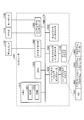
- the storage destination node calculation unit 245 selects a storage destination node based on the hash value calculated by the first hash value calculation unit 244. Specifically, the storage destination node calculation unit 245 calculates the storage destination node number using the equation (1), and selects the node having the number obtained as the calculation result as the storage destination node. In equation (1), the number of nodes to be distributed is set, and the number of one node is calculated as a solution.
- the key setting unit 246 performs setting to store the front bit string divided by the first dividing unit 243 in the key of the storage destination node. Then, the value setting unit 247 performs setting to store the backward bit string and the corresponding data divided by the first dividing unit 243 in the key value set by the key setting unit 246 among the keys of the storage destination nodes.
- the storage instruction unit 248 stores data in the storage destination node according to the settings of the key setting unit 246 and the value setting unit 247.
- the storage unit 24 selects a different node as a storage destination according to the difference of each key by using the expression (1). Therefore, the storage unit 24 stores the data at the same time and the same area separately for a plurality of nodes and distributes the storage destinations, so that the storage load on the nodes can be reduced.
- the storage unit 24 converts the spatiotemporal information using a one-dimensional bit string conversion method, and uses the front bits of the spatiotemporal information converted into a one-dimensional bit string as a key.
- the storage unit 24 creates a key using a one-dimensional bit string conversion method that is a relatively simple conversion process, the time required for key creation can be shortened.
- the search unit 25 includes a search reception unit 251, a second conversion unit 252, a second division unit 253, a second hash value calculation unit 254, a search destination node calculation unit 255 (search destination node acquisition unit), and a key search unit. 256, a backward bit string search unit 257, and a value return unit 258 (output unit).
- the search reception unit 251 receives an input of search conditions transmitted from the terminal device 40.
- the search condition is a range condition of the spatio-temporal information to be searched for use in route guidance or failure point notification.
- the search information is information indicating the start and end of time, longitude, and latitude, as shown in the list L3 in FIG.
- the second conversion unit 252 converts the range condition of the search target spatio-temporal information received into the search into a one-dimensional bit string.
- the second division unit 253 divides the one-dimensional bit string converted by the second conversion unit 252 into a front bit string and a rear bit string.
- the second hash value calculation unit 254 calculates the hash value of the forward bit string divided by the second division unit 253.
- the search destination node calculation unit 255 obtains a search destination node based on the hash value calculated by the second hash value calculation unit 254. Specifically, the search destination node calculation unit 255 calculates the node number of the search destination using equation (2), and sets the node of the number obtained as the calculation result as the node at the time of search.
- equation (2) when a plurality of distribution destination node numbers D are set in the formula (1), solutions corresponding to the number set in the formula (1) are obtained.
- the key search unit 256 searches the search destination node for a key that matches the forward bit string divided by the second division unit 253.
- the backward bit string search unit 257 searches the value of the key searched by the key search unit 256 for a value that matches the backward bit string divided by the second dividing unit.
- the value return unit 258 outputs the corresponding data included in the value searched by the backward bit string search unit 257 as the search result. In other words, the value return unit 258 returns the corresponding data included in the value searched by the backward bit string search unit 257 to the terminal device 40.
- the search unit 25 executes the search process by narrowing down the number of search destination nodes by using the expression (2). Therefore, in the first embodiment, the search can be reduced without concentrating the search on one node, and the search is not performed on all the nodes. Can do.
- FIG. 7 is a diagram for explaining the processing flow of the storage unit 24 shown in FIG.
- the storage receiving unit 241 receives input of data having “time (unix_timestamp): 1483196400, longitude: 40.7212905884, latitude: ⁇ 73.8441925049, data unit:“ test_data1 ”” will be described. To do.
- the first conversion unit 242 converts the time “1483196400”, the longitude “40.7212905884”, and the latitude “ ⁇ 73.8441925049” into a one-dimensional bit string (eg, 96 bits) using a three-dimensional Z curve.
- the obtained one-dimensional bit string is “101010101101111001010110100110111010110010100010001000100011101001110111000100110011001000011011”.
- the first dividing unit 243 divides the one-dimensional bit string into a front bit string (example: 45 bits) and a backward bit string (example: 51 bits). Specifically, among the “101010101101111001010110100110111010110010100010001000100011101001110111000100110011001000011011”, the first dividing unit 243 uses the front 45 bits “101010101101111001010110100110111010110010100” as the front bit string and the rear 51 bits “010001000100011101001110111000100110011001000011011” as the rear bits.
- the first hash value calculation unit 244 calculates the hash value of the forward bit string “101010101101111001010110100110111010110010100”. For example, the first hash value calculation unit 244 uses murmurhash as the hash function and calculates the hash value of the forward bit string “101010101101111001010110100110111010110010100” as “8088516515490849671”.
- the key setting unit 246 performs setting so as to store the forward bit string “101010101101111001010110100110111010110010100” in the key of the node W1.
- the value setting unit 247 stores the backward bit string “010001000100011101001110111000100110011001000011011” in the secondary index part among the values of the key “1010101101111001010110100110111010110010100” of the storage destination node W1, and performs setting to store “test_data1” in the data part.
- the storage instruction unit 248 stores data in the storage destination node according to the settings of the key setting 246 unit and the value setting unit 247.
- FIG. 8 is a diagram for explaining a data holding format in the data storage system 30 shown in FIG.
- “101010101101111001010110100110111010110010100” is stored in the key of the node “1” according to the setting of the storage unit 24 shown in FIG.
- “010001000100011101001110111000100110011001000011011” is stored in the secondary index portion, and “test_data1” is stored in the data portion.
- FIG. 9 is a diagram for explaining the processing flow of the search unit 25 shown in FIG.
- FIG. 10 is a diagram for explaining a data holding format in the data storage system 30 shown in FIG.
- search receiving unit 251 receives an input of “time (unix_timestamp): 1483194823 to 1483196748, longitude: 40.7211685180 to 40.7213401794, latitude: ⁇ 73.8442611694 to ⁇ 73.8439178466” as search conditions, for example. explain.
- the second conversion unit 252 converts the input range of time “1483194823 to 1483196748”, longitude “longitude: 40.7211685180 to 40.7213401794”, latitude “-73.8442611694 to -73.8439178466” into a one-dimensional bit string using a three-dimensional Z curve. .
- the second conversion unit 252 can obtain the bit string “10101010110111100101011010011011101011001010001000100011”.
- the second dividing unit 253 divides the one-dimensional bit string into a front bit string (example: 45 bits) and a backward bit string (example: 51 bits). Specifically, the second dividing unit 253 divides the front 45 bits “101010101101111001010110100110111010110010100” of “101010110111100101011010011011101011001010001000100011” as a front bit string and the rear 15 bits “010001000100011” as a back bit string.
- the second hash value calculation unit 254 calculates the hash value of the forward bit string “101010101101111001010110100110111010110010100”. For example, the second hash value calculation unit 254 uses murmurhash as the hash function and calculates the hash value of the forward bit string “101010101101111001010100110111010110010100” as “8088516515490849670”.
- the search destination node calculation unit 255 applies the hash value “8088516515490849670” calculated by the second hash value calculation unit 254 to the expression (2), and calculates the search destination node number.
- the key search unit 256 searches for a key that matches the forward bit string “101010101101111001010100110111010110010100” from the search destination node. As a result, as shown in the list L2a, the key in the column C1 of the node “1” is searched as a search key (see (2) in FIG. 10).
- the backward bit string search unit 257 searches for the secondary index part that matches the backward bit string “010001000100011” from the value of the key searched by the key search unit 256.
- the column C2 that matches the backward bit string “010001000100011” is searched as the search value (see (3) in FIG. 10).
- the value return unit 258 uses the data “test_data1” (refer to the column C3 in FIG. 10) of the data portion corresponding to the secondary index portion of the column C2 searched by the backward bit string search unit 257 as the value corresponding to the search as a terminal. It returns to the apparatus 40 (refer (4) of FIG. 10).
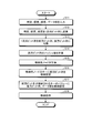
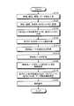
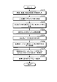
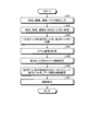
- FIG. 11 is a flowchart showing a processing procedure of information storage processing by the spatiotemporal information management apparatus 20 shown in FIG.
- step S11 when the storage receiving unit 241 receives an input of acquired data transmitted from the data transmitting device 10 (step S11), the first converting unit 242 The time, longitude, and latitude, which are spatial information, are converted into a one-dimensional bit string (step S12).
- the first dividing unit 243 divides the one-dimensional bit string converted by the first converting unit 242 into a front bit string and a rear bit string (step S13). Then, the first hash value calculation unit 244 calculates the hash value of the forward bit string converted by the first conversion unit 242 (step S14).
- the storage destination node calculation unit 245 calculates a storage destination node based on the hash value calculated by the first hash value calculation unit 244 (step S15). Specifically, the storage destination node calculation unit 245 calculates the storage destination node number using the equation (1), and selects the node having the number obtained as the calculation result as the storage destination node.
- the key setting unit 246 performs setting to store the front bit string divided by the first dividing unit 243 in the key of the storage destination node (step S16). Then, the value setting unit 247 performs setting to store the backward bit string and the corresponding data divided by the first dividing unit 243 in the key value set by the key setting unit 246 among the keys of the storage destination nodes ( Step S17).
- the storage instruction unit 248 instructs the storage destination node to store data according to the settings of the key setting unit 246 and the value setting unit 247 (step S18), and ends the storage process.
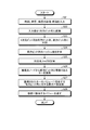
- FIG. 12 is a flowchart showing a processing procedure of information search processing by the spatiotemporal information management apparatus 20 shown in FIG.
- the search receiving unit 251 receives an input using information indicating the time, longitude, and the start and end of latitude transmitted from the terminal device 40 as a search condition (step S21). Then, the second conversion unit 252 converts the input value into a one-dimensional bit string (step S22).
- the second dividing unit 253 divides the one-dimensional bit string converted by the second converting unit 252 into a front bit string and a rear bit string (step S23). Then, the second hash value calculation unit 254 calculates the hash value of the forward bit string divided by the second division unit 253 (step S24).
- the search destination node calculation unit 255 calculates a search destination node based on the hash value calculated by the second hash value calculation unit 254 (step S25). Specifically, the search destination node calculation unit 255 calculates the node number of the search destination using equation (2), and sets the node of the number obtained as the calculation result as the node at the time of search.
- the key search unit 256 searches the search destination node for a key that matches (is equivalent to) the forward bit string divided by the second division unit 253 (step S26). Then, the backward bit string search unit 257 searches the backward bit string existing in the value of the key searched by the key search unit 256 for a value that matches the backward bit string divided by the second dividing unit (step S27).
- the value return unit 258 returns the corresponding data included in the value searched by the backward bit string search unit 257 to the terminal device 40 as the value corresponding to the search (step S28), and ends the search process.
- the spatio-temporal information management device 20 converts the spatio-temporal information of the information to be stored into a one-dimensional bit string, divides the converted one-dimensional bit string into a front bit string and a rear bit string, The divided front bit string is stored in the key, and the divided rear bit string and the corresponding data are stored in the storage destination node in the value of the key.
- the spatio-temporal information management device 20 calculates the hash value of the forward bit string and applies the calculated hash value to the equation (1) to obtain the storage destination node number.
- one node number is obtained in equation (1).
- the number D of distribution destination nodes is set in equation (1).
- each data is stored separately in D nodes.
- the hash value of the different key in the formula (1) is calculated. Therefore, the node storing the data of the key “A” Stored in one of a plurality of other nodes.
- the spatio-temporal information management device 20 even if data is biased in a certain time and a certain region, different nodes are calculated as storage destination nodes for each data. Therefore, according to the spatio-temporal information management device 20, even when data of the same time or the same region is stored, it can be distributed and stored in a plurality of nodes, and the load unevenness among the nodes Can be reduced. As a result, according to the spatiotemporal information management device 20, a large amount of data including spatiotemporal information can be appropriately distributed and stored.
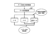
- 13 and 15 are diagrams for explaining data distribution in a conventional database system.
- 14 and 16 are diagrams for explaining data distribution performed by the spatiotemporal information management apparatus 20 according to the first embodiment.
- the conventional data processing apparatus 20P divides the spatio-temporal data in a predefined area and determines the data arrangement. For this reason, conventionally, the density of data differs depending on the area, and the load is concentrated on a specific node. Therefore, in the past, in order to distribute the load of a specific node, data rearrangement occurs with the addition of the node (see (1) in FIG. 13), and it is necessary to add and update the storage destination information. Become.
- the conventional method of assigning the definition area in advance has a problem that the load is uneven among the nodes (see (1) and (2) in FIG. 15). For example, if Tokyo is divided into 4 areas in advance and areas 1 to 4 are assigned to 4 nodes, respectively, area 1 has less data and less load, whereas area 4 has more data and more load. Become. As described above, according to the conventional method, the density of data differs depending on the area, and the load is concentrated on a specific node.
- the number of existing IoT devices varies greatly depending on the time zone (rush hour and night) and region (city and suburb). For this reason, in the conventional method, when the secondary index is used with the time information and position information held in the key, the number of values held by one key is greatly different, and as a result, the nodes constituting the distributed key value store are different. Load imbalance occurred. That is, in the conventional method, load concentration on a specific node has occurred.
- the spatio-temporal information management device 20 since data is always distributed to a plurality of nodes, the amount of data held by each node is evenly distributed and the performance can be maintained. . Also, as shown in FIG. 16, according to the first embodiment, data is distributed and stored in a plurality of nodes, and data is acquired from the plurality of nodes at the time of search, so the load is uniform among the nodes. . In other words, the data can be distributed without being affected by the bias of the data according to the time zone and the region. Therefore, according to the spatiotemporal information management device 20, multidimensional information called spatiotemporal information can be efficiently stored in the data store.
- the spatio-temporal information management device 20 converts the range condition of the spatio-temporal information to be searched into a one-dimensional bit string, divides the converted one-dimensional bit string into a front bit string and a rear bit string, and divides it from a search destination node.
- the key is searched using the forward bit, the value corresponding to the divided backward bit string is searched from the value of the searched key, and the corresponding data included in the searched value is output as the search result.
- the spatio-temporal information management device 20 does not search for all the nodes, but performs key search by narrowing down to a fixed number (D) of nodes calculated using the equation (2). Thereafter, a forward matching search is performed by the secondary index part of the searched key, and the stored data is searched. For this reason, the spatio-temporal information management device 20 does not concentrate search on one node.
- the spatio-temporal information management device 20 since the spatio-temporal information management device 20 performs a key search focusing on a certain number of nodes, the search process can be performed efficiently while reducing the load of the search process as compared with the case of performing a key search for all nodes. It can be executed at high speed.
- the spatio-temporal information management device 20 converts the spatio-temporal information using a one-dimensional bit string conversion method when storing the spatio-temporal information, and uses the forward bit as a key. Since the one-dimensional bit string conversion method is a relatively simple process, the spatio-temporal information management apparatus 20 can reduce the time required for the index creation process as compared with the conventional one. Therefore, the spatiotemporal information management device 20 can increase the speed and efficiency of storing the spatiotemporal information, which is multidimensional information, as compared with the conventional storage method.
- the processing load among the nodes constituting the data store can be distributed.
- the spatio-temporal information management device 20 a business operator who handles data of a moving IoT device can store a huge amount of data at high speed.
- the spatio-temporal information management device 20 the business operator can perform a high-speed search according to the range condition of the spatio-temporal information, so that an effect of expanding expandable services can be expected.
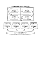
- FIG. 17 is a diagram illustrating an example of a configuration of a spatiotemporal information management apparatus according to a modification of the first embodiment.
- the spatiotemporal information management device 20A has a control unit 23A instead of the control unit 23 of the spatiotemporal information management device 20 shown in FIG.
- the spatiotemporal information management apparatus 20A has distribution destination node combination information 221A in the storage unit 22.
- the distribution destination node combination information 221A is a combination table of storage destination nodes created in advance.
- FIG. 18 is a diagram illustrating an example of a data configuration of the distribution destination node combination information 221A.
- the control unit 23A includes a storage unit 24A and a search unit 25A.
- the storage unit 24A includes a storage destination node calculation unit 245A instead of the storage destination node calculation unit 245 illustrated in FIG.
- the storage destination calculation unit 245A selects a combination of distribution destination nodes.
- the storage destination calculation unit 245A selects a combination of nodes to be distributed using the forward bit divided by the first division unit 243 as a key and using the hash value calculated by the first hash value calculation unit 244.
- the storage destination calculation unit 245A calculates the pattern number k of the combination of the node numbers of the distribution destination using the equation (3).
- the storage destination node calculator 245A includes a combination i m node number corresponding to the pattern number k, obtained from the combination information 221A distribution destination node, from among nodes included in the combination i m, storage destination node Is calculated using equation (4).
- the key setting unit 246, the value setting unit 247, and the storage instruction unit 248 store data in the storage destination node calculated by the storage destination node calculation unit 245A.
- the search unit 25A has a search destination node calculation unit 255A instead of the search destination node calculation unit 255.
- the search destination node calculation unit 255A selects a combination of search destination nodes.
- the search destination node calculation unit 255A applies the hash value calculated by the second hash value calculation unit 254 to the expression (3) using the forward bit divided by the second division unit 253 as a key, and the search destination node The combination of is calculated.
- the storage destination calculation unit 245A calculates the pattern number k of the combination of the node numbers of the distribution destination using the equation (3).
- the key setting unit 256 the combination i m node number corresponding to the pattern number k, obtained from the combination information 221A distribution destination node from among the nodes included in the combination i m, the second division section A key matching the front bit string divided by 253 is searched.
- the backward bit string search unit 257 searches the key value searched by the key search unit 256 for a value that matches the backward bit string divided by the second dividing unit.
- the value return unit 258 outputs the correspondence data included in the value searched by the backward bit string search unit 257 as the search result.
- FIG. 19 is a flowchart showing a processing procedure of information storage processing by the spatiotemporal information management apparatus 20A shown in FIG. Steps S11A to S14A shown in FIG. 19 are the same processes as steps S11 to S14 shown in FIG.
- the storage destination calculation unit 245A obtains the pattern number k of the combination of the distribution destination nodes using the expression (3) (step S15-1A).
- Storage destination node calculator 245A includes a combination i m node number corresponding to the pattern number k, obtained from the combination information 221A distribution destination node, from among nodes included in the combination i m, the storage destination node, ( 4) Calculate using the equation (step S15-2A).
- Steps S16A to S18A shown in FIG. 19 are the same processes as steps S16 to S18 shown in FIG.
- FIG. 20 is a flowchart showing a processing procedure of information search processing by the spatiotemporal information management apparatus 20A shown in FIG.
- Steps S21A to S24A shown in FIG. 20 are the same processes as steps S21 to S24 shown in FIG.
- the search destination node calculation unit 255A acquires a combination of search destination nodes based on the hash value calculated by the second hash value calculation unit 254 (step S25A).
- the search destination node calculation unit 255A applies the hash value calculated by the second hash value calculation unit 254 to the equation (3), calculates the pattern number k of the combination of search destination nodes, and corresponds to the pattern number k. the combined i m node number that will be obtained from the combination information 221A distribution destination node.
- Step S26A the key search unit 256 searches for a key that matches (is equivalent to) the forward bit string divided by the second division unit 253 from the combination of nodes obtained by the search destination node calculation unit 255A (step S26A).
- Steps S27 and S28 in FIG. 20 are the same processes as steps S27 and S28 in FIG.
- the spatio-temporal information management device 20 creates a combination table of storage destination nodes in advance, and at the time of storage, combinations of nodes using the value of the front bit divided by the first dividing unit 243 as a key And store the data in one of the selected nodes. Further, in the spatio-temporal information management device 20, at the time of search, a combination of search destination nodes is obtained by using the value of the front bit divided by the second division unit 253 as a key, and a search is performed on the nodes of the obtained combination. .
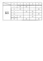
- FIG. 21 is a diagram showing combinations of nodes that can be selected by the spatiotemporal information management apparatus 20A shown in FIG. FIG. 21 shows an example in which N is four and D is two. As shown in FIG. 21, the spatio-temporal information management device 20A can select all combinations for all nodes as storage destinations, so that the load can be evenly distributed to all nodes. In addition, since the spatiotemporal information management device 20A can accurately acquire a combination of search destination nodes, an appropriate search can also be realized.
- FIG. 22 is a diagram illustrating an example of the configuration of the information management system according to the second embodiment.
- the information management system 201 includes a data storage system 230 in which a plurality of nodes 1 to N operate in a cluster configuration.
- the information management system 201 includes a spatiotemporal information management device 220 (information management device) including a storage unit 224 and a search unit 225.
- the spatiotemporal information management device 220 manages the acquired data (for example, the list L1 in FIG. 2) transmitted by the data transmission device 10 by storing it in the data storage system 230. Also, the spatiotemporal information management device 220 outputs corresponding data corresponding to the range condition of the spatiotemporal information to be searched from the data stored in the data storage system 230 as a search result.
- the storage unit 224 converts the spatio-temporal information of the information to be stored into a one-dimensional bit string, and divides the converted one-dimensional bit string into a front bit string and a rear bit string. Then, the storage unit 224 calculates a label number for the information to be stored, stores the divided front bit string and label number in the key, and stores the divided rear bit string and corresponding data in the data storage system 230 as the value of the key. Store.
- the search unit 225 outputs corresponding data corresponding to the range condition of the spatiotemporal information to be searched as a search result.
- the search unit 225 converts the range condition of the spatio-temporal information to be searched into a one-dimensional bit string, and divides the converted one-dimensional bit string into a front bit string and a rear bit string. Then, the search unit 25 searches the search destination node for a key equivalent to the divided forward bit and label number, searches the value of the searched key for the value corresponding to the divided backward bit string, and searches The corresponding data included in the selected value is output as a search result.
- FIG. 23 is a diagram illustrating an example of a data configuration of data stored in the data storage system 230 illustrated in FIG. As shown in a list L22 in FIG. 23, the data structure of data stored in the nodes 1 to N is assumed to be a key-value type having a secondary index part.
- the nodes 1 to N store data in a configuration having node identification information, key, and value items as in the list L2 (see FIG. 3), as in the list L22.
- the list L22 stores a forward bit string and a label number when the space-time information is converted into a bit string.
- the node N1 stores “rear bit string 1” in the secondary index part and “data1” in the data part. Indicates to do.
- FIG. 24 is a diagram showing an example of the configuration of the spatiotemporal information management device 220 shown in FIG.
- the spatiotemporal information management device 220 includes a control unit 223 having a storage unit 224 and a search unit 225 as compared to the spatiotemporal information management device 20.
- the storage unit 224 includes a storage reception unit 241, a first conversion unit 242, a first division unit 243, a label calculation unit 2245, a key setting unit 2246, a value setting unit 247, and a storage instruction unit 248.
- the storage reception unit 241, the first conversion unit 242, the first division unit 243, the key setting unit 2246, the value setting unit 247, and the storage instruction unit 248 are the first conversion unit 242 and the first division shown in FIG. Unit 243, value setting unit 247, and storage instruction unit 248 perform the same processing. Note that the value of D, which is the number of nodes, is variable and is determined at the time of storage.
- the label calculation unit 2245 calculates the label number stored in the key together with the front bit divided by the first division unit 243.
- the label calculation unit 2245 calculates the label number using equation (5).
- the key setting unit 2246 performs setting to store the front bit string divided by the first dividing unit 243 and the label number calculated by the label calculating unit 2245 as a set in the key of the data storage system 230. Then, the value setting unit 247 performs setting to store the backward bit string and the corresponding data divided by the first dividing unit 243 in the key value set by the key setting unit 2246 among the keys of the storage destination nodes.
- the storage instruction unit 248 stores data in the storage destination node according to the settings of the key setting unit 246 and the value setting unit 247.
- the storage unit 224 obtains the label number by using the expression (5), and stores the obtained label number in the key in association with the forward bit string.
- the search unit 225 includes a search reception unit 251, a second conversion unit 252, a second division unit 253, a label derivation unit 2255, a key search unit 2256, a backward bit string search unit 257, and a value return unit 258 (output unit). .
- the search reception unit 251, the second conversion unit 252, the second division unit 253, the backward bit string search unit 257, and the value return unit 258 are the search reception unit 251, the second conversion unit 252, and the second return unit 258 illustrated in FIG. The same processing as that of the division unit 253, the backward bit string search unit 257, and the value return unit 258 is performed.
- the label deriving unit 2255 derives a search target label number from the value of D determined at the time of storage.
- the key search unit 2256 searches the data management system 230 for a key that matches the front bit string and the label number divided by the second division unit 253.
- the backward bit string search unit 257 searches the value of the key searched by the key search unit 2256 for a value that matches the backward bit string divided by the second dividing unit.
- the value return unit 258 outputs the corresponding data included in the value searched by the backward bit string search unit 257 as a search result.
- FIG. 25 is a diagram for explaining the flow of processing of the storage unit 224 shown in FIG.
- the first conversion unit 242 converts the time “1483196400”, the longitude “40.7212905884”, and the latitude “ ⁇ 73.8441925049” into a one-dimensional bit string (eg, 96 bits) using a three-dimensional Z curve.
- the obtained one-dimensional bit string is “101010101101111001010110100110111010110010100010001000100011101001110111000100110011001000011011”.
- the first dividing unit 243 divides the one-dimensional bit string into a front bit string (example: 45 bits) and a backward bit string (example: 51 bits). Specifically, among the “101010101101111001010110100110111010110010100010001000100011101001110111000100110011001000011011”, the first dividing unit 243 uses the front 45 bits “101010101101111001010110100110111010110010100” as the front bit string and the rear 51 bits “010001000100011101001110111000100110011001000011011” as the rear bits.
- the key setting unit 2246 performs setting so that the front bit string and the label number “101010101101111001010110100110111010110010100-0” are stored in the key of the data storage system 230. Then, the value setting unit 247 stores the backward bit string “010001000100011101001110111000100110011001000011011” in the secondary index portion of the value of the key “101010101101111001010110100110111010110010100-0”, and performs setting for storing “test_data1” in the data portion.
- the storage instruction unit 248 stores data in the data storage system 230 according to the settings of the key setting 2246 unit and the value setting unit 247.
- FIG. 26 is a diagram for explaining a data holding format in the data storage system 230 shown in FIG.
- “101010101101111001010110100110111010110010100-0” is stored in the key of the node “1” according to the setting of the storage unit 224 shown in FIG.
- “010001000100011101001110111000100110011001000011011” is stored in the secondary index portion, and “test_data1” is stored in the data portion.
- FIG. 27 is a diagram for explaining the flow of processing of the search unit 225 shown in FIG.
- FIG. 28 is a diagram for explaining a data holding format in the data storage system 230 shown in FIG.
- search reception unit 251 receives an input of “time (unix_timestamp): 1483194823 to 1483196748, longitude: 40.7211685180 to 40.7213401794, latitude: ⁇ 73.8442611694 to ⁇ 73.8439178466” as the search condition, for example. explain.
- the second conversion unit 252 converts the input range of time “1483194823 to 1483196748”, longitude “longitude: 40.7211685180 to 40.7213401794”, latitude “-73.8442611694 to -73.8439178466” into a one-dimensional bit string using a three-dimensional Z curve. .
- the second conversion unit 252 can obtain the bit string “10101010110111100101011010011011101011001010001000100011”.
- the second dividing unit 253 divides the one-dimensional bit string into a front bit string (example: 45 bits) and a backward bit string (example: 51 bits). Specifically, the second dividing unit 253 divides the front 45 bits “101010101101111001010110100110111010110010100” of “101010110111100101011010011011101011001010001000100011” as a front bit string and the rear 15 bits “010001000100011” as a back bit string.
- the backward bit string search unit 257 searches for the secondary index part that matches the backward bit string “010001000100011” from the value of the key searched by the key search unit 256.
- the column C12 that matches the backward bit string “010001000100011” is searched as the search value (see (3) in FIG. 28).
- the value return unit 258 uses the data “test_data1” (see the column C13 in FIG. 28) of the data portion corresponding to the secondary index portion of the column C12 searched by the backward bit string search unit 257 as the value corresponding to the search, as a terminal. Return to device 40. (See (4) in FIG. 28).
- FIG. 29 is a flowchart showing a processing procedure of information storage processing by the spatiotemporal information management apparatus 220 shown in FIG.
- Steps S31 to S33 shown in FIG. 29 are the same processes as steps S11 to S13 shown in FIG.
- the label calculating unit 2245 calculates the label number stored in the key together with the front bit divided by the first dividing unit 243 using the equation (5) (step S34).
- the key setting unit 2246 performs setting to store the front bit string divided by the first dividing unit 243 and the label number calculated by the label calculating unit 2245 as a set in the key of the data storage system 230 (step S35).
- Steps S36 and S37 shown in FIG. 29 are the same processes as steps S17 and S18 shown in FIG.
- FIG. 30 is a flowchart showing a processing procedure of information search processing by the spatiotemporal information management apparatus 220 shown in FIG.
- the label deriving unit 2255 derives a search target label number from the value of D (step S44).
- the key search unit 2256 searches the data storage system 230 for a key equivalent to the forward bit string and the label number divided by the second division unit 253 (step S45).
- Steps S46 and S47 shown in FIG. 30 are the same processes as steps S27 and S28 shown in FIG.
- the present invention can be applied to the data storage system 230 in which a plurality of nodes 1 to N operate in a cluster configuration, and can be distributed and stored in a plurality of nodes. Load imbalance among nodes can be reduced.
- each component of each illustrated device is functionally conceptual and does not necessarily need to be physically configured as illustrated.
- the specific form of distribution / integration of each device is not limited to the one shown in the figure, and all or a part of the distribution / integration is functionally or physically distributed in arbitrary units according to various loads or usage conditions. Can be integrated and configured.
- all or a part of each processing function performed in each device can be realized by a CPU and a program that is analyzed and executed by the CPU, or can be realized as hardware by wired logic.
- FIG. 31 is a diagram illustrating an example of a computer in which the spatiotemporal information management device 20 is realized by executing a program.
- the computer 1000 includes a memory 1010 and a CPU 1020, for example.
- the computer 1000 also includes a hard disk drive interface 1030, a disk drive interface 1040, a serial port interface 1050, a video adapter 1060, and a network interface 1070. These units are connected by a bus 1080.
- the memory 1010 includes a ROM (Read Only Memory) 1011 and a RAM 1012.
- the ROM 1011 stores a boot program such as BIOS (Basic Input Output System).
- BIOS Basic Input Output System
- the hard disk drive interface 1030 is connected to the hard disk drive 1090.
- the disk drive interface 1040 is connected to the disk drive 1100.
- a removable storage medium such as a magnetic disk or an optical disk is inserted into the disk drive 1100.
- the serial port interface 1050 is connected to a mouse 1110 and a keyboard 1120, for example.
- the video adapter 1060 is connected to the display 1130, for example.
- the hard disk drive 1090 stores, for example, an OS (Operating System) 1091, an application program 1092, a program module 1093, and program data 1094. That is, a program that defines each process of the spatiotemporal information management device 20 is implemented as a program module 1093 in which a code executable by a computer is described.
- the program module 1093 is stored in the hard disk drive 1090, for example.
- a program module 1093 for executing processing similar to the functional configuration in the spatiotemporal information management device 20 is stored in the hard disk drive 1090.
- the hard disk drive 1090 may be replaced by an SSD (Solid State Drive).
- the setting data used in the processing of the above-described embodiment is stored as program data 1094 in, for example, the memory 1010 or the hard disk drive 1090. Then, the CPU 1020 reads the program module 1093 and the program data 1094 stored in the memory 1010 and the hard disk drive 1090 to the RAM 1012 and executes them as necessary.
- the program module 1093 and the program data 1094 are not limited to being stored in the hard disk drive 1090, but may be stored in, for example, a removable storage medium and read by the CPU 1020 via the disk drive 1100 or the like. Alternatively, the program module 1093 and the program data 1094 may be stored in another computer connected via a network (LAN, WAN (Wide Area Network), etc.). Then, the program module 1093 and the program data 1094 may be read by the CPU 1020 from another computer via the network interface 1070.
- LAN Local Area Network
- WAN Wide Area Network
- 1,201 Information management system 10 Data transmission device 20, 20A, 220 Spatio-temporal information management device 21 Communication unit 22 Storage unit 23, 23A, 223 Control unit 24, 24A, 224 Storage unit 25, 25A, 225 Search unit 30, 230 Data storage system 40 Terminal device 41 Application 221A Distribution destination node combination information 241 Storage reception unit 242 First conversion unit 243 First division unit 244 First hash value calculation unit 245, 245A Storage destination node calculation unit 246, 2246 Key Setting unit 247 Value setting unit 248 Storage instruction unit 251 Search reception unit 252 Second conversion unit 253 Second division unit 254 Second hash value calculation unit 255, 255A Search destination node calculation unit 256, 2256 Key search unit 257 Back Bit string search part 258 Value return Part 2245 label calculation part 2255 label deriving part
Abstract
A spatiotemporal information management device (20) is an information management device for managing spatiotemporal information in a distributed manner at a plurality of nodes, the spatiotemporal information management device having: a storage unit (24) which converts and divides spatiotemporal information into a one-dimensional bit string, stores a front bit string of the converted one-dimensional bit string at least in a key, and stores a rear bit string and corresponding data in the value of said key at a storage destination node; and a search unit (25) which converts and divides a range condition of the spatiotemporal information of a search object into a one-dimensional bit string, runs a search for a key from a node to be searched by using at least the divided front bit string, runs a search for a value corresponding to the divided rear bit string from the value of the searched key, and outputs corresponding data including in the searched value as a search result.
Description
本発明は、情報管理装置、情報管理方法及び情報管理プログラムに関する。
The present invention relates to an information management apparatus, an information management method, and an information management program.
IoT(Internet of Things)時代の到来に伴い、IoT機器によって取得されたデータが、ネットワークを介して、多様な使われ方をされるようになっている。このIoT機器が、車両、ドローン、スマートフォンなどの移動機器である場合、実際の取得データに時間情報及び位置情報(時空間情報)が対応付けられるため、データ量が膨大となる。このため、IoT機器のデータを扱う事業者からは、膨大な量のデータを適切に蓄積できるとともに、これらのデータの中から、時空間情報を用いて、効率的かつ高速にデータを検索できるデータベースシステムが求められていた。
With the advent of the IoT (Internet of Things) era, data acquired by IoT devices are used in a variety of ways via networks. When this IoT device is a mobile device such as a vehicle, a drone, or a smartphone, time information and position information (spatio-temporal information) are associated with actual acquired data, resulting in an enormous amount of data. For this reason, a database that can store a huge amount of data appropriately from business operators handling IoT device data, and can efficiently and quickly search for data using spatio-temporal information from these data. A system was sought.
そこで、従来、蓄積したデータを表の形式で管理することによって、空間の範囲検索を含み、汎用的な検索に対応することができる関係データベース管理システム(RDBMS)が提案されている(非特許文献1参照)。
Therefore, conventionally, a relational database management system (RDBMS) has been proposed that can manage a general-purpose search by managing the accumulated data in the form of a table, including a spatial range search (non-patent literature). 1).
また、他のデータベース技術として、大量のデータを複数のノードに分散して格納し、限られた検索条件に対して高速に検索できる分散キーバリューストアが提案されている(非特許文献2参照)。そして、分散キーバリューストアにおける検索条件の制限を緩和するために、一つのキーに複数のバリューを格納することでセカンダリインデクスを構築する技術が提案されている(非特許文献3参照)。また、時空間情報を扱う技術として、時空間情報を1次元のビット列に変換し、効率的に格納および検索する技術が提案されている(非特許文献4参照)。
As another database technology, a distributed key-value store has been proposed in which a large amount of data is distributed and stored in a plurality of nodes and can be searched at a high speed according to limited search conditions (see Non-Patent Document 2). . And in order to ease the restriction | limiting of the search condition in a distributed key value store, the technique which constructs | assembles a secondary index by storing several values in one key is proposed (refer nonpatent literature 3). In addition, as a technique for handling spatiotemporal information, a technique has been proposed in which spatiotemporal information is converted into a one-dimensional bit string and efficiently stored and retrieved (see Non-Patent Document 4).
RDBMSに時空間情報を蓄積する場合、データを格納または削除する度にインデクスを更新する必要がある。しかしながら、RDBMSでは、インデクス更新のための時間が発生するため、膨大な量のデータを扱う場合、その更新時間も膨大になるという問題があった。
When accumulating spatiotemporal information in an RDBMS, it is necessary to update the index every time data is stored or deleted. However, in the RDBMS, time for index update occurs, and therefore, when an enormous amount of data is handled, there is a problem that the update time becomes enormous.
また、分散キーバリューストアでセカンダリインデクスを用い、時空間情報を1次元のビット列に変換した場合であっても、時空間情報という多次元情報による範囲検索が困難であり、時空間情報を用いた効率的かつ高速なデータ検索は難しかった。
In addition, even if the secondary index is used in the distributed key-value store and the spatio-temporal information is converted into a one-dimensional bit string, it is difficult to perform a range search using multi-dimensional information called spatio-temporal information. Efficient and fast data retrieval has been difficult.
さらに、セカンダリインデクスを用いる場合、一つのキーに大量のバリューが格納されると、データストアを構成するノード間で処理負荷が偏り、大幅に性能が低下するというおそれもある。
Furthermore, when a secondary index is used, if a large amount of value is stored in one key, the processing load may be biased among the nodes constituting the data store, and the performance may be significantly reduced.
本発明は、上記に鑑みてなされたものであって、時空間情報を含む大量のデータを適切に分散して格納できるとともに、時空間情報を用いて効率的かつ高速にデータを検索できる情報管理装置、情報管理方法及び情報管理プログラムを提供することを目的とする。
The present invention has been made in view of the above, and is an information management capable of appropriately distributing and storing a large amount of data including spatiotemporal information and efficiently and rapidly searching for data using spatiotemporal information. An object is to provide an apparatus, an information management method, and an information management program.
上述した課題を解決し、目的を達成するために、本発明に係る情報管理装置は、時間情報及び位置情報を含む時空間情報と該時空間情報に対応する対応データとを、キーバリューストアである複数のノードに分散して管理する情報管理装置であって、格納対象の情報のうち時空間情報を1次元ビット列に変換し、変換した1次元ビット列を前方ビット列及び後方ビット列に分割し、少なくとも分割した前方ビット列をキーに格納させ、該キーのバリューに、分割した後方ビット列及び対応データを格納先のノードに格納させる格納部と、検索対象の時空間情報の範囲条件を1次元ビット列に変換し、変換した1次元ビット列を前方ビット列及び後方ビット列に分割し、検索先のノードから、少なくとも分割した前方ビットを用いてキーを検索し、検索されたキーのバリューから、分割した後方ビット列に対応するバリューを検索し、検索したバリューに含まれる対応データを検索結果として出力する検索部と、を有することを特徴とする。
In order to solve the above-described problems and achieve the object, the information management apparatus according to the present invention uses a key-value store to store temporal and spatial information including time information and position information and corresponding data corresponding to the temporal and spatial information. An information management device that distributes and manages to a plurality of nodes, converts spatiotemporal information of information to be stored into a one-dimensional bit string, divides the converted one-dimensional bit string into a front bit string and a rear bit string, and at least The divided front bit string is stored in the key, and the storage unit that stores the divided rear bit string and the corresponding data in the storage node in the key value, and the range condition of the space-time information to be searched is converted into a one-dimensional bit string Then, the converted one-dimensional bit string is divided into a front bit string and a rear bit string, and a key is detected using at least the divided front bits from the search destination node. And, from the value of the search key, searches the value corresponding to the divided rear bit string, and having a a search unit which outputs the corresponding data contained in the retrieved value as a search result.
本発明によれば、時空間情報を含む大量のデータを適切に分散して格納できるとともに、時空間情報を用いて効率的かつ高速にデータを検索できる。
According to the present invention, a large amount of data including spatiotemporal information can be appropriately distributed and stored, and data can be retrieved efficiently and quickly using spatiotemporal information.
以下、図面を参照して、本発明の一実施形態を詳細に説明する。なお、この実施の形態により本発明が限定されるものではない。また、図面の記載において、同一部分には同一の符号を付して示している。
Hereinafter, an embodiment of the present invention will be described in detail with reference to the drawings. In addition, this invention is not limited by this embodiment. Moreover, in description of drawing, the same code | symbol is attached | subjected and shown to the same part.
[実施の形態1]
本発明の実施1の形態について説明する。図1は、実施の形態1における情報管理システムの構成の一例を示す図である。 [Embodiment 1]
Embodiment 1 of the present invention will be described. FIG. 1 is a diagram illustrating an example of the configuration of the information management system according to the first embodiment.
本発明の実施1の形態について説明する。図1は、実施の形態1における情報管理システムの構成の一例を示す図である。 [Embodiment 1]
図1に示すように、実施の形態1に係る情報管理システム1は、データ送信機器10、時空間情報管理装置20(情報管理装置)、データ記憶システム30及び端末装置40を有する。時空間情報管理装置20は、データ送信機器10、データ記憶システム30及び端末装置40と、ネットワーク等によって接続する。
As shown in FIG. 1, the information management system 1 according to the first embodiment includes a data transmission device 10, a spatiotemporal information management device 20 (information management device), a data storage system 30, and a terminal device 40. The spatiotemporal information management device 20 is connected to the data transmission device 10, the data storage system 30, and the terminal device 40 via a network or the like.
データ送信機器10は、IoT機器である。データ送信機器10は、例えば、車両、ドローン或いはスマートフォンなどの移動機器である。データ送信機器10は、移動しながら取得したデータを、時空間情報管理装置20に送信する。データ送信機器10は、時間情報及び位置情報を含む時空間情報と該時空間情報に対応する対応データとを対応付けた取得データを、時空間情報管理装置20に送信する。データ送信機器10は、1台でもよく、複数台でもよい。
The data transmission device 10 is an IoT device. The data transmission device 10 is, for example, a mobile device such as a vehicle, a drone, or a smartphone. The data transmission device 10 transmits the data acquired while moving to the spatiotemporal information management device 20. The data transmission device 10 transmits acquisition data in which the spatiotemporal information including the time information and the position information is associated with the corresponding data corresponding to the spatiotemporal information to the spatiotemporal information management device 20. There may be one data transmission device 10 or a plurality of data transmission devices 10.
図2は、図1に示すデータ送信機器10が送信する取得データのデータ構成の一例を示す図である。図2のリストL1に示すように、データ送信機器10による取得データは、データ取得時刻を示す時間情報と経度及び緯度を示す位置情報とに、データ送信機器10が取得した各種データ(データ部)を対応付けた構成を有する。例えば、データ送信機器10は、時刻「2017/1/1 10:15:30」に、経度「27.1984°」及び緯度「-15.2958°」の位置で取得した「data1」を、時間情報及び位置情報に対応付けて時空間情報管理装置20に送信する。
FIG. 2 is a diagram illustrating an example of a data configuration of acquired data transmitted by the data transmission device 10 illustrated in FIG. As shown in the list L1 of FIG. 2, the data acquired by the data transmission device 10 includes various data (data portion) acquired by the data transmission device 10 in time information indicating data acquisition time and position information indicating longitude and latitude. Are associated with each other. For example, the data transmission device 10 obtains “data1” acquired at the position of longitude “27.1984 °” and latitude “-15.2958 °” at time “2017/1/1 10:15:30”, time information and position information. Are transmitted to the spatiotemporal information management device 20 in association with
図1に戻り、時空間情報管理装置20の概略について説明する。時空間情報管理装置20は、データ送信機器10によって送信された取得データを、キーバリューストアである複数のノード1~Nに分散して格納することで管理する。また、時空間情報管理装置20は、ノード1~Nが格納するデータの中から、検索対象の時空間情報の範囲条件に対応する対応データを検索結果として出力する。時空間情報管理装置20は、要部として、格納部24及び検索部25を有する。なお、時空間情報管理装置20は、データ送信機器10またはアプリケーション41に組み込まれた構成でもよい。
Referring back to FIG. 1, the outline of the spatiotemporal information management device 20 will be described. The spatio-temporal information management device 20 manages the acquired data transmitted by the data transmitting device 10 by distributing and storing the acquired data in a plurality of nodes 1 to N that are key-value stores. In addition, the spatiotemporal information management device 20 outputs corresponding data corresponding to the range condition of the spatiotemporal information to be searched from the data stored in the nodes 1 to N as a search result. The spatio-temporal information management device 20 includes a storage unit 24 and a search unit 25 as main parts. The space-time information management device 20 may be configured to be incorporated in the data transmission device 10 or the application 41.
格納部24は、取得データをノード1~Nに分散して格納する。格納部24は、格納対象の情報のうち時空間情報を1次元ビット列に変換し、変換した1次元ビット列を前方ビット列及び後方ビット列に分割する。そして、格納部24は、分割した前方ビット列をキーに格納させ、該キーのバリューに、分割した後方ビット列及び対応データを格納先のノードに格納させる。後述するように、格納部24は、ある時間、ある地域にデータが偏った場合であっても、それぞれのデータに対して、異なるノードを格納先として設定するため、格納先を分散させることができる。
The storage unit 24 stores the acquired data distributed to the nodes 1 to N. The storage unit 24 converts the spatio-temporal information of the information to be stored into a one-dimensional bit string, and divides the converted one-dimensional bit string into a front bit string and a rear bit string. The storage unit 24 stores the divided forward bit string in the key, and stores the divided backward bit string and the corresponding data in the storage destination node in the value of the key. As will be described later, even if the data is biased to a certain area for a certain time, the storage unit 24 can set different nodes as storage destinations for each data, and thus the storage destinations can be distributed. it can.
検索部25は、検索対象の時空間情報の範囲条件に対応する対応データを検索結果として出力する。検索部25は、検索対象の時空間情報の範囲条件を1次元ビット列に変換し、変換した1次元ビット列を前方ビット列及び後方ビット列に分割する。そして、検索部25は、検索先のノードから、分割した前方ビットを用いてキーを検索し、検索されたキーのバリューから、分割した後方ビット列に対応するバリューを検索し、検索したバリューに含まれる対応データを検索結果として出力する。後述するように、検索部25は、検索先のノードの台数を絞って検索を行うことから、1台のノードに検索が集中することもなく検索の負荷を低減することができるとともに、全ノードに検索をおこなうこともないため、検索処理の高速化を図ることができる。
The search unit 25 outputs corresponding data corresponding to the range condition of the spatiotemporal information to be searched as a search result. The search unit 25 converts the range condition of the spatio-temporal information to be searched into a one-dimensional bit string, and divides the converted one-dimensional bit string into a front bit string and a rear bit string. Then, the search unit 25 searches the search destination node for the key using the divided front bits, searches the value of the searched key for the value corresponding to the divided backward bit string, and includes the value in the searched value. Corresponding data is output as a search result. As will be described later, since the search unit 25 performs the search by narrowing down the number of search destination nodes, the search load can be reduced without the search being concentrated on one node, and all the nodes can be reduced. Therefore, the search process can be speeded up.
データ記憶システム30は、キーバリューストアである複数のノード1~Nを有する。ノード1~Nは、例えば、ストレージを有し、ストレージへのデータ入出力を実行するサーバであり、それぞれのサーバが連動してデータ入出力に関する動作を行う。
The data storage system 30 has a plurality of nodes 1 to N that are key-value stores. The nodes 1 to N are, for example, servers that have storage and execute data input / output to / from the storage, and each server performs operations related to data input / output in conjunction with each other.
図3は、図1に示すノード1~Nが記憶するデータのデータ構成の一例を示す図である。図3のリストL2に示すように、ノード1~Nが記憶するデータのデータ構成は、セカンダリインデクス部を有するキーバリュー型を想定している。
FIG. 3 is a diagram showing an example of the data configuration of data stored in the nodes 1 to N shown in FIG. As shown in the list L2 in FIG. 3, the data structure of the data stored in the nodes 1 to N is assumed to be a key-value type having a secondary index part.
具体的には、ノード1~Nは、リストL2のように、ノードの識別情報、キー、バリューの項目を有する構成でデータを記憶する。そして、リストL2に示すように、バリューには、セカンダリインデクス部と、対応データが格納されるデータ部とが設けられる。後述するように、キーには、時空間情報をビット列変換した際の前方ビット列が格納される。また、バリューのセカンダリインデクスには、時空間情報をビット列変換した際の後方ビット列が格納される。
Specifically, the nodes 1 to N store data in a configuration having items of node identification information, key, and value as in the list L2. As shown in the list L2, the value is provided with a secondary index part and a data part in which the corresponding data is stored. As will be described later, the key stores a forward bit string when the space-time information is converted into a bit string. The secondary index of the value stores a backward bit string when the space-time information is bit string converted.
具体的には、リストL2では、例えば、ノードN1が、「前方ビット列1」を格納するキーのバリューのうち、セカンダリインデクス部に「後方ビット列1」が格納され、データ部に「data1」を格納することを示す。
Specifically, in the list L2, for example, among the values of the key in which the node N1 stores “front bit string 1”, “rear bit string 1” is stored in the secondary index part, and “data1” is stored in the data part Indicates to do.
図1に戻り、端末装置40について説明する。端末装置40は、ユーザが所有するスマートフォン等であり、アプリケーション41を有する。アプリケーション41は、ルート案内や障害地点通知などのための検索を、時空間情報管理装置20に要求する機能を有する。例えば、端末装置40は、検索対象の時空間情報の範囲条件を検索条件として、時空間情報管理装置20に検索要求を送信する。
Returning to FIG. 1, the terminal device 40 will be described. The terminal device 40 is a smartphone or the like owned by the user, and has an application 41. The application 41 has a function of requesting the space-time information management device 20 to perform a search for route guidance or failure point notification. For example, the terminal device 40 transmits a search request to the spatiotemporal information management device 20 using the range condition of the spatiotemporal information to be searched as a search condition.
図4は、図1に示す端末装置40が送信する検索要求のデータ構成の一例を示す図である。図4のリストL3に示すように、検索要求データは、検索対象の時空間情報の始端を示すデータ列と終端となるデータ列とが対応付けられたデータ構成を有する。リストL3では、検索対象の時空間情報の範囲を示す始端及び終端のそれぞれについて、時刻、経度、緯度が示される。端末装置40は、リストL3の例では、時刻が「2017/1/1 09:00:00」から「2017/1/1 09:15:00」の範囲であり、経度「27°」から「28°」であって緯度が「-16°」から「-15°」の範囲を、検索対象の時空間情報の範囲条件として要求する。
FIG. 4 is a diagram illustrating an example of a data configuration of a search request transmitted by the terminal device 40 illustrated in FIG. As shown in the list L3 in FIG. 4, the search request data has a data configuration in which a data string indicating the start end of the spatiotemporal information to be searched is associated with a data string serving as the end. In the list L3, time, longitude, and latitude are indicated for each of the start end and the end end indicating the range of the spatiotemporal information to be searched. In the example of the list L3, the terminal device 40 has a time in the range of “2017/1/1 09:00:00” to “2017/1/1 09:15:00”, and the longitude “27 °” to “ A range of “28 °” and a latitude of “−16 °” to “−15 °” is requested as a range condition of the spatio-temporal information to be searched.
図5は、図1に示す時空間情報管理装置20が出力する検索結果のデータ構成の一例を示す図である。時空間情報管理装置20は、図3に示す検索条件を基にノード1~Nのデータを検索する。そして、時空間情報管理装置20は、例えば、図5に示すリストL4を検索結果として、端末装置40に返却する。時空間情報管理装置20は、リストL4に示すように、検索条件に該当する該当バリューとして、「data1」を返却する。
FIG. 5 is a diagram showing an example of a data structure of a search result output from the spatiotemporal information management device 20 shown in FIG. The spatiotemporal information management device 20 searches the data of the nodes 1 to N based on the search condition shown in FIG. Then, the spatiotemporal information management device 20 returns the list L4 shown in FIG. 5 to the terminal device 40 as a search result, for example. As shown in the list L4, the spatiotemporal information management device 20 returns “data1” as the corresponding value corresponding to the search condition.
[時空間情報管理装置の構成]
次に、時空間情報管理装置20の構成について説明する。図6は、図1に示す時空間情報管理装置20の構成の一例を示す図である。図6に示すように、時空間情報管理装置20は、通信部21、記憶部22及び制御部23を有する。なお、時空間情報管理装置20は、物理サーバであってもよいし、物理サーバ上に展開された仮想サーバであってもよい。 [Configuration of space-time information management device]
Next, the configuration of the spatiotemporalinformation management device 20 will be described. FIG. 6 is a diagram showing an example of the configuration of the spatiotemporal information management device 20 shown in FIG. As illustrated in FIG. 6, the spatiotemporal information management device 20 includes a communication unit 21, a storage unit 22, and a control unit 23. Note that the spatiotemporal information management device 20 may be a physical server or a virtual server deployed on the physical server.
次に、時空間情報管理装置20の構成について説明する。図6は、図1に示す時空間情報管理装置20の構成の一例を示す図である。図6に示すように、時空間情報管理装置20は、通信部21、記憶部22及び制御部23を有する。なお、時空間情報管理装置20は、物理サーバであってもよいし、物理サーバ上に展開された仮想サーバであってもよい。 [Configuration of space-time information management device]
Next, the configuration of the spatiotemporal
通信部21は、ネットワーク2等を介して接続された他の装置との間で、各種情報を送受信する通信インタフェースである。通信部21は、NIC(Network Interface Card)等で実現され、LAN(Local Area Network)やインターネットなどの電気通信回線を介した他の装置と制御部23(後述)との間の通信を行う。
The communication unit 21 is a communication interface that transmits and receives various types of information to and from other devices connected via the network 2 or the like. The communication unit 21 is realized by a NIC (Network Interface Card) or the like, and performs communication between another device and a control unit 23 (described later) via a telecommunication line such as a LAN (Local Area Network) or the Internet.
記憶部22は、HDD(Hard Disk Drive)、SSD(Solid State Drive)、光ディスク等の記憶装置である。なお、記憶部22は、RAM(Random Access Memory)、フラッシュメモリ、NVSRAM(Non Volatile Static Random Access Memory)等のデータを書き換え可能な半導体メモリであってもよい。記憶部22は、時空間情報管理装置20で実行されるOS(Operating System)や各種プログラムを記憶する。さらに、記憶部22は、プログラムの実行で用いられる各種情報を記憶する。
The storage unit 22 is a storage device such as an HDD (Hard Disk Drive), an SSD (Solid State Drive), or an optical disk. Note that the storage unit 22 may be a semiconductor memory capable of rewriting data such as a RAM (Random Access Memory), a flash memory, and a NVSRAM (Non Volatile Static Random Access Memory). The storage unit 22 stores an OS (Operating System) executed by the spatiotemporal information management device 20 and various programs. Furthermore, the storage unit 22 stores various information used in executing the program.
制御部23は、時空間情報管理装置20全体を制御する。制御部23は、例えば、CPU(Central Processing Unit)、MPU(Micro Processing Unit)等の電子回路や、ASIC(Application Specific Integrated Circuit)、FPGA(Field Programmable Gate Array)等の集積回路である。また、制御部23は、各種の処理手順を規定したプログラムや制御データを格納するための内部メモリを有し、内部メモリを用いて各処理を実行する。また、制御部23は、各種のプログラムが動作することにより各種の処理部として機能する。制御部23は、格納部24及び検索部25を有する。
The control unit 23 controls the entire spatiotemporal information management device 20. The control unit 23 is, for example, an electronic circuit such as a CPU (Central Processing Unit) or MPU (Micro Processing Unit), or an integrated circuit such as an ASIC (Application Specific Integrated Circuit) or FPGA (Field Programmable Gate Array). The control unit 23 has an internal memory for storing programs and control data that define various processing procedures, and executes each process using the internal memory. The control unit 23 functions as various processing units when various programs are operated. The control unit 23 includes a storage unit 24 and a search unit 25.
[格納部の構成]
格納部24は、格納受付部241、第1の変換部242、第1の分割部243、第1のハッシュ値計算部244、格納先ノード計算部245(格納先ノード選択部)、キー設定部246、バリュー設定部247及び格納指示部248を有する。 [Configuration of storage unit]
Thestorage unit 24 includes a storage reception unit 241, a first conversion unit 242, a first division unit 243, a first hash value calculation unit 244, a storage destination node calculation unit 245 (storage destination node selection unit), and a key setting unit. 246, a value setting unit 247, and a storage instruction unit 248.
格納部24は、格納受付部241、第1の変換部242、第1の分割部243、第1のハッシュ値計算部244、格納先ノード計算部245(格納先ノード選択部)、キー設定部246、バリュー設定部247及び格納指示部248を有する。 [Configuration of storage unit]
The
格納受付部241は、データ送信機器10から送信された取得データを、格納対象のデータとして、入力を受付ける。取得データは、前述したように、時間情報及び位置情報を含む時空間情報と該時空間に対応する対応データとを対応付けたものである。具体的には、取得データは、時刻、経度、緯度、データ部を有する。
The storage accepting unit 241 accepts input using the acquired data transmitted from the data transmitting device 10 as data to be stored. As described above, the acquired data is obtained by associating spatiotemporal information including time information and position information with corresponding data corresponding to the spatiotemporal. Specifically, the acquired data has time, longitude, latitude, and a data part.
第1の変換部242は、入力を受け付けた取得データのうち、時空間情報を1次元ビット列に変換する。すなわち、第1の変換部242は、時刻、経度、緯度を1次元ビット列に変換する。
The first conversion unit 242 converts the spatio-temporal information in the acquired data that has received the input into a one-dimensional bit string. That is, the first conversion unit 242 converts time, longitude, and latitude into a one-dimensional bit string.
第1の分割部243は、第1の変換部242が変換した1次元ビット列を、前方ビット列及び後方ビット列に分割する。そして、第1のハッシュ値計算部244は、第1の変換部242が変換した前方ビット列のハッシュ値を計算する。
The first dividing unit 243 divides the one-dimensional bit string converted by the first converting unit 242 into a front bit string and a rear bit string. Then, the first hash value calculation unit 244 calculates the hash value of the forward bit string converted by the first conversion unit 242.
格納先ノード計算部245は、第1のハッシュ値計算部244が計算したハッシュ値を基に格納先のノードを選択する。具体的には、格納先ノード計算部245は、(1)式を用いて、格納先のノード番号を計算し、計算結果として得られた番号のノードを格納先のノードとして選択する。なお、(1)式では、分散先のノード数が設定されており、1台のノードの番号が解として算出される。
The storage destination node calculation unit 245 selects a storage destination node based on the hash value calculated by the first hash value calculation unit 244. Specifically, the storage destination node calculation unit 245 calculates the storage destination node number using the equation (1), and selects the node having the number obtained as the calculation result as the storage destination node. In equation (1), the number of nodes to be distributed is set, and the number of one node is calculated as a solution.
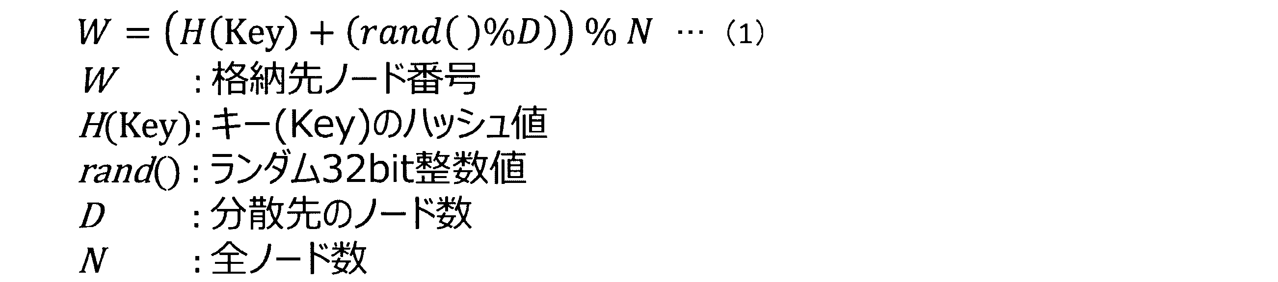
キー設定部246は、第1の分割部243が分割した前方のビット列を、格納先のノードのキーに格納する設定を行う。そして、バリュー設定部247は、格納先のノードのキーのうち、キー設定部246が設定したキーのバリューに、第1の分割部243が分割した後方ビット列及び対応データを格納する設定を行う。格納指示部248は、キー設定246部及びバリュー設定部247の設定に応じて、格納先のノードにデータを格納させる。
The key setting unit 246 performs setting to store the front bit string divided by the first dividing unit 243 in the key of the storage destination node. Then, the value setting unit 247 performs setting to store the backward bit string and the corresponding data divided by the first dividing unit 243 in the key value set by the key setting unit 246 among the keys of the storage destination nodes. The storage instruction unit 248 stores data in the storage destination node according to the settings of the key setting unit 246 and the value setting unit 247.
このように、格納部24は、(1)式を用いることによって、各キーの違いに応じて、異なるノードを格納先として選択する。したがって、格納部24は、同じ時間や同じ地域のデータであっても、複数のノードに分けて格納して、格納先を分散するため、ノードに対する格納の負荷を低減することができる。また、格納部24は、時空間情報を、1次元ビット列変換法を用いて変換し、1次元ビット列に変換した時空間情報のうちの前方ビットをキーとして使用する。このように、格納部24は、比較的簡易な変換処理である1次元ビット列変換法を用いて、キーを作成するため、キー作成に要する時間を短縮することができる。
Thus, the storage unit 24 selects a different node as a storage destination according to the difference of each key by using the expression (1). Therefore, the storage unit 24 stores the data at the same time and the same area separately for a plurality of nodes and distributes the storage destinations, so that the storage load on the nodes can be reduced. In addition, the storage unit 24 converts the spatiotemporal information using a one-dimensional bit string conversion method, and uses the front bits of the spatiotemporal information converted into a one-dimensional bit string as a key. Thus, since the storage unit 24 creates a key using a one-dimensional bit string conversion method that is a relatively simple conversion process, the time required for key creation can be shortened.
[検索部の構成]
次に、検索部25について説明する。検索部25は、検索受付部251、第2の変換部252、第2の分割部253、第2のハッシュ値計算部254、検索先ノード計算部255(検索先ノード取得部)、キー検索部256、後方ビット列検索部257及びバリュー返却部258(出力部)を有する。 [Configuration of search section]
Next, thesearch unit 25 will be described. The search unit 25 includes a search reception unit 251, a second conversion unit 252, a second division unit 253, a second hash value calculation unit 254, a search destination node calculation unit 255 (search destination node acquisition unit), and a key search unit. 256, a backward bit string search unit 257, and a value return unit 258 (output unit).
次に、検索部25について説明する。検索部25は、検索受付部251、第2の変換部252、第2の分割部253、第2のハッシュ値計算部254、検索先ノード計算部255(検索先ノード取得部)、キー検索部256、後方ビット列検索部257及びバリュー返却部258(出力部)を有する。 [Configuration of search section]
Next, the
検索受付部251は、端末装置40から送信された検索条件の入力を受け付ける。検索条件は、ルート案内や障害地点通知などに用いるための、検索対象の時空間情報の範囲条件である。具体的には、検索情報は、図4のリストL3に示すように、時刻、経度、緯度の始端及び終端を示す情報である。
The search reception unit 251 receives an input of search conditions transmitted from the terminal device 40. The search condition is a range condition of the spatio-temporal information to be searched for use in route guidance or failure point notification. Specifically, the search information is information indicating the start and end of time, longitude, and latitude, as shown in the list L3 in FIG.
第2の変換部252は、検索を受けた検索対象の時空間情報の範囲条件を、1次元ビット列に変換する。第2の分割部253は、第2の変換部252が変換した1次元ビット列を前方ビット列及び後方ビット列に分割する。第2のハッシュ値計算部254は、第2の分割部253が分割した前方ビット列のハッシュ値を計算する。
The second conversion unit 252 converts the range condition of the search target spatio-temporal information received into the search into a one-dimensional bit string. The second division unit 253 divides the one-dimensional bit string converted by the second conversion unit 252 into a front bit string and a rear bit string. The second hash value calculation unit 254 calculates the hash value of the forward bit string divided by the second division unit 253.
検索先ノード計算部255は、第2のハッシュ値計算部254が計算したハッシュ値を基に検索先のノードを求める。具体的には、検索先ノード計算部255は、(2)式を用いて、検索先のノード番号を計算し、計算結果として得られた番号のノードを検索の際のノードとする。(2)式では、(1)式で分散先のノード数Dが複数台設定されている場合には、(1)式で設定された台数分の解が出る。
The search destination node calculation unit 255 obtains a search destination node based on the hash value calculated by the second hash value calculation unit 254. Specifically, the search destination node calculation unit 255 calculates the node number of the search destination using equation (2), and sets the node of the number obtained as the calculation result as the node at the time of search. In the formula (2), when a plurality of distribution destination node numbers D are set in the formula (1), solutions corresponding to the number set in the formula (1) are obtained.

キー検索部256は、検索先のノードから、第2の分割部253が分割した前方ビット列と一致するキーを検索する。そして、後方ビット列検索部257は、キー検索部256が検索したキーのバリューから、第2の分割部が分割した後方ビット列と前方一致するバリューを検索する。
The key search unit 256 searches the search destination node for a key that matches the forward bit string divided by the second division unit 253. The backward bit string search unit 257 then searches the value of the key searched by the key search unit 256 for a value that matches the backward bit string divided by the second dividing unit.
バリュー返却部258は、後方ビット列検索部257が検索したバリューに含まれる対応データを、検索結果として出力する。言い換えると、バリュー返却部258は、後方ビット列検索部257が検索したバリューに含まれる対応データを、端末装置40に返却する。
The value return unit 258 outputs the corresponding data included in the value searched by the backward bit string search unit 257 as the search result. In other words, the value return unit 258 returns the corresponding data included in the value searched by the backward bit string search unit 257 to the terminal device 40.
検索部25は、(2)式を用いることによって、検索先のノードの台数を絞って検索処理を実行する。したがって、実施の形態1では、1台のノードに検索が集中することもなく検索の負荷を低減することができるとともに、全ノードに検索を行うこともないため、検索処理の高速化を図ることができる。
The search unit 25 executes the search process by narrowing down the number of search destination nodes by using the expression (2). Therefore, in the first embodiment, the search can be reduced without concentrating the search on one node, and the search is not performed on all the nodes. Can do.
[格納部の処理の流れ]
次に、図7を参照して、格納部24の処理の流れについて具体的に説明する。図7は、図1に示す格納部24の処理の流れを説明する図である。 [Processing flow of storage unit]
Next, the processing flow of thestorage unit 24 will be specifically described with reference to FIG. FIG. 7 is a diagram for explaining the processing flow of the storage unit 24 shown in FIG.
次に、図7を参照して、格納部24の処理の流れについて具体的に説明する。図7は、図1に示す格納部24の処理の流れを説明する図である。 [Processing flow of storage unit]
Next, the processing flow of the
図7に示すように、例えば、格納受付部241が、「時刻(unix_timestamp):1483196400,経度:40.7212905884,緯度:-73.8441925049,データ部:“test_data1”」であるデータの入力を受け付けた場合について説明する。
As illustrated in FIG. 7, for example, the case where the storage receiving unit 241 receives input of data having “time (unix_timestamp): 1483196400, longitude: 40.7212905884, latitude: −73.8441925049, data unit:“ test_data1 ”” will be described. To do.
この場合、第1の変換部242は、3次元Z曲線により時刻「1483196400」、経度「40.7212905884」,緯度「-73.8441925049」を1次元ビット列(例:96ビット)に変換する。得られた1次元ビット列は、「101010101101111001010110100110111010110010100010001000100011101001110111000100110011001000011011」である。
In this case, the first conversion unit 242 converts the time “1483196400”, the longitude “40.7212905884”, and the latitude “−73.8441925049” into a one-dimensional bit string (eg, 96 bits) using a three-dimensional Z curve. The obtained one-dimensional bit string is “101010101101111001010110100110111010110010100010001000100011101001110111000100110011001000011011”.
続いて、第1の分割部243は、1次元ビット列を前方ビット列(例:45ビット)、後方ビット列(例:51ビット)に分割する。具体的には、第1の分割部243は、「101010101101111001010110100110111010110010100010001000100011101001110111000100110011001000011011」のうち、前方の45ビット「101010101101111001010110100110111010110010100」を前方ビット列とし、後方の51ビット「010001000100011101001110111000100110011001000011011」を後方ビット列として分割する。
Subsequently, the first dividing unit 243 divides the one-dimensional bit string into a front bit string (example: 45 bits) and a backward bit string (example: 51 bits). Specifically, among the “101010101101111001010110100110111010110010100010001000100011101001110111000100110011001000011011”, the first dividing unit 243 uses the front 45 bits “101010101101111001010110100110111010110010100” as the front bit string and the rear 51 bits “010001000100011101001110111000100110011001000011011” as the rear bits.
第1のハッシュ値計算部244は、前方ビット列「101010101101111001010110100110111010110010100」のハッシュ値を計算する。例えば、第1のハッシュ値計算部244は、ハッシュ関数としてmurmurhashを用い、前方ビット列「101010101101111001010110100110111010110010100」のハッシュ値を「8088516515490849671」と計算する。
The first hash value calculation unit 244 calculates the hash value of the forward bit string “101010101101111001010110100110111010110010100”. For example, the first hash value calculation unit 244 uses murmurhash as the hash function and calculates the hash value of the forward bit string “101010101101111001010110100110111010110010100” as “8088516515490849671”.
そして、格納先ノード計算部245は、第1のハッシュ値計算部244が計算したハッシュ値「8088516515490849671」を(1)式に適用し、格納先ノードの番号を計算する。例えば、D=3、N=10の場合であって、ノード番号W=1、W=2またはW=3のうち、今回は、W=1が選ばれたものとする。
Then, the storage node calculation unit 245 applies the hash value “8088516515490849671” calculated by the first hash value calculation unit 244 to the equation (1) to calculate the number of the storage node. For example, it is assumed that D = 3 and N = 10, and among the node numbers W = 1, W = 2 or W = 3, this time W = 1 is selected.
キー設定部246は、ノードW1のキーに前方ビット列「101010101101111001010110100110111010110010100」を格納するように設定する。そして、バリュー設定部247は、格納先のノードW1のキー「101010101101111001010110100110111010110010100」のバリューのうち、セカンダリインデクス部に、後方ビット列「010001000100011101001110111000100110011001000011011」を格納し、データ部に「test_data1」を格納する設定を行う。そして、この格納指示部248は、キー設定246部及びバリュー設定部247の設定に応じて、格納先のノードにデータを格納させる。
The key setting unit 246 performs setting so as to store the forward bit string “101010101101111001010110100110111010110010100” in the key of the node W1. Then, the value setting unit 247 stores the backward bit string “010001000100011101001110111000100110011001000011011” in the secondary index part among the values of the key “101010101101111001010110100110111010110010100” of the storage destination node W1, and performs setting to store “test_data1” in the data part. Then, the storage instruction unit 248 stores data in the storage destination node according to the settings of the key setting 246 unit and the value setting unit 247.
図8は、図1に示すデータ記憶システム30内のデータ保持形式を説明する図である。図8のリストL2aに示すように、図7に示す格納部24の設定に従い、ノード「1」のキーに「101010101101111001010110100110111010110010100」が格納される。そして、リストL2aに示すように、このキー「101010101101111001010110100110111010110010100」のバリューのうち、セカンダリインデクス部に、「010001000100011101001110111000100110011001000011011」が格納され、データ部に「test_data1」が格納される。
FIG. 8 is a diagram for explaining a data holding format in the data storage system 30 shown in FIG. As shown in the list L2a of FIG. 8, “101010101101111001010110100110111010110010100” is stored in the key of the node “1” according to the setting of the storage unit 24 shown in FIG. As shown in the list L2a, among the values of the key “101010101101111001010110100110111010110010100”, “010001000100011101001110111000100110011001000011011” is stored in the secondary index portion, and “test_data1” is stored in the data portion.
[検索部の処理の流れ]
次に、図9を参照して、検索部25の処理の流れについて具体的に説明する。図9は、図1に示す検索部25の処理の流れを説明する図である。また、図10は、図1に示すデータ記憶システム30内のデータ保持形式を説明する図である。 [Processing flow of search unit]
Next, with reference to FIG. 9, the processing flow of thesearch unit 25 will be specifically described. FIG. 9 is a diagram for explaining the processing flow of the search unit 25 shown in FIG. FIG. 10 is a diagram for explaining a data holding format in the data storage system 30 shown in FIG.
次に、図9を参照して、検索部25の処理の流れについて具体的に説明する。図9は、図1に示す検索部25の処理の流れを説明する図である。また、図10は、図1に示すデータ記憶システム30内のデータ保持形式を説明する図である。 [Processing flow of search unit]
Next, with reference to FIG. 9, the processing flow of the
図9に示すように、例えば、検索受付部251が、検索条件として、「時刻(unix_timestamp):1483194823~1483196748,経度:40.7211685180~40.7213401794,緯度:-73.8442611694~-73.8439178466」の入力を受け付けた場合について説明する。
As shown in FIG. 9, for example, when the search receiving unit 251 receives an input of “time (unix_timestamp): 1483194823 to 1483196748, longitude: 40.7211685180 to 40.7213401794, latitude: −73.8442611694 to −73.8439178466” as search conditions, for example. explain.
この場合、第2の変換部252は、3次元Z曲線により時刻「1483194823~1483196748」、経度「経度:40.7211685180~40.7213401794」、緯度「-73.8442611694~-73.8439178466」の入力範囲を1次元ビット列に変換する。この例では、60ビットで表現が可能であり、第2の変換部252は、ビット列「101010101101111001010110100110111010110010100010001000100011」を得ることができる。
In this case, the second conversion unit 252 converts the input range of time “1483194823 to 1483196748”, longitude “longitude: 40.7211685180 to 40.7213401794”, latitude “-73.8442611694 to -73.8439178466” into a one-dimensional bit string using a three-dimensional Z curve. . In this example, it is possible to express with 60 bits, and the second conversion unit 252 can obtain the bit string “101010101101111001010110100110111010110010100010001000100011”.
続いて、第2の分割部253は、1次元ビット列を前方ビット列(例:45ビット)、後方ビット列(例:51ビット)に分割する。具体的には、第2の分割部253は、「101010101101111001010110100110111010110010100010001000100011」のうち前方の45ビット「101010101101111001010110100110111010110010100」を前方ビット列とし、後方の15ビット「010001000100011」を後方ビット列として分割する。
Subsequently, the second dividing unit 253 divides the one-dimensional bit string into a front bit string (example: 45 bits) and a backward bit string (example: 51 bits). Specifically, the second dividing unit 253 divides the front 45 bits “101010101101111001010110100110111010110010100” of “101010101101111001010110100110111010110010100010001000100011” as a front bit string and the rear 15 bits “010001000100011” as a back bit string.
第2のハッシュ値計算部254は、前方ビット列「101010101101111001010110100110111010110010100」のハッシュ値を計算する。例えば、第2のハッシュ値計算部254は、ハッシュ関数としてmurmurhashを用い、前方ビット列「101010101101111001010110100110111010110010100」のハッシュ値を「8088516515490849670」と計算する。
The second hash value calculation unit 254 calculates the hash value of the forward bit string “101010101101111001010110100110111010110010100”. For example, the second hash value calculation unit 254 uses murmurhash as the hash function and calculates the hash value of the forward bit string “101010101101111001010110100110111010110010100” as “8088516515490849670”.
そして、検索先ノード計算部255は、第2のハッシュ値計算部254が計算したハッシュ値「8088516515490849670」を(2)式に適用し、検索先ノードの番号を計算する。例えば、D=3、N=10の場合であって、(2)式により、検索先ノードが、R1=1、かつ、R2=2、かつ、R3=3であると求められる。したがって、図10のリストL2aのうち、ノード「1」,「2」,「3」が検索先ノードとして求められる(図10の(1)参照)。
Then, the search destination node calculation unit 255 applies the hash value “8088516515490849670” calculated by the second hash value calculation unit 254 to the expression (2), and calculates the search destination node number. For example, in the case of D = 3 and N = 10, the search destination node is determined to be R 1 = 1, R 2 = 2 and R 3 = 3 by equation (2). Therefore, the nodes “1”, “2”, and “3” in the list L2a in FIG. 10 are obtained as search destination nodes (see (1) in FIG. 10).
そして、キー検索部256は、検索先のノードから、前方ビット列「101010101101111001010110100110111010110010100」と一致するキーを検索する。この結果、リストL2aに示すように、ノード「1」の欄C1のキーが検索キーとして検索される(図10の(2)参照)。
Then, the key search unit 256 searches for a key that matches the forward bit string “101010101101111001010110100110111010110010100” from the search destination node. As a result, as shown in the list L2a, the key in the column C1 of the node “1” is searched as a search key (see (2) in FIG. 10).
続いて、後方ビット列検索部257は、キー検索部256が検索したキーのバリューから、後方ビット列「010001000100011」と前方一致するセカンダリインデクス部を検索する。この結果、ノード「1」の欄C1のキーに対応するバリューのうち、後方ビット列「010001000100011」と前方一致する欄C2が検索バリューとして検索される(図10の(3)参照)。
Subsequently, the backward bit string search unit 257 searches for the secondary index part that matches the backward bit string “010001000100011” from the value of the key searched by the key search unit 256. As a result, among the values corresponding to the keys in the column “C1” of the node “1”, the column C2 that matches the backward bit string “010001000100011” is searched as the search value (see (3) in FIG. 10).
そして、バリュー返却部258は、後方ビット列検索部257が検索した欄C2のセカンダリインデクス部に対応するデータ部のデータ「test_data1」(図10の欄C3参照)を、検索に該当するバリューとして、端末装置40に返却する(図10の(4)参照)。
Then, the value return unit 258 uses the data “test_data1” (refer to the column C3 in FIG. 10) of the data portion corresponding to the secondary index portion of the column C2 searched by the backward bit string search unit 257 as the value corresponding to the search as a terminal. It returns to the apparatus 40 (refer (4) of FIG. 10).
[格納処理の処理手順]
次に、時空間情報管理装置20による情報の格納処理の処理手順について説明する。図11は、図6に示す時空間情報管理装置20による情報の格納処理の処理手順を示すフローチャートである。 [Storage procedure]
Next, a processing procedure of information storage processing by the spatiotemporalinformation management apparatus 20 will be described. FIG. 11 is a flowchart showing a processing procedure of information storage processing by the spatiotemporal information management apparatus 20 shown in FIG.
次に、時空間情報管理装置20による情報の格納処理の処理手順について説明する。図11は、図6に示す時空間情報管理装置20による情報の格納処理の処理手順を示すフローチャートである。 [Storage procedure]
Next, a processing procedure of information storage processing by the spatiotemporal
図11に示すように、格納受付部241がデータ送信機器10から送信された取得データの入力を受け付けると(ステップS11)、第1の変換部242は、入力を受け付けた取得データのうち、時空間情報である時刻、経度、緯度を1次元ビット列に変換する(ステップS12)。
As shown in FIG. 11, when the storage receiving unit 241 receives an input of acquired data transmitted from the data transmitting device 10 (step S11), the first converting unit 242 The time, longitude, and latitude, which are spatial information, are converted into a one-dimensional bit string (step S12).
続いて、第1の分割部243は、第1の変換部242が変換した1次元ビット列を、前方ビット列及び後方ビット列に分割する(ステップS13)。そして、第1のハッシュ値計算部244は、第1の変換部242が変換した前方ビット列のハッシュ値を計算する(ステップS14)。
Subsequently, the first dividing unit 243 divides the one-dimensional bit string converted by the first converting unit 242 into a front bit string and a rear bit string (step S13). Then, the first hash value calculation unit 244 calculates the hash value of the forward bit string converted by the first conversion unit 242 (step S14).
格納先ノード計算部245は、第1のハッシュ値計算部244が計算したハッシュ値を基に格納先のノードを計算する(ステップS15)。具体的には、格納先ノード計算部245は、(1)式を用いて、格納先のノード番号を計算し、計算結果として得られた番号のノードを格納先のノードとして選択する。
The storage destination node calculation unit 245 calculates a storage destination node based on the hash value calculated by the first hash value calculation unit 244 (step S15). Specifically, the storage destination node calculation unit 245 calculates the storage destination node number using the equation (1), and selects the node having the number obtained as the calculation result as the storage destination node.
キー設定部246は、第1の分割部243が分割した前方のビット列を、格納先のノードのキーに格納する設定を行う(ステップS16)。そして、バリュー設定部247は、格納先のノードのキーのうち、キー設定部246が設定したキーのバリューに、第1の分割部243が分割した後方ビット列及び対応データを格納する設定を行う(ステップS17)。格納指示部248は、キー設定246部及びバリュー設定部247の設定に応じて、格納先のノードにデータを格納させる指示を行い(ステップS18)、格納処理を終了する。
The key setting unit 246 performs setting to store the front bit string divided by the first dividing unit 243 in the key of the storage destination node (step S16). Then, the value setting unit 247 performs setting to store the backward bit string and the corresponding data divided by the first dividing unit 243 in the key value set by the key setting unit 246 among the keys of the storage destination nodes ( Step S17). The storage instruction unit 248 instructs the storage destination node to store data according to the settings of the key setting unit 246 and the value setting unit 247 (step S18), and ends the storage process.
[検索処理の処理手順]
次に、時空間情報管理装置20による情報の検索処理の処理手順について説明する。図12は、図6に示す時空間情報管理装置20による情報の検索処理の処理手順を示すフローチャートである。 [Search procedure]
Next, a processing procedure of information search processing by the spatiotemporalinformation management device 20 will be described. FIG. 12 is a flowchart showing a processing procedure of information search processing by the spatiotemporal information management apparatus 20 shown in FIG.
次に、時空間情報管理装置20による情報の検索処理の処理手順について説明する。図12は、図6に示す時空間情報管理装置20による情報の検索処理の処理手順を示すフローチャートである。 [Search procedure]
Next, a processing procedure of information search processing by the spatiotemporal
図12に示すように、まず、検索受付部251は、端末装置40から送信された時刻、経度、緯度の始端及び終端を示す情報を、検索条件として、入力を受け付ける(ステップS21)。そして、第2の変換部252は、入力値を、1次元ビット列に変換する(ステップS22)。
As shown in FIG. 12, first, the search receiving unit 251 receives an input using information indicating the time, longitude, and the start and end of latitude transmitted from the terminal device 40 as a search condition (step S21). Then, the second conversion unit 252 converts the input value into a one-dimensional bit string (step S22).
続いて、第2の分割部253は、第2の変換部252が変換した1次元ビット列を前方ビット列及び後方ビット列に分割する(ステップS23)。そして、第2のハッシュ値計算部254は、第2の分割部253が分割した前方ビット列のハッシュ値を計算する(ステップS24)。
Subsequently, the second dividing unit 253 divides the one-dimensional bit string converted by the second converting unit 252 into a front bit string and a rear bit string (step S23). Then, the second hash value calculation unit 254 calculates the hash value of the forward bit string divided by the second division unit 253 (step S24).
検索先ノード計算部255は、第2のハッシュ値計算部254が計算したハッシュ値を基に検索先のノードを計算する(ステップS25)。具体的には、検索先ノード計算部255は、(2)式を用いて、検索先のノード番号を計算し、計算結果として得られた番号のノードを検索際のノードとする。
The search destination node calculation unit 255 calculates a search destination node based on the hash value calculated by the second hash value calculation unit 254 (step S25). Specifically, the search destination node calculation unit 255 calculates the node number of the search destination using equation (2), and sets the node of the number obtained as the calculation result as the node at the time of search.
そして、キー検索部256は、検索先のノードから、第2の分割部253が分割した前方ビット列と一致する(等価である)キーを検索する(ステップS26)。そして、後方ビット列検索部257は、キー検索部256が検索したキーのバリューに存在する後方ビット列に対し、第2の分割部が分割した後方ビット列と前方一致するバリューを検索する(ステップS27)。
Then, the key search unit 256 searches the search destination node for a key that matches (is equivalent to) the forward bit string divided by the second division unit 253 (step S26). Then, the backward bit string search unit 257 searches the backward bit string existing in the value of the key searched by the key search unit 256 for a value that matches the backward bit string divided by the second dividing unit (step S27).
バリュー返却部258は、後方ビット列検索部257が検索したバリューに含まれる対応データを、検索に該当するバリューとして端末装置40に返却し(ステップS28)、検索処理を終了する。
The value return unit 258 returns the corresponding data included in the value searched by the backward bit string search unit 257 to the terminal device 40 as the value corresponding to the search (step S28), and ends the search process.
[実施の形態1の効果]
このように、実施の形態1に係る時空間情報管理装置20は、格納対象の情報のうち時空間情報を1次元ビット列に変換し、変換した1次元ビット列を前方ビット列及び後方ビット列に分割し、分割した前方ビット列をキーに格納させ、該キーのバリューに、分割した後方ビット列及び対応データを格納先のノードに格納させる。この際、時空間情報管理装置20は、前方ビット列のハッシュ値を計算し、計算したハッシュ値を(1)式に適用して、格納先のノード番号を取得している。ここで、(1)式では1つのノード番号を求めている。 [Effect of Embodiment 1]
As described above, the spatio-temporalinformation management device 20 according to Embodiment 1 converts the spatio-temporal information of the information to be stored into a one-dimensional bit string, divides the converted one-dimensional bit string into a front bit string and a rear bit string, The divided front bit string is stored in the key, and the divided rear bit string and the corresponding data are stored in the storage destination node in the value of the key. At this time, the spatio-temporal information management device 20 calculates the hash value of the forward bit string and applies the calculated hash value to the equation (1) to obtain the storage destination node number. Here, one node number is obtained in equation (1).
このように、実施の形態1に係る時空間情報管理装置20は、格納対象の情報のうち時空間情報を1次元ビット列に変換し、変換した1次元ビット列を前方ビット列及び後方ビット列に分割し、分割した前方ビット列をキーに格納させ、該キーのバリューに、分割した後方ビット列及び対応データを格納先のノードに格納させる。この際、時空間情報管理装置20は、前方ビット列のハッシュ値を計算し、計算したハッシュ値を(1)式に適用して、格納先のノード番号を取得している。ここで、(1)式では1つのノード番号を求めている。 [Effect of Embodiment 1]
As described above, the spatio-temporal
本実施の形態1では、(1)式において、分散先のノード数Dを設定する。これによって、データが同じキー「A」を有する場合でも、各データは、D台のノードに分かれて格納される。また、本実施の形態1では、データがキー「B」を有すれば、(1)式において異なるキーのハッシュ値が計算されるため、キー「A」のデータが格納されるノードとは、別の複数台のノードのいずれかに格納される。
In the first embodiment, the number D of distribution destination nodes is set in equation (1). Thus, even when the data has the same key “A”, each data is stored separately in D nodes. In the first embodiment, if the data has the key “B”, the hash value of the different key in the formula (1) is calculated. Therefore, the node storing the data of the key “A” Stored in one of a plurality of other nodes.
したがって、時空間情報管理装置20によれば、ある時間及びある地域において、データが偏った場合であっても、それぞれのデータに対し、格納先のノードとして、それぞれ異なるノードが算出される。このため、時空間情報管理装置20によれば、同じ時間や同じ地域のデータを格納する場合であっても、複数のノードにそれぞれ分散して格納することができ、ノード間での負荷の偏りを軽減することができる。この結果、時空間情報管理装置20によれば、時空間情報を含む大量のデータを適切に分散して格納できる。
Therefore, according to the spatio-temporal information management device 20, even if data is biased in a certain time and a certain region, different nodes are calculated as storage destination nodes for each data. Therefore, according to the spatio-temporal information management device 20, even when data of the same time or the same region is stored, it can be distributed and stored in a plurality of nodes, and the load unevenness among the nodes Can be reduced. As a result, according to the spatiotemporal information management device 20, a large amount of data including spatiotemporal information can be appropriately distributed and stored.
図13及び図15は、従来のデータベースシステムのデータ分散を説明する図である。図14及び図16は、本実施の形態1に係る時空間情報管理装置20が行うデータ分散を説明する図である。
13 and 15 are diagrams for explaining data distribution in a conventional database system. 14 and 16 are diagrams for explaining data distribution performed by the spatiotemporal information management apparatus 20 according to the first embodiment.
図13に示すように、従来のデータ処理装置20Pは、予め定義した領域で時空間データを分割し、データ配置を決定する。このため、従来では、領域に応じてデータの粗密が異なり、特定のノードに負荷を集中していた。したがって、従来では、特定のノードの負荷を分散させるために、ノードの追加に伴うデータの再配置が発生してしまい(図13の(1)参照)、格納先情報の追加及び更新が必要となる。
As shown in FIG. 13, the conventional data processing apparatus 20P divides the spatio-temporal data in a predefined area and determines the data arrangement. For this reason, conventionally, the density of data differs depending on the area, and the load is concentrated on a specific node. Therefore, in the past, in order to distribute the load of a specific node, data rearrangement occurs with the addition of the node (see (1) in FIG. 13), and it is necessary to add and update the storage destination information. Become.
また、図15に示すように、事前の定義領域の割り当てる従来の手法では、ノード間で負荷が偏るという問題があった(図15の(1),(2)参照)。例えば、東京都を4地域に事前に分割し、4つのノードにそれぞれエリア1~4を割り当てた場合、エリア1では、データが少なく負荷が少ないのに対し、エリア4ではデータが多く負荷が大きくなる。このように、従来手法では、エリアに応じてデータの粗密が異なり、特定のノードに負荷が集中していた。
Further, as shown in FIG. 15, the conventional method of assigning the definition area in advance has a problem that the load is uneven among the nodes (see (1) and (2) in FIG. 15). For example, if Tokyo is divided into 4 areas in advance and areas 1 to 4 are assigned to 4 nodes, respectively, area 1 has less data and less load, whereas area 4 has more data and more load. Become. As described above, according to the conventional method, the density of data differs depending on the area, and the load is concentrated on a specific node.
特に、移動するIoT機器は、時間帯(ラッシュ時と夜間)や地域(都会と郊外)によって存在する機器の数が大幅に異なる。このため、従来手法では、キーに時間情報や位置情報を保持した状態でセカンダリインデクスを利用すると、一つのキーが保持するバリュー数が大幅に異なり、結果として分散キーバリューストアを構成するノード間で負荷の偏りが発生していた。すなわち、従来手法では、特定のノードへの負荷集中が発生していた。
In particular, the number of existing IoT devices varies greatly depending on the time zone (rush hour and night) and region (city and suburb). For this reason, in the conventional method, when the secondary index is used with the time information and position information held in the key, the number of values held by one key is greatly different, and as a result, the nodes constituting the distributed key value store are different. Load imbalance occurred. That is, in the conventional method, load concentration on a specific node has occurred.
これに対し、図14に示すように、時空間情報管理装置20では、常に複数のノードにデータを分散するため、各ノードが保持するデータ量が均等に分散し、性能を維持することができる。また、図16に示すように、本実施の形態1によれば、データを複数のノードに分散して格納し、検索時に複数のノードからデータを取得するため、ノード間で負荷が均一になる。言い換えると、時間帯や地域に応じたデータの偏りに影響を受けずにデータを分散できる。したがって、時空間情報管理装置20によれば、時空間情報という多次元の情報をデータストアに効率的に格納することができる。
On the other hand, as shown in FIG. 14, in the spatio-temporal information management device 20, since data is always distributed to a plurality of nodes, the amount of data held by each node is evenly distributed and the performance can be maintained. . Also, as shown in FIG. 16, according to the first embodiment, data is distributed and stored in a plurality of nodes, and data is acquired from the plurality of nodes at the time of search, so the load is uniform among the nodes. . In other words, the data can be distributed without being affected by the bias of the data according to the time zone and the region. Therefore, according to the spatiotemporal information management device 20, multidimensional information called spatiotemporal information can be efficiently stored in the data store.
また、時空間情報管理装置20は、検索対象の時空間情報の範囲条件を1次元ビット列に変換し、変換した1次元ビット列を前方ビット列及び後方ビット列に分割して、検索先のノードから、分割した前方ビットを用いてキーを検索し、検索されたキーのバリューから、分割した後方ビット列に対応するバリューを検索し、検索したバリューに含まれる対応データを検索結果として出力する。
The spatio-temporal information management device 20 converts the range condition of the spatio-temporal information to be searched into a one-dimensional bit string, divides the converted one-dimensional bit string into a front bit string and a rear bit string, and divides it from a search destination node. The key is searched using the forward bit, the value corresponding to the divided backward bit string is searched from the value of the searched key, and the corresponding data included in the searched value is output as the search result.
ここで、時空間情報管理装置20は、全ノードに対して検索を行うのではなく、(2)式を用いて計算した一定数(D台)のノードに絞ってキー検索を行う。その後、検索されたキーのセカンダリインデクス部による前方一致検索を行い、格納されたデータを検索する。このため、時空間情報管理装置20は、1台のノードに検索が集中することもない。また、時空間情報管理装置20は、一定数のノードに絞ってキー検索を行うため、全ノードにキー検索を行う場合と比して、検索処理の負荷を低減しながら、検索処理を効率かつ高速に実行することができる。
Here, the spatio-temporal information management device 20 does not search for all the nodes, but performs key search by narrowing down to a fixed number (D) of nodes calculated using the equation (2). Thereafter, a forward matching search is performed by the secondary index part of the searched key, and the stored data is searched. For this reason, the spatio-temporal information management device 20 does not concentrate search on one node. In addition, since the spatio-temporal information management device 20 performs a key search focusing on a certain number of nodes, the search process can be performed efficiently while reducing the load of the search process as compared with the case of performing a key search for all nodes. It can be executed at high speed.
また、従来のRDBMSでは、時空間情報の格納時に、大量のデータが格納されるたびにインデクスの作成および更新が必要となり、インデクス作成処理のために一定以上の時間が必要となる。これに対し、時空間情報管理装置20は、時空間情報の格納時に、1次元ビット列変換法を用いて時空間情報を変換し、このうちの前方ビットをキーとして用いる。1次元ビット列変換法は比較的簡易な処理であるため、時空間情報管理装置20は、従来よりも、インデクス作成処理の時間を削減することができる。したがって、時空間情報管理装置20は、従来の格納手法に比して、多次元の情報である時空間情報の格納を高速化かつ効率化できる。
Also, in the conventional RDBMS, when storing a spatio-temporal information, it is necessary to create and update an index every time a large amount of data is stored, and a certain amount of time is required for the index creation process. On the other hand, the spatio-temporal information management device 20 converts the spatio-temporal information using a one-dimensional bit string conversion method when storing the spatio-temporal information, and uses the forward bit as a key. Since the one-dimensional bit string conversion method is a relatively simple process, the spatio-temporal information management apparatus 20 can reduce the time required for the index creation process as compared with the conventional one. Therefore, the spatiotemporal information management device 20 can increase the speed and efficiency of storing the spatiotemporal information, which is multidimensional information, as compared with the conventional storage method.
このように、本実施の形態1に係る時空間情報管理装置20を用いて、時空間情報を格納及び検索することによって、データストアを構成するノード間での処理負荷を分散することができる。このため、時空間情報管理装置20によれば、移動するIoT機器のデータを扱う事業者は、膨大な量のデータを高速に格納することができる。また、時空間情報管理装置20によれば、事業者は、時空間情報の範囲条件による高速な検索を行えることが可能になるため、展開可能なサービスを拡大する効果が期待できる。
As described above, by using the spatiotemporal information management device 20 according to the first embodiment to store and search spatiotemporal information, the processing load among the nodes constituting the data store can be distributed. For this reason, according to the spatio-temporal information management device 20, a business operator who handles data of a moving IoT device can store a huge amount of data at high speed. Further, according to the spatio-temporal information management device 20, the business operator can perform a high-speed search according to the range condition of the spatio-temporal information, so that an effect of expanding expandable services can be expected.
[実施の形態1の変形例]
次に、実施の形態の変形例1について説明する。図17は、実施の形態1の変形例に係る時空間情報管理装置の構成の一例を示す図である。図17に示すように、時空間情報管理装置20Aは、図6に示す時空間情報管理装置20の制御部23に代えて制御部23Aを有する。時空間情報管理装置20Aは、記憶部22に、分散先ノード組合せ情報221Aを有する。 [Modification of Embodiment 1]
Next,Modification 1 of the embodiment will be described. FIG. 17 is a diagram illustrating an example of a configuration of a spatiotemporal information management apparatus according to a modification of the first embodiment. As shown in FIG. 17, the spatiotemporal information management device 20A has a control unit 23A instead of the control unit 23 of the spatiotemporal information management device 20 shown in FIG. The spatiotemporal information management apparatus 20A has distribution destination node combination information 221A in the storage unit 22.
次に、実施の形態の変形例1について説明する。図17は、実施の形態1の変形例に係る時空間情報管理装置の構成の一例を示す図である。図17に示すように、時空間情報管理装置20Aは、図6に示す時空間情報管理装置20の制御部23に代えて制御部23Aを有する。時空間情報管理装置20Aは、記憶部22に、分散先ノード組合せ情報221Aを有する。 [Modification of Embodiment 1]
Next,
分散先ノード組合せ情報221Aは、予め作成された格納先のノードの組合せ表である。図18は、分散先ノード組合せ情報221Aのデータ構成の一例を示す図である。図18に示すように、分散先ノード組合せ情報221Aは、パターン番号k(k=0,1,2,3,・・・,nCd-1)と、分散先のノード番号の組合せimとが対応付けられた一覧表である。なお、nは、ノードの台数であり、dは、格納先のノードの台数である。
The distribution destination node combination information 221A is a combination table of storage destination nodes created in advance. FIG. 18 is a diagram illustrating an example of a data configuration of the distribution destination node combination information 221A. As illustrated in FIG. 18, the distribution destination node combination information 221A includes a combination i m of a pattern number k (k = 0, 1, 2, 3,..., N C d −1) and a distribution destination node number. Is a list in which and are associated with each other. Note that n is the number of nodes, and d is the number of storage destination nodes.
制御部23Aは、格納部24A及び検索部25Aを有する。格納部24Aは、図6に示す格納先ノード計算部245に代えて、格納先ノード計算部245Aを有する。格納先計算部245Aは、分散先のノードの組合せを選択する。格納先計算部245Aは、第1の分割部243が分割した前方ビットをキーとし、第1のハッシュ値計算部244が計算したハッシュ値を用いて、分散先のノードの組合せを選択する。
The control unit 23A includes a storage unit 24A and a search unit 25A. The storage unit 24A includes a storage destination node calculation unit 245A instead of the storage destination node calculation unit 245 illustrated in FIG. The storage destination calculation unit 245A selects a combination of distribution destination nodes. The storage destination calculation unit 245A selects a combination of nodes to be distributed using the forward bit divided by the first division unit 243 as a key and using the hash value calculated by the first hash value calculation unit 244.
具体的には、格納先計算部245Aは、(3)式を用いて、分散先のノード番号の組合せのパターン番号kを計算する。
Specifically, the storage destination calculation unit 245A calculates the pattern number k of the combination of the node numbers of the distribution destination using the equation (3).

続いて、格納先ノード計算部245Aは、パターン番号kに対応するノード番号の組合せimを、分散先ノードの組合せ情報221Aから取得し、組合せimに含まれるノード中から、格納先のノードを(4)式を用いて計算する。
Then, the storage destination node calculator 245A includes a combination i m node number corresponding to the pattern number k, obtained from the combination information 221A distribution destination node, from among nodes included in the combination i m, storage destination node Is calculated using equation (4).
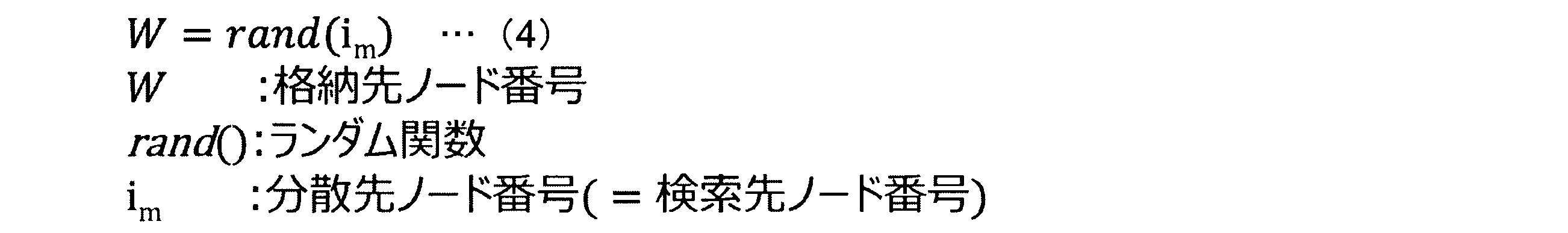
そして、実施の形態と同様に、キー設定部246、バリュー設定部247及び格納指示部248は、格納先ノード計算部245Aが計算した格納先のノードにデータを格納させる。
Similarly to the embodiment, the key setting unit 246, the value setting unit 247, and the storage instruction unit 248 store data in the storage destination node calculated by the storage destination node calculation unit 245A.
また、検索部25Aは、検索先ノード計算部255に代えて、検索先ノード計算部255Aを有する。検索先ノード計算部255Aは、検索先のノードの組合せを選択する。検索先ノード計算部255Aは、第2の分割部253が分割した前方ビットをキーとして、第2のハッシュ値計算部254が計算したハッシュ値を、(3)式に適用し、検索先のノードの組合せを計算する。
Also, the search unit 25A has a search destination node calculation unit 255A instead of the search destination node calculation unit 255. The search destination node calculation unit 255A selects a combination of search destination nodes. The search destination node calculation unit 255A applies the hash value calculated by the second hash value calculation unit 254 to the expression (3) using the forward bit divided by the second division unit 253 as a key, and the search destination node The combination of is calculated.
具体的には、格納先計算部245Aは、(3)式を用いて、分散先のノード番号の組合せのパターン番号kを計算する。
Specifically, the storage destination calculation unit 245A calculates the pattern number k of the combination of the node numbers of the distribution destination using the equation (3).
続いて、キー設定部256は、パターン番号kに対応するノード番号の組合せimを、分散先ノードの組合せ情報221Aから取得し、組合せimに含まれるノードの中から、第2の分割部253が分割した前方ビット列と一致するキーを検索する。そして、実施の形態1と同様に、後方ビット列検索部257は、キー検索部256が検索したキーのバリューから、第2の分割部が分割した後方ビット列と前方一致するバリューを検索する。そして、バリュー返却部258は、後方ビット列検索部257が検索したバリューに含まれる対応データを、検索結果として出力する。
Subsequently, the key setting unit 256, the combination i m node number corresponding to the pattern number k, obtained from the combination information 221A distribution destination node from among the nodes included in the combination i m, the second division section A key matching the front bit string divided by 253 is searched. Similarly to the first embodiment, the backward bit string search unit 257 searches the key value searched by the key search unit 256 for a value that matches the backward bit string divided by the second dividing unit. Then, the value return unit 258 outputs the correspondence data included in the value searched by the backward bit string search unit 257 as the search result.
[格納処理の処理手順]
次に、時空間情報管理装置20Aによる情報の格納処理の処理手順について説明する。図19は、図17に示す時空間情報管理装置20Aによる情報の格納処理の処理手順を示すフローチャートである。図19に示すステップS11A~ステップS14Aは、図11に示すステップS11~ステップS14と同じ処理である。 [Storage procedure]
Next, a processing procedure of information storage processing by the spatiotemporal information management apparatus 20A will be described. FIG. 19 is a flowchart showing a processing procedure of information storage processing by the spatiotemporal information management apparatus 20A shown in FIG. Steps S11A to S14A shown in FIG. 19 are the same processes as steps S11 to S14 shown in FIG.
格納先計算部245Aは、(3)式を用いて、分散先のノードの組合せのパターン番号kを取得する(ステップS15-1A)。格納先ノード計算部245Aは、パターン番号kに対応するノード番号の組合せimを、分散先ノードの組合せ情報221Aから取得し、組合せimに含まれるノード中から、格納先のノードを、(4)式を用いて計算する(ステップS15-2A)。図19に示すステップS16A~ステップS18Aは、図11に示すステップS16~ステップS18と同じ処理である。
The storage destination calculation unit 245A obtains the pattern number k of the combination of the distribution destination nodes using the expression (3) (step S15-1A). Storage destination node calculator 245A includes a combination i m node number corresponding to the pattern number k, obtained from the combination information 221A distribution destination node, from among nodes included in the combination i m, the storage destination node, ( 4) Calculate using the equation (step S15-2A). Steps S16A to S18A shown in FIG. 19 are the same processes as steps S16 to S18 shown in FIG.
[検索処理の処理手順]
次に、時空間情報管理装置20Aによる情報の検索処理の処理手順について説明する。図20は、図17に示す時空間情報管理装置20Aによる情報の検索処理の処理手順を示すフローチャートである。図20に示すステップS21A~ステップS24Aは、図12に示すステップS21~ステップS24と同じ処理である。 [Search procedure]
Next, a processing procedure of information search processing by the spatiotemporal information management apparatus 20A will be described. FIG. 20 is a flowchart showing a processing procedure of information search processing by the spatiotemporal information management apparatus 20A shown in FIG. Steps S21A to S24A shown in FIG. 20 are the same processes as steps S21 to S24 shown in FIG.
検索先ノード計算部255Aは、第2のハッシュ値計算部254が計算したハッシュ値を基に、検索先のノードの組合せを取得する(ステップS25A)。検索先ノード計算部255Aは、第2のハッシュ値計算部254が計算したハッシュ値を、(3)式に適用し、検索先のノードの組合せのパターン番号kを計算し、パターン番号kに対応するノード番号の組合せimを、分散先ノードの組合せ情報221Aから取得する。
The search destination node calculation unit 255A acquires a combination of search destination nodes based on the hash value calculated by the second hash value calculation unit 254 (step S25A). The search destination node calculation unit 255A applies the hash value calculated by the second hash value calculation unit 254 to the equation (3), calculates the pattern number k of the combination of search destination nodes, and corresponds to the pattern number k. the combined i m node number that will be obtained from the combination information 221A distribution destination node.
そして、キー検索部256は、検索先ノード計算部255Aが求めた組合せのノードから、第2の分割部253が分割した前方ビット列と一致する(等価である)キーを検索する(ステップS26A)。図20のステップS27及びステップS28は、図12のステップS27及びステップS28と同じ処理である。
Then, the key search unit 256 searches for a key that matches (is equivalent to) the forward bit string divided by the second division unit 253 from the combination of nodes obtained by the search destination node calculation unit 255A (step S26A). Steps S27 and S28 in FIG. 20 are the same processes as steps S27 and S28 in FIG.
[実施の形態1の変形例の効果]
このように、時空間情報管理装置20では、予め、格納先のノードの組合せ表を作成しておき、格納時には、第1の分割部243が分割した前方ビットの値をキーとして、ノードの組合せを選択し、選択したノードのいずれかに格納処理を行う。また、時空間情報管理装置20では、検索時には、第2の分割部253が分割した前方ビットの値をキーとして、検索先のノードの組合せを求め、求めた組合せのノードに対して検索を行う。 [Effect of Modification of Embodiment 1]
In this way, the spatio-temporalinformation management device 20 creates a combination table of storage destination nodes in advance, and at the time of storage, combinations of nodes using the value of the front bit divided by the first dividing unit 243 as a key And store the data in one of the selected nodes. Further, in the spatio-temporal information management device 20, at the time of search, a combination of search destination nodes is obtained by using the value of the front bit divided by the second division unit 253 as a key, and a search is performed on the nodes of the obtained combination. .
このように、時空間情報管理装置20では、予め、格納先のノードの組合せ表を作成しておき、格納時には、第1の分割部243が分割した前方ビットの値をキーとして、ノードの組合せを選択し、選択したノードのいずれかに格納処理を行う。また、時空間情報管理装置20では、検索時には、第2の分割部253が分割した前方ビットの値をキーとして、検索先のノードの組合せを求め、求めた組合せのノードに対して検索を行う。 [Effect of Modification of Embodiment 1]
In this way, the spatio-temporal
図21は、図17に示す時空間情報管理装置20Aが選択できるノードの組合せを示す図である。図21では、Nを4台とし、Dを2台とした例を示す。図21に示すように、時空間情報管理装置20Aは、全ノードに対する全ての組合せを、格納先として選択できるため、全ノードに均等に負荷を分散することができる。また、時空間情報管理装置20Aは、検索先のノードの組合せを正確に取得できるため、適切な検索も実現することができる。
FIG. 21 is a diagram showing combinations of nodes that can be selected by the spatiotemporal information management apparatus 20A shown in FIG. FIG. 21 shows an example in which N is four and D is two. As shown in FIG. 21, the spatio-temporal information management device 20A can select all combinations for all nodes as storage destinations, so that the load can be evenly distributed to all nodes. In addition, since the spatiotemporal information management device 20A can accurately acquire a combination of search destination nodes, an appropriate search can also be realized.
[実施の形態2]
本発明の実施の形態2について説明する。図22は、実施の形態2における情報管理システムの構成の一例を示す図である。 [Embodiment 2]
A second embodiment of the present invention will be described. FIG. 22 is a diagram illustrating an example of the configuration of the information management system according to the second embodiment.
本発明の実施の形態2について説明する。図22は、実施の形態2における情報管理システムの構成の一例を示す図である。 [Embodiment 2]
A second embodiment of the present invention will be described. FIG. 22 is a diagram illustrating an example of the configuration of the information management system according to the second embodiment.
図22に示すように、実施の形態2に係る情報管理システム201は、複数のノード1~Nがクラスタ構成で動作するデータ記憶システム230を有する。そして、情報管理システム201は、格納部224及び検索部225を有する時空間情報管理装置220(情報管理装置)を有する。時空間情報管理装置220は、データ送信機器10によって送信された取得データ(例えば、図2のリストL1)を、データ記憶システム230に格納することで管理する。また、時空間情報管理装置220は、データ記憶システム230が格納するデータの中から、検索対象の時空間情報の範囲条件に対応する対応データを検索結果として出力する。
As shown in FIG. 22, the information management system 201 according to the second embodiment includes a data storage system 230 in which a plurality of nodes 1 to N operate in a cluster configuration. The information management system 201 includes a spatiotemporal information management device 220 (information management device) including a storage unit 224 and a search unit 225. The spatiotemporal information management device 220 manages the acquired data (for example, the list L1 in FIG. 2) transmitted by the data transmission device 10 by storing it in the data storage system 230. Also, the spatiotemporal information management device 220 outputs corresponding data corresponding to the range condition of the spatiotemporal information to be searched from the data stored in the data storage system 230 as a search result.
格納部224は、格納対象の情報のうち時空間情報を1次元ビット列に変換し、変換した1次元ビット列を前方ビット列及び後方ビット列に分割する。そして、格納部224は、格納対象の情報についてラベル番号を計算し、分割した前方ビット列及びラベル番号をキーに格納させ、該キーのバリューに、分割した後方ビット列及び対応データをデータ記憶システム230に格納させる。
The storage unit 224 converts the spatio-temporal information of the information to be stored into a one-dimensional bit string, and divides the converted one-dimensional bit string into a front bit string and a rear bit string. Then, the storage unit 224 calculates a label number for the information to be stored, stores the divided front bit string and label number in the key, and stores the divided rear bit string and corresponding data in the data storage system 230 as the value of the key. Store.
検索部225は、検索対象の時空間情報の範囲条件に対応する対応データを検索結果として出力する。検索部225は、検索対象の時空間情報の範囲条件を1次元ビット列に変換し、変換した1次元ビット列を前方ビット列及び後方ビット列に分割する。そして、検索部25は、検索先のノードから、分割した前方ビット及びラベル番号と等価であるキーを検索し、検索されたキーのバリューから、分割した後方ビット列に対応するバリューを検索し、検索したバリューに含まれる対応データを検索結果として出力する。
The search unit 225 outputs corresponding data corresponding to the range condition of the spatiotemporal information to be searched as a search result. The search unit 225 converts the range condition of the spatio-temporal information to be searched into a one-dimensional bit string, and divides the converted one-dimensional bit string into a front bit string and a rear bit string. Then, the search unit 25 searches the search destination node for a key equivalent to the divided forward bit and label number, searches the value of the searched key for the value corresponding to the divided backward bit string, and searches The corresponding data included in the selected value is output as a search result.
データ記憶システム230は、キーバリューストアである複数のノード1~Nがクラスタ構成で動作する。図23は、図22に示すデータ記憶システム230が記憶するデータのデータ構成の一例を示す図である。図23のリストL22に示すように、ノード1~Nが記憶するデータのデータ構成は、セカンダリインデクス部を有するキーバリュー型を想定している。
In the data storage system 230, a plurality of nodes 1 to N, which are key-value stores, operate in a cluster configuration. FIG. 23 is a diagram illustrating an example of a data configuration of data stored in the data storage system 230 illustrated in FIG. As shown in a list L22 in FIG. 23, the data structure of data stored in the nodes 1 to N is assumed to be a key-value type having a secondary index part.
具体的には、ノード1~Nは、リストL22のように、リストL2(図3参照)と同様に、ノードの識別情報、キー、バリューの項目を有する構成でデータを記憶する。リストL22は、リスト2と異なり、キーには、時空間情報をビット列変換した際の前方ビット列及びラベル番号が格納される。
Specifically, the nodes 1 to N store data in a configuration having node identification information, key, and value items as in the list L2 (see FIG. 3), as in the list L22. Unlike the list 2, the list L22 stores a forward bit string and a label number when the space-time information is converted into a bit string.
そして、リストL22では、例えば、ノードN1が、「前方ビット列1_ラベル番号」を格納するキーのバリューのうち、セカンダリインデクス部に「後方ビット列1」が格納され、データ部に「data1」を格納することを示す。
In the list L22, for example, among the key values for storing “front bit string 1_label number”, the node N1 stores “rear bit string 1” in the secondary index part and “data1” in the data part. Indicates to do.
[時空間情報管理装置の構成]
次に、時空間情報管理装置220の構成について説明する。図24は、図22に示す時空間情報管理装置220の構成の一例を示す図である。図24に示すように、時空間情報管理装置220は、時空間情報管理装置20と比して、格納部224及び検索部225を有する制御部223を有する。 [Configuration of space-time information management device]
Next, the configuration of the spatiotemporalinformation management device 220 will be described. FIG. 24 is a diagram showing an example of the configuration of the spatiotemporal information management device 220 shown in FIG. As illustrated in FIG. 24, the spatiotemporal information management device 220 includes a control unit 223 having a storage unit 224 and a search unit 225 as compared to the spatiotemporal information management device 20.
次に、時空間情報管理装置220の構成について説明する。図24は、図22に示す時空間情報管理装置220の構成の一例を示す図である。図24に示すように、時空間情報管理装置220は、時空間情報管理装置20と比して、格納部224及び検索部225を有する制御部223を有する。 [Configuration of space-time information management device]
Next, the configuration of the spatiotemporal
[格納部の構成]
格納部224は、格納受付部241、第1の変換部242、第1の分割部243、ラベル計算部2245、キー設定部2246、バリュー設定部247及び格納指示部248を有する。格納受付部241、第1の変換部242、第1の分割部243、キー設定部2246、バリュー設定部247及び格納指示部248は、図6に示す第1の変換部242、第1の分割部243、バリュー設定部247及び格納指示部248と同じ処理を行う。なお、ノードの台数であるDの値は、可変であり、格納時には決められている。 [Configuration of storage unit]
Thestorage unit 224 includes a storage reception unit 241, a first conversion unit 242, a first division unit 243, a label calculation unit 2245, a key setting unit 2246, a value setting unit 247, and a storage instruction unit 248. The storage reception unit 241, the first conversion unit 242, the first division unit 243, the key setting unit 2246, the value setting unit 247, and the storage instruction unit 248 are the first conversion unit 242 and the first division shown in FIG. Unit 243, value setting unit 247, and storage instruction unit 248 perform the same processing. Note that the value of D, which is the number of nodes, is variable and is determined at the time of storage.
格納部224は、格納受付部241、第1の変換部242、第1の分割部243、ラベル計算部2245、キー設定部2246、バリュー設定部247及び格納指示部248を有する。格納受付部241、第1の変換部242、第1の分割部243、キー設定部2246、バリュー設定部247及び格納指示部248は、図6に示す第1の変換部242、第1の分割部243、バリュー設定部247及び格納指示部248と同じ処理を行う。なお、ノードの台数であるDの値は、可変であり、格納時には決められている。 [Configuration of storage unit]
The
ラベル計算部2245は、第1の分割部243が分割した前方ビットとともにキーに格納するラベル番号を計算する。ラベル計算部2245は、(5)式を用いてラベル番号を計算する。
The label calculation unit 2245 calculates the label number stored in the key together with the front bit divided by the first division unit 243. The label calculation unit 2245 calculates the label number using equation (5).
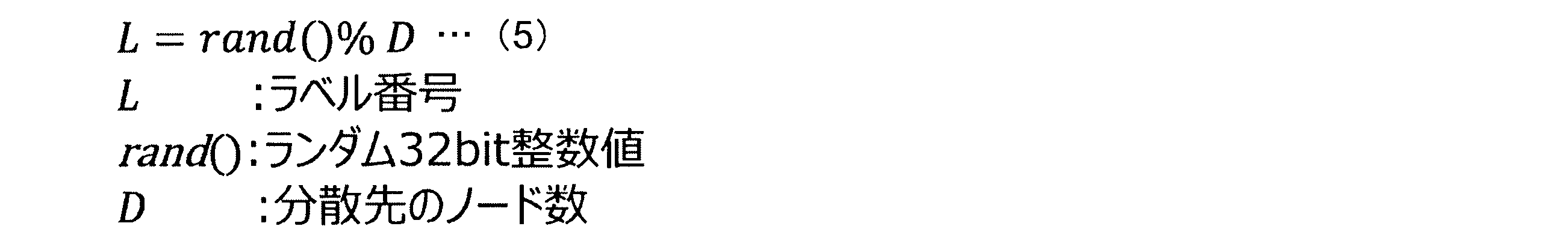
キー設定部2246は、第1の分割部243が分割した前方のビット列と、ラベル計算部2245が計算したラベル番号とを1組として、データ記憶システム230のキーへ格納する設定を行う。そして、バリュー設定部247は、格納先のノードのキーのうち、キー設定部2246が設定したキーのバリューに、第1の分割部243が分割した後方ビット列及び対応データを格納する設定を行う。格納指示部248は、キー設定246部及びバリュー設定部247の設定に応じて、格納先のノードにデータを格納させる。
The key setting unit 2246 performs setting to store the front bit string divided by the first dividing unit 243 and the label number calculated by the label calculating unit 2245 as a set in the key of the data storage system 230. Then, the value setting unit 247 performs setting to store the backward bit string and the corresponding data divided by the first dividing unit 243 in the key value set by the key setting unit 2246 among the keys of the storage destination nodes. The storage instruction unit 248 stores data in the storage destination node according to the settings of the key setting unit 246 and the value setting unit 247.
このように、格納部224は、(5)式を用いることによって、ラベル番号を求め、求めたラベル番号を前方ビット列に対応付けてキーに格納する。
Thus, the storage unit 224 obtains the label number by using the expression (5), and stores the obtained label number in the key in association with the forward bit string.
[検索部の構成]
次に、検索部225について説明する。検索部225は、検索受付部251、第2の変換部252、第2の分割部253、ラベル導出部2255、キー検索部2256、後方ビット列検索部257及びバリュー返却部258(出力部)を有する。検索受付部251、第2の変換部252、第2の分割部253、後方ビット列検索部257及びバリュー返却部258は、図6に示す検索受付部251、第2の変換部252、第2の分割部253、後方ビット列検索部257及びバリュー返却部258と同じ処理を行う。 [Configuration of search section]
Next, thesearch unit 225 will be described. The search unit 225 includes a search reception unit 251, a second conversion unit 252, a second division unit 253, a label derivation unit 2255, a key search unit 2256, a backward bit string search unit 257, and a value return unit 258 (output unit). . The search reception unit 251, the second conversion unit 252, the second division unit 253, the backward bit string search unit 257, and the value return unit 258 are the search reception unit 251, the second conversion unit 252, and the second return unit 258 illustrated in FIG. The same processing as that of the division unit 253, the backward bit string search unit 257, and the value return unit 258 is performed.
次に、検索部225について説明する。検索部225は、検索受付部251、第2の変換部252、第2の分割部253、ラベル導出部2255、キー検索部2256、後方ビット列検索部257及びバリュー返却部258(出力部)を有する。検索受付部251、第2の変換部252、第2の分割部253、後方ビット列検索部257及びバリュー返却部258は、図6に示す検索受付部251、第2の変換部252、第2の分割部253、後方ビット列検索部257及びバリュー返却部258と同じ処理を行う。 [Configuration of search section]
Next, the
ラベル導出部2255は、格納時に決められたDの値から検索対象のラベル番号を導出する。
The label deriving unit 2255 derives a search target label number from the value of D determined at the time of storage.
キー検索部2256は、データ管理システム230から、第2の分割部253が分割した前方ビット列及びラベル番号と一致するキーを検索する。そして、後方ビット列検索部257は、キー検索部2256が検索したキーのバリューから、第2の分割部が分割した後方ビット列と前方一致するバリューを検索する。バリュー返却部258は、後方ビット列検索部257が検索したバリューに含まれる対応データを、検索結果として出力する。
The key search unit 2256 searches the data management system 230 for a key that matches the front bit string and the label number divided by the second division unit 253. The backward bit string search unit 257 then searches the value of the key searched by the key search unit 2256 for a value that matches the backward bit string divided by the second dividing unit. The value return unit 258 outputs the corresponding data included in the value searched by the backward bit string search unit 257 as a search result.
[格納部の処理の流れ]
次に、図25を参照して、格納部224の処理の流れについて具体的に説明する。図25は、図24に示す格納部224の処理の流れを説明する図である。 [Processing flow of storage unit]
Next, with reference to FIG. 25, the processing flow of thestorage unit 224 will be specifically described. FIG. 25 is a diagram for explaining the flow of processing of the storage unit 224 shown in FIG.
次に、図25を参照して、格納部224の処理の流れについて具体的に説明する。図25は、図24に示す格納部224の処理の流れを説明する図である。 [Processing flow of storage unit]
Next, with reference to FIG. 25, the processing flow of the
図25に示すように、例えば、格納受付部241が、「時刻(unix_timestamp):1483196400,経度:40.7212905884,緯度:-73.8441925049,データ部:“test_data1”」であるデータの入力を受け付けた場合について説明する。
As shown in FIG. 25, for example, the case where the storage receiving unit 241 receives input of data “time (unix_timestamp): 1483196400, longitude: 40.7212905884, latitude: −73.8441925049, data unit:“ test_data1 ”” will be described. To do.
この場合、第1の変換部242は、3次元Z曲線により時刻「1483196400」、経度「40.7212905884」,緯度「-73.8441925049」を1次元ビット列(例:96ビット)に変換する。得られた1次元ビット列は、「101010101101111001010110100110111010110010100010001000100011101001110111000100110011001000011011」である。
In this case, the first conversion unit 242 converts the time “1483196400”, the longitude “40.7212905884”, and the latitude “−73.8441925049” into a one-dimensional bit string (eg, 96 bits) using a three-dimensional Z curve. The obtained one-dimensional bit string is “101010101101111001010110100110111010110010100010001000100011101001110111000100110011001000011011”.
続いて、第1の分割部243は、1次元ビット列を前方ビット列(例:45ビット)、後方ビット列(例:51ビット)に分割する。具体的には、第1の分割部243は、「101010101101111001010110100110111010110010100010001000100011101001110111000100110011001000011011」のうち、前方の45ビット「101010101101111001010110100110111010110010100」を前方ビット列とし、後方の51ビット「010001000100011101001110111000100110011001000011011」を後方ビット列として分割する。
Subsequently, the first dividing unit 243 divides the one-dimensional bit string into a front bit string (example: 45 bits) and a backward bit string (example: 51 bits). Specifically, among the “101010101101111001010110100110111010110010100010001000100011101001110111000100110011001000011011”, the first dividing unit 243 uses the front 45 bits “101010101101111001010110100110111010110010100” as the front bit string and the rear 51 bits “010001000100011101001110111000100110011001000011011” as the rear bits.
続いて、ラベル計算部2245は、(5)式に基づきラベル番号を計算する。例えば、D=3の場合、ラベル番号L=0、L=1またはL=2のうち、今回は、L=0が選ばれたものとする。
Subsequently, the label calculation unit 2245 calculates the label number based on the equation (5). For example, when D = 3, it is assumed that L = 0 is selected this time among the label numbers L = 0, L = 1, or L = 2.
キー設定部2246は、データ記憶システム230のキーに前方ビット列及びラベル番号「101010101101111001010110100110111010110010100-0」を格納するように設定する。そして、バリュー設定部247は、キー「101010101101111001010110100110111010110010100-0」のバリューのうち、セカンダリインデクス部に、後方ビット列「010001000100011101001110111000100110011001000011011」を格納し、データ部に「test_data1」を格納する設定を行う。そして、この格納指示部248は、キー設定2246部及びバリュー設定部247の設定に応じて、データ記憶システム230にデータを格納させる。
The key setting unit 2246 performs setting so that the front bit string and the label number “101010101101111001010110100110111010110010100-0” are stored in the key of the data storage system 230. Then, the value setting unit 247 stores the backward bit string “010001000100011101001110111000100110011001000011011” in the secondary index portion of the value of the key “101010101101111001010110100110111010110010100-0”, and performs setting for storing “test_data1” in the data portion. The storage instruction unit 248 stores data in the data storage system 230 according to the settings of the key setting 2246 unit and the value setting unit 247.
図26は、図22に示すデータ記憶システム230内のデータ保持形式を説明する図である。図26のリストL22aに示すように、図24に示す格納部224の設定に従い、ノード「1」のキーに「101010101101111001010110100110111010110010100-0」が格納される。そして、リストL22aに示すように、このキー「101010101101111001010110100110111010110010100-0」のバリューのうち、セカンダリインデクス部に、「010001000100011101001110111000100110011001000011011」が格納され、データ部に「test_data1」が格納される。
FIG. 26 is a diagram for explaining a data holding format in the data storage system 230 shown in FIG. As shown in the list L22a of FIG. 26, “101010101101111001010110100110111010110010100-0” is stored in the key of the node “1” according to the setting of the storage unit 224 shown in FIG. As shown in the list L22a, among the values of the key “101010101101111001010110100110111010110010100-0”, “010001000100011101001110111000100110011001000011011” is stored in the secondary index portion, and “test_data1” is stored in the data portion.
[検索部の処理の流れ]
次に、図27を参照して、検索部225の処理の流れについて具体的に説明する。図27は、図24に示す検索部225の処理の流れを説明する図である。また、図28は、図22に示すデータ記憶システム230内のデータ保持形式を説明する図である。 [Processing flow of search unit]
Next, with reference to FIG. 27, the processing flow of thesearch unit 225 will be specifically described. FIG. 27 is a diagram for explaining the flow of processing of the search unit 225 shown in FIG. FIG. 28 is a diagram for explaining a data holding format in the data storage system 230 shown in FIG.
次に、図27を参照して、検索部225の処理の流れについて具体的に説明する。図27は、図24に示す検索部225の処理の流れを説明する図である。また、図28は、図22に示すデータ記憶システム230内のデータ保持形式を説明する図である。 [Processing flow of search unit]
Next, with reference to FIG. 27, the processing flow of the
図27に示すように、例えば、検索受付部251が、検索条件として、「時刻(unix_timestamp):1483194823~1483196748,経度:40.7211685180~40.7213401794,緯度:-73.8442611694~-73.8439178466」の入力を受け付けた場合について説明する。
As shown in FIG. 27, for example, when the search reception unit 251 receives an input of “time (unix_timestamp): 1483194823 to 1483196748, longitude: 40.7211685180 to 40.7213401794, latitude: −73.8442611694 to −73.8439178466” as the search condition, for example. explain.
この場合、第2の変換部252は、3次元Z曲線により時刻「1483194823~1483196748」、経度「経度:40.7211685180~40.7213401794」、緯度「-73.8442611694~-73.8439178466」の入力範囲を1次元ビット列に変換する。この例では、60ビットで表現が可能であり、第2の変換部252は、ビット列「101010101101111001010110100110111010110010100010001000100011」を得ることができる。
In this case, the second conversion unit 252 converts the input range of time “1483194823 to 1483196748”, longitude “longitude: 40.7211685180 to 40.7213401794”, latitude “-73.8442611694 to -73.8439178466” into a one-dimensional bit string using a three-dimensional Z curve. . In this example, it is possible to express with 60 bits, and the second conversion unit 252 can obtain the bit string “101010101101111001010110100110111010110010100010001000100011”.
続いて、第2の分割部253は、1次元ビット列を前方ビット列(例:45ビット)、後方ビット列(例:51ビット)に分割する。具体的には、第2の分割部253は、「101010101101111001010110100110111010110010100010001000100011」のうち前方の45ビット「101010101101111001010110100110111010110010100」を前方ビット列とし、後方の15ビット「010001000100011」を後方ビット列として分割する。
Subsequently, the second dividing unit 253 divides the one-dimensional bit string into a front bit string (example: 45 bits) and a backward bit string (example: 51 bits). Specifically, the second dividing unit 253 divides the front 45 bits “101010101101111001010110100110111010110010100” of “101010101101111001010110100110111010110010100010001000100011” as a front bit string and the rear 15 bits “010001000100011” as a back bit string.
ラベル導出部2255は、Dの値から検索対象のラベル番号を導出する。そして、キー検索部2256は、データ記憶システム230から、前方ビット列及びラベル番号と等価であるキーを検索する。例えば、D=3の場合、「101010101101111001010110100110111010110010100-0」、「101010101101111001010110100110111010110010100-1」、「101010101101111001010110100110111010110010100-2」のキーを検索する。この結果、リストL22aに示すように、ノード「1」の欄C11のキーが検索キーとして検索される(図28の(1),(2)参照)。
The label deriving unit 2255 derives the search target label number from the D value. Then, the key search unit 2256 searches the data storage system 230 for a key that is equivalent to the forward bit string and the label number. For example, when D = 3, the keys of “101010101101111001010110100110111010110010100-0”, “101010101101111001010110100110111010110010100-1”, and “101010101101111001010110100110111010110010100-2” are searched. As a result, as shown in the list L22a, the key in the column C11 of the node “1” is searched as a search key (see (1) and (2) in FIG. 28).
続いて、後方ビット列検索部257は、キー検索部256が検索したキーのバリューから、後方ビット列「010001000100011」と前方一致するセカンダリインデクス部を検索する。この結果、ノード「1」の欄C11のキーに対応するバリューのうち、後方ビット列「010001000100011」と前方一致する欄C12が検索バリューとして検索される(図28の(3)参照)。
Subsequently, the backward bit string search unit 257 searches for the secondary index part that matches the backward bit string “010001000100011” from the value of the key searched by the key search unit 256. As a result, among the values corresponding to the keys in the column C11 of the node “1”, the column C12 that matches the backward bit string “010001000100011” is searched as the search value (see (3) in FIG. 28).
そして、バリュー返却部258は、後方ビット列検索部257が検索した欄C12のセカンダリインデクス部に対応するデータ部のデータ「test_data1」(図28の欄C13参照)を、検索に該当するバリューとして、端末装置40に返却する。(図28の(4)参照)。
Then, the value return unit 258 uses the data “test_data1” (see the column C13 in FIG. 28) of the data portion corresponding to the secondary index portion of the column C12 searched by the backward bit string search unit 257 as the value corresponding to the search, as a terminal. Return to device 40. (See (4) in FIG. 28).
[格納処理の処理手順]
次に、時空間情報管理装置220による情報の格納処理の処理手順について説明する。図29は、図24に示す時空間情報管理装置220による情報の格納処理の処理手順を示すフローチャートである。 [Storage procedure]
Next, a processing procedure of information storage processing by the spatiotemporalinformation management apparatus 220 will be described. FIG. 29 is a flowchart showing a processing procedure of information storage processing by the spatiotemporal information management apparatus 220 shown in FIG.
次に、時空間情報管理装置220による情報の格納処理の処理手順について説明する。図29は、図24に示す時空間情報管理装置220による情報の格納処理の処理手順を示すフローチャートである。 [Storage procedure]
Next, a processing procedure of information storage processing by the spatiotemporal
図29に示すステップS31~ステップS33は、図11に示すステップS11~ステップS13と同じ処理である。ラベル計算部2245は、第1の分割部243が分割した前方ビットとともにキーに格納するラベル番号を(5)式を用いて計算する(ステップS34)。キー設定部2246は、第1の分割部243が分割した前方のビット列と、ラベル計算部2245が計算したラベル番号とを1組として、データ記憶システム230のキーへ格納する設定を行う(ステップS35)。図29に示すステップS36及びステップS37は、図11に示すステップS17及びステップS18と同じ処理である。
Steps S31 to S33 shown in FIG. 29 are the same processes as steps S11 to S13 shown in FIG. The label calculating unit 2245 calculates the label number stored in the key together with the front bit divided by the first dividing unit 243 using the equation (5) (step S34). The key setting unit 2246 performs setting to store the front bit string divided by the first dividing unit 243 and the label number calculated by the label calculating unit 2245 as a set in the key of the data storage system 230 (step S35). ). Steps S36 and S37 shown in FIG. 29 are the same processes as steps S17 and S18 shown in FIG.
[検索処理の処理手順]
次に、時空間情報管理装置220による情報の検索処理の処理手順について説明する。図30は、図24に示す時空間情報管理装置220による情報の検索処理の処理手順を示すフローチャートである。 [Search procedure]
Next, a processing procedure of information search processing by the spatiotemporalinformation management apparatus 220 will be described. FIG. 30 is a flowchart showing a processing procedure of information search processing by the spatiotemporal information management apparatus 220 shown in FIG.
次に、時空間情報管理装置220による情報の検索処理の処理手順について説明する。図30は、図24に示す時空間情報管理装置220による情報の検索処理の処理手順を示すフローチャートである。 [Search procedure]
Next, a processing procedure of information search processing by the spatiotemporal
図30に示すステップS41~ステップS43は、図12に示すステップS21~ステップS23と同じ処理である。ラベル導出部2255は、Dの値から検索対象のラベル番号を導出する(ステップS44)。
30 are the same as steps S21 to S23 shown in FIG. The label deriving unit 2255 derives a search target label number from the value of D (step S44).
キー検索部2256は、データ記憶システム230のから、第2の分割部253が分割した前方ビット列及びラベル番号と等価であるキーを検索する(ステップS45)。図30に示すステップS46及びステップS47は、図12に示すステップS27及びステップS28と同じ処理である。
The key search unit 2256 searches the data storage system 230 for a key equivalent to the forward bit string and the label number divided by the second division unit 253 (step S45). Steps S46 and S47 shown in FIG. 30 are the same processes as steps S27 and S28 shown in FIG.
この実施の形態2の処理を行うことによって、複数のノード1~Nがクラスタ構成で動作するデータ記憶システム230についても適用が可能であり、複数のノードにそれぞれ分散して格納することができ、ノード間での負荷の偏りを軽減することができる。
By performing the processing of the second embodiment, the present invention can be applied to the data storage system 230 in which a plurality of nodes 1 to N operate in a cluster configuration, and can be distributed and stored in a plurality of nodes. Load imbalance among nodes can be reduced.
[システム構成等]
図示した各装置の各構成要素は機能概念的なものであり、必ずしも物理的に図示の如く構成されていることを要しない。すなわち、各装置の分散・統合の具体的形態は図示のものに限られず、その全部又は一部を、各種の負荷や使用状況等に応じて、任意の単位で機能的又は物理的に分散・統合して構成することができる。さらに、各装置にて行なわれる各処理機能は、その全部又は任意の一部が、CPU及び当該CPUにて解析実行されるプログラムにて実現され、あるいは、ワイヤードロジックによるハードウェアとして実現され得る。 [System configuration, etc.]
Each component of each illustrated device is functionally conceptual and does not necessarily need to be physically configured as illustrated. In other words, the specific form of distribution / integration of each device is not limited to the one shown in the figure, and all or a part of the distribution / integration is functionally or physically distributed in arbitrary units according to various loads or usage conditions. Can be integrated and configured. Further, all or a part of each processing function performed in each device can be realized by a CPU and a program that is analyzed and executed by the CPU, or can be realized as hardware by wired logic.
また、本実施形態において説明した各処理のうち、自動的に行われるものとして説明した処理の全部又は一部を手動的におこなうこともでき、あるいは、手動的に行なわれるものとして説明した処理の全部又は一部を公知の方法で自動的におこなうこともできる。この他、上記文書中や図面中で示した処理手順、制御手順、具体的名称、各種のデータやパラメータを含む情報については、特記する場合を除いて任意に変更することができる。
In addition, among the processes described in the present embodiment, all or part of the processes described as being automatically performed can be manually performed, or the processes described as being performed manually can be performed. All or a part can be automatically performed by a known method. In addition, the processing procedure, control procedure, specific name, and information including various data and parameters shown in the above-described document and drawings can be arbitrarily changed unless otherwise specified.
[プログラム]
図31は、プログラムが実行されることにより、時空間情報管理装置20が実現されるコンピュータの一例を示す図である。コンピュータ1000は、例えば、メモリ1010、CPU1020を有する。また、コンピュータ1000は、ハードディスクドライブインタフェース1030、ディスクドライブインタフェース1040、シリアルポートインタフェース1050、ビデオアダプタ1060、ネットワークインタフェース1070を有する。これらの各部は、バス1080によって接続される。 [program]
FIG. 31 is a diagram illustrating an example of a computer in which the spatiotemporalinformation management device 20 is realized by executing a program. The computer 1000 includes a memory 1010 and a CPU 1020, for example. The computer 1000 also includes a hard disk drive interface 1030, a disk drive interface 1040, a serial port interface 1050, a video adapter 1060, and a network interface 1070. These units are connected by a bus 1080.
図31は、プログラムが実行されることにより、時空間情報管理装置20が実現されるコンピュータの一例を示す図である。コンピュータ1000は、例えば、メモリ1010、CPU1020を有する。また、コンピュータ1000は、ハードディスクドライブインタフェース1030、ディスクドライブインタフェース1040、シリアルポートインタフェース1050、ビデオアダプタ1060、ネットワークインタフェース1070を有する。これらの各部は、バス1080によって接続される。 [program]
FIG. 31 is a diagram illustrating an example of a computer in which the spatiotemporal
メモリ1010は、ROM(Read Only Memory)1011及びRAM1012を含む。ROM1011は、例えば、BIOS(Basic Input Output System)等のブートプログラムを記憶する。ハードディスクドライブインタフェース1030は、ハードディスクドライブ1090に接続される。ディスクドライブインタフェース1040は、ディスクドライブ1100に接続される。例えば磁気ディスクや光ディスク等の着脱可能な記憶媒体が、ディスクドライブ1100に挿入される。シリアルポートインタフェース1050は、例えばマウス1110、キーボード1120に接続される。ビデオアダプタ1060は、例えばディスプレイ1130に接続される。
The memory 1010 includes a ROM (Read Only Memory) 1011 and a RAM 1012. The ROM 1011 stores a boot program such as BIOS (Basic Input Output System). The hard disk drive interface 1030 is connected to the hard disk drive 1090. The disk drive interface 1040 is connected to the disk drive 1100. For example, a removable storage medium such as a magnetic disk or an optical disk is inserted into the disk drive 1100. The serial port interface 1050 is connected to a mouse 1110 and a keyboard 1120, for example. The video adapter 1060 is connected to the display 1130, for example.
ハードディスクドライブ1090は、例えば、OS(Operating System)1091、アプリケーションプログラム1092、プログラムモジュール1093、プログラムデータ1094を記憶する。すなわち、時空間情報管理装置20の各処理を規定するプログラムは、コンピュータにより実行可能なコードが記述されたプログラムモジュール1093として実装される。プログラムモジュール1093は、例えばハードディスクドライブ1090に記憶される。例えば、時空間情報管理装置20における機能構成と同様の処理を実行するためのプログラムモジュール1093が、ハードディスクドライブ1090に記憶される。なお、ハードディスクドライブ1090は、SSD(Solid State Drive)により代替されてもよい。
The hard disk drive 1090 stores, for example, an OS (Operating System) 1091, an application program 1092, a program module 1093, and program data 1094. That is, a program that defines each process of the spatiotemporal information management device 20 is implemented as a program module 1093 in which a code executable by a computer is described. The program module 1093 is stored in the hard disk drive 1090, for example. For example, a program module 1093 for executing processing similar to the functional configuration in the spatiotemporal information management device 20 is stored in the hard disk drive 1090. The hard disk drive 1090 may be replaced by an SSD (Solid State Drive).
また、上述した実施形態の処理で用いられる設定データは、プログラムデータ1094として、例えばメモリ1010やハードディスクドライブ1090に記憶される。そして、CPU1020が、メモリ1010やハードディスクドライブ1090に記憶されたプログラムモジュール1093やプログラムデータ1094を必要に応じてRAM1012に読み出して実行する。
The setting data used in the processing of the above-described embodiment is stored as program data 1094 in, for example, the memory 1010 or the hard disk drive 1090. Then, the CPU 1020 reads the program module 1093 and the program data 1094 stored in the memory 1010 and the hard disk drive 1090 to the RAM 1012 and executes them as necessary.
なお、プログラムモジュール1093やプログラムデータ1094は、ハードディスクドライブ1090に記憶される場合に限らず、例えば着脱可能な記憶媒体に記憶され、ディスクドライブ1100等を介してCPU1020によって読み出されてもよい。あるいは、プログラムモジュール1093及びプログラムデータ1094は、ネットワーク(LAN、WAN(Wide Area Network)等)を介して接続された他のコンピュータに記憶されてもよい。そして、プログラムモジュール1093及びプログラムデータ1094は、他のコンピュータから、ネットワークインタフェース1070を介してCPU1020によって読み出されてもよい。
The program module 1093 and the program data 1094 are not limited to being stored in the hard disk drive 1090, but may be stored in, for example, a removable storage medium and read by the CPU 1020 via the disk drive 1100 or the like. Alternatively, the program module 1093 and the program data 1094 may be stored in another computer connected via a network (LAN, WAN (Wide Area Network), etc.). Then, the program module 1093 and the program data 1094 may be read by the CPU 1020 from another computer via the network interface 1070.
以上、本発明者によってなされた発明を適用した実施形態について説明したが、本実施形態による本発明の開示の一部をなす記述及び図面により本発明は限定されることはない。すなわち、本実施形態に基づいて当業者等によりなされる他の実施形態、実施例及び運用技術等は全て本発明の範疇に含まれる。
As mentioned above, although the embodiment to which the invention made by the present inventor is applied has been described, the present invention is not limited by the description and the drawings that form part of the disclosure of the present invention according to this embodiment. That is, other embodiments, examples, operation techniques, and the like made by those skilled in the art based on this embodiment are all included in the scope of the present invention.
1,201 情報管理システム
10 データ送信機器
20,20A,220 時空間情報管理装置
21 通信部
22 記憶部
23,23A,223 制御部
24,24A,224 格納部
25,25A,225 検索部
30,230 データ記憶システム
40 端末装置
41 アプリケーション
221A 分散先ノード組合せ情報
241 格納受付部
242 第1の変換部
243 第1の分割部
244 第1のハッシュ値計算部
245,245A 格納先ノード計算部
246,2246 キー設定部
247 バリュー設定部
248 格納指示部
251 検索受付部
252 第2の変換部
253 第2の分割部
254 第2のハッシュ値計算部
255,255A 検索先ノード計算部
256,2256 キー検索部
257 後方ビット列検索部
258 バリュー返却部
2245 ラベル計算部
2255 ラベル導出部 1,201Information management system 10 Data transmission device 20, 20A, 220 Spatio-temporal information management device 21 Communication unit 22 Storage unit 23, 23A, 223 Control unit 24, 24A, 224 Storage unit 25, 25A, 225 Search unit 30, 230 Data storage system 40 Terminal device 41 Application 221A Distribution destination node combination information 241 Storage reception unit 242 First conversion unit 243 First division unit 244 First hash value calculation unit 245, 245A Storage destination node calculation unit 246, 2246 Key Setting unit 247 Value setting unit 248 Storage instruction unit 251 Search reception unit 252 Second conversion unit 253 Second division unit 254 Second hash value calculation unit 255, 255A Search destination node calculation unit 256, 2256 Key search unit 257 Back Bit string search part 258 Value return Part 2245 label calculation part 2255 label deriving part
10 データ送信機器
20,20A,220 時空間情報管理装置
21 通信部
22 記憶部
23,23A,223 制御部
24,24A,224 格納部
25,25A,225 検索部
30,230 データ記憶システム
40 端末装置
41 アプリケーション
221A 分散先ノード組合せ情報
241 格納受付部
242 第1の変換部
243 第1の分割部
244 第1のハッシュ値計算部
245,245A 格納先ノード計算部
246,2246 キー設定部
247 バリュー設定部
248 格納指示部
251 検索受付部
252 第2の変換部
253 第2の分割部
254 第2のハッシュ値計算部
255,255A 検索先ノード計算部
256,2256 キー検索部
257 後方ビット列検索部
258 バリュー返却部
2245 ラベル計算部
2255 ラベル導出部 1,201
Claims (7)
- 時間情報及び位置情報を含む時空間情報と該時空間情報に対応する対応データとを、キーバリューストアである複数のノードに分散して管理する情報管理装置であって、
格納対象の情報のうち前記時空間情報を1次元ビット列に変換し、変換した1次元ビット列を前方ビット列及び後方ビット列に分割し、格納先のノードに、少なくとも分割した前方ビット列をキーに格納させ、該キーのバリューに、分割した後方ビット列及び前記対応データを格納させる格納部と、
検索対象の時空間情報の範囲条件を1次元ビット列に変換し、変換した1次元ビット列を前方ビット列及び後方ビット列に分割し、検索先のノードから、少なくとも分割した前方ビットを用いてキーを検索し、検索されたキーのバリューから、分割した後方ビット列に対応するバリューを検索し、検索したバリューに含まれる対応データを検索結果として出力する検索部と、
を有することを特徴とする情報管理装置。 An information management device that manages spatio-temporal information including time information and position information and corresponding data corresponding to the spatio-temporal information distributed to a plurality of nodes that are key-value stores,
Of the information to be stored, the spatio-temporal information is converted into a one-dimensional bit string, the converted one-dimensional bit string is divided into a front bit string and a rear bit string, and at least the divided front bit string is stored in a storage destination node as a key, A storage unit that stores the divided backward bit string and the corresponding data in the value of the key;
The range condition of the spatio-temporal information to be searched is converted into a one-dimensional bit string, the converted one-dimensional bit string is divided into a front bit string and a rear bit string, and a key is searched from the search destination node using at least the divided front bits. A search unit for searching for a value corresponding to the divided backward bit string from the value of the searched key, and outputting corresponding data included in the searched value as a search result;
An information management apparatus comprising: - 前記格納部は、
前記格納対象の情報のうち前記時空間情報を1次元ビット列に変換する第1の変換部と、
前記第1の変換部が変換した1次元ビット列を前方ビット列及び後方ビット列に分割する第1の分割部と、
前記第1の分割部が分割した前方ビット列のハッシュ値を計算する第1のハッシュ値計算部と、
前記第1のハッシュ値計算部が計算したハッシュ値を基に格納先のノードを選択する格納先ノード選択部と、
前記第1の分割部が分割した前方のビット列を、前記格納先のノードのキーに格納する設定を行うキー設定部と、
前記格納先のノードのキーのうち、前記キー設定部が設定したキーのバリューに、前記第1の分割部が分割した後方ビット列及び前記対応データを格納する設定を行うバリュー設定部と、
前記キー設定部及び前記バリュー設定部の設定に応じて、前記格納先のノードにデータを格納させる格納指示部と、
を含むことを特徴とする請求項1に記載の情報管理装置。 The storage unit
A first converter that converts the spatiotemporal information of the information to be stored into a one-dimensional bit string;
A first dividing unit that divides the one-dimensional bit string converted by the first conversion unit into a front bit string and a rear bit string;
A first hash value calculation unit that calculates a hash value of a forward bit string divided by the first division unit;
A storage node selection unit that selects a storage node based on the hash value calculated by the first hash value calculation unit;
A key setting unit for performing a setting to store the front bit string divided by the first dividing unit in a key of the storage destination node;
A value setting unit configured to store the backward bit string divided by the first dividing unit and the corresponding data in the value of the key set by the key setting unit among the keys of the storage destination node;
A storage instruction unit for storing data in the storage destination node in accordance with the setting of the key setting unit and the value setting unit;
The information management apparatus according to claim 1, further comprising: - 前記検索部は、
検索対象の時空間情報の範囲条件を1次元ビット列に変換する第2の変換部と、
前記第2の変換部が変換した1次元ビット列を前方ビット列及び後方ビット列に分割する第2の分割部と、
前記第2の分割部が分割した前方ビット列のハッシュ値を計算する第2のハッシュ値計算部と、
第2のハッシュ値計算部が計算したハッシュ値を基に検索先のノードを求める検索先ノード取得部と、
前記検索先のノードから、前記第2の分割部が分割した前方ビット列と一致するキーを検索するキー検索部と、
前記キー検索部が検索したキーのバリューから、前記第2の分割部が分割した後方ビット列と前方一致するバリューを検索する後方ビット列検索部と、
前記後方ビット列検索部が検索したバリューに含まれる対応データを検索結果として出力する出力部と、
を有することを特徴とする請求項1または2に記載の情報管理装置。 The search unit
A second converter that converts the range condition of the spatio-temporal information to be searched into a one-dimensional bit string;
A second dividing unit that divides the one-dimensional bit string converted by the second conversion unit into a front bit string and a rear bit string;
A second hash value calculation unit that calculates a hash value of a forward bit string divided by the second division unit;
A search destination node acquisition unit for obtaining a search destination node based on the hash value calculated by the second hash value calculation unit;
A key search unit for searching for a key that matches the forward bit string divided by the second division unit from the search destination node;
A backward bit string search unit for searching for a value that matches the backward bit string divided by the second dividing unit from the value of the key searched by the key searching unit;
An output unit that outputs corresponding data included in the value searched by the backward bit string search unit as a search result;
The information management apparatus according to claim 1, further comprising: - 前記複数のノードは、クラスタ構成で動作し、
前記格納部は、
前記格納対象の情報のうち前記時空間情報を1次元ビット列に変換する第1の変換部と、
前記第1の変換部が変換した1次元ビット列を前方ビット列及び後方ビット列に分割する第1の分割部と、
前記第1の分割部が分割した前方ビットとともにキーに格納するラベル番号を計算するラベル計算部と、
前記第1の分割部が分割した前方のビット列と前記ラベル計算部が計算したラベル番号とを、前記クラスタ構成で動作する複数のノードのキーに格納する設定を行うキー設定部と、
前記格納先のノードのキーのうち、前記キー設定部が設定したキーのバリューに、前記第1の分割部が分割した後方ビット列及び前記対応データを格納する設定を行うバリュー設定部と、
前記キー設定部及び前記バリュー設定部の設定に応じて、前記格納先のノードにデータを格納させる格納指示部と、
を含むことを特徴とする請求項1に記載の情報管理装置。 The plurality of nodes operate in a cluster configuration,
The storage unit
A first converter that converts the spatiotemporal information of the information to be stored into a one-dimensional bit string;
A first dividing unit that divides the one-dimensional bit string converted by the first conversion unit into a front bit string and a rear bit string;
A label calculation unit for calculating a label number stored in the key together with the front bit divided by the first division unit;
A key setting unit configured to store the front bit string divided by the first division unit and the label number calculated by the label calculation unit in keys of a plurality of nodes operating in the cluster configuration;
A value setting unit configured to store the backward bit string divided by the first dividing unit and the corresponding data in the value of the key set by the key setting unit among the keys of the storage destination node;
A storage instruction unit for storing data in the storage destination node in accordance with the setting of the key setting unit and the value setting unit;
The information management apparatus according to claim 1, further comprising: - 前記検索部は、
検索対象の時空間情報の範囲条件を1次元ビット列に変換する第2の変換部と、
前記第2の変換部が変換した1次元ビット列を前方ビット列及び後方ビット列に分割する第2の分割部と、
検索対象のラベル番号を導出するラベル導出部と、
前記クラスタ構成で動作する複数のノードから、前記第2の分割部が分割した前方ビット列及び前記ラベル導出部が計算したラベル番号と一致するキーを検索するキー検索部と、
前記キー検索部が検索したキーのバリューから、前記第2の分割部が分割した後方ビット列と前方一致するバリューを検索する後方ビット列検索部と、
前記後方ビット列検索部が検索したバリューに含まれる対応データを検索結果として出力する出力部と、
を有することを特徴とする請求項4に記載の情報管理装置。 The search unit
A second converter that converts the range condition of the spatio-temporal information to be searched into a one-dimensional bit string;
A second dividing unit that divides the one-dimensional bit string converted by the second conversion unit into a front bit string and a rear bit string;
A label derivation unit for deriving a label number to be searched;
A key search unit that searches a plurality of nodes operating in the cluster configuration for a key that matches the forward bit string divided by the second division unit and the label number calculated by the label derivation unit;
A backward bit string search unit for searching for a value that matches the backward bit string divided by the second dividing unit from the value of the key searched by the key searching unit;
An output unit that outputs corresponding data included in the value searched by the backward bit string search unit as a search result;
The information management apparatus according to claim 4, further comprising: - 時間情報及び位置情報を含む時空間情報と該時空間情報に対応する対応データとを、キーバリューストアである複数のノードに分散して管理する情報管理装置が実行する情報管理方法であって、
格納対象の情報のうち前記時空間情報を1次元ビット列に変換し、少なくとも変換した1次元ビット列を前方ビット列及び後方ビット列に分割し、格納先のノードに、分割した前方ビット列をキーに格納させ、該キーのバリューに、分割した後方ビット列及び前記対応データを格納させる工程と、
検索対象の時空間情報の範囲条件を1次元ビット列に変換し、変換した1次元ビット列を前方ビット列及び後方ビット列に分割し、検索先のノードから、少なくとも分割した前方ビットを用いてキーを検索し、検索されたキーのバリューから、分割した後方ビット列に対応するバリューを検索し、検索したバリューに含まれる対応データを検索結果として出力する工程と、
を含んだことを特徴とする情報管理方法。 An information management method executed by an information management apparatus that distributes and manages spatiotemporal information including time information and position information and corresponding data corresponding to the spatiotemporal information to a plurality of nodes that are key-value stores,
Of the information to be stored, the spatio-temporal information is converted into a one-dimensional bit string, at least the converted one-dimensional bit string is divided into a front bit string and a rear bit string, and the divided front bit string is stored in a key at a storage destination node. Storing the divided backward bit string and the corresponding data in the value of the key;
The range condition of the spatio-temporal information to be searched is converted into a one-dimensional bit string, the converted one-dimensional bit string is divided into a front bit string and a rear bit string, and a key is searched from the search destination node using at least the divided front bits. Searching for a value corresponding to the divided backward bit string from the value of the searched key, and outputting corresponding data included in the searched value as a search result;
Information management method characterized by including - 格納対象の時間情報及び位置情報を含む時空間情報と該時空間情報に対応する対応データとのうち前記時空間情報を1次元ビット列に変換し、変換した1次元ビット列を前方ビット列及び後方ビット列に分割し、格納先のキーバリューストアであるノードに、少なくとも分割した前方ビット列をキーに格納させ、該キーのバリューに、分割した後方ビット列及び前記対応データを格納させるステップと、
検索対象の時空間情報の範囲条件を1次元ビット列に変換し、変換した1次元ビット列を前方ビット列及び後方ビット列に分割し、検索先のノードから、少なくとも分割した前方ビットを用いてキーを検索し、検索されたキーのバリューから、分割した後方ビット列に対応するバリューを検索し、検索したバリューに含まれる対応データを検索結果として出力するステップと、
をコンピュータに実行させるための情報管理プログラム。 Of the spatio-temporal information including temporal information and position information to be stored and corresponding data corresponding to the spatio-temporal information, the spatio-temporal information is converted into a one-dimensional bit string, and the converted one-dimensional bit string is converted into a front bit string and a rear bit string. Dividing and storing at least the divided forward bit string in a key in a node which is a key value store of the storage destination, and storing the divided backward bit string and the corresponding data in the value of the key;
The range condition of the spatio-temporal information to be searched is converted into a one-dimensional bit string, the converted one-dimensional bit string is divided into a front bit string and a rear bit string, and a key is searched from the search destination node using at least the divided front bits. Searching for the value corresponding to the divided backward bit string from the value of the searched key, and outputting the corresponding data included in the searched value as a search result;
Management program for causing a computer to execute
Priority Applications (3)
| Application Number | Priority Date | Filing Date | Title |
|---|---|---|---|
| CN201980013813.5A CN111727427B (en) | 2018-02-19 | 2019-02-18 | Information management apparatus, information management method, and recording medium |
| US16/970,387 US11238046B2 (en) | 2018-02-19 | 2019-02-18 | Information management device, information management method, and information management program |
| EP19754451.3A EP3739466A4 (en) | 2018-02-19 | 2019-02-18 | Information management device, information management method, and information management program |
Applications Claiming Priority (6)
| Application Number | Priority Date | Filing Date | Title |
|---|---|---|---|
| JP2018027368 | 2018-02-19 | ||
| JP2018-027368 | 2018-02-19 | ||
| JP2018129528 | 2018-07-06 | ||
| JP2018-129528 | 2018-07-06 | ||
| JP2019020118A JP6911877B2 (en) | 2018-02-19 | 2019-02-06 | Information management device, information management method and information management program |
| JP2019-020118 | 2019-02-06 |
Publications (1)
| Publication Number | Publication Date |
|---|---|
| WO2019160133A1 true WO2019160133A1 (en) | 2019-08-22 |
Family
ID=67620128
Family Applications (1)
| Application Number | Title | Priority Date | Filing Date |
|---|---|---|---|
| PCT/JP2019/005769 WO2019160133A1 (en) | 2018-02-19 | 2019-02-18 | Information management device, information management method, and information management program |
Country Status (2)
| Country | Link |
|---|---|
| US (1) | US11238046B2 (en) |
| WO (1) | WO2019160133A1 (en) |
Cited By (4)
| Publication number | Priority date | Publication date | Assignee | Title |
|---|---|---|---|---|
| WO2021186737A1 (en) * | 2020-03-19 | 2021-09-23 | 日本電信電話株式会社 | Information management method, information management program, and information management device |
| WO2021186738A1 (en) * | 2020-03-19 | 2021-09-23 | 日本電信電話株式会社 | Information management method, information management program, and information management device |
| CN113722286A (en) * | 2020-05-26 | 2021-11-30 | 杭州海康威视数字技术股份有限公司 | Space-time data compression method, device, server and storage medium |
| CN115203379A (en) * | 2022-09-15 | 2022-10-18 | 太平金融科技服务(上海)有限公司深圳分公司 | Retrieval method, retrieval apparatus, computer device, storage medium, and program product |
Families Citing this family (1)
| Publication number | Priority date | Publication date | Assignee | Title |
|---|---|---|---|---|
| US11360683B1 (en) * | 2019-04-06 | 2022-06-14 | Pliops Ltd. | Logical raid |
Citations (1)
| Publication number | Priority date | Publication date | Assignee | Title |
|---|---|---|---|---|
| JP2014002519A (en) * | 2012-06-18 | 2014-01-09 | Hitachi Ltd | Spatiotemporal data management system, spatiotemporal data management method, and spatiotemporal data management program |
Family Cites Families (24)
| Publication number | Priority date | Publication date | Assignee | Title |
|---|---|---|---|---|
| US6618117B2 (en) * | 1997-07-12 | 2003-09-09 | Silverbrook Research Pty Ltd | Image sensing apparatus including a microcontroller |
| FI991261A (en) * | 1999-06-02 | 2000-12-03 | Nokia Networks Oy | Functional memory based on tree structure |
| US7117504B2 (en) * | 2001-07-10 | 2006-10-03 | Microsoft Corporation | Application program interface that enables communication for a network software platform |
| JP2003208764A (en) * | 2002-01-16 | 2003-07-25 | Sony Corp | Modulating device and method, recording medium, and program |
| JP3813136B2 (en) * | 2003-04-25 | 2006-08-23 | インターナショナル・ビジネス・マシーンズ・コーポレーション | Communication control device, communication control method, communication control program, communication control data structure |
| WO2005020152A1 (en) * | 2003-08-21 | 2005-03-03 | Matsushita Electric Industrial Co., Ltd. | Human detection device and human detection method |
| US7805460B2 (en) * | 2006-10-26 | 2010-09-28 | Polytechnic Institute Of New York University | Generating a hierarchical data structure associated with a plurality of known arbitrary-length bit strings used for detecting whether an arbitrary-length bit string input matches one of a plurality of known arbitrary-length bit string |
| JP4277918B2 (en) * | 2007-04-13 | 2009-06-10 | 日本電気株式会社 | Data search device, data search method, and data search program |
| WO2008142799A1 (en) * | 2007-05-24 | 2008-11-27 | Fujitsu Limited | Information search program, recording medium containing the program, information search method, and information search device |
| US8723795B2 (en) * | 2008-04-24 | 2014-05-13 | Oblong Industries, Inc. | Detecting, representing, and interpreting three-space input: gestural continuum subsuming freespace, proximal, and surface-contact modes |
| JP4514810B2 (en) * | 2008-05-18 | 2010-07-28 | 株式会社エスグランツ | Bit string search device, search method and program |
| US8200693B2 (en) * | 2009-06-26 | 2012-06-12 | Fair Isaac Corporation | Decision logic comparison and review |
| JP5165662B2 (en) * | 2009-10-27 | 2013-03-21 | 株式会社高速屋 | Bit string key classification / distribution device, classification / distribution method and program |
| JP5418218B2 (en) * | 2009-12-25 | 2014-02-19 | 富士通株式会社 | Information processing program, information search program, information processing device, and information search device |
| KR101540899B1 (en) * | 2010-04-09 | 2015-07-30 | 미쓰비시덴키 가부시키가이샤 | Image encoding device |
| JP5630275B2 (en) * | 2011-01-11 | 2014-11-26 | ソニー株式会社 | SEARCH DEVICE, SEARCH METHOD, AND PROGRAM |
| US20120240098A1 (en) * | 2011-03-18 | 2012-09-20 | Viacom International, Inc. | Software Development and Publishing Platform |
| US20130091266A1 (en) * | 2011-10-05 | 2013-04-11 | Ajit Bhave | System for organizing and fast searching of massive amounts of data |
| HUE045386T2 (en) * | 2013-01-04 | 2019-12-30 | Samsung Electronics Co Ltd | Method for entropy-decoding slice segments |
| JP6187478B2 (en) * | 2013-01-11 | 2017-08-30 | 日本電気株式会社 | Index key generation device, index key generation method, and search method |
| KR101554569B1 (en) * | 2014-01-28 | 2015-09-22 | 서울대학교산학협력단 | System and method for skyline queries |
| JP6666312B2 (en) * | 2017-08-03 | 2020-03-13 | 株式会社日立製作所 | Multidimensional data management system and multidimensional data management method |
| US10574258B1 (en) * | 2019-04-17 | 2020-02-25 | Infineon Technologies Ag | Open pin detection for analog-to-digital converter |
| WO2020227718A1 (en) * | 2019-05-09 | 2020-11-12 | Catalog Technologies, Inc. | Data structures and operations for searching, computing, and indexing in dna-based data storage |
-
2019
- 2019-02-18 WO PCT/JP2019/005769 patent/WO2019160133A1/en unknown
- 2019-02-18 US US16/970,387 patent/US11238046B2/en active Active
Patent Citations (1)
| Publication number | Priority date | Publication date | Assignee | Title |
|---|---|---|---|---|
| JP2014002519A (en) * | 2012-06-18 | 2014-01-09 | Hitachi Ltd | Spatiotemporal data management system, spatiotemporal data management method, and spatiotemporal data management program |
Non-Patent Citations (6)
| Title |
|---|
| IOT NI TEKISHITA NOSQL•BUNSAN KEY-VALUE SUTOA (NOSQL SUITED TO IOT/DISTRIBUTED KEY-VALUE STORE, 2 February 2018 (2018-02-02), Retrieved from the Internet <URL:https://thinkit.co.jp/story/2014/09/25/5280?page=0%2C1> |
| NAGAI TAKUYA , MITSUDA NARUKI , FUKUYASU NAOKI , MATSUNOBE TAKUO , AJISAKA TSEUNEO : "A study on the construction and operation of distributed database for sensor data server ", INFORMATION PROCESSING SOCIETY OF JAPAN , TECHNICAL REPORT OF IEICE, vol. 182, no. 23, 17 October 2013 (2013-10-17), JP, pages 1 - 8, XP009522430 * |
| REDIS, 2 February 2018 (2018-02-02), Retrieved from the Internet <URL:https://redis.io/topics/indexes> |
| See also references of EP3739466A4 |
| ST CODE: THE TEXT ENCODING ALGORITHM FOR LATITUDE/LONGITUDE/TIME, 2 February 2018 (2018-02-02), Retrieved from the Internet <URL:https://link.springer.com/chapter/10.1007%2F978-3-319-03611-3_10> |
| WHAT IS A RELATIONAL DATABASE?, 2 February 2018 (2018-02-02), Retrieved from the Internet <URL:https://aws.amazon.com/jp/relational-database> |
Cited By (7)
| Publication number | Priority date | Publication date | Assignee | Title |
|---|---|---|---|---|
| WO2021186737A1 (en) * | 2020-03-19 | 2021-09-23 | 日本電信電話株式会社 | Information management method, information management program, and information management device |
| WO2021186738A1 (en) * | 2020-03-19 | 2021-09-23 | 日本電信電話株式会社 | Information management method, information management program, and information management device |
| US20230064789A1 (en) * | 2020-03-19 | 2023-03-02 | Nippon Telegraph And Telephone Corporation | Information management method, information management program, and information management device |
| JP7355219B2 (en) | 2020-03-19 | 2023-10-03 | 日本電信電話株式会社 | Information management method, information management program and information management device |
| JP7364039B2 (en) | 2020-03-19 | 2023-10-18 | 日本電信電話株式会社 | Information management method, information management program and information management device |
| CN113722286A (en) * | 2020-05-26 | 2021-11-30 | 杭州海康威视数字技术股份有限公司 | Space-time data compression method, device, server and storage medium |
| CN115203379A (en) * | 2022-09-15 | 2022-10-18 | 太平金融科技服务(上海)有限公司深圳分公司 | Retrieval method, retrieval apparatus, computer device, storage medium, and program product |
Also Published As
| Publication number | Publication date |
|---|---|
| US11238046B2 (en) | 2022-02-01 |
| US20210109925A1 (en) | 2021-04-15 |
Similar Documents
| Publication | Publication Date | Title |
|---|---|---|
| WO2019160133A1 (en) | Information management device, information management method, and information management program | |
| JP6911877B2 (en) | Information management device, information management method and information management program | |
| US11188562B2 (en) | Adaptive distribution for hash operations | |
| US11403284B2 (en) | System for data sharing platform based on distributed data sharing environment based on block chain, method of searching for data in the system, and method of providing search index in the system | |
| KR102133951B1 (en) | Short link handling methods, devices, and servers | |
| US20180276274A1 (en) | Parallel processing database system with a shared metadata store | |
| US20160323367A1 (en) | Massively-scalable, asynchronous backend cloud computing architecture | |
| US20110307470A1 (en) | Distributed database management system and distributed database management method | |
| JP5719323B2 (en) | Distributed processing system, dispatcher and distributed processing management device | |
| US11281720B2 (en) | Efficient and scalable time-series data storage and retrieval over a network | |
| WO2019120093A1 (en) | Cardinality estimation in databases | |
| US20150278303A1 (en) | Dynamic rules to optimize common information model queries | |
| US20180321706A1 (en) | Timestamp Alignment Across a Plurality Of Computing Devices | |
| US9953067B2 (en) | Method and system for processing data in a parallel database environment | |
| Wang et al. | Distributed collaborative filtering recommendation algorithm based on DHT | |
| JP2018147301A (en) | Computer system and processing assignment method | |
| KR102060198B1 (en) | Generating sketches sensitive to high-overlap estimation | |
| US20170161508A1 (en) | Management device, method executed by the management device, and non-transitory computer-readable storage medium | |
| US10083121B2 (en) | Storage system and storage method | |
| CN106202303B (en) | A kind of Chord routing table compression method and optimization file search method | |
| JP5472885B2 (en) | Program, stream data processing method, and stream data processing computer | |
| JP7355219B2 (en) | Information management method, information management program and information management device | |
| JP7364039B2 (en) | Information management method, information management program and information management device | |
| JP5594460B2 (en) | Transmission information control apparatus, method and program | |
| JP5874915B2 (en) | Data stream processing system, management apparatus, data stream processing method, and computer program |
Legal Events
| Date | Code | Title | Description |
|---|---|---|---|
| 121 | Ep: the epo has been informed by wipo that ep was designated in this application |
Ref document number: 19754451 Country of ref document: EP Kind code of ref document: A1 |
|
| NENP | Non-entry into the national phase |
Ref country code: DE |
|
| ENP | Entry into the national phase |
Ref document number: 2019754451 Country of ref document: EP Effective date: 20200813 |