WO2019156059A1 - Catheter and method for producing same - Google Patents
Catheter and method for producing same Download PDFInfo
- Publication number
- WO2019156059A1 WO2019156059A1 PCT/JP2019/004001 JP2019004001W WO2019156059A1 WO 2019156059 A1 WO2019156059 A1 WO 2019156059A1 JP 2019004001 W JP2019004001 W JP 2019004001W WO 2019156059 A1 WO2019156059 A1 WO 2019156059A1
- Authority
- WO
- WIPO (PCT)
- Prior art keywords
- cylinder member
- outer cylinder
- wire
- electrode
- lumen
- Prior art date
Links
Images


Classifications
-
- A—HUMAN NECESSITIES
- A61—MEDICAL OR VETERINARY SCIENCE; HYGIENE
- A61B—DIAGNOSIS; SURGERY; IDENTIFICATION
- A61B18/00—Surgical instruments, devices or methods for transferring non-mechanical forms of energy to or from the body
- A61B18/04—Surgical instruments, devices or methods for transferring non-mechanical forms of energy to or from the body by heating
- A61B18/12—Surgical instruments, devices or methods for transferring non-mechanical forms of energy to or from the body by heating by passing a current through the tissue to be heated, e.g. high-frequency current
- A61B18/14—Probes or electrodes therefor
- A61B18/1492—Probes or electrodes therefor having a flexible, catheter-like structure, e.g. for heart ablation
-
- A—HUMAN NECESSITIES
- A61—MEDICAL OR VETERINARY SCIENCE; HYGIENE
- A61M—DEVICES FOR INTRODUCING MEDIA INTO, OR ONTO, THE BODY; DEVICES FOR TRANSDUCING BODY MEDIA OR FOR TAKING MEDIA FROM THE BODY; DEVICES FOR PRODUCING OR ENDING SLEEP OR STUPOR
- A61M25/00—Catheters; Hollow probes
- A61M25/0009—Making of catheters or other medical or surgical tubes
- A61M25/0012—Making of catheters or other medical or surgical tubes with embedded structures, e.g. coils, braids, meshes, strands or radiopaque coils
-
- A—HUMAN NECESSITIES
- A61—MEDICAL OR VETERINARY SCIENCE; HYGIENE
- A61B—DIAGNOSIS; SURGERY; IDENTIFICATION
- A61B5/00—Measuring for diagnostic purposes; Identification of persons
- A61B5/24—Detecting, measuring or recording bioelectric or biomagnetic signals of the body or parts thereof
- A61B5/25—Bioelectric electrodes therefor
- A61B5/279—Bioelectric electrodes therefor specially adapted for particular uses
- A61B5/28—Bioelectric electrodes therefor specially adapted for particular uses for electrocardiography [ECG]
- A61B5/283—Invasive
- A61B5/287—Holders for multiple electrodes, e.g. electrode catheters for electrophysiological study [EPS]
-
- A—HUMAN NECESSITIES
- A61—MEDICAL OR VETERINARY SCIENCE; HYGIENE
- A61B—DIAGNOSIS; SURGERY; IDENTIFICATION
- A61B5/00—Measuring for diagnostic purposes; Identification of persons
- A61B5/68—Arrangements of detecting, measuring or recording means, e.g. sensors, in relation to patient
- A61B5/6846—Arrangements of detecting, measuring or recording means, e.g. sensors, in relation to patient specially adapted to be brought in contact with an internal body part, i.e. invasive
- A61B5/6847—Arrangements of detecting, measuring or recording means, e.g. sensors, in relation to patient specially adapted to be brought in contact with an internal body part, i.e. invasive mounted on an invasive device
- A61B5/6852—Catheters
-
- A—HUMAN NECESSITIES
- A61—MEDICAL OR VETERINARY SCIENCE; HYGIENE
- A61M—DEVICES FOR INTRODUCING MEDIA INTO, OR ONTO, THE BODY; DEVICES FOR TRANSDUCING BODY MEDIA OR FOR TAKING MEDIA FROM THE BODY; DEVICES FOR PRODUCING OR ENDING SLEEP OR STUPOR
- A61M25/00—Catheters; Hollow probes
- A61M25/01—Introducing, guiding, advancing, emplacing or holding catheters
- A61M25/0105—Steering means as part of the catheter or advancing means; Markers for positioning
- A61M25/0133—Tip steering devices
- A61M25/0136—Handles therefor
-
- A—HUMAN NECESSITIES
- A61—MEDICAL OR VETERINARY SCIENCE; HYGIENE
- A61M—DEVICES FOR INTRODUCING MEDIA INTO, OR ONTO, THE BODY; DEVICES FOR TRANSDUCING BODY MEDIA OR FOR TAKING MEDIA FROM THE BODY; DEVICES FOR PRODUCING OR ENDING SLEEP OR STUPOR
- A61M25/00—Catheters; Hollow probes
- A61M25/01—Introducing, guiding, advancing, emplacing or holding catheters
- A61M25/0105—Steering means as part of the catheter or advancing means; Markers for positioning
- A61M25/0133—Tip steering devices
- A61M25/0147—Tip steering devices with movable mechanical means, e.g. pull wires
-
- A—HUMAN NECESSITIES
- A61—MEDICAL OR VETERINARY SCIENCE; HYGIENE
- A61B—DIAGNOSIS; SURGERY; IDENTIFICATION
- A61B18/00—Surgical instruments, devices or methods for transferring non-mechanical forms of energy to or from the body
- A61B2018/00053—Mechanical features of the instrument of device
- A61B2018/00166—Multiple lumina
-
- A—HUMAN NECESSITIES
- A61—MEDICAL OR VETERINARY SCIENCE; HYGIENE
- A61B—DIAGNOSIS; SURGERY; IDENTIFICATION
- A61B18/00—Surgical instruments, devices or methods for transferring non-mechanical forms of energy to or from the body
- A61B2018/00315—Surgical instruments, devices or methods for transferring non-mechanical forms of energy to or from the body for treatment of particular body parts
- A61B2018/00345—Vascular system
- A61B2018/00351—Heart
- A61B2018/00357—Endocardium
-
- A—HUMAN NECESSITIES
- A61—MEDICAL OR VETERINARY SCIENCE; HYGIENE
- A61B—DIAGNOSIS; SURGERY; IDENTIFICATION
- A61B18/00—Surgical instruments, devices or methods for transferring non-mechanical forms of energy to or from the body
- A61B2018/00571—Surgical instruments, devices or methods for transferring non-mechanical forms of energy to or from the body for achieving a particular surgical effect
- A61B2018/00577—Ablation
-
- A—HUMAN NECESSITIES
- A61—MEDICAL OR VETERINARY SCIENCE; HYGIENE
- A61B—DIAGNOSIS; SURGERY; IDENTIFICATION
- A61B18/00—Surgical instruments, devices or methods for transferring non-mechanical forms of energy to or from the body
- A61B2018/00571—Surgical instruments, devices or methods for transferring non-mechanical forms of energy to or from the body for achieving a particular surgical effect
- A61B2018/00595—Cauterization
-
- A—HUMAN NECESSITIES
- A61—MEDICAL OR VETERINARY SCIENCE; HYGIENE
- A61B—DIAGNOSIS; SURGERY; IDENTIFICATION
- A61B18/00—Surgical instruments, devices or methods for transferring non-mechanical forms of energy to or from the body
- A61B2018/00636—Sensing and controlling the application of energy
- A61B2018/00773—Sensed parameters
- A61B2018/00839—Bioelectrical parameters, e.g. ECG, EEG
-
- A—HUMAN NECESSITIES
- A61—MEDICAL OR VETERINARY SCIENCE; HYGIENE
- A61B—DIAGNOSIS; SURGERY; IDENTIFICATION
- A61B18/00—Surgical instruments, devices or methods for transferring non-mechanical forms of energy to or from the body
- A61B2018/00636—Sensing and controlling the application of energy
- A61B2018/00904—Automatic detection of target tissue
-
- A—HUMAN NECESSITIES
- A61—MEDICAL OR VETERINARY SCIENCE; HYGIENE
- A61B—DIAGNOSIS; SURGERY; IDENTIFICATION
- A61B18/00—Surgical instruments, devices or methods for transferring non-mechanical forms of energy to or from the body
- A61B18/04—Surgical instruments, devices or methods for transferring non-mechanical forms of energy to or from the body by heating
- A61B18/12—Surgical instruments, devices or methods for transferring non-mechanical forms of energy to or from the body by heating by passing a current through the tissue to be heated, e.g. high-frequency current
- A61B18/14—Probes or electrodes therefor
- A61B2018/1467—Probes or electrodes therefor using more than two electrodes on a single probe
-
- A—HUMAN NECESSITIES
- A61—MEDICAL OR VETERINARY SCIENCE; HYGIENE
- A61M—DEVICES FOR INTRODUCING MEDIA INTO, OR ONTO, THE BODY; DEVICES FOR TRANSDUCING BODY MEDIA OR FOR TAKING MEDIA FROM THE BODY; DEVICES FOR PRODUCING OR ENDING SLEEP OR STUPOR
- A61M25/00—Catheters; Hollow probes
- A61M25/0043—Catheters; Hollow probes characterised by structural features
- A61M25/0045—Catheters; Hollow probes characterised by structural features multi-layered, e.g. coated
-
- A—HUMAN NECESSITIES
- A61—MEDICAL OR VETERINARY SCIENCE; HYGIENE
- A61N—ELECTROTHERAPY; MAGNETOTHERAPY; RADIATION THERAPY; ULTRASOUND THERAPY
- A61N1/00—Electrotherapy; Circuits therefor
- A61N1/02—Details
- A61N1/04—Electrodes
- A61N1/05—Electrodes for implantation or insertion into the body, e.g. heart electrode
- A61N1/056—Transvascular endocardial electrode systems
- A61N1/0563—Transvascular endocardial electrode systems specially adapted for defibrillation or cardioversion
-
- A—HUMAN NECESSITIES
- A61—MEDICAL OR VETERINARY SCIENCE; HYGIENE
- A61N—ELECTROTHERAPY; MAGNETOTHERAPY; RADIATION THERAPY; ULTRASOUND THERAPY
- A61N1/00—Electrotherapy; Circuits therefor
- A61N1/18—Applying electric currents by contact electrodes
- A61N1/32—Applying electric currents by contact electrodes alternating or intermittent currents
- A61N1/38—Applying electric currents by contact electrodes alternating or intermittent currents for producing shock effects
- A61N1/39—Heart defibrillators
- A61N1/3956—Implantable devices for applying electric shocks to the heart, e.g. for cardioversion
Definitions
- the present invention relates to a catheter having an outer cylinder member having an electrode.
- a catheter having an electrode may be used in the examination and treatment of arrhythmia such as atrial fibrillation.
- arrhythmia such as atrial fibrillation.
- a catheter is inserted into the heart chamber, and an intracardiac potential is measured to identify an abnormal portion of the heart that causes arrhythmia.
- a high-frequency current is passed from the catheter electrode to the myocardium causing the arrhythmia, and the source of the arrhythmia is cauterized to be electrically separated from the heart (ablation surgery).
- electrical stimulation is applied from the electrode of the catheter. Give it to the heart for defibrillation.
- an insulating tube member having a multi-lumen structure, a first electrode group including a plurality of ring-shaped electrodes attached to a distal end region of the tube member, and a proximal end side away from the first electrode group Then, a second electrode group consisting of a plurality of ring-shaped electrodes attached to the tip region of the tube member, and a first lead wire group consisting of lead wires (conductive wires) connected to each of the electrodes constituting the first electrode group And a second lead wire group consisting of lead wires connected to each of the electrodes constituting the second electrode group, the first lead wire group and the second lead wire group extending to different lumens of the tube member
- catheters that perform defibrillation in the heart chamber by applying voltages of different polarities between the first electrode group and the second electrode group (for example, Patent Documents 1 to 4).
- JP 2017-153633 A JP 2010-63708 A JP 2014-97085 A JP 2014-97084 A
- the catheter lumen has a multi-lumen structure, and the insulation is ensured by arranging the lead wires in different lumens according to the polarity of the applied voltage.
- the catheters disclosed in Patent Documents 1 to 4 have a multi-lumen structure, a space through which a conducting wire or the like passes is limited in the lumen of the tube member. Therefore, in order to increase the number of electrodes placed on the catheter so that the intracardiac potential can be measured at more positions with a single catheter, or to improve the insertion property of the catheter to the target site, It is difficult to reduce the diameter.
- the present invention has been made in view of the above circumstances, and an object of the present invention is a catheter having a plurality of electrodes to which voltages having different polarities are applied, and the conductive wires connected to the electrodes are arranged in the same lumen. And providing a catheter with improved insulation between the conductors.
- a catheter capable of solving the above-described problem is an outer cylinder member having a lumen extending in a perspective direction, a handle provided on the proximal side of the outer cylinder member, and a plurality of catheters provided on the outer cylinder member
- the connection point between the electrode and the lead wire and the connection point between the other electrode and the lead wire are at different positions in the circumferential direction of the outer cylinder member, and the lead wire connected to one electrode and the lead wire connected to the other electrode Are arranged in the same lumen of the outer cylinder member.
- a method of manufacturing a catheter that can solve the above problems includes an outer cylinder member having a lumen extending in a perspective direction, a handle provided on a proximal side of the outer cylinder member, and a distal side of the outer cylinder member A plurality of electrodes provided on the lead wire, a conductive wire having a sheath connected to the one or more electrodes and disposed in the lumen and in the handle, an inner cylindrical member disposed in the lumen, and a proximal end portion A wire disposed in the lumen of the handle and having a distal end fixed to the distal end of the outer cylindrical member, and a connection point between one electrode and a conductor and a connection between the other electrode and the conductor
- the method of manufacturing a catheter in which the point is at a different position in the circumferential direction of the outer tube member, and the lead wire connected to one electrode and the lead wire connected to the other electrode are arranged in the same lumen of the outer tube member
- the present invention it is possible to improve the insulation between the conductive wires of the catheter in which a plurality of conductive wires to which voltages having different polarities are applied are arranged in the same lumen.
- FIG. 3 is a cross-sectional view taken along the line III-III of the catheter shown in FIG. Fig. 4 shows a IV-IV sectional view of the catheter shown in Fig. 2.
- FIG. 3 shows a VV cross-sectional view of the catheter shown in FIG.
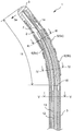
- FIG. 1 is a plan view of a catheter in the embodiment of the present invention
- FIG. 2 is a cross-sectional view along the perspective direction of the catheter in the embodiment of the present invention.
- the catheter 1 includes an outer cylinder member 3 having a lumen 2 extending in the perspective direction, a handle 4 provided on the proximal side of the outer cylinder member 3, and a plurality of electrodes 5 provided on the outer cylinder member 3.
- a conductor 6 having a sheath connected to one or more electrodes 5 and disposed in the lumen 2; and a wire 7 having a distal end fixed to the distal end of the outer tubular member 3. .
- the proximal end of the wire 7 is connected to the handle 4.
- the catheter 1 is used for, for example, inspection, treatment, or defibrillation of the arrhythmia in the heart by allowing the catheter 1 to reach the heart through the blood vessel of the patient from the distal side.
- the proximal side refers to the user's hand side with respect to the extending direction of the outer cylinder member 3 and the distal side refers to the opposite side of the proximal side, that is, the treatment target side.
- the extending direction of the outer cylinder member 3 is referred to as the axial direction.
- the radial direction refers to the radial direction of the outer cylinder member 3
- the inner direction in the radial direction refers to the direction toward the axial center of the outer cylinder member 3
- the outer direction in the radial direction is the direction toward the opposite side to the inner side. Point to.
- the catheter 1 can be bent or straightened by operating the handle 4. Since the distal end portion of the wire 7 is fixed to the distal end portion of the outer cylindrical member 3, the distal end of the outer cylindrical member 3 fixed to the wire 7 is moved by moving the wire 7 in the axial direction. The portion is interlocked with the movement of the wire 7, and the distal side of the outer cylinder member 3 is bent to the one side 3a.
- FIG. 3 is a sectional view taken along the line III-III of the catheter shown in FIG. 2
- FIG. 4 is a sectional view taken along the line IV-IV of the catheter shown in FIG.
- the electrode 5 is composed of at least one electrode 5a and another electrode 5b
- the catheter 1 has a connection point 8a between the one electrode 5a and the lead wire 6a and another electrode 5a.
- the connection point 8b between the electrode 5b and the conductive wire 6b is at a different position in the circumferential direction of the outer cylinder member 3.
- connection point 8a between the one electrode 5a and the conductive wire 6a and the connection point 8b between the other electrode 5b and the conductive wire 6b are arranged in this manner, whereby the conductive wire 6a connected to the one electrode 5a, Even if the conductor 6b connected to the other electrode 5b that applies a voltage having a polarity different from that of the one electrode 5a is disposed in the same lumen 2, the distance between the conductor 6a and the conductor 6b can be sufficiently maintained. Insulation can be sufficient. Therefore, it is not necessary to arrange the conductors in different lumens for each polarity. Defibrillation can be performed by applying voltages of different polarities to one electrode 5a and the other electrode 5b.
- FIG. 5 is a VV cross-sectional view of the catheter shown in FIG. Similar to the catheter shown in FIGS. 3 and 4, the conducting wire 6 a connected to one electrode 5 a and the conducting wire 6 b connected to the other electrode 5 b are arranged in the same lumen 2 of the outer cylinder member 3. .
- the conductors 6a and 6b By arranging the conductors 6a and 6b in the same lumen 2 of the outer cylinder member 3, it is not necessary to have a plurality of lumens 2 for arranging the conductors separately for each polarity. The lumen can be expanded. Thereby, since the number of the conducting wires 6 which can be arrange
- the catheter 1 can be further reduced in diameter and the flexibility of the outer cylinder member 3 can be increased.
- the number of lumens 2 is small, it is not necessary to form a partition wall that constitutes the lumens 2, so that the flexibility of the outer cylinder member 3 can be increased.
- the accuracy of examination and treatment can be improved.
- the movement of the distal end of the catheter 1 can be precisely controlled by reducing the diameter of the catheter 1 and increasing the flexibility.
- the outer cylinder member 3 becomes flexible, the electrode 5 is sunk into the outer cylinder member 3 and is difficult to be peeled off, so that peeling of the electrode 5 at the time of bending can be prevented.
- the outer cylinder member 3 has a flexible tubular structure, for example, a polyolefin resin such as polyethylene and polypropylene, a polyamide resin such as nylon, a polyester resin such as PET, and an aromatic polymer such as PEEK.
- the outer cylinder member 3 may have a single layer structure or a multilayer structure. When the outer cylinder member 3 has a multilayer structure, the material forming each layer may be the same or different.
- a structure using a metal braid can be used as the intermediate layer of the resin tube.
- the material constituting the outer cylinder member 3 is preferably a fluorine-based resin, and more preferably PTFE. Since the outer cylinder member 3 is configured in this manner, the catheter 1 can be easily inserted into a blood vessel.
- the length of the outer cylinder member 3 in the axial direction can be selected as appropriate for treatment.
- the axial length of the outer cylinder member 3 can be set to 500 mm or more and 1200 mm or less. According to the catheter 1 of the present invention, even if the length of the catheter 1 is increased, the insulation state between the conducting wires 6 can be maintained.
- the outer diameter of the outer cylinder member 3 is, for example, preferably 0.6 mm or more, more preferably 0.8 mm or more, and further preferably 1.0 mm or more.
- the outer cylinder member 3 has appropriate rigidity, and the insertion property of the catheter 1 into the blood vessel can be enhanced.
- the outer diameter of the catheter is about 2.0 mm in order to provide a plurality of lumens, and it has been difficult to reduce the outer diameter of the catheter.
- a diameter catheter can be provided.
- the outer diameter of the outer cylinder member 3 is preferably 3.0 mm or less, more preferably 2.8 mm or less, and further preferably 2.5 mm or less.
- the thickness of the outer cylinder member 3 is preferably 50 ⁇ m or more, more preferably 100 ⁇ m or more, and further preferably 150 ⁇ m or more.
- the outer cylinder member 3 can be provided with an appropriate rigidity, and the catheter 1 can be inserted into a blood vessel.
- the thickness of the outer cylinder member 3 is preferably 350 ⁇ m or less, more preferably 250 ⁇ m or less, and further preferably 150 ⁇ m or less.
- the outer cylinder member 3 may have a single lumen structure having one lumen 2 therein or a multi-lumen structure having a plurality of lumens 2. Especially, it is preferable that the number of the lumen
- bore of the outer cylinder member 3 can be made wide, it can be set as the catheter which has a some electrode, or a small diameter catheter.
- a conductive wire 6 connected to the electrode 5, a wire 7 and the like are arranged.
- the outer cylinder member 3 may have a tip 9 at the distal end.
- the tip 9 is a lid-like member that closes the opening at the distal end of the outer cylinder member 3. Since the outer cylinder member 3 has the tip 9, moisture such as blood enters the lumen 2 of the outer cylinder member 3 when the catheter 1 is used, and the moisture contacts the connecting portion between the electrode 5 and the lead wire 6. By doing so, it is possible to prevent the insulating property between the plurality of conductors 6 from being lowered and the drift phenomenon that the baseline potential of the electrocardiogram becomes unstable when measuring the intracardiac potential. Further, the distal tip 9 serves as a guide for the distal end of the catheter 1, and the insertion property of the catheter 1 can be improved. Furthermore, the tip 9 can be used as a fixed portion of the wire 7. By having the fixed end of the wire 7 at the distal tip 9 portion, the catheter 1 can be effectively bent by the wire operation.
- the material constituting the tip 9 is not particularly limited, and for example, the material constituting the outer cylinder member 3 described above or the material constituting the electrode 5 described later can be used.
- the tip chip 9 can also serve as the electrode 5 by forming the tip chip 9 from a conductive material such as a material constituting the electrode 5 described later and connecting the tip chip 9 to the conductive wire 6.
- distal end of the outer cylinder member 3 is not provided at the distal end, and the distal end of the outer cylinder member 3 is heat-sealed, so that the opening at the distal end of the outer cylinder member 3 is blocked. It may be.
- a handle 4 is provided on the proximal side of the outer cylinder member 3.
- the distal end portion is fixed to the distal end portion of the outer cylinder member 3, and the wire 7 disposed in the inner cavity of the outer cylinder member 3 is fixed to the inner wall of the handle 4. Therefore, by operating the handle 4, the wire 7 can be moved in the axial direction to bend the outer cylinder member 3.
- the electrode 5 is composed of at least one electrode 5 a and another electrode 5 b, and the one electrode 5 a and the other electrode 5 b are on the outer cylinder member 3 and separated from the distal side of the outer cylinder member 3. Is provided. Since the catheter 1 has a plurality of spaced electrodes 5a and 5b, the electrodes 5a and 5b are brought into contact with the inner wall of the patient's heart, and the intracardiac potential is measured to identify an abnormal portion of the heart that causes arrhythmia. Or defibrillation can be performed in the heart chamber. When performing defibrillation, for example, a negative voltage may be applied to one electrode 5a, and a positive voltage may be applied to the other electrode 5b. In addition, the polarity of the voltage applied to one electrode 5a and the other electrode 5b can be switched. That is, a positive voltage can be applied after applying a negative voltage to one electrode 5a.
- Each type of the plurality of electrodes 5 including the one electrode 5a and the other electrode 5b is not particularly limited, but preferably has both an electrode for performing defibrillation and an electrode for measuring an intracardiac potential.
- one electrode 5a and another electrode 5b are electrodes that are defibrillated by applying voltages having different polarities, and another electrode different from one electrode 5a and the other electrode 5b is an intracardiac potential. It can be said that it is an electrode which measures. Further, the electrode for performing defibrillation can also serve as the electrode for measuring the potential.
- the plurality of electrodes 5 are configured in this manner, defibrillation is performed when an arrhythmia such as atrial fibrillation occurs, and an abnormal site causing the arrhythmia is determined by measuring an intracardiac potential. Can be performed with a single catheter.
- the number of one electrode 5a, another electrode 5b, and another electrode may be one or plural. In addition, the number of one electrode 5a, another electrode 5b, and another electrode may be the same or different.
- the arrangement of the plurality of electrodes 5 including one electrode 5a and the other electrode 5b is not particularly limited.
- electrodes for performing defibrillation and electrodes for measuring intracardiac potential are alternately arranged.
- one electrode 5a is a negative electrode that performs defibrillation
- the other electrode 5b is a positive electrode that performs defibrillation, and is different from the one electrode 5a and the other electrode 5b.
- the electrode 5a is an electrode for measuring an intracardiac potential, and is a negative electrode for performing defibrillation from the distal side to the proximal side of the outer cylindrical member 3, and the intracardiac potential is measured.
- the negative electrode and the positive electrode that perform defibrillation so as to become another electrode different from the one electrode 5a and the other electrode 5b that perform, and the other electrode 5b that is the positive electrode that performs defibrillation It is preferable that an electrode for measuring the intracardiac potential is disposed between the electrode and the other electrode.
- the negative electrode for defibrillation is arranged in the coronary sinus and the positive electrode for defibrillation is arranged in the right atrium to sandwich the heart
- the electrode for measuring the intracardiac potential is located on the inner wall of the heart. Therefore, when electrical stimulation is applied between the positive electrode and the negative electrode that perform defibrillation, it is possible to quickly confirm whether or not defibrillation is successful.
- the electrode 5 may be a ring-shaped electrode, or a rectangular or square plate electrode formed independently on the outer cylinder member 3 in an island shape.
- at least one of the back surface (inner surface) and the surface (outer surface) of such a flat plate electrode may be a curved surface so as to easily follow the curved surface of the surface of the outer cylinder member 3.
- the electrode 5 is preferably ring-shaped. Since the electrode 5 is ring-shaped, the area of the electrode 5 on the circumference of the outer cylinder member 3 can be increased, and the electrode 5 can be easily brought into contact with the inner wall of the heart.
- the material constituting the electrode 5 examples include metal materials such as copper, gold, platinum, aluminum, iron, and alloys thereof.
- the electrode 5 is comprised from platinum or its alloy.
- the conducting wire 6 electrically connects the electrode 5 and an external device (not shown) of the catheter 1, and is disposed in the lumen 2 of the outer cylinder member 3.
- the conductor 6 is connected to the electrode 5 and passes through the lumen 2 of the outer cylinder member 3 as shown in FIGS.
- the material of the core of the conducting wire 6 is not particularly limited as long as it is a conductive material.
- iron wire, copper wire, silver wire, stainless steel wire, tungsten wire, nickel titanium wire and the like can be used.
- the stainless steel wire is particularly preferable in that it has straightness and rigidity, so that the conducting wire 6 can be easily passed through the outer cylindrical member 3 and the connection between the conducting wire 6 and the electrode 5 is not easily broken.
- the conducting wire 6 has a coating on a portion other than both ends connected to the electrode 5 and other objects. Specifically, it is preferable to connect, for example, by partially removing the coating on one end of the conducting wire 6 and welding this portion to the electrode 5.
- the coating of the conductive wire 6 may be any insulating material, for example, a polyolefin resin such as polyethylene or polypropylene, a polyamide resin such as nylon, a polyester resin such as PET, an aromatic polyether ketone resin such as PEEK, Examples thereof include polyether polyamide resins, polyurethane resins, polyimide resins, fluorine resins such as PTFE, PFA, and ETFE, and synthetic resins such as polyvinyl chloride resins.
- the covering of the conductive wire 6 is preferably made of a fluorine resin, and more preferably made of PFA. Since the covering of the conducting wire 6 is configured in this way, the insulating property of the conducting wire 6 can be ensured. Furthermore, in the lumen 2 of the outer cylinder member 3, it is possible to improve the slidability with other conductors such as the other conductors 6 and the wires 7 and prevent the conductor 6 from being damaged.
- the coating thickness of the conductive wire 6 is preferably 20 ⁇ m or more, more preferably 25 ⁇ m or more, and further preferably 30 ⁇ m or more. By setting the lower limit value of the coating thickness of the conducting wire 6 in this way, sufficient insulation can be imparted to the conducting wire 6. Moreover, the thickness of the coating of the conducting wire 6 is preferably 50 ⁇ m or less, more preferably 40 ⁇ m or less, and even more preferably 35 ⁇ m or less. By setting the upper limit value of the coating thickness of the conducting wire 6 in this way, the diameter of the conducting wire 6 can be reduced while ensuring sufficient insulation of the conducting wire 6. Therefore, at the time of manufacturing the catheter 1, it is easy to pass the lead wire 6 through the lumen 2 of the outer cylinder member 3.
- the conducting wire 6 is connected to the electrode 5 by welding, the connection between the conducting wire 6 and the electrode 5 can be easily made strong.
- the inner space of the electrode 5 can be secured most widely, and the electrode 5 can be easily attached to the outer cylinder member 3. As a result, workability in manufacturing can be improved.
- the conducting wire 6 and the electrode 5 may be connected via a conductive member therebetween.
- the connecting portion between the lead wire 6 and the electrode 5 is preferably coated with a resin or the like in order to prevent oxidative deterioration due to moisture contained in the atmosphere.
- a resin or the like examples include polyurethane resin and epoxy resin.
- the conducting wire 6 is composed of a conducting wire 6a connected to at least one electrode 5a and a conducting wire 6b connected to another electrode 5b, a connection point 8a between the one electrode 5a and the conducting wire 6a, and the other
- the connection point 8b between the electrode 5b and the conductive wire 6b may be at a different position in the circumferential direction of the outer cylinder member 3.
- the connection point 8a between the one electrode 5a and the conductor 6a is adjacent to the one electrode 5a.
- the distance between the connection point 8b between the other electrode 5b and the conductor 6b is preferably L / 15 or more, more preferably L / 10 or more, and further preferably L / 8 or more.
- the upper limit value of the distance between the connection point 8a between the one electrode 5a and the conductive wire 6a and the connection point 8b between the other electrode 5b adjacent to the one electrode 5a and the conductive wire 6b is not particularly limited.
- L / 2 It can be as follows. When there are a plurality of one electrode 5a and a plurality of other electrodes 5b, all the connection points may be at different positions in the circumferential direction, and the connection points of the electrodes to which the same polarity voltage is applied are at the same position in the circumferential direction. May be.
- An electrode to which a voltage having the same polarity is applied refers to all electrodes of one electrode 5a or all electrodes of another electrode 5b.
- the angle ⁇ 1 formed by the straight line S1 and the straight line S2 passing through the center point of the minimum circumscribed circle of the outer cylinder member 3 and the connection point 8b between the other electrode 5b and the conductor 6b is 30 degrees. Preferably, it is 45 degrees or more, more preferably 60 degrees or more.
- the upper limit value of the angle ⁇ 1 formed by the straight line S1 and the straight line S2 is not particularly limited, but may be, for example, 180 degrees or less.
- the outer cylinder member 3 has a hole 10 penetrating in the radial direction, and the lead wire 6 connected to the electrode 5 is inserted into the hole 10 and the lumen 2 of the outer cylinder member 3. It is preferable to arrange in the inside. Since the catheter 1 is configured in this way, it is easy to perform a step of arranging the conducting wire 6 connected to the electrode 5 in the lumen 2 of the outer cylinder member 3 when the catheter 1 is manufactured.
- the conducting wire 6 is connected to one or a plurality of electrodes 5 and arranged in the lumen 2.
- One conductive wire 6 is preferably connected to each electrode 5 one by one.
- the electrode 5 can be individually controlled, for example, the one electrode 5a can be used for the measurement of the intracardiac potential, or the voltage can be applied for the defibrillation.
- the conducting wire 6 may be connected to a plurality of electrodes 5, and for example, the electrodes 5 can be connected in series. The electrodes 5 connected in series can be suitably used for defibrillation.
- the plurality of electrodes 5 are connected in series to one conductor 6, the other plurality of electrodes 5 are connected in series to different conductors 6, and the remaining plurality of electrodes 5 are connected to each electrode 5 by one.
- the conducting wires 6 can be connected one by one. Thereby, the electrode 5 used for cardiac potential measurement and the electrode 5 used for defibrillation can be used as a dedicated electrode. Even when the conductive wires 6 are connected to all the electrodes 5 one by one, each electrode 5 may be used as a dedicated electrode for intracardiac potential measurement or defibrillation.
- the distal end of the wire 7 is fixed to the distal end of the outer cylinder member 3.
- the wire 7 only needs to have the distal end of the wire 7 fixed to the distal end of the outer cylinder member 3, but the distal end of the wire 7 is fixed to the distal end of the lumen of the outer cylinder member 3. It is preferable that By fixing the wire 7 to the outer cylinder member 3 in this way, the distal side of the outer cylinder member 3 can be bent greatly.
- the distal end portion of the wire 7 is fixed to the distal end portion of the outer cylindrical member 3.
- the distal end portion of the wire 7 is connected to the distal end portion of the outer cylindrical member 3. It is fixed directly or indirectly such that the distal end portion of the wire 7 is fixed to the distal end portion of the outer cylindrical member 3 through another object such as the tip 9. It is also included.
- the material constituting the wire 7 is, for example, a metal wire such as stainless steel, carbon steel, nickel titanium alloy, a polyolefin resin such as polyethylene or polypropylene, a polyamide resin such as nylon, a polyester resin such as PET, PEEK, etc. Yarns formed from synthetic resins such as aromatic polyether ketone resins, polyether polyamide resins, polyurethane resins, polyimide resins, fluorine resins such as PTFE, PFA, ETFE, and polyvinyl chloride resins Can be used.
- the wire 7 may have a structure in which a metal material and a synthetic resin material are combined.
- a wire obtained by knitting a metal wire and a synthetic resin wire, or a metal wire having a resin coating may be used.
- the material constituting the wire 7 is preferably a metal wire, and more preferably stainless steel.
- the method for fixing the distal end portion of the wire 7 and the distal end portion of the outer cylindrical member 3 is not particularly limited, and examples thereof include soldering or the like, welding, bonding with an adhesive, caulking, etc. It is done.
- the distal end portion of the wire 7 and the distal end portion of the outer cylindrical member 3 are fixed by the outer cylindrical member 3 having a metal tip 9 at the distal end, and the wire 7 being a metal wire. It is preferable that the wire 7 and the tip end 9 are fixed by soldering. Since the distal end portion of the wire 7 and the distal end portion of the outer cylinder member 3 are fixed in this manner, the wire 7 and the outer cylinder member 3 are firmly fixed. Therefore, even if the wire 7 is moved in the axial direction for bending the distal side of the outer cylinder member 3, the wire 7 is hardly detached from the outer cylinder member 3.
- the diameter of the wire 7 is not particularly limited, but is preferably 100 ⁇ m or more, more preferably 150 ⁇ m or more, and further preferably 200 ⁇ m or more. By setting the lower limit value of the diameter of the wire 7 in this way, the strength of the wire 7 can be made sufficient.
- the diameter of the wire 7 is preferably 500 ⁇ m or less, more preferably 450 ⁇ m or less, and further preferably 400 ⁇ m or less. By setting the upper limit value of the diameter of the wire 7 in this way, the lumen 2 of the outer cylinder member 3 can be secured sufficiently wide.
- the distal side of the outer cylinder member 3 is bent to one side 3a by moving the wire 7 in the axial direction.
- an operation such as pulling the wire 7 proximally by operating the handle 4 and winding the wire 7 may be performed.
- the distal side of the outer cylinder member 3 can be bent by pushing the wire 7 distally.
- the number of wires 7 may be one or plural. If the number of the wires 7 is one, the volume occupied by the wires 7 in the lumen of the outer cylinder member 3 can be reduced, and the lumen 2 of the outer cylinder member 3 can be widened. There are a plurality of wires 7. For example, the distal end portion of one wire is fixed to one side of the distal end portion of the outer cylinder member 3 in the cross section perpendicular to the axial direction of the outer cylinder member 3.
- the distal side of the outer cylinder member 3 is set to one side and
- the electrode 5 can be bent in a plurality of directions on the other side, and the electrode 5 can be easily brought into contact with various locations in the heart.
- one side 3a of the outer cylinder member 3 is opposite to the one side 3a. It is preferable that at least one of the conductive wires 6 is present on at least one place on the other side 3b and on the one side 3a.
- the bent portion 11 refers to a portion from a portion serving as a base point of bending to a distal end of the outer cylindrical member 3 when the outer cylindrical member 3 is bent by moving the wire 7 in the axial direction.
- a conducting wire 6 a connected to one electrode 5 a exists on one side 3 a of the outer cylinder member 3.
- the conducting wire 6a connected to one electrode 5a and the conducting wire 6b connected to the other electrode 5b are at different positions in the circumferential direction of the outer cylinder member 3. That is, the connection point 8a between the one electrode 5a and the conductive wire 6a and the connection point 8b between the other electrode 5b and the conductive wire 6b are at different positions in the circumferential direction of the outer cylindrical member 3, and the one electrode 5a Since the connected conducting wire 6a and the conducting wire 6b connected to the other electrode 5b are at different positions in the circumferential direction of the outer cylinder member 3, the conducting wire 6a and the conducting wire 6b are less likely to contact each other in the lumen 2. . Therefore, the insulation can be further improved.
- the catheter 1 preferably includes an inner cylinder member 12 disposed in the lumen 2. Since the inner cylinder member 12 is disposed in the lumen 2, the rigidity of the outer cylinder member 3 can be increased, and the insertion of the catheter 1 into the blood vessel can be improved.
- the type of the inner cylinder member 12 is not particularly limited, and examples thereof include a tube, pipe, or a coil in which a wire rod is spirally wound. Especially, it is preferable that the inner cylinder member 12 is a coil or a pipe, and it is more preferable that they are these combinations. Since the inner cylinder member 12 is configured in this manner, it is possible to impart moderate flexibility while increasing the rigidity of the outer cylinder member 3, so that it is easily inserted into the blood vessel and bent. Even if it is a blood vessel, the catheter 1 can be easily inserted.
- the inner cylinder member 12 As the material constituting the inner cylinder member 12, the same synthetic resin, metal, or the like as the outer cylinder member 3 can be used.
- the inner cylinder member 12 may have a layer structure.
- the materials of the inner cylinder member 12 and the outer cylinder member 3 may be the same or different.
- the inner cylinder member 12 is preferably a metal, and more preferably a coil in which a stainless steel wire is wound in a spiral shape. Since the inner cylinder member 12 is configured in this manner, the catheter 1 can easily adjust the bending of the outer cylinder member 3 while giving the outer cylinder member 3 sufficient rigidity.
- the outer diameter of the distal end of the inner cylinder member 12 is preferably smaller than the outer diameter of the proximal end.
- the pushability of the catheter 1 can be improved.
- swaging a metal tube that joins a tube having a large outer diameter and a tube having a small outer diameter for example, swaging a metal tube that joins a tube having a large outer diameter and a tube having a small outer diameter. Examples thereof include a method of performing processing, partially applying heat to a heat-shrinkable resin tube, and partially reducing the diameter.
- the inner cylinder member 12 is preferably a metal tube having a distal end outer diameter smaller than a proximal end outer diameter, and a metal coil provided on the distal side of the metal tube. Since the inner cylinder member 12 is configured in this manner, the hardness of the proximal side of the inner cylinder member is high, the hardness of the distal side is low, and the force applied from the proximal side of the catheter 1 can be efficiently separated. It is possible to tell the position side. As a result, torque transmission loss can be reduced.
- the wire 7 is disposed inside the inner cylinder member 12. By arranging the wire 7 in this way, the wire 7 is less likely to come into contact with the conductor 6 and the coating of the conductor 6 can be prevented from being damaged.
- the inner cylinder member 12 and the wire 7 are disposed in the lumen 2 in which the conducting wire 6 is disposed. That is, it is preferable that the conducting wire 6, the wire 7, and the inner cylinder member 12 are arranged in the same lumen 2 of the outer cylinder member 3. Furthermore, the wire 7 is preferably disposed in the inner cavity of the inner cylinder member 12.
- the inner cylinder member 12 preferably has a protective member 13 on the outer side in the radial direction of the inner cylinder member 12. Since the inner cylinder member 12 has the protection member 13, it is possible to prevent the inner cylinder member 12 from coming into contact with the conductor 6 and damage to the coating of the conductor 6.
- the material constituting the protective member 13 of the inner cylinder member 12 is preferably an insulating material.
- the material constituting the protective member 13 of the inner cylinder member 12 those listed as the material constituting the covering of the conductive wire 6 can be used, and among these, the material is made of a polyolefin resin such as polyethylene. It is preferable. Since the material constituting the protective member 13 is configured as described above, even when the covering of the conducting wire 6 is broken when the inner tubular member 12 is made of metal, the conductor 6 and the inner tubular member 12 The insulation between them can be maintained, and safety can be improved.
- the protective member 13 of the inner cylinder member 12 is preferably an insulating material different from the coating of the conductive wire 6. That is, it is more preferable that the protective member 13 of the inner cylinder member 12 is made of a polyolefin resin, and the coating of the conductive wire 6 is made of a fluorine resin. Since the protective member 13 is configured in this manner, the sliding property between the protective member 13 and the conductive wire 6 is increased, and the conductive wire 6 is brought into contact with the protective member 13 by contact between the conductive wire 6 and the protective member 13 when the catheter 1 is manufactured or used. It is possible to prevent the coating from being damaged.
- the thickness of the protective member 13 of the inner cylinder member 12 is preferably thinner than the thickness of the outer cylinder member 3 and thicker than the coating of the conductor 6. Since the protective member 13 is configured in this way, it is difficult to damage the coating of the conductive wire 6 when the protective member 13 and the conductive wire 6 come into contact with each other. Moreover, the distance between the protective member 13 and the inner side surface of the outer cylinder member 3 can be increased, and the conductive wire 6 and the protective member 13 are less likely to contact each other.
- the catheter 1 preferably has an elastic member 14 having a distal end fixed to the distal end of the outer cylindrical member 3 and a proximal end fixed to the inner cylindrical member 12. .
- the elastic member 14 extends along the perspective direction. Since the catheter 1 has the elastic member 14, it is possible to finely adjust the degree of bending of the distal side of the outer cylindrical member 3 by moving the wire 7 in the axial direction.
- the type of the elastic member 14 is not particularly limited, and examples thereof include a leaf spring and a coil spring.
- the elastic member 14 is preferably a leaf spring.
- the plate spring is a spring using a plate material, and the cross-sectional shape in the axial direction of the plate spring is rectangular. Since the long side portion in the cross-sectional shape of the leaf spring is bent, when the wire 7 is moved in the axial direction, the long side portion of the leaf spring is bent toward the wire 7 side. Therefore, when the elastic member 14 is a leaf spring, the bending direction on the distal side of the outer cylinder member 3 can be determined.
- Examples of the material constituting the elastic member 14 include stainless steel, carbon steel, copper alloy, and titanium alloy. Especially, it is preferable that the material which comprises the elastic member 14 is stainless steel. By configuring the elastic member 14 in this way, it becomes easier to adjust the degree of bending of the outer cylinder member 3 on the distal side.
- the distal end of the elastic member 14 may be fixed to the distal end of the outer cylinder member 3, but the distal end of the elastic member 14 is fixed to the distal end of the inner wall of the outer cylinder member 3. Preferably it is. Since the distal end of the elastic member 14 is fixed to the outer cylinder member 3 in this way, it becomes easier to control the bending of the outer cylinder member 3 on the distal side.
- the method for fixing the distal end portion of the elastic member 14 and the distal end portion of the outer cylinder member 3 is not particularly limited. For example, soldering or the like, welding, bonding with an adhesive, caulking, or the like may be used. Can be mentioned.
- the distal end of the elastic member 14 and the distal end of the outer cylinder member 3 are fixed by the outer cylinder member 3 having a metal tip 9 at the distal end, and the elastic member 14 being metal.
- the elastic member 14 and the tip chip 9 are preferably fixed by soldering.
- the elastic member 14 can be firmly fixed to the outer cylinder member 3, and the outer cylinder member Even if the distal side of 3 is bent, the elastic member 14 can be made difficult to come off from the outer cylinder member 3. Further, the process of fixing the elastic member 14 and the outer cylinder member 3 may be performed simultaneously with the process of fixing the wire 7 and the outer cylinder member 3.
- the catheter 1 preferably has a cylindrical member 15 provided on the proximal side of the distal end portion of the wire 7. It is preferable that the cylindrical member 15 is disposed in the lumen 2 of the outer cylindrical member 3. Since the catheter 1 has the cylindrical member 15, the conductive wire 6 comes into contact with another object such as the wire 7 disposed in the lumen 2 of the outer cylindrical member 3, and the covering of the conductive wire 6 is damaged. Can be prevented.
- At least one of the wire 7 and the elastic member 14 is disposed in the lumen of the cylindrical member 15.
- the wire 7 in the lumen of the cylindrical member 15 it is possible to prevent the wire 7 and the conductor 6 from coming into contact with each other and damage to the coating of the conductor 6.
- the position of the wire 7 in the lumen 2 of the outer cylinder member 3 is fixed, and the distance of the wire 7 moved in the axial direction for bending the distal side of the outer cylinder member 3 can be reduced. As a result, it is possible to finely adjust the degree of bending of the outer cylinder member 3 and to quickly bend it.
- the elastic member 14 is arranged in the lumen of the cylindrical member 15, the elastic member 14 and the conductive wire 6 are prevented from coming into contact with each other, and the covering of the conductive wire 6 is hardly damaged.
- the wire 7 and the elastic member 14 are disposed in the lumen of the cylindrical member 15.
- the material which comprises the cylindrical member 15 is not specifically limited, It is preferable that it is an insulating material, For example, what was mentioned as a material which comprises the coating
- the material constituting the covering of the conductive wire 6 is PTFE
- the material constituting the cylindrical member 15 is preferably not PTFE.
- the thickness of the cylindrical member 15 is preferably thinner than the outer cylindrical member 3 and thicker than the conductor 6. Since the cylindrical member 15 is configured in this way, the distance between the cylindrical member 15 and the inner surface of the outer cylindrical member 3 can be increased, and the conductor 6 and the cylindrical member 15 are less likely to contact each other. . Moreover, even if the cylindrical member 15 and the conducting wire 6 come into contact with each other, it is possible to make it difficult to damage the coating of the conducting wire 6.
- the proximal end portion of the tubular member 15 is more distal than the distal end portion of the protective member 13 of the inner tubular member 12, and is distal to the protective member 13 of the inner tubular member 12. It is preferable that the end and the proximal end of the cylindrical member 15 are separated from each other. That is, the space between the distal end of the protective member 13 of the inner cylindrical member 12 and the proximal end of the cylindrical member 15 is open, and the inner cylindrical member 12 is separated from the protective member 13 in the lumen 2 of the outer cylindrical member 3. It is preferable that it is exposed.
- the distal end portion of the inner cylinder member 12 is preferably fixed to the inner wall of the outer cylinder member 3.
- the inner cylinder member 12 is exposed from the protection member 13, and the inner cylinder member 12 is fixed to the inner wall of the outer cylinder member 3, so that the distal end portion of the inner cylinder member 12 is fixed. 3 is increased, and this high hardness portion can be the starting point of bending of the outer cylindrical member 3.
- the position of the inner cylinder member 12 in the lumen 2 of the outer cylinder member 3 is fixed, and the wire 7 disposed in the lumen of the inner cylinder member 12 in the axial direction is fixed. It is possible to reduce the fluctuation of the bending state of the outer cylinder member 3 due to the movement, to make the bending state of the outer cylinder member 3 constant, and to control it.
- the inner cylinder member 12 is fixed to the inner wall of the outer cylinder member 3, the axial rotation (torque) of the catheter 1 given by the operator to the outer cylinder member 3 through the inner cylinder member 12. It becomes easy to transmit, and it becomes easy to control the axial rotation of the distal end portion of the outer cylindrical member 3.
- an adhesive is poured into the outer cylinder member 3 so that the inner surface of the outer cylinder member 3 and the inner cylinder member 12 are fixed. And fixing the distal end of the outer cylindrical member 3 by attaching and crimping a ring-shaped part or the like on the outer cylindrical member 3 at a position where the distal end of the inner cylindrical member 12 exists in the inner cavity. And a method of fixing the distal end portion of the inner cylinder member 12 from the outer side in the radial direction of the outer cylinder member 3.
- Examples of the adhesive used for fixing the distal end portion of the inner cylinder member 12 in the lumen 2 of the outer cylinder member 3 include an epoxy resin adhesive, an acrylic resin adhesive, a urethane resin adhesive, and the like. . Among these, it is preferable to use an epoxy resin adhesive. By using such an adhesive, it is easy to handle and the distal end portion of the inner cylinder member 12 can be sufficiently fixed into the lumen 2 of the outer cylinder member 3.
- the inner cylinder member 12 is preferably fixed in the handle 4. That is, it is preferable that the proximal end portion of the inner cylinder member 12 is fixed inside the handle 4. Since the inner cylinder member 12 is fixed in this manner, when a load such as torsion is applied to the outer cylinder member 3 in the lumen 2 of the outer cylinder member 3, it is difficult to apply a load to the conductor 6. It is possible to prevent the insulation from deteriorating due to damage to the coating.
- the method of fixing the inner cylinder member 12 in the handle 4 is, for example, a method such as adhesion by an adhesive, welding to melt and fix a synthetic resin, fixing using another member such as a screw, fitting of unevenness, etc. These combinations and the like can be mentioned.
- the inner cylinder member 12 is preferably fixed in the handle 4 by fitting the inner cylinder member 12 to the handle 4. Since the inner cylinder member 12 is thus fixed in the handle 4, the inner cylinder member 12 can be easily and firmly fixed inside the handle 4.
- the manufacturing method of the catheter 1 according to the present invention includes an outer cylinder member 3 having a lumen 2 extending in the perspective direction, a handle 4 provided on the proximal side of the outer cylinder member 3, and a distal end of the outer cylinder member 3.
- the connection point 8a of the other electrode 5b and the connection point 8b of the conductive wire 6b are at different positions in the circumferential direction of the outer cylinder member 3, and are connected to the conductive wire 6a connected to the one electrode 5a and the other electrode 5b.
- the conducted wire 6b is a catheter 1 disposed in the same lumen 2 of the outer cylinder member 3.
- a manufacturing method comprising: a first step of arranging the lead wire 6 in the outer cylinder member 3; and a second step of arranging at least one of the inner cylinder member 12 and the wire 7 in the outer cylinder member 3, The second step is performed after one step.
- the conducting wire 6 is disposed in the lumen 2 of the outer cylinder member 3.
- the conducting wire 6 may be connected to the electrode 5 and inserted into the hole 10 from the radially outer side of the outer cylinder member 3 to be disposed in the outer cylinder member 3.
- the conducting wire 6 may be disposed in the outer cylinder member 3.
- the outer cylinder member 3 may be inserted into the hole 10 from the radially inner side and connected to the electrode 5.
- At least one of the inner cylinder member 12 and the wire 7 is disposed in the lumen 2 of the outer cylinder member 3.
- an opening communicating with the lumen 2 is provided on the distal side or the proximal side of the outer cylinder member 3, and at least one of the inner cylinder member 12 and the wire 7 is inserted from this opening.
- the wire 7 may be arranged in the inner cylinder member 12 after the inner cylinder member 12 is arranged in the outer cylinder member 3.
- the wire 7 may be disposed in the inner cylinder member 12, and then the inner cylinder member 12 in which the wire 7 is disposed in the inner cavity may be disposed in the outer cylinder member 3. Especially, it is preferable to arrange
- the second step is performed after the first step.
- the lead wire 6 having a lower rigidity than the inner cylinder member 12 and the wire 7 and having a higher possibility of damage than the inner cylinder member 12 and the wire 7 in a state where the lumen of the outer cylinder member 3 is widest, Breakage of the coating can be prevented.
- a catheter includes an outer cylinder member having a lumen extending in a perspective direction, a handle provided on the proximal side of the outer cylinder member, and a plurality of electrodes provided on the outer cylinder member
- a conductor having a sheath connected to the one or more electrodes and disposed within the lumen, and a wire having a distal end secured to the distal end of the outer tubular member,
- the connection point between the electrode and the lead wire and the connection point between the other electrode and the lead wire are at different positions in the circumferential direction of the outer cylinder member, and the lead wire connected to one electrode and the lead wire connected to the other electrode are
- the outer cylinder member is disposed in the same lumen. Thereby, the insulation between the conducting wires to which voltages having different polarities are applied can be enhanced.
- the catheter may include an inner cylinder member disposed in the lumen, the wire may be disposed inside the inner cylinder member, and the inner cylinder member and the wire may be disposed in the lumen in which the conducting wire is disposed.
- a wire and a conducting wire are arrange
- the distal side of the outer cylinder member is bent to one side by moving the wire in the axial direction, and the outer cylinder member has a cross section perpendicular to the axial direction of the outer cylinder member at the bent portion of the outer cylinder member. It is preferable that at least one of the conductors exists on one side and the other side which is the opposite side of the one side and the other side. Thereby, it becomes difficult to apply a load to the conducting wire when the outer cylinder member is bent, and damage to the coating of the conducting wire and disconnection of the conducting wire can be prevented. Therefore, it is possible to maintain the insulation of the conducting wire.
- the lead wire connected to one electrode and the lead wire connected to the other electrode are preferably located at different positions in the circumferential direction of the outer cylinder member. Thereby, the fall of the insulation of the conducting wire by contact of conducting wire and a conducting wire can be prevented.
- the inner cylinder member has a protective member radially outward of the inner cylinder member.
- the protective member of an inner cylinder member is an insulating material different from the coating
- the protective member for the inner cylinder member is made of a polyolefin resin.
- cover of conducting wire is comprised from the fluorine resin.
- the thickness of the conductor coating is preferably 20 ⁇ m or more and 50 ⁇ m or less. Thereby, it becomes difficult for the coating of the conductive wire to fall off. Further, it is possible to prevent the conductive wires from becoming thicker than necessary and contacting the conductive wires in the lumen.
- the catheter has an elastic member having a distal end fixed to the distal end of the outer cylindrical member and a proximal end fixed to the inner cylindrical member. As a result, it is possible to finely adjust the degree of bending of the outer cylinder member on the distal side by moving the wire in the axial direction.
- the above catheter has a cylindrical member provided more proximally than the distal end portion of the wire, and the wire and the elastic member are disposed in the lumen of the cylindrical member.
- a conducting wire contacts other things, such as a wire arrange
- the proximal end portion of the tubular member is located more distally than the distal end portion of the protective member of the inner tubular member, and the distal end of the protective member of the inner tubular member and the vicinity of the tubular member
- the distal end of the inner cylinder member is preferably fixed in the lumen of the outer cylinder member.
- the proximal end portion of the inner cylindrical member is fixed inside the handle.
- the load is difficult to be transmitted to the conductor, and the insulation of the conductor can be prevented from being deteriorated due to damage to the sheath of the conductor.
- the inner cylinder member is preferably a coil or a pipe.
- moderate flexibility can be imparted while increasing the rigidity of the outer cylinder member, so that the blood vessel can be easily inserted into even a bent blood vessel.
- a catheter manufacturing method includes an outer cylinder member having a lumen extending in a perspective direction, a handle provided on a proximal side of the outer cylinder member, and a distal side of the outer cylinder member.
- a plurality of electrodes provided, a conductor having a sheath connected to the one or more electrodes and disposed in the lumen and the handle; an inner cylindrical member disposed in the lumen; and a proximal end of the handle
- a first step of arranging the conducting wire in the outer cylinder member, and the inner cylinder member and the It includes a second step of disposing at least one of Ya the outer cylinder member, and performing the second step after the first step. Thereby, contact with a conducting wire, an inner cylinder member, and a wire can be decreased more.
- the catheter of the present invention includes an outer cylinder member having a lumen extending in the perspective direction, a handle provided on the proximal side of the outer cylinder member, and a plurality of electrodes provided on the outer cylinder member.
- a conductor having a sheath connected to the one or more electrodes and disposed within the lumen, and a wire having a distal end secured to the distal end of the outer tubular member, The connection point between the electrode and the lead wire and the connection point between the other electrode and the lead wire are at different positions in the circumferential direction of the outer cylinder member, and the lead wire connected to one electrode and the lead wire connected to the other electrode are
- the outer cylinder member is disposed in the same lumen.
- the catheter With such a configuration, the space through which the conducting wire etc. passes in the lumen of the outer cylindrical member is wide, the catheter can be multipolarized or reduced in diameter, and the bending of the catheter tip can be finely controlled, Moreover, even if the conducting wire is disposed in the same lumen of the outer cylinder member, the insulation of the conducting wire can be sufficiently ensured.
- Electrode 5a One electrode 5b: Other electrode 6: Conductor 6a: Conductor connected to one electrode 6b: Conductor connected to another electrode 7: Wire 8a: Connection point between one electrode and conductive wire 8b: Connection point between another electrode and conductive wire 9: Tip tip 10: Hole 11: Bent portion of outer cylinder member 12: Inner cylinder member 13: Protection member 14 : Elastic member 15: Cylindrical member S1: A straight line passing through the center point of the minimum circumscribed circle of the outer cylinder member and the connection point between one electrode and the conductor S2: Center point of the minimum circumscribed circle of the outer cylinder member and others A straight line passing through the connection point between the electrode and the lead wire ⁇ 1: an angle formed by the straight line S1 and the straight line S2
Landscapes
- Health & Medical Sciences (AREA)
- Life Sciences & Earth Sciences (AREA)
- Engineering & Computer Science (AREA)
- Public Health (AREA)
- Veterinary Medicine (AREA)
- General Health & Medical Sciences (AREA)
- Biomedical Technology (AREA)
- Heart & Thoracic Surgery (AREA)
- Animal Behavior & Ethology (AREA)
- Surgery (AREA)
- Biophysics (AREA)
- Physics & Mathematics (AREA)
- Medical Informatics (AREA)
- Molecular Biology (AREA)
- Pulmonology (AREA)
- Anesthesiology (AREA)
- Hematology (AREA)
- Cardiology (AREA)
- Otolaryngology (AREA)
- Nuclear Medicine, Radiotherapy & Molecular Imaging (AREA)
- Plasma & Fusion (AREA)
- Pathology (AREA)
- Mechanical Engineering (AREA)
- Physiology (AREA)
- Media Introduction/Drainage Providing Device (AREA)
- Measurement And Recording Of Electrical Phenomena And Electrical Characteristics Of The Living Body (AREA)
- Electrotherapy Devices (AREA)
Abstract
Provided is a catheter having a plurality of electrodes to which voltages of different polarities are applied, in which conductive wires connected to the electrodes are disposed in the same lumen to enhance the insulation between the conductive wires. The catheter comprises: an outer tubular member (3) having a lumen (2) extending in a perspective direction; a handle provided on the proximal side of the outer tubular member (3); a plurality of electrodes (5) provided on the outer tubular member (3); a conductive wire (6) having a coating, connected to one or a plurality of electrodes (5), and disposed in the lumen (2); and a wire (7) fixed by the distal end thereof to the distal end of the outer tubular member (3), wherein the connection point between one electrode (5a) and the conductive wire (6a) and the connection point between the other electrode (5b) and the conductive wire are at different positions in the circumferential direction of the outer tubular member (3), and the conductive wire (6a) connected to the one electrode (5a) and the conductive wire connected to the other electrode (5b) are arranged inside the same lumen (2) of the outer tubular member (3).
Description
本発明は、外筒部材が電極を有するカテーテルに関するものである。
The present invention relates to a catheter having an outer cylinder member having an electrode.
心房細動等の不整脈の検査や治療において、電極を有するカテーテルを用いることがある。検査時には、カテーテルを心腔内に挿入し、心内電位を測定して不整脈の原因となっている心臓の異常部位を特定する。治療時には、カテーテルの電極から高周波電流を不整脈の原因となっている心筋へ流し、不整脈の発生源を焼灼することによって心臓から電気的に分離する(アブレーション手術)。また、これらの検査時や治療時に、心房細動が自然に発生した、または、心臓の異常部位の特定のために心房細動を発生させた場合には、カテーテルの電極から電気的な刺激を心臓に与えて除細動を行う。
A catheter having an electrode may be used in the examination and treatment of arrhythmia such as atrial fibrillation. At the time of examination, a catheter is inserted into the heart chamber, and an intracardiac potential is measured to identify an abnormal portion of the heart that causes arrhythmia. During treatment, a high-frequency current is passed from the catheter electrode to the myocardium causing the arrhythmia, and the source of the arrhythmia is cauterized to be electrically separated from the heart (ablation surgery). In addition, when atrial fibrillation occurs naturally during these examinations and treatments, or when atrial fibrillation is generated to identify an abnormal part of the heart, electrical stimulation is applied from the electrode of the catheter. Give it to the heart for defibrillation.
このようなカテーテルとして、マルチルーメン構造を有する絶縁性のチューブ部材と、チューブ部材の先端領域に装着された複数のリング状電極からなる第1電極群と、第1電極群から基端側に離間してチューブ部材の先端領域に装着された複数のリング状電極からなる第2電極群と、第1電極群を構成する電極の各々に接続されたリード線(導線)からなる第1リード線群と、第2電極群を構成する電極の各々に接続されたリード線からなる第2リード線群とを備え、第1リード線群と第2リード線群とがチューブ部材の異なるルーメンに延在しており、第1電極群と第2電極群との間に互いに異なる極性の電圧を印加することによって、心腔内において除細動を行うカテーテルがある(例えば、特許文献1~4)。
As such a catheter, an insulating tube member having a multi-lumen structure, a first electrode group including a plurality of ring-shaped electrodes attached to a distal end region of the tube member, and a proximal end side away from the first electrode group Then, a second electrode group consisting of a plurality of ring-shaped electrodes attached to the tip region of the tube member, and a first lead wire group consisting of lead wires (conductive wires) connected to each of the electrodes constituting the first electrode group And a second lead wire group consisting of lead wires connected to each of the electrodes constituting the second electrode group, the first lead wire group and the second lead wire group extending to different lumens of the tube member There are catheters that perform defibrillation in the heart chamber by applying voltages of different polarities between the first electrode group and the second electrode group (for example, Patent Documents 1 to 4).
特許文献1~4に開示されているカテーテルは、カテーテル内腔をマルチルーメン構造とし、印加される電圧の極性別に、導線を異なるルーメンに配置することによって絶縁性を確保している。しかし、特許文献1~4に開示されているカテーテルはマルチルーメン構造であるため、チューブ部材の内腔において導線等が通る空間が限定されている。そのため、一つのカテーテルでより多くの位置での心内電位の測定が可能となるようにカテーテルに配置する電極の数を増やすことや、目的部位へのカテーテルの挿入性を向上させるためにカテーテルを細径化することが困難である。
In the catheters disclosed in Patent Documents 1 to 4, the catheter lumen has a multi-lumen structure, and the insulation is ensured by arranging the lead wires in different lumens according to the polarity of the applied voltage. However, since the catheters disclosed in Patent Documents 1 to 4 have a multi-lumen structure, a space through which a conducting wire or the like passes is limited in the lumen of the tube member. Therefore, in order to increase the number of electrodes placed on the catheter so that the intracardiac potential can be measured at more positions with a single catheter, or to improve the insertion property of the catheter to the target site, It is difficult to reduce the diameter.
また、特許文献1~4に開示されているカテーテルは、マルチルーメン構造であるためにチューブ部材が硬くなり、カテーテル先端部の屈曲を細やかにコントロールすることが難しいという問題や、屈曲時に電極がカテーテルから剥離することがあるという問題もあった。
In addition, since the catheters disclosed in Patent Documents 1 to 4 have a multi-lumen structure, the tube member becomes hard, and it is difficult to finely control the bending of the distal end of the catheter. There was also a problem that it sometimes peeled off.
これらの問題は、極性ごとに異なるルーメンに導線を配置するのではなく、異なる極性の電圧を印加する導線であっても同じルーメンに配置し、よりルーメンの数が少ない構成のカテーテルとすることによって改善することができる。しかし、単に複数の導線を同じルーメンに配置しただけでは、極性の異なる電圧が印加される導線間の絶縁性が不十分となってしまうおそれがある。
These problems are not caused by placing the lead wires in different lumens for each polarity, but by placing the lead wires that apply voltages of different polarities in the same lumen so that the catheter has a smaller number of lumens. Can be improved. However, simply arranging a plurality of conducting wires in the same lumen may result in insufficient insulation between conducting wires to which voltages having different polarities are applied.
本発明は、前記の事情に鑑みてなされたものであり、その目的は、極性の異なる電圧が印加される複数の電極を有するカテーテルであって、電極と接続された導線が同一のルーメンに配置され、導線間の絶縁性が高められたカテーテルを提供することにある。
The present invention has been made in view of the above circumstances, and an object of the present invention is a catheter having a plurality of electrodes to which voltages having different polarities are applied, and the conductive wires connected to the electrodes are arranged in the same lumen. And providing a catheter with improved insulation between the conductors.
前記課題を解決することができたカテーテルは、遠近方向に延びているルーメンを有する外筒部材と、外筒部材の近位側に設けられたハンドルと、外筒部材上に設けられた複数の電極と、1または複数の電極に接続され、ルーメン内に配置されている、被覆を有する導線と、遠位端部が外筒部材の遠位端部に固定されたワイヤと、を含み、一の電極と導線との接続点と、他の電極と導線との接続点とが外筒部材の周方向の異なる位置にあり、一の電極に接続された導線と他の電極に接続された導線は、外筒部材の同じルーメン内に配置されていることを特徴とするものである。
A catheter capable of solving the above-described problem is an outer cylinder member having a lumen extending in a perspective direction, a handle provided on the proximal side of the outer cylinder member, and a plurality of catheters provided on the outer cylinder member An electrode, a conductive wire connected to the one or more electrodes and disposed within the lumen, and a wire having a distal end secured to the distal end of the outer tubular member; The connection point between the electrode and the lead wire and the connection point between the other electrode and the lead wire are at different positions in the circumferential direction of the outer cylinder member, and the lead wire connected to one electrode and the lead wire connected to the other electrode Are arranged in the same lumen of the outer cylinder member.
前記課題を解決することができたカテーテルの製造方法は、遠近方向に延びているルーメンを有する外筒部材と、外筒部材の近位側に設けられたハンドルと、外筒部材の遠位側に設けられた複数の電極と、1または複数の電極に接続され、ルーメン内およびハンドル内に配置された、被覆を有する導線と、ルーメン内に配置された内筒部材と、近位端部がハンドルの内腔に配置され、遠位端部が外筒部材の遠位端部に固定されたワイヤと、を含み、一の電極と導線との接続点と、他の電極と導線との接続点とが外筒部材の周方向の異なる位置にあり、一の電極に接続された導線と他の電極に接続された導線は、外筒部材の同じルーメン内に配置されているカテーテルの製造方法であって、導線を外筒部材内に配置する第1工程と、内筒部材およびワイヤの少なくとも一方を外筒部材内に配置する第2工程と、を含み、第1工程の後に第2工程を行うことを特徴とするものである。
A method of manufacturing a catheter that can solve the above problems includes an outer cylinder member having a lumen extending in a perspective direction, a handle provided on a proximal side of the outer cylinder member, and a distal side of the outer cylinder member A plurality of electrodes provided on the lead wire, a conductive wire having a sheath connected to the one or more electrodes and disposed in the lumen and in the handle, an inner cylindrical member disposed in the lumen, and a proximal end portion A wire disposed in the lumen of the handle and having a distal end fixed to the distal end of the outer cylindrical member, and a connection point between one electrode and a conductor and a connection between the other electrode and the conductor The method of manufacturing a catheter in which the point is at a different position in the circumferential direction of the outer tube member, and the lead wire connected to one electrode and the lead wire connected to the other electrode are arranged in the same lumen of the outer tube member A first step of arranging the conducting wire in the outer cylinder member, and the inner cylinder member And wherein a second step of arranging at least one wire into the outer cylinder member, and is characterized in carrying out the second step after the first step.
本発明によれば、極性の異なる電圧が印加される複数の導線が同じルーメン内に配置されたカテーテルの導線間の絶縁性を高めることができる。
According to the present invention, it is possible to improve the insulation between the conductive wires of the catheter in which a plurality of conductive wires to which voltages having different polarities are applied are arranged in the same lumen.
以下、下記実施の形態に基づき本発明をより具体的に説明するが、本発明はもとより下記実施の形態によって制限を受けるものではなく、前・後記の趣旨に適合し得る範囲で適当に変更を加えて実施することも勿論可能であり、それらはいずれも本発明の技術的範囲に包含される。なお、各図面において、便宜上、ハッチングや部材符号等を省略する場合もあるが、かかる場合、明細書や他の図面を参照するものとする。また、図面における種々部材の寸法は、本発明の特徴の理解に資することを優先しているため、実際の寸法とは異なる場合がある。
Hereinafter, the present invention will be described in more detail based on the following embodiments, but the present invention is not limited by the following embodiments as a matter of course, and appropriate modifications are made within a range that can meet the purpose described above and below. In addition, it is of course possible to carry out them, all of which are included in the technical scope of the present invention. In addition, in each drawing, although hatching, a member code | symbol, etc. may be abbreviate | omitted for convenience, in this case, a description and another drawing shall be referred. In addition, the dimensions of the various members in the drawings are given priority to contribute to the understanding of the characteristics of the present invention, and may be different from the actual dimensions.
図1は、本発明の実施の形態におけるカテーテルの平面図であり、図2は、本発明の実施の形態におけるカテーテルの遠近方向に沿った断面図である。図1および図2を参照して、本発明の実施の形態におけるカテーテルの全体構成について説明する。カテーテル1は、遠近方向に延びているルーメン2を有する外筒部材3と、外筒部材3の近位側に設けられたハンドル4と、外筒部材3上に設けられた複数の電極5と、1または複数の電極5に接続され、ルーメン2内に配置されている、被覆を有する導線6と、遠位端部が外筒部材3の遠位端部に固定されたワイヤ7とを含む。ワイヤ7の近位端部は、ハンドル4と連結している。カテーテル1は、例えば、その遠位側から患者の血管内を通って心臓まで到達させて、心臓における不整脈の検査、治療、または除細動に用いられる。
FIG. 1 is a plan view of a catheter in the embodiment of the present invention, and FIG. 2 is a cross-sectional view along the perspective direction of the catheter in the embodiment of the present invention. With reference to FIG. 1 and FIG. 2, the whole structure of the catheter in embodiment of this invention is demonstrated. The catheter 1 includes an outer cylinder member 3 having a lumen 2 extending in the perspective direction, a handle 4 provided on the proximal side of the outer cylinder member 3, and a plurality of electrodes 5 provided on the outer cylinder member 3. A conductor 6 having a sheath connected to one or more electrodes 5 and disposed in the lumen 2; and a wire 7 having a distal end fixed to the distal end of the outer tubular member 3. . The proximal end of the wire 7 is connected to the handle 4. The catheter 1 is used for, for example, inspection, treatment, or defibrillation of the arrhythmia in the heart by allowing the catheter 1 to reach the heart through the blood vessel of the patient from the distal side.
本発明において、近位側とは外筒部材3の延在方向に対して使用者の手元側を指し、遠位側とは近位側の反対側、即ち処置対象側を指す。また、外筒部材3の延在方向を軸方向と称する。径方向とは外筒部材3の半径方向を指し、径方向において内方とは外筒部材3の軸中心側に向かう方向を指し、径方向において外方とは内方と反対側に向かう方向を指す。
In the present invention, the proximal side refers to the user's hand side with respect to the extending direction of the outer cylinder member 3, and the distal side refers to the opposite side of the proximal side, that is, the treatment target side. The extending direction of the outer cylinder member 3 is referred to as the axial direction. The radial direction refers to the radial direction of the outer cylinder member 3, the inner direction in the radial direction refers to the direction toward the axial center of the outer cylinder member 3, and the outer direction in the radial direction is the direction toward the opposite side to the inner side. Point to.
カテーテル1は、ハンドル4を操作することによって、カテーテル1の先端を湾曲させたり直線状にしたりすることが可能である。ワイヤ7の遠位端部が外筒部材3の遠位端部に固定されているため、ワイヤ7を軸方向に移動させることにより、ワイヤ7と固定されている外筒部材3の遠位端部がワイヤ7の動きに連動して、外筒部材3の遠位側が一方側3aに屈曲する。
The catheter 1 can be bent or straightened by operating the handle 4. Since the distal end portion of the wire 7 is fixed to the distal end portion of the outer cylindrical member 3, the distal end of the outer cylindrical member 3 fixed to the wire 7 is moved by moving the wire 7 in the axial direction. The portion is interlocked with the movement of the wire 7, and the distal side of the outer cylinder member 3 is bent to the one side 3a.
図3は、図2に示したカテーテルのIII-III断面図であり、図4は、図2に示したカテーテルのIV-IV断面図である。図3および図4に示すように、電極5は、少なくとも一の電極5aと他の電極5bから構成されており、カテーテル1は、一の電極5aと導線6aとの接続点8aと、他の電極5bと導線6bとの接続点8bとが外筒部材3の周方向の異なる位置にある。一の電極5aと導線6aとの接続点8aと、他の電極5bと導線6bとの接続点8bとがこのように配置されていることにより、一の電極5aに接続される導線6aと、一の電極5aと極性が異なる電圧を印加する他の電極5bに接続される導線6bとが同じルーメン2内に配置されていても、導線6aと導線6bとの距離を十分に保つことができ、絶縁性を十分なものとすることができる。そのため、極性ごとに別ルーメンに導線を配置する必要がなくなる。一の電極5aと他の電極5bに異なる極性の電圧を印加することにより、除細動を行うことができる。
3 is a sectional view taken along the line III-III of the catheter shown in FIG. 2, and FIG. 4 is a sectional view taken along the line IV-IV of the catheter shown in FIG. As shown in FIGS. 3 and 4, the electrode 5 is composed of at least one electrode 5a and another electrode 5b, and the catheter 1 has a connection point 8a between the one electrode 5a and the lead wire 6a and another electrode 5a. The connection point 8b between the electrode 5b and the conductive wire 6b is at a different position in the circumferential direction of the outer cylinder member 3. The connection point 8a between the one electrode 5a and the conductive wire 6a and the connection point 8b between the other electrode 5b and the conductive wire 6b are arranged in this manner, whereby the conductive wire 6a connected to the one electrode 5a, Even if the conductor 6b connected to the other electrode 5b that applies a voltage having a polarity different from that of the one electrode 5a is disposed in the same lumen 2, the distance between the conductor 6a and the conductor 6b can be sufficiently maintained. Insulation can be sufficient. Therefore, it is not necessary to arrange the conductors in different lumens for each polarity. Defibrillation can be performed by applying voltages of different polarities to one electrode 5a and the other electrode 5b.
図5は、図2に示したカテーテルのV-V断面図である。図3および図4に示したカテーテルと同様に、一の電極5aに接続された導線6aと他の電極5bに接続された導線6bは、外筒部材3の同じルーメン2内に配置されている。導線6a、6bを外筒部材3の同じルーメン2内に配置することにより、極性ごとに導線を分けて配置するための複数のルーメン2を有していなくてもよいため、外筒部材3の内腔を広げることができる。これにより、カテーテル1内に配置できる導線6の数を増やすことができるため、カテーテル1の電極5の数をより増やすことができる。また、カテーテル1内のルーメン2の数を少なくすることができるため、カテーテル1のさらなる細径化や、外筒部材3の柔軟性を高めることが可能となる。ルーメン2の数が少ないと、ルーメン2を構成する隔壁を形成する必要もなくなるため、外筒部材3の柔軟性を高めることができる。カテーテル1の電極5の数を増やすことにより、検査や治療の精度を向上させることができる。また、カテーテル1を細径にすることや、柔軟性を高めることにより、カテーテル1の先端の動きを精密に制御することができる。また、外筒部材3が柔軟になることで電極5が外筒部材3にめり込み、剥離しづらくなるため、屈曲時の電極5の剥離を防止することができる。
FIG. 5 is a VV cross-sectional view of the catheter shown in FIG. Similar to the catheter shown in FIGS. 3 and 4, the conducting wire 6 a connected to one electrode 5 a and the conducting wire 6 b connected to the other electrode 5 b are arranged in the same lumen 2 of the outer cylinder member 3. . By arranging the conductors 6a and 6b in the same lumen 2 of the outer cylinder member 3, it is not necessary to have a plurality of lumens 2 for arranging the conductors separately for each polarity. The lumen can be expanded. Thereby, since the number of the conducting wires 6 which can be arrange | positioned in the catheter 1 can be increased, the number of the electrodes 5 of the catheter 1 can be increased more. Further, since the number of lumens 2 in the catheter 1 can be reduced, the catheter 1 can be further reduced in diameter and the flexibility of the outer cylinder member 3 can be increased. When the number of lumens 2 is small, it is not necessary to form a partition wall that constitutes the lumens 2, so that the flexibility of the outer cylinder member 3 can be increased. By increasing the number of electrodes 5 of the catheter 1, the accuracy of examination and treatment can be improved. In addition, the movement of the distal end of the catheter 1 can be precisely controlled by reducing the diameter of the catheter 1 and increasing the flexibility. Further, since the outer cylinder member 3 becomes flexible, the electrode 5 is sunk into the outer cylinder member 3 and is difficult to be peeled off, so that peeling of the electrode 5 at the time of bending can be prevented.
外筒部材3は、可撓性を有する管状構造を有しており、例えば、ポリエチレン、ポリプロピレン等のポリオレフィン系樹脂、ナイロン等のポリアミド系樹脂、PET等のポリエステル系樹脂、PEEK等の芳香族ポリエーテルケトン系樹脂、ポリエーテルポリアミド系樹脂、ポリウレタン系樹脂、ポリイミド系樹脂、PTFE、PFA、ETFE等のフッ素系樹脂、ポリ塩化ビニル系樹脂等の合成樹脂や、ステンレス鋼、炭素鋼、ニッケルチタン合金等の金属等から構成することができる。外筒部材3は、単層構造であっても複層構造であってもよい。外筒部材3が複層構造である場合、各層を形成する材料は、同一であってもよく、異なる材料であってもよい。例えば、樹脂チューブの中間層として金属編組を用いた構造を用いることができる。外筒部材3を構成する材料は、フッ素系樹脂であることが好ましく、PTFEであることがより好ましい。外筒部材3がこのように構成されていることにより、血管への挿通性がよいカテーテル1とすることができる。
The outer cylinder member 3 has a flexible tubular structure, for example, a polyolefin resin such as polyethylene and polypropylene, a polyamide resin such as nylon, a polyester resin such as PET, and an aromatic polymer such as PEEK. Ether ketone resins, polyether polyamide resins, polyurethane resins, polyimide resins, fluorine resins such as PTFE, PFA, ETFE, synthetic resins such as polyvinyl chloride resins, stainless steel, carbon steel, nickel titanium alloys It can comprise from metals, such as. The outer cylinder member 3 may have a single layer structure or a multilayer structure. When the outer cylinder member 3 has a multilayer structure, the material forming each layer may be the same or different. For example, a structure using a metal braid can be used as the intermediate layer of the resin tube. The material constituting the outer cylinder member 3 is preferably a fluorine-based resin, and more preferably PTFE. Since the outer cylinder member 3 is configured in this manner, the catheter 1 can be easily inserted into a blood vessel.
外筒部材3の軸方向の長さは、治療に適切な長さを選択することができる。例えば、外筒部材3の軸方向の長さは、500mm以上1200mm以下とすることができる。本発明のカテーテル1によれば、カテーテル1の長さが長くなっても、導線6間の絶縁状態を維持することができる。
The length of the outer cylinder member 3 in the axial direction can be selected as appropriate for treatment. For example, the axial length of the outer cylinder member 3 can be set to 500 mm or more and 1200 mm or less. According to the catheter 1 of the present invention, even if the length of the catheter 1 is increased, the insulation state between the conducting wires 6 can be maintained.
外筒部材3の外径は、例えば、0.6mm以上であることが好ましく、0.8mm以上であることがより好ましく、1.0mm以上であることがさらに好ましい。外筒部材3の外径の下限値をこのように設定することにより、外筒部材3が適度な剛性を有し、血管へのカテーテル1の挿通性を高めることができる。マルチルーメンカテーテルの場合、複数のルーメンを設けるために、カテーテルの外径は、2.0mm程度となり、カテーテルの外径を小さくすることが困難であったが、本発明の構造により、より細い外径のカテーテルを提供することができる。また、外筒部材3の外径は、3.0mm以下であることが好ましく、2.8mm以下であることがより好ましく、2.5mm以下であることがさらに好ましい。外筒部材3の外径の上限値をこのように設定することにより、カテーテル1の挿通時に外筒部材3が血管内壁へ接触しにくくなり、患者への負担を低減することができる。
The outer diameter of the outer cylinder member 3 is, for example, preferably 0.6 mm or more, more preferably 0.8 mm or more, and further preferably 1.0 mm or more. By setting the lower limit value of the outer diameter of the outer cylinder member 3 in this manner, the outer cylinder member 3 has appropriate rigidity, and the insertion property of the catheter 1 into the blood vessel can be enhanced. In the case of a multi-lumen catheter, the outer diameter of the catheter is about 2.0 mm in order to provide a plurality of lumens, and it has been difficult to reduce the outer diameter of the catheter. A diameter catheter can be provided. Further, the outer diameter of the outer cylinder member 3 is preferably 3.0 mm or less, more preferably 2.8 mm or less, and further preferably 2.5 mm or less. By setting the upper limit value of the outer diameter of the outer cylinder member 3 in this manner, the outer cylinder member 3 is less likely to contact the inner wall of the blood vessel when the catheter 1 is inserted, and the burden on the patient can be reduced.
外筒部材3の厚みは、外筒部材3がシングルルーメンである場合、50μm以上であることが好ましく、100μm以上であることがより好ましく、150μm以上であることがさらに好ましい。外筒部材3の厚みの下限値をこのように設定することにより、外筒部材3に適度な剛性を与えて、血管への挿通性がよいカテーテル1とすることができる。また、外筒部材3の厚みは、350μm以下であることが好ましく、250μm以下であることがより好ましく、150μm以下であることがさらに好ましい。外筒部材3の厚みの上限値をこのように設定することにより、外筒部材3のルーメン2を広くすることができる。
When the outer cylinder member 3 is a single lumen, the thickness of the outer cylinder member 3 is preferably 50 μm or more, more preferably 100 μm or more, and further preferably 150 μm or more. By setting the lower limit value of the thickness of the outer cylinder member 3 in this manner, the outer cylinder member 3 can be provided with an appropriate rigidity, and the catheter 1 can be inserted into a blood vessel. Further, the thickness of the outer cylinder member 3 is preferably 350 μm or less, more preferably 250 μm or less, and further preferably 150 μm or less. By setting the upper limit value of the thickness of the outer cylinder member 3 in this way, the lumen 2 of the outer cylinder member 3 can be widened.
外筒部材3は、内部に1つのルーメン2を有するシングルルーメン構造であってもよく、複数のルーメン2を有するマルチルーメン構造であってもよい。中でも、外筒部材3が有するルーメン2の数は、1つであることが好ましい。ルーメン2の数が1つであれば、外筒部材3の内腔に隔壁等を有しないため、外筒部材3の柔軟性を高めることができ、カテーテル1の先端部の屈曲性のコントロールが行いやすくなり、屈曲時に電極5が剥離しにくくなる。また、外筒部材3の内腔を広くすることができるため、複数の電極を有するカテーテルや細径のカテーテルとすることができる。ルーメン2には、例えば、電極5に接続した導線6や、ワイヤ7等が配置される。
The outer cylinder member 3 may have a single lumen structure having one lumen 2 therein or a multi-lumen structure having a plurality of lumens 2. Especially, it is preferable that the number of the lumen | rumen 2 which the outer cylinder member 3 has is one. If the number of lumens 2 is one, the inner cylinder member 3 does not have a partition or the like in the lumen, so that the flexibility of the outer cylinder member 3 can be increased and the flexibility of the distal end portion of the catheter 1 can be controlled. It becomes easy to perform and the electrode 5 becomes difficult to peel at the time of bending. Moreover, since the lumen | bore of the outer cylinder member 3 can be made wide, it can be set as the catheter which has a some electrode, or a small diameter catheter. In the lumen 2, for example, a conductive wire 6 connected to the electrode 5, a wire 7 and the like are arranged.
外筒部材3は、遠位端に先端チップ9を有していてもよい。先端チップ9は、外筒部材3の遠位端の開口を塞ぐ、蓋状の部材である。外筒部材3が先端チップ9を有していることにより、カテーテル1の使用時に血液等の水分が外筒部材3のルーメン2内に入り込み、電極5と導線6との接続部に水分が接触することによって複数の導線6間の絶縁性が低下することや、心内電位を測定する際に心電図のベースライン電位が不安定になるドリフト現象が起こることを防止することができる。また、先端チップ9がカテーテル1先端の案内役となり、カテーテル1の挿入性を向上させることも可能となる。さらに、先端チップ9をワイヤ7の固定部分とすることができる。先端チップ9部分にワイヤ7の固定端があることで、ワイヤ操作によってカテーテル1を効果的に屈曲させることが可能となる。
The outer cylinder member 3 may have a tip 9 at the distal end. The tip 9 is a lid-like member that closes the opening at the distal end of the outer cylinder member 3. Since the outer cylinder member 3 has the tip 9, moisture such as blood enters the lumen 2 of the outer cylinder member 3 when the catheter 1 is used, and the moisture contacts the connecting portion between the electrode 5 and the lead wire 6. By doing so, it is possible to prevent the insulating property between the plurality of conductors 6 from being lowered and the drift phenomenon that the baseline potential of the electrocardiogram becomes unstable when measuring the intracardiac potential. Further, the distal tip 9 serves as a guide for the distal end of the catheter 1, and the insertion property of the catheter 1 can be improved. Furthermore, the tip 9 can be used as a fixed portion of the wire 7. By having the fixed end of the wire 7 at the distal tip 9 portion, the catheter 1 can be effectively bent by the wire operation.
先端チップ9を構成する材料は特に限定されないが、例えば、前述の外筒部材3を構成する材料、または、後述する電極5を構成する材料等を用いることができる。先端チップ9を後述する電極5を構成する材料等の導電性材料で構成し、先端チップ9を導線6に接続することによって、先端チップ9が電極5を兼ねることもできる。
The material constituting the tip 9 is not particularly limited, and for example, the material constituting the outer cylinder member 3 described above or the material constituting the electrode 5 described later can be used. The tip chip 9 can also serve as the electrode 5 by forming the tip chip 9 from a conductive material such as a material constituting the electrode 5 described later and connecting the tip chip 9 to the conductive wire 6.
なお、外筒部材3の遠位端に先端チップ9を設けず、外筒部材3の遠位端部が熱融着されること等によって、外筒部材3の遠位端の開口が塞がれていてもよい。
Note that the distal end of the outer cylinder member 3 is not provided at the distal end, and the distal end of the outer cylinder member 3 is heat-sealed, so that the opening at the distal end of the outer cylinder member 3 is blocked. It may be.
外筒部材3の近位側には、ハンドル4が設けられている。ハンドル4内に、遠位端部が外筒部材3の遠位端部に固定され、外筒部材3の内腔に配されたワイヤ7がハンドル4の内壁に固定されている。そのため、ハンドル4を操作することによってワイヤ7を軸方向に移動させて外筒部材3を屈曲等させることができる。
A handle 4 is provided on the proximal side of the outer cylinder member 3. In the handle 4, the distal end portion is fixed to the distal end portion of the outer cylinder member 3, and the wire 7 disposed in the inner cavity of the outer cylinder member 3 is fixed to the inner wall of the handle 4. Therefore, by operating the handle 4, the wire 7 can be moved in the axial direction to bend the outer cylinder member 3.
電極5は、少なくとも一の電極5aと他の電極5bから構成されており、一の電極5aと他の電極5bとが外筒部材3上であり外筒部材3の遠位側に離間して設けられている。カテーテル1が複数の離間した電極5aおよび5bを有することにより、電極5aおよび5bを患者の心臓の内壁に接触させて心内電位を測定し、不整脈の原因となっている心臓の異常部位を特定したり、心腔内において除細動を行ったりすることができる。除細動を行う際には、例えば、一の電極5aに負電圧、他の電極5bに正電圧をそれぞれ印加する等、電極5aおよび5bに極性の異なる電圧を印加すればよい。なお、一の電極5aおよび他の電極5bに印加する電圧の極性は、入れ替えることができる。つまり、一の電極5aに負電圧を印加した後に、正電圧を印加することができる。
The electrode 5 is composed of at least one electrode 5 a and another electrode 5 b, and the one electrode 5 a and the other electrode 5 b are on the outer cylinder member 3 and separated from the distal side of the outer cylinder member 3. Is provided. Since the catheter 1 has a plurality of spaced electrodes 5a and 5b, the electrodes 5a and 5b are brought into contact with the inner wall of the patient's heart, and the intracardiac potential is measured to identify an abnormal portion of the heart that causes arrhythmia. Or defibrillation can be performed in the heart chamber. When performing defibrillation, for example, a negative voltage may be applied to one electrode 5a, and a positive voltage may be applied to the other electrode 5b. In addition, the polarity of the voltage applied to one electrode 5a and the other electrode 5b can be switched. That is, a positive voltage can be applied after applying a negative voltage to one electrode 5a.
一の電極5aおよび他の電極5bを含む複数の電極5のそれぞれの種類は特に限定されないが、除細動を行う電極と心内電位を測定する電極の両方を有していることが好ましい。例えば、一の電極5aおよび他の電極5bは極性の異なる電圧がそれぞれ印加されて除細動を行う電極であって、一の電極5aおよび他の電極5bとは異なる別の電極が心内電位を測定する電極であるとすることができる。また、除細動を行う電極が、電位を測定する電極を兼ねることができる。複数の電極5がこのように構成されていることにより、心房細動等の不整脈の発生時に除細動を行うことと、心内電位を測定して不整脈の原因となっている異常部位の特定とを1つのカテーテルで行うことができる。なお、一の電極5a、他の電極5b、および別の電極のそれぞれの個数は、1であっても複数であってもよい。また、一の電極5a、他の電極5b、および別の電極のそれぞれの個数は同じでもよく、異なっていてもよい。
Each type of the plurality of electrodes 5 including the one electrode 5a and the other electrode 5b is not particularly limited, but preferably has both an electrode for performing defibrillation and an electrode for measuring an intracardiac potential. For example, one electrode 5a and another electrode 5b are electrodes that are defibrillated by applying voltages having different polarities, and another electrode different from one electrode 5a and the other electrode 5b is an intracardiac potential. It can be said that it is an electrode which measures. Further, the electrode for performing defibrillation can also serve as the electrode for measuring the potential. Since the plurality of electrodes 5 are configured in this manner, defibrillation is performed when an arrhythmia such as atrial fibrillation occurs, and an abnormal site causing the arrhythmia is determined by measuring an intracardiac potential. Can be performed with a single catheter. Note that the number of one electrode 5a, another electrode 5b, and another electrode may be one or plural. In addition, the number of one electrode 5a, another electrode 5b, and another electrode may be the same or different.
一の電極5aおよび他の電極5bを含む複数の電極5の配置は特に限定されないが、例えば、除細動を行う電極と心内電位を測定する電極とが交互に配置されていることが好ましい。具体例としては、一の電極5aが除細動を行う負極の電極であり、他の電極5bが除細動を行う正極の電極であり、一の電極5aおよび他の電極5bとは異なる別の電極が心内電位を測定する電極であって、外筒部材3の遠位側から近位側に向かって、除細動を行う負極の電極である一の電極5a、心内電位を測定する電極である一の電極5aおよび他の電極5bとは異なる別の電極、除細動を行う正極の電極である他の電極5b、となるように、除細動を行う負極の電極と正極の電極との間に心内電位を測定する電極が配置されていることが好ましい。複数の電極5がこのように配置されていることにより、除細動を行う負極の電極を冠状静脈洞に配置し、除細動を行う正極の電極を右心房に配置して、心臓を挟み込むように除細動を行う電極を配置した際に、心内電位を測定する電極が心臓の内壁に位置する。そのため、除細動を行う正極の電極と負極の電極との間に電気的な刺激を加えた際に、除細動が成功したか否かを迅速に確認することができる。
The arrangement of the plurality of electrodes 5 including one electrode 5a and the other electrode 5b is not particularly limited. For example, it is preferable that electrodes for performing defibrillation and electrodes for measuring intracardiac potential are alternately arranged. . As a specific example, one electrode 5a is a negative electrode that performs defibrillation, the other electrode 5b is a positive electrode that performs defibrillation, and is different from the one electrode 5a and the other electrode 5b. The electrode 5a is an electrode for measuring an intracardiac potential, and is a negative electrode for performing defibrillation from the distal side to the proximal side of the outer cylindrical member 3, and the intracardiac potential is measured. The negative electrode and the positive electrode that perform defibrillation so as to become another electrode different from the one electrode 5a and the other electrode 5b that perform, and the other electrode 5b that is the positive electrode that performs defibrillation It is preferable that an electrode for measuring the intracardiac potential is disposed between the electrode and the other electrode. By arranging the plurality of electrodes 5 in this way, the negative electrode for defibrillation is arranged in the coronary sinus and the positive electrode for defibrillation is arranged in the right atrium to sandwich the heart Thus, when the electrode for performing defibrillation is arranged, the electrode for measuring the intracardiac potential is located on the inner wall of the heart. Therefore, when electrical stimulation is applied between the positive electrode and the negative electrode that perform defibrillation, it is possible to quickly confirm whether or not defibrillation is successful.
電極5は、リング状の電極であってもよく、外筒部材3上に島状に独立して形成された長方形状あるいは正方形状等の平板電極であってもよい。また、このような平板電極の裏面(内側面)および表面(外側面)の少なくとも一方が、外筒部材3の表面の曲面に沿いやすいように曲面であってもよい。中でも、電極5はリング状であることが好ましい。電極5がリング状であることにより、外筒部材3の周上での電極5の面積を大きくすることができ、電極5を心臓の内壁等に接触させやすくなる。
The electrode 5 may be a ring-shaped electrode, or a rectangular or square plate electrode formed independently on the outer cylinder member 3 in an island shape. In addition, at least one of the back surface (inner surface) and the surface (outer surface) of such a flat plate electrode may be a curved surface so as to easily follow the curved surface of the surface of the outer cylinder member 3. Among these, the electrode 5 is preferably ring-shaped. Since the electrode 5 is ring-shaped, the area of the electrode 5 on the circumference of the outer cylinder member 3 can be increased, and the electrode 5 can be easily brought into contact with the inner wall of the heart.
電極5を構成する材料は、例えば、銅、金、白金、アルミニウム、鉄、またはこれらの合金等の金属材料が挙げられる。なお、カテーテル1の使用時におけるX線に対する造影性を良好にするために、電極5は、白金またはその合金から構成されていることが好ましい。
Examples of the material constituting the electrode 5 include metal materials such as copper, gold, platinum, aluminum, iron, and alloys thereof. In addition, in order to make the contrast property with respect to X-rays good at the time of use of the catheter 1, it is preferable that the electrode 5 is comprised from platinum or its alloy.
導線6は、電極5とカテーテル1の外部機器(図示せず)とを電気的に接続するものであり、外筒部材3のルーメン2内に配置されている。導線6は、図2~図5に示すように、電極5に接続されて外筒部材3のルーメン2内を通っている。
The conducting wire 6 electrically connects the electrode 5 and an external device (not shown) of the catheter 1, and is disposed in the lumen 2 of the outer cylinder member 3. The conductor 6 is connected to the electrode 5 and passes through the lumen 2 of the outer cylinder member 3 as shown in FIGS.
導線6のコアの材料は、導電性材料であれば特に限定されず、例えば、鉄線、銅線、銀線、ステンレス線、タングステン線、ニッケルチタン線等を用いることができる。中でも、ステンレス線は真直性と剛性があるため、導線6を外筒部材3内に通しやすく、また、導線6と電極5の接続部の断線が生じにくい点で特に好ましい。
The material of the core of the conducting wire 6 is not particularly limited as long as it is a conductive material. For example, iron wire, copper wire, silver wire, stainless steel wire, tungsten wire, nickel titanium wire and the like can be used. Among them, the stainless steel wire is particularly preferable in that it has straightness and rigidity, so that the conducting wire 6 can be easily passed through the outer cylindrical member 3 and the connection between the conducting wire 6 and the electrode 5 is not easily broken.
導線6は、電極5等の他物と接続される両端部以外の部分に被覆を有している。具体的には、例えば、導線6の一方端の被覆を一部除去し、この部分を電極5に溶接する等して接続することが好ましい。
The conducting wire 6 has a coating on a portion other than both ends connected to the electrode 5 and other objects. Specifically, it is preferable to connect, for example, by partially removing the coating on one end of the conducting wire 6 and welding this portion to the electrode 5.
導線6の被覆は、絶縁性材料であればよく、例えば、ポリエチレン、ポリプロピレン等のポリオレフィン系樹脂、ナイロン等のポリアミド系樹脂、PET等のポリエステル系樹脂、PEEK等の芳香族ポリエーテルケトン系樹脂、ポリエーテルポリアミド系樹脂、ポリウレタン系樹脂、ポリイミド系樹脂、PTFE、PFA、ETFE等のフッ素系樹脂、ポリ塩化ビニル系樹脂等の合成樹脂が挙げられる。導線6の被覆は、中でも、フッ素系樹脂から構成されていることが好ましく、PFAから構成されていることがより好ましい。導線6の被覆がこのように構成されていることにより、導線6の絶縁性を確保することができる。さらに、外筒部材3のルーメン2内において、他の導線6やワイヤ7等の他物との摺動性を高めて導線6の被覆が破損することを防ぐことができる。
The coating of the conductive wire 6 may be any insulating material, for example, a polyolefin resin such as polyethylene or polypropylene, a polyamide resin such as nylon, a polyester resin such as PET, an aromatic polyether ketone resin such as PEEK, Examples thereof include polyether polyamide resins, polyurethane resins, polyimide resins, fluorine resins such as PTFE, PFA, and ETFE, and synthetic resins such as polyvinyl chloride resins. Above all, the covering of the conductive wire 6 is preferably made of a fluorine resin, and more preferably made of PFA. Since the covering of the conducting wire 6 is configured in this way, the insulating property of the conducting wire 6 can be ensured. Furthermore, in the lumen 2 of the outer cylinder member 3, it is possible to improve the slidability with other conductors such as the other conductors 6 and the wires 7 and prevent the conductor 6 from being damaged.
導線6の被覆の厚みは、20μm以上であることが好ましく、25μm以上であることがより好ましく、30μm以上であることがさらに好ましい。導線6の被覆の厚みの下限値をこのように設定することにより、導線6に十分な絶縁性を与えることができる。また、導線6の被覆の厚みは、50μm以下であることが好ましく、40μm以下であることがより好ましく、35μm以下であることがさらに好ましい。導線6の被覆の厚みの上限値をこのように設定することにより、導線6の十分な絶縁性を確保しつつ、導線6の径を小さくすることができる。そのため、カテーテル1の製造時において、外筒部材3のルーメン2内に導線6を通すことが行いやすくなる。
The coating thickness of the conductive wire 6 is preferably 20 μm or more, more preferably 25 μm or more, and further preferably 30 μm or more. By setting the lower limit value of the coating thickness of the conducting wire 6 in this way, sufficient insulation can be imparted to the conducting wire 6. Moreover, the thickness of the coating of the conducting wire 6 is preferably 50 μm or less, more preferably 40 μm or less, and even more preferably 35 μm or less. By setting the upper limit value of the coating thickness of the conducting wire 6 in this way, the diameter of the conducting wire 6 can be reduced while ensuring sufficient insulation of the conducting wire 6. Therefore, at the time of manufacturing the catheter 1, it is easy to pass the lead wire 6 through the lumen 2 of the outer cylinder member 3.
導線6の電極5への接続の方法としては、例えば、溶接、はんだ等のろう付け、かしめ等による接続等を用いることができるが、中でも、溶接が好ましい。導線6が電極5へ溶接によって接続されていることにより、導線6と電極5との接続を容易に強固なものとすることができる。また、電極5の内側の空間を最も広く確保することができ、外筒部材3へ電極5を取り付けることが容易となる。その結果、製造における作業性を向上させることができる。導線6と電極5は、その間に導電性部材を介して接続されてもよい。
As a method for connecting the conductive wire 6 to the electrode 5, for example, welding, brazing of solder or the like, connection by caulking or the like can be used, and among them, welding is preferable. Since the conducting wire 6 is connected to the electrode 5 by welding, the connection between the conducting wire 6 and the electrode 5 can be easily made strong. In addition, the inner space of the electrode 5 can be secured most widely, and the electrode 5 can be easily attached to the outer cylinder member 3. As a result, workability in manufacturing can be improved. The conducting wire 6 and the electrode 5 may be connected via a conductive member therebetween.
導線6と電極5の接続部は、大気中等に含まれる水分等による酸化劣化が生じないようにするため、樹脂等によりコーティングを行うことが好ましい。導線6と電極5の接続部のコーティングに用いる樹脂としては、例えば、ポリウレタン樹脂やエポキシ樹脂等が挙げられる。
The connecting portion between the lead wire 6 and the electrode 5 is preferably coated with a resin or the like in order to prevent oxidative deterioration due to moisture contained in the atmosphere. Examples of the resin used for coating the connection portion between the conductive wire 6 and the electrode 5 include polyurethane resin and epoxy resin.
導線6は、少なくとも一の電極5aに接続されている導線6aと、他の電極5bに接続されている導線6bから構成されており、一の電極5aと導線6aとの接続点8aと、他の電極5bと導線6bとの接続点8bとは、外筒部材3の周方向の異なる位置にあればよい。中でも、外筒部材3の軸方向に垂直な断面において、外筒部材3の外周長をLとした場合に、一の電極5aと導線6aとの接続点8aと、一の電極5aに隣接する他の電極5bと導線6bとの接続点8bとの距離がL/15以上であることが好ましく、L/10以上であることがより好ましく、L/8以上であることがさらに好ましい。一の電極5aと導線6aとの接続点8aと、他の電極5bと導線6bとの接続点8bとの距離の下限値をこのように設定することにより、一の電極5aに接続されている導線6aと他の電極5bに接続されている導線6bとが接触しにくくなり、絶縁性をより高めることができる。一の電極5aと導線6aとの接続点8aと、一の電極5aに隣接する他の電極5bと導線6bとの接続点8bとの距離の上限値は特に限定されないが、例えば、L/2以下とすることができる。なお、一の電極5aおよび他の電極5bがそれぞれ複数ある場合、全ての接続点が周方向の異なる位置であってもよく、同じ極性の電圧を印加する電極の接続点が周方向の同じ位置にあってもよい。同じ極性の電圧を印加する電極とは、一の電極5aの全ての電極または他の電極5bの全ての電極をいう。
The conducting wire 6 is composed of a conducting wire 6a connected to at least one electrode 5a and a conducting wire 6b connected to another electrode 5b, a connection point 8a between the one electrode 5a and the conducting wire 6a, and the other The connection point 8b between the electrode 5b and the conductive wire 6b may be at a different position in the circumferential direction of the outer cylinder member 3. In particular, in the cross section perpendicular to the axial direction of the outer cylinder member 3, when the outer peripheral length of the outer cylinder member 3 is L, the connection point 8a between the one electrode 5a and the conductor 6a is adjacent to the one electrode 5a. The distance between the connection point 8b between the other electrode 5b and the conductor 6b is preferably L / 15 or more, more preferably L / 10 or more, and further preferably L / 8 or more. By setting the lower limit value of the distance between the connection point 8a between one electrode 5a and the conductive wire 6a and the connection point 8b between the other electrode 5b and the conductive wire 6b in this way, the connection is made to the one electrode 5a. It becomes difficult for the conducting wire 6a and the conducting wire 6b connected to the other electrode 5b to come into contact with each other, and the insulation can be further improved. The upper limit value of the distance between the connection point 8a between the one electrode 5a and the conductive wire 6a and the connection point 8b between the other electrode 5b adjacent to the one electrode 5a and the conductive wire 6b is not particularly limited. For example, L / 2 It can be as follows. When there are a plurality of one electrode 5a and a plurality of other electrodes 5b, all the connection points may be at different positions in the circumferential direction, and the connection points of the electrodes to which the same polarity voltage is applied are at the same position in the circumferential direction. May be. An electrode to which a voltage having the same polarity is applied refers to all electrodes of one electrode 5a or all electrodes of another electrode 5b.
また、外筒部材3の軸方向に垂直な断面において、図3に示すように、外筒部材3の最小外接円の中心点と、一の電極5aと導線6aとの接続点8aとを通る直線S1と、図4に示すように、外筒部材3の最小外接円の中心点と、他の電極5bと導線6bとの接続点8bとを通る直線S2とがなす角度θ1は、30度以上であることが好ましく、45度以上であることがより好ましく、60度以上であることがさらに好ましい。角度θ1の下限値をこのように設定することにより、一の電極5aに接続されている導線6aと、他の電極5bに接続されている導線6bとが接触しにくくなり、導線6aと導線6bとの絶縁性を保つことができる。また、直線S1と直線S2とがなす角度θ1の上限値は特に限定されないが、例えば、180度以下とすることができる。
Further, in the cross section perpendicular to the axial direction of the outer cylinder member 3, as shown in FIG. 3, it passes through the center point of the minimum circumscribed circle of the outer cylinder member 3 and the connection point 8a between the one electrode 5a and the conductor 6a. As shown in FIG. 4, the angle θ1 formed by the straight line S1 and the straight line S2 passing through the center point of the minimum circumscribed circle of the outer cylinder member 3 and the connection point 8b between the other electrode 5b and the conductor 6b is 30 degrees. Preferably, it is 45 degrees or more, more preferably 60 degrees or more. By setting the lower limit value of the angle θ1 in this way, the conductive wire 6a connected to one electrode 5a and the conductive wire 6b connected to the other electrode 5b are less likely to come into contact with each other, and the conductive wire 6a and the conductive wire 6b. And insulation can be maintained. Further, the upper limit value of the angle θ1 formed by the straight line S1 and the straight line S2 is not particularly limited, but may be, for example, 180 degrees or less.
図3および図4に示すように、外筒部材3は径方向に貫通した穴10を有しており、電極5に接続された導線6が穴10に挿通されて外筒部材3のルーメン2内に配置されていることが好ましい。カテーテル1がこのように構成されていることにより、カテーテル1の製造時において、電極5に接続された導線6を外筒部材3のルーメン2内に配置する工程が行いやすくなる。
As shown in FIG. 3 and FIG. 4, the outer cylinder member 3 has a hole 10 penetrating in the radial direction, and the lead wire 6 connected to the electrode 5 is inserted into the hole 10 and the lumen 2 of the outer cylinder member 3. It is preferable to arrange in the inside. Since the catheter 1 is configured in this way, it is easy to perform a step of arranging the conducting wire 6 connected to the electrode 5 in the lumen 2 of the outer cylinder member 3 when the catheter 1 is manufactured.
導線6は、1または複数の電極5に接続され、ルーメン2内に配置される。導線6は、各電極5に1本ずつ接続されていることが好ましい。これにより、一の電極5aを心内電位の測定に使用したり、電圧を印加して除細動に用いたりすることができる等、個別に電極5を制御することができる。また、導線6は、複数の電極5に接続されてもよく、例えば各電極5を直列に接続することができる。直列に接続された電極5は、除細動に好適に用いることができる。この場合、一部の複数の電極5を一の導線6に直列に接続し、他の複数の電極5を異なる導線6に直列に接続し、さらに残りの複数の電極5は各電極5に1本ずつ導線6を接続することができる。これにより、心電位計測に用いる電極5と除細動に用いる電極5とを専用電極として用いることができる。全ての電極5に1本ずつ導線6を接続している場合においても、各電極5を心内電位計測用や除細動用の専用電極として用いてもよい。
The conducting wire 6 is connected to one or a plurality of electrodes 5 and arranged in the lumen 2. One conductive wire 6 is preferably connected to each electrode 5 one by one. Thereby, the electrode 5 can be individually controlled, for example, the one electrode 5a can be used for the measurement of the intracardiac potential, or the voltage can be applied for the defibrillation. Moreover, the conducting wire 6 may be connected to a plurality of electrodes 5, and for example, the electrodes 5 can be connected in series. The electrodes 5 connected in series can be suitably used for defibrillation. In this case, some of the plurality of electrodes 5 are connected in series to one conductor 6, the other plurality of electrodes 5 are connected in series to different conductors 6, and the remaining plurality of electrodes 5 are connected to each electrode 5 by one. The conducting wires 6 can be connected one by one. Thereby, the electrode 5 used for cardiac potential measurement and the electrode 5 used for defibrillation can be used as a dedicated electrode. Even when the conductive wires 6 are connected to all the electrodes 5 one by one, each electrode 5 may be used as a dedicated electrode for intracardiac potential measurement or defibrillation.
図2に示すように、ワイヤ7は、遠位端部が外筒部材3の遠位端部に固定されている。ワイヤ7は、ワイヤ7の遠位端部が外筒部材3の遠位端部に固定されていればよいが、ワイヤ7の遠位端が外筒部材3の内腔の遠位端に固定されていることが好ましい。ワイヤ7がこのように外筒部材3へ固定されていることにより、外筒部材3の遠位側を大きく屈曲させることができる。なお、本明細書において、ワイヤ7の遠位端部が外筒部材3の遠位端部に固定されているとは、ワイヤ7の遠位端部が外筒部材3の遠位端部に直接固定されていることも、ワイヤ7の遠位端部が先端チップ9等の他物を介して外筒部材3の遠位端部に固定されているような、間接的に固定されていることも含むものとする。
2, the distal end of the wire 7 is fixed to the distal end of the outer cylinder member 3. The wire 7 only needs to have the distal end of the wire 7 fixed to the distal end of the outer cylinder member 3, but the distal end of the wire 7 is fixed to the distal end of the lumen of the outer cylinder member 3. It is preferable that By fixing the wire 7 to the outer cylinder member 3 in this way, the distal side of the outer cylinder member 3 can be bent greatly. In the present specification, the distal end portion of the wire 7 is fixed to the distal end portion of the outer cylindrical member 3. The distal end portion of the wire 7 is connected to the distal end portion of the outer cylindrical member 3. It is fixed directly or indirectly such that the distal end portion of the wire 7 is fixed to the distal end portion of the outer cylindrical member 3 through another object such as the tip 9. It is also included.
ワイヤ7を構成する材料は、例えば、ステンレス鋼、炭素鋼、ニッケルチタン合金等の金属線材や、ポリエチレン、ポリプロピレン等のポリオレフィン系樹脂、ナイロン等のポリアミド系樹脂、PET等のポリエステル系樹脂、PEEK等の芳香族ポリエーテルケトン系樹脂、ポリエーテルポリアミド系樹脂、ポリウレタン系樹脂、ポリイミド系樹脂、PTFE、PFA、ETFE等のフッ素系樹脂、ポリ塩化ビニル系樹脂等の合成樹脂から形成された糸条を用いることができる。ワイヤ7は、金属材料と合成樹脂材料を組み合わせた構造であってもよく、例えば、金属の線材と合成樹脂の線材を編んだもの、金属線材に樹脂被覆をしたものを用いることができる。ワイヤ7を構成する材料は、中でも、金属線材であることが好ましく、ステンレス鋼であることがさらに好ましい。ワイヤ7がこのように構成されていることにより、外筒部材3の屈曲のためにワイヤ7を繰り返し屈曲させても、ワイヤ7の破損や変形を起こりにくくすることができる。
The material constituting the wire 7 is, for example, a metal wire such as stainless steel, carbon steel, nickel titanium alloy, a polyolefin resin such as polyethylene or polypropylene, a polyamide resin such as nylon, a polyester resin such as PET, PEEK, etc. Yarns formed from synthetic resins such as aromatic polyether ketone resins, polyether polyamide resins, polyurethane resins, polyimide resins, fluorine resins such as PTFE, PFA, ETFE, and polyvinyl chloride resins Can be used. The wire 7 may have a structure in which a metal material and a synthetic resin material are combined. For example, a wire obtained by knitting a metal wire and a synthetic resin wire, or a metal wire having a resin coating may be used. Among these, the material constituting the wire 7 is preferably a metal wire, and more preferably stainless steel. By configuring the wire 7 in this way, even if the wire 7 is repeatedly bent for bending the outer cylinder member 3, the wire 7 can be hardly damaged or deformed.
ワイヤ7の遠位端部と外筒部材3の遠位端部との固定の方法は特に限定されず、例えば、はんだ等のろう付け、溶接、接着剤による接着、かしめ等による接続等が挙げられる。ワイヤ7の遠位端部と外筒部材3の遠位端部との固定は、外筒部材3が遠位端に金属の先端チップ9を有しており、ワイヤ7が金属線材であり、ワイヤ7と先端チップ9とがはんだ付けによって固定されていることが好ましい。ワイヤ7の遠位端部と外筒部材3の遠位端部とがこのように固定されていることにより、ワイヤ7と外筒部材3との固定が強固となる。そのため、外筒部材3の遠位側の屈曲のためにワイヤ7を軸方向に移動させても、ワイヤ7が外筒部材3から外れにくくなる。
The method for fixing the distal end portion of the wire 7 and the distal end portion of the outer cylindrical member 3 is not particularly limited, and examples thereof include soldering or the like, welding, bonding with an adhesive, caulking, etc. It is done. The distal end portion of the wire 7 and the distal end portion of the outer cylindrical member 3 are fixed by the outer cylindrical member 3 having a metal tip 9 at the distal end, and the wire 7 being a metal wire. It is preferable that the wire 7 and the tip end 9 are fixed by soldering. Since the distal end portion of the wire 7 and the distal end portion of the outer cylinder member 3 are fixed in this manner, the wire 7 and the outer cylinder member 3 are firmly fixed. Therefore, even if the wire 7 is moved in the axial direction for bending the distal side of the outer cylinder member 3, the wire 7 is hardly detached from the outer cylinder member 3.
ワイヤ7の径は特に限定されないが、100μm以上であることが好ましく、150μm以上であることがより好ましく、200μm以上であることがさらに好ましい。ワイヤ7の径の下限値をこのように設定することにより、ワイヤ7の強度を十分なものとすることができる。また、ワイヤ7の径は、500μm以下であることが好ましく、450μm以下であることがより好ましく、400μm以下であることがさらに好ましい。ワイヤ7の径の上限値をこのように設定することにより、外筒部材3のルーメン2を十分に広く確保することができる。
The diameter of the wire 7 is not particularly limited, but is preferably 100 μm or more, more preferably 150 μm or more, and further preferably 200 μm or more. By setting the lower limit value of the diameter of the wire 7 in this way, the strength of the wire 7 can be made sufficient. The diameter of the wire 7 is preferably 500 μm or less, more preferably 450 μm or less, and further preferably 400 μm or less. By setting the upper limit value of the diameter of the wire 7 in this way, the lumen 2 of the outer cylinder member 3 can be secured sufficiently wide.
図2に示すように、ワイヤ7を軸方向に移動させることにより外筒部材3の遠位側が一方側3aに屈曲する。ワイヤ7を軸方向に移動させるには、ハンドル4を操作してワイヤ7を巻き取ること等によって、ワイヤ7を近位側へ引っ張る等の操作を行えばよい。あるいは、ワイヤ7を遠位側に押し込むことによっても、外筒部材3の遠位側を屈曲させることができる。外筒部材3の遠位側が一方側3aに屈曲することにより、心臓内において外筒部材3の遠位側に配置されている電極5を心臓の内壁へ接近させることができ、心臓内の目的部位へ電極5を接触させることが容易となる。
As shown in FIG. 2, the distal side of the outer cylinder member 3 is bent to one side 3a by moving the wire 7 in the axial direction. In order to move the wire 7 in the axial direction, an operation such as pulling the wire 7 proximally by operating the handle 4 and winding the wire 7 may be performed. Alternatively, the distal side of the outer cylinder member 3 can be bent by pushing the wire 7 distally. By bending the distal side of the outer cylinder member 3 to the one side 3a, the electrode 5 arranged on the distal side of the outer cylinder member 3 in the heart can be brought close to the inner wall of the heart, and the purpose in the heart It is easy to bring the electrode 5 into contact with the site.
ワイヤ7の数は、1本であっても複数本であってもよい。ワイヤ7が1本であれば、外筒部材3の内腔においてワイヤ7が占める体積を小さくすることができ、外筒部材3のルーメン2を広くすることができる。ワイヤ7が複数本であり、例えば、一のワイヤの遠位端部を外筒部材3の遠位端部の、外筒部材3の軸方向に垂直な断面における一方側に固定し、他のワイヤの遠位端部を外筒部材3の遠位端部の、外筒部材3の軸方向に垂直な断面における他方側に固定することによって、外筒部材3の遠位側を一方側および他方側の複数の方向に屈曲させることができ、心臓内の様々な箇所に電極5を接触させやすくなる。
The number of wires 7 may be one or plural. If the number of the wires 7 is one, the volume occupied by the wires 7 in the lumen of the outer cylinder member 3 can be reduced, and the lumen 2 of the outer cylinder member 3 can be widened. There are a plurality of wires 7. For example, the distal end portion of one wire is fixed to one side of the distal end portion of the outer cylinder member 3 in the cross section perpendicular to the axial direction of the outer cylinder member 3. By fixing the distal end of the wire to the other side of the cross-section perpendicular to the axial direction of the outer cylinder member 3 at the distal end of the outer cylinder member 3, the distal side of the outer cylinder member 3 is set to one side and The electrode 5 can be bent in a plurality of directions on the other side, and the electrode 5 can be easily brought into contact with various locations in the heart.
図2~図4に示すように、外筒部材3の屈曲部11における外筒部材3の軸方向に垂直な断面において、外筒部材3の一方側3aと、一方側3aの反対側である他方側3bのうち、少なくとも一箇所、一方側3aに導線6のうち少なくとも一つが存在していることが好ましい。屈曲部11とは、ワイヤ7を軸方向に移動させることにより外筒部材3の屈曲した際に、屈曲の基点となる部分から外筒部材3の遠位端までの部分を指す。図3に示す例では、外筒部材3の一方側3aに、一の電極5aに接続された導線6aが存在している。導線6がこのように配置されていることにより、外筒部材3の屈曲時に導線6に負荷がかかりにくくなって導線6の被覆の破損や断線を防止でき、導線6の絶縁性を保つことができる。
As shown in FIGS. 2 to 4, in the cross section perpendicular to the axial direction of the outer cylinder member 3 at the bent portion 11 of the outer cylinder member 3, one side 3a of the outer cylinder member 3 is opposite to the one side 3a. It is preferable that at least one of the conductive wires 6 is present on at least one place on the other side 3b and on the one side 3a. The bent portion 11 refers to a portion from a portion serving as a base point of bending to a distal end of the outer cylindrical member 3 when the outer cylindrical member 3 is bent by moving the wire 7 in the axial direction. In the example shown in FIG. 3, a conducting wire 6 a connected to one electrode 5 a exists on one side 3 a of the outer cylinder member 3. By arranging the conducting wire 6 in this way, it is difficult to apply a load to the conducting wire 6 when the outer cylindrical member 3 is bent, and it is possible to prevent the coating of the conducting wire 6 from being damaged or disconnected, and to maintain the insulation of the conducting wire 6. it can.
図5に示すように、一の電極5aに接続された導線6aと他の電極5bに接続された導線6bは、外筒部材3の周方向の異なる位置にあることが好ましい。即ち、一の電極5aと導線6aとの接続点8aと、他の電極5bと導線6bとの接続点8bとが外筒部材3の周方向の異なる位置にあり、かつ、一の電極5aに接続された導線6aと他の電極5bに接続された導線6bとが外筒部材3の周方向の異なる位置にあることにより、導線6aと導線6bとがルーメン2内において、より接触しにくくなる。そのため、絶縁性をさらに高めることができる。
As shown in FIG. 5, it is preferable that the conducting wire 6a connected to one electrode 5a and the conducting wire 6b connected to the other electrode 5b are at different positions in the circumferential direction of the outer cylinder member 3. That is, the connection point 8a between the one electrode 5a and the conductive wire 6a and the connection point 8b between the other electrode 5b and the conductive wire 6b are at different positions in the circumferential direction of the outer cylindrical member 3, and the one electrode 5a Since the connected conducting wire 6a and the conducting wire 6b connected to the other electrode 5b are at different positions in the circumferential direction of the outer cylinder member 3, the conducting wire 6a and the conducting wire 6b are less likely to contact each other in the lumen 2. . Therefore, the insulation can be further improved.
カテーテル1は、ルーメン2内に配置された内筒部材12を備えていることが好ましい。ルーメン2内に内筒部材12が配されていることにより、外筒部材3の剛性を高めることができ、カテーテル1の血管への挿通性を向上させることができる。
The catheter 1 preferably includes an inner cylinder member 12 disposed in the lumen 2. Since the inner cylinder member 12 is disposed in the lumen 2, the rigidity of the outer cylinder member 3 can be increased, and the insertion of the catheter 1 into the blood vessel can be improved.
内筒部材12の種類は特に限定されず、筒形状であるチューブ、パイプ、または線材をらせん状に巻いたコイル等が挙げられる。中でも、内筒部材12はコイルまたはパイプであることが好ましく、これらの組み合わせであることがより好ましい。内筒部材12がこのように構成されていることにより、外筒部材3の剛性を高めつつ、適度な柔軟性も付与することができるため、血管への挿通性がよく、かつ、曲がった状態の血管であっても挿通しやすいカテーテル1とすることができる。
The type of the inner cylinder member 12 is not particularly limited, and examples thereof include a tube, pipe, or a coil in which a wire rod is spirally wound. Especially, it is preferable that the inner cylinder member 12 is a coil or a pipe, and it is more preferable that they are these combinations. Since the inner cylinder member 12 is configured in this manner, it is possible to impart moderate flexibility while increasing the rigidity of the outer cylinder member 3, so that it is easily inserted into the blood vessel and bent. Even if it is a blood vessel, the catheter 1 can be easily inserted.
内筒部材12を構成する材料は、外筒部材3と同様の合成樹脂、金属等を用いることができる。内筒部材12は層構造であってもよい。内筒部材12と外筒部材3の材料は、同一であってもよく、異なる材料であってもよい。内筒部材12は、金属であることが好ましく、中でも、ステンレス鋼の線材をらせん状に巻いたコイルであることがより好ましい。内筒部材12がこのように構成されていることにより、外筒部材3に十分な剛性を与えつつ、外筒部材3の屈曲を調整しやすいカテーテル1となる。
As the material constituting the inner cylinder member 12, the same synthetic resin, metal, or the like as the outer cylinder member 3 can be used. The inner cylinder member 12 may have a layer structure. The materials of the inner cylinder member 12 and the outer cylinder member 3 may be the same or different. The inner cylinder member 12 is preferably a metal, and more preferably a coil in which a stainless steel wire is wound in a spiral shape. Since the inner cylinder member 12 is configured in this manner, the catheter 1 can easily adjust the bending of the outer cylinder member 3 while giving the outer cylinder member 3 sufficient rigidity.
内筒部材12がパイプである場合、内筒部材12の遠位端の外径は、近位端の外径よりも小さいことが好ましい。内筒部材12がこのように構成されていることにより、カテーテル1のプッシャビリティを高めることができる。遠位端の外径が近位端の外径よりも小さい内筒部材12を形成するには、例えば、外径の大きいチューブと外径の小さいチューブとを接合する、金属のチューブにスウェージング加工を施す、熱収縮性樹脂のチューブへ部分的に熱を加えて一部を縮径する等の方法が挙げられる。
When the inner cylinder member 12 is a pipe, the outer diameter of the distal end of the inner cylinder member 12 is preferably smaller than the outer diameter of the proximal end. By configuring the inner cylinder member 12 in this way, the pushability of the catheter 1 can be improved. In order to form the inner cylindrical member 12 having the outer diameter of the distal end smaller than the outer diameter of the proximal end, for example, swaging a metal tube that joins a tube having a large outer diameter and a tube having a small outer diameter. Examples thereof include a method of performing processing, partially applying heat to a heat-shrinkable resin tube, and partially reducing the diameter.
内筒部材12は、遠位端の外径が近位端の外径よりも小さい金属チューブと、この金属チューブの遠位側に金属コイルを設けたものであることが好ましい。内筒部材12がこのように構成されていることにより、内筒部材の近位側の硬度が高く、遠位側の硬度は低くなり、カテーテル1の手元側から加えた力を効率的に遠位側へ伝えることが可能となる。その結果、トルク伝達のロスを低減することができる。
The inner cylinder member 12 is preferably a metal tube having a distal end outer diameter smaller than a proximal end outer diameter, and a metal coil provided on the distal side of the metal tube. Since the inner cylinder member 12 is configured in this manner, the hardness of the proximal side of the inner cylinder member is high, the hardness of the distal side is low, and the force applied from the proximal side of the catheter 1 can be efficiently separated. It is possible to tell the position side. As a result, torque transmission loss can be reduced.
ワイヤ7は、内筒部材12の内側に配置されていることが好ましい。ワイヤ7がこのように配されていることにより、ワイヤ7が導線6と接触しにくくなり、導線6の被覆が破損することを防止できる。
It is preferable that the wire 7 is disposed inside the inner cylinder member 12. By arranging the wire 7 in this way, the wire 7 is less likely to come into contact with the conductor 6 and the coating of the conductor 6 can be prevented from being damaged.
内筒部材12およびワイヤ7は、導線6が配置されているルーメン2内に配置されていることが好ましい。つまり、導線6、ワイヤ7、および内筒部材12が外筒部材3の同じルーメン2内に配されていることが好ましい。さらに、ワイヤ7は、内筒部材12の内腔に配されていることが好ましい。カテーテル1がこのように構成されていることにより、外筒部材3のルーメン2の数を減らすことによるカテーテル1の細径化や、外筒部材3の内腔を広げて電極5の数を増やすことによるカテーテル1の多極化が可能となる。また、外筒部材3の柔軟性を高めることができる。
It is preferable that the inner cylinder member 12 and the wire 7 are disposed in the lumen 2 in which the conducting wire 6 is disposed. That is, it is preferable that the conducting wire 6, the wire 7, and the inner cylinder member 12 are arranged in the same lumen 2 of the outer cylinder member 3. Furthermore, the wire 7 is preferably disposed in the inner cavity of the inner cylinder member 12. By configuring the catheter 1 in this way, the diameter of the catheter 1 can be reduced by reducing the number of lumens 2 of the outer cylinder member 3, and the number of electrodes 5 can be increased by expanding the lumen of the outer cylinder member 3. Therefore, the catheter 1 can be multipolarized. Further, the flexibility of the outer cylinder member 3 can be increased.
図2および図5に示すように、内筒部材12は、内筒部材12の径方向外方に保護部材13を有していることが好ましい。内筒部材12が保護部材13を有していることにより、内筒部材12が導線6に接触して、導線6の被覆が破損することを防止できる。
As shown in FIGS. 2 and 5, the inner cylinder member 12 preferably has a protective member 13 on the outer side in the radial direction of the inner cylinder member 12. Since the inner cylinder member 12 has the protection member 13, it is possible to prevent the inner cylinder member 12 from coming into contact with the conductor 6 and damage to the coating of the conductor 6.
内筒部材12の保護部材13を構成する材料は、絶縁性材料であることが好ましい。内筒部材12の保護部材13を構成する材料の具体例としては、導線6の被覆を構成する材料として挙げたものを用いることができるが、中でも、ポリエチレン等のポリオレフィン系樹脂から構成されていることが好ましい。保護部材13を構成する材料がこのようになっていることにより、内筒部材12が金属で構成されている場合に、導線6の被覆が破損しても、導線6と内筒部材12との間の絶縁性を保つことができ、安全性を高めることができる。
The material constituting the protective member 13 of the inner cylinder member 12 is preferably an insulating material. As a specific example of the material constituting the protective member 13 of the inner cylinder member 12, those listed as the material constituting the covering of the conductive wire 6 can be used, and among these, the material is made of a polyolefin resin such as polyethylene. It is preferable. Since the material constituting the protective member 13 is configured as described above, even when the covering of the conducting wire 6 is broken when the inner tubular member 12 is made of metal, the conductor 6 and the inner tubular member 12 The insulation between them can be maintained, and safety can be improved.
また、内筒部材12の保護部材13は、導線6の被覆と異なる絶縁性材料であることが好ましい。即ち、内筒部材12の保護部材13がポリオレフィン系樹脂から構成されており、導線6の被覆がフッ素系樹脂から構成されていることがより好ましい。保護部材13がこのように構成されていることにより、保護部材13と導線6との摺動性が高まり、カテーテル1の製造時や使用時において導線6と保護部材13との接触によって導線6の被覆が破損することを防ぐことができる。
Further, the protective member 13 of the inner cylinder member 12 is preferably an insulating material different from the coating of the conductive wire 6. That is, it is more preferable that the protective member 13 of the inner cylinder member 12 is made of a polyolefin resin, and the coating of the conductive wire 6 is made of a fluorine resin. Since the protective member 13 is configured in this manner, the sliding property between the protective member 13 and the conductive wire 6 is increased, and the conductive wire 6 is brought into contact with the protective member 13 by contact between the conductive wire 6 and the protective member 13 when the catheter 1 is manufactured or used. It is possible to prevent the coating from being damaged.
内筒部材12の保護部材13の厚みは、外筒部材3の厚みよりも薄く、導線6の被覆よりも厚いことが好ましい。保護部材13がこのように構成されていることにより、保護部材13と導線6とが接触した際に、導線6の被覆に損傷を与えにくくなる。また、保護部材13と外筒部材3の内側面との距離を大きくすることができ、導線6と保護部材13とが接触しにくくなる。
The thickness of the protective member 13 of the inner cylinder member 12 is preferably thinner than the thickness of the outer cylinder member 3 and thicker than the coating of the conductor 6. Since the protective member 13 is configured in this way, it is difficult to damage the coating of the conductive wire 6 when the protective member 13 and the conductive wire 6 come into contact with each other. Moreover, the distance between the protective member 13 and the inner side surface of the outer cylinder member 3 can be increased, and the conductive wire 6 and the protective member 13 are less likely to contact each other.
図2に示すように、カテーテル1は、外筒部材3の遠位端部に遠位端部が固定され、内筒部材12に近位端部が固定された弾性部材14を有することが好ましい。弾性部材14は、遠近方向に沿って延在している。カテーテル1が弾性部材14を有することにより、ワイヤ7を軸方向に移動させることによる外筒部材3の遠位側の屈曲の度合いを細かく調整することが可能となる。
As shown in FIG. 2, the catheter 1 preferably has an elastic member 14 having a distal end fixed to the distal end of the outer cylindrical member 3 and a proximal end fixed to the inner cylindrical member 12. . The elastic member 14 extends along the perspective direction. Since the catheter 1 has the elastic member 14, it is possible to finely adjust the degree of bending of the distal side of the outer cylindrical member 3 by moving the wire 7 in the axial direction.
弾性部材14の種類は特に限定されないが、例えば、板バネ、コイルバネ等が挙げられる。中でも、弾性部材14は板バネであることが好ましい。板バネは、板材を用いたバネであり、板バネの軸方向における断面形状が長方形である。板バネは、この断面形状における長辺部が屈曲するため、ワイヤ7を軸方向に移動させると、板バネの長辺部がワイヤ7側へ屈曲することとなる。そのため、弾性部材14が板バネであることにより、外筒部材3の遠位側の屈曲方向を定めることができる。
The type of the elastic member 14 is not particularly limited, and examples thereof include a leaf spring and a coil spring. Among these, the elastic member 14 is preferably a leaf spring. The plate spring is a spring using a plate material, and the cross-sectional shape in the axial direction of the plate spring is rectangular. Since the long side portion in the cross-sectional shape of the leaf spring is bent, when the wire 7 is moved in the axial direction, the long side portion of the leaf spring is bent toward the wire 7 side. Therefore, when the elastic member 14 is a leaf spring, the bending direction on the distal side of the outer cylinder member 3 can be determined.
弾性部材14を構成する材料は、ステンレス鋼、炭素鋼、銅合金、チタン合金等が挙げられる。中でも、弾性部材14を構成する材料は、ステンレス鋼であることが好ましい。弾性部材14がこのように構成されていることにより、外筒部材3の遠位側の屈曲度合いの調整がより行いやすくなる。
Examples of the material constituting the elastic member 14 include stainless steel, carbon steel, copper alloy, and titanium alloy. Especially, it is preferable that the material which comprises the elastic member 14 is stainless steel. By configuring the elastic member 14 in this way, it becomes easier to adjust the degree of bending of the outer cylinder member 3 on the distal side.
弾性部材14の遠位端部は、外筒部材3の遠位端部に固定されていればよいが、弾性部材14の遠位端が外筒部材3の内壁の遠位端に固定されていることが好ましい。弾性部材14の遠位端がこのように外筒部材3へ固定されていることにより、外筒部材3の遠位側の屈曲のコントロールが行いやすくなる。
The distal end of the elastic member 14 may be fixed to the distal end of the outer cylinder member 3, but the distal end of the elastic member 14 is fixed to the distal end of the inner wall of the outer cylinder member 3. Preferably it is. Since the distal end of the elastic member 14 is fixed to the outer cylinder member 3 in this way, it becomes easier to control the bending of the outer cylinder member 3 on the distal side.
弾性部材14の遠位端部と外筒部材3の遠位端部との固定の方法は特に限定されないが、例えば、はんだ等のろう付け、溶接、接着剤による接着、かしめ等による接続等が挙げられる。弾性部材14の遠位端部と外筒部材3の遠位端部との固定は、外筒部材3が遠位端に金属の先端チップ9を有しており、弾性部材14が金属であり、弾性部材14と先端チップ9とがはんだ付けによって固定されていることが好ましい。弾性部材14の遠位端部と外筒部材3の遠位端部とがこのように固定されていることにより、弾性部材14を外筒部材3へ強固に固定することができ、外筒部材3の遠位側を屈曲させても弾性部材14が外筒部材3から外れにくくすることができる。また、弾性部材14と外筒部材3との固定の工程を、ワイヤ7と外筒部材3との固定の工程と同時に行ってもよい。
The method for fixing the distal end portion of the elastic member 14 and the distal end portion of the outer cylinder member 3 is not particularly limited. For example, soldering or the like, welding, bonding with an adhesive, caulking, or the like may be used. Can be mentioned. The distal end of the elastic member 14 and the distal end of the outer cylinder member 3 are fixed by the outer cylinder member 3 having a metal tip 9 at the distal end, and the elastic member 14 being metal. The elastic member 14 and the tip chip 9 are preferably fixed by soldering. Since the distal end portion of the elastic member 14 and the distal end portion of the outer cylinder member 3 are fixed in this manner, the elastic member 14 can be firmly fixed to the outer cylinder member 3, and the outer cylinder member Even if the distal side of 3 is bent, the elastic member 14 can be made difficult to come off from the outer cylinder member 3. Further, the process of fixing the elastic member 14 and the outer cylinder member 3 may be performed simultaneously with the process of fixing the wire 7 and the outer cylinder member 3.
図2に示すように、カテーテル1は、ワイヤ7の遠位端部よりも近位側に設けられた筒状部材15を有していることが好ましい。筒状部材15は、外筒部材3のルーメン2内に配置されていることが好ましい。カテーテル1が筒状部材15を有していることにより、導線6が外筒部材3のルーメン2に配置されているワイヤ7等の他物と接触して、導線6の被覆が損傷することを防止できる。
As shown in FIG. 2, the catheter 1 preferably has a cylindrical member 15 provided on the proximal side of the distal end portion of the wire 7. It is preferable that the cylindrical member 15 is disposed in the lumen 2 of the outer cylindrical member 3. Since the catheter 1 has the cylindrical member 15, the conductive wire 6 comes into contact with another object such as the wire 7 disposed in the lumen 2 of the outer cylindrical member 3, and the covering of the conductive wire 6 is damaged. Can be prevented.
筒状部材15の内腔に、ワイヤ7と弾性部材14の少なくとも一方が配置されていることが好ましい。ワイヤ7が筒状部材15の内腔に配されていることにより、ワイヤ7と導線6が接触して導線6の被覆が破損することを防止できる。また、外筒部材3のルーメン2内におけるワイヤ7の位置が固定されて、外筒部材3の遠位側の屈曲のために軸方向に移動させるワイヤ7の距離を小さくすることができる。その結果、外筒部材3の屈曲具合の細かな調節や迅速な屈曲が可能となる。弾性部材14が筒状部材15の内腔に配されていることにより、弾性部材14と導線6が接触することを防ぎ、導線6の被覆の破損が起こりにくくなる。中でも、筒状部材15の内腔にワイヤ7および弾性部材14が配置されていることがより好ましい。
It is preferable that at least one of the wire 7 and the elastic member 14 is disposed in the lumen of the cylindrical member 15. By arranging the wire 7 in the lumen of the cylindrical member 15, it is possible to prevent the wire 7 and the conductor 6 from coming into contact with each other and damage to the coating of the conductor 6. Moreover, the position of the wire 7 in the lumen 2 of the outer cylinder member 3 is fixed, and the distance of the wire 7 moved in the axial direction for bending the distal side of the outer cylinder member 3 can be reduced. As a result, it is possible to finely adjust the degree of bending of the outer cylinder member 3 and to quickly bend it. Since the elastic member 14 is arranged in the lumen of the cylindrical member 15, the elastic member 14 and the conductive wire 6 are prevented from coming into contact with each other, and the covering of the conductive wire 6 is hardly damaged. In particular, it is more preferable that the wire 7 and the elastic member 14 are disposed in the lumen of the cylindrical member 15.
筒状部材15を構成する材料は特に限定されないが、絶縁性材料であることが好ましく、例えば、導線6の被覆を構成する材料として挙げたものを用いることができる。中でも、筒状部材15を構成する材料は、導線6の被覆と異なる種類の材料であることが好ましい。例えば、導線6の被覆を構成する材料がPTFEである場合には、筒状部材15を構成する材料はPTFEではないことが好ましい。筒状部材15がこのように構成されていることにより、導線6と筒状部材15との滑り性が向上できる。そのため、カテーテル1の製造時や使用時に導線6と筒状部材15とが接触して、導線6の被覆が破損することを防止できる。
Although the material which comprises the cylindrical member 15 is not specifically limited, It is preferable that it is an insulating material, For example, what was mentioned as a material which comprises the coating | cover of the conducting wire 6 can be used. Especially, it is preferable that the material which comprises the cylindrical member 15 is a kind of material different from the coating | cover of the conducting wire 6. FIG. For example, when the material constituting the covering of the conductive wire 6 is PTFE, the material constituting the cylindrical member 15 is preferably not PTFE. By configuring the cylindrical member 15 in this way, the slipperiness between the conductor 6 and the cylindrical member 15 can be improved. Therefore, it can prevent that the conducting wire 6 and the cylindrical member 15 contact at the time of manufacture or use of the catheter 1 and the covering of the conducting wire 6 is damaged.
筒状部材15の厚みは、外筒部材3の厚みよりも薄く、導線6の被覆よりも厚いことが好ましい。筒状部材15がこのように構成されていることにより、筒状部材15と外筒部材3の内側面との距離を大きくすることができて導線6と筒状部材15とが接触しにくくなる。また、筒状部材15と導線6とが接触したとしても導線6の被覆に損傷を与えにくくすることができる。
The thickness of the cylindrical member 15 is preferably thinner than the outer cylindrical member 3 and thicker than the conductor 6. Since the cylindrical member 15 is configured in this way, the distance between the cylindrical member 15 and the inner surface of the outer cylindrical member 3 can be increased, and the conductor 6 and the cylindrical member 15 are less likely to contact each other. . Moreover, even if the cylindrical member 15 and the conducting wire 6 come into contact with each other, it is possible to make it difficult to damage the coating of the conducting wire 6.
図2に示すように、筒状部材15の近位端部は、内筒部材12の保護部材13の遠位端部よりも遠位側にあり、内筒部材12の保護部材13の遠位端と筒状部材15の近位端とは離れていることが好ましい。つまり、内筒部材12の保護部材13の遠位端と筒状部材15の近位端との間が空いており、外筒部材3のルーメン2内において、内筒部材12が保護部材13から露出していることが好ましい。また、内筒部材12の遠位端部は、外筒部材3の内壁に固定されていることが好ましい。内筒部材12が保護部材13から露出し、内筒部材12が外筒部材3の内壁に固定されていることにより、内筒部材12の遠位端部が固定されている部分の外筒部材3の硬度が高まり、この硬度の高い部分を外筒部材3の屈曲の起点とすることができる。また、外筒部材3の遠位側において、外筒部材3のルーメン2内における内筒部材12の位置が固定され、内筒部材12の内腔に配置されているワイヤ7の軸方向への移動による外筒部材3の屈曲具合のぶれを低減し、外筒部材3の屈曲具合を一定なものとし、制御することができる。また、内筒部材12が外筒部材3の内壁に固定されていることによって、術者が手元で与えたカテーテル1の軸方向の回転(トルク)を、内筒部材12を通して外筒部材3に伝えやすくなり、外筒部材3の遠位端部の軸方向の回転を制御しやすくなる。
As shown in FIG. 2, the proximal end portion of the tubular member 15 is more distal than the distal end portion of the protective member 13 of the inner tubular member 12, and is distal to the protective member 13 of the inner tubular member 12. It is preferable that the end and the proximal end of the cylindrical member 15 are separated from each other. That is, the space between the distal end of the protective member 13 of the inner cylindrical member 12 and the proximal end of the cylindrical member 15 is open, and the inner cylindrical member 12 is separated from the protective member 13 in the lumen 2 of the outer cylindrical member 3. It is preferable that it is exposed. The distal end portion of the inner cylinder member 12 is preferably fixed to the inner wall of the outer cylinder member 3. The inner cylinder member 12 is exposed from the protection member 13, and the inner cylinder member 12 is fixed to the inner wall of the outer cylinder member 3, so that the distal end portion of the inner cylinder member 12 is fixed. 3 is increased, and this high hardness portion can be the starting point of bending of the outer cylindrical member 3. In addition, on the distal side of the outer cylinder member 3, the position of the inner cylinder member 12 in the lumen 2 of the outer cylinder member 3 is fixed, and the wire 7 disposed in the lumen of the inner cylinder member 12 in the axial direction is fixed. It is possible to reduce the fluctuation of the bending state of the outer cylinder member 3 due to the movement, to make the bending state of the outer cylinder member 3 constant, and to control it. Further, since the inner cylinder member 12 is fixed to the inner wall of the outer cylinder member 3, the axial rotation (torque) of the catheter 1 given by the operator to the outer cylinder member 3 through the inner cylinder member 12. It becomes easy to transmit, and it becomes easy to control the axial rotation of the distal end portion of the outer cylindrical member 3.
外筒部材3のルーメン2内への内筒部材12の遠位端部の固定の方法は、例えば、外筒部材3内に接着剤を流し込み、外筒部材3の内側面と内筒部材12の遠位端部とを固定する方法、外筒部材3上の、内腔に内筒部材12の遠位端部が存在する位置にリング状部品等を取り付けてかしめることによって外筒部材3と内筒部材12の遠位端部とを外筒部材3の径方向外方から固定する方法等が挙げられる。中でも、外筒部材3内に接着剤を流し込んで外筒部材3と内筒部材12の遠位端部とを固定することが好ましい。外筒部材3と内筒部材12の遠位端部とをこのように固定することにより、容易に内筒部材12の遠位端部を外筒部材3に強固に固定することができる。
As a method for fixing the distal end portion of the inner cylinder member 12 into the lumen 2 of the outer cylinder member 3, for example, an adhesive is poured into the outer cylinder member 3 so that the inner surface of the outer cylinder member 3 and the inner cylinder member 12 are fixed. And fixing the distal end of the outer cylindrical member 3 by attaching and crimping a ring-shaped part or the like on the outer cylindrical member 3 at a position where the distal end of the inner cylindrical member 12 exists in the inner cavity. And a method of fixing the distal end portion of the inner cylinder member 12 from the outer side in the radial direction of the outer cylinder member 3. In particular, it is preferable to fix the outer cylinder member 3 and the distal end portion of the inner cylinder member 12 by pouring an adhesive into the outer cylinder member 3. By fixing the outer cylinder member 3 and the distal end portion of the inner cylinder member 12 in this manner, the distal end portion of the inner cylinder member 12 can be easily firmly fixed to the outer cylinder member 3.
外筒部材3のルーメン2内への内筒部材12の遠位端部の固定に用いる接着剤は、例えば、エポキシ樹脂系接着剤、アクリル樹脂系接着剤、ウレタン樹脂系接着剤等が挙げられる。中でも、エポキシ樹脂系接着剤を用いることが好ましい。このような接着剤を用いることにより、取り扱いが容易であり、内筒部材12の遠位端部を外筒部材3のルーメン2内へ十分に固定することができる。
Examples of the adhesive used for fixing the distal end portion of the inner cylinder member 12 in the lumen 2 of the outer cylinder member 3 include an epoxy resin adhesive, an acrylic resin adhesive, a urethane resin adhesive, and the like. . Among these, it is preferable to use an epoxy resin adhesive. By using such an adhesive, it is easy to handle and the distal end portion of the inner cylinder member 12 can be sufficiently fixed into the lumen 2 of the outer cylinder member 3.
内筒部材12は、ハンドル4内に固定されていることが好ましい。つまり、内筒部材12の近位端部が、ハンドル4の内部に固定されていることが好ましい。内筒部材12がこのように固定されていることにより、外筒部材3のルーメン2内において、外筒部材3に捩れ等の負荷が加わった際に導線6へ負荷が加わりにくく、導線6の被覆が破損する等して絶縁性が低下することを防止できる。
The inner cylinder member 12 is preferably fixed in the handle 4. That is, it is preferable that the proximal end portion of the inner cylinder member 12 is fixed inside the handle 4. Since the inner cylinder member 12 is fixed in this manner, when a load such as torsion is applied to the outer cylinder member 3 in the lumen 2 of the outer cylinder member 3, it is difficult to apply a load to the conductor 6. It is possible to prevent the insulation from deteriorating due to damage to the coating.
ハンドル4内への内筒部材12の固定の方法は、例えば、接着剤による接着、合成樹脂を溶かして固定する溶着、ネジ等の別部材を用いた固定、凹凸の嵌合等の方法や、これらの組み合わせ等が挙げられる。中でも、内筒部材12のハンドル4内への固定は、内筒部材12をハンドル4へ嵌合することによって固定することが好ましい。内筒部材12がハンドル4内へこのように固定されていることにより、内筒部材12をハンドル4の内部に容易かつ強固に固定することができる。
The method of fixing the inner cylinder member 12 in the handle 4 is, for example, a method such as adhesion by an adhesive, welding to melt and fix a synthetic resin, fixing using another member such as a screw, fitting of unevenness, etc. These combinations and the like can be mentioned. In particular, the inner cylinder member 12 is preferably fixed in the handle 4 by fitting the inner cylinder member 12 to the handle 4. Since the inner cylinder member 12 is thus fixed in the handle 4, the inner cylinder member 12 can be easily and firmly fixed inside the handle 4.
本発明にかかるカテーテル1の製造方法は、遠近方向に延びているルーメン2を有する外筒部材3と、外筒部材3の近位側に設けられたハンドル4と、外筒部材3の遠位側に設けられた複数の電極5と、1または複数の電極5に接続され、ルーメン2内およびハンドル4内に配置された、被覆を有する導線6と、ルーメン2内に配置された内筒部材12と、近位端部がハンドル4の内腔に配置され、遠位端部が外筒部材3の遠位端部に固定されたワイヤ7と、を含み、一の電極5aと導線6aとの接続点8aと、他の電極5bと導線6bとの接続点8bとが外筒部材3の周方向の異なる位置にあり、一の電極5aに接続された導線6aと他の電極5bに接続された導線6bは、外筒部材3の同じルーメン2内に配置されているカテーテル1の製造方法であって、導線6を外筒部材3内に配置する第1工程と、内筒部材12およびワイヤ7の少なくとも一方を外筒部材3内に配置する第2工程と、を含み、第1工程の後に第2工程を行うことを特徴とする。
The manufacturing method of the catheter 1 according to the present invention includes an outer cylinder member 3 having a lumen 2 extending in the perspective direction, a handle 4 provided on the proximal side of the outer cylinder member 3, and a distal end of the outer cylinder member 3. A plurality of electrodes 5 provided on the side, a conductive wire 6 having a covering connected to one or a plurality of electrodes 5 and disposed in the lumen 2 and the handle 4, and an inner cylinder member disposed in the lumen 2 12, a wire 7 having a proximal end disposed in the lumen of the handle 4 and a distal end fixed to the distal end of the outer tube member 3, one electrode 5 a and a conductor 6 a The connection point 8a of the other electrode 5b and the connection point 8b of the conductive wire 6b are at different positions in the circumferential direction of the outer cylinder member 3, and are connected to the conductive wire 6a connected to the one electrode 5a and the other electrode 5b. The conducted wire 6b is a catheter 1 disposed in the same lumen 2 of the outer cylinder member 3. A manufacturing method comprising: a first step of arranging the lead wire 6 in the outer cylinder member 3; and a second step of arranging at least one of the inner cylinder member 12 and the wire 7 in the outer cylinder member 3, The second step is performed after one step.
第1工程において、導線6を外筒部材3のルーメン2内に配置する。導線6は、電極5に接続して外筒部材3の径方向外方から穴10へ挿通して外筒部材3内に配置してもよく、導線6を外筒部材3内に配置して外筒部材3の径方向内方から穴10へ挿通して電極5に接続してもよい。中でも、導線6を電極に接続した後に、外筒部材3の穴10に導線6を挿通して、導線6を外筒部材3内に配置することが好ましい。このように第1工程を行うことにより、導線6と電極5との接続が行いやすく、作業性を向上することができる。
In the first step, the conducting wire 6 is disposed in the lumen 2 of the outer cylinder member 3. The conducting wire 6 may be connected to the electrode 5 and inserted into the hole 10 from the radially outer side of the outer cylinder member 3 to be disposed in the outer cylinder member 3. The conducting wire 6 may be disposed in the outer cylinder member 3. The outer cylinder member 3 may be inserted into the hole 10 from the radially inner side and connected to the electrode 5. Especially, after connecting the conducting wire 6 to an electrode, it is preferable to insert the conducting wire 6 into the hole 10 of the outer cylinder member 3 and arrange the conducting wire 6 in the outer cylinder member 3. By performing the first step in this manner, it is easy to connect the conductive wire 6 and the electrode 5 and workability can be improved.
第2工程において、内筒部材12とワイヤ7の少なくとも一方を外筒部材3のルーメン2内に配置する。具体的には、例えば、外筒部材3の遠位側または近位側に、ルーメン2と連通する開口を設け、この開口から内筒部材12とワイヤ7の少なくとも一方を挿通する等が挙げられる。中でも、内筒部材12およびワイヤ7を外筒部材3内に配置することが好ましい。内筒部材12とワイヤ7の両方を外筒部材3内に配置する場合、外筒部材3内に内筒部材12を配置してから、内筒部材12内にワイヤ7を配置してもよく、内筒部材12内にワイヤ7を配置してから、内腔にワイヤ7が配置されている内筒部材12を外筒部材3内に配置してもよい。中でも、外筒部材3内に内筒部材12を配置し、その後、内筒部材12内にワイヤ7を配置することが好ましい。このように第2工程を行うことにより、内筒部材12およびワイヤ7を外筒部材3内に配置することが行いやすく、内筒部材12やワイヤ7が外筒部材3の内側面や導線6と擦れ合って、導線6の被覆が破損したり内筒部材12や外筒部材3の内側面に傷が入ったりすることを防止できる。
In the second step, at least one of the inner cylinder member 12 and the wire 7 is disposed in the lumen 2 of the outer cylinder member 3. Specifically, for example, an opening communicating with the lumen 2 is provided on the distal side or the proximal side of the outer cylinder member 3, and at least one of the inner cylinder member 12 and the wire 7 is inserted from this opening. . Especially, it is preferable to arrange the inner cylinder member 12 and the wire 7 in the outer cylinder member 3. When both the inner cylinder member 12 and the wire 7 are arranged in the outer cylinder member 3, the wire 7 may be arranged in the inner cylinder member 12 after the inner cylinder member 12 is arranged in the outer cylinder member 3. Alternatively, the wire 7 may be disposed in the inner cylinder member 12, and then the inner cylinder member 12 in which the wire 7 is disposed in the inner cavity may be disposed in the outer cylinder member 3. Especially, it is preferable to arrange | position the inner cylinder member 12 in the outer cylinder member 3, and to arrange | position the wire 7 in the inner cylinder member 12 after that. By performing the second step in this manner, it is easy to arrange the inner cylinder member 12 and the wire 7 in the outer cylinder member 3, and the inner cylinder member 12 and the wire 7 are connected to the inner surface of the outer cylinder member 3 and the conductor 6. It is possible to prevent the coating of the conductive wire 6 from being damaged and the inner cylinder member 12 and the inner surface of the outer cylinder member 3 from being damaged.
第2工程は、第1工程の後に行う。内筒部材12およびワイヤ7よりも剛性が低く、内筒部材12およびワイヤ7よりも破損のおそれの高い導線6を外筒部材3の内腔が最も広い状態で配置することによって、導線6の被覆の破損を防ぐことができる。なお、第1工程と第2工程の間に、外筒部材3の近位側にハンドル4を設ける等の別の工程を行ってもよい。
The second step is performed after the first step. By arranging the lead wire 6 having a lower rigidity than the inner cylinder member 12 and the wire 7 and having a higher possibility of damage than the inner cylinder member 12 and the wire 7 in a state where the lumen of the outer cylinder member 3 is widest, Breakage of the coating can be prevented. In addition, you may perform another process of providing the handle 4 in the proximal side of the outer cylinder member 3 between a 1st process and a 2nd process.
本発明の一実施形態であるカテーテルは、遠近方向に延びているルーメンを有する外筒部材と、外筒部材の近位側に設けられたハンドルと、外筒部材上に設けられた複数の電極と、1または複数の電極に接続され、ルーメン内に配置されている、被覆を有する導線と、遠位端部が外筒部材の遠位端部に固定されたワイヤと、を含み、一の電極と導線との接続点と、他の電極と導線との接続点とが外筒部材の周方向の異なる位置にあり、一の電極に接続された導線と他の電極に接続された導線は、外筒部材の同じルーメン内に配置されていることを特徴とする。これにより、異なる極性の電圧が印加される導線間の絶縁性を高めることができる。
A catheter according to an embodiment of the present invention includes an outer cylinder member having a lumen extending in a perspective direction, a handle provided on the proximal side of the outer cylinder member, and a plurality of electrodes provided on the outer cylinder member A conductor having a sheath connected to the one or more electrodes and disposed within the lumen, and a wire having a distal end secured to the distal end of the outer tubular member, The connection point between the electrode and the lead wire and the connection point between the other electrode and the lead wire are at different positions in the circumferential direction of the outer cylinder member, and the lead wire connected to one electrode and the lead wire connected to the other electrode are The outer cylinder member is disposed in the same lumen. Thereby, the insulation between the conducting wires to which voltages having different polarities are applied can be enhanced.
上記のカテーテルにおいて、ルーメン内に配置された内筒部材を備え、ワイヤは内筒部材の内側に配置され、内筒部材およびワイヤは、導線が配置されているルーメン内に配置されていることが好ましい。これにより、ワイヤと導線がルーメン内の異なる空間に配置され、ワイヤと導線との接触による導線の絶縁性の低下を防ぐことができる。
The catheter may include an inner cylinder member disposed in the lumen, the wire may be disposed inside the inner cylinder member, and the inner cylinder member and the wire may be disposed in the lumen in which the conducting wire is disposed. preferable. Thereby, a wire and a conducting wire are arrange | positioned in the different space in a lumen | rumen, and the fall of the insulation of a conducting wire by the contact with a wire and a conducting wire can be prevented.
上記のカテーテルにおいて、ワイヤを軸方向に移動させることにより外筒部材の遠位側が一方側に屈曲し、外筒部材の屈曲部における外筒部材の軸方向に垂直な断面において、外筒部材の一方側と、一方側の反対側である他方側のうち、少なくとも一箇所、一方側に導線のうち少なくとも一つが存在していることが好ましい。これにより、外筒部材の屈曲時に導線に負荷がかかりにくくなって導線の被覆の破損や導線の断線を防止できる。そのため、導線の絶縁性を保つことができる。
In the above catheter, the distal side of the outer cylinder member is bent to one side by moving the wire in the axial direction, and the outer cylinder member has a cross section perpendicular to the axial direction of the outer cylinder member at the bent portion of the outer cylinder member. It is preferable that at least one of the conductors exists on one side and the other side which is the opposite side of the one side and the other side. Thereby, it becomes difficult to apply a load to the conducting wire when the outer cylinder member is bent, and damage to the coating of the conducting wire and disconnection of the conducting wire can be prevented. Therefore, it is possible to maintain the insulation of the conducting wire.
上記のカテーテルにおいて、一の電極に接続された導線と他の電極に接続された導線は、外筒部材の周方向の異なる位置にあることが好ましい。これにより、導線と導線の接触による導線の絶縁性の低下を防ぐことができる。
In the above catheter, the lead wire connected to one electrode and the lead wire connected to the other electrode are preferably located at different positions in the circumferential direction of the outer cylinder member. Thereby, the fall of the insulation of the conducting wire by contact of conducting wire and a conducting wire can be prevented.
上記のカテーテルにおいて、内筒部材は、内筒部材の径方向外方に保護部材を有していることが好ましい。また、内筒部材の保護部材は、導線の被覆と異なる絶縁性材料であることが好ましい。これらにより、内筒部材と導線との接触による導線の絶縁性の低下を防ぐことができる。
In the above catheter, it is preferable that the inner cylinder member has a protective member radially outward of the inner cylinder member. Moreover, it is preferable that the protective member of an inner cylinder member is an insulating material different from the coating | cover of conducting wire. By these, the insulation fall of the conducting wire by contact with an inner cylinder member and conducting wire can be prevented.
上記のカテーテルにおいて、内筒部材の保護部材は、ポリオレフィン系樹脂から構成されていることが好ましい。また、導線の被覆は、フッ素系樹脂から構成されていることが好ましい。これらにより、内筒部材と導線との接触による導線の絶縁性の低下を防ぐことができる。
In the above catheter, it is preferable that the protective member for the inner cylinder member is made of a polyolefin resin. Moreover, it is preferable that the coating | cover of conducting wire is comprised from the fluorine resin. By these, the insulation fall of the conducting wire by contact with an inner cylinder member and conducting wire can be prevented.
上記のカテーテルにおいて、導線の被覆の厚みは、20μm以上50μm以下であることが好ましい。これにより、導線の被覆が脱落しにくくなる。さらに、導線が必要以上に太くなって導線同士がルーメン内で接触することを防ぐことができる。
In the above catheter, the thickness of the conductor coating is preferably 20 μm or more and 50 μm or less. Thereby, it becomes difficult for the coating of the conductive wire to fall off. Further, it is possible to prevent the conductive wires from becoming thicker than necessary and contacting the conductive wires in the lumen.
上記のカテーテルにおいて、外筒部材の遠位端部に遠位端部が固定され、内筒部材に近位端部が固定された弾性部材を有することが好ましい。これにより、ワイヤを軸方向に移動させることによる外筒部材の遠位側の屈曲の度合いを細かく調整することが可能となる。
It is preferable that the catheter has an elastic member having a distal end fixed to the distal end of the outer cylindrical member and a proximal end fixed to the inner cylindrical member. As a result, it is possible to finely adjust the degree of bending of the outer cylinder member on the distal side by moving the wire in the axial direction.
上記のカテーテルにおいて、ワイヤの遠位端部よりも近位側に設けられた筒状部材を有しており、筒状部材の内腔にワイヤおよび弾性部材が配置されていることが好ましい。これにより、導線が外筒部材のルーメンに配置されているワイヤ等の他物と接触して、導線の被覆が損傷することを防止できる。
It is preferable that the above catheter has a cylindrical member provided more proximally than the distal end portion of the wire, and the wire and the elastic member are disposed in the lumen of the cylindrical member. Thereby, it can prevent that a conducting wire contacts other things, such as a wire arrange | positioned at the lumen | rumen of an outer cylinder member, and damages the coating | cover of a conducting wire.
上記のカテーテルにおいて、筒状部材の近位端部は、内筒部材の保護部材の遠位端部よりも遠位側にあり、内筒部材の保護部材の遠位端と筒状部材の近位端とは離れており、内筒部材の遠位端部は、外筒部材のルーメン内に固定されていることが好ましい。これにより、内筒部材の遠位端部が固定されている部分の外筒部材の硬度が高まり、この硬度の高い部分を外筒部材の屈曲の起点とすることができ、外筒部材の屈曲具合の調節が行いやすくなる。
In the above catheter, the proximal end portion of the tubular member is located more distally than the distal end portion of the protective member of the inner tubular member, and the distal end of the protective member of the inner tubular member and the vicinity of the tubular member The distal end of the inner cylinder member is preferably fixed in the lumen of the outer cylinder member. As a result, the hardness of the outer cylinder member at the portion where the distal end portion of the inner cylinder member is fixed is increased, and this high hardness portion can be used as a starting point for bending the outer cylinder member. It becomes easier to adjust the condition.
上記のカテーテルにおいて、内筒部材の近位端部が、ハンドルの内部に固定されていることが好ましい。これにより、外筒部材に捩れ等の負荷が加わった際に、その負荷が導線へ伝わりにくく、導線の被覆が破損する等して絶縁性が低下することを防ぐことができる。
In the above catheter, it is preferable that the proximal end portion of the inner cylindrical member is fixed inside the handle. As a result, when a load such as a twist is applied to the outer cylinder member, the load is difficult to be transmitted to the conductor, and the insulation of the conductor can be prevented from being deteriorated due to damage to the sheath of the conductor.
上記のカテーテルにおいて、内筒部材は、コイルまたはパイプであることが好ましい。これにより、外筒部材の剛性を高めつつ、適度な柔軟性も付与することができるため、血管への挿通性がよく、かつ、曲がった状態の血管であっても挿通しやすい。
In the above catheter, the inner cylinder member is preferably a coil or a pipe. As a result, moderate flexibility can be imparted while increasing the rigidity of the outer cylinder member, so that the blood vessel can be easily inserted into even a bent blood vessel.
本発明の一実施形態であるカテーテルの製造方法は、遠近方向に延びているルーメンを有する外筒部材と、外筒部材の近位側に設けられたハンドルと、外筒部材の遠位側に設けられた複数の電極と、1または複数の電極に接続されルーメン内およびハンドル内に配置された、被覆を有する導線と、ルーメン内に配置された内筒部材と、近位端部がハンドルの内腔に配置され、遠位端部が外筒部材の遠位端部に固定されたワイヤと、を含み、一の電極と導線との接続点と、他の電極と導線との接続点とが外筒部材の周方向の異なる位置にあり、一の電極に接続された導線と他の電極に接続された導線は、外筒部材の同じルーメン内に配置されているカテーテルの製造方法であって、導線を外筒部材内に配置する第1工程と、内筒部材およびワイヤの少なくとも一方を外筒部材内に配置する第2工程と、を含み、第1工程の後に第2工程を行うことを特徴とする。これにより、導線と内筒部材およびワイヤとの接触をより少なくすることができる。
A catheter manufacturing method according to an embodiment of the present invention includes an outer cylinder member having a lumen extending in a perspective direction, a handle provided on a proximal side of the outer cylinder member, and a distal side of the outer cylinder member. A plurality of electrodes provided, a conductor having a sheath connected to the one or more electrodes and disposed in the lumen and the handle; an inner cylindrical member disposed in the lumen; and a proximal end of the handle A wire disposed in the lumen and having a distal end fixed to the distal end of the outer cylinder member, and a connection point between one electrode and a conductive wire, and a connection point between the other electrode and the conductive wire, Is a method of manufacturing a catheter in which the lead wire connected to one electrode and the lead wire connected to the other electrode are disposed in the same lumen of the outer cylinder member. A first step of arranging the conducting wire in the outer cylinder member, and the inner cylinder member and the It includes a second step of disposing at least one of Ya the outer cylinder member, and performing the second step after the first step. Thereby, contact with a conducting wire, an inner cylinder member, and a wire can be decreased more.
以上のように、本発明のカテーテルは、遠近方向に延びているルーメンを有する外筒部材と、外筒部材の近位側に設けられたハンドルと、外筒部材上に設けられた複数の電極と、1または複数の電極に接続され、ルーメン内に配置されている、被覆を有する導線と、遠位端部が外筒部材の遠位端部に固定されたワイヤと、を含み、一の電極と導線との接続点と、他の電極と導線との接続点とが外筒部材の周方向の異なる位置にあり、一の電極に接続された導線と他の電極に接続された導線は、外筒部材の同じルーメン内に配置されていることを特徴とする。このような構成であることにより、外筒部材の内腔において導線等が通る空間が広く、カテーテルの多極化または細径化が可能であり、カテーテル先端部の屈曲を細やかにコントロールすることができ、また、導線が外筒部材の同じルーメン内に配置されていても、導線の絶縁性を十分に確保することができる。
As described above, the catheter of the present invention includes an outer cylinder member having a lumen extending in the perspective direction, a handle provided on the proximal side of the outer cylinder member, and a plurality of electrodes provided on the outer cylinder member. A conductor having a sheath connected to the one or more electrodes and disposed within the lumen, and a wire having a distal end secured to the distal end of the outer tubular member, The connection point between the electrode and the lead wire and the connection point between the other electrode and the lead wire are at different positions in the circumferential direction of the outer cylinder member, and the lead wire connected to one electrode and the lead wire connected to the other electrode are The outer cylinder member is disposed in the same lumen. With such a configuration, the space through which the conducting wire etc. passes in the lumen of the outer cylindrical member is wide, the catheter can be multipolarized or reduced in diameter, and the bending of the catheter tip can be finely controlled, Moreover, even if the conducting wire is disposed in the same lumen of the outer cylinder member, the insulation of the conducting wire can be sufficiently ensured.
本願は、2018年2月6日に出願された日本国特許出願第2018-19459号に基づく優先権の利益を主張するものである。2018年2月6日に出願された日本国特許出願第2018-19459号の明細書の全内容が、本願に参考のため援用される。
This application claims the benefit of priority based on Japanese Patent Application No. 2018-19459 filed on Feb. 6, 2018. The entire contents of Japanese Patent Application No. 2018-19459 filed on Feb. 6, 2018 are incorporated herein by reference.
1:カテーテル
2:ルーメン
3:外筒部材
4:ハンドル
5:電極
5a:一の電極
5b:他の電極
6:導線
6a:一の電極に接続された導線
6b:他の電極に接続された導線
7:ワイヤ
8a:一の電極と導線との接続点
8b:他の電極と導線との接続点
9:先端チップ
10:穴
11:外筒部材の屈曲部
12:内筒部材
13:保護部材
14:弾性部材
15:筒状部材
S1:外筒部材の最小外接円の中心点と、一の電極と導線との接続点とを通る直線
S2:外筒部材の最小外接円の中心点と、他の電極と導線との接続点とを通る直線
θ1:直線S1と直線S2とがなす角度 1: Catheter 2: Lumen 3: Outer cylinder member 4: Handle 5:Electrode 5a: One electrode 5b: Other electrode 6: Conductor 6a: Conductor connected to one electrode 6b: Conductor connected to another electrode 7: Wire 8a: Connection point between one electrode and conductive wire 8b: Connection point between another electrode and conductive wire 9: Tip tip 10: Hole 11: Bent portion of outer cylinder member 12: Inner cylinder member 13: Protection member 14 : Elastic member 15: Cylindrical member S1: A straight line passing through the center point of the minimum circumscribed circle of the outer cylinder member and the connection point between one electrode and the conductor S2: Center point of the minimum circumscribed circle of the outer cylinder member and others A straight line passing through the connection point between the electrode and the lead wire θ1: an angle formed by the straight line S1 and the straight line S2
2:ルーメン
3:外筒部材
4:ハンドル
5:電極
5a:一の電極
5b:他の電極
6:導線
6a:一の電極に接続された導線
6b:他の電極に接続された導線
7:ワイヤ
8a:一の電極と導線との接続点
8b:他の電極と導線との接続点
9:先端チップ
10:穴
11:外筒部材の屈曲部
12:内筒部材
13:保護部材
14:弾性部材
15:筒状部材
S1:外筒部材の最小外接円の中心点と、一の電極と導線との接続点とを通る直線
S2:外筒部材の最小外接円の中心点と、他の電極と導線との接続点とを通る直線
θ1:直線S1と直線S2とがなす角度 1: Catheter 2: Lumen 3: Outer cylinder member 4: Handle 5:
Claims (15)
- 遠近方向に延びているルーメンを有する外筒部材と、
前記外筒部材の近位側に設けられたハンドルと、
前記外筒部材上に設けられた複数の電極と、
1または複数の前記電極に接続され、前記ルーメン内に配置されている、被覆を有する導線と、
遠位端部が前記外筒部材の遠位端部に固定されたワイヤと、を含み、
一の電極と導線との接続点と、他の電極と導線との接続点とが前記外筒部材の周方向の異なる位置にあり、前記一の電極に接続された導線と前記他の電極に接続された導線は、前記外筒部材の同じルーメン内に配置されていることを特徴とするカテーテル。 An outer cylinder member having a lumen extending in the perspective direction;
A handle provided on the proximal side of the outer cylinder member;
A plurality of electrodes provided on the outer cylinder member;
A conducting wire connected to one or more of the electrodes and disposed within the lumen;
A wire having a distal end fixed to the distal end of the outer tubular member,
A connection point between one electrode and the conductive wire and a connection point between the other electrode and the conductive wire are at different positions in the circumferential direction of the outer cylinder member, and the conductive wire connected to the one electrode and the other electrode The connected conducting wire is disposed in the same lumen of the outer cylinder member. - 前記ルーメン内に配置された内筒部材を備え、
前記ワイヤは前記内筒部材の内側に配置され、
前記内筒部材および前記ワイヤは、前記導線が配置されているルーメン内に配置されている請求項1に記載のカテーテル。 An inner cylinder member disposed in the lumen;
The wire is disposed inside the inner cylinder member;
The catheter according to claim 1, wherein the inner cylinder member and the wire are disposed in a lumen in which the conducting wire is disposed. - 前記ワイヤを軸方向に移動させることにより前記外筒部材の遠位側が一方側に屈曲し、
前記外筒部材の屈曲部における前記外筒部材の軸方向に垂直な断面において、前記外筒部材の前記一方側と、前記一方側の反対側である他方側のうち、少なくとも一箇所、前記一方側に前記導線のうち少なくとも一つが存在している請求項1または2に記載のカテーテル。 The distal side of the outer cylinder member is bent to one side by moving the wire in the axial direction,
In the cross section perpendicular to the axial direction of the outer cylinder member at the bent portion of the outer cylinder member, at least one of the one side of the outer cylinder member and the other side opposite to the one side, the one The catheter according to claim 1, wherein at least one of the conducting wires is present on a side. - 前記一の電極に接続された導線と前記他の電極に接続された導線は、前記外筒部材の周方向の異なる位置にある請求項1~3のいずれか一項に記載のカテーテル。 The catheter according to any one of claims 1 to 3, wherein the conducting wire connected to the one electrode and the conducting wire connected to the other electrode are at different positions in the circumferential direction of the outer cylinder member.
- 前記内筒部材は、前記内筒部材の径方向外方に保護部材を有している請求項2に記載のカテーテル。 The catheter according to claim 2, wherein the inner cylinder member has a protection member on a radially outer side of the inner cylinder member.
- 前記内筒部材の保護部材は、前記導線の被覆と異なる絶縁性材料である請求項5に記載のカテーテル。 The catheter according to claim 5, wherein the protective member of the inner cylinder member is an insulating material different from the covering of the conducting wire.
- 前記内筒部材の保護部材は、ポリオレフィン系樹脂から構成されている請求項5または6に記載のカテーテル。 The catheter according to claim 5 or 6, wherein the protective member of the inner tubular member is made of a polyolefin resin.
- 前記導線の被覆は、フッ素系樹脂から構成されている請求項1~7のいずれか一項に記載のカテーテル。 The catheter according to any one of claims 1 to 7, wherein the coating of the conducting wire is made of a fluorine-based resin.
- 前記導線の被覆の厚みは、20μm以上50μm以下である請求項1~8のいずれか一項に記載のカテーテル。 The catheter according to any one of claims 1 to 8, wherein a thickness of the covering of the conducting wire is 20 袖 m or more and 50 袖 m or less.
- 前記外筒部材の遠位端部に遠位端部が固定され、前記内筒部材に近位端部が固定された弾性部材を有する請求項5~7のいずれか一項に記載のカテーテル。 The catheter according to any one of claims 5 to 7, further comprising an elastic member having a distal end fixed to a distal end of the outer cylindrical member and a proximal end fixed to the inner cylindrical member.
- 前記ワイヤの遠位端部よりも近位側に設けられた筒状部材を有しており、
前記筒状部材の内腔に前記ワイヤおよび前記弾性部材が配置されている請求項10に記載のカテーテル。 It has a cylindrical member provided more proximal than the distal end of the wire,
The catheter according to claim 10, wherein the wire and the elastic member are disposed in a lumen of the cylindrical member. - 前記筒状部材の近位端部は、前記内筒部材の保護部材の遠位端部よりも遠位側にあり、
前記内筒部材の遠位端部は、前記外筒部材内に固定されている請求項11に記載のカテーテル。 The proximal end of the tubular member is more distal than the distal end of the protective member of the inner tubular member;
The catheter according to claim 11, wherein a distal end portion of the inner cylinder member is fixed in the outer cylinder member. - 前記内筒部材は、前記ハンドル内に固定されている請求項1~12のいずれか一項に記載のカテーテル。 The catheter according to any one of claims 1 to 12, wherein the inner cylinder member is fixed in the handle.
- 前記内筒部材は、コイルまたはパイプである請求項5~7のいずれか一項に記載のカテーテル。 The catheter according to any one of claims 5 to 7, wherein the inner cylinder member is a coil or a pipe.
- 遠近方向に延びているルーメンを有する外筒部材と、
前記外筒部材の近位側に設けられたハンドルと、
前記外筒部材の遠位側に設けられた複数の電極と、
1または複数の前記電極に接続され、前記ルーメン内および前記ハンドル内に配置された、被覆を有する導線と、
前記ルーメン内に配置された内筒部材と、
近位端部が前記ハンドルの内腔に配置され、遠位端部が前記外筒部材の遠位端部に固定されたワイヤと、を含み、
一の電極と導線との接続点と、他の電極と導線との接続点とが前記外筒部材の周方向の異なる位置にあり、前記一の電極に接続された導線と前記他の電極に接続された導線は、前記外筒部材の同じルーメン内に配置されているカテーテルの製造方法であって、
前記導線を前記外筒部材内に配置する第1工程と、
前記内筒部材および前記ワイヤの少なくとも一方を前記外筒部材内に配置する第2工程と、を含み、
前記第1工程の後に前記第2工程を行うことを特徴とするカテーテルの製造方法。 An outer cylinder member having a lumen extending in the perspective direction;
A handle provided on the proximal side of the outer cylinder member;
A plurality of electrodes provided on the distal side of the outer cylinder member;
A conductor having a sheath connected to one or more of the electrodes and disposed in the lumen and in the handle;
An inner cylinder member disposed in the lumen;
A wire having a proximal end disposed in the lumen of the handle and a distal end secured to the distal end of the barrel member;
A connection point between one electrode and the conductive wire and a connection point between the other electrode and the conductive wire are at different positions in the circumferential direction of the outer cylinder member, and the conductive wire connected to the one electrode and the other electrode The connected conducting wire is a method for manufacturing a catheter disposed in the same lumen of the outer cylinder member,
A first step of arranging the conducting wire in the outer cylinder member;
A second step of disposing at least one of the inner cylinder member and the wire in the outer cylinder member,
A method for manufacturing a catheter, wherein the second step is performed after the first step.
Priority Applications (4)
| Application Number | Priority Date | Filing Date | Title |
|---|---|---|---|
| JP2019570746A JP7261183B2 (en) | 2018-02-06 | 2019-02-05 | Catheter and manufacturing method thereof |
| CN201980011630.XA CN111683716B (en) | 2018-02-06 | 2019-02-05 | Catheter and method of manufacturing the same |
| EP19751070.4A EP3750593B1 (en) | 2018-02-06 | 2019-02-05 | Catheter and method for producing same |
| US16/966,837 US11925767B2 (en) | 2018-02-06 | 2019-02-05 | Catheter and manufacturing method therefor |
Applications Claiming Priority (2)
| Application Number | Priority Date | Filing Date | Title |
|---|---|---|---|
| JP2018-019459 | 2018-02-06 | ||
| JP2018019459 | 2018-02-06 |
Publications (1)
| Publication Number | Publication Date |
|---|---|
| WO2019156059A1 true WO2019156059A1 (en) | 2019-08-15 |
Family
ID=67549372
Family Applications (1)
| Application Number | Title | Priority Date | Filing Date |
|---|---|---|---|
| PCT/JP2019/004001 WO2019156059A1 (en) | 2018-02-06 | 2019-02-05 | Catheter and method for producing same |
Country Status (5)
| Country | Link |
|---|---|
| US (1) | US11925767B2 (en) |
| EP (1) | EP3750593B1 (en) |
| JP (1) | JP7261183B2 (en) |
| CN (1) | CN111683716B (en) |
| WO (1) | WO2019156059A1 (en) |
Cited By (5)
| Publication number | Priority date | Publication date | Assignee | Title |
|---|---|---|---|---|
| WO2022009566A1 (en) * | 2020-07-08 | 2022-01-13 | 株式会社カネカ | Catheter |
| WO2022009567A1 (en) * | 2020-07-08 | 2022-01-13 | 株式会社カネカ | Catheter |
| WO2022202524A1 (en) * | 2021-03-23 | 2022-09-29 | ニプロ株式会社 | Catheter and catheter system |
| JP7263593B1 (en) | 2022-05-06 | 2023-04-24 | 学 朝妻 | Intracardiac defibrillation system |
| JP7409850B2 (en) | 2019-12-06 | 2024-01-09 | ダイキンファインテック株式会社 | Lead wire for electrode catheter and electrode catheter including the same |
Citations (11)
| Publication number | Priority date | Publication date | Assignee | Title |
|---|---|---|---|---|
| JPH09253063A (en) * | 1996-03-25 | 1997-09-30 | Terumo Corp | Electrode catheter |
| JP2010063708A (en) | 2008-09-11 | 2010-03-25 | Japan Lifeline Co Ltd | Defibrillation catheter |
| EP2476453A1 (en) * | 2007-06-27 | 2012-07-18 | Flip Technologies Limited | A catheter and a method for producing a catheter |
| JP2012176163A (en) * | 2011-02-28 | 2012-09-13 | Japan Lifeline Co Ltd | Electrode catheter |
| WO2013058088A1 (en) * | 2011-10-21 | 2013-04-25 | 日本ライフライン株式会社 | Electrode catheter |
| JP2013533067A (en) * | 2010-08-13 | 2013-08-22 | キャスアールエックス リミテッド | Method for manufacturing electrical leads |
| JP2014097085A (en) | 2008-12-12 | 2014-05-29 | Japan Lifeline Co Ltd | Defibrillation catheter |
| JP2014097084A (en) | 2008-12-12 | 2014-05-29 | Japan Lifeline Co Ltd | Defibrillation catheter |
| JP2016137020A (en) * | 2015-01-26 | 2016-08-04 | 株式会社カネカ | Electrode catheter and manufacturing method of electrode catheter |
| JP2017153633A (en) | 2016-02-29 | 2017-09-07 | 日本ライフライン株式会社 | Intracardiac defibrillation catheter |
| JP2018019459A (en) | 2016-07-25 | 2018-02-01 | 日本電産セイミツ株式会社 | Vibration motor, and manufacturing method thereof |
Family Cites Families (14)
| Publication number | Priority date | Publication date | Assignee | Title |
|---|---|---|---|---|
| AU4945490A (en) * | 1989-01-06 | 1990-08-01 | Angioplasty Systems Inc. | Electrosurgical catheter for resolving atherosclerotic plaque |
| US5341818A (en) * | 1992-12-22 | 1994-08-30 | Advanced Cardiovascular Systems, Inc. | Guidewire with superelastic distal portion |
| US6165292A (en) * | 1990-12-18 | 2000-12-26 | Advanced Cardiovascular Systems, Inc. | Superelastic guiding member |
| US5462521A (en) * | 1993-12-21 | 1995-10-31 | Angeion Corporation | Fluid cooled and perfused tip for a catheter |
| US5462545A (en) * | 1994-01-31 | 1995-10-31 | New England Medical Center Hospitals, Inc. | Catheter electrodes |
| US7194294B2 (en) * | 1999-01-06 | 2007-03-20 | Scimed Life Systems, Inc. | Multi-functional medical catheter and methods of use |
| JP4836492B2 (en) * | 2005-05-25 | 2011-12-14 | 富士フイルム株式会社 | High-frequency treatment instrument and mucosal detachment method using the high-frequency treatment instrument |
| US8122594B2 (en) * | 2007-12-31 | 2012-02-28 | St. Jude Medical, Atrial Fibrillation Division, Inc. | Method of manufacturing a deflectable electrophysiological catheter |
| JP4526585B2 (en) * | 2008-09-26 | 2010-08-18 | 日本ライフライン株式会社 | Tip deflectable catheter |
| US10568686B2 (en) * | 2013-11-21 | 2020-02-25 | Biosense Webster (Israel) Ltd. | Multi-electrode balloon catheter with circumferential and point electrodes |
| JP6313034B2 (en) * | 2013-12-18 | 2018-04-18 | 株式会社カネカ | Catheter manufacturing method and catheter |
| CN107529958B (en) * | 2014-10-20 | 2021-07-27 | 研发国际公司 | Steerable miniature endoscope |
| US10034707B2 (en) * | 2014-12-30 | 2018-07-31 | Biosense Webster (Israel) Ltd. | Catheter with irrigated tip electrode with porous substrate and high density surface micro-electrodes |
| CN109310863A (en) * | 2016-03-09 | 2019-02-05 | 卡迪诺米克公司 | Cardiac contractility neural stimulation system and method |
-
2019
- 2019-02-05 CN CN201980011630.XA patent/CN111683716B/en active Active
- 2019-02-05 US US16/966,837 patent/US11925767B2/en active Active
- 2019-02-05 WO PCT/JP2019/004001 patent/WO2019156059A1/en unknown
- 2019-02-05 JP JP2019570746A patent/JP7261183B2/en active Active
- 2019-02-05 EP EP19751070.4A patent/EP3750593B1/en active Active
Patent Citations (11)
| Publication number | Priority date | Publication date | Assignee | Title |
|---|---|---|---|---|
| JPH09253063A (en) * | 1996-03-25 | 1997-09-30 | Terumo Corp | Electrode catheter |
| EP2476453A1 (en) * | 2007-06-27 | 2012-07-18 | Flip Technologies Limited | A catheter and a method for producing a catheter |
| JP2010063708A (en) | 2008-09-11 | 2010-03-25 | Japan Lifeline Co Ltd | Defibrillation catheter |
| JP2014097085A (en) | 2008-12-12 | 2014-05-29 | Japan Lifeline Co Ltd | Defibrillation catheter |
| JP2014097084A (en) | 2008-12-12 | 2014-05-29 | Japan Lifeline Co Ltd | Defibrillation catheter |
| JP2013533067A (en) * | 2010-08-13 | 2013-08-22 | キャスアールエックス リミテッド | Method for manufacturing electrical leads |
| JP2012176163A (en) * | 2011-02-28 | 2012-09-13 | Japan Lifeline Co Ltd | Electrode catheter |
| WO2013058088A1 (en) * | 2011-10-21 | 2013-04-25 | 日本ライフライン株式会社 | Electrode catheter |
| JP2016137020A (en) * | 2015-01-26 | 2016-08-04 | 株式会社カネカ | Electrode catheter and manufacturing method of electrode catheter |
| JP2017153633A (en) | 2016-02-29 | 2017-09-07 | 日本ライフライン株式会社 | Intracardiac defibrillation catheter |
| JP2018019459A (en) | 2016-07-25 | 2018-02-01 | 日本電産セイミツ株式会社 | Vibration motor, and manufacturing method thereof |
Non-Patent Citations (1)
| Title |
|---|
| See also references of EP3750593A4 |
Cited By (8)
| Publication number | Priority date | Publication date | Assignee | Title |
|---|---|---|---|---|
| JP7409850B2 (en) | 2019-12-06 | 2024-01-09 | ダイキンファインテック株式会社 | Lead wire for electrode catheter and electrode catheter including the same |
| WO2022009566A1 (en) * | 2020-07-08 | 2022-01-13 | 株式会社カネカ | Catheter |
| WO2022009567A1 (en) * | 2020-07-08 | 2022-01-13 | 株式会社カネカ | Catheter |
| WO2022202524A1 (en) * | 2021-03-23 | 2022-09-29 | ニプロ株式会社 | Catheter and catheter system |
| JP7263593B1 (en) | 2022-05-06 | 2023-04-24 | 学 朝妻 | Intracardiac defibrillation system |
| WO2023214529A1 (en) * | 2022-05-06 | 2023-11-09 | 学 朝妻 | Intracardiac defibrillation system |
| JP2023165531A (en) * | 2022-05-06 | 2023-11-16 | 学 朝妻 | Intracardiac defibrillation system |
| JP7482283B2 (en) | 2022-05-06 | 2024-05-13 | 学 朝妻 | Intracardiac Defibrillation System |
Also Published As
| Publication number | Publication date |
|---|---|
| CN111683716A (en) | 2020-09-18 |
| JPWO2019156059A1 (en) | 2021-01-14 |
| EP3750593B1 (en) | 2022-09-07 |
| US20210038859A1 (en) | 2021-02-11 |
| JP7261183B2 (en) | 2023-04-19 |
| CN111683716B (en) | 2023-06-30 |
| EP3750593A4 (en) | 2021-11-10 |
| EP3750593A1 (en) | 2020-12-16 |
| US11925767B2 (en) | 2024-03-12 |
Similar Documents
| Publication | Publication Date | Title |
|---|---|---|
| WO2019156059A1 (en) | Catheter and method for producing same | |
| JP5531352B2 (en) | Catheter assembly | |
| US20190001143A1 (en) | Intracardiac defibrillation catheter | |
| JP2003111740A (en) | Catheter having mapping assembly | |
| JP2018500085A (en) | Improved catheter and manufacturing method thereof | |
| US20080058765A1 (en) | Catheter for linear and circular mapping | |
| JP7171187B2 (en) | Catheter with tapered support member for variable arc distal assembly | |
| JP5253535B2 (en) | Electrode catheter | |
| JPH09140802A (en) | Electrode catheter | |
| CN106714719A (en) | An irrigated ablation catheter and process thereof | |
| US20220226610A1 (en) | Catheter and method for manufacturing catheter | |
| JP2016137019A (en) | Electrode catheter and manufacturing method of electrode catheter | |
| JP2009082515A (en) | Electrode catheter | |
| JP7290264B2 (en) | CATHETER TUBE UNIT USED FOR ELECTRODE CATHETER AND MANUFACTURING METHOD THEREOF, CATHETER TUBE AND ELECTRODE CATHETER | |
| JP7187331B2 (en) | Catheter manufacturing method | |
| JP7236455B2 (en) | electrode catheter | |
| JP7464600B2 (en) | Catheter and method for manufacturing same | |
| JP4925206B2 (en) | Electrode catheter | |
| JP6876091B2 (en) | Intracardiac defibrillation catheter | |
| US20240058585A1 (en) | Temporary pacing guidewire | |
| JP2023068575A (en) | Production method of electrode catheter | |
| JP2023068574A (en) | electrode catheter | |
| JP2023068572A (en) | Electrode catheter and production method of electrode catheter | |
| JP2023030906A (en) | electrode catheter | |
| JP2023002009A (en) | multilayer coil body |
Legal Events
| Date | Code | Title | Description |
|---|---|---|---|
| 121 | Ep: the epo has been informed by wipo that ep was designated in this application |
Ref document number: 19751070 Country of ref document: EP Kind code of ref document: A1 |
|
| ENP | Entry into the national phase |
Ref document number: 2019570746 Country of ref document: JP Kind code of ref document: A |
|
| NENP | Non-entry into the national phase |
Ref country code: DE |
|
| ENP | Entry into the national phase |
Ref document number: 2019751070 Country of ref document: EP Effective date: 20200907 |