WO2019145998A1 - Generator and method for operating generator - Google Patents
Generator and method for operating generator Download PDFInfo
- Publication number
- WO2019145998A1 WO2019145998A1 PCT/JP2018/001974 JP2018001974W WO2019145998A1 WO 2019145998 A1 WO2019145998 A1 WO 2019145998A1 JP 2018001974 W JP2018001974 W JP 2018001974W WO 2019145998 A1 WO2019145998 A1 WO 2019145998A1
- Authority
- WO
- WIPO (PCT)
- Prior art keywords
- control circuit
- output
- generator
- circuit
- trigger
- Prior art date
Links
Images


Classifications
-
- A—HUMAN NECESSITIES
- A61—MEDICAL OR VETERINARY SCIENCE; HYGIENE
- A61B—DIAGNOSIS; SURGERY; IDENTIFICATION
- A61B17/00—Surgical instruments, devices or methods, e.g. tourniquets
- A61B17/32—Surgical cutting instruments
- A61B17/320068—Surgical cutting instruments using mechanical vibrations, e.g. ultrasonic
-
- A—HUMAN NECESSITIES
- A61—MEDICAL OR VETERINARY SCIENCE; HYGIENE
- A61B—DIAGNOSIS; SURGERY; IDENTIFICATION
- A61B18/00—Surgical instruments, devices or methods for transferring non-mechanical forms of energy to or from the body
- A61B18/04—Surgical instruments, devices or methods for transferring non-mechanical forms of energy to or from the body by heating
- A61B18/12—Surgical instruments, devices or methods for transferring non-mechanical forms of energy to or from the body by heating by passing a current through the tissue to be heated, e.g. high-frequency current
- A61B18/1206—Generators therefor
-
- A—HUMAN NECESSITIES
- A61—MEDICAL OR VETERINARY SCIENCE; HYGIENE
- A61B—DIAGNOSIS; SURGERY; IDENTIFICATION
- A61B17/00—Surgical instruments, devices or methods, e.g. tourniquets
- A61B17/32—Surgical cutting instruments
-
- A—HUMAN NECESSITIES
- A61—MEDICAL OR VETERINARY SCIENCE; HYGIENE
- A61B—DIAGNOSIS; SURGERY; IDENTIFICATION
- A61B18/00—Surgical instruments, devices or methods for transferring non-mechanical forms of energy to or from the body
- A61B18/04—Surgical instruments, devices or methods for transferring non-mechanical forms of energy to or from the body by heating
- A61B18/12—Surgical instruments, devices or methods for transferring non-mechanical forms of energy to or from the body by heating by passing a current through the tissue to be heated, e.g. high-frequency current
- A61B18/14—Probes or electrodes therefor
- A61B18/1402—Probes for open surgery
-
- A—HUMAN NECESSITIES
- A61—MEDICAL OR VETERINARY SCIENCE; HYGIENE
- A61B—DIAGNOSIS; SURGERY; IDENTIFICATION
- A61B17/00—Surgical instruments, devices or methods, e.g. tourniquets
- A61B2017/00017—Electrical control of surgical instruments
- A61B2017/00203—Electrical control of surgical instruments with speech control or speech recognition
-
- A—HUMAN NECESSITIES
- A61—MEDICAL OR VETERINARY SCIENCE; HYGIENE
- A61B—DIAGNOSIS; SURGERY; IDENTIFICATION
- A61B18/00—Surgical instruments, devices or methods for transferring non-mechanical forms of energy to or from the body
- A61B2018/00053—Mechanical features of the instrument of device
- A61B2018/00184—Moving parts
- A61B2018/0019—Moving parts vibrating
-
- A—HUMAN NECESSITIES
- A61—MEDICAL OR VETERINARY SCIENCE; HYGIENE
- A61B—DIAGNOSIS; SURGERY; IDENTIFICATION
- A61B18/00—Surgical instruments, devices or methods for transferring non-mechanical forms of energy to or from the body
- A61B2018/00571—Surgical instruments, devices or methods for transferring non-mechanical forms of energy to or from the body for achieving a particular surgical effect
- A61B2018/00607—Coagulation and cutting with the same instrument
-
- A—HUMAN NECESSITIES
- A61—MEDICAL OR VETERINARY SCIENCE; HYGIENE
- A61B—DIAGNOSIS; SURGERY; IDENTIFICATION
- A61B18/00—Surgical instruments, devices or methods for transferring non-mechanical forms of energy to or from the body
- A61B2018/00636—Sensing and controlling the application of energy
- A61B2018/00696—Controlled or regulated parameters
- A61B2018/00702—Power or energy
-
- A—HUMAN NECESSITIES
- A61—MEDICAL OR VETERINARY SCIENCE; HYGIENE
- A61B—DIAGNOSIS; SURGERY; IDENTIFICATION
- A61B18/00—Surgical instruments, devices or methods for transferring non-mechanical forms of energy to or from the body
- A61B2018/00636—Sensing and controlling the application of energy
- A61B2018/00773—Sensed parameters
- A61B2018/00845—Frequency
- A61B2018/00857—Frequency harmonic
-
- A—HUMAN NECESSITIES
- A61—MEDICAL OR VETERINARY SCIENCE; HYGIENE
- A61B—DIAGNOSIS; SURGERY; IDENTIFICATION
- A61B18/00—Surgical instruments, devices or methods for transferring non-mechanical forms of energy to or from the body
- A61B2018/00636—Sensing and controlling the application of energy
- A61B2018/00773—Sensed parameters
- A61B2018/00875—Resistance or impedance
-
- A—HUMAN NECESSITIES
- A61—MEDICAL OR VETERINARY SCIENCE; HYGIENE
- A61B—DIAGNOSIS; SURGERY; IDENTIFICATION
- A61B18/00—Surgical instruments, devices or methods for transferring non-mechanical forms of energy to or from the body
- A61B2018/00994—Surgical instruments, devices or methods for transferring non-mechanical forms of energy to or from the body combining two or more different kinds of non-mechanical energy or combining one or more non-mechanical energies with ultrasound
-
- A—HUMAN NECESSITIES
- A61—MEDICAL OR VETERINARY SCIENCE; HYGIENE
- A61B—DIAGNOSIS; SURGERY; IDENTIFICATION
- A61B18/00—Surgical instruments, devices or methods for transferring non-mechanical forms of energy to or from the body
- A61B18/04—Surgical instruments, devices or methods for transferring non-mechanical forms of energy to or from the body by heating
- A61B18/12—Surgical instruments, devices or methods for transferring non-mechanical forms of energy to or from the body by heating by passing a current through the tissue to be heated, e.g. high-frequency current
- A61B18/1206—Generators therefor
- A61B2018/1246—Generators therefor characterised by the output polarity
- A61B2018/1253—Generators therefor characterised by the output polarity monopolar
-
- A—HUMAN NECESSITIES
- A61—MEDICAL OR VETERINARY SCIENCE; HYGIENE
- A61B—DIAGNOSIS; SURGERY; IDENTIFICATION
- A61B90/00—Instruments, implements or accessories specially adapted for surgery or diagnosis and not covered by any of the groups A61B1/00 - A61B50/00, e.g. for luxation treatment or for protecting wound edges
- A61B90/06—Measuring instruments not otherwise provided for
- A61B2090/061—Measuring instruments not otherwise provided for for measuring dimensions, e.g. length
-
- A—HUMAN NECESSITIES
- A61—MEDICAL OR VETERINARY SCIENCE; HYGIENE
- A61B—DIAGNOSIS; SURGERY; IDENTIFICATION
- A61B90/00—Instruments, implements or accessories specially adapted for surgery or diagnosis and not covered by any of the groups A61B1/00 - A61B50/00, e.g. for luxation treatment or for protecting wound edges
- A61B90/06—Measuring instruments not otherwise provided for
- A61B2090/064—Measuring instruments not otherwise provided for for measuring force, pressure or mechanical tension
- A61B2090/065—Measuring instruments not otherwise provided for for measuring force, pressure or mechanical tension for measuring contact or contact pressure
Definitions
- the present invention relates to a generator and a method of operating the generator.
- an electric scalpel which supplies a high frequency current to a living tissue to be treated and coagulates or incises the living tissue.
- a technique for preventing a living tissue from sticking to the tip of the scalpel by vibrating an electrode which is the tip of the scalpel at a frequency in an ultrasonic region For example, U.S. Patent Application Publication 2009/0326569 discloses a technique for such a surgical tool. This document discloses determining whether the scalpel and the living tissue are in contact with each other based on the electrical impedance measured by flowing a high frequency current. Also, this document discloses that when it is determined that a contact is made, the output of high frequency current and the output of vibration are set to values set for treatment.
- the present invention aims to improve the functionality and ease of use of the surgical system.
- a generator for a surgical tool is configured to supply power to the ultrasonic transducer of a surgical tool for treating biological tissue comprising an ultrasonic transducer.
- Monitoring a first trigger leading to instructing to perform a resonant point scan of the oscillating system comprising the circuit and the probe and said ultrasound transducer and second leading to instructing treating the living tissue When the trigger is monitored and the first trigger is detected, resonance point scanning of the vibration system is performed to search for a resonance point, and when a resonance point is found, the ultrasonic transducer is maintained in the drive circuit so as to maintain resonance.
- the output operation for causing the drive circuit to supply power to the surgical instrument so that the surgical instrument treats the living tissue when the standby operation for causing the power to be supplied is performed and the second trigger is detected.
- at least one control circuit is configured to row.
- FIG. 1 is a view showing an outline of an example of an operation system according to an embodiment.
- FIG. 2 is a block diagram showing an outline of a configuration example of a surgical operation system according to an embodiment.
- FIG. 3 is a flow chart outlining an example of the operation of the surgical system according to one embodiment.
- FIG. 4 is a flow chart outlining an example of the operation of the first mode of the surgical system according to one embodiment.
- FIG. 5 is a timing chart for explaining the operation of the first mode of the surgery system according to an embodiment.
- FIG. 6 is a timing chart for explaining the operation of the second mode of the surgery system according to an embodiment.
- FIG. 7 is a flow chart outlining an example of the operation of the second mode of the surgical system according to one embodiment.
- FIG. 8 is a schematic view of a configuration example of a surgical instrument having a pressure sensor.
- FIG. 9 is a diagram schematically showing an example of the configuration of a surgical instrument having an optical distance sensor.
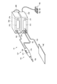
- FIG. 1 is a diagram showing an outline of the appearance of a surgery system 10 according to the present embodiment.
- the surgery system 10 is a system for treating a living tissue to be treated by high frequency current and ultrasonic vibration.
- the surgical system 10 has a function as a monopolar high frequency treatment tool.
- a probe as an electrode vibrates at a frequency in the ultrasonic region. Probe vibration is also utilized in the procedure.
- the surgical system 10 includes a surgical instrument 110, a return electrode plate 180, a foot switch 190, a first generator 200, and a second generator 300.
- the surgical instrument 110 includes an operation unit 120 and a probe 130.
- the operation unit 120 is a portion which the user holds and operates the surgical instrument 110.
- the probe 130 is provided at the tip of the operation unit 120.
- the probe 130 is applied to a living tissue to be treated at the time of treatment.
- the probe 130 functions as a high frequency electrode.
- a high frequency current flows from the probe 130 to the living tissue.
- the probe 130 is connected to an ultrasonic transducer provided in the operation unit 120. During the procedure, the probe 130 vibrates at a frequency in the ultrasound range.
- the operation unit 120 is provided with an output switch 121.
- the output switch 121 includes a first switch 122 and a second switch 124.
- the first switch 122 is a switch related to an input for operating the surgical instrument 110 in the incision mode.
- the dissection mode is a mode in which a living tissue to be treated is burnt at a portion in contact with the probe 130 by outputting a relatively large high frequency current.
- the second switch 124 is a switch related to an input for operating the surgical instrument 110 in the hemostasis mode. In the hemostasis mode, a weak high frequency current is output as compared to the incision mode. In the hemostasis mode, the probe 130 performs the hemostasis treatment by denaturing the end face of the living body tissue to be treated while burning it at the contacting portion.
- the return electrode plate 180 is attached to the body surface of the treatment subject.
- the current output from the probe 130 of the surgical instrument 110 is collected by the return electrode plate 180.
- the foot switch 190 comprises a first switch 192 and a second switch 194.
- the first switch 192 of the foot switch 190 has the same function as the first switch 122 provided on the surgical instrument 110.
- the second switch 194 of the foot switch 190 has the same function as the second switch 124 provided on the surgical instrument 110. That is, the user can switch on / off of the operation of the surgical tool 110 using the first switch 122 and the second switch 124 provided on the surgical tool 110, and the first of the foot switches 190 can be switched.
- the switch 192 and the second switch 194 can also be used to switch.
- the first generator 200 controls the operation of the surgical instrument 110.
- the first generator 200 outputs power for driving the ultrasonic transducer of the surgical instrument 110.
- the first generator 200 is connected to the surgical instrument 110 by a cable 152.
- the first generator 200 outputs power to the surgical instrument 110 via the cable 152.
- the first generator 200 is connected to the second generator 300 by a cable 290.
- the first generator 200 and the second generator 300 exchange necessary information via the cable 290.
- the first generator 200 includes a touch screen 272 as a user interface, an input unit 274, and a microphone 276.
- the touch screen 272 has, for example, a liquid crystal display (LCD) and a touch panel.
- the input unit 274 includes a button switch and the like.
- the first generator 200 may obtain an instruction from the user using the touch screen 272, the input unit 274, and the microphone 276.
- the first generator 200 may use the touch screen 272 to present information to the user.
- the second generator 300 controls the operation of the surgical instrument 110.
- the second generator 300 outputs power so as to cause current to flow between the probe 130 of the surgical tool 110 and the return electrode plate 180.
- the second generator 300 is connected to the surgical instrument 110 by a cable 154.
- the second generator 300 is connected to the return electrode plate 180 by a cable 156.
- the second generator 300 includes a touch screen 372 as a user interface and an input unit 374.
- the touch screen 372 has, for example, a liquid crystal display (LCD) and a touch panel.
- the input unit 374 includes a button switch and the like.
- the second generator 300 may obtain an instruction from the user using the touch screen 372 and the input unit 374.
- the second generator 300 can use the touch screen 372 to present information to the user.
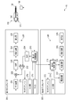
- FIG. 2 is a block diagram showing an outline of a configuration example of the surgery system 10.
- the surgical instrument 110 is provided with an ultrasonic transducer 140.
- the ultrasonic transducer 140 includes a plurality of piezoelectric elements. Each of the piezoelectric elements is sandwiched by electrodes of different polarities.
- the ultrasonic transducer 140 is formed by laminating these piezoelectric elements.
- the ultrasonic transducer 140 vibrates at the frequency when an AC voltage of a frequency in the ultrasonic region is applied from the first generator 200. This vibration is transmitted to the probe 130.
- the first generator 200 comprises a first control circuit 210.
- the first control circuit 210 controls the operation of each part of the first generator 200.
- the first control circuit 210 includes an integrated circuit such as, for example, a central processing unit (CPU), an application specific integrated circuit (ASIC), or a field programmable gate array (FPGA).
- the first control circuit 210 may be configured of one integrated circuit or the like, or may be configured by combining a plurality of integrated circuits or the like.
- the operation of the first control circuit 210 is performed, for example, in accordance with a program or the like recorded in a storage circuit or a storage area inside the control circuit.
- the first control circuit 210 acquires input signals to the output switch 121 of the surgical tool 110, the touch screen 272 of the first generator 200, the input unit 274, the microphone 276, and the like.
- the first control circuit 210 also controls display on the touch screen 272.
- the first generator 200 includes a drive circuit 220.
- the drive circuit 220 is a circuit for driving the ultrasonic transducer 140. That is, the drive circuit 220 is a circuit that generates a voltage to be applied to the electrode of the ultrasonic transducer 140.
- the first generator 200 of this embodiment employs a PLL control method as a resonance tracking method. Further, the first generator 200 employs a constant current control method as an amplitude control method.
- the Drive circuit 220 includes a transformer 222.
- the transformer 222 boosts and outputs a necessary voltage.
- the output of the transformer 222 is input to the ultrasonic transducer 140.
- the transformer 222 also plays a role of preventing a current of a direct current component from flowing between the circuit of the first generator 200 and the circuit of the surgical instrument 110.
- the circuit of the surgical instrument 110 is a circuit in contact with the patient.
- the circuit of the first generator 200 is a circuit connected to a commercial power supply.
- the drive circuit 220 includes a detection circuit 224, a power amplifier 226, a voltage control amplifier 228, a phase locked loop (PLL) circuit 230, a differential amplifier 232, and a DA converter (DAC) 234.
- PLL phase locked loop
- DAC DA converter
- the output of the voltage control amplifier 228 is input to the power amplifier 226.
- the power amplifier 226 amplifies the output of the voltage control amplifier 228 and adjusts the signal input to the transformer 222.
- the detection circuit 224 detects the voltage and current input from the power amplifier 226 to the primary coil of the transformer 222 and their phases.
- the PLL circuit 230 is a circuit for tracking the resonance frequency of the ultrasonic transducer 140.
- the PLL circuit 230 performs resonance tracking using the voltage phase signal detected by the detection circuit 224 and the current phase signal.
- the PLL circuit 230 performs resonance tracking by performing control to bring the phase difference between the voltage and the current close to zero.
- the output of PLL circuit 230 is input to voltage control amplifier 228.
- the voltage control amplifier 228 is a multiplier.
- the signal from the differential amplifier 232 is input to the voltage control amplifier 228.
- the differential amplifier 232 compares the signal of the current magnitude obtained from the detection circuit 224 with the signal from the DAC 234.
- the DAC 234 inputs a signal related to the magnitude of the output from the first control circuit 210 to the ultrasonic transducer 140 to the differential amplifier 232.
- the first control circuit 210 detects that the power switch is turned on. At this time, the first control circuit 210 outputs a digital signal relating to the target value of the size of the output to the ultrasonic transducer 140 to the DAC 234.
- the DAC 234 converts the signal input from the first control circuit 210 into an analog signal, and outputs the converted signal to the differential amplifier 232.
- the signal from the DAC 234 and the signal from the detection circuit 224 are input to the differential amplifier 232.
- Differential amplifier 232 compares the signal from DAC 234 with the signal from detection circuit 224. That is, the differential amplifier 232 compares the control signal indicating the target value of the output output from the first control circuit 210 with the current output detected by the detection circuit 224.
- the differential amplifier 232 outputs the comparison result to the voltage control amplifier 228.
- Voltage control amplifier 228 multiplies the input from PLL circuit 230 by the input from differential amplifier 232. As a result, the output voltage is adjusted to the magnitude instructed by the first control circuit 210. Therefore, a signal whose resonance is tracked by PLL circuit 230 and whose output is adjusted to a magnitude based on the control signal of first control circuit 210 using voltage control amplifier 228 and differential amplifier 232 is power.
- the signal is input to the amplifier 226.
- the power amplifier 226 amplifies the signal and outputs it to the transformer 222.
- the transformer 222 boosts the input voltage and supplies power to the ultrasonic transducer 140. Thus, appropriate energy supply to the ultrasonic transducer 140 is performed. As a result, the ultrasonic transducer 140 vibrates.
- the second generator 300 comprises a second control circuit 310.
- the second control circuit 310 controls the operation of each part of the second generator 300.
- the second control circuit 310 includes an integrated circuit such as, for example, a central processing unit (CPU), an application specific integrated circuit (ASIC), or a field programmable gate array (FPGA).
- the second control circuit 310 may be configured of one integrated circuit or the like, or may be configured by combining a plurality of integrated circuits or the like.
- the operation of the second control circuit 310 is performed, for example, according to a program or the like recorded in a memory circuit or a memory area inside the control circuit.
- the second control circuit 310 obtains input signals to the output switch 121 of the surgical tool 110, the touch screen 372 of the second generator 300, the input unit 374 and the like.
- the second control circuit 310 also controls display on the touch screen 372.
- the first control circuit 210 of the first generator 200 and the second control circuit 310 of the second generator 300 are connected.
- the first control circuit 210 of the first generator 200 and the second control circuit 310 of the second generator 300 exchange necessary information.
- the second generator 300 comprises an output circuit 320.
- the output circuit 320 is a circuit that applies a high frequency voltage between the probe 130 of the surgical instrument 110 and the return electrode plate 180.
- the output circuit 320 includes a power supply circuit 322, a resonant circuit 324, a detection circuit 326, and a transformer 328.
- the power supply circuit 322 is, for example, a DC / DC converter.
- the second control circuit 310 turns on the output of the power supply circuit 322 based on the fact that the output switch 121 of the surgical instrument 110 is turned on. At this time, the second control circuit 310 controls the magnitude of the output of the power supply circuit 322.
- the DC voltage output from the power supply circuit 322 is supplied to the resonance circuit 324.
- the resonance circuit 324 converts the DC voltage supplied from the power supply circuit 322 into an AC voltage under the control of the second control circuit 310.
- the resonant circuit 324 inputs the generated AC voltage to the primary coil of the transformer 328 through the detection circuit 326.
- the detection circuit 326 detects, for example, the voltage applied to the primary coil of the transformer 328 and the current flowing through the primary coil.
- the detection circuit 326 transmits the detection result to the second control circuit 310.
- the second control circuit 310 controls the output of the power supply circuit 322 using the detection result of the detection circuit 326.
- the transformer 328 boosts the output voltage of the resonant circuit 324.
- the transformer 328 applies a boosted voltage between the probe 130 of the surgical instrument 110 and the return electrode plate 180.
- the transformer 328 also plays a role of preventing a current of a DC component from flowing between the circuit of the second generator 300 and the circuit of the surgical instrument 110.
- the circuit of the surgical instrument 110 is a circuit in contact with the patient.
- the circuit of the second generator 300 is a circuit to which a commercial power supply is connected.
- the user brings the probe 130 into contact with the living tissue to be treated, and turns on the output switch 121.
- the surgical instrument 110 outputs energy.
- the first control circuit 210 of the first generator 200 acquires information indicating that the output switch 121 is turned on.
- the first control circuit 210 causes the drive circuit 220 to output power for driving the ultrasonic transducer 140.
- the ultrasonic transducer 140 vibrates due to this output power. This vibration is transmitted and the probe 130 vibrates.
- the second control circuit 310 of the second generator 300 causes the output circuit 320 to output high frequency power. As a result, a high frequency current flows in the living tissue located between the probe 130 and the return electrode plate 180.
- a PLL is used to resonate a vibration system including the ultrasonic transducer 140 and the probe 130 at a frequency in the ultrasonic region.
- some time is required to generate resonance in a PLL. Therefore, in order to simultaneously output high frequency power while the probe 130 is in resonance, it is necessary to output high frequency power after the resonance of the probe 130 is realized.
- the first mode is a mode in which the resonance of the probe 130 is realized in advance before the output switch 121 is pressed.
- the second mode is a mode in which the resonance of the probe 130 is first realized after the output switch 121 is pressed, and then the output of high frequency power is performed.
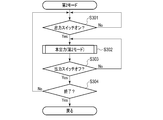
- step S101 the first control circuit 210 of the first generator 200 determines whether the currently set mode is the first mode or the second mode.
- the output mode is previously selected by the user at the start of use, for example, by an input using the touch screen 272 of the first generator 200.
- an example in which either the first mode or the second mode is set by the first generator 200 and the setting is determined by the first control circuit 210 of the first generator 200 is shown.
- the setting and determination may be performed by the second generator 300 without being limited thereto.
- step S102 When the first mode is selected, the process proceeds to step S102, and the treatment of the first mode is performed.
- the process proceeds to step S103, and the process of the second mode is performed. After the operation in each mode, the process proceeds to step S104.
- step S104 the first control circuit 210 of the first generator 200 determines whether to end the process. For example, when the power of the first generator 200 is turned off, it is determined to end. If not, the process returns to step S101. On the other hand, when the process ends, the present process ends.
- the process of the first mode will be described with reference to the flowchart shown in FIG.
- the first mode is a mode in which the resonance of the probe 130 is realized in advance before the output switch 121 is pressed.
- the output switch 121 is pressed, the vibration of the treatment probe 130 and the output of high frequency power are simultaneously started.
- step S201 the first control circuit 210 of the first generator 200 performs a standby required detection process to determine whether standby is required.
- standby refers to a state in which the resonance of the probe 130 is maintained. When the standby is necessary, it shifts to the standby state.
- a criterion determined to require standby is referred to as a first trigger.
- the probe 130 when the probe 130 is in contact with a living tissue, it is determined that the standby is necessary. Whether or not the probe 130 and the living tissue are in contact with each other can be determined, for example, by obtaining a value reflecting the electrical impedance between the probe 130 and the return electrode 180.
- the impedance between the probe 130 and the return electrode 180 connected to the living tissue is relatively low.
- the second generator 300 applies a weak current between the probe 130 and the return electrode plate 180, and obtains a value related to the impedance between the probe 130 and the return electrode plate 180.
- the second control circuit 310 transmits this value to the first control circuit 210 of the first generator 200.
- the first control circuit 210 of the first generator 200 performs a standby required detection process based on the received value.
- the first trigger is that the impedance between the probe 130 and the return electrode plate 180 is less than a predetermined value.
- step S202 the first control circuit 210 determines whether to start the standby state based on the processing result of step S201. When in the standby state, the process proceeds to step S203. In step S203 and subsequent steps, a standby operation is performed.
- the standby operation includes performing resonance point scanning of the vibration system in response to the detection of the first trigger to search for a resonance point, and maintaining the resonance of the vibration system if a resonance point is found.
- the first control circuit 210 causes the drive circuit 220 to perform resonance point search.
- the output of the drive circuit 220 is adjusted to a low level, and the probe 130 is slightly vibrated by the ultrasonic transducer 140.
- the first control circuit 210 gradually changes the output frequency, for example, from high frequency to low frequency.
- the first control circuit 210 analyzes the phase difference between the voltage and current detected by the detection circuit 224 at this time. At the resonance point of the vibration system including the ultrasonic transducer 140 and the probe 130, the phase difference between the voltage and the current disappears. At the resonance point, the current easily flows.
- the first control circuit 210 performs a resonance point scan that determines a resonance point based on the phase of the voltage and the current while gradually changing the output frequency from, for example, a high frequency to a low frequency. In addition, since the current easily flows and the amplitude increases when the resonance point is found, the first control circuit 210 adjusts the current value to an appropriate range so as to appropriately suppress the amplitude. If a resonance point is found, the process proceeds to step S204.
- step S204 the first control circuit 210 causes the drive circuit 220 to perform a resonance point maintaining operation.
- the resonance point maintaining operation the ultrasonic transducer 140 continues vibrating at a low output, and PLL processing continues to be performed. Because the output level is low, the vibration amplitude of the probe 130 is also small. Therefore, even if the probe 130 comes in contact with the living tissue, the living tissue is not treated by this contact.
- step S205 the first control circuit 210 performs a standby required detection process as in step S201.
- step S206 the first control circuit 210 determines whether to maintain the standby state.
- the output to the ultrasonic transducer 140 is stopped, and the process returns to step S201.
- the standby state is not maintained.
- the first trigger is released, the power supply to the ultrasonic transducer 140 is stopped.
- the process proceeds to step S207.
- step S207 the first control circuit 210 determines whether the output switch 121 is on. If the output switch 121 is not on, the process returns to step S204. That is, resonance is maintained while the standby state is to be maintained. On the other hand, when it is determined that the output switch 121 is on, the process proceeds to step S208.
- step S208 the surgery system 10 performs the main output operation in the first mode. That is, the first control circuit 210 of the first generator 200 raises the output of the drive circuit 220 to a necessary level so that the probe 130 vibrates at an amplitude suitable for treatment. Also at this time, the resonance of the probe 130 is continuously maintained. As a result, the probe 130 vibrates with a sufficiently large amplitude.
- the second control circuit 310 of the second generator 300 makes the output of the output circuit 320 an output necessary for treatment with a high frequency current. As a result, a high frequency current flows from the probe 130 to the living tissue. The high frequency current and the vibration of the probe 130 treat the living tissue.
- the criteria that lead to the treatment of living tissue will be referred to as the second trigger. Turning on the output switch 121 is a second trigger. Similarly, turning on the foot switch 190 is also a second trigger.
- step S209 the first control circuit 210 of the first generator 200 determines whether the output switch 121 is off. If the output is not turned off and the on state continues, the process returns to step S208. That is, this output is maintained, the probe 130 vibrates with a large amplitude, and a high frequency current flows from the probe 130 to the living tissue. Even when the probe 130 and the living tissue are separated, this output is maintained while the output switch 121 is on.
- step S210 the surgery system 10 stops the output.
- step S210 the first control circuit 210 of the first generator 200 determines whether to end the processing of the first mode. When it is determined to end, the process ends. For example, when the treatment is finished and the power is turned off, the process ends. Further, when the mode switching operation is performed from the menu screen and the mode is switched from the first mode to the second mode, the present process ends. On the other hand, when it is determined that the process does not end, the process returns to step S201. That is, the above process is repeated.
- each part in the first mode will be described with reference to the timing chart shown in FIG. It is assumed that standby is required at time t1. Here, the output switch 121 remains off. At this time, resonance point search is performed at low output. It is assumed that a resonance point is found at time t2. Even after time t2, the output for driving the ultrasonic transducer 140 of the drive circuit 220 is maintained at a low output for maintaining resonance.
- the output switch 121 is turned on at time t3. At this time, the output for driving the ultrasonic transducer 140 of the drive circuit 220 is set to a high output. Also, the output of the output circuit 320 is set to a high output, and the output of high frequency power is started. At time t4, when the output switch 121 is turned off, the output of the drive circuit 220 is stopped and the vibration of the ultrasonic transducer 140 is stopped. Further, the output of the output circuit 320 is stopped, and the output of high frequency power is stopped.
- step S202 If it is determined in step S202 that standby is not to be started, the process proceeds to step S211.
- step S211 the first control circuit 210 of the first generator 200 determines whether the output switch 121 is on. If the output switch 121 is not on, the process returns to step S201. That is, the above process is repeated. On the other hand, when it is determined that the output switch 121 is on, the process proceeds to step S212.
- step S212 the surgery system 10 performs this output.
- the main output is performed in the second mode.
- step S213 the first control circuit 210 of the first generator 200 determines whether the output switch 121 is turned off. When the output switch 121 is not turned off and the on state is maintained, the process returns to step S212, and this output is maintained. On the other hand, when the output switch 121 is turned off, the process proceeds to step S210.
- each part in the second mode will be described with reference to the timing chart shown in FIG. It is assumed that the output switch 121 is turned on at time t5. At this time, resonance point search is performed at low output. Assume that a resonance point is found at time t6. At this time, the output for driving the ultrasonic transducer 140 of the drive circuit 220 is set to a high output. Also, the output of the output circuit 320 is set to a high output, and the output of high frequency power is started.
- Switching of the drive circuit 220 to a high output and start of the output of the output circuit 320 may be performed based on a lock signal indicating that a resonance point has been found and resonated. That is, such a lock signal is output from the first control circuit 210 of the first generator 200 to the second control circuit 310 of the second generator 300.
- the second control circuit 310 may start output of high frequency power when the lock signal is received.
- the time required for the past resonance point search may be stored and used. That is, switching of the drive circuit 220 to high output and start of output of the output circuit 320 may be performed after the time has elapsed since the output switch 121 was turned on.
- the probe 130 As described above, in the first mode, it is determined whether standby is necessary.
- a standby state such as when the living tissue comes in contact
- resonance point search is performed, and resonance is maintained while the standby state is to be maintained.
- the output switch 121 As soon as the output switch 121 is turned on, the ultrasonic wave output and the high frequency output are simultaneously started.
- the output switch 121 is turned on while not in the standby state, resonance point search is first performed, and as soon as a resonance point is found, ultrasonic wave output and high frequency output are simultaneously started.
- step S103 The operation of the second mode performed in step S103 will be described with reference to the flowchart shown in FIG.
- step S301 the first control circuit 210 of the first generator 200 determines whether the output switch 121 is on. If the output switch 121 is not on, the process returns to step S301. That is, it waits until the output switch 121 is turned on. On the other hand, when it is determined that the output switch 121 is on, the process proceeds to step S302.
- step S302 the surgery system 10 performs the main output in the second mode described above.
- step S303 the first control circuit 210 of the first generator 200 determines whether the output switch 121 is turned off. When the output switch 121 is not turned off and the on state is maintained, the process returns to step S302, and this output is maintained. On the other hand, when the output switch 121 is turned off, the process proceeds to step S304.
- step S304 the first control circuit 210 of the first generator 200 determines whether to end the present process. When it is determined to end, the process ends. On the other hand, when it is determined that the process does not end, the process returns to step S301. That is, the above process is repeated.
- no output is required before the output switch 121 is turned on.
- an output for grasping the contact state between the probe 130 and the living tissue is not necessary.
- the vibration of the probe 130 is delayed with respect to the output of the high frequency power, the effect of preventing the sticking of the tissue to the probe 130 by the vibration can not be obtained while the high frequency power is output alone.
- the vibration of the probe 130 at the ultrasonic frequency and the output of the high frequency power are adjusted to start at the same time.
- the resonance point search is performed in advance so that the output is performed immediately when the user turns on the output switch 121.
- the surgical system 10 is sophisticated and easy to use.
- the contact state between the probe 130 and the return electrode 180 may be determined based on the value of the output voltage or the output current.
- changes in various electrical parameters can be the first trigger.
- a pressure sensor 171 that senses that the probe 130 is in contact with the living tissue 900 may be provided on the surgical instrument 110.
- the position where the pressure sensor 171 is disposed may be any position at which the contact pressure between the probe 130 and the living tissue can be detected.
- the contact pressure is detected, for example, by pushing the probe 130 proximally.
- the first control circuit 210 of the first generator 200 can acquire the detection result of the pressure sensor 171 and can determine whether the probe 130 is in contact with the living tissue 900. When in contact, the first control circuit 210 can determine that a standby state is required.
- the pressure sensor is an example, and various dynamic sensors such as a strain sensor may be used as well.
- an optical distance sensor capable of measuring the distance to an object present in the direction of the tip of the probe 130 may be used.
- the surgical instrument 110 is provided with a light emitting unit 174 that emits, for example, infrared light in the direction of the tip of the probe 130 and a light receiving unit 175 that detects light reflected by the biological tissue 900 or the like. It may be done.
- the first control circuit 210 of the first generator 200 can acquire the detection result of such an optical distance sensor, and acquire the distance between the tip of the probe 130 and an object such as the living tissue 900.
- the first control circuit 210 can determine that the standby state is necessary when the distance between the tip of the probe 130 and the object is less than a predetermined value.
- the tip of the probe 130 and the object may not necessarily be in contact with each other.
- the distance between the tip of the probe 130 and the object may be specified based on the image obtained by capturing the tip of the probe 130.
- the first control circuit 210 acquires an image of the tip of the probe 130.
- the first control circuit 210 performs image processing on this image to specify the distance between the probe 130 and the living tissue.
- the first control circuit 210 may determine whether a standby state is necessary based on the identification result of the distance.
- the first control circuit 210 may monitor a first trigger based on image information.
- a switch for switching to the standby state may be provided.
- the output switch 121 is a two-stage switch and the first stage switch is turned on, the standby state is established, and when the second stage switch is turned on, this output is performed. It may be configured. In this case, the presence or absence of standby may be set by the user using the user interface.
- the first generator 200 may be configured to allow the user to instruct by voice to put on standby.
- the microphone 276 picks up the sound, and the first control circuit 210 performs speech recognition processing.
- the first control circuit 210 may determine whether the user desires the standby state based on the voice recognition result.
- the first control circuit 210 may monitor a first trigger based on audio information.
- the determination as to whether or not the standby state is necessary can be made based on various information.
- the division of roles between the first control circuit 210 of the first generator 200 and the second control circuit 310 of the second generator 300 in the surgery system 10 of the above-described embodiment is an example. Any control circuit may play any role.
- the first generator 200 and the second generator 300 may be integrated, and the number of control circuits may be one.
- the output of the surgical instrument 110 is a combination of the output of the high frequency power and the vibration at the frequency in the ultrasonic region, but it is not limited thereto.
- the surgical tool may, for example, treat living tissue only by vibration.
- the surgical instrument may be, for example, a surgical instrument provided with a heater at the tip of the probe 130. In this case, the surgical instrument uses a combination of heat output by the heater and vibration at a frequency in the ultrasonic range. Again, it may be configured and function the same as the embodiments described above.
Landscapes
- Health & Medical Sciences (AREA)
- Surgery (AREA)
- Life Sciences & Earth Sciences (AREA)
- Engineering & Computer Science (AREA)
- Molecular Biology (AREA)
- Public Health (AREA)
- Heart & Thoracic Surgery (AREA)
- Medical Informatics (AREA)
- Nuclear Medicine, Radiotherapy & Molecular Imaging (AREA)
- Animal Behavior & Ethology (AREA)
- General Health & Medical Sciences (AREA)
- Biomedical Technology (AREA)
- Veterinary Medicine (AREA)
- Physics & Mathematics (AREA)
- Plasma & Fusion (AREA)
- Otolaryngology (AREA)
- Dentistry (AREA)
- Mechanical Engineering (AREA)
- Surgical Instruments (AREA)
Abstract
A generator (200) for a surgical tool (110) includes a drive circuit (220) and a control circuit (210). The drive circuit (220) is configured to supply power to an ultrasonic vibrator (140) of the surgical tool (110). The control circuit (210) monitors a first trigger that leads to an instruction to perform resonance point scanning of a vibration system, and monitors a second trigger that leads to an instruction to treat body tissue. Upon detecting the first trigger, the control circuit (210) searches for a resonance point by means of the resonance point scanning of the vibration system and causes a standby operation to be executed to maintain resonance, and upon detecting the second trigger, causes the execution of a formal output operation in which the surgical tool (110) treats the body tissue.
Description
本発明は、ジェネレータ及びジェネレータの作動方法に関する。
The present invention relates to a generator and a method of operating the generator.
手術の際に、処置対象である生体組織に高周波電流を流し、当該生体組織を凝固させたり切開したりする電気メスが知られている。このような電気メスにおいて、メスの先である電極を超音波領域の周波数で振動させることで、メス先に生体組織が張り付かないようにする技術が知られている。例えば、米国特許出願公開第2009/0326569号明細書は、このような手術具についての技術を開示している。この文献は、高周波電流を流すことによって計測される電気インピーダンスに基づいて、メス先と生体組織とが接触しているか否かを判定することを開示している。また、この文献は、接触していると判定されるとき、高周波電流の出力及び振動の出力を処置用に設定された値にすることについて開示している。
BACKGROUND ART At the time of surgery, an electric scalpel is known which supplies a high frequency current to a living tissue to be treated and coagulates or incises the living tissue. In such an electric knife, there is known a technique for preventing a living tissue from sticking to the tip of the scalpel by vibrating an electrode which is the tip of the scalpel at a frequency in an ultrasonic region. For example, U.S. Patent Application Publication 2009/0326569 discloses a technique for such a surgical tool. This document discloses determining whether the scalpel and the living tissue are in contact with each other based on the electrical impedance measured by flowing a high frequency current. Also, this document discloses that when it is determined that a contact is made, the output of high frequency current and the output of vibration are set to values set for treatment.
上述のような手術システムにおいて、ユーザが意図したタイミングで最適な出力がなされることが望ましい。本発明は、手術システムの機能性と使いやすさとを向上させることを目的とする。
In the surgical system as described above, it is desirable that an optimal output be made at the timing intended by the user. The present invention aims to improve the functionality and ease of use of the surgical system.
本発明の一態様によれば、手術具のためのジェネレータは、超音波振動子を備えた生体組織を処置するための手術具の前記超音波振動子に電力を供給するように構成された駆動回路と、プローブと前記超音波振動子を備える振動系の共振点走査を行うことを指示することにつながる第1のトリガーを監視し、生体組織を処置することを指示することにつながる第2のトリガーを監視し、前記第1のトリガーを検出したら、前記振動系の共振点走査を行って共振点を探索し、共振点を発見したら共振を維持するように前記駆動回路に前記超音波振動子へ電力を供給させるスタンバイ動作を実行させ、前記第2のトリガーを検出したら、前記手術具が生体組織を処置するように、前記駆動回路に前記手術具への電力供給を行わせる本出力動作を実行させるように構成された少なくとも1つの制御回路とを備える。
According to one aspect of the invention, a generator for a surgical tool is configured to supply power to the ultrasonic transducer of a surgical tool for treating biological tissue comprising an ultrasonic transducer. Monitoring a first trigger leading to instructing to perform a resonant point scan of the oscillating system comprising the circuit and the probe and said ultrasound transducer and second leading to instructing treating the living tissue When the trigger is monitored and the first trigger is detected, resonance point scanning of the vibration system is performed to search for a resonance point, and when a resonance point is found, the ultrasonic transducer is maintained in the drive circuit so as to maintain resonance. And the output operation for causing the drive circuit to supply power to the surgical instrument so that the surgical instrument treats the living tissue when the standby operation for causing the power to be supplied is performed and the second trigger is detected. And at least one control circuit is configured to row.
[手術システムの構成]
本発明の一実施形態について図面を参照して説明する。図1は、本実施形態に係る手術システム10の外観の概略を示す図である。手術システム10は、高周波電流と、超音波振動とによって、処置対象である生体組織の処置を行うためのシステムである。手術システム10は、モノポーラ型の高周波処置具としての機能を有する。手術システム10では、さらに、電極としてのプローブが超音波領域の周波数で振動する。プローブの振動も処置において利用される。 [Configuration of surgery system]
An embodiment of the present invention will be described with reference to the drawings. FIG. 1 is a diagram showing an outline of the appearance of asurgery system 10 according to the present embodiment. The surgery system 10 is a system for treating a living tissue to be treated by high frequency current and ultrasonic vibration. The surgical system 10 has a function as a monopolar high frequency treatment tool. Furthermore, in the surgical system 10, a probe as an electrode vibrates at a frequency in the ultrasonic region. Probe vibration is also utilized in the procedure.
本発明の一実施形態について図面を参照して説明する。図1は、本実施形態に係る手術システム10の外観の概略を示す図である。手術システム10は、高周波電流と、超音波振動とによって、処置対象である生体組織の処置を行うためのシステムである。手術システム10は、モノポーラ型の高周波処置具としての機能を有する。手術システム10では、さらに、電極としてのプローブが超音波領域の周波数で振動する。プローブの振動も処置において利用される。 [Configuration of surgery system]
An embodiment of the present invention will be described with reference to the drawings. FIG. 1 is a diagram showing an outline of the appearance of a
図1に示すように、手術システム10は、手術具110と、対極板180と、フットスイッチ190と、第1のジェネレータ200と、第2のジェネレータ300とを備える。
As shown in FIG. 1, the surgical system 10 includes a surgical instrument 110, a return electrode plate 180, a foot switch 190, a first generator 200, and a second generator 300.
手術具110は、操作部120と、プローブ130とを備える。操作部120は、ユーザが把持し、手術具110の操作を行うための部分である。プローブ130は、操作部120の先端に設けられている。プローブ130は、処置時において、処置対象である生体組織にあてられる。プローブ130は、高周波電極として機能する。処置時には、プローブ130から生体組織に高周波の電流が流れる。また、プローブ130は、操作部120内に設けられた超音波振動子に接続されている。処置時には、プローブ130は、超音波領域の周波数で振動する。
The surgical instrument 110 includes an operation unit 120 and a probe 130. The operation unit 120 is a portion which the user holds and operates the surgical instrument 110. The probe 130 is provided at the tip of the operation unit 120. The probe 130 is applied to a living tissue to be treated at the time of treatment. The probe 130 functions as a high frequency electrode. At the time of treatment, a high frequency current flows from the probe 130 to the living tissue. The probe 130 is connected to an ultrasonic transducer provided in the operation unit 120. During the procedure, the probe 130 vibrates at a frequency in the ultrasound range.
また、操作部120には、出力スイッチ121が設けられている。出力スイッチ121は、第1のスイッチ122と第2のスイッチ124とを含む。第1のスイッチ122は、手術具110を切開モードで動作させるための入力に係るスイッチである。切開モードは、比較的大きな高周波電流が出力されることで、プローブ130と接触する部分において、処置対象である生体組織を焼切るモードである。第2のスイッチ124は、手術具110を止血モードで動作させるための入力に係るスイッチである。止血モードでは、切開モードに比べて弱い高周波電流が出力される。止血モードでは、プローブ130は、接触する部分において、処置対象である生体組織を焼切りつつ、その端面を生体的に変性させて止血処置を行う。
In addition, the operation unit 120 is provided with an output switch 121. The output switch 121 includes a first switch 122 and a second switch 124. The first switch 122 is a switch related to an input for operating the surgical instrument 110 in the incision mode. The dissection mode is a mode in which a living tissue to be treated is burnt at a portion in contact with the probe 130 by outputting a relatively large high frequency current. The second switch 124 is a switch related to an input for operating the surgical instrument 110 in the hemostasis mode. In the hemostasis mode, a weak high frequency current is output as compared to the incision mode. In the hemostasis mode, the probe 130 performs the hemostasis treatment by denaturing the end face of the living body tissue to be treated while burning it at the contacting portion.
対極板180は、処置対象者の体表面に貼付される。手術具110のプローブ130から出力された電流は、対極板180で回収される。
The return electrode plate 180 is attached to the body surface of the treatment subject. The current output from the probe 130 of the surgical instrument 110 is collected by the return electrode plate 180.
フットスイッチ190は、第1のスイッチ192と第2のスイッチ194とを備える。フットスイッチ190の第1のスイッチ192は、手術具110に設けられた第1のスイッチ122と同様の機能を有する。また、フットスイッチ190の第2のスイッチ194は、手術具110に設けられた第2のスイッチ124と同様の機能を有する。すなわち、ユーザは、手術具110の動作のオン/オフを、手術具110に設けられた第1のスイッチ122及び第2のスイッチ124を用いて切り替えることができるし、フットスイッチ190の第1のスイッチ192及び第2のスイッチ194を用いて切り替えることもできる。
The foot switch 190 comprises a first switch 192 and a second switch 194. The first switch 192 of the foot switch 190 has the same function as the first switch 122 provided on the surgical instrument 110. The second switch 194 of the foot switch 190 has the same function as the second switch 124 provided on the surgical instrument 110. That is, the user can switch on / off of the operation of the surgical tool 110 using the first switch 122 and the second switch 124 provided on the surgical tool 110, and the first of the foot switches 190 can be switched. The switch 192 and the second switch 194 can also be used to switch.
第1のジェネレータ200は、手術具110の動作を制御する。第1のジェネレータ200は、手術具110の超音波振動子を駆動させるための電力を出力する。第1のジェネレータ200は、ケーブル152で手術具110に接続されている。第1のジェネレータ200は、ケーブル152を介して手術具110へと電力を出力する。第1のジェネレータ200は、ケーブル290で第2のジェネレータ300に接続されている。第1のジェネレータ200と第2のジェネレータ300とは、ケーブル290を介して必要な情報を交換する。
The first generator 200 controls the operation of the surgical instrument 110. The first generator 200 outputs power for driving the ultrasonic transducer of the surgical instrument 110. The first generator 200 is connected to the surgical instrument 110 by a cable 152. The first generator 200 outputs power to the surgical instrument 110 via the cable 152. The first generator 200 is connected to the second generator 300 by a cable 290. The first generator 200 and the second generator 300 exchange necessary information via the cable 290.
第1のジェネレータ200は、ユーザインタフェースとしてのタッチスクリーン272と、入力部274と、マイク276とを備える。タッチスクリーン272は、例えば液晶ディスプレイ(LCD)とタッチパネルとを有する。入力部274は、ボタンスイッチ等を含む。第1のジェネレータ200は、タッチスクリーン272、入力部274及びマイク276を用いて、ユーザからの指示を取得することができる。第1のジェネレータ200は、タッチスクリーン272を用いて、ユーザに情報を提示することができる。
The first generator 200 includes a touch screen 272 as a user interface, an input unit 274, and a microphone 276. The touch screen 272 has, for example, a liquid crystal display (LCD) and a touch panel. The input unit 274 includes a button switch and the like. The first generator 200 may obtain an instruction from the user using the touch screen 272, the input unit 274, and the microphone 276. The first generator 200 may use the touch screen 272 to present information to the user.
第2のジェネレータ300は、手術具110の動作を制御する。第2のジェネレータ300は、手術具110のプローブ130と、対極板180との間に電流を流すように電力を出力する。第2のジェネレータ300は、ケーブル154で手術具110に接続されている。第2のジェネレータ300は、ケーブル156で対極板180に接続されている。第2のジェネレータ300は、ユーザインタフェースとしてのタッチスクリーン372と、入力部374とを備える。タッチスクリーン372は、例えば液晶ディスプレイ(LCD)とタッチパネルとを有する。入力部374は、ボタンスイッチ等を含む。第2のジェネレータ300は、タッチスクリーン372及び入力部374を用いて、ユーザからの指示を取得することができる。第2のジェネレータ300は、タッチスクリーン372を用いて、ユーザに情報を提示することができる。
The second generator 300 controls the operation of the surgical instrument 110. The second generator 300 outputs power so as to cause current to flow between the probe 130 of the surgical tool 110 and the return electrode plate 180. The second generator 300 is connected to the surgical instrument 110 by a cable 154. The second generator 300 is connected to the return electrode plate 180 by a cable 156. The second generator 300 includes a touch screen 372 as a user interface and an input unit 374. The touch screen 372 has, for example, a liquid crystal display (LCD) and a touch panel. The input unit 374 includes a button switch and the like. The second generator 300 may obtain an instruction from the user using the touch screen 372 and the input unit 374. The second generator 300 can use the touch screen 372 to present information to the user.
図2は、手術システム10の構成例の概略を示すブロック図である。図2に示すように、手術具110には、超音波振動子140が設けられている。この超音波振動子140は、複数の圧電素子を含む。圧電素子の各々は、極性が異なる電極で挟まれている。これら圧電素子が積層されて超音波振動子140が形成されている。超音波振動子140は、第1のジェネレータ200から超音波領域の周波数の交流電圧が印加されることで、当該周波数で振動する。この振動は、プローブ130へと伝達される。
FIG. 2 is a block diagram showing an outline of a configuration example of the surgery system 10. As shown in FIG. 2, the surgical instrument 110 is provided with an ultrasonic transducer 140. The ultrasonic transducer 140 includes a plurality of piezoelectric elements. Each of the piezoelectric elements is sandwiched by electrodes of different polarities. The ultrasonic transducer 140 is formed by laminating these piezoelectric elements. The ultrasonic transducer 140 vibrates at the frequency when an AC voltage of a frequency in the ultrasonic region is applied from the first generator 200. This vibration is transmitted to the probe 130.
第1のジェネレータ200は、第1の制御回路210を備える。第1の制御回路210は、第1のジェネレータ200の各部の動作を制御する。第1の制御回路210は、例えばCentral Processing Unit(CPU)、Application Specific Integrated Circuit(ASIC)、又はField Programmable Gate Array(FPGA)等の集積回路を含む。第1の制御回路210は、1つの集積回路等で構成されてもよいし、複数の集積回路等が組み合わされて構成されてもよい。第1の制御回路210の動作は、例えば記憶回路又は制御回路の内部の記憶領域に記録されたプログラム等に従って行われる。
The first generator 200 comprises a first control circuit 210. The first control circuit 210 controls the operation of each part of the first generator 200. The first control circuit 210 includes an integrated circuit such as, for example, a central processing unit (CPU), an application specific integrated circuit (ASIC), or a field programmable gate array (FPGA). The first control circuit 210 may be configured of one integrated circuit or the like, or may be configured by combining a plurality of integrated circuits or the like. The operation of the first control circuit 210 is performed, for example, in accordance with a program or the like recorded in a storage circuit or a storage area inside the control circuit.
例えば、第1の制御回路210は、手術具110の出力スイッチ121、第1のジェネレータ200のタッチスクリーン272、入力部274及びマイク276等への入力信号を取得する。また、第1の制御回路210は、タッチスクリーン272への表示を制御する。
For example, the first control circuit 210 acquires input signals to the output switch 121 of the surgical tool 110, the touch screen 272 of the first generator 200, the input unit 274, the microphone 276, and the like. The first control circuit 210 also controls display on the touch screen 272.
第1のジェネレータ200は、駆動回路220を備える。駆動回路220は、超音波振動子140を駆動するための回路である。すなわち、駆動回路220は、超音波振動子140の電極に印加する電圧を発生する回路である。本実施形態の第1のジェネレータ200は、共振追尾方式としてPLL制御方式を採用している。また、第1のジェネレータ200は、振幅制御方式として定電流制御方式を採用している。
The first generator 200 includes a drive circuit 220. The drive circuit 220 is a circuit for driving the ultrasonic transducer 140. That is, the drive circuit 220 is a circuit that generates a voltage to be applied to the electrode of the ultrasonic transducer 140. The first generator 200 of this embodiment employs a PLL control method as a resonance tracking method. Further, the first generator 200 employs a constant current control method as an amplitude control method.
駆動回路220は、変圧器222を含む。変圧器222は、昇圧して必要な電圧を出力する。変圧器222の出力は、超音波振動子140に入力される。また、変圧器222は、第1のジェネレータ200の回路と手術具110の回路との間に、直流成分の電流が流れないようにする役割も担う。ここで、手術具110の回路は、患者に接する回路である。第1のジェネレータ200の回路は、商用電源に接続する回路である。
Drive circuit 220 includes a transformer 222. The transformer 222 boosts and outputs a necessary voltage. The output of the transformer 222 is input to the ultrasonic transducer 140. The transformer 222 also plays a role of preventing a current of a direct current component from flowing between the circuit of the first generator 200 and the circuit of the surgical instrument 110. Here, the circuit of the surgical instrument 110 is a circuit in contact with the patient. The circuit of the first generator 200 is a circuit connected to a commercial power supply.
駆動回路220は、検出回路224と、パワーアンプ226と、電圧制御アンプ228と、位相同期ループ(PLL)回路230と、差動アンプ232と、DAコンバータ(DAC)234とを含む。
The drive circuit 220 includes a detection circuit 224, a power amplifier 226, a voltage control amplifier 228, a phase locked loop (PLL) circuit 230, a differential amplifier 232, and a DA converter (DAC) 234.
パワーアンプ226には、電圧制御アンプ228の出力が入力される。パワーアンプ226は、電圧制御アンプ228の出力を増幅し、変圧器222へ入力する信号を調整する。検出回路224は、パワーアンプ226から変圧器222の一次コイルに入力される電圧と電流とそれらの位相を検出する。
The output of the voltage control amplifier 228 is input to the power amplifier 226. The power amplifier 226 amplifies the output of the voltage control amplifier 228 and adjusts the signal input to the transformer 222. The detection circuit 224 detects the voltage and current input from the power amplifier 226 to the primary coil of the transformer 222 and their phases.
PLL回路230は、超音波振動子140の共振周波数を追尾するための回路である。PLL回路230は、検出回路224が検出した電圧位相信号と電流位相信号とを用いて、共振追尾を行う。PLL回路230は、電圧と電流との位相差をゼロに近づける制御を行うことにより、共振追尾を行う。PLL回路230の出力は、電圧制御アンプ228へと入力される。電圧制御アンプ228は、乗算器である。電圧制御アンプ228には、PLL回路230からの信号の他、差動アンプ232からの信号が入力される。差動アンプ232は、検出回路224から得られた電流の大きさの信号と、DAC234からの信号とを比較する。DAC234は、第1の制御回路210からの超音波振動子140への出力の大きさと関係する信号を差動アンプ232へと入力する。
The PLL circuit 230 is a circuit for tracking the resonance frequency of the ultrasonic transducer 140. The PLL circuit 230 performs resonance tracking using the voltage phase signal detected by the detection circuit 224 and the current phase signal. The PLL circuit 230 performs resonance tracking by performing control to bring the phase difference between the voltage and the current close to zero. The output of PLL circuit 230 is input to voltage control amplifier 228. The voltage control amplifier 228 is a multiplier. In addition to the signal from the PLL circuit 230, the signal from the differential amplifier 232 is input to the voltage control amplifier 228. The differential amplifier 232 compares the signal of the current magnitude obtained from the detection circuit 224 with the signal from the DAC 234. The DAC 234 inputs a signal related to the magnitude of the output from the first control circuit 210 to the ultrasonic transducer 140 to the differential amplifier 232.
手術具110の出力スイッチ121がオンになったとき、第1の制御回路210は、オンになったことを検出する。このとき、第1の制御回路210は、超音波振動子140への出力の大きさの目標値に係るデジタル信号をDAC234へと出力する。DAC234は、第1の制御回路210から入力された信号をアナログ信号に変換し、変換後の信号を差動アンプ232へと出力する。
When the output switch 121 of the surgical tool 110 is turned on, the first control circuit 210 detects that the power switch is turned on. At this time, the first control circuit 210 outputs a digital signal relating to the target value of the size of the output to the ultrasonic transducer 140 to the DAC 234. The DAC 234 converts the signal input from the first control circuit 210 into an analog signal, and outputs the converted signal to the differential amplifier 232.
差動アンプ232には、DAC234からの信号と、検出回路224からの信号とが入力される。差動アンプ232は、DAC234からの信号と検出回路224からの信号とを比較する。すなわち、差動アンプ232は、第1の制御回路210から出力された出力の目標値を示す制御信号と、検出回路224で検出された現在の出力とを比較する。差動アンプ232は、比較結果を電圧制御アンプ228へと出力する。
The signal from the DAC 234 and the signal from the detection circuit 224 are input to the differential amplifier 232. Differential amplifier 232 compares the signal from DAC 234 with the signal from detection circuit 224. That is, the differential amplifier 232 compares the control signal indicating the target value of the output output from the first control circuit 210 with the current output detected by the detection circuit 224. The differential amplifier 232 outputs the comparison result to the voltage control amplifier 228.
電圧制御アンプ228は、PLL回路230からの入力と差動アンプ232からの入力とを乗算する。その結果、出力電圧は、第1の制御回路210が指示した大きさに調整される。したがって、PLL回路230によって共振追尾が行われた信号であって、電圧制御アンプ228及び差動アンプ232を用いて第1の制御回路210の制御信号に基づく大きさに調整された出力が、パワーアンプ226に入力される。パワーアンプ226は、信号を増幅し、変圧器222へと出力する。変圧器222は、入力された電圧を昇圧し、超音波振動子140に電力を供給する。このようにして、超音波振動子140に適切なエネルギー供給が行われる。その結果、超音波振動子140は振動する。
Voltage control amplifier 228 multiplies the input from PLL circuit 230 by the input from differential amplifier 232. As a result, the output voltage is adjusted to the magnitude instructed by the first control circuit 210. Therefore, a signal whose resonance is tracked by PLL circuit 230 and whose output is adjusted to a magnitude based on the control signal of first control circuit 210 using voltage control amplifier 228 and differential amplifier 232 is power. The signal is input to the amplifier 226. The power amplifier 226 amplifies the signal and outputs it to the transformer 222. The transformer 222 boosts the input voltage and supplies power to the ultrasonic transducer 140. Thus, appropriate energy supply to the ultrasonic transducer 140 is performed. As a result, the ultrasonic transducer 140 vibrates.
第2のジェネレータ300は、第2の制御回路310を備える。第2の制御回路310は、第2のジェネレータ300の各部の動作を制御する。第2の制御回路310は、例えばCentral Processing Unit(CPU)、Application Specific Integrated Circuit(ASIC)、又はField Programmable Gate Array(FPGA)等の集積回路を含む。第2の制御回路310は、1つの集積回路等で構成されてもよいし、複数の集積回路等が組み合わされて構成されてもよい。第2の制御回路310の動作は、例えば記憶回路又は制御回路の内部の記憶領域に記録されたプログラム等に従って行われる。
The second generator 300 comprises a second control circuit 310. The second control circuit 310 controls the operation of each part of the second generator 300. The second control circuit 310 includes an integrated circuit such as, for example, a central processing unit (CPU), an application specific integrated circuit (ASIC), or a field programmable gate array (FPGA). The second control circuit 310 may be configured of one integrated circuit or the like, or may be configured by combining a plurality of integrated circuits or the like. The operation of the second control circuit 310 is performed, for example, according to a program or the like recorded in a memory circuit or a memory area inside the control circuit.
例えば、第2の制御回路310は、手術具110の出力スイッチ121、第2のジェネレータ300のタッチスクリーン372及び入力部374等への入力信号を取得する。また、第2の制御回路310は、タッチスクリーン372への表示を制御する。また、第1のジェネレータ200の第1の制御回路210と第2のジェネレータ300の第2の制御回路310とは接続されている。第1のジェネレータ200の第1の制御回路210と第2のジェネレータ300の第2の制御回路310とは、必要な情報を交換する。
For example, the second control circuit 310 obtains input signals to the output switch 121 of the surgical tool 110, the touch screen 372 of the second generator 300, the input unit 374 and the like. The second control circuit 310 also controls display on the touch screen 372. Further, the first control circuit 210 of the first generator 200 and the second control circuit 310 of the second generator 300 are connected. The first control circuit 210 of the first generator 200 and the second control circuit 310 of the second generator 300 exchange necessary information.
第2のジェネレータ300は、出力回路320を備える。出力回路320は、手術具110のプローブ130と、対極板180との間に高周波電圧を印加する回路である。出力回路320は、電源回路322と、共振回路324と、検出回路326と、変圧器328とを備える。
The second generator 300 comprises an output circuit 320. The output circuit 320 is a circuit that applies a high frequency voltage between the probe 130 of the surgical instrument 110 and the return electrode plate 180. The output circuit 320 includes a power supply circuit 322, a resonant circuit 324, a detection circuit 326, and a transformer 328.
電源回路322は例えばDC/DCコンバータである。第2の制御回路310は、手術具110の出力スイッチ121がオンにされたことに基づいて、電源回路322の出力をオンにする。このとき、第2の制御回路310は、電源回路322の出力の大きさを制御する。電源回路322から出力された直流電圧は、共振回路324に供給される。
The power supply circuit 322 is, for example, a DC / DC converter. The second control circuit 310 turns on the output of the power supply circuit 322 based on the fact that the output switch 121 of the surgical instrument 110 is turned on. At this time, the second control circuit 310 controls the magnitude of the output of the power supply circuit 322. The DC voltage output from the power supply circuit 322 is supplied to the resonance circuit 324.
共振回路324は、第2の制御回路310の制御下で、電源回路322から供給された直流電圧を交流電圧に変換する。共振回路324は、生成した交流電圧を、検出回路326を介して、変圧器328の一次コイルへと入力する。
The resonance circuit 324 converts the DC voltage supplied from the power supply circuit 322 into an AC voltage under the control of the second control circuit 310. The resonant circuit 324 inputs the generated AC voltage to the primary coil of the transformer 328 through the detection circuit 326.
検出回路326は、例えば、変圧器328の一次コイルに印加される電圧と、一次コイルを流れる電流とを検出する。検出回路326は、検出結果を第2の制御回路310へと伝達する。第2の制御回路310は、検出回路326の検出結果を用いて、電源回路322の出力を制御する。
The detection circuit 326 detects, for example, the voltage applied to the primary coil of the transformer 328 and the current flowing through the primary coil. The detection circuit 326 transmits the detection result to the second control circuit 310. The second control circuit 310 controls the output of the power supply circuit 322 using the detection result of the detection circuit 326.
変圧器328は、共振回路324の出力電圧を昇圧する。変圧器328は、昇圧した電圧を、手術具110のプローブ130と、対極板180との間に印加する。また、変圧器328は、第2のジェネレータ300の回路と手術具110の回路との間に直流成分の電流が流れないようにする役割も担う。ここで、手術具110の回路は、患者に接する回路である。第2のジェネレータ300の回路は、商用電源が接続される回路である。
The transformer 328 boosts the output voltage of the resonant circuit 324. The transformer 328 applies a boosted voltage between the probe 130 of the surgical instrument 110 and the return electrode plate 180. The transformer 328 also plays a role of preventing a current of a DC component from flowing between the circuit of the second generator 300 and the circuit of the surgical instrument 110. Here, the circuit of the surgical instrument 110 is a circuit in contact with the patient. The circuit of the second generator 300 is a circuit to which a commercial power supply is connected.
[手術システムの動作]
手術具110を用いた処置において、ユーザがプローブ130を処置対象である生体組織に接触させて、出力スイッチ121をオンにする。このとき、手術具110は、エネルギーの出力を行う。例えば、出力スイッチ121がオンにされたとき、第1のジェネレータ200の第1の制御回路210は、出力スイッチ121がオンになった旨の情報を取得する。第1の制御回路210は、駆動回路220に、超音波振動子140を駆動する電力を出力させる。この出力電力によって、超音波振動子140は、振動する。この振動が伝達されて、プローブ130は振動する。このとき、第2のジェネレータ300の第2の制御回路310は、出力回路320に高周波電力の出力を行わせる。その結果、プローブ130と対極板180との間にある生体組織に高周波電流が流れる。 Operation of the surgical system
In the treatment using thesurgical instrument 110, the user brings the probe 130 into contact with the living tissue to be treated, and turns on the output switch 121. At this time, the surgical instrument 110 outputs energy. For example, when the output switch 121 is turned on, the first control circuit 210 of the first generator 200 acquires information indicating that the output switch 121 is turned on. The first control circuit 210 causes the drive circuit 220 to output power for driving the ultrasonic transducer 140. The ultrasonic transducer 140 vibrates due to this output power. This vibration is transmitted and the probe 130 vibrates. At this time, the second control circuit 310 of the second generator 300 causes the output circuit 320 to output high frequency power. As a result, a high frequency current flows in the living tissue located between the probe 130 and the return electrode plate 180.
手術具110を用いた処置において、ユーザがプローブ130を処置対象である生体組織に接触させて、出力スイッチ121をオンにする。このとき、手術具110は、エネルギーの出力を行う。例えば、出力スイッチ121がオンにされたとき、第1のジェネレータ200の第1の制御回路210は、出力スイッチ121がオンになった旨の情報を取得する。第1の制御回路210は、駆動回路220に、超音波振動子140を駆動する電力を出力させる。この出力電力によって、超音波振動子140は、振動する。この振動が伝達されて、プローブ130は振動する。このとき、第2のジェネレータ300の第2の制御回路310は、出力回路320に高周波電力の出力を行わせる。その結果、プローブ130と対極板180との間にある生体組織に高周波電流が流れる。 Operation of the surgical system
In the treatment using the
生体組織とプローブ130との接触部分では、生体組織を流れる高周波電流によって、生体組織で熱が発生する。また、プローブ130が振動することで、焼灼された生体組織がプローブ130に張り付くことが防止される。なお、生体組織と超音波領域の周波数で振動するプローブ130との間の摩擦で発生する熱によっても、生体組織が切開又は止血され得る。
At the contact portion between the living tissue and the probe 130, heat is generated in the living tissue by the high frequency current flowing through the living tissue. In addition, the vibration of the probe 130 prevents the cauterized biological tissue from sticking to the probe 130. Note that the heat generated by the friction between the living tissue and the probe 130 vibrating at the frequency of the ultrasonic region may also incise or stop the living tissue.
本実施形態の手術システム10では、超音波振動子140及びプローブ130を含む振動系を超音波領域の周波数で共振させるため、PLLが用いられている。一般に、PLLで共振を生じさせるには、ある程度の時間が必要とされる。このため、プローブ130が共振している状態で高周波電力の出力も同時に行わせるためには、プローブ130の共振が実現した後に高周波電力の出力が行われる必要がある。
In the surgery system 10 according to the present embodiment, a PLL is used to resonate a vibration system including the ultrasonic transducer 140 and the probe 130 at a frequency in the ultrasonic region. In general, some time is required to generate resonance in a PLL. Therefore, in order to simultaneously output high frequency power while the probe 130 is in resonance, it is necessary to output high frequency power after the resonance of the probe 130 is realized.
そこで、本実施形態に係る手術システム10には、2つの出力モードが用意されている。第1モードは、出力スイッチ121が押される前に予めプローブ130の共振を実現するモードである。第2モードは、出力スイッチ121が押された後に、まずプローブ130の共振を実現し、その後に高周波電力の出力が行われるモードである。
Therefore, two output modes are prepared for the surgery system 10 according to the present embodiment. The first mode is a mode in which the resonance of the probe 130 is realized in advance before the output switch 121 is pressed. The second mode is a mode in which the resonance of the probe 130 is first realized after the output switch 121 is pressed, and then the output of high frequency power is performed.
出力動作について、フローチャートを参照して説明する。図3に示すように、ステップS101において、例えば第1のジェネレータ200の第1の制御回路210は、現在設定されているモードが第1モードであるか第2モードであるかを判定する。出力モードは、例えば、第1のジェネレータ200のタッチスクリーン272を用いた入力によって、使用開始時に予めユーザによって選択される。ここでは、第1モードと第2モードとのいずれかが第1のジェネレータ200によって設定され、その設定が第1のジェネレータ200の第1の制御回路210で判定される例を示す。しかしながらこれに限らず、第2のジェネレータ300によってこれらの設定及び判定が行われてもよい。
The output operation will be described with reference to the flowchart. As shown in FIG. 3, in step S101, for example, the first control circuit 210 of the first generator 200 determines whether the currently set mode is the first mode or the second mode. The output mode is previously selected by the user at the start of use, for example, by an input using the touch screen 272 of the first generator 200. Here, an example in which either the first mode or the second mode is set by the first generator 200 and the setting is determined by the first control circuit 210 of the first generator 200 is shown. However, the setting and determination may be performed by the second generator 300 without being limited thereto.
第1モードが選択されているとき、処理はステップS102に進み、第1モードの処置が実行される。第2モードが選択されているとき、処理はステップS103に進み、第2モードの処理が実行される。各モードの動作の後、処理はステップS104に進む。
When the first mode is selected, the process proceeds to step S102, and the treatment of the first mode is performed. When the second mode is selected, the process proceeds to step S103, and the process of the second mode is performed. After the operation in each mode, the process proceeds to step S104.
ステップS104において、第1のジェネレータ200の第1の制御回路210は、処理を終了するか否か判定する。例えば、第1のジェネレータ200の電源が切られたとき、終了すると判定される。終了しないとき、処理はステップS101に戻る。一方、終了するとき、本処理は終了する。
In step S104, the first control circuit 210 of the first generator 200 determines whether to end the process. For example, when the power of the first generator 200 is turned off, it is determined to end. If not, the process returns to step S101. On the other hand, when the process ends, the present process ends.
第1モードの処理について、図4に示すフローチャート参照して説明する。第1モードは、出力スイッチ121が押される前に予めプローブ130の共振を実現するモードである。出力スイッチ121が押されたとき、処置用のプローブ130の振動と高周波電力の出力とが同時に開始される。
The process of the first mode will be described with reference to the flowchart shown in FIG. The first mode is a mode in which the resonance of the probe 130 is realized in advance before the output switch 121 is pressed. When the output switch 121 is pressed, the vibration of the treatment probe 130 and the output of high frequency power are simultaneously started.
ステップS201において、第1のジェネレータ200の第1の制御回路210は、スタンバイが必要な状態であるか否かを判定するための、要スタンバイ検出処理を行う。ここでスタンバイとは、プローブ130の共振を維持する状態を言うものとする。スタンバイが必要であるとき、スタンバイ状態に移行する。スタンバイが必要であると判定される基準を第1のトリガーと称することにする。
In step S201, the first control circuit 210 of the first generator 200 performs a standby required detection process to determine whether standby is required. Here, the term "standby" refers to a state in which the resonance of the probe 130 is maintained. When the standby is necessary, it shifts to the standby state. A criterion determined to require standby is referred to as a first trigger.
例えば、プローブ130が生体組織に接触しているとき、スタンバイが必要であると判定される。プローブ130と生体組織が接触しているか否かは、例えば、プローブ130と対極板180との間の電気インピーダンスを反映する値を取得することで行われる。プローブ130と生体組織とが接触しているとき、プローブ130と、生体組織とつながっている対極板180との間のインピーダンスは比較的低くなる。一方、プローブ130と生体組織とが離れているとき、プローブ130と対極板180との間のインピーダンスは、比較的高くなる。そこで、第2のジェネレータ300は、プローブ130と対極板180との間に微弱電流を流し、プローブ130と対極板180との間のインピーダンスに関係する値を取得する。第2の制御回路310は、この値を第1のジェネレータ200の第1の制御回路210へ送信する。第1のジェネレータ200の第1の制御回路210は、受信した値に基づいて、要スタンバイ検出処理を行う。この場合、プローブ130と対極板180との間のインピーダンスが所定値未満となることが第1のトリガーとなる。
For example, when the probe 130 is in contact with a living tissue, it is determined that the standby is necessary. Whether or not the probe 130 and the living tissue are in contact with each other can be determined, for example, by obtaining a value reflecting the electrical impedance between the probe 130 and the return electrode 180. When the probe 130 is in contact with a living tissue, the impedance between the probe 130 and the return electrode 180 connected to the living tissue is relatively low. On the other hand, when the probe 130 and the living tissue are apart, the impedance between the probe 130 and the return electrode 180 is relatively high. Therefore, the second generator 300 applies a weak current between the probe 130 and the return electrode plate 180, and obtains a value related to the impedance between the probe 130 and the return electrode plate 180. The second control circuit 310 transmits this value to the first control circuit 210 of the first generator 200. The first control circuit 210 of the first generator 200 performs a standby required detection process based on the received value. In this case, the first trigger is that the impedance between the probe 130 and the return electrode plate 180 is less than a predetermined value.
ステップS202において、第1の制御回路210は、ステップS201の処理結果に基づいて、スタンバイ状態を開始させるか否かを判定する。スタンバイ状態にするとき、処理はステップS203に進む。ステップS203以降において、スタンバイ動作が行われる。スタンバイ動作は、第1のトリガーの検知に応じて振動系の共振点走査を行って共振点を探索し、共振点を発見したら振動系の共振を維持することを含む。
In step S202, the first control circuit 210 determines whether to start the standby state based on the processing result of step S201. When in the standby state, the process proceeds to step S203. In step S203 and subsequent steps, a standby operation is performed. The standby operation includes performing resonance point scanning of the vibration system in response to the detection of the first trigger to search for a resonance point, and maintaining the resonance of the vibration system if a resonance point is found.
ステップS203において、第1の制御回路210は、共振点探索を駆動回路220に実行させる。共振点探索では、駆動回路220の出力は低レベルに調整され、超音波振動子140によってプローブ130がわずかに振動させられる。第1の制御回路210は、出力周波数を例えば高周波から低周波に徐々に変更する。第1の制御回路210は、このときの検出回路224で検出される電圧と電流との位相差を解析する。超音波振動子140及びプローブ130を含む振動系の共振点においては、電圧と電流との位相差がなくなる。共振点においては、電流が流れやすくなる。第1の制御回路210は、出力周波数を例えば高周波から低周波に徐々に変更しながら電圧と電流との位相に基づいて共振点を決定する共振点走査を行う。また、第1の制御回路210は、共振点が発見されたとき、電流が流れやすくなり振幅が増加するので、振幅を適切に抑えるように電流値を適切な範囲に調整する。共振点が見つかったら、処理はステップS204に進む。
In step S203, the first control circuit 210 causes the drive circuit 220 to perform resonance point search. In the resonance point search, the output of the drive circuit 220 is adjusted to a low level, and the probe 130 is slightly vibrated by the ultrasonic transducer 140. The first control circuit 210 gradually changes the output frequency, for example, from high frequency to low frequency. The first control circuit 210 analyzes the phase difference between the voltage and current detected by the detection circuit 224 at this time. At the resonance point of the vibration system including the ultrasonic transducer 140 and the probe 130, the phase difference between the voltage and the current disappears. At the resonance point, the current easily flows. The first control circuit 210 performs a resonance point scan that determines a resonance point based on the phase of the voltage and the current while gradually changing the output frequency from, for example, a high frequency to a low frequency. In addition, since the current easily flows and the amplitude increases when the resonance point is found, the first control circuit 210 adjusts the current value to an appropriate range so as to appropriately suppress the amplitude. If a resonance point is found, the process proceeds to step S204.
ステップS204において、第1の制御回路210は、駆動回路220に共振点維持動作を行わせる。共振点維持動作では、低出力で超音波振動子140を振動させ続け、PLL処理が行われ続ける。出力レベルが低いので、プローブ130の振動振幅も小さい。このため、仮にプローブ130が生体組織に接触しても、この接触によって生体組織が処置されることはない。
In step S204, the first control circuit 210 causes the drive circuit 220 to perform a resonance point maintaining operation. In the resonance point maintaining operation, the ultrasonic transducer 140 continues vibrating at a low output, and PLL processing continues to be performed. Because the output level is low, the vibration amplitude of the probe 130 is also small. Therefore, even if the probe 130 comes in contact with the living tissue, the living tissue is not treated by this contact.
ステップS205において、第1の制御回路210は、ステップS201と同様に、要スタンバイ検出処理を行う。
In step S205, the first control circuit 210 performs a standby required detection process as in step S201.
ステップS206において、第1の制御回路210は、スタンバイ状態を維持すべきか否かを判定する。スタンバイ状態を維持しないとき、超音波振動子140への出力は停止され、処理はステップS201に戻る。例えば、プローブ130と生体組織とが離れたとき、スタンバイ状態を維持しないと判定される。このように第1のトリガーが解除されたとき、超音波振動子140への電力供給は停止する。一方、スタンバイ状態を維持すべきと判定されたとき、処理はステップS207に進む。
In step S206, the first control circuit 210 determines whether to maintain the standby state. When the standby state is not maintained, the output to the ultrasonic transducer 140 is stopped, and the process returns to step S201. For example, when the probe 130 and the living tissue are separated, it is determined that the standby state is not maintained. As described above, when the first trigger is released, the power supply to the ultrasonic transducer 140 is stopped. On the other hand, when it is determined that the standby state should be maintained, the process proceeds to step S207.
ステップS207において、第1の制御回路210は、出力スイッチ121がオンであるか否かを判定する。出力スイッチ121がオンでないとき、処理はステップS204に戻る。すなわち、スタンバイ状態を維持すべき間、共振が維持される。一方、出力スイッチ121がオンであると判定されたとき、処理はステップS208に進む。
In step S207, the first control circuit 210 determines whether the output switch 121 is on. If the output switch 121 is not on, the process returns to step S204. That is, resonance is maintained while the standby state is to be maintained. On the other hand, when it is determined that the output switch 121 is on, the process proceeds to step S208.
ステップS208において、手術システム10は、第1モードの本出力動作を行う。すなわち、第1のジェネレータ200の第1の制御回路210は、処置に最適な振幅でプローブ130が振動するように、駆動回路220の出力を必要なレベルに上げる。このときも、引き続きプローブ130の共振は維持される。その結果、プローブ130は、振幅が十分大きい状態で振動する。また、これと同時に第2のジェネレータ300の第2の制御回路310は、出力回路320の出力を、高周波電流による処置に必要な出力とする。その結果、プローブ130から生体組織へ高周波電流が流れる。この高周波電流とプローブ130の振動とによって、生体組織が処置される。生体組織の処置されることにつながる基準を第2のトリガーと称することにする。出力スイッチ121がオンになることは、第2のトリガーである。同様に、フットスイッチ190がオンになることも、第2のトリガーである。
In step S208, the surgery system 10 performs the main output operation in the first mode. That is, the first control circuit 210 of the first generator 200 raises the output of the drive circuit 220 to a necessary level so that the probe 130 vibrates at an amplitude suitable for treatment. Also at this time, the resonance of the probe 130 is continuously maintained. As a result, the probe 130 vibrates with a sufficiently large amplitude. At the same time, the second control circuit 310 of the second generator 300 makes the output of the output circuit 320 an output necessary for treatment with a high frequency current. As a result, a high frequency current flows from the probe 130 to the living tissue. The high frequency current and the vibration of the probe 130 treat the living tissue. The criteria that lead to the treatment of living tissue will be referred to as the second trigger. Turning on the output switch 121 is a second trigger. Similarly, turning on the foot switch 190 is also a second trigger.
ステップS209において、第1のジェネレータ200の第1の制御回路210は、出力スイッチ121がオフか否かを判定する。出力がオフにならず、オン状態が継続しているとき、処理はステップS208に戻る。すなわち、本出力が維持され、プローブ130は、大振幅で振動し、プローブ130から生体組織へ高周波電流が流れる。なお、プローブ130と生体組織とが離れても、出力スイッチ121がオンである間は、本出力が維持される。
In step S209, the first control circuit 210 of the first generator 200 determines whether the output switch 121 is off. If the output is not turned off and the on state continues, the process returns to step S208. That is, this output is maintained, the probe 130 vibrates with a large amplitude, and a high frequency current flows from the probe 130 to the living tissue. Even when the probe 130 and the living tissue are separated, this output is maintained while the output switch 121 is on.
ステップS209において、出力スイッチ121がオフになったと判定されたとき、処理はステップS210に進む。ステップS210において、手術システム10は、出力を停止する。ステップS210において、第1のジェネレータ200の第1の制御回路210は、第1モードの処理を終了するか否かを判定する。終了すると判定されたとき、処理は終了する。例えば、処置が終了し電源が切られたとき、本処理は終了する。また、メニュー画面からモード切り替え操作が行われ、第1モードから第2モードに切り替えられたとき、本処理は終了する。一方、終了しないと判定されたとき、処理はステップS201に戻る。すなわち、上述の処理が繰り返される。
When it is determined in step S209 that the output switch 121 is turned off, the process proceeds to step S210. In step S210, the surgery system 10 stops the output. In step S210, the first control circuit 210 of the first generator 200 determines whether to end the processing of the first mode. When it is determined to end, the process ends. For example, when the treatment is finished and the power is turned off, the process ends. Further, when the mode switching operation is performed from the menu screen and the mode is switched from the first mode to the second mode, the present process ends. On the other hand, when it is determined that the process does not end, the process returns to step S201. That is, the above process is repeated.
第1モードのときの各部の動作について、図5に示すタイミングチャートを参照して説明する。時刻t1において、スタンバイが必要な状態になったとする。ここで、出力スイッチ121は、オフのままである。このとき、低出力で共振点探索が行われる。時刻t2において、共振点が発見されたとする。時刻t2以降でも、駆動回路220の超音波振動子140を駆動するための出力が、共振を維持するための低出力に維持される。
The operation of each part in the first mode will be described with reference to the timing chart shown in FIG. It is assumed that standby is required at time t1. Here, the output switch 121 remains off. At this time, resonance point search is performed at low output. It is assumed that a resonance point is found at time t2. Even after time t2, the output for driving the ultrasonic transducer 140 of the drive circuit 220 is maintained at a low output for maintaining resonance.
時刻t3において、出力スイッチ121がオンになったとする。このとき、駆動回路220の超音波振動子140を駆動するための出力は、高出力に設定される。また、出力回路320の出力は高出力に設定され、高周波電力の出力が開始される。時刻t4において、出力スイッチ121がオフになったとき、駆動回路220の出力は停止し、超音波振動子140の振動は停止する。また、出力回路320の出力は停止し、高周波電力の出力は停止する。
It is assumed that the output switch 121 is turned on at time t3. At this time, the output for driving the ultrasonic transducer 140 of the drive circuit 220 is set to a high output. Also, the output of the output circuit 320 is set to a high output, and the output of high frequency power is started. At time t4, when the output switch 121 is turned off, the output of the drive circuit 220 is stopped and the vibration of the ultrasonic transducer 140 is stopped. Further, the output of the output circuit 320 is stopped, and the output of high frequency power is stopped.
図4に戻って説明を続ける。ステップS202においてスタンバイを開始しないと判定されたとき、処理はステップS211に進む。ステップS211において、第1のジェネレータ200の第1の制御回路210は、出力スイッチ121がオンであるか否かを判定する。出力スイッチ121がオンでないとき、処理はステップS201に戻る。すなわち、上述の処理が繰り返される。一方、出力スイッチ121がオンであると判定されたとき、処理はステップS212に進む。
Returning to FIG. 4, the description will be continued. If it is determined in step S202 that standby is not to be started, the process proceeds to step S211. In step S211, the first control circuit 210 of the first generator 200 determines whether the output switch 121 is on. If the output switch 121 is not on, the process returns to step S201. That is, the above process is repeated. On the other hand, when it is determined that the output switch 121 is on, the process proceeds to step S212.
ステップS212において、手術システム10は、本出力を行う。このとき、共振点探索が行われていないので、第2モードで本出力が行われる。ステップS213において、第1のジェネレータ200の第1の制御回路210は、出力スイッチ121がオフになったか否かを判定する。出力スイッチ121がオフになっておらず、オン状態が維持されているとき、処理はステップS212に戻り、本出力が維持される。一方、出力スイッチ121がオフになったとき、処理はステップS210に進む。
In step S212, the surgery system 10 performs this output. At this time, since the resonance point search is not performed, the main output is performed in the second mode. In step S213, the first control circuit 210 of the first generator 200 determines whether the output switch 121 is turned off. When the output switch 121 is not turned off and the on state is maintained, the process returns to step S212, and this output is maintained. On the other hand, when the output switch 121 is turned off, the process proceeds to step S210.
第2モードのときの各部の動作について、図6に示すタイミングチャートを参照して説明する。時刻t5において、出力スイッチ121がオンになったとする。このとき、低出力で共振点探索が行われる。時刻t6において、共振点が発見されたとする。このとき、駆動回路220の超音波振動子140を駆動するための出力は、高出力に設定される。また、出力回路320の出力は高出力に設定され、高周波電力の出力が開始される。
The operation of each part in the second mode will be described with reference to the timing chart shown in FIG. It is assumed that the output switch 121 is turned on at time t5. At this time, resonance point search is performed at low output. Assume that a resonance point is found at time t6. At this time, the output for driving the ultrasonic transducer 140 of the drive circuit 220 is set to a high output. Also, the output of the output circuit 320 is set to a high output, and the output of high frequency power is started.
駆動回路220の高出力への切り替え、及び出力回路320の出力の開始は、共振点が見つかり共振したことを示すロック信号に基づいて行われてもよい。すなわち、第1のジェネレータ200の第1の制御回路210から第2のジェネレータ300の第2の制御回路310宛にこのようなロック信号が出力される。第2の制御回路310は、ロック信号を受信したときに高周波電力の出力を開始してもよい。また、過去の共振点探索に要した時間が記憶され、これが用いられてもよい。すなわち、出力スイッチ121がオンになってから当該時間が経過したのちに駆動回路220の高出力への切り替え、及び出力回路320の出力の開始が行われてもよい。
Switching of the drive circuit 220 to a high output and start of the output of the output circuit 320 may be performed based on a lock signal indicating that a resonance point has been found and resonated. That is, such a lock signal is output from the first control circuit 210 of the first generator 200 to the second control circuit 310 of the second generator 300. The second control circuit 310 may start output of high frequency power when the lock signal is received. In addition, the time required for the past resonance point search may be stored and used. That is, switching of the drive circuit 220 to high output and start of output of the output circuit 320 may be performed after the time has elapsed since the output switch 121 was turned on.
時刻t7において、出力スイッチ121がオフになったとき、駆動回路220の出力は停止し、超音波振動子140の振動は停止する。また、出力回路320の出力は停止し、高周波電力の出力は停止する。
At time t7, when the output switch 121 is turned off, the output of the drive circuit 220 is stopped and the vibration of the ultrasonic transducer 140 is stopped. Further, the output of the output circuit 320 is stopped, and the output of high frequency power is stopped.
以上のとおり、第1モードでは、スタンバイが必要であるか否かの判定が行われる。プローブ130と生体組織とが接触したなどのスタンバイ状態にすべきときには、共振点探索が行われ、スタンバイ状態を維持すべき間、共振が維持される。その結果、出力スイッチ121がオンになったとき直ちに、超音波出力と高周波出力とが同時に開始される。一方、スタンバイ状態でないときに出力スイッチ121がオンになると、まず共振点探索が行われ、共振点が発見され次第、超音波出力と高周波出力とが同時に開始される。
As described above, in the first mode, it is determined whether standby is necessary. When the probe 130 should be in a standby state, such as when the living tissue comes in contact, resonance point search is performed, and resonance is maintained while the standby state is to be maintained. As a result, as soon as the output switch 121 is turned on, the ultrasonic wave output and the high frequency output are simultaneously started. On the other hand, when the output switch 121 is turned on while not in the standby state, resonance point search is first performed, and as soon as a resonance point is found, ultrasonic wave output and high frequency output are simultaneously started.
ステップS103で行われる第2モードの動作について、図7に示すフローチャートを参照して説明する。
The operation of the second mode performed in step S103 will be described with reference to the flowchart shown in FIG.
ステップS301において、第1のジェネレータ200の第1の制御回路210は、出力スイッチ121がオンであるか否かを判定する。出力スイッチ121がオンでないとき、処理はステップS301に戻る。すなわち、出力スイッチ121がオンになるまで待機する。一方、出力スイッチ121がオンであると判定されたとき、処理はステップS302に進む。
In step S301, the first control circuit 210 of the first generator 200 determines whether the output switch 121 is on. If the output switch 121 is not on, the process returns to step S301. That is, it waits until the output switch 121 is turned on. On the other hand, when it is determined that the output switch 121 is on, the process proceeds to step S302.
ステップS302において、手術システム10は、上述の第2モードで本出力を行う。ステップS303において、第1のジェネレータ200の第1の制御回路210は、出力スイッチ121がオフになったか否かを判定する。出力スイッチ121がオフになっておらず、オン状態が維持されているとき、処理はステップS302に戻り、本出力が維持される。一方、出力スイッチ121がオフになったとき、処理はステップS304に進む。
In step S302, the surgery system 10 performs the main output in the second mode described above. In step S303, the first control circuit 210 of the first generator 200 determines whether the output switch 121 is turned off. When the output switch 121 is not turned off and the on state is maintained, the process returns to step S302, and this output is maintained. On the other hand, when the output switch 121 is turned off, the process proceeds to step S304.
ステップS304において、第1のジェネレータ200の第1の制御回路210は、本処理を終了するか否かを判定する。終了すると判定されたとき、処理は終了する。一方、終了しないと判定されたとき、処理はステップS301に戻る。すなわち、上述の処理が繰り返される。
In step S304, the first control circuit 210 of the first generator 200 determines whether to end the present process. When it is determined to end, the process ends. On the other hand, when it is determined that the process does not end, the process returns to step S301. That is, the above process is repeated.
第2モードによれば、出力スイッチ121がオンになる前では、一切の出力が必要ない。例えばプローブ130と生体組織との接触状態を把握するための出力などが必要ない。
According to the second mode, no output is required before the output switch 121 is turned on. For example, an output for grasping the contact state between the probe 130 and the living tissue is not necessary.
共振点探索には、例えば数百ミリ秒の時間を要する。プローブ130の振動が高周波電力の出力に対して遅れると、高周波電力が単独で出力されている間は、組織のプローブ130への張り付きを振動によって防止する効果などが得られない。本実施形態の手術システム10では、プローブ130の超音波周波数での振動と高周波電力の出力とが同時に開始するように調整されている。特に第1モードにおいては、ユーザが出力スイッチ121をオンにしたときに直ちに出力がなされるように、予め共振点探索が行われる。したがって、この手術システム10は、高機能で使いやすい。
For example, several hundreds of milliseconds are required for resonance point search. If the vibration of the probe 130 is delayed with respect to the output of the high frequency power, the effect of preventing the sticking of the tissue to the probe 130 by the vibration can not be obtained while the high frequency power is output alone. In the surgery system 10 of the present embodiment, the vibration of the probe 130 at the ultrasonic frequency and the output of the high frequency power are adjusted to start at the same time. In particular, in the first mode, the resonance point search is performed in advance so that the output is performed immediately when the user turns on the output switch 121. Thus, the surgical system 10 is sophisticated and easy to use.
[要スタンバイ検出について]
上述の実施形態では、共振を維持するスタンバイ状態が必要か否かの判定をプローブ130が生体組織に接触したか否かによって判定する例を挙げた。また、プローブ130が生体組織に接触しているか否かを、プローブ130と対極板180との間のインピーダンスに関係する値に基づいて、判定する例を挙げた。しかしながら、これに限らない。すなわち、種々の情報が第1のトリガーになり得る。 [About standby detection required]
In the above-described embodiment, an example in which it is determined whether or not the standby state for maintaining the resonance is necessary is determined based on whether or not theprobe 130 is in contact with the living tissue. Further, an example has been given of determining whether or not the probe 130 is in contact with a living tissue based on a value related to the impedance between the probe 130 and the return electrode plate 180. However, it is not limited to this. That is, various information can be the first trigger.
上述の実施形態では、共振を維持するスタンバイ状態が必要か否かの判定をプローブ130が生体組織に接触したか否かによって判定する例を挙げた。また、プローブ130が生体組織に接触しているか否かを、プローブ130と対極板180との間のインピーダンスに関係する値に基づいて、判定する例を挙げた。しかしながら、これに限らない。すなわち、種々の情報が第1のトリガーになり得る。 [About standby detection required]
In the above-described embodiment, an example in which it is determined whether or not the standby state for maintaining the resonance is necessary is determined based on whether or not the
例えば、インピーダンスの代わりに、出力電圧又は出力電流の値に基づいて、プローブ130と対極板180との間の接触状態が判断されてもよい。このように、種々の電気的パラメータの変化が、第1のトリガーになり得る。
For example, instead of impedance, the contact state between the probe 130 and the return electrode 180 may be determined based on the value of the output voltage or the output current. Thus, changes in various electrical parameters can be the first trigger.
また、例えば図8に示すように、プローブ130が生体組織900に接触したことを感知する圧力センサ171が、手術具110に設けられてもよい。圧力センサ171が配置される位置は、プローブ130と生体組織との間の接触圧力を検出できる位置であれば、どこであってもよい。接触圧力は、例えばプローブ130が基端側に押されることで検出される。第1のジェネレータ200の第1の制御回路210は、圧力センサ171の検出結果を取得し、プローブ130が生体組織900に接触しているか否かを判定できる。第1の制御回路210は、接触しているとき、スタンバイ状態が必要であると判断できる。圧力センサは一例であり、ひずみセンサ等、種々の力学センサが同様に用いられ得る。
For example, as shown in FIG. 8, a pressure sensor 171 that senses that the probe 130 is in contact with the living tissue 900 may be provided on the surgical instrument 110. The position where the pressure sensor 171 is disposed may be any position at which the contact pressure between the probe 130 and the living tissue can be detected. The contact pressure is detected, for example, by pushing the probe 130 proximally. The first control circuit 210 of the first generator 200 can acquire the detection result of the pressure sensor 171 and can determine whether the probe 130 is in contact with the living tissue 900. When in contact, the first control circuit 210 can determine that a standby state is required. The pressure sensor is an example, and various dynamic sensors such as a strain sensor may be used as well.
また、プローブ130の先端の方向に存在する物体までの距離を計測できる光学距離センサが用いられてもよい。例えば図9に示すように、プローブ130の先端の方向に例えば赤外光を放射する光放射部174と、生体組織900等で反射された光を検出する受光部175とが手術具110に設けられてもよい。第1のジェネレータ200の第1の制御回路210は、このような光学距離センサの検出結果を取得し、プローブ130の先端と生体組織900等の物体との距離を取得することができる。第1の制御回路210は、プローブ130の先端と物体との距離が所定値未満であるとき、スタンバイ状態が必要であると判断できる。プローブ130の先端と物体とは必ずしも接触していなくてもよい。
Also, an optical distance sensor capable of measuring the distance to an object present in the direction of the tip of the probe 130 may be used. For example, as shown in FIG. 9, the surgical instrument 110 is provided with a light emitting unit 174 that emits, for example, infrared light in the direction of the tip of the probe 130 and a light receiving unit 175 that detects light reflected by the biological tissue 900 or the like. It may be done. The first control circuit 210 of the first generator 200 can acquire the detection result of such an optical distance sensor, and acquire the distance between the tip of the probe 130 and an object such as the living tissue 900. The first control circuit 210 can determine that the standby state is necessary when the distance between the tip of the probe 130 and the object is less than a predetermined value. The tip of the probe 130 and the object may not necessarily be in contact with each other.
また、プローブ130の先端部が撮影された画像に基づいて、プローブ130の先端と物体との距離が特定されてもよい。例えば、第1の制御回路210は、プローブ130の先端部の画像を取得する。第1の制御回路210は、この画像に対して画像処理を行い、プローブ130と生体組織との距離を特定する。第1の制御回路210は、この距離の特定結果に基づいて、スタンバイ状態が必要であるか否かを判定してもよい。このように、第1の制御回路210は、画像情報に基づく第1のトリガーを監視してもよい。
In addition, the distance between the tip of the probe 130 and the object may be specified based on the image obtained by capturing the tip of the probe 130. For example, the first control circuit 210 acquires an image of the tip of the probe 130. The first control circuit 210 performs image processing on this image to specify the distance between the probe 130 and the living tissue. The first control circuit 210 may determine whether a standby state is necessary based on the identification result of the distance. Thus, the first control circuit 210 may monitor a first trigger based on image information.
また、スタンバイ状態に切り替えるためのスイッチが設けられていてもよい。例えば、出力スイッチ121が2段スイッチになっており、1段目のスイッチがオンになったとき、スタンバイ状態になり、2段目のスイッチがオンになったとき、本出力がなされるように構成されていてもよい。この場合、ユーザインタフェースを用いてユーザによってスタンバイの有無が設定され得る。
In addition, a switch for switching to the standby state may be provided. For example, when the output switch 121 is a two-stage switch and the first stage switch is turned on, the standby state is established, and when the second stage switch is turned on, this output is performed. It may be configured. In this case, the presence or absence of standby may be set by the user using the user interface.
また、ユーザが音声によってスタンバイ状態にする旨の指示をできるように第1のジェネレータ200は構成されていてもよい。例えば、マイク276で収音し、第1の制御回路210が音声認識処理を行う。第1の制御回路210は、音声認識結果に基づいて、ユーザがスタンバイ状態を希望しているか否かを判定してもよい。このように、第1の制御回路210は、音声情報に基づく第1のトリガーを監視してもよい。
In addition, the first generator 200 may be configured to allow the user to instruct by voice to put on standby. For example, the microphone 276 picks up the sound, and the first control circuit 210 performs speech recognition processing. The first control circuit 210 may determine whether the user desires the standby state based on the voice recognition result. Thus, the first control circuit 210 may monitor a first trigger based on audio information.
このように、スタンバイ状態が必要か否かの判断は、種々の情報に基づいてなされ得る。
Thus, the determination as to whether or not the standby state is necessary can be made based on various information.
[変形例]
上述の実施形態では、共振点維持動作においては、駆動回路220の出力レベルが本出力よりも小さい場合を例に挙げて説明したが、これに限らない。共振時には駆動回路220の出力レベルが常に本出力と同等であってもよい。 [Modification]
In the above embodiment, in the resonance point maintaining operation, the case where the output level of thedrive circuit 220 is smaller than the main output has been described as an example, but the present invention is not limited to this. At the time of resonance, the output level of the drive circuit 220 may be always equal to this output.
上述の実施形態では、共振点維持動作においては、駆動回路220の出力レベルが本出力よりも小さい場合を例に挙げて説明したが、これに限らない。共振時には駆動回路220の出力レベルが常に本出力と同等であってもよい。 [Modification]
In the above embodiment, in the resonance point maintaining operation, the case where the output level of the
上述の実施形態の手術システム10における、第1のジェネレータ200の第1の制御回路210と、第2のジェネレータ300の第2の制御回路310との役割分担は一例である。いずれの制御回路がどのような役割を担ってもよい。また、第1のジェネレータ200と第2のジェネレータ300とは、一体となっており、制御回路が1つであってもよい。
The division of roles between the first control circuit 210 of the first generator 200 and the second control circuit 310 of the second generator 300 in the surgery system 10 of the above-described embodiment is an example. Any control circuit may play any role. In addition, the first generator 200 and the second generator 300 may be integrated, and the number of control circuits may be one.
上述の実施形態では、手術具110の出力は、高周波電力の出力と超音波領域の周波数での振動との組み合わせであったが、これに限らない。手術具は、例えば振動のみによって生体組織を処置してもよい。また、手術具は、例えばプローブ130の先端にヒータが設けられた手術具であってもよい。この場合、手術具は、ヒータによる熱の出力と超音波領域の周波数での振動との組み合わせを用いる。この場合も、上述の実施形態と同様に構成され得るし、同様に機能し得る。
In the above embodiment, the output of the surgical instrument 110 is a combination of the output of the high frequency power and the vibration at the frequency in the ultrasonic region, but it is not limited thereto. The surgical tool may, for example, treat living tissue only by vibration. In addition, the surgical instrument may be, for example, a surgical instrument provided with a heater at the tip of the probe 130. In this case, the surgical instrument uses a combination of heat output by the heater and vibration at a frequency in the ultrasonic range. Again, it may be configured and function the same as the embodiments described above.
Claims (12)
- 超音波振動子を備えた生体組織を処置するための手術具の前記超音波振動子に電力を供給するように構成された駆動回路と、
プローブと前記超音波振動子を備える振動系の共振点走査を行うことを指示することにつながる第1のトリガーを監視し、
生体組織を処置することを指示することにつながる第2のトリガーを監視し、
前記第1のトリガーを検出したら、前記振動系の共振点走査を行って共振点を探索し、共振点を発見したら共振を維持するように前記駆動回路に前記超音波振動子へ電力を供給させるスタンバイ動作を実行させ、
前記第2のトリガーを検出したら、前記手術具が生体組織を処置するように、前記駆動回路に前記手術具への電力供給を行わせる本出力動作を実行させる
ように構成された少なくとも1つの制御回路と
を備える手術具のためのジェネレータ。 A driving circuit configured to supply power to the ultrasonic transducer of a surgical instrument for treating a living tissue provided with an ultrasonic transducer;
Monitoring a first trigger leading to an indication to perform a resonant point scan of a vibration system comprising a probe and said ultrasound transducer;
Monitoring a second trigger leading to directing treatment of the living tissue;
When the first trigger is detected, resonance point scanning of the vibration system is performed to search for a resonance point, and when a resonance point is found, power is supplied to the ultrasonic transducer so as to maintain the resonance. Execute the standby operation,
At least one control configured to cause the drive circuit to perform a main output operation to supply power to the surgical instrument so that the surgical instrument treats a living tissue when the second trigger is detected. A generator for a surgical instrument comprising a circuit. - 前記少なくとも1つの制御回路は、前記スタンバイ動作を実行しているときであって前記第2のトリガーを検出する前に前記第1のトリガーが解除されたことを検出したら、前記駆動回路に、共振を維持するように供給していた前記電力の供給を停止させる、請求項1に記載のジェネレータ。 When it is detected that the first trigger is released before the second trigger is detected while the at least one control circuit is performing the standby operation, the drive circuit resonates. The generator according to claim 1, wherein the supply of the power supplied to maintain the power supply is stopped.
- 前記少なくとも1つの制御回路は、前記手術具のプローブが前記生体組織に接触したことに基づき発生した前記第1のトリガーを監視する、請求項1に記載のジェネレータ。 The generator according to claim 1, wherein the at least one control circuit monitors the first trigger that is generated based on the probe of the surgical instrument being in contact with the living tissue.
- 前記少なくとも1つの制御回路は、電源に、前記プローブに電圧を印加させ、
前記プローブと前記生体組織とが接触したことによって変化する電気的パラメータの変化を検出する検出回路をさらに備え、
前記少なくとも1つの制御回路は、前記検出回路の出力に基づく前記第1のトリガーを監視する、
請求項3に記載のジェネレータ。 The at least one control circuit causes a power supply to apply a voltage to the probe;
The detection circuit further includes a detection circuit that detects a change in an electrical parameter that is changed by the contact between the probe and the living tissue.
The at least one control circuit monitors the first trigger based on an output of the detection circuit,
The generator according to claim 3. - 前記プローブと前記生体組織との間の接触圧力を検出する力学センサをさらに備え、
前記少なくとも1つの制御回路は、前記力学センサの出力に基づく前記第1のトリガーを監視する、
請求項3に記載のジェネレータ。 The dynamic sensor further includes a dynamic sensor that detects a contact pressure between the probe and the living tissue.
The at least one control circuit monitors the first trigger based on the output of the dynamics sensor,
The generator according to claim 3. - 前記第1のトリガーを発生させるためにユーザによって操作されるユーザインタフェースをさらに備え、
前記少なくとも1つの制御回路は、前記ユーザインタフェースへの入力に基づく前記第1のトリガーを監視する、
請求項1に記載のジェネレータ。 Further comprising a user interface operated by a user to generate the first trigger;
The at least one control circuit monitors the first trigger based on an input to the user interface,
The generator of claim 1. - 前記少なくとも1つの制御回路は、
画像情報又は音声情報を取得し、
前記画像情報又は前記音声情報に基づく第1のトリガーを監視する、
請求項1に記載のジェネレータ。 The at least one control circuit is
Obtain image information or audio information,
Monitoring a first trigger based on the image information or the audio information;
The generator of claim 1. - 前記少なくとも1つの制御回路は、前記本出力動作として、前記超音波振動子へ供給する電力を上げさせる、請求項1に記載のジェネレータ。 The generator according to claim 1, wherein the at least one control circuit causes the power supplied to the ultrasonic transducer to be increased as the main output operation.
- 前記手術具は、高周波処置具として機能するための高周波電極を前記プローブに備えており、
前記高周波電極に高周波電流を供給する出力回路をさらに備え、
前記少なくとも1つの制御回路は、前記本出力動作として、出力回路に前記高周波電極への高周波電力の供給を開始させる、
請求項8に記載のジェネレータ。 The surgical instrument is provided with a high frequency electrode for functioning as a high frequency treatment tool in the probe,
It further comprises an output circuit for supplying a high frequency current to the high frequency electrode,
The at least one control circuit causes an output circuit to start supplying high frequency power to the high frequency electrode as the main output operation.
The generator according to claim 8. - 前記手術具は、高周波処置具として機能するための高周波電極を前記プローブに備えており、
前記高周波電極に高周波電流を供給する出力回路をさらに備え、
前記少なくとも1つの制御回路は、前記本出力動作として、出力回路に前記高周波電極への高周波電力の供給を開始させる、
請求項1に記載のジェネレータ。 The surgical instrument is provided with a high frequency electrode for functioning as a high frequency treatment tool in the probe,
It further comprises an output circuit for supplying a high frequency current to the high frequency electrode,
The at least one control circuit causes an output circuit to start supplying high frequency power to the high frequency electrode as the main output operation.
The generator of claim 1. - 前記少なくとも1つの制御回路は、前記スタンバイ動作を行い、その後に前記本出力動作を行う第1モードと、前記スタンバイ動作を行わずに前記本出力動作を行う第2モードとを備え、
前記第1モードと前記第2モードとを切り替えるためにユーザによって操作されるユーザインタフェースをさらに備え、
前記少なくとも1つの制御回路は、前記ユーザインタフェースへの入力に基づいて前記第1モードと前記第2モードとを切り替える、
請求項1に記載のジェネレータ。 The at least one control circuit performs the standby operation, and then includes a first mode in which the main output operation is performed, and a second mode in which the main output operation is performed without the standby operation.
It further comprises a user interface operated by a user to switch between the first mode and the second mode,
The at least one control circuit switches between the first mode and the second mode based on an input to the user interface.
The generator of claim 1. - 超音波振動子を備えた生体組織を処置するための手術具の前記超音波振動子に電力を供給するように構成された駆動回路を備えた手術具のためのジェネレータの作動方法であって、
プローブと超音波振動子を備える振動系の共振点走査を行うことを指示することにつながる第1のトリガーを監視することと、
生体組織を処置することを指示することにつながる第2のトリガーを監視することと、
前記第1のトリガーを検出したら、前記振動系の共振点走査を行って共振点を探索し、共振点を発見したら共振を維持するように前記駆動回路に前記超音波振動子へ電力を供給させるスタンバイ動作を実行させることと、
前記第2のトリガーを検出したら、前記手術具が生体組織を処置するように、前記駆動回路に前記手術具への電力供給を行わせる本出力動作を実行させることと
を含む作動方法。 A method of operating a generator for a surgical tool comprising a drive circuit configured to supply power to the ultrasonic transducer of a surgical tool for treating biological tissue comprising an ultrasonic transducer, the drive circuit comprising:
Monitoring a first trigger leading to instructing performing a resonant point scan of a vibration system comprising a probe and an ultrasound transducer;
Monitoring a second trigger leading to instructing treatment of the living tissue;
When the first trigger is detected, resonance point scanning of the vibration system is performed to search for a resonance point, and when a resonance point is found, power is supplied to the ultrasonic transducer so as to maintain the resonance. Performing a standby operation,
And D. causing the drive circuit to perform a main output operation to supply power to the surgical instrument so that the surgical instrument treats a living tissue when the second trigger is detected.
Priority Applications (2)
| Application Number | Priority Date | Filing Date | Title |
|---|---|---|---|
| PCT/JP2018/001974 WO2019145998A1 (en) | 2018-01-23 | 2018-01-23 | Generator and method for operating generator |
| US16/936,088 US20200345407A1 (en) | 2018-01-23 | 2020-07-22 | Generator and operation method thereof |
Applications Claiming Priority (1)
| Application Number | Priority Date | Filing Date | Title |
|---|---|---|---|
| PCT/JP2018/001974 WO2019145998A1 (en) | 2018-01-23 | 2018-01-23 | Generator and method for operating generator |
Related Child Applications (1)
| Application Number | Title | Priority Date | Filing Date |
|---|---|---|---|
| US16/936,088 Continuation US20200345407A1 (en) | 2018-01-23 | 2020-07-22 | Generator and operation method thereof |
Publications (1)
| Publication Number | Publication Date |
|---|---|
| WO2019145998A1 true WO2019145998A1 (en) | 2019-08-01 |
Family
ID=67395897
Family Applications (1)
| Application Number | Title | Priority Date | Filing Date |
|---|---|---|---|
| PCT/JP2018/001974 WO2019145998A1 (en) | 2018-01-23 | 2018-01-23 | Generator and method for operating generator |
Country Status (2)
| Country | Link |
|---|---|
| US (1) | US20200345407A1 (en) |
| WO (1) | WO2019145998A1 (en) |
Citations (4)
| Publication number | Priority date | Publication date | Assignee | Title |
|---|---|---|---|---|
| JP2007537013A (en) * | 2004-05-14 | 2007-12-20 | メドトロニック・インコーポレーテッド | Method for forming an ablated tissue region using high intensity focused ultrasound |
| JP2008036390A (en) * | 2006-08-09 | 2008-02-21 | Olympus Medical Systems Corp | Relay unit and ultrasonic surgical/high frequency cautery apparatus |
| JP2010005370A (en) * | 2008-06-26 | 2010-01-14 | Olympus Medical Systems Corp | Surgical operation system |
| WO2014034224A1 (en) * | 2012-08-31 | 2014-03-06 | オリンパスメディカルシステムズ株式会社 | Ultrasound surgery system |
Family Cites Families (13)
| Publication number | Priority date | Publication date | Assignee | Title |
|---|---|---|---|---|
| US5026387A (en) * | 1990-03-12 | 1991-06-25 | Ultracision Inc. | Method and apparatus for ultrasonic surgical cutting and hemostatis |
| ATE556745T1 (en) * | 2005-01-18 | 2012-05-15 | Alma Lasers Ltd | IMPROVED SYSTEM FOR HEATING BIOLOGICAL TISSUE USING RF ENERGY |
| US8308721B2 (en) * | 2008-12-04 | 2012-11-13 | Olympus Medical Systems Corp. | Surgical system and surgical method |
| US20100331833A1 (en) * | 2009-06-26 | 2010-12-30 | Michael Maschke | In-vitro device monitoring during minimally invasive ablation therapy |
| US9161803B2 (en) * | 2010-11-05 | 2015-10-20 | Ethicon Endo-Surgery, Inc. | Motor driven electrosurgical device with mechanical and electrical feedback |
| SG10201607576PA (en) * | 2011-06-14 | 2016-11-29 | Aerin Medical Inc | Devices for treating nasal airways |
| JP5465353B2 (en) * | 2011-09-20 | 2014-04-09 | オリンパスメディカルシステムズ株式会社 | Surgery system |
| US20130197404A1 (en) * | 2012-01-27 | 2013-08-01 | Avner Spector | Method for imporoving kidney function with extracorporeal shockwaves |
| US10610289B2 (en) * | 2013-09-25 | 2020-04-07 | Covidien Lp | Devices, systems, and methods for grasping, treating, and dividing tissue |
| CN105979899B (en) * | 2013-12-09 | 2019-10-01 | 直观外科手术操作公司 | System and method for device-aware compliant tool registration |
| EP3206612B1 (en) * | 2014-10-13 | 2022-06-29 | Boston Scientific Scimed Inc. | Tissue diagnosis and treatment using mini-electrodes |
| US20160324531A1 (en) * | 2015-05-05 | 2016-11-10 | Rainbow Medical Ltd. | Sinus treatment |
| US10939956B2 (en) * | 2016-05-02 | 2021-03-09 | Affera, Inc. | Pulsed radiofrequency ablation |
-
2018
- 2018-01-23 WO PCT/JP2018/001974 patent/WO2019145998A1/en active Application Filing
-
2020
- 2020-07-22 US US16/936,088 patent/US20200345407A1/en active Pending
Patent Citations (4)
| Publication number | Priority date | Publication date | Assignee | Title |
|---|---|---|---|---|
| JP2007537013A (en) * | 2004-05-14 | 2007-12-20 | メドトロニック・インコーポレーテッド | Method for forming an ablated tissue region using high intensity focused ultrasound |
| JP2008036390A (en) * | 2006-08-09 | 2008-02-21 | Olympus Medical Systems Corp | Relay unit and ultrasonic surgical/high frequency cautery apparatus |
| JP2010005370A (en) * | 2008-06-26 | 2010-01-14 | Olympus Medical Systems Corp | Surgical operation system |
| WO2014034224A1 (en) * | 2012-08-31 | 2014-03-06 | オリンパスメディカルシステムズ株式会社 | Ultrasound surgery system |
Also Published As
| Publication number | Publication date |
|---|---|
| US20200345407A1 (en) | 2020-11-05 |
Similar Documents
| Publication | Publication Date | Title |
|---|---|---|
| CA2813385C (en) | Devices and techniques for cutting and coagulating tissue | |
| JP5722215B2 (en) | Ultrasonic device for cutting and solidifying with stepped output | |
| US8808286B2 (en) | Surgical system | |
| US20100168742A1 (en) | Surgical operation system and surgical operation method | |
| EP1609428A1 (en) | Ultrasonic apparatus with selectable treatment modes | |
| US8292883B2 (en) | Electrosurgical apparatus and method of controlling electrosurgical apparatus | |
| US9878183B2 (en) | Surgical operation system | |
| JP2008036390A (en) | Relay unit and ultrasonic surgical/high frequency cautery apparatus | |
| WO2019145998A1 (en) | Generator and method for operating generator | |
| JP4291377B2 (en) | Ultrasonic surgical apparatus and control method for ultrasonic surgical apparatus | |
| JP6095878B1 (en) | POWER SUPPLY DEVICE FOR HIGH FREQUENCY TREATMENT DEVICE, HIGH FREQUENCY TREATMENT SYSTEM, AND OPERATING METHOD OF HIGH FREQUENCY TREATMENT SYSTEM | |
| US20200121380A1 (en) | Treatment system | |
| JPH0538343A (en) | Ultrasonic wave driving device | |
| JPH03131245A (en) | Ultrasonic therapy equipment | |
| US20170245918A1 (en) | Power supply device for high frequency treatment instrument, high frequency treatment system, and control method for high frequency treatment instrument | |
| JP2001205189A (en) | Ultrasonic drive circuit and ultrasonic operation device | |
| WO2018016016A1 (en) | Energy control apparatus and treatment system | |
| JPH05212048A (en) | Surgical system | |
| US20190038338A1 (en) | Power Supply Device for High-Frequency Treatment Tool, High-Frequency Treatment System, and Method of Controlling High-Frequency Treatment Tool | |
| US20190038339A1 (en) | Power Supply Device for High-Frequency Treatment Tool, High-Frequency Treatment System, and Method of Controlling High-Frequency Treatment Tool | |
| WO2020183737A1 (en) | Control device, ultrasonic treatment system, and method for probing resonance frequency | |
| US8206382B2 (en) | Surgical apparatus with sensor for obtaining states of surgical instrument information | |
| JP2001238893A (en) | Equipment for ultrasound operation | |
| JPH0956726A (en) | Electric operating device | |
| AU2015227493A1 (en) | Ultrasonic device for cutting and coagulating with stepped output |
Legal Events
| Date | Code | Title | Description |
|---|---|---|---|
| 121 | Ep: the epo has been informed by wipo that ep was designated in this application |
Ref document number: 18902778 Country of ref document: EP Kind code of ref document: A1 |
|
| NENP | Non-entry into the national phase |
Ref country code: DE |
|
| 122 | Ep: pct application non-entry in european phase |
Ref document number: 18902778 Country of ref document: EP Kind code of ref document: A1 |
|
| NENP | Non-entry into the national phase |
Ref country code: JP |