WO2019105353A1 - Process cartridge - Google Patents
Process cartridge Download PDFInfo
- Publication number
- WO2019105353A1 WO2019105353A1 PCT/CN2018/117774 CN2018117774W WO2019105353A1 WO 2019105353 A1 WO2019105353 A1 WO 2019105353A1 CN 2018117774 W CN2018117774 W CN 2018117774W WO 2019105353 A1 WO2019105353 A1 WO 2019105353A1
- Authority
- WO
- WIPO (PCT)
- Prior art keywords
- power receiving
- main body
- drive shaft
- receiving portion
- body portion
- Prior art date
Links
Images


Classifications
-
- G—PHYSICS
- G03—PHOTOGRAPHY; CINEMATOGRAPHY; ANALOGOUS TECHNIQUES USING WAVES OTHER THAN OPTICAL WAVES; ELECTROGRAPHY; HOLOGRAPHY
- G03G—ELECTROGRAPHY; ELECTROPHOTOGRAPHY; MAGNETOGRAPHY
- G03G21/00—Arrangements not provided for by groups G03G13/00 - G03G19/00, e.g. cleaning, elimination of residual charge
- G03G21/16—Mechanical means for facilitating the maintenance of the apparatus, e.g. modular arrangements
- G03G21/18—Mechanical means for facilitating the maintenance of the apparatus, e.g. modular arrangements using a processing cartridge, whereby the process cartridge comprises at least two image processing means in a single unit
- G03G21/1839—Means for handling the process cartridge in the apparatus body
- G03G21/1857—Means for handling the process cartridge in the apparatus body for transmitting mechanical drive power to the process cartridge, drive mechanisms, gears, couplings, braking mechanisms
-
- G—PHYSICS
- G03—PHOTOGRAPHY; CINEMATOGRAPHY; ANALOGOUS TECHNIQUES USING WAVES OTHER THAN OPTICAL WAVES; ELECTROGRAPHY; HOLOGRAPHY
- G03G—ELECTROGRAPHY; ELECTROPHOTOGRAPHY; MAGNETOGRAPHY
- G03G21/00—Arrangements not provided for by groups G03G13/00 - G03G19/00, e.g. cleaning, elimination of residual charge
- G03G21/16—Mechanical means for facilitating the maintenance of the apparatus, e.g. modular arrangements
- G03G21/1642—Mechanical means for facilitating the maintenance of the apparatus, e.g. modular arrangements for connecting the different parts of the apparatus
- G03G21/1647—Mechanical connection means
-
- G—PHYSICS
- G03—PHOTOGRAPHY; CINEMATOGRAPHY; ANALOGOUS TECHNIQUES USING WAVES OTHER THAN OPTICAL WAVES; ELECTROGRAPHY; HOLOGRAPHY
- G03G—ELECTROGRAPHY; ELECTROPHOTOGRAPHY; MAGNETOGRAPHY
- G03G2221/00—Processes not provided for by group G03G2215/00, e.g. cleaning or residual charge elimination
- G03G2221/16—Mechanical means for facilitating the maintenance of the apparatus, e.g. modular arrangements and complete machine concepts
- G03G2221/1651—Mechanical means for facilitating the maintenance of the apparatus, e.g. modular arrangements and complete machine concepts for connecting the different parts
- G03G2221/1657—Mechanical means for facilitating the maintenance of the apparatus, e.g. modular arrangements and complete machine concepts for connecting the different parts transmitting mechanical drive power
Definitions
- the present invention relates to a process cartridge for use in an image forming apparatus.
- the process cartridge is a cartridge detachably incorporated in an image forming apparatus, and the cartridge as an integral unit includes at least one electrophotographic photosensitive member and at least a processor such as a charger, a developer, a cleaner, or the like One. Since the process cartridge is detachably mounted with respect to the image forming apparatus main body, maintenance of the image forming apparatus is facilitated.
- An image forming apparatus using an electrophotographic image forming apparatus works by selectively exposing an electrophotographic photosensitive member uniformly charged by a light of an image forming apparatus to form an electrostatic latent image, which is toned by a developing device The toner is developed into a toner image, and the formed toner image is transferred onto a recording medium by a transfer device to form an image on the recording material.
- Taiwan Patent Publication No. TW201633019A discloses a process cartridge including a drive assembly that can drive rotation of a photosensitive drum, the drive assembly having a hub and power receiving connection with the hub through a deformable connection
- a drive shaft is disposed, and the drive shaft is circumferentially disposed with a recess engageable with the power receiving portion, and the front end of the drive shaft is directly squeezed when the process cartridge is mounted in the image forming apparatus
- the receiving portion deforms the connecting portion and passes over the power receiving portion such that the power receiving portion finally engages with the concave portion to realize transmission of the driving force.
- the above-described driving assembly is connected to the hub and the power receiving portion by only relying on a thin deformable connecting portion, which causes the power receiving portion to damage the connecting portion when transmitting the driving force to the hub, resulting in failure to transmit the driving force.
- the thin deformable connecting portion needs to add a metal material during the molding process to strengthen the torsional strength that the driving assembly can withstand, and the molding process is complicated, resulting in an increase in the production cost of the driving assembly.
- a process cartridge detachably mounted in an image forming apparatus including a drive shaft provided with a recess, the drive shaft having a closed front end, and the process cartridge comprising:
- the coupling member includes a body portion and a power receiving portion configured to enter the recess and receive a rotational driving force from the drive shaft,
- the coupling member further includes a support portion that supports the power receiving portion, the support portion non-elastically supporting the power receiving portion.
- the power receiving portion is immovable in a radial direction of the main body portion with respect to the main body portion.
- the power receiving portion is configured as at least one protruding portion that protrudes radially inward of the main body portion.
- the main body portion is provided with a support portion supporting the power receiving portion, the support portion is configured to fixedly support the power receiving portion, and the support portion extends in a circumferential direction of the main body portion
- the arc length is larger than an arc length of the power receiving portion extending in the circumferential direction of the main body portion.
- the urging portions are disposed in at least two, and at least two of the urging portions are disposed to be asymmetrically arranged in a circumferential direction of the main body portion.
- an elastic member is disposed between the pressing portion and the main body portion.
- the urging portion is disposed inside the main body portion.
- the urging portion is provided with a force receiving portion that is inclined with respect to a moving direction of the urging portion.
- the force receiving portion is disposed such that a force receiving the drive shaft during engagement of the coupling member with the drive shaft forces the urging portion to move radially outward of the body portion.
- the power receiving portion has a guiding urging portion configured to urge the driving shaft to move to one of the driving shafts while the coupling member is engaged with the driving shaft
- the axis of inclination is inclined relative to the axis of the body portion.
- the power receiving portion is integrally formed with the main body portion.
- the power receiving portion is slidable along the support portion.
- a relative movement between the power receiving portion and the main body portion may be caused by a magnetic force formed between the power receiving portion and the main body portion.
- a magnetic member is disposed on the power receiving portion and the main body portion.
- the power receiving portion may urge the drive shaft to move inside the main body portion such that an axis of the drive shaft is inclined with respect to an axis of the main body portion.
- a pushing portion that can push the driving shaft when the driving shaft enters the inside of the main body portion and the axis of the driving shaft is inclined with respect to an axis of the main body portion The movement causes the power receiving portion to enter the recess.
- the coupling member is fixed to an axial one end of the photosensitive drum, and at least a portion of the urging portion is disposed inside the photosensitive drum.
- the power receiving portion is engaged with the concave portion from a radially outer side of the concave portion.
- the main body portion is configured in a cylindrical shape, and the power receiving portion is disposed inside the inner circumference of the main body portion.
- the driving assembly provided by the present invention does not have a local thin material structure, and the molding processing process of the driving component is simple, and the complicated processing technology of the metal fittings in the plastic component does not occur, and the processing is greatly reduced.
- the processing of the drive assembly is difficult to form and improves the stability of the power transmission of the drive assembly.
- the technical problem that the molding process of the driving component is complicated, the production cost is high, and the driving force transmission is unstable is solved in the prior art.
- FIG. 1 is a schematic structural view of a process cartridge according to a first embodiment of the present invention
- FIG. 2 is a schematic structural view of a drive shaft in an image forming apparatus in the prior art
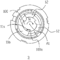
- FIG. 3 is a schematic exploded view of a driving assembly in a first embodiment of the present invention.
- FIG. 4 is a schematic top plan view of a driving assembly in a first embodiment of the present invention.
- Figure 5 is a schematic view showing the installation of the pushing portion of the coupling member in the first embodiment of the present invention
- Figure 6 is a first schematic view showing a state in which the drive assembly and the drive shaft in the image forming apparatus are engaged in the first embodiment of the present invention
- Figure 7 is a second schematic view showing the process of engaging the drive assembly in the first embodiment of the present invention with the drive shaft in the image forming apparatus;
- Figure 8 is a schematic view showing the drive assembly being disengaged from the drive shaft in the first embodiment of the present invention.
- Figure 9 is an exploded perspective view showing a driving assembly in a second embodiment of the present invention.
- Figure 10 is a schematic view of a positioning member in a drive assembly in a second embodiment of the present invention.
- Figure 11 is a schematic view of a coupling member in a drive assembly in a second embodiment of the present invention.
- FIG. 12 is a first schematic view showing a driving assembly and a drive shaft in a second embodiment of the present invention.
- Figure 13 is a schematic view showing a second state of the drive assembly and the drive shaft in the second embodiment of the present invention.
- Figure 14 is another schematic cross-sectional view showing the engagement of the drive shaft of the image forming apparatus with the drive assembly in the second embodiment of the present invention
- Figure 15 is a schematic view of a drive assembly in a third embodiment of the present invention.
- Figure 16 is a partially cutaway cross-sectional view showing the drive assembly of the third embodiment of the present invention.
- Figure 17 is a schematic view showing the mounting of a magnetic component of a drive assembly in a third embodiment of the present invention.
- Figure 18 is a first schematic view showing a driving assembly and a drive shaft in a third embodiment of the present invention.
- Figure 19 is a schematic view showing a second state of the drive assembly and the drive shaft in the third embodiment of the present invention.
- FIG. 20 is a schematic exploded view of a driving assembly according to a fourth embodiment of the present invention.
- Figure 21 is a partially cutaway structural view showing a drive assembly in a fourth embodiment of the present invention.
- Figure 22 is a schematic view showing the structure of the drive assembly before the drive shaft in the image forming apparatus is engaged in the fourth embodiment of the present invention
- Figure 23 is a schematic view showing the structure of the drive unit in engagement with the drive shaft in the image forming apparatus in the fourth embodiment of the present invention.
- Figure 24 is a cross-sectional view showing a driving force assembly in a fifth embodiment of the present invention.
- Figure 25 is a schematic view showing the first state of the drive assembly and the drive shaft in the fifth embodiment of the present invention.
- Figure 26 is a schematic view showing the second state of the drive assembly and the drive shaft in the fifth embodiment of the present invention.
- Figure 27 is a schematic view showing the third state of the drive assembly and the drive shaft in the fifth embodiment of the present invention.
- FIG. 1 is a schematic structural view of a process cartridge 1 according to an embodiment of the present invention.
- the process cartridge 1 includes a casing 2 in which a developer is stored, a photosensitive drum 4 rotatably supported on the casing 2, and a drive unit 3 mounted at a longitudinal end of the photosensitive drum 4 for receiving image formation
- the driving force transmitted by the device drives the photosensitive drum 4 to rotate.
- FIG. 2 it is a schematic structural view of the image forming apparatus driving shaft 100 in the prior art.
- the drive shaft 100 is substantially cylindrical, and three circumferentially distributed recesses 100b (only one shown) are provided on the circumferential surface of the drive shaft 100.
- One end of the drive shaft 100 is connected to the elastic member 101, and the drive shaft 100 can be extended in the A1 direction or in the A2 direction in the axial direction by the elastic force of the elastic member 101.
- the drive shaft 100 has a certain gap h with the image forming apparatus frame in the direction of the vertical axis.
- the drive shaft 100 When the drive shaft 100 is subjected to an external force perpendicular to the axial direction, the drive shaft 100 can be inclined with respect to the axial direction in the A3 or A4 direction.
- the drive assembly 3 cooperates with the drive shaft 100 to rotate the photosensitive drum, and the specific fitting process will be described in detail below.
- the drive assembly 3 of the present embodiment includes a coupling member 5 and a positioning member 6.
- the coupling member 5 is substantially cylindrical and engages with the drive shaft 100 in the image forming apparatus to receive and transmit a driving force to the photosensitive drum 4, and the coupling member 5 is substantially coaxial with the photosensitive drum 4.
- the coupling member 5 includes a main body portion 7, a power receiving portion 11a, a support portion 11b, and a pushing portion 12.
- the main body portion 7 is a hollow cylindrical shape having a first end 9 and a second end 10 in the direction of the axis X; the outer circumferential surface of the first end 9 can be inserted into the inner wall of the drum of the photosensitive drum 4, through the interference
- the coupling member 5 is fitted to the photosensitive drum 4, and generally, in order to prevent the coupling member 5 from coming off the photosensitive drum 4, an appropriate amount of adhesive may be applied on the outer circumferential surface of the first end 9, so that the coupling member 5 and the photosensitive member are sensitized.
- the inner wall of the cylinder of the drum 4 fits more compactly; the second end 10 is a part of the drum of the photosensitive drum 4 which is coupled to the coupling member 5.
- the support portion 11b is configured as a support plate that protrudes from the inner wall of the main body portion 7 in the radial direction toward the axis X
- the power receiving portion 11a is a hook portion that protrudes from the support portion 11b toward the axis X
- the power receiving portion 11a and the support portion 11b They are all made of a rigid material and are integrally formed with the main body portion 7 and are not movable relative to the main body portion 7.
- the pressing portion 12 is detachably mounted in the main body portion 7.
- the main body portion 7 is provided with a protruding portion 15 projecting from the inner wall thereof toward the axis X in the radial direction, and the protruding portion 15 is integrally formed with the main body portion 7 at An opening 16 is formed between the protruding portion 15 and the supporting portion 11b, and the pushing portion 12 can be installed into the opening 16.
- the pushing portion 12 is specifically configured as two, and is asymmetrically disposed on the main body with respect to the circumferential direction.
- the pressing portion 12 is formed with a mounting hole 12a, a first limiting portion 12b, and a second limiting portion 12c.
- the elastic member 14 is mounted in the mounting hole 12a when the pushing portion 12 is mounted in the opening 16.
- the elastic member 14 abuts against the inner wall of the main body portion 7 and the other end abuts in the mounting hole 12a. Therefore, the pressing portion 12 can move in the radial direction under the action of the elastic member 14;
- the amount of movement of the pushing portion 12 in the radial direction, the protruding portion 15 is provided with a first projecting portion 15a at one end forming the opening 16, and the support portion 11b is provided with a second projecting portion 11b1 at one end forming the opening 16, first A space is formed between the protruding portion 15a and the second protruding portion 11b1 in the radial direction, the first limit Portion 12b and the second stopper portion 12c can move only in the space to limit movement amount forcible pushing portion 12 in the radial direction.
- the positioning member 6 is configured in a substantially boss shape and is mountable to the first end 9 of the coupling member 5, and is connected to the first end 9 of the coupling member 5 by an adhesive or a snap or the like and stably mounted at the first end 9
- the inner wall of the cylinder is closed and the axial end of the first end 9 of the coupling member 5 is closed.
- the positioning member 6 is directly engaged with the axial end of the first end 9 by an interference fit such that the positioning member 6 is mounted on the coupling member 5.
- the positioning member 6 is formed with a positioning groove 8, and the positioning member 6 is explained below in conjunction with FIG. 2 to restrict and position the movement of the image forming apparatus drive shaft 100 in the axial direction.
- the front end 100a of the image forming apparatus drive shaft 100 has a conical shape, and the positioning groove 8 of the positioning member 6 receives and accommodates the front end 100a of the drive shaft 100. Since the positioning member 6 is fixed in the process cartridge, movement does not occur, so the drive is driven. During the transmission of the force, the drive shaft 100 has a tendency to move toward the side of the positioning member 6 under the action of the elastic member 101, but since the front end 100a of the drive shaft 100 abuts against the positioning groove 8, the positioning groove 8 is restricted. The movement of the drive shaft 100 in the axial direction.
- the drive unit 3 in this embodiment is provided with the positioning member 6 in order to make the transmission of the driving force more stable. Alternatively, the positioning member 6 may be omitted.
- the pushing portion 12 is further provided with a pressing surface 12d facing the axis of the main body portion 7 and a force receiving portion 12e.
- the guide urging portion 11a1 provided on the power receiving portion 11a abuts and urges the front end 100a of the drive shaft 100.
- the power receiving portion 11a applies a radial direction force to the drive shaft 100, forcing the axis of the drive shaft 100 to be inclined with respect to the axis of the main body portion 7, and the drive shaft 100 is in a plane equal to the power receiving portion 11a.
- the axial center position is shifted from A1 to A2, and at the same time, the front end 100a of the drive shaft 100 abuts against the force receiving portion 12e on the urging portion 12 so that the urging portion 12 overcomes the elastic force of the elastic member 14 toward the main body portion 7.
- the outer side is moved radially, that is, the pushing portion 12 is pressed by the drive shaft 100 to move radially away from the axis A1.
- the thrust portion 12 is abutted against the outer surface of the drive shaft 100 in order to prevent the pushing portion 12 from entering the recess 100b of the drive shaft 100.
- the minimum arc length of the forced push surface 12d is set longer than the arc length of the concave portion 100b of the drive shaft 100, and as the drive shaft 100 is further rotated in the N direction, the drive shaft 100 is rotated until its concave portion 100b is opposed to the power receiving portion 11a.
- the urging portion 12 presses the drive shaft 100 under the elastic potential energy accumulated by the elastic member 14 and moves in the radial direction near the axis A1, forcing the concave portion 100b of the drive shaft 100 to mesh with the power receiving portion 11a.
- the drive shaft 100 is further rotated in the N direction, as shown in FIG.
- the power receiving portion 11a abuts on a surface of the recess 100b, and the drive shaft 100 transmits the driving force through the recess 100b at the abutment of the power receiving portion 11a.
- the power receiving portion 11a drives the photosensitive drum to rotate in the N direction.
- the pressing portion 12 always abuts against the outer circumferential surface of the driving shaft 100 under the elastic force of the elastic member 14, and therefore, the driving shaft 100 does not cause the concave portion 100b and the power receiving portion due to its own centrifugal force when rotating.
- the minimum arc length of the thrust surface 12d is defined to be larger than the maximum arc length of the opening of the concave portion 100b, and therefore, during the rotation of the drive shaft 100
- the pushing portion 12 and the recess 100b are always spaced apart.
- the power receiving portion 11a of the drive unit 3 and the recess 100b of the drive shaft 100 interfere with each other near a portion of the front end 100a.
- the power receiving portion 11a abuts against the recess 100b of the drive shaft 100.
- the power receiving portion 11a applies a component force in the radial direction to the drive shaft 100, and the drive shaft 100 is inclined with respect to the axis of the main body portion 7 by the radial force applied by the power receiving portion 11a, and the drive shaft 100 is shifted from A1 to A3 in a plane in a plane equal to the power receiving portion 11a, and the urging portion 12 is urged to move radially away from the axis A1 by the drive shaft 100 as the drive shaft 100 is displaced.
- the power receiving portion 11a is disengaged from the recess 100b of the drive shaft 100 during the radial offset of the drive shaft 100, the drive shaft 100 no longer interferes with the drive assembly 3, and the process cartridge 1 can be smoothly taken out from the image forming apparatus.
- the drive assembly 20 of the present embodiment includes a positioning member 25 and a coupling member 24.
- the coupling member 24 is configured to be substantially cylindrical and engages with the drive shaft 100 in the image forming apparatus to receive and transmit a driving force to the photosensitive drum, thereby driving the photosensitive drum to rotate.
- the coupling member 24 includes a main body portion 26, a first power receiving portion 21b, a second power receiving portion 22b, a first reinforcing portion 21a, a second reinforcing portion 22a, and a positioning boss 23.
- the body portion 26 is configured as a hollow cylinder having a first end 27 and a second end 28 in the axial direction B; the axial end of the first end 27 is provided as a hole, and the outer circumferential surface of the first end 27 is provided with a plurality of Guide ribs 27a, the guide ribs 27a can guide the insertion of the coupling member 24 during the insertion of the coupling member 24 into the photosensitive drum, usually in order to make the coupling member 24 more closely connected to the photosensitive drum, and also at the first end 27 An appropriate amount of adhesive is applied to the outer circumferential surface such that the first end 27 of the coupling member 24 is bonded to the inner wall of the photosensitive drum to form a tight fit.
- the axial end of the second end 28 is provided as a hole.
- the first power receiving portion 21 b is configured in a columnar shape extending from the main body portion 26 in the radial direction toward the axis X, and the main body portion 26 is provided at substantially the center of the coupling member 24 in the axial direction B.
- the shape of the second power receiving portion 22b is substantially the same as the shape of the first power receiving portion 21b, and is configured to have a columnar shape extending from the main body portion 26 toward the axis X, and the second power receiving portion 22b and the first power receiving portion 21b are located at the coupling member.
- the first power receiving portion 21b and the second power receiving portion 22b are asymmetrically disposed on the main body portion 26 with respect to the axial direction B.
- the first power receiving portion 21b and the second power receiving portion 22b are both made of a rigid material, are not movable relative to the main body portion 26, and are integrally formed with the main body portion 26.
- the first reinforcing portion 21a extends from the main body portion 26 and intersects with the first power receiving portion 21b to increase the strength of the first power receiving portion 21b; the second reinforcing portion 22a also extends from the main body portion 26 and the second power receiving portion 22b When intersected, the strength of the second power receiving portion 22b can be increased.
- the positioning bosses 23 in this embodiment are provided in three, and are evenly distributed in the circumferential direction of the main body portion 26.
- the positioning member 25 is configured in a substantially boss shape and is mountable to the first end 27 of the coupling member 24, and can be coupled and stabilized to the first end 27 of the coupling member 24 by means of an adhesive or a snap. It is mounted within the circumferential inner wall of the first end 27 and encloses the axial end of the first end 27 of the coupling member 24.
- the positioning member 25 is provided with a positioning buckle 25b, and the positioning buckle 25b is provided with three, which can be engaged with the positioning boss 23 in the coupling member 24, so that the positioning member 25 is connected to the coupling member 24.
- a positioning groove 25a is also provided in the positioning member 25, and the positioning groove 25a is formed as a tapered inner concave portion at a center position of the positioning member 25 and is symmetrical with respect to the axis X of the coupling member 24.
- the drive unit 20 in this embodiment is provided with the positioning member 25 in order to make the transmission of the driving force more stable.
- the positioning member 25 may be omitted.
- the first power receiving portion 21b of the coupling member 24 abuts the second power receiving portion 22b against the circumferential surface of the drive shaft 100 and applies it to the drive shaft 100. a force perpendicular to the axial direction such that the axial position of the drive shaft 100 is deflected from A1 to A2, so that the coupling member 24 and the drive shaft 100 are in a state as shown in FIG.
- the second power receiving portion 22b and the first power are The receiving portion 21b is engaged with the concave portion 100b of the drive shaft, respectively, so that the drive shaft 100 drives the coupling member 24 to rotate together in the N direction, and the photosensitive drum is coupled with the coupling member 24 to drive the photosensitive drum to rotate together.
- the drive shaft 100 and the positioning member 25 are in a state as shown in FIG. 14, the front end 100a of the drive shaft 100 is configured in a conical shape, and the positioning groove 25a of the positioning member 25 receives and accommodates the front end of the drive shaft 100.
- the drive shaft 100 since the positioning member 25 is fixed in the process cartridge and does not move, the drive shaft 100 tends to move toward the side of the positioning member 25 even under the action of the elastic member during the driving force transmission, but is driven by the drive member.
- the front end 100a of the shaft 100 abuts against the positioning groove 25a.
- the positioning groove 25a restricts the movement of the driving shaft 100 in the axial direction, and the driving shaft 100 stably drives the driving assembly 20 to rotate.
- the drive assembly 30 of the present embodiment includes a main body portion 31, a coupling member 32, and a positioning member 33, and the drive assembly 30 is rotatable about the axis X.
- the coupling member 32 includes a power receiving portion 34 and a support portion 35 that is movably mounted in the support portion 35.
- the support portion 35 includes a groove portion 35a which is an open groove formed in the circumferential outer wall of the main body portion 31, and an opening thereof which faces the outside of the main body portion 31 in the radial direction; the protruding portion 35b is formed in the main body portion 31.
- the circumferential inner wall and the radial direction toward the axis A1 are convex, the protruding portion 35b is integrally formed with the groove portion 35a, and the protruding portion 35b is formed with a first opening 35C that communicates with the groove portion 35a.
- the power receiving portion 34 includes a projecting portion 34a and a restricting portion 34b. When the power receiving portion 34 is mounted in the support portion 35, the projecting portion 34a sequentially moves through the groove portion 35a and the first opening 35c toward the axis A1 in the radial direction.
- the coupling members 32 are specifically provided in three, and the power receiving portions 34 of the coupling members 32 are each made of a magnetic metal material.
- a magnetic member 36 is sleeved around the protruding portion 34a of the power receiving portion 34.
- the magnetic member 36 is formed with a second opening 36a, and the protruding portion 34a of the power receiving portion 34 passes through the second opening 36a to make the magnetic member. 36 abuts on the restriction portion 34b of the power receiving portion 34.
- the magnetic member 36 When the power receiving portion 34 is mounted in the support portion 35, the magnetic member 36 is attached to the groove portion 35a of the support portion 35 with the power receiving portion 34, and the magnetic member 36 is sandwiched between the restricting portion 34b and the support portion 35 of the power receiving portion 34. Between the protrusions 35b. Since the magnetic member 36 has a magnetic force, the power receiving portion 34 made of a magnetic metal material can be moved in the radial direction in the first opening 35c under the attraction of the magnetic member 36. Alternatively, the magnetic portion 36 may be disposed on the protruding portion 34a of the power receiving portion 34 or directly set the power receiving portion 34 to be magnetic, and the power receiving portion 34 is attracted to each other such that the power receiving portion 34 is at the first position.
- the opening 35c moves in the radial direction.
- the magnetic member 36 may be separately disposed in the power receiving portion 34 and the support portion 35, wherein the magnetic member 36 on the power receiving portion 34 and the magnetic member 36 in the support portion 35 are opposite to each other, and pass through the magnetic member 36.
- the mutual repulsiveness may also cause the power receiving portion 34 to move in the radial direction in the first opening 35c.
- the front end 100a of the drive shaft 100 abuts against the projecting portion 34a of the power receiving portion 34, and at this time, as shown in Fig. 18, the drive shaft 100 is oriented
- the power receiving portion 34 applies a force in the radial direction to force the power receiving portion 34 to move radially away from the axis A1 in the support portion 35 until the front end 100a of the drive shaft 100 is housed in the positioning member 33.
- the power receiving portion 34 since the power receiving portion 34 is attracted by the magnetic member 36, the power receiving portion 34 moves in the radial direction toward the axis A1, Thereby, the recess 100b of the drive shaft 100 is engaged, the drive shaft 100 transmits the driving force to the power receiving portion 34 through the recess 100b against the power receiving portion 34, and the power receiving portion 34 further transmits the driving force to the driving assembly 30.
- the photosensitive drum is also rotated.
- the power receiving portion 34 when the process cartridge is detached, the power receiving portion 34 is always attracted to each other due to the action of the magnetic member 36, so that the power receiving portion 34 is not pressed by the drive shaft 100 to be detached from the support portion 35; Further, the power receiving portion 34 is caught by the first opening 35c of the support portion 35, and when the power receiving portion 34 is rotated by the drive shaft 100, the centrifugal force applied to the power receiving portion 34 by the drive shaft 100 does not force the power receiving portion 34 from The support portion 35 is detached.
- the drive assembly 40 of the present embodiment includes a main body portion 41 and a coupling kit 42.
- the coupling kit 42 is mounted into the main body portion 41 and can drive the main body portion 41 to rotate.
- the coupling set 42 includes a coupling member 43 that supports the bottom plate 44, the axle pin 46, and the resilient member 45.
- the coupling member 43 is provided substantially in an L shape, and has a pressing portion 43b and a power receiving portion 43c, and one rotation center 43a is provided between the pressing portion 43b and the power receiving portion 43c.
- the support base plate 44 is equidistantly arranged in the circumferential direction with three coupling member mounting portions 44a, which are specifically provided with a pair of oppositely disposed mounting ribs, and an installation space is formed between the pair of the mounting ribs, and the pressing portion 43b of the coupling member 43 is mounted.
- a shaft pin 46 is rotatably mounted at the coupling member mounting portion 44a through the above-described mounting rib, the rotation center 43a of the coupling member 43, and the elastic member 45.
- the elastic member 45 is specifically configured as a torsion spring, one of which has a free end abutting the support base 44, and the other free end abuts against the side wall of the coupling member 43. To reduce the space, the other free end is on the support base 44.
- the inner arm surface of the coupling member 43 is abutted in the circumferential direction, and of course, it is also possible to selectively abut or connect with any other place of the coupling member 43.
- a restriction portion (not shown) that restricts the stroke of the coupling member 43 to rotate outward is further disposed on the support base 44, and the restriction portion may be coupled to the coupling member 43 after the coupling member 43 is rotated outward by a certain stroke. Contacting restricts the coupling member 43 to further rotate outward.
- the coupling member 42 since the coupling member 42 is mounted in the main body portion 41, the coupling member 43 will be located in the hollow cylinder of the main body portion 41, and therefore, the inner side wall surface of the main body portion 41 can be utilized to restrict the coupling member 43 from rotating outward. It is not necessary to provide a restriction on the support base 44.
- only a schematic view of the elastic member and the pin of the coupling member 43 is shown in the drawing, it being understood that all of the coupling members 43 are mounted with the elastic member and the pin.
- the inner surface of the main body portion 41 is further provided with a guide portion 41a which can guide the movement of the power receiving portion 43c of the coupling member 43, and the driving force received by the power receiving portion 43c from the image forming device can also be It is transmitted to the main body portion 41 through the guide portion 41a and drives the main body portion 41 to rotate.
- the coupling member 43 can also transmit the driving force to the main body portion 41 through the support base 44.
- the mounting portion of the coupling member 43 may be disposed in the support base 44.
- a mounting portion may be directly disposed on the inner wall of the main body portion 41, and the coupling member 43 may be directly mounted to the main body portion 41. On the inside wall.
- the process cartridge is mounted in the image forming apparatus in an X direction substantially parallel to the axis of the drive shaft 100, and the coupling member 43 is elastic member 45 before the coupling member 43 comes into contact with the drive shaft 100.
- the biasing force biasing position is a position that is rotated outward to open, and for convenience of description, a position at which the coupling member 43 is rotated outward to be opened later is referred to as an opening position of the coupling member 43.
- the coupling member 43 When the coupling member 43 is in the open position, the front end 100a of the drive shaft 100 will pass over the power receiving portion 43c of the coupling member 43, and abut against the pressing portion 43b of the coupling member 43 to apply pressure, and the pressing portion 43b receives the pressing of the driving shaft 100. After the pressure, the elastic force of the elastic member 45 is rotated inwardly against the elastic force.
- the power receiving portion 43c is engaged in the recess 100b of the drive shaft 100 to complete the engagement with the drive shaft 100.
- the position where the coupling member 43 is rotated inward and finally stopped at the recess 100b of the drive shaft 100 is referred to as a closed position of the coupling member 43.
- the drive shaft 100 transmits a rotational driving force to the drive unit 40 by the engagement of the recess 100b with the power receiving portion 43c, and the drive unit 40 transmits the rotational driving force to the respective force receiving members in the process cartridge.
- the power receiving portion 43c has an inner guide portion 43c2 that abuts against the closed end of the concave portion 100b of the drive shaft 100 on the side close to the front end 100a when the process cartridge needs to be detached, forcing the coupling member 43 to move from the closed position to the open position. The position is ultimately disengaged from the drive shaft 100.
- the outer guide portion 43c1 is provided at a position opposite to the inner guide portion 43c2 on the power receiving portion 43c of the coupling member 43 in the present embodiment, and the outer guide portion 43c1 is disposed such that even the coupling member 43 is provided.
- the coupling member 43 can be further rotated outward by the engagement of the outer guide portion 43c1 with the front end 100a of the drive shaft 100, and the front end 100a of the drive shaft 100 can smoothly pass over the power receiving portion 43c.
- the drive unit 50 of the present embodiment includes a main body portion 51, a pressing portion 52, and a power receiving portion 53.
- the pressing portion 52 is movably provided in the main body portion 51. Specifically, the pressing portion 52 moves axially along the circumferential inner wall of the main body portion 51 along the axis X.
- the power receiving portion 53 is specifically provided in three. In the present embodiment, the power receiving portion 53 is specifically configured as a triangular block including a tip end 53a and a flat portion 53b.
- the circumferential inner walls of the main body portion 51 are respectively formed with three mounting grooves 51a, and the power receiving portions 53 are respectively mounted in the mounting grooves 51a by the connecting pins 54, and are rotatable around the connecting pins 54.
- the drive shaft 100 in the image forming apparatus is combined with the drive assembly 50.
- the projection 100c of the drive shaft 100 abuts against the pressing portion 52, and the pressing portion 52 is pressed to move closer to the power receiving portion 53 along the axis X.
- the front end 100a of the drive shaft 100 abuts against the tip end 53a of the power receiving portion 53, forcing the power receiving portion 53 to rotate about the connecting pin 54 to avoid a position interfering with the front end 100a, that is, the power receiving portion 53 is rotated to its flat portion 53b and The drive shaft 100 is opposed to each other.
- the front end 100a of the drive shaft 100 does not contact the power receiving portion 53.
- the drive shaft 100 presses the pressing portion 52 to abut the pressing portion 52 against the power receiving portion 53, forcing the power receiving portion 53 to rotate about the connecting pin 54.
- the power receiving portion 53 is pressed by the pressing portion 52 to rotate to its tip end 53a to engage with the concave portion 100b of the drive shaft 100, when the drive shaft 100 is image-formed by the image forming apparatus
- the drive unit 50 receives the driving force from the drive shaft 100 and rotates by the power receiving unit 53.
- the power receiving portion 53 is always pressed by the pressing portion 52.
- the drive shaft 100 When the drive shaft 100 is driven to rotate by the motor of the image forming apparatus, as the concave portion 100b of the drive shaft 100 is rotated to face the power receiving portion 53, the power receiving portion 53 pressed by the pressing portion 52 is rotated to the tip end 53a thereof. The recess 100b of the drive shaft 100 is engaged, and the drive unit 50 is rotated by receiving a driving force from the drive shaft 100 through the power receiving portion 53.
- the power receiving portion in the coupling member is formed in a movable form with respect to the main body portion, and specifically, in the embodiment 3, the power receiving portion is disposed at the main body portion with respect to the main body portion. Moving in the radial direction, but the moving direction of the power receiving portion with respect to the main body portion is not limited to the radial direction, for example, the power receiving portion may be moved in a direction at a certain angle with the radial direction of the main body portion, in the embodiment.
- the power receiving portion is disposed to be rotatable in a radial direction of the main body with respect to the main body portion about one fulcrum, but the rotation direction of the power receiving portion is not limited to the radial direction of the main body portion, for example, power receiving The portion may be rotated in a direction that is at an angle to the radial direction of the main body portion.
- the above solution differs from the prior art in that the power receiving portion is integrally moved relative to the main body portion, between the power receiving portion and the main body portion.
- the power receiving portion can be integrally formed with the main body portion, and the support portion for supporting the power receiving portion between the power receiving portion and the main body portion is directly in the form of a fixed support, which can greatly simplify the production and processing cost of the coupling member, and at the same time
- the coupling member is not damaged by the large torque.
- the driving assembly provided by the invention does not have a local thin material structure, and the molding processing process of the driving assembly is simple, and the complicated processing technology of the metal parts in the plastic parts does not occur, and the driving is greatly reduced.
- the processing of the components is difficult to form and the stability of the power transmission of the drive components is improved.
- the technical problem that the molding process of the driving component is complicated, the production cost is high, and the driving force transmission is unstable is solved in the prior art.
Landscapes
- Physics & Mathematics (AREA)
- General Physics & Mathematics (AREA)
- Engineering & Computer Science (AREA)
- Computer Vision & Pattern Recognition (AREA)
- Electrophotography Configuration And Component (AREA)
Abstract
A process cartridge (1). The process cartridge (1) comprises a drive assembly (3) engageable with a drive shaft (100) having a recess in an image forming apparatus. The drive assembly (3) comprises: a coupling member (5), configured to receive a driving force from the drive shaft (100) and provided with a power receiving portion (11a) engageable with the recess of the drive shaft (100); and a body portion (7) capable of rotating after receiving the driving force transmitted by the power receiving portion (11a). When the drive assembly (3) is mounted in the image forming apparatus, the power receiving portion (11a) can force the axis of the drive shaft (100) to be inclined with respect to the axis of the drive assembly (3). The coupling member (5) forces the drive shaft (100) to be inclined to implement engagement and disengagement, thus solving the technical problem in the prior art that the drive assembly (3) has complicated molding process, high production cost and unstable transmission of the driving force.
Description
本发明涉及一种用于图像形成装置中的处理盒。The present invention relates to a process cartridge for use in an image forming apparatus.
处理盒是一种可拆卸地装入图像形成装置中的盒,且该盒作为一个整体单元包括有一个电子照相感光组件和至少诸如充电器,显影器,清洁器等之类的处理器的至少一个。由于处理盒相对于图像形成装置主体是可拆卸地安装的,因此便于图像形成装置的保养。采用电子照相成像方式的图像形成装置是这样工作的:通过图像形成装置的光对充电器均匀充电的电子照相感光组件进行有选择的曝光来形成静电潜像,该静电潜像由显影器用调色剂显影成调色剂像,所形成的调色剂图像由转印器转印到记录介质上,以在记录材料上形成图像。The process cartridge is a cartridge detachably incorporated in an image forming apparatus, and the cartridge as an integral unit includes at least one electrophotographic photosensitive member and at least a processor such as a charger, a developer, a cleaner, or the like One. Since the process cartridge is detachably mounted with respect to the image forming apparatus main body, maintenance of the image forming apparatus is facilitated. An image forming apparatus using an electrophotographic image forming apparatus works by selectively exposing an electrophotographic photosensitive member uniformly charged by a light of an image forming apparatus to form an electrostatic latent image, which is toned by a developing device The toner is developed into a toner image, and the formed toner image is transferred onto a recording medium by a transfer device to form an image on the recording material.
现有技术中,例如中国台湾专利公开号TW201633019A,公开了一种处理盒,包括可驱动感光鼓旋转的驱动组件,该驱动组件具有轮毂和与轮毂之间通过可变形的连接部连接的动力接收部,在图像形成装置中设置有驱动轴,该驱动轴周向布置有可与上述动力接收部啮合的凹部,在将处理盒安装至图像形成装置中时,上述驱动轴的前端直接挤压动力接收部使得连接部变形并越过动力接收部使得动力接收部最终与凹部啮合实现驱动力的传递。但是,上述驱动组件,由于仅仅依靠一个薄的可变形的连接部来连接轮毂和动力接收部,这使得动力接收部在将驱动力传递至轮毂时可能会损坏连接部而导致不能传递驱动力的情况。In the prior art, for example, Taiwan Patent Publication No. TW201633019A, discloses a process cartridge including a drive assembly that can drive rotation of a photosensitive drum, the drive assembly having a hub and power receiving connection with the hub through a deformable connection In the image forming apparatus, a drive shaft is disposed, and the drive shaft is circumferentially disposed with a recess engageable with the power receiving portion, and the front end of the drive shaft is directly squeezed when the process cartridge is mounted in the image forming apparatus The receiving portion deforms the connecting portion and passes over the power receiving portion such that the power receiving portion finally engages with the concave portion to realize transmission of the driving force. However, the above-described driving assembly is connected to the hub and the power receiving portion by only relying on a thin deformable connecting portion, which causes the power receiving portion to damage the connecting portion when transmitting the driving force to the hub, resulting in failure to transmit the driving force. Happening.
另外,上述薄的可变形的连接部在成型过程中需要添加金属材质以加强驱动组件可以承受的扭力强度,其成型工艺复杂,导致驱动组件的生产成本增加。In addition, the thin deformable connecting portion needs to add a metal material during the molding process to strengthen the torsional strength that the driving assembly can withstand, and the molding process is complicated, resulting in an increase in the production cost of the driving assembly.
发明内容Summary of the invention
为了解决现有技术中驱动组件成型工艺复杂、生产成本高、驱动力传递不稳定的技术问题。本发明是通过以下技术方案实现的:In order to solve the technical problem that the molding process of the driving component is complicated, the production cost is high, and the driving force is unstable is transmitted in the prior art. The invention is achieved by the following technical solutions:
一种处理盒,可拆卸的安装至图像形成装置中,图像形成装置包括设置有凹部的驱动轴,所述驱动轴具有封闭的前端,所述处理盒包括:A process cartridge detachably mounted in an image forming apparatus, the image forming apparatus including a drive shaft provided with a recess, the drive shaft having a closed front end, and the process cartridge comprising:
壳体,case,
耦合构件,设置在所述壳体的一侧端,a coupling member disposed at one side of the housing
所述耦合构件包括主体部和配置成进入所述凹部并从所述驱动轴接收旋转驱动 力的动力接收部,The coupling member includes a body portion and a power receiving portion configured to enter the recess and receive a rotational driving force from the drive shaft,
所述耦合构件还包括支撑所述动力接收部的支撑部,所述支撑部非弹性的支撑所述动力接收部。The coupling member further includes a support portion that supports the power receiving portion, the support portion non-elastically supporting the power receiving portion.
进一步的,所述动力接收部相对于所述主体部在所述主体部的径向方向上不可移动。Further, the power receiving portion is immovable in a radial direction of the main body portion with respect to the main body portion.
进一步的,所述动力接收部构造为至少一个向所述主体部的径向内侧突出的突出部。Further, the power receiving portion is configured as at least one protruding portion that protrudes radially inward of the main body portion.
进一步的,所述主体部上设置有支撑所述动力接收部的支撑部,所述支撑部构造为固定支撑所述动力接收部,并且所述支撑部在所述主体部的周向方向上延伸的弧长大于所述动力接收部在所述主体部的周向方向上延伸的弧长。Further, the main body portion is provided with a support portion supporting the power receiving portion, the support portion is configured to fixedly support the power receiving portion, and the support portion extends in a circumferential direction of the main body portion The arc length is larger than an arc length of the power receiving portion extending in the circumferential direction of the main body portion.
进一步的,还包括可与所述驱动轴弹性抵接的迫推部,所述迫推部可相对于所述主体部在所述主体部的径向方向上移动。Further, further comprising an urging portion elastically abutting the drive shaft, the urging portion being movable in a radial direction of the main body portion with respect to the main body portion.
进一步的,所述迫推部设置为至少两个,至少两个所述迫推部设置为在所述主体部的周向上不对称排布。Further, the urging portions are disposed in at least two, and at least two of the urging portions are disposed to be asymmetrically arranged in a circumferential direction of the main body portion.
进一步的,所述迫推部和所述主体部之间设置有弹性构件。Further, an elastic member is disposed between the pressing portion and the main body portion.
进一步的,所述迫推部的至少一部分设置在所述主体部的内部。Further, at least a portion of the urging portion is disposed inside the main body portion.
进一步的,所述迫推部设置有相对于所述迫推部的移动方向倾斜的受力部。Further, the urging portion is provided with a force receiving portion that is inclined with respect to a moving direction of the urging portion.
进一步的,所述受力部设置成使得当所述耦合构件与所述驱动轴啮合的过程中接收所述驱动轴的力迫使所述迫推部向所述主体部的径向外侧移动。Further, the force receiving portion is disposed such that a force receiving the drive shaft during engagement of the coupling member with the drive shaft forces the urging portion to move radially outward of the body portion.
进一步的,所述动力接收部具有导向迫推部,所述导向迫推部设置为使得当所述耦合构件与所述驱动轴啮合的过程中迫推所述驱动轴移动至一个所述驱动轴的轴线相对于所述主体部的轴线倾斜的倾斜位置。Further, the power receiving portion has a guiding urging portion configured to urge the driving shaft to move to one of the driving shafts while the coupling member is engaged with the driving shaft The axis of inclination is inclined relative to the axis of the body portion.
进一步的,所述动力接收部与所述主体部一体成型。Further, the power receiving portion is integrally formed with the main body portion.
进一步的,所述动力接收部可沿所述支撑部滑动。Further, the power receiving portion is slidable along the support portion.
进一步的,所述动力接收部与所述主体部之间可通过形成在所述动力接收部和所述主体部之间的磁性力而产生相对移动。Further, a relative movement between the power receiving portion and the main body portion may be caused by a magnetic force formed between the power receiving portion and the main body portion.
进一步的,所述动力接收部上和所述主体部上都设置有磁性部件。Further, a magnetic member is disposed on the power receiving portion and the main body portion.
进一步的,所述动力接收部可迫推所述驱动轴在所述主体部内部移动使得所述驱动轴的轴线相对于所述主体部的轴线倾斜。Further, the power receiving portion may urge the drive shaft to move inside the main body portion such that an axis of the drive shaft is inclined with respect to an axis of the main body portion.
进一步的,还包括迫推部,当所述驱动轴进入所述主体部内部并且所述驱动轴的轴线相对于所述主体部的轴线倾斜时,所述迫推部可迫推所述驱动轴移动使得所述动力接收部进入所述凹部。Further, further comprising a pushing portion that can push the driving shaft when the driving shaft enters the inside of the main body portion and the axis of the driving shaft is inclined with respect to an axis of the main body portion The movement causes the power receiving portion to enter the recess.
进一步的,还包括感光鼓,所述耦合构件固定在所述感光鼓的轴向一侧端,所述迫推部的至少一部分设置在所述感光鼓的内部。Further, further comprising a photosensitive drum, the coupling member is fixed to an axial one end of the photosensitive drum, and at least a portion of the urging portion is disposed inside the photosensitive drum.
进一步的,所述动力接收部从所述凹部的径向外侧卡合入所述凹部中。Further, the power receiving portion is engaged with the concave portion from a radially outer side of the concave portion.
进一步的,所述主体部构造为圆筒形,所述动力接收部设置在所述主体部内圆周的内部。Further, the main body portion is configured in a cylindrical shape, and the power receiving portion is disposed inside the inner circumference of the main body portion.
在采用了上述技术方案后,本发明提供的驱动组件不会存在局部薄料的结构,并且驱动组件的成型加工工艺简单,不会出现在塑胶件中夹杂金属件的复杂加工工艺,大大降低了驱动组件的加工形成难度,提高了驱动组件动力传递的稳定性。解决了现有技术中驱动组件成型工艺复杂、生产成本高、驱动力传递不稳定的技术问题。After adopting the above technical solution, the driving assembly provided by the present invention does not have a local thin material structure, and the molding processing process of the driving component is simple, and the complicated processing technology of the metal fittings in the plastic component does not occur, and the processing is greatly reduced. The processing of the drive assembly is difficult to form and improves the stability of the power transmission of the drive assembly. The technical problem that the molding process of the driving component is complicated, the production cost is high, and the driving force transmission is unstable is solved in the prior art.
为了更清楚地说明本发明实施例或现有技术中的技术方案,下面将对实施例或现有技术描述中所需要使用的附图作一简单地介绍,显而易见地,下面描述中的附图是本发明的一些实施例,对于本领域普通技术人员来讲,在不付出创造性劳动的前提下,还可以根据这些附图获得其它的附图。In order to more clearly illustrate the embodiments of the present invention or the technical solutions in the prior art, a brief description of the drawings used in the embodiments or the prior art description will be briefly described below. Obviously, the drawings in the following description It is a certain embodiment of the present invention, and other drawings can be obtained from those skilled in the art without any creative work.
图1为本发明第一实施例的处理盒的结构示意图;1 is a schematic structural view of a process cartridge according to a first embodiment of the present invention;
图2为现有技术中图像形成装置中的驱动轴的结构示意图;2 is a schematic structural view of a drive shaft in an image forming apparatus in the prior art;
图3为本发明第一实施例中的驱动组件的分解结构示意图;3 is a schematic exploded view of a driving assembly in a first embodiment of the present invention;
图4为本发明第一实施例中的驱动组件的俯视结构示意图;4 is a schematic top plan view of a driving assembly in a first embodiment of the present invention;
图5为本发明第一实施例中耦合构件的迫推部的安装示意图;Figure 5 is a schematic view showing the installation of the pushing portion of the coupling member in the first embodiment of the present invention;
图6为本发明第一实施例中的驱动组件与图像形成装置中的驱动轴啮合过程的第一状态示意图;Figure 6 is a first schematic view showing a state in which the drive assembly and the drive shaft in the image forming apparatus are engaged in the first embodiment of the present invention;
图7为本发明第一实施例中的驱动组件与图像形成装置中的驱动轴啮合过程的第二状态示意图;Figure 7 is a second schematic view showing the process of engaging the drive assembly in the first embodiment of the present invention with the drive shaft in the image forming apparatus;
图8为本发明第一实施例中驱动组件与驱动轴脱离啮合的示意图;Figure 8 is a schematic view showing the drive assembly being disengaged from the drive shaft in the first embodiment of the present invention;
图9为本发明第二实施例中驱动组件的分解示意图;Figure 9 is an exploded perspective view showing a driving assembly in a second embodiment of the present invention;
图10为本发明第二实施例中驱动组件中的定位构件的示意图;Figure 10 is a schematic view of a positioning member in a drive assembly in a second embodiment of the present invention;
图11为本发明第二实施例中驱动组件中的耦合构件的示意图;Figure 11 is a schematic view of a coupling member in a drive assembly in a second embodiment of the present invention;
图12为本发明第二实施例中驱动组件与驱动轴的第一状态示意图;12 is a first schematic view showing a driving assembly and a drive shaft in a second embodiment of the present invention;
图13为本发明第二实施例中驱动组件与驱动轴的第二状态示意图;Figure 13 is a schematic view showing a second state of the drive assembly and the drive shaft in the second embodiment of the present invention;
图14为本发明第二实施例中图像形成装置的驱动轴与驱动组件啮合的另一截面示意图;Figure 14 is another schematic cross-sectional view showing the engagement of the drive shaft of the image forming apparatus with the drive assembly in the second embodiment of the present invention;
图15为本发明第三实施例中驱动组件的示意图;Figure 15 is a schematic view of a drive assembly in a third embodiment of the present invention;
图16为本发明第三实施例中驱动组件部分分解的剖视图;Figure 16 is a partially cutaway cross-sectional view showing the drive assembly of the third embodiment of the present invention;
图17为本发明第三实施例中驱动组件的磁性部件的安装示意图;Figure 17 is a schematic view showing the mounting of a magnetic component of a drive assembly in a third embodiment of the present invention;
图18为本发明第三实施例中驱动组件与驱动轴的第一状态示意图;Figure 18 is a first schematic view showing a driving assembly and a drive shaft in a third embodiment of the present invention;
图19为本发明第三实施例中驱动组件与驱动轴的第二状态示意图;Figure 19 is a schematic view showing a second state of the drive assembly and the drive shaft in the third embodiment of the present invention;
图20为本发明第四实施例中驱动组件的分解结构示意图;20 is a schematic exploded view of a driving assembly according to a fourth embodiment of the present invention;
图21为本发明第四实施例中驱动组件的局部剖切结构示意图;Figure 21 is a partially cutaway structural view showing a drive assembly in a fourth embodiment of the present invention;
图22为本发明第四实施例中驱动组件与图像形成装置中的驱动轴啮合前的结构示意图;Figure 22 is a schematic view showing the structure of the drive assembly before the drive shaft in the image forming apparatus is engaged in the fourth embodiment of the present invention;
图23为本发明第四实施例中驱动组件与图像形成装置中的驱动轴啮合时的结构示意图;Figure 23 is a schematic view showing the structure of the drive unit in engagement with the drive shaft in the image forming apparatus in the fourth embodiment of the present invention;
图24为本发明第五实施例中驱动力组件的剖视图;Figure 24 is a cross-sectional view showing a driving force assembly in a fifth embodiment of the present invention;
图25为本发明第五实施例中驱动组件与驱动轴处于第一状态示意图;Figure 25 is a schematic view showing the first state of the drive assembly and the drive shaft in the fifth embodiment of the present invention;
图26为本发明第五实施例中驱动组件与驱动轴处于第二状态示意图;Figure 26 is a schematic view showing the second state of the drive assembly and the drive shaft in the fifth embodiment of the present invention;
图27为本发明第五实施例中驱动组件与驱动轴处于第三状态示意图。Figure 27 is a schematic view showing the third state of the drive assembly and the drive shaft in the fifth embodiment of the present invention.
为使本发明实施例的目的、技术方案和优点更加清楚,下面将结合本发明实施例中的附图,对本发明实施例中的技术方案进行清楚、完整地描述,显然,所描述的实施例是本发明一部分实施例,而不是全部的实施例。基于本发明中的实施例,本领域的普通技术人员在没有做出创造性劳动前提下所获得的所有其他实施例,都属于本发明保护的范围。The technical solutions in the embodiments of the present invention will be clearly and completely described in conjunction with the drawings in the embodiments of the present invention. It is a partial embodiment of the invention, and not all of the embodiments. All other embodiments obtained by those skilled in the art based on the embodiments of the present invention without creative efforts are within the scope of the present invention.
第一实施例First embodiment
如图1所示,为本发明实施例中处理盒1的结构示意图。处理盒1包括:壳体2,其内存储有显影剂;感光鼓4,可旋转地被支撑在壳体2上;驱动组件3,安装在感光鼓4的纵向一末端,用于接收图像形成装置传递的驱动力并带动感光鼓4旋转。FIG. 1 is a schematic structural view of a process cartridge 1 according to an embodiment of the present invention. The process cartridge 1 includes a casing 2 in which a developer is stored, a photosensitive drum 4 rotatably supported on the casing 2, and a drive unit 3 mounted at a longitudinal end of the photosensitive drum 4 for receiving image formation The driving force transmitted by the device drives the photosensitive drum 4 to rotate.
如图2所示,为现有技术中图像形成装置驱动轴100的结构示意图。该驱动轴100大致为圆筒形,在驱动轴100的圆周表面上设置有均匀分布的三个凹部100b(图中只示出一个)。驱动轴100的一端连接着弹性构件101,驱动轴100在弹性构件101弹性力的作用下可沿着轴向朝A1方向伸出或朝A2方向缩进。驱动轴100在垂直轴向的方向上与图像形成装置框架具有一定的间隙h,当驱动轴100受到垂直于轴向的外力作用时,驱动轴100可沿着A3或A4方向相对轴向倾斜。当处理盒1沿着大致平行于感光鼓轴线的方向被安装进图像形成装置中时,驱动组件3与驱动轴100配合而带动感光鼓旋转,具体配合过程将在下文详细描述。As shown in FIG. 2, it is a schematic structural view of the image forming apparatus driving shaft 100 in the prior art. The drive shaft 100 is substantially cylindrical, and three circumferentially distributed recesses 100b (only one shown) are provided on the circumferential surface of the drive shaft 100. One end of the drive shaft 100 is connected to the elastic member 101, and the drive shaft 100 can be extended in the A1 direction or in the A2 direction in the axial direction by the elastic force of the elastic member 101. The drive shaft 100 has a certain gap h with the image forming apparatus frame in the direction of the vertical axis. When the drive shaft 100 is subjected to an external force perpendicular to the axial direction, the drive shaft 100 can be inclined with respect to the axial direction in the A3 or A4 direction. When the process cartridge 1 is mounted into the image forming apparatus in a direction substantially parallel to the axis of the photosensitive drum, the drive assembly 3 cooperates with the drive shaft 100 to rotate the photosensitive drum, and the specific fitting process will be described in detail below.
作为优选实施例,如图3至图5所示,本实施例中驱动组件3包括耦合构件5和定位构件6。耦合构件5大致呈圆柱状,可与图像形成装置中的驱动轴100啮合而接收并传递驱动力至感光鼓4,耦合构件5与感光鼓4大致同轴。耦合构件5包括主体部7、动力接收部11a、支撑部11b和迫推部12。主体部7为中空的圆筒形,其在轴线X的方向上具有第一端9和第二端10;第一端9的外圆周表面可插入感光鼓4的鼓筒内壁中,通过过盈配合使得耦合构件5安装至感光鼓4,通常为了防止耦合构件5从感光鼓4中脱落,还可在第一端9的外圆周表面上涂上适量的粘合剂,使得耦合构件5与感光鼓4的圆筒内壁配合得更加紧凑;第二端10为耦合构件5伸出感光鼓4鼓筒的一部分。支撑部11b构造为从主体部7的内壁沿径向方向朝向轴线X突出的支撑板,动力接收部11a为从支撑部11b上朝向轴线X突出的勾状部,动力接收部11a和支撑部11b均由刚性材料制成,与主体部7一体成型,不可相对于主体部7移动。迫推部12可拆卸地安装在主体部7内,具体的,主体部7内设置有从其内壁沿径向朝向轴线X突出的突出部15,该突出部15与主体部7一体成型,在突出部15和支撑部11b之间形成有开口16,迫推部12可安装进开口16中,本实施例中迫推部12具体构造为两个,相对于周向方向不对称地设置在主体部7上;迫推部12上形成有安装孔 12a、第一限位部12b、第二限位部12c,弹性部件14安装至安装孔12a中,当迫推部12安装在开口16中时,弹性部件14一端抵接在主体部7的内壁上,另一端抵接在安装孔12a中,因此,迫推部12在弹性部件14的作用下可沿着径向方向移动;其中,为了限制迫推部12在径向方向的移动量,突出部15在形成开口16的一端设置有第一伸出部15a,支撑部11b在形成开口16的一端设置有第二伸出部11b1,第一伸出部15a和第二伸出部11b1之间在径向方向形成一空间,第一限位部12b和第二限位部12c仅能在该空间中移动而限制迫推部12在径向方向的移动量。As a preferred embodiment, as shown in FIGS. 3 to 5, the drive assembly 3 of the present embodiment includes a coupling member 5 and a positioning member 6. The coupling member 5 is substantially cylindrical and engages with the drive shaft 100 in the image forming apparatus to receive and transmit a driving force to the photosensitive drum 4, and the coupling member 5 is substantially coaxial with the photosensitive drum 4. The coupling member 5 includes a main body portion 7, a power receiving portion 11a, a support portion 11b, and a pushing portion 12. The main body portion 7 is a hollow cylindrical shape having a first end 9 and a second end 10 in the direction of the axis X; the outer circumferential surface of the first end 9 can be inserted into the inner wall of the drum of the photosensitive drum 4, through the interference The coupling member 5 is fitted to the photosensitive drum 4, and generally, in order to prevent the coupling member 5 from coming off the photosensitive drum 4, an appropriate amount of adhesive may be applied on the outer circumferential surface of the first end 9, so that the coupling member 5 and the photosensitive member are sensitized. The inner wall of the cylinder of the drum 4 fits more compactly; the second end 10 is a part of the drum of the photosensitive drum 4 which is coupled to the coupling member 5. The support portion 11b is configured as a support plate that protrudes from the inner wall of the main body portion 7 in the radial direction toward the axis X, and the power receiving portion 11a is a hook portion that protrudes from the support portion 11b toward the axis X, and the power receiving portion 11a and the support portion 11b They are all made of a rigid material and are integrally formed with the main body portion 7 and are not movable relative to the main body portion 7. The pressing portion 12 is detachably mounted in the main body portion 7. Specifically, the main body portion 7 is provided with a protruding portion 15 projecting from the inner wall thereof toward the axis X in the radial direction, and the protruding portion 15 is integrally formed with the main body portion 7 at An opening 16 is formed between the protruding portion 15 and the supporting portion 11b, and the pushing portion 12 can be installed into the opening 16. In the embodiment, the pushing portion 12 is specifically configured as two, and is asymmetrically disposed on the main body with respect to the circumferential direction. The pressing portion 12 is formed with a mounting hole 12a, a first limiting portion 12b, and a second limiting portion 12c. The elastic member 14 is mounted in the mounting hole 12a when the pushing portion 12 is mounted in the opening 16. The elastic member 14 abuts against the inner wall of the main body portion 7 and the other end abuts in the mounting hole 12a. Therefore, the pressing portion 12 can move in the radial direction under the action of the elastic member 14; The amount of movement of the pushing portion 12 in the radial direction, the protruding portion 15 is provided with a first projecting portion 15a at one end forming the opening 16, and the support portion 11b is provided with a second projecting portion 11b1 at one end forming the opening 16, first A space is formed between the protruding portion 15a and the second protruding portion 11b1 in the radial direction, the first limit Portion 12b and the second stopper portion 12c can move only in the space to limit movement amount forcible pushing portion 12 in the radial direction.
定位构件6构造为大致凸台状,可安装至耦合构件5的第一端9,通过粘合剂或者卡扣等方式与耦合构件5的第一端9连接并稳定地安装在第一端9的圆筒内壁内,并且封闭耦合构件5的第一端9的轴向末端。在本实施例中,定位构件6直接通过过盈配合扣合在第一端9的轴向末端上,使得定位构件6安装在耦合构件5上。其中,定位构件6上形成有定位凹槽8,下面结合图2阐明定位构件6限制和定位图像形成装置驱动轴100在轴向上的移动。图像形成装置驱动轴100的前端100a为圆锥状,定位构件6的定位凹槽8接收并且容纳驱动轴100的前端100a,由于定位构件6固定在处理盒中,因此不会发生移动,所以在驱动力传递的过程中,驱动轴100在弹性构件101作用下会有朝向定位构件6一侧运动的趋势,但是由于驱动轴100的前端100a与定位凹槽8抵接,使得定位凹槽8限制了驱动轴100在轴向上的运动。本实施例中的驱动组件3为了使驱动力传递更加稳定而设置有定位构件6,可选择的,定位构件6也可以省略。The positioning member 6 is configured in a substantially boss shape and is mountable to the first end 9 of the coupling member 5, and is connected to the first end 9 of the coupling member 5 by an adhesive or a snap or the like and stably mounted at the first end 9 The inner wall of the cylinder is closed and the axial end of the first end 9 of the coupling member 5 is closed. In the present embodiment, the positioning member 6 is directly engaged with the axial end of the first end 9 by an interference fit such that the positioning member 6 is mounted on the coupling member 5. Therein, the positioning member 6 is formed with a positioning groove 8, and the positioning member 6 is explained below in conjunction with FIG. 2 to restrict and position the movement of the image forming apparatus drive shaft 100 in the axial direction. The front end 100a of the image forming apparatus drive shaft 100 has a conical shape, and the positioning groove 8 of the positioning member 6 receives and accommodates the front end 100a of the drive shaft 100. Since the positioning member 6 is fixed in the process cartridge, movement does not occur, so the drive is driven. During the transmission of the force, the drive shaft 100 has a tendency to move toward the side of the positioning member 6 under the action of the elastic member 101, but since the front end 100a of the drive shaft 100 abuts against the positioning groove 8, the positioning groove 8 is restricted. The movement of the drive shaft 100 in the axial direction. The drive unit 3 in this embodiment is provided with the positioning member 6 in order to make the transmission of the driving force more stable. Alternatively, the positioning member 6 may be omitted.
下面结合附图5至图8,说明本实施例中驱动组件3是如何与图像形成装置中的驱动轴100啮合及脱离啮合的。Next, how the drive unit 3 of the present embodiment is engaged and disengaged from the drive shaft 100 in the image forming apparatus will be described with reference to Figs. 5 to 8.
如图5所示,迫推部12上还设置有面对主体部7的轴线的迫推面12d和受力部12e。当处理盒1沿与轴线X大致平行的方向安装进图像形成装置中时,设置在动力接收部11a上的导向迫推部11a1抵接并迫推驱动轴100的前端100a,此时,如图6所示,动力接收部11a向驱动轴100施加一个径向方向的力,迫使驱动轴100的轴线相对于主体部7的轴线倾斜,驱动轴100在与动力接收部11a等高的平面内的轴心位置从A1偏移至A2,同时,驱动轴100的前端100a通过抵接迫推部12上的受力部12e使得迫推部12克服弹性部件14的弹性力向所述 主体部7的径向外侧移动,即迫推部12被驱动轴100挤压而沿径向远离轴心A1移动。当驱动轴100被图像形成装置中的电机驱动而沿N方向旋转时,为了防止迫推部12进入驱动轴100的凹部100b中,将所述迫推部12与驱动轴100的外侧表面抵接的迫推面12d的最小弧长设置的比驱动轴100的凹部100b的弧长要长,随着驱动轴100沿N方向进一步旋转,驱动轴100旋转至其凹部100b与动力接收部11a相对,迫推部12在弹性部件14积聚的弹性势能作用下挤压着驱动轴100并沿径向靠近轴心A1移动,迫使驱动轴100的凹部100b与动力接收部11a啮合。随着驱动轴100沿N方向再进一步旋转,如图7所示,动力接收部11a抵接在凹部100b的一表面上,驱动轴100通过凹部100b与动力接收部11a相抵接处将驱动力传递至动力接收部11a上,动力接收部11a带动感光鼓沿N方向旋转。此时,迫推部12在弹性部件14弹性力的作用下始终保持着抵接驱动轴100的外圆周表面,因此,驱动轴100在旋转时不会因为自身离心力而使凹部100b与动力接收部11a脱离啮合,影响驱动力的传递;而且,由于在主体部7的圆周方向测量,迫推面12d的最小弧长限定为大于凹部100b开口的最大弧长,因此,在驱动轴100旋转过程中,迫推部12与凹部100b始终保持间隔。As shown in FIG. 5, the pushing portion 12 is further provided with a pressing surface 12d facing the axis of the main body portion 7 and a force receiving portion 12e. When the process cartridge 1 is mounted in the image forming apparatus in a direction substantially parallel to the axis X, the guide urging portion 11a1 provided on the power receiving portion 11a abuts and urges the front end 100a of the drive shaft 100. As shown in Fig. 6, the power receiving portion 11a applies a radial direction force to the drive shaft 100, forcing the axis of the drive shaft 100 to be inclined with respect to the axis of the main body portion 7, and the drive shaft 100 is in a plane equal to the power receiving portion 11a. The axial center position is shifted from A1 to A2, and at the same time, the front end 100a of the drive shaft 100 abuts against the force receiving portion 12e on the urging portion 12 so that the urging portion 12 overcomes the elastic force of the elastic member 14 toward the main body portion 7. The outer side is moved radially, that is, the pushing portion 12 is pressed by the drive shaft 100 to move radially away from the axis A1. When the drive shaft 100 is driven by the motor in the image forming apparatus to rotate in the N direction, the thrust portion 12 is abutted against the outer surface of the drive shaft 100 in order to prevent the pushing portion 12 from entering the recess 100b of the drive shaft 100. The minimum arc length of the forced push surface 12d is set longer than the arc length of the concave portion 100b of the drive shaft 100, and as the drive shaft 100 is further rotated in the N direction, the drive shaft 100 is rotated until its concave portion 100b is opposed to the power receiving portion 11a. The urging portion 12 presses the drive shaft 100 under the elastic potential energy accumulated by the elastic member 14 and moves in the radial direction near the axis A1, forcing the concave portion 100b of the drive shaft 100 to mesh with the power receiving portion 11a. As the drive shaft 100 is further rotated in the N direction, as shown in FIG. 7, the power receiving portion 11a abuts on a surface of the recess 100b, and the drive shaft 100 transmits the driving force through the recess 100b at the abutment of the power receiving portion 11a. To the power receiving portion 11a, the power receiving portion 11a drives the photosensitive drum to rotate in the N direction. At this time, the pressing portion 12 always abuts against the outer circumferential surface of the driving shaft 100 under the elastic force of the elastic member 14, and therefore, the driving shaft 100 does not cause the concave portion 100b and the power receiving portion due to its own centrifugal force when rotating. 11a is disengaged, affecting the transmission of the driving force; moreover, since the circumferential length of the main body portion 7 is measured, the minimum arc length of the thrust surface 12d is defined to be larger than the maximum arc length of the opening of the concave portion 100b, and therefore, during the rotation of the drive shaft 100 The pushing portion 12 and the recess 100b are always spaced apart.
当处理盒1沿与轴线X大致平行的方向从图像形成装置中拆除时,驱动组件3的动力接收部11a与驱动轴100的凹部100b靠近前端100a的一部分相互干涉。此时,如图8所示,当外力继续作用在处理盒1上而使动力接收部11a挤压驱动轴100的凹部100b时,由于动力接收部11a与驱动轴100的凹部100b相抵接处为斜面靠斜面,因此动力接收部11a向驱动轴100施加一个径向方向的分力,驱动轴100在动力接收部11a施加的径向力的作用下而相对于主体部7的轴线倾斜,驱动轴100在一个与动力接收部11a等高的平面内的轴心位置从A1偏移至A3,迫推部12随着驱动轴100的偏移而被驱动轴压迫着沿径向远离轴心A1移动,动力接收部11a在驱动轴100沿径向偏移的过程中与驱动轴100的凹部100b脱离啮合,驱动轴100不再干涉驱动组件3,处理盒1可以顺利从图像形成装置中取出。When the process cartridge 1 is detached from the image forming apparatus in a direction substantially parallel to the axis X, the power receiving portion 11a of the drive unit 3 and the recess 100b of the drive shaft 100 interfere with each other near a portion of the front end 100a. At this time, as shown in FIG. 8, when the external force continues to act on the process cartridge 1 and the power receiving portion 11a presses the recess 100b of the drive shaft 100, the power receiving portion 11a abuts against the recess 100b of the drive shaft 100. Since the inclined surface faces the inclined surface, the power receiving portion 11a applies a component force in the radial direction to the drive shaft 100, and the drive shaft 100 is inclined with respect to the axis of the main body portion 7 by the radial force applied by the power receiving portion 11a, and the drive shaft 100 is shifted from A1 to A3 in a plane in a plane equal to the power receiving portion 11a, and the urging portion 12 is urged to move radially away from the axis A1 by the drive shaft 100 as the drive shaft 100 is displaced. The power receiving portion 11a is disengaged from the recess 100b of the drive shaft 100 during the radial offset of the drive shaft 100, the drive shaft 100 no longer interferes with the drive assembly 3, and the process cartridge 1 can be smoothly taken out from the image forming apparatus.
第二实施例Second embodiment
接下来将描述本发明处理盒的第二实施例。在本实施例中,与第一实施例中相同的结构将不再赘述,只简要描述与第一实施例中不相同的技术特征。如图9 至图11所示,本实施例的驱动组件20包括定位构件25和耦合构件24。耦合构件24构造为大致圆柱形并可与图像形成装置中的驱动轴100啮合而接收并传递驱动力至感光鼓,从而驱动感光鼓旋转。耦合构件24包括有主体部26,第一动力接收部21b,第二动力接收部22b,第一加强部21a,第二加强部22a以及定位凸台23。主体部26构造为中空的圆柱体,在轴向方向B上具有第一端27和第二端28;第一端27的轴向末端设置为孔,第一端27的外圆周表面设置有多个导向肋27a,当耦合构件24插入至感光鼓的过程中,导向肋27a可导向耦合构件24的插入,通常为了使得耦合构件24与感光鼓的连接更加紧密,还可以在第一端27的外圆周表面上涂上适量的粘合剂,使得耦合构件24的第一端27与感光鼓的内壁粘结,形成紧密的配合。第二端28的轴向末端设置为孔。第一动力接收部21b构造为从主体部26在径向方向朝向轴线X延伸的柱状,主体部26设置在耦合构件24的轴向方向上B的大致中央处。第二动力接收部22b的形状与第一动力接收部21b的形状大致相同,都构造为从主体部26朝向轴线X延伸的柱状,第二动力接收部22b与第一动力接收部21b位于耦合构件24圆周方向上不同的位置,且第一动力接收部21b和第二动力接收部22b相对于轴向方向B不对称地设置在主体部26上。第一动力接收部21b和第二动力接收部22b都是由刚性材料制成,不可相对于主体部26移动,并与主体部26一体成型。第一加强部21a从主体部26延伸并与第一动力接收部21b相交,可增加第一动力接收部21b的强度;第二加强部22a也是从主体部26延伸并与第二动力接收部22b相交,可增加第二动力接收部22b的强度。本实施例中的定位凸台23设置有三个,均匀分布在主体部26的圆周方向上。Next, a second embodiment of the process cartridge of the present invention will be described. In the present embodiment, the same configurations as those in the first embodiment will not be described again, and only the technical features that are different from those in the first embodiment will be briefly described. As shown in FIGS. 9 to 11, the drive assembly 20 of the present embodiment includes a positioning member 25 and a coupling member 24. The coupling member 24 is configured to be substantially cylindrical and engages with the drive shaft 100 in the image forming apparatus to receive and transmit a driving force to the photosensitive drum, thereby driving the photosensitive drum to rotate. The coupling member 24 includes a main body portion 26, a first power receiving portion 21b, a second power receiving portion 22b, a first reinforcing portion 21a, a second reinforcing portion 22a, and a positioning boss 23. The body portion 26 is configured as a hollow cylinder having a first end 27 and a second end 28 in the axial direction B; the axial end of the first end 27 is provided as a hole, and the outer circumferential surface of the first end 27 is provided with a plurality of Guide ribs 27a, the guide ribs 27a can guide the insertion of the coupling member 24 during the insertion of the coupling member 24 into the photosensitive drum, usually in order to make the coupling member 24 more closely connected to the photosensitive drum, and also at the first end 27 An appropriate amount of adhesive is applied to the outer circumferential surface such that the first end 27 of the coupling member 24 is bonded to the inner wall of the photosensitive drum to form a tight fit. The axial end of the second end 28 is provided as a hole. The first power receiving portion 21 b is configured in a columnar shape extending from the main body portion 26 in the radial direction toward the axis X, and the main body portion 26 is provided at substantially the center of the coupling member 24 in the axial direction B. The shape of the second power receiving portion 22b is substantially the same as the shape of the first power receiving portion 21b, and is configured to have a columnar shape extending from the main body portion 26 toward the axis X, and the second power receiving portion 22b and the first power receiving portion 21b are located at the coupling member. 24 different positions in the circumferential direction, and the first power receiving portion 21b and the second power receiving portion 22b are asymmetrically disposed on the main body portion 26 with respect to the axial direction B. The first power receiving portion 21b and the second power receiving portion 22b are both made of a rigid material, are not movable relative to the main body portion 26, and are integrally formed with the main body portion 26. The first reinforcing portion 21a extends from the main body portion 26 and intersects with the first power receiving portion 21b to increase the strength of the first power receiving portion 21b; the second reinforcing portion 22a also extends from the main body portion 26 and the second power receiving portion 22b When intersected, the strength of the second power receiving portion 22b can be increased. The positioning bosses 23 in this embodiment are provided in three, and are evenly distributed in the circumferential direction of the main body portion 26.
如图10所示,定位构件25构造为大致凸台状,可安装至耦合构件24的第一端27,可通过粘结剂或者卡扣等方式与耦合构件24的第一端27连接并稳定地安装在第一端27圆周内壁内,并且封闭耦合构件24的第一端27的轴向末端。在本实施例中,定位构件25上设置有定位卡扣25b,定位卡扣25b设置有3个,可与耦合构件24中的定位凸台23啮合,从而定位构件25连接至耦合构件24内。定位构件25中还设置有定位凹槽25a,定位凹槽25a形成为锥形的内凹部,位于定位构件25的中心位置处,并相对于耦合构件24的轴线X对称。本实施例 中的驱动组件20为了使得驱动力传递更加稳定而设置有定位构件25,可选择的,定位构件25也可以省略。As shown in FIG. 10, the positioning member 25 is configured in a substantially boss shape and is mountable to the first end 27 of the coupling member 24, and can be coupled and stabilized to the first end 27 of the coupling member 24 by means of an adhesive or a snap. It is mounted within the circumferential inner wall of the first end 27 and encloses the axial end of the first end 27 of the coupling member 24. In the present embodiment, the positioning member 25 is provided with a positioning buckle 25b, and the positioning buckle 25b is provided with three, which can be engaged with the positioning boss 23 in the coupling member 24, so that the positioning member 25 is connected to the coupling member 24. A positioning groove 25a is also provided in the positioning member 25, and the positioning groove 25a is formed as a tapered inner concave portion at a center position of the positioning member 25 and is symmetrical with respect to the axis X of the coupling member 24. The drive unit 20 in this embodiment is provided with the positioning member 25 in order to make the transmission of the driving force more stable. Alternatively, the positioning member 25 may be omitted.
下面将结合附图,说明本实施例中驱动组件20是如何与图像形成装置中的驱动轴100啮合并传递驱动力的。Next, how the drive unit 20 of the present embodiment meshes with the drive shaft 100 in the image forming apparatus and transmits the driving force will be described with reference to the drawings.
当处理盒沿与轴线X大致平行的方向安装进图像形成装置中时,耦合构件24的第一动力接收部21b第二动力接收部22b抵接驱动轴100的圆周表面,并向驱动轴100施加一个垂直于轴向方向上的力,从而使得驱动轴100的轴心位置从A1偏斜至A2,从而使耦合构件24与驱动轴100位于如图12所示的状态,第一动力接收部21b抵接驱动轴100的圆周表面,第二动力接收部22b抵接驱动轴100的圆周表面;此时驱动轴100与耦合构件24处于非啮合的状态。然后驱动轴100在图像形成装置的驱动下可沿着方向N旋转,可旋转至如图13所示的状态,此时第一动力接收部21b位于驱动轴100的凹部100b内,第二动力接收部22b位于驱动轴100的另一凹部100b内,耦合构件20的轴心与驱动轴100的轴心位于同一位置A处,当驱动轴100进一步旋转时,第二动力接收部22b和第一动力接收部21b分别与驱动轴的凹部100b啮合,从而驱动轴100带动耦合构件24一起绕N方向旋转,因感光鼓与耦合构件24耦合,从而带动感光鼓一起旋转。在驱动力传递过程中,驱动轴100与定位构件25处于如图14所示的状态,驱动轴100的前端100a构造为圆锥形,定位构件25的定位凹槽25a接收并容纳驱动轴100的前端100a,由于定位构件25固定在处理盒中,不会发生移动,所以在驱动力传递过程中,驱动轴100即使在弹性构件作用下,会有朝向定位构件25一侧的运动趋势,但是由于驱动轴100的前端100a与定位凹槽25a抵接,定位凹槽25a限制了驱动轴100在轴向方向上的运动,驱动轴100稳定带动驱动组件20旋转。When the process cartridge is mounted into the image forming apparatus in a direction substantially parallel to the axis X, the first power receiving portion 21b of the coupling member 24 abuts the second power receiving portion 22b against the circumferential surface of the drive shaft 100 and applies it to the drive shaft 100. a force perpendicular to the axial direction such that the axial position of the drive shaft 100 is deflected from A1 to A2, so that the coupling member 24 and the drive shaft 100 are in a state as shown in FIG. 12, the first power receiving portion 21b Abutting against the circumferential surface of the drive shaft 100, the second power receiving portion 22b abuts against the circumferential surface of the drive shaft 100; at this time, the drive shaft 100 and the coupling member 24 are in a non-engaged state. Then, the drive shaft 100 is rotatable in the direction N under the driving of the image forming apparatus, and is rotatable to a state as shown in FIG. 13, at which time the first power receiving portion 21b is located in the recess 100b of the drive shaft 100, and the second power receiving The portion 22b is located in the other recess 100b of the drive shaft 100, and the axis of the coupling member 20 is at the same position A as the axis of the drive shaft 100. When the drive shaft 100 is further rotated, the second power receiving portion 22b and the first power are The receiving portion 21b is engaged with the concave portion 100b of the drive shaft, respectively, so that the drive shaft 100 drives the coupling member 24 to rotate together in the N direction, and the photosensitive drum is coupled with the coupling member 24 to drive the photosensitive drum to rotate together. During the driving force transmission, the drive shaft 100 and the positioning member 25 are in a state as shown in FIG. 14, the front end 100a of the drive shaft 100 is configured in a conical shape, and the positioning groove 25a of the positioning member 25 receives and accommodates the front end of the drive shaft 100. 100a, since the positioning member 25 is fixed in the process cartridge and does not move, the drive shaft 100 tends to move toward the side of the positioning member 25 even under the action of the elastic member during the driving force transmission, but is driven by the drive member. The front end 100a of the shaft 100 abuts against the positioning groove 25a. The positioning groove 25a restricts the movement of the driving shaft 100 in the axial direction, and the driving shaft 100 stably drives the driving assembly 20 to rotate.
第三实施例Third embodiment
接下来将描述本发明处理盒的第三实施例。如图15至图17所示,本实施例的驱动组件30包括主体部31、耦合构件32和定位构件33,驱动组件30可绕着轴线X旋转。耦合构件32包括动力接收部34和支撑部35,动力接收部34可移动地安装在支撑部35中。其中,支撑部35包括槽部35a和突出部35b,槽部35a为形成在主体部31圆周外壁的开口槽,其开口沿径向朝向主体部31的外部;突 出部35b为形成在主体部31圆周内壁、沿径向朝向轴心A1的凸出,突出部35b与槽部35a一体成型,且突出部35b上形成有与槽部35a相流通的第一开口35C。动力接收部34包括伸出部34a和限制部34b,当动力接收部34安装至支撑部35中时,伸出部34a沿径向依次穿过槽部35a、第一开口35c朝向轴心A1移动,直至限制部34b抵接在突出部35b面向槽部35a的一侧面上,即表明动力接收部34已安装至支撑部35中,本实施例中限制部34b起限制伸出部34a伸出第一开口35c伸出量的作用。Next, a third embodiment of the process cartridge of the present invention will be described. As shown in FIGS. 15 to 17, the drive assembly 30 of the present embodiment includes a main body portion 31, a coupling member 32, and a positioning member 33, and the drive assembly 30 is rotatable about the axis X. The coupling member 32 includes a power receiving portion 34 and a support portion 35 that is movably mounted in the support portion 35. The support portion 35 includes a groove portion 35a which is an open groove formed in the circumferential outer wall of the main body portion 31, and an opening thereof which faces the outside of the main body portion 31 in the radial direction; the protruding portion 35b is formed in the main body portion 31. The circumferential inner wall and the radial direction toward the axis A1 are convex, the protruding portion 35b is integrally formed with the groove portion 35a, and the protruding portion 35b is formed with a first opening 35C that communicates with the groove portion 35a. The power receiving portion 34 includes a projecting portion 34a and a restricting portion 34b. When the power receiving portion 34 is mounted in the support portion 35, the projecting portion 34a sequentially moves through the groove portion 35a and the first opening 35c toward the axis A1 in the radial direction. Until the restricting portion 34b abuts on the side of the protruding portion 35b facing the groove portion 35a, that is, the power receiving portion 34 has been mounted into the supporting portion 35, and the restricting portion 34b in the present embodiment extends the restricting protruding portion 34a. An opening 35c acts as an extension.
在本实施例中,耦合构件32具体设置为三个,且耦合构件32的动力接收部34均由磁性金属材料制成。动力接收部34的伸出部34a外围套接有磁性部件36,具体的,磁性部件36上形成有第二开口36a,动力接收部34的伸出部34a穿过第二开口36a而使得磁性部件36抵接至动力接收部34的限制部34b上。当动力接收部34安装至支撑部35中时,磁性部件36随着动力接收部34安装至支撑部35的槽部35a中,磁性部件36夹在动力接收部34的限制部34b和支撑部35的突出部35b之间。由于磁性部件36具有磁力,由磁性金属材料制成的动力接收部34在磁性部件36的吸引下可在第一开口35c中沿径向移动。可选的,也可将磁性部36设置在动力接收部34的伸出部34a上或直接将动力接收部34设置为磁性,通过动力接收部34之间相互吸引使得动力接收部34在第一开口35c中沿径向移动。可选的,还可在动力接收部34和支撑部35中分别设置磁性部件36,其中动力接收部34上的磁性部件36与支撑部35中的磁性部件36同性磁极相对,通过磁性部件36之间的相互排斥也可使得动力接收部34在第一开口35c中沿径向移动。In the present embodiment, the coupling members 32 are specifically provided in three, and the power receiving portions 34 of the coupling members 32 are each made of a magnetic metal material. A magnetic member 36 is sleeved around the protruding portion 34a of the power receiving portion 34. Specifically, the magnetic member 36 is formed with a second opening 36a, and the protruding portion 34a of the power receiving portion 34 passes through the second opening 36a to make the magnetic member. 36 abuts on the restriction portion 34b of the power receiving portion 34. When the power receiving portion 34 is mounted in the support portion 35, the magnetic member 36 is attached to the groove portion 35a of the support portion 35 with the power receiving portion 34, and the magnetic member 36 is sandwiched between the restricting portion 34b and the support portion 35 of the power receiving portion 34. Between the protrusions 35b. Since the magnetic member 36 has a magnetic force, the power receiving portion 34 made of a magnetic metal material can be moved in the radial direction in the first opening 35c under the attraction of the magnetic member 36. Alternatively, the magnetic portion 36 may be disposed on the protruding portion 34a of the power receiving portion 34 or directly set the power receiving portion 34 to be magnetic, and the power receiving portion 34 is attracted to each other such that the power receiving portion 34 is at the first position. The opening 35c moves in the radial direction. Alternatively, the magnetic member 36 may be separately disposed in the power receiving portion 34 and the support portion 35, wherein the magnetic member 36 on the power receiving portion 34 and the magnetic member 36 in the support portion 35 are opposite to each other, and pass through the magnetic member 36. The mutual repulsiveness may also cause the power receiving portion 34 to move in the radial direction in the first opening 35c.
当处理盒沿与轴线X大致平行的方向安装进图像形成装置中时,驱动轴100的前端100a抵接动力接收部34的伸出部34a,此时,如图18所示,驱动轴100向动力接收部34施加一径向方向的力,迫使动力接收部34在支撑部35中沿径向远离轴心A1移动,直至驱动轴100的前端100a容纳在定位部件33中。当驱动轴100被图像形成装置中的电机驱动而沿N方向旋转时,驱动轴100的圆周表面进一步挤压动力接收部34,使动力接收部34继续沿径向远离轴心A1移动。随着驱动轴100旋转至其上凹部100b与动力接收部34相对时,如图19所示,由于动力接收部34被磁性部件36所吸引,因此动力接收部34沿径向靠近轴线 A1移动,从而与驱动轴100的凹部100b相啮合,驱动轴100通过凹部100b抵接着动力接收部34而将驱动力传递至动力接收部34并带动旋转,动力接收部34进一步将驱动力传递至驱动组件30而使感光鼓也被带动旋转。When the process cartridge is mounted in the image forming apparatus in a direction substantially parallel to the axis X, the front end 100a of the drive shaft 100 abuts against the projecting portion 34a of the power receiving portion 34, and at this time, as shown in Fig. 18, the drive shaft 100 is oriented The power receiving portion 34 applies a force in the radial direction to force the power receiving portion 34 to move radially away from the axis A1 in the support portion 35 until the front end 100a of the drive shaft 100 is housed in the positioning member 33. When the drive shaft 100 is driven by the motor in the image forming apparatus to rotate in the N direction, the circumferential surface of the drive shaft 100 further presses the power receiving portion 34, so that the power receiving portion 34 continues to move radially away from the axis A1. As the drive shaft 100 rotates until the upper concave portion 100b thereof opposes the power receiving portion 34, as shown in FIG. 19, since the power receiving portion 34 is attracted by the magnetic member 36, the power receiving portion 34 moves in the radial direction toward the axis A1, Thereby, the recess 100b of the drive shaft 100 is engaged, the drive shaft 100 transmits the driving force to the power receiving portion 34 through the recess 100b against the power receiving portion 34, and the power receiving portion 34 further transmits the driving force to the driving assembly 30. The photosensitive drum is also rotated.
本实施例中,在处理盒拆装时,动力接收部34由于磁性部件36的作用而始终处于相互吸引的状态,因此动力接收部34不会被驱动轴100挤压至从支撑部35脱落;而且动力接收部34被支撑部35的第一开口35c卡接着,在动力接收部34被驱动轴100带动旋转时,驱动轴100向动力接收部34施加的离心力也不会迫使动力接收部34从支撑部35中脱离。In the present embodiment, when the process cartridge is detached, the power receiving portion 34 is always attracted to each other due to the action of the magnetic member 36, so that the power receiving portion 34 is not pressed by the drive shaft 100 to be detached from the support portion 35; Further, the power receiving portion 34 is caught by the first opening 35c of the support portion 35, and when the power receiving portion 34 is rotated by the drive shaft 100, the centrifugal force applied to the power receiving portion 34 by the drive shaft 100 does not force the power receiving portion 34 from The support portion 35 is detached.
第四实施例Fourth embodiment
接下来将描述本发明处理盒的第四实施例。如图20所示,本实施例的驱动组件40包括主体部41和耦合套件42。耦合套件42安装至主体部41中并可驱动主体部41旋转。耦合套件42包含耦合构件43,支撑底板44、轴销46和弹性构件45。耦合构件43大致呈L形设置,其具有按压部43b和动力接收部43c,一个旋转中心43a设置在按压部43b和动力接收部43c之间。支撑底板44沿周向等距离排布有三处耦合构件安装部44a,其具体设置一对相对设置的安装肋,在一对上述安装肋之间形成有安装空间,耦合构件43的按压部43b安装在上述安装空间,一个轴销46穿过上述安装肋、耦合构件43的旋转中心43a以及弹性构件45将耦合构件43可旋转的安装在耦合构件安装部44a处。本实施例中弹性构件45具体构造为扭簧,其一个自由端抵接支撑底板44,另一自由端抵接耦合构件43的侧壁,为了减小空间将另一自由端在支撑底板44的周向方向上抵接耦合构件43的内侧臂表面,当然也可以选择与耦合构件43的其他任何地方抵接或连接。当安装好弹性构件45后,弹性构件45的弹性力将耦合构件43的动力接收部43c沿驱动组件40的周向朝外侧推动使得耦合构件43绕旋转中心43a旋转。为了便于安装,在支撑底座44上还设置有限制耦合构件43朝外旋转的行程的限制部(图中未示出),当耦合构件43朝外旋转一定行程后该限制部可与耦合构件43接触而限制耦合构件43进一步朝外旋转。可选择的,由于耦合套件42安装在主体部41中时,耦合构件43将会位于主体部41的中空的圆筒中,因此,可以利用主体部41的内侧壁表面来限制耦合构件43朝外旋转的行程而不必在支撑底板44上设置限制部。为了简化表示,附图中仅仅示出了一处耦合构件43的弹 性构件和轴销的示意图,应当理解,所有耦合构件43的安装都具有弹性构件和轴销。Next, a fourth embodiment of the process cartridge of the present invention will be described. As shown in FIG. 20, the drive assembly 40 of the present embodiment includes a main body portion 41 and a coupling kit 42. The coupling kit 42 is mounted into the main body portion 41 and can drive the main body portion 41 to rotate. The coupling set 42 includes a coupling member 43 that supports the bottom plate 44, the axle pin 46, and the resilient member 45. The coupling member 43 is provided substantially in an L shape, and has a pressing portion 43b and a power receiving portion 43c, and one rotation center 43a is provided between the pressing portion 43b and the power receiving portion 43c. The support base plate 44 is equidistantly arranged in the circumferential direction with three coupling member mounting portions 44a, which are specifically provided with a pair of oppositely disposed mounting ribs, and an installation space is formed between the pair of the mounting ribs, and the pressing portion 43b of the coupling member 43 is mounted. In the above-described installation space, a shaft pin 46 is rotatably mounted at the coupling member mounting portion 44a through the above-described mounting rib, the rotation center 43a of the coupling member 43, and the elastic member 45. In this embodiment, the elastic member 45 is specifically configured as a torsion spring, one of which has a free end abutting the support base 44, and the other free end abuts against the side wall of the coupling member 43. To reduce the space, the other free end is on the support base 44. The inner arm surface of the coupling member 43 is abutted in the circumferential direction, and of course, it is also possible to selectively abut or connect with any other place of the coupling member 43. When the elastic member 45 is mounted, the elastic force of the elastic member 45 pushes the power receiving portion 43c of the coupling member 43 outward in the circumferential direction of the drive assembly 40 such that the coupling member 43 rotates around the rotation center 43a. For ease of installation, a restriction portion (not shown) that restricts the stroke of the coupling member 43 to rotate outward is further disposed on the support base 44, and the restriction portion may be coupled to the coupling member 43 after the coupling member 43 is rotated outward by a certain stroke. Contacting restricts the coupling member 43 to further rotate outward. Alternatively, since the coupling member 42 is mounted in the main body portion 41, the coupling member 43 will be located in the hollow cylinder of the main body portion 41, and therefore, the inner side wall surface of the main body portion 41 can be utilized to restrict the coupling member 43 from rotating outward. It is not necessary to provide a restriction on the support base 44. In order to simplify the representation, only a schematic view of the elastic member and the pin of the coupling member 43 is shown in the drawing, it being understood that all of the coupling members 43 are mounted with the elastic member and the pin.
如图21所示,主体部41内侧表面还设置有导向部41a,该导向部41a可导向耦合构件43的动力接收部43c的移动,同时动力接收部43c从图像形成装置中接收的驱动力也可通过导向部41a传递至主体部41并驱动主体部41旋转,可选择的,耦合构件43也可通过支撑底座44将驱动力传递至主体部41中。另外,为了便于安装,可将耦合构件43的安装部设置在支撑底座44中,可选择的,也可以在主体部41的内壁上直接设置有安装部,将耦合构件43直接安装在主体部41的内壁上。As shown in Fig. 21, the inner surface of the main body portion 41 is further provided with a guide portion 41a which can guide the movement of the power receiving portion 43c of the coupling member 43, and the driving force received by the power receiving portion 43c from the image forming device can also be It is transmitted to the main body portion 41 through the guide portion 41a and drives the main body portion 41 to rotate. Alternatively, the coupling member 43 can also transmit the driving force to the main body portion 41 through the support base 44. In addition, for ease of installation, the mounting portion of the coupling member 43 may be disposed in the support base 44. Alternatively, a mounting portion may be directly disposed on the inner wall of the main body portion 41, and the coupling member 43 may be directly mounted to the main body portion 41. On the inside wall.
如图22所示,当处理盒安装入图像形成装置中,利用驱动轴100的前端100a按压耦合构件43的按压部43b可使得耦合构件43旋转并与驱动轴100的凹部100b啮合,这将在后文中详细描述。As shown in FIG. 22, when the process cartridge is mounted in the image forming apparatus, pressing the pressing portion 43b of the coupling member 43 by the front end 100a of the drive shaft 100 allows the coupling member 43 to rotate and mesh with the recess 100b of the drive shaft 100, which will be It will be described in detail later.
如图20至图23所示,处理盒沿着大致与驱动轴100的轴线平行的X方向安装入图像形成装置中,在耦合构件43与驱动轴100接触前,耦合构件43被弹性构件45的偏压力偏压处于向外侧旋转而张开的位置,为了方便描述,后文中将耦合构件43向外侧旋转而张开的位置称为耦合构件43的打开位置。当耦合构件43处于打开位置,驱动轴100的前端100a将越过耦合构件43的动力接收部43c,并与耦合构件43的按压部43b抵接以施加压力,按压部43b在接收驱动轴100的按压力后克服弹性构件45的弹性力向内侧旋转,当处理盒安装到最终位置后,动力接收部43c卡入驱动轴100的凹部100b中完成与驱动轴100的啮合。为了方便描述,将耦合构件43向内侧旋转并最终停止在与驱动轴100的凹部100b啮合的位置称为耦合构件43的闭合位置。驱动轴100通过凹部100b与动力接收部43c的啮合而向驱动组件40传递旋转驱动力,驱动组件40再将旋转驱动力传递给处理盒中各受力部件。动力接收部43c具有内侧导向部43c2,当需要拆卸处理盒时,该内侧导向部43c2与驱动轴100的凹部100b靠近前端100a一侧的闭合端抵接,迫使耦合构件43从闭合位置移动至打开位置并最终与驱动轴100脱离啮合。为了使得处理盒的安装过程更加稳定,本实施例中在耦合构件43的动力接收部43c上与内侧导向部43c2相对的位置设置有外侧导向部43c1,外侧导向部43c1的设置使得即使耦合构件43向外侧旋转的行程不足时仍然可以通过 外侧导向部43c1与驱动轴100的前端100a配合而使得耦合构件43进一步向外旋转,驱动轴100的前端100a得以顺畅越过动力接收部43c。As shown in FIGS. 20 to 23, the process cartridge is mounted in the image forming apparatus in an X direction substantially parallel to the axis of the drive shaft 100, and the coupling member 43 is elastic member 45 before the coupling member 43 comes into contact with the drive shaft 100. The biasing force biasing position is a position that is rotated outward to open, and for convenience of description, a position at which the coupling member 43 is rotated outward to be opened later is referred to as an opening position of the coupling member 43. When the coupling member 43 is in the open position, the front end 100a of the drive shaft 100 will pass over the power receiving portion 43c of the coupling member 43, and abut against the pressing portion 43b of the coupling member 43 to apply pressure, and the pressing portion 43b receives the pressing of the driving shaft 100. After the pressure, the elastic force of the elastic member 45 is rotated inwardly against the elastic force. When the process cartridge is mounted to the final position, the power receiving portion 43c is engaged in the recess 100b of the drive shaft 100 to complete the engagement with the drive shaft 100. For convenience of description, the position where the coupling member 43 is rotated inward and finally stopped at the recess 100b of the drive shaft 100 is referred to as a closed position of the coupling member 43. The drive shaft 100 transmits a rotational driving force to the drive unit 40 by the engagement of the recess 100b with the power receiving portion 43c, and the drive unit 40 transmits the rotational driving force to the respective force receiving members in the process cartridge. The power receiving portion 43c has an inner guide portion 43c2 that abuts against the closed end of the concave portion 100b of the drive shaft 100 on the side close to the front end 100a when the process cartridge needs to be detached, forcing the coupling member 43 to move from the closed position to the open position. The position is ultimately disengaged from the drive shaft 100. In order to make the mounting process of the process cartridge more stable, the outer guide portion 43c1 is provided at a position opposite to the inner guide portion 43c2 on the power receiving portion 43c of the coupling member 43 in the present embodiment, and the outer guide portion 43c1 is disposed such that even the coupling member 43 is provided. When the stroke to the outside is insufficient, the coupling member 43 can be further rotated outward by the engagement of the outer guide portion 43c1 with the front end 100a of the drive shaft 100, and the front end 100a of the drive shaft 100 can smoothly pass over the power receiving portion 43c.
第五实施例Fifth embodiment
接下来将描述本发明处理盒的第五实施例。如图24所示,本实施例的驱动组件50包括主体部51、按压部52和动力接收部53。按压部52可移动地设置在主体部51中,具体的,按压部52沿着轴线X贴着主体部51的圆周内壁轴向移动。动力接收部53具体设置为三个,本实施例中动力接收部53具体构造为三角块,包括尖端53a和平面部53b。主体部51的圆周内壁分别形成有三个安装槽51a,动力接收部53通过连接销钉54分别安装在安装槽51a中,并可绕着连接销钉54旋转。Next, a fifth embodiment of the process cartridge of the present invention will be described. As shown in FIG. 24, the drive unit 50 of the present embodiment includes a main body portion 51, a pressing portion 52, and a power receiving portion 53. The pressing portion 52 is movably provided in the main body portion 51. Specifically, the pressing portion 52 moves axially along the circumferential inner wall of the main body portion 51 along the axis X. The power receiving portion 53 is specifically provided in three. In the present embodiment, the power receiving portion 53 is specifically configured as a triangular block including a tip end 53a and a flat portion 53b. The circumferential inner walls of the main body portion 51 are respectively formed with three mounting grooves 51a, and the power receiving portions 53 are respectively mounted in the mounting grooves 51a by the connecting pins 54, and are rotatable around the connecting pins 54.
如图25至图27所示,当处理盒沿与轴线X大致平行的方向安装进图像形成装置中时,图像形成装置中的驱动轴100与驱动组件50相结合。其中,随着驱动轴100伸入主体部51中时,驱动轴100的凸起100c抵接按压部52,按压部52被压迫而沿轴线X靠近动力接收部53移动。驱动轴100的前端100a抵接动力接收部53的尖端53a,迫使动力接收部53绕着连接销钉54旋转而避开与前端100a相干涉的位置,即动力接收部53旋转至其平面部53b与驱动轴100相对,需要说明的是,当动力接收部53的原始状态为平面部53b与驱动轴100的相对时,驱动轴100的前端100a则不会接触动力接收部53。随着驱动轴100进一步伸入主体部51中时,驱动轴100压迫着按压部52而使按压部52抵接至动力接收部53上,迫使动力接收部53绕着连接销钉54旋转,此时,若驱动轴100的凹部100b与动力接收部53相对时,动力接收部53被按压部52按压着旋转至其尖端53a与驱动轴100的凹部100b相啮合,当驱动轴100被图像形成装置的电机驱动旋转时,驱动组件50通过动力接收部53从驱动轴100接收驱动力而旋转;若驱动轴100的圆周表面与动力接收部53相对时,则动力接收部53一直被按压部52所按压,当驱动轴100被图像形成装置的电机驱动旋转时,随着驱动轴100的凹部100b旋转至与动力接收部53相对时,被按压部52所按压的动力接收部53旋转至其尖端53a与驱动轴100的凹部100b相啮合,驱动组件50通过动力接收部53从驱动轴100接收驱动力而旋转。As shown in FIGS. 25 to 27, when the process cartridge is mounted in the image forming apparatus in a direction substantially parallel to the axis X, the drive shaft 100 in the image forming apparatus is combined with the drive assembly 50. Here, as the drive shaft 100 projects into the main body portion 51, the projection 100c of the drive shaft 100 abuts against the pressing portion 52, and the pressing portion 52 is pressed to move closer to the power receiving portion 53 along the axis X. The front end 100a of the drive shaft 100 abuts against the tip end 53a of the power receiving portion 53, forcing the power receiving portion 53 to rotate about the connecting pin 54 to avoid a position interfering with the front end 100a, that is, the power receiving portion 53 is rotated to its flat portion 53b and The drive shaft 100 is opposed to each other. When the original state of the power receiving portion 53 is such that the flat portion 53b faces the drive shaft 100, the front end 100a of the drive shaft 100 does not contact the power receiving portion 53. As the drive shaft 100 further extends into the main body portion 51, the drive shaft 100 presses the pressing portion 52 to abut the pressing portion 52 against the power receiving portion 53, forcing the power receiving portion 53 to rotate about the connecting pin 54. When the concave portion 100b of the drive shaft 100 faces the power receiving portion 53, the power receiving portion 53 is pressed by the pressing portion 52 to rotate to its tip end 53a to engage with the concave portion 100b of the drive shaft 100, when the drive shaft 100 is image-formed by the image forming apparatus When the motor is driven to rotate, the drive unit 50 receives the driving force from the drive shaft 100 and rotates by the power receiving unit 53. When the circumferential surface of the drive shaft 100 faces the power receiving portion 53, the power receiving portion 53 is always pressed by the pressing portion 52. When the drive shaft 100 is driven to rotate by the motor of the image forming apparatus, as the concave portion 100b of the drive shaft 100 is rotated to face the power receiving portion 53, the power receiving portion 53 pressed by the pressing portion 52 is rotated to the tip end 53a thereof. The recess 100b of the drive shaft 100 is engaged, and the drive unit 50 is rotated by receiving a driving force from the drive shaft 100 through the power receiving portion 53.
在以上实施例3至实施例5中,将耦合构件中的动力接收部相对于主体部分做成可移动的形式,具体在实施例3中将动力接收部设置为相对于主体部在主体部的径向方向上移动,但动力接收部相对于主体部的移动方向不限于径向方向,例如动力接收部可以是在一个与主体部的径向方向呈一定夹角的方向上移动,在实施例4和实施例5中将动力接收部设置为可绕一个支点相对于主体部在主体的径向方向上旋转,但动力接收部的旋转方向也不局限于主体部的径向方向,例如动力接收部可以是在一个与主体部的径向方向呈一定夹角的方向上旋转,以上方案与现有技术的区别在于动力接收部是整体相对于主体部移动的,动力接收部和主体部之间不会通过薄壁结构的弹性构件连接,这样避免了动力接收部在传递驱动力至主体部时连接动力接收部和主体部的弹性构件因扭力过大而损害的技术问题,同时也可以降低耦合构件的加工工艺难度,降低加工制作成本。In the above embodiments 3 to 5, the power receiving portion in the coupling member is formed in a movable form with respect to the main body portion, and specifically, in the embodiment 3, the power receiving portion is disposed at the main body portion with respect to the main body portion. Moving in the radial direction, but the moving direction of the power receiving portion with respect to the main body portion is not limited to the radial direction, for example, the power receiving portion may be moved in a direction at a certain angle with the radial direction of the main body portion, in the embodiment. 4 and Embodiment 5, the power receiving portion is disposed to be rotatable in a radial direction of the main body with respect to the main body portion about one fulcrum, but the rotation direction of the power receiving portion is not limited to the radial direction of the main body portion, for example, power receiving The portion may be rotated in a direction that is at an angle to the radial direction of the main body portion. The above solution differs from the prior art in that the power receiving portion is integrally moved relative to the main body portion, between the power receiving portion and the main body portion. It is not connected by the elastic member of the thin-walled structure, thus avoiding the elastic member that connects the power receiving portion and the main body portion when the power receiving portion transmits the driving force to the main body portion Excessive torque to the detriment of the technical problem, but can also reduce the difficulty of process coupling member, reducing the cost of manufacture.
优选的,可以将动力接收部直接与主体部一体成型,动力接收部和主体部之间用于支撑动力接收部的支撑部直接采用固定支撑的形式,可以大大简化耦合部件的生产加工成本,同时,在动力接收部与图像形成装置中的驱动轴啮合并传递驱动力至主体的过程中,耦合部件不会因为大的扭矩而损坏。与现有技术相比,本发明提供的驱动组件不会存在局部薄料的结构,并且驱动组件的成型加工工艺简单,不会出现在塑胶件中夹杂金属件的复杂加工工艺,大大降低了驱动组件的加工形成难度,提高了驱动组件动力传递的稳定性。解决了现有技术中驱动组件成型工艺复杂、生产成本高、驱动力传递不稳定的技术问题。Preferably, the power receiving portion can be integrally formed with the main body portion, and the support portion for supporting the power receiving portion between the power receiving portion and the main body portion is directly in the form of a fixed support, which can greatly simplify the production and processing cost of the coupling member, and at the same time In the process in which the power receiving portion engages with the drive shaft in the image forming apparatus and transmits the driving force to the main body, the coupling member is not damaged by the large torque. Compared with the prior art, the driving assembly provided by the invention does not have a local thin material structure, and the molding processing process of the driving assembly is simple, and the complicated processing technology of the metal parts in the plastic parts does not occur, and the driving is greatly reduced. The processing of the components is difficult to form and the stability of the power transmission of the drive components is improved. The technical problem that the molding process of the driving component is complicated, the production cost is high, and the driving force transmission is unstable is solved in the prior art.
以上实施例仅用以说明本发明的技术方案,而非对其限制;尽管参照前述实施例对本发明进行了详细的说明,本领域的普通技术人员应当理解:其依然可以对前述各实施例所记载的技术方案进行修改,或者对其中部分技术特征进行等同替换;而这些修改或者替换,并不使相应技术方案的本质脱离本发明各实施例技术方案的精神和范围。The above embodiments are only used to illustrate the technical solutions of the present invention, and are not intended to be limiting; although the present invention has been described in detail with reference to the foregoing embodiments, it will be understood by those of ordinary skill in the art that The technical solutions are described as being modified, or equivalent to some of the technical features, and the modifications and substitutions do not depart from the spirit and scope of the technical solutions of the embodiments of the present invention.
Claims (20)
- 一种处理盒,可拆卸的安装至图像形成装置中,图像形成装置包括设置有凹部的驱动轴,所述驱动轴具有封闭的前端,所述处理盒包括:A process cartridge detachably mounted in an image forming apparatus, the image forming apparatus including a drive shaft provided with a recess, the drive shaft having a closed front end, and the process cartridge comprising:壳体,case,耦合构件,设置在所述壳体的一侧端,a coupling member disposed at one side of the housing所述耦合构件包括主体部和配置成进入所述凹部并从所述驱动轴接收旋转驱动力的动力接收部,The coupling member includes a body portion and a power receiving portion configured to enter the recess and receive a rotational driving force from the drive shaft,其特征在于,所述耦合构件还包括支撑所述动力接收部的支撑部,所述支撑部非弹性的支撑所述动力接收部。It is characterized in that the coupling member further includes a support portion that supports the power receiving portion, and the support portion non-elastically supports the power receiving portion.
- 如权利要求1所述的处理盒,其特征在于,所述动力接收部相对于所述主体部在所述主体部的径向方向上不可移动。The process cartridge according to Claim 1, wherein said power receiving portion is immovable in a radial direction of said main body portion with respect to said main body portion.
- 如权利要求1所述的处理盒,其特征在于,所述动力接收部构造为至少一个向所述主体部的径向内侧突出的突出部。The process cartridge according to claim 1, wherein the power receiving portion is configured as at least one protruding portion that protrudes radially inward of the main body portion.
- 如权利要求1所述的处理盒,其特征在于,所述主体部上设置有支撑所述动力接收部的支撑部,所述支撑部构造为固定支撑所述动力接收部,并且所述支撑部在所述主体部的周向方向上延伸的弧长大于所述动力接收部在所述主体部的周向方向上延伸的弧长。The process cartridge according to claim 1, wherein the main body portion is provided with a support portion that supports the power receiving portion, the support portion is configured to fixedly support the power receiving portion, and the support portion An arc length extending in a circumferential direction of the main body portion is larger than an arc length of the power receiving portion extending in a circumferential direction of the main body portion.
- 如权利要求1所述的处理盒,其特征在于,还包括可与所述驱动轴弹性抵接的迫推部,所述迫推部可相对于所述主体部在所述主体部的径向方向上移动。A process cartridge according to claim 1, further comprising an urging portion elastically abutting against said drive shaft, said urging portion being rotatable in said radial direction of said main body portion with respect to said main body portion Move in the direction.
- 如权利要求5所述的处理盒,其特征在于,所述迫推部设置为至少两个,至少两个所述迫推部设置为在所述主体部的周向上不对称排布。A process cartridge according to Claim 5, wherein said urging portions are provided in at least two, and at least two of said urging portions are disposed to be asymmetrically arranged in the circumferential direction of said main body portion.
- 如权利要求5所述的处理盒,其特征在于,所述迫推部和所述主体部之间设置有弹性构件。A process cartridge according to Claim 5, wherein an elastic member is provided between said urging portion and said body portion.
- 如权利要求5所述的处理盒,其特征在于,所述迫推部的至少一部分设置在所述主体部的内部。A process cartridge according to Claim 5, wherein at least a portion of said urging portion is provided inside said main body portion.
- 如权利要求5所述的处理盒,其特征在于,所述迫推部设置有相对于所述迫推部的移动方向倾斜的受力部。The process cartridge according to claim 5, wherein the urging portion is provided with a force receiving portion that is inclined with respect to a moving direction of the urging portion.
- 如权利要求9所述的处理盒,其特征在于,所述受力部设置成使得当所述耦合构件与所述驱动轴啮合的过程中接收所述驱动轴的力迫使所述迫推部向所述主体部的径向外侧移动。A process cartridge according to Claim 9, wherein said force receiving portion is disposed such that a force receiving said drive shaft during engagement of said coupling member with said drive shaft forces said urging portion toward The main body portion moves radially outward.
- 如权利要求1所述的处理盒,其特征在于,所述动力接收部具有导向迫推部,所述导向迫推部设置为使得当所述耦合构件与所述驱动轴啮合的过程中迫推所述驱动轴移动至一个所述驱动轴的轴线相对于所述主体部的轴线倾斜的倾斜位置。A process cartridge according to Claim 1, wherein said power receiving portion has a guide urging portion which is disposed such that it is urged during engagement of said coupling member with said drive shaft The drive shaft is moved to an inclined position in which an axis of the drive shaft is inclined with respect to an axis of the main body portion.
- 如权利要求1所述的处理盒,其特征在于,所述动力接收部与所述主体部一体成型。A process cartridge according to claim 1, wherein said power receiving portion is integrally formed with said main body portion.
- 如权利要求1所述的处理盒,其特征在于,所述动力接收部可沿所述支撑部滑动。A process cartridge according to claim 1, wherein said power receiving portion is slidable along said support portion.
- 如权利要求13所述的处理盒,其特征在于,所述动力接收部与所述主体部之间可通过形成在所述动力接收部和所述主体部之间的磁性力而产生相对移动。The process cartridge according to claim 13, wherein a relative movement between the power receiving portion and the main body portion is formed by a magnetic force formed between the power receiving portion and the main body portion.
- 如权利要求13所述的处理盒,其特征在于,所述动力接收部上和所述主体部上都设置有磁性部件。A process cartridge according to Claim 13, wherein a magnetic member is provided on said power receiving portion and said main body portion.
- 如权利要求1所述的处理盒,其特征在于,所述动力接收部可迫推所述驱动轴在所述主体部内部移动使得所述驱动轴的轴线相对于所述主体部的轴线倾斜。The process cartridge according to Claim 1, wherein said power receiving portion is urged to move said drive shaft inside said main body portion such that an axis of said drive shaft is inclined with respect to an axis of said main body portion.
- 如权利要求1所述的处理盒,其特征在于,还包括迫推部,当所述驱动轴进入所述主体部内部并且所述驱动轴的轴线相对于所述主体部的轴线倾斜时,所述迫推部可迫推所述驱动轴移动使得所述动力接收部进入所述凹部。A process cartridge according to claim 1, further comprising an urging portion, when said drive shaft enters said main body portion and said axis of said drive shaft is inclined with respect to an axis of said main body portion The urging portion may urge the drive shaft to move such that the power receiving portion enters the recess.
- 如权利要求17所述的处理盒,其特征在于,还包括感光鼓,所述耦合构件固定在所述感光鼓的轴向一侧端,所述迫推部的至少一部分设置在所述感光鼓的内部。A process cartridge according to Claim 17, further comprising a photosensitive drum, said coupling member being fixed to an axial one end of said photosensitive drum, at least a part of said urging portion being disposed on said photosensitive drum internal.
- 如权利要求1所述的处理盒,其特征在于,所述动力接收部从所述凹部的径向外侧卡合入所述凹部中。The process cartridge according to Claim 1, wherein said power receiving portion is engaged with said concave portion from a radially outer side of said concave portion.
- 如权利要求1所述的处理盒,其特征在于,所述主体部构造为圆筒形,所述动力接收部设置在所述主体部内圆周的内部。A process cartridge according to claim 1, wherein said main body portion is configured in a cylindrical shape, and said power receiving portion is provided inside said inner circumference of said main body portion.
Priority Applications (1)
| Application Number | Priority Date | Filing Date | Title |
|---|---|---|---|
| US16/886,006 US11016439B2 (en) | 2017-11-30 | 2020-05-28 | Process cartridge |
Applications Claiming Priority (8)
| Application Number | Priority Date | Filing Date | Title |
|---|---|---|---|
| CN201721638906.1 | 2017-11-30 | ||
| CN201721638864.1 | 2017-11-30 | ||
| CN201721638864.1U CN207601522U (en) | 2017-11-30 | 2017-11-30 | A kind of driving force transfer mechanism and handle box |
| CN201721638906.1U CN207601523U (en) | 2017-11-30 | 2017-11-30 | A kind of drive component and the handle box comprising the drive component |
| CN201821559464 | 2018-09-25 | ||
| CN201821559464.6 | 2018-09-25 | ||
| CN201821582479 | 2018-09-27 | ||
| CN201821582479.4 | 2018-09-27 |
Related Child Applications (1)
| Application Number | Title | Priority Date | Filing Date |
|---|---|---|---|
| US16/886,006 Continuation US11016439B2 (en) | 2017-11-30 | 2020-05-28 | Process cartridge |
Publications (1)
| Publication Number | Publication Date |
|---|---|
| WO2019105353A1 true WO2019105353A1 (en) | 2019-06-06 |
Family
ID=66664698
Family Applications (1)
| Application Number | Title | Priority Date | Filing Date |
|---|---|---|---|
| PCT/CN2018/117774 WO2019105353A1 (en) | 2017-11-30 | 2018-11-28 | Process cartridge |
Country Status (2)
| Country | Link |
|---|---|
| US (1) | US11016439B2 (en) |
| WO (1) | WO2019105353A1 (en) |
Families Citing this family (1)
| Publication number | Priority date | Publication date | Assignee | Title |
|---|---|---|---|---|
| EP4202557A1 (en) * | 2020-09-17 | 2023-06-28 | Canon Kabushiki Kaisha | Cartridge, drum unit and image forming apparatus |
Citations (11)
| Publication number | Priority date | Publication date | Assignee | Title |
|---|---|---|---|---|
| US5983055A (en) * | 1996-03-19 | 1999-11-09 | Sharp Kabushiki Kaisha | Photosensitive element for electrophotography |
| CN1728006A (en) * | 2004-06-28 | 2006-02-01 | 三星电子株式会社 | The imaging device and the manufacture method of the image error that minimizing is caused by image carrier |
| CN202904225U (en) * | 2012-09-05 | 2013-04-24 | 江西镭博钛电子科技有限公司 | Power receiving head and processing box |
| CN203502738U (en) * | 2012-09-21 | 2014-03-26 | 兄弟工业株式会社 | Driven component, box and image forming equipment |
| CN104765257A (en) * | 2014-01-06 | 2015-07-08 | 兄弟工业株式会社 | Developing cartridge having drive-force receiving member |
| CN205229681U (en) * | 2015-10-26 | 2016-05-11 | 中山鑫威打印耗材有限公司 | Power coupling device and processing box |
| WO2016088303A1 (en) * | 2014-12-03 | 2016-06-09 | Canon Kabushiki Kaisha | Image forming apparatus |
| WO2016137014A1 (en) * | 2015-02-27 | 2016-09-01 | キヤノン株式会社 | Drum unit, cartridge and coupling member |
| CN205827076U (en) * | 2016-05-31 | 2016-12-21 | 江西亿铂电子科技有限公司 | A kind of box being detachably mounted in imaging device |
| CN207601522U (en) * | 2017-11-30 | 2018-07-10 | 江西亿铂电子科技有限公司 | A kind of driving force transfer mechanism and handle box |
| CN207601523U (en) * | 2017-11-30 | 2018-07-10 | 江西亿铂电子科技有限公司 | A kind of drive component and the handle box comprising the drive component |
Family Cites Families (4)
| Publication number | Priority date | Publication date | Assignee | Title |
|---|---|---|---|---|
| US9684274B2 (en) * | 2013-08-13 | 2017-06-20 | General Plastic Industrial Co., Ltd. | Transmission device for photosensitive drum and drum device having same |
| CN203503738U (en) | 2013-10-16 | 2014-03-26 | 无锡华燕新电源有限公司 | Positive and negative polar plate grid structure for casting and welding colloid power battery |
| KR102461061B1 (en) * | 2016-08-26 | 2022-10-28 | 캐논 가부시끼가이샤 | Drum unit, cartridge, electrophotographic image forming apparatus, and coupling member |
| KR102250501B1 (en) * | 2016-08-26 | 2021-05-10 | 캐논 가부시끼가이샤 | Drum unit, cartridge, electrophotographic image forming device, and coupling member |
-
2018
- 2018-11-28 WO PCT/CN2018/117774 patent/WO2019105353A1/en active Application Filing
-
2020
- 2020-05-28 US US16/886,006 patent/US11016439B2/en active Active
Patent Citations (12)
| Publication number | Priority date | Publication date | Assignee | Title |
|---|---|---|---|---|
| US5983055A (en) * | 1996-03-19 | 1999-11-09 | Sharp Kabushiki Kaisha | Photosensitive element for electrophotography |
| CN1728006A (en) * | 2004-06-28 | 2006-02-01 | 三星电子株式会社 | The imaging device and the manufacture method of the image error that minimizing is caused by image carrier |
| CN202904225U (en) * | 2012-09-05 | 2013-04-24 | 江西镭博钛电子科技有限公司 | Power receiving head and processing box |
| CN203502738U (en) * | 2012-09-21 | 2014-03-26 | 兄弟工业株式会社 | Driven component, box and image forming equipment |
| CN104765257A (en) * | 2014-01-06 | 2015-07-08 | 兄弟工业株式会社 | Developing cartridge having drive-force receiving member |
| WO2016088303A1 (en) * | 2014-12-03 | 2016-06-09 | Canon Kabushiki Kaisha | Image forming apparatus |
| WO2016137014A1 (en) * | 2015-02-27 | 2016-09-01 | キヤノン株式会社 | Drum unit, cartridge and coupling member |
| CN205229681U (en) * | 2015-10-26 | 2016-05-11 | 中山鑫威打印耗材有限公司 | Power coupling device and processing box |
| CN106610576A (en) * | 2015-10-26 | 2017-05-03 | 中山诚威科技有限公司 | Driven unit and processing box |
| CN205827076U (en) * | 2016-05-31 | 2016-12-21 | 江西亿铂电子科技有限公司 | A kind of box being detachably mounted in imaging device |
| CN207601522U (en) * | 2017-11-30 | 2018-07-10 | 江西亿铂电子科技有限公司 | A kind of driving force transfer mechanism and handle box |
| CN207601523U (en) * | 2017-11-30 | 2018-07-10 | 江西亿铂电子科技有限公司 | A kind of drive component and the handle box comprising the drive component |
Also Published As
| Publication number | Publication date |
|---|---|
| US11016439B2 (en) | 2021-05-25 |
| US20200301356A1 (en) | 2020-09-24 |
Similar Documents
| Publication | Publication Date | Title |
|---|---|---|
| US11353822B2 (en) | Cartridge and electrophotographic image forming apparatus | |
| US20230161289A1 (en) | Cartridge and drum unit for electrophotographic image forming apparatus | |
| AU2016414528B2 (en) | Driving assembly and developing cartridge | |
| US10795311B2 (en) | Cartridge, photosensitive member unit and electrophotographic image forming apparatus | |
| JP2010262056A (en) | Cartridge and electrophotographic image forming apparatus | |
| US20180074456A1 (en) | Process cartridge and photosensitive drum driving component | |
| CN107918259B (en) | Control mechanism and developing box | |
| AU2017271569B2 (en) | Driving force reception assembly and processing box using assembly | |
| CN105824213B (en) | Driving assembly and developing box | |
| WO2019105353A1 (en) | Process cartridge | |
| CN110941168A (en) | Driving force transmission mechanism and processing box | |
| US10459403B2 (en) | End member, photoreceptor drum unit, and process cartridge | |
| JP2016040610A (en) | Cartridge and electrophotographic image forming apparatus | |
| CN205862103U (en) | Delevoping cartridge and driving assembly | |
| NL2019394B1 (en) | Process cartridge and photosensitive drum driving component cross-reference to related applications | |
| CN205899248U (en) | Drive assembly and development cartridge | |
| CN220894728U (en) | Drum unit and processing box | |
| JP2014112265A (en) | Cartridge and electrophotographic image forming apparatus | |
| CN105824214A (en) | Developing box and drive module | |
| JP2017161930A (en) | Cartridge, and electrophotographic image forming device |
Legal Events
| Date | Code | Title | Description |
|---|---|---|---|
| 121 | Ep: the epo has been informed by wipo that ep was designated in this application |
Ref document number: 18884821 Country of ref document: EP Kind code of ref document: A1 |
|
| NENP | Non-entry into the national phase |
Ref country code: DE |
|
| 122 | Ep: pct application non-entry in european phase |
Ref document number: 18884821 Country of ref document: EP Kind code of ref document: A1 |