WO2019103126A1 - Systems and methods for signaling tile structures for pictures of coded video - Google Patents
Systems and methods for signaling tile structures for pictures of coded video Download PDFInfo
- Publication number
- WO2019103126A1 WO2019103126A1 PCT/JP2018/043282 JP2018043282W WO2019103126A1 WO 2019103126 A1 WO2019103126 A1 WO 2019103126A1 JP 2018043282 W JP2018043282 W JP 2018043282W WO 2019103126 A1 WO2019103126 A1 WO 2019103126A1
- Authority
- WO
- WIPO (PCT)
- Prior art keywords
- tile
- video
- itu
- data
- structures
- Prior art date
Links
Images


Classifications
-
- H—ELECTRICITY
- H04—ELECTRIC COMMUNICATION TECHNIQUE
- H04N—PICTORIAL COMMUNICATION, e.g. TELEVISION
- H04N19/00—Methods or arrangements for coding, decoding, compressing or decompressing digital video signals
- H04N19/70—Methods or arrangements for coding, decoding, compressing or decompressing digital video signals characterised by syntax aspects related to video coding, e.g. related to compression standards
-
- H—ELECTRICITY
- H04—ELECTRIC COMMUNICATION TECHNIQUE
- H04N—PICTORIAL COMMUNICATION, e.g. TELEVISION
- H04N19/00—Methods or arrangements for coding, decoding, compressing or decompressing digital video signals
- H04N19/10—Methods or arrangements for coding, decoding, compressing or decompressing digital video signals using adaptive coding
- H04N19/102—Methods or arrangements for coding, decoding, compressing or decompressing digital video signals using adaptive coding characterised by the element, parameter or selection affected or controlled by the adaptive coding
- H04N19/117—Filters, e.g. for pre-processing or post-processing
-
- H—ELECTRICITY
- H04—ELECTRIC COMMUNICATION TECHNIQUE
- H04N—PICTORIAL COMMUNICATION, e.g. TELEVISION
- H04N19/00—Methods or arrangements for coding, decoding, compressing or decompressing digital video signals
- H04N19/10—Methods or arrangements for coding, decoding, compressing or decompressing digital video signals using adaptive coding
- H04N19/102—Methods or arrangements for coding, decoding, compressing or decompressing digital video signals using adaptive coding characterised by the element, parameter or selection affected or controlled by the adaptive coding
- H04N19/119—Adaptive subdivision aspects, e.g. subdivision of a picture into rectangular or non-rectangular coding blocks
-
- H—ELECTRICITY
- H04—ELECTRIC COMMUNICATION TECHNIQUE
- H04N—PICTORIAL COMMUNICATION, e.g. TELEVISION
- H04N19/00—Methods or arrangements for coding, decoding, compressing or decompressing digital video signals
- H04N19/10—Methods or arrangements for coding, decoding, compressing or decompressing digital video signals using adaptive coding
- H04N19/169—Methods or arrangements for coding, decoding, compressing or decompressing digital video signals using adaptive coding characterised by the coding unit, i.e. the structural portion or semantic portion of the video signal being the object or the subject of the adaptive coding
- H04N19/17—Methods or arrangements for coding, decoding, compressing or decompressing digital video signals using adaptive coding characterised by the coding unit, i.e. the structural portion or semantic portion of the video signal being the object or the subject of the adaptive coding the unit being an image region, e.g. an object
- H04N19/176—Methods or arrangements for coding, decoding, compressing or decompressing digital video signals using adaptive coding characterised by the coding unit, i.e. the structural portion or semantic portion of the video signal being the object or the subject of the adaptive coding the unit being an image region, e.g. an object the region being a block, e.g. a macroblock
-
- H—ELECTRICITY
- H04—ELECTRIC COMMUNICATION TECHNIQUE
- H04N—PICTORIAL COMMUNICATION, e.g. TELEVISION
- H04N19/00—Methods or arrangements for coding, decoding, compressing or decompressing digital video signals
- H04N19/50—Methods or arrangements for coding, decoding, compressing or decompressing digital video signals using predictive coding
- H04N19/597—Methods or arrangements for coding, decoding, compressing or decompressing digital video signals using predictive coding specially adapted for multi-view video sequence encoding
-
- H—ELECTRICITY
- H04—ELECTRIC COMMUNICATION TECHNIQUE
- H04N—PICTORIAL COMMUNICATION, e.g. TELEVISION
- H04N19/00—Methods or arrangements for coding, decoding, compressing or decompressing digital video signals
- H04N19/85—Methods or arrangements for coding, decoding, compressing or decompressing digital video signals using pre-processing or post-processing specially adapted for video compression
- H04N19/86—Methods or arrangements for coding, decoding, compressing or decompressing digital video signals using pre-processing or post-processing specially adapted for video compression involving reduction of coding artifacts, e.g. of blockiness
Landscapes
- Engineering & Computer Science (AREA)
- Multimedia (AREA)
- Signal Processing (AREA)
- Compression Or Coding Systems Of Tv Signals (AREA)
Abstract
The invention discloses a method comprising: Determining a number of tile structures; Setting a value of a syntax element to indicate the number of tile structures; And generating a parameter set including the syntax element.
Description
This disclosure relates to video coding and more particularly to techniques for signaling of tile structures for pictures of coded video.
Digital video capabilities can be incorporated into a wide range of devices, including digital televisions, laptop or desktop computers, tablet computers, digital recording devices, digital media players, video gaming devices, cellular telephones, including so-called smartphones, medical imaging devices, and the like. Digital video may be coded according to a video coding standard. Video coding standards may incorporate video compression techniques. Examples of video coding standards include ISO/IEC MPEG-4 Visual and ITU-T H.264 (also known as ISO/IEC MPEG-4 AVC) and High-Efficiency Video Coding (HEVC). HEVC is described in High Efficiency Video Coding (HEVC), Rec. ITU-T H.265, December 2016, which is incorporated by reference, and referred to herein as ITU-T H.265. Extensions and improvements for ITU-T H.265 are currently being considered for the development of next generation video coding standards. For example, the ITU-T Video Coding Experts Group (VCEG) and ISO/IEC (Moving Picture Experts Group (MPEG) (collectively referred to as the Joint Video Exploration Team (JVET)) are studying the potential need for standardization of future video coding technology with a compression capability that significantly exceeds that of the current HEVC standard. The Joint Exploration Model 6 (JEM 6), Algorithm Description of Joint Exploration Test Model 6 (JEM 6), ISO/IEC JTC1/SC29/WG11 Document: JVET-F1001v3, April 2017, Hobart, AU, which is incorporated by reference herein, describes the coding features that are under coordinated test model study by the JVET as potentially enhancing video coding technology beyond the capabilities of ITU-T H.265. It should be noted that the coding features of JEM 6 are implemented in JEM reference software. As used herein, the term JEM is used to collectively refer to algorithms included in JEM 6 and implementations of JEM reference software.
Video compression techniques reduce data requirements for storing and transmitting video data by exploiting the inherent redundancies in a video sequence. Video compression techniques may sub-divide a video sequence into successively smaller portions (i.e., groups of frames within a video sequence, a frame within a group of frames, slices within a frame, coding tree units (e.g., macroblocks) within a slice, coding blocks within a coding tree unit, etc.). Intra prediction coding techniques (e.g., intra-picture (spatial)) and inter prediction techniques (i.e., inter-picture (temporal)) may be used to generate difference values between a unit of video data to be coded and a reference unit of video data. The difference values may be referred to as residual data. Residual data may be coded as quantized transform coefficients. Syntax elements may relate residual data and a reference coding unit (e.g., intra-prediction mode indices, motion vectors, and block vectors). Residual data and syntax elements may be entropy coded. Entropy encoded residual data and syntax elements may be included in a compliant bitstream. Compliant bitstreams and associated metadata may be formatted according to data structures.
In one example, a method of signaling tile set structures comprises determining a number of tile structures, setting a value of a syntax element to indicate the number of tile structures, and generating a parameter set including the syntax element.
In one example, a method of decoding video data comprises receiving a parameter set including one or more syntax elements indicating information associated with one or more tile structures, parsing the one or more syntax elements, and generating video data based on values of the parsed syntax elements.
In general, this disclosure describes various techniques for coding video data. In particular, this disclosure describes techniques for signaling of tile structures for pictures of coded video. As used herein the term tile structure may refer to a particular partitioning of a picture into tiles. As described in further detail below, according to the techniques described herein a picture may be partitioned into variable sized tiles and tile structures in some examples may include overlapping tiles. Signaling of tile structures according to the techniques described herein may be particularly useful for improving video distribution system performance by lowering transmission bandwidth and/or facilitating parallelization of a video encoder and/or decoder. It should be noted that although techniques of this disclosure are described with respect to ITU-T H.264 and ITU-T H.265, the techniques of this disclosure are generally applicable to video coding. For example, the coding techniques described herein may be incorporated into video coding systems, (including video coding systems based on future video coding standards) including block structures, intra prediction techniques, inter prediction techniques, transform techniques, filtering techniques, and/or entropy coding techniques other than those included in ITU-T H.265. Thus, reference to ITU-T H.264 and ITU-T H.265 is for descriptive purposes and should not be construed to limit the scope of the techniques described herein. Further, it should be noted that incorporation by reference of documents herein should not be construed to limit or create ambiguity with respect to terms used herein. For example, in the case where an incorporated reference provides a different definition of a term than another incorporated reference and/or as the term is used herein, the term should be interpreted in a manner that broadly includes each respective definition and/or in a manner that includes each of the particular definitions in the alternative.
In one example, a device comprises one or more processors configured to determine a number of tile structures, set a value of a syntax element to indicate the number of tile structures, and generate a parameter set including the syntax element.
In one example, a non-transitory computer-readable storage medium comprises instructions stored thereon that, when executed, cause one or more processors of a device to determine a number of tile structures, set a value of a syntax element to indicate the number of tile structures, and generate a parameter set including the syntax element.
In one example, an apparatus comprises means for determining a number of tile structures, means for setting a value of a syntax element to indicate the number of tile structures, and means for generating a parameter set including the syntax element.
In one example, a device comprises one or more processors configured to receive a parameter set including one or more syntax elements indicating information associated with one or more tile structures, parse the one or more syntax elements, and generate video data based on values of the parsed syntax elements.
In one example, a non-transitory computer-readable storage medium comprises instructions stored thereon that, when executed, cause one or more processors of a device to receive a parameter set including one or more syntax elements indicating information associated with one or more tile structures, parse the one or more syntax elements, and generate video data based on values of the parsed syntax elements.
In one example, an apparatus comprises means for receiving a parameter set including one or more syntax elements indicating information associated with one or more tile structures, means for parsing the one or more syntax elements, and means for generating video data based on values of the parsed syntax elements.
The details of one or more examples are set forth in the accompanying drawings and the description below. Other features, objects, and advantages will be apparent from the description and drawings, and from the claims.
Video content typically includes video sequences comprised of a series of frames. A series of frames may also be referred to as a group of pictures (GOP). Each video frame or picture may include a one or more slices, where a slice includes a plurality of video blocks. A video block includes an array of pixel values (also referred to as samples) that may be predictively coded. Video blocks may be ordered according to a scan pattern (e.g., a raster scan). A video encoder performs predictive encoding on video blocks and sub-divisions thereof. ITU-T H.264 specifies a macroblock including 16 x 16 luma samples. ITU-T H.265 specifies an analogous Coding Tree Unit (CTU) structure (which may be referred to as a Largest Coding Unit (LCU)) where a picture may be split into CTUs of equal size and each CTU may include Coding Tree Blocks (CTB) having 16 x 16, 32 x 32, or 64 x 64 luma samples. As used herein, the term video block may generally refer to an area of a picture or may more specifically refer to the largest array of pixel values that may be predictively coded, sub-divisions thereof, and/or corresponding structures. Further, according to ITU-T H.265, each video frame or picture may be partitioned to include one or more tiles, where a tile is a sequence of coding tree units corresponding to a rectangular area of a picture.
In ITU-T H.265, a CTU is composed of respective CTBs for each component of video data (e.g., luma (Y) and chroma (Cb and Cr)). Further, in ITU-T H.265, a CTU may be partitioned according to a quadtree (QT) partitioning structure, which results in the CTBs of the CTU being partitioned into Coding Blocks (CB). That is, in ITU-T H.265, a CTU may be partitioned into quadtree leaf nodes. According to ITU-T H.265, one luma CB together with two corresponding chroma CBs and associated syntax elements are referred to as a coding unit (CU). In ITU-T H.265, a minimum allowed size of a CB may be signaled. In ITU-T H.265, the smallest minimum allowed size of a luma CB is 8x8 luma samples. In ITU-T H.265, the decision to code a picture area using intra prediction or inter prediction is made at the CU level.
In ITU-T H.265, a CU is associated with a prediction unit (PU) structure having its root at the CU. In ITU-T H.265, PU structures allow luma and chroma CBs to be split for purposes of generating corresponding reference samples. That is, in ITU-T H.265, luma and chroma CBs may be split into respect luma and chroma prediction blocks (PBs), where a PB includes a block of sample values for which the same prediction is applied. In ITU-T H.265, a CB may be partitioned into 1, 2, or 4 PBs. ITU-T H.265 supports PB sizes from 64x64 samples down to 4x4 samples. In ITU-T H.265, square PBs are supported for intra prediction, where a CB may form the PB or the CB may be split into four square PBs (i.e., intra prediction PB sizes type include MxM or M/2xM/2, where M is the height and width of the square CB). In ITU-T H.265, in addition to the square PBs, rectangular PBs are supported for inter prediction, where a CB may by halved vertically or horizontally to form PBs (i.e., inter prediction PB types include MxM, M/2xM/2, M/2xM, or MxM/2). Further, it should be noted that in ITU-T H.265, for inter prediction, four asymmetric PB partitions are supported, where the CB is partitioned into two PBs at one quarter of the height (at the top or the bottom) or width (at the left or the right) of the CB (i.e., asymmetric partitions include M/4xM left, M/4xM right, MxM/4 top, and MxM/4 bottom). Intra prediction data (e.g., intra prediction mode syntax elements) or inter prediction data (e.g., motion data syntax elements) corresponding to a PB is used to produce reference and/or predicted sample values for the PB.
JEM specifies a CTU having a maximum size of 256x256 luma samples. JEM specifies a quadtree plus binary tree (QTBT) block structure. In JEM, the QTBT structure enables quadtree leaf nodes to be further partitioned by a binary tree (BT) structure. That is, in JEM, the binary tree structure enables quadtree leaf nodes to be recursively divided vertically or horizontally. Thus, the binary tree structure in JEM enables square and rectangular leaf nodes, where each leaf node includes a CB. As illustrated in FIG. 2A, a picture included in a GOP may include slices, where each slice includes a sequence of CTUs and each CTU may be partitioned according to a QTBT structure. In JEM, CBs are used for prediction without any further partitioning. That is, in JEM, a CB may be a block of sample values on which the same prediction is applied. Thus, a JEM QTBT leaf node may be analogous a PB in ITU-T H.265.
Intra prediction data (e.g., intra prediction mode syntax elements) or inter prediction data (e.g., motion data syntax elements) may associate PUs with corresponding reference samples. Residual data may include respective arrays of difference values corresponding to each component of video data (e.g., luma (Y) and chroma (Cb and Cr)). Residual data may be in the pixel domain. A transform, such as, a discrete cosine transform (DCT), a discrete sine transform (DST), an integer transform, a wavelet transform, or a conceptually similar transform, may be applied to pixel difference values to generate transform coefficients. It should be noted that in ITU-T H.265, CUs may be further sub-divided into Transform Units (TUs). That is, an array of pixel difference values may be sub-divided for purposes of generating transform coefficients (e.g., four 8 x 8 transforms may be applied to a 16 x 16 array of residual values corresponding to a 16 x16 luma CB), such sub-divisions may be referred to as Transform Blocks (TBs). Transform coefficients may be quantized according to a quantization parameter (QP). Quantized transform coefficients (which may be referred to as level values) may be entropy coded according to an entropy encoding technique (e.g., content adaptive variable length coding (CAVLC), context adaptive binary arithmetic coding (CABAC), probability interval partitioning entropy coding (PIPE), etc.). Further, syntax elements, such as, a syntax element indicating a prediction mode, may also be entropy coded. Entropy encoded quantized transform coefficients and corresponding entropy encoded syntax elements may form a compliant bitstream that can be used to reproduce video data. A binarization process may be performed on syntax elements as part of an entropy coding process. Binarization refers to the process of converting a syntax value into a series of one or more bits. These bits may be referred to as “bins.”
As described above, intra prediction data or inter prediction data is used to produce reference sample values for a block of sample values. The difference between sample values included in a current PB, or another type of picture area structure, and associated reference samples (e.g., those generated using a prediction) may be referred to as residual data. As described above, intra prediction data or inter prediction data may associate an area of a picture (e.g., a PB or a CB) with corresponding reference samples. For intra prediction coding, an intra prediction mode may specify the location of reference samples within a picture. In ITU-T H.265, defined possible intra prediction modes include a planar (i.e., surface fitting) prediction mode (predMode: 0), a DC (i.e., flat overall averaging) prediction mode (predMode: 1), and 33 angular prediction modes (predMode: 2-34). In JEM, defined possible intra-prediction modes include a planar prediction mode (predMode: 0), a DC prediction mode (predMode: 1), and 65 angular prediction modes (predMode: 2-66). It should be noted that planar and DC prediction modes may be referred to as non-directional prediction modes and that angular prediction modes may be referred to as directional prediction modes. It should be noted that the techniques described herein may be generally applicable regardless of the number of defined possible prediction modes.
As described above, intra prediction data or inter prediction data is used to produce reference sample values for a block of sample values. The difference between sample values included in a current PB, or another type of picture area structure, and associated reference samples (e.g., those generated using a prediction) may be referred to as residual data. As described above, intra prediction data or inter prediction data may associate an area of a picture (e.g., a PB or a CB) with corresponding reference samples. For intra prediction coding, an intra prediction mode may specify the location of reference samples within a picture. In ITU-T H.265, defined possible intra prediction modes include a planar (i.e., surface fitting) prediction mode (predMode: 0), a DC (i.e., flat overall averaging) prediction mode (predMode: 1), and 33 angular prediction modes (predMode: 2-34). In JEM, defined possible intra-prediction modes include a planar prediction mode (predMode: 0), a DC prediction mode (predMode: 1), and 65 angular prediction modes (predMode: 2-66). It should be noted that planar and DC prediction modes may be referred to as non-directional prediction modes and that angular prediction modes may be referred to as directional prediction modes. It should be noted that the techniques described herein may be generally applicable regardless of the number of defined possible prediction modes.
For inter prediction coding, a motion vector (MV) identifies reference samples in a picture other than the picture of a video block to be coded and thereby exploits temporal redundancy in video. For example, a current video block may be predicted from reference block(s) located in previously coded frame(s) and a motion vector may be used to indicate the location of the reference block. A motion vector and associated data may describe, for example, a horizontal component of the motion vector, a vertical component of the motion vector, a resolution for the motion vector (e.g., one-quarter pixel precision, one-half pixel precision, one-pixel precision, two-pixel precision, four-pixel precision), a prediction direction and/or a reference picture index value. Further, a coding standard, such as, for example ITU-T H.265, may support motion vector prediction. Motion vector prediction enables a motion vector to be specified using motion vectors of neighboring blocks. Examples of motion vector prediction include advanced motion vector prediction (AMVP), temporal motion vector prediction (TMVP), so-called “merge” mode, and “skip” and “direct” motion inference. Further, JEM supports advanced temporal motion vector prediction (ATMVP), Spatial-temporal motion vector prediction (STMVP), Pattern matched motion vector derivation (PMMVD) mode, which is a special merge mode based on Frame-Rate Up Conversion (FRUC) techniques, and affine transform motion compensation prediction.
Residual data may include respective arrays of difference values corresponding to each component of video data. Residual data may be in the pixel domain. A transform, such as, a discrete cosine transform (DCT), a discrete sine transform (DST), an integer transform, a wavelet transform, or a conceptually similar transform, may be applied to an array of difference values to generate transform coefficients. In ITU-T H.265, a CU is associated with a transform unit (TU) structure having its root at the CU level. That is, in ITU-T H.265, as described above, an array of difference values may be sub-divided for purposes of generating transform coefficients (e.g., four 8x8 transforms may be applied to a 16x16 array of residual values). It should be noted that in ITU-T H.265, TBs are not necessarily aligned with PBs.
It should be noted that in JEM, residual values corresponding to a CB are used to generate transform coefficients without further partitioning. That is, in JEM a QTBT leaf node may be analogous to both a PB and a TB in ITU-T H.265. It should be noted that in JEM, a core transform and a subsequent secondary transforms may be applied (in the video encoder) to generate transform coefficients. For a video decoder, the order of transforms is reversed. Further, in JEM, whether a secondary transform is applied to generate transform coefficients may be dependent on a prediction mode.
A quantization process may be performed on transform coefficients. Quantization approximates transform coefficients by amplitudes restricted to a set of specified values. Quantization may be used in order to vary the amount of data required to represent a group of transform coefficients. Quantization may be realized through division of transform coefficients by a scaling factor and any associated rounding functions (e.g., rounding to the nearest integer). Quantized transform coefficients may be referred to as coefficient level values. Inverse quantization (or “dequantization”) may include multiplication of coefficient level values by the scaling factor. It should be noted that as used herein the term quantization process in some instances may refer to division by a scaling factor to generate level values or multiplication by a scaling factor to recover transform coefficients in some instances. That is, a quantization process may refer to quantization in some cases and inverse quantization in some cases.
With respect to the equations used herein, the following arithmetic operators may be used:

Further, the following mathematical functions may be used:

With respect to the example syntax used herein, the following definitions of logical operators may be applied:

Further, the following relational operators may be applied:

Further, it should be noted that in the syntax descriptors used herein, the following descriptors may be applied:

Virtual Reality (VR) applications may include video content that may be rendered with a head-mounted display, where only the area of the spherical video that corresponds to the orientation of the user’s head is rendered. VR applications may be enabled by omnidirectional video, which is also referred to as 360° spherical video. Omnidirectional video is typically captured by multiple cameras that cover up to 360° of a scene. A distinct feature of omnidirectional video compared to normal video is that, typically only a subset of the entire captured video region is displayed, i.e., the area corresponding to the current user’s field of view (FOV) is displayed. A FOV is sometimes also referred to as viewport. In other cases, a viewport may be part of the spherical video that is currently displayed and viewed by the user. It should be noted that the size of the viewport can be smaller than or equal to the field of view.
A most-interested region in an omnidirectional video picture may refer to a subset of the entire video region that is statistically the most likely to be rendered to the user at the presentation time of that picture (i.e., most likely to be in a FOV). It should be noted that most-interested regions of an omnidirectional video may be determined by the intent of a director or producer, or derived from user statistics by a service or content provider, e.g., through the statistics of which regions have been requested/seen the most by users when the omnidirectional video content was provided through a streaming service. Most-interested regions may be used for data pre-fetching in omnidirectional video adaptive streaming by edge servers or clients, and/or transcoding optimization when an omnidirectional video is transcoded, e.g., to a different codec or projection mapping. Thus, signaling most-interested regions in an omnidirectional video picture may improve system performance by lowering transmission bandwidth and lowering decoding complexity. It should be noted that a base region generally refers to an overall region of coded video data, e.g., the entire video region.
As described above, according to ITU-T H.265, each video frame or picture may be partitioned to include one or more slices and further partitioned to include one or more tiles. FIGS. 2A-2C are conceptual diagrams illustrating an example of a group of pictures including slices and further partitioning pictures into tiles. In the example illustrated in FIG. 2A, Pic4 is illustrated as including two slices (i.e., Slice1 and Slice2) where each slice includes a sequence of CTUs (e.g., in raster scan order). In the example illustrated in FIG. 2B, Pic4 is illustrated as including six tiles (i.e., Tile1 to Tile6), where each tile is rectangular and includes a sequence of CTUs. It should be noted that in ITU-T H.265, a tile may consist of coding tree units contained in more than one slice and a slice may consist of coding tree units contained in more than one tile. However, ITU-T H.265 provides that one or both of the following conditions shall be fulfilled: (1) All coding tree units in a slice belong to the same tile; and (2) All coding tree units in a tile belong to the same slice. Thus, for example, with respect to FIG. 2B, all of the tiles may belong to a single slice or the tiles may belong to multiple slices (e.g., Tile1 to Tile3 may belong to Slice1 and Tile4 to Tile6 may belong to Slice2).
Further, as illustrated in FIG. 2B, tiles may form tile sets (i.e., Tile2 and Tile3 form a tile set). Tile sets may be used to define boundaries for coding dependencies (e.g., intra-prediction dependencies, entropy encoding dependencies, etc.,) and as such, may enable parallelism in coding and region-of-interest coding. For example, if the video sequence in the example illustrated in FIG. 2B corresponds to a nightly news program, the tile set formed by Tile2 and Tile3 may correspond to a visual region-of-interest including a news anchor reading the news. ITU-T H.265 defines signaling that enables motion-constrained tile sets (MCTS). A motion-constrained tile set may include a tile set for which inter-picture prediction dependencies are limited to the collocated tile sets in reference pictures. Thus, it is possible to perform motion compensation for a given MCTS independent of the decoding of other tile sets outside the MCTS. For example, referring to FIG. 2B, if the tile set formed by Tile2 and Tile3 is a MCTS and each of Pic1 to Pic3 include collocated tile sets, motion compensation may be performed on Tile2 and Tile3 independent of coding Tile1, Tile4, Tile5, and Tile6 in Pic4 and tiles collocated with tiles Tile1, Tile4, Tile5, and Tile6 in each of Pic1 to Pic3. Coding video data according to MCTS may be useful for video applications including omnidirectional video presentations.
As illustrated in FIG. 2C, Tile1 to Tile6 may form a most-interested region of an omnidirectional video. Further, the tile set formed by Tile2 and Tile3 may be a MCTS included within the most-interested region. Viewport dependent video coding, which may also be referred to as viewport dependent partial video coding, may be used to enable decoding of only part of an entire video region. That is, for example, viewport dependent video coding may be used to provide sufficient information for rendering of a current FOV. For example, omnidirectional video may be encoded using MCTS, such that each potential region covering a viewport can be independently decoded from other regions across time. In this case, for example, for a particular current viewport, a minimum set of tiles that cover a viewport may be sent to the client, decoded, and/or rendered. This process may be referred to as simple tile based partial decoding (STPD).
In ITU-T H.265, a coded video sequence (CVS) may be encapsulated (or structured) as a sequence of access units, where each access unit includes video data structured as network abstraction layer (NAL) units. In ITU-T H.265, a bitstream is described as including a sequence of NAL units forming one or more CVSs. It should be noted that ITU-T H.265 supports multi-layer extensions, including format range extensions (RExt), scalability (SHVC), multi-view (MV-HEVC), and 3-D (3D-HEVC). Multi-layer extensions enable a video presentation to include a base layer and one or more additional enhancement layers. For example, a base layer may enable a video presentation having a basic level of quality (e.g., High Definition rendering) to be presented and an enhancement layer may enable a video presentation having an enhanced level of quality (e.g., an Ultra High Definition rendering) to be presented. In ITU-T H.265, an enhancement layer may be coded by referencing a base layer. That is, for example, a picture in an enhancement layer may be coded (e.g., using inter prediction techniques) by referencing one or more pictures (including scaled versions thereof) in a base layer. In ITU-T H.265, each NAL unit may include an identifier indicating a layer of video data the NAL unit is associated with. Referring to the example illustrated in FIG. 2A, each slice of video data included in Pic4 (i.e., Slice1 and Slice2) is illustrated as being encapsulated in a NAL unit. Further, in ITU-T H.265 each of a video sequence, a GOP, a picture, a slice, and CTU may be associated with metadata that describes video coding properties. ITU-T H.265 defines parameters sets that may be used to describe video data and/or video coding properties. In ITU-T H.265, parameter sets may be encapsulated as a special type of NAL unit or may be signaled as a message. NAL units including coded video data (e.g., a slice) may be referred to as VCL (Video Coding Layer) NAL units and NAL units including metadata (e.g., parameter sets) may be referred to as non-VCL NAL units. Further, ITU-T H.265 enables supplemental enhancement information (SEI) messages to be signaled. In ITU-T H.265, SEI messages assist in processes related to decoding, display or other purposes, however, SEI messages may not be required for constructing the luma or chroma samples by the decoding process. In ITU-T H.265, SEI messages may be signaled in a bitstream using non-VCL NAL units. Further, SEI messages may be conveyed by some means other than by being present in the bitstream (i.e., signaled out-of-band).
FIG. 3 illustrates an example of a bitstream including multiple CVSs, where a CVS is represented by NAL units included in a respective access unit. In the example, illustrated in FIG. 3, non-VCL NAL units include respective parameter set units (i.e., Video Parameter Sets (VPS), Sequence Parameter Sets (SPS), and Picture Parameter Set (PPS) units) and an access unit delimiter NAL unit. It should be noted that ITU-T H.265 defines NAL unit header semantics that specify the type of Raw Byte Sequence Payload (RBSP) data structure included in the NAL unit. As described above, omnidirectional video may be coded using MCTS. Sub-bitstream extraction may refer to a process where a device receiving a ITU-T H.265 compliant bitstream forms a new ITU-T H.265 compliant bitstream by discarding and/or modifying data in the received bitstream. For example, as described above, for a particular current viewport, a minimum set of tiles that cover a viewport may be sent to the client. Sub-bitstream extraction may be used to form a new ITU-T H.265 compliant bitstream including the minimum set of tiles. For example, referring to FIG. 2C, if a viewport includes only Tile2 and Tile3 and an access unit in a bitstream includes VCL NAL units for Tile1 to Tile6, where Tile1, Tile2 and Tile3 are included in a first slice and Tile4, Tile5 and Tile6 are included in a second slice, a sub-bitstream extraction process may include generating a new bitstream that only includes VCL NAL units for the slice including Tile2 and Tile3 (i.e., VCL NAL unit including the slice including for Tile4, Tile5 and Tile6 is removed from the received bitstream).
As described above, the term tile structure may refer to a particular partitioning of a picture into tiles. Referring to FIG. 2B, the tile structure for Pic4 includes the illustrated tiles, Tile1-Tile6. In some cases, it may be useful to use different tile structures for different pictures. In ITU-T H.265, a tile structure for a picture is signaled using a Picture Parameter Set. Table 1 is a portion of the syntax of the PPS specified in ITU-T H.265 including the relevant syntax elements for signaling a tile structure.

ITU-T H.265 provides the following definitions for the respective syntax elements illustrated in Table 1.


Further, ITU-T H.265 specifies a syntax element slice_pic_parameter_set_id in the slice header with the following definition:

Further, ITU-T H.265 generally provides where at most one PPS is considered active at any given moment during the operation of the decoding process, and the activation of any particular PPS results in the deactivation of the previously-active PPS (if any) and when a PPS with a particular value of pps_pic_parameter_set_id is not active and it is referred to by a coded slice segment NAL unit (using a value of slice_pic_parameter_set_id equal to the pps_pic_parameter_set_id value), it is activated. Thus, in ITU-T H.265, in order to determine a tile structure for a picture, reference is made to an active PPS and when a new tile structure is required (e.g., for a subsequent picture), it is necessary to activate a new PPS to specify the new tile structure. It should be noted that a PPS may or may not be available prior to its activation. That is, in some cases, activating a new PPS may require signaling/receiving a new PPS. The requirement in ITU-T H.265 of conveying multiple tile structures using multiple PPSs may be less than ideal. Further, as illustrated in the syntax and semantics above, in ITU-T H.265, tile structures are specified by a number of columns and a number rows and thus are limited in that each row and column includes the same number of tiles. Further, as illustrated in the syntax and semantics above, in ITU-T H.265, tile structures including overlapping tiles are not specified. Limiting tiles structures in this manner may be less than ideal.
FIG. 1 is a block diagram illustrating an example of a system that may be configured to code (i.e., encode and/or decode) video data according to one or more techniques of this disclosure. System 100 represents an example of a system that may encapsulate video data according to one or more techniques of this disclosure. As illustrated in FIG. 1, system 100 includes source device 102, communications medium 110, and destination device 120. In the example illustrated in FIG. 1, source device 102 may include any device configured to encode video data and transmit encoded video data to communications medium 110. Destination device 120 may include any device configured to receive encoded video data via communications medium 110 and to decode encoded video data. Source device 102 and/or destination device 120 may include computing devices equipped for wired and/or wireless communications and may include, for example, set top boxes, digital video recorders, televisions, desktop, laptop or tablet computers, gaming consoles, medical imagining devices, and mobile devices, including, for example, smartphones, cellular telephones, personal gaming devices.
Communications medium 110 may include any combination of wireless and wired communication media, and/or storage devices. Communications medium 110 may include coaxial cables, fiber optic cables, twisted pair cables, wireless transmitters and receivers, routers, switches, repeaters, base stations, or any other equipment that may be useful to facilitate communications between various devices and sites. Communications medium 110 may include one or more networks. For example, communications medium 110 may include a network configured to enable access to the World Wide Web, for example, the Internet. A network may operate according to a combination of one or more telecommunication protocols. Telecommunications protocols may include proprietary aspects and/or may include standardized telecommunication protocols. Examples of standardized telecommunications protocols include Digital Video Broadcasting (DVB) standards, Advanced Television Systems Committee (ATSC) standards, Integrated Services Digital Broadcasting (ISDB) standards, Data Over Cable Service Interface Specification (DOCSIS) standards, Global System Mobile Communications (GSM) standards, code division multiple access (CDMA) standards, 3rd Generation Partnership Project (3GPP) standards, European Telecommunications Standards Institute (ETSI) standards, Internet Protocol (IP) standards, Wireless Application Protocol (WAP) standards, and Institute of Electrical and Electronics Engineers (IEEE) standards.
Storage devices may include any type of device or storage medium capable of storing data. A storage medium may include a tangible or non-transitory computer-readable media. A computer readable medium may include optical discs, flash memory, magnetic memory, or any other suitable digital storage media. In some examples, a memory device or portions thereof may be described as non-volatile memory and in other examples portions of memory devices may be described as volatile memory. Examples of volatile memories may include random access memories (RAM), dynamic random access memories (DRAM), and static random access memories (SRAM). Examples of non-volatile memories may include magnetic hard discs, optical discs, floppy discs, flash memories, or forms of electrically programmable memories (EPROM) or electrically erasable and programmable (EEPROM) memories. Storage device(s) may include memory cards (e.g., a Secure Digital (SD) memory card), internal/external hard disk drives, and/or internal/external solid state drives. Data may be stored on a storage device according to a defined file format.
FIG. 4 is a conceptual drawing illustrating an example of components that may be included in an implementation of system 100. In the example implementation illustrated in FIG. 4, system 100 includes one or more computing devices 402A-402N, television service network 404, television service provider site 406, wide area network 408, local area network 410, and one or more content provider sites 412A-412N. The implementation illustrated in FIG. 4 represents an example of a system that may be configured to allow digital media content, such as, for example, a movie, a live sporting event, etc., and data and applications and media presentations associated therewith to be distributed to and accessed by a plurality of computing devices, such as computing devices 402A-402N. In the example illustrated in FIG. 4, computing devices 402A-402N may include any device configured to receive data from one or more of television service network 404, wide area network 408, and/or local area network 410. For example, computing devices 402A-402N may be equipped for wired and/or wireless communications and may be configured to receive services through one or more data channels and may include televisions, including so-called smart televisions, set top boxes, and digital video recorders. Further, computing devices 402A-402N may include desktop, laptop, or tablet computers, gaming consoles, mobile devices, including, for example, “smart” phones, cellular telephones, and personal gaming devices.
Television service network 404 is an example of a network configured to enable digital media content, which may include television services, to be distributed. For example, television service network 404 may include public over-the-air television networks, public or subscription-based satellite television service provider networks, and public or subscription-based cable television provider networks and/or over the top or Internet service providers. It should be noted that although in some examples television service network 404 may primarily be used to enable television services to be provided, television service network 404 may also enable other types of data and services to be provided according to any combination of the telecommunication protocols described herein. Further, it should be noted that in some examples, television service network 404 may enable two-way communications between television service provider site 406 and one or more of computing devices 402A-402N. Television service network 404 may comprise any combination of wireless and/or wired communication media. Television service network 404 may include coaxial cables, fiber optic cables, twisted pair cables, wireless transmitters and receivers, routers, switches, repeaters, base stations, or any other equipment that may be useful to facilitate communications between various devices and sites. Television service network 404 may operate according to a combination of one or more telecommunication protocols. Telecommunications protocols may include proprietary aspects and/or may include standardized telecommunication protocols. Examples of standardized telecommunications protocols include DVB standards, ATSC standards, ISDB standards, DTMB standards, DMB standards, Data Over Cable Service Interface Specification (DOCSIS) standards, HbbTV standards, W3C standards, and UPnP standards.
Referring again to FIG. 4, television service provider site 406 may be configured to distribute television service via television service network 404. For example, television service provider site 406 may include one or more broadcast stations, a cable television provider, or a satellite television provider, or an Internet-based television provider. For example, television service provider site 406 may be configured to receive a transmission including television programming through a satellite uplink/downlink. Further, as illustrated in FIG. 4, television service provider site 406 may be in communication with wide area network 408 and may be configured to receive data from content provider sites 412A-412N. It should be noted that in some examples, television service provider site 406 may include a television studio and content may originate therefrom.
Referring again to FIG. 4, content provider sites 412A-412N represent examples of sites that may provide multimedia content to television service provider site 406 and/or computing devices 402A-402N. For example, a content provider site may include a studio having one or more studio content servers configured to provide multimedia files and/or streams to television service provider site 406. In one example, content provider sites 412A-412N may be configured to provide multimedia content using the IP suite. For example, a content provider site may be configured to provide multimedia content to a receiver device according to Real Time Streaming Protocol (RTSP), HTTP, or the like. Further, content provider sites 412A-412N may be configured to provide data, including hypertext based content, and the like, to one or more of receiver devices computing devices 402A-402N and/or television service provider site 406 through wide area network 408. Content provider sites 412A-412N may include one or more web servers. Data provided by data provider site 412A-412N may be defined according to data formats.
Referring again to FIG. 1, source device 102 includes video source 104, video encoder 106, data encapsulator 107, and interface 108. Video source 104 may include any device configured to capture and/or store video data. For example, video source 104 may include a video camera and a storage device operably coupled thereto. Video encoder 106 may include any device configured to receive video data and generate a compliant bitstream representing the video data. A compliant bitstream may refer to a bitstream that a video decoder can receive and reproduce video data therefrom. Aspects of a compliant bitstream may be defined according to a video coding standard. When generating a compliant bitstream video encoder 106 may compress video data. Compression may be lossy (discernible or indiscernible to a viewer) or lossless. FIG. 5 is a block diagram illustrating an example of video encoder 500 that may implement the techniques for encoding video data described herein. It should be noted that although example video encoder 500 is illustrated as having distinct functional blocks, such an illustration is for descriptive purposes and does not limit video encoder 500 and/or sub-components thereof to a particular hardware or software architecture. Functions of video encoder 500 may be realized using any combination of hardware, firmware, and/or software implementations.
In the example illustrated in FIG. 5, video encoder 500 may generate residual data by subtracting a predictive video block from a source video block. The selection of a predictive video block is described in detail below. Summer 502 represents a component configured to perform this subtraction operation. In one example, the subtraction of video blocks occurs in the pixel domain. Transform coefficient generator 504 applies a transform, such as a discrete cosine transform (DCT), a discrete sine transform (DST), or a conceptually similar transform, to the residual block or sub-divisions thereof (e.g., four 8 x 8 transforms may be applied to a 16 x 16 array of residual values) to produce a set of residual transform coefficients. Transform coefficient generator 504 may be configured to perform any and all combinations of the transforms included in the family of discrete trigonometric transforms, including approximations thereof. Transform coefficient generator 504 may output transform coefficients to coefficient quantization unit 506. Coefficient quantization unit 506 may be configured to perform quantization of the transform coefficients. The quantization process may reduce the bit depth associated with some or all of the coefficients. The degree of quantization may alter the rate-distortion (i.e., bit-rate vs. quality of video) of encoded video data. The degree of quantization may be modified by adjusting a quantization parameter (QP). A quantization parameter may be determined based on slice level values and/or CU level values (e.g., CU delta QP values). QP data may include any data used to determine a QP for quantizing a particular set of transform coefficients. As illustrated in FIG. 5, quantized transform coefficients (which may be referred to as level values) are output to inverse quantization and transform coefficient processing unit 508. Inverse quantization and transform coefficient processing unit 508 may be configured to apply an inverse quantization and an inverse transformation to generate reconstructed residual data. As illustrated in FIG. 5, at summer 510, reconstructed residual data may be added to a predictive video block. In this manner, an encoded video block may be reconstructed and the resulting reconstructed video block may be used to evaluate the encoding quality for a given prediction, transformation, and/or quantization. Video encoder 500 may be configured to perform multiple coding passes (e.g., perform encoding while varying one or more of a prediction, transformation parameters, and quantization parameters). The rate-distortion of a bitstream or other system parameters may be optimized based on evaluation of reconstructed video blocks. Further, reconstructed video blocks may be stored and used as reference for predicting subsequent blocks.
Referring again to FIG. 5, intra prediction processing unit 512 may be configured to select an intra prediction mode for a video block to be coded. Intra prediction processing unit 512 may be configured to evaluate a frame and determine an intra prediction mode to use to encode a current block. As described above, possible intra prediction modes may include planar prediction modes, DC prediction modes, and angular prediction modes. Further, it should be noted that in some examples, a prediction mode for a chroma component may be inferred from a prediction mode for a luma prediction mode. Intra prediction processing unit 512 may select an intra prediction mode after performing one or more coding passes. Further, in one example, intra prediction processing unit 512 may select a prediction mode based on a rate-distortion analysis. As illustrated in FIG. 5, intra prediction processing unit 512 outputs intra prediction data (e.g., syntax elements) to entropy encoding unit 516 and transform coefficient generator 504. As described above, a transform performed on residual data may be mode dependent (e.g., a secondary transform matrix may be determined based on a predication mode).
Referring again to FIG. 5, inter prediction processing unit 514 may be configured to perform inter prediction coding for a current video block. Inter prediction processing unit 514 may be configured to receive source video blocks and calculate a motion vector for PUs of a video block. A motion vector may indicate the displacement of a PU of a video block within a current video frame relative to a predictive block within a reference frame. Inter prediction coding may use one or more reference pictures. Further, motion prediction may be uni-predictive (use one motion vector) or bi-predictive (use two motion vectors). Inter prediction processing unit 514 may be configured to select a predictive block by calculating a pixel difference determined by, for example, sum of absolute difference (SAD), sum of square difference (SSD), or other difference metrics. As described above, a motion vector may be determined and specified according to motion vector prediction. Inter prediction processing unit 514 may be configured to perform motion vector prediction, as described above. Inter prediction processing unit 514 may be configured to generate a predictive block using the motion prediction data. For example, inter prediction processing unit 514 may locate a predictive video block within a frame buffer (not shown in FIG. 5). It should be noted that inter prediction processing unit 514 may further be configured to apply one or more interpolation filters to a reconstructed residual block to calculate sub-integer pixel values for use in motion estimation. Inter prediction processing unit 514 may output motion prediction data for a calculated motion vector to entropy encoding unit 516.
Referring again to FIG. 5, entropy encoding unit 518 receives quantized transform coefficients and predictive syntax data (i.e., intra prediction data and motion prediction data). It should be noted that in some examples, coefficient quantization unit 506 may perform a scan of a matrix including quantized transform coefficients before the coefficients are output to entropy encoding unit 518. In other examples, entropy encoding unit 518 may perform a scan. Entropy encoding unit 518 may be configured to perform entropy encoding according to one or more of the techniques described herein. In this manner, video encoder 500 represents an example of a device configured to generate encoded video data according to one or more techniques of this disclose. In one example, video encoder 500 may generate encoded video data including motion-constrained tile sets.
Referring again to FIG. 1, data encapsulator 107 may receive encoded video data and generate a compliant bitstream, e.g., a sequence of NAL units according to a defined data structure. A device receiving a compliant bitstream can reproduce video data therefrom. Further, as described above, sub-bitstream extraction may refer to a process where a device receiving a ITU-T H.265 compliant bitstream forms a new ITU-T H.265 compliant bitstream by discarding and/or modifying data in the received bitstream. It should be noted that the term conforming bitstream may be used in place of the term compliant bitstream.
As described above, the requirement in ITU-T H.265 of conveying multiple tile structures using multiple PPSs may be less than ideal. In one example, data encapsulator 107 may be configured to signal tile structures according to one or more techniques described herein. It should be noted that data encapsulator 107 need not necessary be located in the same physical device as video encoder 106. For example, functions described as being performed by video encoder 106 and data encapsulator 107 may be distributed among devices illustrated in FIG. 4. Table 2 illustrates an example of syntax for a parameter set that may be used to signal tile structures according to the techniques herein. In one example, the example syntax included in Table 2 may be included in a SPS. In other examples, the example syntax included in Table 2 may be included in a VPS or PPS.

With respect to Table 2, it should be noted that syntax elements tiles_enabled_flag, num_tile_columns_minus1, num_tile_rows_minus1, uniform_spacing_flag, column_width_minus1, row_height_minus1, and loop_filter_across_tiles_enabled_flag may be based on the definitions provided above with respect to Table 1. num_tile_structures_minus1 may be based on the following example definition:

Further, with respect to Table 2, a syntax element tile_structure_id included in a picture’s first slice header and may be based the following definition:

It should be noted that in one example, tile_structure_id values may be assigned to tile structures signaled using the example syntax illustrated in Table 2 according to a set of assignment rules. That is, for example, tile structures may be assigned an index value based on the order in which they are specified in the active parameter set. In this manner, source device 102 may be configured to signal an indexed array of tile structures within a parameter set. That is, a change in a tile structure may occur without signaling and/or activating a new PPS.
It should be noted that, if a tile structure is not a part of the tile structure set defined in a parameter set corresponding to the syntax illustrated in Table 2, a new parameter set may be sent to signal the tile structure. It should be noted, however, that doing so would require all the parameter set overhead. In one example, source device 102 may be configured to signal a new tile structure without requiring all of the parameter set overhead. In one example, tile_structure_id equal to 0 may be used as an indication that information for a tile structure that applies to the current slice is to be signaled in the slice immediately following the tile_structure_id syntax element (i.e., a tile structure override). In one example, a tile structure override may be controlled by a new flag (e.g., tile_structure_set_override). In one example, a variation of tile structure override may include using tile_structure_id equal to 0 as an indication that information for a tile structure that applies to the current slice and is added to the set of tile structures for use by future slices. In one example, this feature may be controlled by a new flag (e.g., tile_structure_set_augmentation).
In one example, in order to save high-level syntax bit overhead, the loop index of the for loop in Table 2 corresponding the j < num_tile_structures_minus_1 may begin at j=1 and syntax element num_tile_structures_minus1 may be instead signaled as num_tile_structures_minus2. In one example, for the case in which j=0, the number of tiles may be inferred to equal 1 obviating the need for the tiles_enabled_flag (i.e., the tiles_enabled_flag would no longer be needed in Table 2) and in the j=0 case the values for following syntax elements can be inferred as follows:

As described above, in ITU-T H.265, tile structures are limited in that each row and column includes the same number of tiles. In some cases, it may be useful to have a varying number of tiles in rows and/or columns. For example, for coding of 360° spherical video, it may be useful to have fewer tiles at the polar regions than at the equator of a sphere and as such in this case it may be useful to varying the number of tile columns from row-to-row. FIGS. 6A-6B are a conceptual diagrams illustrating coded video data and corresponding data structures according to one or more techniques of this this disclosure. FIG. 6A illustrates an example where the number of tile columns varies from row-to-row. FIG. 6B illustrates an example where the number of tile rows varies from column-to-column. According to the techniques herein, data encapsulator 107 may be configured to signal tile structures having a varying number of tile columns from row-to-row and/or tile structures having a varying number of tile rows from column-to-column. Table 3 illustrates an example of syntax for a parameter set that may be used to signal tile structures according to the techniques herein. In one example, the example syntax included in Table 3 may be included in a SPS. In other examples, the example syntax included in Table 3 may be included in a VPS or PPS. The example illustrated in Table 3 enables signaling of tile structures having a varying number of tile columns from row-to-row. It should be noted that for the example illustrated in Table 3, a picture is partitioned into tiles in the vertical direction, in the same manner as provided in ITU-T H.265. Further, it should be noted that the syntax in Table 3 and associated syntax element definitions may be modified by interchanging “column” and “row” in order to enable signaling of tile structures having a varying number of tile rows from column-to-column.

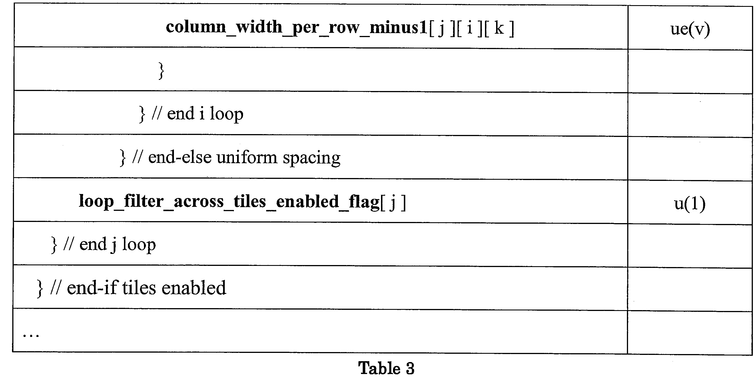
With respect to Table 3, it should be noted that syntax elements tiles_enabled_flag, number_tile_structures_minus_1, num_tile_rows_minus1, uniform_spacing_flag, num_tile_columns_minus1, row_height_minus1, and loop_filter_across_tiles_enabled_flag may be based on the definitions provided above with respect to Table 2. uniform_row_spacing_flag, num_tile_columns_in_row_minus1, uniform_column_spacing_flag, and column_width_per_row_minus1 may be based on the following example definitions:

In one example, in the syntax in Table 3, the syntax element uniform_row_spacing_flag[j] may be signaled only when the condition num_tile_rows_minus1[ j ] > 0 is true. That is, the syntax in Table 3 may be modified as follows:

In this case, the following inference may be added: When not present uniform_row_spacing_flag[ j ] is inferred to be equal to 1.
In one example in the syntax in Table 3 the syntax element uniform_column_spacing_flag[j][i] may be signaled only when the condition (num_tile_columns_in_row_minus1[ j ][ i ] > 0) is satisfied. That is, the syntax in Table 3 may be modified as:

In this case, the following inference may be added: When not present uniform_column_spacing_flag[ j ][ i ] is inferred to be equal to 1.
In this manner, source device 102 may be configured to signal tile structures having a varying number of tile columns from row-to-row and/or tile structures having a varying number of tile rows from column-to-column.
As described above, in ITU-T H.265, tile structures are limited to non-overlapping tiles. Overlapping tiles are useful for mitigating artifacts at tile boundaries that can occur when 360-degree video is mapped into a rectangular picture and that picture is partitioned into tiles prior to encoding. In these use cases, tiles, which are independently decodable, may be extracted from the 360-degree video in order to avoid sending and decoding the entire video in cases when only a small fraction of the video is being viewed. It should be noted that CTUs that lie in the tile overlap regions are coded twice.
According to the techniques herein, data encapsulator 107 may be configured to signal tile structures having overlapping tiles. Table 4 illustrates an example of syntax for a parameter set that may be used to signal tile structures according to the techniques herein. In one example, the example syntax included in Table 4 may be included in a SPS. In other examples, the example syntax included in Table 4 may be included in a VPS or PPS.

With respect to Table 4, it should be noted that syntax elements tiles_enabled_flag, num_tile_structures_minus1, num_tile_columns_minus1, num_tile_rows_minus1, uniform_spacing_flag, column_width_minus1, row_height_minus1, and loop_filter_across_tiles_enabled_flag may be based on the definitions provided above with respect to Table 2. tile_width_overlap and tile_height_overlap may be based on the following example definitions:

In this manner, source device 102 represents an example of a device configured to signal tile structures having overlapping tiles.
FIG. 7A illustrates an example where tile_width_overlap = 1; tile_height_overlap = 0. As illustrated in FIG. 7A, column boundaries are shifted right and left resulting in the overlap region (crosshatched region). That is, the shift results in Tile1, Tile3, Tile4, and Tile5 including 4 x 3 CTUs and Tile2 and Tile5 including 6 x 3 CTUs. In the example illustrated in FIG. 7A, there is no overlap in the vertical direction.
In one example, source device 102 may be configured to signal tile structures having asymmetric tile overlap. That is, for example, tile_width_overlap may be replaced in Table 4 with syntax elements tile_width_overlap_left and tile_width_overlap_right and/or tile_height_overlap may be replaced with syntax elements tile_height_overlap_top and tile_height_overlap_bottom. In one example, syntax elements tile_width_overlap_left, tile_width_overlap_right, tile_height_overlap_top and tile_height_overlap_bottom may be based on the following example definitions:

In one example, source device 102 may be configured to signal tile structures where each tile has its own vertical and horizontal overlap.
In one example, the following constraints may be applied to tile_width_overlap[ j ] and tile_height_overlap[ j ] syntax elements:

As described above, omnidirectional video may be coded using MCTS. ITU-T H.265 provides the following syntax elements in a Temporal motion-constrained tile sets SEI message to indicate which tiles comprise an MCTS.

Extracting motion-constrained tile information from the Temporal motion-constrained tile sets SEI message may be less than ideal. Further, specifying a motion-constrained tile set when the number of tiles in rows and/or columns vary may be difficult due to the fact that the tile set may not be rectangular. According to the techniques herein, data encapsulator 107 may be configured to signal motion-constrained tile information according to a parameter set, which may be included within a compliant bitstream in some cases. Table 5 illustrates an example of syntax for a parameter set that may be used to signal tile structures according to the techniques herein. In one example, the example syntax included in Table 5 may be included in a SPS. In other examples, the example syntax included in Table 5 may be included in a VPS or PPS.

With respect to Table 5, it should be noted that syntax elements tiles_enabled_flag and num_tile_structures_minus1 may be based on the definitions provided above with respect to Table 2. num_tile_sets_minus1, mcts_id, num_tile_columns_minus1, num_tile_rows_minus1, and tile_is_in_motion_constrained_tile_set may be based on the following example definitions:

In one example, instead of explicitly signaling mcts_id[j], its value can be inferred to be equal to j.
In one example, the example syntax that may be used to signal tile structures illustrated in Table 5 may be combined with the example syntax included in Table 3 such that tile structures in the example illustrated in Table 5 may include rows with a varying number of tile columns and/or columns with a varying number of tiles rows.
It should be noted that it is typically easier for a destination device to extract motion-constrained tile information from a parameter set included in a compliant bitstream rather than form Temporal motion-constrained tile sets SEI message because with a parameter set in a compliant bitstream, e.g., the parameter set illustrated in Table 5, there is no need to derive which tiles comprise the MCTS, as is required when using the Temporal motion-constrained tile sets SEI message. Further, it should be noted that the syntax in Table 5 allows for the specification of non-rectangular motion constrained tile groups and enables specifying the upper-left and lower-right corners of an MCTS when a variable number of Tiles per row (or column) is allowed. Further, using the syntax in Table 5, there is no need to separately indicate which tile boundaries are motion constrained and which are not. Such boundaries may be inferred, for example, from a Temporal motion-constrained tile sets SEI message as follows: the inter prediction process is constrained such that no sample value outside each identified tile set, and no sample value at a fractional sample position that is derived using one or more sample values outside the identified tile set, is used for inter prediction of any sample within the identified tile set.
Further, using the syntax in Table 5, there is no need for num_tile_rects_in_set_minus1, since each tile rectangle within a given tile set would be specified as a collection of explicitly signaled tiles.
As described above, data encapsulator 107 may be configured to signal a number of motion-constrained tile sets and may be configured to signal tile structures where each tile has its own vertical and horizontal overlap. In one example, data encapsulator 107 may be configured to signal a number of a number of motion-constrained tile sets and for each tile set signal vertical and horizontal overlap occurring at the boundary of a motion-constrained tile set. Table 6 illustrates an example of syntax for a parameter set that may be used to signal tile structures according to the techniques herein. In one example, the example syntax included in Table 6 may be included in a SPS. In other examples, the example syntax included in Table 6 may be included in a VPS or PPS.

With respect to Table 6, it should be noted that syntax elements tiles_enabled_flag, num_tile_structures_minus1, and num_tile_sets_minus1 may be based on the definitions provided above with respect to Table 5. mcts_overlap, mcts_width_overlap, and mcts_height_overlap may be based on the following example definitions:

FIG. 7B illustrates an example where mcts_overlap = 1; mcts_width_overlap = 1; and mcts_height_overlap = 1 for the illustrated tile set comprising Tile5 and Tile8. As illustrated in FIG. 7B, vertical boundaries are shifted right and left by one CTU and horizontal boundaries are shifted are shifted above and below by one CTU resulting in the overlap region which is illustrated as crosshatched).
It should be noted that in one example, the example syntax illustrated in Table 6 may be modified to specify left boundary, right boundary, top boundary and/or bottom boundary shifts independently. For example, mcts_width_overlap may be replaced in Table 6 with syntax elements mcts_width_overlap_left and mcts_width_overlap_right and/or mcts_height_overlap may be replaced with syntax elements mcts_height_overlap_top and mcts_height_overlap_bottom. In one example, syntax elements mcts_width_overlap_left, mcts_width_overlap_right, mcts_height_overlap_top and mcts_height_overlap_bottom may be based on the following example definitions:

As described above, in ITU-T H.265, the degree of quantization may be determined by a quantization parameter, QP. In ITU-T H.265, for a bit-depth of 8-bits, the QP can take 52 values from 0 to 51 and a change of 1 for QP generally corresponds to a change in the value of the quantization scaling factor by approximately 12%. It should be noted that more generally, in ITU-T H.265, the valid range of QP values for a source bit-depth is: -6*(bitdepth-8) to +51 (inclusive). Thus, for example, in the case where the bit-depth is 10-bits, QP can take 64 values from -12 to 51, which may be mapped to values 0 to 63 during dequantization. In ITU-T H.265, a quantization parameter may be updated for each CU and a respective quantization parameter may be derived for each of luma and chroma components. It should be noted that as the degree of quantization increases (e.g., transform coefficients are divided by a larger scaling factor value), the amount of distortion may be increased (e.g., reconstructed video data may appear more “blocky” to a user).
In some cases, blocking artifacts may cause coding block boundaries of reconstructed video data to be visually perceptible to a user. In order to reduce blocking artifacts, reconstructed sample values may be modified to minimize artifacts introduced by the video coding process. Such modifications may generally be referred to as filtering. It should be noted that filtering may occur as part of an in-loop filtering process or a post-loop filtering process. For an in-loop filtering process, the resulting sample values of a filtering process may be used for predictive video blocks (e.g., stored to a reference frame buffer for subsequent encoding at video encoder and subsequent decoding at a video decoder). For a post-loop filtering process the resulting sample values of a filtering process are merely output as part of the decoding process (e.g., not used for subsequent coding). For example, for an in-loop filtering process, the sample values resulting from filtering a reconstructed block would be used for subsequent decoding (e.g., stored to a reference buffer) and would be output (e.g., to a display). For a post-loop filtering process, the reconstructed block without modification would be used for subsequent decoding and the sample values resulting from filtering the reconstructed block would be output.
Deblocking (or de-blocking), deblock filtering, performing deblocking, or applying a deblocking filter refers to the process of smoothing video block boundaries with neighboring reconstructed video blocks (i.e., making boundaries less perceptible to a viewer). Smoothing the boundaries of neighboring reconstructed video blocks may include modifying sample values included in rows or columns adjacent to a boundary. ITU-T H.265 provides where a deblocking filter is applied to reconstructed sample values as part of an in-loop filtering process. ITU-T H.265 includes two types deblocking filters that may be used for modifying luma samples: a Strong Filter which modifies sample values in the three adjacent rows or columns to a boundary and a Weak Filter which modifies sample values in the immediately adjacent row or column to a boundary and conditionally modifies sample values in the second row or column from the boundary. Further, ITU-T H.265 includes one type of filter that may be used for modifying chroma samples, i.e., a Normal Filter.
FIGS. 9A-9B illustrate sample values included in video blocks P and Q having a boundary. As used herein, video blocks P and Q are used to refer to adjacent video blocks having a block boundary at which deblocking may be applied. The manner in which sample values are modified may be based on defined filters, where pi and qi represent respective sample values in a column for a vertical boundary and sample values in a row for a horizontal boundary and pi’ and qi’ represent modified sample values. ITU-T H.265 includes two types of filters that may be used for modifying luma samples: a Strong Filter which modifies sample values in the three adjacent rows or columns to a boundary and a Weak Filter which modifies sample values in the immediately adjacent row or column to a boundary and conditionally modifies sample values in the second row or column from the boundary. Simplified definitions of the Strong Filter and Weak Filter equations for modifying luma sample values are provided below. The definitions are simplified in that they do not include clipping operations provided in ITU-T H.265 (i.e., in ITU-T H.265, filtered values are clipped based on a value tC, described below), however, reference is made to Section 8.7.2.5.7 of ITU-T H.265, which provides the complete definitions.

Further, ITU-T H.265 includes one type of filter that may be used for modifying chroma samples: Normal Filter. Simplified definitions for the Normal Filter equations for modifying chroma sample values are provided below.

Deblocking may be performed based on a deblocking granularity. ITU-T H.265 provides an 8x8 deblocking granularity. That is, in ITU-T H.265 for an area of a picture, each edge lying on the 8x8 grid is evaluated to determine if a boundary exists. Further, in ITU-T H.265, a boundary strength (Bs) is determined for each boundary. In ITU-T H.265, Bs is determined as follows:

In ITU-T H.265, based on the QP used for coding the CBs including video blocks P and Q (which may be referred to as QPP and QPQ), variables tC’ and β’ are determined. FIG. 10 provides a table for determining tC’ and β’. In ITU-T H.265, the index Q is determined as follows:

ITU-T H.265, defines a variable d, where d is determined based on luma sample values as follows:

Further, in ITU-T H.265 a variable dpq is set to a value based on the values of d and β. Finally, in ITU-T H.265, each of Bs, tC, β, and d are used to determine which filter type to apply (e.g., Strong Filter or Weak Filter). Further, in ITU-T H.265, for the chroma component, the Normal Filter is applied only when Bs equals 2. That is, in ITU-T H.265, deblocking only occurs for the chroma component if one the blocks P or Q is generated using an intra prediction mode.
As described above, according to ITU-T H.265, each video frame or picture may be partitioned to include one or more slices and further partitioned to include one or more tiles. In ITU-T H.265, the deblocking filter may be applied differently to CTU boundaries that coincide with slice and tile boundaries compared with CTU boundaries that do not coincide with slice and tile boundaries. Specifically, ITU-T H.265 specifies a flag, slice_loop_filter_across_slices_enabled_flag, present in a slice segment header that enables/disables the deblocking filter across CTU boundaries that coincide with top and left slice boundaries. ITU-T H.265 provides the following definition for slice_loop_filter_across_slices_enabled_flag:
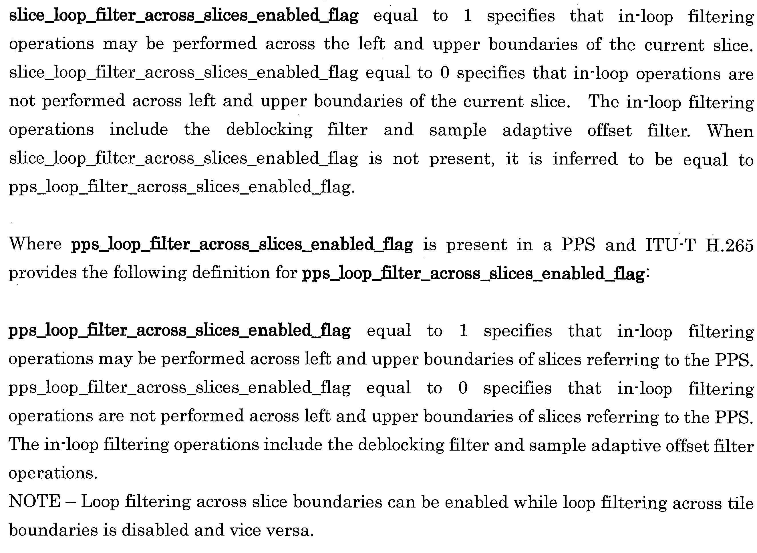
Similarly, a flag, loop_filter_across_tiles_enabled_flag, present in a PPS enables/disables the deblocking filter across CTU boundaries that coincide with tile boundaries. ITU-T H.265 provides the following definition for loop_filter_across_tiles_enabled_flag:

As described above, for deblocking, the index Q is determined based on slice_beta_offset_div2 and slice_tc_offset_div2. In ITU-T H.265, the values of slice_beta_offset_div2 and slice_tc_offset_div2 may be included in a slice segment header and have the following definitions:

It should be noted that in ITU-T H.265, β and tC are derived as follows:

As described above, a MCTS may include a tile set for which inter-picture prediction dependencies are limited to the collocated tile sets in reference pictures. In some cases, CTU boundaries that coincide with MCTS boundaries (or other tile set boundaries) may benefit from different filter strengths compared with CTU boundaries that do not coincide with MCTS boundaries. In one example, according to the techniques described herein, the derivation of Q for CTU boundaries that coincide with MCTS boundaries may be as follows:

In one example, pps_beta_offset_tile_set_div2 and pps_tc_offset_tile_set_div2 are syntax elements included in a PPS and may be based on the following example definition:

In some example, parameters that indicate tile set offset values may be included in the VPS or SPS. For example, syntax elements vps_beta_offset_tile_set_div2 and vps_tc_offset_tile_set_div2 may be included in a VPS and/or syntax elements sps_beta_offset_tile_set_div2 and sps_tc_offset_tile_set_div2 may be included in an SPS, where vps_beta_offset_tile_set_div2, vps_tc_offset_tile_set_div2, sps_beta_offset_tile_set_div2, and/or sps_tc_offset_tile_set_div2 are used to infer values for pps_beta_offset_tile_set_div2, and/or pps_tc_offset_tile_set_div2.
It should be noted that the case in which tiles overlap one another, the deblocking filter strength derivation may be applied to CTU boundaries coinciding with the tile boundaries prior to any boundary extensions, where the extension of the tile boundaries creates overlap.
In some cases, it may be useful to enable a binary control for deblocking such that a deblocking filter may be enabled or disabled on a tile set-by-tile set basis. In one example, according to the techniques described herein, a syntax element, loop_filter_across_tile_set_enabled_flag[ k ][ j ], may be included in a PPS to control whether or not a loop filter is to be applied across a tile set boundary. Table 7 illustrates an example of syntax for a parameter set that may be used to signal tile structures according to the techniques herein. In one example, the example syntax included in Table 7 may be included in a SPS. In other examples, the example syntax included in Table 7 may be included in a VPS or PPS.

With respect to Table 7, it should be noted that syntax elements tiles_enabled_flag, num_tile_structures_minus1, num_tile_columns_minus1, num_tile_rows_minus1, num_tile_sets_minus1, and mcts_id may be based on the definitions provided above with respect to Table 5. loop_filter_across_tile_set_enabled_flag[ k ][ j ] may be based on the following example definition:

In one example, rather than including loop_filter_across_tile_set_enabled_flag[ k ][ j ] in the PPS, as illustrated in the example of Table 7, it may be advantageous to include loop_filter_across_tile_set_enabled_flag[ k ][ j ] in the VPS or SPS.
In one example, rather than enabling or disabling deblocking on a tile set-by-tile set basis, as illustrated in the example of Table 7, a single flag, loop_filter_across_tile_set_enabled_flag, would enable/disable deblocking at all tile set boundaries in pictures for which the PPS (or VPS or SPS) containing loop_filter_across_tile_set_enabled_flag is active. In one example, rather than enabling or disabling deblocking on a tile set-by-tile set basis, as illustrated in the example of Table 7, the flags, loop_filter_across_tile_set_enabled_flag[k], would enable/disable deblocking at all tile set boundaries in the k-th tile structure in pictures for which the PPS (or VPS or SPS) containing loop_filter_across_tile_set_enabled_flag[k] is active.
In another example, rather than enabling and disabling deblocking on a tile set-by-tile set basis, as illustrated in the example of Table 7, a single flag can be defined, e.g., loop_filter_enabled_within_mctsextractioninformationset_tileset to enable/disable deblocking filtering at tile set boundaries that are inside a motion constrained tile sets extraction information set. A bitstream corresponding to a motion constrained tile sets extraction information set can be extracted using a MCTS sub-bitstream extraction process, for example the sub-bitstream extraction process described in ITU-T H.265. In one example, the semantics for loop_filter_enabled_within_mctsextractioninformationset_tileset may be as follows:

In another example, the semantics for loop_filter_enabled_within_mctsextractioninformationset_tileset may be as follows:

In one case, it may be advantageous to control the deblocking filter strength on a tile set-by-tile set basis. For example, in lieu of loop_filter_across_tile_set_enabled_flag[ k ][ j ] illustrated in the example syntax of Table 7 above, Table 7 may include syntax elements pps_beta_offset_tile_set_div2[ k ][ j ] and pps_tc_offset_tile_set_div2[ k ][ j ], where pps_beta_offset_tile_set_div2[ k ][ j ] and pps_tc_offset_tile_set_div2[ k ][ j ] are based on the following example definitions:

In one case, it may be advantageous to control the deblocking filter strength on a tile structure-by-tile structure basis. For example, in lieu of loop_filter_across_tile_set_enabled_flag[ k ][ j ] illustrated in the example syntax of Table 7 above, Table 7 may include syntax elements pps_beta_offset_tile_set_div2[ k ] and pps_tc_offset_tile_set_div2[ k ], where pps_beta_offset_tile_set_div2[ k ] and pps_tc_offset_tile_set_div2[ k ] are based on the following example definitions:

In this manner, source device 102 represents an example of a device configured to signal motion-constrained tile information using a parameter set.
Referring again to FIG. 1, interface 108 may include any device configured to receive data generated by data encapsulator 107 and transmit and/or store the data to a communications medium. Interface 108 may include a network interface card, such as an Ethernet card, and may include an optical transceiver, a radio frequency transceiver, or any other type of device that can send and/or receive information. Further, interface 108 may include a computer system interface that may enable a file to be stored on a storage device. For example, interface 108 may include a chipset supporting Peripheral Component Interconnect (PCI) and Peripheral Component Interconnect Express (PCIe) bus protocols, proprietary bus protocols, Universal Serial Bus (USB) protocols, I2C, or any other logical and physical structure that may be used to interconnect peer devices.
Referring again to FIG. 1, destination device 120 includes interface 122, data decapsulator 123, video decoder 124, and display 126. Interface 122 may include any device configured to receive data from a communications medium. Interface 122 may include a network interface card, such as an Ethernet card, and may include an optical transceiver, a radio frequency transceiver, or any other type of device that can receive and/or send information. Further, interface 122 may include a computer system interface enabling a compliant video bitstream to be retrieved from a storage device. For example, interface 122 may include a chipset supporting PCI and PCIe bus protocols, proprietary bus protocols, USB protocols, I2C, or any other logical and physical structure that may be used to interconnect peer devices. Data decapsulator 123 may be configured to receive and parse any of the example parameter sets described herein.
FIG. 8 is a block diagram illustrating an example of a video decoder that may be configured to decode video data according to one or more techniques of this disclosure. In one example, video decoder 600 may be configured to decode transform data and reconstruct residual data from transform coefficients based on decoded transform data. Video decoder 600 may be configured to perform intra prediction decoding and inter prediction decoding and, as such, may be referred to as a hybrid decoder. In the example illustrated in FIG. 8, video decoder 600 includes an entropy decoding unit 602, inverse quantization unit and transform coefficient processing unit 604, intra prediction processing unit 606, inter prediction processing unit 608, summer 610, post filter unit 612, and reference buffer 614. Video decoder 600 may be configured to decode video data in a manner consistent with a video coding system. It should be noted that although example video decoder 600 is illustrated as having distinct functional blocks, such an illustration is for descriptive purposes and does not limit video decoder 600 and/or sub-components thereof to a particular hardware or software architecture. Functions of video decoder 600 may be realized using any combination of hardware, firmware, and/or software implementations.
As illustrated in FIG. 8, entropy decoding unit 602 receives an entropy encoded bitstream. Entropy decoding unit 602 may be configured to decode syntax elements and quantized coefficients from the bitstream according to a process reciprocal to an entropy encoding process. Entropy decoding unit 602 may be configured to perform entropy decoding according any of the entropy coding techniques described above. Entropy decoding unit 602 may determine values for syntax elements in an encoded bitstream in a manner consistent with a video coding standard. As illustrated in FIG. 6, entropy decoding unit 602 may determine a quantization parameter, quantized coefficient values, transform data, and predication data from a bitstream. In the example, illustrated in FIG. 8, inverse quantization unit and transform coefficient processing unit 604 receives a quantization parameter, quantized coefficient values, transform data, and predication data from entropy decoding unit 602 and outputs reconstructed residual data.
Referring again to FIG. 8, reconstructed residual data may be provided to summer 610 Summer 610 may add reconstructed residual data to a predictive video block and generate reconstructed video data. A predictive video block may be determined according to a predictive video technique (i.e., intra prediction and inter frame prediction). Intra prediction processing unit 606 may be configured to receive intra prediction syntax elements and retrieve a predictive video block from reference buffer 614. Reference buffer 614 may include a memory device configured to store one or more frames of video data. Intra prediction syntax elements may identify an intra prediction mode, such as the intra prediction modes described above. Inter prediction processing unit 608 may receive inter prediction syntax elements and generate motion vectors to identify a prediction block in one or more reference frames stored in reference buffer 814. Inter prediction processing unit 608 may produce motion compensated blocks, possibly performing interpolation based on interpolation filters. Identifiers for interpolation filters to be used for motion estimation with sub-pixel precision may be included in the syntax elements. Inter prediction processing unit 808 may use interpolation filters to calculate interpolated values for sub-integer pixels of a reference block. Post filter unit 612 may be configured to perform filtering on reconstructed video data. For example, post filter unit 612 may be configured to perform deblocking and/or Sample Adaptive Offset (SAO) filtering, e.g., based on parameters specified in a bitstream. Further, it should be noted that in some examples, post filter unit 612 may be configured to perform proprietary discretionary filtering (e.g., visual enhancements, such as, mosquito noise reduction). As illustrated in FIG. 8, a reconstructed video block may be output by video decoder 600. In this manner, video decoder 600 may be configured to generate reconstructed video data according to one or more of the techniques described herein.
In one or more examples, the functions described may be implemented in hardware, software, firmware, or any combination thereof. If implemented in software, the functions may be stored on or transmitted over as one or more instructions or code on a computer-readable medium and executed by a hardware-based processing unit. Computer-readable media may include computer-readable storage media, which corresponds to a tangible medium such as data storage media, or communication media including any medium that facilitates transfer of a computer program from one place to another, e.g., according to a communication protocol. In this manner, computer-readable media generally may correspond to (1) tangible computer-readable storage media which is non-transitory or (2) a communication medium such as a signal or carrier wave. Data storage media may be any available media that can be accessed by one or more computers or one or more processors to retrieve instructions, code and/or data structures for implementation of the techniques described in this disclosure. A computer program product may include a computer-readable medium.
By way of example, and not limitation, such computer-readable storage media can comprise RAM, ROM, EEPROM, CD-ROM or other optical disk storage, magnetic disk storage, or other magnetic storage devices, flash memory, or any other medium that can be used to store desired program code in the form of instructions or data structures and that can be accessed by a computer. Also, any connection is properly termed a computer-readable medium. For example, if instructions are transmitted from a website, server, or other remote source using a coaxial cable, fiber optic cable, twisted pair, digital subscriber line (DSL), or wireless technologies such as infrared, radio, and microwave, then the coaxial cable, fiber optic cable, twisted pair, DSL, or wireless technologies such as infrared, radio, and microwave are included in the definition of medium. It should be understood, however, that computer-readable storage media and data storage media do not include connections, carrier waves, signals, or other transitory media, but are instead directed to non-transitory, tangible storage media. Disk and disc, as used herein, includes compact disc (CD), laser disc, optical disc, digital versatile disc (DVD), floppy disk and Blu-ray disc where disks usually reproduce data magnetically, while discs reproduce data optically with lasers. Combinations of the above should also be included within the scope of computer-readable media.
Instructions may be executed by one or more processors, such as one or more digital signal processors (DSPs), general purpose microprocessors, application specific integrated circuits (ASICs), field programmable logic arrays (FPGAs), or other equivalent integrated or discrete logic circuitry. Accordingly, the term “processor,” as used herein may refer to any of the foregoing structure or any other structure suitable for implementation of the techniques described herein. In addition, in some aspects, the functionality described herein may be provided within dedicated hardware and/or software modules configured for encoding and decoding, or incorporated in a combined codec. Also, the techniques could be fully implemented in one or more circuits or logic elements.
The techniques of this disclosure may be implemented in a wide variety of devices or apparatuses, including a wireless handset, an integrated circuit (IC) or a set of ICs (e.g., a chip set). Various components, modules, or units are described in this disclosure to emphasize functional aspects of devices configured to perform the disclosed techniques, but do not necessarily require realization by different hardware units. Rather, as described above, various units may be combined in a codec hardware unit or provided by a collection of interoperative hardware units, including one or more processors as described above, in conjunction with suitable software and/or firmware.
Moreover, each functional block or various features of the base station device and the terminal device used in each of the aforementioned embodiments may be implemented or executed by a circuitry, which is typically an integrated circuit or a plurality of integrated circuits. The circuitry designed to execute the functions described in the present specification may comprise a general-purpose processor, a digital signal processor (DSP), an application specific or general application integrated circuit (ASIC), a field programmable gate array (FPGA), or other programmable logic devices, discrete gates or transistor logic, or a discrete hardware component, or a combination thereof. The general-purpose processor may be a microprocessor, or alternatively, the processor may be a conventional processor, a controller, a microcontroller or a state machine. The general-purpose processor or each circuit described above may be configured by a digital circuit or may be configured by an analogue circuit. Further, when a technology of making into an integrated circuit superseding integrated circuits at the present time appears due to advancement of a semiconductor technology, the integrated circuit by this technology is also able to be used.
Various examples have been described. These and other examples are within the scope of the following claims.
<Cross Reference>
This Nonprovisional application claims priority under 35 U.S.C. § 119 on provisional Application No. 62/589939 on November 22, 2017, 62/591979 on November 29, 2017, and 62/608502 on December 20, 2017, the entire contents of which are hereby incorporated by reference.
This Nonprovisional application claims priority under 35 U.S.C. § 119 on provisional Application No. 62/589939 on November 22, 2017, 62/591979 on November 29, 2017, and 62/608502 on December 20, 2017, the entire contents of which are hereby incorporated by reference.
Claims (15)
- A method of signaling tile set structures, the method comprising:
determining a number of tile structures;
setting a value of a syntax element to indicate the number of tile structures;
and
generating a parameter set including the syntax element. - The method of claim 1, wherein the parameter set includes a syntax element indicating a number of tile columns in each respective row of tiles.
- The method of claim 1, wherein the parameter set includes a syntax element indicating a number of tile rows in each respective column of tiles.
- The method of any of claims 1-3, wherein the parameter set includes a syntax element specifying a shift of tile boundaries to the left and right.
- The method of any of claims 1-4, wherein the parameter set includes a syntax element specifying a shift of tile boundaries above and below.
- The method of any of claims 1-5, wherein the parameter set includes a syntax element indicating whether a particular tile is included within a particular motion constrained tile set.
- The method of claim 6, wherein the parameter set includes a syntax element indicating whether a particular motion constrained tile set is associated with an overlap region.
- The method of any of claims 1-7, wherein the parameter set includes a flag indicating whether loop filtering across tile sets is enabled.
- A method of decoding video data, the method comprising:
receiving a parameter set including one or more syntax elements indicating information associated with one or more tile structures;
parsing the one or more syntax elements; and
generating video data based on values of the parsed syntax elements. - A device comprising one or more processors configured to perform any and all combinations of the steps of claims 1-9.
- The device of claim 10, wherein the device includes a video encoder.
- The device of claim 10, wherein the device includes a video decoder.
- A system comprising:
the device of claim 11; and
the device of claim 12. - An apparatus comprising means for performing any and all combinations of the steps of claims 1-9.
- A non-transitory computer-readable storage medium comprising instructions stored thereon that, when executed, cause one or more processors of a device to perform any and all combinations of the steps of claims 1-9.
Applications Claiming Priority (6)
| Application Number | Priority Date | Filing Date | Title |
|---|---|---|---|
| US201762589939P | 2017-11-22 | 2017-11-22 | |
| US62/589,939 | 2017-11-22 | ||
| US201762591979P | 2017-11-29 | 2017-11-29 | |
| US62/591,979 | 2017-11-29 | ||
| US201762608502P | 2017-12-20 | 2017-12-20 | |
| US62/608,502 | 2017-12-20 |
Publications (1)
| Publication Number | Publication Date |
|---|---|
| WO2019103126A1 true WO2019103126A1 (en) | 2019-05-31 |
Family
ID=66630578
Family Applications (1)
| Application Number | Title | Priority Date | Filing Date |
|---|---|---|---|
| PCT/JP2018/043282 WO2019103126A1 (en) | 2017-11-22 | 2018-11-22 | Systems and methods for signaling tile structures for pictures of coded video |
Country Status (1)
| Country | Link |
|---|---|
| WO (1) | WO2019103126A1 (en) |
Cited By (3)
| Publication number | Priority date | Publication date | Assignee | Title |
|---|---|---|---|---|
| US20210211663A1 (en) * | 2018-09-14 | 2021-07-08 | Huawei Technologies Co., Ltd. | Tile Signaling In Video Coding |
| US20220394306A1 (en) * | 2020-02-14 | 2022-12-08 | Beijing Bytedance Network Technology Co., Ltd. | Interplay between in-loop filtering and video slices |
| WO2024002497A1 (en) * | 2022-07-01 | 2024-01-04 | Huawei Technologies Co., Ltd. | Parallel processing of image regions with neural networks – decoding, post filtering, and rdoq |
Citations (5)
| Publication number | Priority date | Publication date | Assignee | Title |
|---|---|---|---|---|
| US20140079126A1 (en) * | 2012-09-18 | 2014-03-20 | Vid Scale, Inc. | Method and Apparatus for Region of Interest Video Coding Using Tiles and Tile Groups |
| US20140301464A1 (en) * | 2013-04-08 | 2014-10-09 | Microsoft Corporation | Control data for motion-constrained tile set |
| US20150110201A1 (en) * | 2012-04-30 | 2015-04-23 | Panasonic Intellectual Property Corporation Of America | Image encoding method, image decoding method, image encoding apparatus, image decoding apparatus, and image encoding and decoding apparatus |
| US20160286235A1 (en) * | 2013-12-06 | 2016-09-29 | Huawei Technologies Co., Ltd. | Image Decoding Apparatus, Image Coding Apparatus, and Coded Data Transformation Apparatus |
| JP2018056686A (en) * | 2016-09-27 | 2018-04-05 | 株式会社ドワンゴ | Image encoder, image encoding method and image encoding program, and image decoder, image decoding method and image decoding program |
-
2018
- 2018-11-22 WO PCT/JP2018/043282 patent/WO2019103126A1/en active Application Filing
Patent Citations (5)
| Publication number | Priority date | Publication date | Assignee | Title |
|---|---|---|---|---|
| US20150110201A1 (en) * | 2012-04-30 | 2015-04-23 | Panasonic Intellectual Property Corporation Of America | Image encoding method, image decoding method, image encoding apparatus, image decoding apparatus, and image encoding and decoding apparatus |
| US20140079126A1 (en) * | 2012-09-18 | 2014-03-20 | Vid Scale, Inc. | Method and Apparatus for Region of Interest Video Coding Using Tiles and Tile Groups |
| US20140301464A1 (en) * | 2013-04-08 | 2014-10-09 | Microsoft Corporation | Control data for motion-constrained tile set |
| US20160286235A1 (en) * | 2013-12-06 | 2016-09-29 | Huawei Technologies Co., Ltd. | Image Decoding Apparatus, Image Coding Apparatus, and Coded Data Transformation Apparatus |
| JP2018056686A (en) * | 2016-09-27 | 2018-04-05 | 株式会社ドワンゴ | Image encoder, image encoding method and image encoding program, and image decoder, image decoding method and image decoding program |
Non-Patent Citations (1)
| Title |
|---|
| YE-KUI WANG ET AL.: "Tile groups", JOINT COLLABORATIVE TEAM ON VIDEO CODING(JCT-VC) OF ITU-T SG 16 WP3 AND ISO/IEC JTC1/SC29/WG11 8TH, no. JCTVC-H0520r1, 30 January 2012 (2012-01-30), San Jose, CA , USA, pages 1 - 8 * |
Cited By (4)
| Publication number | Priority date | Publication date | Assignee | Title |
|---|---|---|---|---|
| US20210211663A1 (en) * | 2018-09-14 | 2021-07-08 | Huawei Technologies Co., Ltd. | Tile Signaling In Video Coding |
| US20220394306A1 (en) * | 2020-02-14 | 2022-12-08 | Beijing Bytedance Network Technology Co., Ltd. | Interplay between in-loop filtering and video slices |
| US11825123B2 (en) | 2020-02-14 | 2023-11-21 | Beijing Bytedance Network Technology Co., Ltd. | Interplay between in-loop filtering and video tiles |
| WO2024002497A1 (en) * | 2022-07-01 | 2024-01-04 | Huawei Technologies Co., Ltd. | Parallel processing of image regions with neural networks – decoding, post filtering, and rdoq |
Similar Documents
| Publication | Publication Date | Title |
|---|---|---|
| WO2021033749A1 (en) | Systems and methods for signaling picture information in video coding | |
| WO2020059688A1 (en) | Systems and methods for signaling parameters in video coding | |
| WO2021045128A1 (en) | Systems and methods for signaling temporal sub-layer information in video coding | |
| KR102572140B1 (en) | Systems and methods for signaling tile structures for pictures of coded video | |
| US11070845B2 (en) | Systems and methods for signaling of motion-constrained tile sets for virtual reality applications | |
| WO2021049551A1 (en) | Systems and methods for signaling subpicture information in video coding | |
| WO2021153475A1 (en) | Systems and methods for signaling picture information in a slice header in video coding | |
| AU2019297829B2 (en) | Systems and methods for signaling picture order count values for pictures included in coded video | |
| WO2020171230A1 (en) | Systems and methods for signaling types of pictures and associated information in video coding | |
| WO2020122062A1 (en) | Systems and methods for signaling reference pictures in video coding | |
| US20230023370A1 (en) | Systems and methods for signaling picture types of pictures included in coded video | |
| WO2019103126A1 (en) | Systems and methods for signaling tile structures for pictures of coded video | |
| WO2020059687A1 (en) | Systems and methods for signaling reference pictures in video coding | |
| WO2018128071A1 (en) | Systems and methods for signaling of tiles in most-interested regions for virtual reality applications | |
| WO2019189890A1 (en) | Systems and methods for signaling tile structures for pictures of coded video | |
| WO2024004811A1 (en) | Systems and methods for signaling neural network post-filter parameter information in video coding | |
| WO2024004978A1 (en) | Systems and methods for signaling neural network post-filter parameter information in video coding | |
| WO2023234133A1 (en) | Systems and methods for signaling reference picture list entry information in video coding | |
| WO2019124226A1 (en) | Systems and methods for applying deblocking filters to reconstructed video data at picture partition boundaries | |
| WO2020009124A1 (en) | Systems and methods for high-level syntax signaling in video coding | |
| WO2023171484A1 (en) | Systems and methods for handling out of boundary motion compensation predictors in video coding | |
| WO2021187375A1 (en) | Systems and methods for applying deblocking filters in video coding | |
| WO2020235552A1 (en) | Systems and methods for signaling picture property information in video coding | |
| WO2020230798A1 (en) | Systems and methods for signaling tile group information in video coding |
Legal Events
| Date | Code | Title | Description |
|---|---|---|---|
| 121 | Ep: the epo has been informed by wipo that ep was designated in this application |
Ref document number: 18882063 Country of ref document: EP Kind code of ref document: A1 |
|
| NENP | Non-entry into the national phase |
Ref country code: DE |
|
| 122 | Ep: pct application non-entry in european phase |
Ref document number: 18882063 Country of ref document: EP Kind code of ref document: A1 |