WO2019098317A1 - Shift range switching system - Google Patents
Shift range switching system Download PDFInfo
- Publication number
- WO2019098317A1 WO2019098317A1 PCT/JP2018/042422 JP2018042422W WO2019098317A1 WO 2019098317 A1 WO2019098317 A1 WO 2019098317A1 JP 2018042422 W JP2018042422 W JP 2018042422W WO 2019098317 A1 WO2019098317 A1 WO 2019098317A1
- Authority
- WO
- WIPO (PCT)
- Prior art keywords
- motor
- range
- range switching
- shift range
- output shaft
- Prior art date
Links
Images


Classifications
-
- F—MECHANICAL ENGINEERING; LIGHTING; HEATING; WEAPONS; BLASTING
- F16—ENGINEERING ELEMENTS AND UNITS; GENERAL MEASURES FOR PRODUCING AND MAINTAINING EFFECTIVE FUNCTIONING OF MACHINES OR INSTALLATIONS; THERMAL INSULATION IN GENERAL
- F16H—GEARING
- F16H61/00—Control functions within control units of change-speed- or reversing-gearings for conveying rotary motion ; Control of exclusively fluid gearing, friction gearing, gearings with endless flexible members or other particular types of gearing
- F16H61/26—Generation or transmission of movements for final actuating mechanisms
- F16H61/28—Generation or transmission of movements for final actuating mechanisms with at least one movement of the final actuating mechanism being caused by a non-mechanical force, e.g. power-assisted
- F16H61/32—Electric motors actuators or related electrical control means therefor
-
- H—ELECTRICITY
- H02—GENERATION; CONVERSION OR DISTRIBUTION OF ELECTRIC POWER
- H02K—DYNAMO-ELECTRIC MACHINES
- H02K7/00—Arrangements for handling mechanical energy structurally associated with dynamo-electric machines, e.g. structural association with mechanical driving motors or auxiliary dynamo-electric machines
-
- F—MECHANICAL ENGINEERING; LIGHTING; HEATING; WEAPONS; BLASTING
- F16—ENGINEERING ELEMENTS AND UNITS; GENERAL MEASURES FOR PRODUCING AND MAINTAINING EFFECTIVE FUNCTIONING OF MACHINES OR INSTALLATIONS; THERMAL INSULATION IN GENERAL
- F16H—GEARING
- F16H61/00—Control functions within control units of change-speed- or reversing-gearings for conveying rotary motion ; Control of exclusively fluid gearing, friction gearing, gearings with endless flexible members or other particular types of gearing
- F16H61/12—Detecting malfunction or potential malfunction, e.g. fail safe; Circumventing or fixing failures
-
- F—MECHANICAL ENGINEERING; LIGHTING; HEATING; WEAPONS; BLASTING
- F16—ENGINEERING ELEMENTS AND UNITS; GENERAL MEASURES FOR PRODUCING AND MAINTAINING EFFECTIVE FUNCTIONING OF MACHINES OR INSTALLATIONS; THERMAL INSULATION IN GENERAL
- F16H—GEARING
- F16H63/00—Control outputs from the control unit to change-speed- or reversing-gearings for conveying rotary motion or to other devices than the final output mechanism
- F16H63/02—Final output mechanisms therefor; Actuating means for the final output mechanisms
- F16H63/30—Constructional features of the final output mechanisms
- F16H63/34—Locking or disabling mechanisms
-
- F—MECHANICAL ENGINEERING; LIGHTING; HEATING; WEAPONS; BLASTING
- F16—ENGINEERING ELEMENTS AND UNITS; GENERAL MEASURES FOR PRODUCING AND MAINTAINING EFFECTIVE FUNCTIONING OF MACHINES OR INSTALLATIONS; THERMAL INSULATION IN GENERAL
- F16H—GEARING
- F16H63/00—Control outputs from the control unit to change-speed- or reversing-gearings for conveying rotary motion or to other devices than the final output mechanism
- F16H63/02—Final output mechanisms therefor; Actuating means for the final output mechanisms
- F16H63/30—Constructional features of the final output mechanisms
- F16H63/38—Detents
-
- F—MECHANICAL ENGINEERING; LIGHTING; HEATING; WEAPONS; BLASTING
- F16—ENGINEERING ELEMENTS AND UNITS; GENERAL MEASURES FOR PRODUCING AND MAINTAINING EFFECTIVE FUNCTIONING OF MACHINES OR INSTALLATIONS; THERMAL INSULATION IN GENERAL
- F16H—GEARING
- F16H61/00—Control functions within control units of change-speed- or reversing-gearings for conveying rotary motion ; Control of exclusively fluid gearing, friction gearing, gearings with endless flexible members or other particular types of gearing
- F16H61/12—Detecting malfunction or potential malfunction, e.g. fail safe; Circumventing or fixing failures
- F16H2061/1208—Detecting malfunction or potential malfunction, e.g. fail safe; Circumventing or fixing failures with diagnostic check cycles; Monitoring of failures
- F16H2061/1216—Display or indication of detected failures
-
- F—MECHANICAL ENGINEERING; LIGHTING; HEATING; WEAPONS; BLASTING
- F16—ENGINEERING ELEMENTS AND UNITS; GENERAL MEASURES FOR PRODUCING AND MAINTAINING EFFECTIVE FUNCTIONING OF MACHINES OR INSTALLATIONS; THERMAL INSULATION IN GENERAL
- F16H—GEARING
- F16H61/00—Control functions within control units of change-speed- or reversing-gearings for conveying rotary motion ; Control of exclusively fluid gearing, friction gearing, gearings with endless flexible members or other particular types of gearing
- F16H61/12—Detecting malfunction or potential malfunction, e.g. fail safe; Circumventing or fixing failures
- F16H2061/1256—Detecting malfunction or potential malfunction, e.g. fail safe; Circumventing or fixing failures characterised by the parts or units where malfunctioning was assumed or detected
- F16H2061/126—Detecting malfunction or potential malfunction, e.g. fail safe; Circumventing or fixing failures characterised by the parts or units where malfunctioning was assumed or detected the failing part is the controller
-
- F—MECHANICAL ENGINEERING; LIGHTING; HEATING; WEAPONS; BLASTING
- F16—ENGINEERING ELEMENTS AND UNITS; GENERAL MEASURES FOR PRODUCING AND MAINTAINING EFFECTIVE FUNCTIONING OF MACHINES OR INSTALLATIONS; THERMAL INSULATION IN GENERAL
- F16H—GEARING
- F16H61/00—Control functions within control units of change-speed- or reversing-gearings for conveying rotary motion ; Control of exclusively fluid gearing, friction gearing, gearings with endless flexible members or other particular types of gearing
- F16H61/26—Generation or transmission of movements for final actuating mechanisms
- F16H61/28—Generation or transmission of movements for final actuating mechanisms with at least one movement of the final actuating mechanism being caused by a non-mechanical force, e.g. power-assisted
- F16H61/32—Electric motors actuators or related electrical control means therefor
- F16H2061/323—Electric motors actuators or related electrical control means therefor for power assistance, i.e. servos with follow up action
Definitions
- the present disclosure relates to a shift range switching system.
- the biasing force of the detent spring is a force that causes the roller portion to fall into the valley.
- the shift range switching system when switching the range, a state where the spring load works in the direction of assisting the motor torque and a state in which the spring load works in the direction of blocking the motor torque occur repeatedly as the roller moves in the valley. Do.
- An object of the present disclosure is to provide a shift range switching system capable of continuing the drive of the motor even when an abnormality occurs in a part of the motor drive control system.
- the shift range switching system of the present disclosure includes a motor, a drive circuit, an output shaft, a shift range switching mechanism, and a control unit.
- the motor has a motor winding, and a cogging torque is generated by the permanent magnet.
- the drive circuit switches energization of the motor winding.
- the output shaft transmits the rotation of a motor shaft, which is a rotational shaft of the motor.
- the shift range switching mechanism has a valley forming member, an engaging member, and a biasing member.
- the valley forming member is formed with a plurality of valleys and ridges separating the valleys, and rotates integrally with the output shaft.
- the engagement member fits in a valley corresponding to the shift range.
- the biasing member biases the engaging member in a direction to fit in the valley.
- the control unit has an operation unit that performs an operation related to drive control of the motor.
- a play is formed between the motor shaft and the output shaft, and the play can be used to drop the engagement member into the valley.
- a drive circuit, a motor winding, a connection wire connecting the drive circuit and the motor winding, and an arithmetic unit are used as a motor drive control system.
- the output shaft cogging torque which is a cogging torque transmitted to the output shaft, and the load of the biasing member when an abnormality occurs in the motor drive control system while the engaging member is moving from the valley portion to the peak portion.
- a plurality of motor drive control systems are provided to avoid the occurrence of an intermediate range stop abnormality in which the output shaft stops due to the balance of torque including torque.
- FIG. 1 is a perspective view of a shift-by-wire system according to a first embodiment
- FIG. 2 is a schematic block diagram showing a shift-by-wire system according to the first embodiment
- FIG. 3 is a circuit diagram showing a motor and a motor driver according to the first embodiment
- FIG. 4 is an explanatory view for explaining the behavior of the detent mechanism according to the first embodiment
- FIG. 5 is an explanatory view for explaining a torque applied to the detent mechanism according to the first embodiment
- FIG. 6 is an explanatory view showing the relationship between the energization time and the output shaft stop position according to the first embodiment
- FIG. 1 is a perspective view of a shift-by-wire system according to a first embodiment
- FIG. 2 is a schematic block diagram showing a shift-by-wire system according to the first embodiment
- FIG. 3 is a circuit diagram showing a motor and a motor driver according to the first embodiment
- FIG. 4 is an explanatory view for explaining the behavior of the detent mechanism according to the
- FIG. 7 is a time chart showing experimental results in the case where the energization is turned off after the energization for a predetermined time in the first embodiment
- FIG. 8 is a schematic view showing a state in which an intermediate range stop abnormality has occurred according to the first embodiment
- FIG. 9 is a schematic view showing a motor drive control system according to the first embodiment
- FIG. 10 is a flowchart illustrating motor control processing according to the first embodiment
- FIG. 11 is a schematic view showing a motor drive control system according to the second embodiment
- FIG. 12 is a flowchart illustrating motor control processing according to the third embodiment
- FIG. 13 is a flowchart illustrating motor control processing according to the fourth embodiment
- FIG. 14 is a flowchart illustrating motor control processing according to the fifth embodiment.
- FIGS. 1 and 2 A shift range control device according to a first embodiment is shown in FIGS.
- the shift-by-wire system 1 as a shift range switching system includes a motor 10, a shift range switching mechanism 20, a parking lock mechanism 30, a shift range control device 40, and the like.
- the motor 10 is rotated by being supplied with electric power from a battery 45 (see FIG. 3) mounted on a vehicle (not shown), and functions as a drive source of the shift range switching mechanism 20.
- the motor 10 according to the present embodiment is a permanent magnet type DC brushless motor, and generates cogging torque.
- the cogging torque and the torque due to the motor friction and the like which are generated also at the time of deenergization are appropriately described as “motor cogging torque”.
- the motor 10 has two sets of motor windings 11 and 12.
- the first motor winding 11 has a U1 coil 111, a V1 coil 112, and a W1 coil 113.
- the second motor winding 12 has a U2 coil 121, a V2 coil 122, and a W2 coil 123.
- the encoder 13 detects a motor angle ⁇ m which is a rotational position of a not-shown rotor of the motor 10.
- the encoder 13 is, for example, a magnetic rotary encoder, and includes a magnet that rotates integrally with the rotor, and a Hall IC for magnetic detection.
- the encoder 13 outputs A-phase and B-phase pulse signals at predetermined angles in synchronization with the rotation of the rotor.
- the reduction gear 14 is provided between a motor shaft 105 (see FIG. 4), which is a rotation shaft of the motor 10, and the output shaft 15, and decelerates the rotation of the motor 10 and outputs it to the output shaft 15.
- the output shaft 15 is provided with an output shaft sensor 16 that detects an output shaft angle ⁇ s that is an angle of the output shaft 15.
- the output shaft sensor 16 is, for example, a potentiometer.
- a play such as a gear backlash exists between the motor shaft 105 and the output shaft 15.
- the total of the play between the motor shaft 105 and the output shaft 15 will be referred to as "play".
- the shift range switching mechanism 20 has a detent plate 21 and a detent spring 25 and the like, and the rotational driving force output from the reduction gear 14 is a manual valve 28 and a parking lock mechanism 30. Transmit to
- the detent plate 21 is fixed to the output shaft 15 and driven by the motor 10.
- the detent plate 21 is provided with a pin 24 projecting in parallel with the output shaft 15.
- the pin 24 is connected to the manual valve 28.
- the shift range switching mechanism 20 converts the rotational movement of the motor 10 into a linear movement and transmits it to the manual valve 28.
- the manual valve 28 is provided on the valve body 29. The manual valve 28 reciprocates in the axial direction, thereby switching the hydraulic pressure supply path to the hydraulic clutch (not shown), and switching the engagement state of the hydraulic clutch changes the shift range.
- valley portions 221 to 224 for holding the manual valve 28 at positions corresponding to the respective ranges are provided.
- the valleys 221 to 224 are a P valley 221 corresponding to the P (parking) range, an R valley 222 corresponding to the R (reverse) range, and an N corresponding to the N (neutral) range from the front end side of the detent spring 25.
- the valleys 223 and the D valleys 224 corresponding to the D (drive) range are arranged in this order.
- the detent spring 25 as a biasing member is an elastically deformable plate-like member, and a detent roller 26 as an engagement member is provided at the tip.
- the detent spring 25 biases the detent roller 26 toward the rotation center of the detent plate 21.
- the detent spring 25 elastically deforms and the detent roller 26 moves in the valleys 221 to 224.
- the detent plate 26 rotates in the forward rotation direction, whereby the detent roller 26 moves from the P valley portion 221 to the D valley portion 224 and fits in the D valley portion 224 .
- the detent roller 26 By the detent roller 26 being fitted in any of the valleys 221 to 224, the swing of the detent plate 21 is restricted, the axial position of the manual valve 28 and the state of the parking lock mechanism 30 are determined, and the automatic The shift range of the transmission 5 is fixed.
- the region Rp is a region on the side opposite to the R valley portion 222 with respect to the predetermined position on the R valley portion 222 side from the center of the P valley portion 221, and the output shaft with the detent roller 26 in the region Rp
- the parking lock by the parking lock mechanism 30 is a P lock guarantee range in which the parking lock is guaranteed.
- the range Rr is a predetermined range including the center of the R valley 222, and the R hydraulic pressure is guaranteed in the R range by the automatic transmission 5 when the detent roller 26 is at the output shaft angle in the range Rr. It is.
- Region Rd is a predetermined range including the center of the D valley portion 224, and when the detent roller 26 is at the output shaft angle in the region Rd, the D hydraulic pressure generation range in which the hydraulic pressure of the D range is guaranteed in the automatic transmission 5 It is.
- Region Rn is a predetermined region including the center of N valley 223, and when the detent roller 26 is at the output shaft angle in region Rn, a friction engagement element (not shown) is engaged in the oil passage of automatic transmission 5 And it is a range where it is guaranteed that oil pressure is not generated.
- regions Rp, Rr, Rn, and Rd are appropriately set as range guaranteeing regions, and regions other than the range guaranteeing region are set as intermediate range regions.
- the parking lock mechanism 30 has a parking rod 31, a cone 32, a parking lock pole 33, a shaft 34 and a parking gear 35.
- the parking rod 31 is formed in a substantially L-shape, and one end 311 side is fixed to the detent plate 21.
- a conical body 32 is provided on the other end 312 side of the parking rod 31.
- the conical body 32 is formed to decrease in diameter toward the other end 312 side.
- the parking lock pole 33 abuts on the conical surface of the conical body 32 and is provided so as to be able to pivot about the shaft 34.
- a protrusion capable of meshing with the parking gear 35 on the parking gear 35 side of the parking lock pole 33 331 are provided.
- the parking gear 35 is provided on an axle (not shown), and is provided so as to be able to mesh with the convex portion 331 of the parking lock pole 33.
- the rotation of the axle is restricted.
- the shift range is the not P range which is a range other than P
- the parking gear 35 is not locked by the parking lock pole 33, and the rotation of the axle is not blocked by the parking lock mechanism 30.
- the shift range is the P range
- the parking gear 35 is locked by the parking lock pole 33, and the rotation of the axle is restricted.
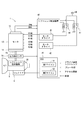
- the shift range control device 40 has motor drivers 41 and 42 as drive circuits, an ECU 50 as a control unit, and the like.
- the motor driver 41 is a three-phase inverter that switches the energization of the first motor winding 11, and the switching elements 411 to 416 are bridge-connected.
- One end of the U1 coil 111 is connected to a connection point between the U-phase switching elements 411 and 414 that are paired.
- One end of the V1 coil 112 is connected to the connection point of the V-phase switching elements 412 and 415 that are paired.
- One end of the W1 coil 113 is connected to a connection point of the W-phase switching elements 413 and 416 that are paired.
- the other ends of the coils 111 to 113 are connected by a connecting portion 115.
- the motor driver 42 is a three-phase inverter that switches the energization of the second motor winding 12, and the switching elements 421 to 426 are bridge-connected.
- One end of the U2 coil 121 is connected to the connection point of the U-phase switching elements 421 and 424 that form a pair.
- One end of the V2 coil 122 is connected to a connection point of the V-phase switching elements 422 and 425 which are paired.
- One end of the W2 coil 123 is connected to a connection point of the W-phase switching elements 423 and 426 which are paired.
- the other ends of the coils 121 to 123 are connected by a connecting portion 125.
- the switching elements 411 to 416 and 421 to 426 in the present embodiment are MOSFETs, other elements such as IGBTs may be used.
- a motor relay 46 is provided between the first motor driver 41 and the battery 45.
- a motor relay 47 is provided between the second motor driver 42 and the battery 45.
- the motor relays 46 and 47 are turned on when a start switch such as an ignition switch is turned on, and power is supplied to the motor 10 side.
- the motor relays 46 and 47 are turned off when the start switch is turned off, and the supply of power to the motor 10 side is cut off.
- a voltage sensor 48 for detecting the battery voltage Vb is provided on the high potential side of the battery 45.
- the ECU 50 controls the on / off operation of the switching elements 411 to 416 and 421 to 426, and controls the drive of the motor 10 to control the switching of the shift range. Further, the ECU 50 controls the driving of the shift hydraulic control solenoid 6 based on the vehicle speed, the accelerator opening degree, the driver's requested shift range, and the like. By controlling the shift hydraulic control solenoid 6, the gear is controlled.
- the transmission hydraulic control solenoid 6 is provided in a number corresponding to the number of shift stages and the like. In the present embodiment, one ECU 50 controls the drive of the motor 10 and the solenoid 6, but the motor control ECU for controlling the motor 10 may be divided into an AT-ECU for solenoid control. Hereinafter, drive control of the motor 10 will be mainly described.
- the ECU 50 has microcomputers 51 and 52 and the like, and internally includes a CPU, a ROM, a RAM, an I / O, and a bus line connecting these components, which are not shown.
- Each process in the ECU 50 may be a software process by executing a program stored in advance in a tangible memory device (that is, a readable non-transitory tangible recording medium) such as a ROM by a CPU, or may be dedicated It may be hardware processing by an electronic circuit.
- the first microcomputer 51 is connected to the first motor driver 41 and controls energization of the first motor winding 11.
- the second microcomputer 52 is connected to the second motor driver 42 and controls energization of the second motor winding 12.
- the microcomputers 51 and 52 perform calculations relating to drive control of the motor 10, and correspond to a "calculation unit".
- the microcomputers 51 and 52 perform feedback control or the like so that the motor angle ⁇ m is stopped at the motor angle target value ⁇ cmd set according to the required shift range based on the motor angle ⁇ m, the output shaft angle ⁇ s, etc. Control the drive.
- the details of the drive control of the motor 10 may be arbitrary.
- the microcomputers 51 and 52 also monitor the abnormality of the shift by wire system 1. In particular, in the present embodiment, due to the occurrence of a motor off failure in which the motor 10 stops during range switching, an intermediate range stop abnormality in which the detent roller 26 stops in the intermediate range region is detected.
- FIG. 4 the concept of “play” is schematically shown, in which the output shaft 15 and the reduction gear 14 are integrated, and the motor shaft 105 is movable within the range of the reduction gear 14. Described.
- the motor shaft 105 and the reduction gear 14 may be integrated, and “play” may be present between the reduction gear 14 and the output shaft 15.
- the “play” between the motor shaft 105 and the output shaft 15 will be described centering on what exists between the gear of the reduction gear 14 and the motor shaft 105, but “play” means the motor shaft 105.
- the output shaft 15 can be regarded as the sum of play and play.
- FIG. 4 schematically shows a state in which the detent roller 26 moves from the R valley portion 222 to the P valley portion 221 as the motor 10 rotates.
- the rotation direction of the motor 10 and the output shaft 15 is described as the left-right direction in the drawing, and the movement of the detent roller 26 along with the rotation of the motor 10 is shown from the upper stage to the lower stage.
- the detent roller 26 moves between the valleys 221 to 224 by rotating the detent plate 21 integrally with the output shaft 15.
- FIG. It is illustrated as moving.
- the load torque TL generated by the spring load SL of the detent spring 25 acts as a positive torque assisting the drive torque of the motor 10, and the drive torque of the motor 10
- the condition that acts as a negative torque that interferes with is repeated.
- the torque applied in the P direction with respect to the detent roller 26 is defined as a positive torque
- the torque applied in the D direction is defined as a negative torque.
- the positive torque is mainly generated by the driving torque of the motor 10 and the spring load SL during the descent of the detent roller 26.
- the negative torque is mainly generated by the spring load SL during climbing of the detent roller 26.
- the shift range is switched by moving the detent roller 26 between the valleys 221 to 224 by the rotation of the detent plate 21.
- the detent roller 26 is dropped to the valley portions 221 to 224 according to the required shift range by the spring load SL using the backlash provided between the motor shaft 105 and the output shaft 15.
- the motor 10 When moving the detent roller 26 from the R valley portion 222 to the P valley portion 221, as shown in the state a, the motor 10 is rotated in the backlash so that the motor shaft 105 and the reduction gear 14 abut each other. Get stuck. When the rattling occurs, the motor shaft 105 and the output shaft 15 rotate integrally, and the detent roller 26 starts climbing.
- the motor 10 pulls the output shaft 15 when the detent roller 26 moves up from the R valley portion 222 to the mountain portion 226.
- the spring load SL works as a negative torque.
- a DC motor having a permanent magnet is used as the motor 10, and motor cogging torque TC_M is generated periodically as shown in the lower part of FIG.
- the generation cycle of the cogging torque differs depending on the number of magnetic poles of the motor 10 and the like.
- the motor cogging torque TC_M is amplified according to the gear ratio of the reduction gear 14 and transmitted to the output shaft 15.
- the cogging torque amplified by the reduction gear 14 is referred to as an output shaft cogging torque TC_S.
- an output shaft in the case where energization is started when a certain time has elapsed from when the detent roller 26 is in the D valley portion 224 and the detent roller 26 reaches the P valley portion 221 has elapsed. It shows 15 stop positions. Even if energization is turned off during range switching, the detent roller 26 is dropped into any of the valleys 221 to 224 at the spring load SL depending on the energization OFF timing. However, as indicated by encircled by a two-dot chain line, if the current is turned off during climbing of the detent roller 26, the intermediate roller may stop in the middle range region.
- FIGS. 7 and 8 show experimental results when the current application time to the motor 10 is xa, which corresponds to the point A in FIG.
- the common time axis is taken as the horizontal axis, and the drive mode and the angle are shown from the upper stage.
- P, R, N, and D in the figure correspond to the output shaft angles when the detent roller 26 is at the center of the valleys 221 to 224.
- the motor angle ⁇ m and the motor angle target value ⁇ cmd are described in terms of output shaft.
- the manual valve 28 stops at a halfway position, so that an appropriate hydraulic pressure can not be generated, which may lead to failure of the automatic transmission 5. is there.
- a plurality of motor drive control systems are organized so that an intermediate range stop abnormality does not occur even if a break or the like occurs in part of the motor drive control system.
- the motor drive control system includes motor windings 11 and 12, motor drivers 41 and 42, microcomputers 51 and 52, and connection wiring for connecting them.
- the combination of the first motor winding 11, the first motor driver 41 and the first microcomputer 51, and the connection wires 61 and 71 connecting them is a first system
- the second motor winding 12 the second motor driver 42 and A combination of the second microcomputer 52 and the connection wires 62 and 72 connecting these is used as a second system.
- the first motor driver 41 is connected to the first microcomputer 51 by the first microcomputer side connection wire 61 and is connected to the first motor winding 11 by the first motor side connection wire 71. .
- the first microcomputer 51 controls the energization of the first motor winding 11 by controlling the on / off operation of the switching elements 411 to 416 (not shown in FIG. 9) of the first motor driver 41.
- the second motor driver 42 is connected to the second microcomputer 52 by the second microcomputer side connection wiring 62, and is connected to the second motor winding 12 by the second motor side connection wiring 72.
- the second microcomputer 52 controls the energization of the second motor winding 12 by controlling the on / off operation of the switching elements 421 to 426 (not shown in FIG. 9) of the second motor driver 42.
- the range switching request and the like are input to the microcomputers 51 and 52, respectively, and various controls are performed based on the input information.
- the motor windings 11 and 12 are indicated by the symbol "M".
- step S101 is omitted and simply referred to as the symbol “S”. The same applies to the other steps.
- S the same applies to the third to fifth embodiments.
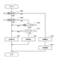
- the first microcomputer 51 determines whether or not its own system is normal. If it is determined that the own system is normal (S101: YES), the process proceeds to S102, and range switching is permitted. Specifically, in order to drive the motor 10 in accordance with the required shift range, control of energization of the first motor winding 11 is performed. If it is determined that the own system is not normal (S101: NO), the process proceeds to S103, and range switching in the own system is prohibited. Specifically, the first motor winding 11 is not energized. At this time, if the other system is normal, the driving of the motor 10 is continued using the other system.
- the first microcomputer 51 causes a failure in the first system to the second microcomputer 52 and another ECU (not shown) such as a host ECU that controls the entire vehicle, for example, outside the shift-by-wire system 1. Notify that it has occurred.
- Information transmission between the microcomputers 51 and 52 may be directly performed by inter-microcomputer communication, or may be performed via a vehicle communication network such as CAN (Controller Area Network).
- the shift-by-wire system 1 of the present embodiment includes the motor 10, the motor drivers 41 and 42, the output shaft 15, the shift range switching mechanism 20, and the ECU 50.
- the motor 10 has motor windings 11 and 12 and generates cogging torque by permanent magnets.
- the motor drivers 41 and 42 switch the energization of the motor windings 11 and 12.
- the output shaft 15 transmits the rotation of a motor shaft 105 which is a rotation shaft of the motor 10.
- the shift range switching mechanism 20 has a detent plate 21, a detent roller 26 and a detent spring 25.
- the detent plate 21 is formed with a plurality of valleys 221 to 224 and ridges 226 to 228 separating the valleys 221 to 224, and rotates integrally with the output shaft 15.
- the detent roller 26 fits into the valleys 221 to 224 according to the shift range.
- the detent spring 25 biases the detent roller 26 in a direction to fit the valleys 221-224.
- the ECU 50 has microcomputers 51 and 52 that perform calculations related to drive control of the motor 10.
- a play is formed between the motor shaft 105 and the output shaft 15, and the play can be used to drop the detent roller 26 into the valleys 221 to 224.
- Motor drivers 41 and 42, motor windings 11 and 12, connection wires 71 and 72 for connecting motor drivers 41 and 42 with motor windings 11 and 12, and microcomputers 51 and 52 are motor drive control systems.
- Output shaft cogging which is a cogging torque transmitted to the output shaft 15, when an abnormality occurs in the motor drive control system during uphill climbing in which the detent roller 26 is moving from the valleys 221 to 224 to the peaks 226 to 228.
- a plurality of motor drive control systems are provided to avoid occurrence of an intermediate range stop abnormality in which the output shaft 15 stops due to the balance of torque including the load torque by the torque and the detent spring 25.
- an abnormality occurs in the motor drive control system while the detent roller 26 climbs, the drive of the motor 10 can be continued, and the intermediate range stop abnormality is avoided. It is possible to prevent the failure of the
- Each of the microcomputers 51 and 52 independently controls energization of the corresponding motor windings 11 and 12 in response to the common range switching request.
- the motor 10 can be driven by using a plurality of systems simultaneously, and the output can be secured.
- the motor 10 can be driven as it is in the normal system and the range switching can be continued.
- the drive of the motor 10 is continued using the normal motor drive control system.
- the range switching can be continued even when an abnormality occurs in some of the systems.
- the first microcomputer 51 When an abnormality occurs in the motor drive control system, the first microcomputer 51 notifies the information indicating that the abnormality has occurred to at least one of the second microcomputer 52 which is the “other operation unit” and the outside of the system. Thereby, it is possible to take measures according to the abnormal state. Further, for example, early notification can be promoted by notifying the driver of the abnormality.
- Second Embodiment A second embodiment is shown in FIG.
- the microcomputers 51 and 52 perform synchronous control for matching control timing.
- clock signals held by the respective microcomputers 51 and 52 are synchronized.
- the synchronization control may be performed by sharing synchronization information between the microcomputers 51 and 52, or information such as an external clock from outside the microcomputers 51 and 52 may be used.
- the microcomputers 51 and 52 perform synchronization processing to synchronize the energization instruction timing with the other microcomputers 52 and 51.
- difference of the electricity_supply timing to motor winding 11 and 12 can be reduced.
- the same effect as that of the above embodiment can be obtained.
- Third Embodiment A third embodiment is shown in FIG. In the third to fifth embodiments, since the motor control process is performed with the first embodiment, this point will be mainly described. As in the second embodiment, synchronization control may be performed.
- the first microcomputer 51 determines whether or not its own system is normal. If it is determined that the own system is not normal (S201: NO), the process proceeds to S206.
- the processes of S206 and S207 are the same as the processes of S103 and S104 in FIG. If it is determined that the own system is normal (S201: YES), the process proceeds to S202.
- the first microcomputer 51 determines whether the other system is normal. If it is determined that the other system is normal (S202: YES), the process proceeds to S204, and range switching is permitted. If it is determined that the other system is not normal (S202: NO), the process proceeds to S203.
- the first microcomputer 51 determines whether the battery voltage Vb is equal to or higher than the voltage determination threshold Vth.
- the battery voltage Vb corresponds to “the input voltage input to the drive circuit”.
- the voltage determination threshold Vth is set to a voltage that can drive the motor 10 in one system.
- the voltage determination threshold Vth may have the same value regardless of the range, and for example, when the current shift range is the P range, the voltage determination threshold Vth is set to a larger value than in the other ranges. The values may be different depending on the current shift range. If it is determined that the battery voltage Vb is equal to or higher than the voltage determination threshold Vth (S203: YES), the process proceeds to S204, and range switching is permitted. If it is determined that the battery voltage Vb is less than the voltage determination threshold Vth (S203: NO), the process proceeds to S205 to prohibit range switching.
- the torque that can be output is reduced as compared with the case of driving by two systems. Furthermore, if the battery voltage is reduced, the torque that can be output is further reduced, and there is a possibility that the range switching may fail. So, in this embodiment, when abnormality has arisen in one system and battery voltage Vb is falling, change of shift range is prohibited. Thus, it is possible to prevent range switching failure due to a decrease in torque.
- the ECU 50 when abnormality occurs in a part of the motor drive control system, range switching execution determination is performed, and permission or prohibition of range switching is selected. Specifically, the ECU 50 performs range switching execution determination as: The battery voltage Vb is determined as the input voltage input to the motor drivers 41 and 42. When the battery voltage Vb is equal to or higher than the voltage determination threshold Vth, range switching is permitted, and when the battery voltage Vb is lower than the voltage determination threshold Vth Prohibit range switching. As a result, it is possible to prevent range switching failure due to insufficient torque due to failure of a part of the system, and it is possible to avoid occurrence of an intermediate range stop abnormality. In addition, the same effect as that of the above embodiment can be obtained.
- FIG. 4 A fourth embodiment is shown in FIG.
- the motor control process of the present embodiment is the same as that of the third embodiment except that the process of S211 is performed instead of S203 in FIG.
- the first microcomputer 51 determines whether or not the engine is being driven. When it is determined that the engine is being driven (S211: YES), the process proceeds to S204, and range switching is permitted. When it is determined that the engine is not being driven (S211: NO), the process proceeds to S205, and range switching is prohibited.
- the ECU 50 determines the driving state of the engine as the range switching execution determination.
- the engine is running, allow range switching, and when the engine is stopped, prohibit range switching.
- the battery voltage Vb may be reduced. Therefore, in the present embodiment, switching of the shift range is prohibited when an abnormality occurs in one system and the engine is stopped. As a result, it is possible to prevent range switching failure due to insufficient torque, and it is possible to avoid the occurrence of an intermediate range stop abnormality. In addition, the same effect as that of the above embodiment can be obtained.
- step S216 in which a negative determination is made in step S202, the first microcomputer 51 determines whether the current shift range is outside the P range. If it is determined that the current shift range is not the P range (S216: YES), the process proceeds to S204, and range switching is permitted. If it is determined that the current shift range is the P range (S216: NO), the process proceeds to S217.
- the first microcomputer 51 determines whether the inclination angle ⁇ i of the vehicle is equal to or less than the angle determination threshold ⁇ th.
- the inclination angle ⁇ i of the vehicle is calculated based on, for example, the detection value of the inclination angle sensor. If it is determined that the inclination angle ⁇ i is equal to or less than the angle determination threshold ⁇ th (S217: YES), the process proceeds to S204, and range switching is permitted. If it is determined that the inclination angle ⁇ i is larger than the angle determination threshold ⁇ th (S217: NO), the process proceeds to S205, and range switching is prohibited.
- the ECU 50 determines the current shift range as the range switching implementation determination. When the current shift range is other than the P range, range switching is permitted, and when the current shift range is the P range, range switching is prohibited. Further, the ECU 50 determines the current shift range and the inclination angle ⁇ i of the vehicle as the range switching implementation determination. When the current shift range is other than the P range, and when the current shift range is the P range and the inclination angle ⁇ i is less than or equal to the angle determination threshold ⁇ th, range switching is permitted. When the current shift range is the P range and the inclination angle ⁇ i is larger than the angle determination threshold ⁇ th, range switching is prohibited. This makes it possible to prevent range switching failure due to insufficient torque when removing P, which requires a relatively large torque, and to avoid the occurrence of an intermediate range stop abnormality. In addition, the same effect as that of the above embodiment can be obtained.
- the motor is a DC brushless motor. In other embodiments, the motor may be other than a DC brushless motor that generates cogging torque.
- the motor driver as the drive circuit is a three-phase inverter. In other embodiments, the drive circuit may be any circuit configuration that can switch the energization of the motor windings. In the above embodiment, two motor drive control systems are provided. In another embodiment, three or more motor drive control systems may be provided.
- the motor rotation angle sensor is an encoder. In another embodiment, the motor rotation angle sensor is not limited to the encoder, and any sensor such as a resolver may be used. In the above embodiment, a potentiometer is illustrated as an output axis sensor. In other embodiments, the output shaft sensor may be of any type, for example, may be constituted by a switch turned on in each range guaranteeing area, or a non-contact magnetic sensor may be used. Good. Also, the output shaft sensor may be omitted.
- the detent plate is provided with four valleys.
- the number of valleys is not limited to four, but may be any number.
- two valleys corresponding to the P range and the not P range which is a range other than the P range may be provided.
- the shift range switching mechanism, the parking lock mechanism, etc. may be different from the above embodiment.
- a reduction gear is provided between the motor shaft and the output shaft.
- the details of the reduction gear are not mentioned in the above embodiment, for example, a cycloid gear, a planetary gear, a spur gear that transmits torque from the reduction mechanism substantially coaxial with the motor shaft to the drive shaft, or these Any configuration may be used, such as one using a combination of
- the reduction gear between the motor shaft and the output shaft may be omitted, or a mechanism other than the reduction gear may be provided.
- this indication is not limited at all to the above-mentioned embodiment, and can be carried out in various forms in the range which does not deviate from the meaning.
Landscapes
- Engineering & Computer Science (AREA)
- General Engineering & Computer Science (AREA)
- Mechanical Engineering (AREA)
- Power Engineering (AREA)
- Gear-Shifting Mechanisms (AREA)
- Connection Of Motors, Electrical Generators, Mechanical Devices, And The Like (AREA)
Abstract
The present invention has play formed between a motor shaft (105) and an output shaft (15) and can use the play to drop an engagement member (26) into valleys (221–24). A motor drive system comprises drive circuits (41, 42), motor windings (11, 12), connection wiring (71, 72) that connects the drive circuits (41, 42) and motor windings (11, 12), and calculation units (51, 52). A plurality of motor drive control systems are provided so as to avoid the occurrence of intermediate range stop errors whereby the output shaft (15) stops as a result of the balance between torque including output shaft cogging torque, being cogging torque transmitted to the output shaft (14), and load torque caused by an impelling member (25), when an error has occurred in a motor drive system during mountain climbing, being during travel of an engagement member (26) from valleys (221–24) to ridges (226–228).
Description
本出願は、2017年11月20日に出願された特許出願番号2017-222865号に基づくものであり、ここにその記載内容を援用する。
This application is based on patent application number 2017-222865 filed on November 20, 2017, the contents of which are incorporated herein by reference.
本開示は、シフトレンジ切替システムに関する。
The present disclosure relates to a shift range switching system.
従来、運転者からのシフトレンジ切替要求に応じてモータを制御することでシフトレンジを切り替えるシフト装置が知られている。例えば特許文献1では、2つの中間ギアの間に設けた所定量のガタを利用することで谷底の位置を学習している。
BACKGROUND Conventionally, there is known a shift device that switches a shift range by controlling a motor in response to a shift range switching request from a driver. For example, in Patent Document 1, the position of the valley bottom is learned by using a predetermined amount of rattling provided between two intermediate gears.
特許文献1では、ディテントスプリングの付勢力は、ローラ部が谷部に落ち込むように働く力である。シフトレンジ切替システムでは、レンジを切り替えるとき、ローラ部が山谷を移動していくのに伴い、スプリング荷重がモータトルクをアシストする方向に働く状態と、モータトルクを妨げる方向に働く状態とが繰り返し発生する。
In Patent Document 1, the biasing force of the detent spring is a force that causes the roller portion to fall into the valley. In the shift range switching system, when switching the range, a state where the spring load works in the direction of assisting the motor torque and a state in which the spring load works in the direction of blocking the motor torque occur repeatedly as the roller moves in the valley. Do.
駆動源として、コギングトルクが発生するモータを用いた場合、スプリング荷重による負荷トルクと、コギングトルクおよびモータフリクション等によるトルクとが釣り合うトルク釣り合い点が生じる。ここで、シフトレンジの切り替え中にモータを駆動できなくなるモータオフ故障が生じた場合、モータオフ故障発生時のモータ位置によっては、トルクが釣り合い、中間レンジにて出力軸が停止してしまうという新たな課題が見いだされた。出力軸が中間レンジにて停止すると、自動変速機にて適切な油圧を発生させることができず、自動変速機の故障につながる虞がある。本開示の目的は、モータ駆動制御系の一部に異常が生じた場合であってもモータの駆動を継続可能であるシフトレンジ切替システムを提供することにある。
When a motor that generates cogging torque is used as a drive source, a torque balance point occurs in which the load torque due to the spring load and the torque due to the cogging torque and motor friction and the like are balanced. Here, if a motor-off failure that can not drive the motor occurs while switching the shift range, the torque balances depending on the motor position at the time of the motor-off failure, and the output shaft stops in the middle range. Was found. If the output shaft stops in the middle range, the automatic transmission can not generate an appropriate hydraulic pressure, which may lead to a failure of the automatic transmission. An object of the present disclosure is to provide a shift range switching system capable of continuing the drive of the motor even when an abnormality occurs in a part of the motor drive control system.
本開示のシフトレンジ切替システムは、モータと、駆動回路と、出力軸と、シフトレンジ切替機構と、制御部と、を備える。モータは、モータ巻線を有し、永久磁石によるコギングトルクが発生する。駆動回路は、モータ巻線への通電を切り替える。出力軸は、モータの回転軸であるモータ軸の回転が伝達される。シフトレンジ切替機構は、谷部形成部材、係合部材および付勢部材を有する。谷部形成部材には、複数の谷部および谷部を隔てる山部が形成され、出力軸と一体に回転する。係合部材は、シフトレンジに応じた谷部に嵌まり合う。付勢部材は、係合部材を谷部に嵌まり合う方向に付勢する。制御部は、モータの駆動制御に係る演算を行う演算部を有する。
The shift range switching system of the present disclosure includes a motor, a drive circuit, an output shaft, a shift range switching mechanism, and a control unit. The motor has a motor winding, and a cogging torque is generated by the permanent magnet. The drive circuit switches energization of the motor winding. The output shaft transmits the rotation of a motor shaft, which is a rotational shaft of the motor. The shift range switching mechanism has a valley forming member, an engaging member, and a biasing member. The valley forming member is formed with a plurality of valleys and ridges separating the valleys, and rotates integrally with the output shaft. The engagement member fits in a valley corresponding to the shift range. The biasing member biases the engaging member in a direction to fit in the valley. The control unit has an operation unit that performs an operation related to drive control of the motor.
モータ軸と出力軸との間には遊びが形成されており、遊びを利用して係合部材を谷部に落とすことが可能である。駆動回路、モータ巻線、駆動回路とモータ巻線とを接続する接続配線、および、演算部をモータ駆動制御系統とする。係合部材が谷部から山部への移動中である山上り中にモータ駆動制御系統に異常が生じたとき、出力軸に伝達されるコギングトルクである出力軸コギングトルクおよび付勢部材の負荷トルクを含むトルクの釣り合いにより出力軸が停止する中間レンジ停止異常の発生を回避するように、モータ駆動制御系統が複数系統設けられている。
A play is formed between the motor shaft and the output shaft, and the play can be used to drop the engagement member into the valley. A drive circuit, a motor winding, a connection wire connecting the drive circuit and the motor winding, and an arithmetic unit are used as a motor drive control system. The output shaft cogging torque, which is a cogging torque transmitted to the output shaft, and the load of the biasing member when an abnormality occurs in the motor drive control system while the engaging member is moving from the valley portion to the peak portion. A plurality of motor drive control systems are provided to avoid the occurrence of an intermediate range stop abnormality in which the output shaft stops due to the balance of torque including torque.
これにより、係合部材の山上り中に一部のモータ駆動制御系統に異常が生じた場合であっても、モータの駆動を継続可能であって、中間レンジ停止異常が回避されるので、自動変速機の故障を防止することができる。
As a result, even if an abnormality occurs in a part of the motor drive control system during the climbing of the engaging member, the driving of the motor can be continued, and the intermediate range stop abnormality is avoided, so the automatic operation is possible. Failure of the transmission can be prevented.
本開示についての上記目的及びその他の目的、特徴や利点は、添付の図面を参照しながら下記の詳細な記述により、より明確になる。その図面は、
図1は、第1実施形態によるシフトバイワイヤシステムを示す斜視図であり、
図2は、第1実施形態によるシフトバイワイヤシステムを示す概略構成図であり、
図3は、第1実施形態によるモータおよびモータドライバを示す回路図であり、
図4は、第1実施形態によるディテント機構の挙動を説明する説明図であり、
図5は、第1実施形態によるディテント機構に加わるトルクを説明する説明図であり、
図6は、第1実施形態による通電時間と出力軸停止位置との関係を示す説明図であり、
図7は、第1実施形態において、所定時間通電後に通電をオフにした場合の実験結果を示すタイムチャートであり、
図8は、第1実施形態による中間レンジ停止異常が発生している状態を示す模式図であり、
図9は、第1実施形態によるモータ駆動制御系統を示す模式図であり、
図10は、第1実施形態によるモータ制御処理を説明するフローチャートであり、
図11は、第2実施形態によるモータ駆動制御系統を示す模式図であり、
図12は、第3実施形態によるモータ制御処理を説明するフローチャートであり、
図13は、第4実施形態によるモータ制御処理を説明するフローチャートであり、
図14は、第5実施形態によるモータ制御処理を説明するフローチャートである。
The above object and other objects, features and advantages of the present disclosure will become more apparent from the following detailed description with reference to the attached drawings. The drawing is
FIG. 1 is a perspective view of a shift-by-wire system according to a first embodiment, FIG. 2 is a schematic block diagram showing a shift-by-wire system according to the first embodiment, FIG. 3 is a circuit diagram showing a motor and a motor driver according to the first embodiment, FIG. 4 is an explanatory view for explaining the behavior of the detent mechanism according to the first embodiment, FIG. 5 is an explanatory view for explaining a torque applied to the detent mechanism according to the first embodiment, FIG. 6 is an explanatory view showing the relationship between the energization time and the output shaft stop position according to the first embodiment, FIG. 7 is a time chart showing experimental results in the case where the energization is turned off after the energization for a predetermined time in the first embodiment, FIG. 8 is a schematic view showing a state in which an intermediate range stop abnormality has occurred according to the first embodiment, FIG. 9 is a schematic view showing a motor drive control system according to the first embodiment, FIG. 10 is a flowchart illustrating motor control processing according to the first embodiment, FIG. 11 is a schematic view showing a motor drive control system according to the second embodiment, FIG. 12 is a flowchart illustrating motor control processing according to the third embodiment, FIG. 13 is a flowchart illustrating motor control processing according to the fourth embodiment, FIG. 14 is a flowchart illustrating motor control processing according to the fifth embodiment.
以下、シフトレンジ切替システムを図面に基づいて説明する。以下、複数の実施形態において、実質的に同一の構成には同一の符号を付して説明を省略する。
(第1実施形態)
第1実施形態によるシフトレンジ制御装置を図1~図10に示す。図1および図2に示すように、シフトレンジ切替システムとしてのシフトバイワイヤシステム1は、モータ10、シフトレンジ切替機構20、パーキングロック機構30、および、シフトレンジ制御装置40等を備える。 Hereinafter, the shift range switching system will be described based on the drawings. Hereinafter, in a plurality of embodiments, substantially the same configuration will be assigned the same reference numerals and descriptions thereof will be omitted.
First Embodiment
A shift range control device according to a first embodiment is shown in FIGS. As shown in FIGS. 1 and 2, the shift-by-wire system 1 as a shift range switching system includes a motor 10, a shift range switching mechanism 20, a parking lock mechanism 30, a shift range control device 40, and the like.
(第1実施形態)
第1実施形態によるシフトレンジ制御装置を図1~図10に示す。図1および図2に示すように、シフトレンジ切替システムとしてのシフトバイワイヤシステム1は、モータ10、シフトレンジ切替機構20、パーキングロック機構30、および、シフトレンジ制御装置40等を備える。 Hereinafter, the shift range switching system will be described based on the drawings. Hereinafter, in a plurality of embodiments, substantially the same configuration will be assigned the same reference numerals and descriptions thereof will be omitted.
First Embodiment
A shift range control device according to a first embodiment is shown in FIGS. As shown in FIGS. 1 and 2, the shift-by-
モータ10は、図示しない車両に搭載されるバッテリ45(図3参照)から電力が供給されることで回転し、シフトレンジ切替機構20の駆動源として機能する。本実施形態のモータ10は、永久磁石式のDCブラシレスモータであって、コギングトルクが発生する。本明細書では、通電オフ時にも生じるコギングトルクおよびモータフリクション等によるトルクを、適宜「モータコギングトルク」と記載する。
The motor 10 is rotated by being supplied with electric power from a battery 45 (see FIG. 3) mounted on a vehicle (not shown), and functions as a drive source of the shift range switching mechanism 20. The motor 10 according to the present embodiment is a permanent magnet type DC brushless motor, and generates cogging torque. In the present specification, the cogging torque and the torque due to the motor friction and the like which are generated also at the time of deenergization are appropriately described as “motor cogging torque”.
図3に示すように、モータ10は、2組のモータ巻線11、12を有する。第1モータ巻線11は、U1コイル111、V1コイル112、および、W1コイル113を有する。第2モータ巻線12は、U2コイル121、V2コイル122、および、W2コイル123を有する。
As shown in FIG. 3, the motor 10 has two sets of motor windings 11 and 12. The first motor winding 11 has a U1 coil 111, a V1 coil 112, and a W1 coil 113. The second motor winding 12 has a U2 coil 121, a V2 coil 122, and a W2 coil 123.
図2に示すように、エンコーダ13は、モータ10の図示しないロータの回転位置であるモータ角度θmを検出する。エンコーダ13は、例えば磁気式のロータリーエンコーダであって、ロータと一体に回転する磁石と、磁気検出用のホールIC等により構成される。エンコーダ13は、ロータの回転に同期して、所定角度ごとにA相およびB相のパルス信号を出力する。
As shown in FIG. 2, the encoder 13 detects a motor angle θm which is a rotational position of a not-shown rotor of the motor 10. The encoder 13 is, for example, a magnetic rotary encoder, and includes a magnet that rotates integrally with the rotor, and a Hall IC for magnetic detection. The encoder 13 outputs A-phase and B-phase pulse signals at predetermined angles in synchronization with the rotation of the rotor.
減速機14は、モータ10の回転軸であるモータ軸105(図4参照)と出力軸15との間に設けられ、モータ10の回転を減速して出力軸15に出力する。これにより、モータ10の回転がシフトレンジ切替機構20に伝達される。出力軸15には、出力軸15の角度である出力軸角度θsを検出する出力軸センサ16が設けられる。出力軸センサ16は、例えばポテンショメータである。実施形態では、モータ軸105と出力軸15との間には、ギアバックラッシュ等の遊びが存在している。以下適宜、モータ軸105と出力軸15との間の遊びの合計を、「ガタ」とする。
The reduction gear 14 is provided between a motor shaft 105 (see FIG. 4), which is a rotation shaft of the motor 10, and the output shaft 15, and decelerates the rotation of the motor 10 and outputs it to the output shaft 15. Thus, the rotation of the motor 10 is transmitted to the shift range switching mechanism 20. The output shaft 15 is provided with an output shaft sensor 16 that detects an output shaft angle θs that is an angle of the output shaft 15. The output shaft sensor 16 is, for example, a potentiometer. In the embodiment, a play such as a gear backlash exists between the motor shaft 105 and the output shaft 15. Hereinafter, as appropriate, the total of the play between the motor shaft 105 and the output shaft 15 will be referred to as "play".
図1に示すように、シフトレンジ切替機構20は、ディテントプレート21、および、ディテントスプリング25等を有し、減速機14から出力された回転駆動力を、マニュアルバルブ28、および、パーキングロック機構30へ伝達する。
As shown in FIG. 1, the shift range switching mechanism 20 has a detent plate 21 and a detent spring 25 and the like, and the rotational driving force output from the reduction gear 14 is a manual valve 28 and a parking lock mechanism 30. Transmit to
ディテントプレート21は、出力軸15に固定され、モータ10により駆動される。ディテントプレート21には、出力軸15と平行に突出するピン24が設けられる。ピン24は、マニュアルバルブ28と接続される。ディテントプレート21がモータ10によって駆動されることで、マニュアルバルブ28は軸方向に往復移動する。すなわち、シフトレンジ切替機構20は、モータ10の回転運動を直線運動に変換してマニュアルバルブ28に伝達する。マニュアルバルブ28は、バルブボディ29に設けられる。マニュアルバルブ28が軸方向に往復移動することで、図示しない油圧クラッチへの油圧供給路が切り替えられ、油圧クラッチの係合状態が切り替わることでシフトレンジが変更される。
The detent plate 21 is fixed to the output shaft 15 and driven by the motor 10. The detent plate 21 is provided with a pin 24 projecting in parallel with the output shaft 15. The pin 24 is connected to the manual valve 28. When the detent plate 21 is driven by the motor 10, the manual valve 28 reciprocates in the axial direction. That is, the shift range switching mechanism 20 converts the rotational movement of the motor 10 into a linear movement and transmits it to the manual valve 28. The manual valve 28 is provided on the valve body 29. The manual valve 28 reciprocates in the axial direction, thereby switching the hydraulic pressure supply path to the hydraulic clutch (not shown), and switching the engagement state of the hydraulic clutch changes the shift range.
図1および図5に示すように、谷部形成部材であるディテントプレート21のディテントスプリング25側には、マニュアルバルブ28を各レンジに対応する位置に保持するための4つの谷部221~224が設けられる。谷部221~224は、ディテントスプリング25の先端側から、P(パーキング)レンジに対応するP谷部221、R(リバース)レンジに対応するR谷部222、N(ニュートラル)レンジに対応するN谷部223、D(ドライブ)レンジに対応するD谷部224の順に配列されている。
As shown in FIGS. 1 and 5, on the detent spring 25 side of the detent plate 21 which is a valley portion forming member, four valley portions 221 to 224 for holding the manual valve 28 at positions corresponding to the respective ranges are provided. Provided. The valleys 221 to 224 are a P valley 221 corresponding to the P (parking) range, an R valley 222 corresponding to the R (reverse) range, and an N corresponding to the N (neutral) range from the front end side of the detent spring 25. The valleys 223 and the D valleys 224 corresponding to the D (drive) range are arranged in this order.
付勢部材であるディテントスプリング25は、弾性変形可能な板状部材であり、先端に係合部材であるディテントローラ26が設けられる。ディテントスプリング25は、ディテントローラ26をディテントプレート21の回動中心側に付勢する。ディテントプレート21に所定以上の回転力が加わると、ディテントスプリング25が弾性変形し、ディテントローラ26が谷部221~224を移動する。例えば、PレンジからDレンジに切り替えるとき、ディテントプレート21が正回転方向に回転することで、ディテントローラ26は、P谷部221からD谷部224に移動し、D谷部224に嵌まり合う。ディテントローラ26が谷部221~224のいずれかに嵌まり込むことで、ディテントプレート21の揺動が規制され、マニュアルバルブ28の軸方向位置、および、パーキングロック機構30の状態が決定され、自動変速機5のシフトレンジが固定される。
The detent spring 25 as a biasing member is an elastically deformable plate-like member, and a detent roller 26 as an engagement member is provided at the tip. The detent spring 25 biases the detent roller 26 toward the rotation center of the detent plate 21. When a rotational force of a predetermined value or more is applied to the detent plate 21, the detent spring 25 elastically deforms and the detent roller 26 moves in the valleys 221 to 224. For example, when switching from the P range to the D range, the detent plate 26 rotates in the forward rotation direction, whereby the detent roller 26 moves from the P valley portion 221 to the D valley portion 224 and fits in the D valley portion 224 . By the detent roller 26 being fitted in any of the valleys 221 to 224, the swing of the detent plate 21 is restricted, the axial position of the manual valve 28 and the state of the parking lock mechanism 30 are determined, and the automatic The shift range of the transmission 5 is fixed.
図6に示すように、領域Rpは、P谷部221の中心よりR谷部222側の所定位置よりも反R谷部222側の領域であって、ディテントローラ26が領域Rpにある出力軸角度のとき、パーキングロック機構30によるパーキングロックが保証されるPロック保証範囲である。領域Rrは、R谷部222の中心を含む所定範囲であって、ディテントローラ26が領域Rrにある出力軸角度のとき、自動変速機5にてRレンジの油圧が保証されるR油圧発生範囲である。領域Rdは、D谷部224の中心を含む所定範囲であって、ディテントローラ26が領域Rdにある出力軸角度のとき、自動変速機5にてDレンジの油圧が保証されるD油圧発生範囲である。領域Rnは、N谷部223の中心を含む所定範囲であって、ディテントローラ26が領域Rnにある出力軸角度のとき、自動変速機5の油路において、図示しない摩擦係合要素が係合されておらず、油圧が発生していないことが保証される範囲である。以下適宜、領域Rp、Rr、Rn、Rdをレンジ保証領域とし、レンジ保証領域以外を中間レンジ領域とする。
As shown in FIG. 6, the region Rp is a region on the side opposite to the R valley portion 222 with respect to the predetermined position on the R valley portion 222 side from the center of the P valley portion 221, and the output shaft with the detent roller 26 in the region Rp At the angle, the parking lock by the parking lock mechanism 30 is a P lock guarantee range in which the parking lock is guaranteed. The range Rr is a predetermined range including the center of the R valley 222, and the R hydraulic pressure is guaranteed in the R range by the automatic transmission 5 when the detent roller 26 is at the output shaft angle in the range Rr. It is. Region Rd is a predetermined range including the center of the D valley portion 224, and when the detent roller 26 is at the output shaft angle in the region Rd, the D hydraulic pressure generation range in which the hydraulic pressure of the D range is guaranteed in the automatic transmission 5 It is. Region Rn is a predetermined region including the center of N valley 223, and when the detent roller 26 is at the output shaft angle in region Rn, a friction engagement element (not shown) is engaged in the oil passage of automatic transmission 5 And it is a range where it is guaranteed that oil pressure is not generated. Hereinafter, regions Rp, Rr, Rn, and Rd are appropriately set as range guaranteeing regions, and regions other than the range guaranteeing region are set as intermediate range regions.
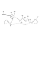
図1に示すように、パーキングロック機構30は、パーキングロッド31、円錐体32、パーキングロックポール33、軸部34、および、パーキングギア35を有する。パーキングロッド31は、略L字形状に形成され、一端311側がディテントプレート21に固定される。パーキングロッド31の他端312側には、円錐体32が設けられる。円錐体32は、他端312側にいくほど縮径するように形成される。ディテントプレート21が逆回転方向に揺動すると、円錐体32が矢印Pの方向に移動する。
As shown in FIG. 1, the parking lock mechanism 30 has a parking rod 31, a cone 32, a parking lock pole 33, a shaft 34 and a parking gear 35. The parking rod 31 is formed in a substantially L-shape, and one end 311 side is fixed to the detent plate 21. A conical body 32 is provided on the other end 312 side of the parking rod 31. The conical body 32 is formed to decrease in diameter toward the other end 312 side. When the detent plate 21 swings in the reverse rotation direction, the conical body 32 moves in the direction of the arrow P.
パーキングロックポール33は、円錐体32の円錐面と当接し、軸部34を中心に揺動可能に設けられる、パーキングロックポール33のパーキングギア35側には、パーキングギア35と噛み合い可能な凸部331が設けられる。ディテントプレート21が逆回転方向に回転し、円錐体32が矢印P方向に移動すると、パーキングロックポール33が押し上げられ、凸部331とパーキングギア35とが噛み合う。一方、ディテントプレート21が正回転方向に回転し、円錐体32が矢印notP方向に移動すると、凸部331とパーキングギア35との噛み合いが解除される。
The parking lock pole 33 abuts on the conical surface of the conical body 32 and is provided so as to be able to pivot about the shaft 34. A protrusion capable of meshing with the parking gear 35 on the parking gear 35 side of the parking lock pole 33 331 are provided. When the detent plate 21 rotates in the reverse rotation direction and the cone 32 moves in the arrow P direction, the parking lock pole 33 is pushed up, and the convex portion 331 and the parking gear 35 mesh with each other. On the other hand, when the detent plate 21 rotates in the normal rotation direction and the conical body 32 moves in the arrow notP direction, the engagement between the convex portion 331 and the parking gear 35 is released.
パーキングギア35は、図示しない車軸に設けられ、パーキングロックポール33の凸部331と噛み合い可能に設けられる。パーキングギア35と凸部331とが噛み合うと、車軸の回転が規制される。シフトレンジがP以外のレンジであるnotPレンジのとき、パーキングギア35はパーキングロックポール33によりロックされず、車軸の回転は、パーキングロック機構30により妨げられない。また、シフトレンジがPレンジのとき、パーキングギア35はパーキングロックポール33によってロックされ、車軸の回転が規制される。
The parking gear 35 is provided on an axle (not shown), and is provided so as to be able to mesh with the convex portion 331 of the parking lock pole 33. When the parking gear 35 and the convex portion 331 mesh with each other, the rotation of the axle is restricted. When the shift range is the not P range which is a range other than P, the parking gear 35 is not locked by the parking lock pole 33, and the rotation of the axle is not blocked by the parking lock mechanism 30. Further, when the shift range is the P range, the parking gear 35 is locked by the parking lock pole 33, and the rotation of the axle is restricted.
図2および図3に示すように、シフトレンジ制御装置40は、駆動回路としてのモータドライバ41、42、および、制御部としてのECU50等を有する。モータドライバ41は、第1モータ巻線11の通電を切り替える3相インバータであって、スイッチング素子411~416がブリッジ接続される。対になるU相のスイッチング素子411、414の接続点には、U1コイル111の一端が接続される。対になるV相のスイッチング素子412、415の接続点には、V1コイル112の一端が接続される。対になるW相のスイッチング素子413、416の接続点には、W1コイル113の一端が接続される。コイル111~113の他端は、結線部115で結線される。
As shown in FIGS. 2 and 3, the shift range control device 40 has motor drivers 41 and 42 as drive circuits, an ECU 50 as a control unit, and the like. The motor driver 41 is a three-phase inverter that switches the energization of the first motor winding 11, and the switching elements 411 to 416 are bridge-connected. One end of the U1 coil 111 is connected to a connection point between the U-phase switching elements 411 and 414 that are paired. One end of the V1 coil 112 is connected to the connection point of the V- phase switching elements 412 and 415 that are paired. One end of the W1 coil 113 is connected to a connection point of the W- phase switching elements 413 and 416 that are paired. The other ends of the coils 111 to 113 are connected by a connecting portion 115.
モータドライバ42は、第2モータ巻線12の通電を切り替える3相インバータであって、スイッチング素子421~426がブリッジ接続される。対になるU相のスイッチング素子421、424の接続点には、U2コイル121の一端が接続される。対になるV相のスイッチング素子422、425の接続点には、V2コイル122の一端が接続される。対になるW相のスイッチング素子423、426の接続点には、W2コイル123の一端が接続される。コイル121~123の他端は、結線部125で結線される。本実施形態のスイッチング素子411~416、421~426は、MOSFETであるが、IGBT等の他の素子を用いてもよい。
The motor driver 42 is a three-phase inverter that switches the energization of the second motor winding 12, and the switching elements 421 to 426 are bridge-connected. One end of the U2 coil 121 is connected to the connection point of the U-phase switching elements 421 and 424 that form a pair. One end of the V2 coil 122 is connected to a connection point of the V- phase switching elements 422 and 425 which are paired. One end of the W2 coil 123 is connected to a connection point of the W- phase switching elements 423 and 426 which are paired. The other ends of the coils 121 to 123 are connected by a connecting portion 125. Although the switching elements 411 to 416 and 421 to 426 in the present embodiment are MOSFETs, other elements such as IGBTs may be used.
第1モータドライバ41とバッテリ45との間には、モータリレー46が設けられる。第2モータドライバ42とバッテリ45との間には、モータリレー47が設けられる。モータリレー46、47は、イグニッションスイッチ等である始動スイッチがオンされているときにオンされ、モータ10側へ電力が供給される。また、モータリレー46、47は、始動スイッチがオフされているときにオフされ、モータ10側への電力の供給が遮断される。バッテリ45の高電位側には、バッテリ電圧Vbを検出する電圧センサ48が設けられる。
A motor relay 46 is provided between the first motor driver 41 and the battery 45. A motor relay 47 is provided between the second motor driver 42 and the battery 45. The motor relays 46 and 47 are turned on when a start switch such as an ignition switch is turned on, and power is supplied to the motor 10 side. The motor relays 46 and 47 are turned off when the start switch is turned off, and the supply of power to the motor 10 side is cut off. On the high potential side of the battery 45, a voltage sensor 48 for detecting the battery voltage Vb is provided.
ECU50は、スイッチング素子411~416、421~426のオンオフ作動を制御し、モータ10の駆動を制御することで、シフトレンジの切り替えを制御する。また、ECU50は、車速、アクセル開度、および、ドライバ要求シフトレンジ等に基づき、変速用油圧制御ソレノイド6の駆動を制御する。変速用油圧制御ソレノイド6を制御することで、変速段が制御される。変速用油圧制御ソレノイド6は、変速段数等に応じた本数が設けられる。本実施形態では、1つのECU50がモータ10およびソレノイド6の駆動を制御するが、モータ10を制御するモータ制御用のモータECUと、ソレノイド制御用のAT-ECUとを分けてもよい。以下、モータ10の駆動制御を中心に説明する。
The ECU 50 controls the on / off operation of the switching elements 411 to 416 and 421 to 426, and controls the drive of the motor 10 to control the switching of the shift range. Further, the ECU 50 controls the driving of the shift hydraulic control solenoid 6 based on the vehicle speed, the accelerator opening degree, the driver's requested shift range, and the like. By controlling the shift hydraulic control solenoid 6, the gear is controlled. The transmission hydraulic control solenoid 6 is provided in a number corresponding to the number of shift stages and the like. In the present embodiment, one ECU 50 controls the drive of the motor 10 and the solenoid 6, but the motor control ECU for controlling the motor 10 may be divided into an AT-ECU for solenoid control. Hereinafter, drive control of the motor 10 will be mainly described.
ECU50は、マイコン51、52等を有し、内部にはいずれも図示しないCPU、ROM、RAM、I/O、及び、これらの構成を接続するバスライン等を備えている。ECU50における各処理は、ROM等の実体的なメモリ装置(すなわち、読み出し可能非一時的有形記録媒体)に予め記憶されたプログラムをCPUで実行することによるソフトウェア処理であってもよいし、専用の電子回路によるハードウェア処理であってもよい。
The ECU 50 has microcomputers 51 and 52 and the like, and internally includes a CPU, a ROM, a RAM, an I / O, and a bus line connecting these components, which are not shown. Each process in the ECU 50 may be a software process by executing a program stored in advance in a tangible memory device (that is, a readable non-transitory tangible recording medium) such as a ROM by a CPU, or may be dedicated It may be hardware processing by an electronic circuit.
図2および図9に示すように、第1マイコン51は、第1モータドライバ41と接続され、第1モータ巻線11の通電を制御する。第2マイコン52は、第2マイコン52は、第2モータドライバ42と接続され、第2モータ巻線12の通電を制御する。マイコン51、52は、モータ10の駆動制御に係る演算を行うものであって、「演算部」に対応する。
As shown in FIGS. 2 and 9, the first microcomputer 51 is connected to the first motor driver 41 and controls energization of the first motor winding 11. The second microcomputer 52 is connected to the second motor driver 42 and controls energization of the second motor winding 12. The microcomputers 51 and 52 perform calculations relating to drive control of the motor 10, and correspond to a "calculation unit".
マイコン51、52は、モータ角度θmおよび出力軸角度θs等に基づき、モータ角度θmが要求シフトレンジに応じて設定されるモータ角度目標値θcmdにて停止するように、フィードバック制御等によりモータ10の駆動を制御する。モータ10の駆動制御の詳細は、どのようであってもよい。また、マイコン51、52は、シフトバイワイヤシステム1の異常を監視する。特に本実施形態では、レンジ切替中にモータ10が停止するモータオフ故障の発生により、ディテントローラ26が中間レンジ領域にて停止する中間レンジ停止異常を検出する。
The microcomputers 51 and 52 perform feedback control or the like so that the motor angle θm is stopped at the motor angle target value θcmd set according to the required shift range based on the motor angle θm, the output shaft angle θs, etc. Control the drive. The details of the drive control of the motor 10 may be arbitrary. The microcomputers 51 and 52 also monitor the abnormality of the shift by wire system 1. In particular, in the present embodiment, due to the occurrence of a motor off failure in which the motor 10 stops during range switching, an intermediate range stop abnormality in which the detent roller 26 stops in the intermediate range region is detected.
ここで、シフトレンジ切替時におけるディテント機構の挙動を図4に基づいて説明する。図4では、「遊び」の概念を模式的に示しており、出力軸15と減速機14とが一体となっており、モータ軸105が減速機14の遊びの範囲で移動可能であるものとして記載している。なお、モータ軸105と減速機14とが一体となっており、減速機14と出力軸15との間に「遊び」が存在しているように構成しても差し支えない。ここでは、モータ軸105と出力軸15との間の「遊び」は、減速機14のギアとモータ軸105との間に存在するものを中心に説明するが、「遊び」とはモータ軸105と出力軸15との間に存在する遊びやガタ等の合計と捉えることができる。
Here, the behavior of the detent mechanism at the time of shift range switching will be described based on FIG. In FIG. 4, the concept of “play” is schematically shown, in which the output shaft 15 and the reduction gear 14 are integrated, and the motor shaft 105 is movable within the range of the reduction gear 14. Described. The motor shaft 105 and the reduction gear 14 may be integrated, and "play" may be present between the reduction gear 14 and the output shaft 15. Here, the “play” between the motor shaft 105 and the output shaft 15 will be described centering on what exists between the gear of the reduction gear 14 and the motor shaft 105, but “play” means the motor shaft 105. And the output shaft 15 can be regarded as the sum of play and play.
以下、Pレンジ以外のレンジからPレンジへシフトレンジを切り替える場合の例を中心に説明する。図4では、モータ10が回転することで、ディテントローラ26が、R谷部222からP谷部221へ移動する状態を模式的に示している。図4においては、モータ10および出力軸15の回転方向を紙面左右方向として説明し、モータ10の回転に伴ってディテントローラ26が移動していく様子を上段から下段に示す。実際には、ディテントプレート21が出力軸15と一体に回転することで、ディテントローラ26が谷部221~224間を移動するが、図4では、説明のため、ディテントローラ26が出力軸15とともに移動するものとして図示した。
Hereinafter, an example in which the shift range is switched from the range other than the P range to the P range will be mainly described. FIG. 4 schematically shows a state in which the detent roller 26 moves from the R valley portion 222 to the P valley portion 221 as the motor 10 rotates. In FIG. 4, the rotation direction of the motor 10 and the output shaft 15 is described as the left-right direction in the drawing, and the movement of the detent roller 26 along with the rotation of the motor 10 is shown from the upper stage to the lower stage. Actually, the detent roller 26 moves between the valleys 221 to 224 by rotating the detent plate 21 integrally with the output shaft 15. However, in FIG. It is illustrated as moving.
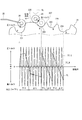
ディテント機構の挙動の説明に先立ち、ディテント機構に加わるトルクについて、図5を用いて説明する。図5の上段に示すように、ディテントプレート21を回転させるとき、ディテントスプリング25のスプリング荷重SLにより生じる負荷トルクTLがモータ10の駆動トルクをアシストする正トルクとして働く状態と、モータ10の駆動トルクを妨げる負トルクとして働く状態と、が繰り返される。シフトレンジをPレンジ方向に切り替える場合、ディテントローラ26に対し、P方向にかかるトルクを正トルク、D方向にかかるトルクを負トルクと定義する。正トルクは、主に、モータ10の駆動トルク、および、ディテントローラ26の山下り中においてスプリング荷重SLにより生じる。負トルクは、主に、ディテントローラ26の山上り中においてスプリング荷重SLにより生じる。
Prior to describing the behavior of the detent mechanism, torque applied to the detent mechanism will be described with reference to FIG. As shown in the upper part of FIG. 5, when the detent plate 21 is rotated, the load torque TL generated by the spring load SL of the detent spring 25 acts as a positive torque assisting the drive torque of the motor 10, and the drive torque of the motor 10 The condition that acts as a negative torque that interferes with is repeated. When the shift range is switched in the P range direction, the torque applied in the P direction with respect to the detent roller 26 is defined as a positive torque, and the torque applied in the D direction is defined as a negative torque. The positive torque is mainly generated by the driving torque of the motor 10 and the spring load SL during the descent of the detent roller 26. The negative torque is mainly generated by the spring load SL during climbing of the detent roller 26.
図4に示すように、シフトバイワイヤシステム1では、シフトレンジ切替機構20において、ディテントプレート21の回転により、ディテントローラ26が谷部221~224間を移動することで、シフトレンジが切り替えられる。本実施形態では、モータ軸105と出力軸15との間に設けられるガタを利用して、スプリング荷重SLにて、ディテントローラ26を要求シフトレンジに応じた谷部221~224に落とす。
As shown in FIG. 4, in the shift-by-wire system 1, in the shift range switching mechanism 20, the shift range is switched by moving the detent roller 26 between the valleys 221 to 224 by the rotation of the detent plate 21. In the present embodiment, the detent roller 26 is dropped to the valley portions 221 to 224 according to the required shift range by the spring load SL using the backlash provided between the motor shaft 105 and the output shaft 15.
ディテントローラ26をR谷部222からP谷部221へ移動させるとき、状態aに示すように、モータ10がガタ内にて回転することで、モータ軸105と減速機14とが当接し、ガタが詰まる。ガタ詰まり状態となると、モータ軸105と出力軸15とが一体となって回転し、ディテントローラ26が山上りを開始する。
When moving the detent roller 26 from the R valley portion 222 to the P valley portion 221, as shown in the state a, the motor 10 is rotated in the backlash so that the motor shaft 105 and the reduction gear 14 abut each other. Get stuck. When the rattling occurs, the motor shaft 105 and the output shaft 15 rotate integrally, and the detent roller 26 starts climbing.
状態bに示すように、ディテントローラ26がR谷部222から山部226へ移動する山上り状態のとき、モータ10が出力軸15を引っ張る。このとき、スプリング荷重SLが負トルクとして働く。
As shown in the state b, the motor 10 pulls the output shaft 15 when the detent roller 26 moves up from the R valley portion 222 to the mountain portion 226. At this time, the spring load SL works as a negative torque.
状態cに示すように、ディテントローラ26が山部226の頂点からP谷部221へ移動する山下り状態のとき、スプリング荷重SLが正トルクとして働き、出力軸15がモータ10に先行し、ガタ内にてP谷部221に吸い込まれる。そして状態dに示すように、ディテントローラ26は、P谷部221に落ちる。
As shown in state c, when the detent roller 26 moves from the top of the mountain portion 226 to the P valley portion 221, the spring load SL acts as a positive torque, and the output shaft 15 precedes the motor 10, and rattling. It sucks into P valley part 221 inside. Then, as shown in the state d, the detent roller 26 falls in the P valley portion 221.
本実施形態では、モータ10に永久磁石を有するDCモータを用いており、図5の下段に示すように、モータコギングトルクTC_Mが周期的に発生する。コギングトルクの発生周期は、モータ10の磁極数等によって異なる。また、モータコギングトルクTC_Mは、減速機14のギア比に応じて増幅されて出力軸15に伝達される。以下、減速機14にて増幅されたコギングトルクを出力軸コギングトルクTC_Sとする。
In the present embodiment, a DC motor having a permanent magnet is used as the motor 10, and motor cogging torque TC_M is generated periodically as shown in the lower part of FIG. The generation cycle of the cogging torque differs depending on the number of magnetic poles of the motor 10 and the like. The motor cogging torque TC_M is amplified according to the gear ratio of the reduction gear 14 and transmitted to the output shaft 15. Hereinafter, the cogging torque amplified by the reduction gear 14 is referred to as an output shaft cogging torque TC_S.
図5に「×」で示すように、山上り側において、負荷トルクTLと、出力軸コギングトルクTC_Sとが釣り合うトルク釣り合い点が生じる。特に、減速機14のギア比が大きく、出力軸コギングトルクTC_Sの最大値が、ディテントスプリング25による負トルクの最大値より大きい場合、出力軸コギングトルクTC_Sの最大値が負トルク最大値より小さい場合と比較し、トルク釣り合い点が多くなる。なお、煩雑になることを避けるため、釣り合い点を示す「×」印は、一部について記載している。
As indicated by “x” in FIG. 5, on the mountain upstream side, a torque balance point at which the load torque TL and the output shaft cogging torque TC_S balance is generated. In particular, when the gear ratio of reduction gear 14 is large and the maximum value of output shaft cogging torque TC_S is larger than the maximum value of negative torque by detent spring 25, the maximum value of output shaft cogging torque TC_S is smaller than the negative torque maximum value. Compared to the above, there are more torque balance points. In addition, in order to avoid becoming complicated, "x" mark which shows a balance point is described about one part.
ここで、レンジ切替中において、断線等によりモータ10を駆動できなくなる異常であるモータオフ故障が発生した場合について説明する。ディテントローラ26の山下り中にモータオフ故障が生じた場合、スプリング荷重SLが正トルクとして働くため、ガタを大きく設けておけば、スプリング荷重SLにより、ディテントローラ26を谷に落とすことが可能である。
Here, there will be described a case where a motor off failure, which is an abnormality in which the motor 10 can not be driven due to disconnection or the like, occurs during the range switching. If a motor-off failure occurs while the detent roller 26 descends, the spring load SL acts as a positive torque. Therefore, the detent roller 26 can be dropped to the valley by the spring load SL if a large play is provided. .
一方、ディテントローラの山上り中にモータオフ故障が生じた場合、スプリング荷重SLが負トルクとして働く。そのため、トルク釣り合い点にてモータオフ故障が生じると、ディテントローラ26が山上り途中にて停止してしまい、中間レンジ停止異常となる新たな課題が見出された(図8参照)。なお、トルク釣り合い点にてディテントローラ26が止まってしまう場合、ガタを大きく設けたとしても、中間レンジ停止異常は解消されない。また、例えばスイッチトリラクタンスモータ等のように、永久磁石を用いていないモータの場合、コギングトルクが発生しないため、トルク釣り合い点が生じず、ディテントローラ26がディテントスプリング25のスプリング荷重SLにていずれかの谷部221~224に落とし込まれるため、中間レンジ停止異常は発生しない。
On the other hand, when a motor-off failure occurs during climbing of the detent roller, the spring load SL works as a negative torque. Therefore, when the motor-off failure occurs at the torque balance point, the detent roller 26 is stopped halfway up the mountain, and a new problem of an intermediate range stop abnormality is found (see FIG. 8). When the detent roller 26 stops at the torque balance point, the middle range stop abnormality is not resolved even if the play is largely provided. Further, in the case of a motor using no permanent magnet, such as a switched reluctance motor, for example, no cogging torque is generated, so no torque balance point occurs, and the detent roller 26 receives the spring load SL of the detent spring 25 at any time. Since it falls into the valleys 221 to 224, an intermediate range stop abnormality does not occur.
図6では、ディテントローラ26がD谷部224にある状態から通電を開始し、ディテントローラ26がP谷部221に到達するまでの、ある時間が経過したところで通電をオフにした場合の出力軸15の停止位置を示している。レンジ切替中に通電がオフされたとしても、通電オフタイミングによっては、スプリング荷重SLにて、ディテントローラ26はいずれかの谷部221~224に落とし込まれる。しかしながら、二点鎖線にて囲んで示すように、ディテントローラ26の山上り中に通電がオフされると、中間レンジ領域にて停止してしまう場合がある。
In FIG. 6, an output shaft in the case where energization is started when a certain time has elapsed from when the detent roller 26 is in the D valley portion 224 and the detent roller 26 reaches the P valley portion 221 has elapsed. It shows 15 stop positions. Even if energization is turned off during range switching, the detent roller 26 is dropped into any of the valleys 221 to 224 at the spring load SL depending on the energization OFF timing. However, as indicated by encircled by a two-dot chain line, if the current is turned off during climbing of the detent roller 26, the intermediate roller may stop in the middle range region.
図7および図8は、モータ10への通電時間をxaとしたときの実験結果であり、図6中の点Aに対応している。図7では、共通時間軸を横軸とし、上段から、駆動モードおよび角度を示している。図中のP、R、N、Dは、ディテントローラ26が谷部221~224の中心にあるときの出力軸角度に対応している。また、モータ角度θmおよびモータ角度目標値θcmdは、出力軸換算にて記載した。
FIGS. 7 and 8 show experimental results when the current application time to the motor 10 is xa, which corresponds to the point A in FIG. In FIG. 7, the common time axis is taken as the horizontal axis, and the drive mode and the angle are shown from the upper stage. P, R, N, and D in the figure correspond to the output shaft angles when the detent roller 26 is at the center of the valleys 221 to 224. The motor angle θm and the motor angle target value θcmd are described in terms of output shaft.
ディテントローラ26がD谷部224にある状態から時間xaの間通電した後に通電オフにすると、モータ角度θmがモータ角度目標値θcmdに到達せず、出力軸角度θsがR谷部222とP谷部221との間の中間レンジ領域にて停止してしまうことがわかる。
When the detent roller 26 is energized in the D valley portion 224 for the time xa and then switched off, the motor angle θm does not reach the motor angle target value θcmd, and the output shaft angle θs is R valley portion 222 and P valley It can be seen that it stops in the intermediate range region between the unit 221 and the unit.
中間レンジ領域にて出力軸15が停止する異常が発生すると、マニュアルバルブ28が中途半端な位置で停止するため、適切な油圧を発生させることができず、自動変速機5の故障につながる虞がある。
If an abnormality occurs in which the output shaft 15 stops in the intermediate range region, the manual valve 28 stops at a halfway position, so that an appropriate hydraulic pressure can not be generated, which may lead to failure of the automatic transmission 5. is there.
そこで本実施形態では、モータ駆動制御系統の一部に断線等が生じた場合であっても、中間レンジ停止異常が生じないように、モータ駆動制御系統を複数系統化している。モータ駆動制御系統には、モータ巻線11、12、モータドライバ41、42、マイコン51、52、および、これらを接続する接続配線が含まれる。第1モータ巻線11、第1モータドライバ41および第1マイコン51、ならびに、これらを接続する接続配線61、71の組み合わせを第1系統とし、第2モータ巻線12、第2モータドライバ42および第2マイコン52、ならびに、これらを接続する接続配線62、72の組み合わせを第2系統とする。
Therefore, in the present embodiment, a plurality of motor drive control systems are organized so that an intermediate range stop abnormality does not occur even if a break or the like occurs in part of the motor drive control system. The motor drive control system includes motor windings 11 and 12, motor drivers 41 and 42, microcomputers 51 and 52, and connection wiring for connecting them. The combination of the first motor winding 11, the first motor driver 41 and the first microcomputer 51, and the connection wires 61 and 71 connecting them is a first system, and the second motor winding 12, the second motor driver 42 and A combination of the second microcomputer 52 and the connection wires 62 and 72 connecting these is used as a second system.
図9に示すように、第1モータドライバ41は、第1マイコン側接続配線61にて第1マイコン51と接続され、第1モータ側接続配線71にて第1モータ巻線11と接続される。第1マイコン51は、第1モータドライバ41のスイッチング素子411~416(図9中では不図示)のオンオフ作動を制御することで、第1モータ巻線11の通電を制御する。
As shown in FIG. 9, the first motor driver 41 is connected to the first microcomputer 51 by the first microcomputer side connection wire 61 and is connected to the first motor winding 11 by the first motor side connection wire 71. . The first microcomputer 51 controls the energization of the first motor winding 11 by controlling the on / off operation of the switching elements 411 to 416 (not shown in FIG. 9) of the first motor driver 41.
第2モータドライバ42は、第2マイコン側接続配線62にて第2マイコン52と接続され、第2モータ側接続配線72にて第2モータ巻線12と接続される。第2マイコン52は、第2モータドライバ42のスイッチング素子421~426(図9中では不図示)のオンオフ作動を制御することで、第2モータ巻線12の通電を制御する。レンジ切替要求等は、マイコン51、52にそれぞれ入力され、入力された情報に基づいて、各種制御を行う。図9および図11では、モータ巻線11、12を記号「M」で記した。
The second motor driver 42 is connected to the second microcomputer 52 by the second microcomputer side connection wiring 62, and is connected to the second motor winding 12 by the second motor side connection wiring 72. The second microcomputer 52 controls the energization of the second motor winding 12 by controlling the on / off operation of the switching elements 421 to 426 (not shown in FIG. 9) of the second motor driver 42. The range switching request and the like are input to the microcomputers 51 and 52, respectively, and various controls are performed based on the input information. In FIGS. 9 and 11, the motor windings 11 and 12 are indicated by the symbol "M".
本実施形態のモータ制御処理を図10のフローチャートに基づいて説明する。この処理は、マイコン51、52のそれぞれにて所定の周期で実行される。ここでは、第1マイコン51での処理として説明し、第2マイコン52での処理は同様であるので説明を省略する。以下、ステップS101の「ステップ」を省略し、単に記号「S」と記す。他のステップも同様とする。第3実施形態~第5実施形態も同様とする。
The motor control processing of the present embodiment will be described based on the flowchart of FIG. This process is executed by each of the microcomputers 51 and 52 at a predetermined cycle. Here, the processing in the first microcomputer 51 is described, and the processing in the second microcomputer 52 is the same, so the description will be omitted. Hereinafter, the “step” of step S101 is omitted and simply referred to as the symbol “S”. The same applies to the other steps. The same applies to the third to fifth embodiments.
S101では、第1マイコン51は、自系統が正常か否かを判断する。自系統が正常であると判断された場合(S101:YES)、S102へ移行し、レンジ切り替えを許可する。具体的には、要求シフトレンジに応じ、モータ10を駆動すべく、第1モータ巻線11への通電を制御する。自系統が正常ではないと判断された場合(S101:NO)、S103へ移行し、自系統でのレンジ切り替えを禁止する。具体的には、第1モータ巻線11への通電を行わない。このとき、他系統が正常であれば、他系統を用いてモータ10の駆動が継続される。また、S104では、第1マイコン51は、第2マイコン52、および、シフトバイワイヤシステム1の外部、例えば車両全体の制御を司る上位ECU等の図示しない他のECUに、第1系統にて故障が生じた旨の情報を通知する。マイコン51、52間の情報伝達は、マイコン間通信にて直接的に行ってもよいし、CAN(Controller Area Network)等の車両通信網を経由して行ってもよい。
In S101, the first microcomputer 51 determines whether or not its own system is normal. If it is determined that the own system is normal (S101: YES), the process proceeds to S102, and range switching is permitted. Specifically, in order to drive the motor 10 in accordance with the required shift range, control of energization of the first motor winding 11 is performed. If it is determined that the own system is not normal (S101: NO), the process proceeds to S103, and range switching in the own system is prohibited. Specifically, the first motor winding 11 is not energized. At this time, if the other system is normal, the driving of the motor 10 is continued using the other system. In S104, the first microcomputer 51 causes a failure in the first system to the second microcomputer 52 and another ECU (not shown) such as a host ECU that controls the entire vehicle, for example, outside the shift-by-wire system 1. Notify that it has occurred. Information transmission between the microcomputers 51 and 52 may be directly performed by inter-microcomputer communication, or may be performed via a vehicle communication network such as CAN (Controller Area Network).
以上説明したように、本実施形態のシフトバイワイヤシステム1は、モータ10と、モータドライバ41、42と、出力軸15と、シフトレンジ切替機構20と、ECU50と、を備える。モータ10は、モータ巻線11、12を有し、永久磁石によるコギングトルクが発生する。モータドライバ41、42は、モータ巻線11、12への通電を切り替える。出力軸15は、モータ10の回転軸であるモータ軸105の回転が伝達される。
As described above, the shift-by-wire system 1 of the present embodiment includes the motor 10, the motor drivers 41 and 42, the output shaft 15, the shift range switching mechanism 20, and the ECU 50. The motor 10 has motor windings 11 and 12 and generates cogging torque by permanent magnets. The motor drivers 41 and 42 switch the energization of the motor windings 11 and 12. The output shaft 15 transmits the rotation of a motor shaft 105 which is a rotation shaft of the motor 10.
シフトレンジ切替機構20は、ディテントプレート21、ディテントローラ26およびディテントスプリング25を有する。ディテントプレート21には、複数の谷部221~224および谷部221~224を隔てる山部226~228が形成され、出力軸15と一体に回転する。ディテントローラ26は、シフトレンジに応じた谷部221~224に嵌まり合う。ディテントスプリング25は、ディテントローラ26を谷部221~224に嵌まり合う方向に付勢する。ECU50は、モータ10の駆動制御に係る演算を行うマイコン51、52を有する。
The shift range switching mechanism 20 has a detent plate 21, a detent roller 26 and a detent spring 25. The detent plate 21 is formed with a plurality of valleys 221 to 224 and ridges 226 to 228 separating the valleys 221 to 224, and rotates integrally with the output shaft 15. The detent roller 26 fits into the valleys 221 to 224 according to the shift range. The detent spring 25 biases the detent roller 26 in a direction to fit the valleys 221-224. The ECU 50 has microcomputers 51 and 52 that perform calculations related to drive control of the motor 10.
モータ軸105と出力軸15との間には遊びが形成されており、遊びを利用してディテントローラ26を谷部221~224に落とすことが可能である。モータドライバ41、42、モータ巻線11、12、モータドライバ41、42とモータ巻線11、12とを接続する接続配線71、72、および、マイコン51、52をモータ駆動制御系統とする。ディテントローラ26が谷部221~224から山部226~228への移動中である山上り中にモータ駆動制御系統に異常が生じたとき、出力軸15に伝達されるコギングトルクである出力軸コギングトルクおよびディテントスプリング25による負荷トルクを含むトルクの釣り合いにより出力軸15が停止する中間レンジ停止異常の発生を回避するように、モータ駆動制御系統が複数系統設けられている。これにより、ディテントローラ26の山上り中にモータ駆動制御系統に異常が生じた場合であっても、モータ10の駆動を継続可能であり、中間レンジ停止異常が回避されるので、自動変速機5の故障を防止することができる。
A play is formed between the motor shaft 105 and the output shaft 15, and the play can be used to drop the detent roller 26 into the valleys 221 to 224. Motor drivers 41 and 42, motor windings 11 and 12, connection wires 71 and 72 for connecting motor drivers 41 and 42 with motor windings 11 and 12, and microcomputers 51 and 52 are motor drive control systems. Output shaft cogging, which is a cogging torque transmitted to the output shaft 15, when an abnormality occurs in the motor drive control system during uphill climbing in which the detent roller 26 is moving from the valleys 221 to 224 to the peaks 226 to 228. A plurality of motor drive control systems are provided to avoid occurrence of an intermediate range stop abnormality in which the output shaft 15 stops due to the balance of torque including the load torque by the torque and the detent spring 25. As a result, even if an abnormality occurs in the motor drive control system while the detent roller 26 climbs, the drive of the motor 10 can be continued, and the intermediate range stop abnormality is avoided. It is possible to prevent the failure of the
それぞれのマイコン51、52は、共通のレンジ切替要求に応じ、対応して設けられるモータ巻線11、12の通電を独立して制御する。これにより、複数系統を同時に用いてモータ10を駆動することができ、出力を確保できる。また、一部の系統に異常が生じた場合であっても、正常系統にてそのままモータ10を駆動し、レンジ切り替えを継続可能である。
Each of the microcomputers 51 and 52 independently controls energization of the corresponding motor windings 11 and 12 in response to the common range switching request. Thereby, the motor 10 can be driven by using a plurality of systems simultaneously, and the output can be secured. In addition, even when an abnormality occurs in a part of the system, the motor 10 can be driven as it is in the normal system and the range switching can be continued.
一部のモータ駆動制御系統に異常が生じた場合、正常であるモータ駆動制御系統を用いてモータ10の駆動を継続する。これにより、一部の系統に異常が生じた場合であっても、レンジ切り替えを継続可能である。
When an abnormality occurs in a part of the motor drive control system, the drive of the motor 10 is continued using the normal motor drive control system. Thus, the range switching can be continued even when an abnormality occurs in some of the systems.
第1マイコン51は、モータ駆動制御系統に異常が生じた場合、異常が生じた旨の情報を、「他の演算部」である第2マイコン52、および、システム外部の少なくとも一方に通知する。これにより、異常状態に応じた処置を講じることができる。また例えばドライバに異常を通知することで、早期の修理を促すことができる。
When an abnormality occurs in the motor drive control system, the first microcomputer 51 notifies the information indicating that the abnormality has occurred to at least one of the second microcomputer 52 which is the “other operation unit” and the outside of the system. Thereby, it is possible to take measures according to the abnormal state. Further, for example, early notification can be promoted by notifying the driver of the abnormality.
(第2実施形態)
第2実施形態を図11に示す。図11に示すように、本実施形態では、マイコン51、52では、制御タイミングを一致させるための同期制御を行う。本実施形態では、それぞれのマイコン51、52が有しているクロック信号を同期させる。同期制御は、マイコン51、52にて同期情報を共有することで同期するようにしてもよいし、マイコン51、52の外部からの外部クロック等の情報を用いてもよい。 Second Embodiment
A second embodiment is shown in FIG. As shown in FIG. 11, in the present embodiment, the microcomputers 51 and 52 perform synchronous control for matching control timing. In the present embodiment, clock signals held by the respective microcomputers 51 and 52 are synchronized. The synchronization control may be performed by sharing synchronization information between the microcomputers 51 and 52, or information such as an external clock from outside the microcomputers 51 and 52 may be used.
第2実施形態を図11に示す。図11に示すように、本実施形態では、マイコン51、52では、制御タイミングを一致させるための同期制御を行う。本実施形態では、それぞれのマイコン51、52が有しているクロック信号を同期させる。同期制御は、マイコン51、52にて同期情報を共有することで同期するようにしてもよいし、マイコン51、52の外部からの外部クロック等の情報を用いてもよい。 Second Embodiment
A second embodiment is shown in FIG. As shown in FIG. 11, in the present embodiment, the
本実施形態では、マイコン51、52は、他のマイコン52、51との通電指示タイミングを同期させる同期処理を行う。これにより、モータ巻線11、12への通電タイミングのずれを低減することができる。これにより、通電タイミングのずれに起因するトルク低下を防ぐことができる。また上記実施形態と同様の効果を奏する。
In the present embodiment, the microcomputers 51 and 52 perform synchronization processing to synchronize the energization instruction timing with the other microcomputers 52 and 51. Thereby, the shift | offset | difference of the electricity_supply timing to motor winding 11 and 12 can be reduced. As a result, it is possible to prevent the torque decrease due to the deviation of the energization timing. In addition, the same effect as that of the above embodiment can be obtained.
(第3実施形態)
第3実施形態を図12に示す。第3実施形態~第5実施形態では、モータ制御処理が第1実施形態と行っているので、この点を中心に説明する。第2実施形態のように、同期制御を行ってもよい。 Third Embodiment
A third embodiment is shown in FIG. In the third to fifth embodiments, since the motor control process is performed with the first embodiment, this point will be mainly described. As in the second embodiment, synchronization control may be performed.
S201では、図10のS101と同様、第1マイコン51は、自系統が正常か否かを判断する。自系統が正常ではないと判断された場合(S201:NO)、S206へ移行する。S206およびS207の処理は、図10中のS103およびS104の処理と同様である。自系統が正常であると判断された場合(S201:YES)、S202へ移行する。
In S201, as in S101 of FIG. 10, the first microcomputer 51 determines whether or not its own system is normal. If it is determined that the own system is not normal (S201: NO), the process proceeds to S206. The processes of S206 and S207 are the same as the processes of S103 and S104 in FIG. If it is determined that the own system is normal (S201: YES), the process proceeds to S202.
S202では、第1マイコン51は、他系統が正常か否かを判断する。他系統が正常であると判断された場合(S202:YES)、S204へ移行し、レンジ切り替えを許可する。他系統が正常ではないと判断された場合(S202:NO)、S203へ移行する。
In S202, the first microcomputer 51 determines whether the other system is normal. If it is determined that the other system is normal (S202: YES), the process proceeds to S204, and range switching is permitted. If it is determined that the other system is not normal (S202: NO), the process proceeds to S203.
S203では、第1マイコン51は、バッテリ電圧Vbが電圧判定閾値Vth以上か否かを判断する。本実施形態では、バッテリ電圧Vbが「駆動回路に入力される入力電圧」に対応する。電圧判定閾値Vthは、1系統にてモータ10を駆動可能な程度の電圧に設定される。電圧判定閾値Vthは、レンジによらず同一の値としてもよいし、例えば、現在のシフトレンジがPレンジのとき、他のレンジのときよりも電圧判定閾値Vthを大きい値にする、といった具合に、現在のシフトレンジに応じて異なる値としてもよい。バッテリ電圧Vbが電圧判定閾値Vth以上であると判断された場合(S203:YES)、S204へ移行し、レンジ切り替えを許可する。バッテリ電圧Vbが電圧判定閾値Vth未満であると判断された場合(S203:NO)、S205へ移行し、レンジ切り替えを禁止する。
In S203, the first microcomputer 51 determines whether the battery voltage Vb is equal to or higher than the voltage determination threshold Vth. In the present embodiment, the battery voltage Vb corresponds to “the input voltage input to the drive circuit”. The voltage determination threshold Vth is set to a voltage that can drive the motor 10 in one system. The voltage determination threshold Vth may have the same value regardless of the range, and for example, when the current shift range is the P range, the voltage determination threshold Vth is set to a larger value than in the other ranges. The values may be different depending on the current shift range. If it is determined that the battery voltage Vb is equal to or higher than the voltage determination threshold Vth (S203: YES), the process proceeds to S204, and range switching is permitted. If it is determined that the battery voltage Vb is less than the voltage determination threshold Vth (S203: NO), the process proceeds to S205 to prohibit range switching.
1系統にてモータ10を駆動とすると、2系統での駆動時と比較し、出力可能なトルクが低下する。その上で、バッテリ電圧が低下していると、出力可能なトルクがさらに低下し、レンジ切り替えに失敗する虞がある。そこで本実施形態では、一方の系統に異常が生じており、かつ、バッテリ電圧Vbが低下している場合、シフトレンジの切り替えを禁止している。これにより、トルク低下によるレンジ切替失敗を防止できる。
When the motor 10 is driven by one system, the torque that can be output is reduced as compared with the case of driving by two systems. Furthermore, if the battery voltage is reduced, the torque that can be output is further reduced, and there is a possibility that the range switching may fail. So, in this embodiment, when abnormality has arisen in one system and battery voltage Vb is falling, change of shift range is prohibited. Thus, it is possible to prevent range switching failure due to a decrease in torque.
本実施形態では、一部のモータ駆動制御系統に異常が生じた場合、レンジ切替実施判定を行い、レンジ切り替えの許可または禁止を選択する、具体的には、ECU50は、レンジ切替実施判定として、モータドライバ41、42に入力される入力電圧としてバッテリ電圧Vbの判定を行い、バッテリ電圧Vbが電圧判定閾値Vth以上の場合、レンジ切り替えを許可し、バッテリ電圧Vbが電圧判定閾値Vth未満の場合、レンジ切り替えを禁止する。これにより、一部の系統の故障によるトルク不足によるレンジ切替失敗を防止可能であって、中間レンジ停止異常の発生を回避することができる。また、上記実施形態と同様の効果を奏する。
In the present embodiment, when abnormality occurs in a part of the motor drive control system, range switching execution determination is performed, and permission or prohibition of range switching is selected. Specifically, the ECU 50 performs range switching execution determination as: The battery voltage Vb is determined as the input voltage input to the motor drivers 41 and 42. When the battery voltage Vb is equal to or higher than the voltage determination threshold Vth, range switching is permitted, and when the battery voltage Vb is lower than the voltage determination threshold Vth Prohibit range switching. As a result, it is possible to prevent range switching failure due to insufficient torque due to failure of a part of the system, and it is possible to avoid occurrence of an intermediate range stop abnormality. In addition, the same effect as that of the above embodiment can be obtained.
(第4実施形態)
第4実施形態を図13に示す。本実施形態のモータ制御処理は、図12中のS203に替えてS211の処理を行う点を除き、第3実施形態と同様である。S202にて否定判断された場合に移行するS211では、第1マイコン51は、エンジン駆動中か否かを判断する。エンジン駆動中であると判断された場合(S211:YES)、S204へ移行し、レンジ切り替えを許可する。エンジン駆動中ではない判断された場合(S211:NO)、S205へ移行し、レンジ切り替えを禁止する。 Fourth Embodiment
A fourth embodiment is shown in FIG. The motor control process of the present embodiment is the same as that of the third embodiment except that the process of S211 is performed instead of S203 in FIG. In S211, which is shifted when a negative determination is made in S202, thefirst microcomputer 51 determines whether or not the engine is being driven. When it is determined that the engine is being driven (S211: YES), the process proceeds to S204, and range switching is permitted. When it is determined that the engine is not being driven (S211: NO), the process proceeds to S205, and range switching is prohibited.
第4実施形態を図13に示す。本実施形態のモータ制御処理は、図12中のS203に替えてS211の処理を行う点を除き、第3実施形態と同様である。S202にて否定判断された場合に移行するS211では、第1マイコン51は、エンジン駆動中か否かを判断する。エンジン駆動中であると判断された場合(S211:YES)、S204へ移行し、レンジ切り替えを許可する。エンジン駆動中ではない判断された場合(S211:NO)、S205へ移行し、レンジ切り替えを禁止する。 Fourth Embodiment
A fourth embodiment is shown in FIG. The motor control process of the present embodiment is the same as that of the third embodiment except that the process of S211 is performed instead of S203 in FIG. In S211, which is shifted when a negative determination is made in S202, the
本実施形態では、ECU50は、レンジ切替実施判定として、エンジンの駆動状態を判定する。エンジンが駆動中の場合、レンジ切り替えを許可し、エンジンが停止中の場合、レンジ切り替えを禁止する。例えばアイドルストップ等でエンジンが停止しているとき、バッテリ電圧Vbが低下する虞がある。そこで本実施形態では、一方の系統に異常が生じており、かつ、エンジンが停止している場合、シフトレンジの切り替えを禁止している。これにより、トルク不足によるレンジ切替失敗を防止可能であって、中間レンジ停止異常の発生を回避することができる。また上記実施形態と同様の効果を奏する。
In the present embodiment, the ECU 50 determines the driving state of the engine as the range switching execution determination. When the engine is running, allow range switching, and when the engine is stopped, prohibit range switching. For example, when the engine is stopped due to idle stop or the like, the battery voltage Vb may be reduced. Therefore, in the present embodiment, switching of the shift range is prohibited when an abnormality occurs in one system and the engine is stopped. As a result, it is possible to prevent range switching failure due to insufficient torque, and it is possible to avoid the occurrence of an intermediate range stop abnormality. In addition, the same effect as that of the above embodiment can be obtained.
(第5実施形態)
第5実施形態を図14に示す。本実施形態のモータ制御処理は、図12中のS203に替えて、S216およびS217の処理を行う点を除き、第3実施形態と同様である。S202にて否定判断された場合に移行するS216では、第1マイコン51は、現在のシフトレンジがPレンジ以外か否かを判断する。現在のシフトレンジがPレンジ以外であると判断された場合(S216:YES)、S204へ移行し、レンジ切り替えを許可する。現在のシフトレンジがPレンジであると判断された場合(S216:NO)、S217へ移行する。 Fifth Embodiment
A fifth embodiment is shown in FIG. The motor control process of the present embodiment is the same as that of the third embodiment except that the processes of S216 and S217 are performed instead of S203 in FIG. In step S216, in which a negative determination is made in step S202, thefirst microcomputer 51 determines whether the current shift range is outside the P range. If it is determined that the current shift range is not the P range (S216: YES), the process proceeds to S204, and range switching is permitted. If it is determined that the current shift range is the P range (S216: NO), the process proceeds to S217.
第5実施形態を図14に示す。本実施形態のモータ制御処理は、図12中のS203に替えて、S216およびS217の処理を行う点を除き、第3実施形態と同様である。S202にて否定判断された場合に移行するS216では、第1マイコン51は、現在のシフトレンジがPレンジ以外か否かを判断する。現在のシフトレンジがPレンジ以外であると判断された場合(S216:YES)、S204へ移行し、レンジ切り替えを許可する。現在のシフトレンジがPレンジであると判断された場合(S216:NO)、S217へ移行する。 Fifth Embodiment
A fifth embodiment is shown in FIG. The motor control process of the present embodiment is the same as that of the third embodiment except that the processes of S216 and S217 are performed instead of S203 in FIG. In step S216, in which a negative determination is made in step S202, the
S217では、第1マイコン51は、車両の傾斜角度θiが角度判定閾値θth以下か否かを判断する。車両の傾斜角度θiは、例えば傾斜角センサの検出値に基づいて演算される。傾斜角度θiが角度判定閾値θth以下であると判断された場合(S217:YES)、S204へ移行し、レンジ切り替えを許可する。傾斜角度θiが角度判定閾値θthより大きいと判断された場合(S217:NO)、S205へ移行し、レンジ切り替えを禁止する。
In S217, the first microcomputer 51 determines whether the inclination angle θi of the vehicle is equal to or less than the angle determination threshold θth. The inclination angle θi of the vehicle is calculated based on, for example, the detection value of the inclination angle sensor. If it is determined that the inclination angle θi is equal to or less than the angle determination threshold θth (S217: YES), the process proceeds to S204, and range switching is permitted. If it is determined that the inclination angle θi is larger than the angle determination threshold θth (S217: NO), the process proceeds to S205, and range switching is prohibited.
シフトレンジをPレンジからPレンジ以外のレンジへ切り替える、いわゆる「P抜き」において、他のレンジ切替時よりも大きなトルクが必要になる。また、車両が傾斜している場合、パーキングロックポール33とパーキングギア35との噛み合い箇所に傾斜角度θiおよび車重に応じた摩擦が発生するため、P抜き時により大きなトルクが必要になる。そこで本実施形態では、一方の系統に異常が生じており、かつ、車両傾斜状態でのP抜き時、シフトレンジの切り替えを禁止している。これにより、トルク低下によるレンジ切替失敗を防止できる。
In the so-called "P-out" in which the shift range is switched from the P range to a range other than the P range, a larger torque is required than at other range switching. In addition, when the vehicle is inclined, friction corresponding to the inclination angle θi and the vehicle weight is generated at the meshing position of the parking lock pole 33 and the parking gear 35, so a larger torque is required at P removal. Therefore, in the present embodiment, an abnormality occurs in one of the systems, and switching of the shift range is prohibited when P is removed in the vehicle inclining state. Thus, it is possible to prevent range switching failure due to a decrease in torque.
モータ制御処理において、S217の処理を省略し、一方の系統に異常が生じている場合、車両の傾斜角度θiによらず、Pレンジから他のレンジへの切り替えを禁止するようにしてもよい。また、モータ制御処理において、図12中のS203、図13中のS211、および、図14中のS216、S217の複数を組み合わせてもよい。
In the motor control process, if the process of S217 is omitted and an abnormality occurs in one system, switching from the P range to another range may be prohibited regardless of the inclination angle θi of the vehicle. Further, in the motor control process, a plurality of S203 in FIG. 12, S211 in FIG. 13, and S216 and S217 in FIG. 14 may be combined.
本実施形態では、ECU50は、レンジ切替実施判定として、現在のシフトレンジを判定する。現在のシフトレンジがPレンジ以外の場合、レンジ切替を許可し、現在のシフトレンジがPレンジのとき、レンジ切り替えを禁止する。また、ECU50は、レンジ切替実施判定として、現在のシフトレンジおよび車両の傾斜角度θiを判定する。現在のシフトレンジがPレンジ以外の場合、および、現在のシフトレンジがPレンジであって、傾斜角度θiが角度判定閾値θth以下の場合、レンジ切り替えを許可する。また、現在のシフトレンジがPレンジであって、かつ、傾斜角度θiが角度判定閾値θthより大きい場合、レンジ切り替えを禁止する。これにより、比較的大きなトルクが必要であるP抜きにおいて、トルク不足によるレンジ切り替え失敗を防止可能であって、中間レンジ停止異常の発生を回避することができる。また上記実施形態と同様の効果を奏する。
In the present embodiment, the ECU 50 determines the current shift range as the range switching implementation determination. When the current shift range is other than the P range, range switching is permitted, and when the current shift range is the P range, range switching is prohibited. Further, the ECU 50 determines the current shift range and the inclination angle θi of the vehicle as the range switching implementation determination. When the current shift range is other than the P range, and when the current shift range is the P range and the inclination angle θi is less than or equal to the angle determination threshold θth, range switching is permitted. When the current shift range is the P range and the inclination angle θi is larger than the angle determination threshold θth, range switching is prohibited. This makes it possible to prevent range switching failure due to insufficient torque when removing P, which requires a relatively large torque, and to avoid the occurrence of an intermediate range stop abnormality. In addition, the same effect as that of the above embodiment can be obtained.
(他の実施形態)
上記実施形態では、モータは、DCブラシレスモータである。他の実施形態では、モータは、コギングトルクが発生するDCブラシレスモータ以外のものでもよい。上記実施形態では、駆動回路であるモータドライバは、3相インバータである。他の実施形態では、駆動回路を、モータ巻線の通電を切替可能などのような回路構成としてもよい。上記実施形態では、モータ駆動制御系統が2系統設けられている。他の実施形態では、モータ駆動制御系統を3系統以上設けてもよい。 (Other embodiments)
In the above embodiment, the motor is a DC brushless motor. In other embodiments, the motor may be other than a DC brushless motor that generates cogging torque. In the above embodiment, the motor driver as the drive circuit is a three-phase inverter. In other embodiments, the drive circuit may be any circuit configuration that can switch the energization of the motor windings. In the above embodiment, two motor drive control systems are provided. In another embodiment, three or more motor drive control systems may be provided.
上記実施形態では、モータ回転角センサは、エンコーダである。他の実施形態では、モータ回転角センサは、エンコーダに限らず、レゾルバ等、どのようなものを用いてもよい。上記実施形態では、出力軸センサとしてポテンショメータを例示した。他の実施形態では、出力軸センサは、どのようなものであってもよく、例えば、各レンジ保証領域にてオンされるスイッチにより構成されてもよいし、非接触の磁気センサを用いてもよい。また、出力軸センサを省略してもよい。
In the above embodiment, the motor rotation angle sensor is an encoder. In another embodiment, the motor rotation angle sensor is not limited to the encoder, and any sensor such as a resolver may be used. In the above embodiment, a potentiometer is illustrated as an output axis sensor. In other embodiments, the output shaft sensor may be of any type, for example, may be constituted by a switch turned on in each range guaranteeing area, or a non-contact magnetic sensor may be used. Good. Also, the output shaft sensor may be omitted.
上記実施形態では、ディテントプレートには4つの谷部が設けられる。他の実施形態では、谷部の数は4つに限らず、いくつであってもよい。例えば、Pレンジと、Pレンジ以外のレンジであるnotPレンジに対応する2つの谷部が設けられていてもよい。シフトレンジ切替機構やパーキングロック機構等は、上記実施形態と異なっていてもよい。
In the above embodiment, the detent plate is provided with four valleys. In other embodiments, the number of valleys is not limited to four, but may be any number. For example, two valleys corresponding to the P range and the not P range which is a range other than the P range may be provided. The shift range switching mechanism, the parking lock mechanism, etc. may be different from the above embodiment.
上記実施形態では、モータ軸と出力軸との間に減速機が設けられる。減速機の詳細について、上記実施形態では言及していないが、例えば、サイクロイド歯車、遊星歯車、モータ軸と略同軸の減速機構から駆動軸へトルクを伝達する平歯歯車を用いたものや、これらを組み合わせて用いたもの等、どのような構成であってもよい。また、他の実施形態では、モータ軸と出力軸との間の減速機を省略してもよいし、減速機以外の機構を設けてもよい。以上、本開示は、上記実施形態になんら限定されるものではなく、その趣旨を逸脱しない範囲において種々の形態で実施可能である。
In the above embodiment, a reduction gear is provided between the motor shaft and the output shaft. Although the details of the reduction gear are not mentioned in the above embodiment, for example, a cycloid gear, a planetary gear, a spur gear that transmits torque from the reduction mechanism substantially coaxial with the motor shaft to the drive shaft, or these Any configuration may be used, such as one using a combination of In other embodiments, the reduction gear between the motor shaft and the output shaft may be omitted, or a mechanism other than the reduction gear may be provided. As mentioned above, this indication is not limited at all to the above-mentioned embodiment, and can be carried out in various forms in the range which does not deviate from the meaning.
本開示は、実施形態に準拠して記述された。しかしながら、本開示は当該実施形態および構造に限定されるものではない。本開示は、様々な変形例および均等の範囲内の変形をも包含する。また、様々な組み合わせおよび形態、さらには、それらに一要素のみ、それ以上、あるいはそれ以下、を含む他の組み合わせおよび形態も、本開示の範疇および思想範囲に入るものである。
The present disclosure has been described in accordance with the embodiments. However, the present disclosure is not limited to the embodiments and structures. The present disclosure also includes various modifications and variations within the scope of equivalents. In addition, various combinations and forms, and further, other combinations and forms including one element or more, or less or less, are also within the scope and the scope of the present disclosure.
Claims (10)
- モータ巻線(11、12)を有し、永久磁石によるコギングトルクが発生するモータ(10)と、
前記モータ巻線への通電を切り替える駆動回路(41、42)と、
前記モータの回転軸であるモータ軸(105)の回転が伝達される出力軸(15)と、
複数の谷部(221~224)および前記谷部を隔てる山部(226~228)が形成され前記出力軸と一体に回転する谷部形成部材(21)、シフトレンジに応じた前記谷部に嵌まり合う係合部材(26)、および、前記係合部材を前記谷部に嵌まり合う方向に付勢する付勢部材(25)を有するシフトレンジ切替機構(20)と、
前記モータの駆動制御に係る演算を行う演算部(51、52)を有する制御部(50)と、
を備え、
前記モータ軸と前記出力軸との間には遊びが形成されており、前記遊びを利用して前記係合部材を前記谷部に落とすことが可能であって、
前記駆動回路、前記モータ巻線、前記駆動回路と前記モータ巻線とを接続する接続配線(71、72)、および、前記演算部をモータ駆動制御系統とすると、前記係合部材が前記谷部から前記山部への移動中である山上り中に前記モータ駆動制御系統に異常が生じたとき、前記出力軸に伝達されるコギングトルクである出力軸コギングトルクおよび前記付勢部材の負荷トルクを含むトルクの釣り合いにより前記出力軸が停止する中間レンジ停止異常の発生を回避するように、前記モータ駆動制御系統が複数系統設けられているシフトレンジ切替システム。 A motor (10) having motor windings (11, 12) and generating cogging torque by permanent magnets;
A drive circuit (41, 42) that switches energization of the motor winding;
An output shaft (15) to which rotation of a motor shaft (105), which is a rotation shaft of the motor, is transmitted;
A plurality of valleys (221 to 224) and valleys (226 to 228) separating the valleys are formed, and a valley forming member (21) which rotates integrally with the output shaft, the valleys corresponding to the shift range A shift range switching mechanism (20) having an engaging member (26) to be fitted, and a biasing member (25) for biasing the engaging member in the direction to be fitted to the valley portion;
A control unit (50) having an operation unit (51, 52) for performing an operation related to drive control of the motor;
Equipped with
A play is formed between the motor shaft and the output shaft, and the play can be used to drop the engagement member into the valley portion.
When the drive circuit, the motor winding, connection wires (71, 72) for connecting the drive circuit and the motor winding, and the calculation unit as a motor drive control system, the engagement member is in the valley portion. Output shaft cogging torque which is the cogging torque transmitted to the output shaft and the load torque of the biasing member when abnormality occurs in the motor drive control system while moving up from mountain to mountain. A shift range switching system in which a plurality of systems of motor drive control systems are provided so as to avoid the occurrence of an intermediate range stop abnormality in which the output shaft stops due to the balance of contained torque. - それぞれの前記演算部は、共通のレンジ切替要求に応じ、対応して設けられる前記モータ巻線の通電を独立して制御する請求項1に記載のシフトレンジ切替システム。 2. The shift range switching system according to claim 1, wherein each of the calculation units independently controls energization of the motor winding provided correspondingly in response to a common range switching request.
- 前記演算部は、他の前記演算部との通電指示タイミングを同期させる同期処理を行う請求項1に記載のシフトレンジ切替システム。 The shift range switching system according to claim 1, wherein the calculation unit performs synchronization processing to synchronize energization instruction timing with another calculation unit.
- 一部の前記モータ駆動制御系統に異常が生じた場合、正常である前記モータ駆動制御系統を用いて前記モータの駆動を継続する請求項1~3のいずれか一項に記載のシフトレンジ切替システム。 The shift range switching system according to any one of claims 1 to 3, wherein, when an abnormality occurs in a part of the motor drive control system, driving of the motor is continued using the normal motor drive control system. .
- 一部の前記モータ駆動制御系統に異常が生じた場合、レンジ切替実施判定を行い、レンジ切り替えの許可または禁止を選択する請求項4に記載のシフトレンジ切替システム。 5. The shift range switching system according to claim 4, wherein when an abnormality occurs in a part of the motor drive control system, range switching implementation determination is performed, and permission or prohibition of range switching is selected.
- 前記制御部は、前記レンジ切替実施判定として、前記駆動回路に入力される入力電圧の判定を行い、
前記入力電圧が電圧判定閾値以上の場合、レンジ切り替えを許可し、
前記入力電圧が前記電圧判定閾値未満の場合、レンジ切り替えを禁止する請求項5に記載のシフトレンジ切替システム。 The control unit determines the input voltage input to the drive circuit as the range switching execution determination,
When the input voltage is equal to or higher than the voltage determination threshold, range switching is permitted,
The shift range switching system according to claim 5, wherein range switching is prohibited when the input voltage is less than the voltage determination threshold. - 前記制御部は、前記レンジ切替実施判定として、エンジンの駆動状態を判定し、
前記エンジンが駆動中の場合、レンジ切り替えを許可し、
前記エンジンが停止中の場合、レンジ切り替えを禁止する請求項5または6に記載のシフトレンジ切替システム。 The control unit determines the driving state of the engine as the range switching execution determination,
If the engine is running, allow range switching,
The shift range switching system according to claim 5 or 6, wherein range switching is prohibited when the engine is stopped. - 前記制御部は、前記レンジ切替実施判定として、現在のシフトレンジを判定し、
現在のシフトレンジがPレンジ以外の場合、レンジ切り替えを許可し、
現在のシフトレンジがPレンジの場合、レンジ切り替えを禁止する請求項5~7のいずれか一項に記載のシフトレンジ切替システム。 The control unit determines a current shift range as the range switching execution determination,
If the current shift range is not P range, allow range switching,
The shift range switching system according to any one of claims 5 to 7, wherein range switching is inhibited when the current shift range is a P range. - 前記制御部は、前記レンジ切替実施判定として、現在のシフトレンジおよび車両の傾斜角度を判定し、
現在のシフトレンジがPレンジ以外の場合、および、現在のシフトレンジがPレンジであって前記傾斜角度が角度判定閾値以下の場合、レンジ切り替えを許可し、
現在のシフトレンジがPレンジであって、かつ、前記傾斜角度が前記角度判定閾値より大きい場合、レンジ切り替えを禁止する請求項5~7のいずれか一項に記載のシフトレンジ切替システム。 The control unit determines the current shift range and the inclination angle of the vehicle as the range switching execution determination,
If the current shift range is other than the P range and if the current shift range is the P range and the inclination angle is less than the angle determination threshold, the range switching is permitted,
The shift range switching system according to any one of claims 5 to 7, wherein range switching is prohibited when the current shift range is a P range and the inclination angle is larger than the angle determination threshold. - 前記演算部は、前記モータ駆動制御系統に異常が生じた場合、異常が生じた旨の情報を他の前記演算部およびシステム外部の少なくとも一方に通知する請求項1~9のいずれか一項に記載のシフトレンジ切替システム。 10. The arithmetic unit according to any one of claims 1 to 9, wherein when an abnormality occurs in the motor drive control system, the arithmetic unit notifies information indicating that the abnormality has occurred to at least one of the other arithmetic unit and the outside of the system. Shift range switching system described.
Priority Applications (3)
| Application Number | Priority Date | Filing Date | Title |
|---|---|---|---|
| DE112018005634.1T DE112018005634T5 (en) | 2017-11-20 | 2018-11-16 | Switching range switching system |
| CN201880074026.7A CN111356867B (en) | 2017-11-20 | 2018-11-16 | Gear shifting and shifting system |
| US16/867,850 US11112007B2 (en) | 2017-11-20 | 2020-05-06 | Shift range switching system |
Applications Claiming Priority (2)
| Application Number | Priority Date | Filing Date | Title |
|---|---|---|---|
| JP2017222865A JP6939462B2 (en) | 2017-11-20 | 2017-11-20 | Shift range switching system |
| JP2017-222865 | 2017-11-20 |
Related Child Applications (1)
| Application Number | Title | Priority Date | Filing Date |
|---|---|---|---|
| US16/867,850 Continuation US11112007B2 (en) | 2017-11-20 | 2020-05-06 | Shift range switching system |
Publications (1)
| Publication Number | Publication Date |
|---|---|
| WO2019098317A1 true WO2019098317A1 (en) | 2019-05-23 |
Family
ID=66540235
Family Applications (1)
| Application Number | Title | Priority Date | Filing Date |
|---|---|---|---|
| PCT/JP2018/042422 WO2019098317A1 (en) | 2017-11-20 | 2018-11-16 | Shift range switching system |
Country Status (5)
| Country | Link |
|---|---|
| US (1) | US11112007B2 (en) |
| JP (1) | JP6939462B2 (en) |
| CN (1) | CN111356867B (en) |
| DE (1) | DE112018005634T5 (en) |
| WO (1) | WO2019098317A1 (en) |
Families Citing this family (4)
| Publication number | Priority date | Publication date | Assignee | Title |
|---|---|---|---|---|
| JP6729495B2 (en) * | 2017-05-29 | 2020-07-22 | 株式会社デンソー | Shift range control device |
| JP6939461B2 (en) * | 2017-11-20 | 2021-09-22 | 株式会社デンソー | Shift range switching system |
| JP6939462B2 (en) | 2017-11-20 | 2021-09-22 | 株式会社デンソー | Shift range switching system |
| JP7087845B2 (en) | 2018-09-03 | 2022-06-21 | 株式会社デンソー | Shift range controller |
Citations (4)
| Publication number | Priority date | Publication date | Assignee | Title |
|---|---|---|---|---|
| JP2012212388A (en) * | 2011-03-31 | 2012-11-01 | Nec Corp | Disk array device |
| JP2015010640A (en) * | 2013-06-27 | 2015-01-19 | 株式会社デンソー | Range switching device |
| JP2016094949A (en) * | 2014-11-12 | 2016-05-26 | 株式会社デンソー | Range changeover control device |
| JP2017150618A (en) * | 2016-02-26 | 2017-08-31 | 三菱電機株式会社 | Range change-over device |
Family Cites Families (32)
| Publication number | Priority date | Publication date | Assignee | Title |
|---|---|---|---|---|
| US7312595B2 (en) * | 2002-07-09 | 2007-12-25 | Denso Corporation | Motor control apparatus |
| JP2004052819A (en) * | 2002-07-16 | 2004-02-19 | Aisin Aw Co Ltd | Range switching device of vehicle |
| JP4189953B2 (en) * | 2002-12-13 | 2008-12-03 | 株式会社デンソー | Position switching control device |
| US7161314B2 (en) * | 2002-10-07 | 2007-01-09 | Denso Corporation | Motor control apparatus having current supply phase correction |
| JP4187574B2 (en) * | 2003-04-09 | 2008-11-26 | 株式会社デンソー | Shift control system and shift control method |
| JP4385768B2 (en) * | 2004-01-09 | 2009-12-16 | 株式会社デンソー | Motor control device |
| JP4305556B2 (en) * | 2007-11-28 | 2009-07-29 | トヨタ自動車株式会社 | Vehicle control device |
| JP4930457B2 (en) * | 2008-05-26 | 2012-05-16 | トヨタ自動車株式会社 | Vehicle control device |
| WO2010070974A1 (en) * | 2008-12-19 | 2010-06-24 | アイシン・エィ・ダブリュ株式会社 | Shift-by-wire device and transmission device using same |
| WO2011024284A1 (en) * | 2009-08-27 | 2011-03-03 | トヨタ自動車株式会社 | Vehicle parking lock device |
| CN102667257B (en) * | 2009-11-25 | 2013-11-20 | 丰田自动车株式会社 | Transmission control device of shift-by-wire system |
| CN102497055A (en) * | 2011-11-25 | 2012-06-13 | 焦耀峰 | Parallel multi-winding motor |
| JP5811507B2 (en) * | 2012-02-16 | 2015-11-11 | 株式会社デンソー | Abnormality diagnosis device for range switching device |
| US9150214B2 (en) * | 2013-07-18 | 2015-10-06 | Fca Us Llc | Techniques for robust park lock control |
| DE112014003847T5 (en) | 2013-08-20 | 2016-05-19 | Fuji Heavy Industries Ltd. | Switching control device |
| JP6173875B2 (en) * | 2013-10-24 | 2017-08-02 | 日立オートモティブシステムズ株式会社 | Automatic transmission range switching device |
| JP5762582B1 (en) * | 2014-02-04 | 2015-08-12 | 三菱電機株式会社 | Shift range switching device |
| JP6455059B2 (en) | 2014-10-08 | 2019-01-23 | アイシン精機株式会社 | Shift device |
| EP3020752A1 (en) | 2014-11-17 | 2016-05-18 | LANXESS Deutschland GmbH | Flame retardant fibre-matrix semifinished products |
| JP6569584B2 (en) * | 2016-04-15 | 2019-09-04 | 株式会社デンソー | Shift range control device |
| CN106051154A (en) * | 2016-05-23 | 2016-10-26 | 广州汽车集团股份有限公司 | Electric parking mechanism and automobile |
| JP6696856B2 (en) * | 2016-08-09 | 2020-05-20 | トヨタ自動車株式会社 | Vehicle shift control device |
| JP6614078B2 (en) * | 2016-09-09 | 2019-12-04 | 株式会社デンソー | Shift range control device |
| KR101798115B1 (en) * | 2017-05-08 | 2017-11-15 | 콘티넨탈 오토모티브 게엠베하 | Safety mode control apparatus and method for dual clutch transmission in vehicle |
| KR102389131B1 (en) * | 2017-06-15 | 2022-04-21 | 현대자동차주식회사 | Method for preventing interlock of transmission |
| JP6705431B2 (en) * | 2017-07-21 | 2020-06-03 | 株式会社デンソー | Shift range control device |
| JP6939462B2 (en) | 2017-11-20 | 2021-09-22 | 株式会社デンソー | Shift range switching system |
| JP6863245B2 (en) * | 2017-11-20 | 2021-04-21 | 株式会社デンソー | Shift range controller |
| JP6559816B1 (en) * | 2018-02-08 | 2019-08-14 | 株式会社Subaru | Continuously variable transmission control device, continuously variable transmission, and continuously variable transmission control method |
| JP6843095B2 (en) * | 2018-07-04 | 2021-03-17 | 本田技研工業株式会社 | Vehicle control device |
| KR20200062505A (en) * | 2018-11-27 | 2020-06-04 | 현대자동차주식회사 | Gear shifting device for multi-speed transmission of electric vehicles |
| KR20210101661A (en) * | 2020-02-10 | 2021-08-19 | 현대자동차주식회사 | Method and system of learning pressure applied to countershaft brake |
-
2017
- 2017-11-20 JP JP2017222865A patent/JP6939462B2/en active Active
-
2018
- 2018-11-16 WO PCT/JP2018/042422 patent/WO2019098317A1/en active Application Filing
- 2018-11-16 DE DE112018005634.1T patent/DE112018005634T5/en active Pending
- 2018-11-16 CN CN201880074026.7A patent/CN111356867B/en active Active
-
2020
- 2020-05-06 US US16/867,850 patent/US11112007B2/en active Active
Patent Citations (4)
| Publication number | Priority date | Publication date | Assignee | Title |
|---|---|---|---|---|
| JP2012212388A (en) * | 2011-03-31 | 2012-11-01 | Nec Corp | Disk array device |
| JP2015010640A (en) * | 2013-06-27 | 2015-01-19 | 株式会社デンソー | Range switching device |
| JP2016094949A (en) * | 2014-11-12 | 2016-05-26 | 株式会社デンソー | Range changeover control device |
| JP2017150618A (en) * | 2016-02-26 | 2017-08-31 | 三菱電機株式会社 | Range change-over device |
Also Published As
| Publication number | Publication date |
|---|---|
| US20200263790A1 (en) | 2020-08-20 |
| US11112007B2 (en) | 2021-09-07 |
| CN111356867B (en) | 2021-07-13 |
| JP2019094943A (en) | 2019-06-20 |
| CN111356867A (en) | 2020-06-30 |
| JP6939462B2 (en) | 2021-09-22 |
| DE112018005634T5 (en) | 2020-07-16 |
Similar Documents
| Publication | Publication Date | Title |
|---|---|---|
| WO2019098308A1 (en) | Shift range control device | |
| WO2019098317A1 (en) | Shift range switching system | |
| US11125325B2 (en) | Shift range switching system | |
| JP6614078B2 (en) | Shift range control device | |
| WO2017221689A1 (en) | Shift range switching device | |
| JP6569584B2 (en) | Shift range control device | |
| JP6531707B2 (en) | Shift range control device | |
| US11313460B2 (en) | Shift range control device | |
| JP2020191737A (en) | Shift range control device | |
| US11084493B2 (en) | Shift range control device | |
| WO2019181886A1 (en) | Shift range control device | |
| WO2019176849A1 (en) | Shift range control device | |
| US11316464B2 (en) | Shift range control device | |
| WO2021149657A1 (en) | Motor control device | |
| WO2021075365A1 (en) | Motor control device | |
| JP7067382B2 (en) | Shift range controller | |
| WO2021039504A1 (en) | Shift range control device | |
| JP2020184840A (en) | Motor controller |
Legal Events
| Date | Code | Title | Description |
|---|---|---|---|
| 121 | Ep: the epo has been informed by wipo that ep was designated in this application |
Ref document number: 18878785 Country of ref document: EP Kind code of ref document: A1 |
|
| 122 | Ep: pct application non-entry in european phase |
Ref document number: 18878785 Country of ref document: EP Kind code of ref document: A1 |