WO2019098207A1 - Body fluid analysis device - Google Patents
Body fluid analysis device Download PDFInfo
- Publication number
- WO2019098207A1 WO2019098207A1 PCT/JP2018/042033 JP2018042033W WO2019098207A1 WO 2019098207 A1 WO2019098207 A1 WO 2019098207A1 JP 2018042033 W JP2018042033 W JP 2018042033W WO 2019098207 A1 WO2019098207 A1 WO 2019098207A1
- Authority
- WO
- WIPO (PCT)
- Prior art keywords
- base
- attachment
- body fluid
- tube
- light
- Prior art date
Links
Images


Classifications
-
- G—PHYSICS
- G01—MEASURING; TESTING
- G01N—INVESTIGATING OR ANALYSING MATERIALS BY DETERMINING THEIR CHEMICAL OR PHYSICAL PROPERTIES
- G01N21/00—Investigating or analysing materials by the use of optical means, i.e. using sub-millimetre waves, infrared, visible or ultraviolet light
- G01N21/01—Arrangements or apparatus for facilitating the optical investigation
- G01N21/03—Cuvette constructions
- G01N21/05—Flow-through cuvettes
-
- G—PHYSICS
- G01—MEASURING; TESTING
- G01N—INVESTIGATING OR ANALYSING MATERIALS BY DETERMINING THEIR CHEMICAL OR PHYSICAL PROPERTIES
- G01N21/00—Investigating or analysing materials by the use of optical means, i.e. using sub-millimetre waves, infrared, visible or ultraviolet light
- G01N21/17—Systems in which incident light is modified in accordance with the properties of the material investigated
- G01N21/59—Transmissivity
-
- G—PHYSICS
- G01—MEASURING; TESTING
- G01N—INVESTIGATING OR ANALYSING MATERIALS BY DETERMINING THEIR CHEMICAL OR PHYSICAL PROPERTIES
- G01N33/00—Investigating or analysing materials by specific methods not covered by groups G01N1/00 - G01N31/00
- G01N33/48—Biological material, e.g. blood, urine; Haemocytometers
- G01N33/483—Physical analysis of biological material
- G01N33/487—Physical analysis of biological material of liquid biological material
- G01N33/49—Blood
-
- G—PHYSICS
- G01—MEASURING; TESTING
- G01N—INVESTIGATING OR ANALYSING MATERIALS BY DETERMINING THEIR CHEMICAL OR PHYSICAL PROPERTIES
- G01N33/00—Investigating or analysing materials by specific methods not covered by groups G01N1/00 - G01N31/00
- G01N33/48—Biological material, e.g. blood, urine; Haemocytometers
- G01N33/483—Physical analysis of biological material
- G01N33/487—Physical analysis of biological material of liquid biological material
- G01N33/493—Physical analysis of biological material of liquid biological material urine
Definitions
- the present invention relates to a body fluid analyzer that irradiates light onto body fluid contained in a translucent tube and analyzes the body fluid based on the light passing through the body fluid.
- a balloon catheter for patients who undergo surgery under general anesthesia or who can not move from the bed for a long period of time, place a balloon catheter in the bladder and store the urine collected from the bladder in the urine bag There is.
- a urine bag (uro bag) has a urinary duct connected to the outer end of the balloon catheter, a reservoir connected to the urinary duct where urine can be stored, and urine accumulated in a fixed amount in the reservoir.
- a discharge pipe for discharge and processing see Patent Document 1.
- the latent blood level may be left as it is by visually comparing the color of the urine with the 6-step color sample, or if it is the color of the urine that has no problem with nurses alone.
- the nurse must determine if it is the color of urine that must be treated to
- the present invention has been made in view of the problems as described above, and it is possible to analyze body fluid such as urine more accurately than by visual observation, and it is possible to reduce, for example, the burden on medical workers. Intended to provide.
- the body fluid analyzer is a body fluid analyzer which irradiates light to body fluid in a translucent tube and analyzes the body fluid based on the light passing through the tube, the base And an attachment attached to the base such that the tube is sandwiched in the radial direction between the base, a light emitting element provided on either the base or the attachment, the base or the base A light receiving element provided on any of the attachments, the light emitting element and the light receiving element radially extending the tube between the base and the attachment in a state where the attachment is attached to the base Are placed in such a way as to sandwich the base, or the base or the attach Characterized in that both of the light emitting element and the light-emitting element in one of cement is placed.
- the body fluid is a concept including not only various liquids possessed by the living body but also liquids excreted and secreted outside the body.
- the light emitting element and the light receiving element can be positioned at a position suitable for measuring a body fluid, simply by attaching the tube so as to sandwich the base and the attachment.
- the light emitting element or the light receiving element may be separated by a predetermined distance from the outer surface of the tube or a predetermined contact state may be realized by sandwiching the tube between the base and the attachment. it can. Therefore, an optical system suitable for reducing the influence of light passing through the tube and the influence of other stray light, or sufficiently detecting the light passing through the body fluid can be realized with good reproducibility. Therefore, even when a nurse who is not familiar with the assembly of an optical system or a machine attaches the base and the attachment to the tube, an instrument error in the analysis of the body fluid hardly occurs.
- a body fluid analyzer it is possible to retrofit a body fluid analyzer to a tube through which body fluid flows in a conventional medical instrument etc., and to optically measure body fluid flowing in or staying in the tube. Analysis is possible.
- the tube does not move with respect to its extending direction or circumferential direction to allow continuous analysis of body fluid at the same location, and between the light emitting element or the light receiving element and the outer surface of the tube
- the attachment comprises a contact surface that contacts the outer surface of the tube, such that the contact or separation distance is realized to be suitable for body fluid analysis, the attachment relative to the base
- the tube may be configured to be pressed against the base in the attached state.
- the attachment is of the light emitting element or the light receiving element. It is sufficient that at least a part thereof is configured to be substantially flush with the contact surface.
- the tube through which the body fluid used in the medical device flows may be bent. Even in such a case, the tube can be fixed in a predetermined posture or direction simply by sandwiching the tube between the base and the attachment, and light can be made to reach the light receiving element from the light emitting element, and accurate bodily fluid
- the base is provided with a groove into which the tube is fitted, and the light emitted from the light emitting element is allowed to pass through the bottom of the groove so that a state suitable for realizing the analysis of It is sufficient that the passage hole is formed.
- the base itself comprises a housing portion into which the attachment is fitted, and the attachment is fitted into the housing portion
- the light receiving element may be disposed on the optical axis of the light emitting element.
- the base is attached to the main body to which the attachment is attached.
- a protruding portion that protrudes outward from the main body along the extending direction of the groove, and a portion of the groove is formed to cover at least the protruding portion of the base It is sufficient if the cover further includes
- the cover is configured to cover the main body portion of the base and the attachment attached to the main body portion of the base;
- the cover may be configured to press the attachment toward the base in a state where the cover is engaged with the base.
- the groove may be curved to temporarily stay between the light emitting element and the light receiving element to allow light to pass through the body fluid for analysis. It should just be formed.
- the groove is vertical in a use state in which the light receiving element receives light passing through the tube. What is formed to be convex downward with respect to the direction is mentioned.
- the groove has a vertex in the main body near the optical axis of the light emitting element It should just be formed.
- a body fluid analyzer further including a urine analysis unit for analyzing urine based on the output of the light receiving element
- a urine analysis unit for analyzing urine based on the output of the light receiving element
- a patient in which a balloon catheter is indwelled in a bladder, in which urine flows in the tube and the urine analyzing unit analyzes the urine based on the output of the light receiving element. It is possible to accurately and automatically detect the state of occult blood level and the like with respect to urine. Therefore, not only can the treatment according to the patient's condition be appropriately performed, but, for example, medical resources can be efficiently used.
- blood flows in the tube, and the blood analysis unit further analyzes the blood based on the output of the light receiving element.
- the blood analysis unit further analyzes the blood based on the output of the light receiving element.
- the state such as hematocrit value of blood circulating in the artificial dialysis apparatus without contact during dialysis, and it becomes possible to manage the state of blood more accurately.
- the body fluid analysis device of the present invention by attaching the attachment to the base, the tube is sandwiched between the base and the attachment, and the space between the light emitting element and the light receiving element is The light necessary for analysis of body fluid can be in a state suitable for acquisition by the light receiving element. Therefore, since the body fluid in the tube can be accurately analyzed based on light, it is possible to automate accurate classification of the state even with an indicator that is difficult to determine, for example, the degree of blood loss.
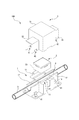
- BRIEF DESCRIPTION OF THE DRAWINGS The typical disassembled perspective view of the bodily fluid analyzer which concerns on 1st Embodiment of this invention.
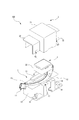
- BRIEF DESCRIPTION OF THE DRAWINGS The typical perspective view which shows the state which attached the attachment with respect to the base of the bodily fluid analyzer which concerns on 1st Embodiment of this invention.
- BRIEF DESCRIPTION OF THE DRAWINGS The typical perspective view which shows the assembled state of the bodily fluid analyzer which concerns on 1st Embodiment of this invention.
- Typical sectional drawing and functional block diagram of the bodily fluid analyzer which concern on 1st Embodiment of this invention The typical disassembled perspective view of the bodily fluid analyzer which concerns on 2nd Embodiment of this invention.
- the schematic perspective view which shows the state which attached the attachment with respect to the base of the bodily fluid analyzer which concerns on 2nd Embodiment of this invention.
- the schematic perspective view which shows the assembled state of the bodily fluid analyzer which concerns on 2nd Embodiment of this invention.
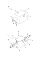
- the schematic perspective view of the bodily fluid analyzer which concerns on 3rd Embodiment of this invention.
- the typical disassembled perspective view of the bodily fluid analyzer which concerns on 4th Embodiment of this invention.
- the schematic diagram which shows the use condition of the bodily fluid analyzer of 4th Embodiment.
- a bodily fluid analyzer 100 according to a first embodiment of the present invention will be described with reference to FIGS. 1 to 5.
- the body fluid analysis device 100 is attached to a urine bag UB for storing urine which is inducted from a balloon catheter indwelling to a bladder of a hospitalized patient, for example, It analyzes the state of circulating urine.
- the urine bag UB includes a urinary tube T1 connected to an end of the balloon catheter that is outside the patient's body, and a reservoir BG in which urine having passed through the urinary tube T1 is stored. And a discharge pipe T2 for discharging urine accumulated from the storage part BG to the outside.
- the urinary duct T1, the reservoir BG, and the discharge pipe T2 are each formed of a transparent resin having translucency, and are configured such that the urine inside can be viewed.
- the urinary duct T1 and the discharge pipe T2 are configured as a translucent cylindrical tube.
- the body fluid analysis device 100 is attached to the urinary tract T1, and emits light to urine which is circulating in or retained in the urinary tract T1, and the transmitted light thereof For example, it is configured to automatically determine the degree of inoculum.
- the body fluid analyzer 100 comprises a base 1 having a light emitting element L, a light receiving element D, and an attachment 2 attached to the base 1 and an attachment 2 attached.
- a cover 3 for covering the base 1 and an analyzer 5 for analyzing urine based on the output of the light receiving element D are provided.
- the urinary tract T1 which is a tube is sandwiched, and the light emitting element L and the light receiving element D mutually It is configured to face each other.
- the light emitting element L is, for example, a chip-type LED
- the light receiving element D is a photodiode.
- the base 1 is fixed by screwing to the board BD on which the urine bag UB is hung.
- the base 1 is provided with a linearly extending groove 10 which is fitted in a state where the urinary duct T1 is extended straight. Further, the base 1 has a main body portion 11 in which a housing portion 13 in which the attachment 2 is fitted and housed is formed, and two projecting portions 12 projecting to both sides in the extending direction of the groove 10 with respect to the main body portion 11 It consists of
- the groove 10 passing through the main body 11 and the two protrusions 12 has a width dimension substantially the same as the outer diameter of the urinary duct T1, and a depth dimension substantially the same as the outer diameter of the urinary duct T1, Alternatively, it is slightly smaller than the outer diameter of the urinary tract T1. That is, when the urinary duct T1 is fitted to the groove 10, the outer surface of the urinary duct T1 on the opening side of the groove 10 is substantially flush with the bottom surface of the housing portion 13 or slightly outward. It is done like that.
- the housing portion 13 formed on the front side of the main body portion 11 is a recess formed to be substantially the same as the external dimension of the attachment 2 as shown in FIG. It is made to fit.
- the height dimension of the standing wall of the housing portion 13 is set to about 1/3 of the height dimension of the attachment 2, and only the bottom surface side provided with the light receiving element D in the attachment 2 is accommodated
- the top surface side of the attachment 2 is disposed outside the accommodation portion 13.
- the end face of the standing wall forming the inner wall surface of the housing portion 13 is formed to be flush with the side surface of the groove 10. That is, the standing wall forming the housing portion 13 is configured to prevent the light from the opening side from entering the central side of the main body portion 11 when viewed from the extension direction of the urinal tube T1.
- a housing space 16 for housing the light emitting element L and the substrate S on which the light emitting element L and its drive circuit are mounted is formed on the bottom surface side of the base 1, and the housing space 16 is closed by the lid 17. is there. Further, the light emission surface of the light emitting element L is disposed in the accommodation space 16 so as to face the passage hole 15.
- a wavelength of light emitted from the light emitting element L is selected to be suitable for absorption analysis, and a wavelength emitted from the light emitting element L may be a single wavelength or a plurality of wavelengths.
- the attachment 2 has a substantially rectangular parallelepiped shape, and a light receiving element D is provided at the center of the bottom surface.
- the bottom surface of the attachment 2 is the bottom surface 14 of the housing portion of the base 1 and the contact surface 21 that contacts the outer surface of the urine drainage tube T1.
- the light receiving surface of the light receiving element D is this contact It is flush with surface 21. Therefore, in a state in which the attachment 2 is attached to the base 1, the urinal T1 is pressed against the bottom of the groove 10 of the base 1 by the contact surface 21 and the light receiving surface of the light receiving element D. Further, the light receiving element D is in contact with the outer surface of the urinary duct T1.
- the attachment 2 is provided with a micro USB terminal or the like connected to a substrate to which the internal light receiving element D is attached, so that power can be supplied to the light receiving element D, an output can be obtained, etc.
- a wavelength band of light that can be received is set in accordance with the wavelength of the light emitted from the light emitting element L.
- the light receiving element D may be configured to receive only a single wavelength.
- the cover 3 has a shape corresponding to the base 1, and as shown in FIGS. 3 and 4, both the base 1 and the attachment 2 attached to the base 1 are attached so as to cover all from the top side Be
- the cover 3 covers the main body 11 of the base 1 and covers the pressing part 31 for pressing the attachment 2 against the base 1 and the projecting part 12 of the base 1, and external light is attached to the main body 11 of the base 1
- a shielding portion 32 for preventing the light receiving element D of the attachment 2 from being incident.
- an engagement structure 4 is formed between the base 1 and the attachment 2, and the cover 3 is attached to the base 2 when the cover 3 is attached to the base 1. It is configured to be kept pressed against the urinary duct T1 in a pinched state. That is, the engagement structure 4 includes an engagement protrusion 41 formed on the base 1 and an engagement recess 42 formed on the cover 3, and the engagement protrusion 41 and the engagement recess 42 engage with each other to hold the base.
- the cover 3 is fixed to 1.
- the engaging projections 41 and the engaging recesses 42 are respectively provided in pairs on the two outer side surfaces of the protrusion 12 and the two side surfaces of the shielding portion 32.
- the light receiving element D In the state where the cover 3 is attached to the base 1, the light receiving element D is pressed against the outer surface of the urinary duct T 1 and fixed in the groove 10 of the base 1. For this reason, the light receiving element D is disposed on the optical axis of the light emitting element L, and the light receiving element D is in contact with the outer surface of the urinary duct T1 and is suitable for receiving light necessary for analysis of urine.
- the state is realized.
- the urinary duct T1 is sandwiched between the base 1 and the attachment 2, it is possible to prevent deviation with respect to the extension direction of the urinary duct T1, and analysis of urine at the same location in the urinary duct T1 It is possible to do
- the analysis device 5 is configured to acquire the output of the light receiving element D by wire or wirelessly and to determine the latent blood level of urine. More specifically, the analysis device 5 has its function realized by a so-called computer provided with, for example, a CPU, a memory, an A / D / D / A converter, and other input / output means. The analysis device 5 executes an analysis program stored in the memory, and when various devices cooperate, as shown in FIG. 5, the analysis device 5 exhibits at least functions as the measurement unit 51 and the urine analysis unit 52.
- the measuring unit 51 converts the light amount received based on the A / D converted output from the light receiving element D.
- the urine analysis unit 52 calculates the hematocrit value based on the light amount obtained by the measurement unit 51, and determines the latent blood level from the hematocrit value. Specifically, for example, when the hemagtrit value is less than 0.1%, the urine analysis unit 52 determines that the level is 0 (Lv. 0) and the hemagtrit value is 0.1% or more and less than 0.5%. Level 1 (Lv. 1), hematocrit value of 0.5% or more and less than 1.0%, level 2 (Lv. 2), hematocrit value of 1.0% or more and less than 3.0% In some cases, the level 3 (Lv. 3), when the hematocrit value is 3.0% or more and less than 10.0%, the level 4 (Lv. 4), and when the hematocrit value is 10.0% or more Is determined to be level 5 (Lv. 5).
- the urine analysis unit 52 may determine the latent blood level constantly or at predetermined time intervals.
- the light emitting element L and the light receiving element D can be positioned suitable for urine measurement only by attaching them so as to be sandwiched between the base 1 and the attachment 2 with respect to the urinary tract T1. It can be positioned at
- the light receiving element D can realize a predetermined contact state with the outer surface of the urinary tract T1. For this reason, it is possible to reduce the influence of light passing through the urinary tract T1 and to realize an optical system suitable for sufficiently detecting the passed light with high reproducibility. Therefore, even when a nurse who is not familiar with the assembly of the optical system or the machine attaches the base 1 and the attachment 2 to the ureter T1, the device error hardly occurs.
- the base 1 includes a main body 11 including an optical system including the light emitting element L and the light receiving element D, and two protrusions 12 bulging outward from the main body 11. Since the cover 3 is attached so as to cover both 11 and the protrusion 12, it is possible to prevent external light from entering the main body 11 from the protrusion 12. In addition, because the portion where the urinary tract T1 is exposed to outside light can be separated from the main body 11 by the projecting portion 12, for example, the light satisfies the total reflection condition in the resin that constitutes the urinary tract T1. Even when incident at an incident angle, the light can be sufficiently attenuated before reaching the main body portion 11 and substantially undetected by the light receiving element D.
- the body fluid analyzer 100 of the first embodiment In addition to retrofitting the body fluid analyzer 100 of the first embodiment to the urine bag UB which normally does not have the role of a measuring device, it is possible not only to simply store urine but also to use the bladder of a patient, etc. Can be added as a medical device for managing the urinary system. As described above, since the body fluid analyzer 100 can be retrofitted to the urine bag UB, it is possible to use the urine bag UB without changing the various urine bags UB used in each hospital.
- FIGS. 6 to 8 a body fluid analyzer 100 according to a second embodiment of the present invention will be described with reference to FIGS. 6 to 8.
- symbol is attached
- the body fluid analyzer 100 of the second embodiment is attached to a blood transport tube T3 which is a tube through which blood dialyzed in, for example, an artificial dialysis device or blood after dialysis flows, and analyzes the state of the blood Used for
- the body fluid analyzer 100 of the second embodiment has the size of the groove 10 in accordance with the outer diameter of the blood transport pipe T3 as shown in FIGS. 6 and 7 in comparison with the body fluid analyzer 100 of the first embodiment. Is different in that the housing portion 13 is configured to be able to accommodate the entire attachment 2.
- the body fluid analysis apparatus 100 includes a blood analysis unit (not shown) instead of the urine analysis unit 52, and based on the output of the light receiving element D, evaluation items such as blood hematocrit value etc. It is configured to calculate.
- the body fluid analysis device 100 according to the third embodiment as compared with the body fluid analysis device 100 according to the first embodiment, has an attachment 2 in which the cover 3 is attached to the body portion 11 and the body portion 11 as shown in FIG. It differs in that it is not provided with a pressing part that covers and presses against the base 1, and that only a shielding part 32 that covers the projecting part 12 is provided.
- FIG. 10 a body fluid analyzer 100 according to a fourth embodiment of the present invention will be described with reference to FIGS. 10 and 11.
- FIG. 10 suppose that the same code
- the groove 10 formed in the base 1 is not straight but curved.
- the engagement protrusion 41 forming the engagement structure 4 is formed on only one of the outer side surfaces of the projection 12, and the engagement recess 42 is formed on only one side of the shield 32.
- the groove 10 is formed in the base 1 so as to form a substantially U-shape as shown in FIGS. 10 and 11, and the light receiving element D is guided in a use state in which the light passing through the urine is received and analyzed.
- the inflow side and the outflow side of the ureter T1 are disposed at positions higher than the optical axis of the light emitting element L, respectively.
- the groove 10 in the vicinity of the optical axis of the light emitting element L, the groove 10 is curved so as to have an apex. Further, as shown in FIG. 11, in the use state, the groove 10 is installed so as to be vertically downwardly convex, and urine is present in a portion of the urinary duct T1 which is sandwiched between the main body portion 11 of the base 1 and the attachment 2. It is made to stay temporarily.
- the groove 10 is curved and provided as described above, an amount necessary to analyze the urine always exists in the vicinity of the optical axis of the light emitting element D even when the urine volume is small as in an elderly patient, for example. It will be possible to carry out urine analysis continuously. In addition, since urine can not flow at a flow velocity equal to or higher than a predetermined value in the urinary tract T1, generation of an error in the analysis result due to the influence of the flow velocity can be prevented.
- the body fluid analysis apparatus is attached to the ureteral tube, but is attached to, for example, the drainage tube, and analyzes information such as urine occult blood level when excreting urine. It is also good. Further, the body fluid analyzer may measure the evaluation items other than the latent blood level based on the output of the light receiving element. For example, detectable parameters may be analyzed based on transmitted light such as turbidity of urine.
- the light emitting element is provided on the base and the light receiving element is provided on the attachment, but the light receiving element may be provided on the base and the light emitting element may be provided on the attachment.
- the light emitting element may be disposed in the through hole of the base and attached in contact with the outer surface of the tube.
- the light emitting element or the light receiving element is provided on either one of the base or the interlocking touch element, and the light emitting element light receiving element is configured to sandwich the tube in the radial direction.
- a light emitting element and a light receiving element may be provided on one of the two.
- the light emitting element and the light receiving element may be configured as a transmission type detector that sandwiches the tube, or the light emitting element and the light receiving element may be configured as a reflection type detector disposed on the same side with respect to the outer surface of the tube.
- both of the light emitting element and the light receiving element may be provided in the base, and may be configured as a transmissive detector in which the optical axis is set in the width direction of the groove.
- the base of the body fluid analyzer may be constituted only by the main body, and may not be provided with the protrusion. Also, only one protrusion may be provided to the main body.
- the body fluid analyzer may be configured only with the base and the attachment.
- an engagement structure may be configured between the base and the attachment, and light shielding is realized so that stray light does not enter the optical system including the light emitting element and the light receiving element in the state where the attachment is attached. are preferred.
- the shape of the groove is not limited to that curved in a U-shape as in the fourth embodiment, and it may be curved so that the body fluid is temporarily stored in the vicinity of the main body in the use state.
- the inflow side of the tube may be horizontally incident, and the outflow side of the tube may be curved upward to form a groove so as to interrupt the flow of body fluid.
- the groove may be formed in a V-shape.
- the body fluid analyzed by the body fluid analyzer is not limited to those described in the first and second embodiments.
- the body fluid may be lymph fluid, interstitial fluid, spinal fluid, saliva, sweat or the like.
- the fluid flowing through the drain taken up by the patient during or after surgery may be analyzed.
- a body fluid analyzer capable of accurately classifying states based on light on body fluid in a tube, for example, even indicators which are difficult to determine for humans, such as the blood contamination degree.
Landscapes
- Health & Medical Sciences (AREA)
- Life Sciences & Earth Sciences (AREA)
- Engineering & Computer Science (AREA)
- Chemical & Material Sciences (AREA)
- Physics & Mathematics (AREA)
- Biomedical Technology (AREA)
- General Physics & Mathematics (AREA)
- Immunology (AREA)
- Pathology (AREA)
- General Health & Medical Sciences (AREA)
- Biochemistry (AREA)
- Analytical Chemistry (AREA)
- Urology & Nephrology (AREA)
- Hematology (AREA)
- Medicinal Chemistry (AREA)
- Food Science & Technology (AREA)
- Biophysics (AREA)
- Molecular Biology (AREA)
- Ecology (AREA)
- Investigating Or Analysing Materials By Optical Means (AREA)
- Investigating Or Analysing Biological Materials (AREA)
Abstract
The present invention provides a body fluid analysis device that makes it possible to analyze a body fluid such as urine more accurately than by visual observation and that can reduce the burdens of medical workers, etc. A body fluid analysis device 100 that: shines light at a body fluid in a translucent tube T1 and analyzes the body fluid on the basis of the light that passes through the tube T1. The body fluid analysis device 100 comprises a base 1, an attachment 2 that is attached to the base 1 such that the tube T1 is sandwiched in the radial direction thereof between the attachment 2 and the base 1, a light-emitting element L that is provided to the base 1 or the attachment 2, and a light-receiving element D that is provided to the base 1 or the attachment 2. When the attachment 2 has been attached to the base 1, the light-emitting element L and the light-receiving element D are arranged between the base 1 and the attachment 2 so as to sandwich the tube T1 in the radial direction, or the light-emitting element L and the light-receiving element D are both arranged on the base 1 or on the attachment 2.
Description
本発明は、透光性を有するチューブに内にある体液に対して光を照射し、体液を通過した光に基づいて体液の分析を行う体液分析装置に関するものである。
The present invention relates to a body fluid analyzer that irradiates light onto body fluid contained in a translucent tube and analyzes the body fluid based on the light passing through the body fluid.
例えば、全身麻酔による手術が行われる患者や長期間にわたってベッドから動くことのできない患者に対して、膀胱内にバルーンカテーテルを留置し、膀胱内から導尿された尿を尿バック内に貯留することがある。このような尿バッグ(ウロバッグ)は、バルーンカテーテルの外側端部に接続される導尿管と、導尿管に接続されて尿が溜められる貯留部と、貯留部に一定量たまった尿を外部へ排出し、処理するための排出管と、を備えている(特許文献1参照)。
For example, for patients who undergo surgery under general anesthesia or who can not move from the bed for a long period of time, place a balloon catheter in the bladder and store the urine collected from the bladder in the urine bag There is. Such a urine bag (uro bag) has a urinary duct connected to the outer end of the balloon catheter, a reservoir connected to the urinary duct where urine can be stored, and urine accumulated in a fixed amount in the reservoir. And a discharge pipe for discharge and processing (see Patent Document 1).
ところで、膀胱内にバルーンカテーテルが留置されていると、特に免疫力が弱くなっている患者の場合、膀胱やそれに連なる腎臓に細菌感染等による炎症が生じる恐れがある。このため、正常な腎臓の働きが保たれているかどうかを確認するために、尿量や尿の潜血度が看護師によって確認される。
By the way, when a balloon catheter is indwelled in the bladder, in particular in the case of a patient whose immunity is weakened, there is a possibility that inflammation due to bacterial infection or the like may occur in the bladder and the kidney connected thereto. For this reason, urine volume and urine blood subdivision are checked by a nurse to confirm whether normal kidney function is maintained.
しかしながら、潜血度は尿の色と、6段階の色見本を目視で見比べて、このまま放置してもよい、あるいは、看護師のみの対処で問題のない尿の色なのか、医師のみが行うことができる医療行為を施さなくてはならない尿の色なのかを看護師が判断しなくてはならない。
However, it should be done only by the doctor whether the latent blood level may be left as it is by visually comparing the color of the urine with the 6-step color sample, or if it is the color of the urine that has no problem with nurses alone. The nurse must determine if it is the color of urine that must be treated to
特に看護師のみで対処できる場合と、医師による医療行為が必要な場合との尿の色の違いは非常に微妙であり、看護師にとって判断が難しい場合がある。例えば、安全を見て曖昧な場合は常に医師を呼ぶようにすると、本来医師が担当する必要の無い患者に医師が掛かりきりになってしまい、他の重篤な患者に手が回らなくなる等、貴重な医療資源が無駄になってしまう可能性がある。かといって、医師による医療行為が必要な場合に看護師だけで対処していると、患者の容体が悪化してしまう可能性もある。
The difference in the color of urine, especially when it can be handled only by a nurse and when it requires medical treatment by a doctor, is very subtle and may be difficult for the nurse to judge. For example, if you look at safety and always call a doctor if you are vague, the doctor will not be able to take care of patients who do not need to be in charge of the doctor, and other serious patients will not be able to reach your hand, etc. Valuable medical resources may be wasted. However, there is a possibility that the condition of the patient may be deteriorated if the nurse alone deals with the case where the medical practice by the doctor is necessary.
本発明は上述したような問題に鑑みてなされたものであり、尿等の体液の分析を目視よりも正確に行うことが可能となり、例えば医療従事者の負担を軽減することができる体液分析装置を提供することを目的とする。
The present invention has been made in view of the problems as described above, and it is possible to analyze body fluid such as urine more accurately than by visual observation, and it is possible to reduce, for example, the burden on medical workers. Intended to provide.
すなわち、本発明に係る体液分析装置は、透光性を有するチューブ内にある体液に対して光を照射し、前記チューブを通過した光に基づいて体液について分析する体液分析装置であって、ベースと、前記ベースとの間に前記チューブがその半径方向に対して挟み込まれるように当該ベースに対して取り付けられるアタッチメントと、前記ベース又は前記アタッチメントのいずれかに設けられる発光素子と、前記ベース又は前記アタッチメントのいずれかに設けられる受光素子と、を備え、前記ベースに対して前記アタッチメントが取り付けられた状態で、前記ベースと前記アタッチメントの間において、前記発光素子及び前記受光素子が前記チューブを半径方向に対して挟み込むように配置されている、又は、前記ベース又は前記アタッチメントのいずれか一方に前記発光素子及び前記発光素子の両方が配置されていることを特徴とする。
That is, the body fluid analyzer according to the present invention is a body fluid analyzer which irradiates light to body fluid in a translucent tube and analyzes the body fluid based on the light passing through the tube, the base And an attachment attached to the base such that the tube is sandwiched in the radial direction between the base, a light emitting element provided on either the base or the attachment, the base or the base A light receiving element provided on any of the attachments, the light emitting element and the light receiving element radially extending the tube between the base and the attachment in a state where the attachment is attached to the base Are placed in such a way as to sandwich the base, or the base or the attach Characterized in that both of the light emitting element and the light-emitting element in one of cement is placed.
ここで、体液とは生物が体内に持っている各種液体だけでなく、体外へ排出、分泌される液体も含む概念である。
Here, the body fluid is a concept including not only various liquids possessed by the living body but also liquids excreted and secreted outside the body.
このようなものであれば、前記チューブを前記ベースと前記アタッチメントで挟み込むようにして取り付けるだけで、前記発光素子と前記受光素子を体液の測定に適した位置に位置決めできる。
If it is such, the light emitting element and the light receiving element can be positioned at a position suitable for measuring a body fluid, simply by attaching the tube so as to sandwich the base and the attachment.
さらに、前記ベースと前記アタッチメントとの間に前記チューブを挟み込むことによって前記発光素子又は前記受光素子を前記チューブの外表面に対して所定距離離間させたり、所定の接触状態を実現したりすることができる。このため、前記チューブを光が通過する際の影響やその他の迷光による影響を低減したり、体液を通過した光を十分に検出したりするのに適した光学系を再現性よく実現できる。したがって、光学系や機械の組み立て等に習熟していない看護師が前記チューブに対して前記ベースと前記アタッチメントを付けた場合でも、体液の分析における機器誤差が発生しにくい。
Furthermore, the light emitting element or the light receiving element may be separated by a predetermined distance from the outer surface of the tube or a predetermined contact state may be realized by sandwiching the tube between the base and the attachment. it can. Therefore, an optical system suitable for reducing the influence of light passing through the tube and the influence of other stray light, or sufficiently detecting the light passing through the body fluid can be realized with good reproducibility. Therefore, even when a nurse who is not familiar with the assembly of an optical system or a machine attaches the base and the attachment to the tube, an instrument error in the analysis of the body fluid hardly occurs.
これらのことから、前記受光素子で検出される光に基づいて、チューブ内にある体液を非接触でも正確に分析することが可能となり、例えば従来看護師によって目視により判定されていた潜血度等の判定を自動化し、医療現場の負担を大幅に低減することができるようになる。
From these facts, it becomes possible to accurately analyze even non-contact bodily fluid in the tube based on the light detected by the light receiving element, and, for example, the degree of occult blood etc. which was conventionally determined visually by a nurse It will be possible to automate the judgment and to significantly reduce the burden on the medical site.
加えて、本発明であれば、従来からある医療器具等において体液が流通しているチューブに対して体液分析装置を後付けでき、チューブ内を流れている、あるいは、滞留している体液について光学的な分析が可能である。
In addition, according to the present invention, it is possible to retrofit a body fluid analyzer to a tube through which body fluid flows in a conventional medical instrument etc., and to optically measure body fluid flowing in or staying in the tube. Analysis is possible.
前記チューブがその延伸方向や円周方向に対して動きにくくして、同じ箇所での継続的な体液の分析を可能とし、かつ、前記発光素子又は前記受光素子と前記チューブの外側面との間の接触状態又は離間距離が体液分析に適した状態が実現されるようにするには、前記アタッチメントが、前記チューブの外側面に対して接触する接触面を具備し、前記ベースに対して前記アタッチメントが取り付けられた状態で、前記チューブが前記ベースに対して押し付けられるように構成されていればよい。
The tube does not move with respect to its extending direction or circumferential direction to allow continuous analysis of body fluid at the same location, and between the light emitting element or the light receiving element and the outer surface of the tube The attachment comprises a contact surface that contacts the outer surface of the tube, such that the contact or separation distance is realized to be suitable for body fluid analysis, the attachment relative to the base The tube may be configured to be pressed against the base in the attached state.
前記発光素子又は前記受光素子が前記チューブの外側面に対して接触するようにして、チューブによる迷光の発生又は検出を低減できるようにするには、前記アタッチメントが、前記発光素子又は前記受光素子の少なくとも一部が前記接触面とほぼ面一となるように構成されていればよい。
In order for the light emitting element or the light receiving element to be in contact with the outer surface of the tube so that generation or detection of stray light by the tube can be reduced, the attachment is of the light emitting element or the light receiving element. It is sufficient that at least a part thereof is configured to be substantially flush with the contact surface.
医療機器に用いられている体液が流通するようなチューブは、屈曲している場合もある。そのようなものであっても、前記ベースと前記アタッチメントとの間に前記チューブを挟みこむだけで所定の姿勢や向きに固定でき、前記発光素子から前記受光素子まで光を到達させ、正確な体液の分析を実現するのに適した状態が構築されやすくするには、前記ベースが、前記チューブが嵌め込まれる溝を具備し、前記溝の底部に前記発光素子から射出された光を通過させるための通過孔が形成されているものであればよい。
The tube through which the body fluid used in the medical device flows may be bent. Even in such a case, the tube can be fixed in a predetermined posture or direction simply by sandwiching the tube between the base and the attachment, and light can be made to reach the light receiving element from the light emitting element, and accurate bodily fluid The base is provided with a groove into which the tube is fitted, and the light emitted from the light emitting element is allowed to pass through the bottom of the groove so that a state suitable for realizing the analysis of It is sufficient that the passage hole is formed.
前記発光素子の光軸が前記受光素子に対して簡単に合うようにするには、自前記ベースが、前記アタッチメントが嵌め込まれる収容部を具備し、前記収容部に前記アタッチメントが嵌め込まれた状態で、前記発光素子の光軸上に前記受光素子が配置されるように構成されていればよい。
In order for the optical axis of the light emitting element to easily fit to the light receiving element, the base itself comprises a housing portion into which the attachment is fitted, and the attachment is fitted into the housing portion The light receiving element may be disposed on the optical axis of the light emitting element.
前記受光素子に対して、前記発光素子から射出された光以外の外光が検出されにくくし、より体液の分析精度を向上させられるようにするには、前記ベースが、前記アタッチメントが取り付けられる本体部と、前記溝の延伸方向に沿って前記本体部から外側に突出するとともに、当該溝の一部が形成された突出部と、を具備し、少なくとも前記ベースの前記突出部を覆うように構成されたカバーと、をさらに備えたものであればよい。
In order to make it difficult to detect external light other than light emitted from the light emitting element with respect to the light receiving element and to improve analysis accuracy of body fluid, the base is attached to the main body to which the attachment is attached. , And a protruding portion that protrudes outward from the main body along the extending direction of the groove, and a portion of the groove is formed to cover at least the protruding portion of the base It is sufficient if the cover further includes
前記アタッチメントが、前記チューブの外側面に対して所定の力で押しつけられるようにして、体液の分析において理想的な接触状態が実現されるようにするには、前記ベースと前記カバーとの間に形成された係合構造と、をさらに備え、前記カバーが、前記ベースの前記本体部、及び、前記ベースの本体部に取り付けられた前記アタッチメントを覆うように構成されており、前記係合構造によって前記ベースに対して前記カバーが係合された状態で、前記カバーが前記アタッチメントを前記ベース側へと押圧するように構成されていればよい。
To ensure that the attachment is pressed against the outer surface of the tube with a predetermined force, so that an ideal contact is achieved in the analysis of body fluid, between the base and the cover An engaging structure formed, wherein the cover is configured to cover the main body portion of the base and the attachment attached to the main body portion of the base; The cover may be configured to press the attachment toward the base in a state where the cover is engaged with the base.
前記チューブ内を流れる体液の量が少ない場合でも、前記発光素子と前記受光素子との間で一時的に滞留させて光が体液を通過し分析できるようにするには、測定前記溝が湾曲させて形成されていればよい。
Even if the amount of body fluid flowing in the tube is small, the groove may be curved to temporarily stay between the light emitting element and the light receiving element to allow light to pass through the body fluid for analysis. It should just be formed.
前記チューブを流れる体液を分析する際に体液分析装置内で一時滞留させやすくするための具体的な構成としては、前記チューブを通過した光を前記受光素子に受光させる使用状態において、前記溝が鉛直方向に対して下向きに凸となるように形成されているものが挙げられる。
As a specific configuration for facilitating temporary retention in the body fluid analyzer when analyzing body fluid flowing through the tube, the groove is vertical in a use state in which the light receiving element receives light passing through the tube. What is formed to be convex downward with respect to the direction is mentioned.
前記発光素子の光軸上に体液が存在しやすくして、何も分析されていない状態が発生しにくくするには、前記溝が、前記本体部において前記発光素子の光軸近傍で頂点を有するように形成されていればよい。
In order to facilitate the presence of body fluid on the optical axis of the light emitting element and to make it difficult for a state where nothing is analyzed to occur, the groove has a vertex in the main body near the optical axis of the light emitting element It should just be formed.
前記チューブ内に尿が流れるものであり、前記受光素子の出力に基づいて、尿について解析する尿解析部をさらに備えた体液分析装置であれば、例えばバルーンカテーテルが膀胱内に留置されている患者の尿について潜血度等の状態を正確、かつ、自動で検出し続けることが可能となる。したがって、患者の状態に応じた処置が適切に行えるだけでなく、例えば医療資源を効率的に運用できるようになる。
In the case of a body fluid analyzer further including a urine analysis unit for analyzing urine based on the output of the light receiving element, for example, a patient in which a balloon catheter is indwelled in a bladder, in which urine flows in the tube and the urine analyzing unit analyzes the urine based on the output of the light receiving element. It is possible to accurately and automatically detect the state of occult blood level and the like with respect to urine. Therefore, not only can the treatment according to the patient's condition be appropriately performed, but, for example, medical resources can be efficiently used.
本発明に係る体液分析装置の具体的な実施態様の1つとしては、前記チューブ内に血液が流れるものであり、前記受光素子の出力に基づいて、血液について解析する血液解析部をさらに備えたものが挙げられる。例えば、人工透析装置において流通している血液のヘマトクリット値等の状態を透析中に非接触で測定することが可能となり、血液の状態をより正確に管理する事が可能となる。
As a specific embodiment of the body fluid analyzer according to the present invention, blood flows in the tube, and the blood analysis unit further analyzes the blood based on the output of the light receiving element. The thing is mentioned. For example, it becomes possible to measure the state such as hematocrit value of blood circulating in the artificial dialysis apparatus without contact during dialysis, and it becomes possible to manage the state of blood more accurately.
このように本発明に係る体液分析装置によれば、前記ベースに対して前記アタッチメントを取り付けることで、前記ベースと前記アタッチメントの間に前記チューブを挟み込み、前記発光素子と前記受光素子との間を体液の分析に必要な光を前記受光素子で取得するのに適した状態にすることができる。したがって、前記チューブ内の体液について光に基づいて正確に分析できるので、例えば潜血度等の人間には判定しにくい指標でも状態を正確に分類することを自動化できる。
As described above, according to the body fluid analysis device of the present invention, by attaching the attachment to the base, the tube is sandwiched between the base and the attachment, and the space between the light emitting element and the light receiving element is The light necessary for analysis of body fluid can be in a state suitable for acquisition by the light receiving element. Therefore, since the body fluid in the tube can be accurately analyzed based on light, it is possible to automate accurate classification of the state even with an indicator that is difficult to determine, for example, the degree of blood loss.
100・・・体液分析装置
1 ・・・ベース
10 ・・・溝
11 ・・・本体部
12 ・・・突出部
13 ・・・収容部
14 ・・・収容部底面
15 ・・・通過孔
L ・・・発光素子
2 ・・・アタッチメント
21 ・・・接触面
22 ・・・周囲側面
3 ・・・カバー
31 ・・・押圧部
32 ・・・遮蔽部
D ・・・受光素子
UB ・・・尿バッグ
T1 ・・・導尿管
T2 ・・・排出管
BG ・・・貯留部 100 · · · bodyfluid analysis device 1 · · · base 10 · · · groove 11 · · · body portion 12 · · · protruding portion 13 · · · housing portion 14 · · · housing portion bottom surface 15 · · · passing hole L · · · .. Light emitting element 2 ... Attachment 21 ... Contact surface 22 ... Surrounding side 3 ... Cover 31 ... Pressing part 32 ... Shielding part D ... Light receiving element UB ... Urine bag T1 ··· Urine tube T2 ··· Discharge tube BG · · · Reservoir
1 ・・・ベース
10 ・・・溝
11 ・・・本体部
12 ・・・突出部
13 ・・・収容部
14 ・・・収容部底面
15 ・・・通過孔
L ・・・発光素子
2 ・・・アタッチメント
21 ・・・接触面
22 ・・・周囲側面
3 ・・・カバー
31 ・・・押圧部
32 ・・・遮蔽部
D ・・・受光素子
UB ・・・尿バッグ
T1 ・・・導尿管
T2 ・・・排出管
BG ・・・貯留部 100 · · · body
本発明の第1実施形態に係る体液分析装置100について図1乃至図5を参照しながら説明する。第1実施形態の体液分析装置100は、図1に示すように、例えば入院患者の膀胱に留置されたバルーンカテーテルから導尿される尿を貯留する尿バッグUBに対して取り付けられ、チューブ内を流通する尿の状態を分析するものである。ここで、尿バッグUBは、バルーンカテーテルにおいて患者の体外に出ている端部に対して接続される導尿管T1と、導尿管T1を通ってきた尿が貯留される貯留部BGと、貯留部BGから溜められた尿を外部へ排出するための排出管T2と、を備えたものである。なお、導尿管T1、貯留部BG、排出管T2はそれぞれ透光性を有する透明樹脂で形成されており、内部の尿を目視できるように構成されている。また、導尿管T1及び排出管T2は透光性を有する円筒状のチューブとして構成されている。
A bodily fluid analyzer 100 according to a first embodiment of the present invention will be described with reference to FIGS. 1 to 5. As shown in FIG. 1, the body fluid analysis device 100 according to the first embodiment is attached to a urine bag UB for storing urine which is inducted from a balloon catheter indwelling to a bladder of a hospitalized patient, for example, It analyzes the state of circulating urine. Here, the urine bag UB includes a urinary tube T1 connected to an end of the balloon catheter that is outside the patient's body, and a reservoir BG in which urine having passed through the urinary tube T1 is stored. And a discharge pipe T2 for discharging urine accumulated from the storage part BG to the outside. The urinary duct T1, the reservoir BG, and the discharge pipe T2 are each formed of a transparent resin having translucency, and are configured such that the urine inside can be viewed. In addition, the urinary duct T1 and the discharge pipe T2 are configured as a translucent cylindrical tube.
第1実施形態では体液分析装置100は、導尿管T1に対して取り付けられており、導尿管T1内を流通する、又は、滞留している尿に対して光を照射し、その透過光に基づいて例えば潜血度を自動的に判定するように構成してある。
In the first embodiment, the body fluid analysis device 100 is attached to the urinary tract T1, and emits light to urine which is circulating in or retained in the urinary tract T1, and the transmitted light thereof For example, it is configured to automatically determine the degree of inoculum.
図2乃至図5に示すように、体液分析装置100は、発光素子Lを具備するベース1と、受光素子Dを具備し、ベース1に対して取り付けられるアタッチメント2と、アタッチメント2が取り付けられたベース1を覆うカバー3と、受光素子Dの出力に基づいて、尿について解析する解析装置5と、を備えている。図3及び図5に示すように、ベース1に対してアタッチメント2が取り付けられた状態で、チューブである導尿管T1が挟み込まれるとともに、発光素子Lと受光素子Dが互いに導尿管T1を介して対向するように構成してある。ここで、発光素子Lは例えばチップ型のLEDであり、受光素子Dはフォトダイオードである。また、ベース1は尿バッグUBが掛けられているボードBDに対してネジ止めにより、固定される。
As shown in FIGS. 2 to 5, the body fluid analyzer 100 comprises a base 1 having a light emitting element L, a light receiving element D, and an attachment 2 attached to the base 1 and an attachment 2 attached. A cover 3 for covering the base 1 and an analyzer 5 for analyzing urine based on the output of the light receiving element D are provided. As shown in FIGS. 3 and 5, in a state where the attachment 2 is attached to the base 1, the urinary tract T1 which is a tube is sandwiched, and the light emitting element L and the light receiving element D mutually It is configured to face each other. Here, the light emitting element L is, for example, a chip-type LED, and the light receiving element D is a photodiode. In addition, the base 1 is fixed by screwing to the board BD on which the urine bag UB is hung.
ベース1は、図2及び図5に示すように、導尿管T1をまっすぐにのばした状態で嵌め込まれる直線状に延びる溝10を備えている。また、このベース1は、アタッチメント2が嵌め込まれて収容される収容部13が形成された本体部11と、本体部11に対して溝10の延伸方向へ両側に突出した2つの突出部12と、からなる。
As shown in FIGS. 2 and 5, the base 1 is provided with a linearly extending groove 10 which is fitted in a state where the urinary duct T1 is extended straight. Further, the base 1 has a main body portion 11 in which a housing portion 13 in which the attachment 2 is fitted and housed is formed, and two projecting portions 12 projecting to both sides in the extending direction of the groove 10 with respect to the main body portion 11 It consists of
本体部11及び2つの突出部12を通る溝10は、その幅寸法が導尿管T1の外径とほぼ同じにしてあるとともに、その深さ寸法は導尿管T1の外径とほぼ同じ、又は、導尿管T1の外径よりも少し小さくしてある。すなわち、溝10に対して導尿管T1を嵌め合わせた場合、溝10の開口側にでる導尿管T1の外側面は、収容部13の底面とほぼ面一、又は、少しだけ外側に出るようにしてある。
The groove 10 passing through the main body 11 and the two protrusions 12 has a width dimension substantially the same as the outer diameter of the urinary duct T1, and a depth dimension substantially the same as the outer diameter of the urinary duct T1, Alternatively, it is slightly smaller than the outer diameter of the urinary tract T1. That is, when the urinary duct T1 is fitted to the groove 10, the outer surface of the urinary duct T1 on the opening side of the groove 10 is substantially flush with the bottom surface of the housing portion 13 or slightly outward. It is done like that.
本体部11の表側に形成されている収容部13は、図3に示すようにアタッチメント2の外形寸法とほぼ同じに形成された凹部であり、その内壁面に対してアタッチメント2の周囲側面22が嵌め合わさるようにしてある。第1実施形態では、収容部13の立壁の高さ寸法は、アタッチメント2の高さ寸法の1/3程度に設定してあり、アタッチメント2において受光素子Dが設けられている底面側のみが収容され、アタッチメント2の天面側は収容部13の外側に配置される。また、収容部13の内壁面を形成する立壁の端面は、溝10の側面と面一となるように形成してある。すなわち、収容部13を形成する立壁は導尿管T1の延伸方向から見て開口側からの光が本体部11の中心側へと外光が侵入するのを防ぐようにしてある。
The housing portion 13 formed on the front side of the main body portion 11 is a recess formed to be substantially the same as the external dimension of the attachment 2 as shown in FIG. It is made to fit. In the first embodiment, the height dimension of the standing wall of the housing portion 13 is set to about 1/3 of the height dimension of the attachment 2, and only the bottom surface side provided with the light receiving element D in the attachment 2 is accommodated The top surface side of the attachment 2 is disposed outside the accommodation portion 13. Further, the end face of the standing wall forming the inner wall surface of the housing portion 13 is formed to be flush with the side surface of the groove 10. That is, the standing wall forming the housing portion 13 is configured to prevent the light from the opening side from entering the central side of the main body portion 11 when viewed from the extension direction of the urinal tube T1.
また、図5の断面図に示すように本体部11に形成されている溝10の底面中央部には、本体部11の内部に収容されている発光素子Lから射出される光を通過させるための通過孔15が形成してある。ベース1の底面側には発光素子L、及び、発光素子Lやその駆動回路が搭載された基板Sが収容される収容空間16が形成されており、蓋体17で収容空間16は閉鎖してある。また、収容空間16内において発光素子Lの光射出面が通過孔15に対して対向するように配置してある。発光素子Lから射出される光の波長は例えば吸光分析に適したものが選択され、発光素子Lから射出される波長は、単波長であってもよいし、複数波長であっても構わない。
Further, as shown in the cross-sectional view of FIG. 5, light emitted from the light emitting element L accommodated in the inside of the main body 11 is allowed to pass through the center of the bottom of the groove 10 formed in the main body 11. Through holes 15 are formed. A housing space 16 for housing the light emitting element L and the substrate S on which the light emitting element L and its drive circuit are mounted is formed on the bottom surface side of the base 1, and the housing space 16 is closed by the lid 17. is there. Further, the light emission surface of the light emitting element L is disposed in the accommodation space 16 so as to face the passage hole 15. For example, a wavelength of light emitted from the light emitting element L is selected to be suitable for absorption analysis, and a wavelength emitted from the light emitting element L may be a single wavelength or a plurality of wavelengths.
アタッチメント2は、図2乃至図5に示すように、概略直方体形状のものであり、底面中央に受光素子Dが設けてある。図5に示すように、アタッチメント2の底面は、ベース1の収容部底面14、及び、導尿管T1の外側面に対して接触する接触面21であり、受光素子Dの受光面はこの接触面21と面一にしてある。したがって、ベース1に対してアタッチメント2が取り付けられた状態において、接触面21及び受光素子Dの受光面により導尿管T1はベース1の溝10の底に対して押し付けられた状態になる。また、受光素子Dは導尿管T1の外側面に対して接触した状態となっている。このアタッチメント2には、内部の受光素子Dが取り付けられている基板に対して接続されるマイクロUSB端子等が設けられており、受光素子Dに対する給電や、出力の取得等が行えるように構成してある。受光素子Dについては、例えば発光素子Lから射出される光の波長に合わせて受光できる光の波長帯域が設定されている。逆に受光素子Dが単波長しか受光できないように構成しても構わない。
As shown in FIGS. 2 to 5, the attachment 2 has a substantially rectangular parallelepiped shape, and a light receiving element D is provided at the center of the bottom surface. As shown in FIG. 5, the bottom surface of the attachment 2 is the bottom surface 14 of the housing portion of the base 1 and the contact surface 21 that contacts the outer surface of the urine drainage tube T1. The light receiving surface of the light receiving element D is this contact It is flush with surface 21. Therefore, in a state in which the attachment 2 is attached to the base 1, the urinal T1 is pressed against the bottom of the groove 10 of the base 1 by the contact surface 21 and the light receiving surface of the light receiving element D. Further, the light receiving element D is in contact with the outer surface of the urinary duct T1. The attachment 2 is provided with a micro USB terminal or the like connected to a substrate to which the internal light receiving element D is attached, so that power can be supplied to the light receiving element D, an output can be obtained, etc. It is For the light receiving element D, for example, a wavelength band of light that can be received is set in accordance with the wavelength of the light emitted from the light emitting element L. Conversely, the light receiving element D may be configured to receive only a single wavelength.
カバー3は、ベース1に対応する形状を有しており、図3及び図4に示すように、ベース1と、ベース1に対して取り付けられたアタッチメント2ともに天面側からすべて覆うように取り付けられる。カバー3は、ベース1の本体部11を覆い、アタッチメント2をベース1に対して押し付ける押圧部31と、ベース1の突出部12を覆い、外部からの光がベース1の本体部11に取り付けられているアタッチメント2の受光素子Dに対して入射するのを防ぐ遮蔽部32とからなる。
The cover 3 has a shape corresponding to the base 1, and as shown in FIGS. 3 and 4, both the base 1 and the attachment 2 attached to the base 1 are attached so as to cover all from the top side Be The cover 3 covers the main body 11 of the base 1 and covers the pressing part 31 for pressing the attachment 2 against the base 1 and the projecting part 12 of the base 1, and external light is attached to the main body 11 of the base 1 And a shielding portion 32 for preventing the light receiving element D of the attachment 2 from being incident.
図2乃至図5に示すように、ベース1とアタッチメント2との間には、係合構造4が形成してあり、ベース1に対してカバー3を取り付けると、カバー3がアタッチメント2をベース1に対して押し付けて導尿管T1が挟み込まれた状態が維持されるように構成してある。すなわち、係合構造4は、ベース1に形成された係合突起41と、カバー3に形成された係合凹部42とからなり、係合突起41と係合凹部42が掛かり留め合うことによってベース1に対してカバー3が固定される。この実施形態では係合突起41と係合凹部42は、突出部12の2つの外側面、及び、遮蔽部32の2つの側面にそれぞれ一対ずつ設けられている。
As shown in FIGS. 2 to 5, an engagement structure 4 is formed between the base 1 and the attachment 2, and the cover 3 is attached to the base 2 when the cover 3 is attached to the base 1. It is configured to be kept pressed against the urinary duct T1 in a pinched state. That is, the engagement structure 4 includes an engagement protrusion 41 formed on the base 1 and an engagement recess 42 formed on the cover 3, and the engagement protrusion 41 and the engagement recess 42 engage with each other to hold the base. The cover 3 is fixed to 1. In this embodiment, the engaging projections 41 and the engaging recesses 42 are respectively provided in pairs on the two outer side surfaces of the protrusion 12 and the two side surfaces of the shielding portion 32.
カバー3がベース1に対して取り付けられた状態において、受光素子Dが導尿管T1の外側面に対して押し付けられてベース1の溝10内に固定されることになる。このため、発光素子Lの光軸上に受光素子Dが配置され、かつ、受光素子Dが導尿管T1の外側面に接し、尿の分析のために必要な光を受光するのに適した状態が実現される。また、導尿管T1がベース1とアタッチメント2によって挟み込まれた状態になるので、導尿管T1の延伸方向に対してずれが生じないようにでき、導尿管T1において同じ箇所で尿の分析を行うことが可能となる。
In the state where the cover 3 is attached to the base 1, the light receiving element D is pressed against the outer surface of the urinary duct T 1 and fixed in the groove 10 of the base 1. For this reason, the light receiving element D is disposed on the optical axis of the light emitting element L, and the light receiving element D is in contact with the outer surface of the urinary duct T1 and is suitable for receiving light necessary for analysis of urine. The state is realized. In addition, since the urinary duct T1 is sandwiched between the base 1 and the attachment 2, it is possible to prevent deviation with respect to the extension direction of the urinary duct T1, and analysis of urine at the same location in the urinary duct T1 It is possible to do
解析装置5は、受光素子Dの出力を有線又は無線により取得して、尿の潜血度を判定するように構成してある。より具体的には解析装置5は、例えばCPU、メモリ、A/D・D/Aコンバータ、その他の入出力手段を備えたいわゆるコンピュータによってその機能が実現されるものである。解析装置5は、メモリに格納されている分析用プログラムが実行され、各種機器が協業することにより、図5に示すように少なくとも計測部51と、尿解析部52としての機能を発揮する。
The analysis device 5 is configured to acquire the output of the light receiving element D by wire or wirelessly and to determine the latent blood level of urine. More specifically, the analysis device 5 has its function realized by a so-called computer provided with, for example, a CPU, a memory, an A / D / D / A converter, and other input / output means. The analysis device 5 executes an analysis program stored in the memory, and when various devices cooperate, as shown in FIG. 5, the analysis device 5 exhibits at least functions as the measurement unit 51 and the urine analysis unit 52.
計測部51は、受光素子DからのA/D変換された出力に基づいて受光された光量へ変換するものである。
The measuring unit 51 converts the light amount received based on the A / D converted output from the light receiving element D.
尿解析部52は、計測部51で得られた光量に基づいて、ヘマトクリット値を算出し、ヘマトクリット値から潜血度を判定するものである。具体的には、尿解析部52は、例えば、ヘマクトリット値が0.1%未満である場合にはレベル0(Lv.0)、ヘマクトリット値が0.1%以上0.5%未満である場合にはレベル1(Lv.1)、ヘマクトリット値が0.5%以上1.0%未満である場合にはレベル2(Lv.2)、ヘマトクリット値が1.0%以上3.0%未満である場合にはレベル3(Lv.3)、ヘマトクリット値が3.0%以上10.0%未満である場合にはレベル4(Lv.4)、ヘマトクリット値が10.0%以上である場合にはレベル5(Lv.5)であると判定する。尿解析部52は、潜血度の判定を常時行ってもよいし、所定の時間毎に行ってもよい。
The urine analysis unit 52 calculates the hematocrit value based on the light amount obtained by the measurement unit 51, and determines the latent blood level from the hematocrit value. Specifically, for example, when the hemagtrit value is less than 0.1%, the urine analysis unit 52 determines that the level is 0 (Lv. 0) and the hemagtrit value is 0.1% or more and less than 0.5%. Level 1 (Lv. 1), hematocrit value of 0.5% or more and less than 1.0%, level 2 (Lv. 2), hematocrit value of 1.0% or more and less than 3.0% In some cases, the level 3 (Lv. 3), when the hematocrit value is 3.0% or more and less than 10.0%, the level 4 (Lv. 4), and when the hematocrit value is 10.0% or more Is determined to be level 5 (Lv. 5). The urine analysis unit 52 may determine the latent blood level constantly or at predetermined time intervals.
このように構成された体液分析装置100によれば、導尿管T1に対してベース1とアタッチメント2で挟み込むようにして取り付けるだけで、発光素子Lと受光素子Dを尿の測定に適した位置に位置決めできる。
According to the body fluid analysis apparatus 100 configured as described above, the light emitting element L and the light receiving element D can be positioned suitable for urine measurement only by attaching them so as to be sandwiched between the base 1 and the attachment 2 with respect to the urinary tract T1. It can be positioned at
さらに、ベース1とアタッチメント2との間に導尿管T1を挟み込むことによって、受光素子Dを導尿管T1の外表面に対して所定の接触状態を実現できる。このため、導尿管T1を光が通過する際の影響を低減し、通過した光を十分に検出するのに適した光学系を再現性よく実現できる。したがって、光学系や機械の組み立て等に習熟していない看護師が導尿管T1に対してベース1とアタッチメント2を付けた場合でも、機器誤差が発生しにくい。
Furthermore, by inserting the urinary tract T1 between the base 1 and the attachment 2, the light receiving element D can realize a predetermined contact state with the outer surface of the urinary tract T1. For this reason, it is possible to reduce the influence of light passing through the urinary tract T1 and to realize an optical system suitable for sufficiently detecting the passed light with high reproducibility. Therefore, even when a nurse who is not familiar with the assembly of the optical system or the machine attaches the base 1 and the attachment 2 to the ureter T1, the device error hardly occurs.
また、ベース1が、発光素子Lと受光素子Dとからなる光学系が構成される本体部11と、本体部11から外側へと膨出した2つの突出部12を具備しており、本体部11及び突出部12の両方を覆うようにカバー3が取り付けられるの、突出部12から本体部11側へ外の光が入射するのを防ぐことができる。また、突出部12によって、導尿管T1が外の光にさらされる部分は、本体部11から離すことができるので、例えば導尿管T1を構成する樹脂内に光が全反射条件を満たすような入射角度で入射したとしても、本体部11に到達するまでに十分に減衰し、受光素子Dでは実質的には検出されないようにもできる。
In addition, the base 1 includes a main body 11 including an optical system including the light emitting element L and the light receiving element D, and two protrusions 12 bulging outward from the main body 11. Since the cover 3 is attached so as to cover both 11 and the protrusion 12, it is possible to prevent external light from entering the main body 11 from the protrusion 12. In addition, because the portion where the urinary tract T1 is exposed to outside light can be separated from the main body 11 by the projecting portion 12, for example, the light satisfies the total reflection condition in the resin that constitutes the urinary tract T1. Even when incident at an incident angle, the light can be sufficiently attenuated before reaching the main body portion 11 and substantially undetected by the light receiving element D.
これらのことから、受光素子Dで検出される光に基づいて、導尿管T1内にある尿の潜血度を非接触でも正確に分析することが可能となる。したがって、従来看護師によって目視により判定されていた潜血度等の判定を自動化し、医療現場の負担を大幅に低減することができるようになる。
From these facts, based on the light detected by the light receiving element D, it is possible to accurately analyze the occult blood level of the urine in the ureter T1 without contact. Therefore, it is possible to automate the determination of the latent blood level and the like conventionally determined by visual observation by a nurse, and to significantly reduce the burden on the medical site.
加えて、本来であれば測定器の役割を有していない尿バッグUBに対して、第1実施形態の体液分析装置100を後付けすることで、単に尿を貯めるだけでなく、患者の膀胱等の泌尿器を管理するための医療機としての機能を付加することができる。このように尿バッグUBに対して体液分析装置100は後付けできるので、病院ごとに用いられている各種尿バッグUBを変更することなく、利用することが可能である。
In addition to retrofitting the body fluid analyzer 100 of the first embodiment to the urine bag UB which normally does not have the role of a measuring device, it is possible not only to simply store urine but also to use the bladder of a patient, etc. Can be added as a medical device for managing the urinary system. As described above, since the body fluid analyzer 100 can be retrofitted to the urine bag UB, it is possible to use the urine bag UB without changing the various urine bags UB used in each hospital.
次に本発明の第2実施形態に係る体液分析装置100について図6乃至図8を参照しながら説明する。なお、第1実施形態において説明した部材と対応する部材には同じ符号を付すこととする。
Next, a body fluid analyzer 100 according to a second embodiment of the present invention will be described with reference to FIGS. 6 to 8. In addition, suppose that the same code | symbol is attached | subjected to the member corresponding to the member demonstrated in 1st Embodiment.
第2実施形態の体液分析装置100は、例えば人工透析装置において透析される血液、又は、透析後の血液が流通するチューブである血液輸送管T3に対して取り付けられ、その血液の状態を分析するために用いられるものである。
The body fluid analyzer 100 of the second embodiment is attached to a blood transport tube T3 which is a tube through which blood dialyzed in, for example, an artificial dialysis device or blood after dialysis flows, and analyzes the state of the blood Used for
第2実施形態の体液分析装置100は、第1実施形態の体液分析装置100と比較して、図6及び図7に示すように、血液輸送管T3の外径に合わせて溝10の大きさが設定してある点、収容部13がアタッチメント2の全体を収容できるように構成してある点が異なっている。
The body fluid analyzer 100 of the second embodiment has the size of the groove 10 in accordance with the outer diameter of the blood transport pipe T3 as shown in FIGS. 6 and 7 in comparison with the body fluid analyzer 100 of the first embodiment. Is different in that the housing portion 13 is configured to be able to accommodate the entire attachment 2.
また、第2実施形態の体液分析装置100は、尿解析部52の代わりに血液解析部(図示しない)を備えており、受光素子Dの出力に基づいて例えば血液のヘマトクリット値等の評価項目を算出するように構成してある。
In addition, the body fluid analysis apparatus 100 according to the second embodiment includes a blood analysis unit (not shown) instead of the urine analysis unit 52, and based on the output of the light receiving element D, evaluation items such as blood hematocrit value etc. It is configured to calculate.
このように第2実施形態の体液分析装置100であっても、第1実施形態と同様の効果を人工透析装置において享受することができる。
Thus, even with the body fluid analyzer 100 of the second embodiment, the same effects as those of the first embodiment can be enjoyed in the artificial dialysis device.
次に本発明の第3実施形態に係る体液分析装置100について図9を参照しながら説明する。なお、第1実施形態において説明した部材と対応する部材には同じ符号を付すこととする。
Next, a body fluid analyzer 100 according to a third embodiment of the present invention will be described with reference to FIG. In addition, suppose that the same code | symbol is attached | subjected to the member corresponding to the member demonstrated in 1st Embodiment.
第3実施形態の体液分析装置100は、第1実施形態の体液分析装置100と比較して、図9に示すように、カバー3が、本体部11及び本体部11に取り付けられたアタッチメント2を覆うとともにベース1に対して押圧する押圧部を備えておらず、突出部12を覆う遮蔽部32のみを備えている点で異なっている。
The body fluid analysis device 100 according to the third embodiment, as compared with the body fluid analysis device 100 according to the first embodiment, has an attachment 2 in which the cover 3 is attached to the body portion 11 and the body portion 11 as shown in FIG. It differs in that it is not provided with a pressing part that covers and presses against the base 1, and that only a shielding part 32 that covers the projecting part 12 is provided.
このように構成されたカバー3であっても、導尿管T1の軸方向から入射する外光が受光素子Dで検出されにくくし、尿の分析精度を向上させられる。また、収容部13に対するアタッチメント2の嵌合をきつめに設定しておけば、カバー3で押圧されなくても十分に導尿管T1を挟み込むことができる。また、アタッチメント2と本体部11との間に導尿管T1が設けられているので、この部分についてはカバー3がなくても半径方向から外光が入り込まないようにできる。
Even with the cover 3 configured in this manner, external light incident from the axial direction of the urinary canal T1 can be made difficult to detect by the light receiving element D, and urine analysis accuracy can be improved. Moreover, if fitting of the attachment 2 with respect to the accommodating part 13 is set to tightness, even if it does not press with the cover 3, the urinary tract T1 can be inserted enough. Further, since the urinary duct T1 is provided between the attachment 2 and the main body 11, external light can be prevented from entering from the radial direction even if the cover 3 is not provided for this part.
次に本発明の第4実施形態に係る体液分析装置100について図10及び図11を参照しながら説明する。なお、第1実施形態において説明した部材と対応する部材には同じ符号を付すこととする。
Next, a body fluid analyzer 100 according to a fourth embodiment of the present invention will be described with reference to FIGS. 10 and 11. FIG. In addition, suppose that the same code | symbol is attached | subjected to the member corresponding to the member demonstrated in 1st Embodiment.
第4実施形態の体液分析装置100は、第1実施形態の体液分析装置100と比較して、図10に示すように、ベース1に形成された溝10が直線状ではなく、湾曲させて形成されている点と、係合構造4を形成する係合突起41が突出部12の外側面の一方のみに形成されており、係合凹部42が遮蔽部32の一方の側面のみに形成されている点が異なっている。以下に溝10の構成について詳述する。
Compared with the body fluid analysis device 100 according to the first embodiment, as shown in FIG. 10, in the body fluid analysis device 100 according to the fourth embodiment, the groove 10 formed in the base 1 is not straight but curved. And the engagement protrusion 41 forming the engagement structure 4 is formed on only one of the outer side surfaces of the projection 12, and the engagement recess 42 is formed on only one side of the shield 32. There are differences in The configuration of the groove 10 will be described in detail below.
溝10は、図10及び図11に示すように概略U字状をなすようにベース1において形成されており、受光素子Dにおいて尿を通過した光が受光され分析が行われる使用状態において、導尿管T1の流入側と流出側がそれぞれ発光素子Lの光軸よりも高い位置に配置されるようにしてある。
The groove 10 is formed in the base 1 so as to form a substantially U-shape as shown in FIGS. 10 and 11, and the light receiving element D is guided in a use state in which the light passing through the urine is received and analyzed. The inflow side and the outflow side of the ureter T1 are disposed at positions higher than the optical axis of the light emitting element L, respectively.
すなわち、発光素子Lの光軸近傍において溝10は頂点を有するように湾曲させてある。また、図11に示すように使用状態においては溝10が鉛直下向きに凸となるように設置され、導尿管T1においてベース1の本体部11とアタッチメント2との間に挟まれる部分に尿が一時的に滞留するようにしてある。
That is, in the vicinity of the optical axis of the light emitting element L, the groove 10 is curved so as to have an apex. Further, as shown in FIG. 11, in the use state, the groove 10 is installed so as to be vertically downwardly convex, and urine is present in a portion of the urinary duct T1 which is sandwiched between the main body portion 11 of the base 1 and the attachment 2. It is made to stay temporarily.
このように溝10が湾曲させて設けられているので、例えば高齢の患者のように尿量が少ない場合でも、尿の分析を行うのに必要な量が発光素子Dの光軸近傍に常に存在するようにして、継続して尿の分析を行う事が可能となる。また、導尿管T1内を尿が所定値以上の流速で流れなくできるので、流速の影響により分析結果に誤差が発生するのも防ぐことができる。
Since the groove 10 is curved and provided as described above, an amount necessary to analyze the urine always exists in the vicinity of the optical axis of the light emitting element D even when the urine volume is small as in an elderly patient, for example. It will be possible to carry out urine analysis continuously. In addition, since urine can not flow at a flow velocity equal to or higher than a predetermined value in the urinary tract T1, generation of an error in the analysis result due to the influence of the flow velocity can be prevented.
その他の実施形態について説明する。
Other embodiments will be described.
第1実施形態の体液分析装置は、導尿管に対して取り付けられていたが、例えば排出管に対して取り付けられ、尿を排出する際に尿の潜血度等の情報を分析するようにしてもよい。また、体液分析装置は、受光素子の出力に基づいて、潜血度以外の評価項目について測定するようにしてもよい。例えば尿の濁度等の透過光に基づいて検出可能なパラメータを分析するようにしてもよい。
The body fluid analysis apparatus according to the first embodiment is attached to the ureteral tube, but is attached to, for example, the drainage tube, and analyzes information such as urine occult blood level when excreting urine. It is also good. Further, the body fluid analyzer may measure the evaluation items other than the latent blood level based on the output of the light receiving element. For example, detectable parameters may be analyzed based on transmitted light such as turbidity of urine.
各実施形態に記載の体液分析装置は、ベースに発光素子、アタッチメントに受光素子を設けていたが、ベースに受光素子、アタッチメントに発光素子を設けても構わない。また、ベースの通過孔内に発光素子を配置してチューブの外側面に対して接触させた状態で取り付けられるようにしてもよい。さらに、各実施形態ではベース又は合タッチメントのいずれか一方に発光素子又は受光素子がそれぞれ設けられ、発光素子受光素子がチューブを半径方向に対して挟みこむように構成されていたが、ベース又はアタッチメントの一方に発光素子及び受光素子が設けられているものであってもよい。このような場合には、例えば発光素子から射出された光がチューブ内に入射し、体液を通過した後でチューブの対向側で反射され、戻ってくる光を受光素子で検出するように構成してもよい。すなわち、発光素子及び受光素子がチューブを挟み込む透過型の検出器として構成してもよいし、発光素子及び受光素子がチューブの外側面に対して同じ側に配置される反射型の検出器として構成してもよい。加えて、ベースにおいて発光素子及び受光素子が両方設けられて、溝の幅方向に光軸が設定された透過型の検出器として構成されていてもよい。
In the body fluid analysis device according to each embodiment, the light emitting element is provided on the base and the light receiving element is provided on the attachment, but the light receiving element may be provided on the base and the light emitting element may be provided on the attachment. Alternatively, the light emitting element may be disposed in the through hole of the base and attached in contact with the outer surface of the tube. Furthermore, in each of the embodiments, the light emitting element or the light receiving element is provided on either one of the base or the interlocking touch element, and the light emitting element light receiving element is configured to sandwich the tube in the radial direction. A light emitting element and a light receiving element may be provided on one of the two. In such a case, for example, light emitted from the light emitting element enters the tube, passes through the body fluid, is reflected on the opposite side of the tube, and detects light returned by the light receiving element. May be That is, the light emitting element and the light receiving element may be configured as a transmission type detector that sandwiches the tube, or the light emitting element and the light receiving element may be configured as a reflection type detector disposed on the same side with respect to the outer surface of the tube. You may In addition, both of the light emitting element and the light receiving element may be provided in the base, and may be configured as a transmissive detector in which the optical axis is set in the width direction of the groove.
体液分析装置のベースは本体部だけで構成されており、突出部が設けられていないものであってもよい。また、突出部は本体部に対して一方だけ設けられていても良い。
The base of the body fluid analyzer may be constituted only by the main body, and may not be provided with the protrusion. Also, only one protrusion may be provided to the main body.
また、体液分析装置は、ベースとアタッチメントだけで構成されていてもよい。この場合には、ベースとアタッチメントとの間に係合構造を構成してもよいし、アタッチメントが取り付けられた状態で発光素子と受光素子からなる光学系に迷光が入射しないように遮光が実現されるものが好ましい。
Also, the body fluid analyzer may be configured only with the base and the attachment. In this case, an engagement structure may be configured between the base and the attachment, and light shielding is realized so that stray light does not enter the optical system including the light emitting element and the light receiving element in the state where the attachment is attached. Are preferred.
溝の形状については第4実施形態のようにU字状に湾曲したものに限られず、使用状態において体液が一時的に本体部の近傍で貯留されるように湾曲していればよい。例えば、チューブの流入側が水平に入射するようにして、チューブの流出側が上方へと湾曲し、体液の流れが遮られるように溝を形成してもよい。また、溝がV字状に形成されていてもよい。
The shape of the groove is not limited to that curved in a U-shape as in the fourth embodiment, and it may be curved so that the body fluid is temporarily stored in the vicinity of the main body in the use state. For example, the inflow side of the tube may be horizontally incident, and the outflow side of the tube may be curved upward to form a groove so as to interrupt the flow of body fluid. Moreover, the groove may be formed in a V-shape.
体液分析装置が分析する体液は、第1実施形態及び第2実施形態において説明したものに限られない。体液としては、リンパ液、組織液、髄液、唾液、汗等その他ものであってもよい。例えば手術中又は手術後の患者に取りけられたドレーンを流通する体液を分析してもよい。
The body fluid analyzed by the body fluid analyzer is not limited to those described in the first and second embodiments. The body fluid may be lymph fluid, interstitial fluid, spinal fluid, saliva, sweat or the like. For example, the fluid flowing through the drain taken up by the patient during or after surgery may be analyzed.
その他、本発明の趣旨に反しない限りにおいて、様々な実施形態の一部同士を組み合わせてもよいし、各実施形態の一部を変形しても構わない。
In addition, unless it is contrary to the meaning of the present invention, a part of various embodiments may be combined, and a part of each embodiment may be changed.
本発明によれば、チューブ内の体液について光に基づいて、例えば潜血度等の人間には判定しにくい指標でも状態を正確に自動で分類できる体液分析装置を提供できる。
According to the present invention, it is possible to provide a body fluid analyzer capable of accurately classifying states based on light on body fluid in a tube, for example, even indicators which are difficult to determine for humans, such as the blood contamination degree.
Claims (12)
- 透光性を有するチューブ内にある体液に対して光を照射し、前記チューブを通過した光に基づいて体液について分析する体液分析装置であって、
ベースと、
前記ベースとの間に前記チューブがその半径方向に対して挟み込まれるように当該ベースに対して取り付けられるアタッチメントと、
前記ベース又は前記アタッチメントのいずれかに設けられる発光素子と、
前記ベース又は前記アタッチメントのいずれかに設けられる受光素子と、を備え、
前記ベースに対して前記アタッチメントが取り付けられた状態で、前記ベースと前記アタッチメントの間において、前記発光素子及び前記受光素子が前記チューブを半径方向に対して挟み込むように配置されている、又は、前記ベース又は前記アタッチメントのいずれか一方に前記発光素子及び前記発光素子の両方が配置されていることを特徴とする体液分析装置。 A body fluid analyzer which irradiates light to body fluid in a translucent tube and analyzes the body fluid based on the light passing through the tube,
Base and
An attachment attached to the base such that the tube is nipped with respect to the radial direction with the base;
A light emitting element provided on either the base or the attachment;
A light receiving element provided on either the base or the attachment;
In a state where the attachment is attached to the base, the light emitting element and the light receiving element are disposed so as to sandwich the tube in the radial direction between the base and the attachment, or An apparatus for analyzing body fluid, wherein both the light emitting element and the light emitting element are disposed on either the base or the attachment. - 前記アタッチメントが、前記チューブの外側面に対して接触する接触面を具備し、
前記ベースに対して前記アタッチメントが取り付けられた状態で、前記チューブが前記ベースに対して押し付けられるように構成されている請求項1記載の体液分析装置。 The attachment comprises a contact surface that contacts the outer surface of the tube;
The body fluid analyzer according to claim 1, wherein the tube is configured to be pressed against the base in a state where the attachment is attached to the base. - 前記アタッチメントが、前記発光素子又は前記受光素子の少なくとも一部が前記接触面とほぼ面一となるように構成されている請求項2記載の体液分析装置。 The body fluid analyzer according to claim 2, wherein the attachment is configured such that at least a part of the light emitting element or the light receiving element is substantially flush with the contact surface.
- 前記ベースが、前記チューブが嵌め込まれる溝を具備し、
前記溝の底部に前記発光素子から射出された光を通過させるための通過孔が形成されている請求項1記載の体液分析装置。 The base comprises a groove in which the tube is fitted;
The bodily fluid analyzer according to claim 1, wherein a passage hole for passing light emitted from the light emitting element is formed at the bottom of the groove. - 前記ベースが、前記アタッチメントが嵌め込まれる収容部を具備し、
前記収容部に前記アタッチメントが嵌め込まれた状態で、前記発光素子の光軸上に前記受光素子が配置されるように構成されている請求項1記載の体液分析装置。 The base comprises a receptacle into which the attachment is fitted;
The bodily fluid analyzer according to claim 1, wherein the light receiving element is disposed on an optical axis of the light emitting element in a state where the attachment is fitted into the housing portion. - 前記ベースが、
前記アタッチメントが取り付けられる本体部と、
前記溝の延伸方向に沿って前記本体部から外側に突出するとともに、当該溝の一部が形成された突出部と、を具備し、
少なくとも前記ベースの前記突出部を覆うように構成されたカバーと、をさらに備えた請求項4記載の体液分析装置。 The base is
A main body to which the attachment is attached;
And a protruding portion that protrudes outward from the main body along the extending direction of the groove and in which a portion of the groove is formed,
The body fluid analyzer according to claim 4, further comprising a cover configured to cover at least the protrusion of the base. - 前記ベースと前記カバーとの間に形成された係合構造と、をさらに備え、
前記カバーが、前記ベースの前記本体部、及び、前記ベースの本体部に取り付けられた前記アタッチメントを覆うように構成されており、
前記係合構造によって前記ベースに対して前記カバーが係合された状態で、前記カバーが前記アタッチメントを前記ベース側へと押圧するように構成されている請求項4記載の体液分析装置。 An engagement structure formed between the base and the cover;
The cover is configured to cover the body portion of the base and the attachment attached to the body portion of the base;
The body fluid analyzer according to claim 4, wherein the cover is configured to press the attachment toward the base in a state in which the cover is engaged with the base by the engagement structure. - 前記溝が湾曲させて形成されている請求項4記載の体液分析装置。 The body fluid analyzer according to claim 4, wherein the groove is formed to be curved.
- 前記チューブを通過した光を前記受光素子に受光させる使用状態において、前記溝が鉛直方向に対して下向きに凸となるように形成されている請求項8記載の体液分析装置。 The bodily fluid analyzer according to claim 8, wherein the groove is formed to be convex downward with respect to the vertical direction in a use state in which light received through the tube is received by the light receiving element.
- 前記溝が、前記本体部において前記発光素子の光軸近傍で頂点を有するように形成されている請求項9記載の体液分析装置。 The bodily fluid analyzer according to claim 9, wherein the groove is formed to have a vertex in the vicinity of the optical axis of the light emitting element in the main body portion.
- 前記チューブ内に尿が流れるものであり、
前記受光素子の出力に基づいて、尿について解析する尿解析部をさらに備えた請求項1記載の体液分析装置。 Urine flows into the tube,
The body fluid analyzer according to claim 1, further comprising a urine analysis unit that analyzes urine based on the output of the light receiving element. - 前記チューブ内に血液が流れるものであり、
前記受光素子の出力に基づいて、血液について解析する血液解析部をさらに備えた請求項1記載の体液分析装置。 Blood flows into the tube,
The body fluid analyzer according to claim 1, further comprising a blood analyzer that analyzes blood based on the output of the light receiving element.
Priority Applications (3)
| Application Number | Priority Date | Filing Date | Title |
|---|---|---|---|
| US16/762,643 US11499961B2 (en) | 2017-11-14 | 2018-11-13 | Body fluid optical analysis device |
| CN201880072969.6A CN111465839A (en) | 2017-11-14 | 2018-11-13 | Body fluid analysis device |
| EP18878396.3A EP3712598B1 (en) | 2017-11-14 | 2018-11-13 | Body fluid analysis device |
Applications Claiming Priority (4)
| Application Number | Priority Date | Filing Date | Title |
|---|---|---|---|
| JP2017219480 | 2017-11-14 | ||
| JP2017-219480 | 2017-11-14 | ||
| JP2018-077353 | 2018-04-13 | ||
| JP2018077353A JP6986266B2 (en) | 2017-11-14 | 2018-04-13 | Body fluid analyzer |
Publications (1)
| Publication Number | Publication Date |
|---|---|
| WO2019098207A1 true WO2019098207A1 (en) | 2019-05-23 |
Family
ID=66539643
Family Applications (1)
| Application Number | Title | Priority Date | Filing Date |
|---|---|---|---|
| PCT/JP2018/042033 WO2019098207A1 (en) | 2017-11-14 | 2018-11-13 | Body fluid analysis device |
Country Status (1)
| Country | Link |
|---|---|
| WO (1) | WO2019098207A1 (en) |
Citations (8)
| Publication number | Priority date | Publication date | Assignee | Title |
|---|---|---|---|---|
| JPS6378257U (en) * | 1986-11-10 | 1988-05-24 | ||
| JPH07301630A (en) * | 1994-03-07 | 1995-11-14 | Kyoto Daiichi Kagaku:Kk | Toilet bowl with urine component measuring device |
| JP2002156376A (en) | 2000-11-16 | 2002-05-31 | Sumitomo Bakelite Co Ltd | Bag with urine measuring apparatus |
| JP2009300337A (en) * | 2008-06-16 | 2009-12-24 | Kyokko Denki Kk | Fluid detection sensor |
| US20100160751A1 (en) * | 2007-08-21 | 2010-06-24 | Starr Life Sciences Corp. | Photoplethysmographic sensor based blood gas monitor device for analysis, research and calibration in an extracorporeal circuit or extracorporeal pulse simulation system |
| JP2012040058A (en) * | 2010-08-13 | 2012-03-01 | Asahi Kasei Kuraray Medical Co Ltd | Blood component concentration measuring device and method for the same |
| WO2014170985A1 (en) * | 2013-04-18 | 2014-10-23 | ニプロ株式会社 | Fluid concentration measuring device |
| JP2017104578A (en) * | 2010-12-08 | 2017-06-15 | コンバテック・テクノロジーズ・インコーポレイテッドConvatec Technologies Inc | Wound exudate system accessory device |
-
2018
- 2018-11-13 WO PCT/JP2018/042033 patent/WO2019098207A1/en unknown
Patent Citations (8)
| Publication number | Priority date | Publication date | Assignee | Title |
|---|---|---|---|---|
| JPS6378257U (en) * | 1986-11-10 | 1988-05-24 | ||
| JPH07301630A (en) * | 1994-03-07 | 1995-11-14 | Kyoto Daiichi Kagaku:Kk | Toilet bowl with urine component measuring device |
| JP2002156376A (en) | 2000-11-16 | 2002-05-31 | Sumitomo Bakelite Co Ltd | Bag with urine measuring apparatus |
| US20100160751A1 (en) * | 2007-08-21 | 2010-06-24 | Starr Life Sciences Corp. | Photoplethysmographic sensor based blood gas monitor device for analysis, research and calibration in an extracorporeal circuit or extracorporeal pulse simulation system |
| JP2009300337A (en) * | 2008-06-16 | 2009-12-24 | Kyokko Denki Kk | Fluid detection sensor |
| JP2012040058A (en) * | 2010-08-13 | 2012-03-01 | Asahi Kasei Kuraray Medical Co Ltd | Blood component concentration measuring device and method for the same |
| JP2017104578A (en) * | 2010-12-08 | 2017-06-15 | コンバテック・テクノロジーズ・インコーポレイテッドConvatec Technologies Inc | Wound exudate system accessory device |
| WO2014170985A1 (en) * | 2013-04-18 | 2014-10-23 | ニプロ株式会社 | Fluid concentration measuring device |
Non-Patent Citations (1)
| Title |
|---|
| See also references of EP3712598A4 * |
Similar Documents
| Publication | Publication Date | Title |
|---|---|---|
| US20090149776A1 (en) | Optical sensor for detecting infection and other anomalous conditions associated with catheter systems | |
| US8226620B2 (en) | Drainage pump unit with a coupling element having a capacitive filling level sensor embedded therein | |
| US10788421B2 (en) | Electronic assay apparatus, method and kit thereof | |
| US20170030758A1 (en) | Fluid output measurement device and method | |
| WO2009142508A1 (en) | System for real time long-term recording and/or real time spectroscopy of a discharged urine amount from a patient | |
| US20190342973A1 (en) | Color sensing using pulsed light | |
| US20120264229A1 (en) | Collection device with double outputs and method of using the same | |
| JP2019090781A (en) | Body fluid analysis device | |
| US11896343B2 (en) | Optical imaging device and cap | |
| WO2019098207A1 (en) | Body fluid analysis device | |
| JP6920006B2 (en) | Capsule with blood detection sensor | |
| JPWO2019239980A1 (en) | Body fluid analyzer | |
| JPWO2008114398A1 (en) | Biological information measuring device | |
| EP2987473B1 (en) | Fluid collection and expulsion apparatus | |
| JP5773770B2 (en) | Liquid sensor | |
| KR101897602B1 (en) | Portable automatic urine measurement apparatus and driving method thereof | |
| CN106908414B (en) | Urine specific gravity measuring system and method based on optical fiber sensor | |
| CN116648271A (en) | Quantification of blood loss using medical waste collection systems | |
| WO1987001025A1 (en) | Monitor for liquid level and urine flow | |
| CN108852357B (en) | Holding device for a breathing tube and method for reading a code on the surface of a breathing tube | |
| JP2023050368A (en) | Inspection device and peritoneal dialyzer | |
| WO2015073876A1 (en) | Fluorescence-based sensor with multiple indicator grafts | |
| KR102663056B1 (en) | Surgical gauze and smart medical waste management apparatus for the same | |
| EP2594923B1 (en) | Preliminary diagnostic system | |
| JP2012013419A (en) | Urine sugar meter |
Legal Events
| Date | Code | Title | Description |
|---|---|---|---|
| 121 | Ep: the epo has been informed by wipo that ep was designated in this application |
Ref document number: 18878396 Country of ref document: EP Kind code of ref document: A1 |
|
| NENP | Non-entry into the national phase |
Ref country code: DE |
|
| ENP | Entry into the national phase |
Ref document number: 2018878396 Country of ref document: EP Effective date: 20200615 |