WO2019098005A1 - Optical measurement device and optical measurement method - Google Patents
Optical measurement device and optical measurement method Download PDFInfo
- Publication number
- WO2019098005A1 WO2019098005A1 PCT/JP2018/040225 JP2018040225W WO2019098005A1 WO 2019098005 A1 WO2019098005 A1 WO 2019098005A1 JP 2018040225 W JP2018040225 W JP 2018040225W WO 2019098005 A1 WO2019098005 A1 WO 2019098005A1
- Authority
- WO
- WIPO (PCT)
- Prior art keywords
- light
- unit
- pixel
- phase
- interference
- Prior art date
Links
- 238000005259 measurement Methods 0.000 title claims description 91
- 230000003287 optical effect Effects 0.000 title claims description 85
- 238000000691 measurement method Methods 0.000 title claims description 32
- 238000001514 detection method Methods 0.000 claims abstract description 77
- 238000006073 displacement reaction Methods 0.000 claims abstract description 64
- 238000001228 spectrum Methods 0.000 claims description 43
- 230000007246 mechanism Effects 0.000 claims description 24
- 238000012937 correction Methods 0.000 claims description 19
- 230000001678 irradiating effect Effects 0.000 claims description 4
- 230000005540 biological transmission Effects 0.000 abstract 1
- 238000000034 method Methods 0.000 description 36
- 238000012545 processing Methods 0.000 description 27
- 238000003384 imaging method Methods 0.000 description 22
- 230000010365 information processing Effects 0.000 description 10
- 238000012360 testing method Methods 0.000 description 9
- 238000010191 image analysis Methods 0.000 description 8
- 238000012014 optical coherence tomography Methods 0.000 description 8
- 238000010586 diagram Methods 0.000 description 6
- 230000003595 spectral effect Effects 0.000 description 6
- 239000000284 extract Substances 0.000 description 5
- 238000004611 spectroscopical analysis Methods 0.000 description 5
- 238000005033 Fourier transform infrared spectroscopy Methods 0.000 description 3
- 230000000694 effects Effects 0.000 description 3
- 238000005516 engineering process Methods 0.000 description 2
- 239000007788 liquid Substances 0.000 description 2
- 238000011160 research Methods 0.000 description 2
- 210000001519 tissue Anatomy 0.000 description 2
- 230000010356 wave oscillation Effects 0.000 description 2
- 230000001133 acceleration Effects 0.000 description 1
- 238000004458 analytical method Methods 0.000 description 1
- 238000013459 approach Methods 0.000 description 1
- 238000004364 calculation method Methods 0.000 description 1
- 230000001427 coherent effect Effects 0.000 description 1
- 238000007405 data analysis Methods 0.000 description 1
- 230000007423 decrease Effects 0.000 description 1
- 210000002615 epidermis Anatomy 0.000 description 1
- 230000005484 gravity Effects 0.000 description 1
- 239000004615 ingredient Substances 0.000 description 1
- 230000002452 interceptive effect Effects 0.000 description 1
- 230000000149 penetrating effect Effects 0.000 description 1
- 239000012466 permeate Substances 0.000 description 1
- 239000004065 semiconductor Substances 0.000 description 1
- 230000002123 temporal effect Effects 0.000 description 1
Images


Classifications
-
- G—PHYSICS
- G01—MEASURING; TESTING
- G01B—MEASURING LENGTH, THICKNESS OR SIMILAR LINEAR DIMENSIONS; MEASURING ANGLES; MEASURING AREAS; MEASURING IRREGULARITIES OF SURFACES OR CONTOURS
- G01B9/00—Measuring instruments characterised by the use of optical techniques
- G01B9/02—Interferometers
- G01B9/0209—Low-coherence interferometers
- G01B9/02091—Tomographic interferometers, e.g. based on optical coherence
-
- G—PHYSICS
- G01—MEASURING; TESTING
- G01B—MEASURING LENGTH, THICKNESS OR SIMILAR LINEAR DIMENSIONS; MEASURING ANGLES; MEASURING AREAS; MEASURING IRREGULARITIES OF SURFACES OR CONTOURS
- G01B9/00—Measuring instruments characterised by the use of optical techniques
- G01B9/02—Interferometers
- G01B9/02097—Self-interferometers
-
- G—PHYSICS
- G01—MEASURING; TESTING
- G01J—MEASUREMENT OF INTENSITY, VELOCITY, SPECTRAL CONTENT, POLARISATION, PHASE OR PULSE CHARACTERISTICS OF INFRARED, VISIBLE OR ULTRAVIOLET LIGHT; COLORIMETRY; RADIATION PYROMETRY
- G01J3/00—Spectrometry; Spectrophotometry; Monochromators; Measuring colours
- G01J3/28—Investigating the spectrum
- G01J3/45—Interferometric spectrometry
-
- G—PHYSICS
- G01—MEASURING; TESTING
- G01N—INVESTIGATING OR ANALYSING MATERIALS BY DETERMINING THEIR CHEMICAL OR PHYSICAL PROPERTIES
- G01N21/00—Investigating or analysing materials by the use of optical means, i.e. using sub-millimetre waves, infrared, visible or ultraviolet light
- G01N21/17—Systems in which incident light is modified in accordance with the properties of the material investigated
- G01N21/41—Refractivity; Phase-affecting properties, e.g. optical path length
- G01N21/45—Refractivity; Phase-affecting properties, e.g. optical path length using interferometric methods; using Schlieren methods
Definitions
- the present invention relates to a light measurement device and a light measurement method.
- a laser beam is irradiated to a reference master via a beam splitter and a collimator lens, and the subject is also irradiated with the laser light through the reference master, from the reference plane of the reference master.
- the reflected light and the reflected light from the test surface of the subject are condensed on a semitransparent screen through a collimator lens and a beam splitter.
- the light spot imaging lens and the interference fringe imaging lens are disposed exchangeably on the optical path, and the solid-state imaging device is disposed at the focal position of the light spot imaging lens. Then, by capturing a light spot image on the screen using the solid-state imaging device, it is possible to observe the interference fringes transmitted through the screen by the interference fringe imaging lens.
- OCT optical coherence tomography
- OCT is a technology capable of noninvasively imaging and visualizing a tomographic image from a living epidermis to a depth of about 1 to 2 mm with a spatial resolution of about 10 ⁇ m.
- OCT is based on a Michelson interferometer using low coherence light.
- OCT irradiates light to a living tissue, selectively detects a rectilinear light component reflected inside the tissue, and forms a two-dimensional or three-dimensional tomographic image based on these reflected light components.
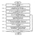
- Non-Patent Document 1 describes a conceptual diagram showing the basic configuration of OCT.
- FIG. 1 refers to FIG. 5.1 of Non-Patent Document 1.
- the OCT comprises a light source, a reference light mirror, a beam splitter and a light detector.
- the object to be measured is, for example, a living body.
- the light source outputs low coherence light in the near infrared region.
- the low coherence light is light having extremely low temporal coherence.
- a super luminescent diode (SLD) is used as a light source.
- the low coherence light emitted from the light source is irradiated to the beam splitter.
- the low coherence light emitted from the light source is, for example, light with a central wavelength of 850 nm and a full width at half maximum of 20 nm of the spectrum.
- the light emitted from the light source is bisected by the beam splitter, and one of the lights bisected by the beam splitter is reflected by the reference mirror and then returns to the beam splitter as the reference light ER. Further, the other light divided by the beam splitter is irradiated to the object to be measured.
- the light irradiated to the object to be measured is reflected on the surface and inside of the object to be measured, and returns to the beam splitter as reflected light (signal light) ES (for example, reflected light ESA, ESB). Since the reference light ER and the reflected light ES returned to the beam splitter coincide with each other in the optical path, they are multiplexed in front of the light detector.
- the object to be measured is based on the beam splitter. If the reflection surface A of the object to be measured and the position 1 of the reference light mirror are optically equidistant, the sine wave oscillations of the reference light ER1 and the reflected light ESA overlap and both interfere with each other. As a result, the photodetector detects interference light of the reference light ER1 and the reflected light ESA.
- the photodetector detects the interference light of the reference light ER2 and the reflected light ESB.
- the interference light is detected by the light detector while moving the reference light mirror continuously, the intensity distribution of the reflected light in the optical axis direction can be obtained.
- there are various types of light measurement devices using light interference and they are used properly depending on the purpose.
- the light point imaging lens and the interference fringe imaging lens need to be arranged so as to be interchangeable on the optical path, so the configuration becomes complicated. There is a problem that the score is increased. Further, in the light measurement device described in Patent Document 1, it is necessary to replace the light spot imaging lens with the interference fringe imaging lens every time between the optical axis adjustment step and the interference fringe observation step. As a result, there is also a problem that when the subject is frequently replaced and measured, the measurement can not be performed quickly.
- Patent Document 2 discloses an example of a technique for solving such a problem.
- coherent light from the same light source is irradiated to the reference surface of the reference lens and the test surface of the object (object to be measured), and the reference light reflected by the reference surface and the test surface are reflected.
- an interferometer which forms an interference beam by superimposing and interfering with the measured light, and observing an image of an interference pattern of the interference beam.
- a reflecting surface is formed on the surface on the incident direction side of the interference light beam, and an aperture plate having an opening for transmitting the interference light beam formed in the center of the reflecting surface;
- a half mirror surface disposed facing the reflection surface of the diaphragm on the optical path, a condensing optical system for condensing light transmitted through the aperture of the diaphragm, and light collected by the condensing optical system
- a focusing optical system is provided such that the reflecting surface of the diaphragm and the imaging surface of the imaging unit are in a conjugate relationship via the half mirror surface.
- the optical axis of the reference surface of the reference lens and the test surface of the test subject do not coincide
- the optical axis of the reference light reflected by the reference surface and the measurement light reflected by the test surface Because of the displacement, at least one of the light reaches the reflection surface of the stop plate to generate a component that is reflected to the half mirror surface side.
- the reflected light component on this reflection surface reaches the half mirror surface, and a part thereof passes through the aperture of the stop plate and is condensed by the condensing optical system.
- the condensing optical system is provided such that the reflecting surface of the diaphragm plate and the imaging surface of the imaging unit are in a conjugate relationship via the half mirror surface, so that the reflected light from the reflecting surface of the diaphragm plate in the imaging unit You can take an image of the ingredients. Therefore, positional deviations of the reference light and the measurement light with respect to the aperture of the diaphragm can be observed through the imaging unit. Therefore, in the interferometer described in Patent Document 2, the optical axis adjustment and the observation of interference fringes can be performed based on the image captured by the imaging unit without replacing the focusing optical system, so the device configuration is simplified. Can be
- Patent Document 3 discloses an image processing apparatus and an interferometer measurement system capable of improving the workability of interference fringe measurement by simplifying the apparatus configuration for image display of the interferometer.
- an alignment camera for capturing an image for alignment and an interference fringe camera for capturing an interference fringe image are connected, and a connection terminal unit for transmitting image data transmitted from these, and transmitted image data Among them, a camera switching switch for selecting one of an alignment image and an interference fringe image, a display unit for displaying an image according to the selected image data, and an image processing unit for analyzing image data of the interference fringe image
- An image processing apparatus comprising: an apparatus control unit for displaying an analysis result analyzed by the image processing unit together with the interference fringe image on the display unit when image data of the interference fringe image is selected by the camera changeover switch There is.
- Patent Document 4 discloses means for performing two-dimensional Fourier spectroscopy by arranging a two-dimensional detector in the detection unit.
- a hyperspectral camera capable of acquiring two-dimensional spectral information is known as a light measuring device capable of measuring the spectrum of a moving object.
- a mechanism for scanning outside is provided, and it is necessary to move the entire camera system for shooting, so it is susceptible to the effects of wind, vibration, etc. and acquires clear captured images. It is difficult.
- the present invention has been made to solve the problems of the background art as described above, and it is an optical measurement that can obtain an accurate spectrum of the object even when the positional relationship between the object and the detection unit changes.
- An object of the present invention is to provide an apparatus and a light measurement method.
- a light measuring device comprises a light source for irradiating light to an object to be measured; A branching unit for branching light transmitted from the light source through the object to be measured or light reflected from the light source from the object to be measured; A phase change unit that changes and outputs the phase of the first light that is one of the lights branched by the branch unit; A phase fixing unit that maintains and outputs the phase of the second light that is the other light branched by the branching unit; A multiplexer that multiplexes, interferes, and outputs the first light output from the phase change unit and the second light output from the phase lock unit; A detection unit that detects the light output from the combining unit; While controlling the change of the phase of said 1st light in said phase change part, the several interference image which consists of interference light detected by said detection part for every phase difference of said 2nd light and said 1st light Control unit to save Have The control unit When a reference point serving as a reference of the position of the object in
- Is corrected following the displacement of the object shown by the displacement of the reference point, and the second light and the second light are corrected based on the luminance value of each of the plurality of interference images after the correction.
- An interferogram indicating the luminance value for each pixel with respect to the phase difference of 1 light is constructed for each pixel, and information of the spectrum for each pixel is acquired from the interferogram.
- a light source for irradiating light to an object to be measured a light source for irradiating light to an object to be measured;
- a phase change unit that changes and outputs the phase of the first light that is one of the lights branched by the branch unit;
- a phase fixing unit that maintains and outputs the phase of the second light that is the other light branched by the branching unit;
- a multiplexer that multiplexes, interferes, and outputs the first light output from the phase change unit and the second light output from the phase lock unit;
- a detection unit that detects the light output from the combining unit; While controlling the change of the phase of said 1st light in said phase change part, the several interference image which consists of interference light detected by said detection part for every phase difference of said 2nd light and said 1st light Control unit to save A light measurement method in a light measurement device having The control
- the present invention it is possible to obtain an accurate spectrum of the object under measurement even when the positional relationship between the object under measurement and the detection unit changes in the Fourier spectroscopy system.
- FIG. 1 is a schematic view showing one configuration example of optical coherence tomography.
- FIG. 2 is a block diagram showing an example of the configuration of the light measurement device according to the first embodiment.
- FIG. 3 is a schematic view showing an embodiment of the light measurement device shown in FIG.
- FIG. 4 is a block diagram showing an example of the configuration of the information processing apparatus shown in FIG.
- FIG. 5 is a schematic view showing another configuration example of the optical system of the light measurement device of the first embodiment.
- FIG. 6 is a schematic view showing an example of the configuration of a light measurement device to be subjected to optical axis adjustment.
- FIG. 7 is a flow chart showing an example of the processing procedure of the optical axis adjustment method in the light measurement device shown in FIG. FIG.
- FIG. 8 is a schematic view showing an example of an interference image at the time of the optical axis adjustment shown in FIG.
- FIG. 9 is a schematic view showing an example of an interference image at the time of the optical axis adjustment shown in FIG.
- FIG. 10 is a schematic view showing an example of an interference image at the time of the optical axis adjustment shown in FIG.
- FIG. 11 is a schematic view showing an example of movement of an object to be measured in the light measurement method of the first embodiment.
- FIG. 12 is a flowchart illustrating an example of the processing procedure of the light measurement method according to the first embodiment.
- FIG. 2 is a block diagram showing an example of the configuration of the light measurement device according to the first embodiment.
- a light source 11 that irradiates light to the object to be measured 21
- a branch part 31 that branches transmitted light or reflected light of the object to be measured 21.
- a phase change unit 41 that applies a phase change to one of the lights branched by the branch unit 31, a phase fixing unit 51 that maintains the phase of the other light branched by the branch unit 31, and an output from the phase change unit 41
- the multiplexing unit 61 multiplexes the light and the light output from the phase fixing unit 51
- the detection unit 71 detects an interference image of the light multiplexed by the multiplexing unit 61
- the detection unit 71 detects
- a control unit 81 that records an interference image and performs signal processing on the interference image.
- Arrows shown in FIG. 2 indicate the traveling direction of the light output from the light source 11.
- the light measurement device shown in FIG. 2 is a kind of Michelson interferometer, and is used in gravity wave detection, light velocity measurement, measurement of reference length, shape measurement, and the like.
- the light source 11 for example, a light emitting element that outputs near infrared light of about 0.78 ⁇ m to 2.5 ⁇ m is used.
- the light source 11 includes ultraviolet light (approximately 0.01 ⁇ m to 0.38 ⁇ m), visible light (approximately 0.38 ⁇ m to 0.78 ⁇ m), mid-infrared light (approximately 2.5 ⁇ m to 25 ⁇ m), or far-infrared light (25 ⁇ m)
- a light emitting element that outputs (about 100 ⁇ m) may be used.
- a laser oscillator that outputs a laser beam may be used as the light source 11, a laser oscillator that outputs a laser beam may be used.
- the object to be measured 21 is, for example, a liquid or a living body.
- the to-be-measured object 21 should just be an object which permeate
- the branching unit 31 bisects the light transmitted through the object to be measured 21 or the light reflected by the object to be measured 21.
- a beam splitter is used for the branching unit 31.
- the two split lights travel along different optical paths, one of the lights is incident on the phase change section 41 which gives a phase change, and the other light is phase fixed not giving a phase change. It is incident on the part 51.
- the phase change unit 41 includes, for example, two mirrors (mirror group) inclined 45 degrees with respect to the optical axis, which are disposed on the moving stage so as to face each other. The light is reflected by the mirror group in the incident direction.
- the moving stage is for changing the position of the mirror group on the optical axis, and generates light having a phase difference with respect to the light output from the phase fixing unit 51 by changing the length of the optical path.
- the phase change unit 41 includes an adjustment mechanism for adjusting the angle and direction in which light is reflected.
- the adjustment mechanism is for adjusting the optical axis of one of the lights split into two by the branch section 31 and incident on the phase change section 41, and an arbitrary optical axis can be created by using two mirrors.
- the adjustment mechanism for adjusting the angle and the traveling direction of the reflected light may be provided in each of the phase change unit 41 and the phase fixing unit 51, or may be provided in only one of them. However, the adjustment mechanism needs to be able to electrically control the angle and position of the two mirrors.
- the phase fixing unit 51 has the same configuration as that of the phase changing unit 41, and basically has a fixed optical path length.
- the combining unit 61 causes interference by combining the light output from the phase change unit 41 and the light output from the phase fixing unit 51.
- the phase changing unit 41 and the phase fixing unit 51 described above are configured to reflect light in the incident direction, the light output from the phase changing unit 41 and the phase fixing unit 51 is returned to the branching unit 31.
- the wave portion 61 is realized using the same optical component.
- the interference light output from the multiplexing unit 61 is detected (photographed) by the detection unit 71.
- the two-dimensional interference image taken by the detection unit 71 is subjected to signal processing by the control unit 81 and then displayed on a display (not shown) or the like.
- the detection unit 71 is not limited to an imaging device or the like that captures an interference image.
- a light intensity detector or the like that detects the distribution of light intensity may be used.
- FIG. 3 is a schematic view showing an embodiment of the light measurement device shown in FIG.
- the beam splitter 35 is disposed in the traveling direction of the transmitted light or the reflected light of the object to be measured 21.
- the beam splitter 35 bisects the transmitted light or the reflected light of the object to be measured 21.
- One light divided by the beam splitter 35 is led to the phase change unit 41 giving a phase change, and the other light is led to the phase fixing unit 51 giving no phase change.
- the phase change unit 41 has a configuration in which mirrors 42 and 43 disposed at an angle of 45 degrees with respect to the optical axis of one of the lights branched by the beam splitter 35 are provided on the moving stage 45.
- the phase fixing unit 51 has a configuration in which mirrors 52 and 53 arranged at an angle of 45 degrees with respect to the optical axis of the other light branched by the beam splitter 35 are provided on the stage 55, respectively.
- the phase fixing unit 51 is provided with angle adjustment units 152 and 153 for changing the direction of the mirrors 52 and 53 with respect to the optical axis.
- the angle adjustment units 152 and 153 are adjustment mechanisms for adjusting the traveling direction of light.
- the adjustment mechanism is for adjusting the optical axis of the other light divided by the beam splitter 35.
- the angle adjustment units 152 and 153 include, for example, stepping motors (not shown) that rotate the mirrors 52 and 53 along their central axes. It is desirable that the rotation axes of the mirrors 52 and 53 be one in the horizontal direction and the other be the vertical direction.
- the stepping motors (not shown) included in the angle adjustment units 152 and 153 are connected to the information processing device 83 via the signal line 302.
- the angle adjustment units 152 and 153 adjust the angles of the mirrors 52 and 53 by driving a stepping motor (not shown) in accordance with a control signal received from the information processing device 83. By adjusting the angle, the traveling direction of the light reflected by the mirror 53 is adjusted.
- a moving mechanism 46 is provided on the moving stage 45 included in the phase change unit 41.
- the moving mechanism 46 has, for example, a moving guide 401 for holding the moving stage 45, a screw shaft 402 penetrating the moving guide 401, and a stepping motor 403 for rotating the screw shaft 402.
- the stepping motor 403 of the moving mechanism 46 rotates the moving guide 401 in the horizontal direction (left and right direction in FIG. 3) by rotating in accordance with the control signal received from the information processing device 83.
- the phase change unit 41 reflects one of the lights branched by the beam splitter 35 in the direction of the beam splitter 35 by a mirror group including mirrors 42 and 43.
- the moving stage 45 moves by the moving mechanism 46
- the position of the mirror group with respect to the optical axis direction changes.
- the length of the optical path in the phase change unit 41 changes, so that a phase difference occurs between the light from the phase change unit 41 and the light from the phase fixing unit 51.
- the light from the phase changing unit 41 and the light from the phase fixing unit 51 are combined by the beam splitter 35 and interference light is output.
- the divided lights are respectively returned to the beam splitter 35.
- the detection unit 71 includes an imaging element (not shown) for capturing an image (interference image) made of, for example, interference light.
- the interference light multiplexed by the multiplexing unit 61 is detected (photographed) as an interference image by the detection unit 71.
- the detection unit 71 is connected to an information processing apparatus 83 including the control unit 81 shown in FIG. 2 via a signal line 301.
- Information on the luminance value of the two-dimensional interference image captured by the detection unit 71 is transmitted to the information processing device 83 via the signal line 301.
- FIG. 4 is a block diagram showing an example of the configuration of the information processing apparatus shown in FIG.
- the information processing device 83 can be realized by, for example, a personal computer.
- the information processing device 83 has a control unit 81 including a storage unit 84 and an operation unit 85.
- the storage unit 84 is, for example, a semiconductor memory such as a flash memory, a random access memory (RAM), or a read only memory (ROM).
- the computing unit 85 is, for example, a CPU (Central Processing Unit).
- the storage unit 84 stores a program for realizing the optical axis adjustment method and the light measurement method described in the present embodiment by the processing of the arithmetic unit 85, and stores various information and the like used in arithmetic processing and signal processing.
- the storage unit 84 information such as the luminance value of the interference image detected by the detection unit 71 is stored.
- the computing unit 85 implements processing according to the program stored in the storage unit 84, thereby implementing an optical axis adjustment method and a light measurement method described later. Details of processing by the control unit 81 will be described later.
- the information processing device 83 includes a display unit for displaying the interference image so that the operator can observe the interference image, and an input unit for the operator to input instructions, information, and the like. You may have.
- the light measurement apparatus shown in FIG. 3 shows a configuration example in which the light output from the light source 11 performs light measurement using the transmitted light transmitted through the object to be measured 21, the light measurement apparatus The light measurement may be performed using the reflected light from the object to be measured 21 by being provided at the position indicated by the broken line in FIG. 3.
- the phase fixing unit 51 is provided with an adjustment mechanism for adjusting the angle and the traveling direction (optical axis) of the reflected light
- the adjustment mechanism may be provided in the phase change unit 41, or may be provided in both the phase fixing unit 51 and the phase change unit 41.
- the adjustment mechanism of the optical axis is provided in the phase fixing unit 51, since the phase is not changed in the phase fixing unit 51, the complexity of the optical axis adjusting process can be suppressed.
- the adjusting mechanism and the moving mechanism 46 are not limited to the configuration shown in FIG. 3, and any configuration may be adopted as long as the position of the optical axis or the moving stage 45 can be adjusted.
- the phase change section 41 is shown as having a mirror group including two mirrors 42 and 43, but as described above, the phase change section 41 is replaced with the mirror group. It may be configured to include a corner cube mirror or a corner cube prism.
- FIG. 5 is a schematic view showing another configuration example of the optical system of the light measurement device of the first embodiment.
- the light measurement apparatus shown in FIG. 5 has a configuration in which the phase change unit 41 includes a corner cube mirror 47 disposed on the moving stage 45 instead of the mirrors 42 and 43 shown in FIG. 3. By using the corner cube mirror 47 or the corner cube prism, the light from the branch 31 (beam splitter 35) can be reliably returned to the branch 31.
- the light measurement device in the light measurement device according to the first embodiment, a configuration example is shown in which the light quantity of the light from the object to be measured 21 is divided into two using the beam splitter 35 as the branch unit 31. Depending on the application, it is not necessary to divide the light quantity.
- FIG. 6 is a schematic view showing an example of the configuration of a light measurement device to be subjected to optical axis adjustment.
- FIG. 7 is a flow chart showing an example of the processing procedure of the optical axis adjustment method in the light measurement device shown in FIG. 8 to 10 are schematic views showing an example of an interference image at the time of the optical axis adjustment shown in FIG.
- the optical axis adjustment method described below controls the adjustment mechanism for adjusting the angle and the traveling direction of the reflected light described above based on the luminance value of the interference image detected by the detection unit 71, and the light in the phase fixing unit 51 Is a method for adjusting the traveling direction (optical axis) of
- a position where the optical path of the phase change unit 41 and the optical path of the phase fixing unit 51 have the same length is set as the initial position.
- the control unit 81 moves the moving stage 45 from the initial position to a reference position, which is a position at which the detection unit 71 detects an interference image for the first time, and records the luminance value of the interference image at the reference position (step S101 in FIG. 7). ).
- An interference image at this reference position is taken as a “first interference image”. It may be determined by well-known image analysis whether it is an interference image. An example of this "first interference image" is shown in FIG.
- the control unit 81 identifies, by image analysis, the first bright portion 211 where the luminance value is maximum, and only a fixed distance from the first bright portion 211.
- the separated second and third bright portions 221 and 231 are determined (step S102 in FIG. 7).
- the second bright part 221 and the third bright part 231 are points extracted in order to secure the in-plane uniformity of the interference image, so for example, from the first bright part 211 in the plane of the interference image It is desirable that the position is as far as possible.
- the control unit 81 determines, by image analysis, a first dark portion 241 which is separated by a fixed distance from the first bright portion 211 and has a minimum luminance value, and the first bright portion 211 and the first dark portion The difference in luminance value from the dark part 241 (this value is D1) is recorded.
- the control unit 81 determines this value D1 as a reference value for determination described later (step S103 in FIG. 7). In addition, it is better that the first dark portion 241 is farther from the first bright portion 211.
- the control unit 81 adjusts the optical axis of the phase fixing unit 51 so that the difference in luminance value between the first bright portion 211, the second bright portion 221, and the third bright portion 231 is minimized. (Step S104 in FIG. 7).
- the control unit 81 includes adjustment information including information on the rotation directions and rotation angles of the mirrors 52 and 53 included in the phase fixing unit 51, and the first bright portion 211, the second bright portion 221, and the like associated with the adjustment.
- the change of the luminance value of the third bright portion 231 is recorded.
- the control unit 81 controls the brightness values of the first bright portion 211, the second bright portion 221 and the third bright portion 231 with respect to the adjustment direction of the angles of the mirrors 52 and 53 based on the recorded adjustment information and the brightness value. Calculate the tendency of change of Then, the control unit 81 determines that the difference between the luminance values of the first bright portion 211 and the second bright portion 221 and the difference between the luminance values of the first bright portion 211 and the third bright portion 231 become equal. , Adjust the angles of the mirrors 52 and 53. An example of the interference image after this adjustment is shown in FIG.
- control unit 81 causes the fourth bright part 251 having the largest luminance value and the second dark part 261 having the smallest luminance value in the interference image illustrated in FIG. It identifies by image analysis (step S105 of FIG. 7).
- the control unit 81 causes the phase fixing unit 51 to include the mirrors 52 and 53 so that the difference between the luminance values of the fourth light unit 251 and the second dark unit 261 (this value is D2) is maximized.
- this value is D2
- the control unit 81 records the change in the difference in the luminance value of the fourth bright portion 251 and the second dark portion 261, and the adjustment information including the information on the rotation direction and the rotation angle of the mirrors 52 and 53.
- control unit 81 Based on the recorded adjustment information and the information on the difference between the luminance values, the control unit 81 changes the difference in the luminance values of the fourth bright part 251 and the second dark part 261 with respect to the adjustment direction of the angles of the mirrors 52 and 53. The tendency is determined by calculation, and the angles of the mirrors 52 and 53 are adjusted until this difference is maximized (step S106 in FIG. 7).
- the control unit 81 moves the movable stage 45 until the bright and dark stripes of the interference image are inverted at least once or more.
- the position of the movable stage 45 when the light and dark stripes of the interference image are inverted at least once is defined as a first displacement position.
- the control unit 81 observes the interference image detected by the detection unit 71, and records the luminance value of the interference image (step S107 in FIG. 7).
- An interference image at this first displacement position is referred to as a "second interference image".
- An example of this second interference image is shown in FIG.
- the control unit 81 identifies, by image analysis, the fifth bright portion 271 having the largest luminance value and the third dark portion 281 having the smallest luminance value.
- the difference between the luminance values of the fifth light portion 271 and the third dark portion 281 (this value is assumed to be D3) is recorded (step S108 in FIG. 7).
- the control unit 81 determines the difference between the difference D2 in luminance value between the fourth light portion 251 and the second dark portion 261 and the difference D3 between luminance values in the fifth light portion 271 and the third dark portion 281 (see FIG. It is determined whether or not this value is D4 or more (step S109 in FIG. 7).
- the threshold value is set to a value smaller than the above-described D1 determined at least as a reference value for determination.
- the control unit 81 ends the adjustment of the optical axis, and when the value D4 is equal to or larger than the threshold, the control unit 81 returns to the process of step S104 and repeats the optical axis adjustment.
- the optical axis adjustment is preferably performed in accordance with the processing procedure shown in FIG. 7, but the first light part 211, the second light part 221, and the third light part 231 in the first interference image are preferably used. It is also possible to adjust based on the luminance value and the luminance value of the fifth bright portion 271 in the second interference image. For example, from the difference in luminance value between the first bright portion 211, the second bright portion 221, and the third bright portion 231, it is possible to predict the angular shift (shift in the light traveling direction) of the mirrors 52 and 53. From the difference between the luminance value of the bright part in the first interference image and the luminance value of the bright part in the second interference image, the deviation of the moving direction of the moving stage 45 can be predicted.
- the angles of the mirrors 52 and 53 and the position of the moving stage 45 may be determined from these predicted values. Further, even if the difference between the luminance values of the first bright area 211, the second bright area 221, and the third bright area 231 shown in step S104 in FIG. A certain effect can be obtained on the optical axis alignment.
- the light measurement method of the first embodiment will be described using the drawings.
- the moving stage 45 is moved, and the phase changing portion 41 for light passing through the phase fixing portion 51
- the spectrum measurement to which Fourier transform infrared spectroscopy is applied is performed by continuously changing the phase of the light passing through.
- control unit 81 moves the moving stage 45, and also converts the image data (the luminance value for each pixel) of the interference image captured by the detecting unit 71 by the moving amount of the moving stage 45 (phase change unit 41). Recording in correspondence with the phase change amount of light).
- “continuously recording” sequentially stops the moving stage 45 at a plurality of predetermined discrete positions, and stops data including the moving amount of the moving stage 45 and the luminance value of each pixel. It means saving in the storage unit 84 for each position.
- a graph showing the luminance value of each pixel of the interference image with respect to the amount of phase change of light (the optical path difference between the phase change unit 41 and the phase fixing unit 51) is generally called an “interferogram”.
- the control unit 81 constructs an interferogram for each pixel based on the luminance value for each pixel of the plurality of interference images stored in the storage unit 84, and Fourier transforms the interferogram to obtain a spectrum for each pixel. Get information on In this way, it is possible to acquire in-plane spectral information from the data of the two-dimensional image (interference image) detected by the detection unit 71.
- FIG. 11 is a schematic view showing an example of movement of an object to be measured in the light measurement method of the first embodiment.
- FIG. 11 is a diagram showing the position of the image showing the object to be measured in the interference image taken by the detection unit 71 in the form of coordinates.
- the image at each coordinate is represented by the luminance value of a plurality of pixels.
- the image of coordinates (1, 1) shown in black moves in the order of coordinates (2, 2) and coordinates (1, 2) as time passes.
- the correct interferogram can not be generated from the series of luminance values for each pixel in the coordinates (1, 1) acquired in the spectral measurement period, accurate in-plane spectral information can not be obtained.
- the control unit 81 extracts a reference point serving as the reference position from the image data of the interference image acquired in the spectrum measurement period.
- the reference point for example, the feature point of the object to be measured 21 extracted from the image data of the interference image is used.
- the control unit 81 detects the displacement of the feature point (reference point) in the plurality of interference images stored in the storage unit 84, the luminance value for each pixel of the plurality of interference images is the displacement of the reference point. It corrects following the displacement of the to-be-measured object 21 shown.
- a method of correcting the luminance value for example, there is the following method.
- the control unit 81 When the displacement of the feature point (reference point) is detected, the control unit 81 first calculates the displacement direction and the displacement amount for each interference image, and specifies the position after displacement of the object 21 in each interference image. . Subsequently, the control unit 81 associates the luminance value for each pixel indicating the object to be measured 21 after displacement in each interference image with the position before the displacement of the object to be measured 21 and stores them in the storage unit 84. Each luminance value may be corrected by replacing the luminance value of each pixel indicating the DUT 21 after displacement in the image with the position before the displacement of the DUT 21.
- the control unit 81 constructs an interferogram for each pixel based on the luminance value for each pixel of each interference image after the correction.
- the positional relationship (distance or direction) between the extracted feature point (reference point) and each pixel in the interference image does not change.
- feature portions such as face (eye, nose, mouth) and hands and feet may be extracted by image analysis, and the extracted feature portions may be used as feature points.
- the feature points may be extracted using known image analysis, and the present invention does not limit the method of extracting feature points.
- FIG. 12 is a flowchart illustrating an example of the processing procedure of the light measurement method according to the first embodiment.
- the processing procedure shown in FIG. 12 is executed by the control unit 81 shown in FIG.
- image data (a luminance value for each pixel) of a plurality of interference images acquired in advance in the spectrum measurement period is stored.
- the image data of each interference image is stored in association with the amount of movement of the movable stage 45, so that interference images corresponding to the amount of phase change of light can be identified. Therefore, it is not necessary for the storage unit 84 to store the image data of the interference image captured by the detection unit 71 at each stop position in order from the first stop position of the movable stage 45 to the last stop position.
- the control unit 81 first uses the well-known image analysis to extract the feature point of the object 21 from the image data of any one or more interference images stored in the storage unit 84 (reference point The point) is extracted (step S201).
- the control unit 81 determines whether or not the feature points extracted in step S201 are displaced in the image data of the plurality of interference images stored in the storage unit 84 (step S202). Whether or not the feature point is displaced may be determined, for example, by detecting the coordinates of the feature point included in each interference image and comparing the coordinates in each interference image.
- control unit 81 proceeds to the process of step S206, and performs an interferogram for each pixel based on the luminance value for each pixel of each interference image stored in the storage unit 84. To construct.
- control unit 81 calculates the displacement direction and the displacement amount for each interference image (step S203).
- control unit 81 specifies the position after displacement of the object to be measured 21 in each interference image based on the displacement direction and displacement amount of the feature point obtained in step S203 (step S204). Subsequently, the control unit 81 stores the luminance value of each pixel indicating the DUT 21 after displacement in the interference image in the storage unit 84 in association with the position of the interference image before displacement of the DUT 21 (see FIG. Step S205) Each luminance value is corrected by replacing the luminance value of each pixel indicating the object to be measured 21 after displacement in each interference image with the position before the displacement of the object to be measured 21 (step S206).
- control unit 81 constructs an interferogram based on the luminance value for each pixel of each interference image corrected in the process of step S206 (step S207). Finally, the control unit 81 Fourier-transforms the constructed interferogram to acquire an in-plane spectrum (step S208).
- the control unit 81 extracts feature points (reference points) from a plurality of interference images captured by the detection unit 71 and detects displacement of the feature points
- the luminance value of each of the plurality of interference images is corrected following the displacement of the object to be measured 21 indicated by the displacement of the reference point, and the corrected luminance value of each of the plurality of interference images is corrected to the luminance value of each of the plurality of interference images.
- Build an interferogram based on it. Therefore, even when the object to be measured 21 or the detection unit 71 or both move, an accurate interferogram can be obtained. Therefore, even when the positional relationship between the object to be measured 21 and the detection unit 71 changes in Fourier transform infrared spectroscopy (Fourier spectroscopy), accurate information on the spectrum of the object to be measured 21 can be obtained.
- the control unit 81 divides the interference image captured by the detection unit 71 into a plurality of regions, and generates an interferogram (first interferogram) of each pixel for each of the divided regions. Information of a spectrum (first spectrum) in a plane for each region from the first interferogram. Then, when a pixel having a characteristic spectrum (hereinafter, referred to as a reference pixel) is extracted from the information of the calculated spectrum and the displacement of the reference pixel is detected, the luminance value of each of the plurality of interference images is calculated.
- the displacement of the DUT 21 indicated by the displacement of the reference pixel is corrected following correction, and an interferogram (second interferogram) is constructed based on the luminance value of each of the plurality of interference images after the correction.
- an interferogram (second interferogram) is constructed based on the luminance value of each of the plurality of interference images after the correction.
- the light measurement method according to the second embodiment is an example in which the reference pixel is used for tracking each pixel, instead of the feature points shown in the first embodiment.
- a reference pixel having a characteristic spectrum refers to, for example, a pixel having a spectrum that has a different envelope compared to surrounding pixels.
- the reference pixel may be extracted, for example, by comparing the envelopes of the calculated first spectrum for each pixel by data analysis.
- the configuration of the light measurement device and the method of adjusting the optical axis of the light measurement device are the same as in the first embodiment, and thus the description thereof is omitted.
- the in-plane spectrum (first spectrum) is calculated in divided area units, and the envelope of the first spectrum of each pixel in the area is compared.
- the reference pixel is extracted.
- the control unit 81 does not have to extract the reference pixels in all the divided regions, and can extract the reference pixels at that time if the reference pixels can be extracted in at least one of the regions. Therefore, without causing an increase in processing load by the control unit 81, it is possible to extract a reference pixel used to track each pixel in the interference image.
- the control unit 81 may extract the reference pixel from the entire interference image without dividing the interference image captured by the detection unit 71 into a plurality of regions. Whether to divide the interference image captured by the detection unit 71 and extract the reference pixel may be determined in consideration of the processing capability of the CPU or the like included in the control unit 81.
- the measurement object 21 and the detection unit 71 Even when the positional relationship changes, accurate spectral information of the object to be measured 21 can be obtained.
- the object to be measured 21 and / or the detection unit 71 move in a direction parallel to the image plane of the two-dimensional image (interference image) detected by the detection unit 71.
- the positional relationship (distance or direction) between the extracted reference point (feature point or reference pixel) and each pixel in the interference image does not change.
- the third embodiment is an example of processing when the positional relationship (distance or direction) between the reference point and each pixel in the interference image changes with time.
- the size of the object to be measured 21 photographed by the detection unit 71 fluctuates.
- the positional relationship (distance or direction) between the reference point and each pixel in the interference image changes.
- the amount of change in the direction and distance of the object 21 with respect to the reference point is calculated from the rate of change in the size of the object 21, and the amount of change in the direction and distance is calculated.
- the position after displacement of the object to be measured 21 in the interference image is specified using the corrected displacement direction and displacement amount.
- the luminance value for each pixel of the plurality of interference images is corrected following the displacement of the DUT 21 indicated by the displacement of the reference point, and the luminance value for each pixel of the plurality of interference images after the correction is corrected.
- Build an interferogram based on it.
- the rate of change of the size of the object to be measured 21 may be obtained, for example, by extracting two or more reference points and determining the displacement of the positional relationship (distance or direction) between the reference points.
- the configuration of the light measurement device and the method of adjusting the optical axis of the light measurement device are the same as in the first embodiment, and thus the description thereof is omitted.
- the first method can be used. And the same effect as the light measurement method of the second embodiment can be obtained.
- the detection unit 71 includes an angular velocity sensor for detecting the angular velocity of the detection unit 71, and a correction mechanism for canceling the angular velocity of the detection unit 71 detected by the angular velocity sensor. is there. If the correction mechanism can move the detection unit 71 or the correction lens or the like in the direction that cancels out the angular velocity of the detection unit 71, that is, the shake of the captured image captured by the detection unit 71, any known mechanism is used. It is also good.
- the angular velocity sensor a known rotational gyro sensor, an optical gyro sensor, a vibration gyro sensor or the like may be used.
- the correction lens When the correction lens is provided as the correction mechanism, the correction lens may be provided on the optical path between the detection unit 71 and the beam splitter 35 illustrated in FIG. 3 and FIG. 5, for example.
- the control unit 81 receives a signal indicating the angular velocity of the detection unit 71 detected by the angular velocity sensor, and a control signal for moving the detection unit 71 or the correction lens so as to cancel the angular velocity. Is output to the correction mechanism.
- the other configuration of the light measurement device and the method of adjusting the optical axis of the light measurement device are the same as in the first embodiment, and thus the description thereof is omitted.
- the light measurement method may be implemented by the methods described in the first to third embodiments.
- the detection unit 71 since the shake of the photographed image due to the angular velocity of the detection unit 71 can be canceled using the correction mechanism, the detection unit 71 can capture a clearer interference image. . Therefore, more accurate interferogram and spectrum information can be obtained than the light measurement method shown in the first to third embodiments.
- the detection unit 71 includes a position sensor that measures the displacement of the detection unit 71, and the control unit 81 uses the displacement amount of the detection unit 71 detected by the position sensor to detect the position of each pixel. While recording the luminance value for each pixel while making corrections, to create an interferogram.
- the position sensor a well-known GPS (Global Positioning System) device, an ultrasonic sensor, a magnetic sensor, an optical sensor, an acceleration sensor or the like may be used.
- GPS Global Positioning System
- the other configuration of the light measurement device and the method of adjusting the optical axis of the light measurement device are the same as in the first embodiment, and thus the description thereof is omitted.
- the light measurement method may be implemented by the methods described in the first to third embodiments.
- the fifth embodiment in order to construct an interferogram while correcting the position of each pixel using the displacement amount of the detection unit 71 detected by the position sensor, as in the fourth embodiment, it is possible to obtain more accurate interferogram and spectrum information than the light measurement method described in the first to third embodiments.
- the sixth embodiment is an example of a combination method of the light measurement method described in the first to third embodiments and the process described in the fourth or fifth embodiment.
- the intensity (brightness value) is maximum in a region where the optical path difference between the two lights divided by the branch 31 is small, and the optical path difference (the amount of phase change of light in the phase change portion 41) is As it becomes larger, the intensity (luminance value) gradually decreases to reach the baseline.
- a region where the optical path difference is small is, for example, an optical path difference until the light and dark stripes of the interference image are inverted about once from the reference position
- a region where the optical path difference is large is, for example, the interference image from the reference position The light and dark stripes of are inverted two or more times.
- the generated interferogram if the intensity (brightness value) in the region where the optical path difference is large is large, the object to be measured 21 or the detection unit 71 or both are largely moved, and the first to third embodiments are implemented. It is considered that an accurate interferogram can not be generated only by the light measurement method shown in the form. On the other hand, if the intensity (brightness value) in the region where the optical path difference is large is small, the movement of the object to be measured 21 and / or the detector 71 is small, and only the light measurement methods shown in the first to third embodiments However, it is considered that an accurate interferogram can be generated.
- the control unit 81 first uses one of the light measurement methods shown in the first to third embodiments to perform the interferogram (second In the case of the embodiment, a first interferogram is generated. Then, when the intensity (brightness value) in the region where the optical path difference of the generated interferogram is large is, for example, 25% or more of the maximum value, the processing shown in the fourth or fifth embodiment is executed together. And generate the interferogram again. At this time, when there is an inflection point where the intensity rapidly changes except for the maximum value in the interferogram, the control unit 81 generates the interferogram again by removing and interpolating the inflection point. May be
- the control unit 81 determines, for example, in the first to third embodiments. Interferograms are generated again by changing the combination of the light measurement method shown and the processing shown in the fourth or fifth embodiment. Alternatively, the processes shown in the fourth and fifth embodiments are respectively performed to generate an interferogram again. In this case, when an interferogram in which the intensity (luminance value) in the region where the optical path difference is large is, for example, 10% or less of the maximum value is obtained, the control unit 81 obtains spectral information from the interferogram. You just need to get
- the control unit 81 performs Fourier transform for each pixel from the interferogram. Get spectrum information.
- the other configuration of the light measurement device and the method of adjusting the optical axis of the light measurement device are the same as in the first embodiment, and thus the description thereof is omitted.
- the light measurement method of the sixth embodiment it is determined from the characteristics of the interferogram whether or not the correct interferogram can be generated, and it is considered that the correct interferogram can not be generated.
- the processing shown in the fourth or fifth embodiment is performed together. Therefore, reduction of processing load and processing time for light measurement can be expected.
- the control section 81 removes the interferogram of the corresponding measurement section, and performs the measurement. Interferograms of intervals are interpolated to create interferograms of all measurement periods.
- the configuration of the light measurement device and the method of adjusting the optical axis of the light measurement device are the same as in the first embodiment, and thus the description thereof is omitted.
- accurate interferogram and spectrum information can be obtained, for example, even when there is a measurement section where an interference image can not be obtained due to a large movement of the object to be measured 21 or the detection unit 71. Can.
Abstract
The present invention has a light source that irradiates an object to be measured with light, a branching part that branches transmission light or reflection light from the object to be measured, a phase change unit that changes the phase of one of the branched lights, a phase-fixing unit that maintains the phase of the other of the branched lights, a combination unit that combines output lights from the phase change unit and the phase-fixing unit and causes interference between the lights, a detection unit that detects output light (an interference image) from the combination unit, and a control unit, the control unit: extracting a reference point of the object to be measured from the interference image; correcting a luminance value for each pixel in each interference image, in association with displacement of the object to be measured as indicated by displacement of the reference point, when displacement of the reference point is detected; and constructing an interferogram on the basis of the corrected luminance value for each pixel in each interference image.
Description
本発明は光測定装置及び光測定方法に関する。
The present invention relates to a light measurement device and a light measurement method.
近年、光の干渉を利用した様々な種類の光測定装置が開発されている。例えば、高精度な平面測定や球面測定には、構成が簡単なフィゾー干渉計やマッハ・ツェンダ干渉計が用いられる。フィゾー干渉計を用いた光測定装置は、例えば特許文献1で開示されている。
In recent years, various types of light measurement devices using light interference have been developed. For example, a Fizeau interferometer or a Mach-Zehnder interferometer with a simple configuration is used for high-accuracy plane measurement or spherical measurement. An optical measurement device using a Fizeau interferometer is disclosed, for example, in Patent Document 1.
特許文献1に記載された光測定装置では、レーザ光をビームスプリッタ及びコリメータレンズを介して基準原器に照射すると共に該基準原器を通して被検体にも照射し、基準原器の参照面からの反射光と被検体の被検面からの反射光とをコリメータレンズ及びビームスプリッタを介して半透明のスクリーンに集光させる。スクリーンの背後には、光点結像用レンズと干渉縞結像用レンズとが光路上で入れ替え可能に配置され、光点結像用レンズの焦点位置に固体撮像用デバイスが配置されている。そして、固体撮像用デバイスを用いてスクリーン上の光点画像を撮影することで、干渉縞結像用レンズによりスクリーンを透過した干渉縞を観察できる。
In the light measurement device described in Patent Document 1, a laser beam is irradiated to a reference master via a beam splitter and a collimator lens, and the subject is also irradiated with the laser light through the reference master, from the reference plane of the reference master. The reflected light and the reflected light from the test surface of the subject are condensed on a semitransparent screen through a collimator lens and a beam splitter. Behind the screen, the light spot imaging lens and the interference fringe imaging lens are disposed exchangeably on the optical path, and the solid-state imaging device is disposed at the focal position of the light spot imaging lens. Then, by capturing a light spot image on the screen using the solid-state imaging device, it is possible to observe the interference fringes transmitted through the screen by the interference fringe imaging lens.
また、眼底検査等には、光コヒーレンストモグラフィー(OCT:Optical Coherence Tomography)が利用されている。OCTは、生体表皮から1~2mm程度の深さまでの断層画像を、約10μmの空間分解能で非侵襲的に画像化・視覚化(イメージング)できる技術である。
OCTは、低コヒーレンス光を用いたマイケルソン干渉計を基本構成としている。また、OCTは、生体組織に光を照射し、該組織内部で反射する直進光成分を選択的に検出し、これら反射光成分に基づいて2次元または3次元の断層イメージを形成する。例えば、非特許文献1にはOCTの基本構成を示す概念図が記載されている。図1は、非特許文献1の図5.1を引用したものである。 In addition, optical coherence tomography (OCT) is used for fundus examinations and the like. OCT is a technology capable of noninvasively imaging and visualizing a tomographic image from a living epidermis to a depth of about 1 to 2 mm with a spatial resolution of about 10 μm.
OCT is based on a Michelson interferometer using low coherence light. Moreover, OCT irradiates light to a living tissue, selectively detects a rectilinear light component reflected inside the tissue, and forms a two-dimensional or three-dimensional tomographic image based on these reflected light components. For example, Non-PatentDocument 1 describes a conceptual diagram showing the basic configuration of OCT. FIG. 1 refers to FIG. 5.1 of Non-Patent Document 1.
OCTは、低コヒーレンス光を用いたマイケルソン干渉計を基本構成としている。また、OCTは、生体組織に光を照射し、該組織内部で反射する直進光成分を選択的に検出し、これら反射光成分に基づいて2次元または3次元の断層イメージを形成する。例えば、非特許文献1にはOCTの基本構成を示す概念図が記載されている。図1は、非特許文献1の図5.1を引用したものである。 In addition, optical coherence tomography (OCT) is used for fundus examinations and the like. OCT is a technology capable of noninvasively imaging and visualizing a tomographic image from a living epidermis to a depth of about 1 to 2 mm with a spatial resolution of about 10 μm.
OCT is based on a Michelson interferometer using low coherence light. Moreover, OCT irradiates light to a living tissue, selectively detects a rectilinear light component reflected inside the tissue, and forms a two-dimensional or three-dimensional tomographic image based on these reflected light components. For example, Non-Patent
図1で示すように、OCTは、光源、参照光ミラー、ビームスプリッタ及び光検出器を備える。被測定物は、例えば生体である。
光源は、近赤外領域の低コヒーレンス光を出力する。この低コヒーレンス光とは、時間的コヒーレンスが極めて低い光のことである。光源には、例えばスーパールミネセントダイオード(SLD:Super Luminescent Diode)が用いられる。 As shown in FIG. 1, the OCT comprises a light source, a reference light mirror, a beam splitter and a light detector. The object to be measured is, for example, a living body.
The light source outputs low coherence light in the near infrared region. The low coherence light is light having extremely low temporal coherence. For example, a super luminescent diode (SLD) is used as a light source.
図1で示すように、光源から出射された低コヒーレンス光はビームスプリッタに照射される。光源から出射される低コヒーレンス光は、例えば中心波長が850nm、スペクトルの半値全幅が20nmの光とする。
光源から出射された光はビームスプリッタで二分され、ビームスプリッタで二分された一方の光は、参照ミラーで反射された後、参照光ERとしてビームスプリッタへ戻る。また、ビームスプリッタで二分された他方の光は、被測定物へ照射される。被測定物へ照射された光は、被測定物の表面及び内部で反射し、反射光(信号光)ES(例として、反射光ESA、ESB)としてビームスプリッタへ戻る。ビームスプリッタへ戻った参照光ERと反射光ESとは光路が一致するため、光検出器の手前で合波される。 As shown in FIG. 1, the low coherence light emitted from the light source is irradiated to the beam splitter. The low coherence light emitted from the light source is, for example, light with a central wavelength of 850 nm and a full width at half maximum of 20 nm of the spectrum.
The light emitted from the light source is bisected by the beam splitter, and one of the lights bisected by the beam splitter is reflected by the reference mirror and then returns to the beam splitter as the reference light ER. Further, the other light divided by the beam splitter is irradiated to the object to be measured. The light irradiated to the object to be measured is reflected on the surface and inside of the object to be measured, and returns to the beam splitter as reflected light (signal light) ES (for example, reflected light ESA, ESB). Since the reference light ER and the reflected light ES returned to the beam splitter coincide with each other in the optical path, they are multiplexed in front of the light detector.
ここで、図1に示すように、信号光の伝搬方向における被測定物の表面(反射面)をAとし、被測定物内部の所定の反射面をBとすると、ビームスプリッタを基準に、被測定物の反射面Aと参照光ミラーの位置1とが光学的に等距離であれば、参照光ER1と反射光ESAの正弦波振動が重なって両者は干渉する。その結果、光検出器は、参照光ER1と反射光ESAの干渉光を検出する。
Here, as shown in FIG. 1, assuming that the surface (reflection surface) of the object to be measured in the propagation direction of the signal light is A and the predetermined reflection surface inside the object to be B is B, the object to be measured is based on the beam splitter. If the reflection surface A of the object to be measured and the position 1 of the reference light mirror are optically equidistant, the sine wave oscillations of the reference light ER1 and the reflected light ESA overlap and both interfere with each other. As a result, the photodetector detects interference light of the reference light ER1 and the reflected light ESA.
一方、参照光ミラーを、反射面Bと等距離となる位置2までビームスプリッタから離れる方向へ移動させると、参照光ER2と反射光ESBの正弦波振動が重なって両者が干渉する。その結果、光検出器は、参照光ER2と反射光ESBの干渉光を検出する。このとき、参照光ミラーを連続的に移動させつつ干渉光を光検出器により検出すれば、光軸方向における反射光の強度分布を得ることができる。
以上説明したように、光の干渉を利用した光測定装置は様々な種類があり、その目的に応じて使い分けられている。 On the other hand, when the reference light mirror is moved in the direction away from the beam splitter to theposition 2 which is equidistant from the reflection surface B, the sine wave oscillations of the reference light ER2 and the reflected light ESB overlap and both interfere with each other. As a result, the photodetector detects the interference light of the reference light ER2 and the reflected light ESB. At this time, if the interference light is detected by the light detector while moving the reference light mirror continuously, the intensity distribution of the reflected light in the optical axis direction can be obtained.
As described above, there are various types of light measurement devices using light interference, and they are used properly depending on the purpose.
以上説明したように、光の干渉を利用した光測定装置は様々な種類があり、その目的に応じて使い分けられている。 On the other hand, when the reference light mirror is moved in the direction away from the beam splitter to the
As described above, there are various types of light measurement devices using light interference, and they are used properly depending on the purpose.
しかしながら、上述した特許文献1に記載された光測定装置は、光点結像用レンズと干渉縞結像用レンズとを光路上で入れ替え可能に配置する必要があるため、構成が複雑となり、部品点数が多くなってしまうという課題がある。
また、特許文献1に記載された光測定装置では、光軸調整工程と干渉縞の観察工程との間に、光点結像用レンズと干渉縞結像用レンズとを入れ替える作業が毎回必要となるため、被検体を頻繁に入れ替えて測定する場合に、迅速に測定できないという課題もある。 However, in the light measurement device described inPatent Document 1 described above, the light point imaging lens and the interference fringe imaging lens need to be arranged so as to be interchangeable on the optical path, so the configuration becomes complicated. There is a problem that the score is increased.
Further, in the light measurement device described inPatent Document 1, it is necessary to replace the light spot imaging lens with the interference fringe imaging lens every time between the optical axis adjustment step and the interference fringe observation step. As a result, there is also a problem that when the subject is frequently replaced and measured, the measurement can not be performed quickly.
また、特許文献1に記載された光測定装置では、光軸調整工程と干渉縞の観察工程との間に、光点結像用レンズと干渉縞結像用レンズとを入れ替える作業が毎回必要となるため、被検体を頻繁に入れ替えて測定する場合に、迅速に測定できないという課題もある。 However, in the light measurement device described in
Further, in the light measurement device described in
このような課題を解決するための技術の一例が、特許文献2で開示されている。
特許文献2には、同一光源からの可干渉光を参照レンズの参照面と被検体(被測定物)の被検面とに照射し、参照面で反射された参照光と被検面で反射された測定光とを重畳して干渉させすることで干渉光束を形成し、該干渉光束の干渉縞の像を観察する干渉計が記載されている。
特許文献2に記載された干渉計は、干渉光束の入射方向側の表面に反射面が形成され、該反射面の中心部に干渉光束を透過させる開口が形成された絞り板と、干渉光束の光路上で、絞り板の反射面と対向して配置されたハーフミラー面と、該絞り板の開口を透過した光を集光する集光光学系と、集光光学系によって集光された光を撮像する撮像部とを備え、集光光学系が、ハーフミラー面を介して絞り板の反射面と撮像部の撮像面とが共役の関係となるように設けられている。Patent Document 2 discloses an example of a technique for solving such a problem.
InPatent Document 2, coherent light from the same light source is irradiated to the reference surface of the reference lens and the test surface of the object (object to be measured), and the reference light reflected by the reference surface and the test surface are reflected. There is described an interferometer which forms an interference beam by superimposing and interfering with the measured light, and observing an image of an interference pattern of the interference beam.
In the interferometer described inPatent Document 2, a reflecting surface is formed on the surface on the incident direction side of the interference light beam, and an aperture plate having an opening for transmitting the interference light beam formed in the center of the reflecting surface; A half mirror surface disposed facing the reflection surface of the diaphragm on the optical path, a condensing optical system for condensing light transmitted through the aperture of the diaphragm, and light collected by the condensing optical system And a focusing optical system is provided such that the reflecting surface of the diaphragm and the imaging surface of the imaging unit are in a conjugate relationship via the half mirror surface.
特許文献2には、同一光源からの可干渉光を参照レンズの参照面と被検体(被測定物)の被検面とに照射し、参照面で反射された参照光と被検面で反射された測定光とを重畳して干渉させすることで干渉光束を形成し、該干渉光束の干渉縞の像を観察する干渉計が記載されている。
特許文献2に記載された干渉計は、干渉光束の入射方向側の表面に反射面が形成され、該反射面の中心部に干渉光束を透過させる開口が形成された絞り板と、干渉光束の光路上で、絞り板の反射面と対向して配置されたハーフミラー面と、該絞り板の開口を透過した光を集光する集光光学系と、集光光学系によって集光された光を撮像する撮像部とを備え、集光光学系が、ハーフミラー面を介して絞り板の反射面と撮像部の撮像面とが共役の関係となるように設けられている。
In
In the interferometer described in
特許文献2に記載された干渉計では、参照レンズの参照面と被検体(被測定物)の被検面との光軸が一致する場合、干渉光束がハーフミラー面及び絞り板の開口を透過して集光光学系によって集光されるため、撮像部によって干渉縞が撮影される。
In the interferometer described in Patent Document 2, when the optical axes of the reference surface of the reference lens and the test surface of the object (object to be measured) coincide, the interference light beam passes through the half mirror surface and the aperture of the diaphragm. Then, since the light is collected by the light collection optical system, the interference fringes are photographed by the imaging unit.
また、参照レンズの参照面と被検体(被測定物)の被検面との光軸が一致しない場合、参照面で反射された参照光と被検面で反射された測定光との光軸がずれるため、少なくとも一方の光が絞り板の反射面に到達してハーフミラー面側に反射される成分が発生する。この反射面における反射光成分は、ハーフミラー面に到達して、一部が絞り板の開口を透過し、集光光学系によって集光される。
In addition, when the optical axis of the reference surface of the reference lens and the test surface of the test subject (the test object) do not coincide, the optical axis of the reference light reflected by the reference surface and the measurement light reflected by the test surface Because of the displacement, at least one of the light reaches the reflection surface of the stop plate to generate a component that is reflected to the half mirror surface side. The reflected light component on this reflection surface reaches the half mirror surface, and a part thereof passes through the aperture of the stop plate and is condensed by the condensing optical system.
集光光学系は、ハーフミラー面を介して、絞り板の反射面と撮像部の撮像面とが共役の関係となるように設けられているため、撮像部では絞り板の反射面における反射光成分の像を撮影できる。このため、撮像部を通して、絞り板の開口に対する参照光及び測定光の位置ずれを観察できる。
したがって、特許文献2に記載された干渉計では、集光光学系を交換することなく、撮像部で撮影された画像に基づいて光軸調整と干渉縞の観察とができるため、装置構成を簡素化できる。 The condensing optical system is provided such that the reflecting surface of the diaphragm plate and the imaging surface of the imaging unit are in a conjugate relationship via the half mirror surface, so that the reflected light from the reflecting surface of the diaphragm plate in the imaging unit You can take an image of the ingredients. Therefore, positional deviations of the reference light and the measurement light with respect to the aperture of the diaphragm can be observed through the imaging unit.
Therefore, in the interferometer described inPatent Document 2, the optical axis adjustment and the observation of interference fringes can be performed based on the image captured by the imaging unit without replacing the focusing optical system, so the device configuration is simplified. Can be
したがって、特許文献2に記載された干渉計では、集光光学系を交換することなく、撮像部で撮影された画像に基づいて光軸調整と干渉縞の観察とができるため、装置構成を簡素化できる。 The condensing optical system is provided such that the reflecting surface of the diaphragm plate and the imaging surface of the imaging unit are in a conjugate relationship via the half mirror surface, so that the reflected light from the reflecting surface of the diaphragm plate in the imaging unit You can take an image of the ingredients. Therefore, positional deviations of the reference light and the measurement light with respect to the aperture of the diaphragm can be observed through the imaging unit.
Therefore, in the interferometer described in
また、干渉計の画像表示のための装置構成を簡素化して、干渉縞計測の作業性を向上できる画像処理装置及び干渉計測定システムが、特許文献3で開示されている。
特許文献3には、アライメント用画像を撮影するアライメントカメラと干渉縞画像を撮影する干渉縞カメラとを接続し、これらから送信される画像データを伝送する接続端子部と、伝送された画像データのうち、アライメント用画像または干渉縞画像のいずれか一方を選択するためのカメラ切替スイッチと、選択された画像データによる画像を表示する表示部と、干渉縞画像の画像データを解析する画像処理部と、カメラ切替スイッチにより干渉縞画像の画像データが選択されたとき、画像処理部によって解析された解析結果を干渉縞画像と共に表示部に表示する装置制御部とを備えた画像処理装置が記載されている。 Further,Patent Document 3 discloses an image processing apparatus and an interferometer measurement system capable of improving the workability of interference fringe measurement by simplifying the apparatus configuration for image display of the interferometer.
InPatent Document 3, an alignment camera for capturing an image for alignment and an interference fringe camera for capturing an interference fringe image are connected, and a connection terminal unit for transmitting image data transmitted from these, and transmitted image data Among them, a camera switching switch for selecting one of an alignment image and an interference fringe image, a display unit for displaying an image according to the selected image data, and an image processing unit for analyzing image data of the interference fringe image An image processing apparatus comprising: an apparatus control unit for displaying an analysis result analyzed by the image processing unit together with the interference fringe image on the display unit when image data of the interference fringe image is selected by the camera changeover switch There is.
特許文献3には、アライメント用画像を撮影するアライメントカメラと干渉縞画像を撮影する干渉縞カメラとを接続し、これらから送信される画像データを伝送する接続端子部と、伝送された画像データのうち、アライメント用画像または干渉縞画像のいずれか一方を選択するためのカメラ切替スイッチと、選択された画像データによる画像を表示する表示部と、干渉縞画像の画像データを解析する画像処理部と、カメラ切替スイッチにより干渉縞画像の画像データが選択されたとき、画像処理部によって解析された解析結果を干渉縞画像と共に表示部に表示する装置制御部とを備えた画像処理装置が記載されている。 Further,
In
また、特許文献4には、検出部に2次元の検出器を配置することで、2次元のフーリエ分光を行う手段が開示されている。
Further, Patent Document 4 discloses means for performing two-dimensional Fourier spectroscopy by arranging a two-dimensional detector in the detection unit.
上述した特許文献1~4及び非特許文献1に記載された光測定装置では、測定対象である被測定物が生体等のように動く場合、あるいは風や振動等により被測定物に対して検出部(撮影部)が移動する場合等、被測定物と検出部との相対的な位置関係が変化する場合に正確なスペクトルを取得するのが困難であるという課題がある。
In the light measurement devices described in Patent Documents 1 to 4 and Non-Patent Document 1 described above, when an object to be measured moves like a living body or the like, it is detected with respect to the object by wind or vibration. There is a problem that it is difficult to obtain an accurate spectrum when the relative positional relationship between the object to be measured and the detection unit changes, such as when the unit (the imaging unit) moves.
移動体のスペクトルが測定可能な光測定装置としては、例えば2次元のスペクトル情報を取得できるハイパースペクトルカメラが知られている。しかしながら、ハイパースペクトルカメラを用いても、被測定物と検出部との位置関係が動的に変化する場合は、正確なスペクトルを取得することが困難である。
例えば、ライン方式のハイパースペクトルカメラでは、外部にスキャンするための機構を設け、カメラシステム全体を動かして撮影する必要があるため、風や振動等の影響を受け易く、明瞭な撮影画像を取得することが難しい。 For example, a hyperspectral camera capable of acquiring two-dimensional spectral information is known as a light measuring device capable of measuring the spectrum of a moving object. However, even if the hyperspectral camera is used, it is difficult to obtain an accurate spectrum when the positional relationship between the object to be measured and the detection unit dynamically changes.
For example, in a line-type hyperspectral camera, a mechanism for scanning outside is provided, and it is necessary to move the entire camera system for shooting, so it is susceptible to the effects of wind, vibration, etc. and acquires clear captured images. It is difficult.
一方、フィルタ方式のハイパースペクトルカメラでは、波長域毎の測定に時間差が発生し、波長分解能が不均一であり、撮影速度が遅い等の課題がある。
また、フーリエ分光方式のハイパースペクトルカメラでは、被測定物または検出部が静止していない場合、正確なインターフェログラムの取得が困難であり、被測定物の位置によっては不正確なスペクトルが算出されてしまう。 On the other hand, in the filter-type hyperspectral camera, time differences occur in measurement for each wavelength range, wavelength resolution is not uniform, and shooting speed is slow.
Moreover, in the hyperspectral camera of the Fourier spectroscopy system, it is difficult to obtain an accurate interferogram when the object or the detection unit is not stationary, and an incorrect spectrum may be calculated depending on the position of the object. It will
本発明は上述したような背景技術が有する課題を解決するためになされたものであり、被測定物と検出部との位置関係が変動する場合でも被測定物の正確なスペクトルが得られる光測定装置及び光測定方法を提供することを目的とする。
The present invention has been made to solve the problems of the background art as described above, and it is an optical measurement that can obtain an accurate spectrum of the object even when the positional relationship between the object and the detection unit changes. An object of the present invention is to provide an apparatus and a light measurement method.
上記目的を達成するため本発明の光測定装置は、被測定物に光を照射する光源と、
前記光源からの光が前記被測定物を透過した透過光または前記光源からの光が前記被測定物で反射した反射光を分岐する分岐部と、
前記分岐部で分岐された一方の光である第1の光の位相を変化させて出力する位相変化部と、
前記分岐部で分岐された他方の光である第2の光の位相を維持して出力する位相固定部と、
前記位相変化部から出力された前記第1の光と前記位相固定部から出力された前記第2の光とを合波して干渉させて出力する合波部と、
前記合波部から出力された光を検出する検出部と、
前記位相変化部における前記第1の光の位相の変化を制御すると共に、前記第2の光と前記第1の光の位相差毎に前記検出部で検出された干渉光から成る複数の干渉像を保存する制御部と、
を有し、
前記制御部は、
前記干渉像から該干渉像における前記被測定物の位置の基準となる基準点を抽出し、複数の前記干渉像から前記基準点の変位を検出すると、複数の前記干渉像の画素毎の輝度値を、該基準点の変位で示される前記被測定物の変位に追随して補正し、該補正後の複数の前記干渉像の画素毎の輝度値に基づいて、前記第2の光と前記第1の光の位相差に対する前記画素毎の輝度値を示すインターフェログラムを前記画素毎に構築し、前記インターフェログラムから前記画素毎のスペクトルの情報を取得する構成である。 In order to achieve the above object, a light measuring device according to the present invention comprises a light source for irradiating light to an object to be measured;
A branching unit for branching light transmitted from the light source through the object to be measured or light reflected from the light source from the object to be measured;
A phase change unit that changes and outputs the phase of the first light that is one of the lights branched by the branch unit;
A phase fixing unit that maintains and outputs the phase of the second light that is the other light branched by the branching unit;
A multiplexer that multiplexes, interferes, and outputs the first light output from the phase change unit and the second light output from the phase lock unit;
A detection unit that detects the light output from the combining unit;
While controlling the change of the phase of said 1st light in said phase change part, the several interference image which consists of interference light detected by said detection part for every phase difference of said 2nd light and said 1st light Control unit to save
Have
The control unit
When a reference point serving as a reference of the position of the object in the interference image is extracted from the interference image, and displacements of the reference point are detected from the plurality of interference images, luminance values for each pixel of the plurality of interference images are detected. Is corrected following the displacement of the object shown by the displacement of the reference point, and the second light and the second light are corrected based on the luminance value of each of the plurality of interference images after the correction. An interferogram indicating the luminance value for each pixel with respect to the phase difference of 1 light is constructed for each pixel, and information of the spectrum for each pixel is acquired from the interferogram.
一方、本発明の光測定方法は、被測定物に光を照射する光源と、
前記光源からの光が前記被測定物を透過した透過光または前記光源からの光が前記被測定物で反射した反射光を分岐する分岐部と、
前記分岐部で分岐された一方の光である第1の光の位相を変化させて出力する位相変化部と、
前記分岐部で分岐された他方の光である第2の光の位相を維持して出力する位相固定部と、
前記位相変化部から出力された前記第1の光と前記位相固定部から出力された前記第2の光とを合波して干渉させて出力する合波部と、
前記合波部から出力された光を検出する検出部と、
前記位相変化部における前記第1の光の位相の変化を制御すると共に、前記第2の光と前記第1の光の位相差毎に前記検出部で検出された干渉光から成る複数の干渉像を保存する制御部と、
を有する光測定装置における光測定方法であって、
前記制御部が、
前記干渉像から該干渉像における前記被測定物の位置の基準となる基準点を抽出し、
複数の前記干渉像から前記基準点の変位を検出すると、複数の前記干渉像の画素毎の輝度値を、該基準点の変位で示される前記被測定物の変位に追随して補正し、
該補正後の複数の前記干渉像の画素毎の輝度値に基づいて、前記第2の光と前記第1の光の位相差に対する前記画素毎の輝度値を示すインターフェログラムを前記画素毎に構築し、
前記インターフェログラムから前記画素毎のスペクトルの情報を取得する方法である。 On the other hand, in the light measurement method of the present invention, a light source for irradiating light to an object to be measured;
A branching unit for branching light transmitted from the light source through the object to be measured or light reflected from the light source from the object to be measured;
A phase change unit that changes and outputs the phase of the first light that is one of the lights branched by the branch unit;
A phase fixing unit that maintains and outputs the phase of the second light that is the other light branched by the branching unit;
A multiplexer that multiplexes, interferes, and outputs the first light output from the phase change unit and the second light output from the phase lock unit;
A detection unit that detects the light output from the combining unit;
While controlling the change of the phase of said 1st light in said phase change part, the several interference image which consists of interference light detected by said detection part for every phase difference of said 2nd light and said 1st light Control unit to save
A light measurement method in a light measurement device having
The control unit
A reference point serving as a reference of the position of the object in the interference image is extracted from the interference image,
When the displacement of the reference point is detected from the plurality of interference images, the luminance value for each pixel of the plurality of interference images is corrected following the displacement of the object to be measured indicated by the displacement of the reference points,
An interferogram showing the luminance value for each pixel with respect to the phase difference between the second light and the first light based on the luminance value for each pixel of the plurality of interference images after the correction is made for each pixel Build
It is a method of acquiring information on the spectrum for each pixel from the interferogram.
本発明によれば、フーリエ分光方式において、被測定物と検出部との位置関係が変動する場合でも被測定物の正確なスペクトルを得ることができる。
According to the present invention, it is possible to obtain an accurate spectrum of the object under measurement even when the positional relationship between the object under measurement and the detection unit changes in the Fourier spectroscopy system.
次に本発明について図面を用いて説明する。
(第1の実施の形態)
図2は、第1の実施の形態の光測定装置の一構成例を示すブロック図である。
図2に示すように、第1の実施の形態の光測定装置は、被測定物21に光を照射する光源11と、被測定物21の透過光または反射光を分岐する分岐部31と、分岐部31で分岐された一方の光に位相変化を与える位相変化部41と、分岐部31で分岐された他方の光の位相を維持する位相固定部51と、位相変化部41から出力された光と位相固定部51から出力された光とを合波する合波部61と、合波部61で合波された光の干渉像を検出する検出部71と、検出部71で検出された干渉像を記録すると共に、該干渉像に対する信号処理を実行する制御部81とを有する。図2に記載した矢印は、光源11から出力された光の進行方向を示している。図2に示す光測定装置は、マイケルソン干渉計の一種であり、重力波検出、光速度計測、基準長さの計測や形状測定等で用いられる。 Next, the present invention will be described with reference to the drawings.
First Embodiment
FIG. 2 is a block diagram showing an example of the configuration of the light measurement device according to the first embodiment.
As shown in FIG. 2, in the light measurement device according to the first embodiment, alight source 11 that irradiates light to the object to be measured 21, and a branch part 31 that branches transmitted light or reflected light of the object to be measured 21. A phase change unit 41 that applies a phase change to one of the lights branched by the branch unit 31, a phase fixing unit 51 that maintains the phase of the other light branched by the branch unit 31, and an output from the phase change unit 41 The multiplexing unit 61 multiplexes the light and the light output from the phase fixing unit 51, the detection unit 71 detects an interference image of the light multiplexed by the multiplexing unit 61, and the detection unit 71 detects A control unit 81 that records an interference image and performs signal processing on the interference image. Arrows shown in FIG. 2 indicate the traveling direction of the light output from the light source 11. The light measurement device shown in FIG. 2 is a kind of Michelson interferometer, and is used in gravity wave detection, light velocity measurement, measurement of reference length, shape measurement, and the like.
(第1の実施の形態)
図2は、第1の実施の形態の光測定装置の一構成例を示すブロック図である。
図2に示すように、第1の実施の形態の光測定装置は、被測定物21に光を照射する光源11と、被測定物21の透過光または反射光を分岐する分岐部31と、分岐部31で分岐された一方の光に位相変化を与える位相変化部41と、分岐部31で分岐された他方の光の位相を維持する位相固定部51と、位相変化部41から出力された光と位相固定部51から出力された光とを合波する合波部61と、合波部61で合波された光の干渉像を検出する検出部71と、検出部71で検出された干渉像を記録すると共に、該干渉像に対する信号処理を実行する制御部81とを有する。図2に記載した矢印は、光源11から出力された光の進行方向を示している。図2に示す光測定装置は、マイケルソン干渉計の一種であり、重力波検出、光速度計測、基準長さの計測や形状測定等で用いられる。 Next, the present invention will be described with reference to the drawings.
First Embodiment
FIG. 2 is a block diagram showing an example of the configuration of the light measurement device according to the first embodiment.
As shown in FIG. 2, in the light measurement device according to the first embodiment, a
光源11には、例えば、0.78μmから2.5μm程度の近赤外光を出力する発光素子が用いられる。光源11には、紫外光(0.01μm~0.38μm程度)、可視光(0.38μm~0.78μm程度)、中赤外光(2.5μm~25μm程度)または遠赤外光(25μm~100μm程度)を出力する発光素子を用いてもよい。また、光源11にはレーザ光を出力するレーザ発振器を用いてもよい。
被測定物21は、例えば液体や生体等である。被測定物21は、光を透過または反射する物体であればよく、液体や生体に限定されるものではない。 For thelight source 11, for example, a light emitting element that outputs near infrared light of about 0.78 μm to 2.5 μm is used. The light source 11 includes ultraviolet light (approximately 0.01 μm to 0.38 μm), visible light (approximately 0.38 μm to 0.78 μm), mid-infrared light (approximately 2.5 μm to 25 μm), or far-infrared light (25 μm) A light emitting element that outputs (about 100 μm) may be used. Further, as the light source 11, a laser oscillator that outputs a laser beam may be used.
The object to be measured 21 is, for example, a liquid or a living body. The to-be-measured object 21 should just be an object which permeate | transmits or reflects light, and is not limited to a liquid or a biological body.
被測定物21は、例えば液体や生体等である。被測定物21は、光を透過または反射する物体であればよく、液体や生体に限定されるものではない。 For the
The object to be measured 21 is, for example, a liquid or a living body. The to-
分岐部31は、被測定物21を透過した光または被測定物21で反射した光を二分する。分岐部31には、通常、ビームスプリッタが用いられる。分岐部31としてビームスプリッタを用いる場合、二分割された光は互いに異なる光路を進行し、一方の光は位相変化を与える位相変化部41に入射され、他方の光は位相変化を与えない位相固定部51に入射される。
The branching unit 31 bisects the light transmitted through the object to be measured 21 or the light reflected by the object to be measured 21. Usually, a beam splitter is used for the branching unit 31. When a beam splitter is used as the branching unit 31, the two split lights travel along different optical paths, one of the lights is incident on the phase change section 41 which gives a phase change, and the other light is phase fixed not giving a phase change. It is incident on the part 51.
位相変化部41は、例えば移動ステージ上に対向して配置された、光軸に対して45度傾斜した2つのミラー(ミラー群)を備えた構成であり、分岐部31から入射された一方の光をミラー群により入射した方向へ反射させる。移動ステージは、光軸上においてミラー群の位置を変化させるためのものであり、光路の長さを変化させることで位相固定部51から出力される光に対して位相差を有する光を生成する。ミラー群には周知のコーナーキューブミラーやコーナーキューブプリズムを用いることも可能である。
The phase change unit 41 includes, for example, two mirrors (mirror group) inclined 45 degrees with respect to the optical axis, which are disposed on the moving stage so as to face each other. The light is reflected by the mirror group in the incident direction. The moving stage is for changing the position of the mirror group on the optical axis, and generates light having a phase difference with respect to the light output from the phase fixing unit 51 by changing the length of the optical path. . It is also possible to use a known corner cube mirror or corner cube prism for the mirror group.
また、位相変化部41は、上記移動ステージに加えて光の反射する角度や方向を調整するための調整機構を備える。調整機構は分岐部31で二分されて位相変化部41に入射される一方の光の光軸を調整するためのものであり、2つのミラーを用いることで任意の光軸を作り出すことができる。この反射光の角度や進行方向を調整するための調整機構は、位相変化部41及び位相固定部51にそれぞれ備えていてもよく、いずれか一方のみに備えていてもよい。但し、調整機構は、2つのミラーの角度や位置をそれぞれ電気的に制御できる必要がある。
位相固定部51は、位相変化部41と同様の構成であり、基本的に光路を固定長とする構成である。 In addition to the moving stage, thephase change unit 41 includes an adjustment mechanism for adjusting the angle and direction in which light is reflected. The adjustment mechanism is for adjusting the optical axis of one of the lights split into two by the branch section 31 and incident on the phase change section 41, and an arbitrary optical axis can be created by using two mirrors. The adjustment mechanism for adjusting the angle and the traveling direction of the reflected light may be provided in each of the phase change unit 41 and the phase fixing unit 51, or may be provided in only one of them. However, the adjustment mechanism needs to be able to electrically control the angle and position of the two mirrors.
Thephase fixing unit 51 has the same configuration as that of the phase changing unit 41, and basically has a fixed optical path length.
位相固定部51は、位相変化部41と同様の構成であり、基本的に光路を固定長とする構成である。 In addition to the moving stage, the
The
合波部61は、位相変化部41から出力された光と位相固定部51から出力された光とを合波することで干渉させる。上述した位相変化部41及び位相固定部51が入射方向へ光を反射する構成の場合、位相変化部41及び位相固定部51から出力された光は分岐部31へ戻るため、分岐部31と合波部61とは同じ光学部品を用いて実現することになる。
The combining unit 61 causes interference by combining the light output from the phase change unit 41 and the light output from the phase fixing unit 51. When the phase changing unit 41 and the phase fixing unit 51 described above are configured to reflect light in the incident direction, the light output from the phase changing unit 41 and the phase fixing unit 51 is returned to the branching unit 31. The wave portion 61 is realized using the same optical component.
合波部61から出力された干渉光は検出部71で検出(撮影)される。
検出部71によって撮影された2次元の干渉像は、制御部81により信号処理された後、ディスプレイ(不図示)等に表示される。検出部71は、干渉像を撮影する撮像素子等に限定されるものではなく、例えば光の強度の分布を検出する光強度検出器等を用いてもよい。 The interference light output from the multiplexingunit 61 is detected (photographed) by the detection unit 71.
The two-dimensional interference image taken by thedetection unit 71 is subjected to signal processing by the control unit 81 and then displayed on a display (not shown) or the like. The detection unit 71 is not limited to an imaging device or the like that captures an interference image. For example, a light intensity detector or the like that detects the distribution of light intensity may be used.
検出部71によって撮影された2次元の干渉像は、制御部81により信号処理された後、ディスプレイ(不図示)等に表示される。検出部71は、干渉像を撮影する撮像素子等に限定されるものではなく、例えば光の強度の分布を検出する光強度検出器等を用いてもよい。 The interference light output from the multiplexing
The two-dimensional interference image taken by the
図3は、図2に示した光測定装置の一実施例を示す模式図である。
図3に示す光測定装置では、被測定物21の透過光または反射光の進行方向にビームスプリッタ35が配置されている。ビームスプリッタ35は、被測定物21の透過光または反射光を二分する。ビームスプリッタ35で二分された一方の光は位相変化を与える位相変化部41へ導かれ、他方の光は位相変化を与えない位相固定部51へ導かれる。 FIG. 3 is a schematic view showing an embodiment of the light measurement device shown in FIG.
In the light measurement device shown in FIG. 3, thebeam splitter 35 is disposed in the traveling direction of the transmitted light or the reflected light of the object to be measured 21. The beam splitter 35 bisects the transmitted light or the reflected light of the object to be measured 21. One light divided by the beam splitter 35 is led to the phase change unit 41 giving a phase change, and the other light is led to the phase fixing unit 51 giving no phase change.
図3に示す光測定装置では、被測定物21の透過光または反射光の進行方向にビームスプリッタ35が配置されている。ビームスプリッタ35は、被測定物21の透過光または反射光を二分する。ビームスプリッタ35で二分された一方の光は位相変化を与える位相変化部41へ導かれ、他方の光は位相変化を与えない位相固定部51へ導かれる。 FIG. 3 is a schematic view showing an embodiment of the light measurement device shown in FIG.
In the light measurement device shown in FIG. 3, the
位相変化部41は、ビームスプリッタ35で分岐された一方の光の光軸に対して45度に傾けて配置されたミラー42及び43が移動ステージ45にそれぞれ設けられた構成である。位相固定部51は、ビームスプリッタ35で分岐された他方の光の光軸に対して45度に傾けて配置されたミラー52及び53がステージ55にそれぞれ設けられた構成である。
The phase change unit 41 has a configuration in which mirrors 42 and 43 disposed at an angle of 45 degrees with respect to the optical axis of one of the lights branched by the beam splitter 35 are provided on the moving stage 45. The phase fixing unit 51 has a configuration in which mirrors 52 and 53 arranged at an angle of 45 degrees with respect to the optical axis of the other light branched by the beam splitter 35 are provided on the stage 55, respectively.
図3に示す光測定装置では、位相固定部51に、光軸に対してミラー52及び53の向きを変えるための角度調整部152及び153が設けられている。角度調整部152及び153は光の進行方向を調整するための調整機構である。調整機構は、ビームスプリッタ35で二分された他方の光の光軸を調整するためのものであり、ミラー52及び53の向きを調整することで任意の方向の光軸を作り出すことができる。
角度調整部152及び153は、例えばミラー52及び53を、その中心軸に沿って回転させるステッピングモータ(不図示)を備える。ミラー52及び53の回転軸は、一方が水平方向であり、他方が垂直方向であることが望ましい。角度調整部152及び153が備えるステッピングモータ(不図示)は信号線302を介して情報処理装置83と接続されている。角度調整部152及び153は、情報処理装置83から受信した制御信号にしたがってステッピングモータ(不図示)を駆動することで、ミラー52及び53の角度を調整する。この角度の調整によって、ミラー53で反射する光の進行方向を調整する。 In the light measurement device shown in FIG. 3, thephase fixing unit 51 is provided with angle adjustment units 152 and 153 for changing the direction of the mirrors 52 and 53 with respect to the optical axis. The angle adjustment units 152 and 153 are adjustment mechanisms for adjusting the traveling direction of light. The adjustment mechanism is for adjusting the optical axis of the other light divided by the beam splitter 35. By adjusting the directions of the mirrors 52 and 53, an optical axis in any direction can be created.
The angle adjustment units 152 and 153 include, for example, stepping motors (not shown) that rotate the mirrors 52 and 53 along their central axes. It is desirable that the rotation axes of the mirrors 52 and 53 be one in the horizontal direction and the other be the vertical direction. The stepping motors (not shown) included in the angle adjustment units 152 and 153 are connected to the information processing device 83 via the signal line 302. The angle adjustment units 152 and 153 adjust the angles of the mirrors 52 and 53 by driving a stepping motor (not shown) in accordance with a control signal received from the information processing device 83. By adjusting the angle, the traveling direction of the light reflected by the mirror 53 is adjusted.
角度調整部152及び153は、例えばミラー52及び53を、その中心軸に沿って回転させるステッピングモータ(不図示)を備える。ミラー52及び53の回転軸は、一方が水平方向であり、他方が垂直方向であることが望ましい。角度調整部152及び153が備えるステッピングモータ(不図示)は信号線302を介して情報処理装置83と接続されている。角度調整部152及び153は、情報処理装置83から受信した制御信号にしたがってステッピングモータ(不図示)を駆動することで、ミラー52及び53の角度を調整する。この角度の調整によって、ミラー53で反射する光の進行方向を調整する。 In the light measurement device shown in FIG. 3, the
The
位相変化部41が備える移動ステージ45には移動機構46が設けられている。移動機構46は、例えば移動ステージ45を保持する移動ガイド401と、移動ガイド401を貫通するねじ軸402と、ねじ軸402を回転させるステッピングモータ403とを有する。
移動機構46のステッピングモータ403は、情報処理装置83から受信した制御信号にしたがって回転することで、移動ガイド401を水平方向(図3の左右方向)に移動させる。これにより、位相変化部41を経由した光と位相固定部51を経由した光とが合波部61(ビームスプリッタ35)にて合波される際、2つの光の位相を異なるようにすることができる。 A movingmechanism 46 is provided on the moving stage 45 included in the phase change unit 41. The moving mechanism 46 has, for example, a moving guide 401 for holding the moving stage 45, a screw shaft 402 penetrating the moving guide 401, and a stepping motor 403 for rotating the screw shaft 402.
The steppingmotor 403 of the moving mechanism 46 rotates the moving guide 401 in the horizontal direction (left and right direction in FIG. 3) by rotating in accordance with the control signal received from the information processing device 83. By this, when the light passing through the phase change unit 41 and the light passing through the phase fixing unit 51 are combined by the combining unit 61 (beam splitter 35), the phases of the two lights are made to be different. Can.
移動機構46のステッピングモータ403は、情報処理装置83から受信した制御信号にしたがって回転することで、移動ガイド401を水平方向(図3の左右方向)に移動させる。これにより、位相変化部41を経由した光と位相固定部51を経由した光とが合波部61(ビームスプリッタ35)にて合波される際、2つの光の位相を異なるようにすることができる。 A moving
The stepping
位相変化部41は、ビームスプリッタ35で分岐された一方の光をミラー42及び43からなるミラー群によりビームスプリッタ35の方向に反射する。移動機構46により移動ステージ45が移動すると、光軸方向に対するミラー群の位置が変化する。ミラー群の位置が変化すると、位相変化部41における光路の長さが変化するため、位相変化部41からの光と位相固定部51からの光とに位相差が生じる。
The phase change unit 41 reflects one of the lights branched by the beam splitter 35 in the direction of the beam splitter 35 by a mirror group including mirrors 42 and 43. When the moving stage 45 moves by the moving mechanism 46, the position of the mirror group with respect to the optical axis direction changes. When the position of the mirror group changes, the length of the optical path in the phase change unit 41 changes, so that a phase difference occurs between the light from the phase change unit 41 and the light from the phase fixing unit 51.
位相変化部41からの光と位相固定部51からの光とはビームスプリッタ35により合波されて干渉光が出力される。図3に示す光測定装置のように、被測定物21からの光をビームスプリッタ35で二分し、二分した光をそれぞれ反射させる構成では、ビームスプリッタ35に二分した光がそれぞれ戻るため、図2に示した分岐部31及び合波部61がビームスプリッタ35で実現される。
The light from the phase changing unit 41 and the light from the phase fixing unit 51 are combined by the beam splitter 35 and interference light is output. In the configuration in which the light from the object to be measured 21 is divided by the beam splitter 35 and the divided lights are respectively reflected as in the light measurement apparatus shown in FIG. 3, the divided lights are respectively returned to the beam splitter 35. The branching unit 31 and the multiplexing unit 61 shown in FIG.
検出部71は、例えば干渉光から成る画像(干渉像)を撮影するための撮像素子(不図示)を有する。合波部61で合波された干渉光は、検出部71にて干渉像として検出(撮影)される。図3で示すように、検出部71は図2で示した制御部81を含む情報処理装置83と信号線301を介して接続されている。検出部71で撮影された2次元の干渉像の輝度値の情報は、信号線301を介して情報処理装置83に送信される。
The detection unit 71 includes an imaging element (not shown) for capturing an image (interference image) made of, for example, interference light. The interference light multiplexed by the multiplexing unit 61 is detected (photographed) as an interference image by the detection unit 71. As shown in FIG. 3, the detection unit 71 is connected to an information processing apparatus 83 including the control unit 81 shown in FIG. 2 via a signal line 301. Information on the luminance value of the two-dimensional interference image captured by the detection unit 71 is transmitted to the information processing device 83 via the signal line 301.
図4は、図3に示した情報処理装置の一構成例を示すブロック図である。
情報処理装置83は、例えばパーソナルコンピュータで実現できる。図4に示すように、情報処理装置83は、記憶部84及び演算部85を含む制御部81を有する。記憶部84は、例えば、フラッシュメモリ、RAM(Random Access Memory)、ROM(Read Only Memory)等の半導体メモリである。演算部85は、例えば、CPU(Central Processing Unit)である。記憶部84は、演算部85の処理により本実施形態で示す光軸調整方法及び光測定方法を実現するためのプログラム、並びに演算処理や信号処理で用いる各種の情報等を保存する。また、記憶部84には、検出部71で検出された干渉像の輝度値等の情報が保存される。演算部85は記憶部84で保存されたプログラムにしたがって処理を実行することで、後述する光軸調整方法や光測定方法を実現する。制御部81による処理の詳細については後述する。図4では示していないが、情報処理装置83は、操作者が干渉像を観察できるように該干渉像を表示するための表示部及び操作者が指示や情報等を入力するための入力部を備えていてもよい。 FIG. 4 is a block diagram showing an example of the configuration of the information processing apparatus shown in FIG.
Theinformation processing device 83 can be realized by, for example, a personal computer. As shown in FIG. 4, the information processing device 83 has a control unit 81 including a storage unit 84 and an operation unit 85. The storage unit 84 is, for example, a semiconductor memory such as a flash memory, a random access memory (RAM), or a read only memory (ROM). The computing unit 85 is, for example, a CPU (Central Processing Unit). The storage unit 84 stores a program for realizing the optical axis adjustment method and the light measurement method described in the present embodiment by the processing of the arithmetic unit 85, and stores various information and the like used in arithmetic processing and signal processing. Further, in the storage unit 84, information such as the luminance value of the interference image detected by the detection unit 71 is stored. The computing unit 85 implements processing according to the program stored in the storage unit 84, thereby implementing an optical axis adjustment method and a light measurement method described later. Details of processing by the control unit 81 will be described later. Although not shown in FIG. 4, the information processing device 83 includes a display unit for displaying the interference image so that the operator can observe the interference image, and an input unit for the operator to input instructions, information, and the like. You may have.
情報処理装置83は、例えばパーソナルコンピュータで実現できる。図4に示すように、情報処理装置83は、記憶部84及び演算部85を含む制御部81を有する。記憶部84は、例えば、フラッシュメモリ、RAM(Random Access Memory)、ROM(Read Only Memory)等の半導体メモリである。演算部85は、例えば、CPU(Central Processing Unit)である。記憶部84は、演算部85の処理により本実施形態で示す光軸調整方法及び光測定方法を実現するためのプログラム、並びに演算処理や信号処理で用いる各種の情報等を保存する。また、記憶部84には、検出部71で検出された干渉像の輝度値等の情報が保存される。演算部85は記憶部84で保存されたプログラムにしたがって処理を実行することで、後述する光軸調整方法や光測定方法を実現する。制御部81による処理の詳細については後述する。図4では示していないが、情報処理装置83は、操作者が干渉像を観察できるように該干渉像を表示するための表示部及び操作者が指示や情報等を入力するための入力部を備えていてもよい。 FIG. 4 is a block diagram showing an example of the configuration of the information processing apparatus shown in FIG.
The
なお、図3に示す光測定装置では、光源11から出力された光が被測定物21を透過した透過光を用いて光測定する構成例を示しているが、光測定装置は、光源11を図3の破線で示す位置に設けることで、被測定物21からの反射光を用いて光測定する構成であってもよい。
Although the light measurement apparatus shown in FIG. 3 shows a configuration example in which the light output from the light source 11 performs light measurement using the transmitted light transmitted through the object to be measured 21, the light measurement apparatus The light measurement may be performed using the reflected light from the object to be measured 21 by being provided at the position indicated by the broken line in FIG. 3.
また、図3に示す光測定装置では、反射光の角度や進行方向(光軸)を調整するための調整機構を位相固定部51に備える構成例を示しているが、上述したように光軸の調整機構は位相変化部41に設けてもよく、位相固定部51及び位相変化部41の両方に設けてもよい。光軸の調整機構を位相固定部51に設けた場合、位相固定部51では位相を変化させないため、光軸調整工程が複雑になるのを抑制できる。調整機構及び移動機構46は、図3に示した構成に限定されるものではなく、光軸や移動ステージ45の位置が調整可能であればどのような構成を採用してもよい。
Further, in the light measurement apparatus shown in FIG. 3, an example of the configuration in which the phase fixing unit 51 is provided with an adjustment mechanism for adjusting the angle and the traveling direction (optical axis) of the reflected light is shown. The adjustment mechanism may be provided in the phase change unit 41, or may be provided in both the phase fixing unit 51 and the phase change unit 41. When the adjustment mechanism of the optical axis is provided in the phase fixing unit 51, since the phase is not changed in the phase fixing unit 51, the complexity of the optical axis adjusting process can be suppressed. The adjusting mechanism and the moving mechanism 46 are not limited to the configuration shown in FIG. 3, and any configuration may be adopted as long as the position of the optical axis or the moving stage 45 can be adjusted.
また、図3に示す光測定装置では、位相変化部41に2つのミラー42及び43から成るミラー群を備える構成例を示しているが、上述したように位相変化部41はミラー群に代えてコーナーキューブミラーやコーナーキューブプリズムを備える構成でもよい。
図5は、第1の実施の形態の光測定装置の光学系の他の構成例を示す模式図である。図5に示す光測定装置は、位相変化部41に、図3に示したミラー42及び43に代えて、移動ステージ45に配置されたコーナーキューブミラー47を備える構成である。コーナーキューブミラー47またはコーナーキューブプリズムを用いることで、分岐部31(ビームスプリッタ35)からの光を該分岐部31へ確実に戻すことができる。 Further, in the light measurement apparatus shown in FIG. 3, thephase change section 41 is shown as having a mirror group including two mirrors 42 and 43, but as described above, the phase change section 41 is replaced with the mirror group. It may be configured to include a corner cube mirror or a corner cube prism.
FIG. 5 is a schematic view showing another configuration example of the optical system of the light measurement device of the first embodiment. The light measurement apparatus shown in FIG. 5 has a configuration in which thephase change unit 41 includes a corner cube mirror 47 disposed on the moving stage 45 instead of the mirrors 42 and 43 shown in FIG. 3. By using the corner cube mirror 47 or the corner cube prism, the light from the branch 31 (beam splitter 35) can be reliably returned to the branch 31.
図5は、第1の実施の形態の光測定装置の光学系の他の構成例を示す模式図である。図5に示す光測定装置は、位相変化部41に、図3に示したミラー42及び43に代えて、移動ステージ45に配置されたコーナーキューブミラー47を備える構成である。コーナーキューブミラー47またはコーナーキューブプリズムを用いることで、分岐部31(ビームスプリッタ35)からの光を該分岐部31へ確実に戻すことができる。 Further, in the light measurement apparatus shown in FIG. 3, the
FIG. 5 is a schematic view showing another configuration example of the optical system of the light measurement device of the first embodiment. The light measurement apparatus shown in FIG. 5 has a configuration in which the
さらに、第1の実施の形態の光測定装置では、分岐部31としてビームスプリッタ35を用いて被測定物21からの光の光量を二分する構成例を示しているが、光測定装置は、その用途によっては光量を二分する構成である必要はない。
Furthermore, in the light measurement device according to the first embodiment, a configuration example is shown in which the light quantity of the light from the object to be measured 21 is divided into two using the beam splitter 35 as the branch unit 31. Depending on the application, it is not necessary to divide the light quantity.
このような構成において、まず光測定装置の光軸調整方法について図面を用いて説明する。
図6は、光軸調整対象となる光測定装置の一構成例を示す模式図である。図7は、図6に示した光測定装置における光軸調整方法の処理手順の一例を示すフローチャートである。図8~図10は、図7に示した光軸調整時における干渉像の一例を示す模式図である。
以下に示す光軸調整方法は、検出部71で検出された干渉像の輝度値に基づいて上述した反射光の角度や進行方向を調整するための調整機構を制御し、位相固定部51における光の進行方向(光軸)を調整するための方法である。 In such a configuration, first, an optical axis adjustment method of the light measurement device will be described using the drawings.
FIG. 6 is a schematic view showing an example of the configuration of a light measurement device to be subjected to optical axis adjustment. FIG. 7 is a flow chart showing an example of the processing procedure of the optical axis adjustment method in the light measurement device shown in FIG. 8 to 10 are schematic views showing an example of an interference image at the time of the optical axis adjustment shown in FIG.
The optical axis adjustment method described below controls the adjustment mechanism for adjusting the angle and the traveling direction of the reflected light described above based on the luminance value of the interference image detected by thedetection unit 71, and the light in the phase fixing unit 51 Is a method for adjusting the traveling direction (optical axis) of
図6は、光軸調整対象となる光測定装置の一構成例を示す模式図である。図7は、図6に示した光測定装置における光軸調整方法の処理手順の一例を示すフローチャートである。図8~図10は、図7に示した光軸調整時における干渉像の一例を示す模式図である。
以下に示す光軸調整方法は、検出部71で検出された干渉像の輝度値に基づいて上述した反射光の角度や進行方向を調整するための調整機構を制御し、位相固定部51における光の進行方向(光軸)を調整するための方法である。 In such a configuration, first, an optical axis adjustment method of the light measurement device will be described using the drawings.
FIG. 6 is a schematic view showing an example of the configuration of a light measurement device to be subjected to optical axis adjustment. FIG. 7 is a flow chart showing an example of the processing procedure of the optical axis adjustment method in the light measurement device shown in FIG. 8 to 10 are schematic views showing an example of an interference image at the time of the optical axis adjustment shown in FIG.
The optical axis adjustment method described below controls the adjustment mechanism for adjusting the angle and the traveling direction of the reflected light described above based on the luminance value of the interference image detected by the
まず、位相変化部41が備える移動ステージ45について、位相変化部41の光路と位相固定部51の光路との長さが同じとなる位置を初期位置とする。
制御部81は、移動ステージ45を、初期位置から検出部71が初めて干渉像を検出する位置である基準位置まで移動させ、該基準位置における干渉像の輝度値を記録する(図7のステップS101)。この基準位置における干渉像を「第1の干渉像」とする。干渉像であるか否かは周知の画像解析により判定すればよい。この「第1の干渉像」の一例を図8に示す。 First, for the movingstage 45 included in the phase change unit 41, a position where the optical path of the phase change unit 41 and the optical path of the phase fixing unit 51 have the same length is set as the initial position.
Thecontrol unit 81 moves the moving stage 45 from the initial position to a reference position, which is a position at which the detection unit 71 detects an interference image for the first time, and records the luminance value of the interference image at the reference position (step S101 in FIG. 7). ). An interference image at this reference position is taken as a “first interference image”. It may be determined by well-known image analysis whether it is an interference image. An example of this "first interference image" is shown in FIG.
制御部81は、移動ステージ45を、初期位置から検出部71が初めて干渉像を検出する位置である基準位置まで移動させ、該基準位置における干渉像の輝度値を記録する(図7のステップS101)。この基準位置における干渉像を「第1の干渉像」とする。干渉像であるか否かは周知の画像解析により判定すればよい。この「第1の干渉像」の一例を図8に示す。 First, for the moving
The
次に、制御部81は、図8で示す第1の干渉像において、輝度値が最大となる第1の明部211を画像解析により識別し、この第1の明部211から一定の距離だけ離れた第2の明部221及び第3の明部231を決定する(図7のステップS102)。この第2の明部221及び第3の明部231は、干渉像の面内の均一性を確保する目的で抽出する点であるため、例えば干渉像の面内において第1の明部211から可能な限り遠い位置であることが望ましい。
Next, in the first interference image shown in FIG. 8, the control unit 81 identifies, by image analysis, the first bright portion 211 where the luminance value is maximum, and only a fixed distance from the first bright portion 211. The separated second and third bright portions 221 and 231 are determined (step S102 in FIG. 7). The second bright part 221 and the third bright part 231 are points extracted in order to secure the in-plane uniformity of the interference image, so for example, from the first bright part 211 in the plane of the interference image It is desirable that the position is as far as possible.
次に、制御部81は、第1の明部211から一定の距離だけ離れた、輝度値が最小となる第1の暗部241を画像解析により決定し、第1の明部211と第1の暗部241との輝度値の差(この値をD1とする)を記録する。制御部81は、この値D1を後述する判定の基準値として決定する(図7のステップS103)。なお、第1の暗部241は、第1の明部211からの距離が遠いほどよい。
Next, the control unit 81 determines, by image analysis, a first dark portion 241 which is separated by a fixed distance from the first bright portion 211 and has a minimum luminance value, and the first bright portion 211 and the first dark portion The difference in luminance value from the dark part 241 (this value is D1) is recorded. The control unit 81 determines this value D1 as a reference value for determination described later (step S103 in FIG. 7). In addition, it is better that the first dark portion 241 is farther from the first bright portion 211.
続いて、制御部81は、第1の明部211、第2の明部221及び第3の明部231の輝度値の差が最小となるように、位相固定部51の光軸を調整する(図7のステップS104)。このとき、制御部81は、位相固定部51が備えるミラー52及び53の回転方向と回転角の情報を含む調整情報と、その調整に伴う第1の明部211、第2の明部221及び第3の明部231の輝度値の変化を記録する。制御部81は、記録した調整情報及び輝度値に基づいて、ミラー52及び53の角度の調整方向に対する、第1の明部211、第2の明部221及び第3の明部231の輝度値の変化の傾向を演算により求める。そして、制御部81は、第1の明部211と第2の明部221の輝度値の差と、第1の明部211と第3の明部231の輝度値の差とが等しくなるまで、ミラー52及び53の角度を調整する。この調整後の干渉像の一例を図9に示す。
Subsequently, the control unit 81 adjusts the optical axis of the phase fixing unit 51 so that the difference in luminance value between the first bright portion 211, the second bright portion 221, and the third bright portion 231 is minimized. (Step S104 in FIG. 7). At this time, the control unit 81 includes adjustment information including information on the rotation directions and rotation angles of the mirrors 52 and 53 included in the phase fixing unit 51, and the first bright portion 211, the second bright portion 221, and the like associated with the adjustment. The change of the luminance value of the third bright portion 231 is recorded. The control unit 81 controls the brightness values of the first bright portion 211, the second bright portion 221 and the third bright portion 231 with respect to the adjustment direction of the angles of the mirrors 52 and 53 based on the recorded adjustment information and the brightness value. Calculate the tendency of change of Then, the control unit 81 determines that the difference between the luminance values of the first bright portion 211 and the second bright portion 221 and the difference between the luminance values of the first bright portion 211 and the third bright portion 231 become equal. , Adjust the angles of the mirrors 52 and 53. An example of the interference image after this adjustment is shown in FIG.
次に、制御部81は、ステップS102の処理と同様に、図9で示す干渉像において、輝度値が最大となる第4の明部251と輝度値が最小となる第2の暗部261とを画像解析により識別する(図7のステップS105)。
Next, in the interference image illustrated in FIG. 9, the control unit 81 causes the fourth bright part 251 having the largest luminance value and the second dark part 261 having the smallest luminance value in the interference image illustrated in FIG. It identifies by image analysis (step S105 of FIG. 7).
続いて、制御部81は、第4の明部251と第2の暗部261の輝度値の差(この値をD2とする)が最大となるように位相固定部51が備えるミラー52及び53の角度を調整することで位相固定部51による光の進行方向を調整する。このとき、制御部81は、ミラー52及び53の回転方向と回転角の情報を含む調整情報と、第4の明部251と第2の暗部261の輝度値の差の変化を記録する。制御部81は、記録した調整情報と輝度値の差の情報に基づいて、ミラー52及び53の角度の調整方向に対する第4の明部251と第2の暗部261の輝度値の差の変化の傾向を演算により求め、この差が最大となるまでミラー52及び53の角度を調整する(図7のステップS106)。
Subsequently, the control unit 81 causes the phase fixing unit 51 to include the mirrors 52 and 53 so that the difference between the luminance values of the fourth light unit 251 and the second dark unit 261 (this value is D2) is maximized. By adjusting the angle, the traveling direction of the light by the phase fixing unit 51 is adjusted. At this time, the control unit 81 records the change in the difference in the luminance value of the fourth bright portion 251 and the second dark portion 261, and the adjustment information including the information on the rotation direction and the rotation angle of the mirrors 52 and 53. Based on the recorded adjustment information and the information on the difference between the luminance values, the control unit 81 changes the difference in the luminance values of the fourth bright part 251 and the second dark part 261 with respect to the adjustment direction of the angles of the mirrors 52 and 53. The tendency is determined by calculation, and the angles of the mirrors 52 and 53 are adjusted until this difference is maximized (step S106 in FIG. 7).
その後、制御部81は、干渉像の明暗の縞が少なくとも1回以上反転するまで移動ステージ45を移動させる。干渉像の明暗の縞が少なくとも1回以上反転したときの移動ステージ45の位置を第1の変位位置とする。この第1の変位位置において、制御部81は検出部71で検出された干渉像を観察し、干渉像の輝度値を記録する(図7のステップS107)。この第1の変位位置における干渉像を「第2の干渉像」とする。この第2の干渉像の一例を図10に示す。
Thereafter, the control unit 81 moves the movable stage 45 until the bright and dark stripes of the interference image are inverted at least once or more. The position of the movable stage 45 when the light and dark stripes of the interference image are inverted at least once is defined as a first displacement position. At this first displacement position, the control unit 81 observes the interference image detected by the detection unit 71, and records the luminance value of the interference image (step S107 in FIG. 7). An interference image at this first displacement position is referred to as a "second interference image". An example of this second interference image is shown in FIG.
次に、制御部81は、図10で示す第2の干渉像において、輝度値が最大となる第5の明部271と、輝度値が最小となる第3の暗部281とを画像解析により識別し、第5の明部271と第3の暗部281の輝度値の差(この値をD3とする)を記録する(図7のステップS108)。
Next, in the second interference image shown in FIG. 10, the control unit 81 identifies, by image analysis, the fifth bright portion 271 having the largest luminance value and the third dark portion 281 having the smallest luminance value. The difference between the luminance values of the fifth light portion 271 and the third dark portion 281 (this value is assumed to be D3) is recorded (step S108 in FIG. 7).
続いて、制御部81は、第4の明部251と第2の暗部261の輝度値の差D2と、第5の明部271と第3の暗部281の輝度値の差D3との差分(この値をD4とする)が予め設定された閾値以上であるか否かを判定する(図7のステップS109)。閾値は、少なくとも先に判定の基準値として決定した上記D1よりも小さい値とする。
制御部81は、値D4が設定された閾値よりも小さい場合、光軸の調整を終了し、値D4が閾値以上である場合、ステップS104の処理に戻って光軸調整を繰り返す。 Subsequently, thecontrol unit 81 determines the difference between the difference D2 in luminance value between the fourth light portion 251 and the second dark portion 261 and the difference D3 between luminance values in the fifth light portion 271 and the third dark portion 281 (see FIG. It is determined whether or not this value is D4 or more (step S109 in FIG. 7). The threshold value is set to a value smaller than the above-described D1 determined at least as a reference value for determination.
When the value D4 is smaller than the set threshold, thecontrol unit 81 ends the adjustment of the optical axis, and when the value D4 is equal to or larger than the threshold, the control unit 81 returns to the process of step S104 and repeats the optical axis adjustment.
制御部81は、値D4が設定された閾値よりも小さい場合、光軸の調整を終了し、値D4が閾値以上である場合、ステップS104の処理に戻って光軸調整を繰り返す。 Subsequently, the
When the value D4 is smaller than the set threshold, the
なお、光軸調整は、図7に示した処理手順にしたがって実施することが望ましいが、第1の干渉像における第1の明部211、第2の明部221及び第3の明部231の輝度値と、第2の干渉像における第5の明部271の輝度値に基づいて調整することも可能である。例えば、第1の明部211、第2の明部221及び第3の明部231の輝度値の差からはミラー52及び53の角度のずれ(光の進行方向のずれ)が予測可能であり、第1の干渉像における明部の輝度値と第2の干渉像における明部の輝度値の差からは、移動ステージ45の移動方向のずれが予測可能である。したがって、これらの予測値からミラー52及び53の角度及び移動ステージ45の位置を決定してもよい。
また、図7のステップS104で示した、第1の明部211、第2の明部221及び第3の明部231の輝度値の差が最小となるように光軸を調整するだけでも、光軸調整に関して一定の効果を得ることができる。 The optical axis adjustment is preferably performed in accordance with the processing procedure shown in FIG. 7, but the firstlight part 211, the second light part 221, and the third light part 231 in the first interference image are preferably used. It is also possible to adjust based on the luminance value and the luminance value of the fifth bright portion 271 in the second interference image. For example, from the difference in luminance value between the first bright portion 211, the second bright portion 221, and the third bright portion 231, it is possible to predict the angular shift (shift in the light traveling direction) of the mirrors 52 and 53. From the difference between the luminance value of the bright part in the first interference image and the luminance value of the bright part in the second interference image, the deviation of the moving direction of the moving stage 45 can be predicted. Therefore, the angles of the mirrors 52 and 53 and the position of the moving stage 45 may be determined from these predicted values.
Further, even if the difference between the luminance values of the firstbright area 211, the second bright area 221, and the third bright area 231 shown in step S104 in FIG. A certain effect can be obtained on the optical axis alignment.
また、図7のステップS104で示した、第1の明部211、第2の明部221及び第3の明部231の輝度値の差が最小となるように光軸を調整するだけでも、光軸調整に関して一定の効果を得ることができる。 The optical axis adjustment is preferably performed in accordance with the processing procedure shown in FIG. 7, but the first
Further, even if the difference between the luminance values of the first
次に第1の実施の形態の光測定方法について図面を用いて説明する。
第1の実施の形態では、図7に示した処理手順にしたがって光測定装置の光軸調整を行った後、移動ステージ45を移動させて、位相固定部51を通過する光に対する位相変化部41を通過する光の位相を連続的に変化させることで、フーリエ変換赤外分光法を適用したスペクトル計測を行う。 Next, the light measurement method of the first embodiment will be described using the drawings.
In the first embodiment, after the optical axis adjustment of the light measurement device is performed according to the processing procedure shown in FIG. 7, the movingstage 45 is moved, and the phase changing portion 41 for light passing through the phase fixing portion 51 The spectrum measurement to which Fourier transform infrared spectroscopy is applied is performed by continuously changing the phase of the light passing through.
第1の実施の形態では、図7に示した処理手順にしたがって光測定装置の光軸調整を行った後、移動ステージ45を移動させて、位相固定部51を通過する光に対する位相変化部41を通過する光の位相を連続的に変化させることで、フーリエ変換赤外分光法を適用したスペクトル計測を行う。 Next, the light measurement method of the first embodiment will be described using the drawings.
In the first embodiment, after the optical axis adjustment of the light measurement device is performed according to the processing procedure shown in FIG. 7, the moving
具体的には、制御部81は、移動ステージ45を移動させると共に、検出部71で撮影された干渉像の画像データ(画素毎の輝度値)を、移動ステージ45の移動量(位相変化部41における光の位相変化量)と対応付けて連続的に記録する。ここで、「連続的に記録する」とは、予め決められた複数の離散的な位置で移動ステージ45を順次停止させ、移動ステージ45の移動量と各画素の輝度値とを含むデータを停止位置毎に記憶部84で保存することを意味する。光の位相変化量(位相変化部41と位相固定部51との光路差)に対する干渉像の画素毎の輝度値を示すグラフは、一般に「インターフェログラム」と呼ばれる。
制御部81は、記憶部84で保存した複数の干渉像の画素毎の輝度値に基づいて、画素毎にインターフェログラムを構築し、該インターフェログラムをフーリエ変換することで、画素毎のスペクトルの情報を取得する。これにより、検出部71で検出された2次元画像(干渉像)のデータから面内のスペクトルの情報を取得できる。 Specifically, thecontrol unit 81 moves the moving stage 45, and also converts the image data (the luminance value for each pixel) of the interference image captured by the detecting unit 71 by the moving amount of the moving stage 45 (phase change unit 41). Recording in correspondence with the phase change amount of light). Here, "continuously recording" sequentially stops the moving stage 45 at a plurality of predetermined discrete positions, and stops data including the moving amount of the moving stage 45 and the luminance value of each pixel. It means saving in the storage unit 84 for each position. A graph showing the luminance value of each pixel of the interference image with respect to the amount of phase change of light (the optical path difference between the phase change unit 41 and the phase fixing unit 51) is generally called an “interferogram”.
Thecontrol unit 81 constructs an interferogram for each pixel based on the luminance value for each pixel of the plurality of interference images stored in the storage unit 84, and Fourier transforms the interferogram to obtain a spectrum for each pixel. Get information on In this way, it is possible to acquire in-plane spectral information from the data of the two-dimensional image (interference image) detected by the detection unit 71.
制御部81は、記憶部84で保存した複数の干渉像の画素毎の輝度値に基づいて、画素毎にインターフェログラムを構築し、該インターフェログラムをフーリエ変換することで、画素毎のスペクトルの情報を取得する。これにより、検出部71で検出された2次元画像(干渉像)のデータから面内のスペクトルの情報を取得できる。 Specifically, the
The
ところで、上記移動ステージ45の停止位置毎に干渉像を撮影し、複数の干渉像の画像データを保存している期間(以下、スペクトル計測期間と称す)において、被測定物21または検出部71、あるいはその両方が動いた場合、被測定物21と検出部71との相対的な位置が変化するため、正しいインターフェログラムを生成することができなくなる。
図11は、第1の実施の形態の光測定方法における被測定物の移動例を示す模式図である。
図11は、検出部71で撮影された干渉像において、被測定物を示す画像の位置を座標で示した図である。各座標の画像は複数の画素の輝度値でそれぞれ表されるものとする。
例えば、図11(a)~(c)で示すように、黒く示した座標(1,1)の画像が、時間の経過と共に、座標(2,2)、座標(1,2)の順に移動した場合、スペクトル計測期間で取得した座標(1,1)における画素毎の一連の輝度値からは正しいインターフェログラムを生成できないため、正確な面内のスペクトルの情報を得ることができない。 By the way, during a period in which an interference image is taken for each stop position of themovable stage 45 and image data of a plurality of interference images is stored (hereinafter referred to as a spectrum measurement period), the object to be measured 21 or the detection unit 71, Alternatively, if both of them move, the relative positions of the object to be measured 21 and the detection unit 71 change, so that it is not possible to generate a correct interferogram.
FIG. 11 is a schematic view showing an example of movement of an object to be measured in the light measurement method of the first embodiment.
FIG. 11 is a diagram showing the position of the image showing the object to be measured in the interference image taken by thedetection unit 71 in the form of coordinates. It is assumed that the image at each coordinate is represented by the luminance value of a plurality of pixels.
For example, as shown in FIGS. 11A to 11C, the image of coordinates (1, 1) shown in black moves in the order of coordinates (2, 2) and coordinates (1, 2) as time passes. In this case, since the correct interferogram can not be generated from the series of luminance values for each pixel in the coordinates (1, 1) acquired in the spectral measurement period, accurate in-plane spectral information can not be obtained.
図11は、第1の実施の形態の光測定方法における被測定物の移動例を示す模式図である。
図11は、検出部71で撮影された干渉像において、被測定物を示す画像の位置を座標で示した図である。各座標の画像は複数の画素の輝度値でそれぞれ表されるものとする。
例えば、図11(a)~(c)で示すように、黒く示した座標(1,1)の画像が、時間の経過と共に、座標(2,2)、座標(1,2)の順に移動した場合、スペクトル計測期間で取得した座標(1,1)における画素毎の一連の輝度値からは正しいインターフェログラムを生成できないため、正確な面内のスペクトルの情報を得ることができない。 By the way, during a period in which an interference image is taken for each stop position of the
FIG. 11 is a schematic view showing an example of movement of an object to be measured in the light measurement method of the first embodiment.
FIG. 11 is a diagram showing the position of the image showing the object to be measured in the interference image taken by the
For example, as shown in FIGS. 11A to 11C, the image of coordinates (1, 1) shown in black moves in the order of coordinates (2, 2) and coordinates (1, 2) as time passes. In this case, since the correct interferogram can not be generated from the series of luminance values for each pixel in the coordinates (1, 1) acquired in the spectral measurement period, accurate in-plane spectral information can not be obtained.
そこで、本発明では、制御部81により、上記スペクトル計測期間で取得した干渉像の画像データからその基準位置となる基準点を抽出する。基準点には、例えば干渉像の画像データから抽出した被測定物21の特徴点を用いる。制御部81は、記憶部84で保存している複数の干渉像において、特徴点(基準点)の変位を検出した場合、複数の干渉像の画素毎の輝度値を、該基準点の変位で示される被測定物21の変位に追随して補正する。
輝度値の補正方法としては、例えば、以下の方法がある。
特徴点(基準点)の変位を検出した場合、制御部81は、まず該変位方向及び変位量を干渉像毎にそれぞれ算出し、各干渉像における被測定物21の変位後の位置を特定する。続いて、制御部81は、各干渉像における変位後の被測定物21を示す画素毎の輝度値を、被測定物21の変位前の位置に関連付けてそれぞれ記憶部84で保存し、各干渉像における変位後の被測定物21を示す画素毎の輝度値を、被測定物21の変位前の位置に置き換えることで各輝度値を補正すればよい。 Therefore, in the present invention, thecontrol unit 81 extracts a reference point serving as the reference position from the image data of the interference image acquired in the spectrum measurement period. As the reference point, for example, the feature point of the object to be measured 21 extracted from the image data of the interference image is used. When the control unit 81 detects the displacement of the feature point (reference point) in the plurality of interference images stored in the storage unit 84, the luminance value for each pixel of the plurality of interference images is the displacement of the reference point. It corrects following the displacement of the to-be-measured object 21 shown.
As a method of correcting the luminance value, for example, there is the following method.
When the displacement of the feature point (reference point) is detected, thecontrol unit 81 first calculates the displacement direction and the displacement amount for each interference image, and specifies the position after displacement of the object 21 in each interference image. . Subsequently, the control unit 81 associates the luminance value for each pixel indicating the object to be measured 21 after displacement in each interference image with the position before the displacement of the object to be measured 21 and stores them in the storage unit 84. Each luminance value may be corrected by replacing the luminance value of each pixel indicating the DUT 21 after displacement in the image with the position before the displacement of the DUT 21.
輝度値の補正方法としては、例えば、以下の方法がある。
特徴点(基準点)の変位を検出した場合、制御部81は、まず該変位方向及び変位量を干渉像毎にそれぞれ算出し、各干渉像における被測定物21の変位後の位置を特定する。続いて、制御部81は、各干渉像における変位後の被測定物21を示す画素毎の輝度値を、被測定物21の変位前の位置に関連付けてそれぞれ記憶部84で保存し、各干渉像における変位後の被測定物21を示す画素毎の輝度値を、被測定物21の変位前の位置に置き換えることで各輝度値を補正すればよい。 Therefore, in the present invention, the
As a method of correcting the luminance value, for example, there is the following method.
When the displacement of the feature point (reference point) is detected, the
各干渉像の画素毎の輝度値を補正すると、制御部81は、該補正後の各干渉像の画素毎の輝度値に基づいて、画素毎のインターフェログラムを構築する。なお、ここでは抽出した特徴点(基準点)と干渉像における各画素との位置関係(距離や方向)は変化しないものとする。
When the luminance value for each pixel of each interference image is corrected, the control unit 81 constructs an interferogram for each pixel based on the luminance value for each pixel of each interference image after the correction. Here, it is assumed that the positional relationship (distance or direction) between the extracted feature point (reference point) and each pixel in the interference image does not change.
例えば、図11(a)~(c)で示すように、黒く示した座標(1,1)の画像が、座標(2,2)、座標(1,2)へ順次移動した場合、第1の実施の形態では、特徴点(基準点)の変位方向及び変位量から該画像の変位後の座標(2,2)、座標(1,2)を順次特定し、特定した座標(2,2)、座標(1,2)の画素毎の輝度値を座標(1,1)に関連付けて保存する。そして、変位前の座標(1,1)の画素毎の輝度値、並びに変位後の座標(2,2)及び座標(1,2)の画素毎の輝度値に基づいてインターフェログラムを構築する。そのため、被測定物21または検出部71、あるいはその両方が動いても、正しいインターフェログラムを生成できる。
For example, as shown in FIGS. 11A to 11C, when the image of the coordinate (1, 1) shown in black is sequentially moved to the coordinates (2, 2) and the coordinates (1, 2), In the embodiment, the coordinates (2, 2) and the coordinates (1, 2) after displacement of the image are sequentially identified from the displacement direction and displacement amount of the feature point (reference point), and the identified coordinates (2, 2) ), The luminance value of each pixel of the coordinates (1, 2) is stored in association with the coordinates (1, 1). Then, an interferogram is constructed based on the luminance value for each pixel of coordinates (1, 1) before displacement, and the luminance values for each pixel of coordinates (2, 2) and coordinates (1, 2) after displacement. . Therefore, even if the device under test 21 or the detection unit 71 or both move, correct interferograms can be generated.
特徴点は、例えば被測定物21が生体であれば、顔(目・鼻・口)や手足等の特徴部位を画像解析により抽出し、抽出した特徴部位を特徴点として用いればよい。特徴点は、周知の画像解析を用いて抽出すればよく、本発明は特徴点の抽出方法を限定するものではない。
As the feature points, for example, if the object to be measured 21 is a living body, feature portions such as face (eye, nose, mouth) and hands and feet may be extracted by image analysis, and the extracted feature portions may be used as feature points. The feature points may be extracted using known image analysis, and the present invention does not limit the method of extracting feature points.
図12は、第1の実施の形態の光測定方法の処理手順の一例を示すフローチャートである。図12に示す処理手順は、図2に示した制御部81で実行される。
なお、記憶部84には、予め上記スペクトル計測期間で取得された複数の干渉像の画像データ(画素毎の輝度値)がそれぞれ保存されているものとする。上述したように、各干渉像の画像データは、それぞれ移動ステージ45の移動量と対応付けて保存されているため、光の位相変化量に対応する干渉像がそれぞれ識別できる。したがって、記憶部84には、検出部71が各停止位置で撮影した干渉像の画像データが、移動ステージ45の最初の停止位置から最後の停止位置まで順番に保存されている必要はない。 FIG. 12 is a flowchart illustrating an example of the processing procedure of the light measurement method according to the first embodiment. The processing procedure shown in FIG. 12 is executed by thecontrol unit 81 shown in FIG.
In thestorage unit 84, image data (a luminance value for each pixel) of a plurality of interference images acquired in advance in the spectrum measurement period is stored. As described above, the image data of each interference image is stored in association with the amount of movement of the movable stage 45, so that interference images corresponding to the amount of phase change of light can be identified. Therefore, it is not necessary for the storage unit 84 to store the image data of the interference image captured by the detection unit 71 at each stop position in order from the first stop position of the movable stage 45 to the last stop position.
なお、記憶部84には、予め上記スペクトル計測期間で取得された複数の干渉像の画像データ(画素毎の輝度値)がそれぞれ保存されているものとする。上述したように、各干渉像の画像データは、それぞれ移動ステージ45の移動量と対応付けて保存されているため、光の位相変化量に対応する干渉像がそれぞれ識別できる。したがって、記憶部84には、検出部71が各停止位置で撮影した干渉像の画像データが、移動ステージ45の最初の停止位置から最後の停止位置まで順番に保存されている必要はない。 FIG. 12 is a flowchart illustrating an example of the processing procedure of the light measurement method according to the first embodiment. The processing procedure shown in FIG. 12 is executed by the
In the
図12で示すように、制御部81は、まず周知の画像解析を用いて、記憶部84で保存された任意の1つまたは複数の干渉像の画像データから被測定物21の特徴点(基準点)を抽出する(ステップS201)。
次に、制御部81は、記憶部84で保存された複数の干渉像の画像データにおいて、ステップS201で抽出した特徴点が変位しているか否かを判定する(ステップS202)。特徴点が変位したか否かは、例えば各干渉像に含まれる特徴点の座標をそれぞれ検出し、各干渉像における該座標を比較することで判定すればよい。
特徴点が変位していない場合、制御部81は、ステップS206の処理へ移行して、記憶部84で保存された各干渉像の画素毎の輝度値に基づいて、画素毎のインターフェログラムを構築する。
特徴点が変位している場合、制御部81は、その変位方向及び変位量を干渉像毎にそれぞれ算出する(ステップS203)。 As shown in FIG. 12, thecontrol unit 81 first uses the well-known image analysis to extract the feature point of the object 21 from the image data of any one or more interference images stored in the storage unit 84 (reference point The point) is extracted (step S201).
Next, thecontrol unit 81 determines whether or not the feature points extracted in step S201 are displaced in the image data of the plurality of interference images stored in the storage unit 84 (step S202). Whether or not the feature point is displaced may be determined, for example, by detecting the coordinates of the feature point included in each interference image and comparing the coordinates in each interference image.
When the feature point is not displaced, thecontrol unit 81 proceeds to the process of step S206, and performs an interferogram for each pixel based on the luminance value for each pixel of each interference image stored in the storage unit 84. To construct.
When the feature point is displaced, thecontrol unit 81 calculates the displacement direction and the displacement amount for each interference image (step S203).
次に、制御部81は、記憶部84で保存された複数の干渉像の画像データにおいて、ステップS201で抽出した特徴点が変位しているか否かを判定する(ステップS202)。特徴点が変位したか否かは、例えば各干渉像に含まれる特徴点の座標をそれぞれ検出し、各干渉像における該座標を比較することで判定すればよい。
特徴点が変位していない場合、制御部81は、ステップS206の処理へ移行して、記憶部84で保存された各干渉像の画素毎の輝度値に基づいて、画素毎のインターフェログラムを構築する。
特徴点が変位している場合、制御部81は、その変位方向及び変位量を干渉像毎にそれぞれ算出する(ステップS203)。 As shown in FIG. 12, the
Next, the
When the feature point is not displaced, the
When the feature point is displaced, the
次に、制御部81は、ステップS203で求めた特徴点の変位方向及び変位量に基づいて、各干渉像における被測定物21の変位後の位置を特定する(ステップS204)。
続いて、制御部81は、干渉像における変位後の被測定物21を示す画素毎の輝度値を、干渉像における被測定物21の変位前の位置に関連付けてそれぞれ記憶部84で保存し(ステップS205)、各干渉像における変位後の被測定物21を示す画素毎の輝度値を、被測定物21の変位前の位置に置き換えることで各輝度値を補正する(ステップS206)。 Next, thecontrol unit 81 specifies the position after displacement of the object to be measured 21 in each interference image based on the displacement direction and displacement amount of the feature point obtained in step S203 (step S204).
Subsequently, thecontrol unit 81 stores the luminance value of each pixel indicating the DUT 21 after displacement in the interference image in the storage unit 84 in association with the position of the interference image before displacement of the DUT 21 (see FIG. Step S205) Each luminance value is corrected by replacing the luminance value of each pixel indicating the object to be measured 21 after displacement in each interference image with the position before the displacement of the object to be measured 21 (step S206).
続いて、制御部81は、干渉像における変位後の被測定物21を示す画素毎の輝度値を、干渉像における被測定物21の変位前の位置に関連付けてそれぞれ記憶部84で保存し(ステップS205)、各干渉像における変位後の被測定物21を示す画素毎の輝度値を、被測定物21の変位前の位置に置き換えることで各輝度値を補正する(ステップS206)。 Next, the
Subsequently, the
次に、制御部81は、ステップS206の処理で補正された各干渉像の画素毎の輝度値に基づいてインターフェログラムを構築する(ステップS207)。
最後に、制御部81は、構築したインターフェログラムをフーリエ変換することで、面内のスペクトルを取得する(ステップS208)。 Next, thecontrol unit 81 constructs an interferogram based on the luminance value for each pixel of each interference image corrected in the process of step S206 (step S207).
Finally, thecontrol unit 81 Fourier-transforms the constructed interferogram to acquire an in-plane spectrum (step S208).
最後に、制御部81は、構築したインターフェログラムをフーリエ変換することで、面内のスペクトルを取得する(ステップS208)。 Next, the
Finally, the
第1の実施の形態の光測定方法によれば、制御部81により、検出部71で撮影された複数の干渉像から特徴点(基準点)を抽出し、該特徴点の変位を検出した場合は、複数の干渉像の画素毎の輝度値を、該基準点の変位で示される被測定物21の変位に追随して補正し、該補正後の複数の干渉像の画素毎の輝度値に基づいてインターフェログラムを構築する。そのため、被測定物21または検出部71、あるいはその両方が動いた場合でも、正確なインターフェログラムが得られる。したがって、フーリエ変換赤外分光法(フーリエ分光方式)において、被測定物21と検出部71との位置関係が変動する場合でも、被測定物21の正確なスペクトルの情報を得ることができる。
According to the light measurement method of the first embodiment, when the control unit 81 extracts feature points (reference points) from a plurality of interference images captured by the detection unit 71 and detects displacement of the feature points The luminance value of each of the plurality of interference images is corrected following the displacement of the object to be measured 21 indicated by the displacement of the reference point, and the corrected luminance value of each of the plurality of interference images is corrected to the luminance value of each of the plurality of interference images. Build an interferogram based on it. Therefore, even when the object to be measured 21 or the detection unit 71 or both move, an accurate interferogram can be obtained. Therefore, even when the positional relationship between the object to be measured 21 and the detection unit 71 changes in Fourier transform infrared spectroscopy (Fourier spectroscopy), accurate information on the spectrum of the object to be measured 21 can be obtained.
(第2の実施の形態)
第2の実施の形態は、制御部81により検出部71で撮影された干渉像を複数の領域に分割し、分割した領域毎に各画素のインターフェログラム(第1のインターフェログラム)を生成し、該第1のインターフェログラムから領域毎に面内のスペクトル(第1のスペクトル)の情報を取得する。そして、算出したスペクトルの情報から特徴的なスペクトルを有する画素(以下、基準画素と称す)を抽出し、基準画素の変位を検出した場合は、複数の干渉像の画素毎の輝度値を、該基準画素の変位で示される被測定物21の変位に追随して補正し、該補正後の複数の干渉像の画素毎の輝度値に基づいてインターフェログラム(第2のインターフェログラム)を構築する。すなわち、第2の実施の形態の光測定方法は、第1の実施の形態で示した特徴点に代えて、上記基準画素を各画素の追跡に用いる基準点とする例である。 Second Embodiment
In the second embodiment, thecontrol unit 81 divides the interference image captured by the detection unit 71 into a plurality of regions, and generates an interferogram (first interferogram) of each pixel for each of the divided regions. Information of a spectrum (first spectrum) in a plane for each region from the first interferogram. Then, when a pixel having a characteristic spectrum (hereinafter, referred to as a reference pixel) is extracted from the information of the calculated spectrum and the displacement of the reference pixel is detected, the luminance value of each of the plurality of interference images is calculated. The displacement of the DUT 21 indicated by the displacement of the reference pixel is corrected following correction, and an interferogram (second interferogram) is constructed based on the luminance value of each of the plurality of interference images after the correction. Do. That is, the light measurement method according to the second embodiment is an example in which the reference pixel is used for tracking each pixel, instead of the feature points shown in the first embodiment.
第2の実施の形態は、制御部81により検出部71で撮影された干渉像を複数の領域に分割し、分割した領域毎に各画素のインターフェログラム(第1のインターフェログラム)を生成し、該第1のインターフェログラムから領域毎に面内のスペクトル(第1のスペクトル)の情報を取得する。そして、算出したスペクトルの情報から特徴的なスペクトルを有する画素(以下、基準画素と称す)を抽出し、基準画素の変位を検出した場合は、複数の干渉像の画素毎の輝度値を、該基準画素の変位で示される被測定物21の変位に追随して補正し、該補正後の複数の干渉像の画素毎の輝度値に基づいてインターフェログラム(第2のインターフェログラム)を構築する。すなわち、第2の実施の形態の光測定方法は、第1の実施の形態で示した特徴点に代えて、上記基準画素を各画素の追跡に用いる基準点とする例である。 Second Embodiment
In the second embodiment, the
特徴的なスペクトルを有する基準画素とは、例えば周囲の画素と比べてエンベロープが異なるスペクトルを有する画素を指す。基準画素は、例えば算出した画素毎の第1のスペクトルのエンベロープをデータ解析により比較することで抽出すればよい。光測定装置の構成、該光測定装置の光軸調整方法は、第1の実施の形態と同様であるため、その説明は省略する。
A reference pixel having a characteristic spectrum refers to, for example, a pixel having a spectrum that has a different envelope compared to surrounding pixels. The reference pixel may be extracted, for example, by comparing the envelopes of the calculated first spectrum for each pixel by data analysis. The configuration of the light measurement device and the method of adjusting the optical axis of the light measurement device are the same as in the first embodiment, and thus the description thereof is omitted.
上述したように、第2の実施の形態では、分割した領域単位で面内のスペクトル(第1のスペクトル)を算出し、該領域内の各画素の第1のスペクトルのエンベロープを比較することで上記基準画素を抽出する。この場合、制御部81は、分割した全ての領域で基準画素を抽出する必要はなく、少なくとも1つの領域で基準画素を抽出できれば、その時点で該基準画素の抽出処理を終了できる。そのため、制御部81による処理負荷の増大を招くことなく、干渉像における各画素の追跡に用いる基準画素を抽出できる。
As described above, in the second embodiment, the in-plane spectrum (first spectrum) is calculated in divided area units, and the envelope of the first spectrum of each pixel in the area is compared. The reference pixel is extracted. In this case, the control unit 81 does not have to extract the reference pixels in all the divided regions, and can extract the reference pixels at that time if the reference pixels can be extracted in at least one of the regions. Therefore, without causing an increase in processing load by the control unit 81, it is possible to extract a reference pixel used to track each pixel in the interference image.
なお、制御部81は、検出部71で撮影された干渉像を複数の領域に分割することなく、該干渉像全体から基準画素を抽出してもよい。検出部71で撮影された干渉像を分割して基準画素を抽出するか否かは、制御部81が備えるCPU等の処理能力を考慮して決定すればよい。
The control unit 81 may extract the reference pixel from the entire interference image without dividing the interference image captured by the detection unit 71 into a plurality of regions. Whether to divide the interference image captured by the detection unit 71 and extract the reference pixel may be determined in consideration of the processing capability of the CPU or the like included in the control unit 81.
第2の実施の形態の光測定方法においても、第1の実施の形態の光測定方法と同様に、フーリエ変換赤外分光法(フーリエ分光方式)において、被測定物21と検出部71との位置関係が変動する場合でも、被測定物21の正確なスペクトルの情報を得ることができる。
Also in the light measurement method of the second embodiment, as in the light measurement method of the first embodiment, in the Fourier transform infrared spectroscopy (Fourier spectroscopy), the measurement object 21 and the detection unit 71 Even when the positional relationship changes, accurate spectral information of the object to be measured 21 can be obtained.
(第3の実施の形態)
上述した第1及び第2の実施の形態では、被測定物21または検出部71、あるいはその両方が、検出部71で検出される2次元画像(干渉像)の画像面と平行な方向へ移動する例、すなわち抽出した基準点(特徴点または基準画素)と干渉像における各画素との位置関係(距離や方向)が変化しない例を示した。
第3の実施の形態は、上記基準点と干渉像における各画素との位置関係(距離や方向)が時間とともに変化する場合の処理例である。 Third Embodiment
In the first and second embodiments described above, the object to be measured 21 and / or thedetection unit 71 move in a direction parallel to the image plane of the two-dimensional image (interference image) detected by the detection unit 71. In the example, the positional relationship (distance or direction) between the extracted reference point (feature point or reference pixel) and each pixel in the interference image does not change.
The third embodiment is an example of processing when the positional relationship (distance or direction) between the reference point and each pixel in the interference image changes with time.
上述した第1及び第2の実施の形態では、被測定物21または検出部71、あるいはその両方が、検出部71で検出される2次元画像(干渉像)の画像面と平行な方向へ移動する例、すなわち抽出した基準点(特徴点または基準画素)と干渉像における各画素との位置関係(距離や方向)が変化しない例を示した。
第3の実施の形態は、上記基準点と干渉像における各画素との位置関係(距離や方向)が時間とともに変化する場合の処理例である。 Third Embodiment
In the first and second embodiments described above, the object to be measured 21 and / or the
The third embodiment is an example of processing when the positional relationship (distance or direction) between the reference point and each pixel in the interference image changes with time.
例えば、被測定物21が検出部71から遠ざかっている場合、あるいは被測定物21が検出部71に近付いている場合、検出部71で撮影される被測定物21の大きさが変動する。このような場合、基準点と干渉像における各画素との位置関係(距離や方向)が変化すると考えられる。
For example, when the object to be measured 21 moves away from the detection unit 71 or when the object to be measured 21 approaches the detection unit 71, the size of the object to be measured 21 photographed by the detection unit 71 fluctuates. In such a case, it is considered that the positional relationship (distance or direction) between the reference point and each pixel in the interference image changes.
そこで、第3の実施の形態では、被測定物21の大きさの変化率から、基準点に対する被測定物21の方向及び距離の変化量を算出し、該方向及び距離の変化量に基づいて補正した変位方向及び変位量を用いて干渉像における被測定物21の変位後の位置を特定する。そして、複数の干渉像の画素毎の輝度値を、該基準点の変位で示される被測定物21の変位に追随して補正し、該補正後の複数の干渉像の画素毎の輝度値に基づいてインターフェログラムを構築する。
被測定物21の大きさの変化率は、例えば基準点を2点以上抽出し、それら基準点間の位置関係(距離や方向)の変位量から求めればよい。光測定装置の構成、該光測定装置の光軸調整方法は、第1の実施の形態と同様であるため、その説明は省略する。 Therefore, in the third embodiment, the amount of change in the direction and distance of theobject 21 with respect to the reference point is calculated from the rate of change in the size of the object 21, and the amount of change in the direction and distance is calculated. The position after displacement of the object to be measured 21 in the interference image is specified using the corrected displacement direction and displacement amount. Then, the luminance value for each pixel of the plurality of interference images is corrected following the displacement of the DUT 21 indicated by the displacement of the reference point, and the luminance value for each pixel of the plurality of interference images after the correction is corrected. Build an interferogram based on it.
The rate of change of the size of the object to be measured 21 may be obtained, for example, by extracting two or more reference points and determining the displacement of the positional relationship (distance or direction) between the reference points. The configuration of the light measurement device and the method of adjusting the optical axis of the light measurement device are the same as in the first embodiment, and thus the description thereof is omitted.
被測定物21の大きさの変化率は、例えば基準点を2点以上抽出し、それら基準点間の位置関係(距離や方向)の変位量から求めればよい。光測定装置の構成、該光測定装置の光軸調整方法は、第1の実施の形態と同様であるため、その説明は省略する。 Therefore, in the third embodiment, the amount of change in the direction and distance of the
The rate of change of the size of the object to be measured 21 may be obtained, for example, by extracting two or more reference points and determining the displacement of the positional relationship (distance or direction) between the reference points. The configuration of the light measurement device and the method of adjusting the optical axis of the light measurement device are the same as in the first embodiment, and thus the description thereof is omitted.
第3の実施の形態の光測定方法によれば、検出部71で検出(撮影)された干渉像のうち、基準点に対する各画素の位置関係(距離や方向)が変化する場合でも、第1及び第2の実施の形態の光測定方法と同様の効果を得ることができる。
According to the light measurement method of the third embodiment, even when the positional relationship (distance or direction) of each pixel with respect to the reference point changes in the interference image detected (photographed) by the detection unit 71, the first method can be used. And the same effect as the light measurement method of the second embodiment can be obtained.
(第4の実施の形態)
第4の実施の形態は、検出部71に、該検出部71の角速度を検出する角速度センサを備え、該角速度センサで検出された検出部71の角速度を打ち消すための補正機構を備えた構成である。補正機構は、検出部71の角速度、すなわち検出部71で撮影された撮影画像のブレを打ち消す方向に、検出部71あるいは補正レンズ等を移動させることができれば、周知のどのような機構を用いてもよい。角速度センサには、周知の回転型ジャイロセンサ、光学式ジャイロセンサ、振動型ジャイロセンサ等を用いればよい。 Fourth Embodiment
In the fourth embodiment, thedetection unit 71 includes an angular velocity sensor for detecting the angular velocity of the detection unit 71, and a correction mechanism for canceling the angular velocity of the detection unit 71 detected by the angular velocity sensor. is there. If the correction mechanism can move the detection unit 71 or the correction lens or the like in the direction that cancels out the angular velocity of the detection unit 71, that is, the shake of the captured image captured by the detection unit 71, any known mechanism is used. It is also good. As the angular velocity sensor, a known rotational gyro sensor, an optical gyro sensor, a vibration gyro sensor or the like may be used.
第4の実施の形態は、検出部71に、該検出部71の角速度を検出する角速度センサを備え、該角速度センサで検出された検出部71の角速度を打ち消すための補正機構を備えた構成である。補正機構は、検出部71の角速度、すなわち検出部71で撮影された撮影画像のブレを打ち消す方向に、検出部71あるいは補正レンズ等を移動させることができれば、周知のどのような機構を用いてもよい。角速度センサには、周知の回転型ジャイロセンサ、光学式ジャイロセンサ、振動型ジャイロセンサ等を用いればよい。 Fourth Embodiment
In the fourth embodiment, the
補正機構として補正レンズを備える場合、該補正レンズは、例えば図3や図5に示した検出部71とビームスプリッタ35との間の光路上に設ければよい。
第4の実施の形態の制御部81は、角速度センサで検出された検出部71の角速度を示す信号を受信し、該角速度を打ち消すように検出部71あるいは補正レンズ等を移動させるための制御信号を補正機構に出力する。その他の光測定装置の構成、該光測定装置の光軸調整方法は、第1の実施の形態と同様であるため、その説明は省略する。光測定方法は、第1の実施の形態~第3の実施の形態で示した方法を実行すればよい。 When the correction lens is provided as the correction mechanism, the correction lens may be provided on the optical path between thedetection unit 71 and the beam splitter 35 illustrated in FIG. 3 and FIG. 5, for example.
Thecontrol unit 81 according to the fourth embodiment receives a signal indicating the angular velocity of the detection unit 71 detected by the angular velocity sensor, and a control signal for moving the detection unit 71 or the correction lens so as to cancel the angular velocity. Is output to the correction mechanism. The other configuration of the light measurement device and the method of adjusting the optical axis of the light measurement device are the same as in the first embodiment, and thus the description thereof is omitted. The light measurement method may be implemented by the methods described in the first to third embodiments.
第4の実施の形態の制御部81は、角速度センサで検出された検出部71の角速度を示す信号を受信し、該角速度を打ち消すように検出部71あるいは補正レンズ等を移動させるための制御信号を補正機構に出力する。その他の光測定装置の構成、該光測定装置の光軸調整方法は、第1の実施の形態と同様であるため、その説明は省略する。光測定方法は、第1の実施の形態~第3の実施の形態で示した方法を実行すればよい。 When the correction lens is provided as the correction mechanism, the correction lens may be provided on the optical path between the
The
第4の実施の形態によれば、補正機構を用いて検出部71の角速度に起因する撮影画像のブレを打ち消すことができるため、検出部71によって、より明瞭な干渉像を撮影することができる。したがって、第1の実施の形態~第3の実施の形態で示した光測定方法よりも正確なインターフェログラム及びスペクトルの情報を得ることができる。
According to the fourth embodiment, since the shake of the photographed image due to the angular velocity of the detection unit 71 can be canceled using the correction mechanism, the detection unit 71 can capture a clearer interference image. . Therefore, more accurate interferogram and spectrum information can be obtained than the light measurement method shown in the first to third embodiments.
(第5の実施の形態)
第5の実施の形態は、検出部71に、該検出部71の変位を測定する位置センサを備え、制御部81が位置センサで検出された検出部71の変位量を用いて各画素の位置を補正しつつ画素毎の輝度値を記録してインターフェログラムを作成する。位置センサには、周知のGPS(Global Positioning System)装置、超音波センサ、磁気センサ、光学式センサ、加速度センサ等を用いればよい。その他の光測定装置の構成、該光測定装置の光軸調整方法は、第1の実施の形態と同様であるため、その説明は省略する。光測定方法は、第1の実施の形態~第3の実施の形態で示した方法を実行すればよい。 Fifth Embodiment
In the fifth embodiment, thedetection unit 71 includes a position sensor that measures the displacement of the detection unit 71, and the control unit 81 uses the displacement amount of the detection unit 71 detected by the position sensor to detect the position of each pixel. While recording the luminance value for each pixel while making corrections, to create an interferogram. As the position sensor, a well-known GPS (Global Positioning System) device, an ultrasonic sensor, a magnetic sensor, an optical sensor, an acceleration sensor or the like may be used. The other configuration of the light measurement device and the method of adjusting the optical axis of the light measurement device are the same as in the first embodiment, and thus the description thereof is omitted. The light measurement method may be implemented by the methods described in the first to third embodiments.
第5の実施の形態は、検出部71に、該検出部71の変位を測定する位置センサを備え、制御部81が位置センサで検出された検出部71の変位量を用いて各画素の位置を補正しつつ画素毎の輝度値を記録してインターフェログラムを作成する。位置センサには、周知のGPS(Global Positioning System)装置、超音波センサ、磁気センサ、光学式センサ、加速度センサ等を用いればよい。その他の光測定装置の構成、該光測定装置の光軸調整方法は、第1の実施の形態と同様であるため、その説明は省略する。光測定方法は、第1の実施の形態~第3の実施の形態で示した方法を実行すればよい。 Fifth Embodiment
In the fifth embodiment, the
第5の実施の形態によれば、位置センサで検出された検出部71の変位量を用いて各画素の位置を補正しつつ、インターフェログラムを構築するため、第4の実施の形態と同様に、第1の実施の形態~第3の実施の形態で示した光測定方法よりも正確なインターフェログラム及びスペクトルの情報を得ることができる。
According to the fifth embodiment, in order to construct an interferogram while correcting the position of each pixel using the displacement amount of the detection unit 71 detected by the position sensor, as in the fourth embodiment, In addition, it is possible to obtain more accurate interferogram and spectrum information than the light measurement method described in the first to third embodiments.
(第6の実施の形態)
第6の実施の形態は、上述した第1~第3の実施の形態で示した光測定方法と、第4または第5の実施の形態で示した処理との組み合わせ方法の一例である。 Sixth Embodiment
The sixth embodiment is an example of a combination method of the light measurement method described in the first to third embodiments and the process described in the fourth or fifth embodiment.
第6の実施の形態は、上述した第1~第3の実施の形態で示した光測定方法と、第4または第5の実施の形態で示した処理との組み合わせ方法の一例である。 Sixth Embodiment
The sixth embodiment is an example of a combination method of the light measurement method described in the first to third embodiments and the process described in the fourth or fifth embodiment.
一般に、インターフェログラムは、分岐部31で二分された2つの光の光路差が小さい領域において、その強度(輝度値)が最大となり、光路差(位相変化部41における光の位相変化量)が大きくなるにつれて強度(輝度値)が徐々に低減してベースラインに到達する。ここで、光路差が小さい領域とは、例えば上記基準位置から干渉像の明暗の縞が1回程度反転するまでの光路差であり、光路差が大きい領域とは、例えば上記基準位置から干渉像の明暗の縞が2回以上反転する光路差である。
したがって、生成したインターフェログラムにおいて、光路差が大きい領域における強度(輝度値)が大きければ、被測定物21または検出部71、あるいはその両方が大きく動いており、第1~第3の実施の形態で示した光測定方法だけでは正確なインターフェログラムが生成できていないと考えられる。
一方、光路差が大きい領域における強度(輝度値)が小さければ、被測定物21または検出部71、あるいはその両方の動きが小さく、第1~第3の実施の形態で示した光測定方法だけでも、正確なインターフェログラムが生成できていると考えられる。 In general, in the interferogram, the intensity (brightness value) is maximum in a region where the optical path difference between the two lights divided by thebranch 31 is small, and the optical path difference (the amount of phase change of light in the phase change portion 41) is As it becomes larger, the intensity (luminance value) gradually decreases to reach the baseline. Here, a region where the optical path difference is small is, for example, an optical path difference until the light and dark stripes of the interference image are inverted about once from the reference position, and a region where the optical path difference is large is, for example, the interference image from the reference position The light and dark stripes of are inverted two or more times.
Therefore, in the generated interferogram, if the intensity (brightness value) in the region where the optical path difference is large is large, the object to be measured 21 or thedetection unit 71 or both are largely moved, and the first to third embodiments are implemented. It is considered that an accurate interferogram can not be generated only by the light measurement method shown in the form.
On the other hand, if the intensity (brightness value) in the region where the optical path difference is large is small, the movement of the object to be measured 21 and / or thedetector 71 is small, and only the light measurement methods shown in the first to third embodiments However, it is considered that an accurate interferogram can be generated.
したがって、生成したインターフェログラムにおいて、光路差が大きい領域における強度(輝度値)が大きければ、被測定物21または検出部71、あるいはその両方が大きく動いており、第1~第3の実施の形態で示した光測定方法だけでは正確なインターフェログラムが生成できていないと考えられる。
一方、光路差が大きい領域における強度(輝度値)が小さければ、被測定物21または検出部71、あるいはその両方の動きが小さく、第1~第3の実施の形態で示した光測定方法だけでも、正確なインターフェログラムが生成できていると考えられる。 In general, in the interferogram, the intensity (brightness value) is maximum in a region where the optical path difference between the two lights divided by the
Therefore, in the generated interferogram, if the intensity (brightness value) in the region where the optical path difference is large is large, the object to be measured 21 or the
On the other hand, if the intensity (brightness value) in the region where the optical path difference is large is small, the movement of the object to be measured 21 and / or the
そこで、第6の実施の形態では、制御部81により、まず第1~第3の実施の形態で示した光測定方法のうち、いずれかの光測定方法を用いてインターフェログラム(第2の実施の形態の場合は第1のインターフェログラム)を生成する。そして、生成したインターフェログラムの光路差が大きい領域における強度(輝度値)が、例えば最大値の25%以上である場合、第4または第5の実施の形態で示した処理を併せて実行して、再度、インターフェログラムを生成する。
このとき、制御部81は、インターフェログラムに、その強度が最大値を除いて急激に変動する変曲点がある場合、該変曲点を除去・補間することでインターフェログラムを再度生成してもよい。 Therefore, in the sixth embodiment, thecontrol unit 81 first uses one of the light measurement methods shown in the first to third embodiments to perform the interferogram (second In the case of the embodiment, a first interferogram is generated. Then, when the intensity (brightness value) in the region where the optical path difference of the generated interferogram is large is, for example, 25% or more of the maximum value, the processing shown in the fourth or fifth embodiment is executed together. And generate the interferogram again.
At this time, when there is an inflection point where the intensity rapidly changes except for the maximum value in the interferogram, thecontrol unit 81 generates the interferogram again by removing and interpolating the inflection point. May be
このとき、制御部81は、インターフェログラムに、その強度が最大値を除いて急激に変動する変曲点がある場合、該変曲点を除去・補間することでインターフェログラムを再度生成してもよい。 Therefore, in the sixth embodiment, the
At this time, when there is an inflection point where the intensity rapidly changes except for the maximum value in the interferogram, the
また、再度生成したインターフェログラムにおいて、光路差が大きい領域における強度(輝度値)が、依然として最大値の25%以上である場合、制御部81は、例えば第1~第3の実施の形態で示した光測定方法と、第4または第5の実施の形態で示した処理との組み合わせを変えて再度インターフェログラムを生成する。あるいは、第4及び第5の実施の形態で示した処理をそれぞれ実施して再度インターフェログラムを生成する。この場合、制御部81は、光路差が大きい領域における強度(輝度値)が、例えば最大値の10%以下の値となるインターフェログラムが得られた時点で、該インターフェログラムからスペクトルの情報を取得すればよい。
Further, in the interferogram generated again, when the intensity (brightness value) in the region where the optical path difference is large is still 25% or more of the maximum value, the control unit 81 determines, for example, in the first to third embodiments. Interferograms are generated again by changing the combination of the light measurement method shown and the processing shown in the fourth or fifth embodiment. Alternatively, the processes shown in the fourth and fifth embodiments are respectively performed to generate an interferogram again. In this case, when an interferogram in which the intensity (luminance value) in the region where the optical path difference is large is, for example, 10% or less of the maximum value is obtained, the control unit 81 obtains spectral information from the interferogram. You just need to get
一方、生成したインターフェログラムの光路差が大きい領域における強度(輝度値)が、例えば最大値の10%以下である場合、制御部81は、該インターフェログラムから画素毎にフーリエ変換することでスペクトルの情報を取得する。その他の光測定装置の構成、該光測定装置の光軸調整方法は、第1の実施の形態と同様であるため、その説明は省略する。
On the other hand, when the intensity (brightness value) in the region where the optical path difference of the generated interferogram is large is, for example, 10% or less of the maximum value, the control unit 81 performs Fourier transform for each pixel from the interferogram. Get spectrum information. The other configuration of the light measurement device and the method of adjusting the optical axis of the light measurement device are the same as in the first embodiment, and thus the description thereof is omitted.
第6の実施の形態の光測定方法によれば、インターフェログラムの特性から正確なインターフェログラムが生成できているか否かを判定し、正確なインターフェログラムが生成できていないと考えられる場合に、第1~第3の実施の形態で示した光測定方法と共に、第4または第5の実施の形態で示した処理を併せて実行する。そのため、光測定のための処理負荷や処理時間の低減が期待できる。
According to the light measurement method of the sixth embodiment, it is determined from the characteristics of the interferogram whether or not the correct interferogram can be generated, and it is considered that the correct interferogram can not be generated. In addition to the light measurement methods shown in the first to third embodiments, the processing shown in the fourth or fifth embodiment is performed together. Therefore, reduction of processing load and processing time for light measurement can be expected.
(第7の実施の形態)
第7の実施の形態は、制御部81により上記スペクトル計測期間を複数の計測区間に分割し、分割した計測区間毎にインターフェログラム(第2の実施の形態では第1のインターフェログラム)を生成する。そして、生成した複数のインターフェログラムから複数の第1のスペクトルを算出し、該第1のスペクトルのエンベロープが他の計測区間と大きく異なる計測区間を除去・補間して全計測期間(=スペクトル計測期間)のインターフェログラムを再度生成する。 Seventh Embodiment
In the seventh embodiment, the spectrum measurement period is divided into a plurality of measurement sections by thecontrol unit 81, and an interferogram (the first interferogram in the second embodiment) is divided for each of the divided measurement sections. Generate Then, a plurality of first spectra are calculated from the generated plurality of interferograms, and the measurement intervals which largely differ from other measurement intervals are removed / interpolated by the envelope of the first spectrum, and the whole measurement period (= spectrum measurement) Generate the interferogram of period) again.
第7の実施の形態は、制御部81により上記スペクトル計測期間を複数の計測区間に分割し、分割した計測区間毎にインターフェログラム(第2の実施の形態では第1のインターフェログラム)を生成する。そして、生成した複数のインターフェログラムから複数の第1のスペクトルを算出し、該第1のスペクトルのエンベロープが他の計測区間と大きく異なる計測区間を除去・補間して全計測期間(=スペクトル計測期間)のインターフェログラムを再度生成する。 Seventh Embodiment
In the seventh embodiment, the spectrum measurement period is divided into a plurality of measurement sections by the
第7の実施の形態の光測定方法は、例えば複数の計測区間のうち、任意の計測区間で被測定物21または検出部71が急激に動くことで、干渉像が得られない場合を想定した処理である。
第7の実施の形態において、制御部81は、算出した複数のスペクトルのうち、そのエンベロープが他の計測区間と大きく異なるスペクトルがある場合、対応する計測区間のインターフェログラムを除去し、該計測区間のインターフェログラムを補間して全計測期間のインターフェログラムを作成する。光測定装置の構成、該光測定装置の光軸調整方法は、第1の実施の形態と同様であるため、その説明は省略する。 In the light measurement method according to the seventh embodiment, for example, it is assumed that an interference image can not be obtained due to theobject 21 or the detection unit 71 rapidly moving in an arbitrary measurement section among a plurality of measurement sections. It is a process.
In the seventh embodiment, when there is a spectrum whose envelope is significantly different from other measurement sections among the plurality of calculated spectra, thecontrol section 81 removes the interferogram of the corresponding measurement section, and performs the measurement. Interferograms of intervals are interpolated to create interferograms of all measurement periods. The configuration of the light measurement device and the method of adjusting the optical axis of the light measurement device are the same as in the first embodiment, and thus the description thereof is omitted.
第7の実施の形態において、制御部81は、算出した複数のスペクトルのうち、そのエンベロープが他の計測区間と大きく異なるスペクトルがある場合、対応する計測区間のインターフェログラムを除去し、該計測区間のインターフェログラムを補間して全計測期間のインターフェログラムを作成する。光測定装置の構成、該光測定装置の光軸調整方法は、第1の実施の形態と同様であるため、その説明は省略する。 In the light measurement method according to the seventh embodiment, for example, it is assumed that an interference image can not be obtained due to the
In the seventh embodiment, when there is a spectrum whose envelope is significantly different from other measurement sections among the plurality of calculated spectra, the
第7の実施の形態によれば、例えば被測定物21または検出部71が大きく動くことで干渉像が得られない計測区間が存在する場合でも、正確なインターフェログラム及びスペクトルの情報を得ることができる。
According to the seventh embodiment, accurate interferogram and spectrum information can be obtained, for example, even when there is a measurement section where an interference image can not be obtained due to a large movement of the object to be measured 21 or the detection unit 71. Can.
以上、実施形態を参照して本願発明を説明したが、本願発明は上記実施形態に限定されものではない。本願発明の構成や詳細には本願発明のスコープ内で当業者が理解し得る様々な変更が可能である。
Although the present invention has been described above with reference to the embodiments, the present invention is not limited to the above embodiments. The configurations and details of the present invention can be variously modified within the scope of the present invention and understood by those skilled in the art.
この出願は、2017年11月16日に出願された特願2017-220971号を基礎とする優先権を主張し、その開示の全てをここに取り込む。
This application claims priority based on Japanese Patent Application No. 2017-220971 filed on Nov. 16, 2017, the entire disclosure of which is incorporated herein.
Claims (9)
- 被測定物に光を照射する光源と、
前記光源からの光が前記被測定物を透過した透過光または前記光源からの光が前記被測定物で反射した反射光を分岐する分岐部と、
前記分岐部で分岐された一方の光である第1の光の位相を変化させて出力する位相変化部と、
前記分岐部で分岐された他方の光である第2の光の位相を維持して出力する位相固定部と、
前記位相変化部から出力された前記第1の光と前記位相固定部から出力された前記第2の光とを合波して干渉させて出力する合波部と、
前記合波部から出力された光を検出する検出部と、
前記位相変化部における前記第1の光の位相の変化を制御すると共に、前記第2の光と前記第1の光の位相差毎に前記検出部で検出された干渉光から成る複数の干渉像を保存する制御部と、
を有し、
前記制御部は、
前記干渉像から該干渉像における前記被測定物の位置の基準となる基準点を抽出し、複数の前記干渉像から前記基準点の変位を検出すると、複数の前記干渉像の画素毎の輝度値を、該基準点の変位で示される前記被測定物の変位に追随して補正し、該補正後の複数の前記干渉像の画素毎の輝度値に基づいて、前記第2の光と前記第1の光の位相差に対する前記画素毎の輝度値を示すインターフェログラムを前記画素毎に構築し、前記インターフェログラムから前記画素毎のスペクトルの情報を取得する光測定装置。 A light source for irradiating light to the object to be measured;
A branching unit for branching light transmitted from the light source through the object to be measured or light reflected from the light source from the object to be measured;
A phase change unit that changes and outputs the phase of the first light that is one of the lights branched by the branch unit;
A phase fixing unit that maintains and outputs the phase of the second light that is the other light branched by the branching unit;
A multiplexer that multiplexes, interferes, and outputs the first light output from the phase change unit and the second light output from the phase lock unit;
A detection unit that detects the light output from the combining unit;
While controlling the change of the phase of said 1st light in said phase change part, the several interference image which consists of interference light detected by said detection part for every phase difference of said 2nd light and said 1st light Control unit to save
Have
The control unit
When a reference point serving as a reference of the position of the object in the interference image is extracted from the interference image, and displacements of the reference point are detected from the plurality of interference images, luminance values for each pixel of the plurality of interference images are detected. Is corrected following the displacement of the object shown by the displacement of the reference point, and the second light and the second light are corrected based on the luminance value of each of the plurality of interference images after the correction. An optical measurement device for constructing an interferogram indicating the luminance value for each pixel with respect to a phase difference of 1 light for each pixel, and acquiring information of a spectrum for each pixel from the interferogram. - 前記制御部は、
前記干渉像から抽出された前記被測定物の特徴点を前記基準点として用いる請求項1記載の光測定装置。 The control unit
The light measurement device according to claim 1, wherein a feature point of the object to be measured extracted from the interference image is used as the reference point. - 前記制御部は、
前記画素毎に生成されたインターフェログラムから得られる前記画素毎のスペクトルのうち、周囲の画素と異なるエンベロープのスペクトルを有する画素を前記基準点として用いる請求項1記載の光測定装置。 The control unit
The light measurement device according to claim 1, wherein a pixel having a spectrum of an envelope different from surrounding pixels is used as the reference point among the spectrum of the pixel for each pixel obtained from the interferogram generated for the pixel. - 前記制御部は、
前記干渉像における前記被測定物の大きさの変化率から、前記基準点に対する前記画素毎の方向及び距離の変化量を算出し、該方向及び変化量に基づいて補正した変位方向及び変位量を用いて前記画素毎の変位後の位置を特定する請求項1から3のいずれか1項に記載の光測定装置。 The control unit
The amount of change in direction and distance of each pixel with respect to the reference point is calculated from the rate of change in size of the object in the interference image, and the displacement direction and amount of displacement corrected based on the direction and the amount of change are calculated. The light measurement device according to any one of claims 1 to 3, wherein the position after displacement for each pixel is specified. - 前記検出部の角速度を検出する角速度センサと、
前記角速度センサで検出された前記検出部の角速度を打ち消すための補正機構と、
をさらに有する請求項1から4のいずれか1項に記載の光測定装置。 An angular velocity sensor that detects an angular velocity of the detection unit;
A correction mechanism for canceling the angular velocity of the detection unit detected by the angular velocity sensor;
The light measurement device according to any one of claims 1 to 4, further comprising: - 前記検出部の変位を測定する位置センサをさらに有し、
前記制御部は、
前記位置センサで検出された前記検出部の変位量を用いて前記干渉像における前記画素毎の位置を補正する請求項1から5のいずれか1項に記載の光測定装置。 It further has a position sensor that measures the displacement of the detection unit,
The control unit
The light measurement device according to any one of claims 1 to 5, wherein the position of each pixel in the interference image is corrected using the displacement amount of the detection unit detected by the position sensor. - 前記制御部は、
前記インターフェログラムに前記輝度値の最大値を除いて変曲点が存在する場合、前記変曲点を除去して補間することで前記インターフェログラムを再生成する請求項1から6のいずれか1項に記載の光測定装置。 The control unit
The interferogram is regenerated by removing the inflection point and interpolating it when there is an inflection point excluding the maximum value of the luminance value in the interferogram. The light measurement device according to item 1. - 前記制御部は、
前記検出部による前記干渉像の検出期間を複数の検出期間に分割し、該分割した検出区間毎にインターフェログラムを生成し、生成した検出区間毎のインターフェログラムから前記画素毎に複数の第1のスペクトルを取得し、
前記複数の第1のスペクトルのうち、エンベロープが他の検出区間と異なる検出区間における第1のスペクトルを除去して補間することで前記インターフェログラムを再生成する請求項1から7のいずれか1項に記載の光測定装置。 The control unit
A detection period of the interference image by the detection unit is divided into a plurality of detection periods, an interferogram is generated for each of the divided detection intervals, and a plurality of interferograms are generated for each of the pixels from the interferogram for each detection interval generated. Get one spectrum,
8. The interferogram is regenerated by removing and interpolating the first spectrum in a detection section different from the other detection sections in the envelope among the plurality of first spectra. The light measurement device according to Item. - 被測定物に光を照射する光源と、
前記光源からの光が前記被測定物を透過した透過光または前記光源からの光が前記被測定物で反射した反射光を分岐する分岐部と、
前記分岐部で分岐された一方の光である第1の光の位相を変化させて出力する位相変化部と、
前記分岐部で分岐された他方の光である第2の光の位相を維持して出力する位相固定部と、
前記位相変化部から出力された前記第1の光と前記位相固定部から出力された前記第2の光とを合波して干渉させて出力する合波部と、
前記合波部から出力された光を検出する検出部と、
前記位相変化部における前記第1の光の位相の変化を制御すると共に、前記第2の光と前記第1の光の位相差毎に前記検出部で検出された干渉光から成る複数の干渉像を保存する制御部と、
を有する光測定装置における光測定方法であって、
前記制御部が、
前記干渉像から該干渉像における前記被測定物の位置の基準となる基準点を抽出し、
複数の前記干渉像から前記基準点の変位を検出すると、複数の前記干渉像の画素毎の輝度値を、該基準点の変位で示される前記被測定物の変位に追随して補正し、
該補正後の複数の前記干渉像の画素毎の輝度値に基づいて、前記第2の光と前記第1の光の位相差に対する前記画素毎の輝度値を示すインターフェログラムを前記画素毎に構築し、
前記インターフェログラムから前記画素毎のスペクトルの情報を取得する光測定方法。 A light source for irradiating light to the object to be measured;
A branching unit for branching light transmitted from the light source through the object to be measured or light reflected from the light source from the object to be measured;
A phase change unit that changes and outputs the phase of the first light that is one of the lights branched by the branch unit;
A phase fixing unit that maintains and outputs the phase of the second light that is the other light branched by the branching unit;
A multiplexer that multiplexes, interferes, and outputs the first light output from the phase change unit and the second light output from the phase lock unit;
A detection unit that detects the light output from the combining unit;
While controlling the change of the phase of said 1st light in said phase change part, the several interference image which consists of interference light detected by said detection part for every phase difference of said 2nd light and said 1st light Control unit to save
A light measurement method in a light measurement device having
The control unit
A reference point serving as a reference of the position of the object in the interference image is extracted from the interference image,
When the displacement of the reference point is detected from the plurality of interference images, the luminance value for each pixel of the plurality of interference images is corrected following the displacement of the object to be measured indicated by the displacement of the reference points,
An interferogram showing the luminance value for each pixel with respect to the phase difference between the second light and the first light based on the luminance value for each pixel of the plurality of interference images after the correction is made for each pixel Build
A light measurement method for acquiring information of the spectrum for each pixel from the interferogram.
Priority Applications (2)
| Application Number | Priority Date | Filing Date | Title |
|---|---|---|---|
| JP2019553790A JP6831506B2 (en) | 2017-11-16 | 2018-10-30 | Light measuring device and light measuring method |
| US16/764,526 US11231272B2 (en) | 2017-11-16 | 2018-10-30 | Optical measuring apparatus and optical measuring method |
Applications Claiming Priority (2)
| Application Number | Priority Date | Filing Date | Title |
|---|---|---|---|
| JP2017220971 | 2017-11-16 | ||
| JP2017-220971 | 2017-11-16 |
Publications (1)
| Publication Number | Publication Date |
|---|---|
| WO2019098005A1 true WO2019098005A1 (en) | 2019-05-23 |
Family
ID=66538995
Family Applications (1)
| Application Number | Title | Priority Date | Filing Date |
|---|---|---|---|
| PCT/JP2018/040225 WO2019098005A1 (en) | 2017-11-16 | 2018-10-30 | Optical measurement device and optical measurement method |
Country Status (3)
| Country | Link |
|---|---|
| US (1) | US11231272B2 (en) |
| JP (1) | JP6831506B2 (en) |
| WO (1) | WO2019098005A1 (en) |
Cited By (1)
| Publication number | Priority date | Publication date | Assignee | Title |
|---|---|---|---|---|
| KR102421127B1 (en) * | 2021-12-23 | 2022-07-15 | 주식회사 뷰온 | Inspection apparatus having area camera and Inspection method using thereof |
Families Citing this family (1)
| Publication number | Priority date | Publication date | Assignee | Title |
|---|---|---|---|---|
| WO2020217448A1 (en) * | 2019-04-26 | 2020-10-29 | 株式会社島津製作所 | Interference image imaging device |
Citations (5)
| Publication number | Priority date | Publication date | Assignee | Title |
|---|---|---|---|---|
| US20070242277A1 (en) * | 2006-04-13 | 2007-10-18 | Dolfi David W | Optical navigation in relation to transparent objects |
| US20100280321A1 (en) * | 2003-02-04 | 2010-11-04 | Modell Mark D | Self-interfering tomography system |
| JP2012010960A (en) * | 2010-06-30 | 2012-01-19 | Canon Inc | Optical tomographic imaging device and method for controlling the same |
| JP2015031831A (en) * | 2013-08-02 | 2015-02-16 | オリンパス株式会社 | Cell tracking device and method, and cell tracking program |
| JP2016008956A (en) * | 2014-06-26 | 2016-01-18 | ソニー株式会社 | Imaging device and method |
Family Cites Families (19)
| Publication number | Priority date | Publication date | Assignee | Title |
|---|---|---|---|---|
| SE445778B (en) * | 1980-04-03 | 1986-07-14 | Gerhard Westerberg | COMPENSATION DEVICE FOR A LASER INTERFEROMETER |
| JPH0397608U (en) | 1990-01-25 | 1991-10-08 | ||
| US6906806B2 (en) * | 2003-01-31 | 2005-06-14 | Michael Mermelstein | Method and apparatus for measuring motion |
| JP2007114160A (en) | 2005-10-24 | 2007-05-10 | Sumitomo Electric Ind Ltd | Optical coherence tomography system |
| JP4461258B2 (en) | 2005-10-31 | 2010-05-12 | 国立大学法人 筑波大学 | Correction method in optical tomography |
| US7758189B2 (en) * | 2006-04-24 | 2010-07-20 | Physical Sciences, Inc. | Stabilized retinal imaging with adaptive optics |
| JP4461259B2 (en) | 2006-08-09 | 2010-05-12 | 国立大学法人 筑波大学 | Optical tomographic image processing method |
| JP4389032B2 (en) | 2007-01-18 | 2009-12-24 | 国立大学法人 筑波大学 | Optical coherence tomography image processing device |
| JP5078004B2 (en) | 2007-06-15 | 2012-11-21 | 国立大学法人 香川大学 | Spectroscopic measurement apparatus and spectral measurement method |
| JP2009198205A (en) | 2008-02-19 | 2009-09-03 | Olympus Corp | Interferometer |
| JP5478840B2 (en) | 2008-05-19 | 2014-04-23 | キヤノン株式会社 | Optical tomographic imaging apparatus and control method for optical tomographic imaging apparatus |
| JP5355994B2 (en) * | 2008-11-05 | 2013-11-27 | 株式会社ニデック | Ophthalmic imaging equipment |
| JP2011215084A (en) | 2010-04-01 | 2011-10-27 | Olympus Corp | Image processing device and interferometer measurement system |
| DE102011086226B3 (en) * | 2011-11-11 | 2013-01-17 | Bruker Optik Gmbh | Method for receiving spectrally resolved two-dimensional image by Fourier transform spectroscopy, involves feeding light to interferometer and splitting light into two partial-beams |
| US9795292B2 (en) * | 2012-02-29 | 2017-10-24 | Nidek Co., Ltd. | Method for taking tomographic image of eye |
| WO2013140396A1 (en) * | 2012-03-21 | 2013-09-26 | Ramot At Tel-Aviv University Ltd. | Portable interferometric device |
| EP2692284A1 (en) * | 2012-07-30 | 2014-02-05 | Canon Kabushiki Kaisha | Method and apparatus for geometric correction of OCT data representing a scan obtained by means of optical coherence tomography imaging of a sample |
| US9763569B2 (en) * | 2014-02-04 | 2017-09-19 | University Of Southern California | Optical coherence tomography (OCT) system with improved motion contrast |
| KR101861672B1 (en) * | 2015-10-29 | 2018-05-29 | 주식회사 고영테크놀러지 | Full-field swept-source optical coherence tomography system and three-dimensional image compensation method for same |
-
2018
- 2018-10-30 WO PCT/JP2018/040225 patent/WO2019098005A1/en active Application Filing
- 2018-10-30 US US16/764,526 patent/US11231272B2/en active Active
- 2018-10-30 JP JP2019553790A patent/JP6831506B2/en active Active
Patent Citations (5)
| Publication number | Priority date | Publication date | Assignee | Title |
|---|---|---|---|---|
| US20100280321A1 (en) * | 2003-02-04 | 2010-11-04 | Modell Mark D | Self-interfering tomography system |
| US20070242277A1 (en) * | 2006-04-13 | 2007-10-18 | Dolfi David W | Optical navigation in relation to transparent objects |
| JP2012010960A (en) * | 2010-06-30 | 2012-01-19 | Canon Inc | Optical tomographic imaging device and method for controlling the same |
| JP2015031831A (en) * | 2013-08-02 | 2015-02-16 | オリンパス株式会社 | Cell tracking device and method, and cell tracking program |
| JP2016008956A (en) * | 2014-06-26 | 2016-01-18 | ソニー株式会社 | Imaging device and method |
Cited By (1)
| Publication number | Priority date | Publication date | Assignee | Title |
|---|---|---|---|---|
| KR102421127B1 (en) * | 2021-12-23 | 2022-07-15 | 주식회사 뷰온 | Inspection apparatus having area camera and Inspection method using thereof |
Also Published As
| Publication number | Publication date |
|---|---|
| US11231272B2 (en) | 2022-01-25 |
| JP6831506B2 (en) | 2021-02-17 |
| JPWO2019098005A1 (en) | 2020-11-19 |
| US20200333128A1 (en) | 2020-10-22 |
Similar Documents
| Publication | Publication Date | Title |
|---|---|---|
| US10575724B2 (en) | High resolution 3-D spectral domain optical imaging apparatus and method | |
| US9332902B2 (en) | Line-field holoscopy | |
| US10076243B2 (en) | Ophthalmic imaging device | |
| JP5794664B2 (en) | Tomographic image generating apparatus and tomographic image generating method | |
| US10681259B2 (en) | Imaging apparatus, imaging method, and imaging system | |
| CN103222853A (en) | Optical coherence tomographic apparatus and control method thereof | |
| US20130258285A1 (en) | Image processing apparatus and image processing method | |
| JP2007313208A (en) | Intraocular dimension measuring instrument | |
| EP3430975B1 (en) | Ophthalmic device | |
| CN102670166A (en) | Photographic apparatus and image processing method | |
| KR20160035036A (en) | Image processing apparatus and image processing method | |
| JP5753277B2 (en) | Apparatus and method for optical coherence tomography | |
| JP2016212105A (en) | Optical coherence tomography device | |
| JP2018068578A (en) | OCT apparatus and OCT control program | |
| JP2016198279A (en) | Oct signal processing device and oct signal processing program | |
| WO2019098005A1 (en) | Optical measurement device and optical measurement method | |
| JP6953673B2 (en) | Optical measuring device and optical axis adjustment method | |
| JP5905711B2 (en) | Optical image measuring device | |
| JP2020022723A (en) | OCT apparatus and OCT image processing program | |
| JP6779674B2 (en) | OCT device | |
| JP6922351B2 (en) | Biopsy device | |
| JP6418817B2 (en) | Tomographic imaging apparatus and control method thereof | |
| JP2019063268A (en) | Ophthalmologic imaging device | |
| JP2019170807A (en) | Imaging device and control method |
Legal Events
| Date | Code | Title | Description |
|---|---|---|---|
| 121 | Ep: the epo has been informed by wipo that ep was designated in this application |
Ref document number: 18877344 Country of ref document: EP Kind code of ref document: A1 |
|
| ENP | Entry into the national phase |
Ref document number: 2019553790 Country of ref document: JP Kind code of ref document: A |
|
| NENP | Non-entry into the national phase |
Ref country code: DE |
|
| 122 | Ep: pct application non-entry in european phase |
Ref document number: 18877344 Country of ref document: EP Kind code of ref document: A1 |