WO2019088487A2 - Wireless power transmission device, wireless power reception device, and wireless power transmission system - Google Patents
Wireless power transmission device, wireless power reception device, and wireless power transmission system Download PDFInfo
- Publication number
- WO2019088487A2 WO2019088487A2 PCT/KR2018/011888 KR2018011888W WO2019088487A2 WO 2019088487 A2 WO2019088487 A2 WO 2019088487A2 KR 2018011888 W KR2018011888 W KR 2018011888W WO 2019088487 A2 WO2019088487 A2 WO 2019088487A2
- Authority
- WO
- WIPO (PCT)
- Prior art keywords
- wireless power
- power transmission
- matching circuit
- capacitance
- resonance frequency
- Prior art date
Links
Classifications
-
- H—ELECTRICITY
- H02—GENERATION; CONVERSION OR DISTRIBUTION OF ELECTRIC POWER
- H02J—CIRCUIT ARRANGEMENTS OR SYSTEMS FOR SUPPLYING OR DISTRIBUTING ELECTRIC POWER; SYSTEMS FOR STORING ELECTRIC ENERGY
- H02J50/00—Circuit arrangements or systems for wireless supply or distribution of electric power
- H02J50/60—Circuit arrangements or systems for wireless supply or distribution of electric power responsive to the presence of foreign objects, e.g. detection of living beings
-
- H—ELECTRICITY
- H02—GENERATION; CONVERSION OR DISTRIBUTION OF ELECTRIC POWER
- H02J—CIRCUIT ARRANGEMENTS OR SYSTEMS FOR SUPPLYING OR DISTRIBUTING ELECTRIC POWER; SYSTEMS FOR STORING ELECTRIC ENERGY
- H02J50/00—Circuit arrangements or systems for wireless supply or distribution of electric power
- H02J50/10—Circuit arrangements or systems for wireless supply or distribution of electric power using inductive coupling
- H02J50/12—Circuit arrangements or systems for wireless supply or distribution of electric power using inductive coupling of the resonant type
-
- H—ELECTRICITY
- H03—ELECTRONIC CIRCUITRY
- H03H—IMPEDANCE NETWORKS, e.g. RESONANT CIRCUITS; RESONATORS
- H03H7/00—Multiple-port networks comprising only passive electrical elements as network components
- H03H7/38—Impedance-matching networks
Definitions
- Wireless power transmission apparatus Wireless power reception apparatus, and wireless power transmission system
- the present invention relates to a wireless power transmission apparatus, a wireless power reception apparatus, and a wireless power transmission system. More particularly, the present invention relates to a method and apparatus for wireless power transmission of a self-resonating system based on resonant coupling, and more particularly, to a method of wireless power transmission capable of wireless power transmission even when a metallic material obstacle is interposed between a bar- Transmitting apparatus, a wireless power receiving apparatus, and a wireless power transmission system.
- wireless power transmission technology that is being commercialized or studied can be broadly divided into four types.
- One of them is a high power microwave radiation system. Since this method can transmit high power using a frequency of several GHz band, it can be transmitted over a long distance, but it is difficult to commercialize due to problems such as harmfulness to human body and straightness.
- the other is a radiative short-range transmission method, which is an RFID service using the RFID / USN frequency band of the UHF (Ultra High Frequency) band or the 2.4 GHz ISM band.
- UHF Ultra High Frequency
- ISM 2.4 GHz ISM band
- the contact-type transmission method using inductive coupling has a problem in that a distance of several mm to several cm As a method of transmitting a few W of electric power in contact, the frequency range from llOkH to 200 kHz is used.
- the frequency range from llOkH to 200 kHz is used.
- it is applied to smart phone > transportation card wireless shaver and electric toothbrush, but due to limit of contact type, It is hard to say that the advantage of "
- Non-radiated self-resonant wireless power transmission is based on resonant couplings.
- Resonance coupling refers to a phenomenon in which, when self-resonant, two media are resonated at the same frequency, the electromagnetic wave travels from one medium to another through a near-field, The advantage of being able to transmit is expected to be utilized field and possibility of development.
- the self-resonant wireless power transmission technology enables wireless power transmission even when the transmission part and the reception part are disposed apart from each other. Therefore, in order to take advantage of such characteristics, There is a need for a technique for ensuring a sufficient radio power transmission capability even when there is a metal obstacle disposed between the radio base station and the base station.
- the present invention relates to a wireless power transmission apparatus capable of wireless power transmission even when a metal material obstacle is interposed between a wireless power transmission unit and a wireless power reception unit in a wireless power transmission based on a resonance coupling, A wireless power receiving apparatus and a wireless power transmission system are provided.
- a self-resonant wireless power transmission system including: a wireless power transmission apparatus for transmitting wireless power in a self-resonant manner; A wireless power receiving device disposed apart from the wireless power transmission device and receiving wireless power transmitted from the wireless power transmission device; And a metal obstacle interposed between the wireless power transmission apparatus and the wireless power transmission apparatus, wherein the wireless power transmission capability from the wireless power transmission apparatus to the wireless power reception apparatus is determined by the wireless power transmission apparatus and the wireless power transmission apparatus,
- the radio power transmission system is characterized in that it is higher than the case where there is no metal obstacle between the radio power receiving apparatuses.
- the metal obstacle may be a metal wire layer.
- the metal obstacle may be repeatedly interposed between the wireless power transmission apparatus and the wireless power reception apparatus.
- a wireless power transmission device including a wireless power transmission device, a wireless power transmission device, and a metal obstacle interposed between the wireless power transmission device and the wireless power reception device,
- the wireless power transmission apparatus and the wireless power reception apparatus are provided with a matching circuit unit.
- the wireless power transmission apparatus and the wireless power reception apparatus are connected to each other by a resonance frequency f at a predetermined resonance frequency f ,
- the capacitance (C) of the matching circuit section is determined by a resonance frequency (0 and inductance? Of the receiving coil to the transmitting coil) of the wireless power transmitting apparatus and the wireless power receiving apparatus
- the present invention can provide a wireless power transmission system of a self-resonance type.
- the metal mesh protector may have a metal wire layer having a space margin through which a magnetic field can pass.
- a radio power transmission apparatus designed to resonate with a radio power receiving apparatus at a predetermined resonance frequency f to transmit power wirelessly, A wireless power transmission circuit for converting the resonance frequency into the resonance frequency; And a transmission coil for generating a magnetic field and resonating with the wireless power receiving apparatus to form an energy transfer channel, wherein when a metal obstacle is interposed in the energy transfer channel, Wherein the wireless power transfer capability to the receiver is improved over the case where the metal obstacle is not interposed.
- a transmitting apparatus can be provided.
- the wireless power transmission apparatus may further include a matching circuit portion disposed between the wireless power transmission circuit portion and the transmission coil to match impedances of a front end and a rear end of the matching circuit portion and to adjust a capacitance C, When the resonance frequency f and the inductance L of the transmission coil are
- the resonance frequency f ' is changed by interposing a metal obstacle in the energy transfer channel while satisfying the condition of K ⁇ , the capacitance (C) Can be changed.
- the matching circuit is 1 can be the sum of the series matching circuit in parallel with the matching includes the circuitry, and capacitance (C) of the matching circuit is a serial matching circuit capacitance (Cp) in parallel with the matching circuit capacitance (Cs) of the.
- the changed resonance frequency r when the metal obstacle is interposed in the energy transmission channel can be changed to the resonance frequency (0) which is the amount of the designer.
- a wireless power receiving apparatus designed to resonate with a wireless power transmission apparatus at a predetermined resonance frequency f to wirelessly receive power
- the wireless power receiving apparatus comprising: A receiving coil for receiving power in the form of electromagnetic waves through the energy transfer channel; And a wireless superposition receiving circuitry for rectifying or converting power of the receiving coil, wherein when a metallic obstacle is interposed in the energy transfer channel, wireless power transfer capability from the wireless power transmission device to the wireless power reception device And the metal obstacle is enhanced compared with the case where the metal obstacle is not interposed.
- the wireless power receiving apparatus may further include a matching circuit section disposed between the receiving coil and the wireless power receiving circuit section, wherein the impedance of the front end and the rear end of the matching circuit section (C), the resonance frequency (f), and the inductance (L) of the transmitting coil are equal to each other
- the capacitance C of the matching circuit portion may be adjusted to the AC satisfying the following equation.
- the matching circuit is a serial matching circuit includes a parallel matching circuit, and the capacitance (C) of the matching circuit is parallel with the capacitance (Cp) of the series matching circuit And the capacitance Cs of the matching circuit is equal to the sum of the capacitances Cs.
- the changed resonance frequency ( ⁇ ) when the metal obstacle is interposed in the energy transmission channel can be changed to the resonance frequency (f) as the design specification .
- Wireless Power Transmission Efficiency It is possible to obtain efficiency close to the transfer efficiency in the case where there is no object.
- the radio power transmission apparatus when the metal obstacle is interposed between the power transmission unit and the power reception unit periodically or aperiodically, Even if transmission is required, superimposed wireless power transmission is possible.
- the wireless power transmission apparatus when the metal obstacle is interposed periodically or aperiodically between the power transmission unit and the power reception unit, the radio power transmission efficiency is lowered when it is not interposed periodically or non-periodically between the power transmission part and the power reception part, and in the case where the metal obstacle is interposed periodically or non-periodically between the power transmission part and the power reception part,
- the system can be configured to improve.
- FIG. 1 is a schematic diagram of a self-resonant wireless power transmission system according to an embodiment of the present invention.
- FIG. 2 shows an example of a state in which a metal obstacle is not interposed between a wireless power transmission apparatus and a wireless power reception apparatus constituting the wireless power transmission system.
- FIG. 3 shows an example in which the wireless power transmission system includes a metal obstacle interposed between the wireless power transmission device and the wireless power reception device.
- FIG. 4 is a graph illustrating the wireless power transmission efficiency of the wireless power transmission system shown in FIG. 2 and FIG. Change is shown.
- Fig. 5 shows an example of the configuration of a wireless power transmission system of a self-resonance system according to the present invention.
- FIG. 6 shows a variation of the wireless power transmission efficiency of the wireless power transmission system according to the present invention shown in FIG.
- FIG. 1 is a schematic diagram of a wireless power transmission system 1000 of a self-resonance type according to an embodiment of the present invention.
- FIG. 2 is a schematic diagram of a wireless power transmission system 100 3 shows an example of a state where a metal obstacle is not interposed between the wireless power receiving apparatus 200 and
- FIG. 3 shows an example of a state in which a metal obstacle is interposed between the wireless power transmitting apparatus 100 and the wireless power receiving apparatus 200
- FIG. 4 illustrates a variation of the wireless power transmission efficiency of the wireless power transmission system 1000 shown in FIG. 2 and FIG.
- the wireless power transmission apparatus 100 and the wireless power reception apparatus 200 perform resonant couplings to transmit non-radiation magnetic field energy. That is, the wireless power transmission apparatus 100 and the wireless power reception apparatus 200 perform resonant couplings at a predetermined resonance frequency f to form an energy transfer channel, Is transmitted to the wireless power receiving apparatus 200 through the energy transfer channel.
- the powerless transmission apparatus 100 includes an electromotive power transmission circuit unit 110 including a rectifying unit (not shown) and a wireless power signal generating unit (not shown).
- the rectifier unit converts the AC power supplied from the rectifier unit to DC power when the AC power is supplied to the RF power transmitting apparatus 100, Can be transformed to have the resonance frequency (f).
- the transmission coil 130 generates a magnetic field using the converted power source and resonates with the reception coil 230 of the wireless power reception station 200 to form an energy transfer channel,
- the channel can send power in the form of an electromagnetic wave signal. It is preferable that the transmission coil 130 and the reception ' coil 230 are matched so as to have substantially the same resonance frequency to improve the power transmission efficiency.
- the wireless power receiving apparatus 200 resonates with the wireless power transmitting apparatus 100 and wirelessly receives power. To this end, the wireless power receiving apparatus 200 transmits power And a receiving coil 230 may be provided as a receiving means.
- the receiving coil 230 forms an energy transfer channel by receiving a magnetic field generated from the transmission coil 130, and receives power in the form of an electromagnetic wave signal through the energy transfer channel.
- the power of the electromagnetic wave received through the receiving coil 230 may be rectified and converted by the wireless power receiving circuit unit 210 and converted so that the converted power is supplied to the load device 200 connected to the wireless power receiving device 200.
- the wireless power transmission apparatus 100 and the wireless power reception apparatus 200 may include matching circuit units 120 and 220.
- the matching circuit unit 120 of the wireless power transmission apparatus 100 may be disposed between the transmission coil 130 and the wireless power transmission circuit unit 110 to adjust the impedance of the front end and the rear end of the matching circuit unit 120, The front end of the transmission coil and the impedance of the rear end of the matching circuit portion can be matched.
- the matching circuit unit 220 of the wireless power receiving apparatus 200 may be disposed between the receiving coil 230 and the receiving circuit unit 210 to adjust the impedance of the front end and the rear end of the matching circuit unit 220, The impedance of the front end of the receiving coil 230 and the impedance of the rear end of the matching circuit may be matched.
- the wireless power transmission efficiency can be improved.
- the matching circuit includes a series matching circuit and a parallel matching circuit.
- the serial matching circuit and the parallel matching circuit constituting the matching circuit include a variable inductor and a variable capacitor, respectively, or a capacitor and a FEKField effect transistor And a parallel array structure in which a plurality of directly connected circuits are connected in parallel.
- the variable capacitor or the parallel array is connected to the transmission coil or the reception Impedance matching can be performed by changing the capacitance value of the impedance matching unit 140 in series or in parallel with the coil.
- the wireless power transmission system 1000 of the self-resonance type including the wireless power transmission apparatus 100 and the wireless power reception apparatus 200
- the size (W) of power to be wirelessly transmitted The frequency f of the self-resonance, and the distance between the transmitting device 100 and the receiving device 200 are considered as setting parameters.
- the size of the wireless power and the resonance frequency that is allowed to be used are determined first, and the matching circuit unit can be configured in consideration of the capacitor C and the inductance L, etc. 1 and 2, resonance occurs between the wireless power transmission apparatus 100 and the wireless power reception apparatus 200, so that the wireless power transmission apparatus 100 and the wireless power reception apparatus 200 are required to transmit power wirelessly.
- (120, 220) shall be not less than 90% and not more than 110% of the capacitance value according to the first or second formula below.
- the following equation (1) indicates that the wireless power transmission apparatus 100 and the wireless power reception apparatus 200 constituting the wireless power transmission system 1000 of the self-resonance type enable wireless power transmission by self resonance
- the resonance frequency f of the wireless power transmission apparatus 100 and the wireless power reception apparatus 200, the capacitance C of each matching circuit and the inductance L of the transmission coil and the reception coil satisfy the following equations It means to be satisfied.
- the capacitance value C means the sum of the capacitance Cp of the serial matching circuit and the capacitance Cs of the parallel matching circuit.
- the series matching circuit and the capacitors of the parallel matching circuit may be replaced with inductors according to matching conditions.
- inductors a method of determining and adding or reducing the inductors according to the following formula (2) .
- the wireless power transmission system 1000 shown in FIG. 2 will be described on the assumption that a resonance frequency (0 is 250 kHz) designed for convenience of description
- the self-resonant wireless power transmission system 1000 designed to satisfy the first equation has a metal obstacle interposed between the wireless power transmission device 100 and the reception device 200 Lt; / RTI >
- the metal obstacle may be a metal object, such as a metal mesh net or a metal wire layer, with a space margin through which a magnetic field can pass.
- a metal obstacle (not shown) is provided between the transmitting apparatus 100 and the receiving apparatus 200 of the wireless power transmission system 1000 including the matching circuit units 120 and 220 satisfying the first equation ,
- the wireless power transmission efficiency at the resonance frequency f which is a design condition of the wireless power transmission system 1000, is greatly reduced and it can be confirmed that meaningful wireless power transmission is impossible.
- the circuit has been fabricated to have a resonant frequency of 250 kHz.
- the resonant frequency is reduced to 248.35 kHz due to the influence of the metal obstacle, the power transmission efficiency becomes very poor, If a conductor is present, it can be confirmed that it is a circuit design which is not very good to use.
- FIG. 5 shows an example of the configuration of a self-resonant wireless power transmission system 1000 according to the present invention
- FIG. 6 shows an example of a configuration of a wireless power transmission system 1000 of a barge power transmission system 1000 according to the present invention shown in FIG. Shows change of efficacy
- the present invention assumes a case where a metallic obstacle is interposed between the wireless power transmission device 100 and the wireless power receiving place 200 in the wireless power transmission system 1000 of the self resonance type.
- the metal obstacle is repeatedly transmitted to the transmission apparatus 100
- One of the transmitting apparatus 100 and the receiving apparatus 200 is displaced together with the metallic obstacle and the transmitting apparatus 100 and the receiving apparatus 200 are periodically or aperiodically displaced between the transmitting apparatus 100 and the receiving apparatus 200,
- the case where the metal obstacle is interposed between the first and second substrates 200 and 200 is assumed.
- the impedance and the resonant frequency may be changed, unlike the case where there is no metal obstacle, The redesign of the matching circuit is required.
- the following equation (3) is based on the premise that a metal obstacle is formed between the transmitting apparatus 100 and the receiving apparatus 200 of the radio-frequency power transmission system 1000 of the self-resonance system in which the hitting circuit satisfies the first equation So that self resonance is generated at a predetermined resonance frequency f, which is a design condition
- This is a formula for determining how much the value of the capacitance C of the matching circuit should be changed.
- the original design resonance frequency f was 250 kHz, but since the resonance frequency ( ⁇ ) was changed to 248.35 kHz as the metal obstacle was interposed, That is, it can be confirmed that the capacitance of the existing matching network should be tuned in a direction of reducing a part thereof, and the size thereof is determined by the third equation.
- the wireless power transmission system 1000 shown in FIG. 4 can learn the resonance frequency even when a metal obstacle exists by resonating the capacitance C in a matching circuit designed without a metal obstacle,
- the matching circuit may be added to the frequency f so that the matching circuit can be added.
- the capacitance Cp 'of the parallel capacitor and the capacitance Cs' of the series capacitor are adjusted to reduce the capacitance C It can be seen that the method of adjusting the capacitance (C) value by AC or further replacing the inductor can also be used.
- FIG. 5 shows a state in which the metal obstacle shown in Fig. 3 is interposed between the wireless power transmitting apparatus 200 and the wireless power receiving apparatus 200 in the wireless power transmitting system 1000 tuned so that the matching circuit unit satisfies the equation FIG.
- the metal obstacle shown in FIG. 3 is interposed between the wireless power transmitting device 200 and the wireless power receiving device 200 It can be confirmed that satisfactory wireless power transmission is possible even if it is included.
- the self resonance occurs at the original design resonance frequency of 250 kHz, and that the wireless power transmission of the wireless power transmission system 1000 of FIG. 5 having the tuned matching circuit
- the wireless power transmission efficiency is drastically reduced at a design resonance frequency of 250 kHz in the absence of a metal obstacle
- self resonance can be generated at 251.5 kHz, which is larger than the design resonance frequency.
- the matching circuit when the matching circuit is appropriately crowded, a metal obstacle is interposed between the radio power transmitting apparatus 200 and the radio power receiving apparatus 200 at a resonance frequency that is a design specification of the radio power transmitting system 1000
- the wireless power transmission capability transmitted from the wireless power transmission apparatus 200 to the wireless power reception apparatus 200 is higher or higher than when the metal obstacle is not interposed. That is, in the case where the self-resonant wireless power transmission system 1000 includes a metal obstacle interposed between the wireless power transmission device 200 and the wireless power reception device 200, It means that the wireless power can be transmitted by compensating for the energy loss due to the impedance change of the apparatus 200 and the wireless power receiving apparatus 200.
- the actual wireless power transmission can be implemented by adding or subtracting a circuit that compensates for the impedance change due to metal obstacles in the matching circuitry even if it is assumed, periodically or irregularly interrupted.
- the wireless power transmission apparatus 200 Even when a metal obstacle (a metal wire layer or a metal mesh net) having a space margin through which a magnetic field can pass is included between the wireless power transmission apparatus 200 and the wireless power reception apparatus 200 Circuit loss and the degree of influence of the impedance of the wireless power receiving apparatus 200 of the wireless power transmitting apparatus 200 can be grasped in advance and the circuit can be configured or tuned in consideration of the impedance,
- the power receiving apparatus 200 can not transmit radio power because the resonance frequency is low when there is no complement, and when a conductor considered in advance is interposed between the power receiving apparatus 200 and the resonance frequency reaches a designed value, power is smoothly transmitted.
- the circuit is constructed as described above, the total loss due to the metal obstacle increases as compared to the case where there is no metal obstacle, but the power is transmitted even if there is a conductor. .
Landscapes
- Engineering & Computer Science (AREA)
- Computer Networks & Wireless Communication (AREA)
- Power Engineering (AREA)
- Near-Field Transmission Systems (AREA)
- Charge And Discharge Circuits For Batteries Or The Like (AREA)
Abstract
The present invention relates to a wireless power transmission device, a wireless power reception device, and a wireless power transmission system, wherein wireless power transfer can be achieved even when a metal obstacle is interposed between a wireless power transmission unit and a wireless power reception unit during magnetic resonance wireless power transfer on the basis of resonant inductive coupling.
Description
【명세서】 【Specification】
【발명의 명칭】 Title of the Invention
무선전력 송신장치, 무선전력 수신장치 및 무선전력 전송 시스템 Wireless power transmission apparatus, wireless power reception apparatus, and wireless power transmission system
【기술분야】 TECHNICAL FIELD
본 발명은 무선전력 송신장치, 무선전력 수신장치 및 무선전력 전송 시스템 에 관한 것이다. 보다 상세하게, 본 발명은 공진 결합을 기반으로 하는 자기공진 방식의 무선전력 전송에서 부선전력 송전부와무선전력 수전부 사이에 금속 재질의 장애물이 개재되어 포함되는 경우에도 무선전력 전송이 가능한 무선전력 송신장치, 무선전력 수신장치 및 무선전력 전송 시스템에 관한 것이다. The present invention relates to a wireless power transmission apparatus, a wireless power reception apparatus, and a wireless power transmission system. More particularly, the present invention relates to a method and apparatus for wireless power transmission of a self-resonating system based on resonant coupling, and more particularly, to a method of wireless power transmission capable of wireless power transmission even when a metallic material obstacle is interposed between a bar- Transmitting apparatus, a wireless power receiving apparatus, and a wireless power transmission system.
【배경기술】 BACKGROUND ART [0002]
현재 상용화 또는 연구 중인 무선전력 전송 기술은 크게 4가지 방식으로 분 류할 수 있다. 그 중 하나는 고출력 마이크로파 방사 방식으로서, 이 방식은 수 GHz 대의 주파수를 사용하여 고출력 전송이 가능하므로 원거리 전송을 할 수 있는 반면에, 인체에의 유해성 및 직진성 등의 문제로 인해 상용화가 어렵다. 다른 하나 는 방사 (radiative) 방식의 근거리 전송 방식으로서, 이 방식은 UHF(Ultra High Frequency) 대역의 RFID/USN 주파수 대역 또는 2.4 GHz ISM 대역을 이용한 RFID서 비스이며, 현재는 유통 및 불류 분야 등의 일정 분야에서 상용화된 상태이며, 방사 손실에 의해 최대 수십 mW의 전력 전송만이 가능하다는 단점이 있다. 또한, 이와 같은 RFID표준을 확장한 것으로 NFC등의 초단거리 무선통신 기술이 있다. Currently, wireless power transmission technology that is being commercialized or studied can be broadly divided into four types. One of them is a high power microwave radiation system. Since this method can transmit high power using a frequency of several GHz band, it can be transmitted over a long distance, but it is difficult to commercialize due to problems such as harmfulness to human body and straightness. The other is a radiative short-range transmission method, which is an RFID service using the RFID / USN frequency band of the UHF (Ultra High Frequency) band or the 2.4 GHz ISM band. Currently, It is commercialized in certain fields and has a disadvantage in that only a maximum of several tens of mW of power can be transmitted by radiation loss. In addition, there is an ultra short range wireless communication technology such as NFC that extends this RFID standard.
한편, 유도결합을 이용하는 접촉식 전송 방식은 수 mm ~ 수 cm 의 거리에서
접촉식으로 수 W의 전력을 전송하는 방식으로서, llOkH에서 200kHz 범위의 주파수 를 사용하고 있으며, 현재는 스마트폰> 교통카드 무선 면도기, 전동 칫솔 등에 적 용되고 있으나, 접촉식이라는 한계로 인해 "무선 " 의 장점을 층분히 활용한다고 보기 어렵다. On the other hand, the contact-type transmission method using inductive coupling has a problem in that a distance of several mm to several cm As a method of transmitting a few W of electric power in contact, the frequency range from llOkH to 200 kHz is used. Currently, it is applied to smart phone > transportation card wireless shaver and electric toothbrush, but due to limit of contact type, It is hard to say that the advantage of "
한편, 비방사 (non-radiated) 자기공진 방식의 무선전력 전송 기술은 공진 결 합 (resonant coupl ing)을 기반으로 하는 방식이다. 공진 결합이란, 자기공진의 경 우에 두 매체가 같은 주파수로 공진하게 되면 전자파가 근거리 자기장을 통해 한 매체에서 다른 매체로 이동하는 현상을 말하며, 이 방식은 수 m 이내의 거리에서 수십 W의 대전력 전송이 가능하다는 장점으로 인해 활용 분야와 발전 가능성이 기 대되고 있다. On the other hand, non-radiated self-resonant wireless power transmission is based on resonant couplings. Resonance coupling refers to a phenomenon in which, when self-resonant, two media are resonated at the same frequency, the electromagnetic wave travels from one medium to another through a near-field, The advantage of being able to transmit is expected to be utilized field and possibility of development.
이러한 자기공진 방식 I의 무선전력 전송은 송전부와 수전부가 수 m 이격되어 배치되는 경우에도 무선전력을 전송할 수 있으나, 송전부와수전부 사이에 금속 장 애물이 있는 경우, 출력, 거리 및 주파수에 따라 설계된 무선전력 전송 능력이 의 미 없는 수준으로 저하되는 문제점이 있다. However, if there is a metal obstacle between the transmitter and the receiver, the output, distance, and frequency of the transmitter can be reduced. There is a problem that the designed radio power transmission capability is reduced to an insignificant level.
자기공진 방식의 무선전력 전송기술은 유도결합을 이용하는 접촉식 전송 방 식과 달리 송전부와 수전부가 이격되어 배치되어도 무선전력 전송이 가능하므로, 이와 같은 특성을 장점으로 활용하기 위해서는 송전부와 수전부 사이에 배치되는 금속 장애물이 존재하여도 충분한 무선전력 전송 능력을 확보하는 기술이 요구된 다. Unlike the contact-type transmission method using inductive coupling, the self-resonant wireless power transmission technology enables wireless power transmission even when the transmission part and the reception part are disposed apart from each other. Therefore, in order to take advantage of such characteristics, There is a need for a technique for ensuring a sufficient radio power transmission capability even when there is a metal obstacle disposed between the radio base station and the base station.
【발명의 상세한설명】
【기술적 과제】 DETAILED DESCRIPTION OF THE INVENTION [Technical Problem]
본 발명은 공진 결합을 기반으로 하는 자기공진 방식의 무선전력 전송에서 무선전력 송전부와 무선전력 수전부 사이에 금속 재질의 장애물이 개재되어 포함되 는 경우에도 무선전력 전송이 가능한 무선전력 송신장치, 무선전력 수신장치 및 무 선전력 전송 시스템올 제공하는 것을 해결하고자 하는 과제로 한다. The present invention relates to a wireless power transmission apparatus capable of wireless power transmission even when a metal material obstacle is interposed between a wireless power transmission unit and a wireless power reception unit in a wireless power transmission based on a resonance coupling, A wireless power receiving apparatus and a wireless power transmission system are provided.
【기술적 해결방법】 [Technical Solution]
상기 과제를 해결하기 위하여, 본 발명은 자기공진 방식의 무선전력 전송 시 스템에 있어서, 자기 공진 방식으로 무선전력을 송전하는 무선전력 송신장치; 상기 무선전력 송신장치와 이격되어 배치되며, 상기 무선전력 송신장치에서 전송된 무선 전력을 수전하는 무선전력 수신장치; 및, 상기 무선전력 송신장치 및 상기 무선전 력 수신장치 사이에 개재되는 금속 장애물;를 포함하고, 상기 무선전력 송신장치에 서 상기 무선전력 수신장치로의 무선전력 전달능력은 상기 무선전력 송신장치 및 상기 무선전력 수신장치 사이에 금속 장애물이 없는 경우보다 높은 것을 특징으로 하는 무선전력 전송 시스템을 제공할 수 있다. According to an aspect of the present invention, there is provided a self-resonant wireless power transmission system including: a wireless power transmission apparatus for transmitting wireless power in a self-resonant manner; A wireless power receiving device disposed apart from the wireless power transmission device and receiving wireless power transmitted from the wireless power transmission device; And a metal obstacle interposed between the wireless power transmission apparatus and the wireless power transmission apparatus, wherein the wireless power transmission capability from the wireless power transmission apparatus to the wireless power reception apparatus is determined by the wireless power transmission apparatus and the wireless power transmission apparatus, The radio power transmission system is characterized in that it is higher than the case where there is no metal obstacle between the radio power receiving apparatuses.
여기서 , 상기 금속 장애물은 금속 메쉬망또는 금속 와이어층일 수 있다. 또한, 상기 금속 장애물은 반복적으로 상기 무선전력 송신장치 및 상기 무선 전력 수신장치 사이에 개재될 수 있다. Here, the metal obstacle may be a metal wire layer. In addition, the metal obstacle may be repeatedly interposed between the wireless power transmission apparatus and the wireless power reception apparatus.
그리고, 상기 무선전력 송신장치 및 상기 무선전력 수신장치 중 어느 하나는 상기 금속 장애물과 함께 변위되고 , 주기적 또는 비주기적으로 상기 무선전력 송신 장치 및 상기 무선전력 수신장치 사이에 상기 금속 장애물이 개재될 수 있다.
또한, 상기 과제를 해결하기 위하여, 본 발명은 무선전력 송신장치, 무선전 력 수신장치 및 상기 무선전력 송신장치와 무선전력 수신장치 사이에 개재되는 금 속 장애물을 포함하고, 상기 무선전력 송신장치 및 상기 무선전력 수신장치는 소정 의 공진주파수 ( f )에서 공진 결합을 하여 무선으로 전력을 송수신하는 무선전력 전 송 시스템에 있어서, 상기 무선전력 송신장치와 상기 무선전력 수신장치는 매칭회 로부를 구비하며, 상기 매칭회로부의 캐패시턴스 (C)는 상기 무선전력 송신장치와 상기 무선전력 수신장치의 공진주파수 ( 0 및 상기 수신코일 내지 상기 송신코일의 인덕턴스 α)와
 And, any one of the wireless power transmission apparatus and the wireless power reception apparatus is displaced together with the metal obstacle, and the metal obstacle can be interposed periodically or non-periodically between the wireless power transmission apparatus and the wireless power reception apparatus have. According to another aspect of the present invention, there is provided a wireless power transmission device including a wireless power transmission device, a wireless power transmission device, and a metal obstacle interposed between the wireless power transmission device and the wireless power reception device, The wireless power transmission apparatus and the wireless power reception apparatus are provided with a matching circuit unit. The wireless power transmission apparatus and the wireless power reception apparatus are connected to each other by a resonance frequency f at a predetermined resonance frequency f , The capacitance (C) of the matching circuit section is determined by a resonance frequency (0 and inductance? Of the receiving coil to the transmitting coil) of the wireless power transmitting apparatus and the wireless power receiving apparatus
、 j 의 조건을 만족하는 상태에 서, , J are satisfied,
상기 무선전력 송신장치와 상기 무선전력 수신장치 사이에 금속 장애물이 개 재되어 공진주파수 ( Γ )가 변경되는 경우, 상기 매칭회로부의 캐패시턴스 (C)를
 (C) of the matching circuit portion when the metal obstacle is opened between the wireless power transmission device and the wireless power reception device and the resonance frequency
류닝한 것을 특징으로 하는 자기공진 방식의 무선전력 전송 시스템을 제공할 수 있다. The present invention can provide a wireless power transmission system of a self-resonance type.
그리고, 상기 매칭회로부의 캐패시턴스 (C)를 AC 만큼 류닝한 경우, 상기 무 선전력 송신장치와 상기 무선전력 수신장치 사이에 금속 장애물이 개재된 경우의 변화된 공진주파수 ( Γ )가 설계사양인 공진주파수 ( f )로 변경될 수 있다.
또한, 상기 금속 장애 ί물은 자기장이 통과할 수 있는 공간 여유가 있는 금속 메쉬망또는 금속 와이어층¾ 수 있다. When the capacitance (C) of the matching circuit is angulated by AC, the changed resonance frequency (Γ) when the metal obstacle is interposed between the radio power transmitting device and the radio power receiving device is the resonance frequency (f). In addition, the metal mesh protector may have a metal wire layer having a space margin through which a magnetic field can pass.
그리고; 상기 무선전력 송신장치는 고정되고 상기 무선전력 수신장치는 주기 적 또는 비주기적으로 변위될 수 있다. 또한, 상기 과제를 해결하기 위하여, 본 발명은 소정의 공진 주파수 (f )에서 무선전력 수신장치와 공진 결합을 하여 무선으로 전력을 송신하도록 설계된 무선전 력 송신장치에 있어서, 입력된 전원의 주파수를 상기 공진 주파수로 변환하는 무선 전력 송신회로부; 및 자기장을 생성하며, 상기 무선전력 수신장치와 공진 결합을 하여 에너지 전달채널을 형성하는 송신코일;을 포함하고, 상기 에너지 전달 채널에 금속 장애물이 개재되는 경우, 상기 무선전력 송신장치에서 상기 무선전력 수신장 치로의 무선전력 전달능력이 상기 금속 장애물이 개재되지 않은 경우보다 향상되는 것을 특징으로 하는 무선전력! 송신장치를 제공할 수 있다. And; The wireless power transmission apparatus is fixed and the wireless power reception apparatus can be periodically or non-periodically displaced. According to another aspect of the present invention, there is provided a radio power transmission apparatus designed to resonate with a radio power receiving apparatus at a predetermined resonance frequency f to transmit power wirelessly, A wireless power transmission circuit for converting the resonance frequency into the resonance frequency; And a transmission coil for generating a magnetic field and resonating with the wireless power receiving apparatus to form an energy transfer channel, wherein when a metal obstacle is interposed in the energy transfer channel, Wherein the wireless power transfer capability to the receiver is improved over the case where the metal obstacle is not interposed. A transmitting apparatus can be provided.
그리고, 상기 무선전력 송신장치는, 상기 무선전력 송신회로부와 상기 송신 코일 사이에 배치되는 매칭회로부를 구비하여 상기 매칭회로부 전단과 후단의 임피 던스를 매칭시키고, 상기 매칭회로부의 캐패시턴스 (C) , 상기 공진주파수 (f ) 및 상 기 송신코일의 인덕턴스 (L)가 The wireless power transmission apparatus may further include a matching circuit portion disposed between the wireless power transmission circuit portion and the transmission coil to match impedances of a front end and a rear end of the matching circuit portion and to adjust a capacitance C, When the resonance frequency f and the inductance L of the transmission coil are
K Λ 의 조건을 만족하는 상태에서, 상기 에너지 전달 채널에 금속 장애물이 개재되어 공진 주파수 (f ' )가 변경 되는 경우, 상기 매칭회로부의 캐패시턴스 (C)를 아래 수학식을 만족하는 AC 만큼
변경할 수 있다. The resonance frequency f 'is changed by interposing a metal obstacle in the energy transfer channel while satisfying the condition of K Λ , the capacitance (C) Can be changed.
[수학식]
 또한, 상기 매칭회로부는 직렬 매칭회로와 병렬 매칭회로를 포함하고, 상기 매칭회로부의 캐패시턴스 (C)는 직렬 매칭회로의 캐패시턴스 (Cp)와 병렬 매칭회로의 캐패시턴스 (Cs)의 합일 수 있1다. [Mathematical Expression] Further, the matching circuit is 1 can be the sum of the series matching circuit in parallel with the matching includes the circuitry, and capacitance (C) of the matching circuit is a serial matching circuit capacitance (Cp) in parallel with the matching circuit capacitance (Cs) of the.
그리고, 상기 매칭회로부의 캐패시턴스 (C)를 AC 만큼 튜닝한 경우, 상기 에 너지 전달 채널에 금속 장애물이 개재된 경우의 변화된 공진주파수 ( r )가 설계사 양인 공진주파수 ( 0로 변경될 수 있다. When the capacitance C of the matching circuit portion is tuned by AC, the changed resonance frequency r when the metal obstacle is interposed in the energy transmission channel can be changed to the resonance frequency (0) which is the amount of the designer.
여기서, 소정의 공진 주파수 (f )에서 무선전력 송신장치와 공진결합을 하여 무선으로 전력을 수신하도록 설계된 무선전력 수신장치에 있어서, 상기 무선전력 송신장치에서 발생된 자기장을 포섭하여 에너지 전달 채널을 형성하며, 상기 에너 지 전달 채널을 통해 전자기파 형태로 전력을 수신하는 수신코일; 및 상기 수신코 일이 전력을 정류 내지 컨버팅하는 무선층전 수신회로부;를 포함하고, 상기 에너지 전달 채널에 금속 장애물이 개재되면, 상기 무선전력 송신장치에서 상기 무선전력 수신장치로의 무선전력 전달능력이 상기 금속 장애물이 개재되지 않은 경우보다 향 상되는 것을 특징으로 하는 무선전력 수신장치를 제공할 수 있다. Here, a wireless power receiving apparatus designed to resonate with a wireless power transmission apparatus at a predetermined resonance frequency f to wirelessly receive power, the wireless power receiving apparatus comprising: A receiving coil for receiving power in the form of electromagnetic waves through the energy transfer channel; And a wireless superposition receiving circuitry for rectifying or converting power of the receiving coil, wherein when a metallic obstacle is interposed in the energy transfer channel, wireless power transfer capability from the wireless power transmission device to the wireless power reception device And the metal obstacle is enhanced compared with the case where the metal obstacle is not interposed.
또한, 상기 무선전력 수신장치는, 상기 수신코일과 상기 무선전력 수신회로 부 사이에 배치되는 매칭회로부를 구비하여 상기 매칭회로부 전단과 후단의 임피던
스를 매칭시키고, 상기 매칭회로부의 캐패시턴스 (C) , 상기 공진주파수 (f ) 및 상기 송신코일의 인덕턴스 (L)가
 The wireless power receiving apparatus may further include a matching circuit section disposed between the receiving coil and the wireless power receiving circuit section, wherein the impedance of the front end and the rear end of the matching circuit section (C), the resonance frequency (f), and the inductance (L) of the transmitting coil are equal to each other
의 조건을 만족하는 상태에서, In the state of satisfying the condition of "
상기 에너지 전달 채¾에 금속 장애물이 개재되어 공진 주파수 (r )가 변경 되는 경우, 상기 매칭회로부의 캐패시턴스 (C)를 아래 수학식을 만족하는 AC 만큼 류닝한 것일 수 있다. If the resonance frequency r changes due to the presence of the metal obstacle in the energy transfer channel, the capacitance C of the matching circuit portion may be adjusted to the AC satisfying the following equation.
[수학식] [Mathematical Expression]
1 1 1 1 1 1
:2傘 (2lf 1 - ' (2赠2 L ( 그리고, 상기 매칭회로부는 직렬 매칭회로와 병렬 매칭회로를 포함하고, 상기 매칭회로부의 캐패시턴스 (C)는 직렬 매칭회로의 캐패시턴스 (Cp)와 병렬 매칭회로의 캐패시턴스 (Cs)의! 합일 수 ¾다. : 2傘(2lf 1 - ' (2赠2 L ( and, the matching circuit is a serial matching circuit includes a parallel matching circuit, and the capacitance (C) of the matching circuit is parallel with the capacitance (Cp) of the series matching circuit And the capacitance Cs of the matching circuit is equal to the sum of the capacitances Cs.
또한, 상기 매칭회로부의 캐패시턴스 (C)를 AC 만큼 튜닝한 경우, 상기 에너 지 전달 채널에 금속 장애물이 개재된 경우의 변화된 공진주파수 ( Γ )가 설계사양 인 공진주파수 (f)로 변경될 수 있다. Further, when the capacitance C of the matching circuit portion is tuned by AC, the changed resonance frequency (Γ) when the metal obstacle is interposed in the energy transmission channel can be changed to the resonance frequency (f) as the design specification .
[발명의 효과】 [Effects of the Invention】
본 발명에 따른 무선전력 송신장치, 무선전력 수신장치 및 무선전력 전송 시 스템에 의하면, 종래 소개된 일반적인 자기공진 무선전력 송전부 및 수전부와 달리 송전부와 수전부 사이에 금속 장애물이 존재하여도 무선전력 전송 효율이 금속 장
애물이 없는 경우의 전송 효을에 근접하는 효율을 얻을 수 있다. According to the wireless power transmission apparatus, the wireless power reception apparatus, and the wireless power transmission system according to the present invention, unlike the conventional self-resonant wireless power transmission unit and the power reception unit, Wireless Power Transmission Efficiency It is possible to obtain efficiency close to the transfer efficiency in the case where there is no object.
또한, 본 발명에 따른 무선전력 송신장치, 무선전력 수신장치 및 무선전력 전송 시스템에 의하면, 상기 금속 장애물이 주기적 또는 비주기적으로 송전부 및 수전부 사이에 개재되몌 금속 장애물이 개재된 경우에만 무선전력 전송이 필요한 경우에도 층분한 무선전력 전 i송이 가능하다. Further, according to the radio power transmission apparatus, the radio power reception apparatus, and the radio power transmission system according to the present invention, when the metal obstacle is interposed between the power transmission unit and the power reception unit periodically or aperiodically, Even if transmission is required, superimposed wireless power transmission is possible.
또한, 본 발명에 따른 무선전력 송신장치, 무선전력 수신장치 및 무선전력 전송 시스템에 의하면, 상기 금속 장애물이 주기적 또는 비주기적으로 송전부 및 수전부 사이에 개재되는 경우에도 이를 역이용하여, 금속 장애물이 주기적 또는 비 주기적으로 송전부 및 수전부 사이에 개재되지 않는 경우에는 무선전력 전송 효율 이 낮아지도록 하고 오히려 금속 장애물이 주기적 또는 비주기적으로 송전부 및 수 전부 사이에 개재되는 경우에 무선전력 전송 효율이 향상되도록 시스템을 구성할 수 있다. Further, according to the wireless power transmission apparatus, the wireless power reception apparatus, and the wireless power transmission system according to the present invention, when the metal obstacle is interposed periodically or aperiodically between the power transmission unit and the power reception unit, The radio power transmission efficiency is lowered when it is not interposed periodically or non-periodically between the power transmission part and the power reception part, and in the case where the metal obstacle is interposed periodically or non-periodically between the power transmission part and the power reception part, The system can be configured to improve.
【도면의 간단한 설명】 BRIEF DESCRIPTION OF THE DRAWINGS
도 1은 본 발명의 일 실시예에 따른 자기공진 방식의 무선전력 전송 시스템 의 개요도이다. 1 is a schematic diagram of a self-resonant wireless power transmission system according to an embodiment of the present invention.
도 2는 상기 무선전력 전송 시스템을 구성하는 무선전력 송신장치와 무선전 력 수신장치 사이에 금속 장애물이 개재되지 않은 상태의 예를 도시한다. FIG. 2 shows an example of a state in which a metal obstacle is not interposed between a wireless power transmission apparatus and a wireless power reception apparatus constituting the wireless power transmission system.
도 3은 상기 무선전력 전송 시스템이 상기 무선전력 송신장치와 상기 무선전 력 수신장치 사이에 금속 장애물이 개재되어 포함되는 경우의 예를 도시한다. 도 4은 도 2와 도 3에 도시된 무선전력 전송 시스템의 무선전력 전송효율의
변화를 도시한다. 3 shows an example in which the wireless power transmission system includes a metal obstacle interposed between the wireless power transmission device and the wireless power reception device. FIG. 4 is a graph illustrating the wireless power transmission efficiency of the wireless power transmission system shown in FIG. 2 and FIG. Change is shown.
도 5는 본 발명에 따른 자기 공진 방식의 무선전력 전송 시스템의 구성의 예 를 도시한다. Fig. 5 shows an example of the configuration of a wireless power transmission system of a self-resonance system according to the present invention.
도 6은 도 5에 도시된 본 발명에 따른 무선전력 전송 시스템의 무선전력 전 송효율의 변화를 도시한다. FIG. 6 shows a variation of the wireless power transmission efficiency of the wireless power transmission system according to the present invention shown in FIG.
【발명의 실시를 위한 최선의 1 형태】 [Best Mode for the Invention [1]
이하, 첨부된 도면들을 참조하여 본 발명의 바람직한 실시예들을 상세히 설 명하기로 한다. 그러나, 본 발명은 여기서 설명된 실시예들에 한정되지 않고 다른 형태로 구체화될 수도 있다. 오히려, 여기서 소개되는 실시예들은 개시된 내용이 철저하고 완전해질 수 있도록, 그리고 당업자에게 발명의 사상이 충분히 전달될 수 있도특 하기 위해 제공되는 것이다. 명세서 전체에 걸쳐서 동일한 참조 번호들은 동일한 구성요소들을 나타낸다. Hereinafter, preferred embodiments of the present invention will be described in detail with reference to the accompanying drawings. However, the present invention is not limited to the embodiments described herein but may be embodied in other forms. Rather, the embodiments disclosed herein are provided so that this disclosure will be thorough and complete, and will fully convey the concept of the invention to those skilled in the art. Like reference numerals designate like elements throughout the specification.
도 1은 본 발명의 일 실시예에 따른 자기공진 방식의 무선전력 전송 시스 템 (1000)의 개요도이며, 도 ' 2는 상기 무선전력 전송 시스템 ( 1000)을 구성하는 무선 전력 송신장치 (100)와 무선전력 수신장치 (200) 사이에 금속 장애물이 개재되지 않 은 상태의 예를 도시하고, 도 3은 상기 무선전력 송신장치 (100)와 상기 무선전력 수신장치 (200) 사이에 금속 장애물이 개재되어 포함된 상태의 예를 도시하며, 도 4 은 도 2와 도 3에 도시된 무선전력 전송 시스템 ( 1000)의 무선전력 전송효율의 변화 를 도시한다. FIG. 1 is a schematic diagram of a wireless power transmission system 1000 of a self-resonance type according to an embodiment of the present invention. FIG. 2 is a schematic diagram of a wireless power transmission system 100 3 shows an example of a state where a metal obstacle is not interposed between the wireless power receiving apparatus 200 and FIG. 3 shows an example of a state in which a metal obstacle is interposed between the wireless power transmitting apparatus 100 and the wireless power receiving apparatus 200 And FIG. 4 illustrates a variation of the wireless power transmission efficiency of the wireless power transmission system 1000 shown in FIG. 2 and FIG.
도 1을 참조하면, 본 발명의 무선전력 전송 시스템 (1000)은 무선전력 송신장
치 (100)와 적어도 하나 이상의 무선전력 수신장치 (200)를 구비한다. 상기 무선전력 송신장치 (100)와 상기 무선전력 수신장치 (200)는 공진 결합 (resonant coupl ing)을 하여 비방사형 자기장 에너지가 전달된다. 즉, 상기 무선전력 송신장치 ( 100)와 상 기 무선전력 수신장치 (200)가 소정의 공진 주파수 (f )에서 공진 결합 (resonant coupl ing)을 하여 에너지 전달 채널을 형성하며, 상기 무선전력 송신장치로부터 방 출된 전자기파 신호 형태의 전력이 상기 에너지 전달 채널을 통해 상기 무선전력 수신장치 (200)로 전송된다. Referring to Figure 1, a wireless power transmission system 1000 of the present invention includes a wireless power transmission < RTI ID = 0.0 > (100) and at least one wireless power receiving apparatus (200). The wireless power transmission apparatus 100 and the wireless power reception apparatus 200 perform resonant couplings to transmit non-radiation magnetic field energy. That is, the wireless power transmission apparatus 100 and the wireless power reception apparatus 200 perform resonant couplings at a predetermined resonance frequency f to form an energy transfer channel, Is transmitted to the wireless power receiving apparatus 200 through the energy transfer channel.
구체적으로 상기 무^전력 송신장치 ( 100)는 정류부 (미도시) , 무선전력 신호 발생부 (미도시) 둥을 포함하는 무전전력 송신회로부 (110)를 구비한다. 상기 정류부 는 상기 무선전력 송신장치 (100)에 AC전원이 제공되는 경우 이를 직류 전원으로 변 환하며, 상기 무선전력 신호 발생부는 자기공진에 의해 무선전력 전송이 이루어질 수 있도록 상기 정류부에서 공급받은 직류 전원이 상기 공진주파수 (f)를 갖도록 변 환할수 있다. Specifically, the powerless transmission apparatus 100 includes an electromotive power transmission circuit unit 110 including a rectifying unit (not shown) and a wireless power signal generating unit (not shown). The rectifier unit converts the AC power supplied from the rectifier unit to DC power when the AC power is supplied to the RF power transmitting apparatus 100, Can be transformed to have the resonance frequency (f).
또한, 상기 송신 코일 (130)은 상기 변환된 전원을 이용하여 자기장을 발생시 키며, 상기 무선전력 수신정치 (200)의 수신 코일 (230)과 공진결합을 하여 에너지 전달 채널을 형성하고, 상기 에너지 전달 채널을 통해 전자기파 신호의 형태로 전 력을 보낼 수 있다. 상기 송신 코일 (130)과 상기 수신 '코일 (230)은 거의 동일한 공 진 주파수를 가지도록 매칭되 1어 전력 전송 효율을 향상시키는 것이 바람직하다. 상기 무선전력 수신장치 (200)는 상기 무선전력 송신장치 (100)에 공진 결합되 어 무선으로 전력을 수신한다. 이를 위하여 상기 무선 전력 수신 장치 (200)는 전력
수신 수단으로서 수신 코일 (230)을 구비할 수 있다. 상기 수신 코일 (230)은 상기 송신 코일 ( 130)에서 발생된 자기장을 포섭하여 에너지 전달 채널을 형성시키며, 상 기 에너지 전달 채널을 통해 전자기파 신호의 형태로 전력을 수신한다. 상기 수신 코일 (230)을 통해 수신된 전자기파 형태의 전력은 무선전력 수신회로부 (210)를 통 해 정류되고 컨버팅되어 변환될 수 있으며, 변환된 전력은 무선 전력 수신 장 치 (200)에 연결된 부하 기기에 전력을 제공할 수 있다. The transmission coil 130 generates a magnetic field using the converted power source and resonates with the reception coil 230 of the wireless power reception station 200 to form an energy transfer channel, The channel can send power in the form of an electromagnetic wave signal. It is preferable that the transmission coil 130 and the reception ' coil 230 are matched so as to have substantially the same resonance frequency to improve the power transmission efficiency. The wireless power receiving apparatus 200 resonates with the wireless power transmitting apparatus 100 and wirelessly receives power. To this end, the wireless power receiving apparatus 200 transmits power And a receiving coil 230 may be provided as a receiving means. The receiving coil 230 forms an energy transfer channel by receiving a magnetic field generated from the transmission coil 130, and receives power in the form of an electromagnetic wave signal through the energy transfer channel. The power of the electromagnetic wave received through the receiving coil 230 may be rectified and converted by the wireless power receiving circuit unit 210 and converted so that the converted power is supplied to the load device 200 connected to the wireless power receiving device 200. [ Lt; / RTI >
본 발명에 있어서, 상기 무선전력 송신장치 (100)와 상기 무선전력 수신장 치 (200)는 매칭회로부 (120, 220)를 구비할 수 있다. 상기 무선전력 송신장치 (100) 의 매칭회로부 (120)는 상기 송신 코일 (130)과 상기 무선전력 송신회로부 ( 110) 사이 에 배치되어 상기 매칭회로부 (120)의 전단과 후단의 임피던스, 바람직하게는 상기 송신코일 전단과 상기 매칭회로부 후단의 임피던스를 매칭시킬 수 있다. 또한, 무 선전력 수신장치 (200)의 매칭회로부 (220)는 상기 수신 코일 (230)과 상기 수신회로 부 (210) 사이에 배치되어 상기 매칭회로부 (220)의 전단과 후단의 임피던스, 바람직 하게는 상기 수신 코일 (230)의 전단과 상기 매칭회로부 후단의 임피던스를 매칭시 킬 수 있다. 무선전력 전송효율을 향상시킬 수 있다. In the present invention, the wireless power transmission apparatus 100 and the wireless power reception apparatus 200 may include matching circuit units 120 and 220. The matching circuit unit 120 of the wireless power transmission apparatus 100 may be disposed between the transmission coil 130 and the wireless power transmission circuit unit 110 to adjust the impedance of the front end and the rear end of the matching circuit unit 120, The front end of the transmission coil and the impedance of the rear end of the matching circuit portion can be matched. The matching circuit unit 220 of the wireless power receiving apparatus 200 may be disposed between the receiving coil 230 and the receiving circuit unit 210 to adjust the impedance of the front end and the rear end of the matching circuit unit 220, The impedance of the front end of the receiving coil 230 and the impedance of the rear end of the matching circuit may be matched. The wireless power transmission efficiency can be improved.
상기 매칭회로부는 직렬 매칭회로와 병렬 매칭회로를 포함하며, 상기 매칭회 로부를 구성하는 상기 직렬 매칭회로와 상기 병렬 매칭희로는 각각 가변 인덕터나 가변 커패시터를 포함하거나, 또는 커패시터와 FEKField effect transistor) 스위 치가 직접 연결된 회로가 병렬로 다수 연결된 병렬 어레이 구조를 포함할 수 있다. 이때, 상기의 가변 커패시터 또는 병렬 어레이는 상기 송신 코일 또는 상기 수신
코일과 직렬 연결되거나 또는 병렬 연결되어 임피던스 매칭부 (140)의 커패시턴스 값을 변경함으로써 임피던스 매칭을 시킬 수 있다. The matching circuit includes a series matching circuit and a parallel matching circuit. The serial matching circuit and the parallel matching circuit constituting the matching circuit include a variable inductor and a variable capacitor, respectively, or a capacitor and a FEKField effect transistor And a parallel array structure in which a plurality of directly connected circuits are connected in parallel. At this time, the variable capacitor or the parallel array is connected to the transmission coil or the reception Impedance matching can be performed by changing the capacitance value of the impedance matching unit 140 in series or in parallel with the coil.
한편, 상기 무선전력 송신장치 (100)와 상기 무선전력 수신장치 (200)를 포함 하는 자기 공진 방식의 무선전력 전송 시스템 (1000)을 설계하는 경우, 먼저 무선으 로 전송할 전력의 크기 (W) , 자기 공진의 주파수 (f ) , 상기 송신장치 (100)와 수신장 치 (200) 사이의 거리 등을 설!계변수로 고려하여 설계된다. In the case of designing the wireless power transmission system 1000 of the self-resonance type including the wireless power transmission apparatus 100 and the wireless power reception apparatus 200, first, the size (W) of power to be wirelessly transmitted, The frequency f of the self-resonance, and the distance between the transmitting device 100 and the receiving device 200 are considered as setting parameters.
즉, 무선전력의 크기 및 사용이 허용된 공진 주파수 등이 먼저 결정되고 그 에 따라 캐패시터 (C) 및 인덕 I턴스 (L) 등을 고려하여 매칭회로부를 구성할 수 있다. 도 1 내지 도 2에서 무선전력 송신장치 ( 100)와 무선전력 수신장치 (200) 간에 공진이 이루어져서 전력이 무선으로 전달되기 위해서는 무선전력 송신장치 (100) 및 무선전력 수신장치 (200)의 매칭회로부 (120, 220)가 아래 제 1식 또는 제 2식에 따른 캐패시턴스 값의 90% 이상 110% 이하이여야 한다. That is, the size of the wireless power and the resonance frequency that is allowed to be used are determined first, and the matching circuit unit can be configured in consideration of the capacitor C and the inductance L, etc. 1 and 2, resonance occurs between the wireless power transmission apparatus 100 and the wireless power reception apparatus 200, so that the wireless power transmission apparatus 100 and the wireless power reception apparatus 200 are required to transmit power wirelessly. (120, 220) shall be not less than 90% and not more than 110% of the capacitance value according to the first or second formula below.
구체적으로, 아래의 제 1식은 자기 공진 방식의 무선전력 전송 시스템 (1000) 를 구성하는 무선전력 송신장치 (100)와 무선전력 수신장치 (200)가 자기 공진에 의 한 무선전력 전송을 가능하게 하기 위하여, 무선전력 송신장치 (100)와 무선전력 수 신장치 (200)의 공진주파수 ( f ) , 각각의 매칭회로의 캐패시턴스 (C) 및 송신코일 내지 수신코일의 인덕턴스 (L)가 아래의 식을 만족해야 함을 의미한다. Concretely, the following equation (1) indicates that the wireless power transmission apparatus 100 and the wireless power reception apparatus 200 constituting the wireless power transmission system 1000 of the self-resonance type enable wireless power transmission by self resonance The resonance frequency f of the wireless power transmission apparatus 100 and the wireless power reception apparatus 200, the capacitance C of each matching circuit and the inductance L of the transmission coil and the reception coil satisfy the following equations It means to be satisfied.
여기서, 캐패시턴스 값 (C)은 직렬 매칭회로의 캐패시턴스 (Cp)와 병렬 매칭회 로의 캐패시턴스 (Cs)의 합을 의미한다.
 Here, the capacitance value C means the sum of the capacitance Cp of the serial matching circuit and the capacitance Cs of the parallel matching circuit.
(제 1식) (Formula 1)
상기 직렬 매칭회로와 병렬 매칭회로의 캐패시터는 매칭 상황에 따라 인덕터 로 대체될 수 있으며, 인덕터를 적용하는 경우에는 아래의 (제 2식)에 따라 인덕터 를 결정하고 추가하거나 감소시키는 방법이 사용될 수 있다.
 The series matching circuit and the capacitors of the parallel matching circuit may be replaced with inductors according to matching conditions. In the case of applying the inductor, a method of determining and adding or reducing the inductors according to the following formula (2) .
: (제 2식) : (Formula 2)
도 2에 도시된 무선전력 전송 시스템 (1000)는 설명의 편의를 위하여 설계된 공진주파수 ( 0가 250 kHz인 경우를 가정하여 설명한다ᅳ The wireless power transmission system 1000 shown in FIG. 2 will be described on the assumption that a resonance frequency (0 is 250 kHz) designed for convenience of description
도 2에 도시된 무선전력 전송 시스템 (1000)의 매칭회로부가 제 1식 등을 만족 하도록 설계된 경우, 도 4의 청색 그래프와 같이 주파수가 250 kHz인 경우에 자기 공진이 발생하여 무선전력 전 i송능력이 최대가 됨을 확인할 수 있다. When the matching circuit of the wireless power transmission system 1000 shown in FIG. 2 is designed to satisfy the first equation and the like, self resonance occurs when the frequency is 250 kHz as shown in the blue graph of FIG. 4, We can confirm that the ability is maximum.
그러나, 도 3에 도시된 바와 같이, 제 1식을 만족하도록 설계된 자기 공진 방 식의 무선전력 전송 시스템 (1000)은 무선전력 송신장치 (100)와 수신장치 (200) 사이 에 금속 장애물이 개재되어 구성될 수 있다. 상기 금속 장애물은 자기장이 통과할 수 있는 공간 여유가 있는 금속 물체, 예를 들면 금속 메쉬망 또는 금속 와이어층 일 수 있다. However, as shown in FIG. 3, the self-resonant wireless power transmission system 1000 designed to satisfy the first equation has a metal obstacle interposed between the wireless power transmission device 100 and the reception device 200 Lt; / RTI > The metal obstacle may be a metal object, such as a metal mesh net or a metal wire layer, with a space margin through which a magnetic field can pass.
일반적인 무선전력 전송 시스템의 경우 송신장치 (100)와 수신장치 (200) 사이 에 금속이 개재되는 경우 손실로 인하여 송전되는 전력이 크게 줄어들거나 거의 전 송되지 않게 된다.
상기 무선전력 송신장치 (100)와 상기 무선전력 수신장치 (200) 사이에 금속 장애물이 존재하지 않은 상태에서 상기 제 1식을 만족하더라도, 도 3에 도시된 본 발명의 무선전력 전송 시스템과 같이, 상기 송신장치 (100)와 수신장치 (200) 사이에 금속 장애물을 포함하는 경우ᅳ 상기 매칭회로부 ( 12 220)의 임피던스가 과도하게 변화하여 제 1식의 관계가 만족되지 못하고, 공진 주파수도 변화될 수 있다. In the case of a general wireless power transmission system, when a metal is interposed between the transmission apparatus 100 and the reception apparatus 200, power transmitted due to loss is largely reduced or almost not transmitted. Even if the first equation is satisfied in the state where there is no metal obstacle between the wireless power transmission apparatus 100 and the wireless power reception apparatus 200, as in the wireless power transmission system of the present invention shown in FIG. 3, In the case where a metal obstacle is included between the transmitting apparatus 100 and the receiving apparatus 200, the impedance of the matching circuit unit 220 is excessively changed, so that the relation of the first equation is not satisfied and the resonance frequency is also changed .
즉, 도 4의 적색 그래프와 같이, 제 1식을 만족하는 매칭회로부 (120, 220)를 구비하는 무선전력 전송 시스템 (1000)의 송신장치 (100)와 수신장치 (200) 사이에 금 속 장애물을 포함하는 경우,, , 무선전력 전송 시스템 (1000)의 설계조건인 공진주파 수 (f )에서의 무선전력 전송효율은 큰 폭으로 감소되어 의미있는 무선전력 전송이 불가능함을 확인할수 있다. That is, as shown by a red graph in FIG. 4, a metal obstacle (not shown) is provided between the transmitting apparatus 100 and the receiving apparatus 200 of the wireless power transmission system 1000 including the matching circuit units 120 and 220 satisfying the first equation , The wireless power transmission efficiency at the resonance frequency f, which is a design condition of the wireless power transmission system 1000, is greatly reduced and it can be confirmed that meaningful wireless power transmission is impossible.
구체적으로, 도 3에 도시된 무선전력 전송 시스템 (1000)는 250kHz의 공진주 파수를 갖도록 회로를 제작하였으나, 금속 장애물의 영향으로 공진주파수가 248.35kHz로 감소되고 전력 전송 효율이 매우 나빠지게 되며, 도체가 개재된 경우 사용하기에 매우 좋지 않은 회로설계임을 확인할수 있다. 3, the circuit has been fabricated to have a resonant frequency of 250 kHz. However, the resonant frequency is reduced to 248.35 kHz due to the influence of the metal obstacle, the power transmission efficiency becomes very poor, If a conductor is present, it can be confirmed that it is a circuit design which is not very good to use.
도 5는 본 발명에 따른 자기 공진 방식의 무선전력 전송 시스템 ( 1000)의 구 성의 예를 도시하며 , 도 6은 도 5에 도시된 본 발명에 따른 부선전력 전송 시스 템 (1000)의 무선전력 전송효을의 변화를도시한다ᅳ FIG. 5 shows an example of the configuration of a self-resonant wireless power transmission system 1000 according to the present invention, and FIG. 6 shows an example of a configuration of a wireless power transmission system 1000 of a barge power transmission system 1000 according to the present invention shown in FIG. Shows change of efficacy
본 발명은자기 공진 방식의 무선전력 전송 시스템 (1000)은무선전력 송신장 치 (100)와 무선전력 수신장처 (200) 사이에 금속 장애물이 개재되어 포함되는 경우 를 가정한다. 이 경우, 상기 금속 장애물은 반복적으로 상기 송신장치 (100)와 수신
장치 (200) 사이에 개재되는 경우 또는 상기 송신장치 ( 100)와 수신장치 (200) 중 어 느 하나는 상기 금속 장애물과 함께 변위되고, 주기적 또는 비주기적으로 상기 송 신장치 (100)와 수신장치 (200): 사이에 상기 금속 장애물이 개재되는 경우 등을 가정 할 수 있다. The present invention assumes a case where a metallic obstacle is interposed between the wireless power transmission device 100 and the wireless power receiving place 200 in the wireless power transmission system 1000 of the self resonance type. In this case, the metal obstacle is repeatedly transmitted to the transmission apparatus 100 One of the transmitting apparatus 100 and the receiving apparatus 200 is displaced together with the metallic obstacle and the transmitting apparatus 100 and the receiving apparatus 200 are periodically or aperiodically displaced between the transmitting apparatus 100 and the receiving apparatus 200, The case where the metal obstacle is interposed between the first and second substrates 200 and 200 is assumed.
즉, 지속적으로 무선전력 전송이 필요한 경우 이외에도 주기적 또는 비주기 적으로 금속 장애물이 개재되거나, 송신장치 ( 100)와 수신장치 (200) 중 하나가 금속 장애물과 함께 변위 또는 회전 하는 경우에 주기적 또는 비주기적으로 송신장 치 ( 100)와 수신장치 (200) 사이에서 무선전력 전송이 필요한 경우 둥을 예로 들 수 있다. That is, in the case where a metal obstacle is intermittently or periodically or non-periodically in addition to the case where radio power transmission is continuously required, or when one of the transmitting apparatus 100 and the receiving apparatus 200 is displaced or rotated together with a metal obstacle, For example, when wireless power transmission is required periodically between the transmitting apparatus 100 and the receiving apparatus 200. [
송신장치 (100)와 수신장치 (200) 사이에 금속 장애물이 개재되는 경우에는 전 술한 바와 갈이 금속 장애물이 존재하지 않는 경우와 달리 임피던스와 공진주파수 가 변경될 수 있으므로, 금속 장애물의 존재를 전제로 하는 경우 매칭회로부의 재 설계가요구된다. In the case where a metal obstacle is interposed between the transmitting device 100 and the receiving device 200, the impedance and the resonant frequency may be changed, unlike the case where there is no metal obstacle, The redesign of the matching circuit is required.
도 2 및 도 3에 도시된 각각의 무선전력 전송 시스템 (1000)의 경우, 금속 장 애물이 개재되어 포함되는 경우, 공진주파수가 감소됨을 확인할 수 있었고, 인덕터 가 없거나 동일한 수준의 인덕터가 사용됨을 전제로 이는 매칭회로부의 캐패시턴 스 (C) 값이 변화시켜야 함을 의미한다. In the case of each of the wireless power transmission systems 1000 shown in FIGS. 2 and 3, it is confirmed that the resonance frequency is reduced when the metal enclosure is interposed, and it is assumed that the inductor is absent or the inductor of the same level is used This means that the value of the capacitance (C) of the matching circuit must be changed.
즉, 아래의 제 3식은 째칭회로가 제 1식을 만족하는 자기 공진 방식의 무선전 력 전송 시스템 (1000)의 송신장치 ( 100)와 수신장치 (200) 사이에 금속 장애물이 개 재됨을 전제로 설계조건인 소정의 공진주파수 ( f )에서 자기 공진이 발생되도록 하기
위해서는 매칭회로의 캐패시턴스 (C) 값을 얼마나 변화시켜야 하는지를 판단할 수 있는 수식이다. That is, the following equation (3) is based on the premise that a metal obstacle is formed between the transmitting apparatus 100 and the receiving apparatus 200 of the radio-frequency power transmission system 1000 of the self-resonance system in which the hitting circuit satisfies the first equation So that self resonance is generated at a predetermined resonance frequency f, which is a design condition This is a formula for determining how much the value of the capacitance C of the matching circuit should be changed.
즉, 제 1식을 만족하도톡 매칭회로를 설계한 상태에서 금속 장애물이 송신장 치 (100)와 수신장치 (200) 사이에 삽입되면 도 4에 도시된 바와 같이ᅳ 공진 주파수 가 f에서 f '로 변경되고 이를 아래의 제 3식에 대입하면 새로 설계되는 매칭희로부 는 캐패시턴스 (C) 값을 아래 제 3식에 따른 AC 의 90% 이상 110% 이하 범위에서 변 화시켜야 함을 의미한다.
 That is, when a metal obstacle is inserted between the transmitting device 100 and the receiving device 200 in a state where the matching circuit is designed to satisfy the first equation, as shown in FIG. 4, (C) is changed from 90% to 110% of the AC according to the following equation (3).
: (제 3식) : (Formula 3)
도 1 내지 도 4을 참조한 예에서, 원래의 설계 공진주파수 (f )는 250kHz였으 나, 금속 장애물이 개재됨에 따라 공진주파수 (Γ )가 248.35kHz로 변화되었기 때문 에 위 수식에서 캐패시턴스 변화량은 -값 즉 기존 매칭 네트워크의 캐패시턴스를 일부 줄이는 방향으로 튜닝되어야 함을 확인할 수 있고, 그 크기는 제 3식에 의하여 결정됨을 확인할 수 있다. In the example referring to Figs. 1 to 4, the original design resonance frequency f was 250 kHz, but since the resonance frequency (Γ) was changed to 248.35 kHz as the metal obstacle was interposed, That is, it can be confirmed that the capacitance of the existing matching network should be tuned in a direction of reducing a part thereof, and the size thereof is determined by the third equation.
따라서, 도 4에 도시된 무선전력 전송 시스템 (1000)는 금속 장애물이 없는 상태로 설계된 매칭회로에서 캐패시턴스 (C) 값을 AC 만큼 류닝하여, 금속 장애물 이 존재하는 경우에도 공진주파수가 설계 사양인 공진주파수 ( f )가 되도록 매칭회로 부가 류닝될 수 있다. Therefore, the wireless power transmission system 1000 shown in FIG. 4 can learn the resonance frequency even when a metal obstacle exists by resonating the capacitance C in a matching circuit designed without a metal obstacle, The matching circuit may be added to the frequency f so that the matching circuit can be added.
그리고, 매칭회로부를 튜닝하는 경우, 캐패시턴스 (C) 값을 초절하기 위하여 병렬 캐패시터의 캐패시턴스' (Cp ' ) 및 직렬 캐패시터의 캐패시턴스 (Cs ' )를 조절하여
캐패시턴스 (C) 값을 AC 만큼 조정되도록 하거나 더 나아가 인덕터를 교체하는 방 법도 사용될 수 있음을 확인할 수 있다. When the matching circuit is tuned, the capacitance Cp 'of the parallel capacitor and the capacitance Cs' of the series capacitor are adjusted to reduce the capacitance C It can be seen that the method of adjusting the capacitance (C) value by AC or further replacing the inductor can also be used.
도 5는 매칭회로부가 계 3식을 만족하도록 튜닝된 무선전력 전송 시스 템 ( 1000)에서 무선전력 송신장치 (200)와 무선전력 수신장치 (200) 사이에 도 3에 도 시된 금속 장애물이 개재되어 포함된 상태를 도시한다. 무선전력 전송 시스 템 (1000)의 매칭회로부가 제 3식을 만족하도록 튜닝된 경우, 도 3에 도시된 금속 장 애물이 무선전력 송신장치 (200)와 무선전력 수신장치 (200) 사이에 개재되어 포함된 경우에도 만족스러운 무선전력 전송이 가능함을 확인할 수 있다. 5 shows a state in which the metal obstacle shown in Fig. 3 is interposed between the wireless power transmitting apparatus 200 and the wireless power receiving apparatus 200 in the wireless power transmitting system 1000 tuned so that the matching circuit unit satisfies the equation FIG. When the matching circuit portion of the wireless power transmission system 1000 is tuned to satisfy the third equation, the metal obstacle shown in FIG. 3 is interposed between the wireless power transmitting device 200 and the wireless power receiving device 200 It can be confirmed that satisfactory wireless power transmission is possible even if it is included.
즉, 금속 장애물이 개재되어 포함된 경우에도 자기 공진이 원 설계 공진 주 파수인 250kHz에서 발생함을 확인할 수 있고, 튜닝된 매칭회로부를 구비하는 도 5 의 무선전력 전송 시스템 (1000)의 무선전력 송신장치 (200)와 무선전력 수신장 치 (200) 사이에 개재된 금속 장애물을 제거하는 경우에는 파란색 그래프에 도시된 바와 같이, 금속 장애물이 없는 상태에서는 설계 공진 주파수인 250kHz에서는 무선 전력 전송 효율이 급감하고 설계 공진주파수보다 큰 251.5 kHz에서 자기 공진이 발생될 수 있음을 확인할 수 있다. That is, even when the metal obstacle is included, it can be seen that the self resonance occurs at the original design resonance frequency of 250 kHz, and that the wireless power transmission of the wireless power transmission system 1000 of FIG. 5 having the tuned matching circuit When the metal obstacle interposed between the device 200 and the wireless power reception device 200 is removed, as shown in the blue graph, the wireless power transmission efficiency is drastically reduced at a design resonance frequency of 250 kHz in the absence of a metal obstacle And self resonance can be generated at 251.5 kHz, which is larger than the design resonance frequency.
결국, 매칭회로부를 적절하게 류닝하면, 무선전력 전송 시스템 (1000)의 설계 사양인 공진 주파수에서 상기 무선전력 송신장치 (200) 및 상기 무선전력 수신장 치 (200) 사이에 금속 장애물이 개재되어 포함되는 경우, 상기 무선전력 송신장 치 (200)에서 상기 무선전력 수신장치 (200)로 전송되는 무선전력 전달능력이 상기 금속 장애물이 개재되지 않는 경우보다 향상되거나 더 높음을 확인할 수 있다.
즉, 본 발명은 자기공진 방식의 무선전력 전송 시스템 (1000)이 무선전력 송 신장치 (200)와 무선전력 수신장치 (200) 중간에 개재된 금속 장애물을 포함하는 경 우, 이로 인한 무선전력 송신장치 (200)와 무선전력 수신장치 (200)의 임피던스 변화 에 따른 에너지 손실을 보상하여 무선전력이 전달되도톡 할 수 있음을 의미하며, 무선전력의 전송이 요구되는 환경에서 금속 장애물의 개재됨이 가정되거나, 정기적 또는 부정기적 개재되는 경우에도 매칭회로부에서 금속 장애물로 인한 임피던스 변 화량을 보상하는 회로를 더하거나 빼는 류닝을 통해 실질적인 무선전력 전송을 구 현할 수 있다. As a result, when the matching circuit is appropriately crowded, a metal obstacle is interposed between the radio power transmitting apparatus 200 and the radio power receiving apparatus 200 at a resonance frequency that is a design specification of the radio power transmitting system 1000 The wireless power transmission capability transmitted from the wireless power transmission apparatus 200 to the wireless power reception apparatus 200 is higher or higher than when the metal obstacle is not interposed. That is, in the case where the self-resonant wireless power transmission system 1000 includes a metal obstacle interposed between the wireless power transmission device 200 and the wireless power reception device 200, It means that the wireless power can be transmitted by compensating for the energy loss due to the impedance change of the apparatus 200 and the wireless power receiving apparatus 200. In the environment where the transmission of the wireless power is required, The actual wireless power transmission can be implemented by adding or subtracting a circuit that compensates for the impedance change due to metal obstacles in the matching circuitry even if it is assumed, periodically or irregularly interrupted.
본 발명은 자기장이 통과할 수 있는 공간 여유가 있는 금속 장애물 (금속 와 이어층 또는 금속 메쉬망 둥)이 무선전력 송신장치 (200)와 무선전력 수신장치 (200) 사이에 개재되어 포함되는 경우에도 회로 손실과 무선전력 송신장치 (200) 무선전력 수신장치 (200)의 임피던스 영향 정도를 미리 파악한 후 이를 고려하여 회로를 구성 또는 류닝할 수 있고, 이와 같이 류닝된 무선전력 송신장치 (200)와 무선전력 수신 장치 (200)는 보체가 없을 때는 공진주파수가 를어져 있어서 무선전력을 잘 보내지 못하다가 미리 고려된 도체가 사이에 개재되면 공진주파수가 설계된 값에 도달하게 되어 전력을 원활하게 전송하게 된다. 이와 같이 회로를 구성하면 금속 장애물의 영향으로 전체 손실은 금속 장애물이 없을 때에 비해서 증가하기는 하지만, 도체가 있더라도 전력을 보내는 것이! 가능하게 된다. Even when a metal obstacle (a metal wire layer or a metal mesh net) having a space margin through which a magnetic field can pass is included between the wireless power transmission apparatus 200 and the wireless power reception apparatus 200 Circuit loss and the degree of influence of the impedance of the wireless power receiving apparatus 200 of the wireless power transmitting apparatus 200 can be grasped in advance and the circuit can be configured or tuned in consideration of the impedance, The power receiving apparatus 200 can not transmit radio power because the resonance frequency is low when there is no complement, and when a conductor considered in advance is interposed between the power receiving apparatus 200 and the resonance frequency reaches a designed value, power is smoothly transmitted. When the circuit is constructed as described above, the total loss due to the metal obstacle increases as compared to the case where there is no metal obstacle, but the power is transmitted even if there is a conductor. .
본 명세서는 본 발명의 바람직한 실시예를 참조하여 설명하였지만, 해당 기 술분야의 당업자는 이하에서 서술하는 특허청구범위에 기재된 본 발명의 사상 및
영역으로부터 벗어나지 않는 범위 내에서 본 발명을 다양하게 수정 및 변경 실시할 수 있을 것이다. 그러므로 변형된 실시가 기본적으로 본 발명의 특허청구범위의 구 성요소를 포함한다면 모두본 발명의 기술적 범주에 포함된다고 보아야 한다.
While the present invention has been described with reference to the preferred embodiments thereof, those skilled in the art will appreciate that various modifications, additions and substitutions are possible, It will be understood by those skilled in the art that various changes in form and details may be made therein without departing from the spirit and scope of the invention as defined by the appended claims. It is therefore to be understood that the modified embodiments are included in the technical scope of the present invention, basically including the constituents of the claims of the present invention.
Claims
【청구의 범위】 Claims:
【청구항 11 Claim 11
자기공진 방식의 무선전력 전송 시스템에 있어서, In a self-resonant wireless power transmission system,
자기 공진 방식으로 무선전력을 송전하는 무선전력 송신장치; A wireless power transmission device for transmitting wireless power in a self-resonant manner;
상기 무선전력 송신정 ^ᅵ와 이격되어 배치되며, 상기 무선전력 송신장치에서 전송된 무선전력을 수전하는 무선전력 수신장치; 및, A wireless power receiving device disposed apart from the wireless power transmission device and receiving wireless power transmitted from the wireless power transmission device; And
상기 무선전력 송신장치 및 상기 무선전력 수신장치 사이에 개재되는 금속 장애물;를 포함하고, And a metallic obstacle interposed between the wireless power transmission device and the wireless power reception device,
상기 무선전력 송신장치에서 상기 무선전력 수신장치로의 무선전력 전달능력 은 상기 무선전력 송신장치 및 상기 무선전력 수신장차 사이에 금속 장애물이 없는 경우보다 높은 것을 특징으로 하는 무선전력 전송 시스템. Wherein the wireless power transmission capability from the wireless power transmission device to the wireless power reception device is higher than when there is no metal obstacle between the wireless power transmission device and the wireless power reception device.
【청구항 2】 [Claim 2]
제 1항에 있어서, The method according to claim 1,
상기 금속 장애물은 금속 메쉬망 또는 금속 와이어층인 것을 특징으로 하는 무선전력 전송 시스템 . Wherein the metal obstacle is a metal mesh network or a metal wire layer.
【청구항 3】 [Claim 3]
계 1항에 있어서, In the first aspect,
상기 무선전력 송신장치 및 상기 무선전력 수신장치 증 어느 하나는 상기 금 속 장애물과 함께 변위되고, 주기적 또는 비주기적으로 상기 무선전력 송신장치 및 상기 무선전력 수신장치 사어에 상기 금속 장애물이 개재되는 것을 특징으로 하는
무선전력 전송 시스템. Characterized in that either one of the wireless power transmission apparatus and the wireless power reception apparatus is displaced together with the metal obstacle and the metal obstacle is interposed periodically or aperiodically in the wireless power transmission apparatus and the wireless power reception apparatus To Wireless power transmission system.
【청구항 4】 Claim 4
제 1항에 있어서, The method according to claim 1,
상기 금속 장애물은 반복적으로 상기 무선전력 송신장치 및 상기 무선전력 수신장치 사이에 개재되는 것1을 특징으로 하는 무선전력 전송 시스템. The metallic obstacle is repeatedly wireless power transmission system according to claim 1 to be interposed between the wireless power transmission apparatus and the wireless power receiving apparatus.
【청구항 5】 [Claim 5]
무선전력 송신장치, 무선전력 수신장치 및 상기 무선전력 송신장치와 무선전 력 수신장치 사이에 개재되는 금속 장애물을 포함하고 상기 무선전력 송신장치 및 상기 무선전력 수신장치는 소정의 공진주파수 (f )에서 공진 결합을 하여 무선으로 전력을 송수신하는 무선전력 전송 시스템에 있어서, A radio power transmission device, a radio power reception device, and a metal obstacle interposed between the radio power transmission device and the radio power reception device, wherein the radio power transmission device and the radio power reception device are arranged at a predetermined resonance frequency f 1. A wireless power transmission system for resonating and transmitting and receiving power wirelessly,
상기 무선전력 송신장치와 상기 무선전력 수신장치는 매칭회로부를 구비하 며, Wherein the wireless power transmission apparatus and the wireless power reception apparatus have a matching circuit section,
상기 매칭회로부의 캐패시턴스 (C)는 상기 무선전력 송신장치와 상기 무선전 력 수신장치의 공진주파수 ( f ) 및 상기 수신코일 내지 상기 송신코일의 인덕턴스 (L) 와
 의 조건을 만족하는 샅태에서, The capacitance C of the matching circuit part is determined by the resonance frequency f of the radio power transmission device and the radio frequency power reception device and the inductance L of the reception coil to the transmission coil In the case of satisfying the condition of "
상기 무선전력 송신장치와 상기 무선전력 수신장치 사이에 금속 장애물이 개 재되어 공진주파수 ( Γ )가 변경되는 경우, 상기 매칭회로부의 캐패시턴스 (C)를
 (C) of the matching circuit portion when the metal obstacle is opened between the wireless power transmission device and the wireless power reception device and the resonance frequency
만큼 as much as
튜닝한 것을 특징으로 하는 자기공진 방식의 부선전력 전송 시스템. Wherein the self-resonant-type sub-line power transmission system is tuned.
【청구항 6] [Claim 6]
제 5항에 있어서, 6. The method of claim 5,
상기 매칭회로부의 캐패시턴스 (C)를 AC 만큼 류닝한 경우, 상기 무선전력 송신장치와 상기 무선전력 수신장치 사이에 금속 장애물이 개재된 경우의 변화된 공진주파수 (Γ )가 설계사양인 공진주파수 ( f )로 변경되는 것을 특징으로 하는 무선 전력 전송 시스템. (F), which is a design specification, when the metal obstacle is interposed between the radio power transmitting device and the radio power receiving device, when the capacitance (C) To < RTI ID = 0.0 > 1, < / RTI >
【청구항 7】 7.
제 5항에 있어서, 6. The method of claim 5,
상기 금속 장애물은 자기장이 통과할 수 있는 공간 여유가 있는 금속 메쉬망 또는 금속 와이어층인 것을 특징으로 하는 무선전력 전송 시스템. Wherein the metal obstacle is a metal mesh network or a metal wire layer having a space margin through which a magnetic field can pass.
【청구항 8】 8.
제 7항에 있어서, 8. The method of claim 7,
상기 무선전력 송신장치는 고정되고 상기 무선전력 수신장치는 주기적 또는 비주기적으로 변위되는 것^ 특징으로 하는 무선전력 전송 시스템. Wherein the wireless power transmission apparatus is fixed and the wireless power reception apparatus is periodically or non-periodically displaced.
【청구항 9】 [Claim 9]
소정의 공진 주파수 (f )에서 무선전력 수신장치와 공진 결합올 하여 무선으로 전력을 송신하도톡 설계된 무선전력 송신장치에 있어서,
입력된 전원의 주파수를 상기 공진 주파수로 변환하는 무선전력 송신회로부; 자기장을 생성하며, 상기 무선전력 수신장치와 공진 결합을 하여 에너지 전 달채널을 형성하는 송신코일;을 포함하고, A wireless power transmission apparatus designed to resonate with a wireless power receiving apparatus at a predetermined resonance frequency (f) and to transmit power wirelessly, A wireless power transmission circuit for converting the frequency of the input power source to the resonance frequency; And a transmitting coil for generating a magnetic field and resonating with the wireless power receiving apparatus to form an energy transfer channel,
상기 에너지 전달 채'널에 금속 장애물이 개재되면, 상기 무선전력 송신장치 에서 상기 무선전력 수신장치로의 무선전력 전달능력이 상기 금속 장애물이 개재되 지 않은 경우보다 향상되는 것을 특징으로 하는 무선전력 송신장치. Wherein a radio power transmission capability from the radio power transmission apparatus to the radio power reception apparatus is improved when the metal obstacle is interposed in the energy transmission channel, Device.
【청구항 10】 Claim 10
제 9항에 있어서, 10. The method of claim 9,
상기 무선전력 송신장치는, The wireless power transmission apparatus comprising:
상기 무선전력 송신회로부와 상기 송신코일 사이에 배치되는 매칭회로부를 구비하여 상기 매칭회로부 전 1단과 후단의 임피던스를 매칭시키고, And a matching circuit portion disposed between the wireless power transmission circuit portion and the transmission coil to match impedances of all the first and second ends of the matching circuit portion,
상기 매칭회로부의 캐패시턴스 (C) , 상기 공진주파수 (f ) 및 상기 송신코일의 인덕턴스 (L)가 조건을 만족하는 상태에서, In a state where the capacitance (C), the resonance frequency (f), and the inductance (L) of the transmitting coil satisfy the condition,

상기 에너지 전달 채'널에 금속 장애물이 개재되어 공진 주파수 (f' )가 변경 되는 경우, 상기 매칭회로부의 캐패시턴스 (C)를 아래 수학식을 만족하는 ᅀ C 만큼 변경한 것을 특징으로 하는 무선전력 송신장치 . Wherein a capacitance C of the matching circuit portion is changed by C that satisfies the following equation when a resonance frequency f 'is changed by interposing a metal obstacle in the energy transfer channel: Device .
[수학식]
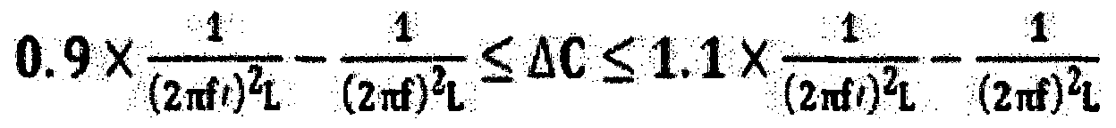 [Mathematical Expression]
【청구항 11】 Claim 11
제 10항에 있어서, 11. The method of claim 10,
상기 매칭회로부는 직렬 매칭회로와 병렬 매칭회로를 포함하고, Wherein the matching circuit portion includes a serial matching circuit and a parallel matching circuit,
상기 매칭회로부의 캐패시턴스 (C)는 직렬 매칭회로의 캐패시턴스 (Cp)와 병렬 매칭회로의 캐패시턴스 (Cs)의 I 합인 것을 특징으로 하는 무선전력 송신장치. Wherein the capacitance (C) of the matching circuit portion is a sum of a capacitance (Cp) of the serial matching circuit and a capacitance (Cs) of the parallel matching circuit.
【청구항 12] [12]
제 11항에 있어서, 12. The method of claim 11,
상기 매칭회로부의 캐!패시턴스 (C)를 AC 만큼 류닝한 경우, 상기 에너지 전 달 채널에 금속 장애물이 개재된 경우의 변화된 공진주파수 ( Γ )가 설계사양인 공 진주파수 (0로 변경되는 것을 특징으로 하는 무선전력 송신장치. Of the matching circuit caviar! Characterized in that, when the capacitance (C) is angulated by AC, the changed resonant frequency (Γ) when the metal obstacle is interposed in the energy transfer channel is changed to a design specification resonant frequency (0 Device.
【청구항 13】 Claim 13
소정의 공진 주파수 (0에서 무선전력 송신장치와 공진결합을 하여 무선으로 전력을 수신하도록 설계된 무선전력 수신장치에 있어서, A wireless power receiving apparatus designed to receive power wirelessly by resonating with a wireless power transmission apparatus at a predetermined resonance frequency (0,
상기 무선전력 송신장치에서 발생된 자기장을 포섭하여 에너지 전달 채널을 형성하며, 상기 에너지 전달 채널을 통해 전자기파 형태로 전력을 수신하는 수신코 일; 및 A receiving coil for receiving an electromagnetic wave in the form of an electromagnetic wave through the energy transfer channel; And
상기 수신코일이 전력을 정류 내지 컨버팅하는 무선충전 수신회로부;를 포함 하고,
상기 에너지 전달 채^에 금속 장애물이 개재되면, 상기 무선전력 송신장치 에서 상기 무선전력 수신장치로의 무선전력 전달능력이 상기 금속 장애물이 개재되 지 않은 경우보다 향상되는 것을 특징으로 하는 무선전력 수신장치. And a wireless charging receiving circuit for rectifying or converting power of the receiving coil, Wherein a radio power transmission capability from the radio power transmission apparatus to the radio power reception apparatus is improved when the metal obstacle is interposed in the energy transmission system, .
【청구항 14】 14.
제 13항에 있어서, 14. The method of claim 13,
상기 무선전력 수신장치는, The wireless power receiving apparatus includes:
상기 수신코일과 상기 무선전력 수신회로부 사이에 배치되는 매칭회로부를 구비하여 상기 매칭회로부 전 i단과 후단의 임피던스를 매칭시키고, And a matching circuit portion disposed between the receiving coil and the wireless power receiving circuit portion to match the impedances of the matching circuit portion front and rear ends,
상기 매칭회로부의 캐패시턴스 (C) , 상기 공진주파수 (f ) 및 상기 송신코일의 인덕턴스 (L)가 The capacitance (C), the resonance frequency (f) and the inductance (L) of the transmitting coil of the matching circuit are
Λ ) Ι i 의 조건을 만족하는 상태에서 , 상기 에너지 전달 채' 에 금속 장애물이 개재되어 공진 주파수 ( Γ )가 변경 되는 경우, 상기 매칭회로부의 캐패시턴스 (C)를 아래 수학식을 만족하는 ᅀ C 만큼 류닝한 것을 특징으로 하는 무선전력 수신장치 . (C) satisfying the following equation is satisfied when the resonance frequency (Γ) is changed by interposing a metal obstacle in the energy transfer chain under the condition that the condition Of the wireless power receiving apparatus.
[수학식]
 [Mathematical Expression]
【청구항 15] [15]
제 14항에 있어서
상기 매칭회로부는 직렬 매칭회로와 병렬 매칭회로를 포함하고 , 상기 매칭회로부의 캐패시턴스 (C)는 직렬 매칭회로의 캐패시턴스 (Cp)와 병렬 매칭회로의 캐패시턴스 (Cs)의 i 합인 것을 특징으로 하는 무선전력 수신장치. The method of claim 14, wherein Characterized in that the matching circuit part comprises a series matching circuit and a parallel matching circuit wherein the capacitance C of the matching circuit part is the sum of the capacitance Cp of the series matching circuit and the capacitance Cs of the parallel matching circuit. Receiving device.
【청구항 16】 Claim 16
제 15항에 있어서, 16. The method of claim 15,
상기 매칭회로부의 캐!패시턴스 (C)를 AC 만큼 튜닝한 경우, 상기 에너지 전 달 채널에 금속 장애물이 개재된 경우의 변화된 공진주파수 (Γ )가 설계사양인 공 진주파수 (f )로 변경되는 것을 특징으로 하는 무선전력 수신장치ᅳ
When the capacitance (C) of the matching circuit portion is tuned by AC, the changed resonance frequency (Γ) when the metal obstacle is interposed in the energy transfer channel is changed to the resonance frequency (f) The wireless power receiving apparatus comprising:
Applications Claiming Priority (2)
| Application Number | Priority Date | Filing Date | Title |
|---|---|---|---|
| KR1020170143157A KR102458948B1 (en) | 2017-10-31 | 2017-10-31 | Wireless Power Transmitting Device, Wireless Power Receiving Device And Wireless Power Transferring System |
| KR10-2017-0143157 | 2017-10-31 |
Publications (2)
| Publication Number | Publication Date |
|---|---|
| WO2019088487A2 true WO2019088487A2 (en) | 2019-05-09 |
| WO2019088487A3 WO2019088487A3 (en) | 2019-06-27 |
Family
ID=66332115
Family Applications (1)
| Application Number | Title | Priority Date | Filing Date |
|---|---|---|---|
| PCT/KR2018/011888 WO2019088487A2 (en) | 2017-10-31 | 2018-10-08 | Wireless power transmission device, wireless power reception device, and wireless power transmission system |
Country Status (2)
| Country | Link |
|---|---|
| KR (1) | KR102458948B1 (en) |
| WO (1) | WO2019088487A2 (en) |
Families Citing this family (1)
| Publication number | Priority date | Publication date | Assignee | Title |
|---|---|---|---|---|
| KR102468941B1 (en) * | 2020-11-13 | 2022-11-23 | 한국과학기술원 | Wireless power transfer system and operating method of mitigating frequency splitting phenomena occurring in wireless power transfer system using a matching capacitor in transmitter |
Family Cites Families (6)
| Publication number | Priority date | Publication date | Assignee | Title |
|---|---|---|---|---|
| KR20120027909A (en) * | 2010-09-14 | 2012-03-22 | 추호성 | Loop resonator for wireless power transmission |
| JP6172956B2 (en) * | 2013-01-31 | 2017-08-02 | 日立マクセル株式会社 | Non-contact power transmission apparatus and non-contact power transmission method |
| US10381875B2 (en) * | 2014-07-07 | 2019-08-13 | Qualcomm Incorporated | Wireless power transfer through a metal object |
| KR101637411B1 (en) * | 2015-07-31 | 2016-07-08 | (주)파워리퍼블릭얼라이언스 | Transmitter for Magnetic Resonance Wireless Power Trasnfer System in Metalic Environment |
| KR20170066791A (en) * | 2015-12-07 | 2017-06-15 | 주식회사 알.에프.텍 | Wireless power transferring apparatus and method |
| US9837832B2 (en) * | 2015-12-29 | 2017-12-05 | Motorola Solutions, Inc. | Wireless power transfer device and method |
-
2017
- 2017-10-31 KR KR1020170143157A patent/KR102458948B1/en active IP Right Grant
-
2018
- 2018-10-08 WO PCT/KR2018/011888 patent/WO2019088487A2/en active Application Filing
Also Published As
| Publication number | Publication date |
|---|---|
| KR102458948B1 (en) | 2022-10-24 |
| KR20190048309A (en) | 2019-05-09 |
| WO2019088487A3 (en) | 2019-06-27 |
Similar Documents
| Publication | Publication Date | Title |
|---|---|---|
| KR101159565B1 (en) | Long range low frequency resonator and materials | |
| KR101646305B1 (en) | Parasitic devices for wireless power transfer | |
| EP2332096B1 (en) | Passive receivers for wireless power transmission | |
| JP6033552B2 (en) | Wireless power apparatus and method | |
| US8766482B2 (en) | High efficiency and power transfer in wireless power magnetic resonators | |
| US8344552B2 (en) | Antennas and their coupling characteristics for wireless power transfer via magnetic coupling | |
| EP3136614A1 (en) | Near-field antenna system | |
| WO2011083594A1 (en) | Non-contact power transmission device and near-field antenna for same | |
| JP2010537496A5 (en) | ||
| US20130328410A1 (en) | Multi-Band and Broadband Wireless Power Transfer through Embedded Geometric Configurations | |
| KR20150032366A (en) | Resonator device with improved isoalation for stable wireless power transfer | |
| EP3032701B1 (en) | Wireless power transmission device | |
| US20210265868A1 (en) | Wireless power transmission device | |
| KR20130111832A (en) | Device and system for wireless power transmission using transmission coil array | |
| KR20140128469A (en) | Wireless power transmission apparatus, wireless power reception apparatus, and wireless power transmission system | |
| KR20130033837A (en) | A wireless power transmission apparatus and method thereof | |
| WO2019088487A2 (en) | Wireless power transmission device, wireless power reception device, and wireless power transmission system | |
| KR101905905B1 (en) | Dual-mode Wireless Power Transfer Device and Mobile Device | |
| KR102207998B1 (en) | Wireless power transmission apparatus and wireless power transmission system | |
| CN110247684A (en) | Wireless device | |
| KR101745043B1 (en) | A wireless power transmission apparatus and method thereof | |
| US20200350784A1 (en) | Wireless near-field self-resonant impulse receiver | |
| KR101883684B1 (en) | Apparatus and method for transmitting wireless power using resonant coupling therefor system | |
| KR20140007223A (en) | Resonator for wireless power transfer | |
| Ramachandran et al. | Optimum wireless power transfer using lumped L section networks |
Legal Events
| Date | Code | Title | Description |
|---|---|---|---|
| 121 | Ep: the epo has been informed by wipo that ep was designated in this application |
Ref document number: 18874645 Country of ref document: EP Kind code of ref document: A2 |
|
| NENP | Non-entry into the national phase |
Ref country code: DE |
|
| 122 | Ep: pct application non-entry in european phase |
Ref document number: 18874645 Country of ref document: EP Kind code of ref document: A2 |