WO2019087344A1 - Bending mechanism and medical manipulator - Google Patents
Bending mechanism and medical manipulator Download PDFInfo
- Publication number
- WO2019087344A1 WO2019087344A1 PCT/JP2017/039661 JP2017039661W WO2019087344A1 WO 2019087344 A1 WO2019087344 A1 WO 2019087344A1 JP 2017039661 W JP2017039661 W JP 2017039661W WO 2019087344 A1 WO2019087344 A1 WO 2019087344A1
- Authority
- WO
- WIPO (PCT)
- Prior art keywords
- driving force
- axis
- link
- groove
- swinging
- Prior art date
Links
Images


Classifications
-
- A—HUMAN NECESSITIES
- A61—MEDICAL OR VETERINARY SCIENCE; HYGIENE
- A61B—DIAGNOSIS; SURGERY; IDENTIFICATION
- A61B34/00—Computer-aided surgery; Manipulators or robots specially adapted for use in surgery
- A61B34/70—Manipulators specially adapted for use in surgery
- A61B34/71—Manipulators operated by drive cable mechanisms
-
- A—HUMAN NECESSITIES
- A61—MEDICAL OR VETERINARY SCIENCE; HYGIENE
- A61B—DIAGNOSIS; SURGERY; IDENTIFICATION
- A61B34/00—Computer-aided surgery; Manipulators or robots specially adapted for use in surgery
- A61B34/30—Surgical robots
-
- A—HUMAN NECESSITIES
- A61—MEDICAL OR VETERINARY SCIENCE; HYGIENE
- A61B—DIAGNOSIS; SURGERY; IDENTIFICATION
- A61B34/00—Computer-aided surgery; Manipulators or robots specially adapted for use in surgery
- A61B34/70—Manipulators specially adapted for use in surgery
-
- B—PERFORMING OPERATIONS; TRANSPORTING
- B25—HAND TOOLS; PORTABLE POWER-DRIVEN TOOLS; MANIPULATORS
- B25J—MANIPULATORS; CHAMBERS PROVIDED WITH MANIPULATION DEVICES
- B25J1/00—Manipulators positioned in space by hand
- B25J1/02—Manipulators positioned in space by hand articulated or flexible
-
- B—PERFORMING OPERATIONS; TRANSPORTING
- B25—HAND TOOLS; PORTABLE POWER-DRIVEN TOOLS; MANIPULATORS
- B25J—MANIPULATORS; CHAMBERS PROVIDED WITH MANIPULATION DEVICES
- B25J9/00—Programme-controlled manipulators
- B25J9/10—Programme-controlled manipulators characterised by positioning means for manipulator elements
-
- A—HUMAN NECESSITIES
- A61—MEDICAL OR VETERINARY SCIENCE; HYGIENE
- A61B—DIAGNOSIS; SURGERY; IDENTIFICATION
- A61B17/00—Surgical instruments, devices or methods, e.g. tourniquets
- A61B2017/00477—Coupling
-
- A—HUMAN NECESSITIES
- A61—MEDICAL OR VETERINARY SCIENCE; HYGIENE
- A61B—DIAGNOSIS; SURGERY; IDENTIFICATION
- A61B34/00—Computer-aided surgery; Manipulators or robots specially adapted for use in surgery
- A61B34/30—Surgical robots
- A61B2034/302—Surgical robots specifically adapted for manipulations within body cavities, e.g. within abdominal or thoracic cavities
-
- A—HUMAN NECESSITIES
- A61—MEDICAL OR VETERINARY SCIENCE; HYGIENE
- A61B—DIAGNOSIS; SURGERY; IDENTIFICATION
- A61B34/00—Computer-aided surgery; Manipulators or robots specially adapted for use in surgery
- A61B34/30—Surgical robots
- A61B2034/305—Details of wrist mechanisms at distal ends of robotic arms
-
- A—HUMAN NECESSITIES
- A61—MEDICAL OR VETERINARY SCIENCE; HYGIENE
- A61B—DIAGNOSIS; SURGERY; IDENTIFICATION
- A61B34/00—Computer-aided surgery; Manipulators or robots specially adapted for use in surgery
- A61B34/70—Manipulators specially adapted for use in surgery
- A61B34/71—Manipulators operated by drive cable mechanisms
- A61B2034/715—Cable tensioning mechanisms for removing slack
Definitions
- the present invention relates to a bending mechanism and a medical manipulator.
- a medical manipulator provided with a bending joint for changing the direction of a treatment tool provided at the tip at the tip of an elongated insertion portion (see, for example, Patent Document 1).
- This medical manipulator is disposed along the insertion portion, and swings the swinging member by pushing and pulling two links connected to the swinging member on the tip side of the bending joint, thereby fixing the swinging member to the swinging member It is designed to swing the treatment instrument.
- the stress applied to one of the links may be excessive, and two links are required to improve the durability. This is disadvantageous in that it is difficult to reduce the diameter of the insertion portion.
- the present invention has been made in view of the above-described circumstances, and provides a bending mechanism and a medical manipulator capable of reducing the diameter of the insertion portion while avoiding the application of an excessive stress to each portion. The purpose is that.
- the present invention provides the following means. According to one aspect of the present invention, there is provided an elongated support member, a rocking member supported so as to be pivotable about an axis intersecting with the longitudinal axis at the tip of the support member, and arranged along the longitudinal axis of the support member.
- a first driving force transmitting member for transmitting the driving force applied at the base end to swing the swinging member with respect to the support member; and the first driving force around a central axis of the support member
- a second driving force disposed on the opposite side of the transmitting member along the longitudinal axis of the supporting member to transmit the driving force applied at the proximal end to swing the swinging member relative to the supporting member
- An external force that is provided to at least one of the transmission member, the first drive force transmission member, and the second drive force transmission member, and the swinging member receives when the one allowable stress becomes smaller than the other allowable stress. Force transmitted to one of the Providing a bending mechanism and a connecting unit for switching one connection state of the as.
- the first driving force transmitting member and the second driving force transmitting member when the driving force is applied to the first driving force transmitting member and the second driving force transmitting member on the base end side of the support member, the first driving force transmitting member and the second driving force transmitting member transmit The driving force is transmitted to the rocking member, and the rocking member is rocked about the axis at the tip of the support member.
- the allowable stress of the first driving force transmitting member and the allowable stress of the second driving force transmitting member are different.
- the first drive is transmitted by the connecting portion provided to the first driving force transmitting member. Switching is performed so that the force transmitted by the force transmission member is reduced.
- the second driving force transmitting member in which the allowable stress is relatively increased due to bending the external force received by the swinging member is received, and the first driving force transmitting member in which the allowable stress decreases is excessive. It is possible to prevent the first driving force transmission member from being damaged. In this case, damage is prevented by changing the magnitude of the driving force to be transmitted, instead of increasing the rigidity of each portion including the first driving force transmitting member and the second driving force transmitting member. It is possible to reduce the diameter of the insertion portion while preventing an increase in cross sectional dimension.
- the connecting portion may be switched so that the transmitted force is reduced when the swing angle of the swing member with respect to the support member exceeds a threshold.
- the transmitted force is switched based on the preset threshold value, so whether external force is received by both the first driving force transmission member and the second driving force transmission member by setting the threshold value , You can choose to receive one. This selection improves the degree of freedom such as the cross-sectional dimension of each part and the diameter of the insertion part.
- control unit further includes an operation unit configured to swing the swinging member with respect to the support member at the swinging angle determined in accordance with the operation amount, and the connecting portion has the threshold value. If exceeded, the transmitted driving force may be switched to be small. By doing this, the threshold value for switching the magnitude of the transmitted driving force is associated with the operation amount received by the operation unit. By this association, the threshold value of the swing angle corresponding to the operation amount is set.
- the connecting portion includes a groove cam having a guide groove and an engaging portion engaged with the guide groove of the groove cam in the longitudinal axial direction, and the guide groove according to the operation amount
- the longitudinal axial position of engagement with the engagement portion may be switched.
- the connecting portion has a region which can freely move along the longitudinal axis direction, depending on the engagement position of the longitudinal engagement portion. In the state in which the connecting portion can move freely, it is not subjected to excessive stress, and breakage of the first driving force transmitting member or the second driving force transmitting member having the connecting portion can be prevented.
- the guide groove can freely move the position of the engagement portion relative to the guide groove in the restraint region for fixing the position of the engagement portion relative to the guide groove in the longitudinal axis direction.
- the position of the engaging portion in the longitudinal axis direction may be switched from the restraint area to the floating area when the swing angle exceeds the threshold.
- the connecting portion is provided in both the first driving force transmitting member and the second driving force transmitting member, and the guide groove is formed in the longitudinal direction of the engaging portion with respect to the guide groove.
- a semi-restrictive area for restraining movement within a predetermined range is provided, and when the rocking member is rocked, the engaging portion is disposed in the semi-restricting area, and the rocking member is rocked.
- the swinging operation is not performed, one of the engaging portions positioned closer to the tip end side in the longitudinal axis direction is disposed in the swinging region, and the other engaging portion is disposed in the constraining region.
- a mechanism may be provided.
- the rocking member can be rocked so that an excessive force is not applied to the first drive power transmission member and the second drive power transmission member.
- the mechanism regulates the rocking of the rocking member according to the release operation received by the operation unit.
- Switching may be performed, and the engagement portion may be disposed in the semi-restraint area.
- At least one of the first driving force transmitting member having the connecting portion and the second driving force transmitting member is connected to the tip of the connecting portion and moves in the longitudinal axis direction.
- the proximal end transmission member connected to the proximal end of the connection portion and moving in the longitudinal axis direction, and the connection portion is pivotable to the proximal end transmission member around the center of oscillation.
- a groove cam having a guide groove one end of the bell crank is fixed to the base end of the distal end side transmission member, and the other end of the bell crank has the swing angle of the swing angle.
- the connecting portion may transmit the driving force to both the first driving force transmitting member and the second driving force transmitting member in both directions in the longitudinal axis direction of the support member. In this way, it is possible to prevent the generation of excessive stress in any direction when the driving force is transmitted in both directions of the longitudinal axis of the support member.
- the other aspect of this invention provides the medical manipulator provided with the bending mechanism of the said aspect, and the treatment tool attached to the said rocking member.
- the first power transmission member and the second drive power transmission member do not receive excessive stress, and damage to the first power transmission member and the second power transmission member can be reduced.
- the bending mechanism provided in the vicinity of the tip for swinging the tip does not break.
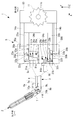
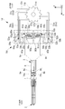
- the medical manipulator 1 includes a treatment tool 2 for treating an affected area, an elongated insertion portion 3, and an operation portion 4 connected to the proximal end of the insertion portion 3.
- the bending mechanism 5 is configured by the insertion portion 3 and the operation portion 4.
- the treatment instrument 2 is attached to a swinging member 7 of the insertion portion 3 described later.
- the insertion portion 3 is, as shown in FIG. 1, an elongated support member 6 and a swing member supported at the tip end of the support member 6 so as to be swingable about a swing axis orthogonal to the longitudinal axis of the support member 6. 7 and two sets of links 8a and 8b for swinging the swinging member 7 with respect to the supporting member 6 by transmitting the driving force applied in the operation unit 4 at the base end of the supporting member 6 .
- Each set of links 8a and 8b is a long first link (a first driving force transmitting member, a second driving force transmitting member, a tip side transmitting member) 9a and 9b disposed along the longitudinal axis of the support member 6.
- the first links 9a, 9b and the swinging member 7 are provided with short short links 10a, 10b swingably connected around an axis parallel to the swing axis.
- a coordinate axis consisting of an X axis, a Y axis, and a Z axis shown in FIG. 1 is defined.
- the longitudinal axis of the support member 6 is defined as the X axis
- the positive direction of the X axis is defined as the left direction in FIG. 1 where the treatment tool 2 is provided.
- the radial direction of the support member 6 is defined as the Y axis orthogonal to the X axis
- the positive direction of the Y axis is defined as the upper direction in FIG.
- a Z-axis orthogonal to each of the X-axis and the Y-axis is defined, and the positive direction of the Z-axis is defined as a direction penetrating from the front to the back of FIG.
- the coordinate axes shown in the following figures are correlated with each other.
- the X-axis positive direction is also referred to as the distal direction or the distal side
- the X-axis negative direction is also referred to as the proximal direction or the proximal side.
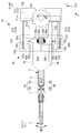
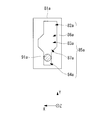
- FIG. 2 shows the medical manipulator 1 when the rocking member 7 is parallel to the X axis without rocking (flexing).
- the operation unit 4 has a base 13, a handle 11 operated by an operator to be applied with a driving force and rotatably attached to the base 13, and a drive applied to the handle 11.
- a bending mechanism 5 capable of supplying force to the two sets of links 8a and 8b and swinging the swinging member 7 is provided.
- the bending mechanism 5 includes two second links (a first driving force transmitting member, a second driving force transmitting member, and a proximal end transmitting member) supported by the base 13 so as to be linearly movable in the longitudinal direction of the links 8a and 8b.
- the connection parts 30a and 30b which change the transmission state of force between link 9a, 9b and 2nd link 14a, 14b are provided.
- the first link 9a and the second link 14a correspond to a first driving force transmission member in the claims
- the first link 9b and the second link 14b correspond to a second driving force transmission member in the claims.
- the second links 14a and 14b move linearly along the X-axis via the rack gear and the pinion gear when the handle 11 rotates about the handle center axis 11c.
- the second link 14a shown on the upper side in FIG. 1 moves to the base end side
- the second link 14b shown on the lower side in FIG. Move to the tip side.
- the second link 14 a moves distally
- the second link 14 b moves proximally.
- each of the connecting portions 30a and 30b is configured symmetrically about the ZX plane including the central axis of the support member 6, in the present embodiment, the connecting portion 30a will be described, and the description of the connecting portion 30b will be described. I omit it.
- the connecting portion 30 a and the connecting portion 30 b are different only in “a” and “b” attached at the end of the reference numerals, and the preceding reference numerals are in a correspondence relation.
- the connecting portion 30a is a fixed pin 38a fixed at a position along the X axis with respect to the second link 14a, and a groove cam fixed at a position along the X axis with respect to the second link 14a by the fixed pin 38a.
- the fixing pin 38a penetrates the second link 14a from the radial outer side, and fixes the groove cam 31a from the radial outer side.
- the fixing pin 38a can move in a predetermined range along the Y-axis direction.
- the groove cam 31a has a guide groove 34a whose central axis is an axis parallel to the Y axis, and two engagement pins 32a and 33a which project in the negative direction of the Z axis.
- the guide groove 34a has a small width groove (restraint area) 37a, a tapered groove 36a, and a large groove (loose area) 35a in order from the radially outer side.
- the narrow groove 37a has a rectangular cross section having a fixed length along the X axis and the Z axis in the ZX plane.
- the large groove 35a has a rectangular cross section having a length along the X axis larger than the narrow groove 37a and a length along the same Z axis as the small groove 37a in the ZX plane.
- the tapered groove 36a has an inclined rectangular cross section which gradually increases the cross sectional area along the Y axis from the small width groove 37a to the large groove 35a.
- the length along the Y axis of each of the narrow groove 37a, the large groove 35a, and the tapered groove 36a is set according to the bending angle of the rocking member 7.
- Each of the engagement pins 32a and 33a is formed on the same axis parallel to the X axis.
- the engagement pins 32a and 33a have a cylindrical shape extending in the negative Z-axis direction.
- the intermediate member 21a is formed with two slits 22a and 23a with which the engagement pins 32a and 33a respectively engage. As shown in FIG. 2, the slits 22 a and 23 a are curved slits that are directed radially outward as the engaged engagement pins 32 a and 33 a approach the tip end side.
- an engaging portion 91a of the first link 9a is engaged with the guide groove 34a of the groove cam 31a.
- the engaging portion 91a has a cylindrical shape extending in the negative Z-axis direction from the proximal end of the first link 9a.
- the diameter of the cylindrical portion of the engaging portion 91a is formed to be the same as the length along the X axis of the narrow groove 37a in the guide groove 34a. In the state in which the rocking member 7 shown in FIG. 2 is not bent, the positions along the X axis of the second links 14 a and 14 b are the same.
- the engaging portions 91a and 91b formed on the first links 9a and 9b are engaged with the narrow grooves 37a and 37b of the guide grooves 34a and 34b.
- the engaging positions of the engaging portions 91a and 92b with respect to the guide grooves 34a and 34b are planes parallel to the YZ plane that restricts the position along the X axis in the narrow grooves 37a and 37b.
- the engagement pins 32a, 33a, 32b, 33b formed on the groove cams 31a, 31b are engaged with the slits 22a, 23a, 22b, 23b in the vicinity of the middle. Near the middle of the slits 22a, 23a, 22b and 23b, the engaged engagement pins 32a, 33a, 32b and 33b are located radially inward of the slits 22a, 23a, 22b and 23b.
- FIG. 3 shows the medical manipulator 1 when the handle 11 is rotated clockwise and the swinging member 7 is bent.
- the second link 14a moves proximally, and the second link 14b moves distally.
- the fixing pin 38a fixed to the distal end side of the second link 14a and the groove cam 31a fixed to the fixing pin 38a move to the base end side.
- the engagement pins 32a and 33a formed on the groove cam 31a move to the proximal end side in the engaged slits 22a and 23a.
- the engagement pins 32a and 33a move in the negative direction of the X axis in the slits 22a and 23a, but do not move at a position along the Y axis. That is, the groove cam 31a having the engagement pins 32a and 33a is not moved in the Y axis direction. As a result, the positional relationship along the Y axis between the guide groove 34a of the groove cam 31a and the engagement portion 91a engaged with the guide groove 34a does not change, and the engagement portion 91a has a small width in the guide groove 34a. It remains engaged with the groove 37a.
- the fixing pin 38b fixed to the tip side of the second link 14b and the groove cam 31a fixed to the fixing pin 38b are tip ends Move to the side.
- the engaging pins 32b and 33b formed on the moving groove cam 31b move to the tip side in the engaged slits 22b and 23b.
- the engagement pins 32b and 33b move to the tip side along the shapes of the slits 22b and 23b, and at the same time, move to the radially outer side (the negative direction of the Y-axis).
- the positional relationship along the Y-axis between the guide groove 34b of the groove cam 31b and the engagement portion 91b engaged with the guide groove 34b changes, and the position of the engagement portion 91b along the Y-axis Changes from the narrow groove 37b to the substantial groove 35b as shown in FIG.
- the diameter of the engaging portion 91b is significantly smaller than the length of the groove 35b along the X axis, so the engaging portion 91b is predetermined. It can move along the X axis in the range.
- the engagement position of the engagement portion 92b with the guide groove 34b in this case is a plane parallel to the YZ plane that regulates the position along the X axis in the narrow groove 37b.
- the second link 14 a moves to the distal end side by rotating the handle 11 counterclockwise, and the second link 14 b Moves proximally.
- the groove cam 31b fixed to the fixing pin 38b moves to the base end side.
- the engagement pins 32b and 33b formed on the groove cam 31b move proximally and radially inward along the shapes of the slits 22b and 23b, the groove cam 31b moves inward in the radial direction.
- the handle 11 is operated to change the state in which the rocking member 7 shown in FIG. 2 is not bent and the state in which the rocking member 7 shown in FIG. 3 is bent.
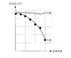
- FIG. 4 shows the relationship of allowable stress (permissible axial force) between the link 8a located inside with respect to the bending angle and the link 8b located outside when the rocking member 7 is bent.
- allowable stress permissible axial force
- the first link 9a, 9b is between 0 degree (degree) and ⁇ degree (degree) in bending angle.
- the guide grooves 34a and 34b may be formed such that the positions along the Y axis of the engaging portions 91a and 91b are positioned in the large grooves 35a and 35b.
- the insertion section 3 is inserted into the body, the treatment tool 2 at the tip is disposed in the vicinity of the affected area, and provided in the operation unit 4
- the handle 11 is operated to swing the swinging member 7 with respect to the support member 6 to adjust the posture of the treatment instrument 2 with respect to the affected part.
- the two second links 14a and 14b connected to the handle 11 via the rack gear and the pinion gear are moved along the X axis.
- the grooved cams 31a and 31b fixed to the second links 14a and 14b via the fixing pins 38a and 38b move along the X axis. Since the engagement pins 32a and 33a of the groove cam 31a fixed to the second link 14a moving to the base end engage with the slits 22a and 23a, the groove cam 31a positioned in the Y-axis positive direction is Y It does not move along the axis.
- the first link 9a since the engaging portion 91a of the first link 9a is engaged with the small width groove 37a of the guide groove 34a, the first link 9a has the same movement amount as the movement amount of the second link 14a along the X axis. Only move along the X axis.
- the groove cam 31a is , Move radially outward.
- the position along the Y axis of the engaging portion 91b in the first link 9b is located in the large groove 35b of the guide groove 34b.
- the diameter of the engaging portion 91b is significantly smaller than the length of the groove 35b along the X axis, the first link 9b is affected by the amount of movement of the second link 14b along the X axis within a predetermined range. Absent. In other words, the first link 9b can freely move along the X axis within a predetermined range.
- the first link 9b moves an amount of movement of the second link 14b. Regardless, it can move along the X axis within a predetermined range. That is, since the first link 9b disposed outside is not fixed in position, it does not break by being moved even if it receives an external force.
- the first link 9 a disposed at the inner side and having a large allowable stress can transmit the movement of the handle 11 along the X axis to the rocking member 7.
- the medical manipulator 1 having the bending mechanism 5 of the present embodiment even when the operation of the handle 11 is received, breakage of the first links 9a and 9b against external force can be reduced.
- FIG. 6 shows a state in which the swinging member 7 of the medical manipulator 1a is not bent.
- the second link first driving force transmission member, proximal end transmission member
- 15a and 15b second driving force
- the transmission member (proximal transmission member) and the connecting portions 40a and 40b are different. Therefore, in the second embodiment, different parts will be described, and the description of the same parts will be omitted.
- the second links 15a and 15b are fixed to the base 13 and extend in the positive direction of the X-axis, and extend inward in the radial direction on the extending end side.
- circular holes 151a and 151b parallel to the Z-axis are formed for pivotally fixing bell cranks 41a and 41b described later.
- each of the connecting portions 40a and 40b is configured symmetrically with respect to the ZX plane including the central axis of the support member 6, in the second embodiment, the connecting portion 40a will be described and the description of the connecting portion 40b Is omitted.
- the connecting portion 40 a and the connecting portion 40 b are different only in “a” and “b” attached at the end of the reference numerals, and the preceding reference numerals are in a corresponding relation.
- the connecting portion 40a is fixed to the bell crank 41a fixed to the second link 15a so as to be able to swing on the XY plane, a base end side fixing portion 92a fixed to one end of the bell crank 41a on the tip side, and the base 13 And a grooved cam 49a.
- the bell crank 41a has a shape in which a cylindrical shape parallel to the X axis and a cylindrical shape parallel to the Y axis orthogonal to the X axis are combined in the state shown in FIG.
- a rocking central axis (rocking center) 44a is formed at the intersection of the two cylinders.
- the swinging central shaft 44a is swingably fixed to the circular hole 151a of the second link 15a.
- the bell crank 41a has a tip end side fixing portion 43a and a spherical free end portion 42a engaged with the groove cam 49a at the other end of the tip end side fixing portion 43a on the inner side in the radial direction.
- the distal fixing portion 43a is fixed to a proximal fixing portion 92a formed on the first link 9a.
- the grooved cam 49a has a guide groove 45a whose central axis is an axis parallel to the X-axis.
- the guide groove 45a includes, in order from the base end side, a narrow groove (restriction region) 46a, a tapered groove 47a, and a large groove (floating region) 48a.
- the narrow groove 46a has a constant groove width slightly larger than the diameter of the free end 42a of the bell crank 41a.
- the large groove 48a has a constant groove width larger than the groove width of the narrow groove 46a.
- the tapered groove 47a is an inclined groove that gradually increases the groove width from the small width groove 46a to the large groove 48a.
- FIG. 7 shows the medical manipulator 1a when the handle 11 is rotated clockwise and the swinging member 7 is bent.
- the second link 15 a moves to the proximal side
- the second link 15 b moves to the distal side.
- the bell crank 41a fixed to the circular hole 151a of the second link 15a moves to the base end side.
- the free end 42a of the bell crank 41a is engaged with the narrow groove 46a in the guide groove 45a in the same manner as shown in FIG. Therefore, the bell crank 41a moves proximally along the X axis without swinging around the swing center shaft 44a.
- the first link 9a fixed to the distal end side fixing portion 43a of the bell crank 41a moves toward the base end along the X axis by the same moving amount as the moving amount of the second link 15a along the X axis. .
- the bell crank 41b fixed to the circular hole 151b of the second link 15b moves to the tip side.
- the position along the X axis of the free end 42b of the bell crank 41b is located in the large groove 48b in the guide groove 45b, unlike the state shown in FIG. In this state, since the free end 42b of the bell crank 41b is not fixed, the bell crank 41b can rotate along the rocking direction DR1 around the rocking central axis 44b.
- the amount of movement of the second link 15b along the X axis is different from the amount of movement of the bell crank 41b along the X axis. For example, when the bell crank 41b pivots clockwise, the amount of movement of the bell crank 41a along the X axis is smaller than the amount of movement of the second link 15b along the X axis.
- the second links 15a and 15b are X. Move along the axis.
- the bell cranks 41a and 41b pivotally fixed to the second links 15a and 15b move along the X axis.
- the bell crank 41b can rock around the rocking central axis 44b.
- the bell crank 41b in which the distal end side fixing portion 43b is fixed to the first link 9b can rock within a predetermined range along the rocking direction DR1. Therefore, since the first link 9b disposed outside is not fixed in position with respect to the second link 15b, the first link 9b does not break by moving within a predetermined range even when receiving an external force.
- FIG. 8 shows a state in which the swinging member 7 of the medical manipulator 1b is not bent.
- the end side transmission member) 57a and the second link (second drive force transmission member, base end transmission member) 57b are different from the connecting portions 50a and 50b. Therefore, in the third embodiment, different parts will be described, and the description of the same parts will be omitted.
- a push member 51 d movable along the X axis is attached to the base 13 b.
- the pushing member 51d includes a base portion 51c to which the handle 11b is rotatably attached, and top pusher pushing portions 51a and 51b extending from the base portion 51c to the tip end side.
- the handle central axis 11 bc is rotatably mounted at the center of the base portion 51 c so that the handle 11 b is rotatable with the Y axis as the longitudinal direction.
- One end of the coma pusher pressing portion 51a is attached to the end of the base portion 51c in the positive Y-axis direction, and has two engaging pins 53a formed along the X-axis on the tip end side.
- one end of the coma pusher pushing portion 51b is attached to the end of the base portion 51c in the negative Y-axis direction, and has two engaging pins 53b formed along the X-axis on the tip end side ing.
- each of the connecting portions 50a and 50b is configured symmetrically with respect to the ZX plane including the central axis of the support member 6, in the third embodiment, the connecting portion 50a will be described and the description of the connecting portion 50b Is omitted.
- the connecting portion 50 a and the connecting portion 50 b are different only in “a” and “b” attached at the end of the reference numerals, and the preceding reference numerals are in a corresponding relation.
- the connecting portion 50a includes a top pusher 59a, a stopper member 65a connected to the top pusher 59a, a top 60a whose position along the X axis is fixed to the inside in the radial direction of the top stopper member 65a, and a top 60a And a narrow portion 93a (described later with reference to FIG. 9) formed on the first link 9a connected to the top 60a.
- the top pusher 59a is restricted from moving along the X axis with respect to the base 13b.
- the top pusher 59a is movable along the Y axis with respect to the base 13b.
- the top pusher 59a has two slits 52a engaged with the two engagement pins 53a of the top pusher pushing portion 51a.
- the slit 52a is a slit directed radially outward as it approaches the tip end side. Therefore, when the pressing member 51d moves to the tip side, the top pusher 59a moves radially inward.
- the stopper member 65a is fixed to the base 13b. Therefore, the cotter pusher 59a can move along the Y-axis direction with respect to the stopper member 65a.
- the stopper member 65a has a first surface 55a parallel to the ZX plane and formed on the base end side, and a second surface formed parallel to the ZX plane and on the front end side and also radially inward of the first surface 55a. It has a surface 56a and a step surface 54a parallel to the YZ plane connecting the first surface 55a and the second surface.
- the top 60a has a guide groove 64a (described later with reference to FIG. 9) with which the proximal end side of the first link a is engaged.
- the radially outward facing surface of the piece 60a is in contact with the first surface 55a of the stopper member 65a or the radially inwardly facing surface of the piece pusher 59a described later with reference to FIG.
- the radially outward facing surface of the piece 60a is in contact with the more radially inward surface of the first surface 55a of the stopper member 65a and the radially inward facing surface of the piece pusher 59a. It has become.
- the radial outer surface of the piece 60 a is defined by the first surface 55 a of the stopper member 65 a along the Y axis.
- the second link 57a is supported by the base 13b so as to be linearly movable in the longitudinal direction of the links 8a and 8b, extends to the tip end side, and moves along the X-axis direction.
- a biasing member 58a is fixed to the tip end side of the second link 57a.
- the biasing member 58a is fixed to the top 60a on the side opposite to the side fixed to the second link 57a.
- the biasing member 58a biases the top 60a radially outward.
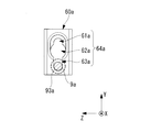
- FIG. 9A shows the engagement relationship between the guide groove 64a formed on the top 60a and the first link 9a when the medical manipulator 1b is in the state shown in FIG.
- the guide groove 64a includes, in order from the inner side in the radial direction to the outer side in the radial direction, the fixing groove (restriction area) 63a, the allowance groove (retraction area) 62a, and the semifixed groove And 61).
- the small-width portion 93a of the first link 9a is smaller in diameter than the other portions, centering on the central axis OP of the first link 9a parallel to the X-axis.
- the length along the X axis of the small width part 93a is the same as the length along the X axis of the fixing groove 63a. Therefore, when the small width portion 93a engages with the fixing groove 63a, the first link 9a is fixed to the top 60a.
- the cross section of the fixed groove 63a in the YZ plane is substantially circular, which is larger than the cross sectional area of the first link 9a.
- FIG. 10 shows a state in which a bending operation necessary to largely bend the swinging member 7 is performed.
- the handle 11b and the pressing member 51d shown in FIG. 10 are moved to the tip side with respect to the base 13b as compared with the state shown in FIG.
- the engagement pins 53a and 53b of the pressing member 51d move to the tip side along the slits 52a and 52b of the top pushers 59a and 59b.
- the top pushers 59a and 59b are movable along the Y axis, they move radially inward.
- the surface of the tops 60a and 60b facing radially outward contacts the surface of the top pushers 59a and 59b facing radially inward. That is, the positions of the tops 60a and 60b along the Y axis are defined by the top pushers 59a and 59b moved radially inward.
- FIGS. 11A and 11B show the engagement relationship between the guide groove 64a formed on the top 60a and the first link 9a when the medical manipulator 1 is in the state shown in FIG. As shown to FIG. 11A and FIG. 11B, the narrow part 93a of the 1st link 9a is engaged with the semi-fixed groove 61a.
- FIG. 12 shows a cross-sectional view parallel to the XY plane when the small width portion 93a is engaged with the half fixed groove 61a.
- the semi-fixed groove 61 a has a substantially cylindrical shape with the same diameter as the small width part 93 a formed on the base end side and the small width part 93 a formed on the tip side. It has a substantially cylindrical portion with the same diameter as the cross-sectional area of the large diameter first link 9a.
- the semi-fixed groove 61a there is a portion where the diameter is large by the distance ⁇ t so that the portion where the diameter of the first link 9a is large can also move along the X axis.
- the movement distance of the second link 57a along the X axis and the movement distance of the second link 57b along the X axis are in a symmetrical relationship.
- the gap of the distance ⁇ t is provided in the semi-fixed groove 61a, thereby absorbing the difference in the movement distance between the first link 9a, 9b and the second link 57a, 57b.
- the difference between the movement amount of the first link 9a along the X axis and the movement amount of the first link 9b along the X axis is within a predetermined range.
- the urging force of the urging members 58a and 58b exerts a force that pushes the top pushers 59a and 59b outward in the radial direction. Since the slits 52a, 52b of the top pushers 59a, 59b and the engagement pins 53a, 53b of the top pusher pressing portions 51a, 51b are engaged, the pressing member 51d receives a force to be pushed toward the proximal end. Thereby, the handle 11 b receives a force to be pushed to the proximal end side.
- the small width portion 93a of the first link 9a is engaged with the fixing groove 63a of the guide groove 64a, as in the state shown in FIGS.
- the portion where the first link 9 b engages with the guide groove 64 b is different from the state shown in FIGS. 8 and 9.
- FIGS. 14A and 14B show the engagement relationship between the guide groove 64b formed on the top 60b and the first link 9b when the medical manipulator 1 is in the state shown in FIG.
- the position along the Y-axis of the narrow portion 93b of the first link 9b is located in the allowing groove 62b. Therefore, when the first link 9b moves along the X-axis direction, the first link 9b does not contact the top 60b, so the inside of the slit 52b can move along the X-axis within the movable range of the engagement pin 53b. I can move freely. That is, in the third embodiment, the release operation for moving the handle 11b to the tip side as shown in FIG.
- the tops 60a and 60b are not restricted by the step surfaces 54a and 54b of the stopper members 65a and 65b, and can move within the predetermined range along the X axis.
- the first links 9a and 9b connected to the tops 60a and 60b can move along the X axis, and the rocking member 7 can bend.
- the allowable stress of the bent first link 9b is lower than that of the inner first link 9a, as shown in the graph of FIG. .
- the position of the outer first link 9b along the X axis is not restricted by the top 60b. Therefore, even if the rocking member 7 receives an external force, it is received only by the inner first link 9a having a large allowable stress, and the outer first link 9b does not receive an external force. As a result, breakage of the first links 9a and 9b can be reduced.
- FIG. 15 shows a state in which the swinging member 7 of the medical manipulator 1c is not bent.
- the medical manipulator 1c according to the fourth embodiment has the rotary encoder 19 in comparison with the medical manipulator 1 according to the first embodiment, the base 13c has the control unit 79a, and the coupling portions 70a and 70b. Is different. Therefore, in the fourth embodiment, different parts will be described, and the description of the same parts will be omitted.
- the rotary encoder 19 is disposed between the short link 10a and the short link 10b.
- the rotary encoder 19 detects a bending angle when the bending mechanism 5c is bent.
- the detected bending angle is processed by the control unit 79a incorporated in the base 13c.
- each of the connecting portions 70a and 70b is configured symmetrically with respect to the ZX plane including the central axis of the support member 6, in the fourth embodiment, the connecting portion 70a will be described and the description of the connecting portion 70b Is omitted.
- the connecting part 70a and the connecting part 70b are different only in “a” and “b” added at the end of the reference numerals, and the reference numerals before them are in correspondence.
- the connecting portion 70a includes an actuator 75a fixed on the tip end side of the second link 14a, a groove cam 71a fixed on the inner side in the radial direction of the actuator 75a and having a guide groove 76a, and a guide groove formed in the first link 9a. And an engaging portion 91a engaged with 76a.
- the actuator 75a changes the position along the Y axis of the groove cam 71a with respect to the second link 14a based on the control signal received from the control unit 79a. Specifically, when the swinging member 7 is bent in the positive Y-axis direction side (upper side in FIG. 15) based on a control signal from the control unit 79a, the actuator 75a moves to the Y-axis of the groove cam 71a. Do not change the position along. When the swinging member 7 is bent in the negative Y-axis direction (the lower side in FIG. 15) based on a control signal from the controller 79a, the actuator 75a takes the position along the Y-axis of the groove cam 71a. Change radially inward.
- the grooved cam 71a has a guide groove 76a of the same shape as the guide groove 34a of the first embodiment.
- the guide groove 76a has a small width groove (restraint area) 74a, a tapered groove 73a, and a large groove (floating area) 72a.
- the engaging portion 91a of the first link 9a is engaged with the guide groove 76a of the groove cam 71a.
- the first link 9a including the engaging portion 91a in the second embodiment is the same as that in the first embodiment. In a state where the swinging member 7 shown in FIG. 15 is not swinging, the engaging portion 91a is engaged with the narrow groove 74a.
- FIG. 16 shows the medical manipulator 1c when the handle 11 is rotated clockwise and the swinging member 7 is in a bent state.
- the second link 14 a moves to the proximal end side
- the second link 14 b moves to the distal end side. Since the engaging portions 91a and 91b of the first links 9a and 9b are engaged with the narrow grooves 74a and 74b of the guide grooves 76a and 76b, the first links 9a and 9b are moved according to the movement of the second links 14a and 14b. 9b also moves along the X axis. Thereby, as shown in FIG. 16, the rocking member 7 is bent.
- the rotary encoder 19 detects the bending angle of the rocking member 7.
- the control unit 79a controls the actuator 75b connected to the outer first link 9b based on the detected bending angle.
- ⁇ is set as the threshold of the bending angle, and when the bending angle exceeds the threshold, the position along the Y axis of the engaging portion 91 b in the outer first link 9 b is the guide groove 76 b Is set to be positioned in the large groove 72b of the.
- the controller 79a moves the groove cam 71b radially outward. As a result, the position along the Y axis of the engaging portion 91b is largely located in the groove 72b.
- each of the second links 14a and 14b extends along the X axis. Move symmetrically.
- the swinging member 7 bends, and the rotary encoder 19 detects the bending angle.
- Control part 79a moves actuator 75a or actuator 75b to the diameter direction outside, when a detected bending angle exceeds a threshold.
- the position along the Y axis of the engaging portion 91a of the first link 9a or the engaging portion 91b of the first link 9b with respect to the guide grooves 76a and 76b changes to a large groove 72a or a large groove 72b. Therefore, the first link 9a or the first link 9b, which is located outside the bending and has a small allowable stress, does not receive an external force, so the breakage of the first links 9a and 9b is reduced.
- FIG. 17 shows a state in which the swinging member 7 of the medical manipulator 1d is not bent.
- the first link 9a coupled to the groove cams 81a and 81b and the groove cams 81a and 81b of the connecting portions 80a and 80b. , 9b are different.
- the fifth embodiment is largely different in that groove cams 81a and 81b are used instead of the tops 60a and 60b of the third embodiment. Therefore, in the fifth embodiment, parts different from the third embodiment will be described, and the description of the same parts will be omitted.
- each of the connecting portions 80a and 80b is configured symmetrically with respect to the ZX plane including the central axis of the support member 6, in the fifth embodiment, the connecting portion 80a will be described and the description of the connecting portion 80b Is omitted.
- the connecting portion 80 a and the connecting portion 80 b are different only in “a” and “b” attached at the end of the reference numerals, and the preceding reference numerals are in a correspondence relation.
- the connecting portion 80a includes a groove cam 81a fixed to the inside in the radial direction of the stopper member 65a, and an engaging portion 91a of the first link 9a engaged with a guide groove 85a formed in the groove cam 81a.
- the radially outward surface of the groove cam 81a is in contact with the first surface 55a of the stopper member 65a or the radially inward surface of a cotter pusher 59a described later with reference to FIG. Specifically, the surface of the groove cam 81a facing radially outward contacts the surface positioned more radially inward of the first surface 55a of the stopper member 65a and the surface of the top pusher 59a facing radially inward. It is supposed to In the state shown in FIG. 17, the surface of the groove cam 81a facing radially outward is defined by the first surface 55a of the stopper member 65a along the Y axis.
- FIG. 18 shows the engagement between the guide groove 85a formed on the groove cam 81a and the engagement portion 91a of the first link 9a when the medical manipulator 1d is in the state shown in FIG. .
- the guide groove 85a includes, in order from the inner side in the radial direction to the outer side in the radial direction, a fixed groove (restriction area) 84a, both tapered grooves 87a, an allowance groove (loose area) 83a, and a piece It has a tapered groove 86a and a semi-fixed groove (semi-restricting area) 82a.
- the fixing groove 84a has a rectangular cross section having a fixed length in the X axis and the Z axis in the ZX plane.
- the allowance groove 83a has a rectangular cross-section expanded distally and proximally of the length of the fixed groove 84a along the X-axis.
- the length along the X axis of the fixing groove 84a is the same as the diameter of the engaging portion 91a of the first link 9a.
- the semi-fixed groove 82a has a rectangular cross section expanded only on the proximal side of the length of the fixed groove 84a along the X-axis.
- Both tapered grooves 87a have an inclined cross-section that gradually increases the rectangular cross-sectional area from the fixing groove 84a to the allowance groove 83a.
- the single tapered groove 86a has an inclined cross section which gradually reduces the rectangular cross-sectional area from the allowance groove 83a to the semi-fixed groove 82a.
- FIG. 19 shows a state in which a bending operation necessary for largely rocking the rocking member 7 is performed.
- the handle 11b in order to bend the swinging member 7, it is necessary to move the handle 11b to the tip side with respect to the base 13b.
- the handle 11b and the pressing member 51d shown in FIG. 19 are moved to the tip end side with respect to the base 13b as compared with the state shown in FIG. In this case, the radially outward facing surfaces of the groove cams 81a and 81b are in contact with the radially inwardly facing surfaces of the top pushers 59a and 59b.
- the position of the first links 9a and 9b along the Y axis with respect to the guide grooves 85a and 85b of the groove cams 81a and 81b changes.
- the positions along the Y-axis of the engaging portions 91a and 91b of the first links 9a and 9b are located in the semi-fixed grooves 82a and 82b.
- the length along the X axis of the semi-fixed grooves 82a, 82b is larger than the length along the X axis of the fixed grooves 84a, 84b so that the first link 9a can move along the X axis within a predetermined range. .
- the reason why the lengths are different is to absorb the difference in the moving distance between the first link 9a, 9b and the second link 57a, 57b, as in the third embodiment.
- the biasing force of the biasing members 58a and 58b acts to push back the top pushers 59a and 59b radially outward.
- the handle 11 b receives a force to be pushed to the proximal end side.
- a state as shown in FIG. 20 is obtained.
- the grooved cam 81b rides over the step surface 54b of the stopper member 65b to form the second surface 56b of the stopper member 65b. Move to position. Symmetrically, the grooved cam 81a moves to the position of the first surface 55a of the stopper member 65a.
- the first link 9a is engaged with the fixed groove 84a of the guide groove 85a as in the state shown in FIG.
- the position along the Y axis in the engaging portion 91b of the first link 9b is located in the allowing groove 83a of the guide groove 85b. Therefore, since the first link 9b does not contact the groove cam 81b when moving along the X axis, the first link 9b can freely move along the X axis within the range in which the engaging pin 53b can move in the slit 52b. .
- the grooved cams 81a and 81b can move within a predetermined range along the X axis. Thereby, the first links 9a and 9b can move along the X axis, and the rocking member 7 can rock.
- the allowable stress of the bent first link 9b is lower than that of the inner first link 9a, as shown in the graph of FIG. .
- the position of the outer first link 9b along the X axis is not restricted by the groove cam 81b. Therefore, even if the swinging member 7 receives an external force, the external first link 9b does not receive an external force only by the inner first link 9a having a large allowable stress. As a result, breakage of the first links 9a and 9b can be reduced.
- bending mechanisms 5, 5a, and 5a for reducing the external force applied to the smaller allowable stress.
- 5b, 5c, 5d and the medical manipulators 1, 1a, 1b, 1c, 1d have been described as an example, the bending mechanism and the medical manipulator can be variously modified.
- a known member may be used for the first links 9a and 9b and the handles 11 and 11b, and another shape is used for the slits 22a and 22b formed on the intermediate members 21a and 21b. May be
- first link first driving force transmitting member, distal end side Transmission member
- First link second driving force transmission member, tip side transmission member
- First link second driving force transmission member, tip side transmission member
- Second link second driving force transmitting member, proximal end transmitting member
Abstract
In order to prevent a bending mechanism from being damaged even when an external force is applied to a distal end, without increasing the diameter of a constituent member, this bending mechanism (5) is provided with: an elongated support member (6); a swing member (7) swingably supported on the distal end of the support member (6); first driving force transmission members (9a, 14a) which transmit a driving force applied to the proximal end, and swing the swing member (7) with respect to the support member (6); second driving force transmission members (9b, 14b) which transmit a driving force applied to the proximal end, and swing the swing member (7) with respect to the support member (6); and connection parts (30a, 30b) which are provided on at least one among the first driving force transmission members (9a, 14a) and the second driving force transmission members (9b, 14b), and which, when the allowable stress in one among the first driving force transmission members (9a, 14a) and the second driving force transmission members (9b, 14b) becomes smaller than the allowable stress in the other, switch the connection state of the one so that the force transmitted to the one by an external force applied to the swing member (7) is reduced.
Description
本発明は、屈曲機構および医療用マニピュレータに関するものである。
The present invention relates to a bending mechanism and a medical manipulator.
先端に備える処置具の方向を変更するための屈曲関節を細長い挿入部の先端部に備えた医療用マニピュレータが知られている(例えば、特許文献1参照。)。
この医療用マニピュレータは、挿入部に沿って配置され、屈曲関節よりも先端側の揺動部材に接続された2本のリンクの押し引きによって、揺動部材を揺動させ、揺動部材に固定された処置具を揺動させるようになっている。 There is known a medical manipulator provided with a bending joint for changing the direction of a treatment tool provided at the tip at the tip of an elongated insertion portion (see, for example, Patent Document 1).
This medical manipulator is disposed along the insertion portion, and swings the swinging member by pushing and pulling two links connected to the swinging member on the tip side of the bending joint, thereby fixing the swinging member to the swinging member It is designed to swing the treatment instrument.
しかしながら、特許文献1の医療用マニピュレータは、処置具の先端に大きな外力を受けた場合に、一方のリンクにかかる応力が過大となる虞があり、耐久性を向上するためには2本のリンクを太くしなければならず、挿入部の細径化を図ることが困難となるという不都合がある。
本発明は上述した事情に鑑みてなされたものであって、各部に過大な応力が作用することを回避しつつ、挿入部の細径化を図ることができる屈曲機構および医療用マニピュレータを提供することを目的としている。 However, in the medical manipulator ofPatent Document 1, when a large external force is applied to the tip of the treatment tool, the stress applied to one of the links may be excessive, and two links are required to improve the durability. This is disadvantageous in that it is difficult to reduce the diameter of the insertion portion.
The present invention has been made in view of the above-described circumstances, and provides a bending mechanism and a medical manipulator capable of reducing the diameter of the insertion portion while avoiding the application of an excessive stress to each portion. The purpose is that.
本発明は上述した事情に鑑みてなされたものであって、各部に過大な応力が作用することを回避しつつ、挿入部の細径化を図ることができる屈曲機構および医療用マニピュレータを提供することを目的としている。 However, in the medical manipulator of
The present invention has been made in view of the above-described circumstances, and provides a bending mechanism and a medical manipulator capable of reducing the diameter of the insertion portion while avoiding the application of an excessive stress to each portion. The purpose is that.
上記目的を達成するため、本発明は以下の手段を提供する。
本発明の一態様は、細長い支持部材と、該支持部材の先端に長手軸に交差する軸線回りに揺動可能に支持された揺動部材と、前記支持部材の前記長手軸に沿って配置され、基端において加えられた駆動力を伝達して、前記支持部材に対して前記揺動部材を揺動させる第1駆動力伝達部材と、前記支持部材の中心軸を中心として前記第1駆動力伝達部材の反対側に前記支持部材の前記長手軸に沿って配置され、基端において加えられた駆動力を伝達して、前記支持部材に対して前記揺動部材を揺動させる第2駆動力伝達部材と、前記第1駆動力伝達部材および前記第2駆動力伝達部材の少なくとも一方に設けられ、該一方の許容応力が他方の許容応力より小さくなったときに、前記揺動部材が受ける外力により該一方に伝達される力が小さくなるように該一方の連結状態を切り替える連結部とを備える屈曲機構を提供する。 In order to achieve the above object, the present invention provides the following means.
According to one aspect of the present invention, there is provided an elongated support member, a rocking member supported so as to be pivotable about an axis intersecting with the longitudinal axis at the tip of the support member, and arranged along the longitudinal axis of the support member. A first driving force transmitting member for transmitting the driving force applied at the base end to swing the swinging member with respect to the support member; and the first driving force around a central axis of the support member A second driving force disposed on the opposite side of the transmitting member along the longitudinal axis of the supporting member to transmit the driving force applied at the proximal end to swing the swinging member relative to the supporting member An external force that is provided to at least one of the transmission member, the first drive force transmission member, and the second drive force transmission member, and the swinging member receives when the one allowable stress becomes smaller than the other allowable stress. Force transmitted to one of the Providing a bending mechanism and a connecting unit for switching one connection state of the as.
本態様によれば、支持部材の基端側において第1駆動力伝達部材および第2駆動力伝達部材に駆動力を加えると、第1駆動力伝達部材および第2駆動力伝達部材によって伝達された駆動力が揺動部材に伝達され、揺動部材が支持部材の先端において軸線回りに揺動させられる。揺動部材の揺動方向に依存して、第1駆動力伝達部材の許容応力と、第2駆動力伝達部材の許容応力とが相違してくる。
According to the aspect, when the driving force is applied to the first driving force transmitting member and the second driving force transmitting member on the base end side of the support member, the first driving force transmitting member and the second driving force transmitting member transmit The driving force is transmitted to the rocking member, and the rocking member is rocked about the axis at the tip of the support member. Depending on the swinging direction of the swinging member, the allowable stress of the first driving force transmitting member and the allowable stress of the second driving force transmitting member are different.
例えば、一方の第1駆動力伝達部材の許容応力が、他方の第2駆動力伝達部材の許容応力より小さくなった場合に、第1駆動力伝達部材に設けられた連結部により、第1駆動力伝達部材により伝達される力が小さくなるように切り替えられる。
これにより、屈曲により許容応力が相対的に大きくなった方の第2駆動力伝達部材において、揺動部材が受ける外力が受け止められ、許容応力が小さくなった方の第1駆動力伝達部材が過大な応力を受けずに済み、第1駆動力伝達部材の破損を防止することができる。この場合において、第1駆動力伝達部材および第2駆動力伝達部材をはじめ各部の剛性を増大させるのではなく、伝達される駆動力の大きさを変化させることにより破損を防止するので、各部の断面寸法の増大を防止して挿入部の細径化を図ることができる。 For example, when the allowable stress of one of the first driving force transmitting members becomes smaller than the allowable stress of the other second driving force transmitting member, the first drive is transmitted by the connecting portion provided to the first driving force transmitting member. Switching is performed so that the force transmitted by the force transmission member is reduced.
As a result, in the second driving force transmitting member in which the allowable stress is relatively increased due to bending, the external force received by the swinging member is received, and the first driving force transmitting member in which the allowable stress decreases is excessive. It is possible to prevent the first driving force transmission member from being damaged. In this case, damage is prevented by changing the magnitude of the driving force to be transmitted, instead of increasing the rigidity of each portion including the first driving force transmitting member and the second driving force transmitting member. It is possible to reduce the diameter of the insertion portion while preventing an increase in cross sectional dimension.
上記態様においては、前記連結部が、前記支持部材に対する前記揺動部材の揺動角度が閾値を超えた場合に、伝達される力が小さくなるように切り替えられてもよい。
このようにすることで、予め設定された閾値に基づいて、伝達される力が切り替えられるため、閾値の設定によって、外力を第1駆動力伝達部材および第2駆動力伝達部材の両方で受けるか、一方で受けるかを選択できる。この選択により、各部の断面寸法や挿入部の径などの自由度が向上する。 In the above aspect, the connecting portion may be switched so that the transmitted force is reduced when the swing angle of the swing member with respect to the support member exceeds a threshold.
In this way, the transmitted force is switched based on the preset threshold value, so whether external force is received by both the first driving force transmission member and the second driving force transmission member by setting the threshold value , You can choose to receive one. This selection improves the degree of freedom such as the cross-sectional dimension of each part and the diameter of the insertion part.
上記態様においては、操作量に応じて決定される前記揺動角度で、前記支持部材に対して前記揺動部材を揺動させる操作部を備え、前記連結部が、前記揺動角度が閾値を超えた場合に、伝達される駆動力が小さくなるように切り替えられてもよい。
このようにすることで、伝達される駆動力の大きさを切り替える閾値と、操作部が受け付けた操作量とが関連付けられる。この関連付けにより、操作量に応じた揺動角度の閾値が設定される。 In the above aspect, the control unit further includes an operation unit configured to swing the swinging member with respect to the support member at the swinging angle determined in accordance with the operation amount, and the connecting portion has the threshold value. If exceeded, the transmitted driving force may be switched to be small.
By doing this, the threshold value for switching the magnitude of the transmitted driving force is associated with the operation amount received by the operation unit. By this association, the threshold value of the swing angle corresponding to the operation amount is set.
上記態様においては、前記連結部が、案内溝を有する溝カムと該溝カムの前記案内溝に前記長手軸方向に係合する係合部とを備え、前記操作量に応じて前記案内溝と前記係合部との前記長手軸方向の係合位置を切り替えてもよい。
このようにすることで、長手軸方向の係合部の係合位置に応じて、連結部は、長手軸方向に沿って自由に動ける領域が生じる。連結部が自由に動ける状態では、過大な応力を受けずに済み、連結部を有する第1駆動力伝達部材または第2駆動力伝達部材の破損を防止できる。 In the above aspect, the connecting portion includes a groove cam having a guide groove and an engaging portion engaged with the guide groove of the groove cam in the longitudinal axial direction, and the guide groove according to the operation amount The longitudinal axial position of engagement with the engagement portion may be switched.
By doing so, the connecting portion has a region which can freely move along the longitudinal axis direction, depending on the engagement position of the longitudinal engagement portion. In the state in which the connecting portion can move freely, it is not subjected to excessive stress, and breakage of the first driving force transmitting member or the second driving force transmitting member having the connecting portion can be prevented.
上記態様においては、前記案内溝が、前記案内溝に対する前記係合部の前記長手軸方向の位置を固定する拘束領域と、前記案内溝に対する前記係合部の前記長手軸方向の位置を遊動可能にする遊動領域とを備え、前記揺動角度が前記閾値を超えた場合に、前記係合部の前記長手軸方向の位置が、前記拘束領域から前記遊動領域へと切り替えられてもよい。
このようにすることで、揺動角度に応じて設定された閾値を基準として、係合部の位置が遊動領域に切り替わると、連結部を有する第1駆動力伝達部材または第2駆動力伝達部材は、過大な応力を受けなくても済む。 In the above aspect, the guide groove can freely move the position of the engagement portion relative to the guide groove in the restraint region for fixing the position of the engagement portion relative to the guide groove in the longitudinal axis direction. The position of the engaging portion in the longitudinal axis direction may be switched from the restraint area to the floating area when the swing angle exceeds the threshold.
In this way, the first driving force transmitting member or the second driving force transmitting member having the connecting portion when the position of the engaging portion is switched to the floating region based on the threshold value set according to the swing angle. It is not necessary to receive excessive stress.
上記態様においては、前記連結部が、前記第1駆動力伝達部材および前記第2駆動力伝達部材の両方に設けられ、前記案内溝が、前記案内溝に対する前記係合部の前記長手軸方向の移動を所定の範囲で拘束する半拘束領域を備え、前記揺動部材の揺動操作を行う場合には、前記係合部を半拘束領域に配置し、前記揺動部材が揺動した状態で前記揺動動作を行わない場合には、前記長手軸方向のより先端側に位置する一方の前記係合部を前記揺動領域に配置し、他方の前記係合部を前記拘束領域に配置する機構を備えていてもよい。
このようにすることで、半拘束領域に配置することにより連結部における係合部の移動が所定の範囲で許容されるので、操作部によって第1駆動力伝達部材および第2駆動力伝達部材を同じ操作量だけ操作しても、第1駆動力伝達部材および第2駆動力伝達部材に無理な力がかからないように揺動部材を揺動させることができる。 In the above aspect, the connecting portion is provided in both the first driving force transmitting member and the second driving force transmitting member, and the guide groove is formed in the longitudinal direction of the engaging portion with respect to the guide groove. A semi-restrictive area for restraining movement within a predetermined range is provided, and when the rocking member is rocked, the engaging portion is disposed in the semi-restricting area, and the rocking member is rocked. When the swinging operation is not performed, one of the engaging portions positioned closer to the tip end side in the longitudinal axis direction is disposed in the swinging region, and the other engaging portion is disposed in the constraining region. A mechanism may be provided.
In this way, by disposing in the semi-restricting region, the movement of the engaging portion in the connecting portion is permitted within a predetermined range, so that the first driving force transmitting member and the second driving force transmitting member can be Even if the same amount of operation is performed, the rocking member can be rocked so that an excessive force is not applied to the first drive power transmission member and the second drive power transmission member.
上記態様においては、前記機構が、前記操作部が受け付けた解除操作に応じて、前記揺動部材の揺動を規制する規制状態から前記揺動部材を揺動可能にする揺動可能状態へと切り替え、前記係合部を半拘束領域に配置してもよい。
このようにすることで、解除操作を受け付けていない状態では、揺動部材が屈曲せず、解除操作を受け付けた状態では、操作量に応じて揺動部材が屈曲する。これにより、操作部によって第1駆動力伝達部材および第2駆動力伝達部材を同じ操作量だけ操作しても、第1駆動力伝達部材および第2駆動力伝達部材に無理な力がかからないように揺動部材を揺動させることができる In the above-mentioned mode, from the regulation state which regulates the rocking of the rocking member to the rockable state which makes the rocking member rockable, the mechanism regulates the rocking of the rocking member according to the release operation received by the operation unit. Switching may be performed, and the engagement portion may be disposed in the semi-restraint area.
By doing this, the swinging member is not bent in a state in which the release operation is not received, and in a state in which the release operation is received, the swing member is bent according to the operation amount. Thereby, even if the first drive power transmission member and the second drive power transmission member are operated by the same amount of operation by the operation unit, the first drive power transmission member and the second drive power transmission member are not subjected to an excessive force. Rocking member can be rocked
上記態様においては、前記連結部を有する前記第1駆動力伝達部材および前記第2駆動力伝達部材の少なくとも一方が、前記連結部の先端に接続されて前記長手軸方向に移動する先端側伝達部材と、前記連結部の基端に接続されて前記長手軸方向に移動する基端側伝達部材とを備え、前記連結部が、前記基端側伝達部材に揺動中心を中心に揺動可能に固定されたベルクランクと、案内溝を有する溝カムとを備え、該ベルクランクの一端が、前記先端側伝達部材の基端に固定され、前記ベルクランクの他端が、前記揺動角度の前記閾値を超えた場合には、前記案内溝に対する前記長手軸方向に直交する方向の位置が固定された状態から揺動可能な状態へと切り替わってもよい。
このようにすることで、ベルクランクを主とする少ない部品によって、許容応力が小さくなった方の第1駆動力伝達部材または第2駆動力伝達部材が過大な応力を受けずに済むようにできる。 In the above aspect, at least one of the first driving force transmitting member having the connecting portion and the second driving force transmitting member is connected to the tip of the connecting portion and moves in the longitudinal axis direction. And the proximal end transmission member connected to the proximal end of the connection portion and moving in the longitudinal axis direction, and the connection portion is pivotable to the proximal end transmission member around the center of oscillation. And a groove cam having a guide groove, one end of the bell crank is fixed to the base end of the distal end side transmission member, and the other end of the bell crank has the swing angle of the swing angle. When the threshold value is exceeded, the position where the position in the direction orthogonal to the longitudinal axis direction with respect to the guide groove is fixed may be switched to the swingable state.
In this way, the first driving force transmission member or the second driving force transmission member having a smaller allowable stress can be prevented from receiving an excessive stress by a small number of parts mainly comprising a bell crank. .
上記態様においては、前記連結部が、前記第1駆動力伝達部材と前記第2駆動力伝達部材とを、前記支持部材の前記長手軸方向の両方向に前記駆動力を伝達可能にしてもよい。
このようにすることで、支持部材の長手軸方向両方向への駆動力伝達時に、いずれの方向についても過大な応力の発生を防止することができる。 In the aspect described above, the connecting portion may transmit the driving force to both the first driving force transmitting member and the second driving force transmitting member in both directions in the longitudinal axis direction of the support member.
In this way, it is possible to prevent the generation of excessive stress in any direction when the driving force is transmitted in both directions of the longitudinal axis of the support member.
また、本発明の他の態様は、上記態様の屈曲機構と、前記揺動部材に取り付けられた処置具とを備える医療用マニピュレータを提供する。
本態様によれば、第1動力伝達部材および第2駆動力伝達部材が、過大な応力を受けずに済み、第1動力伝達部材および第2動力伝達部材の破損を低減できる。 Moreover, the other aspect of this invention provides the medical manipulator provided with the bending mechanism of the said aspect, and the treatment tool attached to the said rocking member.
According to this aspect, the first power transmission member and the second drive power transmission member do not receive excessive stress, and damage to the first power transmission member and the second power transmission member can be reduced.
本発明によれば、構成部材の径を大きくせずに、先端に外力が加わっても、先端を揺動させるために先端付近に設けられた屈曲機構が破損しない効果を奏する。
According to the present invention, even if an external force is applied to the tip without increasing the diameter of the component, the bending mechanism provided in the vicinity of the tip for swinging the tip does not break.
[第1実施形態]
本発明の一実施形態に係る屈曲機構5および医療用マニピュレータ1について、図面を参照して以下に説明する。
本実施形態に係る医療用マニピュレータ1は、図1に示されるように、患部を処置する処置具2と、細長い挿入部3と、該挿入部3の基端に接続された操作部4とを備えている。挿入部3と操作部4とにより屈曲機構5が構成されている。処置具2は、後述する挿入部3の揺動部材7に取り付けられている。 First Embodiment
Thebending mechanism 5 and the medical manipulator 1 according to an embodiment of the present invention will be described below with reference to the drawings.
As shown in FIG. 1, themedical manipulator 1 according to the present embodiment includes a treatment tool 2 for treating an affected area, an elongated insertion portion 3, and an operation portion 4 connected to the proximal end of the insertion portion 3. Have. The bending mechanism 5 is configured by the insertion portion 3 and the operation portion 4. The treatment instrument 2 is attached to a swinging member 7 of the insertion portion 3 described later.
本発明の一実施形態に係る屈曲機構5および医療用マニピュレータ1について、図面を参照して以下に説明する。
本実施形態に係る医療用マニピュレータ1は、図1に示されるように、患部を処置する処置具2と、細長い挿入部3と、該挿入部3の基端に接続された操作部4とを備えている。挿入部3と操作部4とにより屈曲機構5が構成されている。処置具2は、後述する挿入部3の揺動部材7に取り付けられている。 First Embodiment
The
As shown in FIG. 1, the
挿入部3は、図1に示されるように、細長い支持部材6と、支持部材6の先端に、支持部材6の長手軸に直交する揺動軸線回りに揺動可能に支持された揺動部材7と、支持部材6の基端の操作部4において加えられた駆動力を伝達して、支持部材6に対して揺動部材7を揺動させる2組のリンク8a,8bとを備えている。各組のリンク8a,8bは、支持部材6の長手軸に沿って配置された長尺の第1リンク(第1駆動力伝達部材、第2駆動力伝達部材、先端側伝達部材)9a,9bと、該第1リンク9a,9bおよび揺動部材7に揺動軸線に平行な軸線回りに揺動可能に連結された短尺の短尺リンク10a,10bとを備えている。
The insertion portion 3 is, as shown in FIG. 1, an elongated support member 6 and a swing member supported at the tip end of the support member 6 so as to be swingable about a swing axis orthogonal to the longitudinal axis of the support member 6. 7 and two sets of links 8a and 8b for swinging the swinging member 7 with respect to the supporting member 6 by transmitting the driving force applied in the operation unit 4 at the base end of the supporting member 6 . Each set of links 8a and 8b is a long first link (a first driving force transmitting member, a second driving force transmitting member, a tip side transmitting member) 9a and 9b disposed along the longitudinal axis of the support member 6. And the first links 9a, 9b and the swinging member 7 are provided with short short links 10a, 10b swingably connected around an axis parallel to the swing axis.
ここで、図1に示すX軸、Y軸、Z軸からなる座標軸を定義する。この座標軸では、支持部材6の長手軸をX軸と定義し、X軸の正方向を処置具2が備えられている図1の左方向として定義する。また、X軸に直交して支持部材6の径方向をY軸と定義し、Y軸の正方向を図1の上方向として定義する。また、X軸とY軸とのそれぞれに直交するZ軸を定義し、Z軸の正方向を図1の表から裏に貫く方向として定義する。以降の図で示される座標軸は、互いに相関関係にある。なお、X軸正方向を先端方向または先端側とも呼び、X軸負方向を基端方向または基端側とも呼ぶ。
Here, a coordinate axis consisting of an X axis, a Y axis, and a Z axis shown in FIG. 1 is defined. In this coordinate axis, the longitudinal axis of the support member 6 is defined as the X axis, and the positive direction of the X axis is defined as the left direction in FIG. 1 where the treatment tool 2 is provided. Further, the radial direction of the support member 6 is defined as the Y axis orthogonal to the X axis, and the positive direction of the Y axis is defined as the upper direction in FIG. Further, a Z-axis orthogonal to each of the X-axis and the Y-axis is defined, and the positive direction of the Z-axis is defined as a direction penetrating from the front to the back of FIG. The coordinate axes shown in the following figures are correlated with each other. The X-axis positive direction is also referred to as the distal direction or the distal side, and the X-axis negative direction is also referred to as the proximal direction or the proximal side.
図2には、揺動部材7が揺動(屈曲)せずにX軸に平行な状態のときの医療用マニピュレータ1が示されている。操作部4は、図2に示されるように、ベース13と、操作者によって操作されて駆動力が加えられると共にベース13に回転可能に取り付けられたハンドル11と、該ハンドル11に加えられた駆動力を2組のリンク8a,8bに供給すると共に揺動部材7を揺動させることができる屈曲機構5とを備えている。
FIG. 2 shows the medical manipulator 1 when the rocking member 7 is parallel to the X axis without rocking (flexing). As shown in FIG. 2, the operation unit 4 has a base 13, a handle 11 operated by an operator to be applied with a driving force and rotatably attached to the base 13, and a drive applied to the handle 11. A bending mechanism 5 capable of supplying force to the two sets of links 8a and 8b and swinging the swinging member 7 is provided.
屈曲機構5は、ベース13にリンク8a,8bの長手方向に直線移動可能に支持された2本の第2リンク(第1駆動力伝達部材、第2駆動力伝達部材、基端側伝達部材)14a,14bと、該第2リンク14a,14bに取り付けられた図示しないラックギヤと、ハンドル11に設けられ平行な2つの第2リンク14a,14b間に配置されラックギヤに噛み合う図示しないピニオンギヤと、第1リンク9a,9bと第2リンク14a,14bとの間で力の伝達状態を変化させる連結部30a,30bとを備えている。なお、第1リンク9aおよび第2リンク14aは、請求項における第1駆動力伝達部材に相当し、第1リンク9bおよび第2リンク14bは、請求項における第2駆動力伝達部材に相当する。
The bending mechanism 5 includes two second links (a first driving force transmitting member, a second driving force transmitting member, and a proximal end transmitting member) supported by the base 13 so as to be linearly movable in the longitudinal direction of the links 8a and 8b. 14a and 14b, a rack gear (not shown) attached to the second links 14a and 14b, a pinion gear (not shown) disposed on the handle 11 and disposed between two parallel second links 14a and 14b and engaged with the rack gear The connection parts 30a and 30b which change the transmission state of force between link 9a, 9b and 2nd link 14a, 14b are provided. The first link 9a and the second link 14a correspond to a first driving force transmission member in the claims, and the first link 9b and the second link 14b correspond to a second driving force transmission member in the claims.
第2リンク14a,14bは、ハンドル11がハンドル中心軸11cを中心に回転すると、ラックギヤおよびピニオンギヤを介して、X軸に沿って直線移動する。本実施形態では、ハンドル11が時計回りに回転すると、図1において上側に示されている第2リンク14aが基端側に移動し、図1において下側に示されている第2リンク14bが先端側に移動する。ハンドル11が反時計回りに回転すると、第2リンク14aが先端側に移動し、第2リンク14bが基端側に移動する。
The second links 14a and 14b move linearly along the X-axis via the rack gear and the pinion gear when the handle 11 rotates about the handle center axis 11c. In the present embodiment, when the handle 11 rotates clockwise, the second link 14a shown on the upper side in FIG. 1 moves to the base end side, and the second link 14b shown on the lower side in FIG. Move to the tip side. When the handle 11 rotates counterclockwise, the second link 14 a moves distally, and the second link 14 b moves proximally.
連結部30a,30bのそれぞれは、支持部材6の中心軸を含むZX平面を中心として対称的に構成されているため、本実施形態では、連結部30aについて説明し、連結部30bの説明については省略する。連結部30aと連結部30bとでは、符号の最後に付された「a」と「b」とが異なるだけであり、その前の符号が対応関係にある。
Since each of the connecting portions 30a and 30b is configured symmetrically about the ZX plane including the central axis of the support member 6, in the present embodiment, the connecting portion 30a will be described, and the description of the connecting portion 30b will be described. I omit it. The connecting portion 30 a and the connecting portion 30 b are different only in “a” and “b” attached at the end of the reference numerals, and the preceding reference numerals are in a correspondence relation.
連結部30aは、第2リンク14aに対してX軸に沿った位置を固定された固定ピン38aと、固定ピン38aによって第2リンク14aに対してX軸に沿った位置を固定された溝カム31aと、第1リンク9aの基端側に形成された係合部91aと、ベース13に固定されてベース13から先端側に延出している中間部材21aとを備えている。
The connecting portion 30a is a fixed pin 38a fixed at a position along the X axis with respect to the second link 14a, and a groove cam fixed at a position along the X axis with respect to the second link 14a by the fixed pin 38a. 31a, an engaging portion 91a formed on the proximal end side of the first link 9a, and an intermediate member 21a fixed to the base 13 and extending from the base 13 to the distal end side.
固定ピン38aは、径方向外側から第2リンク14aを貫通して、径方向外側から溝カム31aを固定している。固定ピン38aは、Y軸方向に沿って所定の範囲で移動できる。溝カム31aは、Y軸に平行な軸を中心軸とする案内溝34aと、Z軸負方向に突出する2つの係合ピン32a,33aとを有している。案内溝34aは、径方向外側から順番に、小幅溝(拘束領域)37aと、テーパ溝36aと、大幅溝(遊動領域)35aとを有している。
The fixing pin 38a penetrates the second link 14a from the radial outer side, and fixes the groove cam 31a from the radial outer side. The fixing pin 38a can move in a predetermined range along the Y-axis direction. The groove cam 31a has a guide groove 34a whose central axis is an axis parallel to the Y axis, and two engagement pins 32a and 33a which project in the negative direction of the Z axis. The guide groove 34a has a small width groove (restraint area) 37a, a tapered groove 36a, and a large groove (loose area) 35a in order from the radially outer side.
小幅溝37aは、ZX平面において、X軸およびZ軸に沿って一定の長さを有する矩形状の断面を有している。大幅溝35aは、ZX平面において、小幅溝37aよりも大きいX軸に沿った長さと、小幅溝37aと同じZ軸に沿った長さとを有する矩形状の断面を有している。テーパ溝36aは、小幅溝37aから大幅溝35aへとY軸に沿って徐々に断面積を大きくする傾斜した矩形状の断面を有する。小幅溝37aと大幅溝35aとテーパ溝36aとのそれぞれのY軸に沿った長さは、揺動部材7の屈曲角度に応じて設定される。
The narrow groove 37a has a rectangular cross section having a fixed length along the X axis and the Z axis in the ZX plane. The large groove 35a has a rectangular cross section having a length along the X axis larger than the narrow groove 37a and a length along the same Z axis as the small groove 37a in the ZX plane. The tapered groove 36a has an inclined rectangular cross section which gradually increases the cross sectional area along the Y axis from the small width groove 37a to the large groove 35a. The length along the Y axis of each of the narrow groove 37a, the large groove 35a, and the tapered groove 36a is set according to the bending angle of the rocking member 7.
係合ピン32a,33aのそれぞれは、X軸に平行な同じ軸線上に形成されている。係合ピン32a,33aは、Z軸負方向に延びる円柱状の形状を有する。中間部材21aには、係合ピン32a,33aのそれぞれが係合する2つのスリット22a,23aが形成されている。図2に示すように、スリット22a,23aは、係合している係合ピン32a,33aが先端側に近づくほど径方向外側に向かう曲線状のスリットである。
Each of the engagement pins 32a and 33a is formed on the same axis parallel to the X axis. The engagement pins 32a and 33a have a cylindrical shape extending in the negative Z-axis direction. The intermediate member 21a is formed with two slits 22a and 23a with which the engagement pins 32a and 33a respectively engage. As shown in FIG. 2, the slits 22 a and 23 a are curved slits that are directed radially outward as the engaged engagement pins 32 a and 33 a approach the tip end side.
図2に示すように、溝カム31aの案内溝34aには、第1リンク9aの係合部91aが係合するようになっている。係合部91aは、第1リンク9aの基端からZ軸負方向に延びる円柱形状を有している。係合部91aの円柱の径は、案内溝34aにおける小幅溝37aのX軸に沿った長さと同じになるように形成されている。図2に示す揺動部材7が屈曲していない状態では、第2リンク14a,14bのそれぞれのX軸に沿った位置が同じである。この場合に、第1リンク9a,9bに形成された係合部91a,91bが案内溝34a,34bの小幅溝37a,37bに係合するようになっている。換言すると、案内溝34a,34bに対する係合部91a,92bの係合位置は、小幅溝37a,37bにおけるX軸に沿った位置を規制するYZ平面に平行な面である。また、溝カム31a,31bに形成された係合ピン32a,33a,32b,33bがスリット22a,23a,22b,23bにおける真ん中付近に係合するようになっている。スリット22a,23a,22b,23bにおける真ん中付近では、係合している係合ピン32a,33a,32b,33bは、スリット22a,23a,22b,23bにおける径方向内側に位置している。
As shown in FIG. 2, an engaging portion 91a of the first link 9a is engaged with the guide groove 34a of the groove cam 31a. The engaging portion 91a has a cylindrical shape extending in the negative Z-axis direction from the proximal end of the first link 9a. The diameter of the cylindrical portion of the engaging portion 91a is formed to be the same as the length along the X axis of the narrow groove 37a in the guide groove 34a. In the state in which the rocking member 7 shown in FIG. 2 is not bent, the positions along the X axis of the second links 14 a and 14 b are the same. In this case, the engaging portions 91a and 91b formed on the first links 9a and 9b are engaged with the narrow grooves 37a and 37b of the guide grooves 34a and 34b. In other words, the engaging positions of the engaging portions 91a and 92b with respect to the guide grooves 34a and 34b are planes parallel to the YZ plane that restricts the position along the X axis in the narrow grooves 37a and 37b. Further, the engagement pins 32a, 33a, 32b, 33b formed on the groove cams 31a, 31b are engaged with the slits 22a, 23a, 22b, 23b in the vicinity of the middle. Near the middle of the slits 22a, 23a, 22b and 23b, the engaged engagement pins 32a, 33a, 32b and 33b are located radially inward of the slits 22a, 23a, 22b and 23b.
図3には、ハンドル11が時計回りに回転して、揺動部材7が屈曲したときの医療用マニピュレータ1が示されている。ハンドル11が時計回りに回転すると、第2リンク14aが基端側に移動し、第2リンク14bが先端側に移動する。第2リンク14aが基端側に移動すると、第2リンク14aの先端側に固定された固定ピン38aと、固定ピン38aに固定された溝カム31aとが基端側に移動する。その結果、溝カム31aに形成された係合ピン32a,33aは、係合しているスリット22a,23a内で基端側に移動する。係合ピン32a,33aは、スリット22a,23a内において、X軸負方向に移動したものの、Y軸に沿った位置では移動していない。すなわち、係合ピン32a,33aを有する溝カム31aは、Y軸方向に移動していない。その結果、溝カム31aの案内溝34aと、案内溝34aに係合している係合部91aとのY軸に沿った位置関係が変化せず、係合部91aは、案内溝34aにおける小幅溝37aに係合したままである。
FIG. 3 shows the medical manipulator 1 when the handle 11 is rotated clockwise and the swinging member 7 is bent. When the handle 11 rotates clockwise, the second link 14a moves proximally, and the second link 14b moves distally. When the second link 14a moves to the base end side, the fixing pin 38a fixed to the distal end side of the second link 14a and the groove cam 31a fixed to the fixing pin 38a move to the base end side. As a result, the engagement pins 32a and 33a formed on the groove cam 31a move to the proximal end side in the engaged slits 22a and 23a. The engagement pins 32a and 33a move in the negative direction of the X axis in the slits 22a and 23a, but do not move at a position along the Y axis. That is, the groove cam 31a having the engagement pins 32a and 33a is not moved in the Y axis direction. As a result, the positional relationship along the Y axis between the guide groove 34a of the groove cam 31a and the engagement portion 91a engaged with the guide groove 34a does not change, and the engagement portion 91a has a small width in the guide groove 34a. It remains engaged with the groove 37a.
ハンドル11が時計回りに回転して、第2リンク14bが先端側に移動すると、第2リンク14bの先端側に固定された固定ピン38bと、固定ピン38bに固定された溝カム31aとが先端側に移動する。その結果、移動する溝カム31bに形成された係合ピン32b,33bは、係合しているスリット22b,23b内で先端側に移動する。係合ピン32b,33bは、スリット22b,23bの形状に沿って、先端側に移動すると同時に、径方向外側(Y軸負方向)に移動する。その結果、溝カム31bの案内溝34bと、案内溝34bに係合している係合部91bとのY軸に沿った位置関係が変化して、係合部91bのY軸に沿った位置は、図3に示すように、小幅溝37bから大幅溝35bへと変化する。係合部91bのY軸に沿った位置が大幅溝35bに位置する状態では、係合部91bの径が大幅溝35bのX軸に沿った長さよりも小さいため、係合部91bが所定の範囲でX軸に沿って移動できる。この場合の案内溝34bに対する係合部92bの係合位置は、小幅溝37bにおけるX軸に沿った位置を規制するYZ平面に平行な面である。
When the handle 11 rotates clockwise and the second link 14b moves to the tip side, the fixing pin 38b fixed to the tip side of the second link 14b and the groove cam 31a fixed to the fixing pin 38b are tip ends Move to the side. As a result, the engaging pins 32b and 33b formed on the moving groove cam 31b move to the tip side in the engaged slits 22b and 23b. The engagement pins 32b and 33b move to the tip side along the shapes of the slits 22b and 23b, and at the same time, move to the radially outer side (the negative direction of the Y-axis). As a result, the positional relationship along the Y-axis between the guide groove 34b of the groove cam 31b and the engagement portion 91b engaged with the guide groove 34b changes, and the position of the engagement portion 91b along the Y-axis Changes from the narrow groove 37b to the substantial groove 35b as shown in FIG. When the position of the engaging portion 91b along the Y axis is largely positioned in the groove 35b, the diameter of the engaging portion 91b is significantly smaller than the length of the groove 35b along the X axis, so the engaging portion 91b is predetermined. It can move along the X axis in the range. The engagement position of the engagement portion 92b with the guide groove 34b in this case is a plane parallel to the YZ plane that regulates the position along the X axis in the narrow groove 37b.
医療用マニピュレータ1が図3に示す状態から図2に示す状態に変化する場合には、ハンドル11が反時計回りに回転することで、第2リンク14aが先端側に移動し、第2リンク14bが基端側に移動する。このとき、連結部30bでは、固定ピン38bに固定された溝カム31bが基端側に移動する。溝カム31bに形成された係合ピン32b,33bが、スリット22b,23bの形状に沿って、基端側かつ径方向内側に移動すると、溝カム31bが、径方向内側に移動する。これにより、第1リンク9bの係合部91bのY軸に沿った位置が、大幅溝35bからテーパ溝36bに移動し、テーパ溝36bの斜面によって小幅溝37bに案内されて、係合部91bが、小幅溝37bに係合する。医療用マニピュレータ1では、図2に示す揺動部材7が屈曲していない状態と、図3に示す揺動部材7が屈曲した状態との変化が、ハンドル11の操作によって行われる。
When the medical manipulator 1 changes from the state shown in FIG. 3 to the state shown in FIG. 2, the second link 14 a moves to the distal end side by rotating the handle 11 counterclockwise, and the second link 14 b Moves proximally. At this time, in the connecting portion 30b, the groove cam 31b fixed to the fixing pin 38b moves to the base end side. When the engagement pins 32b and 33b formed on the groove cam 31b move proximally and radially inward along the shapes of the slits 22b and 23b, the groove cam 31b moves inward in the radial direction. As a result, the position along the Y axis of the engaging portion 91b of the first link 9b moves from the large groove 35b to the tapered groove 36b, and is guided to the small width groove 37b by the slope of the tapered groove 36b. Engage with the narrow groove 37b. In the medical manipulator 1, the handle 11 is operated to change the state in which the rocking member 7 shown in FIG. 2 is not bent and the state in which the rocking member 7 shown in FIG. 3 is bent.
図4には、揺動部材7が屈曲した場合において、屈曲角度に対する内側に位置するリンク8aと、外側に位置するリンク8bとの許容応力(許容軸力)の関係が示されている。図4に示されるように、屈曲角度が大きくなっていくと屈曲の外側のリンク8bの許容軸力が大きく低下する。一方で、屈曲角度が大きくなっても、屈曲の内側のリンク8aの許容軸力は少しだけしか低下しない。このことから、屈曲時には、許容応力の小さい外側に位置するリンク8bは、内側に位置するリンク8aよりも破損しやすいことがわかる。
FIG. 4 shows the relationship of allowable stress (permissible axial force) between the link 8a located inside with respect to the bending angle and the link 8b located outside when the rocking member 7 is bent. As shown in FIG. 4, as the bending angle increases, the allowable axial force of the link 8b on the outer side of the bending is greatly reduced. On the other hand, even if the bending angle is increased, the allowable axial force of the link 8a inside the bending is only slightly reduced. From this, it can be understood that, at the time of bending, the link 8b located outside with a small allowable stress is more likely to be broken than the link 8a located inside.
図5には、揺動部材7が屈曲しているときに揺動部材7に外力が加わる場合おいて、屈曲角度に対する内側に位置するリンク8aと、外側に位置するリンク8bとの外力が集中したときの許容外力の関係が示されている。図5に示すように、外側に位置するリンク8bに外力が集中した場合には、屈曲角度が大きくなっていくとリンク8bの許容外力が大きく低下する。一方で、内側に位置するリンク8aに外力が集中した場合には、屈曲角度が大きくなっても、リンク8bの許容外力は、低下せずに上昇する。このことから、屈曲時に外力が一方のリンクに集中する場合において、外側に位置するリンク8bは、内側に位置するリンク8aよりも破損しやすいことがわかる。
In FIG. 5, when an external force is applied to the rocking member 7 when the rocking member 7 is bent, the external forces of the link 8a positioned inside with respect to the bending angle and the link 8b positioned outside are concentrated The relationship of the allowable external force when doing is shown. As shown in FIG. 5, when the external force is concentrated on the link 8b located on the outside, the allowable external force of the link 8b is greatly reduced as the bending angle increases. On the other hand, when the external force is concentrated on the link 8a positioned inside, the allowable external force of the link 8b rises without decreasing even if the bending angle becomes large. From this, it is understood that, when the external force is concentrated on one of the links at the time of bending, the link 8b located on the outside is more easily broken than the link 8a located on the inside.
図5に示すように、例えば、許容外力をFニュートン(N)以上に設定したい場合には、屈曲角度が0度(degree)からθ度(degree)までの間で、第1リンク9a,9bの係合部91a,91bのY軸に沿った位置が、大幅溝35a,35bに位置するように案内溝34a,34bが形成されればよい。
As shown in FIG. 5, for example, in the case where it is desired to set the allowable external force to F newtons (N) or more, the first link 9a, 9b is between 0 degree (degree) and θ degree (degree) in bending angle. The guide grooves 34a and 34b may be formed such that the positions along the Y axis of the engaging portions 91a and 91b are positioned in the large grooves 35a and 35b.
このように構成された第1実施形態に係る屈曲機構5および医療用マニピュレータ1の作用について以下に説明する。
本実施形態に係る医療用マニピュレータ1を用いて患部の処置を行う場合には、挿入部3を体内に挿入して先端の処置具2を患部の近傍に配置し、操作部4に設けられたハンドル11を操作して、支持部材6に対して揺動部材7を揺動させることにより患部に対する処置具2の姿勢を調節する。 The actions of thebending mechanism 5 and the medical manipulator 1 according to the first embodiment configured as described above will be described below.
When treating the affected area using themedical manipulator 1 according to the present embodiment, the insertion section 3 is inserted into the body, the treatment tool 2 at the tip is disposed in the vicinity of the affected area, and provided in the operation unit 4 The handle 11 is operated to swing the swinging member 7 with respect to the support member 6 to adjust the posture of the treatment instrument 2 with respect to the affected part.
本実施形態に係る医療用マニピュレータ1を用いて患部の処置を行う場合には、挿入部3を体内に挿入して先端の処置具2を患部の近傍に配置し、操作部4に設けられたハンドル11を操作して、支持部材6に対して揺動部材7を揺動させることにより患部に対する処置具2の姿勢を調節する。 The actions of the
When treating the affected area using the
ハンドル11が回転するように操作されると、図3に示されるように、ハンドル11にラックギヤおよびピニオンギヤを介して連結された2本の第2リンク14a,14bがX軸に沿って移動させられる。このときに、固定ピン38a,38bを介して第2リンク14a,14bに固定された溝カム31a,31bがX軸に沿って移動する。基端側に移動する第2リンク14aに固定された溝カム31aの係合ピン32a,33aがスリット22a,23aに係合しているため、Y軸正方向に位置する溝カム31aは、Y軸に沿っては移動しない。その結果、第1リンク9aの係合部91aが案内溝34aの小幅溝37aに係合しているため、第1リンク9aは、第2リンク14aのX軸に沿った移動量と同じ移動量だけX軸に沿って移動する。
When the handle 11 is operated to rotate, as shown in FIG. 3, the two second links 14a and 14b connected to the handle 11 via the rack gear and the pinion gear are moved along the X axis. . At this time, the grooved cams 31a and 31b fixed to the second links 14a and 14b via the fixing pins 38a and 38b move along the X axis. Since the engagement pins 32a and 33a of the groove cam 31a fixed to the second link 14a moving to the base end engage with the slits 22a and 23a, the groove cam 31a positioned in the Y-axis positive direction is Y It does not move along the axis. As a result, since the engaging portion 91a of the first link 9a is engaged with the small width groove 37a of the guide groove 34a, the first link 9a has the same movement amount as the movement amount of the second link 14a along the X axis. Only move along the X axis.
一方で、図3に示すように、先端側に移動する第2リンク14bに固定された溝カム31bの係合ピン32b,33bがスリット22b,23bに係合しているため、溝カム31aは、径方向外側に移動する。その結果、第1リンク9bにおける係合部91bのY軸に沿った位置が、案内溝34bの大幅溝35bに位置している。係合部91bの径が大幅溝35bのX軸に沿った長さよりも小さいため、第1リンク9bは、所定の範囲内で、第2リンク14bのX軸に沿った移動量の影響を受けない。換言すると、第1リンク9bが所定の範囲内でX軸に沿って自由に移動できる。
On the other hand, as shown in FIG. 3, since the engagement pins 32b and 33b of the groove cam 31b fixed to the second link 14b moving toward the tip end are engaged with the slits 22b and 23b, the groove cam 31a is , Move radially outward. As a result, the position along the Y axis of the engaging portion 91b in the first link 9b is located in the large groove 35b of the guide groove 34b. Since the diameter of the engaging portion 91b is significantly smaller than the length of the groove 35b along the X axis, the first link 9b is affected by the amount of movement of the second link 14b along the X axis within a predetermined range. Absent. In other words, the first link 9b can freely move along the X axis within a predetermined range.
これにより、医療用マニピュレータ1が図3に示すような屈曲した状態で、例えば、処置具2が何かに接触して外力を受けると、第1リンク9bは、第2リンク14bの移動量と関係なく、所定の範囲内でX軸に沿って移動できる。すなわち、外側に配置された第1リンク9bは、位置が固定されていないため、外力を受けても移動することで破損せずに済む。一方で、内側に配置された許容応力が大きい第1リンク9aは、ハンドル11によるX軸に沿った移動を揺動部材7へと伝えることができる。結果として、本実施形態の屈曲機構5を有する医療用マニピュレータ1では、ハンドル11の操作を受け付けた状態でも、外力に対しての第1リンク9a,9bの破損を低減させることができる。
Thereby, in a state where the medical manipulator 1 is bent as shown in FIG. 3, for example, when the treatment tool 2 comes into contact with something and receives an external force, the first link 9b moves an amount of movement of the second link 14b. Regardless, it can move along the X axis within a predetermined range. That is, since the first link 9b disposed outside is not fixed in position, it does not break by being moved even if it receives an external force. On the other hand, the first link 9 a disposed at the inner side and having a large allowable stress can transmit the movement of the handle 11 along the X axis to the rocking member 7. As a result, in the medical manipulator 1 having the bending mechanism 5 of the present embodiment, even when the operation of the handle 11 is received, breakage of the first links 9a and 9b against external force can be reduced.
[第2実施形態]
図6には、第2実施形態の屈曲機構5aを備える医療用マニピュレータ1aが示されている。図6では、医療用マニピュレータ1aの揺動部材7が屈曲していない状態が示されている。第2実施形態の医療用マニピュレータ1aでは、第1実施形態の医療用マニピュレータ1と比較して、第2リンク(第1駆動力伝達部材,基端側伝達部材)15aおよび15b(第2駆動力伝達部材,基端側伝達部材)と、連結部40a,40bとが異なる。そのため、第2実施形態では、異なる部分について説明し、同じ部分についての説明を省略する。 Second Embodiment
Themedical manipulator 1a provided with the bending mechanism 5a of 2nd Embodiment is shown by FIG. FIG. 6 shows a state in which the swinging member 7 of the medical manipulator 1a is not bent. In the medical manipulator 1a of the second embodiment, compared with the medical manipulator 1 of the first embodiment, the second link (first driving force transmission member, proximal end transmission member) 15a and 15b (second driving force) The transmission member (proximal transmission member) and the connecting portions 40a and 40b are different. Therefore, in the second embodiment, different parts will be described, and the description of the same parts will be omitted.
図6には、第2実施形態の屈曲機構5aを備える医療用マニピュレータ1aが示されている。図6では、医療用マニピュレータ1aの揺動部材7が屈曲していない状態が示されている。第2実施形態の医療用マニピュレータ1aでは、第1実施形態の医療用マニピュレータ1と比較して、第2リンク(第1駆動力伝達部材,基端側伝達部材)15aおよび15b(第2駆動力伝達部材,基端側伝達部材)と、連結部40a,40bとが異なる。そのため、第2実施形態では、異なる部分について説明し、同じ部分についての説明を省略する。 Second Embodiment
The
第2リンク15a,15bは、ベース13に固定されてX軸正方向に延出し、延出した先端側で径方向内側に延出している。径方向内側に延出した部分には、後述するベルクランク41a,41bを揺動可能に固定するためのZ軸に平行な円孔151a,151bが形成されている。
The second links 15a and 15b are fixed to the base 13 and extend in the positive direction of the X-axis, and extend inward in the radial direction on the extending end side. In the radially extending portion, circular holes 151a and 151b parallel to the Z-axis are formed for pivotally fixing bell cranks 41a and 41b described later.
連結部40a,40bのそれぞれは、支持部材6の中心軸を含むZX平面を中心として対称的に構成されているため、第2実施形態では、連結部40aについて説明し、連結部40bの説明については省略する。連結部40aと連結部40bとでは、符号の最後に付された「a」と「b」とが異なるだけであり、その前の符号が対応関係にある。連結部40aは、XY平面上で揺動可能に第2リンク15aに固定されたベルクランク41aと、ベルクランク41aの先端側の一端に固定された基端側固定部92aと、ベース13に固定された溝カム49aとを備えている。
Since each of the connecting portions 40a and 40b is configured symmetrically with respect to the ZX plane including the central axis of the support member 6, in the second embodiment, the connecting portion 40a will be described and the description of the connecting portion 40b Is omitted. The connecting portion 40 a and the connecting portion 40 b are different only in “a” and “b” attached at the end of the reference numerals, and the preceding reference numerals are in a corresponding relation. The connecting portion 40a is fixed to the bell crank 41a fixed to the second link 15a so as to be able to swing on the XY plane, a base end side fixing portion 92a fixed to one end of the bell crank 41a on the tip side, and the base 13 And a grooved cam 49a.
ベルクランク41aは、図6に示す状態で、X軸に平行な円柱状の形状と、X軸に直交するY軸に平行である円柱状の形状とが組み合わさった形状を有する。2つの円柱が交わる部分には、揺動中心軸(揺動中心)44aが形成されている。揺動中心軸44aは、第2リンク15aの円孔151aに揺動可能に固定されている。ベルクランク41aは、径方向内側に、先端側固定部43aと、先端側固定部43aの他端で溝カム49aに係合する球状の自由端部42aとを有している。先端側固定部43aは、第1リンク9aに形成された基端側固定部92aに固定される。
The bell crank 41a has a shape in which a cylindrical shape parallel to the X axis and a cylindrical shape parallel to the Y axis orthogonal to the X axis are combined in the state shown in FIG. A rocking central axis (rocking center) 44a is formed at the intersection of the two cylinders. The swinging central shaft 44a is swingably fixed to the circular hole 151a of the second link 15a. The bell crank 41a has a tip end side fixing portion 43a and a spherical free end portion 42a engaged with the groove cam 49a at the other end of the tip end side fixing portion 43a on the inner side in the radial direction. The distal fixing portion 43a is fixed to a proximal fixing portion 92a formed on the first link 9a.
溝カム49aは、X軸に平行な軸を中心軸とする案内溝45aを有している。案内溝45aは、基端側から順番に、小幅溝(拘束領域)46aと、テーパ溝47aと、大幅溝(遊動領域)48aとを有している。小幅溝46aは、ベルクランク41aの自由端部42aの径より若干大きい一定の溝幅を有している。大幅溝48aは、小幅溝46aの溝幅よりも大きい一定の溝幅を有している。テーパ溝47aは、小幅溝46aから大幅溝48aへと徐々に溝幅を大きくする傾斜した溝である。
The grooved cam 49a has a guide groove 45a whose central axis is an axis parallel to the X-axis. The guide groove 45a includes, in order from the base end side, a narrow groove (restriction region) 46a, a tapered groove 47a, and a large groove (floating region) 48a. The narrow groove 46a has a constant groove width slightly larger than the diameter of the free end 42a of the bell crank 41a. The large groove 48a has a constant groove width larger than the groove width of the narrow groove 46a. The tapered groove 47a is an inclined groove that gradually increases the groove width from the small width groove 46a to the large groove 48a.
図6に示すように、屈曲機構5aが屈曲していない状態で、案内溝45aの小幅溝46aには、ベルクランク41aの自由端部42aが係合するようになっている。小幅溝46aに自由端部42aが係合している状態では、ベルクランク41aが揺動中心軸44a回りに揺動できない。そのため、この場合には、第2リンク15aがX軸方向に沿って移動すると、ベルクランク41aは、揺動せずに、第2リンク15aと同じ移動量をX軸に沿って移動するようになっている。
As shown in FIG. 6, when the bending mechanism 5a is not bent, the free end 42a of the bell crank 41a is engaged with the narrow groove 46a of the guide groove 45a. When the free end 42a is engaged with the small width groove 46a, the bell crank 41a can not swing around the swing center shaft 44a. Therefore, in this case, when the second link 15a moves along the X axis direction, the bell crank 41a moves the same amount of movement as the second link 15a along the X axis without swinging. It has become.
図7には、ハンドル11が時計回りに回転して、揺動部材7が屈曲したときの医療用マニピュレータ1aが示されている。ハンドル11が時計回りに回転すると、第2リンク15aが基端側に移動し、第2リンク15bが先端側に移動する。第2リンク15aが基端側に移動すると、第2リンク15aの円孔151aに固定されたベルクランク41aが基端側に移動する。この場合に、ベルクランク41aの自由端部42aは、図6に示す状態と同じように、案内溝45aにおける小幅溝46aに係合している。そのため、ベルクランク41aは、揺動中心軸44a回りに揺動せずに、X軸に沿って基端側に移動する。これにより、ベルクランク41aの先端側固定部43aに固定された第1リンク9aは、第2リンク15aのX軸に沿った移動量と同じ移動量だけX軸に沿って基端側に移動する。
FIG. 7 shows the medical manipulator 1a when the handle 11 is rotated clockwise and the swinging member 7 is bent. When the handle 11 rotates clockwise, the second link 15 a moves to the proximal side, and the second link 15 b moves to the distal side. When the second link 15a moves to the base end side, the bell crank 41a fixed to the circular hole 151a of the second link 15a moves to the base end side. In this case, the free end 42a of the bell crank 41a is engaged with the narrow groove 46a in the guide groove 45a in the same manner as shown in FIG. Therefore, the bell crank 41a moves proximally along the X axis without swinging around the swing center shaft 44a. As a result, the first link 9a fixed to the distal end side fixing portion 43a of the bell crank 41a moves toward the base end along the X axis by the same moving amount as the moving amount of the second link 15a along the X axis. .
ハンドル11が時計回りに回転して、第2リンク15bが先端側に移動すると、第2リンク15bの円孔151bに固定されたベルクランク41bが先端側に移動する。この場合に、ベルクランク41bの自由端部42bのX軸に沿った位置は、図6に示す状態と異なり、案内溝45bにおける大幅溝48bに位置するようになる。この状態だと、ベルクランク41bの自由端部42bが固定されていないため、ベルクランク41bは、揺動中心軸44b回りの揺動方向DR1に沿って回転できる。ベルクランク41bが回転すると、第2リンク15bがX軸に沿って移動した移動量と、ベルクランク41bがX軸に沿って移動した移動量とが異なる。例えば、ベルクランク41bが時計回りに揺動すると、ベルクランク41aのX軸に沿って移動した移動量は、第2リンク15bがX軸に沿って移動した移動量よりも小さくなる。
When the handle 11 rotates clockwise and the second link 15b moves to the tip side, the bell crank 41b fixed to the circular hole 151b of the second link 15b moves to the tip side. In this case, the position along the X axis of the free end 42b of the bell crank 41b is located in the large groove 48b in the guide groove 45b, unlike the state shown in FIG. In this state, since the free end 42b of the bell crank 41b is not fixed, the bell crank 41b can rotate along the rocking direction DR1 around the rocking central axis 44b. When the bell crank 41b rotates, the amount of movement of the second link 15b along the X axis is different from the amount of movement of the bell crank 41b along the X axis. For example, when the bell crank 41b pivots clockwise, the amount of movement of the bell crank 41a along the X axis is smaller than the amount of movement of the second link 15b along the X axis.
このように構成された第2実施形態に係る屈曲機構5aおよび医療用マニピュレータ1aでは、ハンドル11が回転するように操作されると、図7に示されるように、第2リンク15a,15bがX軸に沿って移動する。第2リンク15a,15bに揺動可能に固定されたベルクランク41a,41bが、X軸に沿って移動する。移動した結果、ベルクランク41bの自由端部42bのX軸に沿った位置が案内溝45bの大幅溝48bに位置すると、ベルクランク41bは、揺動中心軸44b回りに揺動可能になる。
In the bending mechanism 5a and the medical manipulator 1a according to the second embodiment configured as described above, when the handle 11 is operated to rotate, as shown in FIG. 7, the second links 15a and 15b are X. Move along the axis. The bell cranks 41a and 41b pivotally fixed to the second links 15a and 15b move along the X axis. As a result of the movement, when the position along the X axis of the free end 42b of the bell crank 41b is positioned in the large groove 48b of the guide groove 45b, the bell crank 41b can rock around the rocking central axis 44b.
図4に示すように、屈曲機構5aの屈曲角度が大きくなるほど、外側の第1リンク9bの許容応力は、小さくなる。この場合に、第1リンク9bに先端側固定部43bが固定されたベルクランク41bが揺動方向DR1に沿って所定の範囲内で揺動できる。そのため、外側に配置された第1リンク9bは、第2リンク15bに対して位置が固定されていないため、外力を受けても所定の範囲内で移動することで破損せずに済む。
As shown in FIG. 4, the larger the bending angle of the bending mechanism 5a, the smaller the allowable stress of the outer first link 9b. In this case, the bell crank 41b in which the distal end side fixing portion 43b is fixed to the first link 9b can rock within a predetermined range along the rocking direction DR1. Therefore, since the first link 9b disposed outside is not fixed in position with respect to the second link 15b, the first link 9b does not break by moving within a predetermined range even when receiving an external force.
[第3実施形態]
図8には、第3実施形態の屈曲機構5bを備える医療用マニピュレータ1bが示されている。図8では、医療用マニピュレータ1bの揺動部材7が屈曲していない状態が示されている。第3実施形態の医療用マニピュレータ1bでは、第1実施形態の医療用マニピュレータ1と比較して、ベース13bと、ハンドル11bと、押し部材51dと、第2リンク(第1駆動力伝達部材,基端側伝達部材)57aおよび第2リンク(第2駆動力伝達部材,基端側伝達部材)57bと、連結部50a,50bとが異なる。そのため、第3実施形態では、異なる部分について説明し、同じ部分についての説明を省略する。 Third Embodiment
Themedical manipulator 1b provided with the bending mechanism 5b of 3rd Embodiment is shown by FIG. FIG. 8 shows a state in which the swinging member 7 of the medical manipulator 1b is not bent. In the medical manipulator 1b according to the third embodiment, compared to the medical manipulator 1 according to the first embodiment, the base 13b, the handle 11b, the pushing member 51d, and the second link (first driving force transmitting member, base The end side transmission member) 57a and the second link (second drive force transmission member, base end transmission member) 57b are different from the connecting portions 50a and 50b. Therefore, in the third embodiment, different parts will be described, and the description of the same parts will be omitted.
図8には、第3実施形態の屈曲機構5bを備える医療用マニピュレータ1bが示されている。図8では、医療用マニピュレータ1bの揺動部材7が屈曲していない状態が示されている。第3実施形態の医療用マニピュレータ1bでは、第1実施形態の医療用マニピュレータ1と比較して、ベース13bと、ハンドル11bと、押し部材51dと、第2リンク(第1駆動力伝達部材,基端側伝達部材)57aおよび第2リンク(第2駆動力伝達部材,基端側伝達部材)57bと、連結部50a,50bとが異なる。そのため、第3実施形態では、異なる部分について説明し、同じ部分についての説明を省略する。 Third Embodiment
The
ベース13bには、X軸に沿って移動可能な押し部材51dが取り付けられている。押し部材51dは、ハンドル11bが回転可能に取り付けられたベース部51cと、ベース部51cから先端側に延出するコマプッシャー押し部51a,51bとを備えている。ベース部51cは、Y軸を長手方向として、中央にハンドル中心軸11bcがハンドル11bを回転可能に取り付けられている。ハンドル11bがハンドル中心軸11bcを中心に回転すると、第2リンク57a,57bがX軸に沿って移動する。
A push member 51 d movable along the X axis is attached to the base 13 b. The pushing member 51d includes a base portion 51c to which the handle 11b is rotatably attached, and top pusher pushing portions 51a and 51b extending from the base portion 51c to the tip end side. The handle central axis 11 bc is rotatably mounted at the center of the base portion 51 c so that the handle 11 b is rotatable with the Y axis as the longitudinal direction. When the handle 11b rotates about the handle center axis 11bc, the second links 57a and 57b move along the X axis.
コマプッシャー押し部51aは、ベース部51cのY軸正方向の端部に一端が取り付けられており、先端側にX軸に沿って形成された2つの係合ピン53aを有している。同じように、コマプッシャー押し部51bは、ベース部51cのY軸負方向の端部に一端が取り付けられており、先端側にX軸に沿って形成された2つの係合ピン53bを有している。
One end of the coma pusher pressing portion 51a is attached to the end of the base portion 51c in the positive Y-axis direction, and has two engaging pins 53a formed along the X-axis on the tip end side. Similarly, one end of the coma pusher pushing portion 51b is attached to the end of the base portion 51c in the negative Y-axis direction, and has two engaging pins 53b formed along the X-axis on the tip end side ing.
連結部50a,50bのそれぞれは、支持部材6の中心軸を含むZX平面を中心として対称的に構成されているため、第3実施形態では、連結部50aについて説明し、連結部50bの説明については省略する。連結部50aと連結部50bとでは、符号の最後に付された「a」と「b」とが異なるだけであり、その前の符号が対応関係にある。
Since each of the connecting portions 50a and 50b is configured symmetrically with respect to the ZX plane including the central axis of the support member 6, in the third embodiment, the connecting portion 50a will be described and the description of the connecting portion 50b Is omitted. The connecting portion 50 a and the connecting portion 50 b are different only in “a” and “b” attached at the end of the reference numerals, and the preceding reference numerals are in a corresponding relation.
連結部50aは、コマプッシャー59aと、コマプッシャー59aに接続されたストッパ部材65aと、ストッパ部材65aの径方向内側にX軸に沿った位置が固定されたコマ60aと、コマ60aを径方向外側に付勢する付勢部材58aと、コマ60aに連結する第1リンク9aに形成された小幅部93a(図9の説明と共に後述する)とを備えている。
The connecting portion 50a includes a top pusher 59a, a stopper member 65a connected to the top pusher 59a, a top 60a whose position along the X axis is fixed to the inside in the radial direction of the top stopper member 65a, and a top 60a And a narrow portion 93a (described later with reference to FIG. 9) formed on the first link 9a connected to the top 60a.
図8に示すように、コマプッシャー59aは、ベース13bに対してX軸に沿った移動を規制されている。一方で、コマプッシャー59aは、ベース13bに対してY軸に沿って移動可能である。コマプッシャー59aは、コマプッシャー押し部51aの2つの係合ピン53aと係合する2つのスリット52aを有する。スリット52aは、先端側に近づくほど径方向外側に向かうスリットである。そのため、押し部材51dが先端側に移動すると、コマプッシャー59aは、径方向内側に移動する。
As shown in FIG. 8, the top pusher 59a is restricted from moving along the X axis with respect to the base 13b. On the other hand, the top pusher 59a is movable along the Y axis with respect to the base 13b. The top pusher 59a has two slits 52a engaged with the two engagement pins 53a of the top pusher pushing portion 51a. The slit 52a is a slit directed radially outward as it approaches the tip end side. Therefore, when the pressing member 51d moves to the tip side, the top pusher 59a moves radially inward.
ストッパ部材65aは、ベース13bに対して固定されている。そのため、ストッパ部材65aに対して、コマプッシャー59aは、Y軸方向に沿って移動できる。ストッパ部材65aは、ZX平面に平行で基端側に形成される第1面55aと、ZX平面に平行で先端側に形成されると共に第1面55aよりも径方向内側に形成される第2面56aと、第1面55aと第2面とを接続するYZ平面に平行な段差面54aとを有している。
The stopper member 65a is fixed to the base 13b. Therefore, the cotter pusher 59a can move along the Y-axis direction with respect to the stopper member 65a. The stopper member 65a has a first surface 55a parallel to the ZX plane and formed on the base end side, and a second surface formed parallel to the ZX plane and on the front end side and also radially inward of the first surface 55a. It has a surface 56a and a step surface 54a parallel to the YZ plane connecting the first surface 55a and the second surface.
コマ60aは、第1リンクaの基端側が係合する案内溝64a(図9の説明と共に後述する)を有する。コマ60aにおける径方向外側を向く面は、ストッパ部材65aの第1面55aまたは図10で後述するコマプッシャー59aの径方向内側を向く面に接触するようになっている。換言すると、コマ60aにおける径方向外側を向く面は、ストッパ部材65aの第1面55aとコマプッシャー59aの径方向内側を向く面との内、より径方向内側に位置する面に接触するようになっている。図8に示す状態では、コマ60aにおける径方向外側を向く面は、ストッパ部材65aの第1面55aによってY軸に沿った位置が規定されている。
The top 60a has a guide groove 64a (described later with reference to FIG. 9) with which the proximal end side of the first link a is engaged. The radially outward facing surface of the piece 60a is in contact with the first surface 55a of the stopper member 65a or the radially inwardly facing surface of the piece pusher 59a described later with reference to FIG. In other words, the radially outward facing surface of the piece 60a is in contact with the more radially inward surface of the first surface 55a of the stopper member 65a and the radially inward facing surface of the piece pusher 59a. It has become. In the state shown in FIG. 8, the radial outer surface of the piece 60 a is defined by the first surface 55 a of the stopper member 65 a along the Y axis.
第2リンク57aは、ベース13bにリンク8a、8bの長手方向に直線移動可能に支持され、先端側に延出し、X軸方向に沿って移動する。第2リンク57aの先端側には、付勢部材58aが固定されている。付勢部材58aは、第2リンク57aに固定されている側の反対側で、コマ60aに固定されている。付勢部材58aは、コマ60aを径方向外側に付勢する。
The second link 57a is supported by the base 13b so as to be linearly movable in the longitudinal direction of the links 8a and 8b, extends to the tip end side, and moves along the X-axis direction. A biasing member 58a is fixed to the tip end side of the second link 57a. The biasing member 58a is fixed to the top 60a on the side opposite to the side fixed to the second link 57a. The biasing member 58a biases the top 60a radially outward.
図9Aには、医療用マニピュレータ1bが図8に示す状態のときに、コマ60aに形成された案内溝64aと第1リンク9aとの係合関係が示されている。図9Aに示すように、案内溝64aは、径方向内側から径方向外側に向かって順番に、固定溝(拘束領域)63aと、許容溝(遊動領域)62aと、半固定溝(半拘束領域)61aとを有している。また、図9Bに示すように、第1リンク9aの小幅部93aは、X軸に平行な第1リンク9aの中心軸OPを中心して、径が他の部分よりも小さくなっている。小幅部93aのX軸に沿った長さは、固定溝63aのX軸に沿った長さと同じである。そのため、小幅部93aが固定溝63aに係合すると、第1リンク9aは、コマ60aに対して固定される。固定溝63aのYZ平面における断面は、第1リンク9aの断面積よりも大きい略円形状である。半固定溝61aの詳細については、図11および図12と一緒に説明する。
FIG. 9A shows the engagement relationship between the guide groove 64a formed on the top 60a and the first link 9a when the medical manipulator 1b is in the state shown in FIG. As shown in FIG. 9A, the guide groove 64a includes, in order from the inner side in the radial direction to the outer side in the radial direction, the fixing groove (restriction area) 63a, the allowance groove (retraction area) 62a, and the semifixed groove And 61). Further, as shown in FIG. 9B, the small-width portion 93a of the first link 9a is smaller in diameter than the other portions, centering on the central axis OP of the first link 9a parallel to the X-axis. The length along the X axis of the small width part 93a is the same as the length along the X axis of the fixing groove 63a. Therefore, when the small width portion 93a engages with the fixing groove 63a, the first link 9a is fixed to the top 60a. The cross section of the fixed groove 63a in the YZ plane is substantially circular, which is larger than the cross sectional area of the first link 9a. The details of the semi-fixed groove 61a will be described together with FIGS. 11 and 12.
図8および図9Aに示す状態で、ハンドル11bが回転しようとすると、第2リンク57a,57bがX軸に沿って移動しようとするが、コマ60aまたはコマ60bの先端側を向く面が段差面54aまたは段差面54bに接触してしまう。そのため、図8および図9に示す状態では、ハンドル11bがほとんど回転できずに、揺動部材7の屈曲角度は小さい。換言すると、この状態は、揺動部材7を自由に屈曲可能ではない規制された状態である。
When the handle 11b tries to rotate in the state shown in FIGS. 8 and 9A, the second links 57a and 57b try to move along the X axis, but the surface facing the tip end of the top 60a or 60b is a step surface It will contact 54a or the step surface 54b. Therefore, in the state shown in FIGS. 8 and 9, the handle 11b can hardly rotate, and the bending angle of the swinging member 7 is small. In other words, this state is a restricted state in which the rocking member 7 can not be freely bent.
図10には、揺動部材7を大きく屈曲させるために必要な屈曲操作を行うときの状態が示されている。第3実施形態の医療用マニピュレータ1bでは、揺動部材7を屈曲させるために、ベース13bに対してハンドル11bを先端側に移動させる必要がある。図10に示すハンドル11bおよび押し部材51dは、図8に示す状態と比較して、ベース13bに対して先端側に移動している。押し部材51dが先端側に移動すると、押し部材51dの係合ピン53a,53bが、コマプッシャー59a,59bのスリット52a,52bに沿って、先端側に移動する。これにより、コマプッシャー59a,59bは、Y軸に沿って移動可能であるため、径方向内側に移動する。
FIG. 10 shows a state in which a bending operation necessary to largely bend the swinging member 7 is performed. In the medical manipulator 1b of the third embodiment, in order to bend the swinging member 7, it is necessary to move the handle 11b to the tip side with respect to the base 13b. The handle 11b and the pressing member 51d shown in FIG. 10 are moved to the tip side with respect to the base 13b as compared with the state shown in FIG. When the pressing member 51d moves to the tip side, the engagement pins 53a and 53b of the pressing member 51d move to the tip side along the slits 52a and 52b of the top pushers 59a and 59b. Thereby, since the top pushers 59a and 59b are movable along the Y axis, they move radially inward.
図10に示す状態では、図8に示す状態と異なり、コマ60a,60bにおける径方向外側を向く面は、コマプッシャー59a,59bの径方向内側を向く面に接触するようになっている。すなわち、コマ60a,60bは、径方向内側に移動したコマプッシャー59a,59bによってY軸に沿った位置が規定されている。
In the state shown in FIG. 10, unlike the state shown in FIG. 8, the surface of the tops 60a and 60b facing radially outward contacts the surface of the top pushers 59a and 59b facing radially inward. That is, the positions of the tops 60a and 60b along the Y axis are defined by the top pushers 59a and 59b moved radially inward.
コマ60a,60bが径方向内側に移動すると、コマ60a,60bの案内溝64a,64bに対する第1リンク9a,9bのY軸に沿った位置が変化する。図11A、図11Bには、医療用マニピュレータ1が図10に示す状態のときに、コマ60aに形成された案内溝64aと第1リンク9aとの係合関係が示されている。図11A、図11Bに示すように、第1リンク9aの小幅部93aは、半固定溝61aに係合している。
When the tops 60a and 60b move inward in the radial direction, the positions of the first links 9a and 9b along the Y axis with respect to the guide grooves 64a and 64b of the tops 60a and 60b change. FIGS. 11A and 11B show the engagement relationship between the guide groove 64a formed on the top 60a and the first link 9a when the medical manipulator 1 is in the state shown in FIG. As shown to FIG. 11A and FIG. 11B, the narrow part 93a of the 1st link 9a is engaged with the semi-fixed groove 61a.
図12には、小幅部93aが半固定溝61aに係合している場合のXY平面に平行な断面図が示されている。図11A、Bおよび図12に示すように、半固定溝61aは、基端側に形成された小幅部93aと同じ径の略円柱状の部分と、先端側に形成された小幅部93aよりも径の大きい第1リンク9aの断面積と同じ径の略円柱状の部分とを有する。半固定溝61aでは、第1リンク9aの径が大きい部分もX軸に沿って移動できるように、距離Δtだけ径が大きい部分が存在する。第3実施形態では、第2リンク57aのX軸に沿った移動距離と、第2リンク57bのX軸に沿った移動距離とは、対称的な関係にある。一方で、揺動部材7が屈曲する際に、第1リンク9aのX軸に沿った移動距離と、第1リンク9bのX軸に沿った移動距離とは、対称的な関係ではない。そのため、半固定溝61aに距離Δtの隙間が設けられることで、第1リンク9a,9bと第2リンク57a,57bとの移動距離の差分が吸収されている。図11A、Bおよび図12に示す状態では、第1リンク9aのX軸に沿った移動量と、第1リンク9bのX軸に沿った移動量との差が所定の範囲内である。
FIG. 12 shows a cross-sectional view parallel to the XY plane when the small width portion 93a is engaged with the half fixed groove 61a. As shown in FIGS. 11A, 11 B and 12, the semi-fixed groove 61 a has a substantially cylindrical shape with the same diameter as the small width part 93 a formed on the base end side and the small width part 93 a formed on the tip side. It has a substantially cylindrical portion with the same diameter as the cross-sectional area of the large diameter first link 9a. In the semi-fixed groove 61a, there is a portion where the diameter is large by the distance Δt so that the portion where the diameter of the first link 9a is large can also move along the X axis. In the third embodiment, the movement distance of the second link 57a along the X axis and the movement distance of the second link 57b along the X axis are in a symmetrical relationship. On the other hand, when the rocking member 7 bends, the movement distance of the first link 9a along the X axis and the movement distance of the first link 9b along the X axis do not have a symmetrical relationship. Therefore, the gap of the distance Δt is provided in the semi-fixed groove 61a, thereby absorbing the difference in the movement distance between the first link 9a, 9b and the second link 57a, 57b. In the states shown in FIGS. 11A, 11B, and 12, the difference between the movement amount of the first link 9a along the X axis and the movement amount of the first link 9b along the X axis is within a predetermined range.
図10に示す状態では、付勢部材58a,58bの付勢力によって、コマプッシャー59a,59bを径方向外側に押し戻す力が働いている。コマプッシャー59a,59bのスリット52a,52bとコマプッシャー押し部51a,51bの係合ピン53a,53bとが係合しているため、押し部材51dは、基端側に押される力を受ける。これにより、ハンドル11bは、基端側に押される力を受けている。
In the state shown in FIG. 10, the urging force of the urging members 58a and 58b exerts a force that pushes the top pushers 59a and 59b outward in the radial direction. Since the slits 52a, 52b of the top pushers 59a, 59b and the engagement pins 53a, 53b of the top pusher pressing portions 51a, 51b are engaged, the pressing member 51d receives a force to be pushed toward the proximal end. Thereby, the handle 11 b receives a force to be pushed to the proximal end side.
この状態で、ハンドル11bが基端側に徐々に移動されると共に、例えば、ハンドル11bが時計回りに回転させられると、図13に示すように、コマプッシャー59bが図8に示すような径方向外側の位置に戻る前に、コマ60bは、ストッパ部材65bの段差面54bを乗り越えて、ストッパ部材65bの第2面56bの位置に移動する。これと対称的に、コマ60aは、ストッパ部材65aの第1面55aの位置に移動する。
In this state, when the handle 11b is gradually moved to the base end side and, for example, the handle 11b is rotated clockwise, as shown in FIG. 13, the coma pusher 59b is in the radial direction as shown in FIG. Before returning to the outside position, the cotter 60b passes over the step surface 54b of the stopper member 65b and moves to the position of the second surface 56b of the stopper member 65b. In contrast to this, the cotter 60a moves to the position of the first surface 55a of the stopper member 65a.
この場合に、第1リンク9aの小幅部93aは、図8および図9に示す状態の時と同様に、案内溝64aの固定溝63aに係合している。一方で、図13に示す状態では、第1リンク9bが案内溝64bに係合する部分は、図8および図9に示す状態と異なっている。
In this case, the small width portion 93a of the first link 9a is engaged with the fixing groove 63a of the guide groove 64a, as in the state shown in FIGS. On the other hand, in the state shown in FIG. 13, the portion where the first link 9 b engages with the guide groove 64 b is different from the state shown in FIGS. 8 and 9.
図14A、図14Bには、医療用マニピュレータ1が図13に示す状態ときに、コマ60bに形成された案内溝64bと第1リンク9bとの係合関係が示されている。図14Aに示すように、第1リンク9bの小幅部93bのY軸に沿った位置は、許容溝62bに位置している。そのため、第1リンク9bがX軸方向に沿って動く場合に、第1リンク9bは、コマ60bに接触しないため、スリット52b内を係合ピン53bが移動可能な範囲内でX軸に沿って自由に移動できる。すなわち、第3実施形態では、揺動部材7を屈曲させるために、図8に示すハンドル11bが少ししか回転しない規制状態から、図10に示すように、ハンドル11bを先端側に移動させる解除操作をハンドル11bが受け付けることで、規制状態が解除される。その後、ハンドル11bが回転可能になり、図13に示す状態では、揺動部材7が揺動可能な状態に切り替わる。
FIGS. 14A and 14B show the engagement relationship between the guide groove 64b formed on the top 60b and the first link 9b when the medical manipulator 1 is in the state shown in FIG. As shown in FIG. 14A, the position along the Y-axis of the narrow portion 93b of the first link 9b is located in the allowing groove 62b. Therefore, when the first link 9b moves along the X-axis direction, the first link 9b does not contact the top 60b, so the inside of the slit 52b can move along the X-axis within the movable range of the engagement pin 53b. I can move freely. That is, in the third embodiment, the release operation for moving the handle 11b to the tip side as shown in FIG. 10 from the restricted state in which the handle 11b shown in FIG. When the handle 11b receives the, the restricted state is released. Thereafter, the handle 11 b becomes rotatable, and in the state shown in FIG. 13, the rocking member 7 switches to a rockable state.
このように構成された第3実施形態に係る屈曲機構5bおよび医療用マニピュレータ1bでは、図8に示すような揺動部材7が屈曲していないときに、ハンドル11bが回転させられても、コマ60a,60bのX軸に沿った位置が、ストッパ部材65a,65bの段差面54a,54bによって規制される。そのため、コマ60a,60bに連結された第1リンク9a,9bは、X軸に沿ってほとんど移動できない。この状態から、図10に示す状態のように、ハンドル11bが先端側に押されると、コマプッシャー59a,59bが径方向内側に動くことで、コマ60a,60bも径方向内側に動く。この状態から、ハンドル11bが回転すると、コマ60a,60bは、ストッパ部材65a,65bの段差面54a,54bによって規制されないため、X軸に沿って所定の範囲内で移動できる。これにより、コマ60a,60bに連結された第1リンク9a,9bは、X軸に沿って移動でき、揺動部材7が屈曲できる。
In the bending mechanism 5b and the medical manipulator 1b according to the third embodiment configured as described above, even if the handle 11b is rotated when the swinging member 7 as shown in FIG. Positions along the X axis of 60a, 60b are regulated by the step surfaces 54a, 54b of the stopper members 65a, 65b. Therefore, the first links 9a and 9b connected to the tops 60a and 60b can hardly move along the X axis. From this state, as shown in FIG. 10, when the handle 11b is pushed to the distal end side, the coa pushers 59a, 59b move radially inward, so that the tops 60a, 60b also move radially inward. From this state, when the handle 11b is rotated, the tops 60a and 60b are not restricted by the step surfaces 54a and 54b of the stopper members 65a and 65b, and can move within the predetermined range along the X axis. Thereby, the first links 9a and 9b connected to the tops 60a and 60b can move along the X axis, and the rocking member 7 can bend.
揺動部材7が屈曲している図13に示す状態では、屈曲している外側の第1リンク9bの許容応力は、図4のグラフに示すように、内側の第1リンク9aよりも低下する。しかし、第3実施形態の医療用マニピュレータ1bでは、外側の第1リンク9bは、コマ60bによってX軸に沿った位置が規制されていない。そのため、揺動部材7が外力を受けても、許容応力の大きい内側の第1リンク9aのみで受け、外側の第1リンク9bは、外力を受けずに済む。これにより、第1リンク9a,9bの破損を低減できる。
In the state shown in FIG. 13 in which the rocking member 7 is bent, the allowable stress of the bent first link 9b is lower than that of the inner first link 9a, as shown in the graph of FIG. . However, in the medical manipulator 1b of the third embodiment, the position of the outer first link 9b along the X axis is not restricted by the top 60b. Therefore, even if the rocking member 7 receives an external force, it is received only by the inner first link 9a having a large allowable stress, and the outer first link 9b does not receive an external force. As a result, breakage of the first links 9a and 9b can be reduced.
[第4実施形態]
図15には、第4実施形態の屈曲機構5cを備える医療用マニピュレータ1cが示されている。図15では、医療用マニピュレータ1cの揺動部材7が屈曲していない状態が示されている。第4実施形態の医療用マニピュレータ1cでは、第1実施形態の医療用マニピュレータ1と比較して、ロータリーエンコーダ19を有することと、ベース13cが制御部79aを有することと、連結部70a,70bとが異なる。そのため、第4実施形態では、異なる部分について説明し、同じ部分についての説明を省略する。 Fourth Embodiment
Themedical manipulator 1c provided with the bending mechanism 5c of 4th Embodiment is shown by FIG. FIG. 15 shows a state in which the swinging member 7 of the medical manipulator 1c is not bent. The medical manipulator 1c according to the fourth embodiment has the rotary encoder 19 in comparison with the medical manipulator 1 according to the first embodiment, the base 13c has the control unit 79a, and the coupling portions 70a and 70b. Is different. Therefore, in the fourth embodiment, different parts will be described, and the description of the same parts will be omitted.
図15には、第4実施形態の屈曲機構5cを備える医療用マニピュレータ1cが示されている。図15では、医療用マニピュレータ1cの揺動部材7が屈曲していない状態が示されている。第4実施形態の医療用マニピュレータ1cでは、第1実施形態の医療用マニピュレータ1と比較して、ロータリーエンコーダ19を有することと、ベース13cが制御部79aを有することと、連結部70a,70bとが異なる。そのため、第4実施形態では、異なる部分について説明し、同じ部分についての説明を省略する。 Fourth Embodiment
The
図15に示すように、ロータリーエンコーダ19は、短尺リンク10aと短尺リンク10bとの間に配置されている。ロータリーエンコーダ19は、屈曲機構5cが屈曲した場合の屈曲角度を検出する。検出された屈曲角度は、ベース13cに内蔵される制御部79aによって処理される。
As shown in FIG. 15, the rotary encoder 19 is disposed between the short link 10a and the short link 10b. The rotary encoder 19 detects a bending angle when the bending mechanism 5c is bent. The detected bending angle is processed by the control unit 79a incorporated in the base 13c.
連結部70a,70bのそれぞれは、支持部材6の中心軸を含むZX平面を中心として対称的に構成されているため、第4実施形態では、連結部70aについて説明し、連結部70bの説明については省略する。連結部70aと連結部70bとでは、符号の最後に付された「a」と「b」とが異なるだけで、その前の符号が対応関係にある。連結部70aは、第2リンク14aの先端側に固定されたアクチュエータ75aと、アクチュエータ75aの径方向内側に固定されて案内溝76aを有する溝カム71aと、第1リンク9aに形成されて案内溝76aに係合する係合部91aとを備えている。
Since each of the connecting portions 70a and 70b is configured symmetrically with respect to the ZX plane including the central axis of the support member 6, in the fourth embodiment, the connecting portion 70a will be described and the description of the connecting portion 70b Is omitted. The connecting part 70a and the connecting part 70b are different only in “a” and “b” added at the end of the reference numerals, and the reference numerals before them are in correspondence. The connecting portion 70a includes an actuator 75a fixed on the tip end side of the second link 14a, a groove cam 71a fixed on the inner side in the radial direction of the actuator 75a and having a guide groove 76a, and a guide groove formed in the first link 9a. And an engaging portion 91a engaged with 76a.
アクチュエータ75aは、制御部79aから受信した制御信号に基づいて、第2リンク14aに対する溝カム71aのY軸に沿った位置を変更する。具体的には、アクチュエータ75aは、制御部79aからの制御信号に基づいて、揺動部材7がY軸正方向側(図15の上側)に屈曲した場合には、溝カム71aのY軸に沿った位置を変更しない。アクチュエータ75aは、制御部79aからの制御信号に基づいて、揺動部材7がY軸負方向側(図15の下側)に屈曲した場合には、溝カム71aのY軸に沿った位置を径方向内側に変更する。
The actuator 75a changes the position along the Y axis of the groove cam 71a with respect to the second link 14a based on the control signal received from the control unit 79a. Specifically, when the swinging member 7 is bent in the positive Y-axis direction side (upper side in FIG. 15) based on a control signal from the control unit 79a, the actuator 75a moves to the Y-axis of the groove cam 71a. Do not change the position along. When the swinging member 7 is bent in the negative Y-axis direction (the lower side in FIG. 15) based on a control signal from the controller 79a, the actuator 75a takes the position along the Y-axis of the groove cam 71a. Change radially inward.
溝カム71aは、第1実施形態の案内溝34aと同じ形状の案内溝76aを有している。案内溝76aは、小幅溝(拘束領域)74aと、テーパ溝73aと、大幅溝(遊動領域)72aとを有している。溝カム71aの案内溝76aには、第1リンク9aの係合部91aが係合するようになっている。なお、第2実施形態における係合部91aを含む第1リンク9aは、第1実施形態のものと同じである。図15に示す揺動部材7が揺動していない状態では、係合部91aは、小幅溝74aに係合している。
The grooved cam 71a has a guide groove 76a of the same shape as the guide groove 34a of the first embodiment. The guide groove 76a has a small width groove (restraint area) 74a, a tapered groove 73a, and a large groove (floating area) 72a. The engaging portion 91a of the first link 9a is engaged with the guide groove 76a of the groove cam 71a. The first link 9a including the engaging portion 91a in the second embodiment is the same as that in the first embodiment. In a state where the swinging member 7 shown in FIG. 15 is not swinging, the engaging portion 91a is engaged with the narrow groove 74a.
図16には、ハンドル11が時計回りに回転して、揺動部材7の屈曲状態のときの医療用マニピュレータ1cが示されている。図15に示す状態から、ハンドル11が時計回りに回転すると、第2リンク14aが基端側に移動し、第2リンク14bが先端側に移動する。第1リンク9a,9bの係合部91a,91bが案内溝76a,76bの小幅溝74a,74bに係合しているため、第2リンク14a,14bの移動に応じて、第1リンク9a,9bもX軸に沿って移動する。これにより、図16に示すように、揺動部材7が屈曲する。
FIG. 16 shows the medical manipulator 1c when the handle 11 is rotated clockwise and the swinging member 7 is in a bent state. When the handle 11 rotates clockwise from the state shown in FIG. 15, the second link 14 a moves to the proximal end side, and the second link 14 b moves to the distal end side. Since the engaging portions 91a and 91b of the first links 9a and 9b are engaged with the narrow grooves 74a and 74b of the guide grooves 76a and 76b, the first links 9a and 9b are moved according to the movement of the second links 14a and 14b. 9b also moves along the X axis. Thereby, as shown in FIG. 16, the rocking member 7 is bent.
揺動部材7が屈曲すると、ロータリーエンコーダ19は、揺動部材7の屈曲角度を検出する。制御部79aは、検出された屈曲角度に基づいて、外側の第1リンク9bに連結しているアクチュエータ75bを制御する。第4実施形態では、屈曲角度の閾値としてθ度が設定されており、屈曲角度が閾値を超えると、外側の第1リンク9bにおける係合部91bのY軸に沿った位置が、案内溝76bの大幅溝72bに位置するように設定されている。図16に示す状態では、揺動部材7の屈曲角度が閾値を超えているため、制御部79aは、溝カム71bを径方向外側に移動させる。これにより、係合部91bのY軸に沿った位置が、大幅溝72bに位置する。
When the rocking member 7 bends, the rotary encoder 19 detects the bending angle of the rocking member 7. The control unit 79a controls the actuator 75b connected to the outer first link 9b based on the detected bending angle. In the fourth embodiment, θ is set as the threshold of the bending angle, and when the bending angle exceeds the threshold, the position along the Y axis of the engaging portion 91 b in the outer first link 9 b is the guide groove 76 b Is set to be positioned in the large groove 72b of the. In the state shown in FIG. 16, since the bending angle of the rocking member 7 exceeds the threshold value, the controller 79a moves the groove cam 71b radially outward. As a result, the position along the Y axis of the engaging portion 91b is largely located in the groove 72b.
このように構成された第4実施形態に係る屈曲機構5cおよび医療用マニピュレータ1cでは、ハンドル11が回転すると、図16に示されるように、第2リンク14a,14bのそれぞれがX軸に沿って対称的に移動する。第2リンク14a,14bが移動すると、揺動部材7が屈曲し、ロータリーエンコーダ19が屈曲角度を検出する。制御部79aは、検出した屈曲角度が閾値を超える場合に、アクチュエータ75aまたはアクチュエータ75bを径方向外側に移動させる。これにより、案内溝76a,76bに対する第1リンク9aの係合部91aまたは第1リンク9bの係合部91bのY軸に沿った位置が大幅溝72aまたは大幅溝72bに変化する。そのため、屈曲の外側に位置し、許容応力の小さい第1リンク9aまたは第1リンク9bは、外力を受けずに済むため、第1リンク9a,9bの破損が低減される。
In the bending mechanism 5c and the medical manipulator 1c according to the fourth embodiment configured as described above, when the handle 11 rotates, as shown in FIG. 16, each of the second links 14a and 14b extends along the X axis. Move symmetrically. When the second links 14a and 14b move, the swinging member 7 bends, and the rotary encoder 19 detects the bending angle. Control part 79a moves actuator 75a or actuator 75b to the diameter direction outside, when a detected bending angle exceeds a threshold. As a result, the position along the Y axis of the engaging portion 91a of the first link 9a or the engaging portion 91b of the first link 9b with respect to the guide grooves 76a and 76b changes to a large groove 72a or a large groove 72b. Therefore, the first link 9a or the first link 9b, which is located outside the bending and has a small allowable stress, does not receive an external force, so the breakage of the first links 9a and 9b is reduced.
[第5実施形態]
図17には、第5実施形態の屈曲機構5dを備える医療用マニピュレータ1dが示されている。図17では、医療用マニピュレータ1dの揺動部材7が屈曲していない状態が示されている。第5実施形態の医療用マニピュレータ1dでは、第3実施形態の医療用マニピュレータ1bと比較して、連結部80a,80bが有する溝カム81a,81bおよび溝カム81a,81bに連結する第1リンク9a,9bの係合部91a,91bが異なる。特に、第5実施形態では、第3実施形態のコマ60a,60bの代わりに、溝カム81a,81bが用いられている点が大きく異なる。そのため、第5実施形態では、第3実施形態に対して異なる部分について説明し、同じ部分についての説明を省略する。 Fifth Embodiment
Themedical manipulator 1d provided with the bending mechanism 5d of 5th Embodiment is shown by FIG. FIG. 17 shows a state in which the swinging member 7 of the medical manipulator 1d is not bent. In the medical manipulator 1d of the fifth embodiment, compared to the medical manipulator 1b of the third embodiment, the first link 9a coupled to the groove cams 81a and 81b and the groove cams 81a and 81b of the connecting portions 80a and 80b. , 9b are different. In particular, the fifth embodiment is largely different in that groove cams 81a and 81b are used instead of the tops 60a and 60b of the third embodiment. Therefore, in the fifth embodiment, parts different from the third embodiment will be described, and the description of the same parts will be omitted.
図17には、第5実施形態の屈曲機構5dを備える医療用マニピュレータ1dが示されている。図17では、医療用マニピュレータ1dの揺動部材7が屈曲していない状態が示されている。第5実施形態の医療用マニピュレータ1dでは、第3実施形態の医療用マニピュレータ1bと比較して、連結部80a,80bが有する溝カム81a,81bおよび溝カム81a,81bに連結する第1リンク9a,9bの係合部91a,91bが異なる。特に、第5実施形態では、第3実施形態のコマ60a,60bの代わりに、溝カム81a,81bが用いられている点が大きく異なる。そのため、第5実施形態では、第3実施形態に対して異なる部分について説明し、同じ部分についての説明を省略する。 Fifth Embodiment
The
連結部80a,80bのそれぞれは、支持部材6の中心軸を含むZX平面を中心として対称的に構成されているため、第5実施形態では、連結部80aについて説明し、連結部80bの説明については省略する。連結部80aと連結部80bとでは、符号の最後に付された「a」と「b」とが異なるだけであり、その前の符号が対応関係にある。
Since each of the connecting portions 80a and 80b is configured symmetrically with respect to the ZX plane including the central axis of the support member 6, in the fifth embodiment, the connecting portion 80a will be described and the description of the connecting portion 80b Is omitted. The connecting portion 80 a and the connecting portion 80 b are different only in “a” and “b” attached at the end of the reference numerals, and the preceding reference numerals are in a correspondence relation.
連結部80aは、ストッパ部材65aの径方向内側に固定された溝カム81aと、溝カム81aに形成された案内溝85aに係合する第1リンク9aの係合部91aとを備えている。
The connecting portion 80a includes a groove cam 81a fixed to the inside in the radial direction of the stopper member 65a, and an engaging portion 91a of the first link 9a engaged with a guide groove 85a formed in the groove cam 81a.
溝カム81aにおける径方向外側を向く面は、ストッパ部材65aの第1面55aまたは図19で後述するコマプッシャー59aの径方向内側を向く面に接触するようになっている。具体的には、溝カム81aにおける径方向外側を向く面は、ストッパ部材65aの第1面55aとコマプッシャー59aの径方向内側を向く面との内、より径方向内側に位置する面に接触するようになっている。図17に示す状態では、溝カム81aにおける径方向外側を向く面は、ストッパ部材65aの第1面55aによってY軸に沿った位置が規定されている。
The radially outward surface of the groove cam 81a is in contact with the first surface 55a of the stopper member 65a or the radially inward surface of a cotter pusher 59a described later with reference to FIG. Specifically, the surface of the groove cam 81a facing radially outward contacts the surface positioned more radially inward of the first surface 55a of the stopper member 65a and the surface of the top pusher 59a facing radially inward. It is supposed to In the state shown in FIG. 17, the surface of the groove cam 81a facing radially outward is defined by the first surface 55a of the stopper member 65a along the Y axis.
図18には、医療用マニピュレータ1dが図17に示す状態のときに、溝カム81aに形成された案内溝85aと、第1リンク9aの係合部91aとの係合関係が示されている。図18に示すように、案内溝85aは、径方向内側から径方向外側に向かって順番に、固定溝(拘束領域)84aと、両テーパ溝87aと、許容溝(遊動領域)83aと、片テーパ溝86aと、半固定溝(半拘束領域)82aとを有している。
FIG. 18 shows the engagement between the guide groove 85a formed on the groove cam 81a and the engagement portion 91a of the first link 9a when the medical manipulator 1d is in the state shown in FIG. . As shown in FIG. 18, the guide groove 85a includes, in order from the inner side in the radial direction to the outer side in the radial direction, a fixed groove (restriction area) 84a, both tapered grooves 87a, an allowance groove (loose area) 83a, and a piece It has a tapered groove 86a and a semi-fixed groove (semi-restricting area) 82a.
固定溝84aは、ZX平面において、X軸およびZ軸で一定の長さを有する矩形状の断面を有している。許容溝83aは、X軸に沿って、固定溝84aの長さよりも先端側および基端側に拡張した矩形状の断面を有している。固定溝84aのX軸に沿った長さは、第1リンク9aの係合部91aの直径と同じである。半固定溝82aは、X軸に沿って、固定溝84aの長さよりも基端側にのみ拡張した矩形状の断面を有している。両テーパ溝87aは、固定溝84aから許容溝83aへと徐々に矩形状の断面積を大きくする傾斜した断面を有している。片テーパ溝86aは、許容溝83aから半固定溝82aへと徐々に矩形状の断面積を小さくする傾斜した断面を有している。
The fixing groove 84a has a rectangular cross section having a fixed length in the X axis and the Z axis in the ZX plane. The allowance groove 83a has a rectangular cross-section expanded distally and proximally of the length of the fixed groove 84a along the X-axis. The length along the X axis of the fixing groove 84a is the same as the diameter of the engaging portion 91a of the first link 9a. The semi-fixed groove 82a has a rectangular cross section expanded only on the proximal side of the length of the fixed groove 84a along the X-axis. Both tapered grooves 87a have an inclined cross-section that gradually increases the rectangular cross-sectional area from the fixing groove 84a to the allowance groove 83a. The single tapered groove 86a has an inclined cross section which gradually reduces the rectangular cross-sectional area from the allowance groove 83a to the semi-fixed groove 82a.
図17および図18に示す状態では、第1リンク9aの係合部91aが案内溝85aの固定溝84aに係合しているため、第2リンク57aのX軸に沿った移動量と、第1リンク9aのX軸に沿った移動量とは同じである。この状態で、ハンドル11bが回転しようとすると、第2リンク57a,57bでは、溝カム81aまたは溝カム81bの先端側を向く面が段差面54aまたは段差面54bに接触してしまう。そのため、図17および図18に示す状態では、ハンドル11bが回転しても、揺動部材7の屈曲可能な角度は小さい。
In the state shown in FIGS. 17 and 18, since the engaging portion 91a of the first link 9a is engaged with the fixed groove 84a of the guide groove 85a, the amount of movement of the second link 57a along the X axis, The amount of movement of the one link 9a along the X axis is the same. In this state, when the handle 11b tries to rotate, in the second links 57a and 57b, the surface facing the tip of the groove cam 81a or the groove cam 81b contacts the step surface 54a or the step surface 54b. Therefore, in the state shown in FIGS. 17 and 18, even if the handle 11b rotates, the bendable angle of the swinging member 7 is small.
図19には、揺動部材7を大きく揺動させるために必要な屈曲操作を行うときの状態が示されている。第5実施形態では、第3実施形態と同様に、揺動部材7を屈曲させるために、ベース13bに対してハンドル11bを先端側に移動させる必要がある。図19に示すハンドル11bおよび押し部材51dは、図17に示す状態と比較して、ベース13bに対して先端側に移動している。この場合に、溝カム81a,81bにおける径方向外側を向く面は、コマプッシャー59a,59bの径方向内側を向く面に接触するようになっている。
FIG. 19 shows a state in which a bending operation necessary for largely rocking the rocking member 7 is performed. In the fifth embodiment, as in the third embodiment, in order to bend the swinging member 7, it is necessary to move the handle 11b to the tip side with respect to the base 13b. The handle 11b and the pressing member 51d shown in FIG. 19 are moved to the tip end side with respect to the base 13b as compared with the state shown in FIG. In this case, the radially outward facing surfaces of the groove cams 81a and 81b are in contact with the radially inwardly facing surfaces of the top pushers 59a and 59b.
溝カム81a,81bが径方向内側に移動すると、溝カム81a,81bの案内溝85a,85bに対する第1リンク9a,9bのY軸に沿った位置が変化する。図19に示すように、第1リンク9a,9bの係合部91a,91bにおけるY軸に沿った位置は、半固定溝82a,82bに位置している。半固定溝82a,82bのX軸に沿った長さは、第1リンク9aが所定の範囲でX軸に沿って移動できるように、固定溝84a,84bのX軸に沿った長さよりも大きい。長さが異なる理由は、第3実施形態の理由と同じく、第1リンク9a,9bと第2リンク57a,57bとの移動距離の差分を吸収するためである。
When the groove cams 81a and 81b move inward in the radial direction, the position of the first links 9a and 9b along the Y axis with respect to the guide grooves 85a and 85b of the groove cams 81a and 81b changes. As shown in FIG. 19, the positions along the Y-axis of the engaging portions 91a and 91b of the first links 9a and 9b are located in the semi-fixed grooves 82a and 82b. The length along the X axis of the semi-fixed grooves 82a, 82b is larger than the length along the X axis of the fixed grooves 84a, 84b so that the first link 9a can move along the X axis within a predetermined range. . The reason why the lengths are different is to absorb the difference in the moving distance between the first link 9a, 9b and the second link 57a, 57b, as in the third embodiment.
図19に示す状態では、付勢部材58a,58bの付勢力によって、コマプッシャー59a,59bを径方向外側に押し戻す力が働いている。これにより、ハンドル11bは、基端側に押される力を受けている。この状態で、ハンドル11bおよび押し部材51dが基端側に徐々に移動されるように操作され、例えば、ハンドル11bが時計回りに回転させられると、図20に示すような状態になる。具体的には、コマプッシャー59bが図17に示すような径方向外側の位置に戻る前に、溝カム81bは、ストッパ部材65bの段差面54bを乗り越えて、ストッパ部材65bの第2面56bの位置に移動する。これと対称的に、溝カム81aは、ストッパ部材65aの第1面55aの位置に移動する。
In the state shown in FIG. 19, the biasing force of the biasing members 58a and 58b acts to push back the top pushers 59a and 59b radially outward. Thereby, the handle 11 b receives a force to be pushed to the proximal end side. In this state, when the handle 11b and the push member 51d are operated so as to be gradually moved to the base end side, for example, when the handle 11b is rotated clockwise, a state as shown in FIG. 20 is obtained. Specifically, before the top pusher 59b returns to the radially outer position as shown in FIG. 17, the grooved cam 81b rides over the step surface 54b of the stopper member 65b to form the second surface 56b of the stopper member 65b. Move to position. Symmetrically, the grooved cam 81a moves to the position of the first surface 55a of the stopper member 65a.
この場合に、第1リンク9aは、図17に示す状態と同様に、案内溝85aの固定溝84aに係合している。一方で、図20に示す状態では、第1リンク9bの係合部91bにおけるY軸に沿った位置は、案内溝85bの許容溝83aに位置している。そのため、第1リンク9bは、X軸に沿って移動する場合に、溝カム81bに接触しないため、スリット52b内を係合ピン53bが移動可能な範囲内でX軸に沿って自由に移動できる。
In this case, the first link 9a is engaged with the fixed groove 84a of the guide groove 85a as in the state shown in FIG. On the other hand, in the state shown in FIG. 20, the position along the Y axis in the engaging portion 91b of the first link 9b is located in the allowing groove 83a of the guide groove 85b. Therefore, since the first link 9b does not contact the groove cam 81b when moving along the X axis, the first link 9b can freely move along the X axis within the range in which the engaging pin 53b can move in the slit 52b. .
このように構成された第5実施形態に係る屈曲機構5dおよび医療用マニピュレータ1dでは、図17に示すような揺動部材7が揺動していないときに、ハンドル11bが回転させられても、溝カム81a,81bのX軸に沿った位置が、ストッパ部材65a,65bの段差面54a,54bによって規制される。そのため、第1リンク9a,9bは、X軸に沿ってほとんど移動できない。この状態から、図19に示す状態のように、ハンドル11bが先端側に押されると、コマプッシャー59a,59bが径方向内側に動くことで、溝カム81a,81bが径方向内側に動く。この状態から、ハンドル11bが回転すると、溝カム81a,81bは、X軸に沿って所定範囲内で移動できる。これにより、第1リンク9a,9bがX軸に沿って移動でき、揺動部材7が揺動できる。
In the bending mechanism 5d and the medical manipulator 1d according to the fifth embodiment configured as described above, even when the handle 11b is rotated when the swinging member 7 as shown in FIG. 17 is not swinging, The positions of the groove cams 81a and 81b along the X axis are regulated by the step surfaces 54a and 54b of the stopper members 65a and 65b. Therefore, the first links 9a and 9b can hardly move along the X axis. From this state, as shown in FIG. 19, when the handle 11b is pushed to the tip side, the groove pushers 59a, 59b move radially inward, whereby the grooved cams 81a, 81b move radially inward. From this state, when the handle 11b rotates, the grooved cams 81a and 81b can move within a predetermined range along the X axis. Thereby, the first links 9a and 9b can move along the X axis, and the rocking member 7 can rock.
揺動部材7が屈曲している図20に示す状態では、屈曲している外側の第1リンク9bの許容応力は、図4のグラフに示すように、内側の第1リンク9aよりも低下する。しかし、第5実施形態の医療用マニピュレータ1dでは、外側の第1リンク9bは、溝カム81bによってX軸に沿った位置が規制されていない。そのため、揺動部材7が外力を受けても、許容応力の大きい内側の第1リンク9aのみで外力を受け、外側の第1リンク9bは、外力を受けずに済む。これにより、第1リンク9a,9bの破損を低減できる。
In the state shown in FIG. 20 in which the rocking member 7 is bent, the allowable stress of the bent first link 9b is lower than that of the inner first link 9a, as shown in the graph of FIG. . However, in the medical manipulator 1d of the fifth embodiment, the position of the outer first link 9b along the X axis is not restricted by the groove cam 81b. Therefore, even if the swinging member 7 receives an external force, the external first link 9b does not receive an external force only by the inner first link 9a having a large allowable stress. As a result, breakage of the first links 9a and 9b can be reduced.
上記実施形態では、2組のリンク8a,8bの一方の許容応力が他方の許容応力より小さくなったときに、許容応力が小さくなった方に加わる外力を小さくするための屈曲機構5,5a,5b,5c,5dおよび医療用マニピュレータ1,1a,1b,1c,1dを一例にあげて説明したが、屈曲機構および医療用マニピュレータについては種々変形可能である。例えば、第1リンク9a,9bやハンドル11,11bなどについては、周知の部材を用いてもよいし、中間部材21a,21bに形成されたスリット22a,22bなどについても、別の形状が用いられてもよい。
In the above embodiment, when the allowable stress of one of the two sets of links 8a and 8b becomes smaller than the other allowable stress, bending mechanisms 5, 5a, and 5a for reducing the external force applied to the smaller allowable stress. Although 5b, 5c, 5d and the medical manipulators 1, 1a, 1b, 1c, 1d have been described as an example, the bending mechanism and the medical manipulator can be variously modified. For example, a known member may be used for the first links 9a and 9b and the handles 11 and 11b, and another shape is used for the slits 22a and 22b formed on the intermediate members 21a and 21b. May be
1,1a,1b,1c,1d 医療用マニピュレータ
2 処置具
4 操作部
5,5a,5b,5c,5d 屈曲機構
6 支持部材
7 揺動部材
9a 第1リンク(第1駆動力伝達部材,先端側伝達部材)
9b 第1リンク(第2駆動力伝達部材,先端側伝達部材)
14a,15a,57a 第2リンク(第1駆動力伝達部材,基端側伝達部材)
14b,15b,57b 第2リンク(第2駆動力伝達部材,基端側伝達部材)
30a,30b,40a,40b,50a,50b,70a,70b,80a,80b 連結部
58a,58b 付勢部材
31a,31b,49a,49b,71a,71b,81a,81b 溝カム
60a,60b コマ(溝カム)
37a,37b,46a,46b,74a,74b 小幅溝(拘束領域)
63a,63b,84a,84b 固定溝(拘束領域)
35a,35b,48a,48b,72a,72b 大幅溝(遊動領域)
61a,61b,82a,82b 半固定溝(半拘束領域)
62a,62b,83a,83b 許容溝(遊動領域)
91a,91b 係合部
93a,93b 小幅部(係合部)
41a,41b ベルクランク
44a,44b 揺動中心軸(揺動中心) 1, 1a, 1b, 1c, 1dmedical manipulator 2 treatment tool 4 operation unit 5, 5a, 5b, 5c, 5d bending mechanism 6 support member 7 swinging member 9a first link (first driving force transmitting member, distal end side Transmission member)
9b First link (second driving force transmission member, tip side transmission member)
14a, 15a, 57a second link (first driving force transmitting member, proximal end transmitting member)
14b, 15b, 57b Second link (second driving force transmitting member, proximal end transmitting member)
30a, 30b, 40a, 40b, 50a, 50b, 70a, 80b, 80b, connecting portions 58a, 58b biasing members 31a, 31b, 49a, 49b, 71a, 71b, 81a, 81b groove cams 60a, 60b cam)
37a, 37b, 46a, 46b, 74a, 74b small width grooves (restraint area)
63a, 63b, 84a, 84b fixed groove (restraint area)
35a, 35b, 48a, 48b, 72a, 72b large groove (floating area)
61a, 61b, 82a, 82b half fixed groove (semi-restriction area)
62a, 62b, 83a, 83b Permissible groove (floating area)
91a, 91b engaging portion 93a, 93b small width portion (engaging portion)
41a, 41b Bell cranks 44a, 44b Swinging central axis (swinging center)
2 処置具
4 操作部
5,5a,5b,5c,5d 屈曲機構
6 支持部材
7 揺動部材
9a 第1リンク(第1駆動力伝達部材,先端側伝達部材)
9b 第1リンク(第2駆動力伝達部材,先端側伝達部材)
14a,15a,57a 第2リンク(第1駆動力伝達部材,基端側伝達部材)
14b,15b,57b 第2リンク(第2駆動力伝達部材,基端側伝達部材)
30a,30b,40a,40b,50a,50b,70a,70b,80a,80b 連結部
58a,58b 付勢部材
31a,31b,49a,49b,71a,71b,81a,81b 溝カム
60a,60b コマ(溝カム)
37a,37b,46a,46b,74a,74b 小幅溝(拘束領域)
63a,63b,84a,84b 固定溝(拘束領域)
35a,35b,48a,48b,72a,72b 大幅溝(遊動領域)
61a,61b,82a,82b 半固定溝(半拘束領域)
62a,62b,83a,83b 許容溝(遊動領域)
91a,91b 係合部
93a,93b 小幅部(係合部)
41a,41b ベルクランク
44a,44b 揺動中心軸(揺動中心) 1, 1a, 1b, 1c, 1d
9b First link (second driving force transmission member, tip side transmission member)
14a, 15a, 57a second link (first driving force transmitting member, proximal end transmitting member)
14b, 15b, 57b Second link (second driving force transmitting member, proximal end transmitting member)
30a, 30b, 40a, 40b, 50a, 50b, 70a, 80b, 80b, connecting
37a, 37b, 46a, 46b, 74a, 74b small width grooves (restraint area)
63a, 63b, 84a, 84b fixed groove (restraint area)
35a, 35b, 48a, 48b, 72a, 72b large groove (floating area)
61a, 61b, 82a, 82b half fixed groove (semi-restriction area)
62a, 62b, 83a, 83b Permissible groove (floating area)
91a,
41a, 41b Bell cranks 44a, 44b Swinging central axis (swinging center)
Claims (10)
- 細長い支持部材と、
該支持部材の先端に長手軸に交差する軸線回りに揺動可能に支持された揺動部材と、
前記支持部材の前記長手軸に沿って配置され、基端において加えられた駆動力を伝達して、前記支持部材に対して前記揺動部材を揺動させる第1駆動力伝達部材と、
前記支持部材の中心軸を中心として前記第1駆動力伝達部材の反対側に前記支持部材の前記長手軸に沿って配置され、基端において加えられた駆動力を伝達して、前記支持部材に対して前記揺動部材を揺動させる第2駆動力伝達部材と、
前記第1駆動力伝達部材および前記第2駆動力伝達部材の少なくとも一方に設けられ、該一方の許容応力が他方の許容応力より小さくなったときに、前記揺動部材が受ける外力により該一方に伝達される力が小さくなるように該一方の連結状態を切り替える連結部とを備える屈曲機構。 An elongated support member,
A pivoting member pivotally supported at an end of the support member about an axis intersecting the longitudinal axis;
A first driving force transmitting member disposed along the longitudinal axis of the supporting member and transmitting a driving force applied at a proximal end to rock the swinging member relative to the supporting member;
The support member is disposed along the longitudinal axis of the support member on the opposite side of the first driving force transmission member about the central axis of the support member, and transmits the driving force applied at the proximal end to the support member. A second driving force transmitting member for swinging the swinging member;
Provided on at least one of the first driving force transmitting member and the second driving force transmitting member, when one of the allowable stresses is smaller than the other allowable stress, the one of the first and second driving force transmitting members is subjected to external force And a connecting portion for switching the one connected state so as to reduce the transmitted force. - 前記連結部が、前記支持部材に対する前記揺動部材の揺動角度が閾値を超えた場合に、伝達される力が小さくなるように切り替えられる請求項1に記載の屈曲機構。 The bending mechanism according to claim 1, wherein the connection portion is switched such that a transmitted force is reduced when a swing angle of the swing member with respect to the support member exceeds a threshold.
- 操作量に応じて決定される前記揺動角度で、前記支持部材に対して前記揺動部材を揺動させる操作部を備え、
前記連結部が、前記揺動角度が閾値を超えた場合に、伝達される力が小さくなるように切り替える請求項2に記載の屈曲機構。 The operation unit includes an operation unit that causes the swinging member to swing relative to the support member at the swinging angle determined in accordance with the amount of operation.
The bending mechanism according to claim 2, wherein the connecting portion is switched so as to reduce the transmitted force when the swing angle exceeds a threshold. - 前記連結部が、案内溝を有する溝カムと、該溝カムの前記案内溝に前記長手軸方向に係合する係合部とを備え、
前記操作量に応じて前記案内溝と前記係合部との前記長手軸方向の係合位置を切り替える請求項3に記載の屈曲機構。 The connecting portion includes a groove cam having a guide groove, and an engaging portion engaged with the guide groove of the groove cam in the longitudinal direction.
The bending mechanism according to claim 3, wherein an engagement position in the longitudinal axis direction between the guide groove and the engagement portion is switched according to the operation amount. - 前記案内溝が、前記案内溝に対する前記係合部の前記長手軸方向の位置を固定する拘束領域と、前記案内溝に対する前記係合部の前記長手軸方向の位置を遊動可能にする遊動領域とを備え、
前記揺動角度が前記閾値を超えた場合に、前記係合部の前記長手軸方向の位置が、前記拘束領域から前記遊動領域へと切り替えられる請求項4に記載の屈曲機構。 A constraining area for fixing the position of the engaging portion in the longitudinal axis direction with respect to the guiding groove; and a floating area in which the longitudinal axis position of the engaging portion with respect to the guiding groove is movable. Equipped with
The bending mechanism according to claim 4, wherein when the swing angle exceeds the threshold, the position in the longitudinal axis direction of the engagement portion is switched from the restraint area to the loose area. - 前記連結部が、前記第1駆動力伝達部材および前記第2駆動力伝達部材の両方に設けられ、
前記案内溝が、前記案内溝に対する前記係合部の前記長手軸方向の移動を所定の範囲で拘束する半拘束領域を備え、
前記揺動部材の揺動動作を行う場合には、前記係合部を半拘束領域に配置し、前記揺動部材が揺動した状態で前記揺動動作を行わない場合には、前記長手軸方向のより先端側に位置する一方の前記係合部を前記揺動領域に配置し、他方の前記係合部を前記拘束領域に配置する機構を備える請求項5に記載の屈曲機構。 The connecting portion is provided on both the first driving force transmitting member and the second driving force transmitting member,
The guide groove includes a semi-restricting region that restricts the longitudinal movement of the engagement portion with respect to the guide groove in a predetermined range.
When the swinging member performs the swinging operation, the engaging portion is disposed in the semi-restricting region, and when the swinging member is not swung in the state where the swinging member is swung, the longitudinal axis is The bending mechanism according to claim 5, further comprising: a mechanism for disposing one of the engaging portions located on the tip end side of the direction in the swinging region and disposing the other of the engaging portions in the restraining region. - 前記機構が、前記操作部が受け付けた解除操作に応じて、前記揺動部材の揺動を規制する規制状態から前記揺動部材を揺動可能にする揺動可能状態へと切り替え、前記係合部を半拘束領域に配置する請求項6に記載の屈曲機構。 The mechanism switches from the restricted state in which the rocking member is rocked to the rockable state in which the rocking member is rockable in response to the release operation received by the operation unit, and the engagement is performed. The bending mechanism according to claim 6, wherein the portion is disposed in the semi-restrictive area.
- 前記連結部を有する前記第1駆動力伝達部材および前記第2駆動力伝達部材の少なくとも一方が、前記連結部の先端に接続されて前記長手軸方向に移動する先端側伝達部材と、前記連結部の基端に接続されて前記長手軸方向に移動する基端側伝達部材とを備え、
前記連結部が、前記基端側伝達部材に揺動中心を中心に揺動可能に固定されたベルクランクと、案内溝を有する溝カムとを備え、
該ベルクランクの一端が、前記先端側伝達部材の基端に固定され、
前記ベルクランクの他端が、前記揺動角度の前記閾値を超えた場合には、前記案内溝に対する前記長手軸方向に直交する方向の位置が固定された状態から揺動可能な状態へと切り替わる請求項3に記載の屈曲機構。 At least one of the first driving force transmitting member having the connecting portion and the second driving force transmitting member is connected to the tip of the connecting portion and moves in the longitudinal axis direction, and the connecting portion A proximal transmission member connected to the proximal end of the
The connecting portion includes a bell crank pivotally fixed to the proximal end transmission member around a center of oscillation and a groove cam having a guide groove;
One end of the bell crank is fixed to the proximal end of the distal side transmission member,
When the other end of the bell crank exceeds the threshold of the rocking angle, the position of the guide groove in the direction orthogonal to the longitudinal axis direction is switched from the fixed state to the rockable state. The bending mechanism according to claim 3. - 前記連結部が、前記第1駆動力伝達部材と前記第2駆動力伝達部材とを、前記支持部材の前記長手軸方向の両方向に前記駆動力を伝達可能にする請求項1から請求項8のいずれかに記載の屈曲機構。 The connection portion enables transmission of the driving force to both the first driving force transmitting member and the second driving force transmitting member in both directions of the longitudinal axis of the support member. The bending mechanism as described in any one.
- 請求項1から請求項9のいずれかに記載の屈曲機構と、
前記揺動部材に取り付けられた処置具とを備える医療用マニピュレータ。
A bending mechanism according to any one of claims 1 to 9,
And a treatment tool attached to the swinging member.
Priority Applications (3)
| Application Number | Priority Date | Filing Date | Title |
|---|---|---|---|
| CN201780096078.XA CN111246817B (en) | 2017-11-02 | 2017-11-02 | Bending mechanism and medical manipulator |
| PCT/JP2017/039661 WO2019087344A1 (en) | 2017-11-02 | 2017-11-02 | Bending mechanism and medical manipulator |
| US16/854,087 US20200246098A1 (en) | 2017-11-02 | 2020-04-21 | Bending mechanism and medical manipulator |
Applications Claiming Priority (1)
| Application Number | Priority Date | Filing Date | Title |
|---|---|---|---|
| PCT/JP2017/039661 WO2019087344A1 (en) | 2017-11-02 | 2017-11-02 | Bending mechanism and medical manipulator |
Related Child Applications (1)
| Application Number | Title | Priority Date | Filing Date |
|---|---|---|---|
| US16/854,087 Continuation US20200246098A1 (en) | 2017-11-02 | 2020-04-21 | Bending mechanism and medical manipulator |
Publications (1)
| Publication Number | Publication Date |
|---|---|
| WO2019087344A1 true WO2019087344A1 (en) | 2019-05-09 |
Family
ID=66331572
Family Applications (1)
| Application Number | Title | Priority Date | Filing Date |
|---|---|---|---|
| PCT/JP2017/039661 WO2019087344A1 (en) | 2017-11-02 | 2017-11-02 | Bending mechanism and medical manipulator |
Country Status (3)
| Country | Link |
|---|---|
| US (1) | US20200246098A1 (en) |
| CN (1) | CN111246817B (en) |
| WO (1) | WO2019087344A1 (en) |
Citations (2)
| Publication number | Priority date | Publication date | Assignee | Title |
|---|---|---|---|---|
| JP4402313B2 (en) * | 2001-03-23 | 2010-01-20 | オリンパス株式会社 | Surgical treatment tool and surgical treatment apparatus |
| JP2015023886A (en) * | 2013-07-24 | 2015-02-05 | オリンパス株式会社 | Medical manipulator |
Family Cites Families (11)
| Publication number | Priority date | Publication date | Assignee | Title |
|---|---|---|---|---|
| US3659329A (en) * | 1970-08-06 | 1972-05-02 | Industra Products | Feed mechanism overload release |
| JP3227955B2 (en) * | 1992-12-01 | 2001-11-12 | 富士電機株式会社 | Vending machine serpentine bend rack |
| US6699235B2 (en) * | 2001-06-29 | 2004-03-02 | Intuitive Surgical, Inc. | Platform link wrist mechanism |
| JP4722645B2 (en) * | 2005-09-22 | 2011-07-13 | オリンパス株式会社 | Condenser lens driving device and microscope |
| DE102008029438B4 (en) * | 2008-06-16 | 2014-05-22 | Keiper Gmbh & Co. Kg | Fitting for a vehicle seat |
| CN104188710B (en) * | 2009-12-10 | 2017-04-12 | 奥林巴斯株式会社 | Medical manipulator |
| JP5861576B2 (en) * | 2012-07-04 | 2016-02-16 | 株式会社豊田自動織機 | Handle device |
| WO2014186412A2 (en) * | 2013-05-15 | 2014-11-20 | Intuitive Surgical Operations, Inc. | Force transmission mechanism for teleoperated surgical system |
| US10806527B2 (en) * | 2013-12-15 | 2020-10-20 | Mazor Robotics Ltd. | Semi-rigid bone attachment robotic surgery system |
| JP6165080B2 (en) * | 2014-02-21 | 2017-07-19 | オリンパス株式会社 | Initialization method of manipulator system |
| CN111658180A (en) * | 2014-08-15 | 2020-09-15 | 直观外科手术操作公司 | Surgical system with variable entry guide configuration |
-
2017
- 2017-11-02 CN CN201780096078.XA patent/CN111246817B/en active Active
- 2017-11-02 WO PCT/JP2017/039661 patent/WO2019087344A1/en active Application Filing
-
2020
- 2020-04-21 US US16/854,087 patent/US20200246098A1/en active Pending
Patent Citations (2)
| Publication number | Priority date | Publication date | Assignee | Title |
|---|---|---|---|---|
| JP4402313B2 (en) * | 2001-03-23 | 2010-01-20 | オリンパス株式会社 | Surgical treatment tool and surgical treatment apparatus |
| JP2015023886A (en) * | 2013-07-24 | 2015-02-05 | オリンパス株式会社 | Medical manipulator |
Also Published As
| Publication number | Publication date |
|---|---|
| US20200246098A1 (en) | 2020-08-06 |
| CN111246817B (en) | 2023-06-27 |
| CN111246817A (en) | 2020-06-05 |
Similar Documents
| Publication | Publication Date | Title |
|---|---|---|
| JP7141500B2 (en) | surgical robot | |
| JP4862105B2 (en) | Medical manipulator | |
| JP6693190B2 (en) | Hand mechanism | |
| KR20160124795A (en) | Articulatable members having constrained motion, and related devices and methods | |
| JP2018531694A (en) | Medical device having a multi-cluster joint that flexes smoothly | |
| WO2017006377A1 (en) | Surgical robot | |
| US20080196533A1 (en) | Remotely Actuated Robotic Wrist | |
| JP6903057B2 (en) | Interface connection configuration between surgical robot and instrument | |
| JP5320121B2 (en) | Medical manipulator | |
| JP6811778B2 (en) | Independent tensioning and alignment mechanisms for surgical instruments | |
| US20190167368A1 (en) | Medical instrument | |
| US11660150B2 (en) | Dexterous 4-DOF surgical tool for compact articulation | |
| WO2018100607A1 (en) | Flexing mechanism and medical manipulator | |
| US11419692B2 (en) | Articulating structure using rolling joint and pin coupling, and tube insert device having the same | |
| WO2019087344A1 (en) | Bending mechanism and medical manipulator | |
| JP2024016205A (en) | Articulating surgical instruments | |
| EP3106119B1 (en) | Treatment device | |
| KR20210048171A (en) | Articulating structure with enhanced bending force, and Tube insert device haivng the same | |
| JP2019093512A (en) | Fingertip mechanism and robot hand incorporating fingertip mechanism | |
| CN110769990A (en) | Manipulator and joint structure thereof | |
| US11426188B2 (en) | End tool for surgical instrument and method of manufacturing the same | |
| WO2018225212A1 (en) | Bending mechanism and medical manipulator | |
| WO2021240624A1 (en) | Surgical instrument holding device and surgical assistance device | |
| WO2022254483A1 (en) | Treatment instrument | |
| WO2020105504A1 (en) | Robot hand device |
Legal Events
| Date | Code | Title | Description |
|---|---|---|---|
| 121 | Ep: the epo has been informed by wipo that ep was designated in this application |
Ref document number: 17930952 Country of ref document: EP Kind code of ref document: A1 |
|
| NENP | Non-entry into the national phase |
Ref country code: DE |
|
| 122 | Ep: pct application non-entry in european phase |
Ref document number: 17930952 Country of ref document: EP Kind code of ref document: A1 |
|
| NENP | Non-entry into the national phase |
Ref country code: JP |