WO2019044708A1 - Power system, electrical storage device, and control method for power system - Google Patents
Power system, electrical storage device, and control method for power system Download PDFInfo
- Publication number
- WO2019044708A1 WO2019044708A1 PCT/JP2018/031380 JP2018031380W WO2019044708A1 WO 2019044708 A1 WO2019044708 A1 WO 2019044708A1 JP 2018031380 W JP2018031380 W JP 2018031380W WO 2019044708 A1 WO2019044708 A1 WO 2019044708A1
- Authority
- WO
- WIPO (PCT)
- Prior art keywords
- power
- storage device
- power storage
- charge
- parameter
- Prior art date
Links
- 238000000034 method Methods 0.000 title claims description 19
- 230000001172 regenerating effect Effects 0.000 claims description 24
- 230000007423 decrease Effects 0.000 claims description 8
- 238000007599 discharging Methods 0.000 abstract description 4
- 238000004891 communication Methods 0.000 description 46
- 230000005611 electricity Effects 0.000 description 12
- 230000006870 function Effects 0.000 description 12
- 238000010586 diagram Methods 0.000 description 11
- 230000015654 memory Effects 0.000 description 9
- 238000005516 engineering process Methods 0.000 description 7
- 230000000694 effects Effects 0.000 description 4
- 238000001514 detection method Methods 0.000 description 3
- 230000007246 mechanism Effects 0.000 description 3
- 230000003287 optical effect Effects 0.000 description 3
- 238000010248 power generation Methods 0.000 description 3
- 230000008569 process Effects 0.000 description 3
- 239000004065 semiconductor Substances 0.000 description 3
- CURLTUGMZLYLDI-UHFFFAOYSA-N Carbon dioxide Chemical compound O=C=O CURLTUGMZLYLDI-UHFFFAOYSA-N 0.000 description 2
- PXHVJJICTQNCMI-UHFFFAOYSA-N Nickel Chemical compound [Ni] PXHVJJICTQNCMI-UHFFFAOYSA-N 0.000 description 2
- 230000002411 adverse Effects 0.000 description 2
- 238000005259 measurement Methods 0.000 description 2
- VNWKTOKETHGBQD-UHFFFAOYSA-N methane Chemical compound C VNWKTOKETHGBQD-UHFFFAOYSA-N 0.000 description 2
- 238000012986 modification Methods 0.000 description 2
- 230000004048 modification Effects 0.000 description 2
- 230000008450 motivation Effects 0.000 description 2
- UFHFLCQGNIYNRP-UHFFFAOYSA-N Hydrogen Chemical compound [H][H] UFHFLCQGNIYNRP-UHFFFAOYSA-N 0.000 description 1
- HBBGRARXTFLTSG-UHFFFAOYSA-N Lithium ion Chemical compound [Li+] HBBGRARXTFLTSG-UHFFFAOYSA-N 0.000 description 1
- 230000004913 activation Effects 0.000 description 1
- OJIJEKBXJYRIBZ-UHFFFAOYSA-N cadmium nickel Chemical compound [Ni].[Cd] OJIJEKBXJYRIBZ-UHFFFAOYSA-N 0.000 description 1
- 229910002092 carbon dioxide Inorganic materials 0.000 description 1
- 239000001569 carbon dioxide Substances 0.000 description 1
- 239000003034 coal gas Substances 0.000 description 1
- 230000008094 contradictory effect Effects 0.000 description 1
- ZZUFCTLCJUWOSV-UHFFFAOYSA-N furosemide Chemical compound C1=C(Cl)C(S(=O)(=O)N)=CC(C(O)=O)=C1NCC1=CC=CO1 ZZUFCTLCJUWOSV-UHFFFAOYSA-N 0.000 description 1
- 229910052739 hydrogen Inorganic materials 0.000 description 1
- 239000001257 hydrogen Substances 0.000 description 1
- 238000009434 installation Methods 0.000 description 1
- 230000010354 integration Effects 0.000 description 1
- 229910001416 lithium ion Inorganic materials 0.000 description 1
- 235000012054 meals Nutrition 0.000 description 1
- 239000003345 natural gas Substances 0.000 description 1
- 229910052759 nickel Inorganic materials 0.000 description 1
- 239000003209 petroleum derivative Substances 0.000 description 1
- 238000012545 processing Methods 0.000 description 1
- 230000009467 reduction Effects 0.000 description 1
Images


Classifications
-
- G—PHYSICS
- G06—COMPUTING; CALCULATING OR COUNTING
- G06Q—INFORMATION AND COMMUNICATION TECHNOLOGY [ICT] SPECIALLY ADAPTED FOR ADMINISTRATIVE, COMMERCIAL, FINANCIAL, MANAGERIAL OR SUPERVISORY PURPOSES; SYSTEMS OR METHODS SPECIALLY ADAPTED FOR ADMINISTRATIVE, COMMERCIAL, FINANCIAL, MANAGERIAL OR SUPERVISORY PURPOSES, NOT OTHERWISE PROVIDED FOR
- G06Q50/00—Information and communication technology [ICT] specially adapted for implementation of business processes of specific business sectors, e.g. utilities or tourism
- G06Q50/06—Energy or water supply
-
- H—ELECTRICITY
- H02—GENERATION; CONVERSION OR DISTRIBUTION OF ELECTRIC POWER
- H02J—CIRCUIT ARRANGEMENTS OR SYSTEMS FOR SUPPLYING OR DISTRIBUTING ELECTRIC POWER; SYSTEMS FOR STORING ELECTRIC ENERGY
- H02J3/00—Circuit arrangements for ac mains or ac distribution networks
-
- H—ELECTRICITY
- H02—GENERATION; CONVERSION OR DISTRIBUTION OF ELECTRIC POWER
- H02J—CIRCUIT ARRANGEMENTS OR SYSTEMS FOR SUPPLYING OR DISTRIBUTING ELECTRIC POWER; SYSTEMS FOR STORING ELECTRIC ENERGY
- H02J3/00—Circuit arrangements for ac mains or ac distribution networks
- H02J3/38—Arrangements for parallely feeding a single network by two or more generators, converters or transformers
-
- H—ELECTRICITY
- H02—GENERATION; CONVERSION OR DISTRIBUTION OF ELECTRIC POWER
- H02J—CIRCUIT ARRANGEMENTS OR SYSTEMS FOR SUPPLYING OR DISTRIBUTING ELECTRIC POWER; SYSTEMS FOR STORING ELECTRIC ENERGY
- H02J7/00—Circuit arrangements for charging or depolarising batteries or for supplying loads from batteries
Definitions
- the present disclosure relates to a power system, a power storage device, and a control method of the power system.
- Patent Document 1 discloses an energy system in which a power storage device for private use is sold to the system side.
- a power system includes a power storage device and a power device.
- the power device receives supply of power from the power storage device.
- the power storage device or the power storage device supplies power received by the power storage device from the power storage device based on charge / discharge history information on charge / discharge of the power storage device. Control.
- a power storage device supplies power to a power device.
- the power storage device includes a control unit. When connected to the power device, the control unit controls supply of power received by the power device from the power storage device based on charge / discharge history information on charge / discharge of the power storage device.
- a control method of a power system is a control method of a power system including a power storage device and a power device.
- the power device receives supply of power from the power storage device.
- a control method of a power system includes charging and discharging of the storage device, the supply of power received by the storage device from the storage device when the storage device or the storage device is connected to the storage device and the storage device. Control based on charge / discharge history information related to
- the present disclosure relates to a power system, a storage device, and a control method of the power system, which improves the convenience of the technology of selling power. According to the power system, the power storage device, and the control method of the power system according to an embodiment of the present disclosure, the convenience of the technology of selling power is improved.
- embodiments of the present disclosure will be described with reference to the drawings.
- FIG. 1 is a diagram showing a schematic configuration of a power system 1 according to an embodiment of the present disclosure.
- Power system 1 includes a power storage device 10, a power device 20, a charging device 30, and a moving body 40.
- the numbers of power storage devices 10, power devices 20, charging devices 30, and moving bodies 40 may be arbitrarily determined.
- Power storage device 10 is used, for example, by a user who is a consumer. Power storage device 10 is charged, for example, by a charging device 30 installed at the user's home or at a charging station, as described later. Power storage device 10 may supply power to load devices provided at the user's home. Power storage device 10 is portable. In the present embodiment, the power storage device 10 is mounted on a moving body 40 described later. For example, the power supplied from the power storage device 10 may be consumed by the mobile object 40. Specifically, the power supplied from storage device 10 to mobile unit 40 may be consumed for the movement of mobile unit 40 and the driving of accessories mounted on mobile unit 40. In another embodiment, power storage device 10 may be portable by a user. Details of power storage device 10 will be described later.
- the power device 20 may be installed at any place.
- power device 20 may be installed in any facility other than the home of the user of power storage device 10.
- the power device 20 may be installed in facilities such as a convenience store, a supermarket, a department store, a restaurant, a hospital, or a parking lot.
- Power device 20 receives the supply of power from power storage device 10.
- a reward according to the amount of power supplied from power storage device 10 to power device 20 may be provided to the user.
- supply of power from the storage device 10 to the power device 20 is also referred to as selling power by the storage device 10.
- “power sale” includes supplying power in exchange for money, supplying power by regarding the power itself as a virtual currency, and the like.
- the amount of power supplied from power storage device 10 to power device 20 is also referred to as the amount of power sold.
- the power device 20 may supply the power sold from the power storage device 10 to, for example, a load device or a storage battery provided in a facility where the power device 20 is installed.
- Power device 20 may function as a charger for charging power storage device 10. In such a case, the power device 20 supplies power to the power storage device 10 from, for example, a commercial power source or a storage battery provided in a facility where the power device 20 is installed. The details of the power device 20 will be described later.
- the charging device 30 may be installed at any place different from the installation place of the power device 20, for example.
- charging device 30 may be installed at a home of a user of power storage device 10 or at a facility such as a charging station.
- Charging device 30 functions as a charger for charging power storage device 10.
- Charging device 30 can supply power storage device 10 with power derived from renewable energy or depletable energy.
- Electrical power from renewable energy may include, for example, electrical power generated using energy such as solar, wind, hydro or geothermal.
- the power from the depletable energy may include, for example, power generated using fossil energy such as petroleum, coal, or natural gas.
- the charging device 30 that supplies power derived from renewable energy is also referred to as a first charging device 30a.
- the charging device 30 connected to the solar power generation device can function as a first charging device 30a.
- the charging device 30 that supplies power derived from the depletable energy is also referred to as a second charging device 30b.
- the charging device 30 connected to the commercial power source derived from the depletable energy can function as a second charging device 30b.
- the charging device 30 may supply power to any load device connected to the charging device 30.
- charging device 30 and load device may be installed at the user's home of power storage device 10.
- the charging device 30 may function as an EMS (Energy Management System).
- the charging device 30 can supply power to at least one of the power storage device 10 and the load device.
- the charging device 30 may supply power to the load device, for example, in a state where the power storage device 10 is not connected. Details of the charging device 30 will be described later.
- the moving body 40 mounts the power storage device 10.
- the mobile 40 may include any movable device.
- the moving body 40 may or may not use the power supplied from the power storage device 10 to move.
- the moving body 40 may be used merely to transport the storage device 10.
- the moving body 40 may include a vehicle, a walking robot, a flight device, and the like.
- the vehicles may include electric vehicles, hybrid electric vehicles, gasoline vehicles, bicycles, and the like.
- the flight device may include a drone, a multicopter, and the like.
- the mobile 40 may be driven or steered by the user. At least a portion of the user's operation relating to driving or steering of the mobile 40 may be automated.
- the mobile unit 40 may be autonomously movable regardless of the user operation.
- the moving body 40 is an electric vehicle that moves using power supplied from the power storage device 10.
- the moving body 40 may use at least a part of the regenerative power generated by the regenerative brake to charge the storage device 10. Details of the mobile unit 40 will be described later.
- the usage example of the power system 1 by a user is demonstrated.
- the user charges the power storage device 10 mounted on the mobile unit 40, for example, by the charging device 30 provided at the user's home or at a charging station.
- the user moves with the mobile body 40 to the facility where the power device 20 is installed.
- the user connects the storage device 10 and the power device 20, and starts selling electricity by the storage device 10.
- a reward according to the amount of sale of electricity is given to the user.
- the content of the reward given to the user may be arbitrarily determined.
- the reward may include money, virtual currency, points available for a predetermined service, and the like.
- the reward may include the right to reduce the user's payment fee at the facility where the power device 20 is installed.
- the facilities may include commercial facilities such as, for example, restaurants and electricity retailers, and the parking lots associated with them.
- the grant of the reward may be performed, for example, by issuing a ticket corresponding to the reward.
- the grant of the reward may be performed by storing electronic data corresponding to the reward in association with the identification information of the user.
- the provision of the reward is performed by the power device 20.
- the reward may be provided by an external server that can communicate with the power device 20 via a communication network such as the Internet. For example, when the user clicks the settlement start button with the application of the smartphone, the power device 20 ends the power reception operation according to the communication from the external server.
- the power device 20 calculates the reward of the power sold by the power storage device 10 so far and transmits the calculated reward to the external server.
- the external server creates a code image such as a reduced barcode or QR code (registered trademark) corresponding to the reward and transmits it to the user's smartphone.
- the user can receive a reduction in payment by presenting a code image displayed on the smartphone, for example, at the time of clearing of a meal or a product purchase.
- a user who uses power system 1 can sell, for example, the power stored in power storage device 10 at any place where power device 20 is installed. Therefore, since the opportunity which a user can sell can increase, the convenience of the technique which sells electric power improves. In addition, since the use of the power stored in power storage device 10 is promoted, the use efficiency of the power for the user is improved. Also, the user can be motivated to move to the location where the power device 20 is installed. For this reason, for example, the economic activity of the user at the relevant place is activated.
- FIG. 2 is a block diagram showing a schematic configuration of power storage device 10 of FIG.
- the power storage device 10 includes a storage battery 11, a communication unit 12, a sensor unit 13, a storage unit 14, and a control unit 15.
- the storage battery 11, the communication unit 12, the sensor unit 13, the storage unit 14, and the control unit 15 may be provided in the mobile object 40 in which the power storage device 10 is mounted.
- the storage battery 11 includes any type of battery that can be charged and discharged.
- the storage battery 11 may include a lead storage battery, a lithium ion battery, a nickel cadmium battery, a nickel hydrogen battery, and the like.
- the communication unit 12 may include a first interface that transmits and receives information and power to and from an external device.
- the first interface may include a module and a connector that correspond to any standard regarding the charge and discharge method of the storage battery 11.
- the standards for the charge and discharge method may include, for example, standards such as CHAdeMO (registered trademark) and USB (registered trademark).
- the communication unit 12 can transmit and receive information and power with each of the power device 20 and the charging device 30 via the first interface.
- the communication unit 12 may include a second interface that transmits and receives information to and from an external device.
- the second interface may include a communication module corresponding to any communication standard via wire or wireless.
- the communication standard may include, for example, a communication standard via an in-vehicle network such as CAN (Controller Area Network).
- the communication unit 12 can transmit and receive information with the mobile unit 40 via the second interface.
- the communication unit 12 may include, for example, a third interface that transmits and receives information to and from an external device via a communication network such as the Internet.
- the third interface may include, for example, a communication module corresponding to any wireless communication standard.
- the communication unit 12 may connect to an external server via the third interface and the communication network to transmit and receive information on power and position.
- the communication unit 12 may receive more advanced service information from the server.
- the sensor unit 13 includes one or more optional sensors or detection mechanisms.
- the sensor unit 13 may include a charge / discharge power sensor and a remaining capacity sensor.
- the charge / discharge power sensor measures the current using, for example, a CT (Current Transformer), and detects the charge / discharge power amount of the storage battery 11.
- the charge / discharge power sensor may detect the amount of power sold at the time of power sale to the power device 20.
- the charge / discharge power sensor may detect the amount of charge power at the time of charging by the charging device 30.
- the remaining capacity sensor monitors the amount of discharge current and the amount of charging current of the storage battery 11 using, for example, a CT to detect the remaining capacity.
- Arbitrary algorithms can be employed to detect the remaining capacity. For example, for detection of the remaining capacity, a remaining capacity estimation algorithm such as a current integration method or an open-circuit voltage method may be employed.
- the storage unit 14 includes one or more memories.
- the storage unit 14 may include a semiconductor memory, a magnetic memory, an optical memory, or the like.
- the storage unit 14 may function as, for example, a primary storage device or a secondary storage device.
- Storage unit 14 may store any information used for the operation of power storage device 10.
- the storage unit 14 may store in advance a power storage device ID that can uniquely identify the power storage device 10.
- the storage unit 14 may store charge / discharge history information described later.
- the control unit 15 includes one or more processors.
- the processor may include a general purpose processor and a dedicated processor specialized for a specific process.
- a processor such as an ECU (Electronic Control Unit) provided in the moving body 40 may function as the control unit 15.
- Control unit 15 controls the overall operation of power storage device 10. A specific example of the operation of power storage device 10 will be described later.
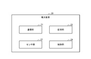
- FIG. 3 is a block diagram showing a schematic configuration of the power unit 20 of FIG.
- the power device 20 includes a communication unit 21, a sensor unit 22, a storage unit 23, and a control unit 24.
- the communication unit 21 may include a first interface that transmits and receives information and power with an external device. In the present embodiment, the communication unit 21 can transmit and receive information and power with the power storage device 10 via the first interface.
- the communication unit 21 may include a third interface that transmits and receives information to and from an external device via a communication network.
- the communication unit 21 may be connected to an external server via the third interface and the communication network to transmit and receive information regarding the charge and discharge history. According to this configuration, for example, when the amount of measurement data in the past is large and can not be stored in the storage unit 23 described later, it is possible to store at least a part of charge / discharge history information in the server It becomes.
- the sensor unit 22 includes one or more optional sensors or detection mechanisms.
- the sensor unit 22 may include a charge / discharge power sensor.
- the charge / discharge power sensor measures the current using, for example, a CT, and detects the charge / discharge power amount of the power storage device 10 connected via the communication unit 21.
- the charge / discharge power sensor may detect the amount of power sold at the time of power sale to the power device 20.
- the storage unit 23 includes one or more memories.
- the storage unit 23 may include a semiconductor memory, a magnetic memory, an optical memory, or the like.
- the storage unit 23 may function as, for example, a primary storage device or a secondary storage device.
- the storage unit 23 may store any information used for the operation of the power device 20.
- the control unit 24 includes one or more processors.
- the processor may include a general-purpose processor and a dedicated processor specialized for a specific process.
- the control unit 24 controls the overall operation of the power device 20. A specific example of the operation of the power device 20 will be described later.
- FIG. 4 is a block diagram showing a schematic configuration of the charging device 30 of FIG.
- the charging device 30 includes a communication unit 31, a sensor unit 32, a storage unit 33, and a control unit 34.
- the communication unit 31 may include a first interface that transmits and receives information and power with an external device.
- the communication unit 31 can transmit and receive information to and from the power storage device 10 through the first interface.
- Communication unit 31 can transmit power to power storage device 10 via the first interface.
- the communication unit 31 of the first charging device 30 a can transmit the power derived from the renewable energy to the storage device 10.
- the communication unit 31 of the second charging device 30 b can transmit the power derived from the depletable energy to the storage device 10.
- the communication unit 31 may include a third interface that transmits and receives information to and from an external device via a communication network.
- the communication unit 31 may be connected to an external server via the third interface and the communication network to transmit and receive information related to power.
- the communication unit 31 may obtain information such as real-time weather information or past power generation results from the server as information regarding power. Good.
- the charging device 30 gives priority to either the storage device 10 or the load device based on the information related to the power. Power can be distributed.
- Sensor portion 32 includes one or more optional sensors or sensing mechanisms.
- the sensor unit 32 may include a charge power sensor.
- the charge power sensor measures the current using, for example, a CT, and detects the amount of charge power of the power storage device 10 connected via the communication unit 31.
- the storage unit 33 includes one or more memories.
- the storage unit 33 may include a semiconductor memory, a magnetic memory, an optical memory, or the like.
- the storage unit 33 may function as, for example, a primary storage device or a secondary storage device.
- the storage unit 33 may store any information used for the operation of the charging device 30.
- Control unit 34 includes one or more processors.
- the processor may include a general-purpose processor and a dedicated processor specialized for a specific process.
- Control unit 34 controls the overall operation of charging device 30. For example, when charging storage device 10, control unit 34 may notify storage device 10 that charging device 30 that performs charging is either first charging device 30a or second charging device 30b.
- the mobile unit 40 shown in FIG. 1 includes one or more accessories, one or more processors, and an in-vehicle network.
- the accessory may include, for example, an air conditioner, a navigation device, and the like.
- the processor may include, for example, an ECU.
- the processor controls the operation of the mobile unit 40 as a whole. For example, the processor may use at least a portion of the regenerative power generated by the regenerative brake of the moving body 40 to charge the power storage device 10.
- the operations of power storage device 10 and power device 20 will be specifically described.
- the operation is an operation related to the sale of power from the storage device 10 to the power device 20.
- the control unit 15 of the power storage device 10 stores charge / discharge history information in the storage unit 14 each time charge / discharge of the power storage device 10 is performed, for example.
- the charge and discharge history information may include any history regarding charge and discharge of the power storage device 10.
- the charge / discharge history information includes a user ID, a power storage device ID, a date and time, a charge / discharge energy amount, an attribute, a remaining capacity, a first parameter, and a second parameter. Including.
- the user ID is information that can uniquely identify the user.
- the storage device ID is information that can uniquely identify the storage device ID as described above.
- the date is a time stamp at which charge and discharge of power storage device 10 were performed.
- control unit 15 may store the date and time when charge and discharge are completed in storage unit 14.
- the charge / discharge power amount is a charge / discharge power amount when charge / discharge of the power storage device 10 is performed.
- the charge energy is indicated by a positive value
- the discharge energy is indicated by a negative value.
- control unit 15 may store, in storage unit 14, the charge and discharge power amount detected using sensor unit 13.
- the charge / discharge power may be calculated in consideration of the discharge efficiency and the charge efficiency. In the following description, the charge efficiency and the discharge efficiency are assumed to be 1.0 for simplification, in the case of using specific numerical values of charge and discharge electric energy.
- the attribute is information indicating a device that has supplied the charging power to the power storage device 10 or a device that has the discharge power supplied by the power storage device 10.
- the attribute may indicate any of the power device 20, the first charging device 30a, the second charging device 30b, or the mobile object 40.
- control unit 15 may store the attribute as “power device” in storage unit 14.
- control unit 15 sets the first charging device 30 to charge the charging device 30 based on the notification acquired from charging device 30. It may be specified which of the device 30a and the second charging device 30b.
- the control unit 15 may store the attribute in the storage unit 14 as “first charging device” or “second charging device” according to the identification result of the charging device 30. For example, when charge / discharge of power storage device 10 is performed when power storage device 10 is not connected to either power device 20 or charging device 30, control unit 15 stores the attribute as “mobile” in storage unit 14. You may
- the remaining capacity is the remaining capacity of storage battery 11 when charging / discharging of power storage device 10 is completed.
- the control unit 15 may store the remaining capacity detected using the sensor unit 13 in the storage unit 14.
- the first parameter is a parameter corresponding to the amount of power derived from renewable energy among the remaining capacity of the storage battery 11.
- the control unit 15 may increase the first parameter in accordance with the amount of charge power from the first charging device 30a. For example, the control unit 15 may increase the first parameter by the charging power amount from the first charging device 30a.
- the second parameter is a parameter corresponding to the amount of power derived from the depletable energy out of the remaining capacity of the storage battery 11.
- the control unit 15 may increase the second parameter in accordance with the amount of charge power from the second charging device 30b. For example, the control unit 15 may increase the charging power amount from the second charging device 30b.
- the power storage device 10 can also be charged by the regenerative brake of the moving body 40.
- the control unit 15 increases the second parameter in accordance with the amount of charging power by the regenerative brake of the moving body 40.
- the control unit 15 may increase the second parameter by the charge output amount by the regenerative brake of the moving body 40.
- Such configuration is based on the concept described below. That is, the situation where only power derived from renewable energy is stored in power storage device 10 is relatively rare, and both power derived from renewable energy and power derived from depletable energy are stored in power storage device 10 It is highly probable. Therefore, mobile unit 40 can be considered to consume both the electric power derived from the renewable energy and the electric power derived from the depletable energy stored in power storage device 10.
- the regenerative brake is for recovering a part of the power consumed by the traveling of the moving body 40. Therefore, the charging power by the regenerative brake can be considered as part of the power derived from the depletable energy.
- the second parameter increases in accordance with the amount of charging power by the regenerative brake of the moving body 40. According to this configuration, among the remaining capacity of the storage battery 11, the accuracy of the first parameter corresponding to the electric energy derived from the renewable energy is improved.
- control unit 15 may increase the first parameter in accordance with the amount of charging power by the regenerative brake of the moving body 40.
- the regenerative brake is for recovering a part of the power consumed for traveling of the moving body 40.
- the power recovered by the regenerative brake is different from the power derived from depletable energy, for example, in that the generation of the power does not involve the emission of carbon dioxide.
- the charging power by the regenerative brake has a property closer to the power derived from the renewable energy than the power derived from the depletable energy.
- the first parameter increases in accordance with the amount of charging power by the regenerative brake of the moving body 40. Therefore, among the remaining capacity of storage battery 11, the accuracy of the second parameter corresponding to the amount of power derived from the depletable energy is improved.
- Control unit 15 may decrease the first parameter in accordance with the amount of power sold by power storage device 10 to power device 20.
- the control unit 15 may decrease the first parameter by the amount of power sold to the power device 20.
- Such a configuration corresponds to the preferential use of the power derived from the renewable energy in the sale of power from the storage device 10 to the power device 20.
- control unit 15 may decrease the total value of the first parameter and the second parameter according to the amount of discharged power.
- control unit 15 may preferentially reduce the second parameter over the first parameter.
- the first line of the charge and discharge history information indicates the initial state of the power storage device 10. Specifically, in the initial state, the remaining capacity of power storage device 10 is 0 kWh.
- the first parameter and the second parameter are each 0 point.
- the second line of the charge and discharge history information indicates that the power storage device 10 is charged with an electric energy of 30 kWh from the first charging device 30a at 8:28 July.
- the remaining capacity of power storage device 10 is increased from 0 kWh to 30 kWh. Since charging is performed by the first charging device 30a, the first parameter increases from 0 point to 30 points. On the other hand, the second parameter remains at 0 point.
- the third line of the charge and discharge history information indicates that the power storage device 10 discharges an electric energy of 5 kWh from the power storage device 10 to the moving body 40 at 9:28 July.
- the remaining capacity of power storage device 10 is reduced from 30 kWh to 25 kWh.
- the total value of the first parameter and the second parameter is reduced from 30 points to 25 points because of the discharge other than the power sale. Specifically, since the second parameter is 0 point, the first parameter is reduced from 30 points to 25 points. On the other hand, the second parameter remains at 0 point.
- the fourth line of the charge and discharge history information indicates that the electric storage device 10 is charged with an electric energy of 1 kWh at 9:01 on July 28 by the regenerative brake of the mobile unit 40.
- the remaining capacity of power storage device 10 is increased from 25 kWh to 26 kWh.
- the second parameter increases from 0 point to 1 point because charging is performed by the regenerative brake.
- the first parameter remains at 25 points.
- the fifth line of the charge and discharge history information indicates that 20 kWh of electric energy has been charged from the second charging device 30 b to the power storage device 10 at 10 o'clock on July 28.
- the remaining capacity of power storage device 10 is increased from 26 kWh to 46 kWh. Since the charging is performed by the second charging device 30b, the second parameter increases from 1 point to 21 points. On the other hand, the first parameter remains at 25 points.
- the sixth line of the charge and discharge history information indicates that the power storage device 10 has discharged a power amount of 5 kWh from the power storage device 10 to the moving body 40 at 11:28 July.
- the remaining capacity of power storage device 10 is reduced from 46 kWh to 41 kWh.
- the total value of the first parameter and the second parameter is reduced from 46 points to 41 points because of the discharge other than the power sale.
- the second parameter since the second parameter is larger than 0 point, the second parameter given priority to the first parameter is reduced from 21 points to 16 points. On the other hand, the second parameter remains at 25 points.
- the seventh line of the charge and discharge history information indicates that the electric storage device 10 is charged with an electric energy of 1 kWh by the regenerative brake of the mobile unit 40 at 11: 1 on July 28.
- the remaining capacity of power storage device 10 is increased from 41 kWh to 42 kWh.
- the second parameter increases from 16 points to 17 points because of charging by the regenerative brake.
- the first parameter remains at 25 points.
- the eighth line of the charge and discharge history information indicates that the power storage device 10 sold a power amount of 5 kWh to the power device 20 at 12:00 on July 28.
- the remaining capacity of power storage device 10 is reduced from 42 kWh to 37 kWh.
- the first parameter is reduced from 25 points to 20 points because of the sale of electricity to the power device 20.
- the second parameter remains at 17 points.
- control unit 15 controls power sale by power storage device 10 based on charge and discharge history information. Specifically, the control unit 15 may determine the upper limit power amount based on the first parameter included in the charge and discharge history information. For example, the control unit 15 may determine the upper limit power amount to a value equal to or less than the first parameter. The control unit 15 permits power sale up to the upper limit power amount. Specifically, the control unit 15 may end the power sale when the amount of power sold reaches the upper limit power amount after the start of the power sale. Control unit 15 may start selling electricity from power storage device 10 to power device 20. When the power sale ends, the control unit 24 of the power device 20 gives the user a reward according to the amount of power sale power.
- FIG. 6 is a sequence diagram showing the operation of the power storage device 10 and the power device 20 according to an embodiment of the present disclosure.
- Step S100 The power storage device 10 stores charge / discharge history information on charge / discharge of the power storage device 10.
- Step S101 The power storage device 10 determines the upper limit electric energy based on the first parameter of the charge and discharge history information.
- Step S102 The power storage device 10 permits power sale up to the upper limit electric energy.
- Step S103 The power storage device 10 starts selling electricity to the power device 20.
- Step S104 When the power sale ends, the power device 20 gives the user a reward according to the amount of power sale electricity.
- power storage device 10 controls power sale by power storage device 10 based on charge / discharge history information on charge / discharge of power storage device 10. According to this configuration, it is possible to sell electricity in consideration of the origin of the power stored in power storage device 10. Therefore, the convenience of the technology for selling power is improved.
- the charge and discharge history information may include a first parameter and a second parameter.
- the first parameter is increased according to the amount of charging power from the first charging device 30a that supplies power derived from renewable energy.
- the second parameter increases in accordance with the amount of charge power from the second charging device 30 b that supplies power derived from the depletable energy.
- Power storage device 10 may permit power sale up to the upper limit electric energy determined based on the first parameter.
- Such a configuration may correspond to permission of selling power only to power derived from renewable energy among power stored in power storage device 10. According to this configuration, it is possible to give the user a motivation to charge the power storage device 10 using the electric power derived from the renewable energy. Therefore, since the use of renewable energy derived power is promoted, the occurrence of adverse effects on the environment is reduced. Therefore, the convenience of the technology for selling power can be further improved.
- At least part of the operation of the power storage device 10 in the above-described embodiment may be performed by the power device 20.
- the above-described steps S100 to S102 may be performed by the power device 20 communicably connected to the power storage device 10.
- the power devices 20 in the above-described embodiment may be divided into a plurality of devices communicably connected to each other.
- at least one device that performs an operation of giving the user a reward according to the amount of power sold may be disposed in the facility where the power device 20 is installed. According to such a configuration, the user can be motivated to enter the facility to receive the reward. Therefore, it is possible to promote the activation of the economic activity of the user in the facility.
- FIG. 7 is a sequence diagram showing operations of power storage device 10 and power device 20 according to another embodiment of the present disclosure.
- Step S200 The power storage device 10 stores charge / discharge history information on charge / discharge of the power storage device 10.
- Step S201 The power storage device 10 permits the power sale by the power storage device 10 when the second parameter included in the charge / discharge history information is 0 point, and prohibits it when the second parameter is not 0 point. Here, it is assumed that power sale by the power storage device 10 is permitted.
- Step S202 The power storage device 10 starts selling electricity to the power device 20.
- Step S203 When the power sale ends, the power device 20 gives the user a reward according to the amount of power sale power.
- Steps S200 to S202 described above may be performed by the power device 20 communicably connected to the power storage device 10.
- the configuration has been described in which the first parameter is increased according to the amount of charging power by the first charging device 30a that supplies power derived from renewable energy.
- a configuration is also possible in which the first parameter is increased according to the amount of charging power by the first charging device 30a only for the specific first charging device 30a.
- the specific first charging device 30 a may be, for example, the first charging device 30 a associated with the user of the power storage device 10.
- the first charging device 30a associated with the user may be, for example, the first charging device 30a owned or rented by the user.
- the first charging device 30a may store the correspondence between the user and the first charging device 30a according to the user operation.
- the discharge power amount from the power storage device 10 to the moving body 40 and the charge power amount of the power storage device 10 by the regenerative brake of the moving body 40 are separately stored in charge / discharge history information. did.
- the amount of discharged power from power storage device 10 to moving body 40 and the amount of charged power of power storage device 10 by the regenerative brake of moving body 40 may be collectively stored in the charge and discharge history information.
- the amount of discharged power from the storage device 10 to the moving body 40 is larger than the amount of charging power of the storage device 10 by the regenerative brake of the moving body 40. Therefore, the remaining capacity of power storage device 10 at the end of movement of mobile unit 40 is smaller than the start time of movement of mobile unit 40. Therefore, the total value of the first parameter and the second parameter may decrease as described above according to the decrease amount of the remaining capacity of power storage device 10 before and after movement of moving body 40.
- the charging device 30 may be one device having the functions of both the first charging device 30a and the second charging device 30b.
- the charging device 30 may select and use the power derived from renewable energy or the power derived from depletable energy, for example, by performing optional processing such as switching inside the device and power measurement separately. it can.
- the charging device 30 supplies power derived from renewable energy as the first charging device 30a, and supplies power derived from depletable energy as the second charging device 30b when the supply of power derived from the renewable energy is stopped. Can.
- the charging device 30 may include a storage battery.
- the charging device 30 functions as the first charging device 30a that can supply the power derived from the renewable energy stored in the storage battery. Good.
- charge and discharge history information on charge and discharge of power storage device 10 may be stored in another device other than power storage device 10.
- Other devices may include, for example, a computer provided at the home of the user of power storage device 10, a storage device mounted on mobile unit 40, and a server connected to a communication network.
- the control unit 15 of the power storage device 10 transmits charge / discharge history information to the other device via the communication unit 12 each time charge / discharge of the power storage device 10 is performed, for example.
- the other device stores charge / discharge history information received from the power storage device 10.
Landscapes
- Engineering & Computer Science (AREA)
- Power Engineering (AREA)
- Business, Economics & Management (AREA)
- Health & Medical Sciences (AREA)
- Economics (AREA)
- Public Health (AREA)
- Water Supply & Treatment (AREA)
- General Health & Medical Sciences (AREA)
- Human Resources & Organizations (AREA)
- Marketing (AREA)
- Primary Health Care (AREA)
- Strategic Management (AREA)
- Tourism & Hospitality (AREA)
- Physics & Mathematics (AREA)
- General Business, Economics & Management (AREA)
- General Physics & Mathematics (AREA)
- Theoretical Computer Science (AREA)
- Charge And Discharge Circuits For Batteries Or The Like (AREA)
- Supply And Distribution Of Alternating Current (AREA)
- Management, Administration, Business Operations System, And Electronic Commerce (AREA)
Abstract
This power system comprises an electrical storage device and a power device. The power device is supplied with power from the electrical storage device. The electrical storage device or the power device, when the electrical storage device and the power device are connected, controls the supply of power received by the power device from the electrical storage device, on the basis of charging/discharging history information pertaining to the charging and discharging of the electrical storage device.
Description
本出願は、2017年8月30日に日本国に特許出願された特願2017-166071号の優先権を主張するものであり、この先の出願の開示全体をここに参照のために取り込む。
This application claims the priority of Japanese Patent Application No. 2017-166071 filed on Aug. 30, 2017, the entire disclosure of the prior application is incorporated herein by reference.
本開示は、電力システム、蓄電装置、および電力システムの制御方法に関する。
The present disclosure relates to a power system, a power storage device, and a control method of the power system.
従来、需要家施設から商用電源へ売電する技術が知られている。例えば特許文献1には、自家用蓄電装置から系統側に売電するエネルギーシステムが開示されている。
BACKGROUND Conventionally, technology for selling power from customer facilities to commercial power sources is known. For example, Patent Document 1 discloses an energy system in which a power storage device for private use is sold to the system side.
本開示の一実施形態に係る電力システムは、蓄電装置と、電力装置と、を備える。前記電力装置は、前記蓄電装置からの電力の供給を受け付ける。前記蓄電装置または前記電力装置は、前記蓄電装置と前記電力装置とが接続されると、前記電力装置が前記蓄電装置から受け付ける電力の供給を、前記蓄電装置の充放電に関する充放電履歴情報に基づいて制御する。
A power system according to an embodiment of the present disclosure includes a power storage device and a power device. The power device receives supply of power from the power storage device. When the power storage device and the power storage device are connected, the power storage device or the power storage device supplies power received by the power storage device from the power storage device based on charge / discharge history information on charge / discharge of the power storage device. Control.
本開示の一実施形態に係る蓄電装置は、電力装置に対して電力を供給する。前記蓄電装置は、制御部を備える。前記制御部は、前記電力装置と接続されると、前記電力装置が前記蓄電装置から受け付ける電力の供給を、前記蓄電装置の充放電に関する充放電履歴情報に基づいて制御する。
A power storage device according to an embodiment of the present disclosure supplies power to a power device. The power storage device includes a control unit. When connected to the power device, the control unit controls supply of power received by the power device from the power storage device based on charge / discharge history information on charge / discharge of the power storage device.
本開示の一実施形態に係る電力システムの制御方法は、蓄電装置と、電力装置と、を備える電力システムの制御方法である。前記電力装置は、前記蓄電装置から電力の供給を受け付ける。電力システムの制御方法は、前記蓄電装置または前記電力装置が、前記蓄電装置と前記電力装置とが接続されると、前記電力装置が前記蓄電装置から受け付ける電力の供給を、前記蓄電装置の充放電に関する充放電履歴情報に基づいて制御するステップを含む。
A control method of a power system according to an embodiment of the present disclosure is a control method of a power system including a power storage device and a power device. The power device receives supply of power from the power storage device. A control method of a power system includes charging and discharging of the storage device, the supply of power received by the storage device from the storage device when the storage device or the storage device is connected to the storage device and the storage device. Control based on charge / discharge history information related to
従来、電力を売電する技術の利便性の向上が望まれている。本開示は、電力を売電する技術の利便性を向上させる電力システム、蓄電装置、および電力システムの制御方法に関する。本開示の一実施形態に係る電力システム、蓄電装置、および電力システムの制御方法によれば、電力を売電する技術の利便性が向上する。以下、本開示の実施形態について、図面を参照して説明する。
Conventionally, it is desired to improve the convenience of the technology for selling power. The present disclosure relates to a power system, a storage device, and a control method of the power system, which improves the convenience of the technology of selling power. According to the power system, the power storage device, and the control method of the power system according to an embodiment of the present disclosure, the convenience of the technology of selling power is improved. Hereinafter, embodiments of the present disclosure will be described with reference to the drawings.
(電力システムの構成)
図1は、本開示の一実施形態に係る電力システム1の概略構成を示す図である。電力システム1は、蓄電装置10と、電力装置20と、充電装置30と、移動体40と、を含む。蓄電装置10、電力装置20、充電装置30、および移動体40それぞれの数は、任意に定められてもよい。 (Configuration of power system)
FIG. 1 is a diagram showing a schematic configuration of apower system 1 according to an embodiment of the present disclosure. Power system 1 includes a power storage device 10, a power device 20, a charging device 30, and a moving body 40. The numbers of power storage devices 10, power devices 20, charging devices 30, and moving bodies 40 may be arbitrarily determined.
図1は、本開示の一実施形態に係る電力システム1の概略構成を示す図である。電力システム1は、蓄電装置10と、電力装置20と、充電装置30と、移動体40と、を含む。蓄電装置10、電力装置20、充電装置30、および移動体40それぞれの数は、任意に定められてもよい。 (Configuration of power system)
FIG. 1 is a diagram showing a schematic configuration of a
蓄電装置10は、例えば需要者であるユーザによって利用される。蓄電装置10は、後述するように、例えばユーザの自宅または充電ステーション等に設置された充電装置30によって充電される。蓄電装置10は、ユーザの自宅に備えられた負荷機器に対して電力を供給してもよい。蓄電装置10は、可搬性を有する。本実施形態において、蓄電装置10は、後述する移動体40に搭載される。例えば、蓄電装置10から供給される電力が、移動体40によって消費されてもよい。具体的には、蓄電装置10から移動体40に供給される電力は、移動体40の移動および移動体40に搭載された補機の駆動等のために消費されてもよい。他の実施形態において、蓄電装置10は、ユーザによって携帯可能であってもよい。蓄電装置10の詳細については後述する。
Power storage device 10 is used, for example, by a user who is a consumer. Power storage device 10 is charged, for example, by a charging device 30 installed at the user's home or at a charging station, as described later. Power storage device 10 may supply power to load devices provided at the user's home. Power storage device 10 is portable. In the present embodiment, the power storage device 10 is mounted on a moving body 40 described later. For example, the power supplied from the power storage device 10 may be consumed by the mobile object 40. Specifically, the power supplied from storage device 10 to mobile unit 40 may be consumed for the movement of mobile unit 40 and the driving of accessories mounted on mobile unit 40. In another embodiment, power storage device 10 may be portable by a user. Details of power storage device 10 will be described later.
電力装置20は、任意の場所に設置されてもよい。例えば、電力装置20は、蓄電装置10のユーザの自宅以外の任意の施設に設置されてもよい。具体的には、電力装置20は、コンビニエンスストア、スーパーマーケット、デパート、レストラン、病院、または駐車場等の施設に設置されてもよい。電力装置20は、蓄電装置10からの電力の供給を受け付ける。後述するように、蓄電装置10から電力装置20に供給された電力量に応じた報酬がユーザに付与されてもよい。以下、蓄電装置10から電力装置20に電力が供給されることを、蓄電装置10による売電ともいう。本開示において「売電」は、金銭と引き換えに電力を供給すること、及び、電力自体を仮想的な通貨とみなして電力を供給すること等を含む。蓄電装置10から電力装置20に供給される電力量を、売電電力量ともいう。電力装置20は、蓄電装置10から売電された電力を、例えば電力装置20が設置された施設に備えられた負荷機器または蓄電池に供給してもよい。電力装置20は、蓄電装置10を充電する充電器として機能してもよい。かかる場合、電力装置20は、例えば商用電源または電力装置20が設置された施設に備えられた蓄電池から、蓄電装置10に電力を供給する。電力装置20の詳細については後述する。
The power device 20 may be installed at any place. For example, power device 20 may be installed in any facility other than the home of the user of power storage device 10. Specifically, the power device 20 may be installed in facilities such as a convenience store, a supermarket, a department store, a restaurant, a hospital, or a parking lot. Power device 20 receives the supply of power from power storage device 10. As described later, a reward according to the amount of power supplied from power storage device 10 to power device 20 may be provided to the user. Hereinafter, supply of power from the storage device 10 to the power device 20 is also referred to as selling power by the storage device 10. In the present disclosure, “power sale” includes supplying power in exchange for money, supplying power by regarding the power itself as a virtual currency, and the like. The amount of power supplied from power storage device 10 to power device 20 is also referred to as the amount of power sold. The power device 20 may supply the power sold from the power storage device 10 to, for example, a load device or a storage battery provided in a facility where the power device 20 is installed. Power device 20 may function as a charger for charging power storage device 10. In such a case, the power device 20 supplies power to the power storage device 10 from, for example, a commercial power source or a storage battery provided in a facility where the power device 20 is installed. The details of the power device 20 will be described later.
充電装置30は、例えば電力装置20の設置場所とは異なる任意の場所に設置されてもよい。例えば、充電装置30は、蓄電装置10のユーザの自宅または充電ステーション等の施設に設置されてもよい。充電装置30は、蓄電装置10を充電する充電器として機能する。充電装置30は、再生可能エネルギー由来または枯渇性エネルギー由来の電力を蓄電装置10に供給可能である。再生可能エネルギー由来の電力は、例えば太陽光、風力、水力、または地熱等のエネルギーを用いて発電される電力を含んでもよい。枯渇性エネルギー由来の電力は、例えば石油、石炭、または天然ガス等の化石エネルギーを用いて発電された電力を含んでもよい。以下、再生可能エネルギー由来の電力を供給する充電装置30を、第1充電装置30aともいう。例えば、太陽光発電装置に接続された充電装置30は、第1充電装置30aとして機能し得る。以下、枯渇性エネルギー由来の電力を供給する充電装置30を、第2充電装置30bともいう。例えば、枯渇性エネルギー由来の商用電源に接続された充電装置30は、第2充電装置30bとして機能し得る。後述するように、充電装置30によって蓄電装置10が充電されると、当該充電装置30が第1充電装置30aであるか第2充電装置30bであるかを識別可能な情報が、蓄電装置10に記憶される。充電装置30は、充電装置30に接続された任意の負荷機器に対して電力を供給してもよい。例えば、充電装置30および負荷機器が、蓄電装置10のユーザの自宅に設置されていてもよい。充電装置30は、EMS(Energy Management System)として機能してもよい。充電装置30は、蓄電装置10および負荷機器の少なくとも一方に電力を供給可能である。充電装置30は、例えば蓄電装置10が接続されていない状態において、負荷機器に電力を供給してもよい。充電装置30の詳細については後述する。
The charging device 30 may be installed at any place different from the installation place of the power device 20, for example. For example, charging device 30 may be installed at a home of a user of power storage device 10 or at a facility such as a charging station. Charging device 30 functions as a charger for charging power storage device 10. Charging device 30 can supply power storage device 10 with power derived from renewable energy or depletable energy. Electrical power from renewable energy may include, for example, electrical power generated using energy such as solar, wind, hydro or geothermal. The power from the depletable energy may include, for example, power generated using fossil energy such as petroleum, coal, or natural gas. Hereinafter, the charging device 30 that supplies power derived from renewable energy is also referred to as a first charging device 30a. For example, the charging device 30 connected to the solar power generation device can function as a first charging device 30a. Hereinafter, the charging device 30 that supplies power derived from the depletable energy is also referred to as a second charging device 30b. For example, the charging device 30 connected to the commercial power source derived from the depletable energy can function as a second charging device 30b. As will be described later, when the storage device 10 is charged by the charging device 30, information that can identify whether the charging device 30 is the first charging device 30a or the second charging device 30b is the storage device 10. It is memorized. The charging device 30 may supply power to any load device connected to the charging device 30. For example, charging device 30 and load device may be installed at the user's home of power storage device 10. The charging device 30 may function as an EMS (Energy Management System). The charging device 30 can supply power to at least one of the power storage device 10 and the load device. The charging device 30 may supply power to the load device, for example, in a state where the power storage device 10 is not connected. Details of the charging device 30 will be described later.
移動体40は、蓄電装置10を搭載する。移動体40は、移動可能な任意の装置を含んでもよい。移動体40は、移動するために蓄電装置10からの供給電力を、使用してもよいし、使用しなくてもよい。移動するために蓄電装置10からの供給電力を使用しない場合、移動体40は、単に蓄電装置10を運搬するために用いられてもよい。例えば、移動体40は、車両、歩行ロボット、および飛行装置等を含んでもよい。例えば、車両は、電気自動車、ハイブリッド電気自動車、ガソリン自動車、および自転車等を含んでもよい。例えば、飛行装置は、ドローンおよびマルチコプタ等を含んでもよい。移動体40は、ユーザによって運転または操縦されてもよい。移動体40の運転または操縦に関するユーザ操作の少なくとも一部が自動化されてもよい。移動体40は、ユーザ操作に拠らず、自律して移動可能であってもよい。本実施形態において、移動体40が、蓄電装置10からの供給電力を用いて移動する電気自動車である例について説明する。移動体40は、回生ブレーキによって生じる回生電力の少なくとも一部を、蓄電装置10の充電に使用してもよい。移動体40の詳細については後述する。
The moving body 40 mounts the power storage device 10. The mobile 40 may include any movable device. The moving body 40 may or may not use the power supplied from the power storage device 10 to move. When the power supplied from the storage device 10 is not used to move, the moving body 40 may be used merely to transport the storage device 10. For example, the moving body 40 may include a vehicle, a walking robot, a flight device, and the like. For example, the vehicles may include electric vehicles, hybrid electric vehicles, gasoline vehicles, bicycles, and the like. For example, the flight device may include a drone, a multicopter, and the like. The mobile 40 may be driven or steered by the user. At least a portion of the user's operation relating to driving or steering of the mobile 40 may be automated. The mobile unit 40 may be autonomously movable regardless of the user operation. In the present embodiment, an example will be described in which the moving body 40 is an electric vehicle that moves using power supplied from the power storage device 10. The moving body 40 may use at least a part of the regenerative power generated by the regenerative brake to charge the storage device 10. Details of the mobile unit 40 will be described later.
ユーザによる電力システム1の利用例について説明する。ユーザは、移動体40に搭載された蓄電装置10を、例えばユーザの自宅または充電ステーション等に備えられた充電装置30によって充電する。ユーザは、電力装置20が設置された施設まで移動体40で移動する。ユーザは、蓄電装置10と電力装置20とを接続して、蓄電装置10による売電を開始する。売電が終了すると、売電電力量に応じた報酬がユーザに付与される。ユーザに付与される報酬の内容は、任意に定められてもよい。例えば、報酬は、金銭、仮想通貨、および所定サービスに利用可能なポイント等を含んでもよい。例えば、報酬は、電力装置20が設置された施設におけるユーザの支払料金を減額する権利を含んでもよい。当該施設は、例えばレストランおよび電気量販店、ならびにそれらに関係する駐車場等の商業施設を含んでもよい。報酬の付与は、例えば報酬に相当するチケットを発券することによって実行されてもよい。報酬の付与は、報酬に相当する電子データをユーザの識別情報に対応付けて記憶することによって実行されてもよい。本実施形態において、報酬の付与は、電力装置20によって実行される。他の実施形態において、報酬の付与は、例えばインターネット等の通信ネットワークを介して電力装置20と通信可能な外部サーバが実行してもよい。例えば、ユーザがスマートフォンのアプリケーションで清算開始ボタンをクリックすると、外部サーバからの通信に応じて電力装置20は受電動作を終了する。電力装置20は、それまでに蓄電装置10から売電された電力の報酬を算出して外部サーバに送信する。外部サーバは、その報酬に相当する減額のバーコードまたはQRコード(登録商標)等のコード画像を作成してユーザのスマートフォンに送信する。ユーザは、例えば食事または商品購入の清算時に、スマートフォン上に表示させたコード画像を提示することで支払いの減額を受けることができる。
The usage example of the power system 1 by a user is demonstrated. The user charges the power storage device 10 mounted on the mobile unit 40, for example, by the charging device 30 provided at the user's home or at a charging station. The user moves with the mobile body 40 to the facility where the power device 20 is installed. The user connects the storage device 10 and the power device 20, and starts selling electricity by the storage device 10. When the sale of electricity ends, a reward according to the amount of sale of electricity is given to the user. The content of the reward given to the user may be arbitrarily determined. For example, the reward may include money, virtual currency, points available for a predetermined service, and the like. For example, the reward may include the right to reduce the user's payment fee at the facility where the power device 20 is installed. The facilities may include commercial facilities such as, for example, restaurants and electricity retailers, and the parking lots associated with them. The grant of the reward may be performed, for example, by issuing a ticket corresponding to the reward. The grant of the reward may be performed by storing electronic data corresponding to the reward in association with the identification information of the user. In the present embodiment, the provision of the reward is performed by the power device 20. In another embodiment, the reward may be provided by an external server that can communicate with the power device 20 via a communication network such as the Internet. For example, when the user clicks the settlement start button with the application of the smartphone, the power device 20 ends the power reception operation according to the communication from the external server. The power device 20 calculates the reward of the power sold by the power storage device 10 so far and transmits the calculated reward to the external server. The external server creates a code image such as a reduced barcode or QR code (registered trademark) corresponding to the reward and transmits it to the user's smartphone. The user can receive a reduction in payment by presenting a code image displayed on the smartphone, for example, at the time of clearing of a meal or a product purchase.
このように、電力システム1を利用するユーザは、例えば蓄電装置10に蓄積された電力を、電力装置20が設置された任意の場所において売電可能である。したがって、ユーザが売電可能な機会が増加するので、電力を売電する技術の利便性が向上する。また、蓄電装置10に蓄積される電力の利用が促進されるので、ユーザにとって当該電力の利用効率が向上する。また、ユーザに対して、電力装置20が設置された場所に移動する動機付けを与えることができる。このため、例えば当該場所におけるユーザの経済活動が活性化する。
Thus, a user who uses power system 1 can sell, for example, the power stored in power storage device 10 at any place where power device 20 is installed. Therefore, since the opportunity which a user can sell can increase, the convenience of the technique which sells electric power improves. In addition, since the use of the power stored in power storage device 10 is promoted, the use efficiency of the power for the user is improved. Also, the user can be motivated to move to the location where the power device 20 is installed. For this reason, for example, the economic activity of the user at the relevant place is activated.
(蓄電装置の構成)
図2は、図1の蓄電装置10の概略構成を示すブロック図である。本実施形態において、蓄電装置10は、蓄電池11と、通信部12と、センサ部13と、記憶部14と、制御部15と、を備える。他の実施形態において、蓄電池11、通信部12、センサ部13、記憶部14、および制御部15のうち少なくとも1つが、蓄電装置10が搭載される移動体40に備えられてもよい。 (Configuration of power storage device)
FIG. 2 is a block diagram showing a schematic configuration ofpower storage device 10 of FIG. In the present embodiment, the power storage device 10 includes a storage battery 11, a communication unit 12, a sensor unit 13, a storage unit 14, and a control unit 15. In another embodiment, at least one of the storage battery 11, the communication unit 12, the sensor unit 13, the storage unit 14, and the control unit 15 may be provided in the mobile object 40 in which the power storage device 10 is mounted.
図2は、図1の蓄電装置10の概略構成を示すブロック図である。本実施形態において、蓄電装置10は、蓄電池11と、通信部12と、センサ部13と、記憶部14と、制御部15と、を備える。他の実施形態において、蓄電池11、通信部12、センサ部13、記憶部14、および制御部15のうち少なくとも1つが、蓄電装置10が搭載される移動体40に備えられてもよい。 (Configuration of power storage device)
FIG. 2 is a block diagram showing a schematic configuration of
蓄電池11は、充放電が可能な任意の形式の電池を含む。例えば、蓄電池11は、鉛蓄電池、リチウムイオン電池、ニッケルカドミウム電池、およびニッケル水素電池等を含んでもよい。
The storage battery 11 includes any type of battery that can be charged and discharged. For example, the storage battery 11 may include a lead storage battery, a lithium ion battery, a nickel cadmium battery, a nickel hydrogen battery, and the like.
通信部12は、外部装置との間で情報および電力の送受信を行う第1インタフェースを含んでもよい。第1インタフェースは、蓄電池11の充放電方法に関する任意の規格に対応するモジュールおよびコネクタを含んでもよい。充放電方法に関する規格は、例えばCHAdeMO(登録商標)およびUSB(登録商標)等の規格を含んでもよい。本実施形態において通信部12は、第1インタフェースを介して、電力装置20および充電装置30それぞれとの間で情報および電力の送受信が可能である。通信部12は、外部装置との間で情報の送受信を行う第2インタフェースを含んでもよい。第2インタフェースは、有線または無線を介する任意の通信規格に対応する通信モジュールを含んでもよい。当該通信規格は、例えばCAN(Controller Area Network)等の車載ネットワークを介する通信規格を含んでもよい。本実施形態において通信部12は、第2インタフェースを介して、移動体40との間で情報の送受信が可能である。通信部12は、例えばインターネット等の通信ネットワークを介して外部装置との間で情報の送受信を行う第3インタフェースを含んでもよい。第3インタフェースは、例えば任意の無線通信規格に対応する通信モジュールを含んでもよい。通信部12は、第3インタフェースおよび通信ネットワークを介して、外部のサーバに接続して電力および位置に関する情報を送受信してもよい。通信部12は、サーバからより高度なサービス情報を受信してもよい。
The communication unit 12 may include a first interface that transmits and receives information and power to and from an external device. The first interface may include a module and a connector that correspond to any standard regarding the charge and discharge method of the storage battery 11. The standards for the charge and discharge method may include, for example, standards such as CHAdeMO (registered trademark) and USB (registered trademark). In the present embodiment, the communication unit 12 can transmit and receive information and power with each of the power device 20 and the charging device 30 via the first interface. The communication unit 12 may include a second interface that transmits and receives information to and from an external device. The second interface may include a communication module corresponding to any communication standard via wire or wireless. The communication standard may include, for example, a communication standard via an in-vehicle network such as CAN (Controller Area Network). In the present embodiment, the communication unit 12 can transmit and receive information with the mobile unit 40 via the second interface. The communication unit 12 may include, for example, a third interface that transmits and receives information to and from an external device via a communication network such as the Internet. The third interface may include, for example, a communication module corresponding to any wireless communication standard. The communication unit 12 may connect to an external server via the third interface and the communication network to transmit and receive information on power and position. The communication unit 12 may receive more advanced service information from the server.
センサ部13は、1つ以上の任意のセンサまたは検知機構を含む。例えば、センサ部13は、充放電電力センサと、残存容量センサと、を含んでもよい。充放電電力センサは、例えばCT(Current Transformer)を用いて電流を測定し、蓄電池11の充放電電力量を検出する。例えば、充放電電力センサは、電力装置20に対する売電時に売電電力量を検出してもよい。充放電電力センサは、充電装置30による充電時に充電電力量を検出してもよい。残存容量センサは、例えばCTを用いて蓄電池11の放電電流量と充電電流量を監視し、残存容量を検出する。残存容量の検出には、任意のアルゴリズムが採用可能である。例えば、残存容量の検出には、電流積算法または開放電圧法等の残存容量推定アルゴリズムが採用されてもよい。
The sensor unit 13 includes one or more optional sensors or detection mechanisms. For example, the sensor unit 13 may include a charge / discharge power sensor and a remaining capacity sensor. The charge / discharge power sensor measures the current using, for example, a CT (Current Transformer), and detects the charge / discharge power amount of the storage battery 11. For example, the charge / discharge power sensor may detect the amount of power sold at the time of power sale to the power device 20. The charge / discharge power sensor may detect the amount of charge power at the time of charging by the charging device 30. The remaining capacity sensor monitors the amount of discharge current and the amount of charging current of the storage battery 11 using, for example, a CT to detect the remaining capacity. Arbitrary algorithms can be employed to detect the remaining capacity. For example, for detection of the remaining capacity, a remaining capacity estimation algorithm such as a current integration method or an open-circuit voltage method may be employed.
記憶部14は、1つ以上のメモリを含む。例えば、記憶部14は、半導体メモリ、磁気メモリ、または光メモリ等を含んでもよい。記憶部14は、例えば一次記憶装置または二次記憶装置として機能してもよい。記憶部14は、蓄電装置10の動作に用いられる任意の情報を記憶してもよい。例えば、記憶部14は、蓄電装置10を一意に識別可能な蓄電装置IDを予め記憶してもよい。記憶部14は、後述する充放電履歴情報を記憶してもよい。
The storage unit 14 includes one or more memories. For example, the storage unit 14 may include a semiconductor memory, a magnetic memory, an optical memory, or the like. The storage unit 14 may function as, for example, a primary storage device or a secondary storage device. Storage unit 14 may store any information used for the operation of power storage device 10. For example, the storage unit 14 may store in advance a power storage device ID that can uniquely identify the power storage device 10. The storage unit 14 may store charge / discharge history information described later.
制御部15は、1つ以上のプロセッサを含む。プロセッサは、汎用のプロセッサ、および特定の処理に特化した専用プロセッサを含んでもよい。他の実施形態において、移動体40に備えられたECU(Electronic Control Unit)等のプロセッサが、制御部15として機能してもよい。制御部15は、蓄電装置10全体の動作を制御する。蓄電装置10の動作の具体例については後述する。
The control unit 15 includes one or more processors. The processor may include a general purpose processor and a dedicated processor specialized for a specific process. In another embodiment, a processor such as an ECU (Electronic Control Unit) provided in the moving body 40 may function as the control unit 15. Control unit 15 controls the overall operation of power storage device 10. A specific example of the operation of power storage device 10 will be described later.
(電力装置の構成)
図3は、図1の電力装置20の概略構成を示すブロック図である。本実施形態において、電力装置20は、通信部21と、センサ部22と、記憶部23と、制御部24と、を備える。 (Configuration of power device)
FIG. 3 is a block diagram showing a schematic configuration of thepower unit 20 of FIG. In the present embodiment, the power device 20 includes a communication unit 21, a sensor unit 22, a storage unit 23, and a control unit 24.
図3は、図1の電力装置20の概略構成を示すブロック図である。本実施形態において、電力装置20は、通信部21と、センサ部22と、記憶部23と、制御部24と、を備える。 (Configuration of power device)
FIG. 3 is a block diagram showing a schematic configuration of the
通信部21は、外部装置との間で情報および電力の送受信を行う第1インタフェースを含んでもよい。本実施形態において通信部21は、第1インタフェースを介して、蓄電装置10との間で情報および電力の送受信が可能である。通信部21は、通信ネットワークを介して外部装置との間で情報の送受信を行う第3インタフェースを含んでもよい。通信部21は、第3インタフェースおよび通信ネットワークを介して、外部のサーバに接続して充放電履歴に関する情報を送受信してもよい。かかる構成によれば、例えば、過去の測定データ量が多くなり、後述する記憶部23に収納し切れない場合などには、充放電履歴情報の少なくとも一部をサーバに保管しておくことが可能となる。
The communication unit 21 may include a first interface that transmits and receives information and power with an external device. In the present embodiment, the communication unit 21 can transmit and receive information and power with the power storage device 10 via the first interface. The communication unit 21 may include a third interface that transmits and receives information to and from an external device via a communication network. The communication unit 21 may be connected to an external server via the third interface and the communication network to transmit and receive information regarding the charge and discharge history. According to this configuration, for example, when the amount of measurement data in the past is large and can not be stored in the storage unit 23 described later, it is possible to store at least a part of charge / discharge history information in the server It becomes.
センサ部22は、1つ以上の任意のセンサまたは検知機構を含む。例えば、センサ部22は、充放電電力センサを含んでもよい。充放電電力センサは、例えばCTを用いて電流を測定し、通信部21を介して接続された蓄電装置10の充放電電力量を検出する。例えば、充放電電力センサは、電力装置20に対する売電時に売電電力量を検出してもよい。
The sensor unit 22 includes one or more optional sensors or detection mechanisms. For example, the sensor unit 22 may include a charge / discharge power sensor. The charge / discharge power sensor measures the current using, for example, a CT, and detects the charge / discharge power amount of the power storage device 10 connected via the communication unit 21. For example, the charge / discharge power sensor may detect the amount of power sold at the time of power sale to the power device 20.
記憶部23は、1つ以上のメモリを含む。例えば、記憶部23は、半導体メモリ、磁気メモリ、または光メモリ等を含んでもよい。記憶部23は、例えば一次記憶装置または二次記憶装置として機能してもよい。記憶部23は、電力装置20の動作に用いられる任意の情報を記憶してもよい。
The storage unit 23 includes one or more memories. For example, the storage unit 23 may include a semiconductor memory, a magnetic memory, an optical memory, or the like. The storage unit 23 may function as, for example, a primary storage device or a secondary storage device. The storage unit 23 may store any information used for the operation of the power device 20.
制御部24は、1つ以上のプロセッサを含む。プロセッサは、汎用のプロセッサ、及び特定の処理に特化した専用プロセッサを含んでもよい。制御部24は、電力装置20全体の動作を制御する。電力装置20の動作の具体例については後述する。
The control unit 24 includes one or more processors. The processor may include a general-purpose processor and a dedicated processor specialized for a specific process. The control unit 24 controls the overall operation of the power device 20. A specific example of the operation of the power device 20 will be described later.
(充電装置の構成)
図4は、図1の充電装置30の概略構成を示すブロック図である。充電装置30は、通信部31と、センサ部32と、記憶部33と、制御部34と、を備える。 (Configuration of charging device)
FIG. 4 is a block diagram showing a schematic configuration of the chargingdevice 30 of FIG. The charging device 30 includes a communication unit 31, a sensor unit 32, a storage unit 33, and a control unit 34.
図4は、図1の充電装置30の概略構成を示すブロック図である。充電装置30は、通信部31と、センサ部32と、記憶部33と、制御部34と、を備える。 (Configuration of charging device)
FIG. 4 is a block diagram showing a schematic configuration of the charging
通信部31は、外部装置との間で情報および電力の送受信を行う第1インタフェースを含んでもよい。本実施形態において通信部31は、第1インタフェースを介して、蓄電装置10との間で情報の送受信が可能である。通信部31は、第1インタフェースを介して、蓄電装置10に対する電力の送信が可能である。具体的には、第1充電装置30aの通信部31は、再生可能エネルギー由来の電力を蓄電装置10へ送信可能である。一方、第2充電装置30bの通信部31は、枯渇性エネルギー由来の電力を蓄電装置10へ送信可能である。通信部31は、通信ネットワークを介して外部装置との間で情報の送受信を行う第3インタフェースを含んでもよい。通信部31は、第3インタフェースおよび通信ネットワークを介して、外部のサーバに接続して電力に関する情報を送受信してもよい。例えば、通信部31は、充電装置30が太陽光発電装置および負荷装置に接続されている場合において、リアルタイムな気象情報または過去の発電実績等の情報を、電力に関する情報としてサーバから取得してもよい。かかる構成によれば、例えば充電装置30に蓄電装置10および負荷装置の両方が接続されている場合において、充電装置30は、電力に関する情報に基づいて、蓄電装置10と負荷装置のいずれかに優先的に電力を振り分けることができる。
The communication unit 31 may include a first interface that transmits and receives information and power with an external device. In the present embodiment, the communication unit 31 can transmit and receive information to and from the power storage device 10 through the first interface. Communication unit 31 can transmit power to power storage device 10 via the first interface. Specifically, the communication unit 31 of the first charging device 30 a can transmit the power derived from the renewable energy to the storage device 10. On the other hand, the communication unit 31 of the second charging device 30 b can transmit the power derived from the depletable energy to the storage device 10. The communication unit 31 may include a third interface that transmits and receives information to and from an external device via a communication network. The communication unit 31 may be connected to an external server via the third interface and the communication network to transmit and receive information related to power. For example, when the charging device 30 is connected to the solar power generation device and the load device, the communication unit 31 may obtain information such as real-time weather information or past power generation results from the server as information regarding power. Good. According to such a configuration, for example, in the case where both the storage device 10 and the load device are connected to the charging device 30, the charging device 30 gives priority to either the storage device 10 or the load device based on the information related to the power. Power can be distributed.
センサ部32は、1つ以上の任意のセンサまたは検知機構を含む。例えば、センサ部32は、充電電力センサを含んでもよい。充電電力センサは、例えばCTを用いて電流を測定し、通信部31を介して接続された蓄電装置10の充電電力量を検出する。
Sensor portion 32 includes one or more optional sensors or sensing mechanisms. For example, the sensor unit 32 may include a charge power sensor. The charge power sensor measures the current using, for example, a CT, and detects the amount of charge power of the power storage device 10 connected via the communication unit 31.
記憶部33は、1つ以上のメモリを含む。例えば、記憶部33は、半導体メモリ、磁気メモリ、または光メモリ等を含んでもよい。記憶部33は、例えば一次記憶装置または二次記憶装置として機能してもよい。記憶部33は、充電装置30の動作に用いられる任意の情報を記憶してもよい。
The storage unit 33 includes one or more memories. For example, the storage unit 33 may include a semiconductor memory, a magnetic memory, an optical memory, or the like. The storage unit 33 may function as, for example, a primary storage device or a secondary storage device. The storage unit 33 may store any information used for the operation of the charging device 30.
制御部34は、1つ以上のプロセッサを含む。プロセッサは、汎用のプロセッサ、及び特定の処理に特化した専用プロセッサを含んでもよい。制御部34は、充電装置30全体の動作を制御する。例えば、制御部34は、蓄電装置10の充電に際して、充電を実行する充電装置30が第1充電装置30aおよび第2充電装置30bのいずれであるかを蓄電装置10に通知してもよい。
Control unit 34 includes one or more processors. The processor may include a general-purpose processor and a dedicated processor specialized for a specific process. Control unit 34 controls the overall operation of charging device 30. For example, when charging storage device 10, control unit 34 may notify storage device 10 that charging device 30 that performs charging is either first charging device 30a or second charging device 30b.
(移動体の構成)
図1に示す移動体40は、1つ以上の補機と、1つ以上のプロセッサと、車載ネットワークと、を含む。補機は、例えば空調装置およびナビゲーション装置等を含んでもよい。プロセッサは、例えばECUを含んでもよい。プロセッサは、移動体40全体の動作を制御する。例えば、プロセッサは、移動体40の回生ブレーキによって生じる回生電力の少なくとも一部を、蓄電装置10の充電に使用してもよい。 (Configuration of mobile)
Themobile unit 40 shown in FIG. 1 includes one or more accessories, one or more processors, and an in-vehicle network. The accessory may include, for example, an air conditioner, a navigation device, and the like. The processor may include, for example, an ECU. The processor controls the operation of the mobile unit 40 as a whole. For example, the processor may use at least a portion of the regenerative power generated by the regenerative brake of the moving body 40 to charge the power storage device 10.
図1に示す移動体40は、1つ以上の補機と、1つ以上のプロセッサと、車載ネットワークと、を含む。補機は、例えば空調装置およびナビゲーション装置等を含んでもよい。プロセッサは、例えばECUを含んでもよい。プロセッサは、移動体40全体の動作を制御する。例えば、プロセッサは、移動体40の回生ブレーキによって生じる回生電力の少なくとも一部を、蓄電装置10の充電に使用してもよい。 (Configuration of mobile)
The
(蓄電装置および電力装置の動作)
蓄電装置10および電力装置20の動作について具体的に説明する。当該動作は、蓄電装置10から電力装置20に対する売電に関連する動作である。 (Operation of power storage device and power device)
The operations ofpower storage device 10 and power device 20 will be specifically described. The operation is an operation related to the sale of power from the storage device 10 to the power device 20.
蓄電装置10および電力装置20の動作について具体的に説明する。当該動作は、蓄電装置10から電力装置20に対する売電に関連する動作である。 (Operation of power storage device and power device)
The operations of
蓄電装置10の制御部15は、例えば蓄電装置10の充放電が実行される度に、充放電履歴情報を記憶部14に記憶する。充放電履歴情報は、蓄電装置10の充放電に関する任意の履歴を含んでもよい。例えば図5に示すように、充放電履歴情報は、ユーザIDと、蓄電装置IDと、日時と、充放電電力量と、属性と、残存容量と、第1パラメータと、第2パラメータと、を含む。
The control unit 15 of the power storage device 10 stores charge / discharge history information in the storage unit 14 each time charge / discharge of the power storage device 10 is performed, for example. The charge and discharge history information may include any history regarding charge and discharge of the power storage device 10. For example, as shown in FIG. 5, the charge / discharge history information includes a user ID, a power storage device ID, a date and time, a charge / discharge energy amount, an attribute, a remaining capacity, a first parameter, and a second parameter. Including.
ユーザIDは、ユーザを一意に識別可能な情報である。蓄電装置IDは、上述したように蓄電装置IDを一意に識別可能な情報である。
The user ID is information that can uniquely identify the user. The storage device ID is information that can uniquely identify the storage device ID as described above.
日時は、蓄電装置10の充放電が実行されたタイムスタンプである。制御部15は、例えば蓄電装置10の充放電が終了すると、充放電の終了した日時を記憶部14に記憶してもよい。
The date is a time stamp at which charge and discharge of power storage device 10 were performed. For example, when charge and discharge of power storage device 10 are completed, control unit 15 may store the date and time when charge and discharge are completed in storage unit 14.
充放電電力量は、蓄電装置10の充放電が実行されたときの充放電電力量である。図5において、充電電力量を正の数値で示し、放電電力量を負の数値で示す。制御部15は、例えば蓄電装置10の充放電が終了すると、センサ部13を用いて検出した充放電電力量を記憶部14に記憶してもよい。この際、放電効率および充電効率を考慮して、充放電電力量が算出されてもよい。以下の説明においては、具体的な充放電電力量の数値を用いて説明する場合、簡略化のため充電効率および放電効率は1.0であるものとして説明する。
The charge / discharge power amount is a charge / discharge power amount when charge / discharge of the power storage device 10 is performed. In FIG. 5, the charge energy is indicated by a positive value, and the discharge energy is indicated by a negative value. For example, when charge and discharge of power storage device 10 are completed, control unit 15 may store, in storage unit 14, the charge and discharge power amount detected using sensor unit 13. At this time, the charge / discharge power may be calculated in consideration of the discharge efficiency and the charge efficiency. In the following description, the charge efficiency and the discharge efficiency are assumed to be 1.0 for simplification, in the case of using specific numerical values of charge and discharge electric energy.
属性は、蓄電装置10に充電電力を供給した装置、または蓄電装置10が放電電力を供給した装置を示す情報である。例えば、属性は、電力装置20、第1充電装置30a、第2充電装置30b、または移動体40のいずれかを示してもよい。制御部15は、例えば蓄電装置10と電力装置20とが接続されているときに蓄電装置10の充放電が実行されると、属性を「電力装置」として記憶部14に記憶してもよい。制御部15は、例えば蓄電装置10と充電装置30とが接続されているときに蓄電装置10の充電が実行されると、充電装置30から取得する通知に基づいて、充電装置30が第1充電装置30aおよび第2充電装置30bのいずれであるかを特定してもよい。制御部15は、充電装置30の特定結果に応じて、属性を「第1充電装置」または「第2充電装置」として記憶部14に記憶してもよい。制御部15は、例えば蓄電装置10が電力装置20および充電装置30のいずれとも接続されていないときに蓄電装置10の充放電が実行されると、属性を「移動体」として記憶部14に記憶してもよい。
The attribute is information indicating a device that has supplied the charging power to the power storage device 10 or a device that has the discharge power supplied by the power storage device 10. For example, the attribute may indicate any of the power device 20, the first charging device 30a, the second charging device 30b, or the mobile object 40. For example, when charge and discharge of power storage device 10 are performed when power storage device 10 and power device 20 are connected, control unit 15 may store the attribute as “power device” in storage unit 14. For example, when charging of power storage device 10 is executed when power storage device 10 and charging device 30 are connected, control unit 15 sets the first charging device 30 to charge the charging device 30 based on the notification acquired from charging device 30. It may be specified which of the device 30a and the second charging device 30b. The control unit 15 may store the attribute in the storage unit 14 as “first charging device” or “second charging device” according to the identification result of the charging device 30. For example, when charge / discharge of power storage device 10 is performed when power storage device 10 is not connected to either power device 20 or charging device 30, control unit 15 stores the attribute as “mobile” in storage unit 14. You may
残存容量は、蓄電装置10の充放電が終了したときの蓄電池11の残存容量である。制御部15は、センサ部13を用いて検出した残存容量を記憶部14に記憶してもよい。
The remaining capacity is the remaining capacity of storage battery 11 when charging / discharging of power storage device 10 is completed. The control unit 15 may store the remaining capacity detected using the sensor unit 13 in the storage unit 14.
第1パラメータは、蓄電池11の残存容量のうち、再生可能エネルギー由来の電力量に相当するパラメータである。制御部15は、第1充電装置30aからの充電電力量に応じて第1パラメータを増加させてもよい。例えば、制御部15は、第1充電装置30aからの充電電力量だけ第1パラメータを増加させてもよい。
The first parameter is a parameter corresponding to the amount of power derived from renewable energy among the remaining capacity of the storage battery 11. The control unit 15 may increase the first parameter in accordance with the amount of charge power from the first charging device 30a. For example, the control unit 15 may increase the first parameter by the charging power amount from the first charging device 30a.
第2パラメータは、蓄電池11の残存容量のうち、枯渇性エネルギー由来の電力量に相当するパラメータである。制御部15は、第2充電装置30bからの充電電力量に応じて第2パラメータを増加させてもよい。例えば、制御部15は、第2充電装置30bからの充電電力量だけ増加してもよい。
The second parameter is a parameter corresponding to the amount of power derived from the depletable energy out of the remaining capacity of the storage battery 11. The control unit 15 may increase the second parameter in accordance with the amount of charge power from the second charging device 30b. For example, the control unit 15 may increase the charging power amount from the second charging device 30b.
上述したように、蓄電装置10は、移動体40の回生ブレーキによっても充電され得る。本実施形態において、制御部15は、移動体40の回生ブレーキによる充電電力量に応じて、第2パラメータを増加させる。例えば、制御部15は、移動体40の回生ブレーキによる充電出力量だけ第2パラメータを増加させてもよい。かかる構成は、次に説明する思想に基づく。すなわち、蓄電装置10に再生可能エネルギー由来の電力のみが蓄積されている状況は比較的稀であり、再生可能エネルギー由来の電力および枯渇性エネルギー由来の電力の両方が蓄電装置10に蓄積されている蓋然性が高い。したがって、移動体40は、蓄電装置10に蓄積された再生可能エネルギー由来の電力および枯渇性エネルギー由来の電力の両方を消費すると考えることができる。回生ブレーキは、移動体40の走行によって消費された電力の一部を回収するものである。このため、回生ブレーキによる充電電力は、枯渇性エネルギー由来の電力の一部と考えることができる。本実施形態では、移動体40の回生ブレーキによる充電電力量に応じて第2パラメータが増加する。かかる構成によれば、蓄電池11の残存容量のうち再生可能エネルギー由来の電力量に相当する第1パラメータの精度が向上する。
As described above, the power storage device 10 can also be charged by the regenerative brake of the moving body 40. In the present embodiment, the control unit 15 increases the second parameter in accordance with the amount of charging power by the regenerative brake of the moving body 40. For example, the control unit 15 may increase the second parameter by the charge output amount by the regenerative brake of the moving body 40. Such configuration is based on the concept described below. That is, the situation where only power derived from renewable energy is stored in power storage device 10 is relatively rare, and both power derived from renewable energy and power derived from depletable energy are stored in power storage device 10 It is highly probable. Therefore, mobile unit 40 can be considered to consume both the electric power derived from the renewable energy and the electric power derived from the depletable energy stored in power storage device 10. The regenerative brake is for recovering a part of the power consumed by the traveling of the moving body 40. Therefore, the charging power by the regenerative brake can be considered as part of the power derived from the depletable energy. In the present embodiment, the second parameter increases in accordance with the amount of charging power by the regenerative brake of the moving body 40. According to this configuration, among the remaining capacity of the storage battery 11, the accuracy of the first parameter corresponding to the electric energy derived from the renewable energy is improved.
他の実施形態において、制御部15は、移動体40の回生ブレーキによる充電電力量に応じて、第1パラメータを増加させてもよい。かかる構成は、次に説明する思想に基づく。すなわち、回生ブレーキは、上述したように移動体40の走行のために消費された電力の一部を回収するものである。回生ブレーキによって回収される電力は、例えば電力の生成に二酸化炭素の排出を伴わない点で、枯渇性エネルギー由来の電力と相違する。このため、回生ブレーキによる充電電力は、枯渇性エネルギー由来の電力よりも、再生可能エネルギー由来の電力に近い性質を有すると考えることができる。他の実施形態では、移動体40の回生ブレーキによる充電電力量に応じて第1パラメータが増加する。このため、蓄電池11の残存容量のうち枯渇性エネルギー由来の電力量に相当する第2パラメータの精度が向上する。
In another embodiment, the control unit 15 may increase the first parameter in accordance with the amount of charging power by the regenerative brake of the moving body 40. Such configuration is based on the concept described below. That is, as described above, the regenerative brake is for recovering a part of the power consumed for traveling of the moving body 40. The power recovered by the regenerative brake is different from the power derived from depletable energy, for example, in that the generation of the power does not involve the emission of carbon dioxide. For this reason, it can be considered that the charging power by the regenerative brake has a property closer to the power derived from the renewable energy than the power derived from the depletable energy. In another embodiment, the first parameter increases in accordance with the amount of charging power by the regenerative brake of the moving body 40. Therefore, among the remaining capacity of storage battery 11, the accuracy of the second parameter corresponding to the amount of power derived from the depletable energy is improved.
制御部15は、蓄電装置10から電力装置20に対する売電電力量に応じて第1パラメータを減少させてもよい。例えば、制御部15は、電力装置20に対する売電電力量だけ第1パラメータを減少させてもよい。かかる構成は、蓄電装置10から電力装置20に対する売電において、再生可能エネルギー由来の電力が優先的に用いられることに相当する。
Control unit 15 may decrease the first parameter in accordance with the amount of power sold by power storage device 10 to power device 20. For example, the control unit 15 may decrease the first parameter by the amount of power sold to the power device 20. Such a configuration corresponds to the preferential use of the power derived from the renewable energy in the sale of power from the storage device 10 to the power device 20.
制御部15は、蓄電装置10が電力装置20に対する売電以外で放電すると、放電電力量に応じて第1パラメータおよび第2パラメータの合計値を減少させてもよい。第1パラメータおよび第2パラメータの合計値を減少させる際、制御部15は、例えば第2パラメータがゼロよりも大きい場合、第1パラメータよりも第2パラメータを優先的に減少させてもよい。かかる構成は、蓄電装置10から電力装置20に対する売電以外の放電において、枯渇性エネルギー由来の電力が優先的に用いられることに相当する。
When power storage device 10 discharges other than selling power to power device 20, control unit 15 may decrease the total value of the first parameter and the second parameter according to the amount of discharged power. When reducing the total value of the first parameter and the second parameter, for example, when the second parameter is larger than zero, the control unit 15 may preferentially reduce the second parameter over the first parameter. Such a configuration corresponds to the preferential use of the power derived from the depletable energy in the discharge other than the sale of power from storage device 10 to power device 20.
図5の充放電履歴情報によって示される具体的内容について説明する。充放電履歴情報の説明において、各電力量の値は、説明のための仮の数値であって、実際の数値と必ずしも一致しない。
Specific contents indicated by the charge and discharge history information of FIG. 5 will be described. In the description of the charge and discharge history information, the value of each power amount is a temporary numerical value for explanation and does not necessarily match the actual numerical value.
充放電履歴情報の1行目は、蓄電装置10の初期状態を示す。具体的には、初期状態において、蓄電装置10の残存容量は0kWhである。第1パラメータおよび第2パラメータは、それぞれ0ポイントである。
The first line of the charge and discharge history information indicates the initial state of the power storage device 10. Specifically, in the initial state, the remaining capacity of power storage device 10 is 0 kWh. The first parameter and the second parameter are each 0 point.
充放電履歴情報の2行目は、7月28日8時に、第1充電装置30aから蓄電装置10に30kWhの電力量が充電されたことを示す。蓄電装置10の残存容量は、0kWhから30kWhに増加している。第1充電装置30aによる充電であるため、第1パラメータが0ポイントから30ポイントに増加している。一方、第2パラメータは0ポイントのままである。
The second line of the charge and discharge history information indicates that the power storage device 10 is charged with an electric energy of 30 kWh from the first charging device 30a at 8:28 July. The remaining capacity of power storage device 10 is increased from 0 kWh to 30 kWh. Since charging is performed by the first charging device 30a, the first parameter increases from 0 point to 30 points. On the other hand, the second parameter remains at 0 point.
充放電履歴情報の3行目は、7月28日9時に、蓄電装置10から移動体40に5kWhの電力量が放電されたことを示す。蓄電装置10の残存容量は、30kWhから25kWhに減少している。売電以外の放電であるため、第1パラメータおよび第2パラメータの合計値が30ポイントから25ポイントに減少している。詳細には、第2パラメータが0ポイントであるため、第1パラメータが30ポイントから25ポイントに減少している。一方、第2パラメータは0ポイントのままである。
The third line of the charge and discharge history information indicates that the power storage device 10 discharges an electric energy of 5 kWh from the power storage device 10 to the moving body 40 at 9:28 July. The remaining capacity of power storage device 10 is reduced from 30 kWh to 25 kWh. The total value of the first parameter and the second parameter is reduced from 30 points to 25 points because of the discharge other than the power sale. Specifically, since the second parameter is 0 point, the first parameter is reduced from 30 points to 25 points. On the other hand, the second parameter remains at 0 point.
充放電履歴情報の4行目は、7月28日9時1分に、移動体40の回生ブレーキによって蓄電装置10に1kWhの電力量が充電されたことを示す。蓄電装置10の残存容量は、25kWhから26kWhに増加している。回生ブレーキによる充電であるため、第2パラメータが0ポイントから1ポイントに増加している。一方、第1パラメータは25ポイントのままである。
The fourth line of the charge and discharge history information indicates that the electric storage device 10 is charged with an electric energy of 1 kWh at 9:01 on July 28 by the regenerative brake of the mobile unit 40. The remaining capacity of power storage device 10 is increased from 25 kWh to 26 kWh. The second parameter increases from 0 point to 1 point because charging is performed by the regenerative brake. On the other hand, the first parameter remains at 25 points.
充放電履歴情報の5行目は、7月28日10時に、第2充電装置30bから蓄電装置10に20kWhの電力量が充電されたことを示す。蓄電装置10の残存容量は、26kWhから46kWhに増加している。第2充電装置30bによる充電であるため、第2パラメータが1ポイントから21ポイントに増加している。一方、第1パラメータは25ポイントのままである。
The fifth line of the charge and discharge history information indicates that 20 kWh of electric energy has been charged from the second charging device 30 b to the power storage device 10 at 10 o'clock on July 28. The remaining capacity of power storage device 10 is increased from 26 kWh to 46 kWh. Since the charging is performed by the second charging device 30b, the second parameter increases from 1 point to 21 points. On the other hand, the first parameter remains at 25 points.
充放電履歴情報の6行目は、7月28日11時に、蓄電装置10から移動体40に5kWhの電力量が放電されたことを示す。蓄電装置10の残存容量は、46kWhから41kWhに減少している。売電以外の放電であるため、第1パラメータおよび第2パラメータの合計値が46ポイントから41ポイントに減少している。詳細には、第2パラメータが0ポイントよりも大きいため、第1パラメータに優先される第2パラメータが21ポイントから16ポイントに減少している。一方、第2パラメータは25ポイントのままである。
The sixth line of the charge and discharge history information indicates that the power storage device 10 has discharged a power amount of 5 kWh from the power storage device 10 to the moving body 40 at 11:28 July. The remaining capacity of power storage device 10 is reduced from 46 kWh to 41 kWh. The total value of the first parameter and the second parameter is reduced from 46 points to 41 points because of the discharge other than the power sale. In detail, since the second parameter is larger than 0 point, the second parameter given priority to the first parameter is reduced from 21 points to 16 points. On the other hand, the second parameter remains at 25 points.
充放電履歴情報の7行目は、7月28日11時1分に、移動体40の回生ブレーキによって蓄電装置10に1kWhの電力量が充電されたことを示す。蓄電装置10の残存容量は、41kWhから42kWhに増加している。回生ブレーキによる充電であるため、第2パラメータが16ポイントから17ポイントに増加している。一方、第1パラメータは25ポイントのままである。
The seventh line of the charge and discharge history information indicates that the electric storage device 10 is charged with an electric energy of 1 kWh by the regenerative brake of the mobile unit 40 at 11: 1 on July 28. The remaining capacity of power storage device 10 is increased from 41 kWh to 42 kWh. The second parameter increases from 16 points to 17 points because of charging by the regenerative brake. On the other hand, the first parameter remains at 25 points.
充放電履歴情報の8行目は、7月28日12時に、蓄電装置10から電力装置20に対して5kWhの電力量が売電されたことを示す。蓄電装置10の残存容量は、42kWhから37kWhに減少している。電力装置20に対する売電であるため、第1パラメータが25ポイントから20ポイントに減少している。一方、第2パラメータは17ポイントのままである。
The eighth line of the charge and discharge history information indicates that the power storage device 10 sold a power amount of 5 kWh to the power device 20 at 12:00 on July 28. The remaining capacity of power storage device 10 is reduced from 42 kWh to 37 kWh. The first parameter is reduced from 25 points to 20 points because of the sale of electricity to the power device 20. On the other hand, the second parameter remains at 17 points.
蓄電装置10と電力装置20とが通信可能に接続されると、制御部15は、蓄電装置10による売電を、充放電履歴情報に基づいて制御する。具体的には、制御部15は、充放電履歴情報に含まれる第1パラメータに基づいて、上限電力量を決定してもよい。例えば、制御部15は、上限電力量を第1パラメータ以下の値に決定してもよい。制御部15は、上限電力量まで売電を許可する。具体的には、制御部15は、売電の開始後に売電電力量が上限電力量に達すると、売電を終了してもよい。制御部15は、蓄電装置10から電力装置20に対する売電を開始してもよい。売電が終了すると、電力装置20の制御部24は、売電電力量に応じた報酬をユーザに付与する。
When power storage device 10 and power device 20 are communicably connected, control unit 15 controls power sale by power storage device 10 based on charge and discharge history information. Specifically, the control unit 15 may determine the upper limit power amount based on the first parameter included in the charge and discharge history information. For example, the control unit 15 may determine the upper limit power amount to a value equal to or less than the first parameter. The control unit 15 permits power sale up to the upper limit power amount. Specifically, the control unit 15 may end the power sale when the amount of power sold reaches the upper limit power amount after the start of the power sale. Control unit 15 may start selling electricity from power storage device 10 to power device 20. When the power sale ends, the control unit 24 of the power device 20 gives the user a reward according to the amount of power sale power.
図6本開示の一実施形態に係る蓄電装置10および電力装置20の動作を示すシーケンス図である。
6 is a sequence diagram showing the operation of the power storage device 10 and the power device 20 according to an embodiment of the present disclosure.
ステップS100:蓄電装置10は、蓄電装置10の充放電に関する充放電履歴情報を記憶する。
Step S100: The power storage device 10 stores charge / discharge history information on charge / discharge of the power storage device 10.
ステップS101:蓄電装置10は、充放電履歴情報の第1パラメータに基づいて、上限電力量を決定する。
Step S101: The power storage device 10 determines the upper limit electric energy based on the first parameter of the charge and discharge history information.
ステップS102:蓄電装置10は、上限電力量まで売電を許可する。
Step S102: The power storage device 10 permits power sale up to the upper limit electric energy.
ステップS103:蓄電装置10は、電力装置20に対する売電を開始する。
Step S103: The power storage device 10 starts selling electricity to the power device 20.
ステップS104:電力装置20は、売電が終了すると、売電電力量に応じた報酬をユーザに付与する。
Step S104: When the power sale ends, the power device 20 gives the user a reward according to the amount of power sale electricity.
以上述べたように、電力システム1において、蓄電装置10は、蓄電装置10の充放電に関する充放電履歴情報に基づいて、蓄電装置10による売電を制御する。かかる構成によれば、蓄電装置10に蓄積された電力の由来を考慮した売電が可能となる。したがって、電力を売電する技術の利便性が向上する。
As described above, in power system 1, power storage device 10 controls power sale by power storage device 10 based on charge / discharge history information on charge / discharge of power storage device 10. According to this configuration, it is possible to sell electricity in consideration of the origin of the power stored in power storage device 10. Therefore, the convenience of the technology for selling power is improved.
例えば、充放電履歴情報は、第1パラメータと、第2パタメータと、を含んでもよい。当該第1パラメータは、再生可能エネルギー由来の電力を供給する第1充電装置30aからの充電電力量に応じて増加する。当該第2パラメータは、枯渇性エネルギー由来の電力を供給する第2充電装置30bからの充電電力量に応じて増加する。蓄電装置10は、第1パラメータに基づいて決定される上限電力量まで売電を許可してもよい。かかる構成は、蓄電装置10に蓄積された電力のうち、再生可能エネルギー由来の電力に限り売電が許可されることに相当し得る。かかる構成によれば、ユーザに対して、再生可能エネルギー由来の電力を用いて蓄電装置10を充電する動機付けを与えることができる。したがって、再生可能エネルギー由来の電力の利用が促進されるので、環境に対する悪影響の発生が低減される。このため、電力を売電する技術の利便性が更に向上する。
For example, the charge and discharge history information may include a first parameter and a second parameter. The first parameter is increased according to the amount of charging power from the first charging device 30a that supplies power derived from renewable energy. The second parameter increases in accordance with the amount of charge power from the second charging device 30 b that supplies power derived from the depletable energy. Power storage device 10 may permit power sale up to the upper limit electric energy determined based on the first parameter. Such a configuration may correspond to permission of selling power only to power derived from renewable energy among power stored in power storage device 10. According to this configuration, it is possible to give the user a motivation to charge the power storage device 10 using the electric power derived from the renewable energy. Therefore, since the use of renewable energy derived power is promoted, the occurrence of adverse effects on the environment is reduced. Therefore, the convenience of the technology for selling power can be further improved.
本開示を諸図面および実施形態に基づき説明してきたが、当業者であれば本開示に基づき種々の変形および修正を行うことが容易であることに注意されたい。したがって、これらの変形および修正は本開示の範囲に含まれることに留意されたい。例えば、各手段、または各ステップ等に含まれる機能等は論理的に矛盾しないように再配置可能である。複数の手段またはステップ等を1つに組み合わせたり、あるいは分割したりすることが可能である。
Although the present disclosure has been described based on the drawings and embodiments, it should be noted that those skilled in the art can easily make various changes and modifications based on the present disclosure. Therefore, it should be noted that these variations and modifications are included in the scope of the present disclosure. For example, the respective means or the functions included in the respective steps can be rearranged so as not to be logically contradictory. It is possible to combine or divide a plurality of means or steps into one.
例えば、上述した実施形態における蓄電装置10の動作の少なくとも一部が、電力装置20によって実行されてもよい。例えば、上述したステップS100-S102は、蓄電装置10と通信可能に接続された電力装置20によって実行されてもよい。
For example, at least part of the operation of the power storage device 10 in the above-described embodiment may be performed by the power device 20. For example, the above-described steps S100 to S102 may be performed by the power device 20 communicably connected to the power storage device 10.
例えば、上述した実施形態における電力装置20が、互いに通信可能に接続された複数の装置に分割されてもよい。複数の装置のうち、例えば売電電力量に応じた報酬をユーザに付与する動作を実行する少なくとも1つの装置が、電力装置20が設置された施設内に配置されてもよい。かかる構成によれば、ユーザに対して、報酬を受け取るために施設に入場する動機付けを与えることができる。したがって、当該施設におけるユーザの経済活動の活性化を促進可能である。
For example, the power devices 20 in the above-described embodiment may be divided into a plurality of devices communicably connected to each other. For example, among the plurality of devices, at least one device that performs an operation of giving the user a reward according to the amount of power sold may be disposed in the facility where the power device 20 is installed. According to such a configuration, the user can be motivated to enter the facility to receive the reward. Therefore, it is possible to promote the activation of the economic activity of the user in the facility.
上述した実施形態において、充放電履歴情報に基づいて蓄電装置10による売電を制御する手法として、充放電履歴情報に含まれる第1パラメータに基づいて決定される上限電力量まで売電が許可される構成について説明した。充放電履歴情報に基づいて売電を制御する手法は、上述した実施形態に限られない。他の実施形態において、例えば蓄電装置10の制御部15は、充放電履歴情報に含まれる第2パラメータが0ポイントである場合に蓄電装置10による売電を許可してもよい。制御部15は、充放電履歴情報に含まれる第2パラメータが0ポイントでない場合に蓄電装置10に蓄電装置10による売電を禁止してもよい。
図7は、本開示の他の実施形態に係る蓄電装置10および電力装置20の動作を示すシーケンス図である。 In the embodiment described above, as a method of controlling power sale bypower storage device 10 based on charge and discharge history information, sale of power is permitted up to the upper limit electric energy determined based on the first parameter included in charge and discharge history information. Configuration has been described. The method of controlling the power sale based on the charge and discharge history information is not limited to the embodiment described above. In another embodiment, for example, the control unit 15 of the power storage device 10 may allow the power storage device 10 to sell electricity when the second parameter included in the charge and discharge history information is 0 point. Control unit 15 may prohibit power storage device 10 from selling electricity by power storage device 10 when the second parameter included in the charge / discharge history information is not 0 points.
FIG. 7 is a sequence diagram showing operations ofpower storage device 10 and power device 20 according to another embodiment of the present disclosure.
図7は、本開示の他の実施形態に係る蓄電装置10および電力装置20の動作を示すシーケンス図である。 In the embodiment described above, as a method of controlling power sale by
FIG. 7 is a sequence diagram showing operations of
ステップS200:蓄電装置10は、蓄電装置10の充放電に関する充放電履歴情報を記憶する。
Step S200: The power storage device 10 stores charge / discharge history information on charge / discharge of the power storage device 10.
ステップS201:蓄電装置10は、蓄電装置10による売電を、充放電履歴情報に含まれる第2パラメータが0ポイントである場合に許可し、第2パラメータが0ポイントでない場合に禁止する。ここでは、蓄電装置10による売電が許可されたものとする。
Step S201: The power storage device 10 permits the power sale by the power storage device 10 when the second parameter included in the charge / discharge history information is 0 point, and prohibits it when the second parameter is not 0 point. Here, it is assumed that power sale by the power storage device 10 is permitted.
ステップS202:蓄電装置10は、電力装置20に対する売電を開始する。
Step S202: The power storage device 10 starts selling electricity to the power device 20.
ステップS203:電力装置20は、売電が終了すると、売電電力量に応じた報酬をユーザに付与する。
Step S203: When the power sale ends, the power device 20 gives the user a reward according to the amount of power sale power.
上述したステップS200-S202は、蓄電装置10と通信可能に接続された電力装置20によって実行されてもよい。
Steps S200 to S202 described above may be performed by the power device 20 communicably connected to the power storage device 10.
上述した実施形態において、再生可能エネルギー由来の電力を供給する第1充電装置30aによる充電電力量に応じて第1パラメータが増加する構成について説明した。他の実施形態において、特定の第1充電装置30aに限り、第1充電装置30aによる充電電力量に応じて第1パラメータが増加する構成も可能である。特定の第1充電装置30aは、例えば、蓄電装置10のユーザに対応付けられた第1充電装置30aであってもよい。ユーザに対応付けられた第1充電装置30aは、例えば、ユーザによって所有されまたは借りられている第1充電装置30aであってもよい。例えば、第1充電装置30aは、ユーザによって所有されまたは借りられたときに、ユーザ操作に応じてユーザと第1充電装置30aとの対応関係を記憶してもよい。かかる構成によれば、ユーザに対して、第1充電装置30aを所有するまたは借りる動機付けを与えることができる。したがって、再生可能エネルギー由来の電力の利用が促進されるので、環境に対する悪影響の発生が低減される。このため、電力を売電する技術の利便性が更に向上する。
In the embodiment described above, the configuration has been described in which the first parameter is increased according to the amount of charging power by the first charging device 30a that supplies power derived from renewable energy. In another embodiment, a configuration is also possible in which the first parameter is increased according to the amount of charging power by the first charging device 30a only for the specific first charging device 30a. The specific first charging device 30 a may be, for example, the first charging device 30 a associated with the user of the power storage device 10. The first charging device 30a associated with the user may be, for example, the first charging device 30a owned or rented by the user. For example, when the first charging device 30a is owned or borrowed by the user, the first charging device 30a may store the correspondence between the user and the first charging device 30a according to the user operation. According to such a configuration, it is possible to give the user a motivation to own or rent the first charging device 30a. Therefore, since the use of renewable energy derived power is promoted, the occurrence of adverse effects on the environment is reduced. Therefore, the convenience of the technology for selling power can be further improved.
上述した実施形態において、蓄電装置10から移動体40への放電電力量と、移動体40の回生ブレーキによる蓄電装置10の充電電力量と、が別々に充放電履歴情報に蓄積される構成について説明した。他の実施形態において、蓄電装置10から移動体40への放電電力量と、移動体40の回生ブレーキによる蓄電装置10の充電電力量と、が纏めて充放電履歴情報に蓄積されてもよい。一般的に、蓄電装置10から移動体40への放電電力量は、移動体40の回生ブレーキによる蓄電装置10の充電電力量よりも大きい。このため、移動体40の移動の終了時点における蓄電装置10の残存容量は、移動体40の移動の開始時点よりも小さい。よって、移動体40の移動前後における蓄電装置10の残存容量の減少量に応じて、上述したように第1パラメータおよび第2パラメータの合計値が減少してもよい。
In the embodiment described above, a configuration is described in which the discharge power amount from the power storage device 10 to the moving body 40 and the charge power amount of the power storage device 10 by the regenerative brake of the moving body 40 are separately stored in charge / discharge history information. did. In another embodiment, the amount of discharged power from power storage device 10 to moving body 40 and the amount of charged power of power storage device 10 by the regenerative brake of moving body 40 may be collectively stored in the charge and discharge history information. In general, the amount of discharged power from the storage device 10 to the moving body 40 is larger than the amount of charging power of the storage device 10 by the regenerative brake of the moving body 40. Therefore, the remaining capacity of power storage device 10 at the end of movement of mobile unit 40 is smaller than the start time of movement of mobile unit 40. Therefore, the total value of the first parameter and the second parameter may decrease as described above according to the decrease amount of the remaining capacity of power storage device 10 before and after movement of moving body 40.
他の実施形態において、充電装置30は、第1充電装置30aと第2充電装置30bの両方の機能を有した1つの装置であってもよい。かかる充電装置30は、例えば、装置内部の切り替えおよび電力測定等の任意の処理が分離して行われることによって、再生可能エネルギー由来の電力または枯渇性エネルギー由来の電力を選択して使用することができる。充電装置30は、第1充電装置30aとして再生可能エネルギー由来の電力を供給し、再生可能エネルギー由来の電力の供給が停止した場合、第2充電装置30bとして枯渇性エネルギー由来の電力を供給することができる。
In another embodiment, the charging device 30 may be one device having the functions of both the first charging device 30a and the second charging device 30b. The charging device 30 may select and use the power derived from renewable energy or the power derived from depletable energy, for example, by performing optional processing such as switching inside the device and power measurement separately. it can. The charging device 30 supplies power derived from renewable energy as the first charging device 30a, and supplies power derived from depletable energy as the second charging device 30b when the supply of power derived from the renewable energy is stopped. Can.
他の実施形態において、充電装置30が蓄電池を備えていてもよい。例えば、充電装置30は、再生可能エネルギー由来の電力のみを蓄電池に充電している場合には、蓄電池に蓄積された再生可能エネルギー由来の電力を供給可能な第1充電装置30aとして機能してもよい。
In another embodiment, the charging device 30 may include a storage battery. For example, in the case where only the power derived from the renewable energy is charged to the storage battery, the charging device 30 functions as the first charging device 30a that can supply the power derived from the renewable energy stored in the storage battery. Good.
他の実施形態において、蓄電装置10の充放電に関する充放電履歴情報は、蓄電装置10以外の他の装置に記憶されてもよい。他の装置は、例えば、蓄電装置10のユーザの自宅に備えられたコンピュータ、移動体40に搭載された記憶装置、および通信ネットワークに接続されたサーバ等を含んでもよい。かかる場合、蓄電装置10の制御部15は、例えば蓄電装置10の充放電が実行される度に、通信部12を介して充放電履歴情報を当該他の装置に送信する。当該他の装置は、蓄電装置10から受信された充放電履歴情報を記憶する。
In another embodiment, charge and discharge history information on charge and discharge of power storage device 10 may be stored in another device other than power storage device 10. Other devices may include, for example, a computer provided at the home of the user of power storage device 10, a storage device mounted on mobile unit 40, and a server connected to a communication network. In such a case, the control unit 15 of the power storage device 10 transmits charge / discharge history information to the other device via the communication unit 12 each time charge / discharge of the power storage device 10 is performed, for example. The other device stores charge / discharge history information received from the power storage device 10.
1 電力システム
10 蓄電装置
11 蓄電池
12 通信部
13 センサ部
14 記憶部
15 制御部
20 電力装置
21 通信部
22 センサ部
23 記憶部
24 制御部
30 充電装置
30a 第1充電装置
30b 第2充電装置
31 通信部
32 センサ部
33 記憶部
34 制御部
40 移動体Reference Signs List 1 power system 10 storage device 11 storage battery 12 communication unit 13 communication unit 13 sensor unit 14 storage unit 15 control unit 20 electric power unit 21 communication unit 22 communication unit 22 sensor unit 23 storage unit 24 control unit 30 charging device 30a first charging device 30b second charging device 31 communication Unit 32 Sensor unit 33 Storage unit 34 Control unit 40 Mobile
10 蓄電装置
11 蓄電池
12 通信部
13 センサ部
14 記憶部
15 制御部
20 電力装置
21 通信部
22 センサ部
23 記憶部
24 制御部
30 充電装置
30a 第1充電装置
30b 第2充電装置
31 通信部
32 センサ部
33 記憶部
34 制御部
40 移動体
Claims (12)
- 蓄電装置と、前記蓄電装置からの電力の供給を受け付ける電力装置と、を備える電力システムであって、
前記蓄電装置または前記電力装置は、前記蓄電装置と前記電力装置とが接続されると、前記電力装置が前記蓄電装置から受け付ける電力の供給を、前記蓄電装置の充放電に関する充放電履歴情報に基づいて制御する、電力システム。 A power system comprising: a power storage device; and a power device that receives supply of power from the power storage device,
When the power storage device and the power storage device are connected, the power storage device or the power storage device supplies power received by the power storage device from the power storage device based on charge / discharge history information on charge / discharge of the power storage device. Control the power system. - 請求項1に記載の電力システムであって、
前記充放電履歴情報は、所定条件を満たす第1充電装置からの充電電力量に応じて増加する第1パラメータと、前記所定条件を満たさない第2充電装置からの充電電力量に応じて増加する第2パラメータと、を含む、電力システム。 The power system according to claim 1,
The charge / discharge history information increases according to a first parameter that increases according to the amount of charge power from the first charging device that satisfies a predetermined condition, and according to the amount of charge energy from a second charging device that does not meet the predetermined condition. And a second parameter, the power system. - 請求項2に記載の電力システムであって、
前記蓄電装置または前記電力装置は、前記第1パラメータに基づいて決定される上限電力量まで前記電力装置が前記蓄電装置から電力の供給の受け付けることを許可する、電力システム。 The power system according to claim 2,
The power storage system, wherein the power storage device or the power device permits the power device to receive supply of power from the power storage device up to an upper limit power amount determined based on the first parameter. - 請求項2に記載の電力システムであって、
前記蓄電装置または前記電力装置は、前記第2パラメータがゼロである場合に前記電力装置が前記蓄電装置から電力の供給の受け付けることを許可し、前記第2パラメータがゼロでない場合に前記電力装置が前記蓄電装置から電力の供給の受け付けることを禁止する、電力システム。 The power system according to claim 2,
The power storage device or the power device permits the power device to accept supply of power from the power storage device when the second parameter is zero, and the power device performs when the second parameter is not zero. A power system for prohibiting acceptance of supply of power from the power storage device. - 請求項2から4のいずれか一項に記載の電力システムであって、
前記所定条件は、再生可能エネルギーを用いて発電された電力を供給する充電装置であるとの条件を含む、電力システム。 The power system according to any one of claims 2 to 4, wherein
The electric power system, wherein the predetermined condition includes a condition that the charging device supplies power generated using renewable energy. - 請求項2から4のいずれか一項に記載の電力システムであって、
前記所定条件は、再生可能エネルギーを用いて発電された電力を供給し、且つ、前記蓄電装置のユーザに対応付けられた充電装置であるとの条件を含む、電力システム。 The power system according to any one of claims 2 to 4, wherein
The power system, wherein the predetermined condition includes a condition that supplies power generated using renewable energy, and is a charging device associated with a user of the power storage device. - 請求項2から6のいずれか一項に記載の電力システムであって、
前記蓄電装置は、前記電力装置に対する電力の供給以外で放電すると、放電電力量の分だけ前記第1パラメータおよび前記第2パラメータの合計値を減少させ、
前記第2パラメータがゼロよりも大きい場合、前記第2パラメータが優先的に減少する、電力システム。 The power system according to any one of claims 2 to 6, wherein
When the power storage device is discharged other than the supply of power to the power device, the power storage device decreases the total value of the first parameter and the second parameter by the amount of discharged power.
A power system, wherein the second parameter preferentially decreases if the second parameter is greater than zero. - 請求項2から7のいずれか一項に記載の電力システムであって、
前記蓄電装置は、前記電力装置に対して電力の供給をすると、前記電力装置に対して供給した電力量の分だけ前記第1パラメータを減少させる、電力システム。 The power system according to any one of claims 2 to 7, wherein
The power storage device, when supplying power to the power device, decreases the first parameter by an amount of power supplied to the power device. - 請求項2から8のいずれか一項に記載の電力システムであって、
前記蓄電装置は、回生ブレーキによって前記蓄電装置を充電する移動体に搭載されており、
前記第2パラメータは、前記移動体の回生ブレーキによる充電電力量に応じて増加する、電力システム。 The power system according to any one of claims 2 to 8, wherein
The power storage device is mounted on a moving body that charges the power storage device by a regenerative brake,
The power system according to claim 1, wherein the second parameter is increased according to the amount of charging power by the regenerative brake of the moving body. - 請求項1から9のいずれか一項に記載の電力システムであって、
前記電力装置は、前記蓄電装置によって供給された電力量に応じた報酬を前記蓄電装置のユーザに付与する、電力システム。 The power system according to any one of claims 1 to 9, wherein
The power system according to claim 1, wherein the power device provides a user of the power storage device with a reward according to the amount of power supplied by the power storage device. - 電力装置に対して電力を供給する蓄電装置であって、
前記電力装置と接続されると、前記電力装置が前記蓄電装置から受け付ける電力の供給を、前記蓄電装置の充放電に関する充放電履歴情報に基づいて制御する制御部
を備える、蓄電装置。 A storage device for supplying power to a power device,
A power storage device comprising: a control unit that controls supply of power received by the power device from the power storage device based on charge / discharge history information on charge / discharge of the power storage device when connected to the power device. - 蓄電装置と、前記蓄電装置から電力の供給を受け付ける電力装置と、を備える電力システムの制御方法であって、
前記蓄電装置または前記電力装置が、前記蓄電装置と前記電力装置とが接続されると、前記電力装置が前記蓄電装置から受け付ける電力の供給を、前記蓄電装置の充放電に関する充放電履歴情報に基づいて制御するステップ
を含む、電力システムの制御方法。 A control method of a power system, comprising: a power storage device; and a power device receiving supply of power from the power storage device,
When the storage device or the power device is connected to the storage device and the power device, supply of power received by the power device from the storage device is based on charge / discharge history information on charge / discharge of the storage device. Method of controlling a power system, comprising the steps of
Priority Applications (1)
| Application Number | Priority Date | Filing Date | Title |
|---|---|---|---|
| JP2019539456A JP7136785B2 (en) | 2017-08-30 | 2018-08-24 | POWER SYSTEM, POWER STORAGE DEVICE, CONTROL METHOD OF POWER SYSTEM, AND MOVING OBJECT |
Applications Claiming Priority (2)
| Application Number | Priority Date | Filing Date | Title |
|---|---|---|---|
| JP2017-166071 | 2017-08-30 | ||
| JP2017166071 | 2017-08-30 |
Publications (1)
| Publication Number | Publication Date |
|---|---|
| WO2019044708A1 true WO2019044708A1 (en) | 2019-03-07 |
Family
ID=65527335
Family Applications (1)
| Application Number | Title | Priority Date | Filing Date |
|---|---|---|---|
| PCT/JP2018/031380 WO2019044708A1 (en) | 2017-08-30 | 2018-08-24 | Power system, electrical storage device, and control method for power system |
Country Status (2)
| Country | Link |
|---|---|
| JP (1) | JP7136785B2 (en) |
| WO (1) | WO2019044708A1 (en) |
Cited By (1)
| Publication number | Priority date | Publication date | Assignee | Title |
|---|---|---|---|---|
| JP7329893B1 (en) | 2023-02-28 | 2023-08-21 | 株式会社グリンバンク | Information processing device, power storage system, and information processing method |
Citations (3)
| Publication number | Priority date | Publication date | Assignee | Title |
|---|---|---|---|---|
| JP2011083085A (en) * | 2009-10-05 | 2011-04-21 | Panasonic Electric Works Co Ltd | Electric power management system |
| JP2012095397A (en) * | 2010-10-25 | 2012-05-17 | Panasonic Corp | Power management system |
| JP2013055734A (en) * | 2011-09-01 | 2013-03-21 | Mitsubishi Heavy Ind Ltd | Power exchange system, power storage information management apparatus, control method, and program |
-
2018
- 2018-08-24 WO PCT/JP2018/031380 patent/WO2019044708A1/en active Application Filing
- 2018-08-24 JP JP2019539456A patent/JP7136785B2/en active Active
Patent Citations (3)
| Publication number | Priority date | Publication date | Assignee | Title |
|---|---|---|---|---|
| JP2011083085A (en) * | 2009-10-05 | 2011-04-21 | Panasonic Electric Works Co Ltd | Electric power management system |
| JP2012095397A (en) * | 2010-10-25 | 2012-05-17 | Panasonic Corp | Power management system |
| JP2013055734A (en) * | 2011-09-01 | 2013-03-21 | Mitsubishi Heavy Ind Ltd | Power exchange system, power storage information management apparatus, control method, and program |
Cited By (1)
| Publication number | Priority date | Publication date | Assignee | Title |
|---|---|---|---|---|
| JP7329893B1 (en) | 2023-02-28 | 2023-08-21 | 株式会社グリンバンク | Information processing device, power storage system, and information processing method |
Also Published As
| Publication number | Publication date |
|---|---|
| JP7136785B2 (en) | 2022-09-13 |
| JPWO2019044708A1 (en) | 2020-08-06 |
Similar Documents
| Publication | Publication Date | Title |
|---|---|---|
| US10065525B2 (en) | Adjusting electric vehicle systems based on an electrical energy storage device thermal profile | |
| US9428067B2 (en) | Vehicle running management system under renewable energy | |
| CN111446729B (en) | Control device and computer-readable storage medium | |
| US11479141B2 (en) | Controlling charging and discharging between an electric power system and a secondary battery | |
| US20140336965A1 (en) | Charge/discharge assist device | |
| US20130127416A1 (en) | System for interfacing with an electric vehicle charging station and method of using and providing the same | |
| US20120161702A1 (en) | Charging method and apparatus for electric vehicle | |
| WO2012004897A1 (en) | Information-providing device and information-providing method | |
| US11580593B2 (en) | Fee setting device, method and system | |
| JP2020112969A (en) | Vehicle management system | |
| KR101413291B1 (en) | Apparatus for charging battery of electric vehicle andmethod thereof | |
| JP7142291B2 (en) | Charging method and charging system | |
| KR101646342B1 (en) | High-Efficiency charging Apparatus and Method for rechargeable battery | |
| JP7136785B2 (en) | POWER SYSTEM, POWER STORAGE DEVICE, CONTROL METHOD OF POWER SYSTEM, AND MOVING OBJECT | |
| US11880786B2 (en) | Vehicle management system, vehicle management computer, and vehicle management method | |
| JP2014207814A (en) | Power supply device and control method for power supply device | |
| US20190160960A1 (en) | Fee setting device and fee setting method for car sharing fee | |
| US20220297568A1 (en) | Management system and energy management method | |
| US20220005090A1 (en) | Car sharing fee system | |
| JP7033874B2 (en) | Parking system, parking system control method, and control device | |
| WO2019044707A1 (en) | Power system, electrical storage device, power device, and method for controlling power system | |
| US20220388420A1 (en) | Vehicle and charging method | |
| US20230128961A1 (en) | Management server and management system | |
| US20240034182A1 (en) | Computing device, vehicle, management server, and computing method | |
| WO2024062947A1 (en) | Information providing method, management system, and charge/discharge system |
Legal Events
| Date | Code | Title | Description |
|---|---|---|---|
| 121 | Ep: the epo has been informed by wipo that ep was designated in this application |
Ref document number: 18850850 Country of ref document: EP Kind code of ref document: A1 |
|
| ENP | Entry into the national phase |
Ref document number: 2019539456 Country of ref document: JP Kind code of ref document: A |
|
| NENP | Non-entry into the national phase |
Ref country code: DE |
|
| 122 | Ep: pct application non-entry in european phase |
Ref document number: 18850850 Country of ref document: EP Kind code of ref document: A1 |