WO2019043832A1 - Travel control method and travel control device for driving-assist vehicle - Google Patents
Travel control method and travel control device for driving-assist vehicle Download PDFInfo
- Publication number
- WO2019043832A1 WO2019043832A1 PCT/JP2017/031167 JP2017031167W WO2019043832A1 WO 2019043832 A1 WO2019043832 A1 WO 2019043832A1 JP 2017031167 W JP2017031167 W JP 2017031167W WO 2019043832 A1 WO2019043832 A1 WO 2019043832A1
- Authority
- WO
- WIPO (PCT)
- Prior art keywords
- vehicle
- rate
- lane boundary
- driving
- road
- Prior art date
Links
- 238000000034 method Methods 0.000 title claims description 29
- 238000001514 detection method Methods 0.000 claims abstract description 81
- 230000001629 suppression Effects 0.000 claims abstract description 4
- 230000001133 acceleration Effects 0.000 claims description 11
- 238000013459 approach Methods 0.000 claims description 6
- 238000012545 processing Methods 0.000 description 23
- 238000012937 correction Methods 0.000 description 20
- 238000004364 calculation method Methods 0.000 description 18
- 230000000052 comparative effect Effects 0.000 description 10
- 230000000694 effects Effects 0.000 description 8
- 238000013500 data storage Methods 0.000 description 5
- 230000010365 information processing Effects 0.000 description 4
- 230000010354 integration Effects 0.000 description 4
- 238000010586 diagram Methods 0.000 description 3
- 238000004891 communication Methods 0.000 description 2
- 230000004069 differentiation Effects 0.000 description 2
- 238000007792 addition Methods 0.000 description 1
- 230000003111 delayed effect Effects 0.000 description 1
- 238000013461 design Methods 0.000 description 1
- 238000006073 displacement reaction Methods 0.000 description 1
- 238000005259 measurement Methods 0.000 description 1
- 230000003287 optical effect Effects 0.000 description 1
- 230000002093 peripheral effect Effects 0.000 description 1
- 238000013519 translation Methods 0.000 description 1
- 230000000007 visual effect Effects 0.000 description 1
Images


Classifications
-
- G—PHYSICS
- G01—MEASURING; TESTING
- G01C—MEASURING DISTANCES, LEVELS OR BEARINGS; SURVEYING; NAVIGATION; GYROSCOPIC INSTRUMENTS; PHOTOGRAMMETRY OR VIDEOGRAMMETRY
- G01C21/00—Navigation; Navigational instruments not provided for in groups G01C1/00 - G01C19/00
- G01C21/26—Navigation; Navigational instruments not provided for in groups G01C1/00 - G01C19/00 specially adapted for navigation in a road network
- G01C21/34—Route searching; Route guidance
- G01C21/36—Input/output arrangements for on-board computers
- G01C21/3602—Input other than that of destination using image analysis, e.g. detection of road signs, lanes, buildings, real preceding vehicles using a camera
-
- B—PERFORMING OPERATIONS; TRANSPORTING
- B60—VEHICLES IN GENERAL
- B60R—VEHICLES, VEHICLE FITTINGS, OR VEHICLE PARTS, NOT OTHERWISE PROVIDED FOR
- B60R21/00—Arrangements or fittings on vehicles for protecting or preventing injuries to occupants or pedestrians in case of accidents or other traffic risks
-
- B—PERFORMING OPERATIONS; TRANSPORTING
- B60—VEHICLES IN GENERAL
- B60W—CONJOINT CONTROL OF VEHICLE SUB-UNITS OF DIFFERENT TYPE OR DIFFERENT FUNCTION; CONTROL SYSTEMS SPECIALLY ADAPTED FOR HYBRID VEHICLES; ROAD VEHICLE DRIVE CONTROL SYSTEMS FOR PURPOSES NOT RELATED TO THE CONTROL OF A PARTICULAR SUB-UNIT
- B60W10/00—Conjoint control of vehicle sub-units of different type or different function
- B60W10/04—Conjoint control of vehicle sub-units of different type or different function including control of propulsion units
-
- B—PERFORMING OPERATIONS; TRANSPORTING
- B60—VEHICLES IN GENERAL
- B60W—CONJOINT CONTROL OF VEHICLE SUB-UNITS OF DIFFERENT TYPE OR DIFFERENT FUNCTION; CONTROL SYSTEMS SPECIALLY ADAPTED FOR HYBRID VEHICLES; ROAD VEHICLE DRIVE CONTROL SYSTEMS FOR PURPOSES NOT RELATED TO THE CONTROL OF A PARTICULAR SUB-UNIT
- B60W10/00—Conjoint control of vehicle sub-units of different type or different function
- B60W10/18—Conjoint control of vehicle sub-units of different type or different function including control of braking systems
-
- B—PERFORMING OPERATIONS; TRANSPORTING
- B60—VEHICLES IN GENERAL
- B60W—CONJOINT CONTROL OF VEHICLE SUB-UNITS OF DIFFERENT TYPE OR DIFFERENT FUNCTION; CONTROL SYSTEMS SPECIALLY ADAPTED FOR HYBRID VEHICLES; ROAD VEHICLE DRIVE CONTROL SYSTEMS FOR PURPOSES NOT RELATED TO THE CONTROL OF A PARTICULAR SUB-UNIT
- B60W10/00—Conjoint control of vehicle sub-units of different type or different function
- B60W10/20—Conjoint control of vehicle sub-units of different type or different function including control of steering systems
-
- B—PERFORMING OPERATIONS; TRANSPORTING
- B60—VEHICLES IN GENERAL
- B60W—CONJOINT CONTROL OF VEHICLE SUB-UNITS OF DIFFERENT TYPE OR DIFFERENT FUNCTION; CONTROL SYSTEMS SPECIALLY ADAPTED FOR HYBRID VEHICLES; ROAD VEHICLE DRIVE CONTROL SYSTEMS FOR PURPOSES NOT RELATED TO THE CONTROL OF A PARTICULAR SUB-UNIT
- B60W30/00—Purposes of road vehicle drive control systems not related to the control of a particular sub-unit, e.g. of systems using conjoint control of vehicle sub-units
- B60W30/10—Path keeping
- B60W30/12—Lane keeping
-
- B—PERFORMING OPERATIONS; TRANSPORTING
- B60—VEHICLES IN GENERAL
- B60W—CONJOINT CONTROL OF VEHICLE SUB-UNITS OF DIFFERENT TYPE OR DIFFERENT FUNCTION; CONTROL SYSTEMS SPECIALLY ADAPTED FOR HYBRID VEHICLES; ROAD VEHICLE DRIVE CONTROL SYSTEMS FOR PURPOSES NOT RELATED TO THE CONTROL OF A PARTICULAR SUB-UNIT
- B60W40/00—Estimation or calculation of non-directly measurable driving parameters for road vehicle drive control systems not related to the control of a particular sub unit, e.g. by using mathematical models
- B60W40/02—Estimation or calculation of non-directly measurable driving parameters for road vehicle drive control systems not related to the control of a particular sub unit, e.g. by using mathematical models related to ambient conditions
- B60W40/06—Road conditions
- B60W40/072—Curvature of the road
-
- B—PERFORMING OPERATIONS; TRANSPORTING
- B60—VEHICLES IN GENERAL
- B60W—CONJOINT CONTROL OF VEHICLE SUB-UNITS OF DIFFERENT TYPE OR DIFFERENT FUNCTION; CONTROL SYSTEMS SPECIALLY ADAPTED FOR HYBRID VEHICLES; ROAD VEHICLE DRIVE CONTROL SYSTEMS FOR PURPOSES NOT RELATED TO THE CONTROL OF A PARTICULAR SUB-UNIT
- B60W40/00—Estimation or calculation of non-directly measurable driving parameters for road vehicle drive control systems not related to the control of a particular sub unit, e.g. by using mathematical models
- B60W40/10—Estimation or calculation of non-directly measurable driving parameters for road vehicle drive control systems not related to the control of a particular sub unit, e.g. by using mathematical models related to vehicle motion
- B60W40/114—Yaw movement
-
- G—PHYSICS
- G01—MEASURING; TESTING
- G01C—MEASURING DISTANCES, LEVELS OR BEARINGS; SURVEYING; NAVIGATION; GYROSCOPIC INSTRUMENTS; PHOTOGRAMMETRY OR VIDEOGRAMMETRY
- G01C21/00—Navigation; Navigational instruments not provided for in groups G01C1/00 - G01C19/00
- G01C21/26—Navigation; Navigational instruments not provided for in groups G01C1/00 - G01C19/00 specially adapted for navigation in a road network
- G01C21/34—Route searching; Route guidance
- G01C21/3407—Route searching; Route guidance specially adapted for specific applications
-
- G—PHYSICS
- G01—MEASURING; TESTING
- G01C—MEASURING DISTANCES, LEVELS OR BEARINGS; SURVEYING; NAVIGATION; GYROSCOPIC INSTRUMENTS; PHOTOGRAMMETRY OR VIDEOGRAMMETRY
- G01C21/00—Navigation; Navigational instruments not provided for in groups G01C1/00 - G01C19/00
- G01C21/26—Navigation; Navigational instruments not provided for in groups G01C1/00 - G01C19/00 specially adapted for navigation in a road network
- G01C21/34—Route searching; Route guidance
- G01C21/36—Input/output arrangements for on-board computers
- G01C21/3626—Details of the output of route guidance instructions
- G01C21/3658—Lane guidance
-
- G—PHYSICS
- G06—COMPUTING; CALCULATING OR COUNTING
- G06V—IMAGE OR VIDEO RECOGNITION OR UNDERSTANDING
- G06V20/00—Scenes; Scene-specific elements
- G06V20/50—Context or environment of the image
- G06V20/56—Context or environment of the image exterior to a vehicle by using sensors mounted on the vehicle
- G06V20/588—Recognition of the road, e.g. of lane markings; Recognition of the vehicle driving pattern in relation to the road
-
- G—PHYSICS
- G08—SIGNALLING
- G08G—TRAFFIC CONTROL SYSTEMS
- G08G1/00—Traffic control systems for road vehicles
- G08G1/16—Anti-collision systems
-
- B—PERFORMING OPERATIONS; TRANSPORTING
- B60—VEHICLES IN GENERAL
- B60W—CONJOINT CONTROL OF VEHICLE SUB-UNITS OF DIFFERENT TYPE OR DIFFERENT FUNCTION; CONTROL SYSTEMS SPECIALLY ADAPTED FOR HYBRID VEHICLES; ROAD VEHICLE DRIVE CONTROL SYSTEMS FOR PURPOSES NOT RELATED TO THE CONTROL OF A PARTICULAR SUB-UNIT
- B60W2420/00—Indexing codes relating to the type of sensors based on the principle of their operation
- B60W2420/40—Photo, light or radio wave sensitive means, e.g. infrared sensors
- B60W2420/403—Image sensing, e.g. optical camera
-
- B—PERFORMING OPERATIONS; TRANSPORTING
- B60—VEHICLES IN GENERAL
- B60W—CONJOINT CONTROL OF VEHICLE SUB-UNITS OF DIFFERENT TYPE OR DIFFERENT FUNCTION; CONTROL SYSTEMS SPECIALLY ADAPTED FOR HYBRID VEHICLES; ROAD VEHICLE DRIVE CONTROL SYSTEMS FOR PURPOSES NOT RELATED TO THE CONTROL OF A PARTICULAR SUB-UNIT
- B60W2420/00—Indexing codes relating to the type of sensors based on the principle of their operation
- B60W2420/40—Photo, light or radio wave sensitive means, e.g. infrared sensors
- B60W2420/408—Radar; Laser, e.g. lidar
-
- B—PERFORMING OPERATIONS; TRANSPORTING
- B60—VEHICLES IN GENERAL
- B60W—CONJOINT CONTROL OF VEHICLE SUB-UNITS OF DIFFERENT TYPE OR DIFFERENT FUNCTION; CONTROL SYSTEMS SPECIALLY ADAPTED FOR HYBRID VEHICLES; ROAD VEHICLE DRIVE CONTROL SYSTEMS FOR PURPOSES NOT RELATED TO THE CONTROL OF A PARTICULAR SUB-UNIT
- B60W2520/00—Input parameters relating to overall vehicle dynamics
- B60W2520/10—Longitudinal speed
-
- B—PERFORMING OPERATIONS; TRANSPORTING
- B60—VEHICLES IN GENERAL
- B60W—CONJOINT CONTROL OF VEHICLE SUB-UNITS OF DIFFERENT TYPE OR DIFFERENT FUNCTION; CONTROL SYSTEMS SPECIALLY ADAPTED FOR HYBRID VEHICLES; ROAD VEHICLE DRIVE CONTROL SYSTEMS FOR PURPOSES NOT RELATED TO THE CONTROL OF A PARTICULAR SUB-UNIT
- B60W2520/00—Input parameters relating to overall vehicle dynamics
- B60W2520/12—Lateral speed
- B60W2520/125—Lateral acceleration
-
- B—PERFORMING OPERATIONS; TRANSPORTING
- B60—VEHICLES IN GENERAL
- B60W—CONJOINT CONTROL OF VEHICLE SUB-UNITS OF DIFFERENT TYPE OR DIFFERENT FUNCTION; CONTROL SYSTEMS SPECIALLY ADAPTED FOR HYBRID VEHICLES; ROAD VEHICLE DRIVE CONTROL SYSTEMS FOR PURPOSES NOT RELATED TO THE CONTROL OF A PARTICULAR SUB-UNIT
- B60W2520/00—Input parameters relating to overall vehicle dynamics
- B60W2520/14—Yaw
-
- B—PERFORMING OPERATIONS; TRANSPORTING
- B60—VEHICLES IN GENERAL
- B60W—CONJOINT CONTROL OF VEHICLE SUB-UNITS OF DIFFERENT TYPE OR DIFFERENT FUNCTION; CONTROL SYSTEMS SPECIALLY ADAPTED FOR HYBRID VEHICLES; ROAD VEHICLE DRIVE CONTROL SYSTEMS FOR PURPOSES NOT RELATED TO THE CONTROL OF A PARTICULAR SUB-UNIT
- B60W2552/00—Input parameters relating to infrastructure
- B60W2552/30—Road curve radius
-
- B—PERFORMING OPERATIONS; TRANSPORTING
- B60—VEHICLES IN GENERAL
- B60W—CONJOINT CONTROL OF VEHICLE SUB-UNITS OF DIFFERENT TYPE OR DIFFERENT FUNCTION; CONTROL SYSTEMS SPECIALLY ADAPTED FOR HYBRID VEHICLES; ROAD VEHICLE DRIVE CONTROL SYSTEMS FOR PURPOSES NOT RELATED TO THE CONTROL OF A PARTICULAR SUB-UNIT
- B60W60/00—Drive control systems specially adapted for autonomous road vehicles
- B60W60/001—Planning or execution of driving tasks
-
- G—PHYSICS
- G05—CONTROLLING; REGULATING
- G05D—SYSTEMS FOR CONTROLLING OR REGULATING NON-ELECTRIC VARIABLES
- G05D1/00—Control of position, course, altitude or attitude of land, water, air or space vehicles, e.g. using automatic pilots
- G05D1/0088—Control of position, course, altitude or attitude of land, water, air or space vehicles, e.g. using automatic pilots characterized by the autonomous decision making process, e.g. artificial intelligence, predefined behaviours
Definitions
- the present disclosure relates to a travel control method and a travel control device for a driving support vehicle that detects the lane boundaries on the left and right and performs travel control of the own vehicle based on lane boundary detection results.
- the present disclosure has been made in view of the above problems, and has an object of traveling without bulging outside the corner at a curvature change portion on a curved road.
- the present disclosure includes a controller that detects left and right lane boundaries and performs travel control of the vehicle based on lane boundary detection results.
- the curved road and the curved direction are determined based on the road shape information.
- the lane boundary detection result on the inner side of the corner is set to a value in which a lateral change approaching the host vehicle is suppressed.
- the curve on the inside of the corner where the delay is likely to occur in the lane boundary detection value is a curve whose lateral change closer to the host vehicle is suppressed. It is possible to travel without bulging outside the corner at the curvature change part on the road.
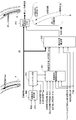
- FIG. 1 is an entire system diagram showing an automatic driving control system to which a traveling control method and a traveling control device of a first embodiment are applied.
- FIG. 7 is a perspective view showing a right side recognition camera and a left side recognition camera of the on-vehicle sensors in the first embodiment.
- FIG. 5 is a perspective view showing a rider provided at left and right positions in front of the vehicle among the on-vehicle sensors in the first embodiment.
- FIG. 5 is an overall block diagram showing a target path corrector included in the navigation control unit in the first embodiment.
- FIG. 5 is a detailed block diagram showing a detailed configuration of a rate limiter unit in the target path correction device shown in FIG.
- FIG. 4 It is a figure which shows the lane boundary detection result inside the corner in the comparative example when driving a curved road, and the lane boundary detection result outside a corner. It is travel control operation explanatory view showing a travel control operation when traveling on a curved road in a comparative example.
- FIG. 6 is a travel control operation explanatory view showing a travel control operation when traveling on a curved road in the first embodiment.
- the traveling control method and the traveling control apparatus according to the first embodiment use the target route information generated by the navigation control unit, and an automatically driven vehicle (a driving assistance vehicle in which steering / driving / braking is automatically controlled by selection of an automatic driving mode) Example)).
- an automatically driven vehicle a driving assistance vehicle in which steering / driving / braking is automatically controlled by selection of an automatic driving mode
- the configuration of the first embodiment will be described by being divided into “overall system configuration”, “detailed configuration of navigation control unit”, “overall configuration of target path corrector”, and “detailed configuration of rate limiter”.
- FIG. 1 shows an automatic driving control system to which the traveling control method and the traveling control device of the first embodiment are applied.
- FIG. 2 shows a right side recognition camera and a left side recognition camera of the on-vehicle sensors
- FIG. 3 shows riders provided at left and right positions in front of the vehicle of the on-vehicle sensors. The overall system configuration will be described below based on FIGS. 1 to 3.
- the automatic driving control system includes an on-vehicle sensor 1, an ambient environment recognition unit 2, a navigation control unit 3, an automatic driving control unit 4, and an actuator 5.
- the surrounding environment recognition unit 2, the navigation control unit 3, and the automatic driving control unit 4 are computers that include arithmetic processing units such as a CPU and execute arithmetic processing.
- the on-vehicle sensor 1 is a sensor that is mounted on an autonomous driving vehicle and acquires peripheral information of the vehicle. It has a front recognition camera 11, a rear recognition camera 12, a right side recognition camera 13, a left side recognition camera 14, a rider 15, and a radar 16.
- a vehicle speed sensor, a yaw rate sensor, a winker switch, etc. outside a figure are provided as sensors etc. which acquire information required for automatic driving control other than the circumference information on the self-vehicle.
- An ambient recognition camera (AVM: around view monitor) is configured by combining the forward recognition camera 11, the backward recognition camera 12, the right side recognition camera 13, and the left side recognition camera 14.
- AVM around view monitor
- the object on the road on the vehicle / object on the road outside the vehicle road structure, leading vehicle, following vehicle, oncoming vehicle, oncoming vehicle, surrounding vehicle, pedestrian, bicycle, two-wheeled vehicle
- Road boundaries, stop lines, pedestrian crossings, road signs (speed limit), etc. are detected.
- the right side recognition camera 13 is a fisheye camera built in the right side door mirror as shown in FIG. 2 and has a right side white line lateral position detection function.
- the left side recognition camera 14 is a fisheye camera built in the left side door mirror as shown in FIG. 2 and has a left white line lateral position detection function.
- the right side white line lateral position means the length from the position of the vehicle width direction center line CL of the vehicle A to the inner end position of the right side white line WR.
- the left side white line lateral position means the length from the position of the vehicle width direction center line CL of the vehicle A to the inner end position of the left side white line WL.
- the right side white line WR and the left side white line WL are left and right lane boundaries, and the right side white line lateral position and the left side white line lateral position are taken as the left and right lane boundary detection results.
- the rider 15 and the radar 16 are disposed at the front end position of the vehicle with the irradiation axis of the output wave directed to the front of the vehicle and receive the reflected wave to detect the presence of an object in front of the vehicle. Detect the distance to the object.
- a rider / radar is configured by combining two types of distance measurement sensors, the rider 15 and the radar 16, and, for example, a laser radar, a millimeter wave radar, an ultrasonic radar, a laser range finder, etc. can be used. With the rider 15 and the radar 16, the position and objects of the vehicle on the road and objects outside the vehicle (road structures, leading vehicles, following vehicles, oncoming vehicles, oncoming vehicles, pedestrians, bicycles, two-wheelers) etc. Detect the distance of
- the rider 15 is provided at the front end left and right position of the vehicle A so as to be able to swing downward rightward and downward leftward downward, and detects right curb lateral position detection function and left curb lateral position detection function And.
- the right side curb lateral position refers to the length from the position of the vehicle width direction center line CL of the vehicle A to the inner end position of the right side curb ER.
- the left side curb lateral position refers to the length from the position of the vehicle width direction center line CL of the vehicle A to the inner end position of the left side curb EL.
- the right side curb ER and the left side curb EL are road ends on the left and right sides, and positions that are a predetermined distance inward from the right side curb lateral position and a predetermined distance inward from the left white line lateral position are taken as lane boundary detection results.
- the surrounding environment recognition unit 2 inputs image data from each recognition camera 11, 12, 13, 14 and object data from the rider / radar 15, 16.
- the surrounding environment recognition unit 2 includes a calibration processing unit 21 that generates calibration data of image data and object data, and an object recognition processing unit 22 that performs object recognition processing based on the calibration data.
- the calibration processing unit 21 estimates parameters of the image data from the recognition cameras 11, 12, 13, 14 and parameters of the object data from the rider / radar 15, 16 and uses the parameters to generate image data or an object. Generate and output calibration data of data. For example, in the case of image data from each of the recognition cameras 11, 12, 13, 14, parameters are used to correct the optical axis and lens distortion.
- the object recognition processing unit 22 receives the calibration data from the calibration processing unit 21, performs object recognition processing based on the calibration data, and outputs recognition result data.
- the object recognition processing unit 22 compares, for example, the image data and the object data, and when it is confirmed that the object exists at the position of the object candidate based on the image data, the object recognition processing unit 22 recognizes the presence of the object. Recognize what the object is.
- the navigation control unit 3 inputs the vehicle position information from the GNSS antenna 31, combines the map data including the road information and the GPS (Global Positioning System) using satellite communication, and searches from the current position to the destination by route search Generate a target route for Then, the generated target route is displayed on the map, and the target route information is output.
- GPS Global Positioning System
- GNSS Global Navigation Satellite System: Global Navigation Satellite System
- GPS Global Positioning System
- the automatic driving control unit 4 receives the recognition result data from the object recognition processing unit 22 of the surrounding environment recognition unit 2 and the target route information from the navigation control unit 3. Then, based on the input information, a target vehicle speed, a target acceleration and a target deceleration are generated. Furthermore, the drive control command value is calculated from the generated target acceleration, and the calculation result is output to the drive actuator 51. A braking control command value is calculated based on the generated target deceleration, and the calculation result is output to the braking actuator 52. The steering angle control command value is calculated based on the input target route information, and the calculation result is output to the steering angle actuator 53.
- the actuator 5 has a drive actuator 51, a braking actuator 52, and a steering angle actuator 53.
- the drive actuator 51 is an actuator that receives a drive control command value from the automatic operation control unit 4 and controls the drive source drive force. That is, in the case of an engine car, an engine actuator is used. In the case of a hybrid vehicle, an engine actuator and a motor actuator are used. In the case of an electric vehicle, a motor actuator is used.
- the braking actuator 52 is an actuator that receives a braking control command value from the automatic operation control unit 4 and controls the braking force.
- a hydraulic booster, an electric booster, or the like is used as the brake actuator 52.
- the steering angle actuator 53 is an actuator that receives a steering angle control command value from the automatic operation control unit 4 and controls the turning angle of the steered wheels.
- a steering angle control motor or the like is used as the steering angle actuator 53.
- the navigation control unit 3 includes a GNSS antenna 31, a position information processing unit 32, a destination setting unit 33, a map data storage unit 34, a route search processing unit 35, and a target route correction unit. And a display device 37.
- the position information processing unit 32 performs detection processing of the latitude / longitude of the stop position of the vehicle and the traveling position of the vehicle based on the satellite communication information input from the GNSS antenna 31.
- the vehicle position information from the position information processing unit 32 is output to the route search processing unit 35.
- the destination setting unit 33 performs input setting of the destination of the vehicle by a touch panel operation on the display screen of the display device 37 by the driver or the like.
- the destination information from the destination setting unit 33 is output to the route search processing unit 35.
- the map data storage unit 34 is a storage unit of so-called electronic map data in which the latitude and longitude are associated with the map information.
- the map data has road information associated with each point, and the road information is defined by nodes and links connecting the nodes.
- the road information includes information specifying the road by the position / area of the road, the road type for each road, the road width for each road, and the shape information of the road.
- the road information associates and stores information on the position of the intersection, the approach direction of the intersection, the type of the intersection, and other intersections for each identification information of each road link.
- the road information includes road type, road width, road shape, whether to go straight, whether to advance, whether to overtake (possibility of entering an adjacent lane), speed limit, etc. for each identification information of each road link. Corresponds and stores information on roads in
- the route search processing unit 35 includes the vehicle position information from the position information processing unit 32, the destination information from the destination setting unit 33, and the road map information (road map data) from the map data storage unit 34. input. Then, a target route is generated by route cost calculation or the like based on the road map information.
- the target route may be generated using GPS and a map, but instead of using GPS and a map, when a preceding vehicle is present, the traveling route of the preceding vehicle may be used as the target route. In this case, when the positional accuracy of the GPS is low, by using the travel locus as the target route, the parallel movement amount in the target route correction unit 36 described later can be small, and the vehicle behavior can be made smoother.
- the target route correction unit 36 inputs the recognition result data from the object recognition processing unit 22, the target route from the route search processing unit 35, and the road map information from the map data storage unit 34. Other than the target route, information such as white line lateral distance (left and right), stationary object lateral distance (left and right), curb lateral distance (left and right), usage status of turn signal (winker) by driver, lane change status, vehicle speed etc. Enter Based on the input information, the lane boundary of the lane in which the vehicle travels is detected.
- the positional relationship between the detected lane boundary and the target route on the map is compared, and if the target route exists within a predetermined distance with respect to the lane boundary, or the target route is with the vehicle relative to the lane boundary If it is on the opposite side, the target path is corrected by lateral translation.
- the "predetermined distance” is a distance that gives the driver a sense of apprehension when the vehicle approaches the lane boundary, and, for example, about 2 m from the center line of the vehicle's width direction to the lane boundary ( The distance from the side of the vehicle to the lane boundary is approximately 1 m.
- the target route is corrected by parallel movement in the lateral direction regardless of the distance to the vehicle.
- the display device 37 inputs the map data information from the map data storage unit 34 and the target route information from the target route corrector 36. Then, the map, the road, the target route, the vehicle position and the destination are displayed on the display screen. That is, the display device 37 provides vehicle position visual information such as where the vehicle is moving on the map during traveling by automatic driving.
- FIG. 4 shows a target path corrector 36 included in the navigation control unit 3 (controller) in the first embodiment.
- the overall configuration of the target path correction unit 36 will be described below based on FIG.
- the target route correction unit 36 sets a navigation error that occurs between the vehicle position and the target route when the vehicle position detected using the navigation information is superimposed on the map information while traveling by automatic driving, Correct by horizontal and parallel movement.
- the target route correction unit 36 includes a road boundary information integration unit 361, a horizontal correction amount calculation unit 362, a horizontal parallel movement unit 363, a road shape determination unit 364, and a rate limiter unit 365. And.
- the road boundary information integration unit 361 has a white line lateral distance (left and right), a stationary object lateral distance (left and right), a curb lateral distance (left and right), and a use condition of a direction indicator (winker) by a driver while traveling on a straight path. Input information such as lane change status and vehicle speed.
- Input information such as lane change status and vehicle speed.
- the white line lateral distance (left and right) input the right side white line lateral position after rate limiter application from the rate limiter 365 and the left side white line lateral position after rate limiter application. Calculate the left and right). Then, the lane boundary of the lane in which the host vehicle A travels is detected, and the lateral distance (left and right) between the host vehicle A and the lane boundary is output to the lateral correction amount calculation unit 362.
- the lateral correction amount calculation unit 362 includes the target route from the route search processing unit 35, the lane boundary lateral distance (left and right) from the road boundary information integration unit 361, the use status of the turn signal by the driver, the lane change status, Input information such as vehicle speed. Then, the positional relationship between the detected lane boundary and the target route on the map is compared, and if the target route exists within a predetermined distance with respect to the lane boundary, or if the target route is the vehicle A with the lane boundary Calculates the lateral correction amount of the target route when it exists on the opposite side.
- the horizontal parallel movement unit 363 inputs the target path from the route search processing unit 35 and the horizontal correction amount from the horizontal correction amount calculation unit 362. Then, when the horizontal correction amount is calculated, as shown in the lower right frame B of FIG. 4, the target route is corrected by the horizontal parallel displacement by the horizontal correction amount to generate a new target route.
- the parallel movement correction of the target route when the traveling direction of the host vehicle A and the target route are deviated, the matching between the traveling direction of the host vehicle A and the new target route is enhanced.
- the road shape determination unit 364 determines a curved road and a curve direction present on the planned travel route of the own vehicle based on the map (road shape information) and the own vehicle position information by the GPS. Then, when reaching the change start point of the corner curvature of the curved road, the curved road information is output to the rate limiter unit 365 only until the predetermined time required to leave the curved road after reaching the curvature change start point is reached. Do.
- the predetermined time required for the vehicle to leave the curved road is determined by the curvature and length of the curved road and the estimated road velocity of the vehicle.
- the rate limiter unit 365 inputs the curved road information from the road shape determination unit 364, the right side white line lateral position detected by the right side recognition camera 13, and the left side white line lateral position detected by the left side recognition camera 14. Do. Then, when traveling on a curved road, when the curved road information is input, the lane boundary detection result on the inner side of the corner of the right side white line lateral position and the left side white line lateral position is the lateral direction approaching the vehicle. It is assumed that the change is suppressed.
- the allowable change rate permitted as the lateral speed (change rate) in the direction in which the lane boundary detection result inside the corner approaches the host vehicle is permitted as the lateral speed (change rate) in the lane boundary detection result outside the corner make it smaller than the change rate. Then, the right side white line lateral position after applying the rate limiter and the left side white line lateral position after applying the rate limiter are output to the road boundary information integration unit 361.
- FIG. 5 shows a detailed configuration of the rate limiter unit 365 in the target path correction unit 36.
- the detailed configuration of the rate limiter unit 365 will be described below based on FIG.
- the rate limiter unit 365 has a curvature calculation unit 365a, an assumed lateral G calculation unit 365b, a first rate upper limit value determination unit 365c, and a first rate lower limit value determination unit 365d. Furthermore, the assumed yaw rate calculating unit 365e, the second rate upper limit determining unit 365f, the second rate lower limit determining unit 365g, the vehicle speed differential value calculating unit 365h, the third rate upper limit determining unit 365i, and the third rate And a lower limit value determination unit 365j. In addition, it has a rate upper limit selecting unit 365k, a rate lower limit selecting unit 365m, a right rate limiter 365n, and a left rate limiter 365p.
- the curvature calculation unit 365a calculates the curvature of the curved road by the road shape acquired using the map and the GPS.
- the assumed lateral G calculation unit 365b inputs the curvature and the vehicle speed, and calculates the assumed lateral G using the following equation.
- ⁇ is the curvature
- D is the travel direction distance.
- ⁇ V 2 is the assumed lateral G
- the first rate upper limit determination unit 365 c has a lookup table with the assumed lateral G as the horizontal axis, and determines the first rate upper limit based on the assumed lateral G and the table characteristics.
- the first rate upper limit value is a value that suppresses the speed at which the right white line moves to the left as the assumed lateral G in the right curve increases.
- the first rate lower limit determination unit 365d has a lookup table with the assumed lateral G as the horizontal axis, and determines the first rate lower limit based on the assumed lateral G and the table characteristics.
- the first rate lower limit value is a value that suppresses the speed at which the left white line moves to the right as the assumed lateral G in the left curve increases.
- the assumed yaw rate calculation unit 365e inputs the curvature and the vehicle speed, and calculates the assumed yaw rate using the following equation.
- ⁇ V is the assumed yaw rate
- the second rate upper limit determination unit 365f has a look-up table with the assumed yaw rate as the horizontal axis, and determines the second rate upper limit based on the assumed yaw rate and the table characteristics.
- the second rate upper limit value is a value that suppresses the speed at which the right white line moves to the left as the assumed yaw rate increases in the right curve.
- the second rate lower limit determination unit 365g has a lookup table with the assumed yaw rate as the horizontal axis, and determines the second rate lower limit based on the assumed yaw rate and the table characteristics.
- the second rate lower limit value is a value that suppresses the speed at which the left white line moves to the right as the assumed yaw rate increases in the left curve.
- the vehicle speed differential value calculation unit 365h inputs curve road information and the vehicle speed, and performs time differentiation processing on the vehicle speed V to calculate a vehicle speed differential value that is a change amount per unit time of the vehicle speed V.
- the third rate upper limit determination unit 365i has a look-up table with the vehicle speed differential value as the horizontal axis, and determines the third rate upper limit value based on the vehicle speed differential value and the table characteristics.
- the third rate upper limit value is a value that suppresses the speed at which the right white line moves to the left as the vehicle speed differential value (deceleration) in the right curve increases.
- the third rate lower limit determination unit 365j has a look-up table with the vehicle speed differential value as the horizontal axis, and determines the third rate lower limit value based on the vehicle speed differential value and the table characteristics.
- the third rate lower limit value is a value that suppresses the speed at which the left white line moves to the right as the vehicle speed differential value (deceleration) increases in the left curve.
- the rate upper limit selecting unit 365k receives the first rate upper limit, the second rate upper limit, and the third rate upper limit, and selects the value with the smallest absolute value as the rate upper limit.
- the rate lower limit selection unit 365m receives the first rate lower limit, the second rate lower limit, and the third rate lower limit, and selects the value with the smallest absolute value as the rate lower limit.
- the right side rate limiter 365n inputs the right side white line lateral position detected by the right side recognition camera 13, the rate upper limit value from the rate upper limit value selection unit 365k, and the rate lower limit value set in advance. Then, by limiting the rate of change of the right side white line lateral position (lateral speed) with the rate upper limit value and the rate lower limit value, the right side white line lateral position after applying the rate limiter is acquired.
- the left side rate limiter 365p inputs the left side white line lateral position detected by the left side recognition camera 14, the rate lower limit value from the rate lower limit value selection unit 365m, and the rate upper limit value set in advance. Then, by limiting the rate of change of the left white line lateral position (lateral speed) with the rate upper limit value and the rate lower limit value, the left white line lateral position after applying the rate limiter is acquired.
- FIG. 6 shows lane boundary detection results inside the corners and lane boundary detection results outside the corners in a comparative example when traveling on a curved road.
- the subject of a comparative example is demonstrated based on FIG.
- the comparative example uses the left and right lane boundary detection values as the lane boundary detection result inside the corner and the lane boundary detection result inside the corner.
- the detection result by the camera becomes a value in the direction approaching the vehicle A. If a delay occurs in the detection of the white line outside the corner after passing the curvature changing portion C, the detection result by the camera becomes a value in the direction away from the vehicle A.
- FIG. 7 shows a travel control action when traveling on a curved road in a comparative example.
- the curved road travel control action in the comparative example will be described based on FIG.
- the white line detection result by the camera becomes a value in the direction in which the vehicle approaches the vehicle A inside the corner. It becomes a value in the direction away from the car A. Therefore, the curvature of the curved road recognized by the white line detection result of the camera is larger (the curvature radius is smaller) than the curvature of the curved road according to the actual left and right white lines, and bulges outside the corner.
- the target route TL created from the map is corrected based on the white line detection result of the camera, and in-line travel is attempted in line trace control.
- the corrected target path TL ' is a path closer to the outside white line of the curved road as described in the frame surrounded by the arrow E in FIG. 7 because the correction works on the outside of the curved road.
- the host vehicle A travels along the corrected target route TL ', the vehicle bulges outside the corner at a portion where the curvature changes on the curved road.
- FIG. 8 shows a travel control action when traveling on a curved road in the first embodiment.
- the curved road travel control operation in the first embodiment will be described based on FIGS. 5 and 8.
- the present invention has been made focusing on the problem in the comparative example.
- the allowable change rate permitted as the lateral velocity in the direction approaching the vehicle is the permissible change rate of the lane boundary detection result inside the corner as the lateral velocity in the lane boundary detection result outside the corner. Be made smaller than the allowable change rate.
- the assumed lateral G is calculated using.
- the first rate upper limit determining unit 365 c the first rate upper limit is determined based on the assumed lateral G and the table characteristics.
- the first rate upper limit value to be determined is a value that suppresses the speed at which the right white line inside the corner moves to the left as the assumed lateral G in the right curve is larger.
- the first rate lower limit is determined based on the assumed lateral G and the table characteristics.
- the first rate lower limit value to be determined is a value that suppresses the speed at which the left white line inside the corner moves to the right as the assumed lateral G is larger in the left curve.
- the second rate upper limit value determination unit 365f determines the second rate upper limit value based on the assumed yaw rate and the table characteristics.
- the second rate upper limit value to be determined is a value that suppresses the speed at which the right white line on the inner side of the corner moves to the left as the assumed yaw rate is larger in the right curve.
- the second rate lower limit determination unit 365g the second rate lower limit is determined based on the assumed yaw rate and the table characteristics.
- the second rate lower limit value to be determined is a value that suppresses the speed at which the left white line inside the corner moves to the right as the assumed yaw rate is larger in the left curve.
- the vehicle speed differential value calculation unit 365h the curve road information and the vehicle speed are input, and the vehicle speed V is subjected to time differentiation processing, whereby the vehicle speed differential value which is the change amount per unit time of the vehicle speed V is calculated. Then, the third rate upper limit value determination unit 365i determines the third rate upper limit value based on the vehicle speed differential value and the table characteristics.
- the third rate upper limit value to be determined is a value that suppresses the speed at which the right white line on the inner side of the corner moves to the left as the vehicle speed differential value (deceleration) is larger in the right curve.
- the third rate lower limit determination unit 365j the third rate lower limit is determined based on the vehicle speed differential value and the table characteristics.
- the third rate lower limit value to be determined is a value that suppresses the speed at which the left white line inside the corner moves to the right as the vehicle speed differential value (deceleration) is larger in the left curve.
- the rate upper limit selecting unit 365k receives the first rate upper limit, the second rate upper limit, and the third rate upper limit, and among the three values, the value with the smallest absolute value is selected as the rate upper limit. Ru. Further, the first rate lower limit value, the second rate lower limit value, and the third rate lower limit value are input in the rate lower limit selection unit 365m, and the value with the smallest absolute value is selected as the rate lower limit among the three values. Ru.
- the right side white line horizontal position detected by the right side recognition camera 13, the rate upper limit value from the rate upper limit value selection unit 365k, and the rate lower limit value set in advance are input. Ru. Then, by limiting the rate of change of the right side white line lateral position (lateral speed) with the rate upper limit value and the rate lower limit value, the right side white line lateral position after applying the rate limiter is acquired.
- the left side white line lateral position detected by the left side recognition camera 14, the rate lower limit value from the rate lower limit value selection unit 365m, and the rate upper limit value set in advance are input. Ru. Then, by limiting the rate of change of the left side white line lateral position (lateral speed) by the rate upper limit value and the rate lower limit value, the left side white line lateral position after acquiring the rate limiter is acquired.
- the speed of moving the left white line on the right side after applying the rate limiter inside the corner is suppressed to the left Position.
- the left white line lateral position after the rate limiter is applied inside the corner is set to a position at which the speed of moving to the right is suppressed. Therefore, the curvature of the curved road recognized by the right side white line lateral position and the left side white line lateral position after application of the rate limiter becomes closer to the curvature of the curved line according to the actual left and right white lines.
- the target route TL created from the map is corrected at the right side white line lateral position and the left side white line lateral position after the rate limiter is applied, and on the other hand, traveling within the lane is attempted by line trace control.
- the corrected target route TL ′ ′ is substantially along the center line of the curved road as described in the frame surrounded by the arrow F in FIG.
- the host vehicle A travels along the corrected target path TL ′ ′
- the vehicle can travel without expanding outside the corner at the curvature changing portion on the curved road.
- a controller (navigation control unit 3) which detects the lane boundaries on the left and right and performs travel control of the vehicle based on the lane boundary detection result.
- the travel control method of the driving support vehicle automated driving vehicle
- the curved road and the curved direction are determined based on the road shape information.
- the lane boundary detection result on the inner side of the corner is set to a value in which a lateral change approaching the vehicle is suppressed (FIG. 8). For this reason, it is possible to provide a travel control method of a driving support vehicle (automatically driven vehicle) that travels without being inflated outside the corner at a curvature change portion on a curved road.
- the lane boundary detection result on the inner side of the corner is set to a value in which the lateral change approaching the vehicle is suppressed until a predetermined time elapses from the change start point of the corner curvature ( Figure 4). Therefore, in addition to the effect of (1) or (2), it becomes possible for the vehicle to travel at the center of the lane in straight running scenes other than the curving road running scene. That is, by limiting only to the curved road traveling scene in which the delay in lane boundary detection result inside the corner is remarkable, in the other traveling scenes, the left and right lane boundary detection results can be used directly.
- the curvature of the curved road is calculated by the road shape, the assumed yaw rate is calculated by the curvature and the vehicle speed, and the second rate upper limit and the second rate lower limit are changed by the assumed yaw rate.
- the absolute value is compared with each of the first rate upper limit and the first rate lower limit obtained based on the assumed lateral acceleration, and the smaller absolute value is adopted as the rate upper limit and the rate lower limit (FIG. 5). For this reason, in addition to the effect of (4), when lane boundary detection is performed in consideration of the yaw rate of the vehicle, adding the assumed yaw rate to the assumed lateral G and limiting the lane boundary detection result inside the corner While traveling on the road, the behavior of the vehicle can be reduced. That is, even if the lateral G is the same, when the change in the yaw rate becomes large, the detection error at the lane boundary becomes large.
- a vehicle speed differential value that is a time change of the vehicle speed when traveling on a curved road is calculated, and the third rate upper limit value and the third rate lower limit value are changed by the vehicle speed differential value.
- a controller (navigation control unit 3) which detects the lane boundaries on the left and right and performs travel control of the vehicle based on the lane boundary detection result.
- the controller includes a road shape determination unit 364 and a detection result change suppression unit (rate limiter unit 365).
- the road shape determination unit 364 determines the curved road and the curve direction based on the road shape information.
- the detection result change suppression unit (rate limiter unit 365) sets the lane boundary detection result inside the corner to a value in which a change in the lateral direction approaching the vehicle is suppressed (FIG. 4). For this reason, it is possible to provide a travel control device for a driving support vehicle (automatically driven vehicle) that travels without being inflated outside the corner at a curvature change portion on a curved road.
- the target route generation and the lane boundary detection result are used in combination.
- the present invention can be applied to an example in which control is performed using only the lane boundary detection result, for example, while maintaining the center position of the left and right white lines based on the left and right white line detection results of the camera.
- the rate limiter for the lane boundary detection result inside the corner when traveling on a curved road, when the lane boundary detection result inside the corner is set to a value in which the change in the lateral direction approaching the vehicle is suppressed, the rate limiter for the lane boundary detection result inside the corner is An example is shown in which the rate limiter for the lane boundary detection result outside the corner is weakened. This is because in order to travel without curving outside the corner at the curvature change part on a curved road, the restriction on the lane boundary detection result inside the corner is more effective than the restriction on the lane boundary detection result outside the corner It is because the path width is not narrowed. However, when traveling on a curved road, the lane boundary detection result inside the corner may be maintained. In addition, when traveling on a curved road, lane boundary detection results inside and outside the corner may be maintained.
- the navigation control unit 3 is used as a controller that generates a target route from the current position of the vehicle to the destination.
- a controller that generates a target route from the current position of the host vehicle to the destination an example may be taken as an automatic driving control unit.
- the target route generation function may be divided into two, a part may be divided by the navigation control unit, and the remaining part may be divided by the automatic driving control unit.
- Example 1 showed the example which applies the traveling control method and traveling control apparatus of this indication to the autonomous driving vehicle by which steering / drive / braking are automatically controlled by selection of automatic operation mode.
- the traveling control method and the traveling control device of the present disclosure may be a driving support vehicle that supports some of the steering driving / driving driving / braking driving by the driver.
- the present invention can be applied to any vehicle that provides driving assistance to the driver by correcting the navigation error.
Landscapes
- Engineering & Computer Science (AREA)
- Mechanical Engineering (AREA)
- Remote Sensing (AREA)
- Radar, Positioning & Navigation (AREA)
- Automation & Control Theory (AREA)
- Physics & Mathematics (AREA)
- Transportation (AREA)
- General Physics & Mathematics (AREA)
- Chemical & Material Sciences (AREA)
- Combustion & Propulsion (AREA)
- Mathematical Physics (AREA)
- Computer Vision & Pattern Recognition (AREA)
- Theoretical Computer Science (AREA)
- Multimedia (AREA)
- Control Of Driving Devices And Active Controlling Of Vehicle (AREA)
- Traffic Control Systems (AREA)
- Steering Control In Accordance With Driving Conditions (AREA)
Abstract
Description
この運転支援車両の走行制御方法において、道路形状情報に基づいてカーブ路とカーブ方向を判別する。
カーブ路を走行するとき、コーナー内側の車線境界検出結果を、自車に近づく横方向の変化が抑えられた値とする。 In order to achieve the above object, the present disclosure includes a controller that detects left and right lane boundaries and performs travel control of the vehicle based on lane boundary detection results.
In the driving control method of the driving support vehicle, the curved road and the curved direction are determined based on the road shape information.
When traveling on a curved road, the lane boundary detection result on the inner side of the corner is set to a value in which a lateral change approaching the host vehicle is suppressed.
実施例1における走行制御方法及び走行制御装置は、ナビゲーション制御ユニットにて生成される目標経路情報を用い、自動運転モードの選択により操舵/駆動/制動が自動制御される自動運転車両(運転支援車両の一例)に適用したものである。以下、実施例1の構成を、「全体システム構成」、「ナビゲーション制御ユニットの詳細構成」、「目標経路補正器の全体構成」、「レートリミッタ部の詳細構成」に分けて説明する。 First, the configuration will be described.
The traveling control method and the traveling control apparatus according to the first embodiment use the target route information generated by the navigation control unit, and an automatically driven vehicle (a driving assistance vehicle in which steering / driving / braking is automatically controlled by selection of an automatic driving mode) Example)). Hereinafter, the configuration of the first embodiment will be described by being divided into “overall system configuration”, “detailed configuration of navigation control unit”, “overall configuration of target path corrector”, and “detailed configuration of rate limiter”.
図1は、実施例1の走行制御方法及び走行制御装置が適用された自動運転制御システムを示す。図2は、車載センサのうち右側方認識カメラ及び左側方認識カメラを示し、図3は、車載センサのうち車両前方の左右位置に設けられたライダーを示す。以下、図1~図3に基づいて全体システム構成を説明する。 [Whole system configuration]
FIG. 1 shows an automatic driving control system to which the traveling control method and the traveling control device of the first embodiment are applied. FIG. 2 shows a right side recognition camera and a left side recognition camera of the on-vehicle sensors, and FIG. 3 shows riders provided at left and right positions in front of the vehicle of the on-vehicle sensors. The overall system configuration will be described below based on FIGS. 1 to 3.
なお、右側白線横位置とは、自車Aの車幅方向中心線CLの位置から右側白線WRの内端位置までの長さをいう。左側白線横位置とは、自車Aの車幅方向中心線CLの位置から左側白線WLの内端位置までの長さをいう。なお、右側白線WRと左側白線WLは、左右の車線境界であり、右側白線横位置と左側白線横位置は、左右の車線境界検出結果とされる。 The right
The right side white line lateral position means the length from the position of the vehicle width direction center line CL of the vehicle A to the inner end position of the right side white line WR. The left side white line lateral position means the length from the position of the vehicle width direction center line CL of the vehicle A to the inner end position of the left side white line WL. The right side white line WR and the left side white line WL are left and right lane boundaries, and the right side white line lateral position and the left side white line lateral position are taken as the left and right lane boundary detection results.
目的地を設定し、最適な目標経路を演算し、自動運転用の目標経路を表示するナビゲーション制御ユニット3の詳細構成を、図1に基づいて説明する。 [Detailed configuration of navigation control unit]
The detailed configuration of the
図4は、実施例1においてナビゲーション制御ユニット3(コントローラ)に有する目標経路補正器36を示す。以下、図4に基づいて目標経路補正器36の全体構成を説明する。 [Overall Configuration of Target Path Corrector]
FIG. 4 shows a
図5は、目標経路補正器36のうちレートリミッタ部365の詳細構成を示す。以下、図5に基づいてレートリミッタ部365の詳細構成を説明する。 [Detailed configuration of rate limiter section]
FIG. 5 shows a detailed configuration of the
実施例1の作用を、「比較例でのカーブ路走行制御作用」、「実施例1でのカーブ路走行制御作用」に分けて説明する。 Next, the operation will be described.
The operation of the first embodiment will be described by being divided into “curve road traveling control operation in a comparative example” and “curve road traveling control operation in the first embodiment”.
図6は、カーブ路を走行するときの比較例でのコーナー内側の車線境界検出結果とコーナー外側の車線境界検出結果を示す。以下、図6に基づいて比較例の課題を説明する。ここで、比較例は、カーブ路を走行するとき、左右の車線境界検出値を、そのままコーナー内側の車線境界検出結果とコーナー内側の車線境界検出結果として用いるものとする。 [Curve road traveling control action in the comparative example]
FIG. 6 shows lane boundary detection results inside the corners and lane boundary detection results outside the corners in a comparative example when traveling on a curved road. Hereinafter, the subject of a comparative example is demonstrated based on FIG. Here, when traveling on a curved road, the comparative example uses the left and right lane boundary detection values as the lane boundary detection result inside the corner and the lane boundary detection result inside the corner.
図8は、実施例1でのカーブ路を走行するときの走行制御作用を示す。以下、図5及び図8に基づいて実施例1でのカーブ路走行制御作用を説明する。 [Curve Road Driving Control Action in Embodiment 1]
FIG. 8 shows a travel control action when traveling on a curved road in the first embodiment. Hereinafter, the curved road travel control operation in the first embodiment will be described based on FIGS. 5 and 8.
実施例1における自動運転車両の走行制御方法及び走行制御装置にあっては、下記に列挙する効果が得られる。 Next, the effects will be described.
In the travel control method and the travel control device for an autonomous driving vehicle in the first embodiment, the following effects can be obtained.
この運転支援車両(自動運転車両)の走行制御方法において、道路形状情報に基づいてカーブ路とカーブ方向を判別する。
カーブ路を走行するとき、コーナー内側の車線境界検出結果を、自車に近づく横方向の変化が抑えられた値とする(図8)。
このため、カーブ路での曲率変化部分で、コーナー外側に膨らまずに走行する運転支援車両(自動運転車両)の走行制御方法を提供することができる。 (1) A controller (navigation control unit 3) is provided which detects the lane boundaries on the left and right and performs travel control of the vehicle based on the lane boundary detection result.
In the travel control method of the driving support vehicle (automatic driving vehicle), the curved road and the curved direction are determined based on the road shape information.
When traveling on a curved road, the lane boundary detection result on the inner side of the corner is set to a value in which a lateral change approaching the vehicle is suppressed (FIG. 8).
For this reason, it is possible to provide a travel control method of a driving support vehicle (automatically driven vehicle) that travels without being inflated outside the corner at a curvature change portion on a curved road.
このため、(1)の効果に加え、横位置の変化レート(横速度)を小さくすることで、コーナー内側の車線境界検出結果が自車に近づくのを防止することができる。なお、実施例1のように、目標経路生成と車線境界検出結果とを組み合わせて使う場合、変化レートを変えるだけで車線境界検出結果を残すため、目標経路の横並行移動補正機能を失うことなく、目標経路の横補正により自車がレーン中心を走行することが可能になる。 (2) When traveling on a curved road, the allowable change rate permitted as the lateral speed in the direction in which the lane boundary detection result inside the corner approaches the host vehicle is permitted as the lateral speed in the lane boundary detection result outside the corner Make it smaller than the change rate (FIG. 5).
Therefore, in addition to the effect of (1), by reducing the rate of change of the lateral position (lateral speed), it is possible to prevent the lane boundary detection result inside the corner from approaching the vehicle. In the case where the target route generation and the lane boundary detection result are used in combination as in the first embodiment, the lane boundary detection result is left only by changing the change rate, so that the horizontal parallel movement correction function of the target route is not lost. Lateral correction of the target route enables the vehicle to travel at the center of the lane.
このため、(1)又は(2)の効果に加え、カーブ路走行シーン以外の直進走行シーンにおいて、自車がレーン中心を走行することが可能になる。即ち、コーナー内側の車線境界検出結果の遅れが顕著であるカーブ路走行シーンにのみに限定することで、その他の走行シーンでは、左右の車線境界検出結果を直接使うことができる。 (3) When traveling on a curved road, the lane boundary detection result on the inner side of the corner is set to a value in which the lateral change approaching the vehicle is suppressed until a predetermined time elapses from the change start point of the corner curvature ( Figure 4).
Therefore, in addition to the effect of (1) or (2), it becomes possible for the vehicle to travel at the center of the lane in straight running scenes other than the curving road running scene. That is, by limiting only to the curved road traveling scene in which the delay in lane boundary detection result inside the corner is remarkable, in the other traveling scenes, the left and right lane boundary detection results can be used directly.
このため、(2)又は(3)の効果に加え、レートリミッタの上下限を想定横加速度(想定横G)により変化させることで、カーブ路走行中、自車の車両挙動を小さく抑えることができる。即ち、車線境界検出結果の横移動量yが大きくなるほど、センサ遅れによる影響が大きくなるという関係にある。そして、横移動量yはρV2τ2であり、想定横GはρV2であるため、想定横Gが大きいほどコーナー内側の車線境界検出結果を制限すると、横移動量yが小さく抑えられる。 (4) The curvature of the curved road is calculated by the road shape, the assumed lateral acceleration (estimated lateral G) is calculated by the curvature and the vehicle speed, and the first rate upper limit and the first rate lower limit are changed by the assumed lateral acceleration (Figure 5).
For this reason, in addition to the effect of (2) or (3), the vehicle behavior of the vehicle can be kept small during traveling on a curved road by changing the upper and lower limits of the rate limiter by assumed lateral acceleration (estimated lateral G). it can. That is, as the lateral movement amount y of the lane boundary detection result increases, the influence of the sensor delay increases. Since the lateral movement amount y is VV 2 τ 2 and the assumed lateral G is VV 2 , the lateral movement amount y can be suppressed small if the lane boundary detection result inside the corner is limited as the assumed lateral G is larger.
想定横加速度に基づいて求めた第1レート上限値と第1レート下限値のそれぞれと絶対値を比較し、絶対値がより小さい方をレート上限値とレート下限値として採用する(図5)。
このため、(4)の効果に加え、自車のヨーレートを加味して車線境界の検出を行っている場合、想定横Gに想定ヨーレートを加えてコーナー内側の車線境界検出結果を制限すると、カーブ路走行中、自車の車両挙動を小さく抑えることができる。即ち、横Gが同じであっても、ヨーレートの変化が大きくなると、車線境界の検出誤差が大きくなってしまうという関係にある。 (5) The curvature of the curved road is calculated by the road shape, the assumed yaw rate is calculated by the curvature and the vehicle speed, and the second rate upper limit and the second rate lower limit are changed by the assumed yaw rate.
The absolute value is compared with each of the first rate upper limit and the first rate lower limit obtained based on the assumed lateral acceleration, and the smaller absolute value is adopted as the rate upper limit and the rate lower limit (FIG. 5).
For this reason, in addition to the effect of (4), when lane boundary detection is performed in consideration of the yaw rate of the vehicle, adding the assumed yaw rate to the assumed lateral G and limiting the lane boundary detection result inside the corner While traveling on the road, the behavior of the vehicle can be reduced. That is, even if the lateral G is the same, when the change in the yaw rate becomes large, the detection error at the lane boundary becomes large.
想定横加速度に基づいて求めた第1レート上限値と第1レート下限値のそれぞれと絶対値を比較し、絶対値がより小さい方をレート上限値とレート下限値として採用する(図5)。
このため、(4)の効果に加え、自車のヨーレートを加味して車線境界の検出を行っている場合、想定横Gに車速微分値を加えてコーナー内側の車線境界検出結果を制限すると、カーブ路走行中、自車の車両挙動を小さく抑えることができる。即ち、曲率と車速の積がヨーレートであるため、車速の変化(=車速微分値)がヨーレートの変化となる。 (6) A vehicle speed differential value that is a time change of the vehicle speed when traveling on a curved road is calculated, and the third rate upper limit value and the third rate lower limit value are changed by the vehicle speed differential value.
The absolute value is compared with each of the first rate upper limit and the first rate lower limit obtained based on the assumed lateral acceleration, and the smaller absolute value is adopted as the rate upper limit and the rate lower limit (FIG. 5).
Therefore, if lane boundary detection is performed in consideration of the yaw rate of the vehicle in addition to the effect of (4), adding the vehicle speed differential value to the assumed lateral G to limit the lane boundary detection result inside the corner, While traveling on a curved road, it is possible to reduce the vehicle behavior of the vehicle itself. That is, since the product of the curvature and the vehicle speed is the yaw rate, the change in the vehicle speed (= the vehicle speed differential value) becomes the change in the yaw rate.
このため、(1)~(6)の効果に加え、カーブ路を含めて目標経路を並行移動により補正することで、スムーズさを優先させるか、はみ出さないことを優先させるかをシーンに応じて選択することが可能となり、より安心できる車両挙動を実現することができる。 (7) Compare the positional relationship between the lane boundary detection result and the target route generated by a method other than left and right lane boundary detection, and the target route exists within a predetermined distance from the lane boundary, or If the target route is on the opposite side of the vehicle with respect to the lane boundary, the target route is corrected by the parallel parallel movement (FIG. 4).
For this reason, in addition to the effects of (1) to (6), whether to give priority to smoothness or to give priority to non-protrusiveness depending on the scene by correcting the target route including the curved road by parallel movement according to the scene It is possible to select a vehicle and to realize more reliable vehicle behavior.
この運転支援車両(自動運転車両)の走行制御装置において、コントローラ(ナビゲーション制御ユニット3)は、道路形状判別部364と、検出結果変化抑制部(レートリミッタ部365)と、を有する。
道路形状判別部364は、道路形状情報に基づいてカーブ路とカーブ方向を判別する。
検出結果変化抑制部(レートリミッタ部365)は、カーブ路を走行するとき、コーナー内側の車線境界検出結果を、自車に近づく横方向の変化が抑えられた値とする(図4)。
このため、カーブ路での曲率変化部分で、コーナー外側に膨らまずに走行する運転支援車両(自動運転車両)の走行制御装置を提供することができる。 (8) A controller (navigation control unit 3) is provided which detects the lane boundaries on the left and right and performs travel control of the vehicle based on the lane boundary detection result.
In the travel control device of the driving support vehicle (automatic driving vehicle), the controller (navigation control unit 3) includes a road
The road
When traveling on a curved road, the detection result change suppression unit (rate limiter unit 365) sets the lane boundary detection result inside the corner to a value in which a change in the lateral direction approaching the vehicle is suppressed (FIG. 4).
For this reason, it is possible to provide a travel control device for a driving support vehicle (automatically driven vehicle) that travels without being inflated outside the corner at a curvature change portion on a curved road.
Claims (8)
- 左右の車線境界を検出し、車線境界検出結果に基づいて自車の走行制御を行うコントローラを備える運転支援車両の走行制御方法において、
道路形状情報に基づいてカーブ路とカーブ方向を判別し、
前記カーブ路を走行するとき、コーナー内側の車線境界検出結果を、自車に近づく横方向の変化が抑えられた値とする
ことを特徴とする運転支援車両の走行制御方法。 In a driving control method of a driving support vehicle including a controller that detects the left and right lane boundaries and performs traveling control of the own vehicle based on the lane boundary detection result,
Determine the curve road and the curve direction based on the road shape information,
A driving control method of a driving assistance vehicle, wherein when traveling on the curved road, a lane boundary detection result on the inner side of a corner is set to a value in which a change in the lateral direction approaching the host vehicle is suppressed. - 請求項1に記載された運転支援車両の走行制御方法において、
前記カーブ路を走行するとき、前記コーナー内側の車線境界検出結果が自車に近づく方向の横速度として許容される許容変化レートを、前記コーナー外側の車線境界検出結果の横速度として許容される許容変化レートよりも小さくする
ことを特徴とする運転支援車両の走行制御方法。 In the driving control method for a driving assistance vehicle according to claim 1,
When traveling on the curved road, the allowable change rate permitted as the lateral speed in the direction in which the lane boundary detection result inside the corner approaches the host vehicle is permitted as the lateral speed in the lane boundary detection result outside the corner A driving control method for a driving assistance vehicle, characterized by making the rate smaller than a change rate. - 請求項1又は2に記載された運転支援車両の走行制御方法において、
前記カーブ路を走行するとき、コーナー曲率の変化開始点から所定時間経過するまでの間、コーナー内側の車線境界検出結果を、自車に近づく横方向の変化が抑えられた値とする
ことを特徴とする運転支援車両の走行制御方法。 In the driving control method for a driving assistance vehicle according to claim 1 or 2,
When traveling on the curved road, the lane boundary detection result on the inner side of the corner is set to a value in which the lateral change approaching the vehicle is suppressed until a predetermined time elapses from the change start point of the corner curvature. Driving control method of driving support vehicle. - 請求項2又は3に記載された運転支援車両の走行制御方法において、
前記カーブ路の曲率を道路形状により算出し、前記曲率と車速により想定横加速度を算出し、前記想定横加速度により第1レート上限値と第1レート下限値を変化させる
ことを特徴とする運転支援車両の走行制御方法。 In the driving control method for a driving assistance vehicle according to claim 2 or 3,
The driving assistance is characterized in that the curvature of the curved road is calculated by the road shape, the assumed lateral acceleration is calculated by the curvature and the vehicle speed, and the first rate upper limit and the first rate lower limit are changed by the assumed lateral acceleration. Vehicle travel control method. - 請求項4に記載された運転支援車両の走行制御方法において、
前記カーブ路の曲率を道路形状により算出し、前記曲率と車速により想定ヨーレートを算出し、前記想定ヨーレートにより第2レート上限値と第2レート下限値を変化させ、
前記想定横加速度に基づいて求めた前記第1レート上限値と前記第1レート下限値のそれぞれと絶対値を比較し、絶対値がより小さい方をレート上限値とレート下限値として採用する
ことを特徴とする運転支援車両の走行制御方法。 In the driving control method for a driving assistance vehicle according to claim 4,
The curvature of the curved road is calculated by the road shape, the assumed yaw rate is calculated by the curvature and the vehicle speed, and the second rate upper limit and the second rate lower limit are changed by the assumed yaw rate.
The absolute value is compared with each of the first rate upper limit value and the first rate lower limit value determined based on the assumed lateral acceleration, and the smaller absolute value is adopted as the rate upper limit value and the rate lower limit value. A driving control method of a driving support vehicle characterized by the present invention. - 請求項4に記載された運転支援車両の走行制御方法において、
前記カーブ路を走行するときの車速の時間変化である車速微分値を算出し、前記車速微分値により第3レート上限値と第3レート下限値を変化させ、
前記想定横加速度に基づいて求めた第1レート上限値と第1レート下限値のそれぞれと絶対値を比較し、絶対値がより小さい方をレート上限値とレート下限値として採用する
ことを特徴とする運転支援車両の走行制御方法。 In the driving control method for a driving assistance vehicle according to claim 4,
A vehicle speed differential value which is a time change of the vehicle speed when traveling on the curved road is calculated, and a third rate upper limit value and a third rate lower limit value are changed by the vehicle speed derivative value,
The absolute value is compared with each of the first rate upper limit and the first rate lower limit obtained based on the assumed lateral acceleration, and the smaller absolute value is adopted as the rate upper limit and the rate lower limit. Control method for driving assistance vehicles. - 請求項1から6までの何れか一項に記載された運転支援車両の走行制御方法において、
前記車線境界の検出結果と左右の車線境界検出以外の手法にて生成された目標経路との位置関係を比較し、前記目標経路が前記車線境界に対して所定距離以内に存在する場合、或いは、前記目標経路が前記車線境界に対して自車とは反対側に存在する場合、前記目標経路を横方向の並行移動により補正する
ことを特徴とする運転支援車両の走行制御方法。 In the driving control method of a driving assistance vehicle according to any one of claims 1 to 6,
The positional relationship between the lane boundary detection result and the target route generated by a method other than left and right lane boundary detection is compared, and the target route exists within a predetermined distance from the lane boundary, or A driving control method for a driving assistance vehicle, comprising: correcting the target route by a parallel movement in the lateral direction when the target route exists on the opposite side to the host vehicle with respect to the lane boundary. - 左右の車線境界を検出し、車線境界検出結果に基づいて自車の走行制御を行うコントローラを備える運転支援車両の走行制御装置において、
前記コントローラは、
道路形状情報に基づいてカーブ路とカーブ方向を判別する道路形状判別部と、
前記カーブ路を走行するとき、コーナー内側の車線境界検出結果を、自車に近づく横方向の変化が抑えられた値とする検出結果変化抑制部と、
を有することを特徴とする運転支援車両の走行制御装置。 In a travel control device of a driving support vehicle including a controller that detects the left and right lane boundaries and performs travel control of the own vehicle based on the lane boundary detection result,
The controller
A road shape determination unit that determines a curved road and a curved direction based on road shape information;
A detection result change suppression unit that sets a lane boundary detection result on the inner side of a corner to a value in which a lateral change approaching the host vehicle is suppressed when traveling on the curved road;
A travel control device for a driving assistance vehicle, comprising:
Priority Applications (10)
| Application Number | Priority Date | Filing Date | Title |
|---|---|---|---|
| CN201780094034.3A CN111226267B (en) | 2017-08-30 | 2017-08-30 | Driving control method and driving control device for driving support vehicle |
| PCT/JP2017/031167 WO2019043832A1 (en) | 2017-08-30 | 2017-08-30 | Travel control method and travel control device for driving-assist vehicle |
| JP2019538820A JP6747597B2 (en) | 2017-08-30 | 2017-08-30 | Driving control method and driving control device for driving assistance vehicle |
| CA3074188A CA3074188A1 (en) | 2017-08-30 | 2017-08-30 | Travel control method and travel control device for drive-assisted vehicle |
| KR1020207006516A KR20200029050A (en) | 2017-08-30 | 2017-08-30 | Driving control method and driving control device for driving support vehicles |
| US16/638,809 US10875530B2 (en) | 2017-08-30 | 2017-08-30 | Travel control method and travel control device for drive-assisted vehicle |
| EP17923204.6A EP3678113B1 (en) | 2017-08-30 | 2017-08-30 | Travel control method and travel control device for driving-assist vehicle |
| MX2020002174A MX2020002174A (en) | 2017-08-30 | 2017-08-30 | Travel control method and travel control device for driving-assist vehicle. |
| BR112020004012-6A BR112020004012A2 (en) | 2017-08-30 | 2017-08-30 | displacement control method and displacement control device for vehicle with assisted driving |
| RU2020112169A RU2741126C1 (en) | 2017-08-30 | 2017-08-30 | Motion control method and vehicle movement control device by means of driving |
Applications Claiming Priority (1)
| Application Number | Priority Date | Filing Date | Title |
|---|---|---|---|
| PCT/JP2017/031167 WO2019043832A1 (en) | 2017-08-30 | 2017-08-30 | Travel control method and travel control device for driving-assist vehicle |
Publications (1)
| Publication Number | Publication Date |
|---|---|
| WO2019043832A1 true WO2019043832A1 (en) | 2019-03-07 |
Family
ID=65525319
Family Applications (1)
| Application Number | Title | Priority Date | Filing Date |
|---|---|---|---|
| PCT/JP2017/031167 WO2019043832A1 (en) | 2017-08-30 | 2017-08-30 | Travel control method and travel control device for driving-assist vehicle |
Country Status (10)
| Country | Link |
|---|---|
| US (1) | US10875530B2 (en) |
| EP (1) | EP3678113B1 (en) |
| JP (1) | JP6747597B2 (en) |
| KR (1) | KR20200029050A (en) |
| CN (1) | CN111226267B (en) |
| BR (1) | BR112020004012A2 (en) |
| CA (1) | CA3074188A1 (en) |
| MX (1) | MX2020002174A (en) |
| RU (1) | RU2741126C1 (en) |
| WO (1) | WO2019043832A1 (en) |
Cited By (5)
| Publication number | Priority date | Publication date | Assignee | Title |
|---|---|---|---|---|
| CN112046474A (en) * | 2019-06-06 | 2020-12-08 | 本田技研工业株式会社 | Vehicle control device, method for operating vehicle control device, vehicle, and storage medium |
| CN112046477A (en) * | 2019-06-06 | 2020-12-08 | 本田技研工业株式会社 | Vehicle control device, method for operating vehicle control device, vehicle, and storage medium |
| JPWO2021006111A1 (en) * | 2019-07-08 | 2021-01-14 | ||
| US20210300364A1 (en) * | 2020-03-26 | 2021-09-30 | Honda Motor Co., Ltd. | Travel control device for vehicle |
| JPWO2022157906A1 (en) * | 2021-01-22 | 2022-07-28 |
Families Citing this family (11)
| Publication number | Priority date | Publication date | Assignee | Title |
|---|---|---|---|---|
| RU2741529C1 (en) * | 2017-08-30 | 2021-01-26 | Ниссан Мотор Ко., Лтд. | Position correcting method and position error correction device for vehicle with drive support |
| US10839139B2 (en) | 2018-04-17 | 2020-11-17 | Adobe Inc. | Glyph aware snapping |
| JP2020050220A (en) * | 2018-09-28 | 2020-04-02 | ロベルト・ボッシュ・ゲゼルシャフト・ミト・ベシュレンクテル・ハフツングRobert Bosch Gmbh | Control device and control method |
| JP2020050221A (en) * | 2018-09-28 | 2020-04-02 | ロベルト・ボッシュ・ゲゼルシャフト・ミト・ベシュレンクテル・ハフツングRobert Bosch Gmbh | Control device and control method |
| KR102504229B1 (en) * | 2018-12-18 | 2023-02-28 | 현대자동차주식회사 | Driving control system and method of autonomous traveling vehicle |
| US10832442B2 (en) * | 2019-03-28 | 2020-11-10 | Adobe Inc. | Displaying smart guides for object placement based on sub-objects of reference objects |
| US10846878B2 (en) * | 2019-03-28 | 2020-11-24 | Adobe Inc. | Multi-axis equal spacing smart guides |
| JP7319832B2 (en) * | 2019-06-06 | 2023-08-02 | 株式会社Subaru | steering device |
| CN111806435B (en) * | 2020-06-25 | 2021-12-07 | 安徽理工大学 | Automatic tracking control system of low-speed electric vehicle |
| US11778935B2 (en) | 2021-09-13 | 2023-10-10 | Deere & Company | Controlling operating envelope for off-road equipment based on a digital fence |
| DE102022109423A1 (en) * | 2022-04-19 | 2023-10-19 | Valeo Schalter Und Sensoren Gmbh | Method for the lateral localization of a vehicle on a road, computer program and driver assistance system |
Citations (4)
| Publication number | Priority date | Publication date | Assignee | Title |
|---|---|---|---|---|
| JP2015013545A (en) | 2013-07-04 | 2015-01-22 | 富士重工業株式会社 | Driving support control device of vehicle |
| JP5783204B2 (en) * | 2013-05-01 | 2015-09-24 | トヨタ自動車株式会社 | Driving support device and driving support method |
| JP6123297B2 (en) * | 2013-01-10 | 2017-05-10 | トヨタ自動車株式会社 | Driving support device |
| WO2017094907A1 (en) * | 2015-12-04 | 2017-06-08 | 株式会社デンソー | Travel trajectory generation device and travel trajectory generation method |
Family Cites Families (13)
| Publication number | Priority date | Publication date | Assignee | Title |
|---|---|---|---|---|
| JP2006175979A (en) * | 2004-12-22 | 2006-07-06 | Nissan Motor Co Ltd | Lane departure prevention device |
| JP4169065B2 (en) * | 2006-02-13 | 2008-10-22 | 株式会社デンソー | Vehicle control device |
| JP4899680B2 (en) * | 2006-07-18 | 2012-03-21 | 日産自動車株式会社 | Lane departure prevention device |
| JP2010003013A (en) * | 2008-06-18 | 2010-01-07 | Aisin Aw Co Ltd | Driving support device, driving support method and driving support program |
| JP5139939B2 (en) * | 2008-09-25 | 2013-02-06 | 日立オートモティブシステムズ株式会社 | Vehicle deceleration support device |
| JP5441549B2 (en) * | 2009-07-29 | 2014-03-12 | 日立オートモティブシステムズ株式会社 | Road shape recognition device |
| DE102011102435A1 (en) * | 2011-05-25 | 2012-11-29 | Audi Ag | Method for operating a longitudinal driver assistance system and motor vehicle |
| RU2624373C1 (en) * | 2013-07-19 | 2017-07-03 | Ниссан Мотор Ко., Лтд. | Driving assistance device for vehicle and method for driving assistance for vehicle |
| JP6284644B2 (en) * | 2014-07-28 | 2018-02-28 | ローベルト ボッシュ ゲゼルシャフト ミット ベシュレンクテル ハフツング | Information providing apparatus and program for motorcycle |
| JP6536340B2 (en) | 2014-12-01 | 2019-07-03 | 株式会社デンソー | Image processing device |
| JP6269534B2 (en) * | 2015-03-02 | 2018-01-31 | トヨタ自動車株式会社 | Travel control device |
| JP5982034B1 (en) | 2015-03-30 | 2016-08-31 | 富士重工業株式会社 | Vehicle driving support system |
| JP6815724B2 (en) * | 2015-11-04 | 2021-01-20 | トヨタ自動車株式会社 | Autonomous driving system |
-
2017
- 2017-08-30 BR BR112020004012-6A patent/BR112020004012A2/en unknown
- 2017-08-30 KR KR1020207006516A patent/KR20200029050A/en not_active Application Discontinuation
- 2017-08-30 CN CN201780094034.3A patent/CN111226267B/en active Active
- 2017-08-30 MX MX2020002174A patent/MX2020002174A/en unknown
- 2017-08-30 CA CA3074188A patent/CA3074188A1/en not_active Abandoned
- 2017-08-30 WO PCT/JP2017/031167 patent/WO2019043832A1/en unknown
- 2017-08-30 RU RU2020112169A patent/RU2741126C1/en active
- 2017-08-30 JP JP2019538820A patent/JP6747597B2/en active Active
- 2017-08-30 US US16/638,809 patent/US10875530B2/en active Active
- 2017-08-30 EP EP17923204.6A patent/EP3678113B1/en active Active
Patent Citations (4)
| Publication number | Priority date | Publication date | Assignee | Title |
|---|---|---|---|---|
| JP6123297B2 (en) * | 2013-01-10 | 2017-05-10 | トヨタ自動車株式会社 | Driving support device |
| JP5783204B2 (en) * | 2013-05-01 | 2015-09-24 | トヨタ自動車株式会社 | Driving support device and driving support method |
| JP2015013545A (en) | 2013-07-04 | 2015-01-22 | 富士重工業株式会社 | Driving support control device of vehicle |
| WO2017094907A1 (en) * | 2015-12-04 | 2017-06-08 | 株式会社デンソー | Travel trajectory generation device and travel trajectory generation method |
Non-Patent Citations (1)
| Title |
|---|
| See also references of EP3678113A4 |
Cited By (11)
| Publication number | Priority date | Publication date | Assignee | Title |
|---|---|---|---|---|
| CN112046474A (en) * | 2019-06-06 | 2020-12-08 | 本田技研工业株式会社 | Vehicle control device, method for operating vehicle control device, vehicle, and storage medium |
| CN112046477A (en) * | 2019-06-06 | 2020-12-08 | 本田技研工业株式会社 | Vehicle control device, method for operating vehicle control device, vehicle, and storage medium |
| CN112046474B (en) * | 2019-06-06 | 2024-01-30 | 本田技研工业株式会社 | Vehicle control device, method for operating same, vehicle, and storage medium |
| CN112046477B (en) * | 2019-06-06 | 2024-02-23 | 本田技研工业株式会社 | Vehicle control device, method for operating same, vehicle, and storage medium |
| JPWO2021006111A1 (en) * | 2019-07-08 | 2021-01-14 | ||
| JP7303304B2 (en) | 2019-07-08 | 2023-07-04 | 日立Astemo株式会社 | vehicle controller |
| US20210300364A1 (en) * | 2020-03-26 | 2021-09-30 | Honda Motor Co., Ltd. | Travel control device for vehicle |
| US11643078B2 (en) * | 2020-03-26 | 2023-05-09 | Honda Motor Co., Ltd. | Travel control device for vehicle |
| JPWO2022157906A1 (en) * | 2021-01-22 | 2022-07-28 | ||
| WO2022157906A1 (en) * | 2021-01-22 | 2022-07-28 | 三菱電機株式会社 | Target trajectory computation device, vehicle control device, and target trajectory computation method |
| JP7475500B2 (en) | 2021-01-22 | 2024-04-26 | 三菱電機株式会社 | Target trajectory calculation device, vehicle control device, and target trajectory calculation method |
Also Published As
| Publication number | Publication date |
|---|---|
| RU2741126C1 (en) | 2021-01-22 |
| KR20200029050A (en) | 2020-03-17 |
| CA3074188A1 (en) | 2019-03-07 |
| BR112020004012A2 (en) | 2020-09-01 |
| CN111226267A (en) | 2020-06-02 |
| MX2020002174A (en) | 2020-07-14 |
| EP3678113A4 (en) | 2020-09-09 |
| EP3678113A1 (en) | 2020-07-08 |
| EP3678113B1 (en) | 2022-06-01 |
| CN111226267B (en) | 2022-01-04 |
| US20200189582A1 (en) | 2020-06-18 |
| JPWO2019043832A1 (en) | 2020-03-26 |
| US10875530B2 (en) | 2020-12-29 |
| JP6747597B2 (en) | 2020-08-26 |
Similar Documents
| Publication | Publication Date | Title |
|---|---|---|
| JP6747597B2 (en) | Driving control method and driving control device for driving assistance vehicle | |
| JP6642772B2 (en) | Driving support vehicle position error correction method and position error correction device | |
| JP6658978B2 (en) | Driving support vehicle position error correction method and position error correction device | |
| US9058247B2 (en) | Risk potential calculation apparatus | |
| JP6330563B2 (en) | Driving support device and driving support method | |
| JP2017189989A (en) | Lane keep apparatus | |
| JP7377822B2 (en) | Driving support method and driving support device | |
| JP6673531B2 (en) | Driving assistance vehicle target vehicle speed generation method and target vehicle speed generation device | |
| TWI755869B (en) | Inclined vehicle with FCW control | |
| WO2024069690A1 (en) | Driving assistance method and driving assistance device |
Legal Events
| Date | Code | Title | Description |
|---|---|---|---|
| 121 | Ep: the epo has been informed by wipo that ep was designated in this application |
Ref document number: 17923204 Country of ref document: EP Kind code of ref document: A1 |
|
| ENP | Entry into the national phase |
Ref document number: 2019538820 Country of ref document: JP Kind code of ref document: A |
|
| ENP | Entry into the national phase |
Ref document number: 3074188 Country of ref document: CA |
|
| NENP | Non-entry into the national phase |
Ref country code: DE |
|
| ENP | Entry into the national phase |
Ref document number: 20207006516 Country of ref document: KR Kind code of ref document: A |
|
| REG | Reference to national code |
Ref country code: BR Ref legal event code: B01A Ref document number: 112020004012 Country of ref document: BR |
|
| ENP | Entry into the national phase |
Ref document number: 2017923204 Country of ref document: EP Effective date: 20200330 |
|
| ENP | Entry into the national phase |
Ref document number: 112020004012 Country of ref document: BR Kind code of ref document: A2 Effective date: 20200228 |