WO2019012809A1 - Connector - Google Patents
Connector Download PDFInfo
- Publication number
- WO2019012809A1 WO2019012809A1 PCT/JP2018/019534 JP2018019534W WO2019012809A1 WO 2019012809 A1 WO2019012809 A1 WO 2019012809A1 JP 2018019534 W JP2018019534 W JP 2018019534W WO 2019012809 A1 WO2019012809 A1 WO 2019012809A1
- Authority
- WO
- WIPO (PCT)
- Prior art keywords
- connector
- stopper
- locked
- rear direction
- socket
- Prior art date
Links
Images


Classifications
-
- H—ELECTRICITY
- H01—ELECTRIC ELEMENTS
- H01R—ELECTRICALLY-CONDUCTIVE CONNECTIONS; STRUCTURAL ASSOCIATIONS OF A PLURALITY OF MUTUALLY-INSULATED ELECTRICAL CONNECTING ELEMENTS; COUPLING DEVICES; CURRENT COLLECTORS
- H01R13/00—Details of coupling devices of the kinds covered by groups H01R12/70 or H01R24/00 - H01R33/00
- H01R13/40—Securing contact members in or to a base or case; Insulating of contact members
- H01R13/42—Securing in a demountable manner
- H01R13/424—Securing in base or case composed of a plurality of insulating parts having at least one resilient insulating part
-
- H—ELECTRICITY
- H01—ELECTRIC ELEMENTS
- H01R—ELECTRICALLY-CONDUCTIVE CONNECTIONS; STRUCTURAL ASSOCIATIONS OF A PLURALITY OF MUTUALLY-INSULATED ELECTRICAL CONNECTING ELEMENTS; COUPLING DEVICES; CURRENT COLLECTORS
- H01R13/00—Details of coupling devices of the kinds covered by groups H01R12/70 or H01R24/00 - H01R33/00
- H01R13/46—Bases; Cases
- H01R13/502—Bases; Cases composed of different pieces
- H01R13/508—Bases; Cases composed of different pieces assembled by a separate clip or spring
-
- H—ELECTRICITY
- H01—ELECTRIC ELEMENTS
- H01R—ELECTRICALLY-CONDUCTIVE CONNECTIONS; STRUCTURAL ASSOCIATIONS OF A PLURALITY OF MUTUALLY-INSULATED ELECTRICAL CONNECTING ELEMENTS; COUPLING DEVICES; CURRENT COLLECTORS
- H01R13/00—Details of coupling devices of the kinds covered by groups H01R12/70 or H01R24/00 - H01R33/00
- H01R13/40—Securing contact members in or to a base or case; Insulating of contact members
- H01R13/42—Securing in a demountable manner
- H01R13/422—Securing in resilient one-piece base or case, e.g. by friction; One-piece base or case formed with resilient locking means
-
- H—ELECTRICITY
- H01—ELECTRIC ELEMENTS
- H01R—ELECTRICALLY-CONDUCTIVE CONNECTIONS; STRUCTURAL ASSOCIATIONS OF A PLURALITY OF MUTUALLY-INSULATED ELECTRICAL CONNECTING ELEMENTS; COUPLING DEVICES; CURRENT COLLECTORS
- H01R13/00—Details of coupling devices of the kinds covered by groups H01R12/70 or H01R24/00 - H01R33/00
- H01R13/46—Bases; Cases
- H01R13/502—Bases; Cases composed of different pieces
- H01R13/506—Bases; Cases composed of different pieces assembled by snap action of the parts
-
- H—ELECTRICITY
- H01—ELECTRIC ELEMENTS
- H01R—ELECTRICALLY-CONDUCTIVE CONNECTIONS; STRUCTURAL ASSOCIATIONS OF A PLURALITY OF MUTUALLY-INSULATED ELECTRICAL CONNECTING ELEMENTS; COUPLING DEVICES; CURRENT COLLECTORS
- H01R13/00—Details of coupling devices of the kinds covered by groups H01R12/70 or H01R24/00 - H01R33/00
- H01R13/62—Means for facilitating engagement or disengagement of coupling parts or for holding them in engagement
- H01R13/639—Additional means for holding or locking coupling parts together, after engagement, e.g. separate keylock, retainer strap
Abstract
A connector provided with terminals, stoppers, and a socket insulator. The stoppers are attached to the respective terminals and are housed together with the terminals in the housing parts of the socket insulator. The stoppers is provided with parts to be locked, and lock spring parts that support the parts to be locked. Locking parts and operation parts are formed on the socket insulator. When the stoppers are housed in the housing parts, the locking parts are located rearward of the parts to be locked, and the locking parts restrict rearward movement of the stoppers. The operation parts can be operated in a prescribed direction that intersects the longitudinal direction. When operated, the operation parts cause the parts to be locked to move in the prescribed direction, and the restriction applied by the locking parts to the parts to be locked is released. Selected drawing. FIG. 30
Description
本発明は、コネクタに関し、特に、インシュレータに取り外し可能に取り付けられたコンタクトを備えるコネクタに関する。
The present invention relates to a connector, and more particularly to a connector comprising a contact removably mounted on an insulator.
コンタクトがインシュレータに取り付けられているコネクタであって、コンタクトの入れ替えや差し替えのために、インシュレータからコンタクトを取り外せるように構成されたコネクタが存在している。この種のコネクタは、例えば、特許文献1に開示されている。
There is a connector in which a contact is attached to an insulator, and the connector is configured to be able to remove the contact from the insulator for replacement or replacement of the contact. This type of connector is disclosed, for example, in Patent Document 1.
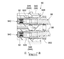
図33を参照すると、特許文献1のコネクタ90は、ケーブル98に夫々取り付けられる複数のコンタクト92と、コンタクト92に取り付けられるインシュレータ94とを備えている。また、図34を参照すると、インシュレータ94は、ハウジング940と、複数のロックリング944と、押さえブロック948と、係止解除部材950とを有している。ハウジング940には、コンタクト92(図33参照)を夫々収容する複数のキャビティ942が形成されている。
Referring to FIG. 33, the connector 90 of Patent Document 1 includes a plurality of contacts 92 attached to the cable 98, and an insulator 94 attached to the contacts 92. Further, referring to FIG. 34, the insulator 94 has a housing 940, a plurality of lock rings 944, a pressing block 948, and a locking release member 950. The housing 940 is formed with a plurality of cavities 942 that respectively receive the contacts 92 (see FIG. 33).
図35に示されるように、ロックリング944は、夫々キャビティ942内に配置される。押さえブロック948は、ハウジング940の後部に固定され、それによってロックリング944はハウジング940のキャビティ942内に固定される。係止解除部材950は、押さえブロック948を介してハウジング940に取り付けられる。係止解除部材950は、前後方向において、押さえブロック948に対して、即ちハウジング940に対して相対的に移動可能である。
As shown in FIG. 35, lock rings 944 are respectively disposed within cavities 942. The pressure block 948 is fixed to the rear of the housing 940 so that the lock ring 944 is fixed in the cavity 942 of the housing 940. The unlocking member 950 is attached to the housing 940 via the pressing block 948. The unlocking member 950 is movable relative to the pressing block 948, ie, the housing 940, in the front-rear direction.
図35に示されるように、コンタクト92がインシュレータ94に取り付けられた状態において、ロックリング944のランス片946は、前後方向において、コンタクト92の係止突起920の後方に位置する。これにより、コンタクト92は、インシュレータ94に対して後方への相対的移動が規制される。この状態において、係止解除部材950をハウジング940に対して相対的に前方へ移動させると、図35から理解されるように、係止解除部材950がランス片946を押し広げる。これにより、ランス片946によるコンタクト92の規制が解除される。その結果、コンタクト92をインシュレータ94の後方へ引き出すことが可能になる。こうして、特許文献1のコネクタ90において、インシュレータ94からコンタクト92を取り外すことができる。
As shown in FIG. 35, in the state where the contact 92 is attached to the insulator 94, the lance piece 946 of the lock ring 944 is located behind the locking protrusion 920 of the contact 92 in the front-rear direction. Thereby, the relative movement of the contact 92 to the rear with respect to the insulator 94 is restricted. In this state, when the unlocking member 950 is moved forward relative to the housing 940, the unlocking member 950 pushes the lance piece 946 apart as understood from FIG. Thereby, the restriction of the contact 92 by the lance piece 946 is released. As a result, the contact 92 can be pulled out to the rear of the insulator 94. Thus, in the connector 90 of Patent Document 1, the contact 92 can be removed from the insulator 94.
なお、特許文献1は、相手側コネクタの構成について明らかにしていない。しかし、コネクタ90の形状から推測すると、相手側コンタクトの先端部と相手側コンタクトを保持する相手側インシュレータとの間には比較的大きな隙間が存在する。これは、相手側コネクタが、相手側コンタクトに人の指が触れないようにするための感電防止構造を備えていないことを意味する。つまり、特許文献1のコネクタは、感電防止構造を備える相手側コネクタとの接続及び自身の感電防止構造について全く考慮されていない。
Patent Document 1 does not clarify the configuration of the mating connector. However, when estimated from the shape of the connector 90, a relatively large gap exists between the tip of the mating contact and the mating insulator that holds the mating contact. This means that the mating connector does not have an electric shock preventing structure for preventing a person's finger from touching the mating contact. That is, the connector of Patent Document 1 is not considered at all for the connection with the mating connector provided with the electric shock prevention structure and the electric shock prevention structure of itself.
特許文献1のコネクタ90において、コンタクト92をインシュレータ94から取り外すためには、コンタクト92を取り外す方向(後方)とは逆の方向(前方)へ、係止解除部材950を移動させなければならない。そのため、特許文献1のコネクタ90には、コンタクト92の取り外し操作が困難であるという問題点がある。この問題は、インシュレータ94が機器のパネルに取り付けられた状態において特に顕著である。
In the connector 90 of Patent Document 1, in order to remove the contact 92 from the insulator 94, the unlocking member 950 must be moved in the direction (forward) opposite to the direction (rear) of removing the contact 92. Therefore, the connector 90 of Patent Document 1 has a problem that the removal operation of the contact 92 is difficult. This problem is particularly noticeable when the insulator 94 is attached to the panel of the device.
本発明は、インシュレータに取り付けられたコンタクト(端子)をより容易にインシュレータから取り外すことができるコネクタを提供することを目的とする。
An object of the present invention is to provide a connector which can more easily remove a contact (terminal) attached to an insulator from the insulator.
本発明の一の側面は、ケーブルに取り付けられるコネクタであって、
複数の端子と、複数のストッパと、ソケットインシュレータとを備えており、
前記端子の夫々は、円筒部とケーブル取付部とを有しており、
前記ケーブル取付部は、前記ケーブルに取り付けられる部位であり、前後方向において前記円筒部よりも後方に位置しており、
前記ストッパは、前記端子に夫々取り付けられており、
前記ストッパの夫々には、被ロック部とロックバネ部とが設けられており、
前記被ロック部は、前記ロックバネ部に支持されており、
前記ロックバネ部は、弾性変形可能であり、
前記ソケットインシュレータには、複数の収容部と、複数のロック部と、複数の操作部が形成されており、
前記収容部は、前後方向に延びており、
前記ストッパは、前記端子とともに前記収容部に夫々収容されており、
前記収容部の前端部は開放しており、且つ前記前後方向において前記円筒部よりも前方に位置しており、
前記ロック部は、前記ストッパが前記収容部に収容された状態において、前記被ロック部の後方に位置しており、且つ前記ストッパの後方への移動を夫々規制しており、
前記操作部は、前記前後方向と交差する所定方向において操作可能であり、操作されると、前記被ロック部を前記所定方向に沿って移動させて前記ロック部による前記被ロック部の規制を夫々解除する
コネクタを提供する。 One aspect of the present invention is a connector attached to a cable, wherein
It has multiple terminals, multiple stoppers, and a socket insulator,
Each of the terminals has a cylindrical portion and a cable attachment portion,
The cable attachment portion is a portion attached to the cable, and is positioned rearward of the cylindrical portion in the front-rear direction,
The stoppers are respectively attached to the terminals,
Each of the stoppers is provided with a locked portion and a lock spring portion,
The locked portion is supported by the lock spring portion,
The lock spring portion is elastically deformable.
The socket insulator is formed with a plurality of housing portions, a plurality of lock portions, and a plurality of operation portions.
The housing portion extends in the front-rear direction,
The stopper is accommodated in the accommodating portion together with the terminal,
The front end portion of the housing portion is open, and is located forward of the cylindrical portion in the front-rear direction,
The lock portion is located rearward of the locked portion in a state in which the stopper is accommodated in the accommodation portion, and restricts the rearward movement of the stopper.
The operation portion is operable in a predetermined direction intersecting the front-rear direction, and when operated, the locked portion is moved along the predetermined direction so that the lock portion is regulated by the lock portion. Provide a connector to release.
本発明のコネクタにおいて、操作部は前後方向と交差する所定方向に操作することができる。これにより、ソケットインシュレータから端子をより容易に取り外すことができる。
In the connector of the present invention, the operating portion can be operated in a predetermined direction intersecting the front-rear direction. Thereby, the terminal can be more easily removed from the socket insulator.
添付の図面を参照しながら下記の最良の実施の形態の説明を検討することにより、本発明の目的が正しく理解され、且つその構成についてより完全に理解されるであろう。
The objects of the present invention will be properly understood and will be more fully understood by considering the following description of the best embodiments with reference to the attached drawings.
本発明については多様な変形や様々な形態にて実現することが可能であるが、その一例として、図面に示すような特定の実施の形態について、以下に詳細に説明する。図面及び実施の形態は、本発明をここに開示した特定の形態に限定するものではなく、添付の請求の範囲に明示されている範囲内においてなされる全ての変形例、均等物、代替例をその対象に含むものとする。
Although the present invention can be realized in various modifications and various forms, a specific embodiment as shown in the drawings will be described in detail below as an example. The drawings and embodiments are not intended to limit the invention to the particular forms disclosed herein, but rather to all variations, equivalents, and alternatives that can be made within the scope of the appended claims. It shall be included in the subject.
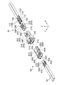
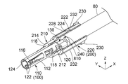
図1及び図2を参照すると、本発明の一実施の形態に係るコネクタ10及び相手側コネクタ50は、夫々二本のケーブル80の端部に取り付けられている。但し、本発明はこれに限定されない。例えば、コネクタ10及び相手側コネクタ50は、夫々一本の多芯ケーブルの端部に取り付けられていてもよい。
Referring to FIGS. 1 and 2, the connector 10 and the mating connector 50 according to an embodiment of the present invention are attached to the ends of two cables 80 respectively. However, the present invention is not limited to this. For example, the connector 10 and the mating connector 50 may be attached to the end of one multicore cable.
図1及び図2から理解されるように、コネクタ10と相手側コネクタ50は、前後方向(嵌合方向)に沿って互いに嵌合可能かつ分離可能である。コネクタ10と相手側コネクタ50は、互いに嵌合してコネクタ組立体を構成する。本実施の形態において、前後方向はX方向である。-X方向が前方であり、+X方向が後方である。
As understood from FIGS. 1 and 2, the connector 10 and the mating connector 50 can be fitted and separated from each other along the front-rear direction (fitting direction). The connector 10 and the mating connector 50 are fitted to each other to constitute a connector assembly. In the present embodiment, the front-rear direction is the X direction. The -X direction is the front, and the + X direction is the rear.
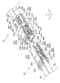
図3を参照すると、コネクタ10は、複数のソケットコンタクト(端子)100と、複数のストッパ200と、ソケットインシュレータ300とを備えている。一方、相手側コネクタ50は、複数のピンコンタクト500とピンインシュレータ600とを備えている。本実施の形態において、ソケットコンタクト100の数、ストッパ200の数及びピンコンタクト500の数は、夫々二つである。但し、本発明はこれに限られない。コネクタ10は、3以上のソケットコンタクト100を備えていてもよい。その場合、コネクタ10は、ソケットコンタクト100の数に等しい数のストッパ200を備える。また、相手側コネクタ50は、ソケットコンタクト100の数に等しい数のピンコンタクト500を備える。
Referring to FIG. 3, the connector 10 includes a plurality of socket contacts (terminals) 100, a plurality of stoppers 200, and a socket insulator 300. On the other hand, the mating connector 50 includes a plurality of pin contacts 500 and a pin insulator 600. In the present embodiment, the number of socket contacts 100, the number of stoppers 200, and the number of pin contacts 500 are two. However, the present invention is not limited to this. The connector 10 may comprise three or more socket contacts 100. In that case, the connector 10 comprises a number of stops 200 equal to the number of socket contacts 100. Also, the mating connector 50 comprises a number of pin contacts 500 equal to the number of socket contacts 100.
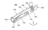
図4から図6を参照すると、ソケットコンタクト100は、円筒部110と、円筒部110に続くケーブル取付部130とを有している。円筒部110は、前後方向に延びている。円筒部110は、前後方向と直交する径方向を規定する。円筒部110は、前後方向において、ケーブル取付部130よりも前方に位置している。換言すると、ケーブル取付部130は、前後方向において、円筒部110よりも後方に位置している。円筒部110は、コネクタ10と相手側コネクタ50とが嵌合したとき、ピンコンタクト500(図29又は図32参照)の一部を受容する部位である。ケーブル取付部130は、ケーブル80(図3参照)に取り付けられる部位である。詳しくは、ケーブル取付部130は、図25に示されるように、ケーブル80の芯線810に圧着される部位である。但し、ケーブル取付部130は、圧着以外の方法、例えば、半田付けによりケーブル80の芯線810に取り付けられてもよい。ソケットコンタクト100は、一枚の金属板を打ち抜き加工及び曲げ加工して形成される。
Referring to FIGS. 4 to 6, the socket contact 100 has a cylindrical portion 110 and a cable attachment portion 130 continuing to the cylindrical portion 110. The cylindrical portion 110 extends in the front-rear direction. The cylindrical portion 110 defines a radial direction orthogonal to the front-rear direction. The cylindrical portion 110 is located forward of the cable attachment portion 130 in the front-rear direction. In other words, the cable attachment portion 130 is located rearward of the cylindrical portion 110 in the front-rear direction. The cylindrical portion 110 is a portion that receives part of the pin contact 500 (see FIG. 29 or 32) when the connector 10 and the mating connector 50 are fitted. The cable attachment portion 130 is a portion attached to the cable 80 (see FIG. 3). Specifically, the cable attachment portion 130 is a portion crimped to the core wire 810 of the cable 80 as shown in FIG. However, the cable attachment portion 130 may be attached to the core wire 810 of the cable 80 by a method other than crimping, for example, by soldering. The socket contact 100 is formed by punching and bending a single metal plate.
図4から図7に示されるように、円筒部110には、複数の接点支持部112と、複数の係止バネ118と、複数の係止突起120と、複数のガイド部122とが設けられている。接点支持部112は、円筒部110の周方向において、等間隔に配置されている。係止バネ118、係止突起120及びガイド部122についても同様である。また、ガイド部122、接点支持部112、係止バネ118及び係止突起120は、前後方向にこの順に並んでいる。本実施の形態において、接点支持部112の数、係止バネ118の数、係止突起120の数及びガイド部122の数は、夫々三つである。但し、本発明はこれに限られない。接点支持部112、係止バネ118、係止突起120及びガイド部122は、夫々少なくとも一つ設けられていればよい。
As shown in FIGS. 4 to 7, the cylindrical portion 110 is provided with a plurality of contact support portions 112, a plurality of locking springs 118, a plurality of locking projections 120, and a plurality of guide portions 122. ing. The contact support portions 112 are arranged at equal intervals in the circumferential direction of the cylindrical portion 110. The same applies to the locking spring 118, the locking projection 120, and the guide portion 122. The guide portion 122, the contact support portion 112, the locking spring 118 and the locking projection 120 are arranged in this order in the front-rear direction. In the present embodiment, the number of contact support portions 112, the number of locking springs 118, the number of locking projections 120, and the number of guide portions 122 are three. However, the present invention is not limited to this. At least one of the contact support portion 112, the locking spring 118, the locking projection 120, and the guide portion 122 may be provided.
図4から図6に示されるように、接点支持部112は、片持ち梁状に形成されている。詳しくは、接点支持部112は、前後方向において、円筒部110の中央部から前方へ斜めに延び、且つ円筒部110の径方向において、円筒部110から内側に突出している。接点支持部112は、接点114(図7参照)を支持しており、弾性変形可能である。即ち、接点支持部112は、接点114を少なくとも円筒部110の径方向に移動可能に支持している。なお、本実施の形態において、接点114は、接点支持部112の一部として形成されている。
As shown in FIG. 4 to FIG. 6, the contact support portion 112 is formed in a cantilever shape. Specifically, the contact support portion 112 obliquely extends forward from the central portion of the cylindrical portion 110 in the front-rear direction, and protrudes inward from the cylindrical portion 110 in the radial direction of the cylindrical portion 110. The contact support portion 112 supports the contact point 114 (see FIG. 7) and is elastically deformable. That is, the contact support portion 112 movably supports the contact point 114 at least in the radial direction of the cylindrical portion 110. In the present embodiment, the contact point 114 is formed as a part of the contact point support portion 112.
図4から図6に示されるように、係止バネ118は、片持ち梁状に形成されている。詳しくは、係止バネ118は、前後方向において、円筒部110の中央部から後方へ斜めに延び、且つ円筒部110の径方向において、円筒部110から外側に突出している。係止バネ118は、弾性変形可能である。係止バネ118の前後方向の長さは、接点支持部112の前後方向の長さよりも短い。
As shown in FIGS. 4 to 6, the locking spring 118 is formed in a cantilever shape. Specifically, the locking spring 118 obliquely extends rearward from the central portion of the cylindrical portion 110 in the front-rear direction, and protrudes outward from the cylindrical portion 110 in the radial direction of the cylindrical portion 110. The locking spring 118 is elastically deformable. The length in the front-rear direction of the locking spring 118 is shorter than the length in the front-rear direction of the contact support portion 112.
図4から図6に示されるように、係止突起120は、前後方向において、係止バネ118の後方に位置し、かつ係止バネ118から離れている。換言すると、係止突起120は、円筒部110の後端126近くに位置している。円筒部110の後端126に続くケーブル取付部130は、前後方向において、係止突起120よりも後方に位置している。係止突起120は、前後方向と直交する面において、アーチ状の形状を有し、円筒部110の径方向において、円筒部110から外側へ突出している。
As shown in FIGS. 4 to 6, the locking projection 120 is located rearward of the locking spring 118 and away from the locking spring 118 in the front-rear direction. In other words, the locking projection 120 is located near the rear end 126 of the cylindrical portion 110. The cable attachment portion 130 subsequent to the rear end 126 of the cylindrical portion 110 is located rearward of the locking projection 120 in the front-rear direction. The locking projection 120 has an arch-like shape in a plane perpendicular to the front-rear direction, and protrudes outward from the cylindrical portion 110 in the radial direction of the cylindrical portion 110.
図4から図6までの図から理解されるように、ガイド部122は、前後方向において、円筒部110の前端124の近傍から後方へ斜めに延びており、且つ円筒部110の径方向において、円筒部110から内側に突出している。図7から理解されるように、円筒部110の径方向において、ガイド部122の突出量は、接点支持部112の突出量よりも少ない。ガイド部122は、ソケットコンタクト100にピンコンタクト500(図28及び図29参照)が挿入されるとき、ピンコンタクト500をガイドし、ピンコンタクト500が接点支持部112の先端116(図4及び図6参照)に突き当たるのを防止する。これにより、接点支持部112の座屈が防止される。
As understood from the drawings in FIGS. 4 to 6, the guide portion 122 obliquely extends rearward from the vicinity of the front end 124 of the cylindrical portion 110 in the front-rear direction, and in the radial direction of the cylindrical portion 110 It projects inward from the cylindrical portion 110. As understood from FIG. 7, in the radial direction of the cylindrical portion 110, the amount of protrusion of the guide portion 122 is smaller than the amount of protrusion of the contact support portion 112. The guide portion 122 guides the pin contact 500 when the pin contact 500 (see FIGS. 28 and 29) is inserted into the socket contact 100, and the pin contact 500 serves as the tip 116 (FIGS. 4 and 6) of the contact support portion 112. Refer to to prevent hitting. Thereby, the buckling of the contact support portion 112 is prevented.
図8から図10を参照すると、ストッパ200は、絶縁樹脂を用いて、筒状に形成されている。本実施の形態において、ストッパ200は、前後方向に延びている。ストッパ200は、円筒形の前部210と、概ね円筒形の後部220とを有している。後部220の径方向の寸法は、前部210の径方向の寸法よりも大きい。図11を参照すると、ストッパ200は、前部210及び後部220を連続的に貫く受容部240を備えている。受容部240は、ソケットコンタクト100(図26参照)を部分的に受容し、それによって、ストッパ200は、ソケットコンタクト100に取り付けられる。
Referring to FIGS. 8 to 10, the stopper 200 is formed in a cylindrical shape using an insulating resin. In the present embodiment, the stopper 200 extends in the front-rear direction. Stopper 200 has a cylindrical front portion 210 and a generally cylindrical rear portion 220. The radial dimension of the rear portion 220 is larger than the radial dimension of the front portion 210. Referring to FIG. 11, the stopper 200 includes a receiving portion 240 continuously penetrating the front portion 210 and the rear portion 220. The receptacle 240 partially receives the socket contact 100 (see FIG. 26), whereby the stopper 200 is attached to the socket contact 100.
図8から図11に示されるように、ストッパ200の後部220には、少なくとも一つの被ロック部222と、少なくとも一つのロックバネ部228とが設けられている。本実施の形態において、被ロック部222の数及びロックバネ部228の数は、夫々二つである。ロックバネ部228は、前後方向に延びる両持ちバネである。ロックバネ部228を両持ちバネにしたことで、片持ちバネを用いた場合のように先端が何かに引っ掛かってめくれ上がるように変形したり破損したりすることを防止することができる。被ロック部222は、前後方向において、ロックバネ部228の中央部に位置している。特に図10に示されるように、本実施の形態において、被ロック部222は、上下方向において、ロックバネ部228から外側へ突出している。ロックバネ部228は、弾性変形可能であり、被ロック部222を少なくとも上下方向に移動可能に支持している。なお、本実施の形態において、上下方向はZ方向であり、+Z方向が上方、-Z方向が下方である。
As shown in FIGS. 8 to 11, at the back 220 of the stopper 200, at least one locked portion 222 and at least one locking spring portion 228 are provided. In the present embodiment, the number of locked portions 222 and the number of lock spring portions 228 are two. The lock spring portion 228 is a double-ended spring extending in the front-rear direction. By using the lock spring portion 228 as a double-ended spring, it is possible to prevent the tip from being caught on something and being deformed or broken up as in the case of using a cantilever spring. The locked portion 222 is located at the center of the lock spring portion 228 in the front-rear direction. In particular, as shown in FIG. 10, in the present embodiment, the locked portion 222 protrudes outward from the lock spring portion 228 in the vertical direction. The lock spring portion 228 is elastically deformable, and supports the locked portion 222 so as to be movable in at least the vertical direction. In the present embodiment, the vertical direction is the Z direction, the + Z direction is the upper side, and the −Z direction is the lower side.
図8から図11に示されるように、ストッパ200の後部220の周方向において、各ロックバネ部228の両側には、側部突起232が設けられている。換言すると、各ロックバネ部228は、後部220の周方向において、一対の側部突起232の間に位置している。側部突起232は、後部220の径方向外側に突出し、かつ前後方向に延びている。後部220の周方向において、ロックバネ部228と側部突起232の各々との間には、所定の間隔が設けられている。側部突起232は、ロックバネ部228の正常な動作を妨げることなく、ロックバネ部228を保護する。詳しくは、側部突起232は、被ロック部222やロックバネ部228とともに、あるいはこれらに代わって、不測の外力を受け止め、ロックバネ部228の過剰な変形を防止する。
As shown in FIGS. 8 to 11, side protrusions 232 are provided on both sides of each lock spring portion 228 in the circumferential direction of the rear portion 220 of the stopper 200. In other words, each lock spring portion 228 is located between the pair of side protrusions 232 in the circumferential direction of the rear portion 220. The side protrusions 232 project radially outward of the rear portion 220 and extend in the front-rear direction. In the circumferential direction of the rear portion 220, a predetermined spacing is provided between the lock spring portion 228 and each of the side protrusions 232. The side projections 232 protect the lock spring portion 228 without interfering with the normal operation of the lock spring portion 228. Specifically, the side projection 232 receives an unexpected external force together with or instead of the locked portion 222 and the lock spring portion 228, and prevents the excessive deformation of the lock spring portion 228.
図8から図11に示されるように、ストッパ200の後部220の後端部には、二対の回転防止突起230が形成されている。回転防止突起230は、夫々、側部突起232に連結されている。回転防止突起230は、ストッパ200の後部220から上下方向に突出している。詳しくは、上下方向において、回転防止突起230は、側部突起232よりも外側に突出している。後部220の周方向において、各対の回転防止突起230の間にロックバネ部228の一端が位置している。但し、本発明は、これに限定されない。回転防止突起230は少なくとも一つあればよい。また、回転防止突起230は、後部220の周方向において、ロックバネ部228から離れていてもよい。
As shown in FIGS. 8 to 11, two pairs of anti-rotation protrusions 230 are formed at the rear end of the rear portion 220 of the stopper 200. The anti-rotation protrusions 230 are each connected to the side protrusions 232. The rotation preventing protrusion 230 protrudes vertically from the rear portion 220 of the stopper 200. Specifically, in the vertical direction, the anti-rotation protrusions 230 project outward beyond the side protrusions 232. One end of the lock spring portion 228 is located between each pair of anti-rotation protrusions 230 in the circumferential direction of the rear portion 220. However, the present invention is not limited to this. There may be at least one anti-rotation protrusion 230. In addition, the rotation preventing protrusion 230 may be separated from the lock spring portion 228 in the circumferential direction of the rear portion 220.
図11から理解されるように、ストッパ200の前部210には、被係止部212が形成されている。詳しくは、被係止部212は、ストッパ200の前端214に位置し、ストッパ200の内周に沿って全周に亘って形成された突出部である。被係止部212の内径は、係止バネ118及び係止突起120を除くソケットコンタクト100(図30参照)の円筒部110の外径よりもわずかに大きい。換言すると、被係止部212の内径は、ソケットコンタクト100の円筒部110の通過を許容するが、係止突起120の通過を阻止するように設定されている。
As understood from FIG. 11, a locked portion 212 is formed on the front portion 210 of the stopper 200. Specifically, the locked portion 212 is a protrusion located at the front end 214 of the stopper 200 and formed along the entire inner circumference of the stopper 200. The inner diameter of the locked portion 212 is slightly larger than the outer diameter of the cylindrical portion 110 of the socket contact 100 (see FIG. 30) excluding the locking spring 118 and the locking projection 120. In other words, the inner diameter of the locked portion 212 is set to allow passage of the cylindrical portion 110 of the socket contact 100 but to prevent passage of the locking projection 120.
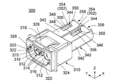
図12から図14及び図17を参照すると、ソケットインシュレータ300は、前部310と、前部310に連続する後部340とを有している。前部310は、概略直方体形状を有している。後部340は、前後方向において、前部310の後方に位置している。後部340は、前後方向に延びる二つの円筒部342を互いに平行に配置して連結したような形状を有している。ソケットインシュレータ300は、絶縁樹脂を用いて一体に形成されている。
With reference to FIGS. 12 to 14 and 17, the socket insulator 300 has a front portion 310 and a rear portion 340 continuous with the front portion 310. The front portion 310 has a substantially rectangular parallelepiped shape. The rear portion 340 is located behind the front portion 310 in the front-rear direction. The rear portion 340 has a shape in which two cylindrical portions 342 extending in the front-rear direction are arranged in parallel and connected to each other. The socket insulator 300 is integrally formed using an insulating resin.
図12、図15及び図17から理解されるように、ソケットインシュレータ300の前部310は、二つの内筒部312と、外筒部318とを有している。外筒部318は、前後方向と直交する面内において、内筒部312の周囲を囲っている。内筒部312と外筒部318との間には被挿入部328が形成されている。二つの内筒部312は、所定の間隔を空けて横方向に並んでいる。本実施の形態において、横方向はY方向である。本実施の形態において、内筒部312には、前後方向に沿って複数のスリット314が形成されている。スリット314は、後述するピンインシュレータ600の内部突起614(図22参照)に対応している。詳しくは、スリット314は、コネクタ10と相手側コネクタ50とが嵌合したとき、内部突起614を少なくとも部分的に受容する。図17から理解されるように、内筒部312は、その後端部において外筒部318に連結されている。また、図12及び図17に示されるように、外筒部318の側壁には、ガイド溝320と嵌合ロック部322が形成されている。
As can be understood from FIGS. 12, 15 and 17, the front portion 310 of the socket insulator 300 has two inner cylindrical portions 312 and an outer cylindrical portion 318. The outer cylindrical portion 318 surrounds the periphery of the inner cylindrical portion 312 in a plane orthogonal to the front-rear direction. An inserted portion 328 is formed between the inner cylindrical portion 312 and the outer cylindrical portion 318. The two inner cylindrical portions 312 are laterally aligned at predetermined intervals. In the present embodiment, the lateral direction is the Y direction. In the present embodiment, the inner cylinder portion 312 is formed with a plurality of slits 314 along the front-rear direction. The slits 314 correspond to internal protrusions 614 (see FIG. 22) of the pin insulator 600 described later. In particular, the slit 314 at least partially receives the internal projection 614 when the connector 10 and the mating connector 50 are mated. As can be understood from FIG. 17, the inner cylindrical portion 312 is connected to the outer cylindrical portion 318 at its rear end. Further, as shown in FIG. 12 and FIG. 17, a guide groove 320 and a fitting lock portion 322 are formed on the side wall of the outer cylindrical portion 318.
図17に示されるように、内筒部312は、後部340の円筒部342と連通している。換言すると、内筒部312と円筒部342とは、前後方向に延びるソケット収容部(収容部)370を形成している。つまり、ソケットインシュレータ300には、前後方向に延びる複数のソケット収容部370が形成されている。ソケット収容部370は、ストッパ200(図30参照)をソケットコンタクト100(図30参照)とともに収容する。
As shown in FIG. 17, the inner cylindrical portion 312 communicates with the cylindrical portion 342 of the rear portion 340. In other words, the inner cylindrical portion 312 and the cylindrical portion 342 form a socket accommodating portion (housing portion) 370 extending in the front-rear direction. That is, the socket insulator 300 is formed with a plurality of socket accommodating portions 370 extending in the front-rear direction. The socket accommodating portion 370 accommodates the stopper 200 (see FIG. 30) together with the socket contact 100 (see FIG. 30).
図12,図15及び図17に示されるように、内筒部312の前端部には、ソケットコンタクト100(図30参照)の前方への移動を阻止するコンタクト止め316が形成されている。コンタクト止め316は、内筒部312の径方向の内側へ突出する突出部である。コンタクト止め316は、内筒部312の内周に沿って全周に亘って形成されている。コンタクト止め316の内径、即ち、内筒部312の前端部の内径は、ソケットコンタクト100の円筒部110の外径よりも小さい。これにより、ソケット収容部370に収容されたソケットコンタクト100の前方への移動が防止される。換言すると、内筒部312の前端部は、前後方向において、常にソケットコンタクト100の円筒部110よりも前方に位置している(図30参照)。また、本実施の形態において、内筒部312の前端部は、電気用品安全法に規定される試験指がソケットコンタクト100に接触しないように形成されている。即ち、コネクタ10は、感電防止構造を備えている。内筒部312の前端部は前方へ開放しており、ピンコンタクト500(図28及び図29参照)がソケットコンタクト100(図28及び図29参照)に挿入されるのを許容する。
As shown in FIGS. 12, 15 and 17, the front end portion of the inner cylindrical portion 312 is formed with a contact stop 316 for blocking the forward movement of the socket contact 100 (see FIG. 30). The contact stopper 316 is a protrusion that protrudes inward in the radial direction of the inner cylindrical portion 312. The contact stop 316 is formed along the entire inner circumference of the inner cylindrical portion 312. The inner diameter of the contact stop 316, ie, the inner diameter of the front end of the inner cylindrical portion 312, is smaller than the outer diameter of the cylindrical portion 110 of the socket contact 100. As a result, forward movement of the socket contact 100 accommodated in the socket accommodation portion 370 is prevented. In other words, the front end portion of the inner cylindrical portion 312 is always positioned forward of the cylindrical portion 110 of the socket contact 100 in the front-rear direction (see FIG. 30). Further, in the present embodiment, the front end portion of the inner cylindrical portion 312 is formed so that the test finger defined in the Electrical Appliances and Materials Safety Act does not contact the socket contact 100. That is, the connector 10 has an electric shock preventing structure. The front end of the inner tubular portion 312 is open forward to allow the pin contacts 500 (see FIGS. 28 and 29) to be inserted into the socket contacts 100 (see FIGS. 28 and 29).
図12から図17に示されるように、外筒部318には、鍔部324と、固定フック326とが設けられている。鍔部324と固定フック326とは、機器(図示せず)のパネル70(図30参照)に固定される固定部として機能する。換言すると、外筒部318には、機器のパネル70に固定される固定部が設けられている。
As shown in FIG. 12 to FIG. 17, the outer cylindrical portion 318 is provided with a collar portion 324 and a fixing hook 326. The hook portion 324 and the fixing hook 326 function as a fixing portion fixed to the panel 70 (see FIG. 30) of the device (not shown). In other words, the outer cylindrical portion 318 is provided with a fixing portion fixed to the panel 70 of the device.
図12、図13及び図17に示されるように、ソケットインシュレータ300の後部340には、複数の開口344が形成されている。本実施の形態において、開口344は各円筒部342の上下に一つずつ形成されている。開口344の形状は、ソケットインシュレータ300を上方又は下方から見たとき矩形である。つまり、各開口344は、四つの縁部によって規定されている。四つの縁部の内、前後方向において前方に位置する前縁部348には、操作部352が設けられている。操作部352は、四つの縁部によって囲まれている。換言すると四つの縁部は、上下方向に直交する面において、操作部352の周囲を包囲する包囲部346を構成している。また、四つの縁部の内、前後方向において後方に位置する後縁部350は、後述するようにロック部として機能する。このように、ソケットインシュレータ300には、複数の操作部352と、操作部352を夫々包囲する複数の包囲部346と、複数のロック部350とが形成されている。
As shown in FIGS. 12, 13 and 17, a plurality of openings 344 are formed in the rear portion 340 of the socket insulator 300. In the present embodiment, one opening 344 is formed above and below each cylindrical portion 342. The shape of the opening 344 is rectangular when the socket insulator 300 is viewed from above or below. That is, each opening 344 is defined by four edges. An operating portion 352 is provided at a front edge 348 located forward in the front-rear direction among the four edges. The operation unit 352 is surrounded by four edges. In other words, the four edges constitute a surrounding portion 346 surrounding the periphery of the operation portion 352 in a plane perpendicular to the vertical direction. Further, among the four edge portions, the rear edge portion 350 located rearward in the front-rear direction functions as a lock portion as described later. As described above, the socket insulator 300 is formed with a plurality of operating portions 352, a plurality of surrounding portions 346 that respectively surround the operating portions 352, and a plurality of locking portions 350.
図12、図13及び図17から理解されるように、操作部352は、操作突部354と操作バネ部356とを有している。操作バネ部356は、前縁部348から後方へ延びる片持ちバネである。操作バネ部356は、弾性変形可能であり、前後方向と交差する所定方向において移動可能に操作突部354を支持している。よって、操作部352は、所定方向において操作可能であり、操作されると所定方向に変位可能である。本実施の形態において、所定方向は、上下方向成分を含む方向である。図14に示されるように、操作突部354は、操作されていない状態で、所定方向又は上下方向において包囲部346から外側へわずかに突出している。換言すると、操作突部354は、円筒部342の径方向において、外側へわずかに突出している。但し、操作突部354は、包囲部346から突出していなくてもよい。操作突部354の包囲部346からの突出量を小さくすることで、操作部352の所定方向への操作を可能にしつつ、操作部352が他の物体に引っ掛かってめくれ上がるように変形したり破損したりするのを防止することができる。なお、本実施の形態では、操作部352は操作突部354と操作バネ部356とを有しているが、操作バネ部356のみで構成されてもよい。
As understood from FIGS. 12, 13 and 17, the operation portion 352 has an operation projection 354 and an operation spring portion 356. The operating spring portion 356 is a cantilever spring extending rearward from the front edge 348. The operation spring portion 356 is elastically deformable and supports the operation projection 354 so as to be movable in a predetermined direction intersecting the front-rear direction. Therefore, the operation unit 352 can be operated in the predetermined direction, and can be displaced in the predetermined direction when operated. In the present embodiment, the predetermined direction is a direction including the vertical direction component. As shown in FIG. 14, the operation projection 354 slightly protrudes outward from the surrounding portion 346 in a predetermined direction or in the vertical direction in an unoperated state. In other words, the operation projection 354 slightly protrudes outward in the radial direction of the cylindrical portion 342. However, the operation projection 354 may not protrude from the surrounding portion 346. By reducing the amount of protrusion of the operation projection 354 from the surrounding portion 346, the operation portion 352 is deformed or broken so as to be caught up with another object and turned up while enabling the operation in the predetermined direction of the operation portion 352. Can be prevented. In the present embodiment, the operation portion 352 includes the operation projection 354 and the operation spring portion 356. However, the operation portion 352 may be configured of only the operation spring portion 356.
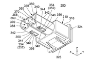
図13、図16及び図17に示されるように、ソケットインシュレータ300の後部340の各円筒部342には、その内壁に一対の浅溝部360が形成されている。一対の浅溝部360は、円筒部342の内壁の上部及び下部に位置している。浅溝部360は、上下方向外側に凹んでおり、かつ前後方向に延びている。各浅溝部360内には、それに対応する操作部352が部分的に露出している。各浅溝部360は、ストッパ200(図8参照)の一つのロックバネ部228とその両側に位置する側部突起232とに対応している。各浅溝部360は、コネクタ10と相手側コネクタ50とが互いに嵌合したときに、ロックバネ部228とその両側に位置する側部突起232とを受容する大きさを有している。
As shown in FIGS. 13, 16 and 17, each cylindrical portion 342 of the rear portion 340 of the socket insulator 300 is provided with a pair of shallow grooves 360 on its inner wall. The pair of shallow grooves 360 are located at the upper and lower portions of the inner wall of the cylindrical portion 342. The shallow groove portion 360 is recessed outward in the vertical direction, and extends in the front-rear direction. In each shallow groove portion 360, a corresponding operation portion 352 is partially exposed. Each shallow groove portion 360 corresponds to one lock spring portion 228 of the stopper 200 (see FIG. 8) and side protrusions 232 located on both sides thereof. Each shallow groove portion 360 has a size to receive the lock spring portion 228 and the side projection 232 located on both sides when the connector 10 and the mating connector 50 are fitted to each other.
図12から図14及び図17に示されるように、ソケットインシュレータ300の後部340の後端には、前後方向において前方へ凹む複数の凹部358が形成されている。凹部358は、前後方向において、浅溝部360の後方に位置している。本実施の形態において、凹部358は四つである。詳しくは、凹部358は、各円筒部342の上下後端に夫々形成されている。凹部358の夫々は、回転防止突起230(図28又は図29参照)の各対に対応している。
As shown in FIG. 12 to FIG. 14 and FIG. 17, the rear end of the rear portion 340 of the socket insulator 300 is formed with a plurality of recessed portions 358 that are recessed forward in the front-rear direction. The recess 358 is located behind the shallow groove 360 in the front-rear direction. In the present embodiment, the number of recesses 358 is four. More specifically, the recesses 358 are respectively formed at the upper and lower rear ends of the respective cylindrical portions 342. Recesses 358 correspond to respective pairs of anti-rotation protrusions 230 (see FIG. 28 or 29).
図3及び図25から理解されるように、ソケットコンタクト100のケーブル80への取り付けは、ケーブル取付部130をケーブル80の芯線810に圧着することにより行われる。その結果、図26から理解されるように、前後方向に沿って見たとき、ケーブル取付部130のサイズは、ケーブル80のサイズよりも小さくなる。これにより、ケーブル取付部130は、ケーブル80の端部とともにストッパ200の受容部240内に受容されることが可能である。
As understood from FIGS. 3 and 25, the attachment of the socket contact 100 to the cable 80 is performed by crimping the cable attachment portion 130 to the core wire 810 of the cable 80. As a result, as seen from FIG. 26, the size of the cable attachment portion 130 becomes smaller than the size of the cable 80 when viewed along the front-rear direction. Thereby, the cable attachment 130 can be received in the receiver 240 of the stopper 200 together with the end of the cable 80.
図3及び図26から理解されるように、ストッパ200のソケットコンタクト100への取り付けは、ソケットコンタクト100をストッパ200の後方からストッパ200に挿入することにより行われる。図26に示されるように、ソケットコンタクト100の円筒部110の前端124はストッパ200を通り抜け、前後方向において、ストッパ200の前端214よりも前方に位置する。前述のように、ストッパ200の被係止部212は、ソケットコンタクト100の係止バネ118及び係止突起120の通過を阻止するように形成されている。しかし、係止バネ118は、前後方向において後方へ延びておりかつ弾性変形可能である。そのため、係止バネ118は、被係止部212に接触すると弾性変形し、被係止部212を越えて前方へ移動することができる。係止バネ118は、被係止部212の前方へ移動すると、その復元力により元の状態に戻る。こうして、係止バネ118は、前後方向において、ストッパ200の前方に位置する。一方、係止突起120は、被係止部212に突き当たる。係止突起120は、弾性変形することができず、ソケットコンタクト100はストッパ200に対して相対的に前方へ移動することが規制される。こうして、ストッパ200は、ソケットコンタクト100に取り付けられる。ストッパ200がソケットコンタクト100に取り付けられた状態で、ストッパ200に対してソケットコンタクト100を後方へ移動させようとすると、係止バネ118が被係止部212に突き当たる。その結果、ソケットコンタクト100は、ストッパ200に対して相対的に後方へ移動することが規制される。なお、治具(図示せず)を用い、円筒部110の径方向において、係止バネ118を内側へ弾性変形させれば、ストッパ200をソケットコンタクト100から取り外すことができる。
As understood from FIGS. 3 and 26, attachment of the stopper 200 to the socket contact 100 is performed by inserting the socket contact 100 into the stopper 200 from the rear of the stopper 200. As shown in FIG. 26, the front end 124 of the cylindrical portion 110 of the socket contact 100 passes through the stopper 200 and is positioned forward of the front end 214 of the stopper 200 in the front-rear direction. As described above, the locked portion 212 of the stopper 200 is formed to block the passage of the locking spring 118 and the locking projection 120 of the socket contact 100. However, the locking spring 118 extends rearward in the front-rear direction and is elastically deformable. Therefore, the locking spring 118 elastically deforms when contacting the locked portion 212, and can move forward beyond the locked portion 212. When the locking spring 118 moves forward of the locked portion 212, it returns to its original state by its restoring force. Thus, the locking spring 118 is located in front of the stopper 200 in the front-rear direction. On the other hand, the locking projection 120 abuts on the locked portion 212. The locking projection 120 can not be elastically deformed, and the socket contact 100 is restricted from moving forward relative to the stopper 200. Thus, the stopper 200 is attached to the socket contact 100. When the socket contact 100 is to be moved backward with respect to the stopper 200 in a state where the stopper 200 is attached to the socket contact 100, the locking spring 118 abuts on the locked portion 212. As a result, the socket contact 100 is restricted from moving rearward relative to the stopper 200. The stopper 200 can be removed from the socket contact 100 by elastically deforming the locking spring 118 inward in the radial direction of the cylindrical portion 110 using a jig (not shown).
図26に示されるように、ストッパ200がソケットコンタクト100に取り付けられた状態で、ソケットコンタクト100のケーブル取付部130は、ストッパ200の受容部240内に位置し、ケーブル80の端部もストッパ200の受容部240内に位置する。ストッパ200の被係止部212は、前後方向において、係止バネ118と係止突起120との間に位置し、ソケットコンタクト100は、ストッパ200に対して相対的な前後方向の移動を規制される。一方、ストッパ200は、前後方向に沿った軸を回転軸とするソケットコンタクト100の回転を規制しない。そのため、ソケットコンタクト100は、ケーブル80に接続されていない状態であれば、前後方向に沿った軸を回転軸として自由に回転することができる。換言すると、ソケットコンタクト100は、ストッパ200に回転可能に保持される。
As shown in FIG. 26, with the stopper 200 attached to the socket contact 100, the cable attachment portion 130 of the socket contact 100 is located within the receiving portion 240 of the stopper 200, and the end of the cable 80 is also the stopper 200. Located within the receptacle 240 of the The locked portion 212 of the stopper 200 is located between the locking spring 118 and the locking projection 120 in the front-rear direction, and the socket contact 100 is restricted from moving in the front-rear direction relative to the stopper 200. Ru. On the other hand, the stopper 200 does not restrict the rotation of the socket contact 100 whose axis of rotation is the axis along the front-rear direction. Therefore, in a state where the socket contact 100 is not connected to the cable 80, the socket contact 100 can freely rotate with the axis along the front-rear direction as a rotation axis. In other words, the socket contact 100 is rotatably held by the stopper 200.
図3及び図30から理解されるように、ソケットコンタクト100に取り付けられたストッパ200は、ソケットインシュレータ300の後方からソケット収容部370(図17参照)に挿入される。このとき、回転防止突起230は、ストッパ200の上下を示す指標となる。また、図8及び図13から理解されるように、ストッパ200の側部突起232とソケットインシュレータ300の浅溝部360とが、ストッパ200の周方向の位置決めを行う位置決め機構として働く。即ち、浅溝部360は、ロックバネ部228及びその両側に位置する側部突起232を受容すると、前後方向に沿った軸を回転軸とするストッパ200の回転を規制する。ロックバネ部228は、側部突起232の間に位置しており、ソケットインシュレータ300と直接接触しないように保護されている。
As understood from FIGS. 3 and 30, the stopper 200 attached to the socket contact 100 is inserted from the rear of the socket insulator 300 into the socket accommodating portion 370 (see FIG. 17). At this time, the rotation preventing protrusion 230 is an index indicating the upper and lower sides of the stopper 200. Further, as can be understood from FIGS. 8 and 13, the side projection 232 of the stopper 200 and the shallow groove portion 360 of the socket insulator 300 function as a positioning mechanism for positioning the stopper 200 in the circumferential direction. That is, when the shallow groove portion 360 receives the lock spring portion 228 and the side protrusions 232 located on both sides thereof, the shallow groove portion 360 restricts the rotation of the stopper 200 whose axis of rotation is the axis in the front-rear direction. The lock spring portion 228 is located between the side protrusions 232 and is protected from direct contact with the socket insulator 300.
図30から理解されるように、ストッパ200とともにソケット収容部370(図17参照)に収容されたソケットコンタクト100の円筒部110の前端124は、ソケットインシュレータ300の内筒部312の前端付近にまで達すると、コンタクト止め316に突き当たる。前述のように、コンタクト止め316の内径がソケットコンタクト100の円筒部110の外径よりも小さいからである。こうして、ソケットコンタクト100及びストッパ200のソケットインシュレータ300に対する前方への相対的な移動が規制される。
As understood from FIG. 30, the front end 124 of the cylindrical portion 110 of the socket contact 100 housed in the socket housing portion 370 (see FIG. 17) together with the stopper 200 extends to the vicinity of the front end of the inner cylindrical portion 312 of the socket insulator 300. Once reached, it strikes contact stop 316. This is because the inner diameter of the contact stop 316 is smaller than the outer diameter of the cylindrical portion 110 of the socket contact 100 as described above. Thus, the forward relative movement of socket contact 100 and stopper 200 with respect to socket insulator 300 is restricted.
図30に示されるように、ストッパ200は、ソケットインシュレータ300の後部340において、ソケット収容部370(図17参照)に収容される。ソケット収容部370は、被ロック部222の進入を阻止する形状と大きさを有しているが、被ロック部222は、ロックバネ部228の弾性変形によりソケット収容部370の内部へ進入することができる。被ロック部222の前面224は、ソケット収容部370への進入を容易にするように、前後方向に対して傾斜している。ソケット収容部370の内部に進入した被ロック部222は、前後方向においてロック部350よりも前方に移動すると、ロックバネ部228の復元力により、少なくとも部分的に開口344(図17参照)内に進入する。その結果、被ロック部222は、前後方向においてロック部350の前方に位置する。換言すると、ロック部350は、前後方向において、被ロック部222の後方に位置する。被ロック部222の後面226は、前後方向に直交している。そのため、ソケットインシュレータ300に対してストッパ200を後方へ相対的に移動させると、被ロック部222がロック部350に突き当たる。換言すると、ロック部350は、ソケットインシュレータ300に対するストッパ200の後方への相対的な移動を規制する。その結果、ストッパ200はソケットインシュレータ300のソケット収容部370内に収容された状態が維持される。
As shown in FIG. 30, the stopper 200 is accommodated in the socket accommodating portion 370 (see FIG. 17) at the rear portion 340 of the socket insulator 300. Although the socket accommodation portion 370 has a shape and a size that prevent entry of the locked portion 222, the locked portion 222 may enter the interior of the socket accommodation portion 370 by elastic deformation of the lock spring portion 228. it can. The front surface 224 of the locked portion 222 is inclined in the front-rear direction so as to facilitate entry into the socket accommodation portion 370. The locked portion 222 which has entered the inside of the socket accommodation portion 370 moves at least partially into the opening 344 (see FIG. 17) by the restoring force of the lock spring portion 228 when it moves forward of the locking portion 350 in the longitudinal direction. Do. As a result, the locked portion 222 is located in front of the locking portion 350 in the front-rear direction. In other words, the lock portion 350 is located rearward of the locked portion 222 in the front-rear direction. The rear surface 226 of the locked portion 222 is orthogonal to the front-rear direction. Therefore, when the stopper 200 is relatively moved rearward with respect to the socket insulator 300, the locked portion 222 abuts on the locking portion 350. In other words, the lock portion 350 regulates the relative movement of the stopper 200 with respect to the socket insulator 300 to the rear. As a result, the state in which the stopper 200 is housed in the socket housing portion 370 of the socket insulator 300 is maintained.
図30から理解されるように、ストッパ200がソケット収容部370(図17参照)に収容された状態において、操作部352の操作突部354は、被ロック部222の近くに位置している。本実施の形態において、操作突部354は、被ロック部222の斜め前方、かつストッパ200の径方向において、外側に位置している。本実施の形態において、操作部352は、部分的に被ロック部222の前面224に接しているが、操作部352は被ロック部222に接していなくてもよい。操作部352は、操作突部354を所定方向に操作することにより、ロックバネ部228を弾性変形させることができる位置にあればよい。
As understood from FIG. 30, in the state where the stopper 200 is accommodated in the socket accommodation portion 370 (see FIG. 17), the operation projection 354 of the operation portion 352 is located near the locked portion 222. In the present embodiment, the operation projection 354 is located on the diagonally front side of the locked portion 222 and on the outer side in the radial direction of the stopper 200. In the present embodiment, the operation unit 352 is partially in contact with the front surface 224 of the locked portion 222, but the operation unit 352 may not be in contact with the locked portion 222. The operation part 352 should just be in the position which can elastically deform the lock spring part 228 by operating the operation protrusion 354 in a predetermined direction.
図30から理解されるように、操作突部354、即ち操作部352を所定方向に操作し、ストッパ200の径方向において、被ロック部222をロック部350の内側へ移動させると、ロック部350による被ロック部222の規制が解除される。規制が解除された状態で、ソケットインシュレータ300に対してストッパ200を相対的に後方へ移動させると、ストッパ200及びソケットコンタクト100をソケット収容部370(図17参照)から引き抜くことができる。このように、本実施の形態では、ソケットコンタクト100とソケットインシュレータ300との組み合わせにストッパ200を加えるという簡易な構成で、治具を用いることなく、ソケットコンタクト100をストッパ200とともに、ソケットインシュレータ300から取り外すことができる。しかも、本実施の形態において、操作部352の操作方向は前後方向と交差する所定方向である。そのため、操作部352の操作とソケットコンタクト100の引き抜きとを一連動作として行うことができる。よって、ソケットインシュレータ300が機器のパネル70に固定され、操作部352が機器の内側に位置した状況下においても、ソケットインシュレータ300からソケットコンタクト100を容易に取り外すことができる。
As understood from FIG. 30, when the operation projection 354, that is, the operation portion 352 is operated in a predetermined direction, and the locked portion 222 is moved inward of the lock portion 350 in the radial direction of the stopper 200, the lock portion 350. The restriction of the locked portion 222 is released. When the stopper 200 is moved relatively backward with respect to the socket insulator 300 in a state where the restriction is released, the stopper 200 and the socket contact 100 can be pulled out from the socket accommodating portion 370 (see FIG. 17). As described above, in the present embodiment, the socket contact 100 is combined with the stopper 200 from the socket insulator 300 without using a jig with a simple configuration in which the stopper 200 is added to the combination of the socket contact 100 and the socket insulator 300. It can be removed. Moreover, in the present embodiment, the operation direction of the operation unit 352 is a predetermined direction intersecting with the front-rear direction. Therefore, the operation of the operation unit 352 and the withdrawal of the socket contact 100 can be performed as a series of operations. Therefore, the socket contact 100 can be easily removed from the socket insulator 300 even in a situation where the socket insulator 300 is fixed to the panel 70 of the device and the operation unit 352 is positioned inside the device.
図28から図30に示されるように、ストッパ200がソケットインシュレータ300に保持された状態において、凹部358は、夫々、一対の回転防止突起230を受容する。回転防止突起230及び凹部358は、ソケットインシュレータ300に対するストッパ200の相対的な回転を規制する回転規制機構として機能する。詳しくは、ストッパ200が前後方向に沿った軸を回転軸として回転しようとすると、円筒部342の周方向において、回転防止突起230が凹部358の縁に突き当たり、ソケットインシュレータ300に対するストッパ200の相対的な回転が規制される。こうして、ストッパ200は、ソケットインシュレータ300に回転不能に保持される。その一方で、依然として、ソケットコンタクト100は、ストッパ200に対して相対的に回転可能である。つまり、ソケットコンタクト100は、ソケットインシュレータ300に対しても相対的に回転可能である。
As shown in FIGS. 28-30, in the state where stopper 200 is held by socket insulator 300, recesses 358 receive a pair of anti-rotation protrusions 230, respectively. The rotation preventing protrusion 230 and the recess 358 function as a rotation restricting mechanism that restricts relative rotation of the stopper 200 with respect to the socket insulator 300. Specifically, when the stopper 200 tries to rotate with the axis along the front-rear direction as a rotation axis, the rotation preventing protrusion 230 abuts on the edge of the recess 358 in the circumferential direction of the cylindrical portion 342 and the relative position of the stopper 200 to the socket insulator 300 Rotation is restricted. Thus, the stopper 200 is non-rotatably held by the socket insulator 300. On the other hand, the socket contact 100 is still rotatable relative to the stopper 200. That is, the socket contact 100 is also rotatable relative to the socket insulator 300.
図18から図20を参照すると、ピンコンタクト500は、接触部510と、被保持部520と、ケーブル取付部530とを有している。接触部510は、円筒形の前部512と円錐形の後部514とを有している。被保持部520は、前後方向において、接触部510の前方に位置する。被保持部520の形状は、概ね円筒形である。被保持部520の外径は、接触部510の外径よりも大きい。被保持部520には、被係止バネ522及び被係止突起524が形成されている。被係止バネ522は、前後方向において、被保持部520の後端部から前方へ向かって斜めに延び、且つ被保持部520の径方向において、被保持部520から外側に突出している。被係止突起524は、前後方向において、被係止バネ522の前方に位置し、かつ被係止バネ522から離れている。被係止突起524は、被保持部520の径方向において、被保持部520から外側へ突出している。ケーブル取付部530は、前後方向において、被保持部520の前方に位置している。図27に示されるように、ケーブル取付部530は、ケーブル80の芯線810に圧着される部位である。ピンコンタクト500は、一枚の金属板を打ち抜き加工及び曲げ加工して形成される。
Referring to FIGS. 18 to 20, the pin contact 500 has a contact portion 510, a held portion 520, and a cable attachment portion 530. The contact portion 510 has a cylindrical front portion 512 and a conical rear portion 514. The held portion 520 is located in front of the contact portion 510 in the front-rear direction. The shape of the held portion 520 is generally cylindrical. The outer diameter of the held portion 520 is larger than the outer diameter of the contact portion 510. In the held portion 520, a locked spring 522 and a locked projection 524 are formed. The locked spring 522 obliquely extends forward from the rear end of the held portion 520 in the front-rear direction, and protrudes outward from the held portion 520 in the radial direction of the held portion 520. The locking projection 524 is located in front of the locking spring 522 in the front-rear direction and is separated from the locking spring 522. The locked projection 524 protrudes outward from the held portion 520 in the radial direction of the held portion 520. The cable attachment portion 530 is located in front of the held portion 520 in the front-rear direction. As shown in FIG. 27, the cable attachment portion 530 is a portion crimped to the core wire 810 of the cable 80. The pin contacts 500 are formed by punching and bending a single metal plate.
図21から図24を参照すると、ピンインシュレータ600は、挿入部610と、胴部620と、基部630とを有している。挿入部610は、二つの円筒612を横方向に平行に並べて連結したような形状を有している。挿入部610は、ソケットインシュレータ300の被挿入部328(図17参照)に挿入可能に形成されている。本実施の形態において、挿入部610は、ピンコンタクト500(図31参照)を保持した状態で、電気用品安全法に規定される試験指がピンコンタクト500に接触しないように形成されている。即ち、相手側コネクタ50は、感電防止構造を有している。詳しくは、円筒612の内壁に、前後方向に沿って延びる複数の内部突起614が形成されている。本実施の形態では、各円筒612に、上下方向内側へ突出する一対の内部突起614と横方向内側へ突出する一対の内部突起614が形成されている。内部突起614は、円筒612の実質的な内径を縮小し、指を入り難くして感電を防止する。
Referring to FIGS. 21-24, the pin insulator 600 has an insertion portion 610, a body portion 620, and a base portion 630. The insertion portion 610 has a shape in which two cylinders 612 are arranged side by side and connected in parallel in the lateral direction. The insertion portion 610 is formed so as to be insertable into the inserted portion 328 (see FIG. 17) of the socket insulator 300. In the present embodiment, the insertion portion 610 is formed such that the test finger defined in the Electrical Appliances and Materials Safety Act does not contact the pin contact 500 while holding the pin contact 500 (see FIG. 31). That is, the mating connector 50 has an electric shock prevention structure. Specifically, the inner wall of the cylinder 612 is formed with a plurality of internal protrusions 614 extending in the front-rear direction. In the present embodiment, each cylinder 612 is formed with a pair of internal protrusions 614 projecting inward in the vertical direction and a pair of internal protrusions 614 projecting inward in the lateral direction. The internal projection 614 reduces the substantial inside diameter of the cylinder 612, making it difficult for the finger to enter and preventing electric shock.
図21から図24に示されるように、胴部620は、前後方向において挿入部610の前方に位置している。胴部620もまた二つの円筒622を横方向に平行に並べて連結した形状を有している。図24から理解されるように、胴部620の各円筒622には係止部624が形成されている。係止部624は、円筒622の内周に沿って全周に亘り形成された突出部である。胴部620の各円筒622の外径は、挿入部610の各円筒612の外径よりも小さい。図21から図24に示されるように、基部630は、前後方向において、胴部620の前方に位置している。基部630は、二つの円筒632とその周囲に形成された複数のフィン634を有している。ピンインシュレータ600は、絶縁樹脂を用いて一体に形成されている。
As shown in FIGS. 21 to 24, the body 620 is located in front of the insertion portion 610 in the front-rear direction. The body 620 also has a shape in which two cylinders 622 are arranged side by side and connected in parallel in the lateral direction. As can be understood from FIG. 24, each cylinder 622 of the body 620 is formed with a locking portion 624. The locking portion 624 is a protrusion formed along the entire inner circumference of the cylinder 622. The outer diameter of each cylinder 622 of the body 620 is smaller than the outer diameter of each cylinder 612 of the insertion portion 610. As shown in FIG. 21 to FIG. 24, the base portion 630 is located in front of the body 620 in the front-rear direction. The base 630 has two cylinders 632 and a plurality of fins 634 formed around them. The pin insulator 600 is integrally formed using an insulating resin.
図24から理解されるように、ピンインシュレータ600は、挿入部610、胴部620及び基部630を貫く複数のピン収容部640を備えている。本実施の形態において、ピン収容部640の数は二つである。また、図21から図24に示されるように、ピンインシュレータ600の横方向外側には、嵌合被ロック部650が設けられている。嵌合被ロック部650は、嵌合被ロック突起652と、嵌合被ロック突起652を支持する嵌合被ロックバネ部654とを有している。嵌合被ロックバネ部654は、挿入部610から基部630に跨るように形成された両持ちバネである。嵌合被ロックバネ部654は、弾性変形可能であり、嵌合被ロック突起652を横方向に移動可能に支持している。
As understood from FIG. 24, the pin insulator 600 includes a plurality of pin receiving portions 640 penetrating the insertion portion 610, the body portion 620 and the base portion 630. In the present embodiment, the number of pin housings 640 is two. Further, as shown in FIGS. 21 to 24, a fitting locked portion 650 is provided on the outer side in the lateral direction of the pin insulator 600. The fitted locked portion 650 includes a fitted locked projection 652 and a fitted locked spring portion 654 that supports the fitted locked projection 652. The fitted lock spring portion 654 is a double-ended spring formed so as to extend from the insertion portion 610 to the base portion 630. The fitted locked spring portion 654 is elastically deformable, and supports the fitted locked projection 652 so as to be movable in the lateral direction.
図3及び図27から理解されるように、ピンコンタクト500はケーブル80の端部に取り付けられる。図27に示されるように、ピンコンタクト500のケーブル80への取り付けは、ケーブル取付部530をケーブル80の芯線810に圧着することにより行われる。その結果、図28及び図29から理解されるように、前後方向に沿って見たとき、ケーブル取付部530のサイズは、ケーブル80のサイズよりも小さくなる。
As seen in FIGS. 3 and 27, pin contacts 500 are attached to the end of cable 80. FIG. As shown in FIG. 27, the attachment of the pin contact 500 to the cable 80 is performed by crimping the cable attachment portion 530 to the core wire 810 of the cable 80. As a result, as seen from FIGS. 28 and 29, the size of the cable attachment portion 530 is smaller than the size of the cable 80 when viewed along the front-rear direction.
図3及び図31から理解されるように、ピンコンタクト500のピンインシュレータ600への取り付けは、ピンコンタクト500を、ピンインシュレータ600の前方からピン収容部640へ挿入することにより行われる。ここで、胴部620に形成された係止部624は、被係止バネ522及び被係止突起524の通過を阻止するように形成されている。図31から理解されるように、被係止バネ522は係止部624に接触すると、弾性変形し、前後方向において、係止部624の後方へ移動することができる。そして、被係止バネ522は係止部624の後方へ一旦移動するとその復元力により元の状態に戻る。一方、被係止突起524は、係止部624に突き当たり、前後方向において係止部624の後方へ移動することができない。こうして、係止部624は、前後方向において、被係止バネ522と被係止突起524との間に位置する。その結果、ピンインシュレータ600に対するピンコンタクト500の前後方向の相対的な移動は、係止部624によって規制される。こうして、被保持部520がピンインシュレータ600の胴部620によって保持される。ピンインシュレータ600は、前後方向に沿った軸を回転軸とするピンコンタクト500の回転を阻止していない。つまり、ピンコンタクト500は、ピンインシュレータ600に回転可能に保持されている。
As understood from FIGS. 3 and 31, the attachment of the pin contact 500 to the pin insulator 600 is performed by inserting the pin contact 500 into the pin housing portion 640 from the front of the pin insulator 600. Here, the locking portion 624 formed on the body portion 620 is formed to block the passage of the locked spring 522 and the locked projection 524. As understood from FIG. 31, when the locked spring 522 contacts the locking portion 624, it elastically deforms and can move rearward of the locking portion 624 in the front-rear direction. Then, once the locked spring 522 moves to the rear of the locking portion 624, it returns to its original state by its restoring force. On the other hand, the locked projection 524 abuts on the locking portion 624 and can not move rearward of the locking portion 624 in the front-rear direction. Thus, the locking portion 624 is located between the locked spring 522 and the locked projection 524 in the front-rear direction. As a result, the relative movement of the pin contact 500 in the front-rear direction with respect to the pin insulator 600 is restricted by the locking portion 624. Thus, the held portion 520 is held by the body portion 620 of the pin insulator 600. The pin insulator 600 does not prevent the rotation of the pin contact 500 whose axis of rotation is the axis along the front-rear direction. That is, the pin contact 500 is rotatably held by the pin insulator 600.
図28から理解されるように、コネクタ10が相手側コネクタ50と嵌合する際、挿入部610は被挿入部328に挿入され、嵌合被ロック部650はガイド溝320によってガイドされる。また、挿入部610の内部突起614は、内筒部312のスリット314に少なくとも部分的に受容される。それから、図28及び図29から理解されるように、嵌合被ロック突起652は、嵌合ロック部322にロックされる。そして、嵌合ロック部322は、前後方向において、嵌合被ロック突起652の前方への移動を規制する。こうして、コネクタ10と相手側コネクタ50との嵌合状態がロックされる。嵌合被ロックバネ部654の一部を、横方向において、内側へ押圧し、嵌合被ロック突起652を内側へ移動させると、嵌合ロック部322による嵌合被ロック突起652のロックが解除される。その状態で、コネクタ10と相手側コネクタ50とを互いに分離することができる。
As understood from FIG. 28, when the connector 10 is fitted with the mating connector 50, the insertion portion 610 is inserted into the inserted portion 328, and the fitted locked portion 650 is guided by the guide groove 320. Also, the internal projection 614 of the insertion portion 610 is at least partially received in the slit 314 of the inner cylindrical portion 312. Then, as understood from FIGS. 28 and 29, the fitting locked projection 652 is locked to the fitting lock 322. Then, the fitting lock portion 322 restricts the forward movement of the fitting locked projection 652 in the front-rear direction. Thus, the fitted state of the connector 10 and the mating connector 50 is locked. When a part of the fitting lock spring portion 654 is pressed inward in the lateral direction to move the fitting lock projection 652 inward, the lock of the fitting lock projection 652 by the fitting lock part 322 is released. Ru. In this state, the connector 10 and the mating connector 50 can be separated from each other.
以上、本発明について、実施の形態を掲げて説明してきたが、本発明は、上記実施の形態に限定されるものではなく、本発明の主旨を逸脱しない範囲で種々の変形、変更が可能である。例えば、上記実施の形態においては、ソケットコンタクト100とソケットインシュレータ300の組み合わせにストッパ200を加える例について説明したが、ピンコンタクト500とピンインシュレータ600との組み合わせにストッパ200を加えるようにしてもよい。
As mentioned above, although the present invention has been described by citing embodiments, the present invention is not limited to the above embodiments, and various modifications and changes can be made without departing from the gist of the present invention. is there. For example, although the example in which the stopper 200 is added to the combination of the socket contact 100 and the socket insulator 300 has been described in the above embodiment, the stopper 200 may be added to the combination of the pin contact 500 and the pin insulator 600.
本発明は2017年7月14日に日本国特許庁に提出された日本特許出願第2017-137900号に基づいており、その内容は参照することにより本明細書の一部をなす。
The present invention is based on Japanese Patent Application No. 2017-137900 filed on Jul. 14, 2017 by the Japan Patent Office, the contents of which are incorporated herein by reference.
本発明の最良の実施の形態について説明したが、当業者には明らかなように、本発明の精神を逸脱しない範囲で実施の形態を変形することが可能であり、そのような実施の形態は本発明の範囲に属するものである。
Although the best embodiment of the present invention has been described, as is apparent to those skilled in the art, the embodiment can be modified without departing from the spirit of the present invention, and such an embodiment can be It belongs to the scope of the present invention.
10 コネクタ
100 ソケットコンタクト(端子)
110 円筒部
112 接点支持部
114 接点
116 先端
118 係止バネ
120 係止突起
122 ガイド部
124 前端
126 後端
130 ケーブル取付部
200 ストッパ
210 前部
212 被係止部
214 前端
220 後部
222 被ロック部
224 前面
226 後面
228 ロックバネ部
230 回転防止突起
232 側部突起
240 受容部
300 ソケットインシュレータ
310 前部
312 内筒部
314 スリット
316 コンタクト止め
318 外筒部
320 ガイド溝
322 嵌合ロック部
324 鍔部
326 固定フック
328 被挿入部
340 後部
342 円筒部
344 開口
346 包囲部
348 前縁部
350 後縁部(ロック部)
352 操作部
354 操作突部
356 操作バネ部
358 凹部
360 浅溝部
370 ソケット収容部(収容部)
50 相手側コネクタ
500 ピンコンタクト
510 接触部
512 前部
514 後部
520 被保持部
522 被係止バネ
524 被係止突起
530 ケーブル取付部
600 ピンインシュレータ
610 挿入部
612 円筒
614 内部突起
620 胴部
622 円筒
624 係止部
630 基部
632 円筒
634 フィン
640 ピン収容部
650 嵌合被ロック部
652 嵌合被ロック突起
654 嵌合被ロックバネ部
70 パネル
80 ケーブル
810 芯線 10connector 100 socket contact (terminal)
DESCRIPTION OFSYMBOLS 110 cylindrical part 112 contact point support part 114 contact point 116 tip spring 118 locking projection 122 guide part 124 front end 126 rear end 130 cable attachment part 200 stopper 210 front part 212 locked part 214 front end 220 rear part 222 locked part 224 Front surface 226 Rear surface 228 Lock spring 230 Rotation preventing projection 232 Side projection 240 Receiver 300 Socket insulator 310 Front 312 Inner cylinder 314 Slit 316 Contact stopper 318 Outer cylinder 320 Guide groove 322 Mating lock part 324 Flange 326 Fixing hook 328 inserted portion 340 rear portion 342 cylindrical portion 344 opening 346 surrounding portion 348 front edge portion 350 rear edge portion (locking portion)
352operation portion 354 operation projection 356 operation spring portion 358 recessed portion 360 shallow groove portion 370 socket receiving portion (housing portion)
Reference Signs List 50 mating connector 500 pin contact 510 contact portion 512 front portion 514 rear portion 520 held portion 522 supported spring 524 locked projection 530 cable mounting portion 600 pin insulator 610 insertion portion 612 cylinder 614 internal protrusion 620 body 622 cylinder 624 Locking part 630 Base 632 Cylindrical 634 Fin 640 Pin housing part 650 Mating locked part 652 Mating locked projection 654 Mating locked spring part 70 Panel 80 Cable 810 Core wire
100 ソケットコンタクト(端子)
110 円筒部
112 接点支持部
114 接点
116 先端
118 係止バネ
120 係止突起
122 ガイド部
124 前端
126 後端
130 ケーブル取付部
200 ストッパ
210 前部
212 被係止部
214 前端
220 後部
222 被ロック部
224 前面
226 後面
228 ロックバネ部
230 回転防止突起
232 側部突起
240 受容部
300 ソケットインシュレータ
310 前部
312 内筒部
314 スリット
316 コンタクト止め
318 外筒部
320 ガイド溝
322 嵌合ロック部
324 鍔部
326 固定フック
328 被挿入部
340 後部
342 円筒部
344 開口
346 包囲部
348 前縁部
350 後縁部(ロック部)
352 操作部
354 操作突部
356 操作バネ部
358 凹部
360 浅溝部
370 ソケット収容部(収容部)
50 相手側コネクタ
500 ピンコンタクト
510 接触部
512 前部
514 後部
520 被保持部
522 被係止バネ
524 被係止突起
530 ケーブル取付部
600 ピンインシュレータ
610 挿入部
612 円筒
614 内部突起
620 胴部
622 円筒
624 係止部
630 基部
632 円筒
634 フィン
640 ピン収容部
650 嵌合被ロック部
652 嵌合被ロック突起
654 嵌合被ロックバネ部
70 パネル
80 ケーブル
810 芯線 10
DESCRIPTION OF
352
Claims (8)
- ケーブルに取り付けられるコネクタであって、
複数の端子と、複数のストッパと、ソケットインシュレータとを備えており、
前記端子の夫々は、円筒部とケーブル取付部とを有しており、
前記ケーブル取付部は、前記ケーブルに取り付けられる部位であり、前後方向において前記円筒部よりも後方に位置しており、
前記ストッパは、前記端子に夫々取り付けられており、
前記ストッパの夫々には、被ロック部とロックバネ部とが設けられており、
前記被ロック部は、前記ロックバネ部に支持されており、
前記ロックバネ部は、弾性変形可能であり、
前記ソケットインシュレータには、複数の収容部と、複数のロック部と、複数の操作部が形成されており、
前記収容部は、前後方向に延びており、
前記ストッパは、前記端子とともに前記収容部に夫々収容されており、
前記収容部の前端部は開放しており、且つ前記前後方向において前記円筒部よりも前方に位置しており、
前記ロック部は、前記ストッパが前記収容部に収容された状態において、前記被ロック部の後方に位置しており、且つ前記ストッパの後方への移動を夫々規制しており、
前記操作部は、前記前後方向と交差する所定方向において操作可能であり、操作されると、前記被ロック部を前記所定方向に沿って移動させて前記ロック部による前記被ロック部の規制を夫々解除する
コネクタ。 A connector attached to the cable,
It has multiple terminals, multiple stoppers, and a socket insulator,
Each of the terminals has a cylindrical portion and a cable attachment portion,
The cable attachment portion is a portion attached to the cable, and is positioned rearward of the cylindrical portion in the front-rear direction,
The stoppers are respectively attached to the terminals,
Each of the stoppers is provided with a locked portion and a lock spring portion,
The locked portion is supported by the lock spring portion,
The lock spring portion is elastically deformable.
The socket insulator is formed with a plurality of housing portions, a plurality of lock portions, and a plurality of operation portions.
The housing portion extends in the front-rear direction,
The stopper is accommodated in the accommodating portion together with the terminal,
The front end portion of the housing portion is open, and is located forward of the cylindrical portion in the front-rear direction,
The lock portion is located rearward of the locked portion in a state in which the stopper is accommodated in the accommodation portion, and restricts the rearward movement of the stopper.
The operation portion is operable in a predetermined direction intersecting the front-rear direction, and when operated, the locked portion is moved along the predetermined direction so that the lock portion is regulated by the lock portion. Connector to release. - 請求項1に記載のコネクタであって、
前記端子の夫々には、係止バネと、係止突起とが設けられており、
前記係止バネは、前記円筒部の径方向において、前記円筒部から外側に突出しており、
前記係止突起は、前記前後方向において、前記係止バネの後方に位置しかつ離れており、
前記係止突起は、前記径方向において、前記円筒部から外側に突出しており、
前記ケーブル取付部は、前記前後方向において前記係止突起よりも後方に位置しており、
前記ストッパの夫々には、被係止部が形成されており、
前記ストッパが前記端子に夫々取り付けられた状態において、前記被係止部は、前記前後方向において、前記係止バネと前記係止突起の間に位置している
コネクタ。 The connector according to claim 1, wherein
Each of the terminals is provided with a locking spring and a locking projection,
The locking spring protrudes outward from the cylindrical portion in the radial direction of the cylindrical portion,
The locking projection is located behind and separated from the locking spring in the front-rear direction,
The locking projection protrudes outward from the cylindrical portion in the radial direction,
The cable attachment portion is located rearward of the locking projection in the front-rear direction,
A locked portion is formed on each of the stoppers,
The connector in which the to-be-locked portion is positioned between the locking spring and the locking projection in the front-rear direction in a state in which the stoppers are attached to the terminals. - 請求項2に記載のコネクタであって、
前記係止バネは、前記前後方向において、前記ストッパよりも前方に位置しており、
前記被係止部は、前記ストッパの前端に位置している
コネクタ。 The connector according to claim 2, wherein
The locking spring is located forward of the stopper in the front-rear direction,
The connector to be engaged is located at the front end of the stopper. - 請求項2又は3に記載のコネクタであって、
前記ストッパの夫々の形状は、筒状であり、
前記被係止部は、前記ストッパの内周に沿って全周に亘って形成されており、
前記端子は、前記ストッパに回転可能に夫々保持されており、
前記ストッパは、前記ソケットインシュレータに回転不能に保持されている
コネクタ。 The connector according to claim 2 or 3, wherein
Each shape of the stopper is cylindrical,
The locked portion is formed along the entire inner circumference of the stopper, and
The terminals are rotatably held by the stoppers, respectively.
The connector, wherein the stopper is non-rotatably held by the socket insulator. - 請求項1から請求項4までのうちのいずれか一つに記載のコネクタであって、
前記ロックバネ部は、両持ちのバネである
コネクタ。 The connector according to any one of claims 1 to 4, wherein
The lock spring portion is a double-ended spring connector. - 請求項1から請求項5までのうちのいずれか一つに記載のコネクタであって、
前記収容部の前記前端部の内径は、前記円筒部の外径よりも小さいものである
コネクタ。 The connector according to any one of claims 1 to 5, wherein
The connector wherein the inner diameter of the front end portion of the housing portion is smaller than the outer diameter of the cylindrical portion. - 請求項1から請求項6までのうちのいずれか一つに記載のコネクタであって、
前記操作部は、操作突部と、前記操作突部を支持する操作バネ部とを有しており、
前記ソケットインシュレータには、包囲部が形成されており、
前記操作部は、前記包囲部に包囲されており、
前記操作突部は、前記所定方向において、前記包囲部から外側に突出している
コネクタ A connector according to any one of claims 1 to 6, wherein
The operation unit has an operation projection and an operation spring portion for supporting the operation projection.
A surrounding portion is formed on the socket insulator,
The operating portion is surrounded by the surrounding portion,
The operation protrusion is a connector protruding outward from the surrounding portion in the predetermined direction. - 請求項1から請求項7までのうちのいずれか一つに記載のコネクタであって、
前記ソケットインシュレータには、機器のパネルに固定される固定部が設けられており、
前記ソケットインシュレータを前記パネルに固定した状態で、前記操作部は、前記機器の内側に位置している
コネクタ。 The connector according to any one of claims 1 to 7, wherein
The socket insulator is provided with a fixing portion fixed to a panel of the device,
The connector in which the operation portion is positioned inside the device in a state where the socket insulator is fixed to the panel.
Priority Applications (3)
| Application Number | Priority Date | Filing Date | Title |
|---|---|---|---|
| US16/623,548 US11063386B2 (en) | 2017-07-14 | 2018-05-21 | Connector with contact removably attached to an insulator |
| CN201880044060.XA CN110832707A (en) | 2017-07-14 | 2018-05-21 | Connector with a locking member |
| EP18832460.2A EP3637558B1 (en) | 2017-07-14 | 2018-05-21 | Connector |
Applications Claiming Priority (2)
| Application Number | Priority Date | Filing Date | Title |
|---|---|---|---|
| JP2017-137900 | 2017-07-14 | ||
| JP2017137900A JP6386138B1 (en) | 2017-07-14 | 2017-07-14 | connector |
Publications (1)
| Publication Number | Publication Date |
|---|---|
| WO2019012809A1 true WO2019012809A1 (en) | 2019-01-17 |
Family
ID=63444339
Family Applications (1)
| Application Number | Title | Priority Date | Filing Date |
|---|---|---|---|
| PCT/JP2018/019534 WO2019012809A1 (en) | 2017-07-14 | 2018-05-21 | Connector |
Country Status (5)
| Country | Link |
|---|---|
| US (1) | US11063386B2 (en) |
| EP (1) | EP3637558B1 (en) |
| JP (1) | JP6386138B1 (en) |
| CN (1) | CN110832707A (en) |
| WO (1) | WO2019012809A1 (en) |
Families Citing this family (2)
| Publication number | Priority date | Publication date | Assignee | Title |
|---|---|---|---|---|
| JP6785265B2 (en) * | 2018-06-15 | 2020-11-18 | 矢崎総業株式会社 | Terminal |
| JP7146845B2 (en) * | 2020-06-01 | 2022-10-04 | 矢崎総業株式会社 | connector |
Citations (5)
| Publication number | Priority date | Publication date | Assignee | Title |
|---|---|---|---|---|
| JP2000091014A (en) * | 1998-09-10 | 2000-03-31 | Yazaki Corp | Terminal hardware |
| JP2010049866A (en) | 2008-08-20 | 2010-03-04 | Tyco Electronics Japan Kk | Electric connector |
| JP3168192U (en) * | 2011-03-22 | 2011-06-02 | 劉泱汝 | Electrical connector |
| JP2012243546A (en) * | 2011-05-19 | 2012-12-10 | Yazaki Corp | Waterproof connector |
| JP2017137900A (en) | 2016-02-01 | 2017-08-10 | ダイキン工業株式会社 | hydraulic unit |
Family Cites Families (13)
| Publication number | Priority date | Publication date | Assignee | Title |
|---|---|---|---|---|
| DE3526664C2 (en) * | 1984-08-06 | 1995-02-16 | Amp Inc | Electrical connector |
| JPH0770334B2 (en) | 1989-12-27 | 1995-07-31 | 矢崎総業株式会社 | Connector with terminal locking device |
| US5240424A (en) * | 1990-03-08 | 1993-08-31 | Daiichi Denshi Kogyo Kabushiki Kaisha | Electrical connector |
| JP3047159B2 (en) * | 1995-11-09 | 2000-05-29 | 矢崎総業株式会社 | Connector mating structure |
| GB9600229D0 (en) * | 1996-01-05 | 1996-03-06 | Amp Gmbh | Sealable electrical connector |
| JP2002367701A (en) * | 2001-06-07 | 2002-12-20 | Yazaki Corp | Connector |
| JP4097589B2 (en) | 2003-10-30 | 2008-06-11 | 日本航空電子工業株式会社 | Cable connector |
| JP2005302398A (en) | 2004-04-08 | 2005-10-27 | D D K Ltd | Electric connector |
| JP4358258B2 (en) | 2007-05-29 | 2009-11-04 | 日本航空電子工業株式会社 | connector |
| JP5303348B2 (en) | 2009-04-28 | 2013-10-02 | 第一電子工業株式会社 | Lock structure and electrical connector using the lock structure |
| JP5552951B2 (en) | 2010-08-06 | 2014-07-16 | 住友電装株式会社 | connector |
| CN204156216U (en) * | 2014-09-18 | 2015-02-11 | 番禺得意精密电子工业有限公司 | Electrical connection module |
| JP6605333B2 (en) * | 2016-01-05 | 2019-11-13 | 日本航空電子工業株式会社 | Connector and connector assembly |
-
2017
- 2017-07-14 JP JP2017137900A patent/JP6386138B1/en active Active
-
2018
- 2018-05-21 EP EP18832460.2A patent/EP3637558B1/en active Active
- 2018-05-21 WO PCT/JP2018/019534 patent/WO2019012809A1/en unknown
- 2018-05-21 CN CN201880044060.XA patent/CN110832707A/en active Pending
- 2018-05-21 US US16/623,548 patent/US11063386B2/en active Active
Patent Citations (5)
| Publication number | Priority date | Publication date | Assignee | Title |
|---|---|---|---|---|
| JP2000091014A (en) * | 1998-09-10 | 2000-03-31 | Yazaki Corp | Terminal hardware |
| JP2010049866A (en) | 2008-08-20 | 2010-03-04 | Tyco Electronics Japan Kk | Electric connector |
| JP3168192U (en) * | 2011-03-22 | 2011-06-02 | 劉泱汝 | Electrical connector |
| JP2012243546A (en) * | 2011-05-19 | 2012-12-10 | Yazaki Corp | Waterproof connector |
| JP2017137900A (en) | 2016-02-01 | 2017-08-10 | ダイキン工業株式会社 | hydraulic unit |
Also Published As
| Publication number | Publication date |
|---|---|
| US11063386B2 (en) | 2021-07-13 |
| JP6386138B1 (en) | 2018-09-05 |
| CN110832707A (en) | 2020-02-21 |
| JP2019021460A (en) | 2019-02-07 |
| EP3637558B1 (en) | 2021-03-24 |
| US20200144758A1 (en) | 2020-05-07 |
| EP3637558A1 (en) | 2020-04-15 |
| EP3637558A4 (en) | 2020-06-03 |
Similar Documents
| Publication | Publication Date | Title |
|---|---|---|
| KR101520585B1 (en) | Electrical connector with integrated moveable terminal stabilizer | |
| EP2250710B1 (en) | Electrical connector having a mechanical mating cycle limitation | |
| JP2014530446A (en) | Shield connector | |
| JP2014053128A (en) | Electric connector assembly | |
| CN108808314B (en) | Electrical connector assembly for airbag ignition mechanism | |
| CN110911891B (en) | Connector structure | |
| JP2018010786A (en) | connector | |
| KR20180077078A (en) | Electrical connector and electrical connector pair | |
| WO2015068692A1 (en) | Terminal fitting and electrical connector provided therewith | |
| JP6649292B2 (en) | Spring type connector | |
| WO2019124030A1 (en) | Connector | |
| WO2019012809A1 (en) | Connector | |
| JP2017004949A (en) | Locking device for electric connector | |
| JP6817271B2 (en) | connector | |
| CN110809839B (en) | Connector with a locking member | |
| KR20230038585A (en) | Circular plug connector with shield connection | |
| CN107925194B (en) | Contact carrier | |
| JP2009048890A (en) | Split connector | |
| WO2024080111A1 (en) | Connector | |
| JP2022047668A (en) | Shield connector | |
| JP2023115589A (en) | connector | |
| CN115528467A (en) | Electrical connector | |
| JP2020187850A (en) | Terminal pull-out jig | |
| JP2005158599A (en) | Connector | |
| JP2014032856A (en) | Waterproof connector, and dummy waterproof plug used in the same |
Legal Events
| Date | Code | Title | Description |
|---|---|---|---|
| 121 | Ep: the epo has been informed by wipo that ep was designated in this application |
Ref document number: 18832460 Country of ref document: EP Kind code of ref document: A1 |
|
| NENP | Non-entry into the national phase |
Ref country code: DE |
|
| ENP | Entry into the national phase |
Ref document number: 2018832460 Country of ref document: EP Effective date: 20200109 |