WO2019003302A1 - Vehicle control apparatus - Google Patents
Vehicle control apparatus Download PDFInfo
- Publication number
- WO2019003302A1 WO2019003302A1 PCT/JP2017/023581 JP2017023581W WO2019003302A1 WO 2019003302 A1 WO2019003302 A1 WO 2019003302A1 JP 2017023581 W JP2017023581 W JP 2017023581W WO 2019003302 A1 WO2019003302 A1 WO 2019003302A1
- Authority
- WO
- WIPO (PCT)
- Prior art keywords
- vehicle
- follow
- variable
- control device
- generation unit
- Prior art date
Links
Images


Classifications
-
- B—PERFORMING OPERATIONS; TRANSPORTING
- B60—VEHICLES IN GENERAL
- B60W—CONJOINT CONTROL OF VEHICLE SUB-UNITS OF DIFFERENT TYPE OR DIFFERENT FUNCTION; CONTROL SYSTEMS SPECIALLY ADAPTED FOR HYBRID VEHICLES; ROAD VEHICLE DRIVE CONTROL SYSTEMS FOR PURPOSES NOT RELATED TO THE CONTROL OF A PARTICULAR SUB-UNIT
- B60W30/00—Purposes of road vehicle drive control systems not related to the control of a particular sub-unit, e.g. of systems using conjoint control of vehicle sub-units, or advanced driver assistance systems for ensuring comfort, stability and safety or drive control systems for propelling or retarding the vehicle
- B60W30/14—Adaptive cruise control
- B60W30/16—Control of distance between vehicles, e.g. keeping a distance to preceding vehicle
- B60W30/165—Automatically following the path of a preceding lead vehicle, e.g. "electronic tow-bar"
-
- B—PERFORMING OPERATIONS; TRANSPORTING
- B60—VEHICLES IN GENERAL
- B60W—CONJOINT CONTROL OF VEHICLE SUB-UNITS OF DIFFERENT TYPE OR DIFFERENT FUNCTION; CONTROL SYSTEMS SPECIALLY ADAPTED FOR HYBRID VEHICLES; ROAD VEHICLE DRIVE CONTROL SYSTEMS FOR PURPOSES NOT RELATED TO THE CONTROL OF A PARTICULAR SUB-UNIT
- B60W50/00—Details of control systems for road vehicle drive control not related to the control of a particular sub-unit, e.g. process diagnostic or vehicle driver interfaces
- B60W50/0097—Predicting future conditions
-
- B—PERFORMING OPERATIONS; TRANSPORTING
- B60—VEHICLES IN GENERAL
- B60W—CONJOINT CONTROL OF VEHICLE SUB-UNITS OF DIFFERENT TYPE OR DIFFERENT FUNCTION; CONTROL SYSTEMS SPECIALLY ADAPTED FOR HYBRID VEHICLES; ROAD VEHICLE DRIVE CONTROL SYSTEMS FOR PURPOSES NOT RELATED TO THE CONTROL OF A PARTICULAR SUB-UNIT
- B60W30/00—Purposes of road vehicle drive control systems not related to the control of a particular sub-unit, e.g. of systems using conjoint control of vehicle sub-units, or advanced driver assistance systems for ensuring comfort, stability and safety or drive control systems for propelling or retarding the vehicle
- B60W30/14—Adaptive cruise control
- B60W30/16—Control of distance between vehicles, e.g. keeping a distance to preceding vehicle
- B60W30/162—Speed limiting therefor
-
- B—PERFORMING OPERATIONS; TRANSPORTING
- B60—VEHICLES IN GENERAL
- B60W—CONJOINT CONTROL OF VEHICLE SUB-UNITS OF DIFFERENT TYPE OR DIFFERENT FUNCTION; CONTROL SYSTEMS SPECIALLY ADAPTED FOR HYBRID VEHICLES; ROAD VEHICLE DRIVE CONTROL SYSTEMS FOR PURPOSES NOT RELATED TO THE CONTROL OF A PARTICULAR SUB-UNIT
- B60W2554/00—Input parameters relating to objects
- B60W2554/40—Dynamic objects, e.g. animals, windblown objects
- B60W2554/404—Characteristics
- B60W2554/4041—Position
-
- B—PERFORMING OPERATIONS; TRANSPORTING
- B60—VEHICLES IN GENERAL
- B60W—CONJOINT CONTROL OF VEHICLE SUB-UNITS OF DIFFERENT TYPE OR DIFFERENT FUNCTION; CONTROL SYSTEMS SPECIALLY ADAPTED FOR HYBRID VEHICLES; ROAD VEHICLE DRIVE CONTROL SYSTEMS FOR PURPOSES NOT RELATED TO THE CONTROL OF A PARTICULAR SUB-UNIT
- B60W2554/00—Input parameters relating to objects
- B60W2554/40—Dynamic objects, e.g. animals, windblown objects
- B60W2554/404—Characteristics
- B60W2554/4046—Behavior, e.g. aggressive or erratic
-
- B—PERFORMING OPERATIONS; TRANSPORTING
- B60—VEHICLES IN GENERAL
- B60W—CONJOINT CONTROL OF VEHICLE SUB-UNITS OF DIFFERENT TYPE OR DIFFERENT FUNCTION; CONTROL SYSTEMS SPECIALLY ADAPTED FOR HYBRID VEHICLES; ROAD VEHICLE DRIVE CONTROL SYSTEMS FOR PURPOSES NOT RELATED TO THE CONTROL OF A PARTICULAR SUB-UNIT
- B60W2554/00—Input parameters relating to objects
- B60W2554/80—Spatial relation or speed relative to objects
- B60W2554/802—Longitudinal distance
-
- B—PERFORMING OPERATIONS; TRANSPORTING
- B60—VEHICLES IN GENERAL
- B60W—CONJOINT CONTROL OF VEHICLE SUB-UNITS OF DIFFERENT TYPE OR DIFFERENT FUNCTION; CONTROL SYSTEMS SPECIALLY ADAPTED FOR HYBRID VEHICLES; ROAD VEHICLE DRIVE CONTROL SYSTEMS FOR PURPOSES NOT RELATED TO THE CONTROL OF A PARTICULAR SUB-UNIT
- B60W2720/00—Output or target parameters relating to overall vehicle dynamics
- B60W2720/10—Longitudinal speed
-
- B—PERFORMING OPERATIONS; TRANSPORTING
- B60—VEHICLES IN GENERAL
- B60W—CONJOINT CONTROL OF VEHICLE SUB-UNITS OF DIFFERENT TYPE OR DIFFERENT FUNCTION; CONTROL SYSTEMS SPECIALLY ADAPTED FOR HYBRID VEHICLES; ROAD VEHICLE DRIVE CONTROL SYSTEMS FOR PURPOSES NOT RELATED TO THE CONTROL OF A PARTICULAR SUB-UNIT
- B60W2754/00—Output or target parameters relating to objects
- B60W2754/10—Spatial relation or speed relative to objects
- B60W2754/30—Longitudinal distance
Definitions
- the present invention relates to a vehicle control device that automatically performs at least partial travel control of a host vehicle.
- a vehicle control device that performs traveling control of a host vehicle at least partially automatically is known.
- various driving support techniques or automatic driving techniques have been developed for causing the vehicle to travel smoothly while considering the relationship with the preceding other vehicle.
- the present invention has been made to solve the above-described problems, and provides a vehicle control device capable of coping with the change with high responsiveness even if the traveling behavior of the preceding other vehicle changes sharply.
- the purpose is to
- the vehicle control device is a device that automatically performs traveling control of the own vehicle at least partially, and an external world state detection unit that detects the external world state of the own vehicle, and the external world condition detection unit
- the vehicle control system further includes: a traveling control unit capable of executing follow-up control on another vehicle detected in front of the vehicle; and a follow-up variable generation unit generating a follow-up variable related to the follow-up control. Calculating a predicted position of the other vehicle at the predicted time point of the vehicle, setting a target position that is ahead of the predicted position by the target inter-vehicle distance, and setting a first follow-up variable for causing the vehicle to reach the target position at the predicted time point decide.
- the target position which is ahead of the predicted position of the other vehicle by the target inter-vehicle distance is set, and the first follow-up variable for causing the vehicle to reach the target position at the predicted time ahead of the current time is determined. It is possible to perform follow-up control that secures an inter-vehicle distance equal to the target inter-vehicle distance at a specific point in time in the future regardless of the traveling behavior. As a result, even if the traveling behavior of the preceding other vehicle changes suddenly, it is possible to cope with the change with high responsiveness.
- the follow-up variable generation unit determines a second follow-up variable based on a vehicle behavior model different from the first follow-up variable, and performs arithmetic processing in which at least the first follow-up variable and the second follow-up variable are input.
- the following variable may be generated by performing. This makes it possible to blend two different responses depending on the vehicle behavior model, and increases the flexibility of optimization design for follow-up control.
- the follow-up variable generation unit may determine the second follow-up variable based on a spring mass damper model as the vehicle behavior model.
- the spring-mass-damper model has an advantage that when the host vehicle approaches another vehicle from a distance greater than the target inter-vehicle distance, the response to cope with the other vehicle is relatively high. That is, it is possible to perform follow-up control incorporating this advantage.
- the follow-up variable generation unit may generate the follow-up variable by performing minimum value calculation processing.
- the follow-up variable generation unit may generate the follow-up variable by performing the arithmetic processing different depending on a traveling scene of the host vehicle.
- the follow-up variable generation unit may generate, as the follow-up variable, at least one of the speed, the acceleration, and the jerk of the host vehicle.
- the vehicle control device even when the traveling behavior of the preceding other vehicle changes rapidly, the change can be dealt with with high responsiveness.
- FIG. 3 is a detailed block diagram of a target speed generator shown in FIG. 2; It is a detailed block diagram of the restriction
- 8A to 8D are diagrams showing the results of performing follow-up control based on a spring mass damper model.
- 9A to 9D are diagrams showing the results of performing follow-up control based on the inter-vehicle preview model and the spring mass damper model.
- 10A to 10D are diagrams showing the results of performing follow-up control based on the inter-vehicle preview model.
- 11A to 11D are diagrams showing the results of performing follow-up control based on the inter-vehicle preview model and the spring mass damper model.
- 12A to 12C are diagrams showing the results of performing follow-up control based on the inter-vehicle preview model and the spring mass damper model.
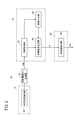
- FIG. 1 is a block diagram showing the configuration of a vehicle control device 10 according to an embodiment of the present invention.
- the vehicle control device 10 is incorporated in a vehicle (the vehicle 110 shown in FIG. 5), and performs travel control of the vehicle automatically or manually.
- This "automatic driving” is a concept including “partial automatic driving” (or driving assistance) that partially automatically performs traveling control, as well as “completely automatic driving” in which all traveling control of the vehicle is automatically performed. .
- the vehicle control device 10 basically includes an input system device group, a control system 12, and an output system device group.
- the respective devices forming the input system device group and the output system device group are connected to the control system 12 via a communication line.
- the input system device group includes an external sensor 14, a communication device 16, a navigation device 18, a vehicle sensor 20, an automatic driving switch 22, and an operation detection sensor 26 connected to the operation device 24.
- the output system group includes a driving force device 28 for driving a wheel, a steering device 30 for steering the wheel, and a braking device 32 for braking the wheel.
- the external world sensor 14 includes a plurality of cameras 33 and a plurality of radars 34 that acquire information indicating the external world state of the vehicle (hereinafter referred to as the external world information), and outputs the acquired external world information to the control system 12.
- the external sensor 14 may further include a plurality of LIDARs (Light Detection and Ranging) and laser imaging detection and Ranging.
- the communication device 16 is configured to be communicable with an external device including a roadside machine, another vehicle, and a server, and transmits and receives, for example, information related to traffic equipment, information related to other vehicles, probe information or latest map information. .
- the map information is stored in the navigation device 18 and is also stored in the map information storage unit 42 of the storage device 40 as the map information.
- the navigation device 18 includes a satellite positioning device capable of detecting the current position of the vehicle, and a user interface (for example, a touch panel display, a speaker and a microphone).
- the navigation device 18 calculates the route to the designated destination based on the current position of the vehicle or the designated position by the user, and outputs it to the control system 12.
- the route calculated by the navigation device 18 is stored in the route information storage unit 44 of the storage device 40 as route information.
- the vehicle sensor 20 is a velocity sensor that detects the velocity (vehicle speed) of the vehicle, a so-called longitudinal acceleration sensor that detects longitudinal acceleration, a so-called lateral acceleration sensor that detects transverse acceleration, a yaw rate sensor that detects angular velocity around the vertical axis, It includes an orientation sensor that detects an orientation, and a gradient sensor that detects a gradient, and outputs detection signals from each sensor to the control system 12. These detection signals are stored in the vehicle state information storage unit 46 of the storage device 40 as the vehicle state information Ivh.
- the operating device 24 is configured to include an accelerator pedal, a steering wheel, a brake pedal, a shift lever, and a direction indication lever.
- the operation device 24 is attached with an operation detection sensor 26 for detecting the presence or absence and the amount of operation of the driver and the operation position.
- the operation detection sensor 26 outputs an accelerator depression amount (accelerator opening degree), a steering wheel operation amount (steering amount), a brake depression amount, a shift position, a turning direction, etc. to the travel control unit 60 as a detection result.
- the automatic operation switch 22 is configured by a hard switch or a soft switch, and is configured to be able to switch between a plurality of operation modes including an “automatic operation mode” and a “manual operation mode” by a user's manual operation.
- the automatic driving mode is a driving mode in which the vehicle travels under the control of the control system 12 in a state where the driver does not operate the operation device 24 (specifically, the accelerator pedal, the steering wheel, and the brake pedal).
- the driving system 28, the steering system 30, and the braking system 32 are controlled based on an action plan (short-term trajectory St described later in the short term) which is sequentially determined by the control system 12. It is an operation mode which controls a part or all.
- the driving force device 28 includes a driving force control ECU (Electronic Control Unit) and a driving source including an engine and a driving motor.
- the driving force device 28 generates traveling driving force (torque) for the vehicle to travel in accordance with the vehicle control value Cvh input from the traveling control unit 60, and transmits it to the wheels via the transmission or directly.
- the steering device 30 is configured of an EPS (Electric Power Steering System) ECU and an EPS device. Steering device 30 changes the direction of the wheels (steering wheels) according to a vehicle control value Cvh input from travel control unit 60.
- EPS Electrical Power Steering System
- the braking device 32 is, for example, an electric servo brake that uses a hydraulic brake in combination, and includes a braking force control ECU and a brake actuator.
- the braking device 32 brakes the wheels according to the vehicle control value Cvh input from the traveling control unit 60.
- the function realizing unit of the control system 12 realizes functions by causing one or more CPUs (Central Processing Units) to execute a program stored in a non-transitory storage medium (for example, the storage device 40).
- Software functional unit may be a hardware function unit formed of an integrated circuit such as an FPGA (Field-Programmable Gate Array).
- the control system 12 includes an external world recognition unit 52, a recognition result reception unit 53, a local environment map generation unit 54, a general control unit 70, and a long-term trajectory generation unit 71, in addition to the storage device 40 and the travel control unit 60.
- a medium-term trajectory generation unit 72 and a short-term trajectory generation unit 73 are included.
- the general control unit 70 controls the task synchronization of the recognition result reception unit 53, the local environment map generation unit 54, the long-term trajectory generation unit 71, the medium-term trajectory generation unit 72, and the short-term trajectory generation unit 73. Perform integrated control of
- the external world recognition unit 52 refers to the vehicle state information Ivh from the traveling control unit 60, and then uses various information (for example, external world information from the external world sensor 14) input by the input system device group to make a lane mark. -After recognizing a sign such as a stop line or a traffic light, "static" external recognition information including position information of the sign or a travelable area of the vehicle is generated. In addition, the external world recognition unit 52 uses the input various information to input “dynamic” external world recognition information including an obstacle such as a parked vehicle, a traffic participant such as a person or another vehicle, or a light color of a traffic light Generate
- the static and dynamic external world recognition information is stored in the external world recognition information storage unit 45 of the storage device 40 as the external world recognition information Ipr.
- the recognition result receiving unit 53 In response to the calculation command Aa, the recognition result receiving unit 53 outputs the external world recognition information Ipr received within a predetermined calculation cycle Toc to the general control unit 70 together with the count value of the update counter.
- the calculation cycle Toc is a reference calculation cycle inside the control system 12, and is set to, for example, a value of about several tens of ms.
- Local environment map generation unit 54 generates local environment map information Iem within the operation cycle Toc with reference to the vehicle state information Ivh and the external world recognition information Ipr in response to the operation command Ab from the general control unit 70. , And the count value of the update counter are output to the general control unit 70. That is, at the start of control, it takes 2 ⁇ Toc to calculate local environment map information Iem.
- the local environment map information Iem is information in which the traveling environment of the vehicle is mapped, and roughly formed by synthesizing the vehicle state information Ivh and the ideal traveling route with the external world recognition information Ipr.
- the local environment map information Iem is stored in the local environment map information storage unit 47 of the storage device 40.
- the long-term trajectory generation unit 71 responds to the calculation command Ac from the general control unit 70, and local environment map information Iem (use only static components of the external world recognition information Ipr), vehicle state information Ivh, and map information With reference to a road map (curvature of a curve or the like) stored in the storage unit 42, a long-term trajectory Lt is generated with a relatively long operation cycle (for example, 9 ⁇ Toc). Then, the long-term trajectory generation unit 71 outputs the generated long-term trajectory Lt to the general control unit 70 together with the count value of the update counter.
- the long-term trajectory Lt is stored in the trajectory information storage unit 48 of the storage device 40 as the trajectory information Ir.
- the mid-term trajectory generation unit 72 responds to the operation command Ad from the general control unit 70, and generates local environment map information Iem (uses both the dynamic component and the static component of the external world recognition information Ipr), With reference to the vehicle state information Ivh and the long-term orbit Lt, the medium-term orbit Mt is generated with a relatively medium operation cycle (for example, 3 ⁇ Toc). Then, the mid-term trajectory generation unit 72 outputs the generated mid-term trajectory Mt to the general control unit 70 together with the count value of the update counter.
- the medium-term orbit Mt is stored in the orbit information storage unit 48 of the storage device 40 as the orbit information Ir, similarly to the long-term orbit Lt.
- the short-term trajectory generation unit 73 responds to the operation command Ae from the general control unit 70 to generate local environment map information Iem (using both dynamic and static components of the external world recognition information Ipr), With reference to the vehicle state information Ivh and the mid-term track Mt, the short-term track St is generated with the relatively shortest operation cycle (for example, Toc). The short-term track generation unit 73 simultaneously outputs the generated short-term track St to the general control unit 70 and the travel control unit 60 together with the count value of the update counter.
- the short-term orbit St is stored in the orbit information storage unit 48 as the orbit information Ir, similarly to the long-term orbit Lt and the middle-term orbit Mt.
- the long-term track Lt indicates a track at a traveling time of, for example, about 10 seconds, and is a track giving priority to ride comfort and comfort.
- the short-term track St indicates a track at a traveling time of, for example, about one second, and is a track giving priority to the realization of vehicle dynamics and the level of safety.
- the middle track Ort indicates a track at a traveling time of, for example, about 5 seconds, and is an intermediate track with respect to the long track Lt and the short track St.
- the short-term track St includes, for example, position x in the longitudinal direction (X axis), position y in the lateral direction (Y axis), attitude angle ⁇ z (yaw angle), velocity V, acceleration G, curvature ⁇ , yaw rate ⁇ , steering angle ⁇ st Trajectory plot (x, y, ⁇ z, V, G, ⁇ , ⁇ , ⁇ st) in which
- the long-term orbit Lt or the middle-term orbit Mt is a data set defined similarly to the short-term orbit St, although the periods are different.
- the traveling control unit 60 determines each vehicle control value Cvh for performing traveling control of the vehicle, in accordance with the traveling behavior (time series of the target behavior) specified from the short-term track St. Then, the traveling control unit 60 outputs the obtained vehicle control values Cvh to the driving force device 28, the steering device 30, and the braking device 32. That is, the traveling control unit 60 is configured to be able to execute one or more types of traveling control corresponding to each value of the short-term track St.
- ACC Adaptive Cruise Control
- follow-up travel deceleration travel
- curve travel curve travel
- obstacle avoidance travel a type of "following control" in which the other preceding vehicle is driven to follow while keeping the inter-vehicle distance substantially constant (that is, the target inter-vehicle distance).
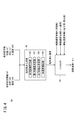
- FIG. 2 is a functional block diagram showing the main features of the vehicle control device 10 of FIG.
- the vehicle control device 10 includes an external state detection unit 80, an information acquisition unit 82, a target speed generation unit 84, a restriction application unit 86, and an acceleration / deceleration control unit 88 in addition to the local environment map generation unit 54 (FIG. 1). And.
- the external world state detection unit 80 corresponds to the external world sensor 14 shown in FIG.
- the information acquisition unit 82, the target velocity generation unit 84, and the restriction application unit 86 correspond to the short-term trajectory generation unit 73 shown in FIG.
- the acceleration / deceleration control unit 88 corresponds to the traveling control unit 60 shown in FIG.
- the external world state detection unit 80 detects the external world state of the host vehicle 110 (FIG. 5). For example, by using the camera 33, a captured image including the road 112 (FIG. 5) on which the vehicle 110 is traveling can be obtained.
- the information acquisition unit 82 acquires various types of information to be provided for the generation of the short-term trajectory St from the local environment map information Iem including the detection result of the external world state detection unit 80.
- This information includes, for example, lane mark information that can specify the shape of lane marks (lane marks 117 and 118 in FIG. 5) in addition to the above-described vehicle state information Ivh, and other vehicles (other vehicles 120 in FIG. 5). Other vehicle information that can specify position and movement is included.
- the target velocity generation unit 84 generates a short-term trajectory St indicating a time-series pattern of the target velocity, using the various information acquired by the information acquisition unit 82.
- the restriction giving unit 86 sets a time-series pattern of speed limit (hereinafter, speed limit pattern) using various information acquired by the information acquisition unit 82, and outputs the time series pattern toward the target speed generation unit 84. That is, the restriction giving unit 86 restricts the traveling behavior (here, the speed) of the host vehicle 110 by reflecting the restriction speed on the generation of the short-term track St.
- the acceleration / deceleration control unit 88 performs acceleration control or deceleration control on the host vehicle 110 to match the target velocity generated by the target velocity generation unit 84. Specifically, the acceleration / deceleration control unit 88 outputs the speed pattern (vehicle control value Cvh) indicated by the short-term track St to the driving force device 28 or the braking device 32.
- FIG. 3 is a detailed block diagram of the target speed generation unit 84 shown in FIG.
- the target velocity generation unit 84 includes a pattern generation unit 91, a trajectory candidate generation unit 92, a trajectory evaluation unit 93, and an output trajectory generation unit 94.
- the pattern generation unit 91 generates a variation group relating to two types of patterns to be provided for the generation of the short-term trajectory St, using the vehicle state information Ivh and the local environment map information Iem. Specifically, the pattern generation unit 91 is a variation on a velocity pattern (longitudinal pattern) indicating a time series of [1] velocity V and a steering angle pattern (horizontal pattern) indicating a time series of [2] steering angle ⁇ st. Generate each group.
- the trajectory candidate generation unit 92 generates a short-term trajectory St candidate (hereinafter simply referred to as “orbit candidate”) using the variation group of the pattern generated by the pattern generation unit 91. Specifically, the track candidate generation unit 92 generates a large number of track candidates including time-series information of the two-dimensional position (x, y) by combining the speed pattern and the steering angle pattern. If there is a short-term trajectory St (hereinafter referred to as the previous output trajectory) generated most recently, a constraint condition may be provided to achieve consistency with the trajectory.
- a short-term trajectory St hereinafter referred to as the previous output trajectory
- the trajectory evaluation unit 93 performs an evaluation process on each of the many trajectory candidates generated by the trajectory candidate generation unit 92 in accordance with a predetermined evaluation standard.
- the evaluation criteria the local environment map information Iem (including the lane mark and the detection result of the preceding vehicle) or the upper layer trajectory (middle trajectory Mt) is referred to.
- the track evaluation unit 93 can change the evaluation criteria so that the host vehicle 110 travels at a speed equal to or less than the speed limit, with reference to the speed limit pattern by the restriction application section 86 (FIG. 2).
- deviation of one or more variables constituting the trajectory plot (x, y, ⁇ z, V, G, ⁇ , ⁇ , ⁇ st) and a target value (reference value) is determined, and this deviation is scored
- a method of calculating an overall score by weighting operation For example, an evaluation result emphasizing particular parameters can be obtained by relatively increasing the weighting factor corresponding to the particular parameter.
- FIG. 4 is a detailed block diagram of the restriction giving unit 86 shown in FIG.
- the restriction giving unit 86 includes a following variable generation unit 96 and a minimum selector 98.
- the follow-up variable generation unit 96 is an ideal follow-up variable (for example, an ideal follow-up to follow the other vehicle 120 using vehicle information on the other vehicle 120 (hereinafter referred to as other vehicle information) besides the vehicle state information Ivh. Generate speed).
- the other vehicle information includes the position, velocity, acceleration, or jerk of the other vehicle 120.
- the minimum selector 98 selects the ideal tracking speed generated by the tracking variable generation unit 96 and the minimum speed among the three types of speed limit candidates A, B and C, and outputs it as a speed limit pattern.
- the speed limit candidate A is the upper limit value of the speed based on the legal regulations (so-called legal speed).
- the speed limit candidate B is an upper limit value of the speed calculated based on the lane curvature to maintain stable traveling behavior.
- the speed limit candidate C is an upper limit value of the speeds that can be stopped at a predetermined stop position, which is calculated based on the indication state of the traffic light and the stop line.
- the vehicle control device 10 in the present embodiment is configured as described above. Subsequently, the operation of the vehicle control device 10 will be described with reference to FIGS.
- FIG. 5 is a diagram showing the positional relationship between the host vehicle 110 and the other vehicle 120. As shown in FIG. The vehicle 110 travels on a road 112 which is generally straight and has three lanes on one side. On the road 112, dashed lane marks 117, 118 for marking the lanes 114, 115, 116 are marked.
- the other vehicle 120 travels on the same lane 115 while preceding the host vehicle 110.
- the traveling control unit 60 assumes that follow-up control is being performed on the other vehicle 120 preceding the host vehicle 110.
- the external world state detection unit 80 detects the lane marks 117 and 118 as stationary objects around the host vehicle 110 and detects the other vehicle 120 as moving objects around the host vehicle 110. Then, the vehicle control device 10 acquires other-vehicle information based on the detection result of the outside sensor 14 (or from the other vehicle 120 via inter-vehicle communication).
- the X axis is defined along the extending direction of the lanes 115, that is, the traveling direction of the host vehicle 110.
- a reference position (for example, a middle point position of a rear wheel axle) of the host vehicle 110 is set as an origin O.
- the roadway distance (S axis) is substantially equal to the position on the X axis.
- the inter-vehicle distance D is the distance between the front end position of the host vehicle 110 (the position of the front grille) and the rear end position of the other vehicle 120.
- the offset amount ofs is a length from the origin O to the tip position.
- the target inter-vehicle distance Dtar is an inter-vehicle distance set in advance by the inter-vehicle distance setting unit 100.
- the traveling position, the road distance, the speed, and the acceleration of the host vehicle 110 are respectively (x0, s0, v0, a0).
- the position of the other vehicle 120, the road distance, the speed, and the acceleration are respectively (x1, s1, v1, a1).
- the first acceleration determination unit 102 determines the traveling behavior (here, the first acceleration) of the host vehicle 110 based on the first vehicle behavior model.
- the first acceleration determination unit 102 uses the other vehicle information (x1, s1, v1, a1) obtained by the detection in step S1 to predict the future position of the other vehicle 120 (hereinafter referred to as “prediction”). Predict position 132). The predicted position 132 corresponds to the position of the other vehicle 120 at the time point of the preview time Tp (arbitrary positive value).
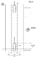
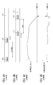
- FIG. 6 is a diagram showing a method of determining the traveling behavior by the preview inter-vehicle model.
- the horizontal axis of the graph indicates time t (unit: s), and the vertical axis of the graph indicates path distance s (unit: m).
- the prediction curve 130 is a curve indicating the prediction result of the road distance Sp (t) of the other vehicle 120.
- the path distance Sp (t) is generally expressed as the following equation (1) using an arbitrary prediction function f ( ⁇ ).
- Sp (t) f (t, s1, v1, a1) ... (1)
- the target curve 134 is a curve indicating the prediction result of the road distance Se (t) of the host vehicle 110.
- the road distance Se (t) is expressed as the following equation (2) using (s0, v0) as a known value and the acceleration ⁇ 1 (first acceleration) as an unknown value.
- Se (t) s0 + ofs + v0 ⁇ t + ⁇ 1 ⁇ t ⁇ t / 2 (2)
- the second acceleration determination unit 104 determines the traveling behavior (here, the second acceleration) of the host vehicle 110 based on the second vehicle behavior model.
- the second vehicle behavior model corresponds to a spring-mass-damper model in which the host vehicle 110 is a mass portion.
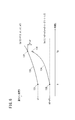
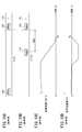
- FIG. 7 is a view showing a method of determining a traveling behavior by a spring mass damper model.
- the horizontal axis of the graph corresponds to the road distance s (unit: m).
- This model describes the positional relationship between a virtual vehicle 140 (mass M) corresponding to the vehicle 110 and a virtual other vehicle 142 corresponding to the other vehicle 120.
- a spring 144 (spring constant; k) and a damper 146 (damping coefficient; c) are provided in parallel between the virtual vehicle 140 and the virtual other vehicle 142.
- the acceleration calculation unit 106 generates a target acceleration ⁇ by performing arbitrary arithmetic processing using the accelerations ⁇ 1 and ⁇ 2 determined in steps S2 and S3, respectively. For example, the acceleration calculation unit 106 performs minimum value calculation processing to select a smaller value, and outputs any one of the accelerations ⁇ 1 and ⁇ 2 Min ( ⁇ 1 and ⁇ 2) as the target acceleration ⁇ .
- the output value of the acceleration calculation unit 106 is not limited to the minimum value, but may be any composite value including the maximum value, the average value, and the weighted average value.
- the acceleration calculation unit 106 may perform different calculation processing in accordance with the traveling scene of the host vehicle 110. For example, the acceleration calculation unit 106 may perform acceleration ⁇ 1 (or ⁇ 2) when [1] another vehicle 120 starts moving, [2] another vehicle 120 accelerates, or [3] another vehicle 120 changes lanes. You may output only
- the follow-up variable generation unit 96 integrates the target acceleration ⁇ obtained by the acceleration calculation unit 106 at time t to generate a velocity pattern, and then outputs the velocity pattern to the minimum selector 98 as an ideal follow-up velocity.
- the follow-up variable generation unit 96 generates and outputs the ideal follow-up speed of the vehicle 110, but the invention is not limited thereto. Specifically, the tracking variable generation unit 96 may generate at least one of the velocity, the acceleration, and the jerk of the vehicle 110 as the tracking variable.
- the traveling control unit 60 continues the traveling control of the vehicle 110 under the condition where the speed is limited by the limitation applying unit 86. In this manner, the host vehicle 110 follows the other vehicle 120 ahead while securing the inter-vehicle distance D equal to the target inter-vehicle distance Dtar at the prediction points set sequentially.
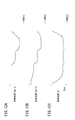
- Example 1 Tracking control based on acceleration ⁇ 2 (comparative example)> 8A to 8D are diagrams showing the results of performing follow-up control based on a spring mass damper model.
- the other vehicle 120 suddenly starts decelerating while traveling on the lane 115 while maintaining the vehicle 110 and the other vehicle 120 at a constant speed and a constant inter-vehicle distance D.
- FIG. 8C is a diagram showing a time change of the speed of the vehicle 110 (vehicle speed) in the traveling scene of FIGS. 8A and 8B.
- the horizontal axis of the graph indicates time t (unit: s), and the vertical axis of the graph indicates vehicle speed (unit: km / h).
- the definition of this graph is the same as in FIGS. 9C, 10C, and 11C described later.
- FIG. 8D is a diagram showing a time change of the acceleration (the host vehicle acceleration) of the host vehicle 110 in the traveling scene of FIGS. 8A and 8B.
- the horizontal axis of the graph indicates time t (unit: s), and the vertical axis of the graph indicates vehicle acceleration (unit: G).
- the definition of this graph is the same as in FIGS. 9D, 10D, and 11D described later.
- FIGS. 9A-9D are diagrams showing the results of performing follow-up control (minimum value calculation) based on the inter-vehicle preview model and the spring mass damper model.
- the traveling scene is the same as in FIGS. 8A-8B.
- Example 4 Tracking control based on accelerations ⁇ 1 and ⁇ 2 (Example)> 11A to 11D are diagrams showing the results of performing follow-up control (minimum value calculation) based on the inter-vehicle preview model and the spring mass damper model.
- the traveling scene is the same as in FIGS. 10A-10B.
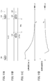
- Example 5 Tracking Control Based on Accelerations ⁇ 1 and ⁇ 2 are diagrams showing the results of performing follow-up control (minimum value calculation) based on the inter-vehicle preview model and the spring mass damper model.
- follow-up control minimum value calculation
- FIG. 12A is a diagram showing a time change of the speed of the other vehicle 120 (the speed of the other vehicle).
- the horizontal axis of the graph indicates time t (unit: s), and the vertical axis of the graph indicates other vehicle speed (unit: km / h).
- the graph shows traveling patterns of the other vehicle 120 that sequentially perform constant speed traveling, deceleration operation, constant speed traveling, deceleration operation, constant speed traveling, and acceleration operation.
- FIG. 12B is a diagram showing a time change of the speed of the host vehicle 110 (the host vehicle speed).
- the horizontal axis of the graph indicates time t (unit: s), and the vertical axis of the graph indicates vehicle speed (unit: km / h).
- FIG. 12C is a diagram showing a time change of inter-vehicle distance D between host vehicle 110 and other vehicle 120.
- the horizontal axis of the graph indicates time t (unit: s), and the vertical axis of the graph indicates inter-vehicle distance D (unit: m).
- the host vehicle 110 performs an operation following the traveling pattern of the other vehicle 120 while always maintaining a relationship of D> Dtar.
- the vehicle control device 10 is a device that automatically performs at least partial travel control of the host vehicle 110, and [1] an external world state detection unit 80 that detects the external world state of the host vehicle 110; 2) A traveling control unit 60 capable of executing follow-up control on another vehicle 120 detected in front of the own vehicle 110, and [3] a follow-up variable generation unit 96 generating a follow-up variable related to follow-up control.
- a vehicle control method using the vehicle control device 10 is a method of automatically performing traveling control of the host vehicle 110 at least partially, and [1] detecting an external state of the host vehicle 110; 2) One or more computers execute a control step capable of executing follow-up control on another vehicle 120 detected in front of the own vehicle 110, and [3] a generation step of generating a follow-up variable related to follow-up control Do.
- the follow-up variable generation unit 96 determines a second follow-up variable (for example, acceleration ⁇ 2) based on a vehicle behavior model different from the first follow-up variable, and uses at least the first follow-up variable and the second follow-up variable as input.
- the tracking variable (target acceleration ⁇ ) may be generated by performing arithmetic processing. This makes it possible to blend two different responses depending on the vehicle behavior model, and increases the flexibility of optimization design for follow-up control.
- the follow-up variable generation unit 96 may determine the second follow-up variable based on a spring mass damper model as a vehicle behavior model.
- the spring, mass, and damper model has an advantage that the responsiveness to cope with the other vehicle 120 is relatively high when the own vehicle 110 approaches the other vehicle 120 from a distance far apart from the target inter-vehicle distance Dtar. There is. That is, it is possible to perform follow-up control incorporating this advantage.
- this invention is not limited to embodiment mentioned above, Of course, it can change freely in the range which does not deviate from the main point of this invention. Or you may combine each structure arbitrarily in the range which a technical contradiction does not arise.
Abstract
The present invention relates to a vehicle control apparatus (10) for at least a partial automatic control over the travel of the host vehicle (110). A following variable generating unit (96) calculates a predicted position (132) of an other vehicle (120) at a predicted time point ahead of the present time point, sets a target position (136) which is short of the predicted position (132) by a target intervehicle distance (Dtar), and determines a first following variable for causing the host vehicle (110) to reach the target position (136) at the predicted time point.
Description
この発明は、自車両の走行制御を少なくとも部分的に自動で行う車両制御装置に関する。
BACKGROUND OF THE INVENTION Field of the Invention The present invention relates to a vehicle control device that automatically performs at least partial travel control of a host vehicle.
従来から、自車両の走行制御を少なくとも部分的に自動で行う車両制御装置が知られている。例えば、先行する他車両との関係を考慮しつつ、自車両を円滑に走行させるための運転支援技術又は自動運転技術が種々開発されている。
2. Description of the Related Art Conventionally, a vehicle control device that performs traveling control of a host vehicle at least partially automatically is known. For example, various driving support techniques or automatic driving techniques have been developed for causing the vehicle to travel smoothly while considering the relationship with the preceding other vehicle.
特許第4366419号公報(図11等)では、自車両の走行レーンから隣接レーンに車線変更しようとする際に、隣接レーンを走行する他車両との関係を考慮したバネ・マス・ダンパモデルに従って、自車位置を制御する装置が提案されている。
According to Japanese Patent No. 4366419 (FIG. 11 etc.), when trying to change lanes from the traveling lane of the own vehicle to the adjacent lane, according to a spring mass damper model that takes into consideration the relationship with other vehicles traveling in the adjacent lane, An apparatus for controlling the position of the vehicle has been proposed.
ところで、このバネ・マス・ダンパモデルを追従制御に適用する場合、先行する他車両の走行挙動が急激に変化した際、その変化に対する応答性が相対的に低くなってしまう短所がある。具体的には、自車両及び他車両が一定の速度及び一定の車間距離を保ちながら走行している途中で、他車両が急に減速を開始した場合、自車両の減速動作が遅れてしまう傾向がある。
By the way, when this spring mass damper model is applied to follow-up control, there is a disadvantage that when the traveling behavior of the preceding other vehicle changes rapidly, the responsiveness to the change becomes relatively low. Specifically, if another vehicle suddenly starts to decelerate while the host vehicle and the other vehicle are traveling while maintaining a constant speed and a constant inter-vehicle distance, the deceleration operation of the host vehicle tends to be delayed. There is.
本発明は上記した問題を解決するためになされたものであり、先行する他車両の走行挙動が急激に変化した場合であっても、高い応答性でその変化に対処可能な車両制御装置を提供することを目的とする。
The present invention has been made to solve the above-described problems, and provides a vehicle control device capable of coping with the change with high responsiveness even if the traveling behavior of the preceding other vehicle changes sharply. The purpose is to
本発明に係る車両制御装置は、自車両の走行制御を少なくとも部分的に自動で行う装置であって、前記自車両の外界状態を検出する外界状態検出部と、前記外界状態検出部により前記自車両の前方に検出された他車両に対する追従制御を実行可能な走行制御部と、前記追従制御に関わる追従変数を生成する追従変数生成部と、を備え、前記追従変数生成部は、現時点より先の予測時点における前記他車両の予測位置を算出し、前記予測位置から目標車間距離だけ手前にある目標位置を設定し、前記予測時点において前記自車両を前記目標位置に到達させる第1追従変数を決定する。
The vehicle control device according to the present invention is a device that automatically performs traveling control of the own vehicle at least partially, and an external world state detection unit that detects the external world state of the own vehicle, and the external world condition detection unit The vehicle control system further includes: a traveling control unit capable of executing follow-up control on another vehicle detected in front of the vehicle; and a follow-up variable generation unit generating a follow-up variable related to the follow-up control. Calculating a predicted position of the other vehicle at the predicted time point of the vehicle, setting a target position that is ahead of the predicted position by the target inter-vehicle distance, and setting a first follow-up variable for causing the vehicle to reach the target position at the predicted time point decide.
このように、他車両の予測位置から目標車間距離だけ手前にある目標位置を設定し、現時点より先の予測時点において自車両を目標位置に到達させる第1追従変数を決定するので、他車両の走行挙動にかかわらず将来的な特定の時点にて、目標車間距離に等しい車間距離を確保する追従制御が可能となる。これにより、先行する他車両の走行挙動が急激に変化した場合であっても、高い応答性でその変化に対処することができる。
As described above, the target position which is ahead of the predicted position of the other vehicle by the target inter-vehicle distance is set, and the first follow-up variable for causing the vehicle to reach the target position at the predicted time ahead of the current time is determined. It is possible to perform follow-up control that secures an inter-vehicle distance equal to the target inter-vehicle distance at a specific point in time in the future regardless of the traveling behavior. As a result, even if the traveling behavior of the preceding other vehicle changes suddenly, it is possible to cope with the change with high responsiveness.
また、前記追従変数生成部は、前記第1追従変数とは異なる車両挙動モデルに基づいて第2追従変数を決定し、少なくとも前記第1追従変数及び前記第2追従変数を入力とする演算処理を行うことで前記追従変数を生成してもよい。これにより、車両挙動モデルに応じて異なる2つの応答性を折衷可能となり、追従制御に関する最適化設計の柔軟性が高くなる。
Further, the follow-up variable generation unit determines a second follow-up variable based on a vehicle behavior model different from the first follow-up variable, and performs arithmetic processing in which at least the first follow-up variable and the second follow-up variable are input. The following variable may be generated by performing. This makes it possible to blend two different responses depending on the vehicle behavior model, and increases the flexibility of optimization design for follow-up control.
また、前記追従変数生成部は、前記車両挙動モデルとしてのバネ・マス・ダンパモデルに基づいて前記第2追従変数を決定してもよい。バネ・マス・ダンパモデルには、目標車間距離よりも大きく離れた遠方から自車両が他車両に近づいていく際に、他車両に対処する応答性が相対的に高くなるという長所がある。つまり、この長所を取り入れた追従制御を行うことができる。
Further, the follow-up variable generation unit may determine the second follow-up variable based on a spring mass damper model as the vehicle behavior model. The spring-mass-damper model has an advantage that when the host vehicle approaches another vehicle from a distance greater than the target inter-vehicle distance, the response to cope with the other vehicle is relatively high. That is, it is possible to perform follow-up control incorporating this advantage.
また、前記追従変数生成部は、最小値演算処理を行うことで前記追従変数を生成してもよい。
Further, the follow-up variable generation unit may generate the follow-up variable by performing minimum value calculation processing.
また、前記追従変数生成部は、前記自車両の走行シーンに応じて異なる前記演算処理を行うことで前記追従変数を生成してもよい。
Further, the follow-up variable generation unit may generate the follow-up variable by performing the arithmetic processing different depending on a traveling scene of the host vehicle.
また、前記追従変数生成部は、前記追従変数として、前記自車両の速度、加速度及びジャークのうち少なくとも1つを生成してもよい。
Further, the follow-up variable generation unit may generate, as the follow-up variable, at least one of the speed, the acceleration, and the jerk of the host vehicle.
本発明に係る車両制御装置によれば、先行する他車両の走行挙動が急激に変化した場合であっても、高い応答性でその変化に対処することができる。
According to the vehicle control device according to the present invention, even when the traveling behavior of the preceding other vehicle changes rapidly, the change can be dealt with with high responsiveness.
以下、本発明に係る車両制御装置について好適な実施形態を挙げ、添付の図面を参照しながら説明する。
Hereinafter, a preferred embodiment of a vehicle control device according to the present invention will be described and described with reference to the accompanying drawings.
[車両制御装置10の構成]
<全体構成>
図1は、本発明の一実施形態における車両制御装置10の構成を示すブロック図である。車両制御装置10は、車両(図5の自車両110)に組み込まれており、かつ、自動又は手動により車両の走行制御を行う。この「自動運転」は、車両の走行制御をすべて自動で行う「完全自動運転」のみならず、走行制御を部分的に自動で行う「部分自動運転」(或いは、運転支援)を含む概念である。 Configuration ofVehicle Control Device 10
<Overall configuration>
FIG. 1 is a block diagram showing the configuration of avehicle control device 10 according to an embodiment of the present invention. The vehicle control device 10 is incorporated in a vehicle (the vehicle 110 shown in FIG. 5), and performs travel control of the vehicle automatically or manually. This "automatic driving" is a concept including "partial automatic driving" (or driving assistance) that partially automatically performs traveling control, as well as "completely automatic driving" in which all traveling control of the vehicle is automatically performed. .
<全体構成>
図1は、本発明の一実施形態における車両制御装置10の構成を示すブロック図である。車両制御装置10は、車両(図5の自車両110)に組み込まれており、かつ、自動又は手動により車両の走行制御を行う。この「自動運転」は、車両の走行制御をすべて自動で行う「完全自動運転」のみならず、走行制御を部分的に自動で行う「部分自動運転」(或いは、運転支援)を含む概念である。 Configuration of
<Overall configuration>
FIG. 1 is a block diagram showing the configuration of a
車両制御装置10は、基本的には、入力系装置群と、制御システム12と、出力系装置群とから構成される。入力系装置群及び出力系装置群をなす各々の装置は、制御システム12に通信線を介して接続されている。
The vehicle control device 10 basically includes an input system device group, a control system 12, and an output system device group. The respective devices forming the input system device group and the output system device group are connected to the control system 12 via a communication line.
入力系装置群は、外界センサ14と、通信装置16と、ナビゲーション装置18と、車両センサ20と、自動運転スイッチ22と、操作デバイス24に接続された操作検出センサ26と、を備える。出力系装置群は、車輪を駆動する駆動力装置28と、当該車輪を操舵する操舵装置30と、当該車輪を制動する制動装置32と、を備える。
The input system device group includes an external sensor 14, a communication device 16, a navigation device 18, a vehicle sensor 20, an automatic driving switch 22, and an operation detection sensor 26 connected to the operation device 24. The output system group includes a driving force device 28 for driving a wheel, a steering device 30 for steering the wheel, and a braking device 32 for braking the wheel.
<入力系装置群の具体的構成>
外界センサ14は、車両の外界状態を示す情報(以下、外界情報)を取得する複数のカメラ33と複数のレーダ34を備え、取得した外界情報を制御システム12に出力する。外界センサ14は、さらに、複数のLIDAR(Light Detection and Ranging;光検出と測距/Laser Imaging Detection and Ranging;レーザ画像検出と測距)を備えてもよい。 <Specific Configuration of Input Device Group>
Theexternal world sensor 14 includes a plurality of cameras 33 and a plurality of radars 34 that acquire information indicating the external world state of the vehicle (hereinafter referred to as the external world information), and outputs the acquired external world information to the control system 12. The external sensor 14 may further include a plurality of LIDARs (Light Detection and Ranging) and laser imaging detection and Ranging.
外界センサ14は、車両の外界状態を示す情報(以下、外界情報)を取得する複数のカメラ33と複数のレーダ34を備え、取得した外界情報を制御システム12に出力する。外界センサ14は、さらに、複数のLIDAR(Light Detection and Ranging;光検出と測距/Laser Imaging Detection and Ranging;レーザ画像検出と測距)を備えてもよい。 <Specific Configuration of Input Device Group>
The
通信装置16は、路側機、他車両、及びサーバを含む外部装置と通信可能に構成されており、例えば、交通機器に関わる情報、他車両に関わる情報、プローブ情報又は最新の地図情報を送受信する。なお、地図情報は、ナビゲーション装置18に記憶されると共に、地図情報として記憶装置40の地図情報記憶部42にも記憶される。
The communication device 16 is configured to be communicable with an external device including a roadside machine, another vehicle, and a server, and transmits and receives, for example, information related to traffic equipment, information related to other vehicles, probe information or latest map information. . The map information is stored in the navigation device 18 and is also stored in the map information storage unit 42 of the storage device 40 as the map information.
ナビゲーション装置18は、車両の現在位置を検出可能な衛星測位装置と、ユーザインタフェース(例えば、タッチパネル式のディスプレイ、スピーカ及びマイク)を含んで構成される。ナビゲーション装置18は、車両の現在位置又はユーザによる指定位置に基づいて、指定した目的地までの経路を算出し、制御システム12に出力する。ナビゲーション装置18により算出された経路は、経路情報として記憶装置40の経路情報記憶部44に記憶される。
The navigation device 18 includes a satellite positioning device capable of detecting the current position of the vehicle, and a user interface (for example, a touch panel display, a speaker and a microphone). The navigation device 18 calculates the route to the designated destination based on the current position of the vehicle or the designated position by the user, and outputs it to the control system 12. The route calculated by the navigation device 18 is stored in the route information storage unit 44 of the storage device 40 as route information.
車両センサ20は、車両の速度(車速)を検出する速度センサ、いわゆる縦加速度を検出する縦加速度センサ、いわゆる横加速度を検出する横加速度センサ、垂直軸周りの角速度を検出するヨーレートセンサ、向き・方位を検出する方位センサ、勾配を検出する勾配センサを含み、各センサからの検出信号を制御システム12に出力する。これらの検出信号は、自車状態情報Ivhとして記憶装置40の自車状態情報記憶部46に記憶される。
The vehicle sensor 20 is a velocity sensor that detects the velocity (vehicle speed) of the vehicle, a so-called longitudinal acceleration sensor that detects longitudinal acceleration, a so-called lateral acceleration sensor that detects transverse acceleration, a yaw rate sensor that detects angular velocity around the vertical axis, It includes an orientation sensor that detects an orientation, and a gradient sensor that detects a gradient, and outputs detection signals from each sensor to the control system 12. These detection signals are stored in the vehicle state information storage unit 46 of the storage device 40 as the vehicle state information Ivh.
操作デバイス24は、アクセルペダル、ステアリングホイール、ブレーキペダル、シフトレバー、及び方向指示レバーを含んで構成される。操作デバイス24には、ドライバによる操作の有無や操作量、操作位置を検出する操作検出センサ26が取り付けられている。
The operating device 24 is configured to include an accelerator pedal, a steering wheel, a brake pedal, a shift lever, and a direction indication lever. The operation device 24 is attached with an operation detection sensor 26 for detecting the presence or absence and the amount of operation of the driver and the operation position.
操作検出センサ26は、検出結果としてアクセル踏込量(アクセル開度)、ハンドル操作量(操舵量)、ブレーキ踏込量、シフト位置、右左折方向等を走行制御部60に出力する。
The operation detection sensor 26 outputs an accelerator depression amount (accelerator opening degree), a steering wheel operation amount (steering amount), a brake depression amount, a shift position, a turning direction, etc. to the travel control unit 60 as a detection result.
自動運転スイッチ22は、ハードスイッチ又はソフトスイッチからなり、ユーザのマニュアル操作により、「自動運転モード」と「手動運転モード」を含む複数の運転モードを切り替え可能に構成される。
The automatic operation switch 22 is configured by a hard switch or a soft switch, and is configured to be able to switch between a plurality of operation modes including an “automatic operation mode” and a “manual operation mode” by a user's manual operation.
自動運転モードは、ドライバが、操作デバイス24(具体的には、アクセルペダル、ステアリングホイール及びブレーキペダル)の操作を行わない状態で、車両が制御システム12による制御下に走行する運転モードである。換言すれば、自動運転モードは、制御システム12が、逐次決定される行動計画(短期的には、後述する短期軌道St)に基づいて、駆動力装置28、操舵装置30、及び制動装置32の一部又は全部を制御する運転モードである。
The automatic driving mode is a driving mode in which the vehicle travels under the control of the control system 12 in a state where the driver does not operate the operation device 24 (specifically, the accelerator pedal, the steering wheel, and the brake pedal). In other words, in the automatic driving mode, the driving system 28, the steering system 30, and the braking system 32 are controlled based on an action plan (short-term trajectory St described later in the short term) which is sequentially determined by the control system 12. It is an operation mode which controls a part or all.
なお、ドライバが、自動運転モード中に操作デバイス24の操作を開始した場合には、自動運転モードは自動的に解除されると共に、運転の自動化レベルが相対的に低い運転モード(手動運転モードを含む)に切り替わる。
When the driver starts operating the operation device 24 during the automatic operation mode, the automatic operation mode is automatically canceled and the operation automation level is relatively low (the manual operation mode). Switch to
<出力系装置群の具体的構成>
駆動力装置28は、駆動力制御用ECU(電子制御装置;Electronic Control Unit)と、エンジン・駆動モータを含む駆動源から構成される。駆動力装置28は、走行制御部60から入力される車両制御値Cvhに従って車両が走行するための走行駆動力(トルク)を生成し、トランスミッションを介し、或いは直接的に車輪に伝達する。 <Specific Configuration of Output Device Group>
The drivingforce device 28 includes a driving force control ECU (Electronic Control Unit) and a driving source including an engine and a driving motor. The driving force device 28 generates traveling driving force (torque) for the vehicle to travel in accordance with the vehicle control value Cvh input from the traveling control unit 60, and transmits it to the wheels via the transmission or directly.
駆動力装置28は、駆動力制御用ECU(電子制御装置;Electronic Control Unit)と、エンジン・駆動モータを含む駆動源から構成される。駆動力装置28は、走行制御部60から入力される車両制御値Cvhに従って車両が走行するための走行駆動力(トルク)を生成し、トランスミッションを介し、或いは直接的に車輪に伝達する。 <Specific Configuration of Output Device Group>
The driving
操舵装置30は、EPS(電動パワーステアリングシステム)用ECUと、EPS装置とから構成される。操舵装置30は、走行制御部60から入力される車両制御値Cvhに従って車輪(操舵輪)の向きを変更する。
The steering device 30 is configured of an EPS (Electric Power Steering System) ECU and an EPS device. Steering device 30 changes the direction of the wheels (steering wheels) according to a vehicle control value Cvh input from travel control unit 60.
制動装置32は、例えば、油圧式ブレーキを併用する電動サーボブレーキであり、制動力制御用ECUと、ブレーキアクチュエータとから構成される。制動装置32は、走行制御部60から入力される車両制御値Cvhに従って車輪を制動する。
The braking device 32 is, for example, an electric servo brake that uses a hydraulic brake in combination, and includes a braking force control ECU and a brake actuator. The braking device 32 brakes the wheels according to the vehicle control value Cvh input from the traveling control unit 60.
<制御システム12の構成>
制御システム12の機能実現部は、1つ又は複数のCPU(Central Processing Unit)が、非一過性の記憶媒体(例えば、記憶装置40)に記憶されているプログラムを実行することにより機能が実現されるソフトウェア機能部である。これに代わって、機能実現部は、FPGA(Field-Programmable Gate Array)等の集積回路からなるハードウェア機能部であってもよい。 <Configuration ofControl System 12>
The function realizing unit of thecontrol system 12 realizes functions by causing one or more CPUs (Central Processing Units) to execute a program stored in a non-transitory storage medium (for example, the storage device 40). Software functional unit. Instead of this, the function implementation unit may be a hardware function unit formed of an integrated circuit such as an FPGA (Field-Programmable Gate Array).
制御システム12の機能実現部は、1つ又は複数のCPU(Central Processing Unit)が、非一過性の記憶媒体(例えば、記憶装置40)に記憶されているプログラムを実行することにより機能が実現されるソフトウェア機能部である。これに代わって、機能実現部は、FPGA(Field-Programmable Gate Array)等の集積回路からなるハードウェア機能部であってもよい。 <Configuration of
The function realizing unit of the
制御システム12は、記憶装置40及び走行制御部60の他、外界認識部52と、認識結果受信部53と、局所環境マップ生成部54と、統括制御部70と、長期軌道生成部71と、中期軌道生成部72と、短期軌道生成部73と、を含んで構成される。ここで、統括制御部70は、認識結果受信部53、局所環境マップ生成部54、長期軌道生成部71、中期軌道生成部72、及び短期軌道生成部73のタスク同期を制御することで、各部の統括制御を行う。
The control system 12 includes an external world recognition unit 52, a recognition result reception unit 53, a local environment map generation unit 54, a general control unit 70, and a long-term trajectory generation unit 71, in addition to the storage device 40 and the travel control unit 60. A medium-term trajectory generation unit 72 and a short-term trajectory generation unit 73 are included. Here, the general control unit 70 controls the task synchronization of the recognition result reception unit 53, the local environment map generation unit 54, the long-term trajectory generation unit 71, the medium-term trajectory generation unit 72, and the short-term trajectory generation unit 73. Perform integrated control of
外界認識部52は、走行制御部60からの自車状態情報Ivhを参照した上で、入力系装置群により入力された各種情報(例えば、外界センサ14からの外界情報)を用いて、レーンマーク・停止線・信号機等の標示物を認識した後、標示物の位置情報又は車両の走行可能領域を含む「静的」な外界認識情報を生成する。また、外界認識部52は、入力された各種情報を用いて、駐停車車両等の障害物、人・他車両等の交通参加者、又は信号機の灯色を含む「動的」な外界認識情報を生成する。
The external world recognition unit 52 refers to the vehicle state information Ivh from the traveling control unit 60, and then uses various information (for example, external world information from the external world sensor 14) input by the input system device group to make a lane mark. -After recognizing a sign such as a stop line or a traffic light, "static" external recognition information including position information of the sign or a travelable area of the vehicle is generated. In addition, the external world recognition unit 52 uses the input various information to input “dynamic” external world recognition information including an obstacle such as a parked vehicle, a traffic participant such as a person or another vehicle, or a light color of a traffic light Generate
なお、静的及び動的な外界認識情報はそれぞれ、外界認識情報Iprとして記憶装置40の外界認識情報記憶部45に記憶される。
The static and dynamic external world recognition information is stored in the external world recognition information storage unit 45 of the storage device 40 as the external world recognition information Ipr.
認識結果受信部53は、演算指令Aaに応答して、所定の演算周期Toc内に受信した外界認識情報Iprを更新カウンタのカウント値と共に、統括制御部70に出力する。ここで、演算周期Tocは、制御システム12の内部での基準の演算周期であり、例えば、数10ms程度の値に設定されている。
In response to the calculation command Aa, the recognition result receiving unit 53 outputs the external world recognition information Ipr received within a predetermined calculation cycle Toc to the general control unit 70 together with the count value of the update counter. Here, the calculation cycle Toc is a reference calculation cycle inside the control system 12, and is set to, for example, a value of about several tens of ms.
局所環境マップ生成部54は、統括制御部70からの演算指令Abに応答して、自車状態情報Ivh及び外界認識情報Iprを参照し、演算周期Toc内に局所環境マップ情報Iemを生成して、更新カウンタのカウント値と共に、統括制御部70に出力する。すなわち、制御の開始時には、局所環境マップ情報Iemが生成されるまでに、演算周期2×Tocを要する。
Local environment map generation unit 54 generates local environment map information Iem within the operation cycle Toc with reference to the vehicle state information Ivh and the external world recognition information Ipr in response to the operation command Ab from the general control unit 70. , And the count value of the update counter are output to the general control unit 70. That is, at the start of control, it takes 2 × Toc to calculate local environment map information Iem.
局所環境マップ情報Iemは、車両の走行環境をマップ化した情報であり、概略的には、外界認識情報Iprに対して自車状態情報Ivh及び理想走行経路を合成してなる。局所環境マップ情報Iemは、記憶装置40の局所環境マップ情報記憶部47に記憶される。
The local environment map information Iem is information in which the traveling environment of the vehicle is mapped, and roughly formed by synthesizing the vehicle state information Ivh and the ideal traveling route with the external world recognition information Ipr. The local environment map information Iem is stored in the local environment map information storage unit 47 of the storage device 40.
長期軌道生成部71は、統括制御部70からの演算指令Acに応答して、局所環境マップ情報Iem(外界認識情報Iprのうち静的な成分のみ利用)、自車状態情報Ivh、及び地図情報記憶部42に記憶されている道路地図(カーブの曲率等)を参照して、相対的に最も長い演算周期(例えば、9×Toc)で長期軌道Ltを生成する。そして、長期軌道生成部71は、生成した長期軌道Ltを更新カウンタのカウント値と共に、統括制御部70に出力する。なお、長期軌道Ltは、軌道情報Irとして、記憶装置40の軌道情報記憶部48に記憶される。
The long-term trajectory generation unit 71 responds to the calculation command Ac from the general control unit 70, and local environment map information Iem (use only static components of the external world recognition information Ipr), vehicle state information Ivh, and map information With reference to a road map (curvature of a curve or the like) stored in the storage unit 42, a long-term trajectory Lt is generated with a relatively long operation cycle (for example, 9 × Toc). Then, the long-term trajectory generation unit 71 outputs the generated long-term trajectory Lt to the general control unit 70 together with the count value of the update counter. The long-term trajectory Lt is stored in the trajectory information storage unit 48 of the storage device 40 as the trajectory information Ir.
中期軌道生成部72は、統括制御部70からの演算指令Adに応答して、局所環境マップ情報Iem(外界認識情報Iprのうち、動的な成分及び静的な成分の両方を利用)、自車状態情報Ivh、及び長期軌道Ltを参照して、相対的に中位の演算周期(例えば、3×Toc)で中期軌道Mtを生成する。そして、中期軌道生成部72は、生成した中期軌道Mtを更新カウンタのカウント値と共に、統括制御部70に出力する。なお、中期軌道Mtは、長期軌道Ltと同様に、軌道情報Irとして、記憶装置40の軌道情報記憶部48に記憶される。
The mid-term trajectory generation unit 72 responds to the operation command Ad from the general control unit 70, and generates local environment map information Iem (uses both the dynamic component and the static component of the external world recognition information Ipr), With reference to the vehicle state information Ivh and the long-term orbit Lt, the medium-term orbit Mt is generated with a relatively medium operation cycle (for example, 3 × Toc). Then, the mid-term trajectory generation unit 72 outputs the generated mid-term trajectory Mt to the general control unit 70 together with the count value of the update counter. The medium-term orbit Mt is stored in the orbit information storage unit 48 of the storage device 40 as the orbit information Ir, similarly to the long-term orbit Lt.
短期軌道生成部73は、統括制御部70からの演算指令Aeに応答して、局所環境マップ情報Iem(外界認識情報Iprのうち、動的な成分及び静的な成分の両方を利用)、自車状態情報Ivh、及び中期軌道Mtを参照し、相対的に最も短い演算周期(例えば、Toc)で短期軌道Stを生成する。そして、短期軌道生成部73は、生成した短期軌道Stを更新カウンタのカウント値と共に、統括制御部70及び走行制御部60に同時に出力する。なお、短期軌道Stは、長期軌道Lt及び中期軌道Mtと同様に、軌道情報Irとして、軌道情報記憶部48に記憶される。
The short-term trajectory generation unit 73 responds to the operation command Ae from the general control unit 70 to generate local environment map information Iem (using both dynamic and static components of the external world recognition information Ipr), With reference to the vehicle state information Ivh and the mid-term track Mt, the short-term track St is generated with the relatively shortest operation cycle (for example, Toc). The short-term track generation unit 73 simultaneously outputs the generated short-term track St to the general control unit 70 and the travel control unit 60 together with the count value of the update counter. The short-term orbit St is stored in the orbit information storage unit 48 as the orbit information Ir, similarly to the long-term orbit Lt and the middle-term orbit Mt.
なお、長期軌道Ltは、例えば10秒間程度の走行時間における軌道を示し、乗り心地・快適性を優先した軌道である。また、短期軌道Stは、例えば1秒間程度の走行時間における軌道を示し、車両ダイナミクスの実現及び安全性の高さを優先した軌道である。中期軌道Mtは、例えば5秒間程度の走行時間における軌道を示し、長期軌道Lt及び短期軌道Stに対する中間的な軌道である。
The long-term track Lt indicates a track at a traveling time of, for example, about 10 seconds, and is a track giving priority to ride comfort and comfort. Further, the short-term track St indicates a track at a traveling time of, for example, about one second, and is a track giving priority to the realization of vehicle dynamics and the level of safety. The middle track Ort indicates a track at a traveling time of, for example, about 5 seconds, and is an intermediate track with respect to the long track Lt and the short track St.
短期軌道Stは、短周期Ts(=Toc)毎の車両の走行軌道(つまり、目標挙動の時系列)を示すデータセットに相当する。短期軌道Stは、例えば、縦方向(X軸)の位置x、横方向(Y軸)の位置y、姿勢角θz(ヨー角)、速度V、加速度G、曲率ρ、ヨーレートγ、操舵角δstをデータ単位とする軌道プロット(x,y,θz,V,G,ρ、γ、δst)である。また、長期軌道Lt又は中期軌道Mtは、周期がそれぞれ異なるものの、短期軌道Stと同様に定義されたデータセットである。
The short-term track St corresponds to a data set indicating the traveling track (that is, the time series of the target behavior) of the vehicle for each short cycle Ts (= Toc). The short-term track St includes, for example, position x in the longitudinal direction (X axis), position y in the lateral direction (Y axis), attitude angle θz (yaw angle), velocity V, acceleration G, curvature ρ, yaw rate γ, steering angle δst Trajectory plot (x, y, θz, V, G, ρ, γ, δst) in which The long-term orbit Lt or the middle-term orbit Mt is a data set defined similarly to the short-term orbit St, although the periods are different.
走行制御部60は、短期軌道Stから特定される走行挙動(目標挙動の時系列)に従って、車両を走行制御するための各々の車両制御値Cvhを決定する。そして、走行制御部60は、得られた各々の車両制御値Cvhを、駆動力装置28、操舵装置30、及び制動装置32に出力する。つまり、走行制御部60は、短期軌道Stの各値に対応する1種類以上の走行制御を実行可能に構成される。
The traveling control unit 60 determines each vehicle control value Cvh for performing traveling control of the vehicle, in accordance with the traveling behavior (time series of the target behavior) specified from the short-term track St. Then, the traveling control unit 60 outputs the obtained vehicle control values Cvh to the driving force device 28, the steering device 30, and the braking device 32. That is, the traveling control unit 60 is configured to be able to execute one or more types of traveling control corresponding to each value of the short-term track St.
レーンキープ(車線維持)の際の走行態様の種類として、定速走行、追従走行、減速走行、カーブ走行、又は障害物回避走行が含まれる。例えば、ACC(Adaptive Cruise Control)制御は、車間距離を略一定(つまり、目標車間距離)に保ちながら、先行する他車両に対して追従走行させる「追従制御」の一種である。
The types of travel modes in the case of lane keeping (lane maintenance) include constant speed travel, follow-up travel, deceleration travel, curve travel, or obstacle avoidance travel. For example, ACC (Adaptive Cruise Control) control is a type of "following control" in which the other preceding vehicle is driven to follow while keeping the inter-vehicle distance substantially constant (that is, the target inter-vehicle distance).
<主要な特徴部>
図2は、図1の車両制御装置10における主要な特徴部を示す機能ブロック図である。車両制御装置10は、局所環境マップ生成部54(図1)の他、外界状態検出部80と、情報取得部82と、目標速度生成部84と、制限付与部86と、加減速制御部88と、を備える。 <Major features>
FIG. 2 is a functional block diagram showing the main features of thevehicle control device 10 of FIG. The vehicle control device 10 includes an external state detection unit 80, an information acquisition unit 82, a target speed generation unit 84, a restriction application unit 86, and an acceleration / deceleration control unit 88 in addition to the local environment map generation unit 54 (FIG. 1). And.
図2は、図1の車両制御装置10における主要な特徴部を示す機能ブロック図である。車両制御装置10は、局所環境マップ生成部54(図1)の他、外界状態検出部80と、情報取得部82と、目標速度生成部84と、制限付与部86と、加減速制御部88と、を備える。 <Major features>
FIG. 2 is a functional block diagram showing the main features of the
外界状態検出部80は、図1に示す外界センサ14に相当する。情報取得部82、目標速度生成部84及び制限付与部86は、図1に示す短期軌道生成部73に相当する。加減速制御部88は、図1に示す走行制御部60に相当する。
The external world state detection unit 80 corresponds to the external world sensor 14 shown in FIG. The information acquisition unit 82, the target velocity generation unit 84, and the restriction application unit 86 correspond to the short-term trajectory generation unit 73 shown in FIG. The acceleration / deceleration control unit 88 corresponds to the traveling control unit 60 shown in FIG.
外界状態検出部80(具体的には、図1のカメラ33又はレーダ34)は、自車両110(図5)の外界状態を検出する。例えば、カメラ33を用いることで、自車両110が走行中の道路112(図5)を含む撮像画像が得られる。
The external world state detection unit 80 (specifically, the camera 33 or the radar 34 in FIG. 1) detects the external world state of the host vehicle 110 (FIG. 5). For example, by using the camera 33, a captured image including the road 112 (FIG. 5) on which the vehicle 110 is traveling can be obtained.
情報取得部82は、外界状態検出部80による検出結果を含む局所環境マップ情報Iemから、短期軌道Stの生成に供される各種情報を取得する。この情報には、例えば、上記した自車状態情報Ivhの他、レーンマーク(図5のレーンマーク117、118)の形状を特定可能なレーンマーク情報、他車両(図5の他車両120)の位置及び動きを特定可能な他車両情報が含まれる。
The information acquisition unit 82 acquires various types of information to be provided for the generation of the short-term trajectory St from the local environment map information Iem including the detection result of the external world state detection unit 80. This information includes, for example, lane mark information that can specify the shape of lane marks (lane marks 117 and 118 in FIG. 5) in addition to the above-described vehicle state information Ivh, and other vehicles (other vehicles 120 in FIG. 5). Other vehicle information that can specify position and movement is included.
目標速度生成部84は、情報取得部82により取得された各種情報を用いて、目標速度の時系列パターンを示す短期軌道Stを生成する。制限付与部86は、情報取得部82により取得された各種情報を用いて制限速度の時系列パターン(以下、制限速度パターン)を設定し、目標速度生成部84に向けて出力する。つまり、制限付与部86は、短期軌道Stの生成に制限速度を反映させることで、自車両110の走行挙動(ここでは速度)を制限する。
The target velocity generation unit 84 generates a short-term trajectory St indicating a time-series pattern of the target velocity, using the various information acquired by the information acquisition unit 82. The restriction giving unit 86 sets a time-series pattern of speed limit (hereinafter, speed limit pattern) using various information acquired by the information acquisition unit 82, and outputs the time series pattern toward the target speed generation unit 84. That is, the restriction giving unit 86 restricts the traveling behavior (here, the speed) of the host vehicle 110 by reflecting the restriction speed on the generation of the short-term track St.
加減速制御部88は、自車両110に対して、目標速度生成部84により生成された目標速度に合わせる加速制御又は減速制御を行う。具体的には、加減速制御部88は、短期軌道Stが示す速度パターン(車両制御値Cvh)を駆動力装置28又は制動装置32に出力する。
The acceleration / deceleration control unit 88 performs acceleration control or deceleration control on the host vehicle 110 to match the target velocity generated by the target velocity generation unit 84. Specifically, the acceleration / deceleration control unit 88 outputs the speed pattern (vehicle control value Cvh) indicated by the short-term track St to the driving force device 28 or the braking device 32.
<目標速度生成部84の詳細ブロック図>
図3は、図2に示す目標速度生成部84の詳細ブロック図である。目標速度生成部84は、パターン生成部91と、軌道候補生成部92と、軌道評価部93と、出力軌道生成部94と、を備える。 <Detailed Block Diagram ofTarget Speed Generator 84>
FIG. 3 is a detailed block diagram of the targetspeed generation unit 84 shown in FIG. The target velocity generation unit 84 includes a pattern generation unit 91, a trajectory candidate generation unit 92, a trajectory evaluation unit 93, and an output trajectory generation unit 94.
図3は、図2に示す目標速度生成部84の詳細ブロック図である。目標速度生成部84は、パターン生成部91と、軌道候補生成部92と、軌道評価部93と、出力軌道生成部94と、を備える。 <Detailed Block Diagram of
FIG. 3 is a detailed block diagram of the target
パターン生成部91は、自車状態情報Ivh及び局所環境マップ情報Iemを用いて、短期軌道Stの生成に供される2種類のパターンに関するバリエーション群を生成する。具体的には、パターン生成部91は、[1]速度Vの時系列を示す速度パターン(縦パターン)と、[2]操舵角δstの時系列を示す操舵角パターン(横パターン)、に関するバリエーション群をそれぞれ生成する。
The pattern generation unit 91 generates a variation group relating to two types of patterns to be provided for the generation of the short-term trajectory St, using the vehicle state information Ivh and the local environment map information Iem. Specifically, the pattern generation unit 91 is a variation on a velocity pattern (longitudinal pattern) indicating a time series of [1] velocity V and a steering angle pattern (horizontal pattern) indicating a time series of [2] steering angle δst. Generate each group.
軌道候補生成部92は、パターン生成部91により生成されたパターンのバリエーション群を用いて、短期軌道Stの候補(以下、単に「軌道候補」という)を生成する。具体的には、軌道候補生成部92は、速度パターン及び操舵角パターンを組み合わせることで、2次元位置(x,y)の時系列情報をそれぞれ含む、多数の軌道候補を生成する。なお、直近に生成された短期軌道St(以下、前回出力軌道)が存在する場合、その軌道との整合性を図るための拘束条件を設けてもよい。
The trajectory candidate generation unit 92 generates a short-term trajectory St candidate (hereinafter simply referred to as “orbit candidate”) using the variation group of the pattern generated by the pattern generation unit 91. Specifically, the track candidate generation unit 92 generates a large number of track candidates including time-series information of the two-dimensional position (x, y) by combining the speed pattern and the steering angle pattern. If there is a short-term trajectory St (hereinafter referred to as the previous output trajectory) generated most recently, a constraint condition may be provided to achieve consistency with the trajectory.
軌道評価部93は、軌道候補生成部92により生成された多数の軌道候補に対してそれぞれ、所定の評価基準に従った評価処理を行う。評価基準として、局所環境マップ情報Iem(レーンマーク及び先行車両の検出結果を含む)又は上位階層軌道(中期軌道Mt)が参照される。なお、軌道評価部93は、制限付与部86(図2)による制限速度パターンを参照し、自車両110が制限速度以下で走行するように評価基準を変更することができる。
The trajectory evaluation unit 93 performs an evaluation process on each of the many trajectory candidates generated by the trajectory candidate generation unit 92 in accordance with a predetermined evaluation standard. As the evaluation criteria, the local environment map information Iem (including the lane mark and the detection result of the preceding vehicle) or the upper layer trajectory (middle trajectory Mt) is referred to. The track evaluation unit 93 can change the evaluation criteria so that the host vehicle 110 travels at a speed equal to or less than the speed limit, with reference to the speed limit pattern by the restriction application section 86 (FIG. 2).
評価手法としては、例えば、軌道プロット(x,y,θz,V,G,ρ、γ、δst)を構成する1つ以上の変数と目標値(参照値)の偏差を求め、この偏差を得点化し、重み付け演算により総合得点を算出する手法が挙げられる。例えば、特定のパラメータに対応する重み係数を相対的に大きくすることで、特定のパラメータを重視した評価結果が得られる。
As an evaluation method, for example, deviation of one or more variables constituting the trajectory plot (x, y, θz, V, G, ρ, γ, δst) and a target value (reference value) is determined, and this deviation is scored There is a method of calculating an overall score by weighting operation. For example, an evaluation result emphasizing particular parameters can be obtained by relatively increasing the weighting factor corresponding to the particular parameter.
<制限付与部86の詳細ブロック図>
図4は、図2に示す制限付与部86の詳細ブロック図である。制限付与部86は、追従変数生成部96と、ミニマムセレクタ98と、を備える。 <Detailed Block Diagram ofRestriction Providing Unit 86>
FIG. 4 is a detailed block diagram of therestriction giving unit 86 shown in FIG. The restriction giving unit 86 includes a following variable generation unit 96 and a minimum selector 98.
図4は、図2に示す制限付与部86の詳細ブロック図である。制限付与部86は、追従変数生成部96と、ミニマムセレクタ98と、を備える。 <Detailed Block Diagram of
FIG. 4 is a detailed block diagram of the
追従変数生成部96は、自車状態情報Ivhの他、他車両120に関する車両情報(以下、他車両情報)を用いて、他車両120に追従するための理想的な追従変数(例えば、理想追従速度)を生成する。この他車両情報には、他車両120の位置、速度、加速度又はジャークが含まれる。
The follow-up variable generation unit 96 is an ideal follow-up variable (for example, an ideal follow-up to follow the other vehicle 120 using vehicle information on the other vehicle 120 (hereinafter referred to as other vehicle information) besides the vehicle state information Ivh. Generate speed). The other vehicle information includes the position, velocity, acceleration, or jerk of the other vehicle 120.
ミニマムセレクタ98は、追従変数生成部96により生成された理想追従速度と、3種類の制限速度候補A、B、Cのうち最小となる速度を選択し、制限速度パターンとして出力する。制限速度候補Aは、法規制に基づく速度の上限値(いわゆる法定速度)である。制限速度候補Bは、レーン曲率に基づいて算出される、安定した走行挙動を保つための速度の上限値である。制限速度候補Cは、信号機の標示状態及び停止線に基づいて算出される、所定の停止位置にて停車可能な速度の上限値である。
The minimum selector 98 selects the ideal tracking speed generated by the tracking variable generation unit 96 and the minimum speed among the three types of speed limit candidates A, B and C, and outputs it as a speed limit pattern. The speed limit candidate A is the upper limit value of the speed based on the legal regulations (so-called legal speed). The speed limit candidate B is an upper limit value of the speed calculated based on the lane curvature to maintain stable traveling behavior. The speed limit candidate C is an upper limit value of the speeds that can be stopped at a predetermined stop position, which is calculated based on the indication state of the traffic light and the stop line.
[車両制御装置10の動作]
本実施形態における車両制御装置10は、以上のように構成される。続いて、車両制御装置10の動作について、図5-図7を参照しながら説明する。 [Operation of Vehicle Control Device 10]
Thevehicle control device 10 in the present embodiment is configured as described above. Subsequently, the operation of the vehicle control device 10 will be described with reference to FIGS.
本実施形態における車両制御装置10は、以上のように構成される。続いて、車両制御装置10の動作について、図5-図7を参照しながら説明する。 [Operation of Vehicle Control Device 10]
The
図5は、自車両110と他車両120の間の位置関係を示す図である。自車両110は、概ね直線状であって片側3車線の道路112上を走行している。道路112上には、レーン114、115、116を区画するための破線状のレーンマーク117、118が標示されている。
FIG. 5 is a diagram showing the positional relationship between the host vehicle 110 and the other vehicle 120. As shown in FIG. The vehicle 110 travels on a road 112 which is generally straight and has three lanes on one side. On the road 112, dashed lane marks 117, 118 for marking the lanes 114, 115, 116 are marked.
本図から理解されるように、他車両120は、自車両110に対して先行しながら同一のレーン115上を走行している。ここで、走行制御部60は、自車両110に先行する他車両120に対して、追従制御を実行中であることを想定する。
As understood from the figure, the other vehicle 120 travels on the same lane 115 while preceding the host vehicle 110. Here, the traveling control unit 60 assumes that follow-up control is being performed on the other vehicle 120 preceding the host vehicle 110.
<STEP1.検出ステップ>
先ず、外界状態検出部80は、自車両110の周辺にある静止物としてレーンマーク117、118を、自車両110の周辺にある移動物として他車両120をそれぞれ検出する。そして、車両制御装置10は、外界センサ14による検出結果に基づいて(又は、車車間通信を介して他車両120から)他車両情報を取得する。 <STEP1. Detection step>
First, the external worldstate detection unit 80 detects the lane marks 117 and 118 as stationary objects around the host vehicle 110 and detects the other vehicle 120 as moving objects around the host vehicle 110. Then, the vehicle control device 10 acquires other-vehicle information based on the detection result of the outside sensor 14 (or from the other vehicle 120 via inter-vehicle communication).
先ず、外界状態検出部80は、自車両110の周辺にある静止物としてレーンマーク117、118を、自車両110の周辺にある移動物として他車両120をそれぞれ検出する。そして、車両制御装置10は、外界センサ14による検出結果に基づいて(又は、車車間通信を介して他車両120から)他車両情報を取得する。 <STEP1. Detection step>
First, the external world
図5に示す例では、レーン115の延在方向、つまり自車両110の進行方向に沿ってX軸が定義されている。自車両110の基準位置(例えば、後輪車軸の中点位置)を原点Oとする。なお、レーン115が直線状である場合、道なり距離(S軸)は、X軸上の位置と実質的に等しくなる。
In the example illustrated in FIG. 5, the X axis is defined along the extending direction of the lanes 115, that is, the traveling direction of the host vehicle 110. A reference position (for example, a middle point position of a rear wheel axle) of the host vehicle 110 is set as an origin O. When the lanes 115 are straight, the roadway distance (S axis) is substantially equal to the position on the X axis.
車間距離Dは、自車両110の先端位置(フロントグリルの位置)と、他車両120の後端位置との間の距離である。ここで、オフセット量ofsは、原点Oから先端位置までの長さである。また、目標車間距離Dtarは、車間距離設定部100により予め設定された車間距離である。
The inter-vehicle distance D is the distance between the front end position of the host vehicle 110 (the position of the front grille) and the rear end position of the other vehicle 120. Here, the offset amount ofs is a length from the origin O to the tip position. Further, the target inter-vehicle distance Dtar is an inter-vehicle distance set in advance by the inter-vehicle distance setting unit 100.
ここで、自車両110の走行位置、道なり距離、速度及び加速度をそれぞれ(x0、s0、v0、a0)とする。一方、他車両120の位置、道なり距離、速度及び加速度をそれぞれ(x1、s1、v1、a1)とする。
Here, the traveling position, the road distance, the speed, and the acceleration of the host vehicle 110 are respectively (x0, s0, v0, a0). On the other hand, the position of the other vehicle 120, the road distance, the speed, and the acceleration are respectively (x1, s1, v1, a1).
<STEP2.第1決定ステップ>
次いで、第1加速度決定部102は、第1車両挙動モデルに基づいて自車両110の走行挙動(ここでは、第1加速度)を決定する。この第1車両挙動モデルは、予見時間Tpの経過時に車間距離D=Dtarを満たすように自車両110の走行挙動を決定するモデル(以下、予見車間モデルという)に相当する。 <STEP 2. First determination step>
Next, the firstacceleration determination unit 102 determines the traveling behavior (here, the first acceleration) of the host vehicle 110 based on the first vehicle behavior model. The first vehicle behavior model corresponds to a model that determines the traveling behavior of the host vehicle 110 so as to satisfy the inter-vehicle distance D = Dtar when the forecasting time Tp elapses (hereinafter referred to as a forecasting inter-vehicle model).
次いで、第1加速度決定部102は、第1車両挙動モデルに基づいて自車両110の走行挙動(ここでは、第1加速度)を決定する。この第1車両挙動モデルは、予見時間Tpの経過時に車間距離D=Dtarを満たすように自車両110の走行挙動を決定するモデル(以下、予見車間モデルという)に相当する。 <STEP 2. First determination step>
Next, the first
この決定に先立ち、第1加速度決定部102は、ステップS1の検出にて得られた他車両情報(x1、s1、v1、a1)を用いて、他車両120の将来的な位置(以下、予測位置132)を予測する。この予測位置132は、予見時間Tp(任意の正値)の経過時点における他車両120の位置に相当する。
Prior to this determination, the first acceleration determination unit 102 uses the other vehicle information (x1, s1, v1, a1) obtained by the detection in step S1 to predict the future position of the other vehicle 120 (hereinafter referred to as “prediction”). Predict position 132). The predicted position 132 corresponds to the position of the other vehicle 120 at the time point of the preview time Tp (arbitrary positive value).
図6は、予見車間モデルによる走行挙動の決定方法を示す図である。グラフの横軸は時間t(単位:s)を示し、グラフの縦軸は道なり距離s(単位:m)を示す。
FIG. 6 is a diagram showing a method of determining the traveling behavior by the preview inter-vehicle model. The horizontal axis of the graph indicates time t (unit: s), and the vertical axis of the graph indicates path distance s (unit: m).
予測曲線130は、他車両120の道なり距離Sp(t)の予測結果を示す曲線である。道なり距離Sp(t)は、一般的には、任意の予測関数f(・)を用いて、次の(1)式のように表現される。
Sp(t)=f(t,s1,v1,a1) ‥‥(1) Theprediction curve 130 is a curve indicating the prediction result of the road distance Sp (t) of the other vehicle 120. The path distance Sp (t) is generally expressed as the following equation (1) using an arbitrary prediction function f (·).
Sp (t) = f (t, s1, v1, a1) ... (1)
Sp(t)=f(t,s1,v1,a1) ‥‥(1) The
Sp (t) = f (t, s1, v1, a1) ... (1)
予測曲線130の一方の端点は、t=0における他車両120の位置(s1;以下、他車位置131)に対応する。また、予測曲線130の他方の端点は、t=Tpにおける他車両120の位置(以下、予測位置132)に対応する。
One end point of the prediction curve 130 corresponds to the position (s1; hereinafter, the other vehicle position 131) of the other vehicle 120 at t = 0. Also, the other end point of the prediction curve 130 corresponds to the position of the other vehicle 120 at t = Tp (hereinafter, the predicted position 132).
一方、目標曲線134は、自車両110の道なり距離Se(t)の予測結果を示す曲線である。道なり距離Se(t)は、既知値としての(s0、v0)及び未知値としての加速度β1(第1加速度)を用いて、次の(2)式のように表現される。
Se(t)=s0+ofs+v0・t+β1・t・t/2 ‥‥(2) On the other hand, thetarget curve 134 is a curve indicating the prediction result of the road distance Se (t) of the host vehicle 110. The road distance Se (t) is expressed as the following equation (2) using (s0, v0) as a known value and the acceleration β1 (first acceleration) as an unknown value.
Se (t) = s0 + ofs + v0 · t + β1 · t · t / 2 (2)
Se(t)=s0+ofs+v0・t+β1・t・t/2 ‥‥(2) On the other hand, the
Se (t) = s0 + ofs + v0 · t + β1 · t · t / 2 (2)
目標曲線134の一方の端点は、t=0における自車両110の位置(s0;以下、自車位置135)に対応する。また、目標曲線134の他方の端点は、t=Tpにおける自車両110の位置(以下、目標位置136)に対応する。
One end point of the target curve 134 corresponds to the position (s0; hereinafter, the vehicle position 135) of the vehicle 110 at t = 0. Further, the other end point of the target curve 134 corresponds to the position of the vehicle 110 at t = Tp (hereinafter, the target position 136).
ここで、予見車間モデルによれば、目標位置136は、予測位置132から目標車間距離Dtarだけ手前の位置にあることを想定する。この場合、次の(3)式に示す関係が満たされる。
Se(Tp)=Sp(Tp)-Dtar ‥‥(3) Here, according to the preview inter-vehicle model, it is assumed that thetarget position 136 is located in front of the predicted position 132 by the target inter-vehicle distance Dtar. In this case, the relationship shown in the following equation (3) is satisfied.
Se (Tp) = Sp (Tp) -Dtar... (3)
Se(Tp)=Sp(Tp)-Dtar ‥‥(3) Here, according to the preview inter-vehicle model, it is assumed that the
Se (Tp) = Sp (Tp) -Dtar... (3)
(1)-(3)式を用いて、加速度β1は、以下の(4)式で求められる。ただし、Δ=Dtar+s0+ofsである。
β1=2・{Sp(Tp)-v0・Tp-Δ}/(Tp・Tp) ‥‥(4) The acceleration β1 can be obtained by the following equation (4) using the equations (1) to (3). However, it is delta = Dtar + s0 + ofs.
β1 = 2 · {Sp (Tp) −v0 · Tp−Δ} / (Tp · Tp)... (4)
β1=2・{Sp(Tp)-v0・Tp-Δ}/(Tp・Tp) ‥‥(4) The acceleration β1 can be obtained by the following equation (4) using the equations (1) to (3). However, it is delta = Dtar + s0 + ofs.
β1 = 2 · {Sp (Tp) −v0 · Tp−Δ} / (Tp · Tp)... (4)
<STEP3.第2決定ステップ>
次いで、第2加速度決定部104は、第2車両挙動モデルに基づいて自車両110の走行挙動(ここでは、第2加速度)を決定する。この第2車両挙動モデルは、自車両110を質量部分(マス)とするバネ・マス・ダンパモデルに相当する。 <STEP3. Second determination step>
Next, the secondacceleration determination unit 104 determines the traveling behavior (here, the second acceleration) of the host vehicle 110 based on the second vehicle behavior model. The second vehicle behavior model corresponds to a spring-mass-damper model in which the host vehicle 110 is a mass portion.
次いで、第2加速度決定部104は、第2車両挙動モデルに基づいて自車両110の走行挙動(ここでは、第2加速度)を決定する。この第2車両挙動モデルは、自車両110を質量部分(マス)とするバネ・マス・ダンパモデルに相当する。 <STEP3. Second determination step>
Next, the second
図7は、バネ・マス・ダンパモデルによる走行挙動の決定方法を示す図である。グラフの横軸は、道なり距離s(単位:m)に相当する。このモデルは、自車両110に相当する仮想自車両140(質量M)と、他車両120に相当する仮想他車両142との間の位置関係を記述している。仮想自車両140と仮想他車両142の間には、バネ144(バネ定数;k)及びダンパ146(減衰係数;c)が並列に設けられている。
FIG. 7 is a view showing a method of determining a traveling behavior by a spring mass damper model. The horizontal axis of the graph corresponds to the road distance s (unit: m). This model describes the positional relationship between a virtual vehicle 140 (mass M) corresponding to the vehicle 110 and a virtual other vehicle 142 corresponding to the other vehicle 120. A spring 144 (spring constant; k) and a damper 146 (damping coefficient; c) are provided in parallel between the virtual vehicle 140 and the virtual other vehicle 142.
仮想自車両140が自由端であり、仮想他車両142が固定端であると仮定すると、未知値としての加速度β2(第2加速度)を用いて、以下の(5)式で示す運動方程式が得られる。ただし、dv=v1-v0、ds=s0+ofs-(s1-Dtar)である。
M・β2=-k・ds-c・dv ‥‥(5) Assuming that thevirtual vehicle 140 is a free end and the virtual other vehicle 142 is a fixed end, the motion equation shown in the following equation (5) is obtained using the acceleration β2 (second acceleration) as an unknown value Be However, it is dv = v1-v0 and ds = s0 + ofs- (s1-Dtar).
M · β 2 =-k · ds-c · dv ... (5)
M・β2=-k・ds-c・dv ‥‥(5) Assuming that the
M · β 2 =-k · ds-c · dv ... (5)
(5)式を変形すると、加速度β2は、以下の(6)式により求められる。ただし、Δ=Dtar+s0+ofsである。
β2=-k・(Δ-s1)/M-c・(v1-v0)/M ‥‥(6) When the equation (5) is modified, the acceleration β2 can be obtained by the following equation (6). However, it is delta = Dtar + s0 + ofs.
β2 = −k · (Δ−s1) / M−c · (v1−v0) / M (6)
β2=-k・(Δ-s1)/M-c・(v1-v0)/M ‥‥(6) When the equation (5) is modified, the acceleration β2 can be obtained by the following equation (6). However, it is delta = Dtar + s0 + ofs.
β2 = −k · (Δ−s1) / M−c · (v1−v0) / M (6)
ここで、目標車間距離Dtarを確保するため、臨界減衰(ξ=1)として設計されている。つまり、定数c、k、Mは、次の(7)式に示す関係を満たすように各値が設定される点に留意する。
c=2√(M・k) ‥‥(7) Here, in order to secure a target inter-vehicle distance Dtar, it is designed as a critical damping (ξ = 1). That is, it should be noted that the values of the constants c, k, and M are set so as to satisfy the relationship shown in the following equation (7).
c = 2 ((M · k) ... (7)
c=2√(M・k) ‥‥(7) Here, in order to secure a target inter-vehicle distance Dtar, it is designed as a critical damping (ξ = 1). That is, it should be noted that the values of the constants c, k, and M are set so as to satisfy the relationship shown in the following equation (7).
c = 2 ((M · k) ... (7)
<STEP4.演算ステップ>
次いで、加速度演算部106は、ステップS2、S3でそれぞれ決定された加速度β1、β2を入力とする任意の演算処理を行うことで、目標加速度βを生成する。例えば、加速度演算部106は、より小さい値を選択する最小値演算処理を行うことで、加速度β1、β2のうちいずれか小さい方Min(β1,β2)を目標加速度βとして出力する。なお、加速度演算部106の出力値は、最小値に限られず、最大値、平均値、重み付け平均値を含む任意の合成値であってもよい。 <STEP 4. Operation step>
Next, theacceleration calculation unit 106 generates a target acceleration β by performing arbitrary arithmetic processing using the accelerations β1 and β2 determined in steps S2 and S3, respectively. For example, the acceleration calculation unit 106 performs minimum value calculation processing to select a smaller value, and outputs any one of the accelerations β1 and β2 Min (β1 and β2) as the target acceleration β. The output value of the acceleration calculation unit 106 is not limited to the minimum value, but may be any composite value including the maximum value, the average value, and the weighted average value.
次いで、加速度演算部106は、ステップS2、S3でそれぞれ決定された加速度β1、β2を入力とする任意の演算処理を行うことで、目標加速度βを生成する。例えば、加速度演算部106は、より小さい値を選択する最小値演算処理を行うことで、加速度β1、β2のうちいずれか小さい方Min(β1,β2)を目標加速度βとして出力する。なお、加速度演算部106の出力値は、最小値に限られず、最大値、平均値、重み付け平均値を含む任意の合成値であってもよい。 <STEP 4. Operation step>
Next, the
また、加速度演算部106は、自車両110の走行シーンに応じて異なる演算処理を行ってもよい。例えば、加速度演算部106は、[1]他車両120が発進した場合、[2]他車両120が加速した場合、又は[3]他車両120がレーン変更した場合に、加速度β1(又はβ2)のみを出力してもよい。
Further, the acceleration calculation unit 106 may perform different calculation processing in accordance with the traveling scene of the host vehicle 110. For example, the acceleration calculation unit 106 may perform acceleration β1 (or β2) when [1] another vehicle 120 starts moving, [2] another vehicle 120 accelerates, or [3] another vehicle 120 changes lanes. You may output only
その後、追従変数生成部96は、加速度演算部106により得られた目標加速度βを時間tで積分して速度パターンを生成した後、理想追従速度としてミニマムセレクタ98に出力する。
Thereafter, the follow-up variable generation unit 96 integrates the target acceleration β obtained by the acceleration calculation unit 106 at time t to generate a velocity pattern, and then outputs the velocity pattern to the minimum selector 98 as an ideal follow-up velocity.
なお、追従変数生成部96は、自車両110に関する理想追従速度を生成して出力しているが、これに限られない。具体的には、追従変数生成部96は、追従変数として、自車両110の速度、加速度及びジャークのうち少なくとも1つを生成してもよい。
The follow-up variable generation unit 96 generates and outputs the ideal follow-up speed of the vehicle 110, but the invention is not limited thereto. Specifically, the tracking variable generation unit 96 may generate at least one of the velocity, the acceleration, and the jerk of the vehicle 110 as the tracking variable.
<STEP5.走行制御ステップ>
最後に、走行制御部60は、制限付与部86により速度が制限された状態下に自車両110の走行制御を継続する。このようにして、自車両110は、逐次的に設定される予測時点にて目標車間距離Dtarに等しい車間距離Dを確保しながら、先行する他車両120に対して追従走行する。 <STEP5. Driving control step>
Finally, the travelingcontrol unit 60 continues the traveling control of the vehicle 110 under the condition where the speed is limited by the limitation applying unit 86. In this manner, the host vehicle 110 follows the other vehicle 120 ahead while securing the inter-vehicle distance D equal to the target inter-vehicle distance Dtar at the prediction points set sequentially.
最後に、走行制御部60は、制限付与部86により速度が制限された状態下に自車両110の走行制御を継続する。このようにして、自車両110は、逐次的に設定される予測時点にて目標車間距離Dtarに等しい車間距離Dを確保しながら、先行する他車両120に対して追従走行する。 <STEP5. Driving control step>
Finally, the traveling
[追従制御の結果]
続いて、本実施形態における追従制御(追従変数生成部96の動作)による結果について、図8A-図12Cを参照しながら説明する。 [Result of follow-up control]
Subsequently, the result of the follow-up control (the operation of the follow-up variable generation unit 96) in the present embodiment will be described with reference to FIGS. 8A to 12C.
続いて、本実施形態における追従制御(追従変数生成部96の動作)による結果について、図8A-図12Cを参照しながら説明する。 [Result of follow-up control]
Subsequently, the result of the follow-up control (the operation of the follow-up variable generation unit 96) in the present embodiment will be described with reference to FIGS. 8A to 12C.
<例1:加速度β2に基づく追従制御(比較例)>
図8A-図8Dは、バネ・マス・ダンパモデルに基づく追従制御を行った結果を示す図である。ここでは、自車両110及び他車両120が一定の速度及び一定の車間距離Dを保ちながらレーン115を走行している途中、他車両120が急に減速を開始した場合を想定する。 <Example 1: Tracking control based on acceleration β2 (comparative example)>
8A to 8D are diagrams showing the results of performing follow-up control based on a spring mass damper model. Here, it is assumed that theother vehicle 120 suddenly starts decelerating while traveling on the lane 115 while maintaining the vehicle 110 and the other vehicle 120 at a constant speed and a constant inter-vehicle distance D.
図8A-図8Dは、バネ・マス・ダンパモデルに基づく追従制御を行った結果を示す図である。ここでは、自車両110及び他車両120が一定の速度及び一定の車間距離Dを保ちながらレーン115を走行している途中、他車両120が急に減速を開始した場合を想定する。 <Example 1: Tracking control based on acceleration β2 (comparative example)>
8A to 8D are diagrams showing the results of performing follow-up control based on a spring mass damper model. Here, it is assumed that the
図8Aは、他車両120が減速を開始した時点(時間t=0)における自車両110及び他車両120の位置関係を示す図である。図8Bは、自車両110が停止した時点(時間t=Ts)における自車両110及び他車両120の位置関係を示す図である。
FIG. 8A is a diagram showing the positional relationship between the host vehicle 110 and the other vehicle 120 when the other vehicle 120 starts to decelerate (time t = 0). FIG. 8B is a diagram showing the positional relationship between the vehicle 110 and the other vehicle 120 when the vehicle 110 stops (time t = Ts).
図8Cは、図8A及び図8Bの走行シーンにおける自車両110の速度(自車速度)の時間変化を示す図である。グラフの横軸は時間t(単位:s)を示し、グラフの縦軸は自車速度(単位:km/h)を示す。このグラフの定義は、後述する図9C、図10C、図11Cについても同様である。
FIG. 8C is a diagram showing a time change of the speed of the vehicle 110 (vehicle speed) in the traveling scene of FIGS. 8A and 8B. The horizontal axis of the graph indicates time t (unit: s), and the vertical axis of the graph indicates vehicle speed (unit: km / h). The definition of this graph is the same as in FIGS. 9C, 10C, and 11C described later.
図8Dは、図8A及び図8Bの走行シーンにおける自車両110の加速度(自車加速度)の時間変化を示す図である。グラフの横軸は時間t(単位:s)を示し、グラフの縦軸は自車加速度(単位:G)を示す。このグラフの定義は、後述する図9D、図10D、図11Dについても同様である。
FIG. 8D is a diagram showing a time change of the acceleration (the host vehicle acceleration) of the host vehicle 110 in the traveling scene of FIGS. 8A and 8B. The horizontal axis of the graph indicates time t (unit: s), and the vertical axis of the graph indicates vehicle acceleration (unit: G). The definition of this graph is the same as in FIGS. 9D, 10D, and 11D described later.
図8C及び図8Dから理解されるように、他車両120が急に減速を開始した場合に、自車両110が減速動作を開始するタイミングが遅れ、車間距離Dは、自車両110の停止の際に目標車間距離Dtar=60[m]よりも小さくなってしまう(図8B)。
As understood from FIGS. 8C and 8D, when the other vehicle 120 suddenly starts to decelerate, the timing when the own vehicle 110 starts the decelerating operation is delayed, and the inter-vehicle distance D is when the own vehicle 110 is stopped. Becomes smaller than the target inter-vehicle distance Dtar = 60 [m] (FIG. 8B).
<例2:加速度β1、β2に基づく追従制御(実施例)>
図9A-図9Dは、車間予見モデル及びバネ・マス・ダンパモデルに基づく追従制御(最小値演算)を行った結果を示す図である。走行シーンは、図8A-図8Bの場合と同様とする。 <Example 2: Tracking control based on accelerations β1 and β2 (Example)>
FIGS. 9A-9D are diagrams showing the results of performing follow-up control (minimum value calculation) based on the inter-vehicle preview model and the spring mass damper model. The traveling scene is the same as in FIGS. 8A-8B.
図9Aは、他車両120が減速を開始した時点(時間t=0)における自車両110及び他車両120の位置関係を示す図である。図9Bは、自車両110が停止した時点(時間t=Ts)における自車両110及び他車両120の位置関係を示す図である。
FIG. 9A is a diagram showing the positional relationship between the host vehicle 110 and the other vehicle 120 when the other vehicle 120 starts to decelerate (time t = 0). FIG. 9B is a diagram showing the positional relationship between the own vehicle 110 and the other vehicle 120 when the own vehicle 110 stops (time t = Ts).
図9C及び図9Dから理解されるように、他車両120が急に減速を開始した場合であっても、自車両110は、高い応答性で減速動作を開始し、目標車間距離Dtar=60[m]よりも大きい車間距離Dにて停止する(図9B)。
As understood from FIGS. 9C and 9D, even when the other vehicle 120 suddenly starts decelerating, the host vehicle 110 starts decelerating operation with high responsiveness, and the target inter-vehicle distance Dtar = 60 [ m] and stop at an inter-vehicle distance D (FIG. 9B).
<例3:加速度β1に基づく追従制御(参考例)>
図10A-図10Dは、車間予見モデルに基づく追従制御を行った結果を示す図である。ここでは、レーン115上に他車両120が停止している状態で、目標車間距離Dtarよりも大きく離れた遠方から自車両110が他車両120に近づいていく場合を想定する。 <Example 3: Follow-up control based on acceleration β1 (reference example)>
10A to 10D are diagrams showing the results of performing follow-up control based on the inter-vehicle preview model. Here, it is assumed that theown vehicle 110 approaches the other vehicle 120 from a distance far apart from the target inter-vehicle distance Dtar while the other vehicle 120 is stopped on the lane 115.
図10A-図10Dは、車間予見モデルに基づく追従制御を行った結果を示す図である。ここでは、レーン115上に他車両120が停止している状態で、目標車間距離Dtarよりも大きく離れた遠方から自車両110が他車両120に近づいていく場合を想定する。 <Example 3: Follow-up control based on acceleration β1 (reference example)>
10A to 10D are diagrams showing the results of performing follow-up control based on the inter-vehicle preview model. Here, it is assumed that the
図10Aは、自車両110が他車両120を認識した時点(時間t=0)における自車両110及び他車両120の位置関係を示す図である。図10Bは、自車両110が停止した時点(時間t=Ts)における自車両110及び他車両120の位置関係を示す図である。
FIG. 10A is a diagram showing the positional relationship between the own vehicle 110 and the other vehicle 120 when the own vehicle 110 recognizes the other vehicle 120 (time t = 0). FIG. 10B is a diagram showing the positional relationship between the own vehicle 110 and the other vehicle 120 when the own vehicle 110 stops (time t = Ts).
図10C及び図10Dから理解されるように、停止中の他車両120に接近する際に、自車両110が減速動作を開始するタイミングが遅れ、車間距離Dは、自車両110の停止の際に目標車間距離Dtar=60[m]よりも小さくなってしまう(図10B)。
As understood from FIG. 10C and FIG. 10D, when approaching the other vehicle 120 while stopped, the timing when the own vehicle 110 starts the decelerating operation is delayed, and the inter-vehicle distance D is when the own vehicle 110 is stopped. It becomes smaller than target inter-vehicle distance Dtar = 60 [m] (FIG. 10B).
<例4:加速度β1、β2に基づく追従制御(実施例)>
図11A-図11Dは、車間予見モデル及びバネ・マス・ダンパモデルに基づく追従制御(最小値演算)を行った結果を示す図である。走行シーンは、図10A-図10Bの場合と同様とする。 <Example 4: Tracking control based on accelerations β1 and β2 (Example)>
11A to 11D are diagrams showing the results of performing follow-up control (minimum value calculation) based on the inter-vehicle preview model and the spring mass damper model. The traveling scene is the same as in FIGS. 10A-10B.
図11C及び図11Dから理解されるように、停止中の他車両120に接近する場合であっても、自車両110は、高い応答性で減速動作を開始し、目標車間距離Dtar=60[m]よりも大きい車間距離Dにて停止する(図11B)。
As understood from FIGS. 11C and 11D, even when approaching another vehicle 120 at rest, the host vehicle 110 starts the deceleration operation with high responsiveness, and the target inter-vehicle distance Dtar = 60 [m] Stop at a larger inter-vehicle distance D (FIG. 11B).
<例5:加速度β1、β2に基づく追従制御(実施例)>
図12A-図12Cは、車間予見モデル及びバネ・マス・ダンパモデルに基づく追従制御(最小値演算)を行った結果を示す図である。ここでは、自車両110及び他車両120が一定の速度及び一定の車間距離Dを保ちながらレーン115を走行している途中、他車両120の走行挙動が変化した場合を想定する。 Example 5 Tracking Control Based on Accelerations β1 and β2 (Example)
12A to 12C are diagrams showing the results of performing follow-up control (minimum value calculation) based on the inter-vehicle preview model and the spring mass damper model. Here, it is assumed that the traveling behavior of theother vehicle 120 changes while the vehicle 110 and the other vehicle 120 travel on the lane 115 while maintaining a constant speed and a constant inter-vehicle distance D.
図12A-図12Cは、車間予見モデル及びバネ・マス・ダンパモデルに基づく追従制御(最小値演算)を行った結果を示す図である。ここでは、自車両110及び他車両120が一定の速度及び一定の車間距離Dを保ちながらレーン115を走行している途中、他車両120の走行挙動が変化した場合を想定する。 Example 5 Tracking Control Based on Accelerations β1 and β2 (Example)
12A to 12C are diagrams showing the results of performing follow-up control (minimum value calculation) based on the inter-vehicle preview model and the spring mass damper model. Here, it is assumed that the traveling behavior of the
図12Aは、他車両120の速度(他車速度)の時間変化を示す図である。グラフの横軸は時間t(単位:s)を示し、グラフの縦軸は他車速度(単位:km/h)を示す。本グラフは、定速走行、減速動作、定速走行、減速動作、定速走行、加速動作を順次行う他車両120の走行パターンを示す。
FIG. 12A is a diagram showing a time change of the speed of the other vehicle 120 (the speed of the other vehicle). The horizontal axis of the graph indicates time t (unit: s), and the vertical axis of the graph indicates other vehicle speed (unit: km / h). The graph shows traveling patterns of the other vehicle 120 that sequentially perform constant speed traveling, deceleration operation, constant speed traveling, deceleration operation, constant speed traveling, and acceleration operation.
図12Bは、自車両110の速度(自車速度)の時間変化を示す図である。グラフの横軸は時間t(単位:s)を示し、グラフの縦軸は自車速度(単位:km/h)を示す。
FIG. 12B is a diagram showing a time change of the speed of the host vehicle 110 (the host vehicle speed). The horizontal axis of the graph indicates time t (unit: s), and the vertical axis of the graph indicates vehicle speed (unit: km / h).
図12Cは、自車両110と他車両120の間の車間距離Dの時間変化を示す図である。グラフの横軸は時間t(単位:s)を示し、グラフの縦軸は車間距離D(単位:m)を示す。図12B及び図12Cから理解されるように、自車両110は、常にD>Dtarの関係を保ちながら、他車両120の走行パターンに追従した動作を行う。
FIG. 12C is a diagram showing a time change of inter-vehicle distance D between host vehicle 110 and other vehicle 120. The horizontal axis of the graph indicates time t (unit: s), and the vertical axis of the graph indicates inter-vehicle distance D (unit: m). As understood from FIGS. 12B and 12C, the host vehicle 110 performs an operation following the traveling pattern of the other vehicle 120 while always maintaining a relationship of D> Dtar.
[車両制御装置10による効果]
以上のように、車両制御装置10は、自車両110の走行制御を少なくとも部分的に自動で行う装置であって、[1]自車両110の外界状態を検出する外界状態検出部80と、[2]自車両110の前方に検出された他車両120に対する追従制御を実行可能な走行制御部60と、[3]追従制御に関わる追従変数を生成する追従変数生成部96と、を備える。 [Effect by vehicle control device 10]
As described above, thevehicle control device 10 is a device that automatically performs at least partial travel control of the host vehicle 110, and [1] an external world state detection unit 80 that detects the external world state of the host vehicle 110; 2) A traveling control unit 60 capable of executing follow-up control on another vehicle 120 detected in front of the own vehicle 110, and [3] a follow-up variable generation unit 96 generating a follow-up variable related to follow-up control.
以上のように、車両制御装置10は、自車両110の走行制御を少なくとも部分的に自動で行う装置であって、[1]自車両110の外界状態を検出する外界状態検出部80と、[2]自車両110の前方に検出された他車両120に対する追従制御を実行可能な走行制御部60と、[3]追従制御に関わる追従変数を生成する追従変数生成部96と、を備える。 [Effect by vehicle control device 10]
As described above, the
また、車両制御装置10を用いた車両制御方法は、自車両110の走行制御を少なくとも部分的に自動で行う方法であって、[1]自車両110の外界状態を検出する検出ステップと、[2]自車両110の前方に検出された他車両120に対する追従制御を実行可能な制御ステップと、[3]追従制御に関わる追従変数を生成する生成ステップと、を1つ又は複数のコンピュータが実行する。
Further, a vehicle control method using the vehicle control device 10 is a method of automatically performing traveling control of the host vehicle 110 at least partially, and [1] detecting an external state of the host vehicle 110; 2) One or more computers execute a control step capable of executing follow-up control on another vehicle 120 detected in front of the own vehicle 110, and [3] a generation step of generating a follow-up variable related to follow-up control Do.
そして、追従変数生成部96は、[4]現時点(t=0)より先の予測時点(t=Tp)における他車両120の予測位置132を算出し、[5]予測位置132から目標車間距離Dtarだけ手前にある目標位置136を設定し、[6]予測時点(t=Tp)において自車両110を目標位置136に到達させる第1追従変数(例えば、加速度β1)を決定する。
Then, the following variable generation unit 96 calculates the predicted position 132 of the other vehicle 120 at the predicted time point (t = Tp) earlier than the [4] present time (t = 0), and the target inter-vehicle distance from the [5] predicted position 132. A target position 136 which is Dtar ahead is set, and a first follow-up variable (for example, acceleration β1) for causing the vehicle 110 to reach the target position 136 at the predicted time point (t = Tp) is determined.
このように、他車両120の予測位置132から目標車間距離Dtarだけ手前にある目標位置136を設定し、予測時点(t=Tp)において自車両110を目標位置136に到達させる第1追従変数を決定するので、他車両120の走行挙動にかかわらず将来的な特定の時点(t=Tp)にて、目標車間距離Dtarに等しい車間距離Dを確保する追従制御が可能となる。これにより、先行する他車両120の走行挙動が急激に変化した場合であっても、高い応答性でその変化に対処することができる。
Thus, the first follow-up variable that causes the vehicle 110 to reach the target position 136 at the prediction time (t = Tp) is set by setting the target position 136 that is ahead of the predicted position 132 of the other vehicle 120 by the target inter-vehicle distance Dtar. Since the determination is made, following control can be performed to secure an inter-vehicle distance D equal to the target inter-vehicle distance Dtar at a future specific time (t = Tp) regardless of the traveling behavior of the other vehicle 120. As a result, even if the traveling behavior of the preceding other vehicle 120 suddenly changes, it is possible to cope with the change with high responsiveness.
また、追従変数生成部96は、第1追従変数とは異なる車両挙動モデルに基づいて第2追従変数(例えば、加速度β2)を決定し、少なくとも第1追従変数及び第2追従変数を入力とする演算処理を行うことで追従変数(目標加速度β)を生成してもよい。これにより、車両挙動モデルに応じて異なる2つの応答性を折衷可能となり、追従制御に関する最適化設計の柔軟性が高くなる。
Further, the follow-up variable generation unit 96 determines a second follow-up variable (for example, acceleration β2) based on a vehicle behavior model different from the first follow-up variable, and uses at least the first follow-up variable and the second follow-up variable as input. The tracking variable (target acceleration β) may be generated by performing arithmetic processing. This makes it possible to blend two different responses depending on the vehicle behavior model, and increases the flexibility of optimization design for follow-up control.
また、追従変数生成部96は、車両挙動モデルとしてのバネ・マス・ダンパモデルに基づいて第2追従変数を決定してもよい。バネ・マス・ダンパモデルには、目標車間距離Dtarよりも大きく離れた遠方から自車両110が他車両120に近づいていく際に、他車両120に対処する応答性が相対的に高くなるという長所がある。つまり、この長所を取り入れた追従制御を行うことができる。
Further, the follow-up variable generation unit 96 may determine the second follow-up variable based on a spring mass damper model as a vehicle behavior model. The spring, mass, and damper model has an advantage that the responsiveness to cope with the other vehicle 120 is relatively high when the own vehicle 110 approaches the other vehicle 120 from a distance far apart from the target inter-vehicle distance Dtar. There is. That is, it is possible to perform follow-up control incorporating this advantage.
[補足]
なお、この発明は、上述した実施形態に限定されるものではなく、この発明の主旨を逸脱しない範囲で自由に変更できることは勿論である。或いは、技術的に矛盾が生じない範囲で各々の構成を任意に組み合わせてもよい。 [Supplement]
In addition, this invention is not limited to embodiment mentioned above, Of course, it can change freely in the range which does not deviate from the main point of this invention. Or you may combine each structure arbitrarily in the range which a technical contradiction does not arise.
Claims (6)
- 自車両(110)の走行制御を少なくとも部分的に自動で行う車両制御装置(10)であって、
前記自車両(110)の外界状態を検出する外界状態検出部(80)と、
前記外界状態検出部(80)により前記自車両(110)の前方に検出された他車両(120)に対する追従制御を実行可能な走行制御部(60)と、
前記追従制御に関わる追従変数を生成する追従変数生成部(96)と、
を備え、
前記追従変数生成部(96)は、
現時点より先の予測時点における前記他車両(120)の予測位置(132)を算出し、
前記予測位置(132)から目標車間距離(Dtar)だけ手前にある目標位置(136)を設定し、
前記予測時点において前記自車両(110)を前記目標位置(136)に到達させる第1追従変数を決定する
ことを特徴とする車両制御装置(10)。 A vehicle control apparatus (10) for automatically and at least partially controlling travel of a host vehicle (110), wherein
An external state detection unit (80) for detecting the external state of the vehicle (110);
A traveling control unit (60) capable of executing follow-up control on another vehicle (120) detected in front of the host vehicle (110) by the external world state detection unit (80);
A tracking variable generation unit (96) that generates a tracking variable related to the tracking control;
Equipped with
The following variable generation unit (96)
Calculating the predicted position (132) of the other vehicle (120) at the predicted time earlier than the current time,
Set a target position (136) which is ahead of the predicted position (132) by a target inter-vehicle distance (Dtar),
A vehicle control device (10) characterized by determining a first follow-up variable that causes the host vehicle (110) to reach the target position (136) at the prediction time point. - 請求項1に記載の車両制御装置(10)において、
前記追従変数生成部(96)は、
前記第1追従変数とは異なる車両挙動モデルに基づいて第2追従変数を決定し、
少なくとも前記第1追従変数及び前記第2追従変数を入力とする演算処理を行うことで前記追従変数を生成する
ことを特徴とする車両制御装置(10)。 In the vehicle control device (10) according to claim 1,
The following variable generation unit (96)
Determining a second tracking variable based on a vehicle behavior model different from the first tracking variable;
A vehicle control device (10), characterized in that the follow-up variable is generated by performing arithmetic processing using at least the first follow-up variable and the second follow-up variable as inputs. - 請求項2に記載の車両制御装置(10)において、
前記追従変数生成部(96)は、前記車両挙動モデルとしてのバネ・マス・ダンパモデルに基づいて前記第2追従変数を決定することを特徴とする車両制御装置(10)。 In the vehicle control device (10) according to claim 2,
A vehicle control device (10) characterized in that the follow-up variable generation unit (96) determines the second follow-up variable based on a spring mass damper model as the vehicle behavior model. - 請求項2又は3に記載の車両制御装置(10)において、
前記追従変数生成部(96)は、最小値演算処理を行うことで前記追従変数を生成することを特徴とする車両制御装置(10)。 In the vehicle control device (10) according to claim 2 or 3,
A vehicle control device (10) characterized in that the follow-up variable generation unit (96) generates the follow-up variable by performing minimum value calculation processing. - 請求項2又は3に記載の車両制御装置(10)において、
前記追従変数生成部(96)は、前記自車両(110)の走行シーンに応じて異なる前記演算処理を行うことで前記追従変数を生成することを特徴とする車両制御装置(10)。 In the vehicle control device (10) according to claim 2 or 3,
A vehicle control device (10), wherein the follow-up variable generation unit (96) generates the follow-up variable by performing the arithmetic processing different according to a traveling scene of the host vehicle (110). - 請求項1-5のいずれか1項に記載の車両制御装置(10)において、
前記追従変数生成部(96)は、前記追従変数として、前記自車両(110)の速度、加速度及びジャークのうち少なくとも1つを生成することを特徴とする車両制御装置(10)。 In the vehicle control device (10) according to any one of claims 1-5,
A vehicle control device (10), wherein the follow-up variable generation unit (96) generates at least one of a velocity, an acceleration and a jerk of the host vehicle (110) as the follow-up variable.
Priority Applications (4)
| Application Number | Priority Date | Filing Date | Title |
|---|---|---|---|
| JP2019526434A JP6868102B2 (en) | 2017-06-27 | 2017-06-27 | Vehicle control unit |
| PCT/JP2017/023581 WO2019003302A1 (en) | 2017-06-27 | 2017-06-27 | Vehicle control apparatus |
| US16/626,070 US11148666B2 (en) | 2017-06-27 | 2017-06-27 | Vehicle control apparatus |
| CN201780092701.4A CN110799402B (en) | 2017-06-27 | 2017-06-27 | Vehicle control device |
Applications Claiming Priority (1)
| Application Number | Priority Date | Filing Date | Title |
|---|---|---|---|
| PCT/JP2017/023581 WO2019003302A1 (en) | 2017-06-27 | 2017-06-27 | Vehicle control apparatus |
Publications (1)
| Publication Number | Publication Date |
|---|---|
| WO2019003302A1 true WO2019003302A1 (en) | 2019-01-03 |
Family
ID=64742911
Family Applications (1)
| Application Number | Title | Priority Date | Filing Date |
|---|---|---|---|
| PCT/JP2017/023581 WO2019003302A1 (en) | 2017-06-27 | 2017-06-27 | Vehicle control apparatus |
Country Status (4)
| Country | Link |
|---|---|
| US (1) | US11148666B2 (en) |
| JP (1) | JP6868102B2 (en) |
| CN (1) | CN110799402B (en) |
| WO (1) | WO2019003302A1 (en) |
Cited By (2)
| Publication number | Priority date | Publication date | Assignee | Title |
|---|---|---|---|---|
| WO2021172502A1 (en) * | 2020-02-28 | 2021-09-02 | いすゞ自動車株式会社 | Driving assistance method and driving assistance device |
| JP2022515437A (en) * | 2019-02-12 | 2022-02-18 | コンティ テミック マイクロエレクトロニック ゲゼルシャフト ミット ベシュレンクテル ハフツング | How to implement an assistant system trajectory plan |
Families Citing this family (2)
| Publication number | Priority date | Publication date | Assignee | Title |
|---|---|---|---|---|
| JP7216579B2 (en) * | 2019-03-08 | 2023-02-01 | 日立Astemo株式会社 | VEHICLE MOTION CONTROL DEVICE, VEHICLE MOTION CONTROL METHOD, AND VEHICLE MOTION CONTROL SYSTEM |
| JP7268464B2 (en) * | 2019-04-23 | 2023-05-08 | 株式会社デンソー | vehicle controller |
Citations (8)
| Publication number | Priority date | Publication date | Assignee | Title |
|---|---|---|---|---|
| JPH07251651A (en) * | 1994-03-15 | 1995-10-03 | Nissan Motor Co Ltd | Intervehicle distance control device |
| JPH11278099A (en) * | 1998-03-31 | 1999-10-12 | Nissan Motor Co Ltd | Inter-vehicle distance control type constant speed traveling device |
| JP2004164188A (en) * | 2002-11-12 | 2004-06-10 | Nissan Motor Co Ltd | Annunciator for vehicle |
| JP2008080896A (en) * | 2006-09-26 | 2008-04-10 | Hitachi Ltd | Vehicle control system, vehicle control method and vehicle control program |
| JP2008120141A (en) * | 2006-11-08 | 2008-05-29 | Fuji Heavy Ind Ltd | Travel control device for vehicle |
| WO2009069410A1 (en) * | 2007-11-26 | 2009-06-04 | Equos Research Co., Ltd. | Vehicle control device |
| JP4366419B2 (en) * | 2007-09-27 | 2009-11-18 | 株式会社日立製作所 | Driving support device |
| JP2011121417A (en) * | 2009-12-08 | 2011-06-23 | Hiroshima City Univ | Travel control system, control program, and recording medium |
Family Cites Families (23)
| Publication number | Priority date | Publication date | Assignee | Title |
|---|---|---|---|---|
| US5594414A (en) * | 1994-08-02 | 1997-01-14 | Namngani; Abdulatif | Collision probability detection system |
| JP4073574B2 (en) * | 1999-05-10 | 2008-04-09 | 本田技研工業株式会社 | Steering control device for auto following vehicle |
| JP4771602B2 (en) | 2001-03-07 | 2011-09-14 | 本田技研工業株式会社 | Auto cruise equipment |
| US6628227B1 (en) * | 2002-07-23 | 2003-09-30 | Ford Global Technologies, Llc | Method and apparatus for determining a target vehicle position from a source vehicle using a radar |
| JP4451315B2 (en) * | 2005-01-06 | 2010-04-14 | 富士重工業株式会社 | Vehicle driving support device |
| JP2006193095A (en) | 2005-01-17 | 2006-07-27 | Fujitsu Ten Ltd | System and device for supporting travelling |
| KR100939039B1 (en) * | 2005-08-05 | 2010-01-27 | 혼다 기켄 고교 가부시키가이샤 | Vehicle control device |
| US7590481B2 (en) * | 2005-09-19 | 2009-09-15 | Ford Global Technologies, Llc | Integrated vehicle control system using dynamically determined vehicle conditions |
| JP4527138B2 (en) * | 2007-07-12 | 2010-08-18 | 本田技研工業株式会社 | Control device for hybrid vehicle |
| JP5077017B2 (en) * | 2008-03-28 | 2012-11-21 | 株式会社豊田中央研究所 | Driving support device and pedestrian detection device |
| US20110224868A1 (en) * | 2010-03-12 | 2011-09-15 | John K. Collings, III | System for Determining Driving Pattern Suitability for Electric Vehicles |
| JP5668359B2 (en) * | 2010-08-11 | 2015-02-12 | トヨタ自動車株式会社 | Vehicle control device |
| WO2014006770A1 (en) * | 2012-07-06 | 2014-01-09 | 本田技研工業株式会社 | Vehicle travel control apparatus |
| CN105636849B (en) * | 2013-10-11 | 2018-05-18 | 日产自动车株式会社 | Travel controlling system and travel control method |
| JP2015093590A (en) | 2013-11-13 | 2015-05-18 | 日産自動車株式会社 | Travel control apparatus |
| JP6042794B2 (en) * | 2013-12-03 | 2016-12-14 | 本田技研工業株式会社 | Vehicle control method |
| DE112014006334B4 (en) * | 2014-02-05 | 2021-06-24 | Honda Motor Co., Ltd. | Stop-and-restart control of a vehicle engine |
| JP6372384B2 (en) | 2015-02-09 | 2018-08-15 | 株式会社デンソー | Vehicle-to-vehicle management device and vehicle-to-vehicle management method |
| JP6126171B2 (en) * | 2015-07-10 | 2017-05-10 | 本田技研工業株式会社 | Emergency vehicle control device |
| JP6442771B2 (en) * | 2015-08-06 | 2018-12-26 | 本田技研工業株式会社 | Vehicle control device, vehicle control method, and vehicle control program |
| JP6344695B2 (en) * | 2015-10-28 | 2018-06-20 | 本田技研工業株式会社 | Vehicle control device, vehicle control method, and vehicle control program |
| JP6304894B2 (en) * | 2015-10-28 | 2018-04-04 | 本田技研工業株式会社 | Vehicle control device, vehicle control method, and vehicle control program |
| CN105644560B (en) * | 2016-03-22 | 2017-12-29 | 辽宁工业大学 | A kind of four-wheel wheel hub motor electric vehicle self-adapting cruise control system and method |
-
2017
- 2017-06-27 US US16/626,070 patent/US11148666B2/en active Active
- 2017-06-27 CN CN201780092701.4A patent/CN110799402B/en active Active
- 2017-06-27 JP JP2019526434A patent/JP6868102B2/en active Active
- 2017-06-27 WO PCT/JP2017/023581 patent/WO2019003302A1/en active Application Filing
Patent Citations (8)
| Publication number | Priority date | Publication date | Assignee | Title |
|---|---|---|---|---|
| JPH07251651A (en) * | 1994-03-15 | 1995-10-03 | Nissan Motor Co Ltd | Intervehicle distance control device |
| JPH11278099A (en) * | 1998-03-31 | 1999-10-12 | Nissan Motor Co Ltd | Inter-vehicle distance control type constant speed traveling device |
| JP2004164188A (en) * | 2002-11-12 | 2004-06-10 | Nissan Motor Co Ltd | Annunciator for vehicle |
| JP2008080896A (en) * | 2006-09-26 | 2008-04-10 | Hitachi Ltd | Vehicle control system, vehicle control method and vehicle control program |
| JP2008120141A (en) * | 2006-11-08 | 2008-05-29 | Fuji Heavy Ind Ltd | Travel control device for vehicle |
| JP4366419B2 (en) * | 2007-09-27 | 2009-11-18 | 株式会社日立製作所 | Driving support device |
| WO2009069410A1 (en) * | 2007-11-26 | 2009-06-04 | Equos Research Co., Ltd. | Vehicle control device |
| JP2011121417A (en) * | 2009-12-08 | 2011-06-23 | Hiroshima City Univ | Travel control system, control program, and recording medium |
Cited By (5)
| Publication number | Priority date | Publication date | Assignee | Title |
|---|---|---|---|---|
| JP2022515437A (en) * | 2019-02-12 | 2022-02-18 | コンティ テミック マイクロエレクトロニック ゲゼルシャフト ミット ベシュレンクテル ハフツング | How to implement an assistant system trajectory plan |
| JP7266684B2 (en) | 2019-02-12 | 2023-04-28 | コンティ テミック マイクロエレクトロニック ゲゼルシャフト ミット ベシュレンクテル ハフツング | A method for performing trajectory planning for an assistant system |
| WO2021172502A1 (en) * | 2020-02-28 | 2021-09-02 | いすゞ自動車株式会社 | Driving assistance method and driving assistance device |
| JP2021133920A (en) * | 2020-02-28 | 2021-09-13 | いすゞ自動車株式会社 | Drive support method and drive support device |
| JP7294185B2 (en) | 2020-02-28 | 2023-06-20 | いすゞ自動車株式会社 | Driving support method and driving support device |
Also Published As
| Publication number | Publication date |
|---|---|
| CN110799402B (en) | 2022-12-16 |
| US11148666B2 (en) | 2021-10-19 |
| US20200398838A1 (en) | 2020-12-24 |
| JPWO2019003302A1 (en) | 2019-11-21 |
| JP6868102B2 (en) | 2021-05-12 |
| CN110799402A (en) | 2020-02-14 |
Similar Documents
| Publication | Publication Date | Title |
|---|---|---|
| US11809194B2 (en) | Target abnormality determination device | |
| US9914458B2 (en) | Control system of automated driving vehicle | |
| US10875529B2 (en) | Vehicle control device | |
| JP6827107B2 (en) | Vehicle control device | |
| US11656618B2 (en) | Autonomous driving device | |
| CN109963760B (en) | Vehicle control device | |
| CN113165648A (en) | Control system and control method for planning possible trajectories of a motor vehicle on the basis of sampling | |
| WO2018066024A1 (en) | Vehicle control device | |
| US11142197B2 (en) | Vehicle control device | |
| JP6868102B2 (en) | Vehicle control unit | |
| JP2017140857A (en) | Vehicle control system | |
| US10946872B2 (en) | Vehicle control device | |
| US11204606B2 (en) | Vehicle control device | |
| JP6982405B2 (en) | Vehicle control device | |
| JP2019151261A (en) | Operation characteristic estimation method and operation characteristic estimation device | |
| JP2018128906A (en) | Vehicle control device | |
| JP2024505833A (en) | How to assist or automatically guide your vehicle |
Legal Events
| Date | Code | Title | Description |
|---|---|---|---|
| 121 | Ep: the epo has been informed by wipo that ep was designated in this application |
Ref document number: 17915492 Country of ref document: EP Kind code of ref document: A1 |
|
| ENP | Entry into the national phase |
Ref document number: 2019526434 Country of ref document: JP Kind code of ref document: A |
|
| NENP | Non-entry into the national phase |
Ref country code: DE |
|
| 122 | Ep: pct application non-entry in european phase |
Ref document number: 17915492 Country of ref document: EP Kind code of ref document: A1 |