WO2018194255A1 - Light diffusion lens - Google Patents
Light diffusion lens Download PDFInfo
- Publication number
- WO2018194255A1 WO2018194255A1 PCT/KR2018/002248 KR2018002248W WO2018194255A1 WO 2018194255 A1 WO2018194255 A1 WO 2018194255A1 KR 2018002248 W KR2018002248 W KR 2018002248W WO 2018194255 A1 WO2018194255 A1 WO 2018194255A1
- Authority
- WO
- WIPO (PCT)
- Prior art keywords
- diffusing lens
- light diffusing
- light
- axis direction
- incident
- Prior art date
Links
Images


Classifications
-
- F—MECHANICAL ENGINEERING; LIGHTING; HEATING; WEAPONS; BLASTING
- F21—LIGHTING
- F21V—FUNCTIONAL FEATURES OR DETAILS OF LIGHTING DEVICES OR SYSTEMS THEREOF; STRUCTURAL COMBINATIONS OF LIGHTING DEVICES WITH OTHER ARTICLES, NOT OTHERWISE PROVIDED FOR
- F21V3/00—Globes; Bowls; Cover glasses
- F21V3/04—Globes; Bowls; Cover glasses characterised by materials, surface treatments or coatings
- F21V3/049—Patterns or structured surfaces for diffusing light, e.g. frosted surfaces
-
- G—PHYSICS
- G02—OPTICS
- G02B—OPTICAL ELEMENTS, SYSTEMS OR APPARATUS
- G02B19/00—Condensers, e.g. light collectors or similar non-imaging optics
- G02B19/0033—Condensers, e.g. light collectors or similar non-imaging optics characterised by the use
- G02B19/0047—Condensers, e.g. light collectors or similar non-imaging optics characterised by the use for use with a light source
- G02B19/0061—Condensers, e.g. light collectors or similar non-imaging optics characterised by the use for use with a light source the light source comprising a LED
-
- F—MECHANICAL ENGINEERING; LIGHTING; HEATING; WEAPONS; BLASTING
- F21—LIGHTING
- F21V—FUNCTIONAL FEATURES OR DETAILS OF LIGHTING DEVICES OR SYSTEMS THEREOF; STRUCTURAL COMBINATIONS OF LIGHTING DEVICES WITH OTHER ARTICLES, NOT OTHERWISE PROVIDED FOR
- F21V5/00—Refractors for light sources
- F21V5/04—Refractors for light sources of lens shape
-
- F—MECHANICAL ENGINEERING; LIGHTING; HEATING; WEAPONS; BLASTING
- F21—LIGHTING
- F21V—FUNCTIONAL FEATURES OR DETAILS OF LIGHTING DEVICES OR SYSTEMS THEREOF; STRUCTURAL COMBINATIONS OF LIGHTING DEVICES WITH OTHER ARTICLES, NOT OTHERWISE PROVIDED FOR
- F21V5/00—Refractors for light sources
- F21V5/08—Refractors for light sources producing an asymmetric light distribution
-
- G—PHYSICS
- G02—OPTICS
- G02B—OPTICAL ELEMENTS, SYSTEMS OR APPARATUS
- G02B1/00—Optical elements characterised by the material of which they are made; Optical coatings for optical elements
- G02B1/04—Optical elements characterised by the material of which they are made; Optical coatings for optical elements made of organic materials, e.g. plastics
- G02B1/041—Lenses
-
- G—PHYSICS
- G02—OPTICS
- G02B—OPTICAL ELEMENTS, SYSTEMS OR APPARATUS
- G02B19/00—Condensers, e.g. light collectors or similar non-imaging optics
- G02B19/0004—Condensers, e.g. light collectors or similar non-imaging optics characterised by the optical means employed
- G02B19/0009—Condensers, e.g. light collectors or similar non-imaging optics characterised by the optical means employed having refractive surfaces only
- G02B19/0014—Condensers, e.g. light collectors or similar non-imaging optics characterised by the optical means employed having refractive surfaces only at least one surface having optical power
-
- F—MECHANICAL ENGINEERING; LIGHTING; HEATING; WEAPONS; BLASTING
- F21—LIGHTING
- F21W—INDEXING SCHEME ASSOCIATED WITH SUBCLASSES F21K, F21L, F21S and F21V, RELATING TO USES OR APPLICATIONS OF LIGHTING DEVICES OR SYSTEMS
- F21W2131/00—Use or application of lighting devices or systems not provided for in codes F21W2102/00-F21W2121/00
- F21W2131/40—Lighting for industrial, commercial, recreational or military use
-
- F—MECHANICAL ENGINEERING; LIGHTING; HEATING; WEAPONS; BLASTING
- F21—LIGHTING
- F21Y—INDEXING SCHEME ASSOCIATED WITH SUBCLASSES F21K, F21L, F21S and F21V, RELATING TO THE FORM OR THE KIND OF THE LIGHT SOURCES OR OF THE COLOUR OF THE LIGHT EMITTED
- F21Y2115/00—Light-generating elements of semiconductor light sources
- F21Y2115/10—Light-emitting diodes [LED]
-
- G—PHYSICS
- G02—OPTICS
- G02B—OPTICAL ELEMENTS, SYSTEMS OR APPARATUS
- G02B3/00—Simple or compound lenses
- G02B2003/0093—Simple or compound lenses characterised by the shape
Definitions
- the present invention relates to a light diffusing lens for diffusing light generated from an LED (LED), and more particularly to a light diffusing lens for improving hot spot phenomenon and dark phenomenon.
- LED LED
- LEDs are increasingly used as light sources throughout the industry, including lighting devices. Accordingly, researches in each industrial field for using LEDs effectively and efficiently are also being actively conducted.
- Light generated from the LED has a characteristic that the light distribution is concentrated in the center portion compared to the surroundings. Therefore, there is a problem that the light is not evenly distributed to the surroundings, and the front portion of the LED becomes brighter and darker as it moves away from the front side.
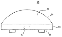
- the conventional light diffusing lens 50 has a hemispherical body 52 and is perpendicular to the isotropic upper surface 54, the planar lower surface 56, and the lower surface 56. It has an isometric side surface 58.
- An entrance hole (not shown) in which an LED (not shown) is accommodated is disposed at the center of the lower surface 56.
- an incident surface 60 is formed which is convexly recessed from the entrance port toward the upper surface 54.
- the upper surface 54 and the incident surface 60 each have a constant curvature.
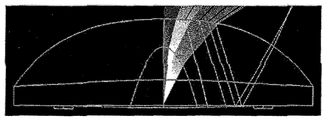
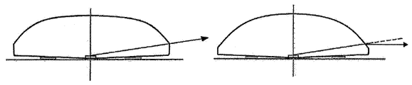
- FIG. 2 shows the light diffusing action of the conventional light diffusing lens shown in FIG. 1.
- FIG. 2 is a view showing a state of light refraction in a conventional light diffusing lens.
- light emitted from the LED is introduced into the body 52 through the incident surface 60, and emitted to the outside through the upper surface 54.
- Body 52 is made of glass or plastic material. Therefore, the body 52 is denser than air and has a high refractive index.
- Light emitted from the LED is firstly refracted as it enters the body 52 through the incident surface 60, and is secondly refracted as it is emitted through the upper surface 54 from the body 52.
- the light reflected from the lower surface 56 after bending from the upper surface 54 to the lower surface 56 is due to internal reflection.
- the light distribution state by the single light diffusing lens has a bright part in the center.
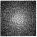
- FIG. 3 shows a light distribution state obtained by the conventional light diffusing lens shown in FIG. 1.
- the light distribution state is rotationally symmetrical. This is because the light diffusing lens 50 shown in FIG. 1 has rotationally symmetric light distribution characteristics.
- a particularly bright part in the center is called a hot spot, and a dark part around the hot spot is called a dark portion.
- Hot spots and dark spots are known to be caused by insufficient central diffusion of light emitted from the LED into the peripheral area, that is, due to the limit of diffusivity and total reflection inside the light diffusing lens.
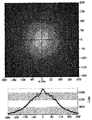
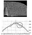
- FIG. 4 shows the intensity distribution of light diffused by the light diffusing lens shown in FIG. 1.
- the vertical axis represents the distance (in mm) from the optical axis and the vertical axis represents the light intensity (in Lux).
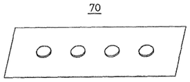
- FIG. 5 illustrates a light diffusing device in which a plurality of light diffusing lenses shown in FIG. 1 are arranged in a horizontal direction.
- the light diffusing device 70 shown in FIG. 5 arranges a plurality of light diffusing lenses adjacently, it is necessary to adjust the light distribution of each light diffusing lens.
- the light diffusing lens according to the present invention to achieve the above object
- Hemispherical body made of glass or plastic
- An elliptical incidence hole accommodating the LED and formed at the center of the lower surface
- the incident surface has a vertex located on the optical axis of the LED (LED), the vertical cross section of the incident surface has a sag profile that is represented by the following equation from the vertex to the inlet,
- z 1 is the sag profile of the incident surface
- C s1 is the curvature represented by 1 / r s1 ,
- r s1 is the radius of curvature
- the incidence surface has a plurality of inflection points at which the curvature C s1 is changed.
- the plurality of inflection points are characterized in that within the range of 20 ° around the optical axis of the LED (LED).
- the curvature C s1 is increased from the vertex of the incident surface toward the entrance hole.
- the number of inflection points is n, the first subincidence plane having a sag profile according to the first curvature in order from the vertex of the incidence plane to the incidence hole bordering the inflection point, sag profile according to the n, curvature
- the difference in the height of the vertex of each sag profile is characterized in that up to 5mm.
- the incident surface is anisotropic in which the incident surface sag profile in the minor axis direction of the light diffusing lens and the incident surface sag profile in the long axis direction of the light diffusing lens are different from each other.
- the ratio of Ca and Cc is 1.2 or more.
- the upper surface has a vertex located on the optical axis of the LED (LED), the vertical cross section of the upper surface is characterized in that it has a sag profile is represented by the following equation from the vertex to the edge of the lower surface do.
- z 2 is the sag profile of the top surface
- C s2 is the curvature of 1 / r s2
- r s2 is the radius of curvature
- the conic constant k of the top surface sag profile z2 satisfies k ⁇ -1.
- the upper surface is anisotropic in which the upper surface sag profile in the minor axis direction of the light diffusing lens and the upper surface sag profile in the major axis direction of the light diffusing lens are different from each other.
- the ratio of Cb and Cd is 1.2 or more.
- a short axis / long axis direction of the light diffusing lens and a short axis / long axis direction of the incidence opening may be different from each other by 90 degrees.
- the side surface is
- first side surface and a third side surface having a first height
- second side surface and a fourth side surface having a second height lower than the first height
- the light diffusing lens according to the present invention has an effect of uniformly diffusing the light emitted from the LED.
- FIG. 1 is a perspective view showing a conventional light diffusing lens.
- FIG. 2 shows the light diffusing action of the conventional light diffusing lens shown in FIG. 1.
- FIG. 3 shows a light distribution state obtained by the conventional light diffusing lens shown in FIG. 1.
- FIG. 4 shows the intensity distribution of light diffused by the light diffusing lens shown in FIG. 1.
- FIG. 5 illustrates a light diffusing device in which a plurality of light diffusing lenses shown in FIG. 1 are arranged in a horizontal direction.
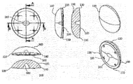
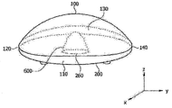
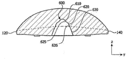
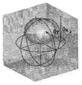
- FIG. 6 shows a configuration of a light diffusing lens according to the present invention.
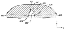
- FIG. 7 is a perspective view showing the configuration of the light diffusing lens according to the present invention, seen from the B-B direction (short axis direction, y direction) of FIG. 6.
- FIG 8 is a perspective view of the light diffusing lens according to the present invention seen in the A-A direction (the long axis direction of the light diffusing lens, the x direction).
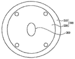
- FIG. 9 is a bottom view showing the bottom shape of the light diffusing lens according to the present invention.
- FIG. 10 is a cross-sectional view showing the shape of the light diffusing lens according to the present invention showing a cross section taken along the B-B direction of FIG.
- FIG. 11 is a cross-sectional view showing the shape of the light diffusing lens according to the present invention showing a cross section taken along the A-A direction of FIG.
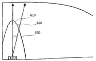
- FIG. 13 shows a comparison of parabola in contact with a plurality of subincident surfaces in a light diffusing lens according to the present invention.
- FIG. 16 illustrates a state in which light starting at the same angle on the basis of LED emission is refracted at the incident surface.
- FIG. 21 is a view illustrating a light distribution state of the conventional light diffusing lens and the light diffusing lens according to the present invention.
- Figure 23 shows the light diffusing action of the light diffusing lens according to the present invention.
- FIG. 25 shows a comparison between the case where the curvature of the incident slopes is optimally set and the case which is out of optimum.
- FIG. 6 shows a configuration of a light diffusing lens according to the present invention.
- the light diffusing lens 10 has a hemispherical body, an upper surface 100 forming an upper outline of the body, a lower surface 200 forming a lower outline of the body, and a lower surface 200.
- the upper surface 100 is a curved surface in which the curvature gradually increases from the top center portion toward the edge, and may have a convex shape.
- the lower surface 200 is a curved surface having a curvature smaller than the curvature of the central portion of the upper surface 100.
- the side surfaces 110, 120, 130, and 140 connect the edges of the top surface 100 and the edges of the bottom surface 200.
- the shortest distance from the edge of the lower surface 200 at any point of the edge of the upper surface 100 is the height of the side surfaces 110, 120, 130, 140.
- the height of the side surfaces 110, 120, 130, and 140 may be a second height to a first height. For convenience of explanation, it is assumed that the first height is greater than the second height.
- the side surfaces 110, 120, 130, and 140 have a first side surface 110 and a third side surface 130 having a first height, and a second side surface 120 and a fourth side surface having a second height. 140 may be included.
- the entrance hole 260 in which the LED 300 is accommodated is disposed at the center of the lower surface 200.
- an incident surface 600 which is convexly recessed from the entrance hole 260 toward the upper surface 100 is formed.
- the entrance hole 260 may be formed in an ellipse shape having a long axis and a short axis on the lower surface 200.
- the long axis may be positioned on a virtual solid line connecting the second side surface 120 and the fourth side surface 140.
- the short axis may be positioned on a virtual solid line connecting the first side surface 110 and the third side surface 130.
- the long axis direction is a direction connecting the second side surface 120 and the fourth side surface 140
- the short axis direction is the first side surface 110 and the third side surface 130. It may be a direction connecting.
- FIG. 7 is a perspective view showing the configuration of the light diffusing lens according to the present invention, showing a cross section in the B-B direction (uniaxial direction, y direction of the light diffusing lens) in FIG.
- FIG. 8 is a perspective view of the light diffusing lens according to the present invention, showing a cross section in the A-A direction (the major axis direction of the light diffusing lens, the x direction).
- the incident surface 600 is formed by recessing into the light diffusion lens 10 at the entrance hole 260.
- the incident surface 600 is a semi-elliptic sphere shape.
- the entrance hole 260 may be formed at the center portion of the surface of the lower convex surface 220 such that the center point of the entrance hole 260 coincides with the center point of the lower surface 200.
- the center point of the entrance hole 260 coincides with the center point of the lower surface 200
- the center of the entrance hole 260 and the entrance surface 600 and the center of the light diffusion lens 10 may coincide with each other.
- the LED 300 is disposed such that the optical axis passes through the vertex of the incident surface 600 from the center of the entrance hole 260.
- the curvature in the minor axis direction and the curvature in the major axis direction of the incident surface 600 are asymmetrical, so that the light emitted from the LED 300 is refracted by the incident surface 600 to diffuse the light diffusion lens 10.
- the curvature in the minor axis direction and the curvature in the major axis direction of the incident surface 600 are asymmetrical, so that the light emitted from the LED 300 is refracted by the incident surface 600 to diffuse the light diffusion lens 10.
- the curvature in the minor axis direction and the curvature in the major axis direction of the incident surface 600 are asymmetrical, so that the light emitted from the LED 300 is refracted by the incident surface 600 to diffuse the light diffusion lens 10.
- the sag profile z 1 of the incident surface 600 may be expressed by Equation (1) below.
- z 1 is the sag profile of the incident surface 600
- C s1 is the curvature of 1 / r s1 ,
- r s1 is the radius of curvature
- the sag profile of the incident surface 600 may not be constant along the direction from the vertex of the incident surface 600 to the incident hole 260. That is, the incident surface 600 may be isotropic or anisotropic. 7 and 8 show examples in which the incident surface 600 is anisotropic.
- the incident surface 600 is anisotropic in which the sag profile of the incident surface 600 in the minor axis direction of the light diffusing lens 10 and the sag profile of the incident surface 600 in the major axis direction of the light diffusing lens 10 are different from each other. Is,
- the ratio of Ca and Cc is 1.2 or more. It is preferable.
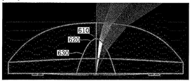
- the incident surface 600 includes a plurality of sub incident surfaces 610, 620, and 630 having different sag profiles.
- different sag profiles are represented by Equation (1) but have different curvatures.
- the spot corresponds to a portion where the light intensity is higher than the surroundings and the dark portion corresponds to a portion where the light intensity is lower than the surroundings.
- a plurality of inflection points are formed on the incident surface to disperse the light intensity.
- the inflection point is also preferably disposed in the range of about 20 degrees around the optical axis.
- the position of the spot and the dark portion may be different, and accordingly, the position of the inflection point may also be changed.
- the curvature gradually increases from the center of the top surface 100 to the edge of the top surface 100.
- the change in curvature may not be constant depending on the direction from the center to the edge of the upper surface 100.
- the change in curvature in the direction of the first side surface 110 and the third side surface 130 at the center of the upper surface 100 may be the same, and also, the second side surface 120 and the fourth side surface 140.
- the change in curvature in the direction may also be the same.
- a change in curvature in the directions of the first side surface 110 and a third side surface 130 and a change in curvature in the direction of the second side surface 120 and the fourth side surface 140 are different. Accordingly, the cross section in the up and down direction passing through the center of the upper surface 100 of the light diffusing lens 10 may be left-right symmetrical but not rotationally symmetrical.
- an increase in curvature when going from the center of the top surface 100 to the edge in the x axis direction may be greater than an increase in curvature when going to the edge in the y axis direction.
- the upper surface 100 may be isotropic or anisotropic. 7 and 8 show an example where the top surface 100 is anisotropic.
- the curvature in the x direction and the curvature in the y direction in the upper surface 100 are asymmetric when the light emitted from the LED 300 is refracted by the upper surface 100 and emitted to the outside. This is to emit asymmetrically with respect to the center of the upper surface (100).
- the sag profile z 2 of the upper surface 100 is represented by the following formula (2).
- z 2 is the sag profile of the top surface
- C s2 is the curvature of 1 / r s2 ,
- r s2 is the radius of curvature
- the upper surface 100 is hyperboloid (hyperbolic) as k ⁇ -1. (See Table 1)
- the upper surface 100 is anisotropic in which the upper surface sag profile z 2s in the minor axis direction of the light diffusing lens 10 and the upper surface sag profile x 2l in the major axis direction of the light diffusing lens are different from each other.
- the ratio of Cb and Cd is 1.2 or more. It is preferable.
- the short axis / long axis direction of the light diffusing lens 10 and the short axis / long axis direction of the incident hole 600 differ from each other by 90 degrees.
- FIG. 9 is a bottom view showing the bottom shape of the light diffusing lens according to the present invention.
- the lower surface 200 is a curved surface having a curvature smaller than the curvature of the central portion of the upper surface 100.
- the lower surface 200 may have a circular or oval cross section and a convex shape convex downward.
- the lower surface 200 may include a plane 210 and a lower convex surface 220 that is convex downward.
- the lower surface 200 may have a plane 210 formed at a constant length from an edge to a center direction, and a lower convex surface 220 may be formed from a point where the plane 210 ends to the center. That is, the lower surface 200 has a curvature of 0 for a predetermined length from the edge to the center direction, but may have a shape in which the curvature increases from the predetermined length or more to the center and then decreases again.
- the lower convex surface 220 is formed on the lower surface 200, the lower convex surface 220 is not provided and is emitted from the LED 300 as compared with the flat surface. The light emitted downward from the generated light can be totally reflected in the upward direction.
- the light emitted from the LED 300 is refracted while being incident into the light diffusing lens 10 through the incident surface 600, and the upper surface 100 or the side surface 110, inside the light diffusing lens 10. 120, 130, 140 is bent once more is emitted to the outside.
- FIG. 10 is a cross-sectional view showing the shape of the light diffusing lens according to the present invention showing a cross section taken along the B-B direction of FIG.
- FIG. 11 is a cross-sectional view showing the shape of the light diffusing lens according to the present invention showing a cross section taken along the A-A direction of FIG.
- the incident surface 600 is convexly concave toward the upper surface 100 from the entrance port 260.
- the incident surface 600 has a predetermined curvature, and the radius of curvature increases from the vertex of the incident surface 600 toward the entrance hole 260.
- the incident surface 600 has a vertex located on the optical axis of the LED 300, the cross section of the incident surface 600 has a paraboloid shape extending from the vertex to the entrance hole 260, and also the optical axis It has a plurality of inflection points that exist within 20 ° of the center.
- the number of inflection points is n, the first incidence plane having the first curvature in order from the vertex of the incidence plane along the incidence direction, and the nth incidence plane having the nth curvature, n An n + 1 incident incident surface having a +1 curvature is formed.
- FIG. 10 and 11 illustrate an example in which three subincident surfaces 610, 620, and 630 are configured by dividing the vertex of the incident surface 600 from the vertex of the incident surface 600 in the horizontal direction.
- the first incident surface 610 to the third incident surface 630 are divided by the inflection points 625 and 635 as boundaries, and are represented by the incident surface profile z 1 represented by Equation (1), but have different curvatures. .
- the inflection points 625 and 635 exist within a range of 20 ° about the optical axis of the LED 300.
- the center of the upper surface of the LED 300 positioned on the lower surface 200 becomes an origin, and the inflection points 625 and 635 are located within a range of 20 ° with respect to the optical axis.
- the two inflection points 625 and 635 are respectively connected to the first incident surface 610 and the second incident surface 620 and the second incident surface 620 and the third incident surface 630 respectively. It is located
- FIG. 13 shows a comparison of parabola in contact with a plurality of subincident surfaces in a light diffusing lens according to the present invention.
- Each parabola pl1, pl2, pl3 abuts the corresponding subincident slopes 610, 620, 630.
- the radius of curvature of the first incident surface 610 is the smallest, and the radius of curvature of the third incident surface 630 is largest.
- the radius of curvature of the second incident surface 620 is greater than the radius of curvature of the first incident surface 610 and less than the radius of curvature of the third incident surface 630.
- the curvature increases as it descends toward the entrance hole 260 from the vertex, in order to produce a multi-stage effect, a height difference between the vertices must occur. If parabolas with different curvatures are at the same height, the parabolic curves with relatively high curvatures fall into the parabolic curves with small curvatures, and thus have no effect.
- Light diffusion that is, the height of the vertex of the parabola pl1 in contact with the first incident surface 610, the parabola pl2 in contact with the second incident surface 620, and the parabola pl3 in contact with the third incident surface 630.
- the deviation between them is preferably at most 5 mm or less.
- FIG. 11 a small circle was used instead of the point to facilitate marking of the inflection points 625 and 635.
- the inflection points 625 and 635 exist within a range of 20 ° to the left and right about the optical axis. This takes into account the intensity distribution of the light emitted from the LED 300. As is known, the intensity of light emitted from the LED 300 has a Gaussian distribution, and most of the light is concentrated within a range of 20 ° about the optical axis.
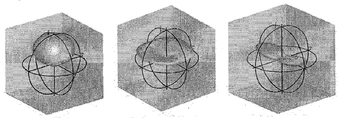
- FIG. 14 is shown to show that even though the LED has a rotationally symmetrical light distribution, it becomes an asymmetric light distribution form when passed through the asymmetric light diffusion lens.
- FIG. 14 shows the light distribution of the LED, and the middle figure and the right figure show the light distribution when the rotationally symmetric lens and the asymmetric lens are applied to the LED, respectively.
- FIG. 14 shows the intensity of light according to an angle when viewed from a distant point that an illumination system having an LED and a light diffusing lens can be regarded as a point light source.
- Candela is Luminous intensity and the unit is cd.
- the full diffusion plane is commonly called the Lambertian distribution. If the incidence plane and the top plane have a rotationally symmetrical shape, the light emitted from the LED will still have a rotationally symmetrical shape even though the light emitted from the LED is widely spread.
- the light intensity is the same in the ⁇ x direction and the ⁇ y direction. However, when passing through the asymmetric light diffusing lens, an asymmetric light distribution pattern is shown.
- the incident angle in the plane of incidence varies.
- the normal line direction of the light-contacting surface becomes the reference axis
- the incident angle of light entering the x direction is larger than the incident angle of light entering the y direction. Therefore, the light directed in the x-direction is refracted more than the light directed in the y-direction at the first refracted incident surface, resulting in asymmetric light distribution.
- C a is the curvature of the incident surface sag profile in the major axis direction of the light diffusing lens
- C c is the curvature of the incident surface sag profile in the minor axis direction of the light diffusing lens.
- FIG. 16 illustrates a state in which light starting at the same angle on the basis of LED emission is refracted at the incident surface.
- the incident angle is different when the incident surface is touched.
- the incidence angle ⁇ x in the x direction and the incidence angle ⁇ y in the y direction are as shown in Equation (1).
- the curvature Cs1 when Ca is the curvature of the incident surface sag profile in the long-axis direction of the light diffusing lens, and Cc is the curvature of the incident surface sag profile in the short axis direction of the light diffusing lens, if Ca> Cc, the incident angle is ⁇ x> ⁇ y and the refractive angle is Relatively larger.
- the curvature condition of the upper surface must be (Cb ⁇ Cd).
- ⁇ xr incident angle when light refracted in the x direction reaches the upper surface
- ⁇ yr The incident angle when light refracted in the y direction reaches the upper surface.
- each surface should be determined so that the following condition is always at the point of each surface where the ray radiated at the same angle from the light source to an arbitrary point P is refracted.
- the light diffusing lens 10 has a free curved shape in the form of an anamorphic lens that spreads light more widely.
- the direction of incidence of curvature of the incident surface is determined as the long axis direction.
- the angles of refraction of light incident through the first incident surface 610 to the third incident surface 630 are different from each other. This is because the first incident surface 610 to the third incident surface 630 have different curvatures.
- the radius of curvature of the first incident surface 610 is the smallest and the radius of curvature of the third incident surface 630 is the largest, it is found that the angle of refraction becomes larger toward the peripheral portion of the light diffusion lens 10. Can be. That is, it can be seen that the light emitted from the LED 300 is sufficiently diffused to the surrounding area, and thus the hot spot phenomenon is improved.
- a portion of the light within the 20 ° range of the center portion, in particular, the optical axis of the light generated by the LED 300 can be sent to the area where the dark phenomenon occurs. Accordingly, it can be seen that the dark phenomenon is improved.
- FIG. 19 an x-axis irradiation area and a y-axis irradiation area according to a light diffusing lens arrangement of a BLU (back light unit) set are shown. It can be seen that seven light diffusing lenses are arranged in a line and the x-axis irradiation area and the y-axis irradiation area are different from each other.
- BLU back light unit
- the X-axis irradiation area is not sensitive to Color Mura due to the narrow LED spacing, but the y-axis irradiation area is very wider than the x-axis irradiation area, making it sensitive to color mura. As a result, the color in the y-axis direction is shifted toward Yellow.
- the curvature of the light incident to the point (corner region) where the upper surface 100 and the side surfaces 110 and 130 meet in the cross section in the x-axis direction is given a curvature to the lower portion of the y axis.
- the side surfaces 120 and 140 the light can be diffused further away from the y axis.
- This corner region is a region where a lot of yellow light is distributed. As a result, yellow light can diffuse farther on the y-axis, and color shift toward yellow can be eliminated.
- the light diffusing lens 10 according to the present invention can reduce the color mura by designing different shapes of the light diffusing lens in the y-axis direction.
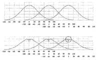
- FIG. 21 is a view illustrating a light distribution state of the conventional light diffusing lens and the light diffusing lens according to the present invention.
- the dotted line shows the light refraction and the light intensity distribution of the conventional light diffusing lens using the single curvature incidence plane
- the solid line shows the light using the multistage curvature incidence plane 600 according to the present invention. The light refraction and light intensity distribution of the diffusing lens are shown.
- the incident surface with inflection points defined by the multi-stage curvature to improve the hot spots and the dark portions generated by the light in the 0 degree direction (optical axis direction) to 20 degree direction (20 degree direction from the optical axis) (600) was formed.
- the light driven in the 0 degree direction by the incident surface 600 is diffused in the peripheral direction where the light is relatively distributed.
- the light intensity distribution is smoothly and evenly changed in the region visually recognized by the dark part as shown by the circle, that is, the hot spot and the dark part are improved.
- FIG 22 shows the light distribution state light intensity distribution of the conventional light diffusing lens and the right picture shows the light distribution state and light intensity distribution by the light diffusing lens 10 according to the present invention.
- the light intensity distribution is smoothly and evenly changed in the region visually recognized by the dark portion as shown by the circle, that is, the hot spot and the dark portion are improved.
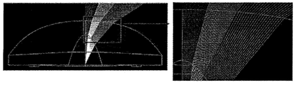
- Figure 23 shows the light diffusing action of the light diffusing lens according to the present invention.
- FIG. 23 is a view showing an optical refraction state in the light diffusing lens according to the present invention.
- an incident surface having inflection points defined by multi-stage curvatures to improve hot spots and dark portions generated by light directed from the 0 degree direction (the optical axis direction) to the 20 degree direction (the 20 degree direction from the optical axis) 600. It can be seen that the light incident in the 0 degree direction by the incident surface 600 is adjusted for each section and diffused to the surroundings.
- 24 is a view showing an optical path inside the light diffusing lens.
- the figure on the left shows that the radius of curvature is the same and the improvement of the optical path is impossible.
- FIG. 25 shows a comparison between the case where the curvature of the incident slopes is optimally set and the case which is out of optimum.
- curvature of the plurality of incident slopes 610 to 630 is out of the optimum range, a darker phenomenon may be generated or image quality may be deteriorated.
- optimal means that the light intensity distribution by the light diffusing lens has an ideal Gaussian distribution.
- the image obtained by the liquid crystal display is clear without mura phenomenon (dark part, hot spot, color separation, etc.).
- each light diffusing lens does not have an ideal Gaussian distribution (for example, when there is a distortion in the center portion), the image obtained by the liquid crystal display is uneven because the center portion is not clean. Hot spots, color separation, etc.).
- the present invention relates to a light diffusing lens for asymmetrically and uniformly spreading the light generated from the LED (LED) and to improve the hot spot phenomenon and the dark phenomenon is the industrial applicability.
Landscapes
- Physics & Mathematics (AREA)
- General Physics & Mathematics (AREA)
- Optics & Photonics (AREA)
- Engineering & Computer Science (AREA)
- General Engineering & Computer Science (AREA)
- Lenses (AREA)
Abstract
A light diffusion lens for remedying the hot spot effect and the dark zone effect is disclosed. The light diffusion lens for diffusing light generated by an LED comprises: a hemispherical body made of a glass material or a plastic material; an upper surface forming the upper appearance of the body; a lower surface forming the lower appearance of the body; an elliptical incident port formed at the center of the lower surface so as to receive the LED therethrough; and an incident surface formed in a convex shape extending from the incident port toward the upper surface.
Description
본 발명은 엘이디(LED)에서 발생하는 광을 확산시키기 위한 광 확산 렌즈에 관한 것으로서 특히, 핫 스팟 현상 및 암부 현상을 개선하는 광 확산 렌즈에 관한 것이다. BACKGROUND OF THE INVENTION 1. Field of the Invention The present invention relates to a light diffusing lens for diffusing light generated from an LED (LED), and more particularly to a light diffusing lens for improving hot spot phenomenon and dark phenomenon.
최근 조명장치를 비롯한 산업 전반에 걸쳐 광원으로 엘이디(LED)를 사용하는 경우가 많아지고 있으며, 이에 따라 LED를 효과적이면서 효율적으로 사용하기 위한 각 산업 분야에서의 연구 또한 활발히 진행되고 있다.Recently, LEDs are increasingly used as light sources throughout the industry, including lighting devices. Accordingly, researches in each industrial field for using LEDs effectively and efficiently are also being actively conducted.
LED에서 발생하는 광(光)은 주변에 비해 중심부분에 광 분포가 집중되는 특성이 있다. 따라서 빛이 주변으로 고르게 분산되지 못하고 LED의 정면 부분이 더 밝고 정면에서 멀어질수록 어두워지는 문제점이 있다.Light generated from the LED has a characteristic that the light distribution is concentrated in the center portion compared to the surroundings. Therefore, there is a problem that the light is not evenly distributed to the surroundings, and the front portion of the LED becomes brighter and darker as it moves away from the front side.
이러한 문제점을 해결하기 위하여, LED에서 발생하는 광을 효과적으로 그리고 균일하게 확산시키기 위한 기술에 대한 수요가 늘어나고 있다.In order to solve this problem, there is an increasing demand for a technique for effectively and uniformly spreading the light generated from the LED.
한편, LED에서 방출되는 빛을 대칭적으로 균일하게 확산시키는 것도 필요하지만, LED의 배치에 따라서는, 빛을 특정 방향으로만 좀 더 많이 확산시키는 것도 필요하다. 예를 들어서, LED의 배치가 좌우 간격을 상하 간격보다 조밀하게 한 경우라면, 상하 방향으로 빛을 좀 더 확산시키고 좌우 방향으로는 덜 확산시켜야 전체적으로 균일한 빛의 분포를 얻을 수 있다.On the other hand, it is also necessary to spread the light emitted from the LED symmetrically and uniformly, but depending on the arrangement of the LED, it is also necessary to diffuse more light only in a specific direction. For example, if the arrangement of the LEDs makes the left and right spacing denser than the up and down spacing, more diffuse light in the up and down directions and less diffuse in the left and right directions to obtain a uniform distribution of light.
따라서, LED에서 방출된 빛을 비대칭적으로 균일하게 확산시키는 기술에 대한 요구가 높아지고 있다.Therefore, there is an increasing demand for a technique for asymmetrically and uniformly spreading the light emitted from the LEDs.
도 1은 종래의 광 확산 렌즈를 보이는 사시도이다. 도 1을 참조하면, 종래의 광 확산 렌즈(50)는 반구형 몸체(52)를 가지며, 등방형의 상부면(54), 평면 형상의 하부면(56), 하부면(56)에 대해 수직인 등방형의 측부면(58)을 갖는다. 1 is a perspective view showing a conventional light diffusing lens. Referring to FIG. 1, the conventional light diffusing lens 50 has a hemispherical body 52 and is perpendicular to the isotropic upper surface 54, the planar lower surface 56, and the lower surface 56. It has an isometric side surface 58.
하부면(56)의 중앙에는 LED(미도시)가 수용되는 입사구(미도시)가 배치된다. 또한, 입사구로부터 상부면(54) 방향으로 볼록하게 함몰된 입사면(60)이 형성되어 있다. An entrance hole (not shown) in which an LED (not shown) is accommodated is disposed at the center of the lower surface 56. In addition, an incident surface 60 is formed which is convexly recessed from the entrance port toward the upper surface 54.
상부면(54) 및 입사면(60)은 각각 일정한 곡률을 갖는다.The upper surface 54 and the incident surface 60 each have a constant curvature.
도 2는 도 1에 도시된 종래의 광 확산 렌즈의 광 확산 작용을 보인다.FIG. 2 shows the light diffusing action of the conventional light diffusing lens shown in FIG. 1.
도 2는 종래의 광 확산 렌즈 내부에서의 광 굴절 상태를 보이는 도이다.2 is a view showing a state of light refraction in a conventional light diffusing lens.
도 2를 참조하면, LED에서 발산된 광은 입사면(60)을 통하여 몸체(52)로 유입되고, 상부면(54)을 통하여 외부로 방출된다.Referring to FIG. 2, light emitted from the LED is introduced into the body 52 through the incident surface 60, and emitted to the outside through the upper surface 54.
몸체(52)는 유리 혹은 플라스틱 재질로 이루어진다. 따라서, 몸체(52)는 공기보다 밀도가 높고, 굴절률도 높다.Body 52 is made of glass or plastic material. Therefore, the body 52 is denser than air and has a high refractive index.
LED에서 방출된 광은 입사면(60)을 통하여 몸체(52)로 유입되면서 1차로 굴절되고, 몸체(52)로부터 상부면(54)을 통하여 방출되면서 2차로 굴절된다.Light emitted from the LED is firstly refracted as it enters the body 52 through the incident surface 60, and is secondly refracted as it is emitted through the upper surface 54 from the body 52.
공기와 몸체(52)의 밀도 차이 때문에 LED에서 발산된 광은 원래의 광 경로보다 주변 방향으로 꺾인 경로를 통하여 방출된다. 즉, LED에서 발산된 광이 주변으로 확산한다.Because of the difference in density between air and body 52, light emitted from the LED is emitted through a path that is bent in the peripheral direction rather than the original light path. That is, light emitted from the LED diffuses to the surroundings.
도 2에서 상부면(54)으로부터 하부면(56)으로 꺽인 후 다시 하부면(56)에서 반사되는 광은 내부반사에 의한 것이다. In FIG. 2, the light reflected from the lower surface 56 after bending from the upper surface 54 to the lower surface 56 is due to internal reflection.
도 2로 인하여, 단일한 광 확산 렌즈에 의한 배광 상태는 중앙에 밝은 부분이 있음을 알 수 있다.2, it can be seen that the light distribution state by the single light diffusing lens has a bright part in the center.
도 2로 인하여, BLU (Back Light Unit) 세트 즉, 복수의 광 확산 렌즈를 일렬로 배치한 것에서 각각의 광 확산 렌즈에 의해 만들어지는 배광에서는 어두운 부분과 밝은 부분이 교차로 배치되게 된다. 이로 인하여 BLU세트의 품질의 저하되는 것을 알 수 있다.2, in the light distribution produced by each of the light diffusing lenses in a BLU (Back Light Unit) set, that is, a plurality of light diffusing lenses arranged in a row, the dark and the bright parts are arranged at the intersection. This can be seen that the quality of the BLU set is deteriorated.
도 3은 도 1에 도시된 종래의 광 확산 렌즈에 의해 얻어지는 배광 상태를 보인다. 3 shows a light distribution state obtained by the conventional light diffusing lens shown in FIG. 1.
도 3을 참조하면, 배광 상태가 회전 대칭형을 이루는 것을 알 수 있다. 이것은 도 1에 도시된 광 확산 렌즈(50)가 회전대칭형 배광 특성을 가지는 것이기 때문이다. Referring to FIG. 3, it can be seen that the light distribution state is rotationally symmetrical. This is because the light diffusing lens 50 shown in FIG. 1 has rotationally symmetric light distribution characteristics.
다시 도 3을 참조하면, 주변 부분에 비해 밝은 부분들과 주변 부분에 비해 어두운 부분들이 있는 것을 볼 수 있다.Referring back to FIG. 3, it can be seen that there are brighter parts and darker parts than the peripheral part.
밝은 부분들 중에서도 중앙의 특히 밝은 부분을 핫 스팟(hot spot) 이라 하고, 핫 스팟 주변의 어두운 부분을 암부(dark portion) 라고 한다.Among the bright parts, a particularly bright part in the center is called a hot spot, and a dark part around the hot spot is called a dark portion.
이러한 핫 스팟과 암부의 명도 대비는 매우 크기 때문에 고른 배광을 저해하는 요인이 된다. 따라서 광 확산 렌즈에서 발생하는 핫 스팟과 암부를 최대한 경감시킬 것이 요구된다. Since the contrast between the hot spots and the dark areas is very large, it is a factor that inhibits even light distribution. Therefore, it is required to reduce as much as possible hot spots and dark areas generated in the light diffusing lens.
핫 스팟 및 암부는 LED에서 발산된 광 중에서 중앙 부분의 광이 주변 부위로 충분히 확산되지 못하는 것 즉, 확산성의 한계와 광 확산 렌즈 내부의 전반사에 의해 발생하는 것으로 알려져 있다.Hot spots and dark spots are known to be caused by insufficient central diffusion of light emitted from the LED into the peripheral area, that is, due to the limit of diffusivity and total reflection inside the light diffusing lens.
도 4는 도 1에 도시된 광 확산 렌즈에 의해 확산된 광의 강도 분포를 보인다.FIG. 4 shows the intensity distribution of light diffused by the light diffusing lens shown in FIG. 1.
도 4에 있어서, 종축은 광축으로부터의 거리(단위; mm)를 나타내고 종축은 광강도(단위; Lux)를 나타낸다.In Fig. 4, the vertical axis represents the distance (in mm) from the optical axis and the vertical axis represents the light intensity (in Lux).
도 4를 참조하면, 중앙 부분에서 광 강도가 피크(peak)를 이루는 부분이 핫 스팟이 되고 핫 스팟 주위로 광강도가 현저하게 떨어진 부분이 암부가 되는 것을 알 수 있다. 또한, 핫 스팟과 암부 사이에서는 광강도 분포가 급격하고 고르지 않은 반면에 암부와 가장자리 사이에서는 광 강도 분포가 비교적 완만하고 고르게 되어 있는 것을 알 수 있다.Referring to FIG. 4, it can be seen that a portion where the light intensity peaks in the central portion becomes a hot spot, and a portion where the light intensity is remarkably dropped around the hot spot becomes a dark portion. Further, it can be seen that the light intensity distribution is sharp and uneven between the hot spot and the dark portion, while the light intensity distribution is relatively smooth and even between the dark portion and the edge.
도 5는 도 1에 도시된 광 확산 렌즈를 가로 방향으로 여러 개 배치한 광 확산 장치를 도시한다. FIG. 5 illustrates a light diffusing device in which a plurality of light diffusing lenses shown in FIG. 1 are arranged in a horizontal direction.
도 5에 도시된 바의 광 확산 장치(70)는 복수의 광 확산 렌즈들을 인접시켜 배치하고 있으므로 각각의 광 확산 렌즈의 배광을 조절할 필요가 있다.Since the light diffusing device 70 shown in FIG. 5 arranges a plurality of light diffusing lenses adjacently, it is necessary to adjust the light distribution of each light diffusing lens.
본 발명은 비대칭 배광을 갖는 광 확산 렌즈를 제공하는 것을 그 목적으로 한다.It is an object of the present invention to provide a light diffusing lens having asymmetric light distribution.
본 발명의 기술적 과제들은 이상에서 언급한 기술적 과제들로 제한되지 않으며, 언급되지 않은 또 다른 기술적 과제들은 아래의 기재로부터 당업자에게 명확하게 이해될 수 있을 것이다.The technical problems of the present invention are not limited to the above-mentioned technical problems, and other technical problems not mentioned will be clearly understood by those skilled in the art from the following description.
상기의 목적을 달성하는 본 발명에 따른 광 확산 렌즈는The light diffusing lens according to the present invention to achieve the above object
엘이디(LED)에서 발생한 광을 확산시키는 광 확산 렌즈에 있어서, In the light diffusion lens for diffusing light generated from the LED (LED),
유리 재질 또는 플라스틱 재질로 이루어진 반구형 몸체;Hemispherical body made of glass or plastic;
상기 몸체의 상부 외형을 이루는 상부면;An upper surface forming an upper outline of the body;
상기 몸체의 하부 외형을 이루는 하부면;A lower surface forming a lower outline of the body;
상기 엘이디(LED)를 수용하며, 상기 하부면의 중심에 형성된 타원 형상의 입사구; 및An elliptical incidence hole accommodating the LED and formed at the center of the lower surface; And
상기 입사구로부터 상기 상부면 쪽으로 볼록하게 형성된 입사면; 을 포함하며,An entrance surface formed convexly from the entrance hole toward the upper surface; Including;
여기서, 상기 입사면은 상기 엘이디(LED)의 광축 상에 위치하는 정점을 가지며, 상기 입사면의 수직단면은 상기 정점으로부터 상기 입사구로 이어지면서 하기의 식으로 표현되는 sag 프로파일을 가지며,Here, the incident surface has a vertex located on the optical axis of the LED (LED), the vertical cross section of the incident surface has a sag profile that is represented by the following equation from the vertex to the inlet,

여기서, , here, ,
z1는 입사면의 sag 프로파일, z 1 is the sag profile of the incident surface,
k는 코닉 상수(conic constant)k is conic constant
Cs1은 1/rs1로 나타내어지는 곡률, C s1 is the curvature represented by 1 / r s1 ,
rs1은 곡률 반경r s1 is the radius of curvature
상기 입사면에는 곡률 Cs1이 변하는 복수의 변곡점이 있는 것을 특징으로 한다.The incidence surface has a plurality of inflection points at which the curvature C s1 is changed.
여기서, 복수의 변곡점은 상기 엘이디(LED)의 광축을 중심으로 20°의 범위 내에 있는 것을 특징으로 한다. Here, the plurality of inflection points are characterized in that within the range of 20 ° around the optical axis of the LED (LED).
여기서, 입사면 sag 프로파일 z1의 코닉 상수 k는 k = -1을 만족하는 것을 특징으로 한다.Here, the conic constant k of the incident surface sag profile z 1 satisfies k = -1.
여기서, 상기 입사면의 정점으로부터 상기 입사구 쪽으로 가면서 곡률 Cs1이 증가하는 것을 특징으로 한다.Here, the curvature C s1 is increased from the vertex of the incident surface toward the entrance hole.
여기서, 변곡점의 개수를 n 이라 하고, 변곡점을 경계로 입사면의 정점으로부터 입사구 방향을 따라 차례로 제1곡률에 따른 sag 프로파일을 가지는 제1부입사면, ,,,제n곡률에 따른 sag 프로파일을 가지는 제n부입사면, 제n+1곡률에 따른 sag 프로파일을 가지는 제n+1부입사면으로 구성하였을 때, 각각의 sag 프로파일의 꼭짓점 높이의 차이가 최대 5mm 이하인 것을 특징으로 한다.Here, the number of inflection points is n, the first subincidence plane having a sag profile according to the first curvature in order from the vertex of the incidence plane to the incidence hole bordering the inflection point, sag profile according to the n, curvature When the n-th incidence surface having a, n + 1 sub-incidence surface having a sag profile according to the n + 1 curvature, the difference in the height of the vertex of each sag profile is characterized in that up to 5mm.
여기서, 상기 입사면은 상기 광 확산 렌즈의 단축 방향의 입사면 sag 프로파일과 상기 광 확산 렌즈의 장축 방향의 입사면 sag 프로파일이 서로 다른 비등방형이며,Here, the incident surface is anisotropic in which the incident surface sag profile in the minor axis direction of the light diffusing lens and the incident surface sag profile in the long axis direction of the light diffusing lens are different from each other.
상기 광 확산 렌즈의 장축 방향의 입사면 sag 프로파일의 곡률을 Ca라고 하고 상기 광 확산 렌즈의 단축 방향의 입사면 sag 프로파일의 곡률을 Cc라고 할 때, Ca와 Cc와의 비율이 1.2 이상인 것을 특징으로 한다.When the curvature of the incident surface sag profile in the long axis direction of the light diffusing lens is Ca and the curvature of the incident surface sag profile in the minor axis direction of the light diffusing lens is Cc, the ratio of Ca and Cc is 1.2 or more. .
여기서, here,
상기 상부면은 상기 엘이디(LED)의 광축 상에 위치하는 정점을 가지며, 상기 상부면의 수직단면은 상기 정점으로부터 상기 하부면의 가장자리로 이어지면서 하기의 식으로 표현되는 sag 프로파일을 가지는 것을 특징으로 한다.The upper surface has a vertex located on the optical axis of the LED (LED), the vertical cross section of the upper surface is characterized in that it has a sag profile is represented by the following equation from the vertex to the edge of the lower surface do.

여기서, here,
z2는 상부면의 sag 프로파일 z 2 is the sag profile of the top surface
K는 코닉 상수(conic constant)K is conic constant
Cs2는 1/rs2의 곡률C s2 is the curvature of 1 / r s2
rs2은 곡률 반경r s2 is the radius of curvature
여기서, 상부면 sag 프로파일 z2의 코닉 상수 k는 k < -1을 만족하는 것을 특징으로 한다.Here, the conic constant k of the top surface sag profile z2 satisfies k <-1.
여기서, here,
상기 상부면은 상기 광 확산 렌즈의 단축 방향의 상부면 sag 프로파일과 상기 광 확산 렌즈의 장축 방향의 상부면 sag 프로파일이 서로 다른 비등방형이며,The upper surface is anisotropic in which the upper surface sag profile in the minor axis direction of the light diffusing lens and the upper surface sag profile in the major axis direction of the light diffusing lens are different from each other.
상기 광 확산 렌즈의 장축 방향의 상부면 sag 프로파일의 곡률을 Cb라고 하고 상기 광 확산 렌즈의 단축 방향의 상부면 sag 프로파일의 곡률을 Cd라고 할 때, Cb와 Cd의 비율이 1.2 이상인 것을 특징으로 한다.When the curvature of the top surface sag profile in the long axis direction of the light diffusing lens is called Cb and the curvature of the top surface sag profile in the short axis direction of the light diffusing lens is Cd, the ratio of Cb and Cd is 1.2 or more. .
여기서, here,
Ca > Cc 라면 Cb < Cd 이고,If C a > C c, then C b <C d ,
Ca < Cc 라면 Cb > Cd 인 것을 특징으로 한다.If C a <C c It is characterized by C b > C d .
Ca ; 광 확산 렌즈의 장축 방향의 입사면 sag 프로파일의 곡률C a ; Curvature of the incident surface sag profile in the long axis direction of the light diffusing lens
Cb ; 광 확산 렌즈의 장축 방향의 상부면 sag 프로파일의 곡률C b ; Curvature of the top surface sag profile in the long axis direction of the light diffusing lens
Cc ; 광 확산 렌즈의 단축 방향의 입사면 sag 프로파일의 곡률C c ; Curvature of the incident surface sag profile in the minor axis direction of the light diffusing lens
Cd; 광 확산 렌즈의 단축 방향의 상부면 sag 프로파일의 곡률C d ; Curvature of the top surface sag profile in the minor axis direction of the light diffusing lens
여기서, here,
상기 광 확산 렌즈의 단축/장축 방향과 상기 입사구의 단축/장축방향은 서로 90도 차이가 있는 것을 특징으로 한다.A short axis / long axis direction of the light diffusing lens and a short axis / long axis direction of the incidence opening may be different from each other by 90 degrees.
여기서, 하기의 식을 만족하는 것을 특징으로 한다.Here, the following formula is satisfied.

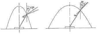
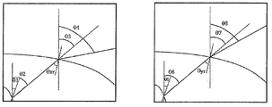
(여기서, (here,
θ1; 광 확산 렌즈의 장축 방향에서 입사면으로 입사되는 광의 입사각이고,θ1; Incident angle of light incident on the incident surface in the long axis direction of the light diffusing lens,
θ2; 광 확산 렌즈의 장축 방향에서 입사면으로부터 굴절되는 광의 굴절각이고,θ2; The angle of refraction of light refracted from the incident surface in the long axis direction of the light diffusing lens,
θ3; 광 확산 렌즈의 장축 방향에서 상부면으로 입사되는 광의 입사각이고,θ3; The incident angle of light incident on the upper surface in the long axis direction of the light diffusing lens,
θ4; 광 확산 렌즈의 장축 방향에서 상부면으로부터 굴절되는 광의 굴절각이고,θ4; The angle of refraction of light refracted from the upper surface in the long axis direction of the light diffusing lens,
θ5; 광 확산 렌즈의 단축 방향에서 입사면으로 입사되는 광의 입사각이고,θ5; The incident angle of light incident on the incident surface in the minor axis direction of the light diffusing lens,
θ6; 광 확산 렌즈의 단축 방향에서 입사면으로부터 굴절되는 광의 굴절각이고,θ6; The angle of refraction of light refracted from the incident surface in the minor axis direction of the light diffusing lens,
θ7; 광 확산 렌즈의 단축 방향에서 상부면으로 입사되는 광의 입사각이며, 그리고θ7; The incident angle of light incident on the upper surface in the minor axis direction of the light diffusing lens, and
θ8; 광 확산 렌즈의 단축 방향에서 상부면으로부터 굴절되는 광의 굴절각이다.)θ8; The angle of refraction of light refracted from the upper surface in the minor axis direction of the light diffusing lens.)
여기서,here,
상기 상부면의 가장자리와 상기 하부면의 가장자리를 연결하는 측부면을 더 포함하고,Further comprising a side surface connecting the edge of the upper surface and the edge of the lower surface,
상부면의 가장자리의 어느 한 지점에서 하부면의 가장자리까지의 거리 중에서 제일 짧은 거리가 측부면의 높이라고 할 때, When the shortest distance from the edge of the upper surface to the edge of the lower surface is the height of the side surface,
상기 측부면은 The side surface is
제1 높이를 가지는 제1 측부면과 제3 측부면, 제1높이보다 낮은 제2 높이를 가지는 제2 측부면과 제4 측부면을 포함하는 것을 특징으로 한다.And a first side surface and a third side surface having a first height, a second side surface and a fourth side surface having a second height lower than the first height.
본 발명에 따른 광 확산 렌즈는 LED에서 방출된 빛을 비대칭적으로 균일하게 확산시킬 수 있는 효과가 있다.The light diffusing lens according to the present invention has an effect of uniformly diffusing the light emitted from the LED.
도 1은 종래의 광 확산 렌즈를 보이는 사시도이다.1 is a perspective view showing a conventional light diffusing lens.
도 2는 도 1에 도시된 종래의 광 확산 렌즈의 광 확산 작용을 보인다.FIG. 2 shows the light diffusing action of the conventional light diffusing lens shown in FIG. 1.
도 3은 도 1에 도시된 종래의 광 확산 렌즈에 의해 얻어지는 배광 상태를 보인다. 3 shows a light distribution state obtained by the conventional light diffusing lens shown in FIG. 1.
도 4는 도 1에 도시된 광 확산 렌즈에 의해 확산된 광의 강도 분포를 보인다.FIG. 4 shows the intensity distribution of light diffused by the light diffusing lens shown in FIG. 1.
도 5는 도 1에 도시된 광 확산 렌즈를 가로 방향으로 여러 개 배치한 광 확산 장치를 도시한다. FIG. 5 illustrates a light diffusing device in which a plurality of light diffusing lenses shown in FIG. 1 are arranged in a horizontal direction.
도 6은 본 발명에 따른 광 확산 렌즈의 구성을 보인다.6 shows a configuration of a light diffusing lens according to the present invention.
도 7은 본 발명에 따른 광 확산 렌즈의 구성을 보이는 투시도로서 도 6에서의 B-B 방향(광 확산 렌즈의 단축 방향, y 방향)에서 본 도이다.FIG. 7 is a perspective view showing the configuration of the light diffusing lens according to the present invention, seen from the B-B direction (short axis direction, y direction) of FIG. 6.
도 8은 본 발명에 따른 광 확산 렌즈의 투시도로서 A-A 방향( 광 확산 렌즈의 장축 방향, x 방향)에서 본 도이다.8 is a perspective view of the light diffusing lens according to the present invention seen in the A-A direction (the long axis direction of the light diffusing lens, the x direction).
도 9는 본 발명에 따른 광 확산 렌즈의 저면 형상을 보이는 저면도이다.9 is a bottom view showing the bottom shape of the light diffusing lens according to the present invention.
도 10은 본 발명에 따른 광 확산 렌즈의 형상을 보이는 단면도로서 도 6의 B-B 방향을 따라 절개한 단면을 보인다.10 is a cross-sectional view showing the shape of the light diffusing lens according to the present invention showing a cross section taken along the B-B direction of FIG.
도 11은 본 발명에 따른 광 확산 렌즈의 형상을 보이는 단면도로서 도 6의 A-A 방향을 따라 절개한 단면을 보인다.11 is a cross-sectional view showing the shape of the light diffusing lens according to the present invention showing a cross section taken along the A-A direction of FIG.
도 12는 엘이디의 광축과 입사면의 정렬 관계를 도시한다.12 shows the alignment relationship between the optical axis of the LED and the incident surface.
도 13은 본 발명에 따른 광 확산 렌즈에서 복수의 부입사면들에 접하는 포물선을 비교하여 보이는 것이다.FIG. 13 shows a comparison of parabola in contact with a plurality of subincident surfaces in a light diffusing lens according to the present invention. FIG.
도 14는 LED의 배광 상태 및 렌즈를 적용한 경우의 배광 상태를 도시한다.14 shows the light distribution state of the LED and the light distribution state when the lens is applied.
도 15는 LED 배광 상태를 보인다.15 shows an LED light distribution state.
도 16은 같이 LED 출사(出謝) 기준으로 같은 각도로 출발한 광이 입사면에서 굴절되는 상태를 도시한다.FIG. 16 illustrates a state in which light starting at the same angle on the basis of LED emission is refracted at the incident surface.
도 17은 상부면에서의 굴절 상태를 보인다.17 shows the refractive state at the top surface.
도 18은 본 발명에 따른 광 확산 렌즈에 의한 광 확산 효과를 도시한다.18 shows the light diffusing effect by the light diffusing lens according to the present invention.
도 19는 백라이트 유닛 세트에서의 광 확산 렌즈의 배열 상태를 도시한다.19 shows the arrangement state of the light diffusing lens in the backlight unit set.
도 20은 본 발명에 따른 광 확산 렌즈에 있어서 측부면에 의한 광 굴절 현상을 도시한다.20 shows the light refraction phenomenon by the side surface in the light diffusing lens according to the present invention.
도 21은 종래의 광 확산 렌즈와 본 발명에 따른 광 확산 렌즈에 의한 배광 상태를 비교하여 도시한 것이다.FIG. 21 is a view illustrating a light distribution state of the conventional light diffusing lens and the light diffusing lens according to the present invention.
도 22는 종래의 광 확산 렌즈와 본 발명에 따른 광 확산 렌즈에 의한 배광 상태 및 광 강도 분포를 비교하여 보이는 것이다. 22 shows a comparison between the light distribution state and the light intensity distribution by the conventional light diffusing lens and the light diffusing lens according to the present invention.
도 23은 본 발명에 따른 광 확산 렌즈의 광 확산 작용을 보인다.Figure 23 shows the light diffusing action of the light diffusing lens according to the present invention.
도 24는 다단 곡률의 적용 단수(段數)에 따른 배광 상태를 도시한다.24 shows a light distribution state according to the number of stages of application of the multi-stage curvature.
도 25는 부입사면들에 대한 곡률이 최적으로 설정된 경우와 최적을 벗어난 경우를 비교하여 보이는 것이다.FIG. 25 shows a comparison between the case where the curvature of the incident slopes is optimally set and the case which is out of optimum.
도 6은 본 발명에 따른 광 확산 렌즈의 구성을 보인다.6 shows a configuration of a light diffusing lens according to the present invention.
도 6을 참조하면, 본 발명에 따른 광 확산 렌즈(10)는 반구형 몸체를 가지며, 몸체의 상부 외형을 이루는 상부면(100), 몸체의 하부 외형을 이루는 하부면(200), 하부면(200)에 대해 수직인 평면 형상의 측부면(110, 120, 130, 140)을 갖는다. Referring to FIG. 6, the light diffusing lens 10 according to the present invention has a hemispherical body, an upper surface 100 forming an upper outline of the body, a lower surface 200 forming a lower outline of the body, and a lower surface 200. Have side faces 110, 120, 130, 140 of planar shape perpendicular to.
상부면(100)은 최상단 중심 부분에서 가장자리로 갈수록 곡률이 점진적으로 증가하는 곡면이며, 볼록한 형상일 수 있다. The upper surface 100 is a curved surface in which the curvature gradually increases from the top center portion toward the edge, and may have a convex shape.
하부면(200)은 상부면(100)의 중심 부분의 곡률보다 더 작은 곡률을 가지는 곡면이다. The lower surface 200 is a curved surface having a curvature smaller than the curvature of the central portion of the upper surface 100.
측부면(110, 120, 130, 140)은 상부면(100)의 가장자리와 하부면(200)의 가장자리를 연결하는 것이다. 상부면(100)의 가장자리의 어느 한 지점에서 하부면(200)의 가장자리까지의 거리 중에서 제일 짧은 거리가 측부면(110, 120, 130, 140)의 높이이다. 측부면(110, 120, 130, 140)의 높이는 제2 높이 내지 제1 높이일 수 있다. 설명의 편의상 제1 높이가 제2 높이보다 더 큰 값인 것을 가정하고 설명한다. 측부면(110, 120, 130, 140)은 제1 높이를 가지는 제1 측부면(110)과 제3 측부면(130), 제2 높이를 가지는 제2 측부면(120)과 제4 측부면(140)을 포함할 수 있다. The side surfaces 110, 120, 130, and 140 connect the edges of the top surface 100 and the edges of the bottom surface 200. The shortest distance from the edge of the lower surface 200 at any point of the edge of the upper surface 100 is the height of the side surfaces 110, 120, 130, 140. The height of the side surfaces 110, 120, 130, and 140 may be a second height to a first height. For convenience of explanation, it is assumed that the first height is greater than the second height. The side surfaces 110, 120, 130, and 140 have a first side surface 110 and a third side surface 130 having a first height, and a second side surface 120 and a fourth side surface having a second height. 140 may be included.
하부면(200)의 중앙에 LED(300)가 수용되는 입사구(260)가 배치된다. 또한, 입사구(260)로부터 상부면(100) 방향으로 볼록하게 함몰된 입사면(600)이 형성되어 있다. The entrance hole 260 in which the LED 300 is accommodated is disposed at the center of the lower surface 200. In addition, an incident surface 600 which is convexly recessed from the entrance hole 260 toward the upper surface 100 is formed.
입사구(260)는 하부면(200)에 장축과 단축을 가진 타원 형상으로 형성될 수 있다. 상기 장축은 제2 측부면(120)과 제4 측부면(140)을 연결하는 가상의 실선 상에 위치할 수 있다. 상기 단축은 제1 측부면(110)과 제3 측부면(130)을 연결하는 가상의 실선 상에 위치할 수 있다. 이하 설명의 편의를 위하여, 장축 방향은 제2 측부면(120)과 제4 측부면(140)을 연결하는 방향이며, 상기 단축 방향은 제1 측부면(110)과 제3 측부면(130)을 연결하는 방향일 수 있다.The entrance hole 260 may be formed in an ellipse shape having a long axis and a short axis on the lower surface 200. The long axis may be positioned on a virtual solid line connecting the second side surface 120 and the fourth side surface 140. The short axis may be positioned on a virtual solid line connecting the first side surface 110 and the third side surface 130. For convenience of explanation, the long axis direction is a direction connecting the second side surface 120 and the fourth side surface 140, and the short axis direction is the first side surface 110 and the third side surface 130. It may be a direction connecting.
이하, 첨부된 도면을 참조하여 본 발명의 바람직한 실시예를 상세히 설명한다. 본 발명의 이점 및 특징, 그리고 그것들을 달성하는 방법은 첨부되는 도면과 함께 상세하게 후술되어 있는 실시 예들을 참조하면 명확해질 것이다. 그러나 본 발명은 이하에서 게시되는 실시예에 한정되는 것이 아니라 서로 다른 다양한 형태로 구현될 수 있으며, 단지 본 실시 예들은 본 발명의 개시가 완전하도록 하고, 본 발명이 속하는 기술분야에서 통상의 지식을 가진 자에게 발명의 범주를 완전하게 알려주기 위해 제공되는 것이며, 본 발명은 청구항의 범주에 의해 정의될 뿐이다. 명세서 전체에 걸쳐 동일 참조 부호는 동일 구성 요소를 지칭한다.Hereinafter, exemplary embodiments of the present invention will be described in detail with reference to the accompanying drawings. Advantages and features of the present invention, and methods for achieving them will be apparent with reference to the embodiments described below in detail in conjunction with the accompanying drawings. However, the present invention is not limited to the embodiments disclosed below, but can be implemented in various forms, and only the embodiments are to make the disclosure of the present invention complete, and the general knowledge in the technical field to which the present invention belongs. It is provided to fully convey the scope of the invention to those skilled in the art, and the present invention is defined only by the scope of the claims. Like reference numerals refer to like elements throughout.
다른 정의가 없다면, 본 명세서에서 사용되는 모든 용어(기술 및 과학적 용어를 포함)는 본 발명이 속하는 기술분야에서 통상의 지식을 가진 자에게 공통으로 이해될 수 있는 의미로 사용될 수 있을 것이다. 또 일반적으로 사용되는 사전에 정의되어 있는 용어들은 명백하게 특별히 정의되어 있지 않은 한 이상적으로 또는 과도하게 해석되지 않는다.Unless otherwise defined, all terms (including technical and scientific terms) used in the present specification may be used in a sense that can be commonly understood by those skilled in the art. In addition, the terms defined in the commonly used dictionaries are not ideally or excessively interpreted unless they are specifically defined clearly.
도 6은 본 발명에 따른 광 확산 렌즈의 구성을 보인다.6 shows a configuration of a light diffusing lens according to the present invention.
도 6을 참조하면, 본 발명에 따른 광 확산 렌즈(10)는 반구형 몸체를 가지며, 몸체의 상부 외형을 이루는 상부면(100), 몸체의 하부 외형을 이루는 하부면(200), 하부면(200)에 대해 수직인 평면 형상의 측부면(110, 120, 130, 140)을 갖는다. Referring to FIG. 6, the light diffusing lens 10 according to the present invention has a hemispherical body, an upper surface 100 forming an upper outline of the body, a lower surface 200 forming a lower outline of the body, and a lower surface 200. Have side faces 110, 120, 130, 140 of planar shape perpendicular to.
상부면(100)은 최상단 중심 부분에서 가장자리로 갈수록 곡률이 점진적으로 증가하는 곡면이며, 볼록한 형상일 수 있다. The upper surface 100 is a curved surface in which the curvature gradually increases from the top center portion toward the edge, and may have a convex shape.
하부면(200)은 상부면(100)의 중심 부분의 곡률보다 더 작은 곡률을 가지는 곡면이다. The lower surface 200 is a curved surface having a curvature smaller than the curvature of the central portion of the upper surface 100.
측부면(110, 120, 130, 140)은 상부면(100)의 가장자리와 하부면(200)의 가장자리를 연결하는 것이다. 상부면(100)의 가장자리의 어느 한 지점에서 하부면(200)의 가장자리까지의 거리 중에서 제일 짧은 거리가 측부면(110, 120, 130, 140)의 높이이다. 측부면(110, 120, 130, 140)의 높이는 제2 높이 내지 제1 높이일 수 있다. 설명의 편의상 제1 높이가 제2 높이보다 더 큰 값인 것을 가정하고 설명한다. 측부면(110, 120, 130, 140)은 제1 높이를 가지는 제1 측부면(110)과 제3 측부면(130), 제2 높이를 가지는 제2 측부면(120)과 제4 측부면(140)을 포함할 수 있다. The side surfaces 110, 120, 130, and 140 connect the edges of the top surface 100 and the edges of the bottom surface 200. The shortest distance from the edge of the lower surface 200 at any point of the edge of the upper surface 100 is the height of the side surfaces 110, 120, 130, 140. The height of the side surfaces 110, 120, 130, and 140 may be a second height to a first height. For convenience of explanation, it is assumed that the first height is greater than the second height. The side surfaces 110, 120, 130, and 140 have a first side surface 110 and a third side surface 130 having a first height, and a second side surface 120 and a fourth side surface having a second height. 140 may be included.
하부면(200)의 중앙에 LED(300)가 수용되는 입사구(260)가 배치된다. 또한, 입사구(260)로부터 상부면(100) 방향으로 볼록하게 함몰된 입사면(600)이 형성되어 있다. The entrance hole 260 in which the LED 300 is accommodated is disposed at the center of the lower surface 200. In addition, an incident surface 600 which is convexly recessed from the entrance hole 260 toward the upper surface 100 is formed.
입사구(260)는 하부면(200)에 장축과 단축을 가진 타원 형상으로 형성될 수 있다. 상기 장축은 제2 측부면(120)과 제4 측부면(140)을 연결하는 가상의 실선 상에 위치할 수 있다. 상기 단축은 제1 측부면(110)과 제3 측부면(130)을 연결하는 가상의 실선 상에 위치할 수 있다. 이하 설명의 편의를 위하여, 장축 방향은 제2 측부면(120)과 제4 측부면(140)을 연결하는 방향이며, 상기 단축 방향은 제1 측부면(110)과 제3 측부면(130)을 연결하는 방향일 수 있다.The entrance hole 260 may be formed in an ellipse shape having a long axis and a short axis on the lower surface 200. The long axis may be positioned on a virtual solid line connecting the second side surface 120 and the fourth side surface 140. The short axis may be positioned on a virtual solid line connecting the first side surface 110 and the third side surface 130. For convenience of explanation, the long axis direction is a direction connecting the second side surface 120 and the fourth side surface 140, and the short axis direction is the first side surface 110 and the third side surface 130. It may be a direction connecting.
도 7은 본 발명에 따른 광 확산 렌즈의 구성을 보이는 투시도로서 도 6에서의 B-B 방향(광 확산 렌즈의 단축 방향, y 방향)의 단면을 보인다.FIG. 7 is a perspective view showing the configuration of the light diffusing lens according to the present invention, showing a cross section in the B-B direction (uniaxial direction, y direction of the light diffusing lens) in FIG.
도 8은 본 발명에 따른 광 확산 렌즈의 투시도로서 A-A 방향( 광 확산 렌즈의 장축 방향, x 방향)의 단면을 보인다.8 is a perspective view of the light diffusing lens according to the present invention, showing a cross section in the A-A direction (the major axis direction of the light diffusing lens, the x direction).
도 7 및 도 8을 참조하면, 입사면(600)은 입사구(260)에서 광 확산 렌즈(10)의 내부로 함몰되어 형성된다. 입사면(600)은 반타원구 형상이다. 7 and 8, the incident surface 600 is formed by recessing into the light diffusion lens 10 at the entrance hole 260. The incident surface 600 is a semi-elliptic sphere shape.
본 발명의 실시예에 따르면, 입사구(260)의 중심점과 하부면(200)의 중심점이 일치하도록, 입사구(260)는 하부볼록면(220)의 표면의 중심 부분에 형성될 수 있다. According to the exemplary embodiment of the present invention, the entrance hole 260 may be formed at the center portion of the surface of the lower convex surface 220 such that the center point of the entrance hole 260 coincides with the center point of the lower surface 200.
입사구(260)의 중심점과 하부면(200)의 중심점이 일치하게 되면, 입사구(260) 및 입사면(600)의 중심과 광 확산 렌즈(10)의 중심이 일치할 수 있다. LED(300)는 광축이 입사구(260)의 중심으로부터 입사면(600)의 정점을 지나도록 배치된다.When the center point of the entrance hole 260 coincides with the center point of the lower surface 200, the center of the entrance hole 260 and the entrance surface 600 and the center of the light diffusion lens 10 may coincide with each other. The LED 300 is disposed such that the optical axis passes through the vertex of the incident surface 600 from the center of the entrance hole 260.
본 발명의 실시예에 따르면, 입사면(600)에 있어서 단축 방향의 곡률과 장축 방향의 곡률이 비대칭인 것은 LED(300)에서 방출된 광이 입사면(600)에서 굴절되어 광 확산 렌즈(10)의 내부로 유입될 때 입사면(600)의 중심을 기준으로 비대칭적으로 유입되도록 하기 위함이다.According to the exemplary embodiment of the present invention, the curvature in the minor axis direction and the curvature in the major axis direction of the incident surface 600 are asymmetrical, so that the light emitted from the LED 300 is refracted by the incident surface 600 to diffuse the light diffusion lens 10. In order to be introduced asymmetrically with respect to the center of the incident surface 600 when flowing into the inside.
입사면(600)의 새그(sag) 프로파일 z1은 하기의 수식 (1)로 표현될 수 있다.The sag profile z 1 of the incident surface 600 may be expressed by Equation (1) below.

여기서, here,
z1는 입사면(600)의 sag 프로파일, z 1 is the sag profile of the incident surface 600,
k는 코닉 상수(conic constant)k is conic constant
Cs1은 1/rs1의 곡률, C s1 is the curvature of 1 / r s1 ,
rs1은 곡률 반경r s1 is the radius of curvature
코닉 상수 k의 값에 따른 sag 프로파일의 형상은 하기의 표와 같다.The shape of the sag profile according to the value of the conic constant k is shown in the table below.
| Conic ConstantConic constant | Surface Type Surface Type |
| k = 0k = 0 | spherical (원추) spherical (cone) |
| k = -1k = -1 | paraboloid (포물선) paraboloid (parabola) |
| k < -1k <-1 | hyperboloid (쌍곡선) hyperboloid (hyperbolic) |
| -1 < k < 0-1 <k <0 | ellipsoid (타원) ellipsoid (ellipse) |
| k > 0k> 0 | oblat elipsoid (편타원) oblat elipsoid |
본 발명에 따른 광 확산 렌즈(10)에 있어서, 입사면(600)은 k = -1 로서 paraboloid (포물선)인 것이 바람직하다.In the light diffusing lens 10 according to the present invention, the incident surface 600 is preferably paraboloid (parabola) as k = -1.
본 발명에 따른 광 확산 렌즈(10)에 있어서, 입사면(600)의 sag 프로파일은 입사면(600)의 정점에서 입사구(260)까지의 방향에 따라 일정하지 않을 수 있다. 즉, 입사면(600)은 등방형이거나 비등방형일 수 있다. 도 7 및 도 8은 입사면(600)이 비등방형인 예를 도시한다.In the light diffusing lens 10 according to the present invention, the sag profile of the incident surface 600 may not be constant along the direction from the vertex of the incident surface 600 to the incident hole 260. That is, the incident surface 600 may be isotropic or anisotropic. 7 and 8 show examples in which the incident surface 600 is anisotropic.
여기서, 입사면(600)은 광 확산 렌즈(10)의 단축 방향의 입사면(600)의 sag 프로파일과 광 확산 렌즈(10)의 장축 방향의 입사면(600)의 sag 프로파일이 서로 다른 비등방형이며,Here, the incident surface 600 is anisotropic in which the sag profile of the incident surface 600 in the minor axis direction of the light diffusing lens 10 and the sag profile of the incident surface 600 in the major axis direction of the light diffusing lens 10 are different from each other. Is,
광 확산 렌즈(10)의 장축 방향의 입사면 sag 프로파일의 곡률을 Ca라고 하고 광 확산 렌즈(10)의 단축 방향의 입사면 sag 프로파일의 곡률을 Cc라고 할 때, Ca와 Cc와의 비율이 1.2 이상인 것이 바람직하다.When the curvature of the incident surface sag profile in the long-axis direction of the light diffusing lens 10 is Ca and the curvature of the incident surface sag profile in the short-axis direction of the light diffusing lens 10 is Cc, the ratio of Ca and Cc is 1.2 or more. It is preferable.
한편, 입사면(600)은 서로 다른 sag 프로파일을 가지는 복수의 부입사면(610, 620, 630)들로 이루어진다. 여기서, 서로 다른 sag 프로파일들은 수식 (1)로 표현되되 서로 다른 곡률을 갖는 것들을 말한다.Meanwhile, the incident surface 600 includes a plurality of sub incident surfaces 610, 620, and 630 having different sag profiles. Here, different sag profiles are represented by Equation (1) but have different curvatures.
도 4를 참조하면, 스팟은 광 강도가 주변에 비해 높은 부분에 해당하고 암부는 주변에 비해 광강도가 낮은 부분에 해당하는 것임을 알 수 있다.Referring to FIG. 4, it can be seen that the spot corresponds to a portion where the light intensity is higher than the surroundings and the dark portion corresponds to a portion where the light intensity is lower than the surroundings.
따라서 스팟과 암부를 개선하기 위해서는 광 강도가 주변보다 높은 부분에서는 광을 주변으로 분산시키고 광 강도가 주변보다 낮은 부분에서는 주변의 광을 암부가 발생하는 부분쪽으로 분산시키는 것이 필요함을 알 수 있다.Therefore, in order to improve the spot and the dark portion, it is necessary to disperse the light to the surroundings at the portion where the light intensity is higher than the surroundings and to disperse the surrounding light toward the portion where the dark portion is generated at the portion having the light intensity lower than the surroundings.
본 발명에서는 광 강도를 분산시킬 수 있도록 입사면에 복수의 변곡점을 형성하도록 한다. In the present invention, a plurality of inflection points are formed on the incident surface to disperse the light intensity.
다시 도 4를 참조하면, 변곡점은 스팟과 암부가 발생되는 부분을 중심으로 복수개 배치되는 것이 바람직함을 알 수 있다.Referring back to Figure 4, it can be seen that it is preferable that a plurality of inflection points are arranged around the portion where the spot and the dark portion are generated.
LED에서 발생되는 광의 분포 특성을 고려할 때, 광축을 중심으로 20도 정도의 범위에서 발생되는 핫스팟 및 암부의 영향이 가장 크다. 따라서 변곡점 역시 광축을 중심으로 20도 정도의 범위에 배치되는 것이 바람직하다. 그렇지만, 광 확산 렌즈의 타입, 용도 등에 따라 스팟과 암부의 발생 위치는 다를 수 있고 이에 따라 변곡점의 위치 또한 달라질 수 있으므로 이에 한정되는 것은 아니다.Considering the distribution characteristics of the light generated from the LED, the hot spots and the dark areas that occur in the range of about 20 degrees around the optical axis is most affected. Therefore, the inflection point is also preferably disposed in the range of about 20 degrees around the optical axis. However, according to the type, use, etc. of the light diffusing lens, the position of the spot and the dark portion may be different, and accordingly, the position of the inflection point may also be changed.
다시, 도 7 및 도 8을 참조하면, 상부면(100)의 중심에서 상부면(100)의 가장자리까지 곡률은 점진적으로 증가한다. Referring again to FIGS. 7 and 8, the curvature gradually increases from the center of the top surface 100 to the edge of the top surface 100.
상기 곡률의 변화는 상부면(100)의 중심에서 가장자리까지의 방향에 따라 일정하지 않을 수 있다.The change in curvature may not be constant depending on the direction from the center to the edge of the upper surface 100.
상부면(100)의 중심에서 제1 측부면(110)과 제3 측부면(130) 방향의 곡률 변화는 동일할 수 있고, 또한, 제2 측부면(120)과 제4 측부면(140) 방향의 곡률 변화도 동일할 수 있다. 그러나 제1 측부면(110)과 제3 측부면(130) 방향의 곡률 변화와 제2 측부면(120)과 제4 측부면(140) 방향의 곡률 변화는 상이하다. 이에 따라, 광 확산 렌즈(10)의 상부면(100)의 중심을 지나는 위 아래 방향의 단면은 좌우 대칭일 수 있지만 회전 대칭은 아닐 수 있다.The change in curvature in the direction of the first side surface 110 and the third side surface 130 at the center of the upper surface 100 may be the same, and also, the second side surface 120 and the fourth side surface 140. The change in curvature in the direction may also be the same. However, a change in curvature in the directions of the first side surface 110 and a third side surface 130 and a change in curvature in the direction of the second side surface 120 and the fourth side surface 140 are different. Accordingly, the cross section in the up and down direction passing through the center of the upper surface 100 of the light diffusing lens 10 may be left-right symmetrical but not rotationally symmetrical.
예를 들어서, 상부면(100)의 중심에서 x축 방향으로 가장자리로 갈 때의 곡률 증가는 y 축 방향으로 가장자리로 갈 때의 곡률 증가보다 더 클 수 있다. 즉, 상부면(100)은 등방형 혹은 비등방형 일 수 있다. 도 7 및 도 8은 상부면(100)이 비등방형인 예를 도시한다.For example, an increase in curvature when going from the center of the top surface 100 to the edge in the x axis direction may be greater than an increase in curvature when going to the edge in the y axis direction. That is, the upper surface 100 may be isotropic or anisotropic. 7 and 8 show an example where the top surface 100 is anisotropic.
본 발명의 실시예에 따르면, 상부면(100)에 있어서 x방향의 곡률과 y방향의 곡률이 비대칭인 것은 LED(300)에서 방출된 광이 상부면(100)에서 굴절되어 외부로 방출될 때 상부면(100)의 중심을 기준으로 비대칭적으로 방출되도록 하기 위함이다.According to an embodiment of the present invention, the curvature in the x direction and the curvature in the y direction in the upper surface 100 are asymmetric when the light emitted from the LED 300 is refracted by the upper surface 100 and emitted to the outside. This is to emit asymmetrically with respect to the center of the upper surface (100).
상부면(100)의 sag 프로파일 z2는 하기의 수식 (2)로 나타내어 진다.The sag profile z 2 of the upper surface 100 is represented by the following formula (2).

여기서, here,
z2는 상부면의 sag 프로파일 z 2 is the sag profile of the top surface
K는 코닉 상수(conic constant)K is conic constant
Cs2는 1/rs2의 곡률, C s2 is the curvature of 1 / r s2 ,
rs2은 곡률 반경r s2 is the radius of curvature
본 발명에 따른 광 확산 렌즈(10)에 있어서, 상부면(100)은 k < -1 로서 hyperboloid(쌍곡선)인 것이 바람직하다. (표 1 참조)In the light diffusing lens 10 according to the present invention, it is preferable that the upper surface 100 is hyperboloid (hyperbolic) as k <-1. (See Table 1)
여기서, 상부면(100)은 광 확산 렌즈(10)의 단축 방향의 상부면 sag 프로파일 z2s와 상기 광 확산 렌즈의 장축 방향의 상부면 sag 프로파일 x2l이 서로 다른 비등방형이며,Here, the upper surface 100 is anisotropic in which the upper surface sag profile z 2s in the minor axis direction of the light diffusing lens 10 and the upper surface sag profile x 2l in the major axis direction of the light diffusing lens are different from each other.
광 확산 렌즈(10)의 장축 방향의 상부면 sag 프로파일의 곡률을 Cb라고 하고 광 확산 렌즈(10)의 단축 방향의 상부면 sag 프로파일의 곡률을 Cd라고 할 때, Cb와 Cd의 비율이 1.2 이상인 것이 바람직하다.When the curvature of the top surface sag profile in the major axis direction of the light diffusing lens 10 is referred to as Cb, and the curvature of the top surface sag profile in the minor direction direction of the light diffusing lens 10 as Cd, the ratio of Cb and Cd is 1.2 or more. It is preferable.
또한, 광 확산 렌즈(10)의 단축/장축 방향과 입사구(600)의 단축/장축방향은 서로 90도 차이가 있는 것이 바람직하다. In addition, it is preferable that the short axis / long axis direction of the light diffusing lens 10 and the short axis / long axis direction of the incident hole 600 differ from each other by 90 degrees.
도 9는 본 발명에 따른 광 확산 렌즈의 저면 형상을 보이는 저면도이다.9 is a bottom view showing the bottom shape of the light diffusing lens according to the present invention.
하부면(200)은 상부면(100)의 중심 부분의 곡률보다 더 작은 곡률을 가지는 곡면이다. The lower surface 200 is a curved surface having a curvature smaller than the curvature of the central portion of the upper surface 100.
도 9를 참조하면, 본 발명의 실시예에 따른 하부면(200)은 단면이 원형 혹은 타원형이며, 아래 방향으로 볼록한 볼록 형상일 수 있다. 하부면(200)은 평면(210)과 아래 방향으로 볼록한 하부 볼록면(220)을 포함할 수 있다. 하부면(200)은 가장자리에서 중심 방향으로 일정한 길이까지는 평면(210)이 형성되어 있을 수 있으며, 평면(210)이 끝나는 지점부터 중심까지는 하부볼록면(220)이 형성될 수 있다. 즉, 하부면(200)은 가장자리에서 중심 방향으로 일정 길이 동안 곡률이 0이지만, 상기 일정 길이 이상부터 상기 중심까지는 곡률이 증가하다가 다시 감소하는 형상일 수 있다.9, the lower surface 200 according to the embodiment of the present invention may have a circular or oval cross section and a convex shape convex downward. The lower surface 200 may include a plane 210 and a lower convex surface 220 that is convex downward. The lower surface 200 may have a plane 210 formed at a constant length from an edge to a center direction, and a lower convex surface 220 may be formed from a point where the plane 210 ends to the center. That is, the lower surface 200 has a curvature of 0 for a predetermined length from the edge to the center direction, but may have a shape in which the curvature increases from the predetermined length or more to the center and then decreases again.
본 발명의 실시예에 따르면, 하부면(200)에 하부볼록면(220)이 형성되어 있으므로 인해서, 하부볼록면(220)이 구비되지 않고 편평한 면이 구비된 것에 비하여, LED(300)에서 방출된 광 중에서 하방으로 방출된 광을 상부 방향으로 더 많이 전반사시킬 수 있다.According to the exemplary embodiment of the present invention, since the lower convex surface 220 is formed on the lower surface 200, the lower convex surface 220 is not provided and is emitted from the LED 300 as compared with the flat surface. The light emitted downward from the generated light can be totally reflected in the upward direction.
LED(300)에서 방출된 광은 입사면(600)을 통하여 광 확산 렌즈(10)의 내부로 입사되면서 굴절되고, 광 확산 렌즈(10)의 내부에서 상부면(100) 또는 측부면(110, 120, 130, 140)으로 한 번 더 굴절되면서 외부로 방출된다.The light emitted from the LED 300 is refracted while being incident into the light diffusing lens 10 through the incident surface 600, and the upper surface 100 or the side surface 110, inside the light diffusing lens 10. 120, 130, 140 is bent once more is emitted to the outside.
도 10은 본 발명에 따른 광 확산 렌즈의 형상을 보이는 단면도로서 도 6의 B-B 방향을 따라 절개한 단면을 보인다.10 is a cross-sectional view showing the shape of the light diffusing lens according to the present invention showing a cross section taken along the B-B direction of FIG.
도 11은 본 발명에 따른 광 확산 렌즈의 형상을 보이는 단면도로서 도 6의 A-A 방향을 따라 절개한 단면을 보인다.11 is a cross-sectional view showing the shape of the light diffusing lens according to the present invention showing a cross section taken along the A-A direction of FIG.
도 10 및 도 11을 참조하면, 입사면(600)은 입사구(260)로부터 상부면(100) 쪽으로 볼록하게 함몰된 형상을 하고 있다. 입사면(600)은 소정의 곡률을 가지며, 입사면(600)의 정점으로부터 입사구(260)를 향하여 곡률 반경이 증가한다.10 and 11, the incident surface 600 is convexly concave toward the upper surface 100 from the entrance port 260. The incident surface 600 has a predetermined curvature, and the radius of curvature increases from the vertex of the incident surface 600 toward the entrance hole 260.
여기서, 입사면(600)은 LED(300)의 광축 상에 위치하는 정점을 가지며, 입사면(600)의 단면은 정점으로부터 입사구(260)로 이어지는 포물선(paraboloid) 형상을 가지며, 또한 광축을 중심으로 20°이내에 존재하는 복수의 변곡점을 가진다.Here, the incident surface 600 has a vertex located on the optical axis of the LED 300, the cross section of the incident surface 600 has a paraboloid shape extending from the vertex to the entrance hole 260, and also the optical axis It has a plurality of inflection points that exist within 20 ° of the center.
변곡점의 개수를 n 이라 하고, 변곡점을 경계로 입사면의 정점으로부터 입사구 방향을 따라 차례로 제1곡률을 가지는 제1부입사면, ,,,제n곡률을 가지는 제n부입사면, 제n+1곡률을 가지는 제n+1부입사면을 구성한다.The number of inflection points is n, the first incidence plane having the first curvature in order from the vertex of the incidence plane along the incidence direction, and the nth incidence plane having the nth curvature, n An n + 1 incident incident surface having a +1 curvature is formed.
도 10 및 도 11은 입사면(600)의 정점으로부터 입사면(600)의 하부까지를 수평 방향으로 분할하여 3개의 부입사면(610, 620, 630)을 구성한 예를 도시한다. 10 and 11 illustrate an example in which three subincident surfaces 610, 620, and 630 are configured by dividing the vertex of the incident surface 600 from the vertex of the incident surface 600 in the horizontal direction.
제1부입사면(610) 내지 제3부입사면(630)은 변곡점(625, 635)을 경계로 나누어지며, 수식 (1)로 표현되는 입사면 프로파일 z1 로 표현되되 서로 다른 곡률을 가진다.The first incident surface 610 to the third incident surface 630 are divided by the inflection points 625 and 635 as boundaries, and are represented by the incident surface profile z 1 represented by Equation (1), but have different curvatures. .
여기서, 변곡점(625, 635)은 LED(300)의 광축을 중심으로 20°의 범위 내에 존재한다.Here, the inflection points 625 and 635 exist within a range of 20 ° about the optical axis of the LED 300.
도 12는 LED의 광축과 입사면의 정렬 관계를 도시한다.12 shows the alignment relationship between the optical axis of the LED and the incident surface.
도 12를 참조하면, 하부면(200) 상에 위치하는 LED(300)의 상면 중심이 원점이 되고, 광축을 기준으로 20°의 범위 내에 변곡점(625, 635)들이 위치한다. 2개의 변곡점(625, 635)은 각각 제1부입사면(610)과 제2부입사면(620)이 이어지는 곳 및 제2부입사면(620)과 제3부입사면(630)이 이어지는 곳에 위치한다. Referring to FIG. 12, the center of the upper surface of the LED 300 positioned on the lower surface 200 becomes an origin, and the inflection points 625 and 635 are located within a range of 20 ° with respect to the optical axis. The two inflection points 625 and 635 are respectively connected to the first incident surface 610 and the second incident surface 620 and the second incident surface 620 and the third incident surface 630 respectively. It is located
도 13은 본 발명에 따른 광 확산 렌즈에서 복수의 부입사면들에 접하는 포물선을 비교하여 보이는 것이다.FIG. 13 shows a comparison of parabola in contact with a plurality of subincident surfaces in a light diffusing lens according to the present invention. FIG.
도 13은 3개의 포물선을 도시한다. 곡률반경이 가장작은 선으로 도시된 것은 상단의 제1부입사면(610)에 접하는 포물선이고, 그 다음으로 곡률반경이 큰선으로 도시된 것은 중단의 제2부입사면(620)에 접하는 포물선이고 그리고 가장 곡률반경이 큰 선으로 도시된 것은 하단의 제3부입사면(630)에 접하는 포물선이다. 이들 포물선들은 수식(2)에 보이는 sag 프로파일로 표현되되 서로 다른 곡률 반경을 가지는 것들이다.13 shows three parabolas. The smallest radius of curvature is shown as a parabola in contact with the first subincidence surface 610 at the top, and the second radius of curvature is shown as a parabolic line in contact with the second subincidence surface 620 of the middle. In addition, the parabolic line that is shown as the line having the largest radius of curvature is in contact with the third incident surface 630 at the bottom. These parabolas are represented by the sag profile shown in Eq. (2), but with different radii of curvature.
각각의 포물선(pl1, pl2, pl3)은 해당하는 부입사면(610, 620, 630)과 접한다.Each parabola pl1, pl2, pl3 abuts the corresponding subincident slopes 610, 620, 630.
전술한 바와 같이, 제1부입사면(610)의 곡률 반경이 제일 작고 제3부입사면(630)의 곡률 반경이 제일 크다. 제2부입사면(620)의 곡률 반경은 제1부입사면(610)의 곡률 반경보다 크고 제3부입사면(630)의 곡률 반경보다 작다.As described above, the radius of curvature of the first incident surface 610 is the smallest, and the radius of curvature of the third incident surface 630 is largest. The radius of curvature of the second incident surface 620 is greater than the radius of curvature of the first incident surface 610 and less than the radius of curvature of the third incident surface 630.
한편, 정점에서 입사구(260) 쪽으로 내려올수록 곡률이 커지게 되는데, 다단의 효과를 내기 위해선 정점의 높이차가 생겨야 한다. 만약에 곡률이 다른 포물선이 같은 높이에 정점이 있다면, 상대적으로 곡률이 큰 포물선들은 작은 곡률의 포물선 안에 들어오기 때문에 다단의 효과가 없어지게 된다On the other hand, the curvature increases as it descends toward the entrance hole 260 from the vertex, in order to produce a multi-stage effect, a height difference between the vertices must occur. If parabolas with different curvatures are at the same height, the parabolic curves with relatively high curvatures fall into the parabolic curves with small curvatures, and thus have no effect.
제1부입사면(610)에 접하는 포물선(pl1), 제2부입사면(620)에 접하는 포물선(pl2) 그리고 제3부입사면(630)에 접하는 포물선(pl3)의 꼭짓점 높이 즉 광 확산 렌즈(10)의 하부면(200)으로부터 각 포물선(pl1, pl2, pl3)의 꼭짓점까지의 높이를 각각 fh1, fh2, fh3라 할 때, 이들 사이의 편차는 최대 5mm 이하인 것이 바람직하다.Light diffusion, that is, the height of the vertex of the parabola pl1 in contact with the first incident surface 610, the parabola pl2 in contact with the second incident surface 620, and the parabola pl3 in contact with the third incident surface 630. When the heights from the lower surface 200 of the lens 10 to the vertices of each parabola pl1, pl2, pl3 are fh1, fh2, fh3, respectively, the deviation between them is preferably at most 5 mm or less.
한편, 도 13에는 2개의 변곡점(625, 635)들이 존재하는 것을 알 수 있다. 도 11에서 변곡점(625, 635)의 표식을 용이하게 하기 위하여 점 대신에 조그만 원을 사용하였다.Meanwhile, it can be seen that two inflection points 625 and 635 exist in FIG. 13. In FIG. 11 a small circle was used instead of the point to facilitate marking of the inflection points 625 and 635.
본 발명에 따른 광 확산 렌즈(10)에 있어서 변곡점(625, 635)들은 광축을 중심으로 좌우로 20°의 범위 내에 존재한다. 이는 LED(300)에서 발산되는 광의 강도 분포를 고려한 것이다. 알려진 바와 같이, LED(300)에서 발산되는 광의 강도는 가우시안 분포를 가지며, 광축을 중심으로 20°의 범위 내에 대부분의 광이 집중되는 특성이 있다. In the light diffusing lens 10 according to the present invention, the inflection points 625 and 635 exist within a range of 20 ° to the left and right about the optical axis. This takes into account the intensity distribution of the light emitted from the LED 300. As is known, the intensity of light emitted from the LED 300 has a Gaussian distribution, and most of the light is concentrated within a range of 20 ° about the optical axis.
도 14는 LED의 배광 상태 및 렌즈를 적용한 경우의 배광 상태를 도시한다.14 shows the light distribution state of the LED and the light distribution state when the lens is applied.
도 14는 LED가 회전 대칭형 배광을 가지더라도 비대칭 광 확산 렌즈를 통과했을 때는 비대칭의 배광 형태가 되는 것을 보이기 위해 도시된 것이다. FIG. 14 is shown to show that even though the LED has a rotationally symmetrical light distribution, it becomes an asymmetric light distribution form when passed through the asymmetric light diffusion lens.
도 14의 왼쪽 그림은 LED의 배광을 보이고, 가운데 그림 및 오른쪽 그림은 각각 LED에 회전 대칭형 렌즈 및 비대칭형 렌즈를 적용했을 때의 배광 분포를 보인다. 또한, 도 14는 LED와 광 확산 렌즈를 가지는 조명 시스템을 점광원으로 간주할 수 있을 정도로 먼 곳에서 바라보았을 때, 각도에 따른 빛의 세기를 보이는 것이다. 여기서, Candela는 광도(Luminous intensity)이고 단위는 cd를 사용한다. The left figure of FIG. 14 shows the light distribution of the LED, and the middle figure and the right figure show the light distribution when the rotationally symmetric lens and the asymmetric lens are applied to the LED, respectively. In addition, FIG. 14 shows the intensity of light according to an angle when viewed from a distant point that an illumination system having an LED and a light diffusing lens can be regarded as a point light source. Here, Candela is Luminous intensity and the unit is cd.
도 14를 참조하면, LED에서 출사하는 빛은 회전 대칭형임을 알 수 있다.Referring to Figure 14, it can be seen that the light emitted from the LED is rotationally symmetrical.
확산면을 바라보는 방향에 관계없이 모든 방향의 휘도가 동일한 발광면을 완전 확산면이라 하고, 하얀 종이나 보름달이 완전 확산면에 가깝다. 완전 확산면은 보통 랑베르 분포(Lamberitian 분포)라고 불리운다. 만약에 입사면과 상부면의 형태가 회전 대칭형을 갖게 되면 LED에서 출사되는 광이 넓게 확산되더라도 여전히 회전 대칭형을 갖게 된다.A light emitting surface having the same luminance in all directions, regardless of the direction of viewing the diffused surface, is called a fully diffused surface, and a white paper or full moon is close to the fully diffused surface. The full diffusion plane is commonly called the Lambertian distribution. If the incidence plane and the top plane have a rotationally symmetrical shape, the light emitted from the LED will still have a rotationally symmetrical shape even though the light emitted from the LED is widely spread.
도 15는 LED의 배광 상태를 보인다.15 shows a light distribution state of the LED.
도 15도 에서 볼 때 θx 방향과 θy방향으로 광 강도가 같다. 그렇지만, 비대칭 광 확산 렌즈를 통과했을 때는 비대칭의 배광 형태를 보이게 된다. In FIG. 15, the light intensity is the same in the θx direction and the θy direction. However, when passing through the asymmetric light diffusing lens, an asymmetric light distribution pattern is shown.
구체적으로, 입사면의 x방향 (장축 방향)으로 들어온 광과 입사면의 y 방향 (단축 방향)으로 들어온 광이 입사면에 도달했을 때 LED 광축 기준으로는 같은 입사각 θ이지만, 첫 번째 닿는 굴절면(입사면)에서의 입사각은 달라진다. 이때 기준은 빛이 닿는 면의 법선 방향이 기준축이 되어, Ca > Cc 일 때 x방향으로 들어온 광의 입사각이 y 방향으로 들어온 광의 입사각보다 커지게 된다. 그래서 1차 굴절되는 입사면에서 x방향으로 향하는 빛이 y방향으로 향하는 광보다 상대적으로 더 많이 굴절되게 되어 비대칭 배광을 갖게 된다.Specifically, when light entering in the x direction (long axis direction) of the incident surface and light entering in the y direction (short axis direction) of the incident surface reach the incident surface, the same incident angle? The angle of incidence in the plane of incidence) varies. In this case, the normal line direction of the light-contacting surface becomes the reference axis, and when Ca> Cc, the incident angle of light entering the x direction is larger than the incident angle of light entering the y direction. Therefore, the light directed in the x-direction is refracted more than the light directed in the y-direction at the first refracted incident surface, resulting in asymmetric light distribution.
여기서, Ca는 광 확산 렌즈의 장축 방향의 입사면 sag 프로파일의 곡률이고, Cc는 광 확산 렌즈의 단축 방향의 입사면 sag 프로파일의 곡률이다.Here, C a is the curvature of the incident surface sag profile in the major axis direction of the light diffusing lens, and C c is the curvature of the incident surface sag profile in the minor axis direction of the light diffusing lens.
도 16은 같이 LED 출사(出謝) 기준으로 같은 각도로 출발한 광이 입사면에서 굴절되는 상태를 도시한다.FIG. 16 illustrates a state in which light starting at the same angle on the basis of LED emission is refracted at the incident surface.
도 16에 도시된 바와 같이 LED 출사 기준으로 같은 각도로 출발하더라도, 입사면에 닿았을 때 입사각이 달라진다.As shown in FIG. 16, even when starting at the same angle on the basis of LED emission, the incident angle is different when the incident surface is touched.
굴절 법칙에서 공기의 굴절률 n1 = 1 이고 PMMA의 혹은 PC의 굴절률 n2 = 1.49(for PMMA) or 1.59 (for PC) 이므로, x방향으로 입사각 θx 과 y방향으로 입사각 θy 는 수식(1)에 보이는 바와 같이 곡률 Cs1에 의해 결정된다. 여기서, Ca를 광 확산 렌즈의 장축 방향의 입사면 sag 프로파일의 곡률이고 Cc를 광 확산 렌즈의 단축 방향의 입사면 sag프로파일의 곡률이라 할 때, Ca > Cc 라면 입사각도 θx > θy가 되어 굴절각이 상대적으로 더 커지게 된다.Since the refractive index of air is n1 = 1 and the refractive index of PMMA or PC is n2 = 1.49 (for PMMA) or 1.59 (for PC), the incidence angle θx in the x direction and the incidence angle θy in the y direction are as shown in Equation (1). As determined by the curvature Cs1. Here, when Ca is the curvature of the incident surface sag profile in the long-axis direction of the light diffusing lens, and Cc is the curvature of the incident surface sag profile in the short axis direction of the light diffusing lens, if Ca> Cc, the incident angle is θx> θy and the refractive angle is Relatively larger.
도 17은 상부면에서의 굴절 상태를 보인다.17 shows the refractive state at the top surface.
입사면 조건(Ca > Cc)에 의해 상부면에 도달했을 때의 입사각을 각각 θxr, θyr 이라고 하면, 극단적으로 비대칭 배광을 만들기 위해서는 θxr > θyr이 되어야 한다. 이러한 조건을 만족시키기 위해서는 상부면의 곡률 조건이 (Cb < Cd) 되어야 한다.When the angles of incidence when the upper surface is reached by the incidence plane condition Ca> Cc are θxr and θyr, respectively, θxr> θyr in order to create extremely asymmetric light distribution. In order to satisfy this condition, the curvature condition of the upper surface must be (Cb <Cd).
여기서, here,
θxr : x방향으로 굴절되어 들어온 빛이 상부면에 도달했을 때 입사각이고,θxr: incident angle when light refracted in the x direction reaches the upper surface,
θyr : y방향으로 굴절되어 들어온 빛이 상부면에 도달했을 때 입사각이다.θyr: The incident angle when light refracted in the y direction reaches the upper surface.
회전 대칭의 배광을 갖는 LED의 경우 극도의 비대칭 배광 형태를 갖게 하기 위해서는For LEDs with rotationally symmetric light distribution, to achieve an extremely asymmetric light distribution
광원으로부터 임의의 P점을 향해 같은 각도로 발산되는 Ray가 굴절되는 각 면의 점에서 항상 다음의 조건이 되도록 각 면의 곡률을 정해야 한다. The curvature of each surface should be determined so that the following condition is always at the point of each surface where the ray radiated at the same angle from the light source to an arbitrary point P is refracted.

여기서, here,
θ1; 광 확산 렌즈의 장축 방향(x축 방향)에서 입사면으로 입사되는 광의 입사각이고,θ1; Incident angle of light incident on the incident surface in the long axis direction (x-axis direction) of the light diffusing lens,
θ2; 광 확산 렌즈의 장축 방향(x축 방향)에서 입사면으로부터 굴절되는 광의 굴절각이고,θ2; The angle of refraction of light refracted from the incident surface in the major axis direction (x axis direction) of the light diffusing lens,
θ3; 광 확산 렌즈의 장축 방향(x축 방향)에서 상부면으로 입사되는 광의 입사각이고,θ3; Incident angle of light incident on the upper surface in the long axis direction (x-axis direction) of the light diffusion lens,
θ4; 광 확산 렌즈의 장축 방향(x축 방향)에서 상부면으로부터 굴절되는 광의 굴절각이고,θ4; The angle of refraction of light refracted from the upper surface in the long axis direction (x-axis direction) of the light diffusion lens,
θ5; 광 확산 렌즈의 단축 방향(y축 방향)에서 입사면으로 입사되는 광의 입사각이고,θ5; The incident angle of light incident on the incident surface in the minor axis direction (y-axis direction) of the light diffusing lens,
θ6; 광 확산 렌즈의 단축 방향(y축 방향)에서 입사면으로부터 굴절되는 광의 굴절각이고,θ6; The angle of refraction of light refracted from the incident surface in the minor axis direction (y-axis direction) of the light diffusing lens,
θ7; 광 확산 렌즈의 단축 방향(y축 방향)에서 상부면으로 입사되는 광의 입사각이며, 그리고θ7; The incident angle of light incident on the upper surface in the minor axis direction (y-axis direction) of the light diffusing lens, and
θ8; 광 확산 렌즈의 단축 방향(y축 방향)에서 상부면으로부터 굴절되는 광의 굴절각이다.θ8; The angle of refraction of light refracted from the upper surface in the minor axis direction (y-axis direction) of the light diffusing lens.
상기 비율이 클수록 상부면(100)을 통과한 뒤 퍼져나가는 배광의 비율이 더 크게 달라지며 상부면(100)이나 입사면(600) 어느 한쪽이라도 대칭형의 구조(
θ2/θ1 =
θ6/θ5 or θ4/θ3 = θ8/θ7 )를 갖는 경우 한쪽 굴절능이 줄어드는 한계로 인해 비대칭으로 출광되는 비율은 줄어들 수밖에 없다.The larger the ratio, the greater the ratio of light distribution passing through the upper surface 100 and then spreading, and the symmetrical structure of either the upper surface 100 or the incident surface 600 ( θ2 / θ1 = θ6 / θ5 or θ4 / θ3 = If having θ8 / θ7) the rate at which outgoing light asymmetrically due to the reduced ability side refractive limit can only decrease.
위의 조건을 만족하기 위해 본 발명에 따른 광 확산 렌즈(10)는 더 넓게 빛을 퍼트리는 애너모픽 렌즈(anamorphic lens) 형태의 자유곡면 형상을 띄고 있으며, 각 단면의 방향에 따라 다음 조건의 곡률 특징을 가져야 한다.In order to satisfy the above conditions, the light diffusing lens 10 according to the present invention has a free curved shape in the form of an anamorphic lens that spreads light more widely. Should have
Ca > Cc 라면 Cb < Cd 이고,...수식(4)If Ca> Cc, Cb <Cd Equation (4)
Ca < Cc 라면 Cb > Cd ...수식(5)If Ca <Cc then Cb> Cd ... (5)
여기서, here,
Ca ; 광 확산 렌즈의 장축 방향의 입사면 sag 프로파일의 곡률Ca; Curvature of the incident surface sag profile in the long axis direction of the light diffusing lens
Cb ; 광 확산 렌즈의 장축 방향의 상부면 sag 프로파일의 곡률Cb; Curvature of the top surface sag profile in the long axis direction of the light diffusing lens
Cc ; 광 확산 렌즈의 단축 방향의 입사면 sag 프로파일의 곡률Cc; Curvature of the incident surface sag profile in the minor axis direction of the light diffusing lens
Cd ; 광 확산 렌즈의 단축 방향의 상부면 sag 프로파일의 곡률Cd; Curvature of the top surface sag profile in the minor axis direction of the light diffusing lens
위 곡률 조건을 만족하는 렌즈에서 입사면 곡률이 큰 방향이 장축 방향으로 결정된다In the lens satisfying the above curvature condition, the direction of incidence of curvature of the incident surface is determined as the long axis direction.
도 18은 본 발명에 따른 광 확산 렌즈에 의한 광 확산 효과를 도시한다.18 shows the light diffusing effect by the light diffusing lens according to the present invention.
도 18에 도시된 바와 같이, 제1부입사면(610) 내지 제3부입사면(630)을 통하여 입사되는 광의 굴절각이 서로 다른 것을 알 수 있다. 이는 제1부입사면(610) 내지 제3부입사면(630)들이 서로 다른 곡률을 가지기 때문이다.As shown in FIG. 18, it can be seen that the angles of refraction of light incident through the first incident surface 610 to the third incident surface 630 are different from each other. This is because the first incident surface 610 to the third incident surface 630 have different curvatures.
한편, 제1부입사면(610)의 곡률 반경이 제일 작고, 제3부입사면(630)의 곡률 반경이 제일 크기 때문에 광 확산 렌즈(10)의 주변 부위로 갈수록 굴절 각도가 더 커지는 것을 알 수 있다. 즉, LED(300)에서 발산된 광이 주변 부위로 충분히 확산하며, 이에 따라 핫 스팟 현상이 개선되는 것을 알 수 있다.On the other hand, since the radius of curvature of the first incident surface 610 is the smallest and the radius of curvature of the third incident surface 630 is the largest, it is found that the angle of refraction becomes larger toward the peripheral portion of the light diffusion lens 10. Can be. That is, it can be seen that the light emitted from the LED 300 is sufficiently diffused to the surrounding area, and thus the hot spot phenomenon is improved.
한편, LED(300)에서 발생한 광 중에서 중심 부위 특히, 광축을 중심으로 20도 범위 내의 광의 일부를 암부 현상이 발생하는 영역으로 보낼 수 있다. 이에 따라, 암부 현상이 개선되는 것을 알 수 있다.On the other hand, a portion of the light within the 20 ° range of the center portion, in particular, the optical axis of the light generated by the LED 300 can be sent to the area where the dark phenomenon occurs. Accordingly, it can be seen that the dark phenomenon is improved.
도 19는 백라이트 유닛 세트에서의 광 확산 렌즈의 배열 상태를 도시한다.19 shows the arrangement state of the light diffusing lens in the backlight unit set.
도 19를 참조하면, BLU(Back Light Unit, 백라이트 유닛) 세트의 광 확산 렌즈 배열에 따른 x축 조사 영역과 y축 조사 영역이 도시된다. 7개의 광 확산 렌즈들이 일렬로 배치되어 있고 x축 조사 영역과 y축 조사 영역이 서로 다름을 알 수 있다.Referring to FIG. 19, an x-axis irradiation area and a y-axis irradiation area according to a light diffusing lens arrangement of a BLU (back light unit) set are shown. It can be seen that seven light diffusing lenses are arranged in a line and the x-axis irradiation area and the y-axis irradiation area are different from each other.
BLU Set 배열 특성상 X축 방향 조사 영역은 LED 간격이 좁아 색 무라(Color Mura; 색 얼룩)에 민감하지 않지만 y축 방향 조사 영역은 x축 방향 조사 영역에 비해 매우 넓어 색 무라에 민감하게 된다. 그 결과 y축 방향에서의 색감이 Yellow쪽으로 치우치게 된다.Due to the BLU set arrangement characteristics, the X-axis irradiation area is not sensitive to Color Mura due to the narrow LED spacing, but the y-axis irradiation area is very wider than the x-axis irradiation area, making it sensitive to color mura. As a result, the color in the y-axis direction is shifted toward Yellow.
도 20은 본 발명에 따른 광 확산 렌즈에 있어서 측부면에 의한 광 굴절 현상을 도시한다.20 shows the light refraction phenomenon by the side surface in the light diffusing lens according to the present invention.
도 20을 참조하면, x축 방향의 단면에서 상부면(100)과 측부면(110, 130)이 만나는 지점(모서리 영역)으로 입사하는 빛에 대하여 y축에서는 축 대비 좀 더 하부까지 곡률을 주어 측부면(120, 140)을 형성함으로써 광이 y축에서 좀 더 멀리 확산 될 수 있게 한다. Referring to FIG. 20, the curvature of the light incident to the point (corner region) where the upper surface 100 and the side surfaces 110 and 130 meet in the cross section in the x-axis direction is given a curvature to the lower portion of the y axis. By forming the side surfaces 120 and 140, the light can be diffused further away from the y axis.
이 모서리 영역은 Yellow 광이 많이 분포하는 영역이다. 이에 따라, y축에서 Yellow광이 좀더 멀리 확산할 수 있게 되어 색감이 Yellow쪽으로 치우치는 현상을 해소할 수 있다.This corner region is a region where a lot of yellow light is distributed. As a result, yellow light can diffuse farther on the y-axis, and color shift toward yellow can be eliminated.
이와 같이 본 발명에 따른 광 확산 렌즈(10)는 y축 방향에서 광 확산 렌즈의 형상을 다르게 설계하여 색 무라를 경감할 수 있게 한다. As described above, the light diffusing lens 10 according to the present invention can reduce the color mura by designing different shapes of the light diffusing lens in the y-axis direction.
도 21은 종래의 광 확산 렌즈와 본 발명에 따른 광 확산 렌즈에 의한 배광 상태를 비교하여 도시한 것이다. 도 21에서 점선으로 도시된 것은 단일 곡률의 입사면을 사용한 종래의 광 확산 렌즈의 광 굴절 및 광 강도 분포를 보이는 것이고 실선으로 도시된 것은 본 발명에 따른 다단 곡률의 입사면(600)을 사용한 광 확산 렌즈의 광 굴절 및 광 강도 분포를 도시한다.FIG. 21 is a view illustrating a light distribution state of the conventional light diffusing lens and the light diffusing lens according to the present invention. In FIG. 21, the dotted line shows the light refraction and the light intensity distribution of the conventional light diffusing lens using the single curvature incidence plane, and the solid line shows the light using the multistage curvature incidence plane 600 according to the present invention. The light refraction and light intensity distribution of the diffusing lens are shown.
도 21의 위쪽 그림을 참조하면, 0도 방향(광축 방향) 내지 20도 방향(광축으로부터 20도 방향)으로 향하는 광이 만드는 핫 스팟 및 암부를 개선하기 위하여 다단 곡률로 정의된 변곡점들이 있는 입사면(600)을 형성하였다. 이러한 입사면(600)에 의해 0도 방향으로 몰리는 광을 상대적으로 광이 적게 분포된 주변 방향으로 확산시켰다. Referring to the upper figure of FIG. 21, the incident surface with inflection points defined by the multi-stage curvature to improve the hot spots and the dark portions generated by the light in the 0 degree direction (optical axis direction) to 20 degree direction (20 degree direction from the optical axis) (600) was formed. The light driven in the 0 degree direction by the incident surface 600 is diffused in the peripheral direction where the light is relatively distributed.
도 21의 아래쪽 그림을 참조하면, 원으로 도시한 바의 암부로 시인되는 영역에서 광 강도 분포가 완만하고 고르게 바뀌어 있는 것 즉, 핫 스팟과 암부가 개선되어 있는 것을 알 수 있다.Referring to the lower figure of FIG. 21, it can be seen that the light intensity distribution is smoothly and evenly changed in the region visually recognized by the dark part as shown by the circle, that is, the hot spot and the dark part are improved.
도 22는 종래의 광 확산 렌즈와 본 발명에 따른 광 확산 렌즈에 의한 배광 상태 및 광 강도 분포를 비교하여 보이는 것이다. 22 shows a comparison between the light distribution state and the light intensity distribution by the conventional light diffusing lens and the light diffusing lens according to the present invention.
도 22에서 왼쪽 사진은 종래의 광 확산 렌즈의 배광 상태 광 강도 분포를 보이는 것이고 오른쪽 사진은 본 발명에 따른 광 확산 렌즈(10)에 의한 배광 상태 및 광 강도 분포를 보이는 것이다.22 shows the light distribution state light intensity distribution of the conventional light diffusing lens and the right picture shows the light distribution state and light intensity distribution by the light diffusing lens 10 according to the present invention.
도 22를 참조하면, 원으로 도시한 바의 암부로 시인되는 영역에서 광 강도 분포가 완만하고 고르게 바뀌어 있는 것 즉, 핫 스팟과 암부가 개선되어 있는 것을 알 수 있다.Referring to FIG. 22, it can be seen that the light intensity distribution is smoothly and evenly changed in the region visually recognized by the dark portion as shown by the circle, that is, the hot spot and the dark portion are improved.
도 23은 본 발명에 따른 광 확산 렌즈의 광 확산 작용을 보인다.Figure 23 shows the light diffusing action of the light diffusing lens according to the present invention.
도 23 본 발명에 따른 광 확산 렌즈 내부에서의 광 굴절 상태를 보이는 것으로 좌측 도면은 우측도면의 줄친부분을 확대한 도이다.FIG. 23 is a view showing an optical refraction state in the light diffusing lens according to the present invention.
도 23의 그림을 참조하면, 0도 방향(광축 방향) 내지 20도 방향(광축으로부터 20도 방향)으로 향하는 광이 만드는 핫 스팟 및 암부를 개선하기 위하여 다단 곡률로 정의된 변곡점들이 있는 입사면(600)을 형성하였다. 이러한 입사면(600)에 의해 0도 방향으로 몰리는 광을 구간별로 조절하여 주변으로 확산시키는 것을 알 수 있다. Referring to the figure of FIG. 23, an incident surface having inflection points defined by multi-stage curvatures to improve hot spots and dark portions generated by light directed from the 0 degree direction (the optical axis direction) to the 20 degree direction (the 20 degree direction from the optical axis) ( 600). It can be seen that the light incident in the 0 degree direction by the incident surface 600 is adjusted for each section and diffused to the surroundings.
도 23의 구성으로 인하여, 핫 스팟이 개선됨을 알 수 있다Due to the configuration of FIG. 23, it can be seen that the hot spot is improved.
도 23의 구성으로 인하여, BLU(Back Light Unit) 세트에서 각각의 광 확산 렌즈에 의해 만들어지는 배광에서 어두운 부분이 개선된다.Due to the configuration of FIG. 23, the dark portion in the light distribution produced by each light diffusing lens in the BLU (Back Light Unit) set is improved.
도 24는 다단 곡률의 적용 단수(段數)에 따른 배광 상태를 도시한다.24 shows a light distribution state according to the number of stages of application of the multi-stage curvature.
도 24는 광 확산 렌즈 내부의 광경로를 보이는 도이다.24 is a view showing an optical path inside the light diffusing lens.
좌측에 있는 도면은 곡률반경이 동일한 것으로 광경로 제어가 불가능하여 개선이 이루어지지 않고 있음을 알 수 있다.The figure on the left shows that the radius of curvature is the same and the improvement of the optical path is impossible.
우측에 있는 도면은 세부적인 광경로 제어가 가능하여 개선이 이루어지고 있음을 알 수 있다.In the drawing on the right, detailed light path control is possible and it can be seen that improvements are made.
도 25는 부입사면들에 대한 곡률이 최적으로 설정된 경우와 최적을 벗어난 경우를 비교하여 보이는 것이다.FIG. 25 shows a comparison between the case where the curvature of the incident slopes is optimally set and the case which is out of optimum.
복수의 부입사면(610 ~ 630)에 대한 곡률이 최적의 범위를 벗어나게 되면 오히려 암부 현상을 더 크게 발생시키거나 화질 저하를 초래한다.If the curvature of the plurality of incident slopes 610 to 630 is out of the optimum range, a darker phenomenon may be generated or image quality may be deteriorated.
여기서, 최적이라는 것은 광 확산 렌즈에 의한 광 강도 분포가 이상적인 가우시안 분포를 가지는 것을 의미한다.Here, optimal means that the light intensity distribution by the light diffusing lens has an ideal Gaussian distribution.
각각의 광 확산 렌즈에 의한 광 강도 분포가 이상적인 가우시안 분포를 가지는 경우, 액정 디스플레이에 의해 얻어지는 화상은 무라 현상(암부, 핫 스팟, 색분리 등)이 없는 깨끗한 것이 된다.In the case where the light intensity distribution by each light diffusing lens has an ideal Gaussian distribution, the image obtained by the liquid crystal display is clear without mura phenomenon (dark part, hot spot, color separation, etc.).
각각의 광 확산 렌즈에 의한 광 강도 분포가 이상적인 가우시안 분포를 가지지 못하는 경우 (예를 들어, 중심 부분에서 찌그러짐이 있는 경우) 중심 부분이 깨끗하지 않기 때문에 액정 디스플레이에 의해 얻어지는 화상은 무라 현상(암부, 핫 스팟, 색분리 등)이 있게 된다.When the light intensity distribution by each light diffusing lens does not have an ideal Gaussian distribution (for example, when there is a distortion in the center portion), the image obtained by the liquid crystal display is uneven because the center portion is not clean. Hot spots, color separation, etc.).
이상적인 가우시안 분포를 가지는 광 강도 분포를 얻기 위해서는 입사면(600)의 굴절 특성 및 상부면(100)의 굴절 특성을 조절하는 것이 필요하다.In order to obtain a light intensity distribution having an ideal Gaussian distribution, it is necessary to adjust the refractive characteristics of the incident surface 600 and the refractive characteristics of the upper surface 100.
본 발명은 엘이디(LED)에서 발생하는 광을 비대칭적으로 균일하게 확산시키기 위한 광 확산 렌즈에 관한 것으로 핫 스팟 현상 및 암부 현상을 개선하는 것으로 산업상 이용가능성이 있는 것이다.The present invention relates to a light diffusing lens for asymmetrically and uniformly spreading the light generated from the LED (LED) and to improve the hot spot phenomenon and the dark phenomenon is the industrial applicability.
Claims (13)
- 엘이디(LED)에서 발생한 광을 확산시키는 광 확산 렌즈에 있어서, In the light diffusion lens for diffusing light generated from the LED (LED),유리재질 또는 플라스틱 재질로 이루어진 반구형 몸체;Hemispherical body made of glass or plastic material;상기 몸체의 상부 외형을 이루는 상부면;An upper surface forming an upper outline of the body;상기 몸체의 하부 외형을 이루는 하부면;A lower surface forming a lower outline of the body;상기 엘이디(LED)를 수용하며, 상기 하부면의 중심에 형성된 타원 형상의 입사구; 및An elliptical incidence hole accommodating the LED and formed at the center of the lower surface; And상기 입사구로부터 상기 상부면 쪽으로 볼록하게 형성된 입사면; 을 포함하며,An entrance surface formed convexly from the entrance hole toward the upper surface; Including;여기서, 상기 입사면은 상기 엘이디(LED)의 광축 상에 위치하는 정점을 가지며, 상기 입사면의 수직단면은 상기 정점으로부터 상기 입사구로 이어지면서 하기의 식으로 표현되는 새그(sag) 프로파일을 가지며,Here, the incident surface has a vertex located on the optical axis of the LED (LED), the vertical cross section of the incident surface has a sag profile is expressed by the following equation from the vertex to the entrance hole,
 여기서, here,z1는 입사면의 sag 프로파일, z 1 is the sag profile of the incident surface,k는 코닉 상수(conic constant)k is conic constantCs1은 1/rs1로 나타내어지는 곡률C s1 is the curvature represented by 1 / r s1rs1은 곡률 반경r s1 is the radius of curvature상기 입사면에는 곡률 Cs1이 변하는 복수의 변곡점이 있는 것을 특징으로 하는 광 확산 렌즈.The incidence surface has a plurality of inflection points at which the curvature C s1 is changed.
 - 제1항에 있어서, 복수의 변곡점은 상기 엘이디(LED)의 광축을 중심으로 20°의 범위 내에 있는 것을 특징으로 하는 광 확산 렌즈.The light diffusing lens of claim 1, wherein the plurality of inflection points are in a range of 20 ° about the optical axis of the LED.
- 제1항에 있어서, 입사면 sag 프로파일 z1의 코닉 상수 k는 k = -1을 만족하는 것을 특징으로 하는 광 확산 렌즈.The light diffusing lens according to claim 1, wherein the conic constant k of the incident surface sag profile z 1 satisfies k = -1.
- 제1항에 있어서, 상기 입사면의 정점으로부터 상기 입사구 쪽으로 가면서 곡률 Cs1이 증가하는 것을 특징으로 하는 광 확산 렌즈.The light diffusing lens of claim 1, wherein the curvature C s1 increases from the vertex of the incident surface toward the entrance hole.
- 제1항에 있어서, 변곡점의 개수를 n 이라 하고, 변곡점을 경계로 입사면의 정점으로부터 입사구 방향을 따라 차례로 제1곡률에 따른 sag 프로파일을 가지는 제1부입사면, ,,,제n곡률에 따른 sag 프로파일을 가지는 제n부입사면, 제n+1곡률에 따른 sag 프로파일을 가지는 제n+1부입사면으로 구성하였을 때, 각각의 sag 프로파일의 꼭짓점 높이의 차이가 최대 5mm 이하인 것을 특징으로 하는 광 확산 렌즈.The first incident incident surface of claim 1, wherein the number of inflection points is n, and has a sag profile according to the first curvature along the direction of incidence from the vertex of the incidence plane at the boundary of the inflection point. When the n-th incident surface having a sag profile according to the n + 1 incident surface having a sag profile according to the n + 1 curvature, the difference in the vertex height of each sag profile is at most 5mm or less Light diffusion lens made with.
- 제5항에 있어서, 상기 입사면은 상기 광 확산 렌즈의 단축 방향의 입사면 sag 프로파일과 상기 광 확산 렌즈의 장축 방향의 입사면 sag 프로파일이 서로 다른 비등방형이며,The method of claim 5, wherein the incident surface is an anisotropic in which the incident surface sag profile in the minor axis direction of the light diffusing lens and the incident surface sag profile in the long axis direction of the light diffusing lens are different from each other,상기 광 확산 렌즈의 장축 방향의 입사면 sag 프로파일의 곡률을 Ca라고 하고 상기 광 확산 렌즈의 단축 방향의 입사면 sag 프로파일의 곡률을 Cc라고 할 때, Ca와 Cc와의 비율이 1.2 이상인 것을 특징으로 하는 광 확산 렌즈.When the curvature of the incident surface sag profile in the major axis direction of the light diffusing lens is Ca and the curvature of the incident surface sag profile in the minor axis direction of the light diffusing lens is Cc, the ratio of Ca and Cc is 1.2 or more. Light diffusing lens.
- 제6항에 있어서, The method of claim 6,상기 상부면은 상기 엘이디(LED)의 광축 상에 위치하는 정점을 가지며, 상기 상부면의 수직단면은 상기 정점으로부터 상기 하부면의 가장자리로 이어지면서 하기의 식으로 표현되는 sag 프로파일을 가지는 것을 특징으로 하는 광 확산 렌즈.The upper surface has a vertex located on the optical axis of the LED (LED), the vertical cross section of the upper surface is characterized in that it has a sag profile is represented by the following equation from the vertex to the edge of the lower surface Light diffusing lens.
 여기서, here,z2는 상부면의 sag 프로파일 z 2 is the sag profile of the top surfaceK는 코닉 상수(conic constant)K is conic constantCs2는 1/rs2의 곡률, C s2 is the curvature of 1 / r s2 ,rs2은 곡률 반경r s2 is the radius of curvature
 - 제7항에 있어서, 상부면 sag 프로파일 z2의 코닉 상수 k는 k < -1을 만족하는 것을 특징으로 하는 광 확산 렌즈.8. A light diffusing lens according to claim 7, wherein the conic constant k of the top surface sag profile z 2 satisfies k <-1.
- 제8항에 있어서, The method of claim 8,상기 상부면은 상기 광 확산 렌즈의 단축 방향의 상부면 sag 프로파일과 상기 광 확산 렌즈의 장축 방향의 상부면 sag 프로파일이 서로 다른 비등방형이며,The upper surface is anisotropic in which the upper surface sag profile in the minor axis direction of the light diffusing lens and the upper surface sag profile in the major axis direction of the light diffusing lens are different from each other.상기 광 확산 렌즈의 장축 방향의 상부면 sag 프로파일의 곡률을 Cb라고 하고 상기 광 확산 렌즈의 단축 방향의 상부면 sag 프로파일의 곡률을 Cd라고 할 때, Cb와 Cd의 비율이 1.2 이상인 것을 특징으로 하는 광 확산 렌즈.When the curvature of the top surface sag profile in the long axis direction of the light diffusing lens is called Cb and the curvature of the top surface sag profile in the short axis direction of the light diffusing lens is Cd, the ratio of Cb and Cd is 1.2 or more. Light diffusing lens.
- 제9항에 있어서, The method of claim 9,Ca > Cc 라면 Cb < Cd 이고,If C a > C c, then C b <C d ,Ca < Cc 라면 Cb > Cd ...수식(6)If C a <C c then C b > C d ...여기서, here,Ca ; 광 확산 렌즈의 장축 방향의 입사면 sag 프로파일의 곡률C a ; Curvature of the incident surface sag profile in the long axis direction of the light diffusing lensCb ; 광 확산 렌즈의 장축 방향의 상부면 sag 프로파일의 곡률C b ; Curvature of the top surface sag profile in the long axis direction of the light diffusing lensCc ; 광 확산 렌즈의 단축 방향의 입사면 sag 프로파일의 곡률C c ; Curvature of the incident surface sag profile in the minor axis direction of the light diffusing lensCd; 광 확산 렌즈의 단축 방향의 상부면 sag 프로파일의 곡률C d ; Curvature of the top surface sag profile in the minor axis direction of the light diffusing lens인 것을 특징으로 하는 광 확산 렌즈Light diffusing lens, characterized in that
- 제7항에 있어서, The method of claim 7, wherein상기 광 확산 렌즈의 단축/장축 방향과 상기 입사구의 단축/장축방향은 서로 90도 차이가 있는 것을 특징으로 하는 광 확산 렌즈.And a short axis / long axis direction of the light diffusing lens and a short axis / long axis direction of the incidence hole are 90 degrees different from each other.
- 제7항에 있어서, 하기의 식을 만족하는 것을 특징으로 하는 광 확산 8. The light diffusion according to claim 7, wherein the following equation is satisfied.렌즈.lens.
 (여기서, (here,θ1; 광 확산 렌즈의 장축 방향에서 입사면으로 입사되는 광의 입사각이고,θ1; Incident angle of light incident on the incident surface in the long axis direction of the light diffusing lens,θ2; 광 확산 렌즈의 장축 방향에서 입사면으로부터 굴절되는 광의 굴절각이고,θ2; The angle of refraction of light refracted from the incident surface in the long axis direction of the light diffusing lens,θ3; 광 확산 렌즈의 장축 방향에서 상부면으로 입사되는 광의 입사각이고,θ3; The incident angle of light incident on the upper surface in the long axis direction of the light diffusing lens,θ4; 광 확산 렌즈의 장축 방향에서 상부면으로부터 굴절되는 광의 굴절각이고,θ4; The angle of refraction of light refracted from the upper surface in the long axis direction of the light diffusing lens,θ5; 광 확산 렌즈의 단축 방향에서 입사면으로 입사되는 광의 입사각이고,θ5; The incident angle of light incident on the incident surface in the minor axis direction of the light diffusing lens,θ6; 광 확산 렌즈의 단축 방향에서 입사면으로부터 굴절되는 광의 굴절각이고,θ6; The angle of refraction of light refracted from the incident surface in the minor axis direction of the light diffusing lens,θ7; 광 확산 렌즈의 단축 방향에서 상부면으로 입사되는 광의 입사각이며, 그리고θ7; The incident angle of light incident on the upper surface in the minor axis direction of the light diffusing lens, andθ8; 광 확산 렌즈의 단축 방향에서 상부면으로부터 굴절되는 광의 굴절각이다.)θ8; The angle of refraction of light refracted from the upper surface in the minor axis direction of the light diffusing lens.)
 - 제1항에 있어서,The method of claim 1,상기 상부면의 가장자리와 상기 하부면의 가장자리를 연결하는 측부면을 더 포함하고,Further comprising a side surface connecting the edge of the upper surface and the edge of the lower surface,상부면의 가장자리의 어느 한 지점에서 하부면의 가장자리까지의 거리 중에서 제일 짧은 거리가 측부면의 높이라고 할 때, When the shortest distance from the edge of the upper surface to the edge of the lower surface is the height of the side surface,상기 측부면은 The side surface is제1 높이를 가지는 제1 측부면과 제3 측부면, 제1높이보다 낮은 제2 높이를 가지는 제2 측부면과 제4 측부면을 포함하는 것을 특징으로 하는 광 확산 렌즈.And a first side surface and a third side surface having a first height, a second side surface and a fourth side surface having a second height lower than the first height.
Priority Applications (2)
| Application Number | Priority Date | Filing Date | Title |
|---|---|---|---|
| EP18787470.6A EP3614189A4 (en) | 2017-04-21 | 2018-02-23 | Light diffusion lens |
| US16/301,440 US10738966B2 (en) | 2017-04-21 | 2018-02-23 | Light diffusion lens |
Applications Claiming Priority (2)
| Application Number | Priority Date | Filing Date | Title |
|---|---|---|---|
| KR1020170051420A KR101875026B1 (en) | 2017-04-21 | 2017-04-21 | Light distribution lens |
| KR10-2017-0051420 | 2017-04-21 |
Publications (1)
| Publication Number | Publication Date |
|---|---|
| WO2018194255A1 true WO2018194255A1 (en) | 2018-10-25 |
Family
ID=62920985
Family Applications (1)
| Application Number | Title | Priority Date | Filing Date |
|---|---|---|---|
| PCT/KR2018/002248 WO2018194255A1 (en) | 2017-04-21 | 2018-02-23 | Light diffusion lens |
Country Status (4)
| Country | Link |
|---|---|
| US (1) | US10738966B2 (en) |
| EP (1) | EP3614189A4 (en) |
| KR (1) | KR101875026B1 (en) |
| WO (1) | WO2018194255A1 (en) |
Families Citing this family (4)
| Publication number | Priority date | Publication date | Assignee | Title |
|---|---|---|---|---|
| DE102019119682A1 (en) * | 2019-07-19 | 2021-01-21 | Erco Gmbh | Building light |
| KR20210101817A (en) * | 2020-02-11 | 2021-08-19 | 현대자동차주식회사 | Diffusion lens for a vehicle lamp and the vehicle lamp |
| KR200492356Y1 (en) * | 2020-03-09 | 2020-09-23 | (주)지엘텍 | Diffusion lens for led lighting |
| KR20220120288A (en) * | 2021-02-23 | 2022-08-30 | 주식회사 에이치엘옵틱스 | Light diffusing lens with square irradiation distribution |
Citations (5)
| Publication number | Priority date | Publication date | Assignee | Title |
|---|---|---|---|---|
| KR20120011185A (en) * | 2010-07-28 | 2012-02-07 | 엘지디스플레이 주식회사 | Liquid crystal display device using light diffusion lens |
| WO2013094599A1 (en) * | 2011-12-20 | 2013-06-27 | ナルックス株式会社 | Optical element, illumination device including optical element and illumination module using illumination device |
| KR20140097724A (en) * | 2013-01-29 | 2014-08-07 | (주)보임기술 | Aspheric lens with rectangular light distribution spread for display |
| KR20150116607A (en) * | 2014-04-08 | 2015-10-16 | 한국광기술원 | Complex aspherical lens |
| KR101690740B1 (en) * | 2016-01-05 | 2016-12-29 | 주식회사 에이치엘옵틱스 | Asymmetric light diffusion lens |
Family Cites Families (23)
| Publication number | Priority date | Publication date | Assignee | Title |
|---|---|---|---|---|
| JP3875247B2 (en) * | 2004-09-27 | 2007-01-31 | 株式会社エンプラス | Light emitting device, surface light source device, display device, and light flux controlling member |
| US9164268B2 (en) * | 2009-02-03 | 2015-10-20 | Fraen Corporation | Light mixing optics and systems |
| JP4660654B1 (en) * | 2009-11-04 | 2011-03-30 | ナルックス株式会社 | Lighting equipment |
| JP2011204657A (en) * | 2010-03-26 | 2011-10-13 | Enplas Corp | Luminous-flux control member and lighting apparatus using the same |
| US9157602B2 (en) * | 2010-05-10 | 2015-10-13 | Cree, Inc. | Optical element for a light source and lighting system using same |
| KR101109581B1 (en) * | 2010-12-01 | 2012-01-31 | 노명재 | Wide icicle type light adjusting lens for diffusing light of led |
| TWI377709B (en) * | 2011-10-18 | 2012-11-21 | E Pin Optical Industry Co Ltd | Led lens and light source device using the same |
| US10047930B2 (en) * | 2011-12-02 | 2018-08-14 | Seoul Semiconductor Co., Ltd. | Light emitting module and lens |
| TW201235707A (en) * | 2011-12-14 | 2012-09-01 | E Pin Optical Industry Co Ltd | LED lens and light emitting device using the same |
| KR20130107849A (en) * | 2012-03-23 | 2013-10-02 | 서울반도체 주식회사 | Light diffusing lens and light emitting unint comprising the same |
| JP2013218940A (en) * | 2012-04-11 | 2013-10-24 | Sharp Corp | Light-emitting module, lighting device including the same, and display device |
| KR101960131B1 (en) * | 2012-05-03 | 2019-03-19 | 나럭스 컴퍼니 리미티드 | Optical element |
| TWI422861B (en) * | 2012-06-29 | 2014-01-11 | 一品光學工業股份有限公司 | Light control lens and light source device using the same |
| JP6304938B2 (en) * | 2013-04-26 | 2018-04-04 | 株式会社東芝 | Lighting device and wide light distribution lens |
| WO2015019683A1 (en) * | 2013-08-09 | 2015-02-12 | 株式会社 東芝 | Illumination device and wide light distribution lens |
| CN103807806B (en) * | 2014-01-22 | 2016-01-20 | 宏力照明集团有限公司 | The light distributing method of the COB module LED street lamp lens in 3,5 tracks can be irradiated to |
| RU2672643C2 (en) * | 2014-03-28 | 2018-11-16 | Асахи Раббер Инк. | Light distribution lens |
| US9410672B2 (en) * | 2014-08-28 | 2016-08-09 | Hon Hai Precision Industry Co., Ltd. | Lens, light emitting device and backlight module |
| KR20160059708A (en) * | 2014-11-19 | 2016-05-27 | 엘지이노텍 주식회사 | Light emitting device package and light emitting module including the package |
| KR101696367B1 (en) * | 2015-05-28 | 2017-01-16 | 주식회사 씨앤지옵틱 | Diffusion Lens for LED lighting |
| KR20170028058A (en) * | 2015-09-03 | 2017-03-13 | 주식회사 디닷 | Light Diffusion Lens for LED |
| KR101935019B1 (en) * | 2015-11-26 | 2019-01-03 | 몰렉스 엘엘씨 | Lens and light emitting module having the same |
| JP6765074B2 (en) * | 2016-10-07 | 2020-10-07 | パナソニックIpマネジメント株式会社 | lighting equipment |
-
2017
- 2017-04-21 KR KR1020170051420A patent/KR101875026B1/en active IP Right Grant
-
2018
- 2018-02-23 WO PCT/KR2018/002248 patent/WO2018194255A1/en active Application Filing
- 2018-02-23 US US16/301,440 patent/US10738966B2/en active Active
- 2018-02-23 EP EP18787470.6A patent/EP3614189A4/en not_active Withdrawn
Patent Citations (5)
| Publication number | Priority date | Publication date | Assignee | Title |
|---|---|---|---|---|
| KR20120011185A (en) * | 2010-07-28 | 2012-02-07 | 엘지디스플레이 주식회사 | Liquid crystal display device using light diffusion lens |
| WO2013094599A1 (en) * | 2011-12-20 | 2013-06-27 | ナルックス株式会社 | Optical element, illumination device including optical element and illumination module using illumination device |
| KR20140097724A (en) * | 2013-01-29 | 2014-08-07 | (주)보임기술 | Aspheric lens with rectangular light distribution spread for display |
| KR20150116607A (en) * | 2014-04-08 | 2015-10-16 | 한국광기술원 | Complex aspherical lens |
| KR101690740B1 (en) * | 2016-01-05 | 2016-12-29 | 주식회사 에이치엘옵틱스 | Asymmetric light diffusion lens |
Non-Patent Citations (1)
| Title |
|---|
| See also references of EP3614189A4 * |
Also Published As
| Publication number | Publication date |
|---|---|
| KR101875026B1 (en) | 2018-07-06 |
| EP3614189A1 (en) | 2020-02-26 |
| US10738966B2 (en) | 2020-08-11 |
| US20190178467A1 (en) | 2019-06-13 |
| EP3614189A4 (en) | 2021-01-13 |
Similar Documents
| Publication | Publication Date | Title |
|---|---|---|
| WO2018194255A1 (en) | Light diffusion lens | |
| WO2011025095A1 (en) | Optical assembly, backlight unit and display apparatus thereof | |
| WO2013180365A1 (en) | Member for cotrolling luminous flux, method for fabricating the member, display device, and light emitting device | |
| WO2011025171A2 (en) | Optical assembly, backlight unit, and display device | |
| WO2013015602A2 (en) | Lighting module | |
| WO2017171388A1 (en) | Camera module and optical apparatus comprising same | |
| WO2016068590A1 (en) | Backlight unit and display device including backlight unit | |
| WO2020222445A1 (en) | Substrate for display | |
| WO2021137478A1 (en) | Resilient member | |
| WO2020145637A1 (en) | Image capturing lens | |
| WO2017010659A1 (en) | Display device and backlight unit included therein | |
| WO2016159489A1 (en) | Display apparatus | |
| WO2018074747A1 (en) | Display panel and display apparatus having the same | |
| WO2016111492A1 (en) | Display module and display apparatus having the same | |
| WO2019083143A1 (en) | Display apparatus | |
| WO2016159490A1 (en) | Manufacturing method of chassis and display apparatus having the same | |
| WO2015046850A1 (en) | Lighting apparatus | |
| WO2016017885A1 (en) | Screen and laser display apparatus using the same | |
| WO2017018616A1 (en) | Optical lens, backlight unit including optical lens, and display device including optical lens | |
| WO2013180366A1 (en) | Member for cotrolling luminous flux, display device, and light emitting device | |
| WO2021157959A1 (en) | Imaging lens | |
| WO2011019126A1 (en) | Backlight unit and display apparatus including the same | |
| WO2024054093A1 (en) | Optical system and camera device comprising same | |
| WO2022270696A1 (en) | Display device | |
| WO2024014607A1 (en) | Display device |
Legal Events
| Date | Code | Title | Description |
|---|---|---|---|
| 121 | Ep: the epo has been informed by wipo that ep was designated in this application |
Ref document number: 18787470 Country of ref document: EP Kind code of ref document: A1 |
|
| NENP | Non-entry into the national phase |
Ref country code: DE |
|
| WWE | Wipo information: entry into national phase |
Ref document number: 2018787470 Country of ref document: EP |
|
| ENP | Entry into the national phase |
Ref document number: 2018787470 Country of ref document: EP Effective date: 20191121 |