WO2018192727A1 - Pane having heatable tco coating - Google Patents
Pane having heatable tco coating Download PDFInfo
- Publication number
- WO2018192727A1 WO2018192727A1 PCT/EP2018/056796 EP2018056796W WO2018192727A1 WO 2018192727 A1 WO2018192727 A1 WO 2018192727A1 EP 2018056796 W EP2018056796 W EP 2018056796W WO 2018192727 A1 WO2018192727 A1 WO 2018192727A1
- Authority
- WO
- WIPO (PCT)
- Prior art keywords
- layer
- coating
- electrically conductive
- thickness
- substrate
- Prior art date
Links
- 238000000576 coating method Methods 0.000 title claims abstract description 73
- 239000011248 coating agent Substances 0.000 title claims abstract description 64
- 239000000758 substrate Substances 0.000 claims abstract description 33
- 230000004888 barrier function Effects 0.000 claims abstract description 25
- QVGXLLKOCUKJST-UHFFFAOYSA-N atomic oxygen Chemical compound [O] QVGXLLKOCUKJST-UHFFFAOYSA-N 0.000 claims abstract description 14
- 238000009792 diffusion process Methods 0.000 claims abstract description 14
- 239000001301 oxygen Substances 0.000 claims abstract description 14
- 229910052760 oxygen Inorganic materials 0.000 claims abstract description 14
- 230000001105 regulatory effect Effects 0.000 claims abstract description 9
- 150000004767 nitrides Chemical class 0.000 claims abstract description 8
- 230000003595 spectral effect Effects 0.000 claims abstract description 8
- 229910052751 metal Inorganic materials 0.000 claims abstract description 7
- 239000002184 metal Substances 0.000 claims abstract description 7
- 230000003287 optical effect Effects 0.000 claims description 14
- 229910052581 Si3N4 Inorganic materials 0.000 claims description 11
- HQVNEWCFYHHQES-UHFFFAOYSA-N silicon nitride Chemical compound N12[Si]34N5[Si]62N3[Si]51N64 HQVNEWCFYHHQES-UHFFFAOYSA-N 0.000 claims description 11
- 238000000034 method Methods 0.000 claims description 9
- 230000005540 biological transmission Effects 0.000 claims description 8
- 238000004519 manufacturing process Methods 0.000 claims description 8
- 239000003513 alkali Substances 0.000 claims description 7
- 230000000903 blocking effect Effects 0.000 claims description 7
- VYPSYNLAJGMNEJ-UHFFFAOYSA-N Silicium dioxide Chemical compound O=[Si]=O VYPSYNLAJGMNEJ-UHFFFAOYSA-N 0.000 claims description 5
- 238000005192 partition Methods 0.000 claims description 4
- 229910052814 silicon oxide Inorganic materials 0.000 claims description 4
- AMGQUBHHOARCQH-UHFFFAOYSA-N indium;oxotin Chemical compound [In].[Sn]=O AMGQUBHHOARCQH-UHFFFAOYSA-N 0.000 claims description 3
- HBMJWWWQQXIZIP-UHFFFAOYSA-N silicon carbide Chemical compound [Si+]#[C-] HBMJWWWQQXIZIP-UHFFFAOYSA-N 0.000 claims description 2
- 229910010271 silicon carbide Inorganic materials 0.000 claims description 2
- 239000005341 toughened glass Substances 0.000 claims description 2
- 238000002834 transmittance Methods 0.000 abstract 1
- 239000010410 layer Substances 0.000 description 99
- 239000011521 glass Substances 0.000 description 22
- 238000010438 heat treatment Methods 0.000 description 12
- 230000000694 effects Effects 0.000 description 10
- BQCADISMDOOEFD-UHFFFAOYSA-N Silver Chemical compound [Ag] BQCADISMDOOEFD-UHFFFAOYSA-N 0.000 description 8
- 229910052709 silver Inorganic materials 0.000 description 8
- 239000004332 silver Substances 0.000 description 8
- QCWXUUIWCKQGHC-UHFFFAOYSA-N Zirconium Chemical compound [Zr] QCWXUUIWCKQGHC-UHFFFAOYSA-N 0.000 description 6
- 229910052782 aluminium Inorganic materials 0.000 description 6
- XAGFODPZIPBFFR-UHFFFAOYSA-N aluminium Chemical compound [Al] XAGFODPZIPBFFR-UHFFFAOYSA-N 0.000 description 6
- 239000000463 material Substances 0.000 description 6
- 229910052726 zirconium Inorganic materials 0.000 description 6
- 238000009833 condensation Methods 0.000 description 5
- 230000005494 condensation Effects 0.000 description 5
- 239000007789 gas Substances 0.000 description 5
- 239000002131 composite material Substances 0.000 description 4
- 230000007797 corrosion Effects 0.000 description 4
- 238000005260 corrosion Methods 0.000 description 4
- 239000011888 foil Substances 0.000 description 4
- 230000002093 peripheral effect Effects 0.000 description 4
- ZOXJGFHDIHLPTG-UHFFFAOYSA-N Boron Chemical compound [B] ZOXJGFHDIHLPTG-UHFFFAOYSA-N 0.000 description 3
- RTAQQCXQSZGOHL-UHFFFAOYSA-N Titanium Chemical compound [Ti] RTAQQCXQSZGOHL-UHFFFAOYSA-N 0.000 description 3
- 229910052796 boron Inorganic materials 0.000 description 3
- 239000002019 doping agent Substances 0.000 description 3
- 229910052735 hafnium Inorganic materials 0.000 description 3
- VBJZVLUMGGDVMO-UHFFFAOYSA-N hafnium atom Chemical compound [Hf] VBJZVLUMGGDVMO-UHFFFAOYSA-N 0.000 description 3
- 229910052758 niobium Inorganic materials 0.000 description 3
- 239000010955 niobium Substances 0.000 description 3
- GUCVJGMIXFAOAE-UHFFFAOYSA-N niobium atom Chemical compound [Nb] GUCVJGMIXFAOAE-UHFFFAOYSA-N 0.000 description 3
- 238000007639 printing Methods 0.000 description 3
- 238000004544 sputter deposition Methods 0.000 description 3
- 229910052715 tantalum Inorganic materials 0.000 description 3
- GUVRBAGPIYLISA-UHFFFAOYSA-N tantalum atom Chemical compound [Ta] GUVRBAGPIYLISA-UHFFFAOYSA-N 0.000 description 3
- XOLBLPGZBRYERU-UHFFFAOYSA-N tin dioxide Chemical compound O=[Sn]=O XOLBLPGZBRYERU-UHFFFAOYSA-N 0.000 description 3
- 229910001887 tin oxide Inorganic materials 0.000 description 3
- 229910052719 titanium Inorganic materials 0.000 description 3
- 239000010936 titanium Substances 0.000 description 3
- WFKWXMTUELFFGS-UHFFFAOYSA-N tungsten Chemical compound [W] WFKWXMTUELFFGS-UHFFFAOYSA-N 0.000 description 3
- 229910052721 tungsten Inorganic materials 0.000 description 3
- 239000010937 tungsten Substances 0.000 description 3
- XKRFYHLGVUSROY-UHFFFAOYSA-N Argon Chemical compound [Ar] XKRFYHLGVUSROY-UHFFFAOYSA-N 0.000 description 2
- IJGRMHOSHXDMSA-UHFFFAOYSA-N Atomic nitrogen Chemical compound N#N IJGRMHOSHXDMSA-UHFFFAOYSA-N 0.000 description 2
- VYZAMTAEIAYCRO-UHFFFAOYSA-N Chromium Chemical compound [Cr] VYZAMTAEIAYCRO-UHFFFAOYSA-N 0.000 description 2
- PXHVJJICTQNCMI-UHFFFAOYSA-N Nickel Chemical compound [Ni] PXHVJJICTQNCMI-UHFFFAOYSA-N 0.000 description 2
- XUIMIQQOPSSXEZ-UHFFFAOYSA-N Silicon Chemical compound [Si] XUIMIQQOPSSXEZ-UHFFFAOYSA-N 0.000 description 2
- 229910006404 SnO 2 Inorganic materials 0.000 description 2
- 238000000231 atomic layer deposition Methods 0.000 description 2
- 238000005229 chemical vapour deposition Methods 0.000 description 2
- 229910052804 chromium Inorganic materials 0.000 description 2
- 239000011651 chromium Substances 0.000 description 2
- 150000002500 ions Chemical class 0.000 description 2
- 239000005340 laminated glass Substances 0.000 description 2
- 239000002923 metal particle Substances 0.000 description 2
- 229920003229 poly(methyl methacrylate) Polymers 0.000 description 2
- 239000004926 polymethyl methacrylate Substances 0.000 description 2
- 238000002310 reflectometry Methods 0.000 description 2
- 238000007650 screen-printing Methods 0.000 description 2
- 229910052710 silicon Inorganic materials 0.000 description 2
- 239000010703 silicon Substances 0.000 description 2
- 239000005361 soda-lime glass Substances 0.000 description 2
- 125000006850 spacer group Chemical group 0.000 description 2
- 239000000126 substance Substances 0.000 description 2
- 238000005496 tempering Methods 0.000 description 2
- 229920001169 thermoplastic Polymers 0.000 description 2
- 239000004416 thermosoftening plastic Substances 0.000 description 2
- 238000007740 vapor deposition Methods 0.000 description 2
- 229910018072 Al 2 O 3 Inorganic materials 0.000 description 1
- RYGMFSIKBFXOCR-UHFFFAOYSA-N Copper Chemical compound [Cu] RYGMFSIKBFXOCR-UHFFFAOYSA-N 0.000 description 1
- 230000002411 adverse Effects 0.000 description 1
- 229910052786 argon Inorganic materials 0.000 description 1
- 238000005452 bending Methods 0.000 description 1
- 239000005388 borosilicate glass Substances 0.000 description 1
- 150000001875 compounds Chemical class 0.000 description 1
- 239000004020 conductor Substances 0.000 description 1
- 239000011889 copper foil Substances 0.000 description 1
- 230000001419 dependent effect Effects 0.000 description 1
- 238000009826 distribution Methods 0.000 description 1
- NJWNEWQMQCGRDO-UHFFFAOYSA-N indium zinc Chemical compound [Zn].[In] NJWNEWQMQCGRDO-UHFFFAOYSA-N 0.000 description 1
- 239000000976 ink Substances 0.000 description 1
- 238000009434 installation Methods 0.000 description 1
- 239000002346 layers by function Substances 0.000 description 1
- 230000007774 longterm Effects 0.000 description 1
- 239000011159 matrix material Substances 0.000 description 1
- 150000001247 metal acetylides Chemical class 0.000 description 1
- 230000007935 neutral effect Effects 0.000 description 1
- 229910052759 nickel Inorganic materials 0.000 description 1
- 229910052757 nitrogen Inorganic materials 0.000 description 1
- 230000003647 oxidation Effects 0.000 description 1
- 238000007254 oxidation reaction Methods 0.000 description 1
- TWNQGVIAIRXVLR-UHFFFAOYSA-N oxo(oxoalumanyloxy)alumane Chemical compound O=[Al]O[Al]=O TWNQGVIAIRXVLR-UHFFFAOYSA-N 0.000 description 1
- 239000002245 particle Substances 0.000 description 1
- 238000000623 plasma-assisted chemical vapour deposition Methods 0.000 description 1
- 239000004033 plastic Substances 0.000 description 1
- 229920003023 plastic Polymers 0.000 description 1
- 239000004417 polycarbonate Substances 0.000 description 1
- 229920000515 polycarbonate Polymers 0.000 description 1
- 230000001681 protective effect Effects 0.000 description 1
- 238000007669 thermal treatment Methods 0.000 description 1
- 229910052720 vanadium Inorganic materials 0.000 description 1
Classifications
-
- H—ELECTRICITY
- H05—ELECTRIC TECHNIQUES NOT OTHERWISE PROVIDED FOR
- H05B—ELECTRIC HEATING; ELECTRIC LIGHT SOURCES NOT OTHERWISE PROVIDED FOR; CIRCUIT ARRANGEMENTS FOR ELECTRIC LIGHT SOURCES, IN GENERAL
- H05B3/00—Ohmic-resistance heating
- H05B3/84—Heating arrangements specially adapted for transparent or reflecting areas, e.g. for demisting or de-icing windows, mirrors or vehicle windshields
- H05B3/86—Heating arrangements specially adapted for transparent or reflecting areas, e.g. for demisting or de-icing windows, mirrors or vehicle windshields the heating conductors being embedded in the transparent or reflecting material
-
- H—ELECTRICITY
- H05—ELECTRIC TECHNIQUES NOT OTHERWISE PROVIDED FOR
- H05B—ELECTRIC HEATING; ELECTRIC LIGHT SOURCES NOT OTHERWISE PROVIDED FOR; CIRCUIT ARRANGEMENTS FOR ELECTRIC LIGHT SOURCES, IN GENERAL
- H05B3/00—Ohmic-resistance heating
- H05B3/84—Heating arrangements specially adapted for transparent or reflecting areas, e.g. for demisting or de-icing windows, mirrors or vehicle windshields
-
- C—CHEMISTRY; METALLURGY
- C03—GLASS; MINERAL OR SLAG WOOL
- C03C—CHEMICAL COMPOSITION OF GLASSES, GLAZES OR VITREOUS ENAMELS; SURFACE TREATMENT OF GLASS; SURFACE TREATMENT OF FIBRES OR FILAMENTS MADE FROM GLASS, MINERALS OR SLAGS; JOINING GLASS TO GLASS OR OTHER MATERIALS
- C03C17/00—Surface treatment of glass, not in the form of fibres or filaments, by coating
- C03C17/34—Surface treatment of glass, not in the form of fibres or filaments, by coating with at least two coatings having different compositions
- C03C17/3411—Surface treatment of glass, not in the form of fibres or filaments, by coating with at least two coatings having different compositions with at least two coatings of inorganic materials
- C03C17/3429—Surface treatment of glass, not in the form of fibres or filaments, by coating with at least two coatings having different compositions with at least two coatings of inorganic materials at least one of the coatings being a non-oxide coating
- C03C17/3435—Surface treatment of glass, not in the form of fibres or filaments, by coating with at least two coatings having different compositions with at least two coatings of inorganic materials at least one of the coatings being a non-oxide coating comprising a nitride, oxynitride, boronitride or carbonitride
-
- C—CHEMISTRY; METALLURGY
- C03—GLASS; MINERAL OR SLAG WOOL
- C03C—CHEMICAL COMPOSITION OF GLASSES, GLAZES OR VITREOUS ENAMELS; SURFACE TREATMENT OF GLASS; SURFACE TREATMENT OF FIBRES OR FILAMENTS MADE FROM GLASS, MINERALS OR SLAGS; JOINING GLASS TO GLASS OR OTHER MATERIALS
- C03C17/00—Surface treatment of glass, not in the form of fibres or filaments, by coating
- C03C17/34—Surface treatment of glass, not in the form of fibres or filaments, by coating with at least two coatings having different compositions
- C03C17/3411—Surface treatment of glass, not in the form of fibres or filaments, by coating with at least two coatings having different compositions with at least two coatings of inorganic materials
- C03C17/3429—Surface treatment of glass, not in the form of fibres or filaments, by coating with at least two coatings having different compositions with at least two coatings of inorganic materials at least one of the coatings being a non-oxide coating
- C03C17/3441—Surface treatment of glass, not in the form of fibres or filaments, by coating with at least two coatings having different compositions with at least two coatings of inorganic materials at least one of the coatings being a non-oxide coating comprising carbon, a carbide or oxycarbide
-
- G—PHYSICS
- G02—OPTICS
- G02B—OPTICAL ELEMENTS, SYSTEMS OR APPARATUS
- G02B1/00—Optical elements characterised by the material of which they are made; Optical coatings for optical elements
- G02B1/10—Optical coatings produced by application to, or surface treatment of, optical elements
- G02B1/11—Anti-reflection coatings
-
- H—ELECTRICITY
- H05—ELECTRIC TECHNIQUES NOT OTHERWISE PROVIDED FOR
- H05B—ELECTRIC HEATING; ELECTRIC LIGHT SOURCES NOT OTHERWISE PROVIDED FOR; CIRCUIT ARRANGEMENTS FOR ELECTRIC LIGHT SOURCES, IN GENERAL
- H05B3/00—Ohmic-resistance heating
- H05B3/10—Heating elements characterised by the composition or nature of the materials or by the arrangement of the conductor
- H05B3/12—Heating elements characterised by the composition or nature of the materials or by the arrangement of the conductor characterised by the composition or nature of the conductive material
- H05B3/14—Heating elements characterised by the composition or nature of the materials or by the arrangement of the conductor characterised by the composition or nature of the conductive material the material being non-metallic
- H05B3/141—Conductive ceramics, e.g. metal oxides, metal carbides, barium titanate, ferrites, zirconia, vitrous compounds
-
- H—ELECTRICITY
- H05—ELECTRIC TECHNIQUES NOT OTHERWISE PROVIDED FOR
- H05B—ELECTRIC HEATING; ELECTRIC LIGHT SOURCES NOT OTHERWISE PROVIDED FOR; CIRCUIT ARRANGEMENTS FOR ELECTRIC LIGHT SOURCES, IN GENERAL
- H05B3/00—Ohmic-resistance heating
- H05B3/20—Heating elements having extended surface area substantially in a two-dimensional plane, e.g. plate-heater
- H05B3/22—Heating elements having extended surface area substantially in a two-dimensional plane, e.g. plate-heater non-flexible
- H05B3/28—Heating elements having extended surface area substantially in a two-dimensional plane, e.g. plate-heater non-flexible heating conductor embedded in insulating material
- H05B3/283—Heating elements having extended surface area substantially in a two-dimensional plane, e.g. plate-heater non-flexible heating conductor embedded in insulating material the insulating material being an inorganic material, e.g. ceramic
-
- C—CHEMISTRY; METALLURGY
- C03—GLASS; MINERAL OR SLAG WOOL
- C03C—CHEMICAL COMPOSITION OF GLASSES, GLAZES OR VITREOUS ENAMELS; SURFACE TREATMENT OF GLASS; SURFACE TREATMENT OF FIBRES OR FILAMENTS MADE FROM GLASS, MINERALS OR SLAGS; JOINING GLASS TO GLASS OR OTHER MATERIALS
- C03C2217/00—Coatings on glass
- C03C2217/20—Materials for coating a single layer on glass
- C03C2217/21—Oxides
- C03C2217/213—SiO2
-
- C—CHEMISTRY; METALLURGY
- C03—GLASS; MINERAL OR SLAG WOOL
- C03C—CHEMICAL COMPOSITION OF GLASSES, GLAZES OR VITREOUS ENAMELS; SURFACE TREATMENT OF GLASS; SURFACE TREATMENT OF FIBRES OR FILAMENTS MADE FROM GLASS, MINERALS OR SLAGS; JOINING GLASS TO GLASS OR OTHER MATERIALS
- C03C2217/00—Coatings on glass
- C03C2217/20—Materials for coating a single layer on glass
- C03C2217/21—Oxides
- C03C2217/24—Doped oxides
-
- C—CHEMISTRY; METALLURGY
- C03—GLASS; MINERAL OR SLAG WOOL
- C03C—CHEMICAL COMPOSITION OF GLASSES, GLAZES OR VITREOUS ENAMELS; SURFACE TREATMENT OF GLASS; SURFACE TREATMENT OF FIBRES OR FILAMENTS MADE FROM GLASS, MINERALS OR SLAGS; JOINING GLASS TO GLASS OR OTHER MATERIALS
- C03C2217/00—Coatings on glass
- C03C2217/20—Materials for coating a single layer on glass
- C03C2217/28—Other inorganic materials
- C03C2217/281—Nitrides
-
- C—CHEMISTRY; METALLURGY
- C03—GLASS; MINERAL OR SLAG WOOL
- C03C—CHEMICAL COMPOSITION OF GLASSES, GLAZES OR VITREOUS ENAMELS; SURFACE TREATMENT OF GLASS; SURFACE TREATMENT OF FIBRES OR FILAMENTS MADE FROM GLASS, MINERALS OR SLAGS; JOINING GLASS TO GLASS OR OTHER MATERIALS
- C03C2217/00—Coatings on glass
- C03C2217/90—Other aspects of coatings
- C03C2217/94—Transparent conductive oxide layers [TCO] being part of a multilayer coating
- C03C2217/948—Layers comprising indium tin oxide [ITO]
-
- C—CHEMISTRY; METALLURGY
- C03—GLASS; MINERAL OR SLAG WOOL
- C03C—CHEMICAL COMPOSITION OF GLASSES, GLAZES OR VITREOUS ENAMELS; SURFACE TREATMENT OF GLASS; SURFACE TREATMENT OF FIBRES OR FILAMENTS MADE FROM GLASS, MINERALS OR SLAGS; JOINING GLASS TO GLASS OR OTHER MATERIALS
- C03C2218/00—Methods for coating glass
- C03C2218/10—Deposition methods
- C03C2218/15—Deposition methods from the vapour phase
- C03C2218/154—Deposition methods from the vapour phase by sputtering
- C03C2218/156—Deposition methods from the vapour phase by sputtering by magnetron sputtering
-
- H—ELECTRICITY
- H05—ELECTRIC TECHNIQUES NOT OTHERWISE PROVIDED FOR
- H05B—ELECTRIC HEATING; ELECTRIC LIGHT SOURCES NOT OTHERWISE PROVIDED FOR; CIRCUIT ARRANGEMENTS FOR ELECTRIC LIGHT SOURCES, IN GENERAL
- H05B2203/00—Aspects relating to Ohmic resistive heating covered by group H05B3/00
- H05B2203/013—Heaters using resistive films or coatings
-
- H—ELECTRICITY
- H05—ELECTRIC TECHNIQUES NOT OTHERWISE PROVIDED FOR
- H05B—ELECTRIC HEATING; ELECTRIC LIGHT SOURCES NOT OTHERWISE PROVIDED FOR; CIRCUIT ARRANGEMENTS FOR ELECTRIC LIGHT SOURCES, IN GENERAL
- H05B2203/00—Aspects relating to Ohmic resistive heating covered by group H05B3/00
- H05B2203/017—Manufacturing methods or apparatus for heaters
Definitions
- the invention relates to a disk with a heatable coating, as well as their production and use.
- the heatable coating contains an electrically conductive silver layer, on which the heating effect is based, as well as further, dielectric layers, such as antireflection layers, blocker or barrier layers.
- dielectric layers such as antireflection layers, blocker or barrier layers.
- the disadvantage of silver-containing coatings is their high susceptibility to corrosion, which is why the coatings can only be used on sealed surfaces of the glass pane that have no contact with the surrounding atmosphere.
- silver-containing coatings can be used on the inner surfaces of laminated glass or insulating glass units.
- TCO transparent conductive oxides
- WO2015091016 discloses a vehicle window with an electrically heatable coating.
- the coating preferably contains silver layers, but alternatively also transparent conductive oxides are mentioned.
- the pane is preferably a windshield, ie composite pane, wherein the heatable coating is disposed on an inner surface where it is protected from the surrounding atmosphere.
- WO2007018951A1 discloses a disc with a TCO coating. Above the TCO layer, a barrier layer of silicon nitride is arranged, which covers the TCO layer. Layer to protect against oxidation during a tempering process. A suitable or necessary thickness of the barrier layer is not disclosed.
- the object of the present invention is to provide an improved disk with heatable coating, which can be used on the exposed surfaces of the glass sheet and is inexpensive to manufacture.
- the heat-coated disc according to the invention comprises a substrate and a heatable coating on a surface of the substrate.
- the heatable coating comprises at least one electrically conductive layer and, above the electrically conductive layer, a dielectric barrier layer for the regulation of substances in the substrate.
- the pane according to the invention is preferably provided as a window pane, in particular a building window pane, as a refrigerator door, as an oven door, as a partition wall or as a bathroom mirror. Due to the heating effect, the pane can lead to a heating of the spatial environment and they can be freed from condensation or icing, which unfolds a particularly advantageous effect in these applications.
- the coating according to the invention is characterized in particular by the very thin conductive TCO layer. The inventors have surprisingly recognized that even with the use of usual supply voltages, a sufficient heating effect can be achieved. The production costs are significantly reduced by the low use of materials. This is a great advantage of the present invention.
- the disc according to the invention has a transmission in the visible spectral range of at least 70%.
- the visible spectral range is understood to mean the spectral range from 400 nm to 750 nm.
- the transmission is preferably determined according to standard DIN EN 410.
- the coating has a sheet resistance of 50 ohms / square to 200 ohms / square, preferably from 50 ohms / square to 100 ohms / square. Such surface resistance is consistent with the invention thin TCO layers achieves and leads to a suitable heat output with normal operating voltages.
- the substrate is made of a transparent, electrically insulating, in particular rigid material, preferably of glass or plastic.
- the substrate contains soda-lime glass in a preferred embodiment, but may in principle also contain other types of glass, for example borosilicate glass or quartz glass.
- the substrate contains polycarbonate (PC) or polymethyl methacrylate (PMMA).
- the substrate preferably has a thickness of 1 mm to 20 mm, typically from 2 mm to 5 mm.
- the substrate may be flat or curved.
- the substrate is a thermally toughened glass pane.
- the coating may be disposed on an exposed surface of the substrate. This refers to a surface that is accessible and in direct contact with the surrounding atmosphere.
- the coating is sufficiently corrosion resistant for this purpose.
- the coating can also be applied to a non-exposed surface, for example on one of the inaccessible inner surfaces of a laminated glass or insulating glass. This can be advantageous to prevent people from touching the coating, which could lead to electric shock depending on the operating voltage.
- the application of the coating on an exposed surface of the substrate because the advantage of the coating according to the invention is its corrosion resistance, which makes such use only possible.
- the exposed surface is accessible in installation position, so it can be touched, for example, and has direct contact with the surrounding atmosphere.
- the pane according to the invention is part of a pane arrangement which, in addition to the pane according to the invention, comprises at least one further pane, such as a composite pane or an insulating glass unit, then the exposed surface of the pane according to the invention is remote from all other panes of the pane arrangement.
- the pane according to the invention is laminated with one or more further panes via a respective thermoplastic intermediate layer.
- the pane according to the invention is provided with one or more further panes via a respective peripheral, connected circumferentially spaced so that each results in a gas-filled or evacuated space between the discs.
- the exposed surface does not face the thermoplastic intermediate layer and the other pane, but faces away from it.
- the exposed surface is therefore not facing the gap and the other disc, but facing away from it. If the disk arrangement comprises more than two disks, then it goes without saying that the disk according to the invention must be a marginal disk, because only these have an exposed surface.
- first layer is arranged above a second layer, this means in the sense of the invention that the first layer is arranged further from the substrate than the second layer. If a first layer is arranged below a second layer, this means in the sense of the invention that the second layer is arranged further from the substrate than the first layer. If a first layer is arranged above or below a second layer, this does not necessarily mean within the meaning of the invention that the first and the second layer are in direct contact with one another. One or more further layers may be arranged between the first and the second layer, unless this is explicitly excluded.
- the coating is typically applied over the entire surface of the substrate surface, with the possible exception of a peripheral edge region and / or other locally limited area, which can serve, for example, for data transmission.
- the coating can also be structured by coating-free lines, by means of which the flow of current can be suitably directed.
- the coated portion of the substrate surface is preferably at least 90%.
- the compounds described in the context of the present invention in particular oxides, nitrides and carbides, can in principle be stoichiometric, substoichiometric or superstoichiometric, even if the stoichiometric empirical formulas are mentioned for better understanding.
- the indicated values for refractive indices are measured at a wavelength of 550 nm.
- the electrically conductive layer according to the invention contains at least one transparent, electrically conductive oxide (TCO, transparent conductive oxide) and has a thickness of 1 nm to 40 nm, preferably from 10 nm to 35 nm. Even with these small thicknesses, a sufficient heating effect can be achieved adapted voltage can be achieved.
- the conductive layer preferably contains indium tin oxide (ITO, indium tin oxide), which has proven particularly useful, in particular due to a low resistivity and a small variation in surface resistance. This ensures a very uniform heating effect.
- the conductive layer may also contain, for example, indium-zinc mixed oxide (IZO), gallium-doped tin oxide (GZO), fluorine-doped tin oxide (SnO 2 : F) or antimony-doped tin oxide (SnO 2 : Sb).
- IZO indium-zinc mixed oxide
- GZO gallium-doped tin oxide
- F fluorine-doped tin oxide
- SnO 2 : Sb antimony-doped tin oxide
- the refractive index of the transparent, electrically conductive oxide is preferably from 1.7 to 2.3.
- the oxygen content of the electrically conductive layer has a significant influence on their properties, in particular on transparency and conductivity.
- the manufacture of the disk typically involves a thermal treatment whereby oxygen can diffuse to and oxidize the conductive layer.
- the dielectric barrier layer according to the invention for regulating oxygen diffusion serves to adjust the oxygen supply to an optimum level.
- the dielectric barrier layer for regulating oxygen diffusion contains at least one metal, a nitride or a carbide.
- the barrier layer may contain, for example, titanium, chromium, nickel, zirconium, hafnium, niobium, tantalum or tungsten or a nitride or carbide of tungsten, niobium, tantalum, zirconium, hafnium, chromium, titanium, silicon or aluminum.
- the barrier layer contains silicon nitride (Si 3 N 4 ) or silicon carbide, in particular silicon nitride (Si 3 N 4 ), with which particularly good results are achieved.
- the silicon nitride may have dopants and is doped in a preferred development with aluminum (Si 3 N 4 : Al), with zirconium (Si 3 N 4 : Zr) or with boron (Si 3 N 4 : B).
- Al aluminum
- Si 3 N 4 : Zr zirconium
- boron Si 3 N 4 : B
- the silicon nitride can be partially oxidized.
- a barrier layer deposited as Si 3 N 4 then contains Si x N y O z after the temperature treatment, the oxygen content typically being from 0 at.% To 35 at.%.
- the thickness of the barrier layer is preferably from 1 nm to 20 nm. In this range, particularly good results are obtained, the barrier layer is thinner, it shows no or too little effect. If the barrier layer is thicker, it may be problematic to electrically contact the underlying conductive layer, for example by means of a bus bar applied to the barrier layer.
- the thickness of the barrier layer is particularly preferably from 2 nm to 10 nm. Thus, the oxygen content of the conductive layer is regulated particularly advantageous.
- the heatable coating according to the invention comprises an optical matching layer underneath the electrically conductive layer. It preferably has a layer thickness of 5 nm to 50 nm, particularly preferably 5 nm to 30 nm.
- the heatable coating according to the invention comprises an antireflection coating above the electrically conductive layer. It preferably has a layer thickness of 10 nm to 100 nm, particularly preferably 15 nm to 50 nm.
- the optical matching layer and the anti-reflection layer in particular bring about advantageous optical properties of the pane. So they set the reflectance down, thereby increasing the transparency of the disc and ensure a neutral color impression.
- the optical matching layer and / or the antireflection layer have a lower refractive index than the electrically conductive layer, preferably a refractive index of 1.3 to 1.8.
- the optical matching layer and / or the antireflection layer preferably contain an oxide, particularly preferably silicon oxide.
- the silicon oxide may have dopants and is preferably doped with aluminum (Si0 2 : Al), with boron (Si0 2 : B) or with zirconium (Si0 2 : Zr).
- the layers can also contain, for example, aluminum oxide (Al 2 O 3 ).
- the coating below the electrically conductive layer, and optionally below the optical matching layer comprises a blocking layer against alkali diffusion.
- the blocker layer reduces or prevents the diffusion of alkali ions from the glass substrate into the layer system. Alkali ions can adversely affect the properties of the coating.
- the blocker layer preferably contains a nitride or a carbide, for example of tungsten, niobium, tantalum, zirconium, hafnium, titanium, silicon or aluminum, particularly preferably silicon nitride (Si 3 N 4 ), with which particularly good results are achieved.
- the silicon nitride may have dopants and is doped in a preferred development with aluminum (Si 3 N 4 : Al), with zirconium (Si 3 N 4 : Zr) or with boron (Si 3 N 4 : B).
- the thickness of the blocking layer is preferably from 5 nm to 50 nm, more preferably from 5 nm to 30 nm.
- the coating is provided with current bus bars (busbars) which can be connected to the poles of a voltage source in order to introduce current into the coating over the entire width of the pane, or at least a large part of the width of the pane.
- the current busbars are preferably formed as printed and baked conductors containing at least one metal, preferably silver.
- the electrical conductivity is preferably realized via metal particles contained in the bus bar, particularly preferably via silver particles.
- the metal particles may be in an organic and / or inorganic matrix such as pastes or inks, preferably as fired screen printing paste with glass frits.
- the layer thickness of the printed Stromomsammeischienen is preferably from 5 ⁇ to 40 ⁇ , more preferably from 10 ⁇ to 20 ⁇ .
- the bus bars are formed as strips of an electrically conductive foil, in particular a metal foil, for example copper foil or aluminum foil.
- the foil strips can be placed or glued on.
- the thickness of the film is preferably from 30 ⁇ to 200 ⁇ .
- the voltage source with which the disk is to be connected as intended preferably has a voltage of 40 V to 250 V. If the disc is operated with these voltages, good heating capacities are achieved, with which the disc can be quickly cleared of condensation and ice. In a first preferred embodiment, the voltage of 210 V to 250 V, for example, 220 V to 230 V. The disc can then be operated with the normal mains voltage, which is particularly suitable for a heating capacity with which the disc can be quickly removed from condensation or icing , In a second preferred embodiment, the voltage is from 40V to 55V, for example 48V. Such voltages are not critical to direct contact by a person so that the coating may be disposed on an exposed surface.
- the disc is connected to a voltage source of 40 V to 250 V, in particular from 40 V to 55 V or from 210 V to 250 V.
- the coating consists only of the layers described and contains no further layers.
- the pane according to the invention is part of an insulating glass unit.
- the invention also encompasses such an insulating glass unit, comprising the pane according to the invention and at least one further pane.
- the additional pane does not have to be designed according to the invention, ie it does not have to carry a heatable coating on its exposed surface.
- the disc according to the invention and the at least one further disc are connected via a peripheral, preferably circumferential spacer, so that a gap is formed between the discs, which can be gas-filled or evacuated.
- the invention also includes a method for producing a disk with heatable coating, wherein
- a dielectric barrier layer for regulating oxygen diffusion which contains at least one metal, a nitride or a carbide,
- the substrate with the coating is subjected to a temperature treatment at least 100 ° C, after which the disc has a transmission in the visible spectral range of at least 70% and the coating has a sheet resistance of 50 ohms / square to 200 ohms / square.
- the pane is preferably subjected to a temperature treatment after the application of the heatable coating, which in particular improves the crystallinity of the functional layer.
- the temperature treatment is preferably carried out at at least 300 ° C.
- the temperature treatment reduces in particular the sheet resistance of the coating.
- the optical properties of the disc are significantly improved.
- the temperature treatment can be carried out in various ways, for example by heating the disc by means of a furnace or a radiant heater. Alternatively, the temperature treatment can also be carried out by irradiation with light, for example with a lamp or a laser as the light source.
- the temperature treatment takes place in the case of a glass substrate in the context of a thermal tempering process.
- the heated substrate is subjected to an air flow, wherein it is cooled rapidly.
- the characteristic stress distribution increases the breaking strength of the glass panes. Biasing may also be preceded by a bending process.
- the heatable coating Stromomsischienen Before or after applying the heatable coating Stromomsischienen be attached, preferably printed, particularly preferably applied by screen printing as a silver-containing printing paste with glass frits, or as a strip of conductive film or glued.
- a printing of the current busbars preferably takes place before the temperature treatment, so that the baking of the printing paste can take place during the temperature treatment and does not have to be carried out as a separate process step.
- the individual layers of the heatable coating are deposited by methods known per se, preferably by magnetic field-assisted Sputtering. This is particularly advantageous in terms of a simple, fast, inexpensive and uniform coating of the substrate.
- the cathode sputtering takes place in a protective gas atmosphere, for example from argon, or in a reactive gas atmosphere, for example by adding oxygen or nitrogen.
- the layers can also be applied by other methods known to the person skilled in the art, for example by vapor deposition or chemical vapor deposition (CVD), atomic layer deposition (ALD), plasma-assisted vapor deposition (PECVD) or by wet-chemical methods.
- a blocking layer against alkali diffusion is applied in front of the electrically conductive layer.
- an optical matching layer is applied in front of the electrically conductive layer and optionally after the blocking layer.
- an antireflection coating is applied in an advantageous embodiment.
- the invention also includes the use of a pane according to the invention with an operating voltage of 40 V to 250 V, preferably as a refrigerator cabinet door, oven door, partition, bathroom mirrors or windows or as a component thereof.
- the operating voltage is preferably from 40 V to 55 V, for example about 48 V, or from 210 V to 250 V, for example about 220 V or 230 V.
- the disc according to the invention is particularly preferably used as part of an insulating glass unit, wherein it with at least one further disc is connected via a peripheral, preferably circumferential spacer, so that between the discs, a gap is formed, which may be gas-filled or evacuated.
- the additional disc does not have to be designed according to the invention.
- FIG. 1 shows a cross section through an embodiment of the disc according to the invention with heatable coating
- Fig. 2 is a flowchart of an embodiment of the invention
- the substrate 1 is, for example, a glass pane of soda-lime glass and has a thickness of 4 mm.
- the disc is for example part of a refrigerator door.
- the coating is applied to the refrigerator side surface of the disc. If the coating is heated, condensation on the outer surface of the refrigerator door as well as condensation and icing on the refrigerator-side surface can be removed.
- the pane can be part of an insulating glazing, in particular the outer pane of an insulating glazing, so that the coating 2 is arranged protected in the interior of the glazing.
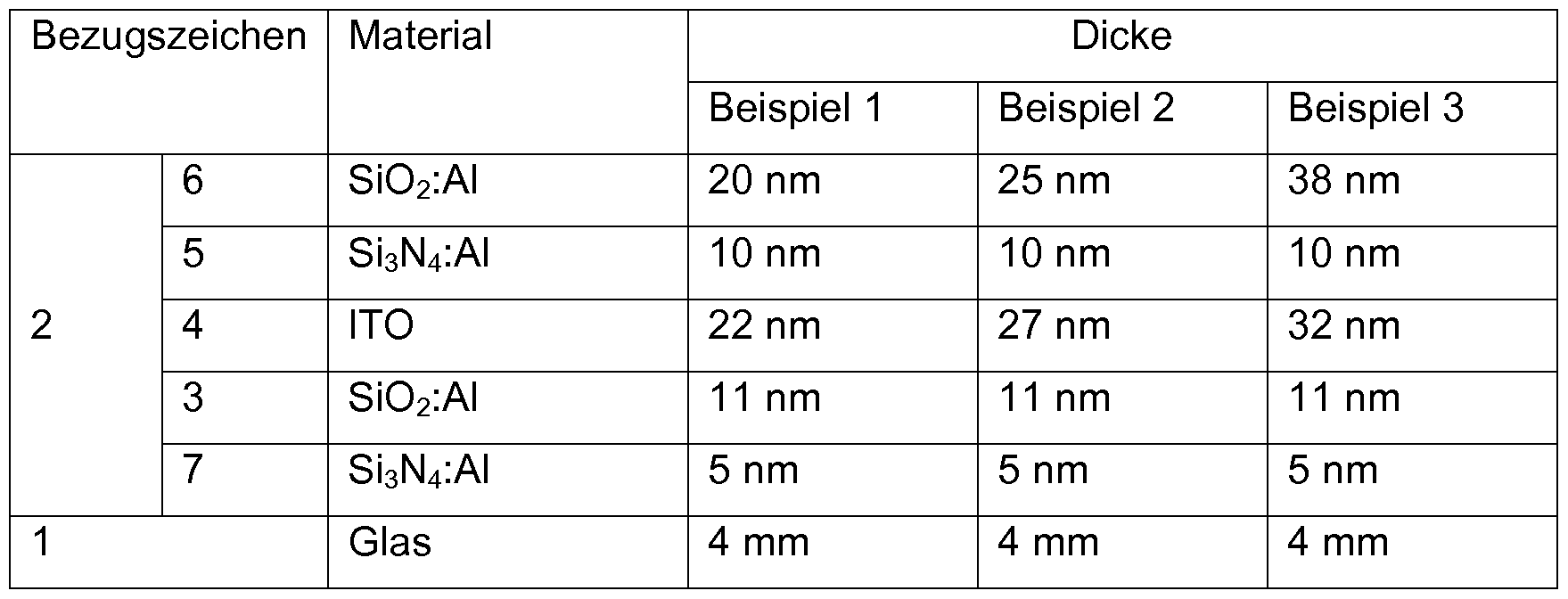
- the coating 2 comprises starting from the substrate 1 a blocking layer 7 against alkali diffusion, an optical matching layer 3, an electrically conductive layer 4, a barrier layer 5 for regulating the oxygen diffusion layer 5 and an antireflection layer 6.
- the materials and layer thicknesses are summarized in Table 1.
- the individual layers of the coating 2 were deposited by magnetic field assisted cathode jet sputtering. Table 1
- the coating 2 Despite the small thickness of the conductive layer 4 could be achieved with the coating 2, connected to a voltage source of 230 V, a good heating effect.
- the coating 2 also proved to be long-term stable and corrosion-resistant on the exposed refrigerator-side surface of the substrate 1.
- FIG. 2 shows a flow chart of an embodiment of the production method according to the invention.
- Example 1 to 3 had a high transmission and low reflectivity, so that they do not critically reduce the transparency through the glass pane. In addition, their sheet resistance was suitable to achieve a good heating effect with a voltage supply of about 230 V. That this can be achieved with such thin conductive ITO layers 4 was unexpected and surprising to those skilled in the art. LIST OF REFERENCE NUMBERS
Landscapes
- Chemical & Material Sciences (AREA)
- Engineering & Computer Science (AREA)
- Ceramic Engineering (AREA)
- Organic Chemistry (AREA)
- Geochemistry & Mineralogy (AREA)
- Materials Engineering (AREA)
- General Chemical & Material Sciences (AREA)
- Life Sciences & Earth Sciences (AREA)
- Chemical Kinetics & Catalysis (AREA)
- Physics & Mathematics (AREA)
- Optics & Photonics (AREA)
- General Physics & Mathematics (AREA)
- Inorganic Chemistry (AREA)
- Surface Treatment Of Glass (AREA)
- Laminated Bodies (AREA)
- Surface Heating Bodies (AREA)
- Resistance Heating (AREA)
Abstract
Description


Claims
Priority Applications (9)
| Application Number | Priority Date | Filing Date | Title |
|---|---|---|---|
| CA3058945A CA3058945C (en) | 2017-04-18 | 2018-03-19 | Pane having heatable tco coating |
| KR1020197029680A KR102269500B1 (en) | 2017-04-18 | 2018-03-19 | Plate Glass with Heatable TCO Coating |
| JP2019553100A JP6923671B2 (en) | 2017-04-18 | 2018-03-19 | Pain with heatable TCO coating |
| BR112019013411-5A BR112019013411B1 (en) | 2017-04-18 | 2018-03-19 | GLASS HAVING HEATABLE TCO COATING, METHOD OF PRODUCING SUCH GLASS AND USE OF A GLASS |
| EP18710494.8A EP3613257A1 (en) | 2017-04-18 | 2018-03-19 | Pane having heatable tco coating |
| CN201880025626.4A CN110506448A (en) | 2017-04-18 | 2018-03-19 | With the glass plate that can heat TCO coating |
| US16/606,059 US20210204366A1 (en) | 2017-04-18 | 2018-03-19 | Pane having heatable tco coating |
| MX2019012371A MX2019012371A (en) | 2017-04-18 | 2018-03-19 | Pane having heatable tco coating. |
| CONC2019/0007673A CO2019007673A2 (en) | 2017-04-18 | 2019-07-17 | Crystal that has heated tco coating |
Applications Claiming Priority (2)
| Application Number | Priority Date | Filing Date | Title |
|---|---|---|---|
| EP17166844 | 2017-04-18 | ||
| EP17166844.5 | 2017-04-18 |
Publications (1)
| Publication Number | Publication Date |
|---|---|
| WO2018192727A1 true WO2018192727A1 (en) | 2018-10-25 |
Family
ID=58632165
Family Applications (1)
| Application Number | Title | Priority Date | Filing Date |
|---|---|---|---|
| PCT/EP2018/056796 WO2018192727A1 (en) | 2017-04-18 | 2018-03-19 | Pane having heatable tco coating |
Country Status (10)
| Country | Link |
|---|---|
| US (1) | US20210204366A1 (en) |
| EP (1) | EP3613257A1 (en) |
| JP (1) | JP6923671B2 (en) |
| KR (1) | KR102269500B1 (en) |
| CN (1) | CN110506448A (en) |
| BR (1) | BR112019013411B1 (en) |
| CA (1) | CA3058945C (en) |
| CO (1) | CO2019007673A2 (en) |
| MX (1) | MX2019012371A (en) |
| WO (1) | WO2018192727A1 (en) |
Cited By (4)
| Publication number | Priority date | Publication date | Assignee | Title |
|---|---|---|---|---|
| WO2022136102A1 (en) | 2020-12-21 | 2022-06-30 | Saint-Gobain Glass France | Glazing having an electrically heatable communication window for sensors and camera systems |
| EP3621930B1 (en) * | 2017-05-09 | 2023-03-22 | Saint-Gobain Glass France | Disc with electrically conductive coating and reduced visibility of fingerprints |
| WO2023247871A1 (en) | 2022-06-23 | 2023-12-28 | Saint-Gobain Glass France | Transparent glass article for a cold compartment and multiple glazing unit incorporating the article |
| FR3137084A1 (en) | 2022-06-23 | 2023-12-29 | Saint-Gobain Glass France | Transparent glass article for cold compartment and multiple glazing incorporating said article. |
Families Citing this family (5)
| Publication number | Priority date | Publication date | Assignee | Title |
|---|---|---|---|---|
| US11454440B2 (en) | 2019-07-12 | 2022-09-27 | Cardinal Cg Company | Bus bar connection and coating technology |
| CN113038641B (en) * | 2021-05-17 | 2022-05-13 | 中熵科技(北京)有限公司 | Novel composite semiconductor heating film and film preparation method |
| US20230095982A1 (en) * | 2021-09-29 | 2023-03-30 | Lawrence Livermore National Security, Llc | System and method for direct electroless plating of 3d-printable glass for selective surface patterning |
| CN114057407A (en) * | 2021-12-23 | 2022-02-18 | 福建省万达汽车玻璃工业有限公司 | Coated glass and laminated glass |
| CN117157571A (en) | 2022-01-25 | 2023-12-01 | 法国圣戈班玻璃厂 | Projection device for head-up display (HUD) with p-polarized radiation |
Citations (7)
| Publication number | Priority date | Publication date | Assignee | Title |
|---|---|---|---|---|
| US5852284A (en) | 1997-01-07 | 1998-12-22 | Libbey-Owens-Ford Co. | Insulating glass with capacitively coupled heating system |
| US20040214010A1 (en) | 1999-12-28 | 2004-10-28 | Kenji Murata | Glass for use in freezers/refrigerator and glass article using said glass |
| WO2007018951A1 (en) | 2005-08-02 | 2007-02-15 | Guardian Industies Corp. | Method of thermally tempering coated article with transparent conductive oxide (tco) coating using inorganic protective layer during tempering and product made using same |
| WO2012168628A1 (en) | 2011-06-07 | 2012-12-13 | Saint-Gobain Glass France | Heating element having films |
| WO2015091016A1 (en) | 2013-12-16 | 2015-06-25 | Saint-Gobain Glass France | Heatable pane with high-frequency transmission |
| WO2015162107A1 (en) * | 2014-04-24 | 2015-10-29 | Saint-Gobain Glass France | Panel with illuminated switching surface and heating function |
| WO2017077133A1 (en) * | 2015-11-06 | 2017-05-11 | Saint-Gobain Glass France | Pane assembly having a heatable composite pane having a capacitive switching region |
Family Cites Families (9)
| Publication number | Priority date | Publication date | Assignee | Title |
|---|---|---|---|---|
| US8409663B2 (en) * | 2007-04-27 | 2013-04-02 | Guardian Industries Corp. | Method of making a coated glass substrate with heat treatable ultraviolet blocking characteristics |
| JP2009242128A (en) * | 2008-03-28 | 2009-10-22 | Asahi Glass Co Ltd | Transparent conductive glass substrate and method for manufacturing the same |
| US20110168252A1 (en) * | 2009-11-05 | 2011-07-14 | Guardian Industries Corp. | Textured coating with etching-blocking layer for thin-film solar cells and/or methods of making the same |
| BE1019826A3 (en) * | 2011-02-17 | 2013-01-08 | Agc Glass Europe | CONDUCTIVE TRANSPARENT GLASS SUBSTRATE FOR PHOTOVOLTAIC CELL. |
| BR112014011760B1 (en) * | 2012-01-10 | 2021-01-19 | Saint-Gobain Glass France | transparent motor vehicle panel with an electrically conductive coating, and, method for producing the transparent motor vehicle panel |
| CA2861707C (en) * | 2012-03-05 | 2017-03-07 | Saint-Gobain Glass France | Pane with thermal radiation reflecting coating |
| US9255029B2 (en) * | 2012-04-17 | 2016-02-09 | Guardian Industries Corp. | Method of making heat treated coated article using TCO and removable protective film |
| FR3002534B1 (en) * | 2013-02-27 | 2018-04-13 | Saint-Gobain Glass France | SUBSTRATE COATED WITH A LOW EMISSIVE STACK. |
| CN106457778B (en) * | 2015-05-15 | 2018-03-30 | 法国圣戈班玻璃厂 | With heat radiation reflectance coating and the glass plate of fixation mounted thereto or potted component |
-
2018
- 2018-03-19 EP EP18710494.8A patent/EP3613257A1/en not_active Withdrawn
- 2018-03-19 US US16/606,059 patent/US20210204366A1/en not_active Abandoned
- 2018-03-19 BR BR112019013411-5A patent/BR112019013411B1/en active IP Right Grant
- 2018-03-19 CA CA3058945A patent/CA3058945C/en active Active
- 2018-03-19 MX MX2019012371A patent/MX2019012371A/en unknown
- 2018-03-19 CN CN201880025626.4A patent/CN110506448A/en active Pending
- 2018-03-19 KR KR1020197029680A patent/KR102269500B1/en active IP Right Grant
- 2018-03-19 WO PCT/EP2018/056796 patent/WO2018192727A1/en unknown
- 2018-03-19 JP JP2019553100A patent/JP6923671B2/en active Active
-
2019
- 2019-07-17 CO CONC2019/0007673A patent/CO2019007673A2/en unknown
Patent Citations (7)
| Publication number | Priority date | Publication date | Assignee | Title |
|---|---|---|---|---|
| US5852284A (en) | 1997-01-07 | 1998-12-22 | Libbey-Owens-Ford Co. | Insulating glass with capacitively coupled heating system |
| US20040214010A1 (en) | 1999-12-28 | 2004-10-28 | Kenji Murata | Glass for use in freezers/refrigerator and glass article using said glass |
| WO2007018951A1 (en) | 2005-08-02 | 2007-02-15 | Guardian Industies Corp. | Method of thermally tempering coated article with transparent conductive oxide (tco) coating using inorganic protective layer during tempering and product made using same |
| WO2012168628A1 (en) | 2011-06-07 | 2012-12-13 | Saint-Gobain Glass France | Heating element having films |
| WO2015091016A1 (en) | 2013-12-16 | 2015-06-25 | Saint-Gobain Glass France | Heatable pane with high-frequency transmission |
| WO2015162107A1 (en) * | 2014-04-24 | 2015-10-29 | Saint-Gobain Glass France | Panel with illuminated switching surface and heating function |
| WO2017077133A1 (en) * | 2015-11-06 | 2017-05-11 | Saint-Gobain Glass France | Pane assembly having a heatable composite pane having a capacitive switching region |
Cited By (5)
| Publication number | Priority date | Publication date | Assignee | Title |
|---|---|---|---|---|
| EP3621930B1 (en) * | 2017-05-09 | 2023-03-22 | Saint-Gobain Glass France | Disc with electrically conductive coating and reduced visibility of fingerprints |
| WO2022136102A1 (en) | 2020-12-21 | 2022-06-30 | Saint-Gobain Glass France | Glazing having an electrically heatable communication window for sensors and camera systems |
| DE202021004228U1 (en) | 2020-12-21 | 2023-03-06 | Saint-Gobain Glass France | Glazing with electrically heated communication window for sensors and camera systems |
| WO2023247871A1 (en) | 2022-06-23 | 2023-12-28 | Saint-Gobain Glass France | Transparent glass article for a cold compartment and multiple glazing unit incorporating the article |
| FR3137084A1 (en) | 2022-06-23 | 2023-12-29 | Saint-Gobain Glass France | Transparent glass article for cold compartment and multiple glazing incorporating said article. |
Also Published As
| Publication number | Publication date |
|---|---|
| BR112019013411A2 (en) | 2020-03-03 |
| CN110506448A (en) | 2019-11-26 |
| CA3058945A1 (en) | 2018-10-25 |
| JP2020515492A (en) | 2020-05-28 |
| KR20190124292A (en) | 2019-11-04 |
| MX2019012371A (en) | 2019-11-28 |
| CA3058945C (en) | 2023-09-26 |
| JP6923671B2 (en) | 2021-08-25 |
| US20210204366A1 (en) | 2021-07-01 |
| EP3613257A1 (en) | 2020-02-26 |
| KR102269500B1 (en) | 2021-06-25 |
| BR112019013411B1 (en) | 2023-11-07 |
| CO2019007673A2 (en) | 2019-07-31 |
Similar Documents
| Publication | Publication Date | Title |
|---|---|---|
| WO2018192727A1 (en) | Pane having heatable tco coating | |
| EP3621930B1 (en) | Disc with electrically conductive coating and reduced visibility of fingerprints | |
| EP3720701B1 (en) | Laminated glass pane with solar control coating and thermal radiation reflective coating | |
| EP2958872B1 (en) | Pane with coating that reflects thermal radiation | |
| EP2300389B1 (en) | Glass product | |
| DE602005003234T2 (en) | MAINTENANCE-FREE COATINGS | |
| EP0838698A2 (en) | Thermally reflecting laminate, transparent to visible light | |
| DE102017102377B4 (en) | Protective glazing, thermal processing unit and process for the production of protective glazing | |
| DE202012013088U1 (en) | Plant for coating and heat treatment | |
| EP2621868B1 (en) | Heat protection glazing and method for producing the same | |
| EP4100375B1 (en) | Vehicle window with reduced emissivity and light reflection | |
| DE102014002965A1 (en) | Layer system of a transparent substrate and method for producing a layer system | |
| EP3660550A2 (en) | Reflective composite material with an aluminum substrate and with a silver reflective layer | |
| EP3702572A1 (en) | Insulating glazing with electrochromic functional element and infrared-reflective coating | |
| EP2760665B2 (en) | Fire protection element with protective coating, and method for producing the same | |
| DE102016114281A1 (en) | Layer system and laminated glass | |
| WO2013045512A2 (en) | Layer system for solar control glass, solar control glass and method for producing solar control glass | |
| JP2020516575A (en) | Solar control coatings for laminated glass | |
| DE10046810C2 (en) | Making heat-reflecting layered coating on glass employs deposition controlled such that functional and blocking layers are merged to form gradient layers | |
| DE202019104357U1 (en) | Improved Resistance of PDLC Films to Radiation from IR and UV Reflective Coatings on Page II of a Composite Disc | |
| EP1123906A1 (en) | Method for the production of heat reflecting coating stack for transparent substrates and thus produced coating stack | |
| WO2012175712A2 (en) | Partially transparent layer system having high ir reflection and method for the production thereof | |
| WO2024083449A1 (en) | Disc coated with an electrically conductive layer stack | |
| WO2023186406A1 (en) | Glass pane with a coating for reducing bird collisions | |
| DE10039412A1 (en) | Production of a substrate having a transparent, conductive coating of metal layers and oxide layers comprises depositing a metal layer with the addition of oxygen in the coating chamber |
Legal Events
| Date | Code | Title | Description |
|---|---|---|---|
| 121 | Ep: the epo has been informed by wipo that ep was designated in this application |
Ref document number: 18710494 Country of ref document: EP Kind code of ref document: A1 |
|
| REG | Reference to national code |
Ref country code: BR Ref legal event code: B01A Ref document number: 112019013411 Country of ref document: BR |
|
| ENP | Entry into the national phase |
Ref document number: 2019553100 Country of ref document: JP Kind code of ref document: A |
|
| ENP | Entry into the national phase |
Ref document number: 3058945 Country of ref document: CA |
|
| ENP | Entry into the national phase |
Ref document number: 20197029680 Country of ref document: KR Kind code of ref document: A |
|
| NENP | Non-entry into the national phase |
Ref country code: DE |
|
| ENP | Entry into the national phase |
Ref document number: 2018710494 Country of ref document: EP Effective date: 20191118 |
|
| ENP | Entry into the national phase |
Ref document number: 112019013411 Country of ref document: BR Kind code of ref document: A2 Effective date: 20190627 |