WO2018190104A1 - Device and method for recovering carbon dioxide in combustion exhaust gas - Google Patents
Device and method for recovering carbon dioxide in combustion exhaust gas Download PDFInfo
- Publication number
- WO2018190104A1 WO2018190104A1 PCT/JP2018/011902 JP2018011902W WO2018190104A1 WO 2018190104 A1 WO2018190104 A1 WO 2018190104A1 JP 2018011902 W JP2018011902 W JP 2018011902W WO 2018190104 A1 WO2018190104 A1 WO 2018190104A1
- Authority
- WO
- WIPO (PCT)
- Prior art keywords
- liquid
- amine compound
- tower
- absorption
- exhaust gas
- Prior art date
Links
Images


Classifications
-
- B—PERFORMING OPERATIONS; TRANSPORTING
- B01—PHYSICAL OR CHEMICAL PROCESSES OR APPARATUS IN GENERAL
- B01D—SEPARATION
- B01D53/00—Separation of gases or vapours; Recovering vapours of volatile solvents from gases; Chemical or biological purification of waste gases, e.g. engine exhaust gases, smoke, fumes, flue gases, aerosols
- B01D53/14—Separation of gases or vapours; Recovering vapours of volatile solvents from gases; Chemical or biological purification of waste gases, e.g. engine exhaust gases, smoke, fumes, flue gases, aerosols by absorption
- B01D53/1425—Regeneration of liquid absorbents
-
- B—PERFORMING OPERATIONS; TRANSPORTING
- B01—PHYSICAL OR CHEMICAL PROCESSES OR APPARATUS IN GENERAL
- B01D—SEPARATION
- B01D53/00—Separation of gases or vapours; Recovering vapours of volatile solvents from gases; Chemical or biological purification of waste gases, e.g. engine exhaust gases, smoke, fumes, flue gases, aerosols
- B01D53/14—Separation of gases or vapours; Recovering vapours of volatile solvents from gases; Chemical or biological purification of waste gases, e.g. engine exhaust gases, smoke, fumes, flue gases, aerosols by absorption
- B01D53/1431—Pretreatment by other processes
-
- B—PERFORMING OPERATIONS; TRANSPORTING
- B01—PHYSICAL OR CHEMICAL PROCESSES OR APPARATUS IN GENERAL
- B01D—SEPARATION
- B01D53/00—Separation of gases or vapours; Recovering vapours of volatile solvents from gases; Chemical or biological purification of waste gases, e.g. engine exhaust gases, smoke, fumes, flue gases, aerosols
- B01D53/14—Separation of gases or vapours; Recovering vapours of volatile solvents from gases; Chemical or biological purification of waste gases, e.g. engine exhaust gases, smoke, fumes, flue gases, aerosols by absorption
- B01D53/1456—Removing acid components
- B01D53/1475—Removing carbon dioxide
-
- B—PERFORMING OPERATIONS; TRANSPORTING
- B01—PHYSICAL OR CHEMICAL PROCESSES OR APPARATUS IN GENERAL
- B01D—SEPARATION
- B01D53/00—Separation of gases or vapours; Recovering vapours of volatile solvents from gases; Chemical or biological purification of waste gases, e.g. engine exhaust gases, smoke, fumes, flue gases, aerosols
- B01D53/14—Separation of gases or vapours; Recovering vapours of volatile solvents from gases; Chemical or biological purification of waste gases, e.g. engine exhaust gases, smoke, fumes, flue gases, aerosols by absorption
- B01D53/1493—Selection of liquid materials for use as absorbents
-
- B—PERFORMING OPERATIONS; TRANSPORTING
- B01—PHYSICAL OR CHEMICAL PROCESSES OR APPARATUS IN GENERAL
- B01D—SEPARATION
- B01D53/00—Separation of gases or vapours; Recovering vapours of volatile solvents from gases; Chemical or biological purification of waste gases, e.g. engine exhaust gases, smoke, fumes, flue gases, aerosols
- B01D53/14—Separation of gases or vapours; Recovering vapours of volatile solvents from gases; Chemical or biological purification of waste gases, e.g. engine exhaust gases, smoke, fumes, flue gases, aerosols by absorption
- B01D53/18—Absorbing units; Liquid distributors therefor
-
- B—PERFORMING OPERATIONS; TRANSPORTING
- B01—PHYSICAL OR CHEMICAL PROCESSES OR APPARATUS IN GENERAL
- B01D—SEPARATION
- B01D53/00—Separation of gases or vapours; Recovering vapours of volatile solvents from gases; Chemical or biological purification of waste gases, e.g. engine exhaust gases, smoke, fumes, flue gases, aerosols
- B01D53/34—Chemical or biological purification of waste gases
- B01D53/46—Removing components of defined structure
- B01D53/62—Carbon oxides
-
- B—PERFORMING OPERATIONS; TRANSPORTING
- B01—PHYSICAL OR CHEMICAL PROCESSES OR APPARATUS IN GENERAL
- B01D—SEPARATION
- B01D53/00—Separation of gases or vapours; Recovering vapours of volatile solvents from gases; Chemical or biological purification of waste gases, e.g. engine exhaust gases, smoke, fumes, flue gases, aerosols
- B01D53/34—Chemical or biological purification of waste gases
- B01D53/74—General processes for purification of waste gases; Apparatus or devices specially adapted therefor
- B01D53/77—Liquid phase processes
- B01D53/78—Liquid phase processes with gas-liquid contact
-
- B—PERFORMING OPERATIONS; TRANSPORTING
- B01—PHYSICAL OR CHEMICAL PROCESSES OR APPARATUS IN GENERAL
- B01D—SEPARATION
- B01D53/00—Separation of gases or vapours; Recovering vapours of volatile solvents from gases; Chemical or biological purification of waste gases, e.g. engine exhaust gases, smoke, fumes, flue gases, aerosols
- B01D53/34—Chemical or biological purification of waste gases
- B01D53/96—Regeneration, reactivation or recycling of reactants
-
- C—CHEMISTRY; METALLURGY
- C01—INORGANIC CHEMISTRY
- C01B—NON-METALLIC ELEMENTS; COMPOUNDS THEREOF; METALLOIDS OR COMPOUNDS THEREOF NOT COVERED BY SUBCLASS C01C
- C01B32/00—Carbon; Compounds thereof
- C01B32/50—Carbon dioxide
-
- F—MECHANICAL ENGINEERING; LIGHTING; HEATING; WEAPONS; BLASTING
- F01—MACHINES OR ENGINES IN GENERAL; ENGINE PLANTS IN GENERAL; STEAM ENGINES
- F01N—GAS-FLOW SILENCERS OR EXHAUST APPARATUS FOR MACHINES OR ENGINES IN GENERAL; GAS-FLOW SILENCERS OR EXHAUST APPARATUS FOR INTERNAL COMBUSTION ENGINES
- F01N3/00—Exhaust or silencing apparatus having means for purifying, rendering innocuous, or otherwise treating exhaust
- F01N3/08—Exhaust or silencing apparatus having means for purifying, rendering innocuous, or otherwise treating exhaust for rendering innocuous
- F01N3/0807—Exhaust or silencing apparatus having means for purifying, rendering innocuous, or otherwise treating exhaust for rendering innocuous by using absorbents or adsorbents
- F01N3/0828—Exhaust or silencing apparatus having means for purifying, rendering innocuous, or otherwise treating exhaust for rendering innocuous by using absorbents or adsorbents characterised by the absorbed or adsorbed substances
- F01N3/0857—Carbon oxides
-
- B—PERFORMING OPERATIONS; TRANSPORTING
- B01—PHYSICAL OR CHEMICAL PROCESSES OR APPARATUS IN GENERAL
- B01D—SEPARATION
- B01D2251/00—Reactants
- B01D2251/30—Alkali metal compounds
- B01D2251/304—Alkali metal compounds of sodium
-
- B—PERFORMING OPERATIONS; TRANSPORTING
- B01—PHYSICAL OR CHEMICAL PROCESSES OR APPARATUS IN GENERAL
- B01D—SEPARATION
- B01D2251/00—Reactants
- B01D2251/40—Alkaline earth metal or magnesium compounds
- B01D2251/404—Alkaline earth metal or magnesium compounds of calcium
-
- B—PERFORMING OPERATIONS; TRANSPORTING
- B01—PHYSICAL OR CHEMICAL PROCESSES OR APPARATUS IN GENERAL
- B01D—SEPARATION
- B01D2251/00—Reactants
- B01D2251/60—Inorganic bases or salts
- B01D2251/604—Hydroxides
-
- B—PERFORMING OPERATIONS; TRANSPORTING
- B01—PHYSICAL OR CHEMICAL PROCESSES OR APPARATUS IN GENERAL
- B01D—SEPARATION
- B01D2251/00—Reactants
- B01D2251/60—Inorganic bases or salts
- B01D2251/606—Carbonates
-
- B—PERFORMING OPERATIONS; TRANSPORTING
- B01—PHYSICAL OR CHEMICAL PROCESSES OR APPARATUS IN GENERAL
- B01D—SEPARATION
- B01D2252/00—Absorbents, i.e. solvents and liquid materials for gas absorption
- B01D2252/20—Organic absorbents
- B01D2252/204—Amines
-
- B—PERFORMING OPERATIONS; TRANSPORTING
- B01—PHYSICAL OR CHEMICAL PROCESSES OR APPARATUS IN GENERAL
- B01D—SEPARATION
- B01D2252/00—Absorbents, i.e. solvents and liquid materials for gas absorption
- B01D2252/20—Organic absorbents
- B01D2252/204—Amines
- B01D2252/20405—Monoamines
-
- B—PERFORMING OPERATIONS; TRANSPORTING
- B01—PHYSICAL OR CHEMICAL PROCESSES OR APPARATUS IN GENERAL
- B01D—SEPARATION
- B01D2252/00—Absorbents, i.e. solvents and liquid materials for gas absorption
- B01D2252/20—Organic absorbents
- B01D2252/204—Amines
- B01D2252/2041—Diamines
-
- B—PERFORMING OPERATIONS; TRANSPORTING
- B01—PHYSICAL OR CHEMICAL PROCESSES OR APPARATUS IN GENERAL
- B01D—SEPARATION
- B01D2252/00—Absorbents, i.e. solvents and liquid materials for gas absorption
- B01D2252/20—Organic absorbents
- B01D2252/204—Amines
- B01D2252/20426—Secondary amines
-
- B—PERFORMING OPERATIONS; TRANSPORTING
- B01—PHYSICAL OR CHEMICAL PROCESSES OR APPARATUS IN GENERAL
- B01D—SEPARATION
- B01D2252/00—Absorbents, i.e. solvents and liquid materials for gas absorption
- B01D2252/20—Organic absorbents
- B01D2252/204—Amines
- B01D2252/20431—Tertiary amines
-
- B—PERFORMING OPERATIONS; TRANSPORTING
- B01—PHYSICAL OR CHEMICAL PROCESSES OR APPARATUS IN GENERAL
- B01D—SEPARATION
- B01D2252/00—Absorbents, i.e. solvents and liquid materials for gas absorption
- B01D2252/20—Organic absorbents
- B01D2252/204—Amines
- B01D2252/20478—Alkanolamines
- B01D2252/20484—Alkanolamines with one hydroxyl group
-
- B—PERFORMING OPERATIONS; TRANSPORTING
- B01—PHYSICAL OR CHEMICAL PROCESSES OR APPARATUS IN GENERAL
- B01D—SEPARATION
- B01D2252/00—Absorbents, i.e. solvents and liquid materials for gas absorption
- B01D2252/20—Organic absorbents
- B01D2252/204—Amines
- B01D2252/20478—Alkanolamines
- B01D2252/20489—Alkanolamines with two or more hydroxyl groups
-
- B—PERFORMING OPERATIONS; TRANSPORTING
- B01—PHYSICAL OR CHEMICAL PROCESSES OR APPARATUS IN GENERAL
- B01D—SEPARATION
- B01D2257/00—Components to be removed
- B01D2257/30—Sulfur compounds
-
- B—PERFORMING OPERATIONS; TRANSPORTING
- B01—PHYSICAL OR CHEMICAL PROCESSES OR APPARATUS IN GENERAL
- B01D—SEPARATION
- B01D2257/00—Components to be removed
- B01D2257/50—Carbon oxides
- B01D2257/504—Carbon dioxide
-
- Y—GENERAL TAGGING OF NEW TECHNOLOGICAL DEVELOPMENTS; GENERAL TAGGING OF CROSS-SECTIONAL TECHNOLOGIES SPANNING OVER SEVERAL SECTIONS OF THE IPC; TECHNICAL SUBJECTS COVERED BY FORMER USPC CROSS-REFERENCE ART COLLECTIONS [XRACs] AND DIGESTS
- Y02—TECHNOLOGIES OR APPLICATIONS FOR MITIGATION OR ADAPTATION AGAINST CLIMATE CHANGE
- Y02C—CAPTURE, STORAGE, SEQUESTRATION OR DISPOSAL OF GREENHOUSE GASES [GHG]
- Y02C20/00—Capture or disposal of greenhouse gases
- Y02C20/40—Capture or disposal of greenhouse gases of CO2
-
- Y—GENERAL TAGGING OF NEW TECHNOLOGICAL DEVELOPMENTS; GENERAL TAGGING OF CROSS-SECTIONAL TECHNOLOGIES SPANNING OVER SEVERAL SECTIONS OF THE IPC; TECHNICAL SUBJECTS COVERED BY FORMER USPC CROSS-REFERENCE ART COLLECTIONS [XRACs] AND DIGESTS
- Y02—TECHNOLOGIES OR APPLICATIONS FOR MITIGATION OR ADAPTATION AGAINST CLIMATE CHANGE
- Y02P—CLIMATE CHANGE MITIGATION TECHNOLOGIES IN THE PRODUCTION OR PROCESSING OF GOODS
- Y02P20/00—Technologies relating to chemical industry
- Y02P20/151—Reduction of greenhouse gas [GHG] emissions, e.g. CO2
Definitions
- the present invention relates to an apparatus and method for recovering carbon dioxide (hereinafter also referred to as CO 2 ) contained in combustion exhaust gas, and more specifically, reacts and absorbs CO 2 contained in combustion exhaust gas in an amine compound-containing absorbent.
- Apparatus and method, apparatus and method for releasing CO 2 contained in amine compound-containing absorbing liquid from amine compound-containing absorbing liquid, and evaporation of impurities contained in amine compound-containing absorbing liquid from amine compound-containing absorbing liquid Apparatus and method for separating, apparatus and method for performing pretreatment such as desulfurization, dust removal and cooling on combustion exhaust gas, and carbon dioxide recovery apparatus and carbon dioxide recovery method using these apparatuses and methods It is.
- a combustion apparatus such as a boiler
- an aqueous solution of an amine compound in response to a request for suppressing CO 2 emission
- the recovered CO 2 There are extensive studies on the method of storing sucrose. As this method is put into practical use, the size of the apparatus, the clogging of the apparatus due to contamination of the absorbing liquid, and the high energy intensity have been regarded as problems.
- the absorption liquid that has absorbed CO 2 is the next CO 2 emission step (“absorption liquid regeneration step”). "and since it is played by dissipating CO 2 in also referred), repeatedly used to circulate the absorption step.
- the CO 2 is absorbed efficiently in the absorption step, likewise from the absorption liquid be dissipated efficiently CO 2 reducing the circulation amount of the absorption liquid, the size of the apparatus, and further to realize the energy saving of the entire process It is desired.
- the absorption liquid is contaminated over time due to the circulation operation and the absorption performance deteriorates, increasing the circulation amount of the absorption liquid and causing contamination of the equipment, increasing the required energy, reducing the operating time, and installing spare equipment. Profits are generated. In order to prevent this, it is necessary to always purify the absorption liquid and restore and maintain the absorption capacity. Furthermore, it is necessary to solve the same problem in the pretreatment process of combustion exhaust gas.
- the present inventors have introduced an improvement technique to each device and each method constituting the carbon dioxide recovery facility and the carbon dioxide recovery method.
- a CO 2 absorption tower that reacts and absorbs CO 2 contained in combustion exhaust gas into an amine compound-containing absorbent, a first cooler that cools the amine compound-containing absorbent, and a liquid that cools a liquid different from the amine compound-containing absorbent.
- a carbon dioxide absorber comprising at least one cooler selected from the group consisting of two coolers, The CO 2 absorption tower, the flue gas and the flue gas inlet for introducing the CO 2 absorption tower, and flue gas discharge port for discharging the flue gas from the CO 2 absorber, an amine compound containing absorbing solution in the CO 2 absorber
- the first cooler includes an absorbent liquid recovery port for recovering an amine compound containing absorbed liquid from the CO 2 absorber, and an amine compound containing absorbing solution the CO 2 absorber to supply the absorption liquid feed inlet, wherein, The absorption liquid recovery port is connected to the CO 2 absorption tower at a position downstream of the packing in
- a combustion exhaust gas inlet port for introducing the flue gas into the CO 2 absorber, the flue gas discharge port for discharging the flue gas from the CO 2 absorber, and absorbing solution inlet for introducing an amine compound containing absorbing solution in the CO 2 absorber the absorption liquid discharge ports for discharging the amine compound-containing absorbing solution from the CO 2 absorber, the CO 2 absorption tower and a filling is static mixer having a spiral perforated wings, including the CO 2 combustion
- CO 2 stripping tower dissipating CO 2 contained in the amine compound-containing absorbing solution from an amine compound-containing absorbing solution, the steam heating the first heater and an amine compound containing absorption liquid heating the amine compound-containing absorbing solution
- An amine compound-containing absorbent regenerator comprising at least one heater selected from the group consisting of second heaters to be produced,
- the amine compound-containing absorbing solution regeneration device further comprises a gas-liquid separator for gas-liquid separation of CO 2 to be discharged together with steam from the CO 2 outlet of the CO 2 stripper
- the gas-liquid separator is a CO 2 inlet for introducing CO 2 discharged together with the vapor into the gas-liquid separator, a CO 2 recovery port for recovering the gas-liquid separated CO 2 , and discharging the gas-liquid separated liquid and a liquid discharge port for, here, CO 2 introduction port, which is connected with the CO 2 desorption column of CO 2 outlet, the liquid outlet is connected to the CO 2 stripping tower of the absorbent inlet
- An amine compound-containing absorbent regenerator is provided.
- the heat source of the second heater is water vapor;
- the amine compound-containing absorbent regenerator is an overheated steam prevention device for reducing the temperature of the steam supplied to the second heater as a heat source of the second heater, and is connected to the second heater.
- An amine compound-containing absorbent regenerator is further provided, further comprising an overheated steam prevention device.
- the CO 2 discharge port for discharging the CO 2 from the CO 2 stripper, the CO 2 stripping tower and a filling is static mixer having a spiral perforated wings, an amine compound containing containing CO 2
- a seventh invention of the present invention in the sixth invention, The CO 2 and CO 2 to be discharged together with steam and gas-liquid separation from the discharge port, thereby collecting the separated CO 2, further a fourth step of supplying the separated liquid from the absorption liquid inlet to CO 2 stripping tower A method for regenerating an amine compound-containing absorbent is provided.
- the amine compound-containing absorbent is heated by heat exchange with water vapor
- the amine compound-containing absorption, wherein the amine compound-containing absorption liquid regeneration method further includes a fifth step of reducing the temperature and pressure of water vapor used for the heat exchange before heat exchange in the third step.
- a liquid regeneration method is provided.
- An evaporation tank that evaporates and separates impurities contained in an amine compound-containing absorption liquid from an amine compound-containing absorption liquid, the evaporation tank including a heating jacket disposed outside the evaporation tank, and the heating jacket
- An amine compound comprising: an overheated steam prevention device for reducing the temperature and pressure of water vapor supplied as a heat source; a gas-liquid separation device for recovering an amine compound-containing absorption liquid evaporated and separated from impurities; and a pressure reducing device for reducing the pressure in the evaporation tank Containing absorption liquid purification device,
- the evaporating tank includes an absorbing liquid inlet for introducing the amine compound-containing absorbing liquid into the evaporating tank, an absorbing liquid outlet for discharging the amine compound-containing absorbing liquid evaporated and separated from the impurities from the evaporating tank, and the amine compound-containing absorbing liquid.
- the gas-liquid separator is an absorption liquid inlet for introducing an amine compound-containing absorption liquid evaporated and separated from impurities into the gas-liquid separator, a gas outlet for discharging the gas-liquid separated gas, and a gas-liquid separated liquid.
- a liquid outlet for discharging, The decompression device is connected to the evaporation tank through an absorption liquid inlet of the gas-liquid separator, a gas outlet of the gas-liquid separator and an absorption liquid outlet of the evaporation tank,
- An amine compound-containing absorbent purifier is provided, wherein the overheated steam prevention device is connected to the heating jacket.
- a first step of purifying the amine compound-containing absorption liquid by introducing the amine compound-containing absorption liquid containing impurities into the evaporation tank under vacuum or reduced pressure continuously or intermittently to evaporate and separate the impurities and the amine compound-containing absorption liquid;
- a method for purifying an amine compound-containing absorbent is provided, which includes a third step of reducing the temperature and pressure of water vapor before supplying to the heating jacket in the second step.
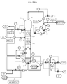
- a combustion exhaust gas pretreatment device including a pretreatment tower for performing desulfurization, dust removal and cooling on the combustion exhaust gas, A combustion exhaust gas inlet for introducing the combustion exhaust gas into the pretreatment tower; a combustion exhaust gas outlet for discharging the combustion exhaust gas from the pretreatment tower; and a desulfurization liquid inlet for introducing the desulfurization liquid into the pretreatment tower.
- the combustion exhaust gas inlet is disposed on the upstream side of the packing in the flow direction of the desulfurization liquid from the desulfurization liquid introduction port to the desulfurization liquid discharge port, and the desulfurization liquid introduction port extends from the combustion exhaust gas introduction port to the combustion exhaust gas discharge port.
- a combustion exhaust gas pretreatment device is provided, which is arranged on the upstream side of the packing in the direction of the flow of the combustion exhaust gas toward.
- the combustion exhaust gas pretreatment device further includes a cooler for cooling the desulfurization liquid,
- the cooler includes a desulfurization liquid recovery port for recovering the desulfurization liquid from the pretreatment tower, and a desulfurization liquid supply port for supplying the desulfurization liquid to the pretreatment tower, wherein the desulfurization liquid recovery port is the desulfurization liquid discharge port And a desulfurization liquid supply port is connected to the desulfurization liquid introduction port.
- a combustion exhaust gas pretreatment device is provided.
- the flue gas pretreatment device further comprises a mixer for mixing the desulfurization liquid and the replenisher liquid cooled by the cooler,
- the mixer has a replenisher introduction port for introducing replenisher into the mixer, a desulfurization solution introduction port for introducing the cooled desulfurization solution into the mixer, and a mixture discharge port for discharging the mixture from the mixer.
- the desulfurization liquid inlet of the mixer is connected to the desulfurization liquid supply port of the cooler, and the mixed liquid discharge port of the mixer is connected to the desulfurization liquid inlet of the pretreatment tower.
- a combustion exhaust gas pretreatment device is provided.
- a pretreatment tower comprising a desulfurization liquid discharge port for discharging from the tower and a packing that is a static mixer having a spiral porous blade, the combustion exhaust gas and the desulfurization liquid are contacted in parallel with the packing.
- a first step of performing desulfurization, dust removal and cooling on the combustion exhaust gas wherein the combustion exhaust gas flows from the combustion exhaust gas inlet to the combustion exhaust gas outlet and the desulfurization liquid flows from the desulfurization liquid inlet to the desulfurization liquid outlet.
- a combustion exhaust gas pretreatment method comprising one step is provided.
- the desulfurization liquid is recovered from the pretreatment tower at a position downstream of the packing in the flow direction of the desulfurization liquid from the desulfurization liquid inlet to the desulfurization liquid discharge port, the recovered desulfurization liquid is cooled, and the cooled desulfurization liquid is A combustion exhaust gas pretreatment method is provided, further comprising a second step of supplying the pretreatment tower at a position upstream of the packing in the flow direction of the desulfurization liquid.
- a combustion exhaust gas pretreatment method is provided, wherein the cooled desulfurization liquid and the replenisher are mixed before supplying the cooled desulfurization liquid to the pretreatment tower.
- the CO 2 contained in the combustion exhaust gas a CO 2 absorption tower reacting absorbed into the amine compound-containing absorbing solution, a combustion exhaust gas inlet port for introducing the flue gas into the CO 2 absorber, the flue gas from the CO 2 absorber a flue gas discharge port for discharging the absorbing liquid inlet for introducing an amine compound containing absorbing solution in the CO 2 absorber, and absorbing solution discharge port for discharging an amine compound containing absorbed liquid from the CO 2 absorber, spiral perforated wings
- a filler that is a stationary mixer having a CO 2 disposed between the flue gas inlet and the flue gas outlet and between the absorbent inlet and the absorbent outlet.
- An absorption tower The CO 2 contained in the amine compound-containing absorbing solution in a CO 2 stripping tower dissipating from an amine compound containing absorbing solution, and the absorption liquid inlet for introducing an amine compound containing absorbing solution in CO 2 stripper, an amine compound containing and absorbing solution discharge port for discharging the absorbing liquid from the CO 2 stripper, a vapor inlet for introducing steam into the CO 2 stripper, and CO 2 discharge port for discharging the CO 2 from the CO 2 stripper, spiral perforated wings and a filler which is a static mixer having the packings, absorbing liquid inlet and absorb liquid and CO 2 emission, which is arranged between the steam inlet and CO 2 outlet between the outlet Tower, An evaporating tank for evaporating and separating impurities contained in an amine compound-containing absorbing liquid from an amine compound-containing absorbing liquid, an absorbing liquid inlet for introducing the amine compound-containing absorbing liquid into the evaporating tank, and an amine compound e
- a first heat exchanger comprising an absorbent liquid recovery port for recovering an amine compound containing absorbing solution from the CO 2 stripper, and an amine compound containing absorbing solution CO 2 stripping tower to supply the absorption liquid feed inlet, absorption liquid recovery port and the absorbing solution supply port, and CO 2 desorption column at a location downstream of the position of the CO 2 filling in the flow direction of the absorption liquid toward the discharge port amine compound containing absorbed liquid from the absorbent liquid inlet stripping tower A connected first heat exchanger;
- a carbon dioxide recovery device comprising a second heat exchanger for exchanging heat with an amine compound-containing absorbent directed toward The absorption liquid discharge port of the CO 2 diffusion tower is connected to the absorption liquid inlet of the CO 2 absorption tower via the
- An amine compound-containing absorption liquid comprising an absorption liquid recovery port and a steam supply port for supplying steam to the CO 2 diffusion tower, the absorption liquid recovery port going from the absorption liquid introduction port of the CO 2 diffusion tower to the absorption liquid discharge port
- a third heat exchanger connected to the CO 2 stripping tower at a position downstream of the packing in the flow direction, and a steam supply port connected to the steam inlet of the CO 2 stripping tower;
- a carbon dioxide recovery device is provided, further comprising an overheated steam prevention device.
- a pretreatment tower for performing desulfurization, dust removal and cooling on the combustion exhaust gas the combustion exhaust gas inlet for introducing the combustion exhaust gas into the pretreatment tower, the combustion exhaust gas outlet for discharging the combustion exhaust gas from the pretreatment tower, and desulfurization
- the pretreatment tower is disposed upstream of the packing in the flow direction, and the desulfurization liquid inlet is disposed upstream of the packing in the flow direction of the combustion exhaust gas from the combustion exhaust gas inlet to the combustion exhaust gas outlet.
- a carbon dioxide recovery device is provided in which a combustion exhaust gas outlet of the pretreatment tower is connected to a combustion exhaust gas inlet of the CO 2 absorption tower.
- a combustion exhaust gas inlet port for introducing the flue gas into the CO 2 absorber, the flue gas discharge port for discharging the flue gas from the CO 2 absorber, and absorbing solution inlet for introducing an amine compound containing absorbing solution in the CO 2 absorber the absorption liquid discharge ports for discharging the amine compound-containing absorbing solution from the CO 2 absorber, the CO 2 absorption tower and a filling is static mixer having a spiral perforated wings, including the CO 2 combustion
- a method for recovering carbon dioxide is provided.
- Recovering a portion of the CO 2 stripping tower of the absorbing liquid downstream of the amine compound-containing absorbing solution from the CO 2 stripping tower at the position of the packing in the flow direction of the absorption liquid toward the discharge port amine compound containing absorbed liquid from the inlet and recovered amine compound-containing absorbing solution is heated by heat exchange with the steam to generate steam, and a tenth step of supplying the CO 2 stripper gas the evaporated from the steam inlet of the CO 2 stripper, An eleventh step of heating the evaporation tank by supplying water vapor to a heating jacket of the evaporation tank;
- a carbon dioxide recovery method further comprising a twelfth step of reducing and depressurizing water vapor used as a heat source in the tenth step and the eleventh step.
- a pretreatment tower comprising a desulfurization liquid discharge port for discharging from the tower and a packing that is a static mixer having a spiral porous blade, the combustion exhaust gas and the desulfurization liquid are contacted in parallel with the packing.
- a thirteenth step of performing desulfurization, dust removal and cooling on the combustion exhaust gas wherein the combustion exhaust gas flows from the combustion exhaust gas inlet to the combustion exhaust gas outlet and the desulfurization liquid flows from the desulfurization liquid inlet to the desulfurization liquid outlet. 13 steps, And a 14th step of introducing the combustion exhaust gas obtained from the 13th step into the CO 2 absorption tower from the absorption liquid inlet of the CO 2 absorption tower.
- CO 2 contained in combustion exhaust gas can be efficiently reacted and absorbed by the amine compound-containing absorption liquid, and CO 2 can be removed from the combustion exhaust gas.
- energy saving can be realized and CO 2 can be efficiently dissipated from the amine compound-containing absorbent to regenerate the amine compound-containing absorbent. be able to.
- the amine compound-containing absorption liquid purification apparatus and the amine compound-containing absorption liquid purification method of the present invention impurities contained in the amine compound-containing absorption liquid are efficiently removed, and the amine compound-containing absorption liquid is purified to restore its capacity. be able to.
- gas cooling, dust removal and desulfurization can be efficiently performed on the combustion exhaust gas.
- CO 2 contained in combustion exhaust gas can be efficiently recovered.
- the circled number 1 in FIG. 4 indicates the flow of the amine compound-containing absorbent supplied from the circled number 1 in FIG. 4 indicates the flow of the amine compound-containing absorbent supplied to the circled number 2 in FIG.
- An embodiment of the amine compound-containing absorbent regenerating method of the present invention using one embodiment of the amine compound-containing absorbent regenerating apparatus of the present invention in one embodiment of the carbon dioxide recovery method of the present invention is schematically shown. It is a control flow figure.
- the circled number 5 indicates the flow of the amine compound-containing absorbent supplied to the circled number 1 in FIG. 1 or FIG.
- the circled number 2 in FIG. 5 indicates the flow of the amine compound-containing absorbent supplied from the circled number 2 in FIG. 1 or FIG.
- the circled number 3 in FIG. 5 indicates the flow of the amine compound-containing absorbent supplied to the circled number 3 in FIG.
- the circled number 4 in FIG. 5 indicates the flow of the amine compound-containing absorbent supplied from the circled number 4 in FIG.
- the circled number 5 in FIG. 5 indicates the flow of water vapor supplied to the circled number 5 in FIG.
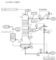
- An embodiment of the method for purifying an amine compound-containing absorbent according to the present invention using the embodiment of the apparatus for purifying an amine compound-containing absorbent according to the present invention in an embodiment of the carbon dioxide recovery method of the present invention is schematically shown. It is a control flow figure.
- the circled number 3 in FIG. 6 shows the flow of the amine compound-containing absorbent supplied from the circled number 3 in FIG.
- the circled number 4 in FIG. 6 shows the flow of the amine compound-containing absorbent supplied to the circled number 4 in FIG.
- the circled number 5 in FIG. 6 indicates the flow of water vapor supplied from the circled number 5 in FIG.
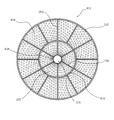
- Carbon dioxide absorption device, carbon dioxide absorption method, amine compound-containing absorption liquid regeneration device, amine compound-containing absorption liquid regeneration method, combustion exhaust gas pretreatment device, combustion exhaust gas pretreatment method, carbon dioxide recovery device, and carbon dioxide recovery method of the present invention It is a perspective view of an example of the static mixer which has a spiral porous wing
- the carbon dioxide absorption device of the present invention includes a CO 2 absorption tower that reacts and absorbs CO 2 contained in combustion exhaust gas into an amine compound-containing absorption liquid, a first cooler that cools the amine compound-containing absorption liquid, and the amine compound containing
- a carbon dioxide absorber comprising: at least one cooler selected from the group consisting of a second cooler that cools a liquid different from the absorbent;
- the CO 2 absorption tower, the flue gas and the flue gas inlet for introducing the CO 2 absorption tower, and flue gas discharge port for discharging the flue gas from the CO 2 absorber, an amine compound containing absorbing solution in the CO 2 absorber
- the CO 2 absorption tower has a spiral porous blade disposed between the combustion exhaust gas inlet and the combustion exhaust gas outlet and between the absorption liquid inlet and the absorption liquid outlet.
- a filling that is a static mixer inside, the combustion exhaust gas and the amine compound-containing absorbent are brought into contact with the filling in a countercurrent or cocurrent flow so that CO 2 contained in the combustion exhaust gas contains the amine compound.
- the absorbing solution can be efficiently absorbed by the reaction.
- the number of packings installed in the CO 2 absorption tower is not particularly limited, and may be one or two or more.
- a high-functional packing as described in US Pat. No. 7,510,172 may be adopted as the packing that is a static mixer having a spiral porous blade. it can.
- CO 2 contained in the combustion exhaust gas can be efficiently reacted and absorbed in the carbon dioxide-containing absorbent, and CO 2 can be removed from the combustion exhaust gas.
- the use of the high-functional packing as the packing is very effective in terms of energy saving, facility downsizing, safety improvement, and maintenance cost reduction.
- This filling material has an excellent feature that the liquid itself has a self-cleaning action of washing the filling material, is maintenance-free, and can be reduced in pressure difference and reduced in size. Further, by reducing the size of the tower, the CO 2 absorption tower and the CO 2 diffusion tower can be unified in the vertical direction to be compact.
- the “static mixer having a spiral porous wing” is a static mixer capable of mixing fluids without power, and is a right-handed and / or left-handed helical blade. It is a mixer which has a body and this blade body is a porous body or a porous body.
- the “static mixer having a spiral porous blade” described here includes a carbon dioxide absorption device, a carbon dioxide absorption method, an amine compound-containing absorption liquid regeneration device, an amine compound-containing absorption liquid regeneration method, and a combustion exhaust gas, which will be described later. This also applies to the CO 2 stripping tower used in the pretreatment device, the combustion exhaust gas pretreatment method, the carbon dioxide recovery device, and the carbon dioxide recovery method, and the packing filled in the pretreatment tower.
- a static mixer having a spiral perforated blade As a preferred static mixer having a spiral perforated blade, a cylindrical passage tube through which a fluid flows, a first rotating blade body rotating clockwise or counterclockwise inside the passage tube, A first inner tube is disposed in the axial center portion of the blade body, a right-handed or left-turned spiral second blade body is provided in the first inner tube tube, and an axial center portion of the second blade body
- a stationary mixer in which a second inner tube is disposed, and the first blade body and the second blade body are a stationary mixer formed of a porous body or a porous body.
- the static mixer 101 has a cylindrical passage tube 102 and a plurality of spiral right-turning first blade bodies 103 provided in the passage tube 102.
- the first blade body 103 is formed of a porous body having a large number of perforated holes 104.
- a cylindrical first inner tube 105 is disposed inside the first blade body 103.
- the first inner tube 105 is provided in the connecting portion of the first blade body 103 by a required length in the axial direction (longitudinal direction), and is not disposed elsewhere.
- the first inner tube 105 includes a plurality of spiral right-rotating second blades 106, and the blades 106 are formed of a porous body having a number of perforated holes 107.
- a cylindrical second inner tube 108 is disposed inside the second blade body 106 to form an opening 109.
- the second inner tube 108 is installed to increase the mechanical strength against the torsional stress of the second blade body 106.
- the second inner tube 108 is provided in the connection portion of the second blade body 106 as necessary, as necessary, and is not disposed elsewhere.
- One end portion of the first blade body 103 is connected to the outer peripheral surface of the first inner tube 105, and the other end portion is spirally twisted in a clockwise direction (clockwise rotation) toward the inner peripheral surface of the passage tube 102. It is connected to the inner peripheral surface of the passage tube 102.
- one end of the second blade body 106 is connected to the outer peripheral surface of the second inner cylindrical tube 108, and the second blade body 106 is spirally twisted clockwise (rotated clockwise) toward the inner peripheral surface of the first inner cylindrical tube 105.
- the other end is connected to the inner peripheral surface of the first inner tube 105. Since the center portion of the second inner tube 108 is opened, the second blade body 106 does not exist in the axial center portion of the second inner tube 108, and this portion is missing. As a result, as shown in FIGS. 8 and 9, an opening 109 is formed in the axial center portion of the second inner tube 108 where no blades are present.
- the rotation angle (twisting angle) of the blades 103 and 106 is not limited to 90 °, but is preferably in the range of about 5 ° to 270 °, more preferably about 10 ° to 270 °, depending on the inner diameter of the static mixer 101. 180 °.
- the number of the inner cylindrical tubes is arranged such that the diameter of the opening 102 is a minimum diameter, for example, 50 mm or less, according to the inner diameter of the static mixer 101, according to the third, fourth, fifth and nth inner cylindrical tubes.
- at least one or more can be used by appropriately increasing or decreasing.
- blades can be used as appropriate.
- the number of blade bodies 103 and 106 is not limited to 12 and 6, but can be appropriately increased or decreased.
- the “amine compound-containing absorbing liquid” is a liquid that can absorb CO 2 contained in the combustion exhaust gas when brought into contact with the combustion exhaust gas, and is composed of an aqueous solution of an amine compound.
- the aqueous solution of the amine compound used in the present invention is not particularly limited as long as it absorbs CO 2 in the state of the aqueous solution and can be regenerated by heating.
- Specific examples of the amine compound include monoethanolamine (MEA).
- Diethanolamine DEA
- triethanolamine TEA
- methyldiethanolamine MDEA
- diisopropanolamine DIPA
- methylaminopropylamine MDEA
- piperazine diethylethanolamine
- DEEA methyldiisopropanolamine
- MDIPA methyldiisopropanolamine
- Alkanolamines such as dimethylaminopropanol (DIMAP), 2-amino-1-butanol (2-AB), and hindered amines and diamines having an alcoholic hydroxyl group.
- combustion exhaust gas is a combustion gas discharged from a combustion apparatus such as a boiler using fossil resources including carbon such as coal and heavy oil and biological resources such as forests, agricultural products, and pasture as fuel.
- the carbon dioxide absorption device of the present invention is at least one cooler selected from the group consisting of a first cooler that cools an amine compound-containing absorbent and a second cooler that cools a liquid different from the amine compound-containing absorbent. Is provided.
- the first cooler can be suitably used to remove the heat generation of the amine compound-containing absorbent due to reaction absorption, and the cooled amine compound-containing absorbent can be reused. is there.
- the absorption liquid recovery port of the first cooler is an amine compound-containing absorption liquid heading from the absorption liquid introduction port of the CO 2 absorption tower to the absorption liquid discharge port. It suffices if it is connected to the CO 2 absorption tower at a position downstream of at least one packing in the flow direction, and the absorption liquid supply port of the first cooler is in the flow direction of the amine compound-containing absorption liquid.
- the absorption liquid cooled by the first cooler is an amine compound-containing absorption liquid introduced into the CO 2 absorption tower in order to react and absorb CO 2 contained in the combustion exhaust gas.
- the second cooler can be suitably used for preventing entrainment in the combustion exhaust gas, and cools the liquid (circulating fluid) whose temperature has been increased by contacting with the combustion exhaust gas. Can be recycled.
- the liquid supply port of the second cooler is preferably provided in the vicinity of the combustion exhaust gas discharge port of the CO 2 absorption tower.
- the liquid recovery port of the second cooler has a flow direction of the combustion exhaust gas from the combustion exhaust gas introduction port of the CO 2 absorption tower to the combustion exhaust gas discharge port when the combustion exhaust gas and the circulating liquid are brought into contact with each other in countercurrent.
- the CO 2 absorption column, while the position where the position and the liquid recovery port of the second cooler liquid supply port of the second cooler is connected is connected it is preferable to provide an additional filler.
- the additional packing is preferably arranged at a position closest to the combustion exhaust gas outlet in the packing in the CO 2 absorption tower.
- a static mixer having the above-described spiral porous wing can be preferably used.
- the liquid (circulating liquid) cooled by the second cooler need not be an amine compound-containing absorbing liquid, and water or the like can be used. However, since the liquid in contact with the combustion exhaust gas is circulated and used, a small amount of amine is used. Contains compounds.
- the carbon dioxide absorption method of the present invention comprises: A combustion exhaust gas inlet port for introducing the flue gas into the CO 2 absorber, the flue gas discharge port for discharging the flue gas from the CO 2 absorber, and absorbing solution inlet for introducing an amine compound containing absorbing solution in the CO 2 absorber the absorption liquid discharge ports for discharging the amine compound-containing absorbing solution from the CO 2 absorber, the CO 2 absorption tower and a filling is static mixer having a spiral perforated wings, including the CO 2 combustion
- the carbon dioxide absorption method of the present invention can be carried out by using the above-described carbon dioxide absorption apparatus of the present invention.
- the first step uses the CO 2 absorption tower, and the second The process can be performed by using the first cooler, and the third process can be performed by using the second cooler.
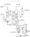
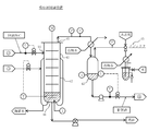
- FIGS. 3 and 4 schematically illustrate an embodiment of the carbon dioxide absorption method of the present invention using one embodiment of the carbon dioxide absorption device of the present invention in one embodiment of the carbon dioxide recovery method of the present invention.
- FIG. 3 shows details when the CO 2 absorption tower is in a countercurrent operation
- FIG. 4 shows details when the CO 2 absorption tower is in a cocurrent operation.
- the carbon dioxide absorber shown in FIG. 3 includes a CO 2 absorption tower 1, a first cooler 2, and a second cooler 3.
- the CO 2 absorption tower 1 shown in FIG. 3 is a stationary mixer having a combustion exhaust gas inlet 4, a combustion exhaust gas outlet 5, an absorbent inlet 6, an absorbent outlet 7, and a spiral porous blade. And two fillings 8 and 8 '.
- the fillers 8, 8 ′ are arranged between the combustion exhaust gas inlet 4 and the combustion exhaust gas outlet 5 and between the absorbing liquid inlet 6 and the absorbing liquid outlet 7.
- Combustion exhaust gas introduced into the CO 2 absorber 1 flows toward the combustion exhaust gas outlet 5 from the flue gas inlet 4, an amine compound is introduced into the CO 2 absorber 1 containing absorption liquid, the absorption liquid inlet 6 To the absorbent discharge port 7.
- the amine compound-containing absorption liquid and the combustion exhaust gas are brought into contact with each other in the packing 8 and the packing 8 ′ so that CO 2 contained in the combustion exhaust gas is efficiently reacted and absorbed by the amine compound-containing absorption liquid.
- the number of packings installed in the CO 2 absorption tower is not particularly limited.
- the first cooler 2 shown in FIG. 3 is configured such that the absorption liquid recovery port for recovering the amine compound-containing absorption liquid from the CO 2 absorption tower is directed from the absorption liquid inlet to the absorption liquid outlet through the flow path.
- An absorption liquid supply port connected to the CO 2 absorption tower 1 at a position 9 on the downstream side of the packing 8 in the flow direction of the containing absorption liquid and supplying the amine compound-containing absorption liquid to the CO 2 absorption tower is provided via a flow path.
- the amine compound-containing absorbent is connected to the CO 2 absorber 1 at a position 10 upstream of the packing 8 ′ in the flow direction of the amine compound-containing absorbent.
- the 1st cooler 2 is a heat exchanger and can cool an amine compound content absorption liquid by heat exchange with cooling water.
- a general method such as a vertical liquid collector or a chimney tray can be used.
- the liquid recovery port for recovering the liquid that is contacted with the flue gas in contact with a liquid inlet and flue gas supplied to the CO 2 absorber liquid from the CO 2 absorber is, flow through the road, it is connected with the CO 2 absorber at a location downstream of the location 11, 12 of the packing 8 in the flow direction of the flue gas towards the combustion exhaust gas outlet from the combustion exhaust gas inlet, the CO 2 absorber 1 has an additional filling 8 ′′ inside between positions 11 and 12.
- the packing 8 ′′ is not a packing disposed between the absorbing liquid inlet 6 and the absorbing liquid outlet 7 of the CO 2 absorption tower, but is similar to the packings 8 and 8 ′ in a spiral porous shape.
- a static mixer with wings can be used.
- the filling 8 ′′, the filling 8, and the filling 8 ′ shown in FIG. 3 are also referred to as an upper filling, an intermediate filling, and a lower filling.
- the 2nd cooler 3 is a heat exchanger, and can cool the circulating fluid which is the aqueous solution etc. which contain a small amount of amine compounds by heat exchange with cooling water.
- a general method such as a vertical liquid collector or a chimney tray can be used as a vertical liquid collector or a chimney tray.
- the carbon dioxide absorption device shown in FIG. 4 includes a CO 2 absorption tower 1 and a first cooler 2.
- the CO 2 absorption tower 1 shown in FIG. 4 includes a combustion exhaust gas inlet 4, a combustion exhaust gas outlet 5, an absorbing liquid inlet 6, an absorbing liquid outlet 7, and a static mixer having a spiral porous blade. And two fillings 8 and 8 '.
- the fillers 8, 8 ′ are arranged between the combustion exhaust gas inlet 4 and the combustion exhaust gas outlet 5 and between the absorbing liquid inlet 6 and the absorbing liquid outlet 7.
- Combustion exhaust gas introduced into the CO 2 absorber 1 flows toward the combustion exhaust gas outlet 5 from the flue gas inlet 4, an amine compound is introduced into the CO 2 absorber 1 containing absorption liquid, the absorption liquid inlet 6 To the absorbent discharge port 7.
- the amine compound-containing absorbent and the combustion exhaust gas are contacted in parallel with the filler 8 and the filler 8 ′ to efficiently react and absorb CO 2 contained in the combustion exhaust gas in the amine compound-containing absorbent.
- the number of packings installed in the CO 2 absorption tower is not particularly limited.
- the packing 8 and the packing 8 ′ shown in FIG. 4 are also referred to as an upper packing and a lower packing.
- the first cooler 2 shown in FIG. 4 has an absorption liquid recovery port for recovering the amine compound-containing absorption liquid from the CO 2 absorption tower at the absorption liquid discharge port 7 of the CO 2 absorption tower 1 via the flow path.
- An absorption liquid supply port connected to the CO 2 absorption tower 1 and supplying the amine compound-containing absorption liquid to the CO 2 absorption tower is upstream of the packing 8 ′ in the flow direction of the amine compound-containing absorption liquid through the flow path. It is connected to the CO 2 absorber 1 at a position 10 on the side.
- the 1st cooler 2 is a heat exchanger and can cool an amine compound content absorption liquid by heat exchange with cooling water.
- the carbon dioxide absorber shown in FIGS. 3 and 4 includes a pressure gauge P, a thermometer T, a flow meter F, a liquid level gauge L, and a CO 2 analyzer, and a control loop is formed.
- the combustion exhaust gas is usually removed from SO X and dust in a pretreatment process, cooled, and supplied to the CO 2 absorption tower.
- the combustion exhaust gas from the pretreatment process is supplied from the combustion exhaust gas inlet 4 located at the lower part of the CO 2 absorption tower 1 through the combustion exhaust gas supply flow path, rises in the absorption tower, Pass 8 ′, 8, 8 ′′ in order.
- the exhaust gas from which the CO 2 has been removed is discharged out of the system from the combustion exhaust gas outlet 5 located at the top of the CO 2 absorption tower 1.
- the combustion exhaust gas from the pretreatment process is supplied from the combustion exhaust gas inlet 4 located in the upper part of the CO 2 absorption tower 1 through the combustion exhaust gas supply flow path, descends in the absorption tower, Pass through 8 and 8 'in order.
- the exhaust gas from which CO 2 has been removed is discharged out of the system from a combustion exhaust gas outlet 5 located at the lower part of the CO 2 absorption tower 1.
- the amine compound-containing absorption liquid is circulated, and the amine compound-containing absorption liquid regenerated by separating CO 2 in the amine compound-containing absorption liquid regeneration method passes through the absorption liquid supply channel. It is supplied to the CO 2 absorption tower 1 from the CO 2 diffusion tower. As described in FIGS. 3 and 4, when supplying a CO 2 desorption column to the CO 2 absorber 1, an amine compound containing absorption liquid, are preferably cooled by the absorption liquid cooler. In FIG.
- the amine compound-containing absorption liquid from the CO 2 diffusion tower is supplied into the CO 2 absorption tower 1 from the absorption liquid inlet 6 located on the upper side of the intermediate packing 8, so that the CO 2 absorption tower The combustion exhaust gas rising in 1 can be brought into contact with the intermediate packing 8 and the lower packing 8 'in countercurrent.
- the amine compound-containing absorption liquid from the CO 2 diffusion tower is supplied into the CO 2 absorption tower 1 from the absorption liquid inlet 6 located on the upper side of the upper packing 8, so that the CO 2 absorption tower The combustion exhaust gas descending in 1 can be contacted in parallel with the upper packing 8 and the lower packing 8 ′.
- the CO 2 absorption tower 1 shown in FIG. 3 has two coolers separately from the absorption liquid cooler for cooling the amine compound-containing absorption liquid from the CO 2 diffusion tower.
- the second cooler 3 located at the upper part is provided for preventing entrainment in the exhaust gas at the top of the tower, and the circulating liquid cooled by the second cooler 3 is connected to the upper side of the upper packing 8 ''.
- the CO 2 absorption tower 1 can be supplied from the position 11. After the circulating liquid is supplied into the CO 2 absorption tower 1, it passes through the upper packing 8 ′′ and is recovered, so that it can be circulated and used as a combustion exhaust gas rising in the CO 2 absorption tower 1.
- the first cooler 2 located at the lower part is provided for removing heat generated by reaction absorption, but is supplied to the CO 2 absorption tower 1 and is one of the amine compound-containing absorbing liquid that has passed through the intermediate packing 8. Is recovered from the connection position 9, cooled, and supplied from the connection position 10 on the upper side of the lower packing 8 ′, so that the combustion exhaust gas and the lower packing 8 rising in the CO 2 absorption tower 1 are collected. It can also be contacted countercurrently with '.
- the cooling device has an absorption liquid recovery port at the bottom of the tower. Only the first cooler 2 connected to the absorbing liquid discharge port 7 is provided. The amine compound-containing absorption liquid accumulated at the bottom of the CO 2 absorption tower 1 is supplied to the CO 2 diffusion tower. In FIG. 4, a part of the amine compound-containing absorption liquid supplied to the CO 2 diffusion tower is used. After being pumped up by a pump or the like and cooled by the first cooler 2, it is supplied from the connection position 10 on the upper side of the lower packing 8 ′.
- the CO 2 absorption tower 1 shown in FIG. 4 does not include a cooler for preventing entrainment, but instead, a mist separator for preventing entrainment is connected to the combustion exhaust gas outlet 5. Yes. The liquid separated by the mist separator is sent to the bottom of the CO 2 absorption tower 1.
- the operation in the CO 2 absorption tower is reaction absorption. Therefore, the gas-liquid contact mixing in the CO 2 absorption tower is preferably an operation by cocurrent flow.
- the general packing of the CO 2 absorption tower by the conventional counter-current operation to the high-functional packing it is possible to replace only the packing while keeping the counter-current as shown in FIG. Is possible.
- the bottom of the CO 2 absorber because the CO 2 absorber bottom liquid that has absorbed CO 2 is accumulated, the CO 2 absorption tower bottoms via an absorption liquid supply channel Supplied to the CO 2 stripping tower.
- a CO 2 stripping tower dissipating CO 2 contained in the amine compound-containing absorbing solution from an amine compound-containing absorbing solution, first heater for heating the amine compound-containing absorbing solution And an amine compound-containing absorbent regenerator comprising at least one heater selected from the group consisting of a second heater that generates steam by heating the amine compound-containing absorbent,
- the CO 2 diffusion tower is a spiral porous blade disposed between the absorbent inlet and the absorbent outlet and between the steam inlet and the CO 2 outlet.
- a filling which is a static mixer having a mixture
- the amine compound-containing absorption liquid and the vapor are brought into contact with each other in a countercurrent with the packing, so that CO 2 contained in the amine compound-containing absorption liquid is efficiently obtained. It can be diffused and separated from the amine compound-containing absorbent to regenerate the amine compound-containing absorbent and to recover CO 2 .
- the number of packings installed in the CO 2 stripping tower is not particularly limited, and may be one or two or more.
- the static mixer having a spiral porous wing serving as a packing is as described above.
- CO 2 can be reduced differential pressure stripping tower, thereby, of the CO 2 stripper is lowered operating pressure
- the temperature in the tower is lowered, and the thermal decomposition and polymerization of the CO 2 absorbent are greatly suppressed, and safety can be improved.
- the amine compound-containing absorbing liquid is as described above.
- the amine compound-containing absorbing liquid led to the CO 2 stripping tower is used for the carbon dioxide absorption method, and CO 2 is used.
- a reaction-absorbed amine compound-containing absorption liquid for example, an amine compound-containing absorption liquid obtained by reaction-absorption of CO 2 using the carbon dioxide absorption method of the present invention.
- the amine compound-containing absorbing liquid led to the CO 2 stripping tower is usually heated by steam rising in the CO 2 stripping tower (for example, steam of an amine compound and water), so that CO 2 is an amine compound-containing absorbing liquid. Released from.
- CO 2 separated from the amine compound-containing absorbing solution is to increase the CO 2 stripping tower is discharged from the CO 2 discharge port located at the top of dissipating Chi, it can be recovered through the gas-liquid separator.
- the amine compound-containing absorption liquid regenerated after removing CO 2 is collected at the bottom of the CO 2 diffusion tower, and can be recycled by supplying it to the CO 2 absorption tower.
- the steam to be brought into contact with the amine compound-containing absorption liquid can use water vapor or the like, but by using a second heater as described later, an amine compound and water vapor are generated from the amine compound-containing absorption liquid. It is also possible to use this.
- the first heater is suitable for efficiently recovering heat of the amine compound-containing absorbent from the bottom of the CO 2 diffusion tower.
- the temperature in the 2 stripping tower is optimized, and a stable CO 2 stripping action is possible in the CO 2 stripping tower.
- the absorption liquid recovery port of the first heater is an amine compound-containing absorption liquid heading from the absorption liquid introduction port of the CO 2 stripping tower to the absorption liquid discharge port. It suffices if it is connected to the CO 2 diffusion tower at a position downstream of at least one packing in the flow direction.
- the absorption liquid supply port of the first heater is preferably connected to the CO 2 stripping tower at a position downstream of the position where the absorption liquid recovery port is connected in the flow direction of the amine compound-containing absorption liquid. Further, when the CO 2 stripping tower is provided with a plurality of packings, the CO 2 stripping tower is connected to the CO 2 stripping tower at a position downstream of the packing located most downstream in the flow direction of the amine compound-containing absorbent. Is preferred.
- the absorption liquid heated by the first heater is an amine compound-containing absorption liquid introduced into the CO 2 diffusion tower in order to dissipate CO 2 contained in the amine compound-containing absorption liquid.
- the second heater can generate vapors of an amine compound and water from a part of the amine compound-containing absorbent, and the vapor is used as the amine compound-containing absorbent. it can be used as a vapor for dissipating CO 2 from.
- the absorption liquid recovery port of the second heater is preferably provided, for example, at a position where the amine compound-containing absorption liquid collected at the bottom of the CO 2 diffusion tower can be recovered.
- the steam inlet of the CO 2 stripper flows from the viewpoint of optimizing the temperature of the CO 2 stripping tower, directed from the absorption liquid inlet CO 2 stripping tower to the absorption liquid discharge ports amine compound containing absorbing solution It is preferable that the first heater is disposed at a position downstream of the position where the absorbent liquid supply port of the first heater is connected.
- the amine compound-containing absorbent regenerator of the present invention preferably includes a gas-liquid separator that gas-liquid separates CO 2 discharged together with steam from the CO 2 discharge port of the CO 2 diffusion tower.
- the gas-liquid separator includes a CO 2 inlet for introducing CO 2 discharged together with steam into the gas-liquid separator, a CO 2 recovery port for recovering the gas-liquid separated CO 2 , and discharging the gas-liquid separated liquid and a liquid discharge port for, here, CO 2 inlet is connected with the CO 2 desorption column of CO 2 outlet, the liquid outlet is connected with the CO 2 stripping tower of the absorbent inlet Yes.
- the heat source of the second heater is steam
- overheated steam prevention is performed by reducing and decompressing the steam supplied to the second heater as the heat source of the second heater. It is an apparatus, Comprising: It is preferable to provide the overheated steam prevention apparatus connected with this 2nd heater.
- the method for regenerating an amine compound-containing absorbent is as follows. And absorbing liquid inlet for introducing an amine compound containing absorbing solution in CO 2 stripper, and the absorption liquid discharge ports for discharging the amine compound-containing absorbing solution from the CO 2 stripper, steam inlet for introducing steam into the CO 2 stripping tower
- the CO 2 discharge port for discharging the CO 2 from the CO 2 stripper, the CO 2 stripping tower and a filling is static mixer having a spiral perforated wings, an amine compound containing containing CO 2
- the amine compound-containing absorbing liquid regeneration method of the present invention gas-liquid separates CO 2 discharged together with steam from the CO 2 outlet, collects the separated CO 2, and removes the separated liquid from the absorbing liquid inlet. preferably includes a fourth step of supplying the CO 2 stripper.
- the heat exchange is performed before the heat exchange in the third step. It is preferable to include a fifth step of reducing the temperature and pressure of the water vapor used.
- the amine compound-containing absorbent regenerating method of the present invention can be carried out by using the above-described amine compound-containing absorbent regenerating apparatus of the present invention.
- the first step uses a CO 2 diffusion tower.
- the second step uses the first heater
- the third step uses the second heater
- the fourth step uses the gas-liquid separator
- the fifth step It can be implemented by using an overheated steam prevention device.
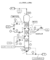
- FIG. 5 schematically illustrates an embodiment of the amine compound-containing absorbent regenerating method of the present invention using one embodiment of the amine compound-containing absorbent regenerating apparatus of the present invention in one embodiment of the carbon dioxide recovery method of the present invention. It is the control flow figure shown automatically.
- the amine compound-containing absorbent regenerator shown in FIG. 5 includes a CO 2 diffusion tower 21, a first heater 22, a second heater 23, a gas-liquid separator 24, and an overheated steam prevention device 25.
- the CO 2 stripping tower 21 shown in FIG. 5 has two absorption liquid inlets 26 and 26 ′, an absorption liquid outlet 27, a steam inlet 28, a CO 2 outlet 29, and a spiral porous blade. And fillings 30 and 30 'which are static mixers.
- the filler 30 is disposed between the absorbent inlets 26 and 26 ′ and the absorbent outlet 27 and between the steam inlet 28 and the CO 2 outlet 29, and the filler 30 ′ is the absorbent liquid. It is disposed between the inlet 26 ′ and the absorbing liquid outlet 27 and between the steam inlet 28 and the CO 2 outlet 29.
- Amine compound is introduced into CO 2 stripping tower 21 containing absorbing solution flows toward the absorbing solution discharge port 27 from the absorbing solution inlet 26, 26 ', the steam introduced into the CO 2 stripping tower 21, the steam inlet It flows from 28 toward the CO 2 outlet 29.
- the amine compound-containing absorbent and vapor are brought into contact with each other in the filling 30 and the filling 30 ′ in countercurrent to efficiently dissipate CO 2 contained in the amine compound-containing absorbent, thereby containing the amine compound.
- the amine compound-containing absorbing solution can be regenerated and CO 2 can be recovered.
- the number of packings installed in the CO 2 diffusion tower is not particularly limited.
- the filling 30 and the filling 30 ′ shown in FIG. 5 are also referred to as a lower filling and an upper filling.
- the CO 2 stripping tower 21 includes a plurality of absorbing liquid inlets, but the present invention is not limited to this, and there may be one absorbing liquid inlet.
- the first heater 22 shown in FIG. 5 has an amine compound in which an absorption liquid recovery port for recovering an amine compound-containing absorption liquid from the CO 2 diffusion tower is directed from the absorption liquid inlet to the absorption liquid outlet through the flow path.
- An absorption liquid supply port that is connected to the CO 2 diffusion tower 21 at a position 31 downstream of the packing 30 in the flow direction of the absorption liquid and supplies the amine compound-containing absorption liquid to the CO 2 diffusion tower is provided via a flow path.
- the amine compound-containing absorbent is connected to the CO 2 stripping tower 21 at a position 32 downstream of the position 31 in the flow direction.
- the first heater 22 is a heat exchanger, and contains an amine compound that passes through the first heater by heat exchange with the amine compound-containing absorbent discharged from the absorbent outlet 27 of the CO 2 diffusion tower 21.
- the absorbing liquid can be heated.
- a general method such as a vertical liquid collector or a chimney tray can be used.
- the first heater 22 in the flow direction of the amine compound-containing absorbent is connected to 21 and the steam supply port for supplying steam to the CO 2 stripping tower flows from the absorbent inlet to the absorbent outlet through the flow path. This is connected to the steam inlet 28 of the CO 2 stripping tower 21 disposed downstream of the position 32 to which the absorbing liquid supply port is connected.
- the second heater 23 is a heat exchanger and can generate an amine compound and water vapor from the amine compound-containing absorbent by heat exchange with water vapor.
- a general technique such as a reboiler can be used as a reboiler.
- a cooler is provided in the middle of the flow path, and gas-liquid separation can be performed efficiently by heat exchange with the cooling water.
- the liquid discharge port for discharging the gas-liquid separated liquid is connected to the absorption liquid inlet 26 ′ of the CO 2 diffusion tower 21 through the flow path.
- the gas-liquid separation device 24 and the CO 2 diffusion tower are connected.
- 21 is connected to the absorption liquid discharge port of the CO 2 absorption tower and the flow path connecting the absorption liquid introduction port 26 ′ of the CO 2 diffusion tower 21.
- a static mixer 33 is provided between the position and the absorbing liquid inlet 26 '.
- the overheated steam prevention device 25 shown in FIG. 5 is connected to the second heater 23 through a flow path, and supplies saturated steam obtained by reducing the temperature of the overheated steam to the second heater 23. can do. Further, the steam supply system shown in FIG. 5 is also used in an amine compound-containing absorbing liquid purifying apparatus described later, and the superheated steam prevention device 25 is also connected to a heating jacket of the evaporation tank to reduce the temperature of the superheated steam. Saturated water vapor obtained by reducing the pressure can be supplied to the heating jacket.
- the amine compound-containing absorbent regenerator shown in FIG. 5 includes a pressure gauge P, a thermometer T, a flow meter F, a liquid level gauge L, and a CO 2 analyzer, and a control loop is formed.
- the amine compound-containing absorbing solution obtained by reaction absorption of CO 2 using the carbon dioxide absorption method is supplied to the CO 2 stripping tower 21 in two systems.
- CO 2 stripping CO 2 from a part of the reaction the absorbed amine compound containing absorbing solution 'absorption liquid inlet 26 located above the' upper packing 30 of CO 2 stripping column 21 as feed A It is supplied into the tower 21.
- Feed A without being heated, the CO 2 absorber bottom liquid discharged from the CO 2 absorber that is supplied while the cold state preferred.
- the supply liquid A is, for example, a static mixer together with a reflux liquid (water or the like) separated when recovering CO 2 discharged from a CO 2 discharge port 29 located at the top of the CO 2 diffusion tower 21.
- the cooled supply liquid A has a role of refluxing the CO 2 diffusion tower 21 and preventing entrainment of droplets.
- the remainder of the amine compound-containing absorbing liquid that has reacted and absorbed CO 2 is positioned as the feed liquid B above the lower packing 30 of the CO 2 diffusion tower 21 and below the upper packing 30 ′. Is supplied into the CO 2 diffusion tower 21 from the absorbing liquid inlet 26.
- feed B from being heated are supplied to the CO 2 stripping tower 21, this time, by heat exchange with the bottom liquid accumulated in the bottom portion of the CO 2 stripping tower 21, CO 2 emission It is preferable to heat the supply liquid B before being supplied to the tower 21.
- the column bottom liquid is an amine compound-containing absorption liquid regenerated after removing CO 2 , it is preferably supplied to the CO 2 absorption tower. At that time, the amine is exchanged with the supply liquid B by heat exchange. It is preferable to cool the compound-containing absorbent.
- the portion filling the bottom and CO 2 stripping tower in CO 2 stripping tower is installed (hereinafter, also referred to as filler layer) temperature difference normal 10
- the first heater 22 is installed at a position between the bottom of the CO 2 stripping tower 21 and the packed bed. Efficient heat recovery can be performed.
- the CO 2 stripping tower 21 includes a plurality of packings 30 and 30 ′. In this case, the CO 2 stripping tower 21 is first positioned at a position between the lowest packing layer (lower packing layer) and the column bottom.
- connection positions 31 and 32 between the heater and the CO 2 diffusion tower In FIG. 5, in the first heater 22, the connection position 31 between the first heater and the CO 2 diffusion tower is installed below the lower packing 30. A part of the amine compound-containing absorbing liquid descending in the CO 2 stripping tower 21 is recovered from the connection position 31, and the recovered amine compound-containing absorbing liquid is discharged from the CO 2 stripping tower 21 to be supplied to the CO 2 absorbing tower. Heat is exchanged with the tower bottom liquid thus heated by the heater 22, and then returned from the connection position 32 into the CO 2 stripping tower 21.
- the 1st heater 22 is an amine compound containing absorption liquid (namely, amine whose temperature is 10 degreeC or more lower than the temperature of a tower bottom) in which the temperature difference with a tower bottom becomes 10 degreeC or more when there is no 1st heater 22 It is preferable that the connection position 31 is installed at a position where the compound-containing absorbing liquid) can be recovered.
- the column bottom liquid of the CO 2 stripping tower 21 is partially recovered from the bottom of the CO 2 stripping tower 21 connected to the absorption liquid recovery port of the second heater 23.
- Heat exchange with the saturated steam is performed to generate steam of the amine compound and water, and then the steam is supplied into the CO 2 stripping tower 21 from the steam inlet 28 and rises in the CO 2 stripping tower 21. .
- the steam to dissipate the CO 2 contained in the amine compound-containing absorbing solution using, CO 2 it is possible to separate the CO 2 from the introduced amine compound-containing absorbing solution into the stripping tower 21, the amine compound-containing absorbing The liquid can be regenerated.
- CO 2 separated from the amine compound-containing absorbing solution is raised to CO 2 stripping tower 21 together with steam, it is discharged from the CO 2 emission port 29 located at the top of dissipating Chi. Thereafter, by performing gas-liquid separation, CO 2 can be recovered, and separated water or the like can be mixed with the supply liquid A as a reflux liquid.
- the steam supply temperature T-2 measured by the setting thermometer 34 for the superheated steam prevention device is desirably set 5-30 ° C. higher than the tower bottom temperature T-1 of the CO 2 diffusion tower 21.
- a part of the column bottom liquid of the CO 2 stripping tower 21 is supplied as an evaporation tank supply liquid to the amine compound-containing absorption liquid purification apparatus via the absorption liquid supply channel.
- the following two effects can be exhibited.
- the temperature in the CO 2 diffusion tower is optimized and the effect of CO 2 emission is improved. In particular, by making the temperature difference between the bottom of the CO 2 diffusion tower and the packed bed (lower packed bed in FIG. 5) 10 ° C. or lower and increasing the temperature of the packed bed, the CO 2 emission effect can be improved. Can be increased. 2.
- the operating pressure of the CO 2 diffusion tower can be reduced, especially the temperature at the bottom of the tower is reduced, and not only steam saving but also thermal decomposition of the CO 2 absorbent is suppressed.
- the static mixer having the above-described spiral porous blade can reduce the pressure difference to 1 ⁇ 2 or less compared to the pressure difference of a general packing (such as Raschig ring), and therefore CO 2 emission.
- the tower bottom temperature in the tower can be lowered by 4 ° C. or more. As a whole, 30% of the water vapor flow rate used in the second heater 23 can be reduced.
- the apparatus for purifying an amine compound-containing absorbent is an evaporation tank for evaporating and separating impurities contained in an amine compound-containing absorbent from an amine compound-containing absorbent, and for heating disposed outside the evaporator tank
- An evaporation tank provided with a jacket, an overheated steam prevention device for reducing and depressurizing water vapor supplied to the heating jacket as a heat source, a gas-liquid separation device for recovering an amine compound-containing absorbing solution evaporated and separated from impurities, and the evaporation
- An amine compound-containing absorption liquid purifying device comprising a decompression device for decompressing the inside of the tank
- the evaporating tank includes an absorbing liquid inlet for introducing the amine compound-containing absorbing liquid into the evaporating tank, an absorbing liquid outlet for discharging the amine compound-containing absorbing liquid evaporated and separated from the impurities from the evaporating tank, and the amine compound-containing absorbing liquid.
- the gas-liquid separator is an absorption liquid inlet for introducing an amine compound-containing absorption liquid evaporated and separated from impurities into the gas-liquid separator, a gas outlet for discharging the gas-liquid separated gas, and a gas-liquid separated liquid.
- a liquid outlet for discharging, The decompression device is connected to the evaporation tank through an absorption liquid inlet of the gas-liquid separator, a gas outlet of the gas-liquid separator and an absorption liquid outlet of the evaporation tank,
- the overheated steam prevention device is connected to the heating jacket.
- the amine compound-containing absorbent purifying apparatus of the present invention the amine compound-containing absorbent containing impurities such as a polymer substance is used in a carbon dioxide absorption method or an amine compound-containing absorbent regeneration method, and is placed in an evaporation tank under a vacuum.
- the amine compound-containing absorbent can be purified to restore its capacity, and the apparatus can be prevented from being soiled or clogged.
- the evaporation tank is connected to the decompression device via the absorption liquid inlet of the gas-liquid separator, the gas outlet of the gas-liquid separator, and the absorbent outlet of the evaporator. Therefore, the inside of the evaporation tank can be vacuum depressurized.
- the amine compound-containing absorption liquid containing impurities generated by long-term operation of the apparatus and impurities mixed in from the pretreatment process is introduced into the evaporation tank under vacuum decompression from the absorption liquid inlet of the evaporation tank. By evaporating the compound-containing absorbent, it can be separated from impurities, and the amine compound-containing absorbent can be purified.
- the gas-liquid separator is a purified amine that is separated from air or the like by performing gas-liquid separation on the amine compound-containing absorbent that has been evaporated and separated from impurities.
- the compound-containing absorbent can be recovered.
- the heating jacket of the evaporating tank is provided with the superheated steam preventing device because steam is used as a heat source. It is preferable that the superheated steam preventing device used for the amine compound-containing absorbent refining device and the superheated steam preventing device used for the amine compound-containing absorbent regenerating device of the present invention are common devices.
- the amine compound-containing absorbent containing impurities is continuously or intermittently introduced into an evaporation tank under vacuum and reduced to evaporate and separate the impurities and amine compound-containing absorbent.
- a first step for purifying the amine compound-containing absorbent a second step for heating the evaporation tank by supplying water vapor to a heating jacket disposed outside the evaporation tank, and a heating jacket in the second process.
- the method for purifying an amine compound-containing absorbent according to the present invention can be carried out by utilizing the above-described apparatus for purifying an amine compound-containing absorbent according to the present invention.
- the amine compound-containing absorbent When an amine compound-containing absorbent is circulated in the method for recovering carbon dioxide in combustion exhaust gas, the amine compound-containing absorbent contains impurities and systems such as trace amounts of SO X and dust that accompany the combustion exhaust gas. Many types of decomposition and heavy components that accumulate in the tank accumulate. This causes the formation and flooding in the tower, which makes the operation unstable, and is the main cause of shortening the operation time of the equipment, installing spare equipment, and increasing maintenance costs. In addition, the performance of the amine compound-containing absorbent is deteriorated, and the equipment such as fillers and heat exchangers becomes dirty and clogged.
- a part of the amine compound-containing absorbent used in the CO 2 absorption tower or the CO 2 stripping tower is led continuously or intermittently to an evaporation tank under vacuum pressure reduction,
- an evaporation tank Under vacuum pressure reduction,
- thermal decomposition products and polymerized substances of the amine compound-containing absorption liquid generated by long-term operation of equipment such as a CO 2 absorption tower and a CO 2 diffusion tower, and contaminants mixed from the pretreatment process And can be separated.
- the amine compound-containing absorbent can be purified to recover its capacity. Further, heavy components and the like can be removed more efficiently than mechanical removal using a conventional filter or the like.
- the amine compound-containing absorbent introduced into the evaporation tank may be, for example, an amine compound-containing absorbent or an amine compound-containing absorbent obtained by reacting and absorbing CO 2 using the carbon dioxide absorption method.
- An amine compound-containing absorption liquid from which CO 2 has been removed in the liquid regeneration method, and an amine compound-containing absorption liquid obtained by reactive absorption of CO 2 in the carbon dioxide absorption method of the present invention or the amine compound-containing absorption liquid regeneration method of the present invention Specific examples thereof include an amine compound-containing absorbent from which CO 2 has been removed.
- FIG. 6 schematically shows an embodiment of the method for purifying an amine compound-containing absorbent according to the present invention using one embodiment of the apparatus for purifying an amine compound-containing absorbent according to the present invention in an embodiment of the carbon dioxide recovery method of the present invention. It is the control flow figure shown automatically.
- 6 includes an evaporating tank 41, an overheated steam prevention device (not shown), a gas-liquid separation device 42, and a decompression device 43.
- the evaporation tank 41 shown in FIG. 6 includes an absorption liquid introduction port 44, an absorption liquid discharge port 45, and an impurity discharge port 46, and further includes a heating jacket 47 disposed outside the evaporation tank 41. .
- a part of the bottom liquid of the CO 2 stripping tower is continuously or intermittently supplied into the evaporation tank 41 from the absorbing liquid inlet 44 through the absorbing liquid supply channel as the supplying liquid C.
- the amine compound-containing absorption liquid containing impurities is evaporated and separated, and the evaporated amine compound-containing absorption liquid is discharged from the absorption liquid discharge port 45.
- the evaporation tank 41 includes a heating jacket 55 disposed outside, the temperature in the evaporation tank 54 can be controlled. Further, since the evaporation tank 41 is connected to the decompression device 43 via the gas-liquid separation device 42, the inside of the evaporation tank 41 can be maintained under vacuum decompression. According to the amine compound-containing absorbing liquid purifying apparatus shown in FIG. 6, impurities such as contaminated heavy components contained in the supply liquid C can be safely evaporated and separated at a low temperature under a vacuum. Preferred conditions are a pressure of 5 to 500 Torr and a temperature of 50 to 90 ° C.
- the gas-liquid separation device 42 shown in FIG. 6 has an absorption liquid inlet for introducing the amine compound-containing absorption liquid evaporated and separated from impurities into the gas-liquid separation apparatus. Although it is connected to 45, a cooler is provided in the middle of the flow path, and gas-liquid separation can be performed efficiently by heat exchange with the cooler.
- the amine compound and water evaporated and separated from impurities such as heavy contaminants are discharged from the absorption liquid discharge port 45 located at the upper part of the evaporation tank 41, and then the air contained in a trace amount is separated by gas-liquid separation.
- the purified amine compound-containing absorption liquid (purified liquid) can be recovered.
- the purified liquid can be supplied from the liquid discharge port of the gas-liquid separator to the CO 2 absorption tower or the CO 2 diffusion tower through the absorption liquid supply channel. 6 is connected to the absorption liquid supply channel for supplying the amine compound-containing absorption liquid to the CO 2 absorption tower shown in FIG. In the CO 2 diffusion tower, the amine compound-containing absorbent from which CO 2 has been removed is supplied to the CO 2 absorption tower.
- the decompression device 43 shown in FIG. 6 is a general vacuum steam-driven ejector, and the inside of the evaporation tank 41 is vacuum-depressurized using this, but the amine compound-containing absorbing liquid purification of the present invention is performed.
- the pressure reducing device is not limited to this.
- impurities such as heavy components that cause clogging and a small amount of absorbing liquid accumulate, and these impurities are discharged as waste liquid through a pump or the like. 46 can be discharged out of the system. As a result, the performance of the amine compound-containing absorbent can be recovered and maintained, and contamination and blockage of the apparatus can be prevented.
- the evaporation tank may be a general evaporation tank, but is preferably a thin film type with a stirrer that can be operated under vacuum reduced pressure.
- the wet wall evaporator is effective for continuous operation.
- the heat source of the heating jacket is preferably steam with reduced temperature and reduced pressure used in the heater of the CO 2 diffusion tower.
- the evaporation tank 41 shown in FIG. 6 is an evaporation tank provided with a stirrer with a motor M, and has a heating jacket 47 outside the evaporation tank 41 for use in the second heater 23 in FIG.
- a part of the prepared water vapor is supplied to the heating jacket 47.
- a method for obtaining vacuum depressurization a method of using a refrigerant for cooling water of a steam ejector, a vacuum pump (not shown) or a condenser (not shown) shown in FIG. 6 is effective.
- the required supply liquid flow rate (flow rate of the supply liquid C) to the evaporation tank 41 shown in FIG. 6 is the amine compound-containing absorption liquid flow rate, that is, supplied to the CO 2 absorption tower after implementing the countermeasures described later in the pretreatment process of the combustion exhaust gas. Therefore, it may be 5% or less of the flow rate of the bottom liquid discharged from the bottom of the CO 2 diffusion tower.
- the amine compound-containing absorbent purification apparatus of the present invention is very important for safe operation and long-term stable operation of the CO 2 recovery facility.
- the amine compound-containing absorbing liquid purification apparatus shown in FIG. 6 includes a pressure gauge P, a thermometer T, a flow meter F, and a liquid level gauge L, and a control loop is formed.
- the combustion exhaust gas pretreatment device of the present invention is a combustion exhaust gas pretreatment device comprising a pretreatment tower for performing desulfurization, dust removal and cooling on the combustion exhaust gas, A combustion exhaust gas inlet for introducing the combustion exhaust gas into the pretreatment tower; a combustion exhaust gas outlet for discharging the combustion exhaust gas from the pretreatment tower; and a desulfurization liquid inlet for introducing the desulfurization liquid into the pretreatment tower.
- the combustion exhaust gas inlet is disposed on the upstream side of the packing in the flow direction of the desulfurization liquid from the desulfurization liquid inlet to the desulfurization liquid discharge port, and the desulfurization liquid inlet is connected to the combustion exhaust gas discharge port from the combustion exhaust gas inlet It arrange
- the pretreatment tower has a spiral porous blade disposed between the combustion exhaust gas inlet and the combustion exhaust gas outlet and between the desulfurization liquid inlet and the desulfurization liquid outlet.
- a filling that is a static mixer is provided inside, where the combustion exhaust gas inlet is disposed upstream of the packing in the flow direction of the desulfurization liquid from the desulfurization liquid introduction port to the desulfurization liquid discharge port. Since the liquid inlet is arranged upstream of the packing in the flow direction of the combustion exhaust from the combustion exhaust gas inlet to the combustion exhaust gas outlet, the combustion exhaust and the desulfurization liquid are contacted in parallel with the packing. Thus, pretreatment such as desulfurization reaction, dust removal and gas cooling can be performed efficiently.
- the number of packings installed in the pretreatment tower is not particularly limited, and may be one or two or more. Note that the static mixer having a spiral porous wing serving as a packing is as described above.
- the combustion exhaust gas pretreatment device of the present invention preferably includes a cooler for cooling the desulfurization liquid.
- the cooler includes a desulfurization liquid recovery port for recovering the desulfurization liquid from the pretreatment tower, and a desulfurization liquid supply port for supplying the desulfurization liquid to the pretreatment tower, wherein the desulfurization liquid recovery port is provided in the pretreatment tower.
- the desulfurization liquid discharge port is connected, and the desulfurization liquid supply port is connected to the desulfurization liquid introduction port of the pretreatment tower.
- the combustion exhaust gas pretreatment device of the present invention preferably includes a mixer for mixing the desulfurization liquid cooled by the cooler and the replenishment liquid.
- the mixer includes a replenisher introduction port for introducing replenisher into the mixer, a desulfurization solution introduction port for introducing the desulfurization solution cooled by the cooler into the mixer, and discharging the obtained mixture from the mixer.
- a desulfurization liquid introduction port of the mixer is connected to a desulfurization liquid supply port of the cooler, and a mixed liquid discharge port of the mixer is desulfurization of the pretreatment tower. Connected to the liquid inlet. A part of the desulfurization liquid circulated and used in the pretreatment tower needs to be discharged out of the system and processed. However, a fresh desulfurization liquid (replenisher) can be replenished by the mixer.
- the combustion exhaust gas pretreatment method of the present invention includes a combustion exhaust gas inlet for introducing combustion exhaust gas into a pretreatment tower, a combustion exhaust gas outlet for exhausting combustion exhaust gas from the pretreatment tower, and a desulfurization that introduces a desulfurization liquid into the pretreatment tower.
- combustion exhaust gas and desulfurization liquid are A first step of desulfurizing, removing dust and cooling the combustion exhaust gas by contacting in parallel with the filler, the combustion exhaust gas flowing from the combustion exhaust gas inlet to the combustion exhaust gas outlet, and the desulfurization liquid being the desulfurization liquid.
- a first step of flowing from the inlet to the desulfurization liquid outlet is included.
- the combustion exhaust gas pretreatment method of the present invention recovers the desulfurization liquid from the pretreatment tower at a position downstream of the packing in the flow direction of the desulfurization liquid from the desulfurization liquid inlet to the desulfurization liquid discharge port, and the recovered desulfurization liquid And a second step of supplying the cooled desulfurization liquid to the pretreatment tower at a position upstream of the packing in the flow direction of the desulfurization liquid.
- the second step it is preferable to mix the cooled desulfurization liquid and the replenishment liquid before supplying the cooled desulfurization liquid to the pretreatment tower.
- the combustion exhaust gas pretreatment method of the present invention can be implemented by using the above-described combustion exhaust gas pretreatment apparatus of the present invention.
- the first step uses a pretreatment tower,
- the two steps can be performed by using a cooler and a mixer.
- FIG. 7 schematically shows one embodiment of the flue gas pretreatment method of the present invention using one embodiment of the flue gas pretreatment device of the present invention in one embodiment of the carbon dioxide recovery method of the present invention.
- a pretreatment tower 51 shown in FIG. 7 is a stationary mixer having a combustion exhaust gas inlet 54, a combustion exhaust gas outlet 55, a desulfurization liquid introduction port 56, a desulfurization liquid discharge port 57, and a spiral porous blade.
- a filling 58 is disposed between the combustion exhaust gas inlet 54 and the combustion exhaust gas outlet 55 and between the desulfurization liquid inlet 56 and the desulfurization liquid outlet 57.
- the combustion exhaust gas inlet 54 is disposed on the upstream side of the filler 58 in the flow direction of the desulfurization liquid from the desulfurization liquid inlet 56 toward the desulfurization liquid discharge port 57, and the desulfurization liquid inlet 56 is the combustion exhaust gas inlet 54.
- the combustion exhaust gas introduced into the pretreatment tower 51 flows from the combustion exhaust gas inlet 54 toward the combustion exhaust gas outlet 55, and the desulfurization liquid introduced into the pretreatment tower 51 passes through the desulfurization liquid inlet 56. It flows toward 57.
- the combustion exhaust gas and the desulfurization liquid are brought into contact with each other in the packing 58 so that desulfurization reaction, dust removal, and gas cooling can be performed efficiently.
- the number of packings installed in the pretreatment tower is not particularly limited.
- the desulfurization liquid recovery port for recovering the desulfurization liquid from the pretreatment tower is connected to the desulfurization liquid discharge port 57 of the pretreatment tower 51 via the flow path, so that the desulfurization liquid is pretreated.
- a desulfurization liquid supply port supplied to the tower is connected to a desulfurization liquid introduction port of the mixer 53 through a flow path.
- the mixer 53 shown in FIG. 7 has a mixed liquid discharge port connected to a desulfurization liquid introducing port 56 of the pretreatment tower 51 through a flow path.
- the relatively high concentration desulfurization liquid supplied from the desulfurization agent supply flow path 59 and the make-up water supplied from the make-up water supply flow path 60 are mixed before reaching the replenishment liquid inlet.
- a replenisher has been prepared.
- the cooler 52 is a heat exchanger and can cool the circulating desulfurization liquid by heat exchange with water.
- the mixer 53 can be a general static mixer.
- the combustion exhaust gas that has passed through the filler 58 is supplied from the combustion exhaust gas outlet 55 to the CO 2 absorption tower through the combustion exhaust gas supply passage 61.
- the desulfurization liquid that has passed through the packing 58 is discharged from the desulfurization liquid discharge port 57 located at the bottom of the pretreatment tower 51 to the outside of the pretreatment tower 51 by the circulating liquid pump 62, but part of the desulfurization liquid is desulfurized. It passes through the liquid recovery flow path, is cooled by the cooler 52, and then mixed with the replenisher supplied from the replenisher introduction port in the mixer 53 to prepare a mixed liquid.
- the desulfurization liquid introduction port 56 located through the desulfurization liquid circulation passage It is supplied into the pretreatment tower 51 from the desulfurization liquid introduction port 56 located through the desulfurization liquid circulation passage. Further, the remainder of the desulfurization liquid discharged to the outside from the bottom of the pretreatment tower 51 is supplied to a sulfuric acid recovery device (not shown) through a flow path branched from the desulfurization liquid recovery flow path.
- a sulfuric acid recovery device not shown
- an aqueous solution of CaCO 3 or NaOH is used as the desulfurization solution, but a used amine compound-containing absorption solution may be used.
- the combustion exhaust gas pretreatment device of the present invention includes a pressure gauge P, a thermometer T, a flow meter F, a liquid level gauge L, and a CO 2 analyzer, and can include a control loop including these.
- the carbon dioxide recovery device of the present invention is The CO 2 contained in the combustion exhaust gas a CO 2 absorption tower reacting absorbed into the amine compound-containing absorbing solution, a combustion exhaust gas inlet port for introducing the flue gas into the CO 2 absorber, the flue gas from the CO 2 absorber a flue gas discharge port for discharging the absorbing liquid inlet for introducing an amine compound containing absorbing solution in the CO 2 absorber, and absorbing solution discharge port for discharging an amine compound containing absorbed liquid from the CO 2 absorber, spiral perforated wings And a filler that is a stationary mixer having a CO 2 disposed between the flue gas inlet and the flue gas outlet and between the absorbent inlet and the absorbent outlet.
- An absorption tower The CO 2 contained in the amine compound-containing absorbing solution in a CO 2 stripping tower dissipating from an amine compound containing absorbing solution, and the absorption liquid inlet for introducing an amine compound containing absorbing solution in CO 2 stripper, an amine compound containing and absorbing solution discharge port for discharging the absorbing liquid from the CO 2 stripper, a vapor inlet for introducing steam into the CO 2 stripper, and CO 2 discharge port for discharging the CO 2 from the CO 2 stripper, spiral perforated wings and a filler which is a static mixer having the packings, absorbing liquid inlet and absorb liquid and CO 2 emission, which is arranged between the steam inlet and CO 2 outlet between the outlet Tower, An evaporating tank for evaporating and separating impurities contained in an amine compound-containing absorbing liquid from an amine compound-containing absorbing liquid, an absorbing liquid inlet for introducing the amine compound-containing absorbing liquid into the evaporating tank, and an amine compound e
- a first heat exchanger comprising an absorbent liquid recovery port for recovering an amine compound containing absorbing solution from the CO 2 stripper, and an amine compound containing absorbing solution CO 2 stripping tower to supply the absorption liquid feed inlet, absorption liquid recovery port and the absorbing solution supply port, and CO 2 desorption column at a location downstream of the position of the CO 2 filling in the flow direction of the absorption liquid toward the discharge port amine compound containing absorbed liquid from the absorbent liquid inlet stripping tower A connected first heat exchanger;
- a carbon dioxide recovery device comprising a second heat exchanger for exchanging heat with an amine compound-containing absorbent directed toward The absorption liquid discharge port of the CO 2 diffusion tower is connected to the absorption liquid inlet of the CO 2 absorption tower via the
- the CO 2 absorption tower of the carbon dioxide absorption apparatus of the present invention described above can be applied to the CO 2 absorption tower.
- the carbon dioxide recovery device of the present invention preferably includes the carbon dioxide absorption device of the present invention.
- the CO 2 stripping tower of the amine compound-containing absorbent regenerating apparatus of the present invention described above can be applied to the CO 2 stripping tower, and the first heat exchanger includes: The 1st heater of the amine compound containing absorption liquid reproduction
- the carbon dioxide recovery device of the present invention preferably includes the amine compound-containing absorbent regenerating device of the present invention.
- the evaporation tank, gas-liquid separation device, and decompression device of the above-described amine compound-containing absorbing liquid purification device of the present invention are applied to the evaporation tank, gas-liquid separation device, and decompression device.
- the carbon dioxide recovery device of the present invention preferably includes the amine compound-containing absorbing liquid purification device of the present invention.
- the second heat exchanger while cooling the amine compound-containing absorption liquid from the absorption liquid discharge port of the CO 2 diffusion tower to the absorption liquid introduction port of the CO 2 absorption tower, the amine compound-containing absorption liquid heading from the absorption liquid outlet of the two absorption tower to the absorption liquid inlet of the CO 2 diffusion tower can be heated.
- CO 2 stripping tower absorbing solution of the absorbing liquid outlet CO 2 stripping tower absorption liquid discharge ports are connected to the absorbing solution inlet CO 2 absorption tower and the CO 2 absorber of Since it is connected to the inlet, it is possible to circulate and use the amine compound-containing absorbent in the CO 2 absorption / CO 2 diffusion step.
- the absorption liquid discharge port of the CO 2 diffusion tower is connected to the absorption liquid introduction port of the evaporation tank, and the liquid discharge port of the gas-liquid separation device connected to the evaporation tank is CO 2.
- the carbon dioxide recovery device of the present invention is a third heat exchanger that generates steam by heating the amine compound-containing absorbent introduced into the CO 2 stripping tower by heat exchange with steam, and the amine compound-containing absorption and absorbing liquid recovery port for recovering the liquid from the CO 2 stripper, and a steam supply port for supplying the CO 2 stripper steam, absorption liquid recovery opening, the absorbing liquid from the absorption liquid inlet of the CO 2 stripping tower
- the CO 2 stripping tower is connected at a position downstream of the packing
- the steam supply port is connected to the steam inlet of the CO 2 stripping tower. It is preferable to provide three heat exchangers.
- the carbon dioxide recovery device of the present invention is an overheated steam prevention device for reducing and depressurizing water vapor supplied as a heat source for the third heat exchanger and the heating jacket of the evaporation tank. It is preferable to provide a superheated steam prevention device connected to the three heat exchangers and the heating jacket of the evaporation tank.
- the second heater of the amine compound-containing absorbent regenerating apparatus of the present invention described above can be applied to the third heat exchanger.
- the superheated steam prevention device is a common superheated steam that is used simultaneously in the above-described amine compound-containing absorbent regenerating device of the present invention and the amine compound-containing absorbent regenerating device of the present invention. A prevention device can be applied.
- the carbon dioxide recovery device of the present invention is a pretreatment tower that performs desulfurization, dust removal and cooling on the combustion exhaust gas, a combustion exhaust gas inlet for introducing the combustion exhaust gas into the pretreatment tower, and the combustion exhaust gas from the pretreatment tower. It is a static mixer having a combustion exhaust gas discharge port for discharging, a desulfurization solution introduction port for introducing a desulfurization solution into the pretreatment tower, a desulfurization solution discharge port for discharging the desulfurization solution from the pretreatment column, and a spiral porous blade.
- a filler is disposed between the combustion exhaust gas inlet and the combustion exhaust gas outlet and between the desulfurization liquid inlet and the desulfurization liquid discharge port, and the combustion exhaust gas inlet is connected to the desulfurization liquid inlet.
- the desulfurization liquid inlet is upstream of the packing in the flow direction of the combustion exhaust gas from the combustion exhaust gas inlet to the combustion exhaust gas discharge port.
- the pretreatment tower of the combustion exhaust gas pretreatment apparatus of the present invention described above can be applied to the pretreatment tower.
- the carbon dioxide recovery device of the present invention preferably includes the combustion exhaust gas pretreatment device of the present invention.
- the carbon dioxide recovery method of the present invention comprises: A combustion exhaust gas inlet port for introducing the flue gas into the CO 2 absorber, the flue gas discharge port for discharging the flue gas from the CO 2 absorber, and absorbing solution inlet for introducing an amine compound containing absorbing solution in the CO 2 absorber the absorption liquid discharge ports for discharging the amine compound-containing absorbing solution from the CO 2 absorber, the CO 2 absorption tower and a filling is static mixer having a spiral perforated wings, including the CO 2 combustion
- the first step of the carbon dioxide absorption method of the present invention described above can be applied to the first step.
- the carbon dioxide recovery method of the present invention preferably includes the carbon dioxide absorption method of the present invention.
- the first step of the above-described amine compound-containing absorbent regenerating method of the present invention can be applied to the second step, and the above-described present invention can be applied to the eighth step.
- the second step of the method for regenerating an amine compound-containing absorbent can be applied.
- the carbon dioxide recovery method of the present invention preferably includes the amine compound-containing absorbing liquid regeneration method of the present invention.
- the first step of the amine compound-containing absorbing liquid purification method of the present invention described above can be applied to the third step.
- the carbon dioxide recovery method of the present invention preferably includes the amine compound-containing absorbing liquid purification method of the present invention.
- the carbon dioxide recovery method of the present invention comprises: Recovering a portion of the CO 2 stripping tower of the absorbing liquid downstream of the amine compound-containing absorbing solution from the CO 2 stripping tower at the position of the packing in the flow direction of the absorption liquid toward the discharge port amine compound containing absorbed liquid from the inlet and recovered amine compound-containing absorbing solution is heated by heat exchange with the steam to generate steam, and a tenth step of supplying the CO 2 stripper gas the evaporated from the steam inlet of the CO 2 stripper, An eleventh step of heating the evaporation tank by supplying water vapor to the heating jacket of the evaporation tank; It is preferable to include a twelfth step of reducing and depressurizing water vapor used as a heat source in the tenth step and the eleventh step.
- the third step of the amine compound-containing absorbent regenerating method of the present invention described above can be applied to the tenth step, and the above-described present invention is applied to the eleventh step.
- the second step of the method for purifying an amine compound-containing absorbent can be applied, and the twelfth step is the fifth step of the method for regenerating an amine compound-containing absorbent of the present invention and the purification of the amine compound-containing absorbent of the present invention.
- the third step of the method can be applied.
- the carbon dioxide recovery method of the present invention comprises: A combustion exhaust gas inlet for introducing combustion exhaust gas into the pretreatment tower, a combustion exhaust gas outlet for discharging combustion exhaust gas from the pretreatment tower, a desulfurization liquid inlet for introducing desulfurization liquid into the pretreatment tower, and a pretreatment of the desulfurization liquid
- a pretreatment tower comprising a desulfurization liquid discharge port for discharging from the tower and a packing that is a static mixer having a spiral porous blade, the combustion exhaust gas and the desulfurization liquid are contacted in parallel with the packing.
- a thirteenth step of performing desulfurization, dust removal and cooling on the combustion exhaust gas wherein the combustion exhaust gas flows from the combustion exhaust gas inlet to the combustion exhaust gas outlet and the desulfurization liquid flows from the desulfurization liquid inlet to the desulfurization liquid outlet.
- 13 steps Preferably includes a fourteenth step of introducing the flue gas obtained from the 13 steps from the absorption liquid inlet of the CO 2 absorption tower in the CO 2 absorber.
- the first step of the combustion exhaust gas pretreatment method of the present invention described above can be applied to the thirteenth step.
- the carbon dioxide recovery method of the present invention preferably includes the combustion exhaust gas pretreatment method of the present invention.
- the carbon dioxide recovery method of the present invention can be carried out by using the carbon dioxide recovery device of the present invention described above.
- FIGS. 1 and 2 are flow charts schematically showing one embodiment of the carbon dioxide recovery method of the present invention using one embodiment of the carbon dioxide recovery device of the present invention.
- FIG. 2 shows details when the CO 2 absorber is in countercurrent operation
- FIG. 2 shows details when the CO 2 absorber is in cocurrent operation.
- the carbon dioxide recovery apparatus shown in FIG. 1 includes the carbon dioxide absorption apparatus shown in FIG. 3, the amine compound-containing absorption liquid regeneration apparatus shown in FIG. 5, and the amine compound-containing absorption liquid purification apparatus shown in FIG.
- the absorption liquid discharge port of the CO 2 diffusion tower is connected to the absorption liquid inlet of the CO 2 absorption tower through the first heat exchanger 72 and the second heat exchanger 73 by the flow path 71.
- the absorption liquid discharge port of the CO 2 diffusion tower is connected to the absorption liquid introduction port of the evaporation tank by a flow path 74.
- the absorption liquid outlet of the CO 2 absorption tower is connected to the absorption liquid inlet of the CO 2 diffusion tower via the second heat exchanger 73 by the flow path 75, but the flow path 75 is connected to the second heat exchange. It also has a flow path that branches before reaching the reactor 73 and is connected to the absorbent inlet of the CO 2 diffusion tower without passing through the second heat exchanger 73.
- the liquid discharge port of the gas-liquid separator in the amine-containing absorption liquid purification apparatus shown in FIG. 6 is connected to the absorption liquid inlet of the CO 2 absorption tower by a flow path 76.
- the flow path 74 is a flow path which is common with the flow path 71 until halfway toward the absorption liquid inlet of the evaporation tank, and is branched from the middle and connected to the absorption liquid inlet of the evaporation tank.
- the flow path 76 is a flow path common to the flow path 71 from the middle toward the absorption liquid inlet of the CO 2 absorption tower.
- the flow path 74 is positioned upstream of the flow path 76 in the flow direction of the amine compound-containing absorption liquid from the absorption liquid outlet of the CO 2 diffusion tower toward the absorption liquid inlet of the CO 2 absorption tower.
- the carbon dioxide recovery apparatus shown in FIG. 2 includes the carbon dioxide absorption apparatus shown in FIG. 4, the amine compound-containing absorption liquid regeneration apparatus shown in FIG. 5, and the amine compound-containing absorption liquid purification apparatus shown in FIG.
- the absorption liquid outlet of the CO 2 diffusion tower is connected to the absorption liquid inlet of the CO 2 absorption tower via the first heat exchanger 82 and the second heat exchanger 83 by the flow path 81.
- the absorption liquid discharge port of the CO 2 diffusion tower is connected to the absorption liquid introduction port of the evaporation tank by a flow path 84.
- the absorption liquid discharge port of the CO 2 absorption tower is connected to the absorption liquid introduction port of the CO 2 diffusion tower via the second heat exchanger 83 by the flow path 85, but the flow path 85 is the same as in FIG. In addition, it branches before reaching the second heat exchanger 83.
- the liquid discharge port of the gas-liquid separation device in the amine-containing absorption liquid purification apparatus shown in FIG. 6 is connected to the absorption liquid inlet of the CO 2 absorption tower by a flow path 86.
- the flow path 84 is a flow path that is common to the flow path 81 until it is halfway toward the absorption liquid inlet of the evaporation tank, and is branched from the middle to be connected to the absorption liquid inlet of the evaporation tank.
- the channel 86 is a channel common to the channel 81 from the middle toward the absorption liquid inlet of the CO 2 absorption tower.
- the flow path 84 is located upstream of the flow path 86 in the flow direction of the amine compound-containing absorption liquid from the absorption liquid outlet of the CO 2 diffusion tower toward the absorption liquid inlet of the CO 2 absorption tower.
- Table 2 shows the downsizing when a tower using a conventional general packing (such as Raschig ring) is changed to a high-functional packing (MU-SSPW element manufactured by Mu Company).
- the tower diameter and height of the tower can be reduced to less than half by adopting highly functional packing in the two towers, the pretreatment tower and the CO 2 absorption tower, and changing to parallel flow operation. It can be seen that there is a significant cost reduction effect.
- gas-liquid separation device 25 ... superheated steam prevention device 26, 26 '... absorption liquid inlet 27 ... absorption liquid discharge port 28 ... steam Gas inlet 29... CO 2 discharge port 30, 30 ′.
- Packing 31 ... Connection position 32 of the first heater and the CO 2 diffusion tower on the absorption liquid recovery port side of the first heater 32.
- Cooler 53 Mixer 54 ... Combustion exhaust gas inlet 55 ... Combustion exhaust gas outlet 56 ... Desulfurization liquid inlet 57 ... Desulfurization liquid outlet 58 ... Filling Material 59 ... Desulfurization agent supply flow path 60 ... Makeup water supply flow path 61 ... Combustion exhaust gas supply flow path 62 ... Circulating fluid pump 71 ... flow path 72 ... first heat exchanger 73 ... second heat exchanger 74 ... flow path 75 ... flow path 76 ... flow path 81 ... flow Channel 82 ... first heat exchanger 83 ... second heat exchanger 84 ... channel 85 ... channel 86 ... channel 101 ... stationary mixer 102 ... channel Pipe 103... First blade body 104... Drilling hole 105... First inner tube 106. Second blade body 107. ... Opening M ... Motor P ... Pressure gauge T ... Thermometer F ... Flow meter L ... Liquid level gauge
Landscapes
- Chemical & Material Sciences (AREA)
- Engineering & Computer Science (AREA)
- Chemical Kinetics & Catalysis (AREA)
- Analytical Chemistry (AREA)
- General Chemical & Material Sciences (AREA)
- Oil, Petroleum & Natural Gas (AREA)
- Environmental & Geological Engineering (AREA)
- Biomedical Technology (AREA)
- Health & Medical Sciences (AREA)
- Organic Chemistry (AREA)
- Sustainable Development (AREA)
- Inorganic Chemistry (AREA)
- Life Sciences & Earth Sciences (AREA)
- Combustion & Propulsion (AREA)
- Mechanical Engineering (AREA)
- General Engineering & Computer Science (AREA)
- Gas Separation By Absorption (AREA)
- Treating Waste Gases (AREA)
Abstract
Description
燃焼排ガス中に含まれるCO2をアミン化合物含有吸収液に反応吸収させるCO2吸収塔と、アミン化合物含有吸収液を冷却する第1冷却器及び該アミン化合物含有吸収液と異なる液体を冷却する第2冷却器よりなる群から選択される少なくとも一つの冷却器とを備える二酸化炭素吸収装置であって、
前記CO2吸収塔が、燃焼排ガスをCO2吸収塔に導入する燃焼排ガス導入口と、燃焼排ガスをCO2吸収塔から排出する燃焼排ガス排出口と、アミン化合物含有吸収液をCO2吸収塔に導入する吸収液導入口と、アミン化合物含有吸収液をCO2吸収塔から排出する吸収液排出口と、螺旋状多孔翼を有する静止型混合器である充填物とを備え、ここで、前記充填物が、燃焼排ガス導入口と燃焼排ガス排出口の間で且つ吸収液導入口と吸収液排出口の間に配置され、
前記第1冷却器が、アミン化合物含有吸収液をCO2吸収塔から回収する吸収液回収口と、アミン化合物含有吸収液をCO2吸収塔に供給する吸収液供給口とを備え、ここで、吸収液回収口が、吸収液導入口から吸収液排出口に向かうアミン化合物含有吸収液の流れ方向において充填物の下流側の位置にてCO2吸収塔と接続され、吸収液供給口が、該アミン化合物含有吸収液の流れ方向において充填物の上流側の位置にてCO2吸収塔と接続され、
前記第2冷却器が、燃焼排ガスと接触させる液体をCO2吸収塔に供給する液体供給口と、燃焼排ガスと接触した液体をCO2吸収塔から回収する液体回収口とを備え、ここで、液体供給口及び液体回収口が、燃焼排ガス導入口から燃焼排ガス排出口に向かう燃焼排ガスの流れ方向において充填物の下流側の位置にてCO2吸収塔と接続されていることを特徴とする、二酸化炭素吸収装置が提供される。 That is, according to the first invention of the present invention,
A CO 2 absorption tower that reacts and absorbs CO 2 contained in combustion exhaust gas into an amine compound-containing absorbent, a first cooler that cools the amine compound-containing absorbent, and a liquid that cools a liquid different from the amine compound-containing absorbent. A carbon dioxide absorber comprising at least one cooler selected from the group consisting of two coolers,
The CO 2 absorption tower, the flue gas and the flue gas inlet for introducing the CO 2 absorption tower, and flue gas discharge port for discharging the flue gas from the CO 2 absorber, an amine compound containing absorbing solution in the CO 2 absorber An absorption liquid introduction port to be introduced, an absorption liquid discharge port for discharging the amine compound-containing absorption liquid from the CO 2 absorption tower, and a filling which is a static mixer having a spiral porous blade, Is disposed between the combustion exhaust gas inlet and the combustion exhaust gas outlet and between the absorbent inlet and the absorbent outlet,
Wherein the first cooler includes an absorbent liquid recovery port for recovering an amine compound containing absorbed liquid from the CO 2 absorber, and an amine compound containing absorbing solution the CO 2 absorber to supply the absorption liquid feed inlet, wherein, The absorption liquid recovery port is connected to the CO 2 absorption tower at a position downstream of the packing in the flow direction of the amine compound-containing absorption liquid from the absorption liquid introduction port to the absorption liquid discharge port, and the absorption liquid supply port is Connected to the CO 2 absorber at a position upstream of the packing in the flow direction of the amine compound-containing absorbent,
The second cooler, the liquid contacting the flue gas with a CO 2 absorption tower for supplying the liquid supply port, and a liquid recovery port for recovering the contact with combustion exhaust gas liquids from the CO 2 absorber, wherein The liquid supply port and the liquid recovery port are connected to the CO 2 absorption tower at a position downstream of the packing in the flow direction of the combustion exhaust gas from the combustion exhaust gas introduction port to the combustion exhaust gas discharge port, A carbon dioxide absorber is provided.
燃焼排ガスをCO2吸収塔に導入する燃焼排ガス導入口と、燃焼排ガスをCO2吸収塔から排出する燃焼排ガス排出口と、アミン化合物含有吸収液をCO2吸収塔に導入する吸収液導入口と、アミン化合物含有吸収液をCO2吸収塔から排出する吸収液排出口と、螺旋状多孔翼を有する静止型混合器である充填物とを備えるCO2吸収塔内において、CO2を含んだ燃焼排ガスとアミン化合物含有吸収液とを充填物にて向流または並流で接触させて、燃焼排ガス中に含まれるCO2をアミン化合物含有吸収液に反応吸収させる第1工程であって、燃焼排ガスが燃焼排ガス導入口から燃焼排ガス排出口に流れ且つアミン化合物含有吸収液が吸収液導入口から吸収液排出口に流れる第1工程と、
吸収液導入口から吸収液排出口に向かうアミン化合物含有吸収液の流れ方向において充填物の下流側の位置にてCO2吸収塔からアミン化合物含有吸収液の一部を回収し、回収したアミン化合物含有吸収液を冷却し、冷却したアミン化合物含有吸収液を該アミン化合物含有吸収液の流れ方向において充填物の上流側の位置にてCO2吸収塔に供給する第2工程、及び、燃焼排ガス導入口から燃焼排ガス排出口に向かう燃焼排ガスの流れ方向において充填物の下流側の位置にてCO2吸収塔に液体を供給して燃焼排ガスと接触させ、燃焼排ガスと接触した液体を回収し、回収した液体を冷却する第3工程よりなる群から選択される少なくとも一つの工程と
を含むことを特徴とする、二酸化炭素吸収方法が提供される。 According to the second invention of the present invention,
A combustion exhaust gas inlet port for introducing the flue gas into the CO 2 absorber, the flue gas discharge port for discharging the flue gas from the CO 2 absorber, and absorbing solution inlet for introducing an amine compound containing absorbing solution in the CO 2 absorber the absorption liquid discharge ports for discharging the amine compound-containing absorbing solution from the CO 2 absorber, the CO 2 absorption tower and a filling is static mixer having a spiral perforated wings, including the CO 2 combustion A first step in which exhaust gas and an amine compound-containing absorbent are brought into contact with each other in a packing in a countercurrent or cocurrent manner to react and absorb CO 2 contained in the combustion exhaust gas into the amine compound-containing absorbent, Flowing from the combustion exhaust gas inlet to the combustion exhaust gas outlet and the amine compound-containing absorption liquid flowing from the absorption liquid inlet to the absorption liquid outlet;
A part of the amine compound-containing absorbing liquid is recovered from the CO 2 absorption tower at a position downstream of the packing in the flow direction of the amine compound-containing absorbing liquid from the absorbing liquid inlet to the absorbing liquid outlet, and the recovered amine compound A second step of cooling the containing absorbent and supplying the cooled amine compound-containing absorbent to the CO 2 absorption tower at a position upstream of the packing in the flow direction of the amine compound-containing absorbent, and introducing combustion exhaust gas The liquid is supplied to the CO 2 absorption tower at a position downstream of the packing in the flow direction of the combustion exhaust gas from the port toward the combustion exhaust gas discharge port and brought into contact with the combustion exhaust gas, and the liquid in contact with the combustion exhaust gas is recovered and recovered. And at least one step selected from the group consisting of a third step of cooling the liquid.
アミン化合物含有吸収液中に含まれるCO2をアミン化合物含有吸収液から放散させるCO2放散塔と、アミン化合物含有吸収液を加熱する第1加熱器及びアミン化合物含有吸収液を加熱して蒸気を生成する第2加熱器よりなる群から選択される少なくとも一つの加熱器とを備えるアミン化合物含有吸収液再生装置であって、
前記CO2放散塔が、アミン化合物含有吸収液をCO2放散塔に導入する吸収液導入口と、アミン化合物含有吸収液をCO2放散塔から排出する吸収液排出口と、蒸気をCO2放散塔に導入する蒸気導入口と、CO2をCO2放散塔から排出するCO2排出口と、螺旋状多孔翼を有する静止型混合器である充填物とを備え、ここで、前記充填物が、吸収液導入口と吸収液排出口の間で且つ蒸気導入口とCO2排出口の間に配置され、
前記第1加熱器が、アミン化合物含有吸収液をCO2放散塔から回収する吸収液回収口と、アミン化合物含有吸収液をCO2放散塔に供給する吸収液供給口とを備え、ここで、吸収液回収口及び吸収液供給口が、吸収液導入口から吸収液排出口に向かうアミン化合物含有吸収液の流れ方向において充填物の下流側の位置にてCO2放散塔と接続され、
前記第2加熱器が、アミン化合物含有吸収液をCO2放散塔から回収する吸収液回収口と、蒸気をCO2放散塔に供給する蒸気供給口とを備え、ここで、吸収液回収口が、前記アミン化合物含有吸収液の流れ方向において充填物の下流側の位置にてCO2放散塔と接続され、蒸気供給口が、前記CO2放散塔の蒸気導入口と接続されていることを特徴とする、アミン化合物含有吸収液再生装置が提供される。 According to the third aspect of the present invention,
And CO 2 stripping tower dissipating CO 2 contained in the amine compound-containing absorbing solution from an amine compound-containing absorbing solution, the steam heating the first heater and an amine compound containing absorption liquid heating the amine compound-containing absorbing solution An amine compound-containing absorbent regenerator comprising at least one heater selected from the group consisting of second heaters to be produced,
The CO 2 stripping tower, the absorbing solution inlet for introducing an amine compound containing absorbing solution in CO 2 stripper, and the absorption liquid discharge ports for discharging the amine compound-containing absorbing solution from the CO 2 stripper, the vapor CO 2 emission comprising a steam inlet for introducing into the column, and CO 2 discharge port for discharging the CO 2 from the CO 2 stripper, and filling a static mixer having a spiral perforated wings, where the packings , Between the absorbent inlet and the absorbent outlet and between the steam inlet and the CO 2 outlet,
Wherein the first heater comprises an absorbent liquid recovery port for recovering an amine compound containing absorbing solution from the CO 2 stripper, and an amine compound containing absorbing solution CO 2 stripping tower to supply the absorption liquid feed inlet, wherein, The absorption liquid recovery port and the absorption liquid supply port are connected to the CO 2 diffusion tower at a position downstream of the packing in the flow direction of the amine compound-containing absorption liquid from the absorption liquid introduction port to the absorption liquid discharge port,
The second heater includes an absorbent liquid recovery port for recovering an amine compound containing absorbing solution from the CO 2 stripper, and a vapor of CO 2 stripping tower to supply the steam supply port, wherein the absorption liquid recovery port In the flow direction of the amine compound-containing absorbent, the CO 2 stripping tower is connected at a position downstream of the packing, and the steam supply port is connected to the steam inlet of the CO 2 stripping tower. An amine compound-containing absorbent regenerator is provided.
前記アミン化合物含有吸収液再生装置が、前記CO2放散塔のCO2排出口から蒸気と共に排出されるCO2を気液分離する気液分離装置を更に備え、
前記気液分離装置が、蒸気と共に排出されるCO2を気液分離装置に導入するCO2導入口と、気液分離したCO2を回収するCO2回収口と、気液分離した液体を排出する液体排出口とを備え、ここで、CO2導入口が、前記CO2放散塔のCO2排出口と接続され、液体排出口が、前記CO2放散塔の吸収液導入口と接続されていることを特徴とする、アミン化合物含有吸収液再生装置が提供される。 According to a fourth invention of the present invention, in the third invention,
Wherein the amine compound-containing absorbing solution regeneration device further comprises a gas-liquid separator for gas-liquid separation of CO 2 to be discharged together with steam from the CO 2 outlet of the CO 2 stripper,
The gas-liquid separator is a CO 2 inlet for introducing CO 2 discharged together with the vapor into the gas-liquid separator, a CO 2 recovery port for recovering the gas-liquid separated CO 2 , and discharging the gas-liquid separated liquid and a liquid discharge port for, here, CO 2 introduction port, which is connected with the CO 2 desorption column of CO 2 outlet, the liquid outlet is connected to the CO 2 stripping tower of the absorbent inlet An amine compound-containing absorbent regenerator is provided.
前記第2加熱器の熱源が水蒸気であり、
前記アミン化合物含有吸収液再生装置が、前記第2加熱器の熱源として該第2加熱器に供給される水蒸気を減温減圧する過熱蒸気防止装置であって、前記第2加熱器と接続されている過熱蒸気防止装置を更に備えることを特徴とする、アミン化合物含有吸収液再生装置が提供される。 According to a fifth invention of the present invention, in the third or fourth invention,
The heat source of the second heater is water vapor;
The amine compound-containing absorbent regenerator is an overheated steam prevention device for reducing the temperature of the steam supplied to the second heater as a heat source of the second heater, and is connected to the second heater. An amine compound-containing absorbent regenerator is further provided, further comprising an overheated steam prevention device.
アミン化合物含有吸収液をCO2放散塔に導入する吸収液導入口と、アミン化合物含有吸収液をCO2放散塔から排出する吸収液排出口と、蒸気をCO2放散塔に導入する蒸気導入口と、CO2をCO2放散塔から排出するCO2排出口と、螺旋状多孔翼を有する静止型混合器である充填物とを備えるCO2放散塔内において、CO2を含んだアミン化合物含有吸収液と蒸気とを充填物にて向流で接触させてアミン化合物含有吸収液からCO2を放散させ、アミン化合物含有吸収液を再生すると共にCO2を回収する第1工程であって、アミン化合物含有吸収液が吸収液導入口から吸収液排出口に流れ且つ蒸気が蒸気導入口からCO2排出口に流れる第1工程と、
吸収液導入口から吸収液排出口に向かうアミン化合物含有吸収液の流れ方向において充填物の下流側の位置にてCO2放散塔からアミン化合物含有吸収液の一部を回収し、回収したアミン化合物含有吸収液を加熱し、加熱したアミン化合物含有吸収液を該アミン化合物含有吸収液の流れ方向において充填物の下流側の位置にてCO2放散塔に供給する第2工程、及び、前記アミン化合物含有吸収液の流れ方向において充填物の下流側の位置にてCO2放散塔からアミン化合物含有吸収液の一部を回収し、回収したアミン化合物含有吸収液を加熱して蒸気を生成し、該蒸気を前記蒸気導入口からCO2放散塔に供給する第3工程よりなる群から選択される少なくとも一つの工程と
を含むことを特徴とする、アミン化合物含有吸収液再生方法が提供される。 According to the sixth aspect of the present invention,
And absorbing liquid inlet for introducing an amine compound containing absorbing solution in CO 2 stripper, and the absorption liquid discharge ports for discharging the amine compound-containing absorbing solution from the CO 2 stripper, steam inlet for introducing steam into the CO 2 stripping tower When the CO 2 discharge port for discharging the CO 2 from the CO 2 stripper, the CO 2 stripping tower and a filling is static mixer having a spiral perforated wings, an amine compound containing containing CO 2 A first step of bringing the absorbing liquid and steam into contact with each other in a packing to dissipate CO 2 from the amine compound-containing absorbing liquid, regenerating the amine compound-containing absorbing liquid and recovering CO 2 ; A first step in which the compound-containing absorbing liquid flows from the absorbing liquid inlet to the absorbing liquid outlet and the steam flows from the steam inlet to the CO 2 outlet;
A part of the amine compound-containing absorbing liquid was recovered from the CO 2 stripping tower at a position downstream of the packing in the flow direction of the amine compound-containing absorbing liquid from the absorbing liquid inlet to the absorbing liquid outlet, and the recovered amine compound A second step of heating the containing absorbent and supplying the heated amine compound-containing absorbent to the CO 2 stripping tower at a position downstream of the packing in the flow direction of the amine compound-containing absorbent, and the amine compound A part of the amine compound-containing absorbent is recovered from the CO 2 stripping tower at a position downstream of the packing in the flow direction of the contained absorbent, and the recovered amine compound-containing absorbent is heated to generate steam, An amine compound-containing absorbent regenerating method comprising: at least one step selected from the group consisting of a third step of supplying steam from the steam inlet to the CO 2 stripping tower. Provided.
前記CO2排出口から蒸気と共に排出されるCO2を気液分離し、分離したCO2を回収すると共に、分離した液体を前記吸収液導入口からCO2放散塔に供給する第4工程を更に含むことを特徴とする、アミン化合物含有吸収液再生方法が提供される。 According to a seventh invention of the present invention, in the sixth invention,
The CO 2 and CO 2 to be discharged together with steam and gas-liquid separation from the discharge port, thereby collecting the separated CO 2, further a fourth step of supplying the separated liquid from the absorption liquid inlet to CO 2 stripping tower A method for regenerating an amine compound-containing absorbent is provided.
前記第3工程においてアミン化合物含有吸収液の加熱が水蒸気との熱交換によって行われ、
前記アミン化合物含有吸収液再生方法が、前記第3工程において熱交換を行う前に該熱交換に使用される水蒸気を減温減圧する第5工程を更に含むことを特徴とする、アミン化合物含有吸収液再生方法が提供される。 According to the eighth invention of the present invention, in the sixth or seventh invention,
In the third step, the amine compound-containing absorbent is heated by heat exchange with water vapor,
The amine compound-containing absorption, wherein the amine compound-containing absorption liquid regeneration method further includes a fifth step of reducing the temperature and pressure of water vapor used for the heat exchange before heat exchange in the third step. A liquid regeneration method is provided.
アミン化合物含有吸収液中に含まれる不純物をアミン化合物含有吸収液から蒸発分離させる蒸発槽であって、該蒸発槽の外側に配設された加熱用ジャケットを備える蒸発槽と、該加熱用ジャケットに熱源として供給される水蒸気を減温減圧する過熱蒸気防止装置と、不純物から蒸発分離したアミン化合物含有吸収液を回収する気液分離装置と、該蒸発槽内を減圧する減圧装置とを備えるアミン化合物含有吸収液精製装置であって、
前記蒸発槽が、アミン化合物含有吸収液を蒸発槽に導入する吸収液導入口と、不純物から蒸発分離したアミン化合物含有吸収液を蒸発槽から排出する吸収液排出口と、アミン化合物含有吸収液から蒸発分離した不純物を蒸発槽から排出する不純物排出口とを備え、
前記気液分離装置が、不純物から蒸発分離したアミン化合物含有吸収液を気液分離装置に導入する吸収液導入口と、気液分離した気体を排出する気体排出口と、気液分離した液体を排出する液体排出口とを備え、
前記減圧装置が、前記気液分離装置の吸収液導入口、前記気液分離装置の気体排出口及び前記蒸発槽の吸収液排出口を介して前記蒸発槽と接続され、
前記過熱蒸気防止装置が、前記加熱用ジャケットと接続されていることを特徴とする、アミン化合物含有吸収液精製装置が提供される。 According to the ninth aspect of the present invention,
An evaporation tank that evaporates and separates impurities contained in an amine compound-containing absorption liquid from an amine compound-containing absorption liquid, the evaporation tank including a heating jacket disposed outside the evaporation tank, and the heating jacket An amine compound comprising: an overheated steam prevention device for reducing the temperature and pressure of water vapor supplied as a heat source; a gas-liquid separation device for recovering an amine compound-containing absorption liquid evaporated and separated from impurities; and a pressure reducing device for reducing the pressure in the evaporation tank Containing absorption liquid purification device,
The evaporating tank includes an absorbing liquid inlet for introducing the amine compound-containing absorbing liquid into the evaporating tank, an absorbing liquid outlet for discharging the amine compound-containing absorbing liquid evaporated and separated from the impurities from the evaporating tank, and the amine compound-containing absorbing liquid. An impurity discharge port for discharging the evaporated and separated impurities from the evaporation tank,
The gas-liquid separator is an absorption liquid inlet for introducing an amine compound-containing absorption liquid evaporated and separated from impurities into the gas-liquid separator, a gas outlet for discharging the gas-liquid separated gas, and a gas-liquid separated liquid. A liquid outlet for discharging,
The decompression device is connected to the evaporation tank through an absorption liquid inlet of the gas-liquid separator, a gas outlet of the gas-liquid separator and an absorption liquid outlet of the evaporation tank,
An amine compound-containing absorbent purifier is provided, wherein the overheated steam prevention device is connected to the heating jacket.
不純物を含んだアミン化合物含有吸収液を連続または間歇的に真空減圧下の蒸発槽に導入して不純物とアミン化合物含有吸収液とを蒸発分離させ、アミン化合物含有吸収液を精製する第1工程と、
前記蒸発槽の外側に配置された加熱用ジャケットに水蒸気を供給して該蒸発槽を加熱する第2工程と、
前記第2工程において加熱用ジャケットへ供給する前に水蒸気を減温減圧する第3工程と
を含むことを特徴とする、アミン化合物含有吸収液精製方法が提供される。 According to the tenth aspect of the present invention,
A first step of purifying the amine compound-containing absorption liquid by introducing the amine compound-containing absorption liquid containing impurities into the evaporation tank under vacuum or reduced pressure continuously or intermittently to evaporate and separate the impurities and the amine compound-containing absorption liquid; ,
A second step of heating the evaporation tank by supplying water vapor to a heating jacket disposed outside the evaporation tank;
A method for purifying an amine compound-containing absorbent is provided, which includes a third step of reducing the temperature and pressure of water vapor before supplying to the heating jacket in the second step.
燃焼排ガスに対して脱硫、除塵及び冷却を行う前処理塔を備える燃焼排ガス前処理装置であって、
前記前処理塔が、燃焼排ガスを前処理塔に導入する燃焼排ガス導入口と、燃焼排ガスを前処理塔から排出する燃焼排ガス排出口と、脱硫液を前処理塔に導入する脱硫液導入口と、脱硫液を前処理塔から排出する脱硫液排出口と、螺旋状多孔翼を有する静止型混合器である充填物とを備え、ここで、前記充填物が、燃焼排ガス導入口と燃焼排ガス排出口の間で且つ脱硫液導入口と脱硫液排出口の間に配置され、
前記燃焼排ガス導入口が、脱硫液導入口から脱硫液排出口に向かう脱硫液の流れ方向において充填物の上流側に配置され、前記脱硫液導入口が、燃焼排ガス導入口から燃焼排ガス排出口に向かう燃焼排ガスの流れ方向において充填物の上流側に配置されていることを特徴とする、燃焼排ガス前処理装置が提供される。 According to the eleventh aspect of the present invention,
A combustion exhaust gas pretreatment device including a pretreatment tower for performing desulfurization, dust removal and cooling on the combustion exhaust gas,
A combustion exhaust gas inlet for introducing the combustion exhaust gas into the pretreatment tower; a combustion exhaust gas outlet for discharging the combustion exhaust gas from the pretreatment tower; and a desulfurization liquid inlet for introducing the desulfurization liquid into the pretreatment tower. A desulfurization liquid discharge port for discharging the desulfurization liquid from the pretreatment tower, and a filling material that is a static mixer having a spiral porous blade, wherein the filling material comprises a combustion exhaust gas introduction port and a combustion exhaust gas exhaust gas. Between the outlet and between the desulfurization liquid inlet and the desulfurization liquid outlet,
The combustion exhaust gas inlet is disposed on the upstream side of the packing in the flow direction of the desulfurization liquid from the desulfurization liquid introduction port to the desulfurization liquid discharge port, and the desulfurization liquid introduction port extends from the combustion exhaust gas introduction port to the combustion exhaust gas discharge port. A combustion exhaust gas pretreatment device is provided, which is arranged on the upstream side of the packing in the direction of the flow of the combustion exhaust gas toward.
前記燃焼排ガス前処理装置が、脱硫液を冷却する冷却器を更に備え、
前記冷却器が、脱硫液を前処理塔から回収する脱硫液回収口と、脱硫液を前処理塔に供給する脱硫液供給口とを備え、ここで、脱硫液回収口が前記脱硫液排出口と接続され、脱硫液供給口が前記脱硫液導入口と接続されていることを特徴とする、燃焼排ガス前処理装置が提供される。 According to a twelfth aspect of the present invention, in the eleventh aspect,
The combustion exhaust gas pretreatment device further includes a cooler for cooling the desulfurization liquid,
The cooler includes a desulfurization liquid recovery port for recovering the desulfurization liquid from the pretreatment tower, and a desulfurization liquid supply port for supplying the desulfurization liquid to the pretreatment tower, wherein the desulfurization liquid recovery port is the desulfurization liquid discharge port And a desulfurization liquid supply port is connected to the desulfurization liquid introduction port. A combustion exhaust gas pretreatment device is provided.
前記燃焼排ガス前処理装置が、前記冷却器にて冷却した脱硫液と補充液とを混合する混合器を更に備え、
前記混合器が、補充液を混合器に導入する補充液導入口と、前記冷却した脱硫液を混合器に導入する脱硫液導入口と、混合液を混合器から排出する混合液排出口とを備え、ここで、該混合器の脱硫液導入口が、前記冷却器の脱硫液供給口と接続され、該混合器の混合液排出口が、前記前処理塔の脱硫液導入口と接続されていることを特徴とする、燃焼排ガス前処理装置が提供される。 According to a thirteenth aspect of the present invention, in the twelfth aspect,
The flue gas pretreatment device further comprises a mixer for mixing the desulfurization liquid and the replenisher liquid cooled by the cooler,
The mixer has a replenisher introduction port for introducing replenisher into the mixer, a desulfurization solution introduction port for introducing the cooled desulfurization solution into the mixer, and a mixture discharge port for discharging the mixture from the mixer. The desulfurization liquid inlet of the mixer is connected to the desulfurization liquid supply port of the cooler, and the mixed liquid discharge port of the mixer is connected to the desulfurization liquid inlet of the pretreatment tower. A combustion exhaust gas pretreatment device is provided.
燃焼排ガスを前処理塔に導入する燃焼排ガス導入口と、燃焼排ガスを前処理塔から排出する燃焼排ガス排出口と、脱硫液を前処理塔に導入する脱硫液導入口と、脱硫液を前処理塔から排出する脱硫液排出口と、螺旋状多孔翼を有する静止型混合器である充填物とを備える前処理塔内において、燃焼排ガスと脱硫液とを充填物にて並流で接触させて、燃焼排ガスに対して脱硫、除塵及び冷却を行う第1工程であって、燃焼排ガスが燃焼排ガス導入口から燃焼排ガス排出口に流れ且つ脱硫液が脱硫液導入口から脱硫液排出口に流れる第1工程を含むことを特徴とする、燃焼排ガス前処理方法が提供される。 According to the fourteenth aspect of the present invention,
A combustion exhaust gas inlet for introducing combustion exhaust gas into the pretreatment tower, a combustion exhaust gas outlet for discharging combustion exhaust gas from the pretreatment tower, a desulfurization liquid inlet for introducing desulfurization liquid into the pretreatment tower, and a pretreatment of the desulfurization liquid In a pretreatment tower comprising a desulfurization liquid discharge port for discharging from the tower and a packing that is a static mixer having a spiral porous blade, the combustion exhaust gas and the desulfurization liquid are contacted in parallel with the packing. , A first step of performing desulfurization, dust removal and cooling on the combustion exhaust gas, wherein the combustion exhaust gas flows from the combustion exhaust gas inlet to the combustion exhaust gas outlet and the desulfurization liquid flows from the desulfurization liquid inlet to the desulfurization liquid outlet. A combustion exhaust gas pretreatment method comprising one step is provided.
脱硫液導入口から脱硫液排出口に向かう脱硫液の流れ方向において充填物の下流側の位置にて前処理塔から脱硫液を回収し、回収した脱硫液を冷却し、冷却した脱硫液を該脱硫液の流れ方向において充填物の上流側の位置にて前処理塔に供給する第2工程を更に含むことを特徴とする、燃焼排ガス前処理方法が提供される。 According to a fifteenth aspect of the present invention, in the fourteenth aspect,
The desulfurization liquid is recovered from the pretreatment tower at a position downstream of the packing in the flow direction of the desulfurization liquid from the desulfurization liquid inlet to the desulfurization liquid discharge port, the recovered desulfurization liquid is cooled, and the cooled desulfurization liquid is A combustion exhaust gas pretreatment method is provided, further comprising a second step of supplying the pretreatment tower at a position upstream of the packing in the flow direction of the desulfurization liquid.
前記第2工程において、前記冷却した脱硫液を前処理塔に供給する前に、該冷却した脱硫液と補充液とを混合することを特徴とする、燃焼排ガス前処理方法が提供される。 According to a sixteenth aspect of the present invention, in the fifteenth aspect,
In the second step, a combustion exhaust gas pretreatment method is provided, wherein the cooled desulfurization liquid and the replenisher are mixed before supplying the cooled desulfurization liquid to the pretreatment tower.
燃焼排ガス中に含まれるCO2をアミン化合物含有吸収液に反応吸収させるCO2吸収塔であって、燃焼排ガスをCO2吸収塔に導入する燃焼排ガス導入口と、燃焼排ガスをCO2吸収塔から排出する燃焼排ガス排出口と、アミン化合物含有吸収液をCO2吸収塔に導入する吸収液導入口と、アミン化合物含有吸収液をCO2吸収塔から排出する吸収液排出口と、螺旋状多孔翼を有する静止型混合器である充填物とを備え、前記充填物が、燃焼排ガス導入口と燃焼排ガス排出口の間で且つ吸収液導入口と吸収液排出口の間に配置されているCO2吸収塔と、
アミン化合物含有吸収液中に含まれるCO2をアミン化合物含有吸収液から放散させるCO2放散塔であって、アミン化合物含有吸収液をCO2放散塔に導入する吸収液導入口と、アミン化合物含有吸収液をCO2放散塔から排出する吸収液排出口と、蒸気をCO2放散塔に導入する蒸気導入口と、CO2をCO2放散塔から排出するCO2排出口と、螺旋状多孔翼を有する静止型混合器である充填物とを備え、前記充填物が、吸収液導入口と吸収液排出口の間で且つ蒸気導入口とCO2排出口の間に配置されているCO2放散塔と、
アミン化合物含有吸収液中に含まれる不純物をアミン化合物含有吸収液から蒸発分離させる蒸発槽であって、アミン化合物含有吸収液を蒸発槽に導入する吸収液導入口と、不純物から蒸発分離したアミン化合物含有吸収液を蒸発槽から排出する吸収液排出口と、アミン化合物含有吸収液から蒸発分離した不純物を蒸発槽から排出する不純物排出口と、該蒸発槽の外側に配設された加熱用ジャケットとを備える蒸発槽と、
前記蒸発槽において不純物から蒸発分離したアミン化合物含有吸収液を回収する気液分離装置であって、不純物から蒸発分離したアミン化合物含有吸収液を気液分離装置に導入する吸収液導入口と、気液分離した気体を排出する気体排出口と、気液分離した液体を排出する液体排出口とを備える気液分離装置と、
前記蒸発槽内を減圧する減圧装置であって、前記気液分離装置の吸収液導入口、前記気液分離装置の気体排出口及び前記蒸発槽の吸収液排出口を介して前記蒸発槽と接続されている減圧装置と、
前記CO2放散塔の吸収液排出口から前記CO2吸収塔の吸収液導入口に向かうアミン化合物含有吸収液との熱交換により前記CO2放散塔に導入されたアミン化合物含有吸収液を加熱する第1熱交換器であって、アミン化合物含有吸収液をCO2放散塔から回収する吸収液回収口と、アミン化合物含有吸収液をCO2放散塔に供給する吸収液供給口とを備え、吸収液回収口及び吸収液供給口が、前記CO2放散塔の吸収液導入口から吸収液排出口に向かうアミン化合物含有吸収液の流れ方向において充填物の下流側の位置にてCO2放散塔と接続されている第1熱交換器と、
前記CO2放散塔の吸収液排出口から前記CO2吸収塔の吸収液導入口に向かうアミン化合物含有吸収液と前記CO2吸収塔の吸収液排出口から前記CO2放散塔の吸収液導入口に向かうアミン化合物含有吸収液との熱交換を行う第2熱交換器と
を備える二酸化炭素回収装置であって、
前記CO2放散塔の吸収液排出口が、前記第1熱交換器及び前記第2熱交換器を介して前記CO2吸収塔の吸収液導入口に接続されると共に、前記蒸発槽の吸収液導入口と接続され、前記CO2吸収塔の吸収液排出口が、前記第2熱交換器を介して前記CO2放散塔の吸収液導入口と接続され、前記気液分離装置の液体排出口が、前記CO2吸収塔の吸収液導入口と接続されていることを特徴とする、二酸化炭素回収装置が提供される。 According to the seventeenth aspect of the present invention,
The CO 2 contained in the combustion exhaust gas a CO 2 absorption tower reacting absorbed into the amine compound-containing absorbing solution, a combustion exhaust gas inlet port for introducing the flue gas into the CO 2 absorber, the flue gas from the CO 2 absorber a flue gas discharge port for discharging the absorbing liquid inlet for introducing an amine compound containing absorbing solution in the CO 2 absorber, and absorbing solution discharge port for discharging an amine compound containing absorbed liquid from the CO 2 absorber, spiral perforated wings And a filler that is a stationary mixer having a CO 2 disposed between the flue gas inlet and the flue gas outlet and between the absorbent inlet and the absorbent outlet. An absorption tower,
The CO 2 contained in the amine compound-containing absorbing solution in a CO 2 stripping tower dissipating from an amine compound containing absorbing solution, and the absorption liquid inlet for introducing an amine compound containing absorbing solution in CO 2 stripper, an amine compound containing and absorbing solution discharge port for discharging the absorbing liquid from the CO 2 stripper, a vapor inlet for introducing steam into the CO 2 stripper, and CO 2 discharge port for discharging the CO 2 from the CO 2 stripper, spiral perforated wings and a filler which is a static mixer having the packings, absorbing liquid inlet and absorb liquid and CO 2 emission, which is arranged between the steam inlet and CO 2 outlet between the outlet Tower,
An evaporating tank for evaporating and separating impurities contained in an amine compound-containing absorbing liquid from an amine compound-containing absorbing liquid, an absorbing liquid inlet for introducing the amine compound-containing absorbing liquid into the evaporating tank, and an amine compound evaporating and separating from the impurities An absorption liquid discharge port for discharging the contained absorption liquid from the evaporation tank, an impurity discharge port for discharging impurities evaporated and separated from the amine compound-containing absorption liquid from the evaporation tank, and a heating jacket disposed outside the evaporation tank; An evaporating tank comprising:
A gas-liquid separator that recovers the amine compound-containing absorption liquid that has been evaporated and separated from the impurities in the evaporation tank, wherein the amine compound-containing absorption liquid that has been evaporated and separated from the impurities is introduced into the gas-liquid separation apparatus; A gas-liquid separator comprising a gas outlet for discharging the liquid-separated gas, and a liquid outlet for discharging the liquid-gas-separated liquid;
A decompression device for decompressing the inside of the evaporation tank, which is connected to the evaporation tank through an absorption liquid inlet of the gas-liquid separator, a gas outlet of the gas-liquid separator, and an absorbent outlet of the evaporation tank A pressure reducing device,
The amine compound-containing absorption liquid introduced into the CO 2 diffusion tower is heated by heat exchange with the amine compound-containing absorption liquid from the absorption liquid discharge port of the CO 2 diffusion tower toward the absorption liquid inlet of the CO 2 absorption tower. a first heat exchanger, comprising an absorbent liquid recovery port for recovering an amine compound containing absorbing solution from the CO 2 stripper, and an amine compound containing absorbing solution CO 2 stripping tower to supply the absorption liquid feed inlet, absorption liquid recovery port and the absorbing solution supply port, and CO 2 desorption column at a location downstream of the position of the CO 2 filling in the flow direction of the absorption liquid toward the discharge port amine compound containing absorbed liquid from the absorbent liquid inlet stripping tower A connected first heat exchanger;
The CO 2 absorbing solution inlet port of the amine compound toward the absorbing solution inlet of the CO 2 absorption tower from the absorption liquid discharge ports of the stripping column containing absorbing solution from the absorption liquid discharge ports of the CO 2 absorption tower the CO 2 stripping tower A carbon dioxide recovery device comprising a second heat exchanger for exchanging heat with an amine compound-containing absorbent directed toward
The absorption liquid discharge port of the CO 2 diffusion tower is connected to the absorption liquid inlet of the CO 2 absorption tower via the first heat exchanger and the second heat exchanger, and the absorption liquid of the evaporation tank Connected to the inlet, the absorbing liquid outlet of the CO 2 absorption tower is connected to the absorbing liquid inlet of the CO 2 diffusion tower via the second heat exchanger, and the liquid outlet of the gas-liquid separator Is connected to the absorption liquid inlet of the CO 2 absorption tower, a carbon dioxide recovery device is provided.
水蒸気との熱交換により前記CO2放散塔に導入されたアミン化合物含有吸収液を加熱して蒸気を生成する第3熱交換器であって、アミン化合物含有吸収液をCO2放散塔から回収する吸収液回収口と、蒸気をCO2放散塔に供給する蒸気供給口とを備え、吸収液回収口が、前記CO2放散塔の吸収液導入口から吸収液排出口に向かうアミン化合物含有吸収液の流れ方向において充填物の下流側の位置にてCO2放散塔と接続され、蒸気供給口が、前記CO2放散塔の蒸気導入口と接続されている第3熱交換器と、
前記第3熱交換器及び前記蒸発槽の加熱用ジャケットの熱源として供給される水蒸気を減温減圧する過熱蒸気防止装置であって、前記第3熱交換器及び前記蒸発槽の加熱用ジャケットと接続されている過熱蒸気防止装置と
を更に備えることを特徴とする、二酸化炭素回収装置が提供される。 According to an eighteenth aspect of the present invention, in the seventeenth aspect,
A third heat exchanger for generating steam by heating the amine compound-containing absorbent introduced into the CO 2 stripping tower by heat exchange with steam, and recovering the amine compound-containing absorbent from the CO 2 stripping tower. An amine compound-containing absorption liquid comprising an absorption liquid recovery port and a steam supply port for supplying steam to the CO 2 diffusion tower, the absorption liquid recovery port going from the absorption liquid introduction port of the CO 2 diffusion tower to the absorption liquid discharge port A third heat exchanger connected to the CO 2 stripping tower at a position downstream of the packing in the flow direction, and a steam supply port connected to the steam inlet of the CO 2 stripping tower;
An overheated steam preventing device for reducing and depressurizing water vapor supplied as a heat source for a heating jacket for the third heat exchanger and the evaporation tank, which is connected to the heating jacket for the third heat exchanger and the evaporation tank A carbon dioxide recovery device is provided, further comprising an overheated steam prevention device.
燃焼排ガスに対して脱硫、除塵及び冷却を行う前処理塔であって、燃焼排ガスを前処理塔に導入する燃焼排ガス導入口と、燃焼排ガスを前処理塔から排出する燃焼排ガス排出口と、脱硫液を前処理塔に導入する脱硫液導入口と、脱硫液を前処理塔から排出する脱硫液排出口と、螺旋状多孔翼を有する静止型混合器である充填物とを備え、前記充填物が、燃焼排ガス導入口と燃焼排ガス排出口の間で且つ脱硫液導入口と脱硫液排出口の間に配置され、前記燃焼排ガス導入口が、脱硫液導入口から脱硫液排出口に向かう脱硫液の流れ方向において充填物の上流側に配置され、前記脱硫液導入口が、燃焼排ガス導入口から燃焼排ガス排出口に向かう燃焼排ガスの流れ方向において充填物の上流側に配置されている前処理塔を更に備え、
前記前処理塔の燃焼排ガス排出口が、前記CO2吸収塔の燃焼排ガス導入口と接続されていることを特徴とする、二酸化炭素回収装置が提供される。 According to a nineteenth aspect of the present invention, in the seventeenth or eighteenth aspect,
A pretreatment tower for performing desulfurization, dust removal and cooling on the combustion exhaust gas, the combustion exhaust gas inlet for introducing the combustion exhaust gas into the pretreatment tower, the combustion exhaust gas outlet for discharging the combustion exhaust gas from the pretreatment tower, and desulfurization A desulfurization liquid introduction port for introducing the liquid into the pretreatment tower, a desulfurization liquid discharge port for discharging the desulfurization liquid from the pretreatment tower, and a packing that is a static mixer having a spiral porous blade. Is disposed between the combustion exhaust gas inlet and the combustion exhaust gas outlet and between the desulfurization liquid introduction port and the desulfurization liquid discharge port, and the combustion exhaust gas introduction port is directed to the desulfurization liquid discharge port from the desulfurization liquid introduction port. The pretreatment tower is disposed upstream of the packing in the flow direction, and the desulfurization liquid inlet is disposed upstream of the packing in the flow direction of the combustion exhaust gas from the combustion exhaust gas inlet to the combustion exhaust gas outlet. Further comprising
A carbon dioxide recovery device is provided in which a combustion exhaust gas outlet of the pretreatment tower is connected to a combustion exhaust gas inlet of the CO 2 absorption tower.
燃焼排ガスをCO2吸収塔に導入する燃焼排ガス導入口と、燃焼排ガスをCO2吸収塔から排出する燃焼排ガス排出口と、アミン化合物含有吸収液をCO2吸収塔に導入する吸収液導入口と、アミン化合物含有吸収液をCO2吸収塔から排出する吸収液排出口と、螺旋状多孔翼を有する静止型混合器である充填物とを備えるCO2吸収塔内において、CO2を含んだ燃焼排ガスとアミン化合物含有吸収液とを充填物にて向流または並流で接触させて、燃焼排ガス中に含まれるCO2をアミン化合物含有吸収液に反応吸収させる第1工程であって、燃焼排ガスが燃焼排ガス導入口から燃焼排ガス排出口に流れ且つアミン化合物含有吸収液が吸収液導入口から吸収液排出口に流れる第1工程と、
アミン化合物含有吸収液をCO2放散塔に導入する吸収液導入口と、アミン化合物含有吸収液をCO2放散塔から排出する吸収液排出口と、蒸気をCO2放散塔に導入する蒸気導入口と、CO2をCO2放散塔から排出するCO2排出口と、螺旋状多孔翼を有する静止型混合器である充填物とを備えるCO2放散塔内において、CO2を含んだアミン化合物含有吸収液と蒸気とを充填物にて向流で接触させてアミン化合物含有吸収液からCO2を放散させ、アミン化合物含有吸収液を再生すると共にCO2を回収する第2工程であって、アミン化合物含有吸収液が吸収液導入口から吸収液排出口に流れ且つ蒸気が蒸気導入口からCO2排出口に流れる第2工程と、
アミン化合物含有吸収液を蒸発槽に導入する吸収液導入口と、不純物から蒸発分離したアミン化合物含有吸収液を蒸発槽から排出する吸収液排出口と、アミン化合物含有吸収液から蒸発分離した不純物を蒸発槽から排出する不純物排出口と、該蒸発槽の外側に配設された加熱用ジャケットとを備える蒸発槽内において、不純物を含んだアミン化合物含有吸収液を連続または間歇的に真空減圧下の蒸発槽に導入して不純物とアミン化合物含有吸収液とを蒸発分離させ、アミン化合物含有吸収液を精製する第3工程と、
第1工程から得られるCO2を含んだアミン化合物含有吸収液を前記CO2放散塔の吸収液導入口からCO2放散塔に導入する第4工程と、
第2工程から得られるCO2が除去されたアミン化合物含有吸収液を前記CO2吸収塔の吸収液導入口からCO2吸収塔に導入する第5工程と、
二酸化炭素回収方法において生じる不純物を含んだアミン化合物含有吸収液を前記CO2放散塔の吸収液排出口から前記蒸発槽の吸収液導入口にて蒸発槽に導入する第6工程と、
第3工程から得られる不純物が除去されたアミン化合物含有吸収液を前記CO2吸収塔の吸収液導入口からCO2吸収塔に導入する第7工程と、
前記CO2放散塔の吸収液導入口から吸収液排出口に向かうアミン化合物含有吸収液の流れ方向において充填物の下流側の位置にてCO2放散塔からアミン化合物含有吸収液の一部を回収し、回収したアミン化合物含有吸収液を第5工程においてCO2吸収塔の吸収液導入口に向かうアミン化合物含有吸収液との熱交換によって加熱し、加熱したアミン化合物含有吸収液を該アミン化合物含有吸収液の流れ方向において充填物の下流側の位置にてCO2放散塔に供給する第8工程と、
第4工程においてCO2放散塔の吸収液導入口に向かうアミン化合物含有吸収液と第5工程においてCO2吸収塔の吸収液導入口に向かうアミン化合物含有吸収液との熱交換を行う第9工程と
を含むことを特徴とする、二酸化炭素回収方法が提供される。 According to the twentieth aspect of the present invention,
A combustion exhaust gas inlet port for introducing the flue gas into the CO 2 absorber, the flue gas discharge port for discharging the flue gas from the CO 2 absorber, and absorbing solution inlet for introducing an amine compound containing absorbing solution in the CO 2 absorber the absorption liquid discharge ports for discharging the amine compound-containing absorbing solution from the CO 2 absorber, the CO 2 absorption tower and a filling is static mixer having a spiral perforated wings, including the CO 2 combustion A first step in which exhaust gas and an amine compound-containing absorbent are brought into contact with each other in a packing in a countercurrent or cocurrent manner to react and absorb CO 2 contained in the combustion exhaust gas into the amine compound-containing absorbent, Flowing from the combustion exhaust gas inlet to the combustion exhaust gas outlet and the amine compound-containing absorption liquid flowing from the absorption liquid inlet to the absorption liquid outlet;
And absorbing liquid inlet for introducing an amine compound containing absorbing solution in CO 2 stripper, and the absorption liquid discharge ports for discharging the amine compound-containing absorbing solution from the CO 2 stripper, steam inlet for introducing steam into the CO 2 stripping tower When the CO 2 discharge port for discharging the CO 2 from the CO 2 stripper, the CO 2 stripping tower and a filling is static mixer having a spiral perforated wings, an amine compound containing containing CO 2 A second step of bringing the absorbing liquid and steam into contact with each other in a packing to dissipate CO 2 from the amine compound-containing absorbing liquid, regenerating the amine compound-containing absorbing liquid and recovering CO 2 ; A second step in which the compound-containing absorbent flows from the absorbent inlet to the absorbent outlet and the steam flows from the steam inlet to the CO 2 outlet;
An absorption liquid inlet for introducing the amine compound-containing absorption liquid into the evaporation tank, an absorption liquid outlet for discharging the amine compound-containing absorption liquid evaporated and separated from the impurities from the evaporation tank, and an impurity evaporated and separated from the amine compound-containing absorption liquid In an evaporation tank comprising an impurity discharge port for discharging from the evaporation tank and a heating jacket disposed outside the evaporation tank, the amine compound-containing absorbent containing impurities is continuously or intermittently subjected to vacuum decompression. A third step of introducing into the evaporation tank to evaporate and separate the impurities and the amine compound-containing absorbent, and purifying the amine compound-containing absorbent;
A fourth step of introducing the amine compound-containing absorption liquid containing CO 2 obtained from the first step into the CO 2 diffusion tower from the absorption liquid inlet of the CO 2 diffusion tower;
A fifth step of introducing the amine compound-containing absorption liquid from which CO 2 has been removed from the second step into the CO 2 absorption tower from the absorption liquid inlet of the CO 2 absorption tower;
A sixth step of introducing an amine compound-containing absorption liquid containing impurities generated in the carbon dioxide recovery method from the absorption liquid discharge port of the CO 2 diffusion tower to the evaporation tank at the absorption liquid inlet of the evaporation tank;
A seventh step of introducing the amine compound-containing absorption liquid from which impurities obtained from the third step are removed into the CO 2 absorption tower from the absorption liquid inlet of the CO 2 absorption tower;
Recovering a portion of the CO 2 stripping tower of the absorbing liquid downstream of the amine compound-containing absorbing solution from the CO 2 stripping tower at the position of the packing in the flow direction of the absorption liquid toward the discharge port amine compound containing absorbed liquid from the inlet The recovered amine compound-containing absorbent is heated by heat exchange with the amine compound-containing absorbent toward the absorbent inlet of the CO 2 absorption tower in the fifth step, and the heated amine compound-containing absorbent is contained in the amine compound. An eighth step of supplying the CO 2 diffusion tower at a position downstream of the packing in the flow direction of the absorption liquid;
Ninth step of exchanging heat between the amine compound-containing absorption liquid heading toward the absorption liquid inlet of the CO 2 diffusion tower in the fourth step and the amine compound-containing absorption liquid heading toward the absorption liquid inlet of the CO 2 absorption tower in the fifth step. A method for recovering carbon dioxide is provided.
前記CO2放散塔の吸収液導入口から吸収液排出口に向かうアミン化合物含有吸収液の流れ方向において充填物の下流側の位置にてCO2放散塔からアミン化合物含有吸収液の一部を回収し、回収したアミン化合物含有吸収液を水蒸気との熱交換により加熱して蒸気を生成し、該蒸気を前記CO2放散塔の蒸気導入口からCO2放散塔に供給する第10工程と、
前記蒸発槽の加熱用ジャケットに水蒸気を供給して前記蒸発槽を加熱する第11工程と、
前記第10工程及び第11工程において熱源として使用される水蒸気を減温減圧する第12工程と
を更に含むことを特徴とする、二酸化炭素回収方法が提供される。 According to a twenty-first aspect of the present invention, in the twentieth aspect,
Recovering a portion of the CO 2 stripping tower of the absorbing liquid downstream of the amine compound-containing absorbing solution from the CO 2 stripping tower at the position of the packing in the flow direction of the absorption liquid toward the discharge port amine compound containing absorbed liquid from the inlet and recovered amine compound-containing absorbing solution is heated by heat exchange with the steam to generate steam, and a tenth step of supplying the CO 2 stripper gas the evaporated from the steam inlet of the CO 2 stripper,
An eleventh step of heating the evaporation tank by supplying water vapor to a heating jacket of the evaporation tank;
There is provided a carbon dioxide recovery method, further comprising a twelfth step of reducing and depressurizing water vapor used as a heat source in the tenth step and the eleventh step.
燃焼排ガスを前処理塔に導入する燃焼排ガス導入口と、燃焼排ガスを前処理塔から排出する燃焼排ガス排出口と、脱硫液を前処理塔に導入する脱硫液導入口と、脱硫液を前処理塔から排出する脱硫液排出口と、螺旋状多孔翼を有する静止型混合器である充填物とを備える前処理塔内において、燃焼排ガスと脱硫液とを充填物にて並流で接触させて、燃焼排ガスに対して脱硫、除塵及び冷却を行う第13工程であって、燃焼排ガスが燃焼排ガス導入口から燃焼排ガス排出口に流れ且つ脱硫液が脱硫液導入口から脱硫液排出口に流れる第13工程と、
第13工程から得られる燃焼排ガスを前記CO2吸収塔の吸収液導入口からCO2吸収塔に導入する第14工程と
を更に含むことを特徴とする、二酸化炭素回収方法が提供される。 According to a twenty-second aspect of the present invention, in the twentieth or twenty-first aspect,
A combustion exhaust gas inlet for introducing combustion exhaust gas into the pretreatment tower, a combustion exhaust gas outlet for discharging combustion exhaust gas from the pretreatment tower, a desulfurization liquid inlet for introducing desulfurization liquid into the pretreatment tower, and a pretreatment of the desulfurization liquid In a pretreatment tower comprising a desulfurization liquid discharge port for discharging from the tower and a packing that is a static mixer having a spiral porous blade, the combustion exhaust gas and the desulfurization liquid are contacted in parallel with the packing. A thirteenth step of performing desulfurization, dust removal and cooling on the combustion exhaust gas, wherein the combustion exhaust gas flows from the combustion exhaust gas inlet to the combustion exhaust gas outlet and the desulfurization liquid flows from the desulfurization liquid inlet to the desulfurization liquid outlet. 13 steps,
And a 14th step of introducing the combustion exhaust gas obtained from the 13th step into the CO 2 absorption tower from the absorption liquid inlet of the CO 2 absorption tower.
本発明のアミン化合物含有吸収液再生装置及びアミン化合物含有吸収液再生方法によれば、省エネルギーを実現できると共に、アミン化合物含有吸収液からCO2を効率よく放散させ、アミン化合物含有吸収液を再生することができる。
本発明のアミン化合物含有吸収液精製装置及びアミン化合物含有吸収液精製方法によれば、アミン化合物含有吸収液中に含まれる不純物を効率よく除去し、アミン化合物含有吸収液を精製し能力を回復させることができる。
本発明の燃焼排ガス前処理装置及び燃焼排ガス前処理方法によれば、燃焼排ガスに対してガス冷却、除塵及び脱硫を効率よく行うことができる。
本発明の二酸化炭素回収装置及び二酸化炭素回収方法によれば、燃焼排ガス中に含まれるCO2を効率よく回収することができる。 According to the carbon dioxide absorption device and the carbon dioxide absorption method of the present invention, CO 2 contained in combustion exhaust gas can be efficiently reacted and absorbed by the amine compound-containing absorption liquid, and CO 2 can be removed from the combustion exhaust gas.
According to the amine compound-containing absorbent regenerating apparatus and the amine compound-containing absorbent regenerating method of the present invention, energy saving can be realized and CO 2 can be efficiently dissipated from the amine compound-containing absorbent to regenerate the amine compound-containing absorbent. be able to.
According to the amine compound-containing absorption liquid purification apparatus and the amine compound-containing absorption liquid purification method of the present invention, impurities contained in the amine compound-containing absorption liquid are efficiently removed, and the amine compound-containing absorption liquid is purified to restore its capacity. be able to.
According to the combustion exhaust gas pretreatment device and the combustion exhaust gas pretreatment method of the present invention, gas cooling, dust removal and desulfurization can be efficiently performed on the combustion exhaust gas.
According to the carbon dioxide recovery device and the carbon dioxide recovery method of the present invention, CO 2 contained in combustion exhaust gas can be efficiently recovered.
前記CO2吸収塔が、燃焼排ガスをCO2吸収塔に導入する燃焼排ガス導入口と、燃焼排ガスをCO2吸収塔から排出する燃焼排ガス排出口と、アミン化合物含有吸収液をCO2吸収塔に導入する吸収液導入口と、アミン化合物含有吸収液をCO2吸収塔から排出する吸収液排出口と、螺旋状多孔翼を有する静止型混合器である充填物とを備え、ここで、前記充填物が、燃焼排ガス導入口と燃焼排ガス排出口の間で且つ吸収液導入口と吸収液排出口の間に配置され、
前記第1冷却器が、アミン化合物含有吸収液をCO2吸収塔から回収する吸収液回収口と、アミン化合物含有吸収液をCO2吸収塔に供給する吸収液供給口とを備え、ここで、吸収液回収口が、吸収液導入口から吸収液排出口に向かうアミン化合物含有吸収液の流れ方向において充填物の下流側の位置にてCO2吸収塔と接続され、吸収液供給口が、該アミン化合物含有吸収液の流れ方向において充填物の上流側の位置にてCO2吸収塔と接続され、
前記第2冷却器が、燃焼排ガスと接触させる液体をCO2吸収塔に供給する液体供給口と、燃焼排ガスと接触した液体をCO2吸収塔から回収する液体回収口とを備え、ここで、液体供給口及び液体回収口が、燃焼排ガス導入口から燃焼排ガス排出口に向かう燃焼排ガスの流れ方向において充填物の下流側の位置にてCO2吸収塔と接続されていることを特徴とする。 The carbon dioxide absorption device of the present invention includes a CO 2 absorption tower that reacts and absorbs CO 2 contained in combustion exhaust gas into an amine compound-containing absorption liquid, a first cooler that cools the amine compound-containing absorption liquid, and the amine compound containing A carbon dioxide absorber comprising: at least one cooler selected from the group consisting of a second cooler that cools a liquid different from the absorbent;
The CO 2 absorption tower, the flue gas and the flue gas inlet for introducing the CO 2 absorption tower, and flue gas discharge port for discharging the flue gas from the CO 2 absorber, an amine compound containing absorbing solution in the CO 2 absorber An absorption liquid introduction port to be introduced, an absorption liquid discharge port for discharging the amine compound-containing absorption liquid from the CO 2 absorption tower, and a filling which is a static mixer having a spiral porous blade, Is disposed between the combustion exhaust gas inlet and the combustion exhaust gas outlet and between the absorbent inlet and the absorbent outlet,
Wherein the first cooler includes an absorbent liquid recovery port for recovering an amine compound containing absorbed liquid from the CO 2 absorber, and an amine compound containing absorbing solution the CO 2 absorber to supply the absorption liquid feed inlet, wherein, The absorption liquid recovery port is connected to the CO 2 absorption tower at a position downstream of the packing in the flow direction of the amine compound-containing absorption liquid from the absorption liquid introduction port to the absorption liquid discharge port, and the absorption liquid supply port is Connected to the CO 2 absorber at a position upstream of the packing in the flow direction of the amine compound-containing absorbent,
The second cooler, the liquid contacting the flue gas with a CO 2 absorption tower for supplying the liquid supply port, and a liquid recovery port for recovering the contact with combustion exhaust gas liquids from the CO 2 absorber, wherein The liquid supply port and the liquid recovery port are connected to the CO 2 absorption tower at a position downstream of the packing in the flow direction of the combustion exhaust gas from the combustion exhaust gas introduction port to the combustion exhaust gas discharge port.
また、上記高機能性充填物を充填物として用いることで、省エネルギー、設備の小型化、安全性の向上、メンテナンス費用の低減面で大いに有効であることが証明された。この充填物は液自身が充填物を洗浄する自浄作用がありメンテナンスフリーで低差圧化、小型化が可能であるという優れた特徴を持ち数多くの実績を有している。また塔の小型化によりCO2吸収塔とCO2放散塔を垂直方向に一本化しコンパクトにすることも可能である。 In the carbon dioxide absorption device of the present invention, a high-functional packing as described in US Pat. No. 7,510,172 may be adopted as the packing that is a static mixer having a spiral porous blade. it can. By using such a highly functional packing, CO 2 contained in the combustion exhaust gas can be efficiently reacted and absorbed in the carbon dioxide-containing absorbent, and CO 2 can be removed from the combustion exhaust gas.
In addition, it has been proved that the use of the high-functional packing as the packing is very effective in terms of energy saving, facility downsizing, safety improvement, and maintenance cost reduction. This filling material has an excellent feature that the liquid itself has a self-cleaning action of washing the filling material, is maintenance-free, and can be reduced in pressure difference and reduced in size. Further, by reducing the size of the tower, the CO 2 absorption tower and the CO 2 diffusion tower can be unified in the vertical direction to be compact.
螺旋状多孔翼を有する静止型混合器については、米国特許7,510,172号において詳細に説明されているものの、本明細書においても、図を参照しながら、螺旋状多孔翼を有する静止型混合器の好適例について以下に説明する。図8は、螺旋状多孔翼を有する静止型混合器の一例の斜視図を示し、図9は、図8に示す螺旋状多孔翼を有する静止型混合器の底面図を示す。 As a preferred static mixer having a spiral perforated blade, a cylindrical passage tube through which a fluid flows, a first rotating blade body rotating clockwise or counterclockwise inside the passage tube, A first inner tube is disposed in the axial center portion of the blade body, a right-handed or left-turned spiral second blade body is provided in the first inner tube tube, and an axial center portion of the second blade body A stationary mixer in which a second inner tube is disposed, and the first blade body and the second blade body are a stationary mixer formed of a porous body or a porous body.
Although the static mixer having a spiral porous blade is described in detail in US Pat. No. 7,510,172, the static mixer having the spiral porous blade is also referred to in this specification with reference to the drawings. A preferred example of the mixer will be described below. 8 shows a perspective view of an example of a static mixer having a spiral porous blade, and FIG. 9 shows a bottom view of the static mixer having a spiral porous blade shown in FIG.
燃焼排ガスをCO2吸収塔に導入する燃焼排ガス導入口と、燃焼排ガスをCO2吸収塔から排出する燃焼排ガス排出口と、アミン化合物含有吸収液をCO2吸収塔に導入する吸収液導入口と、アミン化合物含有吸収液をCO2吸収塔から排出する吸収液排出口と、螺旋状多孔翼を有する静止型混合器である充填物とを備えるCO2吸収塔内において、CO2を含んだ燃焼排ガスとアミン化合物含有吸収液とを充填物にて向流または並流で接触させて、燃焼排ガス中に含まれるCO2をアミン化合物含有吸収液に反応吸収させる第1工程であって、燃焼排ガスが燃焼排ガス導入口から燃焼排ガス排出口に流れ且つアミン化合物含有吸収液が吸収液導入口から吸収液排出口に流れる第1工程と、
吸収液導入口から吸収液排出口に向かうアミン化合物含有吸収液の流れ方向において充填物の下流側の位置にてCO2吸収塔からアミン化合物含有吸収液の一部を回収し、回収したアミン化合物含有吸収液を冷却し、冷却したアミン化合物含有吸収液を該アミン化合物含有吸収液の流れ方向において充填物の上流側の位置にてCO2吸収塔に供給する第2工程、及び、燃焼排ガス導入口から燃焼排ガス排出口に向かう燃焼排ガスの流れ方向において充填物の下流側の位置にてCO2吸収塔に液体を供給して燃焼排ガスと接触させ、燃焼排ガスと接触した液体を回収し、回収した液体を冷却する第3工程よりなる群から選択される少なくとも一つの工程と
を含むことを特徴とする。 The carbon dioxide absorption method of the present invention comprises:
A combustion exhaust gas inlet port for introducing the flue gas into the CO 2 absorber, the flue gas discharge port for discharging the flue gas from the CO 2 absorber, and absorbing solution inlet for introducing an amine compound containing absorbing solution in the CO 2 absorber the absorption liquid discharge ports for discharging the amine compound-containing absorbing solution from the CO 2 absorber, the CO 2 absorption tower and a filling is static mixer having a spiral perforated wings, including the CO 2 combustion A first step in which exhaust gas and an amine compound-containing absorbent are brought into contact with each other in a packing in a countercurrent or cocurrent manner to react and absorb CO 2 contained in the combustion exhaust gas into the amine compound-containing absorbent, Flowing from the combustion exhaust gas inlet to the combustion exhaust gas outlet and the amine compound-containing absorption liquid flowing from the absorption liquid inlet to the absorption liquid outlet;
A part of the amine compound-containing absorbing liquid is recovered from the CO 2 absorption tower at a position downstream of the packing in the flow direction of the amine compound-containing absorbing liquid from the absorbing liquid inlet to the absorbing liquid outlet, and the recovered amine compound A second step of cooling the containing absorbent and supplying the cooled amine compound-containing absorbent to the CO 2 absorption tower at a position upstream of the packing in the flow direction of the amine compound-containing absorbent, and introducing combustion exhaust gas The liquid is supplied to the CO 2 absorption tower at a position downstream of the packing in the flow direction of the combustion exhaust gas from the port toward the combustion exhaust gas discharge port and brought into contact with the combustion exhaust gas, and the liquid in contact with the combustion exhaust gas is recovered and recovered. And at least one step selected from the group consisting of a third step of cooling the liquid.
前記CO2放散塔が、アミン化合物含有吸収液をCO2放散塔に導入する吸収液導入口と、アミン化合物含有吸収液をCO2放散塔から排出する吸収液排出口と、蒸気をCO2放散塔に導入する蒸気導入口と、CO2をCO2放散塔から排出するCO2排出口と、螺旋状多孔翼を有する静止型混合器である充填物とを備え、ここで、前記充填物が、吸収液導入口と吸収液排出口の間で且つ蒸気導入口とCO2排出口の間に配置され、
前記第1加熱器が、アミン化合物含有吸収液をCO2放散塔から回収する吸収液回収口と、アミン化合物含有吸収液をCO2放散塔に供給する吸収液供給口とを備え、ここで、吸収液回収口及び吸収液供給口が、吸収液導入口から吸収液排出口に向かうアミン化合物含有吸収液の流れ方向において充填物の下流側の位置にてCO2放散塔と接続され、
前記第2加熱器が、アミン化合物含有吸収液をCO2放散塔から回収する吸収液回収口と、蒸気をCO2放散塔に供給する蒸気供給口とを備え、ここで、吸収液回収口が、前記アミン化合物含有吸収液の流れ方向において充填物の下流側の位置にてCO2放散塔と接続され、蒸気供給口が、前記CO2放散塔の蒸気導入口と接続されていることを特徴とする。 Amine compound-containing absorbing solution reproducing apparatus of the present invention, a CO 2 stripping tower dissipating CO 2 contained in the amine compound-containing absorbing solution from an amine compound-containing absorbing solution, first heater for heating the amine compound-containing absorbing solution And an amine compound-containing absorbent regenerator comprising at least one heater selected from the group consisting of a second heater that generates steam by heating the amine compound-containing absorbent,
The CO 2 stripping tower, the absorbing solution inlet for introducing an amine compound containing absorbing solution in CO 2 stripper, and the absorption liquid discharge ports for discharging the amine compound-containing absorbing solution from the CO 2 stripper, the vapor CO 2 emission comprising a steam inlet for introducing into the column, and CO 2 discharge port for discharging the CO 2 from the CO 2 stripper, and filling a static mixer having a spiral perforated wings, where the packings , Between the absorbent inlet and the absorbent outlet and between the steam inlet and the CO 2 outlet,
Wherein the first heater comprises an absorbent liquid recovery port for recovering an amine compound containing absorbing solution from the CO 2 stripper, and an amine compound containing absorbing solution CO 2 stripping tower to supply the absorption liquid feed inlet, wherein, The absorption liquid recovery port and the absorption liquid supply port are connected to the CO 2 diffusion tower at a position downstream of the packing in the flow direction of the amine compound-containing absorption liquid from the absorption liquid introduction port to the absorption liquid discharge port,
The second heater includes an absorbent liquid recovery port for recovering an amine compound containing absorbing solution from the CO 2 stripper, and a vapor of CO 2 stripping tower to supply the steam supply port, wherein the absorption liquid recovery port In the flow direction of the amine compound-containing absorbent, the CO 2 stripping tower is connected at a position downstream of the packing, and the steam supply port is connected to the steam inlet of the CO 2 stripping tower. And
上記気液分離装置は、蒸気と共に排出されるCO2を気液分離装置に導入するCO2導入口と、気液分離したCO2を回収するCO2回収口と、気液分離した液体を排出する液体排出口とを備え、ここで、CO2導入口が、上記CO2放散塔のCO2排出口と接続され、液体排出口が、上記CO2放散塔の吸収液導入口と接続されている。気液分離装置を用いることで、純度の高いCO2を回収できると共に、分離された水等を還流液としてCO2放散塔内に戻すことができる。 The amine compound-containing absorbent regenerator of the present invention preferably includes a gas-liquid separator that gas-liquid separates CO 2 discharged together with steam from the CO 2 discharge port of the CO 2 diffusion tower.
The gas-liquid separator includes a CO 2 inlet for introducing CO 2 discharged together with steam into the gas-liquid separator, a CO 2 recovery port for recovering the gas-liquid separated CO 2 , and discharging the gas-liquid separated liquid and a liquid discharge port for, here, CO 2 inlet is connected with the CO 2 desorption column of CO 2 outlet, the liquid outlet is connected with the CO 2 stripping tower of the absorbent inlet Yes. By using the gas-liquid separator, high-purity CO 2 can be recovered, and separated water or the like can be returned to the CO 2 diffusion tower as a reflux liquid.
アミン化合物含有吸収液をCO2放散塔に導入する吸収液導入口と、アミン化合物含有吸収液をCO2放散塔から排出する吸収液排出口と、蒸気をCO2放散塔に導入する蒸気導入口と、CO2をCO2放散塔から排出するCO2排出口と、螺旋状多孔翼を有する静止型混合器である充填物とを備えるCO2放散塔内において、CO2を含んだアミン化合物含有吸収液と蒸気とを充填物にて向流で接触させてアミン化合物含有吸収液からCO2を放散させ、アミン化合物含有吸収液を再生すると共にCO2を回収する第1工程であって、アミン化合物含有吸収液が吸収液導入口から吸収液排出口に流れ且つ蒸気が蒸気導入口からCO2排出口に流れる第1工程と、
吸収液導入口から吸収液排出口に向かうアミン化合物含有吸収液の流れ方向において充填物の下流側の位置にてCO2放散塔からアミン化合物含有吸収液の一部を回収し、回収したアミン化合物含有吸収液を加熱し、加熱したアミン化合物含有吸収液を該アミン化合物含有吸収液の流れ方向において充填物の下流側の位置にてCO2放散塔に供給する第2工程、及び、前記アミン化合物含有吸収液の流れ方向において充填物の下流側の位置にてCO2放散塔からアミン化合物含有吸収液の一部を回収し、回収したアミン化合物含有吸収液を加熱して蒸気を生成し、該蒸気を前記蒸気導入口からCO2放散塔に供給する第3工程よりなる群から選択される少なくとも一つの工程と
を含むことを特徴とする。 The method for regenerating an amine compound-containing absorbent according to the present invention is as follows.
And absorbing liquid inlet for introducing an amine compound containing absorbing solution in CO 2 stripper, and the absorption liquid discharge ports for discharging the amine compound-containing absorbing solution from the CO 2 stripper, steam inlet for introducing steam into the CO 2 stripping tower When the CO 2 discharge port for discharging the CO 2 from the CO 2 stripper, the CO 2 stripping tower and a filling is static mixer having a spiral perforated wings, an amine compound containing containing CO 2 A first step of bringing the absorbing liquid and steam into contact with each other in a packing to dissipate CO 2 from the amine compound-containing absorbing liquid, regenerating the amine compound-containing absorbing liquid and recovering CO 2 ; A first step in which the compound-containing absorbing liquid flows from the absorbing liquid inlet to the absorbing liquid outlet and the steam flows from the steam inlet to the CO 2 outlet;
A part of the amine compound-containing absorbing liquid was recovered from the CO 2 stripping tower at a position downstream of the packing in the flow direction of the amine compound-containing absorbing liquid from the absorbing liquid inlet to the absorbing liquid outlet, and the recovered amine compound A second step of heating the containing absorbent and supplying the heated amine compound-containing absorbent to the CO 2 stripping tower at a position downstream of the packing in the flow direction of the amine compound-containing absorbent, and the amine compound A part of the amine compound-containing absorbent is recovered from the CO 2 stripping tower at a position downstream of the packing in the flow direction of the contained absorbent, and the recovered amine compound-containing absorbent is heated to generate steam, And at least one step selected from the group consisting of a third step of supplying steam from the steam inlet to the CO 2 stripping tower.
1.CO2放散塔内の温度が適正化されCO2放散の効果が向上する。特に、CO2放散塔内における塔底と充填物層(図5では下側充填物層)との温度差を10℃以下にし、充填物層の温度を高くすることで、CO2放散効果を高めることができる。
2.低差圧の高機能性充填物の採用により、CO2放散塔の運転圧力が低下出来、特に塔底の温度が低下し、省スチームだけでなくCO2吸収液の熱分解が抑制されることで安全性が向上できる。例えば、上述した螺旋状多孔翼を有する静止型混合器は、一般的な充填物(ラシヒリング等)の差圧と比較して、1/2以下の差圧とすることができるため、CO2放散塔内の塔底温度を4℃以上低下させることができるようになった。全体として第2加熱器23で使用される水蒸気流量の30%を削減可能となった。 According to the preferred embodiment of the amine compound-containing absorbent regenerating apparatus of the present invention and the amine compound-containing absorbent regenerating method of the present invention, the following two effects can be exhibited.
1. The temperature in the CO 2 diffusion tower is optimized and the effect of CO 2 emission is improved. In particular, by making the temperature difference between the bottom of the CO 2 diffusion tower and the packed bed (lower packed bed in FIG. 5) 10 ° C. or lower and increasing the temperature of the packed bed, the CO 2 emission effect can be improved. Can be increased.
2. By adopting a low-pressure differential high-functional packing, the operating pressure of the CO 2 diffusion tower can be reduced, especially the temperature at the bottom of the tower is reduced, and not only steam saving but also thermal decomposition of the CO 2 absorbent is suppressed. Can improve safety. For example, the static mixer having the above-described spiral porous blade can reduce the pressure difference to ½ or less compared to the pressure difference of a general packing (such as Raschig ring), and therefore CO 2 emission. The tower bottom temperature in the tower can be lowered by 4 ° C. or more. As a whole, 30% of the water vapor flow rate used in the
前記蒸発槽が、アミン化合物含有吸収液を蒸発槽に導入する吸収液導入口と、不純物から蒸発分離したアミン化合物含有吸収液を蒸発槽から排出する吸収液排出口と、アミン化合物含有吸収液から蒸発分離した不純物を蒸発槽から排出する不純物排出口とを備え、
前記気液分離装置が、不純物から蒸発分離したアミン化合物含有吸収液を気液分離装置に導入する吸収液導入口と、気液分離した気体を排出する気体排出口と、気液分離した液体を排出する液体排出口とを備え、
前記減圧装置が、前記気液分離装置の吸収液導入口、前記気液分離装置の気体排出口及び前記蒸発槽の吸収液排出口を介して前記蒸発槽と接続され、
前記過熱蒸気防止装置が、前記加熱用ジャケットと接続されていることを特徴とする。 The apparatus for purifying an amine compound-containing absorbent according to the present invention is an evaporation tank for evaporating and separating impurities contained in an amine compound-containing absorbent from an amine compound-containing absorbent, and for heating disposed outside the evaporator tank An evaporation tank provided with a jacket, an overheated steam prevention device for reducing and depressurizing water vapor supplied to the heating jacket as a heat source, a gas-liquid separation device for recovering an amine compound-containing absorbing solution evaporated and separated from impurities, and the evaporation An amine compound-containing absorption liquid purifying device comprising a decompression device for decompressing the inside of the tank,
The evaporating tank includes an absorbing liquid inlet for introducing the amine compound-containing absorbing liquid into the evaporating tank, an absorbing liquid outlet for discharging the amine compound-containing absorbing liquid evaporated and separated from the impurities from the evaporating tank, and the amine compound-containing absorbing liquid. An impurity discharge port for discharging the evaporated and separated impurities from the evaporation tank,
The gas-liquid separator is an absorption liquid inlet for introducing an amine compound-containing absorption liquid evaporated and separated from impurities into the gas-liquid separator, a gas outlet for discharging the gas-liquid separated gas, and a gas-liquid separated liquid. A liquid outlet for discharging,
The decompression device is connected to the evaporation tank through an absorption liquid inlet of the gas-liquid separator, a gas outlet of the gas-liquid separator and an absorption liquid outlet of the evaporation tank,
The overheated steam prevention device is connected to the heating jacket.
本発明のアミン化合物含有吸収液精製装置においては、二酸化炭素吸収方法やアミン化合物含有吸収液再生方法において使用され、重合物質等の不純物を含んだアミン化合物含有吸収液を真空減圧下の蒸発槽に導き該アミン化合物含有吸収液を精製し能力を回復させることができると共に、装置の汚れまたは閉塞を防止することも可能である。 Generation or pretreatment of thermal decomposition of the amine compound-containing absorbent or long-term operation of the apparatus or generation of a polymer (for example, a polymer generated by the thermal decomposition of the amine compound itself or a polymer generated by polymerization of other impurities) There is a problem in that the contaminants mixed from the above cause a decrease in the reaction absorption performance of the amine compound-containing absorbent, or the device becomes dirty or clogged.
In the amine compound-containing absorbent purifying apparatus of the present invention, the amine compound-containing absorbent containing impurities such as a polymer substance is used in a carbon dioxide absorption method or an amine compound-containing absorbent regeneration method, and is placed in an evaporation tank under a vacuum. In addition, the amine compound-containing absorbent can be purified to restore its capacity, and the apparatus can be prevented from being soiled or clogged.
本発明のアミン化合物含有吸収液精製方法によれば、CO2吸収塔又はCO2放散塔において使用されたアミン化合物含有吸収液の一部を連続または間歇的に真空減圧下の蒸発槽に導き、アミン化合物や水を蒸発させることで、CO2吸収塔やCO2放散塔等の装置の長期運転によって生じるアミン化合物含有吸収液の熱分解物や重合物質および前処理工程から混入してくる汚染物質と分離することができる。これにより、アミン化合物含有吸収液は精製され能力を回復することができる。また、従来のフィルター等による機械的な除去よりも効率的に重質分等を除去することができる。 When an amine compound-containing absorbent is circulated in the method for recovering carbon dioxide in combustion exhaust gas, the amine compound-containing absorbent contains impurities and systems such as trace amounts of SO X and dust that accompany the combustion exhaust gas. Many types of decomposition and heavy components that accumulate in the tank accumulate. This causes the formation and flooding in the tower, which makes the operation unstable, and is the main cause of shortening the operation time of the equipment, installing spare equipment, and increasing maintenance costs. In addition, the performance of the amine compound-containing absorbent is deteriorated, and the equipment such as fillers and heat exchangers becomes dirty and clogged.
According to the method for purifying an amine compound-containing absorbent according to the present invention, a part of the amine compound-containing absorbent used in the CO 2 absorption tower or the CO 2 stripping tower is led continuously or intermittently to an evaporation tank under vacuum pressure reduction, By evaporating the amine compound and water, thermal decomposition products and polymerized substances of the amine compound-containing absorption liquid generated by long-term operation of equipment such as a CO 2 absorption tower and a CO 2 diffusion tower, and contaminants mixed from the pretreatment process And can be separated. As a result, the amine compound-containing absorbent can be purified to recover its capacity. Further, heavy components and the like can be removed more efficiently than mechanical removal using a conventional filter or the like.
図6に示されるアミン化合物含有吸収液精製装置によれば、供給液Cに含有される汚染重質分等の不純物は真空減圧下に於いて低温で安全に蒸発分離できる。好ましい条件としては、圧力が5~500Torrであり、温度が50~90℃である。 The
According to the amine compound-containing absorbing liquid purifying apparatus shown in FIG. 6, impurities such as contaminated heavy components contained in the supply liquid C can be safely evaporated and separated at a low temperature under a vacuum. Preferred conditions are a pressure of 5 to 500 Torr and a temperature of 50 to 90 ° C.
前記前処理塔が、燃焼排ガスを前処理塔に導入する燃焼排ガス導入口と、燃焼排ガスを前処理塔から排出する燃焼排ガス排出口と、脱硫液を前処理塔に導入する脱硫液導入口と、脱硫液を前処理塔から排出する脱硫液排出口と、螺旋状多孔翼を有する静止型混合器である充填物とを備え、ここで、前記充填物が、燃焼排ガス導入口と燃焼排ガス排出口の間で且つ脱硫液導入口と脱硫液排出口の間に配置され、
前記燃焼排ガス導入口が、脱硫液導入口から脱硫液排出口に向かう脱硫液の流れ方向において充填物の上流側に配置され、前記脱硫液導入口が、燃焼排ガス導入口から燃焼排ガス排出口に向かう燃焼排ガスの流れ方向において充填物の上流側に配置されていることを特徴とする。 The combustion exhaust gas pretreatment device of the present invention is a combustion exhaust gas pretreatment device comprising a pretreatment tower for performing desulfurization, dust removal and cooling on the combustion exhaust gas,
A combustion exhaust gas inlet for introducing the combustion exhaust gas into the pretreatment tower; a combustion exhaust gas outlet for discharging the combustion exhaust gas from the pretreatment tower; and a desulfurization liquid inlet for introducing the desulfurization liquid into the pretreatment tower. A desulfurization liquid discharge port for discharging the desulfurization liquid from the pretreatment tower, and a filling material that is a static mixer having a spiral porous blade, wherein the filling material comprises a combustion exhaust gas introduction port and a combustion exhaust gas exhaust gas. Between the outlet and between the desulfurization liquid inlet and the desulfurization liquid outlet,
The combustion exhaust gas inlet is disposed on the upstream side of the packing in the flow direction of the desulfurization liquid from the desulfurization liquid inlet to the desulfurization liquid discharge port, and the desulfurization liquid inlet is connected to the combustion exhaust gas discharge port from the combustion exhaust gas inlet It arrange | positions in the flow direction of the combustion exhaust gas which goes to the upstream of a filler, It is characterized by the above-mentioned.
上記冷却器は、脱硫液を前処理塔から回収する脱硫液回収口と、脱硫液を前処理塔に供給する脱硫液供給口とを備え、ここで、脱硫液回収口が上記前処理塔の脱硫液排出口と接続され、脱硫液供給口が上記前処理塔の脱硫液導入口と接続されている。かかる冷却器を用いることで、脱硫液を循環利用することが可能となる。 The combustion exhaust gas pretreatment device of the present invention preferably includes a cooler for cooling the desulfurization liquid.
The cooler includes a desulfurization liquid recovery port for recovering the desulfurization liquid from the pretreatment tower, and a desulfurization liquid supply port for supplying the desulfurization liquid to the pretreatment tower, wherein the desulfurization liquid recovery port is provided in the pretreatment tower. The desulfurization liquid discharge port is connected, and the desulfurization liquid supply port is connected to the desulfurization liquid introduction port of the pretreatment tower. By using such a cooler, it is possible to circulate and use the desulfurization liquid.
上記混合器は、補充液を混合器に導入する補充液導入口と、上記冷却器にて冷却した脱硫液を混合器に導入する脱硫液導入口と、得られた混合液を混合器から排出する混合液排出口とを備え、ここで、該混合器の脱硫液導入口が、上記冷却器の脱硫液供給口と接続され、該混合器の混合液排出口が、上記前処理塔の脱硫液導入口と接続されている。前処理塔において循環利用される脱硫液は、その一部を系外に排出し処理することが必要になるが、上記混合器によって、新鮮な脱硫液(補充液)を補充することができる。 The combustion exhaust gas pretreatment device of the present invention preferably includes a mixer for mixing the desulfurization liquid cooled by the cooler and the replenishment liquid.
The mixer includes a replenisher introduction port for introducing replenisher into the mixer, a desulfurization solution introduction port for introducing the desulfurization solution cooled by the cooler into the mixer, and discharging the obtained mixture from the mixer. A desulfurization liquid introduction port of the mixer is connected to a desulfurization liquid supply port of the cooler, and a mixed liquid discharge port of the mixer is desulfurization of the pretreatment tower. Connected to the liquid inlet. A part of the desulfurization liquid circulated and used in the pretreatment tower needs to be discharged out of the system and processed. However, a fresh desulfurization liquid (replenisher) can be replenished by the mixer.
燃焼排ガス中に含まれるCO2をアミン化合物含有吸収液に反応吸収させるCO2吸収塔であって、燃焼排ガスをCO2吸収塔に導入する燃焼排ガス導入口と、燃焼排ガスをCO2吸収塔から排出する燃焼排ガス排出口と、アミン化合物含有吸収液をCO2吸収塔に導入する吸収液導入口と、アミン化合物含有吸収液をCO2吸収塔から排出する吸収液排出口と、螺旋状多孔翼を有する静止型混合器である充填物とを備え、前記充填物が、燃焼排ガス導入口と燃焼排ガス排出口の間で且つ吸収液導入口と吸収液排出口の間に配置されているCO2吸収塔と、
アミン化合物含有吸収液中に含まれるCO2をアミン化合物含有吸収液から放散させるCO2放散塔であって、アミン化合物含有吸収液をCO2放散塔に導入する吸収液導入口と、アミン化合物含有吸収液をCO2放散塔から排出する吸収液排出口と、蒸気をCO2放散塔に導入する蒸気導入口と、CO2をCO2放散塔から排出するCO2排出口と、螺旋状多孔翼を有する静止型混合器である充填物とを備え、前記充填物が、吸収液導入口と吸収液排出口の間で且つ蒸気導入口とCO2排出口の間に配置されているCO2放散塔と、
アミン化合物含有吸収液中に含まれる不純物をアミン化合物含有吸収液から蒸発分離させる蒸発槽であって、アミン化合物含有吸収液を蒸発槽に導入する吸収液導入口と、不純物から蒸発分離したアミン化合物含有吸収液を蒸発槽から排出する吸収液排出口と、アミン化合物含有吸収液から蒸発分離した不純物を蒸発槽から排出する不純物排出口と、該蒸発槽の外側に配設された加熱用ジャケットとを備える蒸発槽と、
前記蒸発槽において不純物から蒸発分離したアミン化合物含有吸収液を回収する気液分離装置であって、不純物から蒸発分離したアミン化合物含有吸収液を気液分離装置に導入する吸収液導入口と、気液分離した気体を排出する気体排出口と、気液分離した液体を排出する液体排出口とを備える気液分離装置と、
前記蒸発槽内を減圧する減圧装置であって、前記気液分離装置の吸収液導入口、前記気液分離装置の気体排出口及び前記蒸発槽の吸収液排出口を介して前記蒸発槽と接続されている減圧装置と、
前記CO2放散塔の吸収液排出口から前記CO2吸収塔の吸収液導入口に向かうアミン化合物含有吸収液との熱交換により前記CO2放散塔に導入されたアミン化合物含有吸収液を加熱する第1熱交換器であって、アミン化合物含有吸収液をCO2放散塔から回収する吸収液回収口と、アミン化合物含有吸収液をCO2放散塔に供給する吸収液供給口とを備え、吸収液回収口及び吸収液供給口が、前記CO2放散塔の吸収液導入口から吸収液排出口に向かうアミン化合物含有吸収液の流れ方向において充填物の下流側の位置にてCO2放散塔と接続されている第1熱交換器と、
前記CO2放散塔の吸収液排出口から前記CO2吸収塔の吸収液導入口に向かうアミン化合物含有吸収液と前記CO2吸収塔の吸収液排出口から前記CO2放散塔の吸収液導入口に向かうアミン化合物含有吸収液との熱交換を行う第2熱交換器と
を備える二酸化炭素回収装置であって、
前記CO2放散塔の吸収液排出口が、前記第1熱交換器及び前記第2熱交換器を介して前記CO2吸収塔の吸収液導入口に接続されると共に、前記蒸発槽の吸収液導入口と接続され、前記CO2吸収塔の吸収液排出口が、前記第2熱交換器を介して前記CO2放散塔の吸収液導入口と接続され、前記気液分離装置の液体排出口が、前記CO2吸収塔の吸収液導入口と接続されていることを特徴とする。 The carbon dioxide recovery device of the present invention is
The CO 2 contained in the combustion exhaust gas a CO 2 absorption tower reacting absorbed into the amine compound-containing absorbing solution, a combustion exhaust gas inlet port for introducing the flue gas into the CO 2 absorber, the flue gas from the CO 2 absorber a flue gas discharge port for discharging the absorbing liquid inlet for introducing an amine compound containing absorbing solution in the CO 2 absorber, and absorbing solution discharge port for discharging an amine compound containing absorbed liquid from the CO 2 absorber, spiral perforated wings And a filler that is a stationary mixer having a CO 2 disposed between the flue gas inlet and the flue gas outlet and between the absorbent inlet and the absorbent outlet. An absorption tower,
The CO 2 contained in the amine compound-containing absorbing solution in a CO 2 stripping tower dissipating from an amine compound containing absorbing solution, and the absorption liquid inlet for introducing an amine compound containing absorbing solution in CO 2 stripper, an amine compound containing and absorbing solution discharge port for discharging the absorbing liquid from the CO 2 stripper, a vapor inlet for introducing steam into the CO 2 stripper, and CO 2 discharge port for discharging the CO 2 from the CO 2 stripper, spiral perforated wings and a filler which is a static mixer having the packings, absorbing liquid inlet and absorb liquid and CO 2 emission, which is arranged between the steam inlet and CO 2 outlet between the outlet Tower,
An evaporating tank for evaporating and separating impurities contained in an amine compound-containing absorbing liquid from an amine compound-containing absorbing liquid, an absorbing liquid inlet for introducing the amine compound-containing absorbing liquid into the evaporating tank, and an amine compound evaporating and separating from the impurities An absorption liquid discharge port for discharging the contained absorption liquid from the evaporation tank, an impurity discharge port for discharging impurities evaporated and separated from the amine compound-containing absorption liquid from the evaporation tank, and a heating jacket disposed outside the evaporation tank; An evaporating tank comprising:
A gas-liquid separator that recovers the amine compound-containing absorption liquid that has been evaporated and separated from the impurities in the evaporation tank, wherein the amine compound-containing absorption liquid that has been evaporated and separated from the impurities is introduced into the gas-liquid separation apparatus; A gas-liquid separator comprising a gas outlet for discharging the liquid-separated gas, and a liquid outlet for discharging the liquid-gas-separated liquid;
A decompression device for decompressing the inside of the evaporation tank, which is connected to the evaporation tank through an absorption liquid inlet of the gas-liquid separator, a gas outlet of the gas-liquid separator, and an absorbent outlet of the evaporation tank A pressure reducing device,
The amine compound-containing absorption liquid introduced into the CO 2 diffusion tower is heated by heat exchange with the amine compound-containing absorption liquid from the absorption liquid discharge port of the CO 2 diffusion tower toward the absorption liquid inlet of the CO 2 absorption tower. a first heat exchanger, comprising an absorbent liquid recovery port for recovering an amine compound containing absorbing solution from the CO 2 stripper, and an amine compound containing absorbing solution CO 2 stripping tower to supply the absorption liquid feed inlet, absorption liquid recovery port and the absorbing solution supply port, and CO 2 desorption column at a location downstream of the position of the CO 2 filling in the flow direction of the absorption liquid toward the discharge port amine compound containing absorbed liquid from the absorbent liquid inlet stripping tower A connected first heat exchanger;
The CO 2 absorbing solution inlet port of the amine compound toward the absorbing solution inlet of the CO 2 absorption tower from the absorption liquid discharge ports of the stripping column containing absorbing solution from the absorption liquid discharge ports of the CO 2 absorption tower the CO 2 stripping tower A carbon dioxide recovery device comprising a second heat exchanger for exchanging heat with an amine compound-containing absorbent directed toward
The absorption liquid discharge port of the CO 2 diffusion tower is connected to the absorption liquid inlet of the CO 2 absorption tower via the first heat exchanger and the second heat exchanger, and the absorption liquid of the evaporation tank Connected to the inlet, the absorbing liquid outlet of the CO 2 absorption tower is connected to the absorbing liquid inlet of the CO 2 diffusion tower via the second heat exchanger, and the liquid outlet of the gas-liquid separator Is connected to the absorption liquid inlet of the CO 2 absorption tower.
本発明の二酸化炭素回収装置において、上記CO2放散塔には、上述した本発明のアミン化合物含有吸収液再生装置のCO2放散塔を適用することができ、上記第1熱交換器には、上述した本発明のアミン化合物含有吸収液再生装置の第1加熱器を適用することができる。本発明の二酸化炭素回収装置は、本発明のアミン化合物含有吸収液再生装置を備えることが好ましい。
本発明の二酸化炭素回収装置において、上記蒸発槽、気液分離装置及び減圧装置には、上述した本発明のアミン化合物含有吸収液精製装置の蒸発槽、気液分離装置及び減圧装置を適用することができる。本発明の二酸化炭素回収装置は、本発明のアミン化合物含有吸収液精製装置を備えることが好ましい。 In the carbon dioxide recovery apparatus of the present invention, the CO 2 absorption tower of the carbon dioxide absorption apparatus of the present invention described above can be applied to the CO 2 absorption tower. The carbon dioxide recovery device of the present invention preferably includes the carbon dioxide absorption device of the present invention.
In the carbon dioxide recovery apparatus of the present invention, the CO 2 stripping tower of the amine compound-containing absorbent regenerating apparatus of the present invention described above can be applied to the CO 2 stripping tower, and the first heat exchanger includes: The 1st heater of the amine compound containing absorption liquid reproduction | regeneration apparatus of this invention mentioned above can be applied. The carbon dioxide recovery device of the present invention preferably includes the amine compound-containing absorbent regenerating device of the present invention.
In the carbon dioxide recovery device of the present invention, the evaporation tank, gas-liquid separation device, and decompression device of the above-described amine compound-containing absorbing liquid purification device of the present invention are applied to the evaporation tank, gas-liquid separation device, and decompression device. Can do. The carbon dioxide recovery device of the present invention preferably includes the amine compound-containing absorbing liquid purification device of the present invention.
燃焼排ガスをCO2吸収塔に導入する燃焼排ガス導入口と、燃焼排ガスをCO2吸収塔から排出する燃焼排ガス排出口と、アミン化合物含有吸収液をCO2吸収塔に導入する吸収液導入口と、アミン化合物含有吸収液をCO2吸収塔から排出する吸収液排出口と、螺旋状多孔翼を有する静止型混合器である充填物とを備えるCO2吸収塔内において、CO2を含んだ燃焼排ガスとアミン化合物含有吸収液とを充填物にて向流または並流で接触させて、燃焼排ガス中に含まれるCO2をアミン化合物含有吸収液に反応吸収させる第1工程であって、燃焼排ガスが燃焼排ガス導入口から燃焼排ガス排出口に流れ且つアミン化合物含有吸収液が吸収液導入口から吸収液排出口に流れる第1工程と、
アミン化合物含有吸収液をCO2放散塔に導入する吸収液導入口と、アミン化合物含有吸収液をCO2放散塔から排出する吸収液排出口と、蒸気をCO2放散塔に導入する蒸気導入口と、CO2をCO2放散塔から排出するCO2排出口と、螺旋状多孔翼を有する静止型混合器である充填物とを備えるCO2放散塔内において、CO2を含んだアミン化合物含有吸収液と蒸気とを充填物にて向流で接触させてアミン化合物含有吸収液からCO2を放散させ、アミン化合物含有吸収液を再生すると共にCO2を回収する第2工程であって、アミン化合物含有吸収液が吸収液導入口から吸収液排出口に流れ且つ蒸気が蒸気導入口からCO2排出口に流れる第2工程と、
アミン化合物含有吸収液を蒸発槽に導入する吸収液導入口と、不純物から蒸発分離したアミン化合物含有吸収液を蒸発槽から排出する吸収液排出口と、アミン化合物含有吸収液から蒸発分離した不純物を蒸発槽から排出する不純物排出口と、該蒸発槽の外側に配設された加熱用ジャケットとを備える蒸発槽内において、不純物を含んだアミン化合物含有吸収液を連続または間歇的に真空減圧下の蒸発槽に導入して不純物とアミン化合物含有吸収液とを蒸発分離させ、アミン化合物含有吸収液を精製する第3工程と、
第1工程から得られるCO2を含んだアミン化合物含有吸収液を前記CO2放散塔の吸収液導入口からCO2放散塔に導入する第4工程と、
第2工程から得られるCO2が除去されたアミン化合物含有吸収液を前記CO2吸収塔の吸収液導入口からCO2吸収塔に導入する第5工程と、
二酸化炭素回収方法において生じる不純物を含んだアミン化合物含有吸収液を前記CO2放散塔の吸収液排出口から前記蒸発槽の吸収液導入口にて蒸発槽に導入する第6工程と、
第3工程から得られる不純物が除去されたアミン化合物含有吸収液を前記CO2吸収塔の吸収液導入口からCO2吸収塔に導入する第7工程と、
前記CO2放散塔の吸収液導入口から吸収液排出口に向かうアミン化合物含有吸収液の流れ方向において充填物の下流側の位置にてCO2放散塔からアミン化合物含有吸収液の一部を回収し、回収したアミン化合物含有吸収液を第5工程においてCO2吸収塔の吸収液導入口に向かうアミン化合物含有吸収液との熱交換によって加熱し、加熱したアミン化合物含有吸収液を該アミン化合物含有吸収液の流れ方向において充填物の下流側の位置にてCO2放散塔に供給する第8工程と、
第4工程においてCO2放散塔の吸収液導入口に向かうアミン化合物含有吸収液と第5工程においてCO2吸収塔の吸収液導入口に向かうアミン化合物含有吸収液との熱交換を行う第9工程と
を含むことを特徴とする。 The carbon dioxide recovery method of the present invention comprises:
A combustion exhaust gas inlet port for introducing the flue gas into the CO 2 absorber, the flue gas discharge port for discharging the flue gas from the CO 2 absorber, and absorbing solution inlet for introducing an amine compound containing absorbing solution in the CO 2 absorber the absorption liquid discharge ports for discharging the amine compound-containing absorbing solution from the CO 2 absorber, the CO 2 absorption tower and a filling is static mixer having a spiral perforated wings, including the CO 2 combustion A first step in which exhaust gas and an amine compound-containing absorbent are brought into contact with each other in a packing in a countercurrent or cocurrent manner to react and absorb CO 2 contained in the combustion exhaust gas into the amine compound-containing absorbent, Flowing from the combustion exhaust gas inlet to the combustion exhaust gas outlet and the amine compound-containing absorption liquid flowing from the absorption liquid inlet to the absorption liquid outlet;
And absorbing liquid inlet for introducing an amine compound containing absorbing solution in CO 2 stripper, and the absorption liquid discharge ports for discharging the amine compound-containing absorbing solution from the CO 2 stripper, steam inlet for introducing steam into the CO 2 stripping tower When the CO 2 discharge port for discharging the CO 2 from the CO 2 stripper, the CO 2 stripping tower and a filling is static mixer having a spiral perforated wings, an amine compound containing containing CO 2 A second step of bringing the absorbing liquid and steam into contact with each other in a packing to dissipate CO 2 from the amine compound-containing absorbing liquid, regenerating the amine compound-containing absorbing liquid and recovering CO 2 ; A second step in which the compound-containing absorbent flows from the absorbent inlet to the absorbent outlet and the steam flows from the steam inlet to the CO 2 outlet;
An absorption liquid inlet for introducing the amine compound-containing absorption liquid into the evaporation tank, an absorption liquid outlet for discharging the amine compound-containing absorption liquid evaporated and separated from the impurities from the evaporation tank, and an impurity evaporated and separated from the amine compound-containing absorption liquid In an evaporation tank comprising an impurity discharge port for discharging from the evaporation tank and a heating jacket disposed outside the evaporation tank, the amine compound-containing absorbent containing impurities is continuously or intermittently subjected to vacuum decompression. A third step of introducing into the evaporation tank to evaporate and separate the impurities and the amine compound-containing absorbent, and purifying the amine compound-containing absorbent;
A fourth step of introducing the amine compound-containing absorption liquid containing CO 2 obtained from the first step into the CO 2 diffusion tower from the absorption liquid inlet of the CO 2 diffusion tower;
A fifth step of introducing the amine compound-containing absorption liquid from which CO 2 has been removed from the second step into the CO 2 absorption tower from the absorption liquid inlet of the CO 2 absorption tower;
A sixth step of introducing an amine compound-containing absorption liquid containing impurities generated in the carbon dioxide recovery method from the absorption liquid discharge port of the CO 2 diffusion tower to the evaporation tank at the absorption liquid inlet of the evaporation tank;
A seventh step of introducing the amine compound-containing absorption liquid from which impurities obtained from the third step are removed into the CO 2 absorption tower from the absorption liquid inlet of the CO 2 absorption tower;
Recovering a portion of the CO 2 stripping tower of the absorbing liquid downstream of the amine compound-containing absorbing solution from the CO 2 stripping tower at the position of the packing in the flow direction of the absorption liquid toward the discharge port amine compound containing absorbed liquid from the inlet The recovered amine compound-containing absorbent is heated by heat exchange with the amine compound-containing absorbent toward the absorbent inlet of the CO 2 absorption tower in the fifth step, and the heated amine compound-containing absorbent is contained in the amine compound. An eighth step of supplying the CO 2 diffusion tower at a position downstream of the packing in the flow direction of the absorption liquid;
Ninth step of exchanging heat between the amine compound-containing absorption liquid heading toward the absorption liquid inlet of the CO 2 diffusion tower in the fourth step and the amine compound-containing absorption liquid heading toward the absorption liquid inlet of the CO 2 absorption tower in the fifth step. It is characterized by including.
本発明の二酸化炭素回収方法において、上記第2工程には、上述した本発明のアミン化合物含有吸収液再生方法の第1工程を適用することができ、上記第8工程には、上述した本発明のアミン化合物含有吸収液再生方法の第2工程を適用することができる。本発明の二酸化炭素回収方法は、本発明のアミン化合物含有吸収液再生方法を含むことが好ましい。
本発明の二酸化炭素回収方法において、上記第3工程には、上述した本発明のアミン化合物含有吸収液精製方法の第1工程を適用することができる。本発明の二酸化炭素回収方法は、本発明のアミン化合物含有吸収液精製方法を含むことが好ましい。 In the carbon dioxide recovery method of the present invention, the first step of the carbon dioxide absorption method of the present invention described above can be applied to the first step. The carbon dioxide recovery method of the present invention preferably includes the carbon dioxide absorption method of the present invention.
In the carbon dioxide recovery method of the present invention, the first step of the above-described amine compound-containing absorbent regenerating method of the present invention can be applied to the second step, and the above-described present invention can be applied to the eighth step. The second step of the method for regenerating an amine compound-containing absorbent can be applied. The carbon dioxide recovery method of the present invention preferably includes the amine compound-containing absorbing liquid regeneration method of the present invention.
In the carbon dioxide recovery method of the present invention, the first step of the amine compound-containing absorbing liquid purification method of the present invention described above can be applied to the third step. The carbon dioxide recovery method of the present invention preferably includes the amine compound-containing absorbing liquid purification method of the present invention.
上記CO2放散塔の吸収液導入口から吸収液排出口に向かうアミン化合物含有吸収液の流れ方向において充填物の下流側の位置にてCO2放散塔からアミン化合物含有吸収液の一部を回収し、回収したアミン化合物含有吸収液を水蒸気との熱交換により加熱して蒸気を生成し、該蒸気を前記CO2放散塔の蒸気導入口からCO2放散塔に供給する第10工程と、
上記蒸発槽の加熱用ジャケットに水蒸気を供給して前記蒸発槽を加熱する第11工程と、
上記第10工程及び第11工程において熱源として使用される水蒸気を減温減圧する第12工程と
を含むことが好ましい。 The carbon dioxide recovery method of the present invention comprises:
Recovering a portion of the CO 2 stripping tower of the absorbing liquid downstream of the amine compound-containing absorbing solution from the CO 2 stripping tower at the position of the packing in the flow direction of the absorption liquid toward the discharge port amine compound containing absorbed liquid from the inlet and recovered amine compound-containing absorbing solution is heated by heat exchange with the steam to generate steam, and a tenth step of supplying the CO 2 stripper gas the evaporated from the steam inlet of the CO 2 stripper,
An eleventh step of heating the evaporation tank by supplying water vapor to the heating jacket of the evaporation tank;
It is preferable to include a twelfth step of reducing and depressurizing water vapor used as a heat source in the tenth step and the eleventh step.
燃焼排ガスを前処理塔に導入する燃焼排ガス導入口と、燃焼排ガスを前処理塔から排出する燃焼排ガス排出口と、脱硫液を前処理塔に導入する脱硫液導入口と、脱硫液を前処理塔から排出する脱硫液排出口と、螺旋状多孔翼を有する静止型混合器である充填物とを備える前処理塔内において、燃焼排ガスと脱硫液とを充填物にて並流で接触させて、燃焼排ガスに対して脱硫、除塵及び冷却を行う第13工程であって、燃焼排ガスが燃焼排ガス導入口から燃焼排ガス排出口に流れ且つ脱硫液が脱硫液導入口から脱硫液排出口に流れる第13工程と、
第13工程から得られる燃焼排ガスを上記CO2吸収塔の吸収液導入口からCO2吸収塔に導入する第14工程と
を含むことが好ましい。 The carbon dioxide recovery method of the present invention comprises:
A combustion exhaust gas inlet for introducing combustion exhaust gas into the pretreatment tower, a combustion exhaust gas outlet for discharging combustion exhaust gas from the pretreatment tower, a desulfurization liquid inlet for introducing desulfurization liquid into the pretreatment tower, and a pretreatment of the desulfurization liquid In a pretreatment tower comprising a desulfurization liquid discharge port for discharging from the tower and a packing that is a static mixer having a spiral porous blade, the combustion exhaust gas and the desulfurization liquid are contacted in parallel with the packing. A thirteenth step of performing desulfurization, dust removal and cooling on the combustion exhaust gas, wherein the combustion exhaust gas flows from the combustion exhaust gas inlet to the combustion exhaust gas outlet and the desulfurization liquid flows from the desulfurization liquid inlet to the desulfurization liquid outlet. 13 steps,
Preferably includes a fourteenth step of introducing the flue gas obtained from the 13 steps from the absorption liquid inlet of the CO 2 absorption tower in the CO 2 absorber.
表1に3つの塔のガス負荷を示す。当然、CO2放散塔よりも燃焼排ガスの前処理塔とCO2吸収塔の負荷は大きい。
表2では、従来の一般充填物(ラシヒリング等)を採用した塔を高機能性充填物(ミューカンパニー社製MU-SSPWエレメント)に変更した場合の小型化を示した。特に前処理塔とCO2吸収塔の2塔に高機能性充填物を採用し並流運転に変更することで塔の塔径と高さを半分以下に小型化することが可能であり、設備費の大幅削減の効果があることが分かる。 As described above, as described in the embodiments of the present invention, according to the present invention, it is possible to stably operate a device used in a method for recovering carbon dioxide in combustion exhaust gas for a long period of time, and maintenance costs Reduction and energy saving. In particular, the use of high-performance packing as described in US Pat. No. 7,510,172 has a great merit in downsizing the tower. The following is a comparison of downsizing, taking a 1 million ton CO 2 capture plant as an example.
Table 1 shows the gas loads of the three towers. Naturally, the load of the pretreatment tower of the combustion exhaust gas and the CO 2 absorption tower is larger than that of the CO 2 diffusion tower.
Table 2 shows the downsizing when a tower using a conventional general packing (such as Raschig ring) is changed to a high-functional packing (MU-SSPW element manufactured by Mu Company). In particular, the tower diameter and height of the tower can be reduced to less than half by adopting highly functional packing in the two towers, the pretreatment tower and the CO 2 absorption tower, and changing to parallel flow operation. It can be seen that there is a significant cost reduction effect.

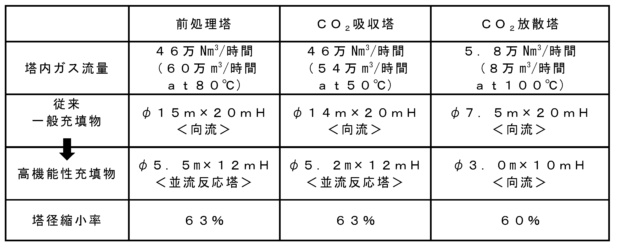
2・・・第1冷却器
3・・・第2冷却器
4・・・燃焼排ガス導入口
5・・・燃焼排ガス排出口
6・・・吸収液導入口
7・・・吸収液排出口
8,8’・・・充填物
8’’・・・追加の充填物
9・・・第1冷却器の吸収液回収口側における第1冷却器とCO2吸収塔の接続位置
10・・・第1冷却器の吸収液供給口側における第1冷却器とCO2吸収塔の接続位置
11・・・第2冷却器の液体供給口側における第2冷却器とCO2吸収塔の接続位置
12・・・第2冷却器の液体回収口側における第2冷却器とCO2吸収塔の接続位置
21・・・CO2放散塔
22・・・第1加熱器
23・・・第2加熱器
24・・・気液分離装置
25・・・過熱蒸気防止装置
26,26’・・・吸収液導入口
27・・・吸収液排出口
28・・・蒸気導入口
29・・・CO2排出口
30,30’・・・充填物
31・・・第1加熱器の吸収液回収口側における第1加熱器とCO2放散塔の接続位置
32・・・第1加熱器の吸収液供給口側における第1加熱器とCO2放散塔の接続位置
33・・・静止型混合器
34・・・過熱蒸気防止装置用設定温度計
41・・・蒸発槽
42・・・気液分離装置
43・・・減圧装置
44・・・吸収液導入口
45・・・吸収液排出口
46・・・不純物排出口
47・・・加熱用ジャケット
51・・・前処理塔
52・・・冷却器
53・・・混合器
54・・・燃焼排ガス導入口
55・・・燃焼排ガス排出口
56・・・脱硫液導入口
57・・・脱硫液排出口
58・・・充填物
59・・・脱硫剤供給流路
60・・・補給水供給流路
61・・・燃焼排ガス供給流路
62・・・循環液ポンプ
71・・・流路
72・・・第1熱交換器
73・・・第2熱交換器
74・・・流路
75・・・流路
76・・・流路
81・・・流路
82・・・第1熱交換器
83・・・第2熱交換器
84・・・流路
85・・・流路
86・・・流路
101・・・静止型混合器
102・・・通路管
103・・・第1羽根体
104・・・穿設孔
105・・・第1内筒管
106・・・第2羽根体
107・・・穿設孔
108・・・第2内筒管
109・・・開口部
M・・・モータ
P・・・圧力計
T・・・温度計
F・・・流量計
L・・・液面計 1 ... CO 2 absorption tower 2 ... first cooler 3 ... second cooler 4 ... combustion exhaust
Claims (22)
- 燃焼排ガス中に含まれるCO2をアミン化合物含有吸収液に反応吸収させるCO2吸収塔と、アミン化合物含有吸収液を冷却する第1冷却器及び該アミン化合物含有吸収液と異なる液体を冷却する第2冷却器よりなる群から選択される少なくとも一つの冷却器とを備える二酸化炭素吸収装置であって、
前記CO2吸収塔が、燃焼排ガスをCO2吸収塔に導入する燃焼排ガス導入口と、燃焼排ガスをCO2吸収塔から排出する燃焼排ガス排出口と、アミン化合物含有吸収液をCO2吸収塔に導入する吸収液導入口と、アミン化合物含有吸収液をCO2吸収塔から排出する吸収液排出口と、螺旋状多孔翼を有する静止型混合器である充填物とを備え、ここで、前記充填物が、燃焼排ガス導入口と燃焼排ガス排出口の間で且つ吸収液導入口と吸収液排出口の間に配置され、
前記第1冷却器が、アミン化合物含有吸収液をCO2吸収塔から回収する吸収液回収口と、アミン化合物含有吸収液をCO2吸収塔に供給する吸収液供給口とを備え、ここで、吸収液回収口が、吸収液導入口から吸収液排出口に向かうアミン化合物含有吸収液の流れ方向において充填物の下流側の位置にてCO2吸収塔と接続され、吸収液供給口が、該アミン化合物含有吸収液の流れ方向において充填物の上流側の位置にてCO2吸収塔と接続され、
前記第2冷却器が、燃焼排ガスと接触させる液体をCO2吸収塔に供給する液体供給口と、燃焼排ガスと接触した液体をCO2吸収塔から回収する液体回収口とを備え、ここで、液体供給口及び液体回収口が、燃焼排ガス導入口から燃焼排ガス排出口に向かう燃焼排ガスの流れ方向において充填物の下流側の位置にてCO2吸収塔と接続されていることを特徴とする、二酸化炭素吸収装置。 A CO 2 absorption tower that reacts and absorbs CO 2 contained in combustion exhaust gas into an amine compound-containing absorbent, a first cooler that cools the amine compound-containing absorbent, and a liquid that cools a liquid different from the amine compound-containing absorbent. A carbon dioxide absorber comprising at least one cooler selected from the group consisting of two coolers,
The CO 2 absorption tower, the flue gas and the flue gas inlet for introducing the CO 2 absorption tower, and flue gas discharge port for discharging the flue gas from the CO 2 absorber, an amine compound containing absorbing solution in the CO 2 absorber An absorption liquid introduction port to be introduced, an absorption liquid discharge port for discharging the amine compound-containing absorption liquid from the CO 2 absorption tower, and a filling which is a static mixer having a spiral porous blade, Is disposed between the combustion exhaust gas inlet and the combustion exhaust gas outlet and between the absorbent inlet and the absorbent outlet,
Wherein the first cooler includes an absorbent liquid recovery port for recovering an amine compound containing absorbed liquid from the CO 2 absorber, and an amine compound containing absorbing solution the CO 2 absorber to supply the absorption liquid feed inlet, wherein, The absorption liquid recovery port is connected to the CO 2 absorption tower at a position downstream of the packing in the flow direction of the amine compound-containing absorption liquid from the absorption liquid introduction port to the absorption liquid discharge port, and the absorption liquid supply port is Connected to the CO 2 absorber at a position upstream of the packing in the flow direction of the amine compound-containing absorbent,
The second cooler, the liquid contacting the flue gas with a CO 2 absorption tower for supplying the liquid supply port, and a liquid recovery port for recovering the contact with combustion exhaust gas liquids from the CO 2 absorber, wherein The liquid supply port and the liquid recovery port are connected to the CO 2 absorption tower at a position downstream of the packing in the flow direction of the combustion exhaust gas from the combustion exhaust gas introduction port to the combustion exhaust gas discharge port, Carbon dioxide absorber. - 燃焼排ガスをCO2吸収塔に導入する燃焼排ガス導入口と、燃焼排ガスをCO2吸収塔から排出する燃焼排ガス排出口と、アミン化合物含有吸収液をCO2吸収塔に導入する吸収液導入口と、アミン化合物含有吸収液をCO2吸収塔から排出する吸収液排出口と、螺旋状多孔翼を有する静止型混合器である充填物とを備えるCO2吸収塔内において、CO2を含んだ燃焼排ガスとアミン化合物含有吸収液とを充填物にて向流または並流で接触させて、燃焼排ガス中に含まれるCO2をアミン化合物含有吸収液に反応吸収させる第1工程であって、燃焼排ガスが燃焼排ガス導入口から燃焼排ガス排出口に流れ且つアミン化合物含有吸収液が吸収液導入口から吸収液排出口に流れる第1工程と、
吸収液導入口から吸収液排出口に向かうアミン化合物含有吸収液の流れ方向において充填物の下流側の位置にてCO2吸収塔からアミン化合物含有吸収液の一部を回収し、回収したアミン化合物含有吸収液を冷却し、冷却したアミン化合物含有吸収液を該アミン化合物含有吸収液の流れ方向において充填物の上流側の位置にてCO2吸収塔に供給する第2工程、及び、燃焼排ガス導入口から燃焼排ガス排出口に向かう燃焼排ガスの流れ方向において充填物の下流側の位置にてCO2吸収塔に液体を供給して燃焼排ガスと接触させ、燃焼排ガスと接触した液体を回収し、回収した液体を冷却する第3工程よりなる群から選択される少なくとも一つの工程と
を含むことを特徴とする、二酸化炭素吸収方法。 A combustion exhaust gas inlet port for introducing the flue gas into the CO 2 absorber, the flue gas discharge port for discharging the flue gas from the CO 2 absorber, and absorbing solution inlet for introducing an amine compound containing absorbing solution in the CO 2 absorber the absorption liquid discharge ports for discharging the amine compound-containing absorbing solution from the CO 2 absorber, the CO 2 absorption tower and a filling is static mixer having a spiral perforated wings, including the CO 2 combustion A first step in which exhaust gas and an amine compound-containing absorbent are brought into contact with each other in a packing in a countercurrent or cocurrent manner to react and absorb CO 2 contained in the combustion exhaust gas into the amine compound-containing absorbent, Flowing from the combustion exhaust gas inlet to the combustion exhaust gas outlet and the amine compound-containing absorption liquid flowing from the absorption liquid inlet to the absorption liquid outlet;
A part of the amine compound-containing absorbing liquid is recovered from the CO 2 absorption tower at a position downstream of the packing in the flow direction of the amine compound-containing absorbing liquid from the absorbing liquid inlet to the absorbing liquid outlet, and the recovered amine compound A second step of cooling the containing absorbent and supplying the cooled amine compound-containing absorbent to the CO 2 absorption tower at a position upstream of the packing in the flow direction of the amine compound-containing absorbent, and introducing combustion exhaust gas The liquid is supplied to the CO 2 absorption tower at a position downstream of the packing in the flow direction of the combustion exhaust gas from the port toward the combustion exhaust gas discharge port and brought into contact with the combustion exhaust gas, and the liquid in contact with the combustion exhaust gas is recovered and recovered. A carbon dioxide absorption method comprising: at least one step selected from the group consisting of a third step of cooling the liquid. - アミン化合物含有吸収液中に含まれるCO2をアミン化合物含有吸収液から放散させるCO2放散塔と、アミン化合物含有吸収液を加熱する第1加熱器及びアミン化合物含有吸収液を加熱して蒸気を生成する第2加熱器よりなる群から選択される少なくとも一つの加熱器とを備えるアミン化合物含有吸収液再生装置であって、
前記CO2放散塔が、アミン化合物含有吸収液をCO2放散塔に導入する吸収液導入口と、アミン化合物含有吸収液をCO2放散塔から排出する吸収液排出口と、蒸気をCO2放散塔に導入する蒸気導入口と、CO2をCO2放散塔から排出するCO2排出口と、螺旋状多孔翼を有する静止型混合器である充填物とを備え、ここで、前記充填物が、吸収液導入口と吸収液排出口の間で且つ蒸気導入口とCO2排出口の間に配置され、
前記第1加熱器が、アミン化合物含有吸収液をCO2放散塔から回収する吸収液回収口と、アミン化合物含有吸収液をCO2放散塔に供給する吸収液供給口とを備え、ここで、吸収液回収口及び吸収液供給口が、吸収液導入口から吸収液排出口に向かうアミン化合物含有吸収液の流れ方向において充填物の下流側の位置にてCO2放散塔と接続され、
前記第2加熱器が、アミン化合物含有吸収液をCO2放散塔から回収する吸収液回収口と、蒸気をCO2放散塔に供給する蒸気供給口とを備え、ここで、吸収液回収口が、前記アミン化合物含有吸収液の流れ方向において充填物の下流側の位置にてCO2放散塔と接続され、蒸気供給口が、前記CO2放散塔の蒸気導入口と接続されていることを特徴とする、アミン化合物含有吸収液再生装置。 And CO 2 stripping tower dissipating CO 2 contained in the amine compound-containing absorbing solution from an amine compound-containing absorbing solution, the steam heating the first heater and an amine compound containing absorption liquid heating the amine compound-containing absorbing solution An amine compound-containing absorbent regenerator comprising at least one heater selected from the group consisting of second heaters to be produced,
The CO 2 stripping tower, the absorbing solution inlet for introducing an amine compound containing absorbing solution in CO 2 stripper, and the absorption liquid discharge ports for discharging the amine compound-containing absorbing solution from the CO 2 stripper, the vapor CO 2 emission comprising a steam inlet for introducing into the column, and CO 2 discharge port for discharging the CO 2 from the CO 2 stripper, and filling a static mixer having a spiral perforated wings, where the packings , Between the absorbent inlet and the absorbent outlet and between the steam inlet and the CO 2 outlet,
Wherein the first heater comprises an absorbent liquid recovery port for recovering an amine compound containing absorbing solution from the CO 2 stripper, and an amine compound containing absorbing solution CO 2 stripping tower to supply the absorption liquid feed inlet, wherein, The absorption liquid recovery port and the absorption liquid supply port are connected to the CO 2 diffusion tower at a position downstream of the packing in the flow direction of the amine compound-containing absorption liquid from the absorption liquid introduction port to the absorption liquid discharge port,
The second heater includes an absorbent liquid recovery port for recovering an amine compound containing absorbing solution from the CO 2 stripper, and a vapor of CO 2 stripping tower to supply the steam supply port, wherein the absorption liquid recovery port In the flow direction of the amine compound-containing absorbent, the CO 2 stripping tower is connected at a position downstream of the packing, and the steam supply port is connected to the steam inlet of the CO 2 stripping tower. An amine compound-containing absorbent regenerator. - 前記アミン化合物含有吸収液再生装置が、前記CO2放散塔のCO2排出口から蒸気と共に排出されるCO2を気液分離する気液分離装置を更に備え、
前記気液分離装置が、蒸気と共に排出されるCO2を気液分離装置に導入するCO2導入口と、気液分離したCO2を回収するCO2回収口と、気液分離した液体を排出する液体排出口とを備え、ここで、CO2導入口が、前記CO2放散塔のCO2排出口と接続され、液体排出口が、前記CO2放散塔の吸収液導入口と接続されていることを特徴とする、請求項3に記載のアミン化合物含有吸収液再生装置。 Wherein the amine compound-containing absorbing solution regeneration device further comprises a gas-liquid separator for gas-liquid separation of CO 2 to be discharged together with steam from the CO 2 outlet of the CO 2 stripper,
The gas-liquid separator is a CO 2 inlet for introducing CO 2 discharged together with the vapor into the gas-liquid separator, a CO 2 recovery port for recovering the gas-liquid separated CO 2 , and discharging the gas-liquid separated liquid and a liquid discharge port for, here, CO 2 introduction port, which is connected with the CO 2 desorption column of CO 2 outlet, the liquid outlet is connected to the CO 2 stripping tower of the absorbent inlet The amine compound-containing absorbent regenerator according to claim 3, wherein: - 前記第2加熱器の熱源が水蒸気であり、
前記アミン化合物含有吸収液再生装置が、前記第2加熱器の熱源として該第2加熱器に供給される水蒸気を減温減圧する過熱蒸気防止装置であって、前記第2加熱器と接続されている過熱蒸気防止装置を更に備えることを特徴とする、請求項3又は4に記載のアミン化合物含有吸収液再生装置。 The heat source of the second heater is water vapor;
The amine compound-containing absorbent regenerator is an overheated steam prevention device for reducing the temperature of the steam supplied to the second heater as a heat source of the second heater, and is connected to the second heater. The amine compound-containing absorbent regenerator according to claim 3 or 4, further comprising a superheated steam prevention device. - アミン化合物含有吸収液をCO2放散塔に導入する吸収液導入口と、アミン化合物含有吸収液をCO2放散塔から排出する吸収液排出口と、蒸気をCO2放散塔に導入する蒸気導入口と、CO2をCO2放散塔から排出するCO2排出口と、螺旋状多孔翼を有する静止型混合器である充填物とを備えるCO2放散塔内において、CO2を含んだアミン化合物含有吸収液と蒸気とを充填物にて向流で接触させてアミン化合物含有吸収液からCO2を放散させ、アミン化合物含有吸収液を再生すると共にCO2を回収する第1工程であって、アミン化合物含有吸収液が吸収液導入口から吸収液排出口に流れ且つ蒸気が蒸気導入口からCO2排出口に流れる第1工程と、
吸収液導入口から吸収液排出口に向かうアミン化合物含有吸収液の流れ方向において充填物の下流側の位置にてCO2放散塔からアミン化合物含有吸収液の一部を回収し、回収したアミン化合物含有吸収液を加熱し、加熱したアミン化合物含有吸収液を該アミン化合物含有吸収液の流れ方向において充填物の下流側の位置にてCO2放散塔に供給する第2工程、及び、前記アミン化合物含有吸収液の流れ方向において充填物の下流側の位置にてCO2放散塔からアミン化合物含有吸収液の一部を回収し、回収したアミン化合物含有吸収液を加熱して蒸気を生成し、該蒸気を前記蒸気導入口からCO2放散塔に供給する第3工程よりなる群から選択される少なくとも一つの工程と
を含むことを特徴とする、アミン化合物含有吸収液再生方法。 And absorbing liquid inlet for introducing an amine compound containing absorbing solution in CO 2 stripper, and the absorption liquid discharge ports for discharging the amine compound-containing absorbing solution from the CO 2 stripper, steam inlet for introducing steam into the CO 2 stripping tower When the CO 2 discharge port for discharging the CO 2 from the CO 2 stripper, the CO 2 stripping tower and a filling is static mixer having a spiral perforated wings, an amine compound containing containing CO 2 A first step of bringing the absorbing liquid and steam into contact with each other in a packing to dissipate CO 2 from the amine compound-containing absorbing liquid, regenerating the amine compound-containing absorbing liquid and recovering CO 2 ; A first step in which the compound-containing absorbing liquid flows from the absorbing liquid inlet to the absorbing liquid outlet and the steam flows from the steam inlet to the CO 2 outlet;
A part of the amine compound-containing absorbing liquid was recovered from the CO 2 stripping tower at a position downstream of the packing in the flow direction of the amine compound-containing absorbing liquid from the absorbing liquid inlet to the absorbing liquid outlet, and the recovered amine compound A second step of heating the containing absorbent and supplying the heated amine compound-containing absorbent to the CO 2 stripping tower at a position downstream of the packing in the flow direction of the amine compound-containing absorbent, and the amine compound A part of the amine compound-containing absorbent is recovered from the CO 2 stripping tower at a position downstream of the packing in the flow direction of the contained absorbent, and the recovered amine compound-containing absorbent is heated to generate steam, An amine compound-containing absorbent regenerating method comprising: at least one step selected from the group consisting of a third step of supplying steam from the steam inlet to the CO 2 stripping tower. - 前記CO2排出口から蒸気と共に排出されるCO2を気液分離し、分離したCO2を回収すると共に、分離した液体を前記吸収液導入口からCO2放散塔に供給する第4工程を更に含むことを特徴とする、請求項6に記載のアミン化合物含有吸収液再生方法。 The CO 2 and CO 2 to be discharged together with steam and gas-liquid separation from the discharge port, thereby collecting the separated CO 2, further a fourth step of supplying the separated liquid from the absorption liquid inlet to CO 2 stripping tower The method for regenerating an absorbent containing an amine compound according to claim 6, comprising:
- 前記第3工程においてアミン化合物含有吸収液の加熱が水蒸気との熱交換によって行われ、
前記アミン化合物含有吸収液再生方法が、前記第3工程において熱交換を行う前に該熱交換に使用される水蒸気を減温減圧する第5工程を更に含むことを特徴とする、請求項6又は7に記載のアミン化合物含有吸収液再生方法。 In the third step, the amine compound-containing absorbent is heated by heat exchange with water vapor,
The said amine compound containing absorption liquid reproduction | regeneration method further includes the 5th process of carrying out the temperature reduction pressure reduction of the water vapor | steam used for this heat exchange, before performing heat exchange in the said 3rd process, The characterized by the above-mentioned. 8. The method for regenerating an amine compound-containing absorbent according to 7. - アミン化合物含有吸収液中に含まれる不純物をアミン化合物含有吸収液から蒸発分離させる蒸発槽であって、該蒸発槽の外側に配設された加熱用ジャケットを備える蒸発槽と、該加熱用ジャケットに熱源として供給される水蒸気を減温減圧する過熱蒸気防止装置と、不純物から蒸発分離したアミン化合物含有吸収液を回収する気液分離装置と、該蒸発槽内を減圧する減圧装置とを備えるアミン化合物含有吸収液精製装置であって、
前記蒸発槽が、アミン化合物含有吸収液を蒸発槽に導入する吸収液導入口と、不純物から蒸発分離したアミン化合物含有吸収液を蒸発槽から排出する吸収液排出口と、アミン化合物含有吸収液から蒸発分離した不純物を蒸発槽から排出する不純物排出口とを備え、
前記気液分離装置が、不純物から蒸発分離したアミン化合物含有吸収液を気液分離装置に導入する吸収液導入口と、気液分離した気体を排出する気体排出口と、気液分離した液体を排出する液体排出口とを備え、
前記減圧装置が、前記気液分離装置の吸収液導入口、前記気液分離装置の気体排出口及び前記蒸発槽の吸収液排出口を介して前記蒸発槽と接続され、
前記過熱蒸気防止装置が、前記加熱用ジャケットと接続されていることを特徴とする、アミン化合物含有吸収液精製装置。 An evaporation tank that evaporates and separates impurities contained in an amine compound-containing absorption liquid from an amine compound-containing absorption liquid, the evaporation tank including a heating jacket disposed outside the evaporation tank, and the heating jacket An amine compound comprising: an overheated steam prevention device for reducing the temperature and pressure of water vapor supplied as a heat source; a gas-liquid separation device for recovering an amine compound-containing absorption liquid evaporated and separated from impurities; and a pressure reducing device for reducing the pressure in the evaporation tank Containing absorption liquid purification device,
The evaporating tank includes an absorbing liquid inlet for introducing the amine compound-containing absorbing liquid into the evaporating tank, an absorbing liquid outlet for discharging the amine compound-containing absorbing liquid evaporated and separated from the impurities from the evaporating tank, and the amine compound-containing absorbing liquid. An impurity discharge port for discharging the evaporated and separated impurities from the evaporation tank,
The gas-liquid separator is an absorption liquid inlet for introducing an amine compound-containing absorption liquid evaporated and separated from impurities into the gas-liquid separator, a gas outlet for discharging the gas-liquid separated gas, and a gas-liquid separated liquid. A liquid outlet for discharging,
The decompression device is connected to the evaporation tank through an absorption liquid inlet of the gas-liquid separator, a gas outlet of the gas-liquid separator and an absorption liquid outlet of the evaporation tank,
The amine compound-containing absorbent purifier is characterized in that the superheated steam prevention device is connected to the heating jacket. - 不純物を含んだアミン化合物含有吸収液を連続または間歇的に真空減圧下の蒸発槽に導入して不純物とアミン化合物含有吸収液とを蒸発分離させ、アミン化合物含有吸収液を精製する第1工程と、
前記蒸発槽の外側に配置された加熱用ジャケットに水蒸気を供給して該蒸発槽を加熱する第2工程と、
前記第2工程において加熱用ジャケットへ供給する前に水蒸気を減温減圧する第3工程と
を含むことを特徴とする、アミン化合物含有吸収液精製方法。 A first step of purifying the amine compound-containing absorption liquid by introducing the amine compound-containing absorption liquid containing impurities into the evaporation tank under vacuum or reduced pressure continuously or intermittently to evaporate and separate the impurities and the amine compound-containing absorption liquid; ,
A second step of heating the evaporation tank by supplying water vapor to a heating jacket disposed outside the evaporation tank;
A method for purifying an amine compound-containing absorbent, comprising: a third step of reducing the temperature of the water vapor before supplying to the heating jacket in the second step. - 燃焼排ガスに対して脱硫、除塵及び冷却を行う前処理塔を備える燃焼排ガス前処理装置であって、
前記前処理塔が、燃焼排ガスを前処理塔に導入する燃焼排ガス導入口と、燃焼排ガスを前処理塔から排出する燃焼排ガス排出口と、脱硫液を前処理塔に導入する脱硫液導入口と、脱硫液を前処理塔から排出する脱硫液排出口と、螺旋状多孔翼を有する静止型混合器である充填物とを備え、ここで、前記充填物が、燃焼排ガス導入口と燃焼排ガス排出口の間で且つ脱硫液導入口と脱硫液排出口の間に配置され、
前記燃焼排ガス導入口が、脱硫液導入口から脱硫液排出口に向かう脱硫液の流れ方向において充填物の上流側に配置され、前記脱硫液導入口が、燃焼排ガス導入口から燃焼排ガス排出口に向かう燃焼排ガスの流れ方向において充填物の上流側に配置されていることを特徴とする、燃焼排ガス前処理装置。 A combustion exhaust gas pretreatment device including a pretreatment tower for performing desulfurization, dust removal and cooling on the combustion exhaust gas,
A combustion exhaust gas inlet for introducing the combustion exhaust gas into the pretreatment tower; a combustion exhaust gas outlet for discharging the combustion exhaust gas from the pretreatment tower; and a desulfurization liquid inlet for introducing the desulfurization liquid into the pretreatment tower. A desulfurization liquid discharge port for discharging the desulfurization liquid from the pretreatment tower, and a filling material that is a static mixer having a spiral porous blade, wherein the filling material comprises a combustion exhaust gas introduction port and a combustion exhaust gas exhaust gas. Between the outlet and between the desulfurization liquid inlet and the desulfurization liquid outlet,
The combustion exhaust gas inlet is disposed on the upstream side of the packing in the flow direction of the desulfurization liquid from the desulfurization liquid introduction port to the desulfurization liquid discharge port, and the desulfurization liquid introduction port extends from the combustion exhaust gas introduction port to the combustion exhaust gas discharge port. A combustion exhaust gas pretreatment device, which is disposed upstream of the packing material in the direction of the flow of the combustion exhaust gas toward it. - 前記燃焼排ガス前処理装置が、脱硫液を冷却する冷却器を更に備え、
前記冷却器が、脱硫液を前処理塔から回収する脱硫液回収口と、脱硫液を前処理塔に供給する脱硫液供給口とを備え、ここで、脱硫液回収口が前記脱硫液排出口と接続され、脱硫液供給口が前記脱硫液導入口と接続されていることを特徴とする、請求項11に記載の燃焼排ガス前処理装置。 The combustion exhaust gas pretreatment device further includes a cooler for cooling the desulfurization liquid,
The cooler includes a desulfurization liquid recovery port for recovering the desulfurization liquid from the pretreatment tower, and a desulfurization liquid supply port for supplying the desulfurization liquid to the pretreatment tower, wherein the desulfurization liquid recovery port is the desulfurization liquid discharge port The flue gas pretreatment device according to claim 11, wherein the desulfurization liquid supply port is connected to the desulfurization liquid introduction port. - 前記燃焼排ガス前処理装置が、前記冷却器にて冷却した脱硫液と補充液とを混合する混合器を更に備え、
前記混合器が、補充液を混合器に導入する補充液導入口と、前記冷却した脱硫液を混合器に導入する脱硫液導入口と、混合液を混合器から排出する混合液排出口とを備え、ここで、該混合器の脱硫液導入口が、前記冷却器の脱硫液供給口と接続され、該混合器の混合液排出口が、前記前処理塔の脱硫液導入口と接続されていることを特徴とする、請求項12に記載の燃焼排ガス前処理装置。 The flue gas pretreatment device further comprises a mixer for mixing the desulfurization liquid and the replenisher liquid cooled by the cooler,
The mixer has a replenisher introduction port for introducing replenisher into the mixer, a desulfurization solution introduction port for introducing the cooled desulfurization solution into the mixer, and a mixture discharge port for discharging the mixture from the mixer. The desulfurization liquid inlet of the mixer is connected to the desulfurization liquid supply port of the cooler, and the mixed liquid discharge port of the mixer is connected to the desulfurization liquid inlet of the pretreatment tower. The combustion exhaust gas pretreatment device according to claim 12, wherein - 燃焼排ガスを前処理塔に導入する燃焼排ガス導入口と、燃焼排ガスを前処理塔から排出する燃焼排ガス排出口と、脱硫液を前処理塔に導入する脱硫液導入口と、脱硫液を前処理塔から排出する脱硫液排出口と、螺旋状多孔翼を有する静止型混合器である充填物とを備える前処理塔内において、燃焼排ガスと脱硫液とを充填物にて並流で接触させて、燃焼排ガスに対して脱硫、除塵及び冷却を行う第1工程であって、燃焼排ガスが燃焼排ガス導入口から燃焼排ガス排出口に流れ且つ脱硫液が脱硫液導入口から脱硫液排出口に流れる第1工程を含むことを特徴とする、燃焼排ガス前処理方法。 A combustion exhaust gas inlet for introducing combustion exhaust gas into the pretreatment tower, a combustion exhaust gas outlet for discharging combustion exhaust gas from the pretreatment tower, a desulfurization liquid inlet for introducing desulfurization liquid into the pretreatment tower, and a pretreatment of the desulfurization liquid In a pretreatment tower comprising a desulfurization liquid discharge port for discharging from the tower and a packing that is a static mixer having a spiral porous blade, the combustion exhaust gas and the desulfurization liquid are contacted in parallel with the packing. , A first step of performing desulfurization, dust removal and cooling on the combustion exhaust gas, wherein the combustion exhaust gas flows from the combustion exhaust gas inlet to the combustion exhaust gas outlet and the desulfurization liquid flows from the desulfurization liquid inlet to the desulfurization liquid outlet. A combustion exhaust gas pretreatment method comprising one step.
- 脱硫液導入口から脱硫液排出口に向かう脱硫液の流れ方向において充填物の下流側の位置にて前処理塔から脱硫液を回収し、回収した脱硫液を冷却し、冷却した脱硫液を該脱硫液の流れ方向において充填物の上流側の位置にて前処理塔に供給する第2工程を更に含むことを特徴とする、請求項14に記載の燃焼排ガス前処理方法。 The desulfurization liquid is recovered from the pretreatment tower at a position downstream of the packing in the flow direction of the desulfurization liquid from the desulfurization liquid inlet to the desulfurization liquid discharge port, the recovered desulfurization liquid is cooled, and the cooled desulfurization liquid is The combustion exhaust gas pretreatment method according to claim 14, further comprising a second step of supplying the pretreatment tower at a position upstream of the packing in the flow direction of the desulfurization liquid.
- 前記第2工程において、前記冷却した脱硫液を前処理塔に供給する前に、該冷却した脱硫液と補充液とを混合することを特徴とする、請求項15に記載の燃焼排ガス前処理方法。 16. The combustion exhaust gas pretreatment method according to claim 15, wherein, in the second step, the cooled desulfurization liquid and the replenishment liquid are mixed before supplying the cooled desulfurization liquid to the pretreatment tower. .
- 燃焼排ガス中に含まれるCO2をアミン化合物含有吸収液に反応吸収させるCO2吸収塔であって、燃焼排ガスをCO2吸収塔に導入する燃焼排ガス導入口と、燃焼排ガスをCO2吸収塔から排出する燃焼排ガス排出口と、アミン化合物含有吸収液をCO2吸収塔に導入する吸収液導入口と、アミン化合物含有吸収液をCO2吸収塔から排出する吸収液排出口と、螺旋状多孔翼を有する静止型混合器である充填物とを備え、前記充填物が、燃焼排ガス導入口と燃焼排ガス排出口の間で且つ吸収液導入口と吸収液排出口の間に配置されているCO2吸収塔と、
アミン化合物含有吸収液中に含まれるCO2をアミン化合物含有吸収液から放散させるCO2放散塔であって、アミン化合物含有吸収液をCO2放散塔に導入する吸収液導入口と、アミン化合物含有吸収液をCO2放散塔から排出する吸収液排出口と、蒸気をCO2放散塔に導入する蒸気導入口と、CO2をCO2放散塔から排出するCO2排出口と、螺旋状多孔翼を有する静止型混合器である充填物とを備え、前記充填物が、吸収液導入口と吸収液排出口の間で且つ蒸気導入口とCO2排出口の間に配置されているCO2放散塔と、
アミン化合物含有吸収液中に含まれる不純物をアミン化合物含有吸収液から蒸発分離させる蒸発槽であって、アミン化合物含有吸収液を蒸発槽に導入する吸収液導入口と、不純物から蒸発分離したアミン化合物含有吸収液を蒸発槽から排出する吸収液排出口と、アミン化合物含有吸収液から蒸発分離した不純物を蒸発槽から排出する不純物排出口と、該蒸発槽の外側に配設された加熱用ジャケットとを備える蒸発槽と、
前記蒸発槽において不純物から蒸発分離したアミン化合物含有吸収液を回収する気液分離装置であって、不純物から蒸発分離したアミン化合物含有吸収液を気液分離装置に導入する吸収液導入口と、気液分離した気体を排出する気体排出口と、気液分離した液体を排出する液体排出口とを備える気液分離装置と、
前記蒸発槽内を減圧する減圧装置であって、前記気液分離装置の吸収液導入口、前記気液分離装置の気体排出口及び前記蒸発槽の吸収液排出口を介して前記蒸発槽と接続されている減圧装置と、
前記CO2放散塔の吸収液排出口から前記CO2吸収塔の吸収液導入口に向かうアミン化合物含有吸収液との熱交換により前記CO2放散塔に導入されたアミン化合物含有吸収液を加熱する第1熱交換器であって、アミン化合物含有吸収液をCO2放散塔から回収する吸収液回収口と、アミン化合物含有吸収液をCO2放散塔に供給する吸収液供給口とを備え、吸収液回収口及び吸収液供給口が、前記CO2放散塔の吸収液導入口から吸収液排出口に向かうアミン化合物含有吸収液の流れ方向において充填物の下流側の位置にてCO2放散塔と接続されている第1熱交換器と、
前記CO2放散塔の吸収液排出口から前記CO2吸収塔の吸収液導入口に向かうアミン化合物含有吸収液と前記CO2吸収塔の吸収液排出口から前記CO2放散塔の吸収液導入口に向かうアミン化合物含有吸収液との熱交換を行う第2熱交換器と
を備える二酸化炭素回収装置であって、
前記CO2放散塔の吸収液排出口が、前記第1熱交換器及び前記第2熱交換器を介して前記CO2吸収塔の吸収液導入口に接続されると共に、前記蒸発槽の吸収液導入口と接続され、前記CO2吸収塔の吸収液排出口が、前記第2熱交換器を介して前記CO2放散塔の吸収液導入口と接続され、前記気液分離装置の液体排出口が、前記CO2吸収塔の吸収液導入口と接続されていることを特徴とする、二酸化炭素回収装置。 The CO 2 contained in the combustion exhaust gas a CO 2 absorption tower reacting absorbed into the amine compound-containing absorbing solution, a combustion exhaust gas inlet port for introducing the flue gas into the CO 2 absorber, the flue gas from the CO 2 absorber a flue gas discharge port for discharging the absorbing liquid inlet for introducing an amine compound containing absorbing solution in the CO 2 absorber, and absorbing solution discharge port for discharging an amine compound containing absorbed liquid from the CO 2 absorber, spiral perforated wings And a filler that is a stationary mixer having a CO 2 disposed between the flue gas inlet and the flue gas outlet and between the absorbent inlet and the absorbent outlet. An absorption tower,
The CO 2 contained in the amine compound-containing absorbing solution in a CO 2 stripping tower dissipating from an amine compound containing absorbing solution, and the absorption liquid inlet for introducing an amine compound containing absorbing solution in CO 2 stripper, an amine compound containing and absorbing solution discharge port for discharging the absorbing liquid from the CO 2 stripper, a vapor inlet for introducing steam into the CO 2 stripper, and CO 2 discharge port for discharging the CO 2 from the CO 2 stripper, spiral perforated wings and a filler which is a static mixer having the packings, absorbing liquid inlet and absorb liquid and CO 2 emission, which is arranged between the steam inlet and CO 2 outlet between the outlet Tower,
An evaporating tank for evaporating and separating impurities contained in an amine compound-containing absorbing liquid from an amine compound-containing absorbing liquid, an absorbing liquid inlet for introducing the amine compound-containing absorbing liquid into the evaporating tank, and an amine compound evaporating and separating from the impurities An absorption liquid discharge port for discharging the contained absorption liquid from the evaporation tank, an impurity discharge port for discharging impurities evaporated and separated from the amine compound-containing absorption liquid from the evaporation tank, and a heating jacket disposed outside the evaporation tank; An evaporating tank comprising:
A gas-liquid separator that recovers the amine compound-containing absorption liquid that has been evaporated and separated from the impurities in the evaporation tank, wherein the amine compound-containing absorption liquid that has been evaporated and separated from the impurities is introduced into the gas-liquid separation apparatus; A gas-liquid separator comprising a gas outlet for discharging the liquid-separated gas, and a liquid outlet for discharging the liquid-gas-separated liquid;
A decompression device for decompressing the inside of the evaporation tank, which is connected to the evaporation tank through an absorption liquid inlet of the gas-liquid separator, a gas outlet of the gas-liquid separator, and an absorbent outlet of the evaporation tank A pressure reducing device,
The amine compound-containing absorption liquid introduced into the CO 2 diffusion tower is heated by heat exchange with the amine compound-containing absorption liquid from the absorption liquid discharge port of the CO 2 diffusion tower toward the absorption liquid inlet of the CO 2 absorption tower. a first heat exchanger, comprising an absorbent liquid recovery port for recovering an amine compound containing absorbing solution from the CO 2 stripper, and an amine compound containing absorbing solution CO 2 stripping tower to supply the absorption liquid feed inlet, absorption liquid recovery port and the absorbing solution supply port, and CO 2 desorption column at a location downstream of the position of the CO 2 filling in the flow direction of the absorption liquid toward the discharge port amine compound containing absorbed liquid from the absorbent liquid inlet stripping tower A connected first heat exchanger;
The CO 2 absorbing solution inlet port of the amine compound toward the absorbing solution inlet of the CO 2 absorption tower from the absorption liquid discharge ports of the stripping column containing absorbing solution from the absorption liquid discharge ports of the CO 2 absorption tower the CO 2 stripping tower A carbon dioxide recovery device comprising a second heat exchanger for exchanging heat with an amine compound-containing absorbent directed toward
The absorption liquid discharge port of the CO 2 diffusion tower is connected to the absorption liquid inlet of the CO 2 absorption tower via the first heat exchanger and the second heat exchanger, and the absorption liquid of the evaporation tank Connected to the inlet, the absorbing liquid outlet of the CO 2 absorption tower is connected to the absorbing liquid inlet of the CO 2 diffusion tower via the second heat exchanger, and the liquid outlet of the gas-liquid separator Is connected to the absorption liquid inlet of the CO 2 absorption tower. - 水蒸気との熱交換により前記CO2放散塔に導入されたアミン化合物含有吸収液を加熱して蒸気を生成する第3熱交換器であって、アミン化合物含有吸収液をCO2放散塔から回収する吸収液回収口と、蒸気をCO2放散塔に供給する蒸気供給口とを備え、吸収液回収口が、前記CO2放散塔の吸収液導入口から吸収液排出口に向かうアミン化合物含有吸収液の流れ方向において充填物の下流側の位置にてCO2放散塔と接続され、蒸気供給口が、前記CO2放散塔の蒸気導入口と接続されている第3熱交換器と、
前記第3熱交換器及び前記蒸発槽の加熱用ジャケットの熱源として供給される水蒸気を減温減圧する過熱蒸気防止装置であって、前記第3熱交換器及び前記蒸発槽の加熱用ジャケットと接続されている過熱蒸気防止装置と
を更に備えることを特徴とする、請求項17に記載の二酸化炭素回収装置。 A third heat exchanger for generating steam by heating the amine compound-containing absorbent introduced into the CO 2 stripping tower by heat exchange with steam, and recovering the amine compound-containing absorbent from the CO 2 stripping tower. An amine compound-containing absorption liquid comprising an absorption liquid recovery port and a steam supply port for supplying steam to the CO 2 diffusion tower, the absorption liquid recovery port going from the absorption liquid introduction port of the CO 2 diffusion tower to the absorption liquid discharge port A third heat exchanger connected to the CO 2 stripping tower at a position downstream of the packing in the flow direction, and a steam supply port connected to the steam inlet of the CO 2 stripping tower;
An overheated steam preventing device for reducing and depressurizing water vapor supplied as a heat source for a heating jacket for the third heat exchanger and the evaporation tank, which is connected to the heating jacket for the third heat exchanger and the evaporation tank The carbon dioxide recovery device according to claim 17, further comprising a superheated steam prevention device. - 燃焼排ガスに対して脱硫、除塵及び冷却を行う前処理塔であって、燃焼排ガスを前処理塔に導入する燃焼排ガス導入口と、燃焼排ガスを前処理塔から排出する燃焼排ガス排出口と、脱硫液を前処理塔に導入する脱硫液導入口と、脱硫液を前処理塔から排出する脱硫液排出口と、螺旋状多孔翼を有する静止型混合器である充填物とを備え、前記充填物が、燃焼排ガス導入口と燃焼排ガス排出口の間で且つ脱硫液導入口と脱硫液排出口の間に配置され、前記燃焼排ガス導入口が、脱硫液導入口から脱硫液排出口に向かう脱硫液の流れ方向において充填物の上流側に配置され、前記脱硫液導入口が、燃焼排ガス導入口から燃焼排ガス排出口に向かう燃焼排ガスの流れ方向において充填物の上流側に配置されている前処理塔を更に備え、
前記前処理塔の燃焼排ガス排出口が、前記CO2吸収塔の燃焼排ガス導入口と接続されていることを特徴とする、請求項17又は18に記載の二酸化炭素回収装置。 A pretreatment tower for performing desulfurization, dust removal and cooling on the combustion exhaust gas, the combustion exhaust gas inlet for introducing the combustion exhaust gas into the pretreatment tower, the combustion exhaust gas outlet for discharging the combustion exhaust gas from the pretreatment tower, and desulfurization A desulfurization liquid introduction port for introducing the liquid into the pretreatment tower, a desulfurization liquid discharge port for discharging the desulfurization liquid from the pretreatment tower, and a packing that is a static mixer having a spiral porous blade. Is disposed between the combustion exhaust gas inlet and the combustion exhaust gas outlet and between the desulfurization liquid introduction port and the desulfurization liquid discharge port, and the combustion exhaust gas introduction port is directed to the desulfurization liquid discharge port from the desulfurization liquid introduction port. The pretreatment tower is disposed upstream of the packing in the flow direction, and the desulfurization liquid inlet is disposed upstream of the packing in the flow direction of the combustion exhaust gas from the combustion exhaust gas inlet to the combustion exhaust gas outlet. Further comprising
The carbon dioxide recovery apparatus according to claim 17 or 18, wherein a combustion exhaust gas discharge port of the pretreatment tower is connected to a combustion exhaust gas introduction port of the CO 2 absorption tower. - 燃焼排ガスをCO2吸収塔に導入する燃焼排ガス導入口と、燃焼排ガスをCO2吸収塔から排出する燃焼排ガス排出口と、アミン化合物含有吸収液をCO2吸収塔に導入する吸収液導入口と、アミン化合物含有吸収液をCO2吸収塔から排出する吸収液排出口と、螺旋状多孔翼を有する静止型混合器である充填物とを備えるCO2吸収塔内において、CO2を含んだ燃焼排ガスとアミン化合物含有吸収液とを充填物にて向流または並流で接触させて、燃焼排ガス中に含まれるCO2をアミン化合物含有吸収液に反応吸収させる第1工程であって、燃焼排ガスが燃焼排ガス導入口から燃焼排ガス排出口に流れ且つアミン化合物含有吸収液が吸収液導入口から吸収液排出口に流れる第1工程と、
アミン化合物含有吸収液をCO2放散塔に導入する吸収液導入口と、アミン化合物含有吸収液をCO2放散塔から排出する吸収液排出口と、蒸気をCO2放散塔に導入する蒸気導入口と、CO2をCO2放散塔から排出するCO2排出口と、螺旋状多孔翼を有する静止型混合器である充填物とを備えるCO2放散塔内において、CO2を含んだアミン化合物含有吸収液と蒸気とを充填物にて向流で接触させてアミン化合物含有吸収液からCO2を放散させ、アミン化合物含有吸収液を再生すると共にCO2を回収する第2工程であって、アミン化合物含有吸収液が吸収液導入口から吸収液排出口に流れ且つ蒸気が蒸気導入口からCO2排出口に流れる第2工程と、
アミン化合物含有吸収液を蒸発槽に導入する吸収液導入口と、不純物から蒸発分離したアミン化合物含有吸収液を蒸発槽から排出する吸収液排出口と、アミン化合物含有吸収液から蒸発分離した不純物を蒸発槽から排出する不純物排出口と、該蒸発槽の外側に配設された加熱用ジャケットとを備える蒸発槽内において、不純物を含んだアミン化合物含有吸収液を連続または間歇的に真空減圧下の蒸発槽に導入して不純物とアミン化合物含有吸収液とを蒸発分離させ、アミン化合物含有吸収液を精製する第3工程と、
第1工程から得られるCO2を含んだアミン化合物含有吸収液を前記CO2放散塔の吸収液導入口からCO2放散塔に導入する第4工程と、
第2工程から得られるCO2が除去されたアミン化合物含有吸収液を前記CO2吸収塔の吸収液導入口からCO2吸収塔に導入する第5工程と、
二酸化炭素回収方法において生じる不純物を含んだアミン化合物含有吸収液を前記CO2放散塔の吸収液排出口から前記蒸発槽の吸収液導入口にて蒸発槽に導入する第6工程と、
第3工程から得られる不純物が除去されたアミン化合物含有吸収液を前記CO2吸収塔の吸収液導入口からCO2吸収塔に導入する第7工程と、
前記CO2放散塔の吸収液導入口から吸収液排出口に向かうアミン化合物含有吸収液の流れ方向において充填物の下流側の位置にてCO2放散塔からアミン化合物含有吸収液の一部を回収し、回収したアミン化合物含有吸収液を第5工程においてCO2吸収塔の吸収液導入口に向かうアミン化合物含有吸収液との熱交換によって加熱し、加熱したアミン化合物含有吸収液を該アミン化合物含有吸収液の流れ方向において充填物の下流側の位置にてCO2放散塔に供給する第8工程と、
第4工程においてCO2放散塔の吸収液導入口に向かうアミン化合物含有吸収液と第5工程においてCO2吸収塔の吸収液導入口に向かうアミン化合物含有吸収液との熱交換を行う第9工程と
を含むことを特徴とする、二酸化炭素回収方法。 A combustion exhaust gas inlet port for introducing the flue gas into the CO 2 absorber, the flue gas discharge port for discharging the flue gas from the CO 2 absorber, and absorbing solution inlet for introducing an amine compound containing absorbing solution in the CO 2 absorber the absorption liquid discharge ports for discharging the amine compound-containing absorbing solution from the CO 2 absorber, the CO 2 absorption tower and a filling is static mixer having a spiral perforated wings, including the CO 2 combustion A first step in which exhaust gas and an amine compound-containing absorbent are brought into contact with each other in a packing in a countercurrent or cocurrent manner to react and absorb CO 2 contained in the combustion exhaust gas into the amine compound-containing absorbent, Flowing from the combustion exhaust gas inlet to the combustion exhaust gas outlet and the amine compound-containing absorption liquid flowing from the absorption liquid inlet to the absorption liquid outlet;
And absorbing liquid inlet for introducing an amine compound containing absorbing solution in CO 2 stripper, and the absorption liquid discharge ports for discharging the amine compound-containing absorbing solution from the CO 2 stripper, steam inlet for introducing steam into the CO 2 stripping tower When the CO 2 discharge port for discharging the CO 2 from the CO 2 stripper, the CO 2 stripping tower and a filling is static mixer having a spiral perforated wings, an amine compound containing containing CO 2 A second step of bringing the absorbing liquid and steam into contact with each other in a packing to dissipate CO 2 from the amine compound-containing absorbing liquid, regenerating the amine compound-containing absorbing liquid and recovering CO 2 ; A second step in which the compound-containing absorbent flows from the absorbent inlet to the absorbent outlet and the steam flows from the steam inlet to the CO 2 outlet;
An absorption liquid inlet for introducing the amine compound-containing absorption liquid into the evaporation tank, an absorption liquid outlet for discharging the amine compound-containing absorption liquid evaporated and separated from the impurities from the evaporation tank, and an impurity evaporated and separated from the amine compound-containing absorption liquid In an evaporation tank comprising an impurity discharge port for discharging from the evaporation tank and a heating jacket disposed outside the evaporation tank, the amine compound-containing absorbent containing impurities is continuously or intermittently subjected to vacuum decompression. A third step of introducing into the evaporation tank to evaporate and separate the impurities and the amine compound-containing absorbent, and purifying the amine compound-containing absorbent;
A fourth step of introducing the amine compound-containing absorption liquid containing CO 2 obtained from the first step into the CO 2 diffusion tower from the absorption liquid inlet of the CO 2 diffusion tower;
A fifth step of introducing the amine compound-containing absorption liquid from which CO 2 has been removed from the second step into the CO 2 absorption tower from the absorption liquid inlet of the CO 2 absorption tower;
A sixth step of introducing an amine compound-containing absorption liquid containing impurities generated in the carbon dioxide recovery method from the absorption liquid discharge port of the CO 2 diffusion tower to the evaporation tank at the absorption liquid inlet of the evaporation tank;
A seventh step of introducing the amine compound-containing absorption liquid from which impurities obtained from the third step are removed into the CO 2 absorption tower from the absorption liquid inlet of the CO 2 absorption tower;
Recovering a portion of the CO 2 stripping tower of the absorbing liquid downstream of the amine compound-containing absorbing solution from the CO 2 stripping tower at the position of the packing in the flow direction of the absorption liquid toward the discharge port amine compound containing absorbed liquid from the inlet The recovered amine compound-containing absorbent is heated by heat exchange with the amine compound-containing absorbent toward the absorbent inlet of the CO 2 absorption tower in the fifth step, and the heated amine compound-containing absorbent is contained in the amine compound. An eighth step of supplying the CO 2 diffusion tower at a position downstream of the packing in the flow direction of the absorption liquid;
Ninth step of exchanging heat between the amine compound-containing absorption liquid heading toward the absorption liquid inlet of the CO 2 diffusion tower in the fourth step and the amine compound-containing absorption liquid heading toward the absorption liquid inlet of the CO 2 absorption tower in the fifth step. And a carbon dioxide recovery method. - 前記CO2放散塔の吸収液導入口から吸収液排出口に向かうアミン化合物含有吸収液の流れ方向において充填物の下流側の位置にてCO2放散塔からアミン化合物含有吸収液の一部を回収し、回収したアミン化合物含有吸収液を水蒸気との熱交換により加熱して蒸気を生成し、該蒸気を前記CO2放散塔の蒸気導入口からCO2放散塔に供給する第10工程と、
前記蒸発槽の加熱用ジャケットに水蒸気を供給して前記蒸発槽を加熱する第11工程と、
前記第10工程及び第11工程において熱源として使用される水蒸気を減温減圧する第12工程と
を更に含むことを特徴とする、請求項20に記載の二酸化炭素回収方法。 Recovering a portion of the CO 2 stripping tower of the absorbing liquid downstream of the amine compound-containing absorbing solution from the CO 2 stripping tower at the position of the packing in the flow direction of the absorption liquid toward the discharge port amine compound containing absorbed liquid from the inlet and recovered amine compound-containing absorbing solution is heated by heat exchange with the steam to generate steam, and a tenth step of supplying the CO 2 stripper gas the evaporated from the steam inlet of the CO 2 stripper,
An eleventh step of heating the evaporation tank by supplying water vapor to a heating jacket of the evaporation tank;
The carbon dioxide recovery method according to claim 20, further comprising a twelfth step of reducing and depressurizing water vapor used as a heat source in the tenth step and the eleventh step. - 燃焼排ガスを前処理塔に導入する燃焼排ガス導入口と、燃焼排ガスを前処理塔から排出する燃焼排ガス排出口と、脱硫液を前処理塔に導入する脱硫液導入口と、脱硫液を前処理塔から排出する脱硫液排出口と、螺旋状多孔翼を有する静止型混合器である充填物とを備える前処理塔内において、燃焼排ガスと脱硫液とを充填物にて並流で接触させて、燃焼排ガスに対して脱硫、除塵及び冷却を行う第13工程であって、燃焼排ガスが燃焼排ガス導入口から燃焼排ガス排出口に流れ且つ脱硫液が脱硫液導入口から脱硫液排出口に流れる第13工程と、
第13工程から得られる燃焼排ガスを前記CO2吸収塔の吸収液導入口からCO2吸収塔に導入する第14工程と
を更に含むことを特徴とする、請求項20又は21に記載の二酸化炭素回収方法。 A combustion exhaust gas inlet for introducing combustion exhaust gas into the pretreatment tower, a combustion exhaust gas outlet for discharging combustion exhaust gas from the pretreatment tower, a desulfurization liquid inlet for introducing desulfurization liquid into the pretreatment tower, and a pretreatment of the desulfurization liquid In a pretreatment tower comprising a desulfurization liquid discharge port for discharging from the tower and a packing that is a static mixer having a spiral porous blade, the combustion exhaust gas and the desulfurization liquid are contacted in parallel with the packing. A thirteenth step of performing desulfurization, dust removal and cooling on the combustion exhaust gas, wherein the combustion exhaust gas flows from the combustion exhaust gas inlet to the combustion exhaust gas outlet and the desulfurization liquid flows from the desulfurization liquid inlet to the desulfurization liquid outlet. 13 steps,
The carbon dioxide according to claim 20 or 21, further comprising a fourteenth step of introducing the combustion exhaust gas obtained from the thirteenth step into the CO 2 absorption tower from an absorption liquid inlet of the CO 2 absorption tower. Collection method.
Priority Applications (3)
| Application Number | Priority Date | Filing Date | Title |
|---|---|---|---|
| JP2019512407A JP7054116B2 (en) | 2017-04-12 | 2018-03-23 | Equipment and methods for recovering carbon dioxide in combustion exhaust gas |
| US16/499,992 US11253812B2 (en) | 2017-04-12 | 2018-03-23 | Apparatus and method for recovering carbon dioxide in combustion exhaust gas |
| CA3056375A CA3056375A1 (en) | 2017-04-12 | 2018-03-23 | Apparatus and method for recovering carbon dioxide in combustion exhaust gas |
Applications Claiming Priority (2)
| Application Number | Priority Date | Filing Date | Title |
|---|---|---|---|
| JP2017090662 | 2017-04-12 | ||
| JP2017-090662 | 2017-04-12 |
Publications (1)
| Publication Number | Publication Date |
|---|---|
| WO2018190104A1 true WO2018190104A1 (en) | 2018-10-18 |
Family
ID=63793472
Family Applications (1)
| Application Number | Title | Priority Date | Filing Date |
|---|---|---|---|
| PCT/JP2018/011902 WO2018190104A1 (en) | 2017-04-12 | 2018-03-23 | Device and method for recovering carbon dioxide in combustion exhaust gas |
Country Status (4)
| Country | Link |
|---|---|
| US (1) | US11253812B2 (en) |
| JP (1) | JP7054116B2 (en) |
| CA (1) | CA3056375A1 (en) |
| WO (1) | WO2018190104A1 (en) |
Cited By (6)
| Publication number | Priority date | Publication date | Assignee | Title |
|---|---|---|---|---|
| WO2019078168A1 (en) * | 2017-10-20 | 2019-04-25 | 三菱重工エンジニアリング株式会社 | Reclaiming device and reclaiming method |
| CN109777544A (en) * | 2019-03-19 | 2019-05-21 | 山东京博石油化工有限公司 | A kind of processing system of torch gas |
| JP2019076810A (en) * | 2017-10-20 | 2019-05-23 | 三菱重工エンジニアリング株式会社 | Acidic gas removal device and acidic gas removal method |
| CN110508095A (en) * | 2019-08-22 | 2019-11-29 | 北京石油化工学院 | A kind of absorption of volatile organic matter and desorption processing and resource recovery device |
| WO2022107392A1 (en) * | 2020-11-17 | 2022-05-27 | 株式会社アネモス | Air diffuser and water treatment apparatus |
| WO2024034216A1 (en) * | 2022-08-10 | 2024-02-15 | 株式会社島津製作所 | Combustion gas absorption solution production apparatus, and combustion ion chromatograph |
Families Citing this family (1)
| Publication number | Priority date | Publication date | Assignee | Title |
|---|---|---|---|---|
| CN114963218A (en) * | 2022-05-31 | 2022-08-30 | 华能营口热电有限责任公司 | Flue gas waste heat recovery device and method coupled with carbon capture |
Citations (6)
| Publication number | Priority date | Publication date | Assignee | Title |
|---|---|---|---|---|
| JPH07284642A (en) * | 1994-04-19 | 1995-10-31 | Hisao Kojima | Mixing element and production therefor |
| WO2005077506A1 (en) * | 2004-02-16 | 2005-08-25 | Anemos Company Ltd. | Mixing element and static fluid mixer using the same |
| JP2008168262A (en) * | 2007-01-15 | 2008-07-24 | Anemosu:Kk | Gas-liquid contact device |
| US20110085956A1 (en) * | 2007-09-18 | 2011-04-14 | Jernberg Gary R | Mixer with catalytic surface |
| JP2012213752A (en) * | 2011-03-31 | 2012-11-08 | Anemosu:Kk | Method of recovering carbon dioxide included in combustion exhaust gas |
| JP2015151319A (en) * | 2014-02-17 | 2015-08-24 | 三菱重工業株式会社 | Co2 recovery apparatus and co2 recovery method |
Family Cites Families (4)
| Publication number | Priority date | Publication date | Assignee | Title |
|---|---|---|---|---|
| JP3969949B2 (en) | 2000-10-25 | 2007-09-05 | 関西電力株式会社 | Amine recovery method and apparatus, and decarbonation gas apparatus provided with the same |
| US7601315B2 (en) | 2006-12-28 | 2009-10-13 | Cansolv Technologies Inc. | Process for the recovery of carbon dioxide from a gas stream |
| NO333145B1 (en) * | 2010-10-28 | 2013-03-18 | Sargas As | Heat integration in a CO2 capture plant |
| US8486357B1 (en) * | 2012-09-12 | 2013-07-16 | Mitsubishi Heavy Industries, Ltd. | Desulfurization apparatus and method of using condensed water produced therein |
-
2018
- 2018-03-23 US US16/499,992 patent/US11253812B2/en active Active
- 2018-03-23 WO PCT/JP2018/011902 patent/WO2018190104A1/en active Application Filing
- 2018-03-23 JP JP2019512407A patent/JP7054116B2/en active Active
- 2018-03-23 CA CA3056375A patent/CA3056375A1/en active Pending
Patent Citations (6)
| Publication number | Priority date | Publication date | Assignee | Title |
|---|---|---|---|---|
| JPH07284642A (en) * | 1994-04-19 | 1995-10-31 | Hisao Kojima | Mixing element and production therefor |
| WO2005077506A1 (en) * | 2004-02-16 | 2005-08-25 | Anemos Company Ltd. | Mixing element and static fluid mixer using the same |
| JP2008168262A (en) * | 2007-01-15 | 2008-07-24 | Anemosu:Kk | Gas-liquid contact device |
| US20110085956A1 (en) * | 2007-09-18 | 2011-04-14 | Jernberg Gary R | Mixer with catalytic surface |
| JP2012213752A (en) * | 2011-03-31 | 2012-11-08 | Anemosu:Kk | Method of recovering carbon dioxide included in combustion exhaust gas |
| JP2015151319A (en) * | 2014-02-17 | 2015-08-24 | 三菱重工業株式会社 | Co2 recovery apparatus and co2 recovery method |
Cited By (9)
| Publication number | Priority date | Publication date | Assignee | Title |
|---|---|---|---|---|
| WO2019078168A1 (en) * | 2017-10-20 | 2019-04-25 | 三菱重工エンジニアリング株式会社 | Reclaiming device and reclaiming method |
| JP2019076810A (en) * | 2017-10-20 | 2019-05-23 | 三菱重工エンジニアリング株式会社 | Acidic gas removal device and acidic gas removal method |
| JP2019076809A (en) * | 2017-10-20 | 2019-05-23 | 三菱重工エンジニアリング株式会社 | Reclaiming apparatus and reclaiming method |
| JP6998174B2 (en) | 2017-10-20 | 2022-01-18 | 三菱重工エンジニアリング株式会社 | Acid gas removal device and acid gas removal method |
| CN109777544A (en) * | 2019-03-19 | 2019-05-21 | 山东京博石油化工有限公司 | A kind of processing system of torch gas |
| CN109777544B (en) * | 2019-03-19 | 2021-07-16 | 山东京博石油化工有限公司 | Flare gas treatment system |
| CN110508095A (en) * | 2019-08-22 | 2019-11-29 | 北京石油化工学院 | A kind of absorption of volatile organic matter and desorption processing and resource recovery device |
| WO2022107392A1 (en) * | 2020-11-17 | 2022-05-27 | 株式会社アネモス | Air diffuser and water treatment apparatus |
| WO2024034216A1 (en) * | 2022-08-10 | 2024-02-15 | 株式会社島津製作所 | Combustion gas absorption solution production apparatus, and combustion ion chromatograph |
Also Published As
| Publication number | Publication date |
|---|---|
| JPWO2018190104A1 (en) | 2020-04-09 |
| CA3056375A1 (en) | 2018-10-18 |
| JP7054116B2 (en) | 2022-04-13 |
| US11253812B2 (en) | 2022-02-22 |
| US20200061525A1 (en) | 2020-02-27 |
Similar Documents
| Publication | Publication Date | Title |
|---|---|---|
| WO2018190104A1 (en) | Device and method for recovering carbon dioxide in combustion exhaust gas | |
| EP3466520B1 (en) | Co-current contactor for contacting a gas stream with a liquid stream | |
| EP2994217B1 (en) | Separating impurities from a gas stream using a vertically oriented co-current contacting system | |
| JP2009531163A (en) | Heat recovery gas absorption process | |
| JP2008296216A (en) | Carbon dioxide-recovering device using aqueous ammonia, and method therefor | |
| JP2011110528A (en) | Carbon dioxide recovery apparatus | |
| JP6740036B2 (en) | Carbon dioxide recovery system and exhaust gas treatment method | |
| CA2855307C (en) | System and method for treatment of a medium | |
| US11413571B2 (en) | Removing impurities from a gas stream | |
| JP5646524B2 (en) | Carbon dioxide separation and recovery system and operation method thereof | |
| US9114350B2 (en) | Apparatus and methods for regeneration of precipitating solvent | |
| RU2659991C2 (en) | Method of absorption distribution of carbon dioxide from gas mixtures by absorbents containing water solutions of amines | |
| JP2021090904A (en) | Carbon dioxide recovery system and operation method thereof | |
| JP2012213752A (en) | Method of recovering carbon dioxide included in combustion exhaust gas | |
| NO20141177A1 (en) | System and method for treating a gaseous medium and / or sorbent |
Legal Events
| Date | Code | Title | Description |
|---|---|---|---|
| 121 | Ep: the epo has been informed by wipo that ep was designated in this application |
Ref document number: 18785231 Country of ref document: EP Kind code of ref document: A1 |
|
| ENP | Entry into the national phase |
Ref document number: 2019512407 Country of ref document: JP Kind code of ref document: A |
|
| ENP | Entry into the national phase |
Ref document number: 3056375 Country of ref document: CA |
|
| NENP | Non-entry into the national phase |
Ref country code: DE |
|
| 122 | Ep: pct application non-entry in european phase |
Ref document number: 18785231 Country of ref document: EP Kind code of ref document: A1 |