WO2018181587A1 - Forming system - Google Patents
Forming system Download PDFInfo
- Publication number
- WO2018181587A1 WO2018181587A1 PCT/JP2018/012991 JP2018012991W WO2018181587A1 WO 2018181587 A1 WO2018181587 A1 WO 2018181587A1 JP 2018012991 W JP2018012991 W JP 2018012991W WO 2018181587 A1 WO2018181587 A1 WO 2018181587A1
- Authority
- WO
- WIPO (PCT)
- Prior art keywords
- metal pipe
- power supply
- main body
- pipe material
- electrode
- Prior art date
Links
Images


Classifications
-
- B—PERFORMING OPERATIONS; TRANSPORTING
- B21—MECHANICAL METAL-WORKING WITHOUT ESSENTIALLY REMOVING MATERIAL; PUNCHING METAL
- B21C—MANUFACTURE OF METAL SHEETS, WIRE, RODS, TUBES OR PROFILES, OTHERWISE THAN BY ROLLING; AUXILIARY OPERATIONS USED IN CONNECTION WITH METAL-WORKING WITHOUT ESSENTIALLY REMOVING MATERIAL
- B21C37/00—Manufacture of metal sheets, bars, wire, tubes or like semi-manufactured products, not otherwise provided for; Manufacture of tubes of special shape
- B21C37/06—Manufacture of metal sheets, bars, wire, tubes or like semi-manufactured products, not otherwise provided for; Manufacture of tubes of special shape of tubes or metal hoses; Combined procedures for making tubes, e.g. for making multi-wall tubes
-
- B—PERFORMING OPERATIONS; TRANSPORTING
- B21—MECHANICAL METAL-WORKING WITHOUT ESSENTIALLY REMOVING MATERIAL; PUNCHING METAL
- B21D—WORKING OR PROCESSING OF SHEET METAL OR METAL TUBES, RODS OR PROFILES WITHOUT ESSENTIALLY REMOVING MATERIAL; PUNCHING METAL
- B21D26/00—Shaping without cutting otherwise than using rigid devices or tools or yieldable or resilient pads, i.e. applying fluid pressure or magnetic forces
- B21D26/02—Shaping without cutting otherwise than using rigid devices or tools or yieldable or resilient pads, i.e. applying fluid pressure or magnetic forces by applying fluid pressure
- B21D26/033—Deforming tubular bodies
-
- B—PERFORMING OPERATIONS; TRANSPORTING
- B21—MECHANICAL METAL-WORKING WITHOUT ESSENTIALLY REMOVING MATERIAL; PUNCHING METAL
- B21D—WORKING OR PROCESSING OF SHEET METAL OR METAL TUBES, RODS OR PROFILES WITHOUT ESSENTIALLY REMOVING MATERIAL; PUNCHING METAL
- B21D37/00—Tools as parts of machines covered by this subclass
- B21D37/14—Particular arrangements for handling and holding in place complete dies
- B21D37/147—Tool exchange carts
-
- B—PERFORMING OPERATIONS; TRANSPORTING
- B21—MECHANICAL METAL-WORKING WITHOUT ESSENTIALLY REMOVING MATERIAL; PUNCHING METAL
- B21D—WORKING OR PROCESSING OF SHEET METAL OR METAL TUBES, RODS OR PROFILES WITHOUT ESSENTIALLY REMOVING MATERIAL; PUNCHING METAL
- B21D37/00—Tools as parts of machines covered by this subclass
- B21D37/16—Heating or cooling
-
- C—CHEMISTRY; METALLURGY
- C21—METALLURGY OF IRON
- C21D—MODIFYING THE PHYSICAL STRUCTURE OF FERROUS METALS; GENERAL DEVICES FOR HEAT TREATMENT OF FERROUS OR NON-FERROUS METALS OR ALLOYS; MAKING METAL MALLEABLE, e.g. BY DECARBURISATION OR TEMPERING
- C21D1/00—General methods or devices for heat treatment, e.g. annealing, hardening, quenching or tempering
- C21D1/62—Quenching devices
- C21D1/673—Quenching devices for die quenching
-
- C—CHEMISTRY; METALLURGY
- C21—METALLURGY OF IRON
- C21D—MODIFYING THE PHYSICAL STRUCTURE OF FERROUS METALS; GENERAL DEVICES FOR HEAT TREATMENT OF FERROUS OR NON-FERROUS METALS OR ALLOYS; MAKING METAL MALLEABLE, e.g. BY DECARBURISATION OR TEMPERING
- C21D8/00—Modifying the physical properties by deformation combined with, or followed by, heat treatment
- C21D8/10—Modifying the physical properties by deformation combined with, or followed by, heat treatment during manufacturing of tubular bodies
- C21D8/105—Modifying the physical properties by deformation combined with, or followed by, heat treatment during manufacturing of tubular bodies of ferrous alloys
-
- C—CHEMISTRY; METALLURGY
- C21—METALLURGY OF IRON
- C21D—MODIFYING THE PHYSICAL STRUCTURE OF FERROUS METALS; GENERAL DEVICES FOR HEAT TREATMENT OF FERROUS OR NON-FERROUS METALS OR ALLOYS; MAKING METAL MALLEABLE, e.g. BY DECARBURISATION OR TEMPERING
- C21D9/00—Heat treatment, e.g. annealing, hardening, quenching or tempering, adapted for particular articles; Furnaces therefor
- C21D9/08—Heat treatment, e.g. annealing, hardening, quenching or tempering, adapted for particular articles; Furnaces therefor for tubular bodies or pipes
- C21D9/085—Cooling or quenching
-
- H—ELECTRICITY
- H05—ELECTRIC TECHNIQUES NOT OTHERWISE PROVIDED FOR
- H05B—ELECTRIC HEATING; ELECTRIC LIGHT SOURCES NOT OTHERWISE PROVIDED FOR; CIRCUIT ARRANGEMENTS FOR ELECTRIC LIGHT SOURCES, IN GENERAL
- H05B3/00—Ohmic-resistance heating
- H05B3/02—Details
- H05B3/03—Electrodes
-
- B—PERFORMING OPERATIONS; TRANSPORTING
- B21—MECHANICAL METAL-WORKING WITHOUT ESSENTIALLY REMOVING MATERIAL; PUNCHING METAL
- B21D—WORKING OR PROCESSING OF SHEET METAL OR METAL TUBES, RODS OR PROFILES WITHOUT ESSENTIALLY REMOVING MATERIAL; PUNCHING METAL
- B21D43/00—Feeding, positioning or storing devices combined with, or arranged in, or specially adapted for use in connection with, apparatus for working or processing sheet metal, metal tubes or metal profiles; Associations therewith of cutting devices
- B21D43/006—Feeding elongated articles, such as tubes, bars, or profiles
-
- C—CHEMISTRY; METALLURGY
- C21—METALLURGY OF IRON
- C21D—MODIFYING THE PHYSICAL STRUCTURE OF FERROUS METALS; GENERAL DEVICES FOR HEAT TREATMENT OF FERROUS OR NON-FERROUS METALS OR ALLOYS; MAKING METAL MALLEABLE, e.g. BY DECARBURISATION OR TEMPERING
- C21D2211/00—Microstructure comprising significant phases
- C21D2211/008—Martensite
Definitions
- the present invention relates to a molding system.
- the molding apparatus disclosed in Patent Document 1 includes a molding die and a gas supply unit that supplies gas into the metal pipe material.
- a metal pipe material is placed in a molding die, and the metal pipe material is expanded by supplying gas from the gas supply unit to the metal pipe material with the molding die closed. Mold into a shape corresponding to the shape of the mold.
- the metal pipe material is heated by energizing each electrode in contact with the metal pipe material. Therefore, a power supply line for supplying power from the power supply unit to the electrodes has been provided.
- a leakage magnetic field may be generated from the power supply line. Such a leakage magnetic field may affect peripheral equipment in the molding system.
- an object of the present invention is to provide a molding system capable of suppressing the influence on peripheral devices due to a leakage magnetic field generated from a power supply line.
- a molding system is a molding system that molds a metal pipe by expanding a metal pipe material, and is disposed in a molding die and a main body having a molding die for molding the metal pipe.
- An electrode that heats the metal pipe material by supplying an electric current
- a power supply unit that is disposed at a position separated from the main body and supplies power to the electrode
- a power supply line that connects the power supply unit and the electrode
- the power supply line is drawn out above the placement surface on which the main body portion is placed, and above the placement surface, and is connected to the lower passage portion and the electrode. 1 connection part, and the 2nd connection part which connects a lower side passage part and an electric power supply part.
- the power supply line connects the electrode for energizing and heating the metal pipe material and the power supply unit arranged at a position spaced from the main body.
- the power supply line is drawn to the lower passage portion that passes below the placement surface on which the main body portion is placed, and to the upper side than the placement surface, and connects the lower passage portion and the electrode. 1 connection part, and the 2nd connection part which connects a lower side passage part and an electric power supply part.
- the power supply line secures the connectivity with the electrode at the first connection portion, and secures the connectivity with the power supply portion at the second connection portion, while maintaining the connectivity with the power supply portion at the second connection portion.
- the lower part passes through the lower side of the mounting surface of the molding die.
- the lower passage portion passes the lower side of the placement surface, so that the device disposed on the placement surface and the lower passage portion can be separated from each other. Therefore, it is possible to suppress the influence of the leakage magnetic field of the lower passing portion on the device arranged on the placement surface. As described above, the influence on the peripheral device due to the leakage magnetic field generated from the power supply line can be suppressed.
- the power supply line may include a positive electrode line and a negative electrode line, and the positive electrode line and the negative electrode line may be arranged in parallel below the placement surface in the lower passage portion. Thereby, it can arrange
- the direction of the magnetic field (magnetic flux direction) generated by the positive electrode line is opposite to the magnetic field (magnetic flux direction) generated by the negative electrode line. Therefore, by arranging the positive electrode line and the negative electrode line in parallel, it is possible to cancel out some of the magnetic fluxes with each other and to further suppress the influence of the leakage magnetic field on the peripheral device.
- a pair of electrodes are provided facing the first direction in the horizontal direction so as to support both ends in the longitudinal direction of the metal pipe material in a state of being arranged in the molding die, and the first electrode in the horizontal direction is provided.
- a mold exchanging carriage arrangement section for moving the mold exchanging carriage forward and backward is provided on one side with respect to the main body section.
- a handling part for installing and removing the metal pipe material from the molding die is provided, and the first connecting part is located from a position other than the region on one side with respect to the main body part in the second direction. , It may be pulled out above the mounting surface. Thereby, it can prevent that a 1st connection part interferes with a metal mold
- the first connection portion may be drawn upward from the placement surface from the region on the other side of the main body portion in the second direction.
- a 1st connection part interferes with a metal mold
- the first connection portion may be drawn upward from the placement surface from the regions on both sides of the main body portion in the first direction. Thereby, it can prevent that a 1st connection part interferes with a metal mold
- a cover may be provided to cover at least one of the first connection portion and the second connection portion that is drawn upward from the placement surface.
- the influence on the peripheral equipment due to the leakage magnetic field generated from the power supply line can be suppressed.
- FIG. 4 is a schematic plan view of the molding system shown in FIG. 3. It is a perspective view which shows the electric power supply line of the shaping
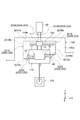
- FIG. 1 is a schematic configuration diagram of a molding apparatus included in the molding system according to the present embodiment.
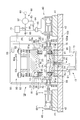
- a molding apparatus 10 for molding a metal pipe includes a molding die 13 including an upper die 12 and a lower die 11, and a drive mechanism 80 that moves at least one of the upper die 12 and the lower die 11.
- the pipe holding mechanism 30 that holds the metal pipe material 14 disposed between the upper mold 12 and the lower mold 11, and the heating mechanism 50 that energizes and heats the metal pipe material 14 held by the pipe holding mechanism 30.
- a gas supply part 60 for supplying high-pressure gas (gas) into the heated metal pipe material 14 held between the upper mold 12 and the lower mold 11 and the metal pipe material held by the pipe holding mechanism 30 14 includes a pair of gas supply mechanisms 40 and 40 for supplying gas from the gas supply unit 60 and a water circulation mechanism 72 for forcibly cooling the molding die 13 with water, and driving of the drive mechanism 80.
- Up Driving the pipe holding mechanism 30 is configured to include the driving of the heating mechanism 50, and a control unit 70 for controlling each of the gas supply of the gas supply unit 60, a.
- the lower mold 11 which is one of the molding dies 13 is fixed to the base 15.
- the lower mold 11 is composed of a large steel block, and includes, for example, a rectangular cavity (concave portion) 16 on the upper surface thereof.
- a cooling water passage 19 is formed in the lower mold 11 and is provided with a thermocouple 21 inserted from below at a substantially central position.
- the thermocouple 21 is supported by a spring 22 so as to be movable up and down.
- a space 11a is provided in the vicinity of the left and right ends (left and right ends in FIG. 1) of the lower mold 11, and electrodes 17 and 18 (lower portions), which are movable parts of the pipe holding mechanism 30, described later, are provided in the space 11a.
- Side electrodes) and the like are arranged so as to be movable up and down. Then, by placing the metal pipe material 14 on the lower electrodes 17 and 18, the lower electrodes 17 and 18 are in contact with the metal pipe material 14 disposed between the upper mold 12 and the lower mold 11. To do. Thus, the lower electrodes 17 and 18 are electrically connected to the metal pipe material 14.
- An insulating material 91 for preventing energization is provided between the lower mold 11 and the lower electrode 17 and under the lower electrode 17, and between the lower mold 11 and the lower electrode 18 and under the lower electrode 18. Each is provided. Each insulating material 91 is fixed to an advance / retreat rod 95 which is a movable portion of an actuator (not shown) constituting the pipe holding mechanism 30. This actuator is for moving the lower electrodes 17, 18 and the like up and down, and the fixed portion of the actuator is held on the base 15 side together with the lower mold 11.
- the upper mold 12 which is the other of the molding dies 13, is fixed to a later-described slide 81 that constitutes the drive mechanism 80.
- the upper mold 12 is composed of a large steel block, and has a cooling water passage 25 formed therein, and is provided with, for example, a rectangular cavity (recess) 24 on the lower surface thereof.
- the cavity 24 is provided at a position facing the cavity 16 of the lower mold 11.
- a space 12a is provided in the vicinity of the left and right ends (left and right ends in FIG. 1) of the upper mold 12 in the same manner as the lower mold 11, and a movable portion of the pipe holding mechanism 30 will be described later in the space 12a.
- Electrodes 17 and 18 (upper electrodes) and the like are arranged so as to be movable up and down. Then, in a state where the metal pipe material 14 is placed on the lower electrodes 17 and 18, the upper electrodes 17 and 18 are arranged between the upper mold 12 and the lower mold 11 by moving downward. Contact the metal pipe material 14. Thereby, the upper electrodes 17 and 18 are electrically connected to the metal pipe material 14.
- Insulating materials 101 for preventing energization are provided between the upper mold 12 and the upper electrode 17 and above the upper electrode 17, and between the upper mold 12 and the upper electrode 18 and above the upper electrode 18, respectively. Yes.
- Each insulating material 101 is fixed to an advance / retreat rod 96 which is a movable portion of an actuator constituting the pipe holding mechanism 30. This actuator is for moving the upper electrodes 17, 18 and the like up and down, and the fixed portion of the actuator is held on the slide 81 side of the drive mechanism 80 together with the upper mold 12.
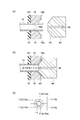
- a semicircular arc-shaped groove 18a corresponding to the outer peripheral surface of the metal pipe material 14 is formed on each of the surfaces where the electrodes 18, 18 face each other (see FIG. 2).
- the metal pipe material 14 can be placed so as to fit into the concave groove 18a.
- a semicircular arc-shaped groove corresponding to the outer peripheral surface of the metal pipe material 14 is formed on the exposed surface where the insulating materials 91 and 101 face each other, like the groove 18a.
- a tapered concave surface 18b is formed on the front surface of the electrode 18 (the surface in the outer direction of the mold).
- the outer periphery of the right end portion of the metal pipe material 14 can be surrounded so as to be in close contact over the entire circumference. ing.
- a semicircular arc-shaped groove 17a corresponding to the outer peripheral surface of the metal pipe material 14 is formed on each of the surfaces where the electrodes 17 and 17 face each other (see FIG. 2).
- the metal pipe material 14 can be placed so as to fit into the concave groove 17a.
- a semicircular arc-shaped groove corresponding to the outer peripheral surface of the metal pipe material 14 is formed on the exposed surface where the insulating materials 91 and 101 face each other, like the groove 18a.
- a tapered concave surface 17b is formed on the front surface of the electrode 17 (surface in the outer direction of the mold). Therefore, when the metal pipe material 14 is sandwiched from above and below by the left portion of the pipe holding mechanism 30, the outer periphery of the left end portion of the metal pipe material 14 can be surrounded so as to be in close contact over the entire circumference. ing.
- the drive mechanism 80 includes a slide 81 that moves the upper mold 12 so that the upper mold 12 and the lower mold 11 are aligned with each other, and a shaft 82 that generates a driving force for moving the slide 81. And a connecting rod 83 for transmitting the driving force generated by the shaft 82 to the slide 81.
- the shaft 82 extends in the left-right direction above the slide 81 and is rotatably supported.
- An eccentric crank 82a that protrudes from the left and right ends and extends in the left-right direction at a position away from the axis. Have.
- the eccentric crank 82 a and a rotating shaft 81 a provided in the upper part of the slide 81 and extending in the left-right direction are connected by a connecting rod 83.
- the height of the eccentric crank 82a is changed by controlling the rotation of the shaft 82 by the control unit 70, and the change in the position of the eccentric crank 82a is transmitted to the slide 81 via the connecting rod 83.
- the vertical movement of the slide 81 can be controlled.
- the swinging (rotating motion) of the connecting rod 83 that occurs when the position change of the eccentric crank 82a is transmitted to the slide 81 is absorbed by the rotating shaft 81a.
- the shaft 82 rotates or stops according to the driving of a motor or the like controlled by the control unit 70, for example.
- the heating mechanism 50 includes a power supply unit 55 and a power supply line 52 that electrically connects the power supply unit 55 and the electrodes 17 and 18.
- the power supply unit 55 includes a direct current power source and a switch, and energizes the metal pipe material 14 through the power supply line 52 and the electrodes 17 and 18 in a state where the electrodes 17 and 18 are electrically connected to the metal pipe material 14. It is possible.
- the power supply line 52 is connected to the lower electrodes 17 and 18 here.
- the direct current output from the power supply unit 55 is transmitted by the power supply line 52 and input to the electrode 17.
- the direct current passes through the metal pipe material 14 and is input to the electrode 18.
- the direct current C is transmitted through the power supply line 52 and input to the power supply unit 55.
- each of the pair of gas supply mechanisms 40 is connected to a cylinder unit 42, a cylinder rod 43 that moves forward and backward in accordance with the operation of the cylinder unit 42, and a tip of the cylinder rod 43 on the pipe holding mechanism 30 side. And a sealing member 44.
- the cylinder unit 42 is mounted and fixed on the block 41.
- a tapered surface 45 is formed at the tip of the seal member 44 so as to be tapered, and is configured to fit the tapered concave surfaces 17b, 18b of the electrodes 17, 18 (see FIG. 2).
- the seal member 44 extends from the cylinder unit 42 toward the tip, and as shown in detail in FIGS. 2A and 2B, a gas passage through which the high-pressure gas supplied from the gas supply unit 60 flows. 46 is provided.
- the gas supply unit 60 includes a gas source 61, an accumulator 62 that stores the gas supplied by the gas source 61, a first tube 63 that extends from the accumulator 62 to the cylinder unit 42 of the gas supply mechanism 40, A pressure control valve 64 and a switching valve 65 provided in one tube 63; a second tube 67 extending from the accumulator 62 to a gas passage 46 formed in the seal member 44; The pressure control valve 68 and the check valve 69 are provided.
- the pressure control valve 64 serves to supply the cylinder unit 42 with a gas having an operating pressure adapted to the pressing force of the seal member 44 against the metal pipe material 14.
- the check valve 69 serves to prevent the high pressure gas from flowing back in the second tube 67.
- the pressure control valve 68 provided in the second tube 67 serves to supply a gas having an operating pressure for expanding the metal pipe material 14 to the gas passage 46 of the seal member 44 under the control of the control unit 70. Fulfill.
- the control unit 70 can supply a gas having a desired operating pressure into the metal pipe material 14 by controlling the pressure control valve 68 of the gas supply unit 60. Moreover, the control part 70 acquires temperature information from the thermocouple 21 by information being transmitted from (A) shown in FIG. 1, and controls the drive mechanism 80, the power supply part 55, and the like.
- the water circulation mechanism 72 includes a water tank 73 that stores water, a water pump 74 that pumps up and pressurizes the water stored in the water tank 73 and sends the water to the cooling water passage 19 of the lower mold 11 and the cooling water passage 25 of the upper mold 12. It consists of a pipe 75. Although omitted, a cooling tower for lowering the water temperature and a filter for purifying water may be interposed in the pipe 75.
- a method for forming a metal pipe using the forming apparatus 10 will be described.
- a cylindrical metal pipe material 14 of a hardenable steel type is prepared.
- the metal pipe material 14 is placed (input) on the electrodes 17 and 18 provided on the lower mold 11 side using, for example, a robot arm or the like. Since the grooves 17a and 18a are formed in the electrodes 17 and 18, the metal pipe material 14 is positioned by the grooves 17a and 18a.
- control unit 70 controls the drive mechanism 80 and the pipe holding mechanism 30 to cause the pipe holding mechanism 30 to hold the metal pipe material 14. Specifically, the upper die 12 and the upper electrodes 17 and 18 held on the slide 81 side by the driving mechanism 80 move to the lower die 11 side, and the upper electrode 17 and the upper electrode 17 included in the pipe holding mechanism 30 are moved. By actuating an actuator that allows the 18 and the like and the lower electrodes 17 and 18 to move forward and backward, the vicinity of both ends of the metal pipe material 14 is sandwiched by the pipe holding mechanism 30 from above and below.
- This clamping is caused to closely adhere to the entire circumference of the metal pipe material 14 near both ends due to the presence of the concave grooves 17a and 18a formed in the electrodes 17 and 18 and the concave grooves formed in the insulating materials 91 and 101. It will be clamped in such a manner.
- the end of the metal pipe material 14 on the electrode 18 side has a groove 18 a and a taper concave surface 18 b of the electrode 18 in the extending direction of the metal pipe material 14. It protrudes to the seal member 44 side from the boundary. Similarly, the end of the metal pipe material 14 on the electrode 17 side protrudes more toward the seal member 44 than the boundary between the concave groove 17a and the tapered concave surface 17b of the electrode 17 in the extending direction of the metal pipe material 14.
- the lower surfaces of the upper electrodes 17 and 18 and the upper surfaces of the lower electrodes 17 and 18 are in contact with each other.
- the configuration is not limited to the configuration in which the metal pipe material 14 is in close contact with the entire periphery of the both ends, and a configuration in which the electrodes 17 and 18 are in contact with part of the metal pipe material 14 in the circumferential direction may be employed.
- the control unit 70 heats the metal pipe material 14 by controlling the heating mechanism 50. Specifically, the control unit 70 controls the power supply unit 55 of the heating mechanism 50 to supply power. Then, the power transmitted to the lower electrodes 17 and 18 through the power supply line 52 is supplied to the upper electrodes 17 and 18 and the metal pipe material 14 sandwiching the metal pipe material 14, and Due to the existing resistance, the metal pipe material 14 itself generates heat due to Joule heat. That is, the metal pipe material 14 is in an electrically heated state.
- the molding die 13 is closed with respect to the heated metal pipe material 14 by the control of the drive mechanism 80 by the control unit 70.
- the cavity 16 of the lower mold 11 and the cavity 24 of the upper mold 12 are combined, and the metal pipe material 14 is disposed and sealed in the cavity portion between the lower mold 11 and the upper mold 12.
- the cylinder unit 42 of the gas supply mechanism 40 is operated to advance the seal member 44 to seal both ends of the metal pipe material 14.
- the seal member 44 is pressed against the end portion of the metal pipe material 14 on the electrode 18 side, so that the boundary between the concave groove 18a and the tapered concave surface 18b of the electrode 18 is exceeded.
- a portion protruding toward the seal member 44 is deformed in a funnel shape so as to follow the tapered concave surface 18b.
- the gas supplied into the metal pipe material 14 is thermally expanded.
- the supplied gas is compressed air, and the metal pipe material 14 at 950 ° C. can be easily expanded by the thermally expanded compressed air.
- austenite transforms to martensite (hereinafter, austenite transforms to martensite is referred to as martensite transformation).
- cooling may be performed by supplying a cooling medium into the cavity 24, for example, instead of or in addition to mold cooling.
- the metal pipe material 14 is brought into contact with the mold (upper mold 12 and lower mold 11) until the temperature at which martensitic transformation begins, and then the mold is opened and the cooling medium (cooling gas) is used as the metal pipe material.
- the martensitic transformation may be generated by spraying on 14.
- the metal pipe material 14 is blow-molded, cooled, and then opened to obtain a metal pipe having a substantially rectangular cylindrical main body, for example.
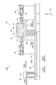
- the molding system 100 includes a molding apparatus 10 including a molding die 13, electrodes 17 and 18, a power supply unit 55, and a power supply line 52, a mounting table 105, and a mold.
- An exchange cart arrangement unit 102 (see FIG. 4) and a handling unit 103 (see FIG. 4) are provided.
- a unit having the molding die 13, the base 15, the gas supply mechanism 40, the block 41, and the drive mechanism 80 (see FIG. 1) is referred to as a main body 110 of the molding system 100.
- a pair of gas supply mechanism 40 and the block 41 are arrange
- the mounting table 105 mounts the main body 110, the power supply unit 55, the mold exchanging cart arrangement unit 102, and the handling unit 103 on the mounting surface 105a (see FIG. 4).
- the direction in which the electrode 17 and the electrode 18 face in the horizontal direction is the “X-axis direction”, the direction orthogonal to the X-axis direction in the horizontal direction is the “Y-axis direction”, and the vertical direction is “Z-axis direction”.
- the electrode 18 side is the positive side in the X-axis direction
- the electrode 17 side is the negative side in the X-axis direction.
- One side in the Y-axis direction is the positive side
- the other side in the Y-axis direction is the negative side.
- the upper side is the positive side in the Z-axis direction
- the lower side is the negative side in the Z-axis direction.
- the X-axis direction corresponds to the “first direction” in the claims
- the Y-axis direction corresponds to the “second direction” in the claims.
- the mold exchanging carriage arrangement unit 102 is a structure for moving the mold exchanging carriage 111 forward and backward.
- the mold exchanging carriage arrangement part 102 is provided on the positive side with respect to the main body part 110 in the Y-axis direction.
- the mold exchanging carriage arrangement section 102 includes a rail section 102a for moving the mold exchanging carriage 111 in the X axis direction and a rail section 102b for moving the mold exchanging carriage 111 in the Y axis direction. I have.
- the rail part 102a is provided at a position spaced from the main body part 110 to the positive side in the Y-axis direction.
- the rail portion 102b extends in the Y-axis direction from the rail portion 102a to a position on the near side of the main body portion 110.
- the handling unit 103 is a device for installing and removing the metal pipe material 14 from the molding die 13.
- the handling unit 103 is configured by a robot arm, for example.
- the handling unit 103 is provided on the negative side with respect to the main body unit 110 in the Y-axis direction.
- the power supply unit 55 is a device that is disposed at a position separated from the main body 110 and supplies power to the electrodes 17 and 18 via the power supply line 52.
- the power supply line is constituted by a bus bar.
- the power supply line 52 includes a positive electrode line 52A that connects the power supply unit 55 and the electrode 17, and a negative electrode line that connects the power supply unit 55 and the electrode 18. 52B.
- the electrode 17 and the electrode 18 is used as a positive electrode or a negative electrode is not particularly limited. Therefore, the electrode 17 may be the negative electrode and the electrode 18 may be the positive electrode.
- the line 52A becomes a negative electrode line
- the line 52B becomes a positive electrode line.
- the power supply line 52 shown in FIG. 3 schematically shows the positional relationship with other components.
- the positive line 52A and the negative line 52B of the power supply line 52 are respectively connected to the lower passage parts 121A and 121B, the first connection parts 122A and 122B, and the second connection parts 123A and 123B. It is equipped with.
- the lower passage portions 121A and 121B are portions that pass below the placement surface 105a of the placement table 105.
- the first connection parts 122A and 122B are parts that connect the lower passage parts 121A and 121B to the electrodes 17 and 18.
- the second connection parts 123 ⁇ / b> A and 123 ⁇ / b> B are parts that connect the lower passage parts 121 ⁇ / b> A and 121 ⁇ / b> B and the power supply part 55.
- connection part 122A, 122B is pulled out above the mounting surface 105a.
- the second connection parts 123A and 123B are pulled out above the placement surface 105a.
- a cover 140 that covers all or a part of the part that is drawn upward from the placement surface 105a is provided.
- a part of the cover 140 is omitted to show the configuration around the molding die 13.
- a cover 141 that covers all or a part of the part that is drawn upward from the placement surface 105a is provided.
- the portion indicated by a broken line is a portion disposed below the placement surface 105a. 4 and 5, the covers 140 and 141 are omitted.
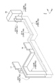
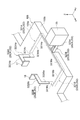
- FIG. 5 only the power supply line 52, the electrodes 17 and 18, and the power supply unit 55 are shown in order to clarify the shape of the power supply line 52.
- the power supply unit 55 is disposed at a position separated from the main body unit 110 toward the negative side in the X-axis direction.
- the lower passage parts 121A and 121B are arranged at positions separated from the main body part 110 and the power supply part 55 toward the negative side in the Y-axis direction.
- the first connecting portions 122A and 122B are drawn upward from the positive end portions in the X-axis direction of the lower passing portions 121A and 121B and connected to the electrodes 17 and 18.
- the second connection parts 123A and 123B are drawn upward from the negative end part in the X-axis direction of the lower passage parts 121A and 121B and connected to the power supply part 55.
- each part of positive electrode line 52A and negative electrode line 52B in the following description is comprised by the elongate board member extended in the state which has the thickness direction in either direction in a horizontal direction.
- the lower passage portions 121A and 121B include straight portions 121Aa and 121Ba, bent portions 121Ab and 121Bb, and bent portions 121Ac and 121Bc.
- the straight portions 121Aa and 121Ba are portions that extend straight in the X-axis direction.
- the bent portions 121Ab and 121Bb are portions that bend toward the positive side in the Y-axis direction from the end on the positive side in the X-axis direction of the straight portions 121Aa and 121Ba toward the main body 110.
- the bent portions 121Ac and 121Bc are portions that bend toward the positive side in the Y-axis direction from the negative end portion in the X-axis direction of the straight portions 121Aa and 121Ba toward the power supply unit 55.
- the straight portion 121Aa is disposed on the positive side in the Y-axis direction from the straight portion 121Ba.
- the bent portion 121Ab is disposed on the negative side in the X-axis direction from the bent portion 121Bb.
- the bent portion 121Ac is disposed on the positive side in the X-axis direction from the bent portion 121Bc.
- the first connecting portions 122A and 122B extend upward from the end portions of the lower passage portions 121A and 121B, extend toward the positive side in the Y-axis direction toward the main body portion 110, and in front of the main body portion 110. Branches to each other and is connected to electrodes 17 and 18 respectively.
- the first connection parts 122A and 122B include rising parts 122Aa and 122Ba, straight line parts 122Ab and 122Bb, branch parts 122Ac and 122Bc, and connection parts 122Ad and 122Bd.
- the rising portions 122Aa and 122Ba are portions that extend straight upward from the positive ends in the Y-axis direction of the bent portions 121Ab and 121Bb of the lower passage portions 121A and 121B.
- the rising portions 122Aa and 122Ba extend to the height positions of the electrodes 17 and 18.
- the straight portions 122Ab and 122Bb extend straight from the upper ends of the rising portions 122Aa and 122Ba to the front side of the molding die 13 toward the positive side in the Y-axis direction.
- the first connection parts 122A and 122B are branched so as to extend in opposite directions at the branch parts 122Ac and 122Bc.
- the branching portion 122Ac extends from the end portion on the positive side in the Y-axis direction of the straight portion 122Ab to the negative side in the X-axis direction.
- the connecting portion 122Ad extends from the negative end portion of the branching portion 122Ac in the X-axis direction to the positive side in the Y-axis direction and is connected to the electrode 17.
- the branching portion 122Bc extends from the end portion on the positive side in the Y-axis direction of the straight portion 122Bb to the positive side in the X-axis direction.
- the connecting portion 122Bd extends from the end portion on the positive side in the X-axis direction of the branch portion 122Bc to the positive side in the Y-axis direction and is connected to the electrode 17. Note that the branch portions 122Ac and 122Bc are branched at a position near the electrode 17. Therefore, the length of the branch portion 122Bc is longer than that of the branch portion 122Ac.
- the second connection parts 123A and 123B extend upward from the end portions of the lower passage parts 121A and 121B, extend toward the positive side in the Y-axis direction toward the power supply part 55, and the power supply part 55.
- the second connection parts 123A and 123B include rising parts 123Aa and 123Ba and connection parts 123Ab and 123Bb.
- the rising portions 123Aa and 123Ba extend to the height positions of the electrodes 17 and 18.
- the connection parts 123Ab and 123Bb extend from the upper ends of the rising parts 123Aa and 123Ba toward the positive side in the Y-axis direction and are connected to the power supply part 55.
- the positive electrode line 52A and the negative electrode line 52B are disposed in parallel below the placement surface 105a. That is, in the lower passage portions 121A and 121B, the straight portions 121Aa and 121Ba, the bent portions 121Ab and 121Bb, and the bent portions 121Ac and 121Bc are arranged so as to extend in parallel with a predetermined gap therebetween. . In the first connection portions 122A and 122B, the rising portions 122Aa and 122Ba and the straight portions 122Ab and 122Bb are arranged so as to extend in parallel with a predetermined gap therebetween.
- the mold exchanging carriage arrangement portion 102 is arranged in a region on the positive side with respect to the main body portion 110 in the Y-axis direction.
- This region is assumed to be a region E1 between both end portions 110a and 110b in the X-axis direction of the main body 110 (in FIG. 4, a region between the straight line L1 and the straight line L2).
- the first connecting portions 122A and 122B are drawn upward from the placement surface 105a from a position other than the region E1.
- the first connecting portions 122A and 122B are drawn upward from the placement surface 105a from the negative region with respect to the main body 110 in the Y-axis direction. That is, the first connection parts 122A and 122B are drawn out from the area where the handling part 103 is arranged, not the mold exchanging carriage arrangement part 102, to the upper side of the placement surface 105a.
- the power supply line 52 connects the electrodes 17 and 18 that energize and heat the metal pipe material 14 and the power supply unit 55 disposed at a position separated from the main body 110. To do.
- the power supply line 52 is drawn out to the lower passages 121A and 121B that pass below the placement surface 105a on which the main body 110 is placed, and to the upper side of the placement surface 105a.
- First connection parts 122A and 122B for connecting 121A and 121B and electrodes 17 and 18 and second connection parts 123A and 123B for connecting lower passage parts 121A and 121B and power supply part 55 are provided. .
- the power supply line 52 ensures the connectivity with the electrodes 17 and 18 at the first connection portions 122A and 122B, and the connectivity with the power supply portion 55 at the second connection portions 123A and 123B.
- the lower passage portions 121A and 121B between the first connection portions 122A and 122B and the second connection portions 123A and 123B pass below the placement surface 105a of the molding die 13. Yes. In this way, the lower passage portions 121A and 121B pass below the placement surface 105a, so that the apparatus disposed on the placement surface 105a and the lower passage portions 121A and 121B are kept away from each other. Can do.
- the power supply line 52 includes the lower passage portions 121A and 121B, the space on the placement surface 105a can be widely used. In addition, the operator can easily move.
- the power supply line 52 includes a positive electrode line 52A and a negative electrode line 52B, and in the lower passage portions 121A and 121B, the positive electrode line 52A and the negative electrode line 52B are disposed in parallel below the placement surface 105a. Has been. Thereby, the positive electrode line 52A and the negative electrode line 52B can be arranged in a combined state.
- the direction of magnetic field (direction of magnetic flux) generated by the positive electrode line 52A is opposite to the magnetic field (direction of magnetic flux) generated by the negative electrode line 52B. Therefore, by disposing the positive electrode line 52A and the negative electrode line 52B in parallel, it is possible to cancel out some of the magnetic fluxes with each other and further suppress the influence of the leakage magnetic field on the peripheral devices.
- a pair of electrodes 17 and 18 are provided opposite to each other in the X-axis direction so as to support both ends in the longitudinal direction of the metal pipe material 14 arranged in the molding die 13.
- a mold exchanging carriage arrangement portion 102 for moving the die exchanging carriage 111 forward and backward is provided on the positive side with respect to the main body 110, and in the Y axis direction, on the negative side with respect to the main body 110,
- a handling part 103 for installing and removing the metal pipe material 14 with respect to the molding die 13 is provided, and the first connecting parts 122A and 122B are positions other than the area E1 on the positive side with respect to the main body part 110 in the Y-axis direction.
- the first connecting portions 122A and 122B are drawn from the negative region with respect to the main body 110 to the upper side of the mounting surface 105a in the Y-axis direction. Thereby, it can prevent that 1st connection part 122A, 122B interferes with the metal mold
- exchange Further, as shown in FIG.
- the positive line 52 ⁇ / b> A and the negative line 52 ⁇ / b> B need to be largely branched as compared with the case where the first connection parts 122 ⁇ / b> A and 122 ⁇ / b> B are pulled out from the regions on both sides of the main body part 110 in the X-axis direction. Therefore, the path of the line can be shortened. Thereby, the resistance of the positive electrode line 52A and the negative electrode line 52B can be reduced.
- covers 140 and 141 are provided to cover the first connection portions 122A and 122B and the second connection portions 123A and 123B, which are drawn upward from the placement surface 105a. . Thereby, the influence of the leakage magnetic field which arises from the part withdraw
- the present invention is not limited to the embodiment described above.
- a power supply line 152 as shown in FIGS. 6 and 7 may be adopted.
- the positive line 152A and the negative line 152B of the power supply line 152 shown in FIGS. 6 and 7 are different in the direction in which the lower passage portions 221A and 221B extend, and thus the positive line of the power supply line 52 shown in FIGS. 52A and the negative electrode line 52B are mainly different.
- the power supply unit 55 is disposed at a position separated from the main body unit 110 toward the positive side in the Y-axis direction. Accordingly, the lower passage portions 221A and 221B of the positive electrode line 152A and the negative electrode line 152B extend in the Y-axis direction from the power supply unit 55 toward the main body 110.
- the lower passage portions 221A and 221B pass below the main body portion 110 and extend to a position on the negative side of the main body portion 110 in the Y-axis direction.
- the first connecting portions 222A and 222B are pulled out above the placement surface 105a from the negative region with respect to the main body 110 in the Y-axis direction.
- the first connecting portions 222A and 222B have the same concept as the first connecting portions 122A and 122B shown in FIGS.
- the second connection portions 223A and 223B have the same configuration as the second connection portions 123A and 123B shown in FIGS.
- a power supply line 252 as shown in FIGS. 8 and 9 may be employed.
- the positive electrode line 252A and the negative electrode line 252B of the power supply line 252 shown in FIGS. 8 and 9 are configured of the lower passage portions 321A and 321B, the drawing structure of the first connection portions 322A and 322B, and the second connection portion 323A. , 323B is mainly different from the positive electrode line 52A and the negative electrode line 52B of the power supply line 52 shown in FIGS.
- the power supply unit 55 is disposed at a position spaced apart from the main body unit 110 toward the positive side in the Y-axis direction. Further, the power supply unit 55 is not provided on the mounting surface 105 a of the mounting table 105, and is disposed at a position separated from the positive end 105 b of the mounting table 105 in the Y-axis direction. Accordingly, the second connection portions 323A and 323B are straightly drawn from the lower passage portions 321A and 321B via the end portion 105b without being drawn upward from the placement surface 105a. As described above, the second connection portions 323A and 323B do not have to be drawn upward from the placement surface 105a.
- the first connecting portion 322 ⁇ / b> A is drawn from the negative region in the X-axis direction with respect to the main body portion 110 to the upper side of the placement surface 105 a and connected to the electrode 17.
- the first connecting portion 322A includes a rising portion 322Aa extending upward and a connecting portion 322Ab extending from the rising portion 322Aa toward the electrode 17 and connected thereto.
- the first connection part 322B is drawn from the area on the positive side in the X-axis direction with respect to the main body part 110 to the upper side from the placement surface 105a and connected to the electrode 18.
- the first connection part 322B includes a rising part 322Ba extending upward and a connection part 322Bb extending from the rising part 322Ba toward the electrode 18 and connected thereto.
- the lower passage portion 321A includes a branch portion 321Aa extending from the second connection portion 323A to the negative side in the X axis direction, a bent portion 321Ab bent from the branch portion 321Aa and extended to the negative side in the Y axis direction, and a bent portion 321Ab Connecting portion 321Ac that extends from the positive side in the X-axis direction and is connected to the first connecting portion 322A.
- the lower passage portion 321B includes a branch portion 321Ba extending from the second connection portion 323B to the positive side in the X-axis direction, a bent portion 321Bb bent from the branch portion 321Ba and extended to the negative side in the Y-axis direction, and a bent portion 321Bb.
- Connecting part 321Bc extending from the negative side in the X-axis direction and connected to the first connecting part 322B.
- the first connection portions 322A and 322B are drawn from the regions on both sides of the main body portion 110 to the upper side of the placement surface 105a in the X-axis direction. . Thereby, it can prevent that 1st connection part 322A, 322B interferes with the metal mold
- peripheral devices temperature measuring devices for measuring the temperature of the mold
Landscapes
- Engineering & Computer Science (AREA)
- Mechanical Engineering (AREA)
- Chemical & Material Sciences (AREA)
- Physics & Mathematics (AREA)
- Fluid Mechanics (AREA)
- Materials Engineering (AREA)
- Crystallography & Structural Chemistry (AREA)
- Metallurgy (AREA)
- Organic Chemistry (AREA)
- Thermal Sciences (AREA)
- Manufacturing & Machinery (AREA)
- Shaping Metal By Deep-Drawing, Or The Like (AREA)
- Moulds For Moulding Plastics Or The Like (AREA)
Abstract
Description
図1は、本実施形態に係る成形システムが有する成形装置の概略構成図である。図1に示されるように、金属パイプを成形する成形装置10は、上型12及び下型11からなる成形金型13と、上型12及び下型11の少なくとも一方を移動させる駆動機構80と、上型12と下型11との間に配置される金属パイプ材料14を保持するパイプ保持機構30と、パイプ保持機構30で保持されている金属パイプ材料14に通電して加熱する加熱機構50と、上型12及び下型11の間に保持され加熱された金属パイプ材料14内に高圧ガス(気体)を供給するための気体供給部60と、パイプ保持機構30で保持された金属パイプ材料14内に気体供給部60からの気体を供給するための一対の気体供給機構40,40と、成形金型13を強制的に水冷する水循環機構72とを備えると共に、上記駆動機構80の駆動、上記パイプ保持機構30の駆動、上記加熱機構50の駆動、及び上記気体供給部60の気体供給をそれぞれ制御する制御部70と、を備えて構成されている。 <Configuration of molding equipment>
FIG. 1 is a schematic configuration diagram of a molding apparatus included in the molding system according to the present embodiment. As shown in FIG. 1, a
次に、成形装置10を用いた金属パイプの成形方法について説明する。最初に、焼入れ可能な鋼種の円筒状の金属パイプ材料14を準備する。この金属パイプ材料14を、例えばロボットアーム等を用いて、下型11側に備わる電極17,18上に載置(投入)する。電極17,18には凹溝17a,18aが形成されているので、当該凹溝17a,18aによって金属パイプ材料14が位置決めされる。 <Metal pipe forming method using forming equipment>
Next, a method for forming a metal pipe using the forming
Claims (6)
- 金属パイプ材料を膨張させて金属パイプを成形する成形システムであって、
前記金属パイプを成形する成形金型を有する本体部と、
前記成形金型に配置される前記金属パイプ材料に電流を流して加熱する電極と、
前記本体部から離間した位置に配置され、前記電極に電力を供給する電力供給部と、
前記電力供給部と前記電極とを接続する電力供給ラインと、を備え、
前記電力供給ラインは、
前記本体部が載置された載置面よりも下側を通過する下側通過部と、
前記載置面よりも上側に引き出され、前記下側通過部と前記電極とを接続する第1の接続部と、
前記下側通過部と前記電力供給部とを接続する第2の接続部と、
を備える、成形システム。 A forming system for forming a metal pipe by expanding a metal pipe material,
A main body having a molding die for molding the metal pipe;
An electrode that heats the metal pipe material disposed in the molding die by passing an electric current;
A power supply unit disposed at a position spaced from the main body and supplying power to the electrode;
A power supply line connecting the power supply unit and the electrode,
The power supply line is
A lower passage portion that passes below the placement surface on which the main body portion is placed; and
A first connection part that is drawn above the placement surface and connects the lower passage part and the electrode;
A second connection portion connecting the lower passage portion and the power supply portion;
A molding system comprising: - 前記電力供給ラインは正極ライン、及び負極ラインを備え、
前記下側通過部において、前記載置面より下側で前記正極ラインと前記負極ラインとが並行に配置される、請求項1に記載の成形システム。 The power supply line includes a positive electrode line and a negative electrode line,
The molding system according to claim 1, wherein, in the lower passage portion, the positive electrode line and the negative electrode line are arranged in parallel below the placement surface. - 前記電極は、前記成形金型に配置された状態の前記金属パイプ材料の長手方向の両端側を支持するように、水平方向における第1の方向に対向して一対設けられ、
水平方向における前記第1の方向と直交する第2の方向のうち、前記本体部に対する一方側には、金型交換台車が進退移動するための金型交換台車配置部が設けられ、
前記第2の方向のうち、前記本体部に対する他方側には、前記成形金型に対する前記金属パイプ材料の設置及び取出しを行うハンドリング部が設けられ、
前記第1の接続部は、前記第2の方向のうち、前記本体部に対する一方側の領域以外の位置から、前記載置面よりも上側に引き出される、請求項1又は2に記載の成形システム。 A pair of the electrodes are provided facing the first direction in the horizontal direction so as to support both ends in the longitudinal direction of the metal pipe material in a state of being arranged in the molding die,
Of the second direction orthogonal to the first direction in the horizontal direction, on one side with respect to the main body portion, a mold exchanging carriage arrangement portion for moving the die exchanging carriage forward and backward is provided,
Of the second direction, the other side of the main body is provided with a handling part for installing and removing the metal pipe material with respect to the molding die,
3. The molding system according to claim 1, wherein the first connection portion is pulled out above the placement surface from a position other than a region on one side with respect to the main body portion in the second direction. . - 前記第1の接続部は、前記第2の方向のうち、前記本体部に対する他方側の領域から、前記載置面よりも上側に引き出される、請求項3に記載の成形システム。 The molding system according to claim 3, wherein the first connection portion is drawn upward from the other surface of the second direction with respect to the main body portion in the second direction.
- 前記第1の接続部は、前記第1の方向のうち、前記本体部に対する両側の領域から、前記載置面よりも上側に引き出される、請求項3に記載の成形システム。 The molding system according to claim 3, wherein the first connection portion is drawn upward from the region on both sides of the main body portion with respect to the main body portion in the first direction.
- 前記第1の接続部、及び前記第2の接続部の少なくとも一方に対して、前記載置面よりも上側に引き出された部分を覆うカバーが設けられる、請求項1~5の何れか一項に記載の成形システム。 The cover according to any one of claims 1 to 5, wherein at least one of the first connection portion and the second connection portion is provided with a cover that covers a portion that is drawn upward from the placement surface. The molding system described in.
Priority Applications (6)
| Application Number | Priority Date | Filing Date | Title |
|---|---|---|---|
| KR1020197018248A KR102384804B1 (en) | 2017-03-30 | 2018-03-28 | molding system |
| CA3049630A CA3049630A1 (en) | 2017-03-30 | 2018-03-28 | Forming system |
| JP2019510049A JP7313279B2 (en) | 2017-03-30 | 2018-03-28 | molding system |
| EP18774339.8A EP3603836A4 (en) | 2017-03-30 | 2018-03-28 | Forming system |
| CN201880005462.9A CN110446567B (en) | 2017-03-30 | 2018-03-28 | Molding system |
| US16/512,492 US11453037B2 (en) | 2017-03-30 | 2019-07-16 | Forming system |
Applications Claiming Priority (2)
| Application Number | Priority Date | Filing Date | Title |
|---|---|---|---|
| JP2017068336 | 2017-03-30 | ||
| JP2017-068336 | 2017-03-30 |
Related Child Applications (1)
| Application Number | Title | Priority Date | Filing Date |
|---|---|---|---|
| US16/512,492 Continuation US11453037B2 (en) | 2017-03-30 | 2019-07-16 | Forming system |
Publications (1)
| Publication Number | Publication Date |
|---|---|
| WO2018181587A1 true WO2018181587A1 (en) | 2018-10-04 |
Family
ID=63676233
Family Applications (1)
| Application Number | Title | Priority Date | Filing Date |
|---|---|---|---|
| PCT/JP2018/012991 WO2018181587A1 (en) | 2017-03-30 | 2018-03-28 | Forming system |
Country Status (7)
| Country | Link |
|---|---|
| US (1) | US11453037B2 (en) |
| EP (1) | EP3603836A4 (en) |
| JP (1) | JP7313279B2 (en) |
| KR (1) | KR102384804B1 (en) |
| CN (1) | CN110446567B (en) |
| CA (1) | CA3049630A1 (en) |
| WO (1) | WO2018181587A1 (en) |
Cited By (1)
| Publication number | Priority date | Publication date | Assignee | Title |
|---|---|---|---|---|
| EP3919201A4 (en) * | 2019-03-04 | 2023-03-22 | Intelligent Aerospace Manufacturing Technology (Beijing) Co., Ltd. | Hot gas bulging and rapid-cooling strengthening system and process for metal pipe |
Families Citing this family (1)
| Publication number | Priority date | Publication date | Assignee | Title |
|---|---|---|---|---|
| DE112019001169T5 (en) * | 2018-03-06 | 2020-12-10 | Sumitomo Heavy Industries, Ltd. | ELECTRIC HEATING DEVICE |
Citations (4)
| Publication number | Priority date | Publication date | Assignee | Title |
|---|---|---|---|---|
| JPH10299980A (en) * | 1997-04-23 | 1998-11-13 | Nabeya Kogyo Kk | Box for distribution |
| JP2002096118A (en) * | 2000-09-18 | 2002-04-02 | Honda Motor Co Ltd | Hot bulging method and apparatus therefor |
| JP2015112608A (en) * | 2013-12-09 | 2015-06-22 | 住友重機械工業株式会社 | Molding device |
| WO2015194660A1 (en) * | 2014-06-19 | 2015-12-23 | 住友重機械工業株式会社 | Molding device, method for replacing molding device components, and replacement unit for molding device |
Family Cites Families (10)
| Publication number | Priority date | Publication date | Assignee | Title |
|---|---|---|---|---|
| US4712295A (en) * | 1985-10-24 | 1987-12-15 | Ap Industries, Inc. | Clamp apparatus |
| KR100596822B1 (en) | 1999-03-30 | 2006-07-03 | 동경 엘렉트론 주식회사 | Plasma processing apparatus, its repair method, and its construction method |
| JP4310720B2 (en) | 2000-03-09 | 2009-08-12 | 株式会社Ihi | Continuous press equipment |
| US7305860B2 (en) * | 2005-11-10 | 2007-12-11 | Gm Global Technology Operations, Inc. | Method for tube forming |
| KR20150003421A (en) * | 2013-06-27 | 2015-01-09 | 자동차부품연구원 | Laser forming apparatus and laser forming method |
| KR101584533B1 (en) | 2014-03-28 | 2016-01-12 | 엘지전자 주식회사 | Ice maker |
| CN104162948B (en) * | 2014-07-11 | 2016-08-24 | 初冠南 | A kind of high intensity or inductile material hollow unit low pressure thermal forming device and method |
| CN204470409U (en) * | 2015-01-06 | 2015-07-15 | 哈尔滨工业大学(威海) | A kind of Fast Heating and forming integrated device |
| JP6745090B2 (en) | 2015-03-31 | 2020-08-26 | 住友重機械工業株式会社 | Molding equipment |
| CN204657234U (en) * | 2015-06-09 | 2015-09-23 | 哈尔滨理工大学 | A kind of gasifying agent pressurization bulging device of Current Heating |
-
2018
- 2018-03-28 WO PCT/JP2018/012991 patent/WO2018181587A1/en unknown
- 2018-03-28 KR KR1020197018248A patent/KR102384804B1/en active IP Right Grant
- 2018-03-28 JP JP2019510049A patent/JP7313279B2/en active Active
- 2018-03-28 EP EP18774339.8A patent/EP3603836A4/en active Pending
- 2018-03-28 CA CA3049630A patent/CA3049630A1/en active Pending
- 2018-03-28 CN CN201880005462.9A patent/CN110446567B/en active Active
-
2019
- 2019-07-16 US US16/512,492 patent/US11453037B2/en active Active
Patent Citations (4)
| Publication number | Priority date | Publication date | Assignee | Title |
|---|---|---|---|---|
| JPH10299980A (en) * | 1997-04-23 | 1998-11-13 | Nabeya Kogyo Kk | Box for distribution |
| JP2002096118A (en) * | 2000-09-18 | 2002-04-02 | Honda Motor Co Ltd | Hot bulging method and apparatus therefor |
| JP2015112608A (en) * | 2013-12-09 | 2015-06-22 | 住友重機械工業株式会社 | Molding device |
| WO2015194660A1 (en) * | 2014-06-19 | 2015-12-23 | 住友重機械工業株式会社 | Molding device, method for replacing molding device components, and replacement unit for molding device |
Non-Patent Citations (1)
| Title |
|---|
| See also references of EP3603836A4 * |
Cited By (2)
| Publication number | Priority date | Publication date | Assignee | Title |
|---|---|---|---|---|
| EP3919201A4 (en) * | 2019-03-04 | 2023-03-22 | Intelligent Aerospace Manufacturing Technology (Beijing) Co., Ltd. | Hot gas bulging and rapid-cooling strengthening system and process for metal pipe |
| US11752535B2 (en) | 2019-03-04 | 2023-09-12 | Intelligent Aerospace Manufacturing Technology (Beijing) Co., Ltd. | Hot metal gas forming and quenching system and process therefor |
Also Published As
| Publication number | Publication date |
|---|---|
| US20190337034A1 (en) | 2019-11-07 |
| JPWO2018181587A1 (en) | 2020-02-06 |
| CN110446567A (en) | 2019-11-12 |
| JP7313279B2 (en) | 2023-07-24 |
| KR102384804B1 (en) | 2022-04-07 |
| EP3603836A4 (en) | 2020-05-06 |
| CN110446567B (en) | 2021-03-02 |
| KR20190132345A (en) | 2019-11-27 |
| US11453037B2 (en) | 2022-09-27 |
| EP3603836A1 (en) | 2020-02-05 |
| CA3049630A1 (en) | 2018-10-04 |
Similar Documents
| Publication | Publication Date | Title |
|---|---|---|
| CN110014066B (en) | Molding device | |
| JP6739437B2 (en) | Molding equipment | |
| KR101842383B1 (en) | Molding device and method for replacing molding device components | |
| KR102430684B1 (en) | molding equipment | |
| WO2018181587A1 (en) | Forming system | |
| KR20210142089A (en) | Molding device and molding method | |
| JP6396249B2 (en) | Molding equipment | |
| WO2018179865A1 (en) | Electroconductive heating device | |
| JP7101241B2 (en) | Molding equipment | |
| JP6651415B2 (en) | Molding equipment | |
| JP2021167023A (en) | Energization heater and energization heating method | |
| JP2018167315A (en) | Molding equipment | |
| JP2018167312A (en) | Molding equipment and molding method | |
| WO2020195277A1 (en) | Forming system | |
| JPWO2018179857A1 (en) | Molding equipment | |
| JP2019150845A (en) | Molding apparatus | |
| JP2020116583A (en) | Molding device |
Legal Events
| Date | Code | Title | Description |
|---|---|---|---|
| 121 | Ep: the epo has been informed by wipo that ep was designated in this application |
Ref document number: 18774339 Country of ref document: EP Kind code of ref document: A1 |
|
| ENP | Entry into the national phase |
Ref document number: 20197018248 Country of ref document: KR Kind code of ref document: A |
|
| ENP | Entry into the national phase |
Ref document number: 2019510049 Country of ref document: JP Kind code of ref document: A |
|
| ENP | Entry into the national phase |
Ref document number: 3049630 Country of ref document: CA |
|
| NENP | Non-entry into the national phase |
Ref country code: DE |
|
| ENP | Entry into the national phase |
Ref document number: 2018774339 Country of ref document: EP Effective date: 20191030 |