WO2018159710A1 - Original plate for lithographic printing plate, method for platemaking lithographic printing plate, and lithographic printing method - Google Patents
Original plate for lithographic printing plate, method for platemaking lithographic printing plate, and lithographic printing method Download PDFInfo
- Publication number
- WO2018159710A1 WO2018159710A1 PCT/JP2018/007612 JP2018007612W WO2018159710A1 WO 2018159710 A1 WO2018159710 A1 WO 2018159710A1 JP 2018007612 W JP2018007612 W JP 2018007612W WO 2018159710 A1 WO2018159710 A1 WO 2018159710A1
- Authority
- WO
- WIPO (PCT)
- Prior art keywords
- lithographic printing
- printing plate
- group
- plate precursor
- recording layer
- Prior art date
Links
Images
Classifications
-
- H—ELECTRICITY
- H01—ELECTRIC ELEMENTS
- H01L—SEMICONDUCTOR DEVICES NOT COVERED BY CLASS H10
- H01L21/00—Processes or apparatus adapted for the manufacture or treatment of semiconductor or solid state devices or of parts thereof
- H01L21/02—Manufacture or treatment of semiconductor devices or of parts thereof
- H01L21/027—Making masks on semiconductor bodies for further photolithographic processing not provided for in group H01L21/18 or H01L21/34
- H01L21/0271—Making masks on semiconductor bodies for further photolithographic processing not provided for in group H01L21/18 or H01L21/34 comprising organic layers
- H01L21/0273—Making masks on semiconductor bodies for further photolithographic processing not provided for in group H01L21/18 or H01L21/34 comprising organic layers characterised by the treatment of photoresist layers
- H01L21/0274—Photolithographic processes
-
- B—PERFORMING OPERATIONS; TRANSPORTING
- B41—PRINTING; LINING MACHINES; TYPEWRITERS; STAMPS
- B41C—PROCESSES FOR THE MANUFACTURE OR REPRODUCTION OF PRINTING SURFACES
- B41C1/00—Forme preparation
- B41C1/10—Forme preparation for lithographic printing; Master sheets for transferring a lithographic image to the forme
- B41C1/1008—Forme preparation for lithographic printing; Master sheets for transferring a lithographic image to the forme by removal or destruction of lithographic material on the lithographic support, e.g. by laser or spark ablation; by the use of materials rendered soluble or insoluble by heat exposure, e.g. by heat produced from a light to heat transforming system; by on-the-press exposure or on-the-press development, e.g. by the fountain of photolithographic materials
-
- G—PHYSICS
- G03—PHOTOGRAPHY; CINEMATOGRAPHY; ANALOGOUS TECHNIQUES USING WAVES OTHER THAN OPTICAL WAVES; ELECTROGRAPHY; HOLOGRAPHY
- G03F—PHOTOMECHANICAL PRODUCTION OF TEXTURED OR PATTERNED SURFACES, e.g. FOR PRINTING, FOR PROCESSING OF SEMICONDUCTOR DEVICES; MATERIALS THEREFOR; ORIGINALS THEREFOR; APPARATUS SPECIALLY ADAPTED THEREFOR
- G03F7/00—Photomechanical, e.g. photolithographic, production of textured or patterned surfaces, e.g. printing surfaces; Materials therefor, e.g. comprising photoresists; Apparatus specially adapted therefor
- G03F7/004—Photosensitive materials
- G03F7/027—Non-macromolecular photopolymerisable compounds having carbon-to-carbon double bonds, e.g. ethylenic compounds
- G03F7/028—Non-macromolecular photopolymerisable compounds having carbon-to-carbon double bonds, e.g. ethylenic compounds with photosensitivity-increasing substances, e.g. photoinitiators
- G03F7/029—Inorganic compounds; Onium compounds; Organic compounds having hetero atoms other than oxygen, nitrogen or sulfur
-
- G—PHYSICS
- G03—PHOTOGRAPHY; CINEMATOGRAPHY; ANALOGOUS TECHNIQUES USING WAVES OTHER THAN OPTICAL WAVES; ELECTROGRAPHY; HOLOGRAPHY
- G03F—PHOTOMECHANICAL PRODUCTION OF TEXTURED OR PATTERNED SURFACES, e.g. FOR PRINTING, FOR PROCESSING OF SEMICONDUCTOR DEVICES; MATERIALS THEREFOR; ORIGINALS THEREFOR; APPARATUS SPECIALLY ADAPTED THEREFOR
- G03F7/00—Photomechanical, e.g. photolithographic, production of textured or patterned surfaces, e.g. printing surfaces; Materials therefor, e.g. comprising photoresists; Apparatus specially adapted therefor
- G03F7/20—Exposure; Apparatus therefor
- G03F7/2051—Exposure without an original mask, e.g. using a programmed deflection of a point source, by scanning, by drawing with a light beam, using an addressed light or corpuscular source
- G03F7/2053—Exposure without an original mask, e.g. using a programmed deflection of a point source, by scanning, by drawing with a light beam, using an addressed light or corpuscular source using a laser
-
- G—PHYSICS
- G03—PHOTOGRAPHY; CINEMATOGRAPHY; ANALOGOUS TECHNIQUES USING WAVES OTHER THAN OPTICAL WAVES; ELECTROGRAPHY; HOLOGRAPHY
- G03F—PHOTOMECHANICAL PRODUCTION OF TEXTURED OR PATTERNED SURFACES, e.g. FOR PRINTING, FOR PROCESSING OF SEMICONDUCTOR DEVICES; MATERIALS THEREFOR; ORIGINALS THEREFOR; APPARATUS SPECIALLY ADAPTED THEREFOR
- G03F7/00—Photomechanical, e.g. photolithographic, production of textured or patterned surfaces, e.g. printing surfaces; Materials therefor, e.g. comprising photoresists; Apparatus specially adapted therefor
- G03F7/26—Processing photosensitive materials; Apparatus therefor
- G03F7/30—Imagewise removal using liquid means
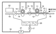
- G03F7/3042—Imagewise removal using liquid means from printing plates transported horizontally through the processing stations
- G03F7/3064—Imagewise removal using liquid means from printing plates transported horizontally through the processing stations characterised by the transport means or means for confining the different units, e.g. to avoid the overflow
-
- H—ELECTRICITY
- H01—ELECTRIC ELEMENTS
- H01L—SEMICONDUCTOR DEVICES NOT COVERED BY CLASS H10
- H01L21/00—Processes or apparatus adapted for the manufacture or treatment of semiconductor or solid state devices or of parts thereof
- H01L21/02—Manufacture or treatment of semiconductor devices or of parts thereof
- H01L21/02104—Forming layers
- H01L21/02107—Forming insulating materials on a substrate
- H01L21/02225—Forming insulating materials on a substrate characterised by the process for the formation of the insulating layer
- H01L21/0226—Forming insulating materials on a substrate characterised by the process for the formation of the insulating layer formation by a deposition process
- H01L21/02282—Forming insulating materials on a substrate characterised by the process for the formation of the insulating layer formation by a deposition process liquid deposition, e.g. spin-coating, sol-gel techniques, spray coating
- H01L21/02288—Forming insulating materials on a substrate characterised by the process for the formation of the insulating layer formation by a deposition process liquid deposition, e.g. spin-coating, sol-gel techniques, spray coating printing, e.g. ink-jet printing
-
- B—PERFORMING OPERATIONS; TRANSPORTING
- B41—PRINTING; LINING MACHINES; TYPEWRITERS; STAMPS
- B41C—PROCESSES FOR THE MANUFACTURE OR REPRODUCTION OF PRINTING SURFACES
- B41C2210/00—Preparation or type or constituents of the imaging layers, in relation to lithographic printing forme preparation
- B41C2210/04—Negative working, i.e. the non-exposed (non-imaged) areas are removed
-
- B—PERFORMING OPERATIONS; TRANSPORTING
- B41—PRINTING; LINING MACHINES; TYPEWRITERS; STAMPS
- B41C—PROCESSES FOR THE MANUFACTURE OR REPRODUCTION OF PRINTING SURFACES
- B41C2210/00—Preparation or type or constituents of the imaging layers, in relation to lithographic printing forme preparation
- B41C2210/08—Developable by water or the fountain solution
-
- B—PERFORMING OPERATIONS; TRANSPORTING
- B41—PRINTING; LINING MACHINES; TYPEWRITERS; STAMPS
- B41C—PROCESSES FOR THE MANUFACTURE OR REPRODUCTION OF PRINTING SURFACES
- B41C2210/00—Preparation or type or constituents of the imaging layers, in relation to lithographic printing forme preparation
- B41C2210/22—Preparation or type or constituents of the imaging layers, in relation to lithographic printing forme preparation characterised by organic non-macromolecular additives, e.g. dyes, UV-absorbers, plasticisers
-
- B—PERFORMING OPERATIONS; TRANSPORTING
- B41—PRINTING; LINING MACHINES; TYPEWRITERS; STAMPS
- B41C—PROCESSES FOR THE MANUFACTURE OR REPRODUCTION OF PRINTING SURFACES
- B41C2210/00—Preparation or type or constituents of the imaging layers, in relation to lithographic printing forme preparation
- B41C2210/24—Preparation or type or constituents of the imaging layers, in relation to lithographic printing forme preparation characterised by a macromolecular compound or binder obtained by reactions involving carbon-to-carbon unsaturated bonds, e.g. acrylics, vinyl polymers
Abstract
Description
この平版印刷版を作製するため、従来、親水性の支持体上に親油性の感光性樹脂層(画像記録層)を設けてなる平版印刷版原版(PS版)が広く用いられている。通常は、平版印刷版原版を、リスフィルムなどの原画を通した露光を行った後、画像記録層の画像部となる部分を残存させ、それ以外の不要な画像記録層をアルカリ性現像液又は有機溶剤によって溶解除去し、親水性の支持体表面を露出させて非画像部を形成する方法により製版を行って、平版印刷版を得ている。 In general, a lithographic printing plate comprises an oleophilic image area that receives ink in the printing process and a hydrophilic non-image area that receives dampening water. Lithographic printing utilizes the property that water and oil-based inks repel each other, so that the oleophilic image area of the lithographic printing plate is the ink receiving area, and the hydrophilic non-image area is dampened with the water receiving area (ink non-receiving area). As described above, a difference in ink adhesion is caused on the surface of a lithographic printing plate, and after ink is applied only to an image portion, the ink is transferred to a printing medium such as paper and printed.
In order to produce this lithographic printing plate, conventionally, a lithographic printing plate precursor (PS plate) in which an oleophilic photosensitive resin layer (image recording layer) is provided on a hydrophilic support has been widely used. Usually, after exposing the lithographic printing plate precursor through an original image such as a lithographic film, the portion to be the image portion of the image recording layer is left, and the other unnecessary image recording layer is made an alkaline developer or organic A lithographic printing plate is obtained by dissolving and removing with a solvent and exposing the surface of the hydrophilic support to form a non-image area.
上記の環境課題に対して、現像あるいは製版の簡易化や無処理化が指向されている。簡易な製版方法の一つとしては、「機上現像」と呼ばれる方法が行われている。すなわち、平版印刷版原版を露光後、従来の現像は行わず、そのまま印刷機に装着して、画像記録層の不要部分の除去を通常の印刷工程の初期段階で行う方法である。
従来の機上現像可能な平版印刷版原版としては、例えば、特開平11-265062号公報、又は、国際公開第2014/078140号に記載のものが知られている。 In addition, due to growing interest in the global environment, environmental issues related to waste liquids associated with wet processing such as development processing have been highlighted.
For the above environmental problems, simplification and no processing of development or plate making are directed. As one simple plate making method, a method called “on-press development” is performed. That is, after the exposure of the lithographic printing plate precursor, conventional development is not performed, but it is mounted on a printing machine as it is, and unnecessary portions of the image recording layer are removed at the initial stage of a normal printing process.
As conventional lithographic printing plate precursors that can be developed on-press, for example, those described in JP-A-11-265062 or International Publication No. 2014/078140 are known.
国際公開第2014/078140号には、特定の赤外線吸収剤を含むネガ型平版印刷版原版が記載されている。 Japanese Patent Application Laid-Open No. 11-265062 discloses a heat-sensitive image comprising a lithographic printing base having a hydrophilic surface and an image recording layer containing thermoplastic particles of styrene homopolymer or copolymer and a hydrophilic polymer containing a carboxyl group. A thermosensitive imaging element is described, wherein the imaging element further comprises an anionic IR-cyanine dye present in the image recording layer or a layer adjacent thereto .
WO 2014/078140 describes a negative planographic printing plate precursor containing a specific infrared absorber.
本発明者等は、鋭意検討した結果、特開平11-265062号公報、及び、国際公開第2014/078140号に記載の平版印刷版原版では、得られる平版印刷版の耐刷性が不十分であるという問題点が存在することを見出した。 In the planographic printing plate, a planographic printing plate excellent in the number of printable plates (hereinafter also referred to as “printing durability”) is required.
As a result of intensive studies, the present inventors have found that the lithographic printing plate precursor described in JP-A-11-265062 and International Publication No. 2014/078140 has insufficient printing durability of the obtained lithographic printing plate. I found that there was a problem.
<1> 支持体上に、式Iで表される赤外線吸収剤を含有する画像記録層を有する平版印刷版原版。 Means for solving the above problems include the following aspects.
<1> A lithographic printing plate precursor having an image recording layer containing an infrared absorbent represented by the formula I on a support.
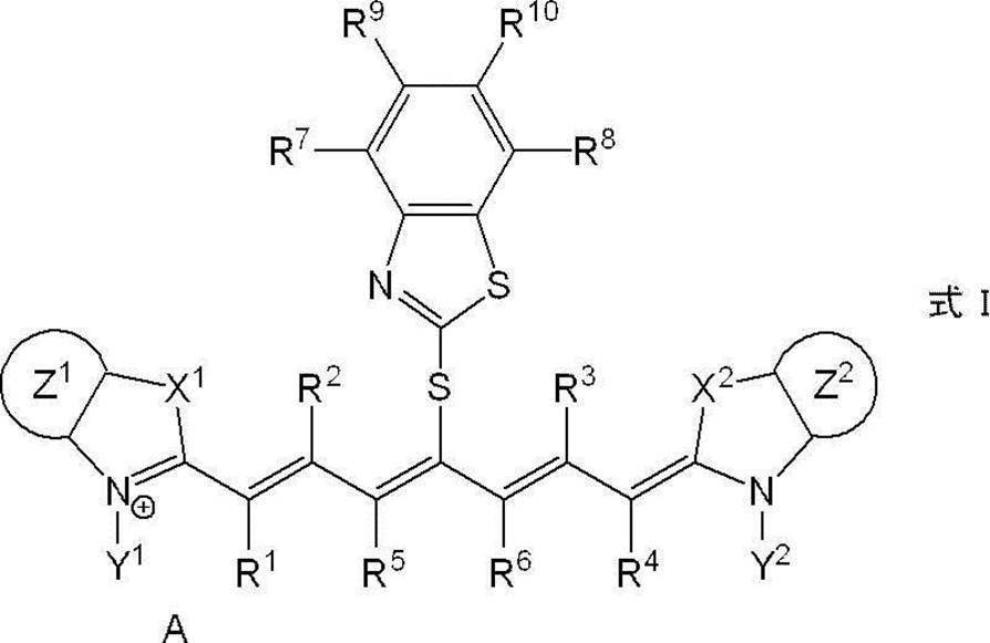
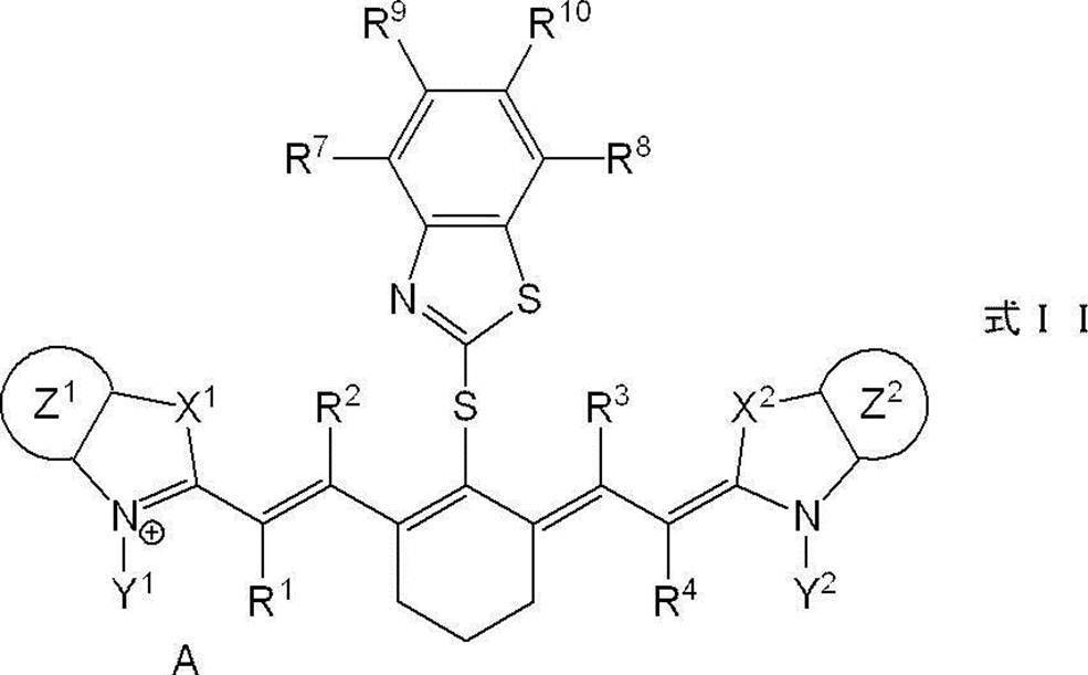
<2> 式Iで表される赤外線吸収剤が、式IIで表される赤外線吸収剤である、<1>に記載の平版印刷版原版。 In formula I, X 1 and X 2 each independently represent a sulfur atom, an oxygen atom or a dialkylmethylene group having 12 or less carbon atoms, and Y 1 and Y 2 each independently represent a monovalent organic group or a hydrogen atom. Z 1 and Z 2 each independently represents a benzene ring, a naphthalene ring or a hetero ring having 6 to 20 ring members which has no substituent or is substituted by an electron donating group or an aryl group having 6 to 20 carbon atoms. Represents an aromatic ring, R 1 , R 2 , R 3 and R 4 each independently represents a hydrogen atom or a hydrocarbon group having 12 or less carbon atoms, and R 5 and R 6 each independently represents a hydrocarbon group. Each may be linked to form a 5-membered or 6-membered ring, R 7 , R 8 , R 9 and R 10 each independently represent a hydrogen atom or a monovalent organic group, and A is a charge The counter ions present when neutralization of .
<2> The lithographic printing plate precursor as described in <1>, wherein the infrared absorbent represented by formula I is an infrared absorbent represented by formula II.

<3> 上記画像記録層が、重合性化合物及び重合開始剤を更に含有する、<1>又は<2>に記載の平版印刷版原版。
<4> 上記重合開始剤が、ヨードニウム系重合開始剤である、<3>に記載の平版印刷版原版。
<5> 上記画像記録層が、熱可塑性ポリマー粒子を更に含有する、<1>~<4>のいずれか1つに記載の平版印刷版原版。
<6> 上記熱可塑性ポリマー粒子に含まれるポリマーが、スチレンに由来するモノマー単位及びアクリル化合物に由来するモノマー単位のいずれか又は両方のモノマー単位を含有する、<5>に記載の平版印刷版原版。
<7> 上記熱可塑性ポリマー粒子に含まれるポリマーが、スチレン-アクリロニトリル樹脂である、<5>又は<6>に記載の平版印刷版原版。
<8> 上記熱可塑性ポリマー粒子に含まれるポリマーの重量平均分子量が、5,000~1,000,000である、<5>~<7>のいずれか1つに記載の平版印刷版原版。
<9> 上記熱可塑性ポリマー粒子の体積平均粒径が、0.01μm~50μmである、<5>~<8>のいずれか1つに記載の平版印刷版原版。
<10> 上記画像記録層の全質量に対する、上記熱可塑性ポリマー粒子の含有量が、20質量%~95質量%である、<5>~<9>のいずれか1つに記載の平版印刷版原版。
<11> 上記画像記録層が、ロイコ化合物を更に含有する、<1>~<10>のいずれか1つに記載の平版印刷版原版。
<12> 上記画像記録層が、湿し水及び印刷インキのいずれか又は両方により除去可能である、<1>~<11>のいずれか1つに記載の平版印刷版原版。
<13> 上記画像記録層が、ガム現像可能である、<1>~<12>のいずれか1つに記載の平版印刷版原版。
<14> <1>~<13>のいずれか1つに記載の平版印刷版原版を、画像様に露光し、露光部と未露光部とを形成する露光工程、及び、印刷インキ及び湿し水の少なくとも一方を供給して上記未露光部を除去する機上現像工程を含む平版印刷版の製版方法。
<15> <1>~<13>のいずれか1つに記載の平版印刷版原版を、画像様に露光し、露光部と未露光部とを形成する露光工程、印刷インキ及び湿し水の少なくとも一方を供給して上記未露光部を除去する機上現像工程、及び、上記機上現像工程において機上現像された平版印刷版に印刷インキを供給して記録媒体を印刷する印刷工程をこの順で含む平版印刷方法。 In Formula II, X 1 and X 2 each independently represent a sulfur atom, an oxygen atom, or a dialkylmethylene group having 12 or less carbon atoms, and Y 1 and Y 2 each independently represent a monovalent organic group or a hydrogen atom. Z 1 and Z 2 each independently represents a benzene ring, a naphthalene ring or a hetero ring having 6 to 20 ring members which has no substituent or is substituted by an electron donating group or an aryl group having 6 to 20 carbon atoms. Represents an aromatic ring, R 1 , R 2 , R 3 and R 4 each independently represent a hydrogen atom or a hydrocarbon group having 12 or less carbon atoms, and R 7 , R 8 , R 9 and R 10 each independently Represents a hydrogen atom or a monovalent organic group, and A represents a counter ion present when charge neutralization is required.
<3> The lithographic printing plate precursor as described in <1> or <2>, wherein the image recording layer further contains a polymerizable compound and a polymerization initiator.
<4> The lithographic printing plate precursor as described in <3>, wherein the polymerization initiator is an iodonium-based polymerization initiator.
<5> The lithographic printing plate precursor as described in any one of <1> to <4>, wherein the image recording layer further contains thermoplastic polymer particles.
<6> The lithographic printing plate precursor as described in <5>, wherein the polymer contained in the thermoplastic polymer particles contains one or both of a monomer unit derived from styrene and a monomer unit derived from an acrylic compound. .
<7> The lithographic printing plate precursor as described in <5> or <6>, wherein the polymer contained in the thermoplastic polymer particles is a styrene-acrylonitrile resin.
<8> The lithographic printing plate precursor as described in any one of <5> to <7>, wherein the polymer contained in the thermoplastic polymer particles has a weight average molecular weight of 5,000 to 1,000,000.
<9> The lithographic printing plate precursor as described in any one of <5> to <8>, wherein the thermoplastic polymer particles have a volume average particle diameter of 0.01 μm to 50 μm.
<10> The lithographic printing plate according to any one of <5> to <9>, wherein the content of the thermoplastic polymer particles is 20% by mass to 95% by mass with respect to the total mass of the image recording layer. Original edition.
<11> The lithographic printing plate precursor as described in any one of <1> to <10>, wherein the image recording layer further contains a leuco compound.
<12> The lithographic printing plate precursor as described in any one of <1> to <11>, wherein the image recording layer is removable with one or both of a fountain solution and a printing ink.
<13> The lithographic printing plate precursor as described in any one of <1> to <12>, wherein the image recording layer is gum developable.
<14> An exposure process in which the lithographic printing plate precursor according to any one of <1> to <13> is exposed imagewise to form an exposed area and an unexposed area, and printing ink and dampening A method for making a lithographic printing plate, comprising an on-machine development step of supplying at least one of water to remove the unexposed portion.
<15> An exposure process in which the lithographic printing plate precursor according to any one of <1> to <13> is exposed imagewise to form an exposed area and an unexposed area, printing ink, and dampening water An on-machine development process for supplying at least one to remove the unexposed area, and a printing process for printing a recording medium by supplying printing ink to the lithographic printing plate developed on-machine in the on-machine development process. Lithographic printing method including in order.
なお、本明細書において、数値範囲を示す「~」とはその前後に記載される数値を下限値及び上限値として含む意味で使用される。
また、本明細書における基(原子団)の表記において、置換及び無置換を記していない表記は、置換基を有さないものと共に置換基を有するものをも包含するものである。例えば「アルキル基」とは、置換基を有さないアルキル基(無置換アルキル基)のみならず、置換基を有するアルキル基(置換アルキル基)をも包含するものである。
また、本明細書において、「質量%」と「重量%」とは同義であり、「質量部」と「重量部」とは同義である。
本明細書において「工程」との語は、独立した工程だけでなく、他の工程と明確に区別できない場合であっても工程の所期の目的が達成されれば、本用語に含まれる。
なお、本明細書において、好ましい態様の組み合わせは、より好ましい態様である。 Hereinafter, the contents of the present disclosure will be described in detail. The description of the constituent elements described below may be made based on typical embodiments of the present disclosure, but the present disclosure is not limited to such embodiments.
In the present specification, “to” indicating a numerical range is used in a sense including numerical values described before and after the numerical value as a lower limit value and an upper limit value.
Moreover, in the description of groups (atomic groups) in this specification, the description that does not indicate substitution and non-substitution includes those that have a substituent as well as those that do not have a substituent. For example, the “alkyl group” includes not only an alkyl group having no substituent (unsubstituted alkyl group) but also an alkyl group having a substituent (substituted alkyl group).
In the present specification, “mass%” and “wt%” are synonymous, and “part by mass” and “part by weight” are synonymous.
In this specification, the term “process” is not only an independent process, but is included in this term if the intended purpose of the process is achieved even when it cannot be clearly distinguished from other processes.
In addition, in this specification, the combination of a preferable aspect is a more preferable aspect.
本開示に係る平版印刷版原版(以下、単に「平版印刷版原版」ともいう。)は、支持体上に、式Iで表される赤外線吸収剤を含有する画像記録層を有する。 (Lithographic printing plate precursor)
A lithographic printing plate precursor according to the present disclosure (hereinafter also simply referred to as “lithographic printing plate precursor”) has an image recording layer containing an infrared absorber represented by Formula I on a support.
そこで、本発明者は鋭意検討した結果、式Iで表される赤外線吸収剤を含むことにより、得られる平版印刷版の耐刷性に優れた平版印刷版原版が得られることを見出した。
上記効果が生じる理由は明確ではないが、次のように考えている。
本開示に係る平版印刷版原版を赤外線(IR)により露光した場合、画像記録層に含まれる式Iで表される赤外線吸収剤は分解すると考えられる。式Iで表される赤外線吸収剤は、上記分解の際に、熱の発生、及び、必要に応じて画像記録層に含まれる重合開始剤への電子移動のいずれか又は両方を、効率よく行うと考えられる。
そのため、画像記録層が例えば重合性化合物及び重合開始剤を含む場合には、重合性化合物の重合が効率よく進行し、耐刷性に優れた、強固な画像部が形成されると考えられる。
更に、式Iで表される赤外線吸収剤は、分解後にメルカプトベンゾチアゾール構造を有する化合物を生成すると考えられる。このメルカプトベンゾチアゾール構造を有する化合物は優れた連鎖移動能を有しているため、画像記録層が重合性化合物及び重合開始剤を含む場合には、重合性化合物の重合が更に効率よく進行し、更に耐刷性に優れた、強固な画像部が形成されると考えられる。
また、画像記録層が、例えば熱可塑性ポリマー粒子を含む場合には、式Iで表される赤外線吸収剤は光熱変換効率に優れており、露光量に対する熱の発生量が大きくなるため、熱可塑性ポリマー粒子がしっかりと溶融し、耐刷性に優れた、強固な画像部が形成されると考えられる。 As described above, the present inventor has found that improvement of printing durability is a problem in the conventional lithographic printing plate precursor.
As a result of intensive studies, the present inventor has found that a lithographic printing plate precursor excellent in printing durability of the obtained lithographic printing plate can be obtained by including an infrared absorber represented by formula I.
The reason for the above effect is not clear, but is considered as follows.
When the lithographic printing plate precursor according to the present disclosure is exposed to infrared rays (IR), it is considered that the infrared absorbent represented by the formula I contained in the image recording layer is decomposed. The infrared absorber represented by Formula I efficiently performs either or both of heat generation and, if necessary, electron transfer to the polymerization initiator contained in the image recording layer during the decomposition. it is conceivable that.
Therefore, when the image recording layer contains, for example, a polymerizable compound and a polymerization initiator, it is considered that the polymerization of the polymerizable compound proceeds efficiently and a strong image portion having excellent printing durability is formed.
Furthermore, the infrared absorber represented by Formula I is considered to produce a compound having a mercaptobenzothiazole structure after decomposition. Since the compound having this mercaptobenzothiazole structure has an excellent chain transfer ability, when the image recording layer contains a polymerizable compound and a polymerization initiator, the polymerization of the polymerizable compound proceeds more efficiently, Further, it is considered that a strong image portion having excellent printing durability is formed.
In addition, when the image recording layer contains, for example, thermoplastic polymer particles, the infrared absorber represented by the formula I is excellent in photothermal conversion efficiency, and the amount of heat generated with respect to the exposure amount is increased, so that the thermoplasticity It is considered that the polymer particles are firmly melted and a strong image portion having excellent printing durability is formed.
加えて、画像記録層が例えばロイコ色素等の発色剤を含む場合には、上述の熱の発生量が大きくなることに起因して、より発色性に優れた平版印刷版原版が得られると考えられる。
以下、本開示に係る平版印刷版原版に含まれる各成分の詳細について記載する。 In addition, the dye represented by Formula I used in the present disclosure has a large absorption wavelength due to the above-described decomposition due to exposure, and thus has excellent color developability at an exposed portion (image portion).
In addition, when the image recording layer contains a color former such as a leuco dye, it is considered that a lithographic printing plate precursor having more excellent color developability can be obtained due to an increase in the amount of heat generated as described above. It is done.
Hereinafter, details of each component included in the lithographic printing plate precursor according to the present disclosure will be described.
本開示における画像記録層は、式Iで表される赤外線吸収剤(「特定赤外線吸収剤」ともいう。)を含む。
本開示における画像記録層は、下記第一の態様~第五の態様のいずれかの態様であることが好ましい。
第一の態様:特定赤外線吸収剤、重合性化合物及び重合開始剤を含有する。
第二の態様:特定赤外線吸収剤及び熱可塑性ポリマー粒子を含有する。
第三の態様:第一の態様において、ポリマー粒子又はミクロゲルを更に含有する。
第四の態様:第一の態様において、熱可塑性ポリマー粒子を更に含有する。
第五の態様:第四の態様において、ミクロゲルを更に含有する。
上記第一の態様又は第二の態様によれば、得られる平版印刷版の耐刷性に優れた平版印刷版原版が得られる。
上記第三の態様によれば、機上現像性に優れた平版印刷版原版が得られる。
上記第四の態様によれば、更に耐刷性に優れた平版印刷版原版が得られる。
上記第五の態様によれば、更に耐刷性に優れた平版印刷版原版が得られる。 <Image recording layer>
The image recording layer in the present disclosure includes an infrared absorber represented by Formula I (also referred to as “specific infrared absorber”).
The image recording layer in the present disclosure is preferably in any one of the following first to fifth embodiments.
1st aspect: It contains a specific infrared absorber, a polymeric compound, and a polymerization initiator.
Second embodiment: Contains a specific infrared absorber and thermoplastic polymer particles.
Third aspect: In the first aspect, it further contains polymer particles or microgel.
Fourth aspect: In the first aspect, thermoplastic polymer particles are further contained.
Fifth embodiment: In the fourth embodiment, a microgel is further contained.
According to the first aspect or the second aspect, a lithographic printing plate precursor excellent in printing durability of the obtained lithographic printing plate can be obtained.
According to the third aspect, a lithographic printing plate precursor having excellent on-press developability can be obtained.
According to the fourth aspect, a lithographic printing plate precursor having further excellent printing durability can be obtained.
According to the fifth aspect, a lithographic printing plate precursor having further excellent printing durability can be obtained.
本開示における画像記録層は、特定赤外線吸収剤を含む。 [Specific infrared absorber]
The image recording layer in the present disclosure includes a specific infrared absorber.

X1及びX2は、異なる構造であってもよいが、同一の構造であることが好ましい。 In formula I, X 1 and X 2 are each independently preferably a dialkylmethylene group having 12 or less carbon atoms, more preferably a dialkylmethylene group in which the two alkyl groups each independently have 1 to 4 carbon atoms, and more preferably a dimethylmethylene group Is more preferable.
X 1 and X 2 may have different structures, but are preferably the same structure.
上記炭素数1~10のアルキル基としては、炭素数2~4のアルキル基がより好ましく、エチル基又はプロピル基がより好ましい。
上記炭素数2~10のアルコキシアルキル基としては、炭素数2~6のアルコキシアルキル基が好ましく、メトキシエチル基、エトキシエチル基、プロポキシエチル基、メトキシプロピル基、エトキシプロピル基、又は、プロポキシプロピル基がより好ましく、メトキシプロピル基が更に好ましい。
上記炭素数7~24のアルコキシアルキル基としては、フェノキシメチル基、フェノキシエチル基、フェノキシプロピル基、ナフトキシメチル基、ナフトキシエチル基、又は、ナフトキシプロピル基が好ましい。
炭素数1~10のアルキルスルホン酸基としては、炭素数1~8のアルキルスルホン酸基が好ましく、炭素数1~6のアルキルスルホン酸基がより好ましい。上記アルキルスルホン酸基に含まれるスルホン酸は、公知のカチオンと塩を形成していてもよい。カチオンとしては、例えば、後述のAに含まれるカチオンが挙げられる。
Y1及びY2は、異なる構造であってもよいが、同一の構造であることが好ましい。 In formula I, Y 1 and Y 2 are preferably each independently a monovalent organic group, and are an alkyl group having 1 to 10 carbon atoms, an alkoxyalkyl group having 2 to 10 carbon atoms, or an alkyl group having 7 to 24 carbon atoms. An aryloxyalkyl group or an alkylsulfonic acid group having 1 to 10 carbon atoms is more preferable, an alkyl group having 1 to 10 carbon atoms, an alkoxyalkyl group having 2 to 10 carbon atoms, or an alkylsulfonic acid group having 1 to 10 carbon atoms. Is more preferable, and from the viewpoint of solubility in the composition, an ethyl group, a propyl group or a methoxypropyl group is particularly preferable, and a methoxypropyl group is most preferable.
The alkyl group having 1 to 10 carbon atoms is more preferably an alkyl group having 2 to 4 carbon atoms, and more preferably an ethyl group or a propyl group.
The alkoxyalkyl group having 2 to 10 carbon atoms is preferably an alkoxyalkyl group having 2 to 6 carbon atoms, and is a methoxyethyl group, ethoxyethyl group, propoxyethyl group, methoxypropyl group, ethoxypropyl group, or propoxypropyl group. Is more preferable, and a methoxypropyl group is still more preferable.
The alkoxyalkyl group having 7 to 24 carbon atoms is preferably a phenoxymethyl group, a phenoxyethyl group, a phenoxypropyl group, a naphthoxymethyl group, a naphthoxyethyl group, or a naphthoxypropyl group.
As the alkylsulfonic acid group having 1 to 10 carbon atoms, an alkylsulfonic acid group having 1 to 8 carbon atoms is preferable, and an alkylsulfonic acid group having 1 to 6 carbon atoms is more preferable. The sulfonic acid contained in the alkylsulfonic acid group may form a salt with a known cation. As a cation, the cation contained in A mentioned later is mentioned, for example.
Y 1 and Y 2 may have different structures, but are preferably the same structure.
上記ヘテロ芳香環に含まれるヘテロ原子としては、窒素原子、酸素原子又は硫黄原子が挙げられる。
Z1及びZ2が上記構造であることにより、耐刷性により優れると考えられる。
本開示において、電子供与性基とは、分子の特定の位置と結合することにより、上記特定の位置における電子密度を増加させる効果を有する置換基をいう。
上記電子供与性基としては、アルキル基、アルコキシ基、ヒドロキシ基、又は、アミノ基が好ましく、メトキシ基、又はアミノ基がより好ましく、メトキシ基が更に好ましい。
これらの電子供与性基は、上述の電子密度を増加させる効果を失わない限りにおいて、更に置換基を有していてもよい。
上記アルキル基としては、炭素数1~10のアルキル基が好ましく、炭素数1~4のアルキル基がより好ましく、メチル基が更に好ましい。
上記アルコキシ基としては、炭素数1~10のアルコキシ基が好ましく、炭素数1~4のアルコキシ基がより好ましく、メトキシ基が更に好ましい。
上記アミノ基としては、無置換アミノ基、ジアルキルアミノ基、ジアリールアミノ基が好ましく、ジアルキルアミノ基がより好ましく、ジメチルアミノ基が更に好ましい。
上述の炭素数6~20のアリール基としては、フェニル基又はナフチル基が好ましく、フェニル基がより好ましい。
Z1及びZ2において、ベンゼン環、ナフタレン環又は環員数6~20のヘテロ芳香環は、上記電子供与性基又は上記炭素数6~20のアリール基を複数有していてもよいが、1つのみ有していることが好ましい。
Z1及びZ2は、異なる構造であってもよいが、同一の構造であることが好ましい。 In formula I, Z 1 and Z 2 are each independently a benzene ring, a naphthalene ring or a ring member having 6 to 20 members which has no substituent or is substituted by an electron donating group or an aryl group having 6 to 20 carbon atoms. A benzene ring, a naphthalene ring, or a heteroaromatic ring having 6 to 20 ring members substituted with an electron donating group is more preferable, and a benzene ring or a naphthalene ring substituted with an electron donating group is Further preferred.
Examples of the hetero atom contained in the heteroaromatic ring include a nitrogen atom, an oxygen atom, and a sulfur atom.
When Z 1 and Z 2 have the above structure, it is considered that the printing durability is more excellent.
In the present disclosure, the electron donating group refers to a substituent having an effect of increasing the electron density at the specific position by binding to a specific position of the molecule.
The electron donating group is preferably an alkyl group, an alkoxy group, a hydroxy group, or an amino group, more preferably a methoxy group or an amino group, and even more preferably a methoxy group.
These electron donating groups may further have a substituent as long as the above-described effect of increasing the electron density is not lost.
The alkyl group is preferably an alkyl group having 1 to 10 carbon atoms, more preferably an alkyl group having 1 to 4 carbon atoms, and still more preferably a methyl group.
The alkoxy group is preferably an alkoxy group having 1 to 10 carbon atoms, more preferably an alkoxy group having 1 to 4 carbon atoms, and further preferably a methoxy group.
As said amino group, an unsubstituted amino group, a dialkylamino group, and a diarylamino group are preferable, a dialkylamino group is more preferable, and a dimethylamino group is still more preferable.
As the aryl group having 6 to 20 carbon atoms, a phenyl group or a naphthyl group is preferable, and a phenyl group is more preferable.
In Z 1 and Z 2 , the benzene ring, naphthalene ring or heteroaromatic ring having 6 to 20 ring members may have a plurality of the electron donating group or the aryl group having 6 to 20 carbon atoms. It is preferable to have only one.
Z 1 and Z 2 may have different structures, but are preferably the same structure.
式I中、耐刷性及び発色性の観点から、R5及びR6はそれぞれが連結し5員環又は6員環を形成することが好ましい。 In formula I, R 5 and R 6 are preferably each independently an alkyl group having 1 to 4 carbon atoms.
In formula I, R 5 and R 6 are preferably connected to each other to form a 5-membered ring or a 6-membered ring from the viewpoint of printing durability and color developability.
上記ハロゲン原子としては、フッ素(F)原子、塩素(Cl)原子、臭素(Br)原子又はヨウ素(I)原子が好ましく、F原子又はCl原子がより好ましい。 In formula I, R 7 , R 8 , R 9 and R 10 are each independently a hydrogen atom, an alkyl group having 1 to 4 carbon atoms, an alkoxy group having 1 to 4 carbon atoms, or an alkoxyalkyl group having 2 to 6 carbon atoms. Or a halogen atom (halogeno group) is preferred, and a hydrogen atom is more preferred.
The halogen atom is preferably a fluorine (F) atom, a chlorine (Cl) atom, a bromine (Br) atom or an iodine (I) atom, more preferably an F atom or a Cl atom.
式Iで示される赤外線吸収剤のうち、対イオンを除く構造が電気的に中性の構造であり、電荷の中和が必要ない場合にはAは必要ない。
Aがアニオンである場合、得られる平版印刷版の耐刷性及び平版印刷版原版の発色性の観点から、スルホネートイオン、カルボキシレートイオン、テトラフルオロボレートイオン、テトラアリールボレートイオン、ヘキサフルオロホスフェートイオン、p-トルエンスルホネートイオン、過塩素酸塩イオン等が挙げられ、テトラアリールボレートイオンが好ましく、テトラフェニルボレートイオンがより好ましい。
Aがカチオンである場合、得られる平版印刷版の耐刷性及び平版印刷版原版の発色性の観点から、アルカリ金属イオン、アルカリ土類金属イオン、アンモニウムイオン、ピリジニウムイオン、又は、スルホニウムイオンが挙げられ、スルホニウムイオンが好ましい。 A represents a counter ion necessary for charge neutralization, and may be an anion or a cation.
Of the infrared absorbers represented by Formula I, A is not necessary when the structure excluding the counter ion is an electrically neutral structure and neutralization of charge is not necessary.
When A is an anion, sulfonate ion, carboxylate ion, tetrafluoroborate ion, tetraarylborate ion, hexafluorophosphate ion, from the viewpoint of printing durability of the resulting lithographic printing plate and color developability of the lithographic printing plate precursor, Examples thereof include p-toluenesulfonate ion and perchlorate ion. Tetraarylborate ion is preferable, and tetraphenylborate ion is more preferable.
When A is a cation, an alkali metal ion, an alkaline earth metal ion, an ammonium ion, a pyridinium ion, or a sulfonium ion is mentioned from the viewpoint of printing durability of the resulting lithographic printing plate and color developability of the lithographic printing plate precursor. And sulfonium ions are preferred.
式Iで表される赤外線吸収剤は、耐刷性及び発色性の観点から、式IIで表される赤外線吸収剤であることが好ましい。 -Infrared absorber represented by Formula II-
The infrared absorbent represented by Formula I is preferably an infrared absorbent represented by Formula II from the viewpoints of printing durability and color developability.
また、特定赤外線吸収剤の含有量は、上記画像記録層の全質量に対し、0.05質量%~30質量%であることが好ましく、0.1質量%~20質量%であることがより好ましく、0.2質量%~10質量%であることが更に好ましい。
以下、特定赤外線吸収剤の具体例を記載するが、これに限定されるものではない。 A specific infrared absorber may be used individually by 1 type, and may use 2 or more types together.
Further, the content of the specific infrared absorber is preferably 0.05% by mass to 30% by mass and more preferably 0.1% by mass to 20% by mass with respect to the total mass of the image recording layer. The content is preferably 0.2% by mass to 10% by mass.
Hereinafter, although the specific example of a specific infrared absorber is described, it is not limited to this.

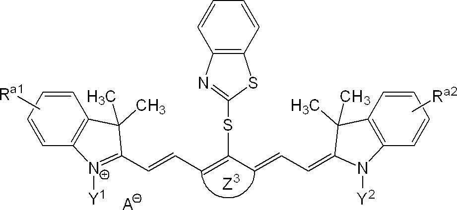
また、表1中、Phはフェニル基を、OTfはトリフラートイオンを、OTsはp-トルエンスルホネートイオンをそれぞれ表す。 In Table 1, numerical values listed in the column of Z 3 represents the ring members hydrocarbon ring corresponding to Z 3 in the following compounds, R a1 and R a2, Y 1 and Y 2 and each description of A, Structures corresponding to R a1 and R a2 , Y 1 and Y 2 and A in the following compounds are shown. In addition, the compound described as “none” in the columns of R a1 and R a2 indicates that the benzene ring has no substituent.
In Table 1, Ph represents a phenyl group, OTf represents a triflate ion, and OTs represents a p-toluenesulfonate ion.
重合性化合物としては、重合性基を有する化合物であればよいが、ラジカル重合性基を有する化合物が好ましい。
ラジカル重合性基を有する化合物としては、エチレン性不飽和化合物が好ましく挙げられる。
エチレン性不飽和化合物としては、単官能及び多官能のいずれでもよいが、多官能エチレン性不飽和化合物が好ましく、耐刷性の観点から、3官能以上の多官能エチレン性不飽和化合物がより好ましく、10官能以上の多官能エチレン性不飽和化合物が更に好ましい。
また、重合性化合物は、例えばモノマー、プレポリマー、すなわち2量体、3量体若しくはオリゴマー、ポリマー、又は、それらの混合物などの化学的形態をもつ。
多官能エチレン性不飽和化合物としては、アルコールの不飽和型エステルが好ましく、ポリオールのアクリル酸エステル化合物及びメタクリル酸エステル化合物がより好ましい。
オリゴマー又はプレポリマーとしては、例えば、ウレタンアクリレート及びメタクリレート、エポキシドアクリレート及びメタクリレート、ポリエステルアクリレート及びメタクリレート、ポリエーテルアクリレート及びメタクリレート、並びに、不飽和型ポリエステル樹脂を使用することもできる。
これらの中でも、アクリレート化合物及びメタクリレート化合物が好ましく、多官能アクリレート化合物及び多官能メタクリレート化合物がより好ましい。
また、重合性化合物としては、耐刷性の観点から、ウレタン結合を有することが好ましい。
ウレタン結合を有する重合性化合物としては、ウレタン(メタ)アクリレート化合物が好ましく挙げられる。 (Polymerizable compound)
The polymerizable compound may be a compound having a polymerizable group, but a compound having a radical polymerizable group is preferable.
Preferred examples of the compound having a radical polymerizable group include ethylenically unsaturated compounds.
The ethylenically unsaturated compound may be monofunctional or polyfunctional, but is preferably a polyfunctional ethylenically unsaturated compound, and more preferably a trifunctional or higher polyfunctional ethylenically unsaturated compound from the viewpoint of printing durability. A polyfunctional ethylenically unsaturated compound having 10 or more functional groups is more preferable.
In addition, the polymerizable compound has a chemical form such as a monomer, a prepolymer, that is, a dimer, a trimer or an oligomer, a polymer, or a mixture thereof.
As the polyfunctional ethylenically unsaturated compound, an unsaturated ester of alcohol is preferable, and an acrylic ester compound and a methacrylic ester compound of polyol are more preferable.
As the oligomer or prepolymer, for example, urethane acrylate and methacrylate, epoxide acrylate and methacrylate, polyester acrylate and methacrylate, polyether acrylate and methacrylate, and unsaturated polyester resin may be used.
Among these, acrylate compounds and methacrylate compounds are preferable, and polyfunctional acrylate compounds and polyfunctional methacrylate compounds are more preferable.
In addition, the polymerizable compound preferably has a urethane bond from the viewpoint of printing durability.
Preferred examples of the polymerizable compound having a urethane bond include urethane (meth) acrylate compounds.
本開示において、低分子化合物の分子量は、質量分析法(MS)により測定される。 The molecular weight of the polymerizable compound (in the case of distribution, the weight average molecular weight) is preferably from 100 to 5,000, more preferably from 200 to 2,000, and preferably from 200 to 1,000. Further preferred.
In the present disclosure, the molecular weight of the low molecular weight compound is measured by mass spectrometry (MS).
本開示に係る平版印刷版原版の画像記録層は、重合開始剤を含むことが好ましい。
本開示において、重合開始剤は、特に制限されないが、特開2013-205569号公報に記載のラジカル重合開始剤が好ましく用いられる。中でもオキシムエステル化合物及びオニウム塩が好ましく、ヨードニウム塩、スルホニウム塩及びアジニウム塩等のオニウム塩がより好ましく、ヨードニウム塩が更に好ましい。
重合開始剤は、1種単独でも、2種以上を適宜併用することもできる。
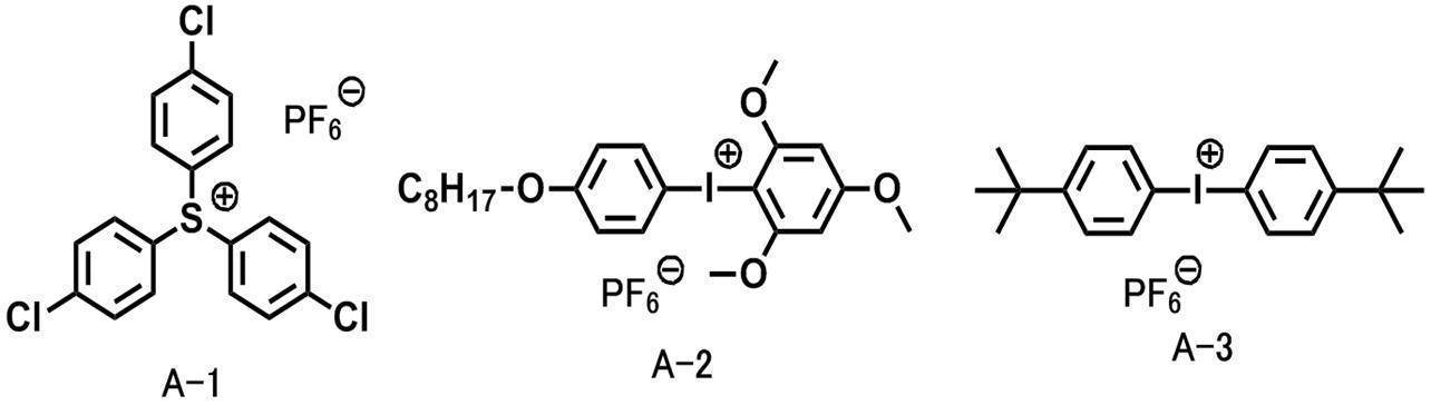
ヨードニウム塩及びスルホニウム塩の具体例を以下に示すが、本開示はこれらに限定されるものではない。 (Polymerization initiator)
The image recording layer of the lithographic printing plate precursor according to the present disclosure preferably contains a polymerization initiator.
In the present disclosure, the polymerization initiator is not particularly limited, but a radical polymerization initiator described in JP2013-205569A is preferably used. Of these, oxime ester compounds and onium salts are preferable, onium salts such as iodonium salts, sulfonium salts, and azinium salts are more preferable, and iodonium salts are more preferable.
The polymerization initiator can be used alone or in combination of two or more.
Specific examples of the iodonium salt and the sulfonium salt are shown below, but the present disclosure is not limited thereto.
また、画像記録層は、増感剤を更に含有していてもよい。
このような増感剤及び重合開始剤の併用の例としては、例えば、米国特許第4,997,745号明細書(Kawamura他)に記載されているような、単独での、又は別個の光増感剤と一緒の状態でのトリハロメチルトリアジン;例えば米国特許第5,599,650号明細書(Bi他)に記載されているような、トリハロメチルトリアジンと一緒の状態での可視光活性化用分光増感剤;米国特許第5,942,372号明細書(West他)に記載されているような、ポリカルボン酸共開始剤、例えばアニリノ-N,N-二酢酸、及び二次共開始剤、例えばジアリールヨードニウム塩、チタノセン、ハロアルキルトリアジン、ヘキサアリールビスイミジゾール、ホウ酸塩、及び、アルコキシ基又はアシルオキシ基によって置換された複素環式窒素原子を含有する光酸化剤と一緒の状態の、紫外線及び可視光の活性化のための3-ケトクマリン;例えば米国特許第5,368,990号明細書(Kawabata他)に記載されているような、シアニン色素、ジアリールヨードニウム塩、及び、芳香族環に直接的に結合されたN、O又はS基に、メチレン基を介して結合されたカルボン酸基を有する共開始剤;例えば米国特許第5,496,903号明細書(Watanabe他)に記載されているような、トリハロメチルトリアジン及び有機ホウ素塩と一緒の状態の赤外線活性化用シアニン色素;赤外線吸収剤、トリクロロメチルトリアジン及びアジニウム化合物を含む、開始用フリーラジカルを生成することができる化合物、並びに、例えば米国特許第6,309,792号明細書(Hauck他)に記載されているような、芳香族環に直接的に結合されたN、O又はS基に、メチレン基を介して結合されたカルボン酸基を有するポリカルボン酸共開始剤が挙げられる。 [Sensitizer]
The image recording layer may further contain a sensitizer.
Examples of such sensitizer and polymerization initiator combinations include, for example, single or separate light, as described in US Pat. No. 4,997,745 (Kawamura et al.). Trihalomethyltriazine in the presence of a sensitizer; visible light activation in the presence of a trihalomethyltriazine, for example as described in US Pat. No. 5,599,650 (Bi et al.) Spectral sensitizers; polycarboxylic acid coinitiators such as anilino-N, N-diacetic acid, and secondary co-initiators, as described in US Pat. No. 5,942,372 (West et al.) Initiators such as diaryliodonium salts, titanocenes, haloalkyltriazines, hexaarylbisimidizoles, borates, and compounds substituted by alkoxy or acyloxy groups. 3-ketocoumarins for activation of ultraviolet and visible light in the presence of photo-oxidants containing cyclic nitrogen atoms; for example described in US Pat. No. 5,368,990 (Kawabata et al.) A cyanine dye, a diaryliodonium salt, and a co-initiator having a carboxylic acid group bonded via a methylene group to an N, O, or S group directly bonded to an aromatic ring; Infrared activating cyanine dyes in combination with trihalomethyltriazines and organoboron salts as described in US Pat. No. 5,496,903 (Watanabe et al.); Infrared absorbers, trichloromethyltriazines and aziniums Compounds capable of generating initiating free radicals, including compounds, as well as, for example, US Pat. No. 6,309,792 Polycarboxylic acid co-initiation with a carboxylic acid group bonded via a methylene group to an N, O or S group bonded directly to an aromatic ring, as described in the specification (Hauck et al.) Agents.
平版印刷版原版の機上現像性を向上させるために、画像記録層は、ミクロゲル又はポリマー粒子を含有してもよい。上記ミクロゲルやポリマー粒子は、赤外線照射による光や熱により架橋、溶融、又は、これら両方が生じる、或いは疎水性に変化することが好ましい。ミクロゲルやポリマー粒子は、非架橋性ミクロゲル、架橋性ミクロゲル、熱可塑性ポリマー粒子、熱反応性ポリマー粒子、及び、重合性基を有するポリマー粒子よりなる群から選ばれる少なくとも1つであることが好ましい。これらはコアシェル構造を有していてもよく、他の化合物を内包していてもよい。 [Microgel and polymer particles]
In order to improve the on-press developability of the lithographic printing plate precursor, the image recording layer may contain microgel or polymer particles. The microgel and polymer particles are preferably crosslinked, melted, or both caused by light or heat generated by infrared irradiation, or changed to hydrophobicity. The microgel and polymer particles are preferably at least one selected from the group consisting of non-crosslinkable microgels, crosslinkable microgels, thermoplastic polymer particles, thermally reactive polymer particles, and polymer particles having a polymerizable group. These may have a core-shell structure and may contain other compounds.
熱可塑性ポリマー粒子としては、1992年1月のResearch Disclosure No.33303、特開平9-123387号公報、同9-131850号公報、同9-171249号公報、同9-171250号公報及び欧州特許第931647号明細書などに記載のポリマー粒子が好適に挙げられる。
熱可塑性ポリマー粒子に含まれるポリマーの具体例としては、エチレン、スチレン、塩化ビニル、アクリル酸メチル、アクリル酸エチル、メタクリル酸メチル、メタクリル酸エチル、塩化ビニリデン、アクリロニトリル、ビニルカルバゾール、ポリアルキレン構造を有するアクリレート又はメタクリレートなどのモノマーのホモポリマー若しくはコポリマー又はそれらの混合物が挙げられる。好ましくは、ポリスチレン、スチレン及びアクリロニトリルを含む共重合体、並びに、ポリメタクリル酸メチルが挙げられる。 -Thermoplastic polymer particles-
Thermoplastic polymer particles include Research Disclosure No. 1 of January 1992. Preferred examples include polymer particles described in Japanese Patent No. 33303, JP-A-9-123387, JP-A-9-131850, JP-A-9-171249, JP-A-9-171250 and European Patent 931647.
Specific examples of the polymer contained in the thermoplastic polymer particles include ethylene, styrene, vinyl chloride, methyl acrylate, ethyl acrylate, methyl methacrylate, ethyl methacrylate, vinylidene chloride, acrylonitrile, vinyl carbazole, and a polyalkylene structure. Mention may be made of homopolymers or copolymers of monomers such as acrylates or methacrylates or mixtures thereof. Preferably, polystyrene, a copolymer containing styrene and acrylonitrile, and polymethyl methacrylate are used.
マクロモノマーとは、高分子鎖及び重合性基を有するモノマーであり、例えば、単官能のマクロモノマーを共重合することにより、簡便にグラフトポリマーを形成することができる。
マクロモノマーの数平均分子量は、300~10,000であることが好ましい。
マクロモノマーとしては、ポリ(アルキレングリコール)アルキルエーテル(メタ)アクリレート化合物が好ましく、ポリ(エチレングリコール)アルキルエーテル(メタ)アクリレート化合物がより好ましく、ポリ(エチレングリコール)アルキルエーテルメタクリレート化合物がより好ましい。上記態様であると、機上現像性により優れる。 The styrene-acrylonitrile particles may contain a monomer unit derived from a macromonomer.
The macromonomer is a monomer having a polymer chain and a polymerizable group. For example, a graft polymer can be easily formed by copolymerizing a monofunctional macromonomer.
The number average molecular weight of the macromonomer is preferably 300 to 10,000.
As the macromonomer, a poly (alkylene glycol) alkyl ether (meth) acrylate compound is preferable, a poly (ethylene glycol) alkyl ether (meth) acrylate compound is more preferable, and a poly (ethylene glycol) alkyl ether methacrylate compound is more preferable. In the above embodiment, the on-press developability is more excellent.
熱可塑性ポリマー粒子における、マクロモノマーに由来するモノマー単位の含有量は、熱可塑性ポリマー粒子に含まれるポリマーの全質量に対し、0質量%~40質量%が好ましく、0質量%~20質量%がより好ましい。
なお、本開示において、モノマー単位の数を定義する際にはマクロモノマーを1つのモノマーとして扱い、1つのマクロモノマーを形成するモノマー単位については考慮しないものとする。 The thermoplastic polymer particles used in the present disclosure include a monomer unit derived from styrene (monomer unit St) and a monomer unit derived from acrylonitrile (monomer unit AN), the monomer unit St: monomer unit AN = 100: 0 to The content is preferably 60:40 (mass ratio), and more preferably the monomer unit St: monomer unit AN = 100: 0 to 80:20 (mass ratio).
The content of the monomer unit derived from the macromonomer in the thermoplastic polymer particle is preferably 0% by mass to 40% by mass, and preferably 0% by mass to 20% by mass with respect to the total mass of the polymer contained in the thermoplastic polymer particle. More preferred.
In the present disclosure, when defining the number of monomer units, the macromonomer is treated as one monomer, and the monomer units forming one macromonomer are not considered.
熱可塑性ポリマー粒子の体積平均粒径は、ナノトラック粒度分布測定装置UPA-EX150(日機装(株)製)を用い、動的光散乱法により測定される The volume average particle size of the thermoplastic polymer particles is preferably 0.01 μm to 50 μm, more preferably 0.02 μm to 30 μm, and even more preferably 0.05 μm to 20 μm.
The volume average particle diameter of the thermoplastic polymer particles is measured by a dynamic light scattering method using a nanotrack particle size distribution analyzer UPA-EX150 (manufactured by Nikkiso Co., Ltd.).
画像記録層の全質量に対する、上記熱可塑性ポリマー粒子の含有量は、10質量%~98質量%であることが好ましく、20質量%~95質量%がより好ましく、25質量%~90質量%が更に好ましい。 The image recording layer used in the present disclosure may contain one kind of thermoplastic polymer particles, or two or more kinds may be used in combination.
The thermoplastic polymer particle content with respect to the total mass of the image recording layer is preferably 10% by mass to 98% by mass, more preferably 20% by mass to 95% by mass, and 25% by mass to 90% by mass. Further preferred.
熱反応性ポリマー粒子としては、熱反応性基を有するポリマー粒子が挙げられる。熱反応性基を有するポリマー粒子は、熱反応による架橋及びその際の官能基変化により疎水化領域を形成する。 -Thermally reactive polymer particles-
Examples of the thermally reactive polymer particles include polymer particles having a thermally reactive group. The polymer particles having a thermoreactive group form a hydrophobized region by crosslinking by a thermal reaction and a functional group change at that time.
マイクロカプセルとしては、例えば、特開2001-277740号公報及び特開2001-277742号公報に記載のごとく、画像記録層の構成成分の全て又は一部をマイクロカプセルに内包させたものが挙げられる。画像記録層の構成成分は、マイクロカプセル外にも含有させることもできる。マイクロカプセルを含有する画像記録層としては、疎水性の構成成分をマイクロカプセルに内包し、親水性の構成成分をマイクロカプセル外に含有することが好ましい態様である。 -Microcapsule-
Examples of the microcapsule include those in which all or part of the constituent components of the image recording layer are encapsulated in a microcapsule as described in JP-A Nos. 2001-277740 and 2001-277742. The constituent components of the image recording layer can also be contained outside the microcapsules. The image recording layer containing microcapsules is preferably a mode in which hydrophobic constituent components are encapsulated in microcapsules and hydrophilic constituent components are contained outside the microcapsules.
ミクロゲルは、その内部及び表面の少なくとも一方に、画像記録層の構成成分の一部を含有することができる。特に、ラジカル重合性基をその表面に有することによって反応性ミクロゲルとした態様が画像形成感度や耐刷性の観点から好ましい。
画像記録層の構成成分をマイクロカプセル化又はミクロゲル化するためには、公知の方法を用いることができる。 -Microgel-
The microgel can contain a part of the constituent components of the image recording layer in at least one of the inside and the surface thereof. In particular, an embodiment in which a reactive microgel is formed by having a radical polymerizable group on the surface thereof is preferable from the viewpoint of image forming sensitivity and printing durability.
In order to microencapsulate or microgel the constituent components of the image recording layer, a known method can be used.
本開示における上記各粒子の平均一次粒子径は、粒子の電子顕微鏡写真を撮影し、写真上で粒子の粒径を総計で5,000個測定し、平均値を算出するものとする。なお、非球形粒子については写真上の粒子面積と同一の粒子面積を持つ球形粒子の粒径値を粒径とする。
ミクロゲル又は熱可塑性ポリマー粒子以外のポリマー粒子の含有量は、画像記録層の全固形分に対して、5質量%~90質量%が好ましい。 When the polymer is contained in the form of polymer particles other than microcapsules, microgels or thermoplastic polymer particles in the image recording layer according to the present disclosure, the average primary particle diameter of the polymer particles other than microcapsules, microgels or thermoplastic polymer particles Is preferably 10 nm to 1,000 nm, more preferably 20 nm to 300 nm, and still more preferably 30 nm to 120 nm.
The average primary particle diameter of each particle in the present disclosure is obtained by taking an electron micrograph of the particle, measuring a total of 5,000 particles on the photograph, and calculating the average value. For non-spherical particles, the particle size of spherical particles having the same particle area as that on the photograph is used as the particle size.
The content of polymer particles other than microgel or thermoplastic polymer particles is preferably 5% by mass to 90% by mass with respect to the total solid content of the image recording layer.
本実施形態における画像記録層は、上述の式Iで表される赤外線吸収剤以外の赤外線吸収剤(「他の赤外線吸収剤」ともいう。)を更に含有してもよい。
他の赤外線吸収剤としては、例えば、特開2017-013318号公報の段落0070~段落0079に記載の化合物が挙げられる。
画像記録層が上記他の赤外線吸収剤を含有する場合、含有量としては、画像記録層の全質量に対し、0.05質量%~30質量%であることが好ましく、0.1質量%~20質量%であることがより好ましく、0.2質量%~10質量%であることが更に好ましい。 [Other infrared absorbers]
The image recording layer in the present embodiment may further contain an infrared absorbent other than the infrared absorbent represented by the above formula I (also referred to as “other infrared absorbent”).
Examples of other infrared absorbers include the compounds described in paragraphs 0070 to 0079 of JP-A-2017-013318.
When the image recording layer contains the above other infrared absorbers, the content is preferably 0.05% by mass to 30% by mass, and preferably 0.1% by mass to 0.1% by mass with respect to the total mass of the image recording layer. It is more preferably 20% by mass, and further preferably 0.2% by mass to 10% by mass.
本実施形態における画像記録層は、赤外線吸収剤以外の着色剤を含有することが好ましい。
着色剤としては、例えば、露光により発色する露光発色色素、露光によりほとんど又は完全に無色になる露光消色色素等を用いることができる。露光発色色素としては、例えば、ロイコ化合物が挙げられる。露光消色色素としては、例えば、トリフェニルメタン系色素、ジフェニルメタン系色素、オキザジン系色素、キサンテン系色素、イミノナフトキノン系色素、アゾメチン系色素、アントラキノン系色素等が挙げられる。
発色性の観点から、上記着色剤の中でも、ロイコ化合物を含有することが好ましい。 [Colorant]
The image recording layer in the present embodiment preferably contains a colorant other than the infrared absorber.
As the colorant, for example, an exposure coloring dye that develops color upon exposure, an exposure decoloring dye that becomes almost or completely colorless upon exposure, and the like can be used. Examples of the exposure coloring dye include leuco compounds. Examples of exposure decolorizing dyes include triphenylmethane dyes, diphenylmethane dyes, oxazine dyes, xanthene dyes, iminonaphthoquinone dyes, azomethine dyes, anthraquinone dyes, and the like.
From the viewpoint of color developability, it is preferable to contain a leuco compound among the colorants.
上記画像記録層は、上記ポリマー粒子とは異なるバインダーポリマーを1種又は2種以上含有していてもよい。
上記バインダーポリマーは、粒子状であっても、粒子状でなくともよいが、粒子状でないことが好ましい。
上記バインダーポリマーとしては、水溶性又は水分散性ポリマー、例えばセルロース誘導体、例えばカルボキシメチルセルロース、メチルセルロース、ヒドロキシプロピルメチルセルロース、ヒドロキシプロピルセルロース、ヒドロキシエチルセルロース;ポリビニルアルコール;ポリアクリル酸;ポリメタクリル酸;ポリビニルピロリドン;ポリラクチド、ポリビニルホスホン酸;合成コポリマー、例えばアルコキシポリエチレングリコールアクリレート又はメタクリレート、例えばメトキシポリエチレングリコールアクリレート又はメタクリレートと、モノマー、例えばメチルメタクリレート、メチルアクリレート、ブチルメタクリレート、ブチルアクリレート又はアリルメタクリレートとのコポリマー;及びこれらの混合物が挙げられる。 [Binder polymer]
The image recording layer may contain one or more binder polymers different from the polymer particles.
The binder polymer may be particulate or non-particulate, but is preferably not particulate.
Examples of the binder polymer include water-soluble or water-dispersible polymers such as cellulose derivatives such as carboxymethylcellulose, methylcellulose, hydroxypropylmethylcellulose, hydroxypropylcellulose, hydroxyethylcellulose; polyvinyl alcohol; polyacrylic acid; polymethacrylic acid; polyvinylpyrrolidone; polylactide. Synthetic copolymers such as alkoxy polyethylene glycol acrylate or methacrylate, such as methoxy polyethylene glycol acrylate or methacrylate, and monomers such as methyl methacrylate, methyl acrylate, butyl methacrylate, butyl acrylate or allyl methacrylate; and mixtures thereof Is mentioned .
上記画像記録層は、上述した以外の他の添加剤を含有していてもよい。
他の添加剤としては、公知の添加剤を用いることができ、例えば、特開2013-205569号公報に記載の添加剤を適宜用いることができる。
また、他の添加剤としては、例えば、界面活性剤等が挙げられる。
他の添加剤の総含有量は、画像記録層の全質量に対し、0質量%~20質量%であることが好ましく、0質量%~5質量%であることがより好ましい。 [Other additives]
The image recording layer may contain additives other than those described above.
As other additives, known additives can be used. For example, additives described in JP2013-205569A can be appropriately used.
Moreover, as another additive, surfactant etc. are mentioned, for example.
The total content of other additives is preferably 0% by mass to 20% by mass and more preferably 0% by mass to 5% by mass with respect to the total mass of the image recording layer.
保存寿命を延ばすのに効果的であり得る添加剤の例としては、メルカプト化合物、アミノ化合物、モノカルボン酸及びポリカルボン酸が挙げられる。
好適なメルカプト化合物が、例えば、Timpe他の米国特許出願公開第2002/0197564号明細書に記載されている。米国特許第6,309,792号明細書(Hauck他)に記載された好適なポリカルボン酸は、ヘテロ原子と置換された芳香族部分を有する。Munnelly他の米国特許出願公開第2004/0091811号明細書、及び、Munnelly他の米国特許出願公開第2004/0259027号明細書には、好適なモノカルボン酸添加剤が記載されている。 Moreover, as another additive, the additive for extending the shelf life of an image recording layer is mentioned, for example.
Examples of additives that may be effective in extending shelf life include mercapto compounds, amino compounds, monocarboxylic acids and polycarboxylic acids.
Suitable mercapto compounds are described, for example, in U.S. Patent Application Publication No. 2002/0197564 to Timpe et al. Suitable polycarboxylic acids described in US Pat. No. 6,309,792 (Hauck et al.) Have aromatic moieties substituted with heteroatoms. U.S. Patent Application Publication No. 2004/0091811 to Munnelly et al. And U.S. Patent Application Publication No. 2004/0259027 to Munnelly et al. Describe suitable monocarboxylic acid additives.
本開示における画像記録層の形成方法は、特に制限はなく、公知の方法、例えば、塗布又はラミネーションにより、支持体上、又は、支持体上に存在する後述する下塗り層上に形成することができる。
具体的には例えば、画像記録層の各成分は、好適な塗布用溶剤、例えば、水、又は、水と有機溶剤との混合溶剤、例えばメタノール、エタノール、イソプロピルアルコール及びアセトンよりなる群から選ばれた少なくとも1種との混合物中に分散又は溶解される。界面活性剤、例えばフッ素化界面活性剤若しくはポリエトキシル化ジメチルポリシロキサンコポリマー、又は、界面活性剤の混合物が、塗布用溶剤中に他の成分を分散させるのを助けるように存在することができる。結果として得られる混合物は、公知の方法、例えばスピン塗布、バー塗布、グラビア塗布、ダイ塗布、スロット塗布、又は、ローラー塗布によって、上記支持体上又は下塗り層上に塗布される。 (Formation of image recording layer)
The method for forming the image recording layer in the present disclosure is not particularly limited, and can be formed on a support or an undercoat layer described later existing on the support by a known method, for example, coating or lamination. .
Specifically, for example, each component of the image recording layer is selected from the group consisting of a suitable coating solvent such as water or a mixed solvent of water and an organic solvent such as methanol, ethanol, isopropyl alcohol and acetone. Or dispersed or dissolved in a mixture with at least one. Surfactants, such as fluorinated surfactants or polyethoxylated dimethylpolysiloxane copolymers, or mixtures of surfactants can be present to help disperse other components in the coating solvent. The resulting mixture is applied to the support or subbing layer by known methods such as spin coating, bar coating, gravure coating, die coating, slot coating, or roller coating.
上記画像記録層の乾燥塗布質量は、0.2g/cm2~5.0g/cm2であることが好ましく、0.5g/cm2~1.5g/cm2であることがより好ましく、0.75g/cm2~1.0g/cm2であることが特に好ましい。
本開示に係る平版印刷版原版に用いられる画像記録層は、湿し水組成物及び印刷インキのいずれか又は両方により除去可能であることが好ましい。
また、本開示に係る平版印刷版原版の用いられる画像記録層は、現像液を用いた現像が可能であることが好ましく、ガム現像可能であることがより好ましい。
本開示において、ガム現像とは、画像記録層の非画像部の除去を、従来の現像液を用いずに、従来は現像の後に施されていたフィニッシャーとしてのガム液によって行う方法をいう。
ガム現像の詳細については、例えば、特開2010-052180号公報に記載されている。 After application, the solvent is evaporated by drying the image recording layer. The image recording layer can be air dried at ambient or elevated temperature, for example in a furnace. Alternatively, it can be dried by blowing warm air on the image recording layer.
The dry coating mass of the image recording layer is preferably 0.2 g / cm 2 to 5.0 g / cm 2 , more preferably 0.5 g / cm 2 to 1.5 g / cm 2 , and 0 It is particularly preferable that it is from .75 g / cm 2 to 1.0 g / cm 2 .
The image recording layer used in the lithographic printing plate precursor according to the present disclosure is preferably removable with either or both of the fountain solution composition and the printing ink.
The image recording layer used in the lithographic printing plate precursor according to the present disclosure is preferably developable using a developer, and more preferably gum developable.
In the present disclosure, the gum development refers to a method in which a non-image portion of an image recording layer is removed using a gum solution as a finisher that has been conventionally applied after development without using a conventional developer.
Details of the gum development are described in, for example, Japanese Patent Application Laid-Open No. 2010-052180.
本開示に係る平版印刷版原版の支持体は、公知の平版印刷版原版用支持体から適宜選択して用いることができる。支持体としては、公知の方法で粗面化処理され、陽極酸化処理されたアルミニウム支持体が好ましい。
アルミニウム支持体は更に必要に応じて、特開2001-253181号公報及び特開2001-322365号公報に記載されている陽極酸化皮膜のマイクロポアの拡大処理や封孔処理、米国特許第2,714,066号、同第3,181,461号、同第3,280,734号及び同第3,902,734号の各明細書に記載されているようなアルカリ金属シリケートによる表面親水化処理、米国特許第3,276,868号、同第4,153,461号及び同第4,689,272号の各明細書に記載されているようなポリビニルホスホン酸などによる表面親水化処理を適宜選択して行ってもよい。
支持体は、中心線平均粗さが0.10μm~1.2μmであることが好ましい。 <Support>
The support of the lithographic printing plate precursor according to the present disclosure can be appropriately selected from known lithographic printing plate precursor supports. The support is preferably an aluminum support that has been roughened and anodized by a known method.
If necessary, the aluminum support is further subjected to micropore enlargement treatment or sealing treatment of an anodized film described in Japanese Patent Application Laid-Open Nos. 2001-253181 and 2001-322365, and US Pat. No. 2,714. No. 066, No. 3,181,461, No. 3,280,734 and No. 3,902,734, surface hydrophilization treatment with an alkali metal silicate, Appropriate selection of surface hydrophilization treatment with polyvinylphosphonic acid as described in US Pat. Nos. 3,276,868, 4,153,461 and 4,689,272 You may do it.
The support preferably has a center line average roughness of 0.10 μm to 1.2 μm.
上記アルミニウム支持体の画像形成層又は後述する下塗り層と接する面に対し、特に陽極酸化処理を行う前に、物理研磨、電気化学研磨、化学研磨等の粗面化処理が行われることが好ましい。
粗面化処理により支持体表面の表面粗さについては、特に制限はないが、陽極酸化処理時に形成するポアの開口部の直径を15nm~40nmとするため、平均粗さ(Ra)が、0.1μm~0.8μmであることが好ましく、0.1μm~0.6μmであることがより好ましい。 (Roughening treatment)
Roughening treatment such as physical polishing, electrochemical polishing, and chemical polishing is preferably performed on the surface of the aluminum support that is in contact with the image forming layer or an undercoat layer described below, particularly before anodizing.
The surface roughness of the support surface by the roughening treatment is not particularly limited, but the average roughness (Ra) is 0 because the diameter of the opening of the pore formed during the anodizing treatment is 15 nm to 40 nm. The thickness is preferably 1 μm to 0.8 μm, more preferably 0.1 μm to 0.6 μm.
陽極酸化処理としては、例えば、アルミニウム支持体の硫酸陽極酸化及びリン酸陽極酸化が挙げられる。硫酸陽極酸化により形成されるポアの皮膜表面における開口部の直径は、典型的には20nm未満であるのに対して、リン酸陽極酸化により形成されるポアの皮膜表面における開口部の直径は典型的には20nm以上となる。
上記アルミニウム支持体は、リン酸を用いて陽極酸化されたアルミニウム支持体であることが好ましい。
上記アルミニウム支持体における陽極酸化皮膜の膜厚は、上記ポアの開口部の直径が上15nm~40nmとなれば特に制限はないが、75nm~2,000nmであることが好ましく、85nm~1,500nmであることがより好ましい。 [Anodizing treatment]
Examples of the anodizing treatment include sulfuric acid anodizing and phosphoric acid anodizing of an aluminum support. The diameter of the opening on the surface of the pore film formed by sulfuric acid anodization is typically less than 20 nm, whereas the diameter of the opening on the film surface of the pore formed by phosphoric acid anodization is typical. Specifically, it is 20 nm or more.
The aluminum support is preferably an aluminum support that has been anodized with phosphoric acid.
The thickness of the anodized film on the aluminum support is not particularly limited as long as the diameter of the opening of the pore is 15 nm to 40 nm above, but is preferably 75 nm to 2,000 nm, and preferably 85 nm to 1,500 nm. It is more preferable that
上記ポアの上記陽極酸化皮膜表面における開口部の直径は、15nm~40nmであることが好ましく、20nm~38nmであることが好ましく、25nm~35nmであることがより好ましい。上記範囲であると、耐刷性及び機上現像性により優れる。
また、上記平均ポア径が15nm以上であれば、耐刷性に優れ、40nm以下であれば、汚れ防止性に優れる。
本開示におけるポアの開口部の直径とは、支持体の表面を、電子顕微鏡を用い15万倍に拡大して、ポアの孔径(直径)である開口部の直径を50個以上のポアについて測定して求めた算術平均値をいう。
なお、ポアの形状が円状でない場合は、円相当径を用いる。上記「円相当径」とは、上記陽極酸化皮膜表面におけるポアの開口部の形状を、開口部の投影面積と同じ投影面積をもつ円と想定したときの上記円の直径である。 [Diameter of pore opening]
The diameter of the opening on the surface of the anodized film of the pore is preferably 15 nm to 40 nm, preferably 20 nm to 38 nm, and more preferably 25 nm to 35 nm. Within the above range, the printing durability and on-press developability are excellent.
Further, when the average pore diameter is 15 nm or more, the printing durability is excellent, and when the average pore diameter is 40 nm or less, the antifouling property is excellent.
The diameter of the opening of the pore in the present disclosure means that the surface of the support is enlarged 150,000 times using an electron microscope, and the diameter of the opening, which is the pore diameter (diameter), is measured for 50 or more pores. This is the arithmetic average value obtained.
When the pore shape is not circular, the equivalent circle diameter is used. The “equivalent circle diameter” is the diameter of the circle when the pore opening shape on the surface of the anodic oxide film is assumed to be a circle having the same projected area as the projected area of the opening.
本開示に係る平版印刷版原版は、画像記録層と支持体との間に下塗り層(中間層と呼ばれることもある。)を設けてもよい。
下塗り層は、露光部においては支持体と画像記録層との密着を強化し、未露光部においては画像記録層の支持体からのはく離を生じやすくさせるため、耐刷性を損なわず現像性を向上させるのに寄与する。また、赤外線レーザー露光の場合は、下塗り層が断熱層として機能することにより、露光により発生した熱が支持体に拡散して感度が低下するのを防ぐ。 <Undercoat layer>
The lithographic printing plate precursor according to the present disclosure may be provided with an undercoat layer (sometimes referred to as an intermediate layer) between the image recording layer and the support.
The undercoat layer enhances the adhesion between the support and the image recording layer in the exposed area, and easily peels off the image recording layer from the support in the unexposed area. Contributes to improvement. In the case of infrared laser exposure, the undercoat layer functions as a heat insulating layer, thereby preventing the heat generated by the exposure from diffusing to the support and reducing the sensitivity.
下塗り層用の高分子樹脂は、重量平均分子量が5,000以上であることが好ましく、1万~30万であることがより好ましい。 The content of the ethylenically unsaturated double bond in the polymer resin for the undercoat layer is preferably 0.1 mmol to 10.0 mmol, and 2.0 mmol to 5.5 mmol per 1 g of the polymer resin. Particularly preferred.
The polymer resin for the undercoat layer preferably has a weight average molecular weight of 5,000 or more, more preferably 10,000 to 300,000.
本開示に係る平版印刷版原版には、露光時の重合反応を妨害する酸素の拡散侵入を遮断するため、上記画像記録層上に保護層(酸素遮断層)を設けてもよい。
上記保護層の材料としては、水溶性ポリマー、水不溶性ポリマーのいずれをも適宜選択して使用することができ、必要に応じて2種類以上を混合して使用することもできる。具体的には、例えば、ポリビニルアルコール、変性ポリビニルアルコール、ポリビニルピロリドン、水溶性セルロース誘導体、ポリ(メタ)アクリロニトリル等が挙げられる。これらの中で、比較的結晶性に優れた水溶性高分子化合物を用いることが好ましい。具体的には、ポリビニルアルコールを主成分として用いることが、酸素遮断性、現像除去性といった基本特性的に特に良好な結果を与える。 <Protective layer>
The lithographic printing plate precursor according to the present disclosure may be provided with a protective layer (oxygen blocking layer) on the image recording layer in order to block diffusion and penetration of oxygen that hinders the polymerization reaction during exposure.
As the material for the protective layer, either a water-soluble polymer or a water-insoluble polymer can be appropriately selected and used, and two or more kinds can be mixed and used as necessary. Specific examples include polyvinyl alcohol, modified polyvinyl alcohol, polyvinyl pyrrolidone, water-soluble cellulose derivatives, poly (meth) acrylonitrile, and the like. Among these, it is preferable to use a water-soluble polymer compound having relatively excellent crystallinity. Specifically, using polyvinyl alcohol as a main component gives particularly good results in terms of basic characteristics such as oxygen barrier properties and development removability.
本開示に係る平版印刷版原版は、必要に応じて、上記アルミニウム支持体の裏面にバックコート層を設けることができる。上記バックコート層としては、例えば、特開平5-45885号公報に記載されている有機高分子化合物、特開平6-35174号公報に記載されている有機金属化合物又は無機金属化合物を加水分解及び重縮合させて得られる金属酸化物からなる被覆層が好適に挙げられる。中でも、Si(OCH3)4、Si(OC2H5)4、Si(OC3H7)4、Si(OC4H9)4等のケイ素のアルコキシ化合物を用いることが、原料が安価で入手しやすい点で好ましい。 <Back coat layer>
The lithographic printing plate precursor according to the present disclosure can be provided with a backcoat layer on the back surface of the aluminum support, if necessary. As the back coat layer, for example, an organic polymer compound described in JP-A-5-45885, an organometallic compound or an inorganic metal compound described in JP-A-6-35174 is hydrolyzed and polymerized. Preferable examples include a coating layer made of a metal oxide obtained by condensation. Among them, it is inexpensive to use a silicon alkoxy compound such as Si (OCH 3 ) 4 , Si (OC 2 H 5 ) 4 , Si (OC 3 H 7 ) 4 , Si (OC 4 H 9 ) 4. It is preferable in terms of easy availability.
本開示に係る平版印刷版原版を画像露光して現像処理を行うことで平版印刷版を作製することができる。
本開示に係る平版印刷版原版は、画像露光された後に、機上現像により現像されてもよいし、現像液を用いた現像により現像されてもよい。
上記現像液としては、例えば、特開2017-013318号公報に記載の現像液や、特開2010-052180号公報に記載のガム現像用現像液が使用可能である。現像液を用いた現像により現像された平版印刷版にインク及び湿し水を供給することにより、平版印刷を行うことができる。
本開示に係る平版印刷版の製版方法は、本開示に係る平版印刷版原版を画像様に露光し、露光部と未露光部とを形成する露光工程、及び、印刷インキ及び湿し水の少なくとも一方を供給して上記未露光部を除去する機上現像工程をこの順で含む。
本開示に係る平版印刷方法は、本開示に係る平版印刷版原版を画像様に露光し、露光部と未露光部とを形成する露光工程、印刷インキ及び湿し水の少なくとも一方を供給して上記未露光部を除去する機上現像工程、及び、上記機上現像工程において機上現像された平版印刷版に印刷インキを供給して記録媒体を印刷する印刷工程をこの順で含む。
以下、本開示に係る平版印刷版の製版方法、及び、本開示に係る平版印刷方法について、各工程の好ましい態様を順に説明する。なお、本開示に係る平版印刷版原版は、現像液によっても現像可能である。
また、本開示に係る平版印刷版の製版方法における露光工程及び機上現像工程の好ましい態様と、本開示に係る平版印刷方法における露光工程及び機上現像工程の好ましい態様とは同様である。 (Plate making method and planographic printing method)
A lithographic printing plate can be prepared by subjecting the lithographic printing plate precursor according to the present disclosure to image exposure and development.
The lithographic printing plate precursor according to the present disclosure may be developed by on-press development after image exposure or may be developed by development using a developer.
As the developer, for example, a developer described in JP-A-2017-013318 or a developer for gum development described in JP-A-2010-052180 can be used. Lithographic printing can be performed by supplying ink and dampening water to a lithographic printing plate developed by development using a developer.
The plate making method of the lithographic printing plate according to the present disclosure includes an exposure step of exposing the lithographic printing plate precursor according to the present disclosure imagewise to form an exposed portion and an unexposed portion, and at least printing ink and dampening water. An on-press development process in which one is supplied to remove the unexposed portion is included in this order.
The lithographic printing method according to the present disclosure includes exposing an lithographic printing plate precursor according to the present disclosure imagewise and supplying at least one of an exposure process for forming an exposed area and an unexposed area, printing ink, and dampening water. An on-press development process for removing the unexposed portion and a printing process for supplying a printing ink to the planographic printing plate developed on-press in the on-press development process and printing a recording medium in this order are included.
Hereinafter, a preferable aspect of each step will be described in order for the lithographic printing plate making method according to the present disclosure and the lithographic printing method according to the present disclosure. Note that the lithographic printing plate precursor according to the present disclosure can also be developed with a developer.
Moreover, the preferable aspect of the exposure process and on-press development process in the plate-making method of the lithographic printing plate which concerns on this indication and the preferable aspect of the exposure process and on-press development process in the lithographic printing method which concern on this indication are the same.
本開示に係る平版印刷版の製版方法は、本開示に係る平版印刷版原版を画像様に露光し、露光部と未露光部とを形成する露光工程を含むことが好ましい。本開示に係る平版印刷版原版は、線画像、網点画像等を有する透明原画を通してレーザー露光するかデジタルデータによるレーザー光走査等で画像様に露光されることが好ましい。
光源の波長は750nm~1,400nmが好ましく用いられる。750nm~1,400nmの光源としては、赤外線を放射する固体レーザー及び半導体レーザーが好適である。赤外線レーザーに関しては、出力は100mW以上であることが好ましく、1画素当たりの露光時間は20マイクロ秒以内であるのが好ましく、また照射エネルギー量は10mJ/cm2~300mJ/cm2であるのが好ましい。また、露光時間を短縮するためマルチビームレーザーデバイスを用いることが好ましい。露光機構は、内面ドラム方式、外面ドラム方式、及びフラットベッド方式等のいずれでもよい。
画像露光は、プレートセッターなどを用いて常法により行うことができる。機上現像の場合には、平版印刷版原版を印刷機に装着した後、印刷機上で画像露光を行ってもよい。 <Exposure process>
The plate making method of the lithographic printing plate according to the present disclosure preferably includes an exposure step of exposing the lithographic printing plate precursor according to the present disclosure imagewise to form an exposed portion and an unexposed portion. The lithographic printing plate precursor according to the present disclosure is preferably imagewise exposed by laser exposure through a transparent original having a line image, a halftone dot image or the like, or by laser beam scanning by digital data.
The wavelength of the light source is preferably 750 nm to 1,400 nm. As a light source having a wavelength of 750 nm to 1,400 nm, a solid-state laser and a semiconductor laser that emit infrared rays are suitable. Regarding the infrared laser, the output is preferably 100 mW or more, the exposure time per pixel is preferably within 20 microseconds, and the irradiation energy amount is 10 mJ / cm 2 to 300 mJ / cm 2. preferable. In order to shorten the exposure time, it is preferable to use a multi-beam laser device. The exposure mechanism may be any of an internal drum system, an external drum system, a flat bed system, and the like.
Image exposure can be performed by a conventional method using a plate setter or the like. In the case of on-press development, the lithographic printing plate precursor may be mounted on a printing press and then image exposure may be performed on the printing press.
本開示に係る平版印刷版の製版方法は、印刷インキ及び湿し水の少なくとも一方を供給して上記未露光部を除去する機上現像工程を含むことが好ましい。
また、本開示に係る平版印刷版の製版方法は、現像液にて現像する方法(現像液処理方式)で行ってもよい。
以下に、機上現像方式について説明する。 <On-machine development process>
It is preferable that the plate making method of the lithographic printing plate according to the present disclosure includes an on-press development process in which at least one of printing ink and fountain solution is supplied to remove the unexposed portion.
In addition, the lithographic printing plate making method according to the present disclosure may be performed by a method of developing with a developer (developer processing method).
The on-machine development method will be described below.
機上現像方式においては、画像露光された平版印刷版原版は、印刷機上で油性インキと水性成分とを供給し、非画像部の画像記録層が除去されて平版印刷版が作製されることが好ましい。
すなわち、平版印刷版原版を画像露光後、なんらの現像処理を施すことなくそのまま印刷機に装着するか、あるいは、平版印刷版原版を印刷機に装着した後、印刷機上で画像露光し、ついで、油性インキと水性成分とを供給して印刷すると、印刷途上の初期の段階で、非画像部においては、供給された油性インキ及び水性成分のいずれか又は両方によって、未硬化の画像記録層が溶解又は分散して除去され、その部分に親水性の表面が露出する。一方、露光部においては、露光により硬化した画像記録層が、親油性表面を有する油性インキ受容部を形成する。最初に版面に供給されるのは、油性インキでもよく、水性成分でもよいが、水性成分が除去された画像記録層の成分によって汚染されることを防止する点で、最初に油性インキを供給することが好ましい。このようにして、平版印刷版原版は印刷機上で機上現像され、そのまま多数枚の印刷に用いられる。油性インキ及び水性成分としては、通常の平版印刷用の印刷インキ及び湿し水が好適に用いられる。 [On-machine development method]
In the on-press development method, an image-exposed lithographic printing plate precursor is supplied with oil-based ink and an aqueous component on the printing machine, and the lithographic printing plate is prepared by removing the image recording layer in the non-image area. Is preferred.
In other words, after image exposure of the lithographic printing plate precursor, it is mounted on the printing machine without any development processing, or after the lithographic printing plate precursor is mounted on the printing machine, image exposure is performed on the printing machine. When an oil-based ink and a water-based component are supplied and printed, an uncured image recording layer is formed in the non-image area at an early stage of printing by either or both of the supplied oil-based ink and water-based component. It is removed by dissolution or dispersion, and a hydrophilic surface is exposed at that portion. On the other hand, in the exposed portion, the image recording layer cured by exposure forms an oil-based ink receiving portion having a lipophilic surface. Oil-based ink or water-based component may be supplied to the printing plate first, but oil-based ink is first supplied in order to prevent contamination by the components of the image recording layer from which the water-based component has been removed. It is preferable. In this way, the lithographic printing plate precursor is subjected to on-press development on a printing machine and used as it is for printing a large number of sheets. As the oil-based ink and the aqueous component, ordinary lithographic printing ink and fountain solution are preferably used.
本開示に係る平版印刷方法は、上記機上現像工程において機上現像された平版印刷版に印刷インキを供給して記録媒体を印刷する印刷工程を含む。
印刷インキとしては、特に制限はなく、所望に応じ、種々の公知のインキを用いることができる。また、印刷インキとしては、油性インキが好ましく挙げられる。
また、上記印刷工程においては、必要に応じ、湿し水を供給してもよい。
また、上記印刷工程は、印刷機を停止することなく、上記機上現像工程に連続して行われてもよい。
記録媒体としては、特に制限はなく、所望に応じ、公知の記録媒体を用いることができる。 <Printing process>
The lithographic printing method according to the present disclosure includes a printing step of printing a recording medium by supplying printing ink to the lithographic printing plate developed on-press in the on-press development step.
The printing ink is not particularly limited, and various known inks can be used as desired. Moreover, as a printing ink, an oil-based ink is mentioned preferably.
In the printing process, dampening water may be supplied as necessary.
The printing process may be performed continuously with the on-press development process without stopping the printing press.
The recording medium is not particularly limited, and a known recording medium can be used as desired.
以下の実施例又は比較例において、IR-1~IR-14は、上述のIR-1~IR-14と同様の特定赤外線吸収剤を表す。 Hereinafter, the present disclosure will be described in detail by way of examples. The materials, amounts used, ratios, processing details, processing procedures, and the like shown in the following examples can be changed as appropriate without departing from the spirit of the embodiment of the present disclosure. Therefore, the scope of the embodiment of the present disclosure is not limited to the specific examples shown below. In this example, “parts” and “%” mean “parts by mass” and “mass%” unless otherwise specified.
In the following examples or comparative examples, IR-1 to IR-14 represent specific infrared absorbers similar to the above-described IR-1 to IR-14.
〔ポリマー粒子PL-1~PL-12の合成〕
下記表2に記載の原料を用いて、特開2016-068546号公報の段落0177~0178を参考にポリマー粒子PL-1~PL-12を合成した。重合開始剤としては、下記VAZO-64を使用した。
下記表2中、「-」の記載は、該当するモノマーを使用していないことを示している。
また、「粒径」の欄の数値は上述の方法により測定した体積平均粒径を示している。
合成に使用した各成分の詳細は下記の通りである。
-モノマー成分-
PEGMA:Sigma-Aldrich Corp.(St.Louis,Missouri)から入手可能なポリ(エチレングリコール)メチルエーテルメタクリレート;50質量%水溶液として、数平均分子量:2080以下。
-重合開始剤-
VAZO-64:E.I.du Pont de Nemours and Co.(Wilmington,Delaware)から入手可能な2,2’-アゾビスイソブチロニトリル。 <Preparation of thermoplastic polymer particles>
[Synthesis of polymer particles PL-1 to PL-12]
Using the raw materials listed in Table 2 below, polymer particles PL-1 to PL-12 were synthesized with reference to paragraphs 0177 to 0178 of JP-A-2016-068546. The following VAZO-64 was used as the polymerization initiator.
In Table 2 below, “-” indicates that the corresponding monomer is not used.
The numerical value in the column of “particle diameter” indicates the volume average particle diameter measured by the above method.
Details of each component used in the synthesis are as follows.
-Monomer component-
PEGMA: poly (ethylene glycol) methyl ether methacrylate available from Sigma-Aldrich Corp. (St. Louis, Missouri); number average molecular weight: 2080 or less as a 50% by weight aqueous solution.
-Polymerization initiator-
VAZO-64: 2,2′-azobisisobutyronitrile available from EI du Pont de Nemours and Co. (Wilmington, Delaware).
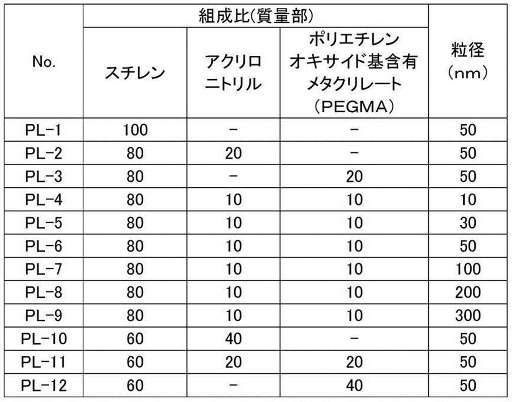
厚さ0.3mmのアルミニウム板(材質JIS A 1050)の表面の圧延油を除去するため、10質量%アルミン酸ソーダ水溶液を用いて50℃で30秒間脱脂処理を施した後、毛径0.3mmの束植ナイロンブラシ3本とメジアン径25μmのパミス-水懸濁液(比重1.1g/cm3)とを用いアルミニウム板表面を砂目立てし、水でよく洗浄した。アルミニウム板を45℃の25質量%水酸化ナトリウム水溶液に9秒間浸漬してエッチングを行い、水洗後、更に60℃で20質量%硝酸水溶液に20秒間浸漬し、水洗した。砂目立て表面のエッチング量は約3g/m2であった。 <Production of support>
In order to remove the rolling oil on the surface of an aluminum plate (material JIS A 1050) having a thickness of 0.3 mm, a degreasing treatment was performed at 50 ° C. for 30 seconds using a 10 mass% sodium aluminate aqueous solution, and then the bristle diameter was set to 0.00. The surface of the aluminum plate was grained using three 3 mm bundle-planted nylon brushes and a pumice-water suspension (specific gravity 1.1 g / cm 3 ) having a median diameter of 25 μm and washed thoroughly with water. Etching was performed by immersing the aluminum plate in a 25 mass% sodium hydroxide aqueous solution at 45 ° C for 9 seconds, washing with water, and further immersed in a 20 mass% nitric acid aqueous solution at 60 ° C for 20 seconds, followed by washing with water. The etching amount of the grained surface was about 3 g / m 2 .
次に、アルミニウム板に液温54℃の15質量%硫酸水溶液(アルミニウムイオンを0.5質量%含む)を電解液として電流密度15A/dm2で2.5g/m2の直流陽極酸化皮膜を形成した後、水洗、乾燥して支持体を作製した。
陽極酸化皮膜の表層における平均ポア径(ポアの開口部の直径)は10nmであった。
陽極酸化皮膜の表層におけるポア径の測定は、超高分解能型SEM((株)日立製作所製S-900)を使用し、12Vという比較的低加速電圧で、導電性を付与する蒸着処理等を施すこと無しに、表面を15万倍の倍率で観察し、50個のポアを無作為抽出して算術平均値を求める方法で行った。標準偏差は上記算術平均値に対し、±10%の範囲内であった。 Subsequently, nitric acid electrolysis was performed with an aqueous solution of 0.5% by mass of hydrochloric acid (containing 0.5% by mass of aluminum ions) and an electrolytic solution having a liquid temperature of 50 ° C. under the condition of an electric quantity of 50 C / dm 2 when the aluminum plate was the anode. Electrochemical surface roughening treatment was carried out in the same manner as above, followed by washing with water by spraying.
Next, a direct current anodic oxide film of 2.5 g / m 2 at a current density of 15 A / dm 2 is prepared on an aluminum plate using a 15 mass% sulfuric acid aqueous solution (containing 0.5 mass% of aluminum ions) at a liquid temperature of 54 ° C. as an electrolyte. After forming, it was washed with water and dried to prepare a support.
The average pore diameter (the diameter of the pore opening) in the surface layer of the anodized film was 10 nm.
The pore diameter in the surface layer of the anodized film is measured using an ultra-high resolution SEM (S-900, manufactured by Hitachi, Ltd.), with a deposition process that imparts conductivity at a relatively low acceleration voltage of 12V. Without applying, the surface was observed at a magnification of 150,000 times, and 50 pores were randomly extracted to obtain an arithmetic average value. The standard deviation was within ± 10% of the arithmetic mean value.
下塗り層上に、下記画像記録層塗布液(1)をバー塗布し、100℃で60秒間オーブン乾燥して乾燥塗布量1.0g/m2の画像記録層を形成した。
画像記録層塗布液(1)は下記感光液(1)及びミクロゲル液を塗布直前に混合し撹拌することにより調製した。
ミクロゲル液を使用しない場合には、感光液(1)をそのまま画像記録層塗布液として使用した。 <Formation of image recording layer>
On the undercoat layer, the following image recording layer coating solution (1) was bar coated and oven dried at 100 ° C. for 60 seconds to form an image recording layer having a dry coating amount of 1.0 g / m 2 .
The image recording layer coating solution (1) was prepared by mixing and stirring the following photosensitive solution (1) and microgel solution immediately before coating.
When the microgel solution was not used, the photosensitive solution (1) was used as it was as the image recording layer coating solution.
・表3~表5に記載の化合物:表3~表5に記載の量
・フッ素系界面活性剤(1)〔下記構造〕:10部
・2-ブタノン:5000部
・1-メトキシ-2-プロパノール:4000部 [Photosensitive solution (1)]
Compounds listed in Tables 3 to 5: Amounts listed in Tables 3 to 5 Fluorosurfactant (1) [Structure below]: 10 parts 2-butanone: 5000 parts 1-methoxy-2- Propanol: 4000 parts

各実施例及び比較例において得られた平版印刷版原版を赤外線半導体レーザー搭載の富士フイルム(株)製Luxel PLATESETTER T-6000IIIにて、外面ドラム回転数1,000rpm、レーザー出力70%、解像度2,400dpi(dot per inch、1 inch=2.54cm)の条件で露光した。露光画像にはベタ画像及び20μmドットFMスクリンの50%網点チャートを含んだ。
露光部(ベタ画像)と未露光部をx-rite(x-rite社)でL値を測定し、差分ΔL(ΔL=露光部のL値-未露光部のL値)を算出した。
ΔLの絶対値が大きいほど発色性に優れることを示しており、3.0以上が発色性として良好な値とする。 <Evaluation of color development>
The lithographic printing plate precursors obtained in each of the examples and comparative examples were subjected to an external drum rotation speed of 1,000 rpm, a laser output of 70%, a resolution of 2 with a Luxel PLANETTER T-6000III manufactured by FUJIFILM Corporation equipped with infrared semiconductor laser. Exposure was performed under conditions of 400 dpi (dot per inch, 1 inch = 2.54 cm). The exposed image contained a solid image and a 50% halftone dot chart of 20 μm dot FM screen.
The L value of the exposed area (solid image) and the unexposed area was measured by x-rite (X-rite), and the difference ΔL (ΔL = L value of the exposed area−L value of the unexposed area) was calculated.
The larger the absolute value of ΔL, the better the color developability, and a value of 3.0 or more is a good color developability.
得られた露光済み平版印刷原版を現像処理することなく、(株)小森コーポレーション製印刷機LITHRONE26の版胴に取り付けた。版胴に対して給水ローラーを5%減速させた上で、Ecolity-2(富士フイルム(株)製)/水道水=2/98(容量比)の湿し水とスペースカラーフュージョンG墨インキ(DICグラフィックス(株)製)とを用い、LITHRONE26の標準自動印刷スタート方法で湿し水とインキとを供給して機上現像した後、毎時10,000枚の印刷速度で、特菱アート(76.5kg)紙に印刷を30,000枚行った。
印刷枚数の増加にともない、徐々に画像記録層が磨耗しインキ受容性が低下するため、印刷用紙におけるインキ濃度が低下した。印刷物におけるFMスクリーン3%網点の網点面積率をx-lite(x-lite社製)で計測した値が印刷100枚目の計測値よりも5%低下したときの印刷部数を刷了枚数として耐刷性を評価した。耐刷性評価は、比較例1を基準平版印刷版原版として、以下のように定義した相対耐刷性で表した。相対耐刷性の数字が大きい程、耐刷性が高いことを表す。
相対耐刷性=(対象平版印刷版原版を用いた場合の印刷枚数X)/(基準平版印刷版原版を用いた場合の印刷枚数X)×100
評価結果は表3~表5に記載した。
相対耐刷性の数値が大きいほど耐刷性に優れることを示しており、110以上が良好な耐刷性とする。 <Evaluation of printing durability>
The obtained exposed lithographic printing original plate was attached to a plate cylinder of a printing machine LITHRONE 26 manufactured by Komori Corporation without developing. After the water supply roller is decelerated by 5% with respect to the plate cylinder, Equality-2 (manufactured by FUJIFILM Corporation) / tap water = 2/98 (volume ratio) dampening water and space color fusion G ink ink ( DIC Graphics Co., Ltd.), fountain solution and ink were supplied by the standard automatic printing start method of LITHRONE26 and developed on-machine, then at a printing speed of 10,000 sheets per hour, 76.5 kg) 30,000 sheets of paper were printed.
As the number of printed sheets increased, the image recording layer was gradually worn out and the ink acceptance decreased, so that the ink density in the printing paper decreased. Number of printed copies when the half-tone dot area ratio of 3% FM dots on the printed material is 5% lower than the measured value for the 100th printed sheet, as measured by x-lite (manufactured by x-lite) The printing durability was evaluated as follows. The evaluation of printing durability was expressed as relative printing durability defined as follows using Comparative Example 1 as a standard lithographic printing plate precursor. The larger the relative printing durability number, the higher the printing durability.
Relative printing durability = (number of printed sheets X when using target lithographic printing plate precursor) / (number of printed sheets X when using standard lithographic printing plate precursor) × 100
The evaluation results are shown in Tables 3 to 5.
It shows that it is excellent in printing durability, so that the numerical value of relative printing durability is large, and it is set as 110 or more favorable printing durability.
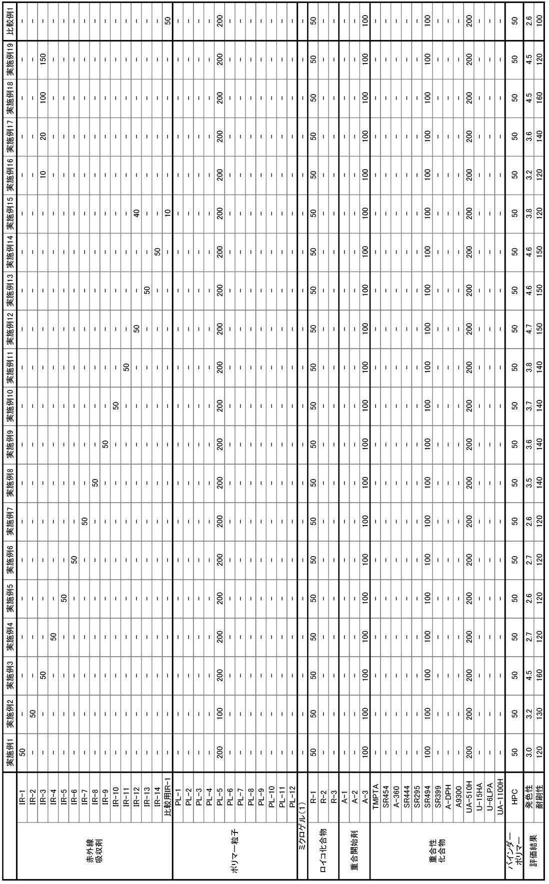

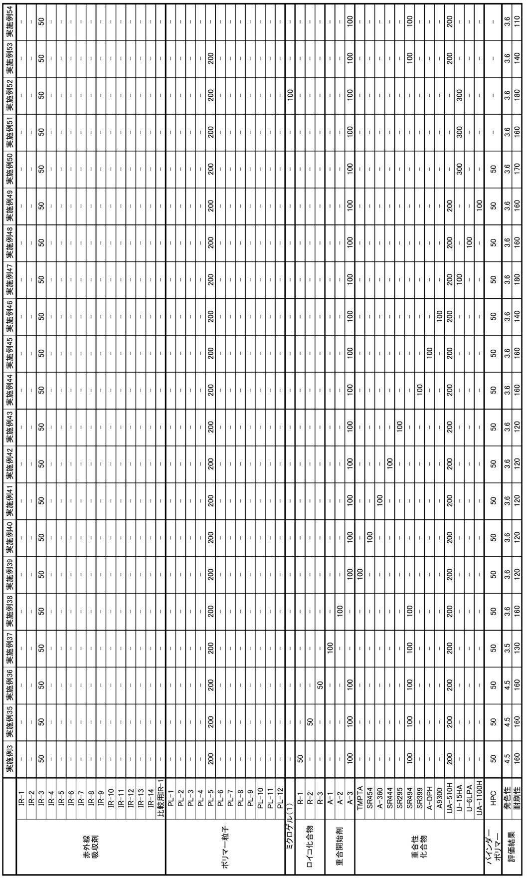
・IR-1~IR-14:上述の具体例として示した特定赤外線吸収剤
・比較用IR-1:下記構造の赤外線吸収剤
・PL-1~PL-12:上述の合成品
・R-1:Black15、山田化学工業(株)製
・R-2:Red500、山田化学工業(株)製
・R-3:S205、山田化学工業(株)製
・A-1~A-3:上述の具体例として示した重合開始剤
・重合性化合物:下記表6に記載の重合性化合物
・HPC:ヒドロキシプロピルセルロース In Tables 3 to 5, the numerical values represent the contents (parts by mass) of the corresponding components. The details of the abbreviations are as follows.
IR-1 to IR-14: specific infrared absorbers shown as the above specific examples IR-1 for comparison: infrared absorbers having the following structures PL-1 to PL-12: the above synthetic products R-1 : Black15, manufactured by Yamada Chemical Co., Ltd. ・ R-2: Red500, manufactured by Yamada Chemical Industry Co., Ltd. ・ R-3: S205, manufactured by Yamada Chemical Industry Co., Ltd. ・ A-1 to A-3: Specific above Polymerization initiators shown as examples Polymerizable compounds: Polymerizable compounds listed in Table 6 below HPC: Hydroxypropyl cellulose

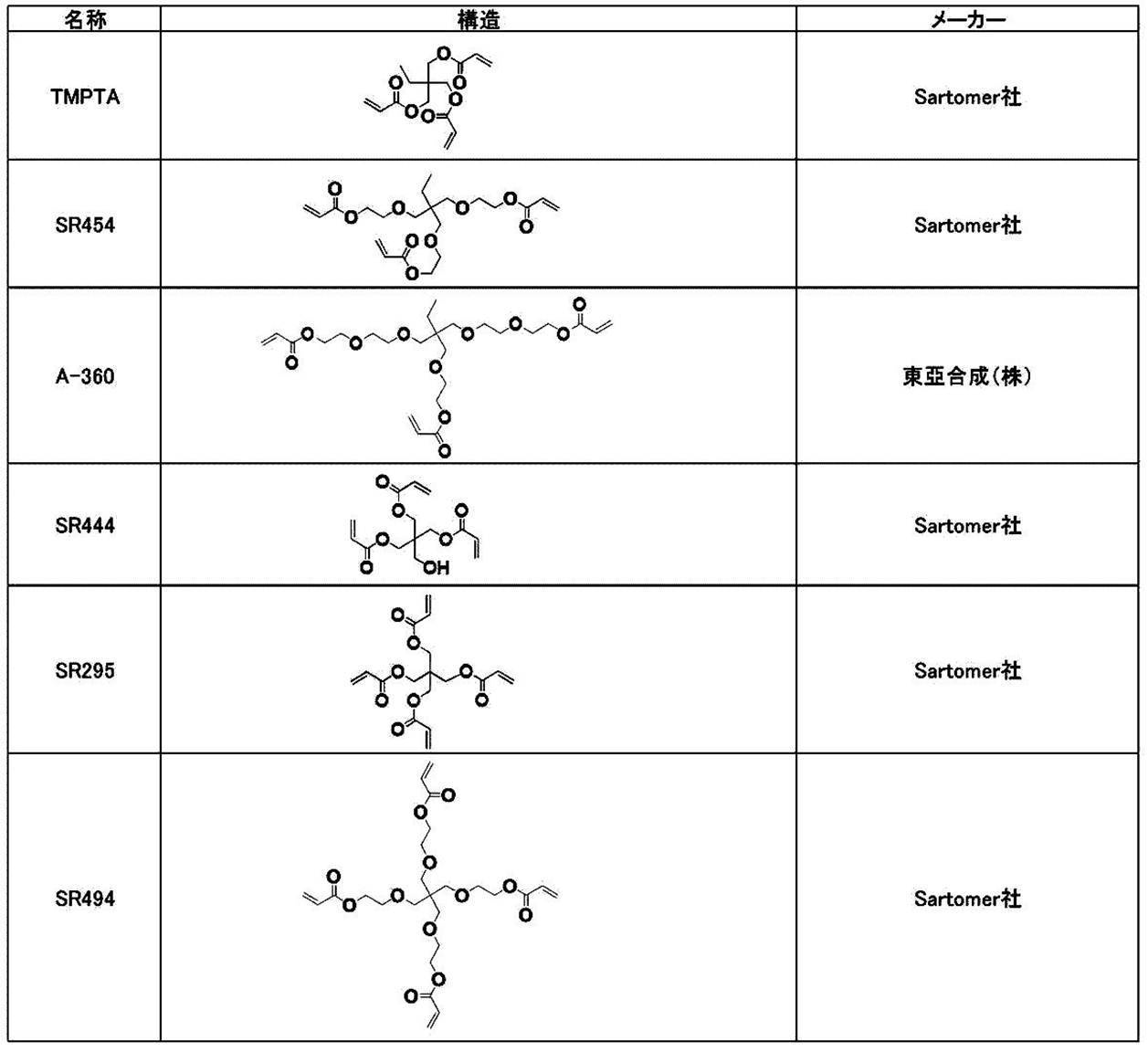
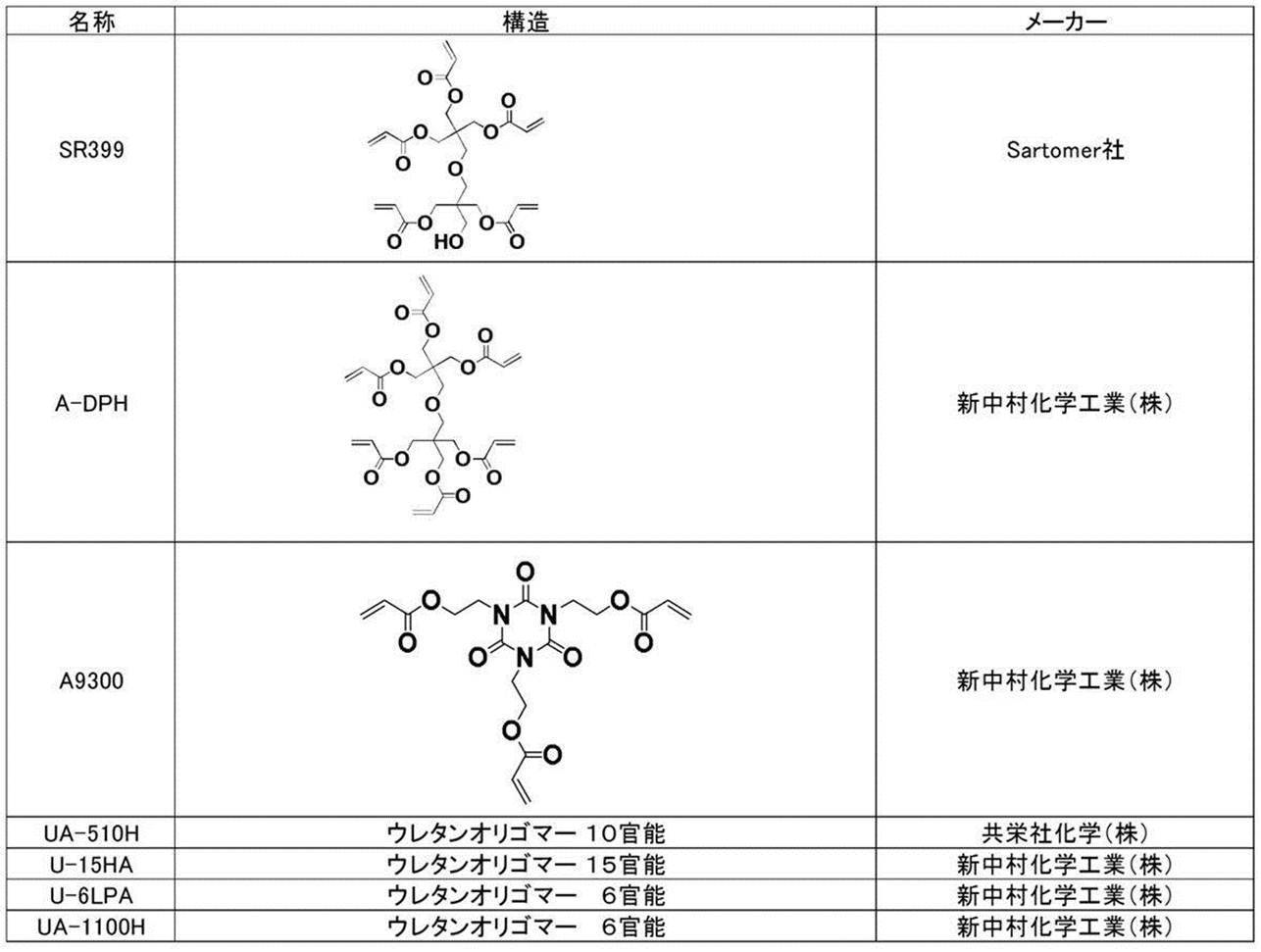
実施例1又は実施例3において使用した平版印刷版原版に対し、上記発色性の評価における露光と同様の露光を行った後、下記方法により耐刷性を評価した。 (Examples 55 and 56)
The lithographic printing plate precursor used in Example 1 or Example 3 was subjected to exposure similar to the exposure in the evaluation of color development, and then the printing durability was evaluated by the following method.
平版印刷版原版は、図1に例示する現像処理装置Aを用いて現像処理を施した。
ここで、「現像処理」とは、画像形成層の現像の他に、必要に応じて保護層の除去、ガム引き及び乾燥よりなる群から選ばれた1以上の処理をも含む複合処理を意味するものとする。
現像処理に用いた処理液は、下記組成の処理液を使用した。 <Development processing>
The planographic printing plate precursor was subjected to development processing using a development processing apparatus A illustrated in FIG.
Here, the “development process” means a composite process including development of the image forming layer and, if necessary, one or more processes selected from the group consisting of removal of the protective layer, gumming and drying. It shall be.
A processing solution having the following composition was used as the processing solution used in the development processing.
・アニオン系界面活性剤(ペレックスNBL):2質量%
・ノニオン系界面活性剤(ニューコールB13):5質量%
・2-ホスホノブタン-1,2,4-トリカルボン酸(バイヒビットAM(商標)):2質量%
・ベンジルアルコール:0.8質量%
・消泡剤(ポリジメチルシロキサン、Bluester Silicones社製、ILCOLAPSE432):0.02質量%
・水:92.18質量% [Treatment solution]
Anionic surfactant (Perex NBL): 2% by mass
Nonionic surfactant (New Coal B13): 5% by mass
2-phosphonobutane-1,2,4-tricarboxylic acid (Baihibit AM ™): 2% by mass
・ Benzyl alcohol: 0.8% by mass
-Antifoaming agent (polydimethylsiloxane, manufactured by Bluester Silicones, ILCOLAPSE432): 0.02% by mass
・ Water: 92.18% by mass
4カ所のスプレーパイプ15には、管路16によりフィルター17を通して、処理液タンク20に貯留された処理液を、循環ポンプ21により供給して、各スプレーパイプ15から版面にシャワーリングして供給した。なお、処理液タンク20の容量は、10リットルであり、処理液は循環使用した。現像処理機から排出された平版印刷版は、水洗することなく乾燥機22により乾燥した。 The development processing apparatus A is an automatic processing machine having two rotating brush rolls 11. As the
The processing liquid stored in the
得られた現像処理済みの平版印刷版を用い、機上現像を行わない以外は上述の耐刷性の評価と同様の方法により、耐刷性の評価を行った。
実施例1において使用した平版印刷版原版を用いた場合の評価結果は表3に記載した実施例1の評価結果と、実施例3において使用した平版印刷版原版を用いた場合の評価結果は実施例3の評価結果と、それぞれ同様であった。 <Evaluation of printing durability>
The obtained lithographic printing plate after development was used, and printing durability was evaluated in the same manner as in the above-described evaluation of printing durability, except that on-press development was not performed.
The evaluation results when the lithographic printing plate precursor used in Example 1 is used are the evaluation results of Example 1 described in Table 3, and the evaluation results when the lithographic printing plate precursor used in Example 3 is used. The results were the same as the evaluation results of Example 3.
上記実施例及び比較例の結果から、本開示に係る平版印刷版の製版方法、及び、平版印刷方法によれば、耐刷性に優れた平版印刷版が得られることがわかる。 From the results of the above Examples and Comparative Examples, it is understood that the lithographic printing plate precursor according to the present disclosure is excellent in printing durability of the obtained lithographic printing plate.
From the results of the above Examples and Comparative Examples, it can be seen that according to the planographic printing plate making method and the planographic printing method according to the present disclosure, a planographic printing plate having excellent printing durability can be obtained.
12:受けロール
13:搬送ロール
14:搬送ガイド板
15:スプレーパイプ
16:管路
17:フィルター
18:給版台
19:排版台
20:処理液タンク
21:循環ポンプ
22:乾燥機
30:平版印刷版原版 11: Rotating brush roll 12: Receiving roll 13: Conveying roll 14: Conveying guide plate 15: Spray pipe 16: Pipe line 17: Filter 18: Plate feeding table 19: Plate discharging table 20: Treatment liquid tank 21: Circulation pump 22: Drying Machine 30: Planographic printing plate precursor
Claims (15)
- 支持体上に、式Iで表される赤外線吸収剤を含有する画像記録層を有する平版印刷版原版。
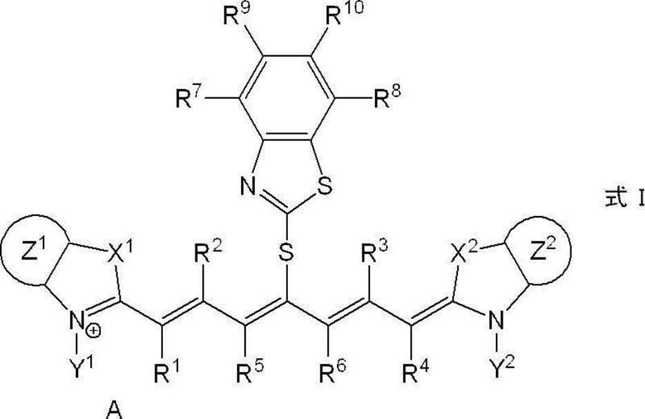
式I中、X1及びX2はそれぞれ独立に、硫黄原子、酸素原子又は炭素数12以下のジアルキルメチレン基を表し、Y1及びY2はそれぞれ独立に、一価の有機基又は水素原子を表し、Z1及びZ2はそれぞれ独立に、置換基を有しないか、電子供与性基又は炭素数6~20のアリール基により置換された、ベンゼン環、ナフタレン環又は環員数6~20のヘテロ芳香環を表し、R1、R2、R3及びR4はそれぞれ独立に、水素原子又は炭素数12以下の炭化水素基を表し、R5及びR6はそれぞれ独立に、炭化水素基を示し、それぞれが連結し5員環又は6員環を形成してもよく、R7、R8、R9及びR10はそれぞれ独立に、水素原子又は一価の有機基を表し、Aは、電荷の中和が必要な場合に存在する対イオンを表す。 A lithographic printing plate precursor having an image recording layer containing an infrared absorber represented by the formula I on a support.
In formula I, X 1 and X 2 each independently represent a sulfur atom, an oxygen atom or a dialkylmethylene group having 12 or less carbon atoms, and Y 1 and Y 2 each independently represent a monovalent organic group or a hydrogen atom. Z 1 and Z 2 each independently represents a benzene ring, a naphthalene ring or a hetero ring having 6 to 20 ring members which has no substituent or is substituted by an electron donating group or an aryl group having 6 to 20 carbon atoms. Represents an aromatic ring, R 1 , R 2 , R 3 and R 4 each independently represents a hydrogen atom or a hydrocarbon group having 12 or less carbon atoms, and R 5 and R 6 each independently represents a hydrocarbon group. Each may be linked to form a 5-membered or 6-membered ring, R 7 , R 8 , R 9 and R 10 each independently represent a hydrogen atom or a monovalent organic group, and A is a charge The counter ions present when neutralization of . - 式Iで表される赤外線吸収剤が、式IIで表される赤外線吸収剤である、請求項1に記載の平版印刷版原版。

式II中、X1及びX2はそれぞれ独立に、硫黄原子、酸素原子又は炭素数12以下のジアルキルメチレン基を表し、Y1及びY2はそれぞれ独立に、一価の有機基又は水素原子を表し、Z1及びZ2はそれぞれ独立に、置換基を有しないか、電子供与性基又は炭素数6~20のアリール基により置換された、ベンゼン環、ナフタレン環又は環員数6~20のヘテロ芳香環を表し、R1、R2、R3及びR4はそれぞれ独立に、水素原子又は炭素数12以下の炭化水素基を表し、R7、R8、R9及びR10はそれぞれ独立に、水素原子又は一価の有機基を表し、Aは、電荷の中和が必要な場合に存在する対イオンを表す。 The lithographic printing plate precursor according to claim 1, wherein the infrared absorbent represented by the formula I is an infrared absorbent represented by the formula II.
In Formula II, X 1 and X 2 each independently represent a sulfur atom, an oxygen atom, or a dialkylmethylene group having 12 or less carbon atoms, and Y 1 and Y 2 each independently represent a monovalent organic group or a hydrogen atom. Z 1 and Z 2 each independently represents a benzene ring, a naphthalene ring or a hetero ring having 6 to 20 ring members which has no substituent or is substituted by an electron donating group or an aryl group having 6 to 20 carbon atoms. Represents an aromatic ring, R 1 , R 2 , R 3 and R 4 each independently represent a hydrogen atom or a hydrocarbon group having 12 or less carbon atoms, and R 7 , R 8 , R 9 and R 10 each independently Represents a hydrogen atom or a monovalent organic group, and A represents a counter ion present when charge neutralization is required. - 前記画像記録層が、重合性化合物及び重合開始剤を更に含有する、請求項1又は請求項2に記載の平版印刷版原版。 The lithographic printing plate precursor according to claim 1 or 2, wherein the image recording layer further contains a polymerizable compound and a polymerization initiator.
- 前記重合開始剤が、ヨードニウム系重合開始剤である、請求項3に記載の平版印刷版原版。 The lithographic printing plate precursor according to claim 3, wherein the polymerization initiator is an iodonium-based polymerization initiator.
- 前記画像記録層が、熱可塑性ポリマー粒子を更に含有する、請求項1~請求項4のいずれか1項に記載の平版印刷版原版。 The lithographic printing plate precursor as claimed in any one of Claims 1 to 4, wherein the image recording layer further contains thermoplastic polymer particles.
- 前記熱可塑性ポリマー粒子に含まれるポリマーが、スチレンに由来するモノマー単位及びアクリル化合物に由来するモノマー単位のいずれか又は両方のモノマー単位を含有する、請求項5に記載の平版印刷版原版。 The lithographic printing plate precursor according to claim 5, wherein the polymer contained in the thermoplastic polymer particles contains one or both of a monomer unit derived from styrene and a monomer unit derived from an acrylic compound.
- 前記熱可塑性ポリマー粒子に含まれるポリマーが、スチレン-アクリロニトリル樹脂である、請求項5又は請求項6に記載の平版印刷版原版。 The lithographic printing plate precursor according to claim 5 or 6, wherein the polymer contained in the thermoplastic polymer particles is a styrene-acrylonitrile resin.
- 前記熱可塑性ポリマー粒子に含まれるポリマーの重量平均分子量が、5,000~1,000,000である、請求項5~請求項7のいずれか1項に記載の平版印刷版原版。 The lithographic printing plate precursor as claimed in any one of claims 5 to 7, wherein the polymer contained in the thermoplastic polymer particles has a weight average molecular weight of 5,000 to 1,000,000.
- 前記熱可塑性ポリマー粒子の体積平均粒径が、0.01μm~50μmである、請求項5~請求項8のいずれか1項に記載の平版印刷版原版。 The lithographic printing plate precursor as claimed in any one of Claims 5 to 8, wherein the thermoplastic polymer particles have a volume average particle diameter of 0.01 µm to 50 µm.
- 前記画像記録層の全質量に対する、前記熱可塑性ポリマー粒子の含有量が、20質量%~95質量%である、請求項5~請求項9のいずれか1項に記載の平版印刷版原版。 The lithographic printing plate precursor as claimed in any one of claims 5 to 9, wherein a content of the thermoplastic polymer particles is 20% by mass to 95% by mass with respect to a total mass of the image recording layer.
- 前記画像記録層が、ロイコ化合物を更に含有する、請求項1~請求項10のいずれか1項に記載の平版印刷版原版。 The lithographic printing plate precursor as claimed in any one of claims 1 to 10, wherein the image recording layer further contains a leuco compound.
- 前記画像記録層が、湿し水及び印刷インキのいずれか又は両方により除去可能である、請求項1~請求項11のいずれか1項に記載の平版印刷版原版。 The lithographic printing plate precursor as claimed in any one of claims 1 to 11, wherein the image recording layer is removable with either or both of dampening water and printing ink.
- 前記画像記録層が、ガム現像可能である、請求項1~請求項12のいずれか1項に記載の平版印刷版原版。 The lithographic printing plate precursor as claimed in any one of claims 1 to 12, wherein the image recording layer is gum developable.
- 請求項1~請求項13のいずれか1項に記載の平版印刷版原版を、画像様に露光し、露光部と未露光部とを形成する露光工程、及び、
印刷インキ及び湿し水の少なくとも一方を供給して前記未露光部を除去する機上現像工程を含む
平版印刷版の製版方法。 An exposure step of exposing the lithographic printing plate precursor according to any one of claims 1 to 13 imagewise to form an exposed portion and an unexposed portion; and
A plate-making method for a lithographic printing plate, comprising an on-machine development step of supplying at least one of printing ink and dampening water to remove the unexposed portion. - 請求項1~請求項13のいずれか1項に記載の平版印刷版原版を、画像様に露光し、露光部と未露光部とを形成する露光工程、
印刷インキ及び湿し水の少なくとも一方を供給して前記未露光部を除去する機上現像工程、及び、
前記機上現像工程において機上現像された平版印刷版に印刷インキを供給して記録媒体を印刷する印刷工程をこの順で含む
平版印刷方法。 An exposure step of exposing the lithographic printing plate precursor according to any one of claims 1 to 13 imagewise to form an exposed portion and an unexposed portion;
On-machine development process for removing the unexposed area by supplying at least one of printing ink and fountain solution, and
A lithographic printing method comprising a printing step of supplying printing ink to a lithographic printing plate developed on-press in the on-press development step to print a recording medium in this order.
Priority Applications (6)
| Application Number | Priority Date | Filing Date | Title |
|---|---|---|---|
| JP2018536314A JP6401431B1 (en) | 2017-02-28 | 2018-02-28 | Planographic printing plate precursor, planographic printing plate making method, and planographic printing method |
| CN201880002111.2A CN109153279B (en) | 2017-02-28 | 2018-02-28 | Lithographic printing plate precursor, plate making method for lithographic printing plate, and lithographic printing method |
| BR112019015835-9A BR112019015835A2 (en) | 2017-02-28 | 2018-02-28 | PRECURSOR OF THE LITOGRAPHIC PRINTING PLATE, METHOD OF PRODUCTION OF THE LITOGRAPHIC PRINTING PLATE AND LITOGRAPHIC PRINTING METHOD |
| EP18761027.4A EP3456547B1 (en) | 2017-02-28 | 2018-02-28 | Lithographic printing plate precursor, method of producing lithographic printing plate, and lithographic printing method |
| US16/191,784 US20190088473A1 (en) | 2017-02-28 | 2018-11-15 | Lithographic printing plate precursor, method of producing lithographic printing plate, and lithographic printing method |
| US16/827,271 US11574810B2 (en) | 2017-02-28 | 2020-03-23 | Lithographic printing plate precursor, method of producing lithographic printing plate, and lithographic printing method |
Applications Claiming Priority (2)
| Application Number | Priority Date | Filing Date | Title |
|---|---|---|---|
| JP2017037664 | 2017-02-28 | ||
| JP2017-037664 | 2017-02-28 |
Related Child Applications (1)
| Application Number | Title | Priority Date | Filing Date |
|---|---|---|---|
| US16/191,784 Continuation US20190088473A1 (en) | 2017-02-28 | 2018-11-15 | Lithographic printing plate precursor, method of producing lithographic printing plate, and lithographic printing method |
Publications (1)
| Publication Number | Publication Date |
|---|---|
| WO2018159710A1 true WO2018159710A1 (en) | 2018-09-07 |
Family
ID=63371236
Family Applications (1)
| Application Number | Title | Priority Date | Filing Date |
|---|---|---|---|
| PCT/JP2018/007612 WO2018159710A1 (en) | 2017-02-28 | 2018-02-28 | Original plate for lithographic printing plate, method for platemaking lithographic printing plate, and lithographic printing method |
Country Status (6)
| Country | Link |
|---|---|
| US (2) | US20190088473A1 (en) |
| EP (1) | EP3456547B1 (en) |
| JP (1) | JP6401431B1 (en) |
| CN (1) | CN109153279B (en) |
| BR (1) | BR112019015835A2 (en) |
| WO (1) | WO2018159710A1 (en) |
Cited By (11)
| Publication number | Priority date | Publication date | Assignee | Title |
|---|---|---|---|---|
| WO2020090996A1 (en) * | 2018-10-31 | 2020-05-07 | 富士フイルム株式会社 | Lithographic printing plate original plate, method for producing lithographic printing plate and lithographic printing method |
| WO2020090995A1 (en) * | 2018-10-31 | 2020-05-07 | 富士フイルム株式会社 | Lithographic printing plate original plate, method for producing lithographic printing plate and lithographic printing method |
| WO2020111259A1 (en) * | 2018-11-30 | 2020-06-04 | 富士フイルム株式会社 | Planographic printing original plete, method for producing planographic printing plete, and planographic printing method |
| WO2020262690A1 (en) * | 2019-06-28 | 2020-12-30 | 富士フイルム株式会社 | On-press development type lithographic printing original plate, method for producing lithographic printing plate, and lithographic printing method |
| WO2020262694A1 (en) | 2019-06-28 | 2020-12-30 | 富士フイルム株式会社 | Lithographic printing plate precursor, method for producing lithographic printing plate, and lithographic printing method |
| CN112930266A (en) * | 2018-10-31 | 2021-06-08 | 富士胶片株式会社 | Lithographic printing plate precursor, method for producing lithographic printing plate, and lithographic printing method |
| CN113165410A (en) * | 2018-10-31 | 2021-07-23 | 富士胶片株式会社 | Lithographic printing plate precursor, method for producing lithographic printing plate, and lithographic printing method |
| WO2021172453A1 (en) * | 2020-02-28 | 2021-09-02 | 富士フイルム株式会社 | Lithographic printing plate original plate, lithographic printing plate manufacturing method, and lithographic printing method |
| WO2021241693A1 (en) * | 2020-05-29 | 2021-12-02 | 富士フイルム株式会社 | Layered body |
| WO2021241457A1 (en) * | 2020-05-29 | 2021-12-02 | 富士フイルム株式会社 | On-press-development-type lithographic printing plate precursor, lithographic printing plate production method, and lithographic printing method |
| WO2021241458A1 (en) * | 2020-05-29 | 2021-12-02 | 富士フイルム株式会社 | On-press-development-type lithographic printing plate precursor, lithographic printing plate production method, and lithographic printing method |
Families Citing this family (4)
| Publication number | Priority date | Publication date | Assignee | Title |
|---|---|---|---|---|
| JP7293356B2 (en) * | 2019-06-28 | 2023-06-19 | 富士フイルム株式会社 | On-machine development type lithographic printing plate precursor, method for preparing lithographic printing plate, and lithographic printing method |
| JPWO2020262686A1 (en) * | 2019-06-28 | 2020-12-30 | ||
| CN114051454B (en) * | 2019-06-28 | 2023-12-15 | 富士胶片株式会社 | On-press development type lithographic printing plate precursor, method for producing lithographic printing plate, and lithographic printing method |
| EP4082791A4 (en) * | 2019-12-27 | 2023-06-21 | FUJIFILM Corporation | Planographic printing method |
Citations (4)
| Publication number | Priority date | Publication date | Assignee | Title |
|---|---|---|---|---|
| JP2005516804A (en) * | 2002-02-04 | 2005-06-09 | コダック・ポリクローム・グラフィックス・エルエルシー | IR-sensitive printing plate capable of on-press development |
| JP2007050659A (en) * | 2005-08-19 | 2007-03-01 | Fujifilm Corp | Lithographic printing plate original plate and lithographic printing method |
| EP2072570A1 (en) * | 2007-12-20 | 2009-06-24 | Agfa Graphics N.V. | A lithographic printing plate precursor |
| JP2014528098A (en) * | 2011-09-22 | 2014-10-23 | イーストマン コダック カンパニー | Negative type planographic printing plate precursor |
Family Cites Families (12)
| Publication number | Priority date | Publication date | Assignee | Title |
|---|---|---|---|---|
| US5576443A (en) * | 1993-05-26 | 1996-11-19 | Sterling Diagnostic Imaging, Inc. | Thioheterocyclic near-infrared absorbing dyes |
| US5440042A (en) * | 1993-05-26 | 1995-08-08 | E. I. Du Pont De Nemours And Company | Thioheterocyclic near-infrared dyes |
| DE69812871T2 (en) | 1998-01-23 | 2004-02-26 | Agfa-Gevaert | Heat-sensitive recording element and method for producing planographic printing plates therewith |
| DE60025283T2 (en) * | 1999-10-19 | 2006-08-24 | Fuji Photo Film Co., Ltd., Minami-Ashigara | Photosensitive composition and planographic printing plate using this composition |
| JP4299639B2 (en) * | 2003-07-29 | 2009-07-22 | 富士フイルム株式会社 | Polymerizable composition and image recording material using the same |
| EP1798031A3 (en) * | 2005-01-26 | 2007-07-04 | FUJIFILM Corporation | Lithographic printing plate precursor and lithographic printing method |
| JP2007050689A (en) * | 2005-07-22 | 2007-03-01 | Fuji Xerox Co Ltd | Method and apparatus for manufacturing plastic sheet |
| US20110165518A1 (en) * | 2008-09-16 | 2011-07-07 | Agfa Graphics Nv | lithographic printing plate precursor |
| WO2010079020A1 (en) * | 2008-12-18 | 2010-07-15 | Agfa Graphics Nv | A lithographic printing plate precursor |
| US8927197B2 (en) | 2012-11-16 | 2015-01-06 | Eastman Kodak Company | Negative-working lithographic printing plate precursors |
| JP2015202586A (en) * | 2014-04-11 | 2015-11-16 | イーストマン コダック カンパニー | Lithographic printing plate |
| JP6510726B2 (en) * | 2016-02-29 | 2019-05-08 | 富士フイルム株式会社 | Lithographic printing plate precursor and method for making lithographic printing plate |
-
2018
- 2018-02-28 JP JP2018536314A patent/JP6401431B1/en active Active
- 2018-02-28 WO PCT/JP2018/007612 patent/WO2018159710A1/en unknown
- 2018-02-28 CN CN201880002111.2A patent/CN109153279B/en active Active
- 2018-02-28 EP EP18761027.4A patent/EP3456547B1/en active Active
- 2018-02-28 BR BR112019015835-9A patent/BR112019015835A2/en unknown
- 2018-11-15 US US16/191,784 patent/US20190088473A1/en not_active Abandoned
-
2020
- 2020-03-23 US US16/827,271 patent/US11574810B2/en active Active
Patent Citations (4)
| Publication number | Priority date | Publication date | Assignee | Title |
|---|---|---|---|---|
| JP2005516804A (en) * | 2002-02-04 | 2005-06-09 | コダック・ポリクローム・グラフィックス・エルエルシー | IR-sensitive printing plate capable of on-press development |
| JP2007050659A (en) * | 2005-08-19 | 2007-03-01 | Fujifilm Corp | Lithographic printing plate original plate and lithographic printing method |
| EP2072570A1 (en) * | 2007-12-20 | 2009-06-24 | Agfa Graphics N.V. | A lithographic printing plate precursor |
| JP2014528098A (en) * | 2011-09-22 | 2014-10-23 | イーストマン コダック カンパニー | Negative type planographic printing plate precursor |
Non-Patent Citations (1)
| Title |
|---|
| See also references of EP3456547A4 * |
Cited By (17)
| Publication number | Priority date | Publication date | Assignee | Title |
|---|---|---|---|---|
| CN112930266B (en) * | 2018-10-31 | 2023-02-28 | 富士胶片株式会社 | Lithographic printing plate precursor, method for producing lithographic printing plate, and lithographic printing method |
| WO2020090995A1 (en) * | 2018-10-31 | 2020-05-07 | 富士フイルム株式会社 | Lithographic printing plate original plate, method for producing lithographic printing plate and lithographic printing method |
| CN113165410B (en) * | 2018-10-31 | 2023-09-26 | 富士胶片株式会社 | Lithographic printing plate precursor, method for producing lithographic printing plate, and lithographic printing method |
| WO2020090996A1 (en) * | 2018-10-31 | 2020-05-07 | 富士フイルム株式会社 | Lithographic printing plate original plate, method for producing lithographic printing plate and lithographic printing method |
| CN112930266A (en) * | 2018-10-31 | 2021-06-08 | 富士胶片株式会社 | Lithographic printing plate precursor, method for producing lithographic printing plate, and lithographic printing method |
| CN113165410A (en) * | 2018-10-31 | 2021-07-23 | 富士胶片株式会社 | Lithographic printing plate precursor, method for producing lithographic printing plate, and lithographic printing method |
| WO2020111259A1 (en) * | 2018-11-30 | 2020-06-04 | 富士フイルム株式会社 | Planographic printing original plete, method for producing planographic printing plete, and planographic printing method |
| WO2020262694A1 (en) | 2019-06-28 | 2020-12-30 | 富士フイルム株式会社 | Lithographic printing plate precursor, method for producing lithographic printing plate, and lithographic printing method |
| WO2020262690A1 (en) * | 2019-06-28 | 2020-12-30 | 富士フイルム株式会社 | On-press development type lithographic printing original plate, method for producing lithographic printing plate, and lithographic printing method |
| WO2021172453A1 (en) * | 2020-02-28 | 2021-09-02 | 富士フイルム株式会社 | Lithographic printing plate original plate, lithographic printing plate manufacturing method, and lithographic printing method |
| JP7397164B2 (en) | 2020-02-28 | 2023-12-12 | 富士フイルム株式会社 | Planographic printing plate original plate, method for preparing a planographic printing plate, and planographic printing method |
| WO2021241693A1 (en) * | 2020-05-29 | 2021-12-02 | 富士フイルム株式会社 | Layered body |
| WO2021241457A1 (en) * | 2020-05-29 | 2021-12-02 | 富士フイルム株式会社 | On-press-development-type lithographic printing plate precursor, lithographic printing plate production method, and lithographic printing method |
| WO2021241458A1 (en) * | 2020-05-29 | 2021-12-02 | 富士フイルム株式会社 | On-press-development-type lithographic printing plate precursor, lithographic printing plate production method, and lithographic printing method |
| JP7413526B2 (en) | 2020-05-29 | 2024-01-15 | 富士フイルム株式会社 | On-press development type lithographic printing plate precursor, method for producing a lithographic printing plate, and lithographic printing method |
| JP7430788B2 (en) | 2020-05-29 | 2024-02-13 | 富士フイルム株式会社 | On-press development type lithographic printing plate precursor, method for producing a lithographic printing plate, and lithographic printing method |
| JP7451702B2 (en) | 2020-05-29 | 2024-03-18 | 富士フイルム株式会社 | laminate |
Also Published As
| Publication number | Publication date |
|---|---|
| EP3456547A4 (en) | 2019-08-14 |
| BR112019015835A2 (en) | 2020-03-31 |
| CN109153279B (en) | 2020-03-17 |
| US11574810B2 (en) | 2023-02-07 |
| EP3456547A1 (en) | 2019-03-20 |
| JP6401431B1 (en) | 2018-10-10 |
| EP3456547B1 (en) | 2020-10-28 |
| US20190088473A1 (en) | 2019-03-21 |
| JPWO2018159710A1 (en) | 2019-03-07 |
| CN109153279A (en) | 2019-01-04 |
| US20200234948A1 (en) | 2020-07-23 |
Similar Documents
| Publication | Publication Date | Title |
|---|---|---|
| JP6401431B1 (en) | Planographic printing plate precursor, planographic printing plate making method, and planographic printing method | |
| JP5703417B2 (en) | Planographic printing plate precursor and printing method thereof | |
| WO2018043259A1 (en) | Color-assuming composition, lithographic printing plate precursor, method for forming lithographic printing plate, and compound | |
| JP5828045B2 (en) | Planographic printing plate precursor and plate making method | |
| JP7096435B2 (en) | Machine-developed lithographic printing plate original plate, lithographic printing plate manufacturing method, and lithographic printing method | |
| JP5537980B2 (en) | Planographic printing plate precursor and plate making method | |
| WO2011115125A1 (en) | Color developing photosensitive composition, lithographic printing original plate, and method for producing same | |
| WO2021241458A1 (en) | On-press-development-type lithographic printing plate precursor, lithographic printing plate production method, and lithographic printing method | |
| JP7413526B2 (en) | On-press development type lithographic printing plate precursor, method for producing a lithographic printing plate, and lithographic printing method | |
| JPWO2014050359A1 (en) | Planographic printing plate precursor and lithographic printing plate making method | |
| JP7397164B2 (en) | Planographic printing plate original plate, method for preparing a planographic printing plate, and planographic printing method | |
| CN104730865A (en) | Negative image treatment-free lithograph plate | |
| JP5736277B2 (en) | Planographic printing plate precursor | |
| WO2012026265A1 (en) | Master planographic printing plate for on-press development, and plate-making method using said master planographic printing plate | |
| JP6608093B2 (en) | On-press development type lithographic printing plate precursor and lithographic printing plate preparation method | |
| WO2021241688A1 (en) | Original plate for on-machine development type lithographic printing plate, lithographic printing plate manufacturing method, and lithographic printing method | |
| JP2010234589A (en) | Original plate of on-machine development type lithographic printing plate and lithographic printing method | |
| WO2016136654A1 (en) | Lithographic printing original plate for on-press development, plate making method for lithographic printing plate, and printing method | |
| WO2018043150A1 (en) | Colorant composition, planographic printing master plate, method of manufacturing planographic printing plate, and compound | |
| JP7378613B2 (en) | On-press development type lithographic printing plate precursor, method for preparing a lithographic printing plate, and lithographic printing method | |
| JP2013054077A (en) | Infrared photosensitive color-developing composition, planographic printing plate precursor and platemaking method using the same | |
| WO2016121667A1 (en) | Coloring composition, lithographic printing plate precursor, method for producing lithographic printing plate, and coloring agent | |
| JP2017047564A (en) | Lithographic printing plate precursor and plate-making method of lithographic printing plate | |
| JP2010234588A (en) | Lithographic printing plate precursor and plate making method of the same | |
| WO2023032682A1 (en) | On-press-developing lithographic printing original plate, method for producing lithographic printing plate, and lithographic printing method |
Legal Events
| Date | Code | Title | Description |
|---|---|---|---|
| ENP | Entry into the national phase |
Ref document number: 2018536314 Country of ref document: JP Kind code of ref document: A |
|
| 121 | Ep: the epo has been informed by wipo that ep was designated in this application |
Ref document number: 18761027 Country of ref document: EP Kind code of ref document: A1 |
|
| ENP | Entry into the national phase |
Ref document number: 2018761027 Country of ref document: EP Effective date: 20181211 |
|
| REG | Reference to national code |
Ref country code: BR Ref legal event code: B01A Ref document number: 112019015835 Country of ref document: BR |
|
| NENP | Non-entry into the national phase |
Ref country code: DE |
|
| ENP | Entry into the national phase |
Ref document number: 112019015835 Country of ref document: BR Kind code of ref document: A2 Effective date: 20190731 |