一种基于热网和房屋热惯性的综合能源系统优化方法An integrated energy system optimization method based on thermal network and thermal inertia of buildings
技术领域Technical field
本发明属于综合区域能源系统热电联合调度领域,具体来说,涉及一种基于热网和房屋热惯性的综合能源系统优化方法。The invention belongs to the field of combined heat and power scheduling of integrated regional energy systems, and in particular relates to an integrated energy system optimization method based on thermal network and thermal inertia of houses.
背景技术Background technique
近年来,风电作为一种可再生能源由于其技术成熟,经济性较好且能源效率较高得到了快速发展。截止2015年底,全球风电总装机容量达到423GW,新增装机容量为63GW,其中,中国占30.5GW。中国风电的发展主要在三北地区,三北地区风力资源丰富且冬季热负荷需求极大。然而,随着风电的快速发展,风电消纳却由于热电联供中热出力与电出力的强耦合关系受到了限制。在吉林省,约有70%的热负荷由集中式热电联供机组(对应英文combined heating and power,文中简称CHP)供应。热电联供机组在冬季一般运行在“以热定电”模式。这种运行模式极大的限制了CHP机组的电出力。在夜间,热负荷较高而电负荷较低,CHP机组运行在“以热定电”模式下则电力供应供过于求,因此导致此时段弃风严重。根据国家能源局数据显示,2016年上半年,全国平均风电利用小时数为917h,弃风量为323TWh,平均风电消纳率为21%。总之,风电消纳已成为风电行业可持续发展的关键问题。为解决风电消纳问题,电力人员已进行了大量的研究,例如采用蓄电池、电锅炉等。考虑到风电与热负荷在时间与空间上的关系,即风力资源丰富的地区与时间一般也是热负荷需求较大的地区与时间,故从整体能源消费的角度看,可以利用热力系统为风电消纳提供空间。In recent years, wind power as a renewable energy has developed rapidly due to its mature technology, economical efficiency and high energy efficiency. By the end of 2015, the total installed capacity of wind power in the world reached 423GW, and the newly installed capacity was 63GW, of which China accounted for 30.5GW. The development of wind power in China is mainly in the Three North region. The wind power resources in the Three North Region are abundant and the demand for heat load in winter is extremely high. However, with the rapid development of wind power, wind power consumption has been limited due to the strong coupling between the heat output and the electric output. In Jilin Province, about 70% of the heat load is supplied by the centralized combined heat and power unit (corresponding to English combined heating and power, referred to as CHP in the text). Cogeneration units generally operate in the “heat-set” mode during the winter. This mode of operation greatly limits the electrical output of the CHP unit. At night, the heat load is higher and the electric load is lower. When the CHP unit is operated in the “heat setting” mode, the power supply is oversupply, which leads to serious wind abandonment during this period. According to the National Energy Administration data, in the first half of 2016, the national average wind power utilization hours were 917 hours, the abandoned wind volume was 323 TWh, and the average wind power consumption rate was 21%. In short, wind power consumption has become a key issue for the sustainable development of the wind power industry. In order to solve the problem of wind power consumption, electric power personnel have carried out a lot of research, such as using batteries and electric boilers. Considering the relationship between wind power and heat load in time and space, that is, the area and time with abundant wind resources are generally the area and time with large heat load demand. Therefore, from the perspective of overall energy consumption, the thermal system can be used as wind power. Provide space.
发明内容Summary of the invention
技术问题:本发明所要解决的技术问题是:提出一种基于热网和房屋热惯性的综合能源系统优化方法,该方法既能利用热网传输延时通过在时间尺度上错开供需,又能利用房屋蓄热特性改变负荷分布,提高热电联供系统运行灵活性,有效改善弃风问题,提升系统整体经济性。Technical Problem: The technical problem to be solved by the present invention is to propose an integrated energy system optimization method based on thermal network and thermal inertia of a house, which can utilize the heat network transmission delay to stagger the supply and demand on the time scale, and can utilize The heat storage characteristics of the house change the load distribution, improve the operational flexibility of the cogeneration system, effectively improve the problem of wind abandonment, and improve the overall economics of the system.
技术方案:为解决上述技术问题,本发明实施例提供一种基于热网和房屋热惯性的综合能源系统优化方法,该方法包括以下步骤:Technical Solution: In order to solve the above technical problem, an embodiment of the present invention provides an integrated energy system optimization method based on a thermal network and a thermal inertia of a house, the method comprising the following steps:
步骤10)分别建立考虑传输延时的热网模型以及考虑蓄热特性的建筑物模型;Step 10) respectively establishing a heat network model considering a transmission delay and a building model considering heat storage characteristics;
步骤20)结合冷热电联供系统模型、热网模型及建筑物模型,建立综合能源系统优化模型;Step 20) Combining the cogeneration system model, the heat network model and the building model to establish an integrated energy system optimization model;
步骤30)运用综合能源系统优化模型求解得到最优调度计划,并按照该最优调度计划,控制燃气轮机和燃气锅炉每小时的出力,并向电网与风电场购电。Step 30) Using the integrated energy system optimization model to solve the optimal scheduling plan, and according to the optimal scheduling plan, control the hourly output of the gas turbine and the gas boiler, and purchase electricity from the grid and the wind farm.
作为优选例,所述的步骤10)中,建立热网模型的过程为:As a preferred example, in the step 10), the process of establishing the heat network model is:
步骤101)建立热网管道模型,具体包括步骤1011)—步骤1015):Step 101) Establish a hot network pipeline model, specifically including step 1011) - step 1015):
步骤1011)建立节点流量平衡方程,如式(1)和式(2)所示:Step 1011) Establish a node flow balance equation, as shown in equations (1) and (2):
式中:q
ps,k,t表示第k段供水管道在t时刻的流量,单位:kg/h;q
pr,k,t表示第k段回水管道在t时刻的流量,单位:kg/h;
表示以节点i为终点的供水管道集合;
表示以节点i为终点的回水管道集合,
表示以节点i为起点的供水管道集合,
表示以节点i为起点的供水管道集合,S
ns表示供水管道节点集合,S
nr表示回水管道节点集合,S
t表示调度时间段集合。
Where: q ps,k,t represents the flow rate of the k- th water supply pipeline at time t, unit: kg/h; q pr,k,t represents the flow of the k-th return water pipeline at time t, unit: kg/ h; Representing a collection of water supply pipes ending at node i; Represents a collection of return pipes with node i as the end point, Represents a collection of water supply pipes starting from node i, Indicates the water supply pipe set starting from node i, S ns represents the water supply pipe node set, Snr represents the return water pipe node set, and S t represents the dispatch time period set.
步骤1012)建立管道压损方程,如式(3)至式(5)所示:Step 1012) Establish a pipeline pressure loss equation, as shown in equations (3) through (5):
式中:Δp
ps,k,t表示第k段供水管道在t时刻的压力损失,单位:m;μ
p表示压损因子,S
ps表示供水管道集合,Δp
pr,k,t表示第k段回水管道在t时刻的压力损失,单位:m;S
pr表示回水管道集合,Δp
pu,i,t表示第i个水泵在t时刻提供的压力,S
pu表示管道中水泵集合;
Where: Δp ps,k,t represents the pressure loss of the kth water supply pipeline at time t, unit: m; μ p represents the pressure loss factor, S ps represents the water supply pipeline set, Δp pr,k,t represents the kth segment Pressure loss of the return pipe at time t, unit: m; S pr represents the return water pipe set, Δp pu, i, t represents the pressure provided by the i-th pump at time t, and S pu represents the pump set in the pipe;
步骤1013)建立温度-流量-热量方程,如式(6)和式(7)所示:Step 1013) Establish a temperature-flow-heat equation as shown in equations (6) and (7):
式中:
表示第k段供水管道t时刻入口热量,单位:kW;C表示水的比热容;
表示第k段供水管道t时刻入口温度,单位:℃;λ表示单位换算因子;
表示第k段供水管道t时刻出口热量,单位:kW;
表示第k段供水管道t时刻出口温度,单位:℃;
表示第k段回水管道t时刻入口热量,单位:kW;
表示第k段回水水管道t时刻入口温度,单位:℃;
表示第k段回水管道t时刻出口热量,单位:kW;
表示第k段回水水管道t时刻出口温度,单位:℃;
In the formula: Indicates the heat input to the water supply pipe at time t in the kth stage, unit: kW; C represents the specific heat capacity of the water; Indicates the inlet temperature at time t of the kth water supply pipe, unit: °C; λ represents the unit conversion factor; Indicates the heat output of the kth section of the water supply pipe at time t, unit: kW; Indicates the outlet temperature at the time t of the kth section of the water supply pipe, unit: °C; Indicates the inlet heat at time t of the k-th return pipe, unit: kW; Indicates the inlet temperature of the k-th return water pipe at time t, unit: °C; Indicates the heat output at the time t of the k-th return pipe, unit: kW; Indicates the exit temperature of the k-th return water pipe at time t, unit: °C;
步骤1014)建立温度融合方程:根据热力学第一定律,设以节点i为终点的各管道流量在节点i处融合后形成一个稳定的温度场,则以节点i为起点的管道入口温度均相等且等于节点温度,如式(8)至式(11)所示:Step 1014) Establish a temperature fusion equation: according to the first law of thermodynamics, the flow of each pipe with the node i as the end point is fused at the node i to form a stable temperature field, and the inlet temperatures of the pipes starting from the node i are equal and Equal to the node temperature, as shown in equations (8) through (11):
式中:T
ns,i,t表示供水管道节点i在t时刻的温度,单位:℃;T
nr,i,t表示回水管道节点i在t时刻的温度,单位:℃;
Where: T ns,i,t represents the temperature of the water supply pipe node i at time t, unit: ° C; T nr, i, t represents the temperature of the return water pipe node i at time t, unit: ° C;
步骤1015)建立热网传输延时方程:Step 1015) Establish a heat network transmission delay equation:
计算管道热水流速,如式(12)和式(13)所示:Calculate the hot water flow rate of the pipeline as shown in equations (12) and (13):
式中:v
ps,k,t表示第k段供水管道内的热水在t时刻的流速,单位:m/s;ρ表示热水密度;d
k表示第k段管道内径,单位:m;v
pr,k,t表示第k段回水管道内的热水在t时刻的流速,单位:m/s;
Where: v ps,k,t represents the flow rate of the hot water in the k- th water supply pipe at time t, unit: m/s; ρ represents the hot water density; d k represents the inner diameter of the k-th pipe, unit: m; v pr,k,t represents the flow rate of hot water in the k- th return water pipe at time t, unit: m/s;
热水流速约束条件满足式(14)和式(15):The hot water flow rate constraint satisfies equations (14) and (15):
式中:
表示第k段供水管道在t时刻热水流速下限,单位:m/s;v
ps,k,t表示第k段供水管道在t时刻热水流速,单位:m/s;
表示第k段供水管道在t时刻热水流速上限,单位:m/s;
表示第k段回水管道在t时刻热水流速下限,单位:m/s;v
pr,k,t表示第k段回水管道在t时刻热水流速,单位:m/s;
表示第k段回水管道在t时刻热水流速上限,单位:m/s;
In the formula: Indicates the lower limit of the hot water flow rate at time t of the kth water supply pipeline, unit: m/s; v ps,k,t represents the hot water flow rate of the kth water supply pipeline at time t, unit: m/s; Indicates the upper limit of the hot water flow rate at time t of the water supply pipe in section k, unit: m/s; Indicates the lower limit of the hot water flow rate at time t of the k-th return pipe, unit: m/s; v pr,k,t represents the hot water flow rate of the k-th return pipe at time t, unit: m/s; Indicates the upper limit of the hot water flow rate at time t of the k-th return pipe, unit: m/s;
计算管道热水传输时间,如式(16)和式(17)所示:Calculate the hot water transfer time of the pipeline, as shown in equations (16) and (17):
式中:τ
ps,k,t表示第k段供水管道在t时刻的传输时间,单位:h;l
j表示第j段管道的长度,单位,m;v
ps,j,t表示第j段供水管道t时刻的热水流速,单位:m/s;S
ps,k表示热水从热源与第k段供水管道之间的管道集合;τ
pr,k,t表示第k段回水管道在t时刻的传输时间,单位:h;S
pr,k表示热水从热源流与第k段回水管道之间的管道集合;v
pr,j,t表示第j段回水管道在t时刻的热水流速,单位:m/s;
Where: τ ps,k,t represents the transmission time of the kth water supply pipeline at time t, unit: h; l j represents the length of the jth pipeline, unit, m; v ps, j, t represents the jth segment The hot water flow rate at the time of the water supply pipe t, unit: m/s; S ps,k represents the collection of pipes between the hot water and the k- th water supply pipe; τ pr,k,t represents the k- th return pipe Transmission time at time t, unit: h; S pr, k represents the collection of pipes between the hot water flow and the k-th return pipe; v pr,j,t represents the j-th return pipe at time t Hot water flow rate, unit: m / s;
对式(16)和式(17)计算的实际传输时间做取整处理,如式(18)和式(19)所示:The actual transmission time calculated by equations (16) and (17) is rounded, as shown in equations (18) and (19):
式中:
表示第k段供水管道在t时刻的传输时间段,单位:h;
表示第k段回水管道在t时刻的传输时间段,单位:h;△t表示调度时间尺度,单位:h;
In the formula: Indicates the transmission time period of the kth water supply pipeline at time t, unit: h; Indicates the transmission time period of the kth backwater pipe at time t, unit: h; Δt represents the scheduling time scale, unit: h;
考虑热网传输延时及传输热损后,管道入口及出口温度满足如式(20)和式(21)所示约束:After considering the heat network transmission delay and the transmission heat loss, the inlet and outlet temperatures of the pipeline satisfy the constraints as shown in equations (20) and (21):
式中:
表示供水管道k
1在t时刻入口处热量,单位:kW;
表示供水管道k2在
时刻出口处热量,单位:kW;μ
hn表示热网热损率;
表示热源与供水管道k
2之间的管道集合;S
ps,hs表示与热源相连的供水管道集合;
表示回水管道k
1在t时刻入口处热量,单位:kW;
表示回水管道k
2在
时刻出口处热量,单位:kW;
表示热源与回水管道k
2之间的管道集合;S
pr,m表示与第m个换热器相连的回水管道集合;
表示t时刻从热源流出的热水至第k
2段供水管道的延时时间段;
表示t时刻从第k
2段回水管道流至热源的延时时间段;l
j表示第j条管道的长度,单位:m;
In the formula: Indicates the heat at the inlet of the water supply pipe k 1 at time t, unit: kW; Indicates that the water supply pipe k2 is Heat at the moment of exit, in kW; μ hn represents the heat loss rate of the heat network; Means a collection of pipes between the heat source and the water supply pipe k 2 ; S ps,hs represents a collection of water supply pipes connected to the heat source; Indicates the heat at the inlet of the return water pipe k 1 at time t, unit: kW; Indicates that the return pipe k 2 is Heat at the exit, in kW; Representing a collection of pipes between the heat source and the return water pipe k 2 ; S pr,m represents a collection of return water pipes connected to the mth heat exchanger; Representing the delay time period from the hot water flowing out of the heat source to the kth second water supply pipe at time t; It represents a delay time period from the time t to the heat source paragraph return pipe k 2 stream; L j represents the j-th pipeline length, unit: m;
步骤102)建立换热器模型:Step 102) Establish a heat exchanger model:
热网中,一级换热器耦合热源与一级供热网,模型如式(22)和式(23)所示:In the heating network, the primary heat exchanger couples the heat source with the primary heating network, and the model is shown in equations (22) and (23):
式中:
表示供水管道k
1在t时刻入口处热量,单位:kW;
表示回水管道k
2在t时刻出口处热量,单位:kW;Q
gt,t表示燃气轮机在t时刻的热出力,单位:kW;Q
gb,t表示燃气锅炉在t时刻的热出力,单位:kW;η
ex,1表示一级热交换器的换热效率;
表示第k
1段供水管道在t时刻的热水流量,单位:kg/h;
表示第k
2段回水管道在t时刻的热水流量,单位:kg/h;S
pr,hs表示与热源相连的回水管道集合;
In the formula: Indicates the heat at the inlet of the water supply pipe k 1 at time t, unit: kW; Indicates the heat at the outlet of the return water pipe k 2 at time t, unit: kW; Q gt, t represents the heat output of the gas turbine at time t, unit: kW; Q gb, t represents the heat output of the gas boiler at time t, unit: kW; η ex, 1 represents the heat exchange efficiency of the primary heat exchanger; K 1 represents the supply line segment at time t in the water flow, unit: kg / h; Indicates the hot water flow rate of the k 2nd return pipe at time t, unit: kg/h; S pr, hs represents the collection of return water pipes connected to the heat source;
二级换热器耦合一级供热网与二级供热网,模型如式(24)和式(25)所示:The secondary heat exchanger is coupled to the primary heating network and the secondary heating network, and the model is as shown in equations (24) and (25):
式中:
表示供水管道k
1在t时刻出口处热量,单位:kW;
表示回水管道k
2在t时刻出口处热量,单位:kW;Q
ra,n,t表示第n个用户散热器在t时刻的散热功率,单位:kW;η
ex,2表示二级换热器的换热效率;S
ps,m表示与第m个二级换热器相连的供水管道集合;S
pr,m表示与第m个二级换热器相连的回水管道集合。
In the formula: Indicates the heat at the outlet of the water supply pipe k 1 at time t, unit: kW; Indicates the heat at the exit of the return water pipe k 2 at time t, unit: kW; Q ra, n, t represents the heat dissipation power of the nth user radiator at time t, unit: kW; η ex, 2 represents the secondary heat transfer The heat exchange efficiency of the device; S ps,m represents a collection of water supply pipes connected to the mth secondary heat exchanger; S pr,m represents a collection of return water pipes connected to the mth secondary heat exchanger.
作为优选例,所述的Δt=0.5h,λ=3600,C=4.168kJ/(kg·℃);ρ=960kg/m
3。
As a preferred example, Δt = 0.5 h, λ = 3600, C = 4.168 kJ / (kg · ° C); ρ = 960 kg / m 3 .
作为优选例,所述的步骤10)中,建立房屋模型的过程为:As a preferred example, in the step 10), the process of building a house model is:
步骤111)建立房屋温度变化模型,如式(26)和式(27)所示:Step 111) Establish a house temperature change model, as shown in equations (26) and (27):
式中:
表示第n个建筑物t+1时刻的室内温度,单位:℃;
表示第n个建筑物t时刻室外温度,单位:℃;η
air表示空气导热率,单位:kW/℃;T
c表示调度周期;
表示第n个建筑物t时刻的室内温度,单位:℃;U
she,m,t表示第m个二级换热器在t时刻的开关状态,即U
she,m,t=1表示第m个二级换热器在t时刻打开,U
she,m,t=0表示第m个二级换热器在t时刻关闭;
表示t时刻房屋温度下限,单位:℃;
表示t时刻房屋温度上限,单位:℃;
In the formula: Indicates the indoor temperature at the t+1th time of the nth building, unit: °C; Indicates the outdoor temperature of the nth building at time t, unit: °C; η air represents the thermal conductivity of the air, unit: kW / ° C; T c represents the scheduling period; Indicates the indoor temperature at the time t of the nth building, unit: °C; U she, m, t represents the switching state of the mth secondary heat exchanger at time t, ie U she, m, t =1 indicates the mth Two secondary heat exchangers are opened at time t, U she, m, t =0 means that the mth secondary heat exchanger is turned off at time t; Indicates the lower limit of the house temperature at time t, unit: °C; Indicates the upper limit of the house temperature at time t, unit: °C;
步骤112)计算供热指标,如式(28)和式(29)所示:Step 112) Calculate the heating index as shown in equations (28) and (29):
式中:
表示第n个建筑物t时刻的设计热负荷,单位:kW;
表示第n个建筑物的面积热指标,单位:W/m
2;A
n表示第n个建筑物面积,单位,m
2。
In the formula: Indicates the design heat load at the time t of the nth building, in kW; Indicates the area thermal index of the nth building, unit: W/m 2 ; A n represents the area of the nth building, unit, m 2 .
作为优选例,所述的步骤20)包括以下过程:As a preferred example, the step 20) includes the following process:
步骤201)建立目标函数,如式(30)所示:Step 201) establish an objective function, as shown in equation (30):
式中:C
total表示日运行总费用,单位:¥;C
e表示日运行购电费用,单位:¥;C
g表示日运行购买燃气费用,单位:¥;C
om表示日运行维护费用,单位:¥;C
wt表示日运行弃风惩罚,单位:¥;P
gd,t表示t时刻从电网购电量,单位:kW;K
gd,e,t表示t时刻从电网购电电费,单位:¥/kWh;P
wt,t表示t时刻从风电场购电量,单位:kW;K
wt,e,t表示t时刻从风电场购电电费,单位:¥/kWh;η
gb,h表示燃气锅炉发热效率;P
gt,t表示表示燃气轮机在t时刻的出力,单位:kW;η
gt,e表示燃气轮机发电效率;K
g表示燃气单价,单位:¥/m
3;H
ng为燃气热值,单位:kWh/m
3;K
gt,om表示燃气轮机运行维护费用,单位:¥/kWh;K
gb,om表示燃气锅炉运行维护费用,单位:¥/kWh;δ表示风电惩罚成本,单位:¥/kWh;
表示t时刻风电预测出力,单位:kW;
Where: C total represents the total daily running cost, the unit: ¥; C e represents the daily running power purchase cost, the unit: ¥; C g represents the daily running purchase gas cost, the unit: ¥; C om represents the daily operation and maintenance costs, the unit :¥;C wt means daily running abandonment wind punishment, unit: ¥; P gd, t means purchasing electricity from the grid at time t, unit: kW; K gd, e, t means purchasing electricity and electricity from the grid at time t, unit: ¥ / kWh; P wt, t represents the electricity purchased from the wind farm at time t, unit: kW; K wt, e, t represents the electricity charge from the wind farm at time t, unit: ¥ / kWh; η gb, h means gas boiler Thermal efficiency; P gt,t represents the output of the gas turbine at time t, unit: kW; η gt, e represents gas turbine power generation efficiency; K g represents gas unit price, unit: ¥/m 3 ; H ng is gas heat value, unit: kWh/m 3 ; K gt, om represents gas turbine operation and maintenance costs, unit: ¥ / kWh; K gb, om represents gas boiler operation and maintenance costs, unit: ¥ / kWh; δ represents wind power penalty cost, unit: ¥ / kWh; Indicates the predicted output of wind power at time t, unit: kW;
步骤202)建立约束条件,包括步骤2021)至步骤2024):Step 202) Establish a constraint condition, including step 2021) to step 2024):
步骤2021)建立电功率平衡约束,如式(31)所示:Step 2021) Establish an electrical power balance constraint, as shown in equation (31):
式中:S
she表示二级换热器集合;S
ra,m表示与第m个二级换热器相连的用户散热器集合;P
n,t表示第n个建筑物的电负荷,单位:kW;
Where: She represents a set of secondary heat exchangers; S ra,m represents a collection of user radiators connected to the mth secondary heat exchanger; P n,t represents the electrical load of the nth building, in: kW;
步骤2022)建立燃气轮机运行约束,如式(32)至式(34)所示:Step 2022) Establish a gas turbine operating constraint, as shown in equations (32) through (34):
Q
gt,t=P
gt,t(1-η
gt,e-η
gt,loss)η
hr,h/η
gt,e式(32)
Q gt,t =P gt,t (1-η gt,e -η gt,loss )η hr,h /η gt,e (32)
式中:η
gt,loss表示燃气轮机损失率;η
hr,h表示热回收器回收效率;
表示燃气 轮机t时刻运行功率上限,单位:kW;
表示燃气轮机t时刻运行功率下限,单位:kW;
表示燃气轮机下坡上限约束,单位:kW;
表示燃气轮机爬坡上限约束,单位:kW;P
gt,t-1表示燃气轮机在t-1时刻的出力,单位:kW;
Where: η gt,loss represents the gas turbine loss rate; η hr,h represents the heat recovery unit recovery efficiency; Indicates the upper limit of the operating power of the gas turbine t, in kW; Indicates the lower limit of the operating power of the gas turbine at time t, unit: kW; Indicates the gas turbine downhill upper limit constraint, unit: kW; Indicates the upper limit of the gas turbine climbing slope, unit: kW; P gt, t-1 represents the output of the gas turbine at time t-1, unit: kW;
步骤2023)建立最小启停时间约束:包括式(35)所示的燃气轮机的最小运行时间约束,式(36)所示的燃气轮机的停止时间约束,式(37)所示的二级换热器的最小运行时间约束,式(38)所示的二级换热器的停止时间约束:Step 2023) Establish a minimum start-stop time constraint: including a minimum operating time constraint of the gas turbine shown in equation (35), a stop time constraint of the gas turbine shown in equation (36), and a secondary heat exchanger represented by equation (37) The minimum run time constraint, the stop time constraint of the secondary heat exchanger shown in equation (38):
式中:
表示截止t时刻燃气轮机连续启动时间,单位:h;
表示截止t-1时刻燃气轮机连续启动时间,单位:h;U
gt,t表示t时刻燃气轮机的运行状态,U
gt,t=1表示t时刻燃气轮机正在运行,U
gt,t=0表示t时刻燃气轮机停机;
表示截止t时刻燃气轮机连续停机时间,单位:h;
表示截止t-1时刻燃气轮机连续停机时间,单位:h;
表示燃气轮机连续启动时间下限,单位:h;
表示燃气轮机连续停机时间下限,单位:h;
表示截止t时刻二级换热器连续启动时间,单位:h;
表示截止t-1时刻二级换热器连续启动时间,单位:h;U
she,m,t表示第m个二级换热器t时刻的开关状态,U
she,m,t=1表示第m个二级换热器t时刻开启,U
she,m,t=0表示第m个二级换热器t时刻关闭;
表示截止t时刻二级换热器连续停止时间,单位:h;
表示截止t-1时刻二级换热器连续停止时间,单位:h;
表示二级换热器连续启动时间下限,单位:h;
表示二级换热器连续停止时间下限,单位:h;
In the formula: Indicates the continuous start-up time of the gas turbine at time t, unit: h; Indicates the continuous start-up time of the gas turbine at time t-1, unit: h; U gt, t represents the operating state of the gas turbine at time t, U gt, t =1 indicates that the gas turbine is running at time t, U gt, t =0 indicates the gas turbine at time t Downtime Indicates the continuous downtime of the gas turbine at time t, unit: h; Indicates the continuous downtime of the gas turbine at time t-1, unit: h; Indicates the lower limit of the continuous start time of the gas turbine, unit: h; Indicates the lower limit of continuous downtime of the gas turbine, unit: h; Indicates the continuous start-up time of the secondary heat exchanger at time t, unit: h; Indicates the continuous start-up time of the secondary heat exchanger at the time t-1, the unit: h; U she, m, t represents the switching state of the mth secondary heat exchanger at time t, U she, m, t =1 indicates the first m secondary heat exchangers are turned on at time t, U she, m, t =0 means that the mth secondary heat exchanger is turned off at time t; Indicates the continuous stop time of the secondary heat exchanger at time t, unit: h; Indicates the continuous stop time of the secondary heat exchanger at time t-1, unit: h; Indicates the lower limit of the continuous start time of the secondary heat exchanger, unit: h; Indicates the lower limit of the continuous stop time of the secondary heat exchanger, unit: h;
步骤2024)建立联络线功率约束,如式(39)所示:Step 2024) Establish a tie line power constraint, as shown in equation (39):
式中:
表示从电网购电下限,单位:kW;
表示从电网购电上限,单位:kW。
In the formula: Indicates the lower limit of power purchase from the grid, in kW; Indicates the upper limit of power purchase from the grid, in kW.
作为优选例,所述的步骤30)中,将热网参数代入式(12)和式(13),求得各管段流速;将热网参数与所求流速代入式(16)和式(17),求得各管段具体延时;将具体延时代入式(18)和式(19)得到个管段延时时间段;最后将各管道延时时间段、热网参数以及系统参数代入综合能源系统优化模型求解,得最优调度计划;按照此最优调度计划控制燃气轮机、燃气锅炉出力,并向电网及风电场购电。As a preferred example, in the step 30), the heat network parameters are substituted into the formulas (12) and (13), and the flow rate of each pipe section is obtained; and the heat network parameters and the requested flow rate are substituted into the formulas (16) and (17). ), the specific delay of each pipe section is obtained; the delay time period of each pipe section is obtained by the specific extension time (18) and (19); finally, the delay time period of each pipe, the heating network parameters and the system parameters are substituted into the comprehensive energy source. The system optimization model is solved to obtain the optimal scheduling plan; the gas turbine and gas boiler output are controlled according to the optimal scheduling plan, and electricity is purchased from the grid and the wind farm.
有益效果:与现有技术相比,本发明实施例具有以下优点:本发明实施例提出的基于热网和房屋热惯性的综合能源系统优化方法,首先建立了完整的区域热网模型,包括节点流量平衡、压力损失方程、节点温度融合方程以及热网传输延时等热网运行约束。其次,将房屋视为蓄热单位纳入调度范畴实际操作性更高,且无需另外加装蓄热槽等其他设备能有效提高经济性。最后,结合热网模型与房屋模型建立完整的涉及综合能源系统内源-网-荷各部分的优化运行模型。该模型能够实现多自由度的调度,有效提高系统运行灵活性。该优化模型,既可以通过热网改变机组出力,又可以通过用户侧改变机组出力。例如,需求侧响应就是一个自由度的调度,是源与荷的协同优化。而本模型是源-网-荷的协同优化,有网-荷两个自由度,调节范围更大,系统运行灵活性更高。该综合能源系统优化运行模型能够大幅提高风电消纳率,且有较好的经济性。考虑房屋的蓄热特性可以通过改变热负荷分布,在风电出力小的白天,提高热负荷供应,将热量存储在建筑物中,在风电出力大的夜间,建筑物散热从而减小CHP机组出力,增加风电消纳。考虑热网延时可以在时间尺度上错开热的供应与需求,不改变热负荷分布,而直接改变机组出力,实现更大时间尺度以及更大容量的出力调整。Advantageous Effects: Compared with the prior art, the embodiment of the present invention has the following advantages: the integrated energy system optimization method based on the heat network and the thermal inertia of the house proposed in the embodiment of the present invention first establishes a complete regional heat network model, including nodes. Heat grid operation constraints such as flow balance, pressure loss equation, node temperature fusion equation, and heat network transmission delay. Secondly, it is more practical to include the house as a heat storage unit in the dispatching category, and it is not necessary to install additional equipment such as a heat storage tank to effectively improve economic efficiency. Finally, a complete operational model involving the internal source-network-load of the integrated energy system is established in combination with the thermal network model and the house model. The model can realize multi-degree-of-freedom scheduling and effectively improve system operation flexibility. The optimization model can change the output of the unit through the heat network, and can change the output of the unit through the user side. For example, the demand side response is a degree of freedom scheduling, which is a collaborative optimization of source and load. The model is a collaborative optimization of source-network-load, with two degrees of freedom of network-loading, a larger adjustment range, and higher system operation flexibility. The integrated energy system optimization operation model can greatly improve the wind power consumption rate and has better economy. Considering the heat storage characteristics of the house, the heat load distribution can be changed, and during the day when the wind power output is small, the heat load supply is increased, and the heat is stored in the building. At nighttime when the wind power output is large, the heat dissipation of the building reduces the output of the CHP unit. Increase wind power consumption. Considering the heat network delay, the heat supply and demand can be staggered on the time scale, and the heat load distribution is not changed, but the unit output is directly changed to achieve a larger time scale and a larger capacity output adjustment.
附图说明DRAWINGS
图1是本发明实施例中的综合能源系统结构图;1 is a structural diagram of an integrated energy system in an embodiment of the present invention;
图2是本发明实施例中的区域热网结构图;2 is a structural diagram of a regional heat network in an embodiment of the present invention;
图3是本发明实施例中的热网传输延时示意图;3 is a schematic diagram of a delay of a heat network transmission in an embodiment of the present invention;
图4是本发明实施例中的房屋模型示意图;4 is a schematic diagram of a house model in an embodiment of the present invention;
图5是本发明实施例中的模型结构图;Figure 5 is a structural diagram of a model in an embodiment of the present invention;
图6是本发明实施例中的一级供热管网分布图。Figure 6 is a distribution diagram of a primary heating pipe network in an embodiment of the present invention.
具体实施方式detailed description
为了使本发明的目的、技术方案及优点更加清楚明白,以下结合附图及实施案例对本发明进行深入地详细说明。应当理解,此处所描述的具体实施案例仅仅用以解释本发明,并不用于限定发明。The present invention will be described in greater detail below with reference to the drawings and embodiments. It is understood that the specific embodiments described herein are merely illustrative of the invention and are not intended to limit the invention.
以冷热电联供系统为例,综合能源系统结构如图1所示。假定一区域能源供应商管理CHP机组的运行以满足该区域用户的热电负荷。供热系统与供电系统均包括源-网-荷三部分。由CHP发出的热经过一级换热器进入一级热网,而后经过二级换热器进入各个二级热网,二级换热器中的热水通过各个散热器向建筑物供热。不足热负荷由燃气锅炉补充。由CHP发出的电,经过变压器进入110kV输电网,而后经过配变进入10kV配网,最后送至用户。不足的电负荷可以通过从电网买电补充,也可从风电场买电补充。Taking the cogeneration system as an example, the structure of the integrated energy system is shown in Figure 1. It is assumed that a regional energy supplier manages the operation of the CHP unit to meet the thermal power load of users in the area. Both the heating system and the power supply system include a source-network-load three-part. The heat emitted by the CHP enters the primary heating network through the primary heat exchanger, and then enters each secondary heating network through the secondary heat exchanger, and the hot water in the secondary heat exchanger supplies heat to the building through the respective radiators. Insufficient heat load is supplemented by gas boilers. The electricity sent by the CHP enters the 110kV transmission network through the transformer, and then enters the 10kV distribution network through the distribution transformer, and finally sends it to the user. Insufficient electrical loads can be supplemented by buying electricity from the grid or by buying electricity from wind farms.
本发明实施例的一种基于热网和房屋热惯性的综合能源系统优化方法,包括以下步骤:An integrated energy system optimization method based on a thermal network and a thermal inertia of a building according to an embodiment of the present invention includes the following steps:
步骤10)分别建立考虑传输延时的热网模型以及考虑蓄热特性的建筑物模型;Step 10) respectively establishing a heat network model considering a transmission delay and a building model considering heat storage characteristics;
步骤20)结合冷热电联供系统模型、热网模型及建筑物模型,建立综合能源系统优化模型;Step 20) Combining the cogeneration system model, the heat network model and the building model to establish an integrated energy system optimization model;
步骤30)运用综合能源系统优化模型求解得到最优调度计划,并按照该最优调度计划,控制燃气轮机和燃气锅炉每小时的出力,并向电网与风电场购电。Step 30) Using the integrated energy system optimization model to solve the optimal scheduling plan, and according to the optimal scheduling plan, control the hourly output of the gas turbine and the gas boiler, and purchase electricity from the grid and the wind farm.
上述实施例中,所述的步骤10)中,建立热网模型的过程为:In the above embodiment, in the step 10), the process of establishing the heat network model is:
步骤101)建立热网管道模型,具体包括步骤1011)—步骤1015):Step 101) Establish a hot network pipeline model, specifically including step 1011) - step 1015):
步骤1011)建立节点流量平衡方程:如图2所示热网管道结构图,根据基尔霍夫定律,流向某一节点的流量之和等于流出该节点的流量之和,故对于供回水管道分别有如式(1)和式(2)所示的平衡方程:Step 1011) Establish a node flow balance equation: as shown in Figure 2, the heat network pipeline structure diagram. According to Kirchhoff's law, the sum of the flows to a node is equal to the sum of the flows flowing out of the node, so that the water supply and return pipes are There are equilibrium equations as shown in equations (1) and (2):
式中:q
ps,k,t表示第k段供水管道在t时刻的流量,单位:kg/h;q
pr,k,t表示第k段回 水管道在t时刻的流量,单位:kg/h;
表示以节点i为终点的供水管道集合;
表示以节点i为终点的回水管道集合,
表示以节点i为起点的供水管道集合;
表示以节点i为起点的回水管道集合;S
ns表示供水管道节点集合,S
nr表示回水管道节点集合,S
t表示调度时间段集合。
Where: q ps,k,t represents the flow rate of the k- th water supply pipeline at time t, unit: kg/h; q pr,k,t represents the flow of the k-th return water pipeline at time t, unit: kg/ h; Representing a collection of water supply pipes ending at node i; Represents a collection of return pipes with node i as the end point, Representing a collection of water supply pipes starting from node i; Represents a collection of return water pipes starting from node i; S ns represents a set of water supply pipe nodes, S nr represents a set of return water pipe nodes, and S t represents a set of scheduling time segments.
步骤1012)建立管道压损方程:管道的压力损失正比于该管道内流量的平方,如式(3)和式(4)所示;根据基尔霍夫定律,管道压降之和等于各水泵提供的压力之和,如式(5)所示:Step 1012) Establish a pipeline pressure loss equation: the pressure loss of the pipeline is proportional to the square of the flow in the pipeline, as shown in equations (3) and (4); according to Kirchhoff's law, the sum of the pipeline pressure drops is equal to each pump The sum of the pressures provided is as shown in equation (5):
式中:Δp
ps,k,t表示第k段供水管道在t时刻的压力损失,单位:m;μ
p表示压损因子,S
ps表示供水管道集合,Δp
pr,k,t表示第k段回水管道在t时刻的压力损失,单位:m;S
pr表示回水管道集合,Δp
pu,i,t表示第i个水泵在t时刻提供的压力,S
pu表示管道中水泵集合;
Where: Δp ps,k,t represents the pressure loss of the kth water supply pipeline at time t, unit: m; μ p represents the pressure loss factor, S ps represents the water supply pipeline set, Δp pr,k,t represents the kth segment Pressure loss of the return pipe at time t, unit: m; S pr represents the return water pipe set, Δp pu, i, t represents the pressure provided by the i-th pump at time t, and S pu represents the pump set in the pipe;
步骤1013)由于热网中存在热损,故管道入口温度与出口温度不同。因此一条管道有两个温度变量,两个热量变量与一个流量变量。建立温度-流量-热量方程,如式(6)和式(7)所示:Step 1013) Because of the heat loss in the heat network, the pipe inlet temperature is different from the outlet temperature. Therefore a pipe has two temperature variables, two heat variables and one flow variable. Establish the temperature-flow-heat equation as shown in equations (6) and (7):
式中:
表示第k段供水管道t时刻入口热量,单位:kW;C表示水的比热容;作为优选,C=4.168kJ/(kg·℃)。
表示第k段供水管道t时刻入口温度,单位:℃;λ表示单位换算因子;本实施例中,λ优选为3600。
表示第k段供水管道t时刻出口热量,单位:kW;
表示第k段供水管道t时刻出口温度,单位:℃;
表示第k段回水管道t时刻入口热量,单位:kW;
表示第k段回水水管道t时刻入口温度,单位:℃;
表示第k段回水管道t时刻出口热量,单位:kW;
表示第k段回水水管道t时刻出口温度,单位:℃;
In the formula: Indicates the inlet heat at time t of the kth water supply pipe, unit: kW; C represents the specific heat capacity of water; preferably, C = 4.168 kJ / (kg · ° C). Indicates the inlet temperature at the time t of the kth water supply pipe, unit: °C; λ represents the unit conversion factor; in the present embodiment, λ is preferably 3600. Indicates the heat output of the kth section of the water supply pipe at time t, unit: kW; Indicates the outlet temperature at the time t of the kth section of the water supply pipe, unit: °C; Indicates the inlet heat at time t of the k-th return pipe, unit: kW; Indicates the inlet temperature of the k-th return water pipe at time t, unit: °C; Indicates the heat output at the time t of the k-th return pipe, unit: kW; Indicates the exit temperature of the k-th return water pipe at time t, unit: °C;
步骤1014)建立温度融合方程:如图2所示热网管道结构图,根据热力学第一定律,流入某一节点的热量与流出该节点的热量相等。设以节点i为终点的各管道流量在节点i处融合后形成一个稳定的温度场,则以节点i为起点的管道入口温度均相等且等于节点温度,如式(8)至式(11)所示:Step 1014) Establish a temperature fusion equation: as shown in Figure 2, the heat network pipeline structure diagram, according to the first law of thermodynamics, the heat flowing into a node is equal to the heat flowing out of the node. The flow of each pipe with the node i as the end point is merged at the node i to form a stable temperature field. The inlet temperature of the pipe starting from the node i is equal and equal to the node temperature, as shown in equations (8) to (11). Shown as follows:
式中:T
ns,i,t表示供水管道节点i在t时刻的温度,单位:℃;T
nr,i,t表示回水管道节点i在t时刻的温度,单位:℃;
Where: T ns,i,t represents the temperature of the water supply pipe node i at time t, unit: ° C; T nr, i, t represents the temperature of the return water pipe node i at time t, unit: ° C;
步骤1015)建立热网传输延时方程:Step 1015) Establish a heat network transmission delay equation:
如图3所示热网传输延时示意图,计算管道热水流速,管道热水流速正比于管道流量,如式(12)和式(13)所示:As shown in Figure 3, the thermal network transmission delay diagram calculates the hot water flow rate of the pipeline. The hot water flow rate of the pipeline is proportional to the pipeline flow, as shown in equations (12) and (13):
式中:v
ps,k,t表示第k段供水管道内的热水在t时刻的流速,单位:m/s;ρ表示热水密度;本实施例中,ρ=960kg/m
3;d
k表示第k段管道内径,单位:m;v
pr,k,t表示第k段回水管道内的热水在t时刻的流速,单位:m/s;
Where: v ps,k,t represents the flow rate of hot water in the k- th water supply pipe at time t, unit: m/s; ρ represents hot water density; in this embodiment, ρ=960kg/m 3 ;d k represents the inner diameter of the k-th pipe, the unit is m; v pr,k,t represents the flow rate of the hot water in the k- th return pipe at time t, unit: m/s;
水流过快会导致管道水力工况不稳定,水流过慢会影响供热效果。建立热水流速约束条件满足式(14)和式(15):If the water flows too fast, the hydraulic condition of the pipeline will be unstable, and the slow water flow will affect the heating effect. Establish hot water flow rate constraints to satisfy equations (14) and (15):
式中:
表示第k段供水管道在t时刻热水流速下限,单位:m/s;v
ps,k,t表示第k段 供水管道在t时刻热水流速,单位:m/s;
表示第k段供水管道在t时刻热水流速上限,单位:m/s;
表示第k段回水管道在t时刻热水流速下限,单位:m/s;v
pr,k,t表示第k段回水管道在t时刻热水流速,单位:m/s;
表示第k段回水管道在t时刻热水流速上限,单位:m/s;
In the formula: Indicates the lower limit of the hot water flow rate at time t of the kth water supply pipeline, unit: m/s; v ps,k,t represents the hot water flow rate of the kth water supply pipeline at time t, unit: m/s; Indicates the upper limit of the hot water flow rate at time t of the water supply pipe in section k, unit: m/s; Indicates the lower limit of the hot water flow rate at time t of the k-th return pipe, unit: m/s; v pr,k,t represents the hot water flow rate of the k-th return pipe at time t, unit: m/s; Indicates the upper limit of the hot water flow rate at time t of the k-th return pipe, unit: m/s;
计算管道热水传输时间,如式(16)和式(17)所示:Calculate the hot water transfer time of the pipeline, as shown in equations (16) and (17):
式中:τ
ps,k,t表示第k段供水管道在t时刻的传输时间,单位:h;l
j表示第j段管道的长度,单位,m;v
ps,j,t表示第j段回水管道在t时刻的热水流速,单位:m/s;S
ps,k表示热水从热源与第k段供水管道之间的管道集合;τ
pr,k,t表示第k段回水管道在t时刻的传输时间,单位:h;S
pr,k表示热水从热源流与第k段回水管道之间的管道集合;v
pr,j,t表示第j段回水管道在t时刻的热水流速,单位:m/s;
Where: τ ps,k,t represents the transmission time of the kth water supply pipeline at time t, unit: h; l j represents the length of the jth pipeline, unit, m; v ps, j, t represents the jth segment The hot water flow rate of the return water pipe at time t, unit: m/s; S ps, k represents the set of pipes between the hot water and the k- th water supply pipe; τ pr, k, t represents the k- th return water The transmission time of the pipeline at time t, unit: h; S pr, k represents the collection of hot water from the heat source flow and the k-th return pipe; v pr, j, t represents the j-th return pipe at t Hot water flow rate at the moment, in m/s;
由于式(16)和式(17)计算的为实际传输时间,而在调度优化模型中以整数时间段为单位执行调度指令,故对式(16)和式(17)计算的实际传输时间做取整处理,如式(18)和式(19)所示:Since the equations (16) and (17) calculate the actual transmission time, and execute the scheduling instruction in units of integer time segments in the scheduling optimization model, the actual transmission time calculated by equations (16) and (17) is made. The rounding process is as shown in equations (18) and (19):
式中:
表示第k段供水管道在t时刻的传输时间段,单位:h;
表示第k段回水管道在t时刻的传输时间段,单位:h;△t表示调度时间尺度,单位:h;作为优选,Δt=0.5h。
In the formula: Indicates the transmission time period of the kth water supply pipeline at time t, unit: h; Indicates the transmission time period of the kth backwater pipe at time t, unit: h; Δt represents the scheduling time scale, unit: h; preferably, Δt=0.5h.
如图4所示热网传输延时示意图,考虑热网传输延时及传输热损后,管道入口及出口温度满足如式(20)和式(21)所示约束:As shown in Figure 4, the delay diagram of the heat network transmission delay, considering the heat network transmission delay and transmission heat loss, the pipeline inlet and outlet temperatures meet the constraints as shown in equations (20) and (21):
式中:
表示供水管道k
1在t时刻入口处热量,单位:kW;
表示供水管道k2在
时刻出口处热量,单位:kW;μ
hn表示热网热损率;
表示热源与供水管道k
2之间的管道集合;S
ps,hs表示与热源相连的供水管道集合;
表示回水管道k
1在t时刻入口处热量,单位:kW;
表示回水管道k
2在
时刻出口处热量,单位:kW;
表示热源与回水管道k
2之间的管道集合;S
pr,m表示与第m个换热器相连的回水管道集合;
表示t时刻从热源流出的热水至第k
2段供水管道的延时时间段;
表示t时刻从第k
2段回水管道流至热源的延时时间段;l
j表示第j条管道的长度,单位:m;
In the formula: Indicates the heat at the inlet of the water supply pipe k 1 at time t, unit: kW; Indicates that the water supply pipe k2 is Heat at the moment of exit, in kW; μ hn represents the heat loss rate of the heat network; Means a collection of pipes between the heat source and the water supply pipe k 2 ; S ps,hs represents a collection of water supply pipes connected to the heat source; Indicates the heat at the inlet of the return water pipe k 1 at time t, unit: kW; Indicates that the return pipe k 2 is Heat at the exit, in kW; Representing a collection of pipes between the heat source and the return water pipe k 2 ; S pr,m represents a collection of return water pipes connected to the mth heat exchanger; Representing the delay time period from the hot water flowing out of the heat source to the kth second water supply pipe at time t; It represents a delay time period from the time t to the heat source paragraph return pipe k 2 stream; L j represents the j-th pipeline length, unit: m;
步骤102)建立换热器模型:Step 102) Establish a heat exchanger model:
热网中,CHP产生的热量通过一级换热器耦合热源进入一级供热网,模型如式(22)所示:In the heating network, the heat generated by the CHP is coupled to the heat source through the primary heat exchanger to the primary heating network, and the model is as shown in equation (22):
保证一级换热器内的供回水管道流量平衡,如式(23)所示:Ensure the flow balance of the return water pipeline in the primary heat exchanger, as shown in equation (23):
式中:
表示供水管道k
1在t时刻入口处热量,单位:kW;
表示回水管道k
2在t时刻出口处热量,单位:kW;Q
gt,t表示燃气轮机在t时刻的热出力,单位:kW;Q
gb,t表示燃气锅炉在t时刻的热出力,单位:kW;η
ex,1表示一级热交换器的换热效率;
表示第k
1段供水管道在t时刻的热水流量,单位:kg/h;
表示第k
2段回水管道在t时刻的热水流量,单位:kg/h;S
pr,hs表示与热源相连的回水管道集合;
In the formula: Indicates the heat at the inlet of the water supply pipe k 1 at time t, unit: kW; Indicates the heat at the outlet of the return water pipe k 2 at time t, unit: kW; Q gt, t represents the heat output of the gas turbine at time t, unit: kW; Q gb, t represents the heat output of the gas boiler at time t, unit: kW; η ex, 1 represents the heat exchange efficiency of the primary heat exchanger; K 1 represents the supply line segment at time t in the water flow, unit: kg / h; Indicates the hot water flow rate of the k 2nd return pipe at time t, unit: kg/h; S pr, hs represents the collection of return water pipes connected to the heat source;
二级换热器耦合一级供热网与二级供热网,模型如式(24)所示:The secondary heat exchanger is coupled to the primary heating network and the secondary heating network, and the model is as shown in equation (24):
为保证二级换热器内的供回水管道流量平衡,如式(25)所示:In order to ensure the flow balance of the water supply and return pipes in the secondary heat exchanger, as shown in equation (25):
式中:
表示供水管道k
1在t时刻出口处热量,单位:kW;
表示回水管道k
2在t时刻出口处热量,单位:kW;Q
ra,n,t表示第n个用户散热器在t时刻的散热功率,单位:kW;η
ex,2表示二级换热器的换热效率;S
ps,m表示与第m个二级换热器相连的供水管道集合;S
pr,m表示与第m个二级换热器相连的回水管道集合。
In the formula: Indicates the heat at the outlet of the water supply pipe k 1 at time t, unit: kW; Indicates the heat at the exit of the return water pipe k 2 at time t, unit: kW; Q ra, n, t represents the heat dissipation power of the nth user radiator at time t, unit: kW; η ex, 2 represents the secondary heat transfer The heat exchange efficiency of the device; S ps,m represents a collection of water supply pipes connected to the mth secondary heat exchanger; S pr,m represents a collection of return water pipes connected to the mth secondary heat exchanger.
在上述实施例中,所述的步骤10)中,建立房屋模型的过程为:In the above embodiment, in the step 10), the process of establishing the house model is:
步骤111)建立房屋温度变化模型,Step 111) establishing a house temperature change model,
考虑到居民供暖是热负荷的主要组成部分且具有巨大的可调节潜能,故本实施例中的热负荷即为居民供暖热负荷。如图4所示房屋模型示意图,通过调节二级换热器的开关,实现小片区居民的热负荷的调节。假定第m个二级换热器下有N
m个用户,其中第n个用户的室内温度的变化可表述为式(26),且为保证居民供暖舒适度,要求温度满足式(27)。
Considering that the heating of the residents is a major component of the heat load and has a large adjustable potential, the heat load in this embodiment is the heating load of the residents. As shown in the schematic diagram of the house model shown in Fig. 4, the regulation of the heat load of the residents in the small area is realized by adjusting the switches of the secondary heat exchanger. It is assumed that there are N m users under the mth secondary heat exchanger, and the change of the indoor temperature of the nth user can be expressed as equation (26), and the temperature is required to satisfy the formula (27) in order to ensure the heating comfort of the residents.
如式(26)和式(27)所示:As shown in equations (26) and (27):
式中:
表示第n个建筑物t+1时刻的室内温度,单位:℃;
表示第n个建筑物t时刻室外温度,单位:℃;η
air表示空气导热率,单位:kW/℃;T
c表示调度周期;作为优选,T
c=24h。
表示第n个建筑物t时刻的室内温度,单位:℃;U
she,m,t表示第m个二级换热器在t时刻的开关状态,即U
she,m,t=1表示第m个二级换热器在t时刻打开,U
she,m,t=0表示第m个二级换热器在t时刻关闭;
表示t时刻房屋温度下限,单位:℃;
表示t时刻房屋温度上限,单位:℃;
In the formula: Indicates the indoor temperature at the t+1th time of the nth building, unit: °C; Indicates the outdoor temperature at the time t of the nth building, unit: °C; η air represents the thermal conductivity of the air, unit: kW / ° C; T c represents the scheduling period; preferably, T c = 24h. Indicates the indoor temperature at the time t of the nth building, unit: °C; U she, m, t represents the switching state of the mth secondary heat exchanger at time t, ie U she, m, t =1 indicates the mth Two secondary heat exchangers are opened at time t, U she, m, t =0 means that the mth secondary heat exchanger is turned off at time t; Indicates the lower limit of the house temperature at time t, unit: °C; Indicates the upper limit of the house temperature at time t, unit: °C;
步骤112)计算供热指标:式(28)为居民供暖设计热负荷的面积热指标算法;为保证居民供热质量,要求在调节居民热负荷的同时保证供热总量等于设计热负荷总量,如式(29)所示:Step 112) Calculate the heating index: Equation (28) is the area heat index algorithm for the heating design of the residential heating; to ensure the heating quality of the residents, it is required to adjust the heat load of the residents while ensuring that the total heating capacity is equal to the total designed heat load. , as shown in equation (29):
如式(28)和式(29)所示:As shown in equations (28) and (29):
式中:
表示第n个建筑物t时刻的设计热负荷,单位:kW;
表示第n个建筑物的面积热指标,单位:W/m
2;A
n表示第n个建筑物面积,单位,m
2。
In the formula: Indicates the design heat load at the time t of the nth building, in kW; Indicates the area thermal index of the nth building, unit: W/m 2 ; A n represents the area of the nth building, unit, m 2 .
在上述实施例中,所述的步骤20)包括以下过程:In the above embodiment, the step 20) includes the following process:
如图5所示优化模型结构示意图,其中区域能源供应商(district energy supply agent)建立优化模型,求解机组日前调度计划以及供电计划以达到最优经济性。由于上述热网模型中,传输延时变量是一个与时间相关的变量,而又需要与时间变量叠加,无法由一般商业优化软件求解,且考虑到在实际热网运行中,一般采用质调节模式,即保证流量固定而调节热水温度,且该固定流量一般为设计流量。因此,当管道设计流量确定了,则每段管道的传输延时也确定了,可以作为参数输入模型,该模型即可由一般商业软件求解。其中,管道设计流量可通过查询采暖通风空调设计规范(GB50019-2003)得知。As shown in Figure 5, the model structure is optimized. The district energy supply agent establishes an optimization model to solve the unit's daily dispatch plan and power supply plan to achieve optimal economy. Because of the above-mentioned heat network model, the transmission delay variable is a time-dependent variable, but needs to be superimposed with the time variable, which cannot be solved by the general commercial optimization software, and considering the actual thermal network operation, the quality adjustment mode is generally adopted. That is, the flow rate is fixed and the hot water temperature is adjusted, and the fixed flow rate is generally the design flow rate. Therefore, when the pipeline design flow is determined, the transmission delay of each section of the pipeline is also determined, which can be used as a parameter input model, and the model can be solved by general commercial software. Among them, the pipeline design flow can be known by querying the design specification of heating, ventilation and air conditioning (GB50019-2003).
步骤201)建立目标函数,优化模型以经济性为目标,包括购电费用、运行维护费用、购燃气费用以及弃风惩罚费用,如式(30)所示:Step 201) Establish an objective function, and the optimization model aims at economy, including power purchase cost, operation and maintenance cost, purchase gas cost, and abandonment penalty fee, as shown in formula (30):
式中:C
total表示日运行总费用,单位:¥;C
e表示日运行购电费用,单位:¥;C
g表示日运行购买燃气费用,单位:¥;C
om表示日运行维护费用,单位:¥;C
wt表示日运行弃风惩罚,单位:¥;P
gd,t表示t时刻从电网购电量,单位:kW;K
gd,e,t表示t时刻从电网购电电费,单位:¥/kWh;P
wt,t表示t时刻从风电场购电量,单位:kW;K
wt,e,t表示t时刻从风电场购电电费,单位:¥/kWh;η
gb,h表示燃气锅炉发热效率;P
gt,t表示表示燃气轮机在t时刻的出力,单位:kW;η
gt,e表示燃气轮机发电效率; K
g表示燃气单价,单位:¥/m
3;H
ng为燃气热值,单位:kWh/m
3;K
gt,om表示燃气轮机运行维护费用,单位:¥/kWh;K
gb,om表示燃气锅炉运行维护费用,单位:¥/kWh;δ表示风电惩罚成本,单位:¥/kWh;
表示t时刻风电预测出力,单位:kW;
Where: C total represents the total daily running cost, the unit: ¥; C e represents the daily running power purchase cost, the unit: ¥; C g represents the daily running purchase gas cost, the unit: ¥; C om represents the daily operation and maintenance costs, the unit :¥;C wt means daily running abandonment wind punishment, unit: ¥; P gd, t means purchasing electricity from the grid at time t, unit: kW; K gd, e, t means purchasing electricity and electricity from the grid at time t, unit: ¥ / kWh; P wt, t represents the electricity purchased from the wind farm at time t, unit: kW; K wt, e, t represents the electricity charge from the wind farm at time t, unit: ¥ / kWh; η gb, h means gas boiler Thermal efficiency; P gt,t represents the output of the gas turbine at time t, unit: kW; η gt, e represents gas turbine power generation efficiency; K g represents gas unit price, unit: ¥/m 3 ; H ng is gas heat value, unit: kWh/m 3 ; K gt, om represents gas turbine operation and maintenance costs, unit: ¥ / kWh; K gb, om represents gas boiler operation and maintenance costs, unit: ¥ / kWh; δ represents wind power penalty cost, unit: ¥ / kWh; Indicates the predicted output of wind power at time t, unit: kW;
步骤202)建立约束条件,包括步骤2021)至步骤2024):Step 202) Establish a constraint condition, including step 2021) to step 2024):
步骤2021)建立电功率平衡约束,如式(31)所示:Step 2021) Establish an electrical power balance constraint, as shown in equation (31):
式中:S
she表示二级换热器集合;S
ra,m表示与第m个二级换热器相连的用户散热器集合;P
n,t表示第n个建筑物的电负荷,单位:kW;
Where: She represents a set of secondary heat exchangers; S ra,m represents a collection of user radiators connected to the mth secondary heat exchanger; P n,t represents the electrical load of the nth building, in: kW;
步骤2022)建立燃气轮机运行约束,如式(32)至式(34)所示:Step 2022) Establish a gas turbine operating constraint, as shown in equations (32) through (34):
Q
gt,t=P
gt,t(1-η
gt,e-η
gt,loss)η
hr,h/η
gt,e式(32)
Q gt,t =P gt,t (1-η gt,e -η gt,loss )η hr,h /η gt,e (32)
式中:η
gt,loss表示燃气轮机损失率;η
hr,h表示热回收器回收效率;
表示燃气轮机t时刻运行功率上限,单位:kW;
表示燃气轮机t时刻运行功率下限,单位:kW;
表示燃气轮机下坡上限约束,单位:kW;
表示燃气轮机爬坡上限约束,单位:kW;P
gt,t-1表示燃气轮机在t-1时刻的出力,单位:kW;
Where: η gt,loss represents the gas turbine loss rate; η hr,h represents the heat recovery unit recovery efficiency; Indicates the upper limit of the operating power of the gas turbine t, in kW; Indicates the lower limit of the operating power of the gas turbine at time t, unit: kW; Indicates the gas turbine downhill upper limit constraint, unit: kW; Indicates the upper limit of the gas turbine climbing slope, unit: kW; P gt, t-1 represents the output of the gas turbine at time t-1, unit: kW;
步骤2023)建立最小启停时间约束:为防止频繁的启停对燃气轮机以及二级换热器造成的机械劳损,需要限制建立燃气轮机的最小运行和停止时间,以及限制二级换热器的最小运行和停止时间,具体包括式(35)所示的燃气轮机的最小运行时间约束,式(36)所示的燃气轮机的停止时间约束,式(37)所示的二级换热器的最小运行时间约束,式(38)所示的二级换热器的停止时间约束:Step 2023) Establish a minimum start-stop time constraint: in order to prevent frequent mechanical start-up of the gas turbine and the secondary heat exchanger, it is necessary to limit the minimum operation and stop time of the gas turbine and limit the minimum operation of the secondary heat exchanger. And stop time, specifically including the minimum operating time constraint of the gas turbine shown in equation (35), the stop time constraint of the gas turbine shown in equation (36), and the minimum operating time constraint of the secondary heat exchanger shown in equation (37) , the stop time constraint of the secondary heat exchanger shown in equation (38):
式中:
表示截止t时刻燃气轮机连续启动时间,单位:h;
表示截止t-1时刻燃气轮机连续启动时间,单位:h;U
gt,t表示t时刻燃气轮机的运行状态,U
gt,t=1表示t时刻燃气轮机正在运行,U
gt,t=0表示t时刻燃气轮机停机;
表示截止t时刻燃气轮机连续停机时间,单位:h;
表示截止t-1时刻燃气轮机连续停机时间,单位:h;
表示燃气轮机连续启动时间下限,单位:h;
表示燃气轮机连续停机时间下限,单位:h;
表示截止t时刻二级换热器连续启动时间,单位:h;
表示截止t-1时刻二级换热器连续启动时间,单位:h;U
she,m,t表示第m个二级换热器t时刻的开关状态,U
she,m,t=1表示第m个二级换热器t时刻开启,U
she,m,t=0表示第m个二级换热器t时刻关闭;
表示截止t时刻二级换热器连续停止时间,单位:h;
表示截止t-1时刻二级换热器连续停止时间,单位:h;
表示二级换热器连续启动时间下限,单位:h;
表示二级换热器连续停止时间下限,单位:h;
In the formula: Indicates the continuous start-up time of the gas turbine at time t, unit: h; Indicates the continuous start-up time of the gas turbine at time t-1, unit: h; U gt, t represents the operating state of the gas turbine at time t, U gt, t =1 indicates that the gas turbine is running at time t, U gt, t =0 indicates the gas turbine at time t Downtime Indicates the continuous downtime of the gas turbine at time t, unit: h; Indicates the continuous downtime of the gas turbine at time t-1, unit: h; Indicates the lower limit of the continuous start time of the gas turbine, unit: h; Indicates the lower limit of continuous downtime of the gas turbine, unit: h; Indicates the continuous start-up time of the secondary heat exchanger at time t, unit: h; Indicates the continuous start-up time of the secondary heat exchanger at the time t-1, the unit: h; U she, m, t represents the switching state of the mth secondary heat exchanger at time t, U she, m, t =1 indicates the first m secondary heat exchangers are turned on at time t, U she, m, t =0 means that the mth secondary heat exchanger is turned off at time t; Indicates the continuous stop time of the secondary heat exchanger at time t, unit: h; Indicates the continuous stop time of the secondary heat exchanger at time t-1, unit: h; Indicates the lower limit of the continuous start time of the secondary heat exchanger, unit: h; Indicates the lower limit of the continuous stop time of the secondary heat exchanger, unit: h;
步骤2024)建立联络线功率约束,如式(39)所示:Step 2024) Establish a tie line power constraint, as shown in equation (39):
式中:
表示从电网购电下限,单位:kW;
表示从电网购电上限,单位:kW。
In the formula: Indicates the lower limit of power purchase from the grid, in kW; Indicates the upper limit of power purchase from the grid, in kW.
在上述实施例中,所述的步骤30)中,将热网参数代入式(12)和式(13),求得各管段流速;将热网参数与所求流速代入式(16)和式(17),求得各管段具体延时;将具体延时代入式(18)和式(19)得到个管段延时时间段;最后将各管道延时时间段、热网参数以及系统参数代入综合能源系统优化模型求解,得最优调度计划;按照此最优调度计划控制燃气轮机、燃气锅炉出力,并向电网及风电场购电。In the above embodiment, in the step 30), the heat network parameters are substituted into the formulas (12) and (13), and the flow rate of each pipe segment is obtained; and the heat network parameters and the requested flow rate are substituted into the formula (16) and (17), to obtain the specific delay of each pipe section; the specific delay time into the equation (18) and formula (19) to obtain a pipe delay time period; finally, the delay time of each pipe, the heating network parameters and system parameters are substituted The integrated energy system optimization model is solved to obtain the optimal scheduling plan; the gas turbine and gas boiler output are controlled according to the optimal scheduling plan, and electricity is purchased from the grid and the wind farm.
该实施例中,运行优化模型的目标函数与约束均为线性,故本发明实施例中建立的综合能源系统优化运行模型为一个典型的混合整数线性规划模型。该实施例中,需 要优化的变量包括机组日前出力计划,购电计划,热网运行管道温度以及二级换热器的控制状态。In this embodiment, the objective function and the constraint of the running optimization model are both linear, so the integrated energy system optimization operation model established in the embodiment of the present invention is a typical mixed integer linear programming model. In this embodiment, the variables that need to be optimized include the unit's current output plan, the power purchase plan, the heat network operating pipe temperature, and the secondary heat exchanger control state.
该实施例首先建立了包含节点流量平衡、节点温度融合、传输延时、传输热损等约束的热网模型,其次将房屋作为蓄热单位且结合热网模型,建立了综合能源系统运行优化模型。本发明实施例将热网与用户纳入调度,利用热电耦合,从热力系统的角度促进风电消纳,不仅能够大幅改善风电消纳,又能有效降低系统运行成本。结合建筑物蓄热特性是通过改变热负荷分布,从而改变联供机组出力分布以实现更多的夜间风电消纳;而在运行优化模型中考虑热网延时则是通过错开联供机组出力与用户热负荷,在时间尺度上形成供应超前延时,从而提高风电消纳与系统运行经济性。In this embodiment, a heat network model including node traffic balance, node temperature fusion, transmission delay, and transmission heat loss is established. Secondly, the house is used as a heat storage unit and combined with the heat network model to establish an integrated energy system operation optimization model. . In the embodiment of the present invention, the hot network and the user are included in the scheduling, and the thermoelectric coupling is utilized to promote the wind power consumption from the perspective of the thermal system, which can not only greatly improve the wind power consumption, but also effectively reduce the system operating cost. Combined with the heat storage characteristics of the building, the heat load distribution is changed to change the output distribution of the joint supply unit to achieve more nighttime wind power consumption. In the operation optimization model, the heat network delay is considered by staggering the output of the combined supply unit. The user's thermal load forms a supply lead time delay on the time scale, thereby improving wind power consumption and system operation economy.
下面例举一实施例。An embodiment is exemplified below.
以吉林省某一实际供热区域为例,该区域一级热网管道布置如图6所示,共有50条管道,24个节点以及26个二级换热器。该区域除区域综合能源供应商(文中简称:DESA)外还有一独立热源为供热高峰时的备用,V1/V2为调峰截止阀。吉林省风电总装机容量为5000MW,由许多个区域消纳,为便于研究单个区域的风电消纳能力,本案例研究设置一5MW虚拟风机通过10kV配网接入。该地区燃气价格为2.3元/m3,电价为5.25元/kWh,风电惩罚费用为0.2元/kWh。为便于比较分析:设置案例1为基本案例,该基础案例既不考虑热网延时,也不考虑房屋蓄热特性;案例2仅考虑房屋蓄热特性;案例3为本发明实施例所提模型。案例运行结果如表1所示。Taking an actual heating area in Jilin Province as an example, the layout of the first-stage heat network pipeline in this area is shown in Figure 6. There are 50 pipelines, 24 nodes and 26 secondary heat exchangers. In addition to the regional integrated energy supplier (referred to as: DESA) in the region, there is an independent heat source for the standby of the heating peak, and V1/V2 is the peaking shut-off valve. The total installed capacity of wind power in Jilin Province is 5000MW, which is consumed by many regions. In order to facilitate the study of wind power consumption capacity in a single area, this case study sets up a 5MW virtual wind turbine to access through 10kV distribution network. The gas price in the region is 2.3 yuan/m3, the electricity price is 5.25 yuan/kWh, and the wind power penalty fee is 0.2 yuan/kWh. In order to facilitate comparative analysis: Case 1 is set as a basic case. The basic case does not consider the heat network delay or the heat storage characteristics of the house; Case 2 only considers the heat storage characteristics of the house; Case 3 is the model proposed in the embodiment of the present invention. . The results of the case run are shown in Table 1.
表1Table 1
1)经济性分析1) Economic analysis
由表1可知,案例2的日运行费用相对于案例1节省了¥3900,节省率2.5%。其中,案例2由于考虑了房屋蓄热,即引入了蓄热装置,通过重新调节热负荷分布,消纳更多的风电,增加了购电费用,但同时降低了弃风惩罚费用。此外,由于引入了蓄热装置,在电负荷大的白天时段提高出力,将热能存储于房屋中,而在电负荷低的夜间时段降低出力,释放房屋存储的热能,从而优化机组出力,降低燃气与运维费用, 提升经济性。案例3日运行费用相对于案例2节省了¥10700,节省率7.0%,相对于案例1节省了¥14600元,节省率9.3%。由此可知,考虑热网传输延时可为风电消纳提供更大空间。It can be seen from Table 1 that the daily running cost of Case 2 is saved by ¥3900 compared with Case 1, and the saving rate is 2.5%. Among them, Case 2 considers the heat storage of the house, that is, the introduction of the heat storage device, by re-regulating the heat load distribution, eliminating more wind power, increasing the cost of purchasing electricity, but at the same time reducing the cost of abandoning the wind. In addition, due to the introduction of the heat storage device, the output is increased during the daytime when the electric load is large, the heat energy is stored in the house, and the output is reduced during the nighttime when the electric load is low, and the heat energy stored in the house is released, thereby optimizing the output of the unit and reducing the gas. And operating costs, improve economics. The case 3 day running cost saved ¥10700 compared to case 2, the saving rate was 7.0%, compared with case 1, saving ¥14,600, and the saving rate was 9.3%. It can be seen that considering the heat network transmission delay can provide more space for wind power consumption.
2)风电消纳分析2) Analysis of wind power consumption
案例1风电消纳量为30.51MWh,消纳率为51.6%;案例2风电消纳量为51.04MWh,相对于案例1提升了风电消纳率35.3%;案例3风电消纳量为56.93MWh,消纳率为96.2%,相对于案例1提升了风电消纳率44.6%,相对于案例2提升了风电消纳率9.3%。在白天时段(07:00-21:00),此时电负荷较大而热负荷较低,风机出力较低,此时段风电在3个案例中均能消纳。在夜间(21:00-24:00)与凌晨(00:00-07:00),此时电负荷低,风机出力大,故在案例1中此时段发生严重弃风;而案例2由于考虑房屋蓄热特性以及热网延时,故此时段风电消纳得到大幅提升。Case 1 wind power consumption is 30.51MWh, the consumption rate is 51.6%; Case 2 wind power consumption is 51.04MWh, compared with Case 1, the wind power consumption rate is increased by 35.3%; Case 3 wind power consumption is 56.93MWh. The consumption rate was 96.2%, which increased the wind power consumption rate by 44.6% compared with Case 1, and increased the wind power consumption rate by 9.3% compared with Case 2. During the daytime period (07:00-21:00), the electric load is large and the heat load is low, and the fan output is low. During this period, wind power can be absorbed in 3 cases. At night (21:00-24:00) and early morning (00:00-07:00), when the electric load is low and the fan output is large, a serious abandonment occurs in case 1 in this case; The heat storage characteristics of the house and the delay of the heating network have greatly improved the wind power consumption during this period.
以上所述仅是本发明的优选实施方式,应该指出,对于本技术领域的普通技术人员来说,在不脱离本发明原理的前提下,还可以做出若干改进和润饰,这些改进和润饰也应视为本发明的保护范围。The above description is only a preferred embodiment of the present invention, and it should be noted that those skilled in the art can also make several improvements and retouchings without departing from the principles of the present invention. It should be considered as the scope of protection of the present invention.


 表示以节点i为终点的回水管道集合,
 表示以节点i为起点的供水管道集合,
 表示以节点i为起点的供水管道集合,S ns表示供水管道节点集合,S nr表示回水管道节点集合,S t表示调度时间段集合。 Where: q ps,k,t represents the flow rate of the k- th water supply pipeline at time t, unit: kg/h; q pr,k,t represents the flow of the k-th return water pipeline at time t, unit: kg/ h;
 Representing a collection of water supply pipes ending at node i;


 表示第k段供水管道t时刻入口温度,单位:℃;λ表示单位换算因子;
 表示第k段供水管道t时刻出口热量,单位:kW;
 表示第k段供水管道t时刻出口温度,单位:℃;
 表示第k段回水管道t时刻入口热量,单位:kW;
 表示第k段回水水管道t时刻入口温度,单位:℃;
 表示第k段回水管道t时刻出口热量,单位:kW;
 表示第k段回水水管道t时刻出口温度,单位:℃; In the formula:
 Indicates the heat input to the water supply pipe at time t in the kth stage, unit: kW; C represents the specific heat capacity of the water;


 表示第k段供水管道在t时刻热水流速,单位:m/s;
 表示第k段供水管道在t时刻热水流速上限,单位:m/s;
 表示第k段回水管道在t时刻热水流速下限,单位:m/s;
 表示第k段回水管道在t时刻热水流速,单位:m/s;
 表示第k段回水管道在t时刻热水流速上限,单位:m/s; In the formula:
 Indicates the lower limit of the hot water flow rate at time t of the water supply pipe in section k, unit: m/s;

 表示第k段回水管道在t时刻的传输时间,单位:h;S pr,k表示热水从热源流与第k段回水管道之间的管道集合;v pr,j,t表示第j段回水管道在t时刻的热水流速,单位:m/s; In the formula:
 Indicates the transmission time of the kth water supply pipeline at time t, the unit: h; l j represents the length of the jth pipeline, the unit, m; v ps, j, t represents the hot water flow rate at the time t of the jth water supply pipeline, Unit: m/s; S ps,k represents the collection of pipes between the hot water source and the k-th water supply pipe;

 表示第k段回 水管道在t时刻的传输时间段,单位:h;△t表示调度时间尺度,单位:h; In the formula:
 Indicates the transmission time period of the kth water supply pipeline at time t, unit: h;

 表示供水管道k2在
 时刻出口处热量,单位:kW;μ hn表示热网热损率;
 表示热源与供水管道k 2之间的管道集合;S ps,hs表示与热源相连的供水管道集合;
 表示回水管道k 1在t时刻入口处热量,单位:kW;
 表示回水管道k 2在
 时刻出口处热量,单位:kW;
 表示热源与回水管道k 2之间的管道集合;S pr,m表示与第m个换热器相连的回水管道集合;
 表示t时刻从热源流出的热水至第k 2段供水管道的延时时间段;
 表示t时刻从第k 2段回水管道流至热源的延时时间段;l j表示第j条管道的长度,单位:m; In the formula:
 Indicates the heat at the inlet of the water supply pipe k 1 at time t, unit: kW;

 表示回水管道k 2在t时刻出口处热量,单位:kW;Q gt,t表示燃气轮机在t时刻的热出力,单位:kW;Q gb,t表示燃气锅炉在t时刻的热出力,单位:kW;η ex,1表示一级热交换器的换热效率;
 表示第k 1段供水管道在t时刻的热水流量,单位:kg/h;
 表示第k 2段回水管道在t时刻的热水流量,单位:kg/h;S pr,hs表示与热源相连的回水管道集合; In the formula:
 Indicates the heat at the inlet of the water supply pipe k 1 at time t, unit: kW;

 表示回水管道k 2在t时刻出口处热量,单位:kW;Q ra,n,t表示第n个用户散热器在t时刻的散热功率,单位:kW;η ex,2表示二级换热器的换热效率;S ps,m表示与第m个二级换热器相连的供水管道集合;S pr,m表示与第m个二级换热器相连的回水管道集合。 In the formula:
 Indicates the heat at the outlet of the water supply pipe k 1 at time t, unit: kW;

 表示第n个建筑物t时刻室外温度,单位:℃;η air表示空气导热率,单位:kW/℃;T c表示调度周期;
 表示第n个建筑物t时刻的室内温度,单位:℃;U she,m,t表示第m个二级换热器在t时刻的开关状态,即U she,m,t=1表示第m个二级换热器在t时刻打开,U she,m,t=0表示第m个二级换热器在t时刻关闭;T t min表示t时刻房屋温度下限,单位:℃;T t max表示t时刻房屋温度上限,单位:℃; In the formula:
 Indicates the indoor temperature at the t+1th time of the nth building, unit: °C;

 表示第n个建筑 物的面积热指标,单位:W/m 2;A n表示第n个建筑物面积,单位,m 2。 In the formula:
 Indicates the design heat load at the time t of the nth building, in kW;
 Indicates the predicted output of wind power at time t, unit: kW;
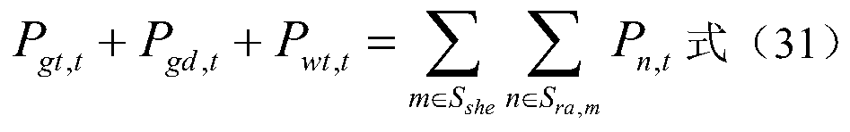


 表示燃气轮机t时刻运行功率下限,单位:kW;
 表示燃气轮机下坡上限约束,单位:kW;
 表示燃气轮机爬坡上限约束,单位:kW;P gt,t-1表示燃气轮机在t-1时刻的出力,单位:kW; Where: η gt,loss represents the gas turbine loss rate; η hr,h represents the heat recovery unit recovery efficiency;
 Indicates the upper limit of the operating power of the gas turbine t, in kW;


 表示截止t-1时刻燃气轮机连续启动时间,单位:h;U gt,t表示t时刻燃气轮机的运行状态,U gt,t=1表示t时刻燃气轮机正在运行,U gt,t=0表示t时刻燃气轮机停机;
 表示截止t时刻燃气轮机连续停机时间,单位:h;
 表示截止t-1时刻燃气轮机连续停机时间,单位:h;
 表示燃气轮机连续启动时间下限,单位:h;
 表示燃气轮机连续停机时间下限,单位:h;
 表示截止t时刻二级换热器连续启动时间,单位:h;
 表示截止t-1时刻二级换热器连续启动时间,单位:h;U she,m,t表示第m个二级换热器t时 刻的开关状态,U she,m,t=1表示第m个二级换热器t时刻开启,U she,m,t=0表示第m个二级换热器t时刻关闭;
 表示截止t时刻二级换热器连续停止时间,单位:h;
 表示截止t-1时刻二级换热器连续停止时间,单位:h;
 表示二级换热器连续启动时间下限,单位:h;
 表示二级换热器连续停止时间下限,单位:h; In the formula:
 Indicates the continuous start-up time of the gas turbine at time t, unit: h;
 表示从电网购电上限,单位:kW。 In the formula:
 Indicates the lower limit of power purchase from the grid, in kW;