WO2018092485A1 - Machine tool management system - Google Patents
Machine tool management system Download PDFInfo
- Publication number
- WO2018092485A1 WO2018092485A1 PCT/JP2017/037471 JP2017037471W WO2018092485A1 WO 2018092485 A1 WO2018092485 A1 WO 2018092485A1 JP 2017037471 W JP2017037471 W JP 2017037471W WO 2018092485 A1 WO2018092485 A1 WO 2018092485A1
- Authority
- WO
- WIPO (PCT)
- Prior art keywords
- machine tool
- information
- usage
- user
- unit
- Prior art date
Links
- 238000012806 monitoring device Methods 0.000 claims abstract description 74
- 238000000034 method Methods 0.000 claims abstract description 31
- 230000008569 process Effects 0.000 claims abstract description 29
- 238000004891 communication Methods 0.000 claims abstract description 3
- 238000007726 management method Methods 0.000 claims description 148
- 230000007246 mechanism Effects 0.000 claims description 103
- 238000004519 manufacturing process Methods 0.000 claims description 79
- 238000012545 processing Methods 0.000 claims description 72
- 238000005516 engineering process Methods 0.000 claims description 67
- 230000005856 abnormality Effects 0.000 claims description 29
- 230000009955 peripheral mechanism Effects 0.000 claims description 21
- 230000006870 function Effects 0.000 claims description 20
- 230000002159 abnormal effect Effects 0.000 claims description 18
- 238000012544 monitoring process Methods 0.000 claims description 14
- 238000003801 milling Methods 0.000 claims description 8
- 238000007514 turning Methods 0.000 claims description 8
- 239000002826 coolant Substances 0.000 claims description 6
- 230000000717 retained effect Effects 0.000 claims 1
- 238000009434 installation Methods 0.000 abstract description 3
- 238000003860 storage Methods 0.000 description 53
- 230000005540 biological transmission Effects 0.000 description 29
- 238000013500 data storage Methods 0.000 description 15
- 238000004364 calculation method Methods 0.000 description 8
- 238000004458 analytical method Methods 0.000 description 6
- 238000003754 machining Methods 0.000 description 6
- 230000002452 interceptive effect Effects 0.000 description 5
- 239000000463 material Substances 0.000 description 5
- 238000005259 measurement Methods 0.000 description 5
- 230000008054 signal transmission Effects 0.000 description 5
- 238000005520 cutting process Methods 0.000 description 4
- 238000010586 diagram Methods 0.000 description 4
- 238000012423 maintenance Methods 0.000 description 4
- 238000011161 development Methods 0.000 description 3
- 238000011156 evaluation Methods 0.000 description 3
- 125000002066 L-histidyl group Chemical group [H]N1C([H])=NC(C([H])([H])[C@](C(=O)[*])([H])N([H])[H])=C1[H] 0.000 description 2
- 230000000694 effects Effects 0.000 description 2
- 230000006872 improvement Effects 0.000 description 2
- 230000002093 peripheral effect Effects 0.000 description 2
- 239000000284 extract Substances 0.000 description 1
- 239000000203 mixture Substances 0.000 description 1
- 238000003825 pressing Methods 0.000 description 1
- 230000004044 response Effects 0.000 description 1
- 230000000087 stabilizing effect Effects 0.000 description 1
Images
Classifications
-
- G—PHYSICS
- G06—COMPUTING; CALCULATING OR COUNTING
- G06Q—INFORMATION AND COMMUNICATION TECHNOLOGY [ICT] SPECIALLY ADAPTED FOR ADMINISTRATIVE, COMMERCIAL, FINANCIAL, MANAGERIAL OR SUPERVISORY PURPOSES; SYSTEMS OR METHODS SPECIALLY ADAPTED FOR ADMINISTRATIVE, COMMERCIAL, FINANCIAL, MANAGERIAL OR SUPERVISORY PURPOSES, NOT OTHERWISE PROVIDED FOR
- G06Q20/00—Payment architectures, schemes or protocols
- G06Q20/08—Payment architectures
- G06Q20/14—Payment architectures specially adapted for billing systems
- G06Q20/145—Payments according to the detected use or quantity
-
- G—PHYSICS
- G06—COMPUTING; CALCULATING OR COUNTING
- G06Q—INFORMATION AND COMMUNICATION TECHNOLOGY [ICT] SPECIALLY ADAPTED FOR ADMINISTRATIVE, COMMERCIAL, FINANCIAL, MANAGERIAL OR SUPERVISORY PURPOSES; SYSTEMS OR METHODS SPECIALLY ADAPTED FOR ADMINISTRATIVE, COMMERCIAL, FINANCIAL, MANAGERIAL OR SUPERVISORY PURPOSES, NOT OTHERWISE PROVIDED FOR
- G06Q30/00—Commerce
- G06Q30/02—Marketing; Price estimation or determination; Fundraising
- G06Q30/0283—Price estimation or determination
-
- G—PHYSICS
- G05—CONTROLLING; REGULATING
- G05B—CONTROL OR REGULATING SYSTEMS IN GENERAL; FUNCTIONAL ELEMENTS OF SUCH SYSTEMS; MONITORING OR TESTING ARRANGEMENTS FOR SUCH SYSTEMS OR ELEMENTS
- G05B19/00—Programme-control systems
- G05B19/02—Programme-control systems electric
- G05B19/18—Numerical control [NC], i.e. automatically operating machines, in particular machine tools, e.g. in a manufacturing environment, so as to execute positioning, movement or co-ordinated operations by means of programme data in numerical form
- G05B19/406—Numerical control [NC], i.e. automatically operating machines, in particular machine tools, e.g. in a manufacturing environment, so as to execute positioning, movement or co-ordinated operations by means of programme data in numerical form characterised by monitoring or safety
- G05B19/4063—Monitoring general control system
-
- G—PHYSICS
- G05—CONTROLLING; REGULATING
- G05B—CONTROL OR REGULATING SYSTEMS IN GENERAL; FUNCTIONAL ELEMENTS OF SUCH SYSTEMS; MONITORING OR TESTING ARRANGEMENTS FOR SUCH SYSTEMS OR ELEMENTS
- G05B19/00—Programme-control systems
- G05B19/02—Programme-control systems electric
- G05B19/418—Total factory control, i.e. centrally controlling a plurality of machines, e.g. direct or distributed numerical control [DNC], flexible manufacturing systems [FMS], integrated manufacturing systems [IMS] or computer integrated manufacturing [CIM]
-
- G—PHYSICS
- G06—COMPUTING; CALCULATING OR COUNTING
- G06Q—INFORMATION AND COMMUNICATION TECHNOLOGY [ICT] SPECIALLY ADAPTED FOR ADMINISTRATIVE, COMMERCIAL, FINANCIAL, MANAGERIAL OR SUPERVISORY PURPOSES; SYSTEMS OR METHODS SPECIALLY ADAPTED FOR ADMINISTRATIVE, COMMERCIAL, FINANCIAL, MANAGERIAL OR SUPERVISORY PURPOSES, NOT OTHERWISE PROVIDED FOR
- G06Q10/00—Administration; Management
-
- G—PHYSICS
- G06—COMPUTING; CALCULATING OR COUNTING
- G06Q—INFORMATION AND COMMUNICATION TECHNOLOGY [ICT] SPECIALLY ADAPTED FOR ADMINISTRATIVE, COMMERCIAL, FINANCIAL, MANAGERIAL OR SUPERVISORY PURPOSES; SYSTEMS OR METHODS SPECIALLY ADAPTED FOR ADMINISTRATIVE, COMMERCIAL, FINANCIAL, MANAGERIAL OR SUPERVISORY PURPOSES, NOT OTHERWISE PROVIDED FOR
- G06Q30/00—Commerce
- G06Q30/06—Buying, selling or leasing transactions
- G06Q30/0645—Rental transactions; Leasing transactions
-
- G—PHYSICS
- G06—COMPUTING; CALCULATING OR COUNTING
- G06Q—INFORMATION AND COMMUNICATION TECHNOLOGY [ICT] SPECIALLY ADAPTED FOR ADMINISTRATIVE, COMMERCIAL, FINANCIAL, MANAGERIAL OR SUPERVISORY PURPOSES; SYSTEMS OR METHODS SPECIALLY ADAPTED FOR ADMINISTRATIVE, COMMERCIAL, FINANCIAL, MANAGERIAL OR SUPERVISORY PURPOSES, NOT OTHERWISE PROVIDED FOR
- G06Q50/00—Information and communication technology [ICT] specially adapted for implementation of business processes of specific business sectors, e.g. utilities or tourism
- G06Q50/04—Manufacturing
-
- G—PHYSICS
- G07—CHECKING-DEVICES
- G07F—COIN-FREED OR LIKE APPARATUS
- G07F17/00—Coin-freed apparatus for hiring articles; Coin-freed facilities or services
- G07F17/0042—Coin-freed apparatus for hiring articles; Coin-freed facilities or services for hiring of objects
-
- G—PHYSICS
- G05—CONTROLLING; REGULATING
- G05B—CONTROL OR REGULATING SYSTEMS IN GENERAL; FUNCTIONAL ELEMENTS OF SUCH SYSTEMS; MONITORING OR TESTING ARRANGEMENTS FOR SUCH SYSTEMS OR ELEMENTS
- G05B2219/00—Program-control systems
- G05B2219/30—Nc systems
- G05B2219/31—From computer integrated manufacturing till monitoring
- G05B2219/31408—Cost calculation of use of certain machine types
-
- Y—GENERAL TAGGING OF NEW TECHNOLOGICAL DEVELOPMENTS; GENERAL TAGGING OF CROSS-SECTIONAL TECHNOLOGIES SPANNING OVER SEVERAL SECTIONS OF THE IPC; TECHNICAL SUBJECTS COVERED BY FORMER USPC CROSS-REFERENCE ART COLLECTIONS [XRACs] AND DIGESTS
- Y02—TECHNOLOGIES OR APPLICATIONS FOR MITIGATION OR ADAPTATION AGAINST CLIMATE CHANGE
- Y02P—CLIMATE CHANGE MITIGATION TECHNOLOGIES IN THE PRODUCTION OR PROCESSING OF GOODS
- Y02P90/00—Enabling technologies with a potential contribution to greenhouse gas [GHG] emissions mitigation
- Y02P90/02—Total factory control, e.g. smart factories, flexible manufacturing systems [FMS] or integrated manufacturing systems [IMS]
-
- Y—GENERAL TAGGING OF NEW TECHNOLOGICAL DEVELOPMENTS; GENERAL TAGGING OF CROSS-SECTIONAL TECHNOLOGIES SPANNING OVER SEVERAL SECTIONS OF THE IPC; TECHNICAL SUBJECTS COVERED BY FORMER USPC CROSS-REFERENCE ART COLLECTIONS [XRACs] AND DIGESTS
- Y02—TECHNOLOGIES OR APPLICATIONS FOR MITIGATION OR ADAPTATION AGAINST CLIMATE CHANGE
- Y02P—CLIMATE CHANGE MITIGATION TECHNOLOGIES IN THE PRODUCTION OR PROCESSING OF GOODS
- Y02P90/00—Enabling technologies with a potential contribution to greenhouse gas [GHG] emissions mitigation
- Y02P90/30—Computing systems specially adapted for manufacturing
Definitions
- the present invention relates to a machine tool management system that manages, via the Internet, one or more machine tools disposed in a place where a specific or unspecified user can use them.
- the user management device is connected to each numerical control unit (control device) of one or more machine tools including a drive mechanism unit and a numerical control unit that controls the operation of the drive mechanism unit. Yes.
- the user management device collects data on the operation status of each drive mechanism unit from each numerical control unit by collecting user-side operation data storage means for storing data on the operation status of the drive mechanism unit of each machine tool, and In addition to accumulating in the user-side operation data storage means, it is confirmed whether or not a preset transmission condition is satisfied, and only when the transmission condition is satisfied, is accumulated in the user-side operation data storage means.
- Data transmission means for transmitting operation status data of each drive mechanism section to the manufacturer management apparatus in the data format of an e-mail.
- the manufacturer management device includes manufacturer-side operation data storage means for storing operation status data of each drive mechanism unit received from the user management device, and operation status data of each drive mechanism unit transmitted from the user management device.
- the data receiving means for updating the operating status data stored in the manufacturer operating data storage means with the received operating status data, and the consumption level for storing the data related to the consumption level of each drive mechanism section
- the wear level of each drive mechanism section is evaluated at any time and stored in the wear level data storage means.
- Consumption level evaluation means for updating the consumption level data with the evaluated consumption level data, and consumption level data stored in the consumption level data storage means. From time to time monitors whether exceeded because set reference value, if it exceeds the reference value, and an alarm output means for outputting an alarm to that effect.
- the data transmission means of each user management device collects data (operation status data) related to the operation status of each drive mechanism unit from the numerical control unit of each machine tool, and these are collected by the user. Accumulated in the side operation data storage means. Whether or not a predetermined transmission condition is satisfied is confirmed at any time, and only when this transmission condition is satisfied, the operation status data of each drive mechanism section stored in the user-side operation data storage means is electronic. It is sent to the manufacturer management device in the mail data format.
- the transmitted operating status data is received by the data receiving means, and the operating status data of each drive mechanism section stored in the manufacturer-side operating data storage means is updated with the received operating status data. Further, the wear level evaluation unit evaluates the wear level of each drive mechanism unit as needed based on the operation status data of each drive mechanism unit stored in the manufacturer side operation data storage unit, and stores it in the wear level data storage unit. The consumption level data is updated with the evaluated consumption level data. The consumption level data stored in the consumption level data storage means is monitored at any time by the alarm output means to determine whether or not the predetermined reference value has been exceeded. An alarm to the effect is output.
- the degree of wear of the drive mechanism portion of each machine tool is evaluated and monitored as needed, and when the degree of wear exceeds a predetermined reference value, that is, the wear of the drive mechanism portion.
- An alarm is output when a part is nearing the end of its life. Based on the output alarm, manufacturers can easily identify consumable parts that are nearing the end of their life. It is possible to predict when and how much parts are needed. As a result, there is no need to have extra inventory for consumable parts, which can be greatly reduced.
- Such a high-performance machine tool is naturally more expensive than a general-purpose machine tool, and requires a considerable amount of capital investment when including peripheral devices. Therefore, as a user, if the work rate of the machine tool that is being considered for introduction is to ensure a work rate that is profitable, or if such work amount is predicted, consider it Although it is possible to proceed with the introduction of existing machine tools, it is necessary to refrain from capital investment if this is not the case.
- the present invention has been made in view of the above circumstances, is not limited by the area where the machine tool is installed, and can efficiently charge a usage fee according to the use state of the machine tool.
- the purpose is to provide a machine tool management system.
- One or more machine tools provided with a use monitoring device having a communication function for connecting to the Internet and disposed in a place where a specific or unspecified user can use;
- a machine tool management system comprising a management device connected to the Internet and communicating with each usage monitoring device, The usage monitoring device is configured to transmit information related to a usage state of the machine tool to the management device,
- the management device is configured to calculate a fee according to a usage state of the machine tool received from the usage monitoring device as a usage fee, and then perform processing for charging the calculated user to the corresponding user.
- a machine tool management system comprising a management device connected to the Internet and communicating with each usage monitoring device, The usage monitoring device is configured to transmit information related to a usage state of the machine tool to the management device, The management device is configured to calculate a fee according to a usage state of the machine tool received from the usage monitoring device as a usage fee, and then perform processing for charging the calculated user to the corresponding user.
- At least one of the machine tools is disposed in a place where a specific or unspecified user can use it.
- a specific user uses the machine tool
- the machine tool is disposed in the user's factory.
- an unspecified user for example, it is arranged in a building set by the manufacturer of the machine tool.
- These machine tools have a usage monitoring device attached to the machine tool connected to the Internet, and can communicate with a management device also connected to the Internet.
- This management device is under the control of the manufacturer of the machine tool, but the installation location is not particularly limited.
- information related to the use state of the machine tool is obtained from the use monitoring device attached to the machine tool. Sent to.
- the information relating to the usage state forms a calculation basis for charging the user with an appropriate cost for using the machine tool, and includes, for example, the usage time of the machine tool.
- the management device calculates a cost according to the usage state of the machine tool received from the usage monitoring device as a usage fee, and executes a process of charging the calculated usage fee to the corresponding user.
- the user does not need to purchase a machine tool, and can perform necessary machining if paying a usage fee according to the use. Therefore, even if the user does not have enough work to fully operate the machine tool, the user can perform processing according to the work without newly installing the machine tool, and the required demand can be met. I can respond.
- the user can update the existing machine tool with a state-of-the-art machine tool without capital investment. Even if there is no risk or there is a risk that the demand will fluctuate suddenly, the renewal of the equipment is promoted.
- machine tool manufacturers can realize stable planned production that is easy to secure profits by creating new demand that does not depend on capital investment.
- a management system is a system through the Internet, there is no restriction on the area where the machine tool is installed. For example, the machine tool can be installed overseas. Even in the case of the arrangement, so-called charging processing can be performed efficiently.
- the management device is configured to settle a charge to the corresponding user by a process linked to the corresponding usage monitoring device.
- Such linked payment means an electronic payment that the user charges the cost charged to the user from the management device through the Internet by the user using the usage monitoring device. , Including payment by credit card and automatic debit from the bank account of the user.
- the usage monitoring device is configured to execute a process of performing user registration with respect to the management device,
- the management device is configured to execute a process of transmitting registered user identification information to a corresponding usage monitoring device.
- the user who uses the management system of the machine tool can be clarified, and the user who has been registered once and given identification information can be charged with high reliability. Can be executed.
- information such as a user's usage history can be accumulated, and by utilizing the accumulated information effectively, it is possible to predict the trend of user orders and future capital investment.
- the machine tool is provided with related facilities and functions used for processing using the machine tool.
- the usage monitoring device may be configured to transmit information relating to the usage state of the machine tool including information relating to the usage state of the related equipment and related functions to the management device.
- the related equipment and related functions include, for example, an automatic programming device, an interactive programming device, a special cycle function, a tool measuring system, and a workpiece measuring system.
- the user may desire to use these related facilities and related functions depending on the processing. According to this configuration, the user can use these related facilities and related functions as necessary, and the machine tool manufacturer can charge the cost according to their use.
- the machine tool includes a turning mechanism as a basic mechanism, and as an additional mechanism, a tailstock mechanism, a steady rest mechanism, a milling mechanism, a second and subsequent tool rests, and a second and subsequent main spindle mechanisms. And one or more mechanisms selected from a coolant mechanism,
- the usage monitoring device may be configured to transmit information relating to the usage state of the machine tool, including information relating to the usage state of the additional mechanism, to the management device.
- the user may wish to use this additional mechanism in addition to the turning mechanism as the basic mechanism.
- the user can use this additional mechanism as necessary, and the machine tool manufacturer can charge a cost according to the use of these additional mechanisms.
- the machine tool includes a milling mechanism as a basic mechanism, and the additional mechanism is selected from a turning axis other than the tool spindle, a mechanism related to the U axis of the tool spindle, a work clamp mechanism, and a coolant mechanism.
- the usage monitoring device may be configured to transmit information relating to the usage state of the machine tool, including information relating to the usage state of the additional mechanism, to the management device.
- the user may desire to use the additional mechanism in addition to the milling mechanism as the basic mechanism. According to this configuration, the user can use this additional mechanism as necessary, and the machine tool manufacturer can charge a cost according to the use of these additional mechanisms.
- the machine tool includes a peripheral mechanism provided in the periphery in addition to the main body mechanism for performing processing
- the usage monitoring device may be configured to transmit information relating to the usage state of the machine tool including information relating to the usage state of the peripheral mechanism to the management device.
- the peripheral mechanism includes, for example, a robot and a work loading / unloading device.
- the user may desire to use a peripheral mechanism in addition to the main body mechanism depending on the processing. According to this configuration, the user can use the peripheral mechanism as necessary, and the machine tool manufacturer can charge a cost according to the use thereof.
- the main body mechanism mentioned here is a concept including the basic mechanism and the additional mechanism.
- an accessory used for processing using the machine tool is provided around the machine tool
- the usage monitoring device may be configured to transmit information relating to the usage state of the machine tool, including information relating to the usage state of the accessory, to the management device.
- the accessory includes, for example, a chuck, a raw nail, a tool (including a tool holder), a throw-away tip, a detachable measuring device, and the like.
- the user may desire to use an accessory that can be used with the machine tool in addition to the machine tool. According to this configuration, the user can use the accessory as necessary, and the machine tool manufacturer can charge a cost according to the use of the accessory.
- the machine tool is provided with various sensors that detect the state of the machine tool.
- the usage monitoring device may be configured to transmit information obtained from the various sensors to the management device as information relating to a usage state of the machine tool.
- the sensor includes, for example, a power meter, a motor load ammeter, an accelerometer, a thermometer, and the like.
- Information obtained from the sensor includes, for example, power amount data, spindle motor load data, and feed motor load data.
- the vibration data of each part of the machine tool and the temperature data of each part of the machine tool are included. By collecting such information, it is possible to obtain data relating to the load state of each machine tool and the performance of the machine tool with respect to the load, which can be used for the development and improvement of the next machine tool.
- the management device analyzes the information obtained from the various sensors received from the usage monitoring device, and predicts whether or not there is an abnormality in the corresponding machine tool. Even if it is configured to transmit a signal regarding the abnormality to the use monitoring device when it is recognized that there is an abnormality or when it is predicted that an abnormal state is expected good. In this way, the user can use the machine tool with peace of mind. Predicting that an abnormal condition will occur means that an abnormal condition will occur in the near future. For the near future, for example, depending on the number of days that the machine tool manufacturer can handle before becoming abnormal. Means the future.
- the usage monitoring device is configured to transmit data related to an operating state acquired from a corresponding machine tool to the management device
- the management apparatus may be configured to accumulate the received data relating to the operating state, analyze the accumulated data, and retain at least the production technology information.
- the data (operation information) related to the operating state includes, for example, data such as cutting conditions (including cutting speed, feed speed, work material, tool material, etc.), tool life data, spindle rotation speed, and the like. included.
- cutting conditions including cutting speed, feed speed, work material, tool material, etc.
- tool life data including cutting speed, feed speed, work material, tool material, etc.
- spindle rotation speed included.
- the usage monitoring device executes processing for requesting the management device to use the production technology information held in the management device
- the said management apparatus may be comprised so that the said usage fee which concerns on a corresponding machine tool may be calculated according to the presence or absence of use of the said production technical information.
- the management device accumulates highly reliable production technology information having a wide range. Therefore, the user can perform more appropriate processing by using such production technology information.
- the machine tool maker provides the accumulated production technology information to the user and charges the usage fee according to the use, the profit can be increased.
- the machine tool is disposed in a place where an unspecified user can use it.
- the usage monitoring device is: Execute a process for requesting permission to use the machine tool to the management device; When the use permission is obtained from the management device, the processing device is configured to execute a process for enabling the machine tool, The management device When a signal requesting permission to use the corresponding machine tool is received from the use monitoring device, a process for recognizing the user is executed, and a process for determining whether or not the user can be used and returning the process to the use monitoring device is executed. It may be configured as follows.
- the machine tool is arranged in a place where an unspecified user can use it.
- the use monitoring device performs processing for requesting the management device to use the machine tool, and processing for making the machine tool usable when use permission is obtained from the management device. Execute.
- the management device determines the user and determines whether or not the use can be performed, and returns it to the use monitoring device. Process.
- the user can use the corresponding machine tool only when the user is recognized by the management device and its use is approved. Therefore, for users who have used improperly in the past or for users who have not made appropriate payments, their use can be eliminated, and in this way, proper operation of the system can be achieved. Can improve safety.
- the user does not need to purchase a machine tool, and can perform necessary processing by paying a usage fee according to use. Therefore, even if the user does not have enough work to fully operate the machine tool, the user can perform processing according to the work without newly installing the machine tool, and the required demand can be met. I can respond. In addition, by paying a usage fee according to the use of the machine tool in this way, the user can update the existing machine tool with a state-of-the-art machine tool without capital investment. Even if there is no risk or there is a risk that the demand will fluctuate suddenly, the renewal of the equipment is promoted.
- machine tool manufacturers can realize stable planned production that is easy to secure profits by creating new demand that does not depend on capital investment.
- a management system is a system through the Internet, there is no restriction on the area where the machine tool is installed. For example, the machine tool can be installed overseas. Even in the case of the arrangement, so-called charging processing can be performed efficiently.
- FIG. 1 is a block diagram showing a schematic configuration of a machine tool management system according to an embodiment of the present invention. It is a block diagram showing composition of a use monitoring device, a machine tool, etc. concerning this embodiment. It is the block diagram which showed the structure of the management apparatus which concerns on this embodiment. It is the flowchart which showed the usage procedure of the machine tool in the machine tool management system of this embodiment.
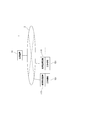
- FIG. 1 is a block diagram showing a schematic configuration of a machine tool management system (hereinafter simply referred to as “management system”) according to an embodiment of the present invention.
- the management system 1 of this example includes a management device 10 connected to the Internet 2 and a usage monitoring device 110, and a plurality of usage monitoring devices 110 connected to the Internet 2.
- Machine tool 101 As shown in FIG. 1, the management system 1 of this example includes a management device 10 connected to the Internet 2 and a usage monitoring device 110, and a plurality of usage monitoring devices 110 connected to the Internet 2.
- Machine tool 101 As shown in FIG. 1, the management system 1 of this example includes a management device 10 connected to the Internet 2 and a usage monitoring device 110, and a plurality of usage monitoring devices 110 connected to the Internet 2.
- Machine tool 101 As shown in FIG. 1, the management system 1 of this example includes a management device 10 connected to the Internet 2 and a usage monitoring device 110, and a plurality of usage monitoring devices 110 connected to the Internet 2.
- Machine tool 101 As shown in FIG. 1, the management system 1 of this example includes a management device 10 connected to the Internet 2 and a usage monitoring device 110, and a plurality of usage monitoring devices 110 connected to the Internet 2.
- Machine tool 101
- Each machine tool 101 can be used by a specific user, for example, a processing factory owned by a specific user, or a place that can be used by an unspecified user, such as a building set by a machine tool manufacturer. Arranged indoors. The building set by this machine tool manufacturer can be used by an unspecified number of users and has a concept of a machining center.
- the management apparatus 10 is under the management of the manufacturer of the machine tool, the installation location is not particularly limited. Details of each part will be described below.
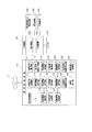
- the machine tool 101 includes a basic mechanism 102 and an additional mechanism 103, and in addition to this, related equipment and related functions (hereinafter referred to as “related equipment”) 104, peripheral mechanisms 105, and various types.
- a sensor 107 is provided, and an accessory device 106 is disposed around the sensor 107.
- the basic mechanism 102 and the additional mechanism 103 are mechanisms for performing processing, and are considered as main body mechanisms.
- the machine tool 101 is not particularly limited, but examples of the most general machine include an NC lathe and a machining center.
- the basic mechanism 102 is a turning mechanism
- the additional mechanism 103 includes a tailstock mechanism, a steady rest mechanism, a milling mechanism, a second and subsequent tool rest, and a second and subsequent spindle mechanism.
- the coolant mechanism is selected from the coolant mechanism.
- the basic mechanism 102 is a milling mechanism
- the additional mechanism 103 is selected from a turning axis other than the tool spindle, a mechanism related to the U axis of the tool spindle, a work clamping mechanism, and a coolant mechanism.
- One or more mechanisms are illustrated.
- the related equipment 104 or the like is equipment or a function built in or attached to the machine tool 101, and examples thereof include an automatic programming device, an interactive programming device, a special cycle function, a tool measuring system, and a workpiece measuring system. .
- the peripheral mechanism 105 is a mechanism portion provided around the basic mechanism 102 and the additional mechanism 103 (main body mechanism) for performing processing.
- a robot or a work loading / unloading device including a loader
- the accessory tool 106 is a tool used for processing using the machine tool 101, and is disposed around the machine tool 101.
- the accessory 106 includes, for example, a chuck, a raw nail, a tool (including a tool holder), a throw-away tip, a detachable measuring device, and the like.
- the sensor 107 is attached to the machine tool 101.
- the sensor 107 includes, for example, a power meter, a motor load ammeter, an accelerometer, a thermometer, and the like. From these sensors 107, for example, electric energy data, spindle motor load data, feed motor load data, machine tools Information such as vibration data of each part and temperature data of each part of the machine tool is obtained.
- each usage monitoring device 110 includes a usage permission request unit 111, a usage permission processing unit 112, a user registration application unit 113, an identification information display unit 114, a settlement processing unit 115, a usage information acquisition unit 116, Usage information storage unit 117, usage information transmission unit 118, sensor information acquisition unit 119, sensor information storage unit 120, sensor information transmission unit 121, operation information acquisition unit 122, operation information storage unit 123, operation information transmission unit 124, production technology
- the information request unit 125, the production technology information display unit 126, an abnormality signal reception unit 127, and an abnormality display unit 128 are included.
- the usage monitoring device 110 is composed of a general computer provided with an input device such as a keyboard and a display in addition to a CPU, ROM, and RAM.
- the sensor information transmission unit 121, the operation information acquisition unit 122, the operation information transmission unit 124, the production technology information request unit 125, the production technology information display unit 126, the abnormality signal reception unit 127, and the abnormality display unit 128 are appropriately configured by software. That function is realized.
- the usage information storage unit 117, the sensor information storage unit 120, and the operation information storage unit 123 are configured by an appropriate storage medium such as a RAM.
- the use permission request unit 111 receives the input identification
- the information related to the information and the contents of use is transmitted to the management device 10 and the management device 10 is requested to permit the use of the machine tool 101 and the like.
- a use permission signal is received from the management device 10
- a use permission signal is transmitted from the use permission processing unit 112 to the control device of the machine tool 101.
- the control device receives the use permission signal
- the board is changed from the unusable state (locked state) to the usable state (unlocked state), thereby enabling the machine tool 101 to be operated.
- the use permission processing unit 112 displays that fact on the display. In this case, the machine tool 101 is maintained in an unusable state (locked state).
- the user registration application unit 113 performs processing. That is, when the user inputs information necessary for registration, the input registration information is transmitted from the user registration application unit 113 to the management apparatus 10 and registered in detail by the user registration processing unit 11 described later.
- the identification information is transmitted from the management device 10.
- the received identification information is displayed on the display by the processing of the identification information display unit 114.
- the registration information include personal information such as a user's address and name, information necessary for electronic payment (for example, information related to credit cards, bank account numbers that can be withdrawn, and the like).
- the unique information of the machine tool 101 or the unique information of the use monitoring device 110 is associated with the identification information of the user. Is transmitted to the management device 10 and registered by the user registration processing unit 11.
- the usage information acquisition unit 116 acquires the usage information from the control device of the machine tool 101, related equipment 104, the peripheral mechanism 105, and each sensor 107.
- information related to the usage content is acquired as usage information from the usage permission request unit 111
- data (operation information) regarding the operating state is acquired as usage information from the control device of the machine tool 101, and more specifically.
- the use status of production technology information acquired from the management apparatus 10 by the production technology information request unit 125 described later is acquired as usage information.
- This usage information forms a calculation basis for charging the user an appropriate cost for the use of the machine tool 101. For example, the usage time and load state of the machine tool 101, related equipment, etc. 104, whether or not the peripheral mechanism 105 is used, how long it is used, whether the accessory 106 is used, and the use status of production technology information provided from the management apparatus 10.
- the usage information acquisition unit 116 acquires this information as usage information.
- the usage information acquisition unit 116 acquires this information as usage information.
- the use information acquisition unit 116 acquires this information as use information.
- the usage information acquisition unit 116 uses the NC code of the NC program analyzed by the control device of the machine tool 101 as the usage information. get.
- a work loading / unloading device such as a gantry loader or a robot is provided as the peripheral mechanism 105
- the use information acquisition unit 116 exchanges signals between the control device of the machine tool 101 in operation and the peripheral mechanism 105. Then, the presence or absence of the use is detected, and this is acquired as use information.
- the use information acquisition unit 116 obtains from the dispenser when the user takes out the necessary device from the dispenser. The operation signal to be detected is detected and obtained as usage information.
- the usage information acquired from the sensor 107 includes, for example, electric energy data, spindle motor load data, feed motor load data, and the like.
- the operation information includes information analyzed from the NC program. For example, in addition to rotation speed information (S code) and feed information (F code), auxiliary such as turning on / off of hydraulic pressure such as steady rest Functional information (M code) and the like are included.
- the usage information acquired by the usage information acquisition unit 116 is stored in the usage information storage unit 117, and when the user finishes using the machine tool 101, the usage information stored in the usage information storage unit 117 is stored. Information is transmitted to the management apparatus 10 by the usage information transmitter 118.
- the sensor information acquisition unit 119 acquires output data from the sensors 107 regularly or irregularly and stores the data in the sensor information storage unit 120.
- the data acquired from the sensor 107 includes, for example, electric energy data, spindle motor load data, feed motor load data, vibration data of each part of the machine tool, temperature data of each part of the machine tool, and the like.
- the data (sensor information) stored in the sensor information storage unit 120 is periodically or irregularly transmitted by the sensor information transmission unit 121 until the user finishes using the machine tool 101. Sent to.
- the operation information acquisition unit 122 acquires data (operation information) related to the operation state from the control device or the like of the corresponding machine tool 101, and stores it in the operation information storage unit 123.
- the operation information includes, for example, data related to cutting conditions (including cutting speed, feed speed, material of the work material, tool material, etc.) of processing executed by the machine tool 101 and data related to the tool life.
- the data such as the spindle speed can be exemplified.
- the operation information stored in the operation information storage unit 123 is transmitted to the management apparatus 10 by the operation information transmission unit 124 when the user finishes using the machine tool 101.
- the production technology information request unit 125 performs processing for requesting the management device 10 to provide production technology information in response to an input from a user, and obtains necessary production technology information from the management device 10 Production technology information is displayed on the display via the production technology information display unit 126.
- the abnormal signal receiving unit 127 performs a process of receiving the abnormal signal transmitted from the management device 10 and displays the received abnormal signal on the display via the abnormal display unit 128.
- the payment processing unit 115 performs processing for electronic payment (for example, payment using a known credit card) through the Internet 2 by processing the usage fee charged by the management device 10 in conjunction with the management device 10.
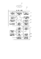
- the management device 10 includes a user registration processing unit 11, a user information storage unit 12, an identification information transmission unit 13, a user information update unit 14, a usability determination unit 15, and a usability transmission unit.
- usage information reception unit 17 usage fee calculation unit 18, usage fee unit price storage unit 19
- settlement processing unit 20 sensor information reception unit 21, sensor information storage unit 22, abnormality determination unit 23, abnormal signal transmission unit 24, operation
- the information receiving unit 25 the information analysis unit 26, the production technology information storage unit 27, the production technology request reception unit 28, and the production technology information transmission unit 29 are configured.
- the management apparatus 10 is also composed of a general computer equipped with an input device such as a keyboard and a display in addition to the CPU, ROM, and RAM.
- 20, the sensor information reception unit 21, the abnormality determination unit 23, the abnormality signal transmission unit 24, the operation information reception unit 25, the information analysis unit 26, the production technology request reception unit 28, and the production technology information transmission unit 29 are each appropriately configured by software. That function is realized.
- the user information storage unit 12, the usage fee unit price storage unit 19, the sensor information storage unit 22, and the production technology information storage unit 27 are configured by an appropriate storage medium such as a RAM.
- the user registration processing unit 11 is a functional unit that receives a registration application from the user registration application unit 113 of each use monitoring device 110 and performs a registration process for the corresponding user, and the user registration application unit 113 receives registration information transmitted from 113, stores it in the user information storage unit 12, and generates and assigns unique identification information for the user, and assigns the assigned identification information to the user information. Processing to be stored in the storage unit 12 is performed. As described above, when the machine tool 101 is installed at a specific user's place of use, the unique information of the machine tool 101 or the unique information of the use monitoring device 110 and the user's The identification information is associated with each other and stored in the user information storage unit 12.
- the user information storage unit 12 stores the usage history and payment status of each registered user. Information from the usage information receiving unit 17 and the payment processing unit 20 is stored in the user information storage unit 12. In addition, the information stored in the user information storage unit 12 is updated by the user information update unit 14 based on information input from the outside in some cases.
- the use permission determination unit 15 receives a signal related to a use permission request transmitted from a use permission processing unit 111 of each use monitoring device 110, which will be described in detail later, and permits use to a user who requests use. It is determined whether or not it is possible. Specifically, the usability determination unit 15 refers to the user information storage unit 12 to confirm the use history and the settlement status, and when inappropriate use is confirmed in the use history, and / or Alternatively, when it is confirmed that the payment is incomplete, the use is determined not to be permitted. In other cases, the user is permitted to use the machine tool 101.
- the machine tool 101 When the machine tool 101 is installed in a place used by a specific user, if the user who requests the use permission is not a user corresponding to the machine tool 101, the use is made. May not be allowed. On the other hand, even in such a case, if the user's use is allowed, the operating rate of the machine tool 101 is improved and the profit of the machine tool manufacturer is increased. The user may be allowed to use it.
- the availability determination unit 15 determines whether the user can use the user, the determination result is sent to the corresponding usage monitoring device 110 by the availability transmission unit 16. Sent.
- the usage information receiving unit 17 is a functional unit that receives the usage information transmitted from the usage information transmitting unit 118 of the usage monitoring device 110 and transfers the received usage information to the usage fee calculating unit 18.
- the usage fee calculation unit 18 calculates the usage fee of the user by referring to the usage fee unit price of each item stored in the usage fee unit price storage unit 19 based on the received usage information.
- the received usage fee is transferred to the settlement processing unit 20.
- the basic usage fee of the machine tool 101 the basic usage fee is calculated by multiplying the usage time by the unit price, and the load state of the machine tool 101, the related equipment 104, the peripheral mechanism 105, the accessory 106, etc.
- an additional usage fee is calculated according to whether or not production technology information is used, and then a total usage fee is calculated.
- the unit price may be lowered if the number of uses is large, or the unit price may be lowered as the usage time is longer, depending on the number of uses of the related equipment 104, the peripheral mechanism 105, and the accessory device 106.
- points according to usage may be given, and if a certain point is reached, some functions may be used without charge.
- the payment processing unit 20 transmits the usage fee calculated by the usage fee calculation unit 18 to the corresponding usage monitoring device 110, and performs a process for electronically paying the usage fee in cooperation with the payment processing unit 115. .
- Electronic payment is as described above.
- the sensor information receiving unit 21 is a functional unit that receives sensor information transmitted from the sensor information transmitting unit 121 of the usage monitoring device 110, stores the received sensor information in the sensor information storage unit 22, and determines whether there is an abnormality. The process of transferring to the unit 23 is performed.
- the abnormality determination unit 23 analyzes the received sensor information to determine whether or not there is an abnormality in the corresponding machine tool 101. When it is determined that there is an abnormality, the abnormality determination unit 23 passes the abnormality signal transmission unit 24. The abnormality signal is transmitted to the corresponding usage monitoring apparatus 110.
- the operation information receiving unit 25 is a functional unit that receives the operation information transmitted from the operation information transmitting unit 124 of the usage monitoring apparatus 110, and performs a process of transferring the received operation information to the information analyzing unit 26.
- the information analysis unit 26 analyzes the received operation information, extracts production technology information, edits the extracted production technology information, organizes it, and stores it in the production technology information storage unit 27. .
- the production technology request receiving unit 28 performs a process of receiving a request signal from the production technology information requesting unit 125 of the use monitoring apparatus 110 and transferring the request signal to the production technology information transmitting unit 29. With reference to the production technology information stored in the production technology information storage unit 27, the production technology information corresponding to the received request signal is read, and the read production technology information is transmitted to the corresponding usage monitoring apparatus 110. .
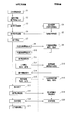
- the user uses the machine tool 101 and charges according to the use state according to the following procedure.
- step S1 when the user turns on the power switch of the machine tool 101 to be used connected to the Internet 2, the machine tool 101 and the corresponding use monitoring device 110 are activated (step S1). ). In this state, the user cannot operate the machine tool 101 yet.
- step S2 when the user inputs his / her identification information, the additional mechanism 103 to be used, the related equipment 104, the peripheral mechanism 105, and the contents (usage contents) of the accessory 106 to the use monitoring apparatus 110 (step S2),
- the input identification information and information related to use contents are transmitted from the use permission request unit 111 to the management apparatus 10 together with a signal related to the use permission request (step S3), and these are received by the usability determination unit 15.
- the usability determination unit 15 refers to the data stored in the user information storage unit 12 on the basis of the received identification information and information related to the usage content, and uses the user's usage history related to the transmitted identification information and The settlement status is confirmed (step S4). Then, when the use history is confirmed to be inappropriate and / or when the settlement is not completed, the availability determination unit 15 determines that the use is not permitted. In this case, it is determined that the user is allowed to use the machine tool 101, and a determination result regarding the availability of the machine tool 101 is sent to the usage monitoring device 110 via the availability transmission unit 16. (Step S5).
- the user registration application unit 113 of the usage monitoring device 110 and the user registration processing unit 11 of the management device 10 can process the user. On the other hand, identification information is attached and user registration is performed.
- the usage permission processing unit 112 of the usage monitoring device 110 sends the determination result to the control device of the corresponding machine tool 101 when the determination result is usable.
- a use permission signal is transmitted (step S6).
- the control device changes the operation panel from the unusable state (locked state) to the usable state (unlocked state).
- the use permission processing unit 112 displays that fact on the display.
- step S7 the user performs necessary processing using the target machine tool 101 (step S7).
- the user can use the production technology information stored in the production technology information storage unit 27 of the management device 10 via the production technology information request unit 125 of the usage monitoring device 110.
- step S8 the necessary production technology information from 125
- step S9 the production technology request receiving unit 28 of the management apparatus 10
- step S9 the production accumulated in the production technology information storage unit 27 by the production technology information transmitting unit 29
- the technical information is searched, and the requested production technical information is transmitted to the usage monitoring apparatus 110 (step S9).
- the use management apparatus 110 the transmitted production technology information is displayed on the display via the production technology information display unit 126 (step S10). Thereby, the user can use the requested production technology information.
- the usage information acquisition unit 116 of the usage management device 110 acquires the usage information from the control device of the machine tool 101, each sensor 107, related equipment 104, and the peripheral mechanism 105, Also, information related to the usage content is acquired as usage information from the usage permission processing unit 111, and the usage status of the production technology information acquired from the management apparatus 10 by the production technology information request unit 125 is acquired as usage information. Is stored in the usage information storage unit 117 (step S11).
- data (sensor information) output from each sensor 107 is stored in the sensor information storage unit 120 regularly or irregularly by the sensor information acquisition unit 119 of the usage management device 110.
- the stored sensor information is transmitted to the management apparatus 10 regularly or irregularly by the sensor information transmitting unit 121 (step S12).
- the operation information acquisition unit 122 acquires data (operation information) related to the operation state from the control device of the corresponding machine tool 101 regularly or irregularly.
- the operation information stored in the operation information storage unit 123 is transmitted to the management apparatus 10 regularly or irregularly by the operation information transmission unit 124 (step S15).
- the sensor information transmitted from the usage monitoring device 110 is received by the sensor information receiving unit 21 and stored in the sensor information storage unit 22, and the data is analyzed by the abnormality determination unit 23 to cope with it. It is determined whether there is an abnormality in the machine tool 101 to be operated. If it is determined that there is an abnormality, the abnormality signal is transmitted to the corresponding use monitoring device 110 via the abnormality signal transmission unit 24 (step). S13). Then, when an abnormal signal is transmitted from the management device 10, it is received by the abnormal signal receiving unit 127 of the corresponding usage monitoring device 110 and displayed on the display via the abnormal display unit 128 (step S14).
- the operation information transmitted from the usage monitoring apparatus 110 is received by the operation information receiving unit 25, the received operation information is analyzed by the information analysis unit 26, the production technology information is extracted, and the extracted production technology information is Edited and systematized and stored in the production technology information storage unit 27 (step S16).
- step S17 When the user finishes processing (step S17), the usage information is stored in the usage information storage unit 117 of the usage monitoring device 110, and the usage information is transmitted to the management device 10 by the usage information transmission unit 118 (step S18).
- the usage fee calculation unit 18 stores each usage information stored in the usage fee unit price storage unit 19 based on the received usage information.
- the usage fee unit price of the item is referred to, the usage fee for the user is calculated, and the calculated usage fee is transferred to the settlement processing unit 20 (step S19).
- the settlement processing unit 20 transmits the calculated usage fee to the corresponding usage monitoring apparatus 110, and in conjunction with the settlement processing unit 115, electronically settles the usage fee (step S20). After the settlement, the machine tool 101 is stopped, that is, locked. .
- the user does not need to purchase the machine tool 101, and can perform necessary processing if paying a usage fee according to use. Therefore, even when the user does not have enough work to fully operate the machine tool 101, the user can perform processing according to the work without installing the machine tool 101 newly. Can meet demand. In addition, by paying the usage fee according to the use of the machine tool 101 in this way, the user can update the existing machine tool with the state-of-the-art machine tool 101 without using capital investment, so that it is stable. Even when there is no demand or when there is a risk that the demand fluctuates suddenly, the renewal of facilities is promoted.
- machine tool manufacturers can realize stable planned production that is easy to secure profits by creating new demand that does not depend on capital investment.
- a management system is a system through the Internet 2
- the machine tool 101 can be installed overseas, for example, without being limited by the area where the machine tool 101 is installed. In this way, so-called billing processing can be performed efficiently even when installed overseas.
- the machine tool 101 having the additional mechanism 103 is adopted, and the related equipment 104, the peripheral mechanism 105, the accessory device 106, and the like are provided. As a result, the operating rate of the machine tool 101 can be improved.
- each machine tool is analyzed by analyzing the obtained data.
- the load state of 101, the performance of the machine tool 101 with respect to the load, and the like can be evaluated, and the obtained evaluation results can be used for the development and improvement of the next machine tool.
- information obtained from each sensor 107 provided in the machine tool 101 is analyzed by the abnormality determination unit 23 of the management device 10, and when it is determined that there is an abnormality, the management device 10 responds. Since an abnormality signal is transmitted to the usage monitoring device 110 and displayed on the display, the user can quickly recognize this when there is an abnormality in the machine tool 101 to be used. Therefore, the user can use the machine tool 101 with peace of mind.
- the operation information of the corresponding machine tool 101 is collected from each usage monitoring device 110, the collected operation information is analyzed by the information analysis unit 26, and the production technology information is extracted. Is compiled, systematized, and stored in the production technology information storage unit 27. Therefore, the production technology information storage unit 27 can store wide-ranging and highly reliable production technology information. Since the production technology information accumulated in this way is made available to the user, the user can perform more appropriate processing by using such production technology information. Moreover, the machine tool manufacturer can increase the profit by providing the user with the accumulated production technology information and charging a usage fee according to the use.
- the usage determination unit 15 of the management apparatus 10 confirms inappropriate use in the usage history and / or confirms that the payment is incomplete, the user determines Since use is not permitted, the system can be properly operated and its safety can be improved.
- the user is registered.
- the present invention is not necessarily limited to this, and it is possible to reliably execute the accounting process for the user and reliably perform the settlement. For example, it is not enough for user registration.
- the machine tool 101 provided with the additional mechanism is adopted, and the related equipment 104, the peripheral mechanism 105, the accessory device 106, and the sensor 107 are provided.
- the machine tool 101 may include the basic mechanism 102 as long as the usage fee can be charged according to the use state.
- the usage monitoring device 110 is provided separately from the machine tool 101.
- the configuration is not limited to such a configuration, and the usage monitoring device 110 is incorporated in the control device of the machine tool 101. It is also good.
Landscapes
- Business, Economics & Management (AREA)
- Engineering & Computer Science (AREA)
- General Physics & Mathematics (AREA)
- Physics & Mathematics (AREA)
- Accounting & Taxation (AREA)
- Strategic Management (AREA)
- Finance (AREA)
- Economics (AREA)
- General Business, Economics & Management (AREA)
- Theoretical Computer Science (AREA)
- Marketing (AREA)
- Development Economics (AREA)
- Manufacturing & Machinery (AREA)
- Quality & Reliability (AREA)
- Tourism & Hospitality (AREA)
- Human Resources & Organizations (AREA)
- Automation & Control Theory (AREA)
- Entrepreneurship & Innovation (AREA)
- Primary Health Care (AREA)
- General Health & Medical Sciences (AREA)
- General Engineering & Computer Science (AREA)
- Health & Medical Sciences (AREA)
- Operations Research (AREA)
- Game Theory and Decision Science (AREA)
- Human Computer Interaction (AREA)
- General Factory Administration (AREA)
- Management, Administration, Business Operations System, And Electronic Commerce (AREA)
Abstract
Provided is a management system (1) with which it is possible to efficiently invoice for a use fee based on a use state of a machine tool (101) without being limited by the installation region of said machine tool (101). This management system (1) is constituted from: one or more machine tools (101) that are positioned in sites where use thereof by a specified or an unspecified user is possible, with a use monitoring device (110) being attached thereto and having a communication function for connecting to the internet (2); and a management device (10) that connects to the internet (2) and communicates with each of the use monitoring devices (110). The use monitoring device (110) transmits, to the management device (10), information concerning the use state of the machine tool (101). The management device (10) computes, as a use fee, a cost based on the use state of the machine tool (101) and received from the use monitoring device (110), and then carries out a process for billing the applicable user for the computed use fee.
Description
本発明は、特定又は不特定の使用者が使用可能な場所に配設された一台以上の工作機械を、インターネットを介して管理する工作機械の管理システムに関する。
The present invention relates to a machine tool management system that manages, via the Internet, one or more machine tools disposed in a place where a specific or unspecified user can use them.
従来より、管理装置と、生産現場に配設された工作機械とを、インターネットを介して接続した各種システムが知られている。本願出願人も、既に、ユーザ側に配設されたユーザ管理装置の一台以上と、工作機械を製造するメーカ側に設けられたメーカ管理装置とを、インターネットを介して接続した保守管理システムを提供している。
Conventionally, various systems in which a management device and a machine tool arranged at a production site are connected via the Internet are known. The applicant of the present application already has a maintenance management system in which one or more user management devices arranged on the user side and a manufacturer management device provided on the manufacturer side that manufactures the machine tool are connected via the Internet. providing.
この保守管理システムにおいて、前記ユーザ管理装置は、駆動機構部及びこの駆動機構部の作動を制御する数値制御部を備えた一台以上の工作機械の各数値制御部(制御装置)に接続されている。
In this maintenance management system, the user management device is connected to each numerical control unit (control device) of one or more machine tools including a drive mechanism unit and a numerical control unit that controls the operation of the drive mechanism unit. Yes.
また、前記ユーザ管理装置は、各工作機械の駆動機構部の稼働状況に関するデータを記憶するユーザ側稼働データ記憶手段と、各数値制御部から各駆動機構部の稼働状況に関するデータを収集して前記ユーザ側稼働データ記憶手段に蓄積するとともに、予め設定された送信条件が満たされているか否かを確認し、該送信条件が満たされている場合にのみ、前記ユーザ側稼働データ記憶手段に蓄積された各駆動機構部の稼働状況データを電子メールのデータ形式で前記メーカ管理装置に送信するデータ送信手段とを備えている。
In addition, the user management device collects data on the operation status of each drive mechanism unit from each numerical control unit by collecting user-side operation data storage means for storing data on the operation status of the drive mechanism unit of each machine tool, and In addition to accumulating in the user-side operation data storage means, it is confirmed whether or not a preset transmission condition is satisfied, and only when the transmission condition is satisfied, is accumulated in the user-side operation data storage means. Data transmission means for transmitting operation status data of each drive mechanism section to the manufacturer management apparatus in the data format of an e-mail.
一方、前記メーカ管理装置は、前記ユーザ管理装置から受信した各駆動機構部の稼働状況データを記憶するメーカ側稼働データ記憶手段と、前記ユーザ管理装置から送信された各駆動機構部の稼働状況データを受信して、前記メーカ側稼働データ記憶手段に格納された稼働状況データを前記受信した稼働状況データでそれぞれ更新するデータ受信手段と、前記各駆動機構部の消耗度に関するデータを記憶する消耗度データ記憶手段と、前記メーカ側稼働データ記憶手段に格納された各駆動機構部の稼働状況データを基に該各駆動機構部の消耗度を随時評価して、前記消耗度データ記憶手段に格納された消耗度データを前記評価した消耗度データでそれぞれ更新する消耗度評価手段と、前記消耗度データ記憶手段に格納された消耗度データが予め設定された基準値を超えたか否かを随時監視し、該基準値を超えた場合に、その旨のアラームを出力するアラーム出力手段とを備えている。
On the other hand, the manufacturer management device includes manufacturer-side operation data storage means for storing operation status data of each drive mechanism unit received from the user management device, and operation status data of each drive mechanism unit transmitted from the user management device. The data receiving means for updating the operating status data stored in the manufacturer operating data storage means with the received operating status data, and the consumption level for storing the data related to the consumption level of each drive mechanism section Based on the operation status data of each drive mechanism section stored in the data storage means and the manufacturer side operation data storage means, the wear level of each drive mechanism section is evaluated at any time and stored in the wear level data storage means. Consumption level evaluation means for updating the consumption level data with the evaluated consumption level data, and consumption level data stored in the consumption level data storage means. From time to time monitors whether exceeded because set reference value, if it exceeds the reference value, and an alarm output means for outputting an alarm to that effect.
この保守管理システムによれば、まず、各ユーザ管理装置のデータ送信手段によって、各工作機械の数値制御部から各駆動機構部の稼働状況に関するデータ(稼働状況データ)がそれぞれ収集され、これらがユーザ側稼働データ記憶手段に蓄積される。そして、所定の送信条件が満たされているか否かが随時確認され、この送信条件が満たされている場合にのみ、ユーザ側稼働データ記憶手段に蓄積された各駆動機構部の稼働状況データが電子メールのデータ形式でメーカ管理装置に送信される。
According to this maintenance management system, first, the data transmission means of each user management device collects data (operation status data) related to the operation status of each drive mechanism unit from the numerical control unit of each machine tool, and these are collected by the user. Accumulated in the side operation data storage means. Whether or not a predetermined transmission condition is satisfied is confirmed at any time, and only when this transmission condition is satisfied, the operation status data of each drive mechanism section stored in the user-side operation data storage means is electronic. It is sent to the manufacturer management device in the mail data format.
送信された稼働状況データは、データ受信手段によって受信され、メーカ側稼働データ記憶手段に格納された各駆動機構部の稼働状況データが前記受信された稼働状況データでそれぞれ更新される。また、消耗度評価手段によって、メーカ側稼働データ記憶手段に格納された各駆動機構部の稼働状況データを基に当該各駆動機構部の消耗度が随時評価され、消耗度データ記憶手段に格納された消耗度データが前記評価された消耗度データでそれぞれ更新される。そして、消耗度データ記憶手段に格納された消耗度データは、アラーム出力手段によって、所定の基準値を超えたか否かが随時監視され、当該基準値を超えたことが確認された場合に、その旨のアラームが出力される。
The transmitted operating status data is received by the data receiving means, and the operating status data of each drive mechanism section stored in the manufacturer-side operating data storage means is updated with the received operating status data. Further, the wear level evaluation unit evaluates the wear level of each drive mechanism unit as needed based on the operation status data of each drive mechanism unit stored in the manufacturer side operation data storage unit, and stores it in the wear level data storage unit. The consumption level data is updated with the evaluated consumption level data. The consumption level data stored in the consumption level data storage means is monitored at any time by the alarm output means to determine whether or not the predetermined reference value has been exceeded. An alarm to the effect is output.
斯くして、この保守管理システムによれば、各工作機械の駆動機構部の消耗度が随時評価,監視され、当該消耗度が所定の基準値を超えたときに、即ち、駆動機構部の消耗部品が寿命に近づいたときに、アラームが出力されるように構成されているので、出力されたアラームを基に、メーカは、寿命に近づいた消耗部品を容易に把握することができ、どの消耗部品が、どの時期に、どの程度必要となるかといったことを予測することが可能となる。これにより、消耗部品について、余分な在庫を持つ必要がなく、これを大幅に減らすことができる。
Thus, according to this maintenance management system, the degree of wear of the drive mechanism portion of each machine tool is evaluated and monitored as needed, and when the degree of wear exceeds a predetermined reference value, that is, the wear of the drive mechanism portion. An alarm is output when a part is nearing the end of its life. Based on the output alarm, manufacturers can easily identify consumable parts that are nearing the end of their life. It is possible to predict when and how much parts are needed. As a result, there is no need to have extra inventory for consumable parts, which can be greatly reduced.
ところで、近年、工作機械の分野では、旋盤としての要素を基本的な構造としながらも、ミーリング加工を行うことができるようになった複合加工型の旋盤や、5軸加工が可能なマシニングセンタなど、高度で複雑な加工が可能になった高機能の工作機械が提供されている。また、自動工具交換装置(ATC)、自動パレット交換装置(APC)、工具計測システムやワーク計測システムを備えた工作機械もあり、多種多様な工作機械が提供されている。更に、ワークの搬送や着脱を行うロボットやローダなど、自動化を目的とした周辺装置も提供されている。
By the way, in recent years, in the field of machine tools, a lathe of a complex machining type capable of performing milling while having a basic structure as a lathe, a machining center capable of 5-axis machining, etc. High-function machine tools that are capable of sophisticated and complex machining are provided. There are also machine tools equipped with an automatic tool changer (ATC), an automatic pallet changer (APC), a tool measurement system and a workpiece measurement system, and a wide variety of machine tools are provided. Furthermore, peripheral devices for the purpose of automation, such as robots and loaders that carry and detach workpieces, are also provided.
このような高機能の工作機械は、当然のことながら、汎用の工作機械に比べてかなり高額であり、周辺装置まで含めるとなると、かなりの額の設備投資を必要とする。したがって、ユーザとしては、導入を検討している工作機械の稼働率が、採算の取れる稼働率となるような仕事量を確保、或いはそのような仕事量が予測される場合には、検討している工作機械の導入を進めることができるが、そうでない場合には、設備投資を控えざるを得ない。
Such a high-performance machine tool is naturally more expensive than a general-purpose machine tool, and requires a considerable amount of capital investment when including peripheral devices. Therefore, as a user, if the work rate of the machine tool that is being considered for introduction is to ensure a work rate that is profitable, or if such work amount is predicted, consider it Although it is possible to proceed with the introduction of existing machine tools, it is necessary to refrain from capital investment if this is not the case.
ところが、近年、世界経済は不透明感を増しており、正確な需要予測を行えない企業が多く、このため積極的な設備投資を行えないのが現状である。特に、中小企業にとっては設備投資の負担は大きい。このため、工作機械メーカは安定した需要が得られず、絶えず、その需要は大きく変動している。
However, in recent years, the global economy has become increasingly uncertain, and there are many companies that cannot make accurate demand forecasts, and as a result, active capital investment cannot be made. Especially for small and medium enterprises, the burden of capital investment is large. For this reason, machine tool manufacturers cannot obtain stable demand, and the demand constantly fluctuates greatly.
一方、設備投資に十分見合うだけの仕事量は無いものの、現状設備では対応できないために、受注を断念せざるを得ないなど、潜在的な受注を抱えている場合もある。また、設備の更新時期に来ているものの、正確な需要予測を行えないために、更新を先延ばしにしている場合もある。
On the other hand, although there is not enough work to meet the capital investment, there are cases where there is a potential order, such as having to give up the order because the current equipment cannot handle it. In addition, although it is time to renew facilities, there are cases in which renewal is postponed because accurate demand forecasting cannot be performed.
したがって、このような場合に、工作機械を販売するのではなく、その使用状態に応じて使用料を請求するようにすれば、ユーザは、過剰な設備投資というリスクを避けることができ、また、実際の使用に応じた設備費用を負担すれば足りるため、極めて有益である。
Therefore, in such a case, if the user charges the usage fee according to the usage state rather than selling the machine tool, the user can avoid the risk of excessive capital investment, It is extremely useful because it is sufficient to bear the equipment cost according to the actual use.
一方、工作機械のメーカ側では、需要が不安定な場合には、安定した平準的な生産を行うことができないことから、人員配置や部品調達を含めた生産計画などにロスを生じ、このようなロスによって、生産コストの上昇を招くという問題を有するが、ユーザ側が抱える潜在的な需要に対応し、また、設備更新をし易くするといった対応を採ることで、従来に比べて工作機械の需要を比較的安定したものにすることができ、このように需要の安定化を図ることで、工作機械メーカは、利益を確保し易い、安定した計画的な生産を実現することができというメリットが得られる。
On the other hand, machine tool manufacturers cannot produce stable and level production when demand is unstable, which causes losses in production planning including personnel allocation and parts procurement. Although there is a problem that the production cost increases due to a large loss, the demand for machine tools is higher than the conventional one by taking measures such as responding to the potential demand on the user side and facilitating equipment renewal. Can be made relatively stable, and by stabilizing demand in this way, machine tool manufacturers can realize stable planned production that is easy to secure profits. can get.
このように、近時の工作機械の分野においては、工作機械を販売するのではなく、その使用状態に応じた使用料を請求することで、ユーザの抱える潜在的な需要を掘り起こし、また、設備更新を促進することができるようなシステムの開発が望まれており、しかも、工作機械を設備する地域に制限がなく、また、その運用を効率的に行うことが可能なシステムの開発が望まれている。
In this way, in the field of machine tools in recent years, instead of selling machine tools, by charging a usage fee according to the state of use, the potential demands of users are dug up, and Development of a system that can promote renewal is desired, and there is also no need to develop a system that can operate efficiently without any restrictions in the area where machine tools are installed. ing.
斯くして、このようなシステムは、工作機械を設置する地域に制限を受けないという条件を満足する必要があり、また、その処理を効率的に行う必要があることから、インターネットを通じたシステムであるのが好ましい。
Thus, such a system needs to satisfy the condition that it is not restricted by the area where the machine tool is installed, and it must be processed efficiently. Preferably there is.
本発明は、以上の実情に鑑みなされたものであって、工作機械を設置する地域に制限を受けず、また、工作機械の使用状態に応じた使用料の請求を効率的に行うことが可能な工作機械の管理システムの提供を、その目的とする。
The present invention has been made in view of the above circumstances, is not limited by the area where the machine tool is installed, and can efficiently charge a usage fee according to the use state of the machine tool. The purpose is to provide a machine tool management system.
上記課題を解決するための本発明は、
インターネットに接続するための通信機能を有する使用監視装置が付設され、特定又は不特定の使用者が使用可能な場所に配設される一台以上の工作機械と、
前記インターネットに接続し、前記各使用監視装置との間で通信する管理装置とから構成される工作機械の管理システムであって、
前記使用監視装置は、当該工作機械の使用状態に係る情報を前記管理装置に送信するように構成され、
前記管理装置は、前記使用監視装置から受信した当該工作機械の使用状態に応じた費用を使用料として算出した後、算出した使用料を該当する使用者に課金する処理を実行するように構成された工作機械の管理システムに係る。 The present invention for solving the above problems is as follows.
One or more machine tools provided with a use monitoring device having a communication function for connecting to the Internet and disposed in a place where a specific or unspecified user can use;
A machine tool management system comprising a management device connected to the Internet and communicating with each usage monitoring device,
The usage monitoring device is configured to transmit information related to a usage state of the machine tool to the management device,
The management device is configured to calculate a fee according to a usage state of the machine tool received from the usage monitoring device as a usage fee, and then perform processing for charging the calculated user to the corresponding user. Related to the machine tool management system.
この工作機械の管理システムによれば、前記工作機械は、その一台以上が、特定又は不特定の使用者が使用可能な場所に配設される。特定の使用者が使用する場合、例えば、工作機械は当該使用者の工場に配設される。一方、不特定の使用者が使用する場合、例えば、工作機械のメーカ側が設定した建屋内に配設される。
According to this machine tool management system, at least one of the machine tools is disposed in a place where a specific or unspecified user can use it. When a specific user uses the machine tool, for example, the machine tool is disposed in the user's factory. On the other hand, when used by an unspecified user, for example, it is arranged in a building set by the manufacturer of the machine tool.
これら工作機械は、当該工作機械に付設される使用監視装置がインターネットに接続され、同じくインターネットに接続される管理装置と通信可能になっている。この管理装置は、工作機械のメーカ側の管理下にあるが、その設置場所は、特に限定されない。
These machine tools have a usage monitoring device attached to the machine tool connected to the Internet, and can communicate with a management device also connected to the Internet. This management device is under the control of the manufacturer of the machine tool, but the installation location is not particularly limited.
そして、配設された或る工作機械が、特定又は不特定の使用者によって使用されると、当該工作機械に付設される使用監視装置から、当該工作機械の使用状態に係る情報が前記管理装置に送信される。使用状態に係る情報は、当該工作機械の使用について、当該使用者に相応の費用を請求するための算出基礎を成すものであり、例えば、当該工作機械の使用時間が含まれる。
When a certain machine tool arranged is used by a specific or unspecified user, information related to the use state of the machine tool is obtained from the use monitoring device attached to the machine tool. Sent to. The information relating to the usage state forms a calculation basis for charging the user with an appropriate cost for using the machine tool, and includes, for example, the usage time of the machine tool.
斯くして、前記管理装置は、前記使用監視装置から受信した当該工作機械の使用状態に応じた費用を使用料として算出し、算出した使用料を該当する使用者に課金する処理を実行する。
Thus, the management device calculates a cost according to the usage state of the machine tool received from the usage monitoring device as a usage fee, and executes a process of charging the calculated usage fee to the corresponding user.
以上のように、本発明に係る工作機械の管理システムによれば、使用者は、工作機械を買い取る必要が無く、使用に応じた使用料を支払えば、必要な加工を行うことができる。したがって、使用者は工作機械をフル稼働させるほどの仕事量を有していない場合でも、工作機械を新たに設備することなく、その仕事量に応じた加工を行うことができ、求められる需要に応えることができる。また、このように工作機械の使用に応じた使用料を支払うという態様により、使用者は設備投資によることなく、既存の工作機械を最新鋭の工作機械で更新することができるので、安定した需要を有していない場合や、需要が急に変動するようなリスクがある場合でも、設備の更新が促進される。
As described above, according to the machine tool management system according to the present invention, the user does not need to purchase a machine tool, and can perform necessary machining if paying a usage fee according to the use. Therefore, even if the user does not have enough work to fully operate the machine tool, the user can perform processing according to the work without newly installing the machine tool, and the required demand can be met. I can respond. In addition, by paying a usage fee according to the use of the machine tool in this way, the user can update the existing machine tool with a state-of-the-art machine tool without capital investment. Even if there is no risk or there is a risk that the demand will fluctuate suddenly, the renewal of the equipment is promoted.
一方、工作機械のメーカは、設備投資によらない新規の需要が生まれることで、利益を確保し易い、安定した計画的な生産を実現することができる。また、このような管理システムは、インターネットを通じたシステムであることから、工作機械を設置する地域に制限を受けず、例えば、工作機械を海外に配設することができ、また、このように海外に配設した場合でも、所謂課金処理を効率的に行うことができる。
On the other hand, machine tool manufacturers can realize stable planned production that is easy to secure profits by creating new demand that does not depend on capital investment. In addition, since such a management system is a system through the Internet, there is no restriction on the area where the machine tool is installed. For example, the machine tool can be installed overseas. Even in the case of the arrangement, so-called charging processing can be performed efficiently.
本発明において、前記管理装置は、対応する前記使用監視装置と連係した処理により、該当する使用者への課金を決済するように構成されているのが好ましい。このような連係決済は、前記管理装置から使用者に請求された費用を、当該使用者がその使用監視装置を用い、インターネットを通じて行う電子決済を意味し、当該連係決済には、具体的には、クレジットカードによる決済や使用者の銀行口座からの自動引き落としによる決済が含まれる。
In the present invention, it is preferable that the management device is configured to settle a charge to the corresponding user by a process linked to the corresponding usage monitoring device. Such linked payment means an electronic payment that the user charges the cost charged to the user from the management device through the Internet by the user using the usage monitoring device. , Including payment by credit card and automatic debit from the bank account of the user.
また、本発明において、前記使用監視装置は、前記管理装置に対して使用者登録を行う処理を実行するように構成され、
前記管理装置は、登録された使用者の識別情報を、対応する使用監視装置に送信する処理を実行するように構成されているのが好ましい。 In the present invention, the usage monitoring device is configured to execute a process of performing user registration with respect to the management device,
Preferably, the management device is configured to execute a process of transmitting registered user identification information to a corresponding usage monitoring device.
このように構成すれば、当該工作機械の管理システムを利用する使用者を明確にすることができるとともに、一度登録され、識別情報を付与された使用者については、その課金処理を高い信頼度で実行することができる。また、使用者の使用履歴などの情報を蓄積することができ、蓄積された情報を有効に活用することで、使用者の受注動向や、今後の設備投資の予測を行うことができる。
With this configuration, the user who uses the management system of the machine tool can be clarified, and the user who has been registered once and given identification information can be charged with high reliability. Can be executed. In addition, information such as a user's usage history can be accumulated, and by utilizing the accumulated information effectively, it is possible to predict the trend of user orders and future capital investment.
また、本発明において、前記工作機械には、当該工作機械を用いた加工に使用される関連設備及び関連機能が備えられ、
前記使用監視装置は、前記工作機械の使用状態に係る情報として、前記関連設備及び関連機能についての使用状態に係る情報を含めて前記管理装置に送信するように構成されていても良い。 In the present invention, the machine tool is provided with related facilities and functions used for processing using the machine tool.
The usage monitoring device may be configured to transmit information relating to the usage state of the machine tool including information relating to the usage state of the related equipment and related functions to the management device.
前記関連設備及び関連機能には、例えば、自動プログラミング装置、対話型プログラミング装置、特殊サイクル機能、工具計測システム及びワーク計測システムが含まれる。使用者は、加工によって、これら関連設備や関連機能の使用を希望する場合がある。この構成によれば、使用者は必要に応じてこれらの関連設備や関連機能を使用することができ、工作機械メーカは、これらの使用に応じた費用を請求することができる。
The related equipment and related functions include, for example, an automatic programming device, an interactive programming device, a special cycle function, a tool measuring system, and a workpiece measuring system. The user may desire to use these related facilities and related functions depending on the processing. According to this configuration, the user can use these related facilities and related functions as necessary, and the machine tool manufacturer can charge the cost according to their use.
また、本発明において、前記工作機械は、旋削機構を基本機構として備えるとともに、付加機構として、心押機構、振れ止め機構、ミーリング機構、2つ目以降の刃物台、2つ目以降の主軸機構及びクーラント機構から選ばれる一以上の機構を備え、
前記使用監視装置は、前記工作機械の使用状態に係る情報として、前記付加機構についての使用状態に係る情報を含めて、前記管理装置に送信するように構成されていても良い。 In the present invention, the machine tool includes a turning mechanism as a basic mechanism, and as an additional mechanism, a tailstock mechanism, a steady rest mechanism, a milling mechanism, a second and subsequent tool rests, and a second and subsequent main spindle mechanisms. And one or more mechanisms selected from a coolant mechanism,
The usage monitoring device may be configured to transmit information relating to the usage state of the machine tool, including information relating to the usage state of the additional mechanism, to the management device.
使用者は、加工によっては、基本機構としての旋削機構の他に、この付加機構の使用を希望する場合がある。この構成によれば、使用者は必要に応じてこの付加機構を使用することができ、工作機械メーカは、これらの使用に応じた費用を請求することができる。
Depending on the machining, the user may wish to use this additional mechanism in addition to the turning mechanism as the basic mechanism. According to this configuration, the user can use this additional mechanism as necessary, and the machine tool manufacturer can charge a cost according to the use of these additional mechanisms.
また、本発明において、前記工作機械は、ミーリング機構を基本機構として備えるとともに、付加機構として、工具主軸以外の旋回軸、工具主軸のU軸に係る機構、ワーククランプ機構及びクーラント機構から選ばれる一以上の機構を備え、
前記使用監視装置は、前記工作機械の使用状態に係る情報として、前記付加機構についての使用状態に係る情報を含めて、前記管理装置に送信するように構成されていても良い。 In the present invention, the machine tool includes a milling mechanism as a basic mechanism, and the additional mechanism is selected from a turning axis other than the tool spindle, a mechanism related to the U axis of the tool spindle, a work clamp mechanism, and a coolant mechanism. With the above mechanism,
The usage monitoring device may be configured to transmit information relating to the usage state of the machine tool, including information relating to the usage state of the additional mechanism, to the management device.
使用者は、加工によっては、基本機構としてのミーリング機構の他に、前記付加機構の使用を希望する場合がある。この構成によれば、使用者は必要に応じてこの付加機構を使用することができ、工作機械メーカは、これらの使用に応じた費用を請求することができる。
Depending on the processing, the user may desire to use the additional mechanism in addition to the milling mechanism as the basic mechanism. According to this configuration, the user can use this additional mechanism as necessary, and the machine tool manufacturer can charge a cost according to the use of these additional mechanisms.
また、本発明において、前記工作機械は、加工を実行する本体機構の他に、その周辺に設けられる周辺機構を備え、
前記使用監視装置は、前記工作機械の使用状態に係る情報として、前記周辺機構の使用状態に係る情報を含めて前記管理装置に送信するように構成されていても良い。 Further, in the present invention, the machine tool includes a peripheral mechanism provided in the periphery in addition to the main body mechanism for performing processing,
The usage monitoring device may be configured to transmit information relating to the usage state of the machine tool including information relating to the usage state of the peripheral mechanism to the management device.
前記周辺機構には、例えば、ロボットやワーク搬入出装置が含まれる。使用者は、加工によっては、本体機構の他に、周辺機構の使用を希望する場合がある。この構成によれば、使用者は必要に応じてこの周辺機構を使用することができ、工作機械メーカは、これらの使用に応じた費用を請求することができる。尚、ここで言う本体機構は、前記基本機構及び付加機構を含む概念である。
The peripheral mechanism includes, for example, a robot and a work loading / unloading device. The user may desire to use a peripheral mechanism in addition to the main body mechanism depending on the processing. According to this configuration, the user can use the peripheral mechanism as necessary, and the machine tool manufacturer can charge a cost according to the use thereof. The main body mechanism mentioned here is a concept including the basic mechanism and the additional mechanism.
また、本発明において、前記工作機械の周辺には、当該工作機械を用いた加工に使用される付属器具が備えられ、
前記使用監視装置は、前記工作機械の使用状態に係る情報として、前記付属器具の使用状態に係る情報を含めて前記管理装置に送信するように構成されていても良い。 Further, in the present invention, an accessory used for processing using the machine tool is provided around the machine tool,
The usage monitoring device may be configured to transmit information relating to the usage state of the machine tool, including information relating to the usage state of the accessory, to the management device.
前記付属器具には、例えば、チャック、生爪、工具(工具ホルダを含む)、スローアウェイチップ及び着脱式測定機器等が含まれる。使用者は、加工によっては、工作機械の他に、この工作機械で使用可能な付属器具の使用を希望する場合がある。この構成によれば、使用者は必要に応じてこの付属器具を使用することができ、工作機械メーカは、これらの使用に応じた費用を請求することができる。
The accessory includes, for example, a chuck, a raw nail, a tool (including a tool holder), a throw-away tip, a detachable measuring device, and the like. Depending on the processing, the user may desire to use an accessory that can be used with the machine tool in addition to the machine tool. According to this configuration, the user can use the accessory as necessary, and the machine tool manufacturer can charge a cost according to the use of the accessory.
また、本発明において、前記工作機械には、当該工作機械の状態を検知する各種センサが備えられ、
前記使用監視装置は、前記工作機械の使用状態に係る情報として、前記各種センサから得られる情報を前記管理装置に送信するように構成されていても良い。 In the present invention, the machine tool is provided with various sensors that detect the state of the machine tool.
The usage monitoring device may be configured to transmit information obtained from the various sensors to the management device as information relating to a usage state of the machine tool.
尚、前記センサには、例えば、電力計、モータ負荷電流計、加速度計及び温度計などが含まれ、センサから得られる情報には、例えば、電力量データ、主軸モータ負荷データ、送りモータ負荷データ、工作機械各部の振動データ及び工作機械各部の温度データなどが含まれる。このような情報を収集することで、各工作機械の負荷状態や負荷に対する工作機械の性能などに関するデータを得ることができ、次期工作機械の開発や改良に役立てることができる。
The sensor includes, for example, a power meter, a motor load ammeter, an accelerometer, a thermometer, and the like. Information obtained from the sensor includes, for example, power amount data, spindle motor load data, and feed motor load data. The vibration data of each part of the machine tool and the temperature data of each part of the machine tool are included. By collecting such information, it is possible to obtain data relating to the load state of each machine tool and the performance of the machine tool with respect to the load, which can be used for the development and improvement of the next machine tool.
また、本発明において、前記管理装置は、前記使用監視装置から受信した前記各種センサから得られる情報を解析して、対応する工作機械に異常があるか否か、又は異常状態になることが予測されるか否かを判別し、異常があると認められたとき、又は異常状態になることが予測されたときは、当該使用監視装置に当該異常に関する信号を送信するように構成されていても良い。このようにすれば、使用者は安心して工作機械を使用することができる。尚、異常状態になることが予測されるとは、近い将来に異常状態になることを意味し、近い将来とは、例えば、異常状態になる前に工作機械のメーカ側が対応可能な日数に応じた将来を意味する。
In the present invention, the management device analyzes the information obtained from the various sensors received from the usage monitoring device, and predicts whether or not there is an abnormality in the corresponding machine tool. Even if it is configured to transmit a signal regarding the abnormality to the use monitoring device when it is recognized that there is an abnormality or when it is predicted that an abnormal state is expected good. In this way, the user can use the machine tool with peace of mind. Predicting that an abnormal condition will occur means that an abnormal condition will occur in the near future. For the near future, for example, depending on the number of days that the machine tool manufacturer can handle before becoming abnormal. Means the future.
また、本発明において、前記使用監視装置は、対応する工作機械から取得される稼働状態に係るデータを前記管理装置に送信するように構成され、
前記管理装置は、受信した稼働状態に係るデータを蓄積するとともに、蓄積されたデータを解析して、少なくとも生産技術情報として保有するように構成されていても良い。 In the present invention, the usage monitoring device is configured to transmit data related to an operating state acquired from a corresponding machine tool to the management device,
The management apparatus may be configured to accumulate the received data relating to the operating state, analyze the accumulated data, and retain at least the production technology information.
前記稼働状態に係るデータ(稼働情報)には、例えば、切削条件(切削速度、送り速度、被削材の材質及び工具材質等が含まれる。)、工具寿命データ、主軸回転数等のデータが含まれる。このような稼働情報を管理装置に送信することで、管理装置に多種多様な生産技術情報を蓄積することができ、蓄積された生産技術情報を適宜解析、編集し、体系化することにより、広汎性を有し、しかも信頼性の高い生産技術情報とすることができる。
The data (operation information) related to the operating state includes, for example, data such as cutting conditions (including cutting speed, feed speed, work material, tool material, etc.), tool life data, spindle rotation speed, and the like. included. By transmitting such operation information to the management device, it is possible to accumulate a wide variety of production technology information in the management device. By analyzing, editing, and systematizing the accumulated production technology information as needed, And reliable production technology information.
また、本発明において、前記使用監視装置は、前記管理装置に対して、前記管理装置に保有される生産技術情報の使用許可を要求する処理を実行し、
前記管理装置は、前記生産技術情報の使用の有無に応じて、該当する工作機械に係る前記使用料を算出するように構成されていても良い。 Further, in the present invention, the usage monitoring device executes processing for requesting the management device to use the production technology information held in the management device,
The said management apparatus may be comprised so that the said usage fee which concerns on a corresponding machine tool may be calculated according to the presence or absence of use of the said production technical information.
上記のように、管理装置に生産技術情報を集積することで、当該管理装置には、広汎性を有する信頼性の高い生産技術情報が蓄積されている。したがって、使用者は、このような生産技術情報を利用することで、より適正な加工を行うことができる。他方、工作機械メーカは蓄積された生産技術情報を使用者に提供し、その使用に応じた使用料を請求するようにすれば、相応の利益を上げることができる。
As described above, by accumulating production technology information in the management device, the management device accumulates highly reliable production technology information having a wide range. Therefore, the user can perform more appropriate processing by using such production technology information. On the other hand, if the machine tool maker provides the accumulated production technology information to the user and charges the usage fee according to the use, the profit can be increased.
また、本発明において、前記工作機械は、不特定の使用者が使用可能な場所に配設され、
前記使用監視装置は、
前記管理装置に対して、当該工作機械の使用許可を要求する処理を実行し、
前記管理装置から使用許可が得られた場合に、当該工作機械を使用可能にする処理を実行するように構成され、
前記管理装置は、
前記使用監視装置から対応する工作機械の使用許可を求める信号を受信したとき、当該使用者を認識する処理を実行するとともに、使用の可否を判断して当該使用監視装置に返信する処理を実行するように構成されていても良い。 In the present invention, the machine tool is disposed in a place where an unspecified user can use it.
The usage monitoring device is:
Execute a process for requesting permission to use the machine tool to the management device;
When the use permission is obtained from the management device, the processing device is configured to execute a process for enabling the machine tool,
The management device
When a signal requesting permission to use the corresponding machine tool is received from the use monitoring device, a process for recognizing the user is executed, and a process for determining whether or not the user can be used and returning the process to the use monitoring device is executed. It may be configured as follows.
この工作機械の管理装置によれば、工作機械は不特定の使用者が使用可能な場所に配設される。そして、前記使用監視装置は、前記管理装置に対して当該工作機械の使用許可を要求する処理と、前記管理装置から使用許可が得られた場合に、当該工作機械を使用可能にする処理とを実行する。
According to this machine tool management device, the machine tool is arranged in a place where an unspecified user can use it. The use monitoring device performs processing for requesting the management device to use the machine tool, and processing for making the machine tool usable when use permission is obtained from the management device. Execute.
一方、前記管理装置は、前記使用監視装置から対応する工作機械の使用許可を求める信号を受信したとき、当該使用者を認識する処理と、使用の可否を判断して当該使用監視装置に返信する処理とを実行する。
On the other hand, when the management device receives a signal requesting permission to use the corresponding machine tool from the use monitoring device, the management device determines the user and determines whether or not the use can be performed, and returns it to the use monitoring device. Process.
斯くして、この管理システムによれば、使用者は、管理装置によって当該使用者が認識されて、その使用が認められた場合にのみ、対応する工作機械を使用することができる。したがって、過去に不適正な使用をした使用者や、適正な支払いを行わなかった使用者については、その使用を排除することができ、このようにすることで、システムの適正な運用を図ることができ、その安全性を高めることができる。
Thus, according to this management system, the user can use the corresponding machine tool only when the user is recognized by the management device and its use is approved. Therefore, for users who have used improperly in the past or for users who have not made appropriate payments, their use can be eliminated, and in this way, proper operation of the system can be achieved. Can improve safety.
特定の使用者が使用する場所に工作機械を配設する場合には、当該使用者の居所は明確で、信頼関係も既に構築されているものと考えられるため、上記のような問題は生じ難いと考えられるが、不特定多数の使用者が使用可能な場所に工作機械を配設する場合には、使用者の信頼性が必ずしも得られていないため、特に有効である。
When a machine tool is installed in a place where a specific user uses it, the user's whereabouts are clear and a trust relationship has already been established. However, when the machine tool is installed in a place where an unspecified number of users can use it, the reliability of the users is not necessarily obtained, which is particularly effective.
以上のように、本発明によれば、使用者は、工作機械を買い取る必要が無く、使用に応じた使用料を支払えば、必要な加工を行うことができる。したがって、使用者は工作機械をフル稼働させるほどの仕事量を有していない場合でも、工作機械を新たに設備することなく、その仕事量に応じた加工を行うことができ、求められる需要に応えることができる。また、このように工作機械の使用に応じた使用料を支払うという態様により、使用者は設備投資によることなく、既存の工作機械を最新鋭の工作機械で更新することができるので、安定した需要を有していない場合や、需要が急に変動するようなリスクがある場合でも、設備の更新が促進される。
As described above, according to the present invention, the user does not need to purchase a machine tool, and can perform necessary processing by paying a usage fee according to use. Therefore, even if the user does not have enough work to fully operate the machine tool, the user can perform processing according to the work without newly installing the machine tool, and the required demand can be met. I can respond. In addition, by paying a usage fee according to the use of the machine tool in this way, the user can update the existing machine tool with a state-of-the-art machine tool without capital investment. Even if there is no risk or there is a risk that the demand will fluctuate suddenly, the renewal of the equipment is promoted.
一方、工作機械のメーカは、設備投資によらない新規の需要が生まれることで、利益を確保し易い、安定した計画的な生産を実現することができる。また、このような管理システムは、インターネットを通じたシステムであることから、工作機械を設置する地域に制限を受けず、例えば、工作機械を海外に配設することができ、また、このように海外に配設した場合でも、所謂課金処理を効率的に行うことができる。
On the other hand, machine tool manufacturers can realize stable planned production that is easy to secure profits by creating new demand that does not depend on capital investment. In addition, since such a management system is a system through the Internet, there is no restriction on the area where the machine tool is installed. For example, the machine tool can be installed overseas. Even in the case of the arrangement, so-called charging processing can be performed efficiently.
以下、本発明の具体的な実施の形態について、図面を参照しながら説明する。図1は、本発明の一実施形態に係る工作機械管理システム(以下、単に、「管理システム」と言う)の概略構成を示したブロック図である。
Hereinafter, specific embodiments of the present invention will be described with reference to the drawings. FIG. 1 is a block diagram showing a schematic configuration of a machine tool management system (hereinafter simply referred to as “management system”) according to an embodiment of the present invention.
図1に示すように、本例の管理システム1は、インターネット2に接続される管理装置10と、それぞれ使用監視装置110が付設され、この使用監視装置110が前記インターネット2に接続される複数台の工作機械101とから構成される。
As shown in FIG. 1, the management system 1 of this example includes a management device 10 connected to the Internet 2 and a usage monitoring device 110, and a plurality of usage monitoring devices 110 connected to the Internet 2. Machine tool 101.
各工作機械101は特定の使用者が使用な可能な場所、例えば、特定の使用者が所有する加工工場の他、不特定の使用者が使用可能な場所、例えば、工作機械メーカが設定した建屋内に配設される。この工作機械メーカが設定した建屋は、不特定多数の使用者が利用可能であり、加工センター的な概念を有する。また、管理装置10は、工作機械のメーカ側の管理下にあるが、その設置場所は、特に限定されない。以下、各部の詳細について説明する。
Each machine tool 101 can be used by a specific user, for example, a processing factory owned by a specific user, or a place that can be used by an unspecified user, such as a building set by a machine tool manufacturer. Arranged indoors. The building set by this machine tool manufacturer can be used by an unspecified number of users and has a concept of a machining center. Moreover, although the management apparatus 10 is under the management of the manufacturer of the machine tool, the installation location is not particularly limited. Details of each part will be described below.
[工作機械]
図2に示すように、工作機械101は、基本機構102及び付加機構103を備えており、この他に、関連設備及び関連機能(以下、「関連設備等」という)104、周辺機構105及び各種センサ107が設けられ、その周辺には、付属器具106配設されている。尚、基本機構102及び付加機構103は加工を実行する機構であり、本体機構と観念される。 [Machine Tools]
As shown in FIG. 2, themachine tool 101 includes a basic mechanism 102 and an additional mechanism 103, and in addition to this, related equipment and related functions (hereinafter referred to as “related equipment”) 104, peripheral mechanisms 105, and various types. A sensor 107 is provided, and an accessory device 106 is disposed around the sensor 107. Note that the basic mechanism 102 and the additional mechanism 103 are mechanisms for performing processing, and are considered as main body mechanisms.
図2に示すように、工作機械101は、基本機構102及び付加機構103を備えており、この他に、関連設備及び関連機能(以下、「関連設備等」という)104、周辺機構105及び各種センサ107が設けられ、その周辺には、付属器具106配設されている。尚、基本機構102及び付加機構103は加工を実行する機構であり、本体機構と観念される。 [Machine Tools]
As shown in FIG. 2, the
工作機械101としては、特に限定されるものではないが、最も一般的なものとして、例えば、NC旋盤やマシニングセンタなどを例示することができる。そして、NC旋盤の場合、前記基本機構102は旋削機構であり、前記付加機構103としては、心押機構、振れ止め機構、ミーリング機構、2つ目以降の刃物台、2つ目以降の主軸機構及びクーラント機構から選ばれる一以上の機構が例示される。また、マシニングセンタの場合には、前記基本機構102はミーリング機構であり、前記付加機構103としては、工具主軸以外の旋回軸、工具主軸のU軸に係る機構、ワーククランプ機構及びクーラント機構から選ばれる一以上の機構が例示される。
The machine tool 101 is not particularly limited, but examples of the most general machine include an NC lathe and a machining center. In the case of an NC lathe, the basic mechanism 102 is a turning mechanism, and the additional mechanism 103 includes a tailstock mechanism, a steady rest mechanism, a milling mechanism, a second and subsequent tool rest, and a second and subsequent spindle mechanism. And one or more mechanisms selected from the coolant mechanism. In the case of a machining center, the basic mechanism 102 is a milling mechanism, and the additional mechanism 103 is selected from a turning axis other than the tool spindle, a mechanism related to the U axis of the tool spindle, a work clamping mechanism, and a coolant mechanism. One or more mechanisms are illustrated.
前記関連設備等104は、工作機械101に内蔵又は付設される設備又は機能であり、例えば、自動プログラミング装置、対話型プログラミング装置、特殊サイクル機能、工具計測システム及びワーク計測システムを例示することができる。
The related equipment 104 or the like is equipment or a function built in or attached to the machine tool 101, and examples thereof include an automatic programming device, an interactive programming device, a special cycle function, a tool measuring system, and a workpiece measuring system. .
また、前記周辺機構105は、加工を実行する前記基本機構102及び付加機構103(本体機構)の周辺に設けられる機構部分であり、例えば、ロボットやワーク搬入出装置(ローダなどを含む)などが例示される。また、前記付属器具106は、当該工作機械101を用いた加工に使用される器具であり、当該工作機械101の周辺に配設される。この付属器具106には、例えば、チャック、生爪、工具(工具ホルダを含む)、スローアウェイチップ及び着脱式測定機器等が含まれる。
The peripheral mechanism 105 is a mechanism portion provided around the basic mechanism 102 and the additional mechanism 103 (main body mechanism) for performing processing. For example, a robot or a work loading / unloading device (including a loader) is included. Illustrated. The accessory tool 106 is a tool used for processing using the machine tool 101, and is disposed around the machine tool 101. The accessory 106 includes, for example, a chuck, a raw nail, a tool (including a tool holder), a throw-away tip, a detachable measuring device, and the like.
また、前記工作機械101には、前記センサ107が取り付けられている。このセンサ107には、例えば、電力計、モータ負荷電流計、加速度計及び温度計などが含まれ、これらのセンサ107から、例えば、電力量データ、主軸モータ負荷データ、送りモータ負荷データ、工作機械各部の振動データ及び工作機械各部の温度データなどの情報が得られる。
The sensor 107 is attached to the machine tool 101. The sensor 107 includes, for example, a power meter, a motor load ammeter, an accelerometer, a thermometer, and the like. From these sensors 107, for example, electric energy data, spindle motor load data, feed motor load data, machine tools Information such as vibration data of each part and temperature data of each part of the machine tool is obtained.
[使用監視装置]
図2に示すように、各使用監視装置110は、使用許可要求部111、使用許可処理部112、使用者登録申請部113、識別情報表示部114、決済処理部115、使用情報取得部116、使用情報記憶部117、使用情報送信部118、センサ情報取得部119、センサ情報記憶部120、センサ情報送信部121、稼働情報取得部122、稼働情報記憶部123、稼働情報送信部124、生産技術情報要求部125、生産技術情報表示部126、異常信号受信部127及び異常表示部128といった各機能部から構成される。 [Usage monitoring device]
As shown in FIG. 2, eachusage monitoring device 110 includes a usage permission request unit 111, a usage permission processing unit 112, a user registration application unit 113, an identification information display unit 114, a settlement processing unit 115, a usage information acquisition unit 116, Usage information storage unit 117, usage information transmission unit 118, sensor information acquisition unit 119, sensor information storage unit 120, sensor information transmission unit 121, operation information acquisition unit 122, operation information storage unit 123, operation information transmission unit 124, production technology The information request unit 125, the production technology information display unit 126, an abnormality signal reception unit 127, and an abnormality display unit 128 are included.
図2に示すように、各使用監視装置110は、使用許可要求部111、使用許可処理部112、使用者登録申請部113、識別情報表示部114、決済処理部115、使用情報取得部116、使用情報記憶部117、使用情報送信部118、センサ情報取得部119、センサ情報記憶部120、センサ情報送信部121、稼働情報取得部122、稼働情報記憶部123、稼働情報送信部124、生産技術情報要求部125、生産技術情報表示部126、異常信号受信部127及び異常表示部128といった各機能部から構成される。 [Usage monitoring device]
As shown in FIG. 2, each
尚、この使用監視装置110は、CPU,ROM,RAMの他、キーボード等の入力ディバイスやディスプレイなどを備えた一般的なコンピュータから構成される。そして、前記使用許可要求部111、使用許可処理部112、使用者登録申請部113、識別情報表示部114、決済処理部115、使用情報取得部116、使用情報送信部118、センサ情報取得部119、センサ情報送信部121、稼働情報取得部122、稼働情報送信部124、生産技術情報要求部125、生産技術情報表示部126、異常信号受信部127及び異常表示部128は、それぞれ適宜ソフトウエアによってその機能が実現される。また、前記使用情報記憶部117、センサ情報記憶部120及び稼働情報記憶部123はRAMなどの適宜記憶媒体によって構成される。
The usage monitoring device 110 is composed of a general computer provided with an input device such as a keyboard and a display in addition to a CPU, ROM, and RAM. The use permission request unit 111, the use permission processing unit 112, the user registration application unit 113, the identification information display unit 114, the settlement processing unit 115, the use information acquisition unit 116, the use information transmission unit 118, and the sensor information acquisition unit 119. The sensor information transmission unit 121, the operation information acquisition unit 122, the operation information transmission unit 124, the production technology information request unit 125, the production technology information display unit 126, the abnormality signal reception unit 127, and the abnormality display unit 128 are appropriately configured by software. That function is realized. In addition, the usage information storage unit 117, the sensor information storage unit 120, and the operation information storage unit 123 are configured by an appropriate storage medium such as a RAM.
前記使用許可要求部111は、使用者が自身の識別情報、使用する工作機械101の付加機構103、関連設備等104、周辺機構105及び付属器具106等の使用内容を入力すると、入力された識別情報及び使用内容に係る情報を前記管理装置10に送信し、当該管理装置10に対してこの工作機械101等の使用の許可を要求する。そして、管理装置10から使用を許可する信号が受信されると、前記使用許可処理部112から工作機械101の制御装置に使用許可信号が送信され、制御装置がこの使用許可信号を受信すると、操作盤を使用不可状態(ロック状態)から使用可能状態(アンロック状態)にし、これにより、当該工作機械101の操作が可能となる。一方、管理装置10から使用不可の信号を受信した場合には、使用許可処理部112は、その旨を前記ディスプレイに表示する。この場合、工作機械101は使用不可状態(ロック状態)が維持される。
When the user inputs his / her own identification information, usage information of the additional mechanism 103 of the machine tool 101 to be used, related equipment 104, the peripheral mechanism 105, the accessory 106, etc., the use permission request unit 111 receives the input identification The information related to the information and the contents of use is transmitted to the management device 10 and the management device 10 is requested to permit the use of the machine tool 101 and the like. When a use permission signal is received from the management device 10, a use permission signal is transmitted from the use permission processing unit 112 to the control device of the machine tool 101. When the control device receives the use permission signal, The board is changed from the unusable state (locked state) to the usable state (unlocked state), thereby enabling the machine tool 101 to be operated. On the other hand, when a use-disabled signal is received from the management apparatus 10, the use permission processing unit 112 displays that fact on the display. In this case, the machine tool 101 is maintained in an unusable state (locked state).
尚、使用者に対して識別情報が付与されていない場合には、前記使用者登録申請部113によって処理が実行される。即ち、使用者は、登録に必要な情報を入力することで、入力された登録情報が使用者登録申請部113から管理装置10に送信され、詳しくは後述する使用者登録処理部11によって登録され、その識別情報が管理装置10から送信されてくる。そして、受信された識別情報は、識別情報表示部114の処理によって前記ディスプレイに表示される。前記登録情報としては、例えば、使用者の住所及び氏名などの個人情報、電子決済に必要な情報(例えば、クレジットカード関係の情報や引き落とし可能な銀行口座番号など)などが例示される。また、工作機械101が特定の使用者の使用場所に設置されたものである場合には、当該工作機械101の固有情報、或いは当該使用監視装置110の固有情報と使用者の識別情報とが関連付けられて前記管理装置10に送信され、使用者登録処理部11によって登録される。
If identification information is not given to the user, the user registration application unit 113 performs processing. That is, when the user inputs information necessary for registration, the input registration information is transmitted from the user registration application unit 113 to the management apparatus 10 and registered in detail by the user registration processing unit 11 described later. The identification information is transmitted from the management device 10. The received identification information is displayed on the display by the processing of the identification information display unit 114. Examples of the registration information include personal information such as a user's address and name, information necessary for electronic payment (for example, information related to credit cards, bank account numbers that can be withdrawn, and the like). Further, when the machine tool 101 is installed at a place where a specific user is used, the unique information of the machine tool 101 or the unique information of the use monitoring device 110 is associated with the identification information of the user. Is transmitted to the management device 10 and registered by the user registration processing unit 11.
前記使用情報取得部116は、工作機械101の制御装置、関連設備等104、周辺機構105や各センサ107からその使用情報を取得する。また、使用許可要求部111から使用内容に係る情報を使用情報として取得し、工作機械101の制御装置等から、その稼働状態に係るデータ(稼働情報)を使用情報として取得し、更に、詳しくは後述する生産技術情報要求部125によって管理装置10から取得される生産技術情報の利用状況を使用情報として取得する。この使用情報は、当該工作機械101の使用について、その使用者に相応の費用を請求するための算出基礎を成すものであり、例えば、当該工作機械101の使用時間及びその負荷状況、関連設備等104や周辺機構105の使用の有無やその使用時間、付属器具106の使用の有無、並びに管理装置10から提供される生産技術情報の利用状況などが含まれる。
The usage information acquisition unit 116 acquires the usage information from the control device of the machine tool 101, related equipment 104, the peripheral mechanism 105, and each sensor 107. In addition, information related to the usage content is acquired as usage information from the usage permission request unit 111, data (operation information) regarding the operating state is acquired as usage information from the control device of the machine tool 101, and more specifically. The use status of production technology information acquired from the management apparatus 10 by the production technology information request unit 125 described later is acquired as usage information. This usage information forms a calculation basis for charging the user an appropriate cost for the use of the machine tool 101. For example, the usage time and load state of the machine tool 101, related equipment, etc. 104, whether or not the peripheral mechanism 105 is used, how long it is used, whether the accessory 106 is used, and the use status of production technology information provided from the management apparatus 10.
より具体的には、前記関連設備等104として、工作機械101の制御装置に自動プログラミング装置や対話型プログラミング装置が搭載されている場合に、使用者がこの自動プログラミング装置を利用してNCプログラムを作成したり、対話型プログラミング装置を利用して対話プログラムを作成したときには、使用情報取得部116はこの情報を使用情報として取得する。また、工作機械101の制御装置に複数の特殊サイクル機能が搭載されている場合に、使用者がこの特殊サイクル機能を選択した場合(例えば、制御装置のディスプレイで特殊サイクル機能のボタンやアイコンを押圧した場合)、使用情報取得部116はこの情報を使用情報として取得する。更に、工作機械101に工具計測システムやワーク計測システムが搭載されている場合に、使用者が当該計測システムを利用したとき、使用情報取得部116はこの情報を使用情報として取得する。
More specifically, when an automatic programming device or an interactive programming device is mounted on the control device of the machine tool 101 as the related equipment 104, the user uses this automatic programming device to execute the NC program. When the interactive program is created using the interactive programming device, the usage information acquisition unit 116 acquires this information as usage information. In addition, when a plurality of special cycle functions are installed in the control device of the machine tool 101, when the user selects the special cycle function (for example, pressing a button or icon for the special cycle function on the display of the control device). The usage information acquisition unit 116 acquires this information as usage information. Further, when a tool measurement system or a workpiece measurement system is mounted on the machine tool 101, when the user uses the measurement system, the use information acquisition unit 116 acquires this information as use information.
また、工作機械101に付加機構103が備えられている場合、使用情報取得部116は、工作機械101の制御装置で解析されるNCプログラムのNCコードから付加機構103の使用の有無を使用情報として取得する。また、ガントリーローダーなどのワーク搬入出装置やロボットなどが前記周辺機構105として設けられている場合、使用情報取得部116は、稼働中の工作機械101の制御装置と周辺機構105との信号のやりとりから、その使用の有無を検出し、これを使用情報として取得する。また、付属器具106として、チャック、生爪、各種工具等を収納するディスペンサーが設けられている場合、使用情報取得部116は、使用者が当該ディスペンサーから必要な器具を取り出したときに当該ディスペンサーから得られる稼働信号を検出し、これを使用情報として取得する。
When the machine tool 101 is provided with the additional mechanism 103, the usage information acquisition unit 116 uses the NC code of the NC program analyzed by the control device of the machine tool 101 as the usage information. get. When a work loading / unloading device such as a gantry loader or a robot is provided as the peripheral mechanism 105, the use information acquisition unit 116 exchanges signals between the control device of the machine tool 101 in operation and the peripheral mechanism 105. Then, the presence or absence of the use is detected, and this is acquired as use information. Further, when a dispenser for storing a chuck, a raw nail, various tools, etc. is provided as the accessory device 106, the use information acquisition unit 116 obtains from the dispenser when the user takes out the necessary device from the dispenser. The operation signal to be detected is detected and obtained as usage information.
また、前記センサ107から取得される使用情報には、例えば、電力量データ、主軸モータ負荷データ、送りモータ負荷データなどが含まれる。また、前記稼働情報には、NCプログラムから解析される情報が含まれ、例えば、回転数情報(Sコード)、送り情報(Fコード)の他、振れ止めなどの油圧のオン/オフ等の補助機能情報(Mコード)などが含まれる。
Further, the usage information acquired from the sensor 107 includes, for example, electric energy data, spindle motor load data, feed motor load data, and the like. The operation information includes information analyzed from the NC program. For example, in addition to rotation speed information (S code) and feed information (F code), auxiliary such as turning on / off of hydraulic pressure such as steady rest Functional information (M code) and the like are included.
そして、使用情報取得部116によって取得された使用情報は、前記使用情報記憶部117に格納され、使用者が当該工作機械101の使用を終了した時点で、使用情報記憶部117に格納された使用情報が前記使用情報送信部118によって前記管理装置10に送信される。
The usage information acquired by the usage information acquisition unit 116 is stored in the usage information storage unit 117, and when the user finishes using the machine tool 101, the usage information stored in the usage information storage unit 117 is stored. Information is transmitted to the management apparatus 10 by the usage information transmitter 118.
また、前記センサ情報取得部119は、前記使用情報取得部116と並行して、前記各センサ107からの出力データを定期的又は不定期に取得し、前記センサ情報記憶部120に格納する処理を行う。このセンサ107から取得されるデータには、例えば、電力量データ、主軸モータ負荷データ、送りモータ負荷データ、工作機械各部の振動データ及び工作機械各部の温度データなどが含まれる。そして、センサ情報記憶部120に格納されたデータ(センサ情報)は、使用者が当該工作機械101の使用を終了するまで、定期的又は不定期に、前記センサ情報送信部121によって前記管理装置10に送信される。
Further, in parallel with the usage information acquisition unit 116, the sensor information acquisition unit 119 acquires output data from the sensors 107 regularly or irregularly and stores the data in the sensor information storage unit 120. Do. The data acquired from the sensor 107 includes, for example, electric energy data, spindle motor load data, feed motor load data, vibration data of each part of the machine tool, temperature data of each part of the machine tool, and the like. The data (sensor information) stored in the sensor information storage unit 120 is periodically or irregularly transmitted by the sensor information transmission unit 121 until the user finishes using the machine tool 101. Sent to.
稼働情報取得部122は、前記使用情報取得部116と並行して、対応する工作機械101の制御装置等から、その稼働状態に係るデータ(稼働情報)を取得し、前記稼働情報記憶部123に格納する処理を行う。前記稼働情報としては、例えば、当該工作機械101で実行される加工の切削条件(切削速度、送り速度、被削材の材質及び工具材質等が含まれる。)に係るデータ、工具寿命に係るデータ、主軸回転数等のデータを例示することができる。そして、稼働情報記憶部123に格納された稼働情報は、使用者が当該工作機械101の使用を終了した時点で、前記稼働情報送信部124によって前記管理装置10に送信される。
In parallel with the use information acquisition unit 116, the operation information acquisition unit 122 acquires data (operation information) related to the operation state from the control device or the like of the corresponding machine tool 101, and stores it in the operation information storage unit 123. Process to store. The operation information includes, for example, data related to cutting conditions (including cutting speed, feed speed, material of the work material, tool material, etc.) of processing executed by the machine tool 101 and data related to the tool life. The data such as the spindle speed can be exemplified. Then, the operation information stored in the operation information storage unit 123 is transmitted to the management apparatus 10 by the operation information transmission unit 124 when the user finishes using the machine tool 101.
前記生産技術情報要求部125は、使用者からの入力により、前記管理装置10に対して生産技術情報の提供を求める処理を行い、管理装置10から必要な生産技術情報を取得して、取得した生産技術情報を、前記生産技術情報表示部126を介して前記ディスプレイに表示させる。
The production technology information request unit 125 performs processing for requesting the management device 10 to provide production technology information in response to an input from a user, and obtains necessary production technology information from the management device 10 Production technology information is displayed on the display via the production technology information display unit 126.
前記異常信号受信部127は、前記管理装置10から送信された異常信号を受信する処理を行い、受信した異常信号を、前記異常表示部128を介して前記ディスプレイに表示させる。
The abnormal signal receiving unit 127 performs a process of receiving the abnormal signal transmitted from the management device 10 and displays the received abnormal signal on the display via the abnormal display unit 128.
前記決済処理部115は、前記管理装置10により請求される使用料を当該管理装置10と連係した処理により、インターネット2を通じて電子決済(例えば、公知のクレジットカードによる決済)する処理を行う。
The payment processing unit 115 performs processing for electronic payment (for example, payment using a known credit card) through the Internet 2 by processing the usage fee charged by the management device 10 in conjunction with the management device 10.
[管理装置]
図3に示すように、前記管理装置10は、使用者登録処理部11、使用者情報記憶部12、識別情報送信部13、使用者情報更新部14、使用可否判定部15、使用可否送信部16、使用情報受信部17、使用料算出部18、使用料単価記憶部19、決済処理部20、センサ情報受信部21、センサ情報記憶部22、異常判定部23、異常信号送信部24、稼働情報受信部25、情報解析部26、生産技術情報記憶部27、生産技術要求受信部28及び生産技術情報送信部29といった各機能部から構成される。 [Management device]
As shown in FIG. 3, themanagement device 10 includes a user registration processing unit 11, a user information storage unit 12, an identification information transmission unit 13, a user information update unit 14, a usability determination unit 15, and a usability transmission unit. 16, usage information reception unit 17, usage fee calculation unit 18, usage fee unit price storage unit 19, settlement processing unit 20, sensor information reception unit 21, sensor information storage unit 22, abnormality determination unit 23, abnormal signal transmission unit 24, operation The information receiving unit 25, the information analysis unit 26, the production technology information storage unit 27, the production technology request reception unit 28, and the production technology information transmission unit 29 are configured.
図3に示すように、前記管理装置10は、使用者登録処理部11、使用者情報記憶部12、識別情報送信部13、使用者情報更新部14、使用可否判定部15、使用可否送信部16、使用情報受信部17、使用料算出部18、使用料単価記憶部19、決済処理部20、センサ情報受信部21、センサ情報記憶部22、異常判定部23、異常信号送信部24、稼働情報受信部25、情報解析部26、生産技術情報記憶部27、生産技術要求受信部28及び生産技術情報送信部29といった各機能部から構成される。 [Management device]
As shown in FIG. 3, the
尚、この管理装置10も、CPU,ROM,RAMの他、キーボード等の入力ディバイスやディスプレイなどを備えた一般的なコンピュータから構成される。そして、前記使用者登録処理部11、識別情報送信部13、使用者情報更新部14、使用可否判定部15、使用可否送信部16、使用情報受信部17、使用料算出部18、決済処理部20、センサ情報受信部21、異常判定部23、異常信号送信部24、稼働情報受信部25、情報解析部26、生産技術要求受信部28及び生産技術情報送信部29は、それぞれ適宜ソフトウエアによってその機能が実現される。また、前記使用者情報記憶部12、使用料単価記憶部19、センサ情報記憶部22及び生産技術情報記憶部27はRAMなどの適宜記憶媒体によって構成される。
The management apparatus 10 is also composed of a general computer equipped with an input device such as a keyboard and a display in addition to the CPU, ROM, and RAM. The user registration processing unit 11, the identification information transmission unit 13, the user information update unit 14, the usage availability determination unit 15, the usage availability transmission unit 16, the usage information reception unit 17, the usage fee calculation unit 18, and the settlement processing unit. 20, the sensor information reception unit 21, the abnormality determination unit 23, the abnormality signal transmission unit 24, the operation information reception unit 25, the information analysis unit 26, the production technology request reception unit 28, and the production technology information transmission unit 29 are each appropriately configured by software. That function is realized. Further, the user information storage unit 12, the usage fee unit price storage unit 19, the sensor information storage unit 22, and the production technology information storage unit 27 are configured by an appropriate storage medium such as a RAM.
前記使用者登録処理部11は、前記各使用監視装置110の使用者登録申請部113からの登録申請を受け付けて、該当する使用者について登録処理を行う機能部であり、前記使用者登録申請部113から送信される登録情報を受け付けて、前記使用者情報記憶部12に格納する処理と、当該使用者について、固有の識別情報を生成して付与するとともに、付与した識別情報を前記使用者情報記憶部12に格納する処理を行う。尚、上述したように、工作機械101が特定の使用者の使用場所に設置されたものである場合には、当該工作機械101の固有情報、或いは当該使用監視装置110の固有情報と使用者の識別情報とが関連付けられて使用者情報記憶部12に格納される。
The user registration processing unit 11 is a functional unit that receives a registration application from the user registration application unit 113 of each use monitoring device 110 and performs a registration process for the corresponding user, and the user registration application unit 113 receives registration information transmitted from 113, stores it in the user information storage unit 12, and generates and assigns unique identification information for the user, and assigns the assigned identification information to the user information. Processing to be stored in the storage unit 12 is performed. As described above, when the machine tool 101 is installed at a specific user's place of use, the unique information of the machine tool 101 or the unique information of the use monitoring device 110 and the user's The identification information is associated with each other and stored in the user information storage unit 12.
そして、付与された識別情報は、前記識別情報送信部13によって、対応する使用監視装置110に送信される。また、使用者情報記憶部12には、登録された各使用者について、その使用履歴や決済状況が格納されるようになっており、前記使用情報受信部17及び決済処理部20からの情報の他、場合によって外部から入力される情報を基に、前記使用者情報更新部14により、前記使用者情報記憶部12に格納された各情報が更新される。
Then, the given identification information is transmitted to the corresponding usage monitoring apparatus 110 by the identification information transmitting unit 13. The user information storage unit 12 stores the usage history and payment status of each registered user. Information from the usage information receiving unit 17 and the payment processing unit 20 is stored in the user information storage unit 12. In addition, the information stored in the user information storage unit 12 is updated by the user information update unit 14 based on information input from the outside in some cases.
前記使用可否判定部15は、詳しくは後述する前記各使用監視装置110の使用許可処理部111から送信される使用許可要求に係る信号を受信して、使用を求める使用者に対して使用が認められるか否かの判定処理を行う。具体的には、前記使用可否判定部15は、前記使用者情報記憶部12を参照して、その使用履歴及び決済状況を確認し、使用履歴に不適切な使用が確認される場合、及び/又は決済が未完な状態が確認される場合には、使用を認めない判定を行い、これら以外の場合には、当該使用者に対して、当該工作機械101の使用を認める判定を行う。
The use permission determination unit 15 receives a signal related to a use permission request transmitted from a use permission processing unit 111 of each use monitoring device 110, which will be described in detail later, and permits use to a user who requests use. It is determined whether or not it is possible. Specifically, the usability determination unit 15 refers to the user information storage unit 12 to confirm the use history and the settlement status, and when inappropriate use is confirmed in the use history, and / or Alternatively, when it is confirmed that the payment is incomplete, the use is determined not to be permitted. In other cases, the user is permitted to use the machine tool 101.
尚、工作機械101が特定の使用者が使用する場所に設置されているものである場合には、使用許可を求める使用者が、当該工作機械101に対応する使用者でない場合には、その使用を認めないようにしても良い。一方、このような場合でも、この使用者の使用を認めるようにすれば、当該工作機械101の稼働率が向上し、工作機械メーカ側の収益が増加するので、他に問題がなければ、多くの使用者に使用を認めるようにしても良い。
When the machine tool 101 is installed in a place used by a specific user, if the user who requests the use permission is not a user corresponding to the machine tool 101, the use is made. May not be allowed. On the other hand, even in such a case, if the user's use is allowed, the operating rate of the machine tool 101 is improved and the profit of the machine tool manufacturer is increased. The user may be allowed to use it.
そして、このようにして、使用可否判定部15によって、当該使用者について、その使用の可否が判定されると、この判定結果が、前記使用可否送信部16によって、対応する前記使用監視装置110に送信される。
In this way, when the availability determination unit 15 determines whether the user can use the user, the determination result is sent to the corresponding usage monitoring device 110 by the availability transmission unit 16. Sent.
前記使用情報受信部17は、前記使用監視装置110の使用情報送信部118から送信される使用情報を受信する機能部であり、受信された使用情報を前記使用料算出部18に転送する。
The usage information receiving unit 17 is a functional unit that receives the usage information transmitted from the usage information transmitting unit 118 of the usage monitoring device 110 and transfers the received usage information to the usage fee calculating unit 18.
前記使用料算出部18は、受信された使用情報を基に、前記使用料単価記憶部19に格納された各項目の使用料単価を参照して、当該使用者の使用料を算出し、算出された使用料を決済処理部20に転送する。例えば、工作機械101の基本的な使用料として、その使用時間に単価を乗じて基本使用料を算出するとともに、当該工作機械101の負荷状態や、関連設備等104,周辺機構105,付属器具106及び生産技術情報の使用の有無に応じて付加的な使用料を算出し、ついで、これらを合計した使用料を算出する。尚、この場合に、関連設備等104、周辺機構105及び付属器具106の利用数に応じて、例えば、利用数が多ければ単価を下げたり、使用時間が長いほど単価を下げるなどしてもよい。さらに、利用に応じたポイントを付与して、一定ポイントに達すれば一部機能等を課金なしで利用可能とするようにしても良い。
The usage fee calculation unit 18 calculates the usage fee of the user by referring to the usage fee unit price of each item stored in the usage fee unit price storage unit 19 based on the received usage information. The received usage fee is transferred to the settlement processing unit 20. For example, as the basic usage fee of the machine tool 101, the basic usage fee is calculated by multiplying the usage time by the unit price, and the load state of the machine tool 101, the related equipment 104, the peripheral mechanism 105, the accessory 106, etc. In addition, an additional usage fee is calculated according to whether or not production technology information is used, and then a total usage fee is calculated. In this case, for example, the unit price may be lowered if the number of uses is large, or the unit price may be lowered as the usage time is longer, depending on the number of uses of the related equipment 104, the peripheral mechanism 105, and the accessory device 106. . Furthermore, points according to usage may be given, and if a certain point is reached, some functions may be used without charge.
前記決済処理部20は、前記使用料算出部18によって算出された使用料を対応する使用監視装置110に送信し、その決済処理部115と連係して、当該使用料を電子決済する処理を行う。電子決済については上述した通りである。
The payment processing unit 20 transmits the usage fee calculated by the usage fee calculation unit 18 to the corresponding usage monitoring device 110, and performs a process for electronically paying the usage fee in cooperation with the payment processing unit 115. . Electronic payment is as described above.
前記センサ情報受信部21は、前記使用監視装置110のセンサ情報送信部121から送信されるセンサ情報を受信する機能部であり、受信したセンサ情報をセンサ情報記憶部22に格納するとともに、異常判定部23に転送する処理を行う。
The sensor information receiving unit 21 is a functional unit that receives sensor information transmitted from the sensor information transmitting unit 121 of the usage monitoring device 110, stores the received sensor information in the sensor information storage unit 22, and determines whether there is an abnormality. The process of transferring to the unit 23 is performed.
前記異常判定部23は、受信したセンサ情報を解析して、対応する工作機械101に異常があるか否かを判別し、異常があると認められたときは、前記異常信号送信部24を介して対応する使用監視装置110に当該異常信号を送信する。
The abnormality determination unit 23 analyzes the received sensor information to determine whether or not there is an abnormality in the corresponding machine tool 101. When it is determined that there is an abnormality, the abnormality determination unit 23 passes the abnormality signal transmission unit 24. The abnormality signal is transmitted to the corresponding usage monitoring apparatus 110.
前記稼働情報受信部25は、前記使用監視装置110の稼働情報送信部124から送信される稼働情報を受信する機能部であり、受信した稼働情報を情報解析部26に転送する処理を行う。そして、前記情報解析部26は、受信した稼働情報を解析して生産技術情報を抽出し、抽出された生産技術情報を編集し、体系化して前記生産技術情報記憶部27に格納する処理を行う。
The operation information receiving unit 25 is a functional unit that receives the operation information transmitted from the operation information transmitting unit 124 of the usage monitoring apparatus 110, and performs a process of transferring the received operation information to the information analyzing unit 26. The information analysis unit 26 analyzes the received operation information, extracts production technology information, edits the extracted production technology information, organizes it, and stores it in the production technology information storage unit 27. .
前記生産技術要求受信部28は、前記使用監視装置110の生産技術情報要求部125からの要求信号を受信して生産技術情報送信部29に転送する処理を行い、生産技術情報送信部29は、前記生産技術情報記憶部27に格納された生産技術情報を参照して、受信した要求信号に応じた生産技術情報を読み出し、読み出した生産技術情報を対応する使用監視装置110に送信する処理を行う。
The production technology request receiving unit 28 performs a process of receiving a request signal from the production technology information requesting unit 125 of the use monitoring apparatus 110 and transferring the request signal to the production technology information transmitting unit 29. With reference to the production technology information stored in the production technology information storage unit 27, the production technology information corresponding to the received request signal is read, and the read production technology information is transmitted to the corresponding usage monitoring apparatus 110. .
以上の構成を備えた、本例の管理システム1によれば、以下の手順により、使用者による工作機械101の使用、及びその使用状態に応じた課金が行われる。
According to the management system 1 of this example having the above-described configuration, the user uses the machine tool 101 and charges according to the use state according to the following procedure.
図4に示すように、まず、使用者がインタネット2に接続される使用対象の工作機械101の電源スイッチをONにすると、当該工作機械101及び対応する使用監視装置110が起動される(ステップS1)。尚、この状態では、使用者は、未だ当該工作機械101の操作を行うことができないようになっている。
As shown in FIG. 4, first, when the user turns on the power switch of the machine tool 101 to be used connected to the Internet 2, the machine tool 101 and the corresponding use monitoring device 110 are activated (step S1). ). In this state, the user cannot operate the machine tool 101 yet.
ついで、使用者が使用監視装置110に、自身の識別情報、使用予定の付加機構103,関連設備等104,周辺機構105及び付属器具106の内容(使用内容)等を入力すると(ステップS2)、入力された識別情報及び使用内容に係る情報が使用許可要求に係る信号とともに、前記使用許可要求部111から前記管理装置10に送信され(ステップS3)、これらが、使用可否判定部15によって受信される。
Next, when the user inputs his / her identification information, the additional mechanism 103 to be used, the related equipment 104, the peripheral mechanism 105, and the contents (usage contents) of the accessory 106 to the use monitoring apparatus 110 (step S2), The input identification information and information related to use contents are transmitted from the use permission request unit 111 to the management apparatus 10 together with a signal related to the use permission request (step S3), and these are received by the usability determination unit 15. The
使用可否判定部15では、受信した識別情報及び使用内容に係る情報を基に、前記使用者情報記憶部12に格納されたデータが参照され、送信された識別情報に係る使用者の使用履歴及び決済状況が確認される(ステップS4)。そして、使用可否判定部15は、使用履歴に不適切な使用が確認される場合、及び/又は決済が未完な状態が確認される場合には、使用を認めない判定を行い、これら以外の場合には、当該使用者に対して、当該工作機械101の使用を認める判定を行って、当該工作機械101の使用可否についての判定結果を、前記使用可否送信部16を介して前記使用監視装置110に送信する(ステップS5)。
The usability determination unit 15 refers to the data stored in the user information storage unit 12 on the basis of the received identification information and information related to the usage content, and uses the user's usage history related to the transmitted identification information and The settlement status is confirmed (step S4). Then, when the use history is confirmed to be inappropriate and / or when the settlement is not completed, the availability determination unit 15 determines that the use is not permitted. In this case, it is determined that the user is allowed to use the machine tool 101, and a determination result regarding the availability of the machine tool 101 is sent to the usage monitoring device 110 via the availability transmission unit 16. (Step S5).
尚、使用者の使用登録がなされていない場合には、上述したように、使用監視装置110の使用者登録申請部113及び管理装置10の使用者登録処理部11の処理によって、当該使用者に対して識別情報が付され、使用者登録がなされる。
If the user has not been registered for use, as described above, the user registration application unit 113 of the usage monitoring device 110 and the user registration processing unit 11 of the management device 10 can process the user. On the other hand, identification information is attached and user registration is performed.
前記使用可否送信部16から使用可否についての判定結果を受信すると、前記使用監視装置110の使用許可処理部112は、判定結果が使用可能である場合には、対応する工作機械101の制御装置に使用許可信号を送信する(ステップS6)。そして、当該制御装置は、この使用許可信号を受信した後、操作盤を使用不可状態(ロック状態)から使用可能状態(アンロック状態)にする。これにより、当該工作機械101の操作が可能となる。一方、管理装置10から使用不可の信号を受信した場合には、使用許可処理部112は、その旨を前記ディスプレイに表示する。
When the determination result about the availability is received from the availability transmission unit 16, the usage permission processing unit 112 of the usage monitoring device 110 sends the determination result to the control device of the corresponding machine tool 101 when the determination result is usable. A use permission signal is transmitted (step S6). Then, after receiving the use permission signal, the control device changes the operation panel from the unusable state (locked state) to the usable state (unlocked state). As a result, the machine tool 101 can be operated. On the other hand, when a use-disabled signal is received from the management apparatus 10, the use permission processing unit 112 displays that fact on the display.
以降、使用可能な場合、使用者は対象の工作機械101を使用して必要な加工を行う(ステップS7)。尚、使用者は、使用監視装置110の生産技術情報要求部125を介して、管理装置10の生産技術情報記憶部27に蓄積された生産技術情報を利用することができ、生産技術情報要求部125から必要な生産技術情報を要求することで(ステップS8)、これが管理装置10の生産技術要求受信部28によって受信され、生産技術情報送信部29により生産技術情報記憶部27に蓄積された生産技術情報が検索され、要求された生産技術情報が使用監視装置110に送信される(ステップS9)。そして、使用管理装置110では、送信された生産技術情報が生産技術情報表示部126を介して前記ディスプレイに表示される(ステップS10)。これにより、使用者は要求した生産技術情報を利用することができる。
Thereafter, when it is usable, the user performs necessary processing using the target machine tool 101 (step S7). Note that the user can use the production technology information stored in the production technology information storage unit 27 of the management device 10 via the production technology information request unit 125 of the usage monitoring device 110. By requesting the necessary production technology information from 125 (step S8), this is received by the production technology request receiving unit 28 of the management apparatus 10, and the production accumulated in the production technology information storage unit 27 by the production technology information transmitting unit 29 The technical information is searched, and the requested production technical information is transmitted to the usage monitoring apparatus 110 (step S9). Then, in the use management apparatus 110, the transmitted production technology information is displayed on the display via the production technology information display unit 126 (step S10). Thereby, the user can use the requested production technology information.
また、加工が行われている間に、使用管理装置110の使用情報取得部116により、工作機械101の制御装置、各センサ107、関連設備等104及び周辺機構105からその使用情報が取得され、また、使用許可処理部111から使用内容に係る情報が使用情報として取得され、また、生産技術情報要求部125によって管理装置10から取得される生産技術情報の利用状況が使用情報として取得され、これらが使用情報記憶部117に格納される(ステップS11)。
In addition, while processing is being performed, the usage information acquisition unit 116 of the usage management device 110 acquires the usage information from the control device of the machine tool 101, each sensor 107, related equipment 104, and the peripheral mechanism 105, Also, information related to the usage content is acquired as usage information from the usage permission processing unit 111, and the usage status of the production technology information acquired from the management apparatus 10 by the production technology information request unit 125 is acquired as usage information. Is stored in the usage information storage unit 117 (step S11).
また、同じく加工が行われている間、使用管理装置110のセンサ情報取得部119により、各センサ107から出力されたデータ(センサ情報)が定期的又は不定期に前記センサ情報記憶部120に格納されており、格納されたセンサ情報が、前記センサ情報送信部121によって、定期的又は不定期に前記管理装置10に送信される(ステップS12)。
In addition, while processing is being performed, data (sensor information) output from each sensor 107 is stored in the sensor information storage unit 120 regularly or irregularly by the sensor information acquisition unit 119 of the usage management device 110. The stored sensor information is transmitted to the management apparatus 10 regularly or irregularly by the sensor information transmitting unit 121 (step S12).
同様に、加工が行われている間、前記稼働情報取得部122により、対応する工作機械101の制御装置等から、その稼働状態に係るデータ(稼働情報)が定期的又は不定期に取得されて、前記稼働情報記憶部123に格納されており、格納された稼働情報が、前記稼働情報送信部124によって、定期的又は不定期に前記管理装置10に送信される(ステップS15)。
Similarly, while the machining is performed, the operation information acquisition unit 122 acquires data (operation information) related to the operation state from the control device of the corresponding machine tool 101 regularly or irregularly. The operation information stored in the operation information storage unit 123 is transmitted to the management apparatus 10 regularly or irregularly by the operation information transmission unit 124 (step S15).
一方、管理装置10では、使用監視装置110から送信されたセンサ情報がセンサ情報受信部21により受信され、センサ情報記憶部22に格納されるとともに、異常判定部23によってデータが解析されて、対応する工作機械101に異常があるか否かが判定され、異常があると認められたときは、前記異常信号送信部24を介して対応する使用監視装置110に当該異常信号が送信される(ステップS13)。そして、管理装置10から異常信号が送信されると、対応する使用監視装置110の異常信号受信部127によって受信され、異常表示部128を介して前記ディスプレイに表示される(ステップS14)。
On the other hand, in the management device 10, the sensor information transmitted from the usage monitoring device 110 is received by the sensor information receiving unit 21 and stored in the sensor information storage unit 22, and the data is analyzed by the abnormality determination unit 23 to cope with it. It is determined whether there is an abnormality in the machine tool 101 to be operated. If it is determined that there is an abnormality, the abnormality signal is transmitted to the corresponding use monitoring device 110 via the abnormality signal transmission unit 24 (step). S13). Then, when an abnormal signal is transmitted from the management device 10, it is received by the abnormal signal receiving unit 127 of the corresponding usage monitoring device 110 and displayed on the display via the abnormal display unit 128 (step S14).
また、使用監視装置110から送信された稼働情報は稼働情報受信部25によって受信され、受信された稼働情報が情報解析部26により解析されて生産技術情報が抽出され、抽出された生産技術情報が編集、体系化されて生産技術情報記憶部27に格納される(ステップS16)。
Further, the operation information transmitted from the usage monitoring apparatus 110 is received by the operation information receiving unit 25, the received operation information is analyzed by the information analysis unit 26, the production technology information is extracted, and the extracted production technology information is Edited and systematized and stored in the production technology information storage unit 27 (step S16).
そして、使用者が加工を終了すると(ステップS17)、使用監視装置110の使用情報記憶部117に格納され使用情報が使用情報送信部118によって管理装置10に送信される(ステップS18)。
When the user finishes processing (step S17), the usage information is stored in the usage information storage unit 117 of the usage monitoring device 110, and the usage information is transmitted to the management device 10 by the usage information transmission unit 118 (step S18).
そして、送信された使用情報が管理装置10の使用情報受信部17によって受信されると、使用料算出部18により、受信された使用情報を基に、使用料単価記憶部19に格納された各項目の使用料単価が参照されて、当該使用者に対する使用料が算出され、算出された使用料が決済処理部20に転送される(ステップS19)。
When the transmitted usage information is received by the usage information receiving unit 17 of the management apparatus 10, the usage fee calculation unit 18 stores each usage information stored in the usage fee unit price storage unit 19 based on the received usage information. The usage fee unit price of the item is referred to, the usage fee for the user is calculated, and the calculated usage fee is transferred to the settlement processing unit 20 (step S19).
以後、決済処理部20は、算出された使用料を対応する使用監視装置110に送信し、その決済処理部115と連係して、当該使用料を電子決済する(ステップS20)。そして、決済終了後、当該工作機械101を停止、即ち、ロック状態にする。
. Thereafter, thesettlement processing unit 20 transmits the calculated usage fee to the corresponding usage monitoring apparatus 110, and in conjunction with the settlement processing unit 115, electronically settles the usage fee (step S20). After the settlement, the machine tool 101 is stopped, that is, locked.
.
. Thereafter, the
.
以上詳述したように、本例の管理システム1によれば、使用者は、工作機械101を買い取る必要が無く、使用に応じた使用料を支払えば、必要な加工を行うことができる。したがって、使用者は工作機械101をフル稼働させるほどの仕事量を有していない場合でも、工作機械101を新たに設備することなく、その仕事量に応じた加工を行うことができ、求められる需要に応えることができる。また、このように工作機械101の使用に応じた使用料を支払うという態様により、使用者は設備投資によることなく、既存の工作機械を最新鋭の工作機械101で更新することができるので、安定した需要を有していない場合や、需要が急に変動するようなリスクがある場合でも、設備の更新が促進される。
As described in detail above, according to the management system 1 of this example, the user does not need to purchase the machine tool 101, and can perform necessary processing if paying a usage fee according to use. Therefore, even when the user does not have enough work to fully operate the machine tool 101, the user can perform processing according to the work without installing the machine tool 101 newly. Can meet demand. In addition, by paying the usage fee according to the use of the machine tool 101 in this way, the user can update the existing machine tool with the state-of-the-art machine tool 101 without using capital investment, so that it is stable. Even when there is no demand or when there is a risk that the demand fluctuates suddenly, the renewal of facilities is promoted.
一方、工作機械のメーカは、設備投資によらない新規の需要が生まれることで、利益を確保し易い、安定した計画的な生産を実現することができる。また、このような管理システムは、インターネット2を通じたシステムであることから、工作機械101を設置する地域に制限を受けず、例えば、工作機械101を海外に配設することができ、また、このように海外に配設した場合でも、所謂課金処理を効率的に行うことができる。
On the other hand, machine tool manufacturers can realize stable planned production that is easy to secure profits by creating new demand that does not depend on capital investment. In addition, since such a management system is a system through the Internet 2, the machine tool 101 can be installed overseas, for example, without being limited by the area where the machine tool 101 is installed. In this way, so-called billing processing can be performed efficiently even when installed overseas.
また、本例では、工作機械101に付加機構103を備えたものを採用し、更に、関連設備等104、周辺機構105及び付属器具106などを配備しているので、使用者の多様な要求、要望に応えることができ、この結果、工作機械101の稼働率を向上させることができる。
Further, in this example, the machine tool 101 having the additional mechanism 103 is adopted, and the related equipment 104, the peripheral mechanism 105, the accessory device 106, and the like are provided. As a result, the operating rate of the machine tool 101 can be improved.
また、各工作機械101に配設されるセンサ107から得られるセンサ情報を管理装置10のセンサ情報記憶部22に蓄積するようにしているので、得られたデータを解析することで、各工作機械101の負荷状態や負荷に対する工作機械101の性能などを評価することができ、得られた評価結果を次期工作機械の開発や改良に役立てることができる。
Further, since the sensor information obtained from the sensor 107 provided in each machine tool 101 is stored in the sensor information storage unit 22 of the management apparatus 10, each machine tool is analyzed by analyzing the obtained data. The load state of 101, the performance of the machine tool 101 with respect to the load, and the like can be evaluated, and the obtained evaluation results can be used for the development and improvement of the next machine tool.
また、本例では、工作機械101に設けられた各センサ107から得られる情報を管理装置10の異常判定部23によって解析し、異常があると判定された場合には、管理装置10から対応する使用監視装置110に異常信号を送信して、そのディスプレイに表示させるようにしているので、使用者は、使用する工作機械101に異常がある場合に、いち早くこれを認識することができる。したがって、使用者は安心して当該工作機械101を使用することができる。
Further, in this example, information obtained from each sensor 107 provided in the machine tool 101 is analyzed by the abnormality determination unit 23 of the management device 10, and when it is determined that there is an abnormality, the management device 10 responds. Since an abnormality signal is transmitted to the usage monitoring device 110 and displayed on the display, the user can quickly recognize this when there is an abnormality in the machine tool 101 to be used. Therefore, the user can use the machine tool 101 with peace of mind.
また、本例では、各使用監視装置110から対応する工作機械101の稼働情報を収集し、収集した稼働情報を情報解析部26により解析して生産技術情報を抽出し、抽出された生産技術情報を編集し、体系化して生産技術情報記憶部27に蓄積するようにしているので、生産技術情報記憶部27に、広汎性を有する信頼性の高い生産技術情報を蓄積することができる。そして、このようにして蓄積された生産技術情報を使用者が利用可能にしているので、使用者は、このような生産技術情報を利用することで、より適正な加工を行うことができる。また、工作機械メーカは蓄積された生産技術情報を使用者に提供し、その使用に応じた使用料を請求することで、相応の利益を上げることができる。
Further, in this example, the operation information of the corresponding machine tool 101 is collected from each usage monitoring device 110, the collected operation information is analyzed by the information analysis unit 26, and the production technology information is extracted. Is compiled, systematized, and stored in the production technology information storage unit 27. Therefore, the production technology information storage unit 27 can store wide-ranging and highly reliable production technology information. Since the production technology information accumulated in this way is made available to the user, the user can perform more appropriate processing by using such production technology information. Moreover, the machine tool manufacturer can increase the profit by providing the user with the accumulated production technology information and charging a usage fee according to the use.
また、本例では、管理装置10の使用可否判定部15により、使用履歴に不適切な使用が確認される場合、及び/又は決済が未完な状態が確認される場合には、当該使用者による使用を認めないようにしているので、システムの適正な運用を図ることができ、その安全性を高めることができる。
Further, in this example, when the usage determination unit 15 of the management apparatus 10 confirms inappropriate use in the usage history and / or confirms that the payment is incomplete, the user determines Since use is not permitted, the system can be properly operated and its safety can be improved.
以上、本発明の一実施形態について説明したが、本発明が採り得る具体的な態様は、何らこれに限定されるものではない。
As mentioned above, although one Embodiment of this invention was described, the specific aspect which this invention can take is not limited to this at all.
例えば、上例では、使用者を登録するようにしたが、必ずしもこれに限られるものではなく、使用者に対して確実に課金処理を実行することができ、その決済を確実に実行できるのであれば、使用者登録を行うには及ばない。
For example, in the above example, the user is registered. However, the present invention is not necessarily limited to this, and it is possible to reliably execute the accounting process for the user and reliably perform the settlement. For example, it is not enough for user registration.
上例では、使用者の利便性を考慮して、付加機構を備えた工作機械101を採用し、また、関連設備等104、周辺機構105、付属器具106及びセンサ107を設けた例としたが、このような構成は、あくまでも付加的なものであり、工作機械101としては、基本機構102を備えたもので良く、その使用状態に応じて使用料を請求できる構成となっていれば良い。
In the above example, considering the convenience of the user, the machine tool 101 provided with the additional mechanism is adopted, and the related equipment 104, the peripheral mechanism 105, the accessory device 106, and the sensor 107 are provided. Such a configuration is merely an addition, and the machine tool 101 may include the basic mechanism 102 as long as the usage fee can be charged according to the use state.
また、上例では、使用監視装置110を工作機械101とは別に設けた構成としたが、このような構成に限られるものではなく、使用監視装置110を工作機械101の制御装置に組み込んだ構成としても良い。
In the above example, the usage monitoring device 110 is provided separately from the machine tool 101. However, the configuration is not limited to such a configuration, and the usage monitoring device 110 is incorporated in the control device of the machine tool 101. It is also good.
1 工作機械の管理システム
2 インターネット
10 管理装置
11 使用者登録処理部
12 使用者情報記憶部
13 識別情報送信部
14 使用者情報更新部
15 使用可否判定部
16 使用可否送信部
17 使用情報受信部
18 使用料算出部
19 使用料単価記憶部
20 決済処理部
21 センサ情報受信部
22 センサ情報記憶部
23 異常判定部
24 異常信号送信部
25 稼働情報受信部
26 情報解析部
27 生産技術情報記憶部
28 生産技術要求受信部
29 生産技術情報送信部
101 工作機械
102 基本機構部
103 付加機構部
104 関連設備及び関連機能
105 周辺機構
106 付属器具
107 センサ
110 使用監視装置
111 使用許可要求部
112 使用許可処理部
113 使用者登録申請部
114 識別情報表示部
115 決済処理部
116 使用情報取得部
117 使用情報記憶部
118 使用情報送信部
119 センサ情報取得部
120 センサ情報記憶部
121 センサ情報送信部
122 稼働情報取得部
123 稼働情報記憶部
124 稼働情報送信部
125 生産技術情報要求部
126 生産技術情報表示部
127 異常信号受信部
128 異常表示部
DESCRIPTION OFSYMBOLS 1 Machine tool management system 2 Internet 10 Management apparatus 11 User registration process part 12 User information memory | storage part 13 Identification information transmission part 14 User information update part 15 Usability determination part 16 Usability determination part 16 Use information reception part 18 Usage fee calculation unit 19 Usage fee unit price storage unit 20 Payment processing unit 21 Sensor information reception unit 22 Sensor information storage unit 23 Abnormality determination unit 24 Abnormal signal transmission unit 25 Operation information reception unit 26 Information analysis unit 27 Production technology information storage unit 28 Production Technical request receiving unit 29 Production technology information transmitting unit 101 Machine tool 102 Basic mechanism unit 103 Additional mechanism unit 104 Related equipment and related functions 105 Peripheral mechanism 106 Accessories 107 Sensor 110 Usage monitoring device 111 Usage permission request unit 112 Usage permission processing unit 113 User registration application section 114 Identification information display section 11 DESCRIPTION OF SYMBOLS 5 Settlement processing part 116 Usage information acquisition part 117 Usage information storage part 118 Usage information transmission part 119 Sensor information acquisition part 120 Sensor information storage part 121 Sensor information transmission part 122 Operation information acquisition part 123 Operation information storage part 124 Operation information transmission part 125 Production technology information request unit 126 Production technology information display unit 127 Abnormal signal reception unit 128 Abnormal display unit
2 インターネット
10 管理装置
11 使用者登録処理部
12 使用者情報記憶部
13 識別情報送信部
14 使用者情報更新部
15 使用可否判定部
16 使用可否送信部
17 使用情報受信部
18 使用料算出部
19 使用料単価記憶部
20 決済処理部
21 センサ情報受信部
22 センサ情報記憶部
23 異常判定部
24 異常信号送信部
25 稼働情報受信部
26 情報解析部
27 生産技術情報記憶部
28 生産技術要求受信部
29 生産技術情報送信部
101 工作機械
102 基本機構部
103 付加機構部
104 関連設備及び関連機能
105 周辺機構
106 付属器具
107 センサ
110 使用監視装置
111 使用許可要求部
112 使用許可処理部
113 使用者登録申請部
114 識別情報表示部
115 決済処理部
116 使用情報取得部
117 使用情報記憶部
118 使用情報送信部
119 センサ情報取得部
120 センサ情報記憶部
121 センサ情報送信部
122 稼働情報取得部
123 稼働情報記憶部
124 稼働情報送信部
125 生産技術情報要求部
126 生産技術情報表示部
127 異常信号受信部
128 異常表示部
DESCRIPTION OF
Claims (13)
- インターネットに接続するための通信機能を有する使用監視装置が付設され、特定又は不特定の使用者が使用可能な場所に配設される一台以上の工作機械と、
前記インターネットに接続し、前記各使用監視装置との間で通信する管理装置とから構成される工作機械の管理システムであって、
前記使用監視装置は、当該工作機械の使用状態に係る情報を前記管理装置に送信するように構成され、
前記管理装置は、前記使用監視装置から受信した当該工作機械の使用状態に応じた費用を使用料として算出した後、算出した使用料を該当する使用者に課金する処理を実行するように構成されていることを特徴とする工作機械の管理システム。 One or more machine tools provided with a use monitoring device having a communication function for connecting to the Internet and disposed in a place where a specific or unspecified user can use;
A machine tool management system comprising a management device connected to the Internet and communicating with each usage monitoring device,
The usage monitoring device is configured to transmit information related to a usage state of the machine tool to the management device,
The management device is configured to calculate a fee according to a usage state of the machine tool received from the usage monitoring device as a usage fee, and then perform processing for charging the calculated user to the corresponding user. A machine tool management system characterized by - 前記管理装置は、対応する前記使用監視装置と連係した処理により、該当する使用者への課金を決済するように構成されていることを特徴とする請求項1記載の工作機械の管理システム。 The machine tool management system according to claim 1, wherein the management device is configured to settle a charge to the corresponding user by a process linked to the corresponding use monitoring device.
- 前記使用監視装置は、前記管理装置に対して使用者登録を行う処理を実行するように構成され、
前記管理装置は、登録された使用者の識別情報を、対応する使用監視装置に送信する処理を実行するように構成されていることを特徴とする請求項1又は2記載の工作機械の管理システム。 The usage monitoring device is configured to execute a process of performing user registration for the management device,
3. The machine tool management system according to claim 1, wherein the management device is configured to execute processing for transmitting registered user identification information to a corresponding use monitoring device. 4. . - 前記工作機械には、当該工作機械を用いた加工に使用される関連設備及び関連機能が備えられており、
前記使用監視装置は、前記工作機械の使用状態に係る情報として、前記関連設備及び関連機能についての使用状態に係る情報を含めて前記管理装置に送信するように構成されていることを特徴とする請求項1乃至3記載のいずれかの工作機械の管理システム。 The machine tool is provided with related equipment and related functions used for processing using the machine tool,
The usage monitoring device is configured to transmit information related to the usage state of the machine tool including information related to the usage state of the related equipment and related functions to the management device. The machine tool management system according to any one of claims 1 to 3. - 前記工作機械が旋削機構を基本機構として備えるとともに、付加機構として、心押機構、振れ止め機構、ミーリング機構、2つ目以降の刃物台、2つ目以降の主軸機構及びクーラント機構から選ばれる一以上の機構を備えており、
前記使用監視装置は、前記工作機械の使用状態に係る情報として、前記付加機構についての使用状態に係る情報を含めて、前記管理装置に送信するように構成されていることを特徴とする請求項1乃至4記載のいずれかの工作機械の管理システム。 The machine tool includes a turning mechanism as a basic mechanism, and an additional mechanism selected from a tailstock mechanism, a steady rest mechanism, a milling mechanism, a second and subsequent tool rests, a second and subsequent main spindle mechanism, and a coolant mechanism. It has the above mechanism,
The said use monitoring apparatus is comprised so that the information which concerns on the use condition about the said additional mechanism may be transmitted to the said management apparatus as the information which concerns on the use condition of the said machine tool. 5. The machine tool management system according to any one of 1 to 4. - 前記工作機械がミーリング機構を基本機構として備えるとともに、付加機構として、工具主軸以外の旋回軸、工具主軸のU軸に係る機構、ワーククランプ機構及びクーラント機構から選ばれる一以上の機構を備えており、
前記使用監視装置は、前記工作機械の使用状態に係る情報として、前記付加機構についての使用状態に係る情報を含めて、前記管理装置に送信するように構成されていることを特徴とする請求項1乃至4記載のいずれかの工作機械の管理システム。 The machine tool includes a milling mechanism as a basic mechanism, and as an additional mechanism, includes one or more mechanisms selected from a turning axis other than the tool spindle, a mechanism related to the U axis of the tool spindle, a work clamp mechanism, and a coolant mechanism. ,
The said use monitoring apparatus is comprised so that the information which concerns on the use condition about the said additional mechanism may be transmitted to the said management apparatus as the information which concerns on the use condition of the said machine tool. 5. The machine tool management system according to any one of 1 to 4. - 前記工作機械は、加工を実行する本体機構の他に、その周辺に設けられる周辺機構を備え、
前記使用監視装置は、前記工作機械の使用状態に係る情報として、前記周辺機構の使用状態に係る情報を含めて前記管理装置に送信するように構成されていることを特徴とする請求項1乃至6記載のいずれかの工作機械の管理システム。 The machine tool includes, in addition to a main body mechanism for performing processing, a peripheral mechanism provided in the periphery thereof,
The said usage monitoring apparatus is comprised so that it may transmit to the said management apparatus including the information which concerns on the usage condition of the said peripheral mechanism as information which concerns on the usage condition of the said machine tool. 7. The machine tool management system according to claim 6. - 前記工作機械の周辺には、当該工作機械を用いた加工に使用される付属器具が備えられており、
前記使用監視装置は、前記工作機械の使用状態に係る情報として、前記付属器具の使用状態に係る情報を含めて前記管理装置に送信するように構成されていることを特徴とする請求項1乃至7記載のいずれかの工作機械の管理システム。 Around the machine tool is equipped with an accessory used for processing using the machine tool,
The said usage monitoring apparatus is comprised so that it may transmit to the said management apparatus including the information which concerns on the use condition of the said accessory as information regarding the use condition of the said machine tool. 8. The machine tool management system according to any one of claims 7 to 9. - 前記工作機械には、当該工作機械の状態を検知する各種センサが備えられており、
前記使用監視装置は、前記工作機械の使用状態に係る情報として、前記各種センサから得られる情報を前記管理装置に送信するように構成されていることを特徴とする請求項1乃至8記載のいずれかの工作機械の管理システム。 The machine tool is provided with various sensors for detecting the state of the machine tool,
The said usage monitoring apparatus is comprised so that the information obtained from the said various sensors may be transmitted to the said management apparatus as information which concerns on the usage condition of the said machine tool. A machine tool management system. - 前記管理装置は、前記使用監視装置から受信した前記各種センサから得られる情報を解析して、対応する工作機械に異常があるか否か、又は異常状態になることが予測されるか否かを判別し、異常があると認められたとき、又は異常状態になることが予測されたときは、当該使用監視装置に当該異常に関する信号を送信するように構成されていることを特徴とする請求項9記載の工作機械の管理システム。 The management device analyzes information obtained from the various sensors received from the usage monitoring device, and determines whether or not the corresponding machine tool is abnormal or is predicted to be in an abnormal state. When it is determined that it is recognized that there is an abnormality, or when it is predicted that an abnormal state is expected, a signal relating to the abnormality is transmitted to the usage monitoring device. 9. The machine tool management system according to 9.
- 前記使用監視装置は、対応する工作機械から取得される稼働状態に係るデータを前記管理装置に送信するように構成され、
前記管理装置は、受信した稼働状態に係るデータを蓄積するとともに、蓄積されたデータを解析して、少なくとも生産技術情報として保有するように構成されていることを特徴とする請求項1乃至10記載のいずれかの工作機械の管理システム。 The usage monitoring device is configured to transmit data related to an operating state acquired from a corresponding machine tool to the management device,
The said management apparatus is comprised so that the data concerning the received operating state may be accumulated, and the accumulated data may be analyzed and retained at least as production technology information. Any machine tool management system. - 前記使用監視装置は、前記管理装置に対して、前記管理装置に保有される生産技術情報の使用許可を要求する処理を実行し、
前記管理装置は、前記生産技術情報の使用の有無に応じて、該当する工作機械に係る前記使用料を算出するように構成されていることを特徴とする請求項11記載の工作機械の管理システム。 The usage monitoring device executes a process of requesting the management device to use the production technology information held in the management device,
12. The machine tool management system according to claim 11, wherein the management device is configured to calculate the usage fee related to a corresponding machine tool in accordance with whether or not the production technology information is used. . - 前記工作機械は、不特定の使用者が使用可能な場所に配設され、
前記使用監視装置は、更に、
前記管理装置に対して、当該工作機械の使用許可を要求する処理を実行し、
前記管理装置から使用許可が得られた場合に、当該工作機械を使用可能にする処理を実行するように構成され、
前記管理装置は、更に、
前記使用監視装置から対応する工作機械の使用許可を求める信号を受信したとき、当該使用者を認識する処理を実行するとともに、使用の可否を判断して当該使用監視装置に返信する処理を実行するように構成されていることを特徴とする請求項1乃至12記載のいずれかの工作機械の管理システム。
The machine tool is disposed in a place where an unspecified user can use it,
The usage monitoring device further includes:
Execute a process for requesting permission to use the machine tool to the management device;
When the use permission is obtained from the management device, the processing device is configured to execute a process for enabling the machine tool,
The management device further includes:
When a signal requesting permission to use the corresponding machine tool is received from the use monitoring device, a process for recognizing the user is executed, and a process for determining whether or not the user can be used and returning the process to the use monitoring device is executed. The machine tool management system according to claim 1, wherein the machine tool management system is configured as described above.
Priority Applications (3)
| Application Number | Priority Date | Filing Date | Title |
|---|---|---|---|
| EP17871643.7A EP3540678A4 (en) | 2016-11-15 | 2017-10-17 | Machine tool management system |
| CN201780070352.6A CN109952591A (en) | 2016-11-15 | 2017-10-17 | Machine management system |
| US16/344,277 US20190272569A1 (en) | 2016-11-15 | 2017-10-17 | Machine Tool Management System |
Applications Claiming Priority (2)
| Application Number | Priority Date | Filing Date | Title |
|---|---|---|---|
| JP2016-222093 | 2016-11-15 | ||
| JP2016222093A JP6654128B2 (en) | 2016-11-15 | 2016-11-15 | Machine tool management system |
Publications (1)
| Publication Number | Publication Date |
|---|---|
| WO2018092485A1 true WO2018092485A1 (en) | 2018-05-24 |
Family
ID=62146555
Family Applications (1)
| Application Number | Title | Priority Date | Filing Date |
|---|---|---|---|
| PCT/JP2017/037471 WO2018092485A1 (en) | 2016-11-15 | 2017-10-17 | Machine tool management system |
Country Status (5)
| Country | Link |
|---|---|
| US (1) | US20190272569A1 (en) |
| EP (1) | EP3540678A4 (en) |
| JP (1) | JP6654128B2 (en) |
| CN (1) | CN109952591A (en) |
| WO (1) | WO2018092485A1 (en) |
Families Citing this family (7)
| Publication number | Priority date | Publication date | Assignee | Title |
|---|---|---|---|---|
| CN108459563B (en) * | 2017-02-17 | 2022-05-17 | 西门子公司 | Method, device and system for processing field data |
| WO2019087546A1 (en) * | 2017-10-30 | 2019-05-09 | ソニー株式会社 | Information processing device and information processing method |
| JP2020015148A (en) * | 2018-07-26 | 2020-01-30 | 三菱マテリアル株式会社 | Cutting management system and cutting management method |
| EP3889707A1 (en) | 2020-03-31 | 2021-10-06 | Siemens Aktiengesellschaft | Method for determining operational usage data of an industrial device |
| US11776379B2 (en) | 2021-02-12 | 2023-10-03 | Parker-Hannifin Corporation | Notification system for detecting tool usage |
| WO2023095343A1 (en) * | 2021-11-29 | 2023-06-01 | ファナック株式会社 | Service providing device, service providing system, and computer-readable recording medium |
| WO2023139708A1 (en) * | 2022-01-19 | 2023-07-27 | ファナック株式会社 | Service providing device, service providing system, and computer-readable recording medium |
Citations (4)
| Publication number | Priority date | Publication date | Assignee | Title |
|---|---|---|---|---|
| JP2002318970A (en) * | 2001-04-20 | 2002-10-31 | Toyoda Mach Works Ltd | Charging device for machine tool |
| JP2004295348A (en) | 2003-03-26 | 2004-10-21 | Mori Seiki Co Ltd | Maintenance management system of machine tool |
| JP2004348482A (en) * | 2003-05-22 | 2004-12-09 | Nitto Polygon Co Ltd | Rental information exchange system for machine tool owned by proprietor |
| JP2005174008A (en) * | 2003-12-11 | 2005-06-30 | Komatsu Ltd | Charge calculating system and method for machine, and program for making computer execute the same method |
Family Cites Families (12)
| Publication number | Priority date | Publication date | Assignee | Title |
|---|---|---|---|---|
| US7603289B2 (en) * | 2001-07-13 | 2009-10-13 | Siemens Aktiengesellschaft | System and method for electronic delivery of content for industrial automation systems |
| JP2003108254A (en) * | 2001-09-26 | 2003-04-11 | Okaya Koki Kk | Rental system of software, computer system therewith, and software |
| JP2003168053A (en) * | 2001-11-29 | 2003-06-13 | Chuo Sangyo Kk | Rental device management system and rental device |
| JP2003256542A (en) * | 2002-03-05 | 2003-09-12 | Matsushita Electric Ind Co Ltd | Equipment information processing system, equipment information processing method, equipment information processor, equipment information processing program and control device |
| US20040176965A1 (en) * | 2003-03-05 | 2004-09-09 | The Minster Machine Company | Durable goods equipment availability and usage system and method |
| CN100573374C (en) * | 2006-09-22 | 2009-12-23 | 鸿富锦精密工业(深圳)有限公司 | Manufacturing monitoring system and method |
| EP2028439A1 (en) * | 2007-07-26 | 2009-02-25 | Renishaw plc | Deactivatable measurement apparatus |
| CN101944242A (en) * | 2010-08-06 | 2011-01-12 | 西北工业大学 | Operational use time recorder of general machine tool |
| EP2476511B1 (en) * | 2011-01-14 | 2013-03-27 | ARTIS GmbH | Device and method for monitoring a machine tool |
| CN203455669U (en) * | 2013-09-16 | 2014-02-26 | 南京工程学院 | Embedded system-based visualization efficiency management monitoring platform for numerically-controlled machine tools |
| TWI501060B (en) * | 2013-11-18 | 2015-09-21 | Inst Information Industry | Utilization-rate calculation method and system thereof, embedded system and computer-readable storage medium |
| CN104539677A (en) * | 2014-12-19 | 2015-04-22 | 华南理工大学 | Numerically-controlled machine tool sharing system and method based on Internet of Things |
-
2016
- 2016-11-15 JP JP2016222093A patent/JP6654128B2/en active Active
-
2017
- 2017-10-17 EP EP17871643.7A patent/EP3540678A4/en active Pending
- 2017-10-17 US US16/344,277 patent/US20190272569A1/en not_active Abandoned
- 2017-10-17 CN CN201780070352.6A patent/CN109952591A/en active Pending
- 2017-10-17 WO PCT/JP2017/037471 patent/WO2018092485A1/en unknown
Patent Citations (4)
| Publication number | Priority date | Publication date | Assignee | Title |
|---|---|---|---|---|
| JP2002318970A (en) * | 2001-04-20 | 2002-10-31 | Toyoda Mach Works Ltd | Charging device for machine tool |
| JP2004295348A (en) | 2003-03-26 | 2004-10-21 | Mori Seiki Co Ltd | Maintenance management system of machine tool |
| JP2004348482A (en) * | 2003-05-22 | 2004-12-09 | Nitto Polygon Co Ltd | Rental information exchange system for machine tool owned by proprietor |
| JP2005174008A (en) * | 2003-12-11 | 2005-06-30 | Komatsu Ltd | Charge calculating system and method for machine, and program for making computer execute the same method |
Non-Patent Citations (1)
| Title |
|---|
| See also references of EP3540678A4 |
Also Published As
| Publication number | Publication date |
|---|---|
| EP3540678A4 (en) | 2020-05-06 |
| US20190272569A1 (en) | 2019-09-05 |
| EP3540678A1 (en) | 2019-09-18 |
| JP6654128B2 (en) | 2020-02-26 |
| CN109952591A (en) | 2019-06-28 |
| JP2018081399A (en) | 2018-05-24 |
Similar Documents
| Publication | Publication Date | Title |
|---|---|---|
| WO2018092485A1 (en) | Machine tool management system | |
| KR101711237B1 (en) | Server of a computer network | |
| US10101735B2 (en) | Modular system for real-time evaluation and monitoring of a machining production-line overall performances calculated from each given workpiece, tool and machine | |
| CN103459078B (en) | Solder type system and the method calculating welding operation cost with cost calculator | |
| CN101689313A (en) | Visual diagnostic system and customize services | |
| KR20080016918A (en) | System, method and program of workability management, system, method and apparatus of work management, and picking truck | |
| JP2011526545A (en) | System and method for monitoring, controlling, and retrieving consumables in a manufacturing environment | |
| JP4876528B2 (en) | Parts life management system for machine tools | |
| JPH1124744A (en) | System and method for mobile type working machine management, mobile type working machine for the system, and slave device and master device | |
| CN113721575A (en) | Intelligent monitoring system and method for service life of cutter | |
| CN101587572A (en) | Manufacturing instruction evaluation support system and manufacturing instruction evaluation support method | |
| JP4893723B2 (en) | Parts life management system for machine tools | |
| CN105807718A (en) | Production machine with own functionality testing and method | |
| KR101815241B1 (en) | Intelligent integrated tool management system | |
| Eversheim et al. | Design-to-cost for production systems | |
| JP2004348482A (en) | Rental information exchange system for machine tool owned by proprietor | |
| Hubbard et al. | A standardized model for the evaluation of machining coolant/lubricant costs | |
| JP2002318970A (en) | Charging device for machine tool | |
| JP2002032498A (en) | Electronic production system, and supply method and registeration method for production information | |
| WO2000011582A1 (en) | Method and apparatus for determining operation balance of machines | |
| JP7252031B2 (en) | Machine tool management systems, management devices, and connection devices connected to machine tools | |
| WO2023095343A9 (en) | Service providing device, service providing system, and computer-readable recording medium | |
| WO2023139708A9 (en) | Service providing device, service providing system, and computer-readable recording medium | |
| WO2016067791A1 (en) | Machining device | |
| WO2022113911A1 (en) | Assistance device, and mechanical system |
Legal Events
| Date | Code | Title | Description |
|---|---|---|---|
| 121 | Ep: the epo has been informed by wipo that ep was designated in this application |
Ref document number: 17871643 Country of ref document: EP Kind code of ref document: A1 |
|
| NENP | Non-entry into the national phase |
Ref country code: DE |
|
| ENP | Entry into the national phase |
Ref document number: 2017871643 Country of ref document: EP Effective date: 20190617 |