WO2018092243A1 - Working-position correcting method and working robot - Google Patents
Working-position correcting method and working robot Download PDFInfo
- Publication number
- WO2018092243A1 WO2018092243A1 PCT/JP2016/084121 JP2016084121W WO2018092243A1 WO 2018092243 A1 WO2018092243 A1 WO 2018092243A1 JP 2016084121 W JP2016084121 W JP 2016084121W WO 2018092243 A1 WO2018092243 A1 WO 2018092243A1
- Authority
- WO
- WIPO (PCT)
- Prior art keywords
- work
- robot
- correction
- correction method
- matrix
- Prior art date
Links
Images


Classifications
-
- B—PERFORMING OPERATIONS; TRANSPORTING
- B25—HAND TOOLS; PORTABLE POWER-DRIVEN TOOLS; MANIPULATORS
- B25J—MANIPULATORS; CHAMBERS PROVIDED WITH MANIPULATION DEVICES
- B25J9/00—Programme-controlled manipulators
- B25J9/16—Programme controls
- B25J9/1679—Programme controls characterised by the tasks executed
- B25J9/1692—Calibration of manipulator
-
- B—PERFORMING OPERATIONS; TRANSPORTING
- B25—HAND TOOLS; PORTABLE POWER-DRIVEN TOOLS; MANIPULATORS
- B25J—MANIPULATORS; CHAMBERS PROVIDED WITH MANIPULATION DEVICES
- B25J13/00—Controls for manipulators
- B25J13/08—Controls for manipulators by means of sensing devices, e.g. viewing or touching devices
-
- B—PERFORMING OPERATIONS; TRANSPORTING
- B25—HAND TOOLS; PORTABLE POWER-DRIVEN TOOLS; MANIPULATORS
- B25J—MANIPULATORS; CHAMBERS PROVIDED WITH MANIPULATION DEVICES
- B25J19/00—Accessories fitted to manipulators, e.g. for monitoring, for viewing; Safety devices combined with or specially adapted for use in connection with manipulators
- B25J19/02—Sensing devices
- B25J19/021—Optical sensing devices
- B25J19/023—Optical sensing devices including video camera means
-
- B—PERFORMING OPERATIONS; TRANSPORTING
- B25—HAND TOOLS; PORTABLE POWER-DRIVEN TOOLS; MANIPULATORS
- B25J—MANIPULATORS; CHAMBERS PROVIDED WITH MANIPULATION DEVICES
- B25J9/00—Programme-controlled manipulators
- B25J9/10—Programme-controlled manipulators characterised by positioning means for manipulator elements
-
- B—PERFORMING OPERATIONS; TRANSPORTING
- B25—HAND TOOLS; PORTABLE POWER-DRIVEN TOOLS; MANIPULATORS
- B25J—MANIPULATORS; CHAMBERS PROVIDED WITH MANIPULATION DEVICES
- B25J9/00—Programme-controlled manipulators
- B25J9/16—Programme controls
- B25J9/1628—Programme controls characterised by the control loop
- B25J9/1638—Programme controls characterised by the control loop compensation for arm bending/inertia, pay load weight/inertia
-
- B—PERFORMING OPERATIONS; TRANSPORTING
- B25—HAND TOOLS; PORTABLE POWER-DRIVEN TOOLS; MANIPULATORS
- B25J—MANIPULATORS; CHAMBERS PROVIDED WITH MANIPULATION DEVICES
- B25J9/00—Programme-controlled manipulators
- B25J9/16—Programme controls
- B25J9/1656—Programme controls characterised by programming, planning systems for manipulators
- B25J9/1664—Programme controls characterised by programming, planning systems for manipulators characterised by motion, path, trajectory planning
-
- B—PERFORMING OPERATIONS; TRANSPORTING
- B25—HAND TOOLS; PORTABLE POWER-DRIVEN TOOLS; MANIPULATORS
- B25J—MANIPULATORS; CHAMBERS PROVIDED WITH MANIPULATION DEVICES
- B25J9/00—Programme-controlled manipulators
- B25J9/16—Programme controls
- B25J9/1694—Programme controls characterised by use of sensors other than normal servo-feedback from position, speed or acceleration sensors, perception control, multi-sensor controlled systems, sensor fusion
- B25J9/1697—Vision controlled systems
-
- H—ELECTRICITY
- H05—ELECTRIC TECHNIQUES NOT OTHERWISE PROVIDED FOR
- H05K—PRINTED CIRCUITS; CASINGS OR CONSTRUCTIONAL DETAILS OF ELECTRIC APPARATUS; MANUFACTURE OF ASSEMBLAGES OF ELECTRICAL COMPONENTS
- H05K13/00—Apparatus or processes specially adapted for manufacturing or adjusting assemblages of electric components
- H05K13/08—Monitoring manufacture of assemblages
- H05K13/089—Calibration, teaching or correction of mechanical systems, e.g. of the mounting head
-
- B—PERFORMING OPERATIONS; TRANSPORTING
- B25—HAND TOOLS; PORTABLE POWER-DRIVEN TOOLS; MANIPULATORS
- B25J—MANIPULATORS; CHAMBERS PROVIDED WITH MANIPULATION DEVICES
- B25J9/00—Programme-controlled manipulators
- B25J9/16—Programme controls
- B25J9/1628—Programme controls characterised by the control loop
- B25J9/1653—Programme controls characterised by the control loop parameters identification, estimation, stiffness, accuracy, error analysis
-
- G—PHYSICS
- G05—CONTROLLING; REGULATING
- G05B—CONTROL OR REGULATING SYSTEMS IN GENERAL; FUNCTIONAL ELEMENTS OF SUCH SYSTEMS; MONITORING OR TESTING ARRANGEMENTS FOR SUCH SYSTEMS OR ELEMENTS
- G05B2219/00—Program-control systems
- G05B2219/30—Nc systems
- G05B2219/45—Nc applications
- G05B2219/45063—Pick and place manipulator
Definitions
- This specification discloses a work position correction method and a work robot.
- a robot that controls the operation of the robot by applying coordinate transformation by applying a DH parameter to a target point has been proposed (for example, see Patent Document 1).
- Setting of the DH parameter is performed as follows. That is, the robot control device sets measurement points in the robot operation space. Next, the control device moves the robot to the measurement point and acquires three-dimensional position data. Then, the control device derives a DH parameter from the error between the acquired position data and the measurement point. When controlling the operation of the robot based on the target point, the control device performs coordinate conversion by applying the DH parameter to the target point.
- the work robot described above may not be able to ensure sufficient work accuracy even if the DH parameters used for coordinate transformation are optimized. For example, if an error (for example, arm distortion) that cannot be corrected by optimization of the DH parameter is included, the work robot cannot move to an accurate position due to the influence of the error.
- an error for example, arm distortion
- the main purpose of this disclosure is to ensure the work accuracy required when operating the work robot by specifying the target position.
- the work position correction method of the present disclosure is a work position correction method when operating an articulated work robot by designating a target position, and sets a plurality of work points in a movable region of the work robot,
- the gist is to set a correction parameter in which a spatial coordinate value and a correction value are associated with each other for the plurality of set work points, and reflect the set correction parameter on the target position.
- this work position correction method of the present disclosure first, a plurality of work points are set within the movable area of the work robot. Next, in the work position correction method, a correction parameter in which a spatial coordinate value is associated with a correction value is set for a plurality of set work points. In the work position correction method, the set correction parameter is reflected on the target position. Thereby, even if an error is included in the robot arm, the work robot can be more accurately moved to the target position without being affected by the error. As a result, according to the present disclosure, it is possible to ensure sufficient work accuracy when operating the work robot by designating the target position.
- the work robot includes a multi-joint type robot arm, an actuator that drives each joint of the robot arm, and a plurality of work coordinate lines arranged in a matrix within the movable area of the robot arm. And a correction device stored in the storage device, the target position is corrected using the correction parameter stored in the storage device, and the actuator is controlled based on the corrected target position. And a control device.
- the work robot includes a robot arm, an actuator, a storage device, and a control device.
- the storage device stores a correction parameter in which a spatial coordinate value and a correction value are associated with each other for a plurality of work points arranged in a matrix within the movable region of the robot arm.
- the control device corrects the target position using the correction parameter stored in the storage device, and controls the actuator based on the corrected target position.
- FIG. 1 is a configuration diagram showing an outline of a configuration of a robot system 10.
- FIG. 2 is a configuration diagram showing an outline of the configuration of a robot 20.
- FIG. 3 is a block diagram showing an electrical connection relationship between a robot 20 and a control device 70.
- FIG. It is a flowchart which shows an example of a robot control routine.
- It is explanatory drawing which shows an example of a matrix correction parameter.
- FIG. 1 is a configuration diagram showing an outline of the configuration of the robot system 10.
- FIG. 2 is a configuration diagram showing an outline of the configuration of the robot 20.
- FIG. 3 is a block diagram showing an electrical connection relationship between the robot 20 and the control device 70. 1 and 2, the front-rear direction is the X-axis direction, the left-right direction is the Y-axis direction, and the up-down direction is the Z-axis direction.
- the robot system 10 includes a robot 20 and a control device 70 that controls the robot 20.
- the robot system 10 is configured as a system that picks up a work and places the picked-up work on an object.
- the robot system 10 is configured as a component mounting system that collects components and mounts them on the substrate S.
- the robot system is not limited to the system described above, and can be applied to any system as long as it is a system that performs work on a workpiece using the robot 20.
- the robot 20 includes a 5-axis vertical articulated arm (hereinafter referred to as an arm) 22 and an end effector (not shown) which is a hand of the robot 20.
- the arm 22 includes six links (first to sixth links 31 to 36) and five joints (first to fifth joints 41 to 45) that connect the links so as to be rotatable or pivotable.
- Each joint (first to fifth joints 41 to 45) includes a motor (first to fifth motors 51 to 55) for driving the corresponding joint, and an encoder (first to fifth) for detecting the rotation angle of the corresponding motor.
- Encoders 61 to 65 the motor is a servo motor and the encoder is a rotary encoder.
- the end effector is attached to the distal end link (sixth link 36) of the arm 22, and can hold and release the part (workpiece).
- the end effector for example, a mechanical chuck, a suction nozzle, an electromagnet, or the like can be used.
- a mark camera 24 is attached to the arm 22 (fifth link 35) for imaging the mark M attached to an object such as a work object installed on the work table 11.
- the proximal end link (first link 31) of the arm 22 is fixed to the work table 11.
- a substrate transfer device 12 On the work table 11, a substrate transfer device 12, a component supply device 13, a parts camera 14, and the like are arranged.
- the substrate transport apparatus 12 includes a pair of belt conveyors that are stretched in the left-right direction (X-axis direction) with a space in the front-rear direction (Y-axis direction).
- substrate S is conveyed from the left to the right by the belt conveyor.
- the component supply device 13 is configured as a tape feeder that feeds a tape in which a plurality of components are accommodated at predetermined intervals to the rear (Y-axis direction).
- the component supply device 13 is not limited to a tape feeder, and may be any type of component supply device such as a tray feeder that supplies a tray on which a plurality of components are arranged.
- the part camera 14 captures an image of the component held by the end effector when the component passes above the part camera 14, and outputs the captured image to the control device 70.
- the control device 70 is configured as a microprocessor centered on the CPU 71, and includes a ROM 72, an HDD 73, a RAM 74, a drive circuit 75, and the like in addition to the CPU 71.
- the drive circuit 75 is a circuit for driving the first to fifth motors 51 to 55. Signals are input to the control device 70 from the first to fifth encoders 61 to 65, the parts camera 14, the mark camera 24, the input device 76, and the like. Signals are output from the control device 70 to the substrate transfer device 12, the component supply device 13, the output device 77, and the first to fifth motors 51 to 55.
- the input device 76 is an input device on which an operator performs an input operation.
- the output device 77 is a display device for displaying various information.
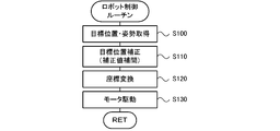
- FIG. 4 is a flowchart showing an example of a robot control routine executed by the control device 70. This routine is repeatedly executed every predetermined time.
- the CPU 71 of the control device 70 first acquires the target position and orientation (S100).
- the target position and posture are the position and posture of the end effector when picking up a component when the picking operation is performed.
- the target position and orientation are the position and orientation of the end effector when the collected component is mounted on the board S when the mounting operation is executed.
- FIG. 5 is an explanatory diagram showing an example of matrix correction parameters.
- the matrix correction parameter is obtained by associating work point identification information (work point No.), a spatial coordinate value, and a correction value (three-dimensional offset amount), and is stored in the HDD 73. Yes.
- the target position is corrected by deriving a correction value at the target position from the correction values of a plurality of work points around the target position using a known interpolation method such as linear interpolation, and offsetting the target position by the derived correction value. Can be done.
- the correction of the target position may be performed by offsetting the target position with the correction value of the work point closest to the target position.
- the CPU 71 sets the target angle of each joint (first to fifth joints 41 to 45) by converting the coordinates of the corrected target position and posture (S120).
- the coordinate conversion can be performed using, for example, a well-known DH parameter.
- the CPU 71 drives and controls the corresponding motor (first motors 51 to 55) based on the set target angle (S130), and ends the robot control routine.
- the CPU 71 causes the end effector to hold the component so that the component is sampled when the end effector reaches the target position and posture.
- the CPU 71 causes the end effector to release the holding of the component so that the component is mounted on the substrate S when the end effector reaches the target position and posture.
- FIG. 6 is an explanatory diagram illustrating an example of a work position correction process.
- the work position correction step is performed by executing assembly adjustment (S200), geometry adjustment (S210), calibration (S220), and matrix measurement / correction (S230) in this order.
- assembly adjustment S200
- geometry adjustment S210
- calibration S220
- matrix measurement / correction S230
- the order of explanation is matrix measurement / correction, assembly adjustment, geometry adjustment, and calibration.
- Matrix measurement / correction is a process for setting the matrix correction parameter used for correcting the target position described above.
- FIG. 7 is an explanatory diagram showing an example of matrix measurement / correction.
- the matrix measurement corresponds to S300 to S330 in FIG.
- the matrix correction includes S340 and S350 in FIG. 7 and S110 in FIG.
- FIG. 8 is an explanatory diagram showing a state in which the three-dimensional measurement is performed on the marker m using the three-dimensional measuring instrument 100.
- an area A is a work area for the robot 20.
- the operator attaches a measurement marker m to the distal link and installs the three-dimensional measuring instrument 100 at the corner of the work table 11 as shown in FIG.
- the three-dimensional measuring instrument 100 can use a laser tracker or a motion capture.
- the CPU 71 of the control device 70 first sets a plurality of work points in a matrix at a designated pitch in the work area A of the robot 20 (S300).
- FIG. 9 is an explanatory diagram illustrating an example of work points.
- the pitch is designated by operating the input device 76 by the operator.
- the CPU 71 designates the spatial coordinate value of each work point as a target position, and controls the arm 22 (first to fifth motors 51 to 55) so as to move to the target position designated by the marker m (S310). .
- the control device 70 inputs the actual position of the marker m measured by the three-dimensional measuring instrument 100 (S320).
- the CPU 71 derives a difference between the spatial coordinate value and the input actual position of the marker m for each work point (S330).
- the CPU 71 derives a correction value (offset value) from the derived difference (S340).
- the CPU 71 sets a matrix correction parameter in which the spatial coordinate value and the correction value are associated for each work point (S350), and ends the matrix measurement / correction.
- the assembly adjustment is a process of adjusting the assembly angle using a jig when assembling each link (first to sixth links 31 to 36).
- Geometry adjustment is a process of optimizing DH parameters used for coordinate transformation.
- the operator attaches the measurement marker m to the distal link and installs the three-dimensional measuring instrument 100 at the corner of the work table 11 as in the matrix measurement / correction.
- the CPU 71 sets a plurality of measurement points in the work area A of the robot 20.
- the measurement point can be set, for example, by the operator operating the input device 76 and specifying the measurement point.
- the CPU 71 designates the spatial coordinate value of each measurement point as a target position, and controls the arm 22 (first to fifth motors 51 to 55) so that the marker m moves to the designated target position.
- the CPU 71 inputs the actual position of the marker m measured by the three-dimensional measuring instrument 100, and DH so that the difference (error) between the spatial coordinate value of the measurement point and the actual position of the input marker m is minimized. Calculate the parameters and finish the geometry adjustment.
- Calibration is a process of grasping the relative positional relationship between the robot 20 and the work table 11 (work object) and reflecting it in the target position when the robot 20 is operated.
- FIG. 10 is an explanatory diagram showing the state of calibration.
- the operator fixes the object 110 with the mark M on the work table 11 at a predetermined position.
- the CPU 71 first controls the arm 22 (first to fifth motors 51 to 55) so that the mark camera 24 moves above the object 110. Subsequently, the CPU 71 images the mark M attached to the object 110 with the mark camera 24.
- the CPU 71 performs coordinate conversion of the rotation angle of each joint detected by the encoders (first to fifth encoders 61 to 65) to calculate the position (imaging position) of the mark camera 24 at the time of imaging.
- the CPU 71 recognizes the position of the mark M that appears in the captured image using the calculated imaging position as a reference.
- the CPU 71 identifies the relative positional relationship between the robot 20 and the workbench 11 from the recognized position of the mark M, reflects it in the target position when operating the robot 20, and ends the calibration.
- the matrix measurement / correction is executed after the geometry adjustment and the calibration are executed. That is, the matrix measurement / correction is performed in a state where the positional accuracy of the robot 20 is improved to some extent by performing geometry adjustment or calibration.
- the correction accuracy of the matrix correction parameter derived by the matrix measurement / correction increases as the pitch between the work points specified in the matrix measurement / correction becomes finer.
- the matrix measurement / correction takes a long time to execute.
- the matrix correction parameter increases the number of data and increases the necessary storage capacity.
- by performing geometry adjustment and calibration before matrix measurement / correction it is possible to obtain a correction value with a required accuracy over the entire work area without setting the pitch excessively finely.
- the arm 22 corresponds to a robot arm
- the motor corresponds to an actuator
- the HDD 73 corresponds to a storage device
- the control device. 70 corresponds to a control device.
- a plurality of work points are set in the movable region of the robot 20, and a matrix measurement parameter for setting a matrix correction parameter in which spatial coordinate values and correction values are associated with each other at the set work points is set.
- the control device 70 of the robot 20 corrects the designated target position using the matrix correction parameter. As a result, even when the arm 22 includes an error that cannot be corrected by geometry adjustment or calibration, the control device 70 can move the arm 22 to the target position more accurately without being affected by the error.
- geometry adjustment is performed before matrix measurement / correction.
- the robot 20 can further improve the position accuracy by a combination of geometry adjustment and matrix measurement / correction.
- by performing the geometry adjustment before the matrix measurement / correction it is possible to obtain a correction value with the required accuracy over the entire work area without excessively finely setting the pitch in the matrix measurement. it can.
- calibration is performed before matrix measurement / correction. For this reason, the robot 20 can correctly grasp the relative positional relationship with the workbench 11 and can further improve the positional accuracy.
- the robot 20 by executing calibration before matrix measurement / correction, it is possible to obtain a correction value with necessary accuracy over the entire work area without excessively finely setting the pitch in matrix measurement. it can.
- the assembly adjustment, the geometry adjustment, and the calibration are executed in addition to the matrix measurement / correction, but some or all of them may be omitted.
- the calibration is performed after the geometry adjustment. However, the calibration may be performed before the geometry adjustment.
- the CPU 71 sets a plurality of work points so as to be arranged in a matrix at a predetermined pitch in the matrix measurement.
- the CPU 71 may set a plurality of work points according to other rules.
- the robot 20 has five-axis joints. However, the robot 20 may have four-axis joints or six-axis joints. Moreover, although the robot 20 has only a rotation / turning joint, it may have a linear motion joint.
- the work position correction method of the present disclosure is a work position correction method for operating a multi-joint type work robot by designating a target position, and a plurality of work position correction methods within a movable region of the work robot.
- a work point is set, a correction parameter in which a spatial coordinate value and a correction value are associated with each other is set for the plurality of set work points, and the set correction parameter is reflected on the target position.
- the plurality of work points may be set so as to be arranged in a matrix at a predetermined pitch. According to the present disclosure, necessary work accuracy can be easily ensured by appropriately setting the pitch between adjacent work points.
- the work robot is moved at each work point by setting the plurality of work points, sequentially designating each spatial coordinate value of the set work points as a target position.
- the actual position of the work robot is measured, matrix measurement is performed to derive the difference between the spatial coordinate value of each work point and the measured actual position, and a correction value for each work point is derived based on the derived difference.
- the correction parameter may be set by associating the spatial coordinate value with the derived correction value for each work point, and matrix correction may be performed to reflect the set correction parameter on the target position. According to the work position correction method of the present disclosure, it is possible to derive a more accurate correction value for each work point.
- a correction value between adjacent work points may be interpolated. According to the work position correction method of the present disclosure, even when the target position is specified at a position shifted from the set work point, the required position accuracy can be ensured.
- geometry adjustment for adjusting a conversion parameter used for coordinate conversion of the target position may be performed before the matrix measurement.
- work precision can be further improved by a combination of matrix correction and geometry adjustment.
- the work position correction method of the present disclosure since the geometry adjustment is performed before the matrix measurement, the required position accuracy can be ensured without increasing the number of work points required for the matrix measurement. it can.
- the relative position relationship between the work robot on which a work target on which the work robot performs work and the work robot is specified is specified, and the target position is determined. It is good also as what performs the calibration reflected in.
- work precision can be further improved by a combination of matrix measurement, geometry adjustment, and calibration.
- the work position correction method of the present disclosure since the calibration is performed before the matrix measurement, the required position accuracy can be ensured without increasing the number of work points necessary for the matrix measurement. it can.
- This disclosure can be used in the manufacturing industry of work robots.
Landscapes
- Engineering & Computer Science (AREA)
- Robotics (AREA)
- Mechanical Engineering (AREA)
- Operations Research (AREA)
- Manufacturing & Machinery (AREA)
- Microelectronics & Electronic Packaging (AREA)
- Human Computer Interaction (AREA)
- Multimedia (AREA)
- Manipulator (AREA)
Abstract
This working robot, which is provided with a multi-articulated robot arm and an actuator that drives each joint of the robot arm, corrects a designated target position by means of a correction parameter and operates the robot arm. The correction of the target position is performed by: setting a plurality of working points within the operating range of the robot; setting a correction parameter in which space coordinates for the set plurality of working points are associated with correction values; and applying the set correction parameter to the target position.
Description
本明細書は、作業位置補正方法および作業ロボットについて開示する。
This specification discloses a work position correction method and a work robot.
従来、この種の作業ロボットとしては、目標点に対してDHパラメータを適用して座標変換を行なうことでロボットの動作を制御するものが提案されている(例えば、特許文献1参照)。DHパラメータの設定は以下のようにして行なわれる。即ち、ロボットの制御装置は、ロボットの動作空間内に測定点を設定する。次に、制御装置は、測定点へロボットを移動させて3次元の位置データを取得する。そして、制御装置は、取得した位置データと測定点との誤差からDHパラメータを導出する。制御装置は、目標点に基づいてロボットの動作を制御する際、目標点に対してDHパラメータを適用して座標変換を行なう。
Conventionally, as this type of work robot, a robot that controls the operation of the robot by applying coordinate transformation by applying a DH parameter to a target point has been proposed (for example, see Patent Document 1). Setting of the DH parameter is performed as follows. That is, the robot control device sets measurement points in the robot operation space. Next, the control device moves the robot to the measurement point and acquires three-dimensional position data. Then, the control device derives a DH parameter from the error between the acquired position data and the measurement point. When controlling the operation of the robot based on the target point, the control device performs coordinate conversion by applying the DH parameter to the target point.
しかし、上述した作業ロボットでは、座標変換に用いるDHパラメータを最適化しても、十分な作業精度を確保できない場合が生じる。例えば、作業ロボットは、DHパラメータの最適化で修正できない誤差(例えば、アームの歪みなど)が含まれると、誤差の影響を受けて正確な位置に移動することができない。
However, the work robot described above may not be able to ensure sufficient work accuracy even if the DH parameters used for coordinate transformation are optimized. For example, if an error (for example, arm distortion) that cannot be corrected by optimization of the DH parameter is included, the work robot cannot move to an accurate position due to the influence of the error.
本開示は、目標位置を指定して作業ロボットを動作させる際に必要な作業精度を確保することを主目的とする。
The main purpose of this disclosure is to ensure the work accuracy required when operating the work robot by specifying the target position.
本開示は、上述の主目的を達成するために以下の手段を採った。
This disclosure has taken the following measures to achieve the main purpose described above.
本開示の作業位置補正方法は、目標位置を指定して多関節型の作業ロボットを動作させる際の作業位置補正方法であって、前記作業ロボットの可動領域内において複数の作業点を設定し、該設定した複数の作業点に対して空間座標値と補正値とを対応付けた補正パラメータを設定し、前記設定した補正パラメータを前記目標位置に反映させることを要旨とする。
The work position correction method of the present disclosure is a work position correction method when operating an articulated work robot by designating a target position, and sets a plurality of work points in a movable region of the work robot, The gist is to set a correction parameter in which a spatial coordinate value and a correction value are associated with each other for the plurality of set work points, and reflect the set correction parameter on the target position.
この本開示の作業位置補正方法では、まず、作業ロボットの可動領域内において複数の作業点を設定する。次に、作業位置補正方法では、設定した複数の作業点に対して空間座標値と補正値とを対応付けた補正パラメータを設定する。そして、作業位置補正方法では、設定した補正パラメータを目標位置に反映させる。これにより、作業ロボットは、ロボットアームに誤差が含まれていても、その誤差の影響を受けることなく、より正確に目標位置へ移動させることができる。この結果、本開示によれば、目標位置を指定して作業ロボットを動作させる際に十分な作業精度を確保することができる。
In this work position correction method of the present disclosure, first, a plurality of work points are set within the movable area of the work robot. Next, in the work position correction method, a correction parameter in which a spatial coordinate value is associated with a correction value is set for a plurality of set work points. In the work position correction method, the set correction parameter is reflected on the target position. Thereby, even if an error is included in the robot arm, the work robot can be more accurately moved to the target position without being affected by the error. As a result, according to the present disclosure, it is possible to ensure sufficient work accuracy when operating the work robot by designating the target position.
本開示の作業ロボットは、多関節型のロボットアームと、前記ロボットアームの各関節を駆動するアクチュエータと、前記ロボットアームの可動領域内でマトリックス状に並ぶ複数の作業点に対してそれぞれ空間座標値と補正値とが対応付けられた補正パラメータを記憶する記憶装置と、前記記憶装置に記憶された補正パラメータを用いて前記目標位置を補正し、該補正した目標位置に基づいて前記アクチュエータを制御する制御装置と、を備えることを要旨とする。
The work robot according to the present disclosure includes a multi-joint type robot arm, an actuator that drives each joint of the robot arm, and a plurality of work coordinate lines arranged in a matrix within the movable area of the robot arm. And a correction device stored in the storage device, the target position is corrected using the correction parameter stored in the storage device, and the actuator is controlled based on the corrected target position. And a control device.
この本開示の作業ロボットでは、ロボットアームとアクチュエータと記憶装置と制御装置とを備える。記憶装置は、ロボットアームの可動領域内でマトリックス状に並ぶ複数の作業点に対してそれぞれ空間座標値と補正値とが対応付けられた補正パラメータを記憶する。制御装置は、記憶装置に記憶された補正パラメータを用いて目標位置を補正し、補正した目標位置に基づいてアクチュエータを制御する。これにより、作業ロボットは、ロボットアームに誤差が含まれていても、その誤差の影響を受けることなく、より正確に目標位置へロボットアームを移動させることができる。この結果、本開示によれば、目標位置を指定して作業ロボットを動作させる際に必要な作業精度を確保することができる。
The work robot according to the present disclosure includes a robot arm, an actuator, a storage device, and a control device. The storage device stores a correction parameter in which a spatial coordinate value and a correction value are associated with each other for a plurality of work points arranged in a matrix within the movable region of the robot arm. The control device corrects the target position using the correction parameter stored in the storage device, and controls the actuator based on the corrected target position. Thereby, even if an error is included in the robot arm, the work robot can move the robot arm to the target position more accurately without being affected by the error. As a result, according to the present disclosure, it is possible to ensure the work accuracy required when operating the work robot by designating the target position.
次に、本開示を実施するための形態について図面を参照しながら説明する。
Next, modes for carrying out the present disclosure will be described with reference to the drawings.
図1は、ロボットシステム10の構成の概略を示す構成図である。図2は、ロボット20の構成の概略を示す構成図である。図3は、ロボット20と制御装置70との電気的な接続関係を示すブロック図である。なお、図1,2中、前後方向はX軸方向であり、左右方向はY軸方向であり、上下方向はZ軸方向である。
FIG. 1 is a configuration diagram showing an outline of the configuration of the robot system 10. FIG. 2 is a configuration diagram showing an outline of the configuration of the robot 20. FIG. 3 is a block diagram showing an electrical connection relationship between the robot 20 and the control device 70. 1 and 2, the front-rear direction is the X-axis direction, the left-right direction is the Y-axis direction, and the up-down direction is the Z-axis direction.
ロボットシステム10は、ロボット20と、ロボット20を制御する制御装置70と、を備える。ロボットシステム10は、ワークをピックアップし、ピックアップしたワークを対象物にプレースするシステムとして構成されている。本実施形態では、ロボットシステム10は、部品を採取して基板S上に実装する部品実装システムとして構成されている。尚、ロボットシステムは、上述のシステムに限られず、ロボット20を用いてワークに対して作業を行なうシステムであれば、如何なるシステムにも適用できる。
The robot system 10 includes a robot 20 and a control device 70 that controls the robot 20. The robot system 10 is configured as a system that picks up a work and places the picked-up work on an object. In the present embodiment, the robot system 10 is configured as a component mounting system that collects components and mounts them on the substrate S. The robot system is not limited to the system described above, and can be applied to any system as long as it is a system that performs work on a workpiece using the robot 20.
ロボット20は、5軸の垂直多関節アーム(以下、アームという)22と、ロボット20の手先である図示しないエンドエフェクタと、を備える。アーム22は、6つのリンク(第1~第6リンク31~36)と、各リンクを回転または旋回可能に連結する5つの関節(第1~第5関節41~45)と、を備える。各関節(第1~第5関節41~45)は、対応する関節を駆動するモータ(第1~第5モータ51~55)、対応するモータの回転角度を検出するエンコーダ(第1~第5エンコーダ61~65)と、を備える。本実施形態では、モータはサーボモータであり、エンコーダはロータリエンコーダである。エンドエフェクタは、アーム22の先端リンク(第6リンク36)に取り付けられ、部品(ワーク)の保持とその解除とが可能となっている。エンドエフェクタは、例えば、メカチャックや吸着ノズル、電磁石などを用いることができる。また、アーム22(第5リンク35)には、作業台11に設置された作業対象物などの物体に付されたマークMを撮像するためのマークカメラ24が取り付けられている。
The robot 20 includes a 5-axis vertical articulated arm (hereinafter referred to as an arm) 22 and an end effector (not shown) which is a hand of the robot 20. The arm 22 includes six links (first to sixth links 31 to 36) and five joints (first to fifth joints 41 to 45) that connect the links so as to be rotatable or pivotable. Each joint (first to fifth joints 41 to 45) includes a motor (first to fifth motors 51 to 55) for driving the corresponding joint, and an encoder (first to fifth) for detecting the rotation angle of the corresponding motor. Encoders 61 to 65). In the present embodiment, the motor is a servo motor and the encoder is a rotary encoder. The end effector is attached to the distal end link (sixth link 36) of the arm 22, and can hold and release the part (workpiece). As the end effector, for example, a mechanical chuck, a suction nozzle, an electromagnet, or the like can be used. In addition, a mark camera 24 is attached to the arm 22 (fifth link 35) for imaging the mark M attached to an object such as a work object installed on the work table 11.
アーム22の基端リンク(第1リンク31)は、作業台11に固定されている。作業台11には、基板搬送装置12や部品供給装置13、パーツカメラ14などが配置されている。基板搬送装置12は、本実施形態では、前後方向(Y軸方向)に間隔を空けて左右方向(X軸方向)に架け渡された一対のベルトコンベアを有する。基板Sは、ベルトコンベアによって左から右へと搬送される。部品供給装置13は、本実施形態では、複数の部品が所定間隔で収容されたテープを後方(Y軸方向)へ送り出すテープフィーダとして構成される。なお、部品供給装置13は、テープフィーダに限られず、例えば、複数の部品が配置されたトレイを供給するトレイフィーダなど、如何なるタイプの部品供給装置であってもよい。パーツカメラ14は、エンドエフェクタに保持された部品がパーツカメラ14の上方を通過する際に当該部品を撮像し、撮像した画像を制御装置70へ出力する。
The proximal end link (first link 31) of the arm 22 is fixed to the work table 11. On the work table 11, a substrate transfer device 12, a component supply device 13, a parts camera 14, and the like are arranged. In the present embodiment, the substrate transport apparatus 12 includes a pair of belt conveyors that are stretched in the left-right direction (X-axis direction) with a space in the front-rear direction (Y-axis direction). The board | substrate S is conveyed from the left to the right by the belt conveyor. In this embodiment, the component supply device 13 is configured as a tape feeder that feeds a tape in which a plurality of components are accommodated at predetermined intervals to the rear (Y-axis direction). The component supply device 13 is not limited to a tape feeder, and may be any type of component supply device such as a tray feeder that supplies a tray on which a plurality of components are arranged. The part camera 14 captures an image of the component held by the end effector when the component passes above the part camera 14, and outputs the captured image to the control device 70.
制御装置70は、CPU71を中心としたマイクロプロセッサとして構成され、CPU71の他に、ROM72やHDD73、RAM74、駆動回路75などを備える。駆動回路75は、第1~第5モータ51~55を駆動するための回路である。制御装置70には、第1~第5エンコーダ61~65やパーツカメラ14、マークカメラ24、入力装置76などから信号が入力される。制御装置70からは、基板搬送装置12や部品供給装置13、出力装置77、第1~第5モータ51~55へ信号が出力される。なお、入力装置76は、オペレータが入力操作を行なう入力デバイスである。また、出力装置77は、各種情報を表示するための表示デバイスである。
The control device 70 is configured as a microprocessor centered on the CPU 71, and includes a ROM 72, an HDD 73, a RAM 74, a drive circuit 75, and the like in addition to the CPU 71. The drive circuit 75 is a circuit for driving the first to fifth motors 51 to 55. Signals are input to the control device 70 from the first to fifth encoders 61 to 65, the parts camera 14, the mark camera 24, the input device 76, and the like. Signals are output from the control device 70 to the substrate transfer device 12, the component supply device 13, the output device 77, and the first to fifth motors 51 to 55. The input device 76 is an input device on which an operator performs an input operation. The output device 77 is a display device for displaying various information.
図4は、制御装置70により実行されるロボット制御ルーチンの一例を示すフローチャートである。このルーチンは、所定時間ごとに繰り返し実行される。ロボット制御ルーチンが実行されると、制御装置70のCPU71は、まず、目標位置および姿勢を取得する(S100)。ここで、本実施形態では、目標位置および姿勢は、採取作業が実行される場合、部品を採取する際のエンドエフェクタの位置および姿勢である。また、目標位置および姿勢は、実装作業が実行される場合、採取した部品を基板Sに実装する際のエンドエフェクタの位置および姿勢である。
FIG. 4 is a flowchart showing an example of a robot control routine executed by the control device 70. This routine is repeatedly executed every predetermined time. When the robot control routine is executed, the CPU 71 of the control device 70 first acquires the target position and orientation (S100). Here, in the present embodiment, the target position and posture are the position and posture of the end effector when picking up a component when the picking operation is performed. The target position and orientation are the position and orientation of the end effector when the collected component is mounted on the board S when the mounting operation is executed.
次に、CPU71は、取得した目標位置をマトリックス補正パラメータを用いて補正する(S110)。図5は、マトリックス補正パラメータの一例を示す説明図である。マトリックス補正パラメータは、図示するように、作業点の識別情報(作業点No.)と空間座標値と補正値(3次元のオフセット量)とが対応付けられたものであり、HDD73に記憶されている。目標位置の補正は、目標位置周辺の複数の作業点の補正値から線形補間などの周知の補間法を用いて目標位置における補正値を導出し、導出した補正値で目標位置をオフセットすることにより行なうことができる。或いは、目標位置の補正は、目標位置から最も近い作業点の補正値で目標位置をオフセットすることにより行なうものとしてもよい。
Next, the CPU 71 corrects the acquired target position using the matrix correction parameter (S110). FIG. 5 is an explanatory diagram showing an example of matrix correction parameters. As shown in the figure, the matrix correction parameter is obtained by associating work point identification information (work point No.), a spatial coordinate value, and a correction value (three-dimensional offset amount), and is stored in the HDD 73. Yes. The target position is corrected by deriving a correction value at the target position from the correction values of a plurality of work points around the target position using a known interpolation method such as linear interpolation, and offsetting the target position by the derived correction value. Can be done. Alternatively, the correction of the target position may be performed by offsetting the target position with the correction value of the work point closest to the target position.
続いて、CPU71は、補正後の目標位置および姿勢を座標変換することにより各関節(第1~第5関節41~45)の目標角度を設定する(S120)。座標変換は、例えば、周知のDHパラメータを用いて行なうことができる。
Subsequently, the CPU 71 sets the target angle of each joint (first to fifth joints 41 to 45) by converting the coordinates of the corrected target position and posture (S120). The coordinate conversion can be performed using, for example, a well-known DH parameter.
そして、CPU71は、設定した目標角度に基づいて対応するモータ(第1モータ51~55)を駆動制御して(S130)、ロボット制御ルーチンを終了する。なお、CPU71は、採取作業を実行する場合、エンドエフェクタが目標位置および姿勢に到達すると、部品が採取されるようエンドエフェクタに部品を保持させる。また、CPU71は、実装作業を実行する場合、エンドエフェクタが目標位置および姿勢に到達すると、部品が基板Sに実装されるようエンドエフェクタに部品の保持を解除させる。
Then, the CPU 71 drives and controls the corresponding motor (first motors 51 to 55) based on the set target angle (S130), and ends the robot control routine. When executing the sampling operation, the CPU 71 causes the end effector to hold the component so that the component is sampled when the end effector reaches the target position and posture. Further, when executing the mounting operation, the CPU 71 causes the end effector to release the holding of the component so that the component is mounted on the substrate S when the end effector reaches the target position and posture.
以下の説明は、目標位置を用いてロボット20の動作を制御する際の作業位置補正工程を説明するものである。図6は、作業位置補正工程の一例を示す説明図である。作業位置補正工程は、組み付け調整(S200)と、ジオメトリ調整(S210)と、キャリブレーション(S220)と、マトリックス測定・補正(S230)とをこの順に実行することにより行なわれる。なお、説明の都合上、説明の順序は、マトリックス測定・補正,組み付け調整,ジオメトリ調整,キャリブレーションとする。
The following description explains the work position correction process when controlling the operation of the robot 20 using the target position. FIG. 6 is an explanatory diagram illustrating an example of a work position correction process. The work position correction step is performed by executing assembly adjustment (S200), geometry adjustment (S210), calibration (S220), and matrix measurement / correction (S230) in this order. For convenience of explanation, the order of explanation is matrix measurement / correction, assembly adjustment, geometry adjustment, and calibration.
マトリックス測定・補正は、上述した目標位置の補正に用いるマトリックス補正パラメータを設定するための工程である。図7は、マトリックス測定・補正の一例を示す説明図である。なお、マトリックス測定は、図7のS300~S330が該当する。マトリックス補正は、図7のS340,S350と図4のS110とが含まれる。また、図8は、3次元計測器100を用いてマーカmに対して3次元計測を行なう様子を示す説明図である。図8中、領域Aは、ロボット20の作業領域である。オペレータは、マトリックス測定の準備として、図8に示すように、先端リンクに計測用のマーカmを取り付けると共に、作業台11の隅部に3次元計測器100を設置する。3次元計測器100は、レーザトラッカやモーションキャプチャを用いることができる。制御装置70のCPU71は、マトリックス測定・補正が指示されると、まず、ロボット20の作業領域Aに指定ピッチでマトリックス状に複数の作業点を設定する(S300)。図9は、作業点の一例を示す説明図である。なお、ピッチの指定は、オペレータが入力装置76を操作することにより行なわれる。続いて、CPU71は、各作業点の空間座標値を目標位置に指定し、マーカmが指定した目標位置へ移動するようアーム22(第1~第5モータ51~55)を制御する(S310)。そして、制御装置70は、3次元計測器100で計測されたマーカmの実位置を入力する(S320)。次に、CPU71は、作業点ごとに空間座標値と入力したマーカmの実位置との差分を導出する(S330)。こうしてマトリックス測定を行なうと、CPU71は、導出した差分から補正値(オフセット値)を導出する(S340)。そして、CPU71は、作業点ごとに空間座標値と補正値とを対応付けたマトリックス補正パラメータを設定して(S350)、マトリックス測定・補正を終了する。
Matrix measurement / correction is a process for setting the matrix correction parameter used for correcting the target position described above. FIG. 7 is an explanatory diagram showing an example of matrix measurement / correction. The matrix measurement corresponds to S300 to S330 in FIG. The matrix correction includes S340 and S350 in FIG. 7 and S110 in FIG. FIG. 8 is an explanatory diagram showing a state in which the three-dimensional measurement is performed on the marker m using the three-dimensional measuring instrument 100. In FIG. 8, an area A is a work area for the robot 20. In preparation for matrix measurement, the operator attaches a measurement marker m to the distal link and installs the three-dimensional measuring instrument 100 at the corner of the work table 11 as shown in FIG. The three-dimensional measuring instrument 100 can use a laser tracker or a motion capture. When the matrix measurement / correction is instructed, the CPU 71 of the control device 70 first sets a plurality of work points in a matrix at a designated pitch in the work area A of the robot 20 (S300). FIG. 9 is an explanatory diagram illustrating an example of work points. The pitch is designated by operating the input device 76 by the operator. Subsequently, the CPU 71 designates the spatial coordinate value of each work point as a target position, and controls the arm 22 (first to fifth motors 51 to 55) so as to move to the target position designated by the marker m (S310). . Then, the control device 70 inputs the actual position of the marker m measured by the three-dimensional measuring instrument 100 (S320). Next, the CPU 71 derives a difference between the spatial coordinate value and the input actual position of the marker m for each work point (S330). When the matrix measurement is thus performed, the CPU 71 derives a correction value (offset value) from the derived difference (S340). Then, the CPU 71 sets a matrix correction parameter in which the spatial coordinate value and the correction value are associated for each work point (S350), and ends the matrix measurement / correction.
組み付け調整は、各リンク(第1~第6リンク31~36)を組み付ける際にジグを用いて組み付け角度などの調整を行なう工程である。
The assembly adjustment is a process of adjusting the assembly angle using a jig when assembling each link (first to sixth links 31 to 36).
ジオメトリ調整は、座標変換に用いるDHパラメータを最適化する工程である。オペレータは、ジオメトリ調整の準備として、マトリックス測定・補正と同様に、先端リンクに計測用のマーカmを取り付けると共に、作業台11の隅部に3次元計測器100を設置する。CPU71は、ジオメトリ調整が指示されると、ロボット20の作業領域Aに複数の測定点を設定する。測定点の設定は、例えば、オペレータが入力装置76を操作して測定点を指定することにより行なうことができる。次に、CPU71は、各測定点の空間座標値を目標位置に指定し、指定した目標位置へマーカmが移動するようアーム22(第1~第5モータ51~55)を制御する。そして、CPU71は、3次元計測器100で計測されたマーカmの実位置を入力し、測定点の空間座標値と入力したマーカmの実位置との差分(誤差)が最小となるようにDHパラメータを逆算して、ジオメトリ調整を終了する。
Geometry adjustment is a process of optimizing DH parameters used for coordinate transformation. In preparation for geometry adjustment, the operator attaches the measurement marker m to the distal link and installs the three-dimensional measuring instrument 100 at the corner of the work table 11 as in the matrix measurement / correction. When the geometry adjustment is instructed, the CPU 71 sets a plurality of measurement points in the work area A of the robot 20. The measurement point can be set, for example, by the operator operating the input device 76 and specifying the measurement point. Next, the CPU 71 designates the spatial coordinate value of each measurement point as a target position, and controls the arm 22 (first to fifth motors 51 to 55) so that the marker m moves to the designated target position. Then, the CPU 71 inputs the actual position of the marker m measured by the three-dimensional measuring instrument 100, and DH so that the difference (error) between the spatial coordinate value of the measurement point and the actual position of the input marker m is minimized. Calculate the parameters and finish the geometry adjustment.
キャリブレーションは、ロボット20と作業台11(作業対象物)との相対的な位置関係を把握し、ロボット20を動作させる際の目標位置に反映させる工程である。図10は、キャリブレーションの様子を示す説明図である。オペレータは、キャリブレーションの準備として、マークMが付された物体110を作業台11に予め決められた位置に固定する。CPU71は、キャリブレーションが指示されると、まず、物体110の上方へマークカメラ24が移動するようアーム22(第1~第5モータ51~55)を制御する。続いて、CPU71は、マークカメラ24で物体110に付されたマークMを撮像する。そして、CPU71は、エンコーダ(第1~第5エンコーダ61~65)により検出された各関節の回転角度を座標変換して撮像時のマークカメラ24の位置(撮像位置)を算出する。次に、CPU71は、算出した撮像位置を基準として、撮像した画像中に写るマークMの位置を認識する。そして、CPU71は、認識したマークMの位置からロボット20と作業台11との相対的な位置関係を特定し、ロボット20を動作させる際の目標位置に反映させて、キャリブレーションを終了する。
Calibration is a process of grasping the relative positional relationship between the robot 20 and the work table 11 (work object) and reflecting it in the target position when the robot 20 is operated. FIG. 10 is an explanatory diagram showing the state of calibration. As a preparation for calibration, the operator fixes the object 110 with the mark M on the work table 11 at a predetermined position. When the calibration is instructed, the CPU 71 first controls the arm 22 (first to fifth motors 51 to 55) so that the mark camera 24 moves above the object 110. Subsequently, the CPU 71 images the mark M attached to the object 110 with the mark camera 24. Then, the CPU 71 performs coordinate conversion of the rotation angle of each joint detected by the encoders (first to fifth encoders 61 to 65) to calculate the position (imaging position) of the mark camera 24 at the time of imaging. Next, the CPU 71 recognizes the position of the mark M that appears in the captured image using the calculated imaging position as a reference. Then, the CPU 71 identifies the relative positional relationship between the robot 20 and the workbench 11 from the recognized position of the mark M, reflects it in the target position when operating the robot 20, and ends the calibration.
このように、本実施形態では、マトリックス測定・補正は、ジオメトリ調整とキャリブレーションとが実行された後に、実行される。即ち、マトリックス測定・補正は、ジオメトリ調整やキャリブレーションの実行によってロボット20の位置精度がある程度高められた状態で実行されることになる。ここで、マトリックス測定・補正で導出されるマトリックス補正パラメータは、マトリックス測定・補正において指定される作業点間のピッチが細かいほど、補正精度が高くなる。しかし、この場合、マトリックス測定・補正は、その実行に長時間を要する。また、マトリックス補正パラメータは、データ数が多くなり、必要な記憶容量を増大させる。本実施形態では、マトリックス測定・補正の前にジオメトリ調整やキャリブレーションを実行することで、ピッチを過度に細かく設定することなく、作業領域全域で必要な精度の補正値を得ることができる。
As described above, in this embodiment, the matrix measurement / correction is executed after the geometry adjustment and the calibration are executed. That is, the matrix measurement / correction is performed in a state where the positional accuracy of the robot 20 is improved to some extent by performing geometry adjustment or calibration. Here, the correction accuracy of the matrix correction parameter derived by the matrix measurement / correction increases as the pitch between the work points specified in the matrix measurement / correction becomes finer. However, in this case, the matrix measurement / correction takes a long time to execute. Also, the matrix correction parameter increases the number of data and increases the necessary storage capacity. In this embodiment, by performing geometry adjustment and calibration before matrix measurement / correction, it is possible to obtain a correction value with a required accuracy over the entire work area without setting the pitch excessively finely.
ここで、本実施例の主要な要素と発明の開示の欄に記載した発明の主要な要素との対応関係について説明する。即ち、アーム22(第1~第6リンク31~36)がロボットアームに相当し、モータ(第1~第5モータ51~55)がアクチュエータに相当し、HDD73が記憶装置に相当し、制御装置70が制御装置に相当する。
Here, the correspondence between the main elements of the present embodiment and the main elements of the invention described in the disclosure section of the invention will be described. That is, the arm 22 (first to sixth links 31 to 36) corresponds to a robot arm, the motor (first to fifth motors 51 to 55) corresponds to an actuator, the HDD 73 corresponds to a storage device, and the control device. 70 corresponds to a control device.
以上説明した本実施形態では、ロボット20の可動領域内において複数の作業点を設定し、設定した複数の作業点において空間座標値と補正値とを対応付けたマトリックス補正パラメータを設定するマトリックス測定・補正を行なう。ロボット20の制御装置70は、指定された目標位置をマトリックス補正パラメータを用いて補正する。これにより、制御装置70は、アーム22にジオメトリ調整やキャリブレーションで補正できない誤差が含まれていても、誤差の影響を受けることなく、アーム22をより正確に目標位置へ移動させることができる。
In the present embodiment described above, a plurality of work points are set in the movable region of the robot 20, and a matrix measurement parameter for setting a matrix correction parameter in which spatial coordinate values and correction values are associated with each other at the set work points is set. Make corrections. The control device 70 of the robot 20 corrects the designated target position using the matrix correction parameter. As a result, even when the arm 22 includes an error that cannot be corrected by geometry adjustment or calibration, the control device 70 can move the arm 22 to the target position more accurately without being affected by the error.
また、本実施形態では、マトリックス測定・補正の前にジオメトリ調整を行なう。このため、ロボット20は、ジオメトリ調整とマトリックス測定・補正との組み合わせにより位置精度をより向上させることができる。加えて、本実施形態では、マトリックス測定・補正の前にジオメトリ調整を実行することで、マトリックス測定においてピッチを過度に細かく設定することなく、作業領域全域で必要な精度の補正値を得ることができる。
In this embodiment, geometry adjustment is performed before matrix measurement / correction. For this reason, the robot 20 can further improve the position accuracy by a combination of geometry adjustment and matrix measurement / correction. In addition, in the present embodiment, by performing the geometry adjustment before the matrix measurement / correction, it is possible to obtain a correction value with the required accuracy over the entire work area without excessively finely setting the pitch in the matrix measurement. it can.
さらに、本実施形態では、マトリックス測定・補正の前にキャリブレーションを行なう。このため、ロボット20は、作業台11との相対的な位置関係を正しく把握することができ、位置精度をさらに向上させることができる。加えて、本実施形態では、マトリックス測定・補正の前にキャリブレーションを実行することで、マトリックス測定においてピッチを過度に細かく設定することなく、作業領域全域で必要な精度の補正値を得ることができる。
Furthermore, in this embodiment, calibration is performed before matrix measurement / correction. For this reason, the robot 20 can correctly grasp the relative positional relationship with the workbench 11 and can further improve the positional accuracy. In addition, in the present embodiment, by executing calibration before matrix measurement / correction, it is possible to obtain a correction value with necessary accuracy over the entire work area without excessively finely setting the pitch in matrix measurement. it can.
なお、本開示は、上述した実施形態に何ら限定されることはなく、本開示の技術的範囲に属する限り種々の態様で実施し得ることはいうまでもない。
It should be noted that the present disclosure is not limited to the above-described embodiment, and it goes without saying that the present disclosure can be implemented in various modes as long as it belongs to the technical scope of the present disclosure.
例えば、上述した実施形態では、マトリックス測定・補正の他に、組み付け調整とジオメトリ調整とキャリブレーションとを実行するものとしたが、これらのうち一部または全部を省略するものとしてもよい。また、上述した実施形態では、キャリブレーションは、ジオメトリ調整の後に実行されるものとしたが、ジオメトリ調整の前に実行されてもよい。
For example, in the above-described embodiment, the assembly adjustment, the geometry adjustment, and the calibration are executed in addition to the matrix measurement / correction, but some or all of them may be omitted. In the above-described embodiment, the calibration is performed after the geometry adjustment. However, the calibration may be performed before the geometry adjustment.
また、上述した実施形態では、CPU71は、マトリックス測定において、所定ピッチでマトリックス状に並ぶように複数の作業点を設定したが、他の規則に従って複数の作業点を設定してもよい。
In the embodiment described above, the CPU 71 sets a plurality of work points so as to be arranged in a matrix at a predetermined pitch in the matrix measurement. However, the CPU 71 may set a plurality of work points according to other rules.
また、上述した実施形態では、ロボット20は、5軸の関節を有するものとしたが、4軸以下の関節を有してもよいし、6軸以上の関節を有してもよい。また、ロボット20は、回転・旋回関節のみを有するものとしたが、直動関節を有してもよい。
In the above-described embodiment, the robot 20 has five-axis joints. However, the robot 20 may have four-axis joints or six-axis joints. Moreover, although the robot 20 has only a rotation / turning joint, it may have a linear motion joint.
以上説明したように、本開示の作業位置補正方法は、目標位置を指定して多関節型の作業ロボットを動作させる際の作業位置補正方法であって、前記作業ロボットの可動領域内において複数の作業点を設定し、該設定した複数の作業点に対して空間座標値と補正値とを対応付けた補正パラメータを設定し、前記設定した補正パラメータを前記目標位置に反映させるものである。
As described above, the work position correction method of the present disclosure is a work position correction method for operating a multi-joint type work robot by designating a target position, and a plurality of work position correction methods within a movable region of the work robot. A work point is set, a correction parameter in which a spatial coordinate value and a correction value are associated with each other is set for the plurality of set work points, and the set correction parameter is reflected on the target position.
この本開示の作業位置補正方法において、前記複数の作業点を、所定ピッチでマトリックス状に並ぶように設定するものとしてもよい。この本開示によれば、隣接する作業点間のピッチを適宜設定することで、必要な作業精度を容易に確保することができる。
In the work position correcting method of the present disclosure, the plurality of work points may be set so as to be arranged in a matrix at a predetermined pitch. According to the present disclosure, necessary work accuracy can be easily ensured by appropriately setting the pitch between adjacent work points.
また、本開示の作業位置補正方法において、前記複数の作業点を設定し前記設定した複数の作業点の各空間座標値を順次目標位置に指定して前記作業ロボットを移動させて各作業点での前記作業ロボットの実位置を計測し各作業点の空間座標値と前記計測した実位置との差分を導出するマトリックス測定を行ない、前記導出した差分に基づいて各作業点ごとの補正値を導出し各作業点ごとに空間座標値と前記導出した補正値とを対応付けて前記補正パラメータを設定し前記設定した補正パラメータを前記目標位置に反映させるマトリックス補正を行なうものとしてもよい。この本開示の作業位置補正方法によれば、各作業点ごとにより正確な補正値を導出することができる。
Further, in the work position correction method of the present disclosure, the work robot is moved at each work point by setting the plurality of work points, sequentially designating each spatial coordinate value of the set work points as a target position. The actual position of the work robot is measured, matrix measurement is performed to derive the difference between the spatial coordinate value of each work point and the measured actual position, and a correction value for each work point is derived based on the derived difference. Then, the correction parameter may be set by associating the spatial coordinate value with the derived correction value for each work point, and matrix correction may be performed to reflect the set correction parameter on the target position. According to the work position correction method of the present disclosure, it is possible to derive a more accurate correction value for each work point.
さらに、本開示の作業位置補正方法において、隣接する作業点の間の補正値を補間するものとしてもよい。この本開示の作業位置補正方法によれば、設定された作業点からズレた位置に目標位置が指定される場合でも、必要な位置精度を確保することができる。
Furthermore, in the work position correction method of the present disclosure, a correction value between adjacent work points may be interpolated. According to the work position correction method of the present disclosure, even when the target position is specified at a position shifted from the set work point, the required position accuracy can be ensured.
また、本開示の作業位置補正方法において、前記マトリックス測定の前に、前記目標位置の座標変換に用いる変換パラメータを調整するジオメトリ調整を行なうものとしてもよい。この本開示の作業位置補正方法によれば、マトリックス補正とジオメトリ調整との組み合わせによって作業精度をより向上させることができる。また、この本開示の作業位置補正方法によれば、ジオメトリ調整をマトリックス測定の前に実行するため、マトリックス測定に必要な作業点の数を増大させることなく、必要な位置精度を確保することができる。
In the work position correction method according to the present disclosure, geometry adjustment for adjusting a conversion parameter used for coordinate conversion of the target position may be performed before the matrix measurement. According to the work position correction method of the present disclosure, work precision can be further improved by a combination of matrix correction and geometry adjustment. Further, according to the work position correction method of the present disclosure, since the geometry adjustment is performed before the matrix measurement, the required position accuracy can be ensured without increasing the number of work points required for the matrix measurement. it can.
また、本開示の作業位置補正方法において、前記マトリックス測定の前に、前記作業ロボットが作業を行なう作業対象物が設置される作業台と該作業ロボットとの相対位置関係を特定して前記目標位置に反映させるキャリブレーションを行なうものとしてもよい。この本開示の作業位置補正方法によれば、マトリックス測定とジオメトリ調整とキャリブレーションとの組み合わせによって作業精度をさらに向上させることができる。また、この本開示の作業位置補正方法によれば、キャリブレーションをマトリックス測定の前に実行するため、マトリックス測定に必要な作業点の数を増大させることなく、必要な位置精度を確保することができる。
Further, in the work position correction method according to the present disclosure, before the matrix measurement, the relative position relationship between the work robot on which a work target on which the work robot performs work and the work robot is specified is specified, and the target position is determined. It is good also as what performs the calibration reflected in. According to the work position correction method of the present disclosure, work precision can be further improved by a combination of matrix measurement, geometry adjustment, and calibration. Further, according to the work position correction method of the present disclosure, since the calibration is performed before the matrix measurement, the required position accuracy can be ensured without increasing the number of work points necessary for the matrix measurement. it can.
本開示は、作業ロボットの製造産業などに利用可能である。
This disclosure can be used in the manufacturing industry of work robots.
10 ロボットシステム、11 作業台、12 基板搬送装置、13 部品供給装置、14 パーツカメラ、20 ロボット、22 アーム、24 マークカメラ、31~36 第1~第6リンク、41~45 第1~第5関節、51~55 第1~第5モータ、61~65 第1~第5エンコーダ、70 制御装置、71 CPU、72 ROM、73 HDD、74 RAM、75 駆動回路、76 入力装置、77 出力装置、100 3次元計測器、m マーカ、M マーク、S 基板。
10 robot system, 11 workbench, 12 substrate transfer device, 13 component supply device, 14 parts camera, 20 robot, 22 arm, 24 mark camera, 31-36 first to sixth links, 41 to 45 first to fifth Joint, 51 to 55, 1st to 5th motor, 61 to 65, 1st to 5th encoder, 70 control device, 71 CPU, 72 ROM, 73 HDD, 74 RAM, 75 drive circuit, 76 input device, 77 output device, 100 3D measuring instrument, m marker, M mark, S substrate.
Claims (7)
- 目標位置を指定して多関節型の作業ロボットを動作させる際の作業位置補正方法であって、
前記作業ロボットの可動領域内において複数の作業点を設定し、該設定した複数の作業点に対して空間座標値と補正値とを対応付けた補正パラメータを設定し、前記設定した補正パラメータを前記目標位置に反映させる、
作業位置補正方法。 A work position correction method for operating an articulated work robot by specifying a target position,
A plurality of work points are set in the movable area of the work robot, a correction parameter in which a spatial coordinate value is associated with a correction value is set for the plurality of work points set, and the set correction parameter is Reflected in the target position,
Work position correction method. - 請求項1記載の作業位置補正方法であって、
前記複数の作業点を、所定ピッチでマトリックス状に並ぶように設定する、
作業位置補正方法。 The work position correction method according to claim 1,
The plurality of work points are set so as to be arranged in a matrix at a predetermined pitch.
Work position correction method. - 請求項1または2記載の作業位置補正方法であって、
前記複数の作業点を設定し前記設定した複数の作業点の各空間座標値を順次目標位置に指定して前記作業ロボットを移動させて各作業点での前記作業ロボットの実位置を計測し各作業点の空間座標値と前記計測した実位置との差分を導出するマトリックス測定を行ない、前記導出した差分に基づいて各作業点ごとの補正値を導出し各作業点ごとに空間座標値と前記導出した補正値とを対応付けて前記補正パラメータを設定し前記設定した補正パラメータを前記目標位置に反映させるマトリックス補正を行なう、
作業位置補正方法。 The work position correction method according to claim 1 or 2,
The plurality of work points are set, the spatial coordinate values of the set work points are sequentially designated as target positions, and the work robot is moved to measure the actual position of the work robot at each work point. Matrix measurement is performed to derive the difference between the spatial coordinate value of the work point and the measured actual position, and the correction value for each work point is derived based on the derived difference, and the spatial coordinate value and the Matrix correction is performed by setting the correction parameter in association with the derived correction value and reflecting the set correction parameter on the target position.
Work position correction method. - 請求項1ないし3いずれか1項に記載の作業位置補正方法であって、
隣接する作業点の間の補正値を補間する、
作業位置補正方法。 A work position correction method according to any one of claims 1 to 3,
Interpolate correction values between adjacent work points,
Work position correction method. - 請求項1ないし4いずれか1項に記載の作業位置補正方法であって、
前記マトリックス測定の前に、前記目標位置の座標変換に用いる変換パラメータを調整するジオメトリ調整を行なう、
作業位置補正方法。 The work position correction method according to any one of claims 1 to 4,
Prior to the matrix measurement, geometry adjustment is performed to adjust conversion parameters used for coordinate conversion of the target position.
Work position correction method. - 請求項1ないし5いずれか1項に記載の作業位置補正方法であって、
前記マトリックス測定の前に、前記作業ロボットが作業を行なう作業対象物が設置される作業台と該作業ロボットとの相対位置関係を特定して前記目標位置に反映させるキャリブレーションを行なう、
作業位置補正方法。 The work position correction method according to any one of claims 1 to 5,
Prior to the matrix measurement, calibration is performed to specify a relative positional relationship between a work table on which a work target on which the work robot performs work and the work robot is reflected and reflect the relative position on the target position.
Work position correction method. - 多関節型のロボットアームと、
前記ロボットアームの各関節を駆動するアクチュエータと、
前記ロボットアームの可動領域内でマトリックス状に並ぶ複数の作業点に対してそれぞれ空間座標値と補正値とが対応付けられた補正パラメータを記憶する記憶装置と、
前記記憶装置に記憶された補正パラメータを用いて前記目標位置を補正し、該補正した目標位置に基づいて前記アクチュエータを制御する制御装置と、
を備える作業ロボット。 An articulated robot arm,
An actuator for driving each joint of the robot arm;
A storage device for storing correction parameters in which spatial coordinate values and correction values are associated with each other for a plurality of work points arranged in a matrix within the movable region of the robot arm;
A control device that corrects the target position using a correction parameter stored in the storage device, and controls the actuator based on the corrected target position;
A working robot equipped with.
Priority Applications (5)
| Application Number | Priority Date | Filing Date | Title |
|---|---|---|---|
| PCT/JP2016/084121 WO2018092243A1 (en) | 2016-11-17 | 2016-11-17 | Working-position correcting method and working robot |
| CN201680090821.6A CN109996653B (en) | 2016-11-17 | 2016-11-17 | Working position correction method and working robot |
| EP16921959.9A EP3542969B1 (en) | 2016-11-17 | 2016-11-17 | Working-position correcting method and working robot |
| US16/341,242 US11285609B2 (en) | 2016-11-17 | 2016-11-17 | Working position correcting method and working robot |
| JP2018550941A JP6661028B2 (en) | 2016-11-17 | 2016-11-17 | Work position correction method |
Applications Claiming Priority (1)
| Application Number | Priority Date | Filing Date | Title |
|---|---|---|---|
| PCT/JP2016/084121 WO2018092243A1 (en) | 2016-11-17 | 2016-11-17 | Working-position correcting method and working robot |
Publications (1)
| Publication Number | Publication Date |
|---|---|
| WO2018092243A1 true WO2018092243A1 (en) | 2018-05-24 |
Family
ID=62145357
Family Applications (1)
| Application Number | Title | Priority Date | Filing Date |
|---|---|---|---|
| PCT/JP2016/084121 WO2018092243A1 (en) | 2016-11-17 | 2016-11-17 | Working-position correcting method and working robot |
Country Status (5)
| Country | Link |
|---|---|
| US (1) | US11285609B2 (en) |
| EP (1) | EP3542969B1 (en) |
| JP (1) | JP6661028B2 (en) |
| CN (1) | CN109996653B (en) |
| WO (1) | WO2018092243A1 (en) |
Cited By (3)
| Publication number | Priority date | Publication date | Assignee | Title |
|---|---|---|---|---|
| US20200101621A1 (en) * | 2018-09-28 | 2020-04-02 | Seiko Epson Corporation | Control device controlling robot and robot system |
| JPWO2021152697A1 (en) * | 2020-01-28 | 2021-08-05 | ||
| WO2022025059A1 (en) * | 2020-07-29 | 2022-02-03 | ファナック株式会社 | Robot system |
Families Citing this family (8)
| Publication number | Priority date | Publication date | Assignee | Title |
|---|---|---|---|---|
| JP7305951B2 (en) * | 2018-12-14 | 2023-07-11 | ニデック株式会社 | CALIBRATION DEVICE AND CALIBRATION METHOD |
| US20210387350A1 (en) * | 2019-06-12 | 2021-12-16 | Mark Oleynik | Robotic kitchen hub systems and methods for minimanipulation library adjustments and calibrations of multi-functional robotic platforms for commercial and residential enviornments with artificial intelligence and machine learning |
| US20210069910A1 (en) * | 2019-06-12 | 2021-03-11 | Mark Oleynik | Systems and methods for minimanipulation library adjustments and calibrations of multi-functional robotic platforms with supported subsystem interactions |
| JP2021154439A (en) * | 2020-03-27 | 2021-10-07 | セイコーエプソン株式会社 | Teaching method |
| JP2022061700A (en) * | 2020-10-07 | 2022-04-19 | セイコーエプソン株式会社 | Belt conveyer calibration method, robot control method, robot system and program |
| JP2022100627A (en) * | 2020-12-24 | 2022-07-06 | セイコーエプソン株式会社 | Method of determining control position of robot, and robot system |
| WO2022254050A1 (en) * | 2021-06-03 | 2022-12-08 | Fundación Tekniker | Method for estimating errors in the positioning of a rotary head in a precision machine, and precision machine |
| US11766778B2 (en) * | 2021-07-19 | 2023-09-26 | Nsk Ltd. | Driving device and method for controlling the same, and parallel link robot and method for controlling the same |
Citations (10)
| Publication number | Priority date | Publication date | Assignee | Title |
|---|---|---|---|---|
| JPS60205713A (en) * | 1984-03-30 | 1985-10-17 | Hitachi Ltd | Correcting device of operation positioning error of industrial robot |
| JPS6190205A (en) * | 1984-10-09 | 1986-05-08 | Komatsu Ltd | Compensating method of absolute positioning error of robot |
| JPH09237112A (en) * | 1996-02-29 | 1997-09-09 | Toyoda Mach Works Ltd | Machine tool provided with error correcting function |
| JP2008269316A (en) * | 2007-04-20 | 2008-11-06 | Makino Milling Mach Co Ltd | Numerical control machine tool and numerical control device |
| WO2009057229A1 (en) * | 2007-11-02 | 2009-05-07 | Makino Milling Machine Co., Ltd. | Method and device for preparing error map and numerically controlled machine tool having error map preparation function |
| JP2009148850A (en) | 2007-12-20 | 2009-07-09 | Denso Wave Inc | Motion control device for robot and its motion control method |
| JP2011173234A (en) * | 2011-01-15 | 2011-09-08 | Ken Kobayashi | Control method for machine tool |
| JP2012014335A (en) * | 2010-06-30 | 2012-01-19 | Fanuc Ltd | Numerical controller for multi-spindle processing machine |
| JP2014155985A (en) * | 2013-02-15 | 2014-08-28 | Panasonic Corp | Robot, robot control device, control method, and control program |
| JP2015069355A (en) * | 2013-09-27 | 2015-04-13 | ファナック株式会社 | Error correction amount creation device |
Family Cites Families (16)
| Publication number | Priority date | Publication date | Assignee | Title |
|---|---|---|---|---|
| US4831549A (en) * | 1987-07-28 | 1989-05-16 | Brigham Young University | Device and method for correction of robot inaccuracy |
| JP2919135B2 (en) * | 1991-10-09 | 1999-07-12 | 川崎重工業株式会社 | Robot position correction method |
| US6304050B1 (en) * | 1999-07-19 | 2001-10-16 | Steven B. Skaar | Means and method of robot control relative to an arbitrary surface using camera-space manipulation |
| DE19962247A1 (en) * | 1999-12-22 | 2001-09-20 | Agie Sa | Motion transmission device |
| DE102009041734B4 (en) * | 2009-09-16 | 2023-11-02 | Kuka Roboter Gmbh | Measuring a manipulator |
| TWI408037B (en) * | 2010-12-03 | 2013-09-11 | Ind Tech Res Inst | A position method and a calibrating method for the robot arm |
| JP5773718B2 (en) * | 2011-04-11 | 2015-09-02 | 富士機械製造株式会社 | Stand-up motion assist robot |
| JP5929271B2 (en) * | 2012-02-07 | 2016-06-01 | セイコーエプソン株式会社 | Robot hand and robot |
| WO2014020739A1 (en) * | 2012-08-02 | 2014-02-06 | 富士機械製造株式会社 | Work machine provided with articulated robot and electric component mounting machine |
| JP2015530276A (en) * | 2012-10-05 | 2015-10-15 | ベックマン コールター, インコーポレイテッド | Camera-based automatic alignment system and method |
| JP6108860B2 (en) * | 2013-02-14 | 2017-04-05 | キヤノン株式会社 | Robot system and control method of robot system |
| CN103231375A (en) * | 2013-04-28 | 2013-08-07 | 苏州大学 | Industrial robot calibration method based on distance error models |
| US9211643B1 (en) * | 2014-06-25 | 2015-12-15 | Microsoft Technology Licensing, Llc | Automatic in-situ registration and calibration of robotic arm/sensor/workspace system |
| JP6415190B2 (en) * | 2014-09-03 | 2018-10-31 | キヤノン株式会社 | ROBOT DEVICE, ROBOT CONTROL PROGRAM, RECORDING MEDIUM, AND ROBOT DEVICE CONTROL METHOD |
| JP6259401B2 (en) * | 2015-01-16 | 2018-01-10 | 矢崎総業株式会社 | Alignment method |
| DE102016116702B4 (en) * | 2015-09-14 | 2019-01-24 | Fanuc Corporation | Measuring system for calibrating the mechanical parameters of a robot |
-
2016
- 2016-11-17 JP JP2018550941A patent/JP6661028B2/en active Active
- 2016-11-17 US US16/341,242 patent/US11285609B2/en active Active
- 2016-11-17 EP EP16921959.9A patent/EP3542969B1/en active Active
- 2016-11-17 CN CN201680090821.6A patent/CN109996653B/en active Active
- 2016-11-17 WO PCT/JP2016/084121 patent/WO2018092243A1/en active Application Filing
Patent Citations (10)
| Publication number | Priority date | Publication date | Assignee | Title |
|---|---|---|---|---|
| JPS60205713A (en) * | 1984-03-30 | 1985-10-17 | Hitachi Ltd | Correcting device of operation positioning error of industrial robot |
| JPS6190205A (en) * | 1984-10-09 | 1986-05-08 | Komatsu Ltd | Compensating method of absolute positioning error of robot |
| JPH09237112A (en) * | 1996-02-29 | 1997-09-09 | Toyoda Mach Works Ltd | Machine tool provided with error correcting function |
| JP2008269316A (en) * | 2007-04-20 | 2008-11-06 | Makino Milling Mach Co Ltd | Numerical control machine tool and numerical control device |
| WO2009057229A1 (en) * | 2007-11-02 | 2009-05-07 | Makino Milling Machine Co., Ltd. | Method and device for preparing error map and numerically controlled machine tool having error map preparation function |
| JP2009148850A (en) | 2007-12-20 | 2009-07-09 | Denso Wave Inc | Motion control device for robot and its motion control method |
| JP2012014335A (en) * | 2010-06-30 | 2012-01-19 | Fanuc Ltd | Numerical controller for multi-spindle processing machine |
| JP2011173234A (en) * | 2011-01-15 | 2011-09-08 | Ken Kobayashi | Control method for machine tool |
| JP2014155985A (en) * | 2013-02-15 | 2014-08-28 | Panasonic Corp | Robot, robot control device, control method, and control program |
| JP2015069355A (en) * | 2013-09-27 | 2015-04-13 | ファナック株式会社 | Error correction amount creation device |
Non-Patent Citations (1)
| Title |
|---|
| See also references of EP3542969A4 |
Cited By (7)
| Publication number | Priority date | Publication date | Assignee | Title |
|---|---|---|---|---|
| US20200101621A1 (en) * | 2018-09-28 | 2020-04-02 | Seiko Epson Corporation | Control device controlling robot and robot system |
| US11541552B2 (en) * | 2018-09-28 | 2023-01-03 | Seiko Epson Corporation | Control device controlling robot and robot system |
| JPWO2021152697A1 (en) * | 2020-01-28 | 2021-08-05 | ||
| WO2021152697A1 (en) * | 2020-01-28 | 2021-08-05 | 株式会社Fuji | Control device, control method, information processing device, and information processing method |
| JP7351935B2 (en) | 2020-01-28 | 2023-09-27 | 株式会社Fuji | Control device, control method, information processing device, and information processing method |
| WO2022025059A1 (en) * | 2020-07-29 | 2022-02-03 | ファナック株式会社 | Robot system |
| JP7401682B2 (en) | 2020-07-29 | 2023-12-19 | ファナック株式会社 | robot system |
Also Published As
| Publication number | Publication date |
|---|---|
| EP3542969A1 (en) | 2019-09-25 |
| US20190255708A1 (en) | 2019-08-22 |
| JPWO2018092243A1 (en) | 2019-07-18 |
| JP6661028B2 (en) | 2020-03-11 |
| EP3542969B1 (en) | 2022-06-01 |
| CN109996653A (en) | 2019-07-09 |
| US11285609B2 (en) | 2022-03-29 |
| CN109996653B (en) | 2022-09-02 |
| EP3542969A4 (en) | 2019-11-20 |
Similar Documents
| Publication | Publication Date | Title |
|---|---|---|
| WO2018092243A1 (en) | Working-position correcting method and working robot | |
| JP3665353B2 (en) | 3D position correction amount acquisition method of robot teaching position data and robot system | |
| JP3733364B2 (en) | Teaching position correction method | |
| JP6429473B2 (en) | Robot system, robot system calibration method, program, and computer-readable recording medium | |
| US10232512B2 (en) | Coordinate system setting method, coordinate system setting apparatus, and robot system provided with coordinate system setting apparatus | |
| JP6468741B2 (en) | Robot system and robot system calibration method | |
| WO2018092236A1 (en) | Work robot and work position correction method | |
| JP5528095B2 (en) | Robot system, control apparatus and method thereof | |
| JP2017035754A (en) | Robot system with visual sensor and multiple robots | |
| US20140156072A1 (en) | Apparatus and method for measuring tool center point position of robot | |
| JP5618770B2 (en) | Robot calibration apparatus and calibration method | |
| JP2007122705A (en) | Welding teaching point correction system and calibration method | |
| JP7281910B2 (en) | robot control system | |
| JP6816060B2 (en) | Work robot system and work robot | |
| JP6912529B2 (en) | How to correct the visual guidance robot arm | |
| JP4056662B2 (en) | Appearance inspection device | |
| WO2023032400A1 (en) | Automatic transport device, and system | |
| JPH09222913A (en) | Teaching position correcting device for robot | |
| JP2004261881A (en) | Work welding system, work welding method, and work welding program | |
| US20230191611A1 (en) | Robot system | |
| CN113905859B (en) | Robot control system and robot control method | |
| JP2022120550A (en) | Robot system, control method of the same, article production method using the same, control program, and recording medium | |
| US20230031819A1 (en) | Positioning method and positioning device | |
| JP2017074637A (en) | Tool center point estimation method and tool center point estimation device | |
| JP2022162340A (en) | picking device |
Legal Events
| Date | Code | Title | Description |
|---|---|---|---|
| 121 | Ep: the epo has been informed by wipo that ep was designated in this application |
Ref document number: 16921959 Country of ref document: EP Kind code of ref document: A1 |
|
| WWE | Wipo information: entry into national phase |
Ref document number: 2018550941 Country of ref document: JP |
|
| NENP | Non-entry into the national phase |
Ref country code: DE |
|
| ENP | Entry into the national phase |
Ref document number: 2016921959 Country of ref document: EP Effective date: 20190617 |