WO2018066702A1 - Wireless communication system, network device, and wireless communication method - Google Patents
Wireless communication system, network device, and wireless communication method Download PDFInfo
- Publication number
- WO2018066702A1 WO2018066702A1 PCT/JP2017/036521 JP2017036521W WO2018066702A1 WO 2018066702 A1 WO2018066702 A1 WO 2018066702A1 JP 2017036521 W JP2017036521 W JP 2017036521W WO 2018066702 A1 WO2018066702 A1 WO 2018066702A1
- Authority
- WO
- WIPO (PCT)
- Prior art keywords
- tunnel
- bearer
- setting
- pdn
- base station
- Prior art date
Links
Images


Classifications
-
- H—ELECTRICITY
- H04—ELECTRIC COMMUNICATION TECHNIQUE
- H04W—WIRELESS COMMUNICATION NETWORKS
- H04W76/00—Connection management
- H04W76/20—Manipulation of established connections
- H04W76/22—Manipulation of transport tunnels
-
- H—ELECTRICITY
- H04—ELECTRIC COMMUNICATION TECHNIQUE
- H04W—WIRELESS COMMUNICATION NETWORKS
- H04W76/00—Connection management
- H04W76/10—Connection setup
- H04W76/12—Setup of transport tunnels
-
- H—ELECTRICITY
- H04—ELECTRIC COMMUNICATION TECHNIQUE
- H04L—TRANSMISSION OF DIGITAL INFORMATION, e.g. TELEGRAPHIC COMMUNICATION
- H04L47/00—Traffic control in data switching networks
- H04L47/10—Flow control; Congestion control
- H04L47/24—Traffic characterised by specific attributes, e.g. priority or QoS
-
- H—ELECTRICITY
- H04—ELECTRIC COMMUNICATION TECHNIQUE
- H04W—WIRELESS COMMUNICATION NETWORKS
- H04W28/00—Network traffic management; Network resource management
- H04W28/02—Traffic management, e.g. flow control or congestion control
- H04W28/10—Flow control between communication endpoints
-
- H—ELECTRICITY
- H04—ELECTRIC COMMUNICATION TECHNIQUE
- H04W—WIRELESS COMMUNICATION NETWORKS
- H04W76/00—Connection management
- H04W76/10—Connection setup
- H04W76/11—Allocation or use of connection identifiers
-
- H—ELECTRICITY
- H04—ELECTRIC COMMUNICATION TECHNIQUE
- H04W—WIRELESS COMMUNICATION NETWORKS
- H04W76/00—Connection management
- H04W76/10—Connection setup
- H04W76/15—Setup of multiple wireless link connections
-
- H—ELECTRICITY
- H04—ELECTRIC COMMUNICATION TECHNIQUE
- H04W—WIRELESS COMMUNICATION NETWORKS
- H04W84/00—Network topologies
- H04W84/18—Self-organising networks, e.g. ad-hoc networks or sensor networks
- H04W84/20—Master-slave selection or change arrangements
-
- H—ELECTRICITY
- H04—ELECTRIC COMMUNICATION TECHNIQUE
- H04W—WIRELESS COMMUNICATION NETWORKS
- H04W92/00—Interfaces specially adapted for wireless communication networks
- H04W92/04—Interfaces between hierarchically different network devices
- H04W92/045—Interfaces between hierarchically different network devices between access point and backbone network device
Definitions
- the present invention relates to a radio communication system, a network device, and a radio communication method including a master radio base station and a secondary radio base station.
- LTE Long Term Evolution
- 5G 5th generation mobile communication system
- NGS Next Generation System
- Non-Patent Document 1 Flow Priority Indicator (FPI) indicating the priority of IP flow, scheduling and priority control of IP flow to EPS bearer (NGS bearer) which is a logical communication path set in the system Is executed.
- FPI Flow Priority Indicator
- NSS bearer EPS bearer
- LTE defines Dual Connectivity (DC) in which user equipment (UE) performs communication via Master Cell Group (MCG) and Secondary Cell Group (SCG) (for example, Non-Patent Document 2).
- DC there are tunnels (for example, GTP tunnels) between the MeNB configuring the MCG and the network device (Serving Gateway (SGW)) on the core network, and between the SeNB configuring the SCG and the SGW. Is set.
- SGW Serving Gateway
- an EPS bearer using the set tunnel is set.
- next-generation core network NextGen Core Core Network
- 5GC 5G Core Core Network
- EPS bearer is composed of data radio bearer (DRB) and core network bearer (specifically, S1 bearer and S5 / S8 bearer), but in the case of flow-based QoS control, conventional bearer-based QoS control As described above, there is no one-to-one correspondence between the data radio bearer and the core network bearer according to the QoS level.
- DRB data radio bearer
- core network bearer specifically, S1 bearer and S5 / S8 bearer
- the MeNB and CN-CP add the sequence for setting up the tunnel and core network bearer between SeNB and CN-UP, as described above.
- the problem can be solved, but the sequence becomes more complex and the existing sequence needs to be significantly modified.
- the present invention has been made in view of such a situation, and even with flow-based QoS control, a wireless communication system, a network device, and a network that can realize Dual Connectivity (DC) without complicating the sequence
- An object is to provide a wireless communication method.
- a radio communication system includes a master radio base station that performs radio communication with a user apparatus and controls radio communication between the user apparatus and a secondary radio base station, and the master radio base station.
- a network device that sets up a bearer including a first tunnel and a second tunnel with the secondary radio base station.
- the master radio base station receives a bearer setting request, and, based on the setting request, transmits a bearer setting instruction for setting a bearer setting instruction for setting the bearer using the first tunnel and the second tunnel.
- the network device includes a tunnel setting unit that sets the first tunnel and the second tunnel based on the bearer setting instruction.
- the tunnel setting unit sets the same identifier as a first tunnel endpoint identifier on the network device side of the first tunnel and a second tunnel endpoint identifier on the network device side of the second tunnel. .
- a network apparatus performs a wireless communication with a user apparatus and a first tunnel between a master wireless base station that controls wireless communication between the user apparatus and a secondary wireless base station, and the secondary wireless A bearer including a second tunnel with the base station is set up.
- the network device includes a tunnel setting unit that sets the first tunnel and the second tunnel based on a bearer setting instruction for setting the bearer using the first tunnel and the second tunnel.
- the tunnel setting unit sets the same identifier as a first tunnel endpoint identifier on the network device side of the first tunnel and a second tunnel endpoint identifier on the network device side of the second tunnel.
- a radio communication method includes a master radio base station that performs radio communication with a user apparatus and controls radio communication between the user apparatus and a secondary radio base station, and the master radio base station.
- a network device that sets up a bearer including a first tunnel and a second tunnel with the secondary radio base station is used.
- the master wireless base station receives the bearer setting request, and issues a bearer setting instruction for setting the bearer using the first tunnel and the second tunnel based on the setting request. Transmitting, and the network device setting the first tunnel and the second tunnel based on the bearer setting instruction.
- a first tunnel endpoint identifier on the network device side of the first tunnel and a second tunnel endpoint on the network device side of the second tunnel Set the same identifier as the identifier.
- FIG. 1 is an overall schematic configuration diagram of a wireless communication system 10.
- FIG. 2 is a diagram showing the configuration of bearers and tunnels set in the wireless communication system 10.
- FIG. 3 is a diagram illustrating a representation example of the configuration of an EPS bearer (NGS bearer).
- FIG. 4 is a functional block configuration diagram of the MeNB 210.
- FIG. 5 is a functional block configuration diagram of SeNB220.
- FIG. 6 is a functional block configuration diagram of CN-UP300.
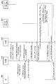
- FIG. 7 is a diagram showing a basic sequence for setting up an EPS bearer (NGS bearer) in the wireless communication system 10.
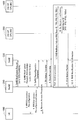
- FIG. 8 is a diagram showing a sequence for adding a PDN tunnel (second tunnel) led by the core network.
- FIG. 9 is a diagram showing a sequence for adding a PDN tunnel (second tunnel) led by the radio access network.
- FIG. 10 is a diagram showing a sequence for deleting a PDN tunnel (second tunnel) led by the radio access network.
- FIG. 11 is a diagram showing a sequence for deleting a PDN tunnel (second tunnel) led by the core network.
- FIG. 12 is a diagram illustrating a sequence (user plane base) of adding a PDN tunnel (second tunnel) led by the core network.
- FIG. 13 is a diagram illustrating an example of a hardware configuration of the MeNB 210, the SeNB 220, and the CN-UP 300.
- FIG. 1 is an overall schematic configuration diagram of a radio communication system 10 according to the present embodiment.
- the radio communication system 10 is a radio communication system according to “5G” which is a successor system of Long Term Evolution (LTE).
- the radio communication system 10 may be referred to as FRA (Future Radio Access), next generation system (NGS), 5G system (5GS), or the like.
- FRA Full Radio Access
- NGS next generation system
- 5GS 5G system
- a radio communication system 10 includes a user apparatus 100 (hereinafter referred to as UE 100), a master radio base station 210 (hereinafter referred to as MeNB 210), a secondary radio base station 220 (hereinafter referred to as SeNB 220), a core network user plane function 300. (Hereinafter referred to as CN-UP300) and core network control plane functions 400 and 410 (hereinafter referred to as CN-CP400 and CN-CP410).
- UE 100 user apparatus 100
- MeNB 210 master radio base station 210
- SeNB 220 secondary radio base station 220
- CN-UP300 core network user plane function 300
- CN-CP400 and 410 core network control plane functions
- the UE100 performs wireless communication with MeNB210 and SeNB220.
- the UE 100 corresponds to Dual Connectivity (DC) defined in 3rd Generation Partnership Project (3GPP).
- the UE 100 performs radio communication via a Master Cell Group (MCG) that is a group of cells formed by the MeNB 210 and a Secondary Cell Group (SCG) that is a group of cells formed by the SeNB 220.
- MCG Master Cell Group
- SCG Secondary Cell Group
- the MeNB 210 and SeNB 220 constitute a radio access network.
- the MeNB 210 performs radio communication with the UE 100 as described above. Moreover, MeNB210 controls the radio
- the SeNB 220 also performs wireless communication with the UE 100 as described above. Specifically, SeNB220 performs radio
- CN-UP300, CN-CP400, and CN-CP410 form a core network of the wireless communication system 10.
- CN-UP300 is connected to MeNB210 and SeNB220 via an S1 interface.
- the CN-UP 300 may be called User Plane Function.
- CN-CP400 is connected to MeNB210 via S1 interface.
- the CN-CP 400 may be divided into functional entities called Access and Mobility Management Function (AMF) and Session Management Function (SMF), or may be called AMF / SMF.
- AMF Access and Mobility Management Function
- SMF Session Management Function
- CN-UP300 provides a user plane function in the wireless communication system 10.
- the CN-UP 300 constitutes a network device.
- CN-CP400 and CN-CP410 provide a control plane function in the radio communication system 10.
- control plane function that realizes control of the UE 100, MeNB 210, SeNB 220, and the like and the user plane function that realizes transmission and reception of user data and the like are clearly separated (CUPS) : C / U plane separation).
- CN-CP400 is installed in UE100's visited network (VPLMN).
- CN-CP410 is provided in the home network (HPLMN) of UE100.
- HPLMN home network
- CN-CP410 may be referred to as Session Management Function (SMF).
- SMF Session Management Function
- CN-UP300 and CN-CP400, 410 can be configured by Mobility Entity (MME), Serving way Gateway (SGW), PDN Gateway (PGW), and Traffic Detection Function (TDF).
- MME Mobility Entity
- SGW Serving way Gateway
- PGW PDN Gateway
- TDF Traffic Detection Function
- CN-UP300 is connected to the external network 20.
- a typical example of the external network 20 is the Internet, but the type of the external network 20 is not particularly limited, and may be a private network provided by an operator of the wireless communication system 10 or the like.
- FIG. 2 shows a configuration of a bearer and a tunnel (PDN tunnel) set in the wireless communication system 10.
- a PDN tunnel 30 is set between the CN-UP 300 that provides a function equivalent to SGW and the CN-UP 300 that provides a function equivalent to PGW (S5 / S8 interface).
- S5 / S8 interface may be referred to as an N9 interface.
- the PDN tunnel 30 is a tunnel according to, for example, GPRS Tunneling Protocol (GTP).
- GTP GPRS Tunneling Protocol
- An S5 / S8 bearer is set between the CN-UP 300 (SGW) and the CN-UP 300 (PGW) using the PDN tunnel 30.
- PDN tunnel 41 (first tunnel) is set between MeNB210 and CN-UP300 (SGW) (S1-U interface).
- a PDN tunnel 42 (second tunnel) is set between the SeNB 220 and the CN-UP 300 (SGW) (S1-U interface).
- SGW CN-UP 300
- S1-U interface may be referred to as an NG3 interface.
- the S1-U interface may be referred to as an N3 interface.
- the PDN tunnel 41 and the PDN tunnel 42 are tunnels according to GTP.
- An S1 bearer is set between the MeNB 210 and the CN-UP 300 (SGW) using the PDN tunnel 41. Further, an S1 bearer is set between the SeNB 220 and the CN-UP 300 (SGW) using the PDN tunnel 42.
- a tunnel endpoint identifier 51 (hereinafter referred to as TEID 51) and a tunnel endpoint identifier 52 (hereinafter referred to as TEID 52) are set.
- the TEID 51 identifies the end point on the CN-UP 300 side of the PDN tunnel 41.
- the TEID 52 identifies the end point on the MeNB 210 side of the PDN tunnel 41.
- TEID 53 and TEID 54 are set in the PDN tunnel 42.
- the TEID 53 identifies the end point of the PDN tunnel 42 on the CN-UP 300 side.
- the TEID 54 identifies the end point of the PDN tunnel 42 on the SeNB 220 side.
- a data radio bearer is set between UE 100 and MeNB 210 and between UE 100 and SeNB 220, respectively.
- DRB data radio bearer
- an MCG bearer is set between UE 100 and MeNB 210
- an SCG bearer is set between UE 100 and SeNB 220.
- the bearer (EPS bearer (NGS bearer)) set in the wireless communication system 10 includes a DRB and a core network bearer.
- the core network bearer includes an S1 bearer and an S5 / S8 bearer.
- the EPS bearer may be referred to as an NGS bearer.
- a unique identifier can be set for each DRB and core network bearer.
- Yes is set. That is, in this embodiment, a single identifier (Bearer ID) is set for the bearer (EPS bearer).
- the Bearer ID may be referred to as PDU session ID.
- a plurality of IP flows 61 and 62 are scheduled using the EPS bearer described above, that is, the EPS bearer in which the same Bearer ID is set. Specifically, the IP flows 61 and 62 are transmitted via an EPS bearer.
- FIG. 2 shows a downstream IP flow.
- processing of the IP flow in the downlink direction will be mainly described.
- the downstream IP packet (DL packet) that arrives at the CN-UP 300 via the external network 20 is processed according to the protocol in the wireless communication system 10 and transmitted as an IP flow.
- the type of IP flow 61 is different from the type of IP flow 62. Specifically, the handling priority of the IP flow 61 in the wireless communication system 10 and the priority of the IP flow 62 are different. That is, in the radio communication system 10, priority control using a flow priority identifier (FPI) indicating the priority of an IP flow transmitted via an EPS bearer is executed.
- FPI flow priority identifier
- QFI QoS Flow Identity
- FPI 1 having a high priority is assigned to the IP flow 61
- FIG. 3 shows a representation example of the configuration of an EPS bearer (NGS bearer). Specifically, FIG. 3 shows a configuration of an EPS bearer (NGS bearer) in which a single Bearer ID is set as shown in FIG. In the example of FIG. 3, three FPIs (FPI1, FPI2, FPI3) having different priorities are defined. Note that the EPS bearer (NGS bearer) may be referred to as a PDU session.
- DRB1 to DRB3 are data radio bearers (MCG bearer or SCG bearer) set via either MeNB210 or SeNB220.
- FIG. 4 is a functional block configuration diagram of the MeNB 210. As illustrated in FIG. 4, the MeNB 210 includes a tunnel setting unit 211, a bearer control unit 213, a bearer setting unit 215, and a communication control unit 217.
- the tunnel setting unit 211 sets the PDN tunnel 41 (see FIG. 2). Specifically, the tunnel setting unit 211 sets the PDN tunnel 41 having the TEID 51 and the TEID 52 based on a request from the bearer control unit 213.
- the bearer control unit 213 controls setting and deletion of bearers set via the MeNB 210 and the SeNB 220. Specifically, bearer control section 213 receives a bearer (EPS bearer) setting request from CN-CP 400. The bearer control unit 213 transmits a bearer setting instruction to the CN-CP 400 based on the setting request.
- EPS bearer bearer
- the bearer control unit 213 receives an E-RAB setup request (setup request) and transmits an E-RAB setup response (bearer setup instruction).
- E-RAB setup response indicates setting up an EPS bearer using the PDN tunnel 41 and the PDN tunnel 42, and includes Bearer ID and TEID.
- the bearer control unit 213 controls the setting of the EPS bearer via the SeNB 220. Specifically, bearer control section 213 determines TEID 53 and TEID 54 of PDN tunnel 42, and instructs SeNB 220 to set the S1 bearer and DRB (SCG bearer) using PDN tunnel 42.
- the bearer setting unit 215 sets an EPS bearer via the MeNB 210 based on the control by the bearer control unit 213.
- the bearer setting unit 215 sets the S1 bearer using the PDN tunnel 41. Further, bearer setting section 215 sets DRB (MCG bearer) and an EPS bearer including the set S1 bearer.
- DRB MCG bearer
- EPS bearer including the set S1 bearer.
- the bearer setting unit 215 sets the same identifier for the DRB and the S1 bearer. Specifically, bearer setting section 215 sets the same identifier (aaa) as the Bearer ID of the set EPS bearer.
- the communication control unit 217 controls communication between the MeNB 210 and the CN-UP 300. Specifically, the communication control unit 217 sets the EPS bearer using the PDN tunnel 41 and the PDN tunnel 41 based on the instructions from the tunnel setting unit 211 and the bearer setting unit 215, and the IP via the bearer. Perform flow control.
- the communication control unit 217 controls communication by the SeNB 220. Specifically, based on an instruction from the bearer control unit 213, the communication control unit 217 sets the PDN tunnel 42 for the SeNB 220 and sets the S1 bearer and DRB (SCG bearer) using the PDN tunnel 42. Control necessary communications (SeNB-addition, etc. described later).
- FIG. 5 is a functional block configuration diagram of SeNB220. As illustrated in FIG. 5, the SeNB 220 includes a tunnel setting unit 221 and a communication control unit 223.
- the tunnel setting unit 221 sets the PDN tunnel 42. Specifically, tunnel setting unit 221 sets PDN tunnel 42 and sets TEID 53 and TEID 54 based on an instruction from MeNB 210.
- the communication control unit 223 controls communication in the SeNB 220 based on an instruction from the MeNB 210. Specifically, the communication control unit 223 executes setting of the S1 bearer and DRB (SCG bearer) using the PDN tunnel 42, and control of the IP flow via the bearer.
- SCG bearer SCG bearer
- FIG. 6 is a functional block configuration diagram of CN-UP300.
- CN-UP 300 includes a tunnel setting unit 310, a bearer setting unit 320, and a communication control unit 330.
- the CN-UP 300 may be configured by functions (apparatuses) corresponding to SGW and PGW. Alternatively, functions corresponding to SGW and PGW may be realized by one apparatus.
- the tunnel setting unit 310 sets the PDN tunnel 41 and the PDN tunnel 42. Also, the CN-UP 300 sets the PDN tunnel 30 between the CN-UP 300 (SGW) and the CN-UP 300 (PGW). When functions corresponding to SGW and PGW are realized by one device, the PDN tunnel 30 may not be set.
- tunnel setting section 310 sets PDN tunnel 41 (first tunnel) and PDN tunnel 42 (second tunnel) based on Session ⁇ ⁇ ⁇ Modification Request (bearer setting instruction) transmitted from CN-CP400.
- the E-RAB setup response transmitted by the MeNB 210 and the Session Modification Request transmitted by the CN-CP 400 correspond to the bearer setup instruction.
- the tunnel setting unit 310 uses the TEID 51 that is the TEID (first tunnel endpoint identifier) on the CN-UP 300 side of the PDN tunnel 41 and the TEID (second tunnel endpoint identifier) on the CN-UP 300 side of the PDN tunnel 42.
- the same identifier (TEID 1) is set for a certain TEID53.
- the bearer setting unit 320 sets an EPS bearer based on instructions from the MeNB 210 and the CN-CP 400. Specifically, bearer setting section 320 sets EPS bearers including PDN tunnel 41 and PDN tunnel 42. As described above, the bearer setting unit 320 sets the same identifier (aaa) as the Bearer ID of the EPS bearer.
- the communication control unit 330 controls communication between the MeNB 210 and the CN-UP 300, communication between the SeNB 220 and the CN-UP 300, and communication between the CN-UP 300 (SGW) and the CN-UP 300 (PGW). .
- the communication control unit 330 schedules IP flows having different FPIs (flow priority identifiers) for the PDN tunnel 41 and the PDN tunnel 42, respectively. Specifically, the communication control unit 330 schedules the downlink IP flow received via the S5 / S8 bearer using the PDN tunnel 30 to the PDN tunnel 41 or the PDN tunnel.
- FPIs flow priority identifiers
- the communication control unit 330 does not pass through the S5 / S8 bearer using the PDN tunnel 30 and receives the received downlink IP flow. Scheduling to PDN tunnel 41 or PDN tunnel 42.
- the communication control unit 330 also schedules IP flows to which other FPIs are assigned to either the PDN tunnel 41 or the PDN tunnel 42.
- FIG. 7 shows a basic sequence for setting up an EPS bearer in the wireless communication system 10.
- the basic sequence shown in FIG. 7 is based on a control plane (C plane).
- C plane control plane
- the radio base station (MeNB 210) starts a setting operation using a message on the C plane as a trigger.
- the basic sequence is applied when no PDN tunnel is set, such as when UE100 is attached to the radio access network.
- the CN-CP 400 provided in the VPLMN transmits a Session Establishment Request to the CN-UP 300 and transmits a Create Session Request to the CN-CP 410 provided in the HPLMN to establish a session ( S1-S3).
- the Bearer ID is also included in the Create Session Request.
- CN-CP400 sends E-RAB setup request to MeNB210 and executes the settings necessary to execute SeNB220 and Dual Connectivity (DC) (S4 to S8).
- E-RAB setup request may be called N2 PDU session request.
- the MeNB 210 transmits an E-RAB setup response to the CN-CP 400 (S9).
- the E-RABRAsetup response may be called N2 PDU session request ACK (hereinafter the same).
- CN-CP400 sends Session Modification Request to CN-UP300 based on the received E-RAB setup response (S10).
- Session Modification Request includes Bearer ID and TEID (x, y), as in E-RAB setup response.
- CN-UP300 sets EPS bearer based on the received Session Modification Request. Specifically, CN-UP 300 sets up an EPS bearer using PDN tunnel 41 and PDN tunnel 42. As described above, the EPS bearer includes DRB, S1 bearer, and S5 / S8 bearer, and the same Bearer ID (aaa) is set in the EPS bearer.
- an EPS bearer using the PDN tunnel as shown in FIG. 2 is established, and a downlink IP packet is transmitted to the UE 100 as an IP flow via the EPS bearer (S11).
- FIG. 8 shows a sequence for adding a PDN tunnel driven by the core network.
- CN-CP400 receives Modify Bearer Request from CN-CP410, and transmits E-RAB setup request to MeNB 210 (S0, S1).
- the MeNB 210 sets up a PDN tunnel in which an IP flow is scheduled based on the received E-RAB setup request (S2 to S5).
- FIG. 9 shows a sequence for adding a PDN tunnel by radio access network initiative.
- the MeNB 210 executes DRB (SCG bearer) via the SeNB 220, PDN tunnel 42, and S1 bearer setting using the PDN tunnel 42 (S1 to S7). Specifically, MeNB210 transmits / receives a command with UE100 and SeNB220, in order to perform Dual * Connectivity (DC) by UE100.
- DRB SCG bearer
- PDN tunnel 42 PDN tunnel 42
- S1 bearer setting using the PDN tunnel 42 (S1 to S7).
- MeNB210 transmits / receives a command with UE100 and SeNB220, in order to perform Dual * Connectivity (DC) by UE100.
- DC Dual * Connectivity
- MeNB210 transmits / receives a command related to the addition of SeNB220 to / from SeNB220 (S1, S2, S5, S7), and executes a command in the radio resource control (RRC) layer with UE100 to execute DC.
- RRC radio resource control
- UE100 performs a random access (RA) procedure with SeNB220 based on control from MeNB210 (S6).
- RA random access
- the SeNB 220 sets the PDN tunnel 42 and the S1 bearer using the PDN tunnel 42 based on the existing Path Update procedure (in the frame of FIG. 9) (S9 to S12).
- Indication / Confirmation may be called by another name using the name of PDU
- FIG. 10 shows a sequence for deleting a PDN tunnel driven by a radio access network.
- the sequence shown in FIG. 10 is similar to the sequence for adding the PDN tunnel shown in FIG.
- SeNB Modification Request / SeNB Modification Request Acknowledge is transmitted / received instead of SeNB Addition Request / SeNB Addition Request Acknowledge.
- the command transmitted / received by each device is the same as the sequence for adding a PDN tunnel, but in this sequence, Dual Connectivity (DC) is canceled by releasing SeNB220 (S1 to S7).
- DC Dual Connectivity
- SeNB220 SeNB220
- S8 Data Forwarding from SeNB220 to MeNB210 is performed (S8), but this Data Forwarding is also stopped by transfer of End Marker Packet (S11).
- FIG. 11 shows a sequence for deleting a PDN tunnel driven by the core network.
- an S1-AP layer command is used (see the frame in FIG. 11).
- E-RAB RELEASE COMMAND includes the bearer ID (Bearer ID) and the reason for deletion. Note that E-RAB RELEASE COMMAND may be called N2 Resource release request.
- MeNB210 performs the process which deletes DRB (SCG bearer) of UE100 and SeNB220 in a RRC layer (S2). In addition, although not shown in figure, MeNB210 performs the process which deletes SeNB220 and the said DRB (SCG bearer).
- SCG bearer DRB
- S2 RRC layer
- the MeNB 210 transmits an S1-AP layer command E-RAB RELEASE ⁇ ⁇ ⁇ ⁇ COMPLETE to the CN-CP400 (S3).
- E-RABERELEASE COMPLETE includes the ID of the bearer that deleted the PDN tunnel (Bearer ID) (when the PDN tunnel deletion succeeds or fails). Also, E-RABERELEASEPLECOMPLETE includes the reason for failure (when PDN tunnel deletion fails). Note that E-RAB RELEASE COMPLETE may be called N2 Resource release ACK.
- FIG. 12 shows a sequence (user plane base) for adding a PDN tunnel led by the core network. As shown in FIG. 12, the sequence is started when the MeNB 210 receives a user plane packet (S0). The sequence of S1 to S8 is the same as the sequence of adding a PDN tunnel led by the radio access network shown in FIG.
- the bearer control unit 213 of the MeNB 210 uses an EPS bearer (NGS bearer) using the PDN tunnel 41 and the PDN tunnel 42 based on a bearer (EPS bearer) setup request (for example, E-RAB setup request).
- NGS bearer EPS bearer
- CN-CP400 sends a Session Modification Request (bearer setup instruction) to CN-UP300 based on the E-RAB setup response.
- the tunnel setting unit 310 of the CN-UP 300 sets the PDN tunnel 41 and the PDN tunnel 42 based on the bearer setting instruction.
- IP flow-based QoS control is introduced as in this embodiment, and the data radio bearer (DRB) and core network bearers (S1 bearer and S5 / S8 bearer), as in the conventional bearer-based QoS control, Even if there is no one-to-one correspondence, the same value is set in TEID 51 and TEID 53 on the CN-UP 300 side. Accordingly, CN-CP 400 can efficiently notify MeNB 210 of the value of TEID 53 of PDN tunnel 42 set as SeNB 220 even when it is unknown whether Dual-Connectivity (DC) is started.
- DC Dual-Connectivity
- the CN-CP 400 can efficiently notify the value of the Bearer ID to the MeNB 210 even when it is unknown whether Dual Connectivity (DC) is started.
- DC Dual Connectivity
- an existing identifier is set by setting a single identifier (Bearer ID) in the wireless communication system 10 (specifically, a network range configured by devices managed by the same CN-CP400). It is possible to support flow-based QoS control while continuing to use bearer management schemes (setting / deleting sequences, etc.).
- the PDN tunnel used can be different depending on the FPI value. Thereby, it is possible to increase the possibility that an IP flow with a high priority can be more reliably processed.
- Bearer ID aaa
- Bearer ⁇ ⁇ ID does not necessarily have to be set with a single identifier.
- CN-CP is called a mobility management entity (MME)
- MME mobility management entity
- CN-UP is called by another name such as SGW / PGW. It does not matter.
- CN-CP on the HPLMN side may be replaced with CN-UP.
- each functional block may be realized by one device physically and / or logically coupled, and two or more devices physically and / or logically separated may be directly and / or indirectly. (For example, wired and / or wireless) and may be realized by the plurality of devices.
- FIG. 13 is a diagram illustrating an example of a hardware configuration of the MeNB 210, the SeNB 220, and the CN-UP 300.
- the MeNB 210, SeNB 220, and CN-UP 300 may be configured as a computer device including a processor 1001, a memory 1002, a storage 1003, a communication device 1004, an input device 1005, an output device 1006, a bus 1007, and the like. .
- Each functional block of MeNB210, SeNB220 and CN-UP300 is realized by any hardware element of the computer device or a combination of the hardware elements.
- the processor 1001 controls the entire computer by operating an operating system, for example.
- the processor 1001 may be configured by a central processing unit (CPU) including an interface with peripheral devices, a control device, an arithmetic device, a register, and the like.
- CPU central processing unit
- the memory 1002 is a computer-readable recording medium and includes, for example, at least one of ROM (Read Only Memory), EPROM (Erasable Programmable ROM), EEPROM (Electrically Erasable Programmable ROM), RAM (Random Access Memory), and the like. May be.
- the memory 1002 may be called a register, a cache, a main memory (main storage device), or the like.
- the memory 1002 can store a program (program code) that can execute the method according to the above-described embodiment, a software module, and the like.
- the storage 1003 is a computer-readable recording medium such as an optical disc such as a CD-ROM (Compact Disc ROM), a hard disk drive, a flexible disc, a magneto-optical disc (eg a compact disc, a digital versatile disc, a Blu-ray). (Registered trademark) disk, smart card, flash memory (for example, card, stick, key drive), floppy (registered trademark) disk, magnetic strip, and the like.
- the storage 1003 may be referred to as an auxiliary storage device.
- the recording medium described above may be, for example, a database including a memory 1002 and / or a storage 1003, a server, or other suitable medium.
- the communication device 1004 is hardware (transmission / reception device) for performing communication between computers via a wired and / or wireless network, and is also referred to as a network device, a network controller, a network card, a communication module, or the like.
- the input device 1005 is an input device (for example, a keyboard, a mouse, a microphone, a switch, a button, a sensor, etc.) that accepts an input from the outside.
- the output device 1006 is an output device (for example, a display, a speaker, an LED lamp, or the like) that performs output to the outside. Note that the input device 1005 and the output device 1006 may have an integrated configuration (for example, a touch panel).
- each device such as the processor 1001 and the memory 1002 is connected by a bus 1007 for communicating information.
- the bus 1007 may be configured with a single bus or may be configured with different buses between apparatuses.
- notification of information includes physical layer signaling (eg, DCI (Downlink Control Information), UCI (Uplink Control Information)), upper layer signaling (eg, RRC signaling, MAC (Medium Access Control) signaling, broadcast information (MIB ( Master (Information Block), SIB (System Information Block)), other signals, or combinations thereof, and RRC signaling may also be referred to as RRC messages, eg, RRC Connection Connection message, RRC It may be a Connection ⁇ ⁇ Reconfiguration message.
- RRC messages eg, RRC Connection Connection message, RRC It may be a Connection ⁇ ⁇ Reconfiguration message.
- input / output information may be stored in a specific location (for example, a memory) or may be managed by a management table.
- the input / output information can be overwritten, updated, or appended.
- the output information may be deleted.
- the input information may be transmitted to other devices.
- the specific operation performed by the MeNB 210, the SeNB 220, and the CN-UP 300 may be performed by another network node (device).
- the function of MeNB210, SeNB220, or CN-UP300 may be provided by the combination of several other network nodes.
- a channel and / or symbol may be a signal (signal) if there is a corresponding description.
- the signal may be a message.
- system and “network” may be used interchangeably.
- the parameter or the like may be represented by an absolute value, may be represented by a relative value from a predetermined value, or may be represented by other corresponding information.
- the radio resource may be indicated by an index.
- MeNB210 and SeNB220 can accommodate one or a plurality of (for example, three) cells (also called sectors).
- a base station accommodates multiple cells, the entire coverage area of the base station can be partitioned into multiple smaller areas, each smaller area being a base station subsystem (eg, indoor small base station RRH: Remote Radio Head) can also provide communication services.
- RRH Remote Radio Head
- cell refers to part or all of the coverage area of a base station and / or base station subsystem that provides communication services in this coverage.
- base station eNB
- cell ector
- a base station may also be referred to in terms such as a fixed station (fixed station), NodeB, eNodeB (eNB), access point (access point), femto cell, small cell, and the like.
- UE100 is a subscriber station, mobile unit, subscriber unit, wireless unit, remote unit, mobile device, wireless device, wireless communication device, remote device, mobile subscriber station, access terminal, mobile terminal, wireless terminal by those skilled in the art , Remote terminal, handset, user agent, mobile client, client, or some other appropriate terminology.
- the phrase “based on” does not mean “based only on”, unless expressly specified otherwise. In other words, the phrase “based on” means both “based only on” and “based at least on.”
- any reference to elements using designations such as “first”, “second”, etc. as used herein does not generally limit the amount or order of those elements. These designations can be used herein as a convenient way to distinguish between two or more elements. Thus, a reference to the first and second elements does not mean that only two elements can be employed there, or that in some way the first element must precede the second element.
- Dual Connectivity can be realized without complicating the sequence even in flow-based QoS control.
- Wireless communication system 20 External network 30 PDN tunnel 41, 42 PDN tunnel 51-54 TEID 61, 62 IP flow 100 UE 210 MeNB 211 Tunnel setting unit 213 Bearer setting instruction unit 215 Bearer setting unit 217 Communication control unit 220 SeNB 221 Tunnel setting part 223 Communication control part 300 CN-UP 310 Tunnel setting section 320 Bearer setting section 330 Communication control section 400, 410 CN-CP 1001 Processor 1002 Memory 1003 Storage 1004 Communication device 1005 Input device 1006 Output device 1007 Bus
Landscapes
- Engineering & Computer Science (AREA)
- Computer Networks & Wireless Communication (AREA)
- Signal Processing (AREA)
- Mobile Radio Communication Systems (AREA)
Abstract
Provided are a wireless communication system, a network device, and a wireless communication method, which are capable of achieving dual connectivity (DC) without using a complicated sequence even when a flow-based QoS control is performed. The wireless communication method includes: a step for transmitting a bearer setting instruction which is set by an MeNB 210 on the basis of a setting request and which is for setting a bearer using a first tunnel and a second tunnel; and a step for setting, by a CN-UP 300, the first tunnel and the second tunnel on the basis of the bearer setting instruction. The CN-UP 300 sets the same identifier to a TEID on the CN-UP 300 side of the first tunnel and a TEID on the CN-UP 300 side of the second tunnel.
Description
本発明は、マスター無線基地局及びセカンダリ無線基地局を含む無線通信システム、ネットワーク装置及び無線通信方法に関する。
The present invention relates to a radio communication system, a network device, and a radio communication method including a master radio base station and a secondary radio base station.
3rd Generation Partnership Project(3GPP)は、Long Term Evolution(LTE)の更なる高速化を目的としてLTE-Advanced(以下、LTE-Advancedを含めてLTEという)を仕様化している。3GPPでは、さらに、5G(5th generation mobile communication system)などと呼ばれる新無線(NR: New Radio)及び次世代システム(NGS: Next Generation System)の仕様が検討されている。
The 3rd Generation Partnership Project (3GPP) specifies LTE-Advanced (hereinafter referred to as LTE including LTE-Advanced) for the purpose of further speeding up Long Term Evolution (LTE). In 3GPP, specifications of new radio (NR: New Radio) called 5G (5th generation mobile communication system) and next generation system (NGS: Next Generation System) are also being studied.
このような次世代システムの仕様の検討において、フローベースのQoS(Quality of Service)フレームワークが提案されている(例えば、非特許文献1)。具体的には、IPフローの優先度を示すFlow Priority Indicator(FPI)に基づいて、システム内で設定される論理的な通信路であるEPSベアラ(NGSベアラ)へのIPフローのスケジューリング及び優先制御が実行される。
In the examination of such next-generation system specifications, a flow-based QoS (Quality of Service) framework has been proposed (for example, Non-Patent Document 1). Specifically, based on Flow Priority Indicator (FPI) indicating the priority of IP flow, scheduling and priority control of IP flow to EPS bearer (NGS bearer) which is a logical communication path set in the system Is executed.
また、LTEは、ユーザ装置(UE)がMaster Cell Group(MCG)及びSecondary Cell Group(SCG)を介して通信を実行するDual Connectivity(DC)を規定している(例えば、非特許文献2)。DCでは、MCGを構成するMeNBと、コアネットワーク上のネットワーク装置(Serving Gateway(SGW))との間、及びSCGを構成するSeNBと、SGWとの間において、それぞれトンネル(例えば、GTPトンネル)が設定される。また、設定された当該トンネルを用いたEPSベアラが設定される。
Also, LTE defines Dual Connectivity (DC) in which user equipment (UE) performs communication via Master Cell Group (MCG) and Secondary Cell Group (SCG) (for example, Non-Patent Document 2). In DC, there are tunnels (for example, GTP tunnels) between the MeNB configuring the MCG and the network device (Serving Gateway (SGW)) on the core network, and between the SeNB configuring the SCG and the SGW. Is set. In addition, an EPS bearer using the set tunnel is set.
具体的には、NRのコアネットワークへの接続に関して、MeNBまたはSeNBの一方をLTEに接続し、他方をNRに接続する構成が検討されている。次世代コアネットワーク(NGC: NextGen Core Network或いは5GC: 5G Core Networkと呼ばれる)に接続する場合、SGWに代わり、CN-UPと呼ばれるユーザプレーンを提供する機能エンティティへのトンネルが設定される。
Specifically, regarding the connection to the core network of NR, a configuration in which one of MeNB or SeNB is connected to LTE and the other is connected to NR is being studied. When connecting to the next-generation core network (NGC: “NextGen Core Core Network” or 5GC: “5G Core Core Network”), a tunnel to a functional entity that provides a user plane called CN-UP is set up instead of SGW.
上述したように、フローベースのQoS制御が導入された場合、IPフロー毎にQoS制御が実行される。EPSベアラは、データ無線ベアラ(DRB)と、コアネットワークベアラ(具体的には、S1ベアラ及びS5/S8ベアラ)とによって構成されるが、フローベースのQoS制御の場合、従来のベアラベースのQoS制御のように、QoSレベルに応じたデータ無線ベアラとコアネットワークベアラとの1対1の対応付けは存在しない。
As described above, when flow-based QoS control is introduced, QoS control is executed for each IP flow. EPS bearer is composed of data radio bearer (DRB) and core network bearer (specifically, S1 bearer and S5 / S8 bearer), but in the case of flow-based QoS control, conventional bearer-based QoS control As described above, there is no one-to-one correspondence between the data radio bearer and the core network bearer according to the QoS level.
このため、Dual Connectivity(DC)が実行される場合、コアネットワーク上のネットワーク装置、具体的には、CN-CPと呼ばれる制御プレーンを提供する機能エンティティは、SeNBと、CN-UPと呼ばれるユーザプレーンを提供する機能エンティティとの間に、PDNトンネル及びコアネットワークベアラ(S1ベアラ)を設定すべきか否かを認識することができない問題が生じる。
For this reason, when Dual Connectivity (DC) is executed, network devices on the core network, specifically, functional entities that provide a control plane called CN-CP are SeNB and user plane called CN-UP. There arises a problem that it is not possible to recognize whether or not a PDN tunnel and a core network bearer (S1 bearer) should be set up with a functional entity that provides the network.
従来のベアラベースのQoS制御では、データ無線ベアラとコアネットワークベアラとの1対1の対応付けが存在するため、ネットワーク装置(Mobility Management Entity(MME))は、DCが実行される場合、SeNBとSGWとの間にトンネル及びコアネットワークベアラ(S1ベアラ)を設定すべきことを認識できる。
In the conventional bearer-based QoS control, since there is a one-to-one correspondence between the data radio bearer and the core network bearer, the network device (Mobility Management Entity (MME)), when DC is executed, SeNB and SGW It is possible to recognize that a tunnel and a core network bearer (S1 bearer) should be set up between them.
勿論、フローベースのQoS制御が導入された場合でも、MeNBとCN-CPとが、SeNBとCN-UPとの間にトンネル及びコアネットワークベアラを設定するためのシーケンスを追加することによって、上述した問題を解決することができるが、シーケンスが複雑化するとともに、既存のシーケンスを大幅に変更する必要がある。
Of course, even when flow-based QoS control is introduced, the MeNB and CN-CP add the sequence for setting up the tunnel and core network bearer between SeNB and CN-UP, as described above. The problem can be solved, but the sequence becomes more complex and the existing sequence needs to be significantly modified.
そこで、本発明は、このような状況に鑑みてなされたものであり、フローベースのQoS制御でも、シーケンスを複雑化することなく、Dual Connectivity(DC)を実現し得る無線通信システム、ネットワーク装置及び無線通信方法の提供を目的とする。
Therefore, the present invention has been made in view of such a situation, and even with flow-based QoS control, a wireless communication system, a network device, and a network that can realize Dual Connectivity (DC) without complicating the sequence An object is to provide a wireless communication method.
本発明の一態様に係る無線通信システムは、ユーザ装置と無線通信を実行するとともに、前記ユーザ装置とセカンダリ無線基地局との無線通信を制御するマスター無線基地局と、前記マスター無線基地局との第1トンネル、及び前記セカンダリ無線基地局との第2トンネルを含むベアラを設定するネットワーク装置とを含む。
A radio communication system according to an aspect of the present invention includes a master radio base station that performs radio communication with a user apparatus and controls radio communication between the user apparatus and a secondary radio base station, and the master radio base station. A network device that sets up a bearer including a first tunnel and a second tunnel with the secondary radio base station.
前記マスター無線基地局は、前記ベアラの設定要求を受信し、前記設定要求に基づいて、前記第1トンネル及び前記第2トンネルを用いた前記ベアラを設定するベアラ設定指示を送信するベアラ制御部を備える。前記ネットワーク装置は、前記ベアラ設定指示に基づいて、前記第1トンネル及び前記第2トンネルを設定するトンネル設定部を備える。
The master radio base station receives a bearer setting request, and, based on the setting request, transmits a bearer setting instruction for setting a bearer setting instruction for setting the bearer using the first tunnel and the second tunnel. Prepare. The network device includes a tunnel setting unit that sets the first tunnel and the second tunnel based on the bearer setting instruction.
前記トンネル設定部は、前記第1トンネルの前記ネットワーク装置側の第1トンネル・エンドポイント識別子と、前記第2トンネルの前記ネットワーク装置側の第2トンネル・エンドポイント識別子とに同一の識別子を設定する。
The tunnel setting unit sets the same identifier as a first tunnel endpoint identifier on the network device side of the first tunnel and a second tunnel endpoint identifier on the network device side of the second tunnel. .
本発明の一態様に係るネットワーク装置は、ユーザ装置と無線通信を実行するとともに、前記ユーザ装置とセカンダリ無線基地局との無線通信を制御するマスター無線基地局との第1トンネル、及び前記セカンダリ無線基地局との第2トンネルを含むベアラを設定する。前記ネットワーク装置は、前記第1トンネル及び前記第2トンネルを用いた前記ベアラを設定するベアラ設定指示に基づいて、前記第1トンネル及び前記第2トンネルを設定するトンネル設定部を備える。前記トンネル設定部は、前記第1トンネルの前記ネットワーク装置側の第1トンネル・エンドポイント識別子と、前記第2トンネルの前記ネットワーク装置側の第2トンネル・エンドポイント識別子とに同一の識別子を設定する。
A network apparatus according to an aspect of the present invention performs a wireless communication with a user apparatus and a first tunnel between a master wireless base station that controls wireless communication between the user apparatus and a secondary wireless base station, and the secondary wireless A bearer including a second tunnel with the base station is set up. The network device includes a tunnel setting unit that sets the first tunnel and the second tunnel based on a bearer setting instruction for setting the bearer using the first tunnel and the second tunnel. The tunnel setting unit sets the same identifier as a first tunnel endpoint identifier on the network device side of the first tunnel and a second tunnel endpoint identifier on the network device side of the second tunnel. .
本発明の一態様に係る無線通信方法は、ユーザ装置と無線通信を実行するとともに、前記ユーザ装置とセカンダリ無線基地局との無線通信を制御するマスター無線基地局と、前記マスター無線基地局との第1トンネル、及び前記セカンダリ無線基地局との第2トンネルを含むベアラを設定するネットワーク装置とを用いる。前記無線通信方法は、前記マスター無線基地局が、前記ベアラの設定要求を受信し、前記設定要求に基づいて、前記第1トンネル及び前記第2トンネルを用いた前記ベアラを設定するベアラ設定指示を送信するステップと、前記ネットワーク装置が、前記ベアラ設定指示に基づいて、前記第1トンネル及び前記第2トンネルを設定するステップとを含む。前記第1トンネル及び前記第2トンネルを設定するステップでは、前記第1トンネルの前記ネットワーク装置側の第1トンネル・エンドポイント識別子と、前記第2トンネルの前記ネットワーク装置側の第2トンネル・エンドポイント識別子とに同一の識別子を設定する。
A radio communication method according to an aspect of the present invention includes a master radio base station that performs radio communication with a user apparatus and controls radio communication between the user apparatus and a secondary radio base station, and the master radio base station. A network device that sets up a bearer including a first tunnel and a second tunnel with the secondary radio base station is used. In the wireless communication method, the master wireless base station receives the bearer setting request, and issues a bearer setting instruction for setting the bearer using the first tunnel and the second tunnel based on the setting request. Transmitting, and the network device setting the first tunnel and the second tunnel based on the bearer setting instruction. In the step of setting the first tunnel and the second tunnel, a first tunnel endpoint identifier on the network device side of the first tunnel and a second tunnel endpoint on the network device side of the second tunnel Set the same identifier as the identifier.
以下、実施形態を図面に基づいて説明する。なお、同一の機能や構成には、同一または類似の符号を付して、その説明を適宜省略する。
Hereinafter, embodiments will be described with reference to the drawings. The same functions and configurations are denoted by the same or similar reference numerals, and description thereof is omitted as appropriate.
(1)無線通信システムの全体概略構成
図1は、本実施形態に係る無線通信システム10の全体概略構成図である。無線通信システム10は、Long Term Evolution(LTE)の後継システムである「5G」に従った無線通信システムである。なお、無線通信システム10は、FRA(Future Radio Access)、次世代システム(NGS)或いは5Gシステム(5GS)などと呼ばれてもよい。 (1) Overall Schematic Configuration of Radio Communication System FIG. 1 is an overall schematic configuration diagram of aradio communication system 10 according to the present embodiment. The radio communication system 10 is a radio communication system according to “5G” which is a successor system of Long Term Evolution (LTE). The radio communication system 10 may be referred to as FRA (Future Radio Access), next generation system (NGS), 5G system (5GS), or the like.
図1は、本実施形態に係る無線通信システム10の全体概略構成図である。無線通信システム10は、Long Term Evolution(LTE)の後継システムである「5G」に従った無線通信システムである。なお、無線通信システム10は、FRA(Future Radio Access)、次世代システム(NGS)或いは5Gシステム(5GS)などと呼ばれてもよい。 (1) Overall Schematic Configuration of Radio Communication System FIG. 1 is an overall schematic configuration diagram of a
図1に示すように、無線通信システム10は、ユーザ装置100(以下、UE100)、マスター無線基地局210(以下、MeNB210)、セカンダリ無線基地局220(以下、SeNB220)、コアネットワークユーザプレーン機能300(以下、CN-UP300)、及びコアネットワーク制御プレーン機能400, 410(以下、CN-CP400, CN-CP410)を含む。
As shown in FIG. 1, a radio communication system 10 includes a user apparatus 100 (hereinafter referred to as UE 100), a master radio base station 210 (hereinafter referred to as MeNB 210), a secondary radio base station 220 (hereinafter referred to as SeNB 220), a core network user plane function 300. (Hereinafter referred to as CN-UP300) and core network control plane functions 400 and 410 (hereinafter referred to as CN-CP400 and CN-CP410).
UE100は、MeNB210及びSeNB220と無線通信を実行する。具体的には、UE100は、3rd Generation Partnership Project(3GPP)において規定されるDual Connectivity(DC)に対応している。UE100は、MeNB210が形成するセルのグループであるMaster Cell Group(MCG)、及びSeNB220が形成するセルのグループであるSecondary Cell Group(SCG)を介して無線通信を実行する。また、MeNB210及びSeNB220によって、無線アクセスネットワークが構成される。
UE100 performs wireless communication with MeNB210 and SeNB220. Specifically, the UE 100 corresponds to Dual Connectivity (DC) defined in 3rd Generation Partnership Project (3GPP). The UE 100 performs radio communication via a Master Cell Group (MCG) that is a group of cells formed by the MeNB 210 and a Secondary Cell Group (SCG) that is a group of cells formed by the SeNB 220. Further, the MeNB 210 and SeNB 220 constitute a radio access network.
MeNB210は、上述したように、UE100と無線通信を実行する。また、MeNB210は、UE100とSeNB220との無線通信を制御する。MeNB210は、X2インタフェースによってSeNB220と接続される。
The MeNB 210 performs radio communication with the UE 100 as described above. Moreover, MeNB210 controls the radio | wireless communication of UE100 and SeNB220. MeNB210 is connected with SeNB220 by X2 interface.
SeNB220も上述したように、UE100と無線通信を実行する。具体的には、SeNB220は、MeNB210による制御に基づいてUE100と無線通信を実行する。
The SeNB 220 also performs wireless communication with the UE 100 as described above. Specifically, SeNB220 performs radio | wireless communication with UE100 based on control by MeNB210.
CN-UP300、CN-CP400及びCN-CP410は、無線通信システム10のコアネットワークを形成する。CN-UP300は、MeNB210及びSeNB220とS1インタフェースによって接続される。なお、CN-UP300は、User Plane Functionと呼ばれてもよい。
CN-UP300, CN-CP400, and CN-CP410 form a core network of the wireless communication system 10. CN-UP300 is connected to MeNB210 and SeNB220 via an S1 interface. The CN-UP 300 may be called User Plane Function.
また、CN-CP400は、MeNB210とS1インタフェースによって接続される。なお、CN-CP400は、Access and Mobility Management Function(AMF)及びSession Management Function(SMF)と呼ばれる機能エンティティに分かれてもよく、AMF/SMFと呼ばれてもよい。
Also, CN-CP400 is connected to MeNB210 via S1 interface. The CN-CP 400 may be divided into functional entities called Access and Mobility Management Function (AMF) and Session Management Function (SMF), or may be called AMF / SMF.
CN-UP300は、無線通信システム10におけるユーザプレーン機能を提供する。本実施形態において、CN-UP300は、ネットワーク装置を構成する。CN-CP400及びCN-CP410は、無線通信システム10における制御プレーン機能を提供する。
CN-UP300 provides a user plane function in the wireless communication system 10. In the present embodiment, the CN-UP 300 constitutes a network device. CN-CP400 and CN-CP410 provide a control plane function in the radio communication system 10.
つまり、無線通信システム10のコアネットワークでは、UE100、MeNB210及びSeNB220などの制御を実現する制御プレーンの機能と、ユーザデータの送受信などを実現するユーザプレーンの機能とが明確に分離された形態(CUPS: C/U plane separation)が採用されている。
That is, in the core network of the radio communication system 10, the control plane function that realizes control of the UE 100, MeNB 210, SeNB 220, and the like and the user plane function that realizes transmission and reception of user data and the like are clearly separated (CUPS) : C / U plane separation).
CN-CP400は、UE100の在圏ネットワーク(VPLMN)に設けられる。CN-CP410は、UE100のホームネットワーク(HPLMN)に設けられる。なお、CN-CP410は、Session Management Function(SMF)と呼ばれてもよい。
CN-CP400 is installed in UE100's visited network (VPLMN). CN-CP410 is provided in the home network (HPLMN) of UE100. Note that CN-CP410 may be referred to as Session Management Function (SMF).
CN-UP300及びCN-CP400, 410は、Mobility Management Entity(MME)、Serving Gateway(SGW)、PDN Gateway(PGW)及びTraffic Detection Function(TDF)などによって構成することができる。
CN-UP300 and CN-CP400, 410 can be configured by Mobility Entity (MME), Serving way Gateway (SGW), PDN Gateway (PGW), and Traffic Detection Function (TDF).
CN-UP300は、外部ネットワーク20に接続される。代表的な外部ネットワーク20の例は、インターネットであるが、外部ネットワーク20の種類は、特に限定されず、無線通信システム10のオペレータなどによって提供されるプライベートのネットワークでも構わない。
CN-UP300 is connected to the external network 20. A typical example of the external network 20 is the Internet, but the type of the external network 20 is not particularly limited, and may be a private network provided by an operator of the wireless communication system 10 or the like.
(2)ベアラ及びトンネルの構成
図2は、無線通信システム10において設定されるベアラ及びトンネル(PDNトンネル)の構成を示す。図2に示すように、SGWに相当する機能を提供するCN-UP300と、PGWに相当する機能を提供するCN-UP300との間(S5/S8インタフェース)には、PDNトンネル30が設定される。なお、S5/S8インタフェースは、N9インタフェースと呼ばれてもよい。 (2) Configuration of Bearer and Tunnel FIG. 2 shows a configuration of a bearer and a tunnel (PDN tunnel) set in thewireless communication system 10. As shown in FIG. 2, a PDN tunnel 30 is set between the CN-UP 300 that provides a function equivalent to SGW and the CN-UP 300 that provides a function equivalent to PGW (S5 / S8 interface). . Note that the S5 / S8 interface may be referred to as an N9 interface.
図2は、無線通信システム10において設定されるベアラ及びトンネル(PDNトンネル)の構成を示す。図2に示すように、SGWに相当する機能を提供するCN-UP300と、PGWに相当する機能を提供するCN-UP300との間(S5/S8インタフェース)には、PDNトンネル30が設定される。なお、S5/S8インタフェースは、N9インタフェースと呼ばれてもよい。 (2) Configuration of Bearer and Tunnel FIG. 2 shows a configuration of a bearer and a tunnel (PDN tunnel) set in the
本実施形態では、PDNトンネル30は、例えば、GPRS Tunneling Protocol(GTP)に従ったトンネルである。CN-UP300(SGW)とCN-UP300(PGW)との間には、PDNトンネル30を用いてS5/S8ベアラが設定される。
In this embodiment, the PDN tunnel 30 is a tunnel according to, for example, GPRS Tunneling Protocol (GTP). An S5 / S8 bearer is set between the CN-UP 300 (SGW) and the CN-UP 300 (PGW) using the PDN tunnel 30.
MeNB210とCN-UP300(SGW)との間(S1-Uインタフェース)には、PDNトンネル41(第1トンネル)が設定される。また、SeNB220とCN-UP300(SGW)との間(S1-Uインタフェース)には、PDNトンネル42(第2トンネル)が設定される。なお、S1-Uインタフェースは、NG3インタフェースと呼ばれてもよい。或いは、S1-Uインタフェースは、N3インタフェースと呼ばれてもよい。
PDN tunnel 41 (first tunnel) is set between MeNB210 and CN-UP300 (SGW) (S1-U interface). A PDN tunnel 42 (second tunnel) is set between the SeNB 220 and the CN-UP 300 (SGW) (S1-U interface). Note that the S1-U interface may be referred to as an NG3 interface. Alternatively, the S1-U interface may be referred to as an N3 interface.
PDNトンネル41及びPDNトンネル42も、PDNトンネル30と同様に、GTPに従ったトンネルである。MeNB210とCN-UP300(SGW)との間には、PDNトンネル41を用いてS1ベアラが設定される。また、SeNB220とCN-UP300(SGW)との間には、PDNトンネル42を用いてS1ベアラが設定される。
Similarly to the PDN tunnel 30, the PDN tunnel 41 and the PDN tunnel 42 are tunnels according to GTP. An S1 bearer is set between the MeNB 210 and the CN-UP 300 (SGW) using the PDN tunnel 41. Further, an S1 bearer is set between the SeNB 220 and the CN-UP 300 (SGW) using the PDN tunnel 42.
PDNトンネル41には、トンネル・エンドポイント識別子51(以下、TEID51)及びトンネル・エンドポイント識別子52(以下、TEID52)が設定される。TEID51は、PDNトンネル41のCN-UP300側のエンドポイントを識別する。TEID52は、PDNトンネル41のMeNB210側のエンドポイントを識別する。
In the PDN tunnel 41, a tunnel endpoint identifier 51 (hereinafter referred to as TEID 51) and a tunnel endpoint identifier 52 (hereinafter referred to as TEID 52) are set. The TEID 51 identifies the end point on the CN-UP 300 side of the PDN tunnel 41. The TEID 52 identifies the end point on the MeNB 210 side of the PDN tunnel 41.
同様に、PDNトンネル42には、TEID53及びTEID54が設定される。TEID53は、PDNトンネル42のCN-UP300側のエンドポイントを識別する。TEID54は、PDNトンネル42のSeNB220側のエンドポイントを識別する。
Similarly, TEID 53 and TEID 54 are set in the PDN tunnel 42. The TEID 53 identifies the end point of the PDN tunnel 42 on the CN-UP 300 side. The TEID 54 identifies the end point of the PDN tunnel 42 on the SeNB 220 side.
TEID51~TEID54には、それぞれ固有の識別子を設定することができるが、本実施形態では、TEID51及びTEID53には、同一の識別子(本実施形態では、便宜上TEID=1とする)が設定される。つまり、本実施形態では、PDNトンネル41のCN-UP300(ネットワーク装置)側のTEID51(第1トンネル・エンドポイント識別子)と、PDNトンネル42のCN-UP300側のTEID53(第2トンネル・エンドポイント識別子)とに同一の識別子(TEID=1)が設定される。
A unique identifier can be set for each of TEID51 to TEID54, but in this embodiment, the same identifier is set for TEID51 and TEID53 (in this embodiment, TEID = 1 for convenience). That is, in this embodiment, the TEID 51 (first tunnel endpoint identifier) on the CN-UP 300 (network device) side of the PDN tunnel 41 and the TEID 53 (second tunnel endpoint identifier) on the CN-UP 300 side of the PDN tunnel 42 ) Is set to the same identifier (TEID = 1).
TEID52及びTEID54には、固有の識別子が設定される。例えば、TEID52には、TEID=xが設定され、TEID54には、TEID=yが設定される。
TEID52 and TEID54 are set with unique identifiers. For example, TEID = x is set in TEID52, and TEID = y is set in TEID54.
また、UE100とMeNB210との間、及びUE100とSeNB220との間には、データ無線ベアラ(DRB)がそれぞれ設定される。具体的には、UE100とMeNB210との間には、MCGベアラが設定され、UE100とSeNB220との間には、SCGベアラが設定される。
In addition, a data radio bearer (DRB) is set between UE 100 and MeNB 210 and between UE 100 and SeNB 220, respectively. Specifically, an MCG bearer is set between UE 100 and MeNB 210, and an SCG bearer is set between UE 100 and SeNB 220.
無線通信システム10において設定されるベアラ(EPSベアラ(NGSベアラ))は、DRBとコアネットワークベアラとを含む。具体的には、コアネットワークベアラは、S1ベアラとS5/S8ベアラとを含む。なお、EPSベアラは、NGSベアラと呼ばれてもよい。
The bearer (EPS bearer (NGS bearer)) set in the wireless communication system 10 includes a DRB and a core network bearer. Specifically, the core network bearer includes an S1 bearer and an S5 / S8 bearer. The EPS bearer may be referred to as an NGS bearer.
DRB及びコアネットワークベアラには、それぞれ固有の識別子(Bearer ID)を設定することができるが、本実施形態では、DRB及びコアネットワークベアラに対して同一の識別子(ここでは、便宜上Bearer ID=aaaとする)が設定される。つまり、本実施形態では、ベアラ(EPSベアラ)に単一の識別子(Bearer ID)が設定される。なお、Bearer IDは、PDU session IDと呼ばれてもよい。
A unique identifier (Bearer ID) can be set for each DRB and core network bearer. However, in this embodiment, the same identifier for the DRB and core network bearer (here, Bearer ID = aaa for convenience) Yes) is set. That is, in this embodiment, a single identifier (Bearer ID) is set for the bearer (EPS bearer). The Bearer ID may be referred to as PDU session ID.
無線通信システム10では、上述したEPSベアラ、つまり、同一のBearer IDが設定されたEPSベアラを用いて複数のIPフロー61, 62がスケジューリングされる。具体的には、IPフロー61, 62は、EPSベアラを介して伝送される。
In the radio communication system 10, a plurality of IP flows 61 and 62 are scheduled using the EPS bearer described above, that is, the EPS bearer in which the same Bearer ID is set. Specifically, the IP flows 61 and 62 are transmitted via an EPS bearer.
図2では、下り方向のIPフローが示されている。以下、本実施形態では、主に下り方向のIPフローの処理について説明する。
FIG. 2 shows a downstream IP flow. Hereinafter, in the present embodiment, processing of the IP flow in the downlink direction will be mainly described.
外部ネットワーク20を経由してCN-UP300に到着した下り方向のIPパケット(DL packets)は、無線通信システム10内でのプロトコルに従った処理が実行され、IPフローとして伝送される。
The downstream IP packet (DL packet) that arrives at the CN-UP 300 via the external network 20 is processed according to the protocol in the wireless communication system 10 and transmitted as an IP flow.
IPフロー61の種別と、IPフロー62の種別とは異なっている。具体的には、IPフロー61の無線通信システム10における取扱いの優先度と、IPフロー62の当該優先度とは、異なっている。つまり、無線通信システム10では、EPSベアラを介して伝送されるIPフローの優先度を示すフロー優先度識別子(FPI)を用いた優先制御が実行される。なお、FPIは、QoS Flow Identity(QFI)と呼ばれてもよい。
The type of IP flow 61 is different from the type of IP flow 62. Specifically, the handling priority of the IP flow 61 in the wireless communication system 10 and the priority of the IP flow 62 are different. That is, in the radio communication system 10, priority control using a flow priority identifier (FPI) indicating the priority of an IP flow transmitted via an EPS bearer is executed. The FPI may be referred to as QoS Flow Identity (QFI).
具体的には、IPフロー61及びIPフロー62には、それぞれ異なるFPIが付与される。ここでは、IPフロー61には、優先度が高いFPI=1が付与され、IPフロー62には、FPI=1よりも優先度が低いFPI=2が付与される。
Specifically, different FPIs are assigned to the IP flow 61 and the IP flow 62, respectively. Here, FPI = 1 having a high priority is assigned to the IP flow 61, and FPI = 2 having a lower priority than FPI = 1 is assigned to the IP flow 62.
IPフロー61(FPI=1)は、MeNB210及びCN-CP400の制御に基づいてCN-UP300において、PDNトンネル41にスケジューリング、つまり、振り分けられる。一方、IPフロー62(FPI=2)は、CN-UP300において、PDNトンネル42に振り分けられる。
The IP flow 61 (FPI = 1) is scheduled, that is, distributed to the PDN tunnel 41 in the CN-UP 300 based on the control of the MeNB 210 and the CN-CP 400. On the other hand, the IP flow 62 (FPI = 2) is distributed to the PDN tunnel 42 in the CN-UP 300.
図3は、EPSベアラ(NGSベアラ)の構成の表現例を示す。具体的には、図3は、図2に示したような単一のBearer IDが設定されるEPSベアラ(NGSベアラ)の構成を示している。図3の例では、優先度が異なる3つのFPI(FPI1, FPI2, FPI3)が規定されている。なお、EPSベアラ(NGSベアラ)は、PDU sessionと呼ばれてもよい。
FIG. 3 shows a representation example of the configuration of an EPS bearer (NGS bearer). Specifically, FIG. 3 shows a configuration of an EPS bearer (NGS bearer) in which a single Bearer ID is set as shown in FIG. In the example of FIG. 3, three FPIs (FPI1, FPI2, FPI3) having different priorities are defined. Note that the EPS bearer (NGS bearer) may be referred to as a PDU session.
図3に示すように、NGSベアラは、2つのNG3トンネル(図2に示したPDNトンネル41, 42と対応)を有する(図3の#leg 1, leg 2の部分参照)。また、NG3 SGW TEID(図2に示したTEID51, 53に相当)には同一の識別子(例えば、上述したようにTEID=1)が設定される。
As shown in FIG. 3, the NGS bearer has two NG3 tunnels (corresponding to the PDN tunnels 41 and 42 shown in FIG. 2) (see the parts # leg # 1 and leg 2 in FIG. 3). Further, the same identifier (for example, TEID = 1 as described above) is set in NG3 SGW TEID (corresponding to TEID51 and 示 し 53 shown in FIG. 2).
#leg 1のNG3トンネルには、FPI=1, 2のIPフローがスケジューリングされる。#leg 2のNG3トンネルには、FPI=3のIPフローがスケジューリングされる。
IPThe IP flow of FPI = 1, 2 is scheduled in the NG3 tunnel of #leg 1. An IP flow with FPI = 3 is scheduled in the NG3 tunnel of #leg 2.
また、本実施形態では、DRBとFPIとは、1対1で対応付けられている。具体的には、に図3に示すように、DRB1にはFPI=1が対応付けられ、DRB2にはFPI=2が対応付けられ、DRB3にはFPI=3が対応付けられる。なお、DRB1~3は、MeNB210またはSeNB220の何れかを経由して設定されるデータ無線ベアラ(MCGベアラまたはSCGベアラ)である。
Further, in this embodiment, DRB and FPI are associated with each other on a one-to-one basis. Specifically, as shown in FIG. 3, FPI = 1 is associated with DRB1, FPI = 2 is associated with DRB2, and FPI = 3 is associated with DRB3. DRB1 to DRB3 are data radio bearers (MCG bearer or SCG bearer) set via either MeNB210 or SeNB220.
(3)無線通信システムの機能ブロック構成
次に、無線通信システム10の機能ブロック構成について説明する。具体的には、MeNB210、SeNB220及びCN-UP300の機能ブロック構成について説明する。 (3) Functional Block Configuration of Radio Communication System Next, a functional block configuration of theradio communication system 10 will be described. Specifically, functional block configurations of MeNB 210, SeNB 220, and CN-UP 300 will be described.
次に、無線通信システム10の機能ブロック構成について説明する。具体的には、MeNB210、SeNB220及びCN-UP300の機能ブロック構成について説明する。 (3) Functional Block Configuration of Radio Communication System Next, a functional block configuration of the
(3.1)MeNB210
図4は、MeNB210の機能ブロック構成図である。図4に示すように、MeNB210は、トンネル設定部211、ベアラ制御部213、ベアラ設定部215及び通信制御部217を備える。 (3.1) MeNB210
FIG. 4 is a functional block configuration diagram of theMeNB 210. As illustrated in FIG. 4, the MeNB 210 includes a tunnel setting unit 211, a bearer control unit 213, a bearer setting unit 215, and a communication control unit 217.
図4は、MeNB210の機能ブロック構成図である。図4に示すように、MeNB210は、トンネル設定部211、ベアラ制御部213、ベアラ設定部215及び通信制御部217を備える。 (3.1) MeNB210
FIG. 4 is a functional block configuration diagram of the
トンネル設定部211は、PDNトンネル41(図2参照)を設定する。具体的には、トンネル設定部211は、ベアラ制御部213からの要求に基づいて、TEID51及びTEID52を有するPDNトンネル41を設定する。
The tunnel setting unit 211 sets the PDN tunnel 41 (see FIG. 2). Specifically, the tunnel setting unit 211 sets the PDN tunnel 41 having the TEID 51 and the TEID 52 based on a request from the bearer control unit 213.
ベアラ制御部213は、MeNB210及びSeNB220を経由して設定されるベアラの設定及び削除を制御する。具体的には、ベアラ制御部213は、CN-CP400からベアラ(EPSベアラ)の設定要求を受信する。ベアラ制御部213は、当該設定要求に基づいてベアラ設定指示をCN-CP400に送信する。
The bearer control unit 213 controls setting and deletion of bearers set via the MeNB 210 and the SeNB 220. Specifically, bearer control section 213 receives a bearer (EPS bearer) setting request from CN-CP 400. The bearer control unit 213 transmits a bearer setting instruction to the CN-CP 400 based on the setting request.
より具体的には、ベアラ制御部213は、E-RAB setup request(設定要求)を受信し、E-RAB setup response(ベアラ設定指示)を送信する。E-RAB setup responseは、PDNトンネル41及びPDNトンネル42を用いたEPSベアラを設定することを示し、Bearer ID及びTEIDが含まれる。
More specifically, the bearer control unit 213 receives an E-RAB setup request (setup request) and transmits an E-RAB setup response (bearer setup instruction). E-RAB setup response indicates setting up an EPS bearer using the PDN tunnel 41 and the PDN tunnel 42, and includes Bearer ID and TEID.
また、ベアラ制御部213は、SeNB220を経由するEPSベアラの設定を制御する。具体的には、ベアラ制御部213は、PDNトンネル42のTEID53及びTEID54を決定し、PDNトンネル42を用いたS1ベアラ及びDRB(SCGベアラ)の設定をSeNB220に指示する。
Also, the bearer control unit 213 controls the setting of the EPS bearer via the SeNB 220. Specifically, bearer control section 213 determines TEID 53 and TEID 54 of PDN tunnel 42, and instructs SeNB 220 to set the S1 bearer and DRB (SCG bearer) using PDN tunnel 42.
ベアラ設定部215は、ベアラ制御部213による制御に基づいて、MeNB210を経由するEPSベアラを設定する。
The bearer setting unit 215 sets an EPS bearer via the MeNB 210 based on the control by the bearer control unit 213.
具体的には、ベアラ設定部215は、PDNトンネル41を用いてS1ベアラを設定する。さらに、ベアラ設定部215は、DRB(MCGベアラ)及び設定した当該S1ベアラを含むEPSベアラを設定する。
Specifically, the bearer setting unit 215 sets the S1 bearer using the PDN tunnel 41. Further, bearer setting section 215 sets DRB (MCG bearer) and an EPS bearer including the set S1 bearer.
ベアラ設定部215は、上述したように、DRB及びS1ベアラに対して同一の識別子を設定する。具体的には、ベアラ設定部215は、設定したEPSベアラのBearer IDとして同一の識別子(aaa)を設定する。
As described above, the bearer setting unit 215 sets the same identifier for the DRB and the S1 bearer. Specifically, bearer setting section 215 sets the same identifier (aaa) as the Bearer ID of the set EPS bearer.
通信制御部217は、MeNB210とCN-UP300との間における通信を制御する。具体的には、通信制御部217は、トンネル設定部211及びベアラ設定部215からの指示に基づいて、PDNトンネル41、及びPDNトンネル41を用いたEPSベアラの設定、及び当該ベアラを経由したIPフローの制御を実行する。
The communication control unit 217 controls communication between the MeNB 210 and the CN-UP 300. Specifically, the communication control unit 217 sets the EPS bearer using the PDN tunnel 41 and the PDN tunnel 41 based on the instructions from the tunnel setting unit 211 and the bearer setting unit 215, and the IP via the bearer. Perform flow control.
また、通信制御部217は、SeNB220による通信を制御する。具体的には、通信制御部217は、ベアラ制御部213からの指示に基づいて、SeNB220に対してPDNトンネル42の設定、及びPDNトンネル42を用いたS1ベアラ及びDRB(SCGベアラ)の設定に必要な通信(後述するSeNB additionなど)を制御する。
Further, the communication control unit 217 controls communication by the SeNB 220. Specifically, based on an instruction from the bearer control unit 213, the communication control unit 217 sets the PDN tunnel 42 for the SeNB 220 and sets the S1 bearer and DRB (SCG bearer) using the PDN tunnel 42. Control necessary communications (SeNB-addition, etc. described later).
(3.2)SeNB220
図5は、SeNB220の機能ブロック構成図である。図5に示すように、SeNB220は、トンネル設定部221及び通信制御部223を備える。 (3.2) SeNB220
FIG. 5 is a functional block configuration diagram of SeNB220. As illustrated in FIG. 5, theSeNB 220 includes a tunnel setting unit 221 and a communication control unit 223.
図5は、SeNB220の機能ブロック構成図である。図5に示すように、SeNB220は、トンネル設定部221及び通信制御部223を備える。 (3.2) SeNB220
FIG. 5 is a functional block configuration diagram of SeNB220. As illustrated in FIG. 5, the
トンネル設定部221は、PDNトンネル42を設定する。具体的には、トンネル設定部221は、MeNB210からの指示に基づいて、PDNトンネル42を設定するとともに、TEID53及びTEID54を設定する。
The tunnel setting unit 221 sets the PDN tunnel 42. Specifically, tunnel setting unit 221 sets PDN tunnel 42 and sets TEID 53 and TEID 54 based on an instruction from MeNB 210.
通信制御部223は、MeNB210からの指示に基づいて、SeNB220における通信を制御する。具体的には、通信制御部223は、PDNトンネル42を用いたS1ベアラ及びDRB(SCGベアラ)の設定、及び当該ベアラを経由したIPフローの制御を実行する。
The communication control unit 223 controls communication in the SeNB 220 based on an instruction from the MeNB 210. Specifically, the communication control unit 223 executes setting of the S1 bearer and DRB (SCG bearer) using the PDN tunnel 42, and control of the IP flow via the bearer.
(3.3)CN-UP300
図6は、CN-UP300の機能ブロック構成図である。図6に示すように、CN-UP300は、トンネル設定部310、ベアラ設定部320及び通信制御部330を備える。図2に示したように、CN-UP300は、SGW及びPGWに相当する機能(装置)によって構成されてもよい。または、SGWとPGWに相当する機能を1つの装置で実現してもよい。 (3.3) CN-UP300
FIG. 6 is a functional block configuration diagram of CN-UP300. As shown in FIG. 6, CN-UP 300 includes a tunnel setting unit 310, a bearer setting unit 320, and a communication control unit 330. As shown in FIG. 2, the CN-UP 300 may be configured by functions (apparatuses) corresponding to SGW and PGW. Alternatively, functions corresponding to SGW and PGW may be realized by one apparatus.
図6は、CN-UP300の機能ブロック構成図である。図6に示すように、CN-UP300は、トンネル設定部310、ベアラ設定部320及び通信制御部330を備える。図2に示したように、CN-UP300は、SGW及びPGWに相当する機能(装置)によって構成されてもよい。または、SGWとPGWに相当する機能を1つの装置で実現してもよい。 (3.3) CN-UP300
FIG. 6 is a functional block configuration diagram of CN-UP300. As shown in FIG. 6, CN-
トンネル設定部310は、PDNトンネル41及びPDNトンネル42を設定する。また、CN-UP300は、CN-UP300(SGW)とCN-UP300(PGW)との間にPDNトンネル30を設定する。なお、SGWとPGWに相当する機能が1つの装置で実現される場合、PDNトンネル30は設定されていなくても構わない。
The tunnel setting unit 310 sets the PDN tunnel 41 and the PDN tunnel 42. Also, the CN-UP 300 sets the PDN tunnel 30 between the CN-UP 300 (SGW) and the CN-UP 300 (PGW). When functions corresponding to SGW and PGW are realized by one device, the PDN tunnel 30 may not be set.
具体的には、トンネル設定部310は、CN-CP400から送信されたSession Modification Request(ベアラ設定指示)に基づいて、PDNトンネル41(第1トンネル)及びPDNトンネル42(第2トンネル)を設定する。本実施形態では、MeNB210が送信するE-RAB setup response、及びCN-CP400が送信するSession Modification Requestがベアラ設定指示に相当する。
Specifically, tunnel setting section 310 sets PDN tunnel 41 (first tunnel) and PDN tunnel 42 (second tunnel) based on Session 基 づ い Modification Request (bearer setting instruction) transmitted from CN-CP400. . In the present embodiment, the E-RAB setup response transmitted by the MeNB 210 and the Session Modification Request transmitted by the CN-CP 400 correspond to the bearer setup instruction.
トンネル設定部310は、PDNトンネル41のCN-UP300側のTEID(第1トンネル・エンドポイント識別子)であるTEID51と、PDNトンネル42のCN-UP300側のTEID(第2トンネル・エンドポイント識別子)であるTEID53とに、同一の識別子(TEID=1)を設定する。
The tunnel setting unit 310 uses the TEID 51 that is the TEID (first tunnel endpoint identifier) on the CN-UP 300 side of the PDN tunnel 41 and the TEID (second tunnel endpoint identifier) on the CN-UP 300 side of the PDN tunnel 42. The same identifier (TEID = 1) is set for a certain TEID53.
ベアラ設定部320は、MeNB210及びCN-CP400からの指示に基づいてEPSベアラを設定する。具体的には、ベアラ設定部320は、PDNトンネル41及びPDNトンネル42を含むEPSベアラを設定する。上述したように、ベアラ設定部320は、当該EPSベアラのBearer IDとして同一の識別子(aaa)を設定する。
The bearer setting unit 320 sets an EPS bearer based on instructions from the MeNB 210 and the CN-CP 400. Specifically, bearer setting section 320 sets EPS bearers including PDN tunnel 41 and PDN tunnel 42. As described above, the bearer setting unit 320 sets the same identifier (aaa) as the Bearer ID of the EPS bearer.
通信制御部330は、MeNB210とCN-UP300との間における通信、SeNB220とCN-UP300との間における通信、及びCN-UP300(SGW)とCN-UP300(PGW)との間における通信を制御する。
The communication control unit 330 controls communication between the MeNB 210 and the CN-UP 300, communication between the SeNB 220 and the CN-UP 300, and communication between the CN-UP 300 (SGW) and the CN-UP 300 (PGW). .
具体的には、通信制御部330は、PDNトンネル41及びPDNトンネル42に対して、FPI(フロー優先度識別子)が異なるIPフローをそれぞれスケジューリングする。具体的には、通信制御部330は、PDNトンネル30を用いたS5/S8ベアラを経由して受信した下り方向のIPフローを、PDNトンネル41またはPDNトンネル42にスケジューリングする。
Specifically, the communication control unit 330 schedules IP flows having different FPIs (flow priority identifiers) for the PDN tunnel 41 and the PDN tunnel 42, respectively. Specifically, the communication control unit 330 schedules the downlink IP flow received via the S5 / S8 bearer using the PDN tunnel 30 to the PDN tunnel 41 or the PDN tunnel.
なお、SGWとPGWに相当する機能が1つの装置で実現される場合、通信制御部330は、PDNトンネル30を用いたS5/S8ベアラの経由することなく、受信した下り方向のIPフローを、PDNトンネル41またはPDNトンネル42にスケジューリングする。
In addition, when the function corresponding to SGW and PGW is realized by one device, the communication control unit 330 does not pass through the S5 / S8 bearer using the PDN tunnel 30 and receives the received downlink IP flow. Scheduling to PDN tunnel 41 or PDN tunnel 42.
より具体的には、通信制御部330は、PDNトンネル41を用いたS1ベアラには、FPI=1が付与されたIPフロー61をスケジューリングする。さらに、通信制御部330は、PDNトンネル42を用いたS1ベアラには、FPI=2が付与されたIPフロー62をスケジューリングする。
More specifically, the communication control unit 330 schedules the IP flow 61 to which FPI = 1 is assigned to the S1 bearer using the PDN tunnel 41. Further, the communication control unit 330 schedules the IP flow 62 to which FPI = 2 is assigned to the S1 bearer using the PDN tunnel 42.
なお、通信制御部330は、他のFPIが付与されたIPフローについても、PDNトンネル41またはPDNトンネル42の何れかにスケジューリングする。
Note that the communication control unit 330 also schedules IP flows to which other FPIs are assigned to either the PDN tunnel 41 or the PDN tunnel 42.
(4)無線通信システムの動作
次に、上述した無線通信システム10の動作について説明する。具体的には、無線通信システム10におけるEPSベアラ(NGSベアラ)の設定、PDNトンネルの追加、及びPDNトンネルの削除に関する動作について説明する。 (4) Operation of Radio Communication System Next, the operation of the above-describedradio communication system 10 will be described. Specifically, operations relating to setting of an EPS bearer (NGS bearer), addition of a PDN tunnel, and deletion of a PDN tunnel in the radio communication system 10 will be described.
次に、上述した無線通信システム10の動作について説明する。具体的には、無線通信システム10におけるEPSベアラ(NGSベアラ)の設定、PDNトンネルの追加、及びPDNトンネルの削除に関する動作について説明する。 (4) Operation of Radio Communication System Next, the operation of the above-described
(4.1)基本シーケンス
図7は、無線通信システム10においてEPSベアラを設定する基本シーケンスを示す。図7に示す基本シーケンスは、制御プレーン(Cプレーン)をベースとしている。Cプレーンをベースとするとは、無線基地局(MeNB210)が、Cプレーン上でのメッセージをトリガーとして設定動作を開始することを意味する。 (4.1) Basic Sequence FIG. 7 shows a basic sequence for setting up an EPS bearer in thewireless communication system 10. The basic sequence shown in FIG. 7 is based on a control plane (C plane). Based on the C plane means that the radio base station (MeNB 210) starts a setting operation using a message on the C plane as a trigger.
図7は、無線通信システム10においてEPSベアラを設定する基本シーケンスを示す。図7に示す基本シーケンスは、制御プレーン(Cプレーン)をベースとしている。Cプレーンをベースとするとは、無線基地局(MeNB210)が、Cプレーン上でのメッセージをトリガーとして設定動作を開始することを意味する。 (4.1) Basic Sequence FIG. 7 shows a basic sequence for setting up an EPS bearer in the
基本シーケンスは、UE100の無線アクセスネットワークへのアタッチなど、PDNトンネルが全く設定されていない状態において適用される。
The basic sequence is applied when no PDN tunnel is set, such as when UE100 is attached to the radio access network.
図7に示すように、VPLMNに設けられたCN-CP400は、Session Establishment RequestをCN-UP300に送信するとともに、Create Session RequestをHPLMNに設けられたCN-CP410に送信し、セッションを確立する(S1~S3)。
As shown in FIG. 7, the CN-CP 400 provided in the VPLMN transmits a Session Establishment Request to the CN-UP 300 and transmits a Create Session Request to the CN-CP 410 provided in the HPLMN to establish a session ( S1-S3).
ここで、Session Establishment Requestには、複数のFPI(FPI=1, 2)に対応するEPSベアラ(E-RAB)を設定する必要があることを示す情報、CN-UP300側のPDNトンネルのTEID値(TEID=1)、及び当該EPSベアラのID(Bearer ID=aaa)が含まれる。また、Create Session Requestにも当該Bearer IDが含まれる。
Here, in Session Establishment Request, information indicating that an EPS bearer (E-RAB) corresponding to multiple FPIs (FPI = 1, 必要 2) needs to be set, the TEID value of the PDN tunnel on the CN-UP300 side (TEID = 1) and the EPS bearer ID (Bearer ID = aaa) are included. In addition, the Bearer ID is also included in the Create Session Request.
なお、具体的なFPIの設定内容については、例えば、UE100の加入者プロファイルを参照することによって決定する。
Note that specific FPI setting contents are determined by referring to the UE100 subscriber profile, for example.
CN-CP400は、E-RAB setup requestをMeNB210に送信し、SeNB220とDual Connectivity(DC)を実行するために必要な設定を実行する(S4~S8)。なお、E-RAB setup requestは、N2 PDU session requestと呼ばれてもよい。
CN-CP400 sends E-RAB setup request to MeNB210 and executes the settings necessary to execute SeNB220 and Dual Connectivity (DC) (S4 to S8). Note that E-RAB setup request may be called N2 PDU session request.
具体的には、CN-CP400は、E-RAB setup requestを用いて、同一のBearer ID(Bearer ID=aaa)を当該EPSベアラに設定することを要求する。また、CN-CP400は、E-RAB setup requestを用いて、複数のFPI(FPI=1, 2)が存在すること、及びCN-UP300側のPDNトンネルに設定されるTEIDの値(TEID=1)を通知する。
Specifically, CN-CP400 uses E-RAB setup request to request that the same Bearer ID (Bearer ID = aaa) be set in the EPS bearer. Also, CN-CP400 uses E-RAB setup request to indicate that there are multiple FPIs (FPI = 1, 2) and the value of TEID set in the PDN tunnel on the CN-UP300 side (TEID = 1 ).
MeNB210は、S5~S8のシーケンスにおいて、E-RAB setup requestに基づいて、FPI=1のIPフロー61(図2参照)及びFPI=2のIPフロー62と対応するDRBを設定する。具体的には、IPフロー61がスケジューリングされるMCGベアラ、及びIPフロー62が割り当てられるSCGベアラを設定する。また、MeNB210は、PDNトンネル41(図2参照)及びPDNトンネル42を用いて、それぞれS1ベアラを設定する。
The MeNB 210 sets the DRB corresponding to the IP flow 61 with FPI = 1 (see FIG. 2) and the IP flow 62 with FPI = 2, based on the E-RAB setup request in the sequence of S5 to S8. Specifically, the MCG bearer to which the IP flow 61 is scheduled and the SCG bearer to which the IP flow 62 is assigned are set. In addition, the MeNB 210 sets S1 bearers using the PDN tunnel 41 (see FIG. 2) and the PDN tunnel 42, respectively.
MeNB210は、上述した設定が完了すると、E-RAB setup responseをCN-CP400に送信する(S9)。E-RAB setup responseには、当該EPSベアラのBearer ID、FPI=1のIPフロー61がスケジューリングされるTEID52の値(TEID=x)、及びFPI=2のIPフロー62がスケジューリングされるTEID54の値(TEID=y)が含まれる。なお、E-RAB setup responseは、N2 PDU session request ACKと呼ばれてもよい(以下同)。
When the above-described setting is completed, the MeNB 210 transmits an E-RAB setup response to the CN-CP 400 (S9). The E-RAB setup response includes the Bearer ID of the EPS bearer, the value of TEID52 (TEID = x) where the IP flow 61 with FPI = 1 is scheduled, and the value of TEID54 where the IP flow 62 with FPI = 2 is scheduled. (TEID = y) is included. The E-RABRAsetup response may be called N2 PDU session request ACK (hereinafter the same).
CN-CP400は、受信したE-RAB setup responseに基づいて、Session Modification RequestをCN-UP300に送信する(S10)。Session Modification Requestには、E-RAB setup responseと同様に、Bearer ID及びTEID(x, y)が含まれる。
CN-CP400 sends Session Modification Request to CN-UP300 based on the received E-RAB setup response (S10). Session Modification Request includes Bearer ID and TEID (x, y), as in E-RAB setup response.
CN-UP300は、受信したSession Modification Requestに基づいて、EPSベアラを設定する。具体的には、CN-UP300は、PDNトンネル41及びPDNトンネル42を用いて、EPSベアラを設定する。当該EPSベアラは、上述したように、DRB、S1ベアラ及びS5/S8ベアラを含むが、当該EPSベアラには、同一のBearer ID(aaa)が設定される。
CN-UP300 sets EPS bearer based on the received Session Modification Request. Specifically, CN-UP 300 sets up an EPS bearer using PDN tunnel 41 and PDN tunnel 42. As described above, the EPS bearer includes DRB, S1 bearer, and S5 / S8 bearer, and the same Bearer ID (aaa) is set in the EPS bearer.
この結果、図2に示したようなPDNトンネルを用いたEPSベアラが確立され、当該EPSベアラを経由して、下り方向のIPパケットがIPフローとしてUE100に送信される(S11)。
As a result, an EPS bearer using the PDN tunnel as shown in FIG. 2 is established, and a downlink IP packet is transmitted to the UE 100 as an IP flow via the EPS bearer (S11).
(4.2)トンネルの追加
次に、EPSベアラが設定された状態において、PDNトンネルを追加する場合におけるシーケンスについて説明する。 (4.2) Addition of Tunnel Next, a sequence in the case of adding a PDN tunnel in a state where an EPS bearer is set will be described.
次に、EPSベアラが設定された状態において、PDNトンネルを追加する場合におけるシーケンスについて説明する。 (4.2) Addition of Tunnel Next, a sequence in the case of adding a PDN tunnel in a state where an EPS bearer is set will be described.
具体的には、EPSベアラが設定されている状態において、さらに、SeNB220とCN-UP300との間に、新たなFPI(FPI=3)用のPDNトンネルを追加するシーケンスについて説明する。本シーケンスも制御プレーン(Cプレーン)をベースとしている。
Specifically, a sequence for adding a new PDN tunnel for FPI (FPI = 3) between SeNB 220 and CN-UP 300 in the state where EPS bearer is set will be described. This sequence is also based on the control plane (C plane).
(4.2.1)コアネットワーク主導による追加
図8は、コアネットワーク主導によってPDNトンネルを追加するシーケンスを示す。図8に示すように、CN-CP400は、CN-CP410からModify Bearer Requestを受信し、E-RAB setup requestをMeNB210に送信する(S0, S1)。Modify Bearer Request及びE-RAB setup requestには、Bearer ID(aaa)及びFPI=3のIPフローがスケジューリングされるPDNトンネルのCN-UP300側のTEIDの値(TEID=1)が含まれる。 (4.2.1) Addition driven by core network FIG. 8 shows a sequence for adding a PDN tunnel driven by the core network. As shown in FIG. 8, CN-CP400 receives Modify Bearer Request from CN-CP410, and transmits E-RAB setup request to MeNB 210 (S0, S1). The Modify Bearer Request and the E-RAB setup request include the Bearer ID (aaa) and the TEID value (TEID = 1) on the CN-UP 300 side of the PDN tunnel in which the IP flow of FPI = 3 is scheduled.
図8は、コアネットワーク主導によってPDNトンネルを追加するシーケンスを示す。図8に示すように、CN-CP400は、CN-CP410からModify Bearer Requestを受信し、E-RAB setup requestをMeNB210に送信する(S0, S1)。Modify Bearer Request及びE-RAB setup requestには、Bearer ID(aaa)及びFPI=3のIPフローがスケジューリングされるPDNトンネルのCN-UP300側のTEIDの値(TEID=1)が含まれる。 (4.2.1) Addition driven by core network FIG. 8 shows a sequence for adding a PDN tunnel driven by the core network. As shown in FIG. 8, CN-CP400 receives Modify Bearer Request from CN-CP410, and transmits E-RAB setup request to MeNB 210 (S0, S1). The Modify Bearer Request and the E-RAB setup request include the Bearer ID (aaa) and the TEID value (TEID = 1) on the CN-
MeNB210は、受信したE-RAB setup requestに基づいて、IPフローがスケジューリングされるPDNトンネルを設定する(S2~S5)。
The MeNB 210 sets up a PDN tunnel in which an IP flow is scheduled based on the received E-RAB setup request (S2 to S5).
ここでは、MeNB210は、MeNB210に終端されるPDNトンネル41(MeNB210側のTEID=x)にFPI=1,2のIPフローがスケジューリングされている状態において、SeNB220に終端されるPDNトンネル42(SeNB220のTEID=y)を新たに設定し、PDNトンネル42にFPI=3のIPフローをスケジューリングすると決定する。
Here, the MeNB 210 is configured such that an IP flow with FPI = 1, 2 is scheduled in the PDN tunnel 41 terminated on the MeNB 210 (TEID = x on the MeNB 210 side). TEID = y) is newly set, and it is determined to schedule an IP flow with FPI = 3 in the PDN tunnel 42.
このように、MeNB210は、PDNトンネルとFPIとの対応付け、つまり、SeNB220を経由するDRB及びS1ベアラを用いるか否かを決定できる。なお、PDNトンネルとFPI=3のIPフローとの対応付けが決定されるまでの間、FPI=3のIPフローを受信した場合には、CN-UP300は、予め指定されているデフォルトのDRB(例えば、MCGベアラ)及びS1ベアラに、当該IPフローをスケジューリングしてもよい。
As described above, the MeNB 210 can determine whether to associate the PDN tunnel with the FPI, that is, whether to use the DRB and the S1 bearer via the SeNB 220. In the meantime, when the FPI = 3 IP flow is received until the association between the PDN tunnel and the FPI = 3 IP flow is determined, the CN-UP 300 receives the default DRB ( For example, the IP flow may be scheduled for MCG bearers) and S1 bearers.
MeNB210は、図7に示した基本シーケンスと概ね同様の処理を実行し、E-RAB setup responseをCN-CP400に送信する(S6)。その後、基本シーケンスと同様に、Session Modification RequestがCN-UP300に送信され、新たなPDNトンネル(PDNトンネル42)とFPI(FPI=3)との対応付けに基づいて、下り方向のIPパケットがIPフローとしてUE100に送信される(S6b, 6c及びS8)。
The MeNB 210 executes processing substantially similar to the basic sequence shown in FIG. 7, and transmits an E-RAB setup response to the CN-CP 400 (S6). After that, similar to the basic sequence, Session 送信 Modification Request is sent to CN-UP300, and based on the association between the new PDN tunnel (PDN tunnel 42) and FPI (FPI = 3), the IP packet in the downlink direction is IP It is transmitted to UE100 as a flow (S6b, 6c and S8).
(4.2.2)無線アクセスネットワーク主導による追加
図9は、無線アクセスネットワーク主導によってPDNトンネルを追加するシーケンスを示す。本シーケンスでは、無線アクセスネットワーク、具体的には、MeNB210が、FPI=3のIPフローのスケジューリングが必要なことを検出し、新たなFPI(FPI=3)用のPDNトンネルを追加する。ここでは、SeNB220に終端されるPDNトンネル42(SeNB220のTEID=y)を新たに設定し、PDNトンネル42にFPI=3のIPフローをスケジューリングすると決定する。 (4.2.2) Radio Access Network-Initiated Addition FIG. 9 shows a sequence for adding a PDN tunnel by radio access network initiative. In this sequence, the radio access network, specifically, theMeNB 210 detects that it is necessary to schedule an IP flow with FPI = 3, and adds a new PDN tunnel for FPI (FPI = 3). Here, it is determined to newly set a PDN tunnel 42 (TENB = y of SeNB 220) terminated at SeNB 220 and to schedule an IP flow of FPI = 3 in PDN tunnel 42.
図9は、無線アクセスネットワーク主導によってPDNトンネルを追加するシーケンスを示す。本シーケンスでは、無線アクセスネットワーク、具体的には、MeNB210が、FPI=3のIPフローのスケジューリングが必要なことを検出し、新たなFPI(FPI=3)用のPDNトンネルを追加する。ここでは、SeNB220に終端されるPDNトンネル42(SeNB220のTEID=y)を新たに設定し、PDNトンネル42にFPI=3のIPフローをスケジューリングすると決定する。 (4.2.2) Radio Access Network-Initiated Addition FIG. 9 shows a sequence for adding a PDN tunnel by radio access network initiative. In this sequence, the radio access network, specifically, the
図9に示すように、MeNB210は、SeNB220を経由したDRB(SCGベアラ)、PDNトンネル42、及びPDNトンネル42を用いたS1ベアラの設定を実行する(S1~S7)。具体的には、MeNB210は、UE100によるDual Connectivity(DC)を実行するため、UE100及びSeNB220とコマンドを送受信する。
As shown in FIG. 9, the MeNB 210 executes DRB (SCG bearer) via the SeNB 220, PDN tunnel 42, and S1 bearer setting using the PDN tunnel 42 (S1 to S7). Specifically, MeNB210 transmits / receives a command with UE100 and SeNB220, in order to perform Dual * Connectivity (DC) by UE100.
より具体的には、MeNB210は、SeNB220の追加に関するコマンドをSeNB220と送受信する(S1, S2, S5, S7)するとともに、DCを実行するために無線リソース制御(RRC)レイヤでのコマンドをUE100と送受信する(S3, S4)。
More specifically, MeNB210 transmits / receives a command related to the addition of SeNB220 to / from SeNB220 (S1, S2, S5, S7), and executes a command in the radio resource control (RRC) layer with UE100 to execute DC. Send and receive (S3, S4).
また、UE100は、MeNB210からの制御に基づいて、SeNB220とランダムアクセス(RA)手順を実行する(S6)。
Moreover, UE100 performs a random access (RA) procedure with SeNB220 based on control from MeNB210 (S6).
MeNB210は、S7までのシーケンスが完了すると、FPI=3のIPフローをSeNB220に転送する(S8)。
When the sequence up to S7 is completed, MeNB210 transfers the FPI = 3 IP flow to SeNB220 (S8).
SeNB220は、既存のPath Update procedure(図9の枠内)に基づいて、PDNトンネル42、及びPDNトンネル42を用いたS1ベアラを設定する(S9~S12)。なお、E-RAB Modification Indication/Confirmationは、PDU sessionの呼称を用いた別の名称で呼ばれてもよい。
The SeNB 220 sets the PDN tunnel 42 and the S1 bearer using the PDN tunnel 42 based on the existing Path Update procedure (in the frame of FIG. 9) (S9 to S12). In addition, E-RAB | Modification | Indication / Confirmation may be called by another name using the name of PDU | session.
S12までのシーケンスが完了すると、新たなPDNトンネル(PDNトンネル42)とFPI(FPI=3)との対応付けに基づいて、下り方向のIPパケットがIPフローとしてUE100に送信される(S13)。
When the sequence up to S12 is completed, a downlink IP packet is transmitted as an IP flow to the UE 100 based on the association between the new PDN tunnel (PDN tunnel 42) and FPI (FPI = 3) (S13).
なお、CN-UP300側のTEIDは維持されるため、E-RAB Modification Confirmationには、CN-UP300側のTEID(TEID=1)を含める必要はない。
Note that the TE-ID on the CN-UP300 side is maintained, so it is not necessary to include the TE-ID on the CN-UP300 side (TEID = 1) in the E-RAB Modification Confirmation.
(4.3)トンネルの削除
次に、EPSベアラが設定された状態において、PDNトンネルを削除する場合におけるシーケンスについて説明する。 (4.3) Tunnel Deletion Next, a sequence in the case of deleting a PDN tunnel in a state where an EPS bearer is set will be described.
次に、EPSベアラが設定された状態において、PDNトンネルを削除する場合におけるシーケンスについて説明する。 (4.3) Tunnel Deletion Next, a sequence in the case of deleting a PDN tunnel in a state where an EPS bearer is set will be described.
具体的には、SeNB220とCN-UP300との間に、FPI=3用のPDNトンネル(PDNトンネル42)が設定されている状態において、当該PDNトンネルを削除し、FPI=3のIPフローをFPI=1, 2用のPDNトンネル(PDNトンネル41)に統合するシーケンスについて説明する。本シーケンスも制御プレーン(Cプレーン)をベースとしている。
Specifically, in the state where the PDN tunnel for FPI = 3 (PDN tunnel 42) is set between SeNB220 and CN-UP300, the PDN tunnel is deleted, and the IP flow of FPI = 3 is changed to FPI. A sequence to be integrated into the PDN tunnel for = 1, 2 (PDN tunnel 41) will be described. This sequence is also based on the control plane (C plane).
(4.3.1)無線アクセスネットワーク主導による削除
図10は、無線アクセスネットワーク主導によってPDNトンネルを削除するシーケンスを示す。図10に示すシーケンスは、図9に示したPDNトンネルを追加するシーケンスと類似している。図10に示すシーケンスでは、PDNトンネルの削除であるため、SeNB Addition Request/SeNB Addition Request Acknowledgeではなく、SeNB Modification Request/SeNB Modification Request Acknowledgeが送受信される。 (4.3.1) Deletion driven by radio access network FIG. 10 shows a sequence for deleting a PDN tunnel driven by a radio access network. The sequence shown in FIG. 10 is similar to the sequence for adding the PDN tunnel shown in FIG. In the sequence shown in FIG. 10, since the PDN tunnel is deleted, SeNB Modification Request / SeNB Modification Request Acknowledge is transmitted / received instead of SeNB Addition Request / SeNB Addition Request Acknowledge.
図10は、無線アクセスネットワーク主導によってPDNトンネルを削除するシーケンスを示す。図10に示すシーケンスは、図9に示したPDNトンネルを追加するシーケンスと類似している。図10に示すシーケンスでは、PDNトンネルの削除であるため、SeNB Addition Request/SeNB Addition Request Acknowledgeではなく、SeNB Modification Request/SeNB Modification Request Acknowledgeが送受信される。 (4.3.1) Deletion driven by radio access network FIG. 10 shows a sequence for deleting a PDN tunnel driven by a radio access network. The sequence shown in FIG. 10 is similar to the sequence for adding the PDN tunnel shown in FIG. In the sequence shown in FIG. 10, since the PDN tunnel is deleted, SeNB Modification Request / SeNB Modification Request Acknowledge is transmitted / received instead of SeNB Addition Request / SeNB Addition Request Acknowledge.
このように、各装置が送受信するコマンドは、PDNトンネルを追加するシーケンスと同様であるが、本シーケンスでは、SeNB220を解除することによって、Dual Connectivity(DC)が中止される(S1~S7)。当面はSeNB220からMeNB210へのData Forwardingが行われるが(S8)、End Marker Packetの転送を以ってこのData Forwardingも中止される(S11)。
As described above, the command transmitted / received by each device is the same as the sequence for adding a PDN tunnel, but in this sequence, Dual Connectivity (DC) is canceled by releasing SeNB220 (S1 to S7). For the time being, Data Forwarding from SeNB220 to MeNB210 is performed (S8), but this Data Forwarding is also stopped by transfer of End Marker Packet (S11).
また、PDNトンネルを追加するシーケンスとコマンドの内容が異なっており、TEID=xが設定されたPDNトンネル、つまり、PDNトンネル41に全てのFPI(FPI=1~3)のIPフローがスケジューリングされることが示される(S9, S10)。
Also, the sequence of adding a PDN tunnel and the content of the command are different, and IP flows of all FPIs (FPI = 1 to 3) are scheduled in the PDN tunnel in which TEID = x is set, that is, the PDN tunnel 41 (S9, S10).
(4.3.2)コアネットワーク主導による削除
図11は、コアネットワーク主導によってPDNトンネルを削除するシーケンスを示す。コアネットワーク主導によってPDNトンネルを削除する場合、S1-APレイヤのコマンドが用いられる(図11の枠内参照)。 (4.3.2) Deletion driven by core network FIG. 11 shows a sequence for deleting a PDN tunnel driven by the core network. When the PDN tunnel is deleted under the initiative of the core network, an S1-AP layer command is used (see the frame in FIG. 11).
図11は、コアネットワーク主導によってPDNトンネルを削除するシーケンスを示す。コアネットワーク主導によってPDNトンネルを削除する場合、S1-APレイヤのコマンドが用いられる(図11の枠内参照)。 (4.3.2) Deletion driven by core network FIG. 11 shows a sequence for deleting a PDN tunnel driven by the core network. When the PDN tunnel is deleted under the initiative of the core network, an S1-AP layer command is used (see the frame in FIG. 11).
図11に示すように、CN-CP400は、S1-APレイヤのコマンドであるE-RAB RELEASE COMMANDを用いて、FPI=3用のPDNトンネル(PDNトンネル42)の削除をMeNB210に要求する(S1)。
As shown in FIG. 11, CN-CP 400 requests MeNB 210 to delete the PDN tunnel (PDN tunnel 42) for FPI = 3 using E-RAB | RELEASE | COMMAND which is a command of the S1-AP layer (S1 ).
E-RAB RELEASE COMMANDには、PDNトンネルを削除すべきベアラのID(Bearer ID)及び削除理由が含まれる。なお、E-RAB RELEASE COMMANDは、N2 Resource release requestと呼ばれてもよい。
∙ E-RAB RELEASE COMMAND includes the bearer ID (Bearer ID) and the reason for deletion. Note that E-RAB RELEASE COMMAND may be called N2 Resource release request.
MeNB210は、RRCレイヤにおいて、UE100とSeNB220とのDRB(SCGベアラ)を削除する処理を実行する(S2)。なお、図示されていないが、MeNB210は、SeNB220と当該DRB(SCGベアラ)を削除する処理を実行する。
MeNB210 performs the process which deletes DRB (SCG bearer) of UE100 and SeNB220 in a RRC layer (S2). In addition, although not shown in figure, MeNB210 performs the process which deletes SeNB220 and the said DRB (SCG bearer).
また、MeNB210は、S1-APレイヤのコマンドであるE-RAB RELEASE COMPLETEをCN-CP400に送信する(S3)。
In addition, the MeNB 210 transmits an S1-AP layer command E-RAB RELEASE コ マ ン ド COMPLETE to the CN-CP400 (S3).
E-RAB RELEASE COMPLETEには、PDNトンネルを削除したベアラのID(Bearer ID)を含む(PDNトンネルの削除の成功時及び失敗時)。また、E-RAB RELEASE COMPLETEには、失敗理由が含まれる(PDNトンネルの削除失敗時)。なお、E-RAB RELEASE COMPLETEは、N2 Resource release ACKと呼ばれてもよい。
∙ E-RABERELEASE COMPLETE includes the ID of the bearer that deleted the PDN tunnel (Bearer ID) (when the PDN tunnel deletion succeeds or fails). Also, E-RABERELEASEPLECOMPLETE includes the reason for failure (when PDN tunnel deletion fails). Note that E-RAB RELEASE COMPLETE may be called N2 Resource release ACK.
CN-CP400は、PDNトンネルが削除されたこと、及び、FPI=3のIPフローをFPI=1, 2用のPDNトンネル(PDNトンネル41)に統合されたことをCN-UP300に通知する(S4)。その後、CN-UP300は、当該通知に基づいて、PDNトンネル42の削除などを実行する。
CN-CP400 notifies CN-UP300 that the PDN tunnel has been deleted and that the IP flow with FPI = 3 has been integrated into the PDN tunnel for FPI = 1, 2 (PDN tunnel 41) (S4 ). Thereafter, the CN-UP 300 executes deletion of the PDN tunnel 42 based on the notification.
(4.4)変更例
上述した図8及び図9に示したシーケンスは、制御プレーン(Cプレーン)をベースとしていたが、ユーザプレーン(Uプレーン)をベースにしてPDNトンネルを追加してもよい。 (4.4) Modification Example The sequence shown in FIGS. 8 and 9 is based on the control plane (C plane), but a PDN tunnel may be added based on the user plane (U plane). .
上述した図8及び図9に示したシーケンスは、制御プレーン(Cプレーン)をベースとしていたが、ユーザプレーン(Uプレーン)をベースにしてPDNトンネルを追加してもよい。 (4.4) Modification Example The sequence shown in FIGS. 8 and 9 is based on the control plane (C plane), but a PDN tunnel may be added based on the user plane (U plane). .
図12は、コアネットワーク主導によってPDNトンネルを追加するシーケンス(ユーザプレーンベース)を示す。図12に示すように、MeNB210がユーザプレーンのパケットを受信することによりシーケンスが起動される(S0)。S1~S8のシーケンスは、図9に示した無線アクセスネットワーク主導によってPDNトンネルを追加するシーケンスと同様である。
FIG. 12 shows a sequence (user plane base) for adding a PDN tunnel led by the core network. As shown in FIG. 12, the sequence is started when the MeNB 210 receives a user plane packet (S0). The sequence of S1 to S8 is the same as the sequence of adding a PDN tunnel led by the radio access network shown in FIG.
また、S9~S12に示すシーケンスも図9と同様であるが、E-RAB Modification Indication及びBearer Modificationの内容が異なる。これにより、Path Update procedure、つまり、Uプレーンをベースとしたコアネットワーク主導によるPDNトンネルの追加を実現する。
Also, the sequence shown in S9 to S12 is the same as that in FIG. This enables Path Update procedure, that is, the addition of a PDN tunnel led by the core network based on the U plane.
具体的には、E-RAB Modification Indication及びBearer Modificationに、追加するFPI(FPI=3)及びPDNトンネル42のSeNB220のTEIDを含める。
Specifically, the FPI (FPI = 3) to be added and the TENB of the SeNB 220 of the PDN tunnel 42 are included in the E-RAB Modification Indication and Bearer Modification.
(5)作用・効果
上述した実施形態によれば、以下の作用効果が得られる。具体的には、MeNB210のベアラ制御部213は、ベアラ(EPSベアラ)の設定要求(例えば、E-RAB setup request)に基づいて、PDNトンネル41及びPDNトンネル42を用いたEPSベアラ(NGSベアラ)を設定するベアラ設定指示(E-RAB setup response)をCN-CP400に送信し、CN-CP400は、E-RAB setup responseに基づいてSession Modification Request(ベアラ設定指示)をCN-UP300に送信する。 (5) Action / Effect According to the above-described embodiment, the following action / effect can be obtained. Specifically, thebearer control unit 213 of the MeNB 210 uses an EPS bearer (NGS bearer) using the PDN tunnel 41 and the PDN tunnel 42 based on a bearer (EPS bearer) setup request (for example, E-RAB setup request). Is sent to CN-CP400, and CN-CP400 sends a Session Modification Request (bearer setup instruction) to CN-UP300 based on the E-RAB setup response.
上述した実施形態によれば、以下の作用効果が得られる。具体的には、MeNB210のベアラ制御部213は、ベアラ(EPSベアラ)の設定要求(例えば、E-RAB setup request)に基づいて、PDNトンネル41及びPDNトンネル42を用いたEPSベアラ(NGSベアラ)を設定するベアラ設定指示(E-RAB setup response)をCN-CP400に送信し、CN-CP400は、E-RAB setup responseに基づいてSession Modification Request(ベアラ設定指示)をCN-UP300に送信する。 (5) Action / Effect According to the above-described embodiment, the following action / effect can be obtained. Specifically, the
また、CN-UP300のトンネル設定部310は、ベアラ設定指示に基づいてPDNトンネル41及びPDNトンネル42を設定する。その際、トンネル設定部310は、PDNトンネル41のCN-UP300(ネットワーク装置)側のTEID51(第1トンネル・エンドポイント識別子)と、PDNトンネル42のCN-UP300側のTEID53(第2トンネル・エンドポイント識別子)とに同一の識別子(TEID=1)を設定する。
Further, the tunnel setting unit 310 of the CN-UP 300 sets the PDN tunnel 41 and the PDN tunnel 42 based on the bearer setting instruction. At this time, the tunnel setting unit 310 includes a TEID 51 (first tunnel endpoint identifier) on the CN-UP 300 (network device) side of the PDN tunnel 41 and a TEID 53 (second tunnel end) on the CN-UP 300 side of the PDN tunnel 42. Set the same identifier (TEID = 1) for the point identifier.
このため、本実施形態のように、IPフローベースのQoS制御が導入され、従来のベアラベースのQoS制御のように、データ無線ベアラ(DRB)とコアネットワークベアラ(S1ベアラ及びS5/S8ベアラ)との1対1の対応付けが存在しない場合でも、CN-UP300側のTEID51及びTEID53に同一の値が設定される。これにより、CN-CP400は、Dual Connectivity(DC)が開始されるか不明な場合でも、SeNB220と設定されるPDNトンネル42のTEID53の値をMeNB210に効率的に通知することができる。
For this reason, IP flow-based QoS control is introduced as in this embodiment, and the data radio bearer (DRB) and core network bearers (S1 bearer and S5 / S8 bearer), as in the conventional bearer-based QoS control, Even if there is no one-to-one correspondence, the same value is set in TEID 51 and TEID 53 on the CN-UP 300 side. Accordingly, CN-CP 400 can efficiently notify MeNB 210 of the value of TEID 53 of PDN tunnel 42 set as SeNB 220 even when it is unknown whether Dual-Connectivity (DC) is started.
すなわち、無線通信システム10によれば、TEID53の値をMeNB210に通知するための追加手順が必要なく、DCを実行する場合でもシーケンスが複雑化することがない。つまり、無線通信システム10によれば、フローベースのQoS制御でも、シーケンスを複雑化することなく、DCを実現し得る。
That is, according to the radio communication system 10, an additional procedure for notifying the MeNB 210 of the value of TEID53 is not necessary, and the sequence is not complicated even when DC is executed. That is, according to the radio communication system 10, DC can be realized without complicating the sequence even in flow-based QoS control.
本実施形態では、MeNB210のベアラ設定部215は、データ無線ベアラ(DRB)とコアネットワークベアラ(S1ベアラ及びS5/S8ベアラ)に対して同一の識別子を設定する。つまり、当該DRB、S1ベアラ及びS5/S8ベアラによって構成されるEPSベアラには、単一の識別子(Bearer ID=aaa)が設定される。
In this embodiment, the bearer setting unit 215 of the MeNB 210 sets the same identifier for the data radio bearer (DRB) and the core network bearer (S1 bearer and S5 / S8 bearer). That is, a single identifier (Bearer ID = aaa) is set for the EPS bearer configured by the DRB, S1 bearer, and S5 / S8 bearer.
このため、上述したTEIDと同様に、CN-CP400は、Dual Connectivity(DC)が開始されるか不明な場合でも、Bearer IDの値をMeNB210に効率的に通知することができる。
Therefore, like the above-described TEID, the CN-CP 400 can efficiently notify the value of the Bearer ID to the MeNB 210 even when it is unknown whether Dual Connectivity (DC) is started.
さらに、本実施形態のようにフローベースのQoS制御の場合、従来のベアラベースのQoS制御のように、データ無線ベアラ(DRB)とコアネットワークベアラ(S1ベアラ及びS5/S8ベアラ)との1対1の対応付けは不要であり、複数のEPSベアラを識別する必要性は低い。より具体的には、フローベースのQoS制御の場合、FPIの値と対応付けられたPDNトンネル及びDRB(MCGベアラまたはSCGベアラ)にIPフローがスケジューリングされるため、複数のEPSベアラを識別する必要性は低い。
Further, in the case of flow-based QoS control as in this embodiment, one-to-one correspondence between a data radio bearer (DRB) and a core network bearer (S1 bearer and S5 / S8 bearer) as in conventional bearer-based QoS control. Is not necessary, and the necessity of identifying a plurality of EPS bearers is low. More specifically, in the case of flow-based QoS control, since an IP flow is scheduled in the PDN tunnel and DRB (MCG bearer or SCG bearer) associated with the FPI value, it is necessary to identify a plurality of EPS bearers. The nature is low.
本実施形態では、無線通信システム10(具体的には、同一のCN-CP400が管理する装置によって構成されるネットワークの範囲)において、単一の識別子(Bearer ID)を設定することによって、既存のベアラの管理スキーム(設定・削除のシーケンスなど)を継続して利用しつつ、フローベースのQoS制御に対応し得る。
In the present embodiment, an existing identifier is set by setting a single identifier (Bearer ID) in the wireless communication system 10 (specifically, a network range configured by devices managed by the same CN-CP400). It is possible to support flow-based QoS control while continuing to use bearer management schemes (setting / deleting sequences, etc.).
本実施形態では、CN-UP300の通信制御部330は、PDNトンネル41及びPDNトンネル42に対して、FPIが異なるIPフローをそれぞれスケジューリングすることができる。例えば、PDNトンネル41には、FPI=1のIPフロー(IPフロー61)がスケジューリングされ、PDNトンネル42には、FPI=2のIPフロー(IPフロー62)がスケジューリングされる。
In this embodiment, the communication control unit 330 of the CN-UP 300 can schedule IP flows having different FPIs for the PDN tunnel 41 and the PDN tunnel 42, respectively. For example, an FPI = 1 IP flow (IP flow 61) is scheduled in the PDN tunnel 41, and an FPI = 2 IP flow (IP flow 62) is scheduled in the PDN tunnel 42.
このため、FPIの値によって用いられるPDNトンネルを異ならせることができる。これにより、優先度が高いIPフローをより確実に処理できる可能性を高め得る。
For this reason, the PDN tunnel used can be different depending on the FPI value. Thereby, it is possible to increase the possibility that an IP flow with a high priority can be more reliably processed.
(6)その他の実施形態
以上、実施形態に沿って本発明の内容を説明したが、本発明はこれらの記載に限定されるものではなく、種々の変形及び改良が可能であることは、当業者には自明である。 (6) Other Embodiments Although the contents of the present invention have been described according to the embodiments, the present invention is not limited to these descriptions, and various modifications and improvements are possible. It is obvious to the contractor.
以上、実施形態に沿って本発明の内容を説明したが、本発明はこれらの記載に限定されるものではなく、種々の変形及び改良が可能であることは、当業者には自明である。 (6) Other Embodiments Although the contents of the present invention have been described according to the embodiments, the present invention is not limited to these descriptions, and various modifications and improvements are possible. It is obvious to the contractor.
例えば、上述した実施形態では、CN-UP300側のTEID51及びTEID53に同一の値が設定されるとともに、DRB、S1ベアラ及びS5/S8ベアラによって構成されるEPSベアラには、単一の識別子(Bearer ID=aaa)が設定されていたが、このうち、Bearer IDには、必ずしも単一の識別子が設定されていなくても構わない。或いは、Bearer IDに単一の識別子を設定し、TEID51及びTEID53に同一の値を設定しなくてもよい。
For example, in the above-described embodiment, the same value is set in TEID51 and TEID53 on the CN-UP300 side, and an EPS bearer configured by DRB, S1 bearer, and S5 / S8 bearer has a single identifier (Bearer ID = aaa) is set. Of these, Bearer 識別 子 ID does not necessarily have to be set with a single identifier. Alternatively, it is not necessary to set a single identifier for Bearer ID and set the same value for TEID51 and TEID53.
上述した実施形態では、CN-CP及びCN-UPの名称が用いられていたが、CN-CPは、移動管理エンティティ(MME)など、CN-UPは、SGW/PGWなどの別の名称で呼ばれても構わない。CN-CPとCN-UPとの機能分担の詳細によっては、HPLMN側のCN-CPはCN-UPと置き換えても構わない。
In the above-described embodiment, the names of CN-CP and CN-UP are used. However, CN-CP is called a mobility management entity (MME), and CN-UP is called by another name such as SGW / PGW. It does not matter. Depending on the details of the function sharing between CN-CP and CN-UP, CN-CP on the HPLMN side may be replaced with CN-UP.
また、上述した実施形態の説明に用いたブロック図(図4~6)は、機能ブロック図を示している。これらの機能ブロック(構成部)は、ハードウェア及び/またはソフトウェアの任意の組み合わせによって実現される。また、各機能ブロックの実現手段は特に限定されない。すなわち、各機能ブロックは、物理的及び/または論理的に結合した1つの装置により実現されてもよいし、物理的及び/または論理的に分離した2つ以上の装置を直接的及び/または間接的に(例えば、有線及び/または無線)で接続し、これら複数の装置により実現されてもよい。
Further, the block diagrams (FIGS. 4 to 6) used in the description of the above-described embodiment are functional block diagrams. These functional blocks (components) are realized by any combination of hardware and / or software. Further, the means for realizing each functional block is not particularly limited. That is, each functional block may be realized by one device physically and / or logically coupled, and two or more devices physically and / or logically separated may be directly and / or indirectly. (For example, wired and / or wireless) and may be realized by the plurality of devices.
さらに、上述したMeNB210、SeNB220及びCN-UP300は、本発明の無線通信方法の処理を行うコンピュータとして機能してもよい。図13は、MeNB210、SeNB220及びCN-UP300のハードウェア構成の一例を示す図である。図13に示すように、MeNB210、SeNB220及びCN-UP300は、プロセッサ1001、メモリ1002、ストレージ1003、通信装置1004、入力装置1005、出力装置1006及びバス1007などを含むコンピュータ装置として構成されてもよい。
Furthermore, MeNB210, SeNB220, and CN-UP300 mentioned above may function as a computer which performs the process of the radio | wireless communication method of this invention. FIG. 13 is a diagram illustrating an example of a hardware configuration of the MeNB 210, the SeNB 220, and the CN-UP 300. As shown in FIG. 13, the MeNB 210, SeNB 220, and CN-UP 300 may be configured as a computer device including a processor 1001, a memory 1002, a storage 1003, a communication device 1004, an input device 1005, an output device 1006, a bus 1007, and the like. .
MeNB210、SeNB220及びCN-UP300各機能ブロック(図4~6参照)は、当該コンピュータ装置の何れかのハードウェア要素、または当該ハードウェア要素の組み合わせによって実現される。
Each functional block of MeNB210, SeNB220 and CN-UP300 (see FIGS. 4 to 6) is realized by any hardware element of the computer device or a combination of the hardware elements.
プロセッサ1001は、例えば、オペレーティングシステムを動作させてコンピュータ全体を制御する。プロセッサ1001は、周辺装置とのインタフェース、制御装置、演算装置、レジスタなどを含む中央処理装置(CPU)で構成されてもよい。
The processor 1001 controls the entire computer by operating an operating system, for example. The processor 1001 may be configured by a central processing unit (CPU) including an interface with peripheral devices, a control device, an arithmetic device, a register, and the like.
メモリ1002は、コンピュータ読み取り可能な記録媒体であり、例えば、ROM(Read Only Memory)、EPROM(Erasable Programmable ROM)、EEPROM(Electrically Erasable Programmable ROM)、RAM(Random Access Memory)などの少なくとも1つで構成されてもよい。メモリ1002は、レジスタ、キャッシュ、メインメモリ(主記憶装置)などと呼ばれてもよい。メモリ1002は、上述した実施形態に係る方法を実行可能なプログラム(プログラムコード)、ソフトウェアモジュールなどを保存することができる。
The memory 1002 is a computer-readable recording medium and includes, for example, at least one of ROM (Read Only Memory), EPROM (Erasable Programmable ROM), EEPROM (Electrically Erasable Programmable ROM), RAM (Random Access Memory), and the like. May be. The memory 1002 may be called a register, a cache, a main memory (main storage device), or the like. The memory 1002 can store a program (program code) that can execute the method according to the above-described embodiment, a software module, and the like.
ストレージ1003は、コンピュータ読み取り可能な記録媒体であり、例えば、CD-ROM(Compact Disc ROM)などの光ディスク、ハードディスクドライブ、フレキシブルディスク、光磁気ディスク(例えば、コンパクトディスク、デジタル多用途ディスク、Blu-ray(登録商標)ディスク)、スマートカード、フラッシュメモリ(例えば、カード、スティック、キードライブ)、フロッピー(登録商標)ディスク、磁気ストリップなどの少なくとも1つで構成されてもよい。ストレージ1003は、補助記憶装置と呼ばれてもよい。上述の記録媒体は、例えば、メモリ1002及び/またはストレージ1003を含むデータベース、サーバその他の適切な媒体であってもよい。
The storage 1003 is a computer-readable recording medium such as an optical disc such as a CD-ROM (Compact Disc ROM), a hard disk drive, a flexible disc, a magneto-optical disc (eg a compact disc, a digital versatile disc, a Blu-ray). (Registered trademark) disk, smart card, flash memory (for example, card, stick, key drive), floppy (registered trademark) disk, magnetic strip, and the like. The storage 1003 may be referred to as an auxiliary storage device. The recording medium described above may be, for example, a database including a memory 1002 and / or a storage 1003, a server, or other suitable medium.
通信装置1004は、有線及び/または無線ネットワークを介してコンピュータ間の通信を行うためのハードウェア(送受信デバイス)であり、例えばネットワークデバイス、ネットワークコントローラ、ネットワークカード、通信モジュールなどともいう。
The communication device 1004 is hardware (transmission / reception device) for performing communication between computers via a wired and / or wireless network, and is also referred to as a network device, a network controller, a network card, a communication module, or the like.
入力装置1005は、外部からの入力を受け付ける入力デバイス(例えば、キーボード、マウス、マイクロフォン、スイッチ、ボタン、センサなど)である。出力装置1006は、外部への出力を実施する出力デバイス(例えば、ディスプレイ、スピーカー、LEDランプなど)である。なお、入力装置1005及び出力装置1006は、一体となった構成(例えば、タッチパネル)であってもよい。
The input device 1005 is an input device (for example, a keyboard, a mouse, a microphone, a switch, a button, a sensor, etc.) that accepts an input from the outside. The output device 1006 is an output device (for example, a display, a speaker, an LED lamp, or the like) that performs output to the outside. Note that the input device 1005 and the output device 1006 may have an integrated configuration (for example, a touch panel).
また、プロセッサ1001及びメモリ1002などの各装置は、情報を通信するためのバス1007で接続される。バス1007は、単一のバスで構成されてもよいし、装置間で異なるバスで構成されてもよい。
Also, each device such as the processor 1001 and the memory 1002 is connected by a bus 1007 for communicating information. The bus 1007 may be configured with a single bus or may be configured with different buses between apparatuses.
また、情報の通知は、上述した実施形態に限られず、他の方法で行われてもよい。例えば、情報の通知は、物理レイヤシグナリング(例えば、DCI(Downlink Control Information)、UCI(Uplink Control Information))、上位レイヤシグナリング(例えば、RRCシグナリング、MAC(Medium Access Control)シグナリング、報知情報(MIB(Master Information Block)、SIB(System Information Block))、その他の信号またはこれらの組み合わせによって実施されてもよい。また、RRCシグナリングは、RRCメッセージと呼ばれてもよく、例えば、RRC Connection Setupメッセージ、RRC Connection Reconfigurationメッセージなどであってもよい。
Further, the information notification is not limited to the above-described embodiment, and may be performed by other methods. For example, notification of information includes physical layer signaling (eg, DCI (Downlink Control Information), UCI (Uplink Control Information)), upper layer signaling (eg, RRC signaling, MAC (Medium Access Control) signaling, broadcast information (MIB ( Master (Information Block), SIB (System Information Block)), other signals, or combinations thereof, and RRC signaling may also be referred to as RRC messages, eg, RRC Connection Connection message, RRC It may be a Connection な ど Reconfiguration message.
さらに、入出力された情報は、特定の場所(例えば、メモリ)に保存されてもよいし、管理テーブルで管理してもよい。入出力される情報は、上書き、更新、または追記され得る。出力された情報は削除されてもよい。入力された情報は他の装置へ送信されてもよい。
Furthermore, input / output information may be stored in a specific location (for example, a memory) or may be managed by a management table. The input / output information can be overwritten, updated, or appended. The output information may be deleted. The input information may be transmitted to other devices.
上述した実施形態におけるシーケンス及びフローチャートなどは、矛盾の無い限り、順序を入れ替えてもよい。
As long as there is no contradiction, the order of the sequences and flowcharts in the above-described embodiment may be changed.
また、上述した実施形態において、MeNB210、SeNB220及びCN-UP300によって行われるとした特定動作は、他のネットワークノード(装置)によって行われることもある。また、複数の他のネットワークノードの組み合わせによってMeNB210、SeNB220またはCN-UP300の機能が提供されても構わない。
In the embodiment described above, the specific operation performed by the MeNB 210, the SeNB 220, and the CN-UP 300 may be performed by another network node (device). Moreover, the function of MeNB210, SeNB220, or CN-UP300 may be provided by the combination of several other network nodes.
なお、本明細書で説明した用語及び/または本明細書の理解に必要な用語については、同一のまたは類似する意味を有する用語と置き換えてもよい。例えば、該当する記載がある場合、チャネル及び/またはシンボルは信号(シグナル)であってもよい。また、信号はメッセージであってもよい。また、「システム」及び「ネットワーク」という用語は、互換的に使用されてもよい。
Note that the terms described in this specification and / or terms necessary for understanding this specification may be replaced with terms having the same or similar meaning. For example, a channel and / or symbol may be a signal (signal) if there is a corresponding description. The signal may be a message. Also, the terms “system” and “network” may be used interchangeably.
さらに、パラメータなどは、絶対値で表されてもよいし、所定の値からの相対値で表されてもよいし、対応する別の情報で表されてもよい。例えば、無線リソースはインデックスで指示されるものであってもよい。
Further, the parameter or the like may be represented by an absolute value, may be represented by a relative value from a predetermined value, or may be represented by other corresponding information. For example, the radio resource may be indicated by an index.
MeNB210及びSeNB220(基地局)は、1つまたは複数(例えば、3つ)のセル(セクタとも呼ばれる)を収容することができる。基地局が複数のセルを収容する場合、基地局のカバレッジエリア全体は複数のより小さいエリアに区分でき、各々のより小さいエリアは、基地局サブシステム(例えば、屋内用の小型基地局RRH:Remote Radio Head)によって通信サービスを提供することもできる。
MeNB210 and SeNB220 (base station) can accommodate one or a plurality of (for example, three) cells (also called sectors). When a base station accommodates multiple cells, the entire coverage area of the base station can be partitioned into multiple smaller areas, each smaller area being a base station subsystem (eg, indoor small base station RRH: Remote Radio Head) can also provide communication services.
「セル」または「セクタ」という用語は、このカバレッジにおいて通信サービスを行う基地局、及び/または基地局サブシステムのカバレッジエリアの一部または全体を指す。さらに、「基地局」「eNB」、「セル」、及び「セクタ」という用語は、本明細書では互換的に使用され得る。基地局は、固定局(fixed station)、NodeB、eNodeB(eNB)、アクセスポイント(access point)、フェムトセル、スモールセルなどの用語で呼ばれる場合もある。
The term “cell” or “sector” refers to part or all of the coverage area of a base station and / or base station subsystem that provides communication services in this coverage. Further, the terms “base station”, “eNB”, “cell”, and “sector” may be used interchangeably herein. A base station may also be referred to in terms such as a fixed station (fixed station), NodeB, eNodeB (eNB), access point (access point), femto cell, small cell, and the like.
UE100は、当業者によって、加入者局、モバイルユニット、加入者ユニット、ワイヤレスユニット、リモートユニット、モバイルデバイス、ワイヤレスデバイス、ワイヤレス通信デバイス、リモートデバイス、モバイル加入者局、アクセス端末、モバイル端末、ワイヤレス端末、リモート端末、ハンドセット、ユーザエージェント、モバイルクライアント、クライアント、またはいくつかの他の適切な用語で呼ばれる場合もある。
UE100 is a subscriber station, mobile unit, subscriber unit, wireless unit, remote unit, mobile device, wireless device, wireless communication device, remote device, mobile subscriber station, access terminal, mobile terminal, wireless terminal by those skilled in the art , Remote terminal, handset, user agent, mobile client, client, or some other appropriate terminology.
本明細書で使用する「に基づいて」という記載は、別段に明記されていない限り、「のみに基づいて」を意味しない。言い換えれば、「に基づいて」という記載は、「のみに基づいて」と「に少なくとも基づいて」の両方を意味する。
As used herein, the phrase “based on” does not mean “based only on”, unless expressly specified otherwise. In other words, the phrase “based on” means both “based only on” and “based at least on.”
また、「含む(including)」、「含んでいる(comprising)」、及びそれらの変形の用語は、「備える」と同様に、包括的であることが意図される。さらに、本明細書或いは特許請求の範囲において使用されている用語「または(or)」は、排他的論理和ではないことが意図される。
Also, the terms “including”, “comprising”, and variations thereof are intended to be inclusive, as well as “comprising”. Further, the term “or” as used herein or in the claims is not intended to be an exclusive OR.
本明細書で使用した「第1」、「第2」などの呼称を使用した要素へのいかなる参照も、それらの要素の量または順序を全般的に限定するものではない。これらの呼称は、2つ以上の要素間を区別する便利な方法として本明細書で使用され得る。したがって、第1及び第2の要素への参照は、2つの要素のみがそこで採用され得ること、または何らかの形で第1の要素が第2の要素に先行しなければならないことを意味しない。
Any reference to elements using designations such as “first”, “second”, etc. as used herein does not generally limit the amount or order of those elements. These designations can be used herein as a convenient way to distinguish between two or more elements. Thus, a reference to the first and second elements does not mean that only two elements can be employed there, or that in some way the first element must precede the second element.
本明細書の全体において、例えば、英語でのa, an, 及びtheのように、翻訳により冠詞が追加された場合、これらの冠詞は、文脈から明らかにそうではないことが示されていなければ、複数のものを含むものとする。
Throughout this specification, if articles are added by translation, for example, a, an, and the in English, these articles must be clearly indicated not in context. , Including multiple items.
上記のように、本発明の実施形態を記載したが、この開示の一部をなす論述及び図面はこの発明を限定するものであると理解すべきではない。この開示から当業者には様々な代替実施の形態、実施例及び運用技術が明らかとなろう。
As described above, the embodiments of the present invention have been described. However, it should not be understood that the descriptions and drawings constituting a part of this disclosure limit the present invention. From this disclosure, various alternative embodiments, examples and operational techniques will be apparent to those skilled in the art.
上述した無線通信システム、ネットワーク装置及び無線通信方法によれば、フローベースのQoS制御でも、シーケンスを複雑化することなく、Dual Connectivity(DC)を実現し得る。
According to the above-described wireless communication system, network device, and wireless communication method, Dual Connectivity (DC) can be realized without complicating the sequence even in flow-based QoS control.
10 無線通信システム
20 外部ネットワーク
30 PDNトンネル
41, 42 PDNトンネル
51~54 TEID
61, 62 IPフロー
100 UE
210 MeNB
211 トンネル設定部
213 ベアラ設定指示部
215 ベアラ設定部
217 通信制御部
220 SeNB
221 トンネル設定部
223 通信制御部
300 CN-UP
310 トンネル設定部
320 ベアラ設定部
330 通信制御部
400, 410 CN-CP
1001 プロセッサ
1002 メモリ
1003 ストレージ
1004 通信装置
1005 入力装置
1006 出力装置
1007 バス 10Wireless communication system 20 External network 30 PDN tunnel 41, 42 PDN tunnel 51-54 TEID
61, 62IP flow 100 UE
210 MeNB
211Tunnel setting unit 213 Bearer setting instruction unit 215 Bearer setting unit 217 Communication control unit 220 SeNB
221Tunnel setting part 223 Communication control part 300 CN-UP
310Tunnel setting section 320 Bearer setting section 330 Communication control section 400, 410 CN-CP
1001Processor 1002 Memory 1003 Storage 1004 Communication device 1005 Input device 1006 Output device 1007 Bus
20 外部ネットワーク
30 PDNトンネル
41, 42 PDNトンネル
51~54 TEID
61, 62 IPフロー
100 UE
210 MeNB
211 トンネル設定部
213 ベアラ設定指示部
215 ベアラ設定部
217 通信制御部
220 SeNB
221 トンネル設定部
223 通信制御部
300 CN-UP
310 トンネル設定部
320 ベアラ設定部
330 通信制御部
400, 410 CN-CP
1001 プロセッサ
1002 メモリ
1003 ストレージ
1004 通信装置
1005 入力装置
1006 出力装置
1007 バス 10
61, 62
210 MeNB
211
221
310
1001
Claims (5)
- ユーザ装置と無線通信を実行するとともに、前記ユーザ装置とセカンダリ無線基地局との無線通信を制御するマスター無線基地局と、
前記マスター無線基地局との第1トンネル、及び前記セカンダリ無線基地局との第2トンネルを含むベアラを設定するネットワーク装置とを含む無線通信システムであって、
前記マスター無線基地局は、前記ベアラの設定要求を受信し、前記設定要求に基づいて、前記第1トンネル及び前記第2トンネルを用いた前記ベアラを設定するベアラ設定指示を送信するベアラ制御部を備え、
前記ネットワーク装置は、前記ベアラ設定指示に基づいて、前記第1トンネル及び前記第2トンネルを設定するトンネル設定部を備え、
前記トンネル設定部は、前記第1トンネルの前記ネットワーク装置側の第1トンネル・エンドポイント識別子と、前記第2トンネルの前記ネットワーク装置側の第2トンネル・エンドポイント識別子とに同一の識別子を設定する無線通信システム。 A master radio base station that performs radio communication with the user apparatus and controls radio communication between the user apparatus and the secondary radio base station,
A wireless communication system including a network device for setting a bearer including a first tunnel with the master wireless base station and a second tunnel with the secondary wireless base station,
The master radio base station receives a bearer setting request, and, based on the setting request, transmits a bearer setting instruction for setting a bearer setting instruction for setting the bearer using the first tunnel and the second tunnel. Prepared,
The network device includes a tunnel setting unit that sets the first tunnel and the second tunnel based on the bearer setting instruction,
The tunnel setting unit sets the same identifier as a first tunnel endpoint identifier on the network device side of the first tunnel and a second tunnel endpoint identifier on the network device side of the second tunnel. Wireless communication system. - 前記ベアラは、
前記ユーザ装置と前記マスター無線基地局との間、及び前記ユーザ装置と前記セカンダリ無線基地局との間において設定されるデータ無線ベアラと、
前記マスター無線基地局と前記ネットワーク装置との間、及び前記セカンダリ無線基地局と前記ネットワーク装置との間において設定されるコアネットワークベアラとを少なくとも含み、
前記マスター無線基地局は、前記データ無線ベアラ及び前記コアネットワークベアラに対して同一の識別子を設定するベアラ設定部を備える請求項1に記載の無線通信システム。 The bearer
A data radio bearer set between the user apparatus and the master radio base station, and between the user apparatus and the secondary radio base station;
Including at least a core network bearer set between the master radio base station and the network device and between the secondary radio base station and the network device;
The radio communication system according to claim 1, wherein the master radio base station includes a bearer setting unit that sets the same identifier for the data radio bearer and the core network bearer. - 前記無線通信システムでは、前記ベアラを介して伝送されるIPフローの優先度を示すフロー優先度識別子を用いた優先制御が実行され、
前記ネットワーク装置は、前記第1トンネル及び前記第2トンネルに対して、前記フロー優先度識別子が異なる前記IPフローをそれぞれスケジューリングする通信制御部を備える請求項1に記載の無線通信システム。 In the wireless communication system, priority control using a flow priority identifier indicating the priority of an IP flow transmitted through the bearer is executed,
The wireless communication system according to claim 1, wherein the network device includes a communication control unit that schedules the IP flows having different flow priority identifiers for the first tunnel and the second tunnel. - ユーザ装置と無線通信を実行するとともに、前記ユーザ装置とセカンダリ無線基地局との無線通信を制御するマスター無線基地局との第1トンネル、及び前記セカンダリ無線基地局との第2トンネルを含むベアラを設定するネットワーク装置であって、
前記第1トンネル及び前記第2トンネルを用いた前記ベアラを設定するベアラ設定指示に基づいて、前記第1トンネル及び前記第2トンネルを設定するトンネル設定部を備え、
前記トンネル設定部は、前記第1トンネルの前記ネットワーク装置側の第1トンネル・エンドポイント識別子と、前記第2トンネルの前記ネットワーク装置側の第2トンネル・エンドポイント識別子とに同一の識別子を設定するネットワーク装置。 A bearer including a first tunnel with a master radio base station that performs radio communication with a user apparatus and controls radio communication between the user apparatus and a secondary radio base station, and a second tunnel with the secondary radio base station A network device to be configured,
A tunnel setting unit for setting the first tunnel and the second tunnel based on a bearer setting instruction for setting the bearer using the first tunnel and the second tunnel;
The tunnel setting unit sets the same identifier as a first tunnel endpoint identifier on the network device side of the first tunnel and a second tunnel endpoint identifier on the network device side of the second tunnel. Network device. - ユーザ装置と無線通信を実行するとともに、前記ユーザ装置とセカンダリ無線基地局との無線通信を制御するマスター無線基地局と、
前記マスター無線基地局との第1トンネル、及び前記セカンダリ無線基地局との第2トンネルを含むベアラを設定するネットワーク装置とを用いた無線通信方法であって、
前記マスター無線基地局が、前記ベアラの設定要求を受信し、前記設定要求に基づいて、前記第1トンネル及び前記第2トンネルを用いた前記ベアラを設定するベアラ設定指示を送信するステップと、
前記ネットワーク装置が、前記ベアラ設定指示に基づいて、前記第1トンネル及び前記第2トンネルを設定するステップとを含み、
前記第1トンネル及び前記第2トンネルを設定するステップでは、前記第1トンネルの前記ネットワーク装置側の第1トンネル・エンドポイント識別子と、前記第2トンネルの前記ネットワーク装置側の第2トンネル・エンドポイント識別子とに同一の識別子を設定する無線通信方法。 A master radio base station that performs radio communication with the user apparatus and controls radio communication between the user apparatus and the secondary radio base station,
A wireless communication method using a network device for setting a bearer including a first tunnel with the master radio base station and a second tunnel with the secondary radio base station,
The master radio base station receives the bearer setting request, and transmits a bearer setting instruction for setting the bearer using the first tunnel and the second tunnel based on the setting request;
The network device configured to set the first tunnel and the second tunnel based on the bearer setting instruction;
In the step of setting the first tunnel and the second tunnel, a first tunnel endpoint identifier on the network device side of the first tunnel and a second tunnel endpoint on the network device side of the second tunnel A wireless communication method for setting the same identifier as the identifier.
Priority Applications (4)
| Application Number | Priority Date | Filing Date | Title |
|---|---|---|---|
| US16/339,750 US10856354B2 (en) | 2016-10-07 | 2017-10-06 | Radio communication system, network device, and radio communication method |
| JP2018543994A JP7030708B2 (en) | 2016-10-07 | 2017-10-06 | Wireless communication system, network device and wireless communication method |
| CN201780060213.5A CN109792733B (en) | 2016-10-07 | 2017-10-06 | Wireless communication system, network device, and wireless communication method |
| EP17858538.6A EP3525537B1 (en) | 2016-10-07 | 2017-10-06 | Radio communication system, network device, and radio communication method |
Applications Claiming Priority (2)
| Application Number | Priority Date | Filing Date | Title |
|---|---|---|---|
| JP2016199102 | 2016-10-07 | ||
| JP2016-199102 | 2016-10-07 |
Publications (1)
| Publication Number | Publication Date |
|---|---|
| WO2018066702A1 true WO2018066702A1 (en) | 2018-04-12 |
Family
ID=61831916
Family Applications (1)
| Application Number | Title | Priority Date | Filing Date |
|---|---|---|---|
| PCT/JP2017/036521 WO2018066702A1 (en) | 2016-10-07 | 2017-10-06 | Wireless communication system, network device, and wireless communication method |
Country Status (5)
| Country | Link |
|---|---|
| US (1) | US10856354B2 (en) |
| EP (1) | EP3525537B1 (en) |
| JP (1) | JP7030708B2 (en) |
| CN (1) | CN109792733B (en) |
| WO (1) | WO2018066702A1 (en) |
Cited By (4)
| Publication number | Priority date | Publication date | Assignee | Title |
|---|---|---|---|---|
| WO2019030981A1 (en) * | 2017-08-09 | 2019-02-14 | 日本電気株式会社 | Wireless access network node, core network node and wireless terminal and method |
| WO2020192510A1 (en) * | 2019-03-28 | 2020-10-01 | 维沃移动通信有限公司 | Configuration negotiation method and network node |
| JP2021019250A (en) * | 2019-07-18 | 2021-02-15 | 日本無線株式会社 | Radio communication unit and radio network system using the same |
| US11678388B2 (en) * | 2017-11-16 | 2023-06-13 | Telefonaktiebolaget Lm Ericsson (Publ) | Bearer setup and establishment using tunnel endpoint identifiers (TEIDs) |
Families Citing this family (7)
| Publication number | Priority date | Publication date | Assignee | Title |
|---|---|---|---|---|
| KR102325344B1 (en) | 2016-09-30 | 2021-11-12 | 삼성전자주식회사 | Method and apparatus for transmitting data by establishing dual-connectivity in a novel wireless communication architecture |
| ES2946703T3 (en) | 2016-09-30 | 2023-07-24 | Samsung Electronics Co Ltd | Method and apparatus for establishing double connectivity to transmit data in a new radio communication architecture |
| EP3689093B1 (en) * | 2017-09-29 | 2023-07-05 | Telefonaktiebolaget LM Ericsson (publ) | Handling dual connectivity in new radio |
| US11924670B2 (en) * | 2018-04-06 | 2024-03-05 | Telefonaktiebolaget Lm Ericsson (Publ) | QoS flow management over E1 |
| WO2020026835A1 (en) * | 2018-08-01 | 2020-02-06 | 日本電気株式会社 | Wireless station, wireless communication method, non-temporary computer-readable medium, and wireless communication system |
| US11706670B2 (en) * | 2018-08-06 | 2023-07-18 | Google Llc | Transferring a radio bearer configuration |
| WO2022040966A1 (en) * | 2020-08-26 | 2022-03-03 | Qualcomm Incorporated | Voice over new radio with time-division duplexing in dual connectivity |
Citations (2)
| Publication number | Priority date | Publication date | Assignee | Title |
|---|---|---|---|---|
| WO2015115606A1 (en) * | 2014-01-31 | 2015-08-06 | 株式会社Nttドコモ | Method for notifying data rate control information, and base station |
| WO2015115629A1 (en) * | 2014-01-31 | 2015-08-06 | 京セラ株式会社 | Communication control method, master base station, secondary base station, and user terminal |
Family Cites Families (22)
| Publication number | Priority date | Publication date | Assignee | Title |
|---|---|---|---|---|
| KR100429187B1 (en) * | 1999-05-11 | 2004-04-28 | 엘지전자 주식회사 | ATM Packet Network and Method for Transmitting Packet |
| FI110902B (en) * | 2000-12-15 | 2003-04-15 | Nokia Corp | Arranging packet data connections in an office system |
| GB0705787D0 (en) | 2007-03-26 | 2007-05-02 | Vodafone Plc | Telecommunications networks |
| US8553729B2 (en) * | 2008-07-03 | 2013-10-08 | Zte Corporation | Hierarchical wireless access system and access point management unit in the system |
| GB0812632D0 (en) * | 2008-07-10 | 2008-08-20 | Vodafone Plc | Security architecture for LTE relays |
| TWI410105B (en) * | 2008-12-01 | 2013-09-21 | Inst Information Industry | Mobile station, access point, gateway apparatus, base station, and handshake method thereof for use in a wireless network framework |
| US9363753B2 (en) * | 2011-07-19 | 2016-06-07 | Qualcomm Incorporated | Sleep mode for user equipment relays |
| US9078257B2 (en) * | 2011-11-11 | 2015-07-07 | Intel Coproration | Random backoff for extended access barring |
| WO2014025208A1 (en) * | 2012-08-08 | 2014-02-13 | Samsung Electronics Co., Ltd. | A method and apparatus of bearer grouping for data transmission in a broadband wireless network |
| CN104040987B (en) * | 2012-12-27 | 2017-05-24 | 华为技术有限公司 | User plane data transmission method, mobility management network element, evolved node b and system |
| CN104885517B (en) * | 2012-12-28 | 2019-05-31 | 日本电气株式会社 | Communication system, base station, movement station, control method and computer-readable medium |
| CN104469852B (en) * | 2013-09-13 | 2019-10-11 | 北京三星通信技术研究有限公司 | Establish the local method and apparatus for shunting carrying |
| CN105144830B (en) | 2013-10-28 | 2019-07-05 | Lg电子株式会社 | Method and apparatus for executing dual connection in heterogeneous network |
| CN104684104B (en) * | 2013-11-29 | 2018-08-31 | 中国移动通信集团公司 | A kind of dual link method, dual link switching method and corresponding system and equipment |
| WO2015108291A1 (en) * | 2014-01-17 | 2015-07-23 | Lg Electronics Inc. | Bearer setup method and apparatus in wierless communication system supporting dual connectivity |
| EP3117682A1 (en) * | 2014-03-14 | 2017-01-18 | NEC Europe Ltd. | Method, user equipment, master evolved node b and communication system for dual connectivity |
| US11025586B2 (en) * | 2014-06-02 | 2021-06-01 | Nokia Solutions And Networks Oy | Multipath TCP with LTE connections |
| CN112911726B (en) | 2014-06-19 | 2023-04-07 | 北京三星通信技术研究有限公司 | Method and device for establishing user plane bearer |
| US20170231018A1 (en) * | 2014-08-06 | 2017-08-10 | Nokia Solutions And Networks Oy | Ipv6 interface id filter using a single pdn connection |
| WO2016050673A1 (en) * | 2014-10-03 | 2016-04-07 | Telefonaktiebolaget Lm Ericsson (Publ) | A network node, a mobility management node and methods therein for handling gtp tunnel failures in a radio communications network |
| WO2017023748A1 (en) * | 2015-07-31 | 2017-02-09 | Convida Wireless, Llc | Notification and trigger for service layers and applications in a small cell network |
| US10194480B2 (en) * | 2016-03-09 | 2019-01-29 | Cisco Technology, Inc. | Core signalling reduction in dual connectivity |
-
2017
- 2017-10-06 JP JP2018543994A patent/JP7030708B2/en active Active
- 2017-10-06 US US16/339,750 patent/US10856354B2/en active Active
- 2017-10-06 WO PCT/JP2017/036521 patent/WO2018066702A1/en active Search and Examination
- 2017-10-06 CN CN201780060213.5A patent/CN109792733B/en active Active
- 2017-10-06 EP EP17858538.6A patent/EP3525537B1/en active Active
Patent Citations (2)
| Publication number | Priority date | Publication date | Assignee | Title |
|---|---|---|---|---|
| WO2015115606A1 (en) * | 2014-01-31 | 2015-08-06 | 株式会社Nttドコモ | Method for notifying data rate control information, and base station |
| WO2015115629A1 (en) * | 2014-01-31 | 2015-08-06 | 京セラ株式会社 | Communication control method, master base station, secondary base station, and user terminal |
Non-Patent Citations (4)
| Title |
|---|
| NOKIA, ALCATEL-LUCENT SHANGHAI BELL,: "EPC -NR PDCP interaction for tight interworking: user plane aspects", 3GPP TSG-RAN WG2#95BIS R2-167037, 1 October 2016 (2016-10-01), XP051162378 * |
| NTT DOCOMO; INC: "Reviewing the benefit of flow based QoS", 3GPP TSG-RANWG2#95BIS R2-167111, 1 October 2016 (2016-10-01), XP051162444 * |
| See also references of EP3525537A4 * |
| ZTE; ZTE MICROELECTRONICS: "RAN Consideration on the impact of QoS on NR CP", 3GPP TSG-RAN WG2#95BIS R2-166335, 30 September 2016 (2016-09-30), XP051161657 * |
Cited By (8)
| Publication number | Priority date | Publication date | Assignee | Title |
|---|---|---|---|---|
| WO2019030981A1 (en) * | 2017-08-09 | 2019-02-14 | 日本電気株式会社 | Wireless access network node, core network node and wireless terminal and method |
| US11076317B2 (en) | 2017-08-09 | 2021-07-27 | Nec Corporation | Radio access network node, core network node, radio terminal, and methods therefor |
| US11576080B2 (en) | 2017-08-09 | 2023-02-07 | Nec Corporation | Radio access network node, core network node, radio terminal, and methods therefor |
| US11877187B2 (en) | 2017-08-09 | 2024-01-16 | Nec Corporation | Radio access network node, core network node, radio terminal, and methods therefor |
| US11678388B2 (en) * | 2017-11-16 | 2023-06-13 | Telefonaktiebolaget Lm Ericsson (Publ) | Bearer setup and establishment using tunnel endpoint identifiers (TEIDs) |
| WO2020192510A1 (en) * | 2019-03-28 | 2020-10-01 | 维沃移动通信有限公司 | Configuration negotiation method and network node |
| JP2021019250A (en) * | 2019-07-18 | 2021-02-15 | 日本無線株式会社 | Radio communication unit and radio network system using the same |
| JP7277300B2 (en) | 2019-07-18 | 2023-05-18 | 日本無線株式会社 | Wireless communication unit and wireless network system using it |
Also Published As
| Publication number | Publication date |
|---|---|
| EP3525537B1 (en) | 2022-01-05 |
| CN109792733B (en) | 2022-12-30 |
| JPWO2018066702A1 (en) | 2019-08-22 |
| US10856354B2 (en) | 2020-12-01 |
| CN109792733A (en) | 2019-05-21 |
| JP7030708B2 (en) | 2022-03-07 |
| US20200053814A1 (en) | 2020-02-13 |
| EP3525537A4 (en) | 2020-05-06 |
| EP3525537A1 (en) | 2019-08-14 |
Similar Documents
| Publication | Publication Date | Title |
|---|---|---|
| JP7030708B2 (en) | Wireless communication system, network device and wireless communication method | |
| US10674420B2 (en) | Method, apparatus, and system for routing user plane data in mobile network | |
| KR101565619B1 (en) | Method and apparatus for switching session of user equipment in wireless communicaton system | |
| US9967781B2 (en) | Apparatus and method for supporting handover | |
| KR101465847B1 (en) | Communication system and communication control method | |
| EP2469930A1 (en) | Method, system and transmission distribution network element for indicating data-distribution | |
| CN110603828B (en) | Network device and wireless communication method | |
| CN110651499B (en) | User device, wireless communication system, and wireless communication method | |
| WO2013170673A1 (en) | Access method, base station, access point and user equipment | |
| JP6345336B2 (en) | Closed subscriber group identity status update method, system and base station | |
| BR112021002769A2 (en) | method for processing change in radio capacity of terminal apparatus and apparatus | |
| WO2014194672A1 (en) | Method and device for inter-system reselection or switching processing | |
| JP6754900B2 (en) | Wireless communication system, user equipment, wireless base station and wireless communication method | |
| WO2018061986A1 (en) | Mobile communication system |
Legal Events
| Date | Code | Title | Description |
|---|---|---|---|
| DPE1 | Request for preliminary examination filed after expiration of 19th month from priority date (pct application filed from 20040101) | ||
| 121 | Ep: the epo has been informed by wipo that ep was designated in this application |
Ref document number: 17858538 Country of ref document: EP Kind code of ref document: A1 |
|
| ENP | Entry into the national phase |
Ref document number: 2018543994 Country of ref document: JP Kind code of ref document: A |
|
| NENP | Non-entry into the national phase |
Ref country code: DE |
|
| ENP | Entry into the national phase |
Ref document number: 2017858538 Country of ref document: EP Effective date: 20190507 |