WO2018025789A1 - Communication system - Google Patents
Communication system Download PDFInfo
- Publication number
- WO2018025789A1 WO2018025789A1 PCT/JP2017/027597 JP2017027597W WO2018025789A1 WO 2018025789 A1 WO2018025789 A1 WO 2018025789A1 JP 2017027597 W JP2017027597 W JP 2017027597W WO 2018025789 A1 WO2018025789 A1 WO 2018025789A1
- Authority
- WO
- WIPO (PCT)
- Prior art keywords
- base station
- communication
- data
- information
- cell
- Prior art date
Links
Images


Classifications
-
- H—ELECTRICITY
- H04—ELECTRIC COMMUNICATION TECHNIQUE
- H04W—WIRELESS COMMUNICATION NETWORKS
- H04W72/00—Local resource management
- H04W72/04—Wireless resource allocation
- H04W72/044—Wireless resource allocation based on the type of the allocated resource
-
- H—ELECTRICITY
- H04—ELECTRIC COMMUNICATION TECHNIQUE
- H04W—WIRELESS COMMUNICATION NETWORKS
- H04W68/00—User notification, e.g. alerting and paging, for incoming communication, change of service or the like
- H04W68/10—User notification, e.g. alerting and paging, for incoming communication, change of service or the like using simulcast notification
-
- H—ELECTRICITY
- H04—ELECTRIC COMMUNICATION TECHNIQUE
- H04B—TRANSMISSION
- H04B7/00—Radio transmission systems, i.e. using radiation field
- H04B7/02—Diversity systems; Multi-antenna system, i.e. transmission or reception using multiple antennas
- H04B7/022—Site diversity; Macro-diversity
- H04B7/024—Co-operative use of antennas of several sites, e.g. in co-ordinated multipoint or co-operative multiple-input multiple-output [MIMO] systems
-
- H—ELECTRICITY
- H04—ELECTRIC COMMUNICATION TECHNIQUE
- H04W—WIRELESS COMMUNICATION NETWORKS
- H04W16/00—Network planning, e.g. coverage or traffic planning tools; Network deployment, e.g. resource partitioning or cells structures
- H04W16/24—Cell structures
- H04W16/32—Hierarchical cell structures
-
- H—ELECTRICITY
- H04—ELECTRIC COMMUNICATION TECHNIQUE
- H04W—WIRELESS COMMUNICATION NETWORKS
- H04W72/00—Local resource management
- H04W72/04—Wireless resource allocation
-
- H—ELECTRICITY
- H04—ELECTRIC COMMUNICATION TECHNIQUE
- H04W—WIRELESS COMMUNICATION NETWORKS
- H04W72/00—Local resource management
- H04W72/30—Resource management for broadcast services
-
- H—ELECTRICITY
- H04—ELECTRIC COMMUNICATION TECHNIQUE
- H04W—WIRELESS COMMUNICATION NETWORKS
- H04W76/00—Connection management
- H04W76/10—Connection setup
- H04W76/15—Setup of multiple wireless link connections
Definitions
- the present invention relates to a communication system that performs wireless communication between a communication terminal device such as a mobile terminal device and a base station device.
- LTE Long Term Evolution
- network the core network and radio access network
- SAE System Architecture Evolution
- OFDM Orthogonal Frequency Division Multiplexing
- SC-FDMA Single Carrier Frequency Division Multiple Access
- W-CDMA Wideband Code Division Multiple Access
- Non-Patent Document 1 (Chapter 5), 3GPP determination items related to the frame configuration in the LTE system will be described with reference to FIG.
- FIG. 1 is an explanatory diagram showing a configuration of a radio frame used in an LTE communication system.
- one radio frame (Radio frame) is 10 ms.
- the radio frame is divided into ten equally sized subframes.
- the subframe is divided into two equally sized slots.
- a downlink synchronization signal (Downlink Synchronization Signal) is included in the first and sixth subframes for each radio frame.
- the synchronization signal includes a first synchronization signal (Primary Synchronization Signal: P-SS) and a second synchronization signal (Secondary Synchronization Signal: S-SS).
- Non-Patent Document 1 (Chapter 5) describes the decision items regarding the channel configuration in the LTE system in 3GPP. It is assumed that the same channel configuration as that of the non-CSG cell is used in a CSG (Closed Subscriber Group) cell.
- a physical broadcast channel (Physical Broadcast Channel: PBCH) is a communication terminal device such as a base station device (hereinafter simply referred to as “base station”) to a mobile terminal device (hereinafter also simply referred to as “mobile terminal”). It is a channel for downlink transmission to (hereinafter sometimes simply referred to as “communication terminal”).
- a BCH transport block (transport block) is mapped to four subframes in a 40 ms interval. There is no obvious signaling of 40ms timing.
- the physical control format indicator channel (Physical Control Format Indicator Channel: PCFICH) is a channel for downlink transmission from the base station to the communication terminal.
- the PCFICH notifies the communication terminal of the number of OFDM (Orthogonal Frequency Division Multiplexing) symbols used for PDCCHs.
- PCFICH is transmitted for each subframe.
- the physical downlink control channel (Physical Downlink Control Channel: PDCCH) is a channel for downlink transmission from the base station to the communication terminal.
- the PDCCH includes resource allocation (allocation) information of a downlink shared channel (DL-SCH), which is one of transport channels described later, and a paging channel (Paging channel: PCH, one of transport channels described later). ) Resource allocation (allocation) information and HARQ (Hybrid Automatic Repeat reQuest) information related to DL-SCH.
- the PDCCH carries an uplink scheduling grant (Uplink Scheduling Grant).
- the PDCCH carries Ack (Acknowledgement) / Nack (Negative Acknowledgment) which is a response signal for uplink transmission.
- the PDCCH is also called an L1 / L2 control signal.
- a physical downlink shared channel is a channel for downlink transmission from a base station to a communication terminal.
- a downlink shared channel (DL-SCH) that is a transport channel and PCH that is a transport channel are mapped.
- the physical multicast channel (Physical Multicast Channel: PMCH) is a channel for downlink transmission from the base station to the communication terminal.
- a multicast channel (Multicast Channel: MCH) that is a transport channel is mapped to the PMCH.
- a physical uplink control channel (Physical Uplink Control Channel: PUCCH) is a channel for uplink transmission from a communication terminal to a base station.
- the PUCCH carries Ack / Nack which is a response signal (response signal) for downlink transmission.
- the PUCCH carries a CQI (Channel Quality Indicator) report.
- CQI is quality information indicating the quality of received data or channel quality.
- the PUCCH carries a scheduling request (SR).
- SR scheduling request
- the physical uplink shared channel (Physical Uplink Shared Channel: PUSCH) is a channel for uplink transmission from the communication terminal to the base station.
- An uplink shared channel (Uplink Shared Channel: UL-SCH), which is one of the transport channels, is mapped to the PUSCH.
- a physical HARQ indicator channel (Physical Hybrid ARQ Indicator Channel: PHICH) is a channel for downlink transmission from the base station to the communication terminal. PHICH carries Ack / Nack which is a response signal for uplink transmission.
- a physical random access channel (Physical Random Access Channel: PRACH) is a channel for uplink transmission from a communication terminal to a base station. The PRACH carries a random access preamble.
- the downlink reference signal (Reference Signal: RS) is a symbol known as an LTE communication system.
- the following five types of downlink reference signals are defined.
- Cell specific reference signal Cell-specific Reference Signal: CRS
- MBSFN reference signal MBSFN Reference Signal
- UE specific reference signal UE-specific Reference Signal: Signal demodulation reference signal (Demodulation Reference Signal: DM-RS)
- Position determination reference signal Position determination reference signal
- PRS Position determination reference signal
- CSI-RS Channel State Information Reference Signal
- RSRP reference signal received power
- Non-Patent Document 1 (Chapter 5) will be described.
- a broadcast channel (Broadcast Channel: BCH) is broadcast to the entire coverage of the base station (cell).
- the BCH is mapped to the physical broadcast channel (PBCH).
- PBCH physical broadcast channel
- HARQ Hybrid ARQ
- DL-SCH downlink shared channel
- the DL-SCH can be broadcast to the entire coverage of the base station (cell).
- DL-SCH supports dynamic or semi-static resource allocation. Quasi-static resource allocation is also referred to as persistent scheduling.
- the DL-SCH supports discontinuous reception (DRX) of the communication terminal in order to reduce the power consumption of the communication terminal.
- the DL-SCH is mapped to the physical downlink shared channel (PDSCH).
- the paging channel supports DRX of the communication terminal in order to enable low power consumption of the communication terminal.
- the PCH is required to be broadcast to the entire coverage of the base station (cell).
- the PCH is mapped to a physical resource such as a physical downlink shared channel (PDSCH) that can be dynamically used for traffic.
- PDSCH physical downlink shared channel
- a multicast channel (Multicast Channel: MCH) is used for broadcasting to the entire coverage of a base station (cell).
- the MCH supports SFN combining of MBMS (Multimedia Broadcast Multicast Service) services (MTCH and MCCH) in multi-cell transmission.
- MTCH and MCCH Multimedia Broadcast Multicast Service
- the MCH supports quasi-static resource allocation.
- MCH is mapped to PMCH.
- HARQ Hybrid ARQ
- PUSCH physical uplink shared channel
- Random Access Channel is limited to control information. RACH is at risk of collision.
- the RACH is mapped to a physical random access channel (PRACH).
- PRACH physical random access channel
- HARQ is a technique for improving the communication quality of a transmission path by a combination of an automatic repeat request (Automatic Repeat reQuest: ARQ) and error correction (Forward Error Correction).
- ARQ Automatic Repeat reQuest
- error correction Forward Error Correction
- HARQ has an advantage that error correction functions effectively by retransmission even for a transmission path whose communication quality changes. In particular, further quality improvement can be obtained by combining the initial transmission reception result and the retransmission reception result upon retransmission.
- BCCH Broadcast Control Channel
- BCH Broadcast Control Channel
- DL-SCH downlink shared channel
- the paging control channel (Paging Control Channel: PCCH) is a downlink channel for transmitting changes in paging information (Paging Information) and system information (System Information).
- PCCH is used when the network does not know the cell location of the communication terminal.
- the PCCH that is a logical channel is mapped to a paging channel (PCH) that is a transport channel.
- PCH paging channel
- the common control channel (Common Control Channel: CCCH) is a channel for transmission control information between the communication terminal and the base station. CCCH is used when the communication terminal does not have an RRC connection with the network.
- CCCH is mapped to a downlink shared channel (DL-SCH) that is a transport channel.
- DL-SCH downlink shared channel
- UL-SCH uplink shared channel
- the multicast control channel (Multicast Control Channel: MCCH) is a downlink channel for one-to-many transmission. MCCH is used for transmission of MBMS control information for one or several MTCHs from a network to a communication terminal. MCCH is used only for communication terminals receiving MBMS.
- the MCCH is mapped to a multicast channel (MCH) that is a transport channel.
- the dedicated control channel (Dedicated Control Channel: DCCH) is a channel for transmitting individual control information between the communication terminal and the network on a one-to-one basis.
- the DCCH is used when the communication terminal is an RRC connection.
- the DCCH is mapped to the uplink shared channel (UL-SCH) in the uplink, and is mapped to the downlink shared channel (DL-SCH) in the downlink.
- the dedicated traffic channel (Dedicated Traffic Channel: DTCH) is a channel for one-to-one communication to individual communication terminals for transmitting user information.
- DTCH exists for both uplink and downlink.
- the DTCH is mapped to the uplink shared channel (UL-SCH) in the uplink, and is mapped to the downlink shared channel (DL-SCH) in the downlink.
- UL-SCH uplink shared channel
- DL-SCH downlink shared channel
- a multicast traffic channel is a downlink channel for transmitting traffic data from a network to a communication terminal.
- MTCH is a channel used only for communication terminals receiving MBMS.
- the MTCH is mapped to a multicast channel (MCH).
- CGI is a Cell Global Identifier.
- ECGI is an E-UTRAN cell global identifier (E-UTRAN Cell Global Identifier).
- LTE Long Term Evolution Advanced
- UMTS Universal Mobile Telecommunication System
- a CSG (Closed Subscriber Group) cell is a cell in which an operator identifies an available subscriber (hereinafter, may be referred to as a “specific subscriber cell”).
- the identified subscribers are allowed to access one or more cells of the PLMN (Public Land Mobile Mobile Network).
- PLMN Public Land Mobile Mobile Network
- One or more cells to which the identified subscribers are allowed access are called “CSG cells (CSG cell (s))”.
- CSG cell (s) Public Land Mobile Mobile Network
- PLMN Public Land Mobile Mobile Network
- the CSG cell is a part of the PLMN that broadcasts a unique CSG identity (CSG identity: CSG ID) and broadcasts “TRUE” by CSG indication (CSG Indication). Members of the subscriber group who have been registered in advance and permitted access the CSG cell using the CSG ID that is the access permission information.
- CSG identity CSG ID
- CSG Indication CSG indication
- the CSG ID is reported by the CSG cell or cell. There are multiple CSG IDs in an LTE communication system.
- the CSG ID is used by a communication terminal (UE) to facilitate access of CSG-related members.
- the location tracking of communication terminals is performed in units of one or more cells.
- the position tracking is performed to track the position of the communication terminal and call the communication terminal even in the standby state, in other words, to enable the communication terminal to receive a call.
- This area for tracking the location of the communication terminal is called a tracking area.
- Non-Patent Document 2 discloses three different modes of access to HeNB and HNB. Specifically, an open access mode (Open access mode), a closed access mode (Closed access mode), and a hybrid access mode (Hybrid access mode) are disclosed.
- Open access mode Open access mode
- closed access mode closed access mode
- Hybrid access mode Hybrid access mode
- LTE-A Long Term Evolution Advanced
- Release 10 the Long Term Evolution Advanced (LTE-A) standard is being developed as Release 10 (see Non-Patent Document 3 and Non-Patent Document 4).
- LTE-A is based on the LTE wireless communication system, and is configured by adding several new technologies.
- CA Carrier aggregation
- the UE When CA is configured, the UE has a network (NW) and only one RRC connection (RRC connection). In the RRC connection, one serving cell provides NAS mobility information and security input. This cell is referred to as a primary cell (PCell).
- a carrier corresponding to PCell is a downlink primary component carrier (Downlink Primary Component Carrier: DL PCC).
- the carrier corresponding to the PCell in the uplink is an uplink primary component carrier (Uplink Primary Component Carrier: UL PCC).
- a secondary cell (Secondary Cell: SCell) is configured to form a set of a PCell and a serving cell.
- the carrier corresponding to the SCell in the downlink is a downlink secondary component carrier (Downlink Secondary Component Carrier: DL SCC).
- the carrier corresponding to the SCell in the uplink is an uplink secondary component carrier (Uplink Secondary Component Carrier: UL SCC).
- a set of serving cells composed of one PCell and one or more SCells is configured for one UE.
- Non-Patent Document 1 describes CoMP being studied for LTE-A by 3GPP.
- the amount of mobile network traffic is increasing and the communication speed is increasing.
- the communication speed is expected to be further increased.
- a small eNB (hereinafter sometimes referred to as a “small base station apparatus”) that constitutes a small cell.
- a technology for increasing frequency utilization efficiency and increasing communication capacity by installing a large number of small eNBs and configuring a large number of small cells has been studied.
- DC dual connectivity
- Non-Patent Document 1 describes DC.
- eNBs that perform dual connectivity (DC)
- master eNB abbreviation: MeNB
- secondary eNB abbreviation: SeNB
- 5G fifth-generation wireless access system aimed at starting service after 2020 for mobile communication that is becoming more sophisticated is being studied.
- 5G requirements are compiled by an organization called METIS (see Non-Patent Document 5).
- the system capacity is 1000 times
- the data transmission speed is 100 times
- the data processing delay is 1/10 (1/10)
- the simultaneous connection number of communication terminals is 100 times that of the LTE system.
- MIMO Multiple Input Input Multiple Output
- the 5G wireless access system is considered to be mixed with the LTE system at the beginning of the service scheduled for 2020.
- Dual connectivity between a base station corresponding to the LTE system (hereinafter also referred to as “LTE base station”) and a base station corresponding to the 5G wireless access system (hereinafter also referred to as “5G base station”).
- LTE base station a base station corresponding to the LTE system
- 5G base station a base station corresponding to the 5G wireless access system
- a configuration in which the LTE base station is a MeNB and the 5G base station is a SeNB is considered.
- control plane (C-plane) data is processed in the LTE base station having a large cell range
- user plane (U-plane) data is processed in the LTE base station and the 5G base station.
- a DC configuration in which the LTE base station is a MeNB and the 5G base station is a SeNB is considered.
- the LTE base station needs to process control plane (C-plane) data of a plurality of 5G base stations.
- U-plane user plane
- PDCP Packet Data Convergence Protocol
- An object of the present invention is to provide a communication system that can simplify processing of at least one of control plane data and user plane data when a communication terminal apparatus communicates with a plurality of base station apparatuses.
- the communication system of the present invention includes a communication terminal device, a plurality of base station devices capable of wireless communication with the communication terminal device, and a core network that provides the plurality of base station devices with information related to communication with the communication terminal device.
- the plurality of base station devices includes a master base station device that performs main processing and a plurality of secondary base station devices connected to the master base station device, and is provided from the core network.
- control plain data related to control of the communication and user plain data related to the user is transmitted / received to / from the communication terminal device via the master base station device.
- control plane data related to communication control and user plane data related to a user among information related to communication with a communication terminal device given from the core network is transmitted via the master base station device. It is transmitted and received with the communication terminal device.
- FIG. 2 is an explanatory diagram showing a configuration of a radio frame used in an LTE communication system.
- 1 is a block diagram showing an overall configuration of an LTE communication system 200 discussed in 3GPP.
- FIG. It is a block diagram which shows the structure of the mobile terminal 202 shown in FIG. 2 which is a communication terminal which concerns on this invention.
- It is a block diagram which shows the structure of the base station 203 shown in FIG. 2 which is a base station which concerns on this invention.
- 3 is a flowchart illustrating an outline from a cell search to a standby operation performed by a communication terminal (UE) in an LTE communication system.
- UE communication terminal
- FIG. 1 is a diagram illustrating a configuration of a conventional communication system 10.
- FIG. It is a figure which shows the structure of the communication system 20 in Embodiment 1 of this invention. It is a figure which shows an example of the frequency of the transmission / reception wave used with the communication system 20 of Embodiment 1 of this invention. It is a figure which shows an example of the transmission / reception waveform used with the communication system 20 of Embodiment 1 of this invention. It is a figure which shows an example of the frequency of the transmission / reception wave used by the example shown in FIG.
- FIG. FIG. 2 is a block diagram showing an overall configuration of an LTE communication system 200 discussed in 3GPP.
- the radio access network is referred to as E-UTRAN (Evolved Universal Terrestrial Radio Access Network) 201.
- a mobile terminal device hereinafter referred to as “user equipment (UE)”
- UE user equipment
- base station E-UTRAN NodeB: eNB
- signals are transmitted and received by wireless communication.
- the “communication terminal device” includes not only a mobile terminal device such as a movable mobile phone terminal device but also a non-moving device such as a sensor.
- the “communication terminal device” may be simply referred to as “communication terminal”.
- Radio Resource Control (Radio Resource Control; abbreviated as RRC) and user planes such as PDCP (Packet Data Convergence Protocol), RLC (Radio Link Control), MAC (Medium Access Control), PHY ( E-UTRAN is composed of one or a plurality of base stations 203.
- RRC Radio Resource Control
- PDCP Packet Data Convergence Protocol
- RLC Radio Link Control
- MAC Medium Access Control
- PHY E-UTRAN is composed of one or a plurality of base stations 203.
- a control protocol RRC (Radio Resource Control) between the mobile terminal 202 and the base station 203 performs broadcast, paging, RRC connection management (RRC connection management), and the like. As states of the base station 203 and the mobile terminal 202 in RRC, there are RRC_IDLE and RRC_CONNECTED.
- RRC_IDLE PLMN (Public Land Mobile Mobile Network) selection, system information (System Information: SI) notification, paging, cell re-selection, mobility, and the like are performed.
- RRC_CONNECTED the mobile terminal has an RRC connection and can send and receive data to and from the network.
- handover Handover: HO
- measurement of neighbor cells neighborhbour cells
- the base station 203 is classified into an eNB 207 and a Home-eNB 206.
- the communication system 200 includes an eNB group 203-1 including a plurality of eNBs 207 and a Home-eNB group 203-2 including a plurality of Home-eNBs 206.
- a system composed of EPC (Evolved Packet Core) as a core network and E-UTRAN 201 as a radio access network is referred to as EPS (Evolved Packet System).
- EPS Evolved Packet System
- the EPC that is the core network and the E-UTRAN 201 that is the radio access network may be collectively referred to as “network”.
- the eNB 207 includes a mobility management entity (Mobility Management Entity: MME), an S-GW (Serving Management Gateway), or an MME / S-GW unit including the MME and S-GW (hereinafter, also referred to as “MME unit”) 204.
- MME mobility management entity
- S-GW Serving Management Gateway
- MME / S-GW unit including the MME and S-GW
- the control information is communicated between the eNB 207 and the MME unit 204 through the S1 interface.
- a plurality of MME units 204 may be connected to one eNB 207.
- the eNBs 207 are connected by the X2 interface, and control information is communicated between the eNBs 207.
- the Home-eNB 206 is connected to the MME unit 204 via the S1 interface, and control information is communicated between the Home-eNB 206 and the MME unit 204.
- a plurality of Home-eNBs 206 are connected to one MME unit 204.
- the Home-eNB 206 is connected to the MME unit 204 via a HeNBGW (Home-eNB GateWay) 205.
- the Home-eNB 206 and the HeNBGW 205 are connected via the S1 interface, and the HeNBGW 205 and the MME unit 204 are connected via the S1 interface.
- One or more Home-eNBs 206 are connected to one HeNBGW 205, and information is communicated through the S1 interface.
- the HeNBGW 205 is connected to one or a plurality of MME units 204, and information is communicated through the S1 interface.
- the MME unit 204 and the HeNBGW 205 are higher-level devices, specifically higher-level nodes, and control the connection between the eNB 207 and Home-eNB 206, which are base stations, and the mobile terminal (UE) 202.
- the MME unit 204 constitutes an EPC that is a core network.
- the base station 203 and the HeNBGW 205 constitute an E-UTRAN 201.
- the X2 interface between Home-eNB 206 is supported. That is, the Home-eNB 206 is connected by the X2 interface, and control information is communicated between the Home-eNB 206. From the MME unit 204, the HeNBGW 205 appears as a Home-eNB 206. From the Home-eNB 206, the HeNBGW 205 appears as the MME unit 204.
- the interface between the Home-eNB 206 and the MME unit 204 is an S1 interface. The same.
- the base station 203 may configure one cell or a plurality of cells. Each cell has a predetermined range as a coverage that is a range in which communication with the mobile terminal 202 is possible, and performs wireless communication with the mobile terminal 202 within the coverage. When one base station 203 forms a plurality of cells, each cell is configured to be able to communicate with the mobile terminal 202.
- FIG. 3 is a block diagram showing a configuration of the mobile terminal 202 shown in FIG. 2, which is a communication terminal according to the present invention.
- the transmission process of the mobile terminal 202 shown in FIG. 3 will be described.
- control data from the protocol processing unit 301 and user data from the application unit 302 are stored in the transmission data buffer unit 303.
- the data stored in the transmission data buffer unit 303 is transferred to the encoder unit 304 and subjected to encoding processing such as error correction.
- the data encoded by the encoder unit 304 is modulated by the modulation unit 305.
- the modulated data is converted into a baseband signal, and then output to the frequency conversion unit 306, where it is converted into a radio transmission frequency.
- a transmission signal is transmitted from the antenna 307 to the base station 203.
- the reception process of the mobile terminal 202 is executed as follows.
- a radio signal from the base station 203 is received by the antenna 307.
- the received signal is converted from a radio reception frequency to a baseband signal by the frequency converter 306, and demodulated by the demodulator 308.
- the demodulated data is transferred to the decoder unit 309 and subjected to decoding processing such as error correction.
- control data is passed to the protocol processing unit 301, and user data is passed to the application unit 302.
- a series of processing of the mobile terminal 202 is controlled by the control unit 310. Therefore, although not shown in FIG. 3, the control unit 310 is connected to the units 301 to 309.
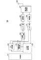
- FIG. 4 is a block diagram showing a configuration of the base station 203 shown in FIG. 2, which is a base station according to the present invention.
- the transmission process of the base station 203 shown in FIG. 4 will be described.
- the EPC communication unit 401 transmits and receives data between the base station 203 and the EPC (such as the MME unit 204) and the HeNBGW 205.
- the other base station communication unit 402 transmits / receives data to / from other base stations.
- the EPC communication unit 401 and the other base station communication unit 402 exchange information with the protocol processing unit 403, respectively. Control data from the protocol processing unit 403 and user data and control data from the EPC communication unit 401 and the other base station communication unit 402 are stored in the transmission data buffer unit 404.
- the data stored in the transmission data buffer unit 404 is passed to the encoder unit 405 and subjected to encoding processing such as error correction. There may exist data directly output from the transmission data buffer unit 404 to the modulation unit 406 without performing the encoding process.
- the encoded data is subjected to modulation processing by the modulation unit 406.
- the modulated data is converted into a baseband signal and then output to the frequency conversion unit 407 where it is converted into a radio transmission frequency. Thereafter, a transmission signal is transmitted from the antenna 408 to one or a plurality of mobile terminals 202.
- the reception processing of the base station 203 is executed as follows. Radio signals from one or more mobile terminals 202 are received by the antenna 408. The received signal is converted from a radio reception frequency to a baseband signal by the frequency conversion unit 407, and demodulated by the demodulation unit 409. The demodulated data is transferred to the decoder unit 410 and subjected to decoding processing such as error correction. Of the decoded data, control data is passed to the protocol processing unit 403 or EPC communication unit 401 and other base station communication unit 402, and user data is passed to the EPC communication unit 401 and other base station communication unit 402. A series of processing of the base station 203 is controlled by the control unit 411. Therefore, although not shown in FIG. 4, the control unit 411 is connected to the units 401 to 410.
- FIG. 5 is a block diagram showing the configuration of the MME according to the present invention.
- FIG. 5 shows the configuration of the MME 204a included in the MME unit 204 shown in FIG.
- the PDN GW communication unit 501 transmits and receives data between the MME 204a and the PDN GW.
- the base station communication unit 502 performs data transmission / reception between the MME 204a and the base station 203 using the S1 interface.
- the data received from the PDN GW is user data
- the user data is passed from the PDN GW communication unit 501 to the base station communication unit 502 via the user plane communication unit 503 and to one or more base stations 203.
- Sent When the data received from the base station 203 is user data, the user data is passed from the base station communication unit 502 to the PDN GW communication unit 501 via the user plane communication unit 503 and transmitted to the PDN GW.
- control data is passed from the PDN GW communication unit 501 to the control plane control unit 505.
- control data is transferred from the base station communication unit 502 to the control plane control unit 505.
- the HeNBGW communication unit 504 is provided when the HeNBGW 205 exists, and performs data transmission / reception through an interface (IF) between the MME 204a and the HeNBGW 205 depending on the information type.
- the control data received from the HeNBGW communication unit 504 is passed from the HeNBGW communication unit 504 to the control plane control unit 505.
- the processing result in the control plane control unit 505 is transmitted to the PDN GW via the PDN GW communication unit 501.
- the result processed by the control plane control unit 505 is transmitted to one or more base stations 203 via the S1 interface via the base station communication unit 502, and to one or more HeNBGWs 205 via the HeNBGW communication unit 504. Sent.
- the control plane control unit 505 includes a NAS security unit 505-1, an SAE bearer control unit 505-2, an idle state mobility management unit 505-3, and the like, and performs overall processing for the control plane.
- the NAS security unit 505-1 performs security of a NAS (Non-Access Stratum) message.
- the SAE bearer control unit 505-2 performs management of SAE (System Architecture) Evolution bearers and the like.
- the idle state mobility management unit 505-3 performs mobility management in a standby state (idle state; also referred to as LTE-IDLE state or simply idle), generation and control of a paging signal in the standby state,
- the tracking area of one or a plurality of mobile terminals 202 is added, deleted, updated, searched, and tracking area list is managed.
- the MME 204a distributes the paging signal to one or a plurality of base stations 203. Further, the MME 204a performs mobility control (Mobility control) in a standby state (Idle State). The MME 204a manages a tracking area list when the mobile terminal is in a standby state and in an active state (Active State). The MME 204a starts a paging protocol by transmitting a paging message to a cell belonging to a tracking area (tracking area: TrackingTrackArea) where the UE is registered. Management of the CSG of the Home-eNB 206 connected to the MME 204a, management of the CSG ID, and management of the white list may be performed by the idle state mobility management unit 505-3.
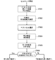
- FIG. 6 is a flowchart illustrating an outline from a cell search to a standby operation performed by a communication terminal (UE) in an LTE communication system.
- the communication terminal uses the first synchronization signal (P-SS) and the second synchronization signal (S-SS) transmitted from the neighboring base stations in step ST601, and performs slot timing, frame Synchronize timing.
- P-SS first synchronization signal
- S-SS second synchronization signal
- the P-SS and S-SS are collectively referred to as a synchronization signal (SS).
- SS synchronization signal
- a synchronization code corresponding to one-to-one is assigned to the PCI assigned to each cell.
- 504 patterns are under consideration. Synchronization is performed using the 504 PCIs, and the PCI of the synchronized cell is detected (specified).
- a cell-specific reference signal that is a reference signal (reference signal: RS) transmitted from the base station to each cell is detected for the synchronized cell.
- Measure the received power of RS Reference Signal Received Power: RSRP.
- RS Reference Signal Received Power
- RS Reference Signal
- a code corresponding to PCI one to one is used. By correlating with that code, it can be separated from other cells.
- deriving the RS code of the cell from the PCI specified in step ST601 it is possible to detect the RS and measure the received power of the RS.
- a cell having the best RS reception quality for example, a cell having the highest RS reception power, that is, the best cell is selected from one or more cells detected in step ST602.
- step ST604 the PBCH of the best cell is received and the BCCH that is broadcast information is obtained.
- MIB Master Information Block
- the MIB information includes, for example, DL (downlink) system bandwidth (also called transmission bandwidth setting (transmission bandwidth configuration: dl-bandwidth)), the number of transmission antennas, SFN (System frame number), and the like.
- SIB1 includes information related to access to the cell, information related to cell selection, and scheduling information of other SIBs (SIBk; an integer of k ⁇ 2).
- SIB1 includes a tracking area code (TrackingTrackArea Code: TAC).
- the communication terminal compares the TAC of SIB1 received in step ST605 with the TAC portion of the tracking area identifier (Tracking Area Identity: TAI) in the tracking area list already held by the communication terminal.
- the tracking area list is also referred to as a TAI list (TAI list).
- TAI is identification information for identifying a tracking area, and is composed of MCC (Mobile Country Code), MNC (Mobile Network Code), and TAC (Tracking Area Code).
- MCC Mobile Country Code
- MNC Mobile Network Code
- TAC Track Area Code
- MCC Mobile Country Code
- MNC Mobile Network Code
- TAC Track Area Code
- step ST606 If, as a result of the comparison in step ST606, the TAC received in step ST605 is the same as the TAC included in the tracking area list, the communication terminal enters a standby operation in the cell. In comparison, if the TAC received in step ST605 is not included in the tracking area list, the communication terminal passes through the cell to a core network (Core Network, EPC) including MME and the like, and TAU (Tracking Area Update). Request tracking area change to do
- EPC Core Network, EPC
- MME Mobile Management Entity
- TAU Track Area Update
- a device that constitutes a core network performs tracking based on the identification number (UE-ID, etc.) of the communication terminal sent from the communication terminal together with the TAU request signal. Update the area list.
- the core network side device transmits the updated tracking area list to the communication terminal.
- the communication terminal rewrites (updates) the TAC list held by the communication terminal based on the received tracking area list. Thereafter, the communication terminal enters a standby operation in the cell.
- a cell configured by an eNB has a relatively wide range of coverage.
- a cell is configured to cover a certain area with a relatively wide range of coverage of a plurality of cells configured by a plurality of eNBs.
- the cell configured by the eNB has a coverage that is narrower than the coverage of the cell configured by the conventional eNB. Therefore, in the same way as in the past, in order to cover a certain area, a larger number of eNBs having a smaller cell size are required as compared with the conventional eNB.
- a cell having a relatively large coverage such as a cell configured by a conventional eNB
- a macro cell an eNB that configures the macro cell
- a cell having a relatively small coverage such as a small cell
- an eNB configuring the small cell is referred to as a “small eNB”.
- the macro eNB may be a “wide area base station” described in Non-Patent Document 7, for example.
- the small eNB may be, for example, a low power node, a local area node, a hot spot, or the like.
- the small eNB is a pico eNB that constitutes a pico cell, a femto eNB that constitutes a femto cell, a HeNB, an RRH (Remote Radio Unit), an RRU (Remote Radio Unit), an RRE (Remote Radio Equipment), or an RN (Relay Node). There may be.
- the small eNB may be a “local area base station (Local (Base Station)” or “Home base station (Home Base Station)” described in Non-Patent Document 7.
- FIG. 7 is a diagram illustrating a concept of a cell configuration when a macro eNB and a small eNB coexist.
- a macro cell configured by a macro eNB has a relatively wide range of coverage 701.
- a small cell configured by a small eNB has a coverage 702 having a smaller range than a coverage 701 of a macro eNB (macro cell).
- the coverage of a cell configured by a certain eNB may be included in the coverage of a cell configured by another eNB.
- the small cell coverage 702 configured by the small eNB is included in the macro cell coverage 701 configured by the macro eNB. May be.
- a plurality of, for example, two small cell coverages 702 may be included in one macro cell coverage 701.
- a mobile terminal (UE) 703 is included in, for example, a small cell coverage 702 and performs communication via the small cell.
- the macro cell coverage 701 configured by the macro eNB and the small cell coverage 702 configured by the small eNB overlap in a complicated manner. Cases arise.
- a plurality of small cell coverages 702 configured by a plurality of small eNBs are configured in one macro cell coverage 701 configured by one macro eNB. Sometimes it happens.
- the 5th generation (5G) which is a future wireless access system aiming for commercialization from 2018 to 2020, includes LTE base stations compatible with LTE-A systems and 5G base stations compatible with 5G systems.
- the architecture to be deployed is considered.
- MeNB MasterNBeNB
- SeNB Secondary eNB
- C-plane control plane
- U-plane user plane
- FIG. 8 is a diagram showing a configuration of a conventional communication system 10.
- a first base station 11 that is a MeNB (hereinafter may be referred to as “BS # 1”) is connected to the core network 15 via an S1 interface, and a second base station 12 that is a SeNB (hereinafter referred to as “BS # 2” via an Xn interface). ”).
- BS # 3 A third base station 13 (hereinafter sometimes referred to as “BS # 3”) installed independently of other base stations is connected to the core network 15 via an S1 interface.
- 5G in addition to LTE-A, a plurality of base stations using different frequencies are connected. In addition, the amount of data in each base station is large.
- MeNB 11 is LTE-A
- LTE-A can cover a relatively wide cell radius.
- the frequency used is low, and there are many base stations already installed for existing base stations. This is because it can be covered.
- a 5G wireless base station is assigned.
- a base station having a low SHF (Super High Frequency) having a frequency of 6 GHz or less hereinafter sometimes referred to as a “low SHF base station”
- a base station having a high SHF having a frequency to be used exceeding 6 GHz (Hereinafter, sometimes referred to as “high SHF base station”) is likely to be placed at the same time.
- SeNB 12 for example, a low SHF base station
- Another base station such as a high SHF base station, can only be deployed as a stand alone base station 13 independent of other base stations. That is, the structure which connects several SeNB12 with respect to one MeNB11 cannot be taken.
- the mobile terminal (hereinafter may be referred to as “UE”) 14 can communicate with three or more base stations simultaneously, the communication path of the control plane (C-plane) information Control that cannot be aggregated into one and a mismatch between a plurality of control plane (C-plane) information does not occur on the UE 14 side is required.
- C-plane control plane
- control plane C-plane information is concentrated on one MeNB 11, and the processing capability of the MeNB 11 may become a network bottleneck.
- one base station corresponding to the MeNB is configured to be able to execute control plane (C-plane) data processing of a plurality of base stations connected as SeNBs.
- control plane C-plane
- U-plane user plane
- control plane (C-plane) data related to communication control among the information related to communication with the UE given from the core network is transmitted to the UE via one base station corresponding to the MeNB. Sent and received.
- control plane (C-plane) data of a communication terminal that can communicate simultaneously with a plurality of base stations.
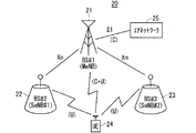
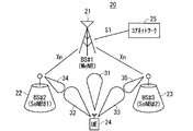
- FIG. 9 is a diagram showing a configuration of the communication system 20 according to Embodiment 1 of the present invention.
- the communication system 20 includes a first base station 21 (hereinafter sometimes referred to as “BS # 1”), a second base station 22 (hereinafter sometimes referred to as “BS # 2”), and a third base station 23 (hereinafter referred to as “BS # 1”). # 3 ”), and a mobile terminal (UE) 24.
- BS # 1 is installed as a MeNB.
- BS # 2 is installed as a first SeNB (hereinafter also referred to as “SeNB # 1”).
- BS # 3 is installed as a second SeNB (hereinafter sometimes referred to as “SeNB # 2”).
- MeNB corresponds to a master base station apparatus.
- the master base station apparatus performs main processing.
- the main process is, for example, an aggregation process in dual connectivity (DC).
- the first SeNB and the second SeNB correspond to secondary base station devices.
- the first SeNB and the second SeNB are each connected to the MeNB.
- One UE 24 is simultaneously communicating with three base stations 21 to 23, that is, BS # 1, BS # 2, and BS # 3.
- BS # 1 is an LTE-A base station
- BS # 2 is a 5G base station
- BS # 3 is a 5G base station.
- an interface capable of direct communication here, an Xn interface is provided.
- UE 24 communicates with BS # 1 for control plane (C-plane) data. Further, the UE 24 communicates user plane (U-plane) data with the BS # 1, BS # 2, and BS # 3, respectively.
- C-plane control plane
- U-plane user plane
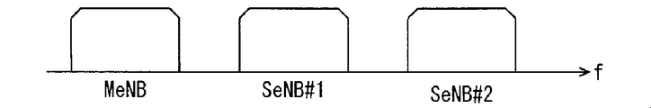
- FIG. 10 is a diagram illustrating an example of the frequency of the transmission / reception wave used in the communication system 20 according to the first embodiment of the present invention.
- the horizontal axis represents the frequency f.
- a first base station 21 installed as a MeNB, a second base station 22 installed as a SeNB # 1, and a third base station installed as a SeNB # 2 23 use transmission / reception waves of different frequency bands.
- FIG. 11 is a diagram illustrating an example of transmission / reception waveforms used in the communication system 20 according to the first embodiment of the present invention.
- FIG. 12 is a diagram illustrating an example of the frequency of the transmission / reception wave used in the example illustrated in FIG. 11.
- 11 and 12 show a case where each base station 21 to 22 and UE 24 apply an array antenna to a transmission / reception antenna.
- transmission / reception waveforms 31 to 35 having a beam shape having directivity are used. Thereby, space separability can be improved.
- a plurality of base stations can be simultaneously allocated in the same frequency band.
- the MeNB and the two SeNBs use transmission / reception waves of different frequency bands, but the SeNB # 1 and the SeNB # 2 use transmission / reception waves of the same frequency band.
- FIG. 13 is a diagram illustrating an example of a data flow in the communication system 20 according to the first embodiment of the present invention.
- the user plane (U-plane) data includes, for example, each base station, that is, the first base station 21 (hereinafter sometimes referred to as “BS # 1”), the second base station (hereinafter referred to as “BS”). # 2 ”) and the third base station (hereinafter also referred to as“ BS # 3 ”) and the core network device 25, which is a higher-level device (Next Generation Core Network), Transmission / reception is performed by communication between each base station and the UE 24.
- BS # 1 the first base station 21
- BS # 2 the second base station
- BS # 3 the third base station
- the core network device 25 which is a higher-level device (Next Generation Core Network)
- Transmission / reception is performed by communication between each base station and the UE 24.
- the user plane (U-plane) data is not limited to this, and is transmitted / received by communication between one base station, for example, BS # 1, and the core network device 25, which is a higher-level device, and BS # 1 and UE24. And communication between BS # 1 and UE 24 via BS # 2 or BS # 3.
- control plane (C-plane) data is transmitted / received only by communication between BS # 1 and UE24.
- the communication between BS # 1 and UE24 may be direct communication between BS # 1 and UE24, or may be via another base station, for example, BS # 3 or BS # 4.
- FIG. 14 is a diagram illustrating an example of a data flow in the communication system 20A, which is another example of the communication system according to the first embodiment of the present invention. Since the communication system 20A shown in FIG. 14 includes the same configuration as the communication system 20 shown in FIG. 13, the same reference numerals are given to the same configurations, and common descriptions are omitted.
- control plane (C-plane) data is transmitted / received by communication between the core network device 25 corresponding to the MME and the BS # 1.
- Control plane (C-plane) data may be transmitted and received by communication between BS # 1 and UE24.
- control plane (C-plane) data is communicated with UE24 via radio resources of BS # 2 and BS # 3 as shown in FIG. May be sent and received.
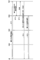
- FIG. 15 is a diagram illustrating an example of a sequence related to processing until communication is started in the communication system according to Embodiment 1 of the present invention.
- FIG. 15 shows a sequence in which BS # 1 and UE add BS # 2 and BS # 3 from the connected state.
- step ST11 BS # 1, BS # 2, BS # 3 and the UE are in a connected state.
- step ST12 BS # 1 notifies BS # 2 of the resource allocation request.
- step ST13 BS # 2 notifies the request response to BS # 1.
- step ST14 BS # 1 notifies the UE of a request to add BS # 2.
- Step ST15 the UE notifies the BS # 1 of an addition request response.
- the UE measures the synchronization signal of the designated BS # 2.
- step ST16 the UE synchronizes with the downlink (DL) of BS # 2.
- step ST17 BS # 2 notifies the UE of channel control, for example, PDCCH.
- step ST18 the UE starts conduction of user plane (U-plane) data based on the resource allocation state of the downlink signal specified by the PDCCH.
- U-plane user plane
- step ST19 BS # 1 notifies the resource allocation request to BS # 3.
- step ST20 BS # 3 notifies the request response to BS # 1.
- step ST21 BS # 1 notifies the UE of a request to add BS # 3.
- Step ST22 the UE notifies the BS # 1 of an addition request response.
- the UE measures the synchronization signal of the designated BS # 3.
- step ST23 the UE synchronizes with the downlink (DL) of BS # 3.
- Step ST24 BS # 3 notifies the UE of channel control, for example, PDCCH.
- step ST25 the UE starts to conduct user plane (U-plane) data based on the resource allocation state of the downlink signal specified by the PDCCH.
- U-plane user plane
- an instruction to delete BS # 1 is transmitted to the UE and executed.
- UEs and base stations compatible with the 5G standard may apply an array antenna to the transmitting / receiving antenna.
- space separation can be improved by using a beam-shaped transmission / reception waveform having directivity. Therefore, there is a possibility that a plurality of base stations may be assigned simultaneously in the same frequency band as shown in FIG.
- selection information for example, a beam ID
- a beam ID is added to the addition request signal of BS # 2 in step ST14 of FIG. 15 and the addition request signal of BS # 3 in step ST21.
- the beam for receiving the PDCCH can be selected, and it is not necessary to transmit the PDCCH information to all the beams, and channel resources can be used efficiently.
- beam selection information can be added to the PDCCH.
- BS # 1 since it is not necessary to consider BS # 1 regarding beam control, when a plurality of base stations are connected to BS # 1, the resource allocation processing of BS # 1 is reduced, and the processing load as a system is reduced. Even if the BS # 1 is an apparatus with limited processing capability such as an existing LTE-A base station, there is a possibility that it can be processed without causing a bottleneck.
- control plane (C-plane) data among the information related to communication with the UE given from the core network is transmitted / received to / from the UE via the MeNB.
- the process of control plane (C-plane) data when the UE communicates with a plurality of base stations can be simplified.
- control plane (C-plane) data is given to the MeNB by the core network.
- Control plane (C-plane) data given from the core network is given to the UE by the MeNB and also given to the UE via a plurality of SeNBs.
- Embodiment 1 Modification 1 As a first modification of the first embodiment, there is a configuration in which a part of the processing of control plane (C-plane) data is distributed to base stations other than the MeNB, for example, BS # 2 described later.
- FIG. 16 is a diagram showing a configuration of the communication system 40 in the first modification of the first embodiment of the present invention.
- the communication system 40 includes a first base station 41 (hereinafter also referred to as “BS # 1”), a second base station 42 (hereinafter also referred to as “BS # 2”), and a third base station 43 (hereinafter referred to as “BS # 1”). # 3 ”), a fourth base station 44 (hereinafter also referred to as“ BS # 4 ”), a mobile terminal (UE) 45, and a core network 46.
- BS # 1 first base station 41
- BS # 2 a second base station 42
- BS # 1 third base station 43
- # 3 a fourth base station 44
- UE mobile terminal
- BS # 1 is a base station for LTE-A
- BS # 2 is a base station for LTE-A
- BS # 3 is a base station for LTE-A
- BS # 4 is 5G base stations.
- the RRC messages for the 5G standard are characterized by being collectively transmitted / received by BS # 2.
- BS # 1 and BS # 2 are connected by an inter-base station interface, specifically, an Xn interface.
- BS # 2 and BS # 3, and BS # 2 and BS # 4 are connected by an inter-base station interface, specifically, an Xn interface.
- BS # 1 and core network 46 are connected by an S1 interface.
- BS # 1 handles the RRC message for BS # 1 and control plane (C-plane) information for adding BS # 2.
- C-plane control plane
- BS # 2 handles control plane (C-plane) information for BS # 2, BS # 3 and BS # 4.
- UE45 transmits / receives control plane (C-plane) information with BS # 1 and BS # 2.
- FIG. 17 is a diagram illustrating an example of a data flow in the communication system 40 according to the first modification of the first embodiment of the present invention.
- FIG. 17 shows an example of arrangement of RRC processing functions.
- BS # 1 is, for example, a first radio system of LTE-A (hereinafter also referred to as “first system”).
- BS # 2, BS # 3, and BS # 4 are, for example, a 5G second wireless system (hereinafter also referred to as “second system”).
- BS # 1 has a function of RRC processing for the first system.
- BS # 2 has a function of RRC processing for the second system.
- the RRC message for the first system may be transmitted / received between the BS # 1 and the UE, or may be communicated with the UE via the radio resource of the BS # 2.
- BS # 2 has a function of the RRC process for the second system.
- the RRC message for the second system may be transmitted / received between BS # 2 and the UE, or may be communicated with the UE via the radio resources of BS # 3 and BS # 4.
- the control plane (C-plane) information for the second system is transmitted / received by communication between the core network 46 and BS # 2.
- the communication between the core network 46 and BS # 2 may be direct communication between the core network 46 and BS # 2, or may be communication via BS # 1.
- UE connectivity refers to the ease of connection of a UE with a base station.
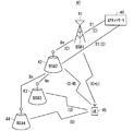
- FIG. 18 is a diagram showing an example of cell arrangement in the communication system 40 according to the first modification of the first embodiment of the present invention.
- BS # 1 constitutes a macro cell 51 having a cell radius of 500 m
- BS # 2 constitutes a microcell 52 having a cell radius of 200 m
- BS # 3 and BS # For example, when 4 configures the small cells 53 and 54 having a cell radius of 50 m, the connection between the BS # 1 and the UE can be maintained in a wide range.
- BS # 2 which is another second base station 42A exists in the cell 51 of BS # 1.
- BS # 2 constitutes a microcell 52A having a cell radius of 200 m, for example, like BS # 2.
- BS # 5 constitutes a small cell 55 having a cell radius of 50 m, for example, like BS # 3 and BS # 4.
- the BS # 2 processes the control plane (C-plane) data of the BS # 2 and controls the base stations BS # 3 and BS # 4 that are subordinate to the cell 52 of the BS # 2.
- Plane (C-plane) data processing is executed. Thereby, the processing load of BS # 1 can be reduced.
- the control plane (C-plane) data processing of BS # 2 ′ and the control plane (C-plane) of BS # 5, which is a base station under the cell 52A of BS # 2 ′ are processed. It is preferable to execute data processing. As a result, the processing load of BS # 1 can be further reduced.
- FIG. 19 is a diagram illustrating an example of a sequence related to processing until communication is started in the communication system 40 according to the first modification of the first embodiment of the present invention.
- FIG. 19 shows a sequence example for establishing connections with a plurality of base stations.
- FIG. 19 shows a sequence in which BS # 1 and UE add BS # 2, BS # 3, and BS # 4 from the connected state.
- step ST31 BS # 1 and UE are in a connected state.
- step ST32 BS # 1 notifies the resource allocation request to BS # 2.
- step ST33 BS # 2 notifies BS # 1 of the request response.
- step ST34 BS # 1 notifies the UE of a request to add BS # 2.
- step ST35 the UE notifies the addition request response to BS # 1.
- the UE measures the synchronization signal of the designated BS # 2.
- step ST36 the UE synchronizes with the downlink (DL) of BS # 2.
- step ST37 BS # 2 notifies the UE of channel control, for example, PDCCH.
- step ST38 the UE starts conduction of user plane (U-plane) data based on the resource allocation state of the downlink signal specified by the PDCCH.
- U-plane user plane
- step ST39 BS # 2 notifies BS # 3 of the resource allocation request.
- step ST40 BS # 3 notifies the request response to BS # 2.
- step ST41 BS # 2 notifies the UE of an addition request for BS # 3.
- step ST42 the UE notifies the BS # 2 of an addition request response.
- the UE measures the synchronization signal of the designated BS # 3.
- step ST43 the UE synchronizes with the downlink (DL) of BS # 3.
- step ST44 BS # 3 notifies the UE of channel control, for example, PDCCH.
- step ST45 the UE starts conduction of user plane (U-plane) data based on the resource allocation state of the downlink signal specified by the PDCCH.
- U-plane user plane
- step T46 BS # 2 notifies BS # 4 of the resource allocation request.
- step ST47 BS # 4 notifies BS # 2 of the request response.
- step ST48 BS # 2 notifies the UE of a request to add BS # 4.
- Step ST49 the UE notifies the BS # 2 of an addition request response.
- the UE measures the synchronization signal of the designated BS # 3.
- step ST50 the UE synchronizes with the downlink (DL) of BS # 4.
- step ST51 BS # 4 notifies the UE of channel control, for example, PDCCH.
- Step ST52 the UE starts to conduct user plane (U-plane) data based on the resource allocation state of the downlink signal specified by the PDCCH.
- U-plane user plane
- the BS # 2 is deleted by an instruction from the BS # 1 to the UE, similarly to the addition of the base station.
- BS # 3 and BS # 4 are deleted by an instruction from BS # 2.
- BS # 2 When BS # 2 is deleted while BS # 3 and BS # 4 are connected, a sequence for deleting BS # 2 from BS # 2 after an instruction to delete the base stations of BS # 3 and BS # 4 It is good.
- BS # 3 and BS # 4 may be deleted at the same time by an instruction to delete BS # 2 from BS # 1.
- the BS # 2 When adding the above-described BS # 2, the BS # 2 includes a message for enabling the RRC processing function of the second system in the BS # 2 addition request instruction for notifying the UE. In addition, a message for validating the RRC processing function is included in the resource allocation request instruction from BS # 1 to BS # 2. If it is invalid, BS # 2 does not validate the RRC processing function of the second system, and has the same role as BS # 2 of the first embodiment shown in FIG.
- the sequence shown in FIG. 19 is executed. Specifically, the radio resource control (RRC) process for BS # 2, BS # 3, and BS # 4, which are SeNBs, is performed as shown in FIG. 19, among BS # 2, BS # 3, and BS # 4. One, for example, by BS # 2. As a result, it is possible to reduce the processing load of the control plane (C-plane) data of BS # 1. Therefore, it is possible to shorten the time for sequence processing such as base station addition processing, and therefore it is possible to suppress processing delay.
- RRC radio resource control
- Embodiment 1 Modification 2 As a second modification of the first embodiment, in the configuration of the first modification of the first embodiment shown in FIG. 16, the RRC message is selected when there are a plurality of component carriers (Component Carrier: CC) in the BS # 2. The example which communicates by CC is shown. Since the configuration of the communication system of this modification is the same as that of the communication system 40 of Modification 1 of Embodiment 1 shown in FIG. 16, the illustration and common description of the configuration are omitted.
- Component Carrier Component Carrier
- 20 to 22 are diagrams showing an example of the frequency of transmission / reception waves used in the communication system according to the second modification of the first embodiment of the present invention.
- the horizontal axis indicates the frequency f.
- FIG. 20 the frequency of the transmission / reception wave used by BS # 1 is shown.
- FIG. 21 shows the frequency of the transmission / reception wave used in BS # 2.
- FIG. 22 the frequency of the transmission / reception wave used in BS # 3 and BS # 4 is shown.
- BS # 1 transmits / receives the first system RRC message using one type of transmission / reception wave.
- the bandwidth BW1 of the transmission / reception wave used in BS # 1 is, for example, 20 MHz.
- BS # 2 handles two CCs. Therefore, in this modification, the RRC message is transmitted by either CC # 1 or CC # 2. As a result, the UE can obtain necessary RRC information without performing modulation processing and demodulation processing on all CCs.
- the transmission / reception wave bandwidth BW2 used in BS # 2 shown in FIG. 21 is, for example, 100 MHz.
- the RRC message for the second system is transmitted / received using CC # 1 among the two CCs used in BS # 2.
- CC # 2 of BS # 2 to which no RRC is assigned is treated as equivalent to other BS # 3 and BS # 4. This can simplify the management of user plane (U-plane) resources.
- the transmission / reception wave bandwidth BW3 used in BS # 3 shown in FIG. 22 is, for example, 100 MHz.
- the RRC message for the second system is transmitted / received by BS # 3, it is mapped to one of CC # 0 to CC # 7 or a plurality of CCs.
- By handling RRC with only a part of the CC it is possible to simplify the management of user plane (U-plane) resources of the CC to which the RRC is not mapped.
- U-plane user plane
- Embodiment 1 Modification 3 As a third modification of the first embodiment, a method in which the configuration of the first embodiment and the configuration of the first modification of the first embodiment are combined will be described.
- the RRC processing function for the second system is executed by BS # 1.
- the RRC processing function for the second system is executed by BS # 2.
- FIG. 23 is a diagram showing an example of a sequence relating to processing for changing the RRC processing function for the second system from BS # 2 to BS # 1.
- Step ST61 RRC communication for the second system is performed between the BS # 2 and the UE.
- step ST62 BS # 1 notifies BS # 2 of a release instruction for RRC processing for the second system.
- step ST63 BS # 2 notifies BS # 1 of a response that can be handled.
- BS # 1 notifies the UE of a change instruction for the RRC process for the second system.
- the change instruction for the second system RRC process is an instruction for the second system RRC process to change from BS # 2 to BS # 1.
- Specific examples of instruction contents include a change in radio resources for handling the RRC message for the second system and a change in message format.
- Step ST65 RRC communication for the second system is performed between the BS # 1 and the UE.
- FIG. 24 is a diagram illustrating an example of a sequence relating to processing for changing the RRC processing function for the second system from BS # 1 to BS # 2.
- Step ST71 RRC communication for the second system is performed between the BS # 1 and the UE.
- step ST72 BS # 1 notifies BS # 2 of an instruction to add the second system RRC process.
- step ST73 BS # 2 notifies BS # 1 of a response that can be handled.
- BS # 1 notifies the UE of an instruction to change the RRC process for the second system.
- the instruction to change the RRC process for the second system is an instruction to change the RRC process for the second system from BS # 1 to BS # 2.
- Specific examples of instruction contents include a change in radio resources for handling the RRC message for the second system and a change in message format.
- Step ST75 RRC communication for the second system is performed between BS # 2 and the UE.
- the RRC process is performed in accordance with the communication state of the UE and the corresponding function of the UE, the load state of the base station, the number of connected terminals, and so Can be distributed.
- the RRC processing for the first system and the RRC processing for the second system are performed in one place.
- it is also effective to transmit and receive RRC messages from BS # 1.
- Embodiment 2 the concept of beam control may be added.
- the interval between the base stations is reduced. This may increase the number of base stations in one cell.
- various types of base stations may be mixed and arranged. For example, a base station of URLLC (Ultra-Reliability and Low Latency Communication) or a plurality of base stations with different frequencies may be mixed and arranged. When this happens, information about the base station to be notified increases. When this is transmitted by one macro base station, there is a problem that processing of the macro base station becomes large.
- URLLC Ultra-Reliability and Low Latency Communication
- the broadcast information is divided into basic information and additional information.
- the basic information is transmitted from BS # 1 having a large cell radius, and the additional information is installed in the cell of BS # 1, and the cell radius is smaller than BS # 1 or equivalent to BS # 1. 2 to transmit from.
- FIG. 25 is a diagram showing a configuration of the communication system 60 according to Embodiment 2 of the present invention.
- the communication system 60 includes a first base station 61 (hereinafter also referred to as “BS # 1”), a second base station 62 (hereinafter also referred to as “BS # 2”), and a third base station 63 (hereinafter referred to as “BS # 1”). # 3 ”), a fourth base station 64 (hereinafter also referred to as“ BS # 4 ”), and a mobile terminal (UE) 65.
- BS # 1 first base station 61
- BS # 2 second base station 62
- BS # 1 third base station 63
- # 3 a fourth base station 64
- UE mobile terminal
- BS # 1 constitutes a macro cell 71 having a cell radius of 500 m, for example.
- BS # 2 constitutes a microcell 72 having a cell radius of 200 m, for example.
- BS # 3 and BS # 4 constitute small cells 73 and 74 having a cell radius of 50 m, for example.
- each base station 61 to 64 is installed as a stand-alone base station independently of other base stations, the broadcast information BrI # 1 to BrI is transmitted from each base station 61 to 64. # 3 is transmitted.
- the description of the broadcast information transmitted from the fourth base station 64 is omitted in order to prevent the drawing from becoming complicated and difficult to understand. Also broadcast information is transmitted.
- At least a part of the broadcast information for each SeNB is one of a plurality of SeNBs, Specifically, the UE is notified by BS # 2.
- This configuration eliminates the need for BS # 1 to transmit broadcast information for all base stations under the cell, and reduces the data amount of broadcast information BrI # 1 of BS # 1. As a result, it is possible to reduce the proportion of the broadcast information BrI # 1 occupying the radio resources of BS # 1. Further, by shortening the transmission period of the broadcast information BrI # 1 of BS # 1, it is possible to shorten the time required for the initial connection of the UE to BS # 1.
- the broadcast information for each SeNB may be notified directly from the BS # 2 to the UE as shown in FIG. 26 to be described later, or other base stations from the BS # 2 as shown in FIGS. 27 and 28 to be described later.
- the UE may be notified via.
- Information necessary for the initial connection of BS # 2 includes, for example, SIB1 (Cell access and cell reselection related information, scheduling information info), SIB2 (radio resource configuration, that is is common, for common) used in LTE-A all UEs).
- SIB1 Cell access and cell reselection related information
- SIB2 radio resource configuration, that is is common, for common
- the additional information corresponds to broadcast information other than information necessary for the initial connection of the BS # 2.
- FIG. 26 is a diagram illustrating an example of a sequence related to a process of acquiring broadcast information in the communication system 60 according to the second embodiment of the present invention.
- FIG. 26 shows an example of a sequence related to a process in which the UE acquires broadcast information for BS # 1, BS # 2, BS # 3, and BS # 4.
- step ST81 BS # 1 notifies the UE of the broadcast information for BS # 1.
- the UE reads the control information for BS # 1 from the broadcast information notified from BS # 1.
- step ST82 communication is performed between BS # 1 and the UE.
- step ST83 BS # 1 notifies the basic information of the broadcast information for BS # 2 to the UE.
- the UE needs to connect to BS # 2, the UE reads basic information of the broadcast information for BS # 2 among the broadcast information of BS # 1, and obtains information for accessing BS # 2.
- step ST84 BS # 2 notifies the UE of the additional information of the broadcast information for BS # 2.
- the UE reads the additional information of BS # 2 from the broadcast information of BS # 2.
- step ST85 communication is performed between BS # 2 and the UE.
- step ST86 BS # 2 notifies the UE of the broadcast information for BS # 3 and the broadcast information for BS # 4.
- the control information for BS # 3 or the control information for BS # 4 is read from the broadcast information notified from BS # 2.
- step ST87 communication is performed between BS # 3 and the UE.
- step ST88 communication is performed between BS # 4 and the UE.
- FIG. 27 is a diagram illustrating an example of a sequence related to a process of notifying broadcast information based on a UE request.
- FIG. 27 shows an example in which BS # 2 corresponds to the broadcast information request from the UE.
- step ST91 BS # 1 notifies BS # 1 broadcast information to the UE.
- step ST92 communication is performed between BS # 1 and the UE.
- step ST93 BS # 1 notifies the basic information of the broadcast information for BS # 2 to the UE.
- step ST94 BS # 2 notifies the UE of the additional information of the broadcast information for BS # 2.
- step ST95 communication is performed between BS # 2 and the UE.
- step ST96 the UE notifies BS # 2 of a broadcast information request for BS # 3.
- step ST97 BS # 2 notifies the UE of radio resource allocation information for notifying broadcast information.
- step ST98 BS # 2 notifies the UE of broadcast information for BS # 3 using the corresponding radio resource.
- step ST99 communication is performed between BS # 3 and the UE.
- FIG. 28 is a diagram illustrating another example of a sequence related to a process of notifying broadcast information based on a UE request.
- FIG. 28 shows a method of notifying the broadcast information requested from the UE using the radio resource of another base station, not the base station that received the request.
- step ST101 BS # 1 and UE are in a communication state.
- step ST102 BS # 2 and UE are in a communication state.
- step ST103 BS # 3 and the UE are in a communication state.
- step ST104 the UE notifies the BS # 2 of a broadcast information request for BS # 4.
- step ST105 BS # 2 notifies BS # 3 of a broadcast information notification resource securing request. Specifically, BS # 2 notifies broadcast information using the radio resource of BS # 3. BS # 2 instructs BS # 3 about the size of the broadcast information and the used radio resource information.
- step ST106 when the radio resource can be secured, BS # 3 notifies the secured radio information to BS # 2.
- Step ST107 BS # 2 notifies the UE of allocation information of the corresponding broadcast information.
- step ST108 BS # 3 notifies the UE of broadcast information for BS # 4.
- a configuration is also considered in which a beam is formed with a transmission / reception antenna waveform to increase the directivity of the antenna.
- spatial multiplexing becomes possible.
- the base station that receives the broadcast information request from the UE and the base station that transmits the broadcast information request from the UE can be freely selected. As a result, the radio resources can be effectively used.
- transmitting the same broadcast information from a plurality of base stations is also an effective configuration for improving data reliability.
- radio resources for transmitting broadcast information in units of CC (Component Carrier), as in Modification 2 of Embodiment 1.
- CC Component Carrier
- Embodiment 3 Regarding the processing of user plane (U-plane) data, in a dual connectivity split bearer configuration up to LTE-A, PDCP (Packet Data Convergence Protocol) function is arranged in MeNB (Master eNB), and SeNB (Secondary The configuration in which eNB) processes lower layers than RLC is standardized.
- PDCP Packet Data Convergence Protocol
- MeNB Master eNB
- SeNB Secondary The configuration in which eNB) processes lower layers than RLC is standardized.
- a user plane (U-plane) data processing method for Embodiment 1 data divided from the PDCP of BS # 1 is used as BS # 2 and BS # 3. Process in layers below RLC.
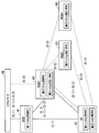
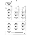
- FIG. 29 is a block diagram showing a configuration of the communication system 80 according to the third embodiment of the present invention.
- the communication system 80 includes a first base station 81 (hereinafter also referred to as “BS # 1”), a second base station 82 (hereinafter also referred to as “BS # 2”), and a third base station 83 (hereinafter referred to as “BS # 1”). # 3 ”) and UE 84 and host device 85.
- BS # 1 includes a PDCP processing unit, an RLC processing unit, a MAC processing unit, and a PHY processing unit.
- BS # 2 and BS # 3 include an RLC processing unit, a MAC processing unit, and a PHY processing unit.
- the UE84 corresponds to BS # 1, PDCP processing unit corresponding to BS # 1, RLC processing unit, MAC processing unit and PHY processing unit, RLC processing unit corresponding to BS # 2, MAC processing unit and PHY processing unit, and BS # 3 An RLC processing unit, a MAC processing unit, and a PHY processing unit.
- the higher level device 85 includes a core network device and a serving gateway (abbreviation: SGW).
- BS # 1 and BS # 2 are equivalent to the configuration (split bearer) of option 3C of dual connectivity.
- BS # 1 receives user plane (U-plane) data from the host device 85.
- ROHC Robot Header ⁇ Compression
- encryption processing are performed by PDCP processing by the PDCP processing unit of BS # 1.
- PDCP SN Sequence Number
- the data is divided and transmitted to the RLC processing unit of BS # 1, the RLC processing unit of BS # 2, and the RLC processing unit of BS # 3.
- the MAC process, and the PHY process are executed in each base station, it is transmitted to the UE 84.
- the UE 84 performs PHY processing, MAC processing, and RLC processing corresponding to each base station, and then aggregates them into one PDCP.
- the reverse procedure described above is performed for uplink data.
- FIG. 30 is a block diagram showing a configuration of a communication system 80A, which is another example of the communication system according to Embodiment 3 of the present invention. 30 includes the same configuration as that of the communication system 80 illustrated in FIG. 29, the same reference numerals are given to the same configurations, and common description is omitted.
- the communication system 80A includes a second base station 82A instead of the second base station 82 shown in FIG.
- the second base station 82A further includes a data division processing unit (also referred to as “SPLIT processing unit”) in addition to the configuration of the second base station 82 of FIG.
- SPLIT processing unit also referred to as “SPLIT processing unit”
- BS # 1 only needs to support a user plane (U-plane) interface that supports only connection with BS # 2, and does not change the specification of Option 3C of LTE dual connectivity. It becomes possible to do.
- U-plane user plane
- the user plane (U-plane) data among the information related to communication with the UE given from the core network is transmitted via one base station BS # 1 corresponding to the MeNB. Are transmitted to and received from the UE.
- user plane (U-plane) data is given to the MeNB by the core network, given to the UE by the MeNB, and given to the UE via a plurality of SeNBs.
- SeNBs SeNBs
- FIG. 31 is a block diagram showing a configuration of a communication system 90 which is still another example of the communication system according to Embodiment 3 of the present invention.
- the communication system 90 includes a first base station 91 (hereinafter also referred to as “BS # 1”), a second base station 92 (hereinafter also referred to as “BS # 2”), and a third base station 93 (hereinafter referred to as “BS # 1”). # 3 ”), a fourth base station 94 (hereinafter also referred to as“ BS # 4 ”), a UE 95, a first core network 96, and a second core network 97.
- the first core network 96 is a core network for LTE-A.
- the second core network 97 is a 5G core network.
- BS # 1 and BS # 2 include a PDCP processing unit, an RLC processing unit, a MAC processing unit, and a PHY processing unit.
- BS # 3 and BS # 4 include an RLC processing unit, a MAC processing unit, and a PHY processing unit.
- the UE 95 includes a PDCP processing unit, RLC processing unit, MAC processing unit and PHY processing unit corresponding to BS # 1, a PDCP processing unit, RLC processing unit, MAC processing unit and PHY processing unit corresponding to BS # 2, and BS RLC processing unit, MAC processing unit and PHY processing unit corresponding to # 3, and RLC processing unit, MAC processing unit and PHY processing unit corresponding to BS # 4.
- BS- # 1 of LTE-A is connected to an LTE core network (Core ⁇ ⁇ ⁇ ⁇ ⁇ Network).
- 5G BS # 2 is connected to the 5G core network.
- 5G BS # 3 and BS # 4 are configured to process user plane (U-plane) data divided from the PDCP processing unit of BS # 2. Indicates.
- BS # 1 is an LTE-A base station and BS # 2, BS # 3, and BS # 4 are 5G base stations.
- the PDCP processing function may be different for LTE-A and 5G.
- the amount of 5G user plane (U-plane) data is the same as the LTE user plane (U-plane). plane) may be several tens of times the amount of data, and the performance of the PDCP processing unit of the conventional LTE-A base station may become a bottleneck. In that case, the 5G PDCP process needs to be executed by the 5G base station.
- PDCP processing of user plane (U-plane) data of the 5G system is executed by BS # 2, and BS # 3 and BS # 4 under its control are executed.
- the user plane (U-plane) data is transmitted to the RLC processing unit.
- BS # 1 is connected to a first core network 96 which is a core network for LTE-A.
- BS # 1 processes the user plane (U-plane) data received from the first core network 96 in the PDCP processing unit, RLC processing unit, MAC processing unit, and PHY processing unit in BS # 1, and then transmits the data to UE95. Send.
- U-plane user plane
- BS # 2 is connected to a second core network 97, which is a 5G core network (Next Generation Core Core).
- BS # 2 executes processing such as PDCP ROHC, encryption, SN (Sequence Number) assignment, etc., on the user plane (U-plane) data received from the second core network 97 by the PDCP processing unit in BS # 2. To do.
- the data after the PDCP processing is divided and transmitted to the RLC processing unit in BS # 2, the RLC processing unit in BS # 3, and the RLC processing unit in BS # 4. After being processed by the RLC processing unit, MAC processing unit, and PHY processing unit of each base station, it is transmitted to the UE 95.
- the UE 95 executes PHY processing, MAC processing, and RLC processing corresponding to each base station, and then aggregates them into two, that is, PDCP for LTE-A and PDCP for 5G.
- This configuration can simplify the PDCP process regardless of the processing capability of the LTE-A base station. Even when the connection interface between BS # 1 and BS # 2 uses a network called “Non Ideal Network” that cannot guarantee the delay specification of data processing, 5G data can be transmitted and received without any problem. .
- the user plane (U-plane) data for the BS # 2, BS # 3, and BS # 4, which are SeNBs and the second system, are BS # 2, BS # 3, and BS # 3. It is transmitted / received to / from the UE via one of BS # 4, for example, BS # 2.
- the user plane (U-plane) data of the second system is given to the representative SeNB (BS # 2) by the core network, and given to the UE by the representative SeNB, and a plurality of the same system To the UE via the SeNB.
- U-plane user plane
- Embodiment 4 In the conventional dual connectivity configuration, the UE notifies the MeNB of the measurement result of each base station as a measurement report.
- the measurement report for BS # 1 is notified to BS # 1, and the measurement reports for BS # 2, BS # 3 and BS # 4 are sent to BS # 2. Notice.
- FIG. 32 is a diagram showing an exemplary sequence related to the measurement report processing of the communication system in the fourth embodiment of the present invention.
- step ST111 the UE notifies BS # 1 of measurement information regarding BS # 1 and BS # 2 as a measurement report (Measurement Report).
- BS # 1 notifies BS # 2 of a base station addition request (Addition) Request) in order to determine whether or not communication with the UE is possible based on the measurement information regarding BS # 2. Specifically, BS # 1 notifies BS # 2 of an addition request for BS # 2.
- step ST113 when the base station can be added, BS # 2 notifies BS # 1 of an addition request response (Addition Request Acknowledge) (hereinafter also referred to as “addition request Ack”) as a normal response.
- addition request Ack an addition request response
- BS # 1 notifies the UE of an RRC connection reconfiguration (RRC Connection Reconfiguration) message as a request for adding a base station. Specifically, BS # 1 notifies the UE of an addition request for BS # 2. Information instructing to notify BS # 2 of measurement reports of BS # 2 and BS # 3, 4 may be included in the RRC connection reconfiguration message in step ST114.
- RRC connection reconfiguration RRC Connection Reconfiguration
- Step ST115 the UE notifies the BS # 1 of an RRC connection reconfiguration complete (RRC ⁇ Connection Reconfiguration Complete) message as an addition completion notification after the establishment of communication with the BS # 2.
- RRC connection reconfiguration complete RRC ⁇ Connection Reconfiguration Complete
- Step ST116 after establishing communication with BS # 2, the UE notifies BS # 1 of measurement information regarding BS # 1 as a measurement report (Measurement Report) for BS # 1.
- step ST117 the UE notifies BS # 2 of measurement information regarding BS # 2, BS # 3, and BS # 4 as a measurement report (Measurement Report) for BS # 2.
- Step ST118 BS # 2 sends a base station addition request (Addition Request) to BS # 3 in order to determine whether or not communication between BS # 3 and the UE is possible based on measurement information regarding BS # 3. Notify Specifically, BS # 2 notifies BS # 3 of an addition request for BS # 3.
- a base station addition request (Addition Request)
- step ST119 BS # 3 notifies BS # 2 of an addition request Ack as a normal response when a base station can be added.
- BS # 2 notifies the UE of an RRC connection reconfiguration (RRC Connection Reconfiguration) message as a base station addition request. Specifically, BS # 2 notifies the UE of a request to add BS # 3.
- RRC connection reconfiguration RRC Connection Reconfiguration
- step ST121 the UE notifies the BS # 2 of an RRC connection reconfiguration complete (RRC Connection Reconfiguration Complete) message as an addition completion notice after the establishment of communication with the BS # 3.
- RRC connection reconfiguration complete RRC Connection Reconfiguration Complete
- step ST122 BS # 2 notifies the UE of measurement information regarding BS # 2, BS # 3, and BS # 4 as a measurement report (Measurement Report).
- step ST123 BS # 2 sends a base station addition request (Addition Request) to BS # 4 in order to determine whether or not communication between BS # 4 and the UE is possible based on measurement information regarding BS # 4. Notify Specifically, BS # 2 notifies BS # 3 of an addition request for BS # 4.
- a base station addition request (Addition Request)
- step ST124 when a base station can be added, BS # 4 notifies BS # 2 of an addition request Ack as a normal response.
- BS # 2 notifies the UE of an RRC connection reconfiguration (RRC Connection Reconfiguration) message as a base station addition request. Specifically, BS # 2 notifies the UE of an addition request for BS # 4.
- RRC connection reconfiguration RRC Connection Reconfiguration
- Step ST126 the UE notifies the BS # 2 of an RRC connection reconfiguration complete (RRC Connection Reconfiguration Complete) message as an addition completion notice after communication establishment with the BS # 4 is completed.
- RRC connection reconfiguration complete RRC Connection Reconfiguration Complete
- Step ST127 after establishing communication with BS # 4, the UE notifies BS # 1 of measurement information regarding BS # 1 as a measurement report (Measurement Report) for BS # 1.
- step ST1208 the UE notifies BS # 2 of measurement information regarding BS # 2, BS # 3, and BS # 4 as a measurement report (Measurement Report) for BS # 2.
- the base station that the UE reports the measurement report may be selected.
- the measurement reports (Measurement Report) for BS # 2, BS # 3, and BS # 4 may be notified using the radio resources of BS # 3 and BS # 4.
- the notification destination of the measurement report may be changed by the above-described RRC message, or may be returned before the change of the notification destination.
Landscapes
- Engineering & Computer Science (AREA)
- Computer Networks & Wireless Communication (AREA)
- Signal Processing (AREA)
- Mobile Radio Communication Systems (AREA)
Abstract
The present invention provides a communication system capable of simplifying processing of control plane data and/or user plane data when a communication terminal device communicates with a plurality of base station devices. In a communication system (20), a plurality of base stations (21-23) include an MeNB that is a first base station (21) (BS#1), and a plurality of SeNBs (SeNB#1, #2) connected to the MeNB. Control plane data relating to control of communication and/or user plane data relating to a user among information relating to communication with user equipment (UE) (24) and given from a core network (25) is transmitted to and received from the UE (24) via the first base station (21) that is the MeNB.
Description
本発明は、移動端末装置などの通信端末装置と基地局装置との間で無線通信を行う通信システムに関する。
The present invention relates to a communication system that performs wireless communication between a communication terminal device such as a mobile terminal device and a base station device.
移動体通信システムの規格化団体である3GPP(3rd Generation Partnership Project)において、無線区間についてはロングタームエボリューション(Long Term Evolution:LTE)と称し、コアネットワークおよび無線アクセスネットワーク(以下、まとめて、ネットワークとも称する)を含めたシステム全体構成については、システムアーキテクチャエボリューション(System Architecture Evolution:SAE)と称される通信方式が検討されている(例えば、非特許文献1~8)。この通信方式は3.9G(3.9 Generation)システムとも呼ばれる。
In 3GPP (3rd Generation Partnership Project), a standardization organization for mobile communication systems, the wireless section is referred to as Long Term Evolution (LTE), and the core network and radio access network (hereinafter collectively referred to as the network). The communication system called System Architecture Evolution (SAE) has been studied (for example, Non-Patent Documents 1 to 8). This communication method is also called a 3.9G (3.9 generation) system.
LTEのアクセス方式としては、下り方向はOFDM(Orthogonal Frequency Division Multiplexing)、上り方向はSC-FDMA(Single Carrier Frequency Division Multiple Access)が用いられる。また、LTEは、W-CDMA(Wideband Code Division Multiple Access)とは異なり、回線交換を含まず、パケット通信方式のみになる。
As the LTE access method, OFDM (Orthogonal Frequency Division Multiplexing) is used in the downlink direction, and SC-FDMA (Single Carrier Frequency Division Multiple Access) is used in the uplink direction. Also, LTE is different from W-CDMA (Wideband Code Division Multiple Access), and does not include circuit switching and is only a packet communication system.
非特許文献1(5章)に記載される、3GPPでの、LTEシステムにおけるフレーム構成に関する決定事項について、図1を用いて説明する。図1は、LTE方式の通信システムで使用される無線フレームの構成を示す説明図である。図1において、1つの無線フレーム(Radio frame)は10msである。無線フレームは10個の等しい大きさのサブフレーム(Subframe)に分割される。サブフレームは、2個の等しい大きさのスロット(slot)に分割される。無線フレーム毎に1番目および6番目のサブフレームに下り同期信号(Downlink Synchronization Signal)が含まれる。同期信号には、第一同期信号(Primary Synchronization Signal:P-SS)と、第二同期信号(Secondary Synchronization Signal:S-SS)とがある。
Non-Patent Document 1 (Chapter 5), 3GPP determination items related to the frame configuration in the LTE system will be described with reference to FIG. FIG. 1 is an explanatory diagram showing a configuration of a radio frame used in an LTE communication system. In FIG. 1, one radio frame (Radio frame) is 10 ms. The radio frame is divided into ten equally sized subframes. The subframe is divided into two equally sized slots. A downlink synchronization signal (Downlink Synchronization Signal) is included in the first and sixth subframes for each radio frame. The synchronization signal includes a first synchronization signal (Primary Synchronization Signal: P-SS) and a second synchronization signal (Secondary Synchronization Signal: S-SS).
3GPPでの、LTEシステムにおけるチャネル構成に関する決定事項が、非特許文献1(5章)に記載されている。CSG(Closed Subscriber Group)セルにおいてもnon-CSGセルと同じチャネル構成が用いられると想定されている。
Non-Patent Document 1 (Chapter 5) describes the decision items regarding the channel configuration in the LTE system in 3GPP. It is assumed that the same channel configuration as that of the non-CSG cell is used in a CSG (Closed Subscriber Group) cell.
物理報知チャネル(Physical Broadcast Channel:PBCH)は、基地局装置(以下、単に「基地局」という場合がある)から移動端末装置(以下、単に「移動端末」という場合がある)などの通信端末装置(以下、単に「通信端末」という場合がある)への下り送信用のチャネルである。BCHトランスポートブロック(transport block)は、40ms間隔中の4個のサブフレームにマッピングされる。40msタイミングの明白なシグナリングはない。
A physical broadcast channel (Physical Broadcast Channel: PBCH) is a communication terminal device such as a base station device (hereinafter simply referred to as “base station”) to a mobile terminal device (hereinafter also simply referred to as “mobile terminal”). It is a channel for downlink transmission to (hereinafter sometimes simply referred to as “communication terminal”). A BCH transport block (transport block) is mapped to four subframes in a 40 ms interval. There is no obvious signaling of 40ms timing.
物理制御フォーマットインジケータチャネル(Physical Control Format Indicator Channel:PCFICH)は、基地局から通信端末への下り送信用のチャネルである。PCFICHは、PDCCHsのために用いるOFDM(Orthogonal Frequency Division Multiplexing)シンボルの数を、基地局から通信端末へ通知する。PCFICHは、サブフレーム毎に送信される。
The physical control format indicator channel (Physical Control Format Indicator Channel: PCFICH) is a channel for downlink transmission from the base station to the communication terminal. The PCFICH notifies the communication terminal of the number of OFDM (Orthogonal Frequency Division Multiplexing) symbols used for PDCCHs. PCFICH is transmitted for each subframe.
物理下り制御チャネル(Physical Downlink Control Channel:PDCCH)は、基地局から通信端末への下り送信用のチャネルである。PDCCHは、後述のトランスポートチャネルの1つである下り共有チャネル(Downlink Shared Channel:DL-SCH)のリソース割り当て(allocation)情報、後述のトランスポートチャネルの1つであるページングチャネル(Paging Channel:PCH)のリソース割り当て(allocation)情報、DL-SCHに関するHARQ(Hybrid Automatic Repeat reQuest)情報を通知する。PDCCHは、上りスケジューリンググラント(Uplink Scheduling Grant)を運ぶ。PDCCHは、上り送信に対する応答信号であるAck(Acknowledgement)/Nack(Negative Acknowledgement)を運ぶ。PDCCHは、L1/L2制御信号とも呼ばれる。
The physical downlink control channel (Physical Downlink Control Channel: PDCCH) is a channel for downlink transmission from the base station to the communication terminal. The PDCCH includes resource allocation (allocation) information of a downlink shared channel (DL-SCH), which is one of transport channels described later, and a paging channel (Paging channel: PCH, one of transport channels described later). ) Resource allocation (allocation) information and HARQ (Hybrid Automatic Repeat reQuest) information related to DL-SCH. The PDCCH carries an uplink scheduling grant (Uplink Scheduling Grant). The PDCCH carries Ack (Acknowledgement) / Nack (Negative Acknowledgment) which is a response signal for uplink transmission. The PDCCH is also called an L1 / L2 control signal.
物理下り共有チャネル(Physical Downlink Shared Channel:PDSCH)は、基地局から通信端末への下り送信用のチャネルである。PDSCHには、トランスポートチャネルである下り共有チャネル(DL-SCH)、およびトランスポートチャネルであるPCHがマッピングされている。
A physical downlink shared channel (PDSCH) is a channel for downlink transmission from a base station to a communication terminal. On the PDSCH, a downlink shared channel (DL-SCH) that is a transport channel and PCH that is a transport channel are mapped.
物理マルチキャストチャネル(Physical Multicast Channel:PMCH)は、基地局から通信端末への下り送信用のチャネルである。PMCHには、トランスポートチャネルであるマルチキャストチャネル(Multicast Channel:MCH)がマッピングされている。
The physical multicast channel (Physical Multicast Channel: PMCH) is a channel for downlink transmission from the base station to the communication terminal. A multicast channel (Multicast Channel: MCH) that is a transport channel is mapped to the PMCH.
物理上り制御チャネル(Physical Uplink Control Channel:PUCCH)は、通信端末から基地局への上り送信用のチャネルである。PUCCHは、下り送信に対する応答信号(response signal)であるAck/Nackを運ぶ。PUCCHは、CQI(Channel Quality Indicator)レポートを運ぶ。CQIとは、受信したデータの品質、もしくは通信路品質を示す品質情報である。またPUCCHは、スケジューリングリクエスト(Scheduling Request:SR)を運ぶ。
A physical uplink control channel (Physical Uplink Control Channel: PUCCH) is a channel for uplink transmission from a communication terminal to a base station. The PUCCH carries Ack / Nack which is a response signal (response signal) for downlink transmission. The PUCCH carries a CQI (Channel Quality Indicator) report. CQI is quality information indicating the quality of received data or channel quality. The PUCCH carries a scheduling request (SR).
物理上り共有チャネル(Physical Uplink Shared Channel:PUSCH)は、通信端末から基地局への上り送信用のチャネルである。PUSCHには、トランスポートチャネルの1つである上り共有チャネル(Uplink Shared Channel:UL-SCH)がマッピングされている。
The physical uplink shared channel (Physical Uplink Shared Channel: PUSCH) is a channel for uplink transmission from the communication terminal to the base station. An uplink shared channel (Uplink Shared Channel: UL-SCH), which is one of the transport channels, is mapped to the PUSCH.
物理HARQインジケータチャネル(Physical Hybrid ARQ Indicator Channel:PHICH)は、基地局から通信端末への下り送信用のチャネルである。PHICHは、上り送信に対する応答信号であるAck/Nackを運ぶ。物理ランダムアクセスチャネル(Physical Random Access Channel:PRACH)は、通信端末から基地局への上り送信用のチャネルである。PRACHは、ランダムアクセスプリアンブル(random access preamble)を運ぶ。
A physical HARQ indicator channel (Physical Hybrid ARQ Indicator Channel: PHICH) is a channel for downlink transmission from the base station to the communication terminal. PHICH carries Ack / Nack which is a response signal for uplink transmission. A physical random access channel (Physical Random Access Channel: PRACH) is a channel for uplink transmission from a communication terminal to a base station. The PRACH carries a random access preamble.
下り参照信号(リファレンスシグナル(Reference Signal):RS)は、LTE方式の通信システムとして既知のシンボルである。以下の5種類の下りリファレンスシグナルが定義されている。セル固有参照信号(Cell-specific Reference Signal:CRS)、MBSFN参照信号(MBSFN Reference Signal)、UE固有参照信号(UE-specific Reference Signal)であるデータ復調用参照信号(Demodulation Reference Signal:DM-RS)、位置決定参照信号(Positioning Reference Signal:PRS)、チャネル状態情報参照信号(Channel State Information Reference Signal:CSI-RS)。通信端末の物理レイヤの測定として、リファレンスシグナルの受信電力(Reference Signal Received Power:RSRP)測定がある。
The downlink reference signal (Reference Signal: RS) is a symbol known as an LTE communication system. The following five types of downlink reference signals are defined. Cell specific reference signal (Cell-specific Reference Signal: CRS), MBSFN reference signal (MBSFN Reference Reference Signal), UE specific reference signal (UE-specific Reference Signal: Signal demodulation reference signal (Demodulation Reference Signal: DM-RS)) Position determination reference signal (Positioning Reference Signal: PRS), channel state information reference signal (Channel State Information Reference Signal: CSI-RS). As a measurement of the physical layer of the communication terminal, there is a reference signal received power (RSRP) measurement.
非特許文献1(5章)に記載されるトランスポートチャネル(Transport channel)について、説明する。下りトランスポートチャネルのうち、報知チャネル(Broadcast Channel:BCH)は、その基地局(セル)のカバレッジ全体に報知される。BCHは、物理報知チャネル(PBCH)にマッピングされる。
The transport channel described in Non-Patent Document 1 (Chapter 5) will be described. Of the downlink transport channels, a broadcast channel (Broadcast Channel: BCH) is broadcast to the entire coverage of the base station (cell). The BCH is mapped to the physical broadcast channel (PBCH).
下り共有チャネル(Downlink Shared Channel:DL-SCH)には、HARQ(Hybrid ARQ)による再送制御が適用される。DL-SCHは、基地局(セル)のカバレッジ全体への報知が可能である。DL-SCHは、ダイナミックあるいは準静的(Semi-static)なリソース割り当てをサポートする。準静的なリソース割り当ては、パーシステントスケジューリング(Persistent Scheduling)ともいわれる。DL-SCHは、通信端末の低消費電力化のために通信端末の間欠受信(Discontinuous reception:DRX)をサポートする。DL-SCHは、物理下り共有チャネル(PDSCH)へマッピングされる。
Retransmission control by HARQ (Hybrid ARQ) is applied to the downlink shared channel (DL-SCH). The DL-SCH can be broadcast to the entire coverage of the base station (cell). DL-SCH supports dynamic or semi-static resource allocation. Quasi-static resource allocation is also referred to as persistent scheduling. The DL-SCH supports discontinuous reception (DRX) of the communication terminal in order to reduce the power consumption of the communication terminal. The DL-SCH is mapped to the physical downlink shared channel (PDSCH).
ページングチャネル(Paging Channel:PCH)は、通信端末の低消費電力を可能とするために通信端末のDRXをサポートする。PCHは、基地局(セル)のカバレッジ全体への報知が要求される。PCHは、動的にトラフィックに利用できる物理下り共有チャネル(PDSCH)のような物理リソースへマッピングされる。
The paging channel (Paging Channel: PCH) supports DRX of the communication terminal in order to enable low power consumption of the communication terminal. The PCH is required to be broadcast to the entire coverage of the base station (cell). The PCH is mapped to a physical resource such as a physical downlink shared channel (PDSCH) that can be dynamically used for traffic.
マルチキャストチャネル(Multicast Channel:MCH)は、基地局(セル)のカバレッジ全体への報知に使用される。MCHは、マルチセル送信におけるMBMS(Multimedia Broadcast Multicast Service)サービス(MTCHとMCCH)のSFN合成をサポートする。MCHは、準静的なリソース割り当てをサポートする。MCHは、PMCHへマッピングされる。
A multicast channel (Multicast Channel: MCH) is used for broadcasting to the entire coverage of a base station (cell). The MCH supports SFN combining of MBMS (Multimedia Broadcast Multicast Service) services (MTCH and MCCH) in multi-cell transmission. The MCH supports quasi-static resource allocation. MCH is mapped to PMCH.
上りトランスポートチャネルのうち、上り共有チャネル(Uplink Shared Channel:UL-SCH)には、HARQ(Hybrid ARQ)による再送制御が適用される。UL-SCHは、ダイナミックあるいは準静的(Semi-static)なリソース割り当てをサポートする。UL-SCHは、物理上り共有チャネル(PUSCH)へマッピングされる。
Among the uplink transport channels, retransmission control by HARQ (Hybrid ARQ) is applied to the uplink shared channel (UL-SCH). UL-SCH supports dynamic or semi-static resource allocation. UL-SCH is mapped to a physical uplink shared channel (PUSCH).
ランダムアクセスチャネル(Random Access Channel:RACH)は、制御情報に限られている。RACHは、衝突のリスクがある。RACHは、物理ランダムアクセスチャネル(PRACH)へマッピングされる。
Random Access Channel (RACH) is limited to control information. RACH is at risk of collision. The RACH is mapped to a physical random access channel (PRACH).
HARQについて説明する。HARQとは、自動再送要求(Automatic Repeat reQuest:ARQ)と誤り訂正(Forward Error Correction)との組合せによって、伝送路の通信品質を向上させる技術である。HARQには、通信品質が変化する伝送路に対しても、再送によって誤り訂正が有効に機能するという利点がある。特に、再送にあたって初送の受信結果と再送の受信結果との合成をすることで、更なる品質向上を得ることも可能である。
HARQ will be described. HARQ is a technique for improving the communication quality of a transmission path by a combination of an automatic repeat request (Automatic Repeat reQuest: ARQ) and error correction (Forward Error Correction). HARQ has an advantage that error correction functions effectively by retransmission even for a transmission path whose communication quality changes. In particular, further quality improvement can be obtained by combining the initial transmission reception result and the retransmission reception result upon retransmission.
再送の方法の一例を説明する。受信側にて、受信データが正しくデコードできなかった場合、換言すればCRC(Cyclic Redundancy Check)エラーが発生した場合(CRC=NG)、受信側から送信側へ「Nack」を送信する。「Nack」を受信した送信側は、データを再送する。受信側にて、受信データが正しくデコードできた場合、換言すればCRCエラーが発生しない場合(CRC=OK)、受信側から送信側へ「Ack」を送信する。「Ack」を受信した送信側は次のデータを送信する。
An example of the retransmission method will be described. When the reception side cannot decode the received data correctly, in other words, when a CRC (Cyclic Redundancy Check) error occurs (CRC = NG), “Nack” is transmitted from the reception side to the transmission side. The transmitting side that has received “Nack” retransmits the data. When the reception side can correctly decode the received data, in other words, when no CRC error occurs (CRC = OK), “Ack” is transmitted from the reception side to the transmission side. The transmitting side that has received “Ack” transmits the next data.
非特許文献1(6章)に記載される論理チャネル(ロジカルチャネル:Logical channel)について、説明する。報知制御チャネル(Broadcast Control Channel:BCCH)は、報知システム制御情報のための下りチャネルである。論理チャネルであるBCCHは、トランスポートチャネルである報知チャネル(BCH)、あるいは下り共有チャネル(DL-SCH)へマッピングされる。
A logical channel (logical channel) described in Non-Patent Document 1 (Chapter 6) will be described. The broadcast control channel (Broadcast Control Channel: BCCH) is a downlink channel for broadcast system control information. The BCCH that is a logical channel is mapped to a broadcast channel (BCH) that is a transport channel or a downlink shared channel (DL-SCH).
ページング制御チャネル(Paging Control Channel:PCCH)は、ページング情報(Paging Information)およびシステム情報(System Information)の変更を送信するための下りチャネルである。PCCHは、通信端末のセルロケーションをネットワークが知らない場合に用いられる。論理チャネルであるPCCHは、トランスポートチャネルであるページングチャネル(PCH)へマッピングされる。
The paging control channel (Paging Control Channel: PCCH) is a downlink channel for transmitting changes in paging information (Paging Information) and system information (System Information). PCCH is used when the network does not know the cell location of the communication terminal. The PCCH that is a logical channel is mapped to a paging channel (PCH) that is a transport channel.
共有制御チャネル(Common Control Channel:CCCH)は、通信端末と基地局との間の送信制御情報のためのチャネルである。CCCHは、通信端末がネットワークとの間でRRC接続(connection)を有していない場合に用いられる。下り方向では、CCCHは、トランスポートチャネルである下り共有チャネル(DL-SCH)へマッピングされる。上り方向では、CCCHは、トランスポートチャネルである上り共有チャネル(UL-SCH)へマッピングされる。
The common control channel (Common Control Channel: CCCH) is a channel for transmission control information between the communication terminal and the base station. CCCH is used when the communication terminal does not have an RRC connection with the network. In the downlink direction, the CCCH is mapped to a downlink shared channel (DL-SCH) that is a transport channel. In the uplink direction, the CCCH is mapped to an uplink shared channel (UL-SCH) that is a transport channel.
マルチキャスト制御チャネル(Multicast Control Channel:MCCH)は、1対多の送信のための下りチャネルである。MCCHは、ネットワークから通信端末への1つあるいはいくつかのMTCH用のMBMS制御情報の送信のために用いられる。MCCHは、MBMS受信中の通信端末のみに用いられる。MCCHは、トランスポートチャネルであるマルチキャストチャネル(MCH)へマッピングされる。
The multicast control channel (Multicast Control Channel: MCCH) is a downlink channel for one-to-many transmission. MCCH is used for transmission of MBMS control information for one or several MTCHs from a network to a communication terminal. MCCH is used only for communication terminals receiving MBMS. The MCCH is mapped to a multicast channel (MCH) that is a transport channel.
個別制御チャネル(Dedicated Control Channel:DCCH)は、1対1にて、通信端末とネットワークとの間の個別制御情報を送信するチャネルである。DCCHは、通信端末がRRC接続(connection)である場合に用いられる。DCCHは、上りでは上り共有チャネル(UL-SCH)へマッピングされ、下りでは下り共有チャネル(DL-SCH)にマッピングされる。
The dedicated control channel (Dedicated Control Channel: DCCH) is a channel for transmitting individual control information between the communication terminal and the network on a one-to-one basis. The DCCH is used when the communication terminal is an RRC connection. The DCCH is mapped to the uplink shared channel (UL-SCH) in the uplink, and is mapped to the downlink shared channel (DL-SCH) in the downlink.
個別トラフィックチャネル(Dedicated Traffic Channel:DTCH)は、ユーザ情報の送信のための個別通信端末への1対1通信のチャネルである。DTCHは、上りおよび下りともに存在する。DTCHは、上りでは上り共有チャネル(UL-SCH)へマッピングされ、下りでは下り共有チャネル(DL-SCH)へマッピングされる。
The dedicated traffic channel (Dedicated Traffic Channel: DTCH) is a channel for one-to-one communication to individual communication terminals for transmitting user information. DTCH exists for both uplink and downlink. The DTCH is mapped to the uplink shared channel (UL-SCH) in the uplink, and is mapped to the downlink shared channel (DL-SCH) in the downlink.
マルチキャストトラフィックチャネル(Multicast Traffic channel:MTCH)は、ネットワークから通信端末へのトラフィックデータ送信のための下りチャネルである。MTCHは、MBMS受信中の通信端末のみに用いられるチャネルである。MTCHは、マルチキャストチャネル(MCH)へマッピングされる。
A multicast traffic channel (MTCH) is a downlink channel for transmitting traffic data from a network to a communication terminal. MTCH is a channel used only for communication terminals receiving MBMS. The MTCH is mapped to a multicast channel (MCH).
CGIとは、セルグローバル識別子(Cell Global Identifier)のことである。ECGIとは、E-UTRANセルグローバル識別子(E-UTRAN Cell Global Identifier)のことである。LTE、後述のLTE-A(Long Term Evolution Advanced)およびUMTS(Universal Mobile Telecommunication System)において、CSG(Closed Subscriber Group)セルが導入される。
CGI is a Cell Global Identifier. ECGI is an E-UTRAN cell global identifier (E-UTRAN Cell Global Identifier). In LTE, LTE-A (Long Term Evolution Advanced) and UMTS (Universal Mobile Telecommunication System) described later, a CSG (Closed Subscriber Group) cell is introduced.
CSG(Closed Subscriber Group)セルとは、利用可能な加入者をオペレータが特定しているセル(以下「特定加入者用セル」という場合がある)である。特定された加入者は、PLMN(Public Land Mobile Network)の1つ以上のセルにアクセスすることが許可される。特定された加入者がアクセスを許可されている1つ以上のセルを「CSGセル(CSG cell(s))」と呼ぶ。ただし、PLMNにはアクセス制限がある。
A CSG (Closed Subscriber Group) cell is a cell in which an operator identifies an available subscriber (hereinafter, may be referred to as a “specific subscriber cell”). The identified subscribers are allowed to access one or more cells of the PLMN (Public Land Mobile Mobile Network). One or more cells to which the identified subscribers are allowed access are called “CSG cells (CSG cell (s))”. However, PLMN has access restrictions.
CSGセルは、固有のCSGアイデンティティ(CSG identity:CSG ID)を報知し、CSGインジケーション(CSG Indication)にて「TRUE」を報知するPLMNの一部である。予め利用登録し、許可された加入者グループのメンバーは、アクセス許可情報であるところのCSG IDを用いてCSGセルにアクセスする。
The CSG cell is a part of the PLMN that broadcasts a unique CSG identity (CSG identity: CSG ID) and broadcasts “TRUE” by CSG indication (CSG Indication). Members of the subscriber group who have been registered in advance and permitted access the CSG cell using the CSG ID that is the access permission information.
CSG IDは、CSGセルまたはセルによって報知される。LTE方式の通信システムにCSG IDは複数存在する。そして、CSG IDは、CSG関連のメンバーのアクセスを容易にするために、通信端末(UE)によって使用される。
The CSG ID is reported by the CSG cell or cell. There are multiple CSG IDs in an LTE communication system. The CSG ID is used by a communication terminal (UE) to facilitate access of CSG-related members.
通信端末の位置追跡は、1つ以上のセルからなる区域を単位に行われる。位置追跡は、待受け状態であっても通信端末の位置を追跡し、通信端末を呼び出す、換言すれば通信端末が着呼することを可能にするために行われる。この通信端末の位置追跡のための区域をトラッキングエリアと呼ぶ。
The location tracking of communication terminals is performed in units of one or more cells. The position tracking is performed to track the position of the communication terminal and call the communication terminal even in the standby state, in other words, to enable the communication terminal to receive a call. This area for tracking the location of the communication terminal is called a tracking area.
3GPPにおいて、Home-NodeB(Home-NB;HNB)、Home-eNodeB(Home-eNB;HeNB)と称される基地局が検討されている。UTRANにおけるHNB、およびE-UTRANにおけるHeNBは、例えば家庭、法人、商業用のアクセスサービス向けの基地局である。非特許文献2には、HeNBおよびHNBへのアクセスの3つの異なるモードが開示されている。具体的には、オープンアクセスモード(Open access mode)と、クローズドアクセスモード(Closed access mode)と、ハイブリッドアクセスモード(Hybrid access mode)とが開示されている。
In 3GPP, base stations called Home-NodeB (Home-NB; HNB) and Home-eNodeB (Home-eNB; HeNB) are being studied. HNB in UTRAN and HeNB in E-UTRAN are base stations for access services for homes, corporations, and commercials, for example. Non-Patent Document 2 discloses three different modes of access to HeNB and HNB. Specifically, an open access mode (Open access mode), a closed access mode (Closed access mode), and a hybrid access mode (Hybrid access mode) are disclosed.
また3GPPでは、リリース10として、ロングタームエボリューションアドヴァンスド(Long Term Evolution Advanced:LTE-A)の規格策定が進められている(非特許文献3、非特許文献4参照)。LTE-Aは、LTEの無線区間通信方式を基本とし、それにいくつかの新技術を加えて構成される。
In 3GPP, the Long Term Evolution Advanced (LTE-A) standard is being developed as Release 10 (see Non-Patent Document 3 and Non-Patent Document 4). LTE-A is based on the LTE wireless communication system, and is configured by adding several new technologies.
LTE-Aシステムでは、100MHzまでのより広い周波数帯域幅(transmission bandwidths)をサポートするために、二つ以上のコンポーネントキャリア(Component Carrier:CC)を集約する(「アグリゲーション(aggregation)する」とも称する)、キャリアアグリゲーション(Carrier Aggregation:CA)が検討されている。CAについては、非特許文献1に記載されている。
In the LTE-A system, two or more component carriers (Component 集約 Carrier: CC) are aggregated to support a wider frequency bandwidth (transmission bandwidths) up to 100 MHz (also referred to as “aggregation”). Carrier aggregation (CA) has been studied. The CA is described in Non-Patent Document 1.
CAが構成される場合、UEはネットワーク(Network:NW)と唯一つのRRC接続(RRC connection)を有する。RRC接続において、一つのサービングセルがNASモビリティ情報とセキュリティ入力を与える。このセルをプライマリセル(Primary Cell:PCell)と呼ぶ。下りリンクで、PCellに対応するキャリアは、下りプライマリコンポーネントキャリア(Downlink Primary Component Carrier:DL PCC)である。上りリンクで、PCellに対応するキャリアは、上りプライマリコンポーネントキャリア(Uplink Primary Component Carrier:UL PCC)である。
When CA is configured, the UE has a network (NW) and only one RRC connection (RRC connection). In the RRC connection, one serving cell provides NAS mobility information and security input. This cell is referred to as a primary cell (PCell). In the downlink, a carrier corresponding to PCell is a downlink primary component carrier (Downlink Primary Component Carrier: DL PCC). The carrier corresponding to the PCell in the uplink is an uplink primary component carrier (Uplink Primary Component Carrier: UL PCC).
UEの能力(ケーパビリティ(capability))に応じて、セカンダリセル(Secondary Cell:SCell)が、PCellとサービングセルの組を形成するために構成される。下りリンクで、SCellに対応するキャリアは、下りセカンダリコンポーネントキャリア(Downlink Secondary Component Carrier:DL SCC)である。上りリンクで、SCellに対応するキャリアは、上りセカンダリコンポーネントキャリア(Uplink Secondary Component Carrier:UL SCC)である。
Depending on the UE capability (capability), a secondary cell (Secondary Cell: SCell) is configured to form a set of a PCell and a serving cell. The carrier corresponding to the SCell in the downlink is a downlink secondary component carrier (Downlink Secondary Component Carrier: DL SCC). The carrier corresponding to the SCell in the uplink is an uplink secondary component carrier (Uplink Secondary Component Carrier: UL SCC).
一つのUEに対して、一つのPCellと、一つ以上のSCellとからなるサービングセルの組が構成される。
A set of serving cells composed of one PCell and one or more SCells is configured for one UE.
また、LTE-Aでの新技術としては、より広い帯域をサポートする技術(Wider bandwidth extension)、および多地点協調送受信(Coordinated Multiple Point transmission and reception:CoMP)技術などがある。3GPPでLTE-Aのために検討されているCoMPについては、非特許文献1に記載されている。
In addition, new technologies in LTE-A include a technology that supports a wider band (Wider bandwidth extension), and a coordinated Multiple 送 受 信 Point transmission and reception (CoMP) technology. Non-Patent Document 1 describes CoMP being studied for LTE-A by 3GPP.
モバイルネットワークのトラフィック量は、増加傾向にあり、通信速度も高速化が進んでいる。LTEおよびLTE-Aが本格的に運用を開始されると、更に通信速度が高速化されることが見込まれる。
The amount of mobile network traffic is increasing and the communication speed is increasing. When LTE and LTE-A are fully operational, the communication speed is expected to be further increased.
また、3GPPにおいて、将来の膨大なトラフィックに対応するために、スモールセルを構成するスモールeNB(以下「小規模基地局装置」という場合がある)を用いることが検討されている。例えば、多数のスモールeNBを設置して、多数のスモールセルを構成することによって、周波数利用効率を高めて、通信容量の増大を図る技術などが検討されている。具体的には、UEが2つのeNBと接続して通信を行うデュアルコネクティビティ(Dual Connectivity;略称:DC)などがある。DCについては、非特許文献1に記載されている。
Also, in 3GPP, in order to cope with future enormous traffic, it is considered to use a small eNB (hereinafter sometimes referred to as a “small base station apparatus”) that constitutes a small cell. For example, a technology for increasing frequency utilization efficiency and increasing communication capacity by installing a large number of small eNBs and configuring a large number of small cells has been studied. Specifically, there is a dual connectivity (abbreviation: DC) in which a UE connects to two eNBs to perform communication. Non-Patent Document 1 describes DC.
デュアルコネクティビティ(DC)を行うeNBのうち、一方を「マスターeNB(略称:MeNB)」といい、他方を「セカンダリeNB(略称:SeNB)」という場合がある。
Among eNBs that perform dual connectivity (DC), one may be referred to as “master eNB (abbreviation: MeNB)” and the other may be referred to as “secondary eNB (abbreviation: SeNB)”.
さらに、高度化する移動体通信に対して、2020年以降にサービスを開始することを目標とした第5世代(以下「5G」という場合がある)無線アクセスシステムが検討されている。例えば、欧州では、METISという団体で5Gの要求事項がまとめられている(非特許文献5参照)。
Furthermore, a fifth-generation (hereinafter sometimes referred to as “5G”) wireless access system aimed at starting service after 2020 for mobile communication that is becoming more sophisticated is being studied. For example, in Europe, 5G requirements are compiled by an organization called METIS (see Non-Patent Document 5).
5G無線アクセスシステムでは、LTEシステムに対して、システム容量は1000倍、データの伝送速度は100倍、データの処理遅延は10分の1(1/10)、通信端末の同時接続数は100倍として、更なる低消費電力化、および装置の低コスト化を実現することが要件として挙げられている。
In the 5G wireless access system, the system capacity is 1000 times, the data transmission speed is 100 times, the data processing delay is 1/10 (1/10), and the simultaneous connection number of communication terminals is 100 times that of the LTE system. As a requirement, further reduction in power consumption and cost reduction of the apparatus are mentioned as requirements.
このような要求を満たすために、周波数を広帯域で使用してデータの伝送容量を増やすこと、および周波数利用効率を上げてデータの伝送速度を上げることが検討されている。これらを実現するために、空間多重を可能とする、多素子アンテナを用いたMIMO(Multiple Input Multiple Output)およびビームフォーミングなどの技術が検討されている。
In order to satisfy such requirements, it has been studied to increase the data transmission capacity by using the frequency in a wide band and to increase the data transmission speed by increasing the frequency utilization efficiency. In order to realize these, techniques such as MIMO (Multiple Input Input Multiple Output) using a multi-element antenna and beam forming, which enable spatial multiplexing, are being studied.
LTE-AにおいてもMIMOの検討は引き続き行われており、MIMOの拡張として、リリース13から、2次元のアンテナアレイを用いるFD(Full Dimension)-MIMOが検討されている。FD-MIMOについては、非特許文献7に記載されている。
Also in LTE-A, the examination of MIMO continues, and as an extension of MIMO, FD (Full-Dimension) -MIMO using a two-dimensional antenna array has been studied from Release 13. FD-MIMO is described in Non-Patent Document 7.
5G無線アクセスシステムは、2020年から予定されているサービスの開始当初は、LTEシステムと混在して配置されることが検討されている。LTEシステムに対応する基地局(以下「LTE基地局」という場合がある)と、5G無線アクセスシステムに対応する基地局(以下「5G基地局」という場合がある)とを、デュアルコネクティビティ(DC)構成で接続し、LTE基地局をMeNBとし、5G基地局をSeNBとする構成が考えられている。
The 5G wireless access system is considered to be mixed with the LTE system at the beginning of the service scheduled for 2020. Dual connectivity (DC) between a base station corresponding to the LTE system (hereinafter also referred to as “LTE base station”) and a base station corresponding to the 5G wireless access system (hereinafter also referred to as “5G base station”). A configuration in which the LTE base station is a MeNB and the 5G base station is a SeNB is considered.
この構成では、セル範囲の大きいLTE基地局で制御プレイン(C-plane)データを処理し、LTE基地局と5G基地局とでユーザプレイン(U-plane)データを処理することが考えられている。本構成の一例は、非特許文献8に記載されている。
In this configuration, it is considered that the control plane (C-plane) data is processed in the LTE base station having a large cell range, and the user plane (U-plane) data is processed in the LTE base station and the 5G base station. . An example of this configuration is described in Non-Patent Document 8.
5G無線アクセスシステムが導入され、複数の5G基地局が同一のロケーションに配置された場合、LTE基地局をMeNBとし、5G基地局をSeNBとするDC構成が考えられている。この場合、複数の5G基地局の制御プレイン(C-plane)データの処理をLTE基地局が行う必要がある。
When a 5G wireless access system is introduced and a plurality of 5G base stations are arranged at the same location, a DC configuration in which the LTE base station is a MeNB and the 5G base station is a SeNB is considered. In this case, the LTE base station needs to process control plane (C-plane) data of a plurality of 5G base stations.
また、ユーザプレイン(U-plane)データの処理に関しても、PDCP(Packet Data Convergence Protocol)をMeNBで集約するスプリットベアラ構成の場合、以下の問題がある。5G基地局のデータ量が多いので、複数の5G基地局がSeNBとして、MeNBであるLTE基地局と接続された場合に、LTE基地局の処理の負荷が高くなってしまう。
Also, regarding the processing of user plane (U-plane) data, there is the following problem in the case of a split bearer configuration in which PDCP (Packet Data Convergence Protocol) is aggregated by MeNB. Since the data amount of the 5G base station is large, when a plurality of 5G base stations are connected as SeNBs to the LTE base station that is the MeNB, the processing load of the LTE base station becomes high.
本発明の目的は、通信端末装置が複数の基地局装置と通信する場合の制御プレインデータおよびユーザプレインデータの少なくとも一方の処理を簡易化することができる通信システムを提供することである。
An object of the present invention is to provide a communication system that can simplify processing of at least one of control plane data and user plane data when a communication terminal apparatus communicates with a plurality of base station apparatuses.
本発明の通信システムは、通信端末装置と、前記通信端末装置と無線通信可能な複数の基地局装置と、前記通信端末装置との通信に関する情報を前記複数の基地局装置を与えるコアネットワークとを備える通信システムであって、前記複数の基地局装置は、主たる処理を行うマスター基地局装置と、前記マスター基地局装置に接続される複数のセカンダリ基地局装置とを含み、前記コアネットワークから与えられる前記通信端末装置との通信に関する情報のうち、前記通信の制御に関する制御プレインデータおよびユーザに関するユーザプレインデータの少なくとも一方は、前記マスター基地局装置を介して前記通信端末装置と送受信されることを特徴とする。
The communication system of the present invention includes a communication terminal device, a plurality of base station devices capable of wireless communication with the communication terminal device, and a core network that provides the plurality of base station devices with information related to communication with the communication terminal device. The plurality of base station devices includes a master base station device that performs main processing and a plurality of secondary base station devices connected to the master base station device, and is provided from the core network. Of the information related to communication with the communication terminal device, at least one of control plain data related to control of the communication and user plain data related to the user is transmitted / received to / from the communication terminal device via the master base station device. And
本発明の通信システムによれば、コアネットワークから与えられる通信端末装置との通信に関する情報のうち、通信の制御に関する制御プレインデータおよびユーザに関するユーザプレインデータの少なくとも一方は、マスター基地局装置を介して通信端末装置と送受信される。これによって、通信端末装置が複数の基地局装置と通信する場合の制御プレインデータおよびユーザプレインデータの少なくとも一方の処理を簡易化することができる。
According to the communication system of the present invention, at least one of control plane data related to communication control and user plane data related to a user among information related to communication with a communication terminal device given from the core network is transmitted via the master base station device. It is transmitted and received with the communication terminal device. Thereby, it is possible to simplify processing of at least one of control plane data and user plane data when the communication terminal apparatus communicates with a plurality of base station apparatuses.
本発明の目的、特徴、局面、および利点は、以下の詳細な説明と添付図面とによって、より明白となる。
The objects, features, aspects and advantages of the present invention will become more apparent from the following detailed description and the accompanying drawings.
実施の形態1.
図2は、3GPPにおいて議論されているLTE方式の通信システム200の全体的な構成を示すブロック図である。図2について説明する。無線アクセスネットワークは、E-UTRAN(Evolved Universal Terrestrial Radio Access Network)201と称される。通信端末装置である移動端末装置(以下「移動端末(User Equipment:UE)」という)202は、基地局装置(以下「基地局(E-UTRAN NodeB:eNB)」という)203と無線通信可能であり、無線通信で信号の送受信を行う。Embodiment 1 FIG.
FIG. 2 is a block diagram showing an overall configuration of anLTE communication system 200 discussed in 3GPP. With reference to FIG. The radio access network is referred to as E-UTRAN (Evolved Universal Terrestrial Radio Access Network) 201. A mobile terminal device (hereinafter referred to as “user equipment (UE)”) 202 which is a communication terminal device is capable of wireless communication with a base station device (hereinafter referred to as “base station (E-UTRAN NodeB: eNB)”) 203. Yes, signals are transmitted and received by wireless communication.
図2は、3GPPにおいて議論されているLTE方式の通信システム200の全体的な構成を示すブロック図である。図2について説明する。無線アクセスネットワークは、E-UTRAN(Evolved Universal Terrestrial Radio Access Network)201と称される。通信端末装置である移動端末装置(以下「移動端末(User Equipment:UE)」という)202は、基地局装置(以下「基地局(E-UTRAN NodeB:eNB)」という)203と無線通信可能であり、無線通信で信号の送受信を行う。
FIG. 2 is a block diagram showing an overall configuration of an
ここで、「通信端末装置」とは、移動可能な携帯電話端末装置などの移動端末装置だけでなく、センサなどの移動しないデバイスも含んでいる。以下の説明では、「通信端末装置」を、単に「通信端末」という場合がある。
Here, the “communication terminal device” includes not only a mobile terminal device such as a movable mobile phone terminal device but also a non-moving device such as a sensor. In the following description, the “communication terminal device” may be simply referred to as “communication terminal”.
移動端末202に対する制御プロトコル、例えば無線リソース制御(Radio Resource Control;略称:RRC)と、ユーザプレイン、例えばPDCP(Packet Data Convergence Protocol)、RLC(Radio Link Control)、MAC(Medium Access Control)、PHY(Physical layer)とが基地局203で終端するならば、E-UTRANは1つあるいは複数の基地局203によって構成される。
Control protocols for the mobile terminal 202 such as radio resource control (Radio Resource Control; abbreviated as RRC) and user planes such as PDCP (Packet Data Convergence Protocol), RLC (Radio Link Control), MAC (Medium Access Control), PHY ( E-UTRAN is composed of one or a plurality of base stations 203.
移動端末202と基地局203との間の制御プロトコルRRC(Radio Resource Control)は、報知(Broadcast)、ページング(paging)、RRC接続マネージメント(RRC connection management)などを行う。RRCにおける基地局203と移動端末202との状態として、RRC_IDLEと、RRC_CONNECTEDとがある。
A control protocol RRC (Radio Resource Control) between the mobile terminal 202 and the base station 203 performs broadcast, paging, RRC connection management (RRC connection management), and the like. As states of the base station 203 and the mobile terminal 202 in RRC, there are RRC_IDLE and RRC_CONNECTED.
RRC_IDLEでは、PLMN(Public Land Mobile Network)選択、システム情報(System Information:SI)の報知、ページング(paging)、セル再選択(cell re-selection)、モビリティなどが行われる。RRC_CONNECTEDでは、移動端末はRRC接続(connection)を有し、ネットワークとのデータの送受信を行うことができる。またRRC_CONNECTEDでは、ハンドオーバ(Handover:HO)、隣接セル(Neighbour cell)の測定(メジャメント(measurement))などが行われる。
In RRC_IDLE, PLMN (Public Land Mobile Mobile Network) selection, system information (System Information: SI) notification, paging, cell re-selection, mobility, and the like are performed. In RRC_CONNECTED, the mobile terminal has an RRC connection and can send and receive data to and from the network. In RRC_CONNECTED, handover (Handover: HO), measurement of neighbor cells (neighbour cells), etc. are performed.
基地局203は、eNB207と、Home-eNB206とに分類される。通信システム200は、複数のeNB207を含むeNB群203-1と、複数のHome-eNB206を含むHome-eNB群203-2とを備える。またコアネットワークであるEPC(Evolved Packet Core)と、無線アクセスネットワークであるE-UTRAN201とで構成されるシステムは、EPS(Evolved Packet System)と称される。コアネットワークであるEPCと、無線アクセスネットワークであるE-UTRAN201とを合わせて、「ネットワーク」という場合がある。
The base station 203 is classified into an eNB 207 and a Home-eNB 206. The communication system 200 includes an eNB group 203-1 including a plurality of eNBs 207 and a Home-eNB group 203-2 including a plurality of Home-eNBs 206. A system composed of EPC (Evolved Packet Core) as a core network and E-UTRAN 201 as a radio access network is referred to as EPS (Evolved Packet System). The EPC that is the core network and the E-UTRAN 201 that is the radio access network may be collectively referred to as “network”.
eNB207は、移動管理エンティティ(Mobility Management Entity:MME)、あるいはS-GW(Serving Gateway)、あるいはMMEおよびS-GWを含むMME/S-GW部(以下「MME部」という場合がある)204とS1インタフェースにより接続され、eNB207とMME部204との間で制御情報が通信される。一つのeNB207に対して、複数のMME部204が接続されてもよい。eNB207間は、X2インタフェースにより接続され、eNB207間で制御情報が通信される。
The eNB 207 includes a mobility management entity (Mobility Management Entity: MME), an S-GW (Serving Management Gateway), or an MME / S-GW unit including the MME and S-GW (hereinafter, also referred to as “MME unit”) 204. The control information is communicated between the eNB 207 and the MME unit 204 through the S1 interface. A plurality of MME units 204 may be connected to one eNB 207. The eNBs 207 are connected by the X2 interface, and control information is communicated between the eNBs 207.
Home-eNB206は、MME部204とS1インタフェースにより接続され、Home-eNB206とMME部204との間で制御情報が通信される。一つのMME部204に対して、複数のHome-eNB206が接続される。あるいは、Home-eNB206は、HeNBGW(Home-eNB GateWay)205を介してMME部204と接続される。Home-eNB206とHeNBGW205とは、S1インタフェースにより接続され、HeNBGW205とMME部204とはS1インタフェースを介して接続される。
The Home-eNB 206 is connected to the MME unit 204 via the S1 interface, and control information is communicated between the Home-eNB 206 and the MME unit 204. A plurality of Home-eNBs 206 are connected to one MME unit 204. Alternatively, the Home-eNB 206 is connected to the MME unit 204 via a HeNBGW (Home-eNB GateWay) 205. The Home-eNB 206 and the HeNBGW 205 are connected via the S1 interface, and the HeNBGW 205 and the MME unit 204 are connected via the S1 interface.
一つまたは複数のHome-eNB206が一つのHeNBGW205と接続され、S1インタフェースを通して情報が通信される。HeNBGW205は、一つまたは複数のMME部204と接続され、S1インタフェースを通して情報が通信される。
One or more Home-eNBs 206 are connected to one HeNBGW 205, and information is communicated through the S1 interface. The HeNBGW 205 is connected to one or a plurality of MME units 204, and information is communicated through the S1 interface.
MME部204およびHeNBGW205は、上位装置、具体的には上位ノードであり、基地局であるeNB207およびHome-eNB206と、移動端末(UE)202との接続を制御する。MME部204は、コアネットワークであるEPCを構成する。基地局203およびHeNBGW205は、E-UTRAN201を構成する。
The MME unit 204 and the HeNBGW 205 are higher-level devices, specifically higher-level nodes, and control the connection between the eNB 207 and Home-eNB 206, which are base stations, and the mobile terminal (UE) 202. The MME unit 204 constitutes an EPC that is a core network. The base station 203 and the HeNBGW 205 constitute an E-UTRAN 201.
さらに3GPPでは、以下のような構成が検討されている。Home-eNB206間のX2インタフェースはサポートされる。すなわち、Home-eNB206間は、X2インタフェースにより接続され、Home-eNB206間で制御情報が通信される。MME部204からは、HeNBGW205はHome-eNB206として見える。Home-eNB206からは、HeNBGW205はMME部204として見える。
Furthermore, the following configuration is being studied in 3GPP. The X2 interface between Home-eNB 206 is supported. That is, the Home-eNB 206 is connected by the X2 interface, and control information is communicated between the Home-eNB 206. From the MME unit 204, the HeNBGW 205 appears as a Home-eNB 206. From the Home-eNB 206, the HeNBGW 205 appears as the MME unit 204.
Home-eNB206が、HeNBGW205を介してMME部204に接続される場合および直接MME部204に接続される場合のいずれの場合も、Home-eNB206とMME部204との間のインタフェースは、S1インタフェースで同じである。
In any case where the Home-eNB 206 is connected to the MME unit 204 via the HeNBGW 205 or directly connected to the MME unit 204, the interface between the Home-eNB 206 and the MME unit 204 is an S1 interface. The same.
基地局203は、1つのセルを構成してもよいし、複数のセルを構成してもよい。各セルは、移動端末202と通信可能な範囲であるカバレッジとして予め定める範囲を有し、カバレッジ内で移動端末202と無線通信を行う。1つの基地局203が複数のセルを構成する場合、1つ1つのセルが、移動端末202と通信可能に構成される。
The base station 203 may configure one cell or a plurality of cells. Each cell has a predetermined range as a coverage that is a range in which communication with the mobile terminal 202 is possible, and performs wireless communication with the mobile terminal 202 within the coverage. When one base station 203 forms a plurality of cells, each cell is configured to be able to communicate with the mobile terminal 202.
図3は、本発明に係る通信端末である図2に示す移動端末202の構成を示すブロック図である。図3に示す移動端末202の送信処理を説明する。まず、プロトコル処理部301からの制御データ、およびアプリケーション部302からのユーザデータが、送信データバッファ部303へ保存される。送信データバッファ部303に保存されたデータは、エンコーダー部304へ渡され、誤り訂正などのエンコード処理が施される。エンコード処理を施さずに、送信データバッファ部303から変調部305へ直接出力されるデータが存在してもよい。エンコーダー部304でエンコード処理されたデータは、変調部305にて変調処理が行われる。変調されたデータは、ベースバンド信号に変換された後、周波数変換部306へ出力され、無線送信周波数に変換される。その後、アンテナ307から基地局203に送信信号が送信される。
FIG. 3 is a block diagram showing a configuration of the mobile terminal 202 shown in FIG. 2, which is a communication terminal according to the present invention. The transmission process of the mobile terminal 202 shown in FIG. 3 will be described. First, control data from the protocol processing unit 301 and user data from the application unit 302 are stored in the transmission data buffer unit 303. The data stored in the transmission data buffer unit 303 is transferred to the encoder unit 304 and subjected to encoding processing such as error correction. There may exist data that is directly output from the transmission data buffer unit 303 to the modulation unit 305 without performing the encoding process. The data encoded by the encoder unit 304 is modulated by the modulation unit 305. The modulated data is converted into a baseband signal, and then output to the frequency conversion unit 306, where it is converted into a radio transmission frequency. Thereafter, a transmission signal is transmitted from the antenna 307 to the base station 203.
また、移動端末202の受信処理は、以下のように実行される。基地局203からの無線信号がアンテナ307により受信される。受信信号は、周波数変換部306にて無線受信周波数からベースバンド信号に変換され、復調部308において復調処理が行われる。復調後のデータは、デコーダー部309へ渡され、誤り訂正などのデコード処理が行われる。デコードされたデータのうち、制御データはプロトコル処理部301へ渡され、ユーザデータはアプリケーション部302へ渡される。移動端末202の一連の処理は、制御部310によって制御される。よって制御部310は、図3では省略しているが、各部301~309と接続している。
Also, the reception process of the mobile terminal 202 is executed as follows. A radio signal from the base station 203 is received by the antenna 307. The received signal is converted from a radio reception frequency to a baseband signal by the frequency converter 306, and demodulated by the demodulator 308. The demodulated data is transferred to the decoder unit 309 and subjected to decoding processing such as error correction. Of the decoded data, control data is passed to the protocol processing unit 301, and user data is passed to the application unit 302. A series of processing of the mobile terminal 202 is controlled by the control unit 310. Therefore, although not shown in FIG. 3, the control unit 310 is connected to the units 301 to 309.
図4は、本発明に係る基地局である図2に示す基地局203の構成を示すブロック図である。図4に示す基地局203の送信処理を説明する。EPC通信部401は、基地局203とEPC(MME部204など)、HeNBGW205などとの間のデータの送受信を行う。他基地局通信部402は、他の基地局との間のデータの送受信を行う。EPC通信部401および他基地局通信部402は、それぞれプロトコル処理部403と情報の受け渡しを行う。プロトコル処理部403からの制御データ、ならびにEPC通信部401および他基地局通信部402からのユーザデータおよび制御データは、送信データバッファ部404へ保存される。
FIG. 4 is a block diagram showing a configuration of the base station 203 shown in FIG. 2, which is a base station according to the present invention. The transmission process of the base station 203 shown in FIG. 4 will be described. The EPC communication unit 401 transmits and receives data between the base station 203 and the EPC (such as the MME unit 204) and the HeNBGW 205. The other base station communication unit 402 transmits / receives data to / from other base stations. The EPC communication unit 401 and the other base station communication unit 402 exchange information with the protocol processing unit 403, respectively. Control data from the protocol processing unit 403 and user data and control data from the EPC communication unit 401 and the other base station communication unit 402 are stored in the transmission data buffer unit 404.
送信データバッファ部404に保存されたデータは、エンコーダー部405へ渡され、誤り訂正などのエンコード処理が施される。エンコード処理を施さずに、送信データバッファ部404から変調部406へ直接出力されるデータが存在してもよい。エンコードされたデータは、変調部406にて変調処理が行われる。変調されたデータは、ベースバンド信号に変換された後、周波数変換部407へ出力され、無線送信周波数に変換される。その後、アンテナ408より一つもしくは複数の移動端末202に対して送信信号が送信される。
The data stored in the transmission data buffer unit 404 is passed to the encoder unit 405 and subjected to encoding processing such as error correction. There may exist data directly output from the transmission data buffer unit 404 to the modulation unit 406 without performing the encoding process. The encoded data is subjected to modulation processing by the modulation unit 406. The modulated data is converted into a baseband signal and then output to the frequency conversion unit 407 where it is converted into a radio transmission frequency. Thereafter, a transmission signal is transmitted from the antenna 408 to one or a plurality of mobile terminals 202.
また、基地局203の受信処理は以下のように実行される。一つもしくは複数の移動端末202からの無線信号が、アンテナ408により受信される。受信信号は、周波数変換部407にて無線受信周波数からベースバンド信号に変換され、復調部409で復調処理が行われる。復調されたデータは、デコーダー部410へ渡され、誤り訂正などのデコード処理が行われる。デコードされたデータのうち、制御データはプロトコル処理部403あるいはEPC通信部401、他基地局通信部402へ渡され、ユーザデータはEPC通信部401および他基地局通信部402へ渡される。基地局203の一連の処理は、制御部411によって制御される。よって制御部411は、図4では省略しているが、各部401~410と接続している。
Further, the reception processing of the base station 203 is executed as follows. Radio signals from one or more mobile terminals 202 are received by the antenna 408. The received signal is converted from a radio reception frequency to a baseband signal by the frequency conversion unit 407, and demodulated by the demodulation unit 409. The demodulated data is transferred to the decoder unit 410 and subjected to decoding processing such as error correction. Of the decoded data, control data is passed to the protocol processing unit 403 or EPC communication unit 401 and other base station communication unit 402, and user data is passed to the EPC communication unit 401 and other base station communication unit 402. A series of processing of the base station 203 is controlled by the control unit 411. Therefore, although not shown in FIG. 4, the control unit 411 is connected to the units 401 to 410.
図5は、本発明に係るMMEの構成を示すブロック図である。図5では、前述の図2に示すMME部204に含まれるMME204aの構成を示す。PDN GW通信部501は、MME204aとPDN GWとの間のデータの送受信を行う。基地局通信部502は、MME204aと基地局203との間のS1インタフェースによるデータの送受信を行う。PDN GWから受信したデータがユーザデータであった場合、ユーザデータは、PDN GW通信部501から、ユーザプレイン通信部503経由で基地局通信部502に渡され、1つあるいは複数の基地局203へ送信される。基地局203から受信したデータがユーザデータであった場合、ユーザデータは、基地局通信部502から、ユーザプレイン通信部503経由でPDN GW通信部501に渡され、PDN GWへ送信される。
FIG. 5 is a block diagram showing the configuration of the MME according to the present invention. FIG. 5 shows the configuration of the MME 204a included in the MME unit 204 shown in FIG. The PDN GW communication unit 501 transmits and receives data between the MME 204a and the PDN GW. The base station communication unit 502 performs data transmission / reception between the MME 204a and the base station 203 using the S1 interface. When the data received from the PDN GW is user data, the user data is passed from the PDN GW communication unit 501 to the base station communication unit 502 via the user plane communication unit 503 and to one or more base stations 203. Sent. When the data received from the base station 203 is user data, the user data is passed from the base station communication unit 502 to the PDN GW communication unit 501 via the user plane communication unit 503 and transmitted to the PDN GW.
PDN GWから受信したデータが制御データであった場合、制御データは、PDN GW通信部501から制御プレイン制御部505へ渡される。基地局203から受信したデータが制御データであった場合、制御データは、基地局通信部502から制御プレイン制御部505へ渡される。
When the data received from the PDN GW is control data, the control data is passed from the PDN GW communication unit 501 to the control plane control unit 505. When the data received from the base station 203 is control data, the control data is transferred from the base station communication unit 502 to the control plane control unit 505.
HeNBGW通信部504は、HeNBGW205が存在する場合に設けられ、情報種別によって、MME204aとHeNBGW205との間のインタフェース(IF)によるデータの送受信を行う。HeNBGW通信部504から受信した制御データは、HeNBGW通信部504から制御プレイン制御部505へ渡される。制御プレイン制御部505での処理の結果は、PDN GW通信部501経由でPDN GWへ送信される。また、制御プレイン制御部505で処理された結果は、基地局通信部502経由でS1インタフェースにより1つあるいは複数の基地局203へ送信され、またHeNBGW通信部504経由で1つあるいは複数のHeNBGW205へ送信される。
The HeNBGW communication unit 504 is provided when the HeNBGW 205 exists, and performs data transmission / reception through an interface (IF) between the MME 204a and the HeNBGW 205 depending on the information type. The control data received from the HeNBGW communication unit 504 is passed from the HeNBGW communication unit 504 to the control plane control unit 505. The processing result in the control plane control unit 505 is transmitted to the PDN GW via the PDN GW communication unit 501. In addition, the result processed by the control plane control unit 505 is transmitted to one or more base stations 203 via the S1 interface via the base station communication unit 502, and to one or more HeNBGWs 205 via the HeNBGW communication unit 504. Sent.
制御プレイン制御部505には、NASセキュリティ部505-1、SAEベアラコントロール部505-2、アイドルステート(Idle State)モビリティ管理部505-3などが含まれ、制御プレインに対する処理全般を行う。NASセキュリティ部505-1は、NAS(Non-Access Stratum)メッセージのセキュリティなどを行う。SAEベアラコントロール部505-2は、SAE(System Architecture Evolution)のベアラの管理などを行う。アイドルステートモビリティ管理部505-3は、待受け状態(アイドルステート(Idle State);LTE-IDLE状態、または、単にアイドルとも称される)のモビリティ管理、待受け状態時のページング信号の生成および制御、傘下の1つあるいは複数の移動端末202のトラッキングエリアの追加、削除、更新、検索、トラッキングエリアリスト管理などを行う。
The control plane control unit 505 includes a NAS security unit 505-1, an SAE bearer control unit 505-2, an idle state mobility management unit 505-3, and the like, and performs overall processing for the control plane. The NAS security unit 505-1 performs security of a NAS (Non-Access Stratum) message. The SAE bearer control unit 505-2 performs management of SAE (System Architecture) Evolution bearers and the like. The idle state mobility management unit 505-3 performs mobility management in a standby state (idle state; also referred to as LTE-IDLE state or simply idle), generation and control of a paging signal in the standby state, The tracking area of one or a plurality of mobile terminals 202 is added, deleted, updated, searched, and tracking area list is managed.
MME204aは、1つまたは複数の基地局203に対して、ページング信号の分配を行う。また、MME204aは、待受け状態(Idle State)のモビリティ制御(Mobility control)を行う。MME204aは、移動端末が待ち受け状態のとき、および、アクティブ状態(Active State)のときに、トラッキングエリア(Tracking Area)リストの管理を行う。MME204aは、UEが登録されている(registered)追跡領域(トラッキングエリア:Tracking Area)に属するセルへ、ページングメッセージを送信することで、ページングプロトコルに着手する。MME204aに接続されるHome-eNB206のCSGの管理、CSG IDの管理、およびホワイトリストの管理は、アイドルステートモビリティ管理部505-3で行われてもよい。
The MME 204a distributes the paging signal to one or a plurality of base stations 203. Further, the MME 204a performs mobility control (Mobility control) in a standby state (Idle State). The MME 204a manages a tracking area list when the mobile terminal is in a standby state and in an active state (Active State). The MME 204a starts a paging protocol by transmitting a paging message to a cell belonging to a tracking area (tracking area: TrackingTrackArea) where the UE is registered. Management of the CSG of the Home-eNB 206 connected to the MME 204a, management of the CSG ID, and management of the white list may be performed by the idle state mobility management unit 505-3.
次に通信システムにおけるセルサーチ方法の一例を示す。図6は、LTE方式の通信システムにおいて通信端末(UE)が行うセルサーチから待ち受け動作までの概略を示すフローチャートである。通信端末は、セルサーチを開始すると、ステップST601で、周辺の基地局から送信される第一同期信号(P-SS)、および第二同期信号(S-SS)を用いて、スロットタイミング、フレームタイミングの同期をとる。
Next, an example of a cell search method in the communication system is shown. FIG. 6 is a flowchart illustrating an outline from a cell search to a standby operation performed by a communication terminal (UE) in an LTE communication system. When starting the cell search, the communication terminal uses the first synchronization signal (P-SS) and the second synchronization signal (S-SS) transmitted from the neighboring base stations in step ST601, and performs slot timing, frame Synchronize timing.
P-SSとS-SSとを合わせて、同期信号(Synchronization Signal:SS)という。同期信号(SS)には、セル毎に割り当てられたPCIに1対1に対応するシンクロナイゼーションコードが割り当てられている。PCIの数は504通りが検討されている。この504通りのPCIを用いて同期をとるとともに、同期がとれたセルのPCIを検出(特定)する。
The P-SS and S-SS are collectively referred to as a synchronization signal (SS). In the synchronization signal (SS), a synchronization code corresponding to one-to-one is assigned to the PCI assigned to each cell. As for the number of PCIs, 504 patterns are under consideration. Synchronization is performed using the 504 PCIs, and the PCI of the synchronized cell is detected (specified).
次に同期がとれたセルに対して、ステップST602で、基地局からセル毎に送信される参照信号(リファレンスシグナル:RS)であるセル固有参照信号(Cell-specific Reference Signal:CRS)を検出し、RSの受信電力(Reference Signal Received Power:RSRP)の測定を行う。参照信号(RS)には、PCIと1対1に対応したコードが用いられている。そのコードで相関をとることによって他セルと分離できる。ステップST601で特定したPCIから、該セルのRS用のコードを導出することによって、RSを検出し、RSの受信電力を測定することが可能となる。
Next, in step ST602, a cell-specific reference signal (Cell-specific Reference Signal: CRS) that is a reference signal (reference signal: RS) transmitted from the base station to each cell is detected for the synchronized cell. Measure the received power of RS (Reference Signal Received Power: RSRP). For the reference signal (RS), a code corresponding to PCI one to one is used. By correlating with that code, it can be separated from other cells. By deriving the RS code of the cell from the PCI specified in step ST601, it is possible to detect the RS and measure the received power of the RS.
次にステップST603で、ステップST602までで検出された一つ以上のセルの中から、RSの受信品質が最もよいセル、例えば、RSの受信電力が最も高いセル、つまりベストセルを選択する。
Next, in step ST603, a cell having the best RS reception quality, for example, a cell having the highest RS reception power, that is, the best cell is selected from one or more cells detected in step ST602.
次にステップST604で、ベストセルのPBCHを受信して、報知情報であるBCCHを得る。PBCH上のBCCHには、セル構成情報が含まれるMIB(Master Information Block)がマッピングされる。したがってPBCHを受信してBCCHを得ることで、MIBが得られる。MIBの情報としては、例えば、DL(ダウンリンク)システム帯域幅(送信帯域幅設定(transmission bandwidth configuration:dl-bandwidth)とも呼ばれる)、送信アンテナ数、SFN(System Frame Number)などがある。
Next, in step ST604, the PBCH of the best cell is received and the BCCH that is broadcast information is obtained. MIB (Master Information Block) including cell configuration information is mapped to BCCH on PBCH. Therefore, the MIB is obtained by receiving the PBCH and obtaining the BCCH. The MIB information includes, for example, DL (downlink) system bandwidth (also called transmission bandwidth setting (transmission bandwidth configuration: dl-bandwidth)), the number of transmission antennas, SFN (System frame number), and the like.
次にステップST605で、MIBのセル構成情報をもとに該セルのDL-SCHを受信して、報知情報BCCHの中のSIB(System Information Block)1を得る。SIB1には、該セルへのアクセスに関する情報、セルセレクションに関する情報、他のSIB(SIBk;k≧2の整数)のスケジューリング情報が含まれる。また、SIB1には、トラッキングエリアコード(Tracking Area Code:TAC)が含まれる。
Next, in step ST605, DL-SCH of the cell is received based on the MIB cell configuration information, and SIB (System Information Block) 1 in broadcast information BCCH is obtained. SIB1 includes information related to access to the cell, information related to cell selection, and scheduling information of other SIBs (SIBk; an integer of k ≧ 2). The SIB1 includes a tracking area code (TrackingTrackArea Code: TAC).
次にステップST606で、通信端末は、ステップST605で受信したSIB1のTACと、通信端末が既に保有しているトラッキングエリアリスト内のトラッキングエリア識別子(Tracking Area Identity:TAI)のTAC部分とを比較する。トラッキングエリアリストは、TAIリスト(TAI list)とも称される。TAIはトラッキングエリアを識別するための識別情報であり、MCC(Mobile Country Code)と、MNC(Mobile Network Code)と、TAC(Tracking Area Code)とによって構成される。MCCは国コードである。MNCはネットワークコードである。TACはトラッキングエリアのコード番号である。
Next, in step ST606, the communication terminal compares the TAC of SIB1 received in step ST605 with the TAC portion of the tracking area identifier (Tracking Area Identity: TAI) in the tracking area list already held by the communication terminal. . The tracking area list is also referred to as a TAI list (TAI list). The TAI is identification information for identifying a tracking area, and is composed of MCC (Mobile Country Code), MNC (Mobile Network Code), and TAC (Tracking Area Code). MCC is a country code. MNC is a network code. TAC is the code number of the tracking area.
通信端末は、ステップST606で比較した結果、ステップST605で受信したTACがトラッキングエリアリスト内に含まれるTACと同じならば、該セルで待ち受け動作に入る。比較して、ステップST605で受信したTACがトラッキングエリアリスト内に含まれなければ、通信端末は、該セルを通して、MMEなどが含まれるコアネットワーク(Core Network,EPC)へ、TAU(Tracking Area Update)を行うためにトラッキングエリアの変更を要求する。
If, as a result of the comparison in step ST606, the TAC received in step ST605 is the same as the TAC included in the tracking area list, the communication terminal enters a standby operation in the cell. In comparison, if the TAC received in step ST605 is not included in the tracking area list, the communication terminal passes through the cell to a core network (Core Network, EPC) including MME and the like, and TAU (Tracking Area Update). Request tracking area change to do
コアネットワークを構成する装置(以下「コアネットワーク側装置」という場合がある)は、TAU要求信号とともに通信端末から送られてくる該通信端末の識別番号(UE-IDなど)をもとに、トラッキングエリアリストの更新を行う。コアネットワーク側装置は、通信端末に更新後のトラッキングエリアリストを送信する。通信端末は、受信したトラッキングエリアリストに基づいて、通信端末が保有するTACリストを書き換える(更新する)。その後、通信端末は、該セルで待ち受け動作に入る。
A device that constitutes a core network (hereinafter also referred to as “core network side device”) performs tracking based on the identification number (UE-ID, etc.) of the communication terminal sent from the communication terminal together with the TAU request signal. Update the area list. The core network side device transmits the updated tracking area list to the communication terminal. The communication terminal rewrites (updates) the TAC list held by the communication terminal based on the received tracking area list. Thereafter, the communication terminal enters a standby operation in the cell.
スマートフォンおよびタブレット型端末装置の普及によって、セルラー系無線通信によるトラフィックが爆発的に増大しており、世界中で無線リソースの不足が懸念されている。これに対応して周波数利用効率を高めるために、小セル化し、空間分離を進めることが検討されている。
With the spread of smartphones and tablet-type terminal devices, traffic due to cellular wireless communication has increased explosively, and there is a concern about the shortage of wireless resources around the world. Correspondingly, in order to increase the frequency utilization efficiency, it has been studied to reduce the cell size and advance the spatial separation.
従来のセルの構成では、eNBによって構成されるセルは、比較的広い範囲のカバレッジを有する。従来は、複数のeNBによって構成される複数のセルの比較的広い範囲のカバレッジによって、あるエリアを覆うように、セルが構成されている。
In the conventional cell configuration, a cell configured by an eNB has a relatively wide range of coverage. Conventionally, a cell is configured to cover a certain area with a relatively wide range of coverage of a plurality of cells configured by a plurality of eNBs.
小セル化された場合、eNBによって構成されるセルは、従来のeNBによって構成されるセルのカバレッジに比べて範囲が狭いカバレッジを有する。したがって、従来と同様に、あるエリアを覆うためには、従来のeNBに比べて、多数の小セル化されたeNBが必要となる。
When the cell size is reduced, the cell configured by the eNB has a coverage that is narrower than the coverage of the cell configured by the conventional eNB. Therefore, in the same way as in the past, in order to cover a certain area, a larger number of eNBs having a smaller cell size are required as compared with the conventional eNB.
以下の説明では、従来のeNBによって構成されるセルのように、カバレッジが比較的大きいセルを「マクロセル」といい、マクロセルを構成するeNBを「マクロeNB」という。また、小セル化されたセルのように、カバレッジが比較的小さいセルを「スモールセル」といい、スモールセルを構成するeNBを「スモールeNB」という。
In the following description, a cell having a relatively large coverage, such as a cell configured by a conventional eNB, is referred to as a “macro cell”, and an eNB that configures the macro cell is referred to as a “macro eNB”. In addition, a cell having a relatively small coverage, such as a small cell, is referred to as a “small cell”, and an eNB configuring the small cell is referred to as a “small eNB”.
マクロeNBは、例えば、非特許文献7に記載される「ワイドエリア基地局(Wide Area Base Station)」であってもよい。
The macro eNB may be a “wide area base station” described in Non-Patent Document 7, for example.
スモールeNBは、例えば、ローパワーノード、ローカルエリアノード、ホットスポットなどであってもよい。また、スモールeNBは、ピコセルを構成するピコeNB、フェムトセルを構成するフェムトeNB、HeNB、RRH(Remote Radio Head)、RRU(Remote Radio Unit)、RRE(Remote Radio Equipment)またはRN(Relay Node)であってもよい。また、スモールeNBは、非特許文献7に記載される「ローカルエリア基地局(Local Area Base Station)」または「ホーム基地局(Home Base Station)」であってもよい。
The small eNB may be, for example, a low power node, a local area node, a hot spot, or the like. The small eNB is a pico eNB that constitutes a pico cell, a femto eNB that constitutes a femto cell, a HeNB, an RRH (Remote Radio Unit), an RRU (Remote Radio Unit), an RRE (Remote Radio Equipment), or an RN (Relay Node). There may be. The small eNB may be a “local area base station (Local (Base Station)” or “Home base station (Home Base Station)” described in Non-Patent Document 7.
図7は、マクロeNBとスモールeNBとが混在する場合のセルの構成の概念を示す図である。マクロeNBによって構成されるマクロセルは、比較的広い範囲のカバレッジ701を有する。スモールeNBによって構成されるスモールセルは、マクロeNB(マクロセル)のカバレッジ701に比べて範囲が小さいカバレッジ702を有する。
FIG. 7 is a diagram illustrating a concept of a cell configuration when a macro eNB and a small eNB coexist. A macro cell configured by a macro eNB has a relatively wide range of coverage 701. A small cell configured by a small eNB has a coverage 702 having a smaller range than a coverage 701 of a macro eNB (macro cell).
複数のeNBが混在する場合、あるeNBによって構成されるセルのカバレッジが、他のeNBによって構成されるセルのカバレッジ内に含まれる場合がある。図7に示すセルの構成では、参照符号「704」または「705」で示されるように、スモールeNBによって構成されるスモールセルのカバレッジ702が、マクロeNBによって構成されるマクロセルのカバレッジ701内に含まれる場合がある。
When a plurality of eNBs coexist, the coverage of a cell configured by a certain eNB may be included in the coverage of a cell configured by another eNB. In the cell configuration shown in FIG. 7, as indicated by reference numerals “704” or “705”, the small cell coverage 702 configured by the small eNB is included in the macro cell coverage 701 configured by the macro eNB. May be.
また、参照符号「705」で示されるように、複数、例えば2つのスモールセルのカバレッジ702が、1つのマクロセルのカバレッジ701内に含まれる場合もある。移動端末(UE)703は、例えばスモールセルのカバレッジ702内に含まれ、スモールセルを介して通信を行う。
Also, as indicated by reference numeral “705”, a plurality of, for example, two small cell coverages 702 may be included in one macro cell coverage 701. A mobile terminal (UE) 703 is included in, for example, a small cell coverage 702 and performs communication via the small cell.
また図7に示すセルの構成では、参照符号「706」で示されるように、マクロeNBによって構成されるマクロセルのカバレッジ701と、スモールeNBによって構成されるスモールセルのカバレッジ702とが複雑に重複する場合が生じる。
Further, in the cell configuration illustrated in FIG. 7, as indicated by the reference numeral “706”, the macro cell coverage 701 configured by the macro eNB and the small cell coverage 702 configured by the small eNB overlap in a complicated manner. Cases arise.
また、参照符号「707」で示されるように、マクロeNBによって構成されるマクロセルのカバレッジ701と、スモールeNBによって構成されるスモールセルのカバレッジ702とが重複しない場合も生じる。
Also, as indicated by reference numeral “707”, there may be a case where the coverage 701 of the macro cell configured by the macro eNB does not overlap with the coverage 702 of the small cell configured by the small eNB.
さらには、参照符号「708」で示されるように、多数のスモールeNBによって構成される多数のスモールセルのカバレッジ702が、1つのマクロeNBによって構成される1つのマクロセルのカバレッジ701内に構成される場合も生じる。
Furthermore, as indicated by reference numeral “708”, a plurality of small cell coverages 702 configured by a plurality of small eNBs are configured in one macro cell coverage 701 configured by one macro eNB. Sometimes it happens.
2018年~2020年の商用化を目指す将来の無線アクセス方式である第5世代(5G)には、LTE-Aシステムに対応するLTE基地局と、5Gシステムに対応する5G基地局とが混在して配置されるアーキテクチャが考えられている。
The 5th generation (5G), which is a future wireless access system aiming for commercialization from 2018 to 2020, includes LTE base stations compatible with LTE-A systems and 5G base stations compatible with 5G systems. The architecture to be deployed is considered.
LTE-Aでは、デュアルコネクティビティ(Dual Connectivity;略称:DC)の構成によって、2つの基地局をMeNB(Master eNB)と、SeNB(Secondary eNB)との主従関係にする。MeNBは、マスター基地局装置に相当し、SeNBは、セカンダリ基地局装置に相当する。制御プレイン(C-plane)データは、MeNBのみで処理し、ユーザプレイン(U-plane)データは、MeNBとSeNBとで処理することが考えられている。
In LTE-A, two base stations are brought into a master-slave relationship between a MeNB (MasterNBeNB) and a SeNB (Secondary eNB) by the configuration of dual connectivity (abbreviation: DC). MeNB corresponds to a master base station apparatus, and SeNB corresponds to a secondary base station apparatus. It is considered that control plane (C-plane) data is processed only by MeNB, and user plane (U-plane) data is processed by MeNB and SeNB.
図8は、従来の通信システム10の構成を示す図である。MeNBである第1基地局11(以下「BS#1」という場合がある)は、S1インタフェースによってコアネットワーク15と接続され、Xnインタフェースによって、SeNBである第2基地局12(以下「BS#2」という場合がある)と接続される。他の基地局から独立して設置される第3基地局13(以下「BS#3」という場合がある)は、S1インタフェースによってコアネットワーク15と接続される。
FIG. 8 is a diagram showing a configuration of a conventional communication system 10. A first base station 11 that is a MeNB (hereinafter may be referred to as “BS # 1”) is connected to the core network 15 via an S1 interface, and a second base station 12 that is a SeNB (hereinafter referred to as “BS # 2” via an Xn interface). ”). A third base station 13 (hereinafter sometimes referred to as “BS # 3”) installed independently of other base stations is connected to the core network 15 via an S1 interface.
5Gでは、LTE-Aに加えて、使用する周波数が異なる複数の基地局が接続される。また、各基地局のデータ量も多い。
In 5G, in addition to LTE-A, a plurality of base stations using different frequencies are connected. In addition, the amount of data in each base station is large.
そこで、MeNB11をLTE-Aとした構成が考えられている。その理由は、LTE-Aは比較的広いセル半径をカバーできるからである。具体的には、LTE-Aでは、使用している周波数が低く、また既存の基地局のために、既に配置されている基地局が多いので、平面的に見て比較的広い範囲でセルをカバーできるからである。
Therefore, a configuration in which MeNB 11 is LTE-A is considered. This is because LTE-A can cover a relatively wide cell radius. Specifically, in LTE-A, the frequency used is low, and there are many base stations already installed for existing base stations. This is because it can be covered.
SeNB12としては、5Gの無線方式の基地局が割り当てられる。このとき、使用する周波数が6GHz以下の低SHF(Super High Frequency)である基地局(以下「低SHF基地局」という場合がある)と、使用する周波数が6GHzを超える高SHFである基地局(以下「高SHF基地局」という場合がある)とが同時に配置される可能性が高い。
As the SeNB 12, a 5G wireless base station is assigned. At this time, a base station having a low SHF (Super High Frequency) having a frequency of 6 GHz or less (hereinafter sometimes referred to as a “low SHF base station”) and a base station having a high SHF having a frequency to be used exceeding 6 GHz ( (Hereinafter, sometimes referred to as “high SHF base station”) is likely to be placed at the same time.
この場合、DC構成では、MeNB11に対して、1台のSeNB12、例えば低SHF基地局しか割り当てることができない。もう1台の基地局、例えば高SHF基地局は、他の基地局から独立したスタンドアローン(Standalone)の基地局13としてしか配置できない。すなわち、1台のMeNB11に対して、複数のSeNB12を接続するような構成がとれない。
In this case, in the DC configuration, only one SeNB 12, for example, a low SHF base station can be assigned to the MeNB 11. Another base station, such as a high SHF base station, can only be deployed as a stand alone base station 13 independent of other base stations. That is, the structure which connects several SeNB12 with respect to one MeNB11 cannot be taken.
したがって、移動端末(以下「UE」という場合がある)14側で3台以上の基地局と同時に通信を行うことが可能な状態であっても、制御プレイン(C-plane)情報の通信経路を1つに集約することができず、UE14側で複数の制御プレイン(C-plane)情報の不整合が発生しないような制御が必要となってしまう。
Therefore, even if the mobile terminal (hereinafter may be referred to as “UE”) 14 can communicate with three or more base stations simultaneously, the communication path of the control plane (C-plane) information Control that cannot be aggregated into one and a mismatch between a plurality of control plane (C-plane) information does not occur on the UE 14 side is required.
また、複数のSeNB12を接続した場合でも、1台のMeNB11に制御プレイン(C-plane)情報が集中してしまい、MeNB11の処理能力がネットワークのボトルネックになる可能性がある。
Also, even when a plurality of SeNBs 12 are connected, control plane (C-plane) information is concentrated on one MeNB 11, and the processing capability of the MeNB 11 may become a network bottleneck.
本実施の形態では、MeNBに相当する1台の基地局が、SeNBとして接続される複数の基地局の制御プレイン(C-plane)データの処理を実行できる構成とする。また、ユーザプレイン(U-plane)データの処理に関しても同様に、MeNBに相当する1台の基地局が処理を実行できる構成とする。
In the present embodiment, one base station corresponding to the MeNB is configured to be able to execute control plane (C-plane) data processing of a plurality of base stations connected as SeNBs. Similarly, the processing of user plane (U-plane) data is configured such that one base station corresponding to the MeNB can execute the processing.
すなわち、本実施の形態では、コアネットワークから与えられるUEとの通信に関する情報のうち、通信の制御に関する制御プレイン(C-plane)データは、MeNBに相当する1台の基地局を介してUEと送受信される。これによって、複数の基地局と同時に通信が可能な通信端末の制御プレイン(C-plane)データの処理を簡易化することが可能となる。
That is, in this embodiment, control plane (C-plane) data related to communication control among the information related to communication with the UE given from the core network is transmitted to the UE via one base station corresponding to the MeNB. Sent and received. As a result, it is possible to simplify the processing of control plane (C-plane) data of a communication terminal that can communicate simultaneously with a plurality of base stations.
図9は、本発明の実施の形態1における通信システム20の構成を示す図である。通信システム20は、第1基地局21(以下「BS#1」という場合がある)、第2基地局22(以下「BS#2」という場合がある)、第3基地局23(以下「BS#3」という場合がある)、および移動端末(UE)24を備えて構成される。BS#1は、MeNBとして設置される。BS#2は、第1SeNB(以下「SeNB#1」という場合がある)として設置される。BS#3は、第2SeNB(以下「SeNB#2」という場合がある)として設置される。
FIG. 9 is a diagram showing a configuration of the communication system 20 according to Embodiment 1 of the present invention. The communication system 20 includes a first base station 21 (hereinafter sometimes referred to as “BS # 1”), a second base station 22 (hereinafter sometimes referred to as “BS # 2”), and a third base station 23 (hereinafter referred to as “BS # 1”). # 3 ”), and a mobile terminal (UE) 24. BS # 1 is installed as a MeNB. BS # 2 is installed as a first SeNB (hereinafter also referred to as “SeNB # 1”). BS # 3 is installed as a second SeNB (hereinafter sometimes referred to as “SeNB # 2”).
MeNBは、マスター基地局装置に相当する。マスター基地局装置は、主たる処理を行う。主たる処理は、例えば、デュアルコネクティビティ(DC)における集約処理である。第1SeNBおよび第2SeNBは、セカンダリ基地局装置に相当する。第1SeNBおよび第2SeNBは、それぞれ、MeNBに接続される。
MeNB corresponds to a master base station apparatus. The master base station apparatus performs main processing. The main process is, for example, an aggregation process in dual connectivity (DC). The first SeNB and the second SeNB correspond to secondary base station devices. The first SeNB and the second SeNB are each connected to the MeNB.
1台のUE24が、3台の基地局21~23、すなわちBS#1、BS#2およびBS#3と同時に通信している。3台の基地局は、例えば、BS#1がLTE-Aの基地局であり、BS#2が5Gの基地局であり、BS#3が5Gの基地局であることが考えられる。BS#1とBS#2との間、およびBS#1とBS#3との間には、それぞれ、直接通信可能なインタフェース、ここではXnインタフェースが設けられている。
One UE 24 is simultaneously communicating with three base stations 21 to 23, that is, BS # 1, BS # 2, and BS # 3. As for the three base stations, for example, BS # 1 is an LTE-A base station, BS # 2 is a 5G base station, and BS # 3 is a 5G base station. Between BS # 1 and BS # 2 and between BS # 1 and BS # 3, an interface capable of direct communication, here, an Xn interface is provided.
UE24は、BS#1と制御プレイン(C-plane)データの通信を行う。また、UE24は、BS#1、BS#2およびBS#3と、それぞれ、ユーザプレイン(U-plane)データの通信を行う。
UE 24 communicates with BS # 1 for control plane (C-plane) data. Further, the UE 24 communicates user plane (U-plane) data with the BS # 1, BS # 2, and BS # 3, respectively.
図10は、本発明の実施の形態1の通信システム20で使用される送受信波の周波数の一例を示す図である。図10において、横軸は周波数fを示す。本実施の形態では、例えば図10に示すように、MeNBとして設置される第1基地局21、SeNB#1として設置される第2基地局22、およびSeNB#2として設置される第3基地局23は、それぞれ異なる周波数帯域の送受信波を使用する。
FIG. 10 is a diagram illustrating an example of the frequency of the transmission / reception wave used in the communication system 20 according to the first embodiment of the present invention. In FIG. 10, the horizontal axis represents the frequency f. In the present embodiment, for example, as shown in FIG. 10, a first base station 21 installed as a MeNB, a second base station 22 installed as a SeNB # 1, and a third base station installed as a SeNB # 2 23 use transmission / reception waves of different frequency bands.
図11は、本発明の実施の形態1の通信システム20で使用される送受信波形の一例を示す図である。図12は、図11に示す例で使用される送受信波の周波数の一例を示す図である。図11および図12では、各基地局21~22およびUE24が、送受信のアンテナにアレーアンテナを適用する場合を示す。この場合、図11に示すように、指向性を有するビーム形状の送受信波形31~35が使用される。これによって、空間分離性を高めることができる。
FIG. 11 is a diagram illustrating an example of transmission / reception waveforms used in the communication system 20 according to the first embodiment of the present invention. FIG. 12 is a diagram illustrating an example of the frequency of the transmission / reception wave used in the example illustrated in FIG. 11. 11 and 12 show a case where each base station 21 to 22 and UE 24 apply an array antenna to a transmission / reception antenna. In this case, as shown in FIG. 11, transmission / reception waveforms 31 to 35 having a beam shape having directivity are used. Thereby, space separability can be improved.
したがって、図12に示すように、同一の周波数帯域で複数の基地局を同時に割り当てることが可能になる。図12に示す例では、MeNBと、2つのSeNBとは、異なる周波数帯域の送受信波を使用するが、SeNB#1とSeNB#2とは、同一の周波数帯域の送受信波を使用する。
Therefore, as shown in FIG. 12, a plurality of base stations can be simultaneously allocated in the same frequency band. In the example illustrated in FIG. 12, the MeNB and the two SeNBs use transmission / reception waves of different frequency bands, but the SeNB # 1 and the SeNB # 2 use transmission / reception waves of the same frequency band.
図13は、本発明の実施の形態1の通信システム20におけるデータの流れの一例を示す図である。図13に示すように、ユーザプレイン(U-plane)データは、例えば、各基地局、すなわち第1基地局21(以下「BS#1」という場合がある)、第2基地局(以下「BS#2」という場合がある)および第3基地局(以下「BS#3」という場合がある)と、上位装置( Next Generation Core Network)であるコアネットワーク装置25との通信によって送受信されるとともに、各基地局とUE24との通信によって送受信される。
FIG. 13 is a diagram illustrating an example of a data flow in the communication system 20 according to the first embodiment of the present invention. As shown in FIG. 13, the user plane (U-plane) data includes, for example, each base station, that is, the first base station 21 (hereinafter sometimes referred to as “BS # 1”), the second base station (hereinafter referred to as “BS”). # 2 ”) and the third base station (hereinafter also referred to as“ BS # 3 ”) and the core network device 25, which is a higher-level device (Next Generation Core Network), Transmission / reception is performed by communication between each base station and the UE 24.
ユーザプレイン(U-plane)データは、これに限定されず、1つの基地局、例えばBS#1と、上位装置であるコアネットワーク装置25との通信によって送受信されるとともに、BS#1とUE24との通信と、BS#2またはBS#3を経由したBS#1とUE24との通信とによって送受信されてもよい。
The user plane (U-plane) data is not limited to this, and is transmitted / received by communication between one base station, for example, BS # 1, and the core network device 25, which is a higher-level device, and BS # 1 and UE24. And communication between BS # 1 and UE 24 via BS # 2 or BS # 3.
本実施の形態では、制御プレイン(C-plane)データは、BS#1とUE24との通信のみによって送受信される。BS#1とUE24との通信は、BS#1とUE24との直接通信であってもよいし、他の基地局、例えばBS#3またはBS#4を経由したものであってもよい。
In this embodiment, control plane (C-plane) data is transmitted / received only by communication between BS # 1 and UE24. The communication between BS # 1 and UE24 may be direct communication between BS # 1 and UE24, or may be via another base station, for example, BS # 3 or BS # 4.
図14は、本発明の実施の形態1の通信システムの他の例である通信システム20Aにおけるデータの流れの一例を示す図である。図14に示す通信システム20Aは、図13に示す通信システム20と同一の構成を含んでいるので、同一の構成には同一の参照符号を付して、共通する説明を省略する。
FIG. 14 is a diagram illustrating an example of a data flow in the communication system 20A, which is another example of the communication system according to the first embodiment of the present invention. Since the communication system 20A shown in FIG. 14 includes the same configuration as the communication system 20 shown in FIG. 13, the same reference numerals are given to the same configurations, and common descriptions are omitted.
図14に示すように、制御プレイン(C-plane)データは、MMEに相当するコアネットワーク装置25とBS#1との通信によって送受信される。
As shown in FIG. 14, control plane (C-plane) data is transmitted / received by communication between the core network device 25 corresponding to the MME and the BS # 1.
制御プレイン(C-plane)データは、BS#1とUE24との間の通信によって送受信されてもよい。また、制御プレイン(C-plane)データは、図14に示すように、BS#1とUE24との間の通信に加えて、BS#2およびBS#3の無線リソースを介したUE24との通信によって送受信されてもよい。
Control plane (C-plane) data may be transmitted and received by communication between BS # 1 and UE24. In addition to communication between BS # 1 and UE24, control plane (C-plane) data is communicated with UE24 via radio resources of BS # 2 and BS # 3 as shown in FIG. May be sent and received.
図15は、本発明の実施の形態1の通信システムにおいて、通信を開始するまでの処理に関するシーケンスの一例を示す図である。図15では、BS#1とUEとがConnected状態から、BS#2とBS#3とを追加するシーケンスを示している。
FIG. 15 is a diagram illustrating an example of a sequence related to processing until communication is started in the communication system according to Embodiment 1 of the present invention. FIG. 15 shows a sequence in which BS # 1 and UE add BS # 2 and BS # 3 from the connected state.
ステップST11において、BS#1、BS#2、BS#3およびUEは、Connected状態である。
In step ST11, BS # 1, BS # 2, BS # 3 and the UE are in a connected state.
ステップST12において、BS#1は、リソース割当て要求をBS#2に通知する。ステップST13において、BS#2は、要求応答をBS#1に通知する。
In step ST12, BS # 1 notifies BS # 2 of the resource allocation request. In step ST13, BS # 2 notifies the request response to BS # 1.
ステップST14において、BS#1は、BS#2の追加要求をUEに通知する。ステップST15において、UEは、追加要求応答をBS#1に通知する。UEは、指定されたBS#2の同期信号を測定する。
In step ST14, BS # 1 notifies the UE of a request to add BS # 2. In Step ST15, the UE notifies the BS # 1 of an addition request response. The UE measures the synchronization signal of the designated BS # 2.
ステップST16において、UEは、BS#2の下りリンク(DL)と同期をとる。
In step ST16, the UE synchronizes with the downlink (DL) of BS # 2.
ステップST17において、BS#2は、チャネル制御、例えば、PDCCHをUEに通知する。
In step ST17, BS # 2 notifies the UE of channel control, for example, PDCCH.
ステップST18において、UEは、PDCCHで指定された下り信号のリソース割当て状態に基づいて、ユーザプレイン(U-plane)データの導通を開始する。
In step ST18, the UE starts conduction of user plane (U-plane) data based on the resource allocation state of the downlink signal specified by the PDCCH.
ステップST19において、BS#1は、リソース割当て要求をBS#3に通知する。ステップST20において、BS#3は、要求応答をBS#1に通知する。
In step ST19, BS # 1 notifies the resource allocation request to BS # 3. In step ST20, BS # 3 notifies the request response to BS # 1.
ステップST21において、BS#1は、BS#3の追加要求をUEに通知する。ステップST22において、UEは、追加要求応答をBS#1に通知する。UEは、指定されたBS#3の同期信号を測定する。
In step ST21, BS # 1 notifies the UE of a request to add BS # 3. In Step ST22, the UE notifies the BS # 1 of an addition request response. The UE measures the synchronization signal of the designated BS # 3.
ステップST23において、UEは、BS#3の下りリンク(DL)と同期をとる。
In step ST23, the UE synchronizes with the downlink (DL) of BS # 3.
ステップST24において、BS#3は、チャネル制御、例えば、PDCCHをUEに通知する。
In Step ST24, BS # 3 notifies the UE of channel control, for example, PDCCH.
ステップST25において、UEは、PDCCHで指定された下り信号のリソース割当て状態に基づいて、ユーザプレイン(U-plane)データの導通を開始する。
In step ST25, the UE starts to conduct user plane (U-plane) data based on the resource allocation state of the downlink signal specified by the PDCCH.
基地局の削除に関しても、BS#1の削除指示がUEに送信されて実行される。
Regarding the deletion of the base station, an instruction to delete BS # 1 is transmitted to the UE and executed.
5G規格対応のUEおよび基地局は、送受信のアンテナにアレーアンテナを適用する可能性がある。その場合、指向性を持ったビーム形状の送受信波形を使用することによって、空間分離性を高めることができる。したがって、図13に示すような同一周波数帯域で複数の基地局を同時に割り当てられる可能性もある。
There is a possibility that UEs and base stations compatible with the 5G standard may apply an array antenna to the transmitting / receiving antenna. In that case, space separation can be improved by using a beam-shaped transmission / reception waveform having directivity. Therefore, there is a possibility that a plurality of base stations may be assigned simultaneously in the same frequency band as shown in FIG.
ビームを扱う場合は、図15のステップST14におけるBS#2の追加要求信号、およびステップST21におけるBS#3の追加要求信号に、どのビームを使用するかの選択情報、例えばビームIDが追加されることもある。その場合、PDCCHを受信するビームを選択することができ、PDCCH情報を全ビームに送信する必要がなく、チャネルリソースを効率的に使用することができる。
When handling a beam, selection information, for example, a beam ID, to be used is added to the addition request signal of BS # 2 in step ST14 of FIG. 15 and the addition request signal of BS # 3 in step ST21. Sometimes. In that case, the beam for receiving the PDCCH can be selected, and it is not necessary to transmit the PDCCH information to all the beams, and channel resources can be used efficiently.
または、PDCCHにビームの選択情報を追加することもできる。その場合、ビーム制御に関しては、BS#1が考慮する必要がないので、BS#1に複数の基地局が接続された場合に、BS#1のリソース割当て処理が軽減され、システムとして、処理負荷の分散を図ることができ、BS#1が既存のLTE-A基地局などの処理能力が限られている装置であっても、ボトルネックにならずに処理できる可能性がある。
Alternatively, beam selection information can be added to the PDCCH. In that case, since it is not necessary to consider BS # 1 regarding beam control, when a plurality of base stations are connected to BS # 1, the resource allocation processing of BS # 1 is reduced, and the processing load as a system is reduced. Even if the BS # 1 is an apparatus with limited processing capability such as an existing LTE-A base station, there is a possibility that it can be processed without causing a bottleneck.
以上のように本実施の形態によれば、コアネットワークから与えられるUEとの通信に関する情報のうち、制御プレイン(C-plane)データは、MeNBを介してUEと送受信される。これによって、UEが複数の基地局と通信する場合の制御プレイン(C-plane)データの処理を簡易化することができる。
As described above, according to the present embodiment, control plane (C-plane) data among the information related to communication with the UE given from the core network is transmitted / received to / from the UE via the MeNB. Thereby, the process of control plane (C-plane) data when the UE communicates with a plurality of base stations can be simplified.
具体的には、本実施の形態では、コアネットワークによって、MeNBに制御プレイン(C-plane)データが与えられる。コアネットワークから与えられた制御プレイン(C-plane)データは、MeNBによって、UEに与えられるとともに、複数のSeNBを経由してUEに与えられる。これによって、複数の基地局と同時に通信が可能なUEの制御プレイン(C-plane)データの処理を簡易化することが可能となる。
Specifically, in the present embodiment, control plane (C-plane) data is given to the MeNB by the core network. Control plane (C-plane) data given from the core network is given to the UE by the MeNB and also given to the UE via a plurality of SeNBs. As a result, it is possible to simplify the processing of control plane (C-plane) data of a UE that can simultaneously communicate with a plurality of base stations.
実施の形態1 変形例1.
実施の形態1の変形例1として、制御プレイン(C-plane)データの処理の一部を、MeNB以外の基地局、例えば後述するBS#2に分散させる構成がある。図16は、本発明の実施の形態1の変形例1における通信システム40の構成を示す図である。通信システム40は、第1基地局41(以下「BS#1」という場合がある)、第2基地局42(以下「BS#2」という場合がある)、第3基地局43(以下「BS#3」という場合がある)、第4基地局44(以下「BS#4」という場合がある)、移動端末(UE)45およびコアネットワーク46を備えて構成される。Embodiment 1 Modification 1
As a first modification of the first embodiment, there is a configuration in which a part of the processing of control plane (C-plane) data is distributed to base stations other than the MeNB, for example,BS # 2 described later. FIG. 16 is a diagram showing a configuration of the communication system 40 in the first modification of the first embodiment of the present invention. The communication system 40 includes a first base station 41 (hereinafter also referred to as “BS # 1”), a second base station 42 (hereinafter also referred to as “BS # 2”), and a third base station 43 (hereinafter referred to as “BS # 1”). # 3 ”), a fourth base station 44 (hereinafter also referred to as“ BS # 4 ”), a mobile terminal (UE) 45, and a core network 46.
実施の形態1の変形例1として、制御プレイン(C-plane)データの処理の一部を、MeNB以外の基地局、例えば後述するBS#2に分散させる構成がある。図16は、本発明の実施の形態1の変形例1における通信システム40の構成を示す図である。通信システム40は、第1基地局41(以下「BS#1」という場合がある)、第2基地局42(以下「BS#2」という場合がある)、第3基地局43(以下「BS#3」という場合がある)、第4基地局44(以下「BS#4」という場合がある)、移動端末(UE)45およびコアネットワーク46を備えて構成される。
As a first modification of the first embodiment, there is a configuration in which a part of the processing of control plane (C-plane) data is distributed to base stations other than the MeNB, for example,
本変形例では、BS#1がLTE-A用の基地局であり、BS#2、BS#3およびBS#4が5G用の基地局である場合を示している。5G規格用のRRCメッセージは、BS#2でまとめて送受信することを特徴としている。
In this modification, BS # 1 is a base station for LTE-A, and BS # 2, BS # 3, and BS # 4 are 5G base stations. The RRC messages for the 5G standard are characterized by being collectively transmitted / received by BS # 2.
BS#1とBS#2とは、基地局間インタフェース、具体的にはXnインタフェースによって接続される。また、BS#2とBS#3、ならびにBS#2とBS#4は、基地局間インタフェース、具体的にはXnインタフェースによって接続される。BS#1とコアネットワーク46とは、S1インタフェースによって接続される。
BS # 1 and BS # 2 are connected by an inter-base station interface, specifically, an Xn interface. BS # 2 and BS # 3, and BS # 2 and BS # 4 are connected by an inter-base station interface, specifically, an Xn interface. BS # 1 and core network 46 are connected by an S1 interface.
BS#1は、BS#1用のRRCメッセージ、およびBS#2を追加するための制御プレイン(C-plane)情報を扱う。
BS # 1 handles the RRC message for BS # 1 and control plane (C-plane) information for adding BS # 2.
他方、BS#2は、BS#2、BS#3およびBS#4用の制御プレイン(C-plane)情報を扱う。UE45は、BS#1およびBS#2と、制御プレイン(C-plane)情報の送受信を行う。
On the other hand, BS # 2 handles control plane (C-plane) information for BS # 2, BS # 3 and BS # 4. UE45 transmits / receives control plane (C-plane) information with BS # 1 and BS # 2.
図16に示すような構成にすることによって、BS#1に、5Gなどの新しいシステム用のRRCメッセージ対応をすることが不要となり、5Gなどの新しいシステムが接続されるシステム構成においても、新しいシステムの導入が簡易にできる。
With the configuration as shown in FIG. 16, it is not necessary to support BS # 1 for the RRC message for a new system such as 5G, and even in a system configuration in which a new system such as 5G is connected, a new system Can be easily introduced.
図17は、本発明の実施の形態1の変形例1の通信システム40におけるデータの流れの一例を示す図である。図17では、RRC処理機能の配置の例を示している。BS#1は、例えばLTE-Aの第1無線システム(以下「第1システム」という場合がある)である。BS#2、BS#3およびBS#4は、例えば5Gの第2無線システム(以下「第2システム」という場合がある)である。
FIG. 17 is a diagram illustrating an example of a data flow in the communication system 40 according to the first modification of the first embodiment of the present invention. FIG. 17 shows an example of arrangement of RRC processing functions. BS # 1 is, for example, a first radio system of LTE-A (hereinafter also referred to as “first system”). BS # 2, BS # 3, and BS # 4 are, for example, a 5G second wireless system (hereinafter also referred to as “second system”).
BS#1は、第1システム用RRC処理の機能を有する。BS#2は、第2システム用RRC処理の機能を有する。第1システム用のRRCメッセージは、BS#1とUEとの間で送受信してもよいし、BS#2の無線リソースを介して、UEと通信してもよい。
BS # 1 has a function of RRC processing for the first system. BS # 2 has a function of RRC processing for the second system. The RRC message for the first system may be transmitted / received between the BS # 1 and the UE, or may be communicated with the UE via the radio resource of the BS # 2.
他方、第2システム用RRC処理の機能は、BS#2が有している。第2システム用のRRCメッセージは、BS#2とUEとの間で送受信してもよいし、BS#3およびBS#4の無線リソースを介して、UEと通信してもよい。第2システム用制御プレイン(C-plane)情報は、コアネットワーク46とBS#2との間の通信によって送受信される。コアネットワーク46とBS#2との間の通信は、コアネットワーク46とBS#2との直接通信でもよいし、BS#1を経由した通信でもよい。
On the other hand, BS # 2 has a function of the RRC process for the second system. The RRC message for the second system may be transmitted / received between BS # 2 and the UE, or may be communicated with the UE via the radio resources of BS # 3 and BS # 4. The control plane (C-plane) information for the second system is transmitted / received by communication between the core network 46 and BS # 2. The communication between the core network 46 and BS # 2 may be direct communication between the core network 46 and BS # 2, or may be communication via BS # 1.
RRC処理機能を無線システム毎に分けることによって、無線システム毎の独立性を維持できるので、新たなシステムを導入したときも、他の無線システムに与える影響を最小限にすることが可能である。
Since the independence of each radio system can be maintained by dividing the RRC processing function for each radio system, it is possible to minimize the influence on other radio systems even when a new system is introduced.
また、無線システム間でデュアルコネクティビティのような複数の基地局を関連させて接続することによって、UEの接続性を改善することができるとともに、セルの追加および削除をスムーズに行うことができる。ここで、「UEの接続性」とは、UEの基地局との接続のし易さのことをいう。
Also, by connecting a plurality of base stations such as dual connectivity in association between radio systems, UE connectivity can be improved, and cells can be added and deleted smoothly. Here, “UE connectivity” refers to the ease of connection of a UE with a base station.
図18は、本発明の実施の形態1の変形例1の通信システム40におけるセルの配置の一例を示す図である。例えば、図18に示すように、BS#1が、例えばセル半径が500mのマクロセル51を構成し、BS#2が、例えばセル半径が200mのマイクロセル52を構成し、BS#3およびBS#4が、例えばセル半径が50mのスモールセル53,54を構成する場合、BS#1とUEとの間の接続は、広範囲で維持できる。
FIG. 18 is a diagram showing an example of cell arrangement in the communication system 40 according to the first modification of the first embodiment of the present invention. For example, as shown in FIG. 18, BS # 1 constitutes a macro cell 51 having a cell radius of 500 m, for example, BS # 2 constitutes a microcell 52 having a cell radius of 200 m, for example, BS # 3 and BS # For example, when 4 configures the small cells 53 and 54 having a cell radius of 50 m, the connection between the BS # 1 and the UE can be maintained in a wide range.
図18に示す例では、BS#1のセル51内には、他の第2基地局42AであるBS#2’が存在する。BS#2’は、例えばBS#2と同様に、セル半径が200mのマイクロセル52Aを構成する。BS#2’のセル52A内には、第5基地局45であるBS#5が存在する。BS#5は、例えばBS#3およびBS#4と同様に、例えばセル半径が50mのスモールセル55を構成する。
In the example shown in FIG. 18, BS # 2 'which is another second base station 42A exists in the cell 51 of BS # 1. BS # 2 'constitutes a microcell 52A having a cell radius of 200 m, for example, like BS # 2. BS # 5, which is the fifth base station 45, exists in the cell 52A of BS # 2 '. BS # 5 constitutes a small cell 55 having a cell radius of 50 m, for example, like BS # 3 and BS # 4.
BS#1のセル51内には、多数の基地局42,42A,43~45が存在することになるので、全ての基地局42,42A,43~45に対して、実施の形態1に示す複数の基地局用の制御プレイン(C-plane)データを処理するのは、BS#1の処理負荷が大きくなってしまう。
Since a large number of base stations 42, 42A and 43 to 45 exist in the cell 51 of BS # 1, all the base stations 42, 42A and 43 to 45 are shown in the first embodiment. Processing the control plane (C-plane) data for a plurality of base stations increases the processing load on BS # 1.
そこで、本変形例では、BS#2に、BS#2の制御プレイン(C-plane)データの処理と、BS#2のセル52の配下の基地局であるBS#3およびBS#4の制御プレイン(C-plane)データの処理とを実行させる。これによって、BS#1の処理の負荷を軽減することができる。また、BS#2’においても、BS#2’の制御プレイン(C-plane)データの処理と、BS#2’のセル52Aの配下の基地局であるBS#5の制御プレイン(C-plane)データの処理とを実行させることが好ましい。これによって、BS#1の処理の負荷をさらに軽減することができる。
Therefore, in the present modification, the BS # 2 processes the control plane (C-plane) data of the BS # 2 and controls the base stations BS # 3 and BS # 4 that are subordinate to the cell 52 of the BS # 2. Plane (C-plane) data processing is executed. Thereby, the processing load of BS # 1 can be reduced. Also in BS # 2 ′, the control plane (C-plane) data processing of BS # 2 ′ and the control plane (C-plane) of BS # 5, which is a base station under the cell 52A of BS # 2 ′, are processed. It is preferable to execute data processing. As a result, the processing load of BS # 1 can be further reduced.
図19は、本発明の実施の形態1の変形例1の通信システム40において、通信を開始するまでの処理に関するシーケンスの一例を示す図である。図19では、複数の基地局との接続を確立するためのシーケンス例を示している。図19では、BS#1とUEがConnected状態から、BS#2、BS#3およびBS#4を追加するシーケンスを示している。
FIG. 19 is a diagram illustrating an example of a sequence related to processing until communication is started in the communication system 40 according to the first modification of the first embodiment of the present invention. FIG. 19 shows a sequence example for establishing connections with a plurality of base stations. FIG. 19 shows a sequence in which BS # 1 and UE add BS # 2, BS # 3, and BS # 4 from the connected state.
ステップST31において、BS#1とUEとは、Connected状態である。
In step ST31, BS # 1 and UE are in a connected state.
ステップST32において、BS#1は、リソース割当て要求をBS#2に通知する。ステップST33において、BS#2は、要求応答をBS#1に通知する。
In step ST32, BS # 1 notifies the resource allocation request to BS # 2. In step ST33, BS # 2 notifies BS # 1 of the request response.
ステップST34において、BS#1は、BS#2の追加要求をUEに通知する。ステップST35において、UEは、追加要求応答をBS#1に通知する。UEは、指定されたBS#2の同期信号を測定する。
In step ST34, BS # 1 notifies the UE of a request to add BS # 2. In step ST35, the UE notifies the addition request response to BS # 1. The UE measures the synchronization signal of the designated BS # 2.
ステップST36において、UEは、BS#2の下りリンク(DL)と同期をとる。
In step ST36, the UE synchronizes with the downlink (DL) of BS # 2.
ステップST37において、BS#2は、チャネル制御、例えばPDCCHをUEに通知する。
In step ST37, BS # 2 notifies the UE of channel control, for example, PDCCH.
ステップST38において、UEは、PDCCHで指定された下り信号のリソース割当て状態に基づいて、ユーザプレイン(U-plane)データの導通を開始する。
In step ST38, the UE starts conduction of user plane (U-plane) data based on the resource allocation state of the downlink signal specified by the PDCCH.
ステップST39において、BS#2は、リソース割当て要求をBS#3に通知する。ステップST40において、BS#3は、要求応答をBS#2に通知する。
In step ST39, BS # 2 notifies BS # 3 of the resource allocation request. In step ST40, BS # 3 notifies the request response to BS # 2.
ステップST41において、BS#2は、BS#3の追加要求をUEに通知する。
In step ST41, BS # 2 notifies the UE of an addition request for BS # 3.
ステップST42において、UEは、追加要求応答をBS#2に通知する。UEは、指定されたBS#3の同期信号を測定する。
In step ST42, the UE notifies the BS # 2 of an addition request response. The UE measures the synchronization signal of the designated BS # 3.
ステップST43において、UEは、BS#3の下りリンク(DL)と同期をとる。
In step ST43, the UE synchronizes with the downlink (DL) of BS # 3.
ステップST44において、BS#3は、チャネル制御、例えばPDCCHをUEに通知する。
In step ST44, BS # 3 notifies the UE of channel control, for example, PDCCH.
ステップST45において、UEは、PDCCHで指定された下り信号のリソース割当て状態に基づいて、ユーザプレイン(U-plane)データの導通を開始する。
In step ST45, the UE starts conduction of user plane (U-plane) data based on the resource allocation state of the downlink signal specified by the PDCCH.
ステップT46において、BS#2は、リソース割当て要求をBS#4に通知する。ステップST47において、BS#4は、要求応答をBS#2に通知する。
In step T46, BS # 2 notifies BS # 4 of the resource allocation request. In step ST47, BS # 4 notifies BS # 2 of the request response.
ステップST48において、BS#2は、BS#4の追加要求をUEに通知する。
In step ST48, BS # 2 notifies the UE of a request to add BS # 4.
ステップST49において、UEは、追加要求応答をBS#2に通知する。UEは、指定されたBS#3の同期信号を測定する。
In Step ST49, the UE notifies the BS # 2 of an addition request response. The UE measures the synchronization signal of the designated BS # 3.
ステップST50において、UEは、BS#4の下りリンク(DL)と同期をとる。
In step ST50, the UE synchronizes with the downlink (DL) of BS # 4.
ステップST51において、BS#4は、チャネル制御、例えばPDCCHをUEに通知する。
In step ST51, BS # 4 notifies the UE of channel control, for example, PDCCH.
ステップST52において、UEは、PDCCHで指定された下り信号のリソース割当て状態に基づいて、ユーザプレイン(U-plane)データの導通を開始する。
In Step ST52, the UE starts to conduct user plane (U-plane) data based on the resource allocation state of the downlink signal specified by the PDCCH.
基地局の削除に関しても、基地局の追加と同様に、BS#2の削除は、BS#1からUEへの指示によって行う。また、BS#3およびBS#4の削除は、BS#2の指示によって行う。
Regarding the deletion of the base station, the BS # 2 is deleted by an instruction from the BS # 1 to the UE, similarly to the addition of the base station. BS # 3 and BS # 4 are deleted by an instruction from BS # 2.
BS#3およびBS#4の接続中に、BS#2が削除される場合は、BS#2から、BS#3およびBS#4の基地局の削除指示の後、BS#2を削除するシーケンスとしてもよい。また、BS#1からのBS#2の削除の指示によって、BS#3およびBS#4が同時に削除されてもよい。
When BS # 2 is deleted while BS # 3 and BS # 4 are connected, a sequence for deleting BS # 2 from BS # 2 after an instruction to delete the base stations of BS # 3 and BS # 4 It is good. In addition, BS # 3 and BS # 4 may be deleted at the same time by an instruction to delete BS # 2 from BS # 1.
前述のBS#2を追加するときに、BS#2を第2システムのRRC処理機能を有効とするメッセージを、UEへ通知する、BS#2の追加要求指示に含ませる。また、BS#1からBS#2へのリソース割当て要求指示に、RRC処理機能を有効とするメッセージを含ませる。無効な場合は、BS#2は、第2システムのRRC処理機能を有効とせずに、図9に示す実施の形態1のBS#2と同じ役割となる。
When adding the above-described BS # 2, the BS # 2 includes a message for enabling the RRC processing function of the second system in the BS # 2 addition request instruction for notifying the UE. In addition, a message for validating the RRC processing function is included in the resource allocation request instruction from BS # 1 to BS # 2. If it is invalid, BS # 2 does not validate the RRC processing function of the second system, and has the same role as BS # 2 of the first embodiment shown in FIG.
以上の本変形例によれば、図19に示すシーケンスが実行される。具体的には、SeNBであるBS#2,BS#3,BS#4に対する無線リソース制御(RRC)処理は、図19に示すように、BS#2,BS#3,BS#4のうちの1つ、例えばBS#2によって行われる。これによって、BS#1の制御プレイン(C-plane)データの処理の負荷を軽減することができる。したがって、基地局の追加処理などのシーケンス処理の時間を短縮化することができるので、処理の遅延を抑えることができる。
According to the above modification, the sequence shown in FIG. 19 is executed. Specifically, the radio resource control (RRC) process for BS # 2, BS # 3, and BS # 4, which are SeNBs, is performed as shown in FIG. 19, among BS # 2, BS # 3, and BS # 4. One, for example, by BS # 2. As a result, it is possible to reduce the processing load of the control plane (C-plane) data of BS # 1. Therefore, it is possible to shorten the time for sequence processing such as base station addition processing, and therefore it is possible to suppress processing delay.
実施の形態1 変形例2.
実施の形態1の変形例2として、図16に示す実施の形態1の変形例1の構成において、BS#2に複数のコンポーネントキャリア(Component Carrier:CC)がある場合に、RRCメッセージを選択したCCで通信する例を示す。本変形例の通信システムは、図16に示す実施の形態1の変形例1の通信システム40と構成が同一であるので、構成の図示および共通する説明を省略する。Embodiment 1 Modification 2
As a second modification of the first embodiment, in the configuration of the first modification of the first embodiment shown in FIG. 16, the RRC message is selected when there are a plurality of component carriers (Component Carrier: CC) in theBS # 2. The example which communicates by CC is shown. Since the configuration of the communication system of this modification is the same as that of the communication system 40 of Modification 1 of Embodiment 1 shown in FIG. 16, the illustration and common description of the configuration are omitted.
実施の形態1の変形例2として、図16に示す実施の形態1の変形例1の構成において、BS#2に複数のコンポーネントキャリア(Component Carrier:CC)がある場合に、RRCメッセージを選択したCCで通信する例を示す。本変形例の通信システムは、図16に示す実施の形態1の変形例1の通信システム40と構成が同一であるので、構成の図示および共通する説明を省略する。
As a second modification of the first embodiment, in the configuration of the first modification of the first embodiment shown in FIG. 16, the RRC message is selected when there are a plurality of component carriers (Component Carrier: CC) in the
図20~図22は、本発明の実施の形態1の変形例2の通信システムで使用される送受信波の周波数の一例を示す図である。図20~図22において、横軸は周波数fを示す。図20では、BS#1で使用される送受信波の周波数を示す。図21では、BS#2で使用される送受信波の周波数を示す。図22では、BS#3およびBS#4で使用される送受信波の周波数を示す。
20 to 22 are diagrams showing an example of the frequency of transmission / reception waves used in the communication system according to the second modification of the first embodiment of the present invention. 20 to 22, the horizontal axis indicates the frequency f. In FIG. 20, the frequency of the transmission / reception wave used by BS # 1 is shown. FIG. 21 shows the frequency of the transmission / reception wave used in BS # 2. In FIG. 22, the frequency of the transmission / reception wave used in BS # 3 and BS # 4 is shown.
図20に示すように、BS#1は、1種類の送受信波を使用して、第1システム用RRCメッセージを送受信する。BS#1で使用される送受信波の帯域幅BW1は、例えば20MHzである。
As shown in FIG. 20, BS # 1 transmits / receives the first system RRC message using one type of transmission / reception wave. The bandwidth BW1 of the transmission / reception wave used in BS # 1 is, for example, 20 MHz.
図21に示すように、BS#2は、2つのCCを扱っている。そこで、本変形例では、RRCメッセージをCC#1またはCC#2のいずれかで送信するようにする。これによって、UEは、全てのCCの変調処理および復調処理を行うことなく、必要なRRC情報を得ることができる。
As shown in FIG. 21, BS # 2 handles two CCs. Therefore, in this modification, the RRC message is transmitted by either CC # 1 or CC # 2. As a result, the UE can obtain necessary RRC information without performing modulation processing and demodulation processing on all CCs.
図21に示すBS#2で使用される送受信波の帯域幅BW2は、例えば100MHzである。本変形例では、BS#2で使用される2つのCCのうち、CC#1を使用して、第2システム用RRCメッセージが送受信される。
The transmission / reception wave bandwidth BW2 used in BS # 2 shown in FIG. 21 is, for example, 100 MHz. In the present modification, the RRC message for the second system is transmitted / received using CC # 1 among the two CCs used in BS # 2.
また本変形例では、RRCが割当てられていないBS#2のCC#2を、他のBS#3およびBS#4と同等の扱いとする。これによって、ユーザプレイン(U-plane)リソースの管理を簡易化することが可能である。
In this modification, CC # 2 of BS # 2 to which no RRC is assigned is treated as equivalent to other BS # 3 and BS # 4. This can simplify the management of user plane (U-plane) resources.
図22に示すBS#3で使用される送受信波の帯域幅BW3は、例えば100MHzである。BS#3で第2システム用RRCメッセージを送受信する場合は、CC#0からCC#7のいずれか、または複数のCCにマッピングされる。CCの一部のみでRRCを扱うことによって、RRCがマッピングされていないCCのユーザプレイン(U-plane)リソースの管理を簡易化することが可能である。
The transmission / reception wave bandwidth BW3 used in BS # 3 shown in FIG. 22 is, for example, 100 MHz. When the RRC message for the second system is transmitted / received by BS # 3, it is mapped to one of CC # 0 to CC # 7 or a plurality of CCs. By handling RRC with only a part of the CC, it is possible to simplify the management of user plane (U-plane) resources of the CC to which the RRC is not mapped.
実施の形態1 変形例3.
実施の形態1の変形例3として、実施の形態1の構成と実施の形態1の変形例1の構成とを組合せた方法を示す。実施の形態1では、第2システム用のRRC処理機能をBS#1で実行している。他方、実施の形態1の変形例1では、第2システム用のRRC処理機能をBS#2で実行している。Embodiment 1 Modification 3
As a third modification of the first embodiment, a method in which the configuration of the first embodiment and the configuration of the first modification of the first embodiment are combined will be described. In the first embodiment, the RRC processing function for the second system is executed byBS # 1. On the other hand, in the first modification of the first embodiment, the RRC processing function for the second system is executed by BS # 2.
実施の形態1の変形例3として、実施の形態1の構成と実施の形態1の変形例1の構成とを組合せた方法を示す。実施の形態1では、第2システム用のRRC処理機能をBS#1で実行している。他方、実施の形態1の変形例1では、第2システム用のRRC処理機能をBS#2で実行している。
As a third modification of the first embodiment, a method in which the configuration of the first embodiment and the configuration of the first modification of the first embodiment are combined will be described. In the first embodiment, the RRC processing function for the second system is executed by
図23は、第2システム用のRRC処理機能をBS#2からBS#1に変更する処理に関するシーケンスの一例を示す図である。
FIG. 23 is a diagram showing an example of a sequence relating to processing for changing the RRC processing function for the second system from BS # 2 to BS # 1.
ステップST61において、BS#2とUEとの間で、第2システム用RRC通信を行う。
In Step ST61, RRC communication for the second system is performed between the BS # 2 and the UE.
ステップST62において、BS#1は、第2システム用RRC処理の解放指示をBS#2に通知する。
In step ST62, BS # 1 notifies BS # 2 of a release instruction for RRC processing for the second system.
ステップST63において、BS#2は、対応可能の応答をBS#1に通知する。
In step ST63, BS # 2 notifies BS # 1 of a response that can be handled.
ステップST64において、BS#1は、第2システム用RRC処理の変更指示をUEに通知する。第2システム用RRC処理の変更指示は、第2システム用RRC処理がBS#2からBS#1に変更する指示である。具体的な指示内容の一例としては、第2システム用のRRCメッセージを扱う無線リソースの変更、およびメッセージフォーマットの変更などである。
In step ST64, BS # 1 notifies the UE of a change instruction for the RRC process for the second system. The change instruction for the second system RRC process is an instruction for the second system RRC process to change from BS # 2 to BS # 1. Specific examples of instruction contents include a change in radio resources for handling the RRC message for the second system and a change in message format.
ステップST65において、BS#1とUEとの間で、第2システム用RRC通信を行う。
In Step ST65, RRC communication for the second system is performed between the BS # 1 and the UE.
図24は、第2システム用のRRC処理機能をBS#1からBS#2に変更する処理に関するシーケンスの一例を示す図である。
FIG. 24 is a diagram illustrating an example of a sequence relating to processing for changing the RRC processing function for the second system from BS # 1 to BS # 2.
ステップST71において、BS#1とUEとの間で、第2システム用RRC通信を行う。
In Step ST71, RRC communication for the second system is performed between the BS # 1 and the UE.
ステップST72において、BS#1は、第2システム用RRC処理の追加指示をBS#2に通知する。
In step ST72, BS # 1 notifies BS # 2 of an instruction to add the second system RRC process.
ステップST73において、BS#2は、対応可能の応答をBS#1に通知する。
In step ST73, BS # 2 notifies BS # 1 of a response that can be handled.
ステップST74において、BS#1は、第2システム用のRRC処理の変更指示をUEに通知する。第2システム用のRRC処理の変更指示は、第2システム用RRC処理がBS#1からBS#2に変更する指示である。具体的な指示内容の一例としては、第2システム用のRRCメッセージを扱う無線リソースの変更、およびメッセージフォーマットの変更などである。
In step ST74, BS # 1 notifies the UE of an instruction to change the RRC process for the second system. The instruction to change the RRC process for the second system is an instruction to change the RRC process for the second system from BS # 1 to BS # 2. Specific examples of instruction contents include a change in radio resources for handling the RRC message for the second system and a change in message format.
ステップST75において、BS#2とUEとの間で、第2システム用RRC通信を行う。
In Step ST75, RRC communication for the second system is performed between BS # 2 and the UE.
以上のように、RRC処理を行う基地局およびリソースを変更することを可能にすることによって、UEの通信状態およびUEの対応機能、基地局の負荷状態、接続端末数などに合わせて、RRC処理の負荷を分散することが可能となる。
As described above, by making it possible to change the base station and the resource that perform the RRC process, the RRC process is performed in accordance with the communication state of the UE and the corresponding function of the UE, the load state of the base station, the number of connected terminals, and so Can be distributed.
また、UE側の通信状態に合わせて、遅延の少ない高速通信が求められる状況において、BS#2を使用することによって、遅延を抑えて、第2システム用のRRC処理を実行することも可能となる。
Also, in a situation where high-speed communication with little delay is required according to the communication state on the UE side, it is possible to execute RRC processing for the second system while suppressing delay by using BS # 2. Become.
他方、UE側で遅延などを気にせず、RRCのメッセージの数を減らすなどの省電力を図るような使い方をする場合は、第1システム用RRC処理と第2システム用RRC処理とを1箇所にまとめて、BS#1からRRCメッセージを送受信するようにすることも有効である。
On the other hand, in the case of using the power saving such as reducing the number of RRC messages without worrying about delay on the UE side, the RRC processing for the first system and the RRC processing for the second system are performed in one place. In summary, it is also effective to transmit and receive RRC messages from BS # 1.
実施の形態2.
5Gでは、ビーム制御の概念が加わる可能性がある。また基地局の配置間隔が狭くなる。これによって、1つのセル内の基地局の数が増えることがある。また、種々のタイプの基地局が混在して配置されることがある。例えば、URLLC(Ultra-Reliability and Low Latency Communication)の基地局、または周波数が異なる複数の基地局が混在して配置されることがある。このようなことが起こると、報知されるべき、基地局に関する情報が増える。これをマクロ基地局1台で送信すると、マクロ基地局の処理が大きくなるという問題がある。Embodiment 2. FIG.
In 5G, the concept of beam control may be added. In addition, the interval between the base stations is reduced. This may increase the number of base stations in one cell. Also, various types of base stations may be mixed and arranged. For example, a base station of URLLC (Ultra-Reliability and Low Latency Communication) or a plurality of base stations with different frequencies may be mixed and arranged. When this happens, information about the base station to be notified increases. When this is transmitted by one macro base station, there is a problem that processing of the macro base station becomes large.
5Gでは、ビーム制御の概念が加わる可能性がある。また基地局の配置間隔が狭くなる。これによって、1つのセル内の基地局の数が増えることがある。また、種々のタイプの基地局が混在して配置されることがある。例えば、URLLC(Ultra-Reliability and Low Latency Communication)の基地局、または周波数が異なる複数の基地局が混在して配置されることがある。このようなことが起こると、報知されるべき、基地局に関する情報が増える。これをマクロ基地局1台で送信すると、マクロ基地局の処理が大きくなるという問題がある。
In 5G, the concept of beam control may be added. In addition, the interval between the base stations is reduced. This may increase the number of base stations in one cell. Also, various types of base stations may be mixed and arranged. For example, a base station of URLLC (Ultra-Reliability and Low Latency Communication) or a plurality of base stations with different frequencies may be mixed and arranged. When this happens, information about the base station to be notified increases. When this is transmitted by one macro base station, there is a problem that processing of the macro base station becomes large.
この問題を解決するために、本実施の形態では、報知情報を基本情報と付加情報とに分ける。そして、基本情報は、セル半径の大きいBS#1から送信し、付加情報は、BS#1のセル内に設置され、セル半径がBS#1よりも小さい、またはBS#1と同等のBS#2から送信する構成とする。
In order to solve this problem, in this embodiment, the broadcast information is divided into basic information and additional information. The basic information is transmitted from BS # 1 having a large cell radius, and the additional information is installed in the cell of BS # 1, and the cell radius is smaller than BS # 1 or equivalent to BS # 1. 2 to transmit from.
これによって、1つの基地局から送信される報知情報の量を減らし、負荷を分散させることができる。また、報知情報の内容を各基地局で必要な情報に絞ることによって、送信する情報の情報量を減らし、結果として、報知情報が全無線リソースに占める割合を減らすことができる。したがって、システムの効率化を図ることができる。
This makes it possible to reduce the amount of broadcast information transmitted from one base station and distribute the load. Further, by narrowing down the content of broadcast information to information necessary for each base station, the amount of information to be transmitted can be reduced, and as a result, the ratio of broadcast information to all radio resources can be reduced. Therefore, the efficiency of the system can be improved.
図25は、本発明の実施の形態2における通信システム60の構成を示す図である。通信システム60は、第1基地局61(以下「BS#1」という場合がある)、第2基地局62(以下「BS#2」という場合がある)、第3基地局63(以下「BS#3」という場合がある)、第4基地局64(以下「BS#4」という場合がある)と、移動端末(UE)65とを備えて構成される。
FIG. 25 is a diagram showing a configuration of the communication system 60 according to Embodiment 2 of the present invention. The communication system 60 includes a first base station 61 (hereinafter also referred to as “BS # 1”), a second base station 62 (hereinafter also referred to as “BS # 2”), and a third base station 63 (hereinafter referred to as “BS # 1”). # 3 ”), a fourth base station 64 (hereinafter also referred to as“ BS # 4 ”), and a mobile terminal (UE) 65.
BS#1は、例えばセル半径が500mのマクロセル71を構成する。BS#2は、例えばセル半径が200mのマイクロセル72を構成する。BS#3およびBS#4は、例えばセル半径が50mのスモールセル73,74を構成する。
BS # 1 constitutes a macro cell 71 having a cell radius of 500 m, for example. BS # 2 constitutes a microcell 72 having a cell radius of 200 m, for example. BS # 3 and BS # 4 constitute small cells 73 and 74 having a cell radius of 50 m, for example.
例えば、各基地局61~64が他の基地局から独立して、スタンドアローン(Standalone)の基地局として設置される構成の場合は、各基地局61~64から、報知情報BrI#1~BrI#3が送信される。図60では、図面が錯綜して理解が困難になることを避けるために、第4基地局64から送信される報知情報の記載を省略しているが、実際には、第4基地局64からも報知情報が送信される。
For example, in the case where each base station 61 to 64 is installed as a stand-alone base station independently of other base stations, the broadcast information BrI # 1 to BrI is transmitted from each base station 61 to 64. # 3 is transmitted. In FIG. 60, the description of the broadcast information transmitted from the fourth base station 64 is omitted in order to prevent the drawing from becoming complicated and difficult to understand. Also broadcast information is transmitted.
しかし、本実施の形態では、実施の形態1の変形例1で示したBS#1のセルの配下で、複数の基地局がUE65に接続される構成を前提とする。本構成では、BS#1から全基地局の設定情報を報知情報BrI#1として送信することも可能であるが、報知情報を効率的に送信するために、BS#1からは、BS#1の設定情報、およびBS#2の初期接続に必要な情報のみを報知情報BrI#1として送信する。BS#2用の報知情報のうち、BS#2の初期接続に必要な情報以外の報知情報と、BS#3用およびBS#4用の報知情報とは、BS#2から送信する。
However, in the present embodiment, it is assumed that a plurality of base stations are connected to UE 65 under the BS # 1 cell shown in the first modification of the first embodiment. In this configuration, it is possible to transmit the setting information of all base stations from BS # 1 as broadcast information BrI # 1, but in order to efficiently transmit the broadcast information, BS # 1 Only the information necessary for the initial connection of BS # 2 is transmitted as broadcast information BrI # 1. Of the broadcast information for BS # 2, broadcast information other than information necessary for the initial connection of BS # 2 and broadcast information for BS # 3 and BS # 4 are transmitted from BS # 2.
このように本実施の形態では、各SeNB用の報知情報、すなわちBS#2用、BS#3用およびBS#4用の報知情報は、少なくとも一部が、複数のSeNBのうちの1つ、具体的にはBS#2によってUEに通知される。
Thus, in the present embodiment, at least a part of the broadcast information for each SeNB, that is, the broadcast information for BS # 2, BS # 3, and BS # 4 is one of a plurality of SeNBs, Specifically, the UE is notified by BS # 2.
この構成によって、BS#1は、セルの配下の全ての基地局用の報知情報を送信する必要がなくなり、BS#1の報知情報BrI#1のデータ量を減らすことができる。これによって、BS#1の無線リソースに占める報知情報BrI#1の割合を減らすことが可能となる。また、BS#1の報知情報BrI#1の送信周期を短くすることによって、UEのBS#1への初期接続にかかる時間を短くすることが可能となる。
This configuration eliminates the need for BS # 1 to transmit broadcast information for all base stations under the cell, and reduces the data amount of broadcast information BrI # 1 of BS # 1. As a result, it is possible to reduce the proportion of the broadcast information BrI # 1 occupying the radio resources of BS # 1. Further, by shortening the transmission period of the broadcast information BrI # 1 of BS # 1, it is possible to shorten the time required for the initial connection of the UE to BS # 1.
各SeNB用の報知情報は、後述する図26に示すようにBS#2からUEに直接通知されてもよいし、後述する図27および図28に示すようにBS#2から他の基地局を経由してUEに通知されてもよい。
The broadcast information for each SeNB may be notified directly from the BS # 2 to the UE as shown in FIG. 26 to be described later, or other base stations from the BS # 2 as shown in FIGS. 27 and 28 to be described later. The UE may be notified via.
BS#2の初期接続に必要な情報としては、例えば、LTE-Aで使用されている報知情報のSIB1(Cell access and cell reselection related info, scheduling info list)、SIB2(radio resource configuration that is common for all UEs)などが挙げられる。また、5G用基地局では、送受信ビームに関する情報も付加されると考えられ、それらは付加情報になる。付加情報は、前述のBS#2の初期接続に必要な情報以外の報知情報に相当する。
Information necessary for the initial connection of BS # 2 includes, for example, SIB1 (Cell access and cell reselection related information, scheduling information info), SIB2 (radio resource configuration, that is is common, for common) used in LTE-A all UEs). In addition, in the 5G base station, it is considered that information regarding transmission / reception beams is also added, which becomes additional information. The additional information corresponds to broadcast information other than information necessary for the initial connection of the BS # 2.
図26は、本発明の実施の形態2の通信システム60において、報知情報を取得する処理に関するシーケンスの一例を示す図である。図26では、UEがBS#1、BS#2、BS#3、BS#4用の報知情報を取得する処理に関するシーケンスの一例を示す。
FIG. 26 is a diagram illustrating an example of a sequence related to a process of acquiring broadcast information in the communication system 60 according to the second embodiment of the present invention. FIG. 26 shows an example of a sequence related to a process in which the UE acquires broadcast information for BS # 1, BS # 2, BS # 3, and BS # 4.
ステップST81において、BS#1は、BS#1用報知情報をUEに通知する。UEは、BS#1用の制御情報を、BS#1から通知された報知情報から読み取る。
In step ST81, BS # 1 notifies the UE of the broadcast information for BS # 1. The UE reads the control information for BS # 1 from the broadcast information notified from BS # 1.
ステップST82において、BS#1とUEとの間で通信を行う。
In step ST82, communication is performed between BS # 1 and the UE.
ステップST83において、BS#1は、BS#2用報知情報の基本情報をUEに通知する。UEは、BS#2への接続が必要になった場合、BS#1の報知情報のうち、BS#2用報知情報の基本情報を読み取り、BS#2にアクセスするための情報を得る。
In step ST83, BS # 1 notifies the basic information of the broadcast information for BS # 2 to the UE. When the UE needs to connect to BS # 2, the UE reads basic information of the broadcast information for BS # 2 among the broadcast information of BS # 1, and obtains information for accessing BS # 2.
ステップST84において、BS#2は、BS#2用報知情報の付加情報をUEに通知する。UEは、BS#2の報知情報から、BS#2の付加情報を読み取る。
In step ST84, BS # 2 notifies the UE of the additional information of the broadcast information for BS # 2. The UE reads the additional information of BS # 2 from the broadcast information of BS # 2.
ステップST85において、BS#2とUEとの間で通信を行う。
In step ST85, communication is performed between BS # 2 and the UE.
ステップST86において、BS#2は、BS#3用報知情報およびBS#4用報知情報をUEに通知する。UEがBS#3またはBS#4への接続が必要になった場合は、BS#2から通知される報知情報から、BS#3用の制御情報またはBS#4用の制御情報を読み取る。
In step ST86, BS # 2 notifies the UE of the broadcast information for BS # 3 and the broadcast information for BS # 4. When the UE needs to connect to BS # 3 or BS # 4, the control information for BS # 3 or the control information for BS # 4 is read from the broadcast information notified from BS # 2.
ステップST87において、BS#3とUEとの間で通信を行う。ステップST88において、BS#4とUEとの間で通信を行う。
In step ST87, communication is performed between BS # 3 and the UE. In step ST88, communication is performed between BS # 4 and the UE.
図27は、UEの要求に基づいて報知情報を通知する処理に関するシーケンスの一例を示す図である。図27では、BS#2がUEの報知情報要求に対応した例を示している。
FIG. 27 is a diagram illustrating an example of a sequence related to a process of notifying broadcast information based on a UE request. FIG. 27 shows an example in which BS # 2 corresponds to the broadcast information request from the UE.
ステップST91において、BS#1は、BS#1用報知情報をUEに通知する。
In step ST91, BS # 1 notifies BS # 1 broadcast information to the UE.
ステップST92において、BS#1とUEとの間で通信を行う。
In step ST92, communication is performed between BS # 1 and the UE.
ステップST93において、BS#1は、BS#2用報知情報の基本情報をUEに通知する。
In step ST93, BS # 1 notifies the basic information of the broadcast information for BS # 2 to the UE.
ステップST94において、BS#2は、BS#2用報知情報の付加情報をUEに通知する。
In step ST94, BS # 2 notifies the UE of the additional information of the broadcast information for BS # 2.
ステップST95において、BS#2とUEとの間で通信を行う。
In step ST95, communication is performed between BS # 2 and the UE.
ステップST96において、UEは、BS#3用の報知情報要求をBS#2に通知する。
In step ST96, the UE notifies BS # 2 of a broadcast information request for BS # 3.
ステップST97において、BS#2は、報知情報を通知するための無線リソース割当て情報をUEに通知する。
In step ST97, BS # 2 notifies the UE of radio resource allocation information for notifying broadcast information.
ステップST98において、BS#2は、該当する無線リソースでBS#3用の報知情報をUEに通知する。
In step ST98, BS # 2 notifies the UE of broadcast information for BS # 3 using the corresponding radio resource.
ステップST99において、BS#3とUEとの間で通信を行う。
In step ST99, communication is performed between BS # 3 and the UE.
図27に示す処理を行うことによって、報知情報の無線リソースの占有率を減らすことができる。特に、5Gでは、ビーム制御などによる基地局設定情報の増加、ならびにmMTC(massive Machine Type Connection)およびURLLC(Ultra-Reliability and Low Latency Communication)などの各種シナリオの対応による基地局設定情報の増加がある。したがって、初期接続に必要な情報のみをブロードキャストで送信し、その他の情報をUEに個別に送信することよって、効率を上げることが可能となる。
27. By performing the processing shown in FIG. 27, it is possible to reduce the radio resource occupancy rate of the broadcast information. In particular, in 5G, there is an increase in base station setting information due to beam control and the like, and an increase in base station setting information corresponding to various scenarios such as mMTC (massive Machine Type Connection) and URLLC (Ultra-Reliability and Low Low Latency Communication). . Therefore, only the information necessary for the initial connection is transmitted by broadcast, and other information is individually transmitted to the UE, thereby improving efficiency.
図28は、UEの要求に基づいて報知情報を通知する処理に関するシーケンスの他の例を示す図である。図28では、UEから要求された報知情報を、要求を受信した基地局ではなく、他の基地局の無線リソースを使用して通知する方法を示している。
FIG. 28 is a diagram illustrating another example of a sequence related to a process of notifying broadcast information based on a UE request. FIG. 28 shows a method of notifying the broadcast information requested from the UE using the radio resource of another base station, not the base station that received the request.
ステップST101において、BS#1とUEとは、通信状態である。
In step ST101, BS # 1 and UE are in a communication state.
ステップST102において、BS#2とUEとは、通信状態である。
In step ST102, BS # 2 and UE are in a communication state.
ステップST103において、BS#3とUEとは、通信状態である。
In step ST103, BS # 3 and the UE are in a communication state.
ステップST104において、UEは、BS#4用報知情報要求をBS#2に通知する。
In step ST104, the UE notifies the BS # 2 of a broadcast information request for BS # 4.
ステップST105において、BS#2は、報知情報通知リソース確保要求をBS#3に通知する。具体的には、BS#2は、BS#3の無線リソースを使用して報知情報を通知する。BS#2は、BS#3に、報知情報のサイズおよび使用無線リソース情報などを指示する。
In step ST105, BS # 2 notifies BS # 3 of a broadcast information notification resource securing request. Specifically, BS # 2 notifies broadcast information using the radio resource of BS # 3. BS # 2 instructs BS # 3 about the size of the broadcast information and the used radio resource information.
ステップST106において、BS#3は、無線リソースを確保できた場合、確保できた無線情報をBS#2に通知する。
In step ST106, when the radio resource can be secured, BS # 3 notifies the secured radio information to BS # 2.
ステップST107において、BS#2は、該当の報知情報の割り当て情報をUEに通知する。
In Step ST107, BS # 2 notifies the UE of allocation information of the corresponding broadcast information.
ステップST108において、BS#3は、BS#4用の報知情報をUEに通知する。
In step ST108, BS # 3 notifies the UE of broadcast information for BS # 4.
5Gでは、アレーアンテナを使用することによって、送受信のアンテナ波形でビームを形成し、アンテナの指向性を高める構成も考えられている。この構成によって、空間多重が可能となる。空間多重が可能なビームリソースを報知情報に適用することによって、更に報知情報の無線リソースに占める割合を減らすことが可能になる。
In 5G, by using an array antenna, a configuration is also considered in which a beam is formed with a transmission / reception antenna waveform to increase the directivity of the antenna. With this configuration, spatial multiplexing becomes possible. By applying beam resources that can be spatially multiplexed to broadcast information, it is possible to further reduce the ratio of broadcast information to radio resources.
また、UEからの報知情報要求を受信する基地局、およびUEからの報知情報要求を送信する基地局は、自由に選択できる構成にすることが好ましい。これによって、更に無線リソースの有効活用が可能となる。
Also, it is preferable that the base station that receives the broadcast information request from the UE and the base station that transmits the broadcast information request from the UE can be freely selected. As a result, the radio resources can be effectively used.
高信頼性が必要な通信においては、同一の報知情報を複数の基地局から送信することも、データの信頼性を向上させる方法として有効な構成である。
In communications that require high reliability, transmitting the same broadcast information from a plurality of base stations is also an effective configuration for improving data reliability.
また、本実施の形態においても、実施の形態1の変形例2のように、CC(Component Carrier)単位で報知情報を送信する無線リソースを決めることが好ましい。これによって、空いた無線リソースを活用できるので、周波数利用効率を改善することができる。
Also in the present embodiment, it is preferable to determine radio resources for transmitting broadcast information in units of CC (Component Carrier), as in Modification 2 of Embodiment 1. As a result, vacant radio resources can be utilized, and frequency use efficiency can be improved.
実施の形態3.
ユーザプレイン(U-plane)データの処理に関して、LTE-Aまでのデュアルコネクティビティのスプリットベアラ(Split Bearer)構成では、PDCP(Packet Data Convergence Protocol)機能をMeNB(Master eNB)に配置し、SeNB(Secondary eNB)がRLCより下位のレイヤの処理を行う構成が規格化されている。Embodiment 3 FIG.
Regarding the processing of user plane (U-plane) data, in a dual connectivity split bearer configuration up to LTE-A, PDCP (Packet Data Convergence Protocol) function is arranged in MeNB (Master eNB), and SeNB (Secondary The configuration in which eNB) processes lower layers than RLC is standardized.
ユーザプレイン(U-plane)データの処理に関して、LTE-Aまでのデュアルコネクティビティのスプリットベアラ(Split Bearer)構成では、PDCP(Packet Data Convergence Protocol)機能をMeNB(Master eNB)に配置し、SeNB(Secondary eNB)がRLCより下位のレイヤの処理を行う構成が規格化されている。
Regarding the processing of user plane (U-plane) data, in a dual connectivity split bearer configuration up to LTE-A, PDCP (Packet Data Convergence Protocol) function is arranged in MeNB (Master eNB), and SeNB (Secondary The configuration in which eNB) processes lower layers than RLC is standardized.
このような構成では、PDCPの暗号化などが1箇所に集約しているので、処理の簡易化を図ることができる。他方、5Gでは、実施の形態1のような複数の基地局が1つのUEと通信を行う構成が考えられる。この場合、デュアルコネクティビティ構成を3台以上の複数の基地局には適用することができないので、3台目以降は、他の基地局から独立した構成とする必要がある。したがって、PDCPなどの処理の簡易化を図ることができないという問題がある。
In such a configuration, since PDCP encryption and the like are concentrated in one place, the processing can be simplified. On the other hand, in 5G, the structure which a some base station like Embodiment 1 communicates with one UE can be considered. In this case, since the dual connectivity configuration cannot be applied to a plurality of three or more base stations, the third and subsequent units need to be configured independently of other base stations. Therefore, there is a problem that simplification of processing such as PDCP cannot be achieved.
この問題を解決するために、本実施の形態では、実施の形態1に対するユーザプレイン(U-plane)データの処理方法として、BS#1のPDCPから分割したデータを、BS#2およびBS#3のRLC以下のレイヤで処理する。
In order to solve this problem, in this embodiment, as a user plane (U-plane) data processing method for Embodiment 1, data divided from the PDCP of BS # 1 is used as BS # 2 and BS # 3. Process in layers below RLC.
図29は、本発明の実施の形態3における通信システム80の構成を示すブロック図である。通信システム80は、第1基地局81(以下「BS#1」という場合がある)、第2基地局82(以下「BS#2」という場合がある)、第3基地局83(以下「BS#3」という場合がある)、UE84および上位装置85を備えて構成される。BS#1は、PDCP処理部、RLC処理部、MAC処理部およびPHY処理部を備える。BS#2およびBS#3は、RLC処理部、MAC処理部およびPHY処理部を備える。UE84は、BS#1に対応するPDCP処理部、RLC処理部、MAC処理部およびPHY処理部と、BS#2に対応するRLC処理部、MAC処理部およびPHY処理部と、BS#3に対応するRLC処理部、MAC処理部およびPHY処理部とを備える。上位装置85は、コアネットワーク装置およびサービングゲートウェイ(Serving Gateway;略称:SGW)を含む。
FIG. 29 is a block diagram showing a configuration of the communication system 80 according to the third embodiment of the present invention. The communication system 80 includes a first base station 81 (hereinafter also referred to as “BS # 1”), a second base station 82 (hereinafter also referred to as “BS # 2”), and a third base station 83 (hereinafter referred to as “BS # 1”). # 3 ”) and UE 84 and host device 85. BS # 1 includes a PDCP processing unit, an RLC processing unit, a MAC processing unit, and a PHY processing unit. BS # 2 and BS # 3 include an RLC processing unit, a MAC processing unit, and a PHY processing unit. UE84 corresponds to BS # 1, PDCP processing unit corresponding to BS # 1, RLC processing unit, MAC processing unit and PHY processing unit, RLC processing unit corresponding to BS # 2, MAC processing unit and PHY processing unit, and BS # 3 An RLC processing unit, a MAC processing unit, and a PHY processing unit. The higher level device 85 includes a core network device and a serving gateway (abbreviation: SGW).
BS#1とBS#2、およびBS#1とBS#3は、デュアルコネクティビティのオプション3Cの構成(スプリットベアラ)相当になる。
BS # 1 and BS # 2, and BS # 1 and BS # 3 are equivalent to the configuration (split bearer) of option 3C of dual connectivity.
BS#1は、上位装置85から、ユーザプレイン(U-plane)データを受信する。BS#1のPDCP処理部によるPDCP処理によって、ROHC(Robust Header Compression)および暗号化処理が行われる。
BS # 1 receives user plane (U-plane) data from the host device 85. ROHC (Robust Header 暗号 Compression) and encryption processing are performed by PDCP processing by the PDCP processing unit of BS # 1.
PDCP SN(Sequence Number)を付与された後、BS#1のRLC処理部、BS#2のRLC処理部、BS#3のRLC処理部に、データを分割して送信する。
After PDCP SN (Sequence Number) is assigned, the data is divided and transmitted to the RLC processing unit of BS # 1, the RLC processing unit of BS # 2, and the RLC processing unit of BS # 3.
各基地局でRLC処理、MAC処理、およびPHY処理を実行した後、UE84向けに送信される。UE84は、各基地局対応のPHY処理、MAC処理、およびRLC処理をそれぞれ実行し、その後、1つのPDCPに集約する。上りデータに関しては、前述の逆の手順を経ることになる。
After the RLC process, the MAC process, and the PHY process are executed in each base station, it is transmitted to the UE 84. The UE 84 performs PHY processing, MAC processing, and RLC processing corresponding to each base station, and then aggregates them into one PDCP. For uplink data, the reverse procedure described above is performed.
このような構成にすることによって、UEが複数の基地局と接続したシステムであっても、UEのPDCP暗号化などの処理を簡易化することができる。
By adopting such a configuration, even in a system in which the UE is connected to a plurality of base stations, processing such as PDCP encryption of the UE can be simplified.
図30は、本発明の実施の形態3の通信システムの他の例である通信システム80Aの構成を示すブロック図である。図30に示す通信システム80Aは、図29に示す通信システム80と同一の構成を含んでいるので、同一の構成には同一の参照符号を付して、共通する説明を省略する。
FIG. 30 is a block diagram showing a configuration of a communication system 80A, which is another example of the communication system according to Embodiment 3 of the present invention. 30 includes the same configuration as that of the communication system 80 illustrated in FIG. 29, the same reference numerals are given to the same configurations, and common description is omitted.
通信システム80Aは、図29に示す第2基地局82に代えて、第2基地局82Aを備えて構成される。第2基地局82Aは、図29の第2基地局82の構成に、さらにデータ分割処理部(「SPLIT処理部」ともいう)を備える。
The communication system 80A includes a second base station 82A instead of the second base station 82 shown in FIG. The second base station 82A further includes a data division processing unit (also referred to as “SPLIT processing unit”) in addition to the configuration of the second base station 82 of FIG.
図30に示すように、BS#2にデータ分割処理部を設けることによって、BS#2からBS#3に、BS#1からのPDCPデータを転送する構成もある。この構成の場合、BS#1は、BS#2との接続のみに対応したユーザプレイン(U-plane)インタフェースに対応すればよく、LTEのデュアルコネクティビティのオプション3Cの仕様を変更せずに、対応することが可能となる。
As shown in FIG. 30, there is a configuration in which the PDCP data from BS # 1 is transferred from BS # 2 to BS # 3 by providing a data division processing unit in BS # 2. In this configuration, BS # 1 only needs to support a user plane (U-plane) interface that supports only connection with BS # 2, and does not change the specification of Option 3C of LTE dual connectivity. It becomes possible to do.
以上のように本実施の形態によれば、コアネットワークから与えられるUEとの通信に関する情報のうち、ユーザプレイン(U-plane)データは、MeNBに相当する1台の基地局BS#1を介してUEと送受信される。具体的には、ユーザプレイン(U-plane)データは、コアネットワークによってMeNBに与えられ、MeNBによって、UEに与えられるとともに、複数のSeNBを経由してUEに与えられる。これによって、UEが複数の基地局と通信する場合のユーザプレイン(U-plane)データの処理を簡易化することができる。
As described above, according to the present embodiment, the user plane (U-plane) data among the information related to communication with the UE given from the core network is transmitted via one base station BS # 1 corresponding to the MeNB. Are transmitted to and received from the UE. Specifically, user plane (U-plane) data is given to the MeNB by the core network, given to the UE by the MeNB, and given to the UE via a plurality of SeNBs. Thereby, it is possible to simplify the processing of user plane (U-plane) data when the UE communicates with a plurality of base stations.
図31は、本発明の実施の形態3の通信システムのさらに他の例である通信システム90の構成を示すブロック図である。通信システム90は、第1基地局91(以下「BS#1」という場合がある)、第2基地局92(以下「BS#2」という場合がある)、第3基地局93(以下「BS#3」という場合がある)、第4基地局94(以下「BS#4」という場合がある)、UE95、第1コアネットワーク96および第2コアネットワーク97を備えて構成される。第1コアネットワーク96は、LTE-A用のコアネットワークである。第2コアネットワーク97は、5G用のコアネットワークである。
FIG. 31 is a block diagram showing a configuration of a communication system 90 which is still another example of the communication system according to Embodiment 3 of the present invention. The communication system 90 includes a first base station 91 (hereinafter also referred to as “BS # 1”), a second base station 92 (hereinafter also referred to as “BS # 2”), and a third base station 93 (hereinafter referred to as “BS # 1”). # 3 ”), a fourth base station 94 (hereinafter also referred to as“ BS # 4 ”), a UE 95, a first core network 96, and a second core network 97. The first core network 96 is a core network for LTE-A. The second core network 97 is a 5G core network.
BS#1およびBS#2は、PDCP処理部、RLC処理部、MAC処理部およびPHY処理部を備える。BS#3およびBS#4は、RLC処理部、MAC処理部およびPHY処理部を備える。UE95は、BS#1に対応するPDCP処理部、RLC処理部、MAC処理部およびPHY処理部と、BS#2に対応するPDCP処理部、RLC処理部、MAC処理部およびPHY処理部と、BS#3に対応するRLC処理部、MAC処理部およびPHY処理部と、BS#4に対応するRLC処理部、MAC処理部およびPHY処理部とを備える。
BS # 1 and BS # 2 include a PDCP processing unit, an RLC processing unit, a MAC processing unit, and a PHY processing unit. BS # 3 and BS # 4 include an RLC processing unit, a MAC processing unit, and a PHY processing unit. The UE 95 includes a PDCP processing unit, RLC processing unit, MAC processing unit and PHY processing unit corresponding to BS # 1, a PDCP processing unit, RLC processing unit, MAC processing unit and PHY processing unit corresponding to BS # 2, and BS RLC processing unit, MAC processing unit and PHY processing unit corresponding to # 3, and RLC processing unit, MAC processing unit and PHY processing unit corresponding to BS # 4.
図31では、実施の形態1の変形例1に対するユーザプレイン(U-plane)データの処理方法として、例えばLTE-AのBS#1は、LTE用のコアネットワーク(Core Network)と接続され、例えば5GのBS#2は、5G用コアネットワークに接続し、例えば5GのBS#3およびBS#4は、BS#2のPDCP処理部から分割されたユーザプレイン(U-plane)データを処理する構成を示す。
In FIG. 31, as a method for processing user plane (U-plane) data with respect to Modification 1 of Embodiment 1, for example, BS- # 1 of LTE-A is connected to an LTE core network (Core ネ ッ ト ワ ー ク Network). 5G BS # 2 is connected to the 5G core network. For example, 5G BS # 3 and BS # 4 are configured to process user plane (U-plane) data divided from the PDCP processing unit of BS # 2. Indicates.
BS#1がLTE-A用基地局、BS#2、BS#3およびBS#4が5G用基地局である場合の構成の一例である。
This is an example of a configuration when BS # 1 is an LTE-A base station and BS # 2, BS # 3, and BS # 4 are 5G base stations.
PDCP処理部の機能は、LTE-A用と5G用とで異なる可能性がある。また、PDCP処理部が、LTE-A用と5G用とで同一の機能であった場合においても、5G用のユーザプレイン(U-plane)データのデータ量は、LTE用のユーザプレイン(U-plane)データのデータ量と比較して、数十倍になる可能性があり、従来のLTE-Aの基地局のPDCP処理部の性能がボトルネックになってしまう可能性がある。その場合、5G用のPDCP処理は、5Gの基地局で実行する必要が出てくる。
The PDCP processing function may be different for LTE-A and 5G. In addition, even when the PDCP processing unit has the same function for LTE-A and 5G, the amount of 5G user plane (U-plane) data is the same as the LTE user plane (U-plane). plane) may be several tens of times the amount of data, and the performance of the PDCP processing unit of the conventional LTE-A base station may become a bottleneck. In that case, the 5G PDCP process needs to be executed by the 5G base station.
図31に示す例では、前述のような問題を解決するために、5Gシステムのユーザプレイン(U-plane)データのPDCP処理をBS#2で実行し、その配下のBS#3、BS#4のRLC処理部に、ユーザプレイン(U-plane)データを送信する構成としている。
In the example shown in FIG. 31, in order to solve the above-described problem, PDCP processing of user plane (U-plane) data of the 5G system is executed by BS # 2, and BS # 3 and BS # 4 under its control are executed. The user plane (U-plane) data is transmitted to the RLC processing unit.
BS#1は、LTE-A用のコアネットワークである第1コアネットワーク96に接続されている。BS#1は、第1コアネットワーク96から受信したユーザプレイン(U-plane)データを、BS#1内のPDCP処理部、RLC処理部、MAC処理部、PHY処理部で処理した後、UE95に送信する。
BS # 1 is connected to a first core network 96 which is a core network for LTE-A. BS # 1 processes the user plane (U-plane) data received from the first core network 96 in the PDCP processing unit, RLC processing unit, MAC processing unit, and PHY processing unit in BS # 1, and then transmits the data to UE95. Send.
BS#2は、5G用のコアネットワーク(Next Generation Core Network)である第2コアネットワーク97に接続されている。BS#2は、第2コアネットワーク97から受信したユーザプレイン(U-plane)データを、BS#2内のPDCP処理部でPDCPのROHC、暗号化、SN(Sequence Number)付与などの処理を実行する。
BS # 2 is connected to a second core network 97, which is a 5G core network (Next Generation Core Core). BS # 2 executes processing such as PDCP ROHC, encryption, SN (Sequence Number) assignment, etc., on the user plane (U-plane) data received from the second core network 97 by the PDCP processing unit in BS # 2. To do.
PDCP処理を行った後のデータを、BS#2内のRLC処理部、BS#3のRLC処理部、およびBS#4のRLC処理部に分割して送信する。各基地局のRLC処理部、MAC処理部、PHY処理部で処理した後、UE95に送信される。
The data after the PDCP processing is divided and transmitted to the RLC processing unit in BS # 2, the RLC processing unit in BS # 3, and the RLC processing unit in BS # 4. After being processed by the RLC processing unit, MAC processing unit, and PHY processing unit of each base station, it is transmitted to the UE 95.
UE95は、各基地局対応のPHY処理、MAC処理、RLC処理をそれぞれ実行し、その後、LTE-A用PDCPと5G用PDCPとの2つに集約する。
The UE 95 executes PHY processing, MAC processing, and RLC processing corresponding to each base station, and then aggregates them into two, that is, PDCP for LTE-A and PDCP for 5G.
本構成により、LTE-A基地局の処理能力によらず、PDCP処理の簡易化を図ることができる。また、BS#1とBS#2の接続インタフェースが「Non Ideal Network」と呼ばれるデータ処理の遅延規定の保証がとれないネットワークを利用した場合でも、5Gのデータを問題なく送受信することが可能となる。
This configuration can simplify the PDCP process regardless of the processing capability of the LTE-A base station. Even when the connection interface between BS # 1 and BS # 2 uses a network called “Non Ideal Network” that cannot guarantee the delay specification of data processing, 5G data can be transmitted and received without any problem. .
以上のように図31に示す例では、SeNBであり、第2システムであるBS#2,BS#3,BS#4に対するユーザプレイン(U-plane)データは、BS#2,BS#3,BS#4のうちの1つ、例えばBS#2を介してUEと送受信される。
As described above, in the example illustrated in FIG. 31, the user plane (U-plane) data for the BS # 2, BS # 3, and BS # 4, which are SeNBs and the second system, are BS # 2, BS # 3, and BS # 3. It is transmitted / received to / from the UE via one of BS # 4, for example, BS # 2.
具体的には、第2システムのユーザプレイン(U-plane)データは、コアネットワークによって、代表するSeNB(BS#2)に与えられ、代表するSeNBによって、UEに与えられるとともに、同一システムの複数のSeNBを経由してUEに与えられる。
Specifically, the user plane (U-plane) data of the second system is given to the representative SeNB (BS # 2) by the core network, and given to the UE by the representative SeNB, and a plurality of the same system To the UE via the SeNB.
これによって、異なる通信システム間でデータ処理の遅延規定の保証が取れないようなネットワークを利用した場合でも、UEが複数の基地局と通信する場合のユーザプレイン(U-plane)データの処理を簡易化することができる。
This simplifies the processing of user plane (U-plane) data when the UE communicates with multiple base stations, even when using a network that cannot guarantee delay specifications for data processing between different communication systems. Can be
実施の形態4.
従来のデュアルコネクティビティ構成では、UEは、各基地局の測定結果を、測定報告(Measurement Report)として、MeNBに通知する。Embodiment 4 FIG.
In the conventional dual connectivity configuration, the UE notifies the MeNB of the measurement result of each base station as a measurement report.
従来のデュアルコネクティビティ構成では、UEは、各基地局の測定結果を、測定報告(Measurement Report)として、MeNBに通知する。
In the conventional dual connectivity configuration, the UE notifies the MeNB of the measurement result of each base station as a measurement report.
これに対し、前述の実施の形態1のように、複数の基地局が通信システムを構成する場合、測定報告をBS#1のみに通知すると、BS#1に処理が集中するおそれがある。
On the other hand, when a plurality of base stations constitute a communication system as in the first embodiment, if the measurement report is notified only to BS # 1, there is a possibility that the processing concentrates on BS # 1.
特に、5Gシステムでは、指向性のあるアレーアンテナを使用することによって、送受信信号にビーム特性をもたせることがあるので、ビーム制御に関わる測定情報などが増加することがある。したがって、従来に比べて、多数の測定(Measurement)処理が必要となる。
In particular, in a 5G system, by using a directional array antenna, beam characteristics may be given to transmission / reception signals, so that measurement information related to beam control may increase. Therefore, a large number of measurement processes are required as compared with the prior art.
本実施の形態では、実施の形態1の変形例1の構成において、BS#2とUEとの通信が確立される前は、BS#2に接続するための測定結果をBS#1に報告する。
In the present embodiment, in the configuration of Modification 1 of Embodiment 1, before the communication between BS # 2 and the UE is established, the measurement result for connecting to BS # 2 is reported to BS # 1. .
BS#2とUEとの通信が確立された後は、BS#1に対する測定報告は、BS#1に通知し、BS#2、BS#3およびBS#4に対する測定報告は、BS#2に通知する。
After the communication between BS # 2 and UE is established, the measurement report for BS # 1 is notified to BS # 1, and the measurement reports for BS # 2, BS # 3 and BS # 4 are sent to BS # 2. Notice.
図32は、本発明の実施の形態4における通信システムの測定報告処理に関するシーケンスの一例を示す図である。
FIG. 32 is a diagram showing an exemplary sequence related to the measurement report processing of the communication system in the fourth embodiment of the present invention.
UEがBS#1とCONNECTED状態となっている場合に、ステップST111において、UEは、BS#1およびBS#2に関する測定情報を測定報告(Measurement Report)として、BS#1に通知する。
When the UE is in the CONNECTED state with BS # 1, in step ST111, the UE notifies BS # 1 of measurement information regarding BS # 1 and BS # 2 as a measurement report (Measurement Report).
ステップST112において、BS#1は、BS#2に関する測定情報に基づいて、UEとの通信が可能かどうかを判断するために、基地局の追加要求(Addition Request)をBS#2に通知する。具体的には、BS#1は、BS#2の追加要求をBS#2に通知する。
In step ST112, BS # 1 notifies BS # 2 of a base station addition request (Addition) Request) in order to determine whether or not communication with the UE is possible based on the measurement information regarding BS # 2. Specifically, BS # 1 notifies BS # 2 of an addition request for BS # 2.
ステップST113において、BS#2は、基地局の追加が可能な場合、正常応答として、追加要求応答(Addition Request Acknowledge)(以下「追加要求Ack」という場合がある)をBS#1に通知する。
In step ST113, when the base station can be added, BS # 2 notifies BS # 1 of an addition request response (Addition Request Acknowledge) (hereinafter also referred to as “addition request Ack”) as a normal response.
ステップST114において、BS#1は、基地局の追加要求として、RRC接続再設定(RRC Connection Reconfiguration)メッセージをUEに通知する。具体的には、BS#1は、BS#2の追加要求をUEに通知する。ステップST114のRRC接続再設定メッセージに、BS#2およびBS#3,4の測定報告をBS#2に通知することを指示する情報を含めてもよい。
In step ST114, BS # 1 notifies the UE of an RRC connection reconfiguration (RRC Connection Reconfiguration) message as a request for adding a base station. Specifically, BS # 1 notifies the UE of an addition request for BS # 2. Information instructing to notify BS # 2 of measurement reports of BS # 2 and BS # 3, 4 may be included in the RRC connection reconfiguration message in step ST114.
ステップST115において、UEは、BS#2との通信確立完了後、追加完了通知として、RRC接続再設定完了(RRC Connection Reconfiguration Complete)メッセージをBS#1に通知する。
In Step ST115, the UE notifies the BS # 1 of an RRC connection reconfiguration complete (RRC を Connection Reconfiguration Complete) message as an addition completion notification after the establishment of communication with the BS # 2.
ステップST116において、UEは、BS#2との通信確立後、BS#1に関する測定情報を、BS#1に対する測定報告(Measurement Report)としてBS#1に通知する。
In Step ST116, after establishing communication with BS # 2, the UE notifies BS # 1 of measurement information regarding BS # 1 as a measurement report (Measurement Report) for BS # 1.
ステップST117において、UEは、BS#2、BS#3およびBS#4に関する測定情報を、BS#2に対する測定報告(Measurement Report)としてBS#2に通知する。
In step ST117, the UE notifies BS # 2 of measurement information regarding BS # 2, BS # 3, and BS # 4 as a measurement report (Measurement Report) for BS # 2.
ステップST118において、BS#2は、BS#3に関する測定情報に基づいて、BS#3とUEとの通信が可能かどうかを判断するために、基地局の追加要求(Addition Request)をBS#3に通知する。具体的には、BS#2は、BS#3の追加要求をBS#3に通知する。
In Step ST118, BS # 2 sends a base station addition request (Addition Request) to BS # 3 in order to determine whether or not communication between BS # 3 and the UE is possible based on measurement information regarding BS # 3. Notify Specifically, BS # 2 notifies BS # 3 of an addition request for BS # 3.
ステップST119において、BS#3は、基地局の追加が可能な場合、正常応答として、追加要求AckをBS#2に通知する。
In step ST119, BS # 3 notifies BS # 2 of an addition request Ack as a normal response when a base station can be added.
ステップST120において、BS#2は、基地局の追加要求として、RRC接続再設定(RRC Connection Reconfiguration)メッセージをUEに通知する。具体的には、BS#2は、BS#3の追加要求をUEに通知する。
In step ST120, BS # 2 notifies the UE of an RRC connection reconfiguration (RRC Connection Reconfiguration) message as a base station addition request. Specifically, BS # 2 notifies the UE of a request to add BS # 3.
ステップST121において、UEは、BS#3との通信確立完了後、追加完了通知として、RRC接続再設定完了(RRC Connection Reconfiguration Complete)メッセージをBS#2に通知する。
In step ST121, the UE notifies the BS # 2 of an RRC connection reconfiguration complete (RRC Connection Reconfiguration Complete) message as an addition completion notice after the establishment of communication with the BS # 3.
ステップST122において、BS#2は、BS#2、BS#3およびBS#4に関する測定情報を、測定報告(Measurement Report)としてUEに通知する。
In step ST122, BS # 2 notifies the UE of measurement information regarding BS # 2, BS # 3, and BS # 4 as a measurement report (Measurement Report).
ステップST123において、BS#2は、BS#4に関する測定情報に基づいて、BS#4とUEとの通信が可能かどうかを判断するために、基地局の追加要求(Addition Request)をBS#4に通知する。具体的には、BS#2は、BS#4の追加要求をBS#3に通知する。
In step ST123, BS # 2 sends a base station addition request (Addition Request) to BS # 4 in order to determine whether or not communication between BS # 4 and the UE is possible based on measurement information regarding BS # 4. Notify Specifically, BS # 2 notifies BS # 3 of an addition request for BS # 4.
ステップST124において、BS#4は、基地局の追加が可能な場合、正常応答として、追加要求AckをBS#2に通知する。
In step ST124, when a base station can be added, BS # 4 notifies BS # 2 of an addition request Ack as a normal response.
ステップST125において、BS#2は、基地局の追加要求として、RRC接続再設定(RRC Connection Reconfiguration)メッセージをUEに通知する。具体的には、BS#2は、BS#4の追加要求をUEに通知する。
In step ST125, BS # 2 notifies the UE of an RRC connection reconfiguration (RRC Connection Reconfiguration) message as a base station addition request. Specifically, BS # 2 notifies the UE of an addition request for BS # 4.
ステップST126において、UEは、BS#4との通信確立完了後、追加完了通知として、RRC接続再設定完了(RRC Connection Reconfiguration Complete)メッセージをBS#2に通知する。
In Step ST126, the UE notifies the BS # 2 of an RRC connection reconfiguration complete (RRC Connection Reconfiguration Complete) message as an addition completion notice after communication establishment with the BS # 4 is completed.
ステップST127において、UEは、BS#4との通信確立後、BS#1に関する測定情報を、BS#1に対する測定報告(Measurement Report)としてBS#1に通知する。
In Step ST127, after establishing communication with BS # 4, the UE notifies BS # 1 of measurement information regarding BS # 1 as a measurement report (Measurement Report) for BS # 1.
ステップST128において、UEは、BS#2、BS#3およびBS#4に関する測定情報を、BS#2に対する測定報告(Measurement Report)としてBS#2に通知する。
In step ST128, the UE notifies BS # 2 of measurement information regarding BS # 2, BS # 3, and BS # 4 as a measurement report (Measurement Report) for BS # 2.
前述の処理によって、例えばLTE-AのBS#1と、例えば5GのBS#2、BS#3およびBS#4とで無線システムが異なる場合でも、無線システム毎に測定情報を扱えることが可能となる。したがって、他の無線システムの測定情報のサイズなどに影響がなく、システムを構築することができる。
With the above-described processing, it is possible to handle measurement information for each wireless system even when the wireless system is different, for example, between BS- # 1 of LTE-A and BS # 2, BS # 3, and BS # 4 of 5G, for example. Become. Therefore, the system can be constructed without affecting the size of measurement information of other wireless systems.
また、UEが測定報告(Measurement Report)を通知する基地局を選択できるようにしてもよい。例えば、BS#3およびBS#4の無線リソースを使用して、BS#2、BS#3およびBS#4用の測定報告(Measurement Report)を通知してもよい。
Also, the base station that the UE reports the measurement report (Measurement Report) may be selected. For example, the measurement reports (Measurement Report) for BS # 2, BS # 3, and BS # 4 may be notified using the radio resources of BS # 3 and BS # 4.
本構成で、測定報告先を設定する方法としては、RRCメッセージを使用する方法がある。この方法を用いることによって、ビーム制御などで測定情報が増えた場合でも、空き無線リソースを利用して、測定報告を通知することが可能となる。
In this configuration, there is a method using an RRC message as a method for setting a measurement report destination. By using this method, even when measurement information increases due to beam control or the like, it becomes possible to notify a measurement report by using free radio resources.
測定報告の通知先の基地局との通信が削除された場合は、前述のRRCメッセージによって、測定報告の通知先を変更してもよいし、通知先の変更前に戻ってもよい。
When the communication with the base station to which the measurement report is notified is deleted, the notification destination of the measurement report may be changed by the above-described RRC message, or may be returned before the change of the notification destination.
前述の各実施の形態およびその変形例は、本発明の例示に過ぎず、本発明の範囲内において、各実施の形態およびその変形例を自由に組合せることができる。また各実施の形態およびその変形例の任意の構成要素を適宜変更または省略することができる。
The above-described embodiments and modifications thereof are merely examples of the present invention, and the embodiments and modifications thereof can be freely combined within the scope of the present invention. In addition, arbitrary components of each embodiment and its modification examples can be appropriately changed or omitted.
本発明は詳細に説明されたが、上記した説明は、すべての局面において、例示であって、本発明がそれに限定されるものではない。例示されていない無数の変形例が、本発明の範囲から外れることなく想定され得るものと解される。
Although the present invention has been described in detail, the above description is illustrative in all aspects, and the present invention is not limited thereto. It is understood that countless variations that are not illustrated can be envisaged without departing from the scope of the present invention.
20 通信システム、21 第1基地局(MeNB)、22 第2基地局(SeNB#1)、23 第3基地局(SeNB#2)、24 移動端末(UE)、25 コアネットワーク。
20 communication system, 21 first base station (MeNB), 22 second base station (SeNB # 1), 23 third base station (SeNB # 2), 24 mobile terminal (UE), 25 core network.
Claims (5)
- 通信端末装置と、前記通信端末装置と無線通信可能な複数の基地局装置と、前記通信端末装置との通信に関する情報を前記複数の基地局装置を与えるコアネットワークとを備える通信システムであって、
前記複数の基地局装置は、主たる処理を行うマスター基地局装置と、前記マスター基地局装置に接続される複数のセカンダリ基地局装置とを含み、
前記コアネットワークから与えられる前記通信端末装置との通信に関する情報のうち、前記通信の制御に関する制御プレインデータおよびユーザに関するユーザプレインデータの少なくとも一方は、前記マスター基地局装置を介して前記通信端末装置と送受信されることを特徴とする通信システム。 A communication system comprising: a communication terminal device; a plurality of base station devices capable of wireless communication with the communication terminal device; and a core network that provides the plurality of base station devices with information related to communication with the communication terminal device,
The plurality of base station devices include a master base station device that performs main processing, and a plurality of secondary base station devices connected to the master base station device,
Of the information relating to communication with the communication terminal device provided from the core network, at least one of control plain data relating to control of the communication and user plain data relating to a user is communicated with the communication terminal device via the master base station device. A communication system characterized by being transmitted and received. - 前記コアネットワークは、前記マスター基地局装置に前記制御プレインデータを与え、
前記マスター基地局装置は、前記コアネットワークから与えられた前記制御プレインデータを前記通信端末装置に与えるとともに、前記複数のセカンダリ基地局装置を経由して前記通信端末装置に与えることを特徴とする請求項1に記載の通信システム。 The core network gives the control plane data to the master base station device,
The master base station apparatus gives the control plane data given from the core network to the communication terminal apparatus and also gives the communication terminal apparatus via the plurality of secondary base station apparatuses. Item 12. The communication system according to Item 1. - 前記コアネットワークは、前記マスター基地局装置に前記ユーザプレインデータを与え、
前記マスター基地局装置は、前記コアネットワークから与えられた前記ユーザプレインデータを前記通信端末装置に与えるとともに、前記複数のセカンダリ基地局装置を経由して前記通信端末装置に与えることを特徴とする請求項1または2に記載の通信システム。 The core network gives the user plane data to the master base station device,
The master base station apparatus gives the user plane data given from the core network to the communication terminal apparatus and also gives the user terminal data to the communication terminal apparatus via the plurality of secondary base station apparatuses. Item 3. The communication system according to Item 1 or 2. - 各前記セカンダリ基地局装置に対する無線リソース制御処理は、前記複数のセカンダリ基地局装置のうちの1つによって行われることを特徴とする請求項1から3のいずれか1つに記載の通信システム。 The communication system according to any one of claims 1 to 3, wherein a radio resource control process for each secondary base station apparatus is performed by one of the plurality of secondary base station apparatuses.
- 各前記セカンダリ基地局装置用の報知情報は、少なくとも一部が、前記複数のセカンダリ基地局装置のうちの1つによって前記通信端末装置に通知されることを特徴とする請求項1から4のいずれか1つに記載の通信システム。 The broadcast information for each of the secondary base station apparatuses is at least partially notified to the communication terminal apparatus by one of the plurality of secondary base station apparatuses. The communication system as described in any one.
Priority Applications (13)
| Application Number | Priority Date | Filing Date | Title |
|---|---|---|---|
| JP2018531874A JPWO2018025789A1 (en) | 2016-08-05 | 2017-07-31 | Communications system |
| CN202310458543.7A CN116249214A (en) | 2016-08-05 | 2017-07-31 | Communication system, auxiliary base station and user device |
| EP17836894.0A EP3496482A4 (en) | 2016-08-05 | 2017-07-31 | Communication system |
| US16/320,119 US10827462B2 (en) | 2016-08-05 | 2017-07-31 | Communication system |
| CN202310456549.0A CN116249213A (en) | 2016-08-05 | 2017-07-31 | Communication system, 1 st base station, 2 nd base station, and user device |
| EP23199706.5A EP4277403A1 (en) | 2016-08-05 | 2017-07-31 | Communication system |
| CN202310461770.5A CN116249215A (en) | 2016-08-05 | 2017-07-31 | Communication system, 1 st base station, 2 nd base station, and user device |
| CN201780047439.1A CN109565810A (en) | 2016-08-05 | 2017-07-31 | Communication system |
| CN202310461763.5A CN116234037A (en) | 2016-08-05 | 2017-07-31 | Communication system, auxiliary base station and user device |
| US17/030,045 US11343798B2 (en) | 2016-08-05 | 2020-09-23 | Communication system |
| JP2021190943A JP7241850B2 (en) | 2016-08-05 | 2021-11-25 | Communication system and communication terminal equipment |
| US17/723,600 US20220248371A1 (en) | 2016-08-05 | 2022-04-19 | Communication system |
| US18/304,185 US20230300796A1 (en) | 2016-08-05 | 2023-04-20 | Communication system, secondary base station, and user apparatus |
Applications Claiming Priority (2)
| Application Number | Priority Date | Filing Date | Title |
|---|---|---|---|
| JP2016-154272 | 2016-08-05 | ||
| JP2016154272 | 2016-08-05 |
Related Child Applications (2)
| Application Number | Title | Priority Date | Filing Date |
|---|---|---|---|
| US16/320,119 A-371-Of-International US10827462B2 (en) | 2016-08-05 | 2017-07-31 | Communication system |
| US17/030,045 Continuation US11343798B2 (en) | 2016-08-05 | 2020-09-23 | Communication system |
Publications (1)
| Publication Number | Publication Date |
|---|---|
| WO2018025789A1 true WO2018025789A1 (en) | 2018-02-08 |
Family
ID=61073692
Family Applications (1)
| Application Number | Title | Priority Date | Filing Date |
|---|---|---|---|
| PCT/JP2017/027597 WO2018025789A1 (en) | 2016-08-05 | 2017-07-31 | Communication system |
Country Status (5)
| Country | Link |
|---|---|
| US (4) | US10827462B2 (en) |
| EP (2) | EP3496482A4 (en) |
| JP (3) | JPWO2018025789A1 (en) |
| CN (5) | CN116249215A (en) |
| WO (1) | WO2018025789A1 (en) |
Cited By (5)
| Publication number | Priority date | Publication date | Assignee | Title |
|---|---|---|---|---|
| JP2020048009A (en) * | 2018-09-18 | 2020-03-26 | Kddi株式会社 | Wireless network system |
| US11224081B2 (en) | 2018-12-05 | 2022-01-11 | Google Llc | Disengaged-mode active coordination set management |
| US11804877B2 (en) | 2019-09-19 | 2023-10-31 | Google Llc | Enhanced beam searching for active coordination sets |
| US11889322B2 (en) | 2019-03-12 | 2024-01-30 | Google Llc | User-equipment coordination set beam sweeping |
| US11956850B2 (en) | 2019-05-22 | 2024-04-09 | Google Llc | User-equipment-coordination set for disengaged mode |
Families Citing this family (3)
| Publication number | Priority date | Publication date | Assignee | Title |
|---|---|---|---|---|
| EP3731570A1 (en) * | 2016-08-11 | 2020-10-28 | Samsung Electronics Co., Ltd. | Method and apparatus for core network selection |
| WO2018030859A1 (en) * | 2016-08-11 | 2018-02-15 | Samsung Electronics Co., Ltd. | Method and apparatus for controlling or paging a user equipment |
| JPWO2021044936A1 (en) * | 2019-09-04 | 2021-03-11 |
Family Cites Families (35)
| Publication number | Priority date | Publication date | Assignee | Title |
|---|---|---|---|---|
| US3663762A (en) * | 1970-12-21 | 1972-05-16 | Bell Telephone Labor Inc | Mobile communication system |
| JPH089455A (en) * | 1994-06-22 | 1996-01-12 | Hitachi Ltd | Radio communication system and communication equipment |
| JP4810313B2 (en) * | 2006-05-29 | 2011-11-09 | 株式会社日立国際電気 | Wireless communication system |
| JP5088091B2 (en) * | 2007-10-29 | 2012-12-05 | 富士通株式会社 | Base station apparatus, communication method, and mobile communication system |
| JP5282491B2 (en) * | 2008-09-02 | 2013-09-04 | 富士通株式会社 | Mobile communication system and position detection method |
| EP2180744A1 (en) * | 2008-10-24 | 2010-04-28 | Mitsubishi Electric R&D Centre Europe B.V. | Method and a device for enabling a mobile terminal to access to a wireless cellular telecommunication network |
| US9585142B2 (en) * | 2008-12-26 | 2017-02-28 | Nec Corporation | Wireless communication system, communication control method, radio base station, radio terminal, and storage medium |
| WO2010125853A1 (en) * | 2009-04-28 | 2010-11-04 | 日本電気株式会社 | Wireless communication system, wireless base station, wireless communication method, and program |
| JP5141831B2 (en) * | 2009-12-18 | 2013-02-13 | 富士通株式会社 | Mobile communication system, base station apparatus, and radio frequency change method |
| EP2395790B1 (en) * | 2010-06-10 | 2013-07-31 | Alcatel Lucent | A wireless network and a method of handover of a call connection |
| KR101723133B1 (en) * | 2010-08-13 | 2017-04-18 | 삼성전자주식회사 | Method and apparatus of controlling resource of femto base station for protecting interference victim terminal and controlling interference among femto base stations |
| WO2012029237A1 (en) * | 2010-09-03 | 2012-03-08 | パナソニック株式会社 | Wireless communication system, low transmission power cell base station, macrocell base station, wireless terminal, and load distribution method |
| US20130225192A1 (en) * | 2010-11-12 | 2013-08-29 | Sumitomo Electric Industries, Ltd. | Base station device, communication system, management device, and methods relating to the same |
| EP2705692B1 (en) * | 2011-05-04 | 2017-03-22 | Nokia Solutions and Networks Oy | Pathloss-based access node wake-up control |
| GB2493154A (en) * | 2011-07-25 | 2013-01-30 | Nec Corp | Communicating control channel reference signal patterns in the control region of a sub-frame in a cellular communication system |
| JP6033601B2 (en) * | 2012-08-07 | 2016-11-30 | 株式会社Nttドコモ | Interference reduction method, radio base station, user terminal, and radio communication system |
| KR101925764B1 (en) * | 2012-08-23 | 2018-12-05 | 인터디지탈 패튼 홀딩스, 인크 | Operating with multiple schedulers in a wireless system |
| US11356216B2 (en) * | 2013-01-10 | 2022-06-07 | Texas Instruments Incorporated | Methods and apparatus for dual connectivity operation in a wireless communication network |
| NZ709755A (en) * | 2013-01-30 | 2016-10-28 | Ericsson Telefon Ab L M | Security key generation for dual connectivity |
| US9160515B2 (en) * | 2013-04-04 | 2015-10-13 | Intel IP Corporation | User equipment and methods for handover enhancement using scaled time-to-trigger and time-of-stay |
| KR102083322B1 (en) * | 2013-08-22 | 2020-03-03 | 삼성전자주식회사 | Apparatus and method for providing service to isolated user equipment in device-to-device communication system |
| JP6382499B2 (en) * | 2013-10-31 | 2018-08-29 | 株式会社Nttドコモ | Wireless base station, user terminal, and wireless communication method |
| US9900844B2 (en) * | 2014-01-13 | 2018-02-20 | Samsung Electronics Co., Ltd. | Uplink transmissions for dual connectivity |
| GB2522665A (en) * | 2014-01-31 | 2015-08-05 | Nec Corp | Communication system |
| WO2015115458A1 (en) | 2014-01-31 | 2015-08-06 | 京セラ株式会社 | Base station, user terminal, and communication control method |
| JP2015177424A (en) * | 2014-03-17 | 2015-10-05 | 株式会社Kddi研究所 | Base station device, terminal device, communication system, and communication method |
| JP6298329B2 (en) * | 2014-03-20 | 2018-03-20 | 株式会社Nttドコモ | User terminal, radio base station, and radio communication method |
| US10123318B2 (en) * | 2014-05-07 | 2018-11-06 | Kyocera Corporation | Communication control method, base station, and user terminal |
| WO2016047904A1 (en) * | 2014-09-25 | 2016-03-31 | Lg Electronics Inc. | Method for handling of data transmission and reception for senb related bearer release at a user equipment in a dual connectivity system and device therefor |
| CN107113599B (en) * | 2015-01-13 | 2020-07-31 | 日本电气株式会社 | Communication device, core network node, system, computer program and method of rerouting NAS messages |
| KR102405403B1 (en) * | 2015-08-11 | 2022-06-07 | 삼성전자주식회사 | Apparatus and method for receiving/transmitting data in wireless communication system |
| CN108293214A (en) * | 2015-11-18 | 2018-07-17 | 瑞典爱立信有限公司 | For changing the wireless communication system of the host node for wireless device, wireless device, network node and method therein |
| WO2017177223A1 (en) * | 2016-04-08 | 2017-10-12 | Altiostar Networks, Inc. | Dual connectivity |
| US10367677B2 (en) * | 2016-05-13 | 2019-07-30 | Telefonaktiebolaget Lm Ericsson (Publ) | Network architecture, methods, and devices for a wireless communications network |
| US10772144B2 (en) * | 2016-06-28 | 2020-09-08 | Nokia Technologies Oy | Switching of flow separation for new radio in dual connectivity |
-
2017
- 2017-07-31 CN CN202310461770.5A patent/CN116249215A/en active Pending
- 2017-07-31 CN CN202310458543.7A patent/CN116249214A/en active Pending
- 2017-07-31 CN CN202310456549.0A patent/CN116249213A/en active Pending
- 2017-07-31 WO PCT/JP2017/027597 patent/WO2018025789A1/en active Application Filing
- 2017-07-31 CN CN201780047439.1A patent/CN109565810A/en active Pending
- 2017-07-31 JP JP2018531874A patent/JPWO2018025789A1/en active Pending
- 2017-07-31 EP EP17836894.0A patent/EP3496482A4/en not_active Withdrawn
- 2017-07-31 CN CN202310461763.5A patent/CN116234037A/en active Pending
- 2017-07-31 EP EP23199706.5A patent/EP4277403A1/en active Pending
- 2017-07-31 US US16/320,119 patent/US10827462B2/en active Active
-
2020
- 2020-09-23 US US17/030,045 patent/US11343798B2/en active Active
-
2021
- 2021-11-25 JP JP2021190943A patent/JP7241850B2/en active Active
-
2022
- 2022-04-19 US US17/723,600 patent/US20220248371A1/en not_active Abandoned
-
2023
- 2023-03-07 JP JP2023034167A patent/JP2023065641A/en active Pending
- 2023-04-20 US US18/304,185 patent/US20230300796A1/en active Granted
Non-Patent Citations (3)
| Title |
|---|
| HUAWEI ET AL.: "LTE-NR tight interworking control plane", 3GPP TSG-RAN WG2#94 R2-164268, 27 May 2016 (2016-05-27), XP051105534 * |
| ZTE: "Discussion on control plane for the DC based LTE/NR tight interworking", 3GPP TSG-RAN WG2#94 R2-163741, 27 May 2016 (2016-05-27), XP051105152 * |
| ZTE: "Interworking Scenarios Between NextGen NW and LTE", 3GPP TSG-RAN WG3#91BIS R3-160791, 15 April 2016 (2016-04-15), XP051082940 * |
Cited By (6)
| Publication number | Priority date | Publication date | Assignee | Title |
|---|---|---|---|---|
| JP2020048009A (en) * | 2018-09-18 | 2020-03-26 | Kddi株式会社 | Wireless network system |
| JP7033037B2 (en) | 2018-09-18 | 2022-03-09 | Kddi株式会社 | Wireless network system |
| US11224081B2 (en) | 2018-12-05 | 2022-01-11 | Google Llc | Disengaged-mode active coordination set management |
| US11889322B2 (en) | 2019-03-12 | 2024-01-30 | Google Llc | User-equipment coordination set beam sweeping |
| US11956850B2 (en) | 2019-05-22 | 2024-04-09 | Google Llc | User-equipment-coordination set for disengaged mode |
| US11804877B2 (en) | 2019-09-19 | 2023-10-31 | Google Llc | Enhanced beam searching for active coordination sets |
Also Published As
| Publication number | Publication date |
|---|---|
| CN116234037A (en) | 2023-06-06 |
| US20190268878A1 (en) | 2019-08-29 |
| EP3496482A1 (en) | 2019-06-12 |
| CN109565810A (en) | 2019-04-02 |
| EP3496482A4 (en) | 2020-03-25 |
| US11343798B2 (en) | 2022-05-24 |
| US10827462B2 (en) | 2020-11-03 |
| EP4277403A1 (en) | 2023-11-15 |
| JPWO2018025789A1 (en) | 2019-05-30 |
| US20230300796A1 (en) | 2023-09-21 |
| CN116249214A (en) | 2023-06-09 |
| CN116249213A (en) | 2023-06-09 |
| JP2022028863A (en) | 2022-02-16 |
| CN116249215A (en) | 2023-06-09 |
| JP7241850B2 (en) | 2023-03-17 |
| US20210007077A1 (en) | 2021-01-07 |
| JP2023065641A (en) | 2023-05-12 |
| US20220248371A1 (en) | 2022-08-04 |
Similar Documents
| Publication | Publication Date | Title |
|---|---|---|
| JP7241850B2 (en) | Communication system and communication terminal equipment | |
| JP7463447B2 (en) | Mobile communication system, base station and mobile terminal | |
| EP4236616A2 (en) | Communication system | |
| JP7321322B2 (en) | mobile terminal equipment | |
| JP6769811B2 (en) | Communications system | |
| WO2020022389A1 (en) | Communication system, base station, and communication terminal | |
| JP2023179745A (en) | Communication system, user equipment, and base station | |
| WO2018011776A1 (en) | Communication system, base station device, communication terminal device, and communication method | |
| WO2018180151A1 (en) | Communications system | |
| WO2020110825A1 (en) | Communication system and communication terminal device | |
| JP7434628B2 (en) | Communications system | |
| WO2023054394A1 (en) | Communication system | |
| KR20240068652A (en) | communication system |
Legal Events
| Date | Code | Title | Description |
|---|---|---|---|
| WWE | Wipo information: entry into national phase |
Ref document number: 2018531874 Country of ref document: JP |
|
| 121 | Ep: the epo has been informed by wipo that ep was designated in this application |
Ref document number: 17836894 Country of ref document: EP Kind code of ref document: A1 |
|
| NENP | Non-entry into the national phase |
Ref country code: DE |
|
| ENP | Entry into the national phase |
Ref document number: 2017836894 Country of ref document: EP Effective date: 20190305 |