WO2018025290A1 - Vehicle control device - Google Patents
Vehicle control device Download PDFInfo
- Publication number
- WO2018025290A1 WO2018025290A1 PCT/JP2016/003559 JP2016003559W WO2018025290A1 WO 2018025290 A1 WO2018025290 A1 WO 2018025290A1 JP 2016003559 W JP2016003559 W JP 2016003559W WO 2018025290 A1 WO2018025290 A1 WO 2018025290A1
- Authority
- WO
- WIPO (PCT)
- Prior art keywords
- vehicle
- brake
- control unit
- control
- wheels
- Prior art date
Links
- 230000007935 neutral effect Effects 0.000 claims abstract description 78
- 230000005540 biological transmission Effects 0.000 claims description 34
- 230000000994 depressogenic effect Effects 0.000 claims description 11
- 230000007246 mechanism Effects 0.000 description 17
- 239000003921 oil Substances 0.000 description 17
- 238000000034 method Methods 0.000 description 15
- 230000008569 process Effects 0.000 description 15
- 230000008859 change Effects 0.000 description 14
- 230000007423 decrease Effects 0.000 description 4
- 239000000725 suspension Substances 0.000 description 4
- 230000006866 deterioration Effects 0.000 description 3
- 230000000630 rising effect Effects 0.000 description 3
- 230000002093 peripheral effect Effects 0.000 description 2
- 230000009467 reduction Effects 0.000 description 2
- 230000007704 transition Effects 0.000 description 2
- 230000001133 acceleration Effects 0.000 description 1
- 230000009471 action Effects 0.000 description 1
- 239000000969 carrier Substances 0.000 description 1
- 238000006243 chemical reaction Methods 0.000 description 1
- 230000008878 coupling Effects 0.000 description 1
- 238000010168 coupling process Methods 0.000 description 1
- 238000005859 coupling reaction Methods 0.000 description 1
- 230000000881 depressing effect Effects 0.000 description 1
- 238000001514 detection method Methods 0.000 description 1
- 238000010586 diagram Methods 0.000 description 1
- 238000007599 discharging Methods 0.000 description 1
- 230000000694 effects Effects 0.000 description 1
- 238000005265 energy consumption Methods 0.000 description 1
- 239000010720 hydraulic oil Substances 0.000 description 1
- 239000007788 liquid Substances 0.000 description 1
- 230000004048 modification Effects 0.000 description 1
- 238000012986 modification Methods 0.000 description 1
Images


Classifications
-
- B—PERFORMING OPERATIONS; TRANSPORTING
- B60—VEHICLES IN GENERAL
- B60W—CONJOINT CONTROL OF VEHICLE SUB-UNITS OF DIFFERENT TYPE OR DIFFERENT FUNCTION; CONTROL SYSTEMS SPECIALLY ADAPTED FOR HYBRID VEHICLES; ROAD VEHICLE DRIVE CONTROL SYSTEMS FOR PURPOSES NOT RELATED TO THE CONTROL OF A PARTICULAR SUB-UNIT
- B60W30/00—Purposes of road vehicle drive control systems not related to the control of a particular sub-unit, e.g. of systems using conjoint control of vehicle sub-units
- B60W30/18—Propelling the vehicle
- B60W30/18009—Propelling the vehicle related to particular drive situations
- B60W30/18054—Propelling the vehicle related to particular drive situations at stand still, e.g. engine in idling state
-
- B—PERFORMING OPERATIONS; TRANSPORTING
- B60—VEHICLES IN GENERAL
- B60W—CONJOINT CONTROL OF VEHICLE SUB-UNITS OF DIFFERENT TYPE OR DIFFERENT FUNCTION; CONTROL SYSTEMS SPECIALLY ADAPTED FOR HYBRID VEHICLES; ROAD VEHICLE DRIVE CONTROL SYSTEMS FOR PURPOSES NOT RELATED TO THE CONTROL OF A PARTICULAR SUB-UNIT
- B60W10/00—Conjoint control of vehicle sub-units of different type or different function
- B60W10/02—Conjoint control of vehicle sub-units of different type or different function including control of driveline clutches
- B60W10/024—Conjoint control of vehicle sub-units of different type or different function including control of driveline clutches including control of torque converters
- B60W10/026—Conjoint control of vehicle sub-units of different type or different function including control of driveline clutches including control of torque converters of lock-up clutches
-
- B—PERFORMING OPERATIONS; TRANSPORTING
- B60—VEHICLES IN GENERAL
- B60W—CONJOINT CONTROL OF VEHICLE SUB-UNITS OF DIFFERENT TYPE OR DIFFERENT FUNCTION; CONTROL SYSTEMS SPECIALLY ADAPTED FOR HYBRID VEHICLES; ROAD VEHICLE DRIVE CONTROL SYSTEMS FOR PURPOSES NOT RELATED TO THE CONTROL OF A PARTICULAR SUB-UNIT
- B60W10/00—Conjoint control of vehicle sub-units of different type or different function
- B60W10/10—Conjoint control of vehicle sub-units of different type or different function including control of change-speed gearings
- B60W10/11—Stepped gearings
- B60W10/115—Stepped gearings with planetary gears
-
- B—PERFORMING OPERATIONS; TRANSPORTING
- B60—VEHICLES IN GENERAL
- B60W—CONJOINT CONTROL OF VEHICLE SUB-UNITS OF DIFFERENT TYPE OR DIFFERENT FUNCTION; CONTROL SYSTEMS SPECIALLY ADAPTED FOR HYBRID VEHICLES; ROAD VEHICLE DRIVE CONTROL SYSTEMS FOR PURPOSES NOT RELATED TO THE CONTROL OF A PARTICULAR SUB-UNIT
- B60W10/00—Conjoint control of vehicle sub-units of different type or different function
- B60W10/18—Conjoint control of vehicle sub-units of different type or different function including control of braking systems
- B60W10/182—Conjoint control of vehicle sub-units of different type or different function including control of braking systems including control of parking brakes
-
- B—PERFORMING OPERATIONS; TRANSPORTING
- B60—VEHICLES IN GENERAL
- B60W—CONJOINT CONTROL OF VEHICLE SUB-UNITS OF DIFFERENT TYPE OR DIFFERENT FUNCTION; CONTROL SYSTEMS SPECIALLY ADAPTED FOR HYBRID VEHICLES; ROAD VEHICLE DRIVE CONTROL SYSTEMS FOR PURPOSES NOT RELATED TO THE CONTROL OF A PARTICULAR SUB-UNIT
- B60W10/00—Conjoint control of vehicle sub-units of different type or different function
- B60W10/18—Conjoint control of vehicle sub-units of different type or different function including control of braking systems
- B60W10/184—Conjoint control of vehicle sub-units of different type or different function including control of braking systems with wheel brakes
- B60W10/188—Conjoint control of vehicle sub-units of different type or different function including control of braking systems with wheel brakes hydraulic brakes
-
- B—PERFORMING OPERATIONS; TRANSPORTING
- B60—VEHICLES IN GENERAL
- B60W—CONJOINT CONTROL OF VEHICLE SUB-UNITS OF DIFFERENT TYPE OR DIFFERENT FUNCTION; CONTROL SYSTEMS SPECIALLY ADAPTED FOR HYBRID VEHICLES; ROAD VEHICLE DRIVE CONTROL SYSTEMS FOR PURPOSES NOT RELATED TO THE CONTROL OF A PARTICULAR SUB-UNIT
- B60W10/00—Conjoint control of vehicle sub-units of different type or different function
- B60W10/18—Conjoint control of vehicle sub-units of different type or different function including control of braking systems
- B60W10/184—Conjoint control of vehicle sub-units of different type or different function including control of braking systems with wheel brakes
- B60W10/192—Conjoint control of vehicle sub-units of different type or different function including control of braking systems with wheel brakes electric brakes
-
- B—PERFORMING OPERATIONS; TRANSPORTING
- B60—VEHICLES IN GENERAL
- B60W—CONJOINT CONTROL OF VEHICLE SUB-UNITS OF DIFFERENT TYPE OR DIFFERENT FUNCTION; CONTROL SYSTEMS SPECIALLY ADAPTED FOR HYBRID VEHICLES; ROAD VEHICLE DRIVE CONTROL SYSTEMS FOR PURPOSES NOT RELATED TO THE CONTROL OF A PARTICULAR SUB-UNIT
- B60W30/00—Purposes of road vehicle drive control systems not related to the control of a particular sub-unit, e.g. of systems using conjoint control of vehicle sub-units
- B60W30/18—Propelling the vehicle
- B60W30/18009—Propelling the vehicle related to particular drive situations
- B60W30/18018—Start-stop drive, e.g. in a traffic jam
-
- B—PERFORMING OPERATIONS; TRANSPORTING
- B60—VEHICLES IN GENERAL
- B60W—CONJOINT CONTROL OF VEHICLE SUB-UNITS OF DIFFERENT TYPE OR DIFFERENT FUNCTION; CONTROL SYSTEMS SPECIALLY ADAPTED FOR HYBRID VEHICLES; ROAD VEHICLE DRIVE CONTROL SYSTEMS FOR PURPOSES NOT RELATED TO THE CONTROL OF A PARTICULAR SUB-UNIT
- B60W30/00—Purposes of road vehicle drive control systems not related to the control of a particular sub-unit, e.g. of systems using conjoint control of vehicle sub-units
- B60W30/18—Propelling the vehicle
- B60W30/18009—Propelling the vehicle related to particular drive situations
- B60W30/18109—Braking
- B60W30/18118—Hill holding
-
- B—PERFORMING OPERATIONS; TRANSPORTING
- B60—VEHICLES IN GENERAL
- B60W—CONJOINT CONTROL OF VEHICLE SUB-UNITS OF DIFFERENT TYPE OR DIFFERENT FUNCTION; CONTROL SYSTEMS SPECIALLY ADAPTED FOR HYBRID VEHICLES; ROAD VEHICLE DRIVE CONTROL SYSTEMS FOR PURPOSES NOT RELATED TO THE CONTROL OF A PARTICULAR SUB-UNIT
- B60W2540/00—Input parameters relating to occupants
- B60W2540/12—Brake pedal position
-
- B—PERFORMING OPERATIONS; TRANSPORTING
- B60—VEHICLES IN GENERAL
- B60W—CONJOINT CONTROL OF VEHICLE SUB-UNITS OF DIFFERENT TYPE OR DIFFERENT FUNCTION; CONTROL SYSTEMS SPECIALLY ADAPTED FOR HYBRID VEHICLES; ROAD VEHICLE DRIVE CONTROL SYSTEMS FOR PURPOSES NOT RELATED TO THE CONTROL OF A PARTICULAR SUB-UNIT
- B60W2540/00—Input parameters relating to occupants
- B60W2540/16—Ratio selector position
-
- B—PERFORMING OPERATIONS; TRANSPORTING
- B60—VEHICLES IN GENERAL
- B60W—CONJOINT CONTROL OF VEHICLE SUB-UNITS OF DIFFERENT TYPE OR DIFFERENT FUNCTION; CONTROL SYSTEMS SPECIALLY ADAPTED FOR HYBRID VEHICLES; ROAD VEHICLE DRIVE CONTROL SYSTEMS FOR PURPOSES NOT RELATED TO THE CONTROL OF A PARTICULAR SUB-UNIT
- B60W2710/00—Output or target parameters relating to a particular sub-units
- B60W2710/18—Braking system
- B60W2710/186—Status of parking brakes
Definitions
- the present invention belongs to a technical field related to a vehicle control device.
- a hydraulic brake device and an electric brake device are provided on at least one wheel of the vehicle, and the control applied to the at least one wheel by cooperative control of the hydraulic brake device and the electric brake device.
- a brake device that controls power is known (for example, see Patent Document 2). This brake device has an effect that the electromagnetic control valve that supplies the hydraulic pressure to the hydraulic brake device can be prevented from generating heat compared to the case where the at least one wheel is braked only by the hydraulic brake device. can get.
- the neutral control and the brake hold control are usually executed when a predetermined neutral control condition and a predetermined brake hold control condition are satisfied, respectively, when the vehicle is stopped.
- the neutral control and / Or stop the execution of the brake hold control and start the vehicle are usually executed when a predetermined neutral control condition and a predetermined brake hold control condition are satisfied, respectively, when the vehicle is stopped.
- a braking force is normally applied to the wheels (particularly drive wheels) by a hydraulic brake device. For this reason, at least when the vehicle holds when the brake hold control condition is satisfied, if there is no vehicle start request by the driver for a long time, the wheel is caused by a gradual decrease in the hydraulic pressure supplied to the hydraulic brake device. There is a concern that it will not be possible to reliably maintain the braking state of the vehicle (and thus the stopped state of the vehicle). Although it is conceivable to pressurize the hydraulic pressure by an electric pump so that the hydraulic pressure becomes the original level, energy consumption increases when the vehicle is stopped. Moreover, when there is no request
- the wheel braking by the execution of the brake hold control is switched to the wheel braking by the electric parking brake device. It is possible.
- the driver makes a vehicle start request after this switching, the braking force applied to the wheels by the electric parking brake device is released (the wheel braking state is released), and the vehicle is started.
- the neutral control when the driver requests the vehicle to start after the switching, the neutral control is executed in addition to releasing the wheel braking by the electric parking brake device. It is necessary to bring the frictional engagement element into a completely engaged state by stopping.
- the timing at which wheel braking by the electric parking brake device is completely released is unstable because it changes due to changes in the thickness of the brake pads.
- the timing at which the frictional engagement element is completely engaged is also unstable. For this reason, when there is a vehicle start request by the driver after the switching, the vehicle performs both the operation of releasing the wheel braking by the electric parking brake device and the operation of bringing the frictional engagement element into a completely engaged state.
- the startability of the vehicle may be deteriorated. There is a high possibility that the driver of the vehicle will feel uncomfortable.
- the present invention has been made in view of such points, and the object of the present invention is to make a vehicle start request by a driver after switching from wheel braking by execution of brake hold control to wheel braking by an electric parking brake device. It is intended to suppress the deterioration of the startability of the vehicle as much as possible, and to prevent the driver of the vehicle from feeling uncomfortable when the vehicle starts at that time.
- the vehicle is an automatic transmission to which a drive source and torque generated by the drive source are input.
- Each of the wheels of the vehicle including an automatic transmission having a frictional engagement element that is fastened when the vehicle is started and a drive wheel that is driven by torque output from the automatic transmission.
- a hydraulic brake device that applies braking force to each wheel, and an electric parking brake that is provided on at least some of all the wheels and applies braking force to at least some of the wheels by driving an electric actuator
- the friction is
- a neutral brake control unit that executes neutral control to make the degree of engagement of the coupling element lower than the fully engaged state or completely released state, and when a predetermined brake hold control condition is satisfied when the vehicle is stopped
- a brake hold control unit that executes brake hold control that applies at least a braking force to the driving wheel by the hydraulic brake device in at least the driving wheel;
- the neutral control unit stops executing neutral control when the switching is performed by the switching control unit. Therefore, when the driver requests the vehicle to start after the switching, the frictional engagement element is already in the fully engaged state. It has become.
- the neutral control unit stops executing neutral control when the switching is performed by the switching control unit. Therefore, when the driver requests the vehicle to start after the switching, the frictional engagement element is already in the fully engaged state. It has become.
- the switching control unit starts the operation of the electric actuator when the predetermined switching condition is satisfied during execution of the brake hold control by the brake hold control unit, and the electric actuator
- the brake hold control unit is configured to stop the execution of the brake hold control when a predetermined time has elapsed from the start of the operation of the brake
- the neutral control unit is configured to stop the brake hold control unit by the brake hold control unit. If the neutral control is being executed when the predetermined switching condition is satisfied during the execution of the control, the frictional engagement element is brought into a fully engaged state before the execution of the brake hold control is stopped. Configured to stop execution of the neutral control There, it is preferable.
- the predetermined time is defined as the time from the start of the operation of the electric actuator to the completion of the application of the braking force that can maintain the stop state of the vehicle to at least some of the wheels by the electric actuator.
- the brake hold control unit is configured to hold the stopped state of the vehicle by the hydraulic brake device on all the wheels of the vehicle, and the electric parking brake device includes the vehicle Are provided on some of the wheels, and are configured to apply a braking force to the some of the wheels.
- the state change of the vehicle is more likely to occur as the switching by the switching control unit and the neutral control stop.
- the brake hold control is stopped after completion of the application of the braking force by the electric actuator and the transition to the fully engaged state of the frictional engagement element, thereby suppressing the driver from feeling uncomfortable due to the above state change. be able to.
- the driving wheel is a front wheel
- the electric parking brake device is provided on the left and right rear wheels of the vehicle so as to apply a braking force to the left and right rear wheels. It is configured.
- the neutral control unit is executing the neutral control when the predetermined switching condition is satisfied during execution of the brake hold control by the brake hold control unit.
- the switching control unit switches, the execution of the neutral control is stopped, so that when the vehicle is requested to start by the driver after switching by the switching control unit, the vehicle driver It is possible to prevent the user from feeling uncomfortable.
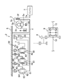
- FIG. 1 shows a vehicle C (in this embodiment, an automobile) equipped with a control device (a control unit 100 described later) according to an exemplary embodiment.
- the vehicle C includes an engine 1 as a drive source and an automatic transmission 2 to which torque generated by the engine 1 is input.
- the engine 1 and the automatic transmission 2 are mounted in an engine room located in the front part of the vehicle C.
- An output shaft 1a of the engine 1 is connected to an input shaft 4 of the automatic transmission 2 via a torque converter 3 (see FIG. 2).
- the output shaft 1a of the engine 1 and the input shaft 4 of the automatic transmission 2 extend in the vehicle width direction.
- the drive source is not limited to the engine 1 and may be an electric motor or the like.
- the automatic transmission 2 has a speed change mechanism 30 to which power (torque) from the torque converter 3 is input via the input shaft 4.
- the transmission mechanism 30 is housed in the transmission case 5 together with the torque converter 3.
- a mechanical oil pump 6 driven by the engine 1 via the torque converter 3 is disposed.
- the oil pump 6 includes the automatic transmission 2 (particularly, hydraulic chambers of a first clutch 18, a second clutch 20, a first brake 70, a second brake 80, and a third brake 90 described later in the transmission mechanism 30) and the torque converter 3. It is provided as an oil supply source for supplying necessary oil.
- an output gear 7 for taking out power from the speed change mechanism 30 (automatic transmission 2) is arranged coaxially with the input shaft 4.
- the power (torque) from the output gear 7 of the speed change mechanism 30 is transmitted to the differential device 9 via the counter drive mechanism 8, and the transmitted power (torque) is transmitted via the left and right drive shafts 10.
- the left and right front wheels 11a (see FIG. 1) are respectively driven.
- the front wheels 11a are drive wheels that are driven by the torque output from the automatic transmission 2. Therefore, in the present embodiment, the vehicle C is an FF vehicle.
- Each of the wheels 11 (front wheel 11a and rear wheel 11b) of the vehicle C is provided with a hydraulic brake device 15 that applies a braking force to each wheel 11 by hydraulic pressure (hydraulic pressure in this embodiment).
- hydraulic brake devices 15 operate by being supplied with hydraulic pressure by the operation of a brake hydraulic pressure control valve 121 (see FIG. 5) to brake each wheel 11.
- a brake hydraulic pressure control valve 121 see FIG. 5
- the electric pump 123 in addition to the operation of the brake oil pressure control valve 121, the electric pump 123 (see FIG. 5) is also operated, so that the oil pressure of the same level as when the brake pedal is depressed is set to each wheel 11. To be able to supply.
- the torque converter 3 includes a case 3a connected to the output shaft 1a of the engine 1, a pump 3b fixed in the case 3a, and opposed to the pump 3b, and is driven by the pump 3b via hydraulic oil.
- Turbine 3c a stator 3e interposed between the pump 3b and the turbine 3c, and supported by the transmission case 5 via the one-way clutch 3d to increase torque, and the case 3a and the turbine 3c.
- the lockup clutch 3f is provided between the output shaft 1a of the engine 1 and the turbine 3c via the case 3a. The rotation of the turbine 3 c is transmitted to the speed change mechanism 30 via the input shaft 4.
- the speed change mechanism 30 includes a first clutch 18, a second clutch 20, a first brake 70, a second brake 80, and a third brake 90 as friction engagement elements.
- a frictional engagement element When it is not necessary to distinguish these, it is called a frictional engagement element.
- Each frictional engagement element is fastened or released by supplying and discharging oil to the hydraulic chamber of each frictional engagement element.
- the first clutch 18 and the second clutch 20 are arranged side by side in the radial direction of the input shaft 4 on the torque converter 3 side of the output gear 7, and on the anti-torque converter 3 side of the output gear 7.
- the first brake 70, the second brake 80, and the third brake 90 are arranged in this order from the torque converter 3 side.
- a one-way clutch 71 is disposed in parallel with the first brake 70.
- the speed change mechanism 30 also has first, second and third planetary gear sets 40, 50 and 60.
- the first, second, and third planetary gear sets 40, 50, 60 are arranged in this order from the torque converter 3 side on the anti-torque converter 3 side of the output gear 7 in the transmission case 5.
- the first, second, and third planetary gear sets 40, 50, 60 are all single-pinion type planetary gear sets, and are respectively engaged with the sun gears 41, 51, 61 and the sun gears 41, 51, 61, respectively.
- 42, 52, 62 (provided in plural in each planetary gear set), carriers 43, 53, 63 that respectively support the pinions 42, 52, 62, and ring gears 44, 54 meshed with the pinions 42, 52, 62, respectively. , 64.
- the input shaft 4 is connected to the sun gear 61 of the third planetary gear set 60. Also, the sun gear 41 of the first planetary gear set 40 and the sun gear 51 of the second planetary gear set 50 are connected, the ring gear 44 of the first planetary gear set 40 and the carrier 53 of the second planetary gear set 50 are connected, and the second planetary gear set. 50 ring gears 54 and the carrier 63 of the third planetary gear set 60 are connected.
- the output gear 7 is connected to the carrier 43 of the first planetary gear set 40.
- the first clutch 18 connects and disconnects between the input shaft 4 and the sun gear 41 of the first planetary gear set 40 and the sun gear 51 of the second planetary gear set 50
- the second clutch 20 connects the input shaft 4 and the first planetary gear set 40.
- the ring gear 44 and the carrier 53 of the second planetary gear set 50 are connected or disconnected.
- the one-way clutch 71 is disposed in parallel with the first brake 70 between the ring gear 44 of the first planetary gear set 40 and the carrier 53 of the second planetary gear set 50 and the transmission case 5. Even if the first brake 70 is not engaged, if the first clutch 18 is engaged, the one-speed clutch 71 is locked and the first speed can be realized. However, in the present embodiment, the first brake 70 is fastened together with the first clutch 18 at the first speed (see the table in FIG. 3).
- the automatic transmission 2 achieves six forward speeds and one reverse speed by combining the engagement states of the friction engagement elements. Engagement and release of each frictional engagement element (supply and discharge of oil to and from the hydraulic chamber) are controlled by operation of an AT hydraulic control valve 122 (see FIG. 5) provided in a hydraulic control circuit including the oil pump 6. Has been.
- FIG. 3 is a table showing the relationship between the engagement combinations of the frictional engagement elements of the automatic transmission 2 and the gear positions. A circle indicates that it has been fastened, and a blank indicates that the fastening has been released (released). This table also shows the state during execution of neutral control, which will be described later.
- the left and right rear wheels 11b of the vehicle C are each provided with an electric parking brake device 16 that applies a braking force to each rear wheel 11b by driving an electric motor 124 (see FIG. 5) as an electric actuator.
- Each electric parking brake device 16 is assembled to the hydraulic brake device 15 of each rear wheel 11b.
- the hydraulic brake device 15 of each rear wheel 11b has a well-known configuration and includes two brake pads 115 respectively disposed on both sides of the disk plate 12 of the rear wheel 11b as shown in FIG. .
- One brake pad 115 (right brake pad 115 in FIG. 4) is supported by the first support plate 116a, and the other brake pad 115 (left brake pad 115 in FIG. 4) is supported by the second support plate 116b.
- the bottom portion 117a of the bottomed cylindrical brake piston 117 is located facing the first support plate 116a.
- the brake piston 117 is fitted into the open side portion of the bottomed cylindrical cylinder member 118.
- the cylinder member 118 is connected to the second support plate 116b through the caliper 119.
- oil hydroaulic pressure
- the brake oil pressure control valve 121 oil (hydraulic pressure) is supplied from the brake oil pressure control valve 121 to the space between the bottom portion 118a in the cylinder member 118 and the brake piston 117, and the brake piston 117 moves the first support plate 116a by this oil supply.
- the brake pad 115 supported by the first support plate 116 a is pressed against the disc plate 12.
- the bottom 118a of the cylinder member 118 is pressed to the side opposite to the brake piston 117, whereby the second support plate 116b moves to the disk plate 12 side, and the second support plate 116b.
- the brake pad 115 supported by the disc plate 12 is pressed against the disc plate 12.
- the rear wheel 11b is braked.
- the hydraulic brake device 15 for the front wheel 11a has the same configuration as the hydraulic brake device 15 for the rear wheel 11b. However, since the electric parking brake device 16 is not assembled to the hydraulic brake device 15 of the front wheel 11a, the shapes of the brake piston 117 and the cylinder member 118 are different in relation to this.
- Each electric parking brake device 16 has a motor unit 125 including the electric motor 124.
- the motor unit 125 includes a speed reduction mechanism (not shown) that decelerates rotation of the electric motor 124 and an output shaft 126 that is an output of the speed reduction mechanism.
- the output shaft 126 rotates around the central axis of the output shaft 126.
- the motor unit 125 is fixedly attached to the outer surface of the bottom 118 a of the cylinder member 118.
- the output shaft 126 penetrates the bottom 118 a of the cylinder member 118 and enters the cylinder member 118.
- a portion of the output shaft 126 located inside the cylinder member 118 is a hollow shaft portion 126a extending coaxially with the cylinder member 118, and a spindle 127 is inserted into the hollow shaft portion 126a.
- the inner peripheral surface of the hollow shaft portion 126a and the outer peripheral surface of the spindle 127 constitute a feed screw mechanism 130.
- the rotation of the hollow shaft portion 126a (output shaft 126) is the axis of the spindle 127. Converted to linear movement in direction.
- the spindle 127 enters the brake piston 117 from the open end of the brake piston 117 and extends coaxially with the output shaft 126 and the brake piston 117 to the vicinity of the bottom 117a of the brake piston 117.
- a pressing member 128 is fixed to the tip of the spindle 127. The pressing member 128 moves in the axial direction of the brake piston 117 with respect to the brake piston 117 when the spindle 127 moves linearly.
- the feed screw mechanism 130 causes the spindle 127 to linearly move toward the bottom 117a side of the brake piston 117.
- the pressing member 128 presses the bottom portion 117a of the brake piston 117 toward the first support plate 116a.
- the brake piston 117 presses the first support plate 116 a toward the disc plate 12, and the brake pad 115 supported by the first support plate 116 a becomes the disc plate 12. Pressed.
- the output shaft 126 is pressed to the side opposite to the pressing member 128 by receiving a reaction force from the spindle 127.
- the bottom 118 a of the cylinder member 118 is pressed to the side opposite to the brake piston 117.
- the second support plate 116 b moves to the disc plate 2 side, and the brake pad 115 supported by the second support plate 116 b is pressed against the disc plate 12.
- the electric motor 124 stops when a preset first set time elapses from the start of the normal rotation.
- the first set time is set to a time from when the electric motor 124 starts to rotate forward until the brake pad 115 is pressed against the disc plate 12 with an appropriate force regardless of the amount of wear of the brake pad 115.
- the output shaft 126 of the motor unit 125 cannot be rotated from the spindle 127 side via the feed screw mechanism 130.
- the electric parking brake device 16 thus applies the braking force to the rear wheel 11b and maintains the braking state of the rear wheel 11b.
- the electric motor 124 When the braking of the rear wheel 11b by the electric parking brake device 16 is released, the electric motor 124 is driven to rotate in the reverse direction. As a result, the spindle 127 and the pressing member 128 move to the side opposite to that during the braking operation described above, and the pressing of the brake piston 117 by the pressing member 128 is released, and the bottom 118a of the cylinder member 118 by the output shaft 126 is released. Is released, and braking of the rear wheel 11b is released.
- the electric motor 124 stops when a preset second set time elapses from the start of the reverse rotation. This second set time is set to a time during which the braking of the rear wheel 11b can be reliably released from the start of reverse rotation of the electric motor 124 regardless of the amount of wear of the brake pad 115.
- the vehicle C is provided with a control unit 100 that controls the operation of the brake hydraulic control valve 121, the AT hydraulic control valve 122, the electric pump 123, and the electric motor 124.
- the control unit 100 is a controller based on a well-known microcomputer, and includes a central processing unit (CPU) that executes a program, a memory that is configured by, for example, RAM and ROM, and stores a program and data, And an input / output (I / O) bus for inputting and outputting signals.
- CPU central processing unit
- I / O input / output
- the control unit 100 includes a signal from the vehicle speed sensor 101 that detects the vehicle speed of the vehicle C, a signal from the accelerator opening sensor 102 that detects the amount of depression of the accelerator pedal of the vehicle C (accelerator opening), A signal from the brake sensor 103 that detects the depression amount of the brake pedal, a signal from the range position sensor 104 that detects the range position of the shift lever of the vehicle C, and the gradient of the travel path on which the vehicle C is traveling are detected.
- the driver of the vehicle C selects whether the signal from the gradient sensor 105, the signal from the AT oil temperature sensor 106 that detects the temperature of the oil flowing through the hydraulic control circuit, and whether or not execution of brake hold control described later is permitted.
- the gradient (%) of the travel path by the gradient sensor 105 is a negative value on a downhill and a positive value on an uphill.
- the control unit 100 controls the operation of the brake hydraulic control valve 121, the AT hydraulic control valve 122, the electric pump 123, and the electric motor 124 based on the input signal.
- control unit 100 In the control unit 100, a shift control unit 100a, a neutral control unit 100b, a brake hold control unit 100c, a switching control unit 100d, and an electric parking brake that controls the operation of the electric parking brake device 16 (electric motor 124).
- a control unit 100e is provided.
- the shift control unit 100a When the range position of the shift lever by the range position sensor 104 is the D range position, the shift control unit 100a is in a running state of the vehicle C (specifically, a signal from the vehicle speed sensor 101 and an accelerator opening degree sensor 102). Signal) is determined using a shift map stored in advance in the memory of the control unit 100, and the AT hydraulic control valve 122 is controlled so that the shift stage of the automatic transmission 2 becomes the determined shift stage. To do. Further, when the range position of the shift lever by the range position sensor 104 is the R range position, the AT hydraulic control valve 122 is controlled so that the gear position of the automatic transmission 2 becomes the reverse speed. Further, when the range position of the shift lever by the range position sensor 104 is the N range position, the AT hydraulic control valve 122 is controlled so that all the friction engagement elements are in the released state.
- the neutral control unit 100b determines that the vehicle is in a state where a predetermined neutral control condition including a condition regarding the range position of the shift lever is satisfied.
- the neutral of the frictional engagement element (in this embodiment, the first clutch 18) that is engaged at the start of C is made lower than the fully engaged state (that is, the plurality of friction plates in the first clutch 18 slip). Execute control.
- the frictional engagement element that is engaged when the vehicle C is started may be in a completely released state. However, from the viewpoint of smoothly starting the vehicle C, it is preferable to slip a plurality of friction plates of the frictional engagement elements that are fastened when the vehicle C starts.
- the predetermined neutral control condition is that the range position of the shift lever by the range position sensor 104 is the D range position, and the absolute value of the gradient of the travel path by the gradient sensor 105 is a predetermined gradient (for example, 5 %) And the temperature of the oil by the AT oil temperature sensor 106 is equal to or higher than a predetermined temperature (the lowest temperature in the warm state of the automatic transmission 2 (for example, 40 ° C.)).
- the condition relating to the range position of the shift lever is a condition that the range position of the shift lever is the D range position, but instead, the range position of the shift lever is the travel range position. It may be a condition that any one of the range positions.
- the travel range position includes a forward travel range position (D range position) and a reverse travel range position (R range position).
- D range position forward travel range position
- R range position reverse travel range position
- other range positions for example, an M range position that allows manual switching of the gear position of the automatic transmission 2 by the operation of the driver of the vehicle C
- the other range positions may be included in the forward travel range position.
- the frictional engagement element that is engaged when the vehicle C is started is a friction engagement element that is engaged when the vehicle is started backward (in this embodiment, the first brake). 70 and / or third brake 90).
- the neutral control unit 100b performs the neutral control when the driver of the vehicle C requests to start the vehicle C during execution of the neutral control (in this embodiment, when the accelerator pedal is depressed by the driver). The execution is stopped (the first clutch 18 is completely engaged).
- the brake hold control unit 100c is configured to detect the liquid in all the wheels 11 of the vehicle C even when the brake pedal is not depressed by the driver of the vehicle C when a predetermined brake hold control condition is satisfied.
- Brake hold control for applying a braking force to all the wheels 11 by the pressure brake device 15 is executed. Note that the wheels that apply the braking force when the brake hold control is executed may be only the driving wheels (the front wheels 11a in the present embodiment).
- the predetermined brake hold control condition is that the brake hold selection switch 108 is ON (the driver of the vehicle C permits execution of the brake hold control) and the driver stops the vehicle C.
- the condition is that the depression of the brake pedal is released (more specifically, the depression amount of the brake pedal has become a predetermined amount or less).
- the brake hold selection switch 108 is ON, the driver releases the brake pedal while the vehicle C is stopped, and the range position of the shift lever is the travel range. It may be a condition that the vehicle C is in a position (that is, a range position where the vehicle C may move due to creep torque of the automatic transmission 2).
- the brake hold control unit 100c executes the brake hold control when there is a start request of the vehicle C by the driver of the vehicle C during execution of the brake hold control (when the accelerator pedal is depressed by the driver). Stop (release braking of all wheels 19).
- the switch control unit 100d When the brake hold control unit 100c executes the brake hold control, the switch control unit 100d performs the brake hold control when a predetermined switch condition is satisfied in a state where there is no start request of the vehicle C by the driver of the vehicle C. Switching from the application of the braking force to all the wheels 11 by execution to the application of the braking force to the rear wheel 11b by the electric parking brake device 16 is performed.
- the predetermined switching condition is that the first predetermined time t1 has elapsed from the start of execution of the brake hold control, and even before the first predetermined time t1 has elapsed, the door opening switch 109 It is a condition that one of the detection of the opening of the door corresponding to the driver's seat is established.
- the predetermined switching condition may be a condition that the first predetermined time t1 elapses from the start of execution of the brake hold control.
- the first predetermined time t1 exceeds the first predetermined time t1, and when the brake hold control is executed, the braking state of the wheel 11 (and thus extended by the decrease in the hydraulic pressure supplied to the hydraulic brake device 15). This is a time during which it is impossible to reliably hold the vehicle C (stopped state) and the brake hydraulic control valve 121 generates a large amount of heat.
- the first predetermined time t1 is set, for example, from several minutes to several tens of minutes.
- the switching control unit 100d performs the switching.
- the neutral control unit 100b When the neutral control is being executed when the predetermined switching condition is satisfied during execution of the brake hold control by the brake hold control unit 100c, the neutral control unit 100b performs the vehicle C by the driver of the vehicle C. Even when there is no start request, the execution of the neutral control is stopped upon the switching by the switching control unit 100d.
- the electric parking brake control unit 100e receives the command from the switching control unit 100d and brakes the rear wheel 11b by the electric parking brake device 16, and the vehicle C by the driver after the switching.
- the start request is issued, the braking of the rear wheel 11b by the electric parking brake device 16 is released.
- the neutral control execution is already stopped, so there is no need to stop the neutral control execution. It is only necessary to release the braking of the rear wheel 11b.
- the switching by the switching control unit 100d is performed so that the braking of all the wheels 11 by the execution of the brake hold control and the braking of the rear wheels 11b by the electric parking brake device 16 overlap.
- the switching control unit 100d causes the electric parking brake control unit 100e to operate the electric motor 124 when the predetermined switching condition is satisfied during execution of the brake hold control by the brake hold control unit 100c.
- the brake hold control unit 100c stops the execution of the brake hold control.
- the second predetermined time t2 is set to the same time as the first set time. That is, the second predetermined time t2 is from the start of the operation of the electric motor 124 until the application of the braking force that can maintain the stop state of the vehicle C to the rear wheel 11b by the electric motor 124 is completed. Time (for example, 500 ms to 1 s).
- the neutral control unit 100b performs the brake hold control when the neutral control is being executed when the predetermined switching condition is satisfied while the brake hold control is being executed by the brake hold control unit 100c.
- the execution of the neutral control is stopped so that the first clutch 18 is completely engaged before the execution is stopped.
- the neutral control unit 100b stops executing the neutral control substantially simultaneously with the start of the operation of the electric motor 124. Thereby, substantially simultaneously with the start of the operation of the electric motor 124, the hydraulic pressure to the first clutch 18 begins to increase, and the first clutch 18 is completely engaged before the execution of the brake hold control is stopped.
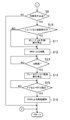
- control operation by the control unit 100 will be described based on the flowcharts of FIGS.
- step S1 input signals from various sensors and switches are read, and in the next step S2, it is determined whether or not the vehicle is stopped (the vehicle speed detected by the vehicle speed sensor 101 is 0). .
- step S2 determines whether or not the predetermined brake hold control condition is satisfied.
- step S3 determines whether the brake hold control or not. If the determination in step S3 is NO, the process proceeds to step S5. On the other hand, when the determination in step S3 is YES, the process proceeds to step S4, and the brake hold control unit 100c executes the brake hold control, and thereafter, step S5. Proceed to
- step S5 it is determined whether or not the predetermined neutral condition is satisfied.
- the process proceeds to step S7.
- the process proceeds to step S6, and the neutral control unit 100c executes neutral control, and then proceeds to step S7. .
- step S7 it is determined whether or not the accelerator pedal is depressed by the driver of the vehicle C.
- step S7 the determination in step S7 is YES
- the process proceeds to step S8, and execution of the control being executed is stopped. That is, when the brake hold control unit 100c is executing the brake hold control, the brake hold control unit 100c stops the execution, and when the neutral control unit 100c is executing the neutral control, the neutral control is performed. The unit 100c stops its execution. After step S8, the process returns.
- step S7 determines whether or not the predetermined switching condition is satisfied during execution of the brake hold control by the brake hold control unit 100c.
- step S9 determines whether the neutral control is being executed.
- step S10 determines whether the neutral control unit 100b is executing the neutral control. If the determination in step S10 is NO, the process proceeds to step S12. On the other hand, when the determination in step S10 is YES, the process proceeds to step S11, and the neutral control unit 100b stops executing the neutral control. Proceed to step S12.
- step S12 the switching control unit 100d outputs a command to the electric parking brake control unit 100e to cause the rear wheel 11b to be braked by the electric parking brake device 16 (EPB).
- the electric motor 124 stops when the first set time elapses from the start of operation.
- step S13 it is determined whether or not the second predetermined time t2 has elapsed from the start of operation of the electric motor 124. If the determination in step S13 is NO, the operation in step S13 is repeated. If the determination in step S13 is YES, the process proceeds to step S14, and the switching control unit 100d stops executing the brake hold control.
- step S15 it is determined whether or not the accelerator pedal is depressed by the driver.
- the determination in step S15 is NO, the operation of step S15 is repeated.
- the determination in step S15 is YES, the process proceeds to step S16, and the electric parking brake control unit 100e causes the electric parking brake device 16 ( The braking of the rear wheel 11b by EPB) is released.
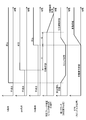
- the predetermined neutral control condition (described as N condition in FIG. 8), the predetermined brake hold control condition (described as BH condition in FIG. 8), and the predetermined switching condition (illustrated in FIG. 8).
- the operation of the hydraulic brake device 15, the first clutch 18, and the electric parking brake device 16 (EPB) when the SW condition is described in FIG. 8 will be described with reference to FIG.
- the brake hold selection switch 108 is in the ON state.
- the predetermined brake hold control condition is satisfied.
- the braking state of all the wheels 11 by the hydraulic brake device 15 is maintained by executing the brake hold control by the brake hold control unit 100c.
- the switching control unit 100d applies all of the wheels 11 by the execution of the brake hold control by the brake hold control unit 100c.
- the application of the braking force is switched to the application of the braking force to the rear wheel 11b by the electric parking brake device 16.
- the electric motor 124 of the electric parking brake device 16 is operated, and the spindle 127 moves to the bottom 117a side of the brake piston 117.
- the electric motor 124 stops.
- the rear wheel 11b is braked by both the hydraulic brake device 15 and the electric parking brake device 16.
- the neutral control performed by the neutral controller 100b is stopped. Specifically, the execution of the neutral control is stopped substantially simultaneously with the start of the operation of the electric motor 124. Thereby, substantially simultaneously with the start of the operation of the electric motor 124, the hydraulic pressure to the first clutch 18 begins to increase, and the first clutch 18 is completely engaged before the execution of the brake hold control is stopped.
- the neutral control unit 100b stops the execution of the neutral control when the switching control unit 100d performs the switching. Therefore, when the driver requests the vehicle C to start after the switching (acceleration by the driver) When the pedal is depressed), the first clutch 18 is already fully engaged. Thus, when the driver requests the vehicle C to start after the switching, it is only necessary to release the braking of the rear wheel 11b by the electric parking brake device 16.
- the operation of releasing the braking of the rear wheel 11b by the electric parking brake device 16 and the operation of bringing the first clutch 18 into a fully engaged state are as follows.
- the startability of the vehicle C is deteriorated depending on which completion timing of the both operations is earlier or later and / or a deviation time of the completion timing of the both operations.
- the vehicle C can be started by performing only the brake releasing operation of the rear wheel 11b by the electric parking brake device 16, the vehicle C can be started by overlapping the above two operations. Deterioration of startability can be suppressed. Therefore, it is possible to prevent the driver of the vehicle C from feeling uncomfortable when the vehicle C starts when the driver requests the vehicle C to start after the switching by the switching control unit 100d.
- the execution of the brake hold control is stopped after the first clutch 18 is in the fully engaged state, so that the front side of the vehicle C can be prevented from rising as much as possible. That is, when a large torque from the automatic transmission 2 acts on the front wheel 11a due to the first clutch 18 being completely engaged, the coil spring of the suspension of the front wheel 11a tends to extend due to the torque. The front side of the vehicle C receives a force that rises from the spring, and this force causes the coil spring of the suspension of the rear wheel 11b to shrink, and the front side of the vehicle C rises further. In this way, when the torque acts on the front wheel 11a, if the braking force is not applied to the front wheel 11a, the front side of the vehicle C rises significantly.
- the electric parking brake device 16 is provided on each of the left and right rear wheels 11b.
- the electric parking brake device 16 is provided on each of the wheels 11 to apply a braking force to all the wheels 11. May be.
- the electric parking brake device 16 may be provided on each of the left and right front wheels 11a to apply a braking force to the front wheels 11a, and may be provided on one front wheel 11a or one rear wheel 11b to provide the front wheel 11a or the rear wheel 11b. It is also possible to apply a braking force to.
- the vehicle C is an FF vehicle.
- the vehicle C may be an FR vehicle.
- the wheel to which the braking force is applied when the brake hold control by the brake hold control unit 100c is performed is Only the wheel 11b or all the wheels 11 may be used.
- the present invention is useful for a vehicle control apparatus in which neutral control and brake hold control are executed.
Landscapes
- Engineering & Computer Science (AREA)
- Transportation (AREA)
- Mechanical Engineering (AREA)
- Chemical & Material Sciences (AREA)
- Combustion & Propulsion (AREA)
- Automation & Control Theory (AREA)
- Regulating Braking Force (AREA)
- Control Of Transmission Device (AREA)
- Control Of Driving Devices And Active Controlling Of Vehicle (AREA)
Abstract
Description
1 エンジン(駆動源)
2 自動変速機
11 車輪
11a 前輪(駆動輪)
11b 後輪
15 液圧ブレーキ装置
16 電動パーキングブレーキ装置
18 第1クラッチ(車両の前進発進時に締結される摩擦締結要素)
100 コントロールユニット(制御装置)
100b ニュートラル制御部
100c ブレーキホールド制御部
100d 切換制御部
124 電動モータ(電動アクチュエータ)
2
100 Control unit (control device)
100b Neutral control unit 100c Brake
Claims (4)
- 車両の制御装置であって、
上記車両は、
駆動源と、
上記駆動源にて生成されたトルクが入力される自動変速機であって上記車両の発進時に締結される摩擦締結要素を有する自動変速機と、
上記自動変速機から出力されたトルクにより駆動される駆動輪を含む、上記車両の全ての車輪のそれぞれに設けられ、液圧により該各車輪に制動力を付与する液圧ブレーキ装置と、
上記全ての車輪のうちの少なくとも一部の車輪に設けられ、電動アクチュエータの駆動により該少なくとも一部の車輪に制動力を付与する電動パーキングブレーキ装置と、
を有し、
上記車両の停車時において、該車両のシフトレバーのレンジ位置に関する条件を含む所定のニュートラル制御条件が成立したときに、上記摩擦締結要素の締結度合いを完全締結状態よりも低くした状態にするか又は完全解放状態にするニュートラル制御を実行するニュートラル制御部と、
上記車両の停車時において、所定のブレーキホールド制御条件が成立したときに、上記車両のドライバーによりブレーキペダルが踏み込まれていなくても、少なくとも上記駆動輪における上記液圧ブレーキ装置により少なくとも該駆動輪に制動力を付与するブレーキホールド制御を実行するブレーキホールド制御部と、
上記ブレーキホールド制御部による上記ブレーキホールド制御の実行中に所定の切換条件が成立したときに、該ブレーキホールド制御の実行による少なくとも上記駆動輪への制動力の付与から、上記電動パーキングブレーキ装置による上記少なくとも一部の車輪への制動力の付与に切り換える切換制御部とを備え、
上記ニュートラル制御部は、上記ブレーキホールド制御部による上記ブレーキホールド制御の実行中に上記所定の切換条件が成立したときにおいて、上記ニュートラル制御を実行中である場合には、上記切換制御部による上記切り換えに際して、上記ニュートラル制御の実行を停止するよう構成されていることを特徴とする車両の制御装置。 A control device for a vehicle,
The above vehicle
A driving source;
An automatic transmission to which torque generated by the drive source is input and having a frictional engagement element that is engaged when the vehicle starts, and
A hydraulic brake device that is provided on each of all wheels of the vehicle, including drive wheels driven by torque output from the automatic transmission, and that applies a braking force to the wheels by hydraulic pressure;
An electric parking brake device that is provided on at least some of the wheels, and applies braking force to the at least some wheels by driving an electric actuator;
Have
When a predetermined neutral control condition including a condition relating to a range position of the shift lever of the vehicle is satisfied when the vehicle is stopped, the engagement degree of the friction engagement element is made lower than a complete engagement state, or A neutral control unit that executes neutral control to be completely released; and
Even when the brake pedal is not depressed by the driver of the vehicle when a predetermined brake hold control condition is satisfied when the vehicle is stopped, at least the drive wheel is driven by the hydraulic brake device in the drive wheel. A brake hold control unit for executing brake hold control for applying braking force;
When a predetermined switching condition is satisfied during execution of the brake hold control by the brake hold control unit, from the application of braking force to at least the drive wheels by execution of the brake hold control, the electric parking brake device performs the above A switching control unit that switches to applying braking force to at least some of the wheels,
When the neutral control is being executed when the predetermined switching condition is satisfied during execution of the brake hold control by the brake hold control unit, the neutral control unit performs the switching by the switch control unit. In this case, the vehicle control device is configured to stop the execution of the neutral control. - 請求項1記載の車両の制御装置において、
上記切換制御部は、上記ブレーキホールド制御部による上記ブレーキホールド制御の実行中に上記所定の切換条件が成立したときには、上記電動アクチュエータの作動を開始させるとともに、該電動アクチュエータの作動の開始から所定時間が経過したときに、上記ブレーキホールド制御部に対して上記ブレーキホールド制御の実行を停止させるように構成され、
上記ニュートラル制御部は、上記ブレーキホールド制御部による上記ブレーキホールド制御の実行中に上記所定の切換条件が成立したときにおいて、上記ニュートラル制御を実行中である場合には、上記ブレーキホールド制御の実行の停止前に上記摩擦締結要素が完全締結状態になるように、上記ニュートラル制御の実行を停止するよう構成されていることを特徴とする車両の制御装置。 The vehicle control device according to claim 1,
When the predetermined switching condition is satisfied during execution of the brake hold control by the brake hold control unit, the switching control unit starts the operation of the electric actuator and also starts a predetermined time from the start of the operation of the electric actuator. Is configured to stop the execution of the brake hold control with respect to the brake hold control unit,
The neutral control unit executes the brake hold control when the neutral control is being executed when the predetermined switching condition is satisfied during execution of the brake hold control by the brake hold control unit. A control apparatus for a vehicle, characterized in that execution of the neutral control is stopped so that the frictional engagement element is in a completely engaged state before stopping. - 請求項2記載の車両の制御装置において、
上記ブレーキホールド制御部は、上記車両の全ての車輪における上記液圧ブレーキ装置により上記車両の停車状態を保持するよう構成され、
上記電動パーキングブレーキ装置は、上記車両の一部の車輪に設けられていて、該一部の車輪に制動力を付与するよう構成されていることを特徴とする車両の制御装置。 The vehicle control device according to claim 2,
The brake hold control unit is configured to hold the stopped state of the vehicle by the hydraulic brake device in all the wheels of the vehicle,
The electric parking brake device is provided on some of the wheels of the vehicle, and is configured to apply a braking force to the some of the wheels. - 請求項3記載の車両の制御装置において、
上記駆動輪は、前輪であり、
上記電動パーキングブレーキ装置は、上記車両の左右の後輪に設けられていて、該左右の後輪に制動力を付与するよう構成されていることを特徴とする車両の制御装置。 The vehicle control device according to claim 3,
The driving wheel is a front wheel,
The electric parking brake device is provided on left and right rear wheels of the vehicle, and is configured to apply a braking force to the left and right rear wheels.
Priority Applications (5)
| Application Number | Priority Date | Filing Date | Title |
|---|---|---|---|
| PCT/JP2016/003559 WO2018025290A1 (en) | 2016-08-02 | 2016-08-02 | Vehicle control device |
| EP16911552.4A EP3418147B1 (en) | 2016-08-02 | 2016-08-02 | Vehicle control device |
| CN201680083725.9A CN108883763B (en) | 2016-08-02 | 2016-08-02 | Vehicle control device |
| JP2018530986A JP6593540B2 (en) | 2016-08-02 | 2016-08-02 | Vehicle control device |
| US16/085,624 US10576982B2 (en) | 2016-08-02 | 2016-08-02 | Vehicle control device |
Applications Claiming Priority (1)
| Application Number | Priority Date | Filing Date | Title |
|---|---|---|---|
| PCT/JP2016/003559 WO2018025290A1 (en) | 2016-08-02 | 2016-08-02 | Vehicle control device |
Publications (1)
| Publication Number | Publication Date |
|---|---|
| WO2018025290A1 true WO2018025290A1 (en) | 2018-02-08 |
Family
ID=61072812
Family Applications (1)
| Application Number | Title | Priority Date | Filing Date |
|---|---|---|---|
| PCT/JP2016/003559 WO2018025290A1 (en) | 2016-08-02 | 2016-08-02 | Vehicle control device |
Country Status (5)
| Country | Link |
|---|---|
| US (1) | US10576982B2 (en) |
| EP (1) | EP3418147B1 (en) |
| JP (1) | JP6593540B2 (en) |
| CN (1) | CN108883763B (en) |
| WO (1) | WO2018025290A1 (en) |
Families Citing this family (2)
| Publication number | Priority date | Publication date | Assignee | Title |
|---|---|---|---|---|
| US11384832B1 (en) | 2021-04-02 | 2022-07-12 | Honda Motor Co., Ltd. | System and method for neutral transmission hold |
| JP2023119758A (en) * | 2022-02-17 | 2023-08-29 | スズキ株式会社 | Control device of vehicle |
Citations (5)
| Publication number | Priority date | Publication date | Assignee | Title |
|---|---|---|---|---|
| JPH09221010A (en) * | 1996-02-16 | 1997-08-26 | Topy Ind Ltd | Brake controller |
| JP2000205393A (en) * | 1999-01-13 | 2000-07-25 | Suzuki Motor Corp | Neutral controller |
| JP2005280640A (en) * | 2004-03-31 | 2005-10-13 | Toyota Motor Corp | Vehicular brake system |
| JP2008120151A (en) * | 2006-11-09 | 2008-05-29 | Nissan Motor Co Ltd | Control device for vehicle |
| JP2009008242A (en) * | 2007-06-29 | 2009-01-15 | Aisin Aw Co Ltd | Control device for automatic transmission and control method for automatic transmission |
Family Cites Families (9)
| Publication number | Priority date | Publication date | Assignee | Title |
|---|---|---|---|---|
| JP4360231B2 (en) | 2004-02-26 | 2009-11-11 | トヨタ自動車株式会社 | Brake device |
| US9878693B2 (en) * | 2004-10-05 | 2018-01-30 | Vision Works Ip Corporation | Absolute acceleration sensor for use within moving vehicles |
| JP4656068B2 (en) | 2006-03-24 | 2011-03-23 | アイシン・エィ・ダブリュ株式会社 | Vehicle parking control system |
| JP2008126933A (en) | 2006-11-24 | 2008-06-05 | Toyota Motor Corp | Control device for vehicle |
| JP4179379B2 (en) * | 2007-01-04 | 2008-11-12 | トヨタ自動車株式会社 | VEHICLE, ITS CONTROL METHOD, AND COMPUTER-READABLE RECORDING MEDIUM RECORDING PROGRAM FOR CAUSING COMPUTER TO EXECUTE VEHICLE CONTROL METHOD |
| JP6227333B2 (en) | 2013-08-30 | 2017-11-08 | 日立オートモティブシステムズ株式会社 | Brake system |
| JP6011518B2 (en) | 2013-11-21 | 2016-10-19 | トヨタ自動車株式会社 | Vehicle control apparatus and control method |
| US9517770B2 (en) * | 2014-07-24 | 2016-12-13 | Ford Global Technologies, Llc | Brake control for stop/start vehicle |
| US10300895B2 (en) * | 2014-12-27 | 2019-05-28 | Hitachi Automotive Systems, Ltd. | Brake device |
-
2016
- 2016-08-02 WO PCT/JP2016/003559 patent/WO2018025290A1/en active Application Filing
- 2016-08-02 EP EP16911552.4A patent/EP3418147B1/en active Active
- 2016-08-02 JP JP2018530986A patent/JP6593540B2/en active Active
- 2016-08-02 US US16/085,624 patent/US10576982B2/en not_active Expired - Fee Related
- 2016-08-02 CN CN201680083725.9A patent/CN108883763B/en active Active
Patent Citations (5)
| Publication number | Priority date | Publication date | Assignee | Title |
|---|---|---|---|---|
| JPH09221010A (en) * | 1996-02-16 | 1997-08-26 | Topy Ind Ltd | Brake controller |
| JP2000205393A (en) * | 1999-01-13 | 2000-07-25 | Suzuki Motor Corp | Neutral controller |
| JP2005280640A (en) * | 2004-03-31 | 2005-10-13 | Toyota Motor Corp | Vehicular brake system |
| JP2008120151A (en) * | 2006-11-09 | 2008-05-29 | Nissan Motor Co Ltd | Control device for vehicle |
| JP2009008242A (en) * | 2007-06-29 | 2009-01-15 | Aisin Aw Co Ltd | Control device for automatic transmission and control method for automatic transmission |
Also Published As
| Publication number | Publication date |
|---|---|
| JP6593540B2 (en) | 2019-10-23 |
| US20190084569A1 (en) | 2019-03-21 |
| JPWO2018025290A1 (en) | 2019-02-14 |
| EP3418147B1 (en) | 2020-07-08 |
| EP3418147A4 (en) | 2019-05-22 |
| US10576982B2 (en) | 2020-03-03 |
| CN108883763B (en) | 2021-07-20 |
| CN108883763A (en) | 2018-11-23 |
| EP3418147A1 (en) | 2018-12-26 |
Similar Documents
| Publication | Publication Date | Title |
|---|---|---|
| WO2013161153A1 (en) | Automatic transmission control method, control device, and automatic transmission system | |
| US7789799B2 (en) | Parking control system for vehicle | |
| US20110316322A1 (en) | Brake device for in-wheel motor | |
| KR102556617B1 (en) | Electronic control brake system in a vehicle and control method thereof | |
| WO2009119243A1 (en) | Control device for automatic transmission | |
| JP6593540B2 (en) | Vehicle control device | |
| JP2009292315A (en) | Driving device of vehicle | |
| JP6285298B2 (en) | Automatic transmission | |
| KR101714244B1 (en) | Method for controlling vehicle to implement avh function | |
| JP2018108747A (en) | Brake device of vehicle | |
| JP5418098B2 (en) | Vehicle drive control device | |
| JP6119684B2 (en) | Control device for automatic transmission | |
| JP6186943B2 (en) | Vehicle drive device | |
| JP6575540B2 (en) | Electric parking brake control device | |
| US10632980B2 (en) | Method for releasing a first brake device which is actuated by electric motor, control unit for a brake system of a vehicle, brake system for a vehicle, and vehicle having a brake system of this type | |
| JP2020199814A (en) | Brake control device for vehicle | |
| JP2015196473A (en) | Vehicular power transmission mechanism control apparatus | |
| JP2019031130A (en) | Vehicle braking apparatus and vehicle braking method | |
| JP7202897B2 (en) | vehicle controller | |
| JP7154709B2 (en) | vehicle controller | |
| JP5953944B2 (en) | Industrial vehicle control device | |
| JP2005344787A (en) | Vehicular starting friction element control device | |
| WO2014050803A1 (en) | Automatic transmission and control method therefor | |
| JP6332316B2 (en) | Vehicle control device | |
| JP6332317B2 (en) | Vehicle control device |
Legal Events
| Date | Code | Title | Description |
|---|---|---|---|
| WWE | Wipo information: entry into national phase |
Ref document number: 2018530986 Country of ref document: JP |
|
| WWE | Wipo information: entry into national phase |
Ref document number: 2016911552 Country of ref document: EP |
|
| ENP | Entry into the national phase |
Ref document number: 2016911552 Country of ref document: EP Effective date: 20180920 |
|
| 121 | Ep: the epo has been informed by wipo that ep was designated in this application |
Ref document number: 16911552 Country of ref document: EP Kind code of ref document: A1 |
|
| NENP | Non-entry into the national phase |
Ref country code: DE |