WO2018020774A1 - 画像読取装置の製造方法 - Google Patents
画像読取装置の製造方法 Download PDFInfo
- Publication number
- WO2018020774A1 WO2018020774A1 PCT/JP2017/017571 JP2017017571W WO2018020774A1 WO 2018020774 A1 WO2018020774 A1 WO 2018020774A1 JP 2017017571 W JP2017017571 W JP 2017017571W WO 2018020774 A1 WO2018020774 A1 WO 2018020774A1
- Authority
- WO
- WIPO (PCT)
- Prior art keywords
- contact glass
- main surface
- image reading
- contact
- manufacturing
- Prior art date
Links
Images


Classifications
-
- H—ELECTRICITY
- H04—ELECTRIC COMMUNICATION TECHNIQUE
- H04N—PICTORIAL COMMUNICATION, e.g. TELEVISION
- H04N1/00—Scanning, transmission or reproduction of documents or the like, e.g. facsimile transmission; Details thereof
- H04N1/00519—Constructional details not otherwise provided for, e.g. housings, covers
- H04N1/00557—Connection or assembly of components or elements
-
- B—PERFORMING OPERATIONS; TRANSPORTING
- B29—WORKING OF PLASTICS; WORKING OF SUBSTANCES IN A PLASTIC STATE IN GENERAL
- B29C—SHAPING OR JOINING OF PLASTICS; SHAPING OF MATERIAL IN A PLASTIC STATE, NOT OTHERWISE PROVIDED FOR; AFTER-TREATMENT OF THE SHAPED PRODUCTS, e.g. REPAIRING
- B29C65/00—Joining or sealing of preformed parts, e.g. welding of plastics materials; Apparatus therefor
- B29C65/48—Joining or sealing of preformed parts, e.g. welding of plastics materials; Apparatus therefor using adhesives, i.e. using supplementary joining material; solvent bonding
-
- B—PERFORMING OPERATIONS; TRANSPORTING
- B29—WORKING OF PLASTICS; WORKING OF SUBSTANCES IN A PLASTIC STATE IN GENERAL
- B29C—SHAPING OR JOINING OF PLASTICS; SHAPING OF MATERIAL IN A PLASTIC STATE, NOT OTHERWISE PROVIDED FOR; AFTER-TREATMENT OF THE SHAPED PRODUCTS, e.g. REPAIRING
- B29C66/00—General aspects of processes or apparatus for joining preformed parts
- B29C66/70—General aspects of processes or apparatus for joining preformed parts characterised by the composition, physical properties or the structure of the material of the parts to be joined; Joining with non-plastics material
- B29C66/74—Joining plastics material to non-plastics material
- B29C66/746—Joining plastics material to non-plastics material to inorganic materials not provided for in groups B29C66/742 - B29C66/744
- B29C66/7465—Glass
-
- B—PERFORMING OPERATIONS; TRANSPORTING
- B29—WORKING OF PLASTICS; WORKING OF SUBSTANCES IN A PLASTIC STATE IN GENERAL
- B29C—SHAPING OR JOINING OF PLASTICS; SHAPING OF MATERIAL IN A PLASTIC STATE, NOT OTHERWISE PROVIDED FOR; AFTER-TREATMENT OF THE SHAPED PRODUCTS, e.g. REPAIRING
- B29C71/00—After-treatment of articles without altering their shape; Apparatus therefor
- B29C71/009—After-treatment of articles without altering their shape; Apparatus therefor using gases without chemical reaction
-
- C—CHEMISTRY; METALLURGY
- C03—GLASS; MINERAL OR SLAG WOOL
- C03B—MANUFACTURE, SHAPING, OR SUPPLEMENTARY PROCESSES
- C03B18/00—Shaping glass in contact with the surface of a liquid
- C03B18/02—Forming sheets
-
- C—CHEMISTRY; METALLURGY
- C03—GLASS; MINERAL OR SLAG WOOL
- C03C—CHEMICAL COMPOSITION OF GLASSES, GLAZES OR VITREOUS ENAMELS; SURFACE TREATMENT OF GLASS; SURFACE TREATMENT OF FIBRES OR FILAMENTS MADE FROM GLASS, MINERALS OR SLAGS; JOINING GLASS TO GLASS OR OTHER MATERIALS
- C03C17/00—Surface treatment of glass, not in the form of fibres or filaments, by coating
- C03C17/001—General methods for coating; Devices therefor
- C03C17/002—General methods for coating; Devices therefor for flat glass, e.g. float glass
-
- C—CHEMISTRY; METALLURGY
- C03—GLASS; MINERAL OR SLAG WOOL
- C03C—CHEMICAL COMPOSITION OF GLASSES, GLAZES OR VITREOUS ENAMELS; SURFACE TREATMENT OF GLASS; SURFACE TREATMENT OF FIBRES OR FILAMENTS MADE FROM GLASS, MINERALS OR SLAGS; JOINING GLASS TO GLASS OR OTHER MATERIALS
- C03C17/00—Surface treatment of glass, not in the form of fibres or filaments, by coating
- C03C17/28—Surface treatment of glass, not in the form of fibres or filaments, by coating with organic material
-
- C—CHEMISTRY; METALLURGY
- C03—GLASS; MINERAL OR SLAG WOOL
- C03C—CHEMICAL COMPOSITION OF GLASSES, GLAZES OR VITREOUS ENAMELS; SURFACE TREATMENT OF GLASS; SURFACE TREATMENT OF FIBRES OR FILAMENTS MADE FROM GLASS, MINERALS OR SLAGS; JOINING GLASS TO GLASS OR OTHER MATERIALS
- C03C23/00—Other surface treatment of glass not in the form of fibres or filaments
- C03C23/0005—Other surface treatment of glass not in the form of fibres or filaments by irradiation
- C03C23/006—Other surface treatment of glass not in the form of fibres or filaments by irradiation by plasma or corona discharge
-
- G—PHYSICS
- G03—PHOTOGRAPHY; CINEMATOGRAPHY; ANALOGOUS TECHNIQUES USING WAVES OTHER THAN OPTICAL WAVES; ELECTROGRAPHY; HOLOGRAPHY
- G03B—APPARATUS OR ARRANGEMENTS FOR TAKING PHOTOGRAPHS OR FOR PROJECTING OR VIEWING THEM; APPARATUS OR ARRANGEMENTS EMPLOYING ANALOGOUS TECHNIQUES USING WAVES OTHER THAN OPTICAL WAVES; ACCESSORIES THEREFOR
- G03B27/00—Photographic printing apparatus
- G03B27/32—Projection printing apparatus, e.g. enlarger, copying camera
- G03B27/52—Details
- G03B27/62—Holders for the original
-
- G—PHYSICS
- G03—PHOTOGRAPHY; CINEMATOGRAPHY; ANALOGOUS TECHNIQUES USING WAVES OTHER THAN OPTICAL WAVES; ELECTROGRAPHY; HOLOGRAPHY
- G03G—ELECTROGRAPHY; ELECTROPHOTOGRAPHY; MAGNETOGRAPHY
- G03G15/00—Apparatus for electrographic processes using a charge pattern
- G03G15/04—Apparatus for electrographic processes using a charge pattern for exposing, i.e. imagewise exposure by optically projecting the original image on a photoconductive recording material
- G03G15/0409—Details of projection optics
-
- H—ELECTRICITY
- H04—ELECTRIC COMMUNICATION TECHNIQUE
- H04N—PICTORIAL COMMUNICATION, e.g. TELEVISION
- H04N1/00—Scanning, transmission or reproduction of documents or the like, e.g. facsimile transmission; Details thereof
- H04N1/00519—Constructional details not otherwise provided for, e.g. housings, covers
- H04N1/00559—Mounting or support of components or elements
-
- H—ELECTRICITY
- H04—ELECTRIC COMMUNICATION TECHNIQUE
- H04N—PICTORIAL COMMUNICATION, e.g. TELEVISION
- H04N1/00—Scanning, transmission or reproduction of documents or the like, e.g. facsimile transmission; Details thereof
- H04N1/00567—Handling of original or reproduction media, e.g. cutting, separating, stacking
- H04N1/0057—Conveying sheets before or after scanning
- H04N1/00599—Using specific components
- H04N1/00615—Guiding elements, e.g. plates
-
- H—ELECTRICITY
- H04—ELECTRIC COMMUNICATION TECHNIQUE
- H04N—PICTORIAL COMMUNICATION, e.g. TELEVISION
- H04N1/00—Scanning, transmission or reproduction of documents or the like, e.g. facsimile transmission; Details thereof
- H04N1/024—Details of scanning heads ; Means for illuminating the original
- H04N1/028—Details of scanning heads ; Means for illuminating the original for picture information pick-up
-
- H—ELECTRICITY
- H04—ELECTRIC COMMUNICATION TECHNIQUE
- H04N—PICTORIAL COMMUNICATION, e.g. TELEVISION
- H04N1/00—Scanning, transmission or reproduction of documents or the like, e.g. facsimile transmission; Details thereof
- H04N1/04—Scanning arrangements, i.e. arrangements for the displacement of active reading or reproducing elements relative to the original or reproducing medium, or vice versa
- H04N1/12—Scanning arrangements, i.e. arrangements for the displacement of active reading or reproducing elements relative to the original or reproducing medium, or vice versa using the sheet-feed movement or the medium-advance or the drum-rotation movement as the slow scanning component, e.g. arrangements for the main-scanning
- H04N1/121—Feeding arrangements
- H04N1/1235—Feeding a sheet past a transparent plate; Details thereof
- H04N1/1245—Arrangements for mounting or holding the plate
-
- B—PERFORMING OPERATIONS; TRANSPORTING
- B29—WORKING OF PLASTICS; WORKING OF SUBSTANCES IN A PLASTIC STATE IN GENERAL
- B29K—INDEXING SCHEME ASSOCIATED WITH SUBCLASSES B29B, B29C OR B29D, RELATING TO MOULDING MATERIALS OR TO MATERIALS FOR MOULDS, REINFORCEMENTS, FILLERS OR PREFORMED PARTS, e.g. INSERTS
- B29K2623/00—Use of polyalkenes or derivatives thereof for preformed parts, e.g. for inserts
- B29K2623/04—Polymers of ethylene
- B29K2623/06—PE, i.e. polyethylene
-
- B—PERFORMING OPERATIONS; TRANSPORTING
- B29—WORKING OF PLASTICS; WORKING OF SUBSTANCES IN A PLASTIC STATE IN GENERAL
- B29K—INDEXING SCHEME ASSOCIATED WITH SUBCLASSES B29B, B29C OR B29D, RELATING TO MOULDING MATERIALS OR TO MATERIALS FOR MOULDS, REINFORCEMENTS, FILLERS OR PREFORMED PARTS, e.g. INSERTS
- B29K2627/00—Use of polyvinylhalogenides or derivatives thereof for preformed parts, e.g. for inserts
- B29K2627/06—PVC, i.e. polyvinylchloride
-
- B—PERFORMING OPERATIONS; TRANSPORTING
- B29—WORKING OF PLASTICS; WORKING OF SUBSTANCES IN A PLASTIC STATE IN GENERAL
- B29K—INDEXING SCHEME ASSOCIATED WITH SUBCLASSES B29B, B29C OR B29D, RELATING TO MOULDING MATERIALS OR TO MATERIALS FOR MOULDS, REINFORCEMENTS, FILLERS OR PREFORMED PARTS, e.g. INSERTS
- B29K2709/00—Use of inorganic materials not provided for in groups B29K2703/00 - B29K2707/00, for preformed parts, e.g. for inserts
- B29K2709/08—Glass
-
- C—CHEMISTRY; METALLURGY
- C03—GLASS; MINERAL OR SLAG WOOL
- C03C—CHEMICAL COMPOSITION OF GLASSES, GLAZES OR VITREOUS ENAMELS; SURFACE TREATMENT OF GLASS; SURFACE TREATMENT OF FIBRES OR FILAMENTS MADE FROM GLASS, MINERALS OR SLAGS; JOINING GLASS TO GLASS OR OTHER MATERIALS
- C03C2217/00—Coatings on glass
- C03C2217/70—Properties of coatings
- C03C2217/76—Hydrophobic and oleophobic coatings
-
- C—CHEMISTRY; METALLURGY
- C03—GLASS; MINERAL OR SLAG WOOL
- C03C—CHEMICAL COMPOSITION OF GLASSES, GLAZES OR VITREOUS ENAMELS; SURFACE TREATMENT OF GLASS; SURFACE TREATMENT OF FIBRES OR FILAMENTS MADE FROM GLASS, MINERALS OR SLAGS; JOINING GLASS TO GLASS OR OTHER MATERIALS
- C03C2218/00—Methods for coating glass
- C03C2218/10—Deposition methods
- C03C2218/11—Deposition methods from solutions or suspensions
- C03C2218/112—Deposition methods from solutions or suspensions by spraying
-
- C—CHEMISTRY; METALLURGY
- C03—GLASS; MINERAL OR SLAG WOOL
- C03C—CHEMICAL COMPOSITION OF GLASSES, GLAZES OR VITREOUS ENAMELS; SURFACE TREATMENT OF GLASS; SURFACE TREATMENT OF FIBRES OR FILAMENTS MADE FROM GLASS, MINERALS OR SLAGS; JOINING GLASS TO GLASS OR OTHER MATERIALS
- C03C2218/00—Methods for coating glass
- C03C2218/30—Aspects of methods for coating glass not covered above
- C03C2218/32—After-treatment
-
- H—ELECTRICITY
- H04—ELECTRIC COMMUNICATION TECHNIQUE
- H04N—PICTORIAL COMMUNICATION, e.g. TELEVISION
- H04N1/00—Scanning, transmission or reproduction of documents or the like, e.g. facsimile transmission; Details thereof
- H04N1/00519—Constructional details not otherwise provided for, e.g. housings, covers
- H04N1/00551—Top covers or the like
-
- H—ELECTRICITY
- H04—ELECTRIC COMMUNICATION TECHNIQUE
- H04N—PICTORIAL COMMUNICATION, e.g. TELEVISION
- H04N1/00—Scanning, transmission or reproduction of documents or the like, e.g. facsimile transmission; Details thereof
- H04N1/00909—Cleaning arrangements or preventing or counter-acting contamination from dust or the like
-
- H—ELECTRICITY
- H04—ELECTRIC COMMUNICATION TECHNIQUE
- H04N—PICTORIAL COMMUNICATION, e.g. TELEVISION
- H04N1/00—Scanning, transmission or reproduction of documents or the like, e.g. facsimile transmission; Details thereof
- H04N1/04—Scanning arrangements, i.e. arrangements for the displacement of active reading or reproducing elements relative to the original or reproducing medium, or vice versa
- H04N1/0464—Scanning arrangements, i.e. arrangements for the displacement of active reading or reproducing elements relative to the original or reproducing medium, or vice versa capable of performing non-simultaneous scanning at more than one scanning station
Definitions
- the present invention relates to a method for manufacturing an image reading apparatus, and more particularly to a method for manufacturing a contact glass of a sheet-through type image reading apparatus.
- a document to be read is conveyed toward the main surface of the contact glass, and the original is read by an image sensor fixed on the surface opposite to the main surface of the contact glass. Then, an image showing a document is acquired.
- the document is transported toward the main surface of the contact glass, and the document contacts the main surface of the contact glass. Therefore, the main surface of the contact glass is required to have high durability against friction with the document. .
- a liquid fluorine coating agent is applied to the main surface of the contact glass and the main surface of the contact glass is naturally dried. A coating film is formed.
- ⁇ Other members may be provided on the main surface of the contact glass by bonding.
- a conveyance guide member that guides a document conveyed toward the main surface of the contact glass to a reading range by an image sensor may be adhered to the main surface of the contact glass.
- the main surface of the contact glass is subjected to plasma treatment before fluorine coating or the contact glass is fired after fluorine coating. It is done.
- the masking tape that covers a part of the contact glass may be deformed or peeled off in the plasma treatment process or the firing process. In this case, the fluorine coating is applied to the masked range, and another member such as a conveyance guide member cannot be adhered to the main surface of the contact glass after the fluorine coating.
- the present invention has been made in view of the above circumstances, and has higher durability against friction between the main surface of the contact glass and the document than a general image reading apparatus, and a conveyance guide member is provided on the main surface of the contact glass. It is an object to enable manufacture of an image reading apparatus that is firmly bonded.
- An image reading apparatus manufacturing method includes an image sensor that conveys a document to be read toward a main surface of a contact glass and is fixed to a surface opposite to the main surface of the contact glass.
- a sheet-through type image reading apparatus that reads the document by using an image reading device on a main surface of the contact glass at a predetermined position outside the reading range by the image sensor, upstream of the reading range in the transport direction of the document.
- the durability of the contact glass main surface against friction with the document is higher than that of a general image reading device, and the conveyance guide member is firmly bonded to the main surface of the contact glass. Can be manufactured.
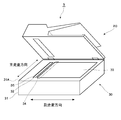
- FIG. 1 is a perspective view illustrating an image forming apparatus including an image reading apparatus that is a manufacturing target according to a manufacturing method according to an embodiment of the present invention. It is sectional drawing which shows the image reading apparatus which is a manufacturing object by the manufacturing method concerning one Embodiment of this invention. It is a perspective view which shows the image reading apparatus which is a manufacturing object by the manufacturing method concerning one Embodiment of this invention.
- FIG. 3 is an enlarged view showing a configuration around a conveyance guide member of the image reading apparatus shown in FIG. 2. It is the figure which showed the apparatus which manufactures the 1st contact glass of an image reading apparatus. It is the flowchart which showed the process of manufacturing the 1st contact glass of an image reading apparatus.
- FIGS. 1st contact glass are figures which show the 1st contact glass after a marking process.
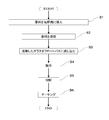
- FIG. 1 is a flowchart which shows the process of fixing the 1st contact glass and the 2nd contact glass in the housing
- (B) is detailed of the one part process shown to (A). It is a flowchart which shows a process. It is a top view which shows the housing
- the image forming apparatus 1 is generally configured by an apparatus main body 80 and an image reading apparatus 10 disposed above the apparatus main body 80.
- An image forming unit (not shown) and the like are accommodated inside the casing 81 that forms the outline of the apparatus main body 80.
- the image forming unit forms a toner image of a document read by the image reading device 10 through charging, exposure, and development processes, and discharges the recording paper onto which the toner image has been transferred onto a discharge tray 82.
- the image reading apparatus 10 includes a reading unit 30 and a document conveying unit 20 disposed above the reading unit 30.
- FIG. 2 is a cross-sectional view showing the image reading apparatus 10
- FIG. 3 is a perspective view showing the image reading apparatus 10.
- the document conveyance unit 20 of the image reading apparatus 10 includes a document table 21, a document discharge tray 22, a pickup roller 25, a conveyance roller 26, and a discharge roller 27.
- the document transport unit 20 feeds documents one by one from a bundle of documents placed on the document placing table 21 by a pickup roller 25, and feeds the document fed by the transport roller 26 to the main contact glass 32 described later. Transport toward the surface (first surface).
- the document conveyed to the first contact glass 32 is read by a scanner 34 described later at a predetermined document reading position, and then discharged to the document discharge tray 22 by a discharge roller 27.
- the reading unit 30 includes a box-shaped casing 31.
- An opening is provided in the upper surface 31A of the casing 31 (the surface facing the document conveying unit 20 when the document conveying unit 20 is closed), and the first contact glass 32 and the second contact glass are provided in the opening. 33 is attached.
- the first contact glass 32 is a contact glass for document conveyance reading, and a document is conveyed from the document conveyance unit 20.
- the second contact glass 33 is a contact glass for reading and fixing a document, on which a document is placed.
- the document conveying unit 20 provided above the second contact glass 33 is provided to be openable and closable with respect to the main surfaces of the first contact glass 32 and the second contact glass 33, and the document conveying unit 20. As a result, the document placed on the second contact glass 33 is fixed.
- a scanner 34 movable in the sub-scanning direction is provided on the lower surface (second surface) side opposite to the main surface of the first contact glass 32 and the second contact glass 33.
- the scanner 34 incorporates a CIS (Contact Image Sensor) type image sensor extended in the main scanning direction.
- the scanner 34 reciprocates in the sub-scanning direction to read the original placed on the second contact glass 33.
- the scanner 34 is fixed at a predetermined position (image reading position) on the back surface of the first contact glass 32 and is directed toward the main surface of the first contact glass 32 by the document conveyance unit 20. Scan the original that was conveyed. Image data obtained by reading the document is stored in an image memory or HDD built in the image reading apparatus 10.
- the reading unit 30 further includes a conveyance guide member 35 on the main surface of the first contact glass 32.
- FIG. 4 is an enlarged cross-sectional view showing a configuration around the transport guide member 35.
- the conveyance guide member 35 is a long sheet extending in the main operation direction, and the adhesive is disposed at a predetermined position on the main surface of the first contact glass 32. 36 is adhered.
- This predetermined position is a position near the position (image reading position) of the scanner 34 at the time of document conveyance reading, and is a position outside the reading range by the scanner 34 at the time of document conveyance reading.
- the leading end portion of the conveyance guide member 35 provided at the predetermined position enters the conveyance path of the document conveyed by the conveyance roller 26.
- the leading end portion of the conveyance guide member 35 contacts the document discharged from the opening 26 ⁇ / b> A on the upstream side in the document conveyance direction with respect to the reading range of the scanner 34.
- the document discharged from the opening 26 ⁇ / b> A is directed to the image reading position of the first contact glass 32 while being in contact with the leading end portion of the conveyance guide member 35.
- foreign matters such as dust attached to the document are removed by the leading end of the conveyance guide member 35.
- the conveyance guide member 35 plays a role of removing foreign matters attached to the document in addition to the role of guiding the document to the image reading position of the first contact glass 32.
- the conveyance guide member 35 is bonded to the upstream end of the document in the conveyance direction as the predetermined position on the main surface of the first contact glass 32. Yes. For this reason, the conveyance guide member 35 can guide the document more appropriately.
- a manufacturing method of the image reading apparatus 10 described above will be described. Note that a configuration other than the reading unit 30 of the image reading apparatus 10, for example, a method for manufacturing the document conveying unit 20, is not particularly different from a general manufacturing method, and thus description thereof is omitted.
- FIG. 5 is a view showing an apparatus for manufacturing the first contact glass 32.
- FIG. 6 is a flowchart showing a process for manufacturing the first contact glass 32.
- glass raw materials such as silica sand, sodium carbonate (soda ash), calcium carbonate, and dolomite are put into a melting tank (step S1), and the glass raw material is heated to 1600 ° C. or more to be melted to produce molten glass.
- Step S2 glass raw material is heated to 1600 ° C. or more to be melted to produce molten glass.
- step S3 the produced
- the molten glass poured into the float bath floats in a strip shape on the tin filled in the melting tank. By floating the molten glass on the molten tin, a glass having a uniform thickness and a smooth surface can be generated.
- a step of removing the internal air by reducing the temperature of the molten glass to 1100 ° C. to 1300 ° C. may be added between the melting step (step
- step S3 After the float process in step S3, the glass temperature is gradually lowered in the slow cooling line (step S4). By gradually lowering the temperature of the glass, it is possible to prevent distortion from occurring inside.
- the glass is cut into the size of the first contact glass 32 (step S5). And after cut
- FIGS. 7A to 7C are views showing the first contact glass 32 after the process of step S6.
- the main surface 32B facing upward on the paper surface is the second surface (non-tin surface) not in contact with tin
- the main surface 32A facing downward on the paper surface is the first surface (tin) Surface).
- one of the four corners of the first contact glass 32 is cut out at an angle of about 45 degrees. Is formed on the first contact glass 32 as the above-mentioned mark.
- any one of the four corners of the first contact glass 32 is cut out.
- a surface that is a tin surface or a non-tin surface cannot be specified only by the notched portion 321.
- the main surface 32A and the main surface 32B of the first contact glass 32 are rectangular in shape, the position where the notch 321 is formed is stored, and then the first visual inspection is performed.
- a surface that is a tin surface or a non-tin surface can be specified.
- the main surface that can be subjected to more effective processing is specified out of the two main surfaces of the first contact glass 32, Since the identified main surface can be processed, the durability of the first contact glass 32 can be improved.
- FIG. 8A is a flowchart illustrating a process of fixing the first contact glass 32 and the second contact glass 33 in the housing 31 of the reading unit 30.
- FIG. 8B is a flowchart showing detailed steps of the step S12 shown in FIG.
- first, the first contact glass 32 and the second contact glass 33 manufactured by the above-described method are prepared (S11). Then, the first contact glass 32 is processed (step S12), and then the processed first contact glass 32 and second contact glass 33 are placed in the housing 31 of the reading unit 30. (Step S13). Note that in order to complete the manufacture of the reading unit 30, a process of mounting the scanner 34 and other members in the housing 31 of the reading unit 30 and a wiring process are required. Since there is no particular difference from the method, explanation is omitted.
- a sheet-like member is bonded to a predetermined position on the main surface of the first contact glass 32 as the conveyance guide member 35 (step S21).
- a member having heat resistance and insulation is used as the sheet-shaped member.
- the heat resistance specifically refers to performance capable of withstanding heat of 150 degrees or more.
- Such a member corresponds to, for example, a member based on polyvinyl chloride or polyethylene.
- the main surface to which the sheet-like member is bonded is the non-tin surface of the two main surfaces of the first contact glass 32.
- the step S21 from the position of the notch 321 formed in the step S6, after specifying which of the two main surfaces of the first contact glass 32 is a non-tin surface, A sheet-like member is bonded to the specified non-tin surface.
- the sheet-like member is bonded to the non-tin surface instead of the tin surface in the process (step S22 and step S23) to be described later, and the sheet-like member is bonded to the non-tin surface. This is because it is necessary to perform a treatment process and a fluorine coating treatment process.
- the conveyance guide member 35 is a member that plays a role of guiding the document to the image reading position of the first contact glass 32 and removing foreign matters attached to the document, but only for these roles. If so, the conveyance guide member 35 may be simply a sheet-like member, and there is no need to employ a member having heat resistance and insulation as described above. In this embodiment, the sheet-like member having heat resistance and insulation is adopted as the conveyance guide member 35 for the following reason.
- the process is performed after the processing for the first contact glass 32 is performed.
- the first contact glass 32 is subjected to plasma treatment, fluorine coating treatment, and baking treatment. It is difficult to adhere another member to the contact glass 32.
- the conveyance guide member 35 is adhered to the first contact glass 32 before performing the plasma treatment, the fluorine coating treatment, and the firing treatment.
- the conveyance guide member 35 is adhered to the first contact glass 32 before performing the plasma treatment, the fluorine coating treatment, and the firing treatment, the conveyance guide is used in the plasma treatment, the fluorine coating treatment, and the firing treatment.
- the member 35 is deformed or peeled off.
- the main surface of the first contact glass 32 can be subjected to plasma treatment or fluorine coating except for a range where another member such as the conveyance guide member 35 is bonded, and the conveyance guide member 35 is removed after the plasma treatment or fluorine coating. It can be adhered to the main surface of the first contact glass 32.
- the masking tape is deformed or peeled off in the steps of plasma treatment, fluorine coating treatment, and baking treatment. Further, since the number of work steps is increased by the masking step, the manufacturing work efficiency of the image reading apparatus 10 is lowered.
- a sheet-like member having heat resistance and insulation is adopted as the conveyance guide member 35, and before the plasma processing step and the fluorine coating processing step.
- the transport guide member 35 is bonded to the main surface of the first contact glass 32 with a small number of work steps.
- the image reading apparatus 10 can be manufactured. Although details will be described later, since plasma treatment, fluorine coating treatment, and baking treatment are performed on the first contact glass 32, durability against friction between the first contact glass 32 and the document is generally provided. Higher than the image reading apparatus.
- step S21 plasma treatment is performed on the non-tin surface of the first contact glass 32 (step S22).
- which of the two main surfaces of the first contact glass 32 is a non-tin surface is specified from the position of the notch 321 formed in step S6.
- tin is thinly adhered to the tin surface. For this reason, as described above, the surface treatment effect by the plasma treatment can be enhanced by specifying the tin surface and the non-tin surface and performing the plasma treatment on the non-tin surface side.
- the first contact glass 32 is installed in the chamber, plasma is generated in the chamber, and the generated plasma is irradiated on the non-tin surface of the first contact glass 32. Since this plasma irradiation gives energy higher than the binding energy of atoms constituting the foreign matter such as C—C bond, C—H bond, and C—O bond, the foreign matter attached to the non-tin surface of the first contact glass 32 is removed. In addition, since molecules such as OH groups ionized by plasma irradiation are modified on the surface of the first contact glass 32, the wettability of water is improved.
- the conveyance guide member 35 bonded to the non-tin surface of the first contact glass 32 is made of an insulating member, it does not burn even when a voltage of several hundred volts is applied by plasma processing. .
- the non-tin surface of the first contact glass 32 is subjected to a fluorine coating process (step S23). Specifically, the liquid fluorine coating agent is sprayed toward the non-tin surface of the first contact glass 32 by spraying, and the fluorine coating agent sprayed on the non-tin surface of the first contact glass 32 is solidified. Let Thereby, a fluorine coating film is formed on the non-tin surface of the first contact glass 32. In the step S22, the non-tin surface foreign matter of the first contact glass 32 is removed and the wettability of water is improved, so that a fine fluorine coating film can be formed.
- a fluorine coating film is formed on the main surface of the contact glass by applying a liquid fluorine coating agent and naturally drying the main surface of the contact glass.
- a dense fluorine coating film can be formed by spraying the liquid fluorine coating agent by spraying as described above.
- step S23 which of the two main surfaces of the first contact glass 32 is a non-tin surface is specified from the position of the notch 321 formed in the step S6. Moreover, you may specify that the surface by which the conveyance guide member 35 was adhere
- the surface treatment effect by the fluorine coating treatment can be enhanced by specifying the tin surface and the non-tin surface and performing the fluorine coating treatment on the non-tin surface side.
- step S24 the side surfaces (the surfaces 32C, 32D, 32E, and 32F shown in FIG. 7B) of the first contact glass 32 are polished (step S24). Since another member may be adhered to the side surface of the first contact glass 32 or an adhesive may be applied in the assembly process of step S26 described later, the first contact is performed by performing the above process. The fluorine coating on the side surface of the glass 32 is removed. Note that it is not always necessary to polish all four side surfaces of the first contact glass 32, and it is not necessary to polish the side surfaces to which other members are not bonded. Moreover, you may perform the grinding
- the first contact glass 32 is baked in a thermostatic bath. Specifically, baking is performed at a temperature of 150 degrees for 30 minutes (step S25). Since the conveyance guide member 35 bonded to the non-tin surface of the first contact glass 32 is made of a heat-resistant member, the conveyance guide member 35 is not damaged or burnt in the firing step of step S25.
- step S12 After the step S12, the first contact glass 32 and the second contact glass 33 are mounted in the housing 31 of the reading unit 30 (step S13). At this time, the non-tin surface indicated by the mark formed on the first contact glass 32 is located on the side in contact with the conveyed document, and the tin surface is on the side where the image sensor 34 in the housing 31 is installed.
- the first contact glass 32 is fixed in the housing 31 so as to be positioned.
- FIG. 9 is a top view showing the housing 31 of the reading unit 30.
- a fitting hole 31B into which the first contact glass 32 is fitted and a fitting hole 31C into which the second contact glass 33 is fitted are formed on the upper surface 31A of the housing 31.
- the fitting hole 31B has a shape corresponding to the notch 321 formed in the first contact glass 32.
- plasma treatment and fluorine coating are performed.
- the first contact glass 32 is placed in a state where the treated non-tin side is located on the side in contact with the conveyed document, and the tin side is located on the side where the scanner 34 in the case 31 is installed. Fixed in the body 31.
- ⁇ Experiment 1> (1) Three types of fluorine coating agents A, B, and C having different friction coefficients, (2) presence / absence of plasma treatment, (3) fluorine coating method (spray spray or application) The surface processing of 1 contact glass 32 was performed. The result is shown in FIG. In FIG. 10, durability refers to the water contact angle when the first contact glass 32 is worn using steel wool under the conditions of load: 1 kg, contact area: 1 cm ⁇ 1 cm, speed: 60 cycles / min. It shows the number of times required to reach 100 degrees or less. Moreover, the water contact angle at the time of 1000 times has shown the water contact angle at the time of wearing 1000 times using steel wool.
- the dynamic friction coefficient is a value measured using paraffin paper under a load of 200 gf and a speed of 200 mm / min.
- a sheet-like member having heat resistance and insulation is adopted as the conveyance guide member 35, and this sheet-like member is used as the first contact glass before the plasma treatment process or the fluorine coating treatment process.
- step S24 For example, in the polishing step of step S24 described above, not all of the four side surfaces of the first contact glass 32 are polished, but a side surface at a predetermined position (for example, the surface shown in FIG. 7B). Only 32C) may be polished. In addition to the position where the notch 321 is formed, the position where the side surface of the first contact glass 32 is polished is memorized, so that the tin of the two main surfaces of the first contact glass 32 is visually observed thereafter. A surface that is a surface or a non-tin surface can be identified more reliably.
- the present invention is not necessarily limited to this case.
- a cut may be made at the end on the tin surface side as the mark.
Landscapes
- Engineering & Computer Science (AREA)
- Multimedia (AREA)
- Signal Processing (AREA)
- Chemical & Material Sciences (AREA)
- Physics & Mathematics (AREA)
- Chemical Kinetics & Catalysis (AREA)
- Materials Engineering (AREA)
- Organic Chemistry (AREA)
- General Chemical & Material Sciences (AREA)
- Geochemistry & Mineralogy (AREA)
- Life Sciences & Earth Sciences (AREA)
- Plasma & Fusion (AREA)
- Mechanical Engineering (AREA)
- General Physics & Mathematics (AREA)
- Optics & Photonics (AREA)
- Inorganic Chemistry (AREA)
- Health & Medical Sciences (AREA)
- Toxicology (AREA)
- Facsimile Scanning Arrangements (AREA)
- Holders For Sensitive Materials And Originals (AREA)
- Surface Treatment Of Glass (AREA)
- Facsimiles In General (AREA)
Abstract
画像読取装置の製造方法は、シートスルー方式の画像読取装置を製造する製造方法であって、コンタクトガラスを準備する第1工程と、耐熱性かつ絶縁性を有するシート状の部材を、搬送ガイド部材として、コンタクトガラスの主面の予め定められた位置に接着する第2工程と、第2工程後、コンタクトガラスの主面にプラズマ処理を施す第3工程と、第3工程後、コンタクトガラスの主面にフッ素コーティング処理を施す第4工程と、第4工程後、コンタクトガラスを焼成する第5工程と、第5工程後、コンタクトガラスを画像読取装置の筐体に固定する第6工程と、を含む。
Description
本発明は、画像読取装置の製造方法に関し、特に、シートスルー方式の画像読取装置のコンタクトガラスを製造する方法に関する。
シートスルー方式の画像読取装置では、読み取り対象の原稿をコンタクトガラスの主面に向けて搬送するとともに、当該コンタクトガラスの主面とは反対側の面に固定されたイメージセンサーにより原稿を読み取ることで、原稿を示す画像を取得する。原稿の読み取り毎に、コンタクトガラスの主面に向けて原稿が搬送され、原稿がコンタクトガラスの主面に接触するため、コンタクトガラスの主面には、原稿との摩擦に対する高い耐久性が求められる。原稿との摩擦に対する耐久性を高めるために、一般には、コンタクトガラスの主面に液状のフッ素コーティング剤を塗布し、コンタクトガラスの主面を自然乾燥させることで、コンタクトガラスの主面上にフッ素コーティング膜を形成させることが行われている。
コンタクトガラスの主面に、別の部材を接着などにより設ける場合がある。例えば、コンタクトガラスの主面に向けて搬送された原稿をイメージセンサーによる読取範囲へ案内する搬送ガイド部材を、コンタクトガラスの主面に接着する場合がある。しかしながら、フッ素コーティングされたコンタクトガラスの主面に搬送ガイド部材などの別部材を接着することは難しく、たとえ別部材を接着できたとしても剥がれ易い。
ここで、上記の特許文献1に開示されているマスキング技術を参考にして、別部材を接着する範囲をマスキングテープを用いて覆い、その後に、コンタクトガラスの主面をフッ素コーティングすることが考えられる。これにより、別部材を接着する範囲を除いてコンタクトガラスの主面をフッ素コーティングすることが可能となり、フッ素コーティング後に別部材をコンタクトガラスの主面に接着させることができる。
ところで、コンタクトガラスの主面の原稿との摩擦に対する耐久性を更に高めるため、フッ素コーティング前に、コンタクトガラスの主面にプラズマ処理を施すことや、フッ素コーティング後に、コンタクトガラスを焼成することが考えられる。しかしながら、上記のプラズマ処理の工程や焼成処理の工程において、コンタクトガラスの一部を覆うマスキングテープが変形したり剥がれたりする場合がある。この場合、マスキングされた範囲にまでフッ素コーティングが施されてしまい、フッ素コーティング後に搬送ガイド部材などの別部材をコンタクトガラスの主面に接着させることができない。
本発明は、上記の事情に鑑みなされたものであり、コンタクトガラスの主面の原稿との摩擦に対する耐久性が一般の画像読取装置よりも高く、かつ、コンタクトガラスの主面に搬送ガイド部材が強固に接着されている画像読取装置の製造を可能にすることを目的とする。
本発明の一局面にかかる画像読取装置の製造方法は、読み取り対象の原稿をコンタクトガラスの主面に向けて搬送するとともに、当該コンタクトガラスの主面とは反対側の面に固定されたイメージセンサーにより前記原稿を読み取るシートスルー方式の画像読取装置であって、前記コンタクトガラスの主面の前記イメージセンサーによる読取範囲外の予め定められた位置に、前記読取範囲よりも前記原稿の搬送方向上流側において前記原稿に当接することで、前記原稿を前記読取範囲へ案内する搬送ガイド部材を設けた画像読取装置を製造する製造方法であって、前記コンタクトガラスを準備する第1工程と、前記第1工程後、耐熱性かつ絶縁性を有するシート状の部材を、前記搬送ガイド部材として、前記コンタクトガラスの主面の前記予め定められた位置に接着する第2工程と、前記第2工程後、前記コンタクトガラスの主面にプラズマ処理を施す第3工程と、前記第3工程後、前記コンタクトガラスの主面にフッ素コーティング処理を施す第4工程と、前記第4工程後、前記コンタクトガラスを焼成する第5工程と、前記第5工程後、前記コンタクトガラスを前記画像読取装置の筐体に固定する第6工程と、を含む画像読取装置の製造方法である。
本発明によれば、コンタクトガラスの主面の原稿との摩擦に対する耐久性が一般の画像読取装置よりも高く、かつ、コンタクトガラスの主面に搬送ガイド部材が強固に接着されている画像読取装置の製造が可能となる。
以下、本発明の一実施形態にかかる画像読取装置の製造方法について図面を参照して説明する。
まず、本発明の一実施形態にかかる画像読取装置の製造方法による製造対象となる画像読取装置について説明する。図1に示すように、画像形成装置1は、装置本体80と、装置本体80の上方に配置された画像読取装置10とから概略構成される。
装置本体80の外郭を構成する筐体81の内部には、画像形成部(不図示)などが収容されている。画像形成部は、帯電、露光、現像の工程により、画像読取装置10が読み取った原稿のトナー画像を形成し、当該トナー像を転写した記録紙を排出トレイ82に排出する。
画像読取装置10は、読取部30と、読取部30の上方に配置された原稿搬送部20とを備えている。図2は、画像読取装置10を示す断面図であり、図3は、画像読取装置10を示す斜視図である。これらの図に示すように、画像読取装置10の原稿搬送部20は、原稿載置台21、原稿排出トレイ22、ピックアップローラー25、搬送ローラー26、および排紙ローラー27などを備えている。
原稿搬送部20は、ピックアップローラー25により原稿載置台21に載置された原稿束から一枚ずつ原稿を繰り出し、搬送ローラー26により当該繰り出された原稿を、後述する第1のコンタクトガラス32の主面(第1面)に向けて搬送する。第1のコンタクトガラス32に搬送された原稿は、予め定められた原稿読取位置で後述するスキャナー34により読み取られ、その後、排出ローラー27により原稿排出トレイ22へ排出される。
読取部30は、箱形の筐体31を備えている。筐体31の上面31A(原稿搬送部20が閉じられた状態で原稿搬送部20に対向する面)には開口が設けられており、当該開口に第1のコンタクトガラス32および第2のコンタクトガラス33が装着されている。第1のコンタクトガラス32は、原稿搬送読取用のコンタクトガラスであって、原稿搬送部20から原稿が搬送される。第2のコンタクトガラス33は、原稿固定読取用のコンタクトガラスであって、原稿が載置される。第2のコンタクトガラス33の上方に設けられた原稿搬送部20は、第1のコンタクトガラス32および第2のコンタクトガラス33の主面に対して開閉自在に設けられており、当該原稿搬送部20により第2のコンタクトガラス33に載置された原稿が固定される。
第1のコンタクトガラス32および第2のコンタクトガラス33の主面とは反対側の下面(第2面)側には、副走査方向に移動可能なスキャナー34が設けられている。スキャナー34は、主走査方向に延伸されたCIS(Contact Image Sensor)方式のイメージセンサーを内蔵している。
原稿固定読取では、スキャナー34が副走査方向に往復移動して、第2のコンタクトガラス33に載置された原稿を読み取る。一方、原稿搬送読取では、スキャナー34を第1のコンタクトガラス32の裏面における予め定められた位置(画像読取位置)に固定して、原稿搬送部20により第1のコンタクトガラス32の主面に向けて搬送された原稿を読み取る。当該原稿の読み取りにより得られた画像データは、画像読取装置10に内蔵された画像メモリーやHDDに記憶される。
読取部30は、更に、第1のコンタクトガラス32の主面上に、搬送ガイド部材35を備えている。図4は、搬送ガイド部材35の周辺の構成を示す拡大断面図である。図2~図4に示すように、搬送ガイド部材35は、主操作方向に延びた長尺状のシートであって、第1のコンタクトガラス32の主面上の予め定められた位置に接着剤36により接着されている。この予め定められた位置は、原稿搬送読取時におけるスキャナー34の位置(画像読取位置)に近傍する位置であって、原稿搬送読取時におけるスキャナー34による読取範囲外の位置である。この予め定められた位置に設けられた搬送ガイド部材35の先端部は、搬送ローラー26により搬送される原稿の搬送路に進入する。これにより、図4に示すように、搬送ガイド部材35の先端部が、開口26Aから排出された原稿と、スキャナー34の読取範囲よりも原稿の搬送方向上流側において接触する。開口26Aから排出された原稿は、搬送ガイド部材35の先端部に接触しながら、第1のコンタクトガラス32の画像読取位置に向かう。原稿が搬送ガイド部材35の先端部に接触するとき、原稿に付着した埃などの異物が搬送ガイド部材35の先端部により除去される。このように、搬送ガイド部材35は、原稿を第1のコンタクトガラス32の画像読取位置へ案内する役割に加えて、原稿に付着した異物を除去する役割も果たす。また、搬送ガイド部材35は、図2~図4に示すように、第1のコンタクトガラス32の主面において、上記予め定められた位置としての原稿の搬送方向上流側の端部に接着されている。このため、搬送ガイド部材35は、原稿をより適切に案内することができる。
続いて、上記で説明した画像読取装置10の製造方法について説明する。なお、画像読取装置10の読取部30以外の構成、例えば原稿搬送部20を製造する方法については、一般的な製造方法と特に変わりがないため説明を略する。
まず、第1のコンタクトガラス32を製造する方法について説明する。図5は、第1のコンタクトガラス32を製造する装置を示した図である。図6は、第1のコンタクトガラス32を製造する工程を示すフローチャートである。
まず、珪砂、炭酸ナトリウム(ソーダ灰)、炭酸カルシウム、ドロマイトなどのガラス原料を溶解槽に投入し(ステップS1)、ガラス原料を1600度以上にまで加熱することで溶解させ、溶解ガラスを生成する(ステップS2)。そして、生成した溶解ガラスを溶解金属(本実施形態ではスズ)を満たしたフロートバス(フロート浴槽)に流し込む(ステップS3)。フロートバスに流し込まれた溶解ガラスは、溶解槽に満たされたスズ上を帯状になって浮く。溶解したスズ上に溶解ガラスを浮かべることで、厚みが均一で、かつ表面が滑らかなガラスを生成することができる。なお、上記の溶解工程(ステップS2)とフロート工程(ステップS3)との間に、溶解ガラスの温度を1100度~1300度にまで下げ、内部の空気の抜く工程を加えてもよい。
ステップS3のフロート工程後、徐冷ラインにおいてガラスの温度を徐々に下げる(ステップS4)。ガラスの温度を徐々に下げることで、内部にひずみが生じることを防止することができる。
ステップS4の徐冷工程後、ガラスを第1のコンタクトガラス32のサイズに切断する(ステップS5)。そして、ガラスを切断した後、ステップS3のフロート工程において溶解したスズと接した第1のコンタクトガラス32の第1面(スズ面)と、第1面とは反対側の面であり、フロート工程において溶解したスズと接していない第1のコンタクトガラス32の第2面(非スズ面)とを示す印を第1のコンタクトガラス32に形成する(ステップS6)。
図7(A)~(C)は、ステップS6の処理後の第1のコンタクトガラス32を示す図である。図7(A)において、紙面上方に向いた主面32Bがスズと接していない第2面(非スズ面)であり、紙面下方に向いた主面32Aがスズと接した第1面(スズ面)である。本実施形態では、第1面側(図中のZ軸方向)から見て、第1のコンタクトガラス32の4隅のうち何れか1隅が約45度の角度で切り欠かれた切欠部321を、上記の印として第1のコンタクトガラス32に形成している。
ここで、仮に第1のコンタクトガラス32の主面32Aと主面32Bとが正方矩形状である場合では、上記のような第1のコンタクトガラス32の4隅のうち何れか1隅を切り欠いた切欠部321だけでは、第1のコンタクトガラス32の2つの主面のうち、スズ面または非スズ面である面を特定することができない。本実施形態では、第1のコンタクトガラス32の主面32Aと主面32Bとが長方矩形状であるため、切欠部321が形成された位置を記憶しておくことで、その後目視により第1のコンタクトガラス32の2つの主面のうちスズ面または非スズ面である面を特定することができる。詳細は後述するが、上記のような印を第1のコンタクトガラス32に形成することにより、後に行うこととなるシート状の部材を接着する工程、プラズマ処理工程、フッ素コーティング処理工程、および第1のコンタクトガラス32を読取部30の筐体31に固定する工程などにおいて、第1のコンタクトガラス32の2つの主面のうち、より効果的な処理を施すことができる主面を特定し、当該特定した主面に処理を施すことができるため、第1のコンタクトガラス32の耐久性などを向上させることができる。
なお、第2のコンタクトガラス33を製造する場合においては、上記のステップS1~ステップS6の工程のうち、ステップS6のマーキング工程を行わなくてもよい。
続いて、第1のコンタクトガラス32および第2のコンタクトガラス33を読取部30の筐体31内に固定する方法を説明する。図8(A)は、第1のコンタクトガラス32および第2のコンタクトガラス33を読取部30の筐体31内に固定する工程を示すフローチャートである。図8(B)は、図8(A)に示すステップS12の工程の詳細な工程を示すフローチャートである。これらの図に示すように、まず、既述の方法で製造した第1のコンタクトガラス32および第2のコンタクトガラス33を準備する(S11)。そして、第1のコンタクトガラス32に対して加工処理を施して(ステップS12)、その後に、加工処理後の第1のコンタクトガラス32および第2のコンタクトガラス33を読取部30の筐体31内に装着する(ステップS13)。なお、読取部30の製造を完成させるには、スキャナー34やその他の部材を読取部30の筐体31内に装着する工程や配線工程が必要となるが、これらの工程については一般的な製造方法と特に変わりがないため説明を略する。
ステップS12の第1のコンタクトガラス32に対する加工工程の詳細を説明する。当該工程では、まず、シート状の部材を、搬送ガイド部材35として第1のコンタクトガラス32の主面の予め定められた位置に接着する(ステップS21)。ステップS21では、耐熱性かつ絶縁性を有する部材を上記のシート状の部材として用いる。ここで耐熱性とは、具体的には、150度以上の熱に耐えうる性能をいう。このような部材には、例えば、ポリ塩化ビニルまたはポリエチレンを基材とした部材が該当する。
また、ステップS21の工程において、シート状の部材を接着する主面は、第1のコンタクトガラス32の2つの主面のうち非スズ面である。ステップS21の工程では、ステップS6の工程で形成された切欠部321の位置から、第1のコンタクトガラス32の2つの主面のうちどちらの面が非スズ面であるかを特定した上で、特定した非スズ面にシート状の部材を接着する。
スズ面ではなく非スズ面にシート状の部材を接着するのは、後述する工程(ステップS22およびステップS23)において、シート状の部材が接着された面であり、かつ、非スズ面に、プラズマ処理工程およびフッ素コーティング処理工程を施す必要があるからである。
ここで、搬送ガイド部材35は、原稿を第1のコンタクトガラス32の画像読取位置へ案内する役割、および原稿に付着した異物を除去する役割を果たす部材であるが、これらの役割を果たすためだけであれば、搬送ガイド部材35が単にシート状の部材であればよく、上記のように耐熱性かつ絶縁性を有する部材を採用する必要がない。本実施形態において、耐熱性かつ絶縁性を有するシート状の部材を搬送ガイド部材35として採用したのは、以下の理由による。
通常、第1のコンタクトガラス32に搬送ガイド部材35などの別の部材を接着する場合、その工程は第1のコンタクトガラス32に対する加工処理が行った後に行われる。しかしながら、本実施形態では、第1のコンタクトガラス32の耐久性などを向上させるために、プラズマ処理、フッ素コーティング処理、および焼成処理を第1のコンタクトガラス32に施しており、当該処理後に第1のコンタクトガラス32に別部材を接着させることが難しい。このため、本実施形態では、プラズマ処理、フッ素コーティング処理、および焼成処理を行う前に、搬送ガイド部材35を第1のコンタクトガラス32に接着させている。
しかしながら、プラズマ処理、フッ素コーティング処理、および焼成処理を行う前に、搬送ガイド部材35を第1のコンタクトガラス32に接着させた場合、プラズマ処理、フッ素コーティング処理、および焼成処理の工程において、搬送ガイド部材35が変形したり剥がれたりしてしまう。
また、搬送ガイド部材35を接着する範囲をマスキングテープを用いて覆い、その後に、第1のコンタクトガラス32の主面に対してプラズマ処理やフッ素コーティング処理をすることが考えられる。これにより、搬送ガイド部材35などの別部材を接着する範囲を除いて第1のコンタクトガラス32の主面をプラズマ処理やフッ素コーティングすることが可能となり、プラズマ処理やフッ素コーティング後に搬送ガイド部材35を第1のコンタクトガラス32の主面に接着させることができる。しかしながら、この場合、マスキングテープがプラズマ処理、フッ素コーティング処理、および焼成処理の工程において、変形したり剥がれたりしてしまう。また、マスキング工程だけ作業工程が増加するため、画像読取装置10の製造作業効率が低下してしまう。
この点、本発明の一実施形態にかかる製造方法によれば、搬送ガイド部材35として耐熱性かつ絶縁性を有するシート状の部材を採用し、かつ、プラズマ処理工程やフッ素コーティング処理工程の前に、当該シート状の部材を第1のコンタクトガラス32に搬送ガイド部材35として接着する工程を行うため、少ない作業工程で、第1のコンタクトガラス32の主面に搬送ガイド部材35が接着されている画像読取装置10を製造することができる。また、詳細は後述するが、第1のコンタクトガラス32に対して、プラズマ処理、フッ素コーティング処理、および焼成処理を行っているため、第1のコンタクトガラス32と原稿との摩擦に対する耐久性が一般の画像読取装置よりも高い。
ステップS21の工程後、第1のコンタクトガラス32の非スズ面に、プラズマ処理を施す(ステップS22)。この時、ステップS6の工程で形成された切欠部321の位置から、第1のコンタクトガラス32の2つの主面のうちどちらの面が非スズ面であるかを特定する。また、ステップS21の工程で搬送ガイド部材35が接着された側の面を非スズ面であると特定してもよい。
第1のコンタクトガラス32の2つの主面のうち、スズ面には薄くスズが付着している。このため、上記のように、スズ面と非スズ面とを特定し、非スズ面側にプラズマ処理を行うようにすることで、プラズマ処理による表面処理効果を高めることができる。
プラズマ処理では、チャンバー内に第1のコンタクトガラス32を設置し、チャンバー内でプラズマを発生させ、当該発生させたプラズマを第1のコンタクトガラス32の非スズ面に照射させる。このプラズマの照射により、C-C結合、C-H結合、C-O結合といった異物を構成する原子の結合エネルギー以上のエネルギーが与えられるため、第1のコンタクトガラス32の非スズ面に付着した異物が除去される。また、プラズマの照射により電離されたOH基などの分子が第1のコンタクトガラス32の表面に修飾されるため、水のぬれ性が向上する。
第1のコンタクトガラス32の非スズ面に接着された搬送ガイド部材35は、絶縁性を有する部材からなるため、プラズマ処理で数百Vの電圧が印加された場合であっても焦げることがない。
ステップS22の工程後、第1のコンタクトガラス32の非スズ面に、フッ素コーティング処理を施す(ステップS23)。具体的には、液状のフッ素コーティング剤をスプレーにより第1のコンタクトガラス32の非スズ面に向けて噴射して、第1のコンタクトガラス32の非スズ面上で噴射されたフッ素コーティング剤を固化させる。これにより、第1のコンタクトガラス32の非スズ面上にフッ素コーティング膜が形成させる。ステップS22の工程で、第1のコンタクトガラス32の非スズ面状の異物が除去されており、かつ水のぬれ性が向上しているため、精細なフッ素コーティング膜を形成することができる。
ここで、通常では、液状のフッ素コーティング剤を塗布し、コンタクトガラスの主面を自然乾燥させることで、コンタクトガラスの主面上にフッ素コーティング膜を形成させることが行われている。この通常行われている工程と比較して、上記のように液状のフッ素コーティング剤をスプレーにより噴射することで、より密なフッ素コーティング膜を形成させることができる。
また、ステップS23の工程では、ステップS6の工程で形成された切欠部321の位置から、第1のコンタクトガラス32の2つの主面のうちどちらの面が非スズ面であるかを特定する。また、ステップS21の工程で搬送ガイド部材35が接着された側の面を非スズ面であると特定してもよい。このように、スズ面と非スズ面とを特定し、非スズ面側にフッ素コーティング処理を行うようにすることで、フッ素コーティング処理による表面処理効果を高めることができる。
ステップS23の工程後、第1のコンタクトガラス32の側面(図7(B)に示された面32C、32D、32E、32F)を研磨する(ステップS24)。第1のコンタクトガラス32の側面に、別の部材を接着する場合や、後述するステップS26の工程の組み立て工程において接着剤を塗る場合があるため、上記の工程を行うことで、第1のコンタクトガラス32の側面のフッ素コーティングを除去している。なお、必ずしも第1のコンタクトガラス32の4つの側面の全てを研磨する必要はなく、別の部材を接着したりしない側面については研磨を行わなくてもよい。また、ステップS24の研磨工程を、後述するステップS25の焼成工程後に行ってもよい。
ステップS25の処理後、第1のコンタクトガラス32を恒温槽で焼成する。具体的には、150度の温度で30分間焼成する(ステップS25)。第1のコンタクトガラス32の非スズ面に接着された搬送ガイド部材35は、耐熱性を有する部材からなるため、ステップS25の焼成工程で破損したり焦げることがない。
以上が、ステップS12の第1のコンタクトガラス32に対する加工工程の詳細である。このステップS12の工程後、第1のコンタクトガラス32および第2のコンタクトガラス33を読取部30の筐体31内に装着する(ステップS13)。この際、第1のコンタクトガラス32に形成された印により示される非スズ面が搬送された原稿と接触する側に位置し、スズ面が筐体31内のイメージセンサー34が設置された側に位置するように、第1のコンタクトガラス32が筐体31内に固定する。
図9は、読取部30の筐体31を示す上面図である。本図に示すように、筐体31の上面31Aには、第1のコンタクトガラス32が嵌り込む嵌込穴31B、および第2のコンタクトガラス33が嵌り込む嵌込穴31Cが形成されている。嵌込穴31Bは、第1のコンタクトガラス32に形成された切欠部321に対応する形状になっており、第1のコンタクトガラス32を嵌込穴31Bに嵌め込むことで、プラズマ処理およびフッ素コーティング処理が施された非スズ面側が搬送された原稿と接触する側に位置し、スズ面側が筐体31内のスキャナー34が設置された側に位置した状態で、第1のコンタクトガラス32が筐体31内に固定される。
<実験>
出願人は、鋭意研究に基づき下記の実験を行い、その実験結果から上記の技術を想到するに至った。
出願人は、鋭意研究に基づき下記の実験を行い、その実験結果から上記の技術を想到するに至った。
<実験1>
(1)摩擦係数が異なるA、B、Cの3種類のフッ素コーティング剤、(2)プラズマ処理の有無、(3)フッ素コーティングの仕方(スプレー噴射または塗布)の3つの条件を変えて、第1のコンタクトガラス32の表面加工処理を行った。その結果を図10に示す。図10において、耐久性とは、スチールウールを用いて、加重:1kg、接触面積:1cm×1cm、スピード:60cycles/minの条件で第1のコンタクトガラス32を摩耗した場合に、水接触角が100度以下になるまでに要した回数を示している。また、1000回時水接触角とは、スチールウールを用いて1000回摩耗した場合の水接触角を示している。また、動摩擦係数とは、パラフィン紙を用い、荷重:200gf、スピード:200mm/minの条件で計測した値を示している。
(1)摩擦係数が異なるA、B、Cの3種類のフッ素コーティング剤、(2)プラズマ処理の有無、(3)フッ素コーティングの仕方(スプレー噴射または塗布)の3つの条件を変えて、第1のコンタクトガラス32の表面加工処理を行った。その結果を図10に示す。図10において、耐久性とは、スチールウールを用いて、加重:1kg、接触面積:1cm×1cm、スピード:60cycles/minの条件で第1のコンタクトガラス32を摩耗した場合に、水接触角が100度以下になるまでに要した回数を示している。また、1000回時水接触角とは、スチールウールを用いて1000回摩耗した場合の水接触角を示している。また、動摩擦係数とは、パラフィン紙を用い、荷重:200gf、スピード:200mm/minの条件で計測した値を示している。
図10に示されるサンプル番号3、4と5、6との結果を比較すると、フッ素コーティング処理の前にプラズマ処理を行うことで、第1のコンタクトガラス32の耐久性が大きく向上していることが分かる。また、サンプル番号1、2と9との結果を比較すると、スプレー噴射によりフッ素コーティングをした場合は、塗布によりフッ素コーティングをした場合と比較して、動摩擦係数が大幅に低くなっている。また、スプレー噴射によりフッ素コーティングをした場合は、塗布によりフッ素コーティングをした場合と比較して、水接触角が高くなっている。このため、原稿が第1のコンタクトガラス32へ搬送された際に、原稿に対して第1のコンタクトガラス32から不要な摩擦が加わらない。また、摩擦係数が最も低いフッ素コーティング剤を用いたサンプル番号7、8が、耐久性、動摩擦係数、および水接触角の各指標について最も良い結果が得られている。
以上の考察から、第1のコンタクトガラス32に対してプラズマ処理を行い、その後、スプレー塗布によりフッ素コーティングを行うことが最適であることが分かる。
<実験2>
ポリカーボネート、ポリエチレンテレフタレート、クレープ紙、ポリ塩化ビニル、およびポリエチレンの各部材を第1のコンタクトガラス32に接着した後、プラズマ処理、フッ素コーティング処理、および焼成処理の各工程を行った。その結果を図11に示す。
ポリカーボネート、ポリエチレンテレフタレート、クレープ紙、ポリ塩化ビニル、およびポリエチレンの各部材を第1のコンタクトガラス32に接着した後、プラズマ処理、フッ素コーティング処理、および焼成処理の各工程を行った。その結果を図11に示す。
ポリカーボネートおよびポリエチレンテレフタレートについては、焼成工程の熱により膨張または縮小し、位置ずれが発生した。また、クレープ紙については、プラズマ処理による焦げや破損が見られた。これは、クレープ紙が160度の耐熱性を有するものの、絶縁性でないためであると考えられる。ポリ塩化ビニルおよびポリエチレンについては、プラズマ処理、フッ素コーティング処理、および焼成処理の各工程を行った場合であっても、焦げや破損が見られなかった。これは、ポリ塩化ビニルは、150度の耐熱性を有しかつ絶縁性であり、またポリエチレンは、200度の耐熱性を有しかつ絶縁性であるためであると考えられる。
以上の考察から、搬送ガイド部材35として耐熱性かつ絶縁性を有するシート状の部材を採用し、かつ、プラズマ処理工程やフッ素コーティング処理工程の前に、このシート状の部材を第1のコンタクトガラス32に搬送ガイド部材35として接着する工程を行うことで、少ない作業工程で、第1のコンタクトガラス32の主面に搬送ガイド部材35が接着されている画像読取装置10を製造することができることが分かる。
<変形例>
なお、本発明は、上記の実施の形態の構成に限られず種々の変形が可能である。
なお、本発明は、上記の実施の形態の構成に限られず種々の変形が可能である。
例えば、上記のステップS24の研磨工程において、第1のコンタクトガラス32の4つの側面の全てを研磨するのではなく、予め定められた位置の側面(例えば、図7(B)に示された面32C)のみを研磨するとしてもよい。切欠部321が形成された位置とともに、上記の第1のコンタクトガラス32の側面が研磨される位置を記憶しておくことで、その後目視により第1のコンタクトガラス32の2つの主面のうちスズ面または非スズ面である面をより確実に特定することができる。
また、上記の実施形態では、スズ面と非スズ面とを示す印として、切欠部321を形成する場合を説明したが、本発明は必ずしもこの場合に限定されない。例えば、上記の印としてスズ面側の端部に切り込みを入れてもよい。
Claims (8)
- 読み取り対象の原稿をコンタクトガラスの主面に向けて搬送するとともに、当該コンタクトガラスの主面とは反対側の面に固定されたイメージセンサーにより前記原稿を読み取るシートスルー方式の画像読取装置であって、前記コンタクトガラスの主面の前記イメージセンサーによる読取範囲外の予め定められた位置に、前記読取範囲よりも前記原稿の搬送方向上流側において前記原稿に当接することで、前記原稿を前記読取範囲へ案内する搬送ガイド部材を設けた画像読取装置を製造する製造方法であって、
前記コンタクトガラスを準備する第1工程と、
前記第1工程後、耐熱性かつ絶縁性を有するシート状の部材を、前記搬送ガイド部材として、前記コンタクトガラスの主面の前記予め定められた位置に接着する第2工程と、
前記第2工程後、前記コンタクトガラスの主面にプラズマ処理を施す第3工程と、
前記第3工程後、前記コンタクトガラスの主面にフッ素コーティング処理を施す第4工程と、
前記第4工程後、前記コンタクトガラスを焼成する第5工程と、
前記第5工程後、前記コンタクトガラスを前記画像読取装置の筐体に固定する第6工程と、を含む画像読取装置の製造方法。 - 前記シート状の部材は、ポリ塩化ビニルまたはポリエチレンを基材とした部材である、請求項1に記載の画像読取装置の製造方法。
- 前記第4工程後、更に、前記コンタクトガラスの側面を研磨する工程を含む、請求項1または請求項2に記載の画像読取装置の製造方法。
- 前記第4工程では、液状のフッ素コーティング剤をスプレーにより前記コンタクトガラスの主面に向けて噴射して、前記コンタクトガラスの主面上で前記噴射されたフッ素コーティング剤を固化させることで、前記コンタクトガラスの主面上にフッ素コーティング膜を形成させる、請求項1乃至請求項3の何れか1項に記載の画像読取装置の製造方法。
- 前記第1工程の前に、更に、前記コンタクトガラスを、浴槽内に収容された溶解金属上で溶融ガラスを流動させて成形するフロート法により製造するフロート工程と、前記フロート工程において前記溶解金属と接した前記コンタクトガラスの第1面と、当該第1面とは反対側の面であり、前記フロート工程において前記溶解金属と接していない前記コンタクトガラスの第2面とを示す印を前記コンタクトガラスに形成するマーキング工程と、を含み、
前記第2工程、前記第3工程、および前記第4工程において、前記コンタクトガラスに形成された前記印により示される前記第2面を前記主面として、前記シート状の部材を接着する処理、プラズマ処理、およびフッ素コーティング処理を施し、
前記第6工程において、前記コンタクトガラスに形成された前記印により示される前記第2面が、前記画像読取装置の筐体内の前記搬送された原稿と接触する側に位置し、前記印により示される前記第1面が、前記筐体内の前記イメージセンサーが設置された側に位置するように、前記コンタクトガラスを前記筐体内に固定する、請求項1乃至請求項4の何れか1項に記載の画像読取装置の製造方法。 - 前記コンタクトガラスは、前記第1面および前記第2面が長方矩形状である直方体であり、
前記第マーキング工程において、前記第1面側から見て前記コンタクトガラスの4隅のうち何れか1隅が切り欠かれた切欠部を、前記印として前記コンタクトガラスに形成し、
前記第2工程、前記第3工程、前記第4工程、および前記第6工程において、前記切欠部が形成された位置に基づき、前記コンタクトガラスの前記第1面および前記第2面を特定する、請求項5に記載の画像読取装置の製造方法。 - 前記筐体には、前記切欠部が形成された前記コンタクトガラスの形状に対応した形状の嵌込穴が形成されており、
前記第6工程において、前記コンタクトガラスを前記嵌込穴に嵌め込むことで、前記第2主面が前記画像読取装置の筐体内の前記搬送された原稿と接触する側に位置し、前記第1主面が前記筐体内の前記イメージセンサーが設置された側に位置した状態で、前記コンタクトガラスが前記筐体内に固定される、請求項6に記載の画像読取装置の製造方法。 - 前記第2工程では、前記シート状の部材は、前記予め定められた位置として、前記コンタクトガラスの主面での前記搬送方向上流側の端部に接着される、請求項1乃至請求項7の何れか1項に記載の画像読取装置の製造方法。
Priority Applications (4)
| Application Number | Priority Date | Filing Date | Title |
|---|---|---|---|
| EP17833785.3A EP3492980A4 (en) | 2016-07-28 | 2017-05-09 | METHOD FOR MANUFACTURING IMAGE SCANNER |
| CN201780046185.1A CN109564381A (zh) | 2016-07-28 | 2017-05-09 | 图像读取装置的制造方法 |
| JP2018529369A JP6724989B2 (ja) | 2016-07-28 | 2017-05-09 | 画像読取装置の製造方法 |
| US16/320,311 US20190230239A1 (en) | 2016-07-28 | 2017-05-09 | Manufacturing method of image reading apparatus |
Applications Claiming Priority (2)
| Application Number | Priority Date | Filing Date | Title |
|---|---|---|---|
| JP2016148957 | 2016-07-28 | ||
| JP2016-148957 | 2016-07-28 |
Publications (1)
| Publication Number | Publication Date |
|---|---|
| WO2018020774A1 true WO2018020774A1 (ja) | 2018-02-01 |
Family
ID=61017503
Family Applications (1)
| Application Number | Title | Priority Date | Filing Date |
|---|---|---|---|
| PCT/JP2017/017571 WO2018020774A1 (ja) | 2016-07-28 | 2017-05-09 | 画像読取装置の製造方法 |
Country Status (5)
| Country | Link |
|---|---|
| US (1) | US20190230239A1 (ja) |
| EP (1) | EP3492980A4 (ja) |
| JP (1) | JP6724989B2 (ja) |
| CN (1) | CN109564381A (ja) |
| WO (1) | WO2018020774A1 (ja) |
Cited By (1)
| Publication number | Priority date | Publication date | Assignee | Title |
|---|---|---|---|---|
| JP2018017933A (ja) * | 2016-07-28 | 2018-02-01 | 京セラドキュメントソリューションズ株式会社 | 画像読取装置の製造方法 |
Citations (8)
| Publication number | Priority date | Publication date | Assignee | Title |
|---|---|---|---|---|
| JPH0662171A (ja) * | 1992-07-17 | 1994-03-04 | Ricoh Co Ltd | 画像読取装置 |
| JP2004075401A (ja) | 2002-08-09 | 2004-03-11 | Asahi Glass Co Ltd | 自動車用窓ガラスのマスキング方法 |
| JP2006211031A (ja) * | 2005-01-25 | 2006-08-10 | Ricoh Co Ltd | 画像読取装置および画像形成装置 |
| JP2007053715A (ja) * | 2004-11-22 | 2007-03-01 | Ricoh Co Ltd | 画像読み取り装置および画像読み取り装置付き記録装置 |
| JP2007223687A (ja) * | 2006-02-21 | 2007-09-06 | Brother Ind Ltd | 原稿読取装置 |
| JP2011071690A (ja) * | 2009-09-25 | 2011-04-07 | Nisca Corp | 画像読取装置 |
| JP2014036364A (ja) * | 2012-08-09 | 2014-02-24 | Canon Inc | 画像読取装置 |
| JP2014143670A (ja) * | 2012-12-25 | 2014-08-07 | Ricoh Co Ltd | 画像読取装置および画像形成装置 |
Family Cites Families (7)
| Publication number | Priority date | Publication date | Assignee | Title |
|---|---|---|---|---|
| GB769692A (en) * | 1953-12-10 | 1957-03-13 | Pilkington Brothers Ltd | Improvements in or relating to the manufacture of flat glass |
| JPS6029972A (ja) * | 1983-07-29 | 1985-02-15 | Ozen Corp | 音響再生機における自己保持スイツチ |
| JP2000356849A (ja) * | 1999-06-15 | 2000-12-26 | Mito Asahi Fine Glass Co Ltd | フォトマスク用基板 |
| JP2005223878A (ja) * | 2004-01-05 | 2005-08-18 | Ricoh Co Ltd | 画像読み取り装置および画像読み取り装置付き記録装置 |
| JP2006251749A (ja) * | 2005-02-10 | 2006-09-21 | Ricoh Co Ltd | コンタクトガラス、画像読み取り装置、画像形成装置及びコンタクトガラスの製造方法 |
| KR20110037647A (ko) * | 2009-10-07 | 2011-04-13 | 삼성전자주식회사 | 화상독취장치 및 이를 채용한 화상형성장치 |
| JP6394198B2 (ja) * | 2014-09-01 | 2018-09-26 | ブラザー工業株式会社 | 画像読取装置及びその製造方法 |
-
2017
- 2017-05-09 US US16/320,311 patent/US20190230239A1/en not_active Abandoned
- 2017-05-09 CN CN201780046185.1A patent/CN109564381A/zh not_active Withdrawn
- 2017-05-09 EP EP17833785.3A patent/EP3492980A4/en not_active Withdrawn
- 2017-05-09 JP JP2018529369A patent/JP6724989B2/ja not_active Expired - Fee Related
- 2017-05-09 WO PCT/JP2017/017571 patent/WO2018020774A1/ja unknown
Patent Citations (8)
| Publication number | Priority date | Publication date | Assignee | Title |
|---|---|---|---|---|
| JPH0662171A (ja) * | 1992-07-17 | 1994-03-04 | Ricoh Co Ltd | 画像読取装置 |
| JP2004075401A (ja) | 2002-08-09 | 2004-03-11 | Asahi Glass Co Ltd | 自動車用窓ガラスのマスキング方法 |
| JP2007053715A (ja) * | 2004-11-22 | 2007-03-01 | Ricoh Co Ltd | 画像読み取り装置および画像読み取り装置付き記録装置 |
| JP2006211031A (ja) * | 2005-01-25 | 2006-08-10 | Ricoh Co Ltd | 画像読取装置および画像形成装置 |
| JP2007223687A (ja) * | 2006-02-21 | 2007-09-06 | Brother Ind Ltd | 原稿読取装置 |
| JP2011071690A (ja) * | 2009-09-25 | 2011-04-07 | Nisca Corp | 画像読取装置 |
| JP2014036364A (ja) * | 2012-08-09 | 2014-02-24 | Canon Inc | 画像読取装置 |
| JP2014143670A (ja) * | 2012-12-25 | 2014-08-07 | Ricoh Co Ltd | 画像読取装置および画像形成装置 |
Non-Patent Citations (1)
| Title |
|---|
| See also references of EP3492980A4 |
Cited By (1)
| Publication number | Priority date | Publication date | Assignee | Title |
|---|---|---|---|---|
| JP2018017933A (ja) * | 2016-07-28 | 2018-02-01 | 京セラドキュメントソリューションズ株式会社 | 画像読取装置の製造方法 |
Also Published As
| Publication number | Publication date |
|---|---|
| JPWO2018020774A1 (ja) | 2019-05-16 |
| JP6724989B2 (ja) | 2020-07-15 |
| CN109564381A (zh) | 2019-04-02 |
| EP3492980A1 (en) | 2019-06-05 |
| US20190230239A1 (en) | 2019-07-25 |
| EP3492980A4 (en) | 2020-03-25 |
Similar Documents
| Publication | Publication Date | Title |
|---|---|---|
| CN102576106B (zh) | 玻璃层叠体及其制造方法、显示面板的制造方法及利用该制造方法获得的显示面板 | |
| US8980409B2 (en) | Laminate, method for producing same, and method for producing device structure using same | |
| US20100263204A1 (en) | High temperature composite tape and method for manufacturing the same | |
| WO2018020774A1 (ja) | 画像読取装置の製造方法 | |
| US20140342148A1 (en) | Glass structures and methods of creating and processing glass structures | |
| JP2015501266A (ja) | 静電的に固定されたガラスロール、その作製方法および装置 | |
| CN101105679A (zh) | 定影辊、定影装置及图像形成装置 | |
| JP6519547B2 (ja) | 画像読取装置の製造方法 | |
| JP5290358B2 (ja) | フィルム除去装置 | |
| JPWO2017010419A1 (ja) | 積層体およびその製造方法 | |
| KR102097744B1 (ko) | 전자부품의 절연코팅장치 및 이를 이용한 전자부품의 절연코팅방법 | |
| TW201532927A (zh) | 用於製造軋輥的方法及設備 | |
| US10462318B2 (en) | Image reading apparatus with a resinous conductive sheet | |
| JP6733357B2 (ja) | ヒータ、画像形成装置及びヒータの製造方法 | |
| JP2006351366A (ja) | 加熱体 | |
| KR20160044985A (ko) | 유리 면취가공용 발열장치 | |
| JP6330739B2 (ja) | 定着装置及び画像形成装置 | |
| JP2005154875A (ja) | フィルムの真空処理装置およびそれを用いた真空処理方法 | |
| JP5166058B2 (ja) | 基板保持具および基板閃光照射方法 | |
| JP2006310420A (ja) | レーザビームプリンタ及び電子機器の製造方法、並びにプリント回路基板 | |
| JP2009104077A (ja) | 複合管状物 | |
| WO2009034893A1 (ja) | 基板載置機構、基板処理装置、基板載置機構上への膜堆積抑制方法及び記憶媒体 | |
| CN1691299A (zh) | 图像传感器的安装方法及其使用的粘合带 | |
| JP5679747B2 (ja) | 帯電装置及び画像形成装置 | |
| JP5586133B2 (ja) | 電子写真感光体および該電子写真感光体を備える画像形成装置 |
Legal Events
| Date | Code | Title | Description |
|---|---|---|---|
| 121 | Ep: the epo has been informed by wipo that ep was designated in this application |
Ref document number: 17833785 Country of ref document: EP Kind code of ref document: A1 |
|
| ENP | Entry into the national phase |
Ref document number: 2018529369 Country of ref document: JP Kind code of ref document: A |
|
| NENP | Non-entry into the national phase |
Ref country code: DE |
|
| ENP | Entry into the national phase |
Ref document number: 2017833785 Country of ref document: EP Effective date: 20190228 |