WO2018017054A1 - Printhead calibration - Google Patents
Printhead calibration Download PDFInfo
- Publication number
- WO2018017054A1 WO2018017054A1 PCT/US2016/042912 US2016042912W WO2018017054A1 WO 2018017054 A1 WO2018017054 A1 WO 2018017054A1 US 2016042912 W US2016042912 W US 2016042912W WO 2018017054 A1 WO2018017054 A1 WO 2018017054A1
- Authority
- WO
- WIPO (PCT)
- Prior art keywords
- printhead
- ink
- fire
- temperature
- energy
- Prior art date
Links
- 238000007639 printing Methods 0.000 claims abstract description 13
- 239000000976 ink Substances 0.000 claims description 134
- 238000000034 method Methods 0.000 claims description 14
- 238000009472 formulation Methods 0.000 claims description 8
- 239000000203 mixture Substances 0.000 claims description 8
- 230000003247 decreasing effect Effects 0.000 claims description 5
- 238000005265 energy consumption Methods 0.000 claims description 3
- 239000002243 precursor Substances 0.000 claims description 3
- 230000037452 priming Effects 0.000 claims description 2
- 238000007641 inkjet printing Methods 0.000 abstract description 3
- 235000021251 pulses Nutrition 0.000 description 59
- 230000015654 memory Effects 0.000 description 26
- 238000010304 firing Methods 0.000 description 19
- 238000010586 diagram Methods 0.000 description 15
- 238000012545 processing Methods 0.000 description 7
- 239000000758 substrate Substances 0.000 description 5
- 238000004519 manufacturing process Methods 0.000 description 4
- 230000001960 triggered effect Effects 0.000 description 4
- 238000013461 design Methods 0.000 description 3
- 238000002474 experimental method Methods 0.000 description 3
- 230000007175 bidirectional communication Effects 0.000 description 2
- 238000012512 characterization method Methods 0.000 description 2
- 238000005516 engineering process Methods 0.000 description 2
- 238000010438 heat treatment Methods 0.000 description 2
- 239000007788 liquid Substances 0.000 description 2
- 238000005259 measurement Methods 0.000 description 2
- 239000000049 pigment Substances 0.000 description 2
- 230000001105 regulatory effect Effects 0.000 description 2
- 238000012360 testing method Methods 0.000 description 2
- 102220516862 Eosinophil cationic protein_I40A_mutation Human genes 0.000 description 1
- LFVLUOAHQIVABZ-UHFFFAOYSA-N Iodofenphos Chemical compound COP(=S)(OC)OC1=CC(Cl)=C(I)C=C1Cl LFVLUOAHQIVABZ-UHFFFAOYSA-N 0.000 description 1
- 101150034459 Parpbp gene Proteins 0.000 description 1
- XUIMIQQOPSSXEZ-UHFFFAOYSA-N Silicon Chemical compound [Si] XUIMIQQOPSSXEZ-UHFFFAOYSA-N 0.000 description 1
- 238000004458 analytical method Methods 0.000 description 1
- 239000011324 bead Substances 0.000 description 1
- 230000002457 bidirectional effect Effects 0.000 description 1
- 238000009529 body temperature measurement Methods 0.000 description 1
- 239000003086 colorant Substances 0.000 description 1
- 230000001010 compromised effect Effects 0.000 description 1
- 230000001276 controlling effect Effects 0.000 description 1
- 230000007547 defect Effects 0.000 description 1
- 230000002500 effect on skin Effects 0.000 description 1
- 230000000694 effects Effects 0.000 description 1
- 101150057199 fpoH gene Proteins 0.000 description 1
- 230000006870 function Effects 0.000 description 1
- 230000000977 initiatory effect Effects 0.000 description 1
- 238000003780 insertion Methods 0.000 description 1
- 230000037431 insertion Effects 0.000 description 1
- 238000009434 installation Methods 0.000 description 1
- 239000004816 latex Substances 0.000 description 1
- 229920000126 latex Polymers 0.000 description 1
- 238000013021 overheating Methods 0.000 description 1
- 230000000717 retained effect Effects 0.000 description 1
- 238000012163 sequencing technique Methods 0.000 description 1
- 229910052710 silicon Inorganic materials 0.000 description 1
- 239000010703 silicon Substances 0.000 description 1
- 239000002904 solvent Substances 0.000 description 1
- 230000003068 static effect Effects 0.000 description 1
- 230000008016 vaporization Effects 0.000 description 1
- 238000009834 vaporization Methods 0.000 description 1
Classifications
-
- B—PERFORMING OPERATIONS; TRANSPORTING
- B41—PRINTING; LINING MACHINES; TYPEWRITERS; STAMPS
- B41J—TYPEWRITERS; SELECTIVE PRINTING MECHANISMS, i.e. MECHANISMS PRINTING OTHERWISE THAN FROM A FORME; CORRECTION OF TYPOGRAPHICAL ERRORS
- B41J2/00—Typewriters or selective printing mechanisms characterised by the printing or marking process for which they are designed
- B41J2/005—Typewriters or selective printing mechanisms characterised by the printing or marking process for which they are designed characterised by bringing liquid or particles selectively into contact with a printing material
- B41J2/01—Ink jet
- B41J2/015—Ink jet characterised by the jet generation process
- B41J2/04—Ink jet characterised by the jet generation process generating single droplets or particles on demand
- B41J2/045—Ink jet characterised by the jet generation process generating single droplets or particles on demand by pressure, e.g. electromechanical transducers
- B41J2/04501—Control methods or devices therefor, e.g. driver circuits, control circuits
- B41J2/04591—Width of the driving signal being adjusted
-
- B—PERFORMING OPERATIONS; TRANSPORTING
- B41—PRINTING; LINING MACHINES; TYPEWRITERS; STAMPS
- B41J—TYPEWRITERS; SELECTIVE PRINTING MECHANISMS, i.e. MECHANISMS PRINTING OTHERWISE THAN FROM A FORME; CORRECTION OF TYPOGRAPHICAL ERRORS
- B41J2/00—Typewriters or selective printing mechanisms characterised by the printing or marking process for which they are designed
- B41J2/005—Typewriters or selective printing mechanisms characterised by the printing or marking process for which they are designed characterised by bringing liquid or particles selectively into contact with a printing material
- B41J2/01—Ink jet
- B41J2/015—Ink jet characterised by the jet generation process
- B41J2/04—Ink jet characterised by the jet generation process generating single droplets or particles on demand
- B41J2/045—Ink jet characterised by the jet generation process generating single droplets or particles on demand by pressure, e.g. electromechanical transducers
- B41J2/04501—Control methods or devices therefor, e.g. driver circuits, control circuits
- B41J2/04563—Control methods or devices therefor, e.g. driver circuits, control circuits detecting head temperature; Ink temperature
-
- B—PERFORMING OPERATIONS; TRANSPORTING
- B41—PRINTING; LINING MACHINES; TYPEWRITERS; STAMPS
- B41J—TYPEWRITERS; SELECTIVE PRINTING MECHANISMS, i.e. MECHANISMS PRINTING OTHERWISE THAN FROM A FORME; CORRECTION OF TYPOGRAPHICAL ERRORS
- B41J2/00—Typewriters or selective printing mechanisms characterised by the printing or marking process for which they are designed
- B41J2/005—Typewriters or selective printing mechanisms characterised by the printing or marking process for which they are designed characterised by bringing liquid or particles selectively into contact with a printing material
- B41J2/01—Ink jet
- B41J2/015—Ink jet characterised by the jet generation process
- B41J2/04—Ink jet characterised by the jet generation process generating single droplets or particles on demand
- B41J2/045—Ink jet characterised by the jet generation process generating single droplets or particles on demand by pressure, e.g. electromechanical transducers
- B41J2/04501—Control methods or devices therefor, e.g. driver circuits, control circuits
- B41J2/0458—Control methods or devices therefor, e.g. driver circuits, control circuits controlling heads based on heating elements forming bubbles
-
- B—PERFORMING OPERATIONS; TRANSPORTING
- B41—PRINTING; LINING MACHINES; TYPEWRITERS; STAMPS
- B41J—TYPEWRITERS; SELECTIVE PRINTING MECHANISMS, i.e. MECHANISMS PRINTING OTHERWISE THAN FROM A FORME; CORRECTION OF TYPOGRAPHICAL ERRORS
- B41J2/00—Typewriters or selective printing mechanisms characterised by the printing or marking process for which they are designed
- B41J2/005—Typewriters or selective printing mechanisms characterised by the printing or marking process for which they are designed characterised by bringing liquid or particles selectively into contact with a printing material
- B41J2/01—Ink jet
- B41J2/015—Ink jet characterised by the jet generation process
- B41J2/04—Ink jet characterised by the jet generation process generating single droplets or particles on demand
- B41J2/045—Ink jet characterised by the jet generation process generating single droplets or particles on demand by pressure, e.g. electromechanical transducers
- B41J2/04501—Control methods or devices therefor, e.g. driver circuits, control circuits
- B41J2/04598—Pre-pulse
-
- B—PERFORMING OPERATIONS; TRANSPORTING
- B41—PRINTING; LINING MACHINES; TYPEWRITERS; STAMPS
- B41J—TYPEWRITERS; SELECTIVE PRINTING MECHANISMS, i.e. MECHANISMS PRINTING OTHERWISE THAN FROM A FORME; CORRECTION OF TYPOGRAPHICAL ERRORS
- B41J2/00—Typewriters or selective printing mechanisms characterised by the printing or marking process for which they are designed
- B41J2/005—Typewriters or selective printing mechanisms characterised by the printing or marking process for which they are designed characterised by bringing liquid or particles selectively into contact with a printing material
- B41J2/01—Ink jet
- B41J2/135—Nozzles
- B41J2/14—Structure thereof only for on-demand ink jet heads
- B41J2/14016—Structure of bubble jet print heads
- B41J2/14153—Structures including a sensor
-
- B—PERFORMING OPERATIONS; TRANSPORTING
- B41—PRINTING; LINING MACHINES; TYPEWRITERS; STAMPS
- B41J—TYPEWRITERS; SELECTIVE PRINTING MECHANISMS, i.e. MECHANISMS PRINTING OTHERWISE THAN FROM A FORME; CORRECTION OF TYPOGRAPHICAL ERRORS
- B41J29/00—Details of, or accessories for, typewriters or selective printing mechanisms not otherwise provided for
- B41J29/38—Drives, motors, controls or automatic cut-off devices for the entire printing mechanism
Definitions
- k the following simply called printers, print dots by ejecting very small drops of ink .onto ihe print medium. They may include a movable carriage thai supports one or more printheads each having ink ejecting ink ejection elements. Recent printer designs include page-wide printheads. The mk ejection elements are controlled to eject drops of ink at appropriate times pursuant to command of a microcomputer or other controller, wherein the timing of the application of the ink drops is intended to correspond to the pattern of pixels of the image being printed.
- a thermal Inkjet prmthead (e.g., the silicon substrate, structures built on the substrate., and connections to the substrate) uses liquid ink (i.e., dissolved colorants or pigments dispersed in a solvent). It has an array of precisely formed orifices or nozzles attached to a prmthead substrate that incorporates an array of ink ejection chambers which receive liquid ink from the ink reservoir. Each chamber is located opposite the nozzle so ink can collect between it and the nozzle and has a firing resistor located in the chamber.
- the ejection of ink droplets is typically under the contro l of a microprocessor, the sign als of which are conveyed by elec trical traces to the resistor elements.
- the ink is fed from an ink reservoir integral to the prmthead or an "off-axis" ink reservoir which feeds ink to the prinihead via tubes or ducts connecting the prmthead and reservoir, and is then fed to the various vaporization chambers.
- Thermal mkjet printheads require an electrical drive poise in order to eject a drop of ink.
- the voltage amplitude, shape and width of the pulse affect the prmthead's performance, it is desirable to operate the prinihead using pulses that deliver a specified amount of energy.
- the energy delivered depends on the pulse characteristics (width, amplitude, shape), as well as the resistance of the prinihead.
- a thermal Inkjet printhead requires a certain minimum energy to fire ink drops of ihe proper volume (herein called the turn-on energy), Turn-on energy can be different for different printhead designs, and in fact varies among different samples of a given printhead design as a result of -manufacturing tolerances.
- thermal inkjet printers are configured to provide a fixed ink firing energy that is greater than the expected lowest turn-on energy for the printhead cartridges it can accommodate,
- the energy applied to a firing resistor affects performance, durability and efficiency, it is well known that the firing energy must be above a certain firing threshold to cause a vapor bubble to nucleate. Above this firing threshold is a transitional range where increasing the firing energy increases the volume of ink expelled. Above this transitional range, there is a higher optimal range where drop volumes do not increase with increasing firing energy. In this optimal range above the optimal firing threshold drop volumes are stable even with moderate firing energy variations. Since, variations in drop volume cause disumfomiities in printed output, it is in this optimal range that printing Ideally takes place. As energy levels increase in this optimal range, unifornuty is not compromised, but energy is wasted and the printhead is prematurely aged due to excessive heating and ink residue build-up.
- FIG. 1 shows a Mock diagram of an example printing system
- FIG, 2 is a diagram of an example waveform of energizing an ink ejection element in an example printhead
- FIG 3 is a simplified illustration of an example thermal Inkjet printhead with different thermal sensors
- FIG. 4 is a diagram showing printhead temperature versus firing pulse width according to an example
- FIG. 5 is a flowchart diagram of storing parameters which are used for printhead calibration according to an example
- FIG, 6 is a flowchart diagram of a first printhead calibration according to an example
- FIG. 7 is a flowchart diagram of a thermal over energy calibration in a. printhead according to an example
- FIG. 8 is a flowchart diagram of an ongoing printhead calibration according to an example
- FIG. 9 is a flowchart ' diagram of a printhead calibration, related to printhead life according to an example.
- FIG. 1 shows a block diagram of a dermal, inkjet printer 100 according to an example.
- the primer 100 includes a printer controller 1 10 coupled to an ink supply 1 12, a power supply 1 14 and a printhead 1 16.
- the printhead 116 can be mounted in or on a printer carriage, as indicated by 150, or it can be realized in another way, as in a page-wide printer which has no carriage.
- the ink supply 1 .12 includes an ink supply memory module 1 18 and is fluidicaily coupled to the printhead 1 16 for selectively providing ink to the printhead 1 16.
- the printhead .1 16 includes a processing bead driver 120 and a printhead memory module 122.
- the processing head driver 120 is comprised of a data processor 124, such as a distributive processor, and a driver head 126, such as an. array of inkjet ink ' ejection elements 130 A, B, as shown in Fig, 3.
- the power supply .1.14 provides a controlled voltage to the controller l it) and the processing driver head 120. Also, the controller 110 receives prim data to process the data into printer control information and into image data. The processed data, image data and other static and dynamically generated data (discussed in detail below), is exchanged with the ink supply i 12 and the printhead ! 16 for controlling the printer.
- the ink supply memory module 1 38 is to store various ink supply specific data, including ink identification data, ink characterization data, ink usage data and the like.
- the ink supply data can be written and stored in the ink supply memory module 1 18 at the time the ink supply 112 is manufactured or during operation of the printer MM).
- the printhead memory module .122 can store various printhead specific data, including prinihead identification data, warranty data, printhead characterization data, printhead usage data, etc. This data can be written and stored in die printhead memory module 122 at the time the printhead 1 16 is manufactured or during operation of the printing system 100, f 00 i 7]
- the printhead data processor 124 can communicate with memory modules 118, 122, the data processor 124 preferably primarily communicates with the printer controller 1 10 in a bi-directional manner,
- Such bi-directional communication enables the printhead data processor 124 to dynamically formulate and perform its own firing and timing operations based on sensed and given operating information for regulating the temperature of, and the energy delivered to the processing head driver 120. These formulated decisions are preferably based OR, among other things, sensed printhead temperatures, sensed amount of power supplied, real time tests, and preprogrammed known optimal operating ranges, such as temperature and energy ranges. As a result, the printhead data processor 124 enables efficient operation of the processing head driver 120 and produces droplets of ink thai are printed on a print media to form a desired pattern for generating printed outputs.
- the driver head 126 further includes thermal sensors 140 (FIG. 1) and 1.40 A, B, C (FIG. 3) for dynamically measuring printhead temperature.
- the sensors 140, 140 A, B, C can he analog or digital sensors.
- the sensors 140 A, B, C include a. thermal sensor 140A of an printhead A which is to print an. ink A, and a thermal sensor 140B of an printhead B which, is to print an ink B.
- Another thermal sensor 140G is for measuring an average temperature of the printhead 116.
- the thermal average sensor 140C can include several sensor elements which are distributed around the driver head so that a "global" temperature is sensed as the average.
- the data processor 124 can communicate with memory device 122, the data processor 124 preferably primarily communicates with the controller 110 in a bi-directional manner.
- the bi-directional communication enables the data processor 124 to dynamically formulate and perform its own firing and timing operations based on sensed and given operating information for regulating the. temperature of and the energy delivered to the processing driver head. 120, These formulated decisions are preierabiy based on. among other things, sensed printhead temperatures, sensed amount of power supplied, real time tests, aid preprogrammed known optimal operating ranges, such, as temperature and energy ranges.
- the data processor 124 enables efficient operation of the processing driver head 120.
- the controller 110 or the printhead data processor 124 is to calculate an adjusted pulse width from the nominal pulse width for the driver head 126.
- FIG. 2 illustrates m example of a pulse to energize the ink ejecting, elements of the printhead 116.
- the pulse width is adjusted to a suitable pulse width based on. the temperature sensed by ihe thermal sensors 140, 140A, B, C.
- the ink ejection elements 130A, B in the driver head 126 of the printhead 116 are, by the way of example, energizable by electrical pul ses of a gi ven energy with fire pulses of an amplitude (V) and a fire pulse width (lb) to spit ink drops.
- the electrical pulses include a precursor pulse (pep), a dead time (di) and the fire pulse width (fp) :i wherein the total pulse width (pw) is
- FIG. 4 shows in an example diagram printhead temperature versus firing pulse width according to an printhead calibration example.
- printhead calibration includes- , initiating calibrating the printhead 1 16, spitting a aumber X o f ink drops at a frequency Y by the ink ejecting elements 130A, B by electrical energizing pulses, reading and storing printhead temperature by the thermal sensors 140A, B, C, varying the fire pulse energy by repeating spitting ink drops and reading and storing printhead temperature, finding minimum temperature from the stored printhead tenrperatures, deriving an operational .fire pulse ipi» F from a fire pulse (fp ⁇ m) that has produced the minimum temperature, and using the operational fire pulse fp on for printing.
- the fire pulse fp on that has produced, the minimum temperature is shown encircled in the diagram of FIG. 4
- the operational fire pulse fp on which is used for printing is derived from the fire pulse fpo» that has produced the minimum temperature by an additional over energy oe.
- the value of over energy oe is optimized between optimal ink drop quality and minimum energy consumption of the printhead.
- the operational fire pulse fp on is derived from the fire pulse fpoH thai has produced the minimum temperature by an additional over energy oe.
- Varying the pulse energy is by varying the pulse width fp of the fire pulses, In the example, varying the pulse energy is by decreasing ihe pulse width ip of the fire pulses starting from a starting fire pulse width fps.
- the printhead calibration is -performed on the basis of at least one of different parameters
- the parameters include parameters related to ink formulation ki, ink storage age fa, printhead life fo, amount of consumed ink t,
- the fire pulse ip and ihe total pulse width pw are optimised starting from a starting fire pulse fps and a starting iota! pulse width pws :
- the parameter ks which is relsteti to the formulation of the ink is stored m the ink siipply memory module 118,
- the parameters fcj related to the ink storage duration and lo which is related to printhead life are stored in the printer memory module 108, and, at 540, an expression relating fpton, oe, and ks is stored in the printer memory module .108.
- FIG. 6 is is a general flowchart diagram of a first printhead calibration according to an example, the fire pulse that has produced the minimum
- TTOE Thermal Turn On Energy
- the fire pulse thai has produced the minimum temperature at the driver head 126 of printhead J 16, as exemplified in FIG. 4, is determined through a TTOE experiment.
- the expression relating fp on oe, k1, k2 and fa as stored in the printer memory module 108 at 540 is retrieved from the same at 630.
- the parameter ki which is related to the formulation of the ink is retrieved from the ink supply memory module US, and at 650 the parameters related to the ink storage duration and which is related to printhead life are retrieved from the printer memory module 10S.
- the operational .fire pulse which, is used for printing is derived from the fire pulse by the expression relating as it is stored in the printer memory module 108 at 540.
- the operational fire pulse fp on is used for printing by generating energy pulses based on and applying energy pulses to a resistive heating element of the ink ejecting element BOA; .BOB at 680.
- FiCI. 7 is a flowchart diagram of a thermal over energy calibration in a printhead according to an example, wherein the turn on energy fire pulse is determined through Thermal Turn On Energy (TTOB) in an experiment:
- TTOB Thermal Turn On Energy
- the printer automatically spits X drops at Y frequency using the energy parameters: V, pep, dt, fp s that have been retrieved from the memories 108, 118, and reads, at 720, the print head temperature by the sensors 140, I40A, B right after the drops have been fired.
- the print head temperature is stored in the printer memory module 108,
- the printer repeats spitting the drops but decreasing; the starting fire pulse tp s one clock at a time during Z cycles which is referenced by 740.
- FIG, 8 is a flowchart diagram of an ongoing printhead calibration according to an example, wherein a calibration is initiated when a new ink supply is been installed.
- a decision is whether a new supply installation took place, if the answer is NO, no new calibration is executed by keep using the same fpopas indicated at 820.
- the parameter ki related to the formulation of the ink is retrieved from the ink supply memory modoie 1 18.
- the parameter kz related to the ink storage is retrie ved from the printer memory module 108.
- the fire pulse is recalculated.
- Printhead TOE and/or Percentage over Energy calibration i .e. the Thermal Turn On. 'Energy (TTOE) calibration is determined the first time the print head is installed irt the printer according to the ink thai is being used at any particular time. If a new ink supply is installed, the printer analyses ihe ink properties for that particular ink supply and if they are different to the previous ink. supply, triggers a new TOE calibration to compensate: ink. variations. This is a critical process that sets the required energy delivered to the Print Head. This setting is a compromise between optimal ink drop volume and minimam energy consumption. Percentage Over energy is the amount of extra energy delivered to the printhead to overcome specific printhead and or ink defects.
- TTOE Thermal Turn On. 'Energy
- This critical printhead. calibration depends on many different variables, as ink technology (dye inks, pigment inks, latex based inks), ink color within ink technology (Black, Cyan, Magenta, Yellow, Light Cyan, Light Magenta. , ink !otinanufacturing within ink color.
- FIG, 9 is a flowchart diagram of a. printhead calibration related to printhead life according to an example.
- a decision is whether the parameter ks related to the print head life has changed. If the answer is NO, no new calibration is executed by keep using the same as indicated at 920. On the other hand, when at 810 the answer is YES in that the parameter related to the print head life has changed, at ' 930 the parameter fcs is retrieved from the ink
- the printhead calibrations are determined as a function, of all listed variables, which allows the printhead to fire with the optimum energy settings, and ensures the printhead ejects the ink drops at the right speed and right size,
- the prmthead includes one or more sensors for the temperature measurements, in an example, one sensor 140A, 1408 is for measurement of each color, and one sensor 140C is for the a verage temperature.
- [00521 Retrieve the expression relating from the printer memory module 108. Retrieve ks from the ink supply memory module 1 18. Reirieve ks and ks from the printer memory module 108. Determine the operational firing pulse based on the expression:
- ki is related to the formulation. of the ink. There might be differences in .formulation ' ' between the ink present in the system (print head, tubes, etc) and the one in the ink supplies that are being replaced.
- k 2 . is related to ink storage. Based on the manufacturing date of the ink, an increase of energy might be triggered by changing k 2 according to reference experimental data retrieved from the printer memory module 108.
- e "on going" calibration (FIG, 8) has three variables; k1 is triggered when the new supply is installed, it depends on. how different the new ink is from the previous ink (ink physics/properties related parameter) fa is triggered when the new supply is installed, it depends on how long the ink has been stored in the supply (how old is the ink)
- k 3 is related to print head life. Drop velocity data is regularly gathered by the printer.
- the new printhead calibration processes are done in the printer during the printhead insertion process and recalibrated based on the information stored in the ink supply and on the printhead usage.
Landscapes
- Ink Jet (AREA)
- Particle Formation And Scattering Control In Inkjet Printers (AREA)
Abstract
Thermal inkjet printing wherein a printhead has ink ejection elements which are energizable by electrical pulses of a given energy with fire pulses of an amplitude (V) and a fire pulse width (fp). A printer controller sends commands to the printhead to spit ink drops, one or more temperature sensors coupled to the printhead measure a temperature of the printhead, and a calibration component coupled to the temperature sensor variably adjusts the fire pulse energy provided to the having ink ejection elements of the printhead. The calibration component initiates calibrating the printhead, spitting a number (X) of ink drops at a frequency (Y) by the electrical pulses, reading and storing printhead temperature, varying the fire pulse energy by repeating spitting ink drops and reading and storing printhead temperature, finding minimum temperature from the stored printhead temperatures, and deriving an operational fire pulse (fpop) from a fire pulse (fpon) that has produced the minimum temperature, wherein the printer controller uses the operational fire pulse (fpop) for printing.
Description
PRINTHEAD CALIBRATION
BACKGROUND
[001 } Inkjet hardcopy devices, k the following simply called printers, print dots by ejecting very small drops of ink .onto ihe print medium. They may include a movable carriage thai supports one or more printheads each having ink ejecting ink ejection elements. Recent printer designs include page-wide printheads. The mk ejection elements are controlled to eject drops of ink at appropriate times pursuant to command of a microcomputer or other controller, wherein the timing of the application of the ink drops is intended to correspond to the pattern of pixels of the image being printed.
{002]: A thermal Inkjet prmthead (e.g., the silicon substrate, structures built on the substrate., and connections to the substrate) uses liquid ink (i.e., dissolved colorants or pigments dispersed in a solvent). It has an array of precisely formed orifices or nozzles attached to a prmthead substrate that incorporates an array of ink ejection chambers which receive liquid ink from the ink reservoir. Each chamber is located opposite the nozzle so ink can collect between it and the nozzle and has a firing resistor located in the chamber. The ejection of ink droplets is typically under the contro l of a microprocessor, the sign als of which are conveyed by elec trical traces to the resistor elements. When electric printing pulses heat the inkjet firing chamber resistor, a small portion of the ink next to it vaporizes and ejects a drop of ink from the printhead. Properly arranged nozzles form a dot ma trix pattern. Properly sequencing the operation of each nozzle causes characters or images to be printed upon the paper as the prmthead moves past the paper.
1003 j The ink is fed from an ink reservoir integral to the prmthead or an "off-axis" ink reservoir which feeds ink to the prinihead via tubes or ducts connecting the prmthead and reservoir, and is then fed to the various vaporization chambers.
[004] Thermal mkjet printheads require an electrical drive poise in order to eject a drop of ink. The voltage amplitude, shape and width of the pulse affect the prmthead's performance, it is desirable to operate the prinihead using pulses that deliver a specified amount of energy. The energy delivered depends on the pulse characteristics (width, amplitude, shape), as well as the resistance of the prinihead.
[005] A thermal Inkjet printhead requires a certain minimum energy to fire ink drops of ihe proper volume (herein called the turn-on energy), Turn-on energy can be different for different printhead designs, and in fact varies among different samples of a given printhead design as a result of -manufacturing tolerances. Different kinds of tolerances add to the uncertainty how much energy is being delivered to any given printhead. Therefore, it is necessary to deliver more energy to the average printhead than is required to fire it (calied "over-energy") in order to allow for this uncertainty. As a result, thermal inkjet printers are configured to provide a fixed ink firing energy that is greater than the expected lowest turn-on energy for the printhead cartridges it can accommodate,
[006] The energy applied to a firing resistor affects performance, durability and efficiency, it is well known that the firing energy must be above a certain firing threshold to cause a vapor bubble to nucleate. Above this firing threshold is a transitional range where increasing the firing energy increases the volume of ink expelled. Above this transitional range, there is a higher optimal range where drop volumes do not increase with increasing firing energy. In this optimal range above the optimal firing threshold drop volumes are stable even with moderate firing energy variations. Since, variations in drop volume cause disumfomiities in printed output, it is in this optimal range that printing Ideally takes place. As energy levels increase in this optimal range, unifornuty is not compromised, but energy is wasted and the printhead is prematurely aged due to excessive heating and ink residue build-up.
[007] In typical Inkjet printers, as each droplet of ink is ejected from the printhead, some of the heat nsed't© vaporize the ink driving the droplet is retained within the printhead and for high flow rates, conduction can heat the ink near the substrate. These actions can overheat the printhead, which can degrade print quality, cause the ink ejection elements to misfire, or can cause the printhead to stop firing completely. Printhead overheating compromises the inkjet printing process and limits high throughput printing. In addition, current inkjet priotheads do not have the ability to make their own firing and timing decisions because they are controlled by remote devices. Consequently, it is difficult to efficiently control important thermal, and energy aspects of the printhead,
[008] Traditional printhead calibrations are done at the print head manufacturing lines and the calibration values are stored in the print head. This kind of calibration does not account for ink lot manidaciuring variations, nor printhead to printhead variations, it only uses information
from printhead manufacturing lot and ink color/type and is not be changed during printer operation.
[009] Therefore, is a need, for efficient thermal and .energy confrol of the printhead in a printer. BRIEF DESCRIPTION OF THE DRAWINGS
[0010] Examples will be described, by way of example only, with reference to the accompanying drawings in which corresponding reference numerals indicate correspondmg parts and in which :
FIG. 1 shows a Mock diagram of an example printing system;
FIG, 2 is a diagram of an example waveform of energizing an ink ejection element in an example printhead;
FIG 3 is a simplified illustration of an example thermal Inkjet printhead with different thermal sensors;
FIG. 4 is a diagram showing printhead temperature versus firing pulse width according to an example;
FIG. 5 is a flowchart diagram of storing parameters which are used for printhead calibration according to an example;
FIG, 6 is a flowchart diagram of a first printhead calibration according to an example;
FIG. 7 is a flowchart diagram of a thermal over energy calibration in a. printhead according to an example;
FIG. 8 is a flowchart diagram of an ongoing printhead calibration according to an example;
FIG. 9 is a flowchart' diagram of a printhead calibration, related to printhead life according to an example.
DETAILED DESCRIPTION
[0011] in the following description of the invention, reference is made to the accompanying drawings, which form a pari hereof, and in which are showa by way of illustration example of priathead calibration in thermal Inkjet printing,
[0012\ FIG. 1 shows a block diagram of a dermal, inkjet printer 100 according to an example. The primer 100 includes a printer controller 1 10 coupled to an ink supply 1 12, a power supply 1 14 and a printhead 1 16. The printhead 116 can be mounted in or on a printer carriage, as indicated by 150, or it can be realized in another way, as in a page-wide printer which has no carriage. The ink supply 1 .12 includes an ink supply memory module 1 18 and is fluidicaily coupled to the printhead 1 16 for selectively providing ink to the printhead 1 16.
[0013] The printhead .1 16 includes a processing bead driver 120 and a printhead memory module 122. The processing head driver 120 is comprised of a data processor 124, such as a distributive processor, and a driver head 126, such as an. array of inkjet ink 'ejection elements 130 A, B, as shown in Fig, 3.
[0014] During operation of the priming system 100, the power supply .1.14 provides a controlled voltage to the controller l it) and the processing driver head 120. Also, the controller 110 receives prim data to process the data into printer control information and into image data. The processed data, image data and other static and dynamically generated data (discussed in detail below), is exchanged with the ink supply i 12 and the printhead ! 16 for controlling the printer.
[0015] The ink supply memory module 1 38 is to store various ink supply specific data, including ink identification data, ink characterization data, ink usage data and the like. The ink supply data can be written and stored in the ink supply memory module 1 18 at the time the ink supply 112 is manufactured or during operation of the printer MM).
[00.161 Similarly, the printhead memory module .122 can store various printhead specific data, including prinihead identification data, warranty data, printhead characterization data, printhead usage data, etc. This data can be written and stored in die printhead memory module 122 at the time the printhead 1 16 is manufactured or during operation of the printing system 100,
f 00 i 7] Although the printhead data processor 124 can communicate with memory modules 118, 122, the data processor 124 preferably primarily communicates with the printer controller 1 10 in a bi-directional manner,
[0018] Such bi-directional communication enables the printhead data processor 124 to dynamically formulate and perform its own firing and timing operations based on sensed and given operating information for regulating the temperature of, and the energy delivered to the processing head driver 120. These formulated decisions are preferably based OR, among other things, sensed printhead temperatures, sensed amount of power supplied, real time tests, and preprogrammed known optimal operating ranges, such as temperature and energy ranges. As a result, the printhead data processor 124 enables efficient operation of the processing head driver 120 and produces droplets of ink thai are printed on a print media to form a desired pattern for generating printed outputs.
[0019] The driver head 126 further includes thermal sensors 140 (FIG. 1) and 1.40 A, B, C (FIG. 3) for dynamically measuring printhead temperature. The sensors 140, 140 A, B, C can he analog or digital sensors.
(00201 As illustrated in an example in FIG. 3, the sensors 140 A, B, C include a. thermal sensor 140A of an printhead A which is to print an. ink A, and a thermal sensor 140B of an printhead B which, is to print an ink B. Another thermal sensor 140G is for measuring an average temperature of the printhead 116. The thermal average sensor 140C can include several sensor elements which are distributed around the driver head so that a "global" temperature is sensed as the average.
[0021 ] Although the data processor 124 can communicate with memory device 122, the data processor 124 preferably primarily communicates with the controller 110 in a bi-directional manner. The bi-directional communication enables the data processor 124 to dynamically formulate and perform its own firing and timing operations based on sensed and given operating information for regulating the. temperature of and the energy delivered to the processing driver head. 120, These formulated decisions are preierabiy based on. among other things, sensed printhead temperatures, sensed amount of power supplied, real time tests, aid preprogrammed known optimal operating ranges, such, as temperature and energy ranges. As a result, the data processor 124 enables efficient operation of the processing driver head 120.
[0022] The controller 110 or the printhead data processor 124 is to calculate an adjusted pulse width from the nominal pulse width for the driver head 126.
[0023] FIG. 2 illustrates m example of a pulse to energize the ink ejecting, elements of the printhead 116. The pulse width is adjusted to a suitable pulse width based on. the temperature sensed by ihe thermal sensors 140, 140A, B, C. The ink ejection elements 130A, B in the driver head 126 of the printhead 116 are, by the way of example, energizable by electrical pul ses of a gi ven energy with fire pulses of an amplitude (V) and a fire pulse width (lb) to spit ink drops.
[0024] As exemplified in FIG. 2; the electrical pulses include a precursor pulse (pep), a dead time (di) and the fire pulse width (fp):i wherein the total pulse width (pw) is

[0025] Some printhead calibrations are improved as described now.
[0026] FIG. 4 shows in an example diagram printhead temperature versus firing pulse width according to an printhead calibration example.
[0027] Generally spoken, printhead calibration, according to this example includes-, initiating calibrating the printhead 1 16, spitting a aumber X o f ink drops at a frequency Y by the ink ejecting elements 130A, B by electrical energizing pulses, reading and storing printhead temperature by the thermal sensors 140A, B, C, varying the fire pulse energy by repeating spitting ink drops and reading and storing printhead temperature, finding minimum temperature from the stored printhead tenrperatures, deriving an operational .fire pulse ipi»F from a lire pulse (fp<m) that has produced the minimum temperature, and using the operational fire pulse fpon for printing. The fire pulse fpon that has produced, the minimum temperature is shown encircled in the diagram of FIG. 4
[0028] The operational fire pulse fpon which is used for printing is derived from the fire pulse fpo» that has produced the minimum temperature by an additional over energy oe. The value of over energy oe is optimized between optimal ink drop quality and minimum energy consumption of the printhead.
[0029] According to an example, the operational fire pulse fpon is derived from the fire pulse fpoH thai has produced the minimum temperature by an additional over energy oe. Varying the
pulse energy is by varying the pulse width fp of the fire pulses, In the example, varying the pulse energy is by decreasing ihe pulse width ip of the fire pulses starting from a starting fire pulse width fps.
[0030] In an example, the printhead calibration is -performed on the basis of at least one of different parameters
 In the example, the parameters include parameters related to ink formulation ki, ink storage age fa, printhead life fo, amount of consumed ink t,
[003 i ] Referring to FIG. 5, at 510 the voltage V, over energy oe, precursor pulse pep, dead time dt and starting fire pulse fps are retrieved from print head memory module 122,
[00321 The fire pulse ip and ihe total pulse width pw are optimised starting from a starting fire pulse fps and a starting iota! pulse width pws :

[0033] Nest, at 520 the parameter ks which is relsteti to the formulation of the ink is stored m the ink siipply memory module 118, At 530 the parameters fcj related to the ink storage duration and lo which is related to printhead life are stored in the printer memory module 108, and, at 540, an expression relating fpton, oe,
 and ks is stored in the printer memory module .108.
[0034] in order not to exceed die energy provided to the system, the operational fire pulse fpop
is calculated. Based on
 , than a operational total pulse width can he calculated as well.
In the example,
 and oe are constants.
[0035] Now, taming to FIG. 6, which is is a general flowchart diagram of a first printhead calibration according to an example, the fire pulse that has produced the minimum

temperature is determined from a Thermal Turn On Energy (TTOE) experiment, and the operational fire pulse
 which is used for printing is determined from the same and from the parameters
[0036] At 610, , dt and are retrieved from print head memory moduie 122, At


620, the fire pulse
 thai has produced the minimum temperature at the driver head 126 of printhead J 16, as exemplified in FIG. 4, is determined through a TTOE experiment. The expression relating fpon oe, k1, k2 and fa as stored in the printer memory module 108 at 540 is retrieved from the same at 630.
[0037] At 640 the parameter ki which is related to the formulation of the ink is retrieved from the ink supply memory module US, and at 650 the parameters
thai has produced the minimum temperature at the driver head 126 of printhead J 16, as exemplified in FIG. 4, is determined through a TTOE experiment. The expression relating fpon oe, k1, k2 and fa as stored in the printer memory module 108 at 540 is retrieved from the same at 630.
[0037] At 640 the parameter ki which is related to the formulation of the ink is retrieved from the ink supply memory module US, and at 650 the parameters
 related to the ink storage duration and which is related to printhead life are retrieved from the printer memory module 10S.
[0038] Then, at 660, the operational .fire pulse
 which, is used for printing is derived from the fire pulse
 by the expression relating
 as it is stored in the printer memory module 108 at 540.
[0039] The operational fire pulse fpon is used for printing by generating energy pulses based on
 and applying energy pulses to a resistive heating element of the ink ejecting element BOA; .BOB at 680.
[0040] FiCI. 7 is a flowchart diagram of a thermal over energy calibration in a printhead according to an example, wherein the turn on energy lire pulse
 is determined through Thermal Turn On Energy (TTOB) in an experiment:
[004.1 ] At 710, the printer automatically spits X drops at Y frequency using the energy parameters: V, pep, dt, fps that have been retrieved from the memories 108, 118, and reads, at 720, the print head temperature by the sensors 140, I40A, B right after the drops have been fired. At 730, the print head temperature is stored in the printer memory module 108,
[0042] The printer repeats spitting the drops but decreasing; the starting fire pulse tps one clock at a time during Z cycles which is referenced by 740.
[0043 J A t 750, a decision is made whether a predermined number :Z of eye les is reached, arid if NO, return is to 710 where the printer spits X drops at Y frequency with the fire pulse ip which has been decreased at 740, On the other hand, if at 750 the decision is YES indicating that the predermined number Z of cycles is reached, ai 760 the minimum temperature from the stored printhead temperatures is determined, and the fire pulse fp»» that has produced the minimum temperature is determined, as referenced at 770,
[0044] FIG, 8 is a flowchart diagram of an ongoing printhead calibration according to an example, wherein a calibration is initiated when a new ink supply is been installed. At 810 a decision is whether a new supply installation took place, if the answer is NO, no new calibration is executed by keep using the same fpopas indicated at 820. On the other hand, when at 810 the
answer is YES in thai a new ink supply has been installed, at 830 the parameter ki related to the formulation of the ink is retrieved from the ink supply memory modoie 1 18. At 840, the parameter kz related to the ink storage is retrie ved from the printer memory module 108. At 850 the fire pulse
 is recalculated.
[00453 Printhead TOE and/or Percentage over Energy calibration, i .e. the Thermal Turn On. 'Energy (TTOE) calibration is determined the first time the print head is installed irt the printer according to the ink thai is being used at any particular time. If a new ink supply is installed, the printer analyses ihe ink properties for that particular ink supply and if they are different to the previous ink. supply, triggers a new TOE calibration to compensate: ink. variations. This is a critical process that sets the required energy delivered to the Print Head. This setting is a compromise between optimal ink drop volume and minimam energy consumption. Percentage Over energy is the amount of extra energy delivered to the printhead to overcome specific printhead and or ink defects.
[0046] This critical printhead. calibration depends on many different variables, as ink technology (dye inks, pigment inks, latex based inks), ink color within ink technology (Black, Cyan, Magenta, Yellow, Light Cyan, Light Magenta. , ink !otinanufacturing within ink color.
[0047 ] Other compensations improve performance, like drop weight compensation for more accurate ink -accounting and color compensation, in ease that printer color calibration is not done, or bidirectional alignment compensation In case that a particular ink lot has effects on drop velocity and the user has not completed a printhead alignment after changing the ink supply.
[0048] FIG, 9 is a flowchart diagram of a. printhead calibration related to printhead life according to an example. At 930 a decision is whether the parameter ks related to the print head life has changed. If the answer is NO, no new calibration is executed by keep using the same as indicated at 920. On the other hand, when at 810 the answer is YES in that the parameter related to the print head life has changed, at '930 the parameter fcs is retrieved from the ink

supply memory module 118, and the fire pulse is recalculated.
j'0049) is the maximum firing pulse that provides the first relative minimum of temperature.
 [0050] The printhead calibrations are determined as a function, of all listed variables, which allows the printhead to fire with the optimum energy settings, and ensures the printhead ejects the ink drops at the right speed and right size,
10051 ] As explained above the calibration is based on measurements of the printhead iemperatore. The prmthead includes one or more sensors for the temperature measurements, in an example, one sensor 140A, 1408 is for measurement of each color, and one sensor 140C is for the a verage temperature.
EXAMPLE
[00521 Retrieve the expression relating
 from the printer memory module 108. Retrieve ks from the ink supply memory module 1 18. Reirieve ks and ks from the printer memory module 108. Determine the operational firing pulse
 based on the expression:

related and print head related conditions, ki is related to the formulation. of the ink. There might be differences in .formulation' 'between the ink present in the system (print head, tubes, etc) and the one in the ink supplies that are being replaced.
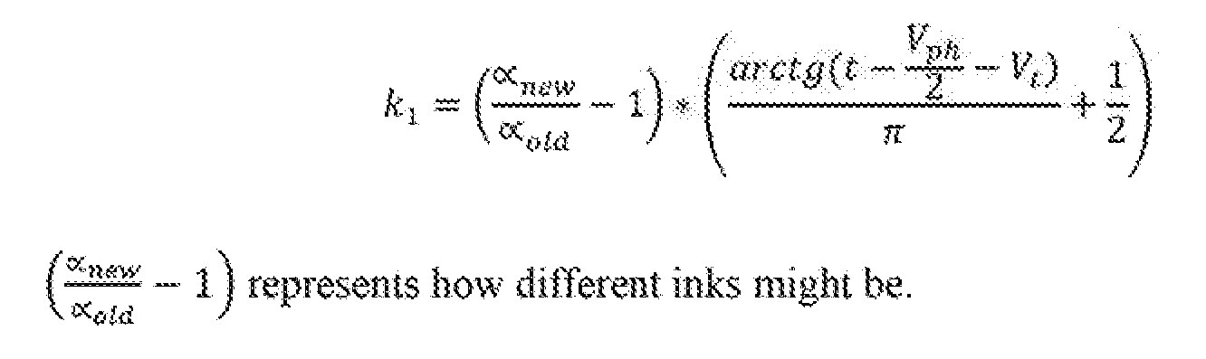
ouew and am are ink -related constants retrieved from the ink supply memory module.
,
allows applying the energy changes gradually and only from the

moment the new ink coming from the supply gets to die print head,

k2. is related to ink storage. Based on the manufacturing date of the ink, an increase of energy might be triggered by changing k2 according to reference experimental data retrieved from the printer memory module 108. e "on going" calibration (FIG, 8) has three variables; k1 is triggered when the new supply is installed, it depends on. how different the new ink is from the previous ink (ink physics/properties related parameter) fa is triggered when the new supply is installed, it depends on how long the ink has been stored in the supply (how old is the ink)

Based on this data, an increase of energy might be triggered by changing b in a similar way as k2..
[0054] The new printhead calibration processes are done in the printer during the printhead insertion process and recalibrated based on the information stored in the ink supply and on the printhead usage.
Claims
1. A method of calibrating a print-head in a thermal Inkjet printer, the pnnthead having ink ejection elements which, are energfe-able by electrical pulses of a given energy with fire pulses of an amplitude (V) and a fire pulse width (fp) to spit ink drops, comprising
intiating calibrating the pnnthead.
spitting a number (X) of ink drops at. a frequency (Y) by the electrical poises,
reading and storing prinihead temperature,
varytng'the fire pulse energy by repeating spitting ink drops and reading and storing prinihead. temperature,
finding minimum temperature from the stored pnnthead temperatures,
deriving an operational fire pulse from a fire ptiise that has produced the minimum


temperature,
using the operational fire pulse for printing.
2. The method of elatrn 1, wherein the operational fire pulse is derived, from die fire pulse

that has produced the minimum temperature, by an additional over energy wherein,

the value of over energy (oe) is optimized between optimal ink drop quality and minimum energy consumption of the pnnthead.
3. The method of claim 1 , wherein the operational fire pulse
 is derived from the fire pulse (fpo») that has produced the minimum temperature by an additional over energy
 and from at least one of different parameters (ki, t) which include parameters related to ink formulation (k.i), ink storage age (ka), prinihead life (ks), amount of consumed ink (t).
4. The method of claim 1, wherein -varying the pulse energy is- by varying tile pulse width (fp) of the fire pluses.
5. The method of claim 1, wherein varying the pulse energy is by decreasing the pulse Width (fp) of the fire pulses s tarting from a starting lire pulse width '(fp¾),
6. The method of claim I , w herein the electrical pulses include a precursor pulse (pep), a dead time (dt) and. the fire pulse width (fp), wherein the total pulse width (pw) is
7. The method o f claim 1 , wherein calibrating the printhead is initiated by one or more of print head mamtfacfuring variation, printhead life, ink fbraiulation, ink storage age, amount of consumed ink.
8. A thermal Inkjet printer including
a printhead having ink. ejection. elements which are enetgiz.ahle by electrical pulses of a gives energy with fire pulses of an amplitude (V) and a fire pulse width (fp), a printer controller to send commands to the printhead to spit ink drops, one or more temperature sensors coupled to the printhead and to measure a temperature of the printhead, and a calibration component coupled to the temperature sensor and to variably adjust the Ore pulse energy provided to the having ink ejection elements of the printhead,
wherein the calibration component is to iotiate calibrating the printhead, spitting a number (X) of ink drops at a frequency (Y) by the electrical pulses, reading and storing printhead temperature, varying the fire pulse energy by repeating spitting ink drops and reading and storing printhead temperature, finding minimum temperature from the stored printhead temperatures, and deriving an operational fire pulse (¾¼) from a fire pulse (ipoa) that has produced the minimum temperature, and
the printer controller uses the operational fire poise (fpop) for printing,
9. The thermal mkjet printer of claim 8, wherein the temperature sensors include a temperature sensor to measure temperature at ink ejection elements associated, to one or more inks, and one or more temperature sensors to measure an a verage printhead temperature,
10. The thermal Inkjet printer of claim 8, wherein the calibration component is included in the printer controller.
11. The thermal mkjet printer of claim 8, wherein the calibration component, is to derive the operational fire pulse from the fire pulse that has produced the minimum


temperature by an additional over energy (oe), and from at least one of different -parameters
 which include parameters related to ink formulation
 ink storage age , printhead life

amount of consumed ink
12, A computer readable medium having a set of computer executable instructions thereon for causing a device to perform a method of calibrating a printhead in a thermal inkjet printer, the printhead having ink ejection elements which are eaergizable by electrical puises of a given energy with fire pulses of an amplitude (V) and a fire pulse width (fp) to spit ink drops, the method comprising:
inflating calibrating the printhead,
spitting a number (X) of ink drops at a frequency (Y) by the electrical puises,.
reading and storing printhead temperature.
varying the fire pulse energy by repeating spitting ink drops and reading and storing printhead temperature,
finding minimum temperature from the stored printhead temperatures- deriving an operational fire pulse from a fire pulse that has produced the minimum temperature,
using the operational fire pulse for priming.
1.3, The medium, of claim 12, Wherein varying the pulse energy is by varying the puise width, (fp) of the lire pulses .
14. The- medium of claim 12, wherein varying the pulse energy is by decreasing the pulse width (fp) of the fire pulses starting from a starting fire pulse width (fps).
15. A thermal inkjet printhead having ink ejection elements which are energizable by electrical puises of a given energy with fire pulses of an amplitude (V) and a fire puise width (fp), to receive print control commands sent to the printhead to spit ink drops, one or more temperature sensors coupled to the printhead and to. measure a temperature of the printhead, and a calibration component coupled to the temperature sensor and to variably adjust the fire pulse energy provided to the having ink ejection elements of the printhead,
wherein the calibration component is to inflate calibrating the printhead, spitting a number (X) of ink drops at a frequency (Y) by the electrical pulses, reading and storing printhead temperature, varying the lire puise energy by repeating spitting ink drops and reading and storing printhead temperature, finding minimum temperature from the stored printhead
temperatures, and deriving an operational fire pulse (fpop) from a fire pulse (ipm) thai has produced the minimum temperature.
Priority Applications (4)
| Application Number | Priority Date | Filing Date | Title |
|---|---|---|---|
| EP16909649.2A EP3426493B1 (en) | 2016-07-19 | 2016-07-19 | Printhead calibration |
| CN201680084825.3A CN109153259B (en) | 2016-07-19 | 2016-07-19 | Printhead calibration |
| US16/097,527 US10562300B2 (en) | 2016-07-19 | 2016-07-19 | Adaptive print head calibration process |
| PCT/US2016/042912 WO2018017054A1 (en) | 2016-07-19 | 2016-07-19 | Printhead calibration |
Applications Claiming Priority (1)
| Application Number | Priority Date | Filing Date | Title |
|---|---|---|---|
| PCT/US2016/042912 WO2018017054A1 (en) | 2016-07-19 | 2016-07-19 | Printhead calibration |
Publications (1)
| Publication Number | Publication Date |
|---|---|
| WO2018017054A1 true WO2018017054A1 (en) | 2018-01-25 |
Family
ID=60995995
Family Applications (1)
| Application Number | Title | Priority Date | Filing Date |
|---|---|---|---|
| PCT/US2016/042912 WO2018017054A1 (en) | 2016-07-19 | 2016-07-19 | Printhead calibration |
Country Status (4)
| Country | Link |
|---|---|
| US (1) | US10562300B2 (en) |
| EP (1) | EP3426493B1 (en) |
| CN (1) | CN109153259B (en) |
| WO (1) | WO2018017054A1 (en) |
Cited By (3)
| Publication number | Priority date | Publication date | Assignee | Title |
|---|---|---|---|---|
| WO2021011961A1 (en) * | 2019-07-17 | 2021-01-21 | The Procter & Gamble Company | Method of atomizing a fluid composition |
| US11027543B2 (en) * | 2018-12-06 | 2021-06-08 | Canon Kabushiki Kaisha | Printing apparatus and method of determining minimum discharge energy |
| US11602932B2 (en) | 2018-06-11 | 2023-03-14 | Hewlett-Packard Development Company, L.P. | Zonal firing signal adjustments |
Families Citing this family (5)
| Publication number | Priority date | Publication date | Assignee | Title |
|---|---|---|---|---|
| WO2020246984A1 (en) * | 2019-06-07 | 2020-12-10 | Hewlett-Packard Development Company, L.P. | Printers and controllers |
| US20230129407A1 (en) * | 2020-03-18 | 2023-04-27 | Mimaki Engineering Co., Ltd. | Inkjet printer and method of controlling inkjet printer |
| JP7473371B2 (en) | 2020-03-18 | 2024-04-23 | 株式会社ミマキエンジニアリング | INKJET PRINTER AND METHOD FOR CONTROLLING INKJET PRINTER |
| JP7370287B2 (en) * | 2020-03-18 | 2023-10-27 | 株式会社ミマキエンジニアリング | Inkjet printers and inkjet printer control methods |
| WO2024096859A1 (en) * | 2022-10-31 | 2024-05-10 | Hewlett-Packard Development Company, L.P. | Turn on energy values for non-ejecting acuators |
Citations (3)
| Publication number | Priority date | Publication date | Assignee | Title |
|---|---|---|---|---|
| US5428376A (en) * | 1993-10-29 | 1995-06-27 | Hewlett-Packard Company | Thermal turn on energy test for an inkjet printer |
| US5714989A (en) * | 1993-11-22 | 1998-02-03 | Hewlett-Packard Company | Inkdrop-volume test using heat-flow effects, for thermal-inkjet printers |
| US6302507B1 (en) * | 1999-10-13 | 2001-10-16 | Hewlett-Packard Company | Method for controlling the over-energy applied to an inkjet print cartridge using dynamic pulse width adjustment based on printhead temperature |
Family Cites Families (11)
| Publication number | Priority date | Publication date | Assignee | Title |
|---|---|---|---|---|
| US6705694B1 (en) * | 1999-02-19 | 2004-03-16 | Hewlett-Packard Development Company, Lp. | High performance printing system and protocol |
| JP2002029037A (en) | 2000-07-17 | 2002-01-29 | Canon Inc | Method for controlling drive energy of ink jet recorder and ink jet recorder |
| US6612673B1 (en) * | 2002-04-29 | 2003-09-02 | Hewlett-Packard Development Company, L.P. | System and method for predicting dynamic thermal conditions of an inkjet printing system |
| US6755509B2 (en) | 2002-11-23 | 2004-06-29 | Silverbrook Research Pty Ltd | Thermal ink jet printhead with suspended beam heater |
| US7097271B2 (en) | 2003-09-26 | 2006-08-29 | Hewlett-Packard Development Company, L.P. | Printhead calibration |
| CN1628978A (en) | 2003-12-19 | 2005-06-22 | 明基电通股份有限公司 | Printer capable of regulating ink-jet energy according to ink-jet head temperature and relative regulating method |
| CN1966275A (en) | 2005-11-15 | 2007-05-23 | 明基电通股份有限公司 | Method for controlling printing of inkjet printer |
| US7425048B2 (en) * | 2006-10-10 | 2008-09-16 | Silverbrook Research Pty Ltd | Printhead IC with de-activatable temperature sensor |
| WO2009102322A1 (en) | 2008-02-12 | 2009-08-20 | Hewlett-Packard Development Company, L.P. | Integrated print head end-of-life detection |
| JP5631057B2 (en) | 2010-05-17 | 2014-11-26 | キヤノン株式会社 | Inkjet recording apparatus and calibration method |
| US8414102B2 (en) | 2011-08-11 | 2013-04-09 | Xerox Corporation | In situ calibration of multiple printheads to reference ink targets |
-
2016
- 2016-07-19 WO PCT/US2016/042912 patent/WO2018017054A1/en active Application Filing
- 2016-07-19 US US16/097,527 patent/US10562300B2/en not_active Expired - Fee Related
- 2016-07-19 EP EP16909649.2A patent/EP3426493B1/en active Active
- 2016-07-19 CN CN201680084825.3A patent/CN109153259B/en active Active
Patent Citations (3)
| Publication number | Priority date | Publication date | Assignee | Title |
|---|---|---|---|---|
| US5428376A (en) * | 1993-10-29 | 1995-06-27 | Hewlett-Packard Company | Thermal turn on energy test for an inkjet printer |
| US5714989A (en) * | 1993-11-22 | 1998-02-03 | Hewlett-Packard Company | Inkdrop-volume test using heat-flow effects, for thermal-inkjet printers |
| US6302507B1 (en) * | 1999-10-13 | 2001-10-16 | Hewlett-Packard Company | Method for controlling the over-energy applied to an inkjet print cartridge using dynamic pulse width adjustment based on printhead temperature |
Cited By (4)
| Publication number | Priority date | Publication date | Assignee | Title |
|---|---|---|---|---|
| US11602932B2 (en) | 2018-06-11 | 2023-03-14 | Hewlett-Packard Development Company, L.P. | Zonal firing signal adjustments |
| US11027543B2 (en) * | 2018-12-06 | 2021-06-08 | Canon Kabushiki Kaisha | Printing apparatus and method of determining minimum discharge energy |
| WO2021011961A1 (en) * | 2019-07-17 | 2021-01-21 | The Procter & Gamble Company | Method of atomizing a fluid composition |
| US20210015958A1 (en) * | 2019-07-17 | 2021-01-21 | The Procter & Gamble Company | Method of atomizing a fluid composition |
Also Published As
| Publication number | Publication date |
|---|---|
| CN109153259B (en) | 2020-07-03 |
| US10562300B2 (en) | 2020-02-18 |
| EP3426493B1 (en) | 2022-02-23 |
| EP3426493A1 (en) | 2019-01-16 |
| CN109153259A (en) | 2019-01-04 |
| EP3426493A4 (en) | 2019-10-16 |
| US20190126616A1 (en) | 2019-05-02 |
Similar Documents
| Publication | Publication Date | Title |
|---|---|---|
| EP3426493B1 (en) | Printhead calibration | |
| US5736995A (en) | Temperature control of thermal inkjet printheads by using synchronous non-nucleating pulses | |
| US6302507B1 (en) | Method for controlling the over-energy applied to an inkjet print cartridge using dynamic pulse width adjustment based on printhead temperature | |
| KR101946194B1 (en) | Printer and method for operating a printer | |
| US5673069A (en) | Method and apparatus for reducing the size of drops ejected from a thermal ink jet printhead | |
| US20030142159A1 (en) | Estimating local ejection chamber temperature to improve printhead performance | |
| JP3337912B2 (en) | Driving method of inkjet head and inkjet apparatus for executing the same | |
| JPH05220963A (en) | Delivery control method in ink jet recording head | |
| JPH11192724A (en) | Ink jet printer and method for judging presence or absence of ink | |
| US6328407B1 (en) | Method and apparatus of prewarming a printhead using prepulses | |
| EP1151868B1 (en) | Method for using highly energetic droplet firing events to improve droplet ejection reliability | |
| US20050007403A1 (en) | Printing apparatus and method for maintaining temperature of a printhead | |
| EP0600648B1 (en) | Method and apparatus for the control of thermal ink jet printers | |
| JPH06246931A (en) | Ink jet device | |
| EP0650836B1 (en) | Temperature control of thermal ink-jet print heads by using synchronous non-nucleating pulses | |
| JP3313751B2 (en) | Discharge control method for inkjet recording head | |
| US6547357B1 (en) | Ink jet recording apparatus and method of driving the same | |
| JP2966121B2 (en) | Ink jet recording apparatus and ink refresh method for the apparatus | |
| JP2003305854A (en) | Inkjet recorder | |
| JP4261874B2 (en) | Recording head and recording apparatus | |
| JPH0781117A (en) | Recorder and recording control method | |
| JP5385586B2 (en) | Head substrate, recording head, head cartridge, and recording apparatus | |
| JP2006256254A (en) | Head temperature detecting method, head temperature detecting apparatus and liquid droplet delivering apparatus | |
| JP2006168105A (en) | Inkjet printing head controlling apparatus | |
| JP2001054948A (en) | Ink-jet recording device and recording head driving method |
Legal Events
| Date | Code | Title | Description |
|---|---|---|---|
| WWE | Wipo information: entry into national phase |
Ref document number: 2016909649 Country of ref document: EP |
|
| ENP | Entry into the national phase |
Ref document number: 2016909649 Country of ref document: EP Effective date: 20181008 |
|
| 121 | Ep: the epo has been informed by wipo that ep was designated in this application |
Ref document number: 16909649 Country of ref document: EP Kind code of ref document: A1 |
|
| NENP | Non-entry into the national phase |
Ref country code: DE |