WO2017203937A1 - Robot control device - Google Patents
Robot control device Download PDFInfo
- Publication number
- WO2017203937A1 WO2017203937A1 PCT/JP2017/017012 JP2017017012W WO2017203937A1 WO 2017203937 A1 WO2017203937 A1 WO 2017203937A1 JP 2017017012 W JP2017017012 W JP 2017017012W WO 2017203937 A1 WO2017203937 A1 WO 2017203937A1
- Authority
- WO
- WIPO (PCT)
- Prior art keywords
- robot
- work
- work area
- worker
- robot control
- Prior art date
Links
Images


Classifications
-
- B—PERFORMING OPERATIONS; TRANSPORTING
- B25—HAND TOOLS; PORTABLE POWER-DRIVEN TOOLS; MANIPULATORS
- B25J—MANIPULATORS; CHAMBERS PROVIDED WITH MANIPULATION DEVICES
- B25J9/00—Programme-controlled manipulators
- B25J9/16—Programme controls
- B25J9/1674—Programme controls characterised by safety, monitoring, diagnostic
- B25J9/1676—Avoiding collision or forbidden zones
-
- B—PERFORMING OPERATIONS; TRANSPORTING
- B25—HAND TOOLS; PORTABLE POWER-DRIVEN TOOLS; MANIPULATORS
- B25J—MANIPULATORS; CHAMBERS PROVIDED WITH MANIPULATION DEVICES
- B25J9/00—Programme-controlled manipulators
- B25J9/16—Programme controls
- B25J9/1694—Programme controls characterised by use of sensors other than normal servo-feedback from position, speed or acceleration sensors, perception control, multi-sensor controlled systems, sensor fusion
-
- B—PERFORMING OPERATIONS; TRANSPORTING
- B25—HAND TOOLS; PORTABLE POWER-DRIVEN TOOLS; MANIPULATORS
- B25J—MANIPULATORS; CHAMBERS PROVIDED WITH MANIPULATION DEVICES
- B25J13/00—Controls for manipulators
- B25J13/08—Controls for manipulators by means of sensing devices, e.g. viewing or touching devices
- B25J13/088—Controls for manipulators by means of sensing devices, e.g. viewing or touching devices with position, velocity or acceleration sensors
-
- B—PERFORMING OPERATIONS; TRANSPORTING
- B25—HAND TOOLS; PORTABLE POWER-DRIVEN TOOLS; MANIPULATORS
- B25J—MANIPULATORS; CHAMBERS PROVIDED WITH MANIPULATION DEVICES
- B25J19/00—Accessories fitted to manipulators, e.g. for monitoring, for viewing; Safety devices combined with or specially adapted for use in connection with manipulators
- B25J19/06—Safety devices
-
- G—PHYSICS
- G05—CONTROLLING; REGULATING
- G05B—CONTROL OR REGULATING SYSTEMS IN GENERAL; FUNCTIONAL ELEMENTS OF SUCH SYSTEMS; MONITORING OR TESTING ARRANGEMENTS FOR SUCH SYSTEMS OR ELEMENTS
- G05B2219/00—Program-control systems
- G05B2219/30—Nc systems
- G05B2219/39—Robotics, robotics to robotics hand
-
- G—PHYSICS
- G05—CONTROLLING; REGULATING
- G05B—CONTROL OR REGULATING SYSTEMS IN GENERAL; FUNCTIONAL ELEMENTS OF SUCH SYSTEMS; MONITORING OR TESTING ARRANGEMENTS FOR SUCH SYSTEMS OR ELEMENTS
- G05B2219/00—Program-control systems
- G05B2219/30—Nc systems
- G05B2219/40—Robotics, robotics mapping to robotics vision
- G05B2219/40202—Human robot coexistence
Definitions
- the present invention relates to a robot control apparatus that operates while sharing a work space with a person.
- Patent Document 1 which is an example of the prior art, describes the current position and movement of both the worker and the robot in response to the problem that the robot stops operation and the work efficiency decreases every time the worker intervenes in the robot operation.
- the operation of the robot is not stopped when it is determined that there is no possibility.
- the present invention has been made in view of the above, and when a worker and a robot perform work while sharing a work space, the robot that maintains high work efficiency and reduces the risk of collision between the two
- the object is to obtain a control device.
- the present invention provides a robot control for controlling a robot that operates in a shared work space with a worker who performs one or more work processes in which work contents are set in advance.
- a robot control state measuring unit that measures a robot control state that is a position and a posture of the robot, and a work operation of the worker from the start to the end of the work process.
- An area including a space to be stored is stored for each work process, and a work area corresponding to the current work process of the worker is set based on a work process designation signal that designates the work process currently performed by the worker.
- a work area setting unit, and a robot command generation unit that generates an operation command to the robot based on the work area and the robot control state, the robot command generation unit, Depending on whether the serial robot is present in the work area, and changes the operation command to the robot.
- FIG. 1 is a schematic diagram illustrating an example of a robot system including the robot control device according to the first embodiment and a work site to which the robot system is applied.
- 1 is a block diagram showing an example of the configuration of the robot control apparatus shown in FIG.
- FIG. 3 is a block diagram showing a configuration example of a robot control apparatus according to a second embodiment.
- FIG. 6 is a block diagram showing a configuration example of a robot control apparatus according to the third embodiment.
- the figure which shows the typical bird's-eye view which shows the work site where a robot and an operator share work space in Embodiment 3 and work Schematic diagram showing an example of a robot system including a robot control device according to a fourth embodiment and a work site to which the robot system is applied.
- FIG. 7 is a block diagram showing a configuration example of a robot control apparatus according to a fifth embodiment.
- FIG. 14 is a block diagram illustrating a configuration example of a work area setting unit illustrated in FIG. 14.
- FIG. 7 is a block diagram showing a configuration example of a robot control apparatus according to a sixth embodiment.
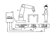
- FIG. 1 is a schematic diagram illustrating an example of a robot system including the robot control device 1 according to the first embodiment of the present invention and a work site to which the robot system is applied.
- a robot control device 1 shown in FIG. 1 is connected to a robot 2, and receives a robot joint angle signal 3 a from a robot joint angle measurement device 3 and a work process designation signal 5 a from a work process designation device 5. In response, an operation command is output.
- a work table 6 is arranged in the work site shown in FIG. 1, and a worker 7 exists, and the robot 2 operates while sharing a work space with the worker 7.
- FIG. 2 is a block diagram showing a configuration example of the robot control apparatus 1 shown in FIG.
- the robot control apparatus 1 shown in FIG. 2 includes a robot control state measuring unit 102 that measures robot control state information 102a that is a robot position and posture, and a work operation of the worker 7 from the start to the end of the work process.
- An area including the space occupied by the body of the worker 7 is stored as a work area, and the current work process of the worker 7 is determined based on the work process designation signal 5a that designates the work process currently performed by the worker 7.
- a work area setting unit 104 that sets a corresponding work area and outputs work area information 104a, and a robot command generation unit that generates an operation command 105a for the robot 2 based on the work area information 104a and the robot control state information 102a. 105.
- the robot controller 1 stores the work area data of the worker 7 for each work process of the worker 7 in a storage unit (not shown).
- the work process is a series of work by the worker 7 divided according to the work content.
- the division point of the work process includes a change point of the position of the worker 7, a change point of the position of tools and parts used in the work, a change point of the body part used in the work, and a discontinuous point of the work movement of the worker 7. It can be illustrated.
- the work process may be divided according to the work process table of the worker 7 already used at the work site, or may be divided by setting a required work time for each work process.
- the work process may be set such that the worker 7 does not work, and the work area corresponding to the work process is set as an empty set.
- the robot control device 1 stores in advance, as work area data, a space area occupied by the body part in the work process for one or more divided work processes for which work contents are set in advance. ing.
- This work area data may be created in advance on CAD (Computer Aided Design) assuming the movement range of the worker 7 for each work process, or a worker when the worker 7 actually performs the work process. You may create by measuring previously 7 operation
- CAD Computer Aided Design
- the robot 2 includes a plurality of arms, and each joint, which is a connection point of the arms, includes a driving device that controls a joint angle, and takes various positions and postures according to an operation command from the robot control device 1.
- the driving device include an electric motor represented by a servo motor or a stepping motor, or a cylinder using air pressure or hydraulic pressure, but the driving device is not limited to these.
- the robot system shown in FIG. 1 includes a robot joint angle measuring device 3 that measures the joint angle of the robot 2 at the current time.
- the robot joint angle measuring device 3 can be exemplified by an encoder, and is provided at each joint of each arm of the robot 2.
- the robot joint angle measuring device 3 can be exemplified by an image sensor such as a camera, and each joint angle of the robot 2 may be measured using such an image sensor.
- the work process designation device 5 outputs a work process designation signal 5a for designating a work process currently being executed by the worker 7 from the work process data stored in the robot controller 1.
- the work process designating device 5 can be exemplified by a digital switch, and this digital switch can be switched by the operator 7.
- the digital switch may have buttons arranged so that the number of the divided work processes can be specified, or by setting the execution order in the work process in advance in the work process data, the digital switch Buttons may be arranged to manipulate the execution order.
- the transmission format of the work process designation signal 5a may be wired or wireless. When the transmission format is wireless transmission, the robot control device 1 may be provided with a wireless reception unit.
- the workers differ for each work process in the work environment or the worker's part.
- the work process designating device 5 The work process determination data to be obtained can be acquired, and the work process designation signal 5a may be output based on the measured result and the work process determination data.
- RGB-D (Red Green Blue-Depth) sensors and range sensors can be exemplified as sensors that can acquire work process determination data. Sensors that can acquire work process determination data include It is not limited to these.
- sensors such as a mat switch, a light curtain, and a laser sensor may be used in combination for the purpose of compensating the undetectable area of these sensors and improving the detection accuracy.
- the robot control state measuring unit 102 calculates the angular velocity at each joint of the robot 2 based on the angle information at each joint of the robot 2 included in the robot joint angle signal 3a input from the robot joint angle measuring device 3.
- the angular velocity at each joint can be calculated by taking the time difference value of the corresponding joint angle. Further, noise can be removed by performing filter processing on the time difference value of the angular velocity at each joint.
- a low-pass filter can be exemplified as the filter of the filter processing.
- the robot control device 1 holds the body data of the robot 2, and the robot control state measurement unit 102 determines the robot 2 as the position and posture of the robot 2 based on the joint angle at each joint of the robot 2 and the angular velocity at each joint. It is possible to calculate the control state information 102a.
- the work area setting unit 104 outputs work area information 104a corresponding to the current work process of the worker 7 designated by the work process designation signal 5a from the work area data stored in the robot controller 1.
- FIG. 3 is a block diagram showing a configuration example of the robot command generation unit 105 shown in FIG.
- the robot command generation unit 105 shown in FIG. 3 is based on an intrusion determination unit 106 that outputs an intrusion determination signal 106a indicating whether or not the robot 2 has entered the work area of the work area information 104a, and an intrusion determination signal 106a.
- the robot 2 When it is determined that the robot 2 has not entered the work area of the work area information 104a, the robot 2 outputs an operation command 105a to the robot 2 in the non-intrusion control mode that is the first control mode.
- an operation command output unit 107 is provided that outputs an operation command 105a to the robot 2 in the intrusion control mode that is the second control mode. .
- the intrusion determination unit 106 outputs an intrusion determination signal 106a to the work area information 104a of the robot 2 based on the robot control state information 102a and the work area information 104a.
- a part of the housing of the robot 2 represented by the robot hand may be set as a determination point, and it may be determined whether or not the determination point exists in the work area information 104a.
- the motion command 105a is output according to the robot motion trajectory.
- the robot motion trajectory is a command value history of the joint angle of each arm constituting the robot 2, and is previously taught by the work content performed by the robot 2.
- the intrusion determination unit 106 changes the intrusion determination signal 106a to change the second control mode. Transition to control mode. Further, the operation may be controlled so that the robot 2 is stopped before entering the work area so that the robot 2 does not enter the work area of the work area information 104a.
- a stop command is output to the robot 2.
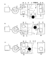
- FIG. 4 is a schematic diagram showing a work site where the robot 2 and the worker 7 share the work space and perform work in the present embodiment.
- 4A shows a side view of the work site
- FIG. 4B shows an overhead view of the work site.
- the robot 2 and the worker 7 perform work in a space on the work table 6 that is a shared work space.
- the robot 2 operates according to a preset robot motion trajectory, and the worker 7 temporarily enters the movable range of the robot 2 at that time.
- the robot 2 and the worker 7 are separated by a safety fence 10, and the worker 7 enters based on a signal from an intrusion detection device 11 such as an interlock or a light curtain. Is detected, the work table 6 is set as a work space for the worker 7, the robot 2 stops operating, and the robot 2 resumes its operation when the intrusion of the worker 7 is no longer detected. And the robot 2 shares a work space.
- an intrusion detection device 11 such as an interlock or a light curtain
- the work area of the worker 7 is set according to the work process of the worker 7, and the operation restriction range for the robot 2 can be narrowed based on the work area. it can. Therefore, the stop frequency of the robot 2 can be suppressed, and as a result, the cooperative work efficiency between the worker 7 and the robot 2 can be improved.
- the work area may be set as described above, and the safety fence 10 and the intrusion detection device 11 may be provided.
- FIG. 5 is a block diagram showing a configuration example of the robot control apparatus 1A according to the present embodiment.
- a robot control apparatus 1A shown in FIG. 5 includes a robot command generation unit 105A instead of the robot command generation unit 105 shown in FIG.
- FIG. 6 is a block diagram illustrating a configuration example of the robot command generation unit 105A illustrated in FIG.
- a robot command generation unit 105A illustrated in FIG. 6 includes a retraction operation trajectory generation unit 108, and includes an operation command output unit 107A instead of the operation command output unit 107 illustrated in FIG.
- the retraction operation trajectory generation unit 108 generates retraction operation trajectory information 108a from a current control state of the robot 2 to a control state at a preset retreat point of the robot 2 based on the robot control state information 102a.
- the retreat point is a space point that temporarily moves separately from the set work so that the robot 2 does not hinder the work of the worker 7, and the work contents of the worker 7 and the preset work One or more spatial points set in consideration of a region.
- the retraction movement trajectory information 108a up to the retraction point may be generated by linear interpolation of the current robot control state information 102a and the amount of change in the joint angle of each arm included in the robot 2 at the retraction point.
- the operation command output unit 107A outputs an operation command 105a to the robot 2 based on the robot control state information 102a, the work area information 104a, the intrusion determination signal 106a, and the retreat operation trajectory information 108a.
- the operation command output unit 107A determines that the robot 2 has not entered the work area of the work area information 104a by the intrusion determination signal 106a
- the operation command output unit 107A uses the non-intrusion control mode that is the first control mode.
- Operation command 105a is output, and when it is determined that the robot 2 has entered the work area of the work area information 104a, the operation command to the robot 2 is executed in the control mode at the time of entry, which is the second control mode. 105a is output.
- the non-intrusion control mode which is the first control mode in the operation command output unit 107A, is the same as that of the operation command output unit 107 in the first embodiment, and a description thereof will be omitted.
- the operation command 105a to the robot 2 is output according to the retreat operation trajectory information 108a.
- the retreat operation trajectory information 108a when a plurality of retreat points are set, one is selected from a plurality of retreat operation trajectory information 108a.
- a retreat point to be used in advance for each work process may be designated.
- a retreat point at which the robot 2 can leave the work area of the work area information 104a in the shortest distance or the shortest time is selected according to the retreat motion trajectory information 108a. May be.
- the retraction point may be selected so that the volume of the housing portion of the robot 2 that has entered the work area is minimized before the robot 2 leaves the work area of the work area information 104a. Alternatively, by the time the robot 2 leaves the work area of the work area information 104a, the robot 2 is retracted so that the volume of a specific part represented by the robot hand of the robot 2 that has entered the work area is minimized. A point may be selected.
- the robot 2 when the robot 2 is operated in the direction of advancing or returning the work in accordance with the robot operation trajectory set in advance, it follows the selection method of the retreat operation trajectory information 108a. As a result of the evaluation, if it is more appropriate to move out of the work area information 104a according to the robot movement trajectory than to move out of the work area of the work area information 104a according to any of the retreat movement trajectory information 108a.
- the operation command 105a to the robot 2 may be output according to the robot operation trajectory.
- the operation command output unit 107A determines that the robot 2 has left the work area of the work area information 104a. 2 may be set to stop before moving to the retreat point.
- FIG. 7 is a diagram showing a schematic overhead view showing a work site where the robot 2 and the worker 7 share a work space and perform work in the present embodiment.
- FIG. 7 is the same as the work site shown in FIG. 4, and the same components are denoted by the same reference numerals and description thereof is omitted.
- the operator 7 enters the shared work space in order to perform the work of assembling the work object 81 to the work object 82.
- the worker 7 is transporting the work object 81 and approaching the work object 82 placed on the work table 6, and the robot 2 moves against the work object 82. Doing work.
- the current work process scheduled route 12 of the worker 7 is indicated by a broken-line arrow.
- the worker 7 is approaching the work object 82 from the state of FIG. 7 (a).
- FIG. 7B when the intrusion detection device 11 detects the intrusion of the worker 7, the robot 2 stops its operation while approaching the work target 82, and the worker 7 stops the work target 82. There is a possibility that it is not possible to secure a work range for performing work on the above.
- the worker 7 cannot perform the assembling work of the work object 81 and the work object 82 because the presence of the robot 2 becomes an obstacle, and the worker 7 waits giving priority to the operation of the robot 2, or There is a problem that it is necessary to forcibly stop the automatic operation of the robot 2 and move the robot 2 to a position where the operation is not hindered by the jog operation.
- the robot 2 when the worker 7 approaches the work object 82, a work area is set, and the robot 2 is output by outputting an operation command 105a so as to retract the robot 2 from the work area. Therefore, the operator 7 and the robot 2 can be prevented from excessively approaching and obstructing the work area. As a result, the waiting operation of the worker 7 and the moving work of the robot 2 by jog operation are unnecessary. The collaborative work efficiency can be improved.
- Embodiment 3 FIG. In the present embodiment, a mode will be described in which the robot operates so as to retreat in advance from the work area next to the worker's current work process.
- FIG. 8 is a block diagram showing a configuration example of the robot control apparatus 1B according to the present embodiment.
- the same components as those shown in FIG. 8 includes a work area setting unit 104B instead of the work area setting unit 104 shown in FIG. 2, and a robot command generation unit 105B instead of the robot command generation unit 105.
- the work area setting unit 104B stores the order of the next work process in addition to the work area in the work process, and stores it in addition to the work area of the work area information 104a corresponding to the work process of the current worker 7.
- the work area of the next work area information 104b corresponding to the next work process is set and output, and the robot command generation unit 105B is based on the work area information 104a, the next work area information 104b, and the robot control state information 102a.
- the robot 2 does not enter the work area of the next work area information 104b but has entered the work area of the work area information 104a.
- the robot 2 has not entered, but has entered the work area of the next work area information 104b, and the robot 2 has entered the work area information 104a and the next work area information 104. By the case not be penetrated in any work area, and to change the method of generating the operation command 105a to the robot 2.
- the operation command 105a is generated by the second control mode in the first embodiment when the robot 2 has not entered the next work area information 104b but has entered the work area of the work area information 104a. Is output when the robot 2 has not entered the work area of the work area information 104a but has entered the work area of the next work area information 104b. Outputs a retract command in the intrusion control mode, which is the second control mode in the second embodiment, to the robot 2, and the robot 2 enters either the work area information 104a or the next work area information 104b. If not, a method of outputting an operation command in the non-intrusion control mode which is the first control mode in the first embodiment can be exemplified.
- FIG. 9 is a diagram showing a schematic overhead view showing a work site where the robot 2 and the worker 7 share the work space and perform work in the present embodiment.
- FIG. 9 is the same as the work site shown in FIG. 4, and the same components are denoted by the same reference numerals and description thereof is omitted.
- a work object 82 and a work object 83 are arranged on the work table 6, a work table 61 facing one side of the rectangular work table 6 is installed, and the work object 81 and the work object 81 are arranged on the work table 61.
- a work object 84 is arranged.
- FIG. 9 shows an example of the work site, and the layout of the work site and the work content of the worker 7 are not limited to this.
- FIGS. 9A to 9C show the current work process schedule path 12 corresponding to the current work process, the current work area 14 corresponding to the current work process, and the next work process schedule corresponding to the next work process.
- a path 13 and a next work area 15 corresponding to the next work process are shown.
- the current work area 14 and the next work area 15 are areas set by the user to prohibit the robot 2 from entering when the worker 7 performs a corresponding work.
- the current work area 14 and the next work area 15 are larger than the body occupation area of the worker 7 while the worker 7 performs the target work in consideration of variations in work movements when the worker 7 repeatedly performs the target work. It is preferable to set a wide range. Since the work process is changed in the process from FIG. 9A to FIG. 9C, the next work area 15 in FIG. 9A becomes the current work area 14 in FIG. Is a newly set area. The same applies to the current work area 14 and the next work area 15 in FIGS. 9B and 9C.
- FIGS. 9A to 9C The work processes in FIGS. 9A to 9C are set as follows. First, the robot 2 performs a machining operation on the work object 82 and a machining operation on the work object 83. Next, the operator 7 performs an operation of assembling the work object 81 with the work object 82 which has been processed by the robot 2 to process the work object 85. In parallel with or following the assembly work of the worker 7, the robot 2 performs a machining work on the work object 83. Next, the worker 7 transports the work object 83 that has been processed by the robot 2 to be assembled with the work object 84. Therefore, first, the worker 7 moves from the position shown in FIG.
- the next work process after the work process for acquiring the work object 81 is a work for assembling the acquired work object 81 to the work object 82 toward the work table 6. Therefore, in FIG. 9A, the next work area 15 corresponding to the next work process is set so as to include the work object 81 and the work object 82. At this time, in FIG.
- the retraction command for the intrusion control mode which is the control mode, is output and retreats outside the next work area 15 within a range that does not enter the current work area 14.
- the robot 2 can not be considered in the movement route predicted only from the movement of the worker 7, but for the work area occupied by the future movement of the worker 7 according to the work process,
- the robot 2 can be saved in advance from the next work area of the current work process, and the robot 2 can be prevented from entering the work area of the next work area information 104b of the worker 7.
- the movement path of the worker 7 is predicted only from the current movement flow of the worker 7, if the movement of the worker 7 that cannot be predicted from the current movement flow occurs according to the work process, the movement path is predicted. It becomes difficult. According to the present embodiment, even if an operation that cannot be predicted from the current operation flow occurs, such as a sudden change of the operation direction according to the work process of the worker 7, prediction is possible.
- FIG. 10 is a schematic diagram illustrating an example of a robot system including the robot control apparatus 1C according to the present embodiment and a work site to which the robot system is applied.
- an operator measuring device 4 is added to the robot system shown in FIG.
- FIG. 10 the same components as those shown in FIG.
- FIG. 11 is a block diagram showing a configuration example of the robot control apparatus 1C shown in FIG.
- an operator measurement unit 101 is added to the robot control apparatus 1 shown in FIG.
- the worker measurement unit 101 measures the state of the worker 7 that is the worker position and posture, and outputs worker state information 101a.
- the robot command generation unit 105C generates an operation command 105a for the robot 2 based on the worker status information 101a, the work area information 104a, and the robot control status information 102a.
- FIG. 11 the same components as those shown in FIG.
- the worker measurement device 4 is a sensor device that measures one or more body parts of the worker 7 as body measurement points and outputs position information 4a.
- the position information 4a is output to the robot controller 1C at a constant cycle.
- the worker measuring device 4 can be exemplified by an RGB-D sensor and a range sensor, similar to the sensor capable of acquiring work process determination data in the first embodiment, but the worker measuring device 4 Is not limited to these.
- FIG. 12 is a diagram illustrating an example of the body measurement points of the worker 7 set in the present embodiment.
- the body measurement points of the operator 7 shown in FIG. 12 include a head 701, a neck 702, a shoulder 703, a spine 704, a buttocks 705, a knee 706, an ankle 707, an elbow 708, a wrist 709, and a hand.
- a part 710 and a toe part 711 are set.
- a bone part 721 is set between the head part 701 and the neck part 702, a bone part 722 is set between the neck part 702 and the shoulder part 703, and a bone is set between the shoulder part 703 and the spine part 704.
- a portion 723 is set, a bone portion 724 is set between the spine portion 704 and the heel portion 705, a bone portion 725 is set between the heel portion 705 and the knee portion 706, and between the knee portion 706 and the ankle portion 707
- a bone portion 726 is set between the ankle portion 707 and the toe portion 711, a bone portion 728 is set between the shoulder portion 703 and the elbow portion 708, and the elbow portion 708 and the wrist
- a bone portion 729 is set between the wrist portion 709 and the bone portion 730 between the wrist portion 709 and the hand portion 710.
- the posture of the worker 7 is detected based on the position information 4 a of the body measurement points measured by the worker measuring device 4 by representing the body of the worker 7 with a human skeleton model. Can do.
- the body measurement points are not limited to these, and a part of the body measurement points shown in FIG. 12 may be selected or the body measurement points shown in FIG. Other body measurement points may be added.
- signals from existing sensors such as mat switches, light curtains, and laser sensors installed at general sites are used to improve the accuracy of the position information 4a of the worker 7 and to the worker measuring device 4. You may use together for the purpose of compensation of the area which cannot detect the position of the worker 7.
- FIG. 13 is a block diagram showing a configuration example of the robot command generation unit 105C shown in FIG.
- a robot command generation unit 105C illustrated in FIG. 13 includes an operation command output unit 107C instead of the operation command output unit 107A of the robot command generation unit 105A illustrated in FIG.
- the motion command output unit 107C outputs a motion command 105a to the robot 2 based on the worker status information 101a, the robot control status information 102a, the work area information 104a, the intrusion determination signal 106a, and the retreat motion trajectory information 108a.
- the same components as those shown in FIG. 6 are denoted by the same reference numerals, and the description thereof is omitted. Further, in this embodiment, the retracting motion trajectory generating unit 108 may not be provided.
- the operation command output unit 107C determines that the robot 2 has not entered the work area of the work area information 104a based on the intrusion determination signal 106a, the operation command output unit 107C uses the non-intrusion control mode that is the first control mode.
- the operation command 105a is output to the robot 2 and it is determined that the robot 2 has entered the work area of the work area information 104a, the robot 2 is instructed by the intrusion control mode which is the second control mode. An operation command 105a is output.
- the non-intrusion control mode which is the first control mode in the operation command output unit 107C
- the intrusion time control mode that is the second control mode in the operation command output unit 107C
- a limit value is set for the operation speed of the robot 2.
- the limit value of the operation speed of the robot 2 may be set lower as the distance between the two is closer.
- the limit value of the operation speed of the robot 2 may be set lower as the relative speed is higher.
- the robot control device 1C keeps the current positional relationship between the robot 2 and the worker 7.
- the robot 2 can be retreated out of the work area of the work area information 104a while avoiding the collision between the two.
- FIG. 14 is a block diagram showing a configuration example of the robot control apparatus 1D according to the present embodiment.
- the same components as those shown in FIG. 11 are denoted by the same reference numerals, and the description thereof is omitted.
- a robot control apparatus 1D illustrated in FIG. 14 includes a work area setting unit 104D instead of the work area setting unit 104 of the robot control apparatus 1C illustrated in FIG.
- FIG. 15 is a block diagram showing a configuration example of the work area setting unit 104D shown in FIG.
- the work area setting unit 104D illustrated in FIG. 15 includes a work area storage unit 109, a work area correction unit 110, and a work area output unit 111.
- the work area storage unit 109 stores correction work area data obtained by duplicating the work area data so that the work area data stored in advance can be corrected. From the stored correction work area data, the work area specification signal 5a is used.
- the correction work area information 109a corresponding to the work process of the designated worker 7 is output.
- the work area correction unit 110 statistically compares the correction work area information 109a and the worker state information 101a, so that the correction work area information 109a is used as the range used in the actual work operation of the worker 7.
- the corrected work area information 110a is output by correcting the work area so that the difference between the two is reduced.
- the work area output unit 111 outputs the corrected work area information as work area information 104a.
- the work area storage unit 109 corrects the corresponding correction work area data based on the correction work area information 110a.
- the robot control device 1D corrects the preset work area of the work area information 104a of the worker 7 with the worker state information 101a measured by the actual work operation of the worker 7. . For this reason, it is possible to reset the work area of the work area information 104a in accordance with the motion trajectory or the motion range at the time of work different for each worker.
- FIG. 16 is a block diagram showing a configuration example of the robot control apparatus 1E according to the present embodiment.
- a robot control apparatus 1E illustrated in FIG. 16 includes a robot control state measurement unit 102E instead of the robot control state measurement unit 102 of the robot control apparatus 1 illustrated in FIG.
- An operation command 105a is input to the robot control state measuring unit 102E instead of the robot joint angle signal 3a.
- the robot joint angle measuring device 3 can be removed from the robot system, and the size and cost can be reduced.
- the configuration described in the above embodiment shows an example of the contents of the present invention, and can be combined with another known technique, and can be combined with other configurations without departing from the gist of the present invention. It is also possible to omit or change the part.
Abstract
The purpose of the present invention is to obtain a robot control device that reduces the risk of a collision occurring between a worker and a robot while maintaining high work efficiency when the worker and the robot work in a shared workspace. The present invention comprises: a robot control state measuring unit (102) that measures a robot control state that includes the position and the posture of a robot; a work area setting unit (104) that stores, for each work process, an area that contains the space occupied by the body of a worker in work actions performed by the worker from the start to the end of the work process, and that sets a work area corresponding to the current work process of the worker on the basis of a work process specifying signal that specifies the work process that is currently being performed by the worker; and a robot command generating unit (105) that generates an operation command (105a) for the robot on the basis of the work area and the robot control state. The robot command generating unit (105) changes the operation command (105a) for the robot in accordance with whether the robot is inside the work area.
Description
本発明は、人と作業空間を共有しつつ動作するロボット制御装置に関する。
The present invention relates to a robot control apparatus that operates while sharing a work space with a person.
近年、作業者とロボットとが安全柵で仕切られることなく作業空間を共有した人協調ロボットシステムの開発が進められている。人協調ロボットシステムでは、作業者がロボットの可動範囲に侵入するおそれがあり、両者の衝突を防ぐために作業者及びロボットの位置及び速度に基づいて両者が衝突するおそれを判定し、衝突し得る場合にはロボットの動作を停止させるように動作を制限することで安全性を担保している。ところで、作業者とロボットとが近い位置に存在するほど、又は両者が高速で移動しているほど両者は衝突しやすい。そのため、両者がより遠い位置に存在する段階、又は両者がより低速で移動している段階においてロボットの動作制限を設定すべきである。しかしながら、両者が衝突しないように、ロボットと作業者とが接近する都度、動作を停止していては作業効率が低下する。そのため、作業者への安全性と作業効率とを両立させるための取り組みがなされている。
In recent years, development of a human cooperative robot system in which a worker and a robot share a work space without being partitioned by a safety fence has been promoted. In a human cooperative robot system, there is a possibility that an operator may enter the movable range of the robot, and in order to prevent the collision between the two, the possibility of collision between the two is determined based on the position and speed of the worker and the robot, and a collision may occur Safety is ensured by restricting the movement to stop the movement of the robot. By the way, the closer the worker and the robot are, or the faster they are moving, the more likely they will collide. For this reason, the robot operation limit should be set at a stage where both are located at a farther position or when both are moving at a lower speed. However, when the robot and the worker approach each other so that the two do not collide, the operation efficiency is lowered if the operation is stopped. For this reason, efforts are being made to achieve both safety for workers and work efficiency.
従来技術の一例である特許文献1には、作業者がロボット動作に介入する度にロボットが動作を停止し作業効率が低下するといった課題に対して、作業者とロボットの双方の現在位置及び移動速度をもとに作業者とロボットの双方の将来位置を予測し、その予測値に基づいてロボットと作業者の接触可能性を判断することで、将来的に作業者とロボットとの接触の可能性がないと判断される場合にはロボットの動作を停止させないようにすることが開示されている。
Patent Document 1, which is an example of the prior art, describes the current position and movement of both the worker and the robot in response to the problem that the robot stops operation and the work efficiency decreases every time the worker intervenes in the robot operation. By predicting the future position of both the worker and the robot based on the speed, and determining the possibility of contact between the robot and the worker based on the predicted value, contact between the worker and the robot is possible in the future. It is disclosed that the operation of the robot is not stopped when it is determined that there is no possibility.
しかしながら、上記従来の技術によれば、作業者の作業内容によっては作業者が作業で利用しない範囲までも過剰に侵入検知範囲として設定される。そのため、作業効率が低下する、という問題があった。
However, according to the above-described conventional technology, depending on the work contents of the worker, the intrusion detection range is excessively set even to the range where the worker does not use the work. Therefore, there has been a problem that work efficiency is lowered.
本発明は、上記に鑑みてなされたものであって、作業者とロボットとが作業空間を共有しつつ作業を行う際に、高い作業効率を維持しつつ両者の衝突のおそれを低下させたロボット制御装置を得ることを目的とする。
The present invention has been made in view of the above, and when a worker and a robot perform work while sharing a work space, the robot that maintains high work efficiency and reduces the risk of collision between the two The object is to obtain a control device.
上述した課題を解決し、目的を達成するために、本発明は、予め作業内容が設定された一つ以上の作業工程を行う作業者と作業空間を共有して動作するロボットを制御するロボット制御装置であって、前記ロボットの位置及び姿勢であるロボット制御状態を計測するロボット制御状態計測部と、前記作業工程の開始から終了までの前記作業者の作業動作で、前記作業者の身体が占有する空間を包含した領域を作業工程毎に記憶し、前記作業者が現在行っている前記作業工程を指定する作業工程指定信号に基づき、前記作業者の現在の作業工程に対応した作業領域を設定する作業領域設定部と、前記作業領域及び前記ロボット制御状態をもとに前記ロボットへの動作指令を生成するロボット指令生成部とを備え、前記ロボット指令生成部は、前記ロボットが前記作業領域内に存在するか否かによって、前記ロボットへの動作指令を変更することを特徴とする。
In order to solve the above-described problems and achieve the object, the present invention provides a robot control for controlling a robot that operates in a shared work space with a worker who performs one or more work processes in which work contents are set in advance. A robot control state measuring unit that measures a robot control state that is a position and a posture of the robot, and a work operation of the worker from the start to the end of the work process. An area including a space to be stored is stored for each work process, and a work area corresponding to the current work process of the worker is set based on a work process designation signal that designates the work process currently performed by the worker. A work area setting unit, and a robot command generation unit that generates an operation command to the robot based on the work area and the robot control state, the robot command generation unit, Depending on whether the serial robot is present in the work area, and changes the operation command to the robot.
本発明によれば、作業者とロボットとが作業空間を共有しつつ作業を行う際に、高い作業効率を維持しつつ両者の衝突のおそれを低下させたロボット制御装置を得ることができるという効果を奏する。
Advantageous Effects of Invention According to the present invention, when a worker and a robot perform work while sharing a work space, it is possible to obtain a robot control device that maintains high work efficiency and reduces the risk of collision between the two. Play.
以下に、本発明の実施の形態にかかるロボット制御装置を図面に基づいて詳細に説明する。なお、この実施の形態によりこの発明が限定されるものではない。
Hereinafter, a robot control apparatus according to an embodiment of the present invention will be described in detail with reference to the drawings. Note that the present invention is not limited to the embodiments.
実施の形態1.
図1は、本発明の実施の形態1にかかるロボット制御装置1を備えるロボットシステム及び該ロボットシステムが適用される作業現場の一例を示す模式図である。図1に示すロボット制御装置1は、ロボット2に接続され、ロボット関節角度計測装置3からのロボット関節角信号3a及び作業工程指定装置5からの作業工程指定信号5aをもとに、ロボット2に対して動作指令を出力する。また、図1に示す作業現場には、作業台6が配され、作業者7が存在し、ロボット2は作業者7と作業空間を共有して動作する。Embodiment 1 FIG.
FIG. 1 is a schematic diagram illustrating an example of a robot system including therobot control device 1 according to the first embodiment of the present invention and a work site to which the robot system is applied. A robot control device 1 shown in FIG. 1 is connected to a robot 2, and receives a robot joint angle signal 3 a from a robot joint angle measurement device 3 and a work process designation signal 5 a from a work process designation device 5. In response, an operation command is output. In addition, a work table 6 is arranged in the work site shown in FIG. 1, and a worker 7 exists, and the robot 2 operates while sharing a work space with the worker 7.
図1は、本発明の実施の形態1にかかるロボット制御装置1を備えるロボットシステム及び該ロボットシステムが適用される作業現場の一例を示す模式図である。図1に示すロボット制御装置1は、ロボット2に接続され、ロボット関節角度計測装置3からのロボット関節角信号3a及び作業工程指定装置5からの作業工程指定信号5aをもとに、ロボット2に対して動作指令を出力する。また、図1に示す作業現場には、作業台6が配され、作業者7が存在し、ロボット2は作業者7と作業空間を共有して動作する。
FIG. 1 is a schematic diagram illustrating an example of a robot system including the
図2は、図1に示すロボット制御装置1の一構成例を示すブロック図である。図2に示すロボット制御装置1は、ロボット位置及び姿勢であるロボット制御状態情報102aを計測するロボット制御状態計測部102と、作業工程の開始から終了までの作業者7の作業動作であって、作業者7の身体が占有する空間を包含した領域を作業領域として記憶し、作業者7が現在行っている作業工程を指定する作業工程指定信号5aに基づいて作業者7の現在の作業工程に対応した作業領域を設定して作業領域情報104aを出力する作業領域設定部104と、作業領域情報104a及びロボット制御状態情報102aをもとにロボット2への動作指令105aを生成するロボット指令生成部105とを備える。
FIG. 2 is a block diagram showing a configuration example of the robot control apparatus 1 shown in FIG. The robot control apparatus 1 shown in FIG. 2 includes a robot control state measuring unit 102 that measures robot control state information 102a that is a robot position and posture, and a work operation of the worker 7 from the start to the end of the work process. An area including the space occupied by the body of the worker 7 is stored as a work area, and the current work process of the worker 7 is determined based on the work process designation signal 5a that designates the work process currently performed by the worker 7. A work area setting unit 104 that sets a corresponding work area and outputs work area information 104a, and a robot command generation unit that generates an operation command 105a for the robot 2 based on the work area information 104a and the robot control state information 102a. 105.
ロボット制御装置1は、図示しない記憶部に作業者7の作業工程毎に作業者7の作業領域データを記憶している。
The robot controller 1 stores the work area data of the worker 7 for each work process of the worker 7 in a storage unit (not shown).
ここで、作業工程は、作業者7の一連の作業を、作業内容に応じて分割したものである。作業工程の分割点には、作業者7の位置の変化点、作業で使用する工具及び部品の位置の変化点、作業における使用身体部位の変化点及び作業者7の作業動作の不連続点を例示することができる。また、作業工程は、作業現場で既に使用されている作業者7の作業工程表に合わせて分割されてもよいし、作業工程毎に所要作業時間を設定することにより分割してもよい。また、作業工程には作業者7が作業を行わないといった設定をしてもよく、その作業工程に対応した作業領域は空集合で設定される。
Here, the work process is a series of work by the worker 7 divided according to the work content. The division point of the work process includes a change point of the position of the worker 7, a change point of the position of tools and parts used in the work, a change point of the body part used in the work, and a discontinuous point of the work movement of the worker 7. It can be illustrated. The work process may be divided according to the work process table of the worker 7 already used at the work site, or may be divided by setting a required work time for each work process. The work process may be set such that the worker 7 does not work, and the work area corresponding to the work process is set as an empty set.
ロボット制御装置1は、予め作業内容が設定された、分割された1つ以上の作業工程に対して、該作業工程において作業者7が身体部位により占有する空間領域を作業領域データとして予め記憶している。この作業領域データは、作業工程毎に作業者7の動作範囲を想定して予めCAD(Computer Aided Design)上で作成してもよいし、作業者7が実際に作業工程を行う際の作業者7の動作を予め計測することで作成してもよい。
The robot control device 1 stores in advance, as work area data, a space area occupied by the body part in the work process for one or more divided work processes for which work contents are set in advance. ing. This work area data may be created in advance on CAD (Computer Aided Design) assuming the movement range of the worker 7 for each work process, or a worker when the worker 7 actually performs the work process. You may create by measuring previously 7 operation | movement.
ロボット2は複数のアームを備え、各アームの結合点である各関節には、関節角度を制御する駆動装置を備え、ロボット制御装置1からの動作指令に応じて、様々な位置及び姿勢をとることが可能である。ここで、駆動装置には、サーボモータ若しくはステッピングモータに代表される電動モータ、又は空気圧若しくは油圧を利用したシリンダを例示することができるが、駆動装置はこれらに限定されるものではない。
The robot 2 includes a plurality of arms, and each joint, which is a connection point of the arms, includes a driving device that controls a joint angle, and takes various positions and postures according to an operation command from the robot control device 1. It is possible. Here, examples of the driving device include an electric motor represented by a servo motor or a stepping motor, or a cylinder using air pressure or hydraulic pressure, but the driving device is not limited to these.
また、図1に示すロボットシステムは、現在時刻でのロボット2の関節角度を計測するロボット関節角度計測装置3を備える。ロボット関節角度計測装置3には、エンコーダを例示することができ、ロボット2の各アームの関節の各々に設けられている。又は、ロボット関節角度計測装置3にはカメラをはじめとする画像センサを例示することができ、このような画像センサを用いてロボット2の各関節角度を計測してもよい。
The robot system shown in FIG. 1 includes a robot joint angle measuring device 3 that measures the joint angle of the robot 2 at the current time. The robot joint angle measuring device 3 can be exemplified by an encoder, and is provided at each joint of each arm of the robot 2. Alternatively, the robot joint angle measuring device 3 can be exemplified by an image sensor such as a camera, and each joint angle of the robot 2 may be measured using such an image sensor.
作業工程指定装置5は、ロボット制御装置1に記憶されている作業工程データの中から作業者7が現在実行中の作業工程を指定する作業工程指定信号5aを出力する。作業工程指定装置5にはデジタルスイッチを例示することができ、このデジタルスイッチは作業者7によって切換え可能である。このとき、デジタルスイッチは分割された作業工程の数だけ指定できるようにボタンが配置されていてもよいし、作業工程データにおいて予め作業工程に実行順を設定することにより、デジタルスイッチが作業工程の実行順を操作するようにボタンが配置されていてもよい。また、作業工程指定信号5aの伝送形式は有線であっても無線であってもよく、伝送形式が無線伝送である場合には、ロボット制御装置1に無線受信部が設けられていればよい。
The work process designation device 5 outputs a work process designation signal 5a for designating a work process currently being executed by the worker 7 from the work process data stored in the robot controller 1. The work process designating device 5 can be exemplified by a digital switch, and this digital switch can be switched by the operator 7. At this time, the digital switch may have buttons arranged so that the number of the divided work processes can be specified, or by setting the execution order in the work process in advance in the work process data, the digital switch Buttons may be arranged to manipulate the execution order. In addition, the transmission format of the work process designation signal 5a may be wired or wireless. When the transmission format is wireless transmission, the robot control device 1 may be provided with a wireless reception unit.
また、ロボット制御装置1に記憶されている作業工程データに対して、1つ以上の作業工程を判別するための付加情報として、作業環境又は作業者の部位で作業工程毎に相違となる作業者位置、作業者姿勢、使用工具位置、使用工具姿勢、部品位置、部品姿勢のうち、少なくともいずれか1つが予め作業工程と対応して記憶されている場合には、作業工程指定装置5は、対応する作業工程判定用データを取得可能なセンサであり、計測した結果及び作業工程判定用データをもとに作業工程指定信号5aを出力すればよい。ここで、作業工程判定用データを取得可能なセンサには、RGB-D(Red Green Blue-Depth)センサ及びレンジセンサを例示することができるが、作業工程判定用データを取得可能なセンサは、これらに限定されるものではない。また、これらのセンサの検出不可領域の補償及び検出精度の向上を目的として、マットスイッチ、ライトカーテン、レーザーセンサといったセンサを併用してもよい。
Further, as additional information for discriminating one or more work processes with respect to the work process data stored in the robot control device 1, the workers differ for each work process in the work environment or the worker's part. When at least one of the position, the worker posture, the tool position used, the tool posture used, the component position, and the component posture is stored in advance corresponding to the work process, the work process designating device 5 The work process determination data to be obtained can be acquired, and the work process designation signal 5a may be output based on the measured result and the work process determination data. Here, RGB-D (Red Green Blue-Depth) sensors and range sensors can be exemplified as sensors that can acquire work process determination data. Sensors that can acquire work process determination data include It is not limited to these. In addition, sensors such as a mat switch, a light curtain, and a laser sensor may be used in combination for the purpose of compensating the undetectable area of these sensors and improving the detection accuracy.
ロボット制御状態計測部102は、ロボット関節角度計測装置3から入力されるロボット関節角信号3aに含まれるロボット2の各関節における角度情報をもとにロボット2の各関節における角速度を演算する。各関節における角速度は、対応した関節角度の時間差分値をとることにより演算可能である。また、各関節における角速度の時間差分値に対してフィルタ処理を行うと、ノイズ除去を行うことができる。フィルタ処理のフィルタにはローパスフィルタを例示することができる。
The robot control state measuring unit 102 calculates the angular velocity at each joint of the robot 2 based on the angle information at each joint of the robot 2 included in the robot joint angle signal 3a input from the robot joint angle measuring device 3. The angular velocity at each joint can be calculated by taking the time difference value of the corresponding joint angle. Further, noise can be removed by performing filter processing on the time difference value of the angular velocity at each joint. A low-pass filter can be exemplified as the filter of the filter processing.
ロボット制御装置1は、ロボット2の筺体データを保持し、ロボット制御状態計測部102ではロボット2の各関節における関節角度と各関節における角速度とをもとに、ロボット2の位置及び姿勢であるロボット制御状態情報102aを演算することが可能である。
The robot control device 1 holds the body data of the robot 2, and the robot control state measurement unit 102 determines the robot 2 as the position and posture of the robot 2 based on the joint angle at each joint of the robot 2 and the angular velocity at each joint. It is possible to calculate the control state information 102a.
作業領域設定部104は、ロボット制御装置1に記憶されている作業領域データから作業工程指定信号5aにより指定された、作業者7の現在の作業工程に対応した作業領域情報104aを出力する。
The work area setting unit 104 outputs work area information 104a corresponding to the current work process of the worker 7 designated by the work process designation signal 5a from the work area data stored in the robot controller 1.
図3は、図2に示すロボット指令生成部105の一構成例を示すブロック図である。図3に示すロボット指令生成部105は、ロボット2が作業領域情報104aの作業領域内に侵入しているか否かの侵入判定信号106aを出力する侵入判定部106と、侵入判定信号106aに基づき、ロボット2が作業領域情報104aの作業領域内に侵入していないと判定した場合には、第1の制御モードである非侵入時制御モードによりロボット2への動作指令105aを出力し、ロボット2が作業領域情報104aの作業領域内に侵入していると判定した場合には、第2の制御モードである侵入時制御モードによりロボット2への動作指令105aを出力する動作指令出力部107とを備える。
FIG. 3 is a block diagram showing a configuration example of the robot command generation unit 105 shown in FIG. The robot command generation unit 105 shown in FIG. 3 is based on an intrusion determination unit 106 that outputs an intrusion determination signal 106a indicating whether or not the robot 2 has entered the work area of the work area information 104a, and an intrusion determination signal 106a. When it is determined that the robot 2 has not entered the work area of the work area information 104a, the robot 2 outputs an operation command 105a to the robot 2 in the non-intrusion control mode that is the first control mode. When it is determined that the work area information 104a has entered the work area, an operation command output unit 107 is provided that outputs an operation command 105a to the robot 2 in the intrusion control mode that is the second control mode. .
侵入判定部106は、ロボット制御状態情報102a及び作業領域情報104aに基づいて、ロボット2の作業領域情報104aへの侵入判定信号106aを出力する。侵入判定では、ロボットハンドに代表されるロボット2の筺体の一部を判定点と設定し、その判定点が作業領域情報104aの内部に存在するか否かを判定すればよい。
The intrusion determination unit 106 outputs an intrusion determination signal 106a to the work area information 104a of the robot 2 based on the robot control state information 102a and the work area information 104a. In the intrusion determination, a part of the housing of the robot 2 represented by the robot hand may be set as a determination point, and it may be determined whether or not the determination point exists in the work area information 104a.
動作指令出力部107における第1の制御モードである非侵入時制御モードでは、ロボット動作軌道に従って動作指令105aを出力する。ロボット動作軌道は、ロボット2を構成する各アームの関節角度の指令値履歴であり、ロボット2が行う作業内容により予め教示されている。ロボット2がロボット動作軌道に従って動作している際に、作業領域情報104aの作業領域内へ侵入すると、侵入判定部106では、侵入判定信号106aが変化することで第2の制御モードである侵入時制御モードに移行する。また、ロボット2が作業領域情報104aの作業領域内へ侵入しないように、ロボット2をこの作業領域内に侵入する前に停止させるように動作を制御してもよい。
In the non-intrusion control mode that is the first control mode in the motion command output unit 107, the motion command 105a is output according to the robot motion trajectory. The robot motion trajectory is a command value history of the joint angle of each arm constituting the robot 2, and is previously taught by the work content performed by the robot 2. When the robot 2 is moving according to the robot motion trajectory and enters the work area of the work area information 104a, the intrusion determination unit 106 changes the intrusion determination signal 106a to change the second control mode. Transition to control mode. Further, the operation may be controlled so that the robot 2 is stopped before entering the work area so that the robot 2 does not enter the work area of the work area information 104a.
動作指令出力部107における第2の制御モードである侵入時制御モードでは、ロボット2に対して停止指令を出力する。
In the intrusion control mode that is the second control mode in the operation command output unit 107, a stop command is output to the robot 2.
図4は、本実施の形態においてロボット2と作業者7が作業空間を共有して作業を行う作業現場を示す模式図である。図4(a)には作業現場の側面図を示し、図4(b)には作業現場の俯瞰図を示す。図4において、ロボット2及び作業者7は、共有作業空間である作業台6上の空間において作業を行う。ロボット2は、予め設定されたロボット動作軌道に従って動作し、その際に作業者7は一時的にロボット2の可動範囲に侵入する。
FIG. 4 is a schematic diagram showing a work site where the robot 2 and the worker 7 share the work space and perform work in the present embodiment. 4A shows a side view of the work site, and FIG. 4B shows an overhead view of the work site. In FIG. 4, the robot 2 and the worker 7 perform work in a space on the work table 6 that is a shared work space. The robot 2 operates according to a preset robot motion trajectory, and the worker 7 temporarily enters the movable range of the robot 2 at that time.
一般的な作業現場では、図4に示すように、ロボット2と作業者7とは安全柵10により分離され、インターロック又はライトカーテンといった侵入検知装置11の信号をもとに作業者7の侵入を検知すると、作業台6は作業者7の作業空間として設定され、ロボット2は動作を停止し、作業者7の侵入を検知しなくなったときにロボット2は動作を再開することで作業者7及びロボット2が作業空間を共有している。しかしながら、このような作業現場では、ロボット2は共有作業空間への作業者7の侵入に対して過剰に反応して停止してしまい、作業効率が低いという問題があった。一例として、図4において、ロボット2が作業対象物82に対して作業を行っている際に、作業者7が作業対象物81を作業台6上の作業対象物82の隣に搬送する場合には、作業者7とロボット2とは、独立して作業できるにも関わらず、侵入検知装置11が作業者7の侵入を検知するためにロボット2は作業の途中で不必要に停止してしまい、結果として作業効率が低下する。
In a general work site, as shown in FIG. 4, the robot 2 and the worker 7 are separated by a safety fence 10, and the worker 7 enters based on a signal from an intrusion detection device 11 such as an interlock or a light curtain. Is detected, the work table 6 is set as a work space for the worker 7, the robot 2 stops operating, and the robot 2 resumes its operation when the intrusion of the worker 7 is no longer detected. And the robot 2 shares a work space. However, in such a work site, there is a problem that the robot 2 is stopped by reacting excessively to the entry of the worker 7 into the shared work space, and the work efficiency is low. As an example, in FIG. 4, when the robot 2 is working on the work object 82, the worker 7 transports the work object 81 next to the work object 82 on the work table 6. Although the operator 7 and the robot 2 can work independently, the robot 2 stops unnecessarily during the operation because the intrusion detection device 11 detects the intrusion of the operator 7. As a result, work efficiency is reduced.
しかしながら、上記説明した本実施の形態によれば、作業者7の作業工程に応じて作業者7の作業領域を設定し、その作業領域に基づいてロボット2への動作制限範囲を狭くすることができる。そのため、ロボット2の停止頻度を抑制することができ、結果として作業者7とロボット2との協調作業効率の向上が可能である。また、本実施の形態では上記したように作業領域が設定されていればよく、安全柵10及び侵入検知装置11が設けられていてもよい。
However, according to the present embodiment described above, the work area of the worker 7 is set according to the work process of the worker 7, and the operation restriction range for the robot 2 can be narrowed based on the work area. it can. Therefore, the stop frequency of the robot 2 can be suppressed, and as a result, the cooperative work efficiency between the worker 7 and the robot 2 can be improved. In the present embodiment, the work area may be set as described above, and the safety fence 10 and the intrusion detection device 11 may be provided.
実施の形態2.
本実施の形態においては、ロボット制御装置内のロボット指令生成部がロボット2を作業領域から退避させるように動作する形態について説明する。図5は、本実施の形態にかかるロボット制御装置1Aの一構成例を示すブロック図である。図5に示すロボット制御装置1Aは、図2に示すロボット指令生成部105に代えてロボット指令生成部105Aを備える。Embodiment 2. FIG.
In the present embodiment, a description will be given of a mode in which the robot command generation unit in the robot control device operates to retract therobot 2 from the work area. FIG. 5 is a block diagram showing a configuration example of the robot control apparatus 1A according to the present embodiment. A robot control apparatus 1A shown in FIG. 5 includes a robot command generation unit 105A instead of the robot command generation unit 105 shown in FIG.
本実施の形態においては、ロボット制御装置内のロボット指令生成部がロボット2を作業領域から退避させるように動作する形態について説明する。図5は、本実施の形態にかかるロボット制御装置1Aの一構成例を示すブロック図である。図5に示すロボット制御装置1Aは、図2に示すロボット指令生成部105に代えてロボット指令生成部105Aを備える。
In the present embodiment, a description will be given of a mode in which the robot command generation unit in the robot control device operates to retract the
図6は、図5に示すロボット指令生成部105Aの一構成例を示すブロック図である。図6に示すロボット指令生成部105Aは、退避動作軌道生成部108を備え、図3に示す動作指令出力部107に代えて動作指令出力部107Aを備える。
FIG. 6 is a block diagram illustrating a configuration example of the robot command generation unit 105A illustrated in FIG. A robot command generation unit 105A illustrated in FIG. 6 includes a retraction operation trajectory generation unit 108, and includes an operation command output unit 107A instead of the operation command output unit 107 illustrated in FIG.
退避動作軌道生成部108は、ロボット制御状態情報102aに基づいて、現在のロボット2の制御状態から予め設定されたロボット2の退避点での制御状態までの退避動作軌道情報108aを生成する。ここで、退避点は、ロボット2が作業者7の作業を阻害しないように、設定された作業とは別に一時的に移動する空間点であり、作業者7の作業内容及び予め設定された作業領域を考慮して設定される1つ以上の空間点である。
The retraction operation trajectory generation unit 108 generates retraction operation trajectory information 108a from a current control state of the robot 2 to a control state at a preset retreat point of the robot 2 based on the robot control state information 102a. Here, the retreat point is a space point that temporarily moves separately from the set work so that the robot 2 does not hinder the work of the worker 7, and the work contents of the worker 7 and the preset work One or more spatial points set in consideration of a region.
退避点までの退避動作軌道情報108aは、現在のロボット制御状態情報102aと退避点でのロボット2が備える各アームの関節角度の変化量とを時間に対して線形補間で作成すればよい。
The retraction movement trajectory information 108a up to the retraction point may be generated by linear interpolation of the current robot control state information 102a and the amount of change in the joint angle of each arm included in the robot 2 at the retraction point.
動作指令出力部107Aは、ロボット制御状態情報102aと作業領域情報104aと侵入判定信号106aと退避動作軌道情報108aとに基づいてロボット2への動作指令105aを出力する。
The operation command output unit 107A outputs an operation command 105a to the robot 2 based on the robot control state information 102a, the work area information 104a, the intrusion determination signal 106a, and the retreat operation trajectory information 108a.
動作指令出力部107Aは、侵入判定信号106aによりロボット2が作業領域情報104aの作業領域内に侵入していないと判定した場合には、第1の制御モードである非侵入時制御モードによりロボット2への動作指令105aを出力し、ロボット2が作業領域情報104aの作業領域内に侵入していると判定した場合には、第2の制御モードである侵入時制御モードによりロボット2への動作指令105aを出力する。
When the operation command output unit 107A determines that the robot 2 has not entered the work area of the work area information 104a by the intrusion determination signal 106a, the operation command output unit 107A uses the non-intrusion control mode that is the first control mode. Operation command 105a is output, and when it is determined that the robot 2 has entered the work area of the work area information 104a, the operation command to the robot 2 is executed in the control mode at the time of entry, which is the second control mode. 105a is output.
動作指令出力部107Aにおける第1の制御モードである非侵入時制御モードは、実施の形態1における動作指令出力部107と同様であるため、説明を省略する。
The non-intrusion control mode, which is the first control mode in the operation command output unit 107A, is the same as that of the operation command output unit 107 in the first embodiment, and a description thereof will be omitted.
動作指令出力部107Aにおける第2の制御モードである侵入時制御モードは、退避動作軌道情報108aに従ってロボット2への動作指令105aを出力する。ここで、退避点が複数設定されている場合には、複数の退避動作軌道情報108aから1つを選択する。退避動作軌道の選択方法の一例は、作業工程毎に予め使用する退避点が指定されていてもよい。又は、現在のロボット制御状態情報102a及び作業領域情報104aの関係から、退避動作軌道情報108aに従って最短距離若しくは最短時間でロボット2が作業領域情報104aの作業領域の外へ離脱可能な退避点が選択されてもよい。又は、ロボット2が作業領域情報104aの作業領域の外へ離脱するまでに、この作業領域内に侵入しているロボット2の筺体部分の体積が最も小さくなるように退避点が選択されてもよい。又は、ロボット2が作業領域情報104aの作業領域の外へ離脱するまでに、この作業領域内に侵入しているロボット2のロボットハンドに代表される特定の部分の体積が最も小さくなるように退避点が選択されてもよい。
In the intrusion control mode that is the second control mode in the operation command output unit 107A, the operation command 105a to the robot 2 is output according to the retreat operation trajectory information 108a. Here, when a plurality of retreat points are set, one is selected from a plurality of retreat operation trajectory information 108a. As an example of a method for selecting the retreat operation trajectory, a retreat point to be used in advance for each work process may be designated. Alternatively, from the relationship between the current robot control state information 102a and the work area information 104a, a retreat point at which the robot 2 can leave the work area of the work area information 104a in the shortest distance or the shortest time is selected according to the retreat motion trajectory information 108a. May be. Alternatively, the retraction point may be selected so that the volume of the housing portion of the robot 2 that has entered the work area is minimized before the robot 2 leaves the work area of the work area information 104a. . Alternatively, by the time the robot 2 leaves the work area of the work area information 104a, the robot 2 is retracted so that the volume of a specific part represented by the robot hand of the robot 2 that has entered the work area is minimized. A point may be selected.
さらには、退避点の選択時に、ロボット2に予め設定されているロボット動作軌道に従って作業を進める方向若しくは作業を戻す方向に動作させたときに、上述の退避動作軌道情報108aの選択方法に則して評価した結果、いずれの退避動作軌道情報108aに従って作業領域情報104aの作業領域の外へ離脱するよりも、ロボット動作軌道に従ってこの作業領域情報104aの外へ離脱する方が適している場合には、このロボット動作軌道に従ってロボット2への動作指令105aを出力してもよい。
Further, when the retreat point is selected, when the robot 2 is operated in the direction of advancing or returning the work in accordance with the robot operation trajectory set in advance, it follows the selection method of the retreat operation trajectory information 108a. As a result of the evaluation, if it is more appropriate to move out of the work area information 104a according to the robot movement trajectory than to move out of the work area of the work area information 104a according to any of the retreat movement trajectory information 108a. The operation command 105a to the robot 2 may be output according to the robot operation trajectory.
また、動作指令出力部107Aは、ロボット2を退避動作軌道情報108aに従って退避点へ移動させている時に、ロボット2が作業領域情報104aの作業領域の外に離脱したと判定される場合にはロボット2を退避点まで移動させる前に停止させるように設定してもよい。
Further, when the operation command output unit 107A moves the robot 2 to the retreat point according to the retreat operation trajectory information 108a, the operation command output unit 107A determines that the robot 2 has left the work area of the work area information 104a. 2 may be set to stop before moving to the retreat point.
図7は、本実施の形態においてロボット2と作業者7が作業空間を共有して作業を行う作業現場を示す模式的な俯瞰図を示す図である。図7は、図4に示す作業現場と同様であり、同様の構成については同一符号を付してその説明を省略する。
FIG. 7 is a diagram showing a schematic overhead view showing a work site where the robot 2 and the worker 7 share a work space and perform work in the present embodiment. FIG. 7 is the same as the work site shown in FIG. 4, and the same components are denoted by the same reference numerals and description thereof is omitted.
図7(a)から(c)では、作業者7が作業対象物81を作業対象物82に組み付ける作業を行うために共有作業空間内に侵入する。図7(a)では、作業者7は、作業対象物81を搬送して作業台6の上に置かれた作業対象物82に接近しており、ロボット2は、作業対象物82に対して作業を行っている。また、図7(a)には、破線矢印により作業者7の現作業工程予定経路12を示している。
7A to 7C, the operator 7 enters the shared work space in order to perform the work of assembling the work object 81 to the work object 82. In FIG. 7A, the worker 7 is transporting the work object 81 and approaching the work object 82 placed on the work table 6, and the robot 2 moves against the work object 82. Doing work. In FIG. 7A, the current work process scheduled route 12 of the worker 7 is indicated by a broken-line arrow.
図7(b),(c)では、図7(a)の状態から、作業者7が作業対象物82に接近している。図7(b)では、侵入検知装置11が作業者7の侵入を検知した際に、ロボット2は作業対象物82に接近した状態で動作を停止させてしまい、作業者7が作業対象物82に対して作業を行うための作業範囲を確保することができないおそれがある。このとき、作業者7はロボット2の存在が障害となり作業対象物81と作業対象物82との組み付け作業を行うことができず、作業者7はロボット2の動作を優先して待機し、又はロボット2の自動運転を強制的に停止させてジョグ運転によりロボット2を作業の障害とならない位置まで移動させるかを行う必要があり、いずれも作業効率が低下するといった問題がある。
7 (b) and 7 (c), the worker 7 is approaching the work object 82 from the state of FIG. 7 (a). In FIG. 7B, when the intrusion detection device 11 detects the intrusion of the worker 7, the robot 2 stops its operation while approaching the work target 82, and the worker 7 stops the work target 82. There is a possibility that it is not possible to secure a work range for performing work on the above. At this time, the worker 7 cannot perform the assembling work of the work object 81 and the work object 82 because the presence of the robot 2 becomes an obstacle, and the worker 7 waits giving priority to the operation of the robot 2, or There is a problem that it is necessary to forcibly stop the automatic operation of the robot 2 and move the robot 2 to a position where the operation is not hindered by the jog operation.
しかしながら、本実施の形態においては、作業者7が作業対象物82へ接近する際に作業領域を設定し、ロボット2をこの作業領域から退避させるように動作指令105aを出力することで、ロボット2のこの作業領域への過度な接近及び作業の妨害を防ぐことができ、結果として作業者7の待機動作、及びジョグ運転によるロボット2の移動作業が不要となるため、作業者7とロボット2との協調作業効率を向上させることができる。
However, in the present embodiment, when the worker 7 approaches the work object 82, a work area is set, and the robot 2 is output by outputting an operation command 105a so as to retract the robot 2 from the work area. Therefore, the operator 7 and the robot 2 can be prevented from excessively approaching and obstructing the work area. As a result, the waiting operation of the worker 7 and the moving work of the robot 2 by jog operation are unnecessary. The collaborative work efficiency can be improved.
実施の形態3.
本実施の形態においては、ロボットが作業者の現在の作業工程の次の作業領域から予め退避するように動作する形態について説明する。Embodiment 3 FIG.
In the present embodiment, a mode will be described in which the robot operates so as to retreat in advance from the work area next to the worker's current work process.
本実施の形態においては、ロボットが作業者の現在の作業工程の次の作業領域から予め退避するように動作する形態について説明する。
In the present embodiment, a mode will be described in which the robot operates so as to retreat in advance from the work area next to the worker's current work process.
図8は、本実施の形態にかかるロボット制御装置1Bの一構成例を示すブロック図である。図8では、図2に示す構成と同様の構成については同一符号を付してその説明を省略する。図8に示すロボット制御装置1Bは、図2に示す作業領域設定部104に代えて作業領域設定部104Bを備え、ロボット指令生成部105に代えてロボット指令生成部105Bを備える。
FIG. 8 is a block diagram showing a configuration example of the robot control apparatus 1B according to the present embodiment. In FIG. 8, the same components as those shown in FIG. 8 includes a work area setting unit 104B instead of the work area setting unit 104 shown in FIG. 2, and a robot command generation unit 105B instead of the robot command generation unit 105.
作業領域設定部104Bでは、作業工程における作業領域に加えて次の作業工程の順番を合わせて記憶しており、現在の作業者7の作業工程に対応した作業領域情報104aの作業領域に加えて次の作業工程に対応した次作業領域情報104bの作業領域を設定して出力し、ロボット指令生成部105Bは、作業領域情報104aと、次作業領域情報104bと、ロボット制御状態情報102aとに基づいて、ロボット2が次作業領域情報104bの作業領域内には侵入していないが作業領域情報104aの作業領域内に侵入している場合と、ロボット2が作業領域情報104aの作業領域内には侵入していないが次作業領域情報104bの作業領域内に侵入している場合と、ロボット2が作業領域情報104a及び次作業領域情報104bのいずれの作業領域内にも侵入していない場合とにより、ロボット2への動作指令105aの生成方法を変更する。
The work area setting unit 104B stores the order of the next work process in addition to the work area in the work process, and stores it in addition to the work area of the work area information 104a corresponding to the work process of the current worker 7. The work area of the next work area information 104b corresponding to the next work process is set and output, and the robot command generation unit 105B is based on the work area information 104a, the next work area information 104b, and the robot control state information 102a. Thus, when the robot 2 does not enter the work area of the next work area information 104b but has entered the work area of the work area information 104a, the robot 2 does not enter the work area of the work area information 104a. If the robot 2 has not entered, but has entered the work area of the next work area information 104b, and the robot 2 has entered the work area information 104a and the next work area information 104. By the case not be penetrated in any work area, and to change the method of generating the operation command 105a to the robot 2.
動作指令105aの生成方法には、ロボット2が次作業領域情報104bには侵入していないが作業領域情報104aの作業領域内に侵入している場合には実施の形態1における第2の制御モードである侵入時制御モードの停止指令をロボット2に出力し、ロボット2が作業領域情報104aの作業領域内には侵入していないが次作業領域情報104bの作業領域内に侵入している場合にはロボット2に実施の形態2における第2の制御モードである侵入時制御モードの退避指令を出力し、ロボット2が作業領域情報104a及び次作業領域情報104bのいずれの作業領域内にも侵入していない場合には、実施の形態1における第1の制御モードである非侵入時制御モードの動作指令を出力する方法を例示することができる。
The operation command 105a is generated by the second control mode in the first embodiment when the robot 2 has not entered the next work area information 104b but has entered the work area of the work area information 104a. Is output when the robot 2 has not entered the work area of the work area information 104a but has entered the work area of the next work area information 104b. Outputs a retract command in the intrusion control mode, which is the second control mode in the second embodiment, to the robot 2, and the robot 2 enters either the work area information 104a or the next work area information 104b. If not, a method of outputting an operation command in the non-intrusion control mode which is the first control mode in the first embodiment can be exemplified.
図9は、本実施の形態においてロボット2と作業者7が作業空間を共有して作業を行う作業現場を示す模式的な俯瞰図を示す図である。図9は、図4に示す作業現場と同様であり、同様の構成については同一符号を付してその説明を省略する。図9においては、作業台6上に作業対象物82及び作業対象物83が配置され、矩形の作業台6の一辺に向かい合った作業台61が設置され、作業台61上に作業対象物81及び作業対象物84が配置されている。ただし、図9は、作業現場の一例を示すものであって、作業現場の配置及び作業者7の作業内容はこれに限定されるものではない。
FIG. 9 is a diagram showing a schematic overhead view showing a work site where the robot 2 and the worker 7 share the work space and perform work in the present embodiment. FIG. 9 is the same as the work site shown in FIG. 4, and the same components are denoted by the same reference numerals and description thereof is omitted. In FIG. 9, a work object 82 and a work object 83 are arranged on the work table 6, a work table 61 facing one side of the rectangular work table 6 is installed, and the work object 81 and the work object 81 are arranged on the work table 61. A work object 84 is arranged. However, FIG. 9 shows an example of the work site, and the layout of the work site and the work content of the worker 7 are not limited to this.
図9(a)から(c)の各々では、図9(a)から(b)、図9(b)から(c)へと、作業者7が作業工程に従って作業を進めている。図9(a)から(c)には、現在の作業工程に対応した現作業工程予定経路12と、現在の作業工程に対応した現作業領域14と、次作業工程に対応した次作業工程予定経路13と、次作業工程に対応した次作業領域15とが示されている。現作業領域14及び次作業領域15は、作業者7が対応する作業を行う際にロボット2の侵入を禁止するために使用者により設定される領域である。現作業領域14及び次作業領域15は、作業者7が対象作業を繰り返し行う際の作業動作のばらつきを考慮して、作業者7が対象作業を行う間の作業者7の身体占有領域よりも広く設定されることが好ましい。図9(a)から(c)に至る過程で作業工程が変化しているために、図9(a)における次作業領域15は図9(b)における現作業領域14となり、次作業領域15は新たに設定される領域である。これは、図9(b)及び図9(c)における現作業領域14及び次作業領域15についても同様である。
In each of FIGS. 9A to 9C, the worker 7 is working according to the work process from FIGS. 9A to 9B and FIGS. 9B to 9C. FIGS. 9A to 9C show the current work process schedule path 12 corresponding to the current work process, the current work area 14 corresponding to the current work process, and the next work process schedule corresponding to the next work process. A path 13 and a next work area 15 corresponding to the next work process are shown. The current work area 14 and the next work area 15 are areas set by the user to prohibit the robot 2 from entering when the worker 7 performs a corresponding work. The current work area 14 and the next work area 15 are larger than the body occupation area of the worker 7 while the worker 7 performs the target work in consideration of variations in work movements when the worker 7 repeatedly performs the target work. It is preferable to set a wide range. Since the work process is changed in the process from FIG. 9A to FIG. 9C, the next work area 15 in FIG. 9A becomes the current work area 14 in FIG. Is a newly set area. The same applies to the current work area 14 and the next work area 15 in FIGS. 9B and 9C.
図9(a)から(c)における作業工程は次のように設定されている。まずロボット2が作業対象物82に対する加工作業と作業対象物83に対する加工作業とを行う。次に、作業者7が作業対象物81をロボット2による加工が終了した作業対象物82と組み付けて作業対象物85に加工する作業を行う。この作業者7の組み付け作業と並行して、又はこの組み付け作業に続いて、ロボット2が作業対象物83に加工作業を行う。次に、作業者7は、ロボット2による加工が終了した作業対象物83を作業対象物84と組み付けるために運搬する。そのため、まず、作業者7は、図9(a)に示す位置から、作業台6と作業台61との間の作業台61に隣接する作業地点に移動して作業対象物81を取得する作業工程を行うので、この作業工程に対応する現作業領域14は、少なくとも、現在の位置の作業者7と作業対象物81とを含むように設定される。また、図9(a)において、作業対象物81を取得する作業工程の次作業工程は、取得した作業対象物81を作業台6に向かって作業対象物82に組み付ける作業である。そのため、図9(a)において、次作業工程に対応する次作業領域15は、作業対象物81及び作業対象物82を含むように設定される。このとき、図9(a)において、ロボット2は、現作業領域14内には侵入していないものの、次作業領域15内に侵入しているので、ロボット2には実施の形態2における第2の制御モードである侵入時制御モードの退避指令が出力され、現作業領域14内には侵入しない範囲で次作業領域15の外へ退避する。
The work processes in FIGS. 9A to 9C are set as follows. First, the robot 2 performs a machining operation on the work object 82 and a machining operation on the work object 83. Next, the operator 7 performs an operation of assembling the work object 81 with the work object 82 which has been processed by the robot 2 to process the work object 85. In parallel with or following the assembly work of the worker 7, the robot 2 performs a machining work on the work object 83. Next, the worker 7 transports the work object 83 that has been processed by the robot 2 to be assembled with the work object 84. Therefore, first, the worker 7 moves from the position shown in FIG. 9A to a work point adjacent to the work table 61 between the work table 6 and the work table 61 to acquire the work object 81. Since the process is performed, the current work area 14 corresponding to this work process is set so as to include at least the worker 7 and the work object 81 at the current position. In FIG. 9A, the next work process after the work process for acquiring the work object 81 is a work for assembling the acquired work object 81 to the work object 82 toward the work table 6. Therefore, in FIG. 9A, the next work area 15 corresponding to the next work process is set so as to include the work object 81 and the work object 82. At this time, in FIG. 9A, although the robot 2 has not entered the current work area 14, but has entered the next work area 15, the robot 2 has the second work area 2 according to the second embodiment. The retraction command for the intrusion control mode, which is the control mode, is output and retreats outside the next work area 15 within a range that does not enter the current work area 14.
本実施の形態によれば、ロボット2は作業者7の動作のみから予測される移動経路では考慮することができない、作業工程に応じた作業者7の将来動作で占有する作業領域に対して、現在の作業工程の次の作業領域から予め退避することができ、ロボット2が作業者7の次作業領域情報104bの作業領域内に侵入することを防止することができる。作業者7の現在の動作の流れのみから作業者7の移動経路を予測する場合、作業工程に応じて現在の動作の流れからは予測できない作業者7の動作が発生すると、移動経路の予測が困難となる。本実施の形態によれば、作業者7の作業工程に応じて急に動作方向を変えるなど、現在の動作の流れからは予測できない動作が発生しても、予測が可能となる。
According to the present embodiment, the robot 2 can not be considered in the movement route predicted only from the movement of the worker 7, but for the work area occupied by the future movement of the worker 7 according to the work process, The robot 2 can be saved in advance from the next work area of the current work process, and the robot 2 can be prevented from entering the work area of the next work area information 104b of the worker 7. When the movement path of the worker 7 is predicted only from the current movement flow of the worker 7, if the movement of the worker 7 that cannot be predicted from the current movement flow occurs according to the work process, the movement path is predicted. It becomes difficult. According to the present embodiment, even if an operation that cannot be predicted from the current operation flow occurs, such as a sudden change of the operation direction according to the work process of the worker 7, prediction is possible.
実施の形態4.
図10は、本実施の形態にかかるロボット制御装置1Cを備えるロボットシステム及び該ロボットシステムが適用される作業現場の一例を示す模式図である。図10に示すロボットシステムでは、図1に示すロボットシステムに対して作業者計測装置4が追加されている。図10では、図1に示す構成と同様の構成については同一符号を付してその説明を省略する。 Embodiment 4 FIG.
FIG. 10 is a schematic diagram illustrating an example of a robot system including therobot control apparatus 1C according to the present embodiment and a work site to which the robot system is applied. In the robot system shown in FIG. 10, an operator measuring device 4 is added to the robot system shown in FIG. In FIG. 10, the same components as those shown in FIG.
図10は、本実施の形態にかかるロボット制御装置1Cを備えるロボットシステム及び該ロボットシステムが適用される作業現場の一例を示す模式図である。図10に示すロボットシステムでは、図1に示すロボットシステムに対して作業者計測装置4が追加されている。図10では、図1に示す構成と同様の構成については同一符号を付してその説明を省略する。 Embodiment 4 FIG.
FIG. 10 is a schematic diagram illustrating an example of a robot system including the
図11は、図10に示すロボット制御装置1Cの一構成例を示すブロック図である。図11に示すロボット制御装置1Cでは、図2に示すロボット制御装置1に対して作業者計測部101が追加されている。作業者計測部101は、作業者位置及び姿勢である作業者7の状態を計測して作業者状態情報101aを出力する。ロボット指令生成部105Cは、作業者状態情報101aと作業領域情報104aとロボット制御状態情報102aとをもとに、ロボット2への動作指令105aを生成する。なお、図11では、図2に示す構成と同様の構成については同一符号を付してその説明を省略する。
FIG. 11 is a block diagram showing a configuration example of the robot control apparatus 1C shown in FIG. In the robot control apparatus 1C shown in FIG. 11, an operator measurement unit 101 is added to the robot control apparatus 1 shown in FIG. The worker measurement unit 101 measures the state of the worker 7 that is the worker position and posture, and outputs worker state information 101a. The robot command generation unit 105C generates an operation command 105a for the robot 2 based on the worker status information 101a, the work area information 104a, and the robot control status information 102a. In FIG. 11, the same components as those shown in FIG.
作業者計測装置4は、作業者7における1つ以上の身体部位を身体計測点として計測し位置情報4aを出力するセンサ装置である。位置情報4aは、一定の周期でロボット制御装置1Cへ出力される。ここで、作業者計測装置4には、実施の形態1における作業工程判定用データを取得可能なセンサと同様に、RGB-Dセンサ及びレンジセンサを例示することができるが、作業者計測装置4は、これらに限定されるものではない。
The worker measurement device 4 is a sensor device that measures one or more body parts of the worker 7 as body measurement points and outputs position information 4a. The position information 4a is output to the robot controller 1C at a constant cycle. Here, the worker measuring device 4 can be exemplified by an RGB-D sensor and a range sensor, similar to the sensor capable of acquiring work process determination data in the first embodiment, but the worker measuring device 4 Is not limited to these.
本実施の形態において、作業者7の身体計測点は、作業者7の姿勢が検出できるように設定される。図12は、本実施の形態において設定される作業者7の身体計測点の一例を示す図である。図12に示す作業者7の身体計測点には、頭部701、頸部702、肩部703、脊柱部704、臀部705、膝部706、足首部707、肘部708、手首部709、手先部710及び足先部711が設定される。そして、頭部701と頸部702との間に骨部721が設定され、頸部702と肩部703との間に骨部722が設定され、肩部703と脊柱部704との間に骨部723が設定され、脊柱部704と臀部705との間に骨部724が設定され、臀部705と膝部706との間に骨部725が設定され、膝部706と足首部707との間に骨部726が設定され、足首部707と足先部711との間に骨部727が設定され、肩部703と肘部708との間に骨部728が設定され、肘部708と手首部709との間に骨部729が設定され、手首部709と手先部710との間に骨部730が設定されている。
In the present embodiment, the body measurement points of the worker 7 are set so that the posture of the worker 7 can be detected. FIG. 12 is a diagram illustrating an example of the body measurement points of the worker 7 set in the present embodiment. The body measurement points of the operator 7 shown in FIG. 12 include a head 701, a neck 702, a shoulder 703, a spine 704, a buttocks 705, a knee 706, an ankle 707, an elbow 708, a wrist 709, and a hand. A part 710 and a toe part 711 are set. Then, a bone part 721 is set between the head part 701 and the neck part 702, a bone part 722 is set between the neck part 702 and the shoulder part 703, and a bone is set between the shoulder part 703 and the spine part 704. A portion 723 is set, a bone portion 724 is set between the spine portion 704 and the heel portion 705, a bone portion 725 is set between the heel portion 705 and the knee portion 706, and between the knee portion 706 and the ankle portion 707 A bone portion 726 is set between the ankle portion 707 and the toe portion 711, a bone portion 728 is set between the shoulder portion 703 and the elbow portion 708, and the elbow portion 708 and the wrist A bone portion 729 is set between the wrist portion 709 and the bone portion 730 between the wrist portion 709 and the hand portion 710.
図12に示すように作業者7の身体が人体骨格モデルで表されることで、作業者計測装置4で計測された身体計測点の位置情報4aに基づいて作業者7の姿勢を検出することができる。
As shown in FIG. 12, the posture of the worker 7 is detected based on the position information 4 a of the body measurement points measured by the worker measuring device 4 by representing the body of the worker 7 with a human skeleton model. Can do.
ただし、身体計測点はこれらに限定されるものではなく、作業者7の作業内容に応じて、図12に示す身体計測点の一部が選択されてもよいし、図12に示す身体計測点以外の身体計測点が追加されてもよい。
However, the body measurement points are not limited to these, and a part of the body measurement points shown in FIG. 12 may be selected or the body measurement points shown in FIG. Other body measurement points may be added.
また、一般的な現場に設置されている他のセンサ、すなわちマットスイッチ、ライトカーテン、レーザーセンサといった既存のセンサからの信号を、作業者7の位置情報4aの精度向上及び作業者計測装置4における作業者7の位置の検出不可領域の補償を目的として併用してもよい。
In addition, signals from existing sensors such as mat switches, light curtains, and laser sensors installed at general sites are used to improve the accuracy of the position information 4a of the worker 7 and to the worker measuring device 4. You may use together for the purpose of compensation of the area which cannot detect the position of the worker 7.
図13は、図11に示すロボット指令生成部105Cの一構成例を示すブロック図である。図13に示すロボット指令生成部105Cは、図6に示すロボット指令生成部105Aの動作指令出力部107Aに代えて動作指令出力部107Cを備える。動作指令出力部107Cは、作業者状態情報101aとロボット制御状態情報102aと作業領域情報104aと侵入判定信号106aと退避動作軌道情報108aとに基づいてロボット2への動作指令105aを出力する。なお、図13では、図6に示す構成と同様の構成については同一符号を付してその説明を省略する。また、本実施の形態においては、退避動作軌道生成部108は設けられていなくてもよい。
FIG. 13 is a block diagram showing a configuration example of the robot command generation unit 105C shown in FIG. A robot command generation unit 105C illustrated in FIG. 13 includes an operation command output unit 107C instead of the operation command output unit 107A of the robot command generation unit 105A illustrated in FIG. The motion command output unit 107C outputs a motion command 105a to the robot 2 based on the worker status information 101a, the robot control status information 102a, the work area information 104a, the intrusion determination signal 106a, and the retreat motion trajectory information 108a. In FIG. 13, the same components as those shown in FIG. 6 are denoted by the same reference numerals, and the description thereof is omitted. Further, in this embodiment, the retracting motion trajectory generating unit 108 may not be provided.
動作指令出力部107Cは、侵入判定信号106aに基づき、ロボット2が作業領域情報104aの作業領域内に侵入していないと判定した場合には、第1の制御モードである非侵入時制御モードによりロボット2への動作指令105aを出力し、ロボット2が作業領域情報104aの作業領域内に侵入していると判定した場合には、第2の制御モードである侵入時制御モードによりロボット2への動作指令105aを出力する。
If the operation command output unit 107C determines that the robot 2 has not entered the work area of the work area information 104a based on the intrusion determination signal 106a, the operation command output unit 107C uses the non-intrusion control mode that is the first control mode. When the operation command 105a is output to the robot 2 and it is determined that the robot 2 has entered the work area of the work area information 104a, the robot 2 is instructed by the intrusion control mode which is the second control mode. An operation command 105a is output.
ここで、動作指令出力部107Cにおける第1の制御モードである非侵入時制御モードでは、実施の形態1の動作指令出力部107の非侵入時制御モードと同様であるため説明を省略する。また、動作指令出力部107Cにおける第2の制御モードである侵入時制御モードでは、動作指令出力部107Aにおける第2の制御モードに対して、作業者状態情報101a及びロボット制御状態情報102aに基づいてロボット2の動作速度に制限値が設定される。一例として、現在時刻における作業者7とロボット2との最も近い距離に基づいて、両者の距離が近いほどロボット2の動作速度の制限値が低く設定されればよい。又は、最も近い距離における作業者7とロボット2の相対速度に基づいて、相対速度が速いほどロボット2の動作速度の制限値が低く設定されていてもよい。
Here, the non-intrusion control mode, which is the first control mode in the operation command output unit 107C, is the same as the non-intrusion control mode of the operation command output unit 107 of the first embodiment, and thus description thereof is omitted. Further, in the intrusion time control mode that is the second control mode in the operation command output unit 107C, based on the worker state information 101a and the robot control state information 102a as compared with the second control mode in the operation command output unit 107A. A limit value is set for the operation speed of the robot 2. As an example, based on the closest distance between the worker 7 and the robot 2 at the current time, the limit value of the operation speed of the robot 2 may be set lower as the distance between the two is closer. Alternatively, based on the relative speed between the worker 7 and the robot 2 at the closest distance, the limit value of the operation speed of the robot 2 may be set lower as the relative speed is higher.
本実施の形態によれば、ロボット2が設定された作業者7の作業領域情報104aの作業領域内に侵入した際においても、ロボット制御装置1Cは、現在のロボット2と作業者7の位置関係をもとに両者の衝突を回避しつつロボット2を作業領域情報104aの作業領域外に退避させることが可能である。
According to the present embodiment, even when the robot 2 enters the work area of the work area information 104a of the worker 7 to which the robot 2 has been set, the robot control device 1C keeps the current positional relationship between the robot 2 and the worker 7. The robot 2 can be retreated out of the work area of the work area information 104a while avoiding the collision between the two.
実施の形態5.
本実施の形態においては、作業者状態情報101aが作業領域設定部に入力される形態について説明する。図14は、本実施の形態にかかるロボット制御装置1Dの一構成例を示すブロック図である。なお、図14では、図11に示す構成と同様の構成については同一符号を付してその説明を省略する。図14に示すロボット制御装置1Dは、図11に示すロボット制御装置1Cの作業領域設定部104に代えて作業領域設定部104Dを備える。Embodiment 5 FIG.
In the present embodiment, a mode in whichworker status information 101a is input to the work area setting unit will be described. FIG. 14 is a block diagram showing a configuration example of the robot control apparatus 1D according to the present embodiment. In FIG. 14, the same components as those shown in FIG. 11 are denoted by the same reference numerals, and the description thereof is omitted. A robot control apparatus 1D illustrated in FIG. 14 includes a work area setting unit 104D instead of the work area setting unit 104 of the robot control apparatus 1C illustrated in FIG.
本実施の形態においては、作業者状態情報101aが作業領域設定部に入力される形態について説明する。図14は、本実施の形態にかかるロボット制御装置1Dの一構成例を示すブロック図である。なお、図14では、図11に示す構成と同様の構成については同一符号を付してその説明を省略する。図14に示すロボット制御装置1Dは、図11に示すロボット制御装置1Cの作業領域設定部104に代えて作業領域設定部104Dを備える。
In the present embodiment, a mode in which
図15は、図14に示す作業領域設定部104Dの一構成例を示すブロック図である。図15に示す作業領域設定部104Dは、作業領域記憶部109と、作業領域修正部110と、作業領域出力部111とを備える。作業領域記憶部109は、予め記憶された作業領域データを修正できるように、作業領域データを複製した修正用作業領域データを記憶し、記憶した修正用作業領域データから、作業工程指定信号5aで指定された作業者7の作業工程に対応した修正用作業領域情報109aを出力する。作業領域修正部110は、修正用作業領域情報109a及び作業者状態情報101aを統計的に比較することにより、修正用作業領域情報109aを、実際の作業者7の作業動作で使用される範囲との差が小さくなるように適応した作業領域に修正して修正作業領域情報110aを出力する。作業領域出力部111は、修正作業領域情報を作業領域情報104aとして出力する。そして、作業領域記憶部109は、修正作業領域情報110aにより対応する修正用作業領域データを修正する。
FIG. 15 is a block diagram showing a configuration example of the work area setting unit 104D shown in FIG. The work area setting unit 104D illustrated in FIG. 15 includes a work area storage unit 109, a work area correction unit 110, and a work area output unit 111. The work area storage unit 109 stores correction work area data obtained by duplicating the work area data so that the work area data stored in advance can be corrected. From the stored correction work area data, the work area specification signal 5a is used. The correction work area information 109a corresponding to the work process of the designated worker 7 is output. The work area correction unit 110 statistically compares the correction work area information 109a and the worker state information 101a, so that the correction work area information 109a is used as the range used in the actual work operation of the worker 7. The corrected work area information 110a is output by correcting the work area so that the difference between the two is reduced. The work area output unit 111 outputs the corrected work area information as work area information 104a. Then, the work area storage unit 109 corrects the corresponding correction work area data based on the correction work area information 110a.
本実施の形態によれば、ロボット制御装置1Dは、予め設定された作業者7の作業領域情報104aの作業領域を作業者7の実際の作業動作で計測された作業者状態情報101aにより修正する。そのため、作業領域情報104aの作業領域を作業者毎に異なる作業時の動作軌道又は動作範囲に合わせて再設定することが可能である。
According to the present embodiment, the robot control device 1D corrects the preset work area of the work area information 104a of the worker 7 with the worker state information 101a measured by the actual work operation of the worker 7. . For this reason, it is possible to reset the work area of the work area information 104a in accordance with the motion trajectory or the motion range at the time of work different for each worker.
実施の形態6.
本実施の形態においては、動作指令105aがロボット制御状態計測部に入力される形態について説明する。図16は、本実施の形態にかかるロボット制御装置1Eの一構成例を示すブロック図である。図16に示すロボット制御装置1Eは、図2に示すロボット制御装置1のロボット制御状態計測部102に代えてロボット制御状態計測部102Eを備える。ロボット制御状態計測部102Eには、ロボット関節角信号3aに代えて動作指令105aが入力される。Embodiment 6 FIG.
In the present embodiment, a mode in which theoperation command 105a is input to the robot control state measurement unit will be described. FIG. 16 is a block diagram showing a configuration example of the robot control apparatus 1E according to the present embodiment. A robot control apparatus 1E illustrated in FIG. 16 includes a robot control state measurement unit 102E instead of the robot control state measurement unit 102 of the robot control apparatus 1 illustrated in FIG. An operation command 105a is input to the robot control state measuring unit 102E instead of the robot joint angle signal 3a.
本実施の形態においては、動作指令105aがロボット制御状態計測部に入力される形態について説明する。図16は、本実施の形態にかかるロボット制御装置1Eの一構成例を示すブロック図である。図16に示すロボット制御装置1Eは、図2に示すロボット制御装置1のロボット制御状態計測部102に代えてロボット制御状態計測部102Eを備える。ロボット制御状態計測部102Eには、ロボット関節角信号3aに代えて動作指令105aが入力される。
In the present embodiment, a mode in which the
本実施の形態によれば、ロボットシステムからロボット関節角度計測装置3を除くことができ、小型化及び低コスト化が可能である。
According to this embodiment, the robot joint angle measuring device 3 can be removed from the robot system, and the size and cost can be reduced.
以上の実施の形態に示した構成は、本発明の内容の一例を示すものであり、別の公知の技術と組み合わせることも可能であるし、本発明の要旨を逸脱しない範囲で、構成の一部を省略、変更することも可能である。
The configuration described in the above embodiment shows an example of the contents of the present invention, and can be combined with another known technique, and can be combined with other configurations without departing from the gist of the present invention. It is also possible to omit or change the part.
1,1A,1B,1C,1D,1E ロボット制御装置、2 ロボット、3 ロボット関節角度計測装置、3a ロボット関節角信号、4 作業者計測装置、4a 位置情報、5 作業工程指定装置、5a 作業工程指定信号、6,61 作業台、7 作業者、10 安全柵、11 侵入検知装置、12 現作業工程予定経路、13 次作業工程予定経路、14 現作業領域、15 次作業領域、81,82,83,84,85 作業対象物、101 作業者計測部、101a 作業者状態情報、102,102E ロボット制御状態計測部、102a ロボット制御状態情報、104,104B,104D 作業領域設定部、104a 作業領域情報、104b 次作業領域情報、105,105A,105B,105C ロボット指令生成部、105a 動作指令、106 侵入判定部、106a 侵入判定信号、107,107A,107C 動作指令出力部、108 退避動作軌道生成部、108a 退避動作軌道情報、109 作業領域記憶部、109a 修正用作業領域情報、110 作業領域修正部、110a 修正作業領域情報、111 作業領域出力部、701 頭部、702 頸部、703 肩部、704 脊柱部、705 臀部、706 膝部、707 足首部、708 肘部、709 手首部、710 手先部、711 足先部、721,722,723,724,725,726,727,728,729,730 骨部。
1, 1A, 1B, 1C, 1D, 1E Robot control device, 2 robot, 3 robot joint angle measurement device, 3a robot joint angle signal, 4 worker measurement device, 4a position information, 5 work process designation device, 5a work process Designated signal, 6,61 work table, 7 worker, 10 safety fence, 11 intrusion detection device, 12 current work process scheduled route, 13 next work process scheduled route, 14 current work area, 15 next work area, 81, 82, 83, 84, 85 Work object, 101 worker measuring unit, 101a worker state information, 102, 102E robot control state measuring unit, 102a robot control state information, 104, 104B, 104D work area setting unit, 104a work area information , 104b Next work area information, 105, 105A, 105B, 105C Robot command Generation unit, 105a operation command, 106 intrusion determination unit, 106a intrusion determination signal, 107, 107A, 107C operation command output unit, 108 evacuation operation trajectory generation unit, 108a evacuation operation trajectory information, 109 work area storage unit, 109a correction work Area information, 110 Work area correction part, 110a Correction work area information, 111 Work area output part, 701 Head, 702 Neck, 703 Shoulder, 704 Spinal column, 705 Hip, 706 Knee, 707 Ankle, 708 Elbow Part, 709 wrist part, 710 hand part, 711 foot part, 721, 722, 723, 724, 725, 726, 727, 728, 729, 730 bone part.
Claims (7)
- 予め作業内容が設定された一つ以上の作業工程を行う作業者と作業空間を共有して動作するロボットを制御するロボット制御装置であって、
前記ロボットの位置及び姿勢であるロボット制御状態を計測するロボット制御状態計測部と、
前記作業工程の開始から終了までの前記作業者の作業動作で、前記作業者の身体が占有する空間を包含した領域を作業工程毎に記憶し、前記作業者が現在行っている前記作業工程を指定する作業工程指定信号に基づき、前記作業者の現在の作業工程に対応した作業領域を設定する作業領域設定部と、
前記作業領域及び前記ロボット制御状態をもとに前記ロボットへの動作指令を生成するロボット指令生成部とを備え、
前記ロボット指令生成部は、前記ロボットが前記作業領域内に存在するか否かによって、前記ロボットへの動作指令を変更することを特徴とするロボット制御装置。 A robot control device that controls a robot that operates while sharing a work space with an operator who performs one or more work processes in which work contents are set in advance,
A robot control state measuring unit that measures a robot control state that is the position and posture of the robot;
In the work operation of the worker from the start to the end of the work process, an area including a space occupied by the worker's body is stored for each work process, and the work process currently performed by the worker is performed. A work area setting unit for setting a work area corresponding to the current work process of the worker, based on a work process designation signal to be designated;
A robot command generation unit that generates an operation command to the robot based on the work area and the robot control state;
The robot control device, wherein the robot command generation unit changes an operation command to the robot depending on whether the robot exists in the work area. - 前記ロボット指令生成部は、前記ロボットが前記作業領域内に存在する場合は、前記ロボットへの動作指令を、前記ロボットが前記作業領域外に退避するように出力することを特徴とする請求項1に記載のロボット制御装置。 The robot command generation unit, when the robot is present in the work area, outputs an operation command to the robot so that the robot retreats out of the work area. The robot control device described in 1.
- 前記作業領域設定部は、作業工程における前記作業領域に加え次の作業工程の順番を合わせて記憶しており、現在の前記作業者の作業工程に対応した前記作業領域に加え、現在の作業工程から次の工程先の作業工程に対応した次作業領域を設定し、
前記ロボット指令生成部は、前記ロボットが前記作業領域内に侵入している場合と、前記作業領域内に侵入しておらず、前記次作業領域内に侵入している場合で、前記作業領域及び前記次作業領域からの退避方法を変更することを特徴とする請求項1又は請求項2に記載のロボット制御装置。 The work area setting unit stores the order of the next work process in addition to the work area in the work process, and stores the current work process in addition to the work area corresponding to the current work process of the worker. Set the next work area corresponding to the work process of the next process from
The robot command generation unit includes a case where the robot has entered the work area and a case where the robot has not entered the work area and has entered the next work area. The robot control apparatus according to claim 1, wherein a method of evacuating from the next work area is changed. - 前記ロボット指令生成部は、前記ロボットが前記作業領域内に侵入しておらず、前記次作業領域内に侵入している場合に、前記作業領域内に侵入しない範囲で前記次作業領域外に退避することを特徴とする請求項3に記載のロボット制御装置。 The robot command generation unit retreats outside the next work area as long as it does not enter the work area when the robot has not entered the work area and has entered the next work area. The robot control apparatus according to claim 3, wherein
- 予め作業内容が設定された一つ以上の作業工程を行う作業者と作業空間を共有して動作するロボットを制御するロボット制御装置であって、
前記作業者の位置及び姿勢である作業者状態を計測する作業者計測部と、
前記ロボットの位置及び姿勢であるロボット制御状態を計測するロボット制御状態計測部と、
前記作業工程の開始から終了までの前記作業者の作業動作で、前記作業者の身体が占有する空間を包含した領域を作業領域として記憶し、前記作業者が現在行っている前記作業工程を指定する作業工程指定信号に基づき、前記作業者の現在の作業工程に対応した前記作業領域を設定する作業領域設定部と、
前記作業領域と前記作業者状態と前記ロボット制御状態をもとに前記ロボットへの動作指令を生成するロボット指令生成部とを備え、
前記ロボット指令生成部は、前記ロボットが前記作業領域に侵入しているか否かの判定により前記ロボットへの動作指令を変更することを特徴とするロボット制御装置。 A robot control device that controls a robot that operates while sharing a work space with an operator who performs one or more work processes in which work contents are set in advance,
An operator measurement unit that measures an operator state that is the position and posture of the operator;
A robot control state measuring unit that measures a robot control state that is the position and posture of the robot;
In the work operation of the worker from the start to the end of the work process, an area including a space occupied by the worker's body is stored as a work area, and the work process currently performed by the worker is designated. A work area setting unit for setting the work area corresponding to the current work process of the worker based on the work process designation signal
A robot command generation unit that generates an operation command to the robot based on the work area, the worker state, and the robot control state;
The robot control device, wherein the robot command generation unit changes an operation command to the robot by determining whether or not the robot has entered the work area. - 前記作業領域設定部は、作業領域修正部を備え、
前記作業領域修正部は、前記作業工程指定信号により指定された前記作業工程に対応した前記作業領域と、前記作業者計測部から入力された前記作業者状態をもとに記憶されている前記作業領域を修正することを特徴とする請求項5に記載のロボット制御装置。 The work area setting unit includes a work area correction unit,
The work area correction unit stores the work based on the work area corresponding to the work process designated by the work process designation signal and the worker state input from the worker measurement unit. The robot control device according to claim 5, wherein the region is corrected. - 前記ロボット制御状態計測部は、前記ロボット指令生成部から出力される前記ロボットへの動作指令をもとに前記ロボット制御状態を計測することを特徴とする請求項1から請求項6のいずれか一項に記載のロボット制御装置。 The robot control state measurement unit measures the robot control state based on an operation command to the robot output from the robot command generation unit. The robot control device according to the item.
Priority Applications (4)
| Application Number | Priority Date | Filing Date | Title |
|---|---|---|---|
| CN201780031483.3A CN109153134B (en) | 2016-05-26 | 2017-04-28 | Robot control device |
| US16/097,858 US11045955B2 (en) | 2016-05-26 | 2017-04-28 | Robot control device |
| DE112017002639.3T DE112017002639T5 (en) | 2016-05-26 | 2017-04-28 | Robot control device |
| JP2018502444A JP6351900B2 (en) | 2016-05-26 | 2017-04-28 | Robot controller |
Applications Claiming Priority (2)
| Application Number | Priority Date | Filing Date | Title |
|---|---|---|---|
| JP2016105489 | 2016-05-26 | ||
| JP2016-105489 | 2016-05-26 |
Publications (1)
| Publication Number | Publication Date |
|---|---|
| WO2017203937A1 true WO2017203937A1 (en) | 2017-11-30 |
Family
ID=60411153
Family Applications (1)
| Application Number | Title | Priority Date | Filing Date |
|---|---|---|---|
| PCT/JP2017/017012 WO2017203937A1 (en) | 2016-05-26 | 2017-04-28 | Robot control device |
Country Status (5)
| Country | Link |
|---|---|
| US (1) | US11045955B2 (en) |
| JP (1) | JP6351900B2 (en) |
| CN (1) | CN109153134B (en) |
| DE (1) | DE112017002639T5 (en) |
| WO (1) | WO2017203937A1 (en) |
Cited By (9)
| Publication number | Priority date | Publication date | Assignee | Title |
|---|---|---|---|---|
| US10099372B2 (en) | 2017-02-07 | 2018-10-16 | Veo Robotics, Inc. | Detecting and classifying workspace regions for safety monitoring |
| JP2018187746A (en) * | 2017-05-11 | 2018-11-29 | ファナック株式会社 | Robot control device and robot control program |
| JP2019145101A (en) * | 2018-02-16 | 2019-08-29 | ピルツ ゲーエムベーハー アンド コー.カーゲー | System for safeguarding person from autonomously operating machine |
| JP2020095617A (en) * | 2018-12-14 | 2020-06-18 | コニカミノルタ株式会社 | Safety management support system and control program |
| DE102019219071A1 (en) | 2018-12-19 | 2020-07-16 | Fanuc Corporation | ROBOT CONTROL DEVICE, ROBOT CONTROL SYSTEM AND ROBOT CONTROL METHOD |
| JP2020160988A (en) * | 2019-03-27 | 2020-10-01 | オムロン株式会社 | Notification system, and notification device |
| US11518051B2 (en) | 2017-02-07 | 2022-12-06 | Veo Robotics, Inc. | Dynamic, interactive signaling of safety-related conditions in a monitored environment |
| US11541543B2 (en) | 2017-02-07 | 2023-01-03 | Veo Robotics, Inc. | Dynamic, interactive signaling of safety-related conditions in a monitored environment |
| US11820025B2 (en) | 2017-02-07 | 2023-11-21 | Veo Robotics, Inc. | Safe motion planning for machinery operation |
Families Citing this family (6)
| Publication number | Priority date | Publication date | Assignee | Title |
|---|---|---|---|---|
| CN113226674A (en) * | 2018-12-28 | 2021-08-06 | 京瓷办公信息系统株式会社 | Control device |
| JP7036078B2 (en) * | 2019-03-28 | 2022-03-15 | オムロン株式会社 | Control system, control method, and control unit |
| JP7384602B2 (en) * | 2019-09-12 | 2023-11-21 | ファナック株式会社 | robot control device |
| DE112021002584T5 (en) * | 2020-04-27 | 2023-02-23 | Fanuc Corporation | mounting system |
| CA3117643A1 (en) * | 2020-05-12 | 2021-11-12 | Soremartec S.A. | Operating device |
| US11738956B2 (en) * | 2021-01-26 | 2023-08-29 | Target Brands, Inc. | Door and light curtain control system for depalletization systems and methods |
Citations (3)
| Publication number | Priority date | Publication date | Assignee | Title |
|---|---|---|---|---|
| JP2007283450A (en) * | 2006-04-18 | 2007-11-01 | National Institute Of Advanced Industrial & Technology | Safety device for coexistent work of human and robot |
| JP4219870B2 (en) * | 2004-08-09 | 2009-02-04 | 本田技研工業株式会社 | Man-machine working system |
| JP2010188515A (en) * | 2009-01-26 | 2010-09-02 | Fanuc Ltd | Production system having cooperating process area between human and robot |
Family Cites Families (29)
| Publication number | Priority date | Publication date | Assignee | Title |
|---|---|---|---|---|
| JP2004243427A (en) * | 2003-02-12 | 2004-09-02 | Yaskawa Electric Corp | Robot control device and robot control method |
| DE102004041821A1 (en) * | 2004-08-27 | 2006-03-16 | Abb Research Ltd. | Device and method for securing a machine-controlled handling device |
| CN100556623C (en) * | 2004-10-19 | 2009-11-04 | 松下电器产业株式会社 | Robot apparatus |
| DE102007028390A1 (en) * | 2007-06-15 | 2008-12-18 | Abb Research Ltd. | Process control, system and method for the automated adaptation of process parameters of at least one handling device |
| CN102248537B (en) * | 2007-06-27 | 2013-12-04 | 松下电器产业株式会社 | Apparatus and method for controlling robot arm, and robot |
| JP2010120139A (en) | 2008-11-21 | 2010-06-03 | New Industry Research Organization | Safety control device for industrial robot |
| US8415609B2 (en) * | 2009-01-31 | 2013-04-09 | Keyence Corporation | Safety photoelectric switch |
| KR101686517B1 (en) | 2009-05-22 | 2016-12-14 | 도요타지도샤 히가시니혼 가부시키가이샤 | Working support robot system |
| WO2011021375A1 (en) * | 2009-08-21 | 2011-02-24 | パナソニック株式会社 | Control device and control method for robot arm, assembly robot, control program for robot arm, and integrated electronic circuit for controlling robot arm |
| EP2481531A2 (en) * | 2009-09-28 | 2012-08-01 | Panasonic Corporation | Control device and control method for robot arm, robot, control program for robot arm, and integrated electronic circuit for controlling robot arm |
| DE102010063214A1 (en) * | 2010-12-16 | 2012-06-21 | Robert Bosch Gmbh | Securing device for a handling device, in particular an industrial robot, and method for operating the securing device |
| ITTO20110994A1 (en) * | 2011-10-31 | 2013-05-01 | Comau Spa | METHOD FOR THE CONTROL OF AT LEAST TWO ROBOTS WITH RESPECTIVE WORKING SPACES INCLUDING AT LEAST ONE COMMON REGION |
| JP5717033B2 (en) | 2012-07-19 | 2015-05-13 | トヨタ自動車東日本株式会社 | Work support system |
| US9043025B2 (en) * | 2012-08-31 | 2015-05-26 | Rethink Robotics, Inc. | Systems and methods for safe robot operation |
| DE102012108716A1 (en) * | 2012-09-17 | 2014-03-20 | Klingelnberg Ag | Handling device for use as component lock for handing component of e.g. CNC-controlled gear cutting machine, has screen blocking receiving of component and/or delivery of component into common handling region by gripper in position |
| JP5949473B2 (en) | 2012-11-09 | 2016-07-06 | トヨタ自動車株式会社 | Robot control apparatus, robot control method, and robot |
| JP5549724B2 (en) * | 2012-11-12 | 2014-07-16 | 株式会社安川電機 | Robot system |
| EP2824522B1 (en) * | 2013-05-06 | 2017-11-29 | ABB Schweiz AG | Human safety provision in mobile automation environments |
| JP6229324B2 (en) * | 2013-06-14 | 2017-11-15 | セイコーエプソン株式会社 | ROBOT, ROBOT CONTROL DEVICE, AND ROBOT CONTROL METHOD |
| JP2015000470A (en) * | 2013-06-18 | 2015-01-05 | トヨタ自動車株式会社 | Robot control apparatus and robot control method |
| DE202013105036U1 (en) * | 2013-11-08 | 2015-02-10 | Daimler Ag | detector |
| US9452532B2 (en) * | 2014-01-27 | 2016-09-27 | Panasonic Intellectual Property Management Co., Ltd. | Robot, device and method for controlling robot, and computer-readable non-transitory recording medium |
| JP6397226B2 (en) * | 2014-06-05 | 2018-09-26 | キヤノン株式会社 | Apparatus, apparatus control method, and program |
| ES2648295T3 (en) * | 2014-11-07 | 2017-12-29 | Comau S.P.A. | Industrial robot and control procedure of an industrial robot |
| DE102014222857A1 (en) * | 2014-11-10 | 2016-05-12 | Kuka Roboter Gmbh | Flexible time-optimized sharing of a working space for robots |
| KR101982226B1 (en) * | 2014-12-26 | 2019-05-24 | 카와사키 주코교 카부시키 카이샤 | Robot system |
| JP6055002B2 (en) * | 2015-02-20 | 2016-12-27 | ファナック株式会社 | Human cooperative robot system that retracts the robot |
| WO2017163251A2 (en) * | 2016-03-24 | 2017-09-28 | Polygon T.R Ltd. | Systems and methods for human and robot collaboration |
| CN107717982B (en) * | 2016-08-12 | 2020-09-25 | 财团法人工业技术研究院 | Control device and operation method of mechanical arm |
-
2017
- 2017-04-28 DE DE112017002639.3T patent/DE112017002639T5/en active Pending
- 2017-04-28 CN CN201780031483.3A patent/CN109153134B/en active Active
- 2017-04-28 WO PCT/JP2017/017012 patent/WO2017203937A1/en active Application Filing
- 2017-04-28 US US16/097,858 patent/US11045955B2/en active Active
- 2017-04-28 JP JP2018502444A patent/JP6351900B2/en active Active
Patent Citations (3)
| Publication number | Priority date | Publication date | Assignee | Title |
|---|---|---|---|---|
| JP4219870B2 (en) * | 2004-08-09 | 2009-02-04 | 本田技研工業株式会社 | Man-machine working system |
| JP2007283450A (en) * | 2006-04-18 | 2007-11-01 | National Institute Of Advanced Industrial & Technology | Safety device for coexistent work of human and robot |
| JP2010188515A (en) * | 2009-01-26 | 2010-09-02 | Fanuc Ltd | Production system having cooperating process area between human and robot |
Cited By (20)
| Publication number | Priority date | Publication date | Assignee | Title |
|---|---|---|---|---|
| US11541543B2 (en) | 2017-02-07 | 2023-01-03 | Veo Robotics, Inc. | Dynamic, interactive signaling of safety-related conditions in a monitored environment |
| US10882185B2 (en) | 2017-02-07 | 2021-01-05 | Veo Robotics, Inc. | Dynamically determining workspace safe zones with speed and separation monitoring |
| US11518051B2 (en) | 2017-02-07 | 2022-12-06 | Veo Robotics, Inc. | Dynamic, interactive signaling of safety-related conditions in a monitored environment |
| US11623356B2 (en) | 2017-02-07 | 2023-04-11 | Veo Robotics, Inc. | Dynamic, interactive signaling of safety-related conditions in a monitored environment |
| US11376741B2 (en) | 2017-02-07 | 2022-07-05 | Veo Robotics, Inc. | Dynamically determining workspace safe zones with speed and separation monitoring |
| US11040450B2 (en) | 2017-02-07 | 2021-06-22 | Veo Robotics, Inc. | Dynamically determining and monitoring workspace safe zones using semantic representations of workpieces |
| US10899007B2 (en) | 2017-02-07 | 2021-01-26 | Veo Robotics, Inc. | Ensuring safe operation of industrial machinery |
| US11279039B2 (en) | 2017-02-07 | 2022-03-22 | Veo Robotics, Inc. | Ensuring safe operation of industrial machinery |
| US10099372B2 (en) | 2017-02-07 | 2018-10-16 | Veo Robotics, Inc. | Detecting and classifying workspace regions for safety monitoring |
| US11820025B2 (en) | 2017-02-07 | 2023-11-21 | Veo Robotics, Inc. | Safe motion planning for machinery operation |
| JP2018187746A (en) * | 2017-05-11 | 2018-11-29 | ファナック株式会社 | Robot control device and robot control program |
| US10486307B2 (en) | 2017-05-11 | 2019-11-26 | Fanuc Corporation | Robot control device and computer readable medium |
| JP7460324B2 (en) | 2018-02-16 | 2024-04-02 | ピルツ ゲーエムベーハー アンド コー.カーゲー | System for protecting people from autonomous machines |
| JP2019145101A (en) * | 2018-02-16 | 2019-08-29 | ピルツ ゲーエムベーハー アンド コー.カーゲー | System for safeguarding person from autonomously operating machine |
| JP2020095617A (en) * | 2018-12-14 | 2020-06-18 | コニカミノルタ株式会社 | Safety management support system and control program |
| DE102019219071A1 (en) | 2018-12-19 | 2020-07-16 | Fanuc Corporation | ROBOT CONTROL DEVICE, ROBOT CONTROL SYSTEM AND ROBOT CONTROL METHOD |
| US11345036B2 (en) | 2018-12-19 | 2022-05-31 | Fanuc Corporation | Robot control device, robot control system, and robot control method |
| JP7127592B2 (en) | 2019-03-27 | 2022-08-30 | オムロン株式会社 | Notification system |
| US11967183B2 (en) | 2019-03-27 | 2024-04-23 | Omron Corporation | Notification system and notification device |
| JP2020160988A (en) * | 2019-03-27 | 2020-10-01 | オムロン株式会社 | Notification system, and notification device |
Also Published As
| Publication number | Publication date |
|---|---|
| CN109153134A (en) | 2019-01-04 |
| JP6351900B2 (en) | 2018-07-04 |
| US20190134819A1 (en) | 2019-05-09 |
| JPWO2017203937A1 (en) | 2018-06-07 |
| DE112017002639T5 (en) | 2019-03-28 |
| CN109153134B (en) | 2021-08-13 |
| US11045955B2 (en) | 2021-06-29 |
Similar Documents
| Publication | Publication Date | Title |
|---|---|---|
| JP6351900B2 (en) | Robot controller | |
| US11039895B2 (en) | Industrial remote control robot system | |
| US9073211B2 (en) | Control system and teaching method for seven-axis articulated robot | |
| CN108568815B (en) | Robot system and robot control method | |
| JP5668770B2 (en) | Robot system and control method of robot system | |
| JP4167940B2 (en) | Robot system | |
| US5378969A (en) | Navigation control system for mobile robot | |
| JP4291385B2 (en) | Robot controller that stops the robot based on the speed of the robot hand | |
| JP4544145B2 (en) | Robot interference avoidance method and robot | |
| US20060149421A1 (en) | Robot controller | |
| EP2781315A1 (en) | Robot picking system, control device and method of manufacturing a workpiece | |
| JP7122821B2 (en) | Robot system and robot control method | |
| US10427298B2 (en) | Robot system displaying information for teaching robot | |
| US20120239190A1 (en) | Robot and Method For Operating A Robot | |
| CN110948468B (en) | Robot control method and control device | |
| JP2014065100A (en) | Robot system and method for teaching robot | |
| JPS6010240B2 (en) | Robot collision prevention control method | |
| JP2018062026A (en) | Robot control device with function for restricting speed and acceleration of robot | |
| JP2010094765A (en) | Apparatus for returning robot to origin | |
| CN107735226B (en) | By using a robot driving over a predetermined trajectory | |
| JP2003330538A (en) | Autonomous moving robot and autonomous moving method thereof | |
| JP2016185586A (en) | Robot device control method, robot device, and robot operating device | |
| JPS60138611A (en) | Controller of arm robot | |
| JP2506418B2 (en) | Robot controller | |
| WO2022196010A1 (en) | Control device, control system, control method, and program |
Legal Events
| Date | Code | Title | Description |
|---|---|---|---|
| ENP | Entry into the national phase |
Ref document number: 2018502444 Country of ref document: JP Kind code of ref document: A |
|
| 121 | Ep: the epo has been informed by wipo that ep was designated in this application |
Ref document number: 17802534 Country of ref document: EP Kind code of ref document: A1 |
|
| 122 | Ep: pct application non-entry in european phase |
Ref document number: 17802534 Country of ref document: EP Kind code of ref document: A1 |