WO2017203902A1 - Gateway device, in-vehicle network system, transfer method, and program - Google Patents
Gateway device, in-vehicle network system, transfer method, and program Download PDFInfo
- Publication number
- WO2017203902A1 WO2017203902A1 PCT/JP2017/015814 JP2017015814W WO2017203902A1 WO 2017203902 A1 WO2017203902 A1 WO 2017203902A1 JP 2017015814 W JP2017015814 W JP 2017015814W WO 2017203902 A1 WO2017203902 A1 WO 2017203902A1
- Authority
- WO
- WIPO (PCT)
- Prior art keywords
- network
- frame
- type frame
- data
- transmitted
- Prior art date
Links
Images


Classifications
-
- H—ELECTRICITY
- H04—ELECTRIC COMMUNICATION TECHNIQUE
- H04L—TRANSMISSION OF DIGITAL INFORMATION, e.g. TELEGRAPHIC COMMUNICATION
- H04L12/00—Data switching networks
- H04L12/28—Data switching networks characterised by path configuration, e.g. LAN [Local Area Networks] or WAN [Wide Area Networks]
- H04L12/46—Interconnection of networks
- H04L12/4604—LAN interconnection over a backbone network, e.g. Internet, Frame Relay
- H04L12/462—LAN interconnection over a bridge based backbone
- H04L12/4625—Single bridge functionality, e.g. connection of two networks over a single bridge
-
- H—ELECTRICITY
- H04—ELECTRIC COMMUNICATION TECHNIQUE
- H04L—TRANSMISSION OF DIGITAL INFORMATION, e.g. TELEGRAPHIC COMMUNICATION
- H04L12/00—Data switching networks
- H04L12/28—Data switching networks characterised by path configuration, e.g. LAN [Local Area Networks] or WAN [Wide Area Networks]
- H04L12/40—Bus networks
- H04L12/40006—Architecture of a communication node
-
- H—ELECTRICITY
- H04—ELECTRIC COMMUNICATION TECHNIQUE
- H04L—TRANSMISSION OF DIGITAL INFORMATION, e.g. TELEGRAPHIC COMMUNICATION
- H04L12/00—Data switching networks
- H04L12/28—Data switching networks characterised by path configuration, e.g. LAN [Local Area Networks] or WAN [Wide Area Networks]
- H04L12/46—Interconnection of networks
-
- H—ELECTRICITY
- H04—ELECTRIC COMMUNICATION TECHNIQUE
- H04L—TRANSMISSION OF DIGITAL INFORMATION, e.g. TELEGRAPHIC COMMUNICATION
- H04L12/00—Data switching networks
- H04L12/66—Arrangements for connecting between networks having differing types of switching systems, e.g. gateways
-
- H—ELECTRICITY
- H04—ELECTRIC COMMUNICATION TECHNIQUE
- H04L—TRANSMISSION OF DIGITAL INFORMATION, e.g. TELEGRAPHIC COMMUNICATION
- H04L67/00—Network arrangements or protocols for supporting network services or applications
- H04L67/01—Protocols
- H04L67/12—Protocols specially adapted for proprietary or special-purpose networking environments, e.g. medical networks, sensor networks, networks in vehicles or remote metering networks
-
- H—ELECTRICITY
- H04—ELECTRIC COMMUNICATION TECHNIQUE
- H04L—TRANSMISSION OF DIGITAL INFORMATION, e.g. TELEGRAPHIC COMMUNICATION
- H04L69/00—Network arrangements, protocols or services independent of the application payload and not provided for in the other groups of this subclass
- H04L69/08—Protocols for interworking; Protocol conversion
-
- H—ELECTRICITY
- H04—ELECTRIC COMMUNICATION TECHNIQUE
- H04L—TRANSMISSION OF DIGITAL INFORMATION, e.g. TELEGRAPHIC COMMUNICATION
- H04L12/00—Data switching networks
- H04L12/28—Data switching networks characterised by path configuration, e.g. LAN [Local Area Networks] or WAN [Wide Area Networks]
- H04L12/40—Bus networks
- H04L2012/40208—Bus networks characterized by the use of a particular bus standard
- H04L2012/40215—Controller Area Network CAN
-
- H—ELECTRICITY
- H04—ELECTRIC COMMUNICATION TECHNIQUE
- H04L—TRANSMISSION OF DIGITAL INFORMATION, e.g. TELEGRAPHIC COMMUNICATION
- H04L12/00—Data switching networks
- H04L12/28—Data switching networks characterised by path configuration, e.g. LAN [Local Area Networks] or WAN [Wide Area Networks]
- H04L12/40—Bus networks
- H04L2012/40267—Bus for use in transportation systems
- H04L2012/40273—Bus for use in transportation systems the transportation system being a vehicle
Definitions
- This disclosure relates to a message processing technique for relaying messages between electronic control units that communicate over a network such as an in-vehicle network.
- ECUs electronice control units
- a network connecting these ECUs is called an in-vehicle network.
- CAN Controller Area Network
- ISO11898-1 CAN Controller Area Network
- each ECU (node) connected to a bus that is a wired transmission path (communication path) transmits and receives a frame (message).
- the transmission node transmits an ID (CAN-ID) for each frame (that is, sends a signal to the bus), and each reception node is predetermined.
- CAN-ID Controller Area Network
- Ethernet registered trademark
- IEEE 802.3 A frame (message) of Ethernet (registered trademark) includes information indicating a transmission destination and a transmission source in a header. In Ethernet (registered trademark), the maximum amount of data that can be transmitted in one frame is larger than CAN.
- Patent Document 1 describes a gateway that relays a message between a device conforming to the CAN protocol and a device conforming to the Ethernet (registered trademark) protocol.
- each electronic control unit (ECU) that communicates with another electronic control unit is at least one of Ethernet (registered trademark) and CAN.
- An interface will be provided. In this case, it is necessary to communicate with an electronic control unit having an Ethernet (registered trademark) interface, and also to communicate with an electronic control unit connected to a CAN bus (that is, an electronic control unit having a CAN interface). If each electronic control unit has both interfaces, there is a problem such as an increase in cost.
- Patent Document 1 discloses an electronic control provided with an Ethernet (registered trademark) interface for a message transmitted from an electronic control unit (hereinafter also referred to as “C-ECU”) connected to a CAN bus by a gateway device.
- C-ECU electronice control unit
- E-ECU electronice control unit
- the present disclosure provides a message transmitted from an ECU (for example, C-ECU) connected to the first network in a network system including a first network such as CAN and a second network such as Ethernet (registered trademark).
- a gateway device is provided that relays appropriately so that a message necessary for an ECU (for example, an E-ECU) connected to a second network is efficiently transmitted.
- the present disclosure also provides an in-vehicle network system including the gateway device and a transfer method and program used in the gateway device.
- a gateway device is different from the first communication protocol in the first network in which the first type frame is transmitted on the bus according to the first communication protocol.
- a gateway device connected to a second network in which transmission of a second type frame is performed according to two communication protocols, a receiving unit for sequentially receiving the first type frame from the bus; and a second unit received by the receiving unit
- a determination unit that determines whether data of the first type frame should be transmitted to the second network for one type of frame, and a plurality of first items that are determined to be transmitted to the second network by the determination unit
- a transmission unit that transmits a second type frame including data of each type frame to the second network.
- an in-vehicle network system is different from a first network in which transmission of a first type frame is performed on a bus according to a first communication protocol and a first communication protocol.
- An in-vehicle network system including a second network for transmitting a second type frame according to a second communication protocol, wherein the first type electronic control unit is connected to the bus and the second network is connected to the second network.
- a vehicle that includes a determination unit that performs transmission, and a transmission unit that transmits, to the second network, a second type frame that includes data of each of the plurality of first type frames determined to be transmitted to the second network by the determination unit. It is a network system.
- a transfer method includes: a bus of a first network in which transmission of a first type frame is performed on a bus according to a first communication protocol; A transfer method used in a gateway device connected to a second network in which transmission of a second type frame is performed according to a different second communication protocol, wherein the receiving step sequentially receives the first type frame from the bus; A determination step for determining whether or not data of the first type frame should be transmitted to the second network for the first type frame received in the reception step, and that the determination type step should be transmitted to the second network A transmission for transmitting a second type frame including data of the determined plurality of first type frames to the second network.
- a transfer method comprising the steps.
- a program according to an aspect of the present disclosure is different from the first communication protocol and the bus of the first network in which transmission of the first type frame is performed on the bus according to the first communication protocol.
- the second type frames include data respectively is a program that includes a transmission step of transmitting to the second network.
- an electronic control unit (a first type electronic control unit, for example, C ⁇ ) connected to a bus of a first network such as CAN. ECU) can be efficiently transmitted to an electronic control unit (second-type electronic control unit such as an E-ECU) connected to a second network such as Ethernet (registered trademark).
- first type electronic control unit for example, C ⁇
- second-type electronic control unit such as an E-ECU
- Ethernet registered trademark
- FIG. 1 is a diagram illustrating an overall configuration of an in-vehicle network system according to Embodiment 1.
- FIG. It is a figure which shows schematic structure of the vehicle-mounted network which concerns on Embodiment 1.
- FIG. It is a figure which shows the format of the data frame (it is also called "CAN frame") prescribed
- 3 is a diagram illustrating a format of an Ethernet (registered trademark) frame (also referred to as an “E frame”) transmitted and received in a part of the in-vehicle network according to Embodiment 1.
- FIG. It is a figure which shows an example of a structure of the payload of an E frame.
- 1 is a configuration diagram of a gateway (gateway device) according to Embodiment 1.
- FIG. 6 is a diagram illustrating an example of a change in a frame configuration at the time of frame transfer by a gateway according to Embodiment 1.
- FIG. It is a figure which shows an example of the transfer rule information used with the gateway which concerns on Embodiment 1.
- FIG. It is a figure which shows an example of the priority transfer list
- FIG. FIG. 12 is a diagram showing a transfer processing sequence of the gateway according to the first embodiment (continuing from FIG. 11). It is a figure which shows the transfer processing sequence of the gateway which concerns on Embodiment 1 (continuing from FIG. 10).
- FIG. 10 is a diagram showing an example of a frame configuration change at the time of frame transfer by a gateway according to the second embodiment.
- the gateway device includes a second type of bus according to a second communication protocol different from the first communication protocol, and the bus of the first network in which transmission of the first type frame is performed on the bus according to the first communication protocol.
- a gateway device connected to a second network in which frame transmission is performed, wherein the first type frame received by the receiving unit and the first type frame received by the receiving unit are sequentially received from the bus.
- a determination unit that determines whether or not seed frame data is to be transmitted to the second network, and data of each of the plurality of first type frames that are determined to be transmitted to the second network by the determination unit
- a transmission unit that transmits a second type frame to the second network.
- the gateway device sequentially receives the first type frame transmitted from the ECU (first type electronic control unit, for example, C-ECU) in the first network such as CAN from the bus, and the data of the plurality of first type frames.
- the frame is transferred (relayed) between networks to which different communication protocols are applied in such a form that the second type frame including the frame is transmitted to the second network.
- the data of each of the plurality of first type frames sequentially received from the bus can be stored in, for example, a buffer (a storage medium such as a memory) inside or outside the gateway device until the data is included in the second type frame and transmitted.
- the transmission efficiency is higher than when the data of the first type frame is individually transmitted to the second network as the contents of the frame. That is, according to this gateway device, information (data) from an ECU (for example, C-ECU) connected to the first network is converted into an ECU (second-type electronic control unit, for example, E-type) connected to the second network. ECU).
- the first network and the second network are in-vehicle networks
- the gateway device is connected to an Ethernet (registered trademark) cable constituting the second network
- the first communication protocol is a CAN (Controller (Area Network) protocol.
- the second communication protocol is the Ethernet (registered trademark) protocol
- the first type frame is a data frame including CAN-ID, and the data is included in the data field
- the second type frame is Ethernet (registered) (Trademark)
- each first type frame such as CAN-ID
- CAN-ID contents of each first type frame
- an E-ECU having only an Ethernet (registered trademark) interface efficiently transmits information (data) transmitted from a C-ECU connected to a bus (CAN bus). Can be acquired automatically.
- the determination unit determines whether the data of the first type frame should be transmitted to the second network based on the CAN-ID of the first type frame received by the receiving unit. It is also good. As a result, only CAN frames including CAN-IDs that are defined in advance as those to be received by the E-ECU among the CAN frames transmitted through the bus can be transmitted to the E-ECU. Therefore, for example, unnecessary transfer of CAN frame data to the second network can be prevented.
- the determination unit further refers to the reference information in which each of a plurality of destinations is associated with a CAN-ID, and based on the CAN-ID of the first type frame received by the reception unit, the plurality of destinations Is selected as the destination of the data of the first type frame to be transmitted to the second network, and the transmission unit selects the data of the first type frame selected by the determination unit.
- the second type frame including the data of each of the plurality of first type frames having the same destination may be transmitted to the second network.
- the destination may be one E-ECU, for example, a plurality of the same type of E-ECUs (sub-networks to which these E-ECUs are connected, etc.).
- the CAN frame data is transmitted in the form of a second type frame (E frame) including a plurality of data having the same destination to be transmitted. It is possible to convey CAN frame data well.
- the transmitting unit selects a second type frame that includes the data of each of the plurality of first type frames that are selected by the determination unit and that have the same data destination of the first type frame.
- the transmission of the second type frame may be performed by including destination information indicating the selected destination. Thereby, for example, it is not necessary to broadcast the E frame, and the E frame can be efficiently transmitted to the destination indicated by the destination information.
- the reference information is information in which each of a plurality of MAC addresses as a plurality of destinations is associated with a CAN-ID, and the transmission unit selects the data of the first type frame selected by the determination unit.
- the data of each of the plurality of first type frames where the destinations of the second type frame are the same, and as the destination MAC address in the Ethernet (registered trademark) header of the second type frame The transmission of the second type frame may be performed by including the MAC address as the selected destination as the destination information.
- a transfer route is selected by referring to the header with a network hub (for example, a switching hub), etc., so that efficient transmission is possible.
- a network hub for example, a switching hub
- the determination unit further refers to the reference information in which each of a plurality of destinations is associated with a CAN-ID, and based on the CAN-ID of the first type frame received by the reception unit, the plurality of destinations Is selected as the destination of the data of the first type frame to be transmitted to the second network, and the transmission unit is determined by the determination unit to be transmitted to the second network.
- the second type frame may be transmitted in which the data of each of the plurality of first type frames and the destination information indicating the destination of the data selected by the determination unit are included in the payload.
- the E frame may be broadcast and transmitted to each E-ECU, for example.
- the E-ECU side extracts and uses necessary data from the E frame on the basis of destination information. It's also good.
- the gateway device is connected to a plurality of buses of the first network, and the reference information associates each of the plurality of destinations with the plurality of buses and a CAN-ID.
- one of the plurality of destinations is transmitted to the second network based on the CAN-ID of the first type frame received by the reception unit and the bus of the reception source. It may be selected as the destination of the data of the first type frame.
- the correspondence between the CAN-ID of the CAN frame and the destination is determined as reference information for each bus (CAN bus), the data of the CAN frame can be transferred to an arbitrary E-ECU even when there are a plurality of buses. It becomes possible to communicate appropriately.
- the gateway device is connected to a plurality of Ethernet (registered trademark) cables, and the determination unit further refers to the reference information in which each of the plurality of cables is associated with a CAN-ID, and Selecting one of the plurality of cables as a destination of the data of the first type frame to be transmitted to the second network based on the CAN-ID of the first type frame received by
- the transmitting unit includes a second type frame that includes the data of each of the plurality of first type frames in which the determination unit has the same cable selected as the destination of the data of the first type frame. It is good also as performing the said transmission by sending out to the selected cable.
- a plurality of CAN frame data selected to be sent to the same Ethernet (registered trademark) cable can be included in the E frame sent to the cable, so that efficient transmission can be possible.
- the transmission unit may determine the data of each of the plurality of first type frames determined to be transmitted to the second network by the determination unit based on a CAN-ID of the first type frame.
- the transmission of the second type frame may be performed by arranging in the second type frame in the order according to the priority order for each CAN-ID.
- the E-ECU that has received the second type frame (E frame) can perform processing based on the priority order of each data included in the E frame.
- the transmission unit may receive the data of each of the plurality of first type frames determined to be transmitted to the second network by the determination unit in the order in which the first type frame is received by the reception unit.
- the transmission of the second type frame may be performed in the second type frame.
- the E-ECU that has received the second type frame (E frame) can perform processing based on the order in which each data included in the E frame is transmitted via the bus (CAN bus).
- the transmission unit receives the transmission of the second type frame including the data of each of the plurality of first type frames received by the receiving unit including the data in the second type frame. It may be performed when a predetermined condition related to the received quantity for the seed frame is satisfied.
- efficient data transmission can be realized by appropriately setting the predetermined condition in view of the transmission efficiency of the second type frame.
- the transmission unit may perform the transmission of the second type frame when a predetermined condition relating to time is satisfied by measuring time.
- a predetermined condition relating to time is satisfied by measuring time.
- the transmission unit when the CAN-ID of the first type frame received by the reception unit is a specific ID, the transmission unit includes the first ID having the specific ID even when the predetermined condition is not satisfied.
- a second type frame including the data of the seed frame may be transmitted to the second network. Accordingly, for example, by defining the CAN-ID of a CAN frame including important data (information) as the specific ID, preferential transfer of important information (transfer without delay) can be realized.
- the transmitting unit determines that the transmitting unit should transmit to the second network and still transmits
- the data of the first type frame not having the specific ID is transmitted by being included in the second type frame, or is determined to be transmitted to the second network by the determination unit. It is also possible to transmit another second type frame including the data of the first type frame that has not been transmitted yet and does not have the specific ID.
- data for example, important data
- the gateway device having the specific ID CAN-ID
- the gateway device having the specific ID CAN-ID
- it has other CAN-IDs.
- the data related to the CAN frame received by the gateway device is transmitted.
- the E-ECU connected to the second network can process data (for example, important data) related to a CAN frame having a specific ID based on the relationship with data related to other CAN frames. Become.
- the in-vehicle network system includes a first network in which transmission of a first type frame is performed on a bus according to a first communication protocol, and a second type according to a second communication protocol different from the first communication protocol.
- a vehicle-mounted network system including a second network in which frame transmission is performed, and a plurality of first-type electronic control units connected to the bus; a second-type electronic control unit connected to the second network;
- a gateway device connected to the bus and a second network, wherein the gateway device sequentially receives a first type frame from the bus, and the first type frame received by the receiving unit.
- a determination unit for determining whether data of one type of frame should be transmitted to the second network By an in-vehicle network system comprising a transmitter which transmits the second type frames include a plurality of first type frames of each data determined to be transmitted to the second network to the second network.
- an ECU for example, C-ECU
- an ECU for example, E-ECU
- the second network such as Ethernet (registered trademark) via the gateway device.
- the transfer method includes the bus in the first network in which transmission of the first type frame is performed on the bus according to the first communication protocol, and the second communication protocol different from the first communication protocol.
- a transmission method including a transmission step of transmitting a second type frame including data of each seed frame to the second network. It is. This makes it possible to efficiently transfer the frame from the ECU connected to the bus of the first network to the second network.
- the program according to an aspect of the present disclosure includes a second bus according to a second communication protocol different from the first communication protocol, and the bus of the first network that transmits the first type frame via the bus according to the first communication protocol.
- a program that includes a transmission step of transmitting a second type frame to the second network.
- an in-vehicle network system including a gateway device (gateway) and an electronic control unit (ECU) according to an embodiment will be described with reference to the drawings.
- Each of the embodiments shown here shows a specific example of the present disclosure. Therefore, numerical values, components, arrangement and connection forms of components, and steps (processes) and order of steps shown in the following embodiments are merely examples, and do not limit the present disclosure.
- constituent elements in the following embodiments constituent elements that are not described in the independent claims can be arbitrarily added. Each figure is a mimetic diagram and is not necessarily illustrated strictly.
- an in-vehicle network system 10 including a plurality of electronic control units (ECUs) that exchange data with an in-vehicle network and a gateway will be described with reference to the drawings.
- ECUs electronice control units
- FIG. 1 shows an overall configuration of an in-vehicle network system 10 according to the first embodiment.
- the in-vehicle network system 10 is a network communication system in a vehicle on which various devices such as a control device, a sensor, an actuator, and a user interface device are mounted.
- the in-vehicle network system 10 includes, as an in-vehicle network, a first network (CAN network) in which data frames (CAN frames) and the like are transmitted by a bus according to the CAN protocol, and an Ethernet (registered trademark) frame according to the Ethernet (registered trademark) protocol. And a second network (Ethernet (registered trademark) network) through which (E frame) is transmitted.
- CAN network data frames
- Ethernet registered trademark
- Ethernet registered trademark
- the in-vehicle network system 10 includes a gateway 100, electronic control units (E-ECUs) 200a to 200c, a network hub 400 (also referred to as “E-HUB”), and an electronic control unit (C- ECU) 500a to 500d and various devices (IVI (In-Vehicle Infotainment) 300a connected to each electronic control unit (E-ECU, C-ECU), rear camera 300b, radar 300c, engine 600a, brake 600b, door opening / closing It includes a sensor 600c, a window opening / closing sensor 600d), cables (Ethernet (registered trademark) cables) 20a to 20d, and buses (CAN buses) 30a and 30b.
- the buses 30a and 30b are transmission lines for the first network
- the Ethernet (registered trademark) cables 20a to 20d are transmission lines for the second network.
- the in-vehicle network system 10 can include a number of ECUs other than the E-ECUs 200a to 200c and the C-ECUs 500a to 500d.
- a C-ECU (not shown) can be connected to the buses 30a and 30b in addition to the C-ECUs 500a to 500d.
- ECUs are devices including, for example, a processor (microprocessor), a digital circuit such as a memory, an analog circuit, a communication circuit, and the like.
- the memory is a ROM, a RAM, or the like, and can store a program (computer program as software) executed by the processor.
- the memory may include a non-volatile memory.
- the processor operates according to a program (computer program)
- the ECU realizes various functions.
- the computer program is configured by combining a plurality of instruction codes indicating instructions for the processor in order to achieve a predetermined function.
- C-ECUs 500a to 500d exchange frames according to the CAN protocol.
- the C-ECUs 500a to 500d are connected to devices such as the engine 600a, the brake 600b, the door opening / closing sensor 600c, and the window opening / closing sensor 600d, respectively, and acquire the state of the devices, for example, periodically, a data frame representing the state.
- devices such as the engine 600a, the brake 600b, the door opening / closing sensor 600c, and the window opening / closing sensor 600d, respectively, and acquire the state of the devices, for example, periodically, a data frame representing the state.
- the C-ECUs 500a to 500d receive data frames from the buses constituting the first network, interpret the data frames, determine whether the data frame has a CAN-ID to be received, and Accordingly, the device connected to the C-ECU can be controlled according to the data in the data frame (the contents of the data field), and a data frame can be generated and transmitted as necessary.
- the gateway 100 is a kind of ECU as a gateway (relay device or the like) connected to the buses 30a and 30b and the cable 20d.
- the gateway 100 includes a digital circuit such as a processor and a memory, an analog circuit, a communication circuit, and the like.
- the gateway 100 has a function of transferring (relaying) a frame received from one transmission path (bus or cable) to another transmission path.
- Frame transfer by the gateway 100 is a relay (that is, reception and transmission) of data (information) related to the frame, and involves conversion of a communication method, a frame format, etc. corresponding to a communication protocol used in a transmission path of a transfer destination. obtain.
- the gateway 100 transfers one or more of one or more frames corresponding to one or more frames received from one or more transmission paths as a transfer of frames between the transmission paths. Transmission to the transmission line can be performed. In the present embodiment, description will be given focusing on a transfer function in the gateway 100 that transmits data related to the CAN frame received from the CAN bus of the first network to the CAN bus of the first network or the cable of the second network.
- the E-ECUs 200a to 200c have an Ethernet (registered trademark) interface and are connected to an Ethernet (registered trademark) cable.
- the E-ECUs 200a to 200c transmit or receive Ethernet (registered trademark) frames (E frames) according to the Ethernet (registered trademark) protocol.
- the E-ECUs 200a to 200c are connected to devices such as the IVI 300a, the rear camera 300b, and the radar 300c, respectively, and perform processing based on information acquired from the devices and control the devices as necessary, or as necessary. Information can be transmitted to other ECUs.
- the IVI 300a is a device that includes a display and has a multimedia function such as reproduction of video and audio, and a communication function that communicates with a server 90 outside the vehicle via an external network 91 such as the Internet.
- the server 90 is a computer having a function of providing information to the ECU of the vehicle, for example.
- the E-HUB 400 is an Ethernet (registered trademark) switch (switching hub) connected to the gateway 100 and the E-ECUs 200a to 200c.
- the E-HUB 400 includes, for example, a digital circuit such as a memory, an analog circuit, a communication circuit, and the like.
- FIG. 2 shows a schematic configuration of the in-vehicle network according to the present embodiment.
- the C-ECUs 500a to 500d can communicate with each other via a first network including the buses 30a and 30b, the gateway 100, and the like. Further, the gateway 100 and the E-ECUs 200a to 200c each have a unique MAC (Media Access Control) address, and can communicate with each other via a second network configured by connecting each cable with the E-HUB 400. .
- the E-HUB 400 holds a MAC address table, for example, and learns a MAC address corresponding to each connection terminal (port) of the cable when receiving an E frame. In addition, the E-HUB 400 selects a transfer destination port based on the destination MAC address in the header of the received E frame according to the MAC address table, and sends the E frame to the cable connected to the port. The E frame is transferred.
- the gateway 100 includes a port (that is, a terminal for connecting an Ethernet (registered trademark) cable) for connection to the second network, and includes a bus 30a (also referred to as “CAN bus 1”) and a bus 30b (“ A plurality of ports (connection terminals) for connecting to each of them are also provided.
- a port that is, a terminal for connecting an Ethernet (registered trademark) cable
- CAN bus 1 also referred to as “CAN bus 1”
- a plurality of ports (connection terminals) for connecting to each of them are also provided.
- information sent by the C-ECU 500a can be transmitted to the E-ECU 200a under certain conditions via the bus 30a, the gateway 100, the cable 20d, the E-HUB 400, and the cable 20a.
- FIG. 3 shows a format of a data frame (CAN frame) transmitted / received in the first network.
- FIG. 3A shows a standard format.
- the data frame includes SOF (Start Of Frame), ID (CAN-ID), RTR (Remote Transmission Request), IDE (Identifier Extension), reserved bit “r”, size, data, CRC (Cyclic Redundancy).
- ID CAN-ID
- ID field is an identifier indicating the type of data, and is also referred to as a message ID.
- communication arbitration is performed by giving priority to a frame having a small CAN-ID.
- the size is a DLC (Data Length Code) indicating the length of the subsequent data field (data).
- DLC Data Length Code
- FIG. 3B shows an extended format.
- the standard format is used in the first network.
- the extended format is used in the first network, the base ID of the 11-bit ID field (part of CAN-ID) and 29 bits combined with the 18-bit extended ID (the remainder of CAN-ID) may be handled as CAN-ID.
- FIG. 4 shows a format of a frame (E frame) transmitted / received in the second network.
- the E frame is configured by adding a header (Ethernet (registered trademark) header) in front of a payload for storing data which is the main transmission content.
- the header includes a destination MAC address, a source MAC address, and a type.
- the gateway 100 in the in-vehicle network system 10 transfers the CAN frame received from the CAN bus to the second network connected to the E-ECU, the gateway 100 transmits an E frame including a plurality of pieces of CAN frame information.
- the CAN frame information is information extracted from a data frame (CAN frame) transmitted through the CAN bus, and includes at least the contents (data) of the data field, and may include, for example, a CAN-ID and a size.
- FIG. 5 shows a data configuration example in the payload of the E frame shown in FIG.
- the CAN frame information includes a CAN-ID, a size, and data.
- the number of messages (number of MSGs) in FIG. 5 indicates the number of CAN frame information. Instead of the number of messages, information indicating the entire data amount of the CAN frame information may be used.
- the CAN flag is an identification flag for identifying whether or not the E frame includes information transmitted from the first network (that is, CAN frame information). In the case where CAN frame information is included in the payload of the E frame, It is a flag that is turned on and turned off in other cases (that is, a value indicating information that is contrary to ON). In the example of FIG.
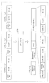
- FIG. 6 is a configuration diagram of the gateway 100.
- the gateway 100 includes a C communication unit 110a, a C communication unit 110b, an E communication unit 120, a transfer rule holding unit 130, and a transfer control unit 140.
- Each of these components is realized by a communication circuit, a memory, a digital circuit, a processor that executes a program stored in the memory, and the like in the gateway 100.
- the C communication unit 110a is a communication circuit or the like connected to the bus 30a configuring the first network, and includes a reception unit 111a that sequentially receives CAN frames from the bus 30a, and a transmission unit 112a that transmits CAN frames to the bus 30a. including.
- the C communication unit 110b is a communication circuit or the like connected to the bus 30b configuring the first network, and includes a reception unit 111b that sequentially receives CAN frames from the bus 30b, and a transmission unit 112b that transmits CAN frames to the bus 30b. including.
- the E communication unit 120 is a communication circuit or the like connected to the cable 20d (wired transmission path connected to the E-HUB 400) constituting the second network, and includes a reception unit 121 that receives an E frame from the cable 20d, 20d, and a transmission unit 122 that transmits the E frame.
- the transfer rule holding unit 130 is realized by a storage medium such as a memory, and holds reference information that defines frame transfer conditions and the like.
- the reference information includes, for example, transfer rule information in which a transfer target CAN-ID and a transfer source bus and a destination (MAC address, etc.) are associated, and a priority transfer target CAN-ID and a transfer source bus and a destination. The priority transfer list attached.
- the transfer control unit 140 is realized by, for example, a processor that executes a program, and determines whether or not the received frame should be transferred, and performs control related to transfer according to the determination result.
- the control related to the transfer is, for example, control for causing the E communication unit 120 to transmit an E frame including a plurality of pieces of CAN frame information as a payload to the cable 20d based on a plurality of CAN frames received sequentially.
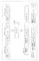
- FIG. 7 shows an image in which an E frame is transmitted based on a plurality of CAN frames (CAN frames 1 to N) received by the gateway 100. As shown in the figure, the gateway 100 changes the configuration of the frame when transferring the frame.
- the payload of the E frame to be transmitted includes N CAN frame information, for example, which is a predetermined number.
- the data of the N CAN frame information is the contents (data) of the data field of the received N CAN frames.
- the contents of the CAN frame received and waiting to be transferred are stored in a storage medium (buffer) such as a memory provided in the gateway 100, for example.
- the E frame including N pieces of CAN frame information in FIG. 7 is received by the destination E-ECU (for example, E-ECU 200a) via the E-HUB 400, for example.
- the MAC address of the gateway 100 is set as the transmission source MAC address of the header of the E frame, and the ON CAN flag indicating that CAN frame information is included is set in the payload of the E frame.
- the MAC address of the destination E-ECU is set according to the transfer rule information held by the transfer rule holding unit 130 or the like.
- the transfer control unit 140 includes a determination unit 141 and a frame construction unit 142, and controls the transmission unit (the transmission unit 122, the transmission unit 112a, or the transmission unit 112b) under a certain condition according to the result of the determination by the determination unit 141. Then, the frame is transmitted.
- the determination unit 141 determines whether or not the CAN frame data should be transmitted to the second network based on the CAN-ID for the CAN frame received by the reception unit 111a or the reception unit 111b. This determination is performed, for example, according to predetermined reference information regarding CAN-ID. Further, the determination unit 141 selects the destination of the CAN frame data according to the reference information. The determination of whether or not the CAN frame should be transmitted to the second network and the selection of the destination of the frame (E frame or CAN frame) including the data of the CAN frame are, for example, 1 to which data should be transmitted to the second network. This is performed using transfer rule information indicating CAN-ID or the like of one or more CAN frames.
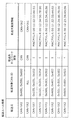
- the transfer rule information is information in which, for example, a transfer source, a transfer target CAN-ID, a transfer destination network type, and transfer destination identification information are associated with each other.
- E indicates the second network (E network)
- CAN indicates the first network.
- the E network is a second network in which transmission is performed using the Ethernet (registered trademark) protocol.
- the transfer destination identification information is information that identifies the MAC address if the transfer destination network type is E network, and identifies the bus if the transfer destination network type is CAN.
- the transfer destination network type is CAN and a plurality of connections are connected. This indicates that transmission is to be made to the CAN bus 2 among the CAN buses that are currently connected. In addition, all CAN frames received from the transfer source CAN bus 2 are to be transmitted to the CAN bus 1. Further, when transferring a CAN frame having a CAN-ID of 0x100, 0x101, or 0x102 received from the transfer source CAN bus 1, the CAN frame information is stored in the E frame because the transfer destination network type is the E network. This indicates that the destination MAC address of the E frame should be transmitted as 00: 11: 22: 33: 44: 55 (for example, the MAC address of the E-ECU 200a).
- the determination unit 141 distinguishes whether the bus that received the CAN frame is the CAN bus 1 (bus 30a) or the CAN bus 2 (bus 30b), compares it with the transfer rule information transfer source, and transfers the CAN-ID of the CAN frame. Match with the transfer target CAN-ID of the rule information. If there is a pair of the transfer source and transfer target CAN-ID corresponding to the collation, the determination unit 141 identifies the corresponding transfer destination network type and transfer destination identification information, and thereby determines a frame based on the received CAN frame. Select the destination. If there is no pair of transfer source and transfer target CAN-ID corresponding to the collation, the determination unit 141 should not transmit the received CAN frame to the first network, and also send it to the second network.
- the determination unit 141 determines that the received CAN frame should be transmitted to the second network. .
- the determination unit 141 uses any one of a plurality of MAC addresses as transfer destination identification information in the transfer rule information as CAN frame data or the like (CAN frame information) to be transmitted to the second network. It is selected as the destination of the included E frame.
- the reference information referred to by the determination unit 141 is, for example, a combination of a reception ID list indicating whether or not a CAN-ID to be transferred and transfer rule information in which a CAN-ID to be transferred and a transfer destination are associated with each other.
- any standard information format may be used.
- the reference information may be a list of CAN-IDs that should not be transferred, a function that distinguishes whether the CAN-IDs should be transferred, or the like.
- the destination in the reference information (for example, transfer destination identification information indicated by the transfer rule information) may be a MAC address or other E-ECU identification information (for example, an IP (Internet Protocol) address). Alternatively, it may be an address representing a subnetwork to which a plurality of E-ECUs of the same type are connected.
- the frame construction unit 142 When the determination unit 141 determines that a plurality of sequentially received CAN frames should be transmitted to the second network, the frame construction unit 142 has the same destination selected by the determination unit 141 (for example, the same destination E -Concatenate data (CAN frame information) between a plurality of (e.g., N, which is a predetermined number) CAN frames by connecting a plurality of CAN frames (CAN frame information), and the CAN flag is turned ON to construct an E frame ( (See FIG. 7). In this case, the frame construction unit 142 sets the MAC address of the destination E-ECU (the MAC address indicated by the transfer destination identification information in the transfer rule information) as the destination MAC address of the E frame header.
- the same destination E -Concatenate data CAN frame information
- N which is a predetermined number
- the transfer control unit 140 causes the transmission unit 122 of the E communication unit 120 to transmit the E frame constructed by the frame construction unit 142 to the cable 20d.
- the frame construction unit 142 provides an IP header in the payload of the E frame (for example, the IP header before the CAN flag in FIG. 7).
- the IP address of the E-ECU of the destination is included as the destination IP address in the IP header, and the MAC address searched based on the IP address of the destination E-ECU is used as the destination MAC of the E frame. It may be set as an address.
- the arrangement order of the CAN frame information when the frame construction unit 142 concatenates a plurality of pieces of CAN frame information and arranges them in the payload of the E frame may be any order.
- the following method is useful: .
- One method is that CAN frame information (data, etc.) relating to each of a plurality of CAN frames determined to be transmitted to the second network by the determination unit 141 is received by the reception unit 111a or the reception unit 111b.
- This is a method of arranging in the E frame in the order received.
- the E-ECU that has received the E frame transmitted to the gateway 100 via the E-HUB 400 can process the data included in the E frame based on the order in which the data is transmitted on the CAN bus. it can.
- CAN frame information (data, etc.) relating to each of a plurality of CAN frames determined to be transmitted to the second network by the determination unit 141 is based on the CAN-ID of the CAN frame.
- the frames are arranged in the E frame in an order according to a predetermined priority order for each CAN-ID.
- the predetermined priority order for each CAN-ID is, for example, in ascending order of CAN-ID values, as in the communication arbitration on the CAN bus.
- the E-ECU that has received the E frame transmitted to the gateway 100 via the E-HUB 400 performs processing based on the priority order (eg, importance order) of each data included in the E frame. Can be performed.
- the transfer control unit 140 receives the received CAN bus.
- the transmission unit (the transmission unit 112a or the transmission unit 112b) is controlled so that the frame is transmitted to the other CAN bus as it is.
- the transfer control unit 140 When the determination unit 141 selects an E-ECU (that is, the MAC address of the E-ECU) as a destination corresponding to a CAN frame received from any CAN bus, the transfer control unit 140 is identical.
- a predetermined condition relating to the received quantity of the CAN frame received by the receiving unit (receiving unit 111a or receiving unit 111b) is established for the CAN frame whose destination is selected, the frame building unit 142 is configured to construct an E frame.
- the transmitting unit 122 transmits the E frame.
- the predetermined condition relating to the received quantity is, for example, that N CAN frames corresponding to the same destination have been received (for example, the CAN frame information in the next E frame for the destination since the previous E frame was transmitted to the destination). Is received N times).
- the predetermined condition related to the received quantity is that a predetermined number M bytes of CAN frames whose CAN frame information should be included in the next E frame for the destination have been received since the previous E
- the transfer control unit 140 determines the specific even if the predetermined condition relating to the received quantity is not satisfied.
- the frame construction unit 142 constructs an E frame including CAN frame information (data etc.) of the CAN frame having the ID, and causes the transmission unit 122 to immediately transmit the E frame to the second network.
- the specific ID is, for example, a priority transfer target CAN-ID described in a priority transfer list as one piece of reference information held in the transfer rule holding unit 130.
- FIG. 9 shows an example of a priority transfer list as one piece of reference information used by the transfer control unit 140.
- the priority transfer list is information in which, for example, a transfer source, a priority transfer target CAN-ID, a transfer destination network type, and transfer destination identification information are associated with each other.
- the priority transfer list in the example of FIG. 9 includes, for example, a CAN frame having a CAN-ID of 0x100 received from the CAN bus 1 and an E-ECU (for example, E-ECU 200a) with a MAC address of 00: 11: 22: 33: 44: 55. ) To be transferred without delay.
- the transfer control unit 140 when the transfer control unit 140 receives a CAN frame with a CAN-ID of 0x100 from the CAN bus 1, the transfer control unit 140 immediately transmits an E frame in which CAN frame information such as data of the CAN frame is included in the payload.
- the transmission unit 122 transmits the data.
- the transfer control unit 140 distinguishes whether the bus that received the CAN frame is the CAN bus 1 (bus 30a) or the CAN bus 2 (bus 30b), and compares it with the transfer source of the priority transfer list.
- the CAN-ID is checked against the priority transfer target CAN-ID in the priority transfer list. Then, if there is a pair of the transfer source and transfer target CAN-ID corresponding to the collation, the transfer control unit 140 identifies the corresponding transfer destination identification information, thereby identifying the E frame based on the received CAN frame. Select a destination.
- the priority transfer target CAN-ID (that is, the specific ID) in the priority transfer list is, for example, a CAN-ID (error notification ID) predetermined for a CAN frame for notifying abnormality in vehicle travel control.
- a CAN-ID error notification ID
- the error notification information is displayed on the display of the IVI 300a connected to the E-ECU 200a. It is possible to quickly display a warning screen based on. Therefore, it is useful for preventing accidents.
- the CAN-ID of the CAN frame related to vehicle running control such as running, turning, and stopping can be determined as a specific ID.
- the transfer control unit 140 may determine the specific ID by any method other than the priority transfer list, for example, by setting all CAN-IDs having a value equal to or less than a predetermined threshold as the specific ID. Also good.
- the transfer control unit 140 transmits the E frame including the CAN frame information of the CAN frame having the specific ID to the transmission unit 122, it is determined by the determination unit 141 that it should be transmitted to the second network. Another E frame including CAN frame information (data, etc.) of one or a plurality of CAN frames not having a specific ID that has not been transmitted is generated in the frame construction unit 142, and the E frame is transmitted to the transmission unit 122. May be sent to. In addition, the transfer control unit 140 determines that the determination unit 141 should transmit the E frame including the CAN frame information of the CAN frame having the specific ID to the frame construction unit 142 and is still transmitted.
- CAN frame information of a CAN frame that does not have a specific ID construct an E frame, and cause the transmission unit 122 to transmit the E frame.
- the priority transfer target CAN-ID that is, the specific ID
- the transfer control unit 140 receives a CAN frame with a CAN-ID of 0x100.
- the accumulated CAN may be transmitted by being connected to the CAN frame information related to the frame and the CAN frame information related to the CAN frame of the specific ID (0x100).
- the transfer control unit 140 has a transmission control function that generates a CAN frame based on the content of the E frame received by the reception unit 121 of the E communication unit 120 and transmits the CAN frame to the transmission unit 112a or the transmission unit 112b to the CAN bus. You may have.
- the transmission unit 122 transmits, to the second network, an E frame including data of each of the plurality of CAN frames determined to be transmitted to the second network by the determination unit 141 under the control of the transfer control unit 140 ( That is, it is sent to the cable 20d). Specifically, the transmission unit 122 transmits an E frame including CAN frame information of each of a plurality of CAN frames for which the same destination is selected by the determination unit 141 to the destination, and the CAN frame information is included in the E frame. This is performed when a predetermined condition relating to the received quantity for the received CAN included is satisfied. Even when the predetermined condition is not satisfied, when the CAN frame having the specific ID is received, the transmission unit 122 transmits an E frame including CAN frame information related to the CAN frame.
- the transmitting unit 122 determines that the determining unit 141 should transmit to the second network and has not yet transmitted.
- the CAN frame information of a CAN frame that does not have a specific ID is included in the E frame and transmitted, or included in another E frame and transmitted.
- FIGS. 10 and 11 show a specific example of a transfer processing sequence related to CAN frame transfer in the gateway 100.
- FIG. The transfer processing sequence in FIGS. 10 and 11 represents a transfer process in cooperation with the C communication unit 110 a, the transfer control unit 140, the C communication unit 110 b, and the E communication unit 120 of the gateway 100.
- the CAN frame transfer is transmission of the same CAN frame as the received CAN frame to the CAN bus, or transmission of an E frame including CAN frame information of one or more received CAN frames.
- the C communication unit 110a connected to the CAN bus 1 receives the CAN-ID from the CAN bus 1 at the receiving unit 111a, and determines whether or not the CAN-ID is to be received (step S1). This determination is made with reference to, for example, a reception ID list in which CAN-IDs to be received are listed in advance. Note that the determination process based on the received ID list by the reception unit 111a may be shared by the determination unit 141 of the transfer control unit 140. In this case, the determination unit 141 determines whether it is a CAN-ID to be received (or whether it is a CAN-ID to be transferred) based on the reception ID list or transfer rule information.
- the receiving unit 111a of the C communication unit 110a determines that the CAN-ID is to be received in step S1
- the receiving unit 111a receives the CAN frame (step S2) and notifies the transfer control unit 140 of the CAN frame (step S3). ).
- the transfer control unit 140 acquires and refers to the transfer rule information held by the transfer rule holding unit 130 in order to confirm the transfer destination of the notified CAN frame (step S4).
- the transfer control unit 140 determines whether or not the CAN-ID of the CAN frame is a CAN-ID to be transferred to the CAN bus 2 (step S5). Only when the CAN-ID is to be transferred, the CAN frame is notified to the C communication unit 110b (step S6).
- the C communication unit 110b notified of the CAN frame transmits the CAN frame to the CAN bus 2 by the transmission unit 112b (step S7).
- step S5 If it is determined in step S5 that the CAN-ID of the CAN frame is not a CAN-ID to be transferred to the CAN bus 2, and if the CAN frame is notified in step S6, the transfer control unit 140 transfers Based on the rule information, it is determined whether or not the CAN-ID of the CAN frame is a CAN-ID to be transferred to the second network (E network) (step S8). If it is determined in step S8 that the CAN-ID is not to be transferred to the E network, the gateway 100 ends the transfer process.
- E network the second network
- step S8 If the transfer control unit 140 determines in step S8 that the CAN-ID of the CAN frame (CAN frame received in step S2) is the CAN-ID to be transferred to the E network, the transfer frame is The priority transfer list held by the transfer rule holding unit 130 is acquired and referred to in order to confirm whether or not it should be transferred preferentially (rapidly) (step S9). Then, the transfer control unit 140 determines whether or not the CAN-ID of the CAN frame is a CAN-ID (priority transfer target CAN-ID) described in the priority transfer list (step S10).
- CAN-ID priority transfer target CAN-ID
- the transfer control unit 140 When it is determined in step S10 that the CAN-ID of the CAN frame is the priority transfer target CAN-ID, the transfer control unit 140 includes the CAN frame information related to the CAN frame and the ON CAN flag in the payload.
- An E frame is generated (step S11).
- the MAC address (MAC address of the destination E-ECU) indicated by the corresponding transfer destination identification information in the priority transfer list is set.
- the MAC address of the gateway 100 is set as the source MAC address of the header of the E frame.
- the transfer control unit 140 gives priority notification (immediate notification) to the E communication unit 120 so that the E frame generated in step S11 is transmitted to the destination (step S12).
- the transmission unit 122 of the E communication unit 120 transmits the E frame (step S13).
- step S10 If it is determined in step S10 that the CAN-ID of the CAN frame is not the priority transfer target CAN-ID, the transfer control unit 140 displays the CAN frame information including the CAN-ID, size, and data of the CAN frame. In association with the destination (MAC address) selected based on the transfer rule information, it is stored in a buffer (a storage medium provided in the gateway 100) (step S14).
- a buffer a storage medium provided in the gateway 100
- step S12 or step S14 the transfer control unit 140 determines whether or not a predetermined condition relating to the received quantity of CAN frames is satisfied, that is, whether or not N pieces of CAN frame information having the same destination are stored in the buffer. Determination is made (step S15).
- step S15 When it is determined in step S15 that the predetermined condition is satisfied (that is, N pieces of CAN frame information of the same destination are accumulated), the transfer control unit 140 sets the N number of the same destination and the CAN flag set to ON.
- An E frame in which the CAN frame information is included in the payload is generated (step S16).
- the MAC address of the destination based on the transfer rule information is set as the destination MAC address of the header of the E frame, and the MAC address of the gateway 100 is set as the source address of the header, for example.
- the transfer control unit 140 notifies the E communication unit 120 to transmit the E frame generated in step S16 to the destination (step S17). Upon receiving this notification, the transmission unit 122 of the E communication unit 120 transmits the E frame (step S18).
- step S15 when the transfer control unit 140 determines that the predetermined condition is not satisfied, the gateway 100 ends the transfer process and waits for reception of the next CAN frame.
- the gateway 100 when the gateway 100 receives the CAN frame transmitted from the C-ECU to the CAN bus in the in-vehicle network including the first network and the second network having different communication protocols.
- the frame is transferred by transmitting information (CAN frame information) such as data of the CAN frame with the E-ECU as a destination under a certain condition.
- the gateway 100 includes CAN frame information related to a plurality of received CAN frames destined for the same E-ECU, and transmits an E frame including the ON CAN flag to the E-ECU. . Thereby, the transmission efficiency can be increased.
- the gateway 100 when receiving a CAN frame having a specific ID, the gateway 100 immediately transmits an E frame including CAN frame information related to the CAN frame to the specific E-ECU, thereby transferring the frame.
- the contents of the CAN frame or the like having the specific ID can be quickly transmitted to the E-ECU. That is, the in-vehicle network system 10 uses a transfer method that can cause delay in the transmission of frame information in order to increase the transmission efficiency of information. For example, by defining the CAN-ID of an important CAN frame as a specific ID, for example. Important information is quickly transmitted from the C-ECU to the E-ECU.
- the in-vehicle network system according to the present embodiment includes a gateway 100a having the same configuration as the gateway 100 (see FIG. 6) in the in-vehicle network system 10 shown in the first embodiment.
- the function of the transfer control unit 140 in the gateway 100a is partially different from the function of the transfer control unit 140 in the gateway 100.
- the same components as those shown in the first embodiment are denoted by the same reference numerals as those in the first embodiment, and the description thereof is omitted as appropriate.
- the in-vehicle network system according to the present embodiment is the same as the in-vehicle network system 10 shown in the first embodiment with respect to points that are not particularly described here.
- the transfer control unit 140 of the gateway 100 shown in the first embodiment determines that a plurality of CAN frames received sequentially should be transmitted to the second network
- the transfer control unit 140 is based on reference information (transfer rule information or the like).
- An E frame in which CAN frame information of a plurality of (for example, a predetermined number N) CAN frames is concatenated and included in the payload with the same selected destination (for example, the MAC address of the same E-ECU with the same destination) Is constructed (see FIG. 7).
- the transfer control unit 140 of the gateway 100a is selected based on reference information (transfer rule information, etc.) when it is determined that a plurality of CAN frames received sequentially should be transmitted to the second network.
- the E frame included in the payload is constructed by concatenating the CAN frame information of a plurality of (for example, a predetermined number N) CAN frames, and the E frame is transmitted to the transmission unit 122. 2 Send to network.
- the configuration of the E frame in this case is as shown in FIG. 12, for example.
- FIG. 12 shows an image in which an E frame is transmitted based on a plurality of CAN frames (CAN frames 1 to N) received by the gateway 100a.
- N CAN frame information (CAN-ID, size and data), which is a predetermined number, is added to a transfer destination MAC address (that is, the destination E-ECU). MAC addresses) are added.
- the data of the N CAN frame information is the contents (data) of the data field of the received N CAN frames.
- the broadcast address is set as the destination MAC address of the header of the E frame
- the MAC address of the gateway 100 is set as the source MAC address of the header of the E frame
- the CAN frame information is included in the payload of the E frame.
- a CAN flag that is turned on is set.
- each E-ECU (E-ECU 200a to 200c, etc.) receives an E frame including N CAN frame information each having a transfer destination MAC address added thereto via, for example, E-HUB 400. Will be.
- the E-HUB 400 receives an E frame whose destination MAC address is a broadcast address
- the E-HUB 400 transmits the E frame from all ports other than the received port (that is, the connection terminal of the cable).
- Each E-ECU can extract CAN frame information addressed to its own device in the E frame by collating the transfer destination MAC address in the payload of the E frame with its own MAC address.
- the E-HUB 400 that has received an E frame including CAN frame information corresponding to each of a plurality of destinations as shown in FIG. 12 sets each of the plurality of CAN frame information in the payload of the E frame as a destination (transfer destination MAC address). For each destination, from the port toward the E-ECU indicated by the destination, the CAN frame information corresponding to the destination is included in the payload, and the transfer destination MAC address is set in the destination MAC address of the header You may have the division transfer function which sends out an E frame.
- An E-HUB having such a division transfer function determines whether to execute a division transfer function or a general E frame transfer function depending on, for example, whether or not the CAN flag in the payload of the E frame is ON.
- the gateway 100a uses not a broadcast address as a destination MAC address of the header of the E frame when transmitting the E frame. It is useful to set the MAC address of the E-HUB.
- the gateway 100a In addition, when the destination indicated by the transfer destination identification information in the transfer rule information (see FIG. 8) is an address representing a subnetwork to which a plurality of the same type of E-ECUs are connected, the gateway 100a In the configuration shown in FIG. 12, an E frame including a plurality of pieces of CAN frame information destined for the same type of E-ECU may be constructed and transmitted to the second network.
- the gateway 100a transmits an E frame including CAN frame information related to a plurality of CAN frames regardless of the destination based on the CAN frame received from the bus of the first network to the second network. Send to. Thereby, the transmission efficiency can be increased to some extent.
- Embodiments 1 and 2 have been described as examples of the technology according to the present disclosure.
- the technology according to the present disclosure is not limited to this, and can also be applied to embodiments in which changes, replacements, additions, omissions, and the like are appropriately performed.
- the following modifications are also included in one embodiment of the present disclosure.
- the in-vehicle network system shown in the above embodiment includes an E-HUB that includes a division transfer function and is connected to the second network in addition to the E-HUB 400 that does not have a division transfer function. May be.
- the gateway 100a shown in the second embodiment sequentially receives the CAN frame and transmits an E frame as shown in FIG. 12 to the E-HUB 400, and the E-HUB 400 performs the division transfer function on the E frame.
- the included E-HUB is transferred as the destination, the E-HUB including the division transfer function is used to divide a plurality of CAN frame information in the E frame, and the CAN frame information corresponding to the destination is obtained for each E-ECU for each destination. It is good also as transmitting the E frame containing.
- the in-vehicle network system is shown.
- the devices such as the gateway, ECU (E-ECU and C-ECU), E-HUB, and the like described above are various network communications such as robots and industrial equipment. Can be used in the system.
- the in-vehicle network includes the first network and the second network, and the first network transmits a CAN frame (data frame) through the CAN bus according to the CAN protocol.
- a CAN frame data frame
- an E frame (Ethernet (registered trademark) frame) is transmitted according to the Ethernet (registered trademark) protocol.
- This CAN protocol has a broad meaning including CANNOpen used for embedded systems in automation systems, or derivative protocols such as TTCAN (Time-Triggered CAN), CANFD (CAN-Flexible Data-Rate). It may be treated.
- the data frame in the CAN protocol may be an extended ID format in addition to the standard ID format.
- the Ethernet (registered trademark) frame may be, for example, an Ethernet (registered trademark) version 2 frame, or may be a frame defined by IEEE 802.3.
- the Ethernet (registered trademark) protocol includes Ethernet (registered trademark) AVB (Audio Video Bridging) according to IEEE 802.1 or Ethernet (registered trademark) TSN (Time Sensitive Network) and Ethernet (registered trademark) according to IEEE 802.1. ) / IP (Industrial Protocol), EtherCAT (registered trademark) (Ethernet (registered trademark) for Control Automation Technology), etc.
- the first network transmits a first type frame (for example, a CAN frame) by a bus according to a first communication protocol, and the second network follows a second communication protocol different from the first communication protocol.
- the first communication protocol is, for example, the CAN protocol, but is not limited to the CAN protocol, for example, LIN (Local Interconnect Network), MOST (registered trademark) (Media Oriented Systems Transport), FlexRay (registered trademark), or the like.
- the second communication protocol is, for example, the Ethernet (registered trademark) protocol, but is not limited to the Ethernet (registered trademark) protocol, and may be, for example, a broader reach protocol.
- the information transmitted by the first type electronic control unit (for example, C-ECU) connected to the first network by the in-vehicle network including the first network and the second network is transmitted to the second type connected to the second network. It can be transmitted to an electronic control unit (eg, E-ECU).
- E-ECU electronice control unit
- Ethernet registered trademark
- the second communication protocol may be various protocols having a higher communication speed than the first communication protocol.
- the second type frame (for example, E frame) includes the data of the first type frame (for example, CAN frame) to be transmitted to the second network in the payload of the second type frame (for example, for example, although it has an identification flag (for example, a CAN flag) for determining whether or not it includes (CAN frame information), the identification flag may be included in the header of the second type frame.
- the gateway 100 may include the CAN flag in the header of the E frame. Thereby, it is possible to determine whether or not the payload includes CAN frame information only by referring to the header of the E frame. For example, when the payload of the E frame is encrypted, the processing is simplified (decrypted). May be possible.
- a bit identifying whether or not the destination MAC address in the header of the E frame is a global MAC address may be used as a CAN flag (for example, a value indicating a local MAC address is treated as a CAN flag being ON).
- a CAN flag may be provided in the type field in the header of the E frame.
- the gateway 100 may include the CAN flag in both the header and the payload of the E frame.
- the gateway 100 is connected to one Ethernet (registered trademark) cable 20d in relation to the second network.
- the gateway 100 is connected to a plurality of Ethernet (registered trademark) cables.
- Each port may be provided. That is, the gateway 100 may be integrated with the E-HUB 400.
- the gateway 100 selects a CAN frame destination based on reference information such as transfer rule information, specifies a port connected to a cable corresponding to the destination by, for example, a MAC address table, and sets E to the port.
- a frame may be transmitted.
- the determination unit 141 in the transfer control unit 140 of the gateway 100 refers to reference information (for example, transfer rule information and a MAC address table) that associates each of a plurality of cables with a CAN-ID. Based on the CAN-ID of the CAN frame received by the receiving unit 111a or the receiving unit 111b, CAN frame information that is data of the CAN frame to be transmitted to the second network through one of the cables As the destination of the message. Then, the transfer control unit 140 includes a frame construction unit 142 including CAN frame information, which is data of each of a plurality of CAN frames where the determination unit 141 has the same cable selected as the CAN frame information transmission destination.
- reference information for example, transfer rule information and a MAC address table
- the gateway 100 may select a plurality of cables and send an E frame having the same payload including one or more pieces of CAN frame information to the plurality of cables.
- the gateway 100 may not have a function as a switch (switching hub), and the E frame may be transmitted to all the cables without distinguishing the destination MAC address of the E frame.
- the gateway 100 when a predetermined condition relating to the reception quantity of CAN frames received sequentially is satisfied (for example, when CAN frame information of the same destination is accumulated in N buffers), An E frame including CAN frame information related to these CAN frames is transmitted to the second network.
- a predetermined condition relating to time may be used. That is, when the gateway 100 measures the time and a predetermined condition relating to time is satisfied, an E frame including unsent CAN frame information of the same destination accumulated in the buffer is generated and transmitted.
- the unit 122 may transmit the E frame to the second network.
- the predetermined condition relating to time is, for example, a condition that is satisfied when a predetermined time has elapsed since the previous E frame was transmitted.
- the gateway 100 is connected to a plurality of CAN buses in relation to the first network, but may be connected to a single CAN bus.
- the transfer source information may be omitted in the transfer rule information and the priority transfer list.
- the CAN frame information included in the E frame transmitted by the gateway 100 is composed of CAN-ID, size, and data.
- the CAN frame information includes only data. It may be included.
- the order of execution of the various processing procedures shown in the above-described embodiment is not necessarily limited to the order described above.
- the execution order can be changed, a plurality of procedures can be performed in parallel, or a part of the procedures can be omitted without departing from the gist.
- the gateway, ECU, E-HUB, and other devices in the above embodiments may include other hardware components such as a hard disk device, a display, a keyboard, and a mouse.
- the program stored in the memory may be executed by a processor to realize the function of the apparatus in software, or the function may be realized by dedicated hardware (digital circuit or the like). May be.
- the function sharing of each component in the apparatus can be changed.
- a part or all of the components constituting each device in the above embodiment may be configured by one system LSI (Large Scale Integration).
- the system LSI is an ultra-multifunctional LSI manufactured by integrating a plurality of components on a single chip.
- the system LSI is a computer system including a microprocessor, a ROM, a RAM, and the like. .
- a computer program is recorded in the RAM.
- the system LSI achieves its functions by the microprocessor operating according to the computer program.
- each part of the constituent elements constituting each of the above devices may be individually made into one chip, or may be made into one chip so as to include a part or the whole.
- the system LSI is used here, it may be called IC, LSI, super LSI, or ultra LSI depending on the degree of integration.
- the method of circuit integration is not limited to LSI's, and implementation using dedicated circuitry or general purpose processors is also possible.
- An FPGA Field Programmable Gate Array
- a reconfigurable processor that can reconfigure the connection and setting of circuit cells inside the LSI may be used.
- integrated circuit technology comes out to replace LSI's as a result of the advancement of semiconductor technology or a derivative other technology, it is naturally also possible to carry out function block integration using this technology. Biotechnology can be applied as a possibility.
- a part or all of the constituent elements constituting each of the above devices may be constituted by an IC card or a single module that can be attached to and detached from each device.
- the IC card or the module is a computer system including a microprocessor, a ROM, a RAM, and the like.
- the IC card or the module may include the super multifunctional LSI described above.
- the IC card or the module achieves its function by the microprocessor operating according to the computer program. This IC card or this module may have tamper resistance.
- a transfer method including all or part of the processing procedure illustrated in FIGS.
- transmission of the second type frame is performed according to the second communication protocol different from the first communication protocol and the bus of the first network where the first type frame is transmitted via the bus according to the first communication protocol.
- a transfer method used in a gateway connected to the second network the reception step of sequentially receiving the first type frame from the bus (for example, step S2), and the first type frame received in the reception step
- a determination step for example, step S8 for determining whether data of the first type frame should be transmitted to the second network, and a plurality of first types determined to be transmitted to the second network in the determination step
- a transmission step of transmitting a second type frame including data of each frame to the second network for example, Step a S16 ⁇ S18
- it may be a program (computer program) for realizing this method by a computer, or may be a digital signal composed of the computer program.
- the program may be a program for executing a predetermined transfer process including a reception step, a determination step, and a transmission step according to the transfer method.
- a computer-readable recording medium such as a flexible disk, a hard disk, a CD-ROM, an MO, a DVD, a DVD-ROM, a DVD-RAM, or a BD can be used as the computer program or the digital signal. (Blu-ray (registered trademark) Disc), recorded on a semiconductor memory or the like. Further, the digital signal may be recorded on these recording media.
- the computer program or the digital signal may be transmitted via an electric communication line, a wireless or wired communication line, a network typified by the Internet, data broadcasting, or the like.
- an aspect of the present disclosure may be a computer system including a microprocessor and a memory, the memory recording the computer program, and the microprocessor operating according to the computer program.
- the program or the digital signal may be carried out by recording and transferring the program or the digital signal on the recording medium, or by transferring the program or the digital signal via the network or the like, by another independent computer system It may be carried out.
- the present disclosure can be used to transmit information transmitted from an ECU connected to a bus of a first network such as CAN to another ECU via a second network such as Ethernet (registered trademark).
- a first network such as CAN
- a second network such as Ethernet (registered trademark).
Landscapes
- Engineering & Computer Science (AREA)
- Computer Networks & Wireless Communication (AREA)
- Signal Processing (AREA)
- Computer Security & Cryptography (AREA)
- Health & Medical Sciences (AREA)
- Computing Systems (AREA)
- General Health & Medical Sciences (AREA)
- Medical Informatics (AREA)
- Small-Scale Networks (AREA)
Abstract
According to the present invention, a gateway (100) is provided with: a reception unit (111a) for successively receiving a first type frame from a bus of a first network; a determination unit (141) for determining whether or not data of the first type frame received by the reception unit (111a) ought to be transmitted to a second network; and a transmission unit (122) for transmitting, to the second network, a second type frame containing data of each of a plurality of the first type frames that, as determined, ought to be transmitted to the second network by the determination unit (141).
Description
本開示は、車載ネットワーク等のネットワークで通信する電子制御ユニット間のメッセージの中継のためのメッセージ処理技術に関する。
This disclosure relates to a message processing technique for relaying messages between electronic control units that communicate over a network such as an in-vehicle network.
近年、自動車の中のシステムには、電子制御ユニット(ECU:Electronic Control Unit)と呼ばれる装置が多数配置されている。これらのECUをつなぐネットワークは車載ネットワークと呼ばれる。車載ネットワークには、多数の規格が存在する。その中でも最も主流な車載ネットワークの一つに、ISO11898-1で規定されているCAN(Controller Area Network)という規格が存在する。CANでは、有線伝送路(通信路)であるバスに接続されている各ECU(ノード)が、フレーム(メッセージ)を送受信する。またCANでは、送信先や送信元を指す識別子は存在せず、送信ノードはフレーム毎にID(CAN-ID)を付けて送信し(つまりバスに信号を送出し)、各受信ノードは予め定められたCAN-IDのメッセージのみを受信する(つまりバスから信号を読み取る)。また、より多くの情報を伝送するための規格として、IEEE802.3で規定されているEthernet(登録商標)という規格が存在する。Ethernet(登録商標)のフレーム(メッセージ)は、送信先や送信元を指す情報をヘッダに含む。Ethernet(登録商標)では、1フレームで送信できる最大データ量がCANより大きい。
In recent years, many systems called electronic control units (ECUs) are arranged in systems in automobiles. A network connecting these ECUs is called an in-vehicle network. There are many standards for in-vehicle networks. Among them, one of the most mainstream in-vehicle networks is a CAN (Controller Area Network) standard defined by ISO11898-1. In CAN, each ECU (node) connected to a bus that is a wired transmission path (communication path) transmits and receives a frame (message). In CAN, there is no identifier indicating a transmission destination or a transmission source, the transmission node transmits an ID (CAN-ID) for each frame (that is, sends a signal to the bus), and each reception node is predetermined. Only the message of the given CAN-ID is received (that is, the signal is read from the bus). Further, as a standard for transmitting more information, there is a standard called Ethernet (registered trademark) defined by IEEE 802.3. A frame (message) of Ethernet (registered trademark) includes information indicating a transmission destination and a transmission source in a header. In Ethernet (registered trademark), the maximum amount of data that can be transmitted in one frame is larger than CAN.
特許文献1には、CANプロトコルに従った機器とEthernet(登録商標)プロトコル等に従った機器との間でメッセージの中継を行うゲートウェイが記載されている。
Patent Document 1 describes a gateway that relays a message between a device conforming to the CAN protocol and a device conforming to the Ethernet (registered trademark) protocol.
Ethernet(登録商標)のネットワークと、CANのネットワークとを含む車載ネットワークシステムにおいて、他の電子制御ユニットと通信する電子制御ユニット(ECU)それぞれは、Ethernet(登録商標)とCANとのうち少なくとも一方のインタフェースを備えることになる。この場合に、Ethernet(登録商標)のインタフェースを有する電子制御ユニットと通信を行い、かつ、CANのバスに接続された電子制御ユニット(つまりCANのインタフェースを有する電子制御ユニット)とも通信を行う必要がある電子制御ユニットそれぞれが、両方のインタフェースを備えることには、コストの増大等といった問題がある。このため、例えばEthernet(登録商標)のインタフェースのみを備える電子制御ユニットが、ゲートウェイ装置等を介して、CANのバスに接続された電子制御ユニットへ情報を伝達できることが望まれる。なお、特許文献1は、ゲートウェイ装置が、CANのバスに接続された電子制御ユニット(以下、「C-ECU」とも称する。)が送信したメッセージを、Ethernet(登録商標)のインタフェースを備える電子制御ユニット(以下、「E-ECU」とも称する。)に中継(転送)する際に、いかなる構成のメッセージを送信すべきかについて示していない。
In an in-vehicle network system including an Ethernet (registered trademark) network and a CAN network, each electronic control unit (ECU) that communicates with another electronic control unit is at least one of Ethernet (registered trademark) and CAN. An interface will be provided. In this case, it is necessary to communicate with an electronic control unit having an Ethernet (registered trademark) interface, and also to communicate with an electronic control unit connected to a CAN bus (that is, an electronic control unit having a CAN interface). If each electronic control unit has both interfaces, there is a problem such as an increase in cost. For this reason, for example, it is desirable that an electronic control unit having only an Ethernet (registered trademark) interface can transmit information to an electronic control unit connected to a CAN bus via a gateway device or the like. Patent Document 1 discloses an electronic control provided with an Ethernet (registered trademark) interface for a message transmitted from an electronic control unit (hereinafter also referred to as “C-ECU”) connected to a CAN bus by a gateway device. When relaying (transferring) to a unit (hereinafter also referred to as “E-ECU”), it does not indicate what type of message should be transmitted.
そこで、本開示は、CAN等の第1ネットワークと、Ethernet(登録商標)等の第2ネットワークとを含むネットワークシステムにおいて、第1ネットワークに接続されたECU(例えばC-ECU)から送信されたメッセージのうち、第2ネットワークに接続されたECU(例えばE-ECU)にとって必要なメッセージが効率良く伝送されるように適切に中継を行うゲートウェイ装置を提供する。また、本開示は、そのゲートウェイ装置を含む車載ネットワークシステム並びにそのゲートウェイ装置で用いられる転送方法及びプログラムを提供する。
Accordingly, the present disclosure provides a message transmitted from an ECU (for example, C-ECU) connected to the first network in a network system including a first network such as CAN and a second network such as Ethernet (registered trademark). Among them, a gateway device is provided that relays appropriately so that a message necessary for an ECU (for example, an E-ECU) connected to a second network is efficiently transmitted. The present disclosure also provides an in-vehicle network system including the gateway device and a transfer method and program used in the gateway device.
上記課題を解決するために本開示の一態様に係るゲートウェイ装置は、第1通信プロトコルに従ってバスで第1種フレームの伝送が行われる第1ネットワークの当該バスと、第1通信プロトコルとは異なる第2通信プロトコルに従って第2種フレームの伝送が行われる第2ネットワークとに接続されるゲートウェイ装置であって、前記バスから第1種フレームを逐次受信する受信部と、前記受信部により受信された第1種フレームについて当該第1種フレームのデータが第2ネットワークに送信されるべきか否かを判定する判定部と、前記判定部により第2ネットワークに送信されるべきと判定された複数の第1種フレームそれぞれのデータを包含する第2種フレームを第2ネットワークに送信する送信部とを備えるゲートウェイ装置である。
In order to solve the above problem, a gateway device according to an aspect of the present disclosure is different from the first communication protocol in the first network in which the first type frame is transmitted on the bus according to the first communication protocol. A gateway device connected to a second network in which transmission of a second type frame is performed according to two communication protocols, a receiving unit for sequentially receiving the first type frame from the bus; and a second unit received by the receiving unit A determination unit that determines whether data of the first type frame should be transmitted to the second network for one type of frame, and a plurality of first items that are determined to be transmitted to the second network by the determination unit And a transmission unit that transmits a second type frame including data of each type frame to the second network. .
また、上記課題を解決するために本開示の一態様に係る車載ネットワークシステムは、第1通信プロトコルに従ってバスで第1種フレームの伝送が行われる第1ネットワークと、第1通信プロトコルとは異なる第2通信プロトコルに従って第2種フレームの伝送が行われる第2ネットワークとを含む車載ネットワークシステムであって、前記バスに接続された複数の第1種電子制御ユニットと、第2ネットワークに接続された第2種電子制御ユニットと、前記バスと第2ネットワークに接続されたゲートウェイ装置とを備え、前記ゲートウェイ装置は、前記バスから第1種フレームを逐次受信する受信部と、前記受信部により受信された第1種フレームについて当該第1種フレームのデータが第2ネットワークに送信されるべきか否かを判定する判定部と、前記判定部により第2ネットワークに送信されるべきと判定された複数の第1種フレームそれぞれのデータを包含する第2種フレームを第2ネットワークに送信する送信部とを備える車載ネットワークシステムである。
In order to solve the above problem, an in-vehicle network system according to an aspect of the present disclosure is different from a first network in which transmission of a first type frame is performed on a bus according to a first communication protocol and a first communication protocol. An in-vehicle network system including a second network for transmitting a second type frame according to a second communication protocol, wherein the first type electronic control unit is connected to the bus and the second network is connected to the second network. A two-type electronic control unit; and a gateway device connected to the bus and a second network, the gateway device receiving a first-type frame from the bus sequentially, and received by the receiving unit For the first type frame, it is determined whether the data of the first type frame should be transmitted to the second network. A vehicle that includes a determination unit that performs transmission, and a transmission unit that transmits, to the second network, a second type frame that includes data of each of the plurality of first type frames determined to be transmitted to the second network by the determination unit. It is a network system.
また、上記課題を解決するために本開示の一態様に係る転送方法は、第1通信プロトコルに従ってバスで第1種フレームの伝送が行われる第1ネットワークの当該バスと、第1通信プロトコルとは異なる第2通信プロトコルに従って第2種フレームの伝送が行われる第2ネットワークとに接続されたゲートウェイ装置で用いられる転送方法であって、前記バスから第1種フレームを逐次受信する受信ステップと、前記受信ステップで受信された第1種フレームについて当該第1種フレームのデータが第2ネットワークに送信されるべきか否かを判定する判定ステップと、前記判定ステップで第2ネットワークに送信されるべきと判定された複数の第1種フレームそれぞれのデータを包含する第2種フレームを第2ネットワークに送信する送信ステップとを含む転送方法である。
In addition, in order to solve the above problem, a transfer method according to an aspect of the present disclosure includes: a bus of a first network in which transmission of a first type frame is performed on a bus according to a first communication protocol; A transfer method used in a gateway device connected to a second network in which transmission of a second type frame is performed according to a different second communication protocol, wherein the receiving step sequentially receives the first type frame from the bus; A determination step for determining whether or not data of the first type frame should be transmitted to the second network for the first type frame received in the reception step, and that the determination type step should be transmitted to the second network A transmission for transmitting a second type frame including data of the determined plurality of first type frames to the second network. A transfer method comprising the steps.
また、上記課題を解決するために本開示の一態様に係るプログラムは、第1通信プロトコルに従ってバスで第1種フレームの伝送が行われる第1ネットワークの当該バスと、第1通信プロトコルとは異なる第2通信プロトコルに従って第2種フレームの伝送が行われる第2ネットワークとに接続される、マイクロプロセッサを含むゲートウェイ装置に所定転送処理を実行させるためのプログラムであって、前記所定転送処理は、前記バスから第1種フレームを逐次受信する受信ステップと、前記受信ステップで受信された第1種フレームについて当該第1種フレームのデータが第2ネットワークに送信されるべきか否かを判定する判定ステップと、前記判定ステップで第2ネットワークに送信されるべきと判定された複数の第1種フレームそれぞれのデータを包含する第2種フレームを第2ネットワークに送信する送信ステップとを含むプログラムである。
In order to solve the above problem, a program according to an aspect of the present disclosure is different from the first communication protocol and the bus of the first network in which transmission of the first type frame is performed on the bus according to the first communication protocol. A program for causing a gateway device including a microprocessor to execute a predetermined transfer process connected to a second network in which transmission of the second type frame is performed according to a second communication protocol, wherein the predetermined transfer process includes: A reception step of sequentially receiving the first type frame from the bus, and a determination step of determining whether data of the first type frame should be transmitted to the second network for the first type frame received in the reception step. And a plurality of first type frames determined to be transmitted to the second network in the determination step The second type frames include data respectively is a program that includes a transmission step of transmitting to the second network.
本開示によれば、互いに通信プロトコルの異なる第1ネットワーク及び第2ネットワークを含むネットワークシステムにおいて、CAN等の第1ネットワークのバスに接続された電子制御ユニット(第1種電子制御ユニット、例えばC-ECU)からのメッセージが、Ethernet(登録商標)等の第2ネットワークに接続された電子制御ユニット(第2種電子制御ユニット、例えばE-ECU)に効率的に伝送され得る。
According to the present disclosure, in a network system including a first network and a second network having different communication protocols, an electronic control unit (a first type electronic control unit, for example, C−) connected to a bus of a first network such as CAN. ECU) can be efficiently transmitted to an electronic control unit (second-type electronic control unit such as an E-ECU) connected to a second network such as Ethernet (registered trademark).
本開示の一態様に係るゲートウェイ装置は、第1通信プロトコルに従ってバスで第1種フレームの伝送が行われる第1ネットワークの当該バスと、第1通信プロトコルとは異なる第2通信プロトコルに従って第2種フレームの伝送が行われる第2ネットワークとに接続されるゲートウェイ装置であって、前記バスから第1種フレームを逐次受信する受信部と、前記受信部により受信された第1種フレームについて当該第1種フレームのデータが第2ネットワークに送信されるべきか否かを判定する判定部と、前記判定部により第2ネットワークに送信されるべきと判定された複数の第1種フレームそれぞれのデータを包含する第2種フレームを第2ネットワークに送信する送信部とを備えるゲートウェイ装置である。このようにゲートウェイ装置は、CAN等の第1ネットワークにおいてECU(第1種電子制御ユニット、例えばC-ECU)が送信した第1種フレームをバスから逐次受信して複数の第1種フレームのデータを包含させた第2種フレームを第2ネットワークに送信するという形態で、互いに異なる通信プロトコルが適用されるネットワーク間でのフレームの転送(中継)を行う。なお、バスから逐次受信した複数の第1種フレームそれぞれのデータは第2種フレームに含められて送信されるまで例えばゲートウェイ装置の内外のバッファ(メモリ等の記憶媒体)に格納され得る。このような転送によれば、第1種フレームのデータを個別にフレームの内容として第2ネットワークに送信するよりも、伝送効率が高まる。即ち、このゲートウェイ装置によれば、第1ネットワークに接続されたECU(例えばC-ECU)からの情報(データ)が、第2ネットワークに接続されたECU(第2種電子制御ユニット、例えばE-ECU)へと効率的に伝送され得る。
The gateway device according to an aspect of the present disclosure includes a second type of bus according to a second communication protocol different from the first communication protocol, and the bus of the first network in which transmission of the first type frame is performed on the bus according to the first communication protocol. A gateway device connected to a second network in which frame transmission is performed, wherein the first type frame received by the receiving unit and the first type frame received by the receiving unit are sequentially received from the bus. A determination unit that determines whether or not seed frame data is to be transmitted to the second network, and data of each of the plurality of first type frames that are determined to be transmitted to the second network by the determination unit A transmission unit that transmits a second type frame to the second network. As described above, the gateway device sequentially receives the first type frame transmitted from the ECU (first type electronic control unit, for example, C-ECU) in the first network such as CAN from the bus, and the data of the plurality of first type frames. The frame is transferred (relayed) between networks to which different communication protocols are applied in such a form that the second type frame including the frame is transmitted to the second network. The data of each of the plurality of first type frames sequentially received from the bus can be stored in, for example, a buffer (a storage medium such as a memory) inside or outside the gateway device until the data is included in the second type frame and transmitted. According to such a transfer, the transmission efficiency is higher than when the data of the first type frame is individually transmitted to the second network as the contents of the frame. That is, according to this gateway device, information (data) from an ECU (for example, C-ECU) connected to the first network is converted into an ECU (second-type electronic control unit, for example, E-type) connected to the second network. ECU).
また、第1ネットワーク及び第2ネットワークは車載ネットワークであり、前記ゲートウェイ装置は、第2ネットワークを構成するEthernet(登録商標)ケーブルと接続され、第1通信プロトコルは、CAN(Controller Area Network)プロトコルであり、第2通信プロトコルは、Ethernet(登録商標)プロトコルであり、第1種フレームは、CAN-IDを含み、前記データをデータフィールドに含むデータフレームであり、第2種フレームは、Ethernet(登録商標)ヘッダとペイロードとを含むEthernet(登録商標)フレームであり、前記送信部は、第2種フレームの第2ネットワークへの前記送信を、前記ケーブルへの当該第2種フレームの送出により行うこととしても良い。なお、第2種フレーム(Eフレーム)には、複数の各第1種フレーム(CANフレーム)のデータ(データフィールドの内容)の他に例えばCANーID等といった各第1種フレームの各種内容を包含させても良い。このゲートウェイ装置でフレームの中継がなされることにより、例えばEthernet(登録商標)インタフェースしか有さないE-ECUが、バス(CANバス)に接続されたC-ECUが送信した情報(データ)を効率的に取得できるようになり得る。
The first network and the second network are in-vehicle networks, the gateway device is connected to an Ethernet (registered trademark) cable constituting the second network, and the first communication protocol is a CAN (Controller (Area Network) protocol. Yes, the second communication protocol is the Ethernet (registered trademark) protocol, the first type frame is a data frame including CAN-ID, and the data is included in the data field, and the second type frame is Ethernet (registered) (Trademark) An Ethernet (registered trademark) frame including a header and a payload, and the transmission unit transmits the second type frame to the second network by transmitting the second type frame to the cable. It is also good. In addition, in the second type frame (E frame), in addition to the data (contents of the data field) of each of the plurality of first type frames (CAN frame), various contents of each first type frame such as CAN-ID are included. It may be included. By relaying frames with this gateway device, for example, an E-ECU having only an Ethernet (registered trademark) interface efficiently transmits information (data) transmitted from a C-ECU connected to a bus (CAN bus). Can be acquired automatically.
また、前記判定部は、前記受信部により受信された第1種フレームのCAN-IDに基づいて、当該第1種フレームの前記データが第2ネットワークに送信されるべきか否かを判定することとしても良い。これにより、バスで伝送されるCANフレームのうち、例えばE-ECUが受信すべきものとして予め規定されたCAN-IDを含むCANフレームのみが、E-ECUに伝達され得る。このため、例えば、必要のないCANフレームのデータの第2ネットワークへの転送が防止され得る。
Further, the determination unit determines whether the data of the first type frame should be transmitted to the second network based on the CAN-ID of the first type frame received by the receiving unit. It is also good. As a result, only CAN frames including CAN-IDs that are defined in advance as those to be received by the E-ECU among the CAN frames transmitted through the bus can be transmitted to the E-ECU. Therefore, for example, unnecessary transfer of CAN frame data to the second network can be prevented.
また、前記判定部は更に、複数の宛先のそれぞれとCAN-IDとを対応付けた基準情報を参照して、前記受信部により受信された第1種フレームのCAN-IDに基づいて、前記複数の宛先のうちいずれかを、第2ネットワークに送信されるべき当該第1種フレームの前記データの宛先として選定し、前記送信部は、前記判定部に選定された、第1種フレームの前記データの宛先が、同一であるところの複数の第1種フレームのそれぞれの前記データを包含する第2種フレームを、第2ネットワークに送信することとしても良い。なお、宛先は、1つのE-ECUであっても良いし、例えば同種の複数のE-ECUであっても良い(これらのE-ECUが接続されたサブネットワーク等であっても良い)。これにより、CANフレームのデータについて、送信すべき宛先が同一であるデータを複数包含させた第2種フレーム(Eフレーム)を構成して送信するので、宛先のE-ECU等に対して、効率良くCANフレームのデータを伝えることが可能となる。
Further, the determination unit further refers to the reference information in which each of a plurality of destinations is associated with a CAN-ID, and based on the CAN-ID of the first type frame received by the reception unit, the plurality of destinations Is selected as the destination of the data of the first type frame to be transmitted to the second network, and the transmission unit selects the data of the first type frame selected by the determination unit. The second type frame including the data of each of the plurality of first type frames having the same destination may be transmitted to the second network. The destination may be one E-ECU, for example, a plurality of the same type of E-ECUs (sub-networks to which these E-ECUs are connected, etc.). As a result, the CAN frame data is transmitted in the form of a second type frame (E frame) including a plurality of data having the same destination to be transmitted. It is possible to convey CAN frame data well.
また、前記送信部は、前記判定部に選定された、第1種フレームの前記データの宛先が、同一であるところの複数の第1種フレームのそれぞれの前記データを包含する第2種フレームに、当該選定された宛先を表す宛先情報を含ませて、当該第2種フレームの前記送信を行うこととしても良い。これにより、例えばEフレームをブロードキャストしなくても良く、Eフレームは、宛先情報が示す宛先へと効率的に伝送され得る。
In addition, the transmitting unit selects a second type frame that includes the data of each of the plurality of first type frames that are selected by the determination unit and that have the same data destination of the first type frame. The transmission of the second type frame may be performed by including destination information indicating the selected destination. Thereby, for example, it is not necessary to broadcast the E frame, and the E frame can be efficiently transmitted to the destination indicated by the destination information.
また、前記基準情報は、複数の宛先としての複数のMACアドレスそれぞれとCAN-IDとを対応付けた情報であり、前記送信部は、前記判定部に選定された、第1種フレームの前記データの宛先が、同一であるところの複数の第1種フレームのそれぞれの前記データを第2種フレームの前記ペイロードに包含させ、当該第2種フレームのEthernet(登録商標)ヘッダにおける宛先MACアドレスとして、当該選定された宛先としてのMACアドレスを前記宛先情報として含ませて、当該第2種フレームの前記送信を行うこととしても良い。これにより、ヘッダで宛先を確認できるEフレームが第2ネットワークに送信される。このため、宛先となるE-ECUにEフレームが到達するまでの経路において、例えばネットワークハブ(例えばスイッチングハブ)等でヘッダを参照して転送経路を選定する等により、効率的な伝送が可能となる。
The reference information is information in which each of a plurality of MAC addresses as a plurality of destinations is associated with a CAN-ID, and the transmission unit selects the data of the first type frame selected by the determination unit. In the payload of the second type frame, the data of each of the plurality of first type frames where the destinations of the second type frame are the same, and as the destination MAC address in the Ethernet (registered trademark) header of the second type frame, The transmission of the second type frame may be performed by including the MAC address as the selected destination as the destination information. As a result, an E frame whose destination can be confirmed by the header is transmitted to the second network. For this reason, in the route until the E frame reaches the destination E-ECU, for example, a transfer route is selected by referring to the header with a network hub (for example, a switching hub), etc., so that efficient transmission is possible. Become.
また、前記判定部は更に、複数の宛先のそれぞれとCAN-IDとを対応付けた基準情報を参照して、前記受信部により受信された第1種フレームのCAN-IDに基づいて、前記複数の宛先のうちいずれかを、第2ネットワークに送信されるべき当該第1種フレームの前記データの宛先として選定し、前記送信部は、前記判定部により第2ネットワークに送信されるべきと判定された複数の第1種フレームそれぞれの前記データと、前記判定部により選定された当該データの宛先を表す宛先情報とを前記ペイロードに含ませた第2種フレームを送信することとしても良い。これにより、異なる宛先に送信されるべき複数のデータが宛先情報とともに1つのEフレームに包含されて第2ネットワークに送信されることになる。このため、例えば第2ネットワークにおいてEフレーム内の各データを宛先毎に分割して宛先に送信する中継装置等にそのEフレームが到達するまでの経路における伝送効率を高めることが可能となり得る。なお、そのEフレームは、例えば、ブロードキャストされて各E-ECUに伝達されても良く、この場合に、E-ECU側でEフレーム内から宛先情報に基づいて必要なデータを抽出して利用することとしても良い。
Further, the determination unit further refers to the reference information in which each of a plurality of destinations is associated with a CAN-ID, and based on the CAN-ID of the first type frame received by the reception unit, the plurality of destinations Is selected as the destination of the data of the first type frame to be transmitted to the second network, and the transmission unit is determined by the determination unit to be transmitted to the second network. The second type frame may be transmitted in which the data of each of the plurality of first type frames and the destination information indicating the destination of the data selected by the determination unit are included in the payload. As a result, a plurality of data to be transmitted to different destinations are included in one E frame together with the destination information and transmitted to the second network. For this reason, for example, in the second network, it may be possible to increase the transmission efficiency in the route until the E frame reaches a relay apparatus that divides each data in the E frame for each destination and transmits the data to the destination. The E frame may be broadcast and transmitted to each E-ECU, for example. In this case, the E-ECU side extracts and uses necessary data from the E frame on the basis of destination information. It's also good.
また、前記ゲートウェイ装置は、第1ネットワークの複数のバスと接続され、前記基準情報は、前記複数の宛先のそれぞれと、前記複数のバス及びCAN-IDとを対応付けており、前記判定部は、前記基準情報を参照して、前記受信部により受信された第1種フレームのCAN-ID及び受信元のバスに基づいて、前記複数の宛先のうちいずれかを、第2ネットワークに送信されるべき当該第1種フレームの前記データの宛先として選定することとしても良い。これにより、基準情報として、バス(CANバス)毎にCANフレームのCAN-IDと宛先との対応を定めておけば、バスが複数存在する場合においてもCANフレームのデータを任意のE-ECUに適切に伝達させることが可能になる。
The gateway device is connected to a plurality of buses of the first network, and the reference information associates each of the plurality of destinations with the plurality of buses and a CAN-ID. Referring to the reference information, one of the plurality of destinations is transmitted to the second network based on the CAN-ID of the first type frame received by the reception unit and the bus of the reception source. It may be selected as the destination of the data of the first type frame. As a result, if the correspondence between the CAN-ID of the CAN frame and the destination is determined as reference information for each bus (CAN bus), the data of the CAN frame can be transferred to an arbitrary E-ECU even when there are a plurality of buses. It becomes possible to communicate appropriately.
また、前記ゲートウェイ装置は、複数のEthernet(登録商標)ケーブルと接続され、前記判定部は更に、前記複数のケーブルのそれぞれとCAN-IDとを対応付けた基準情報を参照して、前記受信部により受信された第1種フレームのCAN-IDに基づいて、前記複数のケーブルのうちいずれかを、第2ネットワークに送信されるべき当該第1種フレームの前記データの送出先として選定し、前記送信部は、前記判定部に第1種フレームの前記データの送出先として選定されたケーブルが同一であるところの複数の第1種フレームのそれぞれの前記データを包含する第2種フレームを、当該選定されたケーブルへ送出することで、前記送信を行うこととしても良い。これにより、同じEthernet(登録商標)ケーブルに送出されるべきと選定されたCANフレームのデータが、そのケーブルに送出されるEフレームに複数包含され得るので、効率的な伝送が可能となり得る。
The gateway device is connected to a plurality of Ethernet (registered trademark) cables, and the determination unit further refers to the reference information in which each of the plurality of cables is associated with a CAN-ID, and Selecting one of the plurality of cables as a destination of the data of the first type frame to be transmitted to the second network based on the CAN-ID of the first type frame received by The transmitting unit includes a second type frame that includes the data of each of the plurality of first type frames in which the determination unit has the same cable selected as the destination of the data of the first type frame. It is good also as performing the said transmission by sending out to the selected cable. As a result, a plurality of CAN frame data selected to be sent to the same Ethernet (registered trademark) cable can be included in the E frame sent to the cable, so that efficient transmission can be possible.
また、前記送信部は、前記判定部により第2ネットワークに送信されるべきと判定された複数の第1種フレームそれぞれの前記データを、当該第1種フレームのCAN-IDに基づく、予め定められたCAN-ID毎の優先順位に従った順序で、第2種フレーム内に配置して、第2種フレームの前記送信を行うこととしても良い。これにより、第2種フレーム(Eフレーム)を受信したE-ECUは、Eフレームに含まれる各データの優先順序を踏まえた処理を行うことが可能となる。
In addition, the transmission unit may determine the data of each of the plurality of first type frames determined to be transmitted to the second network by the determination unit based on a CAN-ID of the first type frame. Alternatively, the transmission of the second type frame may be performed by arranging in the second type frame in the order according to the priority order for each CAN-ID. As a result, the E-ECU that has received the second type frame (E frame) can perform processing based on the priority order of each data included in the E frame.
また、前記送信部は、前記判定部により第2ネットワークに送信されるべきと判定された複数の第1種フレームそれぞれの前記データを、当該第1種フレームが前記受信部で受信された順に第2種フレーム内に配置して、第2種フレームの前記送信を行うこととしても良い。これにより、第2種フレーム(Eフレーム)を受信したE-ECUは、Eフレームに含まれる各データがバス(CANバス)で送信された順序を踏まえた処理を行うことが可能となる。
In addition, the transmission unit may receive the data of each of the plurality of first type frames determined to be transmitted to the second network by the determination unit in the order in which the first type frame is received by the reception unit. The transmission of the second type frame may be performed in the second type frame. As a result, the E-ECU that has received the second type frame (E frame) can perform processing based on the order in which each data included in the E frame is transmitted via the bus (CAN bus).
また、前記送信部は、複数の第1種フレームそれぞれの前記データを包含する第2種フレームの前記送信を、当該第2種フレームに前記データが包含される前記受信部により受信された第1種フレームについての受信数量に係る所定条件が成立した際に行うこととしても良い。これにより、第2種フレームの伝送効率を鑑みて所定条件を適切に定めることで、効率的なデータ伝送が実現され得る。
In addition, the transmission unit receives the transmission of the second type frame including the data of each of the plurality of first type frames received by the receiving unit including the data in the second type frame. It may be performed when a predetermined condition related to the received quantity for the seed frame is satisfied. Thus, efficient data transmission can be realized by appropriately setting the predetermined condition in view of the transmission efficiency of the second type frame.
また、前記送信部は、時刻の計時により時間に係る所定条件が成立した際に、第2種フレームの前記送信を行うこととしても良い。これにより、例えば伝送効率と伝送遅延とのバランスに鑑みて所定条件を適切に定めることで、適切なデータ伝送が実現され得る。
Further, the transmission unit may perform the transmission of the second type frame when a predetermined condition relating to time is satisfied by measuring time. Thereby, for example, appropriate data transmission can be realized by appropriately setting the predetermined condition in view of the balance between transmission efficiency and transmission delay.
また、前記送信部は、前記受信部により受信された第1種フレームのCAN-IDが特定IDである場合には、前記所定条件が成立していないときでも、前記特定IDを有する当該第1種フレームの前記データを包含する第2種フレームを第2ネットワークに送信することとしても良い。これにより、例えば重要なデータ(情報)を含むCANフレームのCAN-IDを特定IDと定めることで、重要な情報の優先的な転送(遅滞なき転送)が実現され得る。
In addition, when the CAN-ID of the first type frame received by the reception unit is a specific ID, the transmission unit includes the first ID having the specific ID even when the predetermined condition is not satisfied. A second type frame including the data of the seed frame may be transmitted to the second network. Accordingly, for example, by defining the CAN-ID of a CAN frame including important data (information) as the specific ID, preferential transfer of important information (transfer without delay) can be realized.
また、前記送信部は、前記特定IDを有する第1種フレームの前記データを包含する第2種フレームを送信する際に、前記判定部により第2ネットワークに送信されるべきと判定されて未だ送信されていない、前記特定IDを有さない第1種フレームの前記データを、当該第2種フレーム内に包含して送信する、又は、前記判定部により第2ネットワークに送信されるべきと判定されて未だ送信されていない、前記特定IDを有さない第1種フレームの前記データを包含する、別の第2種フレームを送信することとしても良い。これにより、特定IDであるCAN-IDを有する、ゲートウェイ装置に受信されたCANフレームに係るデータ(例えば重要なデータ)が優先的に転送(送信)される際に、その他のCAN-IDを有する、ゲートウェイ装置に受信されたCANフレームに係るデータが送信される。このため、第2ネットワークに接続されたE-ECUは、特定IDのCANフレームに係るデータ(例えば重要なデータ)を、他のCANフレームに係るデータとの関係を踏まえて処理することが可能になる。
In addition, when transmitting the second type frame including the data of the first type frame having the specific ID, the transmitting unit determines that the transmitting unit should transmit to the second network and still transmits The data of the first type frame not having the specific ID is transmitted by being included in the second type frame, or is determined to be transmitted to the second network by the determination unit. It is also possible to transmit another second type frame including the data of the first type frame that has not been transmitted yet and does not have the specific ID. Thus, when data (for example, important data) related to the CAN frame received by the gateway device having the specific ID CAN-ID is preferentially transferred (transmitted), it has other CAN-IDs. The data related to the CAN frame received by the gateway device is transmitted. For this reason, the E-ECU connected to the second network can process data (for example, important data) related to a CAN frame having a specific ID based on the relationship with data related to other CAN frames. Become.
また、本開示の一態様に係る車載ネットワークシステムは、第1通信プロトコルに従ってバスで第1種フレームの伝送が行われる第1ネットワークと、第1通信プロトコルとは異なる第2通信プロトコルに従って第2種フレームの伝送が行われる第2ネットワークとを含む車載ネットワークシステムであって、前記バスに接続された複数の第1種電子制御ユニットと、第2ネットワークに接続された第2種電子制御ユニットと、前記バスと第2ネットワークに接続されたゲートウェイ装置とを備え、前記ゲートウェイ装置は、前記バスから第1種フレームを逐次受信する受信部と、前記受信部により受信された第1種フレームについて当該第1種フレームのデータが第2ネットワークに送信されるべきか否かを判定する判定部と、前記判定部により第2ネットワークに送信されるべきと判定された複数の第1種フレームそれぞれのデータを包含する第2種フレームを第2ネットワークに送信する送信部とを備える車載ネットワークシステムである。これにより、CAN等の第1ネットワークのバスに接続されたECU(例えばC-ECU)が、ゲートウェイ装置を介して、Ethernet(登録商標)等の第2ネットワークの接続されたECU(例えばE-ECU)に対しての情報の伝達を、効率的に行えるようになる。
The in-vehicle network system according to an aspect of the present disclosure includes a first network in which transmission of a first type frame is performed on a bus according to a first communication protocol, and a second type according to a second communication protocol different from the first communication protocol. A vehicle-mounted network system including a second network in which frame transmission is performed, and a plurality of first-type electronic control units connected to the bus; a second-type electronic control unit connected to the second network; A gateway device connected to the bus and a second network, wherein the gateway device sequentially receives a first type frame from the bus, and the first type frame received by the receiving unit. A determination unit for determining whether data of one type of frame should be transmitted to the second network; By an in-vehicle network system comprising a transmitter which transmits the second type frames include a plurality of first type frames of each data determined to be transmitted to the second network to the second network. Thereby, an ECU (for example, C-ECU) connected to the bus of the first network such as CAN is connected to an ECU (for example, E-ECU) connected to the second network such as Ethernet (registered trademark) via the gateway device. ) Can be efficiently transmitted.
また、本開示の一態様に係る転送方法は、第1通信プロトコルに従ってバスで第1種フレームの伝送が行われる第1ネットワークの当該バスと、第1通信プロトコルとは異なる第2通信プロトコルに従って第2種フレームの伝送が行われる第2ネットワークとに接続されたゲートウェイ装置で用いられる転送方法であって、前記バスから第1種フレームを逐次受信する受信ステップと、前記受信ステップで受信された第1種フレームについて当該第1種フレームのデータが第2ネットワークに送信されるべきか否かを判定する判定ステップと、前記判定ステップで第2ネットワークに送信されるべきと判定された複数の第1種フレームそれぞれのデータを包含する第2種フレームを第2ネットワークに送信する送信ステップとを含む転送方法である。これにより、第1ネットワークのバスに接続されたECUからのフレームの第2ネットワークへの転送を効率的に行うことが可能になる。
In addition, the transfer method according to an aspect of the present disclosure includes the bus in the first network in which transmission of the first type frame is performed on the bus according to the first communication protocol, and the second communication protocol different from the first communication protocol. A transfer method used in a gateway device connected to a second network in which transmission of two types of frames is performed, wherein a reception step of sequentially receiving the first type frames from the bus, and a first step received in the reception step A determination step for determining whether data of the first type frame should be transmitted to the second network for one type of frame, and a plurality of first items determined to be transmitted to the second network in the determination step A transmission method including a transmission step of transmitting a second type frame including data of each seed frame to the second network. It is. This makes it possible to efficiently transfer the frame from the ECU connected to the bus of the first network to the second network.
また、本開示の一態様に係るプログラムは、第1通信プロトコルに従ってバスで第1種フレームの伝送が行われる第1ネットワークの当該バスと、第1通信プロトコルとは異なる第2通信プロトコルに従って第2種フレームの伝送が行われる第2ネットワークとに接続される、マイクロプロセッサを含むゲートウェイ装置に所定転送処理を実行させるためのプログラムであって、前記所定転送処理は、前記バスから第1種フレームを逐次受信する受信ステップと、前記受信ステップで受信された第1種フレームについて当該第1種フレームのデータが第2ネットワークに送信されるべきか否かを判定する判定ステップと、前記判定ステップで第2ネットワークに送信されるべきと判定された複数の第1種フレームそれぞれのデータを包含する第2種フレームを第2ネットワークに送信する送信ステップとを含むプログラムである。第1ネットワークのバスと第2ネットワークとに接続されてマイクロプロセッサを有するゲートウェイ装置に、このプログラムがインストールされて実行されることで、そのゲートウェイ装置は、第1ネットワークのバスに接続されたECU(例えばC-ECU)からの情報の第2ネットワークへの中継(転送)を適切に行えるようになる。
In addition, the program according to an aspect of the present disclosure includes a second bus according to a second communication protocol different from the first communication protocol, and the bus of the first network that transmits the first type frame via the bus according to the first communication protocol. A program for causing a gateway device including a microprocessor to execute a predetermined transfer process connected to a second network in which a seed frame is transmitted, wherein the predetermined transfer process receives the first frame from the bus. A reception step of sequentially receiving, a determination step of determining whether or not data of the first type frame should be transmitted to the second network for the first type frame received in the reception step, and 2 Includes data of each of a plurality of first type frames determined to be transmitted to the network Is a program that includes a transmission step of transmitting a second type frame to the second network. When this program is installed and executed in a gateway device connected to the bus of the first network and the second network and having a microprocessor, the gateway device is connected to the ECU ( For example, it becomes possible to appropriately relay (transfer) information from the C-ECU to the second network.
なお、これらの全般的又は具体的な態様は、システム、方法、集積回路、コンピュータプログラム又はコンピュータで読み取り可能なCD-ROM等の記録媒体で実現されても良く、システム、方法、集積回路、コンピュータプログラム又は記録媒体の任意な組み合わせで実現されても良い。
These general or specific aspects may be realized by a system, a method, an integrated circuit, a computer program, or a computer-readable recording medium such as a CD-ROM. The system, method, integrated circuit, computer You may implement | achieve with arbitrary combinations of a program or a recording medium.
以下、実施の形態に係るゲートウェイ装置(ゲートウェイ)及び電子制御ユニット(ECU)を含む車載ネットワークシステムについて、図面を参照しながら説明する。ここで示す実施の形態は、いずれも本開示の一具体例を示すものである。従って、以下の実施の形態で示される数値、構成要素、構成要素の配置及び接続形態、並びに、ステップ(工程)及びステップの順序等は、一例であって本開示を限定するものではない。以下の実施の形態における構成要素のうち、独立請求項に記載されていない構成要素については、任意に付加可能な構成要素である。また、各図は、模式図であり、必ずしも厳密に図示されたものではない。
Hereinafter, an in-vehicle network system including a gateway device (gateway) and an electronic control unit (ECU) according to an embodiment will be described with reference to the drawings. Each of the embodiments shown here shows a specific example of the present disclosure. Therefore, numerical values, components, arrangement and connection forms of components, and steps (processes) and order of steps shown in the following embodiments are merely examples, and do not limit the present disclosure. Among the constituent elements in the following embodiments, constituent elements that are not described in the independent claims can be arbitrarily added. Each figure is a mimetic diagram and is not necessarily illustrated strictly.
(実施の形態1)
以下、本開示の実施の形態として、車載ネットワークでデータの授受を行う複数の電子制御ユニット(ECU)とゲートウェイとを含む車載ネットワークシステム10について、図面を用いて説明する。 (Embodiment 1)
Hereinafter, as an embodiment of the present disclosure, an in-vehicle network system 10 including a plurality of electronic control units (ECUs) that exchange data with an in-vehicle network and a gateway will be described with reference to the drawings.
以下、本開示の実施の形態として、車載ネットワークでデータの授受を行う複数の電子制御ユニット(ECU)とゲートウェイとを含む車載ネットワークシステム10について、図面を用いて説明する。 (Embodiment 1)
Hereinafter, as an embodiment of the present disclosure, an in-
[1.1 車載ネットワークシステム10の全体構成]
図1は、実施の形態1に係る車載ネットワークシステム10の全体構成を示す。 [1.1 Overall configuration of in-vehicle network system 10]
FIG. 1 shows an overall configuration of an in-vehicle network system 10 according to the first embodiment.
図1は、実施の形態1に係る車載ネットワークシステム10の全体構成を示す。 [1.1 Overall configuration of in-vehicle network system 10]
FIG. 1 shows an overall configuration of an in-
車載ネットワークシステム10は、制御装置、センサ、アクチュエータ、ユーザインタフェース装置等の各種機器が搭載された車両におけるネットワーク通信システムである。車載ネットワークシステム10は、車載ネットワークとして、CANプロトコルに従ってバスでデータフレーム(CANフレーム)等の伝送が行われる第1ネットワーク(CANのネットワーク)と、Ethernet(登録商標)プロトコルに従ってEthernet(登録商標)フレーム(Eフレーム)の伝送が行われる第2ネットワーク(Ethernet(登録商標)のネットワーク)とを含む。
The in-vehicle network system 10 is a network communication system in a vehicle on which various devices such as a control device, a sensor, an actuator, and a user interface device are mounted. The in-vehicle network system 10 includes, as an in-vehicle network, a first network (CAN network) in which data frames (CAN frames) and the like are transmitted by a bus according to the CAN protocol, and an Ethernet (registered trademark) frame according to the Ethernet (registered trademark) protocol. And a second network (Ethernet (registered trademark) network) through which (E frame) is transmitted.
図1に示すように車載ネットワークシステム10は、ゲートウェイ100と、電子制御ユニット(E-ECU)200a~200cと、ネットワークハブ400(「E-HUB」とも称する。)と、電子制御ユニット(C-ECU)500a~500dと、各電子制御ユニット(E-ECU、C-ECU)に接続した各種機器(IVI(In-Vehicle Infotainment)300a、リアカメラ300b、レーダ300c、エンジン600a、ブレーキ600b、ドア開閉センサ600c、及び、ウィンドウ開閉センサ600d)と、ケーブル(Ethernet(登録商標)ケーブル)20a~20dと、バス(CANバス)30a、30bとを含んで構成される。バス30a、30bは第1ネットワークの伝送路であり、Ethernet(登録商標)ケーブル20a~20dは第2ネットワークの伝送路である。
As shown in FIG. 1, the in-vehicle network system 10 includes a gateway 100, electronic control units (E-ECUs) 200a to 200c, a network hub 400 (also referred to as “E-HUB”), and an electronic control unit (C- ECU) 500a to 500d and various devices (IVI (In-Vehicle Infotainment) 300a connected to each electronic control unit (E-ECU, C-ECU), rear camera 300b, radar 300c, engine 600a, brake 600b, door opening / closing It includes a sensor 600c, a window opening / closing sensor 600d), cables (Ethernet (registered trademark) cables) 20a to 20d, and buses (CAN buses) 30a and 30b. The buses 30a and 30b are transmission lines for the first network, and the Ethernet (registered trademark) cables 20a to 20d are transmission lines for the second network.
なお、車載ネットワークシステム10には、E-ECU200a~200c及びC-ECU500a~500d以外にもいくつものECUが含まれ得る。例えば、バス30a、30bには、C-ECU500a~500d以外にも、図示しないC-ECUが接続され得る。
The in-vehicle network system 10 can include a number of ECUs other than the E-ECUs 200a to 200c and the C-ECUs 500a to 500d. For example, a C-ECU (not shown) can be connected to the buses 30a and 30b in addition to the C-ECUs 500a to 500d.
ECU(E-ECU及びC-ECU)は、例えば、プロセッサ(マイクロプロセッサ)、メモリ等のデジタル回路、アナログ回路、通信回路等を含む装置である。メモリは、ROM、RAM等であり、プロセッサにより実行されるプログラム(ソフトウェアとしてのコンピュータプログラム)を記憶することができる。メモリとして、不揮発性メモリを含んでも良い。例えばプロセッサが、プログラム(コンピュータプログラム)に従って動作することにより、ECUは各種機能を実現することになる。なお、コンピュータプログラムは、所定の機能を達成するために、プロセッサに対する指令を示す命令コードが複数個組み合わされて構成されたものである。
ECUs (E-ECU and C-ECU) are devices including, for example, a processor (microprocessor), a digital circuit such as a memory, an analog circuit, a communication circuit, and the like. The memory is a ROM, a RAM, or the like, and can store a program (computer program as software) executed by the processor. The memory may include a non-volatile memory. For example, when the processor operates according to a program (computer program), the ECU realizes various functions. The computer program is configured by combining a plurality of instruction codes indicating instructions for the processor in order to achieve a predetermined function.
C-ECU500a~500dは、CANプロトコルに従ってフレームの授受を行う。C-ECU500a~500dは、それぞれエンジン600a、ブレーキ600b、ドア開閉センサ600c、ウィンドウ開閉センサ600dといった機器に接続されており、その機器の状態を取得し、例えば周期的に、状態を表すデータフレームを、バス30a、バス30b等で構成される第1ネットワークに送信している。また、C-ECU500a~500dは、第1ネットワークを構成するバスからデータフレームを受信して、データフレームを解釈し、受信すべきCAN-IDを有するデータフレームか否かの判別を行い、必要に応じてデータフレーム内のデータ(データフィールドの内容)に従ってそのC-ECUに接続されている機器の制御を行い得るし、必要に応じてデータフレームを生成して送信し得る。
C-ECUs 500a to 500d exchange frames according to the CAN protocol. The C-ECUs 500a to 500d are connected to devices such as the engine 600a, the brake 600b, the door opening / closing sensor 600c, and the window opening / closing sensor 600d, respectively, and acquire the state of the devices, for example, periodically, a data frame representing the state. To the first network composed of the bus 30a and the bus 30b. The C-ECUs 500a to 500d receive data frames from the buses constituting the first network, interpret the data frames, determine whether the data frame has a CAN-ID to be received, and Accordingly, the device connected to the C-ECU can be controlled according to the data in the data frame (the contents of the data field), and a data frame can be generated and transmitted as necessary.
ゲートウェイ100は、バス30a、30b及びケーブル20dと接続されたゲートウェイ(中継装置等)としての一種のECUである。ゲートウェイ100は、プロセッサ、メモリ等のデジタル回路、アナログ回路、通信回路等を含む。ゲートウェイ100は、一の伝送路(バス或いはケーブル)から受信したフレームを他の伝送路に転送(中継)する機能を有する。ゲートウェイ100によるフレームの転送は、フレームに係るデータ(情報)の中継(つまり受信及び送信)であり、転送先の伝送路で用いられる通信プロトコルに対応した、通信方式、フレームフォーマット等の変換を伴い得る。また、ゲートウェイ100は、伝送路間でのフレームの転送として、1つ又は複数の伝送路から受信した1つ又は複数のフレームに対応して、1つ又は複数のフレームの、1つ又は複数の伝送路への送信を行い得る。本実施の形態では、ゲートウェイ100における、第1ネットワークのCANバスから受信したCANフレームに係るデータを、第1ネットワークのCANバス又は第2ネットワークのケーブルに送信する転送機能に着目して説明する。
The gateway 100 is a kind of ECU as a gateway (relay device or the like) connected to the buses 30a and 30b and the cable 20d. The gateway 100 includes a digital circuit such as a processor and a memory, an analog circuit, a communication circuit, and the like. The gateway 100 has a function of transferring (relaying) a frame received from one transmission path (bus or cable) to another transmission path. Frame transfer by the gateway 100 is a relay (that is, reception and transmission) of data (information) related to the frame, and involves conversion of a communication method, a frame format, etc. corresponding to a communication protocol used in a transmission path of a transfer destination. obtain. Further, the gateway 100 transfers one or more of one or more frames corresponding to one or more frames received from one or more transmission paths as a transfer of frames between the transmission paths. Transmission to the transmission line can be performed. In the present embodiment, description will be given focusing on a transfer function in the gateway 100 that transmits data related to the CAN frame received from the CAN bus of the first network to the CAN bus of the first network or the cable of the second network.
E-ECU200a~200cは、Ethernet(登録商標)のインタフェースを有し、Ethernet(登録商標)ケーブルに接続する。E-ECU200a~200cは、Ethernet(登録商標)プロトコルに従ってEthernet(登録商標)フレーム(Eフレーム)の送信又は受信を行う。E-ECU200a~200cは、それぞれIVI300a、リアカメラ300b、レーダ300cといった機器に接続されており、その機器から取得した情報に基づく処理を行い、必要に応じてその機器を制御し、或いは必要に応じて他のECUへの情報の送信を行い得る。IVI300aは、ディスプレイを備え、映像、音声等の再生といったマルチメディア機能、及び、インターネット等の外部ネットワーク91を介して車両外のサーバ90と通信する通信機能を有する装置である。サーバ90は、例えば車両のECUに対して情報を提供する機能等を有するコンピュータである。
The E-ECUs 200a to 200c have an Ethernet (registered trademark) interface and are connected to an Ethernet (registered trademark) cable. The E-ECUs 200a to 200c transmit or receive Ethernet (registered trademark) frames (E frames) according to the Ethernet (registered trademark) protocol. The E-ECUs 200a to 200c are connected to devices such as the IVI 300a, the rear camera 300b, and the radar 300c, respectively, and perform processing based on information acquired from the devices and control the devices as necessary, or as necessary. Information can be transmitted to other ECUs. The IVI 300a is a device that includes a display and has a multimedia function such as reproduction of video and audio, and a communication function that communicates with a server 90 outside the vehicle via an external network 91 such as the Internet. The server 90 is a computer having a function of providing information to the ECU of the vehicle, for example.
E-HUB400は、ゲートウェイ100及びE-ECU200a~200cと接続されるEthernet(登録商標)スイッチ(スイッチングハブ)である。E-HUB400は、例えば、メモリ等のデジタル回路、アナログ回路、通信回路等を含む。
The E-HUB 400 is an Ethernet (registered trademark) switch (switching hub) connected to the gateway 100 and the E-ECUs 200a to 200c. The E-HUB 400 includes, for example, a digital circuit such as a memory, an analog circuit, a communication circuit, and the like.
[1.2 車載ネットワークの構成]
図2は、本実施の形態に係る車載ネットワークの概略構成を示す。 [1.2 Configuration of in-vehicle network]
FIG. 2 shows a schematic configuration of the in-vehicle network according to the present embodiment.
図2は、本実施の形態に係る車載ネットワークの概略構成を示す。 [1.2 Configuration of in-vehicle network]
FIG. 2 shows a schematic configuration of the in-vehicle network according to the present embodiment.
車載ネットワークシステム10においてC-ECU500a~500dは互いに、バス30a、30b、ゲートウェイ100等で構成される第1ネットワークを介して、通信し得る。また、ゲートウェイ100及びE-ECU200a~200cはそれぞれ固有のMAC(Media Access Control)アドレスを有し、互いに、各ケーブルをE-HUB400で接続して構成される第2ネットワークを介して、通信し得る。E-HUB400は、例えばMACアドレステーブルを保持し、Eフレームを受信するとケーブルの接続端子(ポート)毎に対応するMACアドレスを学習する。また、E-HUB400は、MACアドレステーブルに従って、受信したEフレームのヘッダの宛先MACアドレスに基づいて転送先となるポートを選定し、そのポートに接続されたケーブルへとEフレームを送出することで、Eフレームの転送を行う。
In the in-vehicle network system 10, the C-ECUs 500a to 500d can communicate with each other via a first network including the buses 30a and 30b, the gateway 100, and the like. Further, the gateway 100 and the E-ECUs 200a to 200c each have a unique MAC (Media Access Control) address, and can communicate with each other via a second network configured by connecting each cable with the E-HUB 400. . The E-HUB 400 holds a MAC address table, for example, and learns a MAC address corresponding to each connection terminal (port) of the cable when receiving an E frame. In addition, the E-HUB 400 selects a transfer destination port based on the destination MAC address in the header of the received E frame according to the MAC address table, and sends the E frame to the cable connected to the port. The E frame is transferred.
ゲートウェイ100は、第2ネットワークと接続するためのポート(つまりEthernet(登録商標)ケーブルを接続する端子)を備え、第1ネットワークのバス30a(「CANバス1」とも称する。)及びバス30b(「CANバス2」とも称する。)のそれぞれに接続するための複数のポート(接続端子)を備える。例えば、C-ECU500aが送出した情報は、バス30a、ゲートウェイ100、ケーブル20d、E-HUB400及びケーブル20aを介してE-ECU200aに一定条件下で伝送され得る。
The gateway 100 includes a port (that is, a terminal for connecting an Ethernet (registered trademark) cable) for connection to the second network, and includes a bus 30a (also referred to as “CAN bus 1”) and a bus 30b (“ A plurality of ports (connection terminals) for connecting to each of them are also provided. For example, information sent by the C-ECU 500a can be transmitted to the E-ECU 200a under certain conditions via the bus 30a, the gateway 100, the cable 20d, the E-HUB 400, and the cable 20a.
[1.3 車載ネットワークで送受信されるフレームの構成]
第1ネットワークでは、C-ECU500a~500d等がCANプロトコルに従ってフレームの授受を行う。CANプロトコルにおけるフレームには、データフレーム、リモートフレーム、オーバーロードフレーム及びエラーフレームがあるが、ここでは、主にデータフレームに注目して説明する。図3は、第1ネットワークで送受信されるデータフレーム(CANフレーム)のフォーマットを示す。図3の(a)は標準フォーマットである。標準フォーマットにおいては、データフレームは、SOF(Start Of Frame)、ID(CAN-ID)、RTR(Remote Transmission Request)、IDE(Identifier Extension)、予約ビット「r」、サイズ、データ、CRC(Cyclic Redundancy Check)シーケンス、CRCデリミタ「DEL」、ACK(Acknowledgement)スロット、ACKデリミタ「DEL」、及び、EOF(End Of Frame)で構成される。ここで、IDフィールドの内容としてのID(CAN-ID)は、データの種類を示す識別子であり、メッセージIDとも称される。なお、CANでは、複数のノードが同時に送信を開始した場合、このCAN-IDが小さい値を持つフレームを優先する通信調停がなされる。サイズは、後続するデータフィールド(データ)の長さを示すDLC(Data Length Code)である。データ(データフィールドの内容)の仕様については、CANプロトコルで規定されておらず、車載ネットワークシステム10において定められる。従って、車両の車種、製造者(製造メーカ)等に依存した仕様となり得る。図3の(b)は拡張フォーマットである。本実施の形態では第1ネットワークで標準フォーマットが用いられることとして説明するが、第1ネットワークにおいて拡張フォーマットが用いられる場合には、11ビットのIDフィールドのベースID(CAN-IDの一部)と、18ビットの拡張ID(CAN-IDの残部)とを合わせた29ビットをCAN-IDと扱えば良い。 [1.3 Configuration of frames transmitted and received in vehicle network]
In the first network, the C-ECUs 500a to 500d and the like exchange frames according to the CAN protocol. Frames in the CAN protocol include a data frame, a remote frame, an overload frame, and an error frame. Here, description will be given mainly focusing on the data frame. FIG. 3 shows a format of a data frame (CAN frame) transmitted / received in the first network. FIG. 3A shows a standard format. In the standard format, the data frame includes SOF (Start Of Frame), ID (CAN-ID), RTR (Remote Transmission Request), IDE (Identifier Extension), reserved bit “r”, size, data, CRC (Cyclic Redundancy). Check) sequence, CRC delimiter “DEL”, ACK (Acknowledgement) slot, ACK delimiter “DEL”, and EOF (End Of Frame). Here, ID (CAN-ID) as the contents of the ID field is an identifier indicating the type of data, and is also referred to as a message ID. In the CAN, when a plurality of nodes start transmission at the same time, communication arbitration is performed by giving priority to a frame having a small CAN-ID. The size is a DLC (Data Length Code) indicating the length of the subsequent data field (data). The specification of data (content of data field) is not defined by the CAN protocol, but is defined by the in-vehicle network system 10. Therefore, the specification can depend on the vehicle model, manufacturer (manufacturer), and the like. FIG. 3B shows an extended format. In the present embodiment, it is assumed that the standard format is used in the first network. However, when the extended format is used in the first network, the base ID of the 11-bit ID field (part of CAN-ID) and 29 bits combined with the 18-bit extended ID (the remainder of CAN-ID) may be handled as CAN-ID.
第1ネットワークでは、C-ECU500a~500d等がCANプロトコルに従ってフレームの授受を行う。CANプロトコルにおけるフレームには、データフレーム、リモートフレーム、オーバーロードフレーム及びエラーフレームがあるが、ここでは、主にデータフレームに注目して説明する。図3は、第1ネットワークで送受信されるデータフレーム(CANフレーム)のフォーマットを示す。図3の(a)は標準フォーマットである。標準フォーマットにおいては、データフレームは、SOF(Start Of Frame)、ID(CAN-ID)、RTR(Remote Transmission Request)、IDE(Identifier Extension)、予約ビット「r」、サイズ、データ、CRC(Cyclic Redundancy Check)シーケンス、CRCデリミタ「DEL」、ACK(Acknowledgement)スロット、ACKデリミタ「DEL」、及び、EOF(End Of Frame)で構成される。ここで、IDフィールドの内容としてのID(CAN-ID)は、データの種類を示す識別子であり、メッセージIDとも称される。なお、CANでは、複数のノードが同時に送信を開始した場合、このCAN-IDが小さい値を持つフレームを優先する通信調停がなされる。サイズは、後続するデータフィールド(データ)の長さを示すDLC(Data Length Code)である。データ(データフィールドの内容)の仕様については、CANプロトコルで規定されておらず、車載ネットワークシステム10において定められる。従って、車両の車種、製造者(製造メーカ)等に依存した仕様となり得る。図3の(b)は拡張フォーマットである。本実施の形態では第1ネットワークで標準フォーマットが用いられることとして説明するが、第1ネットワークにおいて拡張フォーマットが用いられる場合には、11ビットのIDフィールドのベースID(CAN-IDの一部)と、18ビットの拡張ID(CAN-IDの残部)とを合わせた29ビットをCAN-IDと扱えば良い。 [1.3 Configuration of frames transmitted and received in vehicle network]
In the first network, the C-
図4は、第2ネットワークで送受信されるフレーム(Eフレーム)のフォーマットを示す。同図に示すように、Eフレームは、主たる伝送内容であるデータを格納するペイロードの前にヘッダ(Ethernet(登録商標)ヘッダ)を付加して構成される。ヘッダには、宛先MACアドレス、送信元MACアドレス、及び、タイプが含まれる。
FIG. 4 shows a format of a frame (E frame) transmitted / received in the second network. As shown in the figure, the E frame is configured by adding a header (Ethernet (registered trademark) header) in front of a payload for storing data which is the main transmission content. The header includes a destination MAC address, a source MAC address, and a type.
車載ネットワークシステム10におけるゲートウェイ100は、CANバスから受信したCANフレームをE-ECUに繋がる第2ネットワークへと転送する際に、複数のCANフレーム情報を含むEフレームを送信する。CANフレーム情報は、CANバスで伝送されたデータフレーム(CANフレーム)から抽出した情報であり、少なくともデータフィールドの内容(データ)を含み、例えばCAN-ID及びサイズを含み得る。
When the gateway 100 in the in-vehicle network system 10 transfers the CAN frame received from the CAN bus to the second network connected to the E-ECU, the gateway 100 transmits an E frame including a plurality of pieces of CAN frame information. The CAN frame information is information extracted from a data frame (CAN frame) transmitted through the CAN bus, and includes at least the contents (data) of the data field, and may include, for example, a CAN-ID and a size.
図4に示すEフレームのペイロード内のデータ構成例を図5に示す。図5の例では、CANフレーム情報は、CAN-ID、サイズ及びデータで構成される。図5のメッセージ数(MSG数)は、CANフレーム情報の個数を示す。なお、メッセージ数の代わりに、CANフレーム情報の全体のデータ量等を示す情報を用いても良い。また、CANフラグは、Eフレームが第1ネットワークから伝送される情報(つまりCANフレーム情報)を含むか否かを識別するための識別フラグであり、EフレームのペイロードにCANフレーム情報を含む場合においてONにされ、それ以外の場合にOFF(つまりONと相反する情報を示す値)にされるフラグである。図5の例では、Eフレームのペイロードの先頭にCANフラグを配置する例を示しているがこれは一例に過ぎない。図5の例のような複数のCANフレーム情報をEフレームのペイロードに含ませることで、例えば、伝送効率が高まり得る。
FIG. 5 shows a data configuration example in the payload of the E frame shown in FIG. In the example of FIG. 5, the CAN frame information includes a CAN-ID, a size, and data. The number of messages (number of MSGs) in FIG. 5 indicates the number of CAN frame information. Instead of the number of messages, information indicating the entire data amount of the CAN frame information may be used. The CAN flag is an identification flag for identifying whether or not the E frame includes information transmitted from the first network (that is, CAN frame information). In the case where CAN frame information is included in the payload of the E frame, It is a flag that is turned on and turned off in other cases (that is, a value indicating information that is contrary to ON). In the example of FIG. 5, an example in which the CAN flag is arranged at the head of the payload of the E frame is shown, but this is only an example. By including a plurality of pieces of CAN frame information as in the example of FIG. 5 in the payload of the E frame, for example, transmission efficiency can be increased.
[1.4 ゲートウェイ100の構成]
図6は、ゲートウェイ100の構成図である。ゲートウェイ100は、図6に示すように、C通信部110aと、C通信部110bと、E通信部120と、転送ルール保持部130と、転送制御部140とを含んで構成される。これらの各構成要素は、ゲートウェイ100における通信回路、メモリ、デジタル回路、メモリに格納されたプログラムを実行するプロセッサ等により実現される。 [1.4 Configuration of Gateway 100]
FIG. 6 is a configuration diagram of thegateway 100. As shown in FIG. 6, the gateway 100 includes a C communication unit 110a, a C communication unit 110b, an E communication unit 120, a transfer rule holding unit 130, and a transfer control unit 140. Each of these components is realized by a communication circuit, a memory, a digital circuit, a processor that executes a program stored in the memory, and the like in the gateway 100.
図6は、ゲートウェイ100の構成図である。ゲートウェイ100は、図6に示すように、C通信部110aと、C通信部110bと、E通信部120と、転送ルール保持部130と、転送制御部140とを含んで構成される。これらの各構成要素は、ゲートウェイ100における通信回路、メモリ、デジタル回路、メモリに格納されたプログラムを実行するプロセッサ等により実現される。 [1.4 Configuration of Gateway 100]
FIG. 6 is a configuration diagram of the
C通信部110aは、第1ネットワークを構成するバス30aに接続される通信回路等であり、バス30aからCANフレームを逐次受信する受信部111aと、バス30aにCANフレームを送信する送信部112aとを含む。
The C communication unit 110a is a communication circuit or the like connected to the bus 30a configuring the first network, and includes a reception unit 111a that sequentially receives CAN frames from the bus 30a, and a transmission unit 112a that transmits CAN frames to the bus 30a. including.
C通信部110bは、第1ネットワークを構成するバス30bに接続される通信回路等であり、バス30bからCANフレームを逐次受信する受信部111bと、バス30bにCANフレームを送信する送信部112bとを含む。
The C communication unit 110b is a communication circuit or the like connected to the bus 30b configuring the first network, and includes a reception unit 111b that sequentially receives CAN frames from the bus 30b, and a transmission unit 112b that transmits CAN frames to the bus 30b. including.
E通信部120は、第2ネットワークを構成するケーブル20d(E-HUB400と接続される有線伝送路)に接続される通信回路等であり、ケーブル20dからEフレームを受信する受信部121と、ケーブル20dにEフレームを送信する送信部122とを含む。
The E communication unit 120 is a communication circuit or the like connected to the cable 20d (wired transmission path connected to the E-HUB 400) constituting the second network, and includes a reception unit 121 that receives an E frame from the cable 20d, 20d, and a transmission unit 122 that transmits the E frame.
転送ルール保持部130は、メモリ等の記憶媒体で実現され、フレームの転送の条件等を定める基準情報を保持する。基準情報は、例えば、転送対象のCAN-ID及び転送元のバスと宛先(MACアドレス等)とを対応付けた転送ルール情報、優先転送対象のCAN-ID及び転送元のバスと宛先とを対応付けた優先転送リスト等である。
The transfer rule holding unit 130 is realized by a storage medium such as a memory, and holds reference information that defines frame transfer conditions and the like. The reference information includes, for example, transfer rule information in which a transfer target CAN-ID and a transfer source bus and a destination (MAC address, etc.) are associated, and a priority transfer target CAN-ID and a transfer source bus and a destination. The priority transfer list attached.
転送制御部140は、例えばプログラムを実行するプロセッサ等で実現され、受信したフレームを転送すべきか否か判定し判定結果に応じて転送に係る制御を行う。この転送に係る制御は、例えば、逐次受信した複数のCANフレームに基づいて、複数のCANフレーム情報をペイロードとして含ませたEフレームを、E通信部120にケーブル20dへと送信させる制御である。図7は、ゲートウェイ100が受信した複数のCANフレーム(CANフレーム1~N)に基づいてEフレームを送信するイメージを示す。同図に示すように、ゲートウェイ100はフレームを転送する際に、フレームの構成を変更する。送信されるEフレームのペイロードには、例えば予め定められた数であるN個のCANフレーム情報が含まれる。そのN個のCANフレーム情報のデータは、受信されたN個のCANフレームのデータフィールドの内容(データ)等である。受信され転送待ちになっているCANフレームの内容は、例えば、ゲートウェイ100が備えるメモリ等の記憶媒体(バッファ)に格納される。図7のN個のCANフレーム情報を含むEフレームは、例えばE-HUB400を経由して、宛先のE-ECU(例えばE-ECU200a)に受信されることになる。Eフレームのヘッダの送信元MACアドレスとして、ゲートウェイ100のMACアドレスが設定され、Eフレームのペイロードには、CANフレーム情報が含まれることを示す、ONにしたCANフラグが設定される。Eフレームの宛先MACアドレスとしては、転送ルール保持部130が保持する転送ルール情報等に従って、宛先となるE-ECUのMACアドレスが設定される。
The transfer control unit 140 is realized by, for example, a processor that executes a program, and determines whether or not the received frame should be transferred, and performs control related to transfer according to the determination result. The control related to the transfer is, for example, control for causing the E communication unit 120 to transmit an E frame including a plurality of pieces of CAN frame information as a payload to the cable 20d based on a plurality of CAN frames received sequentially. FIG. 7 shows an image in which an E frame is transmitted based on a plurality of CAN frames (CAN frames 1 to N) received by the gateway 100. As shown in the figure, the gateway 100 changes the configuration of the frame when transferring the frame. The payload of the E frame to be transmitted includes N CAN frame information, for example, which is a predetermined number. The data of the N CAN frame information is the contents (data) of the data field of the received N CAN frames. The contents of the CAN frame received and waiting to be transferred are stored in a storage medium (buffer) such as a memory provided in the gateway 100, for example. The E frame including N pieces of CAN frame information in FIG. 7 is received by the destination E-ECU (for example, E-ECU 200a) via the E-HUB 400, for example. The MAC address of the gateway 100 is set as the transmission source MAC address of the header of the E frame, and the ON CAN flag indicating that CAN frame information is included is set in the payload of the E frame. As the destination MAC address of the E frame, the MAC address of the destination E-ECU is set according to the transfer rule information held by the transfer rule holding unit 130 or the like.
転送制御部140は、判定部141とフレーム構築部142とを含み、判定部141による判定等の結果に応じて一定条件下で送信部(送信部122、送信部112a或いは送信部112b)を制御して、フレームの送信を行わせる。
The transfer control unit 140 includes a determination unit 141 and a frame construction unit 142, and controls the transmission unit (the transmission unit 122, the transmission unit 112a, or the transmission unit 112b) under a certain condition according to the result of the determination by the determination unit 141. Then, the frame is transmitted.
判定部141は、受信部111a或いは受信部111bにより受信されたCANフレームについて、CAN-IDに基づいてそのCANフレームのデータが第2ネットワークに送信されるべきか否かを判定する。この判定は、例えば、予め定められた、CAN-IDに関する基準情報に従って行われる。また、判定部141は、CANフレームのデータの宛先を、基準情報に従って選定する。CANフレームが第2ネットワークに送信されるべきか否かの判定及びCANフレームのデータを含むフレーム(Eフレーム或いはCANフレーム)の宛先の選定は、例えば、データが第2ネットワークに送信されるべき1つ以上のCANフレームのCAN-ID等を示す転送ルール情報を用いて行われる。
The determination unit 141 determines whether or not the CAN frame data should be transmitted to the second network based on the CAN-ID for the CAN frame received by the reception unit 111a or the reception unit 111b. This determination is performed, for example, according to predetermined reference information regarding CAN-ID. Further, the determination unit 141 selects the destination of the CAN frame data according to the reference information. The determination of whether or not the CAN frame should be transmitted to the second network and the selection of the destination of the frame (E frame or CAN frame) including the data of the CAN frame are, for example, 1 to which data should be transmitted to the second network. This is performed using transfer rule information indicating CAN-ID or the like of one or more CAN frames.
転送ルール保持部130が保持し、転送制御部140の判定部141が参照する基準情報の1つとしての転送ルール情報の一例を図8に示す。同図に示すように、転送ルール情報は、例えば、転送元と、転送対象CAN-IDと、転送先ネットワーク種別と、転送先識別情報とを対応付けた情報である。転送先ネットワーク種別は、Eで第2ネットワーク(Eネットワーク)を示し、CANで第1ネットワークを示す。Eネットワークは、Ethernet(登録商標)プロトコルで伝送が行われる第2ネットワークである。転送先識別情報は、転送先ネットワーク種別がEネットワークであれば、MACアドレスであり、転送先ネットワーク種別がCANであればバスを識別する情報である。図8の例の転送ルール情報は、転送元のCANバス1から受信したCAN-IDが0x400、0x500及び0x600のいずれかのCANフレームを転送する際は、転送先ネットワーク種別がCANで、複数接続されているCANバスのうち、CANバス2へ送信すべきことを示している。また、転送元のCANバス2から受信した全てのCANフレームは、CANバス1へ送信すべきことを示している。また、転送元のCANバス1から受信したCAN-IDが0x100、0x101及び0x102のいずれかのCANフレームを転送する際は、転送先ネットワーク種別がEネットワークであるのでEフレームにCANフレーム情報を格納して、Eフレームの宛先MACアドレスを00:11:22:33:44:55(例えばE-ECU200aのMACアドレス)として送信すべきことを示している。
An example of the transfer rule information as one of the reference information held by the transfer rule holding unit 130 and referred to by the determination unit 141 of the transfer control unit 140 is shown in FIG. As shown in the figure, the transfer rule information is information in which, for example, a transfer source, a transfer target CAN-ID, a transfer destination network type, and transfer destination identification information are associated with each other. For the transfer destination network type, E indicates the second network (E network), and CAN indicates the first network. The E network is a second network in which transmission is performed using the Ethernet (registered trademark) protocol. The transfer destination identification information is information that identifies the MAC address if the transfer destination network type is E network, and identifies the bus if the transfer destination network type is CAN. In the transfer rule information in the example of FIG. 8, when transferring a CAN frame having a CAN-ID of 0x400, 0x500, or 0x600 received from the transfer source CAN bus 1, the transfer destination network type is CAN and a plurality of connections are connected. This indicates that transmission is to be made to the CAN bus 2 among the CAN buses that are currently connected. In addition, all CAN frames received from the transfer source CAN bus 2 are to be transmitted to the CAN bus 1. Further, when transferring a CAN frame having a CAN-ID of 0x100, 0x101, or 0x102 received from the transfer source CAN bus 1, the CAN frame information is stored in the E frame because the transfer destination network type is the E network. This indicates that the destination MAC address of the E frame should be transmitted as 00: 11: 22: 33: 44: 55 (for example, the MAC address of the E-ECU 200a).
判定部141は、CANフレームを受信したバスがCANバス1(バス30a)かCANバス2(バス30b)かを区別して転送ルール情報の転送元と照合し、そのCANフレームのCAN-IDを転送ルール情報の転送対象CAN-IDと照合する。判定部141は、その照合に該当する転送元と転送対象CAN-IDとの組があれば、対応する転送先ネットワーク種別及び転送先識別情報を特定することで、受信したそのCANフレームに基づくフレームの宛先の選定を行う。判定部141は、その照合に該当する転送元と転送対象CAN-IDとの組がなければ、その受信されたCANフレームについて、第1ネットワークに送信されるべきではなく、また、第2ネットワークに送信されるべきではないと判定する。また、宛先の選定において、転送先ネットワーク種別がEネットワークを示すこととなった場合には、判定部141は、その受信されたCANフレームについて、第2ネットワークに送信されるべきであると判定する。この場合には、判定部141は、転送ルール情報における転送先識別情報としての複数のMACアドレスのうちいずれかを、第2ネットワークに送信されるべき、CANフレームのデータ等(CANフレーム情報)を含むEフレームの宛先として選定する。なお、判定部141が参照する基準情報は、例えば、転送すべきCAN-IDか否かを示す受信IDリストと、転送すべきCAN-IDと転送先とを対応付けた転送ルール情報との組み合わせでも良いし、基準情報の様式は、いかなるものでも良い。即ち、基準情報は、転送されるべきでないCAN-IDのリスト等であっても良いし、転送されるべきCAN-IDか否かを区別する関数等であっても良い。また、基準情報における宛先(例えば転送ルール情報で示される転送先識別情報)は、MACアドレスであっても良いし、その他のE-ECUの識別情報(例えばIP(Internet Protocol)アドレス等)であっても良いし、同種の複数のE-ECUが接続されたサブネットワークを表すアドレスであっても良い。
The determination unit 141 distinguishes whether the bus that received the CAN frame is the CAN bus 1 (bus 30a) or the CAN bus 2 (bus 30b), compares it with the transfer rule information transfer source, and transfers the CAN-ID of the CAN frame. Match with the transfer target CAN-ID of the rule information. If there is a pair of the transfer source and transfer target CAN-ID corresponding to the collation, the determination unit 141 identifies the corresponding transfer destination network type and transfer destination identification information, and thereby determines a frame based on the received CAN frame. Select the destination. If there is no pair of transfer source and transfer target CAN-ID corresponding to the collation, the determination unit 141 should not transmit the received CAN frame to the first network, and also send it to the second network. Determine that it should not be sent. Further, in the destination selection, when the transfer destination network type indicates the E network, the determination unit 141 determines that the received CAN frame should be transmitted to the second network. . In this case, the determination unit 141 uses any one of a plurality of MAC addresses as transfer destination identification information in the transfer rule information as CAN frame data or the like (CAN frame information) to be transmitted to the second network. It is selected as the destination of the included E frame. The reference information referred to by the determination unit 141 is, for example, a combination of a reception ID list indicating whether or not a CAN-ID to be transferred and transfer rule information in which a CAN-ID to be transferred and a transfer destination are associated with each other. However, any standard information format may be used. That is, the reference information may be a list of CAN-IDs that should not be transferred, a function that distinguishes whether the CAN-IDs should be transferred, or the like. The destination in the reference information (for example, transfer destination identification information indicated by the transfer rule information) may be a MAC address or other E-ECU identification information (for example, an IP (Internet Protocol) address). Alternatively, it may be an address representing a subnetwork to which a plurality of E-ECUs of the same type are connected.
フレーム構築部142は、逐次受信された複数のCANフレームについて第2ネットワークに送信されるべきと判定部141で判定された場合に、判定部141で選定された宛先が同一(例えば宛先が同じE-ECUのMACアドレス)の複数(例えば予め定められた数であるN個)のCANフレーム同士のデータ等(CANフレーム情報)を連結して、CANフラグをONにして、Eフレームを構築する(図7参照)。この場合に、フレーム構築部142は、宛先のE-ECUのMACアドレス(転送ルール情報の転送先識別情報で示されるMACアドレス)を、Eフレームのヘッダの宛先MACアドレスとして設定する。そして、この場合に、転送制御部140では、フレーム構築部142で構築されたEフレームを、E通信部120の送信部122に、ケーブル20dへと送出させる。なお、基準情報において宛先をE-ECUのIPアドレスで表すこととした場合においては、フレーム構築部142は、EフレームのペイロードにIPヘッダを設けて(例えば図7のCANフラグの前にIPヘッダを挿入し)、そのIPヘッダに宛先IPアドレスとしてその宛先のE-ECUのIPアドレスを含ませることとし、宛先のE-ECUのIPアドレスに基づいて検索したMACアドレスを、Eフレームの宛先MACアドレスとして設定しても良い。
When the determination unit 141 determines that a plurality of sequentially received CAN frames should be transmitted to the second network, the frame construction unit 142 has the same destination selected by the determination unit 141 (for example, the same destination E -Concatenate data (CAN frame information) between a plurality of (e.g., N, which is a predetermined number) CAN frames by connecting a plurality of CAN frames (CAN frame information), and the CAN flag is turned ON to construct an E frame ( (See FIG. 7). In this case, the frame construction unit 142 sets the MAC address of the destination E-ECU (the MAC address indicated by the transfer destination identification information in the transfer rule information) as the destination MAC address of the E frame header. In this case, the transfer control unit 140 causes the transmission unit 122 of the E communication unit 120 to transmit the E frame constructed by the frame construction unit 142 to the cable 20d. When the destination is represented by the IP address of the E-ECU in the reference information, the frame construction unit 142 provides an IP header in the payload of the E frame (for example, the IP header before the CAN flag in FIG. 7). And the IP address of the E-ECU of the destination is included as the destination IP address in the IP header, and the MAC address searched based on the IP address of the destination E-ECU is used as the destination MAC of the E frame. It may be set as an address.
フレーム構築部142が、複数のCANフレーム情報を連結してEフレームのペイロードに配置する場合のCANフレーム情報の配置順序については、いかなる順序であっても良いが、例えば次の方式が有用である。その1つの方式は、判定部141により第2ネットワークに送信されるべきと判定された複数のCANフレームそれぞれに係るCANフレーム情報(データ等)を、そのCANフレームが受信部111a或いは受信部111bで受信された順に、Eフレーム内に配置する方式である。この方式によれば、ゲートウェイ100に送信されたEフレームをE-HUB400を介して受信したE-ECUは、Eフレームに含まれる各データがCANバスで送信された順序を踏まえて処理することができる。また別の1つの方式は、判定部141により第2ネットワークに送信されるべきと判定された複数のCANフレームそれぞれに係るCANフレーム情報(データ等)を、そのCANフレームのCAN-IDに基づく、予め定められたCAN-ID毎の優先順位に従った順序で、Eフレーム内に配置する方式である。予め定められたCAN-ID毎の優先順位は、例えば、CANバスでの通信調停と同様に、CAN-IDの値の小さい順である。この方式によれば、ゲートウェイ100に送信されたEフレームをE-HUB400を介して受信したE-ECUは、Eフレームに含まれる各データの優先順序(例えば重要性の順序等)を踏まえた処理を行うことが可能となる。
The arrangement order of the CAN frame information when the frame construction unit 142 concatenates a plurality of pieces of CAN frame information and arranges them in the payload of the E frame may be any order. For example, the following method is useful: . One method is that CAN frame information (data, etc.) relating to each of a plurality of CAN frames determined to be transmitted to the second network by the determination unit 141 is received by the reception unit 111a or the reception unit 111b. This is a method of arranging in the E frame in the order received. According to this method, the E-ECU that has received the E frame transmitted to the gateway 100 via the E-HUB 400 can process the data included in the E frame based on the order in which the data is transmitted on the CAN bus. it can. Another method is that CAN frame information (data, etc.) relating to each of a plurality of CAN frames determined to be transmitted to the second network by the determination unit 141 is based on the CAN-ID of the CAN frame. In this method, the frames are arranged in the E frame in an order according to a predetermined priority order for each CAN-ID. The predetermined priority order for each CAN-ID is, for example, in ascending order of CAN-ID values, as in the communication arbitration on the CAN bus. According to this method, the E-ECU that has received the E frame transmitted to the gateway 100 via the E-HUB 400 performs processing based on the priority order (eg, importance order) of each data included in the E frame. Can be performed.
転送制御部140は、CANバス1及びCANバス2のうち一方のCANバスから受信されたCANフレームの宛先として、判定部141により他方のCANバスが選定された場合には、その受信されたCANフレームを例えばそのまま他方のCANバスに送信するように、送信部(送信部112a或いは送信部112b)を制御する。
When the determination unit 141 selects the other CAN bus as the destination of the CAN frame received from one of the CAN bus 1 and the CAN bus 2, the transfer control unit 140 receives the received CAN bus. For example, the transmission unit (the transmission unit 112a or the transmission unit 112b) is controlled so that the frame is transmitted to the other CAN bus as it is.
転送制御部140は、いずれかのCANバスから受信されたCANフレームに対応する宛先として、判定部141によりE-ECU(つまりそのE-ECUのMACアドレス)が選定された場合には、同一の宛先が選定されたCANフレームについて受信部(受信部111a或いは受信部111b)により受信されたCANフレームについての受信数量に係る所定条件が成立した際に、フレーム構築部142にEフレームを構築させて、送信部122にそのEフレームを送信させる。この受信数量に係る所定条件は、例えば同一の宛先に対応するCANフレームがN個受信されたこと(例えばその宛先に前回Eフレームが送信されてから、その宛先に対する次のEフレームにCANフレーム情報が含まれるべきCANフレームがN回受信されたこと)である。なお、受信数量に係る所定条件は、その宛先に前回Eフレームが送信されてから、その宛先に対する次のEフレームにCANフレーム情報が含まれるべきCANフレームが合計で一定数Mバイト受信されたこと等であっても良い。
When the determination unit 141 selects an E-ECU (that is, the MAC address of the E-ECU) as a destination corresponding to a CAN frame received from any CAN bus, the transfer control unit 140 is identical. When a predetermined condition relating to the received quantity of the CAN frame received by the receiving unit (receiving unit 111a or receiving unit 111b) is established for the CAN frame whose destination is selected, the frame building unit 142 is configured to construct an E frame. The transmitting unit 122 transmits the E frame. The predetermined condition relating to the received quantity is, for example, that N CAN frames corresponding to the same destination have been received (for example, the CAN frame information in the next E frame for the destination since the previous E frame was transmitted to the destination). Is received N times). The predetermined condition related to the received quantity is that a predetermined number M bytes of CAN frames whose CAN frame information should be included in the next E frame for the destination have been received since the previous E frame was transmitted to the destination. Etc.
また、転送制御部140は、いずれかのCANバスから受信されたCANフレームのCAN-IDが特定IDである場合には、上述の受信数量に係る所定条件が成立していないときでも、その特定IDを有するCANフレームのCANフレーム情報(データ等)を包含するEフレームをフレーム構築部142に構築させて、送信部122にそのEフレームを即座に第2ネットワークに送信させる。特定IDは、例えば転送ルール保持部130に保持される基準情報の1つとしての優先転送リストに記載された優先転送対象CAN-IDである。
Further, when the CAN-ID of the CAN frame received from any of the CAN buses is a specific ID, the transfer control unit 140 determines the specific even if the predetermined condition relating to the received quantity is not satisfied. The frame construction unit 142 constructs an E frame including CAN frame information (data etc.) of the CAN frame having the ID, and causes the transmission unit 122 to immediately transmit the E frame to the second network. The specific ID is, for example, a priority transfer target CAN-ID described in a priority transfer list as one piece of reference information held in the transfer rule holding unit 130.
図9は、転送制御部140で用いられる基準情報の1つとしての優先転送リストの一例を示す。同図に示すように、優先転送リストは、例えば、転送元と、優先転送対象CAN-IDと、転送先ネットワーク種別と、転送先識別情報とを対応付けた情報である。図9の例の優先転送リストは、例えば、CANバス1から受信したCAN-IDが0x100のCANフレームは、MACアドレス00:11:22:33:44:55のE-ECU(例えばE-ECU200a)に遅滞なく転送されるべきであることを示す。このため、転送制御部140は、CAN-IDが0x100のCANフレームをCANバス1から受信した場合には、即座にそのCANフレームのデータ等であるCANフレーム情報をペイロードに含ませたEフレームを、送信部122に送信させる。
FIG. 9 shows an example of a priority transfer list as one piece of reference information used by the transfer control unit 140. As shown in the figure, the priority transfer list is information in which, for example, a transfer source, a priority transfer target CAN-ID, a transfer destination network type, and transfer destination identification information are associated with each other. The priority transfer list in the example of FIG. 9 includes, for example, a CAN frame having a CAN-ID of 0x100 received from the CAN bus 1 and an E-ECU (for example, E-ECU 200a) with a MAC address of 00: 11: 22: 33: 44: 55. ) To be transferred without delay. Therefore, when the transfer control unit 140 receives a CAN frame with a CAN-ID of 0x100 from the CAN bus 1, the transfer control unit 140 immediately transmits an E frame in which CAN frame information such as data of the CAN frame is included in the payload. The transmission unit 122 transmits the data.
詳細には、転送制御部140では、CANフレームを受信したバスがCANバス1(バス30a)かCANバス2(バス30b)かを区別して優先転送リストの転送元と照合し、そのCANフレームのCAN-IDを優先転送リストの優先転送対象CAN-IDと照合する。そして、転送制御部140は、その照合に該当する転送元と転送対象CAN-IDとの組があれば、対応する転送先識別情報を特定することで、受信したそのCANフレームに基づくEフレームの宛先の選定を行う。優先転送リストにおける優先転送対象CAN-ID(つまり特定ID)は、例えば、車両の走行制御における異常を通知するためのCANフレームについて予め定められたCAN-ID(エラー通知用ID)である。例えば、C-ECUが送信したエラー通知用IDを有するCANフレームがゲートウェイ100により迅速にE-ECU200a等に伝達されることは、E-ECU200aに接続されたIVI300aのディスプレイに、エラー通知に係る情報に基づく警告画面を迅速に表示すること等を可能にする。このため、事故の未然防止等に有用となる。また、エラー通知用IDの他に、走る・曲がる・止まるといった車両の走行制御に関するCANフレームのCAN-IDを特定IDとして定めておくことも、E-ECUにおいて走行制御に関連した情報を迅速に表示すること等を可能にする点で、車両の安全な走行のために有用となり得る。なお、転送制御部140は、特定IDを、優先転送リストで定める他に、いかなる方法で定めても良く、例えば予め定められた閾値以下の値を有する全てのCAN-IDを特定IDとして定めても良い。
Specifically, the transfer control unit 140 distinguishes whether the bus that received the CAN frame is the CAN bus 1 (bus 30a) or the CAN bus 2 (bus 30b), and compares it with the transfer source of the priority transfer list. The CAN-ID is checked against the priority transfer target CAN-ID in the priority transfer list. Then, if there is a pair of the transfer source and transfer target CAN-ID corresponding to the collation, the transfer control unit 140 identifies the corresponding transfer destination identification information, thereby identifying the E frame based on the received CAN frame. Select a destination. The priority transfer target CAN-ID (that is, the specific ID) in the priority transfer list is, for example, a CAN-ID (error notification ID) predetermined for a CAN frame for notifying abnormality in vehicle travel control. For example, if the CAN frame having the error notification ID transmitted from the C-ECU is quickly transmitted to the E-ECU 200a or the like by the gateway 100, the error notification information is displayed on the display of the IVI 300a connected to the E-ECU 200a. It is possible to quickly display a warning screen based on. Therefore, it is useful for preventing accidents. In addition to the error notification ID, the CAN-ID of the CAN frame related to vehicle running control such as running, turning, and stopping can be determined as a specific ID. It can be useful for safe driving of the vehicle in that it can be displayed. The transfer control unit 140 may determine the specific ID by any method other than the priority transfer list, for example, by setting all CAN-IDs having a value equal to or less than a predetermined threshold as the specific ID. Also good.
また、転送制御部140は、特定IDを有するCANフレームのCANフレーム情報を包含するEフレームを送信部122に送信させる際に、判定部141により第2ネットワークに送信されるべきと判定されて未だ送信されていない、特定IDを有さない1つ又は複数のCANフレームのCANフレーム情報(データ等)を包含する別のEフレームをフレーム構築部142に生成させて、そのEフレームを送信部122に送信させても良い。また、転送制御部140は、フレーム構築部142に、特定IDを有するCANフレームのCANフレーム情報を包含するEフレームに、判定部141により第2ネットワークに送信されるべきと判定されて未だ送信されていない、特定IDを有さないCANフレームのCANフレーム情報を更に包含させて、Eフレームの構築を行わせて、そのEフレームを送信部122に送信させても良い。具体的には、図9の例のように優先転送対象CAN-ID(つまり特定ID)が0x100である場合において、転送制御部140は、CAN-IDが0x100のCANフレームが受信されると、同じ宛先(MACアドレス00:11:22:33:44:55)のCANフレームが受信数量に係る所定条件の成立待ち(つまりN個の蓄積待ち)で蓄積されていれば、蓄積されているCANフレームに係るCANフレーム情報とその特定ID(0x100)のCANフレームに係るCANフレーム情報と連結してペイロードに含ませたEフレームを送信するようにしても良い。
In addition, when the transfer control unit 140 transmits the E frame including the CAN frame information of the CAN frame having the specific ID to the transmission unit 122, it is determined by the determination unit 141 that it should be transmitted to the second network. Another E frame including CAN frame information (data, etc.) of one or a plurality of CAN frames not having a specific ID that has not been transmitted is generated in the frame construction unit 142, and the E frame is transmitted to the transmission unit 122. May be sent to. In addition, the transfer control unit 140 determines that the determination unit 141 should transmit the E frame including the CAN frame information of the CAN frame having the specific ID to the frame construction unit 142 and is still transmitted. It is also possible to further include CAN frame information of a CAN frame that does not have a specific ID, construct an E frame, and cause the transmission unit 122 to transmit the E frame. Specifically, when the priority transfer target CAN-ID (that is, the specific ID) is 0x100 as in the example of FIG. 9, the transfer control unit 140 receives a CAN frame with a CAN-ID of 0x100. If CAN frames of the same destination (MAC address 00: 11: 22: 33: 44: 55) are accumulated while waiting for establishment of a predetermined condition relating to the received quantity (that is, waiting for N accumulations), the accumulated CAN The E frame included in the payload may be transmitted by being connected to the CAN frame information related to the frame and the CAN frame information related to the CAN frame of the specific ID (0x100).
なお、転送制御部140は、E通信部120の受信部121で受信したEフレームの内容に基づいてCANフレームを生成して送信部112a或いは送信部112bにCANバスへと送信させる送信制御機能を有しても良い。
The transfer control unit 140 has a transmission control function that generates a CAN frame based on the content of the E frame received by the reception unit 121 of the E communication unit 120 and transmits the CAN frame to the transmission unit 112a or the transmission unit 112b to the CAN bus. You may have.
送信部122は、転送制御部140の制御下で、判定部141により第2ネットワークに送信されるべきと判定された複数のCANフレームそれぞれのデータを包含するEフレームを、第2ネットワークに送信(つまりケーブル20dへ送出)することになる。具体的には、送信部122は、判定部141により同じ宛先が選定された複数のCANフレームそれぞれのCANフレーム情報を包含するEフレームのその宛先への送信を、そのEフレームにCANフレーム情報が包含される、受信されたCANについての受信数量に係る所定条件が成立した際に行う。また、その所定条件が成立しない間であっても、送信部122は、特定IDを有するCANフレームが受信された際には、そのCANフレームに係るCANフレーム情報を包含するEフレームの送信を行う。送信部122は、特定IDを有するCANフレームに係るCANフレーム情報を包含するEフレームを送信する際には、判定部141により第2ネットワークに送信されるべきと判定されて未だ送信されていない、特定IDを有さないCANフレームのCANフレーム情報を、そのEフレーム内に包含して送信する、又は、別のEフレームに包含して送信する。
The transmission unit 122 transmits, to the second network, an E frame including data of each of the plurality of CAN frames determined to be transmitted to the second network by the determination unit 141 under the control of the transfer control unit 140 ( That is, it is sent to the cable 20d). Specifically, the transmission unit 122 transmits an E frame including CAN frame information of each of a plurality of CAN frames for which the same destination is selected by the determination unit 141 to the destination, and the CAN frame information is included in the E frame. This is performed when a predetermined condition relating to the received quantity for the received CAN included is satisfied. Even when the predetermined condition is not satisfied, when the CAN frame having the specific ID is received, the transmission unit 122 transmits an E frame including CAN frame information related to the CAN frame. . When transmitting the E frame including the CAN frame information related to the CAN frame having the specific ID, the transmitting unit 122 determines that the determining unit 141 should transmit to the second network and has not yet transmitted. The CAN frame information of a CAN frame that does not have a specific ID is included in the E frame and transmitted, or included in another E frame and transmitted.
[1.5 ゲートウェイ100の動作]
図10及び図11は、ゲートウェイ100におけるCANフレームの転送に係る転送処理シーケンスの具体例を示す。この図10及び図11の転送処理シーケンスは、ゲートウェイ100のC通信部110a、転送制御部140、C通信部110b、及び、E通信部120の連携による転送処理を表している。ここで、CANフレームの転送は、受信したCANフレームと同一のCANフレームのCANバスへの送信、或いは、受信した1つ又は複数のCANフレームのCANフレーム情報を包含したEフレームの送信である。以下、第1ネットワークのCANバス1(バス30a)から受信したCANフレームをCANバス2(バス30b)又は第2ネットワーク(Eネットワーク)へ転送する場合のゲートウェイ100における転送処理について、図10及び図11に即して説明する。この転送処理は、ゲートウェイ100が、CANバスからCANフレームを受信した場合に開始される。 [1.5 Operation of Gateway 100]
10 and 11 show a specific example of a transfer processing sequence related to CAN frame transfer in thegateway 100. FIG. The transfer processing sequence in FIGS. 10 and 11 represents a transfer process in cooperation with the C communication unit 110 a, the transfer control unit 140, the C communication unit 110 b, and the E communication unit 120 of the gateway 100. Here, the CAN frame transfer is transmission of the same CAN frame as the received CAN frame to the CAN bus, or transmission of an E frame including CAN frame information of one or more received CAN frames. Hereinafter, transfer processing in the gateway 100 when the CAN frame received from the CAN bus 1 (bus 30a) of the first network is transferred to the CAN bus 2 (bus 30b) or the second network (E network) will be described with reference to FIGS. 11 will be described. This transfer process is started when the gateway 100 receives a CAN frame from the CAN bus.
図10及び図11は、ゲートウェイ100におけるCANフレームの転送に係る転送処理シーケンスの具体例を示す。この図10及び図11の転送処理シーケンスは、ゲートウェイ100のC通信部110a、転送制御部140、C通信部110b、及び、E通信部120の連携による転送処理を表している。ここで、CANフレームの転送は、受信したCANフレームと同一のCANフレームのCANバスへの送信、或いは、受信した1つ又は複数のCANフレームのCANフレーム情報を包含したEフレームの送信である。以下、第1ネットワークのCANバス1(バス30a)から受信したCANフレームをCANバス2(バス30b)又は第2ネットワーク(Eネットワーク)へ転送する場合のゲートウェイ100における転送処理について、図10及び図11に即して説明する。この転送処理は、ゲートウェイ100が、CANバスからCANフレームを受信した場合に開始される。 [1.5 Operation of Gateway 100]
10 and 11 show a specific example of a transfer processing sequence related to CAN frame transfer in the
CANバス1に接続されたC通信部110aは受信部111aで、CANバス1からCAN-IDを受信し、受信すべきCAN-IDか否かを判定する(ステップS1)。この判定は、例えば、受信すべきCAN-IDを予め列挙した受信IDリスト等を参照して行われる。なお、受信部111aで受信IDリストに基づいて判定する処理を、転送制御部140の判定部141に分担させても良い。この場合には、判定部141で受信IDリスト或いは転送ルール情報に基づいて、受信すべきCAN-IDか否か(或いは転送すべきCAN-IDか否か)を判定することになる。
The C communication unit 110a connected to the CAN bus 1 receives the CAN-ID from the CAN bus 1 at the receiving unit 111a, and determines whether or not the CAN-ID is to be received (step S1). This determination is made with reference to, for example, a reception ID list in which CAN-IDs to be received are listed in advance. Note that the determination process based on the received ID list by the reception unit 111a may be shared by the determination unit 141 of the transfer control unit 140. In this case, the determination unit 141 determines whether it is a CAN-ID to be received (or whether it is a CAN-ID to be transferred) based on the reception ID list or transfer rule information.
C通信部110aの受信部111aは、ステップS1で受信すべきCAN-IDと判定した場合に、そのCANフレームを受信し(ステップS2)、そのCANフレームを転送制御部140へ通知する(ステップS3)。
If the receiving unit 111a of the C communication unit 110a determines that the CAN-ID is to be received in step S1, the receiving unit 111a receives the CAN frame (step S2) and notifies the transfer control unit 140 of the CAN frame (step S3). ).
転送制御部140は、通知されたCANフレームの転送先の確認のために転送ルール保持部130が保持する転送ルール情報を取得して参照する(ステップS4)。
The transfer control unit 140 acquires and refers to the transfer rule information held by the transfer rule holding unit 130 in order to confirm the transfer destination of the notified CAN frame (step S4).
次に転送制御部140は、転送ルール情報に基づいて、そのCANフレームのCAN-IDがCANバス2へ転送すべきCAN-IDであるか否かを判定し(ステップS5)、CANバス2へ転送すべきCAN-IDである場合に限って、C通信部110bにそのCANフレームを通知する(ステップS6)。
Next, based on the transfer rule information, the transfer control unit 140 determines whether or not the CAN-ID of the CAN frame is a CAN-ID to be transferred to the CAN bus 2 (step S5). Only when the CAN-ID is to be transferred, the CAN frame is notified to the C communication unit 110b (step S6).
CANフレームを通知されたC通信部110bは送信部112bによりそのCANフレームをCANバス2に送信する(ステップS7)。
The C communication unit 110b notified of the CAN frame transmits the CAN frame to the CAN bus 2 by the transmission unit 112b (step S7).
ステップS5で、そのCANフレームのCAN-IDがCANバス2へ転送すべきCAN-IDでないと判定した場合、及び、ステップS6でそのCANフレームを通知した場合には、転送制御部140は、転送ルール情報に基づいて、そのCANフレームのCAN-IDが第2ネットワーク(Eネットワーク)へ転送すべきCAN-IDであるか否かを判定する(ステップS8)。ステップS8でEネットワークへ転送すべきCAN-IDでないと判定された場合には、ゲートウェイ100は転送処理を終了する。
If it is determined in step S5 that the CAN-ID of the CAN frame is not a CAN-ID to be transferred to the CAN bus 2, and if the CAN frame is notified in step S6, the transfer control unit 140 transfers Based on the rule information, it is determined whether or not the CAN-ID of the CAN frame is a CAN-ID to be transferred to the second network (E network) (step S8). If it is determined in step S8 that the CAN-ID is not to be transferred to the E network, the gateway 100 ends the transfer process.
転送制御部140は、ステップS8で、そのCANフレーム(ステップS2で受信されたCANフレーム)のCAN-IDがEネットワークへ転送すべきCAN-IDであると判定した場合には、そのCANフレームが優先的(迅速)に転送されるべきものであるか否かの確認のために転送ルール保持部130が保持する優先転送リストを取得して参照する(ステップS9)。そして、転送制御部140は、そのCANフレームのCAN-IDが優先転送リストに記載されているCAN-ID(優先転送対象CAN-ID)であるか否かを判定する(ステップS10)。
If the transfer control unit 140 determines in step S8 that the CAN-ID of the CAN frame (CAN frame received in step S2) is the CAN-ID to be transferred to the E network, the transfer frame is The priority transfer list held by the transfer rule holding unit 130 is acquired and referred to in order to confirm whether or not it should be transferred preferentially (rapidly) (step S9). Then, the transfer control unit 140 determines whether or not the CAN-ID of the CAN frame is a CAN-ID (priority transfer target CAN-ID) described in the priority transfer list (step S10).
ステップS10でそのCANフレームのCAN-IDが優先転送対象CAN-IDであると判定した場合には、転送制御部140は、そのCANフレームに係るCANフレーム情報及びONにしたCANフラグをペイロードに含むEフレームを生成する(ステップS11)。そのEフレームのヘッダの宛先MACアドレスには、優先転送リストにおける該当の転送先識別情報で示されるMACアドレス(宛先となるE-ECUのMACアドレス)が設定される。そのEフレームのヘッダの送信元MACアドレスには、例えばゲートウェイ100のMACアドレスが設定される。
When it is determined in step S10 that the CAN-ID of the CAN frame is the priority transfer target CAN-ID, the transfer control unit 140 includes the CAN frame information related to the CAN frame and the ON CAN flag in the payload. An E frame is generated (step S11). In the destination MAC address of the header of the E frame, the MAC address (MAC address of the destination E-ECU) indicated by the corresponding transfer destination identification information in the priority transfer list is set. For example, the MAC address of the gateway 100 is set as the source MAC address of the header of the E frame.
次に、転送制御部140はステップS11で生成したEフレームを宛先に送信させるべくE通信部120に優先通知(即座に通知)する(ステップS12)。この通知を受けてE通信部120の送信部122はそのEフレームを送信する(ステップS13)。
Next, the transfer control unit 140 gives priority notification (immediate notification) to the E communication unit 120 so that the E frame generated in step S11 is transmitted to the destination (step S12). Upon receiving this notification, the transmission unit 122 of the E communication unit 120 transmits the E frame (step S13).
また、ステップS10でそのCANフレームのCAN-IDが優先転送対象CAN-IDでないと判定した場合には、転送制御部140は、そのCANフレームのCAN-ID、サイズ及びデータを含むCANフレーム情報を、転送ルール情報に基づいて選定した宛先(MACアドレス)と対応付けて、バッファ(ゲートウェイ100が備える記憶媒体)に格納する(ステップS14)。
If it is determined in step S10 that the CAN-ID of the CAN frame is not the priority transfer target CAN-ID, the transfer control unit 140 displays the CAN frame information including the CAN-ID, size, and data of the CAN frame. In association with the destination (MAC address) selected based on the transfer rule information, it is stored in a buffer (a storage medium provided in the gateway 100) (step S14).
ステップS12或いはステップS14の後に、転送制御部140は、CANフレームの受信数量に係る所定条件が成立したか否か、つまり、バッファに、宛先の同じCANフレーム情報がN個蓄積されたか否かを判定する(ステップS15)。
After step S12 or step S14, the transfer control unit 140 determines whether or not a predetermined condition relating to the received quantity of CAN frames is satisfied, that is, whether or not N pieces of CAN frame information having the same destination are stored in the buffer. Determination is made (step S15).
ステップS15で、所定条件が成立した(つまり同じ宛先のCANフレーム情報がN個蓄積された)と判定した場合には、転送制御部140は、ONにしたCANフラグと、同じ宛先のN個のCANフレーム情報とをペイロードに含ませたEフレームを生成する(ステップS16)。このEフレームのヘッダの宛先MACアドレスには、転送ルール情報に基づくその宛先のMACアドレスが設定され、ヘッダの送信元アドレスには、例えばゲートウェイ100のMACアドレスが設定される。
When it is determined in step S15 that the predetermined condition is satisfied (that is, N pieces of CAN frame information of the same destination are accumulated), the transfer control unit 140 sets the N number of the same destination and the CAN flag set to ON. An E frame in which the CAN frame information is included in the payload is generated (step S16). The MAC address of the destination based on the transfer rule information is set as the destination MAC address of the header of the E frame, and the MAC address of the gateway 100 is set as the source address of the header, for example.
次に、転送制御部140はステップS16で生成したEフレームを宛先に送信させるべくE通信部120に通知する(ステップS17)。この通知を受けてE通信部120の送信部122はそのEフレームを送信する(ステップS18)。
Next, the transfer control unit 140 notifies the E communication unit 120 to transmit the E frame generated in step S16 to the destination (step S17). Upon receiving this notification, the transmission unit 122 of the E communication unit 120 transmits the E frame (step S18).
ステップS15で、転送制御部140が、所定条件が成立していないと判定した場合には、ゲートウェイ100は、転送処理を終了して、次のCANフレームの受信を待つ。
In step S15, when the transfer control unit 140 determines that the predetermined condition is not satisfied, the gateway 100 ends the transfer process and waits for reception of the next CAN frame.
[1.6 実施の形態1の効果]
実施の形態1に係る車載ネットワークシステム10では、互いに通信プロトコルの異なる第1ネットワークと第2ネットワークとを含む車載ネットワークにおいて、ゲートウェイ100が、C-ECUがCANバスに送信したCANフレームを受信した場合に、一定条件下でE-ECUを宛先としてそのCANフレームのデータ等の情報(CANフレーム情報)を送信することで、フレームの転送を行う。そしてゲートウェイ100は、転送に際して、同じE-ECUを宛先とする、受信した複数のCANフレームに係るCANフレーム情報を包含し、ONにしたCANフラグを含むEフレームを、そのE-ECUに送信する。これにより、伝送効率が高まり得る。また、ゲートウェイ100は、特定IDを有するCANフレームを受信した場合はそのCANフレームに係るCANフレーム情報を含むEフレームを即座に特定のE-ECUへと送信することで、フレームの転送を行う。これにより特定IDを有するCANフレーム等の内容を迅速にE-ECUに伝達することが可能となる。即ち、車載ネットワークシステム10では、情報の伝送効率を高めるためにフレームの情報の伝達に遅延が生じ得る転送方式を用いるが、例えば重要なCANフレームのCAN-IDを特定IDとして定めておくことにより、重要な情報はC-ECUからE-ECUへ迅速に伝達されるようになる。 [1.6 Effects of Embodiment 1]
In the in-vehicle network system 10 according to the first embodiment, when the gateway 100 receives the CAN frame transmitted from the C-ECU to the CAN bus in the in-vehicle network including the first network and the second network having different communication protocols. In addition, the frame is transferred by transmitting information (CAN frame information) such as data of the CAN frame with the E-ECU as a destination under a certain condition. Then, the gateway 100 includes CAN frame information related to a plurality of received CAN frames destined for the same E-ECU, and transmits an E frame including the ON CAN flag to the E-ECU. . Thereby, the transmission efficiency can be increased. Further, when receiving a CAN frame having a specific ID, the gateway 100 immediately transmits an E frame including CAN frame information related to the CAN frame to the specific E-ECU, thereby transferring the frame. As a result, the contents of the CAN frame or the like having the specific ID can be quickly transmitted to the E-ECU. That is, the in-vehicle network system 10 uses a transfer method that can cause delay in the transmission of frame information in order to increase the transmission efficiency of information. For example, by defining the CAN-ID of an important CAN frame as a specific ID, for example. Important information is quickly transmitted from the C-ECU to the E-ECU.
実施の形態1に係る車載ネットワークシステム10では、互いに通信プロトコルの異なる第1ネットワークと第2ネットワークとを含む車載ネットワークにおいて、ゲートウェイ100が、C-ECUがCANバスに送信したCANフレームを受信した場合に、一定条件下でE-ECUを宛先としてそのCANフレームのデータ等の情報(CANフレーム情報)を送信することで、フレームの転送を行う。そしてゲートウェイ100は、転送に際して、同じE-ECUを宛先とする、受信した複数のCANフレームに係るCANフレーム情報を包含し、ONにしたCANフラグを含むEフレームを、そのE-ECUに送信する。これにより、伝送効率が高まり得る。また、ゲートウェイ100は、特定IDを有するCANフレームを受信した場合はそのCANフレームに係るCANフレーム情報を含むEフレームを即座に特定のE-ECUへと送信することで、フレームの転送を行う。これにより特定IDを有するCANフレーム等の内容を迅速にE-ECUに伝達することが可能となる。即ち、車載ネットワークシステム10では、情報の伝送効率を高めるためにフレームの情報の伝達に遅延が生じ得る転送方式を用いるが、例えば重要なCANフレームのCAN-IDを特定IDとして定めておくことにより、重要な情報はC-ECUからE-ECUへ迅速に伝達されるようになる。 [1.6 Effects of Embodiment 1]
In the in-
(実施の形態2)
以下、実施の形態1で示した車載ネットワークシステム10(図1参照)におけるゲートウェイ100を一部変形した例について説明する。 (Embodiment 2)
Hereinafter, an example in which thegateway 100 in the in-vehicle network system 10 (see FIG. 1) shown in the first embodiment is partially modified will be described.
以下、実施の形態1で示した車載ネットワークシステム10(図1参照)におけるゲートウェイ100を一部変形した例について説明する。 (Embodiment 2)
Hereinafter, an example in which the
[2.1 ゲートウェイ100a]
本実施の形態に係る車載ネットワークシステムは、実施の形態1で示した車載ネットワークシステム10におけるゲートウェイ100(図6参照)と同様の構成を有するゲートウェイ100aを備える。但し、ゲートウェイ100aにおける転送制御部140の機能は、ゲートウェイ100における転送制御部140の機能と部分的に異なる。なお、本実施の形態に係る車載ネットワークシステムにおいて、実施の形態1で示したものと同様の構成要素については、実施の形態1と同じ符号を用い、説明を適宜省略する。また、本実施の形態に係る車載ネットワークシステムは、ここで特に説明しない点については、実施の形態1で示した車載ネットワークシステム10と同様である。 [2.1Gateway 100a]
The in-vehicle network system according to the present embodiment includes agateway 100a having the same configuration as the gateway 100 (see FIG. 6) in the in-vehicle network system 10 shown in the first embodiment. However, the function of the transfer control unit 140 in the gateway 100a is partially different from the function of the transfer control unit 140 in the gateway 100. In the in-vehicle network system according to the present embodiment, the same components as those shown in the first embodiment are denoted by the same reference numerals as those in the first embodiment, and the description thereof is omitted as appropriate. Further, the in-vehicle network system according to the present embodiment is the same as the in-vehicle network system 10 shown in the first embodiment with respect to points that are not particularly described here.
本実施の形態に係る車載ネットワークシステムは、実施の形態1で示した車載ネットワークシステム10におけるゲートウェイ100(図6参照)と同様の構成を有するゲートウェイ100aを備える。但し、ゲートウェイ100aにおける転送制御部140の機能は、ゲートウェイ100における転送制御部140の機能と部分的に異なる。なお、本実施の形態に係る車載ネットワークシステムにおいて、実施の形態1で示したものと同様の構成要素については、実施の形態1と同じ符号を用い、説明を適宜省略する。また、本実施の形態に係る車載ネットワークシステムは、ここで特に説明しない点については、実施の形態1で示した車載ネットワークシステム10と同様である。 [2.1
The in-vehicle network system according to the present embodiment includes a
実施の形態1で示したゲートウェイ100の転送制御部140は、逐次受信された複数のCANフレームについて第2ネットワークに送信されるべきと判定した場合に、基準情報(転送ルール情報等)に基づいて選定された宛先が同一(例えば宛先が同じE-ECUのMACアドレス)の複数(例えば予め定められた数であるN個)のCANフレーム同士のCANフレーム情報を連結してペイロードに含めたEフレームを構築する(図7参照)。
When the transfer control unit 140 of the gateway 100 shown in the first embodiment determines that a plurality of CAN frames received sequentially should be transmitted to the second network, the transfer control unit 140 is based on reference information (transfer rule information or the like). An E frame in which CAN frame information of a plurality of (for example, a predetermined number N) CAN frames is concatenated and included in the payload with the same selected destination (for example, the MAC address of the same E-ECU with the same destination) Is constructed (see FIG. 7).
これに対して、ゲートウェイ100aの転送制御部140は、逐次受信された複数のCANフレームについて第2ネットワークに送信されるべきと判定した場合に、基準情報(転送ルール情報等)に基づいて選定された宛先に拘わらず複数(例えば予め定められた数であるN個)のCANフレーム同士のCANフレーム情報を連結してペイロードに含めたEフレームを構築して、そのEフレームを送信部122に第2ネットワークに送信させる。この場合のEフレームの構成は、例えば図12に示すようになる。
On the other hand, the transfer control unit 140 of the gateway 100a is selected based on reference information (transfer rule information, etc.) when it is determined that a plurality of CAN frames received sequentially should be transmitted to the second network. Regardless of the destination, the E frame included in the payload is constructed by concatenating the CAN frame information of a plurality of (for example, a predetermined number N) CAN frames, and the E frame is transmitted to the transmission unit 122. 2 Send to network. The configuration of the E frame in this case is as shown in FIG. 12, for example.
図12は、ゲートウェイ100aが受信した複数のCANフレーム(CANフレーム1~N)に基づいてEフレームを送信するイメージを示す。送信されるEフレームのペイロードには、例えば予め定められた数であるN個のCANフレーム情報(CAN-ID、サイズ及びデータ)に、宛先を示す転送先MACアドレス(つまり宛先のE-ECUのMACアドレス)が付加されたものが、含まれる。そのN個のCANフレーム情報のデータは、受信されたN個のCANフレームのデータフィールドの内容(データ)等である。Eフレームのヘッダの宛先MACアドレスとして例えばブロードキャストアドレスが設定され、Eフレームのヘッダの送信元MACアドレスとして、ゲートウェイ100のMACアドレスが設定され、Eフレームのペイロードには、CANフレーム情報が含まれることを示す、ONにしたCANフラグが設定される。図12の、転送先MACアドレスがそれぞれに付加されたN個のCANフレーム情報を含むEフレームは、例えばE-HUB400を経由して、各E-ECU(E-ECU200a~200c等)に受信されることになる。E-HUB400では、宛先MACアドレスがブロードキャストアドレスであるEフレームを受信すると受信したポート(つまりケーブルの接続端子)以外の全てのポートからEフレームを送出する。なお、各E-ECUは、Eフレームのペイロード内の転送先MACアドレスを自装置のMACアドレスと照合することで、そのEフレームにおける自装置宛てのCANフレーム情報を抽出し得る。
FIG. 12 shows an image in which an E frame is transmitted based on a plurality of CAN frames (CAN frames 1 to N) received by the gateway 100a. In the payload of the E frame to be transmitted, for example, N CAN frame information (CAN-ID, size and data), which is a predetermined number, is added to a transfer destination MAC address (that is, the destination E-ECU). MAC addresses) are added. The data of the N CAN frame information is the contents (data) of the data field of the received N CAN frames. For example, the broadcast address is set as the destination MAC address of the header of the E frame, the MAC address of the gateway 100 is set as the source MAC address of the header of the E frame, and the CAN frame information is included in the payload of the E frame. A CAN flag that is turned on is set. In FIG. 12, each E-ECU (E-ECU 200a to 200c, etc.) receives an E frame including N CAN frame information each having a transfer destination MAC address added thereto via, for example, E-HUB 400. Will be. When the E-HUB 400 receives an E frame whose destination MAC address is a broadcast address, the E-HUB 400 transmits the E frame from all ports other than the received port (that is, the connection terminal of the cable). Each E-ECU can extract CAN frame information addressed to its own device in the E frame by collating the transfer destination MAC address in the payload of the E frame with its own MAC address.
なお、図12に示すような複数の宛先それぞれに対応するCANフレーム情報を含むEフレームを受信したE-HUB400は、Eフレームのペイロード内の複数のCANフレーム情報それぞれを宛先(転送先MACアドレス)毎に分割して、宛先毎に、その宛先が示すE-ECUに向かうポートから、その宛先に対応するCANフレーム情報をペイロードに含ませてヘッダの宛先MACアドレスにその転送先MACアドレスを設定したEフレームを送出する分割転送機能を有しても良い。このような分割転送機能を有するE-HUBは、例えばEフレームのペイロードにおけるCANフラグがONであるか否かにより、分割転送機能を実行するか、一般的なEフレームの転送機能を行うかを区別しても良い。第2ネットワークに分割転送機能を有しMACアドレスを有するE-HUBが接続されている場合においては、ゲートウェイ100aはEフレームを送信する場合にEフレームのヘッダの宛先MACアドレスとして、ブロードキャストアドレスではなく、そのE-HUBのMACアドレスを設定することが有用である。また、転送ルール情報(図8参照)における転送先識別情報で示される宛先が、同種の複数のE-ECUが接続されたサブネットワークを表すアドレスであるような場合においては、ゲートウェイ100aは、図12に示す構成で、同種のE-ECUを宛先とする複数のCANフレーム情報を複数包含させたEフレームを構築して第2ネットワークに送信することとしても良い。
Note that the E-HUB 400 that has received an E frame including CAN frame information corresponding to each of a plurality of destinations as shown in FIG. 12 sets each of the plurality of CAN frame information in the payload of the E frame as a destination (transfer destination MAC address). For each destination, from the port toward the E-ECU indicated by the destination, the CAN frame information corresponding to the destination is included in the payload, and the transfer destination MAC address is set in the destination MAC address of the header You may have the division transfer function which sends out an E frame. An E-HUB having such a division transfer function determines whether to execute a division transfer function or a general E frame transfer function depending on, for example, whether or not the CAN flag in the payload of the E frame is ON. It may be distinguished. When an E-HUB having a division transfer function and a MAC address is connected to the second network, the gateway 100a uses not a broadcast address as a destination MAC address of the header of the E frame when transmitting the E frame. It is useful to set the MAC address of the E-HUB. In addition, when the destination indicated by the transfer destination identification information in the transfer rule information (see FIG. 8) is an address representing a subnetwork to which a plurality of the same type of E-ECUs are connected, the gateway 100a In the configuration shown in FIG. 12, an E frame including a plurality of pieces of CAN frame information destined for the same type of E-ECU may be constructed and transmitted to the second network.
[2.2 実施の形態2の効果]
実施の形態2に係る車載ネットワークシステムでは、ゲートウェイ100aが、第1ネットワークのバスから受信したCANフレームに基づいて宛先に拘わらず複数のCANフレームに係るCANフレーム情報を包含したEフレームを第2ネットワークに送信する。これにより、ある程度伝送効率が高まり得る。 [2.2 Effects of Embodiment 2]
In the in-vehicle network system according to the second embodiment, thegateway 100a transmits an E frame including CAN frame information related to a plurality of CAN frames regardless of the destination based on the CAN frame received from the bus of the first network to the second network. Send to. Thereby, the transmission efficiency can be increased to some extent.
実施の形態2に係る車載ネットワークシステムでは、ゲートウェイ100aが、第1ネットワークのバスから受信したCANフレームに基づいて宛先に拘わらず複数のCANフレームに係るCANフレーム情報を包含したEフレームを第2ネットワークに送信する。これにより、ある程度伝送効率が高まり得る。 [2.2 Effects of Embodiment 2]
In the in-vehicle network system according to the second embodiment, the
(他の実施の形態)
以上のように、本開示に係る技術の例示として実施の形態1、2を説明した。しかしながら、本開示に係る技術は、これに限定されず、適宜、変更、置き換え、付加、省略等を行った実施の形態にも適用可能である。例えば、以下のような変形例も本開示の一実施態様に含まれる。 (Other embodiments)
As described above,Embodiments 1 and 2 have been described as examples of the technology according to the present disclosure. However, the technology according to the present disclosure is not limited to this, and can also be applied to embodiments in which changes, replacements, additions, omissions, and the like are appropriately performed. For example, the following modifications are also included in one embodiment of the present disclosure.
以上のように、本開示に係る技術の例示として実施の形態1、2を説明した。しかしながら、本開示に係る技術は、これに限定されず、適宜、変更、置き換え、付加、省略等を行った実施の形態にも適用可能である。例えば、以下のような変形例も本開示の一実施態様に含まれる。 (Other embodiments)
As described above,
(1)上記実施の形態で示した車載ネットワークシステムは、分割転送機能を有さないE-HUB400の他に、第2ネットワークに接続された、分割転送機能を含むE-HUBを含むものであっても良い。例えば、実施の形態2で示したゲートウェイ100aがCANフレームを逐次受信して図12に示すようなEフレームをE-HUB400へと送信し、E-HUB400は、そのEフレームを、分割転送機能を含むE-HUBを宛先として転送し、分割転送機能を含むE-HUBでそのEフレームにおける複数のCANフレーム情報を分割して、宛先毎のE-ECU毎にその宛先に対応するCANフレーム情報を含むEフレームを送信することとしても良い。
(1) The in-vehicle network system shown in the above embodiment includes an E-HUB that includes a division transfer function and is connected to the second network in addition to the E-HUB 400 that does not have a division transfer function. May be. For example, the gateway 100a shown in the second embodiment sequentially receives the CAN frame and transmits an E frame as shown in FIG. 12 to the E-HUB 400, and the E-HUB 400 performs the division transfer function on the E frame. The included E-HUB is transferred as the destination, the E-HUB including the division transfer function is used to divide a plurality of CAN frame information in the E frame, and the CAN frame information corresponding to the destination is obtained for each E-ECU for each destination. It is good also as transmitting the E frame containing.
(2)上記実施の形態では、車載ネットワークシステムを示したが、上述したゲートウェイ、ECU(E-ECU及びC-ECU)、E-HUB等といった各装置は、ロボット、産業機器等の各種ネットワーク通信システムに利用され得る。
(2) In the above embodiment, the in-vehicle network system is shown. However, the devices such as the gateway, ECU (E-ECU and C-ECU), E-HUB, and the like described above are various network communications such as robots and industrial equipment. Can be used in the system.
(3)上記実施の形態では、車載ネットワークが第1ネットワーク及び第2ネットワークを含み、第1ネットワークは、CANプロトコルに従ってCANバスでCANフレーム(データフレーム)の伝送が行われるものとし、第2ネットワークは、Ethenet(登録商標)プロトコルに従ってEフレーム(Ethernet(登録商標)フレーム)の伝送が行われるものとした。このCANプロトコルは、オートメーションシステム内の組み込みシステム等に用いられるCANOpen、或いは、TTCAN(Time-Triggered CAN)、CANFD(CAN with Flexible Data Rate)等の派生的なプロトコルを包含する広義の意味のものと扱われることとしても良い。また、CANプロトコルにおけるデータフレームは、標準IDフォーマットの他、拡張IDフォーマットであっても良い。また、Ethernet(登録商標)フレームは、例えばEthernet(登録商標)バージョン2のフレームであっても良いし、IEEE802.3で規定されたフレームであっても良い。また、Ethernet(登録商標)プロトコルは、IEEE802.1に係るEthernet(登録商標)AVB(Audio Video Bridging)、或いは、IEEE802.1に係るEthernet(登録商標)TSN(Time Sensitive Networking)、Ethernet(登録商標)/IP(Industrial Protocol)、EtherCAT(登録商標)(Ethernet(登録商標) for Control Automation Technology)等の派生的なプロトコルを包含する広義の意味のものと扱われることとしても良い。また、第1ネットワークは、第1通信プロトコルに従ってバスで第1種フレーム(例えばCANフレーム等)の伝送が行われるものであり、第2ネットワークは、第1通信プロトコルとは異なる第2通信プロトコルに従って第2種フレーム(例えばEフレーム等)の伝送が行われるものであることとしても良い。この場合において、第1通信プロトコルは、例えばCANプロトコルであるが、CANプロトコルに限られず、例えばLIN(Local Interconnect Network)、MOST(登録商標)(Media Oriented Systems Transport)、FlexRay(登録商標)等であっても良い。また、第2通信プロトコルは、例えばEthernet(登録商標)プロトコルであるが、Ethernet(登録商標)プロトコルに限られず、例えばブローダーリーチプロトコルであっても良い。この第1ネットワークと第2ネットワークとを含む車載ネットワークにより、第1ネットワークに接続された第1種電子制御ユニット(例えばC-ECU)が送信した情報が、第2ネットワークに接続された第2種電子制御ユニット(例えばE-ECU)に伝達され得る。なお、上記実施の形態で示したEthernet(登録商標)は、CANに対して通信速度が速い。この点で、第2通信プロトコルは、第1通信プロトコルに対して通信速度が速い各種プロトコルであることとしても良い。また、上記実施の形態では、第2種フレーム(例えばEフレーム)が、その第2種フレームのペイロードに、第2ネットワークに伝送されるべき第1種フレーム(例えばCANフレーム)のデータ等(例えばCANフレーム情報)を含むか否かを判別するための識別フラグ(例えばCANフラグ)を有することとしたが、その識別フラグは、第2種フレームのヘッダに含まれることとしても良い。例えば、ゲートウェイ100は、CANフラグを、Eフレームのヘッダ内に含ませることとしても良い。これにより、Eフレームのヘッダの参照だけで、ペイロードにCANフレーム情報を含んでいるか否かが判別でき、例えば、Eフレームのペイロードを暗号化しているような場合においては、処理の簡略化(復号の省略等)が可能となり得る。例えば、Eフレームのヘッダ内の宛先MACアドレスにおけるグローバルMACアドレスか否かを識別するビットをCANフラグとして用いること(例えばローカルMACアドレスを示す値をCANフラグがONであると扱うこと)としても良い。また、例えば、Eフレームのヘッダ内のタイプのフィールドにCANフラグを設けることとしても良い。また、例えば、ゲートウェイ100は、CANフラグを、Eフレームのヘッダ内とペイロード内との両方に含ませることとしても良い。
(3) In the above embodiment, the in-vehicle network includes the first network and the second network, and the first network transmits a CAN frame (data frame) through the CAN bus according to the CAN protocol. In this example, an E frame (Ethernet (registered trademark) frame) is transmitted according to the Ethernet (registered trademark) protocol. This CAN protocol has a broad meaning including CANNOpen used for embedded systems in automation systems, or derivative protocols such as TTCAN (Time-Triggered CAN), CANFD (CAN-Flexible Data-Rate). It may be treated. Further, the data frame in the CAN protocol may be an extended ID format in addition to the standard ID format. The Ethernet (registered trademark) frame may be, for example, an Ethernet (registered trademark) version 2 frame, or may be a frame defined by IEEE 802.3. The Ethernet (registered trademark) protocol includes Ethernet (registered trademark) AVB (Audio Video Bridging) according to IEEE 802.1 or Ethernet (registered trademark) TSN (Time Sensitive Network) and Ethernet (registered trademark) according to IEEE 802.1. ) / IP (Industrial Protocol), EtherCAT (registered trademark) (Ethernet (registered trademark) for Control Automation Technology), etc. The first network transmits a first type frame (for example, a CAN frame) by a bus according to a first communication protocol, and the second network follows a second communication protocol different from the first communication protocol. Transmission of a second type frame (for example, an E frame) may be performed. In this case, the first communication protocol is, for example, the CAN protocol, but is not limited to the CAN protocol, for example, LIN (Local Interconnect Network), MOST (registered trademark) (Media Oriented Systems Transport), FlexRay (registered trademark), or the like. There may be. The second communication protocol is, for example, the Ethernet (registered trademark) protocol, but is not limited to the Ethernet (registered trademark) protocol, and may be, for example, a broader reach protocol. The information transmitted by the first type electronic control unit (for example, C-ECU) connected to the first network by the in-vehicle network including the first network and the second network is transmitted to the second type connected to the second network. It can be transmitted to an electronic control unit (eg, E-ECU). Note that Ethernet (registered trademark) shown in the above embodiment has a higher communication speed than CAN. In this regard, the second communication protocol may be various protocols having a higher communication speed than the first communication protocol. In the above-described embodiment, the second type frame (for example, E frame) includes the data of the first type frame (for example, CAN frame) to be transmitted to the second network in the payload of the second type frame (for example, for example, Although it has an identification flag (for example, a CAN flag) for determining whether or not it includes (CAN frame information), the identification flag may be included in the header of the second type frame. For example, the gateway 100 may include the CAN flag in the header of the E frame. Thereby, it is possible to determine whether or not the payload includes CAN frame information only by referring to the header of the E frame. For example, when the payload of the E frame is encrypted, the processing is simplified (decrypted). May be possible. For example, a bit identifying whether or not the destination MAC address in the header of the E frame is a global MAC address may be used as a CAN flag (for example, a value indicating a local MAC address is treated as a CAN flag being ON). . Further, for example, a CAN flag may be provided in the type field in the header of the E frame. For example, the gateway 100 may include the CAN flag in both the header and the payload of the E frame.
(4)上記実施の形態では、ゲートウェイ100が、第2ネットワークとの関係では1つのEthernet(登録商標)ケーブル20dと接続されている例を示したが、複数のEthernet(登録商標)ケーブルと接続される各ポートを有するものであっても良い。即ち、ゲートウェイ100は、E-HUB400と一体化されたものであっても良い。この場合にゲートウェイ100は、転送ルール情報等の基準情報に基づいて、CANフレームの宛先を選定して、宛先に対応するケーブルに接続されるポートを例えばMACアドレステーブルによって特定し、そのポートにEフレームを送信し得る。具体的には、ゲートウェイ100の転送制御部140における判定部141は、複数のケーブルのそれぞれとCAN-IDとを対応付けた基準情報(例えば転送ルール情報及びMACアドレステーブル等)を参照して、受信部111a或いは受信部111bにより受信されたCANフレームのCAN-IDに基づいて、その複数のケーブルのうちいずれかを、第2ネットワークに送信されるべきそのCANフレームのデータ等であるCANフレーム情報の送出先として選定する。そして、転送制御部140はフレーム構築部142で、判定部141にCANフレーム情報の送出先として選定されたケーブルが同一であるところの複数のCANフレームのそれぞれのデータ等であるCANフレーム情報を包含するEフレームを構築し、送信部122を制御して、そのEフレームをその選定されたケーブルへ送出させることで、第2ネットワークへのEフレームの送信を実現し得る。なお、ゲートウェイ100は、複数のケーブルを選定し、1つ又は複数のCANフレーム情報を包含する同一のペイロードを有するEフレームを複数のケーブルに送出することとしても良い。この場合に、ゲートウェイ100がスイッチ(スイッチングハブ)としての機能を有さないこととし、Eフレームの宛先MACアドレスを区別せずに、Eフレームを全てのケーブルに送出することとしても良い。
(4) In the above embodiment, the gateway 100 is connected to one Ethernet (registered trademark) cable 20d in relation to the second network. However, the gateway 100 is connected to a plurality of Ethernet (registered trademark) cables. Each port may be provided. That is, the gateway 100 may be integrated with the E-HUB 400. In this case, the gateway 100 selects a CAN frame destination based on reference information such as transfer rule information, specifies a port connected to a cable corresponding to the destination by, for example, a MAC address table, and sets E to the port. A frame may be transmitted. Specifically, the determination unit 141 in the transfer control unit 140 of the gateway 100 refers to reference information (for example, transfer rule information and a MAC address table) that associates each of a plurality of cables with a CAN-ID. Based on the CAN-ID of the CAN frame received by the receiving unit 111a or the receiving unit 111b, CAN frame information that is data of the CAN frame to be transmitted to the second network through one of the cables As the destination of the message. Then, the transfer control unit 140 includes a frame construction unit 142 including CAN frame information, which is data of each of a plurality of CAN frames where the determination unit 141 has the same cable selected as the CAN frame information transmission destination. By constructing an E frame to be transmitted and controlling the transmission unit 122 to transmit the E frame to the selected cable, transmission of the E frame to the second network can be realized. The gateway 100 may select a plurality of cables and send an E frame having the same payload including one or more pieces of CAN frame information to the plurality of cables. In this case, the gateway 100 may not have a function as a switch (switching hub), and the E frame may be transmitted to all the cables without distinguishing the destination MAC address of the E frame.
(5)上記実施の形態では、ゲートウェイ100は、逐次受信したCANフレームの受信数量に係る所定条件が成立した場合(例えば同じ宛先のCANフレーム情報がN個バッファに蓄積された場合等)に、それらのCANフレームに係るCANフレーム情報を包含するEフレームを第2ネットワークに送信することとした。この所定条件に加えて或いはこの所定条件の代わりに、時間に係る所定条件を用いても良い。即ち、ゲートウェイ100が時刻を計時し、時間に係る所定条件が成立した際に、それまでにバッファに蓄積されている同じ宛先の未送信のCANフレーム情報を包含するEフレームを生成して、送信部122でそのEフレームを第2ネットワークに送信することとしても良い。時間に係る所定条件は、例えば、前回Eフレームを送出してから予め定められた時間が経過した時に成立するような条件である。
(5) In the above-described embodiment, the gateway 100, when a predetermined condition relating to the reception quantity of CAN frames received sequentially is satisfied (for example, when CAN frame information of the same destination is accumulated in N buffers), An E frame including CAN frame information related to these CAN frames is transmitted to the second network. In addition to or instead of this predetermined condition, a predetermined condition relating to time may be used. That is, when the gateway 100 measures the time and a predetermined condition relating to time is satisfied, an E frame including unsent CAN frame information of the same destination accumulated in the buffer is generated and transmitted. The unit 122 may transmit the E frame to the second network. The predetermined condition relating to time is, for example, a condition that is satisfied when a predetermined time has elapsed since the previous E frame was transmitted.
(6)上記実施の形態では、ゲートウェイ100は、第1ネットワークとの関係においては複数のCANバスと接続されている例を示したが、1つのCANバスと接続されていても良く、この場合には、例えば転送ルール情報及び優先転送リストにおいて転送元の情報を省略しても良い。
(6) In the embodiment described above, the gateway 100 is connected to a plurality of CAN buses in relation to the first network, but may be connected to a single CAN bus. In this case, For example, the transfer source information may be omitted in the transfer rule information and the priority transfer list.
(7)上記実施の形態では、ゲートウェイ100により送信されるEフレームに含まれるCANフレーム情報が、CAN-ID、サイズ及びデータで構成される例を示したが、CANフレーム情報は、データのみを含むものであっても良い。
(7) In the above embodiment, the CAN frame information included in the E frame transmitted by the gateway 100 is composed of CAN-ID, size, and data. However, the CAN frame information includes only data. It may be included.
(8)上記実施の形態で示した各種処理の手順(例えば図10及び図11に示した所定手順等)の実行順序は、必ずしも、上述した通りの順序に制限されるものではなく、開示の要旨を逸脱しない範囲で、実行順序を入れ替えたり、複数の手順を並列に行ったり、その手順の一部を省略したりすることができる。
(8) The order of execution of the various processing procedures shown in the above-described embodiment (for example, the predetermined procedures shown in FIGS. 10 and 11) is not necessarily limited to the order described above. The execution order can be changed, a plurality of procedures can be performed in parallel, or a part of the procedures can be omitted without departing from the gist.
(9)上記実施の形態におけるゲートウェイ、ECU、E-HUB等の装置は、ハードディスク装置、ディスプレイ、キーボード、マウス等の他のハードウェア構成要素を含んでいても良い。また、メモリに記憶されたプログラムがプロセッサにより実行されてソフトウェア的にその装置の機能を実現するものであっても良いし、専用のハードウェア(デジタル回路等)によりその機能を実現するものであっても良い。また、その装置内の各構成要素の機能分担は変更可能である。
(9) The gateway, ECU, E-HUB, and other devices in the above embodiments may include other hardware components such as a hard disk device, a display, a keyboard, and a mouse. Further, the program stored in the memory may be executed by a processor to realize the function of the apparatus in software, or the function may be realized by dedicated hardware (digital circuit or the like). May be. Moreover, the function sharing of each component in the apparatus can be changed.
(10)上記実施の形態における各装置を構成する構成要素の一部又は全部は、1個のシステムLSI(Large Scale Integration:大規模集積回路)から構成されているとしても良い。システムLSIは、複数の構成部を1個のチップ上に集積して製造された超多機能LSIであり、具体的には、マイクロプロセッサ、ROM、RAM等を含んで構成されるコンピュータシステムである。前記RAMには、コンピュータプログラムが記録されている。前記マイクロプロセッサが、前記コンピュータプログラムに従って動作することにより、システムLSIは、その機能を達成する。また、上記各装置を構成する構成要素の各部は、個別に1チップ化されていても良いし、一部又は全部を含むように1チップ化されても良い。また、ここでは、システムLSIとしたが、集積度の違いにより、IC、LSI、スーパーLSI、ウルトラLSIと呼称されることもある。また、集積回路化の手法はLSIに限るものではなく、専用回路又は汎用プロセッサで実現しても良い。LSI製造後に、プログラムすることが可能なFPGA(Field Programmable Gate Array)や、LSI内部の回路セルの接続や設定を再構成可能なリコンフィギュラブル・プロセッサを利用しても良い。さらには、半導体技術の進歩又は派生する別技術によりLSIに置き換わる集積回路化の技術が登場すれば、当然、その技術を用いて機能ブロックの集積化を行っても良い。バイオ技術の適用等が可能性としてあり得る。
(10) A part or all of the components constituting each device in the above embodiment may be configured by one system LSI (Large Scale Integration). The system LSI is an ultra-multifunctional LSI manufactured by integrating a plurality of components on a single chip. Specifically, the system LSI is a computer system including a microprocessor, a ROM, a RAM, and the like. . A computer program is recorded in the RAM. The system LSI achieves its functions by the microprocessor operating according to the computer program. In addition, each part of the constituent elements constituting each of the above devices may be individually made into one chip, or may be made into one chip so as to include a part or the whole. Although the system LSI is used here, it may be called IC, LSI, super LSI, or ultra LSI depending on the degree of integration. Further, the method of circuit integration is not limited to LSI's, and implementation using dedicated circuitry or general purpose processors is also possible. An FPGA (Field Programmable Gate Array) that can be programmed after manufacturing the LSI or a reconfigurable processor that can reconfigure the connection and setting of circuit cells inside the LSI may be used. Further, if integrated circuit technology comes out to replace LSI's as a result of the advancement of semiconductor technology or a derivative other technology, it is naturally also possible to carry out function block integration using this technology. Biotechnology can be applied as a possibility.
(11)上記各装置を構成する構成要素の一部又は全部は、各装置に脱着可能なICカード又は単体のモジュールから構成されているとしても良い。前記ICカード又は前記モジュールは、マイクロプロセッサ、ROM、RAM等から構成されるコンピュータシステムである。前記ICカード又は前記モジュールは、上記の超多機能LSIを含むとしても良い。マイクロプロセッサが、コンピュータプログラムに従って動作することにより、前記ICカード又は前記モジュールは、その機能を達成する。このICカード又はこのモジュールは、耐タンパ性を有するとしても良い。
(11) A part or all of the constituent elements constituting each of the above devices may be constituted by an IC card or a single module that can be attached to and detached from each device. The IC card or the module is a computer system including a microprocessor, a ROM, a RAM, and the like. The IC card or the module may include the super multifunctional LSI described above. The IC card or the module achieves its function by the microprocessor operating according to the computer program. This IC card or this module may have tamper resistance.
(12)本開示の一態様としては、例えば図10、図11等に示す処理手順の全部又は一部を含む転送方法であるとしても良い。例えば、転送方法は、第1通信プロトコルに従ってバスで第1種フレームの伝送が行われる第1ネットワークのそのバスと、第1通信プロトコルとは異なる第2通信プロトコルに従って第2種フレームの伝送が行われる第2ネットワークとに接続されたゲートウェイで用いられる転送方法であって、バスから第1種フレームを逐次受信する受信ステップ(例えばステップS2)と、受信ステップで受信された第1種フレームについてその第1種フレームのデータが第2ネットワークに送信されるべきか否かを判定する判定ステップ(例えばステップS8)と、判定ステップで第2ネットワークに送信されるべきと判定された複数の第1種フレームそれぞれのデータを包含する第2種フレームを第2ネットワークに送信する送信ステップ(例えばステップS16~S18)とを含む方法である。また、この方法をコンピュータにより実現するプログラム(コンピュータプログラム)であるとしても良いし、前記コンピュータプログラムからなるデジタル信号であるとしても良い。例えば、転送方法に係る受信ステップと、判定ステップと、送信ステップとを含む所定転送処理を実行するためのプログラムであることとしても良い。また、本開示の一態様としては、前記コンピュータプログラム又は前記デジタル信号をコンピュータで読み取り可能な記録媒体、例えば、フレキシブルディスク、ハードディスク、CD-ROM、MO、DVD、DVD-ROM、DVD-RAM、BD(Blu-ray(登録商標) Disc)、半導体メモリ等に記録したものとしても良い。また、これらの記録媒体に記録されている前記デジタル信号であるとしても良い。また、本開示の一態様としては、前記コンピュータプログラム又は前記デジタル信号を、電気通信回線、無線又は有線通信回線、インターネットを代表とするネットワーク、データ放送等を経由して伝送するものとしても良い。また、本開示の一態様としては、マイクロプロセッサとメモリを備えたコンピュータシステムであって、前記メモリは、上記コンピュータプログラムを記録しており、前記マイクロプロセッサは、前記コンピュータプログラムに従って動作するとしても良い。また、前記プログラム若しくは前記デジタル信号を前記記録媒体に記録して移送することにより、又は、前記プログラム若しくは前記デジタル信号を、前記ネットワーク等を経由して移送することにより、独立した他のコンピュータシステムにより実施するとしても良い。
(12) As an aspect of the present disclosure, for example, a transfer method including all or part of the processing procedure illustrated in FIGS. For example, in the transfer method, transmission of the second type frame is performed according to the second communication protocol different from the first communication protocol and the bus of the first network where the first type frame is transmitted via the bus according to the first communication protocol. A transfer method used in a gateway connected to the second network, the reception step of sequentially receiving the first type frame from the bus (for example, step S2), and the first type frame received in the reception step A determination step (for example, step S8) for determining whether data of the first type frame should be transmitted to the second network, and a plurality of first types determined to be transmitted to the second network in the determination step A transmission step of transmitting a second type frame including data of each frame to the second network (for example, Step a S16 ~ S18) and the method comprising. Moreover, it may be a program (computer program) for realizing this method by a computer, or may be a digital signal composed of the computer program. For example, the program may be a program for executing a predetermined transfer process including a reception step, a determination step, and a transmission step according to the transfer method. Further, as one aspect of the present disclosure, a computer-readable recording medium such as a flexible disk, a hard disk, a CD-ROM, an MO, a DVD, a DVD-ROM, a DVD-RAM, or a BD can be used as the computer program or the digital signal. (Blu-ray (registered trademark) Disc), recorded on a semiconductor memory or the like. Further, the digital signal may be recorded on these recording media. As one aspect of the present disclosure, the computer program or the digital signal may be transmitted via an electric communication line, a wireless or wired communication line, a network typified by the Internet, data broadcasting, or the like. Further, an aspect of the present disclosure may be a computer system including a microprocessor and a memory, the memory recording the computer program, and the microprocessor operating according to the computer program. . Also, by recording and transferring the program or the digital signal on the recording medium, or by transferring the program or the digital signal via the network or the like, by another independent computer system It may be carried out.
(13)上記実施の形態及び上記変形例で示した各構成要素及び機能を任意に組み合わせることで実現される形態も本開示の範囲に含まれる。
(13) Embodiments realized by arbitrarily combining the constituent elements and functions shown in the embodiment and the modified examples are also included in the scope of the present disclosure.
本開示は、CAN等の第1ネットワークのバスに接続されたECUが送信した情報を、Ethernet(登録商標)等の第2ネットワークを介して他のECUに伝達するために利用可能である。
The present disclosure can be used to transmit information transmitted from an ECU connected to a bus of a first network such as CAN to another ECU via a second network such as Ethernet (registered trademark).
10 車載ネットワークシステム
20a~20d ケーブル
30a,30b バス(CANバス)
90 サーバ
91 外部ネットワーク
100,100a ゲートウェイ
110a,110b C通信部
111a,111b,121 受信部
112a,112b,122 送信部
120 E通信部
130 転送ルール保持部
140 転送制御部
141 判定部
142 フレーム構築部
200a~200c 電子制御ユニット(E-ECU)
300a IVI
300b リアカメラ
300c レーダ
400 ネットワークハブ(E-HUB)
500a~500d 電子制御ユニット(C-ECU)
600a エンジン
600b ブレーキ
600c ドア開閉センサ
600d ウィンドウ開閉センサ 10 In-vehicle network system 20a to 20d Cable 30a, 30b Bus (CAN bus)
90server 91 external network 100, 100a gateway 110a, 110b C communication unit 111a, 111b, 121 reception unit 112a, 112b, 122 transmission unit 120 E communication unit 130 transfer rule holding unit 140 transfer control unit 141 determination unit 142 frame construction unit 200a ~ 200c Electronic control unit (E-ECU)
300a IVI
300b Rearcamera 300c Radar 400 Network hub (E-HUB)
500a to 500d Electronic control unit (C-ECU)
600a Engine 600b Brake 600c Door open / close sensor 600d Window open / close sensor
20a~20d ケーブル
30a,30b バス(CANバス)
90 サーバ
91 外部ネットワーク
100,100a ゲートウェイ
110a,110b C通信部
111a,111b,121 受信部
112a,112b,122 送信部
120 E通信部
130 転送ルール保持部
140 転送制御部
141 判定部
142 フレーム構築部
200a~200c 電子制御ユニット(E-ECU)
300a IVI
300b リアカメラ
300c レーダ
400 ネットワークハブ(E-HUB)
500a~500d 電子制御ユニット(C-ECU)
600a エンジン
600b ブレーキ
600c ドア開閉センサ
600d ウィンドウ開閉センサ 10 In-
90
300a IVI
300b Rear
500a to 500d Electronic control unit (C-ECU)
Claims (18)
- 第1通信プロトコルに従ってバスで第1種フレームの伝送が行われる第1ネットワークの当該バスと、第1通信プロトコルとは異なる第2通信プロトコルに従って第2種フレームの伝送が行われる第2ネットワークとに接続されるゲートウェイ装置であって、
前記バスから第1種フレームを逐次受信する受信部と、
前記受信部により受信された第1種フレームについて当該第1種フレームのデータが第2ネットワークに送信されるべきか否かを判定する判定部と、
前記判定部により第2ネットワークに送信されるべきと判定された複数の第1種フレームそれぞれのデータを包含する第2種フレームを第2ネットワークに送信する送信部とを備える
ゲートウェイ装置。 The bus of the first network that transmits the first type frame on the bus according to the first communication protocol, and the second network that transmits the second type frame according to the second communication protocol different from the first communication protocol. A gateway device to be connected,
A receiver for sequentially receiving the first type frame from the bus;
A determination unit that determines whether data of the first type frame should be transmitted to the second network for the first type frame received by the reception unit;
A gateway apparatus comprising: a transmission unit configured to transmit a second type frame including data of each of a plurality of first type frames determined to be transmitted to the second network by the determination unit to the second network. - 第1ネットワーク及び第2ネットワークは車載ネットワークであり、
前記ゲートウェイ装置は、第2ネットワークを構成するEthernet(登録商標)ケーブルと接続され、
第1通信プロトコルは、CAN(Controller Area Network)プロトコルであり、
第2通信プロトコルは、Ethernet(登録商標)プロトコルであり、
第1種フレームは、CAN-IDを含み、前記データをデータフィールドに含むデータフレームであり、
第2種フレームは、Ethernet(登録商標)ヘッダとペイロードとを含むEthernet(登録商標)フレームであり、
前記送信部は、第2種フレームの第2ネットワークへの前記送信を、前記ケーブルへの当該第2種フレームの送出により行う
請求項1記載のゲートウェイ装置。 The first network and the second network are in-vehicle networks,
The gateway device is connected to an Ethernet (registered trademark) cable constituting the second network,
The first communication protocol is a CAN (Controller Area Network) protocol,
The second communication protocol is the Ethernet (registered trademark) protocol,
The first type frame includes a CAN-ID and includes the data in a data field.
The second type frame is an Ethernet (registered trademark) frame including an Ethernet (registered trademark) header and a payload.
The gateway device according to claim 1, wherein the transmission unit performs the transmission of the second type frame to the second network by transmitting the second type frame to the cable. - 前記判定部は、前記受信部により受信された第1種フレームのCAN-IDに基づいて、当該第1種フレームの前記データが第2ネットワークに送信されるべきか否かを判定する
請求項2記載のゲートウェイ装置。 The determination unit determines whether or not the data of the first type frame should be transmitted to the second network based on the CAN-ID of the first type frame received by the receiving unit. The gateway device described. - 前記判定部は更に、複数の宛先のそれぞれとCAN-IDとを対応付けた基準情報を参照して、前記受信部により受信された第1種フレームのCAN-IDに基づいて、前記複数の宛先のうちいずれかを、第2ネットワークに送信されるべき当該第1種フレームの前記データの宛先として選定し、
前記送信部は、前記判定部に選定された、第1種フレームの前記データの宛先が、同一であるところの複数の第1種フレームのそれぞれの前記データを包含する第2種フレームを、第2ネットワークに送信する
請求項3記載のゲートウェイ装置。 The determination unit further refers to reference information in which each of a plurality of destinations is associated with a CAN-ID, and based on the CAN-ID of the first type frame received by the reception unit, the plurality of destinations Is selected as the destination of the data of the first type frame to be transmitted to the second network,
The transmitting unit selects a second type frame that includes the data of each of a plurality of first type frames that is selected by the determination unit and that has the same destination of the data of the first type frame. The gateway device according to claim 3, wherein the gateway device is transmitted to two networks. - 前記送信部は、前記判定部に選定された、第1種フレームの前記データの宛先が、同一であるところの複数の第1種フレームのそれぞれの前記データを包含する第2種フレームに、当該選定された宛先を表す宛先情報を含ませて、当該第2種フレームの前記送信を行う
請求項4記載のゲートウェイ装置。 The transmission unit selects the second type frame including the data of each of the plurality of first type frames, which is selected by the determination unit, and the destination of the data of the first type frame is the same. The gateway apparatus according to claim 4, wherein the transmission of the second type frame is performed by including destination information representing the selected destination. - 前記基準情報は、複数の宛先としての複数のMACアドレスそれぞれとCAN-IDとを対応付けた情報であり、
前記送信部は、前記判定部に選定された、第1種フレームの前記データの宛先が、同一であるところの複数の第1種フレームのそれぞれの前記データを第2種フレームの前記ペイロードに包含させ、当該第2種フレームのEthernet(登録商標)ヘッダにおける宛先MACアドレスとして、当該選定された宛先としてのMACアドレスを前記宛先情報として含ませて、当該第2種フレームの前記送信を行う
請求項5記載のゲートウェイ装置。 The reference information is information in which a plurality of MAC addresses as a plurality of destinations are associated with a CAN-ID,
The transmitting unit includes the data of a plurality of first type frames selected by the determination unit and having the same destination of the data of the first type frame in the payload of the second type frame. The transmission of the second type frame is performed by including the MAC address as the selected destination as the destination information as the destination MAC address in the Ethernet (registered trademark) header of the second type frame. 5. The gateway device according to 5. - 前記判定部は更に、複数の宛先のそれぞれとCAN-IDとを対応付けた基準情報を参照して、前記受信部により受信された第1種フレームのCAN-IDに基づいて、前記複数の宛先のうちいずれかを、第2ネットワークに送信されるべき当該第1種フレームの前記データの宛先として選定し、
前記送信部は、前記判定部により第2ネットワークに送信されるべきと判定された複数の第1種フレームそれぞれの前記データと、前記判定部により選定された当該データの宛先を表す宛先情報とを前記ペイロードに含ませた第2種フレームを送信する
請求項3記載のゲートウェイ装置。 The determination unit further refers to reference information in which each of a plurality of destinations is associated with a CAN-ID, and based on the CAN-ID of the first type frame received by the reception unit, the plurality of destinations Is selected as the destination of the data of the first type frame to be transmitted to the second network,
The transmission unit includes the data of each of the plurality of first type frames determined to be transmitted to the second network by the determination unit, and destination information indicating the destination of the data selected by the determination unit. The gateway device according to claim 3, wherein the second type frame included in the payload is transmitted. - 前記ゲートウェイ装置は、第1ネットワークの複数のバスと接続され、
前記基準情報は、前記複数の宛先のそれぞれと、前記複数のバス及びCAN-IDとを対応付けており、
前記判定部は、前記基準情報を参照して、前記受信部により受信された第1種フレームのCAN-ID及び受信元のバスに基づいて、前記複数の宛先のうちいずれかを、第2ネットワークに送信されるべき当該第1種フレームの前記データの宛先として選定する
請求項4~7のいずれか一項に記載のゲートウェイ装置。 The gateway device is connected to a plurality of buses of a first network;
The reference information associates each of the plurality of destinations with the plurality of buses and CAN-ID,
The determination unit refers to the reference information and determines any one of the plurality of destinations as a second network based on the CAN-ID of the first type frame received by the reception unit and the reception source bus. The gateway device according to any one of claims 4 to 7, wherein the gateway device is selected as a destination of the data of the first type frame to be transmitted to the network. - 前記ゲートウェイ装置は、複数のEthernet(登録商標)ケーブルと接続され、
前記判定部は更に、前記複数のケーブルのそれぞれとCAN-IDとを対応付けた基準情報を参照して、前記受信部により受信された第1種フレームのCAN-IDに基づいて、前記複数のケーブルのうちいずれかを、第2ネットワークに送信されるべき当該第1種フレームの前記データの送出先として選定し、
前記送信部は、前記判定部に第1種フレームの前記データの送出先として選定されたケーブルが同一であるところの複数の第1種フレームのそれぞれの前記データを包含する第2種フレームを、当該選定されたケーブルへ送出することで、前記送信を行う
請求項3記載のゲートウェイ装置。 The gateway device is connected to a plurality of Ethernet (registered trademark) cables,
The determination unit further refers to reference information in which each of the plurality of cables is associated with a CAN-ID, and based on the CAN-ID of the first type frame received by the reception unit, the plurality of cables Select one of the cables as the destination of the data of the first type frame to be transmitted to the second network,
The transmitting unit includes a second type frame that includes the data of each of a plurality of first type frames in which the cables selected as the destination of the data of the first type frame in the determination unit are the same. The gateway apparatus according to claim 3, wherein the transmission is performed by sending the selected cable to the selected cable. - 前記送信部は、前記判定部により第2ネットワークに送信されるべきと判定された複数の第1種フレームそれぞれの前記データを、当該第1種フレームのCAN-IDに基づく、予め定められたCAN-ID毎の優先順位に従った順序で、第2種フレーム内に配置して、第2種フレームの前記送信を行う
請求項2記載のゲートウェイ装置。 The transmission unit uses a predetermined CAN based on the CAN-ID of the first type frame for each of the plurality of first type frames determined to be transmitted to the second network by the determination unit. The gateway apparatus according to claim 2, wherein the gateway apparatus performs transmission of the second type frame by arranging the second type frame in an order according to a priority for each ID. - 前記送信部は、前記判定部により第2ネットワークに送信されるべきと判定された複数の第1種フレームそれぞれの前記データを、当該第1種フレームが前記受信部で受信された順に第2種フレーム内に配置して、第2種フレームの前記送信を行う
請求項2記載のゲートウェイ装置。 The transmission unit receives the data of each of the plurality of first type frames determined to be transmitted to the second network by the determination unit in the order in which the first type frames are received by the reception unit. The gateway apparatus according to claim 2, wherein the transmission is performed in a second type frame arranged in a frame. - 前記送信部は、複数の第1種フレームそれぞれの前記データを包含する第2種フレームの前記送信を、当該第2種フレームに前記データが包含される前記受信部により受信された第1種フレームについての受信数量に係る所定条件が成立した際に行う
請求項2記載のゲートウェイ装置。 The transmitting unit receives the transmission of the second type frame including the data of each of the plurality of first type frames, and the first type frame received by the receiving unit including the data in the second type frame. The gateway device according to claim 2, which is performed when a predetermined condition relating to the received quantity is established. - 前記送信部は、時刻の計時により時間に係る所定条件が成立した際に、第2種フレームの前記送信を行う
請求項2記載のゲートウェイ装置。 The gateway device according to claim 2, wherein the transmission unit performs the transmission of the second type frame when a predetermined condition relating to time is satisfied by counting time. - 前記送信部は、前記受信部により受信された第1種フレームのCAN-IDが特定IDである場合には、前記所定条件が成立していないときでも、前記特定IDを有する当該第1種フレームの前記データを包含する第2種フレームを第2ネットワークに送信する
請求項12又は13記載のゲートウェイ装置。 When the CAN-ID of the first type frame received by the receiving unit is a specific ID, the transmitting unit has the first type frame having the specific ID even when the predetermined condition is not satisfied. The gateway device according to claim 12 or 13, wherein a second type frame including the data is transmitted to the second network. - 前記送信部は、前記特定IDを有する第1種フレームの前記データを包含する第2種フレームを送信する際に、
前記判定部により第2ネットワークに送信されるべきと判定されて未だ送信されていない、前記特定IDを有さない第1種フレームの前記データを、当該第2種フレーム内に包含して送信する、又は、前記判定部により第2ネットワークに送信されるべきと判定されて未だ送信されていない、前記特定IDを有さない第1種フレームの前記データを包含する、別の第2種フレームを送信する
請求項14記載のゲートウェイ装置。 When the transmission unit transmits a second type frame including the data of the first type frame having the specific ID,
The data of the first type frame not having the specific ID, which has been determined to be transmitted to the second network by the determination unit and not yet transmitted, is included in the second type frame and transmitted. Or another second type frame that includes the data of the first type frame that does not have the specific ID and has not been transmitted yet after being determined to be transmitted to the second network by the determination unit. The gateway device according to claim 14 to be transmitted. - 第1通信プロトコルに従ってバスで第1種フレームの伝送が行われる第1ネットワークと、第1通信プロトコルとは異なる第2通信プロトコルに従って第2種フレームの伝送が行われる第2ネットワークとを含む車載ネットワークシステムであって、
前記バスに接続された複数の第1種電子制御ユニットと、
第2ネットワークに接続された第2種電子制御ユニットと、
前記バスと第2ネットワークに接続されたゲートウェイ装置とを備え、
前記ゲートウェイ装置は、
前記バスから第1種フレームを逐次受信する受信部と、
前記受信部により受信された第1種フレームについて当該第1種フレームのデータが第2ネットワークに送信されるべきか否かを判定する判定部と、
前記判定部により第2ネットワークに送信されるべきと判定された複数の第1種フレームそれぞれのデータを包含する第2種フレームを第2ネットワークに送信する送信部とを備える
車載ネットワークシステム。 An in-vehicle network including a first network that transmits a first type frame on a bus according to a first communication protocol, and a second network that transmits a second type frame according to a second communication protocol different from the first communication protocol A system,
A plurality of first type electronic control units connected to the bus;
A second type electronic control unit connected to the second network;
A gateway device connected to the bus and a second network;
The gateway device is
A receiver for sequentially receiving the first type frame from the bus;
A determination unit that determines whether data of the first type frame should be transmitted to the second network for the first type frame received by the reception unit;
An in-vehicle network system comprising: a transmission unit that transmits a second type frame including data of each of a plurality of first type frames determined to be transmitted to the second network by the determination unit. - 第1通信プロトコルに従ってバスで第1種フレームの伝送が行われる第1ネットワークの当該バスと、第1通信プロトコルとは異なる第2通信プロトコルに従って第2種フレームの伝送が行われる第2ネットワークとに接続されたゲートウェイ装置で用いられる転送方法であって、
前記バスから第1種フレームを逐次受信する受信ステップと、
前記受信ステップで受信された第1種フレームについて当該第1種フレームのデータが第2ネットワークに送信されるべきか否かを判定する判定ステップと、
前記判定ステップで第2ネットワークに送信されるべきと判定された複数の第1種フレームそれぞれのデータを包含する第2種フレームを第2ネットワークに送信する送信ステップとを含む
転送方法。 The bus of the first network that transmits the first type frame on the bus according to the first communication protocol, and the second network that transmits the second type frame according to the second communication protocol different from the first communication protocol. A transfer method used in a connected gateway device,
Receiving step of sequentially receiving the first type frame from the bus;
A determination step of determining whether data of the first type frame should be transmitted to the second network for the first type frame received in the receiving step;
And a transmission step of transmitting, to the second network, a second type frame including data of each of the plurality of first type frames determined to be transmitted to the second network in the determination step. - 第1通信プロトコルに従ってバスで第1種フレームの伝送が行われる第1ネットワークの当該バスと、第1通信プロトコルとは異なる第2通信プロトコルに従って第2種フレームの伝送が行われる第2ネットワークとに接続される、マイクロプロセッサを含むゲートウェイ装置に所定転送処理を実行させるためのプログラムであって、
前記所定転送処理は、
前記バスから第1種フレームを逐次受信する受信ステップと、
前記受信ステップで受信された第1種フレームについて当該第1種フレームのデータが
第2ネットワークに送信されるべきか否かを判定する判定ステップと、
前記判定ステップで第2ネットワークに送信されるべきと判定された複数の第1種フレームそれぞれのデータを包含する第2種フレームを第2ネットワークに送信する送信ステップとを含む
プログラム。 The bus of the first network that transmits the first type frame on the bus according to the first communication protocol, and the second network that transmits the second type frame according to the second communication protocol different from the first communication protocol. A connected program for causing a gateway device including a microprocessor to execute a predetermined transfer process,
The predetermined transfer process is:
Receiving step of sequentially receiving the first type frame from the bus;
A determination step of determining whether data of the first type frame should be transmitted to the second network for the first type frame received in the receiving step;
A transmission step of transmitting to the second network a second type frame including data of each of the plurality of first type frames determined to be transmitted to the second network in the determination step.
Priority Applications (6)
| Application Number | Priority Date | Filing Date | Title |
|---|---|---|---|
| EP17802500.3A EP3468106B1 (en) | 2016-05-27 | 2017-04-20 | Gateway device, in-vehicle network system, transfer method, and program |
| EP20185748.9A EP3745657B1 (en) | 2016-05-27 | 2017-04-20 | Gateway device, vehicle network system, transfer method, and program |
| CN202110652898.0A CN113395197B (en) | 2016-05-27 | 2017-04-20 | Gateway device, in-vehicle network system, transfer method, and computer-readable recording medium |
| CN201780004577.1A CN108370342B (en) | 2016-05-27 | 2017-04-20 | Gateway device, in-vehicle network system, transfer method, and program |
| US16/169,039 US10756930B2 (en) | 2016-05-27 | 2018-10-24 | Gateway device, vehicle network system, transfer method, and non-transitory computer-readable recording medium storing program |
| US16/929,918 US11368338B2 (en) | 2016-05-27 | 2020-07-15 | Multi-protocol vehicle relay communication method, gateway device, vehicle network system, transfer method, and non-transitory computer-readable recording medium storing program |
Applications Claiming Priority (4)
| Application Number | Priority Date | Filing Date | Title |
|---|---|---|---|
| US201662342551P | 2016-05-27 | 2016-05-27 | |
| US62/342551 | 2016-05-27 | ||
| JP2017-046311 | 2017-03-10 | ||
| JP2017046311A JP6879789B2 (en) | 2016-05-27 | 2017-03-10 | Gateway devices, in-vehicle network systems, transfer methods and programs |
Related Child Applications (1)
| Application Number | Title | Priority Date | Filing Date |
|---|---|---|---|
| US16/169,039 Continuation US10756930B2 (en) | 2016-05-27 | 2018-10-24 | Gateway device, vehicle network system, transfer method, and non-transitory computer-readable recording medium storing program |
Publications (1)
| Publication Number | Publication Date |
|---|---|
| WO2017203902A1 true WO2017203902A1 (en) | 2017-11-30 |
Family
ID=60412796
Family Applications (1)
| Application Number | Title | Priority Date | Filing Date |
|---|---|---|---|
| PCT/JP2017/015814 WO2017203902A1 (en) | 2016-05-27 | 2017-04-20 | Gateway device, in-vehicle network system, transfer method, and program |
Country Status (3)
| Country | Link |
|---|---|
| EP (1) | EP3745657B1 (en) |
| CN (1) | CN113395197B (en) |
| WO (1) | WO2017203902A1 (en) |
Cited By (6)
| Publication number | Priority date | Publication date | Assignee | Title |
|---|---|---|---|---|
| CN110048922A (en) * | 2017-12-28 | 2019-07-23 | 丰田自动车株式会社 | Onboard system, gateway, repeater, medium, method, system and vehicle |
| CN111600765A (en) * | 2020-06-10 | 2020-08-28 | 北京经纬恒润科技有限公司 | Communication fault recording method and gateway controller |
| CN111953585A (en) * | 2019-05-14 | 2020-11-17 | 现代自动车株式会社 | Gateway device and control method thereof |
| CN113542277A (en) * | 2021-07-16 | 2021-10-22 | 上海海得控制系统股份有限公司 | Method, system, medium, and apparatus for CANOPEN device bridging through TSN network |
| WO2022085055A1 (en) | 2020-10-19 | 2022-04-28 | 日産自動車株式会社 | Relay device, communication network system, and communication control method |
| WO2022085057A1 (en) | 2020-10-19 | 2022-04-28 | 日産自動車株式会社 | Relay device, communication network system and communication control method |
Families Citing this family (1)
| Publication number | Priority date | Publication date | Assignee | Title |
|---|---|---|---|---|
| US11464079B1 (en) * | 2021-01-22 | 2022-10-04 | Samsara Inc. | Automatic coupling of a gateway device and a vehicle |
Citations (2)
| Publication number | Priority date | Publication date | Assignee | Title |
|---|---|---|---|---|
| US20140126584A1 (en) * | 2012-11-06 | 2014-05-08 | Electronics And Telecommunications Research Institute | Frame conversion apparatus for converting controller area network frame into ethernet frame and frame conversion method thereof |
| JP2015139093A (en) * | 2014-01-22 | 2015-07-30 | 株式会社デンソー | relay device |
Family Cites Families (10)
| Publication number | Priority date | Publication date | Assignee | Title |
|---|---|---|---|---|
| JPH10145431A (en) * | 1996-11-12 | 1998-05-29 | Chokosoku Network Computer Gijutsu Kenkyusho:Kk | Frame conversion system |
| US8554896B2 (en) * | 2000-03-02 | 2013-10-08 | Dearborn Group, Inc. | Protocol adapter for transferring diagnostic signals between in-vehicle networks and a computer |
| JP2007166302A (en) * | 2005-12-14 | 2007-06-28 | Denso Corp | On-board network repeater |
| CN101271337B (en) * | 2008-04-03 | 2011-07-06 | 江苏大学 | PH value monitoring device and method based on CAN bus network gate |
| JP5434512B2 (en) * | 2009-11-18 | 2014-03-05 | トヨタ自動車株式会社 | In-vehicle communication system, gateway device |
| DE102012215765A1 (en) * | 2012-09-05 | 2014-05-15 | Robert Bosch Gmbh | Gateway module for a communication system, communication system and method for transferring data between users of a communication system |
| JP5919205B2 (en) * | 2013-01-28 | 2016-05-18 | 日立オートモティブシステムズ株式会社 | Network device and data transmission / reception system |
| KR101500094B1 (en) * | 2013-07-01 | 2015-03-06 | 현대자동차주식회사 | Message transmission/reception system and method for ethernet-based vehicle network |
| WO2015159320A1 (en) * | 2014-04-16 | 2015-10-22 | 三菱電機株式会社 | Protocol conversion apparatus and industrial network system |
| JP2016111477A (en) | 2014-12-04 | 2016-06-20 | トヨタ自動車株式会社 | Communication system and gateway |
-
2017
- 2017-04-20 WO PCT/JP2017/015814 patent/WO2017203902A1/en unknown
- 2017-04-20 CN CN202110652898.0A patent/CN113395197B/en active Active
- 2017-04-20 EP EP20185748.9A patent/EP3745657B1/en active Active
Patent Citations (2)
| Publication number | Priority date | Publication date | Assignee | Title |
|---|---|---|---|---|
| US20140126584A1 (en) * | 2012-11-06 | 2014-05-08 | Electronics And Telecommunications Research Institute | Frame conversion apparatus for converting controller area network frame into ethernet frame and frame conversion method thereof |
| JP2015139093A (en) * | 2014-01-22 | 2015-07-30 | 株式会社デンソー | relay device |
Non-Patent Citations (3)
| Title |
|---|
| JUN MATSUMURA ET AL.: "Shasai Network ni Okeru CAN-Ethernet Protocol Henkan Algorithm [CAN-Ethernet protocol convert algorithm for automotive networks]", IPSJ SIG NOTES 2012 (HEISEI 24) NENDO KUMIKOMI SYSTEM (EMB), no. 7, 13 March 2013 (2013-03-13), pages 1 - 6, XP009510270 * |
| MITSUHIRO KITANI ET AL.: "Development of Data Communication Method In-vehicle Network for Automated Driving", IPSJ SIG NOTES, GROUPWARE AND NETWORK SERVICES (GN), 21 January 2016 (2016-01-21), XP055441760 * |
| See also references of EP3468106A4 * |
Cited By (9)
| Publication number | Priority date | Publication date | Assignee | Title |
|---|---|---|---|---|
| CN110048922A (en) * | 2017-12-28 | 2019-07-23 | 丰田自动车株式会社 | Onboard system, gateway, repeater, medium, method, system and vehicle |
| CN110048922B (en) * | 2017-12-28 | 2021-09-28 | 丰田自动车株式会社 | In-vehicle system, gateway, repeater, medium, method, system, and vehicle |
| CN111953585A (en) * | 2019-05-14 | 2020-11-17 | 现代自动车株式会社 | Gateway device and control method thereof |
| CN111953585B (en) * | 2019-05-14 | 2024-01-23 | 现代自动车株式会社 | Gateway apparatus and control method thereof |
| CN111600765A (en) * | 2020-06-10 | 2020-08-28 | 北京经纬恒润科技有限公司 | Communication fault recording method and gateway controller |
| CN111600765B (en) * | 2020-06-10 | 2022-08-19 | 北京经纬恒润科技股份有限公司 | Communication fault recording method and gateway controller |
| WO2022085055A1 (en) | 2020-10-19 | 2022-04-28 | 日産自動車株式会社 | Relay device, communication network system, and communication control method |
| WO2022085057A1 (en) | 2020-10-19 | 2022-04-28 | 日産自動車株式会社 | Relay device, communication network system and communication control method |
| CN113542277A (en) * | 2021-07-16 | 2021-10-22 | 上海海得控制系统股份有限公司 | Method, system, medium, and apparatus for CANOPEN device bridging through TSN network |
Also Published As
| Publication number | Publication date |
|---|---|
| CN113395197A (en) | 2021-09-14 |
| CN113395197B (en) | 2022-07-26 |
| EP3745657A1 (en) | 2020-12-02 |
| EP3745657B1 (en) | 2022-03-09 |
Similar Documents
| Publication | Publication Date | Title |
|---|---|---|
| JP7312210B2 (en) | GATEWAY DEVICE, VEHICLE NETWORK SYSTEM, TRANSFER METHOD AND PROGRAM | |
| JP7289332B2 (en) | Electronic control unit, frame generation method and program | |
| CN108370343B (en) | Network hub, transfer method, and vehicle-mounted network system | |
| WO2017203902A1 (en) | Gateway device, in-vehicle network system, transfer method, and program | |
| JP7192074B2 (en) | Network hub, transfer method and in-vehicle network system | |
| US10715600B2 (en) | Network hub, transfer method, and onboard network system | |
| US11018897B2 (en) | Electronic control unit, communication method, and onboard network system | |
| WO2017203903A1 (en) | Electronic control unit, communication method, and in-vehicle network system | |
| WO2017203904A1 (en) | Electronic control unit, frame generation method, and program | |
| WO2017203906A1 (en) | Network hub, transfer method, and in-vehicle network system |
Legal Events
| Date | Code | Title | Description |
|---|---|---|---|
| NENP | Non-entry into the national phase |
Ref country code: DE |
|
| 121 | Ep: the epo has been informed by wipo that ep was designated in this application |
Ref document number: 17802500 Country of ref document: EP Kind code of ref document: A1 |
|
| ENP | Entry into the national phase |
Ref document number: 2017802500 Country of ref document: EP Effective date: 20190102 |