WO2017191903A1 - Method and apparatus for changing operating mode in wireless lan system - Google Patents
Method and apparatus for changing operating mode in wireless lan system Download PDFInfo
- Publication number
- WO2017191903A1 WO2017191903A1 PCT/KR2017/003673 KR2017003673W WO2017191903A1 WO 2017191903 A1 WO2017191903 A1 WO 2017191903A1 KR 2017003673 W KR2017003673 W KR 2017003673W WO 2017191903 A1 WO2017191903 A1 WO 2017191903A1
- Authority
- WO
- WIPO (PCT)
- Prior art keywords
- station
- sta
- ppdu
- rom
- field
- Prior art date
Links
- 238000000034 method Methods 0.000 title claims description 57
- 230000008859 change Effects 0.000 claims abstract description 91
- 230000007423 decrease Effects 0.000 claims abstract description 12
- 230000005540 biological transmission Effects 0.000 claims description 82
- 238000004891 communication Methods 0.000 claims description 18
- 238000012545 processing Methods 0.000 claims description 5
- 238000003672 processing method Methods 0.000 abstract 1
- 101150081243 STA1 gene Proteins 0.000 description 32
- OVGWMUWIRHGGJP-WTODYLRWSA-N (z)-7-[(1r,3s,4s,5r)-3-[(e,3r)-3-hydroxyoct-1-enyl]-6-thiabicyclo[3.1.1]heptan-4-yl]hept-5-enoic acid Chemical compound OC(=O)CCC\C=C/C[C@H]1[C@H](/C=C/[C@H](O)CCCCC)C[C@H]2S[C@@H]1C2 OVGWMUWIRHGGJP-WTODYLRWSA-N 0.000 description 21
- 101100366889 Caenorhabditis elegans sta-2 gene Proteins 0.000 description 21
- 238000010586 diagram Methods 0.000 description 19
- 230000004044 response Effects 0.000 description 16
- 101100161473 Arabidopsis thaliana ABCB25 gene Proteins 0.000 description 14
- 101100096893 Mus musculus Sult2a1 gene Proteins 0.000 description 14
- 238000007726 management method Methods 0.000 description 8
- 230000015654 memory Effects 0.000 description 8
- 238000012549 training Methods 0.000 description 7
- 238000012508 change request Methods 0.000 description 6
- 230000008569 process Effects 0.000 description 5
- 238000005516 engineering process Methods 0.000 description 4
- 230000006870 function Effects 0.000 description 4
- 230000011664 signaling Effects 0.000 description 4
- VYLDEYYOISNGST-UHFFFAOYSA-N bissulfosuccinimidyl suberate Chemical compound O=C1C(S(=O)(=O)O)CC(=O)N1OC(=O)CCCCCCC(=O)ON1C(=O)C(S(O)(=O)=O)CC1=O VYLDEYYOISNGST-UHFFFAOYSA-N 0.000 description 3
- 238000010295 mobile communication Methods 0.000 description 3
- 230000007704 transition Effects 0.000 description 3
- 108700026140 MAC combination Proteins 0.000 description 2
- 238000001514 detection method Methods 0.000 description 2
- 230000009977 dual effect Effects 0.000 description 2
- 230000003595 spectral effect Effects 0.000 description 2
- 101000741965 Homo sapiens Inactive tyrosine-protein kinase PRAG1 Proteins 0.000 description 1
- 102100038659 Inactive tyrosine-protein kinase PRAG1 Human genes 0.000 description 1
- 230000006978 adaptation Effects 0.000 description 1
- 230000006399 behavior Effects 0.000 description 1
- 230000001413 cellular effect Effects 0.000 description 1
- 238000012790 confirmation Methods 0.000 description 1
- 125000004122 cyclic group Chemical group 0.000 description 1
- 230000003111 delayed effect Effects 0.000 description 1
- 230000007246 mechanism Effects 0.000 description 1
- 238000013468 resource allocation Methods 0.000 description 1
Images


Classifications
-
- H—ELECTRICITY
- H04—ELECTRIC COMMUNICATION TECHNIQUE
- H04L—TRANSMISSION OF DIGITAL INFORMATION, e.g. TELEGRAPHIC COMMUNICATION
- H04L27/00—Modulated-carrier systems
- H04L27/26—Systems using multi-frequency codes
- H04L27/2601—Multicarrier modulation systems
- H04L27/2602—Signal structure
-
- H—ELECTRICITY
- H04—ELECTRIC COMMUNICATION TECHNIQUE
- H04B—TRANSMISSION
- H04B7/00—Radio transmission systems, i.e. using radiation field
- H04B7/02—Diversity systems; Multi-antenna system, i.e. transmission or reception using multiple antennas
- H04B7/04—Diversity systems; Multi-antenna system, i.e. transmission or reception using multiple antennas using two or more spaced independent antennas
- H04B7/0404—Diversity systems; Multi-antenna system, i.e. transmission or reception using multiple antennas using two or more spaced independent antennas the mobile station comprising multiple antennas, e.g. to provide uplink diversity
-
- H—ELECTRICITY
- H04—ELECTRIC COMMUNICATION TECHNIQUE
- H04B—TRANSMISSION
- H04B7/00—Radio transmission systems, i.e. using radiation field
- H04B7/02—Diversity systems; Multi-antenna system, i.e. transmission or reception using multiple antennas
- H04B7/04—Diversity systems; Multi-antenna system, i.e. transmission or reception using multiple antennas using two or more spaced independent antennas
- H04B7/0413—MIMO systems
- H04B7/0452—Multi-user MIMO systems
-
- H—ELECTRICITY
- H04—ELECTRIC COMMUNICATION TECHNIQUE
- H04B—TRANSMISSION
- H04B7/00—Radio transmission systems, i.e. using radiation field
- H04B7/02—Diversity systems; Multi-antenna system, i.e. transmission or reception using multiple antennas
- H04B7/04—Diversity systems; Multi-antenna system, i.e. transmission or reception using multiple antennas using two or more spaced independent antennas
- H04B7/06—Diversity systems; Multi-antenna system, i.e. transmission or reception using multiple antennas using two or more spaced independent antennas at the transmitting station
- H04B7/0697—Diversity systems; Multi-antenna system, i.e. transmission or reception using multiple antennas using two or more spaced independent antennas at the transmitting station using spatial multiplexing
-
- H—ELECTRICITY
- H04—ELECTRIC COMMUNICATION TECHNIQUE
- H04L—TRANSMISSION OF DIGITAL INFORMATION, e.g. TELEGRAPHIC COMMUNICATION
- H04L5/00—Arrangements affording multiple use of the transmission path
-
- H—ELECTRICITY
- H04—ELECTRIC COMMUNICATION TECHNIQUE
- H04L—TRANSMISSION OF DIGITAL INFORMATION, e.g. TELEGRAPHIC COMMUNICATION
- H04L5/00—Arrangements affording multiple use of the transmission path
- H04L5/003—Arrangements for allocating sub-channels of the transmission path
- H04L5/0053—Allocation of signaling, i.e. of overhead other than pilot signals
-
- H—ELECTRICITY
- H04—ELECTRIC COMMUNICATION TECHNIQUE
- H04W—WIRELESS COMMUNICATION NETWORKS
- H04W72/00—Local resource management
- H04W72/20—Control channels or signalling for resource management
-
- H—ELECTRICITY
- H04—ELECTRIC COMMUNICATION TECHNIQUE
- H04W—WIRELESS COMMUNICATION NETWORKS
- H04W72/00—Local resource management
- H04W72/50—Allocation or scheduling criteria for wireless resources
- H04W72/51—Allocation or scheduling criteria for wireless resources based on terminal or device properties
-
- H—ELECTRICITY
- H04—ELECTRIC COMMUNICATION TECHNIQUE
- H04W—WIRELESS COMMUNICATION NETWORKS
- H04W74/00—Wireless channel access
- H04W74/002—Transmission of channel access control information
- H04W74/004—Transmission of channel access control information in the uplink, i.e. towards network
-
- H—ELECTRICITY
- H04—ELECTRIC COMMUNICATION TECHNIQUE
- H04W—WIRELESS COMMUNICATION NETWORKS
- H04W74/00—Wireless channel access
- H04W74/002—Transmission of channel access control information
- H04W74/006—Transmission of channel access control information in the downlink, i.e. towards the terminal
-
- H—ELECTRICITY
- H04—ELECTRIC COMMUNICATION TECHNIQUE
- H04W—WIRELESS COMMUNICATION NETWORKS
- H04W8/00—Network data management
- H04W8/22—Processing or transfer of terminal data, e.g. status or physical capabilities
- H04W8/24—Transfer of terminal data
-
- H—ELECTRICITY
- H04—ELECTRIC COMMUNICATION TECHNIQUE
- H04L—TRANSMISSION OF DIGITAL INFORMATION, e.g. TELEGRAPHIC COMMUNICATION
- H04L27/00—Modulated-carrier systems
- H04L27/26—Systems using multi-frequency codes
- H04L27/2601—Multicarrier modulation systems
- H04L27/2602—Signal structure
- H04L27/2603—Signal structure ensuring backward compatibility with legacy system
-
- H—ELECTRICITY
- H04—ELECTRIC COMMUNICATION TECHNIQUE
- H04W—WIRELESS COMMUNICATION NETWORKS
- H04W72/00—Local resource management
- H04W72/04—Wireless resource allocation
- H04W72/044—Wireless resource allocation based on the type of the allocated resource
- H04W72/0453—Resources in frequency domain, e.g. a carrier in FDMA
-
- H—ELECTRICITY
- H04—ELECTRIC COMMUNICATION TECHNIQUE
- H04W—WIRELESS COMMUNICATION NETWORKS
- H04W72/00—Local resource management
- H04W72/04—Wireless resource allocation
- H04W72/044—Wireless resource allocation based on the type of the allocated resource
- H04W72/046—Wireless resource allocation based on the type of the allocated resource the resource being in the space domain, e.g. beams
-
- H—ELECTRICITY
- H04—ELECTRIC COMMUNICATION TECHNIQUE
- H04W—WIRELESS COMMUNICATION NETWORKS
- H04W84/00—Network topologies
- H04W84/02—Hierarchically pre-organised networks, e.g. paging networks, cellular networks, WLAN [Wireless Local Area Network] or WLL [Wireless Local Loop]
- H04W84/10—Small scale networks; Flat hierarchical networks
- H04W84/12—WLAN [Wireless Local Area Networks]
Definitions
- the present specification relates to a technique relating to an operation mode in a wireless LAN system, and more particularly, to a method and apparatus for changing the operation mode in a predetermined time interval in a wireless station of a wireless LAN system.
- next-generation WLANs 1) enhancements to the Institute of Electronics and Electronics Engineers (IEEE) 802.11 physical physical access (PHY) and medium access control (MAC) layers in the 2.4 GHz and 5 GHz bands, and 2) spectral efficiency and area throughput. aims to improve performance in real indoor and outdoor environments, such as in environments where interference sources exist, dense heterogeneous network environments, and high user loads.
- IEEE Institute of Electronics and Electronics Engineers
- PHY physical physical access
- MAC medium access control
- next-generation WLAN The environment mainly considered in the next-generation WLAN is a dense environment having many access points (APs) and a station (STA), and improvements in spectral efficiency and area throughput are discussed in such a dense environment.
- next generation WLAN there is an interest in improving practical performance not only in an indoor environment but also in an outdoor environment, which is not much considered in a conventional WLAN.
- next-generation WLAN there is a great interest in scenarios such as wireless office, smart home, stadium, hotspot, building / apartment, and AP based on the scenario.
- STA are discussing about improving system performance in a dense environment with many STAs.
- next-generation WLAN In addition, in the next-generation WLAN, there will be more discussion about improving system performance in outdoor overlapping basic service set (OBSS) environment, improving outdoor environment performance, and cellular offloading, rather than improving single link performance in one basic service set (BSS). It is expected.
- the directionality of these next-generation WLANs means that next-generation WLANs will increasingly have a technology range similar to that of mobile communications. Considering the recent situation in which mobile communication and WLAN technology are discussed together in the small cell and direct-to-direct (D2D) communication area, the technical and business convergence of next-generation WLAN and mobile communication is expected to become more active.
- D2D direct-to-direct
- This disclosure proposes an improved field structure and improved signaling technique related to the mode of operation.
- the present specification proposes an example in which an operation mode may be changed at a preset time point in a transmitting and receiving device.
- various examples of UL MU transmission related to the operation mode are proposed.
- the present specification proposes an example of a method of processing control information for configuring a physical layer protocol data unit (PPDU) in a wireless LAN system and an apparatus on which the method is performed.
- PPDU physical layer protocol data unit
- the first station may be an access point (AP) station
- the second station may correspond to a non-AP station communicating with the AP station.
- AP access point
- indication information indicating a change in an operating mode indicating a number of spatial streams supported by the second station and a reception channel bandwidth is transmitted from a second station to TXOP (transmission opportunity). Transmit during the interval. Since the indication information indicating the change of the operation mode may correspond to the ROM request, the second station requests the first station to change the ROM.
- the reception channel bandwidth may include at least one of 20 MHz, 40 MHz, 80 MHz, and 160 MHz.
- the first station configures a PPDU for the second station using the indication information after transmitting an ACK for the indication information.
- the PPDU for the second station may be configured during the TXOP interval or the next TXOP interval of the TXOP interval. That is, when only the ACK for the ROM request is transmitted to the second station, the changed ROM may be applied even in the current TXOP period.
- a first station configures a PPDU for the second station using the indication information during a subsequent TXOP period of the TXOP period.
- the PPDU for the second station may be configured during the next TXOP interval of the TXOP interval regardless of transmission of an ACK for the indication information.
- the indication information may include an operation mode change indicator bit.
- the operation mode change indicator bit may correspond to a ROM change indicator bit.
- the operation mode change indicator bit may indicate a TXOP interval in which a PPDU for the second station is configured. That is, it is possible to know a section in which the ROM change is applied according to the value indicated by the operation mode change indicator bit.
- the indication information may be included in a data field of the PPDU delivered to the first station.
- the data field of the PPDU delivered to the first station may correspond to a QoS data frame.
- the indication information may be included in a medium access control (MAC) header of the data field.
- MAC medium access control
- the indication information may include whether the second station indicates UL MU transmission (Uplink Multi-User transmission), the number of reception space streams supported by the second station, and the transmission space supported by the second station.
- the number of streams can be indicated. That is, the indication information may be used as information on a transmission operation mode when the second station performs UL MU communication through a trigger frame.
- the operation mode may be changed at a preset time point in the transmitting and receiving apparatus.
- improved field structures and improved signaling techniques related to the mode of operation may be used.
- WLAN wireless local area network
- FIG. 2 is a diagram illustrating an example of a PPDU used in the IEEE standard.
- FIG. 3 is a diagram illustrating an example of a HE PPDU.
- FIG. 4 is a diagram illustrating an arrangement of resource units (RUs) used on a 20 MHz band.
- FIG. 5 is a diagram illustrating an arrangement of resource units (RUs) used on a 40 MHz band.
- FIG. 6 is a diagram illustrating an arrangement of resource units (RUs) used on an 80 MHz band.
- FIG. 7 is a diagram illustrating another example of the HE-PPDU.
- FIG. 8 is a block diagram showing an example of the HE-SIG-B according to the present embodiment.
- FIG. 9 shows an example of a trigger frame.
- FIG 11 illustrates an example of subfields included in an individual user information field.
- control information 1200 used for reporting on an operation mode.
- 16 shows an example of a BA frame for multiple STAs.
- FIG 17 shows an example of an A-Control field used to convey control information.
- 19 illustrates an example in which an inconsistency state of operation modes occurs when the number of spatial streams of a reported operation mode and a reception channel bandwidth decrease.
- FIG. 20 illustrates an example in which an inconsistency state of operation modes occurs when the number of spatial streams of a reported operation mode and a reception channel bandwidth increase.
- 21 shows another example of control information used for reporting on an operation mode.
- FIG. 22 illustrates an example in which an operation mode reported in the SU mode is used for a reception operation of a specific STA.
- FIG. 23 illustrates an example in which an operation mode reported in the MU mode is used for a reception operation of a plurality of STAs.
- 24 is a flowchart illustrating a procedure of processing control information for configuring a PPDU according to the present embodiment.
- 25 is a block diagram illustrating a wireless device to which the present embodiment can be applied.
- WLAN wireless local area network
- BSS infrastructure basic service set
- IEEE Institute of Electrical and Electronic Engineers
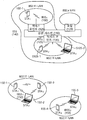
- the WLAN system may include one or more infrastructure BSSs 100 and 105 (hereinafter, BSS).
- BSSs 100 and 105 are a set of APs and STAs such as an access point 125 and a STA1 (station 100-1) capable of successfully synchronizing and communicating with each other, and do not indicate a specific area.
- the BSS 105 may include one or more STAs 103-1 and 105-2 that can be coupled to one AP 130.
- the BSS may include at least one STA, APs 125 and 130 for providing a distribution service, and a distribution system (DS) 110 for connecting a plurality of APs.
- STA STA
- APs 125 and 130 for providing a distribution service
- DS distribution system
- the distributed system 110 may connect several BSSs 100 and 105 to implement an extended service set (ESS) 140 which is an extended service set.
- ESS 140 may be used as a term indicating one network in which one or several APs 125 and 230 are connected through the distributed system 110.
- APs included in one ESS 140 may have the same service set identification (SSID).
- the portal 120 may serve as a bridge for connecting the WLAN network (IEEE 802.11) with another network (for example, 802.X).
- a network between the APs 125 and 130 and a network between the APs 125 and 130 and the STAs 100-1, 105-1 and 105-2 may be implemented. However, it may be possible to perform communication by setting up a network even between STAs without the APs 125 and 130.
- a network that performs communication by establishing a network even between STAs without APs 125 and 130 is defined as an ad-hoc network or an independent basic service set (BSS).
- FIG. 1 is a conceptual diagram illustrating an IBSS.
- the IBSS is a BSS operating in an ad-hoc mode. Since IBSS does not contain an AP, there is no centralized management entity. That is, in the IBSS, the STAs 150-1, 150-2, 150-3, 155-4, and 155-5 are managed in a distributed manner. In the IBSS, all STAs 150-1, 150-2, 150-3, 155-4, and 155-5 may be mobile STAs, and access to a distributed system is not allowed, thus making a self-contained network. network).
- a STA is any functional medium that includes medium access control (MAC) conforming to the Institute of Electrical and Electronics Engineers (IEEE) 802.11 standard and a physical layer interface to a wireless medium. May be used to mean both an AP and a non-AP STA (Non-AP Station).
- MAC medium access control
- IEEE Institute of Electrical and Electronics Engineers
- the STA may include a mobile terminal, a wireless device, a wireless transmit / receive unit (WTRU), a user equipment (UE), a mobile station (MS), a mobile subscriber unit ( It may also be called various names such as a mobile subscriber unit or simply a user.
- WTRU wireless transmit / receive unit
- UE user equipment
- MS mobile station
- UE mobile subscriber unit
- It may also be called various names such as a mobile subscriber unit or simply a user.
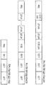
- FIG. 2 is a diagram illustrating an example of a PPDU used in the IEEE standard.
- PPDUs PHY protocol data units
- LTF and STF fields included training signals
- SIG-A and SIG-B included control information for the receiving station
- data fields included user data corresponding to the PSDU.
- This embodiment proposes an improved technique for the signal (or control information field) used for the data field of the PPDU.
- the signal proposed in this embodiment may be applied on a high efficiency PPDU (HE PPDU) according to the IEEE 802.11ax standard. That is, the signals to be improved in the present embodiment may be HE-SIG-A and / or HE-SIG-B included in the HE PPDU. Each of HE-SIG-A and HE-SIG-B may also be represented as SIG-A or SIG-B.
- the improved signal proposed by this embodiment is not necessarily limited to the HE-SIG-A and / or HE-SIG-B standard, and controls / control of various names including control information in a wireless communication system for transmitting user data. Applicable to data fields.
- FIG. 3 is a diagram illustrating an example of a HE PPDU.
- the control information field proposed in this embodiment may be HE-SIG-B included in the HE PPDU as shown in FIG. 3.
- the HE PPDU according to FIG. 3 is an example of a PPDU for multiple users.
- the HE-SIG-B may be included only for the multi-user, and the HE-SIG-B may be omitted in the PPDU for the single user.
- a HE-PPDU for a multiple user includes a legacy-short training field (L-STF), a legacy-long training field (L-LTF), a legacy-signal (L-SIG), High efficiency-signal A (HE-SIG-A), high efficiency-signal-B (HE-SIG-B), high efficiency-short training field (HE-STF), high efficiency-long training field (HE-LTF) It may include a data field (or MAC payload) and a PE (Packet Extension) field. Each field may be transmitted during the time period shown (ie, 4 or 8 ms, etc.).
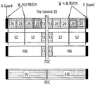
- FIG. 4 is a diagram illustrating an arrangement of resource units (RUs) used on a 20 MHz band.
- resource units corresponding to different numbers of tones (ie, subcarriers) may be used to configure some fields of the HE-PPDU.
- resources may be allocated in units of RUs shown for HE-STF, HE-LTF, and data fields.
- 26-units ie, units corresponding to 26 tones
- Six tones may be used as the guard band in the leftmost band of the 20 MHz band, and five tones may be used as the guard band in the rightmost band of the 20 MHz band.
- seven DC tones are inserted into the center band, that is, the DC band, and 26-units corresponding to each of the 13 tones may exist to the left and right of the DC band.
- other bands may be allocated 26-unit, 52-unit, 106-unit. Each unit can be assigned for a receiving station, i. E. A user.
- the RU arrangement of FIG. 4 is utilized not only for the situation for a plurality of users (MU), but also for the situation for a single user (SU), in which case one 242-unit is shown as shown at the bottom of FIG. It is possible to use and in this case three DC tones can be inserted.
- FIG. 5 is a diagram illustrating an arrangement of resource units (RUs) used on a 40 MHz band.
- the example of FIG. 5 may also use 26-RU, 52-RU, 106-RU, 242-RU, 484-RU, and the like.
- five DC tones can be inserted at the center frequency, 12 tones are used as the guard band in the leftmost band of the 40 MHz band, and 11 tones are in the rightmost band of the 40 MHz band. This guard band can be used.
- the 484-RU may be used when used for a single user. Meanwhile, the specific number of RUs may be changed as in the example of FIG. 4.
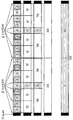
- FIG. 6 is a diagram illustrating an arrangement of resource units (RUs) used on an 80 MHz band.
- the example of FIG. 6 may also use 26-RU, 52-RU, 106-RU, 242-RU, 484-RU, 996-RU, and the like. have.
- seven or five DC tones can be inserted at the center frequency, and 12 tones are used as the guard band in the leftmost band of the 80 MHz band, and in the rightmost band of the 80 MHz band. Eleven tones can be used as guard bands.
- 996-RU may be used when used for a single user. Meanwhile, the specific number of RUs may be changed as in the example of FIGS. 4 and 5.
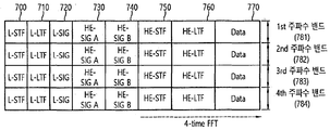
- FIG. 7 is a diagram illustrating another example of the HE-PPDU.
- FIG. 7 is another example illustrating the HE-PPDU block of FIG. 3 in terms of frequency.
- the illustrated L-STF 700 may include a short training orthogonal frequency division multiplexing symbol.
- the L-STF 700 may be used for frame detection, automatic gain control (AGC), diversity detection, and coarse frequency / time synchronization.
- AGC automatic gain control
- the L-LTF 710 may include a long training orthogonal frequency division multiplexing symbol.
- the L-LTF 710 may be used for fine frequency / time synchronization and channel prediction.
- L-SIG 720 may be used to transmit control information.
- the L-SIG 720 may include information about a data rate and a data length.
- the L-SIG 720 may be repeatedly transmitted. That is, the L-SIG 720 may be configured in a repeating format (for example, may be referred to as an R-LSIG).
- the HE-SIG-A 730 may include control information common to the receiving station.
- the HE-SIG-A 730 may include 1) a DL / UL indicator, 2) a BSS color field which is an identifier of a BSS, 3) a field indicating a remaining time of a current TXOP interval, 4) 20, Bandwidth field indicating whether 40, 80, 160, 80 + 80 MHz, 5) field indicating the MCS scheme applied to HE-SIG-B, 6) HE-SIB-B has dual subcarrier modulation for MCS ( field indicating whether it is modulated by dual subcarrier modulation), 7) field indicating the number of symbols used for HE-SIG-B, and 8) indicating whether HE-SIG-B is generated over the entire band.
- PE Packet Extension
- CRC field of the HE-SIG-A and the like.
- Specific fields of the HE-SIG-A may be added or omitted. In addition, some fields may be added or omitted in other environments where the HE-SIG-A is not a multi-user (MU) environment.
- MU multi-user
- the HE-SIG-B 740 may be included only when it is a PPDU for a multi-user (MU) as described above.
- the HE-SIG-A 750 or the HE-SIG-B 760 may include resource allocation information (or virtual resource allocation information) for at least one receiving STA.
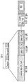
- FIG. 8 is a block diagram showing an example of the HE-SIG-B according to the present embodiment.
- the HE-SIG-B field includes a common field at the beginning, and the common field can be encoded separately from the following field. That is, as shown in FIG. 8, the HE-SIG-B field may include a common field including common control information and a user-specific field including user-specific control information.
- the common field may include a corresponding CRC field and may be coded into one BCC block. Subsequent user-specific fields may be coded into one BCC block, including a "user-feature field" for two users and a corresponding CRC field, as shown.
- the previous field of HE-SIG-B 740 on the MU PPDU may be transmitted in duplicated form.
- the HE-SIG-B 740 transmitted in a part of the frequency band is the frequency band of the corresponding frequency band (ie, the fourth frequency band).
- Control information for a data field and a data field of another frequency band (eg, the second frequency band) except for the corresponding frequency band may be included.
- the HE-SIG-B 740 of a specific frequency band (eg, the second frequency band) duplicates the HE-SIG-B 740 of another frequency band (eg, the fourth frequency band). It can be one format.
- the HE-SIG-B 740 may be transmitted in encoded form on all transmission resources.
- the field after the HE-SIG-B 740 may include individual information for each receiving STA that receives the PPDU.
- the HE-STF 750 may be used to improve automatic gain control estimation in a multiple input multiple output (MIMO) environment or an OFDMA environment.
- MIMO multiple input multiple output
- OFDMA orthogonal frequency division multiple access
- the HE-LTF 760 may be used to estimate a channel in a MIMO environment or an OFDMA environment.
- the size of the FFT / IFFT applied to the field after the HE-STF 750 and the HE-STF 750 may be different from the size of the FFT / IFFT applied to the field before the HE-STF 750.
- the size of the FFT / IFFT applied to the fields after the HE-STF 750 and the HE-STF 750 may be four times larger than the size of the IFFT applied to the field before the HE-STF 750.
- a field of s is called a first field
- at least one of the data field 770, the HE-STF 750, and the HE-LTF 760 may be referred to as a second field.
- the first field may include a field related to a legacy system
- the second field may include a field related to a HE system.
- 256 FFT / IFFT is applied for a bandwidth of 20 MHz
- 512 FFT / IFFT is applied for a bandwidth of 40 MHz
- 1024 FFT / IFFT is applied for a bandwidth of 80 MHz
- 2048 FFT for a bandwidth of 160 MHz continuous or discontinuous 160 MHz.
- / IFFT can be applied.
- spacing may be applied to a subcarrier having a size of 312.5 kHz, which is a conventional subcarrier spacing, and space may be applied to a subcarrier having a size of 78.125 kHz, as a second field of the HE PPDU.
- the length of an OFDM symbol may be a value obtained by adding a length of a guard interval (GI) to an IDFT / DFT length.
- the length of the GI can be various values such as 0.4 ⁇ s, 0.8 ⁇ s, 1.6 ⁇ s, 2.4 ⁇ s, 3.2 ⁇ s.
- the frequency band used by the first field and the frequency band used by the second field are represented in FIG. 7, they may not exactly coincide with each other.
- the main band of the first field L-STF, L-LTF, L-SIG, HE-SIG-A, HE-SIG-B
- HE-STF the main band of the first field
- HE-LTF, Data the second field
- the interface may be inconsistent. 4 to 6, since a plurality of null subcarriers, DC tones, guard tones, etc. are inserted in the process of arranging the RU, it may be difficult to accurately match the interface.
- the user may receive the HE-SIG-A 730 and may be instructed to receive the downlink PPDU based on the HE-SIG-A 730.
- the STA may perform decoding based on the changed FFT size from the field after the HE-STF 750 and the HE-STF 750.
- the STA may stop decoding and configure a network allocation vector (NAV).
- NAV network allocation vector
- the cyclic prefix (CP) of the HE-STF 750 may have a larger size than the CP of another field, and during this CP period, the STA may perform decoding on the downlink PPDU by changing the FFT size.
- data (or frame) transmitted from the AP to the STA is called downlink data (or downlink frame), and data (or frame) transmitted from the STA to the AP is called uplink data (or uplink frame).
- downlink data or downlink frame
- uplink data or uplink frame
- the transmission from the AP to the STA may be expressed in terms of downlink transmission, and the transmission from the STA to the AP may be referred to as uplink transmission.
- each of the PHY protocol data units (PPDUs), frames, and data transmitted through downlink transmission may be expressed in terms of a downlink PPDU, a downlink frame, and downlink data.
- the PPDU may be a data unit including a PPDU header and a physical layer service data unit (PSDU) (or MAC protocol data unit (MPDU)).
- PSDU physical layer service data unit
- MPDU MAC protocol data unit
- the PPDU header may include a PHY header and a PHY preamble
- the PSDU (or MPDU) may be a data unit including a frame (or an information unit of a MAC layer) or indicating a frame.
- the PHY header may be referred to as a physical layer convergence protocol (PLCP) header in another term
- the PHY preamble may be expressed as a PLCP preamble in another term.
- each of the PPDUs, frames, and data transmitted through the uplink transmission may be expressed by the term uplink PPDU, uplink frame, and uplink data.
- the entire bandwidth may be used for downlink transmission to one STA and uplink transmission to one STA based on single (or single) -orthogonal frequency division multiplexing (SUDM) transmission.
- the AP may perform downlink (DL) multi-user (MU) transmission based on multiple input multiple output (MU MIMO), and such transmission is referred to as DL MU MIMO transmission. It can be expressed as.
- an orthogonal frequency division multiple access (OFDMA) based transmission method is preferably supported for uplink transmission and / or downlink transmission. That is, uplink / downlink communication may be performed by allocating data units (eg, RUs) corresponding to different frequency resources to the user.
- the AP may perform DL MU transmission based on OFDMA, and such transmission may be expressed by the term DL MU OFDMA transmission.
- the AP may transmit downlink data (or downlink frame, downlink PPDU) to each of the plurality of STAs through each of the plurality of frequency resources on the overlapped time resources.
- the plurality of frequency resources may be a plurality of subbands (or subchannels) or a plurality of resource units (RUs).
- DL MU OFDMA transmission may be used with DL MU MIMO transmission. For example, DL MU MIMO transmission based on a plurality of space-time streams (or spatial streams) on a specific subband (or subchannel) allocated for DL MU OFDMA transmission is performed. Can be.
- UL MU transmission uplink multi-user transmission
- a plurality of STAs transmit data to the AP on the same time resource.
- Uplink transmission on the overlapped time resource by each of the plurality of STAs may be performed in a frequency domain or a spatial domain.
- different frequency resources may be allocated as uplink transmission resources for each of the plurality of STAs based on OFDMA.
- the different frequency resources may be different subbands (or subchannels) or different resource units (RUs).
- Each of the plurality of STAs may transmit uplink data to the AP through different frequency resources allocated thereto.
- Such a transmission method through different frequency resources may be represented by the term UL MU OFDMA transmission method.
- each of a plurality of STAs When uplink transmission by each of a plurality of STAs is performed on the spatial domain, different space-time streams (or spatial streams) are allocated to each of the plurality of STAs, and each of the plurality of STAs transmits uplink data through different space-time streams. Can transmit to the AP.
- the transmission method through these different spatial streams may be represented by the term UL MU MIMO transmission method.
- the UL MU OFDMA transmission and the UL MU MIMO transmission may be performed together.
- UL MU MIMO transmission based on a plurality of space-time streams (or spatial streams) may be performed on a specific subband (or subchannel) allocated for UL MU OFDMA transmission.
- a multi-channel allocation method was used to allocate a wider bandwidth (for example, a bandwidth exceeding 20 MHz) to one UE.
- the multi-channel may include a plurality of 20 MHz channels when one channel unit is 20 MHz.
- a primary channel rule is used to allocate a wide bandwidth to the terminal. If the primary channel rule is used, there is a constraint for allocating a wide bandwidth to the terminal.
- the primary channel rule when a secondary channel adjacent to the primary channel is used in an overlapped BSS (OBSS) and 'busy', the STA may use the remaining channels except the primary channel. Can't.
- OBSS overlapped BSS
- the STA can transmit the frame only through the primary channel, thereby being limited to the transmission of the frame through the multi-channel. That is, the primary channel rule used for multi-channel allocation in the existing WLAN system may be a big limitation in obtaining high throughput by operating a wide bandwidth in the current WLAN environment where there are not many OBSS.
- a WLAN system supporting the OFDMA technology supporting the OFDMA technology. That is, the above-described OFDMA technique is applicable to at least one of downlink and uplink.
- the above-described MU-MIMO technique may be additionally applied to at least one of downlink and uplink.
- OFDMA technology is used, a plurality of terminals may be used simultaneously instead of one terminal without using a primary channel rule. Therefore, wide bandwidth operation is possible, and the efficiency of the operation of radio resources can be improved.
- the AP when uplink transmission by each of a plurality of STAs (eg, non-AP STAs) is performed in the frequency domain, the AP has different frequency resources for each of the plurality of STAs based on OFDMA. It may be allocated as a link transmission resource. In addition, as described above, different frequency resources may be different subbands (or subchannels) or different resource units (RUs).
- OFDMA orthogonal frequency division multiple access
- Different frequency resources for each of the plurality of STAs are indicated through a trigger frame.
- the trigger frame of FIG. 9 allocates resources for uplink multiple-user transmission and may be transmitted from the AP.
- the trigger frame may consist of a MAC frame and may be included in a PPDU. For example, it may be transmitted through the PPDU shown in FIG. 3, through the legacy PPDU shown in FIG. 2, or through a PPDU specifically designed for the trigger frame. If transmitted through the PPDU of FIG. 3, the trigger frame may be included in the illustrated data field.
- Each field shown in FIG. 9 may be partially omitted, and another field may be added. In addition, each length can be varied as shown.
- the frame control field 910 of FIG. 9 includes information about the version of the MAC protocol and other additional control information, and the duration field 920 includes time information for setting the NAV described below.
- Information about an identifier (eg, AID) of the terminal may be included.
- the RA field 930 includes address information of the receiving STA of the corresponding trigger frame and may be omitted as necessary.
- the TA field 940 includes address information of an STA (for example, an AP) that transmits a corresponding trigger frame, and the common information field 950 is common to be applied to a receiving STA that receives the corresponding trigger frame. Contains control information
- FIG. 10 shows an example of a common information field. Some of the subfields of FIG. 10 may be omitted, and other subfields may be added. In addition, the length of each illustrated subfield may be modified.
- the illustrated length field 1010 has the same value as the length field of the L-SIG field of the uplink PPDU transmitted corresponding to the trigger frame, and the length field of the L-SIG field of the uplink PPDU indicates the length of the uplink PPDU.
- the length field 1010 of the trigger frame may be used to indicate the length of the corresponding uplink PPDU.
- the cascade indicator field 1020 indicates whether a cascade operation is performed.
- the cascade operation means that downlink MU transmission and uplink MU transmission are performed together in the same TXOP. That is, after downlink MU transmission is performed, it means that uplink MU transmission is performed after a predetermined time (eg, SIFS).
- a predetermined time eg, SIFS.
- only one transmitting device (eg, AP) for downlink communication may exist, and a plurality of transmitting devices (eg, non-AP) for uplink communication may exist.
- the CS request field 1030 indicates whether the state of the radio medium, the NAV, or the like should be considered in a situation in which the receiving apparatus receiving the trigger frame transmits the corresponding uplink PPDU.
- the HE-SIG-A information field 1040 may include information for controlling the content of the SIG-A field (ie, the HE-SIG-A field) of the uplink PPDU transmitted in response to the corresponding trigger frame.
- the CP and LTF type field 1050 may include information about the length of the LTF and the CP length of the uplink PPDU transmitted in response to the corresponding trigger frame.
- the trigger type field 1060 may indicate the purpose for which the corresponding trigger frame is used, for example, normal triggering, triggering for beamforming, a request for Block ACK / NACK, and the like.
- per user information fields 960 # 1 to 960 # N corresponding to the number of receiving STAs receiving the trigger frame of FIG. 9.
- the individual user information field may be called a “RU assignment field”.
- the trigger frame of FIG. 9 may include a padding field 970 and a frame check sequence field 980.
- Each of the per user information fields 960 # 1 to 960 # N shown in FIG. 9 preferably includes a plurality of subfields.
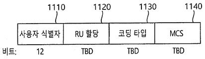
- FIG. 11 illustrates an example of subfields included in an individual user information field. Some of the subfields of FIG. 11 may be omitted, and other subfields may be added. In addition, the length of each illustrated subfield may be modified.
- the user identifier field 1110 of FIG. 11 indicates an identifier of an STA (ie, a receiving STA) to which per user information corresponds.
- An example of the identifier may be all or part of an AID. have.
- the RU Allocation field 1120 may be included. That is, when the receiving STA identified by the user identifier field 1110 transmits an uplink PPDU in response to the trigger frame of FIG. 9, the corresponding uplink PPDU through the RU indicated by the RU Allocation field 1120. Send.
- the RU indicated by the RU Allocation field 1120 preferably indicates the RUs shown in FIGS. 4, 5, and 6.
- the subfield of FIG. 11 may include a coding type field 1130.
- the coding type field 1130 may indicate a coding type of an uplink PPDU transmitted in response to the trigger frame of FIG. 9. For example, when BCC coding is applied to the uplink PPDU, the coding type field 1130 is set to '1', and when LDPC coding is applied, the coding type field 1130 is set to '0'. Can be.
- the subfield of FIG. 11 may include an MCS field 1140.
- the MCS field 1140 may indicate an MCS scheme applied to an uplink PPDU transmitted in response to the trigger frame of FIG. 9.
- this embodiment relates to an operating mode used in a station (eg, an AP and / or a non-AP STA) of a WLAN system.
- a station eg, an AP and / or a non-AP STA
- the operation mode may be classified into a transmit operating mode (TOM) and a receive operating mode (ROM).
- the reception operation mode is related to an operation in which an STA (eg, a non-AP STA) reporting an operation mode receives a signal from a counterpart STA (eg, an AP).
- the transmission operation mode is related to an operation of transmitting a signal to the STA (eg, a non-AP STA) that the other STA (eg, the AP) reported the operation mode.
- the transmission operation mode may be used for a UL MU PPDU simultaneously transmitted by a plurality of STAs in response to the trigger frame of FIG. 9.
- control information 1200 used for reporting on an operation mode.
- control information 1200 includes all or part of the plurality of subfields 1210, 1220, 1230, and 1240, and may further include subfields not shown in FIG. 12.
- the control information 1200 of FIG. 12 may be included in the header of the MAC frame included in the data field of the PPDU.
- the Rx NSS subfield 1210 of FIG. 12 is the maximum number of spatial streams used when a STA (eg, a non-AP STA) reporting the control information 1200 receives a signal / PPDU. Can be indicated.
- the Rx NSS subfield 1210 may be configured as an information field with 3 bits.
- the Rx NSS subfield 1210 of FIG. 12 may indicate the number of spatial streams used when the STA receives a downlink PPDU. That is, when the AP configures a PPDU for a specific receiving STA, the AP may refer to the corresponding subfield 1210.
- the channel width subfield 1220 of FIG. 12 may indicate an operation channel supported by an STA (eg, a non-AP STA) that reports the control information 1200. That is, it may mean the maximum value of the operating channel supported by the STA. For example, a value of “0” is 20 MHz, a value of “1” is 40 MHz, a value of “2” is 80 MHz, and a value of “3” is 160 MHz or 80. It can mean +80 MHz.
- the Channel Width subfield 1220 may commonly indicate a transmission and reception channel used by an STA reporting the control information 1200.
- the UL MU Disable subfield 1230 of FIG. 12 may indicate whether a STA (eg, a non-AP STA) that reports the control information 1200 supports UL MU operation. For example, if for some reason the UL MU operation is suspended, a certain value (eg, “1”) may be indicated, and again if the UL MU operation is resumed, another value ( For example, "0" may be indicated.
- a STA eg, a non-AP STA
- a certain value eg, “1”
- another value For example, "0" may be indicated.
- the UL MU Disable subfield 1230 may be used in the UL MU operation related to the trigger frame of FIG. 9.
- the AP may determine whether the UL MU is supported in a specific non-AP STA. That is, when a trigger frame for UL MU communication (that is, the trigger frame of FIG. 9) is configured, the corresponding subfield 1230 may be used.
- the Tx NSS subfield 1240 of FIG. 12 is a maximum number of spatial streams used when a STA (eg, a non-AP STA) reporting the control information 1200 transmits a signal / PPDU. Can be indicated.
- Rx NSS 1210 and Tx NSS 1240 subfields are separately configured, but the subfields may be modified.
- Rx NSS ie, number of spatial streams used for PPDU reception at a specific STA
- Tx NSS ie, number of spatial streams used for PPDU transmission at a specific STA
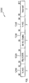
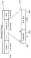
- FIG. 13 is an operation between a first / second station, where the first station may be an AP 1301 and the second station may be an STA 1302.
- the STA1 1302 is a station that reports an operation mode to the AP 1301.
- the STA1 1302 may transmit the PPDU including the data field 1310 to the AP 1301 during the first TXOP 1305, and the corresponding data field 1310 may include the control information 1200 of FIG. 12.
- the AP 1301 may transmit a block ACK (BA) 1320 indicating that the data field 1310 has been successfully received.
- BA block ACK
- the AP 1301 When the AP 1301 knows the transmission operation mode and the reception operation mode of the STA1 1302 through the corresponding data field 1310, and when the AP 1301 performs UL MU communication through the trigger frame 1330. In this case, information about a transmission operation mode may be used. Specifically, the AP 1301 to receive the uplink PPDU from the plurality of STAs including the STA1 1302 secures the TXOP 1325 through contention and transmits the trigger frame 1330 to the plurality of STAs. Can be.
- An example of the trigger frame 1330 may be configured according to the example of FIGS. 9 to 11. That is, the AP 1301 may be configured to transmit the uplink PPDU 1341 to the STA1 1302 through the trigger frame 1330 through a specific RU.
- the bandwidth (ie, the RU) for the uplink PPDU 1341 may be set.
- the Channel Width subfield 1220 indicated in the data field 1310 may be used.
- the trigger frame 1330 may indicate the number of spatial streams that can be used for the uplink PPDU 1341 to the STA1 1302. In this case, the number of spatial streams used by the STA1 1302 for the uplink PPDU 1341 may be signaled through a subfield newly configured in the per user information field of FIG. 11.
- uplink PPDUs 1342 and 1342 are received from a plurality of STAs through a communication technique and a radio resource indicated by the trigger frame 1330.
- the communication technique / wireless resource indicated in the frame 1330 may be determined based on information on an operation mode that is already reported to the AP 1301. More specifically, the number of spatial streams for the STA1 1302 indicated in the trigger frame 1330 is equal to the number of Tx NSS subfields 1240 indicated by the control information 1200 transmitted through the data field 1310. It is preferred that it is determined to be less than or equal to the value.
- the frequency band (ie, RU) for the STA1 1302 indicated in the trigger frame 1330 is determined by the channel width subfield 1220 indicated by the control information 1200 transmitted through the data field 1310. It is preferred that it is determined equal to or less than the value.
- STA1 1302 may not be able to participate in UL MU communication for various reasons.
- the AP 1301 causes the STA 1130 to set the UL MU Disable subfield 1230 of the control information 1200 transmitted through the data field 1310 to a specific value (for example, “1”). ) May inform that it may not participate in UL MU communication. If the UL MU Disable subfield 1230 for the STA1 1302 is set to a specific value, the AP 1301 may identify the uplink PPDUs 1341 and 1342 corresponding to the trigger frame for the corresponding STA1 1302. You may not assign it.
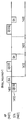
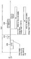
- the operation mode as shown in FIG. 12 is reported, that is, when the operation mode is reported from the second station 1402 to the first station 1401, it is preferable that the application point of the reported operation mode is clearly indicated.
- 14 illustrates an example of a case where the second station 1402 is a non-AP STA and the first station 1401 is an AP.
- the AP 1401 may already be storing downlink data in a queue of the AP. Downlink data already stored does not need to be transmitted to the PPDU according to the reported operation mode (ie, “new operation mode”) through the data field 1410. That is, downlink data already stored is transmitted to the PPDU according to the "previous operation mode", which may help to reduce latency and increase MU throughput.
- the example of FIG. 14 proposes a technique for indicating whether to delay the application of the operation mode (that is, the new operation mode) reported by the AP 1401. Specifically, when the STA 1402 reports a new operation mode through the data field 1410, the AP 1401 transmits a Block ACK 1420 for the corresponding data field 1410. The BA 1420 indicates whether application to a new operation mode is delayed. That is, when “delay_required” is indicated by a specific value (eg, “1”), the AP 1401 uses the previous operation mode instead of the new operation mode for the preset delay time 1410. The PPDU can be transmitted. Meanwhile, after the delay time 1410, the switching time 1420 may exist.
- a specific value eg, “1”
- the AP 1401 may switch the operation mode from the previous operation mode to the new operation mode. After this switching time 1420 has elapsed, the AP 1401 may transmit the PPDU to the STA 1402 according to the new operation mode reported through the data field 1410.
- the delay time and / or transition time of FIG. 14 may be negotiated through a management frame.
- An example of such a management frame includes an association request / response. Since this delay time and / or switching time does not have to exist, it is possible that the length of the corresponding time is set to "0".
- a delay time and / or a transition time may be negotiated through a MAC header (eg, an HE control field) included in the data field 1410.
- the STA 1402 may set the length of the delay time and / or the switching time to “0” in the data field 1410, in which case the AP 1401 may operate without the delay time and / or the switching time. Can be applied.
- TXOP transmission opportunity
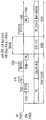
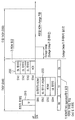
- the example of FIG. 15 may be applied at different stations.
- the first station 1501 of FIG. 15 is an AP STA and the second station 1502 is an example of a non-AP STA.
- the AP 1501 or the STA 1502 may secure the first TXOP 1550 through contingency, and then the STA 1502 may transmit the PPDU including the data field 1510 to the AP 1501. You can report the new mode of operation while sending.
- FIG. 15 Since the example of FIG. 15 is an example of not applying a new operation mode during an implicitly indicated time interval, no additional signaling regarding delay time is required in the Block ACK 1520.
- the AP 1501 controls the received operation so that the new operation mode is not applied during the first TXOP 1550 interval.
- the application of the information 1200 is suspended. Accordingly, the newly received control information 1200 is not applied to the PPDU 1530 configured within the first TXOP 1550 section, but the operation mode applied to the PPDU 1530 is applied.
- the STA 1502 may transmit a Block ACK 1540.
- the indication information that is, the subfield of the control information 1200 included in the data field 1510
- the indicated indication information ie, a subfield of the control information 1200 included in the data field 1510
- the switching time 1560 for the AP 1501 may be applied, but the switching time 1560 does not necessarily need to exist and may be omitted. .
- the AP 1501 may not transmit any PPDU to apply the new operation mode.
- a new second TXOP 1570 may be obtained by the AP 1501 / STA 1502. Since the interval in which the new operation mode is suspended is limited to the first TXOP 1550, the PPDU configured by the AP 1501 during the second TXOP 1570 is configured based on the new operation mode even if there is no separate signal rung. do.
- the STA 1502 receives the PPDU 1580 and transmits a Block ACK 1590 thereto.
- a mechanism for indicating an operation mode is as follows.
- the STA 2 receiving the ROM indication information from any STA 1 determines whether to accept or deny the ROM.
- the remaining bits of the BA / ACK (or Multi-TID BA, OFDMA-BA, etc.) (reserved bit) to inform.
- the method proposed in this specification indicates that the STA 2 indicates an appropriate ROM for the STA 1.
- the remaining bits (8 bits) in the BA control field can be used as follows.
- the ROM If the ROM is accepted, information related to an indicator indicating whether STA 2 transmits an appropriate ROM for STA 1, the number of reception spatial streams, reception channel bandwidth, and the like may be omitted. In addition, even when the ROM is accepted, the ROM information transmitted by the STA may be retransmitted in terms of confirmation.
- the above-described information may be informed by further using reserved values among the values of Multi-TID, Compressed bitmap, and GCR bits.
- STA 2 may transmit a BA frame using the remaining bits to indicate whether the ROM received from STA 1 is accepted or rejected.
- the STA 2 may transmit a BA frame to inform whether the proper ROM is transmitted for the STA1.
- the STA 2 may transmit appropriate ROM information using the BA information field. That is, the STA 2 may transmit information about the number of reception spatial streams or the reception channel bandwidth.
- the STA 2 receiving the ROM from any STA 1 may inform whether to accept or reject the ROM and whether to transmit the appropriate ROM by using an M-BA (Multi-TID BA) frame.
- M-BA Multi-TID BA
- the TID value of the BA information field is predefined as any specific value (for example, all 0s or all 1s).
- the TID Value is set to a specific value
- the Block ACK Starting Sequence Control field and / or the Block ACK Bitmap field which are subfields of the BA information field, may be omitted.
- a field transmitted after the TID Value field may be newly defined as a field indicating the ROM.
- the above-described method is described as indicating whether the STA 2 accepts or rejects the ROM requested by the STA 1 and whether it transmits the appropriate ROM.
- the method is not limited thereto.
- Any STA 2 transmits or piggybacks ROM related information for any STA 1 through a MAC header of a frame transmitted by STA 2 (eg, a data frame, a BA / ACK frame, etc.). Can be.
- the ROM-related information may be channel information for STA 2 to transmit a trigger frame and the number of spatial streams for STA 1 to which the UL MU is to be applied.
- any STA 2 wants to apply a UL MU for STA 1, through a BA / ACK (or M-BA, OFDMA-BA, etc.) that is a response frame for the UL data frame transmitted by STA 1
- Information such as bandwidth or channel information and the number of spatial streams can be transmitted.
- the STA 2 may transmit information such as bandwidth or channel information and the number of spatial streams through a frame (eg, a data frame) transmitted to the STA 1.
- the bandwidth or channel information may correspond to information used when STA 2 wants to transmit the next trigger frame for STA 1.
- the STA 1 receiving the information may perform a subsequent reception operation according to the ROM informed by the STA 2.
- the TOM indication method that is, the method described herein is not limited to the above-described operation for changing the ROM, but may be applied to the operation for changing the TOM.
- the 802.11ax system allows the STA to randomly access a specific resource for coverage extension in consideration of the outdoor environment.
- the TOM transmitted by the STA needs to be changed. For example, it is possible to access the AP using only 26 tones among STAs performing random access.
- information about its TOM eg, maximum RU size, channel bandwidth, or number of spatial streams, etc. that can be accessed by the AP)
- the remaining bits may correspond to bits reserved in a newly defined field or frame (ACK / BA, data buffer status report, etc.) of the aforementioned MAC header.
- an indicator bit indicating whether the ROM and the TOM are ROM / TOM may be added to inform the ROM and the TOM using the same format. For example, when the indicator bit is set to 1, it can be defined as TOM, and when the indicator bit is set to 0, it can be defined as ROM.
- the AP having received the TOM information from the STA, may accept or reject the change of the TOM of the STA. Using TOM information, the AP may transmit a trigger frame for UL MU transmission of the STA in consideration of this when scheduling the UL MU transmission of the STA.
- the AP may allocate a RU unit that is less than or equal to the maximum RU size accessible by the STA to the AP transmitted by the RU unit of the UL MU resource of the STA.
- the AP may allocate UL MU resources to transmit the number of spatial streams smaller than the number of spatial streams transmitted by the STA.
- the AP may allocate 52 to 26 or 26 tones when allocating UL MU resources for the STA.
- the following describes how to send the preferred RU size and MCS for the buffer status report and the TXOP length value calculated using these values.
- the STA When the STA performs its buffer status report by receiving a trigger frame (for random access), the STA may select its own preferred RU size (or maximum RU size accessible by the AP), MCS (or buffer status report). May be omitted when using the same as the MCS when transmitting the information, or may inform the AP of the maximum MCS level that the STA can use). In addition, the STA may inform the AP of the amount of its buffered data by transmitting a TXOP length value determined according to its preferred RU size and MCS level.
- ACK / BA, M-BA, OFDMA BA, data, etc. in response to the transmission of the ROM information (when it transmits its own ROM information or when requesting ROM information of an STA linked to itself).
- data is included in the case of being accepted or receiving information on an appropriate operation mode.
- the STA may change its ROM after a predefined outage time, and accordingly, the transmitting STA may transmit a frame (for example, a data frame) in consideration of the ROM change of the STA having a link with the STA.
- the transmitting STA Withholds its backoff procedure during the outage time and performs the backoff procedure after the outage time.
- the following describes how the AP manages a condition that triggers a ROM / TOM report of an STA.
- the AP may manage a condition that triggers reporting of the TOM / ROM information of the STA.
- the AP may transmit a specific threshold value using a beacon, a trigger frame, a management frame, or the like to trigger ROM information transmission when the battery of the STA is less than or equal to the specific threshold value.
- the AP may inform using a beacon, a trigger frame, a management frame, etc. to transmit ROM information only when the STA can turn off the RF chain (for example, when the STA is changed from 160 MHz to 80 MHz).
- the AP may inform using a beacon, a trigger frame, a management frame, etc. to transmit TOM / ROM information only in a specific section when the OFDMA section, the EDCA section, the legacy section, and the 11ax section are divided in the beacon section. .
- the AP may use a beacon, trigger frame, management frame, or the like to trigger a STA to transmit TOM information when the RSSI (or SNR, SNIR, etc.) of the signal from the AP is below a certain threshold. I can send it.
- RSSI or SNR, SNIR, etc.
- the AP may transmit DL data for the STA to the previous ROM of the STA to improve throughput of the DL data.
- the DL data of the STA is transmitted to the MU. In the case of transmission, such an operation may be performed to obtain MU gain.
- the AP may withhold a change point of the ROM transmitted by the STA for a specific time using a DL frame (eg, BA / ACK / M-BA / OFDMA BA or data frame, etc.).
- a DL frame eg, BA / ACK / M-BA / OFDMA BA or data frame, etc.
- the AP may directly inform the outage time value.
- the AP may directly transmit an outage time value to the STA along with information indicating that it accepts the ROM change request.
- the outage time value may be transmitted through a MAC header or the like, or may be transmitted by using reserved bits of BA / ACK / M-BA / OFDMA BA or by reusing a specific field similarly to the aforementioned method. .
- the outage time value may be transmitted through a field newly defined for the STA supporting the HE system.
- the outage time may be predefined.
- the outage time is applied to determine whether the STA changes the ROM after the outage time or changes the ROM as soon as the STA receives a frame including information indicating that the STA accepts the ROM change request from the AP.
- / ACK / M-BA / OFDMA BA Values that can be defined as outage time are as follows.
- the length of the remaining TXOP interval (in this case the STA may change the ROM in the next TXOP)
- the STA may transmit ROM information to a MAC header or PSDU of a control frame, a data frame, a management frame, or the like to change its ROM.
- the ROM information informed by the STA may include channel bandwidth information or tone information or RU information or the number of received streams.
- the RX mode Request bit may be further defined to indicate that the ROM change request is to be requested.
- the STA If the STA includes a MAC header indicating such information, the STA transmits the ROM information by using a reserved bit in the HT variant field or the VHT variant field of the HT control of the MAC header through the MAC header. Can be sent.
- the STA 2 receiving the information may inform BA or ACK (or M-BA, OFDMA-BA, etc.) whether to accept or reject the information. Specifically, it may be informed using a reserved bit of BA / ACK (or M-BA, OFDMA-BA, etc.).
- any STA 2 may transmit by setting the RX mode Request bit to 1 to change the ROM of STA 1.
- the STA 1 may inform whether to accept or reject the ROM requested by the STA 2 using BA / ACK (or M-BA, OFDMA-BA, etc.). Specifically, it may be informed using a reserved bit of BA / ACK (or M-BA, OFDMA-BA, etc.).
- the AP transmits a Block Ack (BA).
- BA may indicate whether there is data buffered using the reserved bits of the BA in order to indirectly respond to the ROM request of the STA.
- the remaining bits correspond to more bits in the MAC header in the data, thereby putting additional bits (1 bit) in the BA.
- the BA frame of FIG. 16 may correspond to the M-BA supported by the 802.11ax system.
- the BA frame 1600 includes a plurality of subfields such as a BA control field 1610 and a BA information field 1620.
- the BA control field 1610 is a common control field, and the BA information field 1620 corresponds to a user-specific field. That is, the BA information field 1620 may be delivered to different STAs, respectively.
- the additional bit corresponds to one bit among the reserved bits 1630 and B4 to B11 in the BA control field 1610.
- one bit of the remaining bits 1630 included in the BA frame 1600 may be used to indicate whether data to be transmitted for a specific STA remains, such as an additional bit of a data MAC header.
- One bit of the remaining bits 1630 may be referred to as an additional bit, a more data bit, or a delay required bit.
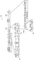
- FIG 17 shows an example of an A-Control field (Aggregated-Control field) used to convey control information.
- A-Control field Aggregated-Control field
- the STA requests ROM from the AP for its power saving.
- the ROM request may be transmitted through a QoS null frame or an A-Control field.
- the ROM request may be transmitted through a QoS data frame, which will be described later.
- the A-Control field is shown in FIG.
- the A-Control field 1710 is a subfield of the MAC header (eg, the HE control field), which is an additional control field added after the QoS control field in the 802.11ax system.
- the A-Control field 1710 includes a sequence of at least one Control subfield 1720-1, 1720-2, ..., 1702-N.
- the control subfield 1720-1 in which the Control ID subfield 1730 is 0 is the first subfield of the sequence.
- the Control ID subfield 1730 indicates the type of information carried in the Control Information subfield 1740.
- the length of the Control Information subfield 1740 is fixed for each value of the Unreserved Control ID subfield 1730.
- the value of the Control ID subfield 1730 and the length of the associated Control Information subfield 1740 are defined as shown in the following table.
- Control ID value Meaning Length of the Control Information subfield (bits) 0 UL MU response scheduling 26 One Operating Mode 12 2 HE link adaptation 16 3 Buffer Status Report (BSR) 26 4 UL Power Headroom 8 5 Bandwidth Query Report (BQR) 10 6-15 Reserved
- the Control Information subfield 1740 includes information related to an operation mode change of an STA transmitting a frame including information on an operation mode indication. Can be. That is, when the Control ID subfield 1730 is 1, the format of the Control Information subfield 1740 is illustrated in FIG. 12.
- the STA transmits a ROM request to change the Rx value (ie, Rx NSS and Rx BW), and the AP transmits an ACK / BA in response to the ROM request.
- the AP transmits the ACK / BA
- the STA fails to receive the ACK / BA, the STA cannot change the ROM.
- FIG. 18 assumes that a STA requests a ROM change 1810 but does not receive an ACK / BA 1820 for a ROM change from an AP.
- the reason why the STA does not receive the ACK / BA 1820 from the AP is because a collision occurs when the ACK / BA 1820 is transmitted.
- the STA since the STA has not received the ACK / BA 1820 for the ROMI, the STA cannot change the ROM. However, the AP may change the ROM requested by the STA after transmitting the ACK / BA 1820 for the ROMI. That is, since the STA applies the Rx value before the change and the AP applies the new Rx value after the change, an inconsistent state of operation modes occurs between the AP and the STA.
- Embodiment 1) is a case of reducing Rx NSS and Rx BW through a ROM request
- embodiment 2) is a case of increasing Rx NSS and Rx BW through a ROM request.
- 19 illustrates an example in which an inconsistency state of operation modes occurs when the number of spatial streams of a reported operation mode and a reception channel bandwidth decrease.
- FIG. 19 illustrates a procedure in which an STA receives DL data after an inconsistency in the operation modes described with reference to FIG. 18 occurs. That is, the STA requests the ROM change (1910), but a collision occurs in the transmission process of the AP, so that the ACK / BA 1920 for the ROM change is not received from the AP.
- the Rx NSS and Rx BW values in the receive operation mode may be represented by (Rx NSS, Rx BW).
- the reception mode before the ROM change of the STA is (4,80), but the STA attempts to decrease the value of the reception mode to (2,20) through a ROM request.
- the STA since the STA has not received the ACK / BA 1920 for the ROMI, the STA cannot change the ROM. However, the AP may change the ROM requested by the STA after transmitting the ACK / BA 1920 for the ROMI. That is, since the STA applies the Rx value before the change and the AP applies the new Rx value after the change, an inconsistent state of operation modes occurs between the AP and the STA.
- the STA may receive the DL Data 1930.
- the new Rx value applied by the AP is smaller than the Rx value before the change of the STA.
- the STA since the AP transmits DL data 1930 by applying a value smaller than the number of spatial streams (Rx NSS) and reception bandwidth (Rx BW) currently supported by the STA, the STA transmits DL data 1930.
- the DL data 1930 may be received through an Rx NSS and a reception bandwidth Rx BW. Accordingly, the STA may transmit a BA 1940 for the DL Data.
- Embodiment 2 When Rx NSS and Rx BW are Increased Through a ROM Request
- FIG. 20 illustrates an example in which an inconsistency state of operation modes occurs when the number of spatial streams of a reported operation mode and a reception channel bandwidth increase.
- FIG. 20 illustrates a procedure in which an STA receives DL data after an inconsistency in the operation modes described with reference to FIG. 18 occurs. That is, although the STA requests the ROM change (2010), a collision occurs in the transmission process of the AP, and thus the ACK / BA 2020 for the ROM change is not received from the AP.
- the Rx NSS and Rx BW values in the receive operation mode may be represented by (Rx NSS, Rx BW).
- the reception mode before the ROM change of the STA is (2,20), but the STA intends to increase the value of the reception mode to (4,80) through a ROM request.
- the STA since the STA has not received the ACK / BA 2020 for the ROMI, the STA cannot change the ROM. However, the AP may change the ROM requested by the STA after transmitting the ACK / BA 2020 for the ROMI. That is, since the STA applies the Rx value before the change and the AP applies the new Rx value after the change, an inconsistent state of operation modes occurs between the AP and the STA.
- the STA when the AP transmits DL Data 2030 by applying a new Rx value, the STA cannot receive the DL Data 2030. This is because the new Rx value applied by the AP is larger than the Rx value before the change of the STA. In other words, since the AP transmits DL Data 2030 by applying a value larger than the number of spatial streams (Rx NSS) and the reception bandwidth (Rx BW) currently supported by the STA, the STA transmits DL data 2030. The DL data 2030 may not be received through the Rx NSS and the reception bandwidth Rx BW. This is because the new Rx value exceeds the maximum capacity of the reception bandwidth and the number of spatial streams that the STA can support.
- Rx NSS the number of spatial streams
- Rx BW reception bandwidth
- a time point for applying a ROM change is set as a method for solving an inconsistency problem in an operation mode according to a ROM change request. Specifically, when the STA requests the ROM change during the TXOP period, it will be described whether the AP applies the ROM change after the TXOP period ends or immediately after receiving the response (ACK) to the ROM request.
- 21 shows another example of control information used for reporting on an operation mode.
- a ROM change indicator bit 2110 may be added to a ROMI field to indicate an interval in which a ROM change is explicitly applied. Assume that the ROM change indicator bit 2110 is 2 bits. If the ROM change indicator bit is 00, the ROM change is applied in the TXOP period. If the ROM change indicator bit is 01, the ROM change is applied during the next (next or subsequent) TXOP period. If the ROM change indicator bit is 10, the ROM change is applied immediately from the next PPDU transmitted after receiving the ACK for the ROM request. If the ROM change indicator bit is 11, it is left as reserved bits.
- the AP applies a ROM immediately changed from the next transmitted PPDU after transmitting an ACK for the ROM request transmitted by the STA.
- 22 and 23 illustrate TXOP intervals to which a ROM change is applied in the UL SU mode and the UL MU mode.
- FIG. 22 illustrates an example in which an operation mode reported in the SU mode is used for a reception operation of a specific STA.
- the STA transmits a ROM request 2210 to change the Rx value.
- the ROM request 2210 may be transmitted via a data frame or a QoS null frame.
- the AP receives a ROM request 2210.
- the AP transmits a BA 2220 in response to the ROM request.
- FIG. 23 illustrates an example in which an operation mode reported in the MU mode is used for a reception operation of a plurality of STAs.
- the AP transmits a trigger frame 2310.
- the STA 1,2 transmits the ROM request 2320 together with the data frame to change the Rx value to the resource unit (RU) allocated by the trigger frame.
- STA 3 transmits only ROM requests.
- STA 4 simply transmits only data frames.
- the ROM request transmitted by the STA 1,2 and 3 may be transmitted through a data frame or a QoS null frame.
- the AP receives a ROM request 2320 of each STA.
- the AP may transmit DL Data or ACK 2330 in response to the ROM request of each STA. This behavior is called a three-way handshake technique.
- the AP applies a ROM change during the current TXOP period 2340 and the next TXOP period 2350.
- Outage Delay present 1
- the AP transmits DL Data or ACK 2330 and applies the changed ROM according to the ROM request after the Outage Delay. Accordingly, the AP may transmit DL data by applying the changed ROM during the next TXOP period 2350.
- Outage Delay present 0, the AP may transmit DL Data or ACK 2330 and immediately apply the changed ROM according to the ROM request.
- the TXOP may be determined in consideration of the amount of packets to be transmitted for each STA, the MCS of the STAs, the operating bandwidth, and the like.
- the reception operation mode (ROM) of a specific STA is changed (for example, when Rx BW and Rx NSS decrease), a problem may occur in scheduling in the current TXOP.
- the AP may similarly determine the TXOP in consideration of the amount of packets to be transmitted for each STA, the MCS of the STAs, the operating bandwidth, and the like. In this case, if an outage delay occurs by changing a Rx value of a specific STA, scheduling may not be possible within a TXOP for a specific STA or a TXOP may be separately set for a specific STA.
- the timing of applying the ROM change may vary depending on the number of spatial streams and the decrease or increase in the reception channel bandwidth according to the ROM change request.
- the AP applies the changed ROM immediately after the next transmitted PPDU after transmitting an ACK for the ROM request transmitted by the STA. can do. That is, if only the ACK for the current ROM request is transmitted, the changed ROM may be applied even in the current TXOP period.
- the AP may apply a ROM change during the next TXOP period after the current TXOP period ends.
- the AP immediately changes from the next PPDU transmitted after transmitting an ACK for the ROM request transmitted by the STA.
- ROM can be applied. If the STA successfully transmits the ACK for the ROM request, the ROM change may be applied in the next TXOP period. If the STA does not receive the ACK for the ROM request, the ROM change is not applied even in the next TXOP period.
- the AP may apply a ROM change during the next TXOP period after the current TXOP period ends. That is, regardless of whether the STA receives the ACK for the ROM request, the ROM change may be applied when the next TXOP period is reached.
- 24 is a flowchart illustrating a procedure of processing control information for configuring a PPDU according to the present embodiment.
- the first station may be an access point (AP) station
- the second station may correspond to a non-AP station communicating with the AP station.
- AP access point
- step S2410 in a first station, TXOP indicating from the second station the indication information indicating a change in an operating mode indicating the number of spatial streams supported by the second station and a reception channel bandwidth; Receive during the transmission opportunity period. Since the indication information indicating the change of the operation mode may correspond to the ROM request, the second station requests the first station to change the ROM.
- the reception channel bandwidth may include at least one of 20 MHz, 40 MHz, 80 MHz, and 160 MHz.
- step S2420 if the number of spatial streams and the reception channel bandwidth decrease, the first station configures a PPDU for the second station using the indication information after transmitting an ACK for the indication information.
- the PPDU for the second station may be configured during the TXOP interval or the next TXOP interval of the TXOP interval. That is, when only the ACK for the ROM request is transmitted to the second station, the changed ROM may be applied even in the current TXOP period.
- step S2430 when the number of the spatial streams and the reception channel bandwidth increase, the first station configures a PPDU for the second station using the indication information during a subsequent TXOP period of the TXOP period.
- the PPDU for the second station may be configured during the next TXOP interval of the TXOP interval regardless of transmission of an ACK for the indication information.
- the indication information may include an operation mode change indicator bit.
- the operation mode change indicator bit may correspond to a ROM change indicator bit.
- the operation mode change indicator bit may indicate a TXOP interval in which a PPDU for the second station is configured. That is, it is possible to know a section in which the ROM change is applied according to the value indicated by the operation mode change indicator bit.
- the indication information may be included in a data field of the PPDU delivered to the first station.
- the data field of the PPDU delivered to the first station may correspond to a QoS data frame.
- the indication information may be included in a medium access control (MAC) header of the data field.
- MAC medium access control
- the indication information may include whether the second station indicates UL MU transmission (Uplink Multi-User transmission), the number of reception space streams supported by the second station, and the transmission space supported by the second station.
- the number of streams can be indicated. That is, the indication information may be used as information on a transmission operation mode when the second station performs UL MU communication through a trigger frame.
- 25 is a block diagram illustrating a wireless device to which the present embodiment can be applied.
- the wireless device may be an AP or a non-AP station (STA) that may implement the above-described embodiment.
- the wireless device may correspond to the above-described user or may correspond to a transmission device for transmitting a signal to the user.
- the AP 2500 includes a processor 2510, a memory 2520, and an RF unit 2530.
- the RF unit 2530 may be connected to the processor 2510 to transmit / receive a radio signal.
- the processor 2510 may implement the functions, processes, and / or methods proposed herein.
- the processor 2510 may perform an operation according to the present embodiment described above. That is, the processor 2510 may perform an operation that may be performed by the AP during the operations disclosed in the embodiments of FIGS. 1 to 24.
- the non-AP STA 2550 includes a processor 2560, a memory 2570, and an RF unit 2580.
- the RF unit 2580 may be connected to the processor 2560 to transmit / receive a radio signal.
- the processor 2560 may implement the functions, processes, and / or methods proposed in this embodiment.
- the processor 2560 may be implemented to perform the non-AP STA operation according to the present embodiment described above.
- the processor may perform the operation of the non-AP STA in the embodiment of FIGS. 1 to 24.
- Processors 2510 and 2560 may include application-specific integrated circuits (ASICs), other chipsets, logic circuits, data processing devices, and / or converters for interconverting baseband signals and wireless signals.
- the memories 2520 and 2570 may include read-only memory (ROM), random access memory (RAM), flash memory, memory cards, storage media, and / or other storage devices.
- the RF unit 2530 and 2580 may include one or more antennas for transmitting and / or receiving a radio signal.
- the above-described technique may be implemented as a module (process, function, etc.) for performing the above-described function.
- the module may be stored in the memories 2520 and 2570 and executed by the processors 2510 and 2560.
- the memories 2520 and 2570 may be inside or outside the processors 2510 and 2560, and may be connected to the processors 2510 and 2560 by various well-known means.
Landscapes
- Engineering & Computer Science (AREA)
- Signal Processing (AREA)
- Computer Networks & Wireless Communication (AREA)
- Databases & Information Systems (AREA)
- Mobile Radio Communication Systems (AREA)
Abstract
The present specification proposes a signal processing method for changing an operating mode for transmitting a PPDU in a wireless LAN system. Specifically, a first station receives, from the second station, indication information which indicates a change in an operating mode indicating a receiving channel bandwidth and a number of spatial streams supported by a second station during a TXOP interval. When the number of spatial streams and the receiving channel bandwidth decrease, the first station configures a PPDU for the second station by using the indication information after transmitting an ACK for the indication information. When the number of spatial streams and the receiving channel bandwidth increase, the first station configures a PPDU for the second station by using the indication information during a subsequent TXOP interval of the TXOP interval.
Description
본 명세서는 무선 랜 시스템에서 동작모드에 관한 기법에 관한 것으로, 보다 상세하게는, 무선 랜 시스템의 무선 스테이션에서 사전에 설정된 시간 구간에 동작모드를 변경하는 방법 및 장치에 관한 것이다.The present specification relates to a technique relating to an operation mode in a wireless LAN system, and more particularly, to a method and apparatus for changing the operation mode in a predetermined time interval in a wireless station of a wireless LAN system.
차세대 WLAN(wireless local area network)를 위한 논의가 진행되고 있다. 차세대 WLAN에서는 1) 2.4GHz 및 5GHz 대역에서 IEEE(institute of electronic and electronics engineers) 802.11 PHY(physical) 계층과 MAC(medium access control) 계층의 향상, 2) 스펙트럼 효율성(spectrum efficiency)과 영역 쓰루풋(area through put)을 높이는 것, 3) 간섭 소스가 존재하는 환경, 밀집한 이종 네트워크(heterogeneous network) 환경 및 높은 사용자 부하가 존재하는 환경과 같은 실제 실내 환경 및 실외 환경에서 성능을 향상 시키는 것을 목표로 한다.Discussion is underway for the next generation wireless local area network (WLAN). In next-generation WLANs, 1) enhancements to the Institute of Electronics and Electronics Engineers (IEEE) 802.11 physical physical access (PHY) and medium access control (MAC) layers in the 2.4 GHz and 5 GHz bands, and 2) spectral efficiency and area throughput. aims to improve performance in real indoor and outdoor environments, such as in environments where interference sources exist, dense heterogeneous network environments, and high user loads.
차세대 WLAN에서 주로 고려되는 환경은 AP(access point)와 STA(station)이 많은 밀집 환경이며, 이러한 밀집 환경에서 스펙트럼 효율(spectrum efficiency)과 공간 송신률(area throughput)에 대한 개선이 논의된다. 또한, 차세대 WLAN에서는 실내 환경뿐만 아니라, 기존 WLAN에서 많이 고려되지 않던 실외 환경에서의 실질적 성능 개선에 관심을 가진다.The environment mainly considered in the next-generation WLAN is a dense environment having many access points (APs) and a station (STA), and improvements in spectral efficiency and area throughput are discussed in such a dense environment. In addition, in the next generation WLAN, there is an interest in improving practical performance not only in an indoor environment but also in an outdoor environment, which is not much considered in a conventional WLAN.
구체적으로 차세대 WLAN에서는 무선 오피스(wireless office), 스마트 홈(smart home), 스타디움(Stadium), 핫스팟(Hotspot), 빌딩/아파트(building/apartment)와 같은 시나리오에 관심이 크며, 해당 시나리오 기반으로 AP와 STA이 많은 밀집 환경에서의 시스템 성능 향상에 대한 논의가 진행되고 있다. Specifically, in the next-generation WLAN, there is a great interest in scenarios such as wireless office, smart home, stadium, hotspot, building / apartment, and AP based on the scenario. And STA are discussing about improving system performance in a dense environment with many STAs.
또한, 차세대 WLAN에서는 하나의 BSS(basic service set)에서의 단일 링크 성능 향상보다는, OBSS(overlapping basic service set) 환경에서의 시스템 성능 향상 및 실외 환경 성능 개선, 그리고 셀룰러 오프로딩 등에 대한 논의가 활발할 것으로 예상된다. 이러한 차세대 WLAN의 방향성은 차세대 WLAN이 점점 이동 통신과 유사한 기술 범위를 갖게 됨을 의미한다. 최근 스몰셀 및 D2D(Direct-to-Direct) 통신 영역에서 이동 통신과 WLAN 기술이 함께 논의되고 있는 상황을 고려해 볼 때, 차세대 WLAN과 이동 통신의 기술적 및 사업적 융합은 더욱 활발해질 것으로 예측된다.In addition, in the next-generation WLAN, there will be more discussion about improving system performance in outdoor overlapping basic service set (OBSS) environment, improving outdoor environment performance, and cellular offloading, rather than improving single link performance in one basic service set (BSS). It is expected. The directionality of these next-generation WLANs means that next-generation WLANs will increasingly have a technology range similar to that of mobile communications. Considering the recent situation in which mobile communication and WLAN technology are discussed together in the small cell and direct-to-direct (D2D) communication area, the technical and business convergence of next-generation WLAN and mobile communication is expected to become more active.
본 명세서는 동작모드에 관련된 개선된 필드 구조 및 개선된 시그널링 기법을 제안한다. This disclosure proposes an improved field structure and improved signaling technique related to the mode of operation.
본 명세서는 송신 및 수신 장치에서 사전에 설정된 시점에 동작모드가 변경될 수 있는 일례를 제안한다. 또한, 동작모드에 관련된 UL MU 송신에 관한 다양한 일례를 제안한다. The present specification proposes an example in which an operation mode may be changed at a preset time point in a transmitting and receiving device. In addition, various examples of UL MU transmission related to the operation mode are proposed.
본 명세서는 무선 랜(wireless LAN) 시스템에서 PPDU(physical layer protocol data unit)를 구성하기 위한 제어정보를 처리하는 방법 및 해당 방법이 수행되는 장치에 관한 일례를 제안한다. The present specification proposes an example of a method of processing control information for configuring a physical layer protocol data unit (PPDU) in a wireless LAN system and an apparatus on which the method is performed.
먼저 용어를 정리하면, 제1 스테이션은 AP(Access Point) 스테이션이고, 제2 스테이션은 상기 AP 스테이션과 통신하는 non-AP 스테이션에 대응할 수 있다. To begin with, the first station may be an access point (AP) station, and the second station may correspond to a non-AP station communicating with the AP station.
제1 스테이션에서, 상기 제2 스테이션이 지원하는 공간 스트림(spatial stream)의 개수와 수신 채널 대역폭을 지시하는 동작모드(operating mode)의 변경을 지시하는 지시 정보를 제2 스테이션으로부터 TXOP(transmission opportunity) 구간 동안에 송신한다. 상기 동작모드의 변경을 지시하는 지시 정보는 ROM 요청에 대응할 수 있으므로, 제2 스테이션은 제1 스테이션에게 ROM의 변경을 요청하는 것이다. 상기 수신 채널 대역폭은 20MHz, 40MHz, 80MHz, 160MHz 중 적어도 하나를 포함할 수 있다.In a first station, indication information indicating a change in an operating mode indicating a number of spatial streams supported by the second station and a reception channel bandwidth is transmitted from a second station to TXOP (transmission opportunity). Transmit during the interval. Since the indication information indicating the change of the operation mode may correspond to the ROM request, the second station requests the first station to change the ROM. The reception channel bandwidth may include at least one of 20 MHz, 40 MHz, 80 MHz, and 160 MHz.
상기 공간 스트림의 개수와 수신 채널 대역폭이 감소하면, 제1 스테이션에서, 상기 지시 정보에 대한 ACK을 송신한 이후에 상기 지시 정보를 사용하여 상기 제2 스테이션을 위한 PPDU를 구성한다. 또한, 상기 공간 스트림의 개수와 수신 채널 대역폭이 감소하면, 상기 제2 스테이션을 위한 PPDU는 상기 TXOP 구간 또는 상기 TXOP 구간의 다음 TXOP 구간 동안에 구성될 수 있다. 즉, ROM 요청에 대한 ACK만 제2 스테이션으로 송신되면 현재 TXOP 구간에서도 변경된 ROM을 적용할 수 있다.When the number of spatial streams and the receiving channel bandwidth decrease, the first station configures a PPDU for the second station using the indication information after transmitting an ACK for the indication information. In addition, when the number of spatial streams and the receiving channel bandwidth decrease, the PPDU for the second station may be configured during the TXOP interval or the next TXOP interval of the TXOP interval. That is, when only the ACK for the ROM request is transmitted to the second station, the changed ROM may be applied even in the current TXOP period.
상기 공간 스트림의 개수와 수신 채널 대역폭이 증가하면, 제1 스테이션에서, 상기 TXOP 구간의 다음(subsequent) TXOP 구간 동안에 상기 지시 정보를 사용하여 상기 제2 스테이션을 위한 PPDU를 구성한다. 또한, 상기 공간 스트림의 개수와 수신 채널 대역폭이 증가하면, 상기 제2 스테이션을 위한 PPDU는 상기 지시 정보에 대한 ACK의 송신과 상관없이 상기 TXOP 구간의 다음 TXOP 구간 동안에 구성될 수 있다.When the number of spatial streams and the reception channel bandwidth increase, a first station configures a PPDU for the second station using the indication information during a subsequent TXOP period of the TXOP period. In addition, when the number of spatial streams and the reception channel bandwidth increase, the PPDU for the second station may be configured during the next TXOP interval of the TXOP interval regardless of transmission of an ACK for the indication information.
또한, 상기 지시 정보는 동작모드 변경 지시자 비트를 포함할 수 있다. 상기 동작모드 변경 지시자 비트는 ROM 변경 지시자 비트에 대응할 수 있다. 상기 동작모드 변경 지시자 비트는 상기 제2 스테이션을 위한 PPDU가 구성되는 TXOP 구간을 지시할 수 있다. 즉, 상기 동작모드 변경 지시자 비트가 지시하는 값에 따라 ROM 변경을 적용하는 구간을 알 수 있다.In addition, the indication information may include an operation mode change indicator bit. The operation mode change indicator bit may correspond to a ROM change indicator bit. The operation mode change indicator bit may indicate a TXOP interval in which a PPDU for the second station is configured. That is, it is possible to know a section in which the ROM change is applied according to the value indicated by the operation mode change indicator bit.
또한, 상기 지시 정보는 상기 제1 스테이션으로 전달되는 PPDU의 데이터 필드에 포함될 수 있다. 상기 제1 스테이션으로 전달되는 PPDU의 데이터 필드는 QoS 데이터 프레임에 대응할 수 있다. 또한, 상기 지시 정보는 상기 데이터 필드의 MAC(Medium Access Control) 헤더에 포함될 수 있다.In addition, the indication information may be included in a data field of the PPDU delivered to the first station. The data field of the PPDU delivered to the first station may correspond to a QoS data frame. In addition, the indication information may be included in a medium access control (MAC) header of the data field.
또한, 상기 지시 정보는, 상기 제2 스테이션이 UL MU 송신(Uplink Multi-User transmission)을 지시하는지 여부, 상기 제2 스테이션이 지원하는 수신 공간 스트림의 개수, 및 상기 제2 스테이션이 지원하는 송신 공간 스트림의 개수를 지시할 수 있다. 즉, 상기 지시 정보는 제2 스테이션이 트리거 프레임을 통한 UL MU 통신을 수행하는 경우, 송신동작모드에 대한 정보로 사용될 수 있다.In addition, the indication information may include whether the second station indicates UL MU transmission (Uplink Multi-User transmission), the number of reception space streams supported by the second station, and the transmission space supported by the second station. The number of streams can be indicated. That is, the indication information may be used as information on a transmission operation mode when the second station performs UL MU communication through a trigger frame.
본 명세서의 일례에 따르면 송신 및 수신 장치에서 사전에 설정된 시점에 동작모드가 변경될 수 있다. 또, 동작모드에 관련된 개선된 필드 구조 및 개선된 시그널링 기법이 사용될 수 있다.According to an example of the present specification, the operation mode may be changed at a preset time point in the transmitting and receiving apparatus. In addition, improved field structures and improved signaling techniques related to the mode of operation may be used.
도 1은 무선랜(wireless local area network, WLAN)의 구조를 나타낸 개념도이다.1 is a conceptual diagram illustrating a structure of a wireless local area network (WLAN).
도 2는 IEEE 규격에서 사용되는 PPDU의 일례를 도시한 도면이다. 2 is a diagram illustrating an example of a PPDU used in the IEEE standard.
도 3은 HE PPDU의 일례를 도시한 도면이다. 3 is a diagram illustrating an example of a HE PPDU.
도 4는 20MHz 대역 상에서 사용되는 자원유닛(RU)의 배치를 나타내는 도면이다. 4 is a diagram illustrating an arrangement of resource units (RUs) used on a 20 MHz band.
도 5는 40MHz 대역 상에서 사용되는 자원유닛(RU)의 배치를 나타내는 도면이다. 5 is a diagram illustrating an arrangement of resource units (RUs) used on a 40 MHz band.
도 6은 80MHz 대역 상에서 사용되는 자원유닛(RU)의 배치를 나타내는 도면이다. 6 is a diagram illustrating an arrangement of resource units (RUs) used on an 80 MHz band.
도 7은 HE-PPDU의 또 다른 일례를 나타낸 도면이다. 7 is a diagram illustrating another example of the HE-PPDU.
도 8은 본 실시예에 따른 HE-SIG-B의 일례를 나타내는 블록도이다. 8 is a block diagram showing an example of the HE-SIG-B according to the present embodiment.
도 9는 트리거 프레임의 일례를 나타낸다. 9 shows an example of a trigger frame.
도 10은 공통 정보(common information) 필드의 일례를 나타낸다. 10 shows an example of a common information field.
도 11은 개별 사용자 정보(per user information) 필드에 포함되는 서브 필드의 일례를 나타낸다. 11 illustrates an example of subfields included in an individual user information field.
도 12는 동작모드에 관한 보고를 위하여 사용되는 제어정보(1200)의 일례이다. 12 is an example of control information 1200 used for reporting on an operation mode.
도 13은 보고된 동작모드가 UL MU 동작을 위해 사용되는 일례를 나타낸다. 13 shows an example in which the reported mode of operation is used for UL MU operation.
도 14는 보고된 동작모드가 특정 STA의 수신 동작에 사용되는 일례를 나타낸다. 14 illustrates an example in which the reported operation mode is used for a reception operation of a specific STA.
도 15는 보고된 동작모드가 특정 STA의 수신 동작에 사용되는 추가적인 일례를 나타낸다. 15 shows an additional example in which the reported operation mode is used for a reception operation of a specific STA.
도 16은 다수의 STA에 대한 BA 프레임의 일례를 나타낸다.16 shows an example of a BA frame for multiple STAs.
도 17은 제어정보를 전달하기 위해 사용되는 A-Control 필드의 일례를 나타낸다.17 shows an example of an A-Control field used to convey control information.
도 18은 AP와 STA 간에 동작모드의 불일치 상태가 발생하는 일례를 나타낸다.18 illustrates an example in which an inconsistent state of operation modes occurs between an AP and an STA.
도 19는 보고된 동작모드의 공간 스트림의 개수와 수신 채널 대역폭이 감소할 때 동작모드의 불일치 상태가 발생하는 일례를 나타낸다.19 illustrates an example in which an inconsistency state of operation modes occurs when the number of spatial streams of a reported operation mode and a reception channel bandwidth decrease.
도 20은 보고된 동작모드의 공간 스트림의 개수와 수신 채널 대역폭이 증가할 때 동작모드의 불일치 상태가 발생하는 일례를 나타낸다.20 illustrates an example in which an inconsistency state of operation modes occurs when the number of spatial streams of a reported operation mode and a reception channel bandwidth increase.
도 21은 동작모드에 관한 보고를 위하여 사용되는 제어정보의 다른 예를 나타낸다.21 shows another example of control information used for reporting on an operation mode.
도 22는 SU mode에서 보고된 동작모드가 특정 STA의 수신 동작에 사용되는 일례를 나타낸다.22 illustrates an example in which an operation mode reported in the SU mode is used for a reception operation of a specific STA.
도 23은 MU mode에서 보고된 동작모드가 복수의 STA의 수신 동작에 사용되는 일례를 나타낸다.23 illustrates an example in which an operation mode reported in the MU mode is used for a reception operation of a plurality of STAs.
도 24는 본 실시예에 따른 PPDU를 구성하기 위한 제어정보를 처리하는 절차를 나타낸 흐름도이다.24 is a flowchart illustrating a procedure of processing control information for configuring a PPDU according to the present embodiment.
도 25는 본 실시예가 적용될 수 있는 무선 장치를 나타내는 블록도이다.25 is a block diagram illustrating a wireless device to which the present embodiment can be applied.
도 1은 무선랜(wireless local area network, WLAN)의 구조를 나타낸 개념도이다.1 is a conceptual diagram illustrating a structure of a wireless local area network (WLAN).
도 1의 상단은 IEEE(institute of electrical and electronic engineers) 802.11의 인프라스트럭쳐 BSS(basic service set)의 구조를 나타낸다.1 shows the structure of the infrastructure basic service set (BSS) of the Institute of Electrical and Electronic Engineers (IEEE) 802.11.
도 1의 상단을 참조하면, 무선랜 시스템은 하나 또는 그 이상의 인프라스트럭쳐 BSS(100, 105)(이하, BSS)를 포함할 수 있다. BSS(100, 105)는 성공적으로 동기화를 이루어서 서로 통신할 수 있는 AP(access point, 125) 및 STA1(Station, 100-1)과 같은 AP와 STA의 집합으로서, 특정 영역을 가리키는 개념은 아니다. BSS(105)는 하나의 AP(130)에 하나 이상의 결합 가능한 STA(105-1, 105-2)을 포함할 수도 있다.Referring to the top of FIG. 1, the WLAN system may include one or more infrastructure BSSs 100 and 105 (hereinafter, BSS). The BSSs 100 and 105 are a set of APs and STAs such as an access point 125 and a STA1 (station 100-1) capable of successfully synchronizing and communicating with each other, and do not indicate a specific area. The BSS 105 may include one or more STAs 103-1 and 105-2 that can be coupled to one AP 130.
BSS는 적어도 하나의 STA, 분산 서비스(distribution Service)를 제공하는 AP(125, 130) 및 다수의 AP를 연결시키는 분산 시스템(distribution System, DS, 110)을 포함할 수 있다.The BSS may include at least one STA, APs 125 and 130 for providing a distribution service, and a distribution system (DS) 110 for connecting a plurality of APs.
분산 시스템(110)는 여러 BSS(100, 105)를 연결하여 확장된 서비스 셋인 ESS(extended service set, 140)를 구현할 수 있다. ESS(140)는 하나 또는 여러 개의 AP(125, 230)가 분산 시스템(110)을 통해 연결되어 이루어진 하나의 네트워크를 지시하는 용어로 사용될 수 있다. 하나의 ESS(140)에 포함되는 AP는 동일한 SSID(service set identification)를 가질 수 있다.The distributed system 110 may connect several BSSs 100 and 105 to implement an extended service set (ESS) 140 which is an extended service set. The ESS 140 may be used as a term indicating one network in which one or several APs 125 and 230 are connected through the distributed system 110. APs included in one ESS 140 may have the same service set identification (SSID).
포털(portal, 120)은 무선랜 네트워크(IEEE 802.11)와 다른 네트워크(예를 들어, 802.X)와의 연결을 수행하는 브리지 역할을 수행할 수 있다.The portal 120 may serve as a bridge for connecting the WLAN network (IEEE 802.11) with another network (for example, 802.X).
도 1의 상단과 같은 BSS에서는 AP(125, 130) 사이의 네트워크 및 AP(125, 130)와 STA(100-1, 105-1, 105-2) 사이의 네트워크가 구현될 수 있다. 하지만, AP(125, 130)가 없이 STA 사이에서도 네트워크를 설정하여 통신을 수행하는 것도 가능할 수 있다. AP(125, 130)가 없이 STA 사이에서도 네트워크를 설정하여 통신을 수행하는 네트워크를 애드-혹 네트워크(Ad-Hoc network) 또는 독립 BSS(independent basic service set, IBSS)라고 정의한다.In the BSS as shown in the upper part of FIG. 1, a network between the APs 125 and 130 and a network between the APs 125 and 130 and the STAs 100-1, 105-1 and 105-2 may be implemented. However, it may be possible to perform communication by setting up a network even between STAs without the APs 125 and 130. A network that performs communication by establishing a network even between STAs without APs 125 and 130 is defined as an ad-hoc network or an independent basic service set (BSS).
도 1의 하단은 IBSS를 나타낸 개념도이다.1 is a conceptual diagram illustrating an IBSS.
도 1의 하단을 참조하면, IBSS는 애드-혹 모드로 동작하는 BSS이다. IBSS는 AP를 포함하지 않기 때문에 중앙에서 관리 기능을 수행하는 개체(centralized management entity)가 없다. 즉, IBSS에서 STA(150-1, 150-2, 150-3, 155-4, 155-5)들은 분산된 방식(distributed manner)으로 관리된다. IBSS에서는 모든 STA(150-1, 150-2, 150-3, 155-4, 155-5)이 이동 STA으로 이루어질 수 있으며, 분산 시스템으로의 접속이 허용되지 않아서 자기 완비적 네트워크(self-contained network)를 이룬다.Referring to the bottom of FIG. 1, the IBSS is a BSS operating in an ad-hoc mode. Since IBSS does not contain an AP, there is no centralized management entity. That is, in the IBSS, the STAs 150-1, 150-2, 150-3, 155-4, and 155-5 are managed in a distributed manner. In the IBSS, all STAs 150-1, 150-2, 150-3, 155-4, and 155-5 may be mobile STAs, and access to a distributed system is not allowed, thus making a self-contained network. network).
STA은 IEEE(Institute of Electrical and Electronics Engineers) 802.11 표준의 규정을 따르는 매체 접속 제어(medium access control, MAC)와 무선 매체에 대한 물리 계층(Physical Layer) 인터페이스를 포함하는 임의의 기능 매체로서, 광의로는 AP와 비-AP STA(Non-AP Station)을 모두 포함하는 의미로 사용될 수 있다.A STA is any functional medium that includes medium access control (MAC) conforming to the Institute of Electrical and Electronics Engineers (IEEE) 802.11 standard and a physical layer interface to a wireless medium. May be used to mean both an AP and a non-AP STA (Non-AP Station).
STA은 이동 단말(mobile terminal), 무선 기기(wireless device), 무선 송수신 유닛(Wireless Transmit/Receive Unit; WTRU), 사용자 장비(User Equipment; UE), 이동국(Mobile Station; MS), 이동 가입자 유닛(Mobile Subscriber Unit) 또는 단순히 유저(user) 등의 다양한 명칭으로도 불릴 수 있다.The STA may include a mobile terminal, a wireless device, a wireless transmit / receive unit (WTRU), a user equipment (UE), a mobile station (MS), a mobile subscriber unit ( It may also be called various names such as a mobile subscriber unit or simply a user.
도 2는 IEEE 규격에서 사용되는 PPDU의 일례를 도시한 도면이다. 2 is a diagram illustrating an example of a PPDU used in the IEEE standard.
도시된 바와 같이, IEEE a/g/n/ac 등의 규격에서는 다양한 형태의 PPDU(PHY protocol data unit)가 사용되었다. 구체적으로, LTF, STF 필드는 트레이닝 신호를 포함하였고, SIG-A, SIG-B 에는 수신 스테이션을 위한 제어정보가 포함되었고, 데이터 필드에는 PSDU에 상응하는 사용자 데이터가 포함되었다. As shown, various types of PHY protocol data units (PPDUs) have been used in the IEEE a / g / n / ac standard. Specifically, the LTF and STF fields included training signals, the SIG-A and SIG-B included control information for the receiving station, and the data fields included user data corresponding to the PSDU.
본 실시예는 PPDU의 데이터 필드를 위해 사용되는 시그널(또는 제어정보 필드)에 관한 개선된 기법을 제안한다. 본 실시예에서 제안하는 시그널은 IEEE 802.11ax 규격에 따른 HE PPDU(high efficiency PPDU) 상에 적용될 수 있다. 즉, 본 실시예에서 개선하는 시그널은 HE PPDU에 포함되는 HE-SIG-A 및/또는 HE-SIG-B일 수 있다. HE-SIG-A 및 HE-SIG-B 각각은 SIG-A, SIG-B로도 표시될 수 있다. 그러나 본 실시예가 제안하는 개선된 시그널이 반드시 HE-SIG-A 및/또는 HE-SIG-B 규격에 제한되는 것은 아니며, 사용자 데이터를 전달하는 무선통신시스템에서 제어정보를 포함하는 다양한 명칭의 제어/데이터 필드에 적용 가능하다. This embodiment proposes an improved technique for the signal (or control information field) used for the data field of the PPDU. The signal proposed in this embodiment may be applied on a high efficiency PPDU (HE PPDU) according to the IEEE 802.11ax standard. That is, the signals to be improved in the present embodiment may be HE-SIG-A and / or HE-SIG-B included in the HE PPDU. Each of HE-SIG-A and HE-SIG-B may also be represented as SIG-A or SIG-B. However, the improved signal proposed by this embodiment is not necessarily limited to the HE-SIG-A and / or HE-SIG-B standard, and controls / control of various names including control information in a wireless communication system for transmitting user data. Applicable to data fields.
도 3은 HE PPDU의 일례를 도시한 도면이다. 3 is a diagram illustrating an example of a HE PPDU.
본 실시예에서 제안하는 제어정보 필드는 도 3에 도시된 바와 같은 HE PPDU 내에 포함되는 HE-SIG-B일 수 있다. 도 3에 따른 HE PPDU는 다중 사용자를 위한 PPDU의 일례로, HE-SIG-B는 다중 사용자를 위한 경우에만 포함되고, 단일 사용자를 위한 PPDU에는 해당 HE-SIG-B가 생략될 수 있다. The control information field proposed in this embodiment may be HE-SIG-B included in the HE PPDU as shown in FIG. 3. The HE PPDU according to FIG. 3 is an example of a PPDU for multiple users. The HE-SIG-B may be included only for the multi-user, and the HE-SIG-B may be omitted in the PPDU for the single user.
도시된 바와 같이, 다중 사용자(Multiple User; MU)를 위한 HE-PPDU는 L-STF(legacy-short training field), L-LTF(legacy-long training field), L-SIG(legacy-signal), HE-SIG-A(high efficiency-signal A), HE-SIG-B(high efficiency-signal-B), HE-STF(high efficiency-short training field), HE-LTF(high efficiency-long training field), 데이터 필드(또는 MAC 페이로드) 및 PE(Packet Extension) 필드를 포함할 수 있다. 각각의 필드는 도시된 시간 구간(즉, 4 또는 8 ㎲ 등) 동안에 송신될 수 있다. As shown, a HE-PPDU for a multiple user (MU) includes a legacy-short training field (L-STF), a legacy-long training field (L-LTF), a legacy-signal (L-SIG), High efficiency-signal A (HE-SIG-A), high efficiency-signal-B (HE-SIG-B), high efficiency-short training field (HE-STF), high efficiency-long training field (HE-LTF) It may include a data field (or MAC payload) and a PE (Packet Extension) field. Each field may be transmitted during the time period shown (ie, 4 or 8 ms, etc.).
도 3의 각 필드에 대한 보다 상세한 설명은 후술한다. Detailed description of each field of FIG. 3 will be described later.
도 4는 20MHz 대역 상에서 사용되는 자원유닛(RU)의 배치를 나타내는 도면이다. 4 is a diagram illustrating an arrangement of resource units (RUs) used on a 20 MHz band.
도 4에 도시된 바와 같이, 서로 다른 개수의 톤(즉, 서브캐리어)에 대응되는 자원유닛(Resource Unit; RU)이 사용되어 HE-PPDU의 일부 필드를 구성할 수 있다. 예를 들어, HE-STF, HE-LTF, 데이터 필드에 대해 도시된 RU 단위로 자원이 할당될 수 있다. As shown in FIG. 4, resource units (RUs) corresponding to different numbers of tones (ie, subcarriers) may be used to configure some fields of the HE-PPDU. For example, resources may be allocated in units of RUs shown for HE-STF, HE-LTF, and data fields.
도 4의 최상단에 도시된 바와 같이, 26-유닛(즉, 26개의 톤에 상응하는 유닛)이 배치될 수 있다. 20MHz 대역의 최좌측(leftmost) 대역에는 6개의 톤이 가드(Guard) 대역으로 사용되고, 20MHz 대역의 최우측(rightmost) 대역에는 5개의 톤이 가드 대역으로 사용될 수 있다. 또한 중심대역, 즉 DC 대역에는 7개의 DC 톤이 삽입되고, DC 대역의 좌우측으로 각 13개의 톤에 상응하는 26-유닛이 존재할 수 있다. 또한, 기타 대역에는 26-유닛, 52-유닛, 106-유닛이 할당될 수 있다. 각 유닛은 수신 스테이션, 즉 사용자를 위해 할당될 수 있다. As shown at the top of FIG. 4, 26-units (ie, units corresponding to 26 tones) may be arranged. Six tones may be used as the guard band in the leftmost band of the 20 MHz band, and five tones may be used as the guard band in the rightmost band of the 20 MHz band. In addition, seven DC tones are inserted into the center band, that is, the DC band, and 26-units corresponding to each of the 13 tones may exist to the left and right of the DC band. In addition, other bands may be allocated 26-unit, 52-unit, 106-unit. Each unit can be assigned for a receiving station, i. E. A user.
한편, 도 4의 RU 배치는 다수의 사용자(MU)를 위한 상황뿐만 아니라, 단일 사용자(SU)를 위한 상황에서도 활용되며, 이 경우에는 도 4의 최하단에 도시된 바와 같이 1개의 242-유닛을 사용하는 것이 가능하며 이 경우에는 3개의 DC 톤이 삽입될 수 있다. On the other hand, the RU arrangement of FIG. 4 is utilized not only for the situation for a plurality of users (MU), but also for the situation for a single user (SU), in which case one 242-unit is shown as shown at the bottom of FIG. It is possible to use and in this case three DC tones can be inserted.
도 4의 일례에서는 다양한 크기의 RU, 즉, 26-RU, 52-RU, 106-RU, 242-RU 등이 제안되었는바, 이러한 RU의 구체적인 크기는 확장 또는 증가할 수 있기 때문에, 본 실시예는 각 RU의 구체적인 크기(즉, 상응하는 톤의 개수)에 제한되지 않는다. In the example of FIG. 4, various sizes of RUs have been proposed, that is, 26-RU, 52-RU, 106-RU, 242-RU, and the like. Since the specific sizes of these RUs can be expanded or increased, the present embodiment Is not limited to the specific size of each RU (ie, the number of corresponding tones).
도 5는 40MHz 대역 상에서 사용되는 자원유닛(RU)의 배치를 나타내는 도면이다. 5 is a diagram illustrating an arrangement of resource units (RUs) used on a 40 MHz band.
도 4의 일례에서 다양한 크기의 RU가 사용된 것과 마찬가지로, 도 5의 일례 역시 26-RU, 52-RU, 106-RU, 242-RU, 484-RU 등이 사용될 수 있다. 또한, 중심주파수에는 5개의 DC 톤이 삽입될 수 있고, 40MHz 대역의 최좌측(leftmost) 대역에는 12개의 톤이 가드(Guard) 대역으로 사용되고, 40MHz 대역의 최우측(rightmost) 대역에는 11개의 톤이 가드 대역으로 사용될 수 있다. Just as RUs of various sizes are used in the example of FIG. 4, the example of FIG. 5 may also use 26-RU, 52-RU, 106-RU, 242-RU, 484-RU, and the like. In addition, five DC tones can be inserted at the center frequency, 12 tones are used as the guard band in the leftmost band of the 40 MHz band, and 11 tones are in the rightmost band of the 40 MHz band. This guard band can be used.
또한, 도시된 바와 같이, 단일 사용자를 위해 사용되는 경우, 484-RU가 사용될 수 있다. 한편, RU의 구체적인 개수가 변경될 수 있다는 점은 도 4의 일례와 동일하다. Also, as shown, the 484-RU may be used when used for a single user. Meanwhile, the specific number of RUs may be changed as in the example of FIG. 4.
도 6은 80MHz 대역 상에서 사용되는 자원유닛(RU)의 배치를 나타내는 도면이다. 6 is a diagram illustrating an arrangement of resource units (RUs) used on an 80 MHz band.
도 4 및 도 5의 일례에서 다양한 크기의 RU가 사용된 것과 마찬가지로, 도 6의 일례 역시 26-RU, 52-RU, 106-RU, 242-RU, 484-RU, 996-RU 등이 사용될 수 있다. 또한, 중심주파수에는 7개 또는 5개의 DC 톤이 삽입될 수 있고, 80MHz 대역의 최좌측(leftmost) 대역에는 12개의 톤이 가드(Guard) 대역으로 사용되고, 80MHz 대역의 최우측(rightmost) 대역에는 11개의 톤이 가드 대역으로 사용될 수 있다. 또한 DC 대역 좌우에 위치하는 각각 13개의 톤을 사용한 26-RU를 사용할 수 있다. Just as RUs of various sizes are used in the example of FIGS. 4 and 5, the example of FIG. 6 may also use 26-RU, 52-RU, 106-RU, 242-RU, 484-RU, 996-RU, and the like. have. In addition, seven or five DC tones can be inserted at the center frequency, and 12 tones are used as the guard band in the leftmost band of the 80 MHz band, and in the rightmost band of the 80 MHz band. Eleven tones can be used as guard bands. Also available is a 26-RU with 13 tones each located to the left and right of the DC band.
또한, 도시된 바와 같이, 단일 사용자를 위해 사용되는 경우, 996-RU가 사용될 수 있다. 한편, RU의 구체적인 개수가 변경될 수 있다는 점은 도 4 및 도 5의 일례와 동일하다. Also, as shown, 996-RU may be used when used for a single user. Meanwhile, the specific number of RUs may be changed as in the example of FIGS. 4 and 5.
도 7은 HE-PPDU의 또 다른 일례를 나타낸 도면이다. 7 is a diagram illustrating another example of the HE-PPDU.
도시된 도 7의 블록은 도 3의 HE-PPDU 블록을 주파수 측면에서 설명하는 또 다른 일례이다. 7 is another example illustrating the HE-PPDU block of FIG. 3 in terms of frequency.
도시된 L-STF(700)는 짧은 트레이닝 OFDM 심볼(short training orthogonal frequency division multiplexing symbol)을 포함할 수 있다. L-STF(700)는 프레임 탐지(frame detection), AGC(automatic gain control), 다이버시티 탐지(diversity detection), 대략적인 주파수/시간 동기화(coarse frequency/time synchronization)을 위해 사용될 수 있다.The illustrated L-STF 700 may include a short training orthogonal frequency division multiplexing symbol. The L-STF 700 may be used for frame detection, automatic gain control (AGC), diversity detection, and coarse frequency / time synchronization.
L-LTF(710)는 긴 트레이닝 OFDM 심볼(long training orthogonal frequency division multiplexing symbol)을 포함할 수 있다. L-LTF(710)는 정밀한 주파수/시간 동기화(fine frequency/time synchronization) 및 채널 예측을 위해 사용될 수 있다.The L-LTF 710 may include a long training orthogonal frequency division multiplexing symbol. The L-LTF 710 may be used for fine frequency / time synchronization and channel prediction.
L-SIG(720)는 제어 정보를 송신하기 위해 사용될 수 있다. L-SIG(720)는 데이터 송신률(rate), 데이터 길이(length)에 대한 정보를 포함할 수 있다. 또한, L-SIG(720)은 반복되어 송신될 수 있다. 즉, L-SIG(720)가 반복되는 포맷(예를 들어, R-LSIG라 칭할 수 있음)으로 구성될 수 있다. L-SIG 720 may be used to transmit control information. The L-SIG 720 may include information about a data rate and a data length. In addition, the L-SIG 720 may be repeatedly transmitted. That is, the L-SIG 720 may be configured in a repeating format (for example, may be referred to as an R-LSIG).
HE-SIG-A(730)는 수신 스테이션에 공통되는 제어정보를 포함할 수 있다. The HE-SIG-A 730 may include control information common to the receiving station.
구체적으로, HE-SIG-A(730)는, 1) DL/UL 지시자, 2) BSS의 식별자인 BSS 칼라(color) 필드, 3) 현행 TXOP 구간의 잔여시간을 지시하는 필드, 4) 20, 40, 80, 160, 80+80 MHz 여부를 지시하는 대역폭 필드, 5) HE-SIG-B에 적용되는 MCS 기법을 지시하는 필드, 6) HE-SIB-B가 MCS 를 위해 듀얼 서브캐리어 모듈레이션(dual subcarrier modulation) 기법으로 모듈레이션되는지에 대한 지시 필드, 7) HE-SIG-B를 위해 사용되는 심볼의 개수를 지시하는 필드, 8) HE-SIG-B가 전 대역에 걸쳐 생성되는지 여부를 지시하는 필드, 9) HE-LTF의 심볼의 개수를 지시하는 필드, 10) HE-LTF의 길이 및 CP 길이를 지시하는 필드, 11) LDPC 코딩을 위해 추가의 OFDM 심볼이 존재하는지를 지시하는 필드, 12) PE(Packet Extension)에 관한 제어정보를 지시하는 필드, 13)HE-SIG-A의 CRC 필드에 대한 정보를 지시하는 필드 등에 관한 정보를 포함할 수 있다. 이러한 HE-SIG-A의 구체적인 필드는 추가되거나 일부가 생략될 수 있다. 또한, HE-SIG-A가 다중사용자(MU) 환경이 아닌 기타 환경에서는 일부 필드가 추가되거나 생략될 수 있다. Specifically, the HE-SIG-A 730 may include 1) a DL / UL indicator, 2) a BSS color field which is an identifier of a BSS, 3) a field indicating a remaining time of a current TXOP interval, 4) 20, Bandwidth field indicating whether 40, 80, 160, 80 + 80 MHz, 5) field indicating the MCS scheme applied to HE-SIG-B, 6) HE-SIB-B has dual subcarrier modulation for MCS ( field indicating whether it is modulated by dual subcarrier modulation), 7) field indicating the number of symbols used for HE-SIG-B, and 8) indicating whether HE-SIG-B is generated over the entire band. Field, 9) field indicating the number of symbols of the HE-LTF, 10) field indicating the length and CP length of the HE-LTF, 11) field indicating whether additional OFDM symbols exist for LDPC coding, 12) It may include information on a field indicating control information on the PE (Packet Extension), 13) a field indicating information on the CRC field of the HE-SIG-A, and the like. The. Specific fields of the HE-SIG-A may be added or omitted. In addition, some fields may be added or omitted in other environments where the HE-SIG-A is not a multi-user (MU) environment.
HE-SIG-B(740)는 상술한 바와 같이 다중 사용자(MU)를 위한 PPDU인 경우에만 포함될 수 있다. 기본적으로, HE-SIG-A(750) 또는 HE-SIG-B(760)는 적어도 하나의 수신 STA에 대한 자원 할당 정보(또는 가상 자원 할당 정보)를 포함할 수 있다. The HE-SIG-B 740 may be included only when it is a PPDU for a multi-user (MU) as described above. Basically, the HE-SIG-A 750 or the HE-SIG-B 760 may include resource allocation information (or virtual resource allocation information) for at least one receiving STA.
도 8은 본 실시예에 따른 HE-SIG-B의 일례를 나타내는 블록도이다. 8 is a block diagram showing an example of the HE-SIG-B according to the present embodiment.
도시된 바와 같이, HE-SIG-B 필드는 맨 앞부분에 공통 필드를 포함하고, 해당 공통 필드는 그 뒤에 따라오는 필드와 분리하여 인코딩하는 것이 가능하다. 즉, 도 8에 도시된 바와 같이, HE-SIG-B 필드는 공통 제어정보를 포함하는 공통 필드와, 사용자-특정(user-specific) 제어정보를 포함하는 사용자-특정 필드를 포함할 수 있다. 이 경우, 공통 필드는 대응되는 CRC 필드 등을 포함하고 하나의 BCC 블록으로 코딩될 수 있다. 이후에 이어지는 사용자-특정 필드는, 도시된 바와 같이 두 사용자(2 users)를 위한 "사용자-특징 필드" 및 그에 대응되는 CRC 필드 등을 포함하여 하나의 BCC 블록으로 코딩될 수 있다. As shown, the HE-SIG-B field includes a common field at the beginning, and the common field can be encoded separately from the following field. That is, as shown in FIG. 8, the HE-SIG-B field may include a common field including common control information and a user-specific field including user-specific control information. In this case, the common field may include a corresponding CRC field and may be coded into one BCC block. Subsequent user-specific fields may be coded into one BCC block, including a "user-feature field" for two users and a corresponding CRC field, as shown.
MU PPDU 상에서 HE-SIG-B(740)의 이전 필드는 듀플리케이트된 형태로 송신될 수 있다. HE-SIG-B(740)의 경우, 일부의 주파수 대역(예를 들어, 제4 주파수 대역)에서 송신되는 HE-SIG-B(740)은, 해당 주파수 대역(즉, 제4 주파수 대역)의 데이터 필드 및 해당 주파수 대역을 제외한 다른 주파수 대역(예를 들어, 제2 주파수 대역)의 데이터 필드를 위한 제어정보도 포함할 수 있다. 또한, 특정 주파수 대역(예를 들어, 제2 주파수 대역)의 HE-SIG-B(740)은 다른 주파수 대역(예를 들어, 제4 주파수 대역)의 HE-SIG-B(740)을 듀플리케이트한 포맷일 수 있다. 또는 HE-SIG-B(740)는 전체 송신 자원 상에서 인코딩된 형태로 송신될 수 있다. HE-SIG-B(740) 이후의 필드는 PPDU를 수신하는 수신 STA 각각을 위한 개별 정보를 포함할 수 있다.The previous field of HE-SIG-B 740 on the MU PPDU may be transmitted in duplicated form. In the case of the HE-SIG-B 740, the HE-SIG-B 740 transmitted in a part of the frequency band (for example, the fourth frequency band) is the frequency band of the corresponding frequency band (ie, the fourth frequency band). Control information for a data field and a data field of another frequency band (eg, the second frequency band) except for the corresponding frequency band may be included. In addition, the HE-SIG-B 740 of a specific frequency band (eg, the second frequency band) duplicates the HE-SIG-B 740 of another frequency band (eg, the fourth frequency band). It can be one format. Alternatively, the HE-SIG-B 740 may be transmitted in encoded form on all transmission resources. The field after the HE-SIG-B 740 may include individual information for each receiving STA that receives the PPDU.
HE-STF(750)는 MIMO(multiple input multiple output) 환경 또는 OFDMA 환경에서 자동 이득 제어 추정(automatic gain control estimation)을 향상시키기 위하여 사용될 수 있다.The HE-STF 750 may be used to improve automatic gain control estimation in a multiple input multiple output (MIMO) environment or an OFDMA environment.
HE-LTF(760)는 MIMO 환경 또는 OFDMA 환경에서 채널을 추정하기 위하여 사용될 수 있다.The HE-LTF 760 may be used to estimate a channel in a MIMO environment or an OFDMA environment.
HE-STF(750) 및 HE-STF(750) 이후의 필드에 적용되는 FFT/IFFT의 크기와 HE-STF(750) 이전의 필드에 적용되는 FFT/IFFT의 크기는 서로 다를 수 있다. 예를 들어, HE-STF(750) 및 HE-STF(750) 이후의 필드에 적용되는 FFT/IFFT의 크기는 HE-STF(750) 이전의 필드에 적용되는 IFFT의 크기보다 4배 클 수 있다. The size of the FFT / IFFT applied to the field after the HE-STF 750 and the HE-STF 750 may be different from the size of the FFT / IFFT applied to the field before the HE-STF 750. For example, the size of the FFT / IFFT applied to the fields after the HE-STF 750 and the HE-STF 750 may be four times larger than the size of the IFFT applied to the field before the HE-STF 750. .
예를 들어, 도 7의 PPDU 상의 L-STF(700), L-LTF(710), L-SIG(720), HE-SIG-A(730), HE-SIG-B(740) 중 적어도 하나의 필드를 제1 필드라 칭하는 경우, 데이터 필드(770), HE-STF(750), HE-LTF(760) 중 적어도 하나를 제2 필드라 칭할 수 있다. 상기 제1 필드는 종래(legacy) 시스템에 관련된 필드를 포함할 수 있고, 상기 제2 필드는 HE 시스템에 관련된 필드를 포함할 수 있다. 이 경우, FFT(fast Fourier transform) 사이즈/IFFT(inverse fast Fourier transform) 사이즈는 기존의 무선랜 시스템에서 사용되던 FFT/IFFT 사이즈의 N배(N은 자연수, 예를 들어, N=1, 2, 4)로 정의될 수 있다. 즉, HE PPDU의 제1 필드에 비해 HE PPDU의 제2 필드에 N(=4)배 사이즈의 FFT/IFFT가 적용될 수 있다. 예를 들어, 20MHz의 대역폭에 대하여 256FFT/IFFT가 적용되고, 40MHz의 대역폭에 대하여 512FFT/IFFT가 적용되고, 80MHz의 대역폭에 대하여 1024FFT/IFFT가 적용되고, 연속 160MHz 또는 불연속 160MHz의 대역폭에 대하여 2048FFT/IFFT가 적용될 수 있다.For example, at least one of L-STF 700, L-LTF 710, L-SIG 720, HE-SIG-A 730, HE-SIG-B 740 on the PPDU of FIG. When a field of s is called a first field, at least one of the data field 770, the HE-STF 750, and the HE-LTF 760 may be referred to as a second field. The first field may include a field related to a legacy system, and the second field may include a field related to a HE system. In this case, the FFT (fast Fourier transform) size / inverse fast Fourier transform (IFFT) size is N times the FFT / IFFT size used in the conventional WLAN system (N is a natural number, for example, N = 1, 2, 4) can be defined. That is, an FFT / IFFT of N (= 4) times size may be applied to the second field of the HE PPDU compared to the first field of the HE PPDU. For example, 256 FFT / IFFT is applied for a bandwidth of 20 MHz, 512 FFT / IFFT is applied for a bandwidth of 40 MHz, 1024 FFT / IFFT is applied for a bandwidth of 80 MHz, and 2048 FFT for a bandwidth of 160 MHz continuous or discontinuous 160 MHz. / IFFT can be applied.
달리 표현하면, 서브캐리어 공간/스페이싱(subcarrier spacing)은 기존의 무선랜 시스템에서 사용되던 서브캐리어 공간의 1/N배(N은 자연수, 예를 들어, N=4일 경우, 78.125kHz)의 크기일 수 있다. 즉, HE PPDU의 제1 필드는 종래의 서브캐리어 스페이싱인 312.5kHz 크기의 서브캐리에 스페이싱이 적용될 수 있고, HE PPDU의 제2 필드는 78.125kHz 크기의 서브캐리에 공간이 적용될 수 있다. In other words, the subcarrier spacing / subcarrier spacing is 1 / N times the size of the subcarrier space used in the conventional WLAN system (N is a natural number, for example, 78.125 kHz when N = 4). Can be. That is, spacing may be applied to a subcarrier having a size of 312.5 kHz, which is a conventional subcarrier spacing, and space may be applied to a subcarrier having a size of 78.125 kHz, as a second field of the HE PPDU.
또는, 상기 제1 필드의 각 심볼에 적용되는 IDFT/DFT 구간(IDFT/DFT period)은 상기 제2 필드의 각 데이터 심볼에 적용되는 IDFT/DFT 구간에 비해 N(=4)배 짧다고 표현할 수 있다. 즉, HE PPDU의 제1 필드의 각 심볼에 대해 적용되는 IDFT/DFT 길이는 3.2μs이고, HE PPDU의 제2 필드의 각 심볼에 대해 적용되는 IDFT/DFT 길이는 3.2μs *4(= 12.8μs)로 표현할 수 있다. OFDM 심볼의 길이는 IDFT/DFT 길이에 GI(guard interval)의 길이를 더한 값일 수 있다. GI의 길이는 0.4μs, 0.8μs, 1.6μs, 2.4μs, 3.2μs와 같은 다양한 값일 수 있다.Alternatively, the IDFT / DFT period applied to each symbol of the first field may be expressed as N (= 4) times shorter than the IDFT / DFT period applied to each data symbol of the second field. . That is, the IDFT / DFT length applied to each symbol of the first field of the HE PPDU is 3.2 μs, and the IDFT / DFT length applied to each symbol of the second field of the HE PPDU is 3.2 μs * 4 (= 12.8 μs Can be expressed as The length of an OFDM symbol may be a value obtained by adding a length of a guard interval (GI) to an IDFT / DFT length. The length of the GI can be various values such as 0.4 μs, 0.8 μs, 1.6 μs, 2.4 μs, 3.2 μs.
설명의 편의상, 도 7에서는 제1 필드가 사용하는 주파수 대역과 제2 필드가 사용하는 주파수 대역은 정확히 일치하는 것이 표현되어 있지만, 실제로는 서로 완전히 일치하지는 않을 수 있다. 예를 들어, 제1 주파수 대역에 상응하는 제1필드(L-STF, L-LTF, L-SIG, HE-SIG-A, HE-SIG-B)의 주요 대역이 제2 필드(HE-STF, HE-LTF, Data)의 주요 대역과 동일하지만, 각 주파수 대역에서는 그 경계면이 불일치할 수 있다. 도 4 내지 도 6에 도시된 바와 같이 RU를 배치하는 과정에서 다수의 널 서브캐리어, DC톤, 가드 톤 등이 삽입되므로, 정확히 경계면을 맞추는 것이 어려울 수 있기 때문이다. For convenience of description, although the frequency band used by the first field and the frequency band used by the second field are represented in FIG. 7, they may not exactly coincide with each other. For example, the main band of the first field (L-STF, L-LTF, L-SIG, HE-SIG-A, HE-SIG-B) corresponding to the first frequency band is the second field (HE-STF). , HE-LTF, Data) is the same as the main band, but in each frequency band, the interface may be inconsistent. 4 to 6, since a plurality of null subcarriers, DC tones, guard tones, etc. are inserted in the process of arranging the RU, it may be difficult to accurately match the interface.
사용자, 즉 수신스테이션은 HE-SIG-A(730)를 수신하고, HE-SIG-A(730)를 기반으로 하향링크 PPDU의 수신을 지시받을 수 있다. 이러한 경우, STA은 HE-STF(750) 및 HE-STF(750) 이후 필드부터 변경된 FFT 사이즈를 기반으로 디코딩을 수행할 수 있다. 반대로 STA이 HE-SIG-A(730)를 기반으로 하향링크 PPDU의 수신을 지시받지 못한 경우, STA은 디코딩을 중단하고 NAV(network allocation vector) 설정을 할 수 있다. HE-STF(750)의 CP(cyclic prefix)는 다른 필드의 CP보다 큰 크기를 가질 수 있고, 이러한 CP 구간 동안 STA은 FFT 사이즈를 변화시켜 하향링크 PPDU에 대한 디코딩을 수행할 수 있다.The user, that is, the receiving station, may receive the HE-SIG-A 730 and may be instructed to receive the downlink PPDU based on the HE-SIG-A 730. In this case, the STA may perform decoding based on the changed FFT size from the field after the HE-STF 750 and the HE-STF 750. On the contrary, if the STA is not instructed to receive the downlink PPDU based on the HE-SIG-A 730, the STA may stop decoding and configure a network allocation vector (NAV). The cyclic prefix (CP) of the HE-STF 750 may have a larger size than the CP of another field, and during this CP period, the STA may perform decoding on the downlink PPDU by changing the FFT size.
이하, 본 실시예에서는 AP에서 STA으로 송신되는 데이터(또는 프레임)는 하향링크 데이터(또는 하향링크 프레임), STA에서 AP로 송신되는 데이터(또는 프레임)는 상향링크 데이터(또는 상향링크 프레임)라는 용어로 표현될 수 있다. 또한, AP에서 STA으로의 송신은 하향링크 송신, STA에서 AP로의 송신은 상향링크 송신이라는 용어로 표현할 수 있다.Hereinafter, in the present embodiment, data (or frame) transmitted from the AP to the STA is called downlink data (or downlink frame), and data (or frame) transmitted from the STA to the AP is called uplink data (or uplink frame). Can be expressed in terms. In addition, the transmission from the AP to the STA may be expressed in terms of downlink transmission, and the transmission from the STA to the AP may be referred to as uplink transmission.
또한, 햐향링크 송신을 통해 송신되는 PPDU(PHY protocol data unit), 프레임 및 데이터 각각은 하향링크 PPDU, 하향링크 프레임 및 하향링크 데이터라는 용어로 표현될 수 있다. PPDU는 PPDU 헤더와 PSDU(physical layer service data unit)(또는 MPDU(MAC protocol data unit))를 포함하는 데이터 단위일 수 있다. PPDU 헤더는 PHY 헤더와 PHY 프리앰블을 포함할 수 있고, PSDU(또는 MPDU)는 프레임(또는 MAC 계층의 정보 단위)을 포함하거나 프레임을 지시하는 데이터 단위일 수 있다. PHY 헤더는 다른 용어로 PLCP(physical layer convergence protocol) 헤더, PHY 프리앰블은 다른 용어로 PLCP 프리앰블로 표현될 수도 있다.In addition, each of the PHY protocol data units (PPDUs), frames, and data transmitted through downlink transmission may be expressed in terms of a downlink PPDU, a downlink frame, and downlink data. The PPDU may be a data unit including a PPDU header and a physical layer service data unit (PSDU) (or MAC protocol data unit (MPDU)). The PPDU header may include a PHY header and a PHY preamble, and the PSDU (or MPDU) may be a data unit including a frame (or an information unit of a MAC layer) or indicating a frame. The PHY header may be referred to as a physical layer convergence protocol (PLCP) header in another term, and the PHY preamble may be expressed as a PLCP preamble in another term.
또한, 상향링크 송신을 통해 송신되는 PPDU, 프레임 및 데이터 각각은 상향링크 PPDU, 상향링크 프레임 및 상향링크 데이터라는 용어로 표현될 수 있다.In addition, each of the PPDUs, frames, and data transmitted through the uplink transmission may be expressed by the term uplink PPDU, uplink frame, and uplink data.
본 실시예가 적용되는 무선랜 시스템에서는 SU(single)-OFDM(orthogonal frequency division multiplexing) 송신을 기반으로 전체 대역폭이 하나의 STA으로의 하향링크 송신 및 하나의 STA의 상향링크 송신을 위해 사용되는 것이 가능하다. 또한, 본 실시예가 적용되는 무선랜 시스템에서 AP는 MU MIMO(multiple input multiple output)를 기반으로 DL(downlink) MU(multi-user) 송신을 수행할 수 있고, 이러한 송신은 DL MU MIMO 송신이라는 용어로 표현될 수 있다.In a WLAN system to which the present embodiment is applied, the entire bandwidth may be used for downlink transmission to one STA and uplink transmission to one STA based on single (or single) -orthogonal frequency division multiplexing (SUDM) transmission. Do. In addition, in the WLAN system to which the present embodiment is applied, the AP may perform downlink (DL) multi-user (MU) transmission based on multiple input multiple output (MU MIMO), and such transmission is referred to as DL MU MIMO transmission. It can be expressed as.
또한, 본 실시예에 따른 무선랜 시스템에서는 OFDMA(orthogonal frequency division multiple access) 기반의 송신 방법이 상향링크 송신 및/또는 하향링크 송신을 위해 지원되는 것이 바람직하다. 즉, 사용자에게 서로 다른 주파수 자원에 해당하는 데이터 유닛(예를 들어, RU)을 할당하여 상향링크/하향링크 통신을 수행할 수 있다. 구체적으로 본 실시예에 따른 무선랜 시스템에서는 AP가 OFDMA를 기반으로 DL MU 송신을 수행할 수 있고, 이러한 송신은 DL MU OFDMA 송신이라는 용어로 표현될 수 있다. DL MU OFDMA 송신이 수행되는 경우, AP는 중첩된 시간 자원 상에서 복수의 주파수 자원 각각을 통해 복수의 STA 각각으로 하향링크 데이터(또는 하향링크 프레임, 하향링크 PPDU)를 송신할 수 있다. 복수의 주파수 자원은 복수의 서브밴드(또는 서브채널) 또는 복수의 RU(resource unit)일 수 있다. DL MU OFDMA 송신은 DL MU MIMO 송신과 함께 사용될 수 있다. 예를 들어, DL MU OFDMA 송신을 위해 할당된 특정 서브 밴드(또는 서브 채널) 상에서 복수의 시공간 스트림(space-time stream)(또는 공간적 스트림(spatial stream))을 기반으로 한 DL MU MIMO 송신이 수행될 수 있다.In addition, in the WLAN system according to the present embodiment, an orthogonal frequency division multiple access (OFDMA) based transmission method is preferably supported for uplink transmission and / or downlink transmission. That is, uplink / downlink communication may be performed by allocating data units (eg, RUs) corresponding to different frequency resources to the user. In more detail, in the WLAN system according to the present embodiment, the AP may perform DL MU transmission based on OFDMA, and such transmission may be expressed by the term DL MU OFDMA transmission. When DL MU OFDMA transmission is performed, the AP may transmit downlink data (or downlink frame, downlink PPDU) to each of the plurality of STAs through each of the plurality of frequency resources on the overlapped time resources. The plurality of frequency resources may be a plurality of subbands (or subchannels) or a plurality of resource units (RUs). DL MU OFDMA transmission may be used with DL MU MIMO transmission. For example, DL MU MIMO transmission based on a plurality of space-time streams (or spatial streams) on a specific subband (or subchannel) allocated for DL MU OFDMA transmission is performed. Can be.
또한, 본 실시예에 따른 무선랜 시스템에서는 복수의 STA이 동일한 시간 자원 상에서 AP로 데이터를 송신하는 것을 UL MU 송신(uplink multi-user transmission)이 지원될 수 있다. 복수의 STA 각각에 의한 중첩된 시간 자원 상에서의 상향링크 송신은 주파수 도메인(frequency domain) 또는 공간 도메인(spatial domain) 상에서 수행될 수 있다.In addition, in the WLAN system according to the present embodiment, UL MU transmission (uplink multi-user transmission) may be supported that a plurality of STAs transmit data to the AP on the same time resource. Uplink transmission on the overlapped time resource by each of the plurality of STAs may be performed in a frequency domain or a spatial domain.
복수의 STA 각각에 의한 상향링크 송신이 주파수 도메인 상에서 수행되는 경우, OFDMA를 기반으로 복수의 STA 각각에 대해 서로 다른 주파수 자원이 상향링크 송신 자원으로 할당될 수 있다. 서로 다른 주파수 자원은 서로 다른 서브밴드(또는 서브채널) 또는 서로 다른 RU(resource unit))일 수 있다. 복수의 STA 각각은 할당된 서로 다른 주파수 자원을 통해 AP로 상향링크 데이터를 송신할 수 있다. 이러한 서로 다른 주파수 자원을 통한 송신 방법은 UL MU OFDMA 송신 방법이라는 용어로 표현될 수도 있다.When uplink transmission by each of the plurality of STAs is performed in the frequency domain, different frequency resources may be allocated as uplink transmission resources for each of the plurality of STAs based on OFDMA. The different frequency resources may be different subbands (or subchannels) or different resource units (RUs). Each of the plurality of STAs may transmit uplink data to the AP through different frequency resources allocated thereto. Such a transmission method through different frequency resources may be represented by the term UL MU OFDMA transmission method.
복수의 STA 각각에 의한 상향링크 송신이 공간 도메인 상에서 수행되는 경우, 복수의 STA 각각에 대해 서로 다른 시공간 스트림(또는 공간적 스트림)이 할당되고 복수의 STA 각각이 서로 다른 시공간 스트림을 통해 상향링크 데이터를 AP로 송신할 수 있다. 이러한 서로 다른 공간적 스트림을 통한 송신 방법은 UL MU MIMO 송신 방법이라는 용어로 표현될 수도 있다.When uplink transmission by each of a plurality of STAs is performed on the spatial domain, different space-time streams (or spatial streams) are allocated to each of the plurality of STAs, and each of the plurality of STAs transmits uplink data through different space-time streams. Can transmit to the AP. The transmission method through these different spatial streams may be represented by the term UL MU MIMO transmission method.
UL MU OFDMA 송신과 UL MU MIMO 송신은 함께 수행될 수 있다. 예를 들어, UL MU OFDMA 송신을 위해 할당된 특정 서브 밴드(또는 서브 채널) 상에서 복수의 시공간 스트림(또는 공간적 스트림)을 기반으로 한 UL MU MIMO 송신이 수행될 수 있다.The UL MU OFDMA transmission and the UL MU MIMO transmission may be performed together. For example, UL MU MIMO transmission based on a plurality of space-time streams (or spatial streams) may be performed on a specific subband (or subchannel) allocated for UL MU OFDMA transmission.
MU OFDMA 송신을 지원하지 않았던 종래의 무선랜 시스템에서 하나의 단말에게 넓은 대역폭(wider bandwidth)(예를 들어, 20MHz 초과 대역폭)을 할당하기 위해 멀티 채널 할당 방법이 사용되었다. 멀티 채널은 하나의 채널 단위를 20MHz라고 할 경우, 복수개의 20MHz 채널을 포함할 수 있다. 멀티 채널 할당 방법에서는 단말에게 넓은 대역폭을 할당하기 위해 프라이머리 채널 규칙(primary channel rule)이 사용되었다. 프라이머리 채널 규칙이 사용되는 경우, 단말로 넓은 대역폭을 할당하기 위한 제약이 존재한다. 구체적으로, 프라이머리 채널 룰에 따르면, 프라이머리 채널에 인접한 세컨더리 채널(secondary channel)이 OBSS(overlapped BSS)에서 사용되어 '비지(busy)' 한 경우, STA은 프라이머리 채널을 제외한 나머지 채널을 사용할 수 없다. 따라서, STA은 프라이머리 채널로만 프레임을 송신할 수 있어 멀티 채널을 통한 프레임의 송신에 대한 제약을 받는다. 즉, 기존의 무선랜 시스템에서 멀티 채널 할당을 위해 사용되던 프라이머리 채널 룰은 OBSS가 적지 않은 현재 무선랜 환경에서 넓은 대역폭을 운용하여 높은 처리량을 얻고자 함에 있어 큰 제약이 될 수 있다.In a conventional WLAN system that did not support MU OFDMA transmission, a multi-channel allocation method was used to allocate a wider bandwidth (for example, a bandwidth exceeding 20 MHz) to one UE. The multi-channel may include a plurality of 20 MHz channels when one channel unit is 20 MHz. In the multi-channel allocation method, a primary channel rule is used to allocate a wide bandwidth to the terminal. If the primary channel rule is used, there is a constraint for allocating a wide bandwidth to the terminal. Specifically, according to the primary channel rule, when a secondary channel adjacent to the primary channel is used in an overlapped BSS (OBSS) and 'busy', the STA may use the remaining channels except the primary channel. Can't. Accordingly, the STA can transmit the frame only through the primary channel, thereby being limited to the transmission of the frame through the multi-channel. That is, the primary channel rule used for multi-channel allocation in the existing WLAN system may be a big limitation in obtaining high throughput by operating a wide bandwidth in the current WLAN environment where there are not many OBSS.
이러한 문제점을 해결하고자 본 실시예에서는 OFDMA 기술을 지원하는 무선랜 시스템이 개시된다. 즉, 하향링크 및 상향링크 중 적어도 하나에 대해 상술한 OFDMA 기술이 적용 가능하다. 또한 하향링크 및 상향링크 중 적어도 하나에 대해 상술한 MU-MIMO이 기법이 추가적으로 적용 가능하다. OFDMA 기술이 사용되는 경우, 프라이머리 채널 룰에 의한 제한 없이 멀티 채널을 하나의 단말이 아닌 다수의 단말이 동시에 사용할 수 있다. 따라서, 넓은 대역폭 운용이 가능하여 무선 자원의 운용의 효율성이 향상될 수 있다.In the present embodiment to solve this problem is disclosed a WLAN system supporting the OFDMA technology. That is, the above-described OFDMA technique is applicable to at least one of downlink and uplink. In addition, the above-described MU-MIMO technique may be additionally applied to at least one of downlink and uplink. When OFDMA technology is used, a plurality of terminals may be used simultaneously instead of one terminal without using a primary channel rule. Therefore, wide bandwidth operation is possible, and the efficiency of the operation of radio resources can be improved.
상술한 바와 같이, 복수의 STA(예를 들어, non-AP STA) 각각에 의한 상향링크 송신이 주파수 도메인 상에서 수행되는 경우, AP는 OFDMA를 기반으로 복수의 STA 각각에 대해 서로 다른 주파수 자원이 상향링크 송신 자원으로 할당될 수 있다. 또한, 상술한 바와 같이, 서로 다른 주파수 자원은 서로 다른 서브밴드(또는 서브채널) 또는 서로 다른 RU(resource unit))일 수 있다.As described above, when uplink transmission by each of a plurality of STAs (eg, non-AP STAs) is performed in the frequency domain, the AP has different frequency resources for each of the plurality of STAs based on OFDMA. It may be allocated as a link transmission resource. In addition, as described above, different frequency resources may be different subbands (or subchannels) or different resource units (RUs).
복수의 STA 각각에 대해 서로 다른 주파수 자원은 트리거 프레임(trigger frame)을 통해 지시된다.Different frequency resources for each of the plurality of STAs are indicated through a trigger frame.
도 9는 트리거 프레임의 일례를 나타낸다. 도 9의 트리거 프레임은 상향링크 MU 송신(Uplink Multiple-User transmission)을 위한 자원을 할당하고, AP로부터 송신될 수 있다. 트리거 프레임은 MAC 프레임으로 구성될 수 있으며, PPDU에 포함될 수 있다. 예를 들어, 도 3에 도시된 PPDU를 통해 송신되거나, 도 2에 도시된 레거시 PPDU를 통해 송신되거나 해당 트리거 프레임을 위해 특별히 설계된 PPDU를 통해 송신될 수 있다. 만약, 도 3의 PPDU를 통해 송신되는 경우, 도시된 데이터 필드에 상기 트리거 프레임이 포함될 수 있다. 9 shows an example of a trigger frame. The trigger frame of FIG. 9 allocates resources for uplink multiple-user transmission and may be transmitted from the AP. The trigger frame may consist of a MAC frame and may be included in a PPDU. For example, it may be transmitted through the PPDU shown in FIG. 3, through the legacy PPDU shown in FIG. 2, or through a PPDU specifically designed for the trigger frame. If transmitted through the PPDU of FIG. 3, the trigger frame may be included in the illustrated data field.
도 9에 도시된 각각의 필드는 일부 생략될 수 있고, 다른 필드가 추가될 수 있다. 또한, 각각의 길이는 도시된 바와 다르게 변화될 수 있다. Each field shown in FIG. 9 may be partially omitted, and another field may be added. In addition, each length can be varied as shown.
도 9의 프레임 컨트롤(frame control) 필드(910)는 MAC 프로토콜의 버전에 관한 정보 정보 및 기타 추가적인 제어 정보가 포함되며, 듀레이션 필드(920)는 이하에서 설명하는 NAV를 설정하기 위한 위한 시간 정보나 단말의 식별자(예를 들어, AID)에 관한 정보가 포함될 수 있다. The frame control field 910 of FIG. 9 includes information about the version of the MAC protocol and other additional control information, and the duration field 920 includes time information for setting the NAV described below. Information about an identifier (eg, AID) of the terminal may be included.
또한, RA 필드(930)는 해당 트리거 프레임의 수신 STA의 주소 정보가 포함되며, 필요에 따라 생략될 수 있다. TA 필드(940)는 해당 트리거 프레임을 송신하는 STA(예를 들어, AP)의 주소 정보가 포함되며, 공통 정보(common information) 필드(950)는 해당 트리거 프레임을 수신하는 수신 STA에게 적용되는 공통 제어 정보를 포함한다In addition, the RA field 930 includes address information of the receiving STA of the corresponding trigger frame and may be omitted as necessary. The TA field 940 includes address information of an STA (for example, an AP) that transmits a corresponding trigger frame, and the common information field 950 is common to be applied to a receiving STA that receives the corresponding trigger frame. Contains control information
도 10은 공통 정보(common information) 필드의 일례를 나타낸다. 도 10의 서브 필드 중 일부는 생략될 수 있고, 기타 서브 필드가 추가될 수도 있다. 또한 도시된 서브 필드 각각의 길이는 변형될 수 있다. 10 shows an example of a common information field. Some of the subfields of FIG. 10 may be omitted, and other subfields may be added. In addition, the length of each illustrated subfield may be modified.
도시된 길이 필드(1010)은 해당 트리거 프레임에 대응하여 송신되는 상향 PPDU의 L-SIG 필드의 길이 필드와 동일한 값을 가지며, 상향 PPDU의 L-SIG 필드의 길이 필드는 상향 PPDU의 길이를 나타낸다. 결과적으로 트리거 프레임의 길이 필드(1010)는 대응되는 상향링크 PPDU의 길이를 지시하는데 사용될 수 있다. The illustrated length field 1010 has the same value as the length field of the L-SIG field of the uplink PPDU transmitted corresponding to the trigger frame, and the length field of the L-SIG field of the uplink PPDU indicates the length of the uplink PPDU. As a result, the length field 1010 of the trigger frame may be used to indicate the length of the corresponding uplink PPDU.
또한, 케스케이드 지시자 필드(1020)는 케스케이드 동작이 수행되는지 여부를 지시한다. 케스케이드 동작은 동일 TXOP 내에 하향링크 MU 송신과 상향링크 MU 송신이 함께 수행되는 것을 의미한다. 즉, 하향링크 MU 송신이 수행된 이후, 기설정된 시간(예를 들어, SIFS) 이후 상향링크 MU 송신이 수행되는 것을 의미한다. 케이스케이드 동작 중에는 하향링크 통신을 수행하는 송신장치(예를 들어, AP)는 1개만 존재하고, 상향링크 통신을 수행하는 송신장치(예를 들어, non-AP)는 복수 개 존재할 수 있다. In addition, the cascade indicator field 1020 indicates whether a cascade operation is performed. The cascade operation means that downlink MU transmission and uplink MU transmission are performed together in the same TXOP. That is, after downlink MU transmission is performed, it means that uplink MU transmission is performed after a predetermined time (eg, SIFS). During the casecade operation, only one transmitting device (eg, AP) for downlink communication may exist, and a plurality of transmitting devices (eg, non-AP) for uplink communication may exist.
CS 요구 필드(1030)는 해당 트리거 프레임을 수신한 수신장치가 대응되는 상향링크 PPDU를 송신하는 상황에서 무선매체의 상태나 NAV 등을 고려해야 하는지 여부를 지시한다. The CS request field 1030 indicates whether the state of the radio medium, the NAV, or the like should be considered in a situation in which the receiving apparatus receiving the trigger frame transmits the corresponding uplink PPDU.
HE-SIG-A 정보 필드(1040)는 해당 트리거 프레임에 대응하여 송신되는 상향 PPDU의 SIG-A 필드(즉, HE-SIG-A 필드)의 내용(content)을 제어하는 정보가 포함될 수 있다. The HE-SIG-A information field 1040 may include information for controlling the content of the SIG-A field (ie, the HE-SIG-A field) of the uplink PPDU transmitted in response to the corresponding trigger frame.
CP 및 LTF 타입 필드(1050)는 해당 트리거 프레임에 대응하여 송신되는 상향 PPDU의 LTF의 길이 및 CP 길이에 관한 정보를 포함할 수 있다. 트리거 타입 필드(1060)는 해당 트리거 프레임이 사용되는 목적, 예를 들어 통상의 트리거링, 빔포밍을 위한 트리거링, Block ACK/NACK에 대한 요청 등을 지시할 수 있다. The CP and LTF type field 1050 may include information about the length of the LTF and the CP length of the uplink PPDU transmitted in response to the corresponding trigger frame. The trigger type field 1060 may indicate the purpose for which the corresponding trigger frame is used, for example, normal triggering, triggering for beamforming, a request for Block ACK / NACK, and the like.
한편, 도 9에 관한 나머지 설명을 추가하면 이하와 같다. On the other hand, the remaining description of Figure 9 is added as follows.
도 9의 트리거 프레임을 수신하는 수신 STA의 개수에 상응하는 개별 사용자 정보(per user information) 필드(960#1 내지 960#N)를 포함하는 것이 바람직하다. 상기 개별 사용자 정보 필드는, “RU 할당 필드”라 불릴 수도 있다. It is preferable to include per user information fields 960 # 1 to 960 # N corresponding to the number of receiving STAs receiving the trigger frame of FIG. 9. The individual user information field may be called a “RU assignment field”.
또한, 도 9의 트리거 프레임은 패딩 필드(970)와, 프레임 체크 시퀀스 필드(980)을 포함할 수 있다. In addition, the trigger frame of FIG. 9 may include a padding field 970 and a frame check sequence field 980.
도 9에 도시된, 개별 사용자 정보(per user information) 필드(960#1 내지 960#N) 각각은 다시 다수의 서브 필드를 포함하는 것이 바람직하다. Each of the per user information fields 960 # 1 to 960 # N shown in FIG. 9 preferably includes a plurality of subfields.
도 11은 개별 사용자 정보(per user information) 필드에 포함되는 서브 필드의 일례를 나타낸다. 도 11의 서브 필드 중 일부는 생략될 수 있고, 기타 서브 필드가 추가될 수도 있다. 또한 도시된 서브 필드 각각의 길이는 변형될 수 있다. 11 illustrates an example of subfields included in an individual user information field. Some of the subfields of FIG. 11 may be omitted, and other subfields may be added. In addition, the length of each illustrated subfield may be modified.
도 11의 사용자 식별자(User Identifier) 필드(1110)는 개별 사용자 정보(per user information)가 대응되는 STA(즉, 수신 STA)의 식별자를 나타내는 것으로, 식별자의 일례는 AID의 전부 또는 일부가 될 수 있다. The user identifier field 1110 of FIG. 11 indicates an identifier of an STA (ie, a receiving STA) to which per user information corresponds. An example of the identifier may be all or part of an AID. have.
또한, RU 할당(RU Allocation) 필드(1120)가 포함될 수 있다. 즉 사용자 식별자 필드(1110)로 식별된 수신 STA가, 도 9의 트리거 프레임에 대응하여 상향링크 PPDU를 송신하는 경우, RU 할당(RU Allocation) 필드(1120)가 지시한 RU를 통해 해당 상향링크 PPDU를 송신한다. 이 경우, RU 할당(RU Allocation) 필드(1120)에 의해 지시되는 RU는 도 4, 도 5, 도 6에 도시된 RU를 지시하는 것이 바람직하다.In addition, the RU Allocation field 1120 may be included. That is, when the receiving STA identified by the user identifier field 1110 transmits an uplink PPDU in response to the trigger frame of FIG. 9, the corresponding uplink PPDU through the RU indicated by the RU Allocation field 1120. Send. In this case, the RU indicated by the RU Allocation field 1120 preferably indicates the RUs shown in FIGS. 4, 5, and 6.
도 11의 서브 필드는 코딩 타입 필드(1130)를 포함할 수 있다. 코딩 타입 필드(1130)는 도 9의 트리거 프레임에 대응하여 송신되는 상향링크 PPDU의 코딩 타입을 지시할 수 있다. 예를 들어, 상기 상향링크 PPDU에 BCC 코딩이 적용되는 경우 상기 코딩 타입 필드(1130)는 '1'로 설정되고, LDPC 코딩이 적용되는 경우 상기 코딩 타입 필드(1130)는 '0'으로 설정될 수 있다. The subfield of FIG. 11 may include a coding type field 1130. The coding type field 1130 may indicate a coding type of an uplink PPDU transmitted in response to the trigger frame of FIG. 9. For example, when BCC coding is applied to the uplink PPDU, the coding type field 1130 is set to '1', and when LDPC coding is applied, the coding type field 1130 is set to '0'. Can be.
또한, 도 11의 서브 필드는 MCS 필드(1140)를 포함할 수 있다. MCS 필드(1140)는 도 9의 트리거 프레임에 대응하여 송신되는 상향링크 PPDU에 적요되는 MCS 기법을 지시할 수 있다. In addition, the subfield of FIG. 11 may include an MCS field 1140. The MCS field 1140 may indicate an MCS scheme applied to an uplink PPDU transmitted in response to the trigger frame of FIG. 9.
이하 본 실시예는 무선 랜 시스템의 스테이션(예를 들어, AP 및/또는 non-AP STA)에서 사용되는 동작모드(operating mode)에 관련된다. Hereinafter, this embodiment relates to an operating mode used in a station (eg, an AP and / or a non-AP STA) of a WLAN system.
동작 모드는 송신동작모드(transmit operating mode; TOM)와 수신동작모드(receive operating mode; ROM)로 구분될 수 있다. 수신동작모드는, 동작모드를 보고한 STA(예를 들어, non-AP STA)이 상대방 STA(예를 들어, AP)로부터 신호를 수신하는 동작에 관련된다. 이에 반해 송신동작모드는, 상대방 STA(예를 들어, AP)이에서 동작모드를 보고한 STA(예를 들어, non-AP STA)으로 신호를 송신하는 동작에 관련된다. 예를 들어, 상기 송신동작모드는 도 9의 트리거 프레임에 대응하여 다수의 STA이 동시에 송신하는 UL MU PPDU를 위해 사용될 수 있다. The operation mode may be classified into a transmit operating mode (TOM) and a receive operating mode (ROM). The reception operation mode is related to an operation in which an STA (eg, a non-AP STA) reporting an operation mode receives a signal from a counterpart STA (eg, an AP). In contrast, the transmission operation mode is related to an operation of transmitting a signal to the STA (eg, a non-AP STA) that the other STA (eg, the AP) reported the operation mode. For example, the transmission operation mode may be used for a UL MU PPDU simultaneously transmitted by a plurality of STAs in response to the trigger frame of FIG. 9.
도 12는 동작모드에 관한 보고를 위하여 사용되는 제어정보(1200)의 일례이다. 12 is an example of control information 1200 used for reporting on an operation mode.
도시된 바와 같이, 제어정보(1200)는 다수의 서브필드(1210, 1220, 1230, 1240) 전부 또는 일부를 포함하며, 도 12에 도시되지 않은 서브필드를 추가로 포함할 수 있다. 도 12의 제어정보(1200)는 PPDU의 데이터 필드에 포함되는 MAC 프레임의 헤더에 포함될 수 있다. As shown, the control information 1200 includes all or part of the plurality of subfields 1210, 1220, 1230, and 1240, and may further include subfields not shown in FIG. 12. The control information 1200 of FIG. 12 may be included in the header of the MAC frame included in the data field of the PPDU.
도 12의 Rx NSS 서브필드(1210)는 상기 제어정보(1200)를 보고하는 STA(예를 들어, non-AP STA)이 신호/PPDU를 수신할 때 사용하는 공간 스트림(spatial stream)의 최대 개수를 지시할 수 있다. 예를 들어, Rx NSS 서브필드(1210)는 3비트로 정보필드로 구성될 수 있다. The Rx NSS subfield 1210 of FIG. 12 is the maximum number of spatial streams used when a STA (eg, a non-AP STA) reporting the control information 1200 receives a signal / PPDU. Can be indicated. For example, the Rx NSS subfield 1210 may be configured as an information field with 3 bits.
예를 들어, 도 12의 Rx NSS 서브필드(1210)는, STA에서 하향링크 PPDU를 수신할 때 사용되는 공간 스트림의 개수를 지시할 수 있다. 즉, AP가 특정 수신 STA을 위해 PPDU를 구성할 때, 해당 서브필드(1210)를 참조할 수 있다. For example, the Rx NSS subfield 1210 of FIG. 12 may indicate the number of spatial streams used when the STA receives a downlink PPDU. That is, when the AP configures a PPDU for a specific receiving STA, the AP may refer to the corresponding subfield 1210.
도 12의 Channel Width 서브필드(1220)는 상기 제어정보(1200)를 보고하는 STA(예를 들어, non-AP STA)이 지원하는 동작 채널을 지시할 수 있다. 즉, 상기 STA이 지원하는 동작 채널의 최대치를 의미할 수 있고, 예를 들어, “0” 값은 20MHz, “1” 값은 40MHz, “2” 값은 80MHz, “3” 값은 160MHz 또는 80+80MHz 를 의미할 수 있다. 상기 Channel Width 서브필드(1220)은, 상기 제어정보(1200)를 보고하는 STA이 사용하는 송신 및 수신채널을 공통으로 지시할 수 있다. The channel width subfield 1220 of FIG. 12 may indicate an operation channel supported by an STA (eg, a non-AP STA) that reports the control information 1200. That is, it may mean the maximum value of the operating channel supported by the STA. For example, a value of “0” is 20 MHz, a value of “1” is 40 MHz, a value of “2” is 80 MHz, and a value of “3” is 160 MHz or 80. It can mean +80 MHz. The Channel Width subfield 1220 may commonly indicate a transmission and reception channel used by an STA reporting the control information 1200.
도 12의 UL MU Disable 서브필드(1230)는 상기 제어정보(1200)를 보고하는 STA(예를 들어, non-AP STA)이 UL MU 동작을 지원하는지 여부를 지시할 수 있다. 예를 들어 특정한 이유로 인해, UL MU 동작이 중단(suspend)되는 경우, 특정 값(예를 들어, “1”)이 지시될 수 있고, 다시 UL MU 동작이 재개(resume)되는 경우, 다른 값(예를 들어, “0”)이 지시될 수 있다. The UL MU Disable subfield 1230 of FIG. 12 may indicate whether a STA (eg, a non-AP STA) that reports the control information 1200 supports UL MU operation. For example, if for some reason the UL MU operation is suspended, a certain value (eg, “1”) may be indicated, and again if the UL MU operation is resumed, another value ( For example, "0" may be indicated.
UL MU Disable 서브필드(1230)는 도 9의 트리거 프레임에 관련된 UL MU 동작에서 사용될 수 있다. AP에서는 적절한 UL MU 통신을 수행하기 위해서는 특정 non-AP STA에서 UL MU가 지원되는지를 확인할 수 있다. 즉 UL MU 통신을 위한 트리거 프레임(즉, 도 9의 트리거 프레임)이 구성될 때, 해당 서브필드(1230)가 사용될 수 있다. The UL MU Disable subfield 1230 may be used in the UL MU operation related to the trigger frame of FIG. 9. In order to perform appropriate UL MU communication, the AP may determine whether the UL MU is supported in a specific non-AP STA. That is, when a trigger frame for UL MU communication (that is, the trigger frame of FIG. 9) is configured, the corresponding subfield 1230 may be used.
도 12의 Tx NSS 서브필드(1240)는 상기 제어정보(1200)를 보고하는 STA(예를 들어, non-AP STA)이 신호/PPDU를 송신할 때 사용하는 공간 스트림(spatial stream)의 최대 개수를 지시할 수 있다. The Tx NSS subfield 1240 of FIG. 12 is a maximum number of spatial streams used when a STA (eg, a non-AP STA) reporting the control information 1200 transmits a signal / PPDU. Can be indicated.
도 12의 일례는 Rx NSS(1210) 및 Tx NSS(1240) 서브필드를 별도로 구성한 일례이지만, 해당 서브필드는 변형이 가능하다. 예를 들어, 하나의 NSS 서브필드를 통해 Rx NSS(즉, 특정 STA에서 PPDU 수신을 위해 사용되는 공간 스트림의 개수) 및 Tx NSS(즉, 특정 STA에서 PPDU 송신을 위해 사용되는 공간 스트림의 개수)를 공통으로 지시하는 것이 가능하다. 12 illustrates an example in which Rx NSS 1210 and Tx NSS 1240 subfields are separately configured, but the subfields may be modified. For example, Rx NSS (ie, number of spatial streams used for PPDU reception at a specific STA) and Tx NSS (ie, number of spatial streams used for PPDU transmission at a specific STA) through one NSS subfield. It is possible to indicate in common.
도 13은 보고된 동작모드가 UL MU 동작을 위해 사용되는 일례를 나타낸다. 13 shows an example in which the reported mode of operation is used for UL MU operation.
도 13의 일례는 제1/제2 스테이션 간의 동작으로, 제1 스테이션은 AP(1301)일 수 있고, 제2 스테이션은 STA(1302)일 수 있다. 도 13의 일례에서 STA1(1302)은 동작모드를 AP(1301)로 보고하는 스테이션이다. STA1(1302)은 제1 TXOP(1305) 동안 데이터 필드(1310)를 포함하는 PPDU를 AP(1301)로 송신하고, 해당 데이터 필드(1310)는 도 12의 제어정보(1200)를 포함할 수 있다. AP(1301)는 해당 데이터 필드(1310)를 성공적으로 수신했음을 지시하는 BA(block ACK)(1320)를 송신할 수 있다. An example of FIG. 13 is an operation between a first / second station, where the first station may be an AP 1301 and the second station may be an STA 1302. In the example of FIG. 13, the STA1 1302 is a station that reports an operation mode to the AP 1301. The STA1 1302 may transmit the PPDU including the data field 1310 to the AP 1301 during the first TXOP 1305, and the corresponding data field 1310 may include the control information 1200 of FIG. 12. . The AP 1301 may transmit a block ACK (BA) 1320 indicating that the data field 1310 has been successfully received.
해당 데이터 필드(1310)를 통해 AP(1301)는 STA1(1302)의 송신동작모드와 수신동작모드를 알 수 있고, 이후 AP(1301)에서 트리거 프레임(1330)을 통한 UL MU 통신을 수행하는 경우, 송신동작모드에 대한 정보가 사용될 수 있다. 구체적으로, STA1(1302)을 포함하는 다수의 STA으로부터 상향링크 PPDU를 수신하려는 AP(1301)는 컨텐딩 등을 통해 TXOP(1325)를 확보하고, 다수의 STA으로 트리거 프레임(1330)을 송신할 수 있다. 트리거 프레임(1330)의 일례는 도 9 내지 도 11의 일례에 따라 구성될 수 있다. 즉, AP(1301)는 트리거 프레임(1330)을 통해 STA1(1302)에게 특정 RU를 통해 상향링크 PPDU(1341)를 송신하도록 설정할 수 있는데, 상향링크 PPDU(1341)를 위한 대역폭(즉, RU)을 할당하는 경우 데이터 필드(1310)에 표시된 Channel Width 서브필드(1220)를 사용할 수 있다. 또한, 트리거 프레임(1330)을 통해 STA1(1302)에게 상향링크 PPDU(1341)를 위해 사용될 수 있는 공간 스트림의 개수를 지시할 수 있다. 이 경우, STA1(1302)이 상향링크 PPDU(1341)을 위해 사용하는 공간 스트림의 개수는 도 11의 개별 사용자 정보(per user information) 필드에 새롭게 구성되는 서브 필드를 통해 시그널링 될 수 있다. When the AP 1301 knows the transmission operation mode and the reception operation mode of the STA1 1302 through the corresponding data field 1310, and when the AP 1301 performs UL MU communication through the trigger frame 1330. In this case, information about a transmission operation mode may be used. Specifically, the AP 1301 to receive the uplink PPDU from the plurality of STAs including the STA1 1302 secures the TXOP 1325 through contention and transmits the trigger frame 1330 to the plurality of STAs. Can be. An example of the trigger frame 1330 may be configured according to the example of FIGS. 9 to 11. That is, the AP 1301 may be configured to transmit the uplink PPDU 1341 to the STA1 1302 through the trigger frame 1330 through a specific RU. The bandwidth (ie, the RU) for the uplink PPDU 1341 may be set. In the case of assigning, the Channel Width subfield 1220 indicated in the data field 1310 may be used. In addition, the trigger frame 1330 may indicate the number of spatial streams that can be used for the uplink PPDU 1341 to the STA1 1302. In this case, the number of spatial streams used by the STA1 1302 for the uplink PPDU 1341 may be signaled through a subfield newly configured in the per user information field of FIG. 11.
정리하면, AP(1301)에서 트리거 프레임(1330)을 송신하면, 트리거 프레임(1330)이 지시하는 통신기법 및 무선 자원을 통해, 다수의 STA으로부터 상향링크 PPDU(1341, 1342)가 수신되는데, 트리거 프레임(1330)에서 지시되는 통신기법/무선 자원은 이미 AP(1301)에 보고된 동작모드에 관한 정보를 기초로 결정될 수 있다. 보다 구체적으로, 트리거 프레임(1330)에서 지시되는 STA1(1302)을 위한 공간 스트림의 개수는, 데이터 필드(1310)를 통해 전달되는 제어정보(1200)에 의해 지시되는 Tx NSS 서브필드(1240)의 값보다 같거나 작게 결정되는 것이 바람직하다. 또한, 트리거 프레임(1330)에서 지시되는 STA1(1302)을 위한 주파수 대역(즉, RU)은 데이터 필드(1310)를 통해 전달되는 제어정보(1200)에 의해 지시되는 Channel Width 서브필드(1220)의 값보다 같거나 작게 결정되는 것이 바람직하다. In summary, when the AP 1301 transmits the trigger frame 1330, uplink PPDUs 1342 and 1342 are received from a plurality of STAs through a communication technique and a radio resource indicated by the trigger frame 1330. The communication technique / wireless resource indicated in the frame 1330 may be determined based on information on an operation mode that is already reported to the AP 1301. More specifically, the number of spatial streams for the STA1 1302 indicated in the trigger frame 1330 is equal to the number of Tx NSS subfields 1240 indicated by the control information 1200 transmitted through the data field 1310. It is preferred that it is determined to be less than or equal to the value. In addition, the frequency band (ie, RU) for the STA1 1302 indicated in the trigger frame 1330 is determined by the channel width subfield 1220 indicated by the control information 1200 transmitted through the data field 1310. It is preferred that it is determined equal to or less than the value.
한편, STA1(1302)은 다양한 이유로 인해 UL MU 통신에 참여할 수 없을 수 있다. 이 경우, 데이터 필드(1310)를 통해 전달되는 제어정보(1200)의 UL MU Disable 서브필드(1230)를 특정한 값(예를 들어, “1”)으로 설정하여 AP(1301)로 하여금 STA1(1302)이 UL MU 통신에 참여할 수 없다는 것을 알릴 수 있다. 만약, STA1(1302)에 대한 UL MU Disable 서브필드(1230)가 특정한 값으로 설정되는 경우, AP(1301)는 해당 STA1(1302)에 대해서는 트리거 프레임에 대응하는 상향링크 PPDU(1341, 1342)를 할당하지 않을 수 있다. On the other hand, STA1 1302 may not be able to participate in UL MU communication for various reasons. In this case, the AP 1301 causes the STA 1130 to set the UL MU Disable subfield 1230 of the control information 1200 transmitted through the data field 1310 to a specific value (for example, “1”). ) May inform that it may not participate in UL MU communication. If the UL MU Disable subfield 1230 for the STA1 1302 is set to a specific value, the AP 1301 may identify the uplink PPDUs 1341 and 1342 corresponding to the trigger frame for the corresponding STA1 1302. You may not assign it.
도 14는 보고된 동작모드가 특정 STA의 수신 동작에 사용되는 일례를 나타낸다. 14 illustrates an example in which the reported operation mode is used for a reception operation of a specific STA.
도 12와 같은 동작모드가 보고되는 경우, 즉 제2 스테이션(1402)에서 동작모드를 제1 스테이션(1401)으로 보고하는 경우, 보고된 동작모드의 적용시점이 분명히 지시되는 것이 바람직하다. 도 14의 일례는 제2 스테이션(1402)이 Non-AP STA이고, 제1 스테이션(1401)가 AP인 경우에 관한 일례이다. When the operation mode as shown in FIG. 12 is reported, that is, when the operation mode is reported from the second station 1402 to the first station 1401, it is preferable that the application point of the reported operation mode is clearly indicated. 14 illustrates an example of a case where the second station 1402 is a non-AP STA and the first station 1401 is an AP.
도 14의 일례에서, 도 12와 같은 동작모드가 데이터 필드(1410)를 통해 보고되는 경우, 이미 AP(1401)는 하향링크 데이터를 AP의 큐(queue)에 보관 중일 수 있다. 이미 보관중인 하향링크 데이터는 데이터 필드(1410)를 통해 보고된 동작모드(즉, “새로운 동작모드”)에 따른 PPDU로 송신될 필요가 없다. 즉, 이미 보관중인 하향링크 데이터는 “종전의 동작모드”에 따른 PPDU로 송신되는 것이, latency 를 낮추고 MU 쓰루풋을 높이는데 도움이 될 수 있다. In the example of FIG. 14, when the operation mode as shown in FIG. 12 is reported through the data field 1410, the AP 1401 may already be storing downlink data in a queue of the AP. Downlink data already stored does not need to be transmitted to the PPDU according to the reported operation mode (ie, “new operation mode”) through the data field 1410. That is, downlink data already stored is transmitted to the PPDU according to the "previous operation mode", which may help to reduce latency and increase MU throughput.
이에 따라, 도 14의 일례는 AP(1401)에서 보고된 동작모드(즉, 새로운 동작모드)의 적용을 지연(delay)할지 여부를 지시하는 기법을 제안한다. 구체적으로, STA(1402)에서 데이터 필드(1410)를 통해 새로운 동작모드를 보고하면, AP(1401)는 해당 데이터 필드(1410)에 대한 Block ACK(1420)을 송신한다. 해당 BA(1420)에는 새로운 동작모드에 대한 적용이 지연되는지 여부가 표시된다. 즉 “delay_required”가 특정한 값(예를 들어, “1”)로 지시되는 경우, AP(1401)는 기설정된 지연시간(1410) 동안에는 새로운 동작모드가 아닌 종전의 동작모드를 사용하여 STA(1402)으로 PPDU를 송신할 수 있다. 한편, 지연시간(1410) 이후에는 전환시간(1420)이 존재할 수 있다. 전환시간 동안(1420), AP(1401)는 동작모드를 종전의 동작모드에서 새로운 동작모드로 전환할 수 있다. 이러한 전환시간(1420)이 경과한 이후, AP(1401)는 데이터 필드(1410)를 통해 보고된 새로운 동작모드에 따라 PPDU를 STA(1402)으로 송신할 수 있다. Accordingly, the example of FIG. 14 proposes a technique for indicating whether to delay the application of the operation mode (that is, the new operation mode) reported by the AP 1401. Specifically, when the STA 1402 reports a new operation mode through the data field 1410, the AP 1401 transmits a Block ACK 1420 for the corresponding data field 1410. The BA 1420 indicates whether application to a new operation mode is delayed. That is, when “delay_required” is indicated by a specific value (eg, “1”), the AP 1401 uses the previous operation mode instead of the new operation mode for the preset delay time 1410. The PPDU can be transmitted. Meanwhile, after the delay time 1410, the switching time 1420 may exist. During the switching time period 1420, the AP 1401 may switch the operation mode from the previous operation mode to the new operation mode. After this switching time 1420 has elapsed, the AP 1401 may transmit the PPDU to the STA 1402 according to the new operation mode reported through the data field 1410.
도 14의 지연시간(delay time) 및/또는 전환시간(transition time)은 management frame으로 통해 협상될 수 있고, 이러한 management frame의 일례는 association request/response를 포함한다. 이러한 지연시간 및/또는 전환시간은 반드시 존재해야 하는 것은 아니므로, 해당 시간의 길이가 “0”으로 설정되는 것이 가능하다. 또한, 지연시간(delay time) 및/또는 전환시간(transition time)은 데이터 필드(1410)에 포함되는 MAC 헤더(예를 들어, HE control field 등)를 통해 협상될 수 있다. 예를 들어, STA(1402)이 데이터 필드(1410)에 지연시간 및/또는 전환시간의 길이를 “0”으로 설정할 수 있고, 이 경우 AP(1401)는 지연시간 및/또는 전환시간 없이 동작모드를 적용할 수 있다. The delay time and / or transition time of FIG. 14 may be negotiated through a management frame. An example of such a management frame includes an association request / response. Since this delay time and / or switching time does not have to exist, it is possible that the length of the corresponding time is set to "0". In addition, a delay time and / or a transition time may be negotiated through a MAC header (eg, an HE control field) included in the data field 1410. For example, the STA 1402 may set the length of the delay time and / or the switching time to “0” in the data field 1410, in which case the AP 1401 may operate without the delay time and / or the switching time. Can be applied.
도 15는 보고된 동작모드가 특정 STA의 수신 동작에 사용되는 추가적인 일례를 나타낸다. 도 15의 일례는, 도 14의 일례와 유사하게, 새로운 동작모드의 적용을 지연하는 일례이다. 도 15의 일례는 묵시적으로 지시되는 시간 구간, 예를 들어 TXOP(transmission opportunity) 동안 새로운 동작모드를 적용하지 않는 일례이다. TXOP는, 무선랜 시스템의 당업자에게 널리 알려진 용어로, 특정한 STA이 무선 매체 상에 프레임 교환 시퀀스를 개시할 수 있는 권한을 가지는 시간 구간(interval of time during which a particular station has the right to initiate frame exchange sequences onto the wireless medium)을 의미한다15 shows an additional example in which the reported operation mode is used for a reception operation of a specific STA. The example of FIG. 15 is an example of delaying application of a new operation mode similarly to the example of FIG. 15 is an example of not applying a new mode of operation during a time period implicitly indicated, for example, a transmission opportunity (TXOP). TXOP is a term well known to those skilled in the WLAN system, an interval of time during which a particular station has the right to initiate frame exchange sequences onto the wireless medium
도 15의 일례는 서로 다른 스테이션에서 적용될 수 있다. 예를 들어, 도 15의 제1 스테이션(1501)은 AP STA이고, 제2 스테이션(1502)가 non-AP STA인 경우에 관한 일례이다.The example of FIG. 15 may be applied at different stations. For example, the first station 1501 of FIG. 15 is an AP STA and the second station 1502 is an example of a non-AP STA.
구체적으로, AP(1501) 또는 STA(1502)은 컨틴딩 등을 통해 제1 TXOP(1550)를 확보할 수 있고, 이후 STA(1502)은 AP(1501)로 데이터 필드(1510)를 포함하는 PPDU를 송신하면서 새로운 동작모드를 보고할 수 있다. 예를 들어, 데이터 필드(1510)에 포함되는 제어정보(1200)를 통해 Rx NSS 서브필드(1210)는 2개의 수신 공간 스트림(RX NSS=2)를 지시할 수 있고, Channel Width 서브필드(1220)는 40MHz의 대역폭을 지시할 수 있다. 이후, AP(1501)는 해당 데이터 필드(1510)에 대한 Block ACK(1520)을 송신한다. In more detail, the AP 1501 or the STA 1502 may secure the first TXOP 1550 through contingency, and then the STA 1502 may transmit the PPDU including the data field 1510 to the AP 1501. You can report the new mode of operation while sending. For example, the Rx NSS subfield 1210 may indicate two reception spatial streams (RX NSS = 2) through the control information 1200 included in the data field 1510, and the Channel Width subfield 1220. ) May indicate a bandwidth of 40 MHz. Thereafter, the AP 1501 transmits a Block ACK 1520 for the corresponding data field 1510.
도 15의 일례는 묵시적으로 지시되는 시간 구간 동안 새로운 동작모드를 적용하지 않는 일례이므로, Block ACK(1520) 내에 지연시간에 관한 추가적인 시그널링이 요구되지 않는다. 만약 제1 TXOP(1550) 구간 내에 STA(1502)을 위한 PPDU (1530)가 구성되는 경우, AP(1501)는 상기 제1 TXOP(1550) 구간 동안 새로운 동작모드가 가 적용되지 않도록 이미 수신된 제어정보(1200)의 적용을 보류한다. 이에 따라, 제1 TXOP(1550) 구간 내에서 구성되는 PPDU(1530)는 새롭게 수신된 제어정보(1200)가 적용되는 것이 아니라 그 이전부터 적용되던 동작모드가 적용된다. 상기 PPDU(1530)가 성공적으로 수신되면, STA(1502)은 Block ACK(1540)을 송신할 수 있다. Since the example of FIG. 15 is an example of not applying a new operation mode during an implicitly indicated time interval, no additional signaling regarding delay time is required in the Block ACK 1520. If the PPDU 1530 for the STA 1502 is configured in the first TXOP 1550 interval, the AP 1501 controls the received operation so that the new operation mode is not applied during the first TXOP 1550 interval. The application of the information 1200 is suspended. Accordingly, the newly received control information 1200 is not applied to the PPDU 1530 configured within the first TXOP 1550 section, but the operation mode applied to the PPDU 1530 is applied. If the PPDU 1530 is successfully received, the STA 1502 may transmit a Block ACK 1540.
동작모드의 변경을 지시하는 지시 정보(즉, 데이터 필드(1510)에 포함되는 제어정보(1200)의 서브 필드)가 AP(1501)로 전달된 제1 TXOP(1550)가 종료된 이후에는 이미 전달된 지시정보(즉, 데이터 필드(1510)에 포함되는 제어정보(1200)의 서브 필드)가 적용된다. 제1 TXOP(1550) 직후에는, 도 14의 일례와 유사하게, AP(1501)를 위한 전환시간(1560)이 적용될 수 있으나, 이러한 전환시간(1560)은 반드시 존재할 필요는 없으며, 생략될 수 있다. 해당 전환시간(1560) 동안 AP(1501)는 새로운 동작모드를 적용시키기 위해 어떠한 PPDU도 송신하지 않을 수 있다. After the first TXOP 1550 in which the indication information (that is, the subfield of the control information 1200 included in the data field 1510) indicating the change of the operation mode is transmitted to the AP 1501, is already delivered. The indicated indication information (ie, a subfield of the control information 1200 included in the data field 1510) is applied. Immediately after the first TXOP 1550, similar to the example of FIG. 14, the switching time 1560 for the AP 1501 may be applied, but the switching time 1560 does not necessarily need to exist and may be omitted. . During the transition time 1560, the AP 1501 may not transmit any PPDU to apply the new operation mode.
상술한 제1 TXOP(1550)가 종료된 이후, 상기 AP(1501)/STA(1502)에 의해 새로운 제2 TXOP(1570)가 획득될 수 있다. 새로운 동작모드의 적용이 보류되는 구간은 제1 TXOP(1550)로 제한되므로, 별도의 시그널렁이 없더라도 제2 TXOP(1570) 동안 AP(1501)에 의해 구성되는 PPDU는 새로운 동작모드를 기초로 구성된다. 도 15의 일례에서는 데이터 필드(1510)에 포함되는 제어정보(1200)를 통해 Rx NSS 서브필드(1210)는 2개의 수신 공간 스트림(RX NSS=2)를 지시하고, Channel Width 서브필드(1220)는 40MHz의 대역폭을 지시하므로, 이를 고려하여 새로운 PPDU(1580)가 구성된다. STA(1502)는 PPDU(1580) 수신하고 이에 대한 Block ACK(1590)을 송신한다. After the first TXOP 1550 is terminated, a new second TXOP 1570 may be obtained by the AP 1501 / STA 1502. Since the interval in which the new operation mode is suspended is limited to the first TXOP 1550, the PPDU configured by the AP 1501 during the second TXOP 1570 is configured based on the new operation mode even if there is no separate signal rung. do. In the example of FIG. 15, the Rx NSS subfield 1210 indicates two reception spatial streams (RX NSS = 2) through the control information 1200 included in the data field 1510, and the Channel Width subfield 1220. Indicates a bandwidth of 40 MHz, a new PPDU 1580 is configured in consideration of this. The STA 1502 receives the PPDU 1580 and transmits a Block ACK 1590 thereto.
본 명세서에서 동작모드를 지시하는 매커니즘을 다음과 같다.In the present specification, a mechanism for indicating an operation mode is as follows.
먼저, ROM 지시 방법을 설명한다. 제안된 방법은 임의의 STA 1으로부터 ROM 지시 정보를 수신한 STA 2는 ROM를 수락(accept)할지 거부(deny)할지 여부를 BA/ACK(또는 Multi-TID BA, OFDMA-BA 등)의 잔여 비트(reserved bit)를 이용하여 알려준다. 본 명세서에서 제안하는 방법은 STA 2가 STA 1을 위한 적절한 ROM을 지시해주는 것이다.First, the ROM instruction method will be described. In the proposed method, the STA 2 receiving the ROM indication information from any STA 1 determines whether to accept or deny the ROM. The remaining bits of the BA / ACK (or Multi-TID BA, OFDMA-BA, etc.) (reserved bit) to inform. The method proposed in this specification indicates that the STA 2 indicates an appropriate ROM for the STA 1.
예를 들어, BA control 필드에서 잔여 비트(8비트)를 다음과 같이 사용할 수 있다. For example, the remaining bits (8 bits) in the BA control field can be used as follows.
- 1비트: STA 2가 STA 1이 요청한 ROM을 수락할지 또는 거부할지 여부를 알려주는 지시자1 bit: an indicator indicating whether STA 2 accepts or rejects the ROM requested by STA 1
- 1비트: STA 2가 STA 1을 위해 적절한 ROM를 송신해주는지 여부를 알려주는 지시자(ROM 요청 비트와 유사하게 적용될 수 있다)1 bit: an indicator indicating whether STA 2 transmits an appropriate ROM for STA 1 (similar to the ROM request bit).
- 3비트: 수신 공간 스트림의 개수3 bits: number of receive spatial streams
- 3비트: 수신 채널 대역폭3-bit: receive channel bandwidth
만약 ROM을 수락하는 경우라면 STA 2가 STA 1을 위해 적절한 ROM을 송신해주는지 여부를 알려주는 지시자, 수신 공간 스트림의 개수, 수신 채널 대역폭 등과 관련된 정보들은 생략될 수 있다. 또한, ROM을 수락하는 경우에도 확인 측면에서 STA 송신한 ROM 정보를 다시 송신해줄 수 있다.If the ROM is accepted, information related to an indicator indicating whether STA 2 transmits an appropriate ROM for STA 1, the number of reception spatial streams, reception channel bandwidth, and the like may be omitted. In addition, even when the ROM is accepted, the ROM information transmitted by the STA may be retransmitted in terms of confirmation.
다른 예로, Multi-TID, Compressed bitmap, GCR bits 값 중에서 유보되어 있는 값들을 추가로 이용하여 상술한 정보를 알려줄 수 있다.As another example, the above-described information may be informed by further using reserved values among the values of Multi-TID, Compressed bitmap, and GCR bits.
또는, 잔여 비트(reserved bits)를 이용하여 STA 2가 BA 프레임을 송신하여 STA 1으로부터 수신한 ROM의 수락 또는 거부 여부를 알려줄 수 있다. 또한, STA 2가 BA 프레임을 송신하여 STA1을 위해서 적절한 ROM을 송신해주는지 여부를 알려줄 수 있다. 이때, STA 2는 BA information 필드를 이용하여 적절한 ROM 정보를 송신해줄 수 있다. 즉, STA 2는 수신 공간 스트림의 개수 또는 수신 채널 대역폭에 대한 정보 등을 송신해줄 수 있다.Alternatively, STA 2 may transmit a BA frame using the remaining bits to indicate whether the ROM received from STA 1 is accepted or rejected. In addition, the STA 2 may transmit a BA frame to inform whether the proper ROM is transmitted for the STA1. In this case, the STA 2 may transmit appropriate ROM information using the BA information field. That is, the STA 2 may transmit information about the number of reception spatial streams or the reception channel bandwidth.
또는, 임의의 STA 1으로부터 ROM을 수신한 STA 2는 ROM을 수락할지 거부할지 여부 및 적절한 ROM을 송신해주는지 여부를 M-BA(Multi-TID BA) 프레임을 이용하여 알려줄 수 있다.Alternatively, the STA 2 receiving the ROM from any STA 1 may inform whether to accept or reject the ROM and whether to transmit the appropriate ROM by using an M-BA (Multi-TID BA) frame.
예를 들어, BA information 필드의 TID Value를 임의의 특정 value로 미리 정의한다(예를 들어 모두 0으로 하거나 모두 1로 정의). TID Value가 특정 value로 설정된 경우에 BA information 필드의 서브필드인 Block ACK Starting Sequence Control 필드 및/또는 Block ACK Bitmap 필드는 생략될 수 있다. 또는 TID Value 필드 뒤에 송신되는 필드를 ROM을 알려주는 필드로 새롭게 정의할 수 있다.For example, the TID value of the BA information field is predefined as any specific value (for example, all 0s or all 1s). When the TID Value is set to a specific value, the Block ACK Starting Sequence Control field and / or the Block ACK Bitmap field, which are subfields of the BA information field, may be omitted. Alternatively, a field transmitted after the TID Value field may be newly defined as a field indicating the ROM.
상술한 방법은 임의의 STA 1이 요청한 ROM를 STA 2가 수락할지 거부할지에 대한 여부 및 적절한 ROM을 송신해주는지 여부를 알려주는 것으로 설명하였으나 이에 국한되는 것은 아니다.The above-described method is described as indicating whether the STA 2 accepts or rejects the ROM requested by the STA 1 and whether it transmits the appropriate ROM. However, the method is not limited thereto.
임의의 STA 2는 임의의 STA 1을 위한 ROM 관련 정보를 STA 2가 송신하는 프레임(예를 들어, 데이터 프레임, BA/ACK 프레임 등)의 MAC Header를 통해 송신하거나 피기백(piggyback)하여 송신해줄 수 있다. ROM 관련 정보는 UL MU를 적용할 STA 1을 위해 STA 2가 트리거 프레임을 송신해주기 위한 채널 정보, 공간 스트림의 개수 등이 될 수 있다.Any STA 2 transmits or piggybacks ROM related information for any STA 1 through a MAC header of a frame transmitted by STA 2 (eg, a data frame, a BA / ACK frame, etc.). Can be. The ROM-related information may be channel information for STA 2 to transmit a trigger frame and the number of spatial streams for STA 1 to which the UL MU is to be applied.
예를 들어, 임의의 STA 2가 STA 1을 위해 UL MU를 적용하고자 할 때, STA 1이 송신한 UL 데이터 프레임에 대한 응답 프레임인 BA/ACK(또는 M-BA, OFDMA-BA 등)을 통해 대역폭 또는 채널 정보, 공간 스트림의 개수 등의 정보를 송신해줄 수 있다. 또는, STA 2가 STA 1에 송신하는 프레임(예를 들어 데이터 프레임 등)을 통해 대역폭 또는 채널 정보, 공간 스트림의 개수 등의 정보를 송신해줄 수 있다. 상기 대역폭 또는 채널 정보는 STA 2가 STA 1을 위해서 다음 트리거 프레임이 송신되고자 할 때 사용되는 정보에 대응할 수 있다. 상기 정보를 수신한 STA 1은 STA 2가 알려준 ROM에 따라서 이후의 수신 동작을 할 수 있다.For example, when any STA 2 wants to apply a UL MU for STA 1, through a BA / ACK (or M-BA, OFDMA-BA, etc.) that is a response frame for the UL data frame transmitted by STA 1 Information such as bandwidth or channel information and the number of spatial streams can be transmitted. Alternatively, the STA 2 may transmit information such as bandwidth or channel information and the number of spatial streams through a frame (eg, a data frame) transmitted to the STA 1. The bandwidth or channel information may correspond to information used when STA 2 wants to transmit the next trigger frame for STA 1. The STA 1 receiving the information may perform a subsequent reception operation according to the ROM informed by the STA 2.
다음은 TOM 지시 방법을 서술한다. 즉, 본 명세서에서 기술하는 방법은 상술한 ROM을 변경하기 위한 동작에만 국한되는 것은 아니고, TOM 변경을 위한 동작에도 적용될 수 있다.The following describes the TOM indication method. That is, the method described herein is not limited to the above-described operation for changing the ROM, but may be applied to the operation for changing the TOM.
802.11ax 시스템은 아웃도어 환경을 고려하여 coverage extension을 위해서 STA이 임의적으로 특정 자원에 UL access를 할 수 있도록 한다. 이때, STA이 송신하는 TOM이 변경되어야 할 필요가 있다. 예를 들어, 랜덤 액세스를 수행하는 STA들 중에서 26 톤(tones)만을 사용하여 AP로 액세스 할 수 있다. STA은 (랜덤 액세스를 위한) 트리거 프레임을 수신하여 UL 프레임을 송신할 때, 자신의 TOM에 대한 정보(예를 들어, AP로 액세스할 수 있는 최대 RU size, 채널 대역폭, 또는 공간 스트림의 개수 등)를 잔여 비트를 이용하거나 새로운 방법의 정의하여 송신해줄 수 있다. 상기 잔여 비트는 상술한 MAC Header의 새롭게 정의된 필드 또는 프레임(ACK/BA, data buffer status report 등)에서 유보된 비트에 대응할 수 있다.The 802.11ax system allows the STA to randomly access a specific resource for coverage extension in consideration of the outdoor environment. At this time, the TOM transmitted by the STA needs to be changed. For example, it is possible to access the AP using only 26 tones among STAs performing random access. When a STA receives a trigger frame (for random access) and transmits an UL frame, information about its TOM (eg, maximum RU size, channel bandwidth, or number of spatial streams, etc. that can be accessed by the AP) ) Can be transmitted using the remaining bits or by defining a new method. The remaining bits may correspond to bits reserved in a newly defined field or frame (ACK / BA, data buffer status report, etc.) of the aforementioned MAC header.
또한, ROM과 TOM을 같은 포맷을 이용하여 알려주기 위해 ROM/TOM인지 여부를 알려주는 지시자 비트가 추가될 수도 있다. 예를 들어, 상기 지시자 비트가 1로 설정되는 경우 TOM임을 알려주고, 상기 지시자 비트가 0으로 설정되는 경우 ROM임을 알려주는 것으로 미리 정의할 수 있다. STA으로부터 TOM 정보를 수신한 AP는 STA의 TOM 변경 여부를 수락하거나 거부할 수 있다. TOM 정보를 이용하여 AP는 STA의 UL MU 송신을 스케줄링 할 때 이를 고려하여 STA의 UL MU 송신을 위한 트리거 프레임을 송신해줄 수 있다. 이때, AP는 STA이 송신한 AP로 액세스할 수 있는 최대 RU size 이하인 RU 단위를 STA의 UL MU 자원의 RU 단위로 할당해줄 수 있다. 또는 AP는 STA이 송신한 공간 스트림의 개수보다 작은 수의 공간 스트림의 개수를 송신하도록 UL MU 자원을 할당해줄 수 있다. In addition, an indicator bit indicating whether the ROM and the TOM are ROM / TOM may be added to inform the ROM and the TOM using the same format. For example, when the indicator bit is set to 1, it can be defined as TOM, and when the indicator bit is set to 0, it can be defined as ROM. The AP, having received the TOM information from the STA, may accept or reject the change of the TOM of the STA. Using TOM information, the AP may transmit a trigger frame for UL MU transmission of the STA in consideration of this when scheduling the UL MU transmission of the STA. At this time, the AP may allocate a RU unit that is less than or equal to the maximum RU size accessible by the STA to the AP transmitted by the RU unit of the UL MU resource of the STA. Alternatively, the AP may allocate UL MU resources to transmit the number of spatial streams smaller than the number of spatial streams transmitted by the STA.
STA이 자신이 AP로 액세스할 수 있는 최대 RU size가 52 톤임을 알려주는 경우에는 AP는 STA을 위해서 UL MU 자원을 할당해 줄 때 52 톤 또는 26 톤으로 할당해줄 수 있다. When the STA informs that the maximum RU size that can be accessed by the AP is 52 tones, the AP may allocate 52 to 26 or 26 tones when allocating UL MU resources for the STA.
다음은 buffer status report에 대해 선호하는 RU size와 MCS를 송신하고 이와 같은 값으로 계산된 TXOP 길이 값을 송신해주는 방법을 설명한다.The following describes how to send the preferred RU size and MCS for the buffer status report and the TXOP length value calculated using these values.
STA은 (랜덤 액세스를 위한) 트리거 프레임을 수신하여 자신의 buffer status report를 수행할 때, STA은 자신이 선호하는 RU size(또는 AP로 액세스할 수 있는 최대 RU size), MCS(또는 buffer status report를 송신할 때의 MCS와 동일하게 사용하는 경우에는 생략될 수 있다. 또는 STA이 사용할 수 있는 최대 MCS 레벨을 알려줄 수도 있다)를 AP에게 알려줄 수 있다. 또한, STA은 자신이 선호하는 RU size와 MCS 레벨에 따라서 결정된 TXOP 길이 값을 송신하여 자신의 버퍼된 데이터의 양을 AP에게 알려줄 수 있다.When the STA performs its buffer status report by receiving a trigger frame (for random access), the STA may select its own preferred RU size (or maximum RU size accessible by the AP), MCS (or buffer status report). May be omitted when using the same as the MCS when transmitting the information, or may inform the AP of the maximum MCS level that the STA can use). In addition, the STA may inform the AP of the amount of its buffered data by transmitting a TXOP length value determined according to its preferred RU size and MCS level.
다음은 백오프 절차를 설명한다.The following describes the backoff procedure.
ROM 정보를 송신한 후(자신의 ROM 정보를 송신한 경우 또는 자신과 link를 맺은 STA의 ROM 정보를 요청하는 경우)에 이에 대한 응답 프레임(ACK/BA, M-BA, OFDMA BA, data 등)을 수신한다. 여기서, data는 수락되거나 적절한 동작 모드에 대한 정보를 받은 경우에 포함된다. 이 경우 STA은 미리 정의된 outage time 이후에 자신의 ROM를 변경하고 이에 따라 송신 STA은 자신과 link를 맺은 STA의 ROM 변경을 고려하여 프레임(예를 들어 데이터 프레임 등)을 송신할 수 있다.Response frame (ACK / BA, M-BA, OFDMA BA, data, etc.) in response to the transmission of the ROM information (when it transmits its own ROM information or when requesting ROM information of an STA linked to itself). Receive Here, data is included in the case of being accepted or receiving information on an appropriate operation mode. In this case, the STA may change its ROM after a predefined outage time, and accordingly, the transmitting STA may transmit a frame (for example, a data frame) in consideration of the ROM change of the STA having a link with the STA.
이때, 송신 STA은 outage time 동안에 자신의 백오프 절차를 보류하고 outage time 이후에 백오프 절차를 수행한다.At this time, the transmitting STA withholds its backoff procedure during the outage time and performs the backoff procedure after the outage time.
다음은 AP가 STA의 ROM/TOM 보고를 트리거하는 조건을 관리하는 방법을 설명한다.The following describes how the AP manages a condition that triggers a ROM / TOM report of an STA.
STA이 자신의 TOM/ROM 정보를 송신하게 하기 위해서 AP(또는 STA)은 STA의 TOM/ROM 정보의 보고를 트리거하는 조건을 관리할 수 있다.In order for the STA to transmit its TOM / ROM information, the AP (or STA) may manage a condition that triggers reporting of the TOM / ROM information of the STA.
예를 들어, AP는 STA의 배터리가 특정 임계값 이하인 경우에 ROM 정보를 송신하도록 트리거하기 위해 특정 임계값을 비컨, 트리거 프레임, management frame 등을 이용하여 송신해줄 수 있다.For example, the AP may transmit a specific threshold value using a beacon, a trigger frame, a management frame, or the like to trigger ROM information transmission when the battery of the STA is less than or equal to the specific threshold value.
또는, AP는 STA이 RF chain을 끌 수 있는 경우(예를 들어 160MHz에서 80MHz로 변경된 경우)에만 ROM 정보를 송신하도록 비컨, 트리거 프레임, management frame 등을 이용하여 알려줄 수 있다.Alternatively, the AP may inform using a beacon, a trigger frame, a management frame, etc. to transmit ROM information only when the STA can turn off the RF chain (for example, when the STA is changed from 160 MHz to 80 MHz).
또는, AP는 비컨 구간 내에서 OFDMA 구간과 EDCA 구간 또는 레가시 구간과 11ax 구간 등이 나누어져 있는 경우에 특정 구간에서만 TOM/ROM 정보를 송신하도록 비컨, 트리거 프레임, management frame 등을 이용하여 알려줄 수 있다.Alternatively, the AP may inform using a beacon, a trigger frame, a management frame, etc. to transmit TOM / ROM information only in a specific section when the OFDMA section, the EDCA section, the legacy section, and the 11ax section are divided in the beacon section. .
다른 예로, AP는 STA이 AP로부터의 신호의 RSSI(또는 SNR, SNIR 등)가 특정 임계값 이하인 경우에 TOM 정보를 송신하도록 트리거하기 위해 특정 임계값을 비컨, 트리거 프레임, management frame 등을 이용하여 송신해줄 수 있다.As another example, the AP may use a beacon, trigger frame, management frame, or the like to trigger a STA to transmit TOM information when the RSSI (or SNR, SNIR, etc.) of the signal from the AP is below a certain threshold. I can send it.
다음은 ROM의 변경 시간을 알려주는 방법을 설명한다.The following describes how to inform the ROM change time.
AP는 ROM의 변경을 요청한 STA을 위한 DL data가 있는 경우에 DL data의 쓰루풋(throughput) 향상을 위해서 STA의 이전 ROM으로 STA을 위한 DL data를 송신해줄 수 있다 특히, STA의 DL data가 MU로 송신되는 경우 MU gain을 얻기 위해서 이와 같은 동작을 수행할 수 있다.When there is DL data for the STA requesting the ROM change, the AP may transmit DL data for the STA to the previous ROM of the STA to improve throughput of the DL data. In particular, the DL data of the STA is transmitted to the MU. In the case of transmission, such an operation may be performed to obtain MU gain.
AP는 DL 프레임(예를 들어, BA/ACK/M-BA/OFDMA BA 또는 데이터 프레임 등)을 이용하여 STA이 송신한 ROM의 변경 시점을 특정 시간 동안 보류시킬 수 있다.The AP may withhold a change point of the ROM transmitted by the STA for a specific time using a DL frame (eg, BA / ACK / M-BA / OFDMA BA or data frame, etc.).
이와 같은 특정 시간을 AP가 알려주는 방법은 다양하다.There are a variety of ways for the AP to inform this particular time.
먼저, AP가 outage time 값을 직접적으로 알려줄 수 있다. AP는 ROM 변경 요청을 수락한다는 정보와 함께 직접 outage time 값을 STA에게 송신해줄 수 있다. 이때, outage time 값은 MAC header 등을 통해 송신될 수도 있고 또는 BA/ACK/M-BA/OFDMA BA의 reserved된 비트를 이용하거나 또는 특정 필드를 앞에서 언급한 방법과 유사하게 재사용하여 송신될 수도 있다. 또는 outage time 값은 HE 시스템을 지원하는 STA을 위해 새롭게 정의된 필드를 통해서 송신될 수도 있다.First, the AP may directly inform the outage time value. The AP may directly transmit an outage time value to the STA along with information indicating that it accepts the ROM change request. In this case, the outage time value may be transmitted through a MAC header or the like, or may be transmitted by using reserved bits of BA / ACK / M-BA / OFDMA BA or by reusing a specific field similarly to the aforementioned method. . Alternatively, the outage time value may be transmitted through a field newly defined for the STA supporting the HE system.
또한, Outage time은 미리 정의될 수 있다. 상기 outage time이 적용되어 STA이 ROM을 outage time 이후에 변경할지 또는 STA이 AP로부터 ROM 변경 요청을 수락한다는 정보를 포함한 프레임을 수신하자마자 ROM을 변경할지 여부를 AP가 DL 프레임(예를 들어, BA/ACK/M-BA/OFDMA BA)을 이용하여 알려줄 수 있다. Outage time으로 정의될 수 있는 값은 다음과 같다.In addition, the outage time may be predefined. The outage time is applied to determine whether the STA changes the ROM after the outage time or changes the ROM as soon as the STA receives a frame including information indicating that the STA accepts the ROM change request from the AP. / ACK / M-BA / OFDMA BA). Values that can be defined as outage time are as follows.
- 현재 TXOP 구간의 길이-Length of the current TXOP interval
- 남은 TXOP 구간의 길이(이 경우에 STA은 다음 TXOP에서 ROM을 변경할 수 있다)The length of the remaining TXOP interval (in this case the STA may change the ROM in the next TXOP)
- Max TXOP 구간의 길이-Length of Max TXOP section
- Service periodService period
- 다음 beacon target transmission time까지 남은 시간(즉, STA은 다음 beacon interval에서 ROM을 변경할 수 있다)-Time remaining until the next beacon target transmission time (ie STA can change ROM in the next beacon interval)
- 이 후의 beacon target transmission time까지 남은 시간(몇 번째 이후의 beacon interval인지 알려줄 수 있다)The remaining time until the beacon target transmission time thereafter (which can tell what is the beacon interval after).
다음은 11ax 시스템에서 ROM 변경을 지시하는 방법을 설명한다.The following describes how to instruct ROM change in 11ax system.
STA은 자신의 ROM 변경을 위해서 제어 프레임, 데이터 프레임, 관리 프레임(management frame)의 MAC header 또는 PSDU 등에 ROM 정보를 송신해줄 수 있다. 이때, STA이 알려주는 ROM 정보로는 채널 대역폭 정보 또는 톤 정보 또는 RU 정보 또는 수신 스트림의 개수가 포함될 수 있다. 또한, ROM 변경을 요청하기 위한 것임을 알려주기 위해 RX mode Request bit를 추가로 정의할 수 있다.The STA may transmit ROM information to a MAC header or PSDU of a control frame, a data frame, a management frame, or the like to change its ROM. In this case, the ROM information informed by the STA may include channel bandwidth information or tone information or RU information or the number of received streams. In addition, the RX mode Request bit may be further defined to indicate that the ROM change request is to be requested.
만일 STA이 이와 같은 정보를 알려주는 MAC header를 포함하고 있는 경우, STA은 MAC header의 HT control의 HT variant field나 VHT variant field에서의 reserved bit를 이용하여 ROM 정보를 송신하는 필드가 MAC header를 통해서 송신됨을 알려줄 수 있다.If the STA includes a MAC header indicating such information, the STA transmits the ROM information by using a reserved bit in the HT variant field or the VHT variant field of the HT control of the MAC header through the MAC header. Can be sent.
이때, 임의의 STA 1이 ROM 정보를 송신한 경우 상기 정보를 수신한 STA 2는 이를 수락할지 또는 거절할지 여부를 BA/ACK(또는 M-BA, OFDMA-BA 등)을 이용하여 알려줄 수 있다. 구체적으로 BA/ACK(또는 M-BA, OFDMA-BA 등)의 reserved bit를 이용하여 알려줄 수 있다.In this case, when any STA 1 transmits ROM information, the STA 2 receiving the information may inform BA or ACK (or M-BA, OFDMA-BA, etc.) whether to accept or reject the information. Specifically, it may be informed using a reserved bit of BA / ACK (or M-BA, OFDMA-BA, etc.).
또는 임의의 STA 2가 STA 1의 ROM을 변경해주기 위해 RX mode Request bit를 1로 설정하여 송신할 수 있다. 이를 수신한 STA 1은 STA 2가 요청한 ROM을 수락할지 또는 거절할지 여부를 BA/ACK(또는 M-BA, OFDMA-BA 등)을 이용하여 알려줄 수 있다. 구체적으로 BA/ACK(또는 M-BA, OFDMA-BA 등)의 reserved bit를 이용하여 알려줄 수 있다.Alternatively, any STA 2 may transmit by setting the RX mode Request bit to 1 to change the ROM of STA 1. Upon receiving this, the STA 1 may inform whether to accept or reject the ROM requested by the STA 2 using BA / ACK (or M-BA, OFDMA-BA, etc.). Specifically, it may be informed using a reserved bit of BA / ACK (or M-BA, OFDMA-BA, etc.).
도 16은 다수의 STA에 대한 BA 프레임의 일례를 나타낸다. 동작 과정을 위해 STA이 송신하는 데이터에 대한 응답으로써 AP는 BA(Block Ack)를 송신하게 된다. 이 BA를 통해 STA의 ROM 요청에 대하여 간접적으로 응답하기 위하여 BA의 잔여 비트(reserved bit)를 이용하여 버퍼된 데이터가 있는지 없는지에 대하여 지시해줄 수 있다. 여기서, 잔여 비트는 데이터 내 MAC header에 있는 추가 비트(more bit)에 대응되는 것으로써 BA 내에 추가 비트(1비트)를 넣어준다.16 shows an example of a BA frame for multiple STAs. In response to the data transmitted by the STA for the operation process, the AP transmits a Block Ack (BA). The BA may indicate whether there is data buffered using the reserved bits of the BA in order to indirectly respond to the ROM request of the STA. Here, the remaining bits correspond to more bits in the MAC header in the data, thereby putting additional bits (1 bit) in the BA.
도 16의 BA 프레임은 802.11ax 시스템에서 지원하는 M-BA에 대응할 수 있다. 도 16을 참조하면, BA 프레임(1600)은 BA control 필드(1610), BA information 필드(1620) 등 다수의 서브필드로 구성된다. BA control 필드(1610)는 공통 제어 필드이고, BA information 필드(1620)는 user-specific 필드에 해당한다. 즉, BA information 필드(1620)는 서로 다른 STA에 각각 전달될 수 있다. 추가 비트는 BA control 필드(1610) 내 Reserved bits(1630, B4~B11) 중 1비트에 해당한다. The BA frame of FIG. 16 may correspond to the M-BA supported by the 802.11ax system. Referring to FIG. 16, the BA frame 1600 includes a plurality of subfields such as a BA control field 1610 and a BA information field 1620. The BA control field 1610 is a common control field, and the BA information field 1620 corresponds to a user-specific field. That is, the BA information field 1620 may be delivered to different STAs, respectively. The additional bit corresponds to one bit among the reserved bits 1630 and B4 to B11 in the BA control field 1610.
즉, BA 프레임(1600)에 포함되어 있는 잔여 비트(1630) 중 1비트를 사용하여 데이터 MAC header의 추가 비트와 같이 AP가 특정 STA에 대해 송신할 데이터가 남아 있는지에 대해 지시해줄 수 있다. 상기 잔여 비트(1630) 중 1비트를 추가 비트, 추가 데이터 비트(more data bit) 또는 지연 요구 비트(delay required bit)라고 부를 수 있다.That is, one bit of the remaining bits 1630 included in the BA frame 1600 may be used to indicate whether data to be transmitted for a specific STA remains, such as an additional bit of a data MAC header. One bit of the remaining bits 1630 may be referred to as an additional bit, a more data bit, or a delay required bit.
도 17은 제어정보를 전달하기 위해 사용되는 A-Control 필드(Aggregated-Control field)의 일례를 나타낸다. 17 shows an example of an A-Control field (Aggregated-Control field) used to convey control information.
STA은 자신의 power saving을 위하여 AP에게 ROM을 요청한다. ROM 요청의 경우 QoS Null frame 또는 A-Control 필드를 통해 송신될 수 있다. 또한, ROM 요청은 후술할 QoS data frame을 통해서도 송신될 수 있다. The STA requests ROM from the AP for its power saving. The ROM request may be transmitted through a QoS null frame or an A-Control field. In addition, the ROM request may be transmitted through a QoS data frame, which will be described later.
상기 A-Control 필드는 도 17에서 도시하고 있다. A-Control 필드(1710)는 MAC 헤더(예를 들어, HE control field)의 서브필드로 802.11ax 시스템에서 QoS control field 뒤에 추가적으로 부가된 제어 필드이다. A-Control 필드(1710)는 적어도 하나의 Control subfield(1720-1, 1720-2,…,1720-N)의 시퀀스를 포함한다. Control ID subfield(1730)가 0인 Control subfield(1720-1)은 시퀀스의 첫 번째 서브필드이다. The A-Control field is shown in FIG. The A-Control field 1710 is a subfield of the MAC header (eg, the HE control field), which is an additional control field added after the QoS control field in the 802.11ax system. The A-Control field 1710 includes a sequence of at least one Control subfield 1720-1, 1720-2, ..., 1702-N. The control subfield 1720-1 in which the Control ID subfield 1730 is 0 is the first subfield of the sequence.
Control ID subfield(1730)은 Control Information subfield(1740)에서 전달되는 정보의 유형을 지시한다. Control Information subfield(1740)의 길이는 유보되지 않은 Control ID subfield(1730)의 각 값을 위해 고정된다. Control ID subfield(1730)의 값과 이와 관련된 Control Information subfield(1740)의 길이는 다음 표와 같이 정의된다.The Control ID subfield 1730 indicates the type of information carried in the Control Information subfield 1740. The length of the Control Information subfield 1740 is fixed for each value of the Unreserved Control ID subfield 1730. The value of the Control ID subfield 1730 and the length of the associated Control Information subfield 1740 are defined as shown in the following table.
| Control ID valueControl ID value | MeaningMeaning | Length of the Control Information subfield (bits)Length of the Control Information subfield (bits) |
| 00 |
UL MU response schedulingUL |
2626 |
| 1One |
Operating Mode |
1212 |
| 22 | HE link adaptationHE link adaptation | 1616 |
| 33 | Buffer Status Report (BSR)Buffer Status Report (BSR) | 2626 |
| 44 |
UL Power Headroom |
88 |
| 55 | Bandwidth Query Report (BQR)Bandwidth Query Report (BQR) | 1010 |
| 6-156-15 | ReservedReserved |
표 1을 참조하면, Control ID subfield(1730)가 1일 때, Control Information subfield(1740)는 동작 모드 지시에 대한 정보를 포함하는 프레임을 송신하는 STA의 동작 모드 변경과 관련된 정보를 포함함을 알 수 있다. 즉, Control ID subfield(1730)가 1일 때, Control Information subfield(1740)의 포맷은 도 12에서 도시하고 있다.Referring to Table 1, it is understood that when the Control ID subfield 1730 is 1, the Control Information subfield 1740 includes information related to an operation mode change of an STA transmitting a frame including information on an operation mode indication. Can be. That is, when the Control ID subfield 1730 is 1, the format of the Control Information subfield 1740 is illustrated in FIG. 12.
본 명세서에서는 ROM 시그널링 실패에 대한 문제점을 해결하기 위한 방법을 제안한다. 구체적으로, STA은 Rx 값(즉, Rx NSS 및 Rx BW)을 변경하기 위해 ROM 요청을 송신하고, AP는 ROM 요청에 대한 응답으로 ACK/BA를 송신한다. 다만, AP가 ACK/BA를 송신하더라도 STA이 ACK/BA의 수신에 실패하면 STA은 ROM을 변경할 수 없는 문제점이 발생한다.In this specification, a method for solving the problem of ROM signaling failure is proposed. Specifically, the STA transmits a ROM request to change the Rx value (ie, Rx NSS and Rx BW), and the AP transmits an ACK / BA in response to the ROM request. However, even if the AP transmits the ACK / BA, if the STA fails to receive the ACK / BA, the STA cannot change the ROM.
도 18은 AP와 STA 간에 동작모드의 불일치 상태가 발생하는 일례를 나타낸다.18 illustrates an example in which an inconsistent state of operation modes occurs between an AP and an STA.
도 18은 STA이 ROM 변경을 요청(1810)하였으나 AP로부터 ROM 변경에 대한 ACK/BA(1820)는 수신하지 못한 경우를 가정한다. STA이 AP로부터 ACK/BA(1820)를 수신하지 못하는 이유는 ACK/BA(1820)의 송신 시 충돌이 발생하였기 때문이다. FIG. 18 assumes that a STA requests a ROM change 1810 but does not receive an ACK / BA 1820 for a ROM change from an AP. The reason why the STA does not receive the ACK / BA 1820 from the AP is because a collision occurs when the ACK / BA 1820 is transmitted.
도 18을 참조하면, STA은 ROMI에 대한 ACK/BA(1820)을 수신하지 못하였기 때문에 ROM 변경을 할 수 없다. 그러나, AP는 ROMI에 대한 ACK/BA(1820)을 송신한 이후에 STA이 요청한 ROM을 변경할 수 있다. 즉, STA은 변경 전 Rx 값을 적용하고 AP는 변경 후 새로운 Rx 값을 적용하고 있어, AP와 STA 간에 동작모드의 불일치 상태가 발생한다. Referring to FIG. 18, since the STA has not received the ACK / BA 1820 for the ROMI, the STA cannot change the ROM. However, the AP may change the ROM requested by the STA after transmitting the ACK / BA 1820 for the ROMI. That is, since the STA applies the Rx value before the change and the AP applies the new Rx value after the change, an inconsistent state of operation modes occurs between the AP and the STA.
이하에서는 상기 동작모드의 불일치 문제를 해결하기 위한 ROM 변경을 수행하는 방법을 2가지 실시예로 나누어 설명한다. 실시예 1)은 ROM 요청을 통해 Rx NSS와 Rx BW를 감소시키는 경우이고, 실시예 2)는 ROM 요청을 통해 Rx NSS와 Rx BW를 증가시키는 경우이다.Hereinafter, a method of performing a ROM change to solve the problem of inconsistency of the operation mode will be described in two embodiments. Embodiment 1) is a case of reducing Rx NSS and Rx BW through a ROM request, and embodiment 2) is a case of increasing Rx NSS and Rx BW through a ROM request.
실시예 1) - ROM 요청을 통해 Rx NSS와 Rx BW를 감소시키는 경우Example 1)-When Rx NSS and Rx BW are reduced by ROM request
도 19은 보고된 동작모드의 공간 스트림의 개수와 수신 채널 대역폭이 감소할 때 동작모드의 불일치 상태가 발생하는 일례를 나타낸다.19 illustrates an example in which an inconsistency state of operation modes occurs when the number of spatial streams of a reported operation mode and a reception channel bandwidth decrease.
도 19은, 도 18에서 설명한 동작모드의 불일치가 발생한 이후에 STA이 DL data를 수신하는 절차를 도시한다. 즉, STA은 ROM 변경을 요청(1910)하였으나 AP의 송신 과정에서 충돌이 발생하여 AP로부터 ROM 변경에 대한 ACK/BA(1920)는 수신하지 못한다. 수신동작모드의 Rx NSS와 Rx BW 값은 (Rx NSS, Rx BW)로 나타낼 수 있다. STA의 ROM 변경 전 수신동작모드는 (4,80)이나 STA은 ROM 요청을 통해 수신동작모드의 값을 (2,20)으로 감소시키고자 하고 있다. FIG. 19 illustrates a procedure in which an STA receives DL data after an inconsistency in the operation modes described with reference to FIG. 18 occurs. That is, the STA requests the ROM change (1910), but a collision occurs in the transmission process of the AP, so that the ACK / BA 1920 for the ROM change is not received from the AP. The Rx NSS and Rx BW values in the receive operation mode may be represented by (Rx NSS, Rx BW). The reception mode before the ROM change of the STA is (4,80), but the STA attempts to decrease the value of the reception mode to (2,20) through a ROM request.
도 19을 참조하면, STA은 ROMI에 대한 ACK/BA(1920)을 수신하지 못하였기 때문에 ROM 변경을 할 수 없다. 그러나, AP는 ROMI에 대한 ACK/BA(1920)을 송신한 이후에 STA이 요청한 ROM을 변경할 수 있다. 즉, STA은 변경 전 Rx 값을 적용하고 AP는 변경 후 새로운 Rx 값을 적용하고 있어, AP와 STA 간에 동작모드의 불일치 상태가 발생한다.Referring to FIG. 19, since the STA has not received the ACK / BA 1920 for the ROMI, the STA cannot change the ROM. However, the AP may change the ROM requested by the STA after transmitting the ACK / BA 1920 for the ROMI. That is, since the STA applies the Rx value before the change and the AP applies the new Rx value after the change, an inconsistent state of operation modes occurs between the AP and the STA.
다만 여기서는, AP가 새로운 Rx값을 적용하여 DL Data(1930)를 송신하더라도 STA은 상기 DL Data(1930)를 수신할 수 있다. 이는, AP가 적용한 새로운 Rx 값이 STA의 변경 전 Rx 값보다 작기 때문이다. 다시 말해서, AP는 STA이 현재 지원하는 공간 스트림의 수(Rx NSS)와 수신 대역폭(Rx BW)보다 작은 값을 적용하여 DL Data(1930)를 송신하므로, STA은 현재 지원하는 공간 스트림의 수(Rx NSS)와 수신 대역폭(Rx BW)을 통해 상기 DL Data(1930)를 수신할 수 있다. 따라서, STA은 상기 DL Data에 대한 BA(1940)를 송신할 수 있다.Here, although the AP transmits the DL Data 1930 by applying a new Rx value, the STA may receive the DL Data 1930. This is because the new Rx value applied by the AP is smaller than the Rx value before the change of the STA. In other words, since the AP transmits DL data 1930 by applying a value smaller than the number of spatial streams (Rx NSS) and reception bandwidth (Rx BW) currently supported by the STA, the STA transmits DL data 1930. The DL data 1930 may be received through an Rx NSS and a reception bandwidth Rx BW. Accordingly, the STA may transmit a BA 1940 for the DL Data.
실시예 2) - ROM 요청을 통해 Rx NSS와 Rx BW를 증가시키는 경우Embodiment 2) When Rx NSS and Rx BW are Increased Through a ROM Request
도 20은 보고된 동작모드의 공간 스트림의 개수와 수신 채널 대역폭이 증가할 때 동작모드의 불일치 상태가 발생하는 일례를 나타낸다.20 illustrates an example in which an inconsistency state of operation modes occurs when the number of spatial streams of a reported operation mode and a reception channel bandwidth increase.
도 20은, 도 18에서 설명한 동작모드의 불일치가 발생한 이후에 STA이 DL data를 수신하는 절차를 도시한다. 즉, STA은 ROM 변경을 요청(2010)하였으나 AP의 송신 과정에서 충돌이 발생하여 AP로부터 ROM 변경에 대한 ACK/BA(2020)는 수신하지 못한다. 수신동작모드의 Rx NSS와 Rx BW 값은 (Rx NSS, Rx BW)로 나타낼 수 있다. STA의 ROM 변경 전 수신동작모드는 (2,20)이나 STA은 ROM 요청을 통해 수신동작모드의 값을 (4,80)으로 증가시키고자 하고 있다. FIG. 20 illustrates a procedure in which an STA receives DL data after an inconsistency in the operation modes described with reference to FIG. 18 occurs. That is, although the STA requests the ROM change (2010), a collision occurs in the transmission process of the AP, and thus the ACK / BA 2020 for the ROM change is not received from the AP. The Rx NSS and Rx BW values in the receive operation mode may be represented by (Rx NSS, Rx BW). The reception mode before the ROM change of the STA is (2,20), but the STA intends to increase the value of the reception mode to (4,80) through a ROM request.
도 20을 참조하면, STA은 ROMI에 대한 ACK/BA(2020)을 수신하지 못하였기 때문에 ROM 변경을 할 수 없다. 그러나, AP는 ROMI에 대한 ACK/BA(2020)을 송신한 이후에 STA이 요청한 ROM을 변경할 수 있다. 즉, STA은 변경 전 Rx 값을 적용하고 AP는 변경 후 새로운 Rx 값을 적용하고 있어, AP와 STA 간에 동작모드의 불일치 상태가 발생한다.Referring to FIG. 20, since the STA has not received the ACK / BA 2020 for the ROMI, the STA cannot change the ROM. However, the AP may change the ROM requested by the STA after transmitting the ACK / BA 2020 for the ROMI. That is, since the STA applies the Rx value before the change and the AP applies the new Rx value after the change, an inconsistent state of operation modes occurs between the AP and the STA.
또한 여기서는, AP가 새로운 Rx값을 적용하여 DL Data(2030)를 송신하면, STA은 상기 DL Data(2030)를 수신할 수 없다. 이는, AP가 적용한 새로운 Rx 값이 STA의 변경 전 Rx 값보다 크기 때문이다. 다시 말해서, AP는 STA이 현재 지원하는 공간 스트림의 수(Rx NSS)와 수신 대역폭(Rx BW)보다 큰 값을 적용하여 DL Data(2030)를 송신하므로, STA은 현재 지원하는 공간 스트림의 수(Rx NSS)와 수신 대역폭(Rx BW)을 통해 상기 DL Data(2030)를 수신할 수 없다. 이는, 새로운 Rx 값이 STA이 지원 가능한 공간 스트림의 수와 수신 대역폭의 최대 용량(capacity)을 초과하기 때문이다.In addition, here, when the AP transmits DL Data 2030 by applying a new Rx value, the STA cannot receive the DL Data 2030. This is because the new Rx value applied by the AP is larger than the Rx value before the change of the STA. In other words, since the AP transmits DL Data 2030 by applying a value larger than the number of spatial streams (Rx NSS) and the reception bandwidth (Rx BW) currently supported by the STA, the STA transmits DL data 2030. The DL data 2030 may not be received through the Rx NSS and the reception bandwidth Rx BW. This is because the new Rx value exceeds the maximum capacity of the reception bandwidth and the number of spatial streams that the STA can support.
본 명세서에서는 ROM 변경 요청에 따른 동작모드의 불일치 문제를 해결하기 위한 방법으로 ROM 변경을 적용하는 시점을 설정한다. 구체적으로, STA이 TXOP 구간 동안에 ROM 변경을 요청하였을 때, AP가 ROM 변경을 상기 TXOP 구간이 끝난 후에 적용할지 또는 ROM 요청에 대한 응답(ACK)을 수신한 후에 바로 적용할지를 설명한다. In this specification, a time point for applying a ROM change is set as a method for solving an inconsistency problem in an operation mode according to a ROM change request. Specifically, when the STA requests the ROM change during the TXOP period, it will be described whether the AP applies the ROM change after the TXOP period ends or immediately after receiving the response (ACK) to the ROM request.
도 21은 동작모드에 관한 보고를 위하여 사용되는 제어정보의 다른 예를 나타낸다.21 shows another example of control information used for reporting on an operation mode.
도 21은 ROM 요청을 하는 ROMI 필드의 다른 실시예를 나타낸다. 도 21을 참조하면, ROMI 필드에 ROM 변경 지시자 비트(2110)를 추가하여 explicit하게 ROM 변경을 적용하는 구간을 지시할 수 있다. ROM 변경 지시자 비트(2110)이 2비트라고 가정한다. ROM 변경 지시자 비트가 00이면 TXOP 구간 내에서 ROM 변경을 적용하고, ROM 변경 지시자 비트가 01이면 TXOP 구간이 끝나고 다음(next 또는 subsequent) TXOP 구간 동안에 ROM 변경을 적용한다. ROM 변경 지시자 비트가 10이면 ROM 요청에 대한 ACK을 수신한 이후 다음에 송신되는 PPDU부터 바로 ROM 변경을 적용한다. ROM 변경 지시자 비트가 11이면 잔여 비트(reserved bits)로 남겨둔다.21 shows another embodiment of a ROMI field for making a ROM request. Referring to FIG. 21, a ROM change indicator bit 2110 may be added to a ROMI field to indicate an interval in which a ROM change is explicitly applied. Assume that the ROM change indicator bit 2110 is 2 bits. If the ROM change indicator bit is 00, the ROM change is applied in the TXOP period. If the ROM change indicator bit is 01, the ROM change is applied during the next (next or subsequent) TXOP period. If the ROM change indicator bit is 10, the ROM change is applied immediately from the next PPDU transmitted after receiving the ACK for the ROM request. If the ROM change indicator bit is 11, it is left as reserved bits.
이하에서는, AP가 ROM 변경을 적용하는 시점을 설정하는 3가지 실시예를 설명한다.Hereinafter, three embodiments of setting a time point at which an AP applies a ROM change will be described.
먼저, AP와 STA 간에 통신이 UL MU mode인지 UL SU mode인지에 따라 ROM 변경을 적용하는 시점이 달라질 수 있다. 만약 UL MU mode인 경우, AP는 현재 TXOP 구간이 끝난 이후에 ROM 변경을 적용한다. 이때, Outage Delay present=0이더라도 바로 ROM 변경을 적용하지는 않는다. 즉, 현재 TXOP 구간에서는 STA이 ROM 요청을 송신한 후에 AP가 ROM 요청에 대한 ACK을 송신하기만 할 뿐 ROM 변경을 바로 적용하지 않는다. AP는 다음 TXOP 구간에서 변경된 ROM을 적용한다. 만약, UL SU mode인 경우, AP는 STA이 송신한 ROM 요청에 대한 ACK을 송신한 이후 다음에 송신되는 PPDU부터 바로 변경된 ROM을 적용한다. 도 22 및 도 23에서는 UL SU mode와 UL MU mode에서의 ROM 변경이 적용되는 TXOP 구간을 도시한다.First, the timing of applying a ROM change may vary depending on whether the communication between the AP and the STA is a UL MU mode or a UL SU mode. If the UL MU mode, the AP applies a ROM change after the end of the current TXOP interval. At this time, even if Outage Delay present = 0, ROM change is not immediately applied. That is, in the current TXOP period, the AP only transmits an ACK for the ROM request after the STA transmits the ROM request and does not immediately apply the ROM change. The AP applies the changed ROM in the next TXOP period. If the UL SU mode, the AP applies a ROM immediately changed from the next transmitted PPDU after transmitting an ACK for the ROM request transmitted by the STA. 22 and 23 illustrate TXOP intervals to which a ROM change is applied in the UL SU mode and the UL MU mode.
도 22는 SU mode에서 보고된 동작모드가 특정 STA의 수신 동작에 사용되는 일례를 나타낸다.22 illustrates an example in which an operation mode reported in the SU mode is used for a reception operation of a specific STA.
도 22를 참조하면, STA은 Rx 값을 변경하기 위해 ROM 요청(2210)을 송신한다. 상기 ROM 요청(2210)은 데이터 프레임 또는 QoS 널 프레임을 통해 송신될 수 있다. AP는 ROM 요청(2210)을 수신한다. AP는 ROM 요청에 대한 응답으로 BA(2220)를 송신한다.Referring to FIG. 22, the STA transmits a ROM request 2210 to change the Rx value. The ROM request 2210 may be transmitted via a data frame or a QoS null frame. The AP receives a ROM request 2210. The AP transmits a BA 2220 in response to the ROM request.
이때, Outage Delay present=1이면, AP는 BA(2220)를 송신하고 Outage Delay 이후에 ROM 요청에 따라 변경된 ROM (2,40)을 적용한다. 따라서, AP는 변경된 ROM을 적용하여 DL Data(2230)을 송신한다. 만약 Outage Delay present=0이면, AP는 BA(2220)을 송신하고 바로 ROM 요청에 따라 변경된 ROM (2,40)을 적용할 수 있다.At this time, if Outage Delay present = 1, the AP transmits a BA 2220 and applies the changed ROM 2,40 according to the ROM request after the Outage Delay. Accordingly, the AP transmits the DL Data 2230 by applying the changed ROM. If Outage Delay present = 0, the AP may transmit the BA 2220 and immediately apply the changed ROM 2,40 according to the ROM request.
도 23은 MU mode에서 보고된 동작모드가 복수의 STA의 수신 동작에 사용되는 일례를 나타낸다.23 illustrates an example in which an operation mode reported in the MU mode is used for a reception operation of a plurality of STAs.
도 23을 참조하면, AP는 트리거 프레임(2310)를 송신한다. STA 1,2는 트리거 프레임이 할당한 자원 유닛(RU)으로 Rx 값을 변경하기 위해 데이터 프레임과 함께 ROM 요청(2320)을 송신한다. STA 3은 ROM 요청만을 송신한다. STA 4는 단순히 데이터 프레임만 송신한다. STA 1,2,3가 송신하는 ROM 요청은 데이터 프레임 또는 QoS 널 프레임을 통해 송신될 수 있다.Referring to FIG. 23, the AP transmits a trigger frame 2310. The STA 1,2 transmits the ROM request 2320 together with the data frame to change the Rx value to the resource unit (RU) allocated by the trigger frame. STA 3 transmits only ROM requests. STA 4 simply transmits only data frames. The ROM request transmitted by the STA 1,2 and 3 may be transmitted through a data frame or a QoS null frame.
AP는 각 STA의 ROM 요청(2320)을 수신한다. AP는 각 STA의 ROM 요청에 대한 응답으로 DL Data 또는 ACK(2330)을 송신할 수 있다. 이러한 동작을 쓰리웨이 핸드쉐이크(three-way handshake) 기법이라 할 수 있다.The AP receives a ROM request 2320 of each STA. The AP may transmit DL Data or ACK 2330 in response to the ROM request of each STA. This behavior is called a three-way handshake technique.
UL MU mode인 경우, AP는 현재 TXOP 구간(2340)이 끝나고 다음 TXOP 구간(2350) 동안에 ROM 변경을 적용한다. 이때, Outage Delay present=1이면, AP는 DL Data 또는 ACK(2330)을 송신하고 Outage Delay 이후에 ROM 요청에 따라 변경된 ROM을 적용한다. 따라서, AP는 다음 TXOP 구간(2350) 동안 변경된 ROM을 적용하여 DL Data를 송신할 수 있다. 만약 Outage Delay present=0이면, AP는 DL Data 또는 ACK(2330)을 송신하고 바로 ROM 요청에 따라 변경된 ROM을 적용할 수 있다.In the UL MU mode, the AP applies a ROM change during the current TXOP period 2340 and the next TXOP period 2350. At this time, if Outage Delay present = 1, the AP transmits DL Data or ACK 2330 and applies the changed ROM according to the ROM request after the Outage Delay. Accordingly, the AP may transmit DL data by applying the changed ROM during the next TXOP period 2350. If Outage Delay present = 0, the AP may transmit DL Data or ACK 2330 and immediately apply the changed ROM according to the ROM request.
UL MU mode인 경우에서는 다음과 같은 문제가 발생할 수 있다. 만약 Outage Delay present=0이면, AP가 TXOP 홀더인 경우 각 STA에 대하여 보낼 패킷의 양, STA들의 MCS, 동작 대역폭 등을 고려하여 TXOP를 결정할 수 있다. 이때, 특정 STA의 수신동작모드(ROM)가 변경되는 경우(예를 들어, Rx BW, Rx NSS가 감소하는 경우) 현재 TXOP 내의 스케줄링에 문제가 발생할 수 있다. In the case of the UL MU mode, the following problems may occur. If Outage Delay present = 0, when the AP is a TXOP holder, the TXOP may be determined in consideration of the amount of packets to be transmitted for each STA, the MCS of the STAs, the operating bandwidth, and the like. In this case, when the reception operation mode (ROM) of a specific STA is changed (for example, when Rx BW and Rx NSS decrease), a problem may occur in scheduling in the current TXOP.
또한, Outage Delay present=1이면, AP가 마찬가지로 각 STA에 대하여 보낼 패킷의 양, STA들의 MCS, 동작 대역폭 등을 고려하여 TXOP를 결정할 수 있다. 이때, 특정 STA이 Rx 값을 변경하여 Outage Delay가 발생한다면 특정 STA에 대하여 TXOP 내에서 스케줄링을 못해줄 수 있거나 또는 특정 STA에 대하여 TXOP를 따로 설정해야 하는 경우가 발생할 수 있다. In addition, when Outage Delay present = 1, the AP may similarly determine the TXOP in consideration of the amount of packets to be transmitted for each STA, the MCS of the STAs, the operating bandwidth, and the like. In this case, if an outage delay occurs by changing a Rx value of a specific STA, scheduling may not be possible within a TXOP for a specific STA or a TXOP may be separately set for a specific STA.
이러한 이유로 UL MU mode에서 ROM 변경 요청을 한 경우에는 현재 TXOP 구간이 아닌 다음 TXOP 구간부터 변경된 ROM을 적용해야 한다.For this reason, when a ROM change request is made in the UL MU mode, the changed ROM must be applied from the next TXOP section instead of the current TXOP section.
다른 예로, Outage delay가 존재하는지(Outage Delay present=1) 또는 Outage delay가 존재하지 않는지(Outage Delay present=0)에 따라 ROM 변경을 적용하는 시점이 달라질 수 있다. 예를 들어, Outage Delay present=0이면 AP는 STA이 송신한 ROM 요청에 대한 ACK을 송신한 이후 다음에 송신되는 PPDU부터 바로 변경된 ROM을 적용한다. 또한, Outage Delay present=1이면 AP는 현재 TXOP 구간이 끝나고 다음 TXOP 구간 동안에 ROM 변경을 적용한다.As another example, the timing of applying the ROM change may vary depending on whether an outage delay is present (Outage Delay present = 1) or no Outage delay is present (Outage Delay present = 0). For example, if Outage Delay present = 0, the AP applies the changed ROM immediately after the next transmitted PPDU after transmitting an ACK for the ROM request transmitted by the STA. In addition, when Outage Delay present = 1, the AP applies a ROM change during the next TXOP period after the current TXOP period ends.
또 다른 예로, ROM 변경 요청에 따라 공간 스트림의 개수와 수신 채널 대역폭이 감소하거나 또는 증가하는지에 따라 ROM 변경을 적용하는 시점이 달라질 수 있다. As another example, the timing of applying the ROM change may vary depending on the number of spatial streams and the decrease or increase in the reception channel bandwidth according to the ROM change request.
예를 들어, STA이 공간 스트림의 개수와 수신 채널 대역폭이 증가시키는 ROM 요청을 한 경우에는, AP는 STA이 송신한 ROM 요청에 대한 ACK을 송신한 이후 다음에 송신되는 PPDU부터 바로 변경된 ROM을 적용할 수 있다. 즉, 현재 ROM 요청에 대한 ACK만 송신되면 현재 TXOP 구간에서도 변경된 ROM을 적용할 수 있다.For example, if the STA makes a ROM request that increases the number of spatial streams and the receiving channel bandwidth, the AP applies the changed ROM immediately after the next transmitted PPDU after transmitting an ACK for the ROM request transmitted by the STA. can do. That is, if only the ACK for the current ROM request is transmitted, the changed ROM may be applied even in the current TXOP period.
또한, STA이 공간 스트림의 개수와 수신 채널 대역폭이 감소시키는 ROM 요청을 한 경우에는, AP는 현재 TXOP 구간이 끝나고 다음 TXOP 구간 동안에 ROM 변경을 적용할 수 있다.In addition, when the STA makes a ROM request for reducing the number of spatial streams and the reception channel bandwidth, the AP may apply a ROM change during the next TXOP period after the current TXOP period ends.
또한, 앞선 예시와 반대로, STA이 공간 스트림의 개수와 수신 채널 대역폭이 감소시키는 ROM 요청을 한 경우에는, AP는 STA이 송신한 ROM 요청에 대한 ACK을 송신한 이후 다음에 송신되는 PPDU부터 바로 변경된 ROM을 적용할 수 있다. STA이 ROM 요청에 대한 ACK을 성공적으로 송신한다면 다음 TXOP 구간에서 ROM 변경이 적용될 수 있다. STA이 ROM 요청에 대한 ACK을 수신하지 못한다면 다음 TXOP 구간이라도 ROM 변경을 적용하지 않는다.In addition, in contrast to the previous example, when the STA makes a ROM request that reduces the number of spatial streams and the reception channel bandwidth, the AP immediately changes from the next PPDU transmitted after transmitting an ACK for the ROM request transmitted by the STA. ROM can be applied. If the STA successfully transmits the ACK for the ROM request, the ROM change may be applied in the next TXOP period. If the STA does not receive the ACK for the ROM request, the ROM change is not applied even in the next TXOP period.
또한, STA이 공간 스트림의 개수와 수신 채널 대역폭이 증가시키는 ROM 요청을 한 경우에는 AP는 현재 TXOP 구간이 끝나고 다음 TXOP 구간 동안에 ROM 변경을 적용할 수 있다. 즉, STA이 ROM 요청에 대한 ACK을 수신했는지 여부에 상관없이 다음 TXOP 구간이 되면 ROM 변경을 적용할 수 있다.In addition, when the STA makes a ROM request for increasing the number of spatial streams and the reception channel bandwidth, the AP may apply a ROM change during the next TXOP period after the current TXOP period ends. That is, regardless of whether the STA receives the ACK for the ROM request, the ROM change may be applied when the next TXOP period is reached.
도 24은 본 실시예에 따른 PPDU를 구성하기 위한 제어정보를 처리하는 절차를 나타낸 흐름도이다.24 is a flowchart illustrating a procedure of processing control information for configuring a PPDU according to the present embodiment.
먼저 용어를 정리하면, 제1 스테이션은 AP(Access Point) 스테이션이고, 제2 스테이션은 상기 AP 스테이션과 통신하는 non-AP 스테이션에 대응할 수 있다. To begin with, the first station may be an access point (AP) station, and the second station may correspond to a non-AP station communicating with the AP station.
단계 S2410에서, 제1 스테이션에서, 상기 제2 스테이션이 지원하는 공간 스트림(spatial stream)의 개수와 수신 채널 대역폭을 지시하는 동작모드(operating mode)의 변경을 지시하는 지시 정보를 제2 스테이션으로부터 TXOP(transmission opportunity) 구간 동안에 수신한다. 상기 동작모드의 변경을 지시하는 지시 정보는 ROM 요청에 대응할 수 있으므로, 제2 스테이션은 제1 스테이션에게 ROM의 변경을 요청하는 것이다. 상기 수신 채널 대역폭은 20MHz, 40MHz, 80MHz, 160MHz 중 적어도 하나를 포함할 수 있다.In step S2410, in a first station, TXOP indicating from the second station the indication information indicating a change in an operating mode indicating the number of spatial streams supported by the second station and a reception channel bandwidth; Receive during the transmission opportunity period. Since the indication information indicating the change of the operation mode may correspond to the ROM request, the second station requests the first station to change the ROM. The reception channel bandwidth may include at least one of 20 MHz, 40 MHz, 80 MHz, and 160 MHz.
단계 S2420에서, 상기 공간 스트림의 개수와 수신 채널 대역폭이 감소하면, 제1 스테이션에서, 상기 지시 정보에 대한 ACK을 송신한 이후에 상기 지시 정보를 사용하여 상기 제2 스테이션을 위한 PPDU를 구성한다. 또한, 상기 공간 스트림의 개수와 수신 채널 대역폭이 감소하면, 상기 제2 스테이션을 위한 PPDU는 상기 TXOP 구간 또는 상기 TXOP 구간의 다음 TXOP 구간 동안에 구성될 수 있다. 즉, ROM 요청에 대한 ACK만 제2 스테이션으로 송신되면 현재 TXOP 구간에서도 변경된 ROM을 적용할 수 있다.In step S2420, if the number of spatial streams and the reception channel bandwidth decrease, the first station configures a PPDU for the second station using the indication information after transmitting an ACK for the indication information. In addition, when the number of spatial streams and the receiving channel bandwidth decrease, the PPDU for the second station may be configured during the TXOP interval or the next TXOP interval of the TXOP interval. That is, when only the ACK for the ROM request is transmitted to the second station, the changed ROM may be applied even in the current TXOP period.
단계 S2430에서, 상기 공간 스트림의 개수와 수신 채널 대역폭이 증가하면, 제1 스테이션에서, 상기 TXOP 구간의 다음(subsequent) TXOP 구간 동안에 상기 지시 정보를 사용하여 상기 제2 스테이션을 위한 PPDU를 구성한다. 또한, 상기 공간 스트림의 개수와 수신 채널 대역폭이 증가하면, 상기 제2 스테이션을 위한 PPDU는 상기 지시 정보에 대한 ACK의 송신과 상관없이 상기 TXOP 구간의 다음 TXOP 구간 동안에 구성될 수 있다.In step S2430, when the number of the spatial streams and the reception channel bandwidth increase, the first station configures a PPDU for the second station using the indication information during a subsequent TXOP period of the TXOP period. In addition, when the number of spatial streams and the reception channel bandwidth increase, the PPDU for the second station may be configured during the next TXOP interval of the TXOP interval regardless of transmission of an ACK for the indication information.
또한, 상기 지시 정보는 동작모드 변경 지시자 비트를 포함할 수 있다. 상기 동작모드 변경 지시자 비트는 ROM 변경 지시자 비트에 대응할 수 있다. 상기 동작모드 변경 지시자 비트는 상기 제2 스테이션을 위한 PPDU가 구성되는 TXOP 구간을 지시할 수 있다. 즉, 상기 동작모드 변경 지시자 비트가 지시하는 값에 따라 ROM 변경을 적용하는 구간을 알 수 있다.In addition, the indication information may include an operation mode change indicator bit. The operation mode change indicator bit may correspond to a ROM change indicator bit. The operation mode change indicator bit may indicate a TXOP interval in which a PPDU for the second station is configured. That is, it is possible to know a section in which the ROM change is applied according to the value indicated by the operation mode change indicator bit.
또한, 상기 지시 정보는 상기 제1 스테이션으로 전달되는 PPDU의 데이터 필드에 포함될 수 있다. 상기 제1 스테이션으로 전달되는 PPDU의 데이터 필드는 QoS 데이터 프레임에 대응할 수 있다. 또한, 상기 지시 정보는 상기 데이터 필드의 MAC(Medium Access Control) 헤더에 포함될 수 있다.In addition, the indication information may be included in a data field of the PPDU delivered to the first station. The data field of the PPDU delivered to the first station may correspond to a QoS data frame. In addition, the indication information may be included in a medium access control (MAC) header of the data field.
또한, 상기 지시 정보는, 상기 제2 스테이션이 UL MU 송신(Uplink Multi-User transmission)을 지시하는지 여부, 상기 제2 스테이션이 지원하는 수신 공간 스트림의 개수, 및 상기 제2 스테이션이 지원하는 송신 공간 스트림의 개수를 지시할 수 있다. 즉, 상기 지시 정보는 제2 스테이션이 트리거 프레임을 통한 UL MU 통신을 수행하는 경우, 송신동작모드에 대한 정보로 사용될 수 있다.In addition, the indication information may include whether the second station indicates UL MU transmission (Uplink Multi-User transmission), the number of reception space streams supported by the second station, and the transmission space supported by the second station. The number of streams can be indicated. That is, the indication information may be used as information on a transmission operation mode when the second station performs UL MU communication through a trigger frame.
도 25는 본 실시예가 적용될 수 있는 무선 장치를 나타내는 블록도이다.25 is a block diagram illustrating a wireless device to which the present embodiment can be applied.
도 25을 참조하면, 무선 장치는 상술한 실시예를 구현할 수 있는 STA로서, AP또는 비AP STA(non-AP station)일 수 있다. 상기 무선 장치는 상술한 사용자에 대응되거나, 상기 사용자에 신호를 송신하는 송신 장치에 대응될 수 있다. Referring to FIG. 25, the wireless device may be an AP or a non-AP station (STA) that may implement the above-described embodiment. The wireless device may correspond to the above-described user or may correspond to a transmission device for transmitting a signal to the user.
AP(2500)는 프로세서(2510), 메모리(2520) 및 RF부(radio frequency unit, 2530)를 포함한다. The AP 2500 includes a processor 2510, a memory 2520, and an RF unit 2530.
RF부(2530)는 프로세서(2510)와 연결하여 무선신호를 송신/수신할 수 있다.The RF unit 2530 may be connected to the processor 2510 to transmit / receive a radio signal.
프로세서(2510)는 본 명세서에서 제안된 기능, 과정 및/또는 방법을 구현할 수 있다. 예를 들어, 프로세서(2510)는 전술한 본 실시예에 따른 동작을 수행할 수 있다. 즉, 프로세서(2510)는 도 1 내지 24의 실시예에서 개시된 동작 중 AP가 수행할 수 있는 동작을 수행할 수 있다.The processor 2510 may implement the functions, processes, and / or methods proposed herein. For example, the processor 2510 may perform an operation according to the present embodiment described above. That is, the processor 2510 may perform an operation that may be performed by the AP during the operations disclosed in the embodiments of FIGS. 1 to 24.
비AP STA(2550)는 프로세서(2560), 메모리(2570) 및 RF부(radio frequency unit, 2580)를 포함한다. The non-AP STA 2550 includes a processor 2560, a memory 2570, and an RF unit 2580.
RF부(2580)는 프로세서(2560)와 연결하여 무선신호를 송신/수신할 수 있다.The RF unit 2580 may be connected to the processor 2560 to transmit / receive a radio signal.
프로세서(2560)는 본 실시예에서 제안된 기능, 과정 및/또는 방법을 구현할 수 있다. 예를 들어, 프로세서(2560)는 전술한 본 실시예에 따른 non-AP STA동작을 수행하도록 구현될 수 있다. 프로세서는 도 1 내지 24의 실시예에서 non-AP STA의 동작을 수행할 수 있다.The processor 2560 may implement the functions, processes, and / or methods proposed in this embodiment. For example, the processor 2560 may be implemented to perform the non-AP STA operation according to the present embodiment described above. The processor may perform the operation of the non-AP STA in the embodiment of FIGS. 1 to 24.
프로세서(2510, 2560)는 ASIC(application-specific integrated circuit), 다른 칩셋, 논리 회로, 데이터 처리 장치 및/또는 베이스밴드 신호 및 무선 신호를 상호 변환하는 변환기를 포함할 수 있다. 메모리(2520, 2570)는 ROM(read-only memory), RAM(random access memory), 플래쉬 메모리, 메모리 카드, 저장 매체 및/또는 다른 저장 장치를 포함할 수 있다. RF부(2530, 2580)는 무선 신호를 송신 및/또는 수신하는 하나 이상의 안테나를 포함할 수 있다. Processors 2510 and 2560 may include application-specific integrated circuits (ASICs), other chipsets, logic circuits, data processing devices, and / or converters for interconverting baseband signals and wireless signals. The memories 2520 and 2570 may include read-only memory (ROM), random access memory (RAM), flash memory, memory cards, storage media, and / or other storage devices. The RF unit 2530 and 2580 may include one or more antennas for transmitting and / or receiving a radio signal.
실시예가 소프트웨어로 구현될 때, 상술한 기법은 상술한 기능을 수행하는 모듈(과정, 기능 등)로 구현될 수 있다. 모듈은 메모리(2520, 2570)에 저장되고, 프로세서(2510, 2560)에 의해 실행될 수 있다. 메모리(2520, 2570)는 프로세서(2510, 2560) 내부 또는 외부에 있을 수 있고, 잘 알려진 다양한 수단으로 프로세서(2510, 2560)와 연결될 수 있다.When the embodiment is implemented in software, the above-described technique may be implemented as a module (process, function, etc.) for performing the above-described function. The module may be stored in the memories 2520 and 2570 and executed by the processors 2510 and 2560. The memories 2520 and 2570 may be inside or outside the processors 2510 and 2560, and may be connected to the processors 2510 and 2560 by various well-known means.
Claims (10)
- 무선 랜(wireless LAN) 시스템에서 PPDU(physical layer protocol data unit)를 구성하기 위한 제어정보를 처리하는 방법에 있어서, A method of processing control information for configuring a physical layer protocol data unit (PPDU) in a wireless LAN system,제1 스테이션에서, 제2 스테이션이 지원하는 공간 스트림(spatial stream)의 개수와 수신 채널 대역폭을 지시하는 동작모드(operating mode)의 변경을 지시하는 지시 정보를 상기 제2 스테이션으로부터 TXOP(transmission opportunity) 구간 동안에 수신하는 단계;In the first station, indication information indicating a change in an operating mode indicating the number of spatial streams supported by the second station and a reception channel bandwidth is transmitted from the second station (TXOP). Receiving during the interval;상기 공간 스트림의 개수와 수신 채널 대역폭이 감소하면, 상기 제1 스테이션에서, 상기 지시 정보에 대한 ACK을 송신한 이후에 상기 지시 정보를 사용하여 상기 제2 스테이션을 위한 PPDU를 구성하는 단계; 및Configuring the PPDU for the second station using the indication information after transmitting an ACK for the indication information at the first station when the number of the spatial streams and the receiving channel bandwidth decrease; And상기 공간 스트림의 개수와 수신 채널 대역폭이 증가하면, 상기 제1 스테이션에서, 상기 TXOP 구간의 다음(subsequent) TXOP 구간 동안에 상기 지시 정보를 사용하여 상기 제2 스테이션을 위한 PPDU를 구성하는 단계를 포함하는Configuring the PPDU for the second station using the indication information during the next TXOP interval of the TXOP interval, when the number of spatial streams and the receiving channel bandwidth increase;방법.Way.
- 제1항에 있어서,The method of claim 1,상기 공간 스트림의 개수와 수신 채널 대역폭이 감소하면, 상기 제2 스테이션을 위한 PPDU는 상기 TXOP 구간 또는 상기 TXOP 구간의 다음 TXOP 구간 동안에 구성되는If the number of spatial streams and the receiving channel bandwidth decreases, the PPDU for the second station is configured during the TXOP interval or the next TXOP interval of the TXOP interval.방법.Way.
- 제1항에 있어서,The method of claim 1,상기 공간 스트림의 개수와 수신 채널 대역폭이 증가하면, 상기 제2 스테이션을 위한 PPDU는 상기 지시 정보에 대한 ACK의 송신과 상관없이 상기 TXOP 구간의 다음 TXOP 구간 동안에 구성되는If the number of spatial streams and the receiving channel bandwidth increase, the PPDU for the second station is configured during the next TXOP interval of the TXOP interval regardless of the transmission of the ACK for the indication information.방법.Way.
- 제1항에 있어서,The method of claim 1,상기 지시 정보는 동작모드 변경 지시자 비트를 포함하고,The indication information includes an operation mode change indicator bit;상기 동작모드 변경 지시자 비트는 상기 제2 스테이션을 위한 PPDU가 구성되는 TXOP 구간을 지시하는The operation mode change indicator bit indicates a TXOP interval in which a PPDU for the second station is configured.방법.Way.
- 제1항에 있어서, The method of claim 1,상기 지시 정보는 상기 제1 스테이션으로 전달되는 PPDU의 데이터 필드에 포함되는 The indication information is included in a data field of the PPDU delivered to the first station.방법. Way.
- 제5항에 있어서, The method of claim 5,상기 지시 정보는 상기 데이터 필드의 MAC(Medium Access Control) 헤더에 포함되는 The indication information is included in a medium access control (MAC) header of the data field.방법.Way.
- 제1항 있어서, The method of claim 1,상기 지시 정보는, 상기 제2 스테이션이 UL MU 송신(Uplink Multi-User transmission)을 지시하는지 여부, 상기 제2 스테이션이 지원하는 수신 공간 스트림의 개수, 및 상기 제2 스테이션이 지원하는 송신 공간 스트림의 개수를 지시하는The indication information indicates whether the second station indicates UL MU transmission (Uplink Multi-User transmission), the number of reception spatial streams supported by the second station, and the transmission spatial streams supported by the second station. Indicating the number방법. Way.
- 제1항에 있어서, The method of claim 1,상기 수신 채널 대역폭은 20MHz, 40MHz, 80MHz, 160MHz 중 적어도 하나를 포함하는The receiving channel bandwidth includes at least one of 20 MHz, 40 MHz, 80 MHz, 160 MHz방법. Way.
- 제1항에 있어서, The method of claim 1,상기 제1 스테이션은 AP(Access Point) 스테이션이고, 상기 제2 스테이션은 상기 AP 스테이션과 통신하는 non-AP 스테이션인 The first station is an access point (AP) station, and the second station is a non-AP station in communication with the AP station.방법.Way.
- 무선 랜(wireless LAN) 시스템의 제1 스테이션에 있어서, A first station of a wireless LAN system,무선 신호를 송신하거나 수신하는 RF 부; 및RF unit for transmitting or receiving a wireless signal; And상기 RF 부를 제어하는 프로세서를 포함하되, 상기 프로세서는A processor for controlling the RF unit, wherein the processor제2 스테이션이 지원하는 공간 스트림(spatial stream)의 개수와 수신 채널 대역폭을 지시하는 동작모드(operating mode)의 변경을 지시하는 지시 정보를 상기 제2 스테이션으로부터 TXOP(transmission opportunity) 구간 동안에 수신하고,Receiving indication information indicating a change in an operating mode indicating a number of spatial streams supported by a second station and a reception channel bandwidth from the second station during a transmission opportunity (TXOP) interval,상기 공간 스트림의 개수와 수신 채널 대역폭이 감소하면, 상기 지시 정보에 대한 ACK을 송신한 이후에 상기 지시 정보를 사용하여 상기 제2 스테이션을 위한 PPDU를 구성하고, 및If the number of the spatial streams and the receiving channel bandwidth is reduced, constructing a PPDU for the second station using the indication information after transmitting an ACK for the indication information, and상기 공간 스트림의 개수와 수신 채널 대역폭이 증가하면, 상기 TXOP 구간의 다음(subsequent) TXOP 구간 동안에 상기 지시 정보를 사용하여 상기 제2 스테이션을 위한 PPDU를 구성하는When the number of the spatial streams and the receiving channel bandwidth increase, configuring the PPDU for the second station using the indication information during the subsequent TXOP interval of the TXOP interval장치.Device.
Priority Applications (1)
| Application Number | Priority Date | Filing Date | Title |
|---|---|---|---|
| US16/091,089 US10743369B2 (en) | 2016-05-05 | 2017-04-04 | Method and apparatus for changing operating mode in wireless LAN system |
Applications Claiming Priority (8)
| Application Number | Priority Date | Filing Date | Title |
|---|---|---|---|
| US201662331982P | 2016-05-05 | 2016-05-05 | |
| US62/331,982 | 2016-05-05 | ||
| US201662333884P | 2016-05-10 | 2016-05-10 | |
| US62/333,884 | 2016-05-10 | ||
| US201662360972P | 2016-07-12 | 2016-07-12 | |
| US62/360,972 | 2016-07-12 | ||
| US201662363323P | 2016-07-17 | 2016-07-17 | |
| US62/363,323 | 2016-07-17 |
Publications (1)
| Publication Number | Publication Date |
|---|---|
| WO2017191903A1 true WO2017191903A1 (en) | 2017-11-09 |
Family
ID=60203149
Family Applications (1)
| Application Number | Title | Priority Date | Filing Date |
|---|---|---|---|
| PCT/KR2017/003673 WO2017191903A1 (en) | 2016-05-05 | 2017-04-04 | Method and apparatus for changing operating mode in wireless lan system |
Country Status (2)
| Country | Link |
|---|---|
| US (1) | US10743369B2 (en) |
| WO (1) | WO2017191903A1 (en) |
Cited By (2)
| Publication number | Priority date | Publication date | Assignee | Title |
|---|---|---|---|---|
| WO2020222597A1 (en) * | 2019-04-30 | 2020-11-05 | 엘지전자 주식회사 | Method and device for performing ul transmission through multi-link in wireless lan system |
| CN116388943A (en) * | 2018-07-25 | 2023-07-04 | 华为技术有限公司 | Resource unit indication method, device and storage medium |
Families Citing this family (2)
| Publication number | Priority date | Publication date | Assignee | Title |
|---|---|---|---|---|
| US10536196B2 (en) * | 2015-09-11 | 2020-01-14 | Interdigital Patent Holdings, Inc. | Multiple resource unit allocation for OFDMA WLAN |
| US10980029B2 (en) * | 2019-05-15 | 2021-04-13 | Charter Communications Operating, Llc | Methods and apparatus for supporting multiple-input and multiple-output (MIMO) advertisements |
Citations (5)
| Publication number | Priority date | Publication date | Assignee | Title |
|---|---|---|---|---|
| US20120177017A1 (en) * | 2011-01-11 | 2012-07-12 | Gong Michelle X | Transmission rules within a txop for wider bandwidth operation |
| US20120207036A1 (en) * | 2011-02-14 | 2012-08-16 | Nokia Corporation | Indicating Status of Radio Resources in Wireless Network |
| US20130155953A1 (en) * | 2011-12-16 | 2013-06-20 | Stmicroelectronics, Inc. | Channel bandwidth indication and txop protection |
| WO2015198157A2 (en) * | 2014-06-27 | 2015-12-30 | Tech Flux, Ltd. | Method and device for transmitting data |
| US20160014696A1 (en) * | 2010-10-08 | 2016-01-14 | Lg Electronics Inc. | Method for power saving in wireless local area network and apparatus for the same |
Family Cites Families (5)
| Publication number | Priority date | Publication date | Assignee | Title |
|---|---|---|---|---|
| AU2011272086B2 (en) * | 2010-06-29 | 2014-09-18 | Lg Electronics Inc. | Method and apparatus for transmitting data frame in WLAN system |
| WO2012148478A1 (en) * | 2011-04-29 | 2012-11-01 | Intel Corporation | Technology for csi feedback in a mimo communication system |
| CN108668348B (en) * | 2012-06-13 | 2021-08-27 | 韩国电子通信研究院 | Method and base station for wireless local area network system |
| US10153812B2 (en) * | 2015-02-10 | 2018-12-11 | Qualcomm Incorporated | Techniques for supporting multiple bandwidth modes |
| US10142993B2 (en) * | 2015-10-12 | 2018-11-27 | Newracom, Inc. | Methods for exchanging operation changes between WLAN stations |
-
2017
- 2017-04-04 US US16/091,089 patent/US10743369B2/en active Active
- 2017-04-04 WO PCT/KR2017/003673 patent/WO2017191903A1/en active Application Filing
Patent Citations (5)
| Publication number | Priority date | Publication date | Assignee | Title |
|---|---|---|---|---|
| US20160014696A1 (en) * | 2010-10-08 | 2016-01-14 | Lg Electronics Inc. | Method for power saving in wireless local area network and apparatus for the same |
| US20120177017A1 (en) * | 2011-01-11 | 2012-07-12 | Gong Michelle X | Transmission rules within a txop for wider bandwidth operation |
| US20120207036A1 (en) * | 2011-02-14 | 2012-08-16 | Nokia Corporation | Indicating Status of Radio Resources in Wireless Network |
| US20130155953A1 (en) * | 2011-12-16 | 2013-06-20 | Stmicroelectronics, Inc. | Channel bandwidth indication and txop protection |
| WO2015198157A2 (en) * | 2014-06-27 | 2015-12-30 | Tech Flux, Ltd. | Method and device for transmitting data |
Cited By (3)
| Publication number | Priority date | Publication date | Assignee | Title |
|---|---|---|---|---|
| CN116388943A (en) * | 2018-07-25 | 2023-07-04 | 华为技术有限公司 | Resource unit indication method, device and storage medium |
| CN116388943B (en) * | 2018-07-25 | 2024-03-15 | 华为技术有限公司 | Resource unit indication method, device and storage medium |
| WO2020222597A1 (en) * | 2019-04-30 | 2020-11-05 | 엘지전자 주식회사 | Method and device for performing ul transmission through multi-link in wireless lan system |
Also Published As
| Publication number | Publication date |
|---|---|
| US10743369B2 (en) | 2020-08-11 |
| US20190124719A1 (en) | 2019-04-25 |
Similar Documents
| Publication | Publication Date | Title |
|---|---|---|
| WO2020045891A1 (en) | Method and device for performing joint transmission in wireless lan system | |
| WO2020013594A1 (en) | Method and device for transmitting data in wireless lan system | |
| WO2017026782A1 (en) | Method and device for forming control field comprising information about resource units in wireless lan system | |
| WO2017074070A1 (en) | Method for transmitting uplink frames of multiple users in a wireless lan system | |
| WO2017026784A1 (en) | Method and device for forming control signal comprising control field in wireless lan system | |
| WO2016072766A1 (en) | Method and device for allocating resource unit on basis of container in wireless lan | |
| WO2020032430A1 (en) | Method and apparatus for transmitting ppdu in wlan system | |
| WO2019245265A1 (en) | Method and device for transmitting data in wireless lan system | |
| WO2020022814A1 (en) | Method and apparatus for receiving ul data in wireless lan system | |
| WO2017164687A1 (en) | Method for power management in wireless lan system and wireless terminal using same | |
| WO2017119759A1 (en) | Method for power management and terminal using same method in wireless lan system | |
| WO2016175517A1 (en) | Method and device for performing communication by using plurality of resource arrangement techniques in wireless lan system | |
| WO2019240541A1 (en) | Method and device for receiving uplink data in wireless lan system | |
| WO2019225986A1 (en) | Method and device for transmitting and receiving ppdu on basis of fdd in wireless lan system | |
| WO2016056878A1 (en) | Method and apparatus for allocating wireless resources according to resource allocation setting in wlan | |
| WO2017183870A2 (en) | Method for frame transmitted on basis of random access in wireless lan system and wireless terminal using same | |
| WO2020060168A1 (en) | Method and device for transmitting data in wireless lan system | |
| WO2016129766A1 (en) | Method and apparatus for increasing transmission coverage of sta performing initial access in wireless lan | |
| WO2016159737A1 (en) | Method and device for configuring signal field in wireless lan system | |
| WO2016021994A1 (en) | Wireless communication method and wireless communication terminal | |
| WO2017142357A1 (en) | Method for uplink transmission in wireless lan system and wireless terminal using same | |
| WO2020050541A1 (en) | Method and device for transceiving frame in wireless lan system | |
| WO2017030428A1 (en) | Wireless communication method using trigger information, and wireless communication terminal | |
| WO2016137201A1 (en) | Method and device for transmitting signal by using resource unit including plurality of subcarriers | |
| WO2017183868A1 (en) | Method for uplink transmission, and wireless terminal using method in wireless lan system |
Legal Events
| Date | Code | Title | Description |
|---|---|---|---|
| NENP | Non-entry into the national phase |
Ref country code: DE |
|
| 121 | Ep: the epo has been informed by wipo that ep was designated in this application |
Ref document number: 17792806 Country of ref document: EP Kind code of ref document: A1 |
|
| 122 | Ep: pct application non-entry in european phase |
Ref document number: 17792806 Country of ref document: EP Kind code of ref document: A1 |