WO2017188302A1 - Relay node and wireless terminal - Google Patents
Relay node and wireless terminal Download PDFInfo
- Publication number
- WO2017188302A1 WO2017188302A1 PCT/JP2017/016496 JP2017016496W WO2017188302A1 WO 2017188302 A1 WO2017188302 A1 WO 2017188302A1 JP 2017016496 W JP2017016496 W JP 2017016496W WO 2017188302 A1 WO2017188302 A1 WO 2017188302A1
- Authority
- WO
- WIPO (PCT)
- Prior art keywords
- information
- wireless terminal
- relay node
- base station
- enb
- Prior art date
Links
- 230000004044 response Effects 0.000 claims abstract description 20
- 238000012790 confirmation Methods 0.000 claims description 67
- 230000005540 biological transmission Effects 0.000 claims description 66
- 238000010586 diagram Methods 0.000 description 32
- 238000004891 communication Methods 0.000 description 25
- 238000000034 method Methods 0.000 description 25
- 101000741965 Homo sapiens Inactive tyrosine-protein kinase PRAG1 Proteins 0.000 description 14
- 102100038659 Inactive tyrosine-protein kinase PRAG1 Human genes 0.000 description 14
- 238000012986 modification Methods 0.000 description 10
- 230000004048 modification Effects 0.000 description 10
- 238000012545 processing Methods 0.000 description 8
- 230000006870 function Effects 0.000 description 7
- 238000010295 mobile communication Methods 0.000 description 5
- 238000007726 management method Methods 0.000 description 4
- 230000009365 direct transmission Effects 0.000 description 2
- 238000013507 mapping Methods 0.000 description 2
- 238000012544 monitoring process Methods 0.000 description 2
- JZEPSDIWGBJOEH-UHFFFAOYSA-N 4-decylbicyclo[2.2.1]hept-2-ene Chemical compound C1CC2C=CC1(CCCCCCCCCC)C2 JZEPSDIWGBJOEH-UHFFFAOYSA-N 0.000 description 1
- 230000006835 compression Effects 0.000 description 1
- 238000007906 compression Methods 0.000 description 1
- 230000006837 decompression Effects 0.000 description 1
- 238000005259 measurement Methods 0.000 description 1
- 239000013589 supplement Substances 0.000 description 1
- 238000012546 transfer Methods 0.000 description 1
Images


Classifications
-
- H—ELECTRICITY
- H04—ELECTRIC COMMUNICATION TECHNIQUE
- H04W—WIRELESS COMMUNICATION NETWORKS
- H04W36/00—Hand-off or reselection arrangements
- H04W36/24—Reselection being triggered by specific parameters
- H04W36/30—Reselection being triggered by specific parameters by measured or perceived connection quality data
- H04W36/305—Handover due to radio link failure
-
- H—ELECTRICITY
- H04—ELECTRIC COMMUNICATION TECHNIQUE
- H04B—TRANSMISSION
- H04B7/00—Radio transmission systems, i.e. using radiation field
- H04B7/24—Radio transmission systems, i.e. using radiation field for communication between two or more posts
- H04B7/26—Radio transmission systems, i.e. using radiation field for communication between two or more posts at least one of which is mobile
- H04B7/2603—Arrangements for wireless physical layer control
- H04B7/2606—Arrangements for base station coverage control, e.g. by using relays in tunnels
-
- H—ELECTRICITY
- H04—ELECTRIC COMMUNICATION TECHNIQUE
- H04L—TRANSMISSION OF DIGITAL INFORMATION, e.g. TELEGRAPHIC COMMUNICATION
- H04L1/00—Arrangements for detecting or preventing errors in the information received
- H04L1/12—Arrangements for detecting or preventing errors in the information received by using return channel
- H04L1/16—Arrangements for detecting or preventing errors in the information received by using return channel in which the return channel carries supervisory signals, e.g. repetition request signals
- H04L1/18—Automatic repetition systems, e.g. Van Duuren systems
- H04L1/1812—Hybrid protocols; Hybrid automatic repeat request [HARQ]
- H04L1/1819—Hybrid protocols; Hybrid automatic repeat request [HARQ] with retransmission of additional or different redundancy
-
- H—ELECTRICITY
- H04—ELECTRIC COMMUNICATION TECHNIQUE
- H04W—WIRELESS COMMUNICATION NETWORKS
- H04W16/00—Network planning, e.g. coverage or traffic planning tools; Network deployment, e.g. resource partitioning or cells structures
- H04W16/24—Cell structures
- H04W16/26—Cell enhancers or enhancement, e.g. for tunnels, building shadow
-
- H—ELECTRICITY
- H04—ELECTRIC COMMUNICATION TECHNIQUE
- H04W—WIRELESS COMMUNICATION NETWORKS
- H04W40/00—Communication routing or communication path finding
- H04W40/02—Communication route or path selection, e.g. power-based or shortest path routing
- H04W40/22—Communication route or path selection, e.g. power-based or shortest path routing using selective relaying for reaching a BTS [Base Transceiver Station] or an access point
-
- H—ELECTRICITY
- H04—ELECTRIC COMMUNICATION TECHNIQUE
- H04W—WIRELESS COMMUNICATION NETWORKS
- H04W84/00—Network topologies
-
- H—ELECTRICITY
- H04—ELECTRIC COMMUNICATION TECHNIQUE
- H04W—WIRELESS COMMUNICATION NETWORKS
- H04W88/00—Devices specially adapted for wireless communication networks, e.g. terminals, base stations or access point devices
- H04W88/02—Terminal devices
- H04W88/04—Terminal devices adapted for relaying to or from another terminal or user
-
- B—PERFORMING OPERATIONS; TRANSPORTING
- B60—VEHICLES IN GENERAL
- B60L—PROPULSION OF ELECTRICALLY-PROPELLED VEHICLES; SUPPLYING ELECTRIC POWER FOR AUXILIARY EQUIPMENT OF ELECTRICALLY-PROPELLED VEHICLES; ELECTRODYNAMIC BRAKE SYSTEMS FOR VEHICLES IN GENERAL; MAGNETIC SUSPENSION OR LEVITATION FOR VEHICLES; MONITORING OPERATING VARIABLES OF ELECTRICALLY-PROPELLED VEHICLES; ELECTRIC SAFETY DEVICES FOR ELECTRICALLY-PROPELLED VEHICLES
- B60L2200/00—Type of vehicles
- B60L2200/26—Rail vehicles
-
- B—PERFORMING OPERATIONS; TRANSPORTING
- B61—RAILWAYS
- B61L—GUIDING RAILWAY TRAFFIC; ENSURING THE SAFETY OF RAILWAY TRAFFIC
- B61L15/00—Indicators provided on the vehicle or train for signalling purposes
- B61L15/0018—Communication with or on the vehicle or train
- B61L15/0027—Radio-based, e.g. using GSM-R
-
- H—ELECTRICITY
- H04—ELECTRIC COMMUNICATION TECHNIQUE
- H04L—TRANSMISSION OF DIGITAL INFORMATION, e.g. TELEGRAPHIC COMMUNICATION
- H04L1/00—Arrangements for detecting or preventing errors in the information received
- H04L1/08—Arrangements for detecting or preventing errors in the information received by repeating transmission, e.g. Verdan system
-
- H—ELECTRICITY
- H04—ELECTRIC COMMUNICATION TECHNIQUE
- H04W—WIRELESS COMMUNICATION NETWORKS
- H04W76/00—Connection management
- H04W76/20—Manipulation of established connections
- H04W76/28—Discontinuous transmission [DTX]; Discontinuous reception [DRX]
-
- H—ELECTRICITY
- H04—ELECTRIC COMMUNICATION TECHNIQUE
- H04W—WIRELESS COMMUNICATION NETWORKS
- H04W84/00—Network topologies
- H04W84/005—Moving wireless networks
-
- Y—GENERAL TAGGING OF NEW TECHNOLOGICAL DEVELOPMENTS; GENERAL TAGGING OF CROSS-SECTIONAL TECHNOLOGIES SPANNING OVER SEVERAL SECTIONS OF THE IPC; TECHNICAL SUBJECTS COVERED BY FORMER USPC CROSS-REFERENCE ART COLLECTIONS [XRACs] AND DIGESTS
- Y02—TECHNOLOGIES OR APPLICATIONS FOR MITIGATION OR ADAPTATION AGAINST CLIMATE CHANGE
- Y02D—CLIMATE CHANGE MITIGATION TECHNOLOGIES IN INFORMATION AND COMMUNICATION TECHNOLOGIES [ICT], I.E. INFORMATION AND COMMUNICATION TECHNOLOGIES AIMING AT THE REDUCTION OF THEIR OWN ENERGY USE
- Y02D30/00—Reducing energy consumption in communication networks
- Y02D30/70—Reducing energy consumption in communication networks in wireless communication networks
Definitions
- This disclosure relates to relay nodes and wireless terminals.
- Non-Patent Document 1 In 3GPP (3rd Generation Partnership Project), which is a standardization project for mobile communication systems, a relay node (RN) is specified (see Non-Patent Document 1).
- a relay node having the functionality of a base station can provide services to wireless terminals on behalf of the base station.
- relay nodes are mainly used to supplement the coverage of base stations.
- a relay node includes a control unit that establishes a connection with a wireless terminal and establishes a connection with a base station, a receiving unit that receives information of the wireless terminal from the base station, and the information A transmission unit that transmits to the wireless terminal.
- the receiving unit receives delivery confirmation information from the wireless terminal before transmitting the information.
- the delivery confirmation information indicates that the wireless terminal has received the information.
- the transmission unit stops transmitting the information to the wireless terminal in response to reception of the delivery confirmation information.
- a wireless terminal includes a control unit that establishes a connection with a relay node, a receiving unit that attempts to receive information on the wireless terminal from a base station to the relay node, and the information received from the base station.
- a transmission unit that transmits delivery confirmation information indicating that the wireless terminal has received the information to the relay node in response to successful reception.
- the relay node includes a control unit that establishes a connection with a wireless terminal, a receiving unit that receives information on the wireless terminal from a base station to the wireless terminal, and a transmission request for the information from the wireless terminal.
- a transmission unit that transmits the information to the wireless terminal only when receiving the information.
- a wireless terminal includes a control unit that establishes a connection with a base station and establishes a connection with a relay node, a receiving unit that receives information on the wireless terminal from the base station, and the receiving unit Includes a transmission unit that transmits a transmission request for the information to the relay node when reception of the information fails.
- FIG. 1 is a diagram illustrating a configuration of an LTE system.
- FIG. 2 is a protocol stack diagram of a radio interface in the LTE system.
- FIG. 3 is a protocol stack diagram of a radio interface in the LTE system.
- FIG. 4 is a configuration diagram of a radio frame used in the LTE system.
- FIG. 5 is a block diagram of the UE 100.
- FIG. 6 is a block diagram of the eNB 200.
- FIG. 7 is a block diagram of the RN 500.
- FIG. 8 is a diagram for explaining the operating environment according to the first embodiment.
- FIG. 9 is a diagram for explaining the operating environment according to the first embodiment.
- FIG. 10 is a sequence diagram for explaining an operation (part 1) according to the first embodiment.
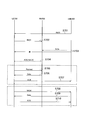
- FIG. 11 is a sequence diagram for explaining the operation (part 2) according to the first embodiment.
- FIG. 12 is a sequence diagram for explaining the operation (part 3) according to the first embodiment.
- FIG. 13 is a sequence diagram for explaining the operation (part 4) according to the first embodiment.
- FIG. 14 is a sequence diagram for explaining an operation according to the first modification of the first embodiment.
- FIG. 15 is a flowchart for explaining an operation according to the second modification of the first embodiment.
- FIG. 16 is a diagram for explaining an operating environment according to the second embodiment.
- FIG. 17 is a sequence diagram for explaining an operation according to the second embodiment.
- a relay node includes a control unit that establishes a connection with a wireless terminal and establishes a connection with a base station, a receiving unit that receives information of the wireless terminal from the base station, and the information A transmission unit that transmits to the wireless terminal.
- the reception unit may receive delivery confirmation information from the wireless terminal before transmitting the information.
- the delivery confirmation information may indicate that the wireless terminal has received the information.
- the transmission unit may transmit the information to the wireless terminal in response to reception of the delivery confirmation information.
- the transmission unit may transmit a retransmission request for the information to the base station when the reception unit fails to receive the information.
- the transmission unit may stop transmitting the retransmission request to the base station in response to reception of the delivery confirmation information, even when the reception unit has failed to receive the information. Good.
- the transmission unit may transmit identification information used for decoding the information to the wireless terminal.
- the identification information may be information assigned to the relay node by the base station.
- the transmission unit may transmit identification information used for decoding the information to both the wireless terminal and the base station.
- the identification information may be information assigned to the wireless terminal by the relay node.
- the transmission unit may transmit information on a period during which the relay node monitors a radio signal from the base station during discontinuous reception to the radio terminal.
- the receiving unit may receive control information from the base station.
- the control information may include resource information used for the relay node to transmit the information to the wireless terminal.
- a wireless terminal includes a control unit that establishes a connection with a relay node, a receiving unit that attempts to receive information on the wireless terminal from a base station to the relay node, and the information received from the base station.
- a transmission unit may be provided that transmits delivery confirmation information indicating that the wireless terminal has received the information to the relay node in response to successful reception.
- the receiving unit may receive identification information used for decoding the information from the relay node.
- the identification information may be information assigned to the relay node by the base station.
- the receiving unit may receive identification information used for decoding the information from the relay node.
- the identification information may be information assigned to the wireless terminal by the relay node.
- the reception unit may receive information on a period during which the relay node monitors a radio signal from the base station during discontinuous reception from the relay node.
- the receiving unit may receive control information from the base station.
- the control information may include resource information used for the relay node to transmit the information to the wireless terminal.
- the receiving unit may receive the information from the relay node based on the resource information.
- the relay node includes a control unit that establishes a connection with a wireless terminal, a receiving unit that receives information on the wireless terminal from a base station to the wireless terminal, and a transmission request for the information from the wireless terminal.
- a transmission unit that transmits the information to the wireless terminal only when receiving the information.
- the transmission unit may transmit delivery confirmation information indicating whether the relay node has received the information to the wireless terminal.
- a wireless terminal includes a control unit that establishes a connection with a base station and establishes a connection with a relay node, a receiving unit that receives information on the wireless terminal from the base station, and the receiving unit May include a transmission unit that transmits a transmission request for the information to the relay node when reception of the information fails.
- the transmission unit may transmit the transmission request only when the delivery confirmation information indicating that the relay node has received the information is received.
- the transmission unit may transmit a retransmission request for the information to the base station when the reception unit fails to receive the information.
- the transmission unit stops transmitting the retransmission request to the base station in response to reception of the information from the relay node even when the reception unit has failed to receive the information. May be.
- FIG. 1 is a diagram illustrating a configuration of an LTE system.
- the LTE system includes a UE (User Equipment) 100, an E-UTRAN (Evolved Universal Terrestrial Radio Access Network) 10, and an EPC (Evolved Packet Core) 20.
- UE User Equipment
- E-UTRAN Evolved Universal Terrestrial Radio Access Network
- EPC Evolved Packet Core
- the UE 100 corresponds to a wireless terminal.
- the UE 100 is a mobile communication device.
- UE100 can perform radio
- the E-UTRAN 10 corresponds to a radio access network.
- the E-UTRAN 10 includes an eNB (evolved Node-B) 200 and an RN (Relay Node) 500.
- eNB evolved Node-B
- RN Relay Node
- ENB 200 corresponds to a base station.
- the eNB 200 is connected to each other via the X2 interface.
- ENB 200 manages one or a plurality of cells.
- eNB200 performs radio
- the eNB 200 has a radio resource management (RRM) function, a routing function of user data (hereinafter also referred to as “data”), a measurement control function for mobility control / scheduling, and the like.
- RRM radio resource management
- Cell is used as a term indicating a minimum unit of a wireless communication area. “Cell” may also be used as a term indicating a function of performing wireless communication with the UE 100.
- RN500 corresponds to a relay device.
- the RN 500 can relay the data of the UE 100 between the UE 100 and the eNB 200.
- the RN 500 is wirelessly connected to the eNB 200 via the Un interface.
- the eNB 200 connected to the RN 500 for relay has a function of serving the RN 500.
- Such an eNB 200 is referred to as a DeNB (Donor eNB).
- the RN 500 corresponds to a relay node (relay device).
- the RN 500 can communicate with the UE 100 in place of the eNB 200.
- the RN 500 supports the functionality of the eNB 200. Accordingly, the RN 500 may terminate the radio protocols of the S1 and X2 interfaces and the E-UTRA (Evolved Universal Terrestrial Radio Access) radio interface.
- E-UTRA Evolved Universal Terrestrial Radio Access
- An S1 interface via the eNB 200 may be established between the RN 500 and the MME 300 / SGW 400. That is, the RN 500 may be connected to the MME 300 / SGW 400 via the S1 interface. The RN 500 may communicate with the MME 300 / SGW 400 via the S1 interface.
- An X2 interface via the eNB 200 may be established between the RN 500 and the eNB 200. That is, the RN 500 may be connected to the eNB 200 via the X2 interface. The RN 500 may communicate with the eNB 200 via the X2 interface.
- RN500 also supports a part (subset) of the functionality of UE100.
- the RN 500 includes a radio interface protocol to be described later in order to connect to the eNB 200 wirelessly (see FIG. 3).
- the EPC 20 corresponds to a core network. Further, the EPC 20 may constitute a network together with the E-UTRAN 10.
- the EPC 20 includes an MME (Mobility Management Entity) 300 and an SGW (Serving Gateway) 400.
- MME Mobility Management Entity
- SGW Serving Gateway
- the MME 300 performs various mobility controls for the UE 100, for example.
- the SGW 400 performs data transfer control.
- MME300 and SGW400 are connected with eNB200 via a S1 interface.
- MME300 and SGW400 may be connected with RN500 via an S1 interface.
- FIG. 2 and 3 are protocol stack diagrams of a radio interface in the LTE system.
- FIG. 2 shows a protocol stack diagram of a radio interface between the UE 100 and the eNB 200.
- FIG. 3 shows a protocol stack diagram of a radio interface between the RN 500 and the eNB 200.
- the radio interface protocol is divided into the first to third layers of the OSI reference model.
- the first layer is a physical (PHY) layer.
- the second layer includes a MAC (Medium Access Control) layer, an RLC (Radio Link Control) layer, and a PDCP (Packet Data Convergence Protocol) layer.
- the third layer includes an RRC (Radio Resource Control) layer.
- the physical layer performs encoding / decoding, modulation / demodulation, antenna mapping / demapping, and resource mapping / demapping.
- Data and control signals are transmitted between the physical layer of the UE 100 (RN 500) and the physical layer of the eNB 200 via a physical channel.
- the MAC layer performs data priority control, retransmission processing by hybrid ARQ (HARQ), random access procedure, and the like.
- Data and control signals are transmitted between the MAC layer of the UE 100 (RN 500) and the MAC layer of the eNB 200 via a transport channel.
- the MAC layer of the eNB 200 includes a scheduler (MAC scheduler). The scheduler determines the uplink / downlink transport format (transport block size, modulation / coding scheme (MCS)) and the resource blocks allocated to the UE 100.
- MCS modulation / coding scheme
- the RLC layer transmits data to the RLC layer on the receiving side using the functions of the MAC layer and the physical layer.
- Data and control signals are transmitted between the RLC layer of the UE 100 (RN 500) and the RLC layer of the eNB 200 via a logical channel.
- the PDCP layer performs header compression / decompression and encryption / decryption.
- the RRC layer is defined only in the control plane that handles control signals. Messages for various settings (RRC messages) are transmitted between the RRC layer of the UE 100 (RN 500) and the RRC layer of the eNB 200.
- the RRC layer controls the logical channel, the transport channel, and the physical channel according to establishment, re-establishment, and release of the radio bearer.
- RRC connection between the RRC of the UE 100 (RN 500) and the RRC of the eNB 200
- the UE 100 (RN 500) is in the RRC connected state.
- the UE 100 (RN 500) is in the RRC idle state.
- a NAS (Non-Access Stratum) layer located above the RRC layer performs, for example, session management and mobility management.
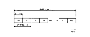
- FIG. 4 is a configuration diagram of a radio frame used in the LTE system.
- OFDMA Orthogonal Frequency Division Multiple Access
- SC-FDMA Single Carrier Frequency Division Multiple Access
- the radio frame is composed of 10 subframes arranged in the time direction.
- Each subframe is composed of two slots arranged in the time direction.
- the length of each subframe is 1 ms.
- the length of each slot is 0.5 ms.
- Each subframe includes a plurality of resource blocks (RB: Resource Block) in the frequency direction.
- Each subframe includes a plurality of symbols in the time direction.
- Each resource block includes a plurality of subcarriers in the frequency direction.
- One resource element (RE) is configured by one symbol and one subcarrier.
- radio resources time / frequency resources
- the section of the first several symbols of each subframe is an area that can be used as a physical downlink control channel (PDCCH: Physical Downlink. Control Channel) for transmitting a downlink control signal.
- the remaining part of each subframe is an area that can be used as a physical downlink shared channel (PDSCH) for transmitting downlink data.
- PDCH Physical Downlink control channel
- PDSCH physical downlink shared channel
- both ends in the frequency direction in each subframe are areas that can be used as physical uplink control channels (PUCCH: Physical Uplink Control Channels) for transmitting uplink control signals.
- PUCCH Physical Uplink Control Channels
- the remaining part of each subframe is an area that can be used as a physical uplink shared channel (PUSCH) for transmitting uplink data.
- PUSCH physical uplink shared channel
- FIG. 5 is a block diagram of the UE 100. As illustrated in FIG. 5, the UE 100 includes a receiver (receiver) 110, a transmitter (transmitter) 120, and a controller (controller) 130.
- the receiver 110 and the transmitter 120 may be an integrated transceiver (transmission / reception unit).
- the receiver 110 performs various types of reception under the control of the controller 130.
- the receiver 110 includes an antenna.
- the receiver 110 converts a radio signal received by the antenna into a baseband signal (received signal).
- the receiver 110 outputs a baseband signal to the controller 130.
- the transmitter 120 performs various transmissions under the control of the controller 130.
- the transmitter 120 includes an antenna.
- the transmitter 120 converts the baseband signal (transmission signal) output from the controller 130 into a radio signal.
- the transmitter 130 transmits a radio signal from the antenna.
- the controller 130 performs various controls in the UE 100.
- the controller 130 includes a processor and a memory.
- the memory stores a program executed by the processor and information used for processing by the processor.
- the processor includes a baseband processor and a CPU (Central Processing Unit).
- the baseband processor performs, for example, modulation / demodulation and encoding / decoding of a baseband signal.
- the CPU performs various processes by executing programs stored in the memory.
- the processor may include a codec that performs encoding / decoding of an audio / video signal.
- the processor executes various processes described later and various communication protocols described above.
- the UE 100 may include a GNSS (Global Navigation Satellite System) receiver.
- the GNSS receiver can receive a GNSS signal in order to obtain location information indicating the geographical location of the UE 100.
- the GNSS receiver outputs a GNSS signal to the controller 130.
- the UE 100 may have a GPS (Global Positioning System) function for acquiring location information of the UE 100.
- the process which at least any one of the receiver 110 with which UE100 is equipped, the transmitter 120, and the controller 130 performs may be demonstrated as a process (operation
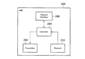
- FIG. 6 is a block diagram of the eNB 200. As illustrated in FIG. 6, the eNB 200 includes a receiver (reception unit) 210, a transmitter (transmission unit) 220, a controller (control unit) 230, and a network interface 240.
- the transmitter 210 and the receiver 220 may be an integrated transceiver (transmission / reception unit).
- the receiver 210 performs various types of reception under the control of the controller 230.
- the receiver 210 includes an antenna.
- the receiver 210 converts a radio signal received by the antenna into a baseband signal (received signal).
- the receiver 210 outputs a baseband signal to the controller 230.
- the transmitter 220 performs various transmissions under the control of the controller 230.
- the transmitter 220 includes an antenna.
- the transmitter 220 converts the baseband signal (transmission signal) output from the controller 230 into a radio signal.
- the transmitter 220 transmits a radio signal from the antenna.
- the controller 230 performs various controls in the eNB 200.
- the controller 230 includes a processor and a memory.
- the memory stores a program executed by the processor and information used for processing by the processor.
- the processor includes a baseband processor and a CPU.
- the baseband processor performs, for example, modulation / demodulation and encoding / decoding of a baseband signal.
- the CPU performs various processes by executing programs stored in the memory.
- the processor executes various processes described later and various communication protocols described above.
- the network interface 240 is connected to the neighboring eNB 200 via the X2 interface.
- the network interface 240 is connected to the MME 300 and the SGW 400 via the S1 interface.
- the network interface 240 is used for communication performed on the X2 interface and communication performed on the S1 interface, for example.
- the process which at least any one of the transmitter 210 with which eNB200 is equipped, the receiver 220, the controller 230, and the network interface 240 performs is demonstrated as a process (operation
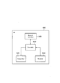
- FIG. 7 is a block diagram of the RN 500. As illustrated in FIG. 7, the RN 500 includes a receiver (reception unit) 510, a transmitter (transmission unit) 520, a controller (control unit) 530, and a network interface 540. The transmitter 510 and the receiver 520 may be an integrated transceiver (transmission / reception unit). The RN 500 may not include the network interface 540.
- the receiver 510 performs various types of reception under the control of the controller 530.
- Receiver 510 includes an antenna.
- the receiver 510 converts a radio signal received by the antenna into a baseband signal (received signal).
- the receiver 510 outputs a baseband signal to the controller 530.
- the transmitter 520 performs various transmissions under the control of the controller 530.
- Transmitter 520 includes an antenna.
- the transmitter 520 converts the baseband signal (transmission signal) output from the controller 530 into a radio signal.
- the transmitter 520 transmits a radio signal from the antenna.
- the controller 530 performs various controls in the RN 500.
- the controller 530 includes a processor and a memory.
- the memory stores a program executed by the processor and information used for processing by the processor.
- the processor includes a baseband processor and a CPU.
- the baseband processor performs, for example, modulation / demodulation and encoding / decoding of a baseband signal.
- the CPU performs various processes by executing programs stored in the memory.
- the processor executes various processes described later and various communication protocols described above.
- the network interface 540 is connected to another node (for example, another RN 500) provided in the mobile body.
- the RN 500 may perform communication with other nodes using the receiver 510 and / or the transmitter 520.
- the RN 500 may perform communication with other nodes using the receiver 510 and / or the transmitter 520 when the network interface 540 is not provided.
- processing executed by at least one of the transmitter 510, the receiver 520, the controller 530, and the network interface 540 included in the RN 500 will be described as processing (operation) executed by the RN 500 for convenience.
- FIGS. 8 and 9 are diagrams for explaining the operating environment according to the first embodiment.
- the mobile body (for example, a train) 1 accommodates each UE 100. Further, the mobile body 1 is provided with an RN 500. Each UE 100 and RN 500 may establish a connection (RRC connection). Each UE 100 may be in an RRC connection state with respect to the RN 500. Each UE 100 and RN 500 may not have established a connection (RRC connection). Each UE 100 may be in an RRC idle state with respect to the RN 500. Each UE 100 may establish a connection (RRC connection) with the RN 500 as necessary.
- RRC connection connection
- RN 500 establishes connection (RRC connection) with eNB 200 (for example, macro eNB).
- the RN 500 may execute communication with the eNB 200 using a frequency of 4 GHz band, for example.
- the RN 500 may perform communication with the UE 100 using, for example, at least one of a frequency of 4 GHz band, 30 GHz band, and 70 GHz band.
- ENB200 is eNB installed in the circumference
- the moving body 1 is moving at high speed.
- the moving body 1 is moving at a speed (for example, 500 km / h) equal to or higher than a threshold. Therefore, each UE 100 and RN 500 is moving at a high speed (at a speed equal to or higher than a threshold).
- information on the UE 100 (for example, user data / packets) is sent from the eNB 200 to the UE 100 via the RN 500.
- the UE 100 can attempt to receive information on the UE 100 transmitted from the eNB 200 to the RN 500.
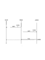
- FIG. 10 is a sequence diagram for explaining an operation (part 1) according to the first embodiment.
- FIG. 11 is a sequence diagram for explaining the operation (part 2) according to the first embodiment.
- the UE 100 can receive information on the UE 100 transmitted from the eNB 200 to the RN 500 by the following method.
- the RN 500 assigns identification information to the UE 100.
- the identification information is, for example, an identifier (RNTI: Radio Network Temporary Identifier) temporarily assigned to the UE 100.
- the identification information may be a cell identifier (C-RNTI: Cell-RNTI).
- C-RNTI Cell-RNTI
- the identification information may be an identifier that is individually assigned to the UE 100.
- the identification information may be an identifier indicating the RN 500 cell. Therefore, the identification information may be an identifier common to each UE 100 in the RN 500 cell.
- the identification information is used for decoding information (for example, data, control information for receiving data, etc.) of the UE 100 sent from the eNB 200 to the RN 500, as will be described later.
- the RN 500 may transmit control information (for example, information on radio resources allocated to the RN 500) for receiving information transmitted from the eNB 200 to each UE 100.
- control information for example, information on radio resources allocated to the RN 500
- the RN 500 transmits the identification information assigned to the UE 100 to the eNB 200.
- eNB200 encodes the information of UE100 transmitted to RN500 using the identification information received from RN500.
- the identification information is an identifier that is individually assigned to the UE 100
- the information of each UE 100 can be encoded using the identification information corresponding to the information of each UE 100.
- the eNB 200 transmits the encoded information (data) of the UE 100 to the RN 500.
- the direct transmission destination of the information of the UE 100 may be the RN 500. That is, the identifier of the transmission destination included in the information transmitted from the eNB 200 may be the identifier of the RN 500. Therefore, in the information on the UE 100, the direct transmission destination from the eNB 200 may not indicate the UE 100.
- the eNB 200 may transmit information of the plurality of UEs 100 as one data to the RN 500.
- UE100 tries to receive information from eNB200.
- UE100 decodes the received information using the identification information allocated from RN500.
- UE100 tries decoding, when the information from eNB200 may contain the information addressed to UE100 itself. For example, when the information from the eNB 200 is information addressed to the RN 500, the UE 100 attempts decoding. If the received information can be decoded, the UE 100 determines that the information has been successfully received. If the received information cannot be decoded, the UE 100 determines that reception of the information has failed.
- the UE 100 determines that the information has been successfully received when the information of the UE 100 itself can be decoded.
- the RN 500 receives information on the UE 100 from the eNB 200.
- the RN 500 decodes the received information addressed to the UE 100 using the identification information transmitted to the eNB 200.
- the RN 500 determines that the information has been successfully received. If the received information cannot be decoded, the UE 100 determines that reception of the information has failed.
- the RN 500 can relay (transmit) the received information on the UE 100 to the UE 100. As will be described later, when the RN 500 determines that the UE 100 has successfully received information from the eNB 200, the transmission (relay) of the information of the UE 100 may be omitted.
- the identification information is, for example, an identifier (RNTI: Radio Network Temporary Identifier) temporarily assigned to the RN 500.
- the identification information may be a cell identifier (C-RNTI: Cell-RNTI).
- C-RNTI Cell-RNTI
- the identification information may be an identifier that is individually assigned to the RN 500.
- the identification information may be an identifier that is individually assigned to the UE 100.
- the identification information may be an identifier common to each UE 100 in the RN 500 cell.
- step S202 the RN 500 transmits identification information to the UE 100.
- the UE 100 receives the identification information.
- Step S203 corresponds to step S103.
- FIG. 12 is a sequence diagram for explaining the operation (part 3) according to the first embodiment.
- step 301 corresponds to step S103 or S203.
- step S302 the UE 100 may transmit delivery confirmation information to the RN 500.
- the delivery confirmation information may indicate whether the UE 100 has received information from the eNB 200.
- the delivery confirmation information may indicate that the UE 100 has received information from the eNB 200 (ACK: Acknowledge).
- the delivery confirmation information may indicate that the UE 100 has not received information from the eNB 200 (NACK: Nackledge).
- the delivery confirmation information may include information indicating the content of information that has been successfully received.
- the delivery confirmation information may include information on a sequence number of a packet that has been successfully received.
- the delivery confirmation information may be information for requesting transmission (retransmission) of information to the RN 500.
- the delivery confirmation information may include information on a sequence number of a packet that has failed to be received.
- the UE 100 may transmit delivery confirmation information (ACK / NACK) in response to success or failure of reception of information from the eNB 200.
- UE100 may transmit delivery confirmation information (ACK) only when reception of information from eNB200 is successful.
- UE100 does not need to transmit delivery confirmation information (NACK), when reception of the information from eNB200 fails.
- the UE 100 can transmit the arrival confirmation information to the RN 500 before the RN 500 transmits the information from the eNB 200 to the UE 100.
- step S303 the RN 500 determines whether or not the UE 100 has received information from the eNB 200.
- the RN 500 may make a determination based on the delivery confirmation information. For example, the RN 500 may determine that the UE 100 has received information from the eNB 200 when receiving acknowledgment information indicating ACK (successful reception) before transmitting information from the eNB 200. On the other hand, RN 500 may determine that UE 100 has not received information from eNB 200 when receiving acknowledgment information indicating NACK (reception failure) before transmission of information from eNB 200.
- RN 500 may determine that UE 100 has not received information from eNB 200 when it does not receive delivery confirmation information even after a predetermined time has elapsed since reception of information from eNB 200.
- the predetermined time is, for example, the time from when the RN 500 receives information from the eNB 200 to before transmitting the information to the UE 100.
- the RN 500 may start a timer for measuring the predetermined time. The RN 500 may stop the timer in response to receiving the delivery confirmation information.
- RN500 performs the process of step S304, when UE100 is not receiving the information from eNB200 (when UE100 fails to receive the information from eNB200).
- the RN 500 ends the process. That is, the RN 500 omits the process of step S304.
- step S304 the RN 500 transmits information from the eNB 200 to the UE 100.
- the RN 500 may transmit (relay) the information to the UE 100 in response to receiving the delivery confirmation information indicating NACK (reception failure).
- the RN 500 may transmit (relay) the information to the UE 100.
- the RN 500 may stop transmitting (relaying) information from the eNB 200 in response to reception of delivery confirmation information indicating ACK (successful reception). Therefore, when the UE 100 succeeds in receiving information from the eNB 200, the RN 500 may stop transmitting information from the eNB 200. In other words, the RN 500 may not transmit information from the eNB 200 (the transmission of information from the eNB 200 may be omitted).
- UE100 can assist communication between eNB200 and RN500. For example, it is effective when the communication throughput between the eNB 200 and the RN 500 is reduced due to high-speed movement. Further, since the RN 500 can omit relaying information to the UE 100, the load on the RN 500 can be reduced.
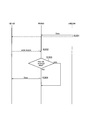
- FIG. 13 is a sequence diagram for explaining the operation (part 4) according to the first embodiment.
- step S401 corresponds to step S301.
- RN 500 has failed to receive information on UE 100 from eNB 200.
- Step S402 corresponds to step S302.
- the UE 100 can transmit the delivery confirmation information to the RN 500 before the RN 500 transmits the delivery confirmation information (step S404 or S406).
- the UE 100 may transmit the delivery confirmation information to the RN 500 at a timing earlier than the conventional transmission confirmation information transmission timing (for example, timing 4 ms after reception of the information). Since the transmission time interval (TTI: Transmission Time Interval) is shorter than before, the UE 100 may transmit the delivery confirmation information to the RN 500 before the RN 500 transmits the delivery confirmation information.
- TTI Transmission Time Interval
- the UE 100 may be able to transmit the delivery confirmation information to the RN 500 before the RN 500 transmits the delivery confirmation information.
- the RN 500 may be set by the eNB 200 to transmit the delivery confirmation information. Further, the RN 500 may notify (request) the eNB 200 of the timing for transmitting the delivery confirmation information.
- Step S403 corresponds to step S303.
- the RN 500 can transmit delivery confirmation information indicating a reception failure (NACK) of information from the eNB 200 to the eNB 200.
- the delivery confirmation information may be information requesting retransmission of information on the UE 100 that has already been transmitted from the eNB 200. Therefore, when both the RN 500 itself and the UE 100 fail to receive information from the eNB 200, the RN 500 can transmit delivery confirmation information indicating NACK to the eNB 200.
- the RN 500 executes the process of step S406.
- step S405 the eNB 200 retransmits the information (data) of the UE 100 to the RN 500 in response to receiving the delivery confirmation information indicating NACK.
- the RN 500 transmits (relays) the received UE100 information to the UE100.
- step S406 when the UE 100 succeeds in receiving information from the eNB 200, the RN 500 can transmit delivery confirmation information indicating successful reception (ACK) of information from the eNB 200 to the eNB 200. Therefore, even when RN 500 itself (receiver 210) fails to receive information from eNB 200, RN 500 sends a retransmission request (acknowledgment information indicating NACK) in response to reception of acknowledgment information indicating ACK. Transmission to the eNB 200 can be stopped.
- ACK delivery confirmation information indicating successful reception
- the UE 100 can assist communication between the eNB 200 and the RN 500. For example, it is effective when the communication throughput between the eNB 200 and the RN 500 is reduced due to high-speed movement.
- the RN 500 may transmit a retransmission request to the eNB 200 when the RN 500 itself fails to receive information from the eNB 200 regardless of whether or not the UE 100 has successfully received information from the eNB 200.
- FIG. 14 is a sequence diagram for explaining an operation according to the first modification of the first embodiment. Description of the same parts as described above will be omitted as appropriate.
- the UE 100 attempts to receive control information from the eNB 200.
- the eNB 200 transmits control information to the RN 500.
- the control information may include information for receiving information (data (user data)) of the UE 100 from the eNB 200 to the RN 500.
- the control information may include information for receiving information (data (user data)) of the UE 100 from the UE 100 to the eNB 200.
- the information for receiving information on the UE 100 may be, for example, resource information (time / frequency resource information) used for transmitting the information on the UE 100.
- Control information may be transmitted by PDCCH.
- RN 500 receives control information from eNB 200.
- the UE 100 attempts to receive control information. The description will proceed assuming that the UE 100 has successfully received the control information.
- control information is easier to receive than the user data because the coding rate is lower than that of the user data. Therefore, the UE 100 does not need to attempt to receive control information from the eNB 200 and to attempt to receive user data of the UE 100 from the eNB 200.
- UE100 may transmit the information for abbreviate
- Step S502 corresponds to step S103.
- UE100 may receive the information (user data) from eNB200 based on the control information from eNB200.
- the RN 500 transmits control information to the UE 100.
- the control information includes resource information used for transmitting information on the UE 100 from the RN 500 to the UE 100.
- the control information may be information included in the control information from the eNB 200.
- the UE 100 may stop receiving the receiver 110 until the process of step S504 is executed. For example, the UE 100 may stop receiving the receiver 110 until the UE 100 executes the process of step S504 after successful reception in step S501.
- the UE 100 may stop the reception of the receiver 110 by discontinuous reception (DRX: Discontinuous Reception). That is, the UE 100 may stop (stop) monitoring of control information from the RN 500.
- DRX Discontinuous Reception
- RN 500 may omit transmission of control information when UE 100 receives control information.
- step S504 the RN 500 transmits (relays) user data of the UE 100 to the UE 100 using the resource information included in the control information from the eNB 200.
- UE100 receives the user data of UE100 from RN500 using the resource information contained in the control information from eNB200.
- the UE 100 may stop the processes in steps S503 and S504 when the data reception is successful in step S502.
- the UE 100 can stop (stop) the monitoring of the control information from the RN 500 even when it is the transmission timing of the control information from the RN 500 by receiving the control information from the eNB 200.
- the power consumption of the UE 100 can be reduced.
- FIG. 15 is a flowchart for explaining an operation according to the second modification of the first embodiment. Description of the same parts as described above will be omitted as appropriate.
- the DRX timings of the UE 100 and the RN 500 coincide.
- the RN 500 transmits DRX information to the UE 100.
- the DRX information includes information on a period during which the RN 500 monitors a radio signal (particularly, information on the UE 100) from the eNB 200 during discontinuous reception (DRX).
- the DRX information may be information set in the RN 500 by the eNB 200.
- RN 500 may transmit DRX information in response to a request from UE 100.
- the RN 500 may transmit the DRX information determined by the RN 500 itself to the eNB 200.
- step S602 the UE 100 starts the DRX operation based on the DRX information. Therefore, the period during which the UE 100 and the RN 500 monitor (receive) a radio signal from the eNB 200 during discontinuous reception (DRX) coincides.
- the UE 100 can attempt to receive information on the UE 100 from the eNB 200 even during DRX.
- FIG. 16 is a diagram for explaining an operating environment according to the second embodiment.
- the UE 100 and the eNB 200 establish a connection (RRC connection).
- the UE 100 may be in an RRC idle state with respect to the eNB 200.
- the UE 100 may establish a connection (RRC connection) with the eNB 200 as necessary.
- the UE 100 may establish a connection (RRC connection) with the eNB 200.
- the RN 500 may be in an RRC idle state.
- the UE 100 may establish a connection (RRC connection) with the RN 500 as necessary.
- the RN 500 may establish a connection (RRC connection) with the eNB 200. Alternatively, the RN 500 may establish a connection (RRC connection) with the RN 500 as necessary.
- information for example, user data / packet
- the eNB 200 transmits information (for example, user data / packet) to the UE 100 without passing through the RN 500.
- the RN 500 can attempt to receive information on the UE 100 transmitted from the eNB 200 to the UE 100.
- the RN 500 may transmit (retransmit) information on the UE 100 to the UE 100.
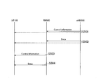
- FIG. 17 is a sequence diagram for explaining an operation according to the second embodiment.
- the eNB 200 assigns identification information to the UE 100.
- the identification information is used to decode information from the eNB 200 to the UE 100.
- the identification information may be the same information (for example, C-RNTI) as in the first embodiment.
- step S702 the UE 100 transmits the identification information assigned from the eNB 200 to the RN 500.
- the RN 500 receives the identification information.
- the eNB 200 transmits information (data) of the UE 100 to the UE 100.
- the information on the UE 100 may be information encoded by identification information assigned to the UE 100.
- RN 500 tries to receive information of UE 100.
- the RN 500 decodes the received information using the identification information received from the UE 100.
- the RN 500 determines that the UE 100 has successfully received the information.
- the RN 500 determines that reception of the information of the UE 100 has failed.
- the UE 100 When the UE 100 receives the information of the UE 100 from the eNB 200, the UE 100 executes the process of step S707. On the other hand, when the UE 100 fails to receive the information of the UE 100, the following processing is executed.
- the description will proceed assuming that the UE 100 has failed to receive the information of the UE 100.
- the RN 500 may transmit delivery confirmation information to the RN 500.
- the delivery confirmation information may indicate whether or not the RN 500 has received information from the eNB 200.
- the delivery confirmation information may indicate that the RN 500 has received information from the eNB 200 (ACK).
- the acknowledgment information may indicate that the RN 500 has not received information from the eNB 200 (NACK). Similarly to the above, it may be the same information as the delivery confirmation information from the UE 100 to the RN 500.
- the RN 500 may transmit delivery confirmation information (ACK / NACK) in response to success or failure in receiving information from the eNB 200.
- the RN 500 may transmit the acknowledgment information (ACK) only when the information from the eNB 200 is successfully received.
- the RN 500 may not transmit the delivery confirmation information (NACK).
- the RN 500 may transmit delivery confirmation information (NACK) only when reception of information from the eNB 200 fails.
- the RN 500 may not transmit the delivery confirmation information (ACK).
- step S705 when RN500 has received the information from eNB200 successfully.
- step S706 when the RN 500 has failed to receive information from the eNB 200, the UE 100 executes the process of step S706.
- step S705 the UE 100 transmits a transmission request (retransmission request) for information on the UE 100 to the RN 500.
- the UE 100 itself fails to receive the information of the eNB 200, the UE 100 may transmit a retransmission request.
- the UE 100 may transmit a retransmission request to the RN 500 only when receiving acknowledgment information indicating ACK from the RN 500.
- the retransmission request may be the delivery confirmation information of the first embodiment described above.
- the RN 500 transmits information (data) of the UE 100 to the UE 100.
- the RN 500 transmits information (data) of the UE 100 to the UE 100.
- the RN 500 may transmit information on the UE 100 to the UE 100 only when a retransmission request is received.
- the RN 500 may transmit the information of the UE 100 to the UE 100 when the retransmission request is not received from the UE 100 even after a predetermined time has elapsed since the reception of the information from the eNB 200.
- UE100 receives the information of UE100 from RN500.
- step S707 the UE 100 transmits delivery confirmation information indicating ACK to the eNB 200.
- UE100 may transmit the delivery confirmation information which shows ACK to eNB200 according to reception of the information of UE100 from RN500, even if UE100 itself has failed in reception of the information of UE100.
- the UE 100 transmits a retransmission request to the eNB 200.
- the retransmission request may be delivery confirmation information indicating NACK.
- the eNB 200 retransmits information (data) of the UE 100.
- UE100 receives the information of UE100.
- UE100 transmits the delivery confirmation information which shows ACK to eNB200.
- the RN 500 can assist communication between the UE 100 and the eNB 200. For example, it is effective when the communication throughput between the UE 100 and the eNB 200 is reduced due to high-speed movement. Further, since the RN 500 can omit relaying information to the UE 100, the load on the RN 500 can be reduced.
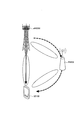
- a plurality of RNs 500 may be installed in the moving body 1.
- An RN 500 may be installed in each of a plurality of vehicles (cargos) constituting the mobile body 1.
- an antenna of RN 500 may be installed at the top of each vehicle.
- UE 100 and RN 500 located in the same vehicle may perform communication (transmission and / or reception).
- Each RN 500 may execute communication (transmission and / or reception) with the eNB 200.
- one RN 500 (representative RN 500) may represent and execute communication with the eNB 200.
- the representative RN 500 may communicate with each other RN 500 (eg, via the network interface 540).
- the relay node may be a relay UE (ProSe UE-to Network Relay) that performs relay using a proximity service (ProSe: ProSe: Proximity-based Services).
- a relay UE ProSe UE-to Network Relay
- ProSe ProSe: Proximity-based Services
- a program for causing a computer to execute each process performed by any of the above-described nodes may be provided.
- the program may be recorded on a computer readable medium. If a computer-readable medium is used, a program can be installed in the computer.
- the computer-readable medium on which the program is recorded may be a non-transitory recording medium.
- the non-transitory recording medium is not particularly limited, but may be a recording medium such as a CD-ROM or a DVD-ROM.
- a chip configured by a memory that stores a program for executing each process performed by any one of the UE 100, the eNB 200, and the RN 500 and a processor that executes the program stored in the memory may be provided.
- the LTE system has been described as an example of the mobile communication system, but the present invention is not limited to the LTE system, and the content according to the present application may be applied to a system other than the LTE system.
- the present invention is useful in the communication field.
Landscapes
- Engineering & Computer Science (AREA)
- Computer Networks & Wireless Communication (AREA)
- Signal Processing (AREA)
- Mobile Radio Communication Systems (AREA)
- Mechanical Engineering (AREA)
- Communication Control (AREA)
Abstract
A relay node according to one embodiment of the present invention is provided with: a control unit for establishing a connection with a wireless terminal and establishing a connection with a base station; a receiving unit for receiving information of the wireless terminal from the base station; and a transmitting unit for transmitting the information to the wireless terminal. The receiving unit receives acknowledgement information from the wireless terminal before transmitting the information. The acknowledgement information indicates that the information has been received by the wireless terminal. The transmitting unit transmits the information to the wireless terminal in response to reception of the acknowledgment information.
Description
本開示は、リレーノード及び無線端末に関する。
This disclosure relates to relay nodes and wireless terminals.
移動通信システムの標準化プロジェクトである3GPP(3rd Generation Partnership Project)では、リレーノード(RN)が仕様化されている(非特許文献1参照)。
In 3GPP (3rd Generation Partnership Project), which is a standardization project for mobile communication systems, a relay node (RN) is specified (see Non-Patent Document 1).
基地局の機能性を有するリレーノードは、基地局に代わって無線端末へサービスを提供できる。現状、リレーノードは、基地局のカバレッジを補うために主に利用されている。
A relay node having the functionality of a base station can provide services to wireless terminals on behalf of the base station. Currently, relay nodes are mainly used to supplement the coverage of base stations.
一の実施形態に係るリレーノードは、無線端末と接続を確立し、かつ基地局と接続を確立する制御部と、前記無線端末の情報を前記基地局から受信する受信部と、前記情報を前記無線端末へ送信する送信部と、を備える。前記受信部は、前記情報の送信前に、送達確認情報を前記無線端末から受信する。前記送達確認情報は、前記無線端末が前記情報を受信したことを示す。前記送信部は、前記送達確認情報の受信に応じて、前記情報を前記無線端末へ送信することを中止する。
A relay node according to an embodiment includes a control unit that establishes a connection with a wireless terminal and establishes a connection with a base station, a receiving unit that receives information of the wireless terminal from the base station, and the information A transmission unit that transmits to the wireless terminal. The receiving unit receives delivery confirmation information from the wireless terminal before transmitting the information. The delivery confirmation information indicates that the wireless terminal has received the information. The transmission unit stops transmitting the information to the wireless terminal in response to reception of the delivery confirmation information.
一の実施形態に係る無線端末は、リレーノードと接続を確立する制御部と、基地局から前記リレーノードへの前記無線端末の情報の受信を試みる受信部と、前記基地局からの前記情報の受信の成功に応じて、前記無線端末が前記情報を受信したことを示す送達確認情報を前記リレーノードへ送信する送信部と、を備える。
A wireless terminal according to an embodiment includes a control unit that establishes a connection with a relay node, a receiving unit that attempts to receive information on the wireless terminal from a base station to the relay node, and the information received from the base station. A transmission unit that transmits delivery confirmation information indicating that the wireless terminal has received the information to the relay node in response to successful reception.
一の実施形態に係るリレーノードは、無線端末と接続を確立する制御部と、基地局から前記無線端末への前記無線端末の情報を受信する受信部と、前記無線端末から前記情報の送信要求を受信した場合にのみ、前記情報を前記無線端末へ送信する送信部と、を備える。
The relay node according to one embodiment includes a control unit that establishes a connection with a wireless terminal, a receiving unit that receives information on the wireless terminal from a base station to the wireless terminal, and a transmission request for the information from the wireless terminal. A transmission unit that transmits the information to the wireless terminal only when receiving the information.
一の実施形態に係る無線端末は、基地局と接続を確立し、かつ、リレーノードと接続を確立する制御部と、前記無線端末の情報を前記基地局から受信する受信部と、前記受信部が前記情報の受信に失敗した場合、前記リレーノードへ前記情報の送信要求を送信する送信部と、を備える。
A wireless terminal according to an embodiment includes a control unit that establishes a connection with a base station and establishes a connection with a relay node, a receiving unit that receives information on the wireless terminal from the base station, and the receiving unit Includes a transmission unit that transmits a transmission request for the information to the relay node when reception of the information fails.
[実施形態の概要]
近年、複数の無線端末が収容される移動体(例えば、電車)にリレーノードを設置することが提案されている。移動体の走行中に、リレーノードが複数の無線端末を代表して基地局との通信を実行することにより、リソースの使用効率が向上する。 [Outline of Embodiment]
In recent years, it has been proposed to install a relay node in a moving body (for example, a train) that accommodates a plurality of wireless terminals. While the mobile unit is traveling, the relay node performs communication with the base station on behalf of a plurality of wireless terminals, thereby improving resource use efficiency.
しかしながら、移動体が高速で移動する場合には、リレーノードと基地局と間の無線環境が刻々と変化するため、リレーノードと基地局と間で通信スループットが十分に確保されない可能性がある。
However, when the mobile body moves at a high speed, the wireless environment between the relay node and the base station changes every moment, so there is a possibility that sufficient communication throughput is not ensured between the relay node and the base station.
一の実施形態に係るリレーノードは、無線端末と接続を確立し、かつ基地局と接続を確立する制御部と、前記無線端末の情報を前記基地局から受信する受信部と、前記情報を前記無線端末へ送信する送信部と、を備えてもよい。前記受信部は、前記情報の送信前に、送達確認情報を前記無線端末から受信してもよい。前記送達確認情報は、前記無線端末が前記情報を受信したことを示してもよい。前記送信部は、前記送達確認情報の受信に応じて、前記情報を前記無線端末へ送信してもよい。
A relay node according to an embodiment includes a control unit that establishes a connection with a wireless terminal and establishes a connection with a base station, a receiving unit that receives information of the wireless terminal from the base station, and the information A transmission unit that transmits to the wireless terminal. The reception unit may receive delivery confirmation information from the wireless terminal before transmitting the information. The delivery confirmation information may indicate that the wireless terminal has received the information. The transmission unit may transmit the information to the wireless terminal in response to reception of the delivery confirmation information.
前記送信部は、前記受信部が前記情報の受信に失敗した場合、前記情報の再送要求を前記基地局へ送信してもよい。前記送信部は、前記受信部が前記情報の受信に失敗していた場合であっても、前記送達確認情報の受信に応じて、前記再送要求を前記基地局へ送信することを中止してもよい。
The transmission unit may transmit a retransmission request for the information to the base station when the reception unit fails to receive the information. The transmission unit may stop transmitting the retransmission request to the base station in response to reception of the delivery confirmation information, even when the reception unit has failed to receive the information. Good.
前記送信部は、前記情報をデコードするために用いられる識別情報を前記無線端末へ送信してもよい。前記識別情報は、前記基地局が前記リレーノードへ割り当てた情報であってもよい。
The transmission unit may transmit identification information used for decoding the information to the wireless terminal. The identification information may be information assigned to the relay node by the base station.
前記送信部は、前記情報をデコードするために用いられる識別情報を前記無線端末及び前記基地局の両方へ送信してもよい。前記識別情報は、前記識別情報は、前記リレーノードが前記無線端末へ割り当てた情報であってもよい。
The transmission unit may transmit identification information used for decoding the information to both the wireless terminal and the base station. The identification information may be information assigned to the wireless terminal by the relay node.
前記送信部は、前記リレーノードが不連続受信中に前記基地局からの無線信号をモニタする期間の情報を前記無線端末へ送信してもよい。
The transmission unit may transmit information on a period during which the relay node monitors a radio signal from the base station during discontinuous reception to the radio terminal.
前記受信部は、制御情報を前記基地局から受信してもよい。前記制御情報は、前記リレーノードが前記無線端末へ前記情報を送信するために用いられるリソース情報を含んでもよい。
The receiving unit may receive control information from the base station. The control information may include resource information used for the relay node to transmit the information to the wireless terminal.
一の実施形態に係る無線端末は、リレーノードと接続を確立する制御部と、基地局から前記リレーノードへの前記無線端末の情報の受信を試みる受信部と、前記基地局からの前記情報の受信の成功に応じて、前記無線端末が前記情報を受信したことを示す送達確認情報を前記リレーノードへ送信する送信部を備えてもよい。
A wireless terminal according to an embodiment includes a control unit that establishes a connection with a relay node, a receiving unit that attempts to receive information on the wireless terminal from a base station to the relay node, and the information received from the base station. A transmission unit may be provided that transmits delivery confirmation information indicating that the wireless terminal has received the information to the relay node in response to successful reception.
前記受信部は、前記情報をデコードするために用いられる識別情報を前記リレーノードから受信してもよい。前記識別情報は、前記基地局が前記リレーノードへ割り当てた情報であってもよい。
The receiving unit may receive identification information used for decoding the information from the relay node. The identification information may be information assigned to the relay node by the base station.
前記受信部は、前記情報をデコードするために用いられる識別情報を前記リレーノードから受信してもよい。前記識別情報は、前記リレーノードが前記無線端末へ割り当てた情報であってもよい。
The receiving unit may receive identification information used for decoding the information from the relay node. The identification information may be information assigned to the wireless terminal by the relay node.
前記受信部は、前記リレーノードが不連続受信中に前記基地局からの無線信号をモニタする期間の情報を前記リレーノードから受信してもよい。
The reception unit may receive information on a period during which the relay node monitors a radio signal from the base station during discontinuous reception from the relay node.
前記受信部は、制御情報を前記基地局から受信してもよい。前記制御情報は、前記リレーノードが前記無線端末へ前記情報を送信するために用いられるリソース情報を含んでもよい。前記受信部は、前記リソース情報に基づいて、前記情報を前記リレーノードから受信してもよい。
The receiving unit may receive control information from the base station. The control information may include resource information used for the relay node to transmit the information to the wireless terminal. The receiving unit may receive the information from the relay node based on the resource information.
一の実施形態に係るリレーノードは、無線端末と接続を確立する制御部と、基地局から前記無線端末への前記無線端末の情報を受信する受信部と、前記無線端末から前記情報の送信要求を受信した場合にのみ、前記情報を前記無線端末へ送信する送信部と、を備えてもよい。
The relay node according to one embodiment includes a control unit that establishes a connection with a wireless terminal, a receiving unit that receives information on the wireless terminal from a base station to the wireless terminal, and a transmission request for the information from the wireless terminal. A transmission unit that transmits the information to the wireless terminal only when receiving the information.
前記送信部は、前記リレーノードが前記情報を受信したか否かを示す送達確認情報を前記無線端末へ送信してもよい。
The transmission unit may transmit delivery confirmation information indicating whether the relay node has received the information to the wireless terminal.
一の実施形態に係る無線端末は、基地局と接続を確立し、かつ、リレーノードと接続を確立する制御部と、前記無線端末の情報を前記基地局から受信する受信部と、前記受信部が前記情報の受信に失敗した場合、前記リレーノードへ前記情報の送信要求を送信する送信部と、を備えてもよい。
A wireless terminal according to an embodiment includes a control unit that establishes a connection with a base station and establishes a connection with a relay node, a receiving unit that receives information on the wireless terminal from the base station, and the receiving unit May include a transmission unit that transmits a transmission request for the information to the relay node when reception of the information fails.
前記送信部は、前記リレーノードが前記情報を受信したことを示す送達確認情報を受信した場合にのみ、前記送信要求を送信してもよい。
The transmission unit may transmit the transmission request only when the delivery confirmation information indicating that the relay node has received the information is received.
前記送信部は、前記受信部が前記情報の受信に失敗した場合、前記情報の再送要求を前記基地局へ送信してもよい。前記送信部は、前記受信部が前記情報の受信に失敗していた場合であっても、前記リレーノードからの前記情報の受信に応じて、前記再送要求を前記基地局へ送信することを中止してもよい。
The transmission unit may transmit a retransmission request for the information to the base station when the reception unit fails to receive the information. The transmission unit stops transmitting the retransmission request to the base station in response to reception of the information from the relay node even when the reception unit has failed to receive the information. May be.
[システム概略]
(移動通信システム)
以下において、実施形態に係る移動通信システムであるLTEシステムについて説明する。図1は、LTEシステムの構成を示す図である。 [System overview]
(Mobile communication system)
Below, the LTE system which is the mobile communication system which concerns on embodiment is demonstrated. FIG. 1 is a diagram illustrating a configuration of an LTE system.
(移動通信システム)
以下において、実施形態に係る移動通信システムであるLTEシステムについて説明する。図1は、LTEシステムの構成を示す図である。 [System overview]
(Mobile communication system)
Below, the LTE system which is the mobile communication system which concerns on embodiment is demonstrated. FIG. 1 is a diagram illustrating a configuration of an LTE system.
図1に示すように、LTEシステムは、UE(User Equipment)100、E-UTRAN(Evolved Universal Terrestrial Radio Access Network)10、及びEPC(Evolved Packet Core)20を備える。
As shown in FIG. 1, the LTE system includes a UE (User Equipment) 100, an E-UTRAN (Evolved Universal Terrestrial Radio Access Network) 10, and an EPC (Evolved Packet Core) 20.
UE100は、無線端末に相当する。UE100は、移動型の通信装置である。UE100は、セル(後述するeNB200又はRN500)と無線通信を行うことができる。
UE 100 corresponds to a wireless terminal. The UE 100 is a mobile communication device. UE100 can perform radio | wireless communication with a cell (eNB200 or RN500 mentioned later).
E-UTRAN10は、無線アクセスネットワークに相当する。E-UTRAN10は、eNB(evolved Node-B)200、及びRN(Relay Node)500を含む。
E-UTRAN 10 corresponds to a radio access network. The E-UTRAN 10 includes an eNB (evolved Node-B) 200 and an RN (Relay Node) 500.
eNB200は、基地局に相当する。eNB200は、X2インターフェイスを介して相互に接続される。
ENB 200 corresponds to a base station. The eNB 200 is connected to each other via the X2 interface.
eNB200は、1又は複数のセルを管理する。eNB200は、eNB200が管理するセルとの接続を確立したUE100との無線通信を行う。eNB200は、無線リソース管理(RRM)機能、ユーザデータ(以下、「データ」と称することがある)のルーティング機能、モビリティ制御・スケジューリングのための測定制御機能等を有する。「セル」は、無線通信エリアの最小単位を示す用語として使用される。「セル」は、UE100との無線通信を行う機能を示す用語としても使用されてもよい。
ENB 200 manages one or a plurality of cells. eNB200 performs radio | wireless communication with UE100 which established the connection with the cell which eNB200 manages. The eNB 200 has a radio resource management (RRM) function, a routing function of user data (hereinafter also referred to as “data”), a measurement control function for mobility control / scheduling, and the like. “Cell” is used as a term indicating a minimum unit of a wireless communication area. “Cell” may also be used as a term indicating a function of performing wireless communication with the UE 100.
RN500は、中継装置に相当する。RN500は、UE100とeNB200との間でUE100のデータを中継できる。RN500は、Unインターフェイスを介してeNB200とワイヤレスで接続する。中継のためにRN500と接続するeNB200は、RN500をサーブ(serve)する機能を有する。このようなeNB200は、DeNB(Donor eNB)と称される。
RN500 corresponds to a relay device. The RN 500 can relay the data of the UE 100 between the UE 100 and the eNB 200. The RN 500 is wirelessly connected to the eNB 200 via the Un interface. The eNB 200 connected to the RN 500 for relay has a function of serving the RN 500. Such an eNB 200 is referred to as a DeNB (Donor eNB).
RN500は、リレーノード(中継装置)に相当する。RN500は、eNB200に代わってUE100と通信できる。RN500は、eNB200の機能性をサポートする。従って、RN500は、S1及びX2インターフェイス、E-UTRA(Evolved Universal Terrestrial Radio Access)無線インターフェイスの無線プロトコルを終端してもよい。
RN 500 corresponds to a relay node (relay device). The RN 500 can communicate with the UE 100 in place of the eNB 200. The RN 500 supports the functionality of the eNB 200. Accordingly, the RN 500 may terminate the radio protocols of the S1 and X2 interfaces and the E-UTRA (Evolved Universal Terrestrial Radio Access) radio interface.
RN500とMME300/SGW400との間で、(D)eNB200を経由するS1インターフェイスが確立されてもよい。すなわち、RN500は、S1インターフェイスを介してMME300/SGW400と接続されてもよい。RN500は、S1インターフェイスを介してMME300/SGW400と通信してもよい。RN500とeNB200との間で、(D)eNB200を経由するX2インターフェイスが確立されてもよい。すなわち、RN500は、X2インターフェイスを介してeNB200と接続されてもよい。RN500は、X2インターフェイスを介してeNB200と通信してもよい。
(D) An S1 interface via the eNB 200 may be established between the RN 500 and the MME 300 / SGW 400. That is, the RN 500 may be connected to the MME 300 / SGW 400 via the S1 interface. The RN 500 may communicate with the MME 300 / SGW 400 via the S1 interface. (D) An X2 interface via the eNB 200 may be established between the RN 500 and the eNB 200. That is, the RN 500 may be connected to the eNB 200 via the X2 interface. The RN 500 may communicate with the eNB 200 via the X2 interface.
また、RN500は、UE100の機能性の一部(サブセット)もサポートする。RN500は、例えば、eNB200とワイヤレスで接続するために、後述する無線インターフェイスのプロトコルを備える(図3参照)。
RN500 also supports a part (subset) of the functionality of UE100. For example, the RN 500 includes a radio interface protocol to be described later in order to connect to the eNB 200 wirelessly (see FIG. 3).
EPC20は、コアネットワークに相当する。また、EPC20は、E-UTRAN10と共にネットワークを構成してもよい。EPC20は、MME(Mobility Management Entity)300、及びSGW(Serving Gateway)400を含む。
The EPC 20 corresponds to a core network. Further, the EPC 20 may constitute a network together with the E-UTRAN 10. The EPC 20 includes an MME (Mobility Management Entity) 300 and an SGW (Serving Gateway) 400.
MME300は、例えば、UE100に対する各種モビリティ制御を行う。SGW400は、例えば、データの転送制御を行う。MME300及びSGW400は、S1インターフェイスを介してeNB200と接続される。MME300及びSGW400は、S1インターフェイスを介してRN500と接続されてもよい。
The MME 300 performs various mobility controls for the UE 100, for example. For example, the SGW 400 performs data transfer control. MME300 and SGW400 are connected with eNB200 via a S1 interface. MME300 and SGW400 may be connected with RN500 via an S1 interface.
図2及び図3は、LTEシステムにおける無線インターフェイスのプロトコルスタック図である。図2は、UE100とeNB200との間の無線インターフェイスのプロトコルスタック図を示す。図3は、RN500とeNB200との間の無線インターフェイスのプロトコルスタック図を示す。
2 and 3 are protocol stack diagrams of a radio interface in the LTE system. FIG. 2 shows a protocol stack diagram of a radio interface between the UE 100 and the eNB 200. FIG. 3 shows a protocol stack diagram of a radio interface between the RN 500 and the eNB 200.
図2及び図3に示すように、無線インターフェイスプロトコルは、OSI参照モデルの第1層乃至第3層に区分される。第1層は、物理(PHY)層である。第2層は、MAC(Medium Access Control)層、RLC(Radio Link Control)層、及びPDCP(Packet Data Convergence Protocol)層を含む。第3層は、RRC(Radio Resource Control)層を含む。
2 and 3, the radio interface protocol is divided into the first to third layers of the OSI reference model. The first layer is a physical (PHY) layer. The second layer includes a MAC (Medium Access Control) layer, an RLC (Radio Link Control) layer, and a PDCP (Packet Data Convergence Protocol) layer. The third layer includes an RRC (Radio Resource Control) layer.
物理層は、符号化・復号化、変調・復調、アンテナマッピング・デマッピング、及びリソースマッピング・デマッピングを行う。UE100(RN500)の物理層とeNB200の物理層との間では、物理チャネルを介してデータ及び制御信号が伝送される。
The physical layer performs encoding / decoding, modulation / demodulation, antenna mapping / demapping, and resource mapping / demapping. Data and control signals are transmitted between the physical layer of the UE 100 (RN 500) and the physical layer of the eNB 200 via a physical channel.
MAC層は、データの優先制御、ハイブリッドARQ(HARQ)による再送処理、及びランダムアクセス手順等を行う。UE100(RN500)のMAC層とeNB200のMAC層との間では、トランスポートチャネルを介してデータ及び制御信号が伝送される。eNB200のMAC層は、スケジューラ(MACスケジューラ)を含む。スケジューラは、上下リンクのトランスポートフォーマット(トランスポートブロックサイズ、変調・符号化方式(MCS))及びUE100への割当リソースブロックを決定する。
The MAC layer performs data priority control, retransmission processing by hybrid ARQ (HARQ), random access procedure, and the like. Data and control signals are transmitted between the MAC layer of the UE 100 (RN 500) and the MAC layer of the eNB 200 via a transport channel. The MAC layer of the eNB 200 includes a scheduler (MAC scheduler). The scheduler determines the uplink / downlink transport format (transport block size, modulation / coding scheme (MCS)) and the resource blocks allocated to the UE 100.
RLC層は、MAC層及び物理層の機能を利用してデータを受信側のRLC層に伝送する。UE100(RN500)のRLC層とeNB200のRLC層との間では、論理チャネルを介してデータ及び制御信号が伝送される。
The RLC layer transmits data to the RLC layer on the receiving side using the functions of the MAC layer and the physical layer. Data and control signals are transmitted between the RLC layer of the UE 100 (RN 500) and the RLC layer of the eNB 200 via a logical channel.
PDCP層は、ヘッダ圧縮・伸張、及び暗号化・復号化を行う。
The PDCP layer performs header compression / decompression and encryption / decryption.
RRC層は、制御信号を取り扱う制御プレーンでのみ定義される。UE100(RN500)のRRC層とeNB200のRRC層との間では、各種設定のためのメッセージ(RRCメッセージ)が伝送される。RRC層は、無線ベアラの確立、再確立及び解放に応じて、論理チャネル、トランスポートチャネル、及び物理チャネルを制御する。UE100(RN500)のRRCとeNB200のRRCとの間にRRC接続がある場合、UE100(RN500)は、RRCコネクティッド状態である。UE100(RN500)のRRCとeNB200のRRCとの間にRRC接続がない場合、UE100(RN500)は、RRCアイドル状態である。
The RRC layer is defined only in the control plane that handles control signals. Messages for various settings (RRC messages) are transmitted between the RRC layer of the UE 100 (RN 500) and the RRC layer of the eNB 200. The RRC layer controls the logical channel, the transport channel, and the physical channel according to establishment, re-establishment, and release of the radio bearer. When there is an RRC connection between the RRC of the UE 100 (RN 500) and the RRC of the eNB 200, the UE 100 (RN 500) is in the RRC connected state. When there is no RRC connection between the RRC of the UE 100 (RN 500) and the RRC of the eNB 200, the UE 100 (RN 500) is in the RRC idle state.
RRC層の上位に位置するNAS(Non-Access Stratum)層は、例えば、セッション管理及びモビリティ管理を行う。
A NAS (Non-Access Stratum) layer located above the RRC layer performs, for example, session management and mobility management.
図4は、LTEシステムで使用される無線フレームの構成図である。LTEシステムにおいて、下りリンクにはOFDMA(Orthogonal Frequency Division Multiple Access)が適用される。上りリンクにはSC-FDMA(Single Carrier Frequency Division Multiple Access)が適用される。
FIG. 4 is a configuration diagram of a radio frame used in the LTE system. In the LTE system, OFDMA (Orthogonal Frequency Division Multiple Access) is applied to the downlink. SC-FDMA (Single Carrier Frequency Division Multiple Access) is applied to the uplink.
図4に示すように、無線フレームは、時間方向に並ぶ10個のサブフレームで構成される。各サブフレームは、時間方向に並ぶ2個のスロットで構成される。各サブフレームの長さは1msである。各スロットの長さは0.5msである。各サブフレームは、周波数方向に複数のリソースブロック(RB:Resource Block)を含む。各サブフレームは、時間方向に複数のシンボルを含む。各リソースブロックは、周波数方向に複数のサブキャリアを含む。1つのシンボル及び1つのサブキャリアにより、1つのリソースエレメント(RE:Resource Element)が構成される。また、UE100には、無線リソース(時間・周波数リソース)が割り当てられる。周波数方向において、無線リソース(周波数リソース)は、リソースブロックにより構成される。時間方向において、無線リソース(時間リソース)は、サブフレーム(又はスロット)により構成される。
As shown in FIG. 4, the radio frame is composed of 10 subframes arranged in the time direction. Each subframe is composed of two slots arranged in the time direction. The length of each subframe is 1 ms. The length of each slot is 0.5 ms. Each subframe includes a plurality of resource blocks (RB: Resource Block) in the frequency direction. Each subframe includes a plurality of symbols in the time direction. Each resource block includes a plurality of subcarriers in the frequency direction. One resource element (RE) is configured by one symbol and one subcarrier. Further, radio resources (time / frequency resources) are allocated to the UE 100. In the frequency direction, radio resources (frequency resources) are configured by resource blocks. In the time direction, radio resources (time resources) are configured by subframes (or slots).
下りリンクにおいて、各サブフレームの先頭数シンボルの区間は、下りリンク制御信号を伝送するための物理下りリンク制御チャネル(PDCCH:Physical Downlink. Control Channel)として使用可能な領域である。また、各サブフレームの残りの部分は、下りリンクデータを伝送するための物理下りリンク共有チャネル(PDSCH:Physical Downlink Shared Channel)として使用可能な領域である。
In the downlink, the section of the first several symbols of each subframe is an area that can be used as a physical downlink control channel (PDCCH: Physical Downlink. Control Channel) for transmitting a downlink control signal. The remaining part of each subframe is an area that can be used as a physical downlink shared channel (PDSCH) for transmitting downlink data.
上りリンクにおいて、各サブフレームにおける周波数方向の両端部は、上りリンク制御信号を伝送するための物理上りリンク制御チャネル(PUCCH:Physical Uplink Control Channel)として使用可能な領域である。各サブフレームにおける残りの部分は、上りリンクデータを伝送するための物理上りリンク共有チャネル(PUSCH:Physical Uplink Shared Channel)として使用可能な領域である。
In the uplink, both ends in the frequency direction in each subframe are areas that can be used as physical uplink control channels (PUCCH: Physical Uplink Control Channels) for transmitting uplink control signals. The remaining part of each subframe is an area that can be used as a physical uplink shared channel (PUSCH) for transmitting uplink data.
(無線端末)
UE100(無線端末)について説明する。図5は、UE100のブロック図である。図5に示すように、UE100は、レシーバ(Receiver:受信部)110、トランスミッタ(Transmitter:送信部)120、及びコントローラ(Controller:制御部)130を備える。レシーバ110とトランスミッタ120とは、一体化されたトランシーバ(送受信部)であってもよい。 (Wireless terminal)
The UE 100 (wireless terminal) will be described. FIG. 5 is a block diagram of theUE 100. As illustrated in FIG. 5, the UE 100 includes a receiver (receiver) 110, a transmitter (transmitter) 120, and a controller (controller) 130. The receiver 110 and the transmitter 120 may be an integrated transceiver (transmission / reception unit).
UE100(無線端末)について説明する。図5は、UE100のブロック図である。図5に示すように、UE100は、レシーバ(Receiver:受信部)110、トランスミッタ(Transmitter:送信部)120、及びコントローラ(Controller:制御部)130を備える。レシーバ110とトランスミッタ120とは、一体化されたトランシーバ(送受信部)であってもよい。 (Wireless terminal)
The UE 100 (wireless terminal) will be described. FIG. 5 is a block diagram of the
レシーバ110は、コントローラ130の制御下で各種の受信を行う。レシーバ110は、アンテナを含む。レシーバ110は、アンテナが受信する無線信号をベースバンド信号(受信信号)に変換する。レシーバ110は、ベースバンド信号をコントローラ130に出力する。
The receiver 110 performs various types of reception under the control of the controller 130. The receiver 110 includes an antenna. The receiver 110 converts a radio signal received by the antenna into a baseband signal (received signal). The receiver 110 outputs a baseband signal to the controller 130.
トランスミッタ120は、コントローラ130の制御下で各種の送信を行う。トランスミッタ120は、アンテナを含む。トランスミッタ120は、コントローラ130が出力するベースバンド信号(送信信号)を無線信号に変換する。トランスミッタ130は、無線信号をアンテナから送信する。
The transmitter 120 performs various transmissions under the control of the controller 130. The transmitter 120 includes an antenna. The transmitter 120 converts the baseband signal (transmission signal) output from the controller 130 into a radio signal. The transmitter 130 transmits a radio signal from the antenna.
コントローラ130は、UE100における各種の制御を行う。コントローラ130は、プロセッサ及びメモリを含む。メモリは、プロセッサにより実行されるプログラム、及びプロセッサによる処理に使用される情報を記憶する。プロセッサは、ベースバンドプロセッサとCPU(Central Processing Unit)とを含む。ベースバンドプロセッサは、例えば、ベースバンド信号の変調・復調及び符号化・復号化を行う。CPUは、メモリに記憶されるプログラムを実行することにより、各種の処理を行う。プロセッサは、音声・映像信号の符号化・復号化を行うコーデックを含んでもよい。プロセッサは、後述する各種の処理及び上述した各種の通信プロトコルを実行する。
The controller 130 performs various controls in the UE 100. The controller 130 includes a processor and a memory. The memory stores a program executed by the processor and information used for processing by the processor. The processor includes a baseband processor and a CPU (Central Processing Unit). The baseband processor performs, for example, modulation / demodulation and encoding / decoding of a baseband signal. The CPU performs various processes by executing programs stored in the memory. The processor may include a codec that performs encoding / decoding of an audio / video signal. The processor executes various processes described later and various communication protocols described above.
UE100は、GNSS(Global Navigation Satellite System)受信機を備えていてもよい。GNSS受信機は、UE100の地理的な位置を示す位置情報を得るために、GNSS信号を受信できる。GNSS受信機は、GNSS信号をコントローラ130に出力する。UE100は、UE100の位置情報を取得するためのGPS(Global Positioning System)機能を有していてもよい。
The UE 100 may include a GNSS (Global Navigation Satellite System) receiver. The GNSS receiver can receive a GNSS signal in order to obtain location information indicating the geographical location of the UE 100. The GNSS receiver outputs a GNSS signal to the controller 130. The UE 100 may have a GPS (Global Positioning System) function for acquiring location information of the UE 100.
なお、本明細書では、UE100が備えるレシーバ110、トランスミッタ120及びコントローラ130の少なくともいずれかが実行する処理を、便宜上、UE100が実行する処理(動作)として説明することがある。
In addition, in this specification, the process which at least any one of the receiver 110 with which UE100 is equipped, the transmitter 120, and the controller 130 performs may be demonstrated as a process (operation | movement) which UE100 performs for convenience.
(基地局)
eNB200(基地局)について説明する。図6は、eNB200のブロック図である。図6に示すように、eNB200は、レシーバ(受信部)210、トランスミッタ(送信部)220、コントローラ(制御部)230、及びネットワークインターフェイス240を備える。トランスミッタ210とレシーバ220は、一体化されたトランシーバ(送受信部)であってもよい。 (base station)
The eNB 200 (base station) will be described. FIG. 6 is a block diagram of theeNB 200. As illustrated in FIG. 6, the eNB 200 includes a receiver (reception unit) 210, a transmitter (transmission unit) 220, a controller (control unit) 230, and a network interface 240. The transmitter 210 and the receiver 220 may be an integrated transceiver (transmission / reception unit).
eNB200(基地局)について説明する。図6は、eNB200のブロック図である。図6に示すように、eNB200は、レシーバ(受信部)210、トランスミッタ(送信部)220、コントローラ(制御部)230、及びネットワークインターフェイス240を備える。トランスミッタ210とレシーバ220は、一体化されたトランシーバ(送受信部)であってもよい。 (base station)
The eNB 200 (base station) will be described. FIG. 6 is a block diagram of the
レシーバ210は、コントローラ230の制御下で各種の受信を行う。レシーバ210は、アンテナを含む。レシーバ210は、アンテナが受信する無線信号をベースバンド信号(受信信号)に変換する。レシーバ210は、ベースバンド信号をコントローラ230に出力する。
The receiver 210 performs various types of reception under the control of the controller 230. The receiver 210 includes an antenna. The receiver 210 converts a radio signal received by the antenna into a baseband signal (received signal). The receiver 210 outputs a baseband signal to the controller 230.
トランスミッタ220は、コントローラ230の制御下で各種の送信を行う。トランスミッタ220は、アンテナを含む。トランスミッタ220は、コントローラ230が出力するベースバンド信号(送信信号)を無線信号に変換する。トランスミッタ220は、無線信号をアンテナから送信する。
The transmitter 220 performs various transmissions under the control of the controller 230. The transmitter 220 includes an antenna. The transmitter 220 converts the baseband signal (transmission signal) output from the controller 230 into a radio signal. The transmitter 220 transmits a radio signal from the antenna.
コントローラ230は、eNB200における各種の制御を行う。コントローラ230は、プロセッサ及びメモリを含む。メモリは、プロセッサにより実行されるプログラム、及びプロセッサによる処理に使用される情報を記憶する。プロセッサは、ベースバンドプロセッサとCPUとを含む。ベースバンドプロセッサは、例えば、ベースバンド信号の変調・復調及び符号化・復号化等を行う。CPUは、メモリに記憶されるプログラムを実行することにより各種の処理を行う。プロセッサは、後述する各種の処理及び上述した各種の通信プロトコルを実行する。
The controller 230 performs various controls in the eNB 200. The controller 230 includes a processor and a memory. The memory stores a program executed by the processor and information used for processing by the processor. The processor includes a baseband processor and a CPU. The baseband processor performs, for example, modulation / demodulation and encoding / decoding of a baseband signal. The CPU performs various processes by executing programs stored in the memory. The processor executes various processes described later and various communication protocols described above.
ネットワークインターフェイス240は、X2インターフェイスを介して隣接eNB200と接続される。ネットワークインターフェイス240は、S1インターフェイスを介してMME300及びSGW400と接続される。ネットワークインターフェイス240は、例えば、X2インターフェイス上で行う通信及びS1インターフェイス上で行う通信に使用される。
The network interface 240 is connected to the neighboring eNB 200 via the X2 interface. The network interface 240 is connected to the MME 300 and the SGW 400 via the S1 interface. The network interface 240 is used for communication performed on the X2 interface and communication performed on the S1 interface, for example.
なお、本明細書では、eNB200が備えるトランスミッタ210、レシーバ220、コントローラ230、及びネットワークインターフェイス240の少なくともいずれかが実行する処理を、便宜上、eNB200が実行する処理(動作)として説明する。
In addition, in this specification, the process which at least any one of the transmitter 210 with which eNB200 is equipped, the receiver 220, the controller 230, and the network interface 240 performs is demonstrated as a process (operation | movement) which eNB200 performs for convenience.
(リレーノード)
RN500(リレーノード)について説明する。図7は、RN500のブロック図である。図7に示すように、RN500は、レシーバ(受信部)510、トランスミッタ(送信部)520、コントローラ(制御部)530、及びネットワークインターフェイス540を備える。トランスミッタ510とレシーバ520は、一体化されたトランシーバ(送受信部)であってもよい。RN500は、ネットワークインターフェイス540を備えなくてもよい。 (Relay node)
The RN 500 (relay node) will be described. FIG. 7 is a block diagram of theRN 500. As illustrated in FIG. 7, the RN 500 includes a receiver (reception unit) 510, a transmitter (transmission unit) 520, a controller (control unit) 530, and a network interface 540. The transmitter 510 and the receiver 520 may be an integrated transceiver (transmission / reception unit). The RN 500 may not include the network interface 540.
RN500(リレーノード)について説明する。図7は、RN500のブロック図である。図7に示すように、RN500は、レシーバ(受信部)510、トランスミッタ(送信部)520、コントローラ(制御部)530、及びネットワークインターフェイス540を備える。トランスミッタ510とレシーバ520は、一体化されたトランシーバ(送受信部)であってもよい。RN500は、ネットワークインターフェイス540を備えなくてもよい。 (Relay node)
The RN 500 (relay node) will be described. FIG. 7 is a block diagram of the
レシーバ510は、コントローラ530の制御下で各種の受信を行う。レシーバ510は、アンテナを含む。レシーバ510は、アンテナが受信する無線信号をベースバンド信号(受信信号)に変換する。レシーバ510は、ベースバンド信号をコントローラ530に出力する。
The receiver 510 performs various types of reception under the control of the controller 530. Receiver 510 includes an antenna. The receiver 510 converts a radio signal received by the antenna into a baseband signal (received signal). The receiver 510 outputs a baseband signal to the controller 530.
トランスミッタ520は、コントローラ530の制御下で各種の送信を行う。トランスミッタ520は、アンテナを含む。トランスミッタ520は、コントローラ530が出力するベースバンド信号(送信信号)を無線信号に変換する。トランスミッタ520は、無線信号をアンテナから送信する。
The transmitter 520 performs various transmissions under the control of the controller 530. Transmitter 520 includes an antenna. The transmitter 520 converts the baseband signal (transmission signal) output from the controller 530 into a radio signal. The transmitter 520 transmits a radio signal from the antenna.
コントローラ530は、RN500における各種の制御を行う。コントローラ530は、プロセッサ及びメモリを含む。メモリは、プロセッサにより実行されるプログラム、及びプロセッサによる処理に使用される情報を記憶する。プロセッサは、ベースバンドプロセッサとCPUとを含む。ベースバンドプロセッサは、例えば、ベースバンド信号の変調・復調及び符号化・復号化等を行う。CPUは、メモリに記憶されるプログラムを実行することにより各種の処理を行う。プロセッサは、後述する各種の処理及び上述した各種の通信プロトコルを実行する。
The controller 530 performs various controls in the RN 500. The controller 530 includes a processor and a memory. The memory stores a program executed by the processor and information used for processing by the processor. The processor includes a baseband processor and a CPU. The baseband processor performs, for example, modulation / demodulation and encoding / decoding of a baseband signal. The CPU performs various processes by executing programs stored in the memory. The processor executes various processes described later and various communication protocols described above.
ネットワークインターフェイス540は、移動体に設けられた他のノード(例えば、他のRN500)と接続される。なお、RN500は、レシーバ510及び/又はトランスミッタ520を用いて他のノードと通信を実行してもよい。例えば、RN500は、ネットワークインターフェイス540を備えない場合に、レシーバ510及び/又はトランスミッタ520を用いて他のノードと通信を実行してもよい。
The network interface 540 is connected to another node (for example, another RN 500) provided in the mobile body. Note that the RN 500 may perform communication with other nodes using the receiver 510 and / or the transmitter 520. For example, the RN 500 may perform communication with other nodes using the receiver 510 and / or the transmitter 520 when the network interface 540 is not provided.
なお、本明細書では、RN500が備えるトランスミッタ510、レシーバ520、コントローラ530、及びネットワークインターフェイス540の少なくともいずれかが実行する処理を、便宜上、RN500が実行する処理(動作)として説明する。
Note that in this specification, processing executed by at least one of the transmitter 510, the receiver 520, the controller 530, and the network interface 540 included in the RN 500 will be described as processing (operation) executed by the RN 500 for convenience.
[第1実施形態]
(第1実施形態に係る動作環境)
第1実施形態に係る動作環境について図8及び図9を用いて説明する。図8及び図9は、第1実施形態に係る動作環境を説明するための図である。 [First Embodiment]
(Operating environment according to the first embodiment)
The operating environment according to the first embodiment will be described with reference to FIGS. 8 and 9 are diagrams for explaining the operating environment according to the first embodiment.
図8に示すように、移動体(例えば、電車)1は、各UE100を収容している。また、移動体1には、RN500が設置されている。各UE100とRN500とは、接続(RRC接続)を確立していてもよい。各UE100は、RN500に対してRRC接続状態であってもよい。各UE100とRN500とは、接続(RRC接続)を確立していなくてもよい。各UE100は、RN500に対してRRCアイドル状態であってもよい。各UE100は、必要に応じて、RN500と接続(RRC接続)を確立してもよい。
As shown in FIG. 8, the mobile body (for example, a train) 1 accommodates each UE 100. Further, the mobile body 1 is provided with an RN 500. Each UE 100 and RN 500 may establish a connection (RRC connection). Each UE 100 may be in an RRC connection state with respect to the RN 500. Each UE 100 and RN 500 may not have established a connection (RRC connection). Each UE 100 may be in an RRC idle state with respect to the RN 500. Each UE 100 may establish a connection (RRC connection) with the RN 500 as necessary.
RN500は、eNB200(例えば、マクロeNB)と接続(RRC接続)を確立する。RN500は、例えば、4GHz帯の周波数を用いてeNB200との通信を実行してもよい。一方で、RN500は、例えば、4GHz帯、30GHz帯、70GHz帯の少なくともいずれかの周波数を用いてUE100との通信を実行してもよい。
RN 500 establishes connection (RRC connection) with eNB 200 (for example, macro eNB). The RN 500 may execute communication with the eNB 200 using a frequency of 4 GHz band, for example. On the other hand, the RN 500 may perform communication with the UE 100 using, for example, at least one of a frequency of 4 GHz band, 30 GHz band, and 70 GHz band.
eNB200は、例えば、移動体1が通過する軌道(例えば、線路)の周辺に設置されたeNBである。
ENB200 is eNB installed in the circumference | surroundings (for example, track | line) through which the mobile body 1 passes, for example.
移動体1は、高速で移動している。例えば、移動体1は、閾値以上の速度(例えば、500km/h)で移動している。従って、各UE100及びRN500は、高速で(閾値以上の速度で)移動している。
The moving body 1 is moving at high speed. For example, the moving body 1 is moving at a speed (for example, 500 km / h) equal to or higher than a threshold. Therefore, each UE 100 and RN 500 is moving at a high speed (at a speed equal to or higher than a threshold).
第1実施形態では、図9に示すように、原則として、UE100の情報(例えば、ユーザデータ/パケットなど)は、eNB200からRN500を経由して、UE100へ送られる。
In the first embodiment, as shown in FIG. 9, in principle, information on the UE 100 (for example, user data / packets) is sent from the eNB 200 to the UE 100 via the RN 500.
UE100は、eNB200からRN500へ送られるUE100の情報の受信を試みることができる。
The UE 100 can attempt to receive information on the UE 100 transmitted from the eNB 200 to the RN 500.
(第1実施形態に係る動作)
次に、第1実施形態に係る動作について説明する。 (Operation according to the first embodiment)
Next, an operation according to the first embodiment will be described.
次に、第1実施形態に係る動作について説明する。 (Operation according to the first embodiment)
Next, an operation according to the first embodiment will be described.
(UE100における受信)
UE100における受信について、図10及び図11を用いて説明する。図10は、第1実施形態に係る動作(その1)を説明するためのシーケンス図である。図11は、第1実施形態に係る動作(その2)を説明するためのシーケンス図である。 (Reception at UE 100)
The reception in UE100 is demonstrated using FIG.10 and FIG.11. FIG. 10 is a sequence diagram for explaining an operation (part 1) according to the first embodiment. FIG. 11 is a sequence diagram for explaining the operation (part 2) according to the first embodiment.
UE100は、以下の方法により、eNB200からRN500へ送信されたUE100の情報を受信できる。
The UE 100 can receive information on the UE 100 transmitted from the eNB 200 to the RN 500 by the following method.
(A)RN500から割り当てられた識別情報
図10に示すように、ステップS101において、RN500は、UE100へ識別情報を割り当てる。識別情報は、例えば、UE100へ一時的に割り当てた識別子(RNTI:Radio Network Temporary Identifier)である。識別情報は、セル識別子(C-RNTI:Cell-RNTI)であってもよい。識別情報は、UE100に個別に割り当てられる識別子であってもよい。或いは、識別情報は、RN500のセルを示す識別子であってもよい。従って、識別情報は、RN500のセルにおける各UE100に共通の識別子であってもよい。 (A) Identification Information Assigned fromRN 500 As shown in FIG. 10, in step S101, the RN 500 assigns identification information to the UE 100. The identification information is, for example, an identifier (RNTI: Radio Network Temporary Identifier) temporarily assigned to the UE 100. The identification information may be a cell identifier (C-RNTI: Cell-RNTI). The identification information may be an identifier that is individually assigned to the UE 100. Alternatively, the identification information may be an identifier indicating the RN 500 cell. Therefore, the identification information may be an identifier common to each UE 100 in the RN 500 cell.
図10に示すように、ステップS101において、RN500は、UE100へ識別情報を割り当てる。識別情報は、例えば、UE100へ一時的に割り当てた識別子(RNTI:Radio Network Temporary Identifier)である。識別情報は、セル識別子(C-RNTI:Cell-RNTI)であってもよい。識別情報は、UE100に個別に割り当てられる識別子であってもよい。或いは、識別情報は、RN500のセルを示す識別子であってもよい。従って、識別情報は、RN500のセルにおける各UE100に共通の識別子であってもよい。 (A) Identification Information Assigned from
識別情報は、後述するように、eNB200からRN500へ送られるUE100の情報(例えば、データ、データを受信するための制御情報など)をデコードするために用いられる。
The identification information is used for decoding information (for example, data, control information for receiving data, etc.) of the UE 100 sent from the eNB 200 to the RN 500, as will be described later.
なお、RN500は、eNB200から送信される情報を受信するための制御情報(例えば、RN500へ割り当てられた無線リソースの情報など)を各UE100へ送信してもよい。
Note that the RN 500 may transmit control information (for example, information on radio resources allocated to the RN 500) for receiving information transmitted from the eNB 200 to each UE 100.
ステップS102において、RN500は、UE100へ割り当てた識別情報をeNB200へ送信する。eNB200は、RN500から受信した識別情報を用いて、RN500へ送信するUE100の情報をエンコードする。識別情報は、UE100に個別に割り当てられる識別子である場合、各UE100の情報に対応する識別情報を用いて、各UE100の情報をエンコードできる。
In step S102, the RN 500 transmits the identification information assigned to the UE 100 to the eNB 200. eNB200 encodes the information of UE100 transmitted to RN500 using the identification information received from RN500. When the identification information is an identifier that is individually assigned to the UE 100, the information of each UE 100 can be encoded using the identification information corresponding to the information of each UE 100.
ステップS103において、eNB200は、エンコードされたUE100の情報(データ)をRN500へ送信する。なお、UE100の情報は、直接的な送信先がRN500であってもよい。すなわち、eNB200から送信される情報に含まれる送信先の識別子がRN500の識別子であってもよい。従って、UE100の情報は、eNB200からの直接的な送信先がUE100を示さなくてもよい。
In step S103, the eNB 200 transmits the encoded information (data) of the UE 100 to the RN 500. Note that the direct transmission destination of the information of the UE 100 may be the RN 500. That is, the identifier of the transmission destination included in the information transmitted from the eNB 200 may be the identifier of the RN 500. Therefore, in the information on the UE 100, the direct transmission destination from the eNB 200 may not indicate the UE 100.
eNB200は、複数のUE100の情報を1つのデータとしてRN500へ送信してもよい。
The eNB 200 may transmit information of the plurality of UEs 100 as one data to the RN 500.
UE100は、eNB200からの情報の受信を試みる。UE100は、受信した情報をRN500から割り当てられた識別情報を用いてデコードする。UE100は、eNB200からの情報がUE100自身宛ての情報が含まれる可能性がある場合、デコードを試みる。例えば、UE100は、eNB200からの情報がRN500宛ての情報である場合、デコードを試みる。UE100は、受信した情報をデコードできた場合、情報の受信に成功したと判定する。UE100は、受信した情報をデコードできなかった場合、情報の受信に失敗したと判定する。
UE100 tries to receive information from eNB200. UE100 decodes the received information using the identification information allocated from RN500. UE100 tries decoding, when the information from eNB200 may contain the information addressed to UE100 itself. For example, when the information from the eNB 200 is information addressed to the RN 500, the UE 100 attempts decoding. If the received information can be decoded, the UE 100 determines that the information has been successfully received. If the received information cannot be decoded, the UE 100 determines that reception of the information has failed.
UE100は、1つのデータが複数のUE100の情報を含む場合、UE100自身の情報をデコードできた場合に、情報の受信に成功したと判定する。
When one piece of data includes information of a plurality of UEs 100, the UE 100 determines that the information has been successfully received when the information of the UE 100 itself can be decoded.
一方、RN500は、eNB200からのUE100の情報を受信する。RN500は、受信したUE100宛ての情報をeNB200へ送信した識別情報を用いてデコードする。RN500は、受信した情報をデコードできた場合、情報の受信に成功したと判定する。UE100は、受信した情報をデコードできなかった場合、情報の受信に失敗したと判定する。
Meanwhile, the RN 500 receives information on the UE 100 from the eNB 200. The RN 500 decodes the received information addressed to the UE 100 using the identification information transmitted to the eNB 200. When the received information can be decoded, the RN 500 determines that the information has been successfully received. If the received information cannot be decoded, the UE 100 determines that reception of the information has failed.
RN500は、受信したUE100の情報をUE100へ中継(送信)できる。なお、後述するように、RN500は、UE100がeNB200からの情報の受信に成功したと判定した場合、UE100の情報の送信(中継)を省略してもよい。
The RN 500 can relay (transmit) the received information on the UE 100 to the UE 100. As will be described later, when the RN 500 determines that the UE 100 has successfully received information from the eNB 200, the transmission (relay) of the information of the UE 100 may be omitted.
(B)eNB200から割り当てられた識別情報
図11に示すように、ステップS201において、eNB200は、RN500へ識別情報を割り当てる。識別情報は、例えば、RN500へ一時的に割り当てた識別子(RNTI:Radio Network Temporary Identifier)である。識別情報は、セル識別子(C-RNTI:Cell-RNTI)であってもよい。識別情報は、RN500に個別に割り当てられる識別子であってもよい。或いは、識別情報は、UE100に個別に割り当てられる識別子であってもよい。識別情報は、RN500のセルにおける各UE100に共通の識別子であってもよい。 (B) Identification Information Assigned fromeNB 200 As shown in FIG. 11, in step S201, the eNB 200 assigns identification information to the RN 500. The identification information is, for example, an identifier (RNTI: Radio Network Temporary Identifier) temporarily assigned to the RN 500. The identification information may be a cell identifier (C-RNTI: Cell-RNTI). The identification information may be an identifier that is individually assigned to the RN 500. Alternatively, the identification information may be an identifier that is individually assigned to the UE 100. The identification information may be an identifier common to each UE 100 in the RN 500 cell.
図11に示すように、ステップS201において、eNB200は、RN500へ識別情報を割り当てる。識別情報は、例えば、RN500へ一時的に割り当てた識別子(RNTI:Radio Network Temporary Identifier)である。識別情報は、セル識別子(C-RNTI:Cell-RNTI)であってもよい。識別情報は、RN500に個別に割り当てられる識別子であってもよい。或いは、識別情報は、UE100に個別に割り当てられる識別子であってもよい。識別情報は、RN500のセルにおける各UE100に共通の識別子であってもよい。 (B) Identification Information Assigned from
ステップS202において、RN500は、識別情報をUE100へ送信する。UE100は、識別情報を受信する。
In step S202, the RN 500 transmits identification information to the UE 100. The UE 100 receives the identification information.
ステップS203は、ステップS103に対応する。
Step S203 corresponds to step S103.
(RN500からのデータ送信)
次に、RN500からのデータ送信(再送)について、図12を用いて説明する。図12は、第1実施形態に係る動作(その3)を説明するためのシーケンス図である。 (Data transmission from RN500)
Next, data transmission (retransmission) fromRN 500 will be described using FIG. FIG. 12 is a sequence diagram for explaining the operation (part 3) according to the first embodiment.
次に、RN500からのデータ送信(再送)について、図12を用いて説明する。図12は、第1実施形態に係る動作(その3)を説明するためのシーケンス図である。 (Data transmission from RN500)
Next, data transmission (retransmission) from
図12に示すように、ステップ301は、ステップS103又はS203に対応する。
As shown in FIG. 12, step 301 corresponds to step S103 or S203.
ステップS302において、UE100は、送達確認情報をRN500へ送信してもよい。
In step S302, the UE 100 may transmit delivery confirmation information to the RN 500.
送達確認情報は、UE100がeNB200から情報を受信したか否かを示してもよい。例えば、送達確認情報は、UE100がeNB200から情報を受信したことを示してもよい(ACK:Acknowledge)。送達確認情報は、UE100がeNB200から情報を受信しなかったことを示してもよい(NACK:Nacknowledge)。
The delivery confirmation information may indicate whether the UE 100 has received information from the eNB 200. For example, the delivery confirmation information may indicate that the UE 100 has received information from the eNB 200 (ACK: Acknowledge). The delivery confirmation information may indicate that the UE 100 has not received information from the eNB 200 (NACK: Nackledge).
送達確認情報は、受信に成功した情報の内容を示す情報を含んでもよい。例えば、送達確認情報は、受信に成功したパケットのシーケンス番号の情報を含んでもよい。送達確認情報は、RN500へ情報の送信(再送)を要求するための情報であってもよい。送達確認情報は、受信に失敗したパケットのシーケンス番号の情報を含んでもよい。
The delivery confirmation information may include information indicating the content of information that has been successfully received. For example, the delivery confirmation information may include information on a sequence number of a packet that has been successfully received. The delivery confirmation information may be information for requesting transmission (retransmission) of information to the RN 500. The delivery confirmation information may include information on a sequence number of a packet that has failed to be received.
UE100は、eNB200からの情報の受信の成功又は失敗に応じて、送達確認情報(ACK/NACK)を送信してもよい。UE100は、eNB200からの情報の受信に成功した場合にのみ、送達確認情報(ACK)を送信してもよい。UE100は、eNB200からの情報の受信に失敗した場合、送達確認情報(NACK)を送信しなくてもよい。
The UE 100 may transmit delivery confirmation information (ACK / NACK) in response to success or failure of reception of information from the eNB 200. UE100 may transmit delivery confirmation information (ACK) only when reception of information from eNB200 is successful. UE100 does not need to transmit delivery confirmation information (NACK), when reception of the information from eNB200 fails.
なお、UE100は、RN500がeNB200からの情報をUE100へ送信する前に、達確認情報をRN500へ送信できる。
Note that the UE 100 can transmit the arrival confirmation information to the RN 500 before the RN 500 transmits the information from the eNB 200 to the UE 100.
ステップS303において、RN500は、UE100がeNB200からの情報を受信したか否かを判定する。
In step S303, the RN 500 determines whether or not the UE 100 has received information from the eNB 200.
例えば、RN500は、送達確認情報に基づいて判定してもよい。例えば、RN500は、eNB200からの情報の送信前に、ACK(受信成功)を示す送達確認情報を受信した場合、UE100がeNB200からの情報を受信したと判定してもよい。一方、RN500は、eNB200からの情報の送信前に、NACK(受信失敗)を示す送達確認情報を受信した場合、UE100がeNB200からの情報を受信しなかったと判定してもよい。
For example, the RN 500 may make a determination based on the delivery confirmation information. For example, the RN 500 may determine that the UE 100 has received information from the eNB 200 when receiving acknowledgment information indicating ACK (successful reception) before transmitting information from the eNB 200. On the other hand, RN 500 may determine that UE 100 has not received information from eNB 200 when receiving acknowledgment information indicating NACK (reception failure) before transmission of information from eNB 200.
また、RN500は、eNB200からの情報の受信から所定時間が経過しても、送達確認情報を受信しない場合、UE100がeNB200からの情報を受信しなかったと判定してもよい。所定時間は、例えば、RN500が、eNB200からの情報を受信してから当該情報をUE100へ送信する前までの時間である。RN500は、eNB200からの情報の受信に応じて、当該所定時間を計測するためのタイマを起動してもよい。RN500は、送達確認情報の受信に応じて、タイマを停止してもよい。
Also, RN 500 may determine that UE 100 has not received information from eNB 200 when it does not receive delivery confirmation information even after a predetermined time has elapsed since reception of information from eNB 200. The predetermined time is, for example, the time from when the RN 500 receives information from the eNB 200 to before transmitting the information to the UE 100. In response to receiving information from the eNB 200, the RN 500 may start a timer for measuring the predetermined time. The RN 500 may stop the timer in response to receiving the delivery confirmation information.
RN500は、UE100がeNB200からの情報を受信していない場合(UE100がeNB200からの情報の受信に失敗した場合)、ステップS304の処理を実行する。一方、RN500は、UE100がeNB200からの情報を受信した場合(UE100がeNB200からの情報の受信に成功した場合)、処理を終了する。すなわち、RN500は、ステップS304の処理を省略する。
RN500 performs the process of step S304, when UE100 is not receiving the information from eNB200 (when UE100 fails to receive the information from eNB200). On the other hand, when the UE 100 receives information from the eNB 200 (when the UE 100 has successfully received information from the eNB 200), the RN 500 ends the process. That is, the RN 500 omits the process of step S304.
ステップS304において、RN500は、eNB200からの情報をUE100へ送信する。
In step S304, the RN 500 transmits information from the eNB 200 to the UE 100.
RN500は、NACK(受信失敗)を示す送達確認情報の受信に応じて、当該情報をUE100へ送信(中継)してもよい。RN500は、UE100から送達確認情報を受信しない場合に、当該情報をUE100へ送信(中継)してもよい。
The RN 500 may transmit (relay) the information to the UE 100 in response to receiving the delivery confirmation information indicating NACK (reception failure). When the delivery confirmation information is not received from the UE 100, the RN 500 may transmit (relay) the information to the UE 100.
一方、RN500は、ACK(受信成功)を示す送達確認情報の受信に応じて、eNB200からの情報を送信(中継)することを中止してもよい。従って、UE100がeNB200からの情報の受信に成功した場合、RN500は、eNB200からの情報を送信することを中止してもよい。すなわち、RN500は、eNB200からの情報を送信しなくてもよい(eNB200からの情報の送信を省略してもよい)。
On the other hand, the RN 500 may stop transmitting (relaying) information from the eNB 200 in response to reception of delivery confirmation information indicating ACK (successful reception). Therefore, when the UE 100 succeeds in receiving information from the eNB 200, the RN 500 may stop transmitting information from the eNB 200. In other words, the RN 500 may not transmit information from the eNB 200 (the transmission of information from the eNB 200 may be omitted).
以上により、UE100は、eNB200とRN500との間の通信を補助できる。例えば、高速移動により、eNB200とRN500との間の通信スループットが低下している場合に、有効である。また、RN500は、UE100へ情報を中継することを省略できるため、RN500の負荷を低減できる。
By the above, UE100 can assist communication between eNB200 and RN500. For example, it is effective when the communication throughput between the eNB 200 and the RN 500 is reduced due to high-speed movement. Further, since the RN 500 can omit relaying information to the UE 100, the load on the RN 500 can be reduced.
(RN500からeNB200への送達確認情報)
次に、RN500からeNB200への送達確認情報について、図13を用いて説明する。図13は、第1実施形態に係る動作(その4)を説明するためのシーケンス図である。 (Delivery confirmation information fromRN 500 to eNB 200)
Next, the delivery confirmation information from RN500 to eNB200 is demonstrated using FIG. FIG. 13 is a sequence diagram for explaining the operation (part 4) according to the first embodiment.
次に、RN500からeNB200への送達確認情報について、図13を用いて説明する。図13は、第1実施形態に係る動作(その4)を説明するためのシーケンス図である。 (Delivery confirmation information from
Next, the delivery confirmation information from RN500 to eNB200 is demonstrated using FIG. FIG. 13 is a sequence diagram for explaining the operation (part 4) according to the first embodiment.
図13に示すように、ステップS401は、ステップS301に対応する。なお、ここでは、RN500は、eNB200からのUE100の情報の受信に失敗したと仮定する。
As shown in FIG. 13, step S401 corresponds to step S301. Here, it is assumed that RN 500 has failed to receive information on UE 100 from eNB 200.
ステップS402は、ステップS302に対応する。なお、ステップS402において、UE100は、RN500が送達確認情報を送信する前(ステップS404又はS406)参照に、送達確認情報をRN500へ送信できる。UE100は、従来の送達確認情報の送信タイミング(例えば、情報の受信から4ms後のタイミング)よりも早いタイミングで送達確認情報をRN500へ送信してもよい。従来よりも送信時間間隔(TTI:Transmission Time Interval)が短いことにより、UE100は、RN500が送達確認情報を送信する前に送達確認情報をRN500へ送信してもよい。
Step S402 corresponds to step S302. In step S402, the UE 100 can transmit the delivery confirmation information to the RN 500 before the RN 500 transmits the delivery confirmation information (step S404 or S406). The UE 100 may transmit the delivery confirmation information to the RN 500 at a timing earlier than the conventional transmission confirmation information transmission timing (for example, timing 4 ms after reception of the information). Since the transmission time interval (TTI: Transmission Time Interval) is shorter than before, the UE 100 may transmit the delivery confirmation information to the RN 500 before the RN 500 transmits the delivery confirmation information.
RN500が送達確認情報をeNB200へ送信するタイミングが既存の送信タイミングよりも遅いために、UE100は、RN500が送達確認情報を送信する前に送達確認情報をRN500へ送信できてもよい。RN500は、送達確認情報を送信するタイミングをeNB200により設定されてもよい。また、RN500は、送達確認情報を送信するタイミングをeNB200へ通知(要求)してもよい。
Since the timing at which the RN 500 transmits the delivery confirmation information to the eNB 200 is later than the existing transmission timing, the UE 100 may be able to transmit the delivery confirmation information to the RN 500 before the RN 500 transmits the delivery confirmation information. The RN 500 may be set by the eNB 200 to transmit the delivery confirmation information. Further, the RN 500 may notify (request) the eNB 200 of the timing for transmitting the delivery confirmation information.
ステップS403は、ステップS303に対応する。ステップS403において、RN500は、UE100がeNB200からの情報の受信に失敗した場合、eNB200からの情報の受信失敗(NACK)を示す送達確認情報をeNB200へ送信できる。送達確認情報は、eNB200から既に送信されたUE100の情報の再送を要求する情報であってもよい。従って、RN500は、RN500自身もUE100もeNB200からの情報の受信に失敗した場合、NACKを示す送達確認情報をeNB200へ送信できる。
Step S403 corresponds to step S303. In step S403, when the UE 100 fails to receive information from the eNB 200, the RN 500 can transmit delivery confirmation information indicating a reception failure (NACK) of information from the eNB 200 to the eNB 200. The delivery confirmation information may be information requesting retransmission of information on the UE 100 that has already been transmitted from the eNB 200. Therefore, when both the RN 500 itself and the UE 100 fail to receive information from the eNB 200, the RN 500 can transmit delivery confirmation information indicating NACK to the eNB 200.
一方、RN500は、UE100がeNB200からの情報の受信に成功した場合、ステップS406の処理を実行する。
On the other hand, when the UE 100 has successfully received information from the eNB 200, the RN 500 executes the process of step S406.
ステップS405において、eNB200は、NACKを示す送達確認情報の受信に応じて、UE100の情報(データ)をRN500へ再送する。RN500は、受信したUE100の情報をUE100へ送信(中継)する。
In step S405, the eNB 200 retransmits the information (data) of the UE 100 to the RN 500 in response to receiving the delivery confirmation information indicating NACK. The RN 500 transmits (relays) the received UE100 information to the UE100.
ステップS406において、RN500は、UE100がeNB200からの情報の受信に成功した場合、eNB200からの情報の受信成功(ACK)を示す送達確認情報をeNB200へ送信できる。従って、RN500は、RN500自身(レシーバ210)がeNB200からの情報の受信に失敗した場合であっても、ACKを示す送達確認情報の受信に応じて、再送要求(NACKを示す送達確認情報)をeNB200へ送信することを中止できる。
In step S406, when the UE 100 succeeds in receiving information from the eNB 200, the RN 500 can transmit delivery confirmation information indicating successful reception (ACK) of information from the eNB 200 to the eNB 200. Therefore, even when RN 500 itself (receiver 210) fails to receive information from eNB 200, RN 500 sends a retransmission request (acknowledgment information indicating NACK) in response to reception of acknowledgment information indicating ACK. Transmission to the eNB 200 can be stopped.
以上より、eNB200からRN500への再送を省略できるため、UE100は、eNB200とRN500との間の通信を補助できる。例えば、高速移動により、eNB200とRN500との間の通信スループットが低下している場合に、有効である。
As described above, since retransmission from the eNB 200 to the RN 500 can be omitted, the UE 100 can assist communication between the eNB 200 and the RN 500. For example, it is effective when the communication throughput between the eNB 200 and the RN 500 is reduced due to high-speed movement.
なお、RN500は、UE100がeNB200からの情報の受信に成功しているか否かにかかわらず、RN500自身がeNB200からの情報の受信に失敗した場合、再送要求をeNB200へ送信してもよい。
Note that the RN 500 may transmit a retransmission request to the eNB 200 when the RN 500 itself fails to receive information from the eNB 200 regardless of whether or not the UE 100 has successfully received information from the eNB 200.
(第1実施形態の変更例1)
次に、第1実施形態の変更例1について、図14を用いて説明する。図14は、第1実施形態の変更例1に係る動作を説明するためのシーケンス図である。上述と同様の部分は、説明を適宜省略する。 (Modification 1 of the first embodiment)
Next, Modification Example 1 of the first embodiment will be described with reference to FIG. FIG. 14 is a sequence diagram for explaining an operation according to the first modification of the first embodiment. Description of the same parts as described above will be omitted as appropriate.
次に、第1実施形態の変更例1について、図14を用いて説明する。図14は、第1実施形態の変更例1に係る動作を説明するためのシーケンス図である。上述と同様の部分は、説明を適宜省略する。 (
Next, Modification Example 1 of the first embodiment will be described with reference to FIG. FIG. 14 is a sequence diagram for explaining an operation according to the first modification of the first embodiment. Description of the same parts as described above will be omitted as appropriate.
本変更例1では、UE100がeNB200から制御情報の受信を試みる。
In the first modification example, the UE 100 attempts to receive control information from the eNB 200.
図14に示すように、eNB200は、制御情報をRN500へ送信する。制御情報は、eNB200からRN500へのUE100の情報(データ(ユーザデータ))を受信するための情報を含んでもよい。制御情報は、UE100からeNB200へのUE100の情報(データ(ユーザデータ))を受信するための情報を含んでもよい。UE100の情報を受信するための情報は、例えば、UE100の情報を送信するために用いられるリソース情報(時間・周波数リソースの情報)であってもよい。制御情報は、PDCCHにより送信されてもよい。
As illustrated in FIG. 14, the eNB 200 transmits control information to the RN 500. The control information may include information for receiving information (data (user data)) of the UE 100 from the eNB 200 to the RN 500. The control information may include information for receiving information (data (user data)) of the UE 100 from the UE 100 to the eNB 200. The information for receiving information on the UE 100 may be, for example, resource information (time / frequency resource information) used for transmitting the information on the UE 100. Control information may be transmitted by PDCCH.
RN500は、制御情報をeNB200から受信する。UE100は、制御情報の受信を試みる。UE100は、制御情報の受信に成功したと仮定して説明を進める。
RN 500 receives control information from eNB 200. The UE 100 attempts to receive control information. The description will proceed assuming that the UE 100 has successfully received the control information.
なお、制御情報は、ユーザデータよりもコーディングレートが低いため、制御情報は、ユーザデータよりも受信しやすい。従って、UE100は、eNB200からの制御情報の受信を試みて、かつeNB200からのUE100のユーザデータの受信を試みていなくてもよい。
Note that the control information is easier to receive than the user data because the coding rate is lower than that of the user data. Therefore, the UE 100 does not need to attempt to receive control information from the eNB 200 and to attempt to receive user data of the UE 100 from the eNB 200.
UE100は、制御情報を受信した場合、S503の送信を省略するための情報をRN500へ送信してもよい。
UE100 may transmit the information for abbreviate | transmitting transmission of S503 to RN500, when control information is received.
ステップS502は、ステップS103に対応する。UE100は、eNB200からの制御情報に基づいて、eNB200からの情報(ユーザデータ)を受信してもよい。
Step S502 corresponds to step S103. UE100 may receive the information (user data) from eNB200 based on the control information from eNB200.
なお、UE100は、eNB200からの情報を受信しなかったと仮定して説明を進める。
Note that the description will proceed assuming that the UE 100 has not received the information from the eNB 200.
ステップS503において、RN500は、制御情報をUE100へ送信する。制御情報は、RN500からUE100へUE100の情報を送信するために用いられるリソース情報を含む。制御情報は、eNB200からの制御情報に含まれる情報であってもよい。
In step S503, the RN 500 transmits control information to the UE 100. The control information includes resource information used for transmitting information on the UE 100 from the RN 500 to the UE 100. The control information may be information included in the control information from the eNB 200.
UE100は、eNB200からリソース情報の受信に成功している場合、ステップS504の処理を実行するまで、レシーバ110の受信を中止していてもよい。例えば、UE100は、ステップS501において受信に成功した後、ステップS504の処理を実行するまで、レシーバ110の受信を中止してもよい。UE100は、不連続受信(DRX: Discontinuous Reception)により、レシーバ110の受信を中止してもよい。すなわち、UE100は、RN500からの制御情報のモニタを中止(停止)してもよい。
When the UE 100 has successfully received the resource information from the eNB 200, the UE 100 may stop receiving the receiver 110 until the process of step S504 is executed. For example, the UE 100 may stop receiving the receiver 110 until the UE 100 executes the process of step S504 after successful reception in step S501. The UE 100 may stop the reception of the receiver 110 by discontinuous reception (DRX: Discontinuous Reception). That is, the UE 100 may stop (stop) monitoring of control information from the RN 500.
RN500は、UE100が制御情報を受信している場合には、制御情報の送信を省略してもよい。
RN 500 may omit transmission of control information when UE 100 receives control information.
ステップS504において、RN500は、eNB200からの制御情報に含まれるリソース情報を用いて、UE100のユーザデータをUE100へ送信(中継)する。UE100は、eNB200からの制御情報に含まれるリソース情報を用いて、UE100のユーザデータをRN500から受信する。
In step S504, the RN 500 transmits (relays) user data of the UE 100 to the UE 100 using the resource information included in the control information from the eNB 200. UE100 receives the user data of UE100 from RN500 using the resource information contained in the control information from eNB200.
なお、UE100は、ステップS502においてデータの受信に成功した場合、ステップS503及びS504の処理を中止してもよい。
Note that the UE 100 may stop the processes in steps S503 and S504 when the data reception is successful in step S502.
以上により、UE100は、eNB200からの制御情報を受信することにより、RN500からの制御情報の送信タイミングであっても、RN500からの制御情報のモニタを中止(停止)できる。UE100の消費電力を低減できる。
As described above, the UE 100 can stop (stop) the monitoring of the control information from the RN 500 even when it is the transmission timing of the control information from the RN 500 by receiving the control information from the eNB 200. The power consumption of the UE 100 can be reduced.
(第1実施形態の変更例2)
次に、第1実施形態の変更例2について、図15を用いて説明する。図15は、第1実施形態の変更例2に係る動作を説明するためのフローチャートである。上述と同様の部分は、説明を適宜省略する。 (Modification 2 of the first embodiment)
Next, Modification Example 2 of the first embodiment will be described with reference to FIG. FIG. 15 is a flowchart for explaining an operation according to the second modification of the first embodiment. Description of the same parts as described above will be omitted as appropriate.
次に、第1実施形態の変更例2について、図15を用いて説明する。図15は、第1実施形態の変更例2に係る動作を説明するためのフローチャートである。上述と同様の部分は、説明を適宜省略する。 (
Next, Modification Example 2 of the first embodiment will be described with reference to FIG. FIG. 15 is a flowchart for explaining an operation according to the second modification of the first embodiment. Description of the same parts as described above will be omitted as appropriate.
本変更例2では、UE100とRN500とのDRXタイミングとが一致する。
In the second modification example, the DRX timings of the UE 100 and the RN 500 coincide.
図15に示すように、ステップS601において、RN500は、DRX情報をUE100へ送信する。DRX情報は、RN500が不連続受信(DRX)中にeNB200からの無線信号(特に、UE100の情報)をモニタする期間の情報を含む。DRX情報は、eNB200がRN500に設定した情報であってもおい。
As shown in FIG. 15, in step S601, the RN 500 transmits DRX information to the UE 100. The DRX information includes information on a period during which the RN 500 monitors a radio signal (particularly, information on the UE 100) from the eNB 200 during discontinuous reception (DRX). The DRX information may be information set in the RN 500 by the eNB 200.
RN500は、UE100からの要求に応じて、DRX情報を送信してもよい。RN500は、RN500自身が決定したDRX情報をeNB200へ送信してもよい。
RN 500 may transmit DRX information in response to a request from UE 100. The RN 500 may transmit the DRX information determined by the RN 500 itself to the eNB 200.
ステップS602において、UE100は、DRX情報に基づいて、DRX動作を開始する。従って、UE100とRN500とが不連続受信(DRX)中にeNB200からの無線信号をモニタ(受信)する期間とが一致する。
In step S602, the UE 100 starts the DRX operation based on the DRX information. Therefore, the period during which the UE 100 and the RN 500 monitor (receive) a radio signal from the eNB 200 during discontinuous reception (DRX) coincides.
以上により、UE100は、DRX中であっても、eNB200からのUE100の情報の受信を試みることができる。
As described above, the UE 100 can attempt to receive information on the UE 100 from the eNB 200 even during DRX.
[第2実施形態]
次に、第2実施形態について説明する。第2実施形態では、UE100とeNB200とが接続を確立している。第1実施形態と同様の部分は、説明を適宜省略する。 [Second Embodiment]
Next, a second embodiment will be described. In the second embodiment, theUE 100 and the eNB 200 establish a connection. Description of the same parts as those in the first embodiment will be omitted as appropriate.
次に、第2実施形態について説明する。第2実施形態では、UE100とeNB200とが接続を確立している。第1実施形態と同様の部分は、説明を適宜省略する。 [Second Embodiment]
Next, a second embodiment will be described. In the second embodiment, the
(第2実施形態に係る動作環境)
第2実施形態に係る動作環境について図16を用いて説明する。図16は、第2実施形態に係る動作環境を説明するための図である。 (Operating environment according to the second embodiment)
The operating environment according to the second embodiment will be described with reference to FIG. FIG. 16 is a diagram for explaining an operating environment according to the second embodiment.
第2実施形態では、UE100とeNB200とが接続(RRC接続)を確立している。UE100は、eNB200に対してRRCアイドル状態であってもよい。UE100は、必要に応じて、eNB200と接続(RRC接続)を確立してもよい。
In the second embodiment, the UE 100 and the eNB 200 establish a connection (RRC connection). The UE 100 may be in an RRC idle state with respect to the eNB 200. The UE 100 may establish a connection (RRC connection) with the eNB 200 as necessary.
UE100は、eNB200と接続(RRC接続)を確立していてもよい。或いは、RN500に対してRRCアイドル状態であってもよい。UE100は、必要に応じて、RN500と接続(RRC接続)を確立してもよい。
The UE 100 may establish a connection (RRC connection) with the eNB 200. Alternatively, the RN 500 may be in an RRC idle state. The UE 100 may establish a connection (RRC connection) with the RN 500 as necessary.
RN500は、eNB200と接続(RRC接続)を確立していてもよい。或いは、RN500は、必要に応じて、RN500と接続(RRC接続)を確立してもよい。
The RN 500 may establish a connection (RRC connection) with the eNB 200. Alternatively, the RN 500 may establish a connection (RRC connection) with the RN 500 as necessary.
図16に示すように、原則として、UE100の情報(例えば、ユーザデータ/パケットなど)は、eNB200から、RN500を経由せずに、UE100へ送られる。
As shown in FIG. 16, in principle, information (for example, user data / packet) of the UE 100 is transmitted from the eNB 200 to the UE 100 without passing through the RN 500.
RN500は、eNB200からUE100へ送られるUE100の情報の受信を試みることができる。RN500は、UE100の情報をUE100へ送信(再送)してもよい。
The RN 500 can attempt to receive information on the UE 100 transmitted from the eNB 200 to the UE 100. The RN 500 may transmit (retransmit) information on the UE 100 to the UE 100.
(第2実施形態に係る動作)
次に、第2実施形態に係る動作について、図17を用いて説明する。図17は、第2実施形態に係る動作を説明するためのシーケンス図である。 (Operation according to the second embodiment)
Next, an operation according to the second embodiment will be described with reference to FIG. FIG. 17 is a sequence diagram for explaining an operation according to the second embodiment.
図17に示すように、ステップS701において、eNB200は、UE100へ識別情報を割り当てる。識別情報は、eNB200からUE100への情報をデコードするために用いられる。識別情報は、第1実施形態と同様の情報(例えば、C-RNTI)であってもよい。
As shown in FIG. 17, in step S701, the eNB 200 assigns identification information to the UE 100. The identification information is used to decode information from the eNB 200 to the UE 100. The identification information may be the same information (for example, C-RNTI) as in the first embodiment.
ステップS702において、UE100は、eNB200から割り当てられた識別情報をRN500へ送信する。RN500は、識別情報を受信する。
In step S702, the UE 100 transmits the identification information assigned from the eNB 200 to the RN 500. The RN 500 receives the identification information.
ステップS703において、eNB200は、UE100の情報(データ)をUE100へ送信する。UE100の情報は、UE100へ割り当てられた識別情報によりエンコードされた情報であってもよい。
In step S703, the eNB 200 transmits information (data) of the UE 100 to the UE 100. The information on the UE 100 may be information encoded by identification information assigned to the UE 100.
RN500は、UE100の情報の受信を試みる。RN500は、受信した情報をUE100から受信した識別情報を用いてデコードする。RN500は、受信した情報をデコードできた場合、UE100の情報の受信に成功したと判定する。RN500は、受信した情報をデコードできなかった場合、UE100の情報の受信に失敗したと判定する。
RN 500 tries to receive information of UE 100. The RN 500 decodes the received information using the identification information received from the UE 100. When the received information can be decoded, the RN 500 determines that the UE 100 has successfully received the information. When the received information cannot be decoded, the RN 500 determines that reception of the information of the UE 100 has failed.
UE100は、eNB200からのUE100の情報に受信した場合、ステップS707の処理を実行する。一方、UE100は、UE100の情報の受信に失敗した場合、以下の処理が実行される。
When the UE 100 receives the information of the UE 100 from the eNB 200, the UE 100 executes the process of step S707. On the other hand, when the UE 100 fails to receive the information of the UE 100, the following processing is executed.
UE100がUE100の情報の受信に失敗したと仮定して説明を進める。
The description will proceed assuming that the UE 100 has failed to receive the information of the UE 100.
ステップS704において、RN500は、送達確認情報をRN500へ送信してもよい。送達確認情報は、RN500がeNB200から情報を受信したか否かを示してもよい。送達確認情報は、RN500がeNB200から情報を受信したことを示してもよい(ACK)。送達確認情報は、RN500がeNB200から情報を受信しなかったことを示してもよい(NACK)。上述と同様に、UE100からRN500への送達確認情報と同様の情報であってもよい。
In step S704, the RN 500 may transmit delivery confirmation information to the RN 500. The delivery confirmation information may indicate whether or not the RN 500 has received information from the eNB 200. The delivery confirmation information may indicate that the RN 500 has received information from the eNB 200 (ACK). The acknowledgment information may indicate that the RN 500 has not received information from the eNB 200 (NACK). Similarly to the above, it may be the same information as the delivery confirmation information from the UE 100 to the RN 500.
RN500は、eNB200からの情報の受信の成功又は失敗に応じて、送達確認情報(ACK/NACK)を送信してもよい。RN500は、eNB200からの情報の受信に成功した場合にのみ、送達確認情報(ACK)を送信してもよい。RN500は、eNB200からの情報の受信に失敗した場合、送達確認情報(NACK)を送信しなくてもよい。RN500は、eNB200からの情報の受信に失敗した場合にのみ、送達確認情報(NACK)を送信してもよい。RN500は、eNB200からの情報の受信に成功した場合、送達確認情報(ACK)を送信しなくてもよい。
The RN 500 may transmit delivery confirmation information (ACK / NACK) in response to success or failure in receiving information from the eNB 200. The RN 500 may transmit the acknowledgment information (ACK) only when the information from the eNB 200 is successfully received. When the reception of information from the eNB 200 fails, the RN 500 may not transmit the delivery confirmation information (NACK). The RN 500 may transmit delivery confirmation information (NACK) only when reception of information from the eNB 200 fails. When receiving information from the eNB 200 is successful, the RN 500 may not transmit the delivery confirmation information (ACK).
UE100は、RN500がeNB200からの情報の受信の成功していた場合、ステップS705の処理を実行する。一方、UE100は、RN500がeNB200からの情報の受信の失敗していた場合、ステップS706の処理を実行する。
UE100 performs the process of step S705, when RN500 has received the information from eNB200 successfully. On the other hand, when the RN 500 has failed to receive information from the eNB 200, the UE 100 executes the process of step S706.
ステップS705において、UE100は、UE100の情報の送信要求(再送要求)をRN500へ送信する。UE100は、UE100自身(レシーバ110)がeNB200の情報の受信に失敗した場合、再送要求を送信してもよい。
In step S705, the UE 100 transmits a transmission request (retransmission request) for information on the UE 100 to the RN 500. When the UE 100 itself (receiver 110) fails to receive the information of the eNB 200, the UE 100 may transmit a retransmission request.
UE100は、RN500からACKを示す送達確認情報を受信した場合にのみ、再送要求をRN500へ送信してもよい。
The UE 100 may transmit a retransmission request to the RN 500 only when receiving acknowledgment information indicating ACK from the RN 500.
再送要求は、上述の第1実施形態の送達確認情報であってもよい。
The retransmission request may be the delivery confirmation information of the first embodiment described above.
ステップS706において、RN500は、UE100の情報(データ)をUE100へ送信する。RN500は、UE100の情報(データ)をUE100へ送信する。RN500は、再送要求を受信した場合にのみ、UE100の情報をUE100へ送信してもよい。RN500は、eNB200からの情報の受信から所定時間が経過しても、UE100から再送要求を受信しない場合、UE100の情報をUE100へ送信してもよい。
In step S706, the RN 500 transmits information (data) of the UE 100 to the UE 100. The RN 500 transmits information (data) of the UE 100 to the UE 100. The RN 500 may transmit information on the UE 100 to the UE 100 only when a retransmission request is received. The RN 500 may transmit the information of the UE 100 to the UE 100 when the retransmission request is not received from the UE 100 even after a predetermined time has elapsed since the reception of the information from the eNB 200.
UE100は、UE100の情報をRN500から受信する。
UE100 receives the information of UE100 from RN500.
ステップS707において、UE100は、ACKを示す送達確認情報をeNB200へ送信する。UE100は、UE100自身がUE100の情報の受信に失敗していた場合であっても、RN500からのUE100の情報の受信に応じて、ACKを示す送達確認情報をeNB200へ送信してもよい。
In step S707, the UE 100 transmits delivery confirmation information indicating ACK to the eNB 200. UE100 may transmit the delivery confirmation information which shows ACK to eNB200 according to reception of the information of UE100 from RN500, even if UE100 itself has failed in reception of the information of UE100.
一方、ステップS708において、UE100は、再送要求をeNB200へ送信する。再送要求は、NACKを示す送達確認情報であってもよい。eNB200は、UE100の情報(データ)を再送する。UE100は、UE100の情報を受信する。UE100は、ACKを示す送達確認情報をeNB200へ送信する。
On the other hand, in step S708, the UE 100 transmits a retransmission request to the eNB 200. The retransmission request may be delivery confirmation information indicating NACK. The eNB 200 retransmits information (data) of the UE 100. UE100 receives the information of UE100. UE100 transmits the delivery confirmation information which shows ACK to eNB200.
以上により、RN500は、UE100とeNB200との間の通信を補助できる。例えば、高速移動により、UE100とeNB200との間の通信スループットが低下している場合に、有効である。また、RN500は、UE100へ情報を中継することを省略できるため、RN500の負荷を低減できる。
As described above, the RN 500 can assist communication between the UE 100 and the eNB 200. For example, it is effective when the communication throughput between the UE 100 and the eNB 200 is reduced due to high-speed movement. Further, since the RN 500 can omit relaying information to the UE 100, the load on the RN 500 can be reduced.
[その他の実施形態]
上述した各実施形態によって、本出願の内容を説明したが、この開示の一部をなす論述及び図面は、本出願の内容を限定するものであると理解すべきではない。この開示から当業者には様々な代替実施形態、実施例及び運用技術が明らかとなろう。 [Other Embodiments]
Although the contents of the present application have been described by the embodiments described above, it should not be understood that the descriptions and drawings constituting a part of this disclosure limit the contents of the present application. From this disclosure, various alternative embodiments, examples and operational techniques will be apparent to those skilled in the art.
上述した各実施形態では、移動体1に設置された1つのRN500とUE100とが通信を行うケースについて説明した。移動体1には、複数のRN500が設置されていてもよい。移動体1を構成する複数の車両(cargos)のそれぞれに、RN500が設置されていてもよい。例えば、図8に示すように、各車両の上部には、RN500のアンテナが設置されてもよい。同じ車両に位置するUE100とRN500とが通信(送信及び/又は受信)を実行してもよい。各RN500は、eNB200と通信(送信及び/又は受信)を実行してもよい。或いは、1つのRN500(代表RN500)が代表して、eNB200と通信を実行してもよい。代表RN500は、(例えば、ネットワークインターフェイス540を介して)各他のRN500と通信を実行してもよい。
Each embodiment mentioned above demonstrated the case where one RN500 installed in the mobile body 1 and UE100 communicate. A plurality of RNs 500 may be installed in the moving body 1. An RN 500 may be installed in each of a plurality of vehicles (cargos) constituting the mobile body 1. For example, as shown in FIG. 8, an antenna of RN 500 may be installed at the top of each vehicle. UE 100 and RN 500 located in the same vehicle may perform communication (transmission and / or reception). Each RN 500 may execute communication (transmission and / or reception) with the eNB 200. Alternatively, one RN 500 (representative RN 500) may represent and execute communication with the eNB 200. The representative RN 500 may communicate with each other RN 500 (eg, via the network interface 540).
上述した各実施形態において、リレーノードは、近傍サービス(ProSe:ProSe:Proximity-based Services)を利用した中継を実行するリレーUE(ProSe UE-to Network Relay)であってもよい。
In each embodiment described above, the relay node may be a relay UE (ProSe UE-to Network Relay) that performs relay using a proximity service (ProSe: ProSe: Proximity-based Services).
上述した各実施形態に係る動作は、適宜組み合わせて実行されてもよい。また、上述した各シーケンスにおいて、必ずしも全ての動作が必須の構成ではない。例えば、各シーケンスにおいて、一部の動作のみが実行されてもよい。
The operations according to the above-described embodiments may be executed in appropriate combination. In addition, in each sequence described above, not all operations are necessarily essential. For example, only a part of the operations may be executed in each sequence.
上述した各実施形態では特に触れていないが、上述した各ノード(UE100、eNB200、RN500など)のいずれかが行う各処理をコンピュータに実行させるプログラムが提供されてもよい。また、プログラムは、コンピュータ読取り可能媒体に記録されていてもよい。コンピュータ読取り可能媒体を用いれば、コンピュータにプログラムをインストールすることが可能である。ここで、プログラムが記録されたコンピュータ読取り可能媒体は、非一過性の記録媒体であってもよい。非一過性の記録媒体は、特に限定されるものではないが、例えば、CD-ROMやDVD-ROM等の記録媒体であってもよい。
Although not particularly mentioned in each of the above-described embodiments, a program for causing a computer to execute each process performed by any of the above-described nodes (UE 100, eNB 200, RN 500, etc.) may be provided. The program may be recorded on a computer readable medium. If a computer-readable medium is used, a program can be installed in the computer. Here, the computer-readable medium on which the program is recorded may be a non-transitory recording medium. The non-transitory recording medium is not particularly limited, but may be a recording medium such as a CD-ROM or a DVD-ROM.
或いは、UE100、eNB200、RN500のいずれかが行う各処理を実行するためのプログラムを記憶するメモリ及びメモリに記憶されたプログラムを実行するプロセッサ)によって構成されるチップが提供されてもよい。
Alternatively, a chip configured by a memory that stores a program for executing each process performed by any one of the UE 100, the eNB 200, and the RN 500 and a processor that executes the program stored in the memory may be provided.
上述した実施形態では、移動通信システムの一例としてLTEシステムを説明したが、LTEシステムに限定されるものではなく、LTEシステム以外のシステムに本出願に係る内容を適用してもよい。
In the above-described embodiment, the LTE system has been described as an example of the mobile communication system, but the present invention is not limited to the LTE system, and the content according to the present application may be applied to a system other than the LTE system.
(相互参照)
日本国特許出願第2016-088308号(2016年4月26日出願)の全内容が、参照により、本願に組み込まれている。 (Cross-reference)
The entire contents of Japanese Patent Application No. 2016-088308 (filed on Apr. 26, 2016) are incorporated herein by reference.
日本国特許出願第2016-088308号(2016年4月26日出願)の全内容が、参照により、本願に組み込まれている。 (Cross-reference)
The entire contents of Japanese Patent Application No. 2016-088308 (filed on Apr. 26, 2016) are incorporated herein by reference.
本発明は通信分野において有用である。
The present invention is useful in the communication field.
The present invention is useful in the communication field.
Claims (16)
- リレーノードであって、
無線端末と接続を確立し、かつ基地局と接続を確立する制御部と、
前記無線端末の情報を前記基地局から受信する受信部と、
前記情報を前記無線端末へ送信する送信部と、を備え、
前記受信部は、前記情報の送信前に、送達確認情報を前記無線端末から受信し、
前記送達確認情報は、前記無線端末が前記情報を受信したことを示し、
前記送信部は、前記送達確認情報の受信に応じて、前記情報を前記無線端末へ送信することを中止するリレーノード。 A relay node,
A control unit that establishes a connection with a wireless terminal and establishes a connection with a base station;
A receiver that receives information of the wireless terminal from the base station;
A transmission unit for transmitting the information to the wireless terminal,
The reception unit receives delivery confirmation information from the wireless terminal before transmitting the information,
The delivery confirmation information indicates that the wireless terminal has received the information;
The relay unit that stops transmitting the information to the wireless terminal in response to reception of the delivery confirmation information. - 前記送信部は、前記受信部が前記情報の受信に失敗した場合、前記情報の再送要求を前記基地局へ送信し、
前記送信部は、前記受信部が前記情報の受信に失敗していた場合であっても、前記送達確認情報の受信に応じて、前記再送要求を前記基地局へ送信することを中止する請求項1に記載のリレーノード。 When the receiving unit fails to receive the information, the transmitting unit transmits a retransmission request for the information to the base station,
The transmission unit stops transmitting the retransmission request to the base station in response to reception of the delivery confirmation information even when the reception unit has failed to receive the information. The relay node according to 1. - 前記送信部は、前記情報をデコードするために用いられる識別情報を前記無線端末へ送信し、
前記識別情報は、前記基地局が前記リレーノードへ割り当てた情報である請求項1に記載のリレーノード。 The transmitter transmits identification information used to decode the information to the wireless terminal;
The relay node according to claim 1, wherein the identification information is information assigned to the relay node by the base station. - 前記送信部は、前記情報をデコードするために用いられる識別情報を前記無線端末及び前記基地局の両方へ送信し、
前記識別情報は、前記識別情報は、前記リレーノードが前記無線端末へ割り当てた情報である請求項1に記載のリレーノード。 The transmitter transmits identification information used to decode the information to both the wireless terminal and the base station,
The relay node according to claim 1, wherein the identification information is information assigned to the radio terminal by the relay node. - 前記送信部は、前記リレーノードが不連続受信中に前記基地局からの無線信号をモニタする期間の情報を前記無線端末へ送信する請求項1に記載のリレーノード。 The relay node according to claim 1, wherein the transmission unit transmits information on a period during which the relay node monitors a radio signal from the base station during discontinuous reception to the radio terminal.
- 前記受信部は、制御情報を前記基地局から受信し、
前記制御情報は、前記リレーノードが前記無線端末へ前記情報を送信するために用いられるリソース情報を含む請求項1に記載のリレーノード。 The receiving unit receives control information from the base station,
The relay node according to claim 1, wherein the control information includes resource information used by the relay node to transmit the information to the wireless terminal. - 無線端末であって、
リレーノードと接続を確立する制御部と、
基地局から前記リレーノードへの前記無線端末の情報の受信を試みる受信部と、
前記基地局からの前記情報の受信の成功に応じて、前記無線端末が前記情報を受信したことを示す送達確認情報を前記リレーノードへ送信する送信部と、を備える無線端末。 A wireless terminal,
A control unit establishing a connection with the relay node;
A receiver that attempts to receive information of the wireless terminal from a base station to the relay node;
A wireless terminal comprising: a transmission unit that transmits delivery confirmation information indicating that the wireless terminal has received the information to the relay node in response to the successful reception of the information from the base station. - 前記受信部は、前記情報をデコードするために用いられる識別情報を前記リレーノードから受信し、
前記識別情報は、前記基地局が前記リレーノードへ割り当てた情報である請求項7に記載の無線端末。 The receiving unit receives identification information used to decode the information from the relay node;
The wireless terminal according to claim 7, wherein the identification information is information assigned to the relay node by the base station. - 前記受信部は、前記情報をデコードするために用いられる識別情報を前記リレーノードから受信し、
前記識別情報は、前記リレーノードが前記無線端末へ割り当てた情報である請求項7に記載の無線端末。 The receiving unit receives identification information used to decode the information from the relay node;
The wireless terminal according to claim 7, wherein the identification information is information assigned to the wireless terminal by the relay node. - 前記受信部は、前記リレーノードが不連続受信中に前記基地局からの無線信号をモニタする期間の情報を前記リレーノードから受信する請求項7に記載の無線端末。 The wireless terminal according to claim 7, wherein the receiving unit receives information on a period during which the relay node monitors a wireless signal from the base station during discontinuous reception from the relay node.
- 前記受信部は、制御情報を前記基地局から受信し、
前記制御情報は、前記リレーノードが前記無線端末へ前記情報を送信するために用いられるリソース情報を含み、
前記受信部は、前記リソース情報に基づいて、前記情報を前記リレーノードから受信する請求項7に記載の無線端末。 The receiving unit receives control information from the base station,
The control information includes resource information used by the relay node to transmit the information to the wireless terminal,
The radio terminal according to claim 7, wherein the reception unit receives the information from the relay node based on the resource information. - リレーノードであって、
無線端末と接続を確立する制御部と、
基地局から前記無線端末への前記無線端末の情報を受信する受信部と、
前記無線端末から前記情報の送信要求を受信した場合にのみ、前記情報を前記無線端末へ送信する送信部と、を備えるリレーノード。 A relay node,
A control unit establishing a connection with the wireless terminal;
A receiver that receives information of the wireless terminal from a base station to the wireless terminal;
A relay node comprising: a transmission unit that transmits the information to the wireless terminal only when the information transmission request is received from the wireless terminal. - 前記送信部は、前記リレーノードが前記情報を受信したか否かを示す送達確認情報を前記無線端末へ送信する請求項12に記載のリレーノード。 The relay node according to claim 12, wherein the transmission unit transmits delivery confirmation information indicating whether or not the relay node has received the information to the wireless terminal.
- 無線端末であって、
基地局と接続を確立し、かつ、リレーノードと接続を確立する制御部と、
前記無線端末の情報を前記基地局から受信する受信部と、
前記受信部が前記情報の受信に失敗した場合、前記リレーノードへ前記情報の送信要求を送信する送信部と、を備える無線端末。 A wireless terminal,
A control unit that establishes a connection with a base station and establishes a connection with a relay node;
A receiver that receives information of the wireless terminal from the base station;
A wireless terminal comprising: a transmission unit that transmits a transmission request for the information to the relay node when the reception unit fails to receive the information. - 前記送信部は、前記リレーノードが前記情報を受信したことを示す送達確認情報を受信した場合にのみ、前記送信要求を送信する請求項14に記載の無線端末。 15. The wireless terminal according to claim 14, wherein the transmission unit transmits the transmission request only when reception confirmation information indicating that the relay node has received the information is received.
- 前記送信部は、前記受信部が前記情報の受信に失敗した場合、前記情報の再送要求を前記基地局へ送信し、
前記送信部は、前記受信部が前記情報の受信に失敗していた場合であっても、前記リレーノードからの前記情報の受信に応じて、前記再送要求を前記基地局へ送信することを中止する請求項14に記載の無線端末。 When the receiving unit fails to receive the information, the transmitting unit transmits a retransmission request for the information to the base station,
The transmission unit stops transmitting the retransmission request to the base station in response to reception of the information from the relay node even when the reception unit has failed to receive the information. The wireless terminal according to claim 14.
Priority Applications (2)
| Application Number | Priority Date | Filing Date | Title |
|---|---|---|---|
| JP2018514657A JP6586515B2 (en) | 2016-04-26 | 2017-04-26 | Relay node and wireless terminal |
| US16/168,905 US10701610B2 (en) | 2016-04-26 | 2018-10-24 | Relay node and radio terminal |
Applications Claiming Priority (2)
| Application Number | Priority Date | Filing Date | Title |
|---|---|---|---|
| JP2016088308 | 2016-04-26 | ||
| JP2016-088308 | 2016-04-26 |
Related Child Applications (1)
| Application Number | Title | Priority Date | Filing Date |
|---|---|---|---|
| US16/168,905 Continuation US10701610B2 (en) | 2016-04-26 | 2018-10-24 | Relay node and radio terminal |
Publications (1)
| Publication Number | Publication Date |
|---|---|
| WO2017188302A1 true WO2017188302A1 (en) | 2017-11-02 |
Family
ID=60159685
Family Applications (1)
| Application Number | Title | Priority Date | Filing Date |
|---|---|---|---|
| PCT/JP2017/016496 WO2017188302A1 (en) | 2016-04-26 | 2017-04-26 | Relay node and wireless terminal |
Country Status (3)
| Country | Link |
|---|---|
| US (1) | US10701610B2 (en) |
| JP (1) | JP6586515B2 (en) |
| WO (1) | WO2017188302A1 (en) |
Families Citing this family (1)
| Publication number | Priority date | Publication date | Assignee | Title |
|---|---|---|---|---|
| US11765723B2 (en) | 2019-10-11 | 2023-09-19 | Qualcomm Incorporated | Scheduling via wireless communication relay |
Citations (4)
| Publication number | Priority date | Publication date | Assignee | Title |
|---|---|---|---|---|
| JP2010263297A (en) * | 2009-04-30 | 2010-11-18 | Ntt Docomo Inc | Radio relay station |
| JP2011509052A (en) * | 2008-01-02 | 2011-03-17 | インターデイジタル テクノロジー コーポレーション | Method and apparatus for cooperative wireless communication (COOPERATING WIRELESS COMMUNICATIONS) |
| JP2012074757A (en) * | 2009-01-27 | 2012-04-12 | Sharp Corp | Base station device, relay station device, and connection processing method |
| JP2014225859A (en) * | 2013-04-22 | 2014-12-04 | 矢崎総業株式会社 | Communication system and communication node |
Family Cites Families (26)
| Publication number | Priority date | Publication date | Assignee | Title |
|---|---|---|---|---|
| JP4690260B2 (en) * | 2006-07-10 | 2011-06-01 | Necインフロンティア株式会社 | Wireless communication system, wireless base station, communication control method, and communication control program |
| EP2168292A4 (en) * | 2007-06-22 | 2013-12-04 | Nokia Corp | Status report messages for multi-layer arq protocol |
| US8270369B1 (en) * | 2007-11-16 | 2012-09-18 | Marvell International Ltd. | Service data unit discard system for radio access networks |
| US8332704B2 (en) * | 2008-03-14 | 2012-12-11 | Samsung Electronics Co., Ltd. | Apparatus and method for supporting automatic retransmission request (ARQ) in a wireless relay communication system |
| EP2134116A1 (en) * | 2008-06-11 | 2009-12-16 | Mitsubishi Electric R&D Centre Europe B.V. | Method and a device for identifying at least one terminal for which signals transferred between the at least one terminal and a base station have to be relayed by a relay |
| US8761059B2 (en) * | 2008-10-10 | 2014-06-24 | Lg Electronics Inc. | Method for transmitting relay node-specific control channel |
| CN102282877B (en) * | 2009-01-20 | 2015-01-07 | 富士通株式会社 | Radio communication system |
| US8537724B2 (en) * | 2009-03-17 | 2013-09-17 | Motorola Mobility Llc | Relay operation in a wireless communication system |
| KR101611300B1 (en) * | 2009-04-21 | 2016-04-11 | 엘지전자 주식회사 | Relay Node Communication Scheme Using Transmission Indicator |
| CN107846265B (en) * | 2009-06-19 | 2021-08-13 | 黑莓有限公司 | Uplink transmission for type 2 relay |
| US20110164577A1 (en) * | 2010-01-06 | 2011-07-07 | Research In Motion Limited | Intra-Donor Cell Coordinated Multi-Point Transmission with Type 1 Relay |
| WO2011100886A1 (en) * | 2010-02-22 | 2011-08-25 | 中国移动通信集团公司 | Method for supporting enhanced multimedia broadcast multicast service (embms), method and device for sending mbms control channel (mcch) modification notice |
| KR101829832B1 (en) * | 2010-03-26 | 2018-02-19 | 엘지전자 주식회사 | Method of transceiving signal in wireless communication system and apparatus thereof |
| US8620302B2 (en) * | 2010-04-02 | 2013-12-31 | Telefonaktiebolaget Lm Ericsson (Publ) | Configuring relay cell identities in cellular networks |
| US9288730B2 (en) * | 2012-01-27 | 2016-03-15 | Futurewei Technologies, Inc. | Multi-homed mobile relay |
| CN103297947B (en) * | 2012-02-22 | 2018-06-26 | 中兴通讯股份有限公司 | A kind of method and system for realizing local IP operation |
| US8873455B2 (en) * | 2013-02-15 | 2014-10-28 | General Dynamics C4 Systems, Inc. | Communication units and methods for relay-assisted uplink communication |
| US9680577B2 (en) * | 2013-05-02 | 2017-06-13 | Lg Electronics Inc. | Method for removing interference in wireless communication system and device for same |
| JP6248489B2 (en) * | 2013-09-13 | 2017-12-20 | 富士通株式会社 | Information processing apparatus, information processing system, communication method, and communication program |
| CN105612806A (en) * | 2013-11-06 | 2016-05-25 | Kt株式会社 | Method for transmitting and receiving data in wireless local area network system and apparatus therefor |
| US10257783B2 (en) * | 2014-07-15 | 2019-04-09 | Sony Corporation | Communications device, communications apparatus operating as a relay node, infrastructure equipment and methods |
| WO2016161603A1 (en) * | 2015-04-09 | 2016-10-13 | Telefonaktiebolaget Lm Ericsson (Publ) | Trigger conditions for measurement reports for relay selection |
| US10356832B2 (en) * | 2015-05-11 | 2019-07-16 | Qualcomm Incorporated | Introduction of powered relay for device-to-device communication |
| JP6449491B2 (en) * | 2015-07-07 | 2019-01-09 | エルジー エレクトロニクス インコーポレイティド | Terminal communication method and terminal in V2X communication system |
| WO2017010634A1 (en) * | 2015-07-10 | 2017-01-19 | 엘지전자 주식회사 | Method and device for transmitting control information in wireless communication system |
| JP6718103B2 (en) * | 2016-11-04 | 2020-07-08 | 京セラ株式会社 | Communication method |
-
2017
- 2017-04-26 WO PCT/JP2017/016496 patent/WO2017188302A1/en active Application Filing
- 2017-04-26 JP JP2018514657A patent/JP6586515B2/en active Active
-
2018
- 2018-10-24 US US16/168,905 patent/US10701610B2/en active Active
Patent Citations (4)
| Publication number | Priority date | Publication date | Assignee | Title |
|---|---|---|---|---|
| JP2011509052A (en) * | 2008-01-02 | 2011-03-17 | インターデイジタル テクノロジー コーポレーション | Method and apparatus for cooperative wireless communication (COOPERATING WIRELESS COMMUNICATIONS) |
| JP2012074757A (en) * | 2009-01-27 | 2012-04-12 | Sharp Corp | Base station device, relay station device, and connection processing method |
| JP2010263297A (en) * | 2009-04-30 | 2010-11-18 | Ntt Docomo Inc | Radio relay station |
| JP2014225859A (en) * | 2013-04-22 | 2014-12-04 | 矢崎総業株式会社 | Communication system and communication node |
Also Published As
| Publication number | Publication date |
|---|---|
| JPWO2017188302A1 (en) | 2019-03-14 |
| US20190059035A1 (en) | 2019-02-21 |
| JP6586515B2 (en) | 2019-10-02 |
| US10701610B2 (en) | 2020-06-30 |
Similar Documents
| Publication | Publication Date | Title |
|---|---|---|
| US10959070B2 (en) | Radio terminal and base station | |
| JP6910363B2 (en) | Communication control method | |
| JP6553592B2 (en) | Communication control method and user terminal | |
| JP6773657B2 (en) | Wireless terminals and base stations | |
| JP6464306B2 (en) | Communication method, wireless terminal, processor | |
| US20150146637A1 (en) | Communication control method, user terminal, processor, storage medium, and base station | |
| JP6189400B2 (en) | User terminal, base station, and processor | |
| US10021039B2 (en) | Mobile communication system and user terminal | |
| KR20100076866A (en) | Method of releasing radio bearer in wireless communication system and receiver | |
| WO2016021644A1 (en) | Reception terminal and transmission terminal | |
| WO2018021297A1 (en) | Communication device and base station | |
| US20160029401A1 (en) | Mobile communication system and user terminal | |
| JP6736045B2 (en) | Wireless communication device | |
| US20160302124A1 (en) | Communication control method and base station | |
| US10701610B2 (en) | Relay node and radio terminal | |
| JP6586516B2 (en) | Wireless terminal and relay node | |
| WO2014192629A1 (en) | User terminal, base station, and processor | |
| WO2015020033A1 (en) | Base station | |
| US20160157079A1 (en) | User terminal, network apparatus, and processor |
Legal Events
| Date | Code | Title | Description |
|---|---|---|---|
| ENP | Entry into the national phase |
Ref document number: 2018514657 Country of ref document: JP Kind code of ref document: A |
|
| NENP | Non-entry into the national phase |
Ref country code: DE |
|
| 121 | Ep: the epo has been informed by wipo that ep was designated in this application |
Ref document number: 17789584 Country of ref document: EP Kind code of ref document: A1 |
|
| 122 | Ep: pct application non-entry in european phase |
Ref document number: 17789584 Country of ref document: EP Kind code of ref document: A1 |