WO2017183219A1 - Unmanned aerial vehicle - Google Patents
Unmanned aerial vehicle Download PDFInfo
- Publication number
- WO2017183219A1 WO2017183219A1 PCT/JP2016/076151 JP2016076151W WO2017183219A1 WO 2017183219 A1 WO2017183219 A1 WO 2017183219A1 JP 2016076151 W JP2016076151 W JP 2016076151W WO 2017183219 A1 WO2017183219 A1 WO 2017183219A1
- Authority
- WO
- WIPO (PCT)
- Prior art keywords
- rotor
- unmanned aerial
- aerial vehicle
- rotary
- vertical
- Prior art date
Links
Images


Classifications
-
- B—PERFORMING OPERATIONS; TRANSPORTING
- B64—AIRCRAFT; AVIATION; COSMONAUTICS
- B64C—AEROPLANES; HELICOPTERS
- B64C25/00—Alighting gear
- B64C25/32—Alighting gear characterised by elements which contact the ground or similar surface
- B64C25/34—Alighting gear characterised by elements which contact the ground or similar surface wheeled type, e.g. multi-wheeled bogies
-
- B—PERFORMING OPERATIONS; TRANSPORTING
- B64—AIRCRAFT; AVIATION; COSMONAUTICS
- B64C—AEROPLANES; HELICOPTERS
- B64C27/00—Rotorcraft; Rotors peculiar thereto
- B64C27/04—Helicopters
- B64C27/08—Helicopters with two or more rotors
-
- B—PERFORMING OPERATIONS; TRANSPORTING
- B64—AIRCRAFT; AVIATION; COSMONAUTICS
- B64C—AEROPLANES; HELICOPTERS
- B64C39/00—Aircraft not otherwise provided for
- B64C39/02—Aircraft not otherwise provided for characterised by special use
- B64C39/024—Aircraft not otherwise provided for characterised by special use of the remote controlled vehicle type, i.e. RPV
-
- B—PERFORMING OPERATIONS; TRANSPORTING
- B64—AIRCRAFT; AVIATION; COSMONAUTICS
- B64U—UNMANNED AERIAL VEHICLES [UAV]; EQUIPMENT THEREFOR
- B64U10/00—Type of UAV
- B64U10/10—Rotorcrafts
- B64U10/13—Flying platforms
-
- B—PERFORMING OPERATIONS; TRANSPORTING
- B64—AIRCRAFT; AVIATION; COSMONAUTICS
- B64U—UNMANNED AERIAL VEHICLES [UAV]; EQUIPMENT THEREFOR
- B64U10/00—Type of UAV
- B64U10/70—Convertible aircraft, e.g. convertible into land vehicles
-
- B—PERFORMING OPERATIONS; TRANSPORTING
- B64—AIRCRAFT; AVIATION; COSMONAUTICS
- B64U—UNMANNED AERIAL VEHICLES [UAV]; EQUIPMENT THEREFOR
- B64U30/00—Means for producing lift; Empennages; Arrangements thereof
- B64U30/20—Rotors; Rotor supports
- B64U30/26—Ducted or shrouded rotors
-
- B—PERFORMING OPERATIONS; TRANSPORTING
- B64—AIRCRAFT; AVIATION; COSMONAUTICS
- B64U—UNMANNED AERIAL VEHICLES [UAV]; EQUIPMENT THEREFOR
- B64U30/00—Means for producing lift; Empennages; Arrangements thereof
- B64U30/20—Rotors; Rotor supports
- B64U30/29—Constructional aspects of rotors or rotor supports; Arrangements thereof
- B64U30/296—Rotors with variable spatial positions relative to the UAV body
- B64U30/297—Tilting rotors
-
- B—PERFORMING OPERATIONS; TRANSPORTING
- B64—AIRCRAFT; AVIATION; COSMONAUTICS
- B64U—UNMANNED AERIAL VEHICLES [UAV]; EQUIPMENT THEREFOR
- B64U70/00—Launching, take-off or landing arrangements
- B64U70/70—Launching or landing using catapults, tracks or rails
-
- B—PERFORMING OPERATIONS; TRANSPORTING
- B64—AIRCRAFT; AVIATION; COSMONAUTICS
- B64C—AEROPLANES; HELICOPTERS
- B64C25/00—Alighting gear
- B64C25/32—Alighting gear characterised by elements which contact the ground or similar surface
- B64C2025/325—Alighting gear characterised by elements which contact the ground or similar surface specially adapted for helicopters
-
- B—PERFORMING OPERATIONS; TRANSPORTING
- B64—AIRCRAFT; AVIATION; COSMONAUTICS
- B64U—UNMANNED AERIAL VEHICLES [UAV]; EQUIPMENT THEREFOR
- B64U10/00—Type of UAV
- B64U10/10—Rotorcrafts
-
- B—PERFORMING OPERATIONS; TRANSPORTING
- B64—AIRCRAFT; AVIATION; COSMONAUTICS
- B64U—UNMANNED AERIAL VEHICLES [UAV]; EQUIPMENT THEREFOR
- B64U10/00—Type of UAV
- B64U10/25—Fixed-wing aircraft
-
- B—PERFORMING OPERATIONS; TRANSPORTING
- B64—AIRCRAFT; AVIATION; COSMONAUTICS
- B64U—UNMANNED AERIAL VEHICLES [UAV]; EQUIPMENT THEREFOR
- B64U20/00—Constructional aspects of UAVs
- B64U20/80—Arrangement of on-board electronics, e.g. avionics systems or wiring
- B64U20/87—Mounting of imaging devices, e.g. mounting of gimbals
-
- B—PERFORMING OPERATIONS; TRANSPORTING
- B64—AIRCRAFT; AVIATION; COSMONAUTICS
- B64U—UNMANNED AERIAL VEHICLES [UAV]; EQUIPMENT THEREFOR
- B64U30/00—Means for producing lift; Empennages; Arrangements thereof
- B64U30/20—Rotors; Rotor supports
-
- B—PERFORMING OPERATIONS; TRANSPORTING
- B64—AIRCRAFT; AVIATION; COSMONAUTICS
- B64U—UNMANNED AERIAL VEHICLES [UAV]; EQUIPMENT THEREFOR
- B64U50/00—Propulsion; Power supply
- B64U50/10—Propulsion
- B64U50/13—Propulsion using external fans or propellers
- B64U50/14—Propulsion using external fans or propellers ducted or shrouded
-
- B—PERFORMING OPERATIONS; TRANSPORTING
- B64—AIRCRAFT; AVIATION; COSMONAUTICS
- B64U—UNMANNED AERIAL VEHICLES [UAV]; EQUIPMENT THEREFOR
- B64U50/00—Propulsion; Power supply
- B64U50/10—Propulsion
- B64U50/19—Propulsion using electrically powered motors
Definitions
- the present invention relates to an unmanned aerial vehicle.
- Unmanned aerial vehicles such as multicopters have a problem that it is difficult to stabilize the position in space compared to vehicles placed on the ground due to their nature of flying in the air.
- Unmanned aerial vehicles such as multicopters have a problem that it is difficult to stabilize the position in space compared to vehicles placed on the ground due to their nature of flying in the air.
- an operator uses an unmanned aerial vehicle to perform surface inspections of structures that have been carried on a bucket or gondola of an aerial work vehicle, it is particularly disturbing under a bridge girder or near the wall of a building. Since a flow tends to occur, it is difficult for a general unmanned aerial vehicle to fly while maintaining a constant distance from the inspection surface.
- the problem to be solved by the present invention is that the airframe can be safely approached to the surface of the structure, and moves on the surface of the structure while keeping the distance between them constant. To provide a possible unmanned aerial vehicle.
- an unmanned aerial vehicle includes one or a plurality of rotor blades and a plurality of rotors having a drive source, and each rotor has at least a part in the rotational radial direction. Extending from the position of the rotating surface of the rotor blade to the intake side of the rotor blade, and the airframe is attracted to the surface of the structure by the negative pressure generated on the intake side of the rotor blade, and the plurality of It is possible to run on the surface by driving the rotating body.
- the rotating body extends to the intake side of the rotor blade, when the airframe approaches the structure on the intake side of the rotor blade, the rotor contacts the structure before the rotor blade. It will be. For this reason, by appropriately arranging a plurality of rotating bodies with respect to the rotor blades, it is possible to prevent physical collision between the structure and the rotor blades, and to allow the aircraft to safely approach the structure. It becomes possible.
- the “rotating body” of the present invention not only wheels such as tires but also endless tracks called crawlers and crawler tracks can be used.
- the unmanned aerial vehicle according to the present invention causes the airframe to be attracted to the surface of the structure by the negative pressure generated on the intake side of the rotor, and the plurality of rotating bodies are driven in that state, thereby It is possible to travel on the surface of the structure while keeping the distance between the aircraft and the aircraft constant.
- the unmanned aerial vehicle of the present invention includes a plurality of the rotary wings, and the plurality of rotary wings includes a horizontal rotary wing and a vertical rotary wing whose arrangement directions of rotation axes intersect, and the plurality of rotary bodies.
- the rotating body extends to the intake side of the horizontal rotary blade from the position of the rotary surface of the horizontal rotary blade, and extends to the intake side of the vertical rotary blade from the position of the rotary surface of the vertical rotary blade. It is preferable that the rotating body is included.
- the unmanned aerial vehicle of the present invention includes a horizontal rotary wing and a vertical rotary wing, and a rotary body extending to the intake side of each of the rotary wings is arranged, for example, as a lower surface of a bridge girder.
- the aircraft can be easily attracted not only to the ceiling surface but also to vertical surfaces such as the walls of buildings and piers. Thereby, the movement from the ceiling surface to the vertical surface and the movement in the opposite direction can be continuously performed.
- the unmanned aerial vehicle of the present invention is preferably capable of changing the orientation of the airframe on the plane by rotating the rotating bodies arranged with the rotor blades interposed therebetween in opposite directions.
- the rotor blades and the plurality of rotating bodies are supported by a frame body made of a pipe material, and the frame body has a pipe material that forms a lower side of the pipe material that forms an upper side. It is good also as a structure which has the side surface arrange
- the side surface of the frame body When the pipe material that forms the lower side of the side surface of the frame body is arranged on the outer side in the horizontal direction than the pipe material that forms the upper side, the side surface is brought into contact with a vertical surface such as a wall surface of a building or a pier.
- the rotor blades are inclined to the vertical plane side together with the frame body. And it becomes possible to press an airframe to a vertical surface by the component force which goes to the vertical surface side among the thrust of a rotary blade. This makes it possible to maintain a stable and constant distance from the vertical plane even with an airframe having only a rotary wing whose horizontal plane of rotation. In this case, it is preferable to arrange the rotating body and other wheels at the four corners of the side surface.
- the plurality of rotor blades and the plurality of rotors are supported by a frame body made of a pipe material, and the frame body is formed in a substantially L shape in a side view.
- the horizontal rotor blades and the vertical rotor blades are arranged in a frame that is substantially L-shaped when viewed from the side, so that the aircraft body is attracted to the ceiling surface using the horizontal rotor blades, or the airframe is attached to the vertical surface using the vertical rotor blades. It is possible to prevent the other rotor blade from obstructing it when sucking.
- the unmanned aerial vehicle of the present invention may further include a fixed wing and use the vertical rotary wing as a thrust during horizontal flight.
- the vertical rotor can be used as thrust during horizontal flight.
- the unmanned aerial vehicle according to the present invention further includes an arm having a hook part formed at a tip thereof, the arm is extended on the hook-like structure, and the hook part is engaged with the back surface of the hook-like structure. It is good also as a structure which can support an airframe by this arm.
- the aircraft when loading a baggage on the unmanned aircraft of the present invention and delivering the baggage to the veranda of the apartment house, the aircraft is sucked to the veranda cage until the resident receives the baggage. Absent.
- the rotor blades are sharp, if a package is delivered while the rotor blades are rotated, the resident may be injured.
- the unmanned aerial vehicle of the present invention is equipped with a hooked arm, and by allowing the body to be locked to a hook-like structure with the arm, it is possible to deliver a package to a resident with the rotary wing stopped, Even if it takes time to deliver the package, it is possible to secure power for homing.
- the aircraft can be safely approached to the surface of the structure, and can be moved on the surface of the structure while maintaining a constant distance therebetween. Can do.
- Embodiment described below is an example about the multicopter which is a kind of unmanned aerial vehicle provided with a some rotary wing.
- “upper” and “lower” refer to the vertical direction in FIG. 1 and the direction parallel to the Z-axis direction shown in the coordinate axis display of FIG.
- “horizontal” refers to the XY plane direction shown in the same coordinate axis display.
- “Front” and “back” refer to the front-rear direction in FIG. 1 and the direction parallel to the X-axis direction shown in the coordinate axis display of FIG.
- “Right” and “Left” refer to the horizontal direction of FIG. 1 as viewed from the reader, and refer to the direction parallel to the Y-axis direction shown in the coordinate axis display of FIG.
- FIG. 1 is a perspective view showing the appearance of the multicopter 101 according to the first embodiment
- FIG. 2 is a side view showing the appearance of the multicopter 101.
- the multicopter 101 includes a plurality of rotors R, and these rotors R are composed of four horizontal rotary blades HR and two vertical rotary blades VR.
- the horizontal rotary blade HR and the vertical rotary blade VR are arranged such that the arrangement directions of the rotation axes are orthogonal to each other.
- the four horizontal rotary blades HR are arranged horizontally and arranged in two rows on the left and right and front and rear.
- the two vertical rotary blades VR are arranged side by side with the intake side facing forward.
- Each of the horizontal rotary blade HR and the vertical rotary blade VR is a ducted fan whose periphery is covered by a duct 400.
- the “horizontal rotary blade” of the present invention refers to a rotary blade arranged such that the rotary surface is horizontal or substantially horizontal, and the “vertical rotary blade” is such that the rotary surface is vertical or substantially vertical. This refers to the rotor blades that are placed.
- the horizontal rotary blade HR and the vertical rotary blade VR are supported by a frame body 510 that is substantially L-shaped in side view and is made of a pipe material.
- the frame body 510 further supports six tires 243 that are rotating bodies.
- Each of the six tires 243 is a drive wheel provided with a motor 242 as a drive source.
- the six tires 243 have their axis of rotation oriented in a direction orthogonal to the direction of arrangement of the rotation axes of the horizontal rotary blades HR and the vertical rotary vanes VR.
- the six tires 243 are arranged on the left and right sides of the ceiling tires HW disposed on the left and right sides of the four horizontal rotary blades HR, and on the left and right sides of the two vertical rotary blades VR. It is constituted by a vertical surface tire VW.
- the ceiling surface tire HW has an upper end in the tire radial direction on the intake side (above) of the horizontal rotary blade HR relative to the position of the rotary surface of the horizontal rotary blade HR, and further, the duct 400 provided in the horizontal rotary blade HR. It extends to the intake side (upward) from the intake side end.
- the front end of the vertical surface tire VW in the tire radial direction is closer to the intake side (front side) of the vertical rotary blade VR than the position of the rotary surface of the vertical rotary blade VR. It extends to the intake side (forward) from the intake side end of the duct 400 provided.
- the tire 243 disposed at the corner of the substantially L-shaped frame 510 viewed from the side also serves as the ceiling surface tire HW and the vertical surface tire VW.
- a control box 590 which is a case body in which the control device of the multicopter 101 and the like are accommodated, is disposed at the rear of the frame 510.
- a stand 511 that is a pipe member that supports the rear portion of the frame body 510 at the time of landing is connected to the rear portion of the frame body 510.
- a reinforcing member 512 which is a T-shaped pipe member that supports the central part of the four horizontal rotary blades HR, is connected to the pipe member constituting the lower side thereof. Has been.
- the camera base 310 to which the camera 300 is fixed is attached to the pipe material constituting the upper side of the pipe material constituting the front surface of the frame 510.
- the camera base 310 is provided with fixing portions 310a and 310b for fixing the camera 300 at both ends in the longitudinal direction.
- the camera 300 that captures the front is fixed to the upper fixing portion 310 a of the camera base 310.
- the camera 300 that captures the upper part is fixed to a fixing unit 310 b on the front side of the camera base 310. Thereby, it is possible to ensure an appropriate distance between the subject to be photographed and the camera 300.
- the ceiling surface tire HW extends upward from the camera 300 fixed to the fixed portion 310a, and the vertical surface tire VW extends forward from the camera 300 fixed to the fixed portion 310b. Yes.
- the multicopter 101 In the multicopter 101, a part of the tire 243 extends to the intake side of the rotor R from the position of the rotating surface of the rotor R. Therefore, when the airframe approaches the structure S on the intake side of the rotor R, the tire 243 comes into contact with the structure S before the rotor R. In other words, the multicopter 101 is configured such that the collision between the structure S and the rotor R cannot physically occur, and thus the aircraft can be brought close to the structure S safely.
- the multicopter 101 since the multicopter 101 has the above-described configuration, the airframe is attracted to the surface of the structure S by the negative pressure generated on the intake side of the rotor R, and the tire 243 is driven in that state, thereby It is possible to travel on the surface of the structure S while keeping the distance between S and the aircraft constant. Further, as described above, since all the rotors R of the present embodiment are ducted fans, the vortex generated at the blade tip of the rotor R is rectified into an axial air flow by the duct 400, and the negative pressure on the intake side of the duct 400 is reduced. Increases and stabilizes. Thereby, it is possible to make the airframe stick to the structure S more firmly.
- FIG. 3 is a schematic diagram showing a state of the wall traveling of the multicopter 101 on a horizontal plane and a vertical plane.
- the multicopter 101 of the present embodiment includes a horizontal rotary blade HR and a vertical rotary blade VR, and further, for each of the horizontal rotary blade HR and the vertical rotary blade VR, for a ceiling surface that extends to the intake side thereof.
- the aircraft can be easily sucked not only on the ceiling surface HS such as the lower surface of the bridge girder but also on the vertical surface VS such as the wall surface of the building or the pier. be able to.
- the movement from the ceiling surface HS to the vertical surface VS and the movement in the opposite direction can be continuously performed.
- the multicopter 101 has a rotor R and a tire 243 arranged in a substantially L-shaped frame 510 in a side view, so that the aircraft can be attracted to the ceiling surface HS using the horizontal rotating blades HR, When the airframe is attracted to the vertical surface VS using the rotary blade VR, the other rotor R is prevented from becoming an obstacle.
- the multicopter 101 of the present embodiment is disposed on the ceiling surface HS or the vertical surface VS on the individual ceiling surface tires HW disposed on the left and right sides of the horizontal rotary blades HR or on the left and right sides of the vertical rotary blades VR.
- the multicopter 101 can be simplified in its structure by making it possible to change the direction of the body on the surface of the structure S according to the number of rotations and the direction of rotation of each tire 243 without providing the tire 243 with a separate steering mechanism. ing.
- movement which replaces the front-and-rear direction of the body, for example on the spot is also attained, and it can move on the surface of the structure S more flexibly and freely.
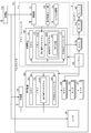
- FIG. 4 is a block diagram showing a functional configuration of the multicopter 101.
- the flight function of the multicopter 101 is mainly configured by a flight controller FC, a plurality of rotors R that are rotor blades, an ESC 141 (Electric Speed Controller) provided for each rotor R, and a battery 190 that supplies electric power to these. ing.
- FC flight controller
- ESC 141 Electric Speed Controller
- Each rotor R is composed of a motor 142 and a blade 143 connected to its output shaft.
- the ESC 141 is connected to the motor 142 of the rotor R, and rotates the motor 142 at a speed instructed by the flight controller FC.
- the flight controller FC includes a receiver 131 that receives a steering signal from an operator (transmitter 110) and a control device 120 that is a microcontroller to which the receiver 131 is connected.
- the control device 120 includes a CPU 121 that is a central processing unit, a memory 122 that is a storage device such as a ROM and a RAM, and a PWM (Pulse Width Modulation) controller 123 that controls the rotation speed of each motor 142 via the ESC 141. ing.
- the flight controller FC further includes a flight control sensor group 132 and a GPS receiver 133 (hereinafter collectively referred to as “sensors”), which are connected to the control device 120.
- the flight control sensor group 132 of the multicopter 101 in the present embodiment includes a triaxial acceleration sensor, a triaxial angular velocity sensor, an atmospheric pressure sensor (altitude sensor), a geomagnetic sensor (orientation sensor), and the like.
- the control device 120 can acquire position information of the own aircraft including the latitude and longitude of the aircraft, the altitude, and the azimuth angle of the nose, in addition to the tilt and rotation of the aircraft, using these sensors and the like.
- the memory 122 of the control device 120 stores a flight control program FCP, which is a program in which an algorithm for controlling the attitude and basic flight operation of the multicopter 101 during flight is stored.
- the flight control program FCP adjusts the number of rotations of each rotor R based on information obtained from a sensor or the like according to instructions from an operator, and causes the multicopter 101 to fly while correcting the attitude and position disturbance of the aircraft. .
- the operation of the multicopter 101 is manually performed by the operator using the transmitter 110, and the flight plan FP, which is a parameter such as the flight path, speed, and altitude of the multicopter 101, is registered in the autonomous flight program APP in advance. It is also possible to fly the multicopter 101 autonomously to the destination (hereinafter, such autonomous flight is referred to as “autopilot”).
- autonomous flight is referred to as “autopilot”.
- the multicopter 101 in this embodiment has an advanced flight control function.
- the unmanned aircraft in the present invention is not limited to the form of the multicopter 101.
- an aircraft in which some sensors are omitted from a sensor or the like, or an aircraft that does not have an autopilot function and can fly only by manual piloting is used. You can also
- the multicopter 101 further includes a receiver 231 that receives a steering signal from an operator (transmitter 110), and a controller 220 that is a microcontroller to which the receiver 231 is connected.
- the control device 220 includes a CPU 221 that is a central processing unit, a memory 222 that is a storage device such as a ROM and a RAM, and a PWM controller 223 that controls the rotational speeds of the motors 242 and the tires 243 via the ESC 241. .
- the memory 222 of the control device 220 stores a traveling control program DCP that is a program for controlling the traveling operation of the airframe on the surface of the structure S.
- the wall traveling function of the multicopter 101 is realized by the above flight function and the traveling control program DCP.
- the flight control program FCP After the multicopter 101 reaches the ceiling surface HS or the vertical surface VS of the structure S, the flight control program FCP only applies the horizontal rotor HR and the vertical wing to attract the aircraft to the ceiling surface HS and the vertical surface VS. The rotor blade VR is driven. Then, the traveling control program DCP drives the tire 243 in accordance with an instruction from the operator, and moves the multicopter 101 on the surface of the structure S.
- the travel control program DCP is arranged in the control device 220 that is separate from the flight control program FCP.
- the travel control program DCP and the PWM controller 223 may be arranged in the control device 120, and the configuration of the control device 220 and the receiver 231 may be omitted.
- the multicopter 101 it is assumed that the movement of the multicopter 101 on the surface of the structure S is basically performed manually by an operator. These parameters are set each time while looking at the surface of the structure S and the state of the multicopter 101 to make the multicopter 101 autonomous or semi-autonomous on the surface of the structure S. A function for running the vehicle may be implemented.
- FIG. 5 is a perspective view showing an appearance of the multicopter 102 according to the second embodiment.
- the multicopter 102 is a machine body having only four horizontal rotary blades HR as the rotor R.
- Four ceiling surface tires HW which are tires 243 provided with a motor 242, are arranged on the intake side (upper side) of these horizontal rotary blades HR.
- the multicopter 102 has a frame body 520 that supports the horizontal rotary blade HR and the ceiling surface tire HW.
- the frame body 520 includes an outer frame 521 which is a substantially rectangular parallelepiped frame body made of a pipe material, and a substantially rectangular inner frame 523 which is supported on the inner side of the outer frame 521 by a connecting pipe 522 and which is also made of a pipe material. And have.
- the inner frame 523 supports the control box 590 and the camera 300 of the multicopter 102.
- tires 245 that do not include a drive source are disposed at portions corresponding to the apexes of the outer frame 521.
- the pipe material constituting the front surface of the outer frame 521 (the surface on the left side in FIG. 5 in the X-axis direction) is such that the pipe material 521b constituting the lower side is arranged on the outer side in the horizontal direction than the pipe material 521a constituting the upper side. Yes.
- the horizontal rotary blade HR is inclined to the vertical surface VS side together with the frame body 520.
- the airframe is pressed against the vertical surface VS by a component force toward the vertical surface VS of the thrust of the horizontal rotary blade HR.
- the multicopter 102 can travel on the wall surface on the ceiling surface HS, and can stably keep the distance from the vertical surface VS constant.
- FIG. 6 is a schematic diagram showing a method for delivering packages L to a veranda of a general apartment house using the multicopter 103 according to the third embodiment.
- the luggage L is fixed to the upper part of the multicopter 103.
- the basic configuration and functions of the multicopter 103 are the same as those of the multicopter 101 except for the features of the multicopter 103 described below.
- the multicopter 103 uses the GPS receiver 133 to go to the location of the collective housing at the delivery destination.
- the multicopter 103 includes fixed wings 700, and uses the vertical rotary wings VR as a thrust in the horizontal direction when moving to the apartment house.
- a signal transmitter B such as LED or Bluetooth (registered trademark) Low Energy beacon is attached in advance to the veranda of each apartment house. After the multicopter 103 has sufficiently approached the apartment house, the multicopter 103 receives the signal from the signal transmitter B by the photographing means and the short-range wireless communication means, and identifies a single veranda that is the destination of the luggage L. . In addition, the multicopter 103 adjusts the aircraft to an optimum position based on the mounting position of the signal transmitter B also when the aircraft is attracted to the veranda collar F.
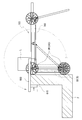
- FIG. 7 is a schematic side view showing a state in which the airframe is locked by the arm 600 to the heel F of the veranda.
- the multicopter 103 is attracted to the veranda collar F by the vertical rotating blades VR, and the arm 600 is further extended onto the veranda collar F so that the collar portion 610 of the arm 600 is engaged with the back surface of the collar F. Then, the vertical rotary blade VR and the horizontal rotary blade HR are stopped, and the airframe is supported by the arm 600. In addition, the position of the collar part 610 can be adjusted according to the thickness of the collar F.
- the multicopter 103 detects it with a pressure sensor or the like, and after waiting for a predetermined time, removes the arm 600 from the bag F and leaves the veranda.
- the aircraft is preferable to place the aircraft on the veranda wall F until the resident receives the package L when the package L is loaded on the multicopter 103 and delivered to the veranda of the apartment house. Absent. Further, since the rotor R is sharp, if the luggage L is delivered while turning the rotor R, the resident may be injured.
- the multicopter 103 is provided with a hooked arm 600, and the arm 600 is used to lock the fuselage to the veranda's hook F so that the luggage L can be delivered to the resident with the rotor R stopped. In addition, even when it takes time to deliver the luggage, it is possible to secure power for homing.
- the present invention is not limited to the above embodiments, and various modifications can be made without departing from the scope of the present invention.
- the multicopters 101, 102, and 103 of the above embodiment all include a plurality of rotors R
- the unmanned aircraft of the present invention may be an airframe having only one horizontal rotor HR.
- the horizontal rotary blades HR and the vertical rotary blades VR of the above embodiment are arranged so that the arrangement directions of the rotary shafts are orthogonal to each other.
- the “rotary body” of the present invention not only wheels such as the tire 273 but also an endless track called a crawler or a crawler track can be used.
Abstract
Description
(構成概要)
図1は、第1実施形態にかかるマルチコプター101の外観を示す斜視図であり、図2はマルチコプター101の外観を示す側面図である。 [First Embodiment]
(Configuration overview)
FIG. 1 is a perspective view showing the appearance of the
マルチコプター101は、ローターRの回転面の位置よりもそのローターRの吸気側にタイヤ243の一部が延出している。そのため、ローターRの吸気側にある構造物Sに機体を接近させたときには、ローターRよりも先にタイヤ243が構造物Sに接触する。つまり、マルチコプター101は、構造物SとローターRとの衝突が物理的に生じ得ない構成とされており、これにより、機体を安全に構造物Sに接近させることが可能とされている。 (Wall running operation)
In the
図4はマルチコプター101の機能構成を示すブロック図である。マルチコプター101の飛行機能は、主に、フライトコントローラFC、回転翼である複数のローターR、ローターRごとに備えられたESC141(Electric Speed Controller)、およびこれらに電力を供給するバッテリー190により構成されている。以下、マルチコプター101の基本的な飛行機能について説明する。 (Flight function)
FIG. 4 is a block diagram showing a functional configuration of the
マルチコプター101はさらに、オペレータ(送信器110)からの操縦信号を受信する受信器231と、受信器231が接続されたマイクロコントローラである制御装置220とを備えている。制御装置220は、中央処理装置であるCPU221、ROMやRAMなどの記憶装置であるメモリ222、並びに、ESC241を介して各モータ242およびタイヤ243の回転数を制御するPWMコントローラ223を有している。制御装置220のメモリ222には、構造物Sの面上における機体の走行動作を制御するプログラムである走行制御プログラムDCPが記憶されている。 (Wall running function)
The
以下に、本発明の無人航空機の第2実施形態について図面を用いて説明する。以下の説明では、先の実施形態と同一または同様の機能を有する構成については、先の実施形態と同一の符号を付してその詳細な説明を省略する。 [Second Embodiment]
Below, 2nd Embodiment of the unmanned aerial vehicle of this invention is described using drawing. In the following description, components having the same or similar functions as those of the previous embodiment are denoted by the same reference numerals as those of the previous embodiment, and detailed description thereof is omitted.
以下に、本発明の無人航空機の第3実施形態について図面を用いて説明する。以下の説明では、先の実施形態と同一または同様の機能を有する構成については、先の実施形態と同一の符号を付してその詳細な説明を省略する。 [Third Embodiment]
Below, 3rd Embodiment of the unmanned aerial vehicle of this invention is described using drawing. In the following description, components having the same or similar functions as those of the previous embodiment are denoted by the same reference numerals as those of the previous embodiment, and detailed description thereof is omitted.
Although the embodiments of the present invention have been described above, the present invention is not limited to the above embodiments, and various modifications can be made without departing from the scope of the present invention. For example, although the
Claims (7)
- 一又は複数の回転翼と、
駆動源を有する複数の回転体と、を備え、
前記各回転体は、その回転径方向における少なくとも一部が、前記回転翼の回転面の位置よりも該回転翼の吸気側に延出しており、
前記回転翼の吸気側に生じる負圧で機体を構造物の面に吸い付かせ、その状態で前記複数の回転体を駆動することにより該面上を走行可能であることを特徴とする無人航空機。 One or more rotor blades;
A plurality of rotating bodies having a drive source,
Each of the rotors has at least a part of the rotor in the radial direction extending from the position of the rotary surface of the rotor to the intake side of the rotor,
An unmanned aerial vehicle capable of traveling on a surface of the structure by attracting the airframe to a surface of a structure with a negative pressure generated on an intake side of the rotor and driving the plurality of rotors in that state. . - 複数の前記回転翼を備え、
前記複数の回転翼は、回転軸の配置方向が交差する水平回転翼および垂直回転翼を有しており、
前記複数の回転体は、前記水平回転翼の回転面の位置よりも該水平回転翼の吸気側に延出した前記回転体と、前記垂直回転翼の回転面の位置よりも該垂直回転翼の吸気側に延出した前記回転体と、を有していることを特徴とする請求項1に記載の無人航空機。 A plurality of the rotor blades;
The plurality of rotary blades have a horizontal rotary blade and a vertical rotary blade whose arrangement directions of the rotation axes intersect,
The plurality of rotating bodies include: the rotating body extending to the intake side of the horizontal rotating blade from the position of the rotating surface of the horizontal rotating blade; and the vertical rotating blade of the vertical rotating blade from the position of the rotating surface of the vertical rotating blade. The unmanned aerial vehicle according to claim 1, further comprising: the rotating body that extends toward the intake side. - 前記回転翼を間に挟んで配置された前記各回転体を互いに逆方向へ回転させることにより、前記面上における機体の向きを変更可能であることを特徴とする請求項1に記載の無人航空機。 2. The unmanned aerial vehicle according to claim 1, wherein the direction of the airframe on the surface can be changed by rotating the rotary bodies arranged with the rotary wings interposed therebetween in opposite directions. .
- 前記回転翼および前記複数の回転体は、パイプ材で構成された枠体に支持されており、
前記枠体は、下辺を構成する前記パイプ材が、上辺を構成する前記パイプ材よりも水平方向外側に配置された側面を有していることを特徴とする請求項1に記載の無人航空機。 The rotor blades and the plurality of rotors are supported by a frame body made of a pipe material,
2. The unmanned aerial vehicle according to claim 1, wherein the frame body has a side surface in which the pipe material constituting the lower side is disposed on the outer side in the horizontal direction than the pipe material constituting the upper side. - 前記複数の回転翼および前記複数の回転体は、パイプ材で構成された枠体に支持されており、
前記枠体は側面視略L字形に形成されていることを特徴とする請求項2に記載の無人航空機。 The plurality of rotor blades and the plurality of rotors are supported by a frame body made of a pipe material,
The unmanned aerial vehicle according to claim 2, wherein the frame is formed in a substantially L shape in a side view. - 固定翼をさらに備え、
水平飛行時には前記垂直回転翼を推力として用いることを特徴とする請求項2に記載の無人航空機。 A fixed wing,
The unmanned aerial vehicle according to claim 2, wherein the vertical rotary wing is used as a thrust during horizontal flight. - 先端に鉤部が形成されたアームをさらに備え、
前記アームを塀状の構造物の上に伸ばし、前記鉤部を該塀状の構造物の背面に係合させることにより、該アームで機体を支持可能であることを特徴とする請求項1に記載の無人航空機。
It further comprises an arm with a buttock formed at the tip,
The aircraft can be supported by the arm by extending the arm over a bowl-like structure and engaging the hook with a back surface of the bowl-like structure. The unmanned aircraft described.
Priority Applications (2)
| Application Number | Priority Date | Filing Date | Title |
|---|---|---|---|
| JP2017521607A JP6178949B1 (en) | 2016-04-19 | 2016-09-06 | Unmanned aerial vehicle |
| US15/759,811 US10099778B2 (en) | 2016-04-19 | 2016-09-06 | Unmanned aerial vehicle |
Applications Claiming Priority (4)
| Application Number | Priority Date | Filing Date | Title |
|---|---|---|---|
| JP2016-083269 | 2016-04-19 | ||
| JP2016083269 | 2016-04-19 | ||
| JP2016091332 | 2016-04-28 | ||
| JP2016-091332 | 2016-04-28 |
Publications (1)
| Publication Number | Publication Date |
|---|---|
| WO2017183219A1 true WO2017183219A1 (en) | 2017-10-26 |
Family
ID=60115976
Family Applications (1)
| Application Number | Title | Priority Date | Filing Date |
|---|---|---|---|
| PCT/JP2016/076151 WO2017183219A1 (en) | 2016-04-19 | 2016-09-06 | Unmanned aerial vehicle |
Country Status (2)
| Country | Link |
|---|---|
| US (1) | US10099778B2 (en) |
| WO (1) | WO2017183219A1 (en) |
Cited By (13)
| Publication number | Priority date | Publication date | Assignee | Title |
|---|---|---|---|---|
| JP2019084934A (en) * | 2017-11-06 | 2019-06-06 | 富士通株式会社 | Suction mechanism and flying machine |
| JP2019089470A (en) * | 2017-11-15 | 2019-06-13 | ショーボンド建設株式会社 | Unmanned aircraft for coating coating material, and coating material coating method with use of unmanned aircraft |
| JP2019130927A (en) * | 2018-01-29 | 2019-08-08 | 株式会社プロドローン | Robot aircraft |
| JP2019136651A (en) * | 2018-02-09 | 2019-08-22 | 日本製鉄株式会社 | Flight type injector and coating method |
| WO2019198155A1 (en) * | 2018-04-10 | 2019-10-17 | 株式会社自律制御システム研究所 | Unmanned aerial vehicle, flight control mechanism for unmanned aerial vehicle, and method for using unmanned aerial vehicle and mechanism for unmanned aerial vehicle |
| WO2020022263A1 (en) * | 2018-07-23 | 2020-01-30 | 株式会社ナイルワークス | Aircraft |
| JP2020037363A (en) * | 2018-09-05 | 2020-03-12 | 住友重機械工業株式会社 | Unmanned aircraft, and structure maintenance inspection method |
| WO2020066889A1 (en) * | 2018-09-25 | 2020-04-02 | 株式会社プロドローン | Unmanned aerial vehicle |
| JP2020059001A (en) * | 2018-10-12 | 2020-04-16 | 株式会社プロドローン | Unmanned aircraft |
| JP2020079069A (en) * | 2018-11-14 | 2020-05-28 | オリエンタル白石株式会社 | Wall surface mobile robot |
| JP2020147231A (en) * | 2019-03-15 | 2020-09-17 | 株式会社Tkkワークス | Unmanned helicopter and inspection appliance fitting device |
| JP6765736B1 (en) * | 2019-12-26 | 2020-10-07 | 株式会社ウオールナット | Unmanned aerial vehicle |
| WO2022070374A1 (en) * | 2020-09-30 | 2022-04-07 | 日本電信電話株式会社 | Propeller guard and flight vehicle |
Families Citing this family (11)
| Publication number | Priority date | Publication date | Assignee | Title |
|---|---|---|---|---|
| JP6642166B2 (en) * | 2016-03-22 | 2020-02-05 | 富士通株式会社 | Flyer and how to use it |
| US11077935B2 (en) * | 2017-08-28 | 2021-08-03 | Saudi Arabian Oil Company | Thruster based locomotion for perched unmanned aerial vehicles |
| US10875644B2 (en) * | 2017-12-28 | 2020-12-29 | Aurora Flight Sciences Corporation | Ground manipulation system and method for fixing an aircraft |
| JP7020279B2 (en) * | 2018-04-27 | 2022-02-16 | 富士通株式会社 | Flyers and how to control them |
| JP7020300B2 (en) * | 2018-05-31 | 2022-02-16 | 富士通株式会社 | Flyers and how to control them |
| USD865637S1 (en) * | 2018-09-06 | 2019-11-05 | AEE Aviation Technology Company | Aircraft with camera |
| CN109981042A (en) * | 2019-04-30 | 2019-07-05 | 天津大学 | A kind of clean intelligent robot of solar panel based on more rotors |
| CN110065642A (en) * | 2019-05-31 | 2019-07-30 | 南京信息工程大学 | A kind of urban viaduct detection unmanned plane |
| JP2021079730A (en) * | 2019-11-14 | 2021-05-27 | ヤマハ発動機株式会社 | Outboard engine and marine vessel |
| CN111086567A (en) * | 2019-12-20 | 2020-05-01 | 同济大学 | Rescue robot chassis capable of climbing wall |
| RU204412U1 (en) * | 2021-02-26 | 2021-05-24 | Автономная некоммерческая организация высшего образования «Университет Иннополис» | UNMANNED AERIAL VEHICLE |
Citations (2)
| Publication number | Priority date | Publication date | Assignee | Title |
|---|---|---|---|---|
| US8794564B2 (en) * | 2012-08-02 | 2014-08-05 | Neurosciences Research Foundation, Inc. | Vehicle capable of in-air and on-ground mobility |
| WO2016069169A1 (en) * | 2014-10-29 | 2016-05-06 | Qualcomm Incorporated | Unmanned aerial vehicle |
Family Cites Families (5)
| Publication number | Priority date | Publication date | Assignee | Title |
|---|---|---|---|---|
| JP5580029B2 (en) | 2009-12-14 | 2014-08-27 | 東急建設株式会社 | Diagnosis method |
| EP3134316B1 (en) * | 2014-04-24 | 2019-05-22 | Neustadt, Roi | Hovering device for drawing on walls |
| JP6597040B2 (en) * | 2015-08-17 | 2019-10-30 | 富士通株式会社 | Flying machine frame structure, flying machine, how to use flying machine |
| WO2017051732A1 (en) | 2015-09-25 | 2017-03-30 | 株式会社日本自動車部品総合研究所 | Flight device |
| JP6642166B2 (en) * | 2016-03-22 | 2020-02-05 | 富士通株式会社 | Flyer and how to use it |
-
2016
- 2016-09-06 US US15/759,811 patent/US10099778B2/en active Active
- 2016-09-06 WO PCT/JP2016/076151 patent/WO2017183219A1/en active Application Filing
Patent Citations (2)
| Publication number | Priority date | Publication date | Assignee | Title |
|---|---|---|---|---|
| US8794564B2 (en) * | 2012-08-02 | 2014-08-05 | Neurosciences Research Foundation, Inc. | Vehicle capable of in-air and on-ground mobility |
| WO2016069169A1 (en) * | 2014-10-29 | 2016-05-06 | Qualcomm Incorporated | Unmanned aerial vehicle |
Cited By (27)
| Publication number | Priority date | Publication date | Assignee | Title |
|---|---|---|---|---|
| JP2019084934A (en) * | 2017-11-06 | 2019-06-06 | 富士通株式会社 | Suction mechanism and flying machine |
| JP2019089470A (en) * | 2017-11-15 | 2019-06-13 | ショーボンド建設株式会社 | Unmanned aircraft for coating coating material, and coating material coating method with use of unmanned aircraft |
| JP7045034B2 (en) | 2017-11-15 | 2022-03-31 | ショーボンド建設株式会社 | Covering material coating method for covering materials using unmanned aerial vehicles and unmanned aerial vehicles |
| JP2019130927A (en) * | 2018-01-29 | 2019-08-08 | 株式会社プロドローン | Robot aircraft |
| JP7089735B2 (en) | 2018-01-29 | 2022-06-23 | 株式会社プロドローン | Unmanned aerial vehicle |
| JP2019136651A (en) * | 2018-02-09 | 2019-08-22 | 日本製鉄株式会社 | Flight type injector and coating method |
| WO2019198155A1 (en) * | 2018-04-10 | 2019-10-17 | 株式会社自律制御システム研究所 | Unmanned aerial vehicle, flight control mechanism for unmanned aerial vehicle, and method for using unmanned aerial vehicle and mechanism for unmanned aerial vehicle |
| US11332244B2 (en) | 2018-04-10 | 2022-05-17 | Acsl Ltd. | Imaging investigation system and imaging investigation method |
| JP2021165142A (en) * | 2018-04-10 | 2021-10-14 | 株式会社自律制御システム研究所 | Unmanned aircraft, flight control mechanism of unmanned aircraft and method of using the same |
| JP7216969B2 (en) | 2018-04-10 | 2023-02-02 | 株式会社Acsl | Unmanned aerial vehicles, flight control mechanisms for unmanned aerial vehicles, and methods of using the same |
| JPWO2019198155A1 (en) * | 2018-04-10 | 2021-04-08 | 株式会社自律制御システム研究所 | Unmanned aerial vehicles, flight control mechanisms for unmanned aerial vehicles, and methods using them |
| US11970266B2 (en) | 2018-04-10 | 2024-04-30 | ACSL, Ltd. | Unmanned aerial vehicle, flight control mechanism for unmanned aerial vehicle, and method for using unmanned aerial vehicle and mechanism for unmanned aerial vehicle |
| WO2020022263A1 (en) * | 2018-07-23 | 2020-01-30 | 株式会社ナイルワークス | Aircraft |
| JPWO2020022263A1 (en) * | 2018-07-23 | 2020-08-06 | 株式会社ナイルワークス | Flying body |
| JP2020037363A (en) * | 2018-09-05 | 2020-03-12 | 住友重機械工業株式会社 | Unmanned aircraft, and structure maintenance inspection method |
| JP7188943B2 (en) | 2018-09-05 | 2022-12-13 | 住友重機械工業株式会社 | Maintenance and inspection method for unmanned aircraft and structures |
| JP2020049981A (en) * | 2018-09-25 | 2020-04-02 | 株式会社プロドローン | Unmanned aircraft |
| WO2020066889A1 (en) * | 2018-09-25 | 2020-04-02 | 株式会社プロドローン | Unmanned aerial vehicle |
| JP2020059001A (en) * | 2018-10-12 | 2020-04-16 | 株式会社プロドローン | Unmanned aircraft |
| JP2020079069A (en) * | 2018-11-14 | 2020-05-28 | オリエンタル白石株式会社 | Wall surface mobile robot |
| JP7197088B2 (en) | 2018-11-14 | 2022-12-27 | オリエンタル白石株式会社 | Wall mobile robot |
| JP2020147231A (en) * | 2019-03-15 | 2020-09-17 | 株式会社Tkkワークス | Unmanned helicopter and inspection appliance fitting device |
| JP7157967B2 (en) | 2019-03-15 | 2022-10-21 | 株式会社Tkkワークス | Unmanned helicopter and inspection equipment attachment device |
| JP2021104729A (en) * | 2019-12-26 | 2021-07-26 | 株式会社ウオールナット | Unmanned flight vehicle |
| JP6765736B1 (en) * | 2019-12-26 | 2020-10-07 | 株式会社ウオールナット | Unmanned aerial vehicle |
| WO2022070374A1 (en) * | 2020-09-30 | 2022-04-07 | 日本電信電話株式会社 | Propeller guard and flight vehicle |
| JP7436924B2 (en) | 2020-09-30 | 2024-02-22 | 日本電信電話株式会社 | Propeller guard and aircraft |
Also Published As
| Publication number | Publication date |
|---|---|
| US10099778B2 (en) | 2018-10-16 |
| US20180251212A1 (en) | 2018-09-06 |
Similar Documents
| Publication | Publication Date | Title |
|---|---|---|
| WO2017183219A1 (en) | Unmanned aerial vehicle | |
| JP6178949B1 (en) | Unmanned aerial vehicle | |
| AU2019260589B2 (en) | Thrust allocation for aerial vehicle | |
| US11591083B2 (en) | Spherical VTOL aerial vehicle | |
| US10875644B2 (en) | Ground manipulation system and method for fixing an aircraft | |
| CN209939215U (en) | Shipping package | |
| KR101827308B1 (en) | A multicopter type smart drone using tilt rotor | |
| KR100812756B1 (en) | Quadro copter | |
| JP7374517B2 (en) | Unmanned aerial vehicle with crash-resistant propulsion and controller | |
| JP2018144627A (en) | Pilotless aircraft | |
| WO2016163482A1 (en) | Mobile unit | |
| JP6592680B1 (en) | Unmanned aerial vehicle | |
| KR102245397B1 (en) | Multi rotor unmanned aerial vehicle | |
| JP7089735B2 (en) | Unmanned aerial vehicle | |
| CN113173244A (en) | Four-axis tilting wing structure and control method thereof | |
| JP2017074868A (en) | Rotorcraft | |
| JP2018090095A (en) | Unmanned flight device, shipment transporting method and program | |
| WO2020115934A1 (en) | Rotary wing aircraft | |
| US20220274701A1 (en) | Aerial vehicle and flying method of aerial vehicle | |
| US20220297834A1 (en) | Flying body | |
| Cetinsoy | Design and simulation of a holonomic quadrotor UAV with sub-rotor control surfaces | |
| Watanabe et al. | Attitude control of a camera mounted-type tethered quadrotor for infrastructure inspection | |
| US20230192290A1 (en) | Uav with augmented lift rotors | |
| WO2021070363A1 (en) | Flying body | |
| NL1040979B1 (en) | Air vehicle. |
Legal Events
| Date | Code | Title | Description |
|---|---|---|---|
| ENP | Entry into the national phase |
Ref document number: 2017521607 Country of ref document: JP Kind code of ref document: A |
|
| WWE | Wipo information: entry into national phase |
Ref document number: 15759811 Country of ref document: US |
|
| NENP | Non-entry into the national phase |
Ref country code: DE |
|
| 121 | Ep: the epo has been informed by wipo that ep was designated in this application |
Ref document number: 16899490 Country of ref document: EP Kind code of ref document: A1 |
|
| 32PN | Ep: public notification in the ep bulletin as address of the adressee cannot be established |
Free format text: NOTING OF LOSS OF RIGHTS PURSUANT TO RULE 112(1) EPC (EPO FORM 1205A DATED 04.02.2019) |
|
| 122 | Ep: pct application non-entry in european phase |
Ref document number: 16899490 Country of ref document: EP Kind code of ref document: A1 |