WO2017177412A1 - Optical fiber state detection method, optical supervisory unit and site - Google Patents
Optical fiber state detection method, optical supervisory unit and site Download PDFInfo
- Publication number
- WO2017177412A1 WO2017177412A1 PCT/CN2016/079232 CN2016079232W WO2017177412A1 WO 2017177412 A1 WO2017177412 A1 WO 2017177412A1 CN 2016079232 W CN2016079232 W CN 2016079232W WO 2017177412 A1 WO2017177412 A1 WO 2017177412A1
- Authority
- WO
- WIPO (PCT)
- Prior art keywords
- station
- otdr
- osc
- module
- data
- Prior art date
Links
Images


Classifications
-
- H—ELECTRICITY
- H04—ELECTRIC COMMUNICATION TECHNIQUE
- H04B—TRANSMISSION
- H04B10/00—Transmission systems employing electromagnetic waves other than radio-waves, e.g. infrared, visible or ultraviolet light, or employing corpuscular radiation, e.g. quantum communication
- H04B10/07—Arrangements for monitoring or testing transmission systems; Arrangements for fault measurement of transmission systems
- H04B10/071—Arrangements for monitoring or testing transmission systems; Arrangements for fault measurement of transmission systems using a reflected signal, e.g. using optical time domain reflectometers [OTDR]
-
- H—ELECTRICITY
- H04—ELECTRIC COMMUNICATION TECHNIQUE
- H04B—TRANSMISSION
- H04B10/00—Transmission systems employing electromagnetic waves other than radio-waves, e.g. infrared, visible or ultraviolet light, or employing corpuscular radiation, e.g. quantum communication
- H04B10/07—Arrangements for monitoring or testing transmission systems; Arrangements for fault measurement of transmission systems
- H04B10/075—Arrangements for monitoring or testing transmission systems; Arrangements for fault measurement of transmission systems using an in-service signal
- H04B10/077—Arrangements for monitoring or testing transmission systems; Arrangements for fault measurement of transmission systems using an in-service signal using a supervisory or additional signal
- H04B10/0771—Fault location on the transmission path
-
- H—ELECTRICITY
- H04—ELECTRIC COMMUNICATION TECHNIQUE
- H04B—TRANSMISSION
- H04B10/00—Transmission systems employing electromagnetic waves other than radio-waves, e.g. infrared, visible or ultraviolet light, or employing corpuscular radiation, e.g. quantum communication
- H04B10/25—Arrangements specific to fibre transmission
-
- H—ELECTRICITY
- H04—ELECTRIC COMMUNICATION TECHNIQUE
- H04J—MULTIPLEX COMMUNICATION
- H04J14/00—Optical multiplex systems
- H04J14/02—Wavelength-division multiplex systems
- H04J14/0227—Operation, administration, maintenance or provisioning [OAMP] of WDM networks, e.g. media access, routing or wavelength allocation
- H04J14/0254—Optical medium access
- H04J14/0272—Transmission of OAMP information
- H04J14/0275—Transmission of OAMP information using an optical service channel
-
- H—ELECTRICITY
- H04—ELECTRIC COMMUNICATION TECHNIQUE
- H04J—MULTIPLEX COMMUNICATION
- H04J14/00—Optical multiplex systems
- H04J14/08—Time-division multiplex systems
Definitions
- the present invention relates to the field of optical communication technologies, and in particular, to a fiber state detection method, an optical monitoring unit, and a station.
- optical line fault location is widely used in optical time domain reflectometer (OTDR), which is made by backscattering caused by Rayleigh scattering and Fresnel reflection when light is transmitted in the fiber.
- OTDR optical time domain reflectometer
- the precision optoelectronic integrated instrument is widely used in the maintenance and construction of optical cable lines. It is mainly used to measure the length of optical fiber, transmission attenuation of optical fiber, joint attenuation and fault location.
- the traditional OTDR is a handheld device. As a test instrument, it is a decentralized and passive manual maintenance method. It is difficult to guarantee higher fiber safety requirements and is expensive. When it is determined that the fiber line is faulty, the worker needs to enter the site, and the fiber line is disconnected for testing, the positioning period is long, and the service interruption time is long, resulting in large economic loss.
- the prior art proposes to directly integrate the OTDR into a device as an independent unit.
- the OTDR unit uses a wavelength independent of the service unit and the optical monitoring unit to access the multiplexer unit.
- Real-time online fiber state detection can be performed in a single direction.
- OADM optical add drop module
- an OTDR detection for the entire network fiber is required, and an exit in each direction is required.
- Both are equipped with OTDR units. Therefore, not only the configuration unit is large, but also a large amount of cabinet space or equipment slots are required, and the equipment cost and installation cost are very high.
- the prior art proposes to integrate the OTDR unit at the same time, and add a multi-channel optical switch for the OTDR unit to monitor the optical fiber alarms in multiple directions in real time.
- the cost of configuring the OTDR unit in multiple directions is reduced, but the real-time online fiber state detection cannot be performed, and the line assembly is cumbersome.
- the above two schemes integrate the OTDR as a separate unit into the site and do not A common wavelength scheme for business units and optical monitoring units. Further, the above two solutions need to be modified on the existing system board, such as adding an OTDR unit access port in the splitting and splitting unit, and the integrated OTDR is a separate unit, and the installation occupies the cabinet or the equipment slot space, and the cost is high. .
- the embodiments of the present invention provide a fiber state detection method, an optical monitoring unit, and a station, which are used to solve the problems of high cost and complicated assembly caused by separately integrating an OTDR unit in the prior art.
- An embodiment of the present invention provides a fiber state detection method, including:
- the first station alternately transmits OTDR pulses and OSC data to the second station in the same channel, and the second station is an adjacent station of the first station.
- the first station receives the reflected light returned by the OTDR pulse through the optical fiber between the first station and the second station, and acquires the OTDR detection value according to the reflected light.
- the same channel means using the same wavelength, the same set of wavelengths or using the same protocol data frame.
- the first station receives the OTDR detection command sent by the network management system, and the OTDR detection instruction includes the OTDR detection needs to be acquired.
- the number of OTDR detection values N where N is a positive integer.
- the first station is based on the OTDR detection value.
- the number N and the preset number of single-transmission OTDR pulses are n, and it is determined that M times of OTDR pulse transmission needs to be performed, that is, the OTDR pulse is transmitted by the slice, which ensures that there is no packet loss and no error in the OSC data communication between the stations.
- the first station alternately transmits the OTDR pulse and the OSC data to the second station in the same channel, and may be limited to the following two methods.
- the first station in a wavelength division multiplexing system using TDM transmission, can insert an OTDR pulse transmission between any two adjacent OSC data frames until the M OTDR pulse is completed. Rush to send.
- the number n of single-transmission OTDR pulses is mainly determined by the buffer size of the buffer module of the optical monitoring unit in the first station, the service bandwidth, and the pulse time for transmitting a single OTDR.
- the cache module in the first optical monitoring unit of the first station will transmit the OSC data that should be sent during the n OTDR pulses. Cached up as the first cached data, and sends the first cached data to the second site through the OSC module in the first optical monitoring unit after the n OTDR pulses are transmitted. Further, the cache module in the first optical monitoring unit caches the OSC data that should be sent when the first cached data is sent, as the second cached data, and sends the first through the OSC module in the first optical monitoring unit. The second cached data is sent after the data is cached, and so on.
- the normal OSC data transmission state does not occupy the entire egress bandwidth, and a part of the redundant bandwidth is reserved. Only when there is cached data in the cache module of the first optical monitoring unit, the redundant bandwidth is occupied. Therefore, the OSC module in the first optical monitoring unit transmits the cached data to occupy all the egress bandwidths. After a period of time, the cache module no longer has cached data and returns to the normal OSC transmission state.
- the first station can insert at least one OTDR pulse transmission between any two adjacent OSC data packets until M times OTDR pulse transmission is completed.
- the first station can send M times of OTDR pulses (ie, N pulses) between any two adjacent OSC data packets, that is, concentrate the N pulses to be transmitted in any two phases. Send between adjacent OSC packets.
- M times of OTDR pulses ie, N pulses
- At least one OTDR pulse transmission is inserted in the interval for sending the maintenance packet until the transmission of the M OTDR pulse is completed.
- the at least one OTDR pulse transmission is inserted in the interval for transmitting the OSC data packet until the transmission of the M OTDR pulse is completed.
- the first station may send the start OTDR detection command to The second station, the start OTDR detection instruction is used to instruct the second station to switch from receiving state of receiving OSC data to silent state waiting for OTDR detection. Therefore, synchronization of the first site and the second site can be ensured, and the second site can ensure that the incomplete OSC data is latched in time.
- the first station may send a preset physical layer recovery message to the second station, where the preset physical layer recovery message is used to indicate that the second station converts from the silent state waiting for the OTDR detection to receiving the OSC data. Receive status. The first station determines to send the OSC data to the second station when receiving the preset physical layer recovery confirmation message fed back by the second station.
- the first station determines that the preset physical layer recovery confirmation message that is not received by the second station exceeds the preset duration, and then goes to the second The site sends OSC data. Therefore, the reliability of the system can be ensured, and in the process of transmitting the OTDR pulse, the failure of the optical fiber cannot be restored to the receiving state in time for the fault alarm.
- the embodiment of the invention provides an optical monitoring unit, which at least includes: an OTDR module, an OSC module, and a switching control module;
- An OTDR module is configured to send an OTDR pulse, and obtain an OTDR detection value according to the received OTDR pulse returned by the optical fiber between the first station and the second station, where the optical monitoring unit 300 is located at the first station, and second The site is an adjacent site of the first site;
- the OSC module is configured to send the first OSC data to the second station, and receive the second OSC data sent by the second station.
- a switching control module configured to control the OTDR module and the OSC module to perform alternately transmitting the OTDR pulse and the first OSC data, and forward the second OSC data sent by the second station to the OSC module.
- the optical monitoring unit further includes a cache module.
- a cache module for caching caches generated by the OTDR module when transmitting OTDR pulses OSC data.
- the light monitoring unit further includes a photoelectric conversion module.
- the photoelectric conversion module is configured to convert the OTDR pulse into a corresponding optical signal, and convert the electrical signal corresponding to the first OSC data into a corresponding optical signal, and convert the received optical signal corresponding to the second OSC data into a corresponding electrical signal. signal.
- the embodiment of the invention further provides a site, including a service unit, a light monitoring unit, a main control unit, and a splitting and splitting unit.
- the optical monitoring unit can implement the optical fiber state detection in the foregoing embodiment.
- the embodiment of the invention solves the problems of high cost and complicated assembly caused by separately integrating the OTDR unit in the WDM system by alternately transmitting the OTDR pulse and the OSC data to the second station in the same channel, and can meet the daily requirements for the optical fiber line. Maintenance needs. Due to the failure of the line fiber in the WDM system, such as the aging of the fiber, the damage of the fiber, the crimping of the fiber, the bending of the large angle, and the large tensile force, the service and communication are degraded, and the bit error rate is high and the service is interrupted. Therefore, the real-time performance state monitoring of the optical fiber by using the method provided by the embodiment of the present invention can timely discover the performance state of the optical fiber in the network, and prevent the timely repair in advance, thereby greatly improving the reliability of the network.
- FIG. 1 is a schematic structural diagram of an OTDR unit being integrated into a station as a separate unit in the background art of the present invention
- FIG. 2 is a schematic structural diagram of a WDM system according to an embodiment of the present invention.
- FIG. 3 is a schematic structural diagram of a light monitoring unit according to an embodiment of the present invention.
- FIG. 4 is a schematic structural diagram of a station in an embodiment of the present invention.
- FIG. 5 is a flowchart of an overview of a fiber state detection method according to an embodiment of the present invention.
- FIG. 6 is a schematic structural diagram of an OTDR period according to an embodiment of the present invention.
- FIG. 7 is a schematic structural diagram of continuous M OTDR periodic transmission according to an embodiment of the present invention.
- FIG. 8 is a schematic structural diagram of centralized transmission of an OTDR pulse according to an embodiment of the present invention.
- FIG. 9 is a structural diagram of inserting and transmitting an OTDR pulse at intervals of transmitting a maintenance packet according to an embodiment of the present invention. intention;
- FIG. 10 is a schematic structural diagram of inserting an OTDR pulse transmission at intervals of sending a maintenance packet and a packet according to an embodiment of the present invention
- FIG. 11 is a schematic structural diagram of an optical monitoring unit adopting a TDM transmission mode according to an embodiment of the present invention.
- FIG. 12 is a schematic structural diagram of an OSC data frame according to an embodiment of the present invention.
- FIG. 13 is a specific flowchart of sending an OTDR period according to an embodiment of the present invention.
- 14A is a schematic diagram showing a state change of an A site in an embodiment of the present invention.
- FIG. 14B is a schematic diagram showing a state change of a B site according to an embodiment of the present invention.
- 15 is a schematic structural diagram of performing OTDR detection by multiple stations in an embodiment of the present invention.
- 16 is a schematic structural diagram of an optical monitoring unit adopting a data packet transmission manner according to an embodiment of the present invention.
- FIG. 17 is a specific flowchart of optical fiber state detection in a wavelength division multiplexing system using a data packet transmission method according to an embodiment of the present invention.
- the embodiments of the present invention provide a fiber state detection method, an optical monitoring unit, and a station, which are used to solve the problems of high cost and complicated assembly caused by separately integrating an OTDR unit in the prior art.
- the method, the optical monitoring unit and the site are based on the same inventive concept. Since the principles of the method, the optical monitoring unit and the site solving the problem are similar, the implementation of the device and the method can be referred to each other, and the repeated description is not repeated.
- the optical wavelength division multiplexing transmission system is the main platform used for the current trunk transmission and multi-service transmission of the metro core network.
- the basic principle is that the optical signal of the input signal respectively modulated at different wavelengths is transmitted through a wave at the transmitting end of the optical system.
- the multiplexers (multiplexers) are multiplexed together and transmitted to the far end via a fiber; at the receiving end of the optical system, the optical carriers of these different signals are separated by another wavelength division multiplexer (demultiplexer).
- demultiplexer another wavelength division multiplexer
- WDM Wavelength Division Multiplexing
- each site It mainly includes a main control unit, a business unit, a split wave unit and a light monitoring unit.
- the main control unit is configured to receive a command from the network management system, execute or receive the parameter configuration and send it to other units, and report the alarms in the site to the network management system;
- the service unit is configured to separately convert the multiple electrical signals.
- the multiplexing and separating unit is configured to convert the plurality of independent specific wavelength optical signals into a combined signal, and The multiplexed signal is converted into a plurality of independent optical signals of specific wavelengths;
- the optical monitoring management unit is used to implement communication between sites, and complete management and control of the WDM system. For example, as shown in FIG.
- the optical monitoring unit can transmit the alarm information between the A site and the B site in real time, and report the alarm information to the network management system through the main control unit.
- the optical monitoring unit can also be delivered according to the network management system.
- the optical system parameter adjustment command realizes the parameter adjustment of the control optical system.
- an embodiment of the present invention provides an optical monitoring unit 300, which includes at least an OTDR module 31, an Optical Supervisory Channel (OSC) module 32, and a switching control module 33;
- OSC Optical Supervisory Channel
- the OTDR module 31 is configured to send an OTDR pulse, and obtain an OTDR detection value according to the reflected light returned by the received OTDR pulse through the optical fiber between the first station and the second station, where the optical monitoring unit 300 is located at the first station,
- the second site is the adjacent site of the first site.
- the OTDR pulse is an optical pulse for measuring the length of the fiber, the transmission attenuation of the fiber, the joint attenuation, and the fault location.
- the OTDR module 31 can generate an OTDR detection pulse with adjustable pulse width when transmitting the OTDR pulse, and can realize the reflected light when receiving the reflected light returned by the optical fiber between the first station and the second station.
- the OSC module 32 is configured to send the first OSC data to the second station, and receive the second OSC data sent by the second station.
- the OSC data refers to the monitoring information and business information of the network management system transmitted between the sites. Information and alarm information.
- the OSC module 32 performs the traditional optical monitoring channel function.
- a Time Division Multiplexing (TDM) transmission mode may be adopted, and the switching control module 33 directly performs the same.
- Control or refer to FIG. 15 for the transmission mode of packet communication, which is controlled by the switching control module 33 and the main control unit.
- the switching control module 33 is configured to control the OTDR module 31 and the OSC module 32 to perform alternately transmitting the OTDR pulse and the first OSC data, and to forward the second OSC data sent by the second station to the OSC module 32.
- the light monitoring unit 300 further includes a cache module 34.
- the cache module 34 is configured to cache cached OSC data generated by the OTDR module 30 when transmitting an OTDR pulse.
- the cache module 34 when the optical monitoring unit 300 transmits the OSC data in the TDM transmission mode, the cache module 34 is located in the optical monitoring unit 300. Referring to FIG. 15, when the optical monitoring unit 300 transmits the OSC data by using a packet communication transmission mode, the cache module 34 may be located in the main control unit of the first station.
- the light monitoring unit 300 further includes a photoelectric conversion module 35.
- the photoelectric conversion module 35 is configured to convert the OTDR pulse into a corresponding optical signal, and convert the electrical signal corresponding to the first OSC data into a corresponding optical signal, and convert the received optical signal corresponding to the second OSC data into a corresponding electric signal.
- An embodiment of the present invention further provides a station, including the optical monitoring unit shown in FIG.
- the station 400 includes a service unit 401 and a light monitoring unit 402.
- the light monitoring unit 402 has the same function as the light monitoring unit shown in FIG. 3, and the main control unit 403 and the splitting unit 404.
- an embodiment of the present invention provides a fiber state detection method, including:
- Step 500 The first station alternately sends the OTDR pulse and the OSC data to the second station in the same channel, where the second station is the adjacent station of the first station.
- the first site here is the site shown in Figure 4.
- the same channel includes the same wavelength, the same wavelength set, or the same The transmission channel of the protocol data frame.
- Step 510 The first station receives the reflected light returned by the OTDR pulse through the optical fiber between the first station and the second station, and acquires the OTDR detection value according to the reflected light.
- the first station receives the OTDR detection command sent by the network management system, and the OTDR detection instruction includes the OTDR detection needs to be acquired.
- the number of OTDR detection values N where N is a positive integer.
- the first station is based on the OTDR detection value.
- the number N and the preset number of single-transmission OTDR pulses are n, and it is determined that M times of OTDR pulse transmission needs to be performed, that is, the OTDR pulse is transmitted by the slice.
- the number of OTDR detection values to be acquired is 10000
- the number of preset single-transmission OTDR pulses is 100
- the first station alternately transmits the OTDR pulse and the OSC data to the second station in the same channel, and may be limited to the following two methods.
- the first station in a wavelength division multiplexing system employing TDM transmission, can insert an OTDR pulse transmission between any two adjacent OSC data frames until M times OTDR pulse transmission is completed.
- the N OTDR pulses are preferably transmitted separately between a plurality of adjacent OSC data frames.
- the long-term interruption of the OSC data transmission may cause the network element to fall off, and the alarm information cannot be reported in time. And other issues. Therefore, it is necessary to divide the N pulses into a plurality of small segments to ensure that the OSC data communication between the first station and the second station has no packet loss and no error.
- the number n of single-transmission OTDR pulses is mainly determined by the buffer size of the buffer module of the optical monitoring unit in the first station, the service bandwidth, and the pulse time for transmitting a single OTDR.
- the first station can determine the number n of single-transmission OTDR pulses based on the calculated n max , where n ⁇ n max .
- the buffer module in the first optical monitoring unit of the first station will send n OTDR pulses during the transmission period.
- the OSC data is buffered as the first cached data, and the first cached data is transmitted to the second site by the OSC module in the first optical monitoring unit after the n OTDR pulses are transmitted.
- the cache module in the first optical monitoring unit caches the OSC data that should be sent when the first cached data is sent, as the second cached data, and sends the first through the OSC module in the first optical monitoring unit.
- the second cached data is sent after the data is cached, and so on.
- the normal OSC data transmission state does not occupy the entire egress bandwidth, and a part of the redundant bandwidth is reserved. Only when there is cached data in the cache module of the first optical monitoring unit, the redundant bandwidth is occupied. Therefore, the OSC module in the first optical monitoring unit uses the data area (ie, service bandwidth) and the redundant bandwidth as shown in FIG. 5 when transmitting the cached data, and after a period of time, there is no more cached data in the cache module. Return to the normal OSC transmission state, that is, only occupy the data area to send OSC data.
- the transmission time of the cached OSC data generated by transmitting n OTDR pulses can also be determined.
- the time for transmitting the OTDR pulse in a single time can be determined, that is, the time for transmitting the OTDR pulse in a single time is equal to the transmission time of each pulse multiplied by the number of single-transmission OTDR pulses. . Further, the time for transmitting the cached OSC data is determined according to the time of transmitting the OTDR pulse and the egress bandwidth information.
- the egress bandwidth information may be a ratio of redundant bandwidth to service bandwidth, or redundant bandwidth and service bandwidth.
- the cache module in the first optical monitoring unit does not cache data, and returns to the normal OSC data transmission state.
- the next OTDR pulse transmission can be initiated immediately, or after the transmission of several normal OSC data frames, the next OTDR pulse transmission is performed.
- the switching timing of the next OTDR pulse may be controlled by the switching control module in the first optical monitoring unit, or the alternate transmission rule of the OTDR pulse and the OSC data may be preset in advance in the switching control module.
- the process of alternately transmitting n OTDR pulses and transmitting OSC buffer data each time is taken as an OTDR period, which can be interspersed in normal OSC data frame transmission, and each OTDR period includes a downstream station.
- Sending an OTDR probe command ie, the protocol packet shown in FIG. 6
- transmitting n OTDR pulses and transmitting a preset physical layer recovery message (ie, a pseudo random bit sequence (PRBS) shown in FIG. )
- the OSC cache data ie, frame 2, frame 3, frame 4 shown in FIG. 6
- frame 2, frame 3, and frame 4 can be used to transmit OSC cache data.
- the M OTDR periods can be continuously transmitted, and the N OTDR detection values that need to be acquired in the current OTDR detection are completed.
- the first station can insert at least one OTDR pulse transmission between any two adjacent OSC data packets until M times OTDR pulse transmission is completed.
- the first station can send M times of OTDR pulses (ie, N pulses) between any two adjacent OSC data packets, that is, concentrate the N pulses to be transmitted in any two phases. Send between adjacent OSC packets.
- M times of OTDR pulses ie, N pulses
- the link state at this time may be idle or may be in the occupied state of sending OSC data packets.
- N OTDR pulses may be directly sent in a centralized manner. Because of the interruption of data transmission, there is a problem of packet loss. However, if the OTDR pulse is worn Inserted in the gap of the OSC data packet transmission, it is also necessary to set the cache module to buffer the OSC data packet that should be sent when the OTDR pulse is sent, and wait until the OTDR pulse is sent, and then send the cached OSC data packet to the second site.
- the capacity of the cache module needs to be larger than the size of the cached OSC packet generated by sending M times of OTDR pulses, which is generally set according to the empirical value.
- At least one OTDR pulse transmission is inserted in the interval for sending the maintenance packet until the transmission of the M OTDR pulse is completed.
- the same number of OTDR pulse transmissions can be inserted, or different times of OTDR pulse transmission can be inserted, which is controlled by the first station.
- the first station when the link is idle, the first station sends a maintenance packet to the second station, and n OTDR pulses can be inserted at the transmission interval of each maintenance packet until the transmission of M OTDR pulses is completed.
- the at least one OTDR pulse transmission is inserted in the interval for transmitting the OSC data packet until the transmission of the M OTDR pulse is completed.
- the same number of OTDR pulse transmissions can be inserted, or different times of OTDR pulse transmission can be inserted, which is controlled by the first station.
- n OTDR pulses are respectively inserted in the interval for transmitting the maintenance packet and the packet until the transmission of the M OTDR pulse is completed.
- the first station may send the start OTDR detection command to The second station, the start OTDR detection instruction is used to instruct the second station to switch from receiving state of receiving OSC data to silent state waiting for OTDR detection.
- the first station may send a preset physical layer recovery message to the second station, for example, sending a PRBS, where a preset physical layer recovery message is used for
- the second station is instructed to switch from a silent state waiting for OTDR detection to a receiving state of receiving OSC data.
- the first station determines to send the OSC data to the second station when receiving the preset physical layer recovery confirmation message fed back by the second station.
- the first station determines that the preset physical layer recovery confirmation message that is not received by the second station exceeds the preset duration, and then goes to the second The site sends OSC data.
- the optical monitoring unit 1100 transmits the OSC data by using a TDM transmission mode.
- the optical monitoring unit 1100 may include an OTDR module 1101, an OSC module 1102, and a switching control module 1103.
- the OTDR module 1101 is configured to send an OTDR pulse, and obtain an OTDR detection value according to the reflected light returned by the received OTDR pulse through the optical fiber between the first station and the second station, where the optical monitoring unit 1100 is located at the first station,
- the second site is the adjacent site of the first site.
- the OSC module 1102 is configured to send first OSC data to the second station, and receive second OSC data sent by the second station.
- the OSC module 1102 functions as a communication pipeline, and carries the control information of the network management system to each station and the reporting status of the alarm status of each station.
- the communication pipeline is a data frame with a rate of 155.52M.
- a part of redundant bandwidth is reserved in the frame structure design for transmitting OSC cache data.
- the OSC cache data is sent out as soon as possible, that is, the normal data frame transmits the OSC data by using the data area (ie, the service bandwidth), and is transmitted by using the service bandwidth and the redundant bandwidth when transmitting the OSC cache data.
- the switching control module 1103 is configured to directly control the OTDR module 1101 and the OSC module 1102 to perform alternate transmission of the OTDR pulse and the first OSC data, and forward the second OSC data sent by the second station to the OSC module 1102.
- the cache module 1104 is configured to buffer cached OSC data generated by the OTDR module sending an OTDR pulse.
- the photoelectric conversion module 1105 is configured to convert the OTDR pulse into a corresponding optical signal, and convert the electrical signal corresponding to the first OSC data into a corresponding optical signal, and convert the received optical signal corresponding to the second OSC data into a corresponding electric signal.
- the optical fiber state detection process in FIG. 6 that is, the sending process of an OTDR period, which specifically includes:
- Step 1301 The first main control unit in the first station receives the OTDR detection instruction delivered by the network management system, and notifies the first optical monitoring unit in the first station.
- the first station here contains a light monitoring unit as shown in FIG.
- the OTDR detection command includes the number N of OTDR detection values that need to be acquired by the OTDR probe, where N is a positive integer.
- Step 1302 The first optical monitoring unit determines, according to the number N of OTDR detection values and the number n of preset single-transmission OTDR pulses, the number M of times that the OTDR pulse needs to be transmitted after the OTDR detection is completed.
- n is a preset positive integer.
- the handover control module 1103 presets the number n of single-transmission OTDR pulses, and further determines the number M of times that the OTDR detection needs to be transmitted after completing the OTDR detection according to the number N of OTDR detection values.
- Step 1303 The first optical monitoring unit sends a second optical monitoring unit that initiates the OTDR detection command to the second station.
- the start OTDR detection instruction is used to instruct the second station to switch from receiving state of receiving OSC data to silent state waiting for OTDR detection, refer to the protocol message in FIG. 6.
- the boot OTDR probe command can be transmitted multiple times in succession.
- the A station sends the start OTDR detection command to the downstream station B station through the overhead byte in the normal frame. For example, after continuously transmitting 5 frames, the OTDR pulse is started, and the A station enters the OTDR detection state.
- the downstream site B site is synchronized with the upstream site A site, and after receiving five startup OTDR detection commands continuously, the downstream site B site starts to latch downstream data, if the downstream site B site has received the OSC currently. If the data is incomplete, the incomplete OSC data lock will be Storage, that is, the currently received OSC data cannot constitute a complete data packet sent to the main control unit of the B site to ensure non-destructive switching between the OSC data and the OTDR pulse. After completing the above latching operation, the downstream station B station enters a silent state waiting for the OTDR detection.
- Step 1304 The first optical monitoring unit sends n OTDR pulses, receives reflected light returned by the n OTDR pulses through the optical fiber between the first station and the second station, and acquires n OTDR detection values according to the reflected light.
- the OTDR module 1101 is included in the optical monitoring unit, and the OTDR module can generate an OTDR pulse with adjustable pulse width, and the OTDR pulse sent by the OTDR module is sent to the first station and the second through the photoelectric conversion module.
- the OTDR detection value is obtained from the optical fiber of the station and according to the reflected light returned by the received OTDR pulse through the optical fiber between the first station and the second station.
- single-fiber bidirectional OTDR detection can be started at the same time to complete the complete detection of the entire optical fiber between the two sites.
- Step 1305 The first optical monitoring unit sends a preset physical layer recovery message to the second optical monitoring unit.
- the preset physical layer recovery message is used to instruct the second station to switch from the silent state waiting for the OTDR detection to the receiving state of receiving the OSC data, see the PRBS in FIG.
- Step 1306 When the first optical monitoring unit determines that the preset physical layer recovery confirmation message fed back by the second optical monitoring unit is received, the buffered OSC data generated by sending the n OTDR pulses is sent to the second optical monitoring unit.
- the OSC cache data sent here is read from the cache module in the optical monitoring unit, referring to frame 2, frame 3, and frame 4 in FIG. 6, for transmitting the read OSC cache data.
- the A site is The optical monitoring unit sends a preset physical layer recovery message to the optical monitoring unit in the B site, for example, sends the PRBS, and the preset physical layer recovery message needs to be set as an invalid frame.
- the optical monitoring unit in the A station determines a preset physical layer recovery confirmation message received by the second optical monitoring unit, for example, ACK, and sends the buffered OSC data generated by sending n OTDR pulses to the optical monitoring in the B station. Unit, restored to the OSC send state.
- a preset physical layer recovery confirmation message received by the second optical monitoring unit, for example, ACK
- the fiber failure may not be restored to the receiving state in time to perform a fault alarm, such as fiber breakage or fiber abnormality, etc., in the first optical monitoring unit and the first
- the second optical monitoring unit is configured to set a timer. If the first optical monitoring unit does not receive the preset physical layer recovery confirmation message fed back by the second optical monitoring unit, the first optical monitoring unit will generate the n OTDR pulses.
- the cached OSC data is sent to the second optical monitoring unit. If the second optical monitoring unit does not receive the preset physical layer recovery message when receiving the start OTDR detection command for more than the second preset time, the second optical monitoring unit returns to the OSC receiving state.
- the first optical monitoring unit feeds back the obtained N OTDR detection values to the network management system through the main control unit.
- the network management system can detect each station piece by piece, for example, the OTM station-ABCD-OTM station detects segment by segment; or it can be parallel detection between multiple stations, for example, OTM station. - ABCD-OTM station parallel detection.
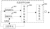
- the optical monitoring unit 1600 transmits the OSC data by using a packet communication manner, and includes at least an OTDR module 1601, an OSC module 1602, a switching control module 1603, and a photoelectric conversion module 1604.
- the OTDR module 1601 is configured to send an OTDR pulse, and obtain an OTDR detection value according to the reflected light returned by the received OTDR pulse through the optical fiber between the first station and the second station, where the optical monitoring unit 1600 is located at the first station,
- the second site is the adjacent site of the first site.
- the OSC module 1602 is configured to send the first OSC data to the second station, and receive the second OSC data sent by the second station.
- the switching control module 1603 is configured to receive a control command of the main control unit, and control the OTDR module 1601 and the OSC module 1602 to perform alternately transmitting the OTDR pulse and the first OSC data, and forward the second OSC data sent by the second station to the OSC module 1602.
- a photoelectric conversion module 1604 configured to convert an OTDR pulse into a corresponding optical signal, and The electrical signal of the first OSC data is converted into a corresponding optical signal, and the received optical signal corresponding to the second OSC data is converted into a corresponding electrical signal.
- the main control unit performs centralized control on each module of the optical monitoring unit, and a cache module is configured in the main control unit to buffer the OSC data that needs to be sent when the OTDR pulse is transmitted. package.
- the optical fiber state detection process in FIG. 10 is specifically described below, and specifically includes:
- Step 1701 The first main control unit in the first station receives the OTDR detection command sent by the network management system, and the OTDR detection instruction includes the N OTDR detection values that need to be acquired in the current OTDR detection.
- N is a positive integer
- Step 1702 The first main control unit determines that M times of OTDR pulse transmission needs to be performed according to the number N of OTDR detection values and the preset number n of single-transmission OTDR pulses.
- Step 1703 The first main control unit inserts the transmission of the OTDR pulse every interval of the maintenance packet and the interval of each packet until the M OTDR pulse transmission is completed.
- the maintenance package and the information packet here are all OSC data packets.
- the maintenance package is an OSC data packet for maintaining inter-site communication
- the information packet is an OSC data packet containing alarm information.
- the main control unit first sends an instruction to start the OTDR module to send an OTDR pulse to the switching control module, so that the switching control module establishes a connection relationship with the OTDR module, and then sends and sends an OTDR pulse command to the OTDR module. Instructs the OTDR module to send an OTDR pulse.
- the main control unit first sends an instruction to the switching control module to start the OSC module to send the OSC data, so that the switching control module establishes a connection relationship with the OSC module, and then sends and sends an OSC data command to the OSC module. And the OSC data packet is sent by the main control unit to the OSC module, and the OTDR module is instructed to send the OSC data packets.
- the main control unit In the process of transmitting the above OTDR pulse, if there is OSC data to be transmitted, the main control unit needs to have a certain buffer at this time, and the OSC data is first buffered, and after the OTDR pulse is sent, the cached device is cached. The OSC packet is sent out.
- Step 1704 The first main control unit feeds back the N OTDR detection values acquired by the first optical monitoring unit based on the N signals returned by the N OTDR pulses through the optical fibers between the first station and the second station to the network management system.
- the embodiments of the present invention solve the problems of high cost and complicated assembly caused by separately integrating the OTDR unit in the WDM system, and can meet the daily maintenance requirements for the optical fiber line.
- the real-time performance state monitoring of the optical fiber by using the method provided by the embodiment of the present invention can timely discover the performance state of the optical fiber in the network, and prevent the timely repair in advance, thereby greatly improving the reliability of the network.
- each functional module in each embodiment of the present application may be used. It can be integrated into one processing module, or each module can exist physically separately, or two or more modules can be integrated into one module.
- the above integrated modules can be implemented in the form of hardware or in the form of software functional modules.
- An integrated module if implemented as a software functional module and sold or used as a standalone product, can be stored in a computer readable storage medium.
- the technical solution of the present application in essence or the contribution to the prior art, or all or part of the technical solution may be embodied in the form of a software product stored in a storage medium.
- a number of instructions are included to cause a computer device (which may be a personal computer, server, or network device, etc.) or a processor to perform all or part of the steps of the various embodiments of the present application.
- the foregoing storage medium includes: a U disk, a mobile hard disk, a read-only memory (ROM), a random access memory (RAM), a magnetic disk, or an optical disk, and the like. .
- embodiments of the present invention can be provided as a method, system, or computer program product. Accordingly, the present invention may take the form of an entirely hardware embodiment, an entirely software embodiment, or a combination of software and hardware. Moreover, the invention may be employed in one or more A computer program product embodied on a computer usable storage medium (including but not limited to disk storage, CD-ROM, optical storage, etc.) containing computer usable program code.
- a computer usable storage medium including but not limited to disk storage, CD-ROM, optical storage, etc.
- the computer program instructions can also be stored in a computer readable memory that can direct a computer or other programmable data processing device to operate in a particular manner, such that the instructions stored in the computer readable memory produce an article of manufacture comprising the instruction device.
- the apparatus implements the functions specified in one or more blocks of a flow or a flow and/or block diagram of the flowchart.
- These computer program instructions can also be loaded onto a computer or other programmable data processing device such that a series of operational steps are performed on a computer or other programmable device to produce computer-implemented processing for execution on a computer or other programmable device.
- the instructions provide steps for implementing the functions specified in one or more of the flow or in a block or blocks of a flow diagram.
Landscapes
- Engineering & Computer Science (AREA)
- Computer Networks & Wireless Communication (AREA)
- Signal Processing (AREA)
- Physics & Mathematics (AREA)
- Electromagnetism (AREA)
- Optical Communication System (AREA)
Abstract
An optical fiber state detection method; the method is characterized by solving the prior art problems of high cost and cumbersome assembly due to separate integration of an OTDR unit. The method comprises: a first site alternately sends to a second site in a same channel optical time domain reflectometry (OTDR) pulses and optical supervisory channel (OSC) data, the second site being adjacent to the first site; the first site receives reflected light of the OTDR pulses returned by an optical fiber between the first site and the second site and obtains an OTDR detection value according to the reflected light.
Description
本发明涉及光通信技术领域,特别是涉及一种光纤状态检测方法、光监控单元及站点。The present invention relates to the field of optical communication technologies, and in particular, to a fiber state detection method, an optical monitoring unit, and a station.
目前光纤线路故障定位广泛采用的是光时域反射仪(Optical Time Domain Reflectometer,OTDR),它是利用光线在光纤中传输时的瑞利散射和菲涅尔反射所产生的背向散射而制成的精密的光电一体化仪表,被广泛应用于光缆线路的维护、施工之中,它主要用于测量光纤长度、光纤的传输衰减、接头衰减和故障定位等。但是,传统的OTDR为手持设备,作为测试仪表的使用是一种分散式、被动式的手工维护手段,难以保障更高的光纤安全要求,而且价格昂贵。当确定光纤线路故障时需要工作人员进入站点,将光纤线路断开进行测试,定位周期长,业务中断时间长,造成较大的经济损失。At present, optical line fault location is widely used in optical time domain reflectometer (OTDR), which is made by backscattering caused by Rayleigh scattering and Fresnel reflection when light is transmitted in the fiber. The precision optoelectronic integrated instrument is widely used in the maintenance and construction of optical cable lines. It is mainly used to measure the length of optical fiber, transmission attenuation of optical fiber, joint attenuation and fault location. However, the traditional OTDR is a handheld device. As a test instrument, it is a decentralized and passive manual maintenance method. It is difficult to guarantee higher fiber safety requirements and is expensive. When it is determined that the fiber line is faulty, the worker needs to enter the site, and the fiber line is disconnected for testing, the positioning period is long, and the service interruption time is long, resulting in large economic loss.
为了实现及时进行OTDR探测,现有技术中提出直接将OTDR做成独立单元集成到设备中,如下图1所示,OTDR单元采用独立于业务单元和光监控单元的波长,接入合分波单元,单方向上可以做到实时在线光纤状态检测,但对于WDM系统中的光分插复用(Optical add drop module,OADM)站点,要达到对全网光纤的OTDR探测,需要在每个方向上的出口均配置OTDR单元。因此,不仅配置单元较多,且需要占用大量机柜空间或设备槽位,设备成本及安装成本均非常高。In order to realize timely OTDR detection, the prior art proposes to directly integrate the OTDR into a device as an independent unit. As shown in FIG. 1 below, the OTDR unit uses a wavelength independent of the service unit and the optical monitoring unit to access the multiplexer unit. Real-time online fiber state detection can be performed in a single direction. However, for an optical add drop module (OADM) site in a WDM system, an OTDR detection for the entire network fiber is required, and an exit in each direction is required. Both are equipped with OTDR units. Therefore, not only the configuration unit is large, but also a large amount of cabinet space or equipment slots are required, and the equipment cost and installation cost are very high.
为了避免在每个方向上的出口均配置OTDR单元,现有技术中提出在站点上集成OTDR单元的同时,加入针对该OTDR单元的多路光开关,用以实时监测多个方向的光纤告警,降低了多方向上配置OTDR单元的成本,但无法做到实时在线的光纤状态检测,且线路装配比较繁琐。In order to avoid the OTDR unit being configured in each direction, the prior art proposes to integrate the OTDR unit at the same time, and add a multi-channel optical switch for the OTDR unit to monitor the optical fiber alarms in multiple directions in real time. The cost of configuring the OTDR unit in multiple directions is reduced, but the real-time online fiber state detection cannot be performed, and the line assembly is cumbersome.
由此可知,上述两种方案均为将OTDR做为独立单元集成到站点中且不与
业务单元及光监控单元共波长的方案。进一步地,上述两种方案需要对现有系统板卡进行改动,如在合分波单元增加OTDR单元的接入口等,且集成的OTDR是独立单元,安装占用机柜或设备槽位空间,成本高。It can be seen that the above two schemes integrate the OTDR as a separate unit into the site and do not
A common wavelength scheme for business units and optical monitoring units. Further, the above two solutions need to be modified on the existing system board, such as adding an OTDR unit access port in the splitting and splitting unit, and the integrated OTDR is a separate unit, and the installation occupies the cabinet or the equipment slot space, and the cost is high. .
发明内容Summary of the invention
本发明实施例提供一种光纤状态检测方法、光监控单元及站点,用以解决现有技术中单独集成OTDR单元造成的成本较高、装配繁琐的问题。The embodiments of the present invention provide a fiber state detection method, an optical monitoring unit, and a station, which are used to solve the problems of high cost and complicated assembly caused by separately integrating an OTDR unit in the prior art.
本发明实施例提供的具体技术方案如下:The specific technical solutions provided by the embodiments of the present invention are as follows:
本发明实施例提供一种光纤状态检测方法,包括:An embodiment of the present invention provides a fiber state detection method, including:
第一站点在同一个信道中向第二站点交替发送OTDR脉冲和OSC数据,第二站点为第一站点的相邻站点。第一站点接收OTDR脉冲经第一站点和第二站点之间的光纤返回的反射光,并根据反射光获取OTDR探测值。The first station alternately transmits OTDR pulses and OSC data to the second station in the same channel, and the second station is an adjacent station of the first station. The first station receives the reflected light returned by the OTDR pulse through the optical fiber between the first station and the second station, and acquires the OTDR detection value according to the reflected light.
同一个信道是指使用相同的波长,相同的波长集或者使用相同的协议数据帧。The same channel means using the same wavelength, the same set of wavelengths or using the same protocol data frame.
可选地,在第一站点在同一个信道中向第二站点交替发送OTDR脉冲和OSC数据之前,第一站点接收网络管理系统下发的OTDR探测指令,OTDR探测指令包含本次OTDR探测需要获取的OTDR探测值的数目N,其中,N为正整数。Optionally, before the first station alternately sends the OTDR pulse and the OSC data to the second station in the same channel, the first station receives the OTDR detection command sent by the network management system, and the OTDR detection instruction includes the OTDR detection needs to be acquired. The number of OTDR detection values N, where N is a positive integer.
可选地,在第一站点接收网络管理系统下发的OTDR探测指令之后,在第一站点在同一个信道中向第二站点交替发送OTDR脉冲和OSC数据之前,第一站点根据OTDR探测值的数目N和预设的单次发送OTDR脉冲的个数n,确定需要执行M次OTDR脉冲发送,即分片发送OTDR脉冲,保证了站点之间的OSC数据通信无丢包无误码。Optionally, after the first station receives the OTDR detection command sent by the network management system, before the first station alternately sends the OTDR pulse and the OSC data to the second station in the same channel, the first station is based on the OTDR detection value. The number N and the preset number of single-transmission OTDR pulses are n, and it is determined that M times of OTDR pulse transmission needs to be performed, that is, the OTDR pulse is transmitted by the slice, which ensures that there is no packet loss and no error in the OSC data communication between the stations.
此时,第一站点在同一个信道中向第二站点交替发送OTDR脉冲和OSC数据,可以采用但不限于以下两种方式。At this time, the first station alternately transmits the OTDR pulse and the OSC data to the second station in the same channel, and may be limited to the following two methods.
第一种方式,在采用TDM传输的波分复用系统中,第一站点可以在任意两个相邻OSC数据帧之间插入一次OTDR脉冲发送直至完成M次OTDR脉
冲发送。In the first method, in a wavelength division multiplexing system using TDM transmission, the first station can insert an OTDR pulse transmission between any two adjacent OSC data frames until the M OTDR pulse is completed.
Rush to send.
单次发送OTDR脉冲的个数n主要由第一站点中光监控单元的缓存模块的缓存大小、业务带宽、以及发送单个OTDR的脉冲时间决定。The number n of single-transmission OTDR pulses is mainly determined by the buffer size of the buffer module of the optical monitoring unit in the first station, the service bandwidth, and the pulse time for transmitting a single OTDR.
当第一站点发送n个OTDR脉冲时,由于当前波分复用系统采用TDM传输方式,则第一站点的第一光监控单元中的缓存模块将发送n个OTDR脉冲期间本应发送的OSC数据缓存起来,作为第一缓存数据,并在n个OTDR脉冲发送完成之后通过第一光监控单元中的OSC模块将第一缓存数据发送至第二站点。进一步地,第一光监控单元中的缓存模块将在发送第一缓存数据时本应发送的OSC数据缓存起来,作为第二缓存数据,并通过第一光监控单元中的OSC模块在发送完第一缓存数据后发送第二缓存数据,以此类推。When the first station sends n OTDR pulses, since the current wavelength division multiplexing system adopts the TDM transmission mode, the cache module in the first optical monitoring unit of the first station will transmit the OSC data that should be sent during the n OTDR pulses. Cached up as the first cached data, and sends the first cached data to the second site through the OSC module in the first optical monitoring unit after the n OTDR pulses are transmitted. Further, the cache module in the first optical monitoring unit caches the OSC data that should be sent when the first cached data is sent, as the second cached data, and sends the first through the OSC module in the first optical monitoring unit. The second cached data is sent after the data is cached, and so on.
一般地,正常的OSC数据发送状态不会占用全部出口带宽,都会预留一部分的冗余带宽,只有当第一光监控单元的缓存模块中有缓存数据时,才会占用冗余带宽。因此,第一光监控单元中的OSC模块在发送上述缓存数据占用全部出口带宽发送,经过一段时间后,缓存模块中不再有缓存数据,恢复到正常的OSC发送状态。Generally, the normal OSC data transmission state does not occupy the entire egress bandwidth, and a part of the redundant bandwidth is reserved. Only when there is cached data in the cache module of the first optical monitoring unit, the redundant bandwidth is occupied. Therefore, the OSC module in the first optical monitoring unit transmits the cached data to occupy all the egress bandwidths. After a period of time, the cache module no longer has cached data and returns to the normal OSC transmission state.
第二种方式,在采用数据包传输的波分复用系统中,第一站点可以在任意两个相邻OSC数据包之间插入至少一次OTDR脉冲发送,直至完成M次OTDR脉冲发送。In the second mode, in a wavelength division multiplexing system using data packet transmission, the first station can insert at least one OTDR pulse transmission between any two adjacent OSC data packets until M times OTDR pulse transmission is completed.
具体包括以下几种可能的实现方式:Specifically, the following possible implementation methods are as follows:
第一种可能的实现方式:第一站点可以将M次OTDR脉冲(即N个脉冲)在任意两个相邻OSC数据包之间发送,即将所需发送的N个脉冲集中在任意两个相邻OSC数据包之间发送。The first possible implementation manner: the first station can send M times of OTDR pulses (ie, N pulses) between any two adjacent OSC data packets, that is, concentrate the N pulses to be transmitted in any two phases. Send between adjacent OSC packets.
第二种可能的实现方式,第一站点确定当前链路空闲时,在发送维护包的间隔中插入至少一次OTDR脉冲发送,直至完成M次OTDR脉冲的发送。In a second possible implementation manner, when the first station determines that the current link is idle, at least one OTDR pulse transmission is inserted in the interval for sending the maintenance packet until the transmission of the M OTDR pulse is completed.
第三种可能的实现方式,第一站点确定当前链路正在发送OSC数据包时,在发送OSC数据包的间隔中插入至少一次OTDR脉冲发送,直至完成M次OTDR脉冲的发送。
In a third possible implementation manner, when the first station determines that the current link is transmitting the OSC data packet, the at least one OTDR pulse transmission is inserted in the interval for transmitting the OSC data packet until the transmission of the M OTDR pulse is completed.
可选地,在第一站点确定需要执行M次OTDR脉冲发送之后,在第一站点在同一个信道中向第二站点交替发送OSC数据和OTDR脉冲之前,第一站点可以发送启动OTDR探测指令至第二站点,启动OTDR探测指令用于指示第二站点从接收OSC数据的接收状态转换为等待OTDR探测的静默态。因此,能够保证第一站点和第二站点的同步,确保第二站点能够及时锁存不完整的OSC数据。Optionally, after the first station determines that the M OTDR pulse transmission needs to be performed, before the first station alternately transmits the OSC data and the OTDR pulse to the second station in the same channel, the first station may send the start OTDR detection command to The second station, the start OTDR detection instruction is used to instruct the second station to switch from receiving state of receiving OSC data to silent state waiting for OTDR detection. Therefore, synchronization of the first site and the second site can be ensured, and the second site can ensure that the incomplete OSC data is latched in time.
可选地,在第一站点向第二站点发送OTDR脉冲之后,在第一站点向第二站点发送OSC数据之前(即在第一站点执行任一次交替发送过程中,在发完OTDR脉冲,继续发送OSC数据之前),第一站点可以发送预设的物理层恢复消息至第二站点,其中,预设的物理层恢复消息用于指示第二站点从等待OTDR探测的静默态转换为接收OSC数据的接收状态。第一站点确定接收到第二站点反馈的预设的物理层恢复确认消息时,向第二站点发送OSC数据。Optionally, after the first station sends the OTDR pulse to the second station, before the first station sends the OSC data to the second station (that is, during the alternate transmission in the first station, after the OTDR pulse is sent, continue Before sending the OSC data, the first station may send a preset physical layer recovery message to the second station, where the preset physical layer recovery message is used to indicate that the second station converts from the silent state waiting for the OTDR detection to receiving the OSC data. Receive status. The first station determines to send the OSC data to the second station when receiving the preset physical layer recovery confirmation message fed back by the second station.
可选地,第一站点发送预设的物理层恢复消息至第二站点之后,第一站点确定超过预设时长未接收到第二站点反馈的预设的物理层恢复确认消息时,向第二站点发送OSC数据。因此,能够保证该系统的可靠性,避免在发送OTDR脉冲的过程中,光纤发生故障无法及时恢复至接收状态进行故障告警。Optionally, after the first station sends the preset physical layer recovery message to the second station, the first station determines that the preset physical layer recovery confirmation message that is not received by the second station exceeds the preset duration, and then goes to the second The site sends OSC data. Therefore, the reliability of the system can be ensured, and in the process of transmitting the OTDR pulse, the failure of the optical fiber cannot be restored to the receiving state in time for the fault alarm.
本发明实施例提供一种光监控单元,至少包括:OTDR模块,OSC模块,切换控制模块;其中,The embodiment of the invention provides an optical monitoring unit, which at least includes: an OTDR module, an OSC module, and a switching control module;
OTDR模块,用于发送OTDR脉冲,以及根据接收到的OTDR脉冲经第一站点和第二站点之间的光纤返回的反射光,获取OTDR探测值,这里光监控单元300位于第一站点,第二站点为第一站点的相邻站点;An OTDR module is configured to send an OTDR pulse, and obtain an OTDR detection value according to the received OTDR pulse returned by the optical fiber between the first station and the second station, where the optical monitoring unit 300 is located at the first station, and second The site is an adjacent site of the first site;
OSC模块,用于向第二站点发送第一OSC数据,以及接收第二站点发送的第二OSC数据。The OSC module is configured to send the first OSC data to the second station, and receive the second OSC data sent by the second station.
切换控制模块,用于控制OTDR模块和OSC模块执行交替发送OTDR脉冲和第一OSC数据,以及转发第二站点发送的第二OSC数据至OSC模块。And a switching control module, configured to control the OTDR module and the OSC module to perform alternately transmitting the OTDR pulse and the first OSC data, and forward the second OSC data sent by the second station to the OSC module.
可选地,光监控单元还包括缓存模块。Optionally, the optical monitoring unit further includes a cache module.
缓存模块,用于缓存由于OTDR模块在发送OTDR脉冲时产生的缓存
OSC数据。a cache module for caching caches generated by the OTDR module when transmitting OTDR pulses
OSC data.
可选地,光监控单元还包括光电转换模块。Optionally, the light monitoring unit further includes a photoelectric conversion module.
光电转换模块,用于将OTDR脉冲转换成对应的光信号,以及将对应第一OSC数据的电信号转换成对应的光信号,将接收到的对应第二OSC数据的光信号转换为对应的电信号。The photoelectric conversion module is configured to convert the OTDR pulse into a corresponding optical signal, and convert the electrical signal corresponding to the first OSC data into a corresponding optical signal, and convert the received optical signal corresponding to the second OSC data into a corresponding electrical signal. signal.
本发明实施例还提供一种站点,包括业务单元,光监控单元,主控单元,合分波单元。其中,光监控单元能够实现上述实施例中的光纤状态检测。The embodiment of the invention further provides a site, including a service unit, a light monitoring unit, a main control unit, and a splitting and splitting unit. The optical monitoring unit can implement the optical fiber state detection in the foregoing embodiment.
本发明实施例通过在同一个信道中向第二站点交替发送OTDR脉冲和OSC数据,解决了WDM系统中单独集成OTDR单元造成的成本较高、装配繁琐的问题,同时可满足日常对光纤线路的维护性需求。由于WDM系统中线路光纤的故障如光纤的老化、外破损伤、光纤卷曲、大角度弯折以及承担较大拉力等光纤问题,就会导致业务及通信均劣化,误码率高甚至造成业务中断,因此,采用本发明实施例提供的方法对光纤实时的性能状态监测可以及时的发现网络中光纤的性能状态,做到提前预防及时修复,可大大提升网络的可靠性。The embodiment of the invention solves the problems of high cost and complicated assembly caused by separately integrating the OTDR unit in the WDM system by alternately transmitting the OTDR pulse and the OSC data to the second station in the same channel, and can meet the daily requirements for the optical fiber line. Maintenance needs. Due to the failure of the line fiber in the WDM system, such as the aging of the fiber, the damage of the fiber, the crimping of the fiber, the bending of the large angle, and the large tensile force, the service and communication are degraded, and the bit error rate is high and the service is interrupted. Therefore, the real-time performance state monitoring of the optical fiber by using the method provided by the embodiment of the present invention can timely discover the performance state of the optical fiber in the network, and prevent the timely repair in advance, thereby greatly improving the reliability of the network.
图1为本发明背景技术中OTDR单元做为独立单元集成到站点的结构示意图;1 is a schematic structural diagram of an OTDR unit being integrated into a station as a separate unit in the background art of the present invention;
图2为本发明实施例中WDM系统的结构示意图;2 is a schematic structural diagram of a WDM system according to an embodiment of the present invention;
图3为本发明实施例中光监控单元的结构示意图之一;3 is a schematic structural diagram of a light monitoring unit according to an embodiment of the present invention;
图4为本发明实施例中站点的结构示意图;4 is a schematic structural diagram of a station in an embodiment of the present invention;
图5为本发明实施例中光纤状态检测方法的概述流程图;5 is a flowchart of an overview of a fiber state detection method according to an embodiment of the present invention;
图6为本发明实施例中OTDR周期的结构示意图;6 is a schematic structural diagram of an OTDR period according to an embodiment of the present invention;
图7为本发明实施例中连续M个OTDR周期发送的结构示意图;FIG. 7 is a schematic structural diagram of continuous M OTDR periodic transmission according to an embodiment of the present invention; FIG.
图8为本发明实施例中集中发送OTDR脉冲的结构示意图;FIG. 8 is a schematic structural diagram of centralized transmission of an OTDR pulse according to an embodiment of the present invention; FIG.
图9为本发明实施例中在发送维护包的间隔插入发送OTDR脉冲的结构示
意图;FIG. 9 is a structural diagram of inserting and transmitting an OTDR pulse at intervals of transmitting a maintenance packet according to an embodiment of the present invention;
intention;
图10为本发明实施例中在发送维护包和信息包的间隔分别插入一次OTDR脉冲发送的结构示意图;10 is a schematic structural diagram of inserting an OTDR pulse transmission at intervals of sending a maintenance packet and a packet according to an embodiment of the present invention;
图11为本发明实施例中采用TDM传输方式的光监控单元的结构示意图;FIG. 11 is a schematic structural diagram of an optical monitoring unit adopting a TDM transmission mode according to an embodiment of the present invention;
图12为本发明实施例中OSC数据帧的结构示意图;FIG. 12 is a schematic structural diagram of an OSC data frame according to an embodiment of the present invention;
图13为本发明实施例中一个OTDR周期的发送具体流程图;FIG. 13 is a specific flowchart of sending an OTDR period according to an embodiment of the present invention;
图14A为本发明实施例中A站点的状态变化示意图;14A is a schematic diagram showing a state change of an A site in an embodiment of the present invention;
图14B为本发明实施例中B站点的状态变化示意图;FIG. 14B is a schematic diagram showing a state change of a B site according to an embodiment of the present invention; FIG.
图15为本发明实施例中多个站点进行OTDR探测的结构示意图;15 is a schematic structural diagram of performing OTDR detection by multiple stations in an embodiment of the present invention;
图16为本发明实施例中采用数据包传输方式的光监控单元的结构示意图;16 is a schematic structural diagram of an optical monitoring unit adopting a data packet transmission manner according to an embodiment of the present invention;
图17为本发明实施例中在采用数据包传输方式的波分复用系统中光纤状态检测的具体流程图。FIG. 17 is a specific flowchart of optical fiber state detection in a wavelength division multiplexing system using a data packet transmission method according to an embodiment of the present invention.
本发明实施例提供一种光纤状态检测方法、光监控单元及站点,用以解决现有技术中单独集成OTDR单元造成的成本较高、装配繁琐的问题。The embodiments of the present invention provide a fiber state detection method, an optical monitoring unit, and a station, which are used to solve the problems of high cost and complicated assembly caused by separately integrating an OTDR unit in the prior art.
其中,方法、光监控单元及站点是基于同一发明构思的,由于方法、光监控单元及站点解决问题的原理相似,因此装置与方法的实施可以相互参见,重复之处不再赘述。The method, the optical monitoring unit and the site are based on the same inventive concept. Since the principles of the method, the optical monitoring unit and the site solving the problem are similar, the implementation of the device and the method can be referred to each other, and the repeated description is not repeated.
光波分复用传输系统是当前干线传输和城域核心网多业务传输采用的主要平台,其基本原理为:在光系统的发送端将分别调制在不同波长的输入信号光载波通过一个波分复用器(合波器)复用在一起,再经过一根光纤传输到远端;在光系统的接收端,利用另一个波分复用器(分波器)将这些不同信号的光载波分离开,将各个光信号转换成对应的电信号完成长距传输。因此,波分复用(Wavelength division multiplexing,WDM)系统具有传输容量大、易扩容、可靠传输等优点,在通信网络中具有较高的地位。The optical wavelength division multiplexing transmission system is the main platform used for the current trunk transmission and multi-service transmission of the metro core network. The basic principle is that the optical signal of the input signal respectively modulated at different wavelengths is transmitted through a wave at the transmitting end of the optical system. The multiplexers (multiplexers) are multiplexed together and transmitted to the far end via a fiber; at the receiving end of the optical system, the optical carriers of these different signals are separated by another wavelength division multiplexer (demultiplexer). On, convert each optical signal into a corresponding electrical signal to complete long-distance transmission. Therefore, the Wavelength Division Multiplexing (WDM) system has the advantages of large transmission capacity, easy expansion, and reliable transmission, and has a high status in the communication network.
参阅图2所示为一个基本的点到点的WDM系统结构示意图,每个站点
主要包括主控单元,业务单元,合分波单元和光监控单元。See Figure 2 for a basic point-to-point WDM system architecture diagram, each site
It mainly includes a main control unit, a business unit, a split wave unit and a light monitoring unit.
其中,主控单元用于从网络管理系统接收命令,执行或接收参数配置下发到其他单元,以及将站点内的告警等上报给网络管理系统;业务单元用于完成将多个电信号分别转换为对应的特定波长的光信号,以及将多个特定波长的光信号分别转换为对应的电信号;合分波单元用于将多个独立的特定波长的光信号转换为合波信号,以及将合波信号转换为多个独立的特定波长的光信号;光监控管理单元用于实现站点间的通信,完成WDM系统的管理和控制。例如,如图2所示,光监控单元可以实时传递A站点和B站点之间的告警信息,以及将告警信息通过主控单元上报至网管系统,此外,光监控单元还可根据网管系统下发的光系统参数调节指令,实现控制光系统的参数调节。The main control unit is configured to receive a command from the network management system, execute or receive the parameter configuration and send it to other units, and report the alarms in the site to the network management system; the service unit is configured to separately convert the multiple electrical signals. Corresponding to a specific wavelength of the optical signal, and converting the plurality of specific wavelengths of the optical signal into corresponding electrical signals; the multiplexing and separating unit is configured to convert the plurality of independent specific wavelength optical signals into a combined signal, and The multiplexed signal is converted into a plurality of independent optical signals of specific wavelengths; the optical monitoring management unit is used to implement communication between sites, and complete management and control of the WDM system. For example, as shown in FIG. 2, the optical monitoring unit can transmit the alarm information between the A site and the B site in real time, and report the alarm information to the network management system through the main control unit. In addition, the optical monitoring unit can also be delivered according to the network management system. The optical system parameter adjustment command realizes the parameter adjustment of the control optical system.
参阅图3所示,本发明实施例提供一种光监控单元300,至少包括:OTDR模块31,光监控信道(Optical Supervisory Channel,OSC)模块32,切换控制模块33;其中,As shown in FIG. 3, an embodiment of the present invention provides an optical monitoring unit 300, which includes at least an OTDR module 31, an Optical Supervisory Channel (OSC) module 32, and a switching control module 33;
OTDR模块31,用于发送OTDR脉冲,以及根据接收到的OTDR脉冲经第一站点和第二站点之间的光纤返回的反射光,获取OTDR探测值,这里光监控单元300位于第一站点,第二站点为第一站点的相邻站点。The OTDR module 31 is configured to send an OTDR pulse, and obtain an OTDR detection value according to the reflected light returned by the received OTDR pulse through the optical fiber between the first station and the second station, where the optical monitoring unit 300 is located at the first station, The second site is the adjacent site of the first site.
其中,OTDR脉冲为一种用于测量光纤长度、光纤的传输衰减、接头衰减和故障定位的光脉冲。Among them, the OTDR pulse is an optical pulse for measuring the length of the fiber, the transmission attenuation of the fiber, the joint attenuation, and the fault location.
具体的,OTDR模块31在发送OTDR脉冲时,可以产生脉宽可调的OTDR探测脉冲,在接收OTDR脉冲经第一站点和第二站点之间的光纤返回的反射光时,可以实现对反射光的光电转换,采样分析,获得OTDR探测值,并将获得的OTDR探测值上传到第一站点中的主控单元,并可由该主控单元进一步将其上传至网络管理系统。Specifically, the OTDR module 31 can generate an OTDR detection pulse with adjustable pulse width when transmitting the OTDR pulse, and can realize the reflected light when receiving the reflected light returned by the optical fiber between the first station and the second station. The photoelectric conversion, sampling analysis, obtaining the OTDR detection value, and uploading the obtained OTDR detection value to the main control unit in the first station, and further uploading the same to the network management system by the main control unit.
OSC模块32,用于向第二站点发送第一OSC数据,以及接收第二站点发送的第二OSC数据。The OSC module 32 is configured to send the first OSC data to the second station, and receive the second OSC data sent by the second station.
其中,OSC数据是指站点之间传输的网络管理系统的监控信息、公务信
息和告警信息等。The OSC data refers to the monitoring information and business information of the network management system transmitted between the sites.
Information and alarm information.
具体的,OSC模块32是完成传统的光监控信道功能,参阅图11,在传输OSC数据时,可采用时分复用(Time Division Multiplexing,TDM)的传输方式,由切换控制模块33对其进行直接控制,或参阅图15采用包通信的传输方式,由切换控制模块33和主控单元联合对其进行控制。Specifically, the OSC module 32 performs the traditional optical monitoring channel function. Referring to FIG. 11, when the OSC data is transmitted, a Time Division Multiplexing (TDM) transmission mode may be adopted, and the switching control module 33 directly performs the same. Control, or refer to FIG. 15 for the transmission mode of packet communication, which is controlled by the switching control module 33 and the main control unit.
切换控制模块33,用于控制OTDR模块31和OSC模块32执行交替发送OTDR脉冲和第一OSC数据,以及转发第二站点发送的第二OSC数据至OSC模块32。The switching control module 33 is configured to control the OTDR module 31 and the OSC module 32 to perform alternately transmitting the OTDR pulse and the first OSC data, and to forward the second OSC data sent by the second station to the OSC module 32.
可选地,光监控单元300还包括缓存模块34。Optionally, the light monitoring unit 300 further includes a cache module 34.
缓存模块34,用于缓存由于OTDR模块30在发送OTDR脉冲时产生的缓存OSC数据。The cache module 34 is configured to cache cached OSC data generated by the OTDR module 30 when transmitting an OTDR pulse.
参阅图11所示,当光监控单元300采用TDM的传输方式传输OSC数据时,缓存模块34位于光监控单元300内。参阅图15所示,当光监控单元300采用包通信的传输方式传输OSC数据时,缓存模块34可位于第一站点的主控单元内。Referring to FIG. 11, when the optical monitoring unit 300 transmits the OSC data in the TDM transmission mode, the cache module 34 is located in the optical monitoring unit 300. Referring to FIG. 15, when the optical monitoring unit 300 transmits the OSC data by using a packet communication transmission mode, the cache module 34 may be located in the main control unit of the first station.
可选地,光监控单元300还包括光电转换模块35。Optionally, the light monitoring unit 300 further includes a photoelectric conversion module 35.
光电转换模块35,用于将OTDR脉冲转换成对应的光信号,以及将对应第一OSC数据的电信号转换成对应的光信号,将接收到的对应第二OSC数据的光信号转换为对应的电信号。The photoelectric conversion module 35 is configured to convert the OTDR pulse into a corresponding optical signal, and convert the electrical signal corresponding to the first OSC data into a corresponding optical signal, and convert the received optical signal corresponding to the second OSC data into a corresponding electric signal.
本发明实施例还提供一种站点,包括如图3所示的光监控单元。An embodiment of the present invention further provides a station, including the optical monitoring unit shown in FIG.
参阅图4所示,站点400包括业务单元401,光监控单元402,该光监控单元402与图3所示的光监控单元功能相同,主控单元403,合分波单元404。Referring to FIG. 4, the station 400 includes a service unit 401 and a light monitoring unit 402. The light monitoring unit 402 has the same function as the light monitoring unit shown in FIG. 3, and the main control unit 403 and the splitting unit 404.
参阅图5所示,本发明实施例提供一种光纤状态检测方法,包括:Referring to FIG. 5, an embodiment of the present invention provides a fiber state detection method, including:
步骤500:第一站点在同一个信道中向第二站点交替发送OTDR脉冲和OSC数据,第二站点为第一站点的相邻站点。Step 500: The first station alternately sends the OTDR pulse and the OSC data to the second station in the same channel, where the second station is the adjacent station of the first station.
这里的第一站点为如图4所示的站点。The first site here is the site shown in Figure 4.
具体的,同一个信道包括使用相同的波长,相同的波长集或者使用相同
的协议数据帧的传输通道。Specifically, the same channel includes the same wavelength, the same wavelength set, or the same
The transmission channel of the protocol data frame.
步骤510:第一站点接收OTDR脉冲经第一站点和第二站点之间的光纤返回的反射光,并根据反射光获取OTDR探测值。Step 510: The first station receives the reflected light returned by the OTDR pulse through the optical fiber between the first station and the second station, and acquires the OTDR detection value according to the reflected light.
可选地,在第一站点在同一个信道中向第二站点交替发送OTDR脉冲和OSC数据之前,第一站点接收网络管理系统下发的OTDR探测指令,OTDR探测指令包含本次OTDR探测需要获取的OTDR探测值的数目N,其中,N为正整数。Optionally, before the first station alternately sends the OTDR pulse and the OSC data to the second station in the same channel, the first station receives the OTDR detection command sent by the network management system, and the OTDR detection instruction includes the OTDR detection needs to be acquired. The number of OTDR detection values N, where N is a positive integer.
可选地,在第一站点接收网络管理系统下发的OTDR探测指令之后,在第一站点在同一个信道中向第二站点交替发送OTDR脉冲和OSC数据之前,第一站点根据OTDR探测值的数目N和预设的单次发送OTDR脉冲的个数n,确定需要执行M次OTDR脉冲发送,即分片发送OTDR脉冲。Optionally, after the first station receives the OTDR detection command sent by the network management system, before the first station alternately sends the OTDR pulse and the OSC data to the second station in the same channel, the first station is based on the OTDR detection value. The number N and the preset number of single-transmission OTDR pulses are n, and it is determined that M times of OTDR pulse transmission needs to be performed, that is, the OTDR pulse is transmitted by the slice.
例如,当需要获取的OTDR探测值数目为10000时,预设的单次发送OTDR脉冲的个数为100个,则完成OTDR探测需要发送OTDR脉冲的次数为10000/100=100次。若不能整除,则将N/n后获得的商值加1作为M。For example, when the number of OTDR detection values to be acquired is 10000, the number of preset single-transmission OTDR pulses is 100, and the number of times the OTDR pulse needs to be transmitted is 10000/100=100 times. If it is not divisible, the quotient obtained after N/n is incremented by 1 as M.
此时,第一站点在同一个信道中向第二站点交替发送OTDR脉冲和OSC数据,可以采用但不限于以下两种方式。At this time, the first station alternately transmits the OTDR pulse and the OSC data to the second station in the same channel, and may be limited to the following two methods.
第一种方式,在采用TDM传输的波分复用系统中,第一站点可以在任意两个相邻OSC数据帧之间插入一次OTDR脉冲发送直至完成M次OTDR脉冲发送。In the first method, in a wavelength division multiplexing system employing TDM transmission, the first station can insert an OTDR pulse transmission between any two adjacent OSC data frames until M times OTDR pulse transmission is completed.
在采用TDM传输的波分复用系统中,N个OTDR脉冲最好在多个相邻的OSC数据帧之间分开发送,因为OSC数据发送长时间中断可能造成网元脱落,告警信息无法及时上报等问题。因此,需要对N个脉冲分成许多小片段进行发送,以保证第一站点和第二站点之间的OSC数据通信无丢包无误码。In a wavelength division multiplexing system using TDM transmission, the N OTDR pulses are preferably transmitted separately between a plurality of adjacent OSC data frames. The long-term interruption of the OSC data transmission may cause the network element to fall off, and the alarm information cannot be reported in time. And other issues. Therefore, it is necessary to divide the N pulses into a plurality of small segments to ensure that the OSC data communication between the first station and the second station has no packet loss and no error.
进一步地,单次发送OTDR脉冲的个数n主要由第一站点中光监控单元的缓存模块的缓存大小、业务带宽、以及发送单个OTDR的脉冲时间决定。Further, the number n of single-transmission OTDR pulses is mainly determined by the buffer size of the buffer module of the optical monitoring unit in the first station, the service bandwidth, and the pulse time for transmitting a single OTDR.
业务带宽A*单次发送OTDR脉冲的最大个数nmax*发送单个OTDR的脉冲时间T≤缓存大小S。
Service Bandwidth A* Maximum number of single-transmission OTDR pulses n max * Pulse time T ≤ buffer size S for transmitting a single OTDR.
即nmax≤S/(A*T)That is, n max ≤ S / (A * T)
第一站点可以根据计算得到的nmax确定一个单次发送OTDR脉冲的个数n,其中,n≤nmax。The first station can determine the number n of single-transmission OTDR pulses based on the calculated n max , where n ≤ n max .
此时,针对每次发送OTDR脉冲还需将发送OTDR脉冲时本应发送的OSC数据缓存起来。At this time, it is necessary to buffer the OSC data that should be transmitted when the OTDR pulse is transmitted for each transmission of the OTDR pulse.
具体的,当第一站点发送n个OTDR脉冲时,由于当前波分复用系统采用TDM传输方式,则第一站点的第一光监控单元中的缓存模块将发送n个OTDR脉冲期间本应发送的OSC数据缓存起来,作为第一缓存数据,并在n个OTDR脉冲发送完成之后通过第一光监控单元中的OSC模块将第一缓存数据发送至第二站点。进一步地,第一光监控单元中的缓存模块将在发送第一缓存数据时本应发送的OSC数据缓存起来,作为第二缓存数据,并通过第一光监控单元中的OSC模块在发送完第一缓存数据后发送第二缓存数据,以此类推。Specifically, when the first station sends n OTDR pulses, since the current wavelength division multiplexing system adopts the TDM transmission mode, the buffer module in the first optical monitoring unit of the first station will send n OTDR pulses during the transmission period. The OSC data is buffered as the first cached data, and the first cached data is transmitted to the second site by the OSC module in the first optical monitoring unit after the n OTDR pulses are transmitted. Further, the cache module in the first optical monitoring unit caches the OSC data that should be sent when the first cached data is sent, as the second cached data, and sends the first through the OSC module in the first optical monitoring unit. The second cached data is sent after the data is cached, and so on.
一般地,正常的OSC数据发送状态不会占用全部出口带宽,都会预留一部分的冗余带宽,只有当第一光监控单元的缓存模块中有缓存数据时,才会占用冗余带宽。因此,第一光监控单元中的OSC模块在发送上述缓存数据时采用如图5所示的数据区(即业务带宽)和冗余带宽,经过一段时间后,缓存模块中不再有缓存数据,恢复到正常的OSC发送状态,即只占用数据区发送OSC数据。Generally, the normal OSC data transmission state does not occupy the entire egress bandwidth, and a part of the redundant bandwidth is reserved. Only when there is cached data in the cache module of the first optical monitoring unit, the redundant bandwidth is occupied. Therefore, the OSC module in the first optical monitoring unit uses the data area (ie, service bandwidth) and the redundant bandwidth as shown in FIG. 5 when transmitting the cached data, and after a period of time, there is no more cached data in the cache module. Return to the normal OSC transmission state, that is, only occupy the data area to send OSC data.
进一步地,由于发送n个OTDR脉冲产生的缓存OSC数据的发送时间也可以确定下来。Further, the transmission time of the cached OSC data generated by transmitting n OTDR pulses can also be determined.
具体的,当单次发送OTDR脉冲数目n确定时,单次发送OTDR脉冲的时间就可以确定下来,即单次发送OTDR脉冲的时间等于每个脉冲的发送时间乘以单次发送OTDR脉冲数目n。进一步地,根据发送OTDR脉冲的时间和出口带宽信息确定发送缓存OSC数据的时间。Specifically, when the number of single-transmission OTDR pulses is determined, the time for transmitting the OTDR pulse in a single time can be determined, that is, the time for transmitting the OTDR pulse in a single time is equal to the transmission time of each pulse multiplied by the number of single-transmission OTDR pulses. . Further, the time for transmitting the cached OSC data is determined according to the time of transmitting the OTDR pulse and the egress bandwidth information.
出口带宽信息可以为冗余带宽和业务带宽的比值,或冗余带宽和业务带宽等。
The egress bandwidth information may be a ratio of redundant bandwidth to service bandwidth, or redundant bandwidth and service bandwidth.
例如,业务带宽为W,冗余带宽为0.2*W,则当发送OTDR脉冲的时间为T时,由于发送OTDR脉冲产生的缓存OSC数据的发送时间为T/0.2=5*T,即经过5T后,第一光监控单元中的缓存模块没有缓存数据,恢复到正常的OSC数据发送状态。此时,可以立即发起下一次OTDR脉冲的发送,或者在发送几个正常的OSC数据帧后,在进行下一次OTDR脉冲的发送。这里可以由第一光监控单元中的切换控制模块对下一次OTDR脉冲的发送时机进行控制,或者将OTDR脉冲和OSC数据的交替发送规则提前预设在该切换控制模块中。For example, if the service bandwidth is W and the redundancy bandwidth is 0.2*W, when the time for transmitting the OTDR pulse is T, the transmission time of the cached OSC data generated by transmitting the OTDR pulse is T/0.2=5*T, that is, after 5T. After that, the cache module in the first optical monitoring unit does not cache data, and returns to the normal OSC data transmission state. At this point, the next OTDR pulse transmission can be initiated immediately, or after the transmission of several normal OSC data frames, the next OTDR pulse transmission is performed. Here, the switching timing of the next OTDR pulse may be controlled by the switching control module in the first optical monitoring unit, or the alternate transmission rule of the OTDR pulse and the OSC data may be preset in advance in the switching control module.
例如,参阅图6所述,将每次交替发送n个OTDR脉冲和发送OSC缓存数据的过程作为一个OTDR周期,该周期可以穿插在正常的OSC数据帧发送中,每个OTDR周期包括向下游站点发送启动OTDR探测指令(即图6中所示的协议报文),发送n个OTDR脉冲,发送预设物理层恢复消息(即图6中所示的伪随机比特序列(Pseudorandom Bit Sequence,PRBS)),发送OSC缓存数据(即图6中所示的帧2、帧3、帧4)。此时帧2、帧3、帧4可用于发送OSC缓存数据。For example, referring to FIG. 6, the process of alternately transmitting n OTDR pulses and transmitting OSC buffer data each time is taken as an OTDR period, which can be interspersed in normal OSC data frame transmission, and each OTDR period includes a downstream station. Sending an OTDR probe command (ie, the protocol packet shown in FIG. 6), transmitting n OTDR pulses, and transmitting a preset physical layer recovery message (ie, a pseudo random bit sequence (PRBS) shown in FIG. ), the OSC cache data (ie, frame 2, frame 3, frame 4 shown in FIG. 6) is transmitted. At this time, frame 2, frame 3, and frame 4 can be used to transmit OSC cache data.
又例如,参阅图7所示,可以连续发送M个OTDR周期,完成本次OTDR探测需要获取的N个OTDR探测值。For example, as shown in FIG. 7, the M OTDR periods can be continuously transmitted, and the N OTDR detection values that need to be acquired in the current OTDR detection are completed.
第二种方式,在采用数据包传输的波分复用系统中,第一站点可以在任意两个相邻OSC数据包之间插入至少一次OTDR脉冲发送,直至完成M次OTDR脉冲发送。In the second mode, in a wavelength division multiplexing system using data packet transmission, the first station can insert at least one OTDR pulse transmission between any two adjacent OSC data packets until M times OTDR pulse transmission is completed.
具体包括以下几种可能的实现方式:Specifically, the following possible implementation methods are as follows:
第一种可能的实现方式:第一站点可以将M次OTDR脉冲(即N个脉冲)在任意两个相邻OSC数据包之间发送,即将所需发送的N个脉冲集中在任意两个相邻OSC数据包之间发送。The first possible implementation manner: the first station can send M times of OTDR pulses (ie, N pulses) between any two adjacent OSC data packets, that is, concentrate the N pulses to be transmitted in any two phases. Send between adjacent OSC packets.
此时的链路状态可能为空闲态,也可能是在发送OSC数据包的占用态,参阅图8所示,可以在发送完一个数据包后,直接集中发送N个OTDR脉冲,此时不会因为数据发送中断,而产生丢包的问题。但是,若将OTDR脉冲穿
插在OSC数据包的间隙发送,也需要设置缓存模块对发送OTDR脉冲时本应发送的OSC数据包缓存起来,等到OTDR脉冲发送完再将缓存的OSC数据包发送至第二站点,此时的缓存模块的容量需要大于发送M次OTDR脉冲产生的缓存OSC数据包的大小,一般根据经验值设定。The link state at this time may be idle or may be in the occupied state of sending OSC data packets. As shown in Figure 8, after sending a data packet, N OTDR pulses may be directly sent in a centralized manner. Because of the interruption of data transmission, there is a problem of packet loss. However, if the OTDR pulse is worn
Inserted in the gap of the OSC data packet transmission, it is also necessary to set the cache module to buffer the OSC data packet that should be sent when the OTDR pulse is sent, and wait until the OTDR pulse is sent, and then send the cached OSC data packet to the second site. The capacity of the cache module needs to be larger than the size of the cached OSC packet generated by sending M times of OTDR pulses, which is generally set according to the empirical value.
第二种可能的实现方式,第一站点确定当前链路空闲时,在发送维护包的间隔中插入至少一次OTDR脉冲发送,直至完成M次OTDR脉冲的发送。In a second possible implementation manner, when the first station determines that the current link is idle, at least one OTDR pulse transmission is inserted in the interval for sending the maintenance packet until the transmission of the M OTDR pulse is completed.
这里可以插入相同次数OTDR脉冲发送,也可以插入不同次数OTDR脉冲发,由第一站点控制。Here, the same number of OTDR pulse transmissions can be inserted, or different times of OTDR pulse transmission can be inserted, which is controlled by the first station.
参阅图9所示,在链路空闲时,第一站点向第二站点发送维护包,可以在发送每个维护包的发送间隔插入n个OTDR脉冲,直至完成M次OTDR脉冲的发送。Referring to FIG. 9, when the link is idle, the first station sends a maintenance packet to the second station, and n OTDR pulses can be inserted at the transmission interval of each maintenance packet until the transmission of M OTDR pulses is completed.
第三种可能的实现方式,第一站点确定当前链路正在发送OSC数据包时,在发送OSC数据包的间隔中插入至少一次OTDR脉冲发送,直至完成M次OTDR脉冲的发送。In a third possible implementation manner, when the first station determines that the current link is transmitting the OSC data packet, the at least one OTDR pulse transmission is inserted in the interval for transmitting the OSC data packet until the transmission of the M OTDR pulse is completed.
这里可以插入相同次数OTDR脉冲发送,也可以插入不同次数OTDR脉冲发,由第一站点控制。Here, the same number of OTDR pulse transmissions can be inserted, or different times of OTDR pulse transmission can be inserted, which is controlled by the first station.
此时,也需要将发送OTDR脉冲时本应发送的OSC数据包缓存起来。At this time, it is also necessary to buffer the OSC data packet that should be transmitted when the OTDR pulse is transmitted.
具体的,参阅图10所示,在发送维护包和信息包的间隔分别插入n个OTDR脉冲,直至完成M次OTDR脉冲的发送。Specifically, referring to FIG. 10, n OTDR pulses are respectively inserted in the interval for transmitting the maintenance packet and the packet until the transmission of the M OTDR pulse is completed.
可选地,在第一站点确定需要执行M次OTDR脉冲发送之后,在第一站点在同一个信道中向第二站点交替发送OSC数据和OTDR脉冲之前,第一站点可以发送启动OTDR探测指令至第二站点,启动OTDR探测指令用于指示第二站点从接收OSC数据的接收状态转换为等待OTDR探测的静默态。Optionally, after the first station determines that the M OTDR pulse transmission needs to be performed, before the first station alternately transmits the OSC data and the OTDR pulse to the second station in the same channel, the first station may send the start OTDR detection command to The second station, the start OTDR detection instruction is used to instruct the second station to switch from receiving state of receiving OSC data to silent state waiting for OTDR detection.
可选地,在第一站点向第二站点发送OTDR脉冲之后,在第一站点向第二站点发送OSC数据之前(即在第一站点执行任一次交替发送过程中,在发完OTDR脉冲,继续发送OSC数据之前),第一站点可以发送预设的物理层恢复消息至第二站点,例如,发送PRBS,其中,预设的物理层恢复消息用于
指示第二站点从等待OTDR探测的静默态转换为接收OSC数据的接收状态。第一站点确定接收到第二站点反馈的预设的物理层恢复确认消息时,向第二站点发送OSC数据。Optionally, after the first station sends the OTDR pulse to the second station, before the first station sends the OSC data to the second station (that is, during the alternate transmission in the first station, after the OTDR pulse is sent, continue Before sending the OSC data, the first station may send a preset physical layer recovery message to the second station, for example, sending a PRBS, where a preset physical layer recovery message is used for
The second station is instructed to switch from a silent state waiting for OTDR detection to a receiving state of receiving OSC data. The first station determines to send the OSC data to the second station when receiving the preset physical layer recovery confirmation message fed back by the second station.
可选地,第一站点发送预设的物理层恢复消息至第二站点之后,第一站点确定超过预设时长未接收到第二站点反馈的预设的物理层恢复确认消息时,向第二站点发送OSC数据。Optionally, after the first station sends the preset physical layer recovery message to the second station, the first station determines that the preset physical layer recovery confirmation message that is not received by the second station exceeds the preset duration, and then goes to the second The site sends OSC data.
参阅图11所示,光监控单元1100采用TDM的传输方式传输OSC数据,光监控单元1100可以包括:OTDR模块1101,OSC模块1102,切换控制模块1103;其中,As shown in FIG. 11 , the optical monitoring unit 1100 transmits the OSC data by using a TDM transmission mode. The optical monitoring unit 1100 may include an OTDR module 1101, an OSC module 1102, and a switching control module 1103.
OTDR模块1101,用于发送OTDR脉冲,以及根据接收到的OTDR脉冲经第一站点和第二站点之间的光纤返回的反射光,获取OTDR探测值,这里光监控单元1100位于第一站点,第二站点为第一站点的相邻站点。The OTDR module 1101 is configured to send an OTDR pulse, and obtain an OTDR detection value according to the reflected light returned by the received OTDR pulse through the optical fiber between the first station and the second station, where the optical monitoring unit 1100 is located at the first station, The second site is the adjacent site of the first site.
OSC模块1102,用于向第二站点发送第一OSC数据,以及接收第二站点发送的第二OSC数据。The OSC module 1102 is configured to send first OSC data to the second station, and receive second OSC data sent by the second station.
具体的,光监控单元1100采用TDM的传输方式传输OSC数据时,OSC模块1102作为一个通信管道,承载网络管理系统对各站点的控制监控信息及各站点告警状态的上报信息。Specifically, when the optical monitoring unit 1100 transmits the OSC data by using the TDM transmission mode, the OSC module 1102 functions as a communication pipeline, and carries the control information of the network management system to each station and the reporting status of the alarm status of each station.
参阅图12所示,该通信管道为速率为155.52M的一个数据帧,为了支持OSC数据和线路上的OTDR探测共存,帧结构设计中预留了部分冗余带宽,用于在发送OSC缓存数据时,能够占用该部分冗余带宽,尽快将OSC缓存数据发送出去,即正常数据帧利用数据区(即业务带宽)发送OSC数据,在发送OSC缓存数据时利用业务带宽和冗余带宽发送。Referring to FIG. 12, the communication pipeline is a data frame with a rate of 155.52M. In order to support coexistence of OSC data and OTDR detection on the line, a part of redundant bandwidth is reserved in the frame structure design for transmitting OSC cache data. When the redundant bandwidth is occupied, the OSC cache data is sent out as soon as possible, that is, the normal data frame transmits the OSC data by using the data area (ie, the service bandwidth), and is transmitted by using the service bandwidth and the redundant bandwidth when transmitting the OSC cache data.
切换控制模块1103,用于直接控制OTDR模块1101和OSC模块1102执行交替发送OTDR脉冲和第一OSC数据,以及转发第二站点发送的第二OSC数据至OSC模块1102。The switching control module 1103 is configured to directly control the OTDR module 1101 and the OSC module 1102 to perform alternate transmission of the OTDR pulse and the first OSC data, and forward the second OSC data sent by the second station to the OSC module 1102.
缓存模块1104,用于缓存由于OTDR模块发送OTDR脉冲产生的缓存OSC数据。
The cache module 1104 is configured to buffer cached OSC data generated by the OTDR module sending an OTDR pulse.
光电转换模块1105,用于将OTDR脉冲转换成对应的光信号,以及将对应第一OSC数据的电信号转换成对应的光信号,将接收到的对应第二OSC数据的光信号转换为对应的电信号。The photoelectric conversion module 1105 is configured to convert the OTDR pulse into a corresponding optical signal, and convert the electrical signal corresponding to the first OSC data into a corresponding optical signal, and convert the received optical signal corresponding to the second OSC data into a corresponding electric signal.
参阅图13所示,针对采用TDM传输的波分复用系统,下面具体描述图6所光纤状态检测过程,即一个OTDR周期的发送过程,具体包括:Referring to FIG. 13 , for the wavelength division multiplexing system adopting TDM transmission, the following describes the optical fiber state detection process in FIG. 6 , that is, the sending process of an OTDR period, which specifically includes:
步骤1301:第一站点中的第一主控单元接收网络管理系统下发的OTDR探测指令,并将该OTDR探测指令通知给第一站点中的第一光监控单元。Step 1301: The first main control unit in the first station receives the OTDR detection instruction delivered by the network management system, and notifies the first optical monitoring unit in the first station.
这里的第一站点包含如图11所示的光监控单元。The first station here contains a light monitoring unit as shown in FIG.
OTDR探测指令包含本次OTDR探测需要获取的OTDR探测值的数目N,其中,N为正整数。The OTDR detection command includes the number N of OTDR detection values that need to be acquired by the OTDR probe, where N is a positive integer.
步骤1302:第一光监控单元根据OTDR探测值的数目N和预设的单次发送OTDR脉冲的个数n,确定完成OTDR探测需要发送OTDR脉冲的次数M。Step 1302: The first optical monitoring unit determines, according to the number N of OTDR detection values and the number n of preset single-transmission OTDR pulses, the number M of times that the OTDR pulse needs to be transmitted after the OTDR detection is completed.
其中,n为预设正整数。Where n is a preset positive integer.
具体的,参阅图11所示,切换控制模块1103预置了单次发送OTDR脉冲的个数n,并进一步根据OTDR探测值的数目N确定完成OTDR探测需要发送OTDR脉冲的次数M。Specifically, referring to FIG. 11, the handover control module 1103 presets the number n of single-transmission OTDR pulses, and further determines the number M of times that the OTDR detection needs to be transmitted after completing the OTDR detection according to the number N of OTDR detection values.
步骤1303:第一光监控单元发送启动OTDR探测指令至第二站点至的第二光监控单元。Step 1303: The first optical monitoring unit sends a second optical monitoring unit that initiates the OTDR detection command to the second station.
启动OTDR探测指令用于指示第二站点从接收OSC数据的接收状态转换为等待OTDR探测的静默态,参阅图6中的协议报文。The start OTDR detection instruction is used to instruct the second station to switch from receiving state of receiving OSC data to silent state waiting for OTDR detection, refer to the protocol message in FIG. 6.
参阅图14A所示,该启动OTDR探测指令可以连续多次发送。一般地,A站点通过正常帧中的开销字节将启动OTDR探测命令发送给下游站点B站点,例如,连续发送5帧后开始发送OTDR脉冲,A站点进入OTDR探测状态。Referring to FIG. 14A, the boot OTDR probe command can be transmitted multiple times in succession. Generally, the A station sends the start OTDR detection command to the downstream station B station through the overhead byte in the normal frame. For example, after continuously transmitting 5 frames, the OTDR pulse is started, and the A station enters the OTDR detection state.
参阅图14B所示,下游站点B站点要与上游站点A站点保持同步,连续收到5个启动OTDR探测指令后,下游站点B站点开始锁存下游数据,若下游站点B站点当前已接收的OSC数据不完整,则将该不完整的OSC数据锁
存,即当前已接收的OSC数据不能构成一个完整的数据包发往B站点的主控单元时,以保证OSC数据和OTDR脉冲间的无损切换。下游站点B站点在完成上述锁存操作后,进入等待OTDR探测的静默态。Referring to FIG. 14B, the downstream site B site is synchronized with the upstream site A site, and after receiving five startup OTDR detection commands continuously, the downstream site B site starts to latch downstream data, if the downstream site B site has received the OSC currently. If the data is incomplete, the incomplete OSC data lock will be
Storage, that is, the currently received OSC data cannot constitute a complete data packet sent to the main control unit of the B site to ensure non-destructive switching between the OSC data and the OTDR pulse. After completing the above latching operation, the downstream station B station enters a silent state waiting for the OTDR detection.
步骤1304:第一光监控单元发送n个OTDR脉冲,接收n个OTDR脉冲经第一站点和第二站点之间的光纤返回的反射光,并根据该反射光获取n个OTDR探测值。Step 1304: The first optical monitoring unit sends n OTDR pulses, receives reflected light returned by the n OTDR pulses through the optical fiber between the first station and the second station, and acquires n OTDR detection values according to the reflected light.
具体的,参阅图11所示,在光监控单元中包含OTDR模块1101,该OTDR模块可以产生脉宽可调的OTDR脉冲,OTDR模块发出的OTDR脉冲经光电转换模块发送至第一站点与第二站点的光纤中,并根据接收到的OTDR脉冲经第一站点和第二站点之间的光纤返回的反射光,获取OTDR探测值。Specifically, as shown in FIG. 11, the OTDR module 1101 is included in the optical monitoring unit, and the OTDR module can generate an OTDR pulse with adjustable pulse width, and the OTDR pulse sent by the OTDR module is sent to the first station and the second through the photoelectric conversion module. The OTDR detection value is obtained from the optical fiber of the station and according to the reflected light returned by the received OTDR pulse through the optical fiber between the first station and the second station.
在实际应用过程中,由于两个站点之间的距离较长,因此,一般地,可以同时启动单纤双向OTDR探测,以完成针对两站点之间整条光纤做到完整探测。In the actual application process, since the distance between the two sites is long, generally, single-fiber bidirectional OTDR detection can be started at the same time to complete the complete detection of the entire optical fiber between the two sites.
步骤1305:第一光监控单元发送预设的物理层恢复消息至第二光监控单元。Step 1305: The first optical monitoring unit sends a preset physical layer recovery message to the second optical monitoring unit.
预设的物理层恢复消息用于指示第二站点从等待OTDR探测的静默态转换为接收OSC数据的接收状态,参阅图6中的PRBS。The preset physical layer recovery message is used to instruct the second station to switch from the silent state waiting for the OTDR detection to the receiving state of receiving the OSC data, see the PRBS in FIG.
步骤1306:第一光监控单元确定接收到第二光监控单元反馈的预设的物理层恢复确认消息时,将由于发送n个OTDR脉冲产生的缓存OSC数据发送至第二光监控单元。Step 1306: When the first optical monitoring unit determines that the preset physical layer recovery confirmation message fed back by the second optical monitoring unit is received, the buffered OSC data generated by sending the n OTDR pulses is sent to the second optical monitoring unit.
这里发送的OSC缓存数据从光监控单元中的缓存模块中读取,参阅图6中的帧2、帧3、帧4,用于发送读取到的OSC缓存数据。The OSC cache data sent here is read from the cache module in the optical monitoring unit, referring to frame 2, frame 3, and frame 4 in FIG. 6, for transmitting the read OSC cache data.
参阅图14A和图14B所示,在A站点中的光监控单元每次发送n个OTDR脉冲之后,在将由于发送n个OTDR脉冲产生的缓存OSC数据发送至第二光监控单元之前,A站点中的光监控单元发送预设的物理层恢复消息至B站点中的光监控单元,例如,发送PRBS,此时需将预设的物理层恢复消息设置为无效帧。
Referring to FIG. 14A and FIG. 14B, after each time the optical monitoring unit in the A station transmits n OTDR pulses, before the cached OSC data generated by transmitting n OTDR pulses is transmitted to the second optical monitoring unit, the A site is The optical monitoring unit sends a preset physical layer recovery message to the optical monitoring unit in the B site, for example, sends the PRBS, and the preset physical layer recovery message needs to be set as an invalid frame.
A站点中的光监控单元确定接收到第二光监控单元反馈的预设的物理层恢复确认消息,例如,ACK,将由于发送n个OTDR脉冲产生的缓存OSC数据发送至B站点中的光监控单元,恢复到OSC发送态。The optical monitoring unit in the A station determines a preset physical layer recovery confirmation message received by the second optical monitoring unit, for example, ACK, and sends the buffered OSC data generated by sending n OTDR pulses to the optical monitoring in the B station. Unit, restored to the OSC send state.
可选地,为了保证该系统的可靠性,避免在发送OTDR脉冲的过程中,光纤发生故障无法及时恢复至接收状态进行故障告警,如断纤或光纤异常等,在第一光监控单元和第二光监控单元均设置定时器,若第一光监控单元超过第一预设时长未收到第二光监控单元反馈的预设的物理层恢复确认消息,则将由于发送n个OTDR脉冲产生的缓存OSC数据发送至第二光监控单元。若第二光监控单元在接收到启动OTDR探测指令超过第二预设时长未收到预设的物理层恢复消息时,第二光监控单元恢复到OSC接收状态。Optionally, in order to ensure the reliability of the system, in the process of transmitting the OTDR pulse, the fiber failure may not be restored to the receiving state in time to perform a fault alarm, such as fiber breakage or fiber abnormality, etc., in the first optical monitoring unit and the first The second optical monitoring unit is configured to set a timer. If the first optical monitoring unit does not receive the preset physical layer recovery confirmation message fed back by the second optical monitoring unit, the first optical monitoring unit will generate the n OTDR pulses. The cached OSC data is sent to the second optical monitoring unit. If the second optical monitoring unit does not receive the preset physical layer recovery message when receiving the start OTDR detection command for more than the second preset time, the second optical monitoring unit returns to the OSC receiving state.
进一步地,第一光监控单元在完成M次OTDR脉冲发送后,将获得的N个OTDR探测值通过主控单元反馈至网络管理系统。Further, after completing the M OTDR pulse transmission, the first optical monitoring unit feeds back the obtained N OTDR detection values to the network management system through the main control unit.
在实际应用过程中,参阅图15所示,网络管理系统可以对各个站点进行逐段探测,例如OTM站-A-B-C-D-OTM站逐段探测;也可以是多个站点之间并行探测,例如OTM站-A-B-C-D-OTM站并行探测。In the actual application process, as shown in FIG. 15, the network management system can detect each station piece by piece, for example, the OTM station-ABCD-OTM station detects segment by segment; or it can be parallel detection between multiple stations, for example, OTM station. - ABCD-OTM station parallel detection.
参阅图16所示,光监控单元1600采用包通信的方式传输OSC数据,至少包括:OTDR模块1601,OSC模块1602,切换控制模块1603,光电转换模块1604;其中,Referring to FIG. 16, the optical monitoring unit 1600 transmits the OSC data by using a packet communication manner, and includes at least an OTDR module 1601, an OSC module 1602, a switching control module 1603, and a photoelectric conversion module 1604.
OTDR模块1601,用于发送OTDR脉冲,以及根据接收到的OTDR脉冲经第一站点和第二站点之间的光纤返回的反射光,获取OTDR探测值,这里光监控单元1600位于第一站点,第二站点为第一站点的相邻站点。The OTDR module 1601 is configured to send an OTDR pulse, and obtain an OTDR detection value according to the reflected light returned by the received OTDR pulse through the optical fiber between the first station and the second station, where the optical monitoring unit 1600 is located at the first station, The second site is the adjacent site of the first site.
OSC模块1602,用于向第二站点发送第一OSC数据,以及接收第二站点发送的第二OSC数据。The OSC module 1602 is configured to send the first OSC data to the second station, and receive the second OSC data sent by the second station.
切换控制模块1603,用于接收主控单元的控制命令,控制OTDR模块1601和OSC模块1602执行交替发送OTDR脉冲和第一OSC数据,以及转发第二站点发送的第二OSC数据至OSC模块1602。The switching control module 1603 is configured to receive a control command of the main control unit, and control the OTDR module 1601 and the OSC module 1602 to perform alternately transmitting the OTDR pulse and the first OSC data, and forward the second OSC data sent by the second station to the OSC module 1602.
光电转换模块1604,用于将OTDR脉冲转换成对应的光信号,以及将对
应第一OSC数据的电信号转换成对应的光信号,将接收到的对应第二OSC数据的光信号转换为对应的电信号。a photoelectric conversion module 1604, configured to convert an OTDR pulse into a corresponding optical signal, and
The electrical signal of the first OSC data is converted into a corresponding optical signal, and the received optical signal corresponding to the second OSC data is converted into a corresponding electrical signal.
在采用数据包传输的波分复用系统中,主控单元对光监控单元的各个模块进行集中控制,并可在主控单元中配置一个缓存模块用以缓存OTDR脉冲发送时需要发送的OSC数据包。In the wavelength division multiplexing system using data packet transmission, the main control unit performs centralized control on each module of the optical monitoring unit, and a cache module is configured in the main control unit to buffer the OSC data that needs to be sent when the OTDR pulse is transmitted. package.
参阅图17所示,针对采用数据包传输的波分复用系统,下面具体描述图10所光纤状态检测过程,,具体包括:Referring to FIG. 17, for the wavelength division multiplexing system using data packet transmission, the optical fiber state detection process in FIG. 10 is specifically described below, and specifically includes:
步骤1701:第一站点中的第一主控单元接收网络管理系统下发的OTDR探测指令,OTDR探测指令包含本次OTDR探测需要获取的N个OTDR探测值。Step 1701: The first main control unit in the first station receives the OTDR detection command sent by the network management system, and the OTDR detection instruction includes the N OTDR detection values that need to be acquired in the current OTDR detection.
其中,N为正整数;Where N is a positive integer;
步骤1702:第一主控单元根据OTDR探测值的数目N和预设的单次发送OTDR脉冲的个数n,确定需要执行M次OTDR脉冲发送。Step 1702: The first main control unit determines that M times of OTDR pulse transmission needs to be performed according to the number N of OTDR detection values and the preset number n of single-transmission OTDR pulses.
步骤1703:第一主控单元在每个维护包的间隔和每个信息包的间隔均插入一次OTDR脉冲的发送,直至完成M次OTDR脉冲发送。Step 1703: The first main control unit inserts the transmission of the OTDR pulse every interval of the maintenance packet and the interval of each packet until the M OTDR pulse transmission is completed.
这里的维护包和信息包均为OSC数据包,一般地,维护包为用于维持站点间通信的OSC数据包,信息包为包含告警信息的OSC数据包。The maintenance package and the information packet here are all OSC data packets. Generally, the maintenance package is an OSC data packet for maintaining inter-site communication, and the information packet is an OSC data packet containing alarm information.
在每次OTDR脉冲的发送过程中,主控单元先向切换控制模块发送启动OTDR模块发送OTDR脉冲的指令,令切换控制模块建立与OTDR模块的连接关系,然后向OTDR模块发送发送OTDR脉冲指令,指示OTDR模块发送OTDR脉冲。在每次OSC数据包的发送过程中,主控单元先向切换控制模块发送启动OSC模块发送OSC数据的指令,令切换控制模块建立与OSC模块的连接关系,然后向OSC模块发送发送OSC数据指令,并由主控单元将OSC数据包发送至OSC模块,指示OTDR模块将这些OSC数据包发送出去。During each OTDR pulse transmission process, the main control unit first sends an instruction to start the OTDR module to send an OTDR pulse to the switching control module, so that the switching control module establishes a connection relationship with the OTDR module, and then sends and sends an OTDR pulse command to the OTDR module. Instructs the OTDR module to send an OTDR pulse. During each transmission of the OSC data packet, the main control unit first sends an instruction to the switching control module to start the OSC module to send the OSC data, so that the switching control module establishes a connection relationship with the OSC module, and then sends and sends an OSC data command to the OSC module. And the OSC data packet is sent by the main control unit to the OSC module, and the OTDR module is instructed to send the OSC data packets.
在上述OTDR脉冲的发送过程中,若有OSC数据需要发送,此时的主控单元需要具有一定的缓存,将这部分OSC数据先缓存下来,在发送完本次OTDR脉冲后,再将缓存的OSC数据包发送出去。
In the process of transmitting the above OTDR pulse, if there is OSC data to be transmitted, the main control unit needs to have a certain buffer at this time, and the OSC data is first buffered, and after the OTDR pulse is sent, the cached device is cached. The OSC packet is sent out.
步骤1704:第一主控单元将第一光监控单元基于N个OTDR脉冲经第一站点和第二站点之间的光纤返回的N个信号获取的N个OTDR探测值反馈至网络管理系统。Step 1704: The first main control unit feeds back the N OTDR detection values acquired by the first optical monitoring unit based on the N signals returned by the N OTDR pulses through the optical fibers between the first station and the second station to the network management system.
综上,本发明实施例解决了WDM系统中单独集成OTDR单元造成的成本较高、装配繁琐的问题,同时可满足日常对光纤线路的维护性需求。In summary, the embodiments of the present invention solve the problems of high cost and complicated assembly caused by separately integrating the OTDR unit in the WDM system, and can meet the daily maintenance requirements for the optical fiber line.
由于WDM系统中线路光纤的故障如光纤的老化、外破损伤、光纤卷曲、大角度弯折以及承担较大拉力等光纤问题,就会导致业务及通信均劣化,误码率高甚至造成业务中断,因此,采用本发明实施例提供的方法对光纤实时的性能状态监测可以及时的发现网络中光纤的性能状态,做到提前预防及时修复,可大大提升网络的可靠性。Due to the failure of the line fiber in the WDM system, such as the aging of the fiber, the damage of the fiber, the crimping of the fiber, the bending of the large angle, and the large tensile force, the service and communication are degraded, and the bit error rate is high and the service is interrupted. Therefore, the real-time performance state monitoring of the optical fiber by using the method provided by the embodiment of the present invention can timely discover the performance state of the optical fiber in the network, and prevent the timely repair in advance, thereby greatly improving the reliability of the network.
需要说明的是,本发明实施例中对模块的划分是示意性的,仅仅为一种逻辑功能划分,实际实现时可以有另外的划分方式,另外,在本申请各个实施例中的各功能模块可以集成在一个处理模块中,也可以是各个模块单独物理存在,也可以两个或两个以上模块集成在一个模块中。上述集成的模块既可以采用硬件的形式实现,也可以采用软件功能模块的形式实现。It should be noted that, in the embodiment of the present invention, the division of the module is schematic, and only one logical function is divided. In actual implementation, there may be another division manner. In addition, each functional module in each embodiment of the present application may be used. It can be integrated into one processing module, or each module can exist physically separately, or two or more modules can be integrated into one module. The above integrated modules can be implemented in the form of hardware or in the form of software functional modules.
集成的模块如果以软件功能模块的形式实现并作为独立的产品销售或使用时,可以存储在一个计算机可读取存储介质中。基于这样的理解,本申请的技术方案本质上或者说对现有技术做出贡献的部分或者该技术方案的全部或部分可以以软件产品的形式体现出来,该计算机软件产品存储在一个存储介质中,包括若干指令用以使得一台计算机设备(可以是个人计算机,服务器,或者网络设备等)或处理器(processor)执行本申请各个实施例方法的全部或部分步骤。而前述的存储介质包括:U盘、移动硬盘、只读存储器(ROM,Read-Only Memory)、随机存取存储器(RAM,Random Access Memory)、磁碟或者光盘等各种可以存储程序代码的介质。An integrated module, if implemented as a software functional module and sold or used as a standalone product, can be stored in a computer readable storage medium. Based on such understanding, the technical solution of the present application, in essence or the contribution to the prior art, or all or part of the technical solution may be embodied in the form of a software product stored in a storage medium. A number of instructions are included to cause a computer device (which may be a personal computer, server, or network device, etc.) or a processor to perform all or part of the steps of the various embodiments of the present application. The foregoing storage medium includes: a U disk, a mobile hard disk, a read-only memory (ROM), a random access memory (RAM), a magnetic disk, or an optical disk, and the like. .
本领域内的技术人员应明白,本发明的实施例可提供为方法、系统、或计算机程序产品。因此,本发明可采用完全硬件实施例、完全软件实施例、或结合软件和硬件方面的实施例的形式。而且,本发明可采用在一个或多个
其中包含有计算机可用程序代码的计算机可用存储介质(包括但不限于磁盘存储器、CD-ROM、光学存储器等)上实施的计算机程序产品的形式。Those skilled in the art will appreciate that embodiments of the present invention can be provided as a method, system, or computer program product. Accordingly, the present invention may take the form of an entirely hardware embodiment, an entirely software embodiment, or a combination of software and hardware. Moreover, the invention may be employed in one or more
A computer program product embodied on a computer usable storage medium (including but not limited to disk storage, CD-ROM, optical storage, etc.) containing computer usable program code.
本发明是参照根据本发明实施例的方法、设备(系统)、和计算机程序产品的流程图和/或方框图来描述的。应理解可由计算机程序指令实现流程图和/或方框图中的每一流程和/或方框、以及流程图和/或方框图中的流程和/或方框的结合。可提供这些计算机程序指令到通用计算机、专用计算机、嵌入式处理机或其他可编程数据处理设备的处理器以产生一个机器,使得通过计算机或其他可编程数据处理设备的处理器执行的指令产生用于实现在流程图一个流程或多个流程和/或方框图一个方框或多个方框中指定的功能的装置。The present invention has been described with reference to flowchart illustrations and/or block diagrams of methods, apparatus (system), and computer program products according to embodiments of the invention. It will be understood that each flow and/or block of the flowchart illustrations and/or FIG. These computer program instructions can be provided to a processor of a general purpose computer, special purpose computer, embedded processor, or other programmable data processing device to produce a machine for the execution of instructions for execution by a processor of a computer or other programmable data processing device. Means for implementing the functions specified in one or more of the flow or in a block or blocks of the flow chart.
这些计算机程序指令也可存储在能引导计算机或其他可编程数据处理设备以特定方式工作的计算机可读存储器中,使得存储在该计算机可读存储器中的指令产生包括指令装置的制造品,该指令装置实现在流程图一个流程或多个流程和/或方框图一个方框或多个方框中指定的功能。The computer program instructions can also be stored in a computer readable memory that can direct a computer or other programmable data processing device to operate in a particular manner, such that the instructions stored in the computer readable memory produce an article of manufacture comprising the instruction device. The apparatus implements the functions specified in one or more blocks of a flow or a flow and/or block diagram of the flowchart.
这些计算机程序指令也可装载到计算机或其他可编程数据处理设备上,使得在计算机或其他可编程设备上执行一系列操作步骤以产生计算机实现的处理,从而在计算机或其他可编程设备上执行的指令提供用于实现在流程图一个流程或多个流程和/或方框图一个方框或多个方框中指定的功能的步骤。These computer program instructions can also be loaded onto a computer or other programmable data processing device such that a series of operational steps are performed on a computer or other programmable device to produce computer-implemented processing for execution on a computer or other programmable device. The instructions provide steps for implementing the functions specified in one or more of the flow or in a block or blocks of a flow diagram.
尽管已描述了本发明的优选实施例,但本领域内的技术人员一旦得知了基本创造性概念,则可对这些实施例作出另外的变更和修改。所以,所附权利要求意欲解释为包括优选实施例以及落入本发明范围的所有变更和修改。While the preferred embodiment of the invention has been described, it will be understood that Therefore, the appended claims are intended to be interpreted as including the preferred embodiments and the modifications and
显然,本领域的技术人员可以对本发明实施例进行各种改动和变型而不脱离本发明实施例的精神和范围。这样,倘若本发明实施例的这些修改和变型属于本发明权利要求及其等同技术的范围之内,则本发明也意图包含这些改动和变型在内。
It is apparent that those skilled in the art can make various modifications and variations to the embodiments of the invention without departing from the spirit and scope of the embodiments of the invention. Thus, it is intended that the present invention cover the modifications and modifications of the embodiments of the invention.
Claims (10)
- 一种光纤状态检测方法,其特征在于,包括:A fiber state detecting method, comprising:第一站点在同一个信道中向第二站点交替发送光时域反射仪OTDR脉冲和光监控信道OSC数据,所述第二站点为所述第一站点的相邻站点;The first station alternately transmits an optical time domain reflectometer OTDR pulse and an optical monitoring channel OSC data to the second station in the same channel, where the second station is an adjacent station of the first station;所述第一站点接收所述OTDR脉冲经所述第一站点和所述第二站点之间的光纤返回的反射光,并根据所述反射光获取OTDR探测值。The first station receives the reflected light returned by the OTDR pulse through the optical fiber between the first station and the second station, and acquires an OTDR detection value according to the reflected light.
- 如权利要求1的方法,其特征在于,在第一站点在同一个信道中向第二站点交替发送OTDR脉冲和OSC数据之前,还包括:The method of claim 1 wherein before the first station alternately transmits the OTDR pulse and the OSC data to the second station in the same channel, the method further comprises:所述第一站点接收网络管理系统下发的OTDR探测指令,所述OTDR探测指令包含本次OTDR探测需要获取的OTDR探测值的数目N,其中,N为正整数。The first station receives an OTDR detection command sent by the network management system, where the OTDR detection instruction includes the number N of OTDR detection values that need to be acquired by the current OTDR detection, where N is a positive integer.
- 如权利要求2的方法,其特征在于,在所述第一站点接收网络管理系统下发的OTDR探测指令之后,在第一站点在同一个信道中向第二站点交替发送OTDR脉冲和OSC数据之前,还包括:The method of claim 2, wherein after the first station receives the OTDR probe command issued by the network management system, before the first station alternately transmits the OTDR pulse and the OSC data to the second station in the same channel ,Also includes:所述第一站点根据所述OTDR探测值的数目N和预设的单次发送OTDR脉冲的个数n,确定需要执行M次OTDR脉冲发送。The first station determines that it is necessary to perform M times of OTDR pulse transmission according to the number N of the OTDR detection values and the preset number n of single-transmission OTDR pulses.第一站点在同一个信道中向第二站点交替发送OTDR脉冲和OSC数据,包括:The first station alternately transmits OTDR pulses and OSC data to the second station in the same channel, including:在采用时分复用TDM传输的波分复用系统中,所述第一站点在任意两个相邻OSC数据帧之间插入一次OTDR脉冲发送直至完成所述M次OTDR脉冲发送;In a wavelength division multiplexing system employing time division multiplexing TDM transmission, the first station inserts an OTDR pulse transmission between any two adjacent OSC data frames until the M OTDR pulse transmission is completed;或者,在采用数据包传输的波分复用系统中,所述第一站点在任意两个相邻OSC数据包之间插入至少一次OTDR脉冲发送,直至完成所述M次OTDR脉冲发送。Alternatively, in a wavelength division multiplexing system employing packet transmission, the first station inserts at least one OTDR pulse transmission between any two adjacent OSC data packets until the M OTDR pulse transmission is completed.
- 如权利要求2的方法,其特征在于,在所述第一站点确定需要执行M次OTDR脉冲发送之后,在第一站点在同一个信道中向第二站点交替发送 OSC数据和OTDR脉冲之前,还包括:The method of claim 2, wherein after said first station determines that M times of OTDR pulse transmission is required to be performed, the first station alternately transmits to the second station in the same channel Before OSC data and OTDR pulses, it also includes:所述第一站点发送启动OTDR探测指令至所述第二站点,所述启动OTDR探测指令用于指示所述第二站点从接收OSC数据的接收状态转换为等待OTDR探测的静默态。The first station sends an initiation OTDR detection instruction to the second station, where the startup OTDR detection instruction is used to instruct the second station to switch from receiving state of receiving OSC data to silent state waiting for OTDR detection.
- 如权利要求4所述的方法,其特征在于,在第一站点向第二站点发送OTDR脉冲之后,在第一站点向第二站点发送OSC数据之前,还包括:The method of claim 4, wherein after the first station sends the OTDR pulse to the second station, before the first station sends the OSC data to the second station, the method further includes:所述第一站点发送预设的物理层恢复消息至所述第二站点,所述预设的物理层恢复消息用于指示所述第二站点从所述等待OTDR探测的静默态转换为所述接收OSC数据的接收状态。The first station sends a preset physical layer recovery message to the second station, where the preset physical layer recovery message is used to indicate that the second station converts the silent state from the waiting OTDR detection to the Receive the reception status of the OSC data.所述第一站点确定接收到所述第二站点反馈的预设的物理层恢复确认消息时,向所述第二站点发送所述OSC数据。The first station determines to send the OSC data to the second station when receiving a preset physical layer recovery confirmation message fed back by the second station.
- 如权利要求3所述的方法,其特征在于,所述第一站点发送预设的物理层恢复消息至所述第二站点之后,还包括:The method of claim 3, wherein after the first station sends a preset physical layer recovery message to the second site, the method further includes:所述第一站点确定超过预设时长未接收到所述第二站点反馈的所述预设的物理层恢复确认消息时,向所述第二站点发送所述OSC数据。When the first station determines that the preset physical layer recovery confirmation message that is not fed back by the second station is received, the OSC data is sent to the second station.
- 一种光监控单元,其特征在于,至少包括:OTDR模块,OSC模块,切换控制模块;其中,An optical monitoring unit, comprising: an OTDR module, an OSC module, and a switching control module; wherein所述OTDR模块,用于发送OTDR脉冲,以及根据接收到的所述OTDR脉冲经所述第一站点和所述第二站点之间的光纤返回的反射光,获取OTDR探测值,所述光监控单元位于所述第一站点,所述第二站点为所述第一站点的相邻站点;The OTDR module is configured to send an OTDR pulse, and acquire an OTDR detection value according to the received reflected light of the OTDR pulse returned by the optical fiber between the first station and the second station, where the optical monitoring a unit is located at the first station, and the second station is an adjacent station of the first station;所述OSC模块,用于向所述第二站点发送第一OSC数据,以及接收所述第二站点发送的第二OSC数据;The OSC module is configured to send first OSC data to the second station, and receive second OSC data sent by the second station;所述切换控制模块,用于控制所述OTDR模块和所述OSC模块执行交替发送所述OTDR脉冲和所述第一OSC数据,以及转发所述第二站点发送的所述第二OSC数据至所述OSC模块。The switching control module is configured to control the OTDR module and the OSC module to perform alternately sending the OTDR pulse and the first OSC data, and forwarding the second OSC data sent by the second station to the The OSC module.
- 如权利要求7所述的单元,其特征在于,所述光监控单元还包括缓存 模块,所述缓存模块,用于缓存由于所述OTDR模块在发送OTDR脉冲时产生的缓存OSC数据。The unit of claim 7 wherein said light monitoring unit further comprises a cache a module, the cache module, configured to cache cached OSC data generated by the OTDR module when transmitting an OTDR pulse.
- 如权利要求7或8所述的单元,其特征在于,所述光监控单元还包括光电转换模块,所述光电转换模块,用于将所述OTDR脉冲转换成对应的光信号,以及将对应所述第一OSC数据的电信号转换成对应的光信号,将接收到的对应所述第二OSC数据的光信号转换为对应的电信号。The unit according to claim 7 or 8, wherein the light monitoring unit further comprises a photoelectric conversion module, wherein the photoelectric conversion module is configured to convert the OTDR pulse into a corresponding optical signal, and the corresponding The electrical signal of the first OSC data is converted into a corresponding optical signal, and the received optical signal corresponding to the second OSC data is converted into a corresponding electrical signal.
- 一种站点,其特征在于,包括如权利要求6~8任一项所述的光监控单元。 A station characterized by comprising the light monitoring unit according to any one of claims 6 to 8.
Priority Applications (4)
| Application Number | Priority Date | Filing Date | Title |
|---|---|---|---|
| EP16898231.2A EP3297182B1 (en) | 2016-04-14 | 2016-04-14 | Optical fiber state detection method |
| PCT/CN2016/079232 WO2017177412A1 (en) | 2016-04-14 | 2016-04-14 | Optical fiber state detection method, optical supervisory unit and site |
| CN201680029519.XA CN107836090B (en) | 2016-04-14 | 2016-04-14 | A kind of optical fiber condition detection method, light monitoring unit and website |
| US15/830,792 US10547378B2 (en) | 2016-04-14 | 2017-12-04 | Optical fiber status detection method, optical supervisory unit, and station |
Applications Claiming Priority (1)
| Application Number | Priority Date | Filing Date | Title |
|---|---|---|---|
| PCT/CN2016/079232 WO2017177412A1 (en) | 2016-04-14 | 2016-04-14 | Optical fiber state detection method, optical supervisory unit and site |
Related Child Applications (1)
| Application Number | Title | Priority Date | Filing Date |
|---|---|---|---|
| US15/830,792 Continuation US10547378B2 (en) | 2016-04-14 | 2017-12-04 | Optical fiber status detection method, optical supervisory unit, and station |
Publications (1)
| Publication Number | Publication Date |
|---|---|
| WO2017177412A1 true WO2017177412A1 (en) | 2017-10-19 |
Family
ID=60042291
Family Applications (1)
| Application Number | Title | Priority Date | Filing Date |
|---|---|---|---|
| PCT/CN2016/079232 WO2017177412A1 (en) | 2016-04-14 | 2016-04-14 | Optical fiber state detection method, optical supervisory unit and site |
Country Status (4)
| Country | Link |
|---|---|
| US (1) | US10547378B2 (en) |
| EP (1) | EP3297182B1 (en) |
| CN (1) | CN107836090B (en) |
| WO (1) | WO2017177412A1 (en) |
Cited By (2)
| Publication number | Priority date | Publication date | Assignee | Title |
|---|---|---|---|---|
| WO2019218732A1 (en) * | 2018-05-14 | 2019-11-21 | 华为技术有限公司 | Optical signal transceiving device |
| WO2024027275A1 (en) * | 2022-08-03 | 2024-02-08 | 中兴通讯股份有限公司 | Optical fiber state detection method, optical transceiver assembly, and network element device |
Families Citing this family (12)
| Publication number | Priority date | Publication date | Assignee | Title |
|---|---|---|---|---|
| US10819424B2 (en) * | 2017-01-13 | 2020-10-27 | Telefonaktiebolaget Lm Ericsson (Publ) | Apparatus and method for monitoring optical links |
| US10411796B1 (en) * | 2018-05-22 | 2019-09-10 | Ciena Corporation | Optical fiber characterization measurement systems and methods |
| JP2019220775A (en) * | 2018-06-18 | 2019-12-26 | 日本電信電話株式会社 | Optical amplifier, optical transmission system, and optical cable failure place measuring method |
| KR102054394B1 (en) * | 2018-08-17 | 2019-12-10 | 주식회사 케이티 | Method and system detecting line fault, and network control system |
| CN109756262A (en) * | 2019-02-27 | 2019-05-14 | 武汉光迅科技股份有限公司 | A kind of optical fiber telecommunications line monitoring method, device and computer storage medium |
| WO2021007706A1 (en) * | 2019-07-12 | 2021-01-21 | Huawei Technologies Co., Ltd. | Method and apparatus for an optical transceiver |
| CN110855372A (en) * | 2019-10-09 | 2020-02-28 | 广东工业大学 | Sensing and positioning eavesdropping device and method in quantum secret communication system |
| CN111490818B (en) * | 2020-04-10 | 2022-03-11 | 武汉光迅科技股份有限公司 | Long-distance optical fiber detection method, device, equipment, system and storage medium |
| CN113541776B (en) * | 2020-04-14 | 2022-10-04 | 华为技术有限公司 | Method for implementing optical fiber detection and clock synchronization and related equipment |
| US11885707B2 (en) * | 2021-11-17 | 2024-01-30 | Ii-Vi Delaware, Inc. | Fiber span characterization utilizing paired optical time domain reflectometers |
| US11870488B2 (en) * | 2022-02-25 | 2024-01-09 | Ciena Corporation | Fast fiber transient locating systems and methods |
| US20230344514A1 (en) * | 2022-04-22 | 2023-10-26 | Viavi Solutions Inc. | High speed bidirectional test of dual-fiber link |
Citations (3)
| Publication number | Priority date | Publication date | Assignee | Title |
|---|---|---|---|---|
| WO2004084439A1 (en) * | 2003-03-21 | 2004-09-30 | Marconi Uk Intellectual Property Limited | Preventing damage to optical components from optical time domain reflectometers |
| CN101630972A (en) * | 2009-08-19 | 2010-01-20 | 烽火通信科技股份有限公司 | Optical fiber line intelligent detection system and optical fiber line intelligent detection method for wavelength division multiplex (WDM) network |
| CN104601228A (en) * | 2015-02-04 | 2015-05-06 | 苏州萤石光电科技有限公司 | System and method for positioning PON network optical fiber link failures |
Family Cites Families (8)
| Publication number | Priority date | Publication date | Assignee | Title |
|---|---|---|---|---|
| JP3674357B2 (en) * | 1999-02-08 | 2005-07-20 | 富士通株式会社 | Transmission line monitoring and control device |
| JP3614818B2 (en) * | 1999-09-10 | 2005-01-26 | アンリツ株式会社 | Optical time domain reflectometer |
| US7088436B2 (en) * | 2000-12-04 | 2006-08-08 | Ross Alexander Saunders | Integrated optical time domain reflectometer and optical supervisory network |
| US7242862B2 (en) * | 2002-01-21 | 2007-07-10 | Altera Corporation | Network diagnostic tool for an optical transport network |
| US20050174563A1 (en) * | 2004-02-11 | 2005-08-11 | Evans Alan F. | Active fiber loss monitor and method |
| CN103095370B (en) * | 2011-11-03 | 2016-05-18 | 华为技术有限公司 | Method and the controller of wavelength division multiplexed optical network dilatation commissioning |
| EP2745442B1 (en) * | 2011-11-09 | 2017-03-01 | Telefonaktiebolaget LM Ericsson (publ) | Optical supervisory channel |
| CA2931526C (en) * | 2013-11-25 | 2022-04-19 | Abl Ip Holding Llc | System and method for communication with a mobile device via a positioning system including rf communication devices and modulated beacon light sources |
-
2016
- 2016-04-14 EP EP16898231.2A patent/EP3297182B1/en active Active
- 2016-04-14 CN CN201680029519.XA patent/CN107836090B/en active Active
- 2016-04-14 WO PCT/CN2016/079232 patent/WO2017177412A1/en unknown
-
2017
- 2017-12-04 US US15/830,792 patent/US10547378B2/en active Active
Patent Citations (3)
| Publication number | Priority date | Publication date | Assignee | Title |
|---|---|---|---|---|
| WO2004084439A1 (en) * | 2003-03-21 | 2004-09-30 | Marconi Uk Intellectual Property Limited | Preventing damage to optical components from optical time domain reflectometers |
| CN101630972A (en) * | 2009-08-19 | 2010-01-20 | 烽火通信科技股份有限公司 | Optical fiber line intelligent detection system and optical fiber line intelligent detection method for wavelength division multiplex (WDM) network |
| CN104601228A (en) * | 2015-02-04 | 2015-05-06 | 苏州萤石光电科技有限公司 | System and method for positioning PON network optical fiber link failures |
Non-Patent Citations (1)
| Title |
|---|
| See also references of EP3297182A4 * |
Cited By (3)
| Publication number | Priority date | Publication date | Assignee | Title |
|---|---|---|---|---|
| WO2019218732A1 (en) * | 2018-05-14 | 2019-11-21 | 华为技术有限公司 | Optical signal transceiving device |
| US11171722B2 (en) | 2018-05-14 | 2021-11-09 | Huawei Technologies Co., Ltd. | Optical signal transceiver apparatus |
| WO2024027275A1 (en) * | 2022-08-03 | 2024-02-08 | 中兴通讯股份有限公司 | Optical fiber state detection method, optical transceiver assembly, and network element device |
Also Published As
| Publication number | Publication date |
|---|---|
| CN107836090A (en) | 2018-03-23 |
| US10547378B2 (en) | 2020-01-28 |
| EP3297182A1 (en) | 2018-03-21 |
| CN107836090B (en) | 2019-11-29 |
| US20180123687A1 (en) | 2018-05-03 |
| EP3297182A4 (en) | 2018-07-25 |
| EP3297182B1 (en) | 2021-12-15 |
Similar Documents
| Publication | Publication Date | Title |
|---|---|---|
| WO2017177412A1 (en) | Optical fiber state detection method, optical supervisory unit and site | |
| US8290364B2 (en) | Method, optical network and network device for locating fiber events | |
| KR100687710B1 (en) | Method and apparatus for monitering optical fiber of passive optical network system | |
| JP4786720B2 (en) | PON system and PON connection method | |
| CN110380809B (en) | Wavelength division multiplexing transmission system and transmission method thereof | |
| EP3018838A1 (en) | Optical path processing method and apparatus | |
| CN107528630B (en) | Dual-mode optical fiber monitoring system and method with protection optical path and fault self-healing function | |
| CN102035599A (en) | FTTH passive optical link monitoring system and method | |
| Esmail et al. | Fiber fault management and protection solution for ring-and-spur WDM/TDM long-reach PON | |
| CN110808811A (en) | Wavelength division multiplexing system and local side equipment thereof | |
| CN111342891A (en) | Optical line switching method and device | |
| JP5326667B2 (en) | Evaluation method and apparatus for transmission line optical fiber failure | |
| CN201918994U (en) | FTTH (Fiber To The Home) passive optical link monitoring system | |
| JP2009171041A (en) | Pon system and station side apparatus | |
| US20060216028A1 (en) | Wavelength division multiplexing transmission system, wavelength division multiplexing transmission apparatus and method for controlling wavelength division multiplexing transmission apparatus | |
| CN107078793B (en) | A kind of fiber fault diagnosis method, apparatus and system | |
| JP2006287888A (en) | Fault location detecting apparatus for optical line in wavelength division multiplexed passive optical subscriber communication network | |
| KR20040024733A (en) | Supervisory system for WDM-PON fiber using optical circulator | |
| CN212969653U (en) | 5G optical signal transmission device and system | |
| CN111970048A (en) | Multifunctional optical monitoring channel module and operation method thereof | |
| WO2004010612A1 (en) | Optical transmission method and system | |
| CN201813370U (en) | Bridge optical fiber link monitoring device and system | |
| CN218829938U (en) | Single-fiber bidirectional wavelength division multiplexing optical module integrated with OTDR function | |
| CN212969652U (en) | 5G optical signal monitoring device and transmission system | |
| CN212969655U (en) | 5G optical signal transmission device and system |
Legal Events
| Date | Code | Title | Description |
|---|---|---|---|
| NENP | Non-entry into the national phase |
Ref country code: DE |