WO2017170363A1 - Circuit de commande de capteur et dispositif de mesure du sang - Google Patents
Circuit de commande de capteur et dispositif de mesure du sang Download PDFInfo
- Publication number
- WO2017170363A1 WO2017170363A1 PCT/JP2017/012328 JP2017012328W WO2017170363A1 WO 2017170363 A1 WO2017170363 A1 WO 2017170363A1 JP 2017012328 W JP2017012328 W JP 2017012328W WO 2017170363 A1 WO2017170363 A1 WO 2017170363A1
- Authority
- WO
- WIPO (PCT)
- Prior art keywords
- blood
- circuit
- shaft
- current
- sensor
- Prior art date
Links
Images


Classifications
-
- A—HUMAN NECESSITIES
- A61—MEDICAL OR VETERINARY SCIENCE; HYGIENE
- A61B—DIAGNOSIS; SURGERY; IDENTIFICATION
- A61B5/00—Measuring for diagnostic purposes; Identification of persons
- A61B5/02—Detecting, measuring or recording pulse, heart rate, blood pressure or blood flow; Combined pulse/heart-rate/blood pressure determination; Evaluating a cardiovascular condition not otherwise provided for, e.g. using combinations of techniques provided for in this group with electrocardiography or electroauscultation; Heart catheters for measuring blood pressure
- A61B5/026—Measuring blood flow
-
- A—HUMAN NECESSITIES
- A61—MEDICAL OR VETERINARY SCIENCE; HYGIENE
- A61B—DIAGNOSIS; SURGERY; IDENTIFICATION
- A61B5/00—Measuring for diagnostic purposes; Identification of persons
- A61B5/02—Detecting, measuring or recording pulse, heart rate, blood pressure or blood flow; Combined pulse/heart-rate/blood pressure determination; Evaluating a cardiovascular condition not otherwise provided for, e.g. using combinations of techniques provided for in this group with electrocardiography or electroauscultation; Heart catheters for measuring blood pressure
- A61B5/0205—Simultaneously evaluating both cardiovascular conditions and different types of body conditions, e.g. heart and respiratory condition
- A61B5/02055—Simultaneously evaluating both cardiovascular condition and temperature
-
- A—HUMAN NECESSITIES
- A61—MEDICAL OR VETERINARY SCIENCE; HYGIENE
- A61B—DIAGNOSIS; SURGERY; IDENTIFICATION
- A61B5/00—Measuring for diagnostic purposes; Identification of persons
- A61B5/02—Detecting, measuring or recording pulse, heart rate, blood pressure or blood flow; Combined pulse/heart-rate/blood pressure determination; Evaluating a cardiovascular condition not otherwise provided for, e.g. using combinations of techniques provided for in this group with electrocardiography or electroauscultation; Heart catheters for measuring blood pressure
- A61B5/021—Measuring pressure in heart or blood vessels
- A61B5/0215—Measuring pressure in heart or blood vessels by means inserted into the body
-
- A—HUMAN NECESSITIES
- A61—MEDICAL OR VETERINARY SCIENCE; HYGIENE
- A61B—DIAGNOSIS; SURGERY; IDENTIFICATION
- A61B5/00—Measuring for diagnostic purposes; Identification of persons
- A61B5/68—Arrangements of detecting, measuring or recording means, e.g. sensors, in relation to patient
- A61B5/6846—Arrangements of detecting, measuring or recording means, e.g. sensors, in relation to patient specially adapted to be brought in contact with an internal body part, i.e. invasive
- A61B5/6847—Arrangements of detecting, measuring or recording means, e.g. sensors, in relation to patient specially adapted to be brought in contact with an internal body part, i.e. invasive mounted on an invasive device
- A61B5/6851—Guide wires
-
- G—PHYSICS
- G01—MEASURING; TESTING
- G01P—MEASURING LINEAR OR ANGULAR SPEED, ACCELERATION, DECELERATION, OR SHOCK; INDICATING PRESENCE, ABSENCE, OR DIRECTION, OF MOVEMENT
- G01P5/00—Measuring speed of fluids, e.g. of air stream; Measuring speed of bodies relative to fluids, e.g. of ship, of aircraft
- G01P5/10—Measuring speed of fluids, e.g. of air stream; Measuring speed of bodies relative to fluids, e.g. of ship, of aircraft by measuring thermal variables
-
- G—PHYSICS
- G01—MEASURING; TESTING
- G01R—MEASURING ELECTRIC VARIABLES; MEASURING MAGNETIC VARIABLES
- G01R19/00—Arrangements for measuring currents or voltages or for indicating presence or sign thereof
- G01R19/165—Indicating that current or voltage is either above or below a predetermined value or within or outside a predetermined range of values
- G01R19/16566—Circuits and arrangements for comparing voltage or current with one or several thresholds and for indicating the result not covered by subgroups G01R19/16504, G01R19/16528, G01R19/16533
- G01R19/16571—Circuits and arrangements for comparing voltage or current with one or several thresholds and for indicating the result not covered by subgroups G01R19/16504, G01R19/16528, G01R19/16533 comparing AC or DC current with one threshold, e.g. load current, over-current, surge current or fault current
-
- G—PHYSICS
- G01—MEASURING; TESTING
- G01R—MEASURING ELECTRIC VARIABLES; MEASURING MAGNETIC VARIABLES
- G01R19/00—Arrangements for measuring currents or voltages or for indicating presence or sign thereof
- G01R19/165—Indicating that current or voltage is either above or below a predetermined value or within or outside a predetermined range of values
- G01R19/16566—Circuits and arrangements for comparing voltage or current with one or several thresholds and for indicating the result not covered by subgroups G01R19/16504, G01R19/16528, G01R19/16533
- G01R19/16576—Circuits and arrangements for comparing voltage or current with one or several thresholds and for indicating the result not covered by subgroups G01R19/16504, G01R19/16528, G01R19/16533 comparing DC or AC voltage with one threshold
-
- G—PHYSICS
- G01—MEASURING; TESTING
- G01R—MEASURING ELECTRIC VARIABLES; MEASURING MAGNETIC VARIABLES
- G01R31/00—Arrangements for testing electric properties; Arrangements for locating electric faults; Arrangements for electrical testing characterised by what is being tested not provided for elsewhere
- G01R31/50—Testing of electric apparatus, lines, cables or components for short-circuits, continuity, leakage current or incorrect line connections
- G01R31/52—Testing for short-circuits, leakage current or ground faults
-
- A—HUMAN NECESSITIES
- A61—MEDICAL OR VETERINARY SCIENCE; HYGIENE
- A61B—DIAGNOSIS; SURGERY; IDENTIFICATION
- A61B2560/00—Constructional details of operational features of apparatus; Accessories for medical measuring apparatus
- A61B2560/02—Operational features
- A61B2560/0204—Operational features of power management
-
- A—HUMAN NECESSITIES
- A61—MEDICAL OR VETERINARY SCIENCE; HYGIENE
- A61B—DIAGNOSIS; SURGERY; IDENTIFICATION
- A61B2560/00—Constructional details of operational features of apparatus; Accessories for medical measuring apparatus
- A61B2560/02—Operational features
- A61B2560/0266—Operational features for monitoring or limiting apparatus function
- A61B2560/0276—Determining malfunction
-
- A—HUMAN NECESSITIES
- A61—MEDICAL OR VETERINARY SCIENCE; HYGIENE
- A61B—DIAGNOSIS; SURGERY; IDENTIFICATION
- A61B2562/00—Details of sensors; Constructional details of sensor housings or probes; Accessories for sensors
- A61B2562/02—Details of sensors specially adapted for in-vivo measurements
- A61B2562/0247—Pressure sensors
-
- A—HUMAN NECESSITIES
- A61—MEDICAL OR VETERINARY SCIENCE; HYGIENE
- A61B—DIAGNOSIS; SURGERY; IDENTIFICATION
- A61B2562/00—Details of sensors; Constructional details of sensor housings or probes; Accessories for sensors
- A61B2562/22—Arrangements of medical sensors with cables or leads; Connectors or couplings specifically adapted for medical sensors
- A61B2562/221—Arrangements of sensors with cables or leads, e.g. cable harnesses
- A61B2562/222—Electrical cables or leads therefor, e.g. coaxial cables or ribbon cables
-
- A—HUMAN NECESSITIES
- A61—MEDICAL OR VETERINARY SCIENCE; HYGIENE
- A61B—DIAGNOSIS; SURGERY; IDENTIFICATION
- A61B2562/00—Details of sensors; Constructional details of sensor housings or probes; Accessories for sensors
- A61B2562/22—Arrangements of medical sensors with cables or leads; Connectors or couplings specifically adapted for medical sensors
- A61B2562/225—Connectors or couplings
- A61B2562/227—Sensors with electrical connectors
-
- A—HUMAN NECESSITIES
- A61—MEDICAL OR VETERINARY SCIENCE; HYGIENE
- A61B—DIAGNOSIS; SURGERY; IDENTIFICATION
- A61B5/00—Measuring for diagnostic purposes; Identification of persons
- A61B5/68—Arrangements of detecting, measuring or recording means, e.g. sensors, in relation to patient
- A61B5/6846—Arrangements of detecting, measuring or recording means, e.g. sensors, in relation to patient specially adapted to be brought in contact with an internal body part, i.e. invasive
- A61B5/6847—Arrangements of detecting, measuring or recording means, e.g. sensors, in relation to patient specially adapted to be brought in contact with an internal body part, i.e. invasive mounted on an invasive device
- A61B5/6852—Catheters
Definitions
- the present invention relates to a blood measuring apparatus that measures a physical quantity related to blood in a blood vessel.
- the present invention also relates to a sensor control circuit and a measuring device that are provided on a long member that can be inserted into a lumen and measure the flow velocity of fluid in the lumen.
- CFR coronary flow reserve
- CFR is about 3.0 to 4.0 in healthy cases, but is less than 2.0 for significant stenosis with a diameter stenosis ratio (% DS) of 75% or more.
- % DS diameter stenosis ratio
- Patent Document 1 discloses a guide wire in which a pressure sensor having a temperature sensing member is provided at a tip portion.
- the pressure sensor is provided in a stainless steel outer tube having an opening, and a temperature sensing member in the pressure sensor is exposed from the stainless steel outer tube through the opening.
- the temperature sensing member outputs a signal corresponding to a temperature change accompanying a change in the mass flow rate of the blood flow contacting through the opening.
- Patent Document 1 describes that the CFR can be calculated based only on the output signal of the temperature sensing member.
- Patent Document 2 discloses a guide wire assembly having sensors such as a pressure sensor and a flow rate sensor.
- the guide wire assembly has a tubular shaft, and a sensor element is provided at the distal end of the shaft.
- a core wire is inserted into the shaft.
- the tip of the core wire is inserted into the sensor element.
- the sensor is mounted on a core wire portion located in the sensor element.
- a cable for transmitting / receiving signals to / from an external device is connected to the sensor. The cable is inserted through the shaft along the core wire.
- the guide wire assembly When measuring blood pressure or the like in a blood vessel with a sensor, the guide wire assembly is inserted into the blood vessel with the sensor element as the head.
- the sensor element is driven through the blood vessel by a driving force applied to the proximal end of the shaft. Further, when a rotational force around the axis is applied to the proximal end portion of the shaft, this rotational force is transmitted to the sensor element via the shaft. Thereby, the sensor element is rotated around the axis.
- the guide wire having the sensor described above is required to be downsized or meridized so that it can be inserted into a small coronary artery.
- the guide wire assembly disclosed in Patent Document 2 requires a space in the shaft through which the cable is inserted together with the core wire.
- the shaft has an outer diameter that can be inserted into a blood vessel, there is a limit to increasing the outer diameter of the shaft. For this reason, when ensuring the space where a cable is inserted with a core wire in the shaft which has a predetermined
- the bending rigidity of the shaft decreases.
- a resistance force such as a frictional force with the blood vessel. This may impair the propulsiveness of the sensor element in the blood vessel.
- the rotational force applied to the proximal end portion of the shaft is likely to be displaced in a state where the peripheral surface portion of the shaft is twisted. For this reason, there exists a possibility that the transmissibility of rotational force may fall.
- the present invention has been made in view of the above-described circumstances, and an object of the present invention is to provide a blood measuring device that has a large bending rigidity and is excellent in propulsiveness and rotational force transmission in a blood vessel.
- Another object of the present invention is to provide a safe control circuit for a small sensor that measures the flow velocity of fluid in a lumen.
- a blood measurement apparatus includes a flexible tubular shaft, a tubular connecting portion that is coaxially positioned at the distal end of the shaft, and whose inner diameter is larger than the inner diameter of the shaft, A passage communicating between the inside and the outside of the connecting portion, a flexible tubular tip guide portion coaxially connected to the distal end of the connecting portion, and an inside of the tip guide portion fitted into the connecting portion A flexible core member extending to the distal end and connected to the tip guide portion, a measuring element that is located in the internal space of the tip guide portion and measures a physical quantity of blood, and the measurement And a signal line extending from the element and inserted into the internal space of the shaft through the passage.
- the bending rigidity of the tip guide portion is ensured by the core material.
- the thickness (wall thickness) of the peripheral surface portion of the shaft can be increased, the bending rigidity of the shaft can be ensured by the thickness of the peripheral surface portion of the shaft.
- the propulsive force and rotational force applied to the shaft can be efficiently transmitted to the tip guide portion depending on the thickness of the peripheral surface portion of the shaft.
- the signal line is inserted through the passage into the connecting portion.
- the connecting portion is formed integrally with the distal end of the shaft.
- the passage is a slit extending in the axial direction at the connecting portion.
- the passage is a groove extending in the axial direction at the proximal end of the core member.
- the connecting portion has an outer diameter smaller than an outer diameter of the proximal end of the shaft, and the blood measuring device further includes a tubular cover member fitted on the connecting portion. It has.
- connection part between the connecting part and the core material is reinforced by the cover member.
- the proximal end of the core member is located between the proximal end and the distal end of the passage.
- the proximal end of the core member and the signal line are difficult to contact.
- the connecting portion includes a tubular main body coaxially connected to the distal end of the shaft, and a tubular support in which the core material is fitted at the distal end in the main body. Part.
- the passage is a slit extending in the axial direction at the support portion.
- the passage is a groove extending in the axial direction at the proximal end of the core member.
- the proximal end of the support portion is located between the proximal end and the distal end of the main body portion.
- the proximal end of the shaft and the signal line are difficult to contact.
- the inner diameter of the inner space of the shaft is smaller than the outer diameter of the proximal end of the core material.
- the tip guide portion includes a coil body in which a wire is wound in a spiral shape, and a tip member positioned at a distal end, and the core member is connected to the tip member. It has been done.
- the tip guide portion has a suitable bending rigidity.
- the measuring element measures blood pressure.
- the measurement element measures a blood flow rate.
- the control circuit of the present invention is a sensor control circuit that is provided on a long member that can be inserted into a lumen and measures a physical quantity of fluid in the lumen.
- the control circuit includes a drive circuit that supplies a drive current to the sensor, and a leakage detection circuit that detects a leakage current and performs output according to the detected leakage current.
- the sensor is inserted into the lumen together with the long member.
- the sensor measures the flow rate of fluid flowing through the lumen at any location in the lumen.
- the leakage detection circuit detects a leakage current. By detecting the leakage current, for example, the driving of the sensor is stopped, the power is turned off, the leakage current is monitored, or a warning is notified.
- the leakage detection circuit outputs a detection signal in response to detection of a leakage current exceeding a threshold value, and stops the supply of drive current to the sensor by the detection signal.
- a circuit may be further provided in the control circuit of the present invention.
- control circuit of the present invention may further include a function switch for turning on / off the input of the detection signal from the leakage detection circuit to the stop circuit.
- the driving of the sensor can be maintained or restarted by turning off the function switch.
- the leakage detection circuit includes a first detection circuit that detects a value corresponding to a difference between a predetermined current and a feedback current from the sensor as a leakage current, and a current between the fluid and the ground. You may have at least any one among the 2nd detection circuits detected as a leakage current.
- the predetermined current is a current or a constant current corresponding to the driving current of the sensor.
- the first detection circuit detects a value corresponding to the difference between the predetermined current and the feedback current as a leakage current. That is, the first detection circuit detects a current leaking from the sensor.
- the second detection circuit detects a current between the fluid and the ground as a leakage current. That is, the second detection circuit detects a leakage current from not only the sensor but also the entire long member to the fluid.
- the drive circuit includes a constant current circuit that supplies a constant current to the current meter
- the first detection circuit includes a first current that converts a feedback current from the current meter into a voltage.
- the first detection signal is output in response to the shunt resistor and the voltage corresponding to the output voltage of the first shunt resistor being larger than the voltage corresponding to the drive current supplied from the constant current circuit to the current meter.
- the second detection circuit includes a second shunt resistor connected between the detection electrode arranged to be in contact with the fluid and the ground, and the second shunt resistor.
- a second comparator that outputs a second detection signal in response to a voltage corresponding to an output voltage being greater than a voltage corresponding to a drive current supplied from the constant current circuit to the sensor; Also good.
- control circuit of the present invention may further include a temperature compensation circuit that receives an input from a detection body provided in the sensor.
- the detector is a member that performs output in accordance with, for example, a thermocouple or an output change due to a temperature change in the sensor.
- the measured flow velocity can be corrected by the temperature compensation circuit.
- the leakage detection circuit can quickly detect the leakage.
- the present invention can also be understood as a measuring apparatus including the control circuit and the sensor.
- the senor may be a hot-wire anemometer.
- a blood measuring device that has a large bending rigidity and is excellent in propulsiveness and transmissibility of rotational force in blood vessels.
- a small and meridian measuring device that measures the flow velocity of the fluid flowing through the lumen is realized with a safety function against leakage current.
- FIG. 1 is a schematic diagram showing a configuration of a blood measuring device 50 according to the first embodiment of the present invention.
- FIG. 2 is a plan view showing a part of the blood measuring device 50 shown in FIG.
- FIG. 3 is a perspective view of the vicinity of the connecting portion 12.
- 4A is a cross-sectional view taken along the line AA in FIG. 1
- FIG. 4B is a cross-sectional view taken along the line BB in FIG. 1
- FIG. 4C is a cross-sectional view taken along the line CC in FIG.
- FIG. 5 is an exploded view of the tip guide portion 20, the shaft 10 and the cover member 15.
- FIG. 6 is a plan view showing a part of the blood measuring apparatus 50 according to the second embodiment of the present invention in a cutaway manner.
- FIG. 7 is a perspective view of the connecting member 30.
- 8A is an exploded view of blood measuring apparatus 50
- FIG. 8B is an exploded view of connecting member 30 and tip guide portion 20 and shaft 10 that are connected to each other.
- FIG. 9 is an overall configuration diagram showing the measurement apparatus 100.
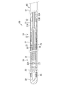
- FIG. 10 is a cross-sectional view of the guide wire 130.
- FIG. 11 is a perspective view of the sensor 133.
- FIG. 12 is a functional block diagram of the measurement apparatus 100.
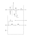
- FIG. 13 is a circuit diagram of the drive circuit 152.
- FIG. 14 is a circuit diagram of the first output circuit 153.
- FIG. 15 is a circuit diagram of the second output circuit 154.
- FIG. 16 is a circuit diagram of the leakage detection circuit 156.
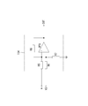
- FIG. 17 is a circuit diagram of the stop circuit 157.
- the blood measuring device 50 shown in FIG. 1 is used for measuring physical quantities such as blood pressure in a blood vessel of a living body, for example.
- the blood measuring device 50 includes a tubular shaft 10 and a tubular tip guide portion 20 provided at the distal end (corresponding to the tip) of the shaft 10.
- the distal end guide portion 20 is provided with a measuring element 27 (see FIG. 2) for measuring blood pressure in the blood vessel.
- a proximal end (corresponding to a base end) of the shaft 10 is connected to a control device 40 as an external device.
- the control device 40 executes control of power supplied to the measurement element 27, processing of signals transmitted from the measurement element 27, and the like.
- the shaft 10 is a flexible tube.
- the shaft 10 has a length suitable for measuring the blood pressure at a desired position of the blood vessel, and is, for example, about 1 to 2 m.
- the shaft 10 is made of, for example, medical stainless steel.
- the outer diameter of the shaft 10 is set according to the thickness of the blood vessel to be inserted, and is, for example, a sufficient number of millimeters.
- the shaft 10 has a shaft main body 11 and a connecting portion 12 formed at the distal end of the shaft main body 11.
- the shaft body 11 is a tubular body having a substantially constant outer diameter in the axial direction.
- the internal space 13A of the shaft body 11 also has a constant inner diameter across the axial direction.
- the connecting portion 12 projects in the axial direction from the distal end of the shaft main body portion 11.
- the connecting portion 12 is formed integrally and coaxially with the shaft main body portion 11.
- “Coaxial” means that the axis of the connecting portion 12 and the axis of the shaft main body 11 are located on the same imaginary straight line. In the following, the term “coaxial” refers to a state in which the axes of a pair of members each having a cylindrical shape are positioned on the same virtual straight line.
- the connecting portion 12 is a tube having a substantially constant outer diameter.
- the outer diameter of the connecting portion 12 is smaller than the outer diameter of the shaft main body portion 11.
- the inner diameter of the connecting portion 12 is larger than the inner diameter of the shaft main body portion 11.
- the internal space 13A of the shaft body 11 and the internal space 13B of the connecting portion 12 are in communication.
- the inner diameter of the internal space 13A of the shaft main body 11 is set in consideration of the outer diameter in a state where the four signal lines 25 to be inserted are bundled and the thickness required for the shaft main body 11.
- the cross section of the connecting portion 12 is C-shaped.
- a slit 14 extending along the axial direction from the distal end to the proximal end of the connecting portion 12 is formed by the C-shaped opening portion continuing in the axial direction.
- the slit 14 occupies a range of about one third with respect to the outer periphery of the connecting portion 12.
- a core material 26 is inserted into the internal space 13B of the connecting portion 12.
- the core material 26 is a flexible wire, and is formed of, for example, stainless steel.
- the outer diameter of the core member 26 is reduced in a tapered shape from the proximal end to the distal end.
- the taper shape of the core member 26 does not need to be formed entirely from the proximal end to the distal end, and may be formed only in a part from the proximal end to the distal end.
- the core material 26 extends from the internal space 13B of the connecting portion 12 toward the distal end, and is inserted into the tip guide portion 20.
- the proximal end of the core member 26 is located between the proximal end and the distal end of the slit 14 of the connecting portion 12.
- the outer diameter near the proximal end of the core member 26 is equal to the inner diameter of the internal space 13B of the connecting portion 12.
- the vicinity of the proximal end of the core member 26 is fitted into and bonded to the internal space 13B of the connecting portion 12.
- the outer diameter near the proximal end of the core member 26 is larger than the inner diameter of the inner space 13 ⁇ / b> A of the shaft body 11.
- the cover member 15 is a tubular body having a constant outer diameter and a constant inner diameter in the axial direction.
- the cover member 15 is made of, for example, a resin such as stainless steel or polyimide.
- the outer diameter of the cover member 15 is equivalent to the outer diameter of the shaft main body 11 in the shaft 10.
- the inner diameter of the cover member 15 is equivalent to the outer diameter of the connecting portion 12 in the shaft 10.
- the dimension along the axial direction of the cover member 15 is shorter than the dimension along the axial direction of the connecting portion 12. Therefore, the cover member 15 protrudes outward of the cover member 15 in a state in which the cover member 15 is externally fitted to the connection portion 12 of the shaft 10.
- the tip guide portion 20 includes a first coil body 21 connected to the distal end of the connecting portion 12, and an element holding body 22 connected to the distal end of the first coil body 21.
- the second coil body 23 is connected to the distal end of the element holding body 22, and the tip member 24 is provided at the distal end of the second coil body 23.
- the element holding body 22, the distal end portion of the first coil body 21, and the proximal end portion of the second coil body 23 are shown in a longitudinal sectional view. For this reason, the element holder 22 is shown in a plan view.
- the first coil body 21 is formed by winding a wire made of stainless steel having a constant diameter, for example, into a spiral shape having a constant diameter.
- the proximal end of the first coil body 21 is fitted to the outside of the distal end of the connecting portion 12.
- the outer diameter of the first coil body 21 is equal to the outer diameter of the cover member 15.
- a core member 26 and four signal lines 25 are inserted in the internal space 21A of the first coil body 21 along the axial direction. Therefore, the inner diameter of the first coil body 21 is sufficiently larger than the outer diameter of the core material 26.
- the element holding body 22 holds the measuring element 27.
- the element holding body 22 has a cylindrical shape and is made of, for example, stainless steel.
- the element holder 22 is coaxially connected to the distal end of the first coil body 21.
- a core member 26 is inserted in the internal space 22D of the element holding body 22 along the axial direction.
- An opening 22 ⁇ / b> A is provided in a part of the peripheral wall of the element holding body 22.
- a support plate 22B on which the measurement element 27 is mounted is provided in the internal space 22D of the element holder 22.
- the support plate 22B is disposed between the core member 26 inserted into the internal space 22D of the element holding body 22 and the opening 22A.
- the support plate 22B has a flat plate shape, and one of the front and back surfaces serving as the maximum surface faces the opening 22A.
- the measuring element 27 is, for example, a pressure sensor.
- the measuring element 27 is mounted on one of the front and back surfaces of the support plate 22B facing the opening 22A.
- the measuring element 27 has a known configuration as a pressure sensor.
- the measuring element 27 has a diaphragm that bends due to pressure and outputs an electrical signal corresponding to the amount of the bend.
- four signal lines 25 are connected to the measurement element 27.
- the four signal lines are used for supplying power to the diaphragm, transmitting an output signal from the diaphragm, and the like.
- the four signal lines 25 extend from the measuring element 27 to the proximal side in the internal space 22D of the element holding body 22.
- the four signal lines 25 are electrically insulated and covered with an outer covering material.
- each signal line 25 is inserted through the inside of the element holding body 22 and through the inside of the first coil body 21 along the axial direction. Further, the four signal lines 25 reach the internal space 13 ⁇ / b> B of the connecting portion 12 through the slit 14 of the connecting portion 12. The four signal lines 25 are inserted along the axial direction from the internal space 13 ⁇ / b> B of the connecting portion 12 through the internal space 13 ⁇ / b> A of the shaft main body 11, and are electrically connected to the control device 40.
- the second coil body 23 is formed, for example, by winding a wire made of stainless steel having a constant diameter into a spiral shape having a constant diameter.
- the proximal end of the second coil body 23 is coaxially connected to the distal end of the element holding body 22.
- a core member 26 is inserted into the second coil body 23 along the axial direction.
- the tip member 24 is formed in a hemispherical shape, for example, from stainless steel.
- the tip member 24 is attached to the distal end of the second coil body 23.
- Connected to the tip member 24 is a tip of a core member 26 inserted through the inside of the second coil body 23.
- the blood measuring device 50 is assembled by assembling the tip guide portion 20 and the core member 26 in advance, and the cover member 15 is externally fitted to the connecting portion 12 of the shaft 10 and these are connected.
- the distal end guide portion 20 is formed by integrally assembling a first coil body 21, an element holding body 22, a second coil body 23, a distal end member 24, and a core member 26. .
- the core material 26 extends from the proximal end of the first coil body 21 to the outside.
- the four signal lines 25 also extend from the proximal end of the first coil body 21 to the outside.
- the cover member 15 is fitted on the connecting portion 12 of the shaft 10.
- the tip guide portion 20 When the tip guide portion 20 is coupled to the shaft 10 and the cover member 15, the four signal lines 25 extending from the tip guide portion 20 enter the internal space 13 ⁇ / b> B through the slits 14 of the connecting portion 12. Further, the shaft body 11 is inserted into the internal space 13A. Then, the core member 26 extending from the distal end guide portion 20 is inserted and fitted into the internal space 13B of the connecting portion 12. The proximal end of the core member 26 is located between the proximal end and the distal end of the slit 14, and the signal line 25 extends in and out of the connecting portion 12 through the slit 14 not blocked by the core member 26. ing.
- the core material 26 and the connecting portion 12 are bonded by an adhesive or the like. Further, the proximal end of the first coil body 21 is fitted to the outside of the distal end of the cover member 15. The first coil body 21, the connecting portion 12, and the cover member 15 are bonded with an adhesive. Thereby, the blood measuring device 50 is assembled.
- the blood measuring device 50 is used, for example, for measuring a change in blood pressure at a predetermined position in the coronary artery.
- the blood measuring device 50 is inserted into the blood vessel with the tip member 24 as the head.
- the blood measuring device 50 inserted into the blood vessel is propelled in the blood vessel by applying a force (propulsive force) toward the distal end to the proximal end of the shaft 10.
- the distal end member 24 inserted into the blood vessel is directed in a predetermined direction by rotating the proximal end of the shaft 10 around the axis.
- the position of the tip member 24 in the blood vessel can be grasped based on the position of the tip member 24 in the X-ray transmission image of the blood vessel.
- the element holder 22 When the tip member 24 is propelled in the blood vessel, the element holder 22 is positioned at a predetermined site in the blood vessel. In such a state, when the proximal end of the shaft body 11 is rotated around the axis, the rotational force applied to the shaft body 11 is connected to the tip guide portion via the connecting portion 12. 20 is transmitted. Thereby, the front end guide portion 20 is rotated around the axis.
- the thickness of the shaft body 11 can be increased.
- the shaft body 11 is less likely to be twisted by the rotational force applied to the shaft body 11.
- the rotation imparted to the shaft body 11 is efficiently transmitted to the tip guide 20.
- the shaft main body part 11, the connecting part 12, and the tip guide part 20 are all configured coaxially. Thereby, the rotational force transmission property of the shaft main body part 11, the connection part 12, and the front-end
- the opening 22 ⁇ / b> A of the element holding body 22 is directed in a predetermined direction by the rotation of the tip guide portion 20. Thereby, the detection surface of the measuring element 27 is also directed in the same direction as the direction in which the opening 22A is directed.
- the blood pressure of the blood flowing in the blood vessel is measured by the measuring element 27.
- the measuring element 27 detects the blood pressure and outputs a predetermined signal to the control device 40 via the signal line 25.
- the control device 40 calculates the blood pressure based on the signal transmitted from the measuring element 27.
- the cover member 15 is externally fitted to the connecting portion 12 of the shaft 10, even if the connection portion between the connecting portion 12 and the core material 26 is bent, the connecting portion 12 is bent to the core material 26. Is unlikely to occur.
- proximal end of the core member 26 is located between the proximal end and the distal end of the slit 14, a space in which the signal line 25 can move is formed in the slit 14. Thereby, even if the connection location of the connection part 12 and the core material 26 is bent, it becomes difficult for the proximal end of the core material 26 and the signal wire
- the connecting portion 12 is formed integrally with the shaft main body portion 11, but the connecting portion of the present invention may be configured as a separate member from the shaft 10.
- the connecting portion of the present invention may be configured as a separate member from the shaft 10.
- the shaft 60 has a shaft main body 61 and a boss 62 formed at the distal end of the shaft main body 61.
- the shaft main body 61 is a tubular body having a substantially constant outer diameter in the axial direction.
- the inner space 63A of the shaft main body 61 has a constant inner diameter over the axial direction.
- the boss portion 62 projects in the axial direction from the distal end of the shaft main body portion 61.
- the boss 62 is formed integrally with the shaft main body 61. Therefore, the internal space 63A of the shaft main body 61 and the internal space 63B of the boss 62 have the same inner diameter.
- the inner diameters of the internal spaces 63A and 63B are set in consideration of the outer diameter in a state where the four signal lines 25 to be inserted are bundled and the wall thickness required for the shaft main body 61.
- the connecting member 30 (an example of a connecting portion) has a connecting body portion 31 and a support portion 32 each having a substantially cylindrical shape.
- the connection main body part 31 and the support part 32 are each comprised as an independent separate member.
- the support part 32 is inserted into the distal end of the connection body part 31 and bonded to the connection body part 31, whereby the connection body part 31 and the support part 32 are integrated.
- the connection main body 31 is a tube having a constant outer diameter and a constant inner diameter in the axial direction.
- the connection main body 31 is formed from a resin such as stainless steel or polyimide.
- the outer diameter of the connection main body 31 is equal to the outer diameter of the shaft main body 61 in the shaft 60.
- the inner diameter of the connection main body portion 31 is equal to the outer diameter of the boss portion 62 in the shaft 60.
- a proximal end of the connection main body portion 31 is fitted to a boss portion 62 of the shaft 60 and is coaxially connected to the shaft 60.
- the outer diameter of the connection main body 31 is equivalent to the outer diameter of the first coil body 21.
- the support part 32 has a C-shaped cross section.
- An opening portion having a C-shaped cross section is continuous in the axial direction, whereby a slit 32A extending along the axial direction over the proximal end and the distal end of the support portion 32 is formed.
- the support portion 32 is made of, for example, stainless steel.
- the slit 32A of the support portion 32 occupies a range of about one third with respect to the outer periphery of the support portion 32.
- the internal space 32B of the support part 32 is equivalent to the outer diameter near the proximal end of the core member 26 described later.
- the outer diameter of the support portion 32 is equal to the inner diameter of the connection main body portion 31.
- the length along the axial direction of the support portion 32 is about half of the length along the axial direction of the connection main body portion 31.
- the proximal end of the support portion 32 is located in the internal space 31 ⁇ / b> A of the connection main body portion 31 and does not reach the proximal end of the connection main body portion 31.
- the proximal end of the support portion 32 is located on the distal end side of the connection main body portion 31 relative to the proximal end. Therefore, there is a space where the support portion 32 does not exist in the vicinity of the proximal end of the internal space 31 ⁇ / b> A of the connection main body 31.
- the core material 26 is inserted into the internal space 32B of the support portion 32.
- the proximal end of the core member 26 is substantially the same position as the proximal end of the support portion 32.
- the outer diameter near the proximal end of the core member 26 is equal to the inner diameter of the internal space 32B of the support portion 32.
- the vicinity of the proximal end of the core member 26 is integrated with the support portion 32 by being inserted into and bonded to the internal space 32B of the support portion 32.
- the outer diameter near the proximal end of the core member 26 is larger than the diameter of the distal end in the inner space 13 ⁇ / b> B of the boss portion 12 in the shaft 10.
- the blood measuring device 50 is assembled by connecting the connecting member 30 to the shaft 60 after the connecting member 30 is connected to the tip guide portion 20 that is assembled in advance.
- the distal end guide portion 20 includes a first coil body 21, an element holding body 22, a second coil body 23, a distal end member 24, and a core member 26 that are assembled together. It will be.
- tip guide part 20 has another structural member, another structural member is also assembled integrally.
- the core material 26 extends from the proximal end of the first coil body 21 to the outside.
- the four signal lines 25 also extend from the proximal end of the first coil body 21 to the outside.
- the four signal lines 25 extending from the distal end guide portion 20 are in the slit 32A of the support portion 32 and in the internal space 31A of the connection main body portion 31. It is inserted and it is made the state extended from the proximal end of the connection main-body part 31 outside. Then, the core member 26 extending from the distal end guide portion 20 is inserted into the internal space 32 ⁇ / b> B of the support portion 32 of the connecting member 30. The core material 26 and the support portion 32 are bonded by an adhesive or the like. Further, the proximal end of the first coil body 21 is fitted to the outside of the distal end of the support portion 32. The first coil body 21, the support part 32, and the connection main body part 31 are bonded together with an adhesive.
- the four signal lines 25 extending from the connection main body 31 of the connection member 30 are the internal space 63 ⁇ / b> A of the shaft main body 61 and the internal space of the boss 62 in the shaft 60.
- 63B is extended from the proximal end of the shaft 60 to the outside.
- the proximal end of the connection main-body part 31 is fitted by the outer side of the boss
- the connection main body part 31 and the boss part 62 are bonded by an adhesive. Thereby, the blood measuring device 50 is assembled.
- connection main body 31 is externally fitted to the support portion 32 of the connection member 30, even if the connection portion between the support portion 32 and the core material 26 is bent, the support portion 32 and the core material 26 are not bent. It is hard to break.
- connection portion 32 is positioned on the distal end side of the connection main body portion 31 in the connection member 30, a space in which the signal line 25 can move is formed on the proximal end side of the connection member 30. Thereby, even if the connecting member 30 is bent, the proximal end of the core member 26 and the signal line 25 are difficult to contact.
- the proximal end of the core member 26 only needs to be located on the distal side of the proximal end of the connection main body 31 in the connection member 30. Therefore, the proximal end of the core member 26 is not limited to the configuration positioned in the internal space 31 ⁇ / b> A of the connection main body portion 31, and may be configured to be positioned in the internal space 32 ⁇ / b> B of the support portion 32.
- the connecting member 30 may not have a configuration in which the connecting main body portion 31 and the support portion 32 are individually configured, and the supporting portion 32 is inserted into the connecting main body portion 31. That is, the structure by which the connection main-body part 31 and the support part 32 are shape
- molded integrally may be sufficient.
- the passage according to the present invention is formed by the slit 14 formed in the connecting portion 12 or the slit 32A formed in the support portion 32.
- a core material A groove extending in the axial direction may be formed on the outer peripheral surface of the proximal end of 26, and the inner space of this groove may be a passage through which the signal line 25 is inserted.
- the number of slits and grooves is not limited to one, and a plurality of slits and grooves may be formed, and each signal line 25 may be divided and inserted.
- the measuring element 27 held by the element holding body 22 is not limited to the pressure sensor, but may be any element that can measure the physical quantity of blood in the blood vessel.
- the measurement element 27 may be, for example, a flow rate sensor that measures the flow rate of blood in the blood vessel, a flow rate sensor that measures the flow rate of blood flow in the blood vessel, a temperature sensor that measures the temperature of blood, and the like.
- the number of signal lines connected to the measuring element 27 is not limited to four, and may be two, three, or five or more.
- the measuring element 27 is not limited to a configuration that electrically measures information related to a physical quantity of blood, but may be a configuration that optically measures. In this case, an optical fiber is used as the signal line 25.
- tip guide part 20 has the 1st coil body 21 and the 2nd coil body 23, and two coil bodies, the measurement element 27 is provided in the element holding body 22, and the 2nd coil body 23 is provided.
- the tip member 24 is provided at the tip of the head.
- the distal end guide portion 20 is not limited to the configuration shown in the embodiment, and the distal end guide portion 20 is configured by one coil body and a distal end member provided at the distal end of the coil body. It is good also as a structure by which the measurement element 27 is provided in the inside.
- blood measurement apparatus 50 is not limited to a configuration used as a guide wire, and may be configured as a catheter.
- the measuring device 100 is shown in FIG.
- the measuring device 100 is a device that measures the flow velocity of blood flowing in a human blood vessel.
- An AC-DC adapter 111 and a personal computer 112 are connected to the measuring apparatus 100 via a cable 113.
- the blood flow rate is an example of a physical quantity of blood.
- the AC-DC adapter 111 is a converter that converts a commercial AC voltage (for example, AC 100V) into a DC voltage (for example, DC 15V) and outputs the converted voltage. Note that the AC-DC adapter 111 may be incorporated in the measurement apparatus 100 and be a part of the measurement apparatus 100.
- Analysis software is installed in the personal computer 112.
- the analysis software analyzes the signal input from the measuring apparatus 100 to the personal computer 112 and displays it on the monitor.
- the measuring apparatus 100 includes a main body 120 to which an AC-DC adapter 111 and a personal computer 112 are connected, and a guide wire 130 connected to the main body 120.
- the guide wire 130 corresponds to a long member.
- the main body 120 includes a power switch 121 for turning on / off a power input from the AC-DC adapter 111, a sensor connector 122 to which a guide wire 130 is connected, and a function switch 123 on the front side.
- the main body 120 also includes an external output connector 115 (FIG. 12) for connection with the cable 113 and a power connector 114 (FIG. 12) to which the AC-DC adapter 111 is connected on the back side.
- the main body 120 includes a control circuit 150 (FIG. 12) in the housing. The control circuit 150 will be described later. *
- the guide wire 130 includes a connection connector 131 connected to the sensor connector 122 of the main body 120, a shaft 132 extending from the connection connector 131, and a sensor 133 disposed at the tip of the shaft 132.
- the guide wire 130 is attached to the main body 120 for each measurement (treatment).
- the above-mentioned “tip” means an end opposite to the end (base end) where the connection connector 131 is provided.
- the shaft 132 is thick enough to be inserted into a human blood vessel and has a length that allows the tip to reach a measurement site such as a chest from an insertion site such as a limb.
- the shaft 132 is formed, for example, by spirally winding a stainless steel, and can be bent according to the curvature of the blood vessel.
- the shaft 132 has a cylindrical shape and is hollow.
- a linear core wire 135 (FIG. 11)
- a plurality of conducting wires 136 and a thermocouple 137 are arranged in the hollow shaft 132.
- the thermocouple 137 corresponds to a detection body.
- One end (base end) of the conducting wire 136 and the thermocouple 137 is connected to a terminal of the connection connector 131 (FIG. 9).
- the conducting wire 136 and the thermocouple 137 are electrically connected to the control circuit 150 (FIG. 12) via the connection connector 131 and the sensor connector 122.
- the other ends (tips) of the conducting wire 136 and the thermocouple 137 extend to the tip of the guide wire 130 and are connected to the sensor 133.
- the sensor 133 includes a holder 141, a bobbin 142 held by the holder 141, a heater 143 wound around the bobbin 142, and a detection electrode 144 for detecting leakage (FIG. 11).
- the holder 141 has a cylindrical shape that is substantially the same diameter as the shaft 132.
- the holder 141 is arranged at the tip end of the shaft 132 with its axis line coinciding with the axis line of the shaft 132.
- the holder 141 is fixed to the shaft 132 with an adhesive or the like.
- the holder 141 has an opening 145 in the peripheral wall.
- the opening 145 is provided along the axial direction of the holder 141 (the left-right direction in FIG. 10).
- the heater 143 is cooled by the blood flow through the opening 145, and the flow velocity is measured. Details will be described later.
- the bobbin 142 around which the heater 143 is wound is disposed in the holder 141.
- the bobbin 142 has a cylindrical shape and is arranged in the holder 141 with its axis line coincided with the axis line of the holder 141.
- the heater 143 is spirally wound around the outer peripheral surface of the bobbin 142.
- the heater 143 is, for example, a resistance wire such as a nickel wire or a platinum wire.
- One end (the right end in FIG. 11) of the heater 143 is connected to the tip of one conductor 136.
- the other end of the heater 143 (the left end in FIG. 11) is connected to the tip of another conductor 136.
- the other lead wire 136 passes through the bobbin 142 to the left end of the bobbin 142 and is connected to the other end of the heater 143.
- the heater 143 is supplied with a direct current by the two conductive wires 136 and generates heat.
- the detection electrode 144 is an electrode for detecting a leakage current from the sensor 133 to the blood.
- the detection electrode 144 is disposed on the outer peripheral surface of the bobbin 142 at a position facing the opening 145.
- a metal piece fixed to the bobbin 142 or a metal foil deposited on the bobbin 142 can be used.
- the detection electrode 144 is connected to the tip of a conductor 136 different from the conductor 136 connected to the heater 143. If a leakage current occurs in the blood, the detection electrode 144 detects the leakage current. Details will be described later.
- thermocouple 137 The tip of a thermocouple 137 is attached to the outer peripheral surface of the bobbin 142 together with the detection electrode 144.
- the tip of the thermocouple 137 is disposed at a position facing the opening 145. Therefore, the thermocouple 137 can output a voltage corresponding to the blood temperature. This output voltage is used to correct the flow velocity.
- a sealing member 146 is filled in the holder 141 to insulate the heater 143 and the thermocouple 137 from the blood and to fix the heater 143 and the bobbin 142.
- the sealing member 146 is made of an insulating material.
- the material of the sealing member 146 for example, silicon, epoxy, polyamide, polyimide, high density polyethylene, or the like is used.
- a configuration in which the detection electrode 144 is not covered by the sealing member 146 is employed so that the leakage current can be detected. For example, an opening or a notch for exposing the detection electrode 144 is provided in the sealing member 146.
- a constant direct current (constant current) is supplied from the main body 120 to the heater 143 via the two conductive wires 136. Then, the heater 143 generates heat. Due to heat generation, the temperature of the heater 143 rises. Due to this temperature rise, the resistance value of the heater 143 changes. That is, the resistance value of the heater 143 changes due to the supply of the direct current. The change in the resistance value depends on the current value of the supplied direct current.
- the heater 143 is cooled by the blood flow.
- the resistance value of the heater 143 changes according to the degree of cooling. This degree of cooling depends on the blood flow velocity. That is, the resistance value of the heater 143 also depends on the blood flow rate.
- the change in the resistance value of the heater 143 depends on the current value of the supplied direct current and the blood flow velocity.
- the current value of the supplied direct current is known (set value). Therefore, if the set value is subtracted from the voltage of the heater 143, a voltage corresponding to the blood flow velocity can be obtained. The flow rate can be calculated from this voltage.
- the sensor 133 is a hot-wire anemometer that measures the blood flow velocity.
- the control circuit 150 is realized by a pattern circuit board (not shown) disposed in the main body 120 and various electronic components such as an integrated circuit (IC) mounted on the circuit board, a resistor, a diode, a capacitor, and a transistor. Is done.
- IC integrated circuit
- a single circuit board may be used, or a plurality of circuit boards connected to each other by lead wires may be used.
- the control circuit 150 includes a power supply circuit 151, a drive circuit 152, a first output circuit 153 that outputs a heater voltage, a second output circuit 154 that outputs a flow velocity, a temperature compensation circuit 155, and a leakage detection circuit 156. And a stop circuit 157.
- the power supply circuit 151 is a DC-DC converter that converts a DC voltage having a constant voltage value into a DC voltage having another constant voltage value.
- the power supply circuit 151 has an input end and one or more output ends. This input end is electrically connected to the power connector 114 via the power switch 121 described above.
- the AC-DC adapter 111 described above is electrically connected to the power connector 114. That is, a constant DC voltage is input from the AC-DC adapter 111 to the power supply circuit 151.
- the above-mentioned “electrically connected” means conducting by a circuit board pattern or a lead wire.
- the power supply circuit 151 converts, for example, an input 15V DC voltage into 5V, 10V, 12V, or the like.
- the power supply circuit 151 can be configured using one or more so-called power supply ICs such as a switching regulator and a series regulator. Further, an insulation type using a transformer may be used for circuit protection or the like. In addition, a simple constant voltage circuit using a Zener diode or the like may be additionally used.
- the drive circuit 152 is a drive circuit that drives the heater 143.
- the drive circuit 152 is configured by a constant current circuit using negative feedback of an operational amplifier, and outputs a constant DC current (constant current).
- the driving circuit 152 includes two voltage dividing resistors R2 and R3, an operational amplifier OP1, a transistor TR1, a determining resistor R1 that determines a current value, and a protective capacitor C1.
- One end of the protective capacitor C ⁇ b> 1 is connected to a constant voltage V ⁇ b> 1 that is one of output terminals of the power supply circuit 151.
- the other end of the protective capacitor C1 is grounded.
- the protective capacitor C1 reduces the inrush current when the power switch 121 is turned on.
- the two voltage dividing resistors R2 and R3 are connected in series, connected to the constant voltage V1 (and the protective capacitor C1) at one end on the voltage dividing resistor R2 side, and grounded at the other end on the voltage dividing resistor R3 side.
- the two voltage dividing resistors R2 and R3 divide the constant voltage V1 and output a divided voltage from the connection point of the two voltage dividing resistors R2 and R3.
- connection point of the two voltage dividing resistors R2 and R3 is connected to the positive terminal (+) of the operational amplifier OP1. That is, the divided voltage is input to the positive terminal (+) of the operational amplifier OP1.
- the output terminal of the operational amplifier OP1 is connected to the gate of the transistor TR1.
- the negative terminal ( ⁇ ) of the operational amplifier OP1 is connected to the emitter of the transistor TR1 and grounded via the decision resistor R1.
- the constant voltages V1 and V2 may be different or the same. Further, a variable resistor may be connected in series with the determining resistor R1 for adjusting the current value. Further, the constant voltage from the power supply circuit 151 may be directly input to the positive terminal (+) of the operational amplifier OP1 without dividing the constant voltage V1.
- the first output circuit 153 shown in FIG. 14 is a circuit that detects the voltage (heater voltage) at the collector terminal (terminal a in FIG. 13) of the transistor TR1.
- a voltage follower using an operational amplifier OP2 is used for the first output circuit 153. Specifically, the positive terminal (+) of the operational amplifier OP2 is connected to the a terminal via the protective resistor R4, and the negative terminal ( ⁇ ) is connected to the output terminal. Therefore, the operational amplifier OP2 outputs a voltage equal to the a-terminal voltage.
- the output terminal of the operational amplifier OP2 is electrically connected to one of the terminals of the external output connector 115 (FIG. 12) provided on the back side of the main body 120. That is, the first output circuit 153 outputs the heater voltage to the outside. The reason why the voltage follower is used in the first output circuit 153 is to perform impedance conversion for external output. In order to remove noise, the output terminal of the operational amplifier OP2 is grounded via the capacitor C2.
- the second output circuit 154 shown in FIG. 15 is a circuit that detects a change in the heater voltage.
- a differential amplifier circuit using an operational amplifier OP3 is used for the second output circuit 154. More specifically, the second output circuit 154 includes an operational amplifier OP3, three protection resistors R5, R6, R7, and a determination resistor R8.
- the positive terminal (+) of the operational amplifier OP3 is connected to the a terminal via the protective resistor R5.
- the negative terminal ( ⁇ ) of the operational amplifier OP3 is connected to the constant voltage V3, which is one of the output terminals of the power supply circuit 151, via the protective resistor R6, and is grounded via the protective resistor R7.
- the decision resistor R8 is connected between the positive terminal (+) and the negative terminal ( ⁇ ) of the operational amplifier OP3.
- the operational amplifier OP3 amplifies and outputs the difference between the heater voltage and the constant voltage V3 with an amplification factor corresponding to the determining resistor R8.
- the constant voltage V3 is set to a voltage equal to the heater voltage when the heater 143 is not cooled by the blood flow, for example.
- the constant voltage V3 may be set to another voltage value.
- the constant voltage V3 may be the same voltage as the constant voltage V1 or the constant voltage V2.
- a voltage obtained by dividing the output voltage from the power supply circuit 151 by a voltage dividing resistor may be used as the constant voltage V3.
- the second output circuit 154 configured as described above amplifies and outputs the change in the heater voltage from the reference value (V3).
- This change corresponds to the flow velocity. That is, the second output circuit 154 outputs a voltage corresponding to the blood flow rate. More specifically, as described above, the heater voltage has a value corresponding to the current value of the supplied direct current and the blood flow velocity.
- the reference value (V3) described above corresponds to the current value of the supplied direct current. Therefore, the above-described change corresponds to the blood flow velocity, and the second output circuit 154 outputs a voltage corresponding to the blood flow velocity.
- the output terminal of the operational amplifier OP3 of the second output circuit 154 is electrically connected to one of the external output connectors 115. That is, the second output circuit 154 outputs a voltage corresponding to the blood flow rate to the outside (the personal computer 112).
- the temperature compensation circuit 155 is an amplifier circuit that amplifies the output voltage of the thermocouple 137 and outputs it to the outside.
- the temperature compensation circuit 155 converts and amplifies 0 ° C. to 50 ° C. to a voltage of 0V to 50V and outputs the voltage. Since the temperature compensation circuit 155 can employ a general configuration, a detailed description thereof is omitted, but for example, an amplifier circuit using an operational amplifier can be used as the temperature compensation circuit 155.
- a variable resistor for correction may be provided in the temperature compensation circuit 155 in order to make 0 ° C. correspond to 0V and make 50 ° C. correspond exactly to 50V.
- thermocouple compensation circuit is provided in the temperature compensation circuit 155 or the personal computer 112 calculates the temperature compensation of the thermocouple 137 itself from a predetermined calculation formula. May be performed.
- the (blood) temperature detected by the thermocouple 137 is used to correct the flow rate.
- the leakage detection circuit 156 that detects the leakage current will be described.
- the leakage detection circuit 156 includes a first detection circuit 161 and a second detection circuit 162.
- the first detection circuit 161 is a circuit that detects a leakage current from the heater 143 into the blood.
- the second detection circuit 162 is a circuit that detects a leakage current from the entire guide wire 130 into the blood.
- the first detection circuit 161 includes a first shunt resistor Rs1, an operational amplifier OP4 that amplifies the voltage across the first shunt resistor Rs1, and a first comparator COM1 that compares the output of the operational amplifier OP4 with the constant voltage V2.
- One end (a end) of the first shunt resistor Rs1 is connected to a connection point (a end in FIG. 12) between the heater 143 and the transistor TR1, and the other end is grounded. Therefore, a voltage having a magnitude corresponding to the feedback current from the heater 143 is generated in the first shunt resistor Rs1.
- This voltage is amplified by the operational amplifier OP4, and is compared with V2 which is a voltage corresponding to the input current (V2 / R1) to the heater 143 in the first comparator COM1. That is, the first comparator COM1 compares the input current and the feedback current.
- the negative terminal ( ⁇ ) of the first comparator COM1 may be connected to a constant voltage other than the constant voltage V2, and the constant voltage may be a comparison target.
- the first comparator COM1 outputs 0V until the leakage current from the heater 143 exceeds the threshold, and outputs a constant voltage when the leakage current from the heater 143 exceeds the threshold.
- the threshold is determined by the resistance value of the first shunt resistor Rs1, the amplification degree of the operational amplifier OP4, and the constant voltage V2.
- the first detection circuit 161 determines that the leakage current from the heater 143 into the blood exceeds a certain value, and outputs a certain voltage (first detection signal).
- the first detection signal is output from the end c of FIG. 16 and input to a stop circuit 157 (FIG. 17) described later.
- the first detection signal changes the voltage at the output terminal (OUT) of the first detection circuit 161. More specifically, the output terminal of the first comparator COM1 is connected to the base of a transistor TR2 as a switching element. The emitter of this transistor TR2 is grounded. The collector of the transistor TR2 is connected to the constant voltage V4. The collector of the transistor TR2 is electrically connected to one of the external output connectors 115. The transistor TR2 is turned on or off depending on whether or not the first comparator COM1 outputs the first detection signal. As a result, the output voltage to the external output connector 115 becomes the constant voltage V4 or 0V.
- the constant voltage V4 may be the same voltage as V1, V2, or V3, or may be different. Further, a backflow prevention diode D1 is connected between the collector and emitter of the transistor TR2.
- the second detection circuit 54 includes a second shunt resistor Rs2, an operational amplifier OP5 that amplifies and outputs the voltage across the second shunt resistor Rs2, and a second comparator COM2 that compares the output of the operational amplifier OP5 with the constant voltage V2. Is provided.
- One end of the second shunt resistor Rs2 is connected to the above-described detection electrode 144, and the other end is grounded (earthed). Therefore, a voltage corresponding to the leakage current from the entire guide wire 130 into the blood is generated in the second shunt resistor Rs2.
- This voltage is amplified by the operational amplifier OP5 and compared with the constant voltage V2 in the second comparator COM2.
- the negative terminal ( ⁇ ) of the second comparator COM2 may be connected to a constant voltage other than the constant voltage V2, and the constant voltage may be a comparison target.
- the second comparator COM2 outputs 0V until the leakage current exceeds the threshold value, and outputs a constant voltage when the leakage current exceeds the threshold value.
- the threshold value is determined by the resistance value of the second shunt resistor Rs2, the amplification factor of the operational amplifier OP6, and the constant voltage V2.
- the second detection circuit 162 determines that the leakage current from the entire guide wire 130 into the blood exceeds a certain value, and outputs a certain voltage (second detection signal). This second detection signal is output from the d end of FIG. 16 and input to a stop circuit 157 (FIG. 17) described later.
- the second detection signal changes the voltage at the output terminal (OUT) of the second detection circuit 162.
- the output terminal of the second comparator COM2 is connected to the base of the transistor TR3 as a switching element.
- the emitter of this transistor TR3 is grounded.
- the collector of the transistor TR3 is connected to the constant voltage V4.
- the collector of the transistor TR3 is electrically connected to one of the external output connectors 115.
- the transistor TR3 is turned on or off depending on whether or not the second comparator COM2 outputs the second detection signal, and as a result, the output voltage to the external output connector 115 becomes the constant voltage V4 or 0V.
- the constant voltage V4 may be the same voltage as V1, V2, or V3, or may be different.
- a backflow prevention diode D2 is connected between the collector and emitter of the transistor TR3.
- the detection signals (first detection signal and second detection signal) output from the leakage detection circuit 156 are input to the stop circuit 157 shown in FIG.
- the stop circuit 157 stops the drive of the drive circuit 152 when the detection signal is input.
- the stop circuit 157 includes a transistor TR4 that is a switching element, a signal maintaining capacitor C3, and a discharging resistor R9.
- the gate of the transistor TR4 is connected to the c terminal of the first detection circuit 161 and the d terminal of the second detection circuit 162 via the function switch 123.
- the transistor TR4 is turned on by a detection signal output from the first detection circuit 161 or the second detection circuit 162. That is, the transistor TR4 is turned on when one of the first detection circuit 161 and the second detection circuit 162 detects a leakage current while the function switch 123 is turned on.
- the collector (b end) of the transistor TR4 is connected to the b end (FIG. 13) of the drive circuit 152.
- the emitter of the transistor TR4 is grounded. Therefore, when the leakage detection circuit 156 detects the leakage current and the transistor TR4 is turned on, the positive terminal (+) of the operational amplifier OP1 of the drive circuit 152 is grounded. That is, the current supply to the heater 143 is stopped.
- One end of the signal maintaining capacitor C3 is connected to the gate of the transistor TR4, and the other end is grounded. Therefore, the signal maintaining capacitor C3 is charged by the detection signal when the leakage detection circuit 156 detects leakage.
- the discharging resistor R9 is connected in parallel with the signal maintaining capacitor C3. The electric charge stored in the signal maintaining capacitor C3 is discharged through the discharging resistor R9.
- the transistor TR3 When the signal maintenance capacitor C3 is charged by the detection signal from the leakage detection circuit 156, the transistor TR3 is kept on for a certain period of time even after the leakage detection circuit 156 stops outputting the detection signal. That is, even after the detection signal is stopped, the supply of current to the heater 143 is stopped for a certain time.
- the predetermined time is determined by the capacitance of the signal maintaining capacitor C3 and the resistance value of the discharging resistor R9.
- the stop circuit 157 is connected to diodes D3 and D4 for circuit protection.
- the guide wire 130 is inserted into a human blood vessel.
- a measurement site for example, a coronary artery
- the power switch 121 and the function switch 123 of the main body 120 are turned on, and the sensor 133 is driven. That is, a constant current is supplied from the drive circuit 152 to the heater 143.
- the first output circuit 153 outputs a heater voltage
- the second output circuit 154 outputs a voltage corresponding to the blood flow velocity
- the temperature compensation circuit 155 amplifies and converts the output of the thermocouple 137. And output.
- the leakage detection circuit 156 monitors the presence or absence of leakage.
- the first detection circuit 161 monitors the leakage current from the heater 143 to the blood
- the second detection circuit 162 monitors the leakage current from the guide wire 130 to the blood.
- the power switch 121 and the function switch 123 may be turned on before the guide wire 130 is inserted into a human blood vessel.
- the heater voltage detected by the first output circuit 153, the voltage (flow velocity voltage) output by the second output circuit 154, and the signal voltage output when the leakage detection circuit 156 detects a leakage are output from the external output connector 115. Is output and input to the personal computer 112 via the cable 113.
- the flow velocity is calculated from the flow velocity voltage by the installed analysis software. This “calculation” includes calculation based on a calculation formula (previously stored in the analysis software) and determination of the flow velocity using a flow velocity determination table (previously stored in the analysis software) representing the correspondence between the flow velocity voltage and the flow velocity. It is.
- the calculated flow velocity is corrected by the input voltage input from the temperature compensation circuit 155.
- the correction value is calculated by a calculation formula input in advance, or the correction value is determined using a conversion table representing the correspondence relationship between the input voltage and the correction value.
- the flow rate is corrected by the determined correction value.
- the corrected flow velocity and the above heater voltage are displayed on the monitor.
- the leakage detection circuit 156 detects a leakage
- the supply of constant current to the heater 143 is stopped, and a signal voltage that indicates that the leakage has been detected is input to the personal computer 112 to detect the leakage. Is displayed on the monitor, or a warning sound is emitted.
- the blood pressure may be calculated from the calculated flow velocity, and the calculated pressure may be displayed on the monitor.
- the measuring apparatus 100 can detect that a certain leakage current has occurred by the leakage detection circuit 156. In addition, it is possible to output the fact that the leakage current has been detected to the outside and display it on a monitor or to emit a warning sound.
- the function switch 123 since the function switch 123 is provided, when it is not appropriate to stop the driving of the sensor 133 or when it is desired to restart the driving of the sensor 133, the driving stop function of the sensor 133 by the stop circuit 37 is turned off. be able to.
- thermocouple 137 and the temperature compensation circuit 155 are provided, it is possible to perform correction relating to the temperature of the calculated flow velocity.
- both the first detection circuit 161 and the second detection circuit 162 are provided in the leakage detection circuit 156, both leakage from the heater 143 and leakage from the entire guide wire 130 are detected. It can be detected separately.
- the stop circuit 157 since the stop circuit 157 is provided, the current supply to the heater 143 is immediately stopped when a leakage is detected. Further, since the signal maintaining capacitor C3 is provided, it is possible to prevent the current supply to the heater 143 from being frequently turned on / off (chattering).
- the leakage detection circuit 156 includes the first detection circuit 161 and the second detection circuit 162 has been described.
- the leakage detection circuit 156 may include only the first detection circuit 161 or only the second detection circuit 162.
- the configuration in which the signal voltage from the first detection circuit 161 and the signal voltage from the second detection circuit 162 are individually input to the personal computer 112 has been described. However, only the signal voltage from the first detection circuit 161 or only the signal voltage from the second detection circuit 162 may be input to the personal computer 112. Further, if the output terminal of the first detection circuit 161 and the output terminal of the second detection circuit 162 are connected and at least one of the first detection circuit 161 and the second detection circuit 162 detects a leakage, the personal computer A configuration may be adopted in which a signal voltage for transmitting that the leakage has been detected is input to 112.
- the configuration in which the personal computer 112 corrects and calculates the flow velocity has been described.
- the calculation and correction of the flow velocity may be performed in the control circuit 150.
- the flow velocity may be corrected and calculated by converting the output of the thermocouple 137 into an appropriate voltage using an amplifier circuit and inputting the converted voltage and the heater voltage to the differential amplifier circuit. A voltage corresponding to the flow velocity corrected and calculated in this way is output to the personal computer 112 via the external output connector 115.
- thermocouple 137 is provided on the guide wire 130 .
- a reference heater may be provided instead of the thermocouple 137.
- a reference heater having the same configuration as the heater 143 is used. Similar to the heater 143, the reference heater is provided at the tip of the guide wire 130. However, the reference heater is provided so as not to be exposed to blood. Therefore, the voltage of the reference heater does not depend on the blood flow velocity but becomes a value dependent on the blood temperature.
- the voltage of the reference heater is output from the temperature compensation circuit 155 to the outside.
- the personal computer 112 determines a correction value based on the voltage of the reference heater and corrects the flow velocity. Similar to the thermocouple 137, the reference heater corresponds to a detector used for temperature compensation.
- control circuit 150 can be performed by the control circuit 150 without being performed by the personal computer 112.
- a differential amplifier circuit that amplifies and outputs the difference between the voltage of the heater 143 and the voltage of the reference heater is provided in the control circuit.
- thermocouple 137 In the third embodiment, the configuration in which the flow velocity is corrected by the thermocouple 137 has been described. However, a configuration in which the thermocouple 137 is not provided can be employed. For example, assuming that the blood temperature is a predetermined value, the flow velocity may be corrected with a correction value corresponding to the predetermined value. Alternatively, the body temperature of the patient may be measured before the operation, and the flow velocity may be corrected with a correction value corresponding to the measured body temperature.
- an example has been described in which when the leakage current is detected, the driving of the sensor 133 is stopped for a certain time by the signal maintaining capacitor C3.
- another configuration for example, a configuration in which once the leakage current is detected, the driving of the sensor 133 is stopped unless the manual return is performed.
- an electromagnetic relay that can be manually restored may be provided in the stop circuit 157.
- the configuration in which the supply of constant current from the drive circuit 152 to the heater 143 is stopped when a leakage current is detected has been described.
- the power switch 121 itself may be turned off.
- the configuration for calculating and displaying the flow velocity using the personal computer 112 has been described.
- the personal computer 112 may not be used.
- a microcomputer that replaces the analysis software is provided in the control circuit 150
- a liquid crystal display that replaces the monitor is provided in the main body 120
- a display driver IC and the like are further provided in the control circuit 150.
- this configuration it is not necessary to connect the personal computer 112 to the main body 120, and the main body 120 displays the heater voltage, the flow velocity, the presence / absence of leakage detection, and the like on the liquid crystal display.
- control circuit 150 of the present invention can also be used for a current meter other than the sensor 133 described in the above embodiment, a blood pressure sensor such as the measuring element 27, and the like.
- the measurement of blood pressure and flow velocity may be performed constantly or intermittently.
- the drive circuit 152 may always output a constant current or intermittently output a constant current.
- a switching element is provided at the output terminal of the driving circuit 152, and a driving signal having a constant frequency is input to the switching element to turn the switching element on and off.
- the drive circuit 152 intermittently outputs a constant current.
- an intermittent constant current can be output using existing technology.
- Measurement accuracy is improved by measuring blood pressure and flow rate intermittently. More specifically, when a leakage current occurs, the voltage level of the reference voltage may shift.
- the reference voltage is a ground or a generated constant voltage. When the voltage level shifts, the detection accuracy decreases. By outputting the constant current intermittently, a shift in the voltage level of the reference voltage is suppressed. As a result, the accuracy of measurement is improved.
- variable the duty ratio which is a ratio of the period which outputs a constant current, and the period which does not output a constant current.
- An existing technique can be used as the technique for changing the duty ratio.
- the duty ratio can be changed from the outside by a potentiometer (digital variable resistor) or the like. For example, when the leakage current amount is large, the duty ratio is decreased, and when the leakage current amount is small, the duty ratio is increased.
Abstract
Priority Applications (5)
| Application Number | Priority Date | Filing Date | Title |
|---|---|---|---|
| JP2018509326A JP6864839B2 (ja) | 2016-03-29 | 2017-03-27 | センサの制御回路及び血液計測装置 |
| EP17774900.9A EP3437552A4 (fr) | 2016-03-29 | 2017-03-27 | Circuit de commande de capteur et dispositif de mesure du sang |
| US16/083,919 US11589763B2 (en) | 2016-03-29 | 2017-03-27 | Sensor control circuit and blood measurement device |
| CN201780021665.2A CN109069041B (zh) | 2016-03-29 | 2017-03-27 | 传感器的控制电路及血液测量装置 |
| US18/101,639 US20230172469A1 (en) | 2016-03-29 | 2023-01-26 | Sensor Control Circuit |
Applications Claiming Priority (4)
| Application Number | Priority Date | Filing Date | Title |
|---|---|---|---|
| JP2016-066022 | 2016-03-29 | ||
| JP2016066022 | 2016-03-29 | ||
| JP2016-066020 | 2016-03-29 | ||
| JP2016066020 | 2016-03-29 |
Related Child Applications (2)
| Application Number | Title | Priority Date | Filing Date |
|---|---|---|---|
| US16/083,919 A-371-Of-International US11589763B2 (en) | 2016-03-29 | 2017-03-27 | Sensor control circuit and blood measurement device |
| US18/101,639 Division US20230172469A1 (en) | 2016-03-29 | 2023-01-26 | Sensor Control Circuit |
Publications (1)
| Publication Number | Publication Date |
|---|---|
| WO2017170363A1 true WO2017170363A1 (fr) | 2017-10-05 |
Family
ID=59965503
Family Applications (1)
| Application Number | Title | Priority Date | Filing Date |
|---|---|---|---|
| PCT/JP2017/012328 WO2017170363A1 (fr) | 2016-03-29 | 2017-03-27 | Circuit de commande de capteur et dispositif de mesure du sang |
Country Status (5)
| Country | Link |
|---|---|
| US (2) | US11589763B2 (fr) |
| EP (1) | EP3437552A4 (fr) |
| JP (2) | JP6864839B2 (fr) |
| CN (2) | CN109069041B (fr) |
| WO (1) | WO2017170363A1 (fr) |
Families Citing this family (3)
| Publication number | Priority date | Publication date | Assignee | Title |
|---|---|---|---|---|
| EP4342366A2 (fr) | 2014-04-04 | 2024-03-27 | St. Jude Medical Systems AB | Systèmes, dispositifs et procédés de diagnostic de données de débit et de pression intravasculaire |
| KR102190440B1 (ko) * | 2019-06-03 | 2020-12-14 | (주)플로트론 | 열식 질량 유량계 |
| US11860197B2 (en) * | 2020-12-22 | 2024-01-02 | Nxstage Medical, Inc. | Leakage current management systems, devices, and methods |
Citations (7)
| Publication number | Priority date | Publication date | Assignee | Title |
|---|---|---|---|---|
| JPS5565006U (fr) * | 1978-10-26 | 1980-05-06 | ||
| JPS63216534A (ja) * | 1987-03-05 | 1988-09-08 | テルモ株式会社 | 漏れ電流を自動認識する生体情報測定装置 |
| JP2001504249A (ja) | 1996-11-20 | 2001-03-27 | エヌ・ヴェ・レイケム・ソシエテ・アノニム | 光ファイバのオーガナイザ |
| JP2007296354A (ja) | 2006-04-28 | 2007-11-15 | Radi Medical Systems Ab | センサ・ガイドワイヤ組立体 |
| JP2008522717A (ja) * | 2004-12-13 | 2008-07-03 | ボストン サイエンティフィック リミテッド | 犠牲構造体を用いて形成される医療器具とその製造方法 |
| JP2012183239A (ja) * | 2011-03-07 | 2012-09-27 | Terumo Corp | 保護シース |
| JP2015501184A (ja) * | 2011-10-28 | 2015-01-15 | スリー リバース カーディオバスキュラー システムズ インコーポレイテッド | 血圧勾配を計測するための装置、システム、および方法 |
Family Cites Families (15)
| Publication number | Priority date | Publication date | Assignee | Title |
|---|---|---|---|---|
| EP0011080A1 (fr) | 1978-11-10 | 1980-05-28 | Günter Horst Röhm | Mandrin de serrage à mâchoires réglables radialement par rapport à l'axe du mandrin, dans le corps du mandrin |
| US5139021A (en) * | 1987-03-05 | 1992-08-18 | Terumo Kabushiki Kaisha | Biological information measurement apparatus |
| SE9600334D0 (sv) | 1996-01-30 | 1996-01-30 | Radi Medical Systems | Combined flow, pressure and temperature sensor |
| US6142958A (en) * | 1998-12-23 | 2000-11-07 | Radi Medical Systems Ab | Sensor and guide wire assembly |
| NL1012223C2 (nl) * | 1999-06-03 | 2000-12-06 | Martil Instr B V | Hartgangmaker alsmede gangmakereenheid en elektrische draad daarvoor. |
| US6672172B2 (en) * | 2000-01-31 | 2004-01-06 | Radi Medical Systems Ab | Triggered flow measurement |
| IL196660A (en) * | 2008-01-23 | 2014-09-30 | Mediguide Ltd | Flexible conductive catheter with sensor |
| WO2010089923A1 (fr) * | 2009-02-09 | 2010-08-12 | オリンパスメディカルシステムズ株式会社 | Tube médical |
| JP2012176113A (ja) * | 2011-02-25 | 2012-09-13 | Fujifilm Corp | 内視鏡 |
| US20140180141A1 (en) * | 2012-12-21 | 2014-06-26 | Volcano Corporation | Mounting Structures for Components of Intravascular Devices |
| CN105636507B (zh) * | 2013-10-14 | 2019-06-25 | 火山公司 | 血管内装置、系统和方法 |
| EP3060105A2 (fr) * | 2013-10-25 | 2016-08-31 | St. Jude Medical Coordination Center BVBA | Dispositif de fil guide de capteur et système comprenant un dispositif de fil guide de capteur |
| US10537255B2 (en) * | 2013-11-21 | 2020-01-21 | Phyzhon Health Inc. | Optical fiber pressure sensor |
| EP3166478A4 (fr) | 2014-07-13 | 2018-02-14 | Three Rivers Cardiovascular Systems Inc. | Système et appareil comprenant un fil-guide à capteurs multiples à utiliser dans des interventions de cardiologie interventionnelle |
| EP3357413A1 (fr) * | 2014-08-28 | 2018-08-08 | Koninklijke Philips N.V. | Dispositifs intravasculaires avec élément de marqueur radio-opaque à pas variable |
-
2017
- 2017-03-27 WO PCT/JP2017/012328 patent/WO2017170363A1/fr active Application Filing
- 2017-03-27 CN CN201780021665.2A patent/CN109069041B/zh active Active
- 2017-03-27 US US16/083,919 patent/US11589763B2/en active Active
- 2017-03-27 JP JP2018509326A patent/JP6864839B2/ja active Active
- 2017-03-27 EP EP17774900.9A patent/EP3437552A4/fr active Pending
- 2017-03-27 CN CN202110989222.0A patent/CN113679363A/zh active Pending
-
2018
- 2018-04-10 JP JP2018075436A patent/JP6733698B2/ja active Active
-
2023
- 2023-01-26 US US18/101,639 patent/US20230172469A1/en active Pending
Patent Citations (7)
| Publication number | Priority date | Publication date | Assignee | Title |
|---|---|---|---|---|
| JPS5565006U (fr) * | 1978-10-26 | 1980-05-06 | ||
| JPS63216534A (ja) * | 1987-03-05 | 1988-09-08 | テルモ株式会社 | 漏れ電流を自動認識する生体情報測定装置 |
| JP2001504249A (ja) | 1996-11-20 | 2001-03-27 | エヌ・ヴェ・レイケム・ソシエテ・アノニム | 光ファイバのオーガナイザ |
| JP2008522717A (ja) * | 2004-12-13 | 2008-07-03 | ボストン サイエンティフィック リミテッド | 犠牲構造体を用いて形成される医療器具とその製造方法 |
| JP2007296354A (ja) | 2006-04-28 | 2007-11-15 | Radi Medical Systems Ab | センサ・ガイドワイヤ組立体 |
| JP2012183239A (ja) * | 2011-03-07 | 2012-09-27 | Terumo Corp | 保護シース |
| JP2015501184A (ja) * | 2011-10-28 | 2015-01-15 | スリー リバース カーディオバスキュラー システムズ インコーポレイテッド | 血圧勾配を計測するための装置、システム、および方法 |
Non-Patent Citations (1)
| Title |
|---|
| See also references of EP3437552A4 |
Also Published As
| Publication number | Publication date |
|---|---|
| CN113679363A (zh) | 2021-11-23 |
| US20190082975A1 (en) | 2019-03-21 |
| JP2019049519A (ja) | 2019-03-28 |
| US11589763B2 (en) | 2023-02-28 |
| US20230172469A1 (en) | 2023-06-08 |
| JP6733698B2 (ja) | 2020-08-05 |
| EP3437552A1 (fr) | 2019-02-06 |
| JPWO2017170363A1 (ja) | 2019-02-14 |
| CN109069041B (zh) | 2021-09-17 |
| CN109069041A (zh) | 2018-12-21 |
| EP3437552A4 (fr) | 2020-03-11 |
| JP6864839B2 (ja) | 2021-04-28 |
Similar Documents
| Publication | Publication Date | Title |
|---|---|---|
| US20230172469A1 (en) | Sensor Control Circuit | |
| US20220151692A1 (en) | Medical device with contact force sensing tip | |
| US11051877B2 (en) | Medical device with contact force sensing tip | |
| US20160249817A1 (en) | Steerable guide wire with pressure sensor and methods of use | |
| EP3099226B1 (fr) | Dispositif d'impédance de lumière ayant des modules de circuit intégré | |
| US20070106165A1 (en) | Sensor wire assembly | |
| US20080132806A1 (en) | Sensor and guide wire assembly | |
| EP1774905B1 (fr) | Fil détecteur. | |
| JP2018105622A (ja) | 圧力センサおよび体外循環装置 | |
| EP3243432B1 (fr) | Débitmètre sanguin et dispositif de mesure | |
| JP6332655B2 (ja) | 熱線流速計およびそれを用いた血流速計 | |
| JP6604709B2 (ja) | 計測装置 |
Legal Events
| Date | Code | Title | Description |
|---|---|---|---|
| ENP | Entry into the national phase |
Ref document number: 2018509326 Country of ref document: JP Kind code of ref document: A |
|
| NENP | Non-entry into the national phase |
Ref country code: DE |
|
| WWE | Wipo information: entry into national phase |
Ref document number: 2017774900 Country of ref document: EP |
|
| ENP | Entry into the national phase |
Ref document number: 2017774900 Country of ref document: EP Effective date: 20181029 |
|
| 121 | Ep: the epo has been informed by wipo that ep was designated in this application |
Ref document number: 17774900 Country of ref document: EP Kind code of ref document: A1 |