WO2017163544A1 - Device for controlling device-to-device communication, base station, radio terminal, and method relating to these - Google Patents
Device for controlling device-to-device communication, base station, radio terminal, and method relating to these Download PDFInfo
- Publication number
- WO2017163544A1 WO2017163544A1 PCT/JP2017/000755 JP2017000755W WO2017163544A1 WO 2017163544 A1 WO2017163544 A1 WO 2017163544A1 JP 2017000755 W JP2017000755 W JP 2017000755W WO 2017163544 A1 WO2017163544 A1 WO 2017163544A1
- Authority
- WO
- WIPO (PCT)
- Prior art keywords
- transmission
- base station
- relay terminal
- terminal
- relay
- Prior art date
Links
Images


Classifications
-
- H—ELECTRICITY
- H04—ELECTRIC COMMUNICATION TECHNIQUE
- H04W—WIRELESS COMMUNICATION NETWORKS
- H04W72/00—Local resource management
- H04W72/50—Allocation or scheduling criteria for wireless resources
- H04W72/52—Allocation or scheduling criteria for wireless resources based on load
-
- H—ELECTRICITY
- H04—ELECTRIC COMMUNICATION TECHNIQUE
- H04W—WIRELESS COMMUNICATION NETWORKS
- H04W28/00—Network traffic management; Network resource management
- H04W28/02—Traffic management, e.g. flow control or congestion control
- H04W28/10—Flow control between communication endpoints
- H04W28/12—Flow control between communication endpoints using signalling between network elements
-
- H—ELECTRICITY
- H04—ELECTRIC COMMUNICATION TECHNIQUE
- H04W—WIRELESS COMMUNICATION NETWORKS
- H04W28/00—Network traffic management; Network resource management
- H04W28/02—Traffic management, e.g. flow control or congestion control
- H04W28/10—Flow control between communication endpoints
- H04W28/14—Flow control between communication endpoints using intermediate storage
-
- H—ELECTRICITY
- H04—ELECTRIC COMMUNICATION TECHNIQUE
- H04W—WIRELESS COMMUNICATION NETWORKS
- H04W72/00—Local resource management
- H04W72/20—Control channels or signalling for resource management
- H04W72/21—Control channels or signalling for resource management in the uplink direction of a wireless link, i.e. towards the network
-
- H—ELECTRICITY
- H04—ELECTRIC COMMUNICATION TECHNIQUE
- H04W—WIRELESS COMMUNICATION NETWORKS
- H04W88/00—Devices specially adapted for wireless communication networks, e.g. terminals, base stations or access point devices
- H04W88/02—Terminal devices
- H04W88/04—Terminal devices adapted for relaying to or from another terminal or user
-
- H—ELECTRICITY
- H04—ELECTRIC COMMUNICATION TECHNIQUE
- H04W—WIRELESS COMMUNICATION NETWORKS
- H04W92/00—Interfaces specially adapted for wireless communication networks
- H04W92/16—Interfaces between hierarchically similar devices
- H04W92/18—Interfaces between hierarchically similar devices between terminal devices
Definitions
- This disclosure relates to direct communication between devices (device-to-device (D2D) communication), and more particularly to control of side link transmission from a remote terminal to a relay terminal.
- D2D device-to-device
- D2D communication A form in which a wireless terminal communicates directly with another wireless terminal without going through an infrastructure network such as a base station is called device-to-device (D2D) communication.
- the D2D communication includes at least one of direct communication (Direct Communication) and direct discovery (Direct Discovery).
- a plurality of wireless terminals that support D2D communication form a D2D communication group autonomously or according to a network instruction, and communicate with other wireless terminals in the D2D communication group.
- Proximity-based services defined in 3GPP Release 12 is an example of D2D communication (see, for example, Non-Patent Document 1).
- ProSe direct discovery is a wireless terminal that can execute ProSe (ProSe-enabled User Equipment (UE)) and other ProSe-enabled UEs, and these two UEs have wireless communication technology (for example, Evolved Universal Universal Terrestrial Radio Access -UTRA) It is performed by the discovery procedure using only the technology (technology).
- ProSe direct discovery may be performed by three or more ProSe-enabled UEs.
- ProSe direct communication enables the establishment of a communication path between two or more ProSe-enabled UEs existing in the direct communication range after the ProSe direct discovery procedure.
- ProSe direct communication allows ProSe-enabled UEs to communicate with other ProSe-enabled UEs without going through a public land mobile communication network (Public Land Mobile Mobile Network (PLMN)) that includes a base station (eNodeB (eNB)). Allows to communicate directly with.
- PLMN Public Land Mobile Mobile Network
- eNB base station
- ProSe direct communication may be performed using the same wireless communication technology (E-UTRA technology) as that used to access the base station (eNB), or wireless technology of Wireless Local Area Network (WLAN) (ie IEEE 802.11 (radio technology) may be used.
- E-UTRA technology wireless technology
- WLAN Wireless Local Area Network
- a wireless link between wireless terminals used for direct communication or direct discovery is referred to as a side link (see, for example, Section 14 of Non-Patent Document 2).
- Sidelink transmission uses the same frame structure as the Long Term Evolution (LTE) frame structure defined for uplink and downlink, and uses a subset of uplink resources in frequency and time domain.
- the radio terminal (UE) performs side link transmission using single carrier frequency division multiplexing (Single-Carrier-FDMA (Frequency-Division-Multiple Access), SC-FDMA) similar to the uplink.
- Single-Carrier-FDMA Frequency-Division-Multiple Access
- radio resources for side link transmission are allocated to UEs by a radio access network (e.g., Evolved Universal Terrestrial Radio Access Network (E-UTRAN)).
- E-UTRAN Evolved Universal Terrestrial Radio Access Network
- the UE that has been permitted side link communication by ProSe function performs ProSe direct discovery or ProSe direct communication using radio resources allocated by the radio access network node (e.g., eNB (eNB)).
- eNB eNB
- sidelink transmission mode 1 For ProSe direct communication, two resource allocation modes, namely scheduled resource resource allocation and scheduled resource resource allocation and automatic resource resource selection are called “sidelink transmission mode 1" and “sidelink transmission mode 2", respectively. (See Section 14 of Non-Patent Document 2).
- a UE desires side link transmission
- the UE requests radio resource allocation for side link transmission from the eNB
- the eNB assigns resources for side link control and data.
- Assign to the UE Specifically, the UE sends a scheduling request to the eNB to request an uplink (UL) data transmission resource (Uplink Shared Channel (UL-SCH) resource) and assigns it with an UL grant.
- UL-SCH Uplink Shared Channel
- UL-SCH Uplink Shared Channel
- Send Sidelink Buffer Status Report (Sidelink BSR) to the eNB in the received UL data transmission resource.
- the eNB determines a side link transmission resource to be allocated to the UE based on the Sidelink BSR, and transmits a side link grant (SL grant) to the UE.
- SL grant side link grant
- SL grant is defined as Downlink Control Information (DCI) format 5.
- DCI Downlink Control Information
- SL grant (DCI format ⁇ ⁇ 5) includes contents such as Resource for PSCCH, Resource block assignment and hopping allocation, and time resource pattern index.
- Resource for PSCCH indicates a radio resource for a side link control channel (i.e., Physical Sidelink Control Channel (PSCCH)).
- Resource block assignment and hopping allocation is a set of frequency resources, that is, a set of subcarriers (resource blocks), for transmitting a sidelink data channel (ie, Physical Sidelink Shared Channel (PSSCH)) for data transmission on the sidelink, Used to determine.
- Time resource pattern index is used to determine a time resource for transmitting PSSCH, that is, a set of subframes.
- a resource block means LTE and LTE-Advanced time-frequency resources, and a plurality of OFDM (or SC-FDMA) symbols continuous in the time domain and a plurality of consecutive OFDM symbols in the frequency domain.
- one resource block includes 12 OFDM (or SC-FDMA) symbols continuous in the time domain and 12 subcarriers in the frequency domain. That is, Resource block assignment and hopping allocation and Time resource pattern index specify a resource block for transmitting PSSCH.
- the UE that is, the side link transmission terminal determines the PSCCH resource and the PSSCH resource according to SL grant.
- the UE autonomously selects a resource for side link control (PSCCH) and data (PSSCH) from the resource pool set by the eNB.
- the eNB may assign a resource pool to be used for autonomous resource selection in the System Information Block (SIB) 18 to the UE.
- SIB System Information Block
- the eNB may assign a resource pool to be used for autonomous resource selection to the UE of Radio Resource Control (RRC) _CONNECTED by dedicated RRC signaling. This resource pool may also be available when the UE is RRC_IDLE.
- RRC Radio Resource Control
- the transmitting side UE When performing direct transmission on the side link, the transmitting side UE (D2D transmitting UE) (hereinafter referred to as the transmitting terminal) uses the radio resource area (resource pool) for the sidelink control channel (ie, PSCCH) Then, scheduling assignment information (Scheduling Assignment) is transmitted.
- the scheduling allocation information is also called Sidelink, Control, Information, (SCI), format, 0.
- the scheduling assignment information includes contents such as resource, block, assignment, and hopping, allocation, time, resource, pattern, index, and modulation, and coding, Scheme (MCS).
- SCI format 0 scheduling resource assignment
- DCI resource format 5 resource grant
- the transmitting terminal transmits data on PSSCH using radio resources according to the scheduling allocation information.
- a receiving UE receives scheduling assignment information from the transmitting terminal on the PSCCH, and receives data on the PSSCH according to the scheduling assignment information.
- transmission terminal is an expression that focuses on the transmission operation of the wireless terminal, and does not mean a wireless terminal dedicated to transmission.
- the term “receiving terminal” is an expression that focuses on the receiving operation of the wireless terminal, and does not mean a terminal dedicated to reception. That is, the transmitting terminal can also perform a receiving operation, and the receiving terminal can also perform a transmitting operation.
- 3GPP Release 12 specifies a partial coverage scenario in which one UE is outside the network coverage and the other UE is within the network coverage (for example, Sections 4.4.3 and 4.5 of Non-Patent Document 1). See 4 and 5.4.4).
- UEs that are out of coverage are called remote UEs or sidelink remote controllers
- UEs that are in coverage and relay between remote UEs and networks are called ProSe UE UE-to-Network Relays or sidelink relays UEs.
- ProSe UE-to-Network Relay relays traffic (downlink and uplink) between remote UE and network (E-UTRA network (E-UTRAN) and EPC).
- ProSe UE-to-Network Relay attaches to the network as a UE, establishes a PDN connection to communicate with a ProSe function ⁇ ⁇ entity or other packet Data Network (PDN), and performs ProSe direct communication. Communicate with the ProSe function entity to get started.
- ProSe UE-to-Network Relay further performs a discovery procedure with remote UE, communicates with remote UE on the direct inter-UE interface (eg, side link or PC5 interface), and between remote UE and network To relay traffic (downlink and uplink).
- IPv4 Internet Protocol Version 4
- DHCPv4 Dynamic Host Configuration Configuration Protocol Version 4
- NAT Network Address Translation
- IPv6 IPv6
- ProSe UE-to-UE Relay is a UE that relays traffic between two remote UEs.
- the distributed relay selection architecture (see, for example, Non-Patent Documents 4-6, 8, and 9) in which the remote UE performs relay selection, and the base station (
- a centralized relay selection architecture (for example, see Non-Patent Documents 7 and 8) in which elements in a network such as eNodeB (eNB) perform relay selection has been proposed.
- the UE-to-Network Relay selection criteria consider the D2D link quality between the remote UE and the relay UE, the backhaul link quality between the relay UE and the eNB, and the D2D link quality and It has been proposed to consider both backhaul link quality (see, for example, Non-Patent Documents 4-9).
- a wireless terminal having D2D communication capability and relay capability such as ProSe UE-to-Network Relay (sidelink UE relay) is referred to as “relay terminal” or “relay UE”.
- a wireless terminal that receives a relay service by the relay UE is referred to as a “remote terminal” or a “remote UE”.
- a remote terminal can also be referred to as a relayed terminal.
- 3GPP TS 23.303 V12.7.0 (2015-12), “3rd Generation Partnership Project; Technical Technical Specification Group Services Services and System Aspects Proximity-based services (ProSe); Stage 2 Release (Release 12), December 2015 3GPP TS 36.213 V12.5.0 (2015-03), “3rd Generation Partnership Project; Technical Specification Group Radio Access Network; Evolved Universal Terrestrial Radio Access (E-UTRA); Physical layer procedures (Release 12) '', March 3GPP TR 23.713 V13.0.0 (2015-09), “3rd Generation Partnership Project; Technical Specification Group Services and System Aspects; Study on extended architecture support for proximity-based services (Release 13) '', September 3GPP® R1-152778, “Support of UE-Network relays”, Qualcomm Incorporated, May 2015 3GPP S2-150925, “UE-to-Network Relay conclusions”, Qualcomm Incorporated, April 2015 3GPP R1-153087, “Discussion on UE-to-Network Re
- the non-patent literature mentioned above determines the amount of uplink data reserved in the relay UE for transmission from the relay UE to the eNB, or determines radio resources for side link transmission from the remote UE to the relay UE. It does not describe what is considered when making adjustments. For example, if there is inconsistency in performance (eg, bandwidth, throughput) between side link transmission from remote UE to relay UE and uplink transmission from relay UE to eNB, the uplink in relay UE May cause a send buffer overflow.
- the uplink transmission buffer is used to store data transmitted on the uplink.
- the significant increase in the occupancy level of the uplink transmission buffer may be due to excessive radio resources allocated for side link transmission from the remote UE to the relay UE. Allocating radio resources that result in excess side link throughput beyond the uplink throughput of the relay UE to side link transmissions from the remote UE to the relay UE may result in wasted side link radio resources.
- One of the objectives that embodiments disclosed herein attempt to achieve is that performance between side link transmission from a remote terminal to a relay terminal and uplink transmission from the relay terminal to the base station (eg, low bandwidth) It is to provide an apparatus, a method, and a program that contribute to avoiding inconsistency of throughput. It should be noted that this object is only one of the objects that the embodiments disclosed herein intend to achieve. Other objects or problems and novel features will become apparent from the description of the present specification or the accompanying drawings.
- an apparatus for controlling device-to-device communication includes a memory and at least one processor coupled to the memory.
- the at least one processor is configured to transmit a band, throughput, or radio resource used for device-to-device (D2D) transmission from a remote terminal to a relay terminal, from the relay terminal to the base station.
- D2D device-to-device
- a method for controlling device-to-device communication includes a bandwidth, throughput, or radio resource used for device-to-device (D2D) transmission from a remote terminal to a relay terminal, wherein Adjusting based on the amount of uplink data reserved in the relay terminal for transmission from the relay terminal to the base station.
- D2D device-to-device
- the base station includes a memory and at least one processor coupled to the memory.
- the at least one processor transmits control information generated based on a buffer state of an uplink transmission buffer that stores uplink data reserved in the relay terminal for transmission from the relay terminal to the base station. Configured to send to.
- the method in the base station obtains the buffer status of an uplink transmission buffer that stores (a) uplink data reserved in the relay terminal for transmission from the relay terminal to the base station. And (b) transmitting control information generated based on the buffer status to a remote terminal.
- the relay terminal includes a memory and at least one processor coupled to the memory.
- the at least one processor remotely transmits control information generated based on a buffer state of an uplink transmission buffer that stores uplink data reserved in the relay terminal for transmission from the relay terminal to a base station. It is configured to transmit to the terminal.
- a method in a relay terminal includes: (a) a buffer state of an uplink transmission buffer that stores uplink data held in the relay terminal for transmission from the relay terminal to a base station. And (b) transmitting control information generated based on the buffer status to a remote terminal.
- the remote terminal includes a memory and at least one processor coupled to the memory.
- the at least one processor transmits control information generated based on a buffer state of an uplink transmission buffer that stores uplink data reserved in the relay terminal for transmission from the relay terminal to the base station. It is configured to receive from a terminal or the base station.
- a method at a remote terminal is generated based on a buffer state of an uplink transmission buffer that stores uplink data reserved in the relay terminal for transmission from the relay terminal to the base station. Receiving control information from the remote terminal or the base station.
- an instruction group (software code) for causing the computer to perform the method according to the second, fourth, sixth, or eighth aspect is provided. Including.
- the plurality of embodiments described below can be implemented independently or in appropriate combinations.
- the plurality of embodiments have different novel features. Therefore, these multiple embodiments contribute to solving different purposes or problems and contribute to producing different effects.
- FIG. 1 shows a configuration example of a wireless communication network according to some embodiments including this embodiment.
- FIG. 1 illustrates an example of UE-to-Network Relay (sidelink relay UE), which includes a plurality of remote UEs 1A, 1B, 1C, and 1D, and a plurality of relays UE2A, 2B, 2C, and 2D is illustrated.
- sidelink relay UE sidelink relay UE
- relay UE1 when a matter common to a plurality of remote UEs including remote UEs 1A, 1B, 1C, and 1D is described, “remote UE1” is simply referred to using reference numeral 1.
- reference numeral 2 is used to simply refer to “relay UE2”.
- the remote UE 1 has at least one radio transceiver and is configured to perform D2D communication with one or more relay UEs 2 on one or more D2D links (e.g., D2D link 101).
- the D2D link is called a PC5 interface or side link.
- the D2D communication includes at least direct communication (i.e., ProSe Direct Communication), and may further include direct discovery (i.e., ProSe Direct Discovery).
- ProSe ⁇ ⁇ Direct Communication is direct communication using side link transmission and is also called Sidelink Direct Communication.
- ProSe Direct Discovery is direct discovery using side link transmission and is also called Sidelink Direct Discovery.
- the remote UE 1 is configured to perform cellular communication within a cellular coverage (cell) 31 provided by the base station (eNB) 3.
- the relay UE2 has at least one radio transceiver, and performs cellular communication in a cellular link (eg, a cellular link 121) including an uplink and a downlink with the base station 3 in the cellular coverage 31, and a D2D link (eg , D2D link 101) and D2D communication (eg, ProSe direct discovery and ProSe direct communication) with remote UE1.
- a cellular link eg, a cellular link 121
- D2D link eg , D2D link 101
- D2D communication eg, ProSe direct discovery and ProSe direct communication
- the base station 3 is an entity arranged in a radio access network (ie, E-UTRAN), provides a cellular coverage 31 including one or more cells, and uses cellular communication technology (eg, E-UTRA technology). It is possible to communicate with the relay UE2 using the cellular link (eg, cellular link 121). Furthermore, the base station 3 is configured to perform cellular communication with the remote UE 1 in the cellular coverage 31.
- E-UTRAN radio access network
- cellular communication technology eg, E-UTRA technology
- Fig. 1 shows three relay configurations.
- one remote UE1A is connected to one relay UE2A.
- the remote UE 1A transmits data on the D2D link 101
- the relay UE 2A transmits the data received from the remote UE 1A to the base station 3 on the cellular link 121 (uplink).
- one remote UE 1B is connected to a plurality of relays UE 2B and 2C.
- the remote UE 1B transmits data on the two D2D links 102 and 103
- the relay UEs 2B and 2C transmit the data received from the remote UE 1B to the base station 3 on the cellular links 122 and 123 (uplink).
- two remote UEs 1C and 1D are connected to one relay UE2D.
- Each of the remote UEs 1C and 1D transmits data on each D2D link 104 or 105, and the relay UE 2D transmits the data received from the two remote UEs 1C and 1D to the base station 3 on the cellular link 124 (uplink).
- the relay UE 2D transmits the data received from the two remote UEs 1C and 1D to the base station 3 on the cellular link 124 (uplink).
- only one of the three relay configurations shown in FIG. 1 may be used, or two or all of the three relay configurations may be used.
- scheduled resource allocation (sidelink transmission mode 1) is used for radio resource allocation for side link transmission.
- the base station 3 determines the radio
- UL-SCH Uplink Shared Channel
- the Sidelink BSR is transmitted to the base station 3 using the received UL data transmission resource.
- the base station 3 determines a side link transmission resource to be allocated to the remote UE 1 based on the Sidelink BSR, and transmits a side link grant (SL grant, DCI format 5) to the UE.
- SL grant side link grant
- DCI format 5 side link grant
- the side link grant specifies PSSCH radio resources for the side link transmitting terminal (here, the remote UE 1) to perform direct transmission.
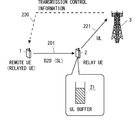
- the remote UE 1 transmits data to the relay UE 2 on the side link 201, and the relay UE 2 transmits data received from the remote UE 1 to the base station 3 on the uplink 221.
- the base station 3 determines a side link radio resource to be allocated for side link transmission from the remote UE 1 to the relay UE 2 and determines an uplink radio resource to be allocated to the uplink 221 of the relay UE 2.
- the base station 3 may determine a side link radio resource to be allocated for side link transmission from the remote UE 1 to the relay UE 2 in consideration of an uplink quality metric from the relay UE 2 to the base station 3. Good.
- the uplink quality metric of the relay UE2 relates to the performance (e.g., bandwidth or throughput) of uplink transmission from the relay UE2 to the base station 3.
- the uplink quality metric of the relay UE2 includes, for example, an estimated bandwidth of the uplink, an estimated throughput of the uplink, an estimated radio resource amount allocated to the uplink, an estimated Modulation and Coding scheme (MCS) applied to the uplink, and a relay Based on at least one of the estimated path loss from the UE 2 to the base station 3.
- the base station 3 may receive the uplink quality metric of the relay UE2 from the relay UE2. Alternatively, the base station 3 may estimate the uplink quality metric itself.
- the base station 3 ensures that the performance (eg, bandwidth or throughput) of the side link transmission from the remote UE 1 to the relay UE 2 is consistent with the performance of the uplink transmission from the relay UE 2 to the base station 3.
- radio resources to be allocated to the side link transmission may be determined.
- the base station 3 has the performance (eg, bandwidth or throughput) of one or more side link transmissions related to one relay UE2 being equal to or less than the performance of uplink transmission of the relay UE2. In this way, the radio resource to be allocated for side link transmission may be determined.
- the side link reception throughput of the relay UE 2 exceeds the uplink transmission throughput.
- the uplink throughput as estimated cannot be obtained due to the fluctuation of the quality of the uplink 221.
- the buffer amount of the uplink transmission buffer 21 in the relay UE2 increases, and in the worst case, there is a possibility that packet discard due to buffer overflow occurs.
- the uplink transmission buffer 21 is used to store data transmitted on the uplink.
- the uplink transmission buffer 21 stores uplink data waiting for transmission.
- the base station 3 transmits the band, throughput, or radio resource used for side link transmission (D2D transmission) from the remote UE 1 to the relay UE 2 from the relay UE to the base station 3. Is configured to adjust based on the amount of uplink data that is reserved in the relay UE for transmission to.
- D2D transmission side link transmission
- FIG. 3 is a flowchart showing an example (processing 300) of the operation of the base station 3 according to the present embodiment.
- the base station 3 acquires the buffer status metric of the uplink transmission buffer 21 of the relay UE2.
- the buffer status metric indicates the amount of uplink data reserved in the uplink transmission buffer 21 or the occupation level of the uplink transmission buffer 21.
- the base station 3 may receive a buffer status report (buffer status information) including a buffer status metric from the relay UE2.
- the buffer status report may be sent periodically or in response to a predetermined trigger event.
- the base station 3 may calculate the buffer state metric itself. For example, the base station 3 calculates the buffer state metric of the uplink transmission buffer 630 in the relay UE2 based on the sidelink radio resource history assigned to the remote UE1 and the uplink radio resource history assigned to the relay UE2. Also good.
- the base station 3 adjusts the bandwidth, throughput, or radio resource used for side link transmission from the remote UE1 to the relay UE2 based on the acquired buffer state metric. For example, the base station 3 reduces the bandwidth, throughput, or radio resources used for side link transmission from the remote UE1 to the relay UE2 in response to an increase in the amount of uplink data reserved in the relay UE2. May be. On the contrary, the base station 3 responds to a decrease in the amount of uplink data reserved in the relay UE2 in the bandwidth, throughput, or used for the sidelink transmission from the remote UE1 to the relay UE2. Radio resources may be increased.
- the base station 3 adjusts radio resources allocated to side link transmissions from the remote UE 1 to the relay UE 2 in a scheduled resource allocation. For example, when the buffer state metric of the uplink transmission buffer 21 exceeds a predetermined threshold, the base station 3 may reduce the radio resource allocation amount for the side link transmission from the remote UE1 to the relay UE2. Specifically, in response to an increase in the amount of uplink data reserved in the relay UE2, the base station 3 reduces the radio resources allocated to the side link transmission from the remote UE1 to the relay UE2, or Allocation of radio resources for link transmission may be temporarily stopped.
- the base station 3 may lower the priority of the remote UE 1 used for side link radio resource allocation (scheduling) in response to an increase in the amount of uplink data reserved in the relay UE 2. Thereby, the bandwidth and throughput of side link transmission from the remote UE 1 to the relay UE 2 can be reduced, and therefore, it is possible to contribute to the suppression of the overflow of the uplink transmission buffer 21.
- the base station 3 may suppress transmission of a side link resource request by the remote UE 1 in response to an increase in the amount of uplink data reserved in the relay UE 2. Thereby, the bandwidth and throughput of side link transmission from the remote UE 1 to the relay UE 2 can be reduced, and therefore, it is possible to contribute to the suppression of the overflow of the uplink transmission buffer 21.
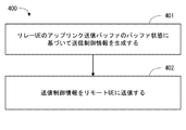
- the base station 3 may operate according to the example (processing 400) shown in FIG.
- the base station 3 generates transmission control information 230 based on the buffer state of the uplink transmission buffer 21 of the relay UE2.
- the base station 3 transmits the transmission control information 230 to the remote UE1.
- the base station 3 may transmit the transmission control information 230 periodically or aperiodically in response to a predetermined trigger event (e.g., buffer occupancy level threshold exceeded).
- the base station 3 may transmit the transmission control information 230 to the remote UE 1 in response to an increase in the amount of uplink data held in the relay UE 2.
- the transmission control information 230 may instruct the remote UE 1 that transmission of the side link resource request to the base station 3 should be suppressed.
- the transmission control information 230 may indicate a buffer status metric related to the uplink transmission buffer 21 of the relay UE2.
- the transmission control information 230 can also be called a pause signal.
- the transmission control information 230 described in the first embodiment may be transmitted from the relay UE2 to the remote UE1 instead of the base station 3. That is, the relay UE2 generates transmission control information 230 based on the buffer state of the uplink transmission buffer 21, and the generated transmission control information 230 is periodically or a predetermined trigger event (eg, exceeding the threshold of the buffer occupancy level). Depending on, it may be transmitted aperiodically.
- the transmission control information 230 may be transmitted in response to an increase in the amount of uplink data reserved in the uplink transmission buffer 21.
- the transmission control information 230 (a) reduce radio resources used for side link transmission from the remote UE1 to the relay UE2, (b) temporarily stop sidelink transmission, or (c) The remote UE 1 may be triggered to suppress transmission of the side link resource request to the base station 3.
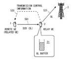
- autonomous resource selection (sidelink transmission mode 2) is used for radio resource allocation for side link transmission.
- the base station 3 uses the SIB-18 or dedicated signaling (RRC signaling) to link the radio resource pools (PSSCH subframe pool and resource block pool) that are allowed to be used for direct transmission. Notification is made to the transmitting terminal (here, remote UE 1).
- the side link transmission terminal (remote UE1) autonomously selects a resource for side link control (PSCCH) and data (PSSCH) from the radio resource pool set by the base station 3.
- PSCCH side link control
- PSSCH data
- the remote UE 1 selects a radio resource for side link transmission from the radio resource pool, and transmits data to the relay UE 2 on the side link 501 using the selected radio resource.
- the relay UE2 transmits the data received from the remote UE1 to the base station 3 on the uplink 521.
- the uplink transmission buffer 21 is used to store data transmitted on the uplink.
- the uplink transmission buffer 21 stores uplink data waiting for transmission.
- the remote UE 1 transmits the band, throughput, or radio resource used for side link transmission (D2D transmission) from the remote UE 1 to the relay UE 2 from the relay UE to the base station 3. It is configured to adjust based on the amount of uplink data reserved in the relay UE for transmission. Specifically, the remote UE 1 receives the transmission control information 530 from the relay UE 2, and adjusts the side link bandwidth, throughput, or radio resource based on the received transmission control information 530.
- the transmission control information 530 is generated based on the buffer state of the uplink transmission buffer 21 of the relay UE2.
- FIG. 6 is a flowchart showing an example of operation (process 600) of the remote UE 1 according to the present embodiment.
- Step 601 the transmission control information 530 generated based on the buffer state of the uplink transmission buffer 21 of the relay UE2 is received.
- the remote UE 1 adjusts the bandwidth, throughput, or radio resource used for side link transmission from the remote UE 1 to the relay UE 2 based on the received transmission control information 530. For example, in response to an increase in the amount of uplink data reserved in the relay UE2, the remote UE1 reduces the bandwidth, throughput, or radio resources used for sidelink transmission from the remote UE1 to the relay UE2. Also good. On the other hand, the remote UE1 responds to a decrease in the amount of uplink data held in the relay UE2 in the band, throughput, or radio used for the sidelink transmission from the remote UE1 to the relay UE2. Resources may be increased.
- FIG. 7 is a flowchart showing an example (processing 700) of the operation of the relay UE2 according to the present embodiment.
- the relay UE2 In Step 701, the relay UE2 generates transmission control information 530 based on the buffer state of the uplink transmission buffer 21.
- the relay UE2 transmits the generated transmission control information 530 to the remote UE1.
- the transmission control information 530 may indicate a buffer state metric for the uplink transmission buffer 21 of the relay UE2.
- the remote UE 1 determines an uplink estimated band or estimated throughput from the relay UE 2 to the base station 3 based on the transmission control information 530 (ie, buffer state metric), and determines the determined uplink estimated band or estimated throughput. May be used to adjust the side link bandwidth, throughput, or radio resource.
- the remote UE 1 may determine radio resources to be allocated to side link transmission so that the side link band or throughput is equal to or less than the uplink estimated band or throughput. Thereby, the bandwidth and throughput of side link transmission from the remote UE 1 to the relay UE 2 can be reduced, and therefore, it is possible to contribute to the suppression of the overflow of the uplink transmission buffer 21.
- the transmission control information 530 may be transmitted in response to an increase in the amount of uplink data reserved in the relay UE2.
- the transmission control information 530 may request the remote UE 1 to reduce the side link bandwidth, throughput, or radio resource.
- the transmission control information 530 may indicate a buffer status metric regarding the uplink transmission buffer 21.
- the transmission control information 530 triggers the remote UE1 to (a) reduce radio resources used for sidelink transmission from the remote UE1 to the relay UE2, or (b) temporarily stop the sidelink transmission. May be.
- the transmission control information 530 can also be called a pause signal. Thereby, the bandwidth and throughput of side link transmission from the remote UE 1 to the relay UE 2 can be reduced, and therefore, it is possible to contribute to the suppression of the overflow of the uplink transmission buffer 21.
- the transmission control information 530 described in the second embodiment may be transmitted from the base station 3 to the remote UE 1 instead of the relay UE 2. That is, the base station 3 generates transmission control information 530 based on the buffer state of the uplink transmission buffer 21, and the generated transmission control information 530 is periodically or predetermined trigger event (eg, a buffer occupancy level exceeding the threshold value). ) May be transmitted aperiodically. Alternatively, the base station 3 may receive the transmission control information 530 from the relay UE2 and transfer the transmission control information 530 received from the relay UE2 to the remote UE1.
- the base station 3 may receive the transmission control information 530 from the relay UE2 and transfer the transmission control information 530 received from the relay UE2 to the remote UE1.
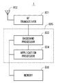
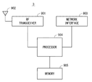
- FIG. 8 is a block diagram illustrating a configuration example of the remote UE 1.
- the relay UE2 may also have the same configuration as that shown in FIG.
- the Radio-Frequency (RF) transceiver 801 performs analog RF signal processing to communicate with the base station 3.
- Analog RF signal processing performed by the RF transceiver 801 includes frequency up-conversion, frequency down-conversion, and amplification.
- RF transceiver 801 is coupled with antenna 802 and baseband processor 803.
- the RF transceiver 801 receives modulation symbol data (or OFDM symbol data) from the baseband processor 803, generates a transmission RF signal, and supplies the transmission RF signal to the antenna 802. Further, the RF transceiver 801 generates a baseband received signal based on the received RF signal received by the antenna 802 and supplies this to the baseband processor 803.
- the RF transceiver 801 may also be used for side link communication with other UEs.
- the RF transceiver 801 may include a plurality of transceivers.
- the baseband processor 803 performs digital baseband signal processing (data plane processing) and control plane processing for wireless communication.
- Digital baseband signal processing consists of (a) data compression / decompression, (b) data segmentation / concatenation, (c) ⁇ transmission format (transmission frame) generation / decomposition, and (d) transmission path encoding / decoding. , (E) modulation (symbol mapping) / demodulation, and (f) generation of OFDM symbol data (baseband OFDM signal) by Inverse Fast Fourier Transform (IFFT).
- control plane processing includes layer 1 (eg, transmission power control), layer 2 (eg, radio resource management, hybrid automatic repeat request (HARQ) processing), and layer 3 (eg, attach, mobility, and call management). Communication management).
- the digital baseband signal processing by the baseband processor 803 includes signal processing of the Packet Data Convergence Protocol (PDCP) layer, Radio Link Control (RLC) layer, MAC layer, and PHY layer. But you can.
- the control plane processing by the baseband processor 803 may include Non-Access Stratum (NAS) protocol, RRC protocol, and MAC CE processing.
- NAS Non-Access Stratum
- the baseband processor 803 includes a modem processor (eg, Digital Signal Processor (DSP)) that performs digital baseband signal processing and a protocol stack processor (eg, Central Processing Unit (CPU), or Micro Processing Unit that performs control plane processing. (MPU)).
- DSP Digital Signal Processor
- MPU Micro Processing Unit that performs control plane processing.
- a protocol stack processor that performs control plane processing may be shared with an application processor 804 described later.
- Application processor 804 is also referred to as a CPU, MPU, microprocessor, or processor core.
- the application processor 804 may include a plurality of processors (a plurality of processor cores).
- the application processor 804 is a system software program (Operating System (OS)) read from the memory 806 or a memory (not shown) and various application programs (for example, call application, web browser, mailer, camera operation application, music playback) By executing the application, various functions of the remote UE 1 are realized.
- OS Operating System
- the baseband processor 803 and the application processor 804 may be integrated on a single chip, as shown by the dashed line (805) in FIG.
- the baseband processor 803 and the application processor 804 may be implemented as one System on Chip (SoC) device 805.
- SoC System on Chip
- An SoC device is sometimes called a system Large Scale Integration (LSI) or chipset.
- the memory 806 is a volatile memory, a nonvolatile memory, or a combination thereof.
- the memory 806 may include a plurality of physically independent memory devices.
- the volatile memory is, for example, Static Random Access Memory (SRAM), Dynamic RAM (DRAM), or a combination thereof.
- the non-volatile memory is a mask Read Only Memory (MROM), Electrically Erasable Programmable ROM (EEPROM), flash memory, hard disk drive, or any combination thereof.
- the memory 806 may include an external memory device accessible from the baseband processor 803, the application processor 804, and the SoC 805.
- Memory 806 may include an embedded memory device integrated within baseband processor 803, application processor 804, or SoC 805.
- the memory 806 may include a memory in a Universal Integrated Circuit Card (UICC).
- UICC Universal Integrated Circuit Card
- the memory 806 may store a software module (computer program) including an instruction group and data for performing processing by the remote UE 1 described in the plurality of embodiments described above.
- the baseband processor 803 or the application processor 804 is configured to read out and execute the software module from the memory 806 to perform the processing of the remote UE 1 described using the drawings in the above-described embodiment. May be.
- FIG. 9 is a block diagram illustrating a configuration example of the base station 3 according to the above-described embodiment.
- the base station 3 includes an RF transceiver 901, a network interface 903, a processor 904, and a memory 905.
- the RF transceiver 901 performs analog RF signal processing to communicate with the remote UE1 and the relay UE2.
- the RF transceiver 901 may include multiple transceivers.
- RF transceiver 901 is coupled with antenna 902 and processor 904.
- the RF transceiver 901 receives modulation symbol data (or OFDM symbol data) from the processor 904, generates a transmission RF signal, and supplies the transmission RF signal to the antenna 902. Further, the RF transceiver 901 generates a baseband received signal based on the received RF signal received by the antenna 902 and supplies this to the processor 904.
- the network interface 903 is used to communicate with network nodes (e.g., Mobility Management Entity (MME) and Serving Gateway (S-GW)).
- MME Mobility Management Entity
- S-GW Serving Gateway
- the network interface 903 may include, for example, a network interface card (NIC) compliant with IEEE 802.3 series.
- NIC network interface card
- the processor 904 performs digital baseband signal processing (data plane processing) and control plane processing for wireless communication.
- the digital baseband signal processing by the processor 904 may include PDCP layer, RLC layer, MAC layer, and PHY layer signal processing.
- the control plane processing by the processor 904 may include S1 protocol, RRC protocol, and MAC-CE processing.
- the processor 904 may include a plurality of processors.
- the processor 904 may include a modem processor (e.g., DSP) that performs digital baseband signal processing and a protocol stack processor (e.g., CPU or MPU) that performs control plane processing.
- DSP digital baseband signal processing
- protocol stack processor e.g., CPU or MPU
- the memory 905 is configured by a combination of a volatile memory and a nonvolatile memory.
- the volatile memory is, for example, SRAM or DRAM or a combination thereof.
- the non-volatile memory is, for example, an MROM, PROM, flash memory, hard disk drive, or a combination thereof.
- Memory 905 may include storage located remotely from processor 904. In this case, the processor 904 may access the memory 905 via the network interface 903 or an I / O interface not shown.
- the memory 905 may store a software module (computer program) including an instruction group and data for performing processing by the base station 3 described in the plurality of embodiments.
- the processor 904 may be configured to perform the processing of the base station 3 described with reference to the drawings in the above-described embodiment by reading the software module from the memory 905 and executing the software module.
- each of the processors included in the remote UE 1, the relay UE 2, and the base station 3 causes the computer to execute the algorithm described with reference to the drawings.
- One or a plurality of programs including the instruction group is executed.
- the program can be stored and supplied to a computer using various types of non-transitory computer readable media.
- Non-transitory computer readable media include various types of tangible storage media (tangible storage medium).
- non-transitory computer-readable media are magnetic recording media (eg flexible disks, magnetic tapes, hard disk drives), magneto-optical recording media (eg magneto-optical discs), Compact Disc Read Only Memory (CD-ROM), CD-ROM R, CD-R / W, semiconductor memory (for example, mask ROM, Programmable ROM (PROM), Erasable PROM (EPROM), flash ROM, Random Access Memory (RAM)).
- the program may also be supplied to the computer by various types of temporary computer-readable media. Examples of transitory computer readable media include electrical signals, optical signals, and electromagnetic waves.
- the temporary computer-readable medium can supply the program to the computer via a wired communication path such as an electric wire and an optical fiber, or a wireless communication path.
- the processing and operation performed by the base station 3 including the allocation of the side link radio resource described in the above-described embodiment is the Digital Unit (DU) or DU and Radio Unit included in the Cloud Radio Access Network (C-RAN) architecture.
- RU may be provided in combination.
- DU is called Baseband Unit (BBU).
- RU is also called Remote Radio Head (RRH) or Remote Radio Equipment (RRE). That is, the process and operation performed by the base station 3 described in the above embodiment may be provided by any one or a plurality of radio stations (RAN nodes).
- (Appendix 1) Memory At least one processor coupled to the memory; With The at least one processor is configured to transmit a band, throughput, or radio resource used for device-to-device (D2D) transmission from a remote terminal to a relay terminal, from the relay terminal to the base station. Configured to adjust based on the amount of uplink data pending in An apparatus for controlling device-to-device communication.
- D2D device-to-device
- the at least one processor receives buffer status information indicating a buffer status metric related to an amount of data in an uplink transmission buffer of the relay terminal or an occupation level of the uplink transmission buffer, and based on the buffer status information, the bandwidth Configured to adjust the throughput, or the radio resource, The apparatus according to appendix 1.
- the at least one processor determines an uplink estimated band or estimated throughput from the relay terminal to the base station based on the buffer state information, and uses the estimated band or estimated throughput for the D2D transmission Configured to adjust the bandwidth, the throughput, or the radio resource to be The apparatus according to appendix 2.
- the at least one processor is configured to reduce the bandwidth, the throughput, or the radio resource used for the D2D transmission in response to an increase in the amount of reserved uplink data.
- the apparatus according to any one of appendices 1 to 3.
- the at least one processor is responsive to an increase in the amount of reserved uplink data, (a) reducing radio resources used for D2D transmission from the remote terminal to the relay terminal; (b) The D2D transmission is temporarily stopped, or (c) the transmission of the D2D resource request to the base station is suppressed.
- the apparatus according to appendix 5.
- Appendix 7 The apparatus is implemented in the base station; The apparatus according to any one of appendices 1 to 4.
- the at least one processor is responsive to an increase in the amount of reserved uplink data, (a) reducing radio resources allocated for D2D transmission from the remote terminal to the relay terminal; (b) the D2D Temporarily stop allocation of the radio resource to transmission, (c) lower the priority of the remote terminal used for D2D radio resource allocation, or (d) inhibit transmission of the D2D resource request by the remote terminal To be configured,
- the bandwidth, throughput, or radio resource used for device-to-device (D2D) transmission from the remote terminal to the relay terminal is reserved in the relay terminal for transmission from the relay terminal to the base station Comprising adjusting based on the amount of link data; A method for controlling device-to-device communication.
- D2D device-to-device
- a program for causing a computer to perform a method for controlling device-to-device communication The method reserves bandwidth, throughput, or radio resources used for device-to-device (D2D) transmission from a remote terminal to a relay terminal within the relay terminal for transmission from the relay terminal to a base station. Including adjusting based on the amount of uplink data being program.
- D2D device-to-device
- control information is used by the remote terminal to adjust the bandwidth, throughput, or radio resources used for D2D transmission from the remote terminal to the relay terminal.
- the base station according to attachment 11.
- the control information indicates a buffer state metric related to the amount of uplink data reserved or the occupation level of the uplink transmission buffer.
- the base station according to Appendix 11 or 12.
- the control information is transmitted in response to an increase in the amount of reserved uplink data,
- the control information includes (a) reducing radio resources used for D2D transmission from the remote terminal to the relay terminal, (b) temporarily stopping the D2D transmission, or (c) a D2D resource request. Deterring transmission to the base station to the remote terminal, 14.
- the base station according to any one of appendices 11 to 13.
- the control information indicates that the base station refuses to allocate radio resources for D2D transmission from the remote terminal to the relay terminal. 14. The base station according to any one of appendices 11 to 13.
- Appendix 17 A program for causing a computer to perform a method in a base station, The method Obtaining a buffer state of an uplink transmission buffer for storing uplink data reserved in the relay terminal for transmission from the relay terminal to the base station; and a device tool generated based on the buffer state Sending device (D2D) control information to the remote terminal; Including the program.
- D2D buffer state Sending device
- control information is used by the remote terminal to adjust the bandwidth, throughput, or radio resources used for D2D transmission from the remote terminal to the relay terminal.
- the relay terminal according to appendix 18.
- the control information indicates a buffer state metric related to the amount of uplink data reserved or the occupation level of the uplink transmission buffer.
- the relay terminal according to appendix 18 or 19.
- the control information is transmitted in response to an increase in the amount of reserved uplink data,
- the control information includes (a) reducing radio resources used for D2D transmission from the remote terminal to the relay terminal, (b) temporarily stopping the D2D transmission, or (c) a D2D resource request. Deterring transmission to the base station to the remote terminal, The relay terminal according to any one of appendices 18 to 20.
- the at least one processor is configured to send the control information to the remote terminal over a D2D link;
- the relay terminal according to any one of appendices 18 to 21.
- Appendix 24 A program for causing a computer to perform a method in a relay terminal, The method Obtaining a buffer state of an uplink transmission buffer for storing uplink data held in the relay terminal for transmission from the relay terminal to a base station; and control information generated based on the buffer state To the remote terminal, Including the program.
- the at least one processor is configured to adjust a bandwidth, throughput, or radio resource used for D2D transmission from the remote terminal to the relay terminal based on the control information.
- the remote terminal according to attachment 25.
- the control information indicates a buffer state metric related to the amount of uplink data reserved or the occupation level of the uplink transmission buffer.
- the remote terminal according to appendix 25 or 26.
- the at least one processor determines an uplink estimated band or estimated throughput from the relay terminal to the base station based on the control information, and is used for the D2D transmission in consideration of the estimated band or estimated throughput. Configured to adjust bandwidth, throughput, or radio resources, The remote terminal according to appendix 27.
- the control information is transmitted in response to an increase in the amount of reserved uplink data,
- the control information includes (a) reducing radio resources used for D2D transmission from the remote terminal to the relay terminal, (b) temporarily stopping the D2D transmission, or (c) a D2D resource request. Deterring transmission to the base station to the remote terminal, 28.
- the remote terminal according to any one of appendices 25 to 27.
- the at least one processor is configured to receive the control information from the relay terminal over a D2D link; Item 30.
- the remote terminal according to any one of appendices 25 to 29.
- a method comprising:
- Appendix 32 Adjusting the bandwidth, throughput, or radio resource used for D2D transmission from the remote terminal to the relay terminal based on the control information; The method according to appendix 31.
- Appendix 33 A program for causing a computer to perform a method in a remote terminal, In the method, control information generated based on a buffer state of an uplink transmission buffer storing uplink data reserved in the relay terminal for transmission from the relay terminal to the base station is transmitted to the remote terminal or the Including receiving from the base station, program.
Abstract
This device (1 or 3) adjusts the band, throughput, or radio resources used in device-to-device transmission from a remote terminal (1) to a relay terminal (2) on the basis of the amount of uplink data held in the relay terminal (2) for transmitting from the relay terminal (2) to a base station (3). By this means, it is possible to contribute, for example, to avoiding inconsistency of performance between sidelink transmission from the remote terminal to the relay terminal and uplink transmission from the relay terminal to the base station.
Description
本開示は、端末間直接通信(device-to-device(D2D)通信)に関し、特にリモート端末からリレー端末へのサイドリンク送信の制御に関する。
This disclosure relates to direct communication between devices (device-to-device (D2D) communication), and more particularly to control of side link transmission from a remote terminal to a relay terminal.
無線端末が基地局等のインフラストラクチャ・ネットワークを介さずに他の無線端末と直接的に通信する形態は、device-to-device(D2D)通信と呼ばれる。D2D通信は、直接通信(Direct Communication)および直接ディスカバリ(Direct Discovery)の少なくとも一方を含む。幾つかの実装において、D2D通信をサポートする複数の無線端末は、自律的に又はネットワークの指示に従ってD2D通信グループを形成し、当該D2D通信グループ内の他の無線端末と通信を行う。
A form in which a wireless terminal communicates directly with another wireless terminal without going through an infrastructure network such as a base station is called device-to-device (D2D) communication. The D2D communication includes at least one of direct communication (Direct Communication) and direct discovery (Direct Discovery). In some implementations, a plurality of wireless terminals that support D2D communication form a D2D communication group autonomously or according to a network instruction, and communicate with other wireless terminals in the D2D communication group.
3GPP Release 12に規定されたProximity-based services(ProSe)は、D2D通信の一例である(例えば、非特許文献1を参照)。ProSe直接ディスカバリは、ProSeを実行可能な無線端末(ProSe-enabled User Equipment(UE))が他のProSe-enabled UEを、これら2つのUEが有する無線通信技術(例えば、Evolved Universal Terrestrial Radio Access (E-UTRA) technology)の能力だけを用いてディスカバリする手順により行われる。ProSe直接ディスカバリは、3つ以上のProSe-enabled UEsにより行われてもよい。
Proximity-based services (ProSe) defined in 3GPP Release 12 is an example of D2D communication (see, for example, Non-Patent Document 1). ProSe direct discovery is a wireless terminal that can execute ProSe (ProSe-enabled User Equipment (UE)) and other ProSe-enabled UEs, and these two UEs have wireless communication technology (for example, Evolved Universal Universal Terrestrial Radio Access -UTRA) It is performed by the discovery procedure using only the technology (technology). ProSe direct discovery may be performed by three or more ProSe-enabled UEs.
ProSe直接通信は、ProSe直接ディスカバリの手順の後に、直接通信レンジ内に存在する2以上のProSe-enabled UEsの間の通信パスの確立を可能にする。言い換えると、ProSe直接通信は、ProSe-enabled UEが、基地局(eNodeB(eNB))を含む公衆地上移動通信ネットワーク(Public Land Mobile Network (PLMN))を経由せずに、他のProSe-enabled UEと直接的に通信することを可能にする。ProSe直接通信は、基地局(eNB)にアクセスする場合と同様の無線通信技術(E-UTRA technology)を用いて行われてもよいし、Wireless Local Area Network (WLAN)の無線技術(つまり、IEEE 802.11 radio technology)を用いて行われてもよい。
ProSe direct communication enables the establishment of a communication path between two or more ProSe-enabled UEs existing in the direct communication range after the ProSe direct discovery procedure. In other words, ProSe direct communication allows ProSe-enabled UEs to communicate with other ProSe-enabled UEs without going through a public land mobile communication network (Public Land Mobile Mobile Network (PLMN)) that includes a base station (eNodeB (eNB)). Allows to communicate directly with. ProSe direct communication may be performed using the same wireless communication technology (E-UTRA technology) as that used to access the base station (eNB), or wireless technology of Wireless Local Area Network (WLAN) (ie IEEE 802.11 (radio technology) may be used.
3GPP Release 12では、直接通信または直接ディスカバリに用いられる無線端末間の無線リンクは、サイドリンク(Sidelink)と呼ばれる(例えば、非特許文献2のセクション14を参照)。サイドリンク送信は、アップリンク及びダウンリンクのために定義されたLong Term Evolution(LTE)フレーム構造と同じフレーム構造を使用し、周波数および時間ドメインにおいてアップリンク・リソースのサブセットを使用する。無線端末(UE)は、アップリンクと同様のシングルキャリア周波数分割多重(Single Carrier FDMA(Frequency Division Multiple Access)、SC-FDMA)を使用してサイドリンク送信を行う。
In 3GPP Release 12, a wireless link between wireless terminals used for direct communication or direct discovery is referred to as a side link (see, for example, Section 14 of Non-Patent Document 2). Sidelink transmission uses the same frame structure as the Long Term Evolution (LTE) frame structure defined for uplink and downlink, and uses a subset of uplink resources in frequency and time domain. The radio terminal (UE) performs side link transmission using single carrier frequency division multiplexing (Single-Carrier-FDMA (Frequency-Division-Multiple Access), SC-FDMA) similar to the uplink.
3GPP Release 12 ProSeでは、サイドリンク送信のための無線リソースのUEへの割り当ては、無線アクセスネットワーク(e.g., Evolved Universal Terrestrial Radio Access Network(E-UTRAN))によって行われる。ProSe functionによってサイドリンク通信を許可されたUEは、無線アクセスネットワークノード(e.g., eNB(eNB))によって割り当てられた無線リソースを使用してProSe直接ディスカバリ又はProSe直接通信を行う。
In 3GPP Release 12 ProSe, radio resources for side link transmission are allocated to UEs by a radio access network (e.g., Evolved Universal Terrestrial Radio Access Network (E-UTRAN)). The UE that has been permitted side link communication by ProSe function performs ProSe direct discovery or ProSe direct communication using radio resources allocated by the radio access network node (e.g., eNB (eNB)).
ProSe直接通信に関しては、2つのリソース割り当てモード、つまりscheduled resource allocation 及び autonomous resource selectionが規定されているscheduled resource allocation 及び autonomous resource selection は、それぞれ“sidelink transmission mode 1”及び“sidelink transmission mode 2”と呼ばれる(非特許文献2のセクション14を参照)。
For ProSe direct communication, two resource allocation modes, namely scheduled resource resource allocation and scheduled resource resource allocation and automatic resource resource selection are called "sidelink transmission mode 1" and "sidelink transmission mode 2", respectively. (See Section 14 of Non-Patent Document 2).
ProSe直接通信のscheduled resource allocationでは、UEがサイドリンク送信を希望する場合、当該UEがサイドリンク送信のための無線リソース割り当てをeNBに要求し、eNBがサイドリンク・コントロール及びデータのためのリソースを当該UEに割り当てる。具体的には、UEは、アップリンク(UL)データ送信リソース(Uplink Shared Channel(UL-SCH)リソース)を要求するためにスケジューリング・リクエストをeNB に送信し、アップリンクグラント(UL grant)で割り当てられたULデータ送信リソースにおいてSidelink Buffer Status Report(Sidelink BSR)をeNBに送信する。eNBは、Sidelink BSRに基づいてUEに割り当てるサイドリンク送信リソースを決定し、サイドリンク・グラント(SL grant)をUEに送信する。
In scheduled resource allocation of ProSe direct communication, when a UE desires side link transmission, the UE requests radio resource allocation for side link transmission from the eNB, and the eNB assigns resources for side link control and data. Assign to the UE. Specifically, the UE sends a scheduling request to the eNB to request an uplink (UL) data transmission resource (Uplink Shared Channel (UL-SCH) resource) and assigns it with an UL grant. Send Sidelink Buffer Status Report (Sidelink BSR) to the eNB in the received UL data transmission resource. The eNB determines a side link transmission resource to be allocated to the UE based on the Sidelink BSR, and transmits a side link grant (SL grant) to the UE.
SL grantは、Downlink Control Information(DCI) format 5として定義されている。SL grant(DCI format 5)は、Resource for PSCCH、Resource block assignment and hopping allocation、及びtime resource pattern indexなどのコンテンツを含む。Resource for PSCCHは、サイドリンク制御チャネル(i.e., Physical Sidelink Control Channel(PSCCH))用の無線リソースを示す。Resource block assignment and hopping allocationは、サイドリンクでのデータ送信用のサイドリンク・データチャネル(i.e., Physical Sidelink Shared Channel(PSSCH))を送信するための周波数リソース、つまりサブキャリア(リソースブロック)のセット、を決定するために使用される。Time resource pattern indexは、PSSCHを送信するための時間リソース、つまりサブフレームのセット、を決定するために使用される。なお、厳密に述べると、リソースブロックは、LTE及びLTE-Advancedの時間-周波数リソースを意味し、時間ドメインにおいて連続する複数個のOFDM(又はSC-FDMA)シンボルと周波数ドメインにおいて連続する複数個のサブキャリアによって規定されるリソース単位である。Normal cyclic prefixの場合、1リソースブロックは、時間ドメインにおいて連続する12OFDM(又はSC-FDMA)シンボルを含み、周波数ドメインにおいて12サブキャリアを含む。すなわち、Resource block assignment and hopping allocationおよびTime resource pattern indexは、PSSCHを送信するためのリソースブロックを指定する。UE(つまり、サイドリンク送信端末)は、SL grantに従ってPSCCHリソースおよびPSSCHリソースを決める。
SL grant is defined as Downlink Control Information (DCI) format 5. SL grant (DCI format 含 む 5) includes contents such as Resource for PSCCH, Resource block assignment and hopping allocation, and time resource pattern index. Resource for PSCCH indicates a radio resource for a side link control channel (i.e., Physical Sidelink Control Channel (PSCCH)). Resource block assignment and hopping allocation is a set of frequency resources, that is, a set of subcarriers (resource blocks), for transmitting a sidelink data channel (ie, Physical Sidelink Shared Channel (PSSCH)) for data transmission on the sidelink, Used to determine. Time resource pattern index is used to determine a time resource for transmitting PSSCH, that is, a set of subframes. Strictly speaking, a resource block means LTE and LTE-Advanced time-frequency resources, and a plurality of OFDM (or SC-FDMA) symbols continuous in the time domain and a plurality of consecutive OFDM symbols in the frequency domain. A resource unit defined by subcarriers. In the case of Normal cyclic prefix, one resource block includes 12 OFDM (or SC-FDMA) symbols continuous in the time domain and 12 subcarriers in the frequency domain. That is, Resource block assignment and hopping allocation and Time resource pattern index specify a resource block for transmitting PSSCH. The UE (that is, the side link transmission terminal) determines the PSCCH resource and the PSSCH resource according to SL grant.
一方、ProSe直接通信のautonomous resource selectionでは、UEは、eNBによって設定されたリソースプールの中から、サイドリンク・コントロール(PSCCH)及びデータ(PSSCH)のためのリソースを自律的に選択する。eNBは、System Information Block(SIB)18において、autonomous resource selectionに使用するためのリソースプールをUEに割り当ててもよい。なお、eNBは、Radio Resource Control (RRC)_CONNECTEDのUEに対して、個別(dedicated)RRCシグナリングで、autonomous resource selectionに使用するためのリソースプールを割り当ててもよい。このリソースプールは、UEがRRC_IDLEであるときにも利用可能であってもよい。
On the other hand, in autonomous resource selection of ProSe direct communication, the UE autonomously selects a resource for side link control (PSCCH) and data (PSSCH) from the resource pool set by the eNB. The eNB may assign a resource pool to be used for autonomous resource selection in the System Information Block (SIB) 18 to the UE. Note that the eNB may assign a resource pool to be used for autonomous resource selection to the UE of Radio Resource Control (RRC) _CONNECTED by dedicated RRC signaling. This resource pool may also be available when the UE is RRC_IDLE.
サイドリンクでの直接送信を行う場合、送信側のUE(D2D transmitting UE)(以下、送信端末とする)は、サイドリンク制御チャネル(i.e., PSCCH)用の無線リソース領域(resource pool)を使って、スケジューリング割当情報(Scheduling Assignment)を送信する。スケジューリング割当情報は、Sidelink Control Information (SCI) format 0とも呼ばれる。スケジューリング割当情報は、resource block assignment and hopping allocation、time resource pattern index、及び Modulation and Coding Scheme(MCS)などのコンテンツを含む。上述したscheduled resource allocation の場合、Scheduling Assignment(SCI format 0)が示す Resource block assignment and hopping allocation及びtime resource pattern indexは、eNBから受信したSL grant(DCI format 5)が示すResource block assignment and hopping allocation及びtime resource pattern indexに従う。
When performing direct transmission on the side link, the transmitting side UE (D2D transmitting UE) (hereinafter referred to as the transmitting terminal) uses the radio resource area (resource pool) for the sidelink control channel (ie, PSCCH) Then, scheduling assignment information (Scheduling Assignment) is transmitted. The scheduling allocation information is also called Sidelink, Control, Information, (SCI), format, 0. The scheduling assignment information includes contents such as resource, block, assignment, and hopping, allocation, time, resource, pattern, index, and modulation, and coding, Scheme (MCS). In the case of the scheduled resource allocation described above, the resource block, assignment, and hopping resource allocation and time resource resource pattern index indicated by the scheduling resource assignment (SCI format 0) and the resource resource block assignment, and hopping resource allocation indicated by the SL resource grant (DCI resource format 5) received from the eNB. Follow time resource pattern index.
送信端末は、スケジューリング割当情報に従った無線リソースを使って、PSSCHにおいてデータを送信する。受信側のUE(D2D receiving UE)(以下、受信端末とする)は、送信端末からのスケジューリング割当情報をPSCCHにおいて受信し、そのスケジューリング割当情報に従ってPSSCHにおいてデータを受信する。なお、ここで送信端末との用語は、無線端末の送信動作に着目した表現であって、送信専用の無線端末を意味するものではない。同様に、受信端末との用語は、無線端末の受信動作に着目した表現であり、受信専用の端末を意味するものではない。すなわち、送信端末は受信動作を行うことも可能であり、受信端末は送信動作を行うことも可能である。
The transmitting terminal transmits data on PSSCH using radio resources according to the scheduling allocation information. A receiving UE (D2D receiving UE) (hereinafter referred to as a receiving terminal) receives scheduling assignment information from the transmitting terminal on the PSCCH, and receives data on the PSSCH according to the scheduling assignment information. Here, the term “transmission terminal” is an expression that focuses on the transmission operation of the wireless terminal, and does not mean a wireless terminal dedicated to transmission. Similarly, the term “receiving terminal” is an expression that focuses on the receiving operation of the wireless terminal, and does not mean a terminal dedicated to reception. That is, the transmitting terminal can also perform a receiving operation, and the receiving terminal can also perform a transmitting operation.
さらに、3GPP Release 12は、一方のUEがネットワークカバレッジ外であり、他方のUEがネットワークカバレッジ内であるパーシャルカバレッジ・シナリオについて規定している(例えば、非特許文献1のセクション4.4.3、4.5.4および5.4.4を参照)。パーシャルカバレッジ・シナリオにおいて、カバレッジ外のUEはremote UE又はsidelink remote UEと呼ばれ、カバレッジ内かつremote UEとネットワークを中継するUEはProSe UE-to-Network Relay又はsidelink relay UEと呼ばれる。ProSe UE-to-Network Relayは、remote UEとネットワーク(E-UTRA network(E-UTRAN)及びEPC)との間でトラフィック(ダウンリンク及びアップリンク)を中継する。
Further, 3GPP Release 12 specifies a partial coverage scenario in which one UE is outside the network coverage and the other UE is within the network coverage (for example, Sections 4.4.3 and 4.5 of Non-Patent Document 1). See 4 and 5.4.4). In the partial coverage scenario, UEs that are out of coverage are called remote UEs or sidelink remote controllers, and UEs that are in coverage and relay between remote UEs and networks are called ProSe UE UE-to-Network Relays or sidelink relays UEs. ProSe UE-to-Network Relay relays traffic (downlink and uplink) between remote UE and network (E-UTRA network (E-UTRAN) and EPC).
より具体的に述べると、ProSe UE-to-Network Relayは、UEとしてネットワークにアタッチし、ProSe function エンティティ又はその他のPacket Data Network(PDN)と通信するためのPDN connectionを確立し、ProSeダイレクト通信を開始するためにProSe function エンティティと通信する。ProSe UE-to-Network Relayは、さらに、remote UEとの間でディスカバリ手順を実行し、UE間ダイレクトインタフェース(e.g., サイドリンク又はPC5インタフェース)においてremote UEと通信し、remote UEとネットワークとの間でトラフィック(ダウンリンク及びアップリンク)を中継する。Internet Protocol version 4(IPv4)が用いられる場合、ProSe UE-to-Network Relayは、Dynamic Host Configuration Protocol Version 4 (DHCPv4) Server及びNetwork Address Translation (NAT) として動作する。IPv6が用いられる場合、ProSe UE-to-Network Relayは、stateless DHCPv6 Relay Agentとして動作する。
More specifically, ProSe UE-to-Network Relay attaches to the network as a UE, establishes a PDN connection to communicate with a ProSe function 又 は entity or other packet Data Network (PDN), and performs ProSe direct communication. Communicate with the ProSe function entity to get started. ProSe UE-to-Network Relay further performs a discovery procedure with remote UE, communicates with remote UE on the direct inter-UE interface (eg, side link or PC5 interface), and between remote UE and network To relay traffic (downlink and uplink). When Internet Protocol Version 4 (IPv4) is used, ProSe UE-to-Network Relay operates as Dynamic Host Configuration Configuration Protocol Version 4 (DHCPv4) Server and Network Address Translation (NAT). When IPv6 is used, ProSe UE-to-Network Relay operates as stateless DHCPv6 Relay Agent.
さらに、3GPP Release 13ではProSeの拡張が議論されている(例えば、非特許文献3-9を参照)。当該議論は、ProSe UE-to-Network Relay 及びProSe UE-to-UE Relayを選択するためのリレー選択基準(relay selection criteria)に関する議論、及びリレー選択の配置を含むリレー選択手順に関する議論を含む。ここで、ProSe UE-to-UE Relayは、2つのremote UEの間でトラフィックを中継するUEである。
Furthermore, the extension of ProSe is discussed in 3GPP Release 13 (for example, see Non-Patent Documents 3-9). The discussion includes a discussion on relay selection criteria for selecting ProSe UE-to-Network Relay and ProSe UE-to-UE Relay, and a relay selection procedure including placement of relay selection. Here, ProSe UE-to-UE Relay is a UE that relays traffic between two remote UEs.
UE-to-Network Relayのリレー選択の配置に関しては、リモートUEがリレー選択を行う分散(distributed)リレー選択アーキテクチャ(例えば、非特許文献4-6、8、及び9を参照)と、基地局(eNodeB(eNB))等のネットワーク内の要素がリレー選択を行う集中(centralized)リレー選択アーキテクチャ(例えば、非特許文献7及び8を参照)が提案されている。UE-to-Network Relayのリレー選択基準に関しては、リモートUEとリレーUEの間のD2Dリンク品質を考慮すること、リレーUEとeNBの間のバックホールリンク品質を考慮すること、並びにD2Dリンク品質及びバックホールリンク品質の両方を考慮することが提案されている(例えば、非特許文献4-9を参照)。
Regarding the relay selection arrangement of UE-to-Network Relay, the distributed relay selection architecture (see, for example, Non-Patent Documents 4-6, 8, and 9) in which the remote UE performs relay selection, and the base station ( A centralized relay selection architecture (for example, see Non-Patent Documents 7 and 8) in which elements in a network such as eNodeB (eNB) perform relay selection has been proposed. Regarding the UE-to-Network Relay selection criteria, consider the D2D link quality between the remote UE and the relay UE, the backhaul link quality between the relay UE and the eNB, and the D2D link quality and It has been proposed to consider both backhaul link quality (see, for example, Non-Patent Documents 4-9).
本明細書では、ProSe UE-to-Network Relay(sidelink relay UE)のようなD2D通信能力およびリレー能力を持つ無線端末を「リレー端末」、又は「リレーUE」と呼ぶ。また、リレーUEによる中継サービスを受ける無線端末を「リモート端末」又は「リモートUE」と呼ぶ。リモート端末は、被リレー(relayed)端末と呼ぶこともできる。
In this specification, a wireless terminal having D2D communication capability and relay capability such as ProSe UE-to-Network Relay (sidelink UE relay) is referred to as “relay terminal” or “relay UE”. A wireless terminal that receives a relay service by the relay UE is referred to as a “remote terminal” or a “remote UE”. A remote terminal can also be referred to as a relayed terminal.
上述した非特許文献は、リレーUEからeNBへ送信するためにリレーUE内で保留されているアップリンク・データの量が、リモートUEからリレーUEへのサイドリンク送信のための無線リソースを決定又は調整する際に考慮されることを記載していない。例えば、リモートUEからリレーUEへのサイドリンク送信とリレーUEからeNBへのアップリンク送信との間に性能(e.g., 帯域、スループット)の不整合(inconsistency)がある場合、リレーUE内のアップリンク送信バッファのオーバフローを招くかもしれない。アップリンク送信バッファは、アップリンクで送信されるデータを格納するために使用される。また、アップリンク送信バッファの占有レベルの著しい増加は、リモートUEからリレーUEへのサイドリンク送信に割り当てられた無線リソースが過剰であることに起因する可能性がある。リレーUEのアップリンク・スループットを超える過剰なサイドリンク・スループットをもたらす無線リソースをリモートUEからリレーUEへのサイドリンク送信に割り当てることは、サイドリンク無線リソースの浪費を招くかもしれない。
The non-patent literature mentioned above determines the amount of uplink data reserved in the relay UE for transmission from the relay UE to the eNB, or determines radio resources for side link transmission from the remote UE to the relay UE. It does not describe what is considered when making adjustments. For example, if there is inconsistency in performance (eg, bandwidth, throughput) between side link transmission from remote UE to relay UE and uplink transmission from relay UE to eNB, the uplink in relay UE May cause a send buffer overflow. The uplink transmission buffer is used to store data transmitted on the uplink. Also, the significant increase in the occupancy level of the uplink transmission buffer may be due to excessive radio resources allocated for side link transmission from the remote UE to the relay UE. Allocating radio resources that result in excess side link throughput beyond the uplink throughput of the relay UE to side link transmissions from the remote UE to the relay UE may result in wasted side link radio resources.
本明細書に開示される実施形態が達成しようとする目的の1つは、リモート端末からリレー端末へのサイドリンク送信とリレー端末から基地局へのアップリンク送信との間の性能(e.g., 帯域、スループット)の不整合(inconsistency)を回避することに寄与する装置、方法、及びプログラムを提供することである。なお、この目的は、本明細書に開示される複数の実施形態が達成しようとする複数の目的の1つに過ぎないことに留意されるべきである。その他の目的又は課題と新規な特徴は、本明細書の記述又は添付図面から明らかにされる。
One of the objectives that embodiments disclosed herein attempt to achieve is that performance between side link transmission from a remote terminal to a relay terminal and uplink transmission from the relay terminal to the base station (eg, low bandwidth) It is to provide an apparatus, a method, and a program that contribute to avoiding inconsistency of throughput. It should be noted that this object is only one of the objects that the embodiments disclosed herein intend to achieve. Other objects or problems and novel features will become apparent from the description of the present specification or the accompanying drawings.
第1の態様では、デバイス・ツー・デバイス通信を制御するための装置は、メモリ、及び前記メモリに結合された少なくとも1つのプロセッサを含む。前記少なくとも1つのプロセッサは、リモート端末からリレー端末へのデバイス・ツー・デバイス(D2D)送信に使用される帯域、スループット、又は無線リソースを、前記リレー端末から基地局へ送信するために前記リレー端末内で保留されているアップリンクデータの量に基づいて調整するよう構成されている。
In a first aspect, an apparatus for controlling device-to-device communication includes a memory and at least one processor coupled to the memory. The at least one processor is configured to transmit a band, throughput, or radio resource used for device-to-device (D2D) transmission from a remote terminal to a relay terminal, from the relay terminal to the base station. Is configured to adjust based on the amount of uplink data that is reserved in the network.
第2の態様では、デバイス・ツー・デバイス通信を制御するための方法は、リモート端末からリレー端末へのデバイス・ツー・デバイス(D2D)送信に使用される帯域、スループット、又は無線リソースを、前記リレー端末から基地局へ送信するために前記リレー端末内で保留されているアップリンクデータの量に基づいて調整することを含む。
In a second aspect, a method for controlling device-to-device communication includes a bandwidth, throughput, or radio resource used for device-to-device (D2D) transmission from a remote terminal to a relay terminal, wherein Adjusting based on the amount of uplink data reserved in the relay terminal for transmission from the relay terminal to the base station.
第3の態様では、基地局は、メモリ、及び前記メモリに結合された少なくとも1つのプロセッサを含む。前記少なくとも1つのプロセッサは、リレー端末から基地局に送信するために前記リレー端末内で保留されているアップリンクデータを格納するアップリンク送信バッファのバッファ状態に基づいて生成される制御情報をリモート端末に送信するよう構成されている。
In a third aspect, the base station includes a memory and at least one processor coupled to the memory. The at least one processor transmits control information generated based on a buffer state of an uplink transmission buffer that stores uplink data reserved in the relay terminal for transmission from the relay terminal to the base station. Configured to send to.
第4の態様では、基地局における方法は、(a)リレー端末から基地局に送信するために前記リレー端末内で保留されているアップリンクデータを格納するアップリンク送信バッファのバッファ状態を取得すること、及び(b)前記バッファ状態に基づいて生成される制御情報をリモート端末に送信すること、を含む。
In the fourth aspect, the method in the base station obtains the buffer status of an uplink transmission buffer that stores (a) uplink data reserved in the relay terminal for transmission from the relay terminal to the base station. And (b) transmitting control information generated based on the buffer status to a remote terminal.
第5の態様では、リレー端末は、メモリ、及び前記メモリに結合された少なくとも1つのプロセッサを含む。前記少なくとも1つのプロセッサは、前記リレー端末から基地局に送信するために前記リレー端末内で保留されているアップリンクデータを格納するアップリンク送信バッファのバッファ状態に基づいて生成される制御情報をリモート端末に送信するよう構成されている。
In a fifth aspect, the relay terminal includes a memory and at least one processor coupled to the memory. The at least one processor remotely transmits control information generated based on a buffer state of an uplink transmission buffer that stores uplink data reserved in the relay terminal for transmission from the relay terminal to a base station. It is configured to transmit to the terminal.
第6の態様では、リレー端末における方法は、(a)前記リレー端末から基地局に送信するために前記リレー端末内で保留されているアップリンク・データを格納するアップリンク送信バッファのバッファ状態を取得すること、及び(b)前記バッファ状態に基づいて生成される制御情報をリモート端末に送信すること、を含む。
In a sixth aspect, a method in a relay terminal includes: (a) a buffer state of an uplink transmission buffer that stores uplink data held in the relay terminal for transmission from the relay terminal to a base station. And (b) transmitting control information generated based on the buffer status to a remote terminal.
第7の態様では、リモート端末は、メモリ、及び前記メモリに結合された少なくとも1つのプロセッサを含む。前記少なくとも1つのプロセッサは、リレー端末から基地局に送信するために前記リレー端末内で保留されているアップリンクデータを格納するアップリンク送信バッファのバッファ状態に基づいて生成される制御情報を前記リモート端末又は前記基地局から受信するよう構成されている。
In a seventh aspect, the remote terminal includes a memory and at least one processor coupled to the memory. The at least one processor transmits control information generated based on a buffer state of an uplink transmission buffer that stores uplink data reserved in the relay terminal for transmission from the relay terminal to the base station. It is configured to receive from a terminal or the base station.
第8の態様では、リモート端末における方法は、リレー端末から基地局に送信するために前記リレー端末内で保留されているアップリンクデータを格納するアップリンク送信バッファのバッファ状態に基づいて生成される制御情報を前記リモート端末又は前記基地局から受信することを含む。
In an eighth aspect, a method at a remote terminal is generated based on a buffer state of an uplink transmission buffer that stores uplink data reserved in the relay terminal for transmission from the relay terminal to the base station. Receiving control information from the remote terminal or the base station.
第9の態様では、プログラムは、コンピュータに読み込まれた場合に、上述の第2、第4、第6、又は第8の態様に係る方法をコンピュータに行わせるための命令群(ソフトウェアコード)を含む。
In a ninth aspect, when a program is read into a computer, an instruction group (software code) for causing the computer to perform the method according to the second, fourth, sixth, or eighth aspect is provided. Including.
上述の態様によれば、リモート端末からリレー端末へのサイドリンク送信とリレー端末から基地局へのアップリンク送信との間の性能(e.g., 帯域、スループット)の不整合(inconsistency)を回避することに寄与する装置、方法、及びプログラムを提供できる。
According to the above aspect, avoiding inconsistency in performance (eg, bandwidth, throughput) between side link transmission from the remote terminal to the relay terminal and uplink transmission from the relay terminal to the base station. An apparatus, a method, and a program that contribute to
以下では、具体的な実施形態について、図面を参照しながら詳細に説明する。各図面において、同一又は対応する要素には同一の符号が付されており、説明の明確化のため、必要に応じて重複説明は省略される。
Hereinafter, specific embodiments will be described in detail with reference to the drawings. In each drawing, the same or corresponding elements are denoted by the same reference numerals, and redundant description is omitted as necessary for clarification of the description.
以下に説明される複数の実施形態は、独立に実施されることもできるし、適宜組み合わせて実施されることもできる。これら複数の実施形態は、互いに異なる新規な特徴を有している。したがって、これら複数の実施形態は、互いに異なる目的又は課題を解決することに寄与し、互いに異なる効果を奏することに寄与する。
The plurality of embodiments described below can be implemented independently or in appropriate combinations. The plurality of embodiments have different novel features. Therefore, these multiple embodiments contribute to solving different purposes or problems and contribute to producing different effects.
以下に示される複数の実施形態は、3GPP ProSeの改良を主な対象として説明される。しかしながら、これらの実施形態は、LTE-Advanced 及びその改良に限定されるものではなく、他のモバイル通信ネットワーク又はシステムでのD2D通信に適用されてもよい。
A plurality of embodiments shown below will be described mainly for improvement of 3GPP ProSe. However, these embodiments are not limited to LTE-Advanced and its improvements, and may be applied to D2D communication in other mobile communication networks or systems.
<第1の実施形態>
図1は、本実施形態を含むいくつかの実施形態に係る無線通信ネットワークの構成例を示している。具体的には、図1は、UE-to-Network Relay(sidelink relay UE)に関する例を示しており、複数のリモートUE1A、1B、1C、及び1D、並びに複数のリレーUE2A、2B、2C、及び2Dを図示している。以下の説明では、リモートUE1A、1B、1C、及び1Dを含む複数のリモートUEに共通する事項を説明する場合、参照符号1を用いて単に“リモートUE1”が参照される。同様に、リレーUE2A、2B、2C、及び2Dを含む複数のリレーUEに共通する事項を説明する場合、参照符号2を用いて単に“リレーUE2”が参照される。 <First Embodiment>
FIG. 1 shows a configuration example of a wireless communication network according to some embodiments including this embodiment. Specifically, FIG. 1 illustrates an example of UE-to-Network Relay (sidelink relay UE), which includes a plurality of remote UEs 1A, 1B, 1C, and 1D, and a plurality of relays UE2A, 2B, 2C, and 2D is illustrated. In the following description, when a matter common to a plurality of remote UEs including remote UEs 1A, 1B, 1C, and 1D is described, “remote UE1” is simply referred to using reference numeral 1. Similarly, when a matter common to a plurality of relay UEs including relays UE2A, 2B, 2C, and 2D is described, reference numeral 2 is used to simply refer to “relay UE2”.
図1は、本実施形態を含むいくつかの実施形態に係る無線通信ネットワークの構成例を示している。具体的には、図1は、UE-to-Network Relay(sidelink relay UE)に関する例を示しており、複数のリモートUE1A、1B、1C、及び1D、並びに複数のリレーUE2A、2B、2C、及び2Dを図示している。以下の説明では、リモートUE1A、1B、1C、及び1Dを含む複数のリモートUEに共通する事項を説明する場合、参照符号1を用いて単に“リモートUE1”が参照される。同様に、リレーUE2A、2B、2C、及び2Dを含む複数のリレーUEに共通する事項を説明する場合、参照符号2を用いて単に“リレーUE2”が参照される。 <First Embodiment>
FIG. 1 shows a configuration example of a wireless communication network according to some embodiments including this embodiment. Specifically, FIG. 1 illustrates an example of UE-to-Network Relay (sidelink relay UE), which includes a plurality of
リモートUE1は、少なくとも1つの無線トランシーバを有し、1又はそれ以上のD2Dリンク(e.g., D2Dリンク101)上で1又はそれ以上のリレーUE2とD2D通信を行うよう構成されている。既に説明したように、3GPPでは、D2Dリンクは、PC5インタフェース又はサイドリンクと呼ばれる。当該D2D通信は、少なくとも直接通信(i.e., ProSe Direct Communication)を含み、直接ディスカバリ(i.e., ProSe Direct Discovery)をさらに含んでもよい。なお、ProSe Direct Communication は、サイドリンク送信を利用する直接通信であり、Sidelink Direct Communicationとも呼ばれる。同様に、ProSe Direct Discoveryは、サイドリンク送信を利用する直接ディスカバリであり、Sidelink Direct Discoveryとも呼ばれる。さらに、図1には示されていないが、リモートUE1は、基地局(eNB)3により提供されるセルラーカバレッジ(セル)31内においてセルラー通信を行うよう構成されている。
The remote UE 1 has at least one radio transceiver and is configured to perform D2D communication with one or more relay UEs 2 on one or more D2D links (e.g., D2D link 101). As already explained, in 3GPP, the D2D link is called a PC5 interface or side link. The D2D communication includes at least direct communication (i.e., ProSe Direct Communication), and may further include direct discovery (i.e., ProSe Direct Discovery). ProSe な お Direct Communication is direct communication using side link transmission and is also called Sidelink Direct Communication. Similarly, ProSe Direct Discovery is direct discovery using side link transmission and is also called Sidelink Direct Discovery. Furthermore, although not shown in FIG. 1, the remote UE 1 is configured to perform cellular communication within a cellular coverage (cell) 31 provided by the base station (eNB) 3.
リレーUE2は、少なくとも1つの無線トランシーバを有し、セルラーカバレッジ31内において基地局3とのアップリンク及びダウンリンクを含むセルラーリンク(e.g., セルラーリンク121)においてセルラー通信を行うとともに、D2Dリンク(e.g., D2Dリンク101)上でリモートUE1とD2D通信(e.g., ProSeダイレクト・ディスカバリ及びProSeダイレクト通信)を行うよう構成されている。
The relay UE2 has at least one radio transceiver, and performs cellular communication in a cellular link (eg, a cellular link 121) including an uplink and a downlink with the base station 3 in the cellular coverage 31, and a D2D link (eg , D2D link 101) and D2D communication (eg, ProSe direct discovery and ProSe direct communication) with remote UE1.
基地局3は、無線アクセスネットワーク(i.e., E-UTRAN)内に配置されたエンティティであり、1又は複数のセルを含むセルラーカバレッジ31を提供し、セルラー通信技術(e.g., E-UTRA technology)を用いてリレーUE2とセルラーリンク(e.g., セルラーリンク121)において通信することができる。さらに、基地局3は、セルラーカバレッジ31内にいるリモートUE1とセルラー通信を行うよう構成されている。
The base station 3 is an entity arranged in a radio access network (ie, E-UTRAN), provides a cellular coverage 31 including one or more cells, and uses cellular communication technology (eg, E-UTRA technology). It is possible to communicate with the relay UE2 using the cellular link (eg, cellular link 121). Furthermore, the base station 3 is configured to perform cellular communication with the remote UE 1 in the cellular coverage 31.
図1は、3通りのリレー形態を示している。第1の例では、1つのリモートUE1Aが1つのリレーUE2Aに接続される。リモートUE1Aは、D2Dリンク101上でデータを送信し、リレーUE2Aは、リモートUE1Aから受信したデータをセルラーリンク121(アップリンク)上で基地局3に送信する。第2の例では、1つのリモートUE1Bは、複数のリレーUE2B及び2Cに接続される。リモートUE1Bは、2つのD2Dリンク102及び103上でデータを送信し、リレーUE2B及び2Cは、リモートUE1Bから受信したデータをセルラーリンク122及び123(アップリンク)上で基地局3に送信する。第3の例では、2つのリモートUE1C及び1Dは、1つのリレーUE2Dに接続される。リモートUE1C及び1Dの各々は、各D2Dリンク104又は105上でデータを送信し、リレーUE2Dは、2つのリモートUE1C及び1Dから受信したデータをセルラーリンク124(アップリンク)上で基地局3に送信する。本実施形態では、図1に示された3通りのリレー形態のいずれかのみが使用されてもよいし、3通りのリレー形態のうち2つ又は全てが使用されてもよい。
Fig. 1 shows three relay configurations. In the first example, one remote UE1A is connected to one relay UE2A. The remote UE 1A transmits data on the D2D link 101, and the relay UE 2A transmits the data received from the remote UE 1A to the base station 3 on the cellular link 121 (uplink). In the second example, one remote UE 1B is connected to a plurality of relays UE 2B and 2C. The remote UE 1B transmits data on the two D2D links 102 and 103, and the relay UEs 2B and 2C transmit the data received from the remote UE 1B to the base station 3 on the cellular links 122 and 123 (uplink). In the third example, two remote UEs 1C and 1D are connected to one relay UE2D. Each of the remote UEs 1C and 1D transmits data on each D2D link 104 or 105, and the relay UE 2D transmits the data received from the two remote UEs 1C and 1D to the base station 3 on the cellular link 124 (uplink). To do. In the present embodiment, only one of the three relay configurations shown in FIG. 1 may be used, or two or all of the three relay configurations may be used.
本実施形態では、サイドリンク送信への無線リソース割り当てのためにscheduled resource allocation(sidelink transmission mode 1)が使用される。Scheduled resource allocationの場合、基地局3が、リモートUE1からリレーUE2へのサイドリンク送信に割り当てる無線リソースを決定する。例えば、リモートUE1は、アップリンク(UL)データ送信リソース(Uplink Shared Channel(UL-SCH)リソース)を要求するためにスケジューリング・リクエストを基地局3に送信し、アップリンクグラント(UL grant)で割り当てられたULデータ送信リソースにおいてSidelink BSRを基地局3に送信する。基地局3は、Sidelink BSRに基づいてリモートUE1に割り当てるサイドリンク送信リソースを決定し、サイドリンク・グラント(SL grant、DCI format 5)をUEに送信する。既に説明したように、サイドリンク・グラントは、サイドリンク送信端末(ここでは、リモートUE1)がダイレクト送信を行うためのPSSCHの無線リソースを指定する。
In this embodiment, scheduled resource allocation (sidelink transmission mode 1) is used for radio resource allocation for side link transmission. In the case of Scheduled | resource | allocation | allocation, the base station 3 determines the radio | wireless resource allocated for the side link transmission from remote UE1 to relay UE2. For example, the remote UE 1 transmits a scheduling request to the base station 3 in order to request an uplink (UL) data transmission resource (Uplink Shared Channel (UL-SCH) resource), and is allocated with an uplink grant (UL grant). The Sidelink BSR is transmitted to the base station 3 using the received UL data transmission resource. The base station 3 determines a side link transmission resource to be allocated to the remote UE 1 based on the Sidelink BSR, and transmits a side link grant (SL grant, DCI format 5) to the UE. As already described, the side link grant specifies PSSCH radio resources for the side link transmitting terminal (here, the remote UE 1) to perform direct transmission.
続いて以下では、本実施形態に係るサイドリンク送信制御の概要を図2を参照して説明する。図2では、リモートUE1は、サイドリンク201上でデータをリレーUE2に送信し、リレーUE2は、リモートUE1から受信したデータをアップリンク221上で基地局3に送信する。
Subsequently, an outline of side link transmission control according to the present embodiment will be described below with reference to FIG. In FIG. 2, the remote UE 1 transmits data to the relay UE 2 on the side link 201, and the relay UE 2 transmits data received from the remote UE 1 to the base station 3 on the uplink 221.
基地局3は、リモートUE1からリレーUE2へのサイドリンク送信に割り当てるサイドリンク無線リソースを決定し、リレーUE2のアップリンク221に割り当てるアップリンク無線リソースを決定する。
The base station 3 determines a side link radio resource to be allocated for side link transmission from the remote UE 1 to the relay UE 2 and determines an uplink radio resource to be allocated to the uplink 221 of the relay UE 2.
いくつかの実装において、基地局3は、リモートUE1からリレーUE2へのサイドリンク送信に割り当てるサイドリンク無線リソースを、リレーUE2から基地局3へのアップリンクの品質メトリックを考慮して決定してもよい。リレーUE2のアップリンク品質メトリックは、リレーUE2から基地局3へのアップリンク送信の性能(e.g., 帯域又はスループット)に関する。リレーUE2のアップリンク品質メトリックは、例えば、アップリンクの推定帯域、アップリンクの推定スループット、アップリンクに割り当てられる推定無線リソース量、アップリンクに適用される推定Modulation and Coding Scheme(MCS)、及びリレーUE2から基地局3への推定パスロス、のうち少なくとも1つに基づく。基地局3は、リレーUE2のアップリンク品質メトリックをリレーUE2から受信してもよい。これに代えて、基地局3は、アップリンク品質メトリックを自ら推定してもよい。
In some implementations, the base station 3 may determine a side link radio resource to be allocated for side link transmission from the remote UE 1 to the relay UE 2 in consideration of an uplink quality metric from the relay UE 2 to the base station 3. Good. The uplink quality metric of the relay UE2 relates to the performance (e.g., bandwidth or throughput) of uplink transmission from the relay UE2 to the base station 3. The uplink quality metric of the relay UE2 includes, for example, an estimated bandwidth of the uplink, an estimated throughput of the uplink, an estimated radio resource amount allocated to the uplink, an estimated Modulation and Coding scheme (MCS) applied to the uplink, and a relay Based on at least one of the estimated path loss from the UE 2 to the base station 3. The base station 3 may receive the uplink quality metric of the relay UE2 from the relay UE2. Alternatively, the base station 3 may estimate the uplink quality metric itself.
具体的には、基地局3は、リモートUE1からリレーUE2へのサイドリンク送信の性能(e.g., 帯域又はスループット)がリレーUE2から基地局3へのアップリンク送信の性能と整合(consistent)するように、当該サイドリンク送信に割り当てる無線リソースを決定してもよい。言い換えると、基地局3は、1つのリレーUE2に関係する1又はそれ以上のサイドリンク送信の性能(e.g., 帯域又はスループット)が当該リレーUE2のアップリンク送信の性能と同程度かそれ以下となるように、サイドリンク送信に割り当てる無線リソースを決定してもよい。
Specifically, the base station 3 ensures that the performance (eg, bandwidth or throughput) of the side link transmission from the remote UE 1 to the relay UE 2 is consistent with the performance of the uplink transmission from the relay UE 2 to the base station 3. In addition, radio resources to be allocated to the side link transmission may be determined. In other words, the base station 3 has the performance (eg, bandwidth or throughput) of one or more side link transmissions related to one relay UE2 being equal to or less than the performance of uplink transmission of the relay UE2. In this way, the radio resource to be allocated for side link transmission may be determined.
しかしながら、何らかの原因に起因して、リレーUE2のサイドリンク受信スループットがアップリンク送信スループットを超える状況が発生し得る。例えば、アップリンク221の品質の変動によって推定通りのアップリンク・スループットが得られないケースが考えられる。この場合、リレーUE2内のアップリンク送信バッファ21のバッファ量が増加し、最悪の場合バッファ・オーバフローによるパケット破棄が発生する可能性がある。なお、アップリンク送信バッファ21は、アップリンクで送信されるデータを格納するために使用される。アップリンク送信バッファ21は、送信待ちのアップリンクデータを格納する。
However, for some reason, a situation may occur in which the side link reception throughput of the relay UE 2 exceeds the uplink transmission throughput. For example, there may be a case where the uplink throughput as estimated cannot be obtained due to the fluctuation of the quality of the uplink 221. In this case, the buffer amount of the uplink transmission buffer 21 in the relay UE2 increases, and in the worst case, there is a possibility that packet discard due to buffer overflow occurs. The uplink transmission buffer 21 is used to store data transmitted on the uplink. The uplink transmission buffer 21 stores uplink data waiting for transmission.
この問題に対処するため、本実施形態に係る基地局3は、リモートUE1からリレーUE2へのサイドリンク送信(D2D送信)に使用される帯域、スループット、又は無線リソースを、リレーUEから基地局3へ送信するためにリレーUE内で保留されているアップリンクデータの量に基づいて調整するよう構成されている。
In order to cope with this problem, the base station 3 according to the present embodiment transmits the band, throughput, or radio resource used for side link transmission (D2D transmission) from the remote UE 1 to the relay UE 2 from the relay UE to the base station 3. Is configured to adjust based on the amount of uplink data that is reserved in the relay UE for transmission to.
図3は、本実施形態に係る基地局3の動作の一例(処理300)を示すフローチャートである。ステップ301では、基地局3は、リレーUE2のアップリンク送信バッファ21のバッファ状態メトリックを取得する。当該バッファ状態メトリックは、アップリンク送信バッファ21内に保留されているアップリンクデータの量又はアップリンク送信バッファ21の占有レベルを示す。
FIG. 3 is a flowchart showing an example (processing 300) of the operation of the base station 3 according to the present embodiment. In step 301, the base station 3 acquires the buffer status metric of the uplink transmission buffer 21 of the relay UE2. The buffer status metric indicates the amount of uplink data reserved in the uplink transmission buffer 21 or the occupation level of the uplink transmission buffer 21.
幾つかの実装において、基地局3は、バッファ状態メトリックを含むバッファ状態報告(バッファ状態情報)をリレーUE2から受信してもよい。バッファ状態報告は、周期的に、又は所定のトリガーイベントに応じて非周期的に送信されてもよい。これに代えて、基地局3は、バッファ状態メトリックを自ら計算してもよい。例えば、基地局3は、リモートUE1に割り当てたサイドリンク無線リソース履歴とリレーUE2に割り当てたアップリンク無線リソース履歴に基づいて、リレーUE2内のアップリンク送信バッファ630のバッファ状態メットリックを計算してもよい。
In some implementations, the base station 3 may receive a buffer status report (buffer status information) including a buffer status metric from the relay UE2. The buffer status report may be sent periodically or in response to a predetermined trigger event. Alternatively, the base station 3 may calculate the buffer state metric itself. For example, the base station 3 calculates the buffer state metric of the uplink transmission buffer 630 in the relay UE2 based on the sidelink radio resource history assigned to the remote UE1 and the uplink radio resource history assigned to the relay UE2. Also good.
ステップ302では、基地局3は、取得したバッファ状態メトリックに基づいて、リモートUE1からリレーUE2へのサイドリンク送信に使用される帯域、スループット、又は無線リソースを調整する。例えば、基地局3は、リレーUE2内で保留されているアップリンクデータの量の増加に応答して、リモートUE1からリレーUE2へのサイドリンク送信に使用される帯域、スループット、又は無線リソースを減らしてもよい。これとは反対に、基地局3は、リレーUE2内で保留されているアップリンクデータの量の減少に応答して、リモートUE1からリレーUE2へのサイドリンク送信に使用される帯域、スループット、又は無線リソースを増やしてもよい。
In step 302, the base station 3 adjusts the bandwidth, throughput, or radio resource used for side link transmission from the remote UE1 to the relay UE2 based on the acquired buffer state metric. For example, the base station 3 reduces the bandwidth, throughput, or radio resources used for side link transmission from the remote UE1 to the relay UE2 in response to an increase in the amount of uplink data reserved in the relay UE2. May be. On the contrary, the base station 3 responds to a decrease in the amount of uplink data reserved in the relay UE2 in the bandwidth, throughput, or used for the sidelink transmission from the remote UE1 to the relay UE2. Radio resources may be increased.
幾つかの実装において、基地局3は、scheduled resource allocationにおいてリモートUE1からリレーUE2へのサイドリンク送信に割り当てる無線リソースを調整する。例えば、基地局3は、アップリンク送信バッファ21のバッファ状態メトリックが所定の閾値を超える場合に、リモートUE1からリレーUE2へのサイドリンク送信に対する無線リソースの割当量を減らしてもよい。具体的には、基地局3は、リレーUE2内で保留されているアップリンクデータの量の増加に応答して、リモートUE1からリレーUE2へのサイドリンク送信に割り当てる無線リソースを減らすか、当該サイドリンク送信への無線リソースの割り当てを一時的に停止してもよい。あるいは、基地局3は、リレーUE2内で保留されているアップリンクデータの量の増加に応答して、サイドリンク無線リソース割り当て(スケジューリング)に使用されるリモートUE1の優先度を下げてもよい。これにより、リモートUE1からリレーUE2へのサイドリンク送信の帯域及びスループットを減らすことができ、したがって、アップリンク送信バッファ21のオーバフローの抑制に寄与できる。
In some implementations, the base station 3 adjusts radio resources allocated to side link transmissions from the remote UE 1 to the relay UE 2 in a scheduled resource allocation. For example, when the buffer state metric of the uplink transmission buffer 21 exceeds a predetermined threshold, the base station 3 may reduce the radio resource allocation amount for the side link transmission from the remote UE1 to the relay UE2. Specifically, in response to an increase in the amount of uplink data reserved in the relay UE2, the base station 3 reduces the radio resources allocated to the side link transmission from the remote UE1 to the relay UE2, or Allocation of radio resources for link transmission may be temporarily stopped. Alternatively, the base station 3 may lower the priority of the remote UE 1 used for side link radio resource allocation (scheduling) in response to an increase in the amount of uplink data reserved in the relay UE 2. Thereby, the bandwidth and throughput of side link transmission from the remote UE 1 to the relay UE 2 can be reduced, and therefore, it is possible to contribute to the suppression of the overflow of the uplink transmission buffer 21.
他の実装において、基地局3は、リレーUE2内で保留されているアップリンクデータの量の増加に応答して、リモートUE1によるサイドリンクリソース要求の送信を抑止してもよい。これにより、リモートUE1からリレーUE2へのサイドリンク送信の帯域及びスループットを減らすことができ、したがって、アップリンク送信バッファ21のオーバフローの抑制に寄与できる。
In another implementation, the base station 3 may suppress transmission of a side link resource request by the remote UE 1 in response to an increase in the amount of uplink data reserved in the relay UE 2. Thereby, the bandwidth and throughput of side link transmission from the remote UE 1 to the relay UE 2 can be reduced, and therefore, it is possible to contribute to the suppression of the overflow of the uplink transmission buffer 21.
具体的には、基地局3は、図4に示される例(処理400)に従って動作してもよい。ステップ401では、基地局3は、リレーUE2のアップリンク送信バッファ21のバッファ状態に基づいて送信制御情報230を生成する。ステップ402では、基地局3は、送信制御情報230をリモートUE1に送信する。基地局3は、周期的に又は所定のトリガーイベント(e.g., バッファ占有レベルの閾値超過)に応じて非周期的に送信制御情報230を送信してもよい。
Specifically, the base station 3 may operate according to the example (processing 400) shown in FIG. In step 401, the base station 3 generates transmission control information 230 based on the buffer state of the uplink transmission buffer 21 of the relay UE2. In step 402, the base station 3 transmits the transmission control information 230 to the remote UE1. The base station 3 may transmit the transmission control information 230 periodically or aperiodically in response to a predetermined trigger event (e.g., buffer occupancy level threshold exceeded).
例えば、基地局3は、リレーUE2内で保留されているアップリンクデータの量の増加に応答して送信制御情報230をリモートUE1に送信してもよい。この場合、送信制御情報230は、サイドリンクリソース要求の基地局3への送信が抑止されるべきであることをリモートUE1に指示してもよい。これに代えて、送信制御情報230は、リレーUE2のアップリンク送信バッファ21に関するバッファ状態メトリックを示してもよい。送信制御情報230は、ポーズ信号と呼ぶこともできる。
For example, the base station 3 may transmit the transmission control information 230 to the remote UE 1 in response to an increase in the amount of uplink data held in the relay UE 2. In this case, the transmission control information 230 may instruct the remote UE 1 that transmission of the side link resource request to the base station 3 should be suppressed. Instead, the transmission control information 230 may indicate a buffer status metric related to the uplink transmission buffer 21 of the relay UE2. The transmission control information 230 can also be called a pause signal.
<第2の実施形態>
本実施形態では、第1の実施形態で説明されたサイドリンク送信制御の変形例が説明される。本実施形態に係る無線通信ネットワークの構成例は、図1と同様である。 <Second Embodiment>
In the present embodiment, a modification of the side link transmission control described in the first embodiment will be described. A configuration example of the wireless communication network according to the present embodiment is the same as that shown in FIG.
第1の実施形態で説明された送信制御情報230は、基地局3ではなく、リレーUE2からリモートUE1に送信されてもよい。すなわち、リレーUE2は、アップリンク送信バッファ21のバッファ状態に基づいて送信制御情報230を生成し、生成した送信制御情報230を周期的に又は所定のトリガーイベント(e.g., バッファ占有レベルの閾値超過)に応じて非周期的に送信してもよい。当該送信制御情報230は、アップリンク送信バッファ21内に保留されているアップリンクデータの量の増加に応答して送信されてもよい。この場合、送信制御情報230は、(a)リモートUE1からリレーUE2へのサイドリンク送信に使用される無線リソースを減らすこと、(b)サイドリンク送信を一時的に停止すること、又は(c)サイドリンクリソース要求の基地局3への送信を抑止すること、をリモートUE1にトリガーしてもよい。
The transmission control information 230 described in the first embodiment may be transmitted from the relay UE2 to the remote UE1 instead of the base station 3. That is, the relay UE2 generates transmission control information 230 based on the buffer state of the uplink transmission buffer 21, and the generated transmission control information 230 is periodically or a predetermined trigger event (eg, exceeding the threshold of the buffer occupancy level). Depending on, it may be transmitted aperiodically. The transmission control information 230 may be transmitted in response to an increase in the amount of uplink data reserved in the uplink transmission buffer 21. In this case, the transmission control information 230 (a) reduce radio resources used for side link transmission from the remote UE1 to the relay UE2, (b) temporarily stop sidelink transmission, or (c) The remote UE 1 may be triggered to suppress transmission of the side link resource request to the base station 3.
このような動作によっても、リモートUE1からリレーUE2へのサイドリンク送信の帯域及びスループットを減らすことができ、したがって、アップリンク送信バッファ21のオーバフローの抑制に寄与できる。
Even with such an operation, it is possible to reduce the bandwidth and throughput of side link transmission from the remote UE 1 to the relay UE 2, and thus contribute to the suppression of the overflow of the uplink transmission buffer 21.
<第3の実施形態>
本実施形態では、第1の実施形態で説明されたサイドリンク送信制御の変形例が説明される。本実施形態に係る無線通信ネットワークの構成例は、図1と同様である。 <Third Embodiment>
In the present embodiment, a modification of the side link transmission control described in the first embodiment will be described. A configuration example of the wireless communication network according to the present embodiment is the same as that shown in FIG.
本実施形態では、サイドリンク送信への無線リソース割り当てのためにautonomous resource selection(sidelink transmission mode 2)が使用される。Autonomous resource selectionの場合、基地局3は、ダイレクト送信ための使用が許可される無線リソースプール(PSSCHサブフレーム・プール及びリソースブロック・プール)をSIB 18又は個別シグナリング(RRCシグナリング)を用いてサイドリンク送信端末(ここでは、リモートUE1)に通知する。サイドリンク送信端末(リモートUE1)は、基地局3によって設定された無線リソースプールの中から、サイドリンク・コントロール(PSCCH)及びデータ(PSSCH)のためのリソースを自律的に選択する。
In this embodiment, autonomous resource selection (sidelink transmission mode 2) is used for radio resource allocation for side link transmission. In the case of autonomous resource selection, the base station 3 uses the SIB-18 or dedicated signaling (RRC signaling) to link the radio resource pools (PSSCH subframe pool and resource block pool) that are allowed to be used for direct transmission. Notification is made to the transmitting terminal (here, remote UE 1). The side link transmission terminal (remote UE1) autonomously selects a resource for side link control (PSCCH) and data (PSSCH) from the radio resource pool set by the base station 3.
以下では、本実施形態に係るサイドリンク送信制御の概要を図5を参照して説明する。図5では、リモートUE1は、無線リソースプールの中からサイドリンク送信のための無線リソースを選択し、選択した無線リソースを使用してサイドリンク501上でデータをリレーUE2に送信する。リレーUE2は、リモートUE1から受信したデータをアップリンク521上で基地局3に送信する。
Hereinafter, an outline of the side link transmission control according to the present embodiment will be described with reference to FIG. In FIG. 5, the remote UE 1 selects a radio resource for side link transmission from the radio resource pool, and transmits data to the relay UE 2 on the side link 501 using the selected radio resource. The relay UE2 transmits the data received from the remote UE1 to the base station 3 on the uplink 521.
図3に関連して説明したのと同様に、何らかの原因に起因して、リレーUE2のサイドリンク受信スループットがアップリンク送信スループットを超える状況が発生し得る。この場合、リレーUE2内のアップリンク送信バッファ21のバッファ量が増加し、最悪の場合バッファ・オーバフローによるパケット破棄が発生する可能性がある。なお、アップリンク送信バッファ21は、アップリンクで送信されるデータを格納するために使用される。アップリンク送信バッファ21は、送信待ちのアップリンクデータを格納する。
As described with reference to FIG. 3, a situation may occur in which the side link reception throughput of the relay UE 2 exceeds the uplink transmission throughput due to some cause. In this case, the buffer amount of the uplink transmission buffer 21 in the relay UE2 increases, and in the worst case, there is a possibility that packet discard due to buffer overflow occurs. The uplink transmission buffer 21 is used to store data transmitted on the uplink. The uplink transmission buffer 21 stores uplink data waiting for transmission.
この問題に対処するため、本実施形態に係るリモートUE1は、リモートUE1からリレーUE2へのサイドリンク送信(D2D送信)に使用される帯域、スループット、又は無線リソースを、リレーUEから基地局3へ送信するためにリレーUE内で保留されているアップリンクデータの量に基づいて調整するよう構成されている。具体的には、リモートUE1は、リレーUE2から送信制御情報530を受信し、受信した送信制御情報530に基づいてサイドリンク帯域、スループット、又は無線リソースを調整する。ここで、送信制御情報530は、リレーUE2のアップリンク送信バッファ21のバッファ状態に基づいて生成される。
In order to cope with this problem, the remote UE 1 according to the present embodiment transmits the band, throughput, or radio resource used for side link transmission (D2D transmission) from the remote UE 1 to the relay UE 2 from the relay UE to the base station 3. It is configured to adjust based on the amount of uplink data reserved in the relay UE for transmission. Specifically, the remote UE 1 receives the transmission control information 530 from the relay UE 2, and adjusts the side link bandwidth, throughput, or radio resource based on the received transmission control information 530. Here, the transmission control information 530 is generated based on the buffer state of the uplink transmission buffer 21 of the relay UE2.
図6は、本実施形態に係るリモートUE1の動作の一例(処理600)を示すフローチャートである。ステップ601では、リレーUE2のアップリンク送信バッファ21のバッファ状態に基づいて生成される送信制御情報530を受信する。
FIG. 6 is a flowchart showing an example of operation (process 600) of the remote UE 1 according to the present embodiment. In Step 601, the transmission control information 530 generated based on the buffer state of the uplink transmission buffer 21 of the relay UE2 is received.
ステップ602では、リモートUE1は、リモートUE1からリレーUE2へのサイドリンク送信に使用される帯域、スループット、又は無線リソースを、受信した送信制御情報530に基づいて調整する。例えば、リモートUE1は、リレーUE2内で保留されているアップリンクデータの量の増加に応答して、リモートUE1からリレーUE2へのサイドリンク送信に使用される帯域、スループット、又は無線リソースを減らしてもよい。これとは反対に、リモートUE1は、リレーUE2内で保留されているアップリンクデータの量の減少に応答して、リモートUE1からリレーUE2へのサイドリンク送信に使用される帯域、スループット、又は無線リソースを増やしてもよい。
In step 602, the remote UE 1 adjusts the bandwidth, throughput, or radio resource used for side link transmission from the remote UE 1 to the relay UE 2 based on the received transmission control information 530. For example, in response to an increase in the amount of uplink data reserved in the relay UE2, the remote UE1 reduces the bandwidth, throughput, or radio resources used for sidelink transmission from the remote UE1 to the relay UE2. Also good. On the other hand, the remote UE1 responds to a decrease in the amount of uplink data held in the relay UE2 in the band, throughput, or radio used for the sidelink transmission from the remote UE1 to the relay UE2. Resources may be increased.
図7は、本実施形態に係るリレーUE2の動作の一例(処理700)を示すフローチャートである。ステップ701では、リレーUE2は、アップリンク送信バッファ21のバッファ状態に基づいて送信制御情報530を生成する。ステップ702では、リレーUE2は、生成した送信制御情報530をリモートUE1に送信する。
FIG. 7 is a flowchart showing an example (processing 700) of the operation of the relay UE2 according to the present embodiment. In Step 701, the relay UE2 generates transmission control information 530 based on the buffer state of the uplink transmission buffer 21. In Step 702, the relay UE2 transmits the generated transmission control information 530 to the remote UE1.
幾つかの実装において、送信制御情報530は、リレーUE2のアップリンク送信バッファ21に関するバッファ状態メトリックを示してもよい。この場合、リモートUE1は、リレーUE2から基地局3へのアップリンクの推定帯域又は推定スループットを送信制御情報530(i.e., バッファ状態メトリック)に基づいて決定し、決定したアップリンク推定帯域又は推定スループットを考慮してサイドリンク帯域、スループット、又は無線リソースを調整してもよい。例えば、リモートUE1は、サイドリンク帯域又はスループットがアップリンク推定帯域又はスループットと同程度かそれ以下となるように、サイドリンク送信に割り当てる無線リソースを決定してもよい。これにより、リモートUE1からリレーUE2へのサイドリンク送信の帯域及びスループットを減らすことができ、したがって、アップリンク送信バッファ21のオーバフローの抑制に寄与できる。
In some implementations, the transmission control information 530 may indicate a buffer state metric for the uplink transmission buffer 21 of the relay UE2. In this case, the remote UE 1 determines an uplink estimated band or estimated throughput from the relay UE 2 to the base station 3 based on the transmission control information 530 (ie, buffer state metric), and determines the determined uplink estimated band or estimated throughput. May be used to adjust the side link bandwidth, throughput, or radio resource. For example, the remote UE 1 may determine radio resources to be allocated to side link transmission so that the side link band or throughput is equal to or less than the uplink estimated band or throughput. Thereby, the bandwidth and throughput of side link transmission from the remote UE 1 to the relay UE 2 can be reduced, and therefore, it is possible to contribute to the suppression of the overflow of the uplink transmission buffer 21.
他の実装において、送信制御情報530は、リレーUE2内で保留されているアップリンクデータの量の増加に応答して送信されてもよい。送信制御情報530は、サイドリンク帯域、スループット、又は無線リソースを減らすようリモートUE1に要求してもよい。あるいは、送信制御情報530は、アップリンク送信バッファ21に関するバッファ状態メトリックを示してもよい。送信制御情報530は、(a)リモートUE1からリレーUE2へのサイドリンク送信に使用される無線リソースを減らすこと、又は(b)当該サイドリンク送信を一時的に停止することを、リモートUE1にトリガーしてもよい。この場合、送信制御情報530は、ポーズ信号と呼ぶこともできる。これにより、リモートUE1からリレーUE2へのサイドリンク送信の帯域及びスループットを減らすことができ、したがって、アップリンク送信バッファ21のオーバフローの抑制に寄与できる。
In other implementations, the transmission control information 530 may be transmitted in response to an increase in the amount of uplink data reserved in the relay UE2. The transmission control information 530 may request the remote UE 1 to reduce the side link bandwidth, throughput, or radio resource. Alternatively, the transmission control information 530 may indicate a buffer status metric regarding the uplink transmission buffer 21. The transmission control information 530 triggers the remote UE1 to (a) reduce radio resources used for sidelink transmission from the remote UE1 to the relay UE2, or (b) temporarily stop the sidelink transmission. May be. In this case, the transmission control information 530 can also be called a pause signal. Thereby, the bandwidth and throughput of side link transmission from the remote UE 1 to the relay UE 2 can be reduced, and therefore, it is possible to contribute to the suppression of the overflow of the uplink transmission buffer 21.
<第4の実施形態>
本実施形態では、第2の実施形態で説明されたサイドリンク送信制御の変形例が説明される。本実施形態に係る無線通信ネットワークの構成例は、図1と同様である。 <Fourth Embodiment>
In the present embodiment, a modification of the side link transmission control described in the second embodiment will be described. A configuration example of the wireless communication network according to the present embodiment is the same as that shown in FIG.
第2の実施形態で説明された送信制御情報530は、リレーUE2ではなく、基地局3からリモートUE1に送信されてもよい。すなわち、基地局3は、アップリンク送信バッファ21のバッファ状態に基づいて送信制御情報530を生成し、生成した送信制御情報530を周期的に又は所定のトリガーイベント(e.g., バッファ占有レベルの閾値超過)に応じて非周期的に送信してもよい。あるいは、基地局3は、リレーUE2から送信制御情報530を受信し、リレーUE2から受信した送信制御情報530をリモートUE1に転送してもよい。
The transmission control information 530 described in the second embodiment may be transmitted from the base station 3 to the remote UE 1 instead of the relay UE 2. That is, the base station 3 generates transmission control information 530 based on the buffer state of the uplink transmission buffer 21, and the generated transmission control information 530 is periodically or predetermined trigger event (eg, a buffer occupancy level exceeding the threshold value). ) May be transmitted aperiodically. Alternatively, the base station 3 may receive the transmission control information 530 from the relay UE2 and transfer the transmission control information 530 received from the relay UE2 to the remote UE1.
このような動作によっても、リモートUE1からリレーUE2へのサイドリンク送信の帯域及びスループットを減らすことができ、したがって、アップリンク送信バッファ21のオーバフローの抑制に寄与できる。
Even with such an operation, it is possible to reduce the bandwidth and throughput of side link transmission from the remote UE 1 to the relay UE 2, and thus contribute to the suppression of the overflow of the uplink transmission buffer 21.
最後に、上述の複数の実施形態に係るリモートUE1、リレーUE2、及び基地局3の構成例について説明する。図8は、リモートUE1の構成例を示すブロック図である。リレーUE2も、図8に示されているのと同様の構成を有してもよい。Radio Frequency(RF)トランシーバ801は、基地局3と通信するためにアナログRF信号処理を行う。RFトランシーバ801により行われるアナログRF信号処理は、周波数アップコンバージョン、周波数ダウンコンバージョン、及び増幅を含む。RFトランシーバ801は、アンテナ802及びベースバンドプロセッサ803と結合される。すなわち、RFトランシーバ801は、変調シンボルデータ(又はOFDMシンボルデータ)をベースバンドプロセッサ803から受信し、送信RF信号を生成し、送信RF信号をアンテナ802に供給する。また、RFトランシーバ801は、アンテナ802によって受信された受信RF信号に基づいてベースバンド受信信号を生成し、これをベースバンドプロセッサ803に供給する。
Finally, configuration examples of the remote UE 1, the relay UE 2, and the base station 3 according to the above-described plurality of embodiments will be described. FIG. 8 is a block diagram illustrating a configuration example of the remote UE 1. The relay UE2 may also have the same configuration as that shown in FIG. The Radio-Frequency (RF) transceiver 801 performs analog RF signal processing to communicate with the base station 3. Analog RF signal processing performed by the RF transceiver 801 includes frequency up-conversion, frequency down-conversion, and amplification. RF transceiver 801 is coupled with antenna 802 and baseband processor 803. That is, the RF transceiver 801 receives modulation symbol data (or OFDM symbol data) from the baseband processor 803, generates a transmission RF signal, and supplies the transmission RF signal to the antenna 802. Further, the RF transceiver 801 generates a baseband received signal based on the received RF signal received by the antenna 802 and supplies this to the baseband processor 803.
RFトランシーバ801は、他のUEとのサイドリンク通信のためにも使用されてもよい。RFトランシーバ801は、複数のトランシーバを含んでもよい。
The RF transceiver 801 may also be used for side link communication with other UEs. The RF transceiver 801 may include a plurality of transceivers.
ベースバンドプロセッサ803は、無線通信のためのデジタルベースバンド信号処理(データプレーン処理)とコントロールプレーン処理を行う。デジタルベースバンド信号処理は、(a) データ圧縮/復元、(b) データのセグメンテーション/コンカテネーション、(c) 伝送フォーマット(伝送フレーム)の生成/分解、(d) 伝送路符号化/復号化、(e) 変調(シンボルマッピング)/復調、及び(f) Inverse Fast Fourier Transform(IFFT)によるOFDMシンボルデータ(ベースバンドOFDM信号)の生成などを含む。一方、コントロールプレーン処理は、レイヤ1(e.g., 送信電力制御)、レイヤ2(e.g., 無線リソース管理、及びhybrid automatic repeat request(HARQ)処理)、及びレイヤ3(e.g., アタッチ、モビリティ、及び通話管理に関するシグナリング)の通信管理を含む。
The baseband processor 803 performs digital baseband signal processing (data plane processing) and control plane processing for wireless communication. Digital baseband signal processing consists of (a) data compression / decompression, (b) data segmentation / concatenation, (c) 生成 transmission format (transmission frame) generation / decomposition, and (d) transmission path encoding / decoding. , (E) modulation (symbol mapping) / demodulation, and (f) generation of OFDM symbol data (baseband OFDM signal) by Inverse Fast Fourier Transform (IFFT). On the other hand, control plane processing includes layer 1 (eg, transmission power control), layer 2 (eg, radio resource management, hybrid automatic repeat request (HARQ) processing), and layer 3 (eg, attach, mobility, and call management). Communication management).
例えば、LTEおよびLTE-Advancedの場合、ベースバンドプロセッサ803によるデジタルベースバンド信号処理は、Packet Data Convergence Protocol(PDCP)レイヤ、Radio Link Control(RLC)レイヤ、MACレイヤ、およびPHYレイヤの信号処理を含んでもよい。また、ベースバンドプロセッサ803によるコントロールプレーン処理は、Non-Access Stratum(NAS)プロトコル、RRCプロトコル、及びMAC CEの処理を含んでもよい。
For example, in the case of LTE and LTE-Advanced, the digital baseband signal processing by the baseband processor 803 includes signal processing of the Packet Data Convergence Protocol (PDCP) layer, Radio Link Control (RLC) layer, MAC layer, and PHY layer. But you can. The control plane processing by the baseband processor 803 may include Non-Access Stratum (NAS) protocol, RRC protocol, and MAC CE processing.
ベースバンドプロセッサ803は、デジタルベースバンド信号処理を行うモデム・プロセッサ(e.g., Digital Signal Processor(DSP))とコントロールプレーン処理を行うプロトコルスタック・プロセッサ(e.g., Central Processing Unit(CPU)、又はMicro Processing Unit(MPU))を含んでもよい。この場合、コントロールプレーン処理を行うプロトコルスタック・プロセッサは、後述するアプリケーションプロセッサ804と共通化されてもよい。
The baseband processor 803 includes a modem processor (eg, Digital Signal Processor (DSP)) that performs digital baseband signal processing and a protocol stack processor (eg, Central Processing Unit (CPU), or Micro Processing Unit that performs control plane processing. (MPU)). In this case, a protocol stack processor that performs control plane processing may be shared with an application processor 804 described later.
アプリケーションプロセッサ804は、CPU、MPU、マイクロプロセッサ、又はプロセッサコアとも呼ばれる。アプリケーションプロセッサ804は、複数のプロセッサ(複数のプロセッサコア)を含んでもよい。アプリケーションプロセッサ804は、メモリ806又は図示されていないメモリから読み出されたシステムソフトウェアプログラム(Operating System(OS))及び様々なアプリケーションプログラム(例えば、通話アプリケーション、WEBブラウザ、メーラ、カメラ操作アプリケーション、音楽再生アプリケーション)を実行することによって、リモートUE1の各種機能を実現する。
Application processor 804 is also referred to as a CPU, MPU, microprocessor, or processor core. The application processor 804 may include a plurality of processors (a plurality of processor cores). The application processor 804 is a system software program (Operating System (OS)) read from the memory 806 or a memory (not shown) and various application programs (for example, call application, web browser, mailer, camera operation application, music playback) By executing the application, various functions of the remote UE 1 are realized.
いくつかの実装において、図8に破線(805)で示されているように、ベースバンドプロセッサ803及びアプリケーションプロセッサ804は、1つのチップ上に集積されてもよい。言い換えると、ベースバンドプロセッサ803及びアプリケーションプロセッサ804は、1つのSystem on Chip(SoC)デバイス805として実装されてもよい。SoCデバイスは、システムLarge Scale Integration(LSI)またはチップセットと呼ばれることもある。
In some implementations, the baseband processor 803 and the application processor 804 may be integrated on a single chip, as shown by the dashed line (805) in FIG. In other words, the baseband processor 803 and the application processor 804 may be implemented as one System on Chip (SoC) device 805. An SoC device is sometimes called a system Large Scale Integration (LSI) or chipset.
メモリ806は、揮発性メモリ若しくは不揮発性メモリ又はこれらの組合せである。メモリ806は、物理的に独立した複数のメモリデバイスを含んでもよい。揮発性メモリは、例えば、Static Random Access Memory(SRAM)若しくはDynamic RAM(DRAM)又はこれらの組み合わせである。不揮発性メモリは、マスクRead Only Memory(MROM)、Electrically Erasable Programmable ROM(EEPROM)、フラッシュメモリ、若しくはハードディスクドライブ、又はこれらの任意の組合せである。例えば、メモリ806は、ベースバンドプロセッサ803、アプリケーションプロセッサ804、及びSoC805からアクセス可能な外部メモリデバイスを含んでもよい。メモリ806は、ベースバンドプロセッサ803内、アプリケーションプロセッサ804内、又はSoC805内に集積された内蔵メモリデバイスを含んでもよい。さらに、メモリ806は、Universal Integrated Circuit Card(UICC)内のメモリを含んでもよい。
The memory 806 is a volatile memory, a nonvolatile memory, or a combination thereof. The memory 806 may include a plurality of physically independent memory devices. The volatile memory is, for example, Static Random Access Memory (SRAM), Dynamic RAM (DRAM), or a combination thereof. The non-volatile memory is a mask Read Only Memory (MROM), Electrically Erasable Programmable ROM (EEPROM), flash memory, hard disk drive, or any combination thereof. For example, the memory 806 may include an external memory device accessible from the baseband processor 803, the application processor 804, and the SoC 805. Memory 806 may include an embedded memory device integrated within baseband processor 803, application processor 804, or SoC 805. Further, the memory 806 may include a memory in a Universal Integrated Circuit Card (UICC).
メモリ806は、上述の複数の実施形態で説明されたリモートUE1による処理を行うための命令群およびデータを含むソフトウェアモジュール(コンピュータプログラム)を格納してもよい。いくつかの実装において、ベースバンドプロセッサ803又はアプリケーションプロセッサ804は、当該ソフトウェアモジュールをメモリ806から読み出して実行することで、上述の実施形態で図面を用いて説明されたリモートUE1の処理を行うよう構成されてもよい。
The memory 806 may store a software module (computer program) including an instruction group and data for performing processing by the remote UE 1 described in the plurality of embodiments described above. In some implementations, the baseband processor 803 or the application processor 804 is configured to read out and execute the software module from the memory 806 to perform the processing of the remote UE 1 described using the drawings in the above-described embodiment. May be.
図9は、上述の実施形態に係る基地局3の構成例を示すブロック図である。図9を参照すると、基地局3は、RFトランシーバ901、ネットワークインターフェース903、プロセッサ904、及びメモリ905を含む。RFトランシーバ901は、リモートUE1及びリレーUE2と通信するためにアナログRF信号処理を行う。RFトランシーバ901は、複数のトランシーバを含んでもよい。RFトランシーバ901は、アンテナ902及びプロセッサ904と結合される。RFトランシーバ901は、変調シンボルデータ(又はOFDMシンボルデータ)をプロセッサ904から受信し、送信RF信号を生成し、送信RF信号をアンテナ902に供給する。また、RFトランシーバ901は、アンテナ902によって受信された受信RF信号に基づいてベースバンド受信信号を生成し、これをプロセッサ904に供給する。
FIG. 9 is a block diagram illustrating a configuration example of the base station 3 according to the above-described embodiment. Referring to FIG. 9, the base station 3 includes an RF transceiver 901, a network interface 903, a processor 904, and a memory 905. The RF transceiver 901 performs analog RF signal processing to communicate with the remote UE1 and the relay UE2. The RF transceiver 901 may include multiple transceivers. RF transceiver 901 is coupled with antenna 902 and processor 904. The RF transceiver 901 receives modulation symbol data (or OFDM symbol data) from the processor 904, generates a transmission RF signal, and supplies the transmission RF signal to the antenna 902. Further, the RF transceiver 901 generates a baseband received signal based on the received RF signal received by the antenna 902 and supplies this to the processor 904.
ネットワークインターフェース903は、ネットワークノード(e.g., Mobility Management Entity (MME)およびServing Gateway (S-GW))と通信するために使用される。ネットワークインターフェース903は、例えば、IEEE 802.3 seriesに準拠したネットワークインターフェースカード(NIC)を含んでもよい。
The network interface 903 is used to communicate with network nodes (e.g., Mobility Management Entity (MME) and Serving Gateway (S-GW)). The network interface 903 may include, for example, a network interface card (NIC) compliant with IEEE 802.3 series.
プロセッサ904は、無線通信のためのデジタルベースバンド信号処理(データプレーン処理)とコントロールプレーン処理を行う。例えば、LTEおよびLTE-Advancedの場合、プロセッサ904によるデジタルベースバンド信号処理は、PDCPレイヤ、RLCレイヤ、MACレイヤ、およびPHYレイヤの信号処理を含んでもよい。また、プロセッサ904によるコントロールプレーン処理は、S1プロトコル、RRCプロトコル、及びMAC CEの処理を含んでもよい。
The processor 904 performs digital baseband signal processing (data plane processing) and control plane processing for wireless communication. For example, for LTE and LTE-Advanced, the digital baseband signal processing by the processor 904 may include PDCP layer, RLC layer, MAC layer, and PHY layer signal processing. Further, the control plane processing by the processor 904 may include S1 protocol, RRC protocol, and MAC-CE processing.
プロセッサ904は、複数のプロセッサを含んでもよい。例えば、プロセッサ904は、デジタルベースバンド信号処理を行うモデム・プロセッサ(e.g., DSP)とコントロールプレーン処理を行うプロトコルスタック・プロセッサ(e.g., CPU又はMPU)を含んでもよい。
The processor 904 may include a plurality of processors. For example, the processor 904 may include a modem processor (e.g., DSP) that performs digital baseband signal processing and a protocol stack processor (e.g., CPU or MPU) that performs control plane processing.
メモリ905は、揮発性メモリ及び不揮発性メモリの組み合わせによって構成される。揮発性メモリは、例えば、SRAM若しくはDRAM又はこれらの組み合わせである。不揮発性メモリは、例えば、MROM、PROM、フラッシュメモリ、若しくはハードディスクドライブ、又はこれらの組合せである。メモリ905は、プロセッサ904から離れて配置されたストレージを含んでもよい。この場合、プロセッサ904は、ネットワークインターフェース903又は図示されていないI/Oインタフェースを介してメモリ905にアクセスしてもよい。
The memory 905 is configured by a combination of a volatile memory and a nonvolatile memory. The volatile memory is, for example, SRAM or DRAM or a combination thereof. The non-volatile memory is, for example, an MROM, PROM, flash memory, hard disk drive, or a combination thereof. Memory 905 may include storage located remotely from processor 904. In this case, the processor 904 may access the memory 905 via the network interface 903 or an I / O interface not shown.
メモリ905は、上述の複数の実施形態で説明された基地局3による処理を行うための命令群およびデータを含むソフトウェアモジュール(コンピュータプログラム)を格納してもよい。いくつかの実装において、プロセッサ904は、当該ソフトウェアモジュールをメモリ905から読み出して実行することで、上述の実施形態で図面を用いて説明された基地局3の処理を行うよう構成されてもよい。
The memory 905 may store a software module (computer program) including an instruction group and data for performing processing by the base station 3 described in the plurality of embodiments. In some implementations, the processor 904 may be configured to perform the processing of the base station 3 described with reference to the drawings in the above-described embodiment by reading the software module from the memory 905 and executing the software module.
図8及び図9を用いて説明したように、上述の実施形態に係るリモートUE1、リレーUE2、及び基地局3が有するプロセッサの各々は、図面を用いて説明されたアルゴリズムをコンピュータに行わせるための命令群を含む1又は複数のプログラムを実行する。このプログラムは、様々なタイプの非一時的なコンピュータ可読媒体(non-transitory computer readable medium)を用いて格納され、コンピュータに供給することができる。非一時的なコンピュータ可読媒体は、様々なタイプの実体のある記録媒体(tangible storage medium)を含む。非一時的なコンピュータ可読媒体の例は、磁気記録媒体(例えばフレキシブルディスク、磁気テープ、ハードディスクドライブ)、光磁気記録媒体(例えば光磁気ディスク)、Compact Disc Read Only Memory(CD-ROM)、CD-R、CD-R/W、半導体メモリ(例えば、マスクROM、Programmable ROM(PROM)、Erasable PROM(EPROM)、フラッシュROM、Random Access Memory(RAM))を含む。また、プログラムは、様々なタイプの一時的なコンピュータ可読媒体(transitory computer readable medium)によってコンピュータに供給されてもよい。一時的なコンピュータ可読媒体の例は、電気信号、光信号、及び電磁波を含む。一時的なコンピュータ可読媒体は、電線及び光ファイバ等の有線通信路、又は無線通信路を介して、プログラムをコンピュータに供給できる。
As described with reference to FIGS. 8 and 9, each of the processors included in the remote UE 1, the relay UE 2, and the base station 3 according to the above-described embodiment causes the computer to execute the algorithm described with reference to the drawings. One or a plurality of programs including the instruction group is executed. The program can be stored and supplied to a computer using various types of non-transitory computer readable media. Non-transitory computer readable media include various types of tangible storage media (tangible storage medium). Examples of non-transitory computer-readable media are magnetic recording media (eg flexible disks, magnetic tapes, hard disk drives), magneto-optical recording media (eg magneto-optical discs), Compact Disc Read Only Memory (CD-ROM), CD-ROM R, CD-R / W, semiconductor memory (for example, mask ROM, Programmable ROM (PROM), Erasable PROM (EPROM), flash ROM, Random Access Memory (RAM)). The program may also be supplied to the computer by various types of temporary computer-readable media. Examples of transitory computer readable media include electrical signals, optical signals, and electromagnetic waves. The temporary computer-readable medium can supply the program to the computer via a wired communication path such as an electric wire and an optical fiber, or a wireless communication path.
<その他の実施形態>
上述の施形態は、各々独立に実施されてもよいし、適宜組み合わせて実施されてもよい。 <Other embodiments>
The above-described embodiments may be implemented independently or may be implemented in combination as appropriate.
上述の施形態は、各々独立に実施されてもよいし、適宜組み合わせて実施されてもよい。 <Other embodiments>
The above-described embodiments may be implemented independently or may be implemented in combination as appropriate.
上述の実施形態で説明されたサイドリンク無線リソースの割り当てを含む基地局3により行われる処理及び動作は、Cloud Radio Access Network(C-RAN)アーキテクチャに含まれるDigital Unit(DU)又はDU及びRadio Unit(RU)の組み合せによって提供されてもよい。DUは、Baseband Unit(BBU)と呼ばれる。RUは、Remote Radio Head(RRH)又はRemote Radio Equipment(RRE)とも呼ばれる。すなわち、上述の実施形態で説明された基地局3により行われる処理及び動作は、任意の1又は複数の無線局(RANノード)によって提供されてもよい。
The processing and operation performed by the base station 3 including the allocation of the side link radio resource described in the above-described embodiment is the Digital Unit (DU) or DU and Radio Unit included in the Cloud Radio Access Network (C-RAN) architecture. (RU) may be provided in combination. DU is called Baseband Unit (BBU). RU is also called Remote Radio Head (RRH) or Remote Radio Equipment (RRE). That is, the process and operation performed by the base station 3 described in the above embodiment may be provided by any one or a plurality of radio stations (RAN nodes).
さらに、上述した実施形態は本件発明者により得られた技術思想の適用に関する例に過ぎない。すなわち、当該技術思想は、上述した実施形態のみに限定されるものではなく、種々の変更が可能であることは勿論である。
Furthermore, the above-described embodiments are merely examples relating to application of the technical idea obtained by the present inventors. That is, the technical idea is not limited to the above-described embodiment, and various changes can be made.
例えば、上記の実施形態の一部又は全部は、以下の付記のようにも記載され得るが、以下には限られない。
For example, a part or all of the above embodiment can be described as in the following supplementary notes, but is not limited thereto.
(付記1)
メモリと、
前記メモリに結合された少なくとも1つのプロセッサと、
を備え、
前記少なくとも1つのプロセッサは、リモート端末からリレー端末へのデバイス・ツー・デバイス(D2D)送信に使用される帯域、スループット、又は無線リソースを、前記リレー端末から基地局へ送信するために前記リレー端末内で保留されているアップリンクデータの量に基づいて調整するよう構成されている、
デバイス・ツー・デバイス通信を制御するための装置。 (Appendix 1)
Memory,
At least one processor coupled to the memory;
With
The at least one processor is configured to transmit a band, throughput, or radio resource used for device-to-device (D2D) transmission from a remote terminal to a relay terminal, from the relay terminal to the base station. Configured to adjust based on the amount of uplink data pending in
An apparatus for controlling device-to-device communication.
(付記2)
前記少なくとも1つのプロセッサは、前記リレー端末のアップリンク送信バッファ内のデータ量又は前記アップリンク送信バッファの占有レベルに関するバッファ状態メトリックを示すバッファ状態情報を受信し、前記バッファ状態情報に基づいて前記帯域、前記スループット、又は前記無線リソースを調整するよう構成されている、
付記1に記載の装置。 (Appendix 2)
The at least one processor receives buffer status information indicating a buffer status metric related to an amount of data in an uplink transmission buffer of the relay terminal or an occupation level of the uplink transmission buffer, and based on the buffer status information, the bandwidth Configured to adjust the throughput, or the radio resource,
The apparatus according toappendix 1.
前記少なくとも1つのプロセッサは、前記リレー端末のアップリンク送信バッファ内のデータ量又は前記アップリンク送信バッファの占有レベルに関するバッファ状態メトリックを示すバッファ状態情報を受信し、前記バッファ状態情報に基づいて前記帯域、前記スループット、又は前記無線リソースを調整するよう構成されている、
付記1に記載の装置。 (Appendix 2)
The at least one processor receives buffer status information indicating a buffer status metric related to an amount of data in an uplink transmission buffer of the relay terminal or an occupation level of the uplink transmission buffer, and based on the buffer status information, the bandwidth Configured to adjust the throughput, or the radio resource,
The apparatus according to
(付記3)
前記少なくとも1つのプロセッサは、前記リレー端末から前記基地局へのアップリンクの推定帯域又は推定スループットを前記バッファ状態情報に基づいて決定し、前記推定帯域又は推定スループットを考慮して前記D2D送信に使用される前記帯域、前記スループット、又は前記無線リソースを調整するよう構成されている、
付記2に記載の装置。 (Appendix 3)
The at least one processor determines an uplink estimated band or estimated throughput from the relay terminal to the base station based on the buffer state information, and uses the estimated band or estimated throughput for the D2D transmission Configured to adjust the bandwidth, the throughput, or the radio resource to be
The apparatus according toappendix 2.
前記少なくとも1つのプロセッサは、前記リレー端末から前記基地局へのアップリンクの推定帯域又は推定スループットを前記バッファ状態情報に基づいて決定し、前記推定帯域又は推定スループットを考慮して前記D2D送信に使用される前記帯域、前記スループット、又は前記無線リソースを調整するよう構成されている、
付記2に記載の装置。 (Appendix 3)
The at least one processor determines an uplink estimated band or estimated throughput from the relay terminal to the base station based on the buffer state information, and uses the estimated band or estimated throughput for the D2D transmission Configured to adjust the bandwidth, the throughput, or the radio resource to be
The apparatus according to
(付記4)
前記少なくとも1つのプロセッサは、前記保留されているアップリンクデータの量の増加に応答して、前記D2D送信に使用される前記帯域、前記スループット、又は前記無線リソースを減らすよう構成されている、
付記1~3のいずれか1項に記載の装置。 (Appendix 4)
The at least one processor is configured to reduce the bandwidth, the throughput, or the radio resource used for the D2D transmission in response to an increase in the amount of reserved uplink data.
The apparatus according to any one ofappendices 1 to 3.
前記少なくとも1つのプロセッサは、前記保留されているアップリンクデータの量の増加に応答して、前記D2D送信に使用される前記帯域、前記スループット、又は前記無線リソースを減らすよう構成されている、
付記1~3のいずれか1項に記載の装置。 (Appendix 4)
The at least one processor is configured to reduce the bandwidth, the throughput, or the radio resource used for the D2D transmission in response to an increase in the amount of reserved uplink data.
The apparatus according to any one of
(付記5)
前記装置は、前記リモート端末に実装される、
付記1~4のいずれか1項に記載の装置。 (Appendix 5)
The device is implemented in the remote terminal;
The apparatus according to any one ofappendices 1 to 4.
前記装置は、前記リモート端末に実装される、
付記1~4のいずれか1項に記載の装置。 (Appendix 5)
The device is implemented in the remote terminal;
The apparatus according to any one of
(付記6)
前記少なくとも1つのプロセッサは、前記保留されているアップリンクデータの量の増加に応答して、(a)前記リモート端末から前記リレー端末へのD2D送信に使用される無線リソースを減らす、(b)前記D2D送信を一時的に停止する、又は(c)D2Dリソース要求の前記基地局への送信を抑止する、よう構成されている、
付記5に記載の装置。 (Appendix 6)
The at least one processor is responsive to an increase in the amount of reserved uplink data, (a) reducing radio resources used for D2D transmission from the remote terminal to the relay terminal; (b) The D2D transmission is temporarily stopped, or (c) the transmission of the D2D resource request to the base station is suppressed.
The apparatus according to appendix 5.
(付記7)
前記装置は、前記基地局に実装される、
付記1~4のいずれか1項に記載の装置。 (Appendix 7)
The apparatus is implemented in the base station;
The apparatus according to any one ofappendices 1 to 4.
前記装置は、前記基地局に実装される、
付記1~4のいずれか1項に記載の装置。 (Appendix 7)
The apparatus is implemented in the base station;
The apparatus according to any one of
(付記8)
前記少なくとも1つのプロセッサは、前記保留されているアップリンクデータの量の増加に応答して、(a)前記リモート端末から前記リレー端末へのD2D送信に割り当てる無線リソースを減らす、(b)前記D2D送信への前記無線リソースの割り当てを一時的に停止する、(c)D2D無線リソース割り当てに使用される前記リモート端末の優先度を下げる、又は(d)前記リモート端末によるD2Dリソース要求の送信を抑止する、よう構成されている、
付記7に記載の装置。 (Appendix 8)
The at least one processor is responsive to an increase in the amount of reserved uplink data, (a) reducing radio resources allocated for D2D transmission from the remote terminal to the relay terminal; (b) the D2D Temporarily stop allocation of the radio resource to transmission, (c) lower the priority of the remote terminal used for D2D radio resource allocation, or (d) inhibit transmission of the D2D resource request by the remote terminal To be configured,
The apparatus according to appendix 7.
(付記9)
リモート端末からリレー端末へのデバイス・ツー・デバイス(D2D)送信に使用される帯域、スループット、又は無線リソースを、前記リレー端末から基地局へ送信するために前記リレー端末内で保留されているアップリンクデータの量に基づいて調整することを備える、
デバイス・ツー・デバイス通信を制御するための方法。 (Appendix 9)
The bandwidth, throughput, or radio resource used for device-to-device (D2D) transmission from the remote terminal to the relay terminal is reserved in the relay terminal for transmission from the relay terminal to the base station Comprising adjusting based on the amount of link data;
A method for controlling device-to-device communication.
(付記10)
デバイス・ツー・デバイス通信を制御するための方法をコンピュータに行わせるためのプログラムであって、
前記方法は、リモート端末からリレー端末へのデバイス・ツー・デバイス(D2D)送信に使用される帯域、スループット、又は無線リソースを、前記リレー端末から基地局へ送信するために前記リレー端末内で保留されているアップリンクデータの量に基づいて調整することを含む、
プログラム。 (Appendix 10)
A program for causing a computer to perform a method for controlling device-to-device communication,
The method reserves bandwidth, throughput, or radio resources used for device-to-device (D2D) transmission from a remote terminal to a relay terminal within the relay terminal for transmission from the relay terminal to a base station. Including adjusting based on the amount of uplink data being
program.
(付記11)
基地局であって、
メモリと、
前記メモリに結合された少なくとも1つのプロセッサと、
を備え、
前記少なくとも1つのプロセッサは、リレー端末から基地局に送信するために前記リレー端末内で保留されているアップリンクデータを格納するアップリンク送信バッファのバッファ状態に基づいて生成される制御情報をリモート端末に送信するよう構成されている、
基地局。 (Appendix 11)
A base station,
Memory,
At least one processor coupled to the memory;
With
The at least one processor transmits control information generated based on a buffer state of an uplink transmission buffer that stores uplink data reserved in the relay terminal for transmission from the relay terminal to the base station. Configured to send to,
base station.
(付記12)
前記制御情報は、前記リモート端末から前記リレー端末へのD2D送信に使用される帯域、スループット、又は無線リソースを調整するために前記リモート端末によって使用される、
付記11に記載の基地局。 (Appendix 12)
The control information is used by the remote terminal to adjust the bandwidth, throughput, or radio resources used for D2D transmission from the remote terminal to the relay terminal.
The base station according to attachment 11.
(付記13)
前記制御情報は、前記保留されているアップリンクデータの量又は前記アップリンク送信バッファの占有レベルに関するバッファ状態メトリックを示す、
付記11又は12に記載の基地局。 (Appendix 13)
The control information indicates a buffer state metric related to the amount of uplink data reserved or the occupation level of the uplink transmission buffer.
The base station according to Appendix 11 or 12.
(付記14)
前記制御情報は、前記保留されているアップリンクデータの量の増加に応答して送信され、
前記制御情報は、(a)前記リモート端末から前記リレー端末へのD2D送信に使用される無線リソースを減らすこと、(b)前記D2D送信を一時的に停止すること、又は(c)D2Dリソース要求の前記基地局への送信を抑止すること、を前記リモート端末にトリガーする、
付記11~13のいずれか1項に記載の基地局。 (Appendix 14)
The control information is transmitted in response to an increase in the amount of reserved uplink data,
The control information includes (a) reducing radio resources used for D2D transmission from the remote terminal to the relay terminal, (b) temporarily stopping the D2D transmission, or (c) a D2D resource request. Deterring transmission to the base station to the remote terminal,
14. The base station according to any one of appendices 11 to 13.
(付記15)
前記制御情報は、前記基地局が前記リモート端末から前記リレー端末へのD2D送信への無線リソースの割り当てを拒否することを示す、
付記11~13のいずれか1項に記載の基地局。 (Appendix 15)
The control information indicates that the base station refuses to allocate radio resources for D2D transmission from the remote terminal to the relay terminal.
14. The base station according to any one of appendices 11 to 13.
(付記16)
基地局における方法であって、
リレー端末から基地局に送信するために前記リレー端末内で保留されているアップリンクデータを格納するアップリンク送信バッファのバッファ状態を取得すること、及び
前記バッファ状態に基づいて生成される制御情報をリモート端末に送信すること、
を備える方法。 (Appendix 16)
A method in a base station,
Obtaining a buffer state of an uplink transmission buffer for storing uplink data held in the relay terminal for transmission from the relay terminal to the base station; and control information generated based on the buffer state. Sending to a remote terminal,
A method comprising:
(付記17)
基地局における方法をコンピュータに行わせるためのプログラムであって、
前記方法は、
リレー端末から基地局に送信するために前記リレー端末内で保留されているアップリンクデータを格納するアップリンク送信バッファのバッファ状態を取得すること、及び
前記バッファ状態に基づいて生成されるデバイス・ツー・デバイス(D2D)制御情報をリモート端末に送信すること、
を含む、プログラム。 (Appendix 17)
A program for causing a computer to perform a method in a base station,
The method
Obtaining a buffer state of an uplink transmission buffer for storing uplink data reserved in the relay terminal for transmission from the relay terminal to the base station; and a device tool generated based on the buffer state Sending device (D2D) control information to the remote terminal;
Including the program.
(付記18)
リレー端末であって、
メモリと、
前記メモリに結合された少なくとも1つのプロセッサと、
を備え、
前記少なくとも1つのプロセッサは、前記リレー端末から基地局に送信するために前記リレー端末内で保留されているアップリンクデータを格納するアップリンク送信バッファのバッファ状態に基づいて生成される制御情報をリモート端末に送信するよう構成されている、
リレー端末。 (Appendix 18)
A relay terminal,
Memory,
At least one processor coupled to the memory;
With
The at least one processor remotely transmits control information generated based on a buffer state of an uplink transmission buffer that stores uplink data reserved in the relay terminal for transmission from the relay terminal to a base station. Configured to send to the device,
Relay terminal.
(付記19)
前記制御情報は、前記リモート端末から前記リレー端末へのD2D送信に使用される帯域、スループット、又は無線リソースを調整するために前記リモート端末によって使用される、
付記18に記載のリレー端末。 (Appendix 19)
The control information is used by the remote terminal to adjust the bandwidth, throughput, or radio resources used for D2D transmission from the remote terminal to the relay terminal.
The relay terminal according to appendix 18.
(付記20)
前記制御情報は、前記保留されているアップリンクデータの量又は前記アップリンク送信バッファの占有レベルに関するバッファ状態メトリックを示す、
付記18又は19に記載のリレー端末。 (Appendix 20)
The control information indicates a buffer state metric related to the amount of uplink data reserved or the occupation level of the uplink transmission buffer.
The relay terminal according to appendix 18 or 19.
(付記21)
前記制御情報は、前記保留されているアップリンクデータの量の増加に応答して送信され、
前記制御情報は、(a)前記リモート端末から前記リレー端末へのD2D送信に使用される無線リソースを減らすこと、(b)前記D2D送信を一時的に停止すること、又は(c)D2Dリソース要求の前記基地局への送信を抑止すること、を前記リモート端末にトリガーする、
付記18~20のいずれか1項に記載のリレー端末。 (Appendix 21)
The control information is transmitted in response to an increase in the amount of reserved uplink data,
The control information includes (a) reducing radio resources used for D2D transmission from the remote terminal to the relay terminal, (b) temporarily stopping the D2D transmission, or (c) a D2D resource request. Deterring transmission to the base station to the remote terminal,
The relay terminal according to any one of appendices 18 to 20.
(付記22)
前記少なくとも1つのプロセッサは、前記制御情報をD2Dリンク上で前記リモート端末に送信するよう構成されている、
付記18~21のいずれか1項に記載のリレー端末。 (Appendix 22)
The at least one processor is configured to send the control information to the remote terminal over a D2D link;
The relay terminal according to any one of appendices 18 to 21.
前記少なくとも1つのプロセッサは、前記制御情報をD2Dリンク上で前記リモート端末に送信するよう構成されている、
付記18~21のいずれか1項に記載のリレー端末。 (Appendix 22)
The at least one processor is configured to send the control information to the remote terminal over a D2D link;
The relay terminal according to any one of appendices 18 to 21.
(付記23)
リレー端末における方法であって、
前記リレー端末から基地局に送信するために前記リレー端末内で保留されているアップリンク・データを格納するアップリンク送信バッファのバッファ状態を取得すること、及び
前記バッファ状態に基づいて生成される制御情報をリモート端末に送信すること、
を備える方法。 (Appendix 23)
A method in a relay terminal,
Obtaining a buffer state of an uplink transmission buffer for storing uplink data reserved in the relay terminal for transmission from the relay terminal to a base station, and a control generated based on the buffer state Sending information to a remote terminal,
A method comprising:
(付記24)
リレー端末における方法をコンピュータに行わせるためのプログラムであって、
前記方法は、
前記リレー端末から基地局に送信するために前記リレー端末内で保留されているアップリンクデータを格納するアップリンク送信バッファのバッファ状態を取得すること、及び
前記バッファ状態に基づいて生成される制御情報をリモート端末に送信すること、
を含む、プログラム。 (Appendix 24)
A program for causing a computer to perform a method in a relay terminal,
The method
Obtaining a buffer state of an uplink transmission buffer for storing uplink data held in the relay terminal for transmission from the relay terminal to a base station; and control information generated based on the buffer state To the remote terminal,
Including the program.
(付記25)
リモート端末であって、
メモリと、
前記メモリに結合された少なくとも1つのプロセッサと、
を備え、
前記少なくとも1つのプロセッサは、リレー端末から基地局に送信するために前記リレー端末内で保留されているアップリンクデータを格納するアップリンク送信バッファのバッファ状態に基づいて生成される制御情報を前記リモート端末又は前記基地局から受信するよう構成されている、
リモート端末。 (Appendix 25)
A remote terminal,
Memory,
At least one processor coupled to the memory;
With
The at least one processor transmits control information generated based on a buffer state of an uplink transmission buffer that stores uplink data reserved in the relay terminal for transmission from the relay terminal to the base station. Configured to receive from a terminal or the base station,
Remote terminal.
(付記26)
前記少なくとも1つのプロセッサは、前記制御情報に基づいて、前記リモート端末から前記リレー端末へのD2D送信に使用される帯域、スループット、又は無線リソースを調整するよう構成されている、
付記25に記載のリモート端末。 (Appendix 26)
The at least one processor is configured to adjust a bandwidth, throughput, or radio resource used for D2D transmission from the remote terminal to the relay terminal based on the control information.
The remote terminal according to attachment 25.
(付記27)
前記制御情報は、前記保留されているアップリンクデータの量又は前記アップリンク送信バッファの占有レベルに関するバッファ状態メトリックを示す、
付記25又は26に記載のリモート端末。 (Appendix 27)
The control information indicates a buffer state metric related to the amount of uplink data reserved or the occupation level of the uplink transmission buffer.
The remote terminal according to appendix 25 or 26.
(付記28)
前記少なくとも1つのプロセッサは、前記リレー端末から前記基地局へのアップリンクの推定帯域又は推定スループットを前記制御情報に基づいて決定し、前記推定帯域又は推定スループットを考慮して前記D2D送信に使用される帯域、スループット、又は無線リソースを調整するよう構成されている、
付記27に記載のリモート端末。 (Appendix 28)
The at least one processor determines an uplink estimated band or estimated throughput from the relay terminal to the base station based on the control information, and is used for the D2D transmission in consideration of the estimated band or estimated throughput. Configured to adjust bandwidth, throughput, or radio resources,
The remote terminal according to appendix 27.
(付記29)
前記制御情報は、前記保留されているアップリンクデータの量の増加に応答して送信され、
前記制御情報は、(a)前記リモート端末から前記リレー端末へのD2D送信に使用される無線リソースを減らすこと、(b)前記D2D送信を一時的に停止すること、又は(c)D2Dリソース要求の前記基地局への送信を抑止すること、を前記リモート端末にトリガーする、
付記25~27のいずれか1項に記載のリモート端末。 (Appendix 29)
The control information is transmitted in response to an increase in the amount of reserved uplink data,
The control information includes (a) reducing radio resources used for D2D transmission from the remote terminal to the relay terminal, (b) temporarily stopping the D2D transmission, or (c) a D2D resource request. Deterring transmission to the base station to the remote terminal,
28. The remote terminal according to any one of appendices 25 to 27.
(付記30)
前記少なくとも1つのプロセッサは、前記制御情報をD2Dリンク上で前記リレー端末から受信するよう構成されている、
付記25~29のいずれか1項に記載のリモート端末。 (Appendix 30)
The at least one processor is configured to receive the control information from the relay terminal over a D2D link;
Item 30. The remote terminal according to any one of appendices 25 to 29.
前記少なくとも1つのプロセッサは、前記制御情報をD2Dリンク上で前記リレー端末から受信するよう構成されている、
付記25~29のいずれか1項に記載のリモート端末。 (Appendix 30)
The at least one processor is configured to receive the control information from the relay terminal over a D2D link;
Item 30. The remote terminal according to any one of appendices 25 to 29.
(付記31)
リモート端末における方法であって、
リレー端末から基地局に送信するために前記リレー端末内で保留されているアップリンクデータを格納するアップリンク送信バッファのバッファ状態に基づいて生成される制御情報を前記リモート端末又は前記基地局から受信することを備える方法。 (Appendix 31)
A method at a remote terminal,
Control information generated based on the buffer state of an uplink transmission buffer that stores uplink data reserved in the relay terminal for transmission from the relay terminal to the base station is received from the remote terminal or the base station. A method comprising:
(付記32)
前記制御情報に基づいて、前記リモート端末から前記リレー端末へのD2D送信に使用される帯域、スループット、又は無線リソースを調整することをさらに備える、
付記31に記載の方法。 (Appendix 32)
Adjusting the bandwidth, throughput, or radio resource used for D2D transmission from the remote terminal to the relay terminal based on the control information;
The method according toappendix 31.
前記制御情報に基づいて、前記リモート端末から前記リレー端末へのD2D送信に使用される帯域、スループット、又は無線リソースを調整することをさらに備える、
付記31に記載の方法。 (Appendix 32)
Adjusting the bandwidth, throughput, or radio resource used for D2D transmission from the remote terminal to the relay terminal based on the control information;
The method according to
(付記33)
リモート端末における方法をコンピュータに行わせるためのプログラムであって、
前記方法は、リレー端末から基地局に送信するために前記リレー端末内で保留されているアップリンクデータを格納するアップリンク送信バッファのバッファ状態に基づいて生成される制御情報を前記リモート端末又は前記基地局から受信することを含む、
プログラム。 (Appendix 33)
A program for causing a computer to perform a method in a remote terminal,
In the method, control information generated based on a buffer state of an uplink transmission buffer storing uplink data reserved in the relay terminal for transmission from the relay terminal to the base station is transmitted to the remote terminal or the Including receiving from the base station,
program.
この出願は、2016年3月23日に出願された日本出願特願2016-058488を基礎とする優先権を主張し、その開示の全てをここに取り込む。
This application claims priority based on Japanese Patent Application No. 2016-058488 filed on Mar. 23, 2016, the entire disclosure of which is incorporated herein.
1 リモートUE
2 リレーUE
3 基地局
21 アップリンク送信バッファ
801 radio frequency(RF)トランシーバ
803 ベースバンドプロセッサ
804 アプリケーションプロセッサ
806 メモリ
904 プロセッサ
905 メモリ 1 Remote UE
2 Relay UE
3base station 21 uplink transmission buffer 801 radio frequency (RF) transceiver 803 baseband processor 804 application processor 806 memory 904 processor 905 memory
2 リレーUE
3 基地局
21 アップリンク送信バッファ
801 radio frequency(RF)トランシーバ
803 ベースバンドプロセッサ
804 アプリケーションプロセッサ
806 メモリ
904 プロセッサ
905 メモリ 1 Remote UE
2 Relay UE
3
Claims (33)
- メモリと、
前記メモリに結合された少なくとも1つのプロセッサと、
を備え、
前記少なくとも1つのプロセッサは、リモート端末からリレー端末へのデバイス・ツー・デバイス(D2D)送信に使用される帯域、スループット、又は無線リソースを、前記リレー端末から基地局へ送信するために前記リレー端末内で保留されているアップリンクデータの量に基づいて調整するよう構成されている、
デバイス・ツー・デバイス通信を制御するための装置。 Memory,
At least one processor coupled to the memory;
With
The at least one processor is configured to transmit a band, throughput, or radio resource used for device-to-device (D2D) transmission from a remote terminal to a relay terminal, from the relay terminal to the base station. Configured to adjust based on the amount of uplink data pending in
An apparatus for controlling device-to-device communication. - 前記少なくとも1つのプロセッサは、前記リレー端末のアップリンク送信バッファ内のデータ量又は前記アップリンク送信バッファの占有レベルに関するバッファ状態メトリックを示すバッファ状態情報を受信し、前記バッファ状態情報に基づいて前記帯域、前記スループット、又は前記無線リソースを調整するよう構成されている、
請求項1に記載の装置。 The at least one processor receives buffer status information indicating a buffer status metric related to an amount of data in an uplink transmission buffer of the relay terminal or an occupation level of the uplink transmission buffer, and based on the buffer status information, the bandwidth Configured to adjust the throughput, or the radio resource,
The apparatus of claim 1. - 前記少なくとも1つのプロセッサは、前記リレー端末から前記基地局へのアップリンクの推定帯域又は推定スループットを前記バッファ状態情報に基づいて決定し、前記推定帯域又は推定スループットを考慮して前記D2D送信に使用される前記帯域、前記スループット、又は前記無線リソースを調整するよう構成されている、
請求項2に記載の装置。 The at least one processor determines an uplink estimated band or estimated throughput from the relay terminal to the base station based on the buffer state information, and uses the estimated band or estimated throughput for the D2D transmission Configured to adjust the bandwidth, the throughput, or the radio resource to be
The apparatus of claim 2. - 前記少なくとも1つのプロセッサは、前記保留されているアップリンクデータの量の増加に応答して、前記D2D送信に使用される前記帯域、前記スループット、又は前記無線リソースを減らすよう構成されている、
請求項1~3のいずれか1項に記載の装置。 The at least one processor is configured to reduce the bandwidth, the throughput, or the radio resource used for the D2D transmission in response to an increase in the amount of reserved uplink data.
The device according to any one of claims 1 to 3. - 前記装置は、前記リモート端末に実装される、
請求項1~4のいずれか1項に記載の装置。 The device is implemented in the remote terminal;
The apparatus according to any one of claims 1 to 4. - 前記少なくとも1つのプロセッサは、前記保留されているアップリンクデータの量の増加に応答して、(a)前記リモート端末から前記リレー端末へのD2D送信に使用される無線リソースを減らす、(b)前記D2D送信を一時的に停止する、又は(c)D2Dリソース要求の前記基地局への送信を抑止する、よう構成されている、
請求項5に記載の装置。 The at least one processor is responsive to an increase in the amount of reserved uplink data, (a) reducing radio resources used for D2D transmission from the remote terminal to the relay terminal; (b) The D2D transmission is temporarily stopped, or (c) the transmission of the D2D resource request to the base station is suppressed.
The apparatus according to claim 5. - 前記装置は、前記基地局に実装される、
請求項1~4のいずれか1項に記載の装置。 The apparatus is implemented in the base station;
The apparatus according to any one of claims 1 to 4. - 前記少なくとも1つのプロセッサは、前記保留されているアップリンクデータの量の増加に応答して、(a)前記リモート端末から前記リレー端末へのD2D送信に割り当てる無線リソースを減らす、(b)前記D2D送信への前記無線リソースの割り当てを一時的に停止する、(c)D2D無線リソース割り当てに使用される前記リモート端末の優先度を下げる、又は(d)前記リモート端末によるD2Dリソース要求の送信を抑止する、よう構成されている、
請求項7に記載の装置。 The at least one processor is responsive to an increase in the amount of reserved uplink data, (a) reducing radio resources allocated for D2D transmission from the remote terminal to the relay terminal; (b) the D2D Temporarily stop allocation of the radio resource to transmission, (c) lower the priority of the remote terminal used for D2D radio resource allocation, or (d) inhibit transmission of the D2D resource request by the remote terminal To be configured,
The apparatus according to claim 7. - リモート端末からリレー端末へのデバイス・ツー・デバイス(D2D)送信に使用される帯域、スループット、又は無線リソースを、前記リレー端末から基地局へ送信するために前記リレー端末内で保留されているアップリンクデータの量に基づいて調整することを備える、
デバイス・ツー・デバイス通信を制御するための方法。 The bandwidth, throughput, or radio resource used for device-to-device (D2D) transmission from the remote terminal to the relay terminal is reserved in the relay terminal for transmission from the relay terminal to the base station Comprising adjusting based on the amount of link data;
A method for controlling device-to-device communication. - デバイス・ツー・デバイス通信を制御するための方法をコンピュータに行わせるためのプログラムを格納した非一時的なコンピュータ可読媒体であって、
前記方法は、リモート端末からリレー端末へのデバイス・ツー・デバイス(D2D)送信に使用される帯域、スループット、又は無線リソースを、前記リレー端末から基地局へ送信するために前記リレー端末内で保留されているアップリンクデータの量に基づいて調整することを含む、
非一時的なコンピュータ可読媒体。 A non-transitory computer-readable medium storing a program for causing a computer to perform a method for controlling device-to-device communication,
The method reserves bandwidth, throughput, or radio resources used for device-to-device (D2D) transmission from a remote terminal to a relay terminal within the relay terminal for transmission from the relay terminal to a base station. Including adjusting based on the amount of uplink data being
A non-transitory computer readable medium. - 基地局であって、
メモリと、
前記メモリに結合された少なくとも1つのプロセッサと、
を備え、
前記少なくとも1つのプロセッサは、リレー端末から基地局に送信するために前記リレー端末内で保留されているアップリンクデータを格納するアップリンク送信バッファのバッファ状態に基づいて生成される制御情報をリモート端末に送信するよう構成されている、
基地局。 A base station,
Memory,
At least one processor coupled to the memory;
With
The at least one processor transmits control information generated based on a buffer state of an uplink transmission buffer that stores uplink data reserved in the relay terminal for transmission from the relay terminal to the base station. Configured to send to,
base station. - 前記制御情報は、前記リモート端末から前記リレー端末へのD2D送信に使用される帯域、スループット、又は無線リソースを調整するために前記リモート端末によって使用される、
請求項11に記載の基地局。 The control information is used by the remote terminal to adjust the bandwidth, throughput, or radio resources used for D2D transmission from the remote terminal to the relay terminal.
The base station according to claim 11. - 前記制御情報は、前記保留されているアップリンクデータの量又は前記アップリンク送信バッファの占有レベルに関するバッファ状態メトリックを示す、
請求項11又は12に記載の基地局。 The control information indicates a buffer state metric related to the amount of uplink data reserved or the occupation level of the uplink transmission buffer.
The base station according to claim 11 or 12. - 前記制御情報は、前記保留されているアップリンクデータの量の増加に応答して送信され、
前記制御情報は、(a)前記リモート端末から前記リレー端末へのD2D送信に使用される無線リソースを減らすこと、(b)前記D2D送信を一時的に停止すること、又は(c)D2Dリソース要求の前記基地局への送信を抑止すること、を前記リモート端末にトリガーする、
請求項11~13のいずれか1項に記載の基地局。 The control information is transmitted in response to an increase in the amount of reserved uplink data,
The control information includes (a) reducing radio resources used for D2D transmission from the remote terminal to the relay terminal, (b) temporarily stopping the D2D transmission, or (c) a D2D resource request. Deterring transmission to the base station to the remote terminal,
The base station according to any one of claims 11 to 13. - 前記制御情報は、前記基地局が前記リモート端末から前記リレー端末へのD2D送信への無線リソースの割り当てを拒否することを示す、
請求項11~13のいずれか1項に記載の基地局。 The control information indicates that the base station refuses to allocate radio resources for D2D transmission from the remote terminal to the relay terminal.
The base station according to any one of claims 11 to 13. - 基地局における方法であって、
リレー端末から基地局に送信するために前記リレー端末内で保留されているアップリンクデータを格納するアップリンク送信バッファのバッファ状態を取得すること、及び
前記バッファ状態に基づいて生成される制御情報をリモート端末に送信すること、
を備える方法。 A method in a base station,
Obtaining a buffer state of an uplink transmission buffer for storing uplink data held in the relay terminal for transmission from the relay terminal to the base station; and control information generated based on the buffer state. Sending to a remote terminal,
A method comprising: - 基地局における方法をコンピュータに行わせるためのプログラムを格納した非一時的なコンピュータ可読媒体であって、
前記方法は、
リレー端末から基地局に送信するために前記リレー端末内で保留されているアップリンクデータを格納するアップリンク送信バッファのバッファ状態を取得すること、及び
前記バッファ状態に基づいて生成されるデバイス・ツー・デバイス(D2D)制御情報をリモート端末に送信すること、
を含む、非一時的なコンピュータ可読媒体。 A non-transitory computer-readable medium storing a program for causing a computer to perform a method in a base station,
The method
Obtaining a buffer state of an uplink transmission buffer for storing uplink data reserved in the relay terminal for transmission from the relay terminal to the base station; and a device tool generated based on the buffer state Sending device (D2D) control information to the remote terminal;
A non-transitory computer readable medium including: - リレー端末であって、
メモリと、
前記メモリに結合された少なくとも1つのプロセッサと、
を備え、
前記少なくとも1つのプロセッサは、前記リレー端末から基地局に送信するために前記リレー端末内で保留されているアップリンクデータを格納するアップリンク送信バッファのバッファ状態に基づいて生成される制御情報をリモート端末に送信するよう構成されている、
リレー端末。 A relay terminal,
Memory,
At least one processor coupled to the memory;
With
The at least one processor remotely transmits control information generated based on a buffer state of an uplink transmission buffer that stores uplink data reserved in the relay terminal for transmission from the relay terminal to a base station. Configured to send to the device,
Relay terminal. - 前記制御情報は、前記リモート端末から前記リレー端末へのD2D送信に使用される帯域、スループット、又は無線リソースを調整するために前記リモート端末によって使用される、
請求項18に記載のリレー端末。 The control information is used by the remote terminal to adjust the bandwidth, throughput, or radio resources used for D2D transmission from the remote terminal to the relay terminal.
The relay terminal according to claim 18. - 前記制御情報は、前記保留されているアップリンクデータの量又は前記アップリンク送信バッファの占有レベルに関するバッファ状態メトリックを示す、
請求項18又は19に記載のリレー端末。 The control information indicates a buffer state metric related to the amount of uplink data reserved or the occupation level of the uplink transmission buffer.
The relay terminal according to claim 18 or 19. - 前記制御情報は、前記保留されているアップリンクデータの量の増加に応答して送信され、
前記制御情報は、(a)前記リモート端末から前記リレー端末へのD2D送信に使用される無線リソースを減らすこと、(b)前記D2D送信を一時的に停止すること、又は(c)D2Dリソース要求の前記基地局への送信を抑止すること、を前記リモート端末にトリガーする、
請求項18~20のいずれか1項に記載のリレー端末。 The control information is transmitted in response to an increase in the amount of reserved uplink data,
The control information includes (a) reducing radio resources used for D2D transmission from the remote terminal to the relay terminal, (b) temporarily stopping the D2D transmission, or (c) a D2D resource request. Deterring transmission to the base station to the remote terminal,
The relay terminal according to any one of claims 18 to 20. - 前記少なくとも1つのプロセッサは、前記制御情報をD2Dリンク上で前記リモート端末に送信するよう構成されている、
請求項18~21のいずれか1項に記載のリレー端末。 The at least one processor is configured to send the control information to the remote terminal over a D2D link;
The relay terminal according to any one of claims 18 to 21. - リレー端末における方法であって、
前記リレー端末から基地局に送信するために前記リレー端末内で保留されているアップリンク・データを格納するアップリンク送信バッファのバッファ状態を取得すること、及び
前記バッファ状態に基づいて生成される制御情報をリモート端末に送信すること、
を備える方法。 A method in a relay terminal,
Obtaining a buffer state of an uplink transmission buffer for storing uplink data reserved in the relay terminal for transmission from the relay terminal to a base station, and a control generated based on the buffer state Sending information to a remote terminal,
A method comprising: - リレー端末における方法をコンピュータに行わせるためのプログラムを格納した非一時的なコンピュータ可読媒体であって、
前記方法は、
前記リレー端末から基地局に送信するために前記リレー端末内で保留されているアップリンクデータを格納するアップリンク送信バッファのバッファ状態を取得すること、及び
前記バッファ状態に基づいて生成される制御情報をリモート端末に送信すること、
を含む、非一時的なコンピュータ可読媒体。 A non-transitory computer-readable medium storing a program for causing a computer to perform a method in a relay terminal,
The method
Obtaining a buffer state of an uplink transmission buffer for storing uplink data held in the relay terminal for transmission from the relay terminal to a base station; and control information generated based on the buffer state To the remote terminal,
A non-transitory computer readable medium including: - リモート端末であって、
メモリと、
前記メモリに結合された少なくとも1つのプロセッサと、
を備え、
前記少なくとも1つのプロセッサは、リレー端末から基地局に送信するために前記リレー端末内で保留されているアップリンクデータを格納するアップリンク送信バッファのバッファ状態に基づいて生成される制御情報を前記リモート端末又は前記基地局から受信するよう構成されている、
リモート端末。 A remote terminal,
Memory,
At least one processor coupled to the memory;
With
The at least one processor transmits control information generated based on a buffer state of an uplink transmission buffer that stores uplink data reserved in the relay terminal for transmission from the relay terminal to the base station. Configured to receive from a terminal or the base station,
Remote terminal. - 前記少なくとも1つのプロセッサは、前記制御情報に基づいて、前記リモート端末から前記リレー端末へのD2D送信に使用される帯域、スループット、又は無線リソースを調整するよう構成されている、
請求項25に記載のリモート端末。 The at least one processor is configured to adjust a bandwidth, throughput, or radio resource used for D2D transmission from the remote terminal to the relay terminal based on the control information.
The remote terminal according to claim 25. - 前記制御情報は、前記保留されているアップリンクデータの量又は前記アップリンク送信バッファの占有レベルに関するバッファ状態メトリックを示す、
請求項25又は26に記載のリモート端末。 The control information indicates a buffer state metric related to the amount of uplink data reserved or the occupation level of the uplink transmission buffer.
The remote terminal according to claim 25 or 26. - 前記少なくとも1つのプロセッサは、前記リレー端末から前記基地局へのアップリンクの推定帯域又は推定スループットを前記制御情報に基づいて決定し、前記推定帯域又は推定スループットを考慮して前記D2D送信に使用される帯域、スループット、又は無線リソースを調整するよう構成されている、
請求項27に記載のリモート端末。 The at least one processor determines an uplink estimated band or estimated throughput from the relay terminal to the base station based on the control information, and is used for the D2D transmission in consideration of the estimated band or estimated throughput. Configured to adjust bandwidth, throughput, or radio resources,
The remote terminal according to claim 27. - 前記制御情報は、前記保留されているアップリンクデータの量の増加に応答して送信され、
前記制御情報は、(a)前記リモート端末から前記リレー端末へのD2D送信に使用される無線リソースを減らすこと、(b)前記D2D送信を一時的に停止すること、又は(c)D2Dリソース要求の前記基地局への送信を抑止すること、を前記リモート端末にトリガーする、
請求項25~27のいずれか1項に記載のリモート端末。 The control information is transmitted in response to an increase in the amount of reserved uplink data,
The control information includes (a) reducing radio resources used for D2D transmission from the remote terminal to the relay terminal, (b) temporarily stopping the D2D transmission, or (c) a D2D resource request. Deterring transmission to the base station to the remote terminal,
The remote terminal according to any one of claims 25 to 27. - 前記少なくとも1つのプロセッサは、前記制御情報をD2Dリンク上で前記リレー端末から受信するよう構成されている、
請求項25~29のいずれか1項に記載のリモート端末。 The at least one processor is configured to receive the control information from the relay terminal over a D2D link;
The remote terminal according to any one of claims 25 to 29. - リモート端末における方法であって、
リレー端末から基地局に送信するために前記リレー端末内で保留されているアップリンクデータを格納するアップリンク送信バッファのバッファ状態に基づいて生成される制御情報を前記リモート端末又は前記基地局から受信することを備える方法。 A method at a remote terminal,
Control information generated based on the buffer state of an uplink transmission buffer that stores uplink data reserved in the relay terminal for transmission from the relay terminal to the base station is received from the remote terminal or the base station. A method comprising: - 前記制御情報に基づいて、前記リモート端末から前記リレー端末へのD2D送信に使用される帯域、スループット、又は無線リソースを調整することをさらに備える、
請求項31に記載の方法。 Adjusting the bandwidth, throughput, or radio resource used for D2D transmission from the remote terminal to the relay terminal based on the control information;
32. The method of claim 31. - リモート端末における方法をコンピュータに行わせるためのプログラムを格納した非一時的なコンピュータ可読媒体であって、
前記方法は、リレー端末から基地局に送信するために前記リレー端末内で保留されているアップリンクデータを格納するアップリンク送信バッファのバッファ状態に基づいて生成される制御情報を前記リモート端末又は前記基地局から受信することを含む、
非一時的なコンピュータ可読媒体。 A non-transitory computer-readable medium storing a program for causing a computer to perform a method in a remote terminal,
In the method, control information generated based on a buffer state of an uplink transmission buffer storing uplink data reserved in the relay terminal for transmission from the relay terminal to the base station is transmitted to the remote terminal or the Including receiving from the base station,
A non-transitory computer readable medium.
Priority Applications (2)
| Application Number | Priority Date | Filing Date | Title |
|---|---|---|---|
| US16/086,183 US11071119B2 (en) | 2016-03-23 | 2017-01-12 | Apparatus for controlling device-to-device communication, base station, radio terminal, and method therefor |
| JP2018507057A JP7044057B2 (en) | 2016-03-23 | 2017-01-12 | Devices and methods for controlling device-to-device communication |
Applications Claiming Priority (2)
| Application Number | Priority Date | Filing Date | Title |
|---|---|---|---|
| JP2016058488 | 2016-03-23 | ||
| JP2016-058488 | 2016-03-23 |
Publications (1)
| Publication Number | Publication Date |
|---|---|
| WO2017163544A1 true WO2017163544A1 (en) | 2017-09-28 |
Family
ID=59901053
Family Applications (1)
| Application Number | Title | Priority Date | Filing Date |
|---|---|---|---|
| PCT/JP2017/000755 WO2017163544A1 (en) | 2016-03-23 | 2017-01-12 | Device for controlling device-to-device communication, base station, radio terminal, and method relating to these |
Country Status (3)
| Country | Link |
|---|---|
| US (1) | US11071119B2 (en) |
| JP (1) | JP7044057B2 (en) |
| WO (1) | WO2017163544A1 (en) |
Cited By (2)
| Publication number | Priority date | Publication date | Assignee | Title |
|---|---|---|---|---|
| JP2019176266A (en) * | 2018-03-27 | 2019-10-10 | 株式会社Kddi総合研究所 | Resource control device, resource control method, and resource control program |
| CN112262604A (en) * | 2018-10-19 | 2021-01-22 | Oppo广东移动通信有限公司 | Internet of vehicles connection configuration method, terminal and storage medium |
Families Citing this family (9)
| Publication number | Priority date | Publication date | Assignee | Title |
|---|---|---|---|---|
| CN111345100B (en) * | 2017-08-18 | 2023-09-22 | 联想(北京)有限公司 | Method and apparatus in side link communication |
| KR102505060B1 (en) * | 2018-01-12 | 2023-03-02 | 삼성전자주식회사 | Apparatus and method for scheudling in wireless communication system |
| US11212773B2 (en) * | 2018-06-27 | 2021-12-28 | Qualcomm Incorporated | Communication of sidelink transmission pattern to wireless wide area network (WWAN) |
| JP7101595B2 (en) * | 2018-11-05 | 2022-07-15 | 住友電気工業株式会社 | Switch device, communication control method and communication control program |
| US11476899B2 (en) * | 2019-04-18 | 2022-10-18 | Huawei Technologies Co., Ltd. | Uplink multi-user equipment (UE) cooperative transmission |
| WO2020226386A1 (en) * | 2019-05-03 | 2020-11-12 | 엘지전자 주식회사 | Method for transmitting sidelink signal in wireless communication system |
| US11871454B2 (en) * | 2019-07-19 | 2024-01-09 | Qualcomm Incorporated | Handling collisions between access link and sidelink |
| US11917605B2 (en) * | 2019-11-05 | 2024-02-27 | Qualcomm Incorporated | Multi-path diversity for uplink transmissions through sidelinks |
| US20220377748A1 (en) * | 2020-02-12 | 2022-11-24 | Apple Inc. | Methods of resource re-selection and pre-emption |
Citations (5)
| Publication number | Priority date | Publication date | Assignee | Title |
|---|---|---|---|---|
| WO2011007388A1 (en) * | 2009-07-15 | 2011-01-20 | 富士通株式会社 | Radio communication system, base station device, terminal device, relay station device, and radio communication method in radio communication system |
| JP2011097340A (en) * | 2009-10-29 | 2011-05-12 | Mitsubishi Electric Corp | Radio communication system, relay station, and radio resource control method |
| JP2013030908A (en) * | 2011-07-27 | 2013-02-07 | Kyocera Corp | Radio relay device and radio communication method |
| JP2013524643A (en) * | 2010-04-02 | 2013-06-17 | インターデイジタル パテント ホールディングス インコーポレイテッド | Method and apparatus for supporting communication via a relay node |
| WO2015046155A1 (en) * | 2013-09-27 | 2015-04-02 | 京セラ株式会社 | Communication control method |
Family Cites Families (22)
| Publication number | Priority date | Publication date | Assignee | Title |
|---|---|---|---|---|
| US8462743B2 (en) * | 2008-01-25 | 2013-06-11 | Nokia Siemens Networks Oy | Method, apparatus and computer program for signaling channel quality information in a network that employs relay nodes |
| US8576714B2 (en) * | 2009-05-29 | 2013-11-05 | Futurewei Technologies, Inc. | System and method for relay node flow control in a wireless communications system |
| US8543054B2 (en) * | 2010-05-03 | 2013-09-24 | Telefonaktiebolaget L M Ericsson (Publ) | Method and apparatus for uplink scheduling using relays |
| US8811306B2 (en) * | 2010-06-22 | 2014-08-19 | Futurewei Technologies, Inc. | System and method for scheduling in a multi-hop environment |
| US9160662B2 (en) * | 2010-08-20 | 2015-10-13 | Google Technology Holdings LLC | Uplink buffer status reporting of relay stations in wireless networks |
| US8948006B2 (en) * | 2013-01-07 | 2015-02-03 | Freescale Semiconductor, Inc. | System for managing uplink quality of service (QoS) in cellular network |
| CN104053213B (en) * | 2013-03-11 | 2018-04-17 | 中兴通讯股份有限公司 | Integrated relaying in cordless communication network |
| WO2015047167A1 (en) * | 2013-09-27 | 2015-04-02 | Telefonaktiebolaget L M Ericsson (Publ) | Device to device (d2d) control information relay |
| EP3086596A4 (en) * | 2013-12-20 | 2017-05-31 | Kyocera Corporation | Mobile communication system, wireless communication device, network device, and wireless terminal |
| CN106489243B (en) * | 2014-07-10 | 2019-10-25 | 索尼公司 | Telecommunication equipment and method |
| US10064035B2 (en) * | 2014-11-07 | 2018-08-28 | Nokia Technologies Oy | Device-to-device (D2D) resource release |
| JPWO2016076107A1 (en) * | 2014-11-14 | 2017-08-31 | 株式会社Nttドコモ | User device and D2D communication method |
| US20180049260A1 (en) * | 2015-03-06 | 2018-02-15 | Nec Corporation | Apparatus and method for proximity-based service communication |
| WO2016155018A1 (en) * | 2015-04-03 | 2016-10-06 | 华为技术有限公司 | Data transmission method, user equipment and base station |
| WO2016163762A1 (en) * | 2015-04-07 | 2016-10-13 | Lg Electronics Inc. | Method and apparatus for performing buffer status reporting procedure for relaying in wireless communication system |
| US9942917B2 (en) * | 2015-05-14 | 2018-04-10 | Blackberry Limited | Allocating resources for a device-to-device transmission |
| US10064212B2 (en) * | 2015-05-14 | 2018-08-28 | Blackberry Limited | Transmitting a scheduling request for a device-to-device transmission |
| EP3125643B1 (en) * | 2015-07-31 | 2019-04-03 | Panasonic Intellectual Property Corporation of America | Improved scheduling mechanism for prose relays serving remote ues |
| EP3148283A1 (en) * | 2015-09-25 | 2017-03-29 | ASUSTek Computer Inc. | Method and apparatus for reducing signaling overhead in a wireless communication system |
| US10187810B1 (en) * | 2015-11-16 | 2019-01-22 | Sprint Spectrum L.P. | Dynamically prioritizing network traffic |
| CN108432311B (en) * | 2015-12-29 | 2021-02-26 | 华为技术有限公司 | Resource request method, equipment, network side node and system |
| EP3420763B1 (en) * | 2016-02-25 | 2021-05-26 | Nokia Solutions and Networks Oy | Methods and apparatuses for allocating resources based on a priority map |
-
2017
- 2017-01-12 WO PCT/JP2017/000755 patent/WO2017163544A1/en active Application Filing
- 2017-01-12 JP JP2018507057A patent/JP7044057B2/en active Active
- 2017-01-12 US US16/086,183 patent/US11071119B2/en active Active
Patent Citations (5)
| Publication number | Priority date | Publication date | Assignee | Title |
|---|---|---|---|---|
| WO2011007388A1 (en) * | 2009-07-15 | 2011-01-20 | 富士通株式会社 | Radio communication system, base station device, terminal device, relay station device, and radio communication method in radio communication system |
| JP2011097340A (en) * | 2009-10-29 | 2011-05-12 | Mitsubishi Electric Corp | Radio communication system, relay station, and radio resource control method |
| JP2013524643A (en) * | 2010-04-02 | 2013-06-17 | インターデイジタル パテント ホールディングス インコーポレイテッド | Method and apparatus for supporting communication via a relay node |
| JP2013030908A (en) * | 2011-07-27 | 2013-02-07 | Kyocera Corp | Radio relay device and radio communication method |
| WO2015046155A1 (en) * | 2013-09-27 | 2015-04-02 | 京セラ株式会社 | Communication control method |
Non-Patent Citations (2)
| Title |
|---|
| COOLPAD: "Further Discussion on Resource Allocation Issues and Way Forward for Release 13", 3GPP TSG-RAN WG2#91BIS R2-154269, 25 September 2015 (2015-09-25), XP051004828, Retrieved from the Internet <URL:http://www.3gpp.org/ftp/tsg_ran/WG2_RL2/TSGR2_91bis/DOCS/R2-154269.zip> * |
| KYOCERA: "Resource allocation schemes for D2D communication", 3GPP TSG-RAN WG2#84 3GPP TSG-RAN WG2#84 R2-134311, 1 November 2013 (2013-11-01), XP050737039, Retrieved from the Internet <URL:http://www.3gpp.org/ftp/tsg_ran/WG2_RL2/TSGR2_84/Docs/R2-134311.zip> * |
Cited By (2)
| Publication number | Priority date | Publication date | Assignee | Title |
|---|---|---|---|---|
| JP2019176266A (en) * | 2018-03-27 | 2019-10-10 | 株式会社Kddi総合研究所 | Resource control device, resource control method, and resource control program |
| CN112262604A (en) * | 2018-10-19 | 2021-01-22 | Oppo广东移动通信有限公司 | Internet of vehicles connection configuration method, terminal and storage medium |
Also Published As
| Publication number | Publication date |
|---|---|
| US20200305165A1 (en) | 2020-09-24 |
| US11071119B2 (en) | 2021-07-20 |
| JP7044057B2 (en) | 2022-03-30 |
| JPWO2017163544A1 (en) | 2019-01-31 |
Similar Documents
| Publication | Publication Date | Title |
|---|---|---|
| JP7414650B2 (en) | User equipment (UE) and its method | |
| US11452118B2 (en) | Apparatus and method for controlling device-to-device communication | |
| JP7044057B2 (en) | Devices and methods for controlling device-to-device communication | |
| JP6822418B2 (en) | Network devices, wireless terminals, and their methods | |
| JP6610656B2 (en) | Apparatus and method for proximity service communication | |
| JP6908054B2 (en) | Wireless terminals, wireless communication systems, and programs for wireless communication | |
| JP7010227B2 (en) | Devices, methods, and programs for wireless communication | |
| US20200296745A1 (en) | Apparatus and method for resource scheduling related to device-to-device communication | |
| JPWO2017130593A1 (en) | Device and method for relay selection | |
| JP6631351B2 (en) | Apparatus and method for resource scheduling for device-to-device communication | |
| JPWO2017002282A1 (en) | Method and apparatus for wireless communication | |
| WO2017187713A1 (en) | Apparatus and method for wireless communication | |
| US10420124B2 (en) | Remote node, center node, communication system, communication terminal, and communication method | |
| JP6696504B2 (en) | Wireless terminal device, network node, and method |
Legal Events
| Date | Code | Title | Description |
|---|---|---|---|
| WWE | Wipo information: entry into national phase |
Ref document number: 2018507057 Country of ref document: JP |
|
| NENP | Non-entry into the national phase |
Ref country code: DE |
|
| 121 | Ep: the epo has been informed by wipo that ep was designated in this application |
Ref document number: 17769591 Country of ref document: EP Kind code of ref document: A1 |
|
| 122 | Ep: pct application non-entry in european phase |
Ref document number: 17769591 Country of ref document: EP Kind code of ref document: A1 |