WO2017158676A1 - Engine system and control method therefor - Google Patents
Engine system and control method therefor Download PDFInfo
- Publication number
- WO2017158676A1 WO2017158676A1 PCT/JP2016/057955 JP2016057955W WO2017158676A1 WO 2017158676 A1 WO2017158676 A1 WO 2017158676A1 JP 2016057955 W JP2016057955 W JP 2016057955W WO 2017158676 A1 WO2017158676 A1 WO 2017158676A1
- Authority
- WO
- WIPO (PCT)
- Prior art keywords
- engine
- intake valve
- load
- timing
- engine system
- Prior art date
Links
Images


Classifications
-
- F—MECHANICAL ENGINEERING; LIGHTING; HEATING; WEAPONS; BLASTING
- F02—COMBUSTION ENGINES; HOT-GAS OR COMBUSTION-PRODUCT ENGINE PLANTS
- F02D—CONTROLLING COMBUSTION ENGINES
- F02D13/00—Controlling the engine output power by varying inlet or exhaust valve operating characteristics, e.g. timing
- F02D13/02—Controlling the engine output power by varying inlet or exhaust valve operating characteristics, e.g. timing during engine operation
- F02D13/0223—Variable control of the intake valves only
- F02D13/0234—Variable control of the intake valves only changing the valve timing only
- F02D13/0238—Variable control of the intake valves only changing the valve timing only by shifting the phase, i.e. the opening periods of the valves are constant
-
- F—MECHANICAL ENGINEERING; LIGHTING; HEATING; WEAPONS; BLASTING
- F02—COMBUSTION ENGINES; HOT-GAS OR COMBUSTION-PRODUCT ENGINE PLANTS
- F02D—CONTROLLING COMBUSTION ENGINES
- F02D13/00—Controlling the engine output power by varying inlet or exhaust valve operating characteristics, e.g. timing
- F02D13/02—Controlling the engine output power by varying inlet or exhaust valve operating characteristics, e.g. timing during engine operation
- F02D13/0269—Controlling the valves to perform a Miller-Atkinson cycle
-
- F—MECHANICAL ENGINEERING; LIGHTING; HEATING; WEAPONS; BLASTING
- F02—COMBUSTION ENGINES; HOT-GAS OR COMBUSTION-PRODUCT ENGINE PLANTS
- F02D—CONTROLLING COMBUSTION ENGINES
- F02D15/00—Varying compression ratio
- F02D15/04—Varying compression ratio by alteration of volume of compression space without changing piston stroke
-
- F—MECHANICAL ENGINEERING; LIGHTING; HEATING; WEAPONS; BLASTING
- F02—COMBUSTION ENGINES; HOT-GAS OR COMBUSTION-PRODUCT ENGINE PLANTS
- F02D—CONTROLLING COMBUSTION ENGINES
- F02D19/00—Controlling engines characterised by their use of non-liquid fuels, pluralities of fuels, or non-fuel substances added to the combustible mixtures
- F02D19/06—Controlling engines characterised by their use of non-liquid fuels, pluralities of fuels, or non-fuel substances added to the combustible mixtures peculiar to engines working with pluralities of fuels, e.g. alternatively with light and heavy fuel oil, other than engines indifferent to the fuel consumed
- F02D19/08—Controlling engines characterised by their use of non-liquid fuels, pluralities of fuels, or non-fuel substances added to the combustible mixtures peculiar to engines working with pluralities of fuels, e.g. alternatively with light and heavy fuel oil, other than engines indifferent to the fuel consumed simultaneously using pluralities of fuels
- F02D19/10—Controlling engines characterised by their use of non-liquid fuels, pluralities of fuels, or non-fuel substances added to the combustible mixtures peculiar to engines working with pluralities of fuels, e.g. alternatively with light and heavy fuel oil, other than engines indifferent to the fuel consumed simultaneously using pluralities of fuels peculiar to compression-ignition engines in which the main fuel is gaseous
- F02D19/105—Controlling engines characterised by their use of non-liquid fuels, pluralities of fuels, or non-fuel substances added to the combustible mixtures peculiar to engines working with pluralities of fuels, e.g. alternatively with light and heavy fuel oil, other than engines indifferent to the fuel consumed simultaneously using pluralities of fuels peculiar to compression-ignition engines in which the main fuel is gaseous operating in a special mode, e.g. in a liquid fuel only mode for starting
-
- F—MECHANICAL ENGINEERING; LIGHTING; HEATING; WEAPONS; BLASTING
- F02—COMBUSTION ENGINES; HOT-GAS OR COMBUSTION-PRODUCT ENGINE PLANTS
- F02D—CONTROLLING COMBUSTION ENGINES
- F02D41/00—Electrical control of supply of combustible mixture or its constituents
- F02D41/0025—Controlling engines characterised by use of non-liquid fuels, pluralities of fuels, or non-fuel substances added to the combustible mixtures
- F02D41/0027—Controlling engines characterised by use of non-liquid fuels, pluralities of fuels, or non-fuel substances added to the combustible mixtures the fuel being gaseous
-
- F—MECHANICAL ENGINEERING; LIGHTING; HEATING; WEAPONS; BLASTING
- F01—MACHINES OR ENGINES IN GENERAL; ENGINE PLANTS IN GENERAL; STEAM ENGINES
- F01L—CYCLICALLY OPERATING VALVES FOR MACHINES OR ENGINES
- F01L13/00—Modifications of valve-gear to facilitate reversing, braking, starting, changing compression ratio, or other specific operations
- F01L13/0015—Modifications of valve-gear to facilitate reversing, braking, starting, changing compression ratio, or other specific operations for optimising engine performances by modifying valve lift according to various working parameters, e.g. rotational speed, load, torque
- F01L13/0021—Modifications of valve-gear to facilitate reversing, braking, starting, changing compression ratio, or other specific operations for optimising engine performances by modifying valve lift according to various working parameters, e.g. rotational speed, load, torque by modification of rocker arm ratio
- F01L13/0026—Modifications of valve-gear to facilitate reversing, braking, starting, changing compression ratio, or other specific operations for optimising engine performances by modifying valve lift according to various working parameters, e.g. rotational speed, load, torque by modification of rocker arm ratio by means of an eccentric
-
- F—MECHANICAL ENGINEERING; LIGHTING; HEATING; WEAPONS; BLASTING
- F01—MACHINES OR ENGINES IN GENERAL; ENGINE PLANTS IN GENERAL; STEAM ENGINES
- F01L—CYCLICALLY OPERATING VALVES FOR MACHINES OR ENGINES
- F01L13/00—Modifications of valve-gear to facilitate reversing, braking, starting, changing compression ratio, or other specific operations
- F01L2013/10—Auxiliary actuators for variable valve timing
- F01L2013/103—Electric motors
-
- F—MECHANICAL ENGINEERING; LIGHTING; HEATING; WEAPONS; BLASTING
- F01—MACHINES OR ENGINES IN GENERAL; ENGINE PLANTS IN GENERAL; STEAM ENGINES
- F01L—CYCLICALLY OPERATING VALVES FOR MACHINES OR ENGINES
- F01L13/00—Modifications of valve-gear to facilitate reversing, braking, starting, changing compression ratio, or other specific operations
- F01L2013/10—Auxiliary actuators for variable valve timing
- F01L2013/106—Pneumatic motors
-
- F—MECHANICAL ENGINEERING; LIGHTING; HEATING; WEAPONS; BLASTING
- F02—COMBUSTION ENGINES; HOT-GAS OR COMBUSTION-PRODUCT ENGINE PLANTS
- F02D—CONTROLLING COMBUSTION ENGINES
- F02D19/00—Controlling engines characterised by their use of non-liquid fuels, pluralities of fuels, or non-fuel substances added to the combustible mixtures
- F02D19/02—Controlling engines characterised by their use of non-liquid fuels, pluralities of fuels, or non-fuel substances added to the combustible mixtures peculiar to engines working with gaseous fuels
-
- F—MECHANICAL ENGINEERING; LIGHTING; HEATING; WEAPONS; BLASTING
- F02—COMBUSTION ENGINES; HOT-GAS OR COMBUSTION-PRODUCT ENGINE PLANTS
- F02D—CONTROLLING COMBUSTION ENGINES
- F02D19/00—Controlling engines characterised by their use of non-liquid fuels, pluralities of fuels, or non-fuel substances added to the combustible mixtures
- F02D19/06—Controlling engines characterised by their use of non-liquid fuels, pluralities of fuels, or non-fuel substances added to the combustible mixtures peculiar to engines working with pluralities of fuels, e.g. alternatively with light and heavy fuel oil, other than engines indifferent to the fuel consumed
- F02D19/0639—Controlling engines characterised by their use of non-liquid fuels, pluralities of fuels, or non-fuel substances added to the combustible mixtures peculiar to engines working with pluralities of fuels, e.g. alternatively with light and heavy fuel oil, other than engines indifferent to the fuel consumed characterised by the type of fuels
- F02D19/0642—Controlling engines characterised by their use of non-liquid fuels, pluralities of fuels, or non-fuel substances added to the combustible mixtures peculiar to engines working with pluralities of fuels, e.g. alternatively with light and heavy fuel oil, other than engines indifferent to the fuel consumed characterised by the type of fuels at least one fuel being gaseous, the other fuels being gaseous or liquid at standard conditions
- F02D19/0647—Controlling engines characterised by their use of non-liquid fuels, pluralities of fuels, or non-fuel substances added to the combustible mixtures peculiar to engines working with pluralities of fuels, e.g. alternatively with light and heavy fuel oil, other than engines indifferent to the fuel consumed characterised by the type of fuels at least one fuel being gaseous, the other fuels being gaseous or liquid at standard conditions the gaseous fuel being liquefied petroleum gas [LPG], liquefied natural gas [LNG], compressed natural gas [CNG] or dimethyl ether [DME]
-
- F—MECHANICAL ENGINEERING; LIGHTING; HEATING; WEAPONS; BLASTING
- F02—COMBUSTION ENGINES; HOT-GAS OR COMBUSTION-PRODUCT ENGINE PLANTS
- F02D—CONTROLLING COMBUSTION ENGINES
- F02D41/00—Electrical control of supply of combustible mixture or its constituents
- F02D41/0002—Controlling intake air
- F02D2041/001—Controlling intake air for engines with variable valve actuation
-
- F—MECHANICAL ENGINEERING; LIGHTING; HEATING; WEAPONS; BLASTING
- F02—COMBUSTION ENGINES; HOT-GAS OR COMBUSTION-PRODUCT ENGINE PLANTS
- F02D—CONTROLLING COMBUSTION ENGINES
- F02D2200/00—Input parameters for engine control
- F02D2200/02—Input parameters for engine control the parameters being related to the engine
- F02D2200/10—Parameters related to the engine output, e.g. engine torque or engine speed
- F02D2200/1002—Output torque
-
- F—MECHANICAL ENGINEERING; LIGHTING; HEATING; WEAPONS; BLASTING
- F02—COMBUSTION ENGINES; HOT-GAS OR COMBUSTION-PRODUCT ENGINE PLANTS
- F02D—CONTROLLING COMBUSTION ENGINES
- F02D2200/00—Input parameters for engine control
- F02D2200/02—Input parameters for engine control the parameters being related to the engine
- F02D2200/10—Parameters related to the engine output, e.g. engine torque or engine speed
- F02D2200/101—Engine speed
-
- F—MECHANICAL ENGINEERING; LIGHTING; HEATING; WEAPONS; BLASTING
- F02—COMBUSTION ENGINES; HOT-GAS OR COMBUSTION-PRODUCT ENGINE PLANTS
- F02D—CONTROLLING COMBUSTION ENGINES
- F02D2700/00—Mechanical control of speed or power of a single cylinder piston engine
- F02D2700/02—Controlling by changing the air or fuel supply
- F02D2700/0202—Controlling by changing the air or fuel supply for engines working with gaseous fuel, including those working with an ignition liquid
- F02D2700/0207—Controlling the air or mixture supply
- F02D2700/0212—Engines with compressor
-
- F—MECHANICAL ENGINEERING; LIGHTING; HEATING; WEAPONS; BLASTING
- F02—COMBUSTION ENGINES; HOT-GAS OR COMBUSTION-PRODUCT ENGINE PLANTS
- F02D—CONTROLLING COMBUSTION ENGINES
- F02D29/00—Controlling engines, such controlling being peculiar to the devices driven thereby, the devices being other than parts or accessories essential to engine operation, e.g. controlling of engines by signals external thereto
- F02D29/06—Controlling engines, such controlling being peculiar to the devices driven thereby, the devices being other than parts or accessories essential to engine operation, e.g. controlling of engines by signals external thereto peculiar to engines driving electric generators
-
- F—MECHANICAL ENGINEERING; LIGHTING; HEATING; WEAPONS; BLASTING
- F02—COMBUSTION ENGINES; HOT-GAS OR COMBUSTION-PRODUCT ENGINE PLANTS
- F02D—CONTROLLING COMBUSTION ENGINES
- F02D41/00—Electrical control of supply of combustible mixture or its constituents
- F02D41/0002—Controlling intake air
- F02D41/0007—Controlling intake air for control of turbo-charged or super-charged engines
-
- Y—GENERAL TAGGING OF NEW TECHNOLOGICAL DEVELOPMENTS; GENERAL TAGGING OF CROSS-SECTIONAL TECHNOLOGIES SPANNING OVER SEVERAL SECTIONS OF THE IPC; TECHNICAL SUBJECTS COVERED BY FORMER USPC CROSS-REFERENCE ART COLLECTIONS [XRACs] AND DIGESTS
- Y02—TECHNOLOGIES OR APPLICATIONS FOR MITIGATION OR ADAPTATION AGAINST CLIMATE CHANGE
- Y02T—CLIMATE CHANGE MITIGATION TECHNOLOGIES RELATED TO TRANSPORTATION
- Y02T10/00—Road transport of goods or passengers
- Y02T10/10—Internal combustion engine [ICE] based vehicles
- Y02T10/12—Improving ICE efficiencies
-
- Y—GENERAL TAGGING OF NEW TECHNOLOGICAL DEVELOPMENTS; GENERAL TAGGING OF CROSS-SECTIONAL TECHNOLOGIES SPANNING OVER SEVERAL SECTIONS OF THE IPC; TECHNICAL SUBJECTS COVERED BY FORMER USPC CROSS-REFERENCE ART COLLECTIONS [XRACs] AND DIGESTS
- Y02—TECHNOLOGIES OR APPLICATIONS FOR MITIGATION OR ADAPTATION AGAINST CLIMATE CHANGE
- Y02T—CLIMATE CHANGE MITIGATION TECHNOLOGIES RELATED TO TRANSPORTATION
- Y02T10/00—Road transport of goods or passengers
- Y02T10/10—Internal combustion engine [ICE] based vehicles
- Y02T10/30—Use of alternative fuels, e.g. biofuels
Definitions
- the present invention relates to a four-stroke engine system using a gas fuel such as natural gas and a control method thereof.
- a variable valve timing device for changing the opening timing of an intake valve in an internal combustion engine described in Patent Document 1 is provided in a gasoline engine.
- This internal combustion engine has a supercharger and a valve timing variable device, sets a target supercharging pressure of the supercharger, and sets a target valve closing timing when the load of the internal combustion engine is in a predetermined high load region. Is set so that the expansion ratio in the combustion cycle exceeds the compression ratio, and the expansion ratio approaches the compression ratio as the detected load of the internal combustion engine increases. As a result, an increase in the supercharging pressure is suppressed and the limit at which knocking starts to occur is expanded. Then, both the valve opening timing and the valve closing timing are changed by changing the phase of the two cams using a mechanism using two cams of the main intake cam and the auxiliary intake cam.
- the compression ratio is suppressed to prevent knocking during the premixed combustion system operation, and the thermal efficiency and fuel ignitability are improved during the diffusion combustion system operation. Therefore, operate at a higher compression ratio.
- An intake valve drive means and a crank angle detection means are provided, and when the premixed combustion mode (gas engine mode) is operated, a signal for outputting the closing timing of the intake valve earlier than that in the diffusion combustion mode is output.
- the closing timing of the intake valve is set to a predetermined position of 60 ° to 70 ° before the bottom dead center, and the advance angle is changed in the premixed combustion mode. No.
- the timing of opening and closing the exhaust valve is advanced by the advance angle of the exhaust valve, and a part of the exhaust gas in the combustion chamber is caused to flow back to the intake port,
- the combustion state of the internal combustion engine is supposed to be good.
- a torque detecting means for detecting the output torque output by the engine body is provided, and when the detected output torque is expected to be smaller than the limit torque, execution of the early exhaust closing control is prohibited. As a result, it is possible to prevent torque fluctuations that cause deterioration of drivability and engine stall.
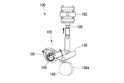
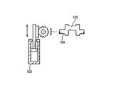
- the drive mechanism of the variable valve timing mechanism 100 described in Patent Document 4 includes a link mechanism 101 and an actuator 102 as shown in FIGS. 11A and 11B.
- the link mechanism 101 the exhaust valve swing arm 103 connected to the push rod of the engine exhaust valve is supported by the link shaft 104, and the intake valve swing arm 105 connected to the push rod of the intake valve is eccentric from the link shaft 104. It is supported by the tappet shaft 106 of the eccentric shaft portion.
- the exhaust valve swing arm 103 and the intake valve swing arm 105 can be advanced and retracted by an eccentric cam 108a of the cam shaft 108, respectively.
- the link shaft 104 is connected to a piston rod 109 provided on the actuator 102. If the position shown in FIG. 11B is before the pop-out operation of the piston rod 109, all the connected swing arms 105 and 103 are rotated to one side by the pop-out operation of the piston rod 109 by the actuator 102. Therefore, the rotation angle of all the swing arms 105 and 103 can be controlled by the actuator 102 via the link mechanism 101.
- variable valve timing mechanisms described in Patent Documents 5 and 6 are described in FIGS.
- the rotational range of the link shaft 104 is regulated by the range of the tooth portion of the sector gear 120 connected to the actuator 102, and the eccentric disk 123 eccentrically fixed to the link shaft 104 (on the tappet shaft). Is equivalent to the exhaust valve swing arm 103 and the intake valve swing arm 105.
- the position where the eccentric cam 108a of the cam shaft 108 contacts and pushes up against the exhaust valve swing arm 103 or the intake valve swing arm 105 changes with respect to the displacement of the rotational angle position of each eccentric disk 123 with respect to the rotational position of the link shaft 104. To do.
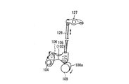
- the exhaust valve swing arm 103 and the intake valve swing arm 105 connected to the rocker arm 127 via the push rod 128 are connected to the tappet shaft 106 of the crank-shaped link shaft 104 (the fulcrum position of the swing arm). )It is connected to the.
- the actuator 102 By changing (turning) the phase of the crank-shaped link shaft 104 by the actuator 102, the fulcrum positions of the intake valve swing arm 105 and the exhaust valve swing arm 103 change, and as a result, the contact position to the camshaft 108 changes. .
- the timing at which the eccentric cam 108a of the cam shaft 108 pushes the exhaust valve swing arm 103 or the intake valve swing arm 105 with the cam shaft 108 to advance and retract is variable.
- the supercharger cannot follow and cannot supply the necessary air amount. This is because the supercharger is driven by the exhaust gas, so that it does not work effectively unless the load of the gas fuel engine increases and the exhaust gas is not sufficiently supplied to the supercharger. If the amount of air is insufficient, the air-fuel ratio becomes gas rich and knocking occurs, leading to engine failure. In order to suppress the knocking, if the load is increased at a speed that can be followed by the supercharger, it takes a long time of about 10 minutes to increase the load.
- the present invention has been made in view of the above-described problems, and provides an engine system and a control method for the engine system that can reduce the load increase time by suppressing knocking that occurs when the load of the gas fuel engine is increased.
- the purpose is to do.
- the engine system according to the present invention is an engine system including a four-stroke engine using gas as fuel, and sets a change in timing for closing the intake valve of the engine when the load on the output shaft of the engine increases. And a variable intake valve timing mechanism that changes the timing at which the intake valve closes in accordance with the intake valve close timing set by the control unit, and the variable intake valve is increased as the load on the output shaft of the engine increases. Control which lowers the compression ratio of the gas-air mixture in the engine is performed by a timing mechanism.
- FIG. 10A shows a normal 4-stroke cycle process
- FIG. 10B shows a mirror cycle process.
- the intake valve is normally closed at the bottom dead center of the piston (see FIG. 10A). If the closing timing is made earlier than the bottom dead center (see FIG. 10B), since the expansion of the air-fuel mixture continues even after the intake valve is closed, the in-cylinder temperature Ts is lower than in the case of FIG. 10A (Ts * ⁇ Ts).
- the timing at which the intake valve closes is advanced (advanced) from the intake bottom dead center or delayed (delayed).
- control is performed to lower the compression ratio of the air-fuel mixture in the combustion chamber of the engine.
- the temperature in the combustion chamber at the time of compression is lowered, so that knocking can be suppressed.
- the compression ratio of the air-fuel mixture is lowered in the combustion chamber, the ignitability deteriorates at the time of start-up and at a low load, and further, the fuel efficiency is deviated from a favorable condition, resulting in a demerit that fuel efficiency is deteriorated.
- the control for lowering the compression ratio at a larger rate is performed by changing the closing timing of the intake valve more greatly in the operation region where the load that is more likely to cause knocking increases.
- a torque sensor for measuring the torque of the output shaft and a rotational speed sensor for measuring the rotational speed of the output shaft are provided. Therefore, it is preferable to set a change in timing for closing the intake valve in the control unit.
- the fuel gas since the fuel gas is an elastic body, it is relatively difficult to obtain an accurate fuel supply amount as compared with the liquid fuel. Therefore, it is preferable to calculate the load in relation to the rotational speed by actually measuring the torque with a torque sensor.
- the load of the output shaft of the engine can be obtained in real time by taking the product of the rotational speed measurement value of the output shaft obtained by providing the rotational speed sensor and the torque measurement value by the torque sensor.
- variable intake valve timing mechanism may adjust the advance angle from the top dead center when the intake valve closes.
- the effect of lowering the compression ratio can be obtained regardless of whether the intake valve close timing is advanced or retarded, and can be applied to the present invention.
- the delay of the closing timing of the intake valve may be harmful due to the air-fuel mixture being blown back to the intake system, it is more desirable to set the advance timing of the closing timing of the intake valve.
- the advance angle of the closing timing of the intake valve in the variable intake valve timing mechanism may be adjusted continuously or in multiple stages. It is preferable to set the advance angle of the closing timing of the intake valve to be continuously variable or variable in accordance with the change of the load in order to suppress knocking and shorten the load increase time. .
- the advance angle determined by the control unit may be set from an advance value that is set by using the load and rotation speed data of a plurality of output shafts measured in advance as parameters.
- a suitable value for the advance angle of the closing timing of the intake valve becomes larger when the load is large, but in addition to this, it also depends on the rotational speed. Therefore, knocking can be further suppressed by creating a map including at least these two parameters in advance and controlling the advance timing of the intake valve closing timing in accordance with changes in engine load and rotational speed.
- a generator may be connected to the output shaft, and the load of the output shaft may be set by the electric power generated by the generator.
- the load of the output shaft can be obtained by obtaining the magnitude of the power generated by the connected generator using a power meter or the like.
- the engine intake pipe preferably includes a supercharger that performs supercharging and an air cooler that cools the air from the supercharger before supplying the air to the intake pipe.
- a supercharger that performs supercharging
- an air cooler that cools the air from the supercharger before supplying the air to the intake pipe.
- a supercharger is provided in the intake pipe of the engine to compensate for the decrease in the air-fuel mixture, and air can be cooled by an air cooler to suppress the rise in air temperature due to supercharging, increasing the amount of air-fuel mixture This contributes to increasing the load on the engine and can suppress knocking by reducing the temperature of the air, so that the load increase time can be shortened.
- An engine system control method is an engine system control method including an engine using gas as fuel, and sets a change in timing for closing an intake valve of the engine when the load on the output shaft of the engine increases. And a step of mechanically changing the timing at which the intake valve closes in accordance with the set timing at which the intake valve closes, and the timing at which the intake valve closes mechanically as the load on the output shaft of the engine increases.
- the compression ratio of the gas / air mixture in the engine is further lowered by changing to.
- the timing at which the intake valve closes is advanced (advanced) or delayed (retarded) from the suction bottom dead center. Then, control is performed to lower the compression ratio of the air-fuel mixture in the combustion chamber of the engine. By reducing the compression ratio, the temperature in the combustion chamber at the time of compression is lowered, so that knocking can be suppressed.
- the compression ratio of the air-fuel mixture in the engine can be lowered. You can save time.
- FIG. 1 It is a block diagram which shows the principal part structure of the marine dual fuel engine by embodiment of this invention. It is a figure which shows the diesel mode and gas mode in the dual fuel engine shown in FIG. It is a three-dimensional map which shows the relationship between load, rotation speed, and valve closing timing of an intake valve. It is a graph which shows a knocking suppression range by the relationship between load, rotation speed, and valve closing timing of an intake valve. It is a 2nd map which shows the relationship between the valve closing timing obtained by the 1st map, and the 1st electric signal. It is a flowchart which shows the change process of the intake valve opening / closing timing of the dual fuel engine shown in FIG.
- FIG. 13A It is a perspective view which shows the other example of the conventional variable intake valve timing mechanism. It is a figure which shows the further another example of the conventional variable intake valve timing mechanism. It is a figure which shows the relationship between the actuator and link shaft in the conventional variable intake valve timing mechanism shown to FIG. 13A.
- FIG. 9 shows the relationship between the angle of the crankshaft of the engine and the lift amounts of the intake valve and the exhaust valve.
- the origin of the crank angle shown on the horizontal axis is the compression top dead center, 0 to 180 degrees is the expansion stroke, 180 degrees to 360 degrees is the exhaust stroke, 360 degrees to 540 degrees is the intake stroke, 540 degrees to 720 degrees is the compression stroke It is a journey.
- the large peak in the exhaust stroke is the lift amount of the exhaust valve
- the small peak indicates the lift amount of the intake valve at high load and low load, respectively.
- the opening / closing timing of the intake valve substantially coincides with the intake stroke, starts to open around 340 degrees, and closes around 540 degrees.
- the opening / closing timing of the intake valve is controlled to advance by the VIVT mechanism.
- the closing timing of the intake valve is not controlled from the initial 545 degrees according to the load. The control is performed in stages, and the valve closing timing is controlled to be 505 degrees at a high load.
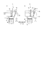
- a marine dual fuel engine 1 (hereinafter, simply referred to as an engine 1) shown in FIGS. 1 and 2 includes diesel mode D and gas mode G engines. During operation, the diesel mode D and gas mode G are provided. It is an engine that can be switched between.
- a dual fuel engine 1 shown in FIG. 1 has a mechanism of a crankshaft 2 as an output shaft connected to a propeller or the like, and the crankshaft 2 is connected to a piston 4 installed in a cylinder block 3.
- a combustion chamber 6 is formed by a piston 4 and an engine head 5 provided in the cylinder block 3.
- the combustion chamber 6 is sealed by an intake valve 8 and an exhaust valve 9 attached to the engine head 5 and a fuel injection valve 10 used in the diesel mode D.
- the engine head 5 is provided with a micro pilot oil injection valve 11 used in the gas mode.
- An intake pipe 13 is connected to the intake port where the intake valve 8 of the engine head 5 is installed, and an exhaust pipe 14 is installed to the exhaust port where the exhaust valve 9 is installed.
- An electromagnetic valve 15 that controls gas injection is installed in the intake pipe 13, and a supercharger 17 that communicates with the air cooler 16 and the exhaust pipe 14 is installed on the upstream side thereof.
- the dual fuel engine 1 can be operated by switching between the diesel mode D and the gas mode G as shown in FIG.
- the diesel mode D for example, heavy fuel oil A or the like can be mechanically injected from the fuel injection valve 10 into the compressed air in the combustion chamber 6 as fuel oil, ignited and burned.
- fuel gas such as natural gas is injected into the intake pipe 13 by the electromagnetic valve 15 and premixed with the air flow to supply the air-fuel mixture into the combustion chamber 6. Pilot fuel is injected from the pilot oil injection valve 11 to ignite and burn.
- the micro pilot oil injection valve 11 is electronically controlled, for example, and injects a small amount of pilot fuel as a powerful ignition source.
- the engine 1 is started in a diesel mode D in which liquid fuel is injected into the combustion chamber 6 from the fuel injection valve 10. After it is confirmed that the gas pressure higher than the reference value is supplied to the engine 1, the gas fuel is injected into the intake pipe 13 by the solenoid valve 15 and mixed with the air, and then flows into the combustion chamber 6. The operation is performed in the gas mode G in which the fuel is burned. When stopping, change to diesel mode D again and stop. The diesel mode D and the gas mode G can be changed except when starting and stopping .
- the dual fuel engine 1 includes a gas engine system that performs load control when the load increases in the gas mode G.
- a rotation speed sensor 20 and a torque sensor 21 are attached to the crankshaft 2.
- the rotation speed sensor 20 measures the rotation speed (rotational speed) of the crankshaft 2
- the torque sensor 21 measures the crankshaft 2.
- the torque sensor 21 for example, a sensor that detects the torque applied to the shaft by strain can be used.
- the measurement data measured by the rotation speed sensor 20 and the torque sensor 21 are output as signals to the control unit 22 that controls the engine 1.
- the control unit 22 detects the operating state of the engine 1 based on signals from the rotation speed sensor 20 and the torque sensor 21.
- a method for obtaining the load of the engine 1 a method of estimating from the fuel supply amount and other information related to the operating state of the engine 1, a torque sensor is provided in the power transmission system of the output shaft of the engine 1, and the actual torque There is a method of obtaining a load by measuring.
- the gas used as fuel is an elastic body, it is relatively difficult to obtain an accurate fuel supply amount as compared with liquid fuel. Therefore, it is preferable to calculate the load by actually measuring the torque with the torque sensor 21.
- the load A and the torque measurement value T are in a directly proportional relationship. Under the condition where the rotational speed n is constant, it is desirable to set the advance timing of the closing timing of the intake valve 8 at a larger rate as the load A is larger, that is, as the torque data T is larger.
- the control unit 22 stores a first map 24 for determining a first electric signal of intake valve opening / closing timing prepared in advance and a second map 25 for determining opening / closing timing corresponding to the first electric signal.
- the control unit 22 based on the rotational speed data n and the torque data T corresponding to the load A of the engine 1 measured by the rotational speed sensor 20 and the torque sensor 21, the control unit 22 calculates the engine 1 by the above formulas (1) and (2). The load A is calculated. Then, the first electric signal corresponding to the opening / closing timing of the intake valve 8 is selected on the first map 24 by the rotation speed n and the load A. Based on the first electric signal, the opening / closing timing of the intake valve 8 corresponding to the first electric signal is determined in the second map 25.
- the second electrical signal at the opening / closing timing set by the control unit 22 is transmitted to the electropneumatic converter 27, and the electropneumatic converter 27 converts the opening / closing timing signal into air pressure.
- This air pressure is sent to the actuator 28 to control the drive of the variable intake valve timing mechanism 30.
- the actuator 28 is supplied with air pressures P1 and P2 for driving and control from the first pressure reducing regulator 34 and the electropneumatic converter 27.
- the air pressure supplied to the actuator 28 is compressed by the air compressor 32 and stored in the air tank 33.
- the air pressure in the air tank 33 is reduced to a required pressure by the first pressure reducing regulator 34.
- the pressure at this time is adjusted by changing the valve opening degree of the first pressure-reducing regulator 34, and is supplied to the actuator 28 as the driving air pressure P1.
- the pressure P1 measured by the pressure gauge 36 is equal to or less than a specified value, the engine 1 cannot be started.
- the air pressure for driving the electropneumatic converter 27 is supplied after the pressure is further reduced from the first pressure reduction regulator 34 by the second pressure reduction regulator 37.
- the electropneumatic converter 27 supplies the air pressure corresponding to the input second electrical signal at the opening / closing timing to the actuator 28 as the air pressure P2 for adjusting the operation of the actuator 28. Based on these air pressures P1 and P2, the rod 28a of the actuator 28 is operated to operate the variable intake valve timing mechanism 30.
- the actuator 28 is, for example, a known P-cylinder (cylinder with a positioner), and controls the advance / retreat of the rod 28 a based on the pressures P 1 and P 2 input from the first pressure-reducing regulator 34 and the electropneumatic converter 27.
- the drive of the variable intake valve timing mechanism 30 is controlled, and the closing timing of the intake valve 8 is advanced (advance) or delayed (delay).
- the angle By controlling the angle, the compression ratio is lowered and control is performed. Since the time between the opening timing and the closing timing of the intake valve 8 does not change, when the opening timing advances from the suction bottom dead center, the closing timing also advances from the suction top dead center by the same time.
- the timing of valve opening and closing is changed in accordance with the load of the engine 1 to suppress knocking and shorten the load increase time.
- the opening / closing timing of the intake valve 8 is set by the first map 24 and the second map 25 in the control unit 22 based on the load A and the rotational speed n of the engine 1, and the intake valve 8 is controlled by the actuator 28 and the variable intake valve timing mechanism 30.
- the valve opening and closing timing is adjusted so that knocking can be suppressed.
- variable intake valve timing mechanism 30 has a structure similar to that shown in FIGS. That is, in the variable intake valve timing mechanism 30, for example, a link shaft whose rotation angle range is set via a sector gear according to the moving length of the rod 28a of the actuator 28 and a cam shaft having an eccentric cam are arranged in parallel. Yes.
- An exhaust swing arm is connected to the link shaft, and an intake swing arm is connected to a tappet shaft provided at an eccentric position of the link shaft.
- An intake valve 8 is connected to the intake swing arm via a push rod and a rocker arm, and an exhaust valve 9 is connected to the exhaust swing arm via a push rod and a rocker arm.
- the distance between the cam shaft and the intake swing arm changes depending on the rotation angle of the tappet shaft according to the rotation of the link shaft, and the timing at which the eccentric cam of the cam shaft starts to change changes.
- the valve closing timing can be changed to an advance angle (or a delay angle).
- the rotation angle of the tappet shaft is changed by the moving length of the rod 28a of the actuator 28.
- the moving length of the rod 28 a is arbitrarily changed by the control air pressures P 1 and P 2 supplied to the actuator 28.
- the magnitude of the advance angle, which is the closing timing of the intake valve 8 is determined by the timing at which the eccentric cam of the cam shaft starts to hit the intake swing arm connected to the tappet shaft of the link shaft.
- the tappet shaft rotating device in the variable intake valve timing mechanism 30 may use a servo motor (not shown) instead of the actuator 28.
- a signal of the opening / closing timing transmitted from the second map 25 of the control unit 22 is input to the servo motor.
- the servo motor can change the opening / closing timing of the intake valve 8 by rotating the link shaft by an amount corresponding to the received signal and rotating the tappet shaft so as to approach and separate from the cam shaft.
- the configuration from the actuator 28 and the air compressor 32 to the pressure gauge 38 is not necessary. Further, the servo motor is driven by a controller instead of the electropneumatic converter 27.
- gas fuel is supplied to a gas vaporizer 41 from an LNG gas tank 40 in which gas fuel such as natural gas is stored, and the gas pressure is reduced to a necessary gas pressure by a gas regulator 42.
- the pressure at this time is displayed on the pressure gauge 43, adjusted by changing the valve opening of the gas regulator 42, and injected from the electromagnetic valve 15 into the intake pipe 13 as gas fuel for combustion.
- the gas fuel and supercharged air cooled by the air cooler 16 are mixed and supplied to the combustion chamber 6.
- the supply amount of the gas fuel is increased by the operation of the electromagnetic valve 15.
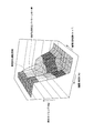
- FIG. 3 is a three-dimensional map showing details of the first map 24 for determining the closing timing of the intake valve 8 based on the rotation speed n of the crankshaft 2 and the load A of the engine 1.
- the first map 24 was created based on the steps of the following experimental procedures (1) to (18). In the experiment, a dual fuel engine 1 of the same model that was actually used was used. (1) The engine 1 is started, the rotational speed n is set to 400 min ⁇ 1 , the load A is set to 10%, and the closing timing of the intake valve 8 is set to 545 deg (the latest closing timing in terms of structure).
- knocking abnormal combustion called knocking that occurs when the engine 1 is driven and the exhaust temperature at that time are measured. Knocking is detected by a knock sensor (not shown) attached to each engine head 5. When knocking occurs, the normal combustion waveform is superimposed on the high-frequency pressure fluctuation.
- the exhaust temperature at the time of knocking measurement is measured by a temperature sensor attached to the exhaust pipe 14.
- the closing timing of the intake valve 8 is decreased by 5 degrees, and the measurement of (2) is performed again. Measurement is performed by changing the valve closing timing to 500 deg (the earliest valve closing timing in terms of structure).
- the load is increased stepwise by 10% until it reaches 110%, and the measurements in (2) and (3) are repeated again.
- FIG. 4 is a graph showing the measurement result of (7) above with three axes of the rotation speed n, the load A, and the opening / closing timing.
- a range surrounded by a straight line is a range where knocking is suppressed and the engine 1 can be operated safely.
- NOx nitrogen oxides
- FIG. 4 Next, nitrogen oxides (hereinafter referred to as NOx) are within a three-dimensional region surrounded by a straight line shown in FIG. 4 that can be operated safely, as measured by the experiments (1) to (8). Further experiments are conducted to find a setting that is below the reference value and has the highest thermal efficiency.
- the engine speed n is set to 400 min ⁇ 1
- the load A is set to 10%
- the valve closing timing of the intake valve 8 is set to 545 deg.
- knocking is detected by increasing the rotational speed n and the load A in an arbitrary load increasing pattern.
- the load increasing pattern is a change state per time of the load A and the rotation speed n, and changes depending on the propeller specifications (shape, rotation speed) of the marine propulsion device.
- the valve closing timing of the measurement point where the knocking strength detected in (15) is equal to or greater than the reference value is decreased by 3 degrees.
- the steps (15) and (16) are repeated until the knocking strength is equal to or less than the reference value, and the valve closing timing at which knocking is suppressed is determined. If the valve closing timing is decreased, the thermal efficiency deteriorates.
- the setting of the valve closing timing at which NOx and the knocking strength are equal to or less than the reference values and the highest thermal efficiency is obtained is set as the setting value of the rotation speed n and the load A.
- the valve closing timing at which knocking was suppressed from the above (17) was measured at each rotation speed n and load A, and the final first map 24 shown in FIG.
- valve closing timing according to the rotation speed n and the load A is shown in a three-dimensional graph, and the upper side in the figure is the direction in which the valve closing timing is further decreased (large advance angle).
- a region indicated by a two-dot chain line on a three-dimensional plane is a practical operation region used in the operation of an actual ship propulsion apparatus, and an example of a good load increase pattern is indicated by a one-dot chain line.
- control is performed to increase the advance angle of the valve closing timing as the engine load increases.
- the advance angle is minimized at the lower right position in the figure where the rotation speed n and the load A are small, and the advance angle increases as the rotation speed n and the load A increase. To do. There is a region where the advance angle is constant in the middle, but the advance angle is increased as the load increases as a whole. Since the load is obtained by the product of the torque and the rotational speed, it can be expressed that the advance angle increases as the torque of the output shaft increases.
- the second map 25 was created by the following experiment.
- the variable intake valve timing mechanism 30 is rotationally controlled by the actuator 28, the second map 25 is created by the following procedure.
- (1) The valve closing timing is changed by the actuator 28, and the pressure when changing to each valve closing timing is measured.
- (2) Based on the specifications of the electropneumatic converter 27, the second electrical signal necessary for supplying the pressure (1) is investigated.
- (3) From the results of (1) and (2) above, the first electric signal selected on the first map 24 on the horizontal axis and the second map 25 indicating the valve closing timing (second electric signal) on the vertical axis. create.
- the above description is for the case where the actuator 28 is used.
- the variable intake valve timing mechanism 30 is controlled to rotate by a servo motor instead of the actuator 28, the following description is given.
- the valve closing timing is changed based on the servo motor, and the second electric signal when changing to each valve closing timing is measured.
- a second map 25 is created that indicates the first electric signal on the horizontal axis and the valve closing timing (second electric signal) on the vertical axis.
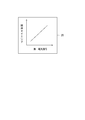
- FIG. 5 shows a detailed view of the second map 25.
- the second map 25 is a map representing the relationship between the valve closing timing (second electric signal) and the first electric signal.
- the load increasing device of the dual fuel engine 1 has the above-described configuration. Next, a load increasing method will be described.
- the air supplied from the supercharger 17 is premixed with the gas fuel injected from the electromagnetic valve 15 while being cooled by the air cooler 16 and supplied into the combustion chamber 6 in the cylinder block 3.
- the In the intake process the intake valve 8 is closed before the piston 4 reaches bottom dead center, and the piston 4 is further lowered, so that the air-fuel mixture in the combustion chamber 6 becomes negative pressure, and the temperature and compression ratio of the air-fuel mixture are reduced. Go down. Thereby, knocking can be suppressed.
- the piston 4 In the compression process, the air-fuel mixture in the combustion chamber 6 is compressed by the piston 4, fuel is injected from the micropilot oil injection valve 11 in the expansion stroke and ignited, the combustion gas expands and pushes the piston 4 to the bottom dead center, In the exhaust process, the piston 4 rises to the top dead center and exhausts the combustion gas.
- Such a control method of the gas mode G will be described along a flowchart of a method for changing the opening / closing timing of the intake valve 8 shown in FIG.
- Whether or not the required pressure P1 is supplied to the actuator 28 when the engine 1 is started is measured by the pressure gauge 36. If this value is equal to or less than a specified value, the engine 1 cannot be started. Further, when the main pressure P1 becomes a specified value or less during engine operation, the engine 1 is stopped.
- the control of the opening / closing timing of the intake valve 8 is started when the intake valve 8 is started regardless of the operation mode of the engine 1.
- the start timing is determined to have been started when a measured value signal of the rotation speed n is input from the rotation speed sensor 20 to the control unit 22.
- the state of the engine 1 is detected at predetermined intervals.
- the detected rotation speed n and torque T are input into the control unit 22 and the load A is calculated by the above equations (1) and (2).
- the rotation speed n and the measured value of the load A are input to the first map 24 for determining the intake valve opening / closing timing.
- the intake valve opening / closing timing corresponding to the input load A and the rotational speed n is determined and output as a first electric signal.
- the first electric signal is input to the second map 25, the opening / closing timing corresponding to the first electric signal is set, the second electric signal corresponding to the opening / closing timing is determined by the second map 25, and the electropneumatic converter 27 is determined.
- the opening / closing timing is set as an advance angle of the opening timing and closing timing of the intake valve 8 from the intake bottom dead center and the intake top dead center of the piston 4.
- Adjustment of the advance angle of the closing timing and opening timing of the intake valve 8 in the variable intake valve timing mechanism 30 is performed so as to change continuously or in multiple stages according to the rotational speed n of the engine 1 and the load A.
- the advance angle of the timing of closing and opening the intake valve 8 can be made in two stages of “1” with advance and “0” without advance, but the number of revolutions n and load A are used as parameters.
- the control air pressure P2 corresponding to the input second electric signal is supplied to the actuator 28.
- the moving length of the rod 28a of the actuator 28 is changed by the control air pressure P2 supplied to the actuator 28, and the tappet shaft of the variable intake valve timing mechanism 30 is rotated by a required angle.
- the moving length of the rod 28a varies depending on the amount of control air pressure P2 supplied to the actuator 28.
- the variable intake valve timing mechanism 30 the distance between the intake valve swing arm connected to the tappet shaft and the cam shaft is changed by the rotation of the tappet shaft, and the timing at which the eccentric cam provided on the cam shaft starts to change changes. From this change, the opening / closing timing of the intake valve 8 when the load is increased changes. Knocking can be suppressed by changing the opening / closing timing of the intake valve 8.
- the intake valve 8 can detect the state of the engine 1 at the time of increasing the load at predetermined intervals based on the load A and the rotation speed n, and can suppress knocking by the first map 24 and the second map 25 of the control unit 22.
- the opening / closing timing of the intake valve 8 is advanced by the actuator 28 and the variable intake valve timing mechanism 30 to suppress knocking, thereby shortening the load increase time.
- FIG. 7 shows a flowchart in the case where the rotation of the tappet shaft is controlled using a servo motor instead of the electropneumatic converter 27 and the actuator 28.
- the engine speed is increased from the first map 24 and the second map 25 by inputting the measured values of the rotational speed n and the torque T detected at predetermined intervals to the control unit 22.
- the opening / closing timing of the intake valve 8 according to the state is sequentially selected.
- the second electric signal transmitted from the second map 25 is input to the servo motor via the controller.
- the servo motor calculates the rotational position corresponding to the input second electrical signal, rotates the tappet shaft by rotating the link shaft by the required angle, and changes the opening / closing timing of the intake valve 8 from the bottom dead center and top dead center To do.
- the load increase response test in the gas mode G was performed on the dual fuel engine 1 according to the embodiment of the present invention.
- the air temperature was set to 18 ° C, 25 ° C, 36 ° C, and 37 ° C.
- the engine speed n, torque T, and elapsed time were measured at predetermined intervals from the start of load increase in the idle rotation state until the rated load (rated rotation) was reached.
- the result was as shown in FIG.
- the temperatures were 18 ° C, 25 ° C, 36 ° C, and 37 ° C. In either case, the rated load was reached in about 20 seconds. For this reason, the load raising speed can be remarkably improved.
- the diesel mode D is switched to the gas mode G, and the first is based on the engine speed n and the torque T measured at predetermined intervals.
- the load increase time can be shortened by sequentially advancing the opening / closing timing of the intake valve 8 so as to suppress knocking by the map 24 and the second map 25.
- the opening / closing timing is selected within the range of the three-dimensional map shown in FIG. 4, the generation of NOx can be reduced.
- the efficiency at low load can be improved by optimizing the opening / closing timing of the intake valve 8.
- gas system according to the present invention is not limited to the dual fuel engine 1 according to the above-described embodiment, and can be appropriately changed or replaced without departing from the gist of the present invention.
- modifications and the like of the present invention will be described, but the same or similar parts and components as those described in the above-described embodiments will be described using the same reference numerals.
- the gas system according to the present invention is not limited to the dual fuel engine 1 capable of switching between the diesel mode D in which liquid fuel is the main fuel and the gas mode G in which gas is the main fuel, and uses gas as the fuel. It can also be applied to gas engines. In that case, it is applicable also to the generator which uses gas as the main fuel. In this case, a generator may be connected to the output shaft instead of the torque sensor, and the load on the output shaft may be measured by the electric power generated by the generator.
- the present invention is not limited to the load increase pattern of the marine engine, but can be applied to a load increase pattern that can be used in a vehicle or an emergency generator.
- the change of the valve opening timing and the valve closing timing of the intake valve 8 at the time of increasing the load is set by the advance angle from the intake bottom dead center and the intake top dead center of the piston 4. Without being limited to the advance angle, it may be set with a retard angle. The effect of lowering the compression ratio of the air-fuel mixture can be obtained regardless of whether the operation is advanced or retarded. However, since the delay of the timing for closing the intake valve 8 may be harmful due to the air-fuel mixture being blown back to the intake system, the advance timing of the opening / closing timing of the intake valve 8 may be applied to an actual engine 1. It is more desirable to adopt.
- the variable intake valve timing mechanism 30 changes both the valve opening timing and the valve closing timing and does not change the time during which the intake valve is open. One or both of the valve opening timings may be selected and changed.
- the present invention provides a gas system that uses a premixed gas fuel and air to suppress knocking at the time of load increase and shorten the load increase time, and a control method therefor.
Landscapes
- Engineering & Computer Science (AREA)
- Chemical & Material Sciences (AREA)
- Combustion & Propulsion (AREA)
- Mechanical Engineering (AREA)
- General Engineering & Computer Science (AREA)
- Oil, Petroleum & Natural Gas (AREA)
- Output Control And Ontrol Of Special Type Engine (AREA)
- Combined Controls Of Internal Combustion Engines (AREA)
- Supercharger (AREA)
Abstract
Description
特許文献2の予混合燃焼モードでは、吸気弁の閉弁時期を下死点前60°~70°の所定の位置に設定するものであり、予混合燃焼モードの中で進角を変化させてはいない。 In the dual fuel engine described in
In the premixed combustion mode of
特許文献4に記載の可変バルブタイミング機構100の駆動機構は、図11A、11Bに示すようにリンク機構101とアクチュエータ102とを備えている。リンク機構101では、エンジンの排気バルブのプッシュロッドに連結された排気バルブスイングアーム103がリンクシャフト104に支持され、吸気バルブのプッシュロッドに連結された吸気バルブスイングアーム105がリンクシャフト104から偏心した偏心軸部のタペット軸106に支持されている。 Examples of specific configurations of the variable valve timing mechanism are described in
The drive mechanism of the variable
図11Bに示す位置をピストンロッド109の飛び出し動作前とすると、アクチュエータ102によるピストンロッド109の飛び出し動作によって、連結された全てのスイングアーム105,103が一方に回転する。そのため、アクチュエータ102によってリンク機構101を介して全てのスイングアーム105,103の回動角度を制御できる。 The exhaust
If the position shown in FIG. 11B is before the pop-out operation of the
図12に示す可変バルブタイミング機構では、アクチュエータ102に連結した扇形ギヤ120の歯部の範囲でリンクシャフト104の回転範囲が規制され、リンクシャフト104に偏心して固定された偏心ディスク123(タペット軸に相当する)が排気バルブスイングアーム103や吸気バルブスイングアーム105の基部に保持されている。
そのため、リンクシャフト104の回転位置に対する各偏心ディスク123の回転角度位置のずれに対して、排気バルブスイングアーム103や吸気バルブスイングアーム105にカム軸108の偏心カム108aが当接して押し上げる位置が変化する。 As another example, variable valve timing mechanisms described in
In the variable valve timing mechanism shown in FIG. 12, the rotational range of the
Therefore, the position where the
一方で、船舶用機関においても有害排気ガスの排出規制が年々厳しくなっており、燃料由来による有害排気ガスの排出量が少なく排出規制を満足することができるデュアルフューエルエンジンを導入することが要望されている。しかし、このようなデュアルフューエルエンジンの導入のためには、船舶用機関の運転モードを満たすために負荷上げ時間を20秒程度にまで短縮する必要があった。 By the way, in the conventional gas fuel engine, even if the supply amount of the gas fuel is increased at a fast rate in order to rapidly increase the load, the supercharger cannot follow and cannot supply the necessary air amount. This is because the supercharger is driven by the exhaust gas, so that it does not work effectively unless the load of the gas fuel engine increases and the exhaust gas is not sufficiently supplied to the supercharger. If the amount of air is insufficient, the air-fuel ratio becomes gas rich and knocking occurs, leading to engine failure. In order to suppress the knocking, if the load is increased at a speed that can be followed by the supercharger, it takes a long time of about 10 minutes to increase the load.
On the other hand, emission regulations for harmful exhaust gases are becoming stricter every year in marine engines, and there is a demand for the introduction of a dual fuel engine that can meet the emission regulations with little emission of harmful exhaust gases derived from fuel. ing. However, in order to introduce such a dual fuel engine, it has been necessary to reduce the load increase time to about 20 seconds in order to satisfy the operation mode of the marine engine.
例えばガスエンジンにおいて、通常、吸気弁はピストンの下死点に閉まる(図10A参照)。閉まるタイミングを下死点より早くすると(図10B参照)、吸気弁の閉弁後にも混合気の膨張が続くため、筒内温度Tsが図10Aの場合より下がる(Ts*<Ts)。その分だけ上死点時の最高圧縮温度も低下することより(Tc*<Tc)、自着火を防ぐことができてノッキングが抑制される。
ミラーサイクルの欠点として、圧縮温度が下がって低負荷域の着火性が悪化するため、起動時や低負荷時には図10Aに示す通常の吸気弁の開弁タイミングに戻し、高負荷時のみ吸気弁の開弁タイミングを早くする必要がある。 As an engine knocking suppression technique, an effective compression ratio can be lowered by using a variable intake valve timing (VIVT) mechanism. In this regard, the knocking suppression technique will be described with reference to FIGS. 10A and 10B. FIG. 10A shows a normal 4-stroke cycle process, and FIG. 10B shows a mirror cycle process.
For example, in a gas engine, the intake valve is normally closed at the bottom dead center of the piston (see FIG. 10A). If the closing timing is made earlier than the bottom dead center (see FIG. 10B), since the expansion of the air-fuel mixture continues even after the intake valve is closed, the in-cylinder temperature Ts is lower than in the case of FIG. 10A (Ts * <Ts). Accordingly, since the maximum compression temperature at the top dead center is also lowered (Tc * <Tc), self-ignition can be prevented and knocking is suppressed.
As a disadvantage of the Miller cycle, since the compression temperature is lowered and the ignitability in the low load region is deteriorated, the normal intake valve opening timing shown in FIG. The valve opening timing needs to be advanced.
なお、燃焼室内で混合気の圧縮比を下げると、起動時や低負荷時では着火性が悪化する上に燃料効率の点で有利な条件から離れてしまい、燃費が悪化するデメリットが生じる。そこで、本発明では、よりノッキングが生じ易い負荷がより増大する運転領域において吸気弁が閉じるタイミングをより大きく変更させて、より大きい割合で圧縮比を下げる制御を行う。これにより、負荷の変化に応じてノッキングを抑制させ、燃費の悪化を防止しつつ負荷上げ時間を短縮させることができる。 In the gas engine according to the present invention, when the gas fuel supply amount is increased and the load on the output shaft of the gas engine increases, the timing at which the intake valve closes is advanced (advanced) from the intake bottom dead center or delayed (delayed). Thus, control is performed to lower the compression ratio of the air-fuel mixture in the combustion chamber of the engine. By reducing the compression ratio, the temperature in the combustion chamber at the time of compression is lowered, so that knocking can be suppressed.
If the compression ratio of the air-fuel mixture is lowered in the combustion chamber, the ignitability deteriorates at the time of start-up and at a low load, and further, the fuel efficiency is deviated from a favorable condition, resulting in a demerit that fuel efficiency is deteriorated. Therefore, in the present invention, the control for lowering the compression ratio at a larger rate is performed by changing the closing timing of the intake valve more greatly in the operation region where the load that is more likely to cause knocking increases. Thereby, knocking can be suppressed in accordance with a change in load, and the load increase time can be shortened while preventing deterioration in fuel consumption.
本発明によるガスエンジンでは、燃料となるガスは弾性体であるため液体燃料に比べて正確な燃料の供給量を得ることが相対的に難しい。そこで、トルクセンサにより実際にトルクの測定を行うことで回転数との関係で負荷を演算するが好ましい。しかも、回転数センサを備えることで得られる出力軸の回転数測定値とトルクセンサによるトルク測定値の積をとることで、エンジンの出力軸の負荷をリアルタイムに求めることができる。 In addition, a torque sensor for measuring the torque of the output shaft and a rotational speed sensor for measuring the rotational speed of the output shaft are provided. Therefore, it is preferable to set a change in timing for closing the intake valve in the control unit.
In the gas engine according to the present invention, since the fuel gas is an elastic body, it is relatively difficult to obtain an accurate fuel supply amount as compared with the liquid fuel. Therefore, it is preferable to calculate the load in relation to the rotational speed by actually measuring the torque with a torque sensor. Moreover, the load of the output shaft of the engine can be obtained in real time by taking the product of the rotational speed measurement value of the output shaft obtained by providing the rotational speed sensor and the torque measurement value by the torque sensor.
吸気弁の閉じるタイミングの進角、遅角、いずれの動作であっても圧縮比を下げる効果を得ることができて本発明に適用可能である。しかし、吸気弁の閉じるタイミングの遅角は、混合気を吸気系統へ吹き戻すことによる弊害の可能性があることから、吸気弁の閉じるタイミングの進角を設定することがより望ましい。 Further, the variable intake valve timing mechanism may adjust the advance angle from the top dead center when the intake valve closes.
The effect of lowering the compression ratio can be obtained regardless of whether the intake valve close timing is advanced or retarded, and can be applied to the present invention. However, since the delay of the closing timing of the intake valve may be harmful due to the air-fuel mixture being blown back to the intake system, it is more desirable to set the advance timing of the closing timing of the intake valve.
吸気弁の閉じるタイミングの進角は、負荷の変化に応じて連続的に可変に設定するか段階的に可変に設定する動作とすることが、ノッキングの抑制と負荷上げ時間の短縮のために好ましい。 Further, the advance angle of the closing timing of the intake valve in the variable intake valve timing mechanism may be adjusted continuously or in multiple stages.
It is preferable to set the advance angle of the closing timing of the intake valve to be continuously variable or variable in accordance with the change of the load in order to suppress knocking and shorten the load increase time. .
吸気弁の閉じるタイミングの進角の好適な値は、負荷が大きい場合により大きくなるが、これに加えて回転速度にも依存する。そのため、少なくともこれら二種のパラメータを含むマップを予め作成し、エンジンの負荷と回転数の変化に応じて吸気弁の閉じるタイミングの進角を制御することでノッキングをより抑制できる。 Further, the advance angle determined by the control unit may be set from an advance value that is set by using the load and rotation speed data of a plurality of output shafts measured in advance as parameters.
A suitable value for the advance angle of the closing timing of the intake valve becomes larger when the load is large, but in addition to this, it also depends on the rotational speed. Therefore, knocking can be further suppressed by creating a map including at least these two parameters in advance and controlling the advance timing of the intake valve closing timing in accordance with changes in engine load and rotational speed.
エンジンシステムを発電に用いる場合、接続された発電機で発電する電力の大きさを電力測定器等によって求めることで、出力軸の負荷とすることができる。 Further, a generator may be connected to the output shaft, and the load of the output shaft may be set by the electric power generated by the generator.
When the engine system is used for power generation, the load of the output shaft can be obtained by obtaining the magnitude of the power generated by the connected generator using a power meter or the like.
負荷が大きい場合ほど吸気弁の閉弁の進角または遅角を大きくして圧縮比を下げることによりノッキングの発生を抑制できるが、燃焼室に吸気できる混合気の量が減少するのでエンジンの負荷上げには不利になる。そのため、エンジンの吸気管に過給機を設けることで混合気の減少を補うと共に、エアクーラによって空気を冷却することで過給による空気の温度上昇を抑制することができ、混合気の量を増大させてエンジンの負荷上げに貢献すると共に空気の温度低減によってノッキングを抑制できるため、負荷上げ時間の短縮を進めることができる。 The engine intake pipe preferably includes a supercharger that performs supercharging and an air cooler that cools the air from the supercharger before supplying the air to the intake pipe.
As the load increases, knocking can be suppressed by increasing the advance or retard angle of the intake valve to lower the compression ratio, but the amount of air-fuel mixture that can be sucked into the combustion chamber decreases. It is disadvantageous to raise. For this reason, a supercharger is provided in the intake pipe of the engine to compensate for the decrease in the air-fuel mixture, and air can be cooled by an air cooler to suppress the rise in air temperature due to supercharging, increasing the amount of air-fuel mixture This contributes to increasing the load on the engine and can suppress knocking by reducing the temperature of the air, so that the load increase time can be shortened.
本発明によるガスエンジンシステムの制御方法では、ガスエンジンの出力軸の負荷が増大した場合に、吸気弁が閉じるタイミングを吸入下死点から進める(進角)か、または遅らせる(遅角)ことで、エンジンの燃焼室内における混合気の圧縮比を下げる制御を行う。圧縮比を下げることで圧縮時の燃焼室内の温度が低くなるためノッキングを抑制することができる。 An engine system control method according to the present invention is an engine system control method including an engine using gas as fuel, and sets a change in timing for closing an intake valve of the engine when the load on the output shaft of the engine increases. And a step of mechanically changing the timing at which the intake valve closes in accordance with the set timing at which the intake valve closes, and the timing at which the intake valve closes mechanically as the load on the output shaft of the engine increases. The compression ratio of the gas / air mixture in the engine is further lowered by changing to.
In the gas engine system control method according to the present invention, when the load on the output shaft of the gas engine increases, the timing at which the intake valve closes is advanced (advanced) or delayed (retarded) from the suction bottom dead center. Then, control is performed to lower the compression ratio of the air-fuel mixture in the combustion chamber of the engine. By reducing the compression ratio, the temperature in the combustion chamber at the time of compression is lowered, so that knocking can be suppressed.
低負荷では吸気弁の開閉タイミングは吸気行程とほぼ一致しており340度付近で開き始め、540度付近で閉じる。また、高負荷では吸気弁の開閉タイミングはVIVT機構によって進角で進める制御を行い、後述する実施形態において、吸気弁の閉弁タイミングを当初の545度から負荷に応じて進角の制御を無段階で行い、高負荷では閉弁のタイミングが505度になるように制御される。 FIG. 9 shows the relationship between the angle of the crankshaft of the engine and the lift amounts of the intake valve and the exhaust valve. The origin of the crank angle shown on the horizontal axis is the compression top dead center, 0 to 180 degrees is the expansion stroke, 180 degrees to 360 degrees is the exhaust stroke, 360 degrees to 540 degrees is the intake stroke, 540 degrees to 720 degrees is the compression stroke It is a journey. In the drawing, the large peak in the exhaust stroke is the lift amount of the exhaust valve, and the small peak indicates the lift amount of the intake valve at high load and low load, respectively.
At low load, the opening / closing timing of the intake valve substantially coincides with the intake stroke, starts to open around 340 degrees, and closes around 540 degrees. In addition, when the load is high, the opening / closing timing of the intake valve is controlled to advance by the VIVT mechanism. In the embodiment described later, the closing timing of the intake valve is not controlled from the initial 545 degrees according to the load. The control is performed in stages, and the valve closing timing is controlled to be 505 degrees at a high load.
図1及び図2に示す舶用のデュアルフューエルエンジン1(以下、単にエンジン1ということがある)はディーゼルモードDとガスモードGの各機関を備えており、運転中にディーゼルモードDとガスモードGとに切り換え可能な機関である。図1に示すデュアルフューエルエンジン1は、プロペラ等に連結された出力軸としてクランク軸2の機構を備えており、クランク軸2はシリンダーブロック3内に設置されたピストン4に連結されている。シリンダーブロック3内に設けたピストン4とエンジンヘッド5によって燃焼室6が形成されている。 Hereinafter, a dual fuel engine used as a marine internal combustion engine as an engine system according to an embodiment of the present invention will be described with reference to the accompanying drawings.
A marine dual fuel engine 1 (hereinafter, simply referred to as an engine 1) shown in FIGS. 1 and 2 includes diesel mode D and gas mode G engines. During operation, the diesel mode D and gas mode G are provided. It is an engine that can be switched between. A
エンジン1は、燃料噴射弁10より液体燃料を燃焼室6内に噴射するディーゼルモードDで始動を行う。エンジン1に基準値以上のガス圧力が供給されていることが確認された後、電磁弁15でガス燃料を吸気管13に噴射して空気と混合してから燃焼室6内に流入させ、ガス燃料を燃焼させるガスモードGで運転を行う。
停止の際には再びディーゼルモードDに変更してから停止を行う。始動時と停止時以外はディーゼルモードDとガスモードGを変更可能である。 Here, the
The
When stopping, change to diesel mode D again and stop. The diesel mode D and the gas mode G can be changed except when starting and stopping .
図1において、クランク軸2には回転数センサ20とトルクセンサ21とが取付けられており、回転数センサ20ではクランク軸2の回転数(回転速度)を計測し、トルクセンサ21ではクランク軸2によってエンジントルクを計測する。トルクセンサ21として、例えば軸にかかるトルクを歪によって検出するセンサが使用可能である。回転数センサ20とトルクセンサ21で計測した測定データはエンジン1を制御する制御部22にそれぞれ信号出力する。
制御部22では、回転数センサ20とトルクセンサ21などからの信号に基づいてエンジン1の運転状態を検出する。即ち、回転数センサ20で計測したクランク軸2の回転数をnとし、トルクセンサ21で計測したトルクをTとして、下記の式(1)と式(2)でエンジン1の負荷Aを演算する。但し、Ltはエンジン1の定格出力とする。
出力Lo=2πTn/60 (1)
負荷A=Lo/Lt×100 (2) The
In FIG. 1, a
The
Output Lo = 2πTn / 60 (1)
Load A = Lo / Lt × 100 (2)
また、回転数nを一定にした場合には、負荷Aとトルク測定値Tは正比例の関係になる。回転数nが一定の条件においては、負荷Aが大きいほど、すなわちトルクデータTが大きいほど、より大きい割合で吸気弁8の閉じるタイミングの進角を設定することが望ましい。 In addition, as a method for obtaining the load of the
Further, when the rotation speed n is constant, the load A and the torque measurement value T are in a directly proportional relationship. Under the condition where the rotational speed n is constant, it is desirable to set the advance timing of the closing timing of the
制御部22で設定された開閉タイミングの第二電気信号は電空変換器27に送信され、電空変換器27で開閉タイミングの信号が空気圧力に変換される。この空気圧力はアクチュエータ28に送られて可変吸気弁タイミング機構30の駆動を制御する。アクチュエータ28には第一減圧レギュレータ34と電空変換器27から駆動用と制御用の空気圧力P1,P2が供給される。 The
The second electrical signal at the opening / closing timing set by the
電空変換器27を駆動するための空気圧力は、第一減圧レギュレータ34から第二減圧レギュレータ37でさらに減圧されて供給される。電空変換器27は入力される開閉タイミングの第二電気信号に対応する空気圧力を、アクチュエータ28の動作を調整するための空気圧力P2としてアクチュエータ28に供給する。これらの空気圧力P1,P2に基づいてアクチュエータ28のロッド28aを動作して可変吸気弁タイミング機構30を作動させる。 The air pressure supplied to the
The air pressure for driving the
吸気弁8の開弁タイミングと閉弁タイミングの間の時間は変わらないので開弁のタイミングが吸入下死点から進むと閉弁のタイミングも吸入上死点から同一時間進む。しかも、本発明ではエンジン1の負荷に応じて開弁と閉弁のタイミングを変更することでノッキングを抑制して負荷上げ時間を短縮させるようにした。エンジン1の負荷Aと回転数nに基づいて制御部22内の第一マップ24と第二マップ25により吸気弁8の開閉タイミングを設定し、アクチュエータ28と可変吸気弁タイミング機構30によって吸気弁8の開弁と閉弁のタイミングを、ノッキングを抑制できるように調整している。 The
Since the time between the opening timing and the closing timing of the
吸気弁8の閉開タイミングである進角の大きさは、リンクシャフトのタペット軸に連結された吸気用スイングアームにカム軸の偏心カムが当たり始めるタイミングで決まる。 The distance between the cam shaft and the intake swing arm changes depending on the rotation angle of the tappet shaft according to the rotation of the link shaft, and the timing at which the eccentric cam of the cam shaft starts to change changes. As a result, the valve closing timing can be changed to an advance angle (or a delay angle). As the distance from the tappet shaft to the cam shaft center increases, the closing timing of the
The magnitude of the advance angle, which is the closing timing of the
この際の圧力は圧力計43に表示され、ガスレギュレータ42のバルブ開度を変更することによって調整し、燃焼用のガス燃料として電磁弁15から吸気管13内に噴射される。吸気管13内ではガス燃料とエアクーラ16で冷却された過給の空気とが混合されて燃焼室6に供給される。負荷上げの際は、電磁弁15の動作によりガス燃料の供給量を増加させる。 A mechanism for supplying gas fuel to the
The pressure at this time is displayed on the
第一マップ24は次の実験手順(1)~(18)の行程に基づいて作成した。
実験には、実際に使用する同一機種のデュアルフューエルエンジン1を用いた。
(1)エンジン1を始動し、回転数nを400min-1、負荷Aを10%、吸気弁8の閉弁タイミングを545deg(構造上、最も遅い閉弁タイミング)に設定する。 Next, a method for creating the
The
In the experiment, a
(1) The
ノッキングは、各エンジンヘッド5に取付けた不図示のノックセンサにより発生を検出する。ノッキング現象発生時は,通常の燃焼波形に高周波の圧力変動が重なった波形となる。 (2) Then, abnormal combustion called knocking that occurs when the
Knocking is detected by a knock sensor (not shown) attached to each
(3)上記のノッキング測定時の排気温度の測定終了後、吸気弁8の閉弁タイミングを5deg減少させ、再度(2)の計測を行う。閉弁タイミングを500deg(構造上、最も早い閉弁タイミング)まで変更して計測を行う。
(4)上記(3)の計測が終了したら、負荷を10%ずつ110%になるまで段階的に増加させて、再度(2)と(3)の計測を繰り返して行う。 The exhaust temperature at the time of knocking measurement is measured by a temperature sensor attached to the
(3) After the exhaust temperature measurement at the time of the knocking measurement is completed, the closing timing of the
(4) When the measurement in the above (3) is completed, the load is increased stepwise by 10% until it reaches 110%, and the measurements in (2) and (3) are repeated again.
(6)上記(5)の計測結果から、X軸が負荷A、Y軸が回転数n、Z軸が開閉タイミングに設定された図4の3次元グラフにおいて、安全に運転可能な計測点に●(黒丸)、安全ではない計測点に×をプロットする。これによって、負荷Aと回転数nと開閉タイミングとの関係におけるノッキング抑制範囲を選定できる。
(7)上記(1)~(6)の計測工程を、回転数nを100min-1ずつ900min-1まで上昇して行い、回転数n毎の安全に運転できる範囲を計測する。 (5) According to the measurements (1) to (4) above, when the knocking strength is less than the reference value and the exhaust temperature is 500 ° C. or less, knocking is suppressed and the
(6) From the measurement result of (5) above, in the three-dimensional graph of FIG. 4 in which the X axis is set to load A, the Y axis is set to the rotation speed n, and the Z axis is set to the opening / closing timing, ● (black circle), x is plotted at unsafe measurement points. Thereby, the knocking suppression range in the relationship among the load A, the rotational speed n, and the opening / closing timing can be selected.
(7) a measuring step of the above (1) to (6), the rotational speed n rises to 100 min -1 by 900 min -1, measured safely driving can range revolutions per n.
(9)次に上記(1)~(8)の実験により計測した図4に示す安全にエンジンを運転できる直線で囲った3次元領域の範囲内で、窒素酸化物(以下、NOxという)が基準値以下であり、熱効率が一番高い設定を探すことを目的に更に実験を行う。
エンジン回転数nを400min-1、負荷Aを10%、吸気弁8の閉弁タイミングを545degに設定する。 (8) FIG. 4 is a graph showing the measurement result of (7) above with three axes of the rotation speed n, the load A, and the opening / closing timing. In FIG. 4, a range surrounded by a straight line is a range where knocking is suppressed and the
(9) Next, nitrogen oxides (hereinafter referred to as NOx) are within a three-dimensional region surrounded by a straight line shown in FIG. 4 that can be operated safely, as measured by the experiments (1) to (8). Further experiments are conducted to find a setting that is below the reference value and has the highest thermal efficiency.
The engine speed n is set to 400 min −1 , the load A is set to 10%, and the valve closing timing of the
熱効率η=360Lo/H/L (3)
但し、H:燃料ガスの低位発熱量(J/Nm3)
Lo:現時点の出力
L:燃料流量 (10) Next, NOx and thermal efficiency are measured. NOx is measured by an exhaust gas analyzer attached to the
Thermal efficiency η = 360Lo / H / L (3)
However, H: Lower heating value of fuel gas (J / Nm 3 )
Lo: Current output L: Fuel flow rate
(12)上記(10)と(11)の計測が終了したら負荷を10%ずつ110%まで段階的に増加させ、再び(10)及び(11)の計測を繰り返して行う。閉弁タイミングは図4で示す安全に運転できる範囲内で変更する。 (11) After the measurement of (10) is completed, the closing timing of the
(12) When the measurements of (10) and (11) are completed, the load is increased stepwise by 10% to 110%, and the measurements of (10) and (11) are repeated again. The valve closing timing is changed within a range where the operation can be safely performed as shown in FIG.
(14)そして、NOxが所定値以下であり、熱効率が一番高い、吸気弁8の閉弁タイミングを各回転数nと負荷A毎に設定する。この結果により、図3に示す第一マップの原案が作成される。 (13) The above measurements (9) to (12) are performed by gradually increasing the rotational speed n by 100 min −1 stepwise to 900 min −1, and the measurement point with the best performance for each rotational speed is determined.
(14) Then, the closing timing of the
(16)上記(15)で検出されたノッキング強さが基準値以上であった計測点の閉弁タイミングを3deg減少させる。
(17)つぎに、ノッキング強さが基準値以下になるまで、(15)(16)の工程を繰り返し、ノッキングが抑制された閉弁タイミングを決定する。閉弁タイミングを減少させると熱効率は悪化する。NOx、ノッキング強さが基準値以下で熱効率が一番高い結果が得られた閉弁タイミングの設定を回転数n、負荷Aの設定値とする。
(18)上記(17)よりノッキングが抑制された閉弁タイミングを各回転数n、負荷Aでそれぞれ計測し、その結果により図3に示す最終的な第一マップ24を作成した。 (15) Further, knocking is detected by increasing the rotational speed n and the load A in an arbitrary load increasing pattern. The load increasing pattern is a change state per time of the load A and the rotation speed n, and changes depending on the propeller specifications (shape, rotation speed) of the marine propulsion device.
(16) The valve closing timing of the measurement point where the knocking strength detected in (15) is equal to or greater than the reference value is decreased by 3 degrees.
(17) Next, the steps (15) and (16) are repeated until the knocking strength is equal to or less than the reference value, and the valve closing timing at which knocking is suppressed is determined. If the valve closing timing is decreased, the thermal efficiency deteriorates. The setting of the valve closing timing at which NOx and the knocking strength are equal to or less than the reference values and the highest thermal efficiency is obtained is set as the setting value of the rotation speed n and the load A.
(18) The valve closing timing at which knocking was suppressed from the above (17) was measured at each rotation speed n and load A, and the final
一点鎖線で示した良好な負荷上げパターンの1例では、回転数nと負荷Aの小さい図中右下の位置では進角は最少とされ、回転数nと負荷Aが増すに従って進角を大きくする。途中で進角が一定となる領域も存在するが、全体として負荷が増すほど進角は大きくされる。なお、負荷はトルクと回転数の積で求められるため、出力軸のトルクが増すほど進角を大きくすると表現することもできる。 In FIG. 3, the valve closing timing according to the rotation speed n and the load A is shown in a three-dimensional graph, and the upper side in the figure is the direction in which the valve closing timing is further decreased (large advance angle). A region indicated by a two-dot chain line on a three-dimensional plane is a practical operation region used in the operation of an actual ship propulsion apparatus, and an example of a good load increase pattern is indicated by a one-dot chain line. In increasing the load in a practical operation range, control is performed to increase the advance angle of the valve closing timing as the engine load increases.
In an example of a good load increasing pattern indicated by a one-dot chain line, the advance angle is minimized at the lower right position in the figure where the rotation speed n and the load A are small, and the advance angle increases as the rotation speed n and the load A increase. To do. There is a region where the advance angle is constant in the middle, but the advance angle is increased as the load increases as a whole. Since the load is obtained by the product of the torque and the rotational speed, it can be expressed that the advance angle increases as the torque of the output shaft increases.
可変吸気弁タイミング機構30がアクチュエータ28によって回転制御されるとき、次の手順で第二マップ25を作成する。
(1)アクチュエータ28により閉弁タイミングを変更し、各閉弁タイミングに変更する際の圧力を計測する。
(2)電空変換器27の仕様より上記(1)の圧力を供給する為に必要な第二電気信号を調査する。
(3)上記(1)及び(2)の結果から、横軸に上記第一マップ24で選択した第一電気信号、縦軸に閉弁タイミング(第二電気信号)を示す第二マップ25を作成する。 Next, the
When the variable intake
(1) The valve closing timing is changed by the
(2) Based on the specifications of the
(3) From the results of (1) and (2) above, the first electric signal selected on the
(1)サーボモータに基づいて閉弁タイミングを変更し、各閉弁タイミングに変更する際の第二電気信号を計測する。
(2)上記(1)の結果により横軸に第一電気信号、縦軸に閉弁タイミング(第二電気信号)を示す第二マップ25を作成する。
なお、図5に第二マップ25の詳細図を示す。第二マップ25は閉弁タイミング(第二電気信号)と第一電気信号との関係を表すマップである。 The above description is for the case where the
(1) The valve closing timing is changed based on the servo motor, and the second electric signal when changing to each valve closing timing is measured.
(2) Based on the result of (1) above, a
FIG. 5 shows a detailed view of the
ガスモードGにおいては、過給機17から供給される空気はエアクーラ16で冷却された状態で電磁弁15から噴射されるガス燃料と予混合されてシリンダーブロック3内の燃焼室6内に供給される。吸気工程ではピストン4が下死点に到達する前に吸気弁8が閉弁し、更にピストン4が降下することで燃焼室6内の混合気が負圧になり混合気の温度と圧縮比が下がる。これによってノッキングを抑えることができる。 The load increasing device of the
In the gas mode G, the air supplied from the
エンジン1の始動時にアクチュエータ28に必要圧力P1が供給されているか否か圧力計36で計測され、この値が規定値以下の場合にはエンジン1が始動できない。また、エンジン動作中に本圧力P1が規定値以下になる場合は、エンジン1が停止する。吸気弁8の開閉タイミングの制御は、エンジン1の運転モードに関係なく始動したときに開始される。始動時期は、回転数センサ20から回転数nの測定値信号が制御部22に入力されたとき始動したと判断する。 Such a control method of the gas mode G will be described along a flowchart of a method for changing the opening / closing timing of the
Whether or not the required pressure P1 is supplied to the
第一電気信号は第二マップ25に入力されて、第一電気信号に対応する開閉タイミングが設定され、第二マップ25により開閉タイミングに対応する第二電気信号を決定して電空変換器27に入力する。開閉タイミングはピストン4の吸気下死点と吸気上死点からの吸気弁8の開弁タイミングと閉弁タイミングの進角として設定される。 By measuring the rotation speed n and the torque T by the
The first electric signal is input to the
可変吸気弁タイミング機構30では、タペット軸の回転によってタペット軸に連結された吸気弁スイングアームとカム軸との距離が変化し、カム軸に設けた偏心カムが当たり始めるタイミングが変化する。この変化より負荷上げ時における吸気弁8の開閉タイミングが変化する。吸気弁8の開閉タイミングの変化によってノッキングを抑制できる。 In the
In the variable intake
第二マップ25から発信された第二電気信号をコントローラを介してサーボモータに入力する。サーボモータは入力した第二電気信号に対応する回転位置を計算し、リンクシャフトを所要角度だけ回転させることでタペット軸を回転させ、吸気弁8の開閉タイミングを下死点及び上死点から変更する。 FIG. 7 shows a flowchart in the case where the rotation of the tappet shaft is controlled using a servo motor instead of the
The second electric signal transmitted from the
負荷上げ試験に際し、気温を18℃、25℃、36℃、37℃に設定した。そしてエンジン1のガスモードGにおいて、アイドル回転状態の負荷上げ開始から定格負荷(定格回転)に到達するまでエンジン1の回転数nとトルクTと経過時間を所定間隔で測定した。
その結果は図8に示すとおりになった。従来のデュアルフューエルエンジンでは負荷上げ開始時から定格負荷になるまでの負荷上げに約10分要していたが、本実施形態の試験例では気温を18℃、25℃、36℃、37℃のいずれの場合も約20秒で定格負荷に到達した。そのため、負荷上げ速度を著しく向上できた。 Next, the load increase response test in the gas mode G was performed on the
During the load increase test, the air temperature was set to 18 ° C, 25 ° C, 36 ° C, and 37 ° C. Then, in the gas mode G of the
The result was as shown in FIG. In the conventional dual fuel engine, it took about 10 minutes to increase the load from the start of the increase to the rated load. However, in the test example of the present embodiment, the temperatures were 18 ° C, 25 ° C, 36 ° C, and 37 ° C. In either case, the rated load was reached in about 20 seconds. For this reason, the load raising speed can be remarkably improved.
また、本実施形態では図4に示す三次元マップの範囲内で開閉タイミングを選定するため、NOxの発生を低減することができる。
しかも、吸気弁8の開閉タイミングを最適化したことより低負荷での効率を向上できた。 As described above, according to the
Further, in this embodiment, since the opening / closing timing is selected within the range of the three-dimensional map shown in FIG. 4, the generation of NOx can be reduced.
In addition, the efficiency at low load can be improved by optimizing the opening / closing timing of the
しかも、舶用エンジンの負荷上げパターンに限定されることなく、車両用や非常用発電機などで活用できる負荷上げパターンにも適用できる。 The gas system according to the present invention is not limited to the
In addition, the present invention is not limited to the load increase pattern of the marine engine, but can be applied to a load increase pattern that can be used in a vehicle or an emergency generator.
なお、上述した実施形態では、可変吸気弁タイミング機構30は開弁タイミング及び閉弁タイミングの両方を変更し、吸気弁が開いている時間は変更しなかったが、吸気弁8の閉弁タイミングと開弁タイミングのいずれか一方または両方を選択して変更制御してもよい。 Further, in the above-described embodiment, the change of the valve opening timing and the valve closing timing of the
In the above-described embodiment, the variable intake
8 吸気弁
9 排気弁
15 電磁弁
20 回転数センサ
21 トルクセンサ
22 制御部
24 第一マップ
25 第二マップ
27 電空変換器
28 アクチュエータ
30 可変吸気弁タイミング機構 DESCRIPTION OF
Claims (8)
- ガスを燃料とする4ストロークのエンジンを備えたエンジンシステムであって、
前記エンジンの出力軸の負荷が増大した場合に前記エンジンの吸気弁が閉じるタイミングの変更を設定する制御部と、
前記制御部で設定された吸気弁の閉じるタイミングに応じて前記吸気弁が閉じるタイミングを変更させる可変吸気弁タイミング機構と、を備え、
前記エンジンの出力軸の負荷の増大に伴い、前記可変吸気弁タイミング機構によって前記エンジン内のガスと空気の混合気の圧縮比をより下げる制御を行うことを特徴とするエンジンシステム。 An engine system comprising a four-stroke engine powered by gas,
A control unit for setting a change in timing for closing the intake valve of the engine when a load on the output shaft of the engine increases;
A variable intake valve timing mechanism that changes the timing of closing the intake valve according to the timing of closing the intake valve set by the control unit,
An engine system that performs control to further lower a compression ratio of a gas-air mixture in the engine by the variable intake valve timing mechanism as the load on the output shaft of the engine increases. - 請求項1に記載のエンジンシステムであって、
前記出力軸のトルクを測定するトルクセンサと、
前記出力軸の回転数を測定する回転数センサとを備え、
前記トルクセンサによるトルク測定値と前記回転数センサによる回転数測定値から前記出力軸の負荷を求めて、前記制御部における吸気弁が閉じるタイミングの変更を設定するようにしたエンジンシステム。 The engine system according to claim 1,
A torque sensor for measuring the torque of the output shaft;
A rotational speed sensor for measuring the rotational speed of the output shaft,
An engine system in which a load of the output shaft is obtained from a torque measurement value by the torque sensor and a rotation speed measurement value by the rotation speed sensor, and a change in timing of closing the intake valve in the control unit is set. - 請求項1または2に記載のエンジンシステムであって、
前記可変吸気弁タイミング機構は、前記吸気弁の閉じるタイミングの上死点からの進角を調整するようにしたエンジンシステム。 The engine system according to claim 1 or 2,
The variable intake valve timing mechanism is an engine system that adjusts an advance angle from a top dead center when the intake valve closes. - 請求項3に記載のエンジンシステムであって、
前記可変吸気弁タイミング機構における前記吸気弁の閉じるタイミングの進角の調整は連続的または多段階的に行うようにしたエンジンシステム。 The engine system according to claim 3,
An engine system in which the advance angle of the closing timing of the intake valve in the variable intake valve timing mechanism is adjusted continuously or in multiple stages. - 請求項4に記載のエンジンシステムであって、
前記制御部において決定する進角は、予め測定した複数の前記出力軸の負荷と回転数のデータをパラメータとして設定した進角の値から設定されるようにしたエンジンシステム。 The engine system according to claim 4,
The advance angle determined by the control unit is set from an advance value that is set by using a plurality of output shaft load and rotation speed data measured in advance as parameters. - 請求項1に記載のエンジンシステムであって、
前記出力軸には発電機が接続され、当該発電機で発電する電力により前記出力軸の負荷を設定するようにしたエンジンシステム。 The engine system according to claim 1,
An engine system in which a generator is connected to the output shaft, and a load of the output shaft is set by electric power generated by the generator. - 請求項1~6のいずれか1項に記載のエンジンシステムであって、
前記エンジンの吸気管には、過給を行う過給機と、前記過給機からの空気を前記吸気管に供給する前に冷却するエアクーラとを備えているエンジンシステム。 The engine system according to any one of claims 1 to 6,
The engine system is provided with a supercharger that performs supercharging and an air cooler that cools the air from the supercharger before supplying the air from the supercharger to the intake pipe. - ガスを燃料とするエンジンを備えたエンジンシステムの制御方法であって、
前記エンジンの出力軸の負荷が増大した場合に前記エンジンの吸気弁が閉じるタイミングの変更を設定する工程と、
前記設定された吸気弁の閉じるタイミングに応じて前記吸気弁が閉じるタイミングを機械的に変更させる工程とを備え、
前記エンジンの出力軸の負荷の増大に伴い、前記吸気弁が閉じるタイミングを機械的に変更させることで前記エンジン内のガスと空気の混合気の圧縮比をより下げるようにしたことを特徴とするエンジンシステムの制御方法。 An engine system control method including an engine using gas as fuel,
Setting a change in timing for closing the intake valve of the engine when the load on the output shaft of the engine increases;
Mechanically changing the closing timing of the intake valve according to the set closing timing of the intake valve,
As the load on the output shaft of the engine increases, the compression ratio of the gas / air mixture in the engine is further lowered by mechanically changing the closing timing of the intake valve. Engine system control method.
Priority Applications (4)
| Application Number | Priority Date | Filing Date | Title |
|---|---|---|---|
| PCT/JP2016/057955 WO2017158676A1 (en) | 2016-03-14 | 2016-03-14 | Engine system and control method therefor |
| JP2017548233A JP6416410B2 (en) | 2016-03-14 | 2016-03-14 | Engine system and control method thereof |
| EP16894300.9A EP3431740A4 (en) | 2016-03-14 | 2016-03-14 | Engine system and control method therefor |
| CN201680082597.6A CN108699971B (en) | 2016-03-14 | 2016-03-14 | Engine system and control method thereof |
Applications Claiming Priority (1)
| Application Number | Priority Date | Filing Date | Title |
|---|---|---|---|
| PCT/JP2016/057955 WO2017158676A1 (en) | 2016-03-14 | 2016-03-14 | Engine system and control method therefor |
Publications (1)
| Publication Number | Publication Date |
|---|---|
| WO2017158676A1 true WO2017158676A1 (en) | 2017-09-21 |
Family
ID=59851679
Family Applications (1)
| Application Number | Title | Priority Date | Filing Date |
|---|---|---|---|
| PCT/JP2016/057955 WO2017158676A1 (en) | 2016-03-14 | 2016-03-14 | Engine system and control method therefor |
Country Status (4)
| Country | Link |
|---|---|
| EP (1) | EP3431740A4 (en) |
| JP (1) | JP6416410B2 (en) |
| CN (1) | CN108699971B (en) |
| WO (1) | WO2017158676A1 (en) |
Cited By (2)
| Publication number | Priority date | Publication date | Assignee | Title |
|---|---|---|---|---|
| CN115135863A (en) * | 2019-12-20 | 2022-09-30 | 涡轮增压系统瑞士有限公司 | Mixture supply system for an internal combustion engine with a dosing mixture control device |
| KR20230001947A (en) * | 2021-06-29 | 2023-01-05 | 한국과학기술원 | Dual-fuel premixed charge compression ignition engine and method for controlling same |
Families Citing this family (2)
| Publication number | Priority date | Publication date | Assignee | Title |
|---|---|---|---|---|
| GB2583912A (en) * | 2019-05-06 | 2020-11-18 | Caterpillar Motoren Gmbh & Co | Charge changing control device, reciprocating engine and method for operating a charge changing control device |
| CN114934846B (en) * | 2022-05-26 | 2023-07-25 | 一汽解放汽车有限公司 | Control method, device, equipment and storage medium for pilot oil control advance angle |
Citations (11)
| Publication number | Priority date | Publication date | Assignee | Title |
|---|---|---|---|---|
| JPS6299606A (en) | 1985-10-28 | 1987-05-09 | Hino Motors Ltd | Variable valve timing device for internal-combustion engine |
| JPH07259655A (en) * | 1994-03-23 | 1995-10-09 | Komatsu Ltd | Exhaust gas circulating device |
| JP2002021608A (en) * | 2000-07-05 | 2002-01-23 | Osaka Gas Co Ltd | Premix compression self ignition engine |
| JP4137704B2 (en) | 2003-06-04 | 2008-08-20 | 本田技研工業株式会社 | Control device for internal combustion engine |
| JP2008202545A (en) | 2007-02-21 | 2008-09-04 | Mitsubishi Heavy Ind Ltd | Dual fuel engine |
| JP2009057958A (en) * | 2007-08-06 | 2009-03-19 | Nissan Motor Co Ltd | Engine |
| JP4367532B2 (en) | 2007-06-08 | 2009-11-18 | トヨタ自動車株式会社 | Control device for internal combustion engine |
| EP2136054A1 (en) | 2008-06-18 | 2009-12-23 | Caterpillar Motoren GmbH & Co. KG | Method and device for controlling the operation of an internal combustion engine |
| JP2013185515A (en) * | 2012-03-08 | 2013-09-19 | Yanmar Co Ltd | Sub chamber type gas engine |
| JP2015048790A (en) * | 2013-09-02 | 2015-03-16 | 株式会社日本自動車部品総合研究所 | Engine control device |
| WO2015060117A1 (en) | 2013-10-25 | 2015-04-30 | ヤンマー株式会社 | Variable valve timing mechanism and engine with variable valve timing mechanism |
Family Cites Families (12)
| Publication number | Priority date | Publication date | Assignee | Title |
|---|---|---|---|---|
| US6230683B1 (en) * | 1997-08-22 | 2001-05-15 | Cummins Engine Company, Inc. | Premixed charge compression ignition engine with optimal combustion control |
| EP0928369B1 (en) * | 1996-08-23 | 2006-05-10 | Cummins Inc. | Premixed charge compression ignition engine with optimal combustion control |
| JPH10141068A (en) * | 1996-11-01 | 1998-05-26 | Yanmar Diesel Engine Co Ltd | Supplied air cooling structure for miller cycle engine |
| DE10191818B3 (en) * | 2000-05-08 | 2013-01-10 | Cummins, Inc. | Internal combustion engine operable in PCCI mode with post-ignition injection and operating method |
| WO2003056159A1 (en) * | 2001-12-25 | 2003-07-10 | NIIGATA POWER SYSYEMS Co., Ltd. | Dual fuel engine |
| DE102004026157B4 (en) * | 2003-05-30 | 2017-11-09 | Honda Motor Co., Ltd. | Valve timing control system and control system for an internal combustion engine |
| US7597072B2 (en) * | 2006-10-24 | 2009-10-06 | Ford Global Technologies, Llc | System and method for operating a multiple fuel engine |
| JP4656052B2 (en) * | 2006-12-21 | 2011-03-23 | トヨタ自動車株式会社 | Valve characteristic control device for internal combustion engine |
| JP4512617B2 (en) * | 2007-06-26 | 2010-07-28 | 日立オートモティブシステムズ株式会社 | Control device and method for internal combustion engine |
| RU2496019C2 (en) * | 2009-02-12 | 2013-10-20 | Тойота Дзидося Кабусики Кайся | Ice with spark-type ignition |
| JP5185910B2 (en) * | 2009-10-16 | 2013-04-17 | 三菱重工業株式会社 | Mirror cycle engine |
| CN102022154A (en) * | 2011-01-13 | 2011-04-20 | 大连理工大学 | Control method of air intake and air exhaust valves of internal combustion engine |
-
2016
- 2016-03-14 CN CN201680082597.6A patent/CN108699971B/en active Active
- 2016-03-14 JP JP2017548233A patent/JP6416410B2/en active Active
- 2016-03-14 WO PCT/JP2016/057955 patent/WO2017158676A1/en active Application Filing
- 2016-03-14 EP EP16894300.9A patent/EP3431740A4/en active Pending
Patent Citations (11)
| Publication number | Priority date | Publication date | Assignee | Title |
|---|---|---|---|---|
| JPS6299606A (en) | 1985-10-28 | 1987-05-09 | Hino Motors Ltd | Variable valve timing device for internal-combustion engine |
| JPH07259655A (en) * | 1994-03-23 | 1995-10-09 | Komatsu Ltd | Exhaust gas circulating device |
| JP2002021608A (en) * | 2000-07-05 | 2002-01-23 | Osaka Gas Co Ltd | Premix compression self ignition engine |
| JP4137704B2 (en) | 2003-06-04 | 2008-08-20 | 本田技研工業株式会社 | Control device for internal combustion engine |
| JP2008202545A (en) | 2007-02-21 | 2008-09-04 | Mitsubishi Heavy Ind Ltd | Dual fuel engine |
| JP4367532B2 (en) | 2007-06-08 | 2009-11-18 | トヨタ自動車株式会社 | Control device for internal combustion engine |
| JP2009057958A (en) * | 2007-08-06 | 2009-03-19 | Nissan Motor Co Ltd | Engine |
| EP2136054A1 (en) | 2008-06-18 | 2009-12-23 | Caterpillar Motoren GmbH & Co. KG | Method and device for controlling the operation of an internal combustion engine |
| JP2013185515A (en) * | 2012-03-08 | 2013-09-19 | Yanmar Co Ltd | Sub chamber type gas engine |
| JP2015048790A (en) * | 2013-09-02 | 2015-03-16 | 株式会社日本自動車部品総合研究所 | Engine control device |
| WO2015060117A1 (en) | 2013-10-25 | 2015-04-30 | ヤンマー株式会社 | Variable valve timing mechanism and engine with variable valve timing mechanism |
Non-Patent Citations (1)
| Title |
|---|
| See also references of EP3431740A4 * |
Cited By (3)
| Publication number | Priority date | Publication date | Assignee | Title |
|---|---|---|---|---|
| CN115135863A (en) * | 2019-12-20 | 2022-09-30 | 涡轮增压系统瑞士有限公司 | Mixture supply system for an internal combustion engine with a dosing mixture control device |
| KR20230001947A (en) * | 2021-06-29 | 2023-01-05 | 한국과학기술원 | Dual-fuel premixed charge compression ignition engine and method for controlling same |
| KR102510053B1 (en) | 2021-06-29 | 2023-03-15 | 한국과학기술원 | Dual-fuel premixed charge compression ignition engine and method for controlling same |
Also Published As
| Publication number | Publication date |
|---|---|
| JP6416410B2 (en) | 2018-10-31 |
| EP3431740A4 (en) | 2019-10-09 |
| CN108699971B (en) | 2021-10-26 |
| CN108699971A (en) | 2018-10-23 |
| EP3431740A1 (en) | 2019-01-23 |
| JPWO2017158676A1 (en) | 2018-03-22 |
Similar Documents
| Publication | Publication Date | Title |
|---|---|---|
| KR101137743B1 (en) | Control device for premix compression self-igniting engine | |
| JP5357957B2 (en) | Control method for sub-chamber gas engine | |
| US8459021B2 (en) | Method and apparatus for controlling supercharged engine | |
| JP6416410B2 (en) | Engine system and control method thereof | |
| EP1777398A2 (en) | Variable valve timing for an internal combustion engine | |
| US11313269B2 (en) | Control apparatus for compression-ignition type engine | |
| US11448156B2 (en) | Control apparatus for compression-ignition type engine | |
| US11203969B2 (en) | Control apparatus for compression-ignition type engine | |
| US20210231077A1 (en) | Control apparatus for compression-ignition type engine | |
| US11105255B2 (en) | Control apparatus for compression-ignition type engine | |
| US11111871B2 (en) | Control apparatus for compression-ignition type engine | |
| US11199152B2 (en) | Control apparatus for compression-ignition type engine | |
| US11125180B2 (en) | Auto-ignition control in a combustion engine | |
| EP3421777B1 (en) | Internal combustion engine control apparatus | |
| JP6831901B2 (en) | Engine system and its control method | |
| WO2018207307A1 (en) | Engine control method and engine system | |
| JP6640950B2 (en) | Engine system and control method | |
| CN111094726B (en) | Engine operating method and engine system | |
| JP2010159683A (en) | Internal combustion engine | |
| JP2010013940A (en) | Internal combustion engine and valve timing control method | |
| WO2011096092A1 (en) | Combustion control device for internal combustion engine | |
| WO2023079799A1 (en) | Engine control apparatus and engine control method | |
| JP2005083284A (en) | Fuel injection control device of internal combustion engine |
Legal Events
| Date | Code | Title | Description |
|---|---|---|---|
| ENP | Entry into the national phase |
Ref document number: 2017548233 Country of ref document: JP Kind code of ref document: A |
|
| NENP | Non-entry into the national phase |
Ref country code: DE |
|
| WWE | Wipo information: entry into national phase |
Ref document number: 2016894300 Country of ref document: EP |
|
| ENP | Entry into the national phase |
Ref document number: 2016894300 Country of ref document: EP Effective date: 20181015 |
|
| 121 | Ep: the epo has been informed by wipo that ep was designated in this application |
Ref document number: 16894300 Country of ref document: EP Kind code of ref document: A1 |