WO2017149915A1 - Sound output device - Google Patents
Sound output device Download PDFInfo
- Publication number
- WO2017149915A1 WO2017149915A1 PCT/JP2016/088918 JP2016088918W WO2017149915A1 WO 2017149915 A1 WO2017149915 A1 WO 2017149915A1 JP 2016088918 W JP2016088918 W JP 2016088918W WO 2017149915 A1 WO2017149915 A1 WO 2017149915A1
- Authority
- WO
- WIPO (PCT)
- Prior art keywords
- sound
- output device
- sound output
- ear
- holding
- Prior art date
Links
- 210000000613 ear canal Anatomy 0.000 claims abstract description 46
- 230000008859 change Effects 0.000 claims description 7
- 239000011324 bead Substances 0.000 claims description 6
- 230000002265 prevention Effects 0.000 claims description 4
- 230000001902 propagating effect Effects 0.000 claims description 4
- 238000005516 engineering process Methods 0.000 description 33
- 210000000624 ear auricle Anatomy 0.000 description 23
- 238000010586 diagram Methods 0.000 description 22
- 230000008901 benefit Effects 0.000 description 11
- 230000005484 gravity Effects 0.000 description 6
- 241000746998 Tragus Species 0.000 description 5
- 210000005069 ears Anatomy 0.000 description 5
- 230000000694 effects Effects 0.000 description 5
- 230000004048 modification Effects 0.000 description 5
- 238000012986 modification Methods 0.000 description 5
- 210000003454 tympanic membrane Anatomy 0.000 description 5
- 229920001971 elastomer Polymers 0.000 description 4
- 239000000806 elastomer Substances 0.000 description 4
- 230000003601 intercostal effect Effects 0.000 description 3
- 238000012423 maintenance Methods 0.000 description 3
- 230000005236 sound signal Effects 0.000 description 3
- 241001272720 Medialuna californiensis Species 0.000 description 2
- 238000005452 bending Methods 0.000 description 2
- 238000004891 communication Methods 0.000 description 2
- 230000008878 coupling Effects 0.000 description 2
- 238000010168 coupling process Methods 0.000 description 2
- 238000005859 coupling reaction Methods 0.000 description 2
- 238000013461 design Methods 0.000 description 2
- 210000003027 ear inner Anatomy 0.000 description 2
- 230000002349 favourable effect Effects 0.000 description 2
- 210000003128 head Anatomy 0.000 description 2
- 238000000034 method Methods 0.000 description 2
- 238000000465 moulding Methods 0.000 description 2
- 239000011347 resin Substances 0.000 description 2
- 229920005989 resin Polymers 0.000 description 2
- 230000035945 sensitivity Effects 0.000 description 2
- 208000037656 Respiratory Sounds Diseases 0.000 description 1
- 239000011358 absorbing material Substances 0.000 description 1
- 230000002730 additional effect Effects 0.000 description 1
- 238000013459 approach Methods 0.000 description 1
- 238000010009 beating Methods 0.000 description 1
- 230000000903 blocking effect Effects 0.000 description 1
- 230000017531 blood circulation Effects 0.000 description 1
- 239000003990 capacitor Substances 0.000 description 1
- 239000002131 composite material Substances 0.000 description 1
- 239000004020 conductor Substances 0.000 description 1
- 230000001351 cycling effect Effects 0.000 description 1
- 230000000994 depressogenic effect Effects 0.000 description 1
- 210000004728 ear cartilage Anatomy 0.000 description 1
- 230000006870 function Effects 0.000 description 1
- 239000011521 glass Substances 0.000 description 1
- 238000009413 insulation Methods 0.000 description 1
- 238000004519 manufacturing process Methods 0.000 description 1
- 230000018984 mastication Effects 0.000 description 1
- 238000010077 mastication Methods 0.000 description 1
- 239000000463 material Substances 0.000 description 1
- 230000007246 mechanism Effects 0.000 description 1
- 230000008447 perception Effects 0.000 description 1
- 230000000644 propagated effect Effects 0.000 description 1
- 230000005855 radiation Effects 0.000 description 1
- 210000003296 saliva Anatomy 0.000 description 1
- 238000006467 substitution reaction Methods 0.000 description 1
- 230000009747 swallowing Effects 0.000 description 1
Images


Classifications
-
- H—ELECTRICITY
- H04—ELECTRIC COMMUNICATION TECHNIQUE
- H04R—LOUDSPEAKERS, MICROPHONES, GRAMOPHONE PICK-UPS OR LIKE ACOUSTIC ELECTROMECHANICAL TRANSDUCERS; DEAF-AID SETS; PUBLIC ADDRESS SYSTEMS
- H04R1/00—Details of transducers, loudspeakers or microphones
- H04R1/10—Earpieces; Attachments therefor ; Earphones; Monophonic headphones
- H04R1/1016—Earpieces of the intra-aural type
-
- H—ELECTRICITY
- H04—ELECTRIC COMMUNICATION TECHNIQUE
- H04R—LOUDSPEAKERS, MICROPHONES, GRAMOPHONE PICK-UPS OR LIKE ACOUSTIC ELECTROMECHANICAL TRANSDUCERS; DEAF-AID SETS; PUBLIC ADDRESS SYSTEMS
- H04R1/00—Details of transducers, loudspeakers or microphones
- H04R1/10—Earpieces; Attachments therefor ; Earphones; Monophonic headphones
- H04R1/1033—Cables or cables storage, e.g. cable reels
-
- H—ELECTRICITY
- H04—ELECTRIC COMMUNICATION TECHNIQUE
- H04R—LOUDSPEAKERS, MICROPHONES, GRAMOPHONE PICK-UPS OR LIKE ACOUSTIC ELECTROMECHANICAL TRANSDUCERS; DEAF-AID SETS; PUBLIC ADDRESS SYSTEMS
- H04R1/00—Details of transducers, loudspeakers or microphones
- H04R1/10—Earpieces; Attachments therefor ; Earphones; Monophonic headphones
- H04R1/105—Earpiece supports, e.g. ear hooks
-
- H—ELECTRICITY
- H04—ELECTRIC COMMUNICATION TECHNIQUE
- H04R—LOUDSPEAKERS, MICROPHONES, GRAMOPHONE PICK-UPS OR LIKE ACOUSTIC ELECTROMECHANICAL TRANSDUCERS; DEAF-AID SETS; PUBLIC ADDRESS SYSTEMS
- H04R1/00—Details of transducers, loudspeakers or microphones
- H04R1/20—Arrangements for obtaining desired frequency or directional characteristics
- H04R1/22—Arrangements for obtaining desired frequency or directional characteristics for obtaining desired frequency characteristic only
- H04R1/28—Transducer mountings or enclosures modified by provision of mechanical or acoustic impedances, e.g. resonator, damping means
- H04R1/2807—Enclosures comprising vibrating or resonating arrangements
- H04R1/2853—Enclosures comprising vibrating or resonating arrangements using an acoustic labyrinth or a transmission line
- H04R1/2857—Enclosures comprising vibrating or resonating arrangements using an acoustic labyrinth or a transmission line for loudspeaker transducers
-
- H—ELECTRICITY
- H04—ELECTRIC COMMUNICATION TECHNIQUE
- H04R—LOUDSPEAKERS, MICROPHONES, GRAMOPHONE PICK-UPS OR LIKE ACOUSTIC ELECTROMECHANICAL TRANSDUCERS; DEAF-AID SETS; PUBLIC ADDRESS SYSTEMS
- H04R2460/00—Details of hearing devices, i.e. of ear- or headphones covered by H04R1/10 or H04R5/033 but not provided for in any of their subgroups, or of hearing aids covered by H04R25/00 but not provided for in any of its subgroups
- H04R2460/09—Non-occlusive ear tips, i.e. leaving the ear canal open, for both custom and non-custom tips
-
- H—ELECTRICITY
- H04—ELECTRIC COMMUNICATION TECHNIQUE
- H04R—LOUDSPEAKERS, MICROPHONES, GRAMOPHONE PICK-UPS OR LIKE ACOUSTIC ELECTROMECHANICAL TRANSDUCERS; DEAF-AID SETS; PUBLIC ADDRESS SYSTEMS
- H04R2460/00—Details of hearing devices, i.e. of ear- or headphones covered by H04R1/10 or H04R5/033 but not provided for in any of their subgroups, or of hearing aids covered by H04R25/00 but not provided for in any of its subgroups
- H04R2460/11—Aspects relating to vents, e.g. shape, orientation, acoustic properties in ear tips of hearing devices to prevent occlusion
Definitions
- the technology disclosed in this specification relates to an acoustic output device that is used by being attached to a listener's ear.
- an inner ear type earphone has a shape that is hooked on a listener's pinna.
- the canal type earphone has a shape to be used by being inserted deeply into the ear hole (the ear canal) (see, for example, Patent Document 1), and is structurally closed and has relatively good sound insulation performance. Therefore, there is an advantage that music can be enjoyed even in a slightly noisy place.
- An object of the present invention is to provide an excellent sound output device.
- the technology disclosed in the present specification has been made in consideration of the above-mentioned problems, and the first aspect thereof is A sound generator disposed on the back of the listener's ear; A hollow structure having one end connected to the sound generation unit and the other end disposed in the listener's auricle, taking in the sound generated by the sound generation unit from the one end and propagating to the other end
- the sound output device further includes a holding unit that holds the other end of the sound guide unit near the ear canal entrance of the listener. I have.
- the holding portion of the sound output device according to the first aspect is inserted into the listener's concha boat and locked with a notch between the beads. ing.
- the sound guide portion of the sound output device according to the third aspect is inserted through a notch between the other ends.
- the holding portion of the sound output device has the sound output hole so that the sound output hole at the other end faces the ear canal.
- the guide portion is configured to be supported near the other end.
- the other end of the sound guide unit of the sound output device according to the second side is configured to be substantially flush with the bottom surface of the holding unit. ing.
- the holding portion of the sound output device includes a hollow structure and is coupled to the other end of the sound guide portion on an inner periphery. Is configured to do.
- the wire of the sound output device according to the first aspect is connected downward near the lower end of the sound guide section.
- the sound guide portion of the sound output device has a bent portion that is folded back at the lower end of the auricle.
- the wire is connected downward near the bent portion.
- a signal line included in the wire of the sound output device according to the ninth aspect is inserted into the sound guide unit.
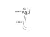
- the wire of the sound output device according to the first aspect is connected downward to the housing of the sound generation unit.
- the sound generation unit of the sound output device includes a sound generating element that generates a change in sound pressure, and a housing that houses the sound generating element. I have.
- the housing of the sound output device includes at least one exhaust hole and sound leakage prevention that prevents sound leakage from the exhaust hole. Department.
- the sound generation unit of the sound output device according to the first aspect is configured to be removable.
- the holding portion of the sound output device includes an earpiece portion having a hollow structure and a tongue piece portion protruding from a lower end of the earpiece portion. It has.
- the holding portion of the sound output device according to the second aspect is configured to be removable.
- the wire of the sound output device according to the first aspect is configured to be removable.
- the technology disclosed in the present specification it is used by being worn on the listener's ear, and at the same time, realizes the listening characteristics of ambient sound equivalent to that in the non-wearing state, while simultaneously outputting good acoustic information. It is possible to provide an excellent sound output device.
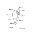
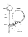
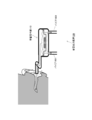
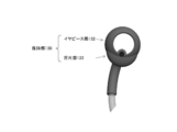
- FIG. 1 is a front view of a sound output device 100 (for left ear wearing) according to an embodiment of the technology disclosed in this specification.
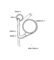
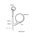
- FIG. 2 is a perspective view of the sound output device 100 (for left ear wearing) according to an embodiment of the technology disclosed in this specification.
- FIG. 3 is a perspective view of the sound output device 100 (for left ear wearing) according to an embodiment of the technique disclosed in this specification.
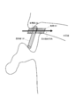
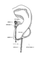
- FIG. 4 is a diagram illustrating a state in which the sound output device 100 according to the present embodiment is attached to the listener's left ear.
- FIG. 5 is a diagram illustrating a state in which the acoustic output device 100 with an open ear hole outputs sound waves to the listener's ear.
- FIG. 1 is a front view of a sound output device 100 (for left ear wearing) according to an embodiment of the technology disclosed in this specification.
- FIG. 2 is a perspective view of the sound output device 100 (for left ear wearing) according to an embodiment of the technology disclosed in
- FIG. 6 is a diagram illustrating a top view and a cross-sectional view of the holding unit 130 coupled to the vicinity of the other end 122 of the sound guide unit 120 coupled to the holding unit 130.
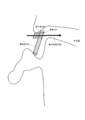
- FIG. 7 is a diagram showing a horizontal section of the wearer's head in which the holding unit 130 is locked by the notch 312 in the left ear.
- FIG. 8 is a diagram illustrating a modification of the sound output device 100.
- FIG. 9 is a diagram illustrating a modification of the sound output device 100.
- FIG. 10 is a diagram illustrating a state in which the wire 140 is inserted into the sound guide unit 120.
- FIG. 11 is a view showing a cross section of the sound guide section 120 through which the signal line of the wire 140 is inserted.
- FIG. 12 is a diagram showing a tensile force acting on the wire 140.
- FIG. 13 is a diagram for explaining a configuration for preventing the sound output device 100 from falling off.
- FIG. 14 is a diagram illustrating a state in which the sound generator 110 is viewed from the front.
- FIG. 15 is a view showing an AA cross section of the sound generator 110.
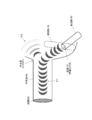
- FIG. 16 is a diagram illustrating a configuration of the sound generation unit 110 in which a pipe 1601 is attached to the exhaust hole 111.
- FIG. 17 is a diagram illustrating an appearance of the sound output device 100 including the sound generation unit 110 having an elliptical shape.
- FIG. 18 is a diagram illustrating an appearance of the sound output device 100 including the half-moon shaped sound generator 110.
- FIG. 14 is a diagram illustrating a state in which the sound generator 110 is viewed from the front.
- FIG. 15 is a view showing an AA cross section of the sound generator 110.
- FIG. 16 is a diagram
- FIG. 19 is a diagram illustrating an external appearance of the sound output device 100 including the sound generation unit 110 having a shape in which the side edge matches the shape of the back of the human ear.
- FIG. 20 is a diagram illustrating a configuration example of the sound output device 100 from which the sound generation unit 110 can be removed.
- FIG. 21 is a diagram illustrating a state in which the holding unit 130 configured in a shape that matches the shape of the bottom surface of the concha cavity in the space between notches of the human ear is viewed from the front.
- FIG. 22 is a diagram illustrating a state where the holding unit 130 illustrated in FIG. 21 is attached to the left ear of the listener.
- FIG. 23 is a diagram illustrating a configuration example of the holding unit 130 including the earpiece portion 132 and the tongue piece portion 133.
- FIG. 24 is a diagram illustrating a configuration example of the sound output device 100 from which the holding unit 130 is removable.
- FIG. 25 is a diagram illustrating the sound output device 100 configured to connect the wire 140 downward to the sound generation unit 110.
- FIG. 26 is a diagram showing a tensile force acting on the wire 140.
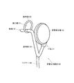
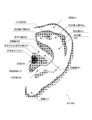
- FIG. 27 is a diagram showing the shape of the pinna and the names of the respective parts.
- FIGS. 1 to 3 show a configuration of an acoustic output device 100 used by being worn on a listener's ear according to an embodiment of the technology disclosed in this specification.
- 1 is a front view of the sound output device 100
- FIG. 2 is a perspective view of the sound output device 100 viewed from the left side
- FIG. 3 is a perspective view of the sound output device 100 viewed from the right side.
- the sound output device 100 shown in FIGS. 1 to 3 is configured to be worn on the left ear
- the sound output device (not shown) for wearing the right ear is configured symmetrically with respect to this. I want you to understand.
- the sound output device 100 includes a sound generation unit 110 that generates sound, a sound guide unit 120 that takes in sound generated from the sound generation unit 110 from one end 121, and a holding unit that holds the sound guide unit 120 near the other end 122. 130 is provided.
- the sound generation unit 110 uses a sound generation element (described later) such as a speaker that generates a change in sound pressure, a change in atmospheric pressure occurs in the housing of the sound generation unit 110 when sound is generated.
- a sound generation element such as a speaker that generates a change in sound pressure
- one or more exhaust holes 111 are formed on the back side of the housing for the case where a high atmospheric pressure generated in the housing is generated.
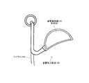
- the sound guide portion 120 is made of a hollow (for example, cylindrical) tube material having an inner diameter of 1 to 5 millimeters, and both ends thereof are open ends.
- One end 121 of the sound guiding unit 120 is an acoustic input hole for the sound generated from the acoustic generating unit 110, and the other end 122 is an acoustic output hole. Therefore, the one end 121 is attached to the sound generation unit 110, so that the sound guide unit 120 is open on one side.
- the sound guide portion 120 can be made of an elastic resin such as an elastomer.
- the tubular sound guide portion 120 has a bent portion 123 at an intermediate portion, and has a bent shape that is folded back from the back side of the auricle to the front side.
- the sound output hole of the sound guide unit 120 is disposed near the entrance of the ear canal by the holding unit 130, while the sound generation unit 110 is connected to the auricle.
- the sound guiding part 120 can be folded back at the lower end of the auricle due to the bent shape, and can propagate the air vibration taken from one end 121 on the back side of the auricle to the front side of the auricle.
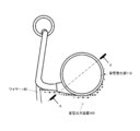
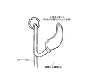
- the holding unit 130 is made of a ring-shaped structure, and is coupled to the other end 122 of the sound guide unit 120 at the inner periphery of the ring. As shown in FIG. 4, the holding unit 130 is inserted into, for example, the concha cavity 310 that is one of the depressions of the auricle, and the coupling portion with the other end 122 of the sound guide unit 120 is caught by the intercostal notch 312. By being locked in this way, the sound output device 100 is attached to the auricle. In the state where the holding part 130 is caught in the intercrocus notch 312 as described above, the holding part 130 is the other end of the sound guide part 120 so that the sound output hole of the other end 122 of the sound guide part 120 faces the ear canal. The vicinity of 122 can be supported.
- the holding part 130 is a ring-shaped structure having an outer diameter of about 13.5 millimeters, for example.
- the holding part 130 is not limited to the ring-shaped structure, and may have any shape that has a hollow structure and can be coupled to and supported by the other end 122 of the sound guide part 120 on the inner periphery.
- the holding unit 130 can be said to be a part corresponding to a conventional earpiece, but can be made of an elastic resin such as an elastomer.
- the outer diameter of at least the other end 122 of the sound guide portion 120 is formed to be much smaller than the inner diameter of the ear hole.
- the holding unit 130 has an opening 131 that opens the ear canal entrance (ear hole) to the outside world even when the sound guide unit 120 is held.
- the vicinity of the other end 122 of the sound guide portion 120 that is an acoustic output hole is coupled to the inner periphery of the ring-shaped holding portion 130, but almost all of the ring-shaped structure is open. Part 131. Therefore, even when the holding portion 130 that supports the other end 122 of the sound guide portion 120 is inserted into the concha conchale 310, the ear hole of the listener is not blocked. That is, the ear hole is open.
- the sound output device 100 can be referred to as an “ear hole open type”.
- the air vibration is propagated, and the other end 122 held near the entrance of the ear canal by the holding unit 130. Radiates to the ear canal and transmits to the eardrum.
- FIG. 4 shows a state in which the sound output device 100 according to the present embodiment is worn on the listener's left ear.
- the shape of the pinna and the names of each part are shown in FIG.
- the holding part 130 coupled to the vicinity of the other end 122 of the sound guiding part 120 is preferably inserted into the concha concavity 310, abuts against the bottom surface of the concha cavity 310, and The connecting portion of the portion 120 with the other end 122 is hooked to the notch 312 and is locked to the auricle.
- the holding unit 130 is in the vicinity of the other end 122 of the sound guide unit 120 so that the sound output hole of the other end 122 of the sound guide unit 120 faces the ear canal. Support.
- the holding part 130 has a hollow structure, and almost all the inside becomes the opening 131. Therefore, even when the holding portion 130 is inserted into the concha cavity 310, the ear hole of the listener is not blocked. That is, the ear hole is open. Unlike the conventional earphone, the sound output device 100 can be referred to as an “ear hole open type”.
- the holding unit 130 is a ring-shaped structure having an outer diameter of, for example, about 13.5 millimeters (described above).
- the size of the outer diameter of the holding part 130 affects not only the mounting stability to the notch 312 but also the feeling of wearing (comfort). There are individual differences in the size of the concha cavity 310, but if the outer diameter (or width) of the holding portion 130 is larger than 16 millimeters, many people cannot be inserted into the concha cavity 310.
- the sound guide portion 120 preferably has an inner diameter as large as possible for the purpose of propagating air vibrations.
- the sound guide portion 120 is inserted into the intercrocus notch 312 near the other end 122.
- the outer diameter of the sound guide part 120 is set to be greater than or equal to the gap (for example, 3.6 millimeters) of the intercuspid notch 312, there is a concern that the wearer's ear (interstitial notch 312) may have a feeling of pressure.
- the sound generation unit 110 is disposed on the back side of the auricle 402 and is coupled to one end 121 of the sound guide unit 120.
- the sound guide unit 120 can bend the lower end of the pinna at the bent portion 123 and propagate the air vibration taken from the one end 121 on the back side of the pinna to the front side of the pinna.
- the distance from the sound generation unit 110 installed on the back side of the pinna to the end of the earlobe 313 by folding back and reaching the entrance to the ear canal is short, and the length of the sound guide unit 120 is accordingly increased. It can be short.
- the length of the sound guide portion 120 can be made the shortest distance.
- the length of the sound guide portion 120 is, for example, about 40 millimeters. If the sound propagation length is short, the attenuation until the sound taken in from the one end 121 of the sound generation unit 110 is output from the other end 122 is small, so it is sufficient to suppress the output of the sound generation unit 110 to be small. Sound quality can be obtained.
- the sound guide 120 is configured to pass through the upper half of the pinna (not shown), the upper half of the pinna is wider than the earlobe 313, so the sound generator 110 installed on the back side of the pinna.
- the distance from the upper end of the ear ring 301 to the entrance of the ear canal becomes longer. Accordingly, the sound guide unit 120 becomes longer and the amount of attenuation until the sound generated from the sound generation unit 110 is radiated to the ear canal increases, or the output of the sound generation unit 110 needs to be increased.
- the sound guide unit 120 passes over the complex uneven shape generated by the shape of the auricular cartilage in the order of the concha 303, the antiaural ring 302, the scaphoid fossa 314, and the auricle 301 toward the outside of the auricle. Because it has to be, the attachment to the pinna becomes unstable. In other words, compared to the earlobe 313, the size of the ear ring 301 in the upper half of the auricle has a large individual difference, so it is necessary to adjust the length of the sound guide 120 when attempting to pass through the upper half of the auricle. Therefore, there is a problem that the design becomes troublesome.
- the holding portion 130 has a hollow structure, and even when the holding portion 130 is inserted into the concha concavity 310, the ear hole is opened to the outside through the opening 131. Therefore, the listener can sufficiently listen to the ambient sound through the opening 131 while wearing the sound output device 100 and listening to the sound output from the sound generation unit 110.
- the sound output device 100 can be referred to as an “ear hole open type”.
- the sound output device 100 opens the ear hole, the sound generated from the sound generator 110 (reproduced sound) can be prevented from leaking to the outside. This is because the other end 122 of the sound guide unit 120 is attached so as to face the external auditory canal and radiates air vibrations of the generated sound near the eardrum, so that sufficient sound quality can be achieved even if the output of the acoustic output unit 100 is reduced. It is because it can obtain.
- FIG. 5 shows a state where the acoustic output device 100 with an open ear hole outputs sound waves to the listener's ear. Air vibration is radiated from the other end 122 of the sound guide portion 120 toward the inside of the ear canal.
- the ear canal 500 is a hole that begins at the ear canal entrance 501 and ends inside the eardrum 502 and is generally approximately 25-30 millimeters long.
- the external auditory canal 500 is a cylindrical closed space that draws an S-shaped curve.
- the air vibration radiated from the other end 122 of the sound guide portion 120 toward the back of the ear canal 500 propagates to the eardrum 502 with directivity as indicated by reference numeral 511.
- the sensitivity (gain) in the low frequency region is particularly improved.
- the outside of the ear canal 500 that is, the outside world is an open space. For this reason, the air vibration radiated from the other end 122 of the sound guide unit 120 to the outside of the ear canal 500 loses directivity when it is released to the outside as indicated by reference numeral 512 and attenuates sharply.
- the holding unit 130 supports the other end 122 of the sound guide unit 120 obliquely so that the sound output hole faces the ear canal entrance 311. This is because, in order to maintain the sensitivity of the low-frequency component, it is extremely important that the sound emission direction from the other end 122 of the sound guide portion 120 matches the hole direction of the ear canal.
- FIG. 6A and 6B respectively show a top view and a cross-sectional view of the holding unit 130 coupled to the vicinity of the other end 122 of the sound guide unit 120.
- FIG. FIG. 7 shows a horizontal section near the left ear of the wearer's head in which the holding unit 130 is locked by the notch 312 in the left ear.
- the holding unit 130 is inserted into the concha concavity 310, for example, and is locked so that the coupling portion with the other end 122 of the sound guide unit 120 is caught by the notch 312.
- the holding portion 130 is inclined from the hole direction of the ear canal when locked by the inner wall of the intercostal notch 312, but the acoustic output hole at the other end 122 of the sound guide portion 120 is The posture is toward the ear canal. That is, the direction of sound emission from the other end 122 of the sound guide portion 120 and the hole direction of the ear canal coincide.
- FIGS. 8 and 9 there is also a configuration example in which the other end 122 of the sound guide portion 120 is protruded from the holding portion 130 and the sound output hole is disposed at a location closer to the ear canal entrance. Conceivable.
- the holding part 130 from which the other end 122 of the sound guide part 120 protrudes is attached to the auricle (concha cavity) 310, a fear of being stuck in the ear is given to the wearer.
- the other end 122 of the sound guide portion 120 does not protrude substantially flush with the bottom surface of the holding portion 130, so There is no fear of piercing.
- the sound radiation direction from the other end 122 of the sound guide portion 120 is substantially directed to the hole direction of the ear canal, a sufficient sound effect can be obtained even if the sound output hole is slightly spaced from the ear canal entrance. it can.
- a wire 140 for inputting a sound signal from a sound reproducing device (not shown) to the sound generating unit 110 is connected to the sound output device 100 described again with reference to FIGS. 1 to 4.
- the audio reproduction device is, for example, a music player, a smartphone, a tablet terminal, or the like.
- an audio signal is input to the sound generation unit 110 from a receiver (not shown) that receives a radio signal from the audio reproduction device instead of the audio reproduction device.
- the wire 140 is connected downward near the bent portion 123 of the sound guide portion 120.
- the sound guide 120 is used as a conduit along with a sound wave propagation path.
- the electric signal line included in the wire 140 is inserted into the sound guiding unit 120 from the bent portion 123 and connected to the sound generating unit 110 as indicated by reference numeral 1001.
- the air vibration generated in the sound generation unit 110 is taken in from one end 121 of the sound guiding unit 120 as indicated by reference numeral 1002, and the traveling direction is turned back by the bending portion 123 and then radiated from the other end 122.
- FIG. 11 shows a state where the signal line of the wire 140 is inserted into the sound guide portion 120 by a cross section indicated by reference numeral 1003 in FIG.
- the sound guiding portion 120 By making the sound guiding portion 120 common to the electric conduit, the inner diameter of the sound guiding portion 120 can be effectively utilized and the tube diameter can be maximized.
- the manufacturing method of insert-molding an electric wire in a mold may be used.
- the signal line is passed through a path different from the sound guiding section 120, it is inefficient.
- the tensile force of the downward wire 140 is applied near the bent portion 123 of the sound guide portion 120.
- gravity is applied to the holding portion 130 that is locked by the intercrocus notch 312.
- the tensile force 1201 acts in a direction approximating the gravity 1202, whereby the lower end of the holding part 130 is pressed against the bottom of the concha cavity 310, and Mounting stability increases. Even if the normally assumed tensile force 1201 is applied to the wire 140, the holding unit 130 does not fall out of the intercrocus notch 312.
- “Sure hook” is known in which the wire is hooked from the top of the pinna through the back of the pinna.
- Inner ear type earphones and canal type earphones have the advantage that they are less likely to fall off the auricles when they are worn with a shoe.
- the holding portion 130 is locked by the intercrocus notch 312 as in the present embodiment, when the wire is shredded, a force in a direction almost opposite to gravity acts on the holding portion 130. In other words, it floats from the notch 312 and tends to fall off.
- the sound guide portion 120 has a bent shape that is folded back from the back side of the auricle to the front side at the middle portion.
- the bent portion causes the holding portion 130 and the sound generation unit 110 to be bent. It looks like holding the pinna between the housing.
- the tensile force 1202 acting on the wire 140 does not completely coincide with the direction of the gravity 1201 applied to the holding unit 130 (or the entire sound output device 100)
- the moment is applied and the sound output device 100 tries to rotate.
- the housing of the sound generating unit 110 abuts against the wall surface on the back side of the auricle to prevent the rotation, so that the dropout is prevented.
- the distance D between the holding unit 130 and the sound generation unit 110 is too close, the force to grip the auricle by the holding unit 130 and the sound generation unit 110 becomes too strong. A person becomes painful because the housing of the sound generation unit 110 is pressed against the back side of the auricle. On the other hand, when the distance D is too far, the force for gripping the auricle by the holding unit 130 and the sound generation unit 110 becomes weak, and thus the sound output device 100 is easily dropped. Roughly speaking, the distance D is preferably 6.5 mm or more and 8.5 mm or less. For example, the distance D may be 7.5 millimeters.
- the sound generator 110 will be described in detail.
- the principle by which the sound generator 110 generates sound is arbitrary.
- the structure of the sound generation unit 110 using a sound generation element such as a speaker that generates a change in sound pressure will be described.
- FIG. 14 shows the sound generator 110 viewed from the front.
- FIG. 15 is a cross-sectional view of the sound generator 110 taken along the line AA.
- the sound generator 110 shown in FIGS. 14 and 15 is a so-called dynamic speaker.
- a diaphragm 1501 having a voice coil 1505 is disposed inside the sound generator 110 so as to face a magnetic circuit constituted by a magnet 1504. Further, the inside of the sound generator 110 is partitioned by the diaphragm 1501 into a diaphragm front space (front cavity) 1502 and a diaphragm rear space 1503 (back cavity).
- the diaphragm 1501 is moved back and forth by the magnetic force of the magnet 1504, so that the diaphragm front space 1502 and the diaphragm rear surface are moved. A change in atmospheric pressure occurs between the spaces 1503, which becomes sound.
- the sound generated in the diaphragm front space 1502 is taken into the one end 121 of the sound guide unit 120, the sound propagates through the tube and is emitted from the other end 122 of the sound guide unit 120 toward the back of the ear canal. After that, it reaches the eardrum.
- the sound generated in the diaphragm back space 1503 is radiated to the outside from the exhaust hole 111 formed on the back side of the housing of the sound generator 110 so as not to disturb the vibration of the diaphragm 1501.
- the inner diameter of the exhaust hole 111 is 1.0 millimeter or less (for example, 0. 6 millimeters).
- two exhaust holes 111 are formed, but three or more exhaust holes 111 may be provided.
- pipes 1601 are attached to the respective exhaust holes 111 so as to attenuate particularly high frequency components in the sound leaking from the exhaust holes 111. Also good. Since the high-frequency component has a high frequency and a strong straightness, the high-frequency component can be sufficiently removed through the elongated pipe 1601. Alternatively, instead of the pipe 1601, a sound absorbing material (acoustic resistance) that removes high frequency components such as a mesh may be stretched inside the housing.
- a sound absorbing material acoustic resistance
- the sound generating element of the sound generation unit 110 may be any one of a balanced armature type, a capacitor type, a piezoelectric type, an electrostatic type, or a composite of two or more in addition to the dynamic type described above. Good.
- Ear-Hole Open Type Earphone The acoustic output device 100 according to the present embodiment is characterized in that it is an ear-hole open type, but the advantages are summarized.
- the listener can naturally listen to the surrounding sound even while wearing the sound output device 100. Therefore, it is possible to normally use human functions that depend on auditory characteristics, such as grasping space, perception of danger, conversation, and grasping subtle nuances during conversation.
- the sound output device 100 Since the sound output device 100 does not close the ear hole when worn, the sound output device 100 has an appearance that may be spoken to by others. In addition, since the listener wearing the sound output device 100 can always hear the ambient sound, as a human property, when the person approaches, the listener changes the body direction to the sound direction from the acoustic information such as footsteps. , Take a lot of passive attitudes such as "Look at the direction of the sound". Such behavior gives the impression that you can "talk” to other people, so it does not hinder communication between people.
- the sound output device 100 is not affected by the self-generated noise sound. Since the other end 122 of the sound guide portion 120 that is an acoustic output hole is separated from the inner wall of the ear canal when the ear hole is worn, the listener's own voice, beating sound, mastication sound, sound when swallowing saliva, It is not affected by blood flow sounds, breathing sounds, vibration sounds transmitted through the body during walking, and rubbing sounds such as cords. In addition, frictional noise between the earpiece and the inner wall of the ear canal is not generated. In addition, since the ear holes are released, there is no worry of moisture in the ear canal.
- the sound output device 100 has good wearability to the ear and can absorb positioning variations caused by individual differences in the size and shape of the ear.
- the holding part 130 is configured to engage with the notch between the beads and support the acoustic output hole of the other end 122 of the sound guide part 120 so as to face the ear canal. Therefore, it is not necessary to adjust the length as in the case of an ear-hanging type sound output device in which the sound conductor is folded at the ear ring 301.
- a favorable mounting state can be maintained because the holding
- a favorable mounting state can be maintained by the tensile force of the wire 140 acting on the bent portion 123 of the sound guide portion 120.
- the structure in which the sound guiding unit 120 is folded from the back of the auricle with the earlobe 313 and extends to the vicinity of the entrance to the external auditory canal allows the listener to use glasses, a glasses-type wearable device, and an ear-mounted device in combination. Does not interfere with these other devices.
- the sound guide unit 120 propagates the sound generated by the sound generation unit 110 from the back of the ear to the vicinity of the entrance to the ear canal at the shortest distance. Therefore, compared with the ear-sound type sound output device, the sound loss can be minimized as much as the length of the sound guide portion is shortened, the sound generator 110 is reduced in output, and the sound quality is good. Can be obtained. In other words, the dimensional tolerance of the sound generator 110 is high, and the design according to the required sound band and sound pressure is possible.
- the shape of the sound generation unit 110 illustrated so far is a disk shape, the shape is not limited to this shape.
- the sound generating unit 110 can be configured in an arbitrary shape so as to match the shape of the sound generating element housed inside or to match the back side surface of the auricle.
- the sound generator 110 having an elliptical shape shown in FIG. 17 or the sound generator 110 having a half-moon shape shown in FIG. 18 may be used.
- the shape of the sound generation unit 110 may be formed to match the shape of the back of the person's ear.
- FIG. 19 illustrates an appearance of the sound output device 100 including the sound generation unit 110 having a shape in which the side edge matches the shape of the back of the human ear.
- the sound output device 100 may be configured such that the sound generator 110 can be removed.
- the sound generator 110 can be removed, the sound generator 110 having a housing adapted to the shape of the back of each ear can be appropriately replaced, or the sound generator 110 having a desired performance can be selected and used. Can be mentioned. For example, it is possible to select and use a sound generator that emphasizes high and low sounds, a high-resolution sound generator, and the like.
- FIG. 21 illustrates a state in which the holding unit 130 configured in a shape that matches the shape of the bottom surface of the concha cavity in the space between notch of the individual's ears is viewed from the front.
- FIG. 22 shows a state where the holding unit 130 shown in FIG. 21 is attached to the left ear of the listener. As can be seen from FIG. 22, the holding portion 130 attached to the intercusp notch of the left ear is adapted to the shape surface 2201 in the intervertebral notch space of the listener's ear, so Become good.
- FIG. 23 shows another configuration example of the holding unit 130.
- the illustrated holding part 130 includes an earpiece part 132 having a hollow structure that is locked by a notch 312 and a tongue piece part 133 that protrudes from the vicinity of the lower end of the earpiece part 132.
- the tongue piece 133 comes into contact with the bottom of the concha cavity 310.
- Both the earpiece part 132 and the tongue piece part 133 can be made of, for example, an elastomer, but the earpiece part 132 is hardened to prevent falling off from the notch between the beads 312 while the tongue piece part 133 is softened. This improves the feeling of wearing.
- the holding part 130 can be manufactured by two-color elastomer molding of the earpiece part 132 and the tongue piece part 133.
- the sound output device 100 may be configured such that the holding unit 130 can be removed.
- FIG. 24 the structural example of the holding
- maintenance part 130 from the sound output device 100 is arbitrary.
- Advantages of making the holding part 130 removable are that the holding part 130 having a contour adapted to the shape of the bottom surface of the respective concha canal and the holding part 130 having a desired hardness can be appropriately replaced. it can.
- the holding unit 130 When the holding unit 130 is configured to be removable and replaceable as shown in FIG. 24, the holding unit 130 is held with respect to the main body of the sound output device 100 (or the sound guide unit 120) when the sound output device 100 is attached to the auricle. There is a problem that the unit 130 rotates and is difficult to operate. Therefore, it is preferable that there is a mechanism for fixing the rotation position of the holding unit 130 with respect to the sound guide unit 120 (or preventing rotation).
- the sound output device 100 in which the wire 140 is connected downward near the bent portion 123 of the sound guide unit 120 has been described.
- the sound output device 100 can be configured to connect the wire 140 downward to the bottom of the sound generation unit 110.
- the wire 140 may be configured to be removable from the main body of the sound output device 100.
- an MMCX (Micro-Miniature CoaXial) type connector for connection between the sound output device 100 and the wire 140, for example, an MMCX (Micro-Miniature CoaXial) type connector, or a 3.5 mm or 2.5 mm plug and jack can be used.
- the wire 140 can be removed from the main body of the sound output device 100, it is possible to share the wire 140 with other products and other users, and it is convenient for storing and carrying the sound output device 100 by removing the wire 140. Some things can be mentioned.
- the structure of the auricle 300 includes an auricle 301, an antiauricle 302, a concha 303, and a tragus 304 in order from the outside. Further, on the outside of the tragus 304, there is a tragus 305 that is a pair of protrusions. A notch between the tragus 304 and the antitragus 305 is an inter-brow notch 312. In addition, the lower end of the auricle 300 is an earlobe 313.
- the ear ring 301 is a part that forms the outline of the ear on the outermost periphery of the ear.
- the auricle 301 is curved inward near the center of the auricle 300 (near the top of the external auditory canal entrance 311), and then passes substantially horizontally near the middle of the auricle 300 to divide the concha 303 vertically. There is a protrusion.
- the ear ring leg 306 is the vicinity where the ear ring 301 is curved toward the inside of the pinna 300, and the ear ring root 307 is a part of the ear ring leg 306 that further enters the concha 303.
- the anti-aural ring 302 is a ridge line directed upward from the anti-conical bead 305, and corresponds to the edge of the concha 303.
- the ridgeline that forms the antiaural ring 302 is divided into two forks, and the upper branch is called an antiaural upper leg 302a and corresponds to the upper side of the triangular fossa 308. Further, the lower branch is called an antiaural lower leg 302 b and corresponds to the lower side of the triangular fossa 308.
- the concha 303 is the most depressed portion in the center of the ear, and is divided into an concha boat 309 composed of an upper half elongated depression, and a lower concha cavity 310, with the ear ring root 307 as a boundary.
- the triangular fossa 308 is a triangular depression having three sides of the upper leg 302 a, the lower leg 302 b, and the ear 301.
- the scaphoid 314 is a depression in the upper and outer portions in the entire pinna 300 between the anti-aural ring 302 and the ear ring 301.
- the sound output device to which the technology disclosed in the present specification is applied is used by being attached to the listener's ear, but is significantly different from the conventional earphone in that it is an “ear hole open type”. Therefore, the sound output device to which the technology disclosed in the present specification is applied can output acoustic information at the same time while realizing the listening characteristics of the ambient sound equivalent to that in the non-wearing state even in the wearing state. Even in the state, there is a feature that it seems that the surrounding people do not block the ear hole of the listener.
- the sound output device to which the technology disclosed in this specification is applied can be used in various sports fields (in the field of play, jogging, cycling, mountaineering, skiing, snowboarding, etc.) , Remote coaching, etc.) Communication or presentation fields that require simultaneous listening to ambient sounds and presentation of voice information (for example, supplementary information during theater viewing, museum voice information presentation, bird watching, etc.), driving or navigation It can be applied to security guards, newscasters, etc.
- a sound generator disposed on the back of the listener's ear; A hollow structure having one end connected to the sound generation unit and the other end disposed in the listener's auricle, taking in the sound generated by the sound generation unit from the one end and propagating to the other end
- the sound guide A wire connected downwards
- a sound output device comprising: (2) It further comprises a holding part that holds the other end of the sound guide part in the vicinity of the ear canal entrance of the listener.
- the holding portion is inserted into the listener's conch boat and locked with a notch between the beads.
- the sound guide portion is inserted into the intercrocus notch in the vicinity of the other end.
- the holding portion supports the sound guide portion in the vicinity of the other end so that the sound output hole of the other end is in a posture facing the ear canal.
- the other end of the sound guide portion is substantially flush with the bottom surface of the holding portion.
- the holding portion includes a hollow structure and is coupled to the other end of the sound guide portion on an inner periphery.
- the wire is connected downward near the lower end of the sound guide portion.
- the sound output device according to (1) above.
- the sound guide portion has a bent portion that is folded back at the lower end of the auricle, The wire is connected downward near the bent portion, The sound output device according to (1) above.
- the signal line included in the wire is inserted into the sound guide portion.
- the sound output device according to (9) above.
- the wire is connected downward to the housing of the sound generation unit,
- the sound generation unit includes a sound generating element that generates a change in sound pressure, and a housing that houses the sound generating element.
- the sound output device according to (1) above.
- the housing includes one or more exhaust holes and a sound leakage prevention unit that prevents sound leakage from the exhaust holes.
- the sound generator is removable.
- the holding portion includes an earpiece portion having a hollow structure and a tongue piece portion protruding from a lower end of the earpiece portion.
- the holding part is removable.
- the wire is removable. The sound output device according to (1) above.
Landscapes
- Physics & Mathematics (AREA)
- Engineering & Computer Science (AREA)
- Acoustics & Sound (AREA)
- Signal Processing (AREA)
- Health & Medical Sciences (AREA)
- Otolaryngology (AREA)
- Headphones And Earphones (AREA)
Abstract
Description
聴取者の耳の背面に配設される音響発生部と、
一端が前記音響発生部に接続されるとともに他端が前記聴取者の耳介内に配設され、前記音響発生部が発生する音響を前記一端から取り込んで前記他端まで伝搬する、中空構造の音導部と、
下向きに接続されたワイヤーと、
を具備する音響出力装置である。 The technology disclosed in the present specification has been made in consideration of the above-mentioned problems, and the first aspect thereof is
A sound generator disposed on the back of the listener's ear;
A hollow structure having one end connected to the sound generation unit and the other end disposed in the listener's auricle, taking in the sound generated by the sound generation unit from the one end and propagating to the other end The sound guide,
A wire connected downwards,
Is an acoustic output device.
図1乃至図3には、本明細書で開示する技術の一実施形態に係る、聴取者の耳に装着して用いられる音響出力装置100の構成を示している。但し、図1は音響出力装置100の正面図であり、図2は音響出力装置100を左側から眺めた斜視図、図3は音響出力装置100を右側から眺めた斜視図である。また、図1乃至図3に示す音響出力装置100は、左耳に装着するように構成されているが、右耳装着用の音響出力装置(図示しない)はこれとは左右対称に構成されているものと理解されたい。 A. Device Configuration FIGS. 1 to 3 show a configuration of an acoustic output device 100 used by being worn on a listener's ear according to an embodiment of the technology disclosed in this specification. 1 is a front view of the sound output device 100, FIG. 2 is a perspective view of the sound output device 100 viewed from the left side, and FIG. 3 is a perspective view of the sound output device 100 viewed from the right side. Moreover, although the sound output device 100 shown in FIGS. 1 to 3 is configured to be worn on the left ear, the sound output device (not shown) for wearing the right ear is configured symmetrically with respect to this. I want you to understand.
本実施形態に係る音響出力装置100は、耳穴開放型である点で特徴があるが、その利点についてまとめておく。 B. Advantages of Ear-Hole Open Type Earphone The acoustic output device 100 according to the present embodiment is characterized in that it is an ear-hole open type, but the advantages are summarized.
これまで図示してきた音響発生部110の形状は円盤状であったが、この形状に限定される訳ではない。例えば、内部に収容する発音素子の形状に合わせて、あるいは耳介の裏側表面に適合するように、音響発生部110を任意の形状に構成することができる。例えば、図17に示す楕円形状を有する音響発生部110や、図18に示す半月形状を有する音響発生部110でもよい。 C. Modification of Sound Generation Unit Although the shape of the sound generation unit 110 illustrated so far is a disk shape, the shape is not limited to this shape. For example, the sound generating unit 110 can be configured in an arbitrary shape so as to match the shape of the sound generating element housed inside or to match the back side surface of the auricle. For example, the sound generator 110 having an elliptical shape shown in FIG. 17 or the sound generator 110 having a half-moon shape shown in FIG. 18 may be used.
保持部130についても、個人の耳の珠間切痕空間内の耳甲介腔の底面の形状面に適合する形状に構成することで、保持部130の珠間切痕への保持性を良好にすることができる。図21には、個人の耳の珠間切痕空間内の耳甲介腔の底面の形状面に適合する形状に構成した保持部130を正面から見た様子を示している。また、図22には、図21に示した保持部130を、聴取者の左耳に装着した様子を示している。図22から分かるように、左耳の珠間切痕に装着された保持部130は、聴取者の耳の珠間切痕空間内の形状面2201に適合するので、珠間切痕への保持性がより良好になる。 D. Modification of the holding portion The holding portion 130 is also configured to fit the shape of the bottom surface of the concha cavity in the space between notch of the individual's ears, so that the holding portion 130 can be held in the notch. Property can be improved. FIG. 21 illustrates a state in which the holding unit 130 configured in a shape that matches the shape of the bottom surface of the concha cavity in the space between notch of the individual's ears is viewed from the front. FIG. 22 shows a state where the holding unit 130 shown in FIG. 21 is attached to the left ear of the listener. As can be seen from FIG. 22, the holding portion 130 attached to the intercusp notch of the left ear is adapted to the
上記では、ワイヤー140を音導部120の屈曲部123付近で下向きに接続した音響出力装置100の構成例について説明してきた。これに対し、図25に示すように、ワイヤー140を音響発生部110の底部に下向きに接続するように音響出力装置100を構成することもできる。 E. In the above, the configuration example of the sound output device 100 in which the wire 140 is connected downward near the bent portion 123 of the sound guide unit 120 has been described. On the other hand, as shown in FIG. 25, the sound output device 100 can be configured to connect the wire 140 downward to the bottom of the sound generation unit 110.
耳介の構造について、図27を参照しながら説明しておく。耳介300の構造を大まかに言うと、外側から順に、耳輪301、対耳輪302、耳甲介303、耳珠304がある。また、耳珠304の外側には、対となる突起である対耳珠305がある。耳珠304と対耳珠305の間にある切れ込みが、珠間切痕312である。また、耳介300の下端は、耳垂313である。 "reference"
The structure of the auricle will be described with reference to FIG. Roughly speaking, the structure of the auricle 300 includes an auricle 301, an
(1)聴取者の耳の背面に配設される音響発生部と、
一端が前記音響発生部に接続されるとともに他端が前記聴取者の耳介内に配設され、前記音響発生部が発生する音響を前記一端から取り込んで前記他端まで伝搬する、中空構造の音導部と、
下向きに接続されたワイヤーと、
を具備する音響出力装置。
(2)前記音導部の前記他端を前記聴取者の外耳道入り口付近で保持する保持部をさらに備える、
上記(1)に記載の音響出力装置。
(3)前記保持部は、前記聴取者の耳甲介艇に挿入され、珠間切痕で係止される、
上記(2)に記載の音響出力装置。
(4)前記音導部は、前記他端付近で珠間切痕に挿通される、
上記(3)に記載の音響出力装置。
(5)前記保持部は、前記他端の音響出力孔が外耳道を向く姿勢となるように、前記音導部を前記他端付近で支持する、
上記(2)に記載の音響出力装置。
(6)前記音導部の前記他端は、前記保持部の底面とほぼ面一となる、
上記(2)に記載の音響出力装置。
(7)前記保持部は、中抜き構造を備え、内周に前記音導部の前記他端と結合する、
上記(2)に記載の音響出力装置。
(8)前記ワイヤーは、前記音導部の下端付近で下向きに接続される、
上記(1)に記載の音響出力装置。
(9)前記音導部は、耳介の下端で折り返す屈曲部を有し、
前記ワイヤーは、前記屈曲部付近で下向きに接続される、
上記(1)に記載の音響出力装置。
(10)前記ワイヤーに含まれる信号線は、前記音導部内に挿通される、
上記(9)に記載の音響出力装置。
(11)前記ワイヤーは、前記音響発生部のハウジングに下向きに接続される、
上記(1)に記載の音響出力装置。
(12)前記音響発生部は、音圧変化を発生する発音素子と、前記発音素子を収容するハウジングを備える、
上記(1)に記載の音響出力装置。
(13)前記ハウジングは、1以上の排気孔と、前記排気孔からの音漏れを防止する音漏れ防止部を備える、
上記(12)に記載の音響出力装置。
(14)前記音響発生部は取り外し可能である、
上記(1)に記載の音響出力装置。
(15)前記保持部は、中抜き構造のイヤピース部と、前記イヤピース部の下端から突出した舌片部を備える、
上記(2)に記載の音響出力装置。
(16)前記保持部は取り外し可能である、
上記(2)に記載の音響出力装置。
(17)前記ワイヤーは取り外し可能である、
上記(1)に記載の音響出力装置。 Note that the technology disclosed in the present specification can also be configured as follows.
(1) a sound generator disposed on the back of the listener's ear;
A hollow structure having one end connected to the sound generation unit and the other end disposed in the listener's auricle, taking in the sound generated by the sound generation unit from the one end and propagating to the other end The sound guide,
A wire connected downwards,
A sound output device comprising:
(2) It further comprises a holding part that holds the other end of the sound guide part in the vicinity of the ear canal entrance of the listener.
The sound output device according to (1) above.
(3) The holding portion is inserted into the listener's conch boat and locked with a notch between the beads.
The acoustic output device according to (2) above.
(4) The sound guide portion is inserted into the intercrocus notch in the vicinity of the other end.
The acoustic output device according to (3) above.
(5) The holding portion supports the sound guide portion in the vicinity of the other end so that the sound output hole of the other end is in a posture facing the ear canal.
The acoustic output device according to (2) above.
(6) The other end of the sound guide portion is substantially flush with the bottom surface of the holding portion.
The acoustic output device according to (2) above.
(7) The holding portion includes a hollow structure and is coupled to the other end of the sound guide portion on an inner periphery.
The acoustic output device according to (2) above.
(8) The wire is connected downward near the lower end of the sound guide portion.
The sound output device according to (1) above.
(9) The sound guide portion has a bent portion that is folded back at the lower end of the auricle,
The wire is connected downward near the bent portion,
The sound output device according to (1) above.
(10) The signal line included in the wire is inserted into the sound guide portion.
The sound output device according to (9) above.
(11) The wire is connected downward to the housing of the sound generation unit,
The sound output device according to (1) above.
(12) The sound generation unit includes a sound generating element that generates a change in sound pressure, and a housing that houses the sound generating element.
The sound output device according to (1) above.
(13) The housing includes one or more exhaust holes and a sound leakage prevention unit that prevents sound leakage from the exhaust holes.
The acoustic output device according to (12) above.
(14) The sound generator is removable.
The sound output device according to (1) above.
(15) The holding portion includes an earpiece portion having a hollow structure and a tongue piece portion protruding from a lower end of the earpiece portion.
The acoustic output device according to (2) above.
(16) The holding part is removable.
The acoustic output device according to (2) above.
(17) The wire is removable.
The sound output device according to (1) above.
120…音導部、121…一端(音響入力孔)、
122…他端(音響出力孔)、123…屈曲部
130…保持部、131…開口部、132…イヤピース部
133…舌片部、140…ワイヤー
1501…振動板、1504…マグネット
1505…ボイス・コイル
1601…パイプ DESCRIPTION OF SYMBOLS 100 ... Sound output device, 110 ... Sound generating part, 111 ... Exhaust hole 120 ... Sound guide part, 121 ... One end (acoustic input hole),
122: Other end (acoustic output hole), 123: Bending part 130 ... Holding part, 131 ... Opening part, 132 ... Earpiece part 133 ... Tongue piece part, 140 ... Wire 1501 ... Diaphragm, 1504 ... Magnet 1505 ... Voice coil 1601 ... Pipe
Claims (17)
- 聴取者の耳の背面に配設される音響発生部と、
一端が前記音響発生部に接続されるとともに他端が前記聴取者の耳介内に配設され、前記音響発生部が発生する音響を前記一端から取り込んで前記他端まで伝搬する、中空構造の音導部と、
下向きに接続されたワイヤーと、
を具備する音響出力装置。 A sound generator disposed on the back of the listener's ear;
A hollow structure having one end connected to the sound generation unit and the other end disposed in the listener's auricle, taking in the sound generated by the sound generation unit from the one end and propagating to the other end The sound guide,
A wire connected downwards,
A sound output device comprising: - 前記音導部の前記他端を前記聴取者の外耳道入り口付近で保持する保持部をさらに備える、
請求項1に記載の音響出力装置。 A holding part for holding the other end of the sound guide part in the vicinity of the listener's ear canal entrance;
The sound output device according to claim 1. - 前記保持部は、前記聴取者の耳甲介艇に挿入され、珠間切痕で係止される、
請求項2に記載の音響出力装置。 The holding portion is inserted into the listener's concha boat and locked with a notch between the beads.
The sound output device according to claim 2. - 前記音導部は、前記他端付近で珠間切痕に挿通される、
請求項3に記載の音響出力装置。 The sound guide portion is inserted into the notch between the other end,
The sound output device according to claim 3. - 前記保持部は、前記他端の音響出力孔が外耳道を向く姿勢となるように、前記音導部を前記他端付近で支持する、
請求項2に記載の音響出力装置。 The holding portion supports the sound guide portion in the vicinity of the other end so that the sound output hole of the other end is in a posture facing the ear canal.
The sound output device according to claim 2. - 前記音導部の前記他端は、前記保持部の底面とほぼ面一となる、
請求項2に記載の音響出力装置。 The other end of the sound guide portion is substantially flush with the bottom surface of the holding portion;
The sound output device according to claim 2. - 前記保持部は、中抜き構造を備え、内周に前記音導部の前記他端と結合する、
請求項2に記載の音響出力装置。 The holding portion includes a hollow structure and is coupled to the other end of the sound guide portion on an inner periphery.
The sound output device according to claim 2. - 前記ワイヤーは、前記音導部の下端付近で下向きに接続される、
請求項1に記載の音響出力装置。 The wire is connected downward near the lower end of the sound guide portion,
The sound output device according to claim 1. - 前記音導部は、耳介の下端で折り返す屈曲部を有し、
前記ワイヤーは、前記屈曲部付近で下向きに接続される、
請求項1に記載の音響出力装置。 The sound guide portion has a bent portion that is folded back at the lower end of the auricle,
The wire is connected downward near the bent portion,
The sound output device according to claim 1. - 前記ワイヤーに含まれる信号線は、前記音導部内に挿通される、
請求項9に記載の音響出力装置。 The signal line included in the wire is inserted into the sound guide portion,
The sound output device according to claim 9. - 前記ワイヤーは、前記音響発生部のハウジングに下向きに接続される、
請求項1に記載の音響出力装置。 The wire is connected downward to the housing of the sound generator,
The sound output device according to claim 1. - 前記音響発生部は、音圧変化を発生する発音素子と、前記発音素子を収容するハウジングを備える、
請求項1に記載の音響出力装置。 The sound generator includes a sound generating element that generates a change in sound pressure, and a housing that houses the sound generating element.
The sound output device according to claim 1. - 前記ハウジングは、1以上の排気孔と、前記排気孔からの音漏れを防止する音漏れ防止部を備える、
請求項12に記載の音響出力装置。 The housing includes one or more exhaust holes and a sound leakage prevention unit that prevents sound leakage from the exhaust holes.
The sound output device according to claim 12. - 前記音響発生部は取り外し可能である、
請求項1に記載の音響出力装置。 The sound generator is removable.
The sound output device according to claim 1. - 前記保持部は、中抜き構造のイヤピース部と、前記イヤピース部の下端から突出した舌片部を備える、
請求項2に記載の音響出力装置。 The holding portion includes an earpiece portion having a hollow structure and a tongue piece portion protruding from a lower end of the earpiece portion.
The sound output device according to claim 2. - 前記保持部は取り外し可能である、
請求項2に記載の音響出力装置。 The holding part is removable;
The sound output device according to claim 2. - 前記ワイヤーは取り外し可能である、
請求項1に記載の音響出力装置。 The wire is removable;
The sound output device according to claim 1.
Priority Applications (4)
| Application Number | Priority Date | Filing Date | Title |
|---|---|---|---|
| JP2018502542A JP7036002B2 (en) | 2016-03-01 | 2016-12-27 | Acoustic output device |
| EP16892749.9A EP3425922B1 (en) | 2016-03-01 | 2016-12-27 | Sound output device |
| CN201680082598.0A CN108702560B (en) | 2016-03-01 | 2016-12-27 | Sound output device |
| US16/077,357 US10623842B2 (en) | 2016-03-01 | 2016-12-27 | Sound output apparatus |
Applications Claiming Priority (2)
| Application Number | Priority Date | Filing Date | Title |
|---|---|---|---|
| JP2016039004 | 2016-03-01 | ||
| JP2016-039004 | 2016-03-01 |
Publications (1)
| Publication Number | Publication Date |
|---|---|
| WO2017149915A1 true WO2017149915A1 (en) | 2017-09-08 |
Family
ID=59743662
Family Applications (1)
| Application Number | Title | Priority Date | Filing Date |
|---|---|---|---|
| PCT/JP2016/088918 WO2017149915A1 (en) | 2016-03-01 | 2016-12-27 | Sound output device |
Country Status (5)
| Country | Link |
|---|---|
| US (1) | US10623842B2 (en) |
| EP (1) | EP3425922B1 (en) |
| JP (1) | JP7036002B2 (en) |
| CN (1) | CN108702560B (en) |
| WO (1) | WO2017149915A1 (en) |
Cited By (2)
| Publication number | Priority date | Publication date | Assignee | Title |
|---|---|---|---|---|
| JP2019134237A (en) * | 2018-01-29 | 2019-08-08 | 株式会社東芝 | Acoustic generation device |
| JP2020014106A (en) * | 2018-07-18 | 2020-01-23 | ヤマハ株式会社 | Electroacoustic transducer |
Families Citing this family (4)
| Publication number | Priority date | Publication date | Assignee | Title |
|---|---|---|---|---|
| USD903630S1 (en) * | 2016-02-29 | 2020-12-01 | Sony Corporation | Earphone |
| CN110100454B (en) | 2016-12-29 | 2021-09-07 | 索尼公司 | Sound output device |
| KR102662483B1 (en) | 2020-07-29 | 2024-05-07 | 썬전 샥 컴퍼니 리미티드 | earphone |
| US11140469B1 (en) | 2021-05-03 | 2021-10-05 | Bose Corporation | Open-ear headphone |
Citations (3)
| Publication number | Priority date | Publication date | Assignee | Title |
|---|---|---|---|---|
| JPH03117999A (en) * | 1989-09-30 | 1991-05-20 | Sony Corp | Electroacoustic transducer and acoustic reproduction system |
| JP2008512882A (en) * | 2004-09-07 | 2008-04-24 | ヴェーデクス・アクティーセルスカプ | Hearing aid earpiece and hearing aid |
| WO2010150475A1 (en) * | 2009-06-24 | 2010-12-29 | パナソニック株式会社 | Hearing aid |
Family Cites Families (16)
| Publication number | Priority date | Publication date | Assignee | Title |
|---|---|---|---|---|
| US3045073A (en) * | 1960-05-11 | 1962-07-17 | Charles S Vickerson | Behind-ear hearing aid |
| US3493695A (en) * | 1967-03-10 | 1970-02-03 | Fredrick J Stork | Hearing aid |
| US3610841A (en) * | 1970-03-06 | 1971-10-05 | Pacific Plantronics Inc | Self-supporting headset |
| US4864610A (en) | 1987-02-27 | 1989-09-05 | Acs Communications, Inc. | Earpiece for a telephone headset |
| JP3057731B2 (en) | 1990-08-21 | 2000-07-04 | ソニー株式会社 | Electroacoustic transducer and sound reproduction system |
| US6681022B1 (en) | 1998-07-22 | 2004-01-20 | Gn Resound North Amerca Corporation | Two-way communication earpiece |
| US20020096391A1 (en) * | 2001-01-24 | 2002-07-25 | Smith Richard C. | Flexible ear insert and audio communication link |
| CN101023707B (en) * | 2004-09-07 | 2012-08-29 | 唯听助听器公司 | Earpiece for a hearing aid and a hearing aid |
| US7720244B2 (en) | 2005-03-16 | 2010-05-18 | Widex A/S | Earpiece for a hearing aid and a hearing aid |
| JP4709017B2 (en) | 2006-01-12 | 2011-06-22 | ソニー株式会社 | Earphone device |
| US8249287B2 (en) * | 2010-08-16 | 2012-08-21 | Bose Corporation | Earpiece positioning and retaining |
| US9055363B2 (en) | 2007-07-09 | 2015-06-09 | Gn Netcom A/S | Headset system comprising a noise dosimeter |
| JP4993023B1 (en) | 2011-02-25 | 2012-08-08 | パナソニック株式会社 | hearing aid |
| CN202310041U (en) * | 2011-10-11 | 2012-07-04 | 南通芯迎设计服务有限公司 | Earphones without influences on outside sound |
| JP2013106130A (en) | 2011-11-11 | 2013-05-30 | Yan-Ru Peng | Open guide type headphone |
| CN109474864A (en) | 2014-10-30 | 2019-03-15 | 索尼公司 | Sound output device |
-
2016
- 2016-12-27 CN CN201680082598.0A patent/CN108702560B/en active Active
- 2016-12-27 US US16/077,357 patent/US10623842B2/en active Active
- 2016-12-27 EP EP16892749.9A patent/EP3425922B1/en active Active
- 2016-12-27 WO PCT/JP2016/088918 patent/WO2017149915A1/en active Application Filing
- 2016-12-27 JP JP2018502542A patent/JP7036002B2/en active Active
Patent Citations (3)
| Publication number | Priority date | Publication date | Assignee | Title |
|---|---|---|---|---|
| JPH03117999A (en) * | 1989-09-30 | 1991-05-20 | Sony Corp | Electroacoustic transducer and acoustic reproduction system |
| JP2008512882A (en) * | 2004-09-07 | 2008-04-24 | ヴェーデクス・アクティーセルスカプ | Hearing aid earpiece and hearing aid |
| WO2010150475A1 (en) * | 2009-06-24 | 2010-12-29 | パナソニック株式会社 | Hearing aid |
Non-Patent Citations (1)
| Title |
|---|
| See also references of EP3425922A4 * |
Cited By (3)
| Publication number | Priority date | Publication date | Assignee | Title |
|---|---|---|---|---|
| JP2019134237A (en) * | 2018-01-29 | 2019-08-08 | 株式会社東芝 | Acoustic generation device |
| JP2020014106A (en) * | 2018-07-18 | 2020-01-23 | ヤマハ株式会社 | Electroacoustic transducer |
| JP7099110B2 (en) | 2018-07-18 | 2022-07-12 | ヤマハ株式会社 | Electro-acoustic converter |
Also Published As
| Publication number | Publication date |
|---|---|
| JP7036002B2 (en) | 2022-03-15 |
| EP3425922B1 (en) | 2021-02-17 |
| EP3425922A1 (en) | 2019-01-09 |
| CN108702560B (en) | 2020-11-24 |
| EP3425922A4 (en) | 2019-03-06 |
| CN108702560A (en) | 2018-10-23 |
| US20190052950A1 (en) | 2019-02-14 |
| JPWO2017149915A1 (en) | 2018-12-27 |
| US10623842B2 (en) | 2020-04-14 |
Similar Documents
| Publication | Publication Date | Title |
|---|---|---|
| JP6652164B2 (en) | Sound output device | |
| WO2017149915A1 (en) | Sound output device | |
| JP7003993B2 (en) | Acoustic output device | |
| US6704429B2 (en) | Earphone without impulse noise and surroundings blockade | |
| TWI530199B (en) | An earphone having an acoustic tuning mechanism | |
| WO2018123210A1 (en) | Sound output device | |
| WO2021027230A1 (en) | Smart head-mounted device | |
| TW201543904A (en) | An earphone having a controlled acoustic leak port | |
| JP6668766B2 (en) | Audio signal processing device | |
| EP3565273B1 (en) | Sound pickup device | |
| JPS5821267Y2 (en) | telephone receiver | |
| EP1068771B1 (en) | Earphone without impulse noise for protection against conductive hearing loss | |
| JP2017147533A (en) | earphone | |
| JP2008060943A (en) | Earphone attachment | |
| JP2023514124A (en) | Adaptive ear tips for true wireless stereo headsets | |
| JP2009253488A (en) | Earplug and earphone |
Legal Events
| Date | Code | Title | Description |
|---|---|---|---|
| WWE | Wipo information: entry into national phase |
Ref document number: 2018502542 Country of ref document: JP |
|
| NENP | Non-entry into the national phase |
Ref country code: DE |
|
| WWE | Wipo information: entry into national phase |
Ref document number: 2016892749 Country of ref document: EP |
|
| ENP | Entry into the national phase |
Ref document number: 2016892749 Country of ref document: EP Effective date: 20181001 |
|
| 121 | Ep: the epo has been informed by wipo that ep was designated in this application |
Ref document number: 16892749 Country of ref document: EP Kind code of ref document: A1 |